Комментарии
19
Войдите или зарегистрируйтесь, чтобы писать комментарии, задавать вопросы и участвовать в обсуждении.

Я езжу на Nissan Murano I
Народ добрый вечер. У кого сохранился файл PDF книга для NISSAN MURANO Z50 2006г. За ранее спасибо.
Я езжу на Nissan Murano I
Здравствуйте.В декабре прошлого года приобрёл NISSAN MURANO Z50 2006г. Не книги не инструкций к ней не было.Если есть возможность пришлите пожалуйста мануал. mudrats69@gmail.com

Здравствуйте, файл потерял, но можно с интернета скачать

Здравствуйте. Отправьте пожалуйста мануал мне тоже fad0110@mail.ru
Здравствуйте, не могу файл найти, как найду отправлю
Друзья попробуйте ещё раз, сейчас ссылка должна работать

Скачивается, но только там мануал на 51

Скинь на почту пожалуйста, a9266374477@ya.ru

и мне пожалуйста bg@orfey.ru

не получается зайти по ссылке
Я пробую, заходить.
Что показывает, загрузка не идёт?
ANDOVARAGYAN
Я пробую, заходить.
Что показывает, загрузка не идёт?

никак не заходит. Если не лень будет швырни сюда скачанный файл oootradzem@gmail.com

И мне тоже ip-eev2012@ya.ru

и мне тоже пожалуйста
demon-red96@mail.ru
Все комментарии
ACCELERATOR CONTROL SYSTEM
B ENGINE
A
SECTION
ACCELERATOR CONTROL SYSTEM
ACC
C
D
CONTENTS
PRECAUTIONS …………………………………………………. 2
Precautions for Supplemental Restraint System
(SRS) “AIR BAG” and “SEAT BELT PRE-TENSIONER” ………………………………………………………… 2
ACCELERATOR CONTROL SYSTEM …………………. 3
Components ……………………………………………………. 3
Removal and Installation …………………………………… 3
REMOVAL ……………………………………………………. 3
INSTALLATION …………………………………………….. 4
INSPECTION AFTER INSTALLATION ……………… 4
E
F
G
H
I
J
K
L
M
ACC-1
PRECAUTIONS
PRECAUTIONS
PFP:00001
Precautions for Supplemental Restraint System (SRS) “AIR BAG” and “SEAT
BELT PRE-TENSIONER”
EBS01CAM
The Supplemental Restraint System such as “AIR BAG” and “SEAT BELT PRE-TENSIONER”, used along
with a front seat belt, helps to reduce the risk or severity of injury to the driver and front passenger for certain
types of collision. This system includes seat belt switch inputs and dual stage front air bag modules. The SRS
system uses the seat belt switches to determine the front air bag deployment, and may only deploy one front
air bag, depending on the severity of a collision and whether the front occupants are belted or unbelted.
Information necessary to service the system safely is included in the SRS and SB section of this Service Manual.
WARNING:
●
To avoid rendering the SRS inoperative, which could increase the risk of personal injury or death
in the event of a collision which would result in air bag inflation, all maintenance must be performed by an authorized NISSAN/INFINITI dealer.
●
Improper maintenance, including incorrect removal and installation of the SRS, can lead to personal injury caused by unintentional activation of the system. For removal of Spiral Cable and Air
Bag Module, see the SRS section.
●
Do not use electrical test equipment on any circuit related to the SRS unless instructed to in this
Service Manual. SRS wiring harnesses can be identified by yellow and/or orange harnesses or
harness connectors.
ACC-2
ACCELERATOR CONTROL SYSTEM
ACCELERATOR CONTROL SYSTEM
Components
PFP:18005
A
EBS01CBK
ACC
C
D
E
F
G
PBIC3115E
1.
Accelerator pedal assembly (adjustable type)
2.
Accelerator pedal assembly (normal type)
Removal and Installation
EBS01CAN
H
REMOVAL
1.
2.
3.
4.
Move accelerator and brake pedals to the front most position (Adjustable type).
Turn ignition switch “OFF” and disconnect negative battery terminal.
Disconnect accelerator pedal position sensor harness connector.
Disconnect drive cable from accelerator pedal assembly (Adjustable type).
● Unlock (1) then pull (2) to disconnect drive cable.
I
J
K
L
M
PBIC3116E
5.
Loosen nuts, and remove accelerator pedal assembly.
CAUTION:
● Before removal and installation accelerator and brake pedals must be in front most position.
This is to align the base position of accelerator and brake pedals (Adjustable type).
● Do not disassemble accelerator pedal assembly. Do not remove accelerator pedal position sensor from accelerator pedal assembly.
● Adjusting mechanism for accelerator pedal position is not able to disassemble (Adjustable
type).
● Avoid impact from dropping etc. during handling.
● Be careful to keep accelerator pedal assembly away from water.
NOTE:
Drive cable of the adjustable type accelerator pedal assembly is a component of brake pedal. Refer to
BR-6, «BRAKE PEDAL» .
ACC-3
ACCELERATOR CONTROL SYSTEM
INSTALLATION
Install in the reverse order of removal.
INSPECTION AFTER INSTALLATION
●
●
●
●
Make sure accelerator pedal moves smoothly within the whole operation range when it is fully depressed
and released.
Make sure accelerator pedal securely returns to the fully released position.
Check operation conditions in forward and rearward movement of accelerator pedal assembly (Adjustable
type). Refer to BR-6, «BRAKE PEDAL» .
For the electrical inspection of accelerator pedal position sensor, refer to EC-597, «DTC P2138 APP SENSOR» .
CAUTION:
When harness connector of accelerator pedal position sensor is disconnected, perform “Accelerator Pedal Released Position Learning”. Refer to EC-62, «Accelerator Pedal Released Position
Learning» .
ACC-4
AUTO CRUISE CONTROL SYSTEM
K ELECTRICAL
A
SECTION
AUTO CRUISE CONTROL SYSTEM
B
C
D
CONTENTS
AUTOMATIC SPEED CONTROL DEVICE (ASCD)….. 2
Description ……………………………………………………… 2
E
F
G
H
I
J
ACS
L
M
ACS-1
AUTOMATIC SPEED CONTROL DEVICE (ASCD)
AUTOMATIC SPEED CONTROL DEVICE (ASCD)
Description
PFP:18930
EKS00JMK
Regarding the information for ASCD system, refer to EC-25, «AUTOMATIC SPEED CONTROL DEVICE
(ASCD)» .
ACS-2
AUTOMATIC AIR CONDITIONER
J AIR CONDITIONER
A
SECTION
AUTOMATIC AIR CONDITIONER
B
C
D
CONTENTS
PRECAUTIONS …………………………………………………. 5
Precautions for Supplemental Restraint System
(SRS) “AIR BAG” and “SEAT BELT PRE-TENSIONER” ………………………………………………………… 5
Precautions for Working with HFC-134a (R-134a)….. 5
General Refrigerant Precautions ………………………… 6
Lubricant Precautions ………………………………………. 6
Precautions for Refrigerant Connection ………………. 7
ABOUT ONE-TOUCH JOINT ………………………….. 7
FEATURES OF NEW TYPE REFRIGERANT
CONNECTION ……………………………………………… 9
O-RING AND REFRIGERANT CONNECTION… 10
Precautions for Servicing Compressor ………………. 13
Precautions for Service Equipment …………………… 13
RECOVERY / RECYCLING EQUIPMENT ………. 13
ELECTRONIC LEAK DETECTOR …………………. 13
VACUUM PUMP …………………………………………. 13
MANIFOLD GAUGE SET ……………………………… 13
SERVICE HOSES ……………………………………….. 14
SERVICE COUPLERS …………………………………. 14
REFRIGERANT WEIGHT SCALE …………………. 14
CALIBRATING ACR4 WEIGHT SCALE ………….. 14
CHARGING CYLINDER ……………………………….. 15
Precautions for Leak Detection Dye ………………….. 15
IDENTIFICATION ………………………………………… 15
IDENTIFICATION LABEL FOR VEHICLE ……….. 15
Wiring Diagrams and Trouble Diagnosis ……………. 15
PREPARATION ………………………………………………… 16
Special Service Tools ……………………………………… 16
HFC-134a (R-134a) Service Tools and Equipment… 17
REFRIGERATION SYSTEM ………………………………. 20
Refrigerant Cycle …………………………………………… 20
REFRIGERANT FLOW ………………………………… 20
FREEZE PROTECTION ………………………………. 20
Refrigerant System Protection …………………………. 20
REFRIGERANT PRESSURE SENSOR …………. 20
PRESSURE RELIEF VALVE …………………………. 20
Component Layout …………………………………………. 21
LUBRICANT …………………………………………………….. 22
Maintenance of Lubricant Quantity in Compressor… 22
LUBRICANT ……………………………………………….. 22
LUBRICANT RETURN OPERATION ……………… 22
LUBRICANT ADJUSTING PROCEDURE FOR
COMPONENTS REPLACEMENT EXCEPT
COMPRESSOR ………………………………………….. 23
LUBRICANT ADJUSTING PROCEDURE FOR
COMPRESSOR REPLACEMENT ………………….. 23
AIR CONDITIONER CONTROL …………………………. 25
Description of Air Conditioner LAN Control System… 25
System Construction ………………………………………. 25
OPERATION ……………………………………………….. 25
TRANSMISSION DATA AND TRANSMISSION
ORDER ……………………………………………………… 26
AIR MIX DOOR CONTROL (AUTOMATIC TEMPERATURE CONTROL) ………………………………. 27
FAN SPEED CONTROL ……………………………….. 27
INTAKE DOOR CONTROL …………………………… 27
OUTLET DOOR CONTROL ………………………….. 27
MAGNET CLUTCH CONTROL ……………………… 28
SELF-DIAGNOSTIC SYSTEM ………………………. 28
Description of Control System ………………………….. 29
Control Operation …………………………………………… 29
MODE CONTROL DIAL ……………………………….. 30
TEMPERATURE CONTROL DIAL (POTENTIO
TEMPERATURE CONTROL) ………………………… 30
FAN CONTROL DIAL …………………………………… 30
REAR WINDOW DEFOGGER SWITCH …………. 30
INTAKE SWITCH …………………………………………. 30
A/C SWITCH ………………………………………………. 30
Discharge Air flow …………………………………………… 31
System Description …………………………………………. 32
SWITCHES AND THEIR CONTROL FUNCTION… 32
CAN Communication System Description ………….. 33
TROUBLE DIAGNOSIS …………………………………….. 34
CONSULT-II (Function BCM) …………………………… 34
CONSULT-II BASIC OPERATION ………………….. 34
DATA MONITOR …………………………………………. 35
How to Perform Trouble Diagnosis for Quick and
ATC-1
E
F
G
H
I
ATC
K
L
M
Accurate Repair ……………………………………………… 36
WORK FLOW ……………………………………………… 36
SYMPTOM TABLE ………………………………………. 36
Component Parts and Harness Connector Location… 37
ENGINE COMPARTMENT ……………………………. 37
PASSENGER COMPARTMENT …………………….. 38
Schematic ……………………………………………………… 40
Wiring Diagram —A/C—, LHD Models ………………. 41
Wiring Diagram—A/C—, RHD Models ………………. 46
Auto Amp. Terminals and Reference Value ………… 51
PIN CONNECTOR TERMINAL LAYOUT ………… 51
TERMINALS AND REFERENCE VALUE FOR
UNIFIED METER AND A/C AMP. …………………… 51
Self-diagnosis Function …………………………………… 53
DESCRIPTION ……………………………………………. 53
FUNCTION CONFIRMATION PROCEDURE …… 55
AUXILIARY MECHANISM: TEMPERATURE
SETTING TRIMMER ……………………………………. 59
AUXILIARY MECHANISM: FOOT POSITION
SETTING TRIMMER ……………………………………. 60
AUXILIARY MECHANISM: INLET PORT MEMORY FUNCTION …………………………………………. 60
Operational Check ………………………………………….. 61
CHECKING BLOWER ………………………………….. 61
CHECKING DISCHARGE AIR ………………………. 61
CHECKING INTAKE DOOR ………………………….. 61
CHECKING TEMPERATURE DECREASE ……… 62
CHECKING TEMPERATURE INCREASE ………. 62
CHECKING A/C SWITCH …………………………….. 62
Power Supply and Ground Circuit for Auto Amp. … 63
INSPECTION FLOW ……………………………………. 63
COMPONENT DESCRIPTION ………………………. 64
DIAGNOSTIC PROCEDURE FOR A/C SYSTEM… 64
LAN System Circuit ………………………………………… 66
DIAGNOSTIC PROCEDURE FOR LAN CIRCUIT ………………………………………………………….. 67
Mode Door Motor Circuit …………………………………. 70
INSPECTION FLOW ……………………………………. 70
SYSTEM DESCRIPTION ……………………………… 71
COMPONENT DESCRIPTION ………………………. 72
DIAGNOSTIC PROCEDURE FOR MODE
DOOR MOTOR …………………………………………… 72
Air Mix Door Motor Circuit ……………………………….. 73
INSPECTION FLOW ……………………………………. 73
SYSTEM DESCRIPTION ……………………………… 74
COMPONENT DESCRIPTION ………………………. 75
DIAGNOSTIC PROCEDURE FOR AIR MIX
DOOR MOTOR …………………………………………… 75
Air Mix Door Motor PBR Circuit ………………………… 75
DIAGNOSTIC PROCEDURE FOR AIR MIX
DOOR PBR ………………………………………………… 75
Intake Door Motor Circuit …………………………………. 76
INSPECTION FLOW ……………………………………. 76
SYSTEM DESCRIPTION ……………………………… 77
COMPONENT DESCRIPTION ………………………. 78
DIAGNOSTIC PROCEDURE FOR INTAKE
DOOR MOTOR …………………………………………… 78
Blower Motor Circuit ……………………………………….. 79
INSPECTION FLOW ……………………………………. 79
SYSTEM DESCRIPTION ……………………………….80
COMPONENT DESCRIPTION ……………………….81
DIAGNOSTIC PROCEDURE FOR BLOWER
MOTOR ……………………………………………………….81
COMPONENT INSPECTION ………………………….84
Magnet Clutch Circuit ……………………………………….85
INSPECTION FLOW ……………………………………..85
SYSTEM DESCRIPTION ……………………………….86
DIAGNOSTIC PROCEDURE FOR MAGNET
CLUTCH ……………………………………………………..86
COMPONENT INSPECTION ………………………….90
Insufficient Cooling …………………………………………..91
INSPECTION FLOW ……………………………………..91
PERFORMANCE TEST DIAGNOSIS ………………92
PERFORMANCE CHART ………………………………94
TROUBLE DIAGNOSIS FOR UNUSUAL PRESSURE ………………………………………………………….95
Insufficient Heating ………………………………………….98
INSPECTION FLOW ……………………………………..98
Noise ……………………………………………………………..99
INSPECTION FLOW ……………………………………..99
Self-diagnosis ………………………………………………. 100
INSPECTION FLOW …………………………………… 100
Ambient Sensor Circuit ………………………………….. 101
COMPONENT DESCRIPTION …………………….. 101
AMBIENT TEMPERATURE INPUT PROCESS .101
DIAGNOSTIC PROCEDURE FOR AMBIENT
SENSOR …………………………………………………… 101
COMPONENT INSPECTION ……………………….. 103
In-vehicle Sensor Circuit ………………………………… 104
COMPONENT DESCRIPTION …………………….. 104
DIAGNOSTIC PROCEDURE FOR IN-VEHICLE
SENSOR …………………………………………………… 105
COMPONENT INSPECTION ……………………….. 106
Sunload Sensor Circuit ………………………………….. 107
COMPONENT DESCRIPTION …………………….. 107
SUNLOAD INPUT PROCESS ……………………… 107
DIAGNOSTIC PROCEDURE FOR SUNLOAD
SENSOR …………………………………………………… 107
COMPONENT INSPECTION ……………………….. 109
Intake Sensor Circuit ……………………………………… 110
COMPONENT DESCRIPTION …………………….. 110
DIAGNOSTIC PROCEDURE FOR INTAKE SENSOR …………………………………………………………. 110
COMPONENT INSPECTION ……………………….. 111
A/C CONTROLLER …………………………………………. 112
Removal and Installation of A/C controller ………… 112
REMOVAL …………………………………………………. 112
INSTALLATION ………………………………………….. 112
AUTO AMP …………………………………………………….. 113
Removal and Installation of Unified Meter and A/C
Amp. ……………………………………………………………. 113
REMOVAL …………………………………………………. 113
INSTALLATION ………………………………………….. 113
AMBIENT SENSOR ………………………………………… 114
Removal and Installation ………………………………… 114
REMOVAL …………………………………………………. 114
INSTALLATION ………………………………………….. 114
ATC-2
IN-VEHICLE SENSOR ………………………………………115
Removal and Installation …………………………………115
REMOVAL ………………………………………………….115
INSTALLATION …………………………………………..115
SUNLOAD SENSOR ………………………………………..116
Removal and Installation …………………………………116
REMOVAL ………………………………………………….116
INSTALLATION …………………………………………..116
INTAKE SENSOR …………………………………………….117
Removal and Installation …………………………………117
REMOVAL ………………………………………………….117
INSTALLATION …………………………………………..117
BLOWER UNIT ………………………………………………..118
Removal and Installation …………………………………118
REMOVAL ………………………………………………….118
INSTALLATION …………………………………………..118
Disassembly and Assembly …………………………….119
Removal and Installation of Blower Duct …………. 120
REMOVAL ………………………………………………… 120
INSTALLATION …………………………………………. 120
BLOWER MOTOR ………………………………………….. 121
Removal and Installation ……………………………….. 121
REMOVAL ………………………………………………… 121
INSTALLATION …………………………………………. 121
INTAKE DOOR MOTOR ………………………………….. 122
Removal and Installation ……………………………….. 122
REMOVAL ………………………………………………… 122
INSTALLATION …………………………………………. 122
AIR CONDITIONER FILTER …………………………….. 123
Removal and Installation ……………………………….. 123
FUNCTION ……………………………………………….. 123
REPLACEMENT TIMING ……………………………. 123
REPLACEMENT PROCEDURES ………………… 123
HEATER & COOLING UNIT ASSEMBLY ………….. 124
Removal and Installation ……………………………….. 124
REMOVAL ………………………………………………… 124
INSTALLATION …………………………………………. 126
Disassembly and Assembly …………………………… 126
MODE DOOR MOTOR ……………………………………. 129
Removal and Installation ……………………………….. 129
REMOVAL ………………………………………………… 129
INSTALLATION …………………………………………. 129
AIR MIX DOOR MOTOR ………………………………….. 130
Removal and Installation ……………………………….. 130
REMOVAL ………………………………………………… 130
INSTALLATION …………………………………………. 130
HEATER CORE ……………………………………………… 131
Removal and Installation ……………………………….. 131
REMOVAL ………………………………………………… 131
INSTALLATION …………………………………………. 131
DUCTS AND GRILLES …………………………………… 132
Removal and Installation ……………………………….. 132
REMOVAL ………………………………………………… 132
INSTALLATION …………………………………………. 137
REFRIGERANT LINES ……………………………………. 138
HFC-134a (R-134a) Service Procedure …………… 138
SETTING OF SERVICE TOOLS AND EQUIPMENT ………………………………………………………. 138
Components ………………………………………………… 140
LHD MODELS …………………………………………… 140
RHD MODELS ………………………………………….. 141
Removal and Installation of Compressor ………….. 142
REMOVAL ………………………………………………… 142
INSTALLATION …………………………………………. 142
Removal and Installation of Compressor Clutch . 143
REMOVAL ………………………………………………… 143
INSTALLATION …………………………………………. 144
Removal and Installation of Low-pressure Flexible
Hose …………………………………………………………… 146
REMOVAL ………………………………………………… 146
INSTALLATION …………………………………………. 146
Removal and Installation of High-pressure Flexible
Hose …………………………………………………………… 147
REMOVAL ………………………………………………… 147
INSTALLATION …………………………………………. 147
Removal and Installation of Low-pressure Pipe 1
(Engine Compartment) ………………………………….. 148
REMOVAL (LHD MODELS) ………………………… 148
REMOVAL (RHD MODELS) ………………………… 148
INSTALLATION …………………………………………. 148
Removal and Installation of High-pressure Pipe 1
(Engine Compartment) ………………………………….. 150
REMOVAL (LHD MODELS) ………………………… 150
REMOVAL (RHD MODELS) ………………………… 151
INSTALLATION …………………………………………. 151
Removal and Installation of Low-pressure Pipe 2
and High-pressure Pipe 2 ………………………………. 152
REMOVAL ………………………………………………… 152
INSTALLATION …………………………………………. 153
Removal and Installation of Liquid Tank …………… 155
REMOVAL ………………………………………………… 155
INSTALLATION …………………………………………. 155
Removal and Installation of Condenser ……………. 156
REMOVAL ………………………………………………… 156
INSTALLATION …………………………………………. 156
Removal and Installation of Refrigerant Pressure
Sensor ………………………………………………………… 157
REMOVAL ………………………………………………… 157
INSTALLATION …………………………………………. 157
Removal and Installation of Evaporator ……………. 157
REMOVAL ………………………………………………… 157
INSTALLATION …………………………………………. 158
Removal and Installation of Expansion Valve ……. 158
REMOVAL ………………………………………………… 158
INSTALLATION …………………………………………. 158
Checking for Refrigerant Leaks ………………………. 159
Checking System for Leaks Using the Fluorescent
Leak Detector ………………………………………………. 159
Dye Injection ………………………………………………… 159
Electronic Refrigerant Leak Detector ……………….. 160
PRECAUTIONS FOR HANDLING LEAK
DETECTOR ………………………………………………. 160
CHECKING PROCEDURE …………………………. 161
SERVICE DATA AND SPECIFICATIONS (SDS) …. 163
Compressor …………………………………………………. 163
Lubricant ……………………………………………………… 163
Refrigerant …………………………………………………… 163
ATC-3
A
B
C
D
E
F
G
H
I
ATC
K
L
M
Engine Idling Speed ……………………………………… 163
Belt Tension …………………………………………………. 163
ATC-4
PRECAUTIONS
PRECAUTIONS
PFP:00001
Precautions for Supplemental Restraint System (SRS) “AIR BAG” and “SEAT
BELT PRE-TENSIONER”
A
EJS00547
The Supplemental Restraint System such as “AIR BAG” and “SEAT BELT PRE-TENSIONER”, used along
with a front seat belt, helps to reduce the risk or severity of injury to the driver and front passenger for certain
types of collision. This system includes seat belt switch inputs and dual stage front air bag modules. The SRS
system uses the seat belt switches to determine the front air bag deployment, and may only deploy one front
air bag, depending on the severity of a collision and whether the front occupants are belted or unbelted.
Information necessary to service the system safely is included in the SRS and SB section of this Service Manual.
WARNING:
●
To avoid rendering the SRS inoperative, which could increase the risk of personal injury or death
in the event of a collision which would result in air bag inflation, all maintenance must be performed by an authorized NISSAN/INFINITI dealer.
●
Improper maintenance, including incorrect removal and installation of the SRS, can lead to personal injury caused by unintentional activation of the system. For removal of Spiral Cable and Air
Bag Module, see the SRS section.
●
Do not use electrical test equipment on any circuit related to the SRS unless instructed to in this
Service Manual. SRS wiring harnesses can be identified by yellow and/or orange harnesses or
harness connectors.
Precautions for Working with HFC-134a (R-134a)
B
C
D
E
F
G
EJS00548
WARNING:
●
Use only specified lubricant for the HFC-134a (R-134a) A/C system and HFC-134a (R-134a) compo- H
nents. If lubricant other than that specified is used, compressor malfunction is likely to occur.
●
The specified HFC-134a (R-134a) lubricant rapidly absorbs moisture from the atmosphere. The folI
lowing handling precautions must be observed:
–
When removing refrigerant components from a vehicle, immediately cap (seal) the component to
minimize the entry of moisture from the atmosphere.
–
When installing refrigerant components to a vehicle, do not remove the caps (unseal) until just ATC
before connecting the components. Connect all refrigerant loop components as quickly as possible to minimize the entry of moisture into system.
–
Only use the specified lubricant from a sealed container. Immediately reseal containers of lubri- K
cant. Without proper sealing, lubricant will become moisture saturated and should not be used.
–
Avoid breathing A/C refrigerant and lubricant vapor or mist. Exposure may irritate eyes, nose and
throat. Use only approved recovery/recycling equipment to discharge HFC-134a (R-134a) refriger- L
ant. If accidental system discharge occurs, ventilate work area before resuming service. Additional health and safety information may be obtained from refrigerant and lubricant
manufacturers.
M
–
Do not allow lubricant (Nissan A/C System Oil Type S) to come in contact with styrofoam parts.
Damage may result.
ATC-5
PRECAUTIONS
General Refrigerant Precautions
EJS00549
WARNING:
●
Do not release refrigerant into the air. Use approved recovery/recycling equipment to capture the
refrigerant every time an air conditioning system is discharged.
●
Always wear eye and hand protection (goggles and gloves) when working with any refrigerant or
air conditioning system.
●
Do not store or heat refrigerant containers above 52°C.
●
Do not heat a refrigerant container with an open flame; if container warming is required, place the
bottom of the container in a warm pail of water.
●
Do not intentionally drop, puncture, or incinerate refrigerant containers.
●
Keep refrigerant away from open flames: poisonous gas will be produced if refrigerant burns.
●
Refrigerant will displace oxygen, therefore be certain to work in well ventilated areas to prevent
suffocation.
●
Do not pressure test or leak test HFC-134a (R-134a) service equipment and/or vehicle air conditioning systems with compressed air during repair. Some mixtures of air and HFC-134a (R-134a)
have been shown to be combustible at elevated pressures. These mixtures, if ignited, may cause
injury or property damage. Additional health and safety information may be obtained from refrigerant manufacturers.
Lubricant Precautions
●
●
–
–
–
●
●
EJS0054A
Use only specified lubricant for the HFC-134a (R-134a) A/C system and HFC-134a (R-134a) components.
If lubricant other than that specified is used, compressor malfunction is likely to occur.
The specified HFC-134a (R-134a) lubricant rapidly absorbs moisture from the atmosphere. The following
handling precautions must be observed:
When removing refrigerant components from a vehicle, immediately cap (seal) the component to minimize
the entry of moisture from the atmosphere.
When installing refrigerant components to a vehicle, do not remove the caps (unseal) until just before connecting the components. Connect all refrigerant loop components as quickly as possible to minimize the
entry of moisture into system.
Only use the specified lubricant from a sealed container. Immediately reseal containers of lubricant. Without proper sealing, lubricant will become moisture saturated and should not be used.
Avoid breathing A/C refrigerant and lubricant vapor or mist. Exposure may irritate eyes, nose and throat.
Use only approved recovery/recycling equipment to discharge HFC-134a (R-134a) refrigerant. If accidental system discharge occurs, ventilate work area before resuming service. Additional health and safety
information may be obtained from refrigerant and lubricant manufacturers.
Do not allow lubricant (Nissan A/C System Oil Type S) to come in contact with styrofoam parts. Damage
may result.
ATC-6
PRECAUTIONS
Precautions for Refrigerant Connection
EJS0054B
A new type refrigerant connection has been introduced to all refrigerant lines except the following location.
●
Expansion valve to evaporator
●
Refrigerant pressure sensor to condenser
A
B
ABOUT ONE-TOUCH JOINT
Description
One-touch joints are pipe joints which do not require tools during piping connection.
●
Unlike conventional connection methods using union nuts and flanges, controlling tightening torque at
connection point is not necessary.
●
When removing a pipe joint, use a disconnector.
COMPONENT PARTS
●
C
D
E
F
G
H
I
ATC
RJIA0970E
K
FUNCTIONS OF COMPONENT PARTS
●
Retains O-rings.
●
Retains garter spring in cage.
Pipe (Male side)
L
Garter spring
Anchors female side piping.
Indicator ring
When connection is made properly, this is ejected from male-side piping. (This part is no longer necessary after connection.)
O-ring
Seals connection point. (Not reusable)
●
Seals connection by compressing O-rings.
●
Anchors piping connection using flare and garter spring.
Pipe (Female side)
NOTE:
Garter spring cannot be removed from cage of male-side piping.
●
Indicator ring remains near piping connection point, however, this is not a malfunction. (This is to check
piping connection during factory assembly.)
●
ATC-7
M
PRECAUTIONS
REMOVAL
SJIA0106E
1.
2.
3.
Clean piping connection point, and set a disconnector.
Slide disconnector in axial direction of piping, and stretch garter spring with tapered point of disconnector.
Slide disconnector farther so that inside diameter of garter spring becomes larger than outside diameter of
female-side piping flare. Then male-side piping can be disconnected.
INSTALLATION
SJIA0107E
1.
2.
3.
Clean piping connection points, and insert male-side piping into female-side piping.
Push inserted male-side piping harder so that female-side piping flare stretches garter spring.
If inside diameter of garter spring becomes larger than outside diameter of female-side piping flare, garter
spring seats on flare. Then, it fits in between male-side piping cage and female-side piping flare to anchor
piping connection point.
NOTICE:
When garter spring seats on flare, and fits in between male-side piping cage and female-side piping flare,
it clicks.
CAUTION:
● Female-side piping connection point is thin. So, when inserting male-side piping, take care not
to deform female-side piping. Slowly insert it in axial direction.
● Insert piping securely until a click is heard.
ATC-8
PRECAUTIONS
After piping connection is completed, pull male-side piping by hand to make sure connection
does not come loose.
NOTE:
One-touch joint connection is used in points below.
● Low-pressure pipe 1 to low-pressure pipe 2 (O-ring size: 16)
● High-pressure pipe 1 to high-pressure pipe 2 (O-ring size:
●
FEATURES OF NEW TYPE REFRIGERANT CONNECTION
●
●
The O-ring has been relocated. It has also been provided with a groove for proper installation. This eliminates the chance of the O-ring being caught in, or damaged by, the mating part. The sealing direction of
the O-ring is now set vertically in relation to the contacting surface of the mating part to improve sealing
characteristics.
The reaction force of the O-ring will not occur in the direction that causes the joint to pull out, thereby facilitating piping connections.
A
B
C
D
E
F
G
H
I
ATC
SHA815E
K
L
M
ATC-9
PRECAUTIONS
O-RING AND REFRIGERANT CONNECTION
LHD MODELS
RJIA1744E
ATC-10
PRECAUTIONS
RHD MODELS
A
B
C
D
E
F
G
H
I
ATC
RJIA3999E
CAUTION:
The new and former refrigerant connections use different O-ring configurations. Do not confuse Orings since they are not interchangeable. If a wrong O-ring is installed, refrigerant will leak at, or
around, the connection.
K
O-Ring Part Numbers and Specifications
L
Connection type
New
Piping connection point
Part number
QTY
O-ring size
Low-pressure pipe 1 to low-pressure pipe 2 (One-touch joint)
92473 N8221
2
16
Low-pressure pipe 2 to expansion valve
92473 N8210
1
16
High-pressure pipe 1 to high-pressure pipe 2 (One-touch joint)
92471 N8221
2
8
High-pressure pipe 2 to expansion valve
92471 N8210
1
8
Condenser to high-pressure flexible hose
92472 N8210
1
12
Condenser to high-pressure pipe 1
92471 N8210
1
8
Low-pressure flexible hose to low-pressure pipe 1
92474 N8210
1
19
Compressor to low-pressure flexible hose
92474 N8210
1
19
Compressor to high-pressure flexible hose
92472 N8210
1
12
Inlet
Liquid tank to condenser pipe
92471 N8210
Outlet
Refrigerant pressure sensor to condenser
Former
Expansion valve to evaporator
1
8
1
J2476 89956
1
10
Inlet
92475 71L00
1
12
Outlet
92475 72L00
1
16
ATC-11
M
PRECAUTIONS
WARNING:
Make sure all refrigerant is discharged into the recycling equipment and the pressure in the system is
less than atmospheric pressure. Then gradually loosen the discharge side hose fitting and remove it.
CAUTION:
When replacing or cleaning refrigerant cycle components, observe the following.
●
When the compressor is removed, store it in the same position as it is when mounted on the car.
Malfunction to do so will cause lubricant to enter the low-pressure chamber.
●
When connecting tubes, always use a torque wrench and a back-up wrench.
●
After disconnecting tubes, immediately plug all openings to prevent entry of dirt and moisture.
●
When installing an air conditioner in the vehicle, connect the pipes as the final stage of the operation. Do not remove the seal caps of pipes and other components until just before required for
connection.
●
Allow components stored in cool areas to warm to working area temperature before removing seal
caps. This prevents condensation from forming inside A/C components.
●
Thoroughly remove moisture from the refrigeration system before charging the refrigerant.
●
Always replace used O-rings.
●
When connecting tube, apply lubricant to circle of the O-rings shown in illustration. Be careful not
to apply lubricant to threaded portion.
Lubricant name
Part number
●
●
●
●
: Nissan A/C System Oil Type S
: KLH00-PAGS0
O-ring must be closely attached to dented portion of tube.
When replacing the O-ring, be careful not to damage O-ring and tube.
Connect tube until you hear it click, then tighten the nut or bolt by hand until snug. Make sure that
the O-ring is installed to tube correctly.
After connecting line, perform leak test and make sure that there is no leakage from connections.
When the refrigerant leaking point is found, disconnect that line and replace the O-ring. Then
tighten connections of seal seat to the specified torque.
RHA861F
ATC-12
PRECAUTIONS
Precautions for Servicing Compressor
●
●
●
●
●
●
EJS0054C
Plug all openings to prevent moisture and foreign matter from entering.
When the compressor is removed, store it in the same position as it is when mounted on the car.
When replacing or repairing compressor, follow “Maintenance of Lubricant Quantity in Compressor” exactly. Refer to ATC-22, «Maintenance of Lubricant Quantity in Compressor» .
Keep friction surfaces between clutch and pulley clean. If the surface is contaminated, with lubricant, wipe it off by using a clean waste cloth moistened with thinner.
After compressor service operation, turn the compressor shaft by hand more than five turns in
both directions. This will equally distribute lubricant inside the compressor. After the compressor
is installed, let the engine idle and operate the compressor for one hour.
After replacing the compressor magnet clutch, apply voltage to the new one and check for usual
operation.
Precautions for Service Equipment
EJS0054D
RECOVERY / RECYCLING EQUIPMENT
Be certain to follow the manufacturer’s instructions for machine operation and machine maintenance. Never
introduce any refrigerant other than that specified into the machine.
A
B
C
D
E
F
ELECTRONIC LEAK DETECTOR
Be certain to follow the manufacturer’s instructions for tester operation and tester maintenance.
G
VACUUM PUMP
The lubricant contained inside the vacuum pump is not compatible
with the specified lubricant for HFC-134a (R-134a) A/C systems.
The vent side of the vacuum pump is exposed to atmospheric pressure. So the vacuum pump lubricant may migrate out of the pump
into the service hose. This is possible when the pump is switched off
after evacuation (vacuuming) and hose is connected to it.
To prevent this migration, use a manual valve placed near the hoseto-pump connection, as follows.
●
Usually vacuum pumps have a manual isolator valve as part of
the pump. Close this valve to isolate the service hose from the
pump.
●
For pumps without an isolator, use a hose equipped with a manual shut-off valve near the pump end. Close the valve to isolate
the hose from the pump.
●
If the hose has an automatic shut-off valve, disconnect the hose
from the pump. As long as the hose is connected, the valve is
open and lubricating oil may migrate.
Some one-way valves open when vacuum is applied and close
under a no vacuum condition. Such valves may restrict the pump’s
ability to pull a deep vacuum and are not recommended.
H
I
ATC
K
L
M
RHA270DA
MANIFOLD GAUGE SET
Be certain that the gauge face indicates HFC-134a or R-134a. Be
sure the gauge set has 1/2″-16 ACME threaded connections for service hoses. Confirm the set has been used only with refrigerant
HFC-134a (R-134a) and specified lubricants.
SHA533D
ATC-13
PRECAUTIONS
SERVICE HOSES
Be certain that the service hoses display the markings described
(colored hose with black stripe). All hoses must include positive shutoff devices (either manual or automatic) near the end of the hoses
opposite the manifold gauge.
RHA272D
SERVICE COUPLERS
Never attempt to connect HFC-134a (R-134a) service couplers to a
CFC-12 (R-12) A/C system. The HFC-134a (R-134a) couplers will
not properly connect to the CFC-12 (R-12) system. However, if an
improper connection is attempted, discharging and contamination
may occur.
Shut-off valve rotation
A/C service valve
Clockwise
Open
Counterclockwise
Close
RHA273D
REFRIGERANT WEIGHT SCALE
Verify that no refrigerant other than HFC-134a (R-134a) and specified lubricants have been used with the scale. If the scale controls
refrigerant flow electronically, the hose fitting must be 1/2″ -16
ACME.
RHA274D
CALIBRATING ACR4 WEIGHT SCALE
Calibrate the scale every three months.
To calibrate the weight scale on the ACR4:
1. Press “Shift/Reset” and “Enter” at the same time.
2. Press “8787” . “A1” will be displayed.
3. Remove all weight from the scale.
4. Press “0” , then press “Enter” . “0.00” will be displayed and change to “A2” .
5. Place a known weight (dumbbell or similar weight), between 4.5 and 8.6 kg (10 and 19 lb.) on the center
of the weight scale.
6. Enter the known weight using four digits. (Example 10 lb. = 10.00, 10.5 lb. = 10.50)
7. Press “Enter” — the display returns to the vacuum mode.
8. Press “Shift/Reset” and “Enter” at the same time.
9. Press “6” — the known weight on the scale is displayed.
10. Remove the known weight from the scale. “0.00” will be displayed.
11. Press “Shift/Reset” to return the ACR4 to the program mode.
ATC-14
PRECAUTIONS
CHARGING CYLINDER
Using a charging cylinder is not recommended. Refrigerant may be vented into air from cylinder’s top valve
when filling the cylinder with refrigerant. Also, the accuracy of the cylinder is generally less than that of an
electronic scale or of quality recycle/recharge equipment.
A
Precautions for Leak Detection Dye
B
●
●
●
●
●
●
●
●
●
●
●
EJS0054E
The A/C system contains a fluorescent leak detection dye used for locating refrigerant leaks. An ultraviolet
(UV) lamp is required to illuminate the dye when inspecting for leaks.
Always wear fluorescence enhancing UV safety goggles to protect your eyes and enhance the visibility of
the fluorescent dye.
The fluorescent dye leak detector is not a replacement for an electronic refrigerant leak detector. The fluorescent dye leak detector should be used in conjunction with an electronic refrigerant leak detector to pinpoint refrigerant leaks.
For your safety and your customer’s satisfaction, read and follow all manufacture’s operating instructions
and precautions prior to performing the work.
A compressor shaft seal should not be repaired because of dye seepage. The compressor shaft seal
should only be repaired after confirming the leak with an electronic refrigerant leak detector.
Always remove any remaining dye from the leak area after repairs are complete to avoid a misdiagnosis
during a future service.
Do not allow dye to come into contact with painted body panels or interior components. If dye is spilled,
clean immediately with the approved dye cleaner. Fluorescent dye left on a surface for an extended period
of time cannot be removed.
Do not spray the fluorescent dye cleaning agent on hot surfaces (engine exhaust manifold, etc.).
Do not use more than one refrigerant dye bottle (1/4 ounce /7.4 cc) per A/C system.
Leak detection dyes for HFC-134a (R-134a) and CFC-12 (R-12) A/C systems are different. Do not use
HFC-134a (R-134a) leak detection dye in CFC-12 (R-12) A/C system or CFC-12 (R-12) leak detector dye
in HFC-134a (R-134a) A/C system or A/C system damage may result.
The fluorescent properties of the dye will remain for over three (3) years unless a compressor malfunction
occurs.
C
D
E
F
G
H
I
ATC
IDENTIFICATION
NOTE:
Vehicles with factory installed fluorescent dye have a green label.
Vehicles without factory installed fluorescent dye have a blue label.
K
IDENTIFICATION LABEL FOR VEHICLE
Vehicles with factory installed fluorescent dye have this identification
label on the front side of hood.
L
M
RJIA2721E
Wiring Diagrams and Trouble Diagnosis
EJS0054F
When you read wiring diagrams, refer to the following:
●
GI-14, «How to Read Wiring Diagrams» in GI section.
●
PG-4, «Wiring Diagram — POWER —/LHD» or PG-17, «Wiring Diagram — POWER —/RHD» in PG section.
When you perform trouble diagnosis, refer to the following:
●
GI-10, «How to Follow Trouble Diagnoses» in GI section.
●
GI-23, «How to Perform Efficient Diagnosis for an Electrical Incident» in GI section.
ATC-15
PREPARATION
PREPARATION
Special Service Tools
PFP:00002
EJS0054G
Tool number
Tool name
Description
KV99233130
Pulley puller
Removing pulley
RJIA1876E
KV99234330
Pulley installer
Installing pulley
RJIA1877E
92530 89908 (for high-pressure
pipe 1)
92530 89912 (for high-pressure
flexible hose)
92530 89916 (for low-pressure
pipe 1 and low-pressure flexible
hose)
Disconnector
Disconnect one-touch joint connection
RJIA0391J
ATC-16
PREPARATION
HFC-134a (R-134a) Service Tools and Equipment
EJS0054H
Never mix HFC-134a (R-134a) refrigerant and/or its specified lubricant with CFC-12 (R-12) refrigerant and/or
its lubricant.
Separate and non-interchangeable service equipment must be used for handling each type of refrigerant/lubricant.
Refrigerant container fittings, service hose fittings and service equipment fittings (equipment which handles
refrigerant and/or lubricant) are different between CFC-12 (R-12) and HFC-134a (R-134a). This is to avoid
mixed use of the refrigerants/lubricant.
Adapters that convert one size fitting to another must never be used: refrigerant/lubricant contamination will
occur and compressor malfunction will result.
Tool number
Tool name
Description
Container color: Light blue
Container marking: HFC-134a (R134a)
Fitting size: Thread size
HFC-134a (R-134a) refrigerant
●
Large container 1/2″ -16 ACME
A
B
C
D
E
F
S-NT196
Type: Polyalkylene glycol oil (PAG),
type S (DH-PS)
Application: HFC-134a (R-134a)
swash plate compressors (Nissan
only)
Lubricity: 40 m (1.4 Imp fl oz.)
KLH00-PAGS0
Nissan A/C System Oil Type S
(DH-PS)
G
H
S-NT197
I
ATC
Recovery/Recycling/
Recharging equipment (ACR4)
Function: Refrigerant recovery and
recycling and recharging
K
L
RJIA0195E
M
Power supply:
DC 12V (Cigarette lighter)
Electrical leak detector
SHA705EB
ATC-17
PREPARATION
Tool number
Tool name
Description
(J-43926)
Refrigerant dye leak detection kit
Kit includes:
(J-42220)
UV lamp and UV safety goggles
(J-41459)
HFC-134a (R-134a) dye injector
Use with J-41447, 1/4 ounce
bottle
(J-41447)
HFC-134a (R-134a) fluorescent
leak detection dye
(Box of 24, 1/4 ounce bottles)
(J-43872)
Refrigerant dye cleaner
Power supply:
DC 12V (Battery terminal)
ZHA200H
Power supply: DC 12V (Battery
terminal)
For checking refrigerant leak when
fluorescent dye is installed in A/C
system
Includes: UV lamp and UV safety
goggles
(J-42220)
UV lamp and UV safety goggles
SHA438F
Application: For HFC-134a (R-134a)
PAG oil
Container: 1/4 ounce (7.4 cc) bottle
(Includes self-adhesive dye
identification labels for affixing to
vehicle after charging system with
dye.)
(J-41447)
HFC-134a (R-134a) fluorescent
leak detection dye
(Box of 24, 1/4 ounce bottles)
SHA439F
(J-41459)
HFC-134a (R-134a) dye injector
Use with J-41447, 1/4 ounce
bottle
For injecting 1/4 ounce of fluorescent
leak detection dye into A/C system
SHA440F
(J-43872)
Refrigerant dye cleaner
For cleaning dye spills
SHA441F
Identification:
●
Manifold gauge set (with hoses
and couplers)
The gauge face indicates HFC-134a
(R-134a).
Fitting size: Thread size
●
RJIA0196E
ATC-18
1/2″ -16 ACME
PREPARATION
Tool number
Tool name
Description
A
Hose color:
Service hoses
●
High-pressure side hose
●
Low-pressure side hose
●
Utility hose
●
Low hose: Blue with black stripe
●
High hose: Red with black stripe
●
Utility hose: Yellow with black stripe
or green with black stripe
Hose fitting to gauge:
S-NT201
●
B
C
1/2″ -16 ACME
D
Service couplers
●
High-pressure side coupler
●
Low-pressure side coupler
Hose fitting to service hose:
M14 x 1.5 fitting is optional or
permanently attached.
E
S-NT202
F
For measuring of refrigerant
Fitting size: Thread size
Refrigerant weight scale
G
″
1/2 -16 ACME
H
S-NT200
Capacity:
Vacuum pump
(Including the isolator valve)
●
Air displacement: 4 CFM
●
Micron rating: 20 microns
●
Oil capacity: 482 g (17 oz.)
Fitting size: Thread size
S-NT203
●
1/2″ -16 ACME
I
ATC
K
Clutch disc wrench
Removing shaft nut and clutch disc
L
RJIA1875E
M
ATC-19
REFRIGERATION SYSTEM
REFRIGERATION SYSTEM
Refrigerant Cycle
PFP:KA990
EJS0054J
REFRIGERANT FLOW
The refrigerant flows in the standard pattern, that is, through the compressor, the condenser with liquid tank,
through the evaporator, and back to the compressor. The refrigerant evaporation through the evaporator is
controlled by an externally equalized expansion valve, located inside the evaporator case.
FREEZE PROTECTION
Under usual operating conditions, when the A/C is switched ON, the compressor runs continuously, and the
evaporator pressure, and therefore, temperature is controlled by the compressor to prevent freeze up.
Refrigerant System Protection
EJS0054K
REFRIGERANT PRESSURE SENSOR
The refrigerant system is protected against excessively high- or low-pressure by the refrigerant pressure sensor, located on the condenser. If the system pressure rises above, or falls below the specifications, the refrigerant pressure sensor detects the pressure inside the refrigerant line and sends the voltage signal to the ECM.
ECM makes the A/C relay go OFF and stops the compressor when pressure on the high-pressure side
detected by refrigerant pressure sensor is over about 2,746 kPa (27.46 bar, 28 kg/cm2 , 398 psi), or below
about 134 kPa (1.34 bar, 1.4 kg/cm2 , 20 psi).
PRESSURE RELIEF VALVE
The refrigerant system is also protected by a pressure relief valve, located in the rear head of the compressor.
When the pressure of refrigerant in the system increases to an unusual level [more than 3,727 kPa (37.27 bar,
38 kg/cm2 , 540 psi)], the release port on the pressure relief valve automatically opens and releases refrigerant into the atmosphere.
RJIA1745E
ATC-20
REFRIGERATION SYSTEM
Component Layout
EJS0054L
A
NOTE:
This illustration is for LHD models. The layout for RHD models is symmetrically opposite.
B
C
D
E
F
G
H
I
ATC
K
L
M
RJIA3936E
ATC-21
LUBRICANT
LUBRICANT
Maintenance of Lubricant Quantity in Compressor
PFP:KLG00
EJS0054M
The lubricant in the compressor circulates through the system with the refrigerant. Add lubricant to compressor when replacing any component or after a large refrigerant leakage occurred. It is important to maintain the
specified amount.
If lubricant quantity is not maintained properly, the following malfunctions may result:
●
Lack of lubricant: May lead to a seized compressor.
●
Excessive lubricant: Inadequate cooling (thermal exchange interference)
LUBRICANT
Name
Part number
: NISSAN A/C System Oil Type S
: KLH00-PAGS0
LUBRICANT RETURN OPERATION
Adjust the lubricant quantity according to the test group shown below.
1. CHECK LUBRICANT RETURN OPERATION
Can lubricant return operation be performed?
A/C system works properly.
●
There is no evidence of a large amount of lubricant leakage.
CAUTION:
If excessive lubricant leakage is noted, do not perform the lubricant return operation.
OK or NG
OK
>> GO TO 2.
NG
>> GO TO 3.
●
2. PERFORM LUBRICANT RETURN OPERATION, PROCEEDING AS FOLLOWS:
1.
–
2.
3.
Start engine, and set the following conditions:
Test condition
Engine speed: Idling to 1,200 rpm
A/C switch: ON
Blower speed: Max. position
Temp. control: Optional (Set so that intake air temperature is 22 to 26°C.)
Intake position: Recirculation (REC)
Perform lubricant return operation for about 10 minutes.
Stop engine.
>> GO TO 3.
3. CHECK REPLACEMENT PART
Should the compressor be replaced?
YES >> GO TO ATC-23, «LUBRICANT ADJUSTING PROCEDURE FOR COMPRESSOR REPLACEMENT» .
NO
>> GO TO ATC-23, «LUBRICANT ADJUSTING PROCEDURE FOR COMPONENTS REPLACEMENT EXCEPT COMPRESSOR» .
ATC-22
LUBRICANT
LUBRICANT ADJUSTING PROCEDURE FOR COMPONENTS REPLACEMENT EXCEPT COMPRESSOR
A
After replacing any of the following major components, add the correct amount of lubricant to the system.
Amount of lubricant to be added
B
Lubricant to be added to system
Part replaced
Amount of lubricant
m (Imp fl oz.)
Remarks
Evaporator
75 (2.6)
—
Condenser
35 (1.2)
—
Liquid tank
10 (0.4)
—
30 (1.1)
Large leak
—
Small leak*1
In case of refrigerant leak
*1:If refrigerant leak is small, no addition of lubricant is needed.
C
D
E
LUBRICANT ADJUSTING PROCEDURE FOR COMPRESSOR REPLACEMENT
1.
2.
3.
4.
5.
6.
7.
Before connecting ACR4 to vehicle, check ACR4 gauges. No refrigerant pressure should be displayed. If F
NG, recover refrigerant from equipment lines.
Discharge refrigerant into the refrigerant recovery/recycling equipment. Measure lubricant discharged into
the recovery/recycling equipment.
G
Drain the lubricant from the old (removed) compressor into a graduated container and recover the amount
of lubricant drained.
Drain the lubricant from the new compressor into a separate, clean container.
H
Measure an amount of new lubricant installed equal to amount drained from old compressor. Add this
lubricant to new compressor through the suction port opening.
Measure an amount of new lubricant equal to the amount recovered during discharging. Add this lubricant
I
to new compressor through the suction port opening.
If the liquid tank also needs to be replaced, add another 5 m (0.2 Imp fl oz.) of lubricant at this time.
Do not add this 5 m (0.2 Imp fl oz.) of lubricant only when replaces the compressor.
ATC
K
L
M
ATC-23
LUBRICANT
SJIA0596E
ATC-24
AIR CONDITIONER CONTROL
AIR CONDITIONER CONTROL
Description of Air Conditioner LAN Control System
PFP:27500
A
EJS0054N
The LAN (Local Area Network) system consists of unified meter and A/C amp., mode door motor, air mix door
motor and intake door motor.
A configuration of these components is shown in the figure below.
B
C
D
E
SJIA0262E
System Construction
EJS0054O
F
A small network is constructed between the unified meter and A/C amp., air mix door motor, mode door motor
and intake door motor. The unified meter and A/C amp. and motors are connected by data transmission lines
G
and motor power supply lines. The LAN network is built through the ground circuits of the each door motor.
Addresses, motor opening angle signals, motor stop signals and error checking messages are all transmitted
through the data transmission lines connecting the unified meter and A/C amp. and the each door motor.
The following functions are contained in LCUs built into the air mix door motor, the mode door motor and the H
intake door motor.
●
Address
●
Motor opening angle signals
I
●
Data transmission
●
Motor stop and drive decision
ATC
●
Opening angle sensor (PBR function)
●
Comparison
●
Decision (Unified meter and A/C amp. indicated value and motor opening angle comparison)
K
L
M
RJIA1747E
OPERATION
The unified meter and A/C amp. receives data from each of the sensors. The unified meter and A/C amp.
sends mode door, air mix door and intake door opening angle data to the mode door motor LCU, air mix door
motor LCU and intake door motor LCU.
The mode door motor, air mix door motor and intake door motor read their respective signals according to the
address signal. Opening angle indication signals received from the unified meter and A/C amp. and each of
the motor position sensors is compared by the LCUs in each motor with the existing decision and opening
angles. Subsequently, HOT/COLD, DEFROST/VENT or FRESH/RECIRCULATION operation is selected. The
new selection data is returned to the unified meter and A/C amp.
ATC-25
AIR CONDITIONER CONTROL
RJIA1748E
TRANSMISSION DATA AND TRANSMISSION ORDER
Unified meter and A/C amp. data is transmitted consecutively to each of the door motors following the form
shown in figure below.
Start:
Initial compulsory signal sent to each of the door motors.
Address:
Data sent from the unified meter and A/C amp. is selected according to data-based decisions made by the air
mix door motor, mode door motor and intake door motor.
If the addresses are identical, the opening angle data and error check signals are received by the door motor
LCUs. The LCUs then make the appropriate error decision. If the opening angle data is usual, door control
begins.
If an error exists, the received data is rejected and corrected data received. Finally, door control is based upon
the corrected opening angle data.
Opening Angle:
Data that shows the indicated door opening angle of each door motor.
Error Check:
Procedure by which sent and received data is checked for errors. Error data is then compiled. The error check
prevents corrupted data from being used by the air mix door motor, mode door motor and intake door motor.
Error data can be related to the following symptoms.
●
Malfunction electrical frequency
●
Poor electrical connections
●
Signal leakage from transmission lines
●
Signal level fluctuation
ATC-26
AIR CONDITIONER CONTROL
Stop Signal:
At the end of each transmission, a stop operation, in-operation, or internal error message is delivered to the
unified meter and A/C amp. This completes one data transmission and control cycle.
A
B
C
D
E
F
G
RJIA1749E
AIR MIX DOOR CONTROL (AUTOMATIC TEMPERATURE CONTROL)
The air mix door is automatically controlled so that in-vehicle temperature is maintained at a predetermined
value by the temperature setting, ambient temperature, in-vehicle temperature and amount of sunload.
H
FAN SPEED CONTROL
I
Blower speed is automatically controlled by the temperature setting, ambient temperature, in-vehicle temperature, intake temperature, amount of sunload and air mix door position.
With FAN control dial set to AUTO, the blower motor starts to gradually increase air flow volume.
When engine coolant temperature is low, the blower motor operation is delayed to prevent cool air from flow- ATC
ing.
INTAKE DOOR CONTROL
The intake doors are automatically controlled by the temperature setting, ambient temperature, in-vehicle temperature, intake temperature, amount of sunload and ON-OFF operation of the compressor.
OUTLET DOOR CONTROL
K
L
The outlet door is automatically controlled by the temperature setting, ambient temperature, in-vehicle temperature, intake temperature and amount of sunload.
M
ATC-27
AIR CONDITIONER CONTROL
MAGNET CLUTCH CONTROL
RJIA1348E
When A/C switch is pressed, turn fan control dial to ON or set mode control dial to DEF or D/F2 position, unified meter and A/C amp. inputs compressor ON signal to BCM.
BCM sends compressor ON signal to ECM, via CAN communication line.
ECM judges whether compressor can be turned ON, based on each sensor status (refrigerant-pressure sensor signal, throttle angle, etc.). If it judges compressor can be turned ON, it sends compressor ON signal to
IPDM E/R, via CAN communication line.
Upon receipt of compressor ON signal from ECM, IPDM E/R turns air conditioner relay ON to operate compressor.
When sending compressor ON signal to IPDM E/R via CAN communication line, ECM simultaneously sends
compressor feedback signal to unified meter and A/C amp. via CAN communication line.
Unified meter and A/C amp., then, uses input compressor feedback signal to control air inlet.
SELF-DIAGNOSTIC SYSTEM
The self-diagnostic system is built into the unified meter and A/C amp. to quickly locate the cause of symptoms.
ATC-28
AIR CONDITIONER CONTROL
Description of Control System
EJS0054P
The control system consists of input sensors, switches, the unified meter and A/C amp. (microcomputer) and
outputs.
The relationship of these components is shown in the figure below:
A
B
C
D
E
F
G
H
I
ATC
K
RJIA3937E
Control Operation
EJS0057S
L
M
RJIA3938E
ATC-29
AIR CONDITIONER CONTROL
MODE CONTROL DIAL
Controls the air discharge outlets.
Positions the air outlet doors to the defrost position. Also positions the intake doors to the outside air position.
When shifting mode control dial to DEF or D/F2 under the following conditions, compressor is turned ON. (A/C
LED ON)
●
FAN: ON
●
A/C: OFF
TEMPERATURE CONTROL DIAL (POTENTIO TEMPERATURE CONTROL)
Increase or decrease the set temperature.
FAN CONTROL DIAL
Automatically or manually control the blower speed. Twenty-five speeds are available for manual control.
Shifting fan control dial to AUTO, compressor is turned ON automatically.
REAR WINDOW DEFOGGER SWITCH
When illumination is ON, rear window is defogged.
INTAKE SWITCH
●
●
●
●
When intake switch is ON, REC LED turns ON, and air inlet is fixed to REC.
When pressing intake switch again, FRE LED turns ON, and air inlet is fixed to FRE.
When intake switch is pressed for approximately 1.5 seconds or longer, REC and FRE switch LEDs blink
twice. Then, automatic control mode is entered. Inlet status is displayed even during automatic control.
When FRE LED is turned ON, shifting mode control dial to DEF or D/F2, or when compressor is turned
from ON to OFF, intake switch is automatically turned OFF (fixed to FRE mode). REC mode can be reentered by pressing intake switch again. (Except DEF or D/F2 position)
A/C SWITCH
The compressor is ON or OFF.
(Pressing the A/C switch when the fan control dial is ON will turn off the A/C switch and compressor.)
ATC-30
AIR CONDITIONER CONTROL
Discharge Air flow
EJS0054S
A
NOTE:
This illustration is for LHD models. The layout for RHD models is symmetrically opposite.
B
C
D
E
F
G
H
I
ATC
K
L
M
RJIA3939E
ATC-31
AIR CONDITIONER CONTROL
System Description
EJS0054T
SWITCHES AND THEIR CONTROL FUNCTION
RJIA3940E
RJIA3941E
ATC-32
AIR CONDITIONER CONTROL
CAN Communication System Description
EJS0054U
CAN (Controller Area Network) is a serial communication line for real time application. It is an on-vehicle multiplex communication line with high data communication speed and excellent error detection ability. Many electronic control units are equipped onto a vehicle, and each control unit shares information and links with other
control units during operation (not independent). In CAN communication, control units are connected with 2
communication lines (CAN H line, CAN L line) allowing a high rate of information transmission with less wiring.
Each control unit transmits/receives data but selectively reads required data only. For details, refer to LAN-21,
«CAN Communication Unit» .
A
B
C
D
E
F
G
H
I
ATC
K
L
M
ATC-33
TROUBLE DIAGNOSIS
TROUBLE DIAGNOSIS
CONSULT-II (Function BCM)
PFP:00004
EJS0055K
CONSULT-II can display each diagnostic item using the diagnostic test modes shown following.
System part
BCM
Check item, diagnosis mode
Data monitor
Description
Displays BCM input data in real time.
CONSULT-II BASIC OPERATION
CAUTION:
If CONSULT-II is used with no connection of CONSULT-II CONVERTER, malfunctions might be
detected in self-diagnosis depending on control unit which carry out CAN communication.
1. With the ignition switch OFF, connect CONSULT-II and “CONSULT-II CONVERTER” to the date link connector, and turn the
ignition switch ON.
PBIB1300E
2.
Touch “START (NISSAN BASED VHCL)”.
BCIA0029E
3.
Touch “BCM” on “SELECT SYSTEM” screen. If “BCM” is not
indicated, refer to GI-35, «CONSULT-II Data Link Connector
(DLC) Circuit» .
BCIA0030E
ATC-34
TROUBLE DIAGNOSIS
DATA MONITOR
Operation Procedure
1.
A
Touch “SIGNAL BUFFER” on “SELECT TEST ITEM” screen.
B
C
D
SJIA0268E
2.
Touch “DATA MONITOR” on “SELECT DIAG MODE” screen.
E
F
G
BCIA0031E
3.
Touch either “ALL SIGNALS” or “SELECTION FROM MENU” on
“DATA MONITOR” screen.
All signals
Monitors all the items.
Selection from menu
Selects and monitors the individual item selected.
4.
5.
6.
When “SELECTION FROM MENU” is selected, touch items to
be monitored. When “ALL SIGNALS” is selected, all the items
will be monitored.
Touch “START”.
Touch “RECORD” while monitoring, then the status of the monitored item can be recorded. To stop recording, touch “STOP”.
H
I
ATC
K
SJIA0270E
L
Display Item List
Monitor item name “operation
or unit”
Contents
IGN ON SW
“ON/OFF”
Displays “IGN Position (ON)/OFF, ACC Position (OFF)” status as judged from ignition switch signal.
COMP ON SW
“ON/OFF”
Displays “COMP (ON)/COMP (OFF)” status as judged from A/C switch signal.
FAN ON SIG
“ON/OFF”
Displays “FAN (ON)/FAN (OFF)” status as judged from blower fan motor switch signal.
ATC-35
M
TROUBLE DIAGNOSIS
How to Perform Trouble Diagnosis for Quick and Accurate Repair
EJS0055L
WORK FLOW
SHA900E
*1
ATC-61, «Operational Check».
SYMPTOM TABLE
Symptom
A/C system does not come on.
Reference Page
Go to Trouble Diagnosis Procedure for A/C System.
Air outlet does not change.
ATC-63, «Power
Supply and
Ground Circuit for
Auto Amp.»
Go to Trouble Diagnosis Procedure for Mode Door Motor. (LAN)
ATC-70, «Mode
Door Motor Circuit»
Go to Trouble Diagnosis Procedure for Air Mix Door Motor. (LAN)
ATC-73, «Air Mix
Door Motor Circuit»
Go to Trouble Diagnosis Procedure for Intake Door Motor. (LAN)
ATC-76, «Intake
Door Motor Circuit»
Blower motor operation is malfunctioning
under out of starting fan speed control.
Go to Trouble Diagnosis Procedure for Blower Motor.
ATC-79, «Blower
Motor Circuit»
Magnet clutch does not engage.
Go to Trouble Diagnosis Procedure for Magnet Clutch.
ATC-85, «Magnet
Clutch Circuit»
Insufficient cooling
Go to Trouble Diagnosis Procedure for Insufficient Cooling.
ATC-91, «Insufficient Cooling»
Insufficient heating
Go to Trouble Diagnosis Procedure for Insufficient Heating.
ATC-98, «Insufficient Heating»
Noise
Go to Trouble Diagnosis Procedure for Noise.
ATC-99, «Noise»
Self-diagnosis cannot be performed.
Go to Trouble Diagnosis Procedure for Self-diagnosis.
ATC-100, «Selfdiagnosis»
Mode door motor does not operate normally.
Discharge air temperature does not change.
Air mix door motor does not operate normally.
Intake door does not change.
Intake door motor does not operate normally.
Blower motor operation is malfunctioning.
ATC-36
TROUBLE DIAGNOSIS
Component Parts and Harness Connector Location
EJS0055M
A
ENGINE COMPARTMENT
B
C
D
E
F
G
H
I
ATC
K
L
M
RJIA3942E
ATC-37
TROUBLE DIAGNOSIS
PASSENGER COMPARTMENT
LHD MODELS
RJIA3943E
ATC-38
TROUBLE DIAGNOSIS
RHD MODELS
A
B
C
D
E
F
G
H
I
ATC
K
L
M
RJIA4000E
ATC-39
TROUBLE DIAGNOSIS
Schematic
EJS0055N
TJWB0097E
ATC-40
TROUBLE DIAGNOSIS
Wiring Diagram —A/C—, LHD Models
EJS0055O
A
B
C
D
E
F
G
H
I
ATC
K
L
M
TJWB0123E
ATC-41
TROUBLE DIAGNOSIS
TJWB0098E
ATC-42
TROUBLE DIAGNOSIS
A
B
C
D
E
F
G
H
I
ATC
K
L
M
TJWA0096E
ATC-43
TROUBLE DIAGNOSIS
TJWB0100E
ATC-44
TROUBLE DIAGNOSIS
A
B
C
D
E
F
G
H
I
ATC
K
L
M
TJWB0101E
ATC-45
TROUBLE DIAGNOSIS
Wiring Diagram—A/C—, RHD Models
EJS005HW
TJWB0102E
ATC-46
TROUBLE DIAGNOSIS
A
B
C
D
E
F
G
H
I
ATC
K
L
M
TJWB0103E
ATC-47
TROUBLE DIAGNOSIS
TJWB0104E
ATC-48
TROUBLE DIAGNOSIS
A
B
C
D
E
F
G
H
I
ATC
K
L
M
TJWB0117E
ATC-49
TROUBLE DIAGNOSIS
TJWB0118E
ATC-50
TROUBLE DIAGNOSIS
Auto Amp. Terminals and Reference Value
EJS0055P
A
Measure voltage between each terminal and ground by following terminals and reference value for unified meter and A/C amp.
B
C
D
RJIA1758E
PIN CONNECTOR TERMINAL LAYOUT
E
F
G
H
RJIA1759E
TERMINALS AND REFERENCE VALUE FOR UNIFIED METER AND A/C AMP.
Terminal
No.
Wire
color
Ignition
switch
Condition
Voltage
(V)
1
L
CAN-H
—
—
—
11
P
CAN-L
—
—
—
21
Y/R
Power supply for BAT
OFF
—
Battery voltage
22
G
Power supply for IGN
ON
—
Battery voltage
29
B
Ground (Power)
ON
—
Approx. 0
Item
30
B
35
P/B
Power supply for ACC
Ground
39
B/R
40
ON
—
Approx. 0
—
Battery voltage
Ambient sensor
—
—
—
LG
In-vehicle sensor
—
—
—
41
R/Y
Intake sensor
—
—
—
42
GR
Compressor ON signal
A/C switch: ON
(Blower motor operates.)
Approx. 0
A/C switch: OFF
Approx. 5
43
L/B
A/C LAN signal
ON
—
46
W/L
Power supply for IGN2
ON
—
Battery voltage
49
B/Y
Sensor ground
ON
—
Approx. 0
50
O
Sunload sensor
—
—
ATC
K
ACC
ON
I
L
M
HAK0652D
ATC-51
—
TROUBLE DIAGNOSIS
Terminal
No.
Wire
color
Item
Ignition
switch
53
L/Y
Blower motor control signal
ON
Voltage
(V)
Condition
Blower speed: 1st step
SJIA0116J
54
57
L/W
SB
Power supply for each
door motor
Blower motor ON signal
ON
ON
—
Battery voltage
Fan control dial: ON
(A/C system operates.)
Approx. 0
Fan control dial: OFF
Approx. 5
ATC-52
TROUBLE DIAGNOSIS
Self-diagnosis Function
EJS0055Q
A
DESCRIPTION
The self-diagnostic system diagnoses sensors, door motors, blower motor, etc. by system line.
Self-diagnosis is step-1 to 7. There are two ways of changing method during self-diagnosis.
●
Switching to self-diagnosis step-1 to 4.
Shifting from usual control to the self-diagnostic system is accomplished by starting the engine (turning
the ignition switch from OFF to ON) and pressing A/C switch for at least 5 seconds. The A/C switch must
be pressed within 10 seconds after starting the engine (ignition switch is turned ON). This system will be
canceled by either pressing intake switch or turning the ignition switch OFF. Shifting from one step to
another is accomplished by means of turning fan control dial, as required.
●
Switching to self-diagnosis step-5 to 7 (Auxiliary mechanism).
Shifting from usual control to the self-diagnostic system is accomplished by starting the engine (turning
the ignition switch from OFF to ON) and pressing intake switch for at least 5 seconds. The intake switch
must be pressed within 10 seconds after starting the engine (ignition switch is turned ON). This system
will be canceled by either pressing A/C switch or turning the ignition switch OFF. Shifting from one step to
another is accomplished by means of turning fan control dial, as required.
B
C
D
E
F
G
H
I
ATC
K
L
M
ATC-53
TROUBLE DIAGNOSIS
SJIA0612E
ATC-54
TROUBLE DIAGNOSIS
FUNCTION CONFIRMATION PROCEDURE
A
1. SET IN SELF-DIAGNOSTIC MODE (STEP-1 TO 4)
1.
2.
3.
Set the fan control dial to OFF position.
Turn ignition switch ON.
Set in self-diagnostic mode as follows. Within 10 seconds after starting engine (ignition switch is turned
ON.), press A/C switch for at least 5 seconds.
CAUTION:
If battery voltage drops below 12V during step diagnosis 3, actuator speed becomes slower and as a
result, the system may generate an error even when operation is usual. To avoid this, start engine
before performing this diagnosis.
B
C
D
>> GO TO 2.
E
2. STEP-1: LEDS ARE CHECKED
F
Check intake and A/C switch LEDs illumination.
OK
>> GO TO 3.
NG
>> Refer to ATC-100, «Self-diagnosis» .
G
H
RJIA3944E
I
3. CHECK TO ADVANCE SELF-DIAGNOSIS STEP-2
1.
Turn fan control dial to AUTO position.
CAUTION:
When switched to STEP-2, LED of REC position blinks for
approximately 25 seconds.
2. Advance to self-diagnosis STEP-2?
Check A/C switch LED illumination.
OK
>> GO TO 4.
NG
>> Replace A/C controller. (Fan control dial malfunctioning)
ATC
K
L
RJIA3945E
4. CHECK TO RETURN SELF-DIAGNOSIS STEP-1
Turn fan control dial to OFF position.
Return to self-diagnosis STEP-1?
YES >> GO TO 5.
NO
>> Replace A/C controller. (Fan control dial malfunctioning)
ATC-55
M
TROUBLE DIAGNOSIS
5. STEP-2: SENSOR CIRCUITS ARE CHECKED FOR OPEN OR SHORT CIRCUIT
1.
2.
Turn fan control dial to AUTO position.
Turn mode control dial to AUTO position.
CAUTION:
When switched to STEP-2, LED of REC position blinks for
approximately 25 seconds.
3. Check A/C switch LED is illuminate.
OK or NG
OK
>> GO TO 6.
NG
>> GO TO 9.
RJIA3946E
6. STEP-3: MODE DOOR AND INTAKE DOOR POSITIONS ARE CHECKED
1.
Turn fan control dial to 1st–12th speed.
CAUTION:
When switched to STEP-3, LED of REC position blinks for
approximately 50 seconds.
2. Check A/C switch LED is illuminate.
OK or NG
OK
>> GO TO 7.
NG
>> GO TO 10.
RJIA3947E
7. STEP-4: OPERATION OF EACH ACTUATOR IS CHECKED
1.
2.
Turn fan control dial to 13th–25th speed.
Change operation status of air conditioner by changing mode
control dial position.
>> GO TO 8.
RJIA3948E
ATC-56
TROUBLE DIAGNOSIS
8. CHECK ACTUATORS
A
Refer to the following chart and confirm discharge air flow, air temperature, blower motor duty ratio and compressor operation.
B
C
D
RJIA3995E
E
Mode control dial position
STEP-No. *1
STEP-41
STEP-42
STEP-43
STEP-44
STEP-45
STEP-46
Mode control dial position
AUTO
VENT
B/L
FOOT or
FOOT2
D/F or D/F2
DEF
Mode door position
VENT
VENT2
B/L
FOOT *2
D/F
DEF
Intake door position
REC
REC
20%FRE
FRE
FRE
FRE
Air mix door position
F
FULL COLD
FULL COLD
FULL HOT
FULL HOT
FULL HOT
FULL HOT
Blower motor duty ratio
37%
91%
65%
65%
65%
91%
Compressor
ON
ON
OFF
OFF
ON
ON
G
H
Checks must be made visually, by listening to any noise, or by touching air outlets with your hand, etc. for
I
improper operation.
*1: Step No. 41 to 46 are for differentiation and will not be displayed.
*2: FOOT position during automatic control. Refer to ATC-60, «AUXILIARY MECHANISM: FOOT POSITION
ATC
SETTING TRIMMER» .
OK or NG
OK
>> 1. Turn ignition switch OFF or intake switch ON.
K
2. INSPECTION END
NG
>> ● Air outlet does not change.
Go to Mode Door Motor Circuit. Refer to ATC-70, «Mode Door Motor Circuit» .
L
● Intake door does not change.
Go to Intake Door Motor Circuit. Refer to ATC-76, «Intake Door Motor Circuit» .
● Blower motor operation is malfunctioning.
M
Go to Blower Motor Circuit. Refer to ATC-79, «Blower Motor Circuit» .
● Magnet clutch does not engage.
Go to Magnet Clutch Circuit. Refer to ATC-85, «Magnet Clutch Circuit» .
● Discharge air temperature does not change.
Go to Air Mix Door Motor Circuit. Refer to ATC-73, «Air Mix Door Motor Circuit» .
ATC-57
TROUBLE DIAGNOSIS
9. CHECK MALFUNCTIONING SENSOR
Refer to the following chart.
*1: Perform self-diagnosis STEP-2 under sunshine.
When performing indoors, aim a light (more than 60W) at sunload
sensor, otherwise LED of A/C switch will not indicate despite that
sunload sensor is functioning properly.
CAUTION:
When switched to STEP-2, LED of REC position blinks for
approximately 25 seconds.
RJIA3949E
Mode control dial position
Unusual
VENT
B/L
FOOT or FOOT2
A/C LED: OFF
D/F or D/F2
DEF
Malfunctioning sensor (Including circuits)
Reference page
Ambient sensor
*2
In-vehicle sensor
*3
Sunload sensor *1
*4
Intake sensor
*5
Air mix door motor (LCU) PBR
*6
*2: ATC-101, «DIAGNOSTIC PROCEDURE FOR AMBIENT SENSOR» .
*3: ATC-105, «DIAGNOSTIC PROCEDURE FOR IN-VEHICLE SENSOR» .
*4: ATC-107, «DIAGNOSTIC PROCEDURE FOR SUNLOAD SENSOR» .
*5: ATC-110, «DIAGNOSTIC PROCEDURE FOR INTAKE SENSOR» .
*6: ATC-67, «DIAGNOSTIC PROCEDURE FOR LAN CIRCUIT» .
>> INSPECTION END
10. CHECK MALFUNCTIONING DOOR MOTOR POSITION SWITCH
Mode and/or intake door motor PBR(s) is/are malfunctioning.
CAUTION:
When switched to STEP-3, LED of REC position blinks for
approximately 50 seconds.
Unusual
Mode or intake door position
Reference page
REC LED: ON
Mode door motor
*1
FRE LED: ON
Intake door motor
*2
*1: ATC-72, «DIAGNOSTIC PROCEDURE FOR MODE DOOR
MOTOR» .
*2: ATC-78, «DIAGNOSTIC PROCEDURE FOR INTAKE DOOR
MOTOR» .
>> INSPECTION END
ATC-58
RJIA3950E
TROUBLE DIAGNOSIS
AUXILIARY MECHANISM: TEMPERATURE SETTING TRIMMER
The trimmer compensates for differences in range of ±3°C between temperature setting (Temperature control
dial position) and temperature felt by driver.
Operating procedures for this trimmer are as follows:
1. Set temperature at 22°C.
2. Set fan control dial to OFF.
3. Turn ignition switch ON.
4. Set in self-diagnostic mode as follows. Within 10 seconds after starting engine (ignition switch is turned
ON.), press intake switch for at least 5 seconds.
5. Turn temperature control dial as desired. Temperature will change at a rate of 1°C each time a dial is
turned.
A
B
C
D
LED status of each switch
Setting temperature
FRE
REC
A/C
−3°C
ON
ON
ON
−2°C
ON
ON
OFF
−1°C
ON
OFF
ON
0°C (Initial setting)
OFF
OFF
OFF
1°C
OFF
OFF
ON
2°C
OFF
ON
OFF
3°C
OFF
ON
ON
E
F
G
H
When battery cable is disconnected, trimmer operation is canceled. Temperature set becomes that of initial
condition, i.e. 0°C.
I
ATC
K
L
M
ATC-59
TROUBLE DIAGNOSIS
AUXILIARY MECHANISM: FOOT POSITION SETTING TRIMMER
Wind distribution ratio in FOOT mode can be set.
Operating procedures for this trimmer are as follows:
1. Set temperature at 22°C.
2. Set fan control dial to AUTO.
3. Turn ignition switch ON.
4. Set in self-diagnostic mode as follows. Within 10 seconds after starting engine (ignition switch is turned
ON.), press intake switch for at least 5 seconds.
5. Turn temperature control dial as desired.
RJIA3951E
LED status of each switch
Type
FRE
REC
A/C
Type-A (initial setting)
OFF
OFF
ON
Type-B
OFF
ON
OFF
Type-C
OFF
ON
ON
Type-D
ON
OFF
OFF
AUXILIARY MECHANISM: INLET PORT MEMORY FUNCTION
When ignition switch is turned from OFF to ON, inlet port can be set to AUTO or manual.
Operating procedures for this trimmer are as follows:
1. Set fan control dial to 1st-25th speed.
2. Turn ignition switch ON.
3. Set in self-diagnostic mode as follows. Within 10 seconds after starting engine (ignition switch is turned
ON.), press intake switch for at least 5 seconds.
4. Press intake switch as desired.
Setting status
LED status of
FRE position
LED status of
REC position
OFF
OFF
AUTO control
AUTO control
OFF
ON
AUTO control (Initial setting)
Manual REC status is memorized.
(Initial setting)
ON
OFF
Manual FRE status is memorized.
AUTO control
ON
ON
Manual FRE status is memorized.
Manual REC status is memorized.
FRE
REC
ATC-60
Setting changeover
method
Intake SW: ON
TROUBLE DIAGNOSIS
Operational Check
EJS0055R
A
The purpose of the operational check is to confirm that the system operates properly.
Conditions
: Engine running at usual operating temperature
B
CHECKING BLOWER
1.
Turn fan control dial to 1st speed. Blower should operate on low
speed.
2. Turn fan control dial to 2nd speed, and continue checking
blower speed until all speeds are checked.
3. Leave blower on Max. speed.
If NG, go to trouble diagnosis procedure for ATC-79, «Blower Motor
Circuit» .
If OK, continue the check.
C
D
E
RJIA3952E
CHECKING DISCHARGE AIR
1.
F
Turn mode control dial to each position.
G
H
I
RJIA3953E
2.
Confirm that discharge air comes out according to the air distribution table. Refer to ATC-31, «Discharge Air flow» .
Intake door position is checked in the next step.
If NG, go to trouble diagnosis procedure for ATC-70, «Mode Door
Motor Circuit» .
If OK, continue the check.
NOTE:
Confirm that the compressor clutch is engaged (sound or visual
inspection) and intake door position is at FRESH when the DEF or
D/F2 is selected.
ATC
K
L
RJIA3995E
CHECKING INTAKE DOOR
1.
2.
3.
Press intake switch. Recirculation LED should illuminate.
Press intake switch again. Fresh LED should illuminate.
Listen for intake door position change (you should hear blower
sound change slightly).
If NG, go to trouble diagnosis procedure for ATC-76, «Intake Door
Motor Circuit» .
If OK, continue the check.
RJIA3954E
ATC-61
M
TROUBLE DIAGNOSIS
CHECKING TEMPERATURE DECREASE
1. Turn temperature control dial until 16°C.
2. Check for cold air at discharge air outlets.
If NG, go to trouble diagnosis procedure for ATC-91, «Insufficient
Cooling» .
If OK, continue the check.
RJIA3955E
CHECKING TEMPERATURE INCREASE
1. Turn temperature control dial until 28°C.
2. Check for hot air at discharge air outlets.
If NG, go to trouble diagnosis procedure for ATC-98, «Insufficient
Heating» .
If OK, continue the check.
RJIA3956E
CHECKING A/C SWITCH
Turn fan control dial to AUTO position. (Compressor is turned ON
automatically.)
●
Confirm that the compressor clutch engages (sound or visual
inspection). (Discharge air and blower speed will depend on
ambient, in-vehicle, and set temperatures.)
If NG, go to trouble diagnosis procedure for ATC-63, «Power Supply
and Ground Circuit for Auto Amp.» , then if necessary, trouble diagnosis procedure for ATC-85, «Magnet Clutch Circuit» .
If all operational checks are OK (symptom cannot be duplicated), go
to Incident Simulation Tests in GI-23, «How to Perform Efficient Diagnosis for an Electrical Incident» and perform tests as outlined to simulate driving conditions environment. If symptom appears, refer to
ATC-36, «SYMPTOM TABLE» and perform applicable trouble diagnosis procedures.
ATC-62
RJIA3957E
TROUBLE DIAGNOSIS
Power Supply and Ground Circuit for Auto Amp.
EJS0055S
A
SYMPTOM: A/C system does not come on.
INSPECTION FLOW
B
C
D
E
F
G
H
I
RJIA3958E
*1
ATC-61, «Operational Check».
*2
ATC
ATC-64, «DIAGNOSTIC PROCEDURE FOR A/C SYSTEM».
K
L
M
ATC-63
TROUBLE DIAGNOSIS
COMPONENT DESCRIPTION
Unified meter and A/C amp. (Automatic Amplifier)
The unified meter and A/C amp. has a built-in microcomputer which
processes information sent from various sensors needed for air conditioner operation. The air mix door motor, mode door motor, intake
door motor, blower motor and compressor are then controlled.
The unified meter and A/C amp. is unitized with control mechanisms.
When the various switches and temperature dials are operated, data
is input to the unified meter and A/C amp. from the A/C controller
using multiplex communication.
Self-diagnostic functions are also built into unified meter and A/C
amp. to provide quick check of malfunctions in the auto air conditioner system.
RJIA1758E
Potentio Temperature Control (PTC)
The PTC is built into the A/C controller. It can be set at an interval of
1°C in the 16°C to 28°C temperature range by turning the temperature control dial.
RJIA3959E
DIAGNOSTIC PROCEDURE FOR A/C SYSTEM
SYMPTOM: A/C system does not come on.
SJIA0301E
ATC-64
TROUBLE DIAGNOSIS
1. CHECK POWER SUPPLY CIRCUIT FOR UNIFIED METER AND A/C AMP.
1.
2.
A
Disconnect unified meter and A/C amp. connector.
Check voltage between unified meter and A/C amp. harness
connector M50 terminals 21, 22 and 35, unified meter and A/C
amp. harness connector M51 terminal 46 and ground.
Terminals
B
Ignition switch position
C
(+)
Unified
meter and
A/C amp.
connector
Terminal No.
(wire color)
M50
21 (Y/R)
Battery
voltage
Battery
voltage
Battery
voltage
M50
22 (G)
Approx. 0V
Approx. 0V
Battery
voltage
M50
35 (P/B)
Approx. 0V
Battery
voltage
Battery
voltage
M51
46 (W/L)
Approx. 0V
Approx. 0V
Battery
voltage
(-)
OFF
ACC
ON
D
RJIA1984E
Ground
E
F
G
OK or NG
OK
>> GO TO 2.
NG
>> Check 10A and 15A fuses [Nos. 6, 10, 11, 12 and 19, located in the fuse block (J/B)]. Refer to PG110, «FUSE BLOCK — JUNCTION BOX (J/B)» .
● If fuses are OK, check harness for open circuit. Repair or replace if necessary.
● If fuses are NG, replace fuse and check harness for short circuit. Repair or replace if necessary.
2. CHECK GROUND CIRCUIT FOR UNIFIED METER AND A/C AMP.
1.
2.
I
ATC
Turn ignition switch OFF.
Check continuity between unified meter and A/C amp. harness
connector M50 terminal 29, 30 and ground.
29, 30 – Ground
H
K
: Continuity should exist.
OK or NG
OK
>> Replace unified meter and A/C amp.
NG
>> Repair harness or connector.
L
M
RJIA1985E
ATC-65
TROUBLE DIAGNOSIS
LAN System Circuit
EJS0055T
SYMPTOM: Mode door motor, intake door motor and/or air mix door motor(s) does not operate normally.
RJIA1775E
ATC-66
TROUBLE DIAGNOSIS
DIAGNOSTIC PROCEDURE FOR LAN CIRCUIT
A
1. CHECK POWER SUPPLY FOR UNIFIED METER AND A/C AMP.
1.
2.
Turn ignition switch ON.
Check voltage between unified meter and A/C amp. harness
connector M51 terminal 54 and ground.
54 – Ground
B
: Battery voltage
C
OK or NG
OK
>> GO TO 2.
NG
>> Replace unified meter and A/C amp.
D
RJIA1986E
E
2. CHECK SIGNAL FOR UNIFIED METER AND A/C AMP.
Confirm A/C LAN signal between unified meter and A/C amp. harness connector M51 terminal 43 and ground using an oscilloscope.
F
Terminals
G
(+)
Unified meter
and A/C amp.
connector
Terminal No.
(wire color)
Voltage
(-)
H
RJIA1987E
M51
43 (L/B)
I
Ground
ATC
HAK0652D
OK or NG
OK
>> GO TO 3.
NG
>> Replace unified meter and A/C amp.
K
3. CHECK POWER SUPPLY FOR EACH DOOR MOTOR
L
Check voltage between mode door motor harness connector M252
terminal 1, air mix door motor (driver side) harness connector M253
terminal 1, air mix door motor (passenger side) harness connector
M254 terminal 1 and/or intake door motor harness connector M255
terminal 1 and ground.
1 – Ground
M
: Battery voltage
OK or NG
OK
>> GO TO 4.
NG
>> Repair harness or connector.
RJIA1988E
ATC-67
TROUBLE DIAGNOSIS
4. CHECK SIGNAL FOR EACH DOOR MOTOR
Confirm A/C LAN signal between mode door motor harness connector M252 terminal 3, air mix door motor (driver side) harness connector M253 terminal 3, air mix door motor (passenger side) harness
connector M254 terminal 3 and/or intake door motor harness connector M255 terminal 3 and ground using an oscilloscope.
Terminals
(+)
Door
motor
Connector
Terminal
No.
(wire color)
Mode
M252
3 (L/B)
Air mix
(Driver
side)
M253
3 (L/B)
Air mix
(Passenger side)
M254
3 (L/B)
Intake
M255
3 (L/B)
Voltage
(-)
RJIA1989E
Ground
HAK0652D
OK or NG
OK
>> GO TO 5.
NG
>> Repair harness or connector.
5. CHECK MOTOR GROUND CIRCUIT
1.
2.
3.
Turn ignition switch OFF.
Disconnect door motor connector.
Check continuity between mode door motor harness connector
M252 terminal 2, air mix door motor (driver side) harness connector M253 terminal 2, air mix door motor (passenger side)
harness connector M254 terminal 2 and/or intake door motor
harness connector M255 terminal 2 and ground.
2 – Ground
: Continuity should exist.
OK or NG
OK
>> GO TO 6.
NG
>> Repair harness or connector.
RJIA1990E
6. CHECK MOTOR OPERATION
1. Turn ignition switch OFF.
2. Disconnect each door motor connector.
3. Reconnect each door motor connector.
4. Turn ignition switch ON.
5. Confirm each door motor operation.
OK or NG
OK
>> (Return to operate normally.)
● Poor contact in motor connector.
NG
>> (Does not operate normally.)
● GO TO 7.
ATC-68
TROUBLE DIAGNOSIS
7. CHECK AIR MIX DOOR MOTOR AND INTAKE DOOR MOTOR OPERATION
Turn ignition switch OFF.
Disconnect mode door motor, air mix door motor (driver side, passenger side), and intake door motor connectors.
3. Reconnect air mix door motor (driver side, passenger side) and intake door motor connectors.
4. Turn ignition switch ON.
5. Confirm air mix door motor (driver side, passenger side) and intake door motor operation.
OK or NG
OK
>> [Air mix door motor (driver side, passenger side) and intake door motor operate normally.]
● Replace mode door motor.
NG
>> [Air mix door motor (driver side, passenger side) and intake door motor does not operate normally.]
● GO TO 8.
A
1.
2.
8. CHECK MODE DOOR MOTOR AND INTAKE DOOR MOTOR OPERATION
1. Turn ignition switch OFF.
2. Disconnect air mix door motor (driver side, passenger side) connectors.
3. Reconnect mode door motor connector.
4. Turn ignition switch ON.
5. Confirm mode door motor and intake door motor operation.
OK or NG
OK
>> (Mode door motor and intake door motor operate normally.)
● GO TO 10.
NG
>> (Mode door motor and intake door motor does not operate normally.)
● GO TO 9.
9. CHECK MODE DOOR MOTOR AND AIR MIX DOOR MOTOR OPERATION
1. Turn ignition switch OFF.
2. Disconnect intake door motor connector.
3. Reconnect air mix door motor (driver side, passenger side) connectors.
4. Turn ignition switch ON.
5. Confirm mode door motor and air mix door motor (driver side, passenger side) operation.
OK or NG
OK
>> [Mode door motor and air mix door motor (driver side, passenger side) operate normally.]
● Replace intake door motor.
NG
>> [Mode door motor and air mix door motor (driver side, passenger side) does not operate normally.]
● Replace unified meter and A/C amp.
10. CHECK AIR MIX DOOR MOTOR OPERATION
1. Turn ignition switch OFF.
2. Disconnect air mix door motor (driver side) connector.
3. Turn ignition switch ON.
4. Confirm air mix door motor (passenger side) operation.
OK or NG
OK
>> [Air mix door motor (passenger side) operates normally.]
● Replace air mix door motor (driver side).
NG
>> [Air mix door motor (passenger side) does not operate normally.]
● Replace air mix door motor (passenger side).
ATC-69
B
C
D
E
F
G
H
I
ATC
K
L
M
TROUBLE DIAGNOSIS
Mode Door Motor Circuit
EJS0055U
SYMPTOM:
●
Air outlet does not change.
●
Mode door motor does not operate normally.
INSPECTION FLOW
RJIA3960E
*1
ATC-31, «Discharge Air flow».
*4
*7
ATC-61, «Operational Check».
*3
ATC-55, «FUNCTION CONFIRMATION PROCEDURE», see No. 1.
ATC-55, «FUNCTION CONFIRMA*5
TION PROCEDURE», see No. 5 to 7.
ATC-101, «Ambient Sensor Circuit».
*6
ATC-104, «In-vehicle Sensor Circuit».
ATC-107, «Sunload Sensor Circuit».
.ATC-110, «Intake Sensor Circuit»
*9
ATC-73, «Air Mix Door Motor Circuit».
*10 ATC-55, «FUNCTION CONFIRMATION PROCEDURE», see No. 9.
*2
*8
*11 ATC-66, «LAN System Circuit».
*13 ATC-36, «SYMPTOM TABLE».
ATC-70
*12 ATC-72, «Mode Door Motor».
TROUBLE DIAGNOSIS
SYSTEM DESCRIPTION
Component Parts
A
Mode door control system components are:
●
Unified meter and A/C amp.
●
Mode door motor (LCU)
●
A/C LAN system (PBR built-in mode door motor, air mix door motor and intake door motor)
●
In-vehicle sensor
●
Ambient sensor
●
Sunload sensor
●
Intake sensor
B
C
D
System Operation
The unified meter and A/C amp. receives data from each of the sensors. The unified meter and A/C amp.
sends air mix door, mode door and intake door opening angle data to the air mix door motor LCU, mode door
motor LCU and intake door motor LCU.
The air mix door motor, mode door motor and intake door motor read their respective signals according to the
address signal. Opening angle indication signals received from the unified meter and A/C amp. and each of
the motor position sensors are compared by the LCUs in each motor with the existing decision and opening
angles. Subsequently, HOT/COLD or DEF/VENT or FRESH/RECIRCULATION operation is selected. The new
selection data is returned to the unified meter and A/C amp.
E
F
G
H
I
ATC
K
L
RJIA1380E
M
ATC-71
TROUBLE DIAGNOSIS
Mode Door Control Specification
RJIA1778E
COMPONENT DESCRIPTION
Mode Door Motor
The mode door motor is attached to the heater & cooling unit. It
rotates so that air is discharged from the outlet set by the unified
meter and A/C amp. Motor rotation is conveyed to a link which activates the mode door.
NOTE:
This illustration is for LHD models. The layout for RHD models is
symmetrically opposite.
RJIA3961E
DIAGNOSTIC PROCEDURE FOR MODE DOOR MOTOR
SYMPTOM: Mode door motor does not operate normally.
Perform diagnostic procedure. Refer to ATC-67, «DIAGNOSTIC PROCEDURE FOR LAN CIRCUIT» .
ATC-72
TROUBLE DIAGNOSIS
Air Mix Door Motor Circuit
EJS0055V
A
SYMPTOM:
●
Discharge air temperature does not change.
●
Air mix door motor does not operate.
B
INSPECTION FLOW
C
D
E
F
G
H
I
ATC
K
L
M
RJIA3962E
*1
ATC-61, «Operational Check».
*2
ATC-55, «FUNCTION CONFIRMATION PROCEDURE», see No. 1.
*3
ATC-55, «FUNCTION CONFIRMATION PROCEDURE», see No. 5 to
7.
*4
ATC-101, «Ambient Sensor Circuit».
*5
ATC-104, «In-vehicle Sensor Circuit».
*6
ATC-107, «Sunload Sensor Circuit».
*7
ATC-110, «Intake Sensor Circuit».
*8
ATC-73, «Air Mix Door Motor Circuit».
*9
ATC-36, «SYMPTOM TABLE».
*10 ATC-55, «FUNCTION CONFIRMATION PROCEDURE», see No. 9.
*11 ATC-66, «LAN System Circuit».
ATC-73
*12 ATC-75, «Air Mix Door Motor».
TROUBLE DIAGNOSIS
SYSTEM DESCRIPTION
Component Parts
Air mix door control system components are:
●
Unified meter and A/C amp.
●
Air mix door motor (LCU)
●
A/C LAN system (PBR built-in mode door motor, air mix door motor and intake door motor)
●
In-vehicle sensor
●
Ambient sensor
●
Sunload sensor
●
Intake sensor
System Operation
The unified meter and A/C amp. receives data from each of the sensors. The unified meter and A/C amp.
sends air mix door, mode door and intake door opening angle data to the air mix door motor LCU, mode door
motor LCU and intake door motor LCU.
The air mix door motor, mode door motor and intake door motor read their respective signals according to the
address signal. Opening angle indication signals received from the unified meter and A/C amp. and each of
the motor position sensors are compared by the LCUs in each motor with the existing decision and opening
angles. Subsequently, HOT/COLD or DEF/VENT or FRESH/RECIRCULATION operation is selected. The new
selection data is returned to the unified meter and A/C amp.
RJIA1382E
Air Mix Door Control Specification
RJIA1782E
ATC-74
TROUBLE DIAGNOSIS
COMPONENT DESCRIPTION
Air Mix Door Motor
A
The air mix door motor is attached to the heater & cooling unit. It
rotates so that the air mix door is opened or closed to a position set
by the unified meter and A/C amp. Motor rotation is conveyed
through a shaft and the air mix door potion is feedback the unified
meter and A/C amp. by PBR built-in air mix door motor.
NOTE:
These illustrations are for LHD models. The layout for RHD models
is symmetrically opposite.
B
C
D
RJIA3963E
E
F
G
H
RJIA3964E
DIAGNOSTIC PROCEDURE FOR AIR MIX DOOR MOTOR
SYMPTOM: Discharge air temperature does not change.
Perform diagnostic procedure. Refer to ATC-67, «DIAGNOSTIC PROCEDURE FOR LAN CIRCUIT» .
Air Mix Door Motor PBR Circuit
I
EJS0055W
ATC
SYMPTOM:
●
Discharge air temperature does not change.
●
PBR circuit is open or shorted.
K
DIAGNOSTIC PROCEDURE FOR AIR MIX DOOR PBR
Perform diagnostic procedure. Refer to ATC-67, «DIAGNOSTIC PROCEDURE FOR LAN CIRCUIT» .
L
M
ATC-75
TROUBLE DIAGNOSIS
Intake Door Motor Circuit
EJS0055X
SYMPTOM:
●
Intake door does not change.
●
Intake door motor does not operate normally.
INSPECTION FLOW
RJIA3965E
*1
ATC-61, «Operational Check».
*2
ATC-55, «FUNCTION CONFIRMATION PROCEDURE», see No. 1.
*3
ATC-55, «FUNCTION CONFIRMATION PROCEDURE», see No. 5 to
7.
*4
ATC-101, «Ambient Sensor Circuit».
*5
ATC-104, «In-vehicle Sensor Circuit».
*6
ATC-107, «Sunload Sensor Circuit».
*7
ATC-110, «Intake Sensor Circuit».
*8
ATC-73, «Air Mix Door Motor Circuit».
*9
ATC-36, «SYMPTOM TABLE».
*10 ATC-55, «FUNCTION CONFIRMATION PROCEDURE», see No. 9.
*11 ATC-66, «LAN System Circuit».
ATC-76
*12 ATC-78, «Intake door motor».
TROUBLE DIAGNOSIS
SYSTEM DESCRIPTION
Component Parts
A
Intake door control system components are:
●
Unified meter and A/C amp.
●
Intake door motor (LCU)
●
A/C LAN system (PBR built-in mode door motor, air mix door motor and intake door motor)
●
In-vehicle sensor
●
Ambient sensor
●
Sunload sensor
●
Intake sensor
B
C
D
System Operation
The intake door control determines intake door position based on the ambient temperature, the intake air temperature and the in-vehicle temperature. When set mode control dial to DEF or D/F2 position, or OFF position,
the unified meter and A/C amp. Sets the intake door at the FRESH position.
E
F
G
H
I
ATC
K
RJIA1385E
Intake Door Control Specification
L
M
RJIA1787E
ATC-77
TROUBLE DIAGNOSIS
COMPONENT DESCRIPTION
Intake door motor
The intake door motor is attached to the blower unit. It rotates so that
air is drawn from inlets set by the unified meter and A/C amp. Motor
rotation is conveyed to a lever which activates the intake door.
NOTE:
This illustration is for LHD models. The layout for RHD models is
symmetrically opposite.
RJIA1788E
DIAGNOSTIC PROCEDURE FOR INTAKE DOOR MOTOR
SYMPTOM: Intake door motor does not operate normally.
Perform diagnostic procedure. Refer to ATC-67, «DIAGNOSTIC PROCEDURE FOR LAN CIRCUIT» .
ATC-78
TROUBLE DIAGNOSIS
Blower Motor Circuit
EJS0055Y
A
SYMPTON: Blower motor operation is malfunctioning.
INSPECTION FLOW
B
C
D
E
F
G
H
I
ATC
K
L
M
RJIA3966E
*1
ATC-61, «Operational Check».
*2
ATC-55, «FUNCTION CONFIRMATION PROCEDURE», see No. 1.
*3
ATC-55, «FUNCTION CONFIRMATION PROCEDURE», see No. 5 to
7.
*4
ATC-55, «FUNCTION CONFIRMATION PROCEDURE», see No. 7.
*5
ATC-101, «Ambient Sensor Circuit».
*6
ATC-104, «In-vehicle Sensor Circuit».
*7
ATC-107, «Sunload Sensor Circuit».
*8
ATC-110, «Intake Sensor Circuit».
*9
ATC-36, «SYMPTOM TABLE».
*10 ATC-55, «FUNCTION CONFIRMATION PROCEDURE», see No. 9.
*11 ATC-81, «DIAGNOSTIC PROCEDURE FOR BLOWER MOTOR».
ATC-79
*12 EC-176, «DTC P0117, P0118 ECT
SENSOR».
TROUBLE DIAGNOSIS
SYSTEM DESCRIPTION
Component Parts
Fan speed control system components are:
●
Unified meter and A/C amp.
●
A/C LAN system (PBR built-in mode door motor, air mix door motor and intake motor)
●
In-vehicle sensor
●
Ambient sensor
●
Sunload sensor
●
Intake sensor
System Operation
RJIA1388E
Automatic Mode
In the automatic mode, the blower motor speed is calculated by the unified meter and A/C amp. based on
input from the PBR, in-vehicle sensor, sunload sensor, intake sensor and ambient sensor.
When the air flow is increased, the duty ratio of the blower motor’s drive signal is changed at 8%/sec. to prevent a sudden increase in air flow.
In addition to manual air flow control and the usual automatic air flow control, starting air flow control, low
water temperature starting control and high passenger compartment temperature starting control are available.
ATC-80
TROUBLE DIAGNOSIS
Starting Fan Speed Control
Start Up from COLD SOAK Condition (Automatic mode)
In a cold start up condition where the engine coolant temperature is below 56°C, the blower will not operate for
a short period of time (up to 150 seconds). The exact start delay time varies depending on the ambient and
engine coolant temperature.
In the most extreme case (very low ambient) the blower starting delay will be 150 seconds as described
above. After this delay, the blower will operate at low speed until the engine coolant temperature rises above
56°C, at which time the blower speed will increase to the objective speed.
Start Up from Usual or HOT SOAK Condition (Automatic mode)
The blower will begin operation momentarily after the AUTO switch is pushed. The blower speed will gradually
rise to the objective speed over a time period of 3 seconds or less (actual time depends on the objective
blower speed).
Blower Speed Compensation
Sunload
When the in-vehicle temperature and the set temperature are very close, the blower will be operating at low
speed. The low speed will vary depending on the sunload. During conditions of low or no sunload, the blower
low speed is usual low speed (duty ratio 25%). During high sunload conditions, the unified meter and A/C
amp. causes the blower speed to increase (duty ratio 49%).
Fan Speed Control Specification
A
B
C
D
E
F
G
H
I
RJIA1996E
COMPONENT DESCRIPTION
Brush-less Motor
ATC
K
The blower motor utilizes a brush-less motor with a rotating magnet.
Quietness is improved over previous motors where the brush was
the point of contact and the coil rotated.
L
M
ZHA152H
DIAGNOSTIC PROCEDURE FOR BLOWER MOTOR
SYMPTOM: Blower motor operation is malfunctioning.
SJIA0266E
ATC-81
TROUBLE DIAGNOSIS
1. CHECK POWER SUPPLY FOR BLOWER MOTOR
1.
2.
3.
Disconnect blower motor connector.
Turn ignition switch ON.
Check voltage between blower motor harness connector M70 terminal 1 and ground.
SJIA0587E
1 – Ground
: Battery voltage
OK or NG
OK
>> GO TO 2.
NG
>> Check power supply circuit and 15A fuses [Nos. 10 and 11, located in the fuse block (J/B)]. Refer
to PG-110, «FUSE BLOCK — JUNCTION BOX (J/B)» .
● If fuse are OK, check harness for open circuit. Repair or replace if necessary.
● If fuse are NG, replace fuse and check harness for short circuit. Repair or replace if necessary.
2. CHECK BLOWER MOTOR GROUND CIRCUIT
1.
2.
Turn ignition switch OFF.
Check continuity between blower motor harness connector M70 terminal 3 and ground.
SJIA0588E
3 – Ground
: Continuity should exist.
OK or NG
OK
>> GO TO 3.
NG
>> Repair harness or connector.
ATC-82
TROUBLE DIAGNOSIS
3. CHECK CIRCUIT CONTINUITY BETWEEN BLOWER MOTOR AND UNIFIED METER AND A/C AMP.
1.
2.
Disconnect unified meter and A/C amp. connector.
Check continuity between blower motor harness connector M70
terminal 2 and unified meter and A/C amp. harness connector
M51 terminal 53.
2 – 53
A
B
: Continuity should exist.
C
OK or NG
OK
>> GO TO 4.
NG
>> Repair harness or connector.
D
RJIA1999E
4. CHECK UNIFIED METER AND A/C AMP. OUTPUT SIGNAL
1.
2.
3.
E
Reconnect blower motor connector and unified meter and A/C
amp. connector.
Turn ignition switch ON.
Vary the fan speed between Lo and Hi and confirm the blower
motor harness connector M70 terminal 2 and ground duty ratios
using an oscilloscope. Usual terminal 2 drive signal duty ratios
are shown in the table below.
F
G
H
RJIA2000E
I
ATC
K
L
M
SJIA0607E
OK or NG
OK
>> GO TO 5.
NG
>> Replace unified meter and A/C amp.
5. CHECK BLOWER MOTOR DRIVE SIGNAL
If the fan air flow does not change, usual terminal 2 drive signal duty ratios are shown in the table above.
OK or NG
OK
>> Replace blower motor.
NG
>> Replace unified meter and A/C amp.
ATC-83
TROUBLE DIAGNOSIS
COMPONENT INSPECTION
Blower Motor
Confirm smooth rotation of the blower motor.
●
Ensure that there are no foreign particles inside the blower unit.
NOTE:
This illustration is for LHD models. The layout for RHD models is
symmetrically opposite.
RJIA1793E
ATC-84
TROUBLE DIAGNOSIS
Magnet Clutch Circuit
EJS0055Z
A
SYMPTOM: Magnet clutch does not engage.
INSPECTION FLOW
B
C
D
E
F
G
H
I
ATC
K
L
M
RJIA3967E
ATC-61, «Operational Check».
*2
ATC-55, «FUNCTION CONFIRMATION PROCEDURE», see No. 1.
*3
ATC-55, «FUNCTION CONFIRMATION PROCEDURE», see No. 5 to 7.
*4
ATC-101, «Ambient Sensor Circuit».
*5
ATC-110, «Intake Sensor Circuit».
*6
ATC-36, «SYMPTOM TABLE».
*7
ATC-55, «FUNCTION CONFIRMATION PROCEDURE», see No. 9.
*8
ATC-86, «DIAGNOSTIC PROCEDURE FOR MAGNET CLUTCH».
*9
ATC-95, «TROUBLE DIAGNOSIS
FOR UNUSUAL PRESSURE».
*1
ATC-85
TROUBLE DIAGNOSIS
SYSTEM DESCRIPTION
Unified meter and A/C amp. controls compressor operation by ambient temperature and signal from ECM.
Low Temperature Protection Control
Unified meter and A/C amp. will turn the compressor ON or OFF as determined by a signal detected by intake
sensor.
When intake air temperature is higher than 4°C, the compressor
turns ON. The compressor turns OFF when intake air temperature is
lower than 2.5°C.
RHA094GD
DIAGNOSTIC PROCEDURE FOR MAGNET CLUTCH
SYMPTOM: Magnet clutch does not engage when A/C switch is ON.
SJIA0382E
1. CHECK INTAKE SENSOR CIRCUIT
Check intake sensor. Refer to ATC-55, «FUNCTION CONFIRMATION PROCEDURE» , see No. 9.
OK or NG
OK
>> GO TO 2.
NG
>> Malfunctioning intake sensor: Refer to ATC-110, «Intake Sensor Circuit» .
2. PERFORM AUTO ACTIVE TEST
Refer to PG-35, «Auto Active Test» .
Does the magnet clutch operate?
YES >> ●
WITH CONSULT-II
GO TO 5.
WITHOUT CONSULT-II
GO TO 6.
>> Check 10A fuse (No. 79, located in IPDM E/R), and GO TO 3.
●
NO
ATC-86
TROUBLE DIAGNOSIS
3. CHECK CIRCUIT CONTINUITY BETWEEN IPDM E/R AND COMPRESSOR
1.
2.
3.
A
Turn ignition switch OFF.
Disconnect IPDM E/R connector and compressor connector.
Check continuity between IPDM E/R harness connector E8 terminal 33 and compressor harness connector F28 terminal 1.
33 – 1
B
: Continuity should exist.
C
OK or NG
OK
>> GO TO 4.
NG
>> Repair harness or connector.
D
RJIA2004E
4. CHECK MAGNET CLUTCH CIRCUIT
E
Check for operation sound when applying battery voltage direct current to terminal.
OK or NG
OK
>> 1. Replace IPDM E/R.
2. Go to self-diagnosis procedure ATC-55, «FUNCTION
CONFIRMATION PROCEDURE» and perform selfdiagnosis STEP-4. Confirm that magnet clutch operation usual.
NG
>> 1. Replace magnet clutch. Refer to ATC-143, «Removal
and Installation of Compressor Clutch» .
RJIA2005E
2. Go to self-diagnosis procedure ATC-55, «FUNCTION
CONFIRMATION PROCEDURE» and perform self-diagnosis STEP-4. Confirm that magnet
clutch operation usual.
5. CHECK BCM INPUT (COMPRESSOR ON) SIGNAL
F
G
H
I
ATC
Check compressor ON/OFF signal. Refer to ATC-34, «CONSULT-II
(Function BCM)» .
A/C SW ON
A/C SW OFF
K
: COMP ON SIG ON
: COMP ON SIG OFF
L
OK or NG
OK
>> GO TO 8.
NG
>> GO TO 6.
M
SJIA0270E
6. CHECK CIRCUIT CONTINUITY BETWEEN BCM AND UNIFIED METER AND A/C AMP.
1.
2.
3.
Turn ignition switch OFF.
Disconnect BCM connector and unified meter and A/C amp.
connector.
Check continuity between BCM harness connector M37 terminal
58 and unified meter and A/C amp. harness connector M51 terminal 42.
58 – 42
: Continuity should exist.
OK or NG
OK
>> GO TO 7.
NG
>> Repair harness or connector.
RJIA2134E
ATC-87
TROUBLE DIAGNOSIS
7. CHECK VOLTAGE FOR UNIFIED METER AND A/C AMP. (COMPRESSOR ON SIGNAL)
1.
2.
3.
Reconnect BCM connector and unified meter and A/C amp.
connector.
Turn ignition switch ON.
Check voltage between unified meter and A/C amp. harness
connector M51 terminal 42 and ground.
Terminals
(+)
Unified
meter and
A/C amp.
connector
Terminal
No.
(wire color)
(-)
M51
42 (GR)
Ground
Condition
Voltage
RJIA2007E
A/C switch: ON
(Blower motor operates.)
Approx. 0V
A/C switch: OFF
Approx. 5V
OK or NG
OK
>> GO TO 8.
NG-1 >> If the voltage is approx. 5V when A/C switch is ON: Replace unified meter and A/C amp.
NG-2 >> If the voltage is approx. 0V when A/C switch is OFF: Replace BCM.
8. CHECK REFRIGERANT PRESSURE SENSOR
WITH CONSULT-II
1. Start the engine.
2. Check voltage of refrigerant pressure sensor. Refer to EC-112,
«CONSULT-II Reference Value in Data Monitor» .
WITHOUT CONSULT-II
1. Start the engine.
2. Check voltage between ECM harness connector F101 terminal
70 and ground.
Terminals
PBIB1188E
(+)
ECM connector
Terminal No.
(wire color)
(-)
F101
70 (W)
Ground
OK or NG
OK
>> ●
Condition
Voltage
A/C switch: ON
(Blower motor
operates.)
Approx. 1.0 — 4.0V
WITH CONSULT-II
GO TO 9.
WITHOUT CONSULT-II
GO TO 10.
>> Refer to EC-661, «REFRIGERANT PRESSURE SENSOR» .
●
NG
ATC-88
TROUBLE DIAGNOSIS
9. CHECK BCM INPUT (FAN ON) SIGNAL
A
Check FAN ON/OFF signal. Refer to ATC-34, «CONSULT-II (Function BCM)» .
FAN CONTROL DIAL ON
FAN CONTROL DIAL OFF
B
: FAN ON SIG ON
: FAN ON SIG OFF
OK or NG
OK
>> GO TO 12.
NG
>> GO TO 10.
C
D
SJIA0270E
10. CHECK CIRCUIT CONTINUITY BETWEEN BCM AND UNIFIED METER AND A/C AMP.
1.
2.
3.
E
Turn ignition switch OFF.
Disconnect BCM connector and unified meter and A/C amp.
connector.
Check continuity between BCM harness connector M37 terminal
65 and unified meter and A/C amp. harness connector M51 terminal 57.
65 – 57
F
G
: Continuity should exist.
H
OK or NG
OK
>> GO TO 11.
NG
>> Repair harness or connector.
RJIA2135E
I
11. CHECK VOLTAGE FOR UNIFIED METER AND A/C AMP. (FAN ON SIGNAL)
1.
2.
3.
Reconnect BCM connector and unified meter and A/C amp.
connector.
Turn ignition switch ON.
Check voltage between unified meter and A/C amp. harness
connector M51 terminal 57 and ground.
ATC
K
Terminals
L
(+)
Unified meter
and A/C amp.
connector
M51
Condition
Terminal No.
(wire color)
57 (SB)
Voltage
(-)
RJIA2010E
Ground
Fan control dial: ON
(Blower motor
operates.)
Approx. 0V
Fan control dial: OFF
(A/C system: OFF)
Approx. 5V
OK or NG
OK
>> GO TO 12.
NG-1 >> If the voltage is approx. 5V when blower motor is ON: Replace unified meter and A/C amp.
NG-2 >> If the voltage is approx. 0V when blower motor is OFF: Replace BCM. Refer to BCS-13, «Removal
and Installation of BCM» .
ATC-89
M
TROUBLE DIAGNOSIS
12. CHECK CAN COMMUNICATION
Check CAN communication. Refer to BCS-12, «CAN Communication Inspection Using CONSULT-II (SelfDiagnosis)» .
●
BCM – ECM
●
ECM – IPDM E/R
●
ECM – Unified meter and A/C amp.
OK or NG
OK
>> INSPECTION END
NG
>> Repair or replace malfunction part(s).
COMPONENT INSPECTION
Refrigerant Pressure Sensor
The refrigerant pressure sensor is attached to the condenser.
Make sure that the A/C refrigerant pressure and the sensor output
voltage are within the specified range as shown in the A/C operating
condition figure. Refer to EC-661, «REFRIGERANT PRESSURE
SENSOR» .
RJIA1795E
RJIA2954E
ATC-90
TROUBLE DIAGNOSIS
Insufficient Cooling
EJS00560
A
SYMPTOM: Insufficient cooling
INSPECTION FLOW
B
C
D
E
F
G
H
I
ATC
K
L
M
RJIA3968E
*1
ATC-61, «Operational Check».
*2
ATC-55, «FUNCTION CONFIRMATION PROCEDURE», see No. 1.
*3
ATC-55, «FUNCTION CONFIRMATION PROCEDURE», see No. 5 to
7.
*4
EM-12, «Checking Drive Belts».
*5
ATC-73, «Air Mix Door Motor Circuit».
*6
ATC-94, «Test Reading».
*7
ATC-59, «AUXILIARY MECHANISM: *8
TEMPERATURE SETTING TRIMMER».
ATC-55, «FUNCTION CONFIRMATION PROCEDURE», see No. 9.
*9
ATC-66, «LAN System Circuit».
ATC-91
TROUBLE DIAGNOSIS
*10 ATC-79, «Blower Motor Circuit».
*11 ATC-85, «Magnet Clutch Circuit».
*12 EC-398, «SYSTEM DESCRIPTION».
*13 ATC-92, «PERFORMANCE TEST
DIAGNOSIS».
PERFORMANCE TEST DIAGNOSIS
RJIA1601E
ATC-92
TROUBLE DIAGNOSIS
*1
ATC-94, «PERFORMANCE
CHART».
*4
ATC-73, «Air Mix Door Motor Circuit».
*2
ATC-94, «PERFORMANCE
CHART».
*3
ATC-95, «TROUBLE DIAGNOSIS
FOR UNUSUAL PRESSURE».
A
B
C
D
E
F
G
H
I
ATC
K
L
M
RJIA3107E
*1
ATC-143, «Removal and Installation
of Compressor Clutch».
*2
ATC-79, «Blower Motor Circuit».
ATC-93
*3
EM-12, «Checking Drive Belts».
TROUBLE DIAGNOSIS
PERFORMANCE CHART
Test Condition
Testing must be performed as follows:
Vehicle condition
Indoors or in the shade (in a well-ventilated place)
Doors
Closed
Door window
Open
Hood
Open
TEMP.
Max. COLD
Mode control dial
(Ventilation) set
Intake switch
(Recirculation) set
Max. speed set
Fan (blower) speed
Engine speed
Idle speed
Operate the air conditioning system for 10 minutes before taking measurements.
Test Reading
Recirculating-to-discharge Air Temperature Table
Inside air (Recirculating air) at blower assembly inlet
Relative humidity
%
Discharge air temperature at center ventilator
°C (°F)
Air temperature
°C (°F)
50 — 60
60 — 70
20 (68)
5.3 — 6.5 (42 — 44)
25 (77)
9.7 — 11.5 (49 -53)
30 (86)
13.8 — 16.3 (57 — 61)
35 (95)
18.0 — 21.2 (64 — 70)
40 (104)
22.2 — 25.7 (72 — 78)
20 (68)
6.5 — 7.7 (44 — 46)
25 (77)
11.5 — 13.3 (53 — 56)
30 (86)
16.3 — 18.8 (61 — 66)
35 (95)
21.2 — 24.0 (70 — 75)
40 (104)
25.7 — 29.2 (78 — 85)
Ambient Air Temperature-to-operating Pressure Table
Ambient air
Relative humidity
%
50 — 70
High-pressure (Discharge side)
Low-pressure (Suction side)
Air temperature
°C (°F)
kPa (bar, kg/cm2 , psi)
kPa (bar, kg/cm2 , psi)
20 (68)
680 — 840
(6.80 — 8.40, 6.94 — 8.57, 98.6 — 121.8)
160 — 198
(1.60 — 1.98, 1.63 — 2.02, 23.2 — 28.7)
25 (77)
800 — 985
(8.00 — 9.85, 8.16 — 10.05, 116.0 — 142.8)
198 — 245
(1.98 — 2.45, 2.02 — 2.50, 28.7 — 35.5)
30 (86)
940 — 1,150
(9.40 — 11.50, 9.59 — 11.73, 136.3 — 166.8)
225 — 278
(2.25 — 2.78, 2.30 — 2.84, 32.6 — 40.3)
35 (95)
1,160 — 1,410
(11.60 — 14.10, 11.83 — 14.38, 168.2 — 204.5)
273 — 335
(2.73 — 3.35, 2.78 — 3.42, 39.6 — 48.6)
40 (104)
1,325 — 1,620
(13.25 — 16.20, 13.52 — 16.52, 192.1 — 234.9)
325 — 398
(3.25 — 3.98, 3.32 — 4.06, 47.1 — 57.7)
ATC-94
TROUBLE DIAGNOSIS
TROUBLE DIAGNOSIS FOR UNUSUAL PRESSURE
Whenever system’s high and/or low side pressure(s) is/are unusual, diagnose using a manifold gauge. The
marker above the gauge scale in the following tables indicates the standard (usual) pressure range. Since the
standard (usual) pressure, however, differs from vehicle to vehicle, refer to above table (Ambient air temperature-to-operating pressure table).
A
B
Both High- and Low-pressure Sides are Too High
Gauge indication
Refrigerant cycle
Pressure is reduced soon
after water is splashed on
condenser.
Air suction by cooling fan is
insufficient.
Probable cause
Excessive refrigerant charge
in refrigeration cycle
Insufficient condenser cooling
performance
↓
1. Condenser fins are clogged.
Corrective action
D
●
Clean condenser.
●
Check and repair cooling fan
as necessary.
2. Improper fan rotation of
cooling fan
●
Both high- and low-pressure sides
are too high.
●
Low-pressure pipe is not
cold.
When compressor is
stopped high-pressure
value quickly drops by
approximately 196 kPa
(1.96 bar, 2 kg/cm2 , 28
psi). It then decreases
gradually thereafter.
AC359A
Engine tends to overheat.
●
●
An area of the low-pressure pipe is colder than
areas near the evaporator
outlet.
Plates are sometimes covered with frost.
C
Reduce refrigerant until specified pressure is obtained.
E
F
Poor heat exchange in condenser
(After compressor operation
stops, high-pressure
decreases too slowly.)
↓
Air in refrigeration cycle
Evacuate repeatedly and
recharge system.
Engine cooling systems malfunction.
Check and repair each engine
cooling system.
●
Excessive liquid refrigerant
on low-pressure side
●
Excessive refrigerant discharge flow
●
Expansion valve is open a
little compared with the
specification.
G
H
I
ATC
Replace expansion valve.
K
↓
Improper expansion valve
adjustment
L
High-pressure Side is Too High and Low-pressure Side is Too Low
Gauge indication
Refrigerant cycle
Probable cause
Corrective action
High-pressure side is too high and
low-pressure side is too low.
Upper side of condenser and
high-pressure side are hot,
however, liquid tank is not so
hot.
High-pressure tube or parts
located between compressor
and condenser are clogged or
crushed.
AC360A
ATC-95
●
Check and repair or replace
malfunctioning parts.
●
Check lubricant for contamination.
M
TROUBLE DIAGNOSIS
High-pressure Side is Too Low and Low-pressure Side is Too High
Gauge indication
High-pressure side is too low and
low-pressure side is too high.
Refrigerant cycle
Probable cause
Corrective action
High- and low-pressure sides
become equal soon after compressor operation stops.
Compressor pressure operation is improper.
↓
Damaged inside compressor
packings
Replace compressor.
No temperature difference
between high- and low-pressure sides.
Compressor pressure operation is improper.
↓
Damaged inside compressor
packings.
Replace compressor.
AC356A
Both High- and Low-pressure Sides are Too Low
Gauge indication
Refrigerant cycle
●
●
Liquid tank inlet and expansion valve are frosted.
●
Temperature of expansion
valve inlet is extremely low
as compared with areas
near liquid tank.
●
●
Both high- and low-pressure sides
are too low.
AC353A
There is a big temperature
difference between liquid
tank outlet and inlet. Outlet
temperature is extremely
low.
Expansion valve inlet may
be frosted.
Probable cause
Liquid tank inside is slightly
clogged.
High-pressure pipe located
between liquid tank and
expansion valve is clogged.
Corrective action
●
Replace liquid tank.
●
Check lubricant for contamination.
●
Check and repair malfunctioning parts.
●
Check lubricant for contamination.
Temperature difference
occurs somewhere in highpressure side.
Expansion valve and liquid
tank are warm or only cool
when touched.
There is a big temperature difference between expansion
valve inlet and outlet while the
valve itself is frosted.
Low refrigerant charge
↓
Leaking fittings or components
Expansion valve closes a little
compared with the specification.
↓
1. Improper expansion valve
adjustment
2. Malfunctioning expansion
valve
Check refrigerant for leaks.
Refer to ATC-159, «Checking
for Refrigerant Leaks» .
●
Remove foreign particles by
using compressed air.
●
Replace expansion valve.
●
Check lubricant for contamination.
●
Check and repair malfunctioning parts.
●
Check lubricant for contamination.
●
Check intake sensor circuit.
Refer to ATC-110, «Intake
Sensor Circuit» .
●
Replace compressor.
●
Repair evaporator fins.
●
Replace evaporator.
●
Refer to ATC-79, «Blower
Motor Circuit» .
3. Outlet and inlet may be
clogged.
An area of the low-pressure
pipe is colder than areas near
the evaporator outlet.
Air flow volume is not enough
or is too low.
Low-pressure pipe is clogged
or crushed.
Evaporator is frozen.
ATC-96
TROUBLE DIAGNOSIS
Low-pressure Side Sometimes Becomes Negative
Gauge indication
Low-pressure side sometimes
becomes negative.
Refrigerant cycle
●
●
AC354A
Air conditioning system
does not function and does
not cyclically cool the compartment air.
The system constantly functions for a certain period of
time after compressor is
stopped and restarted.
Probable cause
Refrigerant does not discharge cyclically.
↓
Moisture is frozen at expansion valve outlet and inlet.
↓
Water is mixed with refrigerant.
Corrective action
A
B
●
Drain water from refrigerant
or replace refrigerant.
●
Replace liquid tank.
C
D
Low-pressure Side Becomes Negative
Gauge indication
Refrigerant cycle
Probable cause
Corrective action
Leave the system at rest until
no frost is present. Start it
again to check whether or not
the malfunction is caused by
water or foreign particles.
●
Low-pressure side becomes negative.
Liquid tank or front/rear side of
expansion valve’s pipe is
frosted or dewed.
High-pressure side is closed
and refrigerant does not flow.
↓
Expansion valve or liquid tank
is frosted.
●
AC362A
●
If water is the cause, initially
cooling is okay. Then the
water freezes causing a
blockage. Drain water from
refrigerant or replace refrigerant.
If due to foreign particles,
remove expansion valve
and remove the particles
with dry and compressed air
(not shop air).
If either of the above methods cannot correct the malfunction, replace expansion
valve.
●
Replace liquid tank.
●
Check lubricant for contamination.
E
F
G
H
I
ATC
K
L
M
ATC-97
TROUBLE DIAGNOSIS
Insufficient Heating
EJS00561
SYMPTOM: Insufficient heating
INSPECTION FLOW
RJIA3969E
*1
ATC-61, «Operational Check».
*2
ATC-55, «FUNCTION CONFIRMATION PROCEDURE», see No. 1.
*3
ATC-55, «FUNCTION CONFIRMATION PROCEDURE», see No. 5 to 7.
*4
CO-9, «Changing Engine Coolant».
*5
CO-15, «Checking Radiator Cap».
*6
EC-176, «DTC P0117, P0118 ECT
SENSOR».
*7
ATC-55, «FUNCTION CONFIRMATION PROCEDURE», see No. 9.
*8
ATC-66, «LAN System Circuit».
*9
ATC-79, «Blower Motor Circuit».
*10 ATC-73, «Air Mix Door Motor Circuit».
ATC-98
TROUBLE DIAGNOSIS
Noise
EJS00562
A
SYMPTOM: Noise
INSPECTION FLOW
B
C
D
E
F
G
H
I
ATC
K
L
M
RJIA3108E
*1
Compressor Clutch, ATC-142,
«REMOVAL» .
*2
Compressor Clutch, ATC-142,
«INSTALLATION» .
*4
ATC-61, «Operational Check».
*5
EM-12, «Checking Drive Belts».
ATC-99
*3
ATC-22, «Maintenance of Lubricant
Quantity in Compressor».
TROUBLE DIAGNOSIS
Self-diagnosis
EJS00563
SYMPTOM: Self-diagnosis cannot be performed.
INSPECTION FLOW
RJIA3970E
*1
ATC-61, «Operational Check».
*2
ATC-63, «Power Supply and Ground
Circuit for Auto Amp.».
ATC-100
*3
ATC-36, «SYMPTOM TABLE».
TROUBLE DIAGNOSIS
Ambient Sensor Circuit
EJS00564
A
COMPONENT DESCRIPTION
Ambient Sensor
The ambient sensor is attached on the radiator core support (left
side). It detects ambient temperature and converts it into a resistance value which is then input into the unified meter and A/C amp.
B
C
D
RJIA3971E
AMBIENT TEMPERATURE INPUT PROCESS
The unified meter and A/C amp. includes a processing circuit for the ambient sensor input. However, when the
temperature detected by the ambient sensor increases quickly, the processing circuit retards the unified meter
and A/C amp. function. It only allows the unified meter and A/C amp. to recognize an ambient temperature
increase of 0.33°C per 100 seconds.
As an example, consider stopping for a few minutes after high speed driving. Although the actual ambient temperature has not changed, the temperature detected by the ambient sensor will increase. This is because the
heat from the engine compartment can radiate to the front grille area, location of the ambient sensor.
DIAGNOSTIC PROCEDURE FOR AMBIENT SENSOR
E
F
G
H
SYMPTOM: Ambient sensor circuit is open or shorted.
LED of A/C switch does not illuminate as a result of performing selfdiagnosis STEP-2.
I
ATC
K
RJIA1461E
1. CHECK VOLTAGE BETWEEN AMBIENT SENSOR AND GROUND
L
1.
2.
3.
M
Disconnect ambient sensor connector.
Turn ignition switch ON.
Check voltage between ambient sensor harness connector E15
terminal 1 and ground.
1 – Ground
: Approx. 5V
OK or NG
OK
>> GO TO 2.
NG
>> GO TO 4.
RJIA2017E
ATC-101
TROUBLE DIAGNOSIS
2. CHECK CIRCUIT CONTINUITY BETWEEN AMBIENT SENSOR AND UNIFIED METER AND A/C AMP.
1.
2.
3.
Turn ignition switch OFF.
Disconnect unified meter and A/C amp. connector.
Check continuity between ambient sensor harness connector
E15 terminal 2 and unified meter and A/C amp. harness connector M51 terminal 49.
2 – 49
: Continuity should exist.
OK or NG
OK
>> GO TO 3.
NG
>> Repair harness or connector.
RJIA2018E
3. CHECK AMBIENT SENSOR
Refer to ATC-103, «Ambient Sensor» .
OK or NG
OK
>> 1. Replace unified meter and A/C amp.
2. Go to self-diagnosis ATC-55, «FUNCTION CONFIRMATION PROCEDURE» and perform selfdiagnosis STEP-2.
NG
>> 1. Replace ambient sensor.
2. Go to self-diagnosis ATC-55, «FUNCTION CONFIRMATION PROCEDURE» and perform selfdiagnosis STEP-2.
4. CHECK CIRCUIT CONTINUITY BETWEEN AMBIENT SENSOR AND UNIFIED METER AND A/C AMP.
1.
2.
3.
Turn ignition switch OFF.
Disconnect unified meter and A/C amp. connector.
Check continuity between ambient sensor harness connector
E15 terminal 1 and unified meter and A/C amp. harness connector M51 terminal 39.
1 – 39
4.
: Continuity should exist.
Check continuity between ambient sensor harness connector
E15 terminal 1 and ground.
1 – Ground
: Continuity should not exist.
RJIA2019E
OK or NG
OK
>> 1. Replace unified meter and A/C amp.
2. Go to self-diagnosis ATC-55, «FUNCTION CONFIRMATION PROCEDURE» and perform selfdiagnosis STEP -2.
NG
>> Repair harness or connector.
ATC-102
TROUBLE DIAGNOSIS
COMPONENT INSPECTION
Ambient Sensor
A
After disconnecting ambient sensor connector E15, measure resistance between terminals 1 and 2 at sensor side, using the table
below.
B
Temperature °C (°F)
Resistance kΩ
−15 (5)
12.73
−10 (14)
9.92
−5 (23)
7.80
0 (32)
6.19
5 (41)
4.95
10 (50)
3.99
15 (59)
3.24
20 (68)
2.65
25 (77)
2.19
30 (86)
1.81
35 (95)
1.51
40 (104)
1.27
45 (113)
1.07
C
D
E
F
G
RJIA3972E
If NG, replace ambient sensor.
H
I
ATC
K
L
M
ATC-103
TROUBLE DIAGNOSIS
In-vehicle Sensor Circuit
EJS00565
COMPONENT DESCRIPTION
In-vehicle Sensor
The in-vehicle sensor is located on instrument driver lower panel. It
converts variations in temperature of compartment air drawn from
the aspirator into a resistance value. It is then input into the unified
meter and A/C amp.
NOTE:
This illustration is for LHD models. The layout for RHD models is
symmetrically opposite.
RJIA1802E
Aspirator
The aspirator is located on driver’s side of heater & cooling unit. It
produces vacuum pressure due to air discharged from the heater &
cooling unit, continuously taking compartment air in the aspirator.
NOTE:
This illustration is for LHD models. The layout for RHD models is
symmetrically opposite.
RJIA3973E
RJIA1804E
ATC-104
TROUBLE DIAGNOSIS
DIAGNOSTIC PROCEDURE FOR IN-VEHICLE SENSOR
A
SYMPTOM: In-vehicle sensor circuit is open or shorted.
LED of A/C switch does not illuminate as a result of performing selfdiagnosis STEP-2.
B
C
RJIA1452E
D
1. CHECK VOLTAGE BETWEEN IN-VEHICLE SENSOR AND GROUND
1.
2.
3.
E
Disconnect in-vehicle sensor connector.
Turn ignition switch ON.
Check voltage between in-vehicle sensor harness connector
M52 terminal 1 and ground.
1 – Ground
F
: Approx. 5V
OK or NG
OK
>> GO TO 2.
NG
>> GO TO 4.
G
RJIA2022E
H
2. CHECK CIRCUIT CONTINUITY BETWEEN IN-VEHICLE SENSOR AND UNIFIED METER AND A/C
AMP.
1.
2.
3.
I
Turn ignition switch OFF.
Disconnect unified meter and A/C amp. connector.
Check continuity between in-vehicle sensor harness connector
M52 terminal 2 and unified meter and A/C amp. harness connector M51 terminal 49.
2 – 49
ATC
K
: Continuity should exist.
OK or NG
OK
>> GO TO 3.
NG
>> Repair harness or connector.
L
RJIA2023E
3. CHECK IN-VEHICLE SENSOR
M
Refer to ATC-106, «In-vehicle Sensor» .
OK or NG
OK
>> 1. Replace unified meter and A/C amp.
2. Go to self-diagnosis ATC-55, «FUNCTION CONFIRMATION PROCEDURE» and perform selfdiagnosis STEP-2.
NG
>> 1. Replace in-vehicle sensor.
2. Go to self-diagnosis ATC-55, «FUNCTION CONFIRMATION PROCEDURE» and perform selfdiagnosis STEP-2.
ATC-105
TROUBLE DIAGNOSIS
4. CHECK CIRCUIT CONTINUITY BETWEEN IN-VEHICLE SENSOR AND UNIFIED METER AND A/C
AMP.
1.
2.
3.
Turn ignition switch OFF.
Disconnect unified meter and A/C amp. connector.
Check continuity between in-vehicle sensor harness connector
M52 terminal 1 and unified meter and A/C amp. harness connector M51 terminal 40.
1 – 40
4.
: Continuity should exist.
Check continuity between in-vehicle sensor harness connector
M52 terminal 1 and ground.
1 – Ground
: Continuity should not exist.
RJIA2024E
OK or NG
OK
>> 1. Replace unified meter and A/C amp.
2. Go to self-diagnosis ATC-55, «FUNCTION CONFIRMATION PROCEDURE» and perform selfdiagnosis STEP-2.
NG
>> Repair harness or connector.
COMPONENT INSPECTION
In-vehicle Sensor
After disconnecting in-vehicle sensor connector M52, measure resistance between terminals 1 and 2 at sensor side, using the table
below.
Temperature °C (°F)
Resistance kΩ
−15 (5)
12.73
−10 (14)
9.92
−5 (23)
7.80
0 (32)
6.19
5 (41)
4.95
10 (50)
3.99
15 (59)
3.24
20 (68)
2.65
25 (77)
2.19
30 (86)
1.81
35 (95)
1.51
40 (104)
1.27
45(113)
1.07
RJIA1805E
If NG, replace in-vehicle sensor.
ATC-106
TROUBLE DIAGNOSIS
Sunload Sensor Circuit
EJS00566
A
COMPONENT DESCRIPTION
Sunload Sensor
The sunload sensor is located on the passenger side instrument
mask. It detects sunload entering through windshield by means of a
photo diode. The sensor converts the sunload into a current value
which is then input into the unified meter and A/C amp.
B
C
D
RJIA1806E
SUNLOAD INPUT PROCESS
The unified meter and A/C amp. also includes a processing circuit which averages the variations in detected
sunload over a period of time. This prevents drastic swings in the ATC system operation due to small or quick
variations in detected sunload.
For example, consider driving along a road bordered by an occasional group of large trees. The sunload
detected by the sunload sensor will vary whenever the trees obstruct the sunlight. The processing circuit averages the detected sunload over a period of time, so that the (insignificant) effect of the trees momentarily
obstructing the sunlight does not cause any change in the ATC system operation. On the other hand, shortly
after entering a long tunnel, the system will recognize the change in sunload, and the system will react accordingly.
E
F
G
H
DIAGNOSTIC PROCEDURE FOR SUNLOAD SENSOR
SYMPTOM: Sunload sensor circuit is open or shorted.
LED of A/C switch does not illuminate as a result of performing selfdiagnosis STEP-2.
I
ATC
K
RJIA1455E
L
1. CHECK VOLTAGE BETWEEN SUNLOAD SENSOR AND GROUND
1.
2.
3.
M
Disconnect sunload sensor connector.
Turn ignition switch ON.
Check voltage between sunload sensor harness connector M79
terminal 1 and ground.
1 – Ground
: Approx. 5V
OK or NG
OK
>> GO TO 2.
NG
>> GO TO 4.
RJIA2027E
ATC-107
TROUBLE DIAGNOSIS
2. CHECK CIRCUIT CONTINUITY BETWEEN SUNLOAD SENSOR AND UNIFIED METER AND A/C AMP.
1.
2.
3.
Turn ignition switch OFF.
Disconnect unified meter and A/C amp. connector.
Check continuity between sunload sensor harness connector
M79 terminal 2 and unified meter and A/C amp. harness connector M51 terminal 49.
2 – 49
: Continuity should exist.
OK or NG
OK
>> GO TO 3.
NG
>> Repair harness or connector.
RJIA2028E
3. CHECK SUNLOAD SENSOR
1. Reconnect sunload sensor connector and unified meter and A/C amp. connector.
2. Refer to ATC-109, «Sunload Sensor» .
OK or NG
OK
>> 1. Replace unified meter and A/C amp.
2. Go to self-diagnosis ATC-55, «FUNCTION CONFIRMATION PROCEDURE» and perform selfdiagnosis STEP-2.
NG
>> 1. Replace sunload sensor.
2. Go to self-diagnosis ATC-55, «FUNCTION CONFIRMATION PROCEDURE» and perform selfdiagnosis STEP-2.
4. CHECK CIRCUIT CONTINUITY BETWEEN SUNLOAD SENSOR AND UNIFIED METER AND A/C AMP.
1.
2.
3.
Turn ignition switch OFF.
Disconnect unified meter and A/C amp. connector.
Check continuity between sunload sensor harness connector
M79 terminal 1 and display and A/C auto amp. harness connector M51 terminal 50.
1 – 50
4.
: Continuity should exist.
Check continuity between sunload sensor harness connector
M79 terminal 1 and ground.
1 – Ground
: Continuity should not exist.
RJIA2029E
OK or NG
OK
>> 1. Replace unified meter and A/C amp.
2. Go to self-diagnosis ATC-55, «FUNCTION CONFIRMATION PROCEDURE» and perform selfdiagnosis STEP-2.
NG
>> Repair harness or connector.
ATC-108
TROUBLE DIAGNOSIS
COMPONENT INSPECTION
Sunload Sensor
A
Measure voltage between unified meter and A/C amp. harness connector M51 terminal 50 and ground.
If NG, replace sunload sensor.
B
C
D
E
F
G
RJIA1807E
●
H
When checking sunload sensor, select a place where sun shines directly on it.
I
ATC
K
L
M
SHA930E
ATC-109
TROUBLE DIAGNOSIS
Intake Sensor Circuit
EJS00567
COMPONENT DESCRIPTION
Intake Sensor
The intake sensor is located on the heater & cooling unit. It converts
temperature of air after it passes through the evaporator into a resistance value which is then input to the unified meter and A/C amp.
NOTE:
This illustration is for LHD models. The layout for RHD models is
symmetrically opposite.
RJIA1808E
DIAGNOSTIC PROCEDURE FOR INTAKE SENSOR
SYMPTOM: Intake sensor circuit is open or shorted.
LED of A/C switch does not illuminate as a result of performing selfdiagnosis STEP-2.
RJIA1458E
1. CHECK VOLTAGE BETWEEN INTAKE SENSOR AND GROUND
1.
2.
3.
Disconnect intake sensor connector.
Turn ignition switch ON.
Check voltage between intake sensor harness connector M256
terminal 1 and ground.
1 – Ground
: Approx. 5V
OK or NG
OK
>> GO TO 2.
NG
>> GO TO 4.
RJIA1809E
2. CHECK CIRCUIT CONTINUITY BETWEEN INTAKE SENSOR AND UNIFIED METER AND A/C AMP.
1.
2.
3.
Turn ignition switch OFF.
Disconnect unified meter and A/C amp. connector.
Check continuity between intake sensor harness connector
M256 terminal 2 and unified meter and A/C amp. harness connector M51 terminal 49.
2 – 49
: Continuity should exist.
OK or NG
OK
>> GO TO 3.
NG
>> Repair harness or connector.
RJIA1810E
ATC-110
TROUBLE DIAGNOSIS
3. CHECK INTAKE SENSOR
A
Refer to ATC-111, «Intake Sensor» .
OK or NG
OK
>> 1. Replace unified meter and A/C amp.
2. Go to self-diagnosis ATC-55, «FUNCTION CONFIRMATION PROCEDURE» and perform selfdiagnosis STEP-2.
NG
>> 1. Replace intake sensor.
2. Go to self-diagnosis ATC-55, «FUNCTION CONFIRMATION PROCEDURE» and perform selfdiagnosis STEP-2.
4. CHECK CIRCUIT CONTINUITY BETWEEN INTAKE SENSOR AND UNIFIED METER AND A/C AMP.
1.
2.
3.
Turn ignition switch OFF.
Disconnect unified meter and A/C amp. connector.
Check continuity between intake sensor harness connector
M256 terminal 1 and unified meter and A/C amp. harness connector M51 terminal 41.
1 – 41
4.
C
D
E
F
: Continuity should exist.
G
Check continuity between intake sensor harness connector
M256 terminal 1 and ground.
1 – Ground
B
: Continuity should not exist.
RJIA1811E
OK or NG
OK
>> 1. Replace unified meter and A/C amp.
2. Go to self-diagnosis ATC-55, «FUNCTION CONFIRMATION PROCEDURE» and perform selfdiagnosis STEP-2.
NG
>> Repair harness or connector.
H
I
ATC
COMPONENT INSPECTION
Intake Sensor
After disconnecting intake sensor connector M256, measure resistance between terminals 1 and 2 at sensor side, using the table
below.
Temperature °C (°F)
Resistance kΩ
−15 (5)
18.63
−10 (14)
14.14
−5 (23)
10.85
0 (32)
8.40
5 (41)
6.57
10 (50)
5.18
15 (59)
4.12
20 (68)
3.30
25 (77)
2.66
30 (86)
2.16
35 (95)
1.77
40 (104)
1.46
45 (113)
1.21
K
L
M
RJIA1812E
If NG, replace intake sensor.
ATC-111
A/C CONTROLLER
A/C CONTROLLER
Removal and Installation of A/C controller
PFP:27500
EJS0057T
REMOVAL
1.
2.
Remove audio unit. Refer to AV-38, «Removal and Installation of Audio Unit» .
Remove mounting screws, and then remove A/C controller.
RJIA3974E
INSTALLATION
Installation is basically the reverse order of removal.
ATC-112
AUTO AMP
AUTO AMP
Removal and Installation of Unified Meter and A/C Amp.
PFP:27760
A
EJS00569
REMOVAL
1.
2.
Remove audio unit. Refer to AV-38, «Removal and Installation of Audio Unit» .
Remove mounting screws, and then remove unified meter and
A/C amp.
B
C
D
E
RJIA3975E
INSTALLATION
Installation is basically the reverse order of removal.
F
G
H
I
ATC
K
L
M
ATC-113
AMBIENT SENSOR
AMBIENT SENSOR
Removal and Installation
PFP:27722
EJS0056A
REMOVAL
1.
2.
Remove ambient sensor from bracket.
Disconnect ambient sensor connector, and then remove it.
RJIA3971E
INSTALLATION
Installation is basically the reverse order of removal.
ATC-114
IN-VEHICLE SENSOR
IN-VEHICLE SENSOR
Removal and Installation
PFP:27720
A
EJS0056B
REMOVAL
1.
2.
Remove instrument driver lower panel. Refer to IP-11, «Removal and Installation» .
Remove mounting screw, and then remove in-vehicle sensor.
NOTE:
This illustration is for LHD models. The layout for RHD models is
symmetrically opposite.
B
C
D
E
RJIA1814E
INSTALLATION
Installation is basically the reverse order of removal.
F
G
H
I
ATC
K
L
M
ATC-115
SUNLOAD SENSOR
SUNLOAD SENSOR
Removal and Installation
PFP:27721
EJS0056C
REMOVAL
1.
2.
Remove instrument mask (right side). Refer to IP-11, «Removal and Installation» .
Disconnect sunload sensor connector, and then remove sunload
sensor.
RJIA1806E
INSTALLATION
Installation is basically the reverse order of removal.
ATC-116
INTAKE SENSOR
INTAKE SENSOR
Removal and Installation
PFP:27723
A
EJS0056D
REMOVAL
1.
2.
Remove low-pressure pipe 2 and high-pressure pipe 2. Refer to ATC-152, «Removal and Installation of
Low-pressure Pipe 2 and High-pressure Pipe 2» .
CAUTION:
Cap or wrap the joint of the pipe with suitable material such as vinyl tape to avoid the entry air.
Slide evaporator to passenger side, and then remove intake
sensor.
NOTE:
This illustration is for LHD models. The layout for RHD models is
symmetrically opposite.
B
C
D
E
F
RJIA1808E
INSTALLATION
Installation is basically the reverse order of removal.
G
CAUTION:
●
Replace O-rings for A/C piping with new ones, and then apply compressor oil to it when installing
it.
H
●
Mark the mounting position of intake sensor bracket.
●
Connection point for female-side piping is thin. So, when inserting male-side piping, take care not
to deform female-side piping. Slowly insert in axial direction.
I
●
Insert one-touch joint connection point securely until it clicks.
●
After piping has been connected, pull male-side piping by hand to make sure piping does not
come off.
ATC
●
When recharging refrigerant, check for leaks.
K
L
M
ATC-117
BLOWER UNIT
BLOWER UNIT
Removal and Installation
PFP:27200
EJS0056E
REMOVAL
1.
2.
3.
4.
5.
Remove instrument passenger lower panel. Refer to IP-11, «Removal and Installation» .
Remove ECM with bracket attached.
Disconnect intake door motor connector and blower fan motor
connector.
Remove mounting nuts, bolts and screw, and then remove
blower unit.
Remove harness clips from blower unit.
RJIA1818E
6.
Remove blower unit.
CAUTION:
Move blower unit rightward, and remove locating pin (1)
and joint. Then remove blower unit downward.
NOTE:
These illustrations are for LHD models. The layout for RHD
models is symmetrically opposite.
RJIA1819E
INSTALLATION
Installation is basically the reverse order of removal.
CAUTION:
Make sure locating pin (1) and joint are securely inserted.
ATC-118
BLOWER UNIT
Disassembly and Assembly
EJS0056F
A
B
C
D
E
F
G
H
I
RJIA1820E
1.
Intake adapter
2.
Intake box case
3.
Intake upper case
4.
Intake lower case
5.
Blower fan motor assembly
6.
Intake door motor
7.
Air conditioner filter
8.
Filter cover
9.
Intake door 2
11.
Intake door lever 1
12. Intake door link
10. Intake door 1
ATC
13. Intake door lever 2
K
CAUTION:
If retaining tabs are damaged while disassembling blower unit,
use 7 screws (27111-2Y000) to assemble blower unit.
NOTE:
These illustrations are for LHD models. The layout for RHD models
is symmetrically opposite.
L
M
RJIA1821E
ATC-119
BLOWER UNIT
Removal and Installation of Blower Duct
EJS0057U
REMOVAL
1.
2.
3.
Remove instrument panel assembly. Refer to IP-11, «Removal and Installation» .
Remove blower unit. Refer to ATC-118, «BLOWER UNIT» .
Remove mounting nuts, and then remove blower duct.
NOTE:
This illustration is for LHD models. The layout for RHD models is
symmetrically opposite.
RJIA4001E
INSTALLATION
Installation is basically the reverse order of removal.
ATC-120
BLOWER MOTOR
BLOWER MOTOR
Removal and Installation
PFP:27226
A
EJS0056G
REMOVAL
1.
2.
3.
Remove instrument passenger lower panel. Refer to IP-11, «Removal and Installation» .
Disconnect blower motor connector.
Remove mounting screws from blower motor, and then remove
it.
NOTE:
This illustration is for LHD models. The layout for RHD models is
symmetrically opposite.
B
C
D
E
RJIA1822E
INSTALLATION
Installation is basically the reverse order of removal.
F
G
H
I
ATC
K
L
M
ATC-121
INTAKE DOOR MOTOR
INTAKE DOOR MOTOR
Removal and Installation
PFP:27730
EJS0056H
REMOVAL
1.
2.
Remove blower unit. Refer to ATC-118, «BLOWER UNIT» .
Remove mounting screws, and then remove intake door motor
from blower unit.
NOTE:
This illustration is for LHD models. The layout for RHD models is
symmetrically opposite.
RJIA1823E
INSTALLATION
Installation is basically the reverse order of removal.
ATC-122
AIR CONDITIONER FILTER
AIR CONDITIONER FILTER
Removal and Installation
PFP:27277
A
EJS0056I
FUNCTION
Air inside passenger compartment is kept clean at either recirculation or fresh mode by installing air conditioner filter into blower unit.
B
C
D
SJIA0573E
E
REPLACEMENT TIMING
Replace air conditioner filter.
Refer to MA-26, «CHASSIS AND BODY MAINTENANCE» .
F
Caution label is fixed inside glove box.
G
REPLACEMENT PROCEDURES
1.
2.
3.
4.
5.
Remove instrument passenger lower panel. Refer to IP-11, «Removal and Installation» .
Remove filter cover, and then remove air conditioner filter.
Take out air conditioner filter from blower unit.
Replace with new one and reinstall on blower unit.
Reinstall glove box.
NOTE:
This illustration is for LHD models. The layout for RHD models is
symmetrically opposite.
H
I
ATC
RJIA3976E
K
L
M
ATC-123
HEATER & COOLING UNIT ASSEMBLY
HEATER & COOLING UNIT ASSEMBLY
Removal and Installation
PFP:27110
EJS0056J
REMOVAL
1.
2.
3.
4.
Use a refrigerant collecting equipment (for HFC-134a) to discharge the refrigerant.
Drain coolant from cooling system. Refer to CO-9, «Changing Engine Coolant» .
Remove cowl top cover. Refer to EI-21, «COWL TOP» .
Remove mounting bolt from low-pressure pipe 1 bracket (RHD
models).
RJIA4002E
5.
a.
b.
c.
Disconnect evaporator-side one-touch joints.
Set a disconnector (High-pressure side: 92530-89908, Low-pressure side: 92530-89916) on A/C piping.
Slide a disconnector toward vehicle front until it clicks.
Slide A/C piping toward vehicle front and disconnect it.
CAUTION:
Cap or wrap the joint of the pipe with suitable material such as vinyl tape to avoid the entry of air.
LHD Models
RJIA1815E
RHD Models
RJIA4003E
ATC-124
HEATER & COOLING UNIT ASSEMBLY
6.
7.
8.
Remove clamps, and then disconnect two heater hoses from
heater core.
Remove instrument panel assembly. Refer to IP-11, «Removal
and Installation» .
Remove blower unit. Refer to ATC-118, «BLOWER UNIT» .
A
B
C
RJIA1825E
D
9. Remove clips of vehicle harness from steering member.
10. Remove mounting nuts, and then remove instrument stays
(driver side and passenger side).
NOTE:
This illustration is for LHD models. The layout for RHD models is
symmetrically opposite.
E
F
G
RJIA1826E
11. Remove mounting bolts from heater & cooling unit.
NOTE:
This illustration is for LHD models. The layout for RHD models is
symmetrically opposite.
H
I
ATC
RJIA1828E
K
12. Remove rear ventilator duct1 and front floor duct. Refer to ATC-135, «Removal of Rear Ventilator Ducts»
and ATC-137, «Removal of Floor Ducts» .
L
M
RJIA1827E
13. Remove the steering member, and then remove heater & cooling unit.
ATC-125
HEATER & COOLING UNIT ASSEMBLY
NOTE:
This illustration is for LHD models. The layout for RHD models is symmetrically opposite.
INSTALLATION
Installation is basically the reverse order of removal.
CAUTION:
●
Replace O-rings for A/C piping with new ones, and then apply compressor oil to it when installing
it.
●
Connection point for female-side piping is thin. So, when inserting male-side piping, take care not
to deform female-side piping. Slowly insert in axial direction.
●
Insert one-touch joint connection point securely until it clicks.
●
After piping has been connected, pull male-side piping by hand to make sure piping does not
come off.
●
When recharging refrigerant, check for leaks.
NOTE:
●
When filling radiator with coolant, refer to CO-9, «Changing Engine Coolant» .
●
Recharge the refrigerant.
Heater & cooling unit mounting bolt
Tightening torque
: 6.8 N·m (0.69 kg-m, 60 in-lb)
Steering member mounting nut and bolt
Tightening torque
: 12 N·m (1.25 kg-m, 9 ft-lb)
Disassembly and Assembly
EJS0056K
NOTE:
This illustration is for LHD models. The layout for RHD models is symmetrically opposite.
ATC-126
HEATER & COOLING UNIT ASSEMBLY
A
B
C
D
E
F
G
H
I
ATC
K
L
M
RJIA3977E
1.
Adaptor duct
2.
Heater & cooling case (left)
3.
Mode door motor bracket
4.
Mode door motor
5.
Instrument lower cover bracket
6.
Aspirator
7.
Aspirator duct
8.
Front heater duct (left)
9.
Sub harness
11.
Foot duct (passenger side)
12. Front heater duct (right)
10. Heater core
13. Heater core cover
14. Air mix door motor (passenger side) 15. Evaporator cover
16. Low-pressure pipe 2
17. High-pressure pipe 2
18. Cooler pipe grommet
19. Heater & cooling case (right)
20. Insulator
21. Air mix door motor (driver side)
ATC-127
HEATER & COOLING UNIT ASSEMBLY
22. Defroster door lever
23. Max. cool door lever
24. Main link
25. Ventilator door lever
26. Ventilator door link
27. Foot duct (left)
28. Ventilator door
29. Heater pipe support
30. Intake sensor
31. Intake sensor bracket
32. Adaptor cover
33. Expansion valve
34. Evaporator
35. Defroster door
36. Defroster door link
37. Max. cool door link
38. Max. cool door (left)
39. Center case
40. Heater pipe grommet
41. Air mix door (Slide door)
42. Max. cool door (right)
ATC-128
MODE DOOR MOTOR
MODE DOOR MOTOR
Removal and Installation
PFP:27731
A
EJS0056L
REMOVAL
1.
2.
3.
Remove BCM. Refer to BCS-13, «Removal and Installation of BCM» .
Remove mounting screws from mode door motor.
Disconnect mode door connector, and then remove mode door
motor.
NOTE:
This illustration is for LHD models. The layout for RHD models is
symmetrically opposite.
B
C
D
E
RJIA3978E
INSTALLATION
Installation is basically the reverse order of removal.
F
G
H
I
ATC
K
L
M
ATC-129
AIR MIX DOOR MOTOR
AIR MIX DOOR MOTOR
Removal and Installation
PFP:27732
EJS0056M
REMOVAL
Driver Side
1.
2.
3.
4.
5.
6.
7.
Set the temperature control dial at 16°C, and then disconnect the battery cable from negative terminal.
Remove instrument driver lower panel. Refer to IP-11, «Removal and Installation» .
Remove BCM. Refer to BCS-13, «Removal and Installation of BCM» .
Remove mounting screws, and then remove front heater duct (right). Refer to ATC-136, «Removal of
Front Heater Ducts» .
Remove aspirator.
Remove mounting screws, and then remove air mix door motor.
Disconnect air mix door motor connector.
NOTE:
This illustration is for LHD models. The layout for RHD models is
symmetrically opposite.
RJIA3979E
Passenger Side
1.
2.
3.
4.
Set the temperature control dial at 16°C, and then disconnect the battery cable from negative terminal.
Remove blower unit. Refer to ATC-118, «BLOWER UNIT» .
Remove mounting screws, and then remove air mix door motor.
Disconnect air mix door motor connector.
NOTE:
This illustration is for LHD models. The layout for RHD models is
symmetrically opposite.
RJIA3980E
INSTALLATION
Installation is basically the reverse order of removal.
ATC-130
HEATER CORE
HEATER CORE
Removal and Installation
PFP:27140
A
EJS0056N
REMOVAL
1.
2.
3.
4.
5.
6.
Remove heater & cooling unit. Refer to ATC-124, «HEATER & COOLING UNIT ASSEMBLY» .
Remove air mix door motor (passenger side). Refer to ATC-130, «Removal and Installation» .
Remove foot duct (right). Refer to ATC-137, «Removal of Foot Ducts» .
Remove mounting screw, and then remove heater core cover.
Remove mounting screw, and then remove heater pipe support and heater pipe grommet.
Slide heater core to passenger side.
B
C
D
E
F
G
H
I
SJIA0530E
NOTE:
This illustration is for LHD models. The layout for RHD models is symmetrically opposite.
ATC
INSTALLATION
Installation is basically the reverse order of removal.
K
L
M
ATC-131
DUCTS AND GRILLES
DUCTS AND GRILLES
Removal and Installation
PFP:27860
EJS0056O
REMOVAL
NOTE:
These illustrations are for LHD models. The layout for RHD models is symmetrically opposite.
RJIA3981E
1.
Defroster nozzle
2.
Side defroster duct (left)
3.
Ventilator duct
4.
Side defroster grille (left)
5.
Side ventilator grille (left)
6.
Center ventilator grille (left)
7.
Center ventilator grille (right)
8.
Side ventilator grille (right)
9.
Instrument panel
10. Side defroster grille (right)
11. Side defroster duct (right)
Removal of Center Ventilator Grille
1.
2.
Remove center ventilator. Refer to IP-11, «Removal and Installation» .
Remove mounting clips, and then remove center ventilator
grilles.
RJIA1834E
Removal of Side Ventilator Grille
1.
2.
Remove side ventilator assembly. Refer to IP-11, «Removal and Installation» .
Remove mounting screw and clips, and then remove side ventilator grilles.
RJIA1835E
ATC-132
DUCTS AND GRILLES
Removal of Rear Ventilator Grille
1.
2.
A
Remove center pillar lower garnish. Refer to EI-31, «CENTER PILLAR LOWER GARNISH» .
Remove mounting clips, and then remove rear ventilator grilles.
B
C
D
RJIA1836E
Removal of Defroster Nozzle, Ducts and Ventilator Ducts
1.
2.
3.
E
Remove instrument panel assembly. Refer to IP-11, «Removal and Installation» .
Remove mounting screws, and then remove side defroster ducts, using power tools.
Remove mounting screws, and then remove defroster nozzle, using power tools.
F
G
H
I
ATC
K
RJIA3982E
L
M
ATC-133
DUCTS AND GRILLES
4.
Remove mounting screws, and then remove ventilator duct, using power tools.
RJIA3983E
Removal of Side Defroster Grille
1.
2.
Remove instrument side finisher. Refer to IP-11, «Removal and Installation» .
Remove mounting clip, and then remove side defroster grilles.
RJIA1838E
ATC-134
DUCTS AND GRILLES
Removal of Rear Ventilator Ducts
1.
2.
3.
A
Remove center console. Refer to IP-17, «Removal and Installation» .
Slide rear ventilator duct 2 toward vehicle rear, and then remove it.
Remove rear ventilator duct 1.
B
C
D
E
F
G
RJIA1839E
4.
5.
H
Remove floor carpet. Refer to EI-33, «Removal and Installation» .
Remove rear ventilator duct 3 mounting screws, and then remove rear ventilator duct 3.
I
ATC
K
L
M
RJIA1840E
ATC-135
DUCTS AND GRILLES
Removal of Front Heater Ducts
1.
Remove mounting screw, and then remove front heater duct
(left).
NOTE:
This illustration is for LHD models. The layout for RHD models is
symmetrically opposite.
RJIA3984E
2.
Remove front heater duct (right).
NOTE:
This illustration is for LHD models. The layout for RHD models is
symmetrically opposite.
RJIA3985E
ATC-136
DUCTS AND GRILLES
Removal of Foot Ducts
1.
2.
3.
A
Remove instrument driver lower panel. Refer to IP-11, «Removal and Installation» .
Remove front heater duct (left). Refer to ATC-136, «Removal of Front Heater Ducts» .
Remove mounting screws, and then remove foot duct (left).
NOTE:
This illustration is for LHD models. The layout for RHD models is
symmetrically opposite.
B
C
D
RJIA3986E
4.
5.
6.
Remove blower unit. Refer to ATC-118, «BLOWER UNIT» .
Remove front heater duct (right). Refer to ATC-136, «Removal of Front Heater Ducts» .
Remove mounting screws, and then remove foot duct (right).
NOTE:
This illustration is for LHD models. The layout for RHD models is
symmetrically opposite.
E
F
G
H
RJIA3987E
I
Removal of Floor Ducts
1.
2.
Remove front seats and center console. Refer to SE-102, «FRONT SEAT» and IP-16, «CENTER CON- ATC
SOLE ASSEMBLY» .
Slide front floor duct downward, and then remove it.
K
L
M
RJIA1843E
3.
4.
Peel back floor carpet to a point where rear floor duct is visible.
Remove mounting clip, and then remove rear floor ducts.
RJIA1844E
INSTALLATION
Installation is basically the reverse order of removal.
ATC-137
REFRIGERANT LINES
REFRIGERANT LINES
HFC-134a (R-134a) Service Procedure
PFP:92600
EJS0056P
SETTING OF SERVICE TOOLS AND EQUIPMENT
Discharging Refrigerant
WARNING:
Avoid breathing A/C refrigerant and lubricant vapor or mist. Exposure may irritate eyes, nose and
throat. Use only approved recovery/recycling equipment to discharge HFC-134a (R-134a) refrigerant. If
accidental system discharge occurs, ventilate work area before resuming service. Additional health
and safety information may be obtained from refrigerant and lubricant manufacturers.
SHA539DE
Evacuating System and Charging Refrigerant
SHA540DC
ATC-138
REFRIGERANT LINES
A
B
C
D
E
F
G
H
I
ATC
K
L
M
RJIA2143E
*1
ATC-22, «LUBRICANT RETURN
OPERATION».
*4
ATC-92, «PERFORMANCE TEST
DIAGNOSIS».
*2
ATC-159, «Checking for Refrigerant
Leaks».
ATC-139
*3
ATC-161, «CHECKING PROCEDURE».
REFRIGERANT LINES
Components
EJS0056Q
Refer to ATC-7, «Precautions for Refrigerant Connection» .
LHD MODELS
SJIA0531E
ATC-140
REFRIGERANT LINES
RHD MODELS
A
B
C
D
E
F
G
H
I
ATC
RJIA4004E
K
L
M
ATC-141
REFRIGERANT LINES
Removal and Installation of Compressor
EJS0056R
REMOVAL
RJIA2795E
1.
2.
3.
4.
5.
6.
7.
Use a refrigerant collecting equipment (for HFC-134a) to discharge the refrigerant.
Remove air duct (inlet). Refer to EM-15, «AIR CLEANER AND AIR DUCT» .
Remove engine undercover, using power tools.
Remove mounting nuts from low-pressure flexible hose and
high-pressure flexible hose.
CAUTION:
Cap or wrap the joint of the pipe with suitable material such
as vinyl tape to avoid the entry of air.
Disconnect compressor connector.
Remove A/C compressor belt. Refer to EM-12, «DRIVE BELTS»
.
Remove idler pulley bracket.
RJIA2983E
8.
Remove engine oil cooler hose bracket mounting bolts from compressor, using power tools.
RJIA2797E
9. Remove mounting bolts from compressor, using power tools.
10. Remove compressor from passenger side of the vehicle.
INSTALLATION
Installation is basically the reverse order of removal.
CAUTION:
●
Replace O-ring of low-pressure flexible hose, high-pressure pipe and high-pressure flexible hose
with a new one, and then apply compressor oil to it when installing it.
ATC-142
REFRIGERANT LINES
●
When recharging refrigerant, check for leaks.
A
Bolts mounting idler pulley bracket
Tightening torque
: 28 N·m (2.9 kg-m, 21 ft-lb)
Removal and Installation of Compressor Clutch
EJS0056S
B
REMOVAL
Overhaul
1.
2.
C
When removing center bolt, hold clutch disc with wrench.
Remove clutch disc.
D
E
RJIA2388E
3.
F
Remove snap ring using external snap ring pliers.
G
H
I
RJIA1880E
ATC
4.
Position center pulley puller on the end of driveshaft, and
remove pulley assembly using any commercially available pulley puller.
To prevent pulley groove from being deformed, puller claws
should be positioned into the edge of pulley assembly.
K
L
M
RJIA2389E
5.
6.
Remove field coil mounting screws.
Remove compressor connector from connector bracket.
RJIA1882E
ATC-143
REFRIGERANT LINES
Inspection
Clutch disc
If the contact surface shows signs of damage due to excessive heat,
replace clutch disc and pulley.
Pulley
Check appearance of pulley assembly. If contact surface of pulley
shows signs of excessive grooving, replace clutch disc and pulley.
Contact surfaces of pulley assembly should be cleaned with a suitable solvent before reinstallation.
RJIA1883E
Coil
Check coil for loose connection or cracked insulation.
INSTALLATION
1.
2.
Install field coil.
Be sure to align coil’s pin with the hole in the compressor’s front
head.
Install compressor connector.
RHA142E
3.
Install pulley assembly using installer and a hand press, and
then install snap ring using snap ring pliers.
RJIA2390E
4.
Using holder to prevent clutch disc rotation.
Tightening torque
: 14 N·m (1.4 kg-m,10 ft-lb)
After tightening bolt, make sure pulley rotates smoothly.
RJIA2391E
ATC-144
REFRIGERANT LINES
5.
Check clearance around entire periphery of clutch disc.
Disc to pulley
clearance
A
: 0.3 — 0.60 mm (0.012 — 0.024 in)
If the specified clearance is not obtained, replace adjusting
spacer and readjust.
B
C
RJIA1886E
D
Break-in Operation
When replacing compressor clutch assembly, always carry out the break-in operation. This is done by engaging and disengaging the clutch about thirty-times. Break-in operation raises the level of transmitted torque.
E
F
G
H
I
ATC
K
L
M
ATC-145
REFRIGERANT LINES
Removal and Installation of Low-pressure Flexible Hose
EJS0056T
REMOVAL
1.
2.
3.
4.
Use a refrigerant collecting equipment (for HFC-134a) to discharge the refrigerant.
Remove cowl top cover. Refer to EI-21, «COWL TOP» .
Remove air duct (inlet). Refer to EM-15, «AIR CLEANER AND AIR DUCT» .
Remove mounting bolt from low-pressure flexible hose. (Compressor side)
RJIA2986E
5.
6.
Remove mounting bolt from low-pressure flexible hose.
Remove low-pressure flexible hose.
CAUTION:
Cap or wrap the joint of the pipe with suitable material such as vinyl tape to avoid the entry of air.
LHD models
RJIA3988E
RHD models
RJIA4005E
INSTALLATION
Installation is basically the reverse order of removal.
CAUTION:
●
Replace O-rings for A/C piping with new ones, and then apply compressor oil to it when installing
it.
●
When recharging refrigerant, check for leaks.
ATC-146
REFRIGERANT LINES
Removal and Installation of High-pressure Flexible Hose
EJS0056U
REMOVAL
A
1.
2.
3.
B
Use a refrigerant collecting equipment (for HFC-134a) to discharge the refrigerant.
Remove air duct (inlet). Refer to EM-15, «AIR CLEANER AND AIR DUCT» .
Remove mounting bolt from high-pressure flexible hose (Compressor side), and then remove high-pressure flexible hose
mounting clip.
C
D
E
RJIA2988E
4.
Remove mounting nut from high-pressure flexible hose (Condenser side), and then remove high-pressure flexible hose.
CAUTION:
Cap or wrap the joint of the pipe with suitable material such
as vinyl tape to avoid the entry of air.
F
G
H
RJIA1853E
I
INSTALLATION
Installation is basically the reverse order of removal.
CAUTION:
ATC
●
Replace O-ring of high-pressure flexible hose with a new one, and then apply compressor oil to it
when installing it.
●
When recharging refrigerant, check for leaks.
K
L
M
ATC-147
REFRIGERANT LINES
Removal and Installation of Low-pressure Pipe 1 (Engine Compartment)
EJS0056V
REMOVAL (LHD MODELS)
1.
2.
3.
4.
Use a refrigerant collecting equipment (for HFC-134a) to discharge the refrigerant.
Remove cowl top cover. Refer to EI-21, «COWL TOP» .
Remove mounting bolt from low-pressure pipe 1 and low-pressure pipe 1 bracket.
Remove high-pressure pipe 1 from clip.
RJIA3989E
5.
a.
b.
c.
6.
Disconnect one-touch joints.
Set a disconnector (92530-89916) on A/C piping.
Slide a disconnector toward vehicle front until it clicks.
Slide A/C piping toward vehicle front and disconnect it.
Remove low-pressure pipe 1.
CAUTION:
Cap or wrap the joint of the pipe with suitable material such
as vinyl tape to avoid the entry of air.
RJIA1815E
REMOVAL (RHD MODELS)
1.
2.
3.
4.
Use a refrigerant collecting equipment (for HFC-134a) to discharge the refrigerant.
Remove cowl top cover. Refer to EI-21, «COWL TOP» .
Remove mounting bolt from low-pressure pipe 1 and low-pressure pipe 1 bracket.
Remove low-pressure pipe 1 and high-pressure pipe 1 from clip.
RJIA4006E
5.
a.
b.
c.
6.
Disconnect one-touch joints.
Set a disconnector (92530-89916) on A/C piping.
Slide a disconnector toward vehicle front until it clicks.
Slide A/C piping toward vehicle front and disconnect it.
Remove low-pressure pipe 1.
CAUTION:
Cap or wrap the joint of the pipe with suitable material such
as vinyl tape to avoid the entry of air.
RJIA4007E
INSTALLATION
Installation is basically the reverse order of removal.
ATC-148
REFRIGERANT LINES
CAUTION:
●
Replace O-ring of low-pressure pipe 1 with a new one, and then apply compressor oil to it when
installing it.
●
Connection point for female-side piping is thin. So, when inserting male-side piping, take care not
to deform female-side piping. Slowly insert in axial direction.
●
Insert one-touch joint connection point securely until it clicks.
●
After piping has been connected, pull male-side piping by hand to make sure piping does not
come off.
●
When recharging refrigerant, check for leaks.
Bolt mounting low-pressure pipe 1 bracket
Tightening torque
: 4.2 N·m (0.43 kg-m, 37 in-lb)
A
B
C
D
E
F
G
H
I
ATC
K
L
M
ATC-149
REFRIGERANT LINES
Removal and Installation of High-pressure Pipe 1 (Engine Compartment)
EJS0056W
REMOVAL (LHD MODELS)
1.
2.
3.
4.
Use a refrigerant collecting equipment (for HFC-134a) to discharge the refrigerant.
Remove cowl top cover. Refer to EI-21, «COWL TOP» .
Remove air duct (inlet). Refer to EM-15, «AIR CLEANER AND AIR DUCT» .
Remove low-pressure pipe 1. Refer to ATC-148, «Removal and Installation of Low-pressure Pipe 1
(Engine Compartment)» .
5. Remove radiator reservoir tank. Refer to CO-13, «RADIATOR» .
6. Remove IPDM E/R. Refer to BCS-13, «Removal and Installation of BCM» .
7. Remove power steering oil tank mounting nuts.
8. Remove vehicle harness connector from bracket.
9. Remove high-pressure pipe 1 from clips.
10. Remove high-pressure flexible hose from vehicle clips.
RJIA3990E
11. Disconnect cooling fan connector.
12. Remove cooling fan harness clips from fan shroud.
13. Remove ground harness terminal mounting bolt.
RJIA1857E
14.
a.
b.
c.
Disconnect one-touch joint of high-pressure pipe 1.
Set a disconnector (92530-89908) on A/C piping.
Slide a disconnector toward vehicle front until it clicks.
Slide A/C piping toward vehicle front and disconnect it.
CAUTION:
Cap or wrap the joint of the pipe with suitable material such
as vinyl tape to avoid the entry of air.
RJIA1855E
15. Remove high-pressure pipe 1 mounting bolt, and then remove it.
CAUTION:
Cap or wrap the joint of the pipe with suitable material such
as vinyl tape to avoid the entry of air.
RJIA1853E
ATC-150
REFRIGERANT LINES
REMOVAL (RHD MODELS)
1.
2.
3.
4.
Use a refrigerant collecting equipment (for HFC-134a) to discharge the refrigerant.
Remove cowl top cover. Refer to EI-21, «COWL TOP» .
Remove air duct (inlet). Refer to EM-15, «AIR CLEANER AND AIR DUCT» .
Remove low-pressure pipe 1. Refer to ATC-148, «Removal and Installation of Low-pressure Pipe 1
(Engine Compartment)» .
5. Remove radiator reservoir tank. Refer to CO-13, «RADIATOR» .
6. Remove IPDM E/R. Refer to PG-41, «Removal and Installation of IPDM E/R» .
7. Remove power steering oil tank mounting nuts.
8. Remove vehicle harness connector from bracket.
9. Remove high-pressure pipe 1 from clips.
10. Remove high-pressure flexible hose from vehicle clips.
A
B
C
D
E
F
RJIA4008E
G
11. Disconnect cooling fan connector.
12. Remove cooling fan harness clip from fan shroud.
13. Remove ground harness terminal mounting bolt.
H
I
ATC
RJIA1857E
14.
15.
a.
b.
c.
Remove high-pressure pipe 1 from clips.
Disconnect one-touch joints of high-pressure pipe 1.
Set a disconnector (92530-89908) on A/C piping.
Slide a disconnector toward vehicle front until it clicks.
Slide A/C piping toward vehicle front and disconnect it.
CAUTION:
Cap or wrap the joint of the pipe with suitable material such
as vinyl tape to avoid the entry of air.
K
L
M
RJIA4009E
16. Remove high-pressure pipe 1 mounting bolt, and then remove it.
CAUTION:
Cap or wrap the joint of the pipe with suitable material such
as vinyl tape to avoid the entry of air.
RJIA1853E
INSTALLATION
Installation is basically the reverse order of removal.
ATC-151
REFRIGERANT LINES
CAUTION:
●
Replace O-ring of high-pressure pipe 1 with a new one, and then apply compressor oil to it when
installing it.
●
Connection point for female-side piping is thin. So, when inserting male-side piping, take care not
to deform female-side piping. Slowly insert in axial direction.
●
Insert one-touch joint connection point securely until it clicks.
●
After piping has been connected, pull male-side piping by hand to make sure piping does not
come off.
●
When recharging refrigerant, check for leaks.
Removal and Installation of Low-pressure Pipe 2 and High-pressure Pipe 2
EJS0056X
REMOVAL
1.
2.
3.
4.
5.
Set the temperature control dial at 16°C, and then disconnect the battery cable from negative terminal.
Use a refrigerant collecting equipment (for HFC-134a) to discharge the refrigerant.
Remove cowl top cover. Refer to EI-21, «COWL TOP» .
Remove mounting bolt from low-pressure flexible pipe 1 bracket.
Remove high-pressure pipe 1 from vehicle clips.
LHD models
RJIA3991E
RHD models
RJIA4010E
6.
a.
b.
c.
Disconnect one-touch joints.
Set a disconnector (High-pressure side: 92530-89908, Low-pressure side: 92530-89916) on A/C piping.
Slide a disconnector toward vehicle front until it clicks.
Slide A/C piping toward vehicle front and disconnect it.
CAUTION:
Cap or wrap the joint of the pipe with suitable material such as vinyl tape to avoid the entry of air.
ATC-152
REFRIGERANT LINES
LHD models
A
B
C
RJIA1815E
D
RHD models
E
F
G
RJIA4003E
7.
8.
Remove blower unit. Refer to ATC-118, «BLOWER UNIT» .
Remove air mix door motor (passenger side), foot duct, heater
core cover and evaporator cover.
NOTE:
This illustration is for LHD models. The layout for RHD models is
symmetrically opposite.
H
I
ATC
K
RJIA3992E
9.
L
Remove mounting bolt, and then remove low-pressure pipe 2
and high-pressure pipe 2.
NOTE:
This illustration is for LHD models. The layout for RHD models is
symmetrically opposite.
CAUTION:
Cap or wrap the joint of the pipe with suitable material such
as vinyl tape to avoid the entry of air.
M
RJIA1817E
INSTALLATION
Installation is basically the reverse order of removal.
CAUTION:
●
Replace O-rings for A/C piping with new ones, and then apply compressor oil to it when installing
it.
●
Connection point for female-side piping is thin. So, when inserting male-side piping, take care not
to deform female-side piping. Slowly insert in axial direction.
●
Insert one-touch joint connection point securely until it clicks.
ATC-153
REFRIGERANT LINES
●
●
After piping has been connected, pull male-side piping by hand to make sure piping does not
come off.
When recharging refrigerant, check for leaks.
Bolt mounting low-pressure pipe 1 bracket
Tightening torque
: 4.2 N·m (0.43 kg-m, 37 in-lb)
ATC-154
REFRIGERANT LINES
Removal and Installation of Liquid Tank
EJS0056Y
A
REMOVAL
1.
2.
3.
Remove condenser. Refer to ATC-156, «Removal and Installation of Condenser» .
Clean liquid tank and its surrounding area, and remove dirt and rust from tank.
CAUTION:
Be sure to clean carefully.
Remove mounting bolts from liquid tank.
B
C
D
E
RJIA1859E
F
4.
5.
Lift liquid tank bracket upward. Remove bracket from protruding
part of condenser.
Slide liquid tank upward, and then remove liquid tank.
G
H
I
RJIA1860E
INSTALLATION
ATC
Install liquid tank, and then install liquid tank bracket on condenser.
CAUTION:
●
Make sure liquid tank bracket is securely installed at protrusion of condenser. (Make sure liquid tank bracket does not
move to a position below center of liquid tank.)
●
Replace O-rings for A/C piping with new ones, and then
apply compressor oil to it when installing it.
●
When recharging refrigerant, check for leaks.
K
L
M
RJIA1861E
Bolt mounting liquid tank bracket (upper side)
Tightening torque
: 3.4 N·m (0.34 kg-m, 30 in-lb)
Bolt mounting liquid tank bracket (lower side)
Tightening torque
: 5.7 N·m (0.58 kg-m, 50 in-lb)
ATC-155
REFRIGERANT LINES
Removal and Installation of Condenser
EJS0056Z
REMOVAL
1.
2.
3.
4.
5.
Use a refrigerant collecting equipment (for HFC-134a) to discharge the refrigerant.
Remove air duct (inlet). Refer to EM-15, «AIR CLEANER AND AIR DUCT» .
Remove engine undercover, using power tools.
Drain engine coolant. Refer to CO-9, «Changing Engine Coolant» .
Remove cooling fan shroud after removing radiator upper hose. Refer to CO-13, «RADIATOR» .
6.
Remove mounting bolt, and then disconnect high-pressure flexible hose and high-pressure pipe 1.
CAUTION:
Cap or wrap the joint of the pipe with suitable material such
as vinyl tape to avoid the entry of air.
Remove radiator upper mount, move radiator and condenser to
the engine side.
7.
RJIA1853E
8.
Remove mounting bolts, and then remove condenser.
CAUTION:
Be careful not to damage core surface of condenser and
radiator.
RJIA1862E
INSTALLATION
Installation is basically the reverse order of removal.
CAUTION:
●
Replace O-rings for A/C piping with new ones, and then apply compressor oil to it when installing
it.
●
When recharging refrigerant, check for leaks.
Bolt mounting condenser
Tightening torque
: 6.1 N·m (0.62 kg-m, 54 in-lb)
ATC-156
REFRIGERANT LINES
Removal and Installation of Refrigerant Pressure Sensor
EJS00570
A
REMOVAL
1.
2.
Remove condenser. Refer to ATC-156, «Removal and Installation of Condenser» .
Remove refrigerant pressure sensor from condenser.
CAUTION:
When working, be careful not to damage the condenser
fins.
B
C
D
RJIA1863E
E
INSTALLATION
Installation is basically the reverse order of removal.
CAUTION:
Apply compressor oil to the O-ring of the refrigerant pressure sensor when installing it.
F
Refrigerant pressure sensor
Tightening torque
: 10.8 N·m (1.1 kg-m, 8.0 ft-lb)
Removal and Installation of Evaporator
G
EJS00571
REMOVAL
1.
2.
3.
H
Remove low-pressure pipe 2 and high-pressure pipe 2. Refer to ATC-152, «Removal and Installation of
Low-pressure Pipe 2 and High-pressure Pipe 2» .
CAUTION:
I
Cap or wrap the joint of the pipe with suitable material such as vinyl tape to avoid the entry of air.
Slide evaporator, and then remove it from heater & cooling unit.
Remove intake sensor from evaporator, and then remove evapATC
orator.
NOTE:
This illustration is for LHD models. The layout for RHD models is
K
symmetrically opposite.
L
RJIA1808E
M
ATC-157
REFRIGERANT LINES
INSTALLATION
Installation is basically the reverse order of removal.
CAUTION:
●
Replace O-rings for A/C piping with new ones, and then apply compressor oil to it when installing
it.
●
Connection point for female-side piping is thin. So, when inserting male-side piping, take care not
to deform female-side piping. Slowly insert in axial direction.
●
Insert one-touch joint connection point securely until it clicks.
●
After piping has been connected, pull male-side piping by hand to make sure piping does not
come off.
●
The O-rings are different from low-pressure pipe 1 (high-pressure pipe 1) and low-pressure pipe 2
(high-pressure pipe 2).
●
Mark the mounting position of the intake sensor bracket.
●
When recharging refrigerant, check for leaks.
Bolt mounting low-pressure pipe 1 bracket
Tightening torque
: 4.2 N·m (0.43 kg-m, 37 in-lb)
Removal and Installation of Expansion Valve
EJS00572
REMOVAL
1.
2.
Remove evaporator. Refer to ATC-157, «Removal and Installation of Evaporator» .
Remove mounting bolts from expansion valve, and then remove
expansion valve.
RJIA1864E
INSTALLATION
Installation is basically the reverse order of removal.
CAUTION:
●
Replace O-rings with new ones, and then apply compressor oil to them when installing them.
●
Connection point for female-side piping is thin. So, when inserting male-side piping, take care not
to deform female-side piping. Slowly insert in axial direction.
●
Insert one-touch joint connection point securely until it clicks.
●
After piping has been connected, pull male-side piping by hand to make sure piping does not
come off.
●
O-rings are different from low-pressure pipe 1 (high-pressure pipe 1) and low-pressure pipe 2
(high-pressure pipe 2).
●
When recharging refrigerant, check for leaks.
Bolt mounting expansion valve
Tightening torque
: 3.9 N·m (0.4 kg-m, 35 in-lb)
ATC-158
REFRIGERANT LINES
Checking for Refrigerant Leaks
EJS00573
Perform a visual inspection of all refrigeration parts, fittings, hoses and components for signs of A/C lubricant
leakage, damage and corrosion. A/C lubricant leakage may indicate an area of refrigerant leakage. Allow
extra inspection time in these areas when using either an electronic refrigerant leak detector or fluorescent
dye leak detector.
If dye is observed, confirm the leak with an electronic refrigerant leak detector. It is possible a prior leak was
repaired and not properly cleaned.
When searching for leaks, do not stop when one leak is found but continue to check for additional leaks at all
system components and connections.
When searching for refrigerant leaks using an electronic leak detector, move the probe along the suspected
leak area at 1 to 2 inches per second and no further than 1/4 inch from the component.
CAUTION:
Moving the electronic leak detector probe slower and closer to the suspected leak area will improve
the chances of finding a leak.
Checking System for Leaks Using the Fluorescent Leak Detector
A
B
C
D
E
EJS00574
1.
Check A/C system for leaks using the UV lamp and safety goggles (J-42220) in a low sunlight area (area
without windows preferable). Illuminate all components, fittings and lines. The dye will appear as a bright F
green/yellow area at the point of leakage. Fluorescent dye observed at the evaporator drain opening indicates an evaporator core assembly (tubes, core or expansion valve) leak.
2. If the suspected area is difficult to see, use an adjustable mirror or wipe the area with a clean shop rag or
G
cloth, with the UV lamp for dye residue.
3. After the leak is repaired, remove any residual dye using dye cleaner (J-43872) to prevent future misdiagnosis.
H
4. Perform a system performance check and verify the leak repair with an approved electronic refrigerant
leak detector.
NOTE:
I
Other gases in the work area or substances on the A/C components, for example, anti-freeze, windshield
washer fluid, solvents and lubricants, may falsely trigger the leak detector. Make sure the surfaces to be
checked are clean.
Clean with a dry cloth or blow off with shop air.
ATC
Do not allow the sensor tip of the detector to contact with any substance. This can also cause false readings
and may damage the detector.
Dye Injection
EJS00575
(This procedure is only necessary when recharging the system or when the compressor has seized and was
replaced.)
1.
2.
3.
4.
5.
6.
7.
Check A/C system static (at rest) pressure. Pressure must be at least 345 kPa (3.45bar, 3.52 kg/cm2 , 50
psi).
Pour one bottle (1/4 ounce / 7.4 cc) of the A/C refrigerant dye into the injector tool (J-41459).
Connect the injector tool to the A/C low-pressure side service fitting.
Start engine and switch A/C ON.
When the A/C operating (compressor running), inject one bottle (1/4 ounce / 7.4 cc) of fluorescent dye
through the low-pressure service valve using dye injector tool J-41459 (refer to the manufacture’s operating instructions).
With the engine still running, disconnect the injector tool from the service fitting.
CAUTION:
Be careful the A/C system or replacing a component, pour the dye directly into the open system
connection and proceed with the service procedures.
Operate the A/C system for a minimum of 20 minutes to mix the dye with the system oil. Depending on the
leak size, operating conditions and location of the leak, it may take from minutes to days for the dye to
penetrate a leak and become visible.
ATC-159
K
L
M
REFRIGERANT LINES
Electronic Refrigerant Leak Detector
EJS00576
PRECAUTIONS FOR HANDLING LEAK DETECTOR
When performing a refrigerant leak check, use an A/C leak detector
or equivalent. Ensure that the instrument is calibrated and set properly per the operating instructions.
The leak detector is a delicate device. In order to use the leak detector properly, read the operating instructions and perform any specified maintenance.
SHA705EB
1.
Position probe approximately 5 mm (3/16 in) away from point to
be checked.
SHA707EA
2.
When testing, circle each fitting completely with probe.
SHA706E
3.
Move probe along component approximately 25 to 50 mm (1 to
2 in)/sec.
SHA708EA
ATC-160
REFRIGERANT LINES
CHECKING PROCEDURE
To prevent inaccurate or false readings, make sure there is no refrigerant vapor, shop chemicals, or cigarette
smoke in the vicinity of the vehicle. Perform the leak test in calm area (low air/wind movement) so that the
leaking refrigerant is not dispersed.
1. Turn engine OFF.
2. Connect a suitable A/C manifold gauge set to the A/C service valves.
3.
4.
5.
6.
7.
8.
a.
b.
c.
d.
e.
9.
A
B
Check if the A/C refrigerant pressure is at least 345 kPa (3.45 bar, 3.52 kg/cm2 , 50 psi) above 16°C If less
C
than specification, recover/evacuate and recharge the system with the specified amount of refrigerant.
NOTE:
At temperatures below 16°C, leaks may not be detected since the system may not reach 345 kPa (3.45
D
bar, 3.52 kg/cm2 , 50 psi).
Perform the leak test from the high-pressure side (compressor discharge a to evaporator inlet g) to the
low-pressure side (evaporator drain hose h to shaft seal m). Refer to ATC-140, «Components» . Perform a
leak check for the following areas carefully. Clean the component to be checked and move the leak E
detected probe completely around the connection/component.
Compressor
Check the fitting of high- and low-pressure flexible hoses, relief valve and shaft seal.
F
Condenser
Check the fitting of high-pressure flexible hose and pipe, refrigerant pressure sensor.
Liquid tank
G
Check the refrigerant connection.
Service valves
Check all around the service valves. Ensure service valve caps are secured on the service valves (to prevent leaks).
H
NOTE:
After removing A/C manifold gauge set from service valves, wipe any residue from valves to prevent any
false readings by leak detector.
I
Cooling unit (Evaporator)
With engine OFF, turn blower fan on “High” for at least 15 seconds to dissipate any refrigerant trace in the
cooling unit. Wait a minimum of 10 minutes accumulation time (refer to the manufacturer’s recommended
ATC
procedure for actual wait time) before inserting the leak detector probe into the drain hose.
Keep the probe inserted for at least 10 seconds. Use caution not to contaminate the probe tip with water
or dirt that may be in the drain hose.
If a leak detector detects a leak, verify at least once by blowing compressed air into area of suspected K
leak, then repeat check as outlined above.
Do not stop when one leak is found. Continue to check for additional leaks at all system components.
If no leaks are found, perform steps 7-10.
L
Start engine.
Set the heater A/C control as follows;
M
A/C switch: ON
MODE control dial: VENT (Ventilation)
Intake door position: Recirculation
Max. cold temperature
Fan speed: High
Run engine at 1,500 rpm for at least 2 minutes.
ATC-161
REFRIGERANT LINES
10. Turn engine off and perform leak check again following steps 4
through 6 above.
Refrigerant leaks should be checked immediately after stopping
the engine. Begin with the leak detector at the compressor. The
pressure on the high-pressure side will gradually drop after
refrigerant circulation stops and pressure on the low-pressure
side will gradually rise, as shown in the graph. Some leaks are
more easily detected when pressure is high.
SHA839E
11. Discharge A/C system using approved refrigerant recovery equipment. Repair the leaking fitting or component if necessary.
12. Evacuate and recharge A/C system and perform the leak test to confirm no refrigerant leaks.
13. Perform A/C performance test to ensure system works properly.
ATC-162
SERVICE DATA AND SPECIFICATIONS (SDS)
SERVICE DATA AND SPECIFICATIONS (SDS)
Compressor
PFP:00030
A
EJS00577
Model
ZEXEL VALEO CLIMATE CONTROL make DKS-17D
Type
Swash plate
Displacement
175.5 (10.7)
cm3 (cu in)/rev
C
Cylinder bore × stroke
mm (in)
30.5 (1.20) × 24.0 (0.94)
Direction of rotation
Clockwise (viewed from drive end)
Drive belt
D
Poly V
Lubricant
EJS00578
Model
ZEXEL VALEO CLIMATE CONTROL make DKS-17D
Name
Nissan A/C System Oil Type S (DH-PS)
Part number
Capacity
m (lmp fl oz)
B
E
F
KLH00-PAGS0
Total in system
150 (5.3)
Compressor (Service part) charging
amount
150 (5.3)
Refrigerant
G
EJS00579
Type
H
HFC-134a (R-134a)
Capacity
kg (lb)
0.525 (1.16)
Engine Idling Speed
I
EJS0057A
ATC
Refer to EC-61, «Idle Speed and Ignition Timing Check» .
Belt Tension
EJS0057B
Refer to EM-12, «DRIVE BELTS» .
K
L
M
ATC-163
SERVICE DATA AND SPECIFICATIONS (SDS)
ATC-164
AUDIO, VISUAL, NAVIGATION & TELEPHONE SYSTEM
K ELECTRICAL
A
SECTION
AUDIO, VISUAL, NAVIGATION & TELEPHONE
SYSTEM
B
C
D
CONTENTS
PRECAUTIONS …………………………………………………. 4
Precautions for Supplemental Restraint System
(SRS) “AIR BAG” and “SEAT BELT PRE-TENSIONER” ………………………………………………………… 4
Wiring Diagrams and Trouble Diagnosis ……………… 4
AUDIO ………………………………………………………………. 5
System Description ………………………………………….. 5
AUDIO SYSTEM …………………………………………… 5
NATS AUDIO LINK ……………………………………….. 6
SERVICE PROCEDURE ……………………………….. 6
PERSONAL AUDIO SETTING ………………………… 7
Component Parts and Harness Connector Location….. 7
LHD MODELS ………………………………………………. 7
RHD MODELS ……………………………………………… 8
Schematic / LHD Models …………………………………… 9
Wiring Diagram — AUDIO — / LHD Models ………. 10
Schematic / RHD Models ………………………………… 17
Wiring Diagram — AUDIO — / RHD Models ……… 18
Terminals and Reference Value for Audio Unit ……. 25
Terminals and Reference Value for BOSE Speaker
Amp. (LHD Models) ………………………………………… 27
Terminals and Reference Value for BOSE Speaker
Amp. (RHD Models) ……………………………………….. 29
Trouble Diagnosis ………………………………………….. 31
MALFUNCTION WITH RADIO, TAPE AND CD… 31
FOR RADIO ONLY ………………………………………. 32
FOR CASSETTE PLAYER ONLY ………………….. 32
FOR CD ONLY ……………………………………………. 32
Noise Inspection …………………………………………….. 33
TYPE OF NOISE AND POSSIBLE CAUSE …….. 33
Power Supply Check for Audio unit …………………… 34
Power Supply and Ground Circuit Check for BOSE
Speaker Amp. ……………………………………………….. 35
Vehicle Speed Signal Check ……………………………. 36
Audio Steering Wheel Switch Does Not Operate … 37
Removal and Installation of Audio Unit ……………… 38
REMOVAL ………………………………………………….. 38
INSTALLATION …………………………………………… 38
Removal and Installation of Audio Steering Wheel
Switch …………………………………………………………… 39
REMOVAL ………………………………………………….. 39
INSTALLATION …………………………………………… 39
Removal and Installation of Front Door Speaker … 39
REMOVAL ………………………………………………….. 39
INSTALLATION …………………………………………… 39
Removal and Installation of Rear Door Speaker … 39
REMOVAL ………………………………………………….. 39
INSTALLATION …………………………………………… 39
Removal and Installation of Tweeter …………………. 40
REMOVAL ………………………………………………….. 40
INSTALLATION …………………………………………… 40
Removal and Installation of Woofer …………………… 40
REMOVAL ………………………………………………….. 40
INSTALLATION …………………………………………… 40
Removal and Installation of BOSE Speaker Amp…. 41
REMOVAL ………………………………………………….. 41
INSTALLATION …………………………………………… 41
AUDIO ANTENNA ……………………………………………. 42
Location of Antenna ………………………………………… 42
LHD MODELS …………………………………………….. 42
RHD MODELS ……………………………………………. 43
Removal and Installation of Roof Antenna (LHD
Models) …………………………………………………………. 43
REMOVAL ………………………………………………….. 43
INSTALLATION …………………………………………… 43
Removal and Installation of Roof Antenna (RHD
Models) …………………………………………………………. 44
REMOVAL ………………………………………………….. 44
INSTALLATION …………………………………………… 44
NAVIGATION SYSTEM ……………………………………… 45
System Description …………………………………………. 45
NAVIGATION SYSTEM ………………………………… 45
REAR VIEW MONITOR ……………………………….. 47
Component Description …………………………………… 48
NAVI CONTROL UNIT …………………………………. 48
GPS ANTENNA …………………………………………… 48
DISPLAY …………………………………………………….. 49
NAVI SWITCH …………………………………………….. 49
TRANSFER UNIT ………………………………………… 49
VOICE CHANGE RELAY ……………………………… 49
AV-1
E
F
G
H
I
J
AV
L
M
TMC TUNER ………………………………………………. 50
REAR VIEW CAMERA …………………………………. 50
REAR VIEW CAMERA CONTROL UNIT ………… 50
System Operation Description ………………………….. 51
NAVIGATION SYSTEM ………………………………… 51
MAP VIEWING STYLE …………………………………. 51
MAP DISPLAY …………………………………………….. 52
FUNCTION OF NAVI SWITCH ………………………. 53
REAR VIEW SCREEN …………………………………. 57
Component Parts and Harness Connector Location… 58
LHD MODELS …………………………………………….. 58
RHD MODELS …………………………………………….. 59
Schematic — NAVI — ……………………………………… 60
Wiring Diagram — NAVI — / LHD Models ………….. 61
Wiring Diagram — NAVI — / RHD Models …………. 68
Terminals and Reference Value for NAVI Control
Unit ………………………………………………………………. 75
Terminals and Reference Value for Display ………… 78
Terminals and Reference Value for Transfer Unit … 80
Terminals and Reference Value for NAVI Switch … 81
Terminals and Reference Value for TMC Tuner …… 82
Terminals and Reference Value for Voice Change
Relay ……………………………………………………………. 83
Terminals and Reference Value for Rear View Camera Control Unit ……………………………………………… 84
On Board Self-Diagnosis Function ……………………. 85
DESCRIPTION ……………………………………………. 85
DIAGNOSIS ITEM ……………………………………….. 85
Self-Diagnosis Mode ………………………………………. 85
OPERATION PROCEDURE ………………………….. 85
SELF-DIAGNOSIS RESULT …………………………. 87
When Malfunctioning Connection Between NAVI
Control Unit and TMC Tuner …………………………….. 88
When NAVI Control Unit Judges DVD-ROM Is Not
Inserted …………………………………………………………. 89
When NAVI Control Unit Judges Inserted DVDROM Is Abnormal, or When NAVI Control Unit Cannot Read from the DVD-ROM …………………………… 89
When Malfunctioning Connection Between NAVI
Control Unit and GPS Antenna …………………………. 89
All Images Are Not Displayed (Navigation System
Does Not Start) ………………………………………………. 90
DIAGNOSIS PROCEDURE …………………………… 90
When Malfunctioning Connection Between Display
and NAVI Switch …………………………………………….. 91
When Malfunctioning Connection Between NAVI
Switch and Transfer Unit …………………………………. 92
When Malfunctioning Connection Between NAVI
Control Unit and Transfer Unit ………………………….. 93
When Malfunctioning Connection Between Transfer Unit and Display ………………………………………… 94
Confirmation/Adjustment Mode ………………………… 95
OPERATION PROCEDURE ………………………….. 95
DISPLAY …………………………………………………….. 96
VEHICLE SIGNALS ……………………………………… 97
HISTORY OF ERRORS ……………………………….. 98
NAVIGATION …………………………………………….. 101
FEATURE RESTRICTION SETTING ……………. 101
CONSULT-II Functions (REAR VIEW CAMERA) . 102
CONSULT-II BASIC OPERATION PROCEDURE
.102
WORK SUPPORT ……………………………………… 103
DATA MONITOR ………………………………………… 103
Vehicle Width and Distance Guiding Line Correction.104
DESCRIPTION ………………………………………….. 104
VEHICLE WIDTH AND DISTANCE GUIDING
LINE CORRECTION PROCEDURE ……………… 104
Power Supply and Ground Circuit Check for NAVI
Control Unit ………………………………………………….. 106
Power Supply and Ground Circuit Check for Display.107
Power Supply and Ground Circuit Check for NAVI
Switch …………………………………………………………. 108
Power Supply and Ground Circuit Check for Transfer Unit ………………………………………………………… 109
Power Supply and Ground Circuit Check for TMC
Tuner …………………………………………………………… 110
Power Supply and Ground Circuit Check for Rear
View Camera Control Unit ……………………………… 111
Vehicle Speed Signal Check for NAVI Control Unit. 112
Illumination Signal Check for NAVI Control Unit … 113
Illumination Signal Check for NAVI Switch ………… 113
Ignition Signal Check for NAVI Control Unit ………. 113
Reverse Signal Check for NAVI Control Unit …….. 114
Reverse Signal Check for Rear View Camera Control Unit ………………………………………………………… 114
RGB Image Is Not Displayed (Rear View Image Is
Displayed) ……………………………………………………. 115
Rear View Image Is Not Displayed if Selector Lever
Is Set in R Position (Other Image Is Displayed) …. 116
When Displaying Rear View Image, Warning Message Rolls or Is Not Displayed ………………………… 120
Vehicle Mark Is Not Displayed Properly ……………. 121
Tint Is Strange for The RGB Image ………………….. 122
RGB Image Is Rolling ……………………………………. 124
Values for All Items in the DRIVE INFORMATION
Screen Do Not Change ………………………………….. 125
Values for Items, «Journey Distance» and «Average
Speed» Do Not Change ………………………………….. 125
Voice Guidance Is Not Heard ………………………….. 125
Example of Symptoms Judged Not Malfunction … 128
BASIC OPERATIONS …………………………………. 128
VEHICLE MARKS ………………………………………. 128
MAP DVD-ROM …………………………………………. 129
DESTINATION, WAY POINTS OR MENU CONTENTS CANNOT BE CHOSEN OR SET ………. 129
VOICE GUIDANCE …………………………………….. 129
ROUTE CALCULATION ……………………………… 130
REAR VIEW MONITOR ………………………………. 130
EXAMPLES OF VEHICLE MARK DISPLACEMENT ……………………………………………………….. 131
VEHICLE MARK SHOWS A POSITION WHICH
IS COMPLETELY WRONG …………………………. 134
VEHICLE MARK JUMPS …………………………….. 134
VEHICLE MARK IS IN A RIVER OR SEA ……… 135
VEHICLE MARK AUTOMATICALLY ROTATES.135
WHEN DRIVING ON SAME ROAD, SOMETIMES VEHICLE MARK IS IN RIGHT PLACE
AND SOMETIMES IT IS WRONG PLACE …….. 135
AV-2
LOCATION CORRECTION BY MAP-MATCHING IS SLOW ……………………………………………. 135
ALTHOUGH GPS RECEIVING DISPLAY IS
GREEN, VEHICLE MARK DOES NOT RETURN
TO CORRECT LOCATION …………………………. 135
NAME OF CURRENT PLACE IS NOT DISPLAYED …………………………………………………… 135
CONTENTS OF DISPLAY DIFFER FOR BIRDVIEW® AND THE (FLAT) MAP SCREEN ……… 135
Program Loading of NAVI Control Unit ……………. 136
Removal and Installation of NAVI Control Unit (LHD
Models) ………………………………………………………. 137
REMOVAL ………………………………………………… 137
INSTALLATION …………………………………………. 137
Removal and Installation of NAVI Control Unit (RHD
Models) ………………………………………………………. 138
REMOVAL ………………………………………………… 138
INSTALLATION …………………………………………. 138
Removal and Installation of GPS Antenna (LHD
Models) ………………………………………………………. 139
REMOVAL ………………………………………………… 139
INSTALLATION …………………………………………. 139
Removal and Installation of GPS Antenna (RHD
Models) ………………………………………………………. 140
REMOVAL ………………………………………………… 140
INSTALLATION …………………………………………. 140
Removal and Installation of Display ………………… 141
REMOVAL ………………………………………………… 141
INSTALLATION …………………………………………. 141
Removal and Installation of NAVI Switch …………. 142
REMOVAL ………………………………………………… 142
INSTALLATION …………………………………………. 142
Removal and Installation of Transfer Unit …………. 143
REMOVAL ………………………………………………… 143
INSTALLATION …………………………………………. 143
Removal and Installation of Voice Change Relay
(LHD Models) ………………………………………………. 144
REMOVAL ………………………………………………… 144
INSTALLATION …………………………………………. 144
Removal and Installation of Voice Change Relay
(RHD Models) ………………………………………………. 144
REMOVAL ………………………………………………… 144
INSTALLATION …………………………………………. 144
Removal and Installation of TMC Tuner (LHD Models) ……………………………………………………………… 145
REMOVAL ………………………………………………… 145
INSTALLATION …………………………………………. 145
Removal and Installation of TMC Tuner (RHD Models) ……………………………………………………………… 146
REMOVAL ………………………………………………… 146
INSTALLATION …………………………………………. 146
Removal and Installation of Rear View Camera … 147
REMOVAL ………………………………………………… 147
INSTALLATION …………………………………………. 147
Removal and Installation of Rear View Camera Control Unit ……………………………………………………….. 147
REMOVAL ………………………………………………… 147
INSTALLATION …………………………………………. 147
TELEPHONE (PRE WIRE) ………………………………. 148
Wiring Diagram — PHONE — ………………………… 148
A
B
C
D
E
F
G
H
I
J
AV
L
M
AV-3
PRECAUTIONS
PRECAUTIONS
PFP:00001
Precautions for Supplemental Restraint System (SRS) “AIR BAG” and “SEAT
BELT PRE-TENSIONER”
EKS00JQT
The Supplemental Restraint System such as “AIR BAG” and “SEAT BELT PRE-TENSIONER”, used along
with a front seat belt, helps to reduce the risk or severity of injury to the driver and front passenger for certain
types of collision. This system includes seat belt switch inputs and dual stage front air bag modules. The SRS
system uses the seat belt switches to determine the front air bag deployment, and may only deploy one front
air bag, depending on the severity of a collision and whether the front occupants are belted or unbelted.
Information necessary to service the system safely is included in the SRS and SB section of this Service Manual.
WARNING:
●
To avoid rendering the SRS inoperative, which could increase the risk of personal injury or death
in the event of a collision which would result in air bag inflation, all maintenance must be performed by an authorized NISSAN/INFINITI dealer.
●
Improper maintenance, including incorrect removal and installation of the SRS, can lead to personal injury caused by unintentional activation of the system. For removal of Spiral Cable and Air
Bag Module, see the SRS section.
●
Do not use electrical test equipment on any circuit related to the SRS unless instructed to in this
Service Manual. SRS wiring harnesses can be identified by yellow and/or orange harnesses or
harness connectors.
Wiring Diagrams and Trouble Diagnosis
When reading wiring diagrams, refer to the following:
●
Refer to GI-14, «How to Read Wiring Diagrams» .
●
Refer to PG-3, «POWER SUPPLY ROUTING CIRCUIT» .
When performing trouble diagnosis, refer to the following:
●
Refer to GI-10, «HOW TO FOLLOW TEST GROUPS IN TROUBLE DIAGNOSES» .
●
Refer to GI-23, «How to Perform Efficient Diagnosis for an Electrical Incident» .
AV-4
EKS00JQU
AUDIO
AUDIO
System Description
PFP:28111
A
EKS00JQV
AUDIO SYSTEM
Refer to Owner’s Manual for audio system operating instructions.
B
Power is supplied at all times
●
through 15A fuse [No. 38, located in the fuse and fusible link block]
●
to audio unit terminal 6
C
●
to BOSE speaker amp. terminal 1
●
to option connector for DVD terminal 1.
With the ignition switch in the ACC or ON position, power is supplied
D
●
through 10A fuse [No. 6, located in the fuse block (J/B)]
●
to audio unit terminal 10
E
●
to option connector for DVD terminal 2.
Ground is supplied through the case of the audio unit.
Ground is also supplied
F
●
to BOSE speaker amp. terminal 17
●
through body grounds B105 and B116 (LHD models)
●
through body grounds B5 and B15 (RHD models),
G
●
to option connector for DVD terminal 3
●
through body grounds M14 and M78.
When audio switch is pushed, audio signals are supplied
H
●
through audio unit terminals 1, 2, 3, 4, 13, 14, 15 and 16
●
to BOSE speaker amp. terminals 23, 24, 25, 26, 27, 28, 29 and 30.
I
Audio signals are amplified by the BOSE speaker amp.
The amplified audio signals are supplied
●
through BOSE speaker amp. terminals 2, 3, 9,10,11,12, 13, 14, 15, 16, 18 and 19
J
●
to terminals 1 and 2 of front door speaker LH and RH
●
to terminals 1 and 2 of rear door speaker LH and RH
●
to terminals 1 and 2 of tweeter LH and RH
AV
●
to terminals 2, 3, 4 and 6 of woofer.
When one of audio steering wheel switch is pushed to volume up, seek up, or mode ON, resistance in audio
steering wheel switch circuit changes depending on which button is pushed.
When one of audio steering wheel switch is pushed to volume down, seek down, or power ON, resistance in L
audio steering wheel switch circuit changes depending on which button is pushed.
Speed Sensitive Volume System
Volume level of this system gone up and down automatically in proportion to the vehicle speed. And the control level can be selected by the customer.
AV-5
M
AUDIO
NATS AUDIO LINK
Description
The link with the NATS IMMU implies that the audio unit can basically only be operated if connected to the
matching NATS IMMU to which the audio unit was initially fitted on the production line.
Since audio unit operation is impossible after the link with the NATS is disrupted theft of the audio unit is basically useless since special equipment is required to reset the audio unit.
Initialization Process for Audio Units That are Linked to The NATS IMMU
New audio units will be delivered to the factories in the “NEW” state, i.e. ready to be linked with the vehicle’s
NATS. When the audio unit in “NEW” state is first switched on at the factory, it will start up communication with
the vehicle’s immobilizer control unit (IMMU) and send the code (“audio unit code”) to the IMMU. The IMMU
will then store this code, which is unique to each audio unit, in its (permanent) memory.
Upon receipt of the code by the IMMU, the NATS will confirm correct receipt of the audio unit code to the audio
unit. Hereafter, the audio unit will operate as normal.
During the initialization process, “NEW” is displayed on the audio unit display. Normally though, communication between audio unit and IMMU takes such a short time (300 ms) that the audio unit seems to switch on
directly without showing “NEW” on its display.
Normal Operation
Each time the audio unit is switched on afterwards, the audio unit code will be verified between the audio unit
and the NATS before the audio unit becomes operational. During the code verification process, “WAIT” is
shown on the audio unit display. Again, the communication takes such a short time (300 ms) that the audio
unit seems to switch on directly without showing “WAIT” on its display.
When The Audio Unit is Locked
In case of an audio unit being linked with the vehicle’s NATS (immobilizer system), disconnection of the link
between the audio unit and the IMMU will cause the audio unit to switch into the lock (“SECURE”) mode in
which the audio unit is fully inoperative. Hence, repair of the audio unit is basically impossible, unless the
audio unit is reset to the “NEW” state for which special decoding equipment is required.
Clarion has provided their authorized service representatives with so called “decoder boxes” which can bring
the audio unit back to the “NEW” state, enabling the audio unit to be switched on after which repair can be carried out. Subsequently, when the repaired audio unit is delivered to the final user again, it will be in the “NEW”
state to enable re-linking the audio unit to the vehicle’s immobilizer system. As a result of the above, repair of
the audio unit can only be done by an authorized Clarion representative (when the owner of the vehicle
requests repair and can show personal identification).
SERVICE PROCEDURE
Item
Service procedure
Description
Battery disconnection
No additional action required.
–
Audio unit needs repair
Repair needs to be done by authorized
representative of audio unit manufacturer
since audio unit cannot be operated unless
it is reset to NEW state, using special
decoding equipment.
–
Replacement of audio unit by new part
No additional action required.
Transferring audio unit to another vehicle/
replacement of audio unit by an “old” part
Audio unit needs to be reset to NEW state
by authorized representative of audio unit
manufacturer.
–
Replacement of IMMU
Audio unit needs to be reset to NEW state
by authorized representative of Clarion.
After switching on the audio unit, it will display “SECURE” after 1 minute.
No communication from IMMU to audio
unit
1. If NATS is malfunctioning, check NATS
system.
After switching on the audio unit, the audio
unit will display “SECURE” after 1 minute.
Further use of audio unit is impossible until
communication is established again, or
after audio unit is reset by authorized representative of Clarion.
2. After NATS is repaired, reset audio unit
to NEW state by authorized representative of Clarion.
When initialized between ECM and IMMU.
Audio unit needs to be reset to NEW status
by authorized representative of Clarion.
AV-6
Audio unit is delivered in NEW state.
After switching on the audio unit, it will display “SECURE” after 1 minute.
AUDIO
PERSONAL AUDIO SETTING
The audio unit is designed to store several settings (volume, bass, treble, preset stations) with every NATS
ignition key used. Up to a maximum of 4 NATS keys can be registered. During the communication mentioned
under “Anti-Theft System”, the audio unit will recognize the used ignition key and select the accompanying
settings.
Component Parts and Harness Connector Location
A
B
EKS00JQW
LHD MODELS
C
D
E
F
G
H
I
J
AV
L
M
SKIB3529E
AV-7
AUDIO
RHD MODELS
SKIB3530E
AV-8
AUDIO
Schematic / LHD Models
EKS00JQX
A
B
C
D
E
F
G
H
I
J
AV
L
M
TKWB1330E
AV-9
AUDIO
Wiring Diagram — AUDIO — / LHD Models
EKS00JQY
TKWB1331E
AV-10
AUDIO
A
B
C
D
E
F
G
H
I
J
AV
L
M
TKWB1332E
AV-11
AUDIO
TKWB1333E
AV-12
AUDIO
A
B
C
D
E
F
G
H
I
J
AV
L
M
TKWB1334E
AV-13
AUDIO
TKWB1335E
AV-14
AUDIO
A
B
C
D
E
F
G
H
I
J
AV
L
M
TKWB1336E
AV-15
AUDIO
TKWB1337E
AV-16
AUDIO
Schematic / RHD Models
EKS00LJL
A
B
C
D
E
F
G
H
I
J
AV
L
M
TKWB1338E
AV-17
AUDIO
Wiring Diagram — AUDIO — / RHD Models
EKS00LJM
TKWB1339E
AV-18
AUDIO
A
B
C
D
E
F
G
H
I
J
AV
L
M
TKWB1340E
AV-19
AUDIO
TKWB1341E
AV-20
AUDIO
A
B
C
D
E
F
G
H
I
J
AV
L
M
TKWB1342E
AV-21
AUDIO
TKWB1343E
AV-22
AUDIO
A
B
C
D
E
F
G
H
I
J
AV
L
M
TKWB1344E
AV-23
AUDIO
TKWB1345E
AV-24
AUDIO
Terminals and Reference Value for Audio Unit
EKS00JQZ
A
Terminal
(Wire color)
+
Item
–
Signal
input/
output
Condition
Reference value
Ignition
switch
B
Operation
C
2 (W)
1 (B)
Audio sound signal
front LH
Output
ON
Receive audio signal
D
SKIB3609E
E
4 (Y)
3 (BR)
Audio sound signal
front RH
Output
ON
Receive audio signal
F
SKIB3609E
5 (G)
Ground
Antenna amp. ON
signal
6 (Y)
Ground
Battery power supply
8 (R/L)
Ground
9
–
10 (P/B)
Ground
11
–
12 (G/W)
Ground
Lighting switch signal
Shield
ACC power supply
Shield
BOSE speaker amp.
ON signal
Output
ON
Input
OFF
Input
ON
–
Approx. 12V
–
Battery voltage
Lighting switch ON
Approx. 12V
Lighting switch OFF
Approx. 0V
–
–
–
–
Input
ACC
–
Battery voltage
–
–
–
–
Output
ON
–
Approx. 12V
G
H
I
J
AV
14 (O)
13 (B/P)
Audio sound signal
rear LH
Output
ON
Receive audio signal
L
SKIB3609E
M
16 (L)
15 (B/W)
Audio sound signal
rear RH
Output
ON
Receive audio signal
SKIB3609E
NOTE:
Maximum voltage may be 5V
due to specifications (connected
units).
22 (G/Y)
Ground
Vehicle speed signal
(2-pulse)
Input
ON
When vehicle speed is
approx. 25 MPH (40 km/h)
SKIB4402E
AV-25
AUDIO
Terminal
(Wire color)
+
–
24 (LG)
–
26 (G)
27 (G/W)
29 (G/B)
29 (G/B)
Item
Immobilizer
Remote control signal
A
Remote control signal
B
Signal
input/
output
–
Input
Input
Condition
Reference value
Ignition
switch
Operation
–
–
–
Keep pushing MODE switch
Approx. 0V
ON
ON
Keep pushing SEEK UP
switch
Approx. 1.7V
Keep pushing VOL UP
switch
Approx. 3.3V
Except for above
Approx. 5V
Keep pushing POWER
switch
Approx. 0V
Keep pushing SEEK DOWN
switch
Approx. 1.7V
Keep pushing VOL DOWN
switch
Approx. 3.3V
Except for above
Approx. 5V
Remote control
ground
–
ON
–
Approx. 0V
–
TEL in (–)
–
–
–
–
31 (L/R)
–
TEL in (+)
–
–
–
–
32 (W)
–
TEL ON
–
–
–
–
29 (G/B)
Ground
30 (B/W)
AV-26
AUDIO
Terminals and Reference Value for BOSE Speaker Amp. (LHD Models)
EKS00JR1
A
Terminal
(Wire color)
+
–
1 (Y)
Ground
Item
Battery power supply
Signal
input/
output
Input
Condition
Reference value
Ignition
switch
Operation
OFF
–
B
Battery voltage
C
9 (G/W)
10 (G)
Audio sound signal
rear LH
Output
ON
Receive audio signal
D
SKIB3609E
E
11 (L)
12 (R)
Audio sound signal
rear RH
Output
ON
F
Receive audio signal
SKIB3609E
13 (L/R)
14 (L/W)
Audio sound signal
front LH
G
H
Output
ON
Receive audio signal
I
SKIB3609E
J
15 (W/B)
16 (G/B)
Audio sound signal
front RH
Output
ON
Receive audio signal
AV
SKIB3609E
17 (B)
Ground
18 (W)
2 (B)
Ground
Audio sound signal
woofer 1
–
ON
Output
ON
–
Approx. 0V
L
M
Receive audio signal
SKIB3609E
19 (B/P)
3 (O)
Audio sound signal
woofer 2
Output
ON
Receive audio signal
SKIB3609E
AV-27
AUDIO
Terminal
(Wire color)
+
–
24 (L)
23 (B/W)
Item
Audio sound signal
rear RH
Signal
input/
output
Input
Condition
Reference value
Ignition
switch
ON
Operation
Receive audio signal
SKIB3609E
26 (O)
25 (Y)
Audio sound signal
rear LH
Input
ON
Receive audio signal
SKIB3609E
28 (Y)
27 (BR)
Audio sound signal
front RH
Input
ON
Receive audio signal
SKIB3609E
30 (W)
29 (B)
Audio sound signal
front LH
Input
ON
Receive audio signal
SKIB3609E
31 (G/W)
Ground
Control signal (SWB+)
Input
ON
AV-28
–
Approx. 12V
AUDIO
Terminals and Reference Value for BOSE Speaker Amp. (RHD Models)
EKS00JR2
A
Terminal
(Wire color)
+
–
1 (Y)
Ground
Item
Battery power supply
Signal
input/
output
Input
Condition
Reference value
Ignition
switch
Operation
OFF
–
B
Battery voltage
C
9 (L)
10 (R)
Audio sound signal
rear RH
Output
ON
Receive audio signal
D
SKIB3609E
E
11 (G/W)
12 (G)
Audio sound signal
rear LH
Output
ON
F
Receive audio signal
SKIB3609E
13 (W/B)
14 (G/B)
Audio sound signal
front RH
G
H
Output
ON
Receive audio signal
I
SKIB3609E
J
15 (L/B)
16 (L/W)
Audio sound signal
front LH
Output
ON
Receive audio signal
AV
SKIB3609E
17 (B)
Ground
18 (W)
2 (B)
Ground
Audio sound signal
woofer 1
–
ON
Output
ON
–
Approx. 0V
L
M
Receive audio signal
SKIB3609E
19 (B/P)
3 (O)
Audio sound signal
woofer 2
Output
ON
Receive audio signal
SKIB3609E
AV-29
AUDIO
Terminal
(Wire color)
+
–
24 (O)
23 (Y)
Item
Audio sound signal
rear LH
Signal
input/
output
Input
Condition
Reference value
Ignition
switch
ON
Operation
Receive audio signal
SKIB3609E
26 (L)
25 (B/W)
Audio sound signal
rear RH
Input
ON
Receive audio signal
SKIB3609E
28 (W)
27 (B)
Audio sound signal
front LH
Input
ON
Receive audio signal
SKIB3609E
30 (Y)
29 (BR)
Audio sound signal
front RH
Input
ON
Receive audio signal
SKIB3609E
31 (G/W)
Ground
Control
signal (SWB+)
Input
ON
AV-30
–
Approx. 12V
AUDIO
Trouble Diagnosis
EKS00JR4
The majority of the audio malfunctions are the result of outside causes (bad CD/cassette, electromagnetic
interference, etc.). Check the symptoms below to diagnose the malfunction.
MALFUNCTION WITH RADIO, TAPE AND CD
Symptom
One or several speakers do not sound
All speakers do not sound
●
Audio unit power supply circuit. Refer to AV-34, «Power Supply Check
for Audio unit» .
●
Audio unit
Noisy
C
Refer to AV-37, «Audio Steering Wheel Switch Does Not Operate» .
●
Open or short in sound signal circuit between audio unit and BOSE
speaker amp.
●
Open or short in sound signal circuit between BOSE speaker amp. and
speaker.
●
Front door speaker
●
Rear door speaker
●
Tweeter
●
Woofer
●
BOSE speaker amp.
●
Audio unit
●
BOSE speaker amp. power supply and ground circuit. Refer to AV-35,
«Power Supply and Ground Circuit Check for BOSE Speaker Amp.» .
●
BOSE speaker amp. ON signal
●
BOSE speaker amp.
●
Audio unit
●
Vehicle speed signal. Refer to AV-36, «Vehicle Speed Signal Check» .
●
Audio unit
●
Audio unit
●
BOSE speaker amp.
●
Speaker
●
Tweeter
●
Woofer
●
Audio unit
●
BOSE speaker amp.
●
Each electrical equipment
Speed sensitive volume system does not function
Poor sound
B
Check item
Inoperative
Audio steering wheel switch does not operate
A
D
E
F
G
H
I
J
AV
L
M
AV-31
AUDIO
FOR RADIO ONLY
Symptom
Check item
●
Audio unit
●
Antenna amp. ON signal
●
Antenna feeder
●
Antenna amp.
●
Audio unit
●
Antenna amp. ON signal
●
Antenna feeder
●
Antenna amp.
●
Noise prevention parts
●
Each electrical equipment
●
Wire harness of each piece of electrical equipment
No sound
Noisy
NOTE:
Noise resulting from variations in field strength, such as fading noise and multi-path noise, or external noise
from trains and other sources. It is not a malfunction.
●
Fading noise: This noise occurs because of variations in the field strength in a narrow range due to mountains or buildings blocking the signal.
●
Multi-path noise: This noise results from the waves sent directly from the broadcast station arriving at the
antenna at a different time from the waves which reflect off of mountains or buildings.
FOR CASSETTE PLAYER ONLY
Symptom
Check item
Cassette tape cannot be inserted
Cassette tape cannot be ejected
Auto reverse does not work, or the tape direction
changes in the middle of play
●
Cassette tape
There is much noise
●
Audio unit
The sound is not clear
Sound fluctuates/tape speed not correct
No sound
FOR CD ONLY
Symptom
Check item
CD cannot be inserted
CD cannot be ejected
●
CD
The CD cannot be played
●
Audio unit
The sound skips, stops suddenly, or is distorted
AV-32
AUDIO
Noise Inspection
EKS00JR5
The vehicle itself can be a source of noise if noise prevention parts or electrical equipment is malfunction.
Check if noise is caused and/or changed by engine speed, ignition switch turned to each position, and operation of each piece of electrical equipment, and determine the cause.
NOTE:
The source of the noise can be found easily by listening to the noise while removing the fuses of electrical
components, one by one.
Occurrence condition
Check item
A continuous growling noise occurs. The speed of
the noise varies with changes in the engine speed.
●
Ignition condenser
D
A whistling noise occurs while the engine speed is
high. A booming noise occurs while the engine is
running and the lighting switch is ON.
●
Alternator
E
●
Fuel pump condenser
●
Relay malfunction, audio unit malfunction
●
Motor case ground
●
Motor
●
Poor ground of antenna amp. or antenna
feeder line
●
Ground wire of body parts
●
Ground due to incorrect installation of parts
●
Wiring connections or a short circuit
The occurrence of the noise is linked with the operation of the fuel pump.
Noise only occurs when various
electrical components are operating.
B
C
TYPE OF NOISE AND POSSIBLE CAUSE
Occurs only when engine is ON.
A
A cracking or snapping sound occurs with the
operation of various switches.
The noise occurs when various motors are operating.
The noise occurs constantly, not just under certain conditions.
A cracking or snapping sound occurs while the vehicle is being driven, especially
when it is vibrating excessively.
F
G
H
I
J
AV
L
M
AV-33
AUDIO
Power Supply Check for Audio unit
EKS00JR6
1. CHECK FUSE
Make sure that the following fuses of the audio unit are not blown.
Unit
Signal
Fuse No.
Battery power supply
38
Ignition switch ACC or ON
6
Audio unit
OK or NG
OK
>> GO TO 2.
NG
>> If fuse is blown, be sure to eliminate cause of malfunction before installing new fuse. Refer to PG3, «POWER SUPPLY ROUTING CIRCUIT» .
2. CHECK POWER SUPPLY CIRCUIT
Check voltage between audio unit harness connector terminals and
ground.
Terminals
(+)
Connector
(–)
OFF
ACC
ON
Terminal
6
Ground
Battery
voltage
Battery
voltage
Battery
voltage
10
Ground
0V
Battery
voltage
Battery
voltage
M44
SKIB3983E
OK or NG
OK
>> INSPECTION END
NG
>> Repair harness or connector.
AV-34
AUDIO
Power Supply and Ground Circuit Check for BOSE Speaker Amp.
EKS00JR7
1. CHECK FUSE
A
Make sure that the following fuse of the BOSE speaker amp. is not blown.
Unit
Signal
Fuse No.
BOSE speaker amp.
Battery power supply
38
B
OK or NG
OK
>> GO TO 2.
NG
>> If fuse is blown, be sure to eliminate cause of malfunction before installing new fuse. Refer to PG3, «POWER SUPPLY ROUTING CIRCUIT» .
C
D
2. CHECK POWER SUPPLY CIRCUIT
Check voltage between BOSE speaker amp. harness connector terminal and ground.
E
Terminals
(+)
(–)
Connector
Terminal
(*)
1
Ground
OFF
ACC
ON
Battery
voltage
Battery
voltage
Battery
voltage
F
G
*: B114 (LHD models), B13 (RHD models)
OK or NG
OK
>> GO TO 3.
NG
>> Repair harness or connector.
SKIB3984E
I
3. CHECK GROUND CIRCUIT
1.
2.
3.
Turn ignition switch OFF.
Disconnect BOSE speaker amp. connector.
Check continuity between BOSE speaker amp. harness connector B114 (LHD models), B13 (RHD models) terminal 17 and
ground.
17 – Ground
H
J
AV
: Continuity should exist.
L
OK or NG
OK
>> INSPECTION END
NG
>> Repair harness or connector.
M
SKIB3985E
AV-35
AUDIO
Vehicle Speed Signal Check
EKS00JRF
1. CHECK SPEEDOMETER FUNCTION
Does speedometer is operated normally?
YES or NO
YES >> GO TO 2.
NO
>> Check combination meter trouble diagnosis. Refer to DI-18, «Vehicle Speed Signal Inspection» .
2. CHECK HARNESS
1.
2.
3.
Turn ignition switch OFF.
Disconnect audio unit and unified meter and A/C amp. connectors.
Check continuity between audio unit harness connector M46 terminal 22 and unified meter and A/C amp. harness connector
M50 terminal 34.
22 – 34
4.
: Continuity should exist.
Check continuity between audio unit harness connector M46 terminal 22 and ground.
22 – Ground
: Continuity should not exist.
OK or NG
OK
>> GO TO 3.
NG
>> Repair harness or connector.
SKIB3986E
3. CHECK VEHICLE SPEED SIGNAL
1.
2.
3.
Connect audio unit and unified meter and A/C amp. connectors.
Start engine and drive vehicle at more than 25 MPH (40 km/h).
Check voltage waveform between audio unit harness connector
M46 terminal 22 and ground using CONSULT-ll or oscilloscope.
NOTE:
Maximum voltage may be 5V due to
specifications (connected units).
22 – Ground:
SKIB3987E
SKIB4402E
OK or NG
OK
>> INSPECTION END
NG
>> Replace unified meter and A/C amp. Refer to DI-36, «Removal and Installation of Unified Meter
and A/C Amp.» .
AV-36
AUDIO
Audio Steering Wheel Switch Does Not Operate
EKS00JR8
1. CHECK AUDIO STEERING WHEEL SWITCH RESISTANCE
A
1.
2.
3.
B
Turn ignition switch OFF.
Disconnect combination switch (spiral cable) connector.
Check resistance between audio steering wheel switch harness
connector terminals.
C
Terminal
16
17
20
Signal name
Condition
Resistance (Ω)
Power
Keep pushing POWER switch.
Approx. 0
Seek down
Keep pushing SEEK DOWN
switch.
Approx. 165
Volume down
Keep pushing VOL DOWN switch.
Approx. 652
Mode
Keep pushing MODE switch.
Seek up
Keep pushing SEEK UP switch.
Approx. 165
Volume up
Keep pushing VOL UP switch.
Approx. 652
D
E
Approx. 0
SKIB3988E
F
OK or NG
OK
>> GO TO 2.
NG
>> Replace audio steering wheel switch.
G
2. CHECK SPIRAL CABLE
1.
2.
H
Disconnect combination switch (spiral cable) connector.
Check continuity between combination switch (spiral cable) connector terminals 16, 17, 20 and connector terminals 32, 31, 24.
16 – 32
17 – 31
20 – 24
I
: Continuity should exist.
: Continuity should exist.
: Continuity should exist.
J
OK or NG
OK
>> GO TO 3.
NG
>> Replace spiral cable.
AV
SKIB3989E
3. CHECK HARNESS
L
1.
2.
M
Disconnect audio unit connector.
Check continuity between audio unit harness connector M46 terminals 26, 27, 29 and combination switch (spiral cable) harness
connector M31 terminals 24, 32, 31.
26 – 24
27 – 32
29 – 31
3.
: Continuity should exist.
: Continuity should exist.
: Continuity should exist.
Check continuity between audio unit harness connector M46 terminals 26, 27 and ground.
26, 27 – Ground
: Continuity should not exist.
OK or NG
OK
>> Replace audio unit.
NG
>> Repair harness or connector.
AV-37
SKIB3990E
AUDIO
Removal and Installation of Audio Unit
EKS00JRH
REMOVAL
1.
2.
3.
Remove center ventilator. Refer to IP-10, «INSTRUMENT PANEL ASSEMBLY» .
Remove instrument stay cover (LH/RH). Refer to IP-10, «INSTRUMENT PANEL ASSEMBLY» .
Remove screws (2).
SKIB3486E
4.
5.
Remove screws (2).
Remove cluster lid C and audio unit.
SKIB3487E
6.
Remove screws (4) and disconnect A/C controller connector.
Then remove audio unit from cluster lid C.
SKIB3488E
7.
Remove audio unit screws (8), unified meter and A/C amp.
screws (2) and remove bracket.
CAUTION:
Use appropriate screws for each, as screws for audio unit
are different from that for unified meter and A/C amp.
SKIB3489E
INSTALLATION
Installation is the reverse order of removal.
AV-38
AUDIO
Removal and Installation of Audio Steering Wheel Switch
EKS00JRJ
REMOVAL
A
1.
2.
3.
B
Remove steering wheel. Refer to PS-9, «Removal and Installation» .
Remove steering wheel cover.
Remove screws (2) and remove audio steering wheel switch.
C
D
E
SKIB0039E
INSTALLATION
Installation is the reverse order of removal.
F
Removal and Installation of Front Door Speaker
EKS00JRL
REMOVAL
1.
2.
G
Remove door finisher. Refer to EI-29, «DOOR FINISHER» .
Remove screws (3) and remove speaker.
H
I
J
SKIB3490E
INSTALLATION
AV
Installation is the reverse order of removal.
Removal and Installation of Rear Door Speaker
EKS00JRN
L
REMOVAL
1.
2.
Remove door finisher. Refer to EI-29, «DOOR FINISHER» .
Remove screws (3) and remove speaker.
M
PKIA2457E
INSTALLATION
Installation is the reverse order of removal.
AV-39
AUDIO
Removal and Installation of Tweeter
EKS00JRO
REMOVAL
1.
2.
3.
Remove side ventilator assembly. Refer to IP-10, «INSTRUMENT PANEL ASSEMBLY» .
Remove instrument side finisher. Refer to IP-10, «INSTRUMENT PANEL ASSEMBLY» .
Remove screws (2) and remove tweeter.
PKIA2458E
INSTALLATION
Installation is the reverse order of removal.
Removal and Installation of Woofer
EKS00JRP
REMOVAL
1.
2.
3.
Open luggage floor board.
Remove woofer clamp and remove connector.
Remove woofer.
PKIA2459E
INSTALLATION
Installation is the reverse order of removal.
AV-40
AUDIO
Removal and Installation of BOSE Speaker Amp.
EKS00JRQ
A
REMOVAL
1.
2.
Remove luggage floor finisher (front). Refer to EI-36, «LUGGAGE FLOOR TRIM» .
Remove screws (4) and connectors (2) and remove BOSE
speaker amp. from luggage floor.
B
C
D
PKIA2460E
E
3.
Remove screws (4) and remove bracket.
F
G
H
PKIA2461E
INSTALLATION
I
Installation is the reverse order of removal.
J
AV
L
M
AV-41
AUDIO ANTENNA
AUDIO ANTENNA
Location of Antenna
PFP:28200
EKS00JRR
LHD MODELS
SKIB3507E
AV-42
AUDIO ANTENNA
RHD MODELS
A
B
C
D
E
F
G
H
SKIB3508E
Removal and Installation of Roof Antenna (LHD Models)
EKS00JRS
REMOVAL
1.
2.
I
J
Remove headlining. Refer to EI-34, «HEADLINING» .
Remove nut and antenna base.
AV
L
M
PKIA2463E
3.
4.
5.
Remove instrument panel. Refer to IP-10, «INSTRUMENT PANEL ASSEMBLY» .
Remove antenna feeder (upper) and antenna feeder (lower).
Remove clips (5), and separate antenna feeder (upper) from vehicle.
INSTALLATION
Installation is the reverse order of removal.
AV-43
AUDIO ANTENNA
Removal and Installation of Roof Antenna (RHD Models)
EKS00JVF
REMOVAL
1.
2.
Remove headlining. Refer to EI-34, «HEADLINING» .
Remove nut and antenna base.
SKIB3509E
3.
4.
5.
Remove instrument panel. Refer to IP-10, «INSTRUMENT PANEL ASSEMBLY» .
Remove antenna feeder (upper) and antenna feeder (lower).
Remove clips (5), and separate antenna feeder (upper) from vehicle.
INSTALLATION
Installation is the reverse order of removal.
AV-44
NAVIGATION SYSTEM
NAVIGATION SYSTEM
System Description
PFP:25915
A
EKS00JRT
NAVIGATION SYSTEM
Location Detection Principle
B
The navigation system periodically calculates the vehicle’s current
position according to the following three signals:
●
Travel distance of the vehicle as determined by the vehicle
speed sensor
●
Turning angle of the vehicle as determined by the gyroscope
(angular velocity sensor)
●
Direction of vehicle travel as determined by the GPS antenna
(GPS information)
The current position of the vehicle is then identified by comparing the
calculated vehicle position with map data read from the map DVDSKIB1058E
ROM, which is stored in the DVD-ROM drive (map-matching), and
indicated on the screen as a vehicle mark. More accurate data is judged and used by comparing vehicle position detection results found by the GPS with the result by map-matching.
The current vehicle position will be calculated by detecting the distance the vehicle moved from the previous calculation point and its
direction.
●
Travel distance
Travel distance calculations are based on the vehicle speed
sensor input signal. Therefore, the calculation may become
incorrect as the tires wear down. To prevent this, an automatic
distance correction function has been adopted.
●
Travel direction
Change in the travel direction of the vehicle is calculated by a
gyroscope (angular velocity sensor) and a GPS antenna (GPS
information). They have both advantages and disadvantages.
Type
Advantage
C
D
E
F
G
H
I
SEL684V
J
Disadvantage
Gyroscope
(angular velocity sensor)
Can detect the vehicle’s turning angle quite
accurately.
Direction errors may accumulate when vehicle is
driven for long distances without stopping.
GPS antenna
(GPS information)
Can detect the vehicle’s travel direction
(North/South/East/West).
Correct direction cannot be detected when vehicle speed is low.
AV
L
More accurate traveling direction is detected because priorities are set for the signals from these two
devices according to the situation.
M
AV-45
NAVIGATION SYSTEM
Map-Matching
Map-matching compares a current location detected by the method
in the “Location Detection Principle“ (refer to AV-45 ) with a road map
data from Map DVD-ROM stored in DVD-ROM drive.
NOTE:
The road map data is based on data stored in the map DVD-ROM.
SEL685V
The vehicle position may not be corrected under the following circumstances and after driving for a certain
time when GPS information is difficult to receive. In this case, the vehicle mark on the display must be corrected manually.
●
In map-matching, alternative routes to reach the destination will
be shown and prioritized, after the road on which the vehicle is
currently driven has been judged and the vehicle mark has been
repositioned.
If there is an error in distance and/or direction, alternative routes
will be shown in different order of priority, and the incorrect road
can be avoided.
If two roads are running in parallel, they are of the same priority.
Therefore, the vehicle mark may appear on either of them alternately, depending on maneuvering of the steering wheel and
configuration of the road.
SEL686V
●
●
Map-matching does not function correctly when a road on which
the vehicle is driving is new and not recorded in the map DVDROM, or when road pattern stored in the map data and the
actual road pattern are different due to repair.
When driving on a road not present in the map, the map-matching function may find another road and position the vehicle mark
on it. Then, when the correct road is detected, the vehicle mark
may change to it.
Effective range for comparing the vehicle position and travel
direction calculated by the distance and direction with the road
data read from the map DVD-ROM is limited. Therefore, when
there is an excessive gap between current vehicle position and
the position on the map, correction by map-matching is not possible.
AV-46
SKIA0613E
NAVIGATION SYSTEM
GPS (Global Positioning System)
GPS (Global Positioning System) was developed for and is controlled by the US Department of Defense. The system utilizes GPS
satellites (NAVSTAR), sending out radio waves while flying on an
orbit around the earth at an altitude of approximately 21,000 km
(13,100 miles).
The GPS receiver calculates the vehicle’s position in three dimensions (latitude/longitude/altitude) according to the time lag of the
radio waves received from four or more GPS satellites (three-dimensional positioning). If radio waves were received only from three
GPS satellites, the GPS receiver calculates the vehicle’s position in
two dimensions (latitude/longitude), utilizing the altitude data calcuSEL526V
lated previously with radio waves from four or more GPS satellites
(two-dimensional positioning).
Position correction by GPS is not available while the vehicle is stopped.
Accuracy of GPS will deteriorate under the following conditions:
●
In two-dimensional positioning, GPS accuracy will deteriorate when altitude of the vehicle position
changes.
●
The accuracy can be even lower depending on the arrangement of the GPS satellites utilized for the positioning.
●
Position detection is not possible when vehicle is in an area where radio waves from the GPS satellite do
not reach, such as in a tunnel, parking lot in a building, and under an elevated highway. Radio waves from
the GPS satellites may not be received when some object is located over the GPS antenna.
NOTE:
●
Even a high-precision three dimensional positioning, the detection result has an error about 10 m (30 ft).
●
Because the signals of GPS satellite is controlled by the Tracking and Control Center in the United States,
the accuracy may be degraded lower intentionally or the radio waves may stop.
A
B
C
D
E
F
G
H
I
Traffic Information (RDS-TMC)
The Traffic Information broadcast allows to you to avoid delays due to traffic incidents.
Traffic jams, roadwork, closed roads around your current location, etc. are represented graphically on the map
J
by icons depicting the nature of the event.
Incidents on the route are automatically brought to your attention when they are approached.
The Traffic Information feature gives you the opportunity to forecast traffic incidents, determine how serious
they are and, via the guidance mode, allows you to detour around traffic problems.
AV
The navigation system receives traffic information from best available sources and enables the RDS-TMC
(Radio Data System-Traffic Message Channel) to inform and guide you.
The RDS-TMC broadcast is fed by a dedicated FM tuner so that you can still tune your radio station while TrafL
fic Information is being broadcasted.
REAR VIEW MONITOR
●
●
●
A rear view monitor was set to vehicle, which can check rearward on screen when backing up the vehicle.
The sense of vehicle width and sense of distance between vehicle and objects were set to be easier to get
by combining guideline of distances and rear end to the rear view screen.
Image quality of the rear view image and of the navigation screen can be adjusted separately.
AV-47
M
NAVIGATION SYSTEM
Component Description
EKS00JRU
NAVI CONTROL UNIT
●
●
The gyro (angular speed sensor) and the DVD-ROM drive are
built-in units that control the navigation functions.
Signals are received from the gyro, the vehicle speed sensor,
and the GPS antenna. Vehicle location is determined by combining this data with the data contained in the DVD-ROM map.
Location information is shown on liquid crystal display panel.
PKIA0248E
DVD-ROM Drive
Maps, traffic control regulations, and other pertinent information can
be easily read from the DVD-ROM disc.
PKIA0249E
Map DVD-ROM
●
●
The map DVD-ROM has maps, traffic control regulations, and other pertinent information.
To improve DVD-ROM map matching and route determination functions, the DVD-ROM uses an exclusive
Nissan format. Therefore, the use of a DVD-ROM provided by other manufacturers cannot be used.
Gyro (Angular Speed Sensor)
●
●
The oscillator gyro sensor is used to detect changes in vehicle steering angle.
The gyro is built into the navigation (NAVI) control unit.
GPS ANTENNA
The GPS antenna receives and amplifies the radio waves from the GPS satellites, and then transmits the GPS
signal to NAVI control unit.
SKIB3585E
AV-48
NAVIGATION SYSTEM
DISPLAY
●
●
A
Images on the display include RGB image such as map screen
and rear view image displayed when setting the select lever to R
range.
NAVI control unit controls images on the display.
B
C
SKIB3586E
D
NAVI SWITCH
●
●
NAVI switch connects to the display and transfer unit with communication lines. NAVI switch transmits the demand signal and
the response signal with the serial transmission.
Communication form of the operation signal is conversed in
transfer unit to NAVI switch. The operation signal is transmitted
to NAVI control unit.
E
F
G
SKIB3586E
H
TRANSFER UNIT
●
●
Transfer unit interfaces the communication signal among NAVI
switch, display and transfer unit to the communication signal
between transfer unit and NAVI control unit.
Transfer unit outputs ON signal and voice guidance signal to
voice change relay.
I
J
AV
SKIB3587E
VOICE CHANGE RELAY
Voice change relay converses the voice signal transmitted from audio unit through BOSE speaker amp. and
the voice guidance signal transmitted from NAVI control unit through transfer unit. And voice change relay outputs the voice signal and the voice guidance signal to driver-side speaker.
SKIB3588E
AV-49
L
M
NAVIGATION SYSTEM
TMC TUNER
TMC tuner connects to NAVI control unit with a communication line. TMC tuner transmits traffic message
channel information to NAVI control unit, and indicates the traffic message channel information on the display.
Also TMC tuner receives the receivable channel list from NAVI control unit.
SKIB3588E
REAR VIEW CAMERA
●
●
Rear view camera transmits rear view image signals as reversing gear to the display screen through the rear view camera control unit.
The rear view image is a mirror image reversed left and right
that is the same as seeing rear side with a room mirror.
SKIB3589E
REAR VIEW CAMERA CONTROL UNIT
●
●
Rear view camera control unit supplies power to the rear view
camera, and then transmits the rear view image from the rear
view camera to the display screen when reverse signal is input.
Guiding lines of vehicle width and distance from rear end are
composited and displayed on rear view image.
SKIB3590E
AV-50
NAVIGATION SYSTEM
System Operation Description
EKS00JRV
A
NAVIGATION SYSTEM
Here is an example of functions. For details, refer to the owner’s manual or navigation system owner’s manual.
MAP VIEWING STYLE
●
●
The NISSAN Navigation System gives you a choice of two map viewing styles, a normal 2-dimensional
PLAN VIEW map and 3-dimensional BIRDVIEW® map.
The 3-dimensional BIRDVIEW® map depicts a geographic area as seen from an elevated perspective.
B
C
PLAN VIEW Map
D
E
F
SKIA1377E
G
BIRDVIEW® Map
H
I
J
SKIA1378E
Description
●
●
●
AV
Display area: Trapezoidal representation showing approximate
distances (Wn, D, and Wd).
Ten horizontal grid lines indicate display width while six vertical
grid lines indicate display depth and direction.
Pushing the “ZOOM IN” button during operation displays the
scale change and the view point height on the left side of the
screen.
The height of the view point increases or decreases when
“ZOOM” or “WIDE” is selected with the joystick.
L
M
SKIA5613E
AV-51
NAVIGATION SYSTEM
MAP DISPLAY
Function of each icon is as follows:
1. Direction indicator
● This indicates the direction of the map.
2. Vehicle mark (cross pointer)
● This indicates your vehicle position and the direction of travel.
3. GPS indicator
● This indicates the strength of the GPS signal received.
4. Distance indicator
● This indicates the distance on the screen according to the
map scale.
AV-52
SKIA1379E
NAVIGATION SYSTEM
FUNCTION OF NAVI SWITCH
DEST Button
A
This key is used to set the destination (and way points).
●
Easy Mode
B
C
D
SKIA9542E
●
E
Expert Mode
F
G
H
SKIA9142E
The function of each icon is as follows:
I
Mode
Icon
Easy
Address Book
Description
Expert
×
Use this category item if you want to go to places stored in the address book.
Address (City / Street)
×
×
Use this category item if you know the city name, street name and house number of the
destination (and way points).
Point of Interest (POI)
×
×
Use this category item if you want to go to a restaurant, hotel, gas station or other facility.
Phone Number
×
Use this category item when the destination phone number is known.
Previous Dest.
×
The ten previous destinations are registered automatically, thereby deleting the older ones.
Intersection
×
Sets a destination using the intersection of 2 streets.
City Centre
×
Sets the destination (way point) on the map screen of the area around the input city.
Map
×
Use this category item if you want to choose the place directly on the map display.
Home
×
Help
×
When you set your home in the address book, a route home will be calculated by selecting
this key.
×
You can see the explanation of the navigational functions.
MAP Button
The map will be displayed.
AV-53
J
AV
L
M
NAVIGATION SYSTEM
ROUTE Button
This key is used to set useful functions for the route guidance to the destination.
●
Easy Mode
SKIA1382E
●
Expert Mode
SKIA1383E
The function of each icon is as follows:
Mode
Icon
Easy
Expert
Quick Stop
×
×
Where am I?
×
Description
This key is used to set the destination (and way points) from a list of commonly used
facilities.
×
This key is used to show the next, current, and previous streets on the screen.
Route Info.
×
This key is used to show the route to the destination in three different ways.
Edit Route
×
This key is used to alter or reset the pre-set destination (and way points).
Route Calculation
×
This key is used to start the route calculation after all the settings are completed.
×
You can see the explanation of the navigational functions.
Help
×
AV-54
NAVIGATION SYSTEM
INFO Button
A
This button is used to show the drive information and maintenance information on the screen.
●
“DRIVE INFORMATION” screen is displayed when pressing
“INFO” button once.
B
C
D
SKIB3592E
●
E
“MAINTENANCE INFORMATION” screen is displayed when
pressing “INFO” button twice.
F
G
SKIB3593E
Display items
DRIVE INFORMATION
Display/Setting contents
Elapsed Time
Displays driving time with a range of 0:00:00 to 9999:59:59.
Journey Distance
Displays journey distance with a range of 0.0 to 99999.9.
Average Speed
Displays average speed with a range of 0.0 to 999.9.
H
I
J
Reminder 1
MAINTENANCE INFORMATION
Reminder 2
Maintenance intervals of vehicle’s consumable and setting of cycles.
Reminder 3
AV
L
M
AV-55
NAVIGATION SYSTEM
SETTING Button
This button is used to set various navigational functions for convenient use.
SKIA9143E
The function of each icon is as follows:
Icon
Description
Display
The key also adjusts the display Brightness/Contrast/Map Background.
Language
This key is used to choose one of the languages shown on the display.
Navigation
Changes various settings of the navigation system.
Navigation Expert Mode
This key changes between Expert Mode and Easy Mode.
Guidance Volume
Adjusts or turns off volume of the voice guidance.
Help (only easy mode)
You can see the explanation of the navigational functions.
VOICE Button
When the guidance volume is set off, and the “VOICE” button is pushed, the guidance volume will be set to
ON, and the system will announce the current vehicle location.
BACK Button
This button has two functions:
To return to the previous screen
●
When this key is pushed during set-up, set-up will be cancelled, and the screen display will return to the
previous screen.
To finish the set-up
●
When this key is pushed after set-up is completed, the settings will be renewed as directed, and the
screen will return to the map.
ZOOM IN/ZOOM OUT Button
Use the “ZOOM IN/ZOOM OUT” button to change the scale of the display and height view.
CANCEL Button
This button has two functions:
●
Operation is cancelled when pushed during operation.
●
The “CONFIRMATION” screen is displayed during route guidance in the present location map.
DAY/NIGHT Button
To change the display brightness, push the “
” button.
AV-56
NAVIGATION SYSTEM
REAR VIEW SCREEN
A
When A/T selector lever is in R position, rear view image is displayed on the display.
B
C
SKIB3594E
D
Image Quality Adjustment
●
●
When pushing “SETTING” switch at rear view image, image
quality can be adjusted.
The image quality of the rear view image and the image quality
of the RGB image can be separately set. And then, it can be
separately set when lighting switch is ON or OFF.
E
F
G
SKIB3595E
H
I
J
AV
L
M
AV-57
NAVIGATION SYSTEM
Component Parts and Harness Connector Location
EKS00JRY
LHD MODELS
SKIB3534E
AV-58
NAVIGATION SYSTEM
RHD MODELS
A
B
C
D
E
F
G
H
I
J
SKIB3535E
AV
L
M
AV-59
NAVIGATION SYSTEM
Schematic — NAVI —
EKS00JRZ
TKWB1346E
AV-60
NAVIGATION SYSTEM
Wiring Diagram — NAVI — / LHD Models
EKS00JS0
A
B
C
D
E
F
G
H
I
J
AV
L
M
TKWB1347E
AV-61
NAVIGATION SYSTEM
TKWB1348E
AV-62
NAVIGATION SYSTEM
A
B
C
D
E
F
G
H
I
J
AV
L
M
TKWB1349E
AV-63
NAVIGATION SYSTEM
TKWB1350E
AV-64
NAVIGATION SYSTEM
A
B
C
D
E
F
G
H
I
J
AV
L
M
TKWB1351E
AV-65
NAVIGATION SYSTEM
TKWB1352E
AV-66
NAVIGATION SYSTEM
A
B
C
D
E
F
G
H
I
J
AV
L
M
TKWB1353E
AV-67
NAVIGATION SYSTEM
Wiring Diagram — NAVI — / RHD Models
EKS00JS2
TKWB1354E
AV-68
NAVIGATION SYSTEM
A
B
C
D
E
F
G
H
I
J
AV
L
M
TKWB1355E
AV-69
NAVIGATION SYSTEM
TKWB1356E
AV-70
NAVIGATION SYSTEM
A
B
C
D
E
F
G
H
I
J
AV
L
M
TKWB1357E
AV-71
NAVIGATION SYSTEM
TKWB1358E
AV-72
NAVIGATION SYSTEM
A
B
C
D
E
F
G
H
I
J
AV
L
M
TKWB1359E
AV-73
NAVIGATION SYSTEM
TKWB1360E
AV-74
NAVIGATION SYSTEM
Terminals and Reference Value for NAVI Control Unit
EKS00JS3
A
Terminal
(Wire color)
Item
+
–
1 (B)
Ground
Ground
Ground
Battery power supply
Signal
input/
output
Condition
Reference value
Ignition
switch
Operation
–
ON
–
Approx. 0V
Input
OFF
–
Battery voltage
B
2 (Y)
3 (Y)
4 (B)
Ground
Ground
6 (P/B)
Ground
ACC power supply
–
ON
–
Approx. 0V
Input
ACC
–
Battery voltage
C
D
E
7 (G)
8 (R)
Voice guidance signal
Output
ON
Push “VOICE” button
F
SKIB3597E
9
–
Shield
–
–
–
–
G
11 (GY/L)
Ground
Vertical synchronizing
(VP) signal
Input
ON
Set the selector lever in R
position, and then display
the rear view image
H
SKIB3598E
J
Set the selector lever in R
position, and then display
the rear view image
12 (G)*1
(Y)*2
I
AV
SKIB3599E
Ground
RGB area (YS) signal
Output
ON
L
Other than the above
M
SKIB3600E
13 (LG)
Ground
Horizontal
synchronizing (HP)
signal
Input
ON
Set the selector lever in R
position, and then display
the rear view image
SKIB3601E
15 (R)
Ground
RGB signal (B: blue)
Output
ON
Start Confirmation/Adjustment mode, and then display color bar by selecting
“Display Color Spectrum
Bar” on DISPLAY DIAGNOSIS screen
SKIB3602E
AV-75
NAVIGATION SYSTEM
Terminal
(Wire color)
+
–
16 (L)
Ground
Item
RGB synchronizing
signal
Signal
input/
output
Output
Condition
Reference value
Ignition
switch
Operation
ON
–
SKIB3603E
18 (BR)
Ground
19
–
RGB signal (R: red)
Output
ON
Start Confirmation/Adjustment mode, and then display color bar by selecting
“Display Color Spectrum
Bar” on DISPLAY DIAGNOSIS screen
–
–
–
ON
Start Confirmation/Adjustment mode, and then display color bar by selecting
“Display Color Spectrum
Bar” on DISPLAY DIAGNOSIS screen
SKIB3604E
21 (W)
Ground
Shield
RGB signal (G: green)
Output
–
SKIB3605E
22 (V/W)
Ground
Camera-connection
recognition signal
Input
ON
25 (R/L)
Ground
Illumination signal
Input
ON
26 (G)
Ground
Ignition signal
Input
ON
Connected to rear view
camera control unit connector
Approx. 0V
Not connected to rear view
camera control unit connector
Approx. 5V
Lighting switch ON
Approx. 12V
Lighting switch OFF
27 (G/W)
Ground
Reverse signal
Input
ON
Approx. 0V
–
Battery voltage
Selector lever in R position
Approx. 12V
Other than selector lever in
R position
Approx. 0V
NOTE:
Maximum voltage may be 5V
due to specifications (connected
units).
28 (V/W)
Ground
Vehicle speed signal
(8-pulse)
Input
ON
When vehicle speed is
approx. 40 km/h (25 MPH)
PKIA1935E
43
–
Shield
–
–
AV-76
–
–
NAVIGATION SYSTEM
Terminal
(Wire color)
+
Item
–
Signal
input/
output
Condition
A
Reference value
Ignition
switch
Operation
B
44 (BR)
Ground
Communication
signal (+)
Input/
Output
ON
C
–
SKIA0175E
45 (Y)
Ground
Communication
signal (–)
Input/
Output
E
ON
–
SKIA0176E
46
–
Shield
–
D
–
–
F
–
G
47 (B/R)
Ground
Communication
signal (+)
Input/
Output
ON
–
H
SKIA0175E
I
48 (LG)
Ground
Communication
signal (–)
Input/
Output
ON
J
–
SKIA0176E
66
Ground
67
–
GPS signal
Shield
Input
ON
Connector is not connected
Approx. 5V
–
–
–
–
AV
L
*1: LHD models
*2: RHD models
M
AV-77
NAVIGATION SYSTEM
Terminals and Reference Value for Display
Terminal
(Wire color)
+
1 (BR)
Item
–
Ground
RGB signal (R: red)
Signal
input/
output
Input
EKS00JS5
Condition
Reference value
Ignition
switch
Operation
ON
Start Confirmation/Adjustment mode, and then display color bar by selecting
“Display Color Spectrum
Bar” on DISPLAY DIAGNOSIS screen
SKIB3604E
2 (W)
Ground
RGB signal (G: green)
Input
ON
Start Confirmation/Adjustment mode, and then display color bar by selecting
“Display Color Spectrum
Bar” on DISPLAY DIAGNOSIS screen
SKIB3605E
3 (R)
Ground
RGB signal (B: blue)
Input
ON
Start Confirmation/Adjustment mode, and then display color bar by selecting
“Display Color Spectrum
Bar” on DISPLAY DIAGNOSIS screen
SKIB3602E
4
–
5 (LG)
Ground
Shield
Horizontal
synchronizing (HP)
signal
–
–
Output
ON
–
–
Set the selector lever in R
position, and then display
the rear view image
SKIB3601E
6 (GY/L)
Ground
Vertical synchronizing
(VP) signal
Output
ON
Set the selector lever in R
position, and then display
the rear view image
SKIB3598E
7 (L)
Ground
RGB synchronizing
signal
Input
ON
–
SKIB3603E
AV-78
NAVIGATION SYSTEM
Terminal
(Wire color)
+
Item
–
Signal
input/
output
Condition
A
Reference value
Ignition
switch
Operation
B
Set the selector lever in R
position, and then display
the rear view image
8 (G)*1
(Y)*2
C
SKIB3599E
Ground
RGB area (YS) signal
Input
ON
D
E
Other than the above
SKIB3600E
F
G
15 (R)
Ground
Communication
signal (DISP-SW)
Output
ON
–
H
SKIB3606E
I
16 (L)
Ground
Communication
signal (NAVI-DISP)
Input
ON
–
J
SKIB3607E
17
–
18 (R)
Ground
Shield
Rear view image
signal
–
–
Input
ON
–
–
AV
L
Set the selector lever in R
position, and then display
the rear view image
M
SKIB3608E
19 (P/B)
Ground
20
–
ACC power supply
21 (Y)
Ground
Battery power supply
22 (B)
Ground
Ground
23 (Y)
Ground
Battery power supply
24 (B)
Ground
Ground
Shield
Input
ACC
–
Battery voltage
–
–
–
–
Input
OFF
–
Battery voltage
–
ON
–
Approx. 0V
Input
OFF
–
Battery voltage
–
ON
–
Approx. 0V
*1: LHD models
*2: RHD models
AV-79
NAVIGATION SYSTEM
Terminals and Reference Value for Transfer Unit
Terminal
(Wire color)
+
–
1 (G/Y)
2 (L/Y)
Item
Voice guidance signal
Signal
input/
output
Output
EKS00JS4
Condition
Reference value
Ignition
switch
ON
Operation
Push “VOICE” button
SKIB3609E
6 (P)
4 (B/W)
Voice change relay
ON signal
Output
ON
Push “VOICE” button
SKIB3610E
7
–
8 (G)
10 (R)
Shield
Voice guidance signal
–
–
Input
ON
–
–
Push “VOICE” button
SKIB3597E
9
–
11 (BR)
Ground
Shield
Communication
signal (+)
–
–
–
Input/
Output
ON
–
–
SKIA0175E
13 (Y)
Ground
Communication
signal (–)
Input/
Output
ON
–
SKIA0176E
15
–
18 (G)
Ground
Shield
Communication
signal (SW-NAVI)
–
–
–
Input
ON
–
–
SKIB3611E
19
–
Shield
–
–
AV-80
–
–
NAVIGATION SYSTEM
Terminal
(Wire color)
+
Item
–
Signal
input/
output
Condition
A
Reference value
Ignition
switch
Operation
B
20 (L)
Ground
Communication
signal (NAVI-DISP)
25 (B)
Ground
27 (B)
C
Output
ON
–
Ground
–
ON
–
Approx. 0V
Ground
Ground
–
ON
–
Approx. 0V
29 (P/B)
Ground
ACC power supply
Input
ACC
–
Battery voltage
31 (Y)
Ground
Battery power supply
Input
OFF
–
Battery voltage
32 (Y)
Ground
Battery power supply
Input
OFF
–
Battery voltage
SKIB3607E
E
F
Terminals and Reference Value for NAVI Switch
Terminal
(Wire color)
Item
+
–
1 (P/B)
Ground
ACC power supply
2 (R/L)
3 (B)
Illumination signal
4 (R)
Ground
Communication
signal (DISP-SW)
Signal
input/
output
D
EKS00JS6
G
Condition
Reference value
Ignition
switch
Operation
Input
ACC
–
Input
ON
H
Battery voltage
Lighting switch ON
Approx. 12V
Lighting switch OFF
Approx. 0V
I
J
Input
ON
–
AV
SKIB3606E
L
5 (G)
Ground
Communication
signal (SW-NAVI)
Output
ON
–
M
SKIB3611E
6
–
Shield
–
–
–
–
7 (B)
Ground
Ground
–
ON
–
Approx. 0V
AV-81
NAVIGATION SYSTEM
Terminals and Reference Value for TMC Tuner
Terminal
(Wire color)
+
–
1 (B/R)
Ground
Item
Communication
signal (+)
Signal
input/
output
Input/
Output
EKS00K3D
Condition
Reference value
Ignition
switch
Operation
ON
–
SKIA0175E
2 (LG)
Ground
Communication
signal (–)
Input/
Output
ON
–
SKIA0176E
3
–
5 (Y)
Ground
7 (P/B)
8 (B)
Shield
–
–
–
–
Battery power supply
Input
OFF
–
Battery voltage
Ground
ACC power supply
Input
ACC
–
Battery voltage
Ground
Ground
–
ON
–
Approx. 0V
AV-82
NAVIGATION SYSTEM
Terminals and Reference Value for Voice Change Relay
EKS00K3E
A
Terminal
(Wire color)
+
Item
–
Signal
input/
output
Condition
Reference value
Ignition
switch
B
Operation
C
2 (P)
1 (B/W)
Voice change relay
ON signal
Input
ON
Push “VOICE” button
D
SKIB3610E
E
3 (Y/R)
5 (Y/B)
Audio sound signal
front LH
Input
ON
Receive audio signal
F
SKIB3609E
G
4 (L/B)
8 (L/R)
Voice guidance signal
Output
ON
Push “VOICE” button
H
SKIB3609E
6 (G/Y)
7 (L/Y)
Voice guidance signal
Input
ON
I
J
Push “VOICE” button
SKIB3609E
AV
L
M
AV-83
NAVIGATION SYSTEM
Terminals and Reference Value for Rear View Camera Control Unit
Terminal
(Wire color)
Item
+
–
1 (Y)
Ground
Battery power supply
2 (P/B)
Ground
ACC power supply
3 (B)
Ground
Ground
4 (G/W)
Ground
Reverse signal
5 (V/W)
Ground
Camera-connection
recognition signal
Signal
input/
output
Condition
Reference value
Ignition
switch
Operation
Input
OFF
–
Battery voltage
Input
ACC
–
Battery voltage
–
ON
–
Approx. 0V
Selector lever in R position
Approx. 12V
Input
ON
Other than selector lever in
R position
Approx. 0V
Connected to rear view
camera control unit connector
Approx. 0V
Not connected to rear view
camera control unit connector
Approx. 5V
–
–
Output
ON
6 (O)
–
Data transmit/receive
signal
–
–
8 (L)
Ground
Camera power supply
Output
ON
9
–
–
–
10 (R)
Ground
Input
ON
Shield
Rear view image
signal
EKS00JS7
Set the selector lever in R
position, and then display
the rear view image
–
Approx. 6V
–
Set the selector lever in R
position, and then display
the rear view image
SKIB3608E
11
–
12 (P/L)
Ground
Shield
Rear view image
signal
–
–
Output
ON
–
–
Set the selector lever in R
position, and then display
the rear view image
SKIB3608E
AV-84
NAVIGATION SYSTEM
On Board Self-Diagnosis Function
EKS00JS8
A
DESCRIPTION
Trouble diagnosis function of navigation system has a Self-Diagnosis mode by automatic operation and a
Confirmation/Adjustment mode by manual operation.
Self-Diagnosis mode checks for connections between the units constituting this system, analyzes each
individual unit at the same time, and displays the results on the display.
Confirmation/Adjustment mode displays trouble diagnosis that require an operation and a judgment by a
human (auto-decision can not be performed by the system), confirmation of preset value, and an error history.
●
●
●
B
C
DIAGNOSIS ITEM
D
Mode
Description
●
NAVI Control unit diagnosis (DVD-ROM drive will not be diagnosed when no map
DVD-ROM is in it.).
●
Analyzes connection between the NAVI control unit and the GPS antenna connection between the NAVI control unit and each unit, and operation of each unit.
Self-Diagnosis
Display
Color tone and shading of the screen can be checked by the display of a color bar
and a gray scale.
Vehicle Signals
Diagnosis of signals that are input to NAVI control unit can be performed for Vehicle
Speed, Light, IGN (ignition switch), and Reverse.
History of Errors
Malfunctions that occurred in the past are displayed, along with the number of times
each has occurred. Time and location when/where the errors occurred are also displayed.
Display Longitude
& Latitude
Display the map. Use the joystick to adjust position. Longitude and latitude will be
displayed.
Speed Calibration
Under ordinary conditions, the navigation system distance measuring function will
automatically compensate for minute decreases in wheel and tire diameter caused
by tire wear or low-pressure. Speed calibration immediately restores system accuracy in cases such as when distance calibration is needed because of the use of
tire chains in inclement weather.
Angle Adjustment
Corrects difference between actual turning angle of a vehicle and turning angle of
the vehicle mark on the display.
Initialize Location
This mode is for initializing the current location. Use when the vehicle is transported
a long distance on a trailer, etc.
Confirmation/
Adjustment
Navigation
Feature Restriction Setting
Operations of navigation system that are performed while driving can be restricted
by using this function.
Self-Diagnosis Mode
E
F
G
H
I
J
AV
L
EKS00JS9
OPERATION PROCEDURE
1.
2.
M
Start the engine.
Push and hold “MAP” and “
” buttons simultaneously for 5
seconds or more.
● Shifting from current screen to previous screen is performed
by pushing “BACK” button.
SKIB3618E
AV-85
NAVIGATION SYSTEM
3.
The initial trouble diagnosis screen will be shown, and items
“Self-Diagnosis” and “Confirmation/Adjustment” will become
selective.
SKIA0381E
4.
Perform self-diagnosis by selecting the “Self-diagnosis”.
● Self-diagnosis screen is displayed, and then self-diagnosis
starts.
● The bar graph visible below self-diagnosis screen displays
progress of the diagnosis.
SKIA0382E
5.
On the diagnosis results screen, each unit name will be colored
according to the diagnosis result, as follows.
Green
Yellow
Red
Gray
: No malfunctioning.
: Cannot be judged by self-diagnosis results.
: Unit is malfunctioning.
: Diagnosis has not been done.
NOTE:
Navigation Unit = NAVI control unit
● Communication Converter = Transfer unit
SKIB3619E
● Satellite Switch = NAVI switch
● RDS-TMC tuner = TMC tuner
● If multiple malfunctions occur at the same time for a single unit, the screen switch colors are determined
according to the following order of priority: red > yellow > gray.
● Display when it is normal
– Between Navigation Unit and GPS antenna, Communication Converter and Display, Display and Satellite Switch are connected in green.
– Between Navigation Unit and Communication Converter, Navigation Unit and RDS-TMC tuner are connected in gray.
● Refer to AV-88, «When Malfunctioning Connection Between NAVI Control Unit and TMC Tuner» and
repair the malfunction part unless displayed “RDS-TMC Tuner” on self-diagnosis screen despite TMC
tuner is installed on the vehicle.
Select a switch on the diagnosis results screen, and comments
for the diagnosis results will be shown.
●
6.
SKIB3620E
AV-86
NAVIGATION SYSTEM
SELF-DIAGNOSIS RESULT
1.
2.
3.
A
Select the applicable diagnosis number in the quick reference table of diagnosis result.
Confirm the estimated malfunction with the diagnosis table, and then perform inspection.
Turn ignition switch OFF and perform self-diagnosis again.
B
Quick Reference Table
Screen switch
Navigation Unit
Red
×
1
Gray
×
2
×
3
Yellow
GPS antenna
Diagnosis No.
Switch color
×
×
D
4
E
Self-Diagnosis Table
Diagnosis
No.
C
Possible cause
Reference page
1
NAVI control unit malfunction.
AV-137, «Removal and Installation of NAVI Control Unit
(LHD Models)» or AV-138, «Removal and Installation of
NAVI Control Unit (RHD Models)»
2
No map DVD-ROM is inserted in the NAVI control unit.
AV-89, «When NAVI Control Unit Judges DVD-ROM Is
Not Inserted»
3
NAVI control unit detects that inserted DVD-ROM map malfunctioning or it is impossible to load data from DVD-ROM map.
AV-89, «When NAVI Control Unit Judges Inserted DVDROM Is Abnormal, or When NAVI Control Unit Cannot
Read from the DVD-ROM»
4
Connection between NAVI control unit and GPS antenna is malfunctioning.
AV-89, «When Malfunctioning Connection Between
NAVI Control Unit and GPS Antenna»
F
G
H
I
J
AV
L
M
AV-87
NAVIGATION SYSTEM
When Malfunctioning Connection Between NAVI Control Unit and TMC Tuner
EKS00KBM
Symptom: “RDS-TMC Tuner” is not displayed on self-diagnosis screen.
1. CHECK TMC TUNER POWER SUPPLY AND GROUND CIRCUIT
Check TMC tuner power supply and ground circuit. Refer to AV-110, «Power Supply and Ground Circuit Check
for TMC Tuner» .
OK or NG
OK
>> GO TO 2.
NG
>> Repair malfunctioning parts.
2. CHECK HARNESS
1.
2.
3.
Turn ignition switch OFF.
Disconnect NAVI control unit and TMC tuner connectors.
Check continuity between NAVI control unit harness connector
M63 terminals 47, 48 and TMC tuner harness connector M140
terminals 1, 2.
47 – 1
48 – 2
4.
: Continuity should exist.
: Continuity should exist.
Check continuity between NAVI control unit harness connector
M43 terminals 47, 48 and ground.
47, 48 – Ground
: Continuity should not exist.
OK or NG
OK
>> GO TO 3.
NG
>> Repair harness or connector.
SKIB3991E
3. CHECK NAVI CONTROL UNIT AND TMC TUNER
1. Replace NAVI control unit or TMC tuner.
2. Turn ignition switch ON.
3. Start self-diagnosis, and check if any malfunction is detected from the self-diagnosis result.
Is any malfunction detected from self-diagnosis result?
YES >> Replace the other unit.
NO
>> INSPECTION END
AV-88
NAVIGATION SYSTEM
When NAVI Control Unit Judges DVD-ROM Is Not Inserted
EKS00JSY
A
Symptom: “Navigation Unit” is displayed in gray on self-diagnosis screen.
1. CHECK DVD-ROM
B
Check if the specified DVD-ROM for this navigation system is inserted appropriately.
OK or NG
OK
>> Replace NAVI control unit.
NG
>> Insert the specified DVD-ROM for this navigation system.
C
When NAVI Control Unit Judges Inserted DVD-ROM Is Abnormal, or When NAVI
Control Unit Cannot Read from the DVD-ROM
EKS00JSZ
D
Symptom: “Navigation Unit” is displayed in yellow on self-diagnosis screen.
1. CHECK DVD-ROM
E
Check if the inserted DVD-ROM is specified for this navigation system, and the disc is dirt, scratched or warp.
OK or NG
OK
>> GO TO 2.
NG
>> Re-insert the appropriate DVD-ROM.
F
2. SELF-DIAGNOSIS
G
Re-insert the DVD-ROM, and perform self-diagnosis again.
Is any malfunction detected from self-diagnosis result?
YES >> Replace NAVI control unit.
NO
>> INSPECTION END
H
When Malfunctioning Connection Between NAVI Control Unit and GPS Antenna
I
EKS00JT0
Symptom: “Navigation Unit”, “GPS antenna” and communication lines between “Navigation Unit” and “GPS
antenna” is displayed in yellow on self-diagnosis screen.
1. CHECK GPS ANTENNA
Check if GPS antenna feeder line is snapped or pinched.
Is GPS antenna feeder line normal?
YES >> GO TO 2.
NO
>> Replace GPS antenna.
J
AV
L
2. SELF-DIAGNOSIS
Replace GPS antenna, and perform self-diagnosis again.
Is any malfunction detected from self-diagnosis result?
YES >> Replace NAVI control unit.
NO
>> INSPECTION END
AV-89
M
NAVIGATION SYSTEM
All Images Are Not Displayed (Navigation System Does Not Start)
EKS00K7N
When all images are not displayed (navigation system does not start), malfunctioning parts can be identified
by a beep sound from the system.
DIAGNOSIS PROCEDURE
1.
2.
3.
4.
Turn ignition switch ON. Make sure whether or not route guidance start sound which is output from driverside speaker comes out 10 seconds after.
Push and hold “MAP” and “
” buttons simultaneously for 5 seconds or more. Make sure whether or not
2 times of beep sound or route guidance start sound comes out.
According to the former two steps, select a proper diagnosis No. in the diagnosis result quick reference
table.
Find estimated malfunctioning system from the diagnosis No. table and perform check.
Procedure 1
Procedure 2
10 seconds after turning ignition switch ON.
Push and hold “MAP” and “
” buttons simultaneously
for 5 seconds or more.
Route guidance start sound comes out from driver-side
speaker.
No sound comes out.
Diagnosis No.
Route guidance start sound comes out from driver-side
speaker.
1
No sound comes out.
2
Beep sound comes out from NAVI switch at two times.*
3
No sound comes out
4
*: Unnecessary to push them 5 seconds or more.
Diagnosis Result Quick Reference Table
Diagnosis No.
Possible cause
●
Display power supply and ground circuit.
●
Communication signal between display and NAVI switch.
●
NAVI switch power supply and ground circuit.
●
Communication signal between NAVI switch and transfer unit.
●
NAVI control unit power supply and ground circuit.
●
Communication signal between NAVI control unit and transfer unit.
●
Transfer unit power supply and ground circuit.
●
Communication signal between transfer unit and display.
1
2
3
4
AV-90
Reference page
AV-91, «When Malfunctioning Connection Between Display and NAVI Switch»
AV-92, «When Malfunctioning Connection Between NAVI Switch and Transfer
Unit»
AV-93, «When Malfunctioning Connection Between NAVI Control Unit and
Transfer Unit»
AV-94, «When Malfunctioning Connection Between Transfer Unit and Display»
NAVIGATION SYSTEM
When Malfunctioning Connection Between Display and NAVI Switch
EKS00JSU
Symptom: Route guidance start sound occurs from driver-side speaker 10 seconds after turning ignition
switch ON and when keeping pressing “MAP” and “
” button at once more than 5 seconds.
1. CHECK DISPLAY POWER SUPPLY AND GROUND CIRCUIT
B
Check display power supply and ground circuit. Refer to AV-107, «Power Supply and Ground Circuit Check for
Display» .
OK or NG
OK
>> GO TO 2.
NG
>> Repair malfunctioning parts.
Turn ignition switch OFF.
Disconnect display and NAVI switch connectors.
Check continuity between display harness connector M38 terminal 15 and NAVI switch harness connector M139 terminal 4.
15 – 4
4.
E
F
: Continuity should exist.
Check continuity between display harness connector M38 terminal 15 and ground.
15 – Ground
G
: Continuity should not exist.
H
OK or NG
OK
>> GO TO 3.
NG
>> Repair harness or connector.
SKIB3992E
I
3. CHECK COMMUNICATION SIGNAL (DISP-SW)
1.
2.
3.
C
D
2. CHECK HARNESS
1.
2.
3.
A
Connect display and NAVI switch connectors.
Turn ignition switch ON.
When operating navigation system with NAVI switch, check voltage waveform between display harness connector M38 terminal
15 and ground.
J
AV
L
15 – Ground:
M
SKIB3606E
SKIB3993E
OK or NG
OK
>> Replace NAVI switch.
NG
>> Replace display.
AV-91
NAVIGATION SYSTEM
When Malfunctioning Connection Between NAVI Switch and Transfer Unit
EKS00JSV
Symptom: Route guidance start sound occurs from driver-side speaker 10 seconds after turning ignition
switch ON. (The sound does not occur when keeping pressing “MAP” and “
” button at once more than 5
seconds.)
1. CHECK NAVI SWITCH POWER SUPPLY AND GROUND CIRCUIT
Check NAVI switch power supply and ground circuit. Refer to AV-108, «Power Supply and Ground Circuit
Check for NAVI Switch» .
OK or NG
OK
>> GO TO 2.
NG
>> Repair malfunctioning parts.
2. CHECK HARNESS
1.
2.
3.
Turn ignition switch OFF.
Disconnect NAVI switch and transfer unit connectors.
Check continuity between NAVI switch harness connector M139
terminal 5 and transfer unit harness connector M141 terminal
18.
5 – 18
4.
: Continuity should exist.
Check continuity between NAVI switch harness connector M139
terminal 5 and ground.
5 – Ground
: Continuity should not exist.
OK or NG
OK
>> GO TO 3.
NG
>> Repair harness or connector.
SKIB3994E
3. CHECK COMMUNICATION SIGNAL (SW-NAVI)
1.
2.
3.
Connect NAVI switch and transfer unit connectors.
Turn ignition switch ON.
When operating navigation system with NAVI switch, check voltage waveform between NAVI switch harness connector M139
terminal 5 and ground.
5 – Ground:
SKIB3611E
SKIB3995E
OK or NG
OK
>> Replace transfer unit.
NG
>> Replace NAVI switch.
AV-92
NAVIGATION SYSTEM
When Malfunctioning Connection Between NAVI Control Unit and Transfer Unit
EKS00JSW
Symptom: Beep sound occurs twice from NAVI switch when keeping pressing “MAP” and “
more than 5 seconds. (No sound when turning ignition switch ON.)
A
” button at once
1. CHECK NAVI CONTROL UNIT POWER SUPPLY AND GROUND CIRCUIT
B
Check NAVI control unit power supply and ground circuit. Refer to AV-106, «Power Supply and Ground Circuit
Check for NAVI Control Unit» .
OK or NG
OK
>> GO TO 2.
NG
>> Repair malfunctioning parts.
C
D
2. CHECK HARNESS
1.
2.
3.
44 – 11
45 – 13
4.
E
Turn ignition switch OFF.
Disconnect NAVI control unit and transfer unit connectors.
Check continuity between NAVI control unit harness connector
M63 terminals 44, 45 and transfer unit harness connector M141
terminals 11, 13.
F
: Continuity should exist.
: Continuity should exist.
G
Check continuity between NAVI control unit harness connector
M63 terminals 44, 45 and ground.
44, 45 – Ground
H
: Continuity should not exist.
OK or NG
OK
>> GO TO 3.
NG
>> Repair harness or connector.
SKIB3996E
I
3. CHECK NAVI CONTROL UNIT AND TRANSFER UNIT
1. Replace NAVI control unit or transfer unit.
2. Turn ignition switch ON.
3. Check if an image is displayed on the screen.
Is an image displayed on the screen?
YES >> INSPECTION END
NO
>> Replace the other unit.
J
AV
L
M
AV-93
NAVIGATION SYSTEM
When Malfunctioning Connection Between Transfer Unit and Display
Symptom: No sound when turning ignition switch ON, and keeping pressing “MAP” and “
EKS00JSX
” button.
1. CHECK TRANSFER UNIT POWER SUPPLY AND GROUND CIRCUIT
Check transfer unit power supply and ground circuit. Refer to AV-109, «Power Supply and Ground Circuit
Check for Transfer Unit» .
OK or NG
OK
>> GO TO 2.
NG
>> Repair malfunctioning parts.
2. CHECK HARNESS
1.
2.
3.
Turn ignition switch OFF.
Disconnect transfer unit and display connectors.
Check continuity between transfer unit harness connector M141
terminal 20 and display harness connector M38 terminal 16.
20 – 16
4.
: Continuity should exist.
Check continuity between transfer unit harness connector M141
terminal 20 and ground.
20 – Ground
: Continuity should not exist.
OK or NG
OK
>> GO TO 3.
NG
>> Repair harness or connector.
SKIB3997E
3. CHECK COMMUNICATION SIGNAL (NAVI-DISP)
1.
2.
3.
Connect transfer unit and display connectors.
Turn ignition switch ON.
When operating navigation system with NAVI switch, check voltage waveform between transfer unit harness connector M141
terminal 20 and ground.
20 – Ground:
SKIB3607E
SKIB3998E
OK or NG
OK
>> Replace display.
NG
>> Replace transfer unit.
AV-94
NAVIGATION SYSTEM
Confirmation/Adjustment Mode
EKS00JSB
A
OPERATION PROCEDURE
1.
2.
Start the engine.
Push and hold “MAP” and “
” buttons simultaneously for 5
seconds or more.
● Shifting from current screen to previous screen is performed
by pushing “BACK” button.
B
C
D
SKIB3618E
3.
The initial trouble diagnosis screen will be shown, and items
“Self-Diagnosis” and “Confirmation/Adjustment” will become
selective.
E
F
G
SKIA0381E
4.
Each diagnosis is shown by selecting each screen switch on
CONFIRMATION/ADJUSTMENT screen.
H
I
J
AV
SKIB3621E
L
M
AV-95
NAVIGATION SYSTEM
DISPLAY
SKIA2251E
●
When RGB signal error occurred in the RGB system, tone of the color bar will change as follows.
R (red) signal error
G (green) signal error
B (blue) signal error
●
: Screen looks bluish.
: Screen looks reddish.
: Screen looks yellowish.
When the color of the screen looks unusual, refer to AV-122, «Tint Is Strange for The RGB Image» .
AV-96
NAVIGATION SYSTEM
VEHICLE SIGNALS
A
A comparison check can be made of each actual vehicle signal and
the signals recognized by the NAVI control unit.
B
C
SKIA1997E
Diagnosis item
Vehicle speed
Display
Condition
ON
When vehicle speed is more than 0 km/h (0 MPH)
OFF
When vehicle speed is 0 km/h (0 MPH)
–
Light
IGN
Reverse
Changes in indication may be delayed
by approx. 1.5 seconds. This is normal.
Ignition switch in ACC position
ON
Lighting switch ON
OFF
Lighting switch OFF
ON
Ignition switch ON
OFF
Ignition switch ACC position
ON
Selector lever in R position
OFF
Selector lever in any position other than R position
–
Remarks
D
E
F
–
G
–
H
Changes in indication may be delayed
by approx. 1.5 seconds. This is normal.
Ignition switch in ACC position
I
CAUTION:
If ignition signal is NG, each vehicle signal of vehicle speed and reverse is not displayed.
●
●
●
●
If Vehicle Speed is NG, refer to AV-112, «Vehicle Speed Signal Check for NAVI Control Unit» , and then J
repair the malfunctioning parts.
If Light is NG, refer to AV-113, «Illumination Signal Check for NAVI Control Unit» , and then repair the malfunctioning parts.
AV
If IGN is NG, refer to AV-113, «Ignition Signal Check for NAVI Control Unit» , and then repair the malfunctioning parts.
If Reverse is NG, refer to AV-114, «Reverse Signal Check for NAVI Control Unit» , and then repair the mal- L
functioning parts.
M
AV-97
NAVIGATION SYSTEM
HISTORY OF ERRORS
Diagnosis results of self-diagnosis depend on if any error occurred during the time after selecting “Self-Diagnosis” until self-diagnosis results is displayed.
Meanwhile, when an error occurs before selecting “Self-Diagnosis”, and if an error does not occur until selfdiagnosis results is displayed, a diagnosis result is judged as normal.
Consequently, a diagnosis needs to be performed with “History of Error” for the past error that is not available
with self-diagnosis.
“History of Error” displays the time and place of the most recent occurrence of that error. However, take note of
the following points.
●
Correct time of the error occurrence may not be displayed when the GPS antenna substrate within the
NAVI control unit has malfunctioned.
●
Place of the error occurrence is represented by the position of the vehicle mark at the time when the error
occurred. If the vehicle mark has deviated from the correct position, then the place of the error occurrence
may be located correctly.
●
“History of Error” stores error occurrences up to 50, and errors after the 51st are displayed as the 50th.
SKIA9553E
AV-98
NAVIGATION SYSTEM
Diagnosis by History of Errors
When having a difficulty on the investigation of cause due to multiple errors with a reproducible malfunction,
turn ON the ignition switch from OFF mode after making a memo of the item and number of time (or delete
“History of Error”). Check “History of Error” again after the malfunction was reproduced, and then perform
diagnosis focusing on the item of which number of time increased.
Possible causes
Error item
A
B
Example of symptom
Action/symptom
C
Communications malfunction between NAVI control unit and internal gyro.
Gyro sensor
disconnected
●
●
Perform self-diagnosis.
●
When the NAVI control unit is judged normal by self-diagnosis,
the symptom may be intermittent, caused by strong radio interference.
Communication error between NAVI control unit and internal GPS
substrate.
GPS disconnected
●
Perform self-diagnosis.
●
When the NAVI control unit is judged normal by self-diagnosis,
the symptom may be intermittent, caused by strong radio interference.
Navigation location detection performance
has deteriorated.
(Angular velocity cannot be detected.)
E
●
●
Navigation location detection performance
has deteriorated.
(Location correction using GPS is not performed.)
●
Perform self-diagnosis.
●
When the NAVI control unit is judged normal by self-diagnosis,
the symptom may be intermittent, caused by strong radio interference.
G
●
Malfunctioning receiving wires to NAVI control unit and internal
GPS substrate.
GPS input
line connection error
●
Perform self-diagnosis.
●
When the NAVI control unit is judged normal by self-diagnosis,
the symptom may be intermittent, caused by strong radio interference.
Oscillating frequency of the GPS substrate frequency synchronizing oscillation circuit exceeded (or below) the specification.
GPS TCX0
over
GPS TCX0
under
●
Perform self-diagnosis.
●
When the NAVI control unit is judged normal by self-diagnosis,
the symptom may be intermittent, caused by strong radio interference, or the control unit may have been subjected to excessively high or low temperatures.
Contents of ROM (or RAM) in GPS substrate are malfunctioning.
GPS ROM
malfunction
GPS RAM
malfunction
●
Perform self-diagnosis.
●
When the NAVI control unit is judged normal by self-diagnosis,
the symptom may be intermittent, caused by strong radio interference.
Clock IC in GPS substrate is malfunctioning.
GPS RTC
malfunction
●
Perform self-diagnosis.
●
When the NAVI control unit is judged normal by self-diagnosis,
the symptom may be intermittent, caused by strong radio interference.
AV-99
F
GPS receiving status remains gray.
Malfunctioning transmission wires to NAVI control unit and internal
GPS substrate.
GPS transmission cable
malfunction
D
●
During self-diagnosis, GPS diagnosis is not
performed.
Navigation location detection performance
has deteriorated.
(Location correction using GPS is not performed.)
●
GPS receiving status remains gray.
●
Navigation location detection performance
has deteriorated.
(Location correction using GPS is not performed.)
H
I
J
AV
●
GPS receiving status remains gray.
●
Location detection accuracy of the navigation
system will deteriorate, depending on the error
area in the memory, because GPS cannot
make correct positioning.
(Location correction using GPS is not performed.)
●
Correct time may not be displayed.
●
After the power is turned on, the system
always takes some time until GPS positioning
becomes possible. (The GPS receiver starts
positioning without re-collecting the whole satellite information when it judged the data
stored in the receiver is correct.)
●
Correct time of error occurrence may not be
stored in the ″History of Errors″.
L
M
NAVIGATION SYSTEM
Possible causes
Error item
Example of symptom
Action/symptom
Malfunctioning connection between GPS substrate in NAVI control
unit and GPS antenna.
GPS antenna
disconnected
●
Perform self-diagnosis.
●
When connection between NAVI control unit and GPS antenna
is judged normal by self-diagnosis, the symptom may be intermittent, caused by impact or vibration.
The power voltage supplied to the GPS circuit board has
decreased.
Low voltage
of GPS
●
Perform self-diagnosis.
●
When connection between NAVI control unit and GPS antenna
is judged normal by self-diagnosis, the symptom may be intermittent, caused by impact or vibration.
●
Navigation location detection performance
has deteriorated.
(Location correction using GPS is not performed.)
●
GPS receiving status remains gray.
●
Navigation location detection performance
has deteriorated.
(Location correction using GPS is not performed.)
●
GPS receiving status remains gray.
Malfunctioning NAVI control unit.
DVD-ROM
malfunction
DVD-ROM
read error
DVD-ROM
response
Error
—
Dedicated map DVD-ROM is in the system, but the data cannot be
read.
●
The map of a particular location cannot be displayed.
●
Specific guidance information cannot be displayed.
●
Is map DVD-ROM damaged, warped, or dirty?
–
If damaged or warped, the map DVD-ROM is malfunctioning.
–
If dirty, wipe the DVD-ROM clean with a soft cloth.
●
Map display is slow.
●
Perform self-diagnosis.
●
Guidance information display is slow.
When NAVI control unit is judged normal by self-diagnosis, the
symptom is judged intermittent, caused by vibration.
●
System has been affected by vibration.
●
AV-100
NAVIGATION SYSTEM
NAVIGATION
Display Longitude & Latitude
A
Able to confirm/adjust longitude and latitude.
B
C
D
SKIA1616E
Speed Calibration
E
During normal driving, distance error caused by tire wear and tire
pressure change is automatically adjusted for by the automatic distance correction function. This function, on the other hand, is for
immediate adjustment, in cases such as driving with tire chain fitted
on tires.
F
G
H
SKIA0365E
Angle Adjustment
I
Adjusts turning angle output detected by the gyroscope.
J
AV
L
SKIA0364E
Initialize Location
Location data for GPS in the NAVI control unit is initialize in Europe by this mode. Then it is possible for NAVI
control unit to receive GPS signals for short time.
FEATURE RESTRICTION SETTING
Operations of navigation system that are performed while driving
can be restricted by using this function.
CAUTION:
Once operational restrictions are imposed, they cannot be cancelled even when the software is updated or the languageswitching program is loaded.
SKIB3742E
AV-101
M
NAVIGATION SYSTEM
CONSULT-II Functions (REAR VIEW CAMERA)
EKS00JSE
CONSULT-II can display each diagnostic item using the diagnostic test modes shown following.
Diagnosis part
REAR VIEW CAMERA
Check Item,
Diagnosis Mode
Description
WORK SUPPORT
It can adjust the vehicle width and distance guiding lines that overlap camera image.
DATA MONITOR
Displays input data for rear view camera control unit in real-time.
ECU PART NUMBER
Displays rear view camera control unit part number.
CONSULT-II BASIC OPERATION PROCEDURE
CAUTION:
If CONSULT-II is used with no connection of CONSULT-II CONVERTER, malfunctions might be
detected in self-diagnosis depending on control unit which carry out CAN communication.
1. With the ignition switch OFF, connect “CONSULT-II” and “CONSULT-II CONVERTER” to the data link connector, and then turn
the ignition switch ON.
PBIB1300E
2.
Touch “START (NISSAN BASED VHCL)”.
BCIA0029E
3.
Touch “REAR VIEW CAMERA” is not indicated, check the following items.
● Rear view camera control unit power supply and ground circuit. Refer to AV-111, «Power Supply and Ground Circuit
Check for Rear View Camera Control Unit» .
● CONSULT-II data link connector (DLC) circuit
Refer to GI-33, «CONSULT-II CHECKING SYSTEM» .
BCIA0030E
AV-102
NAVIGATION SYSTEM
4.
Touch any of “WORK SUPPORT”, “DATA MONITOR”, and “ECU
PART NUMBER” on “SELECT DIAG MODE” screen.
A
B
C
SKIA5748E
D
WORK SUPPORT
Operation Procedure
1.
2.
Touch “WORK SUPPORT” on “SELECT DIAG MODE” screen.
Touch “SELECT GUIDELINE PATTERN” or “ADJ GUIDELINE POSITION” on “SELECT WORK ITEM”
screen.
Work item
Description
SELECT GUIDELINE PATTERN
The opening of the vehicle width and distance guiding lines can be selected from 2 patterns.
ADJ GUIDELINE POSITION
Make fine adjustment to the vehicle width and distance guiding lines upper/lower/left/right.
E
F
G
For details, refer to AV-104, «Vehicle Width and Distance Guiding Line Correction» .
DATA MONITOR
Operation Procedure
1.
2.
H
Touch “DATA MONITOR” on “SELECT DIAG MODE” screen.
Touch either “ALL SIGNALS” or “SELECTION FROM MENU” on “SELECT MONITOR ITEM” screen.
ALL SIGNALS
Monitors all the signal.
SELECTION FROM MENU
Selects and monitors individual items.
3.
4.
5.
I
J
When “SELECTION FROM MENU” is selected, touch individual items to be monitored. When “ALL SIGNALS” is selected, all the items will be monitored.
AV
Touch “START”.
Touch “RECORD” while monitoring, then the status of the monitored item can be recorded. To stop
recording, touch “STOP”.
L
Display Item List
Monitor item
R POSI SIG [ON/OFF]
Content
“ON (Selector lever R position)/OFF (other than R position)” status as judged from the reverse
signal is displayed.
When R position of the selector lever is not correctly displayed, refer to AV-114, «Reverse Signal Check for Rear View Camera Control
Unit» , and repair the malfunctioning parts by diagnostic results.
AV-103
M
NAVIGATION SYSTEM
Vehicle Width and Distance Guiding Line Correction
EKS00JSF
DESCRIPTION
CONSULT-II is used to modify the guiding lines of the width of vehicle and the distance from rear end of vehicle on the back view monitor when these lines are different from the image of rear view monitor, because of
condition variations of body assembly and camera installation.
VEHICLE WIDTH AND DISTANCE GUIDING LINE CORRECTION PROCEDURE
1.
Create a correction line to modify the guiding lines inside monitors. Draw lines on the rearward area of the vehicle passing
through the following points: 250 mm (9.84 in) from both sides of
the vehicle, and 0.5 m (1.64 ft), 1 m (3.28 ft), 2 m (6.56 ft), and 3
m (9.84 ft) from the rear end of the bumper.
SKIB4106E
2.
Connect CONSULT-II and CONSULT-II CONVERTER, and then
touch “REAR VIEW CAMERA” on “SELECT SYSTEM” screen.
CAUTION:
Correct the guiding line with the engine stopped for safety.
BCIA0030E
3.
Shift selector lever to R position.
SKIB3594E
AV-104
NAVIGATION SYSTEM
4.
Touch “ADJ GUIDELINE POSITION” on “SELECT WORK
ITEM” screen.
CAUTION:
When starting “ADJ GUIDELINE POSITION” mode, vehicle
width guiding lines may move horizontally. It is normal.
A
B
C
SKIA5638E
D
5.
Touch “X UP”, “X DOWN”, “Y UP”, and “Y DOWN” so as to align
with a correction line created, and then adjust the guiding lines.
Adjustment direction
6.
E
ADJUST MONITOR
LEFT/RIGHT
X VALUE ADJ
–8-8
UP/DOWN
Y VALUE ADJ
–8-8
F
If the guiding lines align with the correction lines, touch “SAVE”
so as to fix the lines, and then end the correction by touching
“END”. GO TO 7 if the guiding lines do not align with the correction lines.
G
SKIB0841E
7.
Touch “SELECT GUIDELINE PATTERN” on SELECT WORK
ITEM screen.
H
I
J
SKIA5638E
Change the pattern of the guiding lines by touching “UP” or
“DOWN”. [Select from among 2 patterns (“PATTERN NO. 0 or
1”) of the guiding lines.]
9. Fix the pattern of the guiding lines by touching “SAVE”.
10. End the correction by touching “END”.
CAUTION:
If the setting value is changed on “SELECT GUIDELINE
PATTERN” and “ADJ GUIDELINE POSITION”, the change is
not reflected at the next starting if “SAVE” is not touched.
AV
8.
L
M
SKIB0842E
AV-105
NAVIGATION SYSTEM
Power Supply and Ground Circuit Check for NAVI Control Unit
EKS00JSG
1. CHECK FUSE
Make sure that the following fuses of NAVI control unit are not blown.
Unit
NAVI control unit
Signal
Fuse No.
Battery power supply
38
ACC power supply
6
OK or NG
OK
>> GO TO 2.
NG
>> If fuse is blown, be sure to eliminate cause of malfunction before installing new fuse. Refer to PG3, «POWER SUPPLY ROUTING CIRCUIT» .
2. CHECK POWER SUPPLY CIRCUIT
Check voltage between NAVI control unit harness connector terminals and ground.
Terminals
(+)
Connector
(–)
OFF
ACC
ON
Battery
voltage
Battery
voltage
Battery
voltage
0V
Battery
voltage
Battery
voltage
Terminal
2, 3
M62
Ground
6
SKIB3999E
OK or NG
OK
>> GO TO 3.
NG
>> Repair harness or connector.
3. CHECK GROUND CIRCUIT
1.
2.
3.
Turn ignition switch OFF.
Disconnect NAVI control unit connector.
Check continuity between NAVI control unit harness connector
M62 terminals 1, 4 and ground.
1, 4 – Ground
: Continuity should exist.
OK or NG
OK
>> INSPECTION END
NG
>> Repair harness or connector.
SKIB4000E
AV-106
NAVIGATION SYSTEM
Power Supply and Ground Circuit Check for Display
EKS00JSH
1. CHECK FUSE
A
Make sure that the following fuses of display are not blown.
Unit
Display
Signal
Fuse No.
Battery power supply
38
ACC power supply
6
B
C
OK or NG
OK
>> GO TO 2.
NG
>> If fuse is blown, be sure to eliminate cause of malfunction before installing new fuse. Refer to PG3, «POWER SUPPLY ROUTING CIRCUIT» .
2. CHECK POWER SUPPLY CIRCUIT
D
E
Check voltage between display harness connector terminals and
ground.
F
Terminals
(+)
Connector
(–)
OFF
ACC
ON
Terminal
G
21, 23
M38
Ground
19
Battery
voltage
Battery
voltage
Battery
voltage
0V
Battery
voltage
Battery
voltage
H
SKIB4001E
OK or NG
OK
>> GO TO 3.
NG
>> Repair harness or connector.
I
3. CHECK GROUND CIRCUIT
1.
2.
3.
J
Turn ignition switch OFF.
Disconnect display connector.
Check continuity between display harness connector M38 terminals 22, 24 and ground.
22, 24 – Ground
AV
: Continuity should exist.
L
OK or NG
OK
>> INSPECTION END
NG
>> Repair harness or connector.
M
SKIB4002E
AV-107
NAVIGATION SYSTEM
Power Supply and Ground Circuit Check for NAVI Switch
EKS00JSJ
1. CHECK FUSE
Make sure that the following fuses of NAVI switch are not blown.
Unit
Signal
Fuse No.
NAVI switch
ACC power supply
6
OK or NG
OK
>> GO TO 2.
NG
>> If fuse is blown, be sure to eliminate cause of malfunction before installing new fuse. Refer to PG3, «POWER SUPPLY ROUTING CIRCUIT» .
2. CHECK POWER SUPPLY CIRCUIT
Check voltage between NAVI switch harness connector terminal and
ground.
Terminals
(+)
(–)
Connector
Terminal
M139
1
Ground
OFF
ACC
ON
0V
Battery
voltage
Battery
voltage
OK or NG
OK
>> GO TO 3.
NG
>> Repair harness or connector.
SKIB4003E
3. CHECK GROUND CIRCUIT
1.
2.
3.
Turn ignition switch OFF.
Disconnect NAVI switch connector.
Check continuity between NAVI switch harness connector M139
terminal 7 and ground.
7 – Ground
: Continuity should exist.
OK or NG
OK
>> INSPECTION END
NG
>> Repair harness or connector.
SKIB4004E
AV-108
NAVIGATION SYSTEM
Power Supply and Ground Circuit Check for Transfer Unit
EKS00JSI
1. CHECK FUSE
A
Make sure that the following fuses of transfer unit are not blown.
Unit
Transfer unit
Signal
Fuse No.
Battery power supply
38
ACC power supply
6
B
C
OK or NG
OK
>> GO TO 2.
NG
>> If fuse is blown, be sure to eliminate cause of malfunction before installing new fuse. Refer to PG3, «POWER SUPPLY ROUTING CIRCUIT» .
2. CHECK POWER SUPPLY CIRCUIT
D
E
Check voltage between transfer unit harness connector terminals
and ground.
F
Terminals
(+)
Connector
(–)
OFF
ACC
ON
Terminal
G
31, 32
M141
Ground
29
Battery
voltage
Battery
voltage
Battery
voltage
0V
Battery
voltage
Battery
voltage
H
SKIB4005E
OK or NG
OK
>> GO TO 3.
NG
>> Repair harness or connector.
I
3. CHECK GROUND CIRCUIT
1.
2.
3.
J
Turn ignition switch OFF.
Disconnect transfer unit connector.
Check continuity between transfer unit harness connector M141
terminals 25, 27 and ground.
25, 27 – Ground
AV
: Continuity should exist.
L
OK or NG
OK
>> INSPECTION END
NG
>> Repair harness or connector.
M
SKIB4006E
AV-109
NAVIGATION SYSTEM
Power Supply and Ground Circuit Check for TMC Tuner
EKS00JSM
1. CHECK FUSE
Make sure that the following fuses of TMC tuner are not blown.
Unit
TMC tuner
Signal
Fuse No.
Battery power supply
38
ACC power supply
6
OK or NG
OK
>> GO TO 2.
NG
>> If fuse is blown, be sure to eliminate cause of malfunction before installing new fuse. Refer to PG3, «POWER SUPPLY ROUTING CIRCUIT» .
2. CHECK POWER SUPPLY CIRCUIT
Check voltage between TMC tuner harness connector terminals and
ground.
Terminals
(+)
Connector
(–)
OFF
ACC
ON
Battery
voltage
Battery
voltage
Battery
voltage
0V
Battery
voltage
Battery
voltage
Terminal
5
M140
Ground
7
SKIB4007E
OK or NG
OK
>> GO TO 3.
NG
>> Repair harness or connector.
3. CHECK GROUND CIRCUIT
1.
2.
3.
Turn ignition switch OFF.
Disconnect TMC tuner connector.
Check continuity between TMC tuner harness connector M140
terminal 8 and ground.
8 – Ground
: Continuity should exist.
OK or NG
OK
>> INSPECTION END
NG
>> Repair harness or connector.
SKIB4008E
AV-110
NAVIGATION SYSTEM
Power Supply and Ground Circuit Check for Rear View Camera Control Unit
EKS00JSK
1. CHECK FUSE
Make sure that the following fuses of rear view camera control unit are not blown.
Unit
Rear view camera control unit
A
B
Signal
Fuse No.
Battery power supply
38
ACC power supply
6
C
OK or NG
OK
>> GO TO 2.
NG
>> If fuse is blown, be sure to eliminate cause of malfunction before installing new fuse. Refer to PG3, «POWER SUPPLY ROUTING CIRCUIT» .
D
2. CHECK POWER SUPPLY CIRCUIT
E
Check voltage between rear view camera control unit harness connector terminals and ground.
F
Terminals
(+)
Connector
OFF
Terminal
1
(*)
ACC
ON
(–)
G
Battery
voltage
Battery
voltage
Battery
voltage
0V
Battery
voltage
Battery
voltage
Ground
2
H
SKIB4009E
*: B37 (LHD models), B135 (RHD models)
I
OK or NG
OK
>> GO TO 3.
NG
>> Repair harness or connector.
J
3. CHECK GROUND CIRCUIT
1.
2.
3.
AV
Turn ignition switch OFF.
Disconnect rear view camera control unit connector.
Check continuity between rear view camera control unit harness
connector B37 (LHD models), B135 (RHD models) terminal 3
and ground.
3 – Ground
L
: Continuity should exist.
M
OK or NG
OK
>> INSPECTION END
NG
>> Repair harness or connector.
SKIB4010E
AV-111
NAVIGATION SYSTEM
Vehicle Speed Signal Check for NAVI Control Unit
EKS00JSL
1. CHECK SPEEDOMETER FUNCTION
Does speedometer is operated normally?
YES or NO
YES >> GO TO 2.
NO
>> Check combination meter trouble diagnosis. Refer to DI-18, «Vehicle Speed Signal Inspection» .
2. CHECK HARNESS
1.
2.
3.
Turn ignition switch OFF.
Disconnect NAVI control unit and unified meter and A/C amp. connectors.
Check continuity between NAVI control unit harness connector
M63 terminal 28 and unified meter and A/C amp. harness connector M50 terminal 26.
28 – 26
4.
: Continuity should exist.
Check continuity between NAVI control unit harness connector
M63 terminal 28 and ground.
28 – Ground
: Continuity should not exist.
OK or NG
OK
>> GO TO 3.
NG
>> Repair harness or connector.
SKIB4011E
3. CHECK VEHICLE SPEED SIGNAL
1.
2.
3.
Connect NAVI control unit and unified meter and A/C amp. connectors.
Drive vehicle at a constant speed.
Check voltage waveform between NAVI control unit harness
connector M63 terminal 28 and ground using CONSULT-ll or
oscilloscope.
NOTE:
Maximum voltage may be 5V due to
specifications (connected units).
28 – Ground:
SKIB4012E
PKIA1935E
OK or NG
OK
>> INSPECTION END
NG
>> Replace unified meter and A/C amp. Refer to DI-36, «Removal and Installation of Unified Meter
and A/C Amp.» .
AV-112
NAVIGATION SYSTEM
Illumination Signal Check for NAVI Control Unit
EKS00JSN
1. CHECK ILLUMINATION SIGNAL
A
Check voltage between NAVI control unit harness connector terminal
and ground.
B
Terminals
Lighting switch position
(+)
Connector
Terminal
M63
25
C
(–)
Ground
ON
OFF
Approx. 12V
Approx. 0V
D
OK or NG
OK
>> INSPECTION END
NG
>> Repair harness or connector.
SKIB4013E
E
Illumination Signal Check for NAVI Switch
EKS00JSO
1. CHECK ILLUMINATION SIGNAL
F
Check voltage between NAVI switch harness connector terminals.
Terminals
(+)
Lighting switch position
G
(–)
Connector
Terminal
Connector
Terminal
ON
OFF
M139
2
M139
3
Approx.
12V
Approx. 0V
OK or NG
OK
>> INSPECTION END
NG
>> Repair harness or connector.
H
I
SKIB4014E
Ignition Signal Check for NAVI Control Unit
EKS00JSP
1. CHECK IGNITION SIGNAL
1.
2.
J
Turn ignition switch ON.
Check voltage between NAVI control unit harness connector
M63 terminal 26 and ground.
26 – Ground
AV
: Battery voltage
L
OK or NG
OK
>> INSPECTION END
NG
>> Repair harness or connector.
M
SKIB4015E
AV-113
NAVIGATION SYSTEM
Reverse Signal Check for NAVI Control Unit
EKS00JSR
1. CHECK REVERSE LAMP
1. Turn ignition switch ON.
2. Selector lever into R-position. Does “R” in the shift position indicator come on?
YES or NO
YES >> GO TO 2.
NO
>> Check back-up lamp system. Refer to LT-134, «BACK-UP LAMP» .
2. CHECK REVERSE SIGNAL
Check voltage between NAVI control unit harness connector terminal
and ground.
Terminals
Selector lever position
(+)
Connector
Terminal
M63
27
(–)
Ground
R-position
Except
R-position
Approx. 12V
Approx. 0V
OK or NG
OK
>> INSPECTION END
NG
>> Repair harness or connector.
SKIB4016E
Reverse Signal Check for Rear View Camera Control Unit
EKS00JST
1. CHECK REVERSE LAMP
1. Turn ignition switch ON.
2. Selector lever into R-position. Does “R” in the shift position indicator come on?
Does R position of shift position indicator turn on?
YES >> GO TO 2.
NO
>> Check back-up lump system. Refer to LT-134, «BACK-UP LAMP» .
2. CHECK REVERSE SIGNAL
Check voltage between rear view camera control unit harness connector terminal and ground.
Terminals
Selector lever position
(+)
(–)
Connector
Terminal
(*)
4
Ground
R-position
Except
R-position
Approx. 12V
Approx. 0V
*: B37 (LHD models), B135 (RHD models)
OK or NG
OK
>> INSPECTION END
NG
>> Repair harness or connector.
SKIB4017E
AV-114
NAVIGATION SYSTEM
RGB Image Is Not Displayed (Rear View Image Is Displayed)
EKS00JT6
Symptom: RGB image such as a map screen is not displayed. (No warning message though rear view image
is displayed.)
1. CHECK HARNESS
1.
2.
3.
B
Turn ignition switch OFF.
Disconnect NAVI control unit and display connectors.
Check continuity between NAVI control unit harness connector
M62 terminal 12 and display harness connector M38 terminal 8.
12 – 8
4.
C
: Continuity should exist.
D
Check continuity between NAVI control unit harness connector
M62 terminal 12 and ground.
12 – Ground
E
: Continuity should not exist.
OK or NG
OK
>> GO TO 2.
NG
>> Repair harness or connector.
F
SKIB4018E
2. CHECK RGB AREA SIGNAL
1.
2.
3.
A
G
Connect NAVI control unit and display connectors.
Turn ignition switch ON.
Check voltage waveform between NAVI control unit harness
connector M62 terminal 12 and ground using CONSULT-ll or
oscilloscope.
H
I
When displaying rear view image
J
AV
12 – Ground:
SKIB3599E
SKIB4019E
When displaying RGB image
L
M
SKIB3600E
OK or NG
OK
>> Replace display.
NG
>> Replace NAVI control unit.
AV-115
NAVIGATION SYSTEM
Rear View Image Is Not Displayed if Selector Lever Is Set in R Position (Other
Image Is Displayed)
EKS00JTD
Symptom: Rear view image is not displayed. (RGB image is displayed.)
1. CHECK CONDITION
1.
2.
Turn ignition switch ON.
Check if the screen holds current display or shows nothing but warning message when shifting selector
lever to R position.
Does the screen change?
YES >> GO TO 2.
NO
>> GO TO 10.
2. CHECK REAR VIEW CAMERA CONTROL UNIT POWER SUPPLY AND GROUND CIRCUIT
Check rear view camera control unit power supply and ground circuit. Refer to AV-111, «Power Supply and
Ground Circuit Check for Rear View Camera Control Unit» .
OK or NG
OK
>> GO TO 3.
NG
>> Repair malfunctioning parts.
3. CHECK REAR VIEW CAMERA CONTROL UNIT REVERSE SIGNAL
Check rear view camera control unit reverse signal. Refer to AV-114, «Reverse Signal Check for Rear View
Camera Control Unit» .
OK or NG
OK
>> GO TO 4.
NG
>> Repair malfunctioning parts.
4. CHECK HARNESS
1.
2.
3.
Turn ignition switch OFF.
Disconnect rear view camera control unit and rear view camera connectors.
Check continuity between rear view camera control unit harness
connector B37 (LHD models), B135 (RHD models) terminals 8,
10 and rear view camera harness connector D109 terminals 1,
3.
8–1
10 – 3
4.
: Continuity should exist.
: Continuity should exist.
Check continuity between rear view camera control unit harness
connector B37 (LHD models), B135 (RHD models) terminals 8,
10 and ground.
SKIB4020E
8, 10 – Ground
: Continuity should not exist.
OK or NG
OK
>> GO TO 5.
NG
>> Repair harness or connector.
AV-116
NAVIGATION SYSTEM
5. CHECK REAR VIEW CAMERA GROUND CIRCUIT
A
Check continuity between rear view camera harness connector
D109 terminal 2 and ground.
2 – Ground
B
: Continuity should exist.
OK or NG
OK
>> GO TO 6.
NG
>> Repair harness or connector.
C
D
SKIB4021E
6. CHECK CAMERA POWER SUPPLY
1.
2.
3.
E
Connect rear view camera control unit and rear view camera connectors.
Turn ignition switch ON.
When displaying rear view image, check voltage between rear
view camera control unit harness connector B37 (LHD models),
B135 (RHD models) terminal 8 and ground.
8 – Ground
F
G
: Approx. 6V
OK or NG
OK
>> GO TO 7.
NG
>> Replace rear view camera control unit.
H
I
SKIB4022E
7. CHECK REAR VIEW IMAGE SIGNAL
J
When displaying rear view image, check voltage waveform between
rear view camera control unit harness connector B37 (LHD models),
B135 (RHD models) terminal 10 and ground using CONSULT-II or
oscilloscope.
AV
L
10 – Ground:
M
SKIB3608E
OK or NG
OK
>> GO TO 8.
NG
>> Replace rear view camera.
AV-117
SKIB4023E
NAVIGATION SYSTEM
8. CHECK HARNESS
1.
2.
3.
Turn ignition switch OFF.
Disconnect display and rear view camera control unit connectors.
Check continuity between display harness connector M38 terminal 18 and rear view camera control unit harness connector B37
(LHD models), B135 (RHD models) terminal 12.
18 – 12
4.
: Continuity should exist.
Check continuity between display harness connector M38 terminal 18 and ground.
18 – Ground
: Continuity should not exist.
OK or NG
OK
>> GO TO 9.
NG
>> Repair harness or connector.
SKIB4024E
9. CHECK REAR VIEW IMAGE SIGNAL
1.
2.
3.
Connect display and rear view camera control unit connectors.
Turn ignition switch ON.
When displaying rear view image, check voltage waveform
between rear view camera control unit harness connector B37
(LHD models), B135 (RHD models) terminal 12 and ground
using CONSULT-II or oscilloscope.
12 – Ground:
SKIB4025E
SKIB3608E
OK or NG
OK
>> Replace display.
NG
>> Replace rear view camera control unit.
10. CHECK NAVI CONTROL UNIT REVERSE SIGNAL
Select “Vehicle Signals” in Confirmation/Adjustment mode, and check the reverse signal inputting to NAVI
control unit. Refer to AV-97, «VEHICLE SIGNALS» .
OK or NG
OK
>> GO TO 11.
NG
>> Repair malfunctioning parts.
AV-118
NAVIGATION SYSTEM
11. CHECK HARNESS
1.
2.
3.
A
Turn ignition switch OFF.
Disconnect rear view camera control unit and NAVI control unit connectors.
Check continuity between rear view camera control unit harness
connector B37 (LHD models), B135 (RHD models) terminal 5
and NAVI control unit harness connector M62 terminal 22.
5 – 22
B
C
: Continuity should exist.
OK or NG
OK
>> GO TO 12.
NG
>> Repair harness or connector.
D
SKIB4026E
E
12. CHECK CAMERA-CONNECTION RECOGNITION SIGNAL
1.
2.
3.
F
Connect rear view camera control unit and NAVI control unit connectors.
Turn ignition switch ON.
Check voltage between rear view camera control unit harness
connector B37 (LHD models), B135 (RHD models) terminal 5
and ground.
5 – Ground
G
H
: Approx. 0V
OK or NG
OK
>> Replace NAVI control unit.
NG
>> Replace rear view camera control unit.
I
SKIB4027E
J
AV
L
M
AV-119
NAVIGATION SYSTEM
When Displaying Rear View Image, Warning Message Rolls or Is Not Displayed
EKS00JT7
Symptom: When displaying rear view image, warning massage rolls or is not displayed. At this time, with putting the “SETTING” button, SETTING menu rolls or is not displayed.
1. CHECK HARNESS
1.
2.
3.
Turn ignition switch OFF.
Disconnect NAVI control unit and display connectors.
Check continuity between NAVI control unit harness connector
M62 terminals 11, 13 and display harness connector M38 terminals 6, 5.
11 – 6
13 – 5
4.
: Continuity should exist.
: Continuity should exist.
Check continuity between NAVI control unit harness connector
M62 terminals 11, 13 and ground.
11, 13 – Ground
: Continuity should not exist.
OK or NG
OK
>> GO TO 2.
NG
>> Repair harness or connector.
SKIB4028E
2. CHECK VERTICAL SYNCHRONIZING SIGNAL
1.
2.
3.
Connect NAVI control unit and display connectors.
Turn ignition switch ON.
When displaying rear view image, check voltage waveform
between NAVI control unit harness connector M62 terminal 11
and ground using CONSULT-ll or oscilloscope.
11 – Ground:
SKIB3598E
SKIB4029E
OK or NG
OK
>> GO TO 3.
NG
>> Replace display.
3. CHECK HORIZONTAL SYNCHRONIZING SIGNAL
When displaying rear view image, check voltage waveform between
NAVI control unit harness connector M62 terminal 13 and ground
using CONSULT-ll or oscilloscope.
13 – Ground:
SKIB3601E
SKIB4030E
OK or NG
OK
>> Replace NAVI control unit.
NG
>> Replace display.
AV-120
NAVIGATION SYSTEM
Vehicle Mark Is Not Displayed Properly
EKS00JT9
Symptom: Vehicle mark is not displayed at the vehicle driving position properly.
A
1. SYMPTOM CHECK
Check the items, AV-128, «Example of Symptoms Judged Not Malfunction» and AV-131, «EXAMPLES OF
VEHICLE MARK DISPLACEMENT» .
Are the above items displayed?
YES >> Limit of position detection capacity.
NO
>> GO TO 2.
2. NAVIGATION SYSTEM ADJUSTMENT
B
C
D
1.
Select “Navigation” in Confirmation/Adjustment mode, and adjust items, “Display Longitude & Latitude”,
“Speed Calibration”, “Angle Adjustment” and “Initialize Location”. Refer to AV-101, «NAVIGATION» .
2. Check symptom with driving.
Is any malfunction observed?
YES >> GO TO 3.
NO
>> INSPECTION END
3. SELF- DIAGNOSIS
E
F
G
Start self-diagnosis, and check any malfunction related to GPS. Refer to AV-85, «Self-Diagnosis Mode» .
Is any malfunction related to GPS observed?
YES >> Repair the malfunction part. Refer to AV-89, «When Malfunctioning Connection Between NAVI
Control Unit and GPS Antenna» .
NO
>> GO TO 4.
H
I
4. CHECK VEHICLE SIGNAL
Select “Vehicle Signals” in Confirmation/Adjustment mode, and check the vehicle speed signal and reverse
J
signal inputting to NAVI control unit. Refer to AV-97, «VEHICLE SIGNALS» .
OK or NG
OK
>> Limit of position detection capacity.
NG
>> ● Repair the malfunction part when the vehicle speed signal is NG. Refer to AV-112, «Vehicle AV
Speed Signal Check for NAVI Control Unit» .
● Repair the malfunction part when the reverse signal is NG. Refer to AV-114, «Reverse Signal
L
Check for NAVI Control Unit» .
M
AV-121
NAVIGATION SYSTEM
Tint Is Strange for The RGB Image
EKS00JT2
Symptom: Tint of RGB image is strange.
1. CHECK HARNESS
1.
2.
3.
●
Turn ignition switch OFF.
Disconnect NAVI control unit and display connectors.
Check the malfunctioning circuit according to the symptoms.
Blue tinged screen
Check continuity between NAVI control unit harness connector
M62 terminal 18 and display harness connector M38 terminal 1.
18 – 1
: Continuity should exist.
Check continuity between NAVI control unit harness connector
M62 terminal 18 and ground.
18 – Ground
: Continuity should not exist.
SKIB4031E
●
Red tinged screen
Check continuity between NAVI control unit harness connector
M62 terminal 21 and display harness connector M38 terminal 2.
21 – 2
: Continuity should exist.
Check continuity between NAVI control unit harness connector
M62 terminal 21 and ground.
21 – Ground
: Continuity should not exist.
SKIB4032E
●
Yellow tinged screen
Check continuity between NAVI control unit harness connector
M62 terminal 15 and display harness connector M38 terminal 3.
15 – 3
: Continuity should exist.
Check continuity between NAVI control unit harness connector
M62 terminal 15 and ground.
15 – Ground
: Continuity should not exist.
SKIB4033E
OK or NG
OK
>> GO TO 2.
NG
>> Repair harness or connector.
AV-122
NAVIGATION SYSTEM
2. CHECK RGB SIGNAL
1.
2.
3.
4.
5.
●
A
Connect NAVI control unit and display connectors.
Turn ignition switch ON.
Start Confirmation/Adjustment mode. Refer to AV-95, «Confirmation/Adjustment Mode» .
Display color bar by selecting “Display Color Spectrum Bar” on DISPLAY DIAGNOSIS screen. Refer to
AV-96, «DISPLAY» .
Check the malfunctioning circuit according to the symptoms.
Blue tinged screen
Check voltage waveform between NAVI control unit harness
connector M62 terminal 18 and ground.
B
C
D
E
18 – Ground:
F
SKIB3604E
SKIB4034E
●
Red tinged screen
Check voltage waveform between NAVI control unit harness
connector M62 terminal 21 and ground.
G
H
I
21 – Ground:
J
SKIB3605E
SKIB4035E
●
AV
Yellow tinged screen
Check voltage waveform between NAVI control unit harness
connector M62 terminal 15 and ground.
L
M
15 – Ground:
SKIB3602E
SKIB4036E
OK or NG
OK
>> Replace display.
NG
>> Replace NAVI control unit.
AV-123
NAVIGATION SYSTEM
RGB Image Is Rolling
EKS00JT3
Symptom: RGB image such as a map screen is rolling.
1. CHECK HARNESS
1.
2.
3.
Turn ignition switch OFF.
Disconnect NAVI control unit and display connectors.
Check continuity between NAVI control unit harness connector
M62 terminal 16 and display harness connector M38 terminal 7.
16 – 7
4.
: Continuity should exist.
Check continuity between NAVI control unit harness connector
M62 terminal 16 and ground.
16 – Ground
: Continuity should not exist.
OK or NG
OK
>> GO TO 2.
NG
>> Repair harness or connector.
SKIB4037E
2. CHECK RGB SYNCHRONIZING SIGNAL
1.
2.
3.
Connect NAVI control unit and display connectors.
Turn ignition switch ON.
Check voltage waveform between NAVI control unit harness
connector M62 terminal 16 and ground using CONSULT-ll or
oscilloscope.
16 – Ground:
SKIB3603E
SKIB4038E
OK or NG
OK
>> Replace display.
NG
>> Replace NAVI control unit.
AV-124
NAVIGATION SYSTEM
Values for All Items in the DRIVE INFORMATION Screen Do Not Change
EKS00JT8
Symptom: Values for items, “Elapsed Time”, “Journey Distance” and “Average Speed” in the DRIVE INFORMATION screen do not change.
1. CHECK NAVI CONTROL UNIT IGNITION SIGNAL
B
Select “Vehicle Signals” in Confirmation/Adjustment mode, and check the ignition signal inputting to NAVI control unit. Refer to AV-97, «VEHICLE SIGNALS» .
OK or NG
OK
>> Replace NAVI control unit.
NG
>> Repair malfunctioning parts.
Values for Items, «Journey Distance» and «Average Speed» Do Not Change
A
C
D
EKS00JTA
SymptomÅF Values for Items, «Journey Distance» and «Average Speed» do not change. (The Value for
«Elapsed Time» Changes.)
E
1. CHECK NAVI CONTROL UNIT VEHICLE SPEED SIGNAL
Select “Vehicle Signals” in Confirmation/Adjustment mode, and check the vehicle speed signal inputting to
NAVI control unit. Refer to AV-97, «VEHICLE SIGNALS» .
OK or NG
OK
>> Replace NAVI control unit.
NG
>> Repair malfunctioning parts.
Voice Guidance Is Not Heard
F
G
EKS00JT4
Symptom: Voice guidance does not sound at route guidance.
H
1. CHECK VOICE GUIDANCE SETTING
I
While driving in the dark pink route, voice guidance does not operate. (note)
●
Is volume setting not switched ON?
NOTE:
J
Voice guidance is only available at intersections that satisfy certain conditions (indicated by ● on the map).
Therefore, guidance may not be given even when the route on the map changes direction.
YES or NO
AV
YES >> GO TO 2.
NO
>> Switch the setting ON and turn the volume up.
●
2. CHECK CONDITION
L
Turn audio system ON, and check if any sound can be heard from driver-side speaker.
OK or NG
OK
>> GO TO 3.
NG
>> Repair the malfunction part. Refer to AV-31, «Trouble Diagnosis» .
M
3. CHECK CONDITION
Turn audio system ON, and check if driver-side speaker is muted when pressing “VOICE” button during
sounding from drive-side speaker.
Is driver-side speaker muted?
YES >> GO TO 4.
NO
>> GO TO 8.
AV-125
NAVIGATION SYSTEM
4. CHECK HARNESS
1.
2.
3.
Turn ignition switch OFF.
Disconnect NAVI control unit and transfer unit connectors.
Check continuity between NAVI control unit harness connector
M62 terminals 7, 8 and transfer unit harness connector M141
terminals 8, 10.
7–8
8 – 10
4.
: Continuity should exist.
: Continuity should exist.
Check continuity between NAVI control unit harness connector
M62 terminals 7, 8 and ground.
7, 8 – Ground
: Continuity should not exist.
OK or NG
OK
>> GO TO 5.
NG
>> Repair harness or connector.
SKIB4039E
5. CHECK VOICE GUIDANCE SIGNAL
1.
2.
3.
Connect NAVI control unit and transfer unit connectors.
Turn ignition switch ON.
When pushing “VOICE” button, check voltage waveform
between NAVI control unit harness connector M62 terminals 7
and 8 using CONSULT-ll or oscilloscope.
7 – 8:
SKIB3597E
SKIB4040E
OK or NG
OK
>> GO TO 6.
NG
>> Replace NAVI control unit.
6. CHECK HARNESS
1.
2.
3.
Turn ignition switch OFF.
Disconnect transfer unit and voice change relay connectors.
Check continuity between transfer unit harness connector M141
terminals 1, 2 and voice change relay harness connector M138
terminals 6, 7.
1–6
2–7
4.
: Continuity should exist.
: Continuity should exist.
Check continuity between transfer unit harness connector M141
terminals 1, 2 and ground.
1, 2 – Ground
: Continuity should not exist.
OK or NG
OK
>> GO TO 7.
NG
>> Repair harness or connector.
SKIB4041E
AV-126
NAVIGATION SYSTEM
7. CHECK VOICE GUIDANCE SIGNAL
1.
2.
3.
A
Connect transfer unit and voice change relay connectors.
Turn ignition switch ON.
When pushing “VOICE” button, check voltage waveform
between transfer unit harness connector M141 terminals 1 and
2 using CONSULT-ll or oscilloscope.
B
C
D
1 – 2:
SKIB3609E
SKIB4042E
OK or NG
OK
>> Replace voice change relay.
NG
>> Replace transfer unit.
E
F
8. CHECK HARNESS
1.
2.
3.
4–1
6–2
4.
G
Turn ignition switch OFF.
Disconnect transfer unit and voice change relay connectors.
Check continuity between transfer unit harness connector M141
terminals 4, 6 and voice change relay harness connector M138
terminals 1, 2.
H
: Continuity should exist.
: Continuity should exist.
I
Check continuity between transfer unit harness connector M141
terminal 6 and ground.
6 – Ground
J
: Continuity should not exist.
OK or NG
OK
>> GO TO 9.
NG
>> Repair harness or connector.
SKIB4043E
L
9. CHECK VOICE GUIDANCE ON SIGNAL
1.
2.
3.
AV
Connect transfer unit and voice change relay connectors.
Turn ignition switch ON.
When pushing “VOICE” button, check voltage waveform
between transfer unit harness connector M141 terminals 6 and
4 using CONSULT-ll or oscilloscope.
M
6 – 4:
SKIB3610E
SKIB4044E
OK or NG
OK
>> Replace voice change relay.
NG
>> Replace transfer unit.
AV-127
NAVIGATION SYSTEM
Example of Symptoms Judged Not Malfunction
EKS00JTJ
BASIC OPERATIONS
Symptom
Possible cause
Remedy
The brightness adjustment is at the lowest setting.
Adjust to brighter setting.
No map DVD-ROM is inserted, or it is inserted
upside down.
Insert the DVD-ROM correctly.
The map display mode is switched off.
Push the “MAP” button.
No voice guidance is available. or
The volume is not high enough.
The volume is not set correctly or it is turned
off.
Adjust the volume correctly.
The screen is too dim. The movement is slow.
The temperature in the vehicle is low.
Wait for the temperature to rise.
There are darker or brighter dots
in the display.
It is inherent to LC displays.
This is not malfunction.
No image comes on.
No map comes on the screen.
VEHICLE MARKS
Symptom
Possible cause
Remedy
This is because the displayed information is
reduced so that the screen does not become
too crowded. There is also a chance that
names of the roads or locations will be repeatedly displayed. The name appearing on the
screen may be different because of the processing procedure.
It should not be regarded as malfunction.
The vehicle mark is not shown
correctly.
The vehicle might have moved with the ignition
off, for example on a ferry boat or car transporter.
Drive the vehicle with GPS on for some distance.
The screen does not switch to
night mode even after turning the
headlights on.
The last time the lights were turned on, your
setting was in daytime mode.
Turn the headlights on again, go to DISPLAY
SETTINGS screen and set it to the night
mode.
The map does not scroll even
when the vehicle is traveling.
The display is not switched to the map screen.
Push the “MAP” button.
The vehicle mark does not show
up.
The display is not switched to the map screen.
Push the “MAP” button.
GPS signals are not received because the vehicle is indoors or in the shade of buildings.
Move the vehicle outdoors with a clear view of
the sky.
GPS satellites are in poor locations.
Wait for the satellites to move to better locations.
The location names differ between
PLAN VIEW and BIRDVIEW® .
GPS indicator on the screen
remains gray.
Driving on slippery road surface
Driving on slanted area
The location of the vehicle mark
does not match the actual position.
If the vehicle mark does not move to the correct position even after the vehicle has been
driven for approximately 10 km (6 miles),
adjust the current location. If necessary, adjust
the moving speed of the vehicle.
Rough or violent driving.
If the position maker does not move to the correct position even after the vehicle has been
driven for approximately 10 km (6 miles),
adjust the current location.
GPS indicator remains gray.
Please check the GPS indicator on the screen
to see if it remains gray.
Errors (gain or loss) result in calculating the
speed from the speed pulse because the vehicle has tire chains on, or the system was transferred to a different vehicle.
It will move by driving the vehicle for 30 minutes [in case it is running at 30 km/h (19
MPH)]. If you still notice errors, adjust moving
speed.
The map data has an error or is incomplete (if
the location error always happens in the same
area).
Please wait for the updated Map
AV-128
NAVIGATION SYSTEM
MAP DVD-ROM
Symptom
The message “Error” appears
after operation.
Possible cause
Remedy
Check the DVD-ROM and wipe it clean with a
soft cloth.
Map DVD-ROM is soiled or partially damaged.
In case you see any damage, replace the
DVD-ROM.
DESTINATION, WAY POINTS OR MENU CONTENTS CANNOT BE CHOSEN OR SET
Symptom
Possible cause
Set the destination and request route calculation.
The vehicle mark is not on the suggested route.
Please drive the vehicle along the suggested
route.
Route guidance is off.
Turn the route guidance on.
The system has judged that the vehicle has
already passed the point.
If you want to go to that point again, edit the
route again.
Route calculation has not yet been requested.
Set the destination and request route calculation.
The vehicle mark is not on the suggested route.
Please drive the vehicle along the suggested
route.
Route guidance is off.
Turn the route guidance on.
Route is not calculated automatically.
The vehicle is not running on a route that can
be calculated from.
Enter the route that can be calculated from.
Alternatively, you can calculate the route manually. In this case, the entire route will be calculated again.
It is impossible to request a
detour.
Your vehicle is not running on the suggested
route.
Restart route calculation or join the suggested
route.
The detour found is the same as
the previous suggestion.
The system took many conditions into consideration, but the same result was obtained.
This is not malfunction.
The number of way points exceeds 5.
It is impossible to set more than 5 way points.
Please divide them in groups to find them all.
In re-routing, the way points are
not included in the calculation.
Route information is not displayed.
It is impossible to set the waypoints.
The voice guidance is not available.
C
D
E
F
G
H
I
J
AV
VOICE GUIDANCE
Symptom
B
Remedy
Route calculation has not yet been requested.
Turn list is not displayed.
A
Possible cause
Remedy
Voice guidance is only available at certain intersections marked with ●. In some cases, the
guidance is not available even when the vehicle
should make a turn.
System is not malfunction.
The vehicle is off the suggested route.
Return to the recommended route or re-search
the route.
Voice guidance is set off.
Turn the voice guidance on.
Route guidance is set off.
Turn the route guidance on.
The content of the voice guidance may vary,
The guidance content does not
depending on the types of junctions to make
correspond to the actual condition.
turns on.
AV-129
L
Follow the actual rules and regulations.
M
NAVIGATION SYSTEM
ROUTE CALCULATION
Symptom
Although the system is set with
the moving direction as the preference, it does not find the route by
matching the preference.
Route is not indicated.
Possible cause
Remedy
There is no route found in that direction.
This is not malfunction.
There is no road close to the destination that
can be found by this system.
Reset the destination close to the road displayed with orange, or wider ones. Especially
with roads which have separate lanes for
opposite directions, be careful in setting the
destination or way points on it, as results may
differ depending on the lane you choose.
The starting point to the destination is too close.
Set more distant destinations.
The route is not displayed continuously at way points that are for
example not calculated routes
from the vehicle’s current position.
Suggested routes may be displayed discontinuously near way points as route calculation is
done at each way point.
This is not malfunction.
The suggested route the vehicle
has travelled is erased.
Suggested routes are stored in memory by the
blocks; if the vehicle travels past way point 1,
the former data will be erased.
This is not malfunction.
A very detoured route is suggested.
If there are restrictions (such as one-way traffic)
on roads close to the starting point or destination, the system may suggest a detoured route.
Try slightly moving the starting point or destination.
The landmark description does
not correspond to the actual one.
It may be caused by insufficient or incorrect
data on the DVD-ROM.
Please wait for the update Map DVD-ROM.
The suggested route does not
exactly connect to the starting
point, way points, or destination.
There is no data for route calculation closer to
these points.
Set these points on the main road displayed in
thick orange. Please note that in some cases
even main roads lack the data for route calculation.
REAR VIEW MONITOR
Symptom
Rear view monitor image is not
shown.
Rear view monitor image is fuzzy.
Cause
Remedy
Selector lever is not set to R position.
Shift the selector lever to R position.
The front glass of the camera lens is dirty.
Wipe it with a soft wet cloth lightly.
Adherence of raindrops or snow.
Wipe it with a soft cloth lightly.
The lens is illuminated directly by sunlight or
light from headlight of cars behind.
The fuzzy image recovers when the light is
covered.
AV-130
NAVIGATION SYSTEM
EXAMPLES OF VEHICLE MARK DISPLACEMENT
Vehicle’s travel amount is calculated by reading its travel distance and turning angle. Therefore, if the vehicle
is driven in the following manner, an error will occur in the vehicle’s current location display. If correct location
has not been restored after driving the vehicle for a while, perform location correction.
A
B
C
D
E
F
G
H
I
SEL698V
J
AV
L
M
AV-131
NAVIGATION SYSTEM
Cause (condition)
Driving condition
Remarks (correction, etc.)
Y–intersections
At a Y intersection or similar gradual division of roads, error the direction of travel
deduced by the sensor may result in the
vehicle mark appearing on the wrong road.
ELK0192D
Spiral roads
When driving on a large, continuous spiral
road (such as loop bridge), turning angle
error is accumulated and the vehicle mark
may deviate from the correct location.
ELK0193D
Straight roads
Road
configuration
When driving on a long, straight road and
slow curve without stopping, map-matching does not work effectively enough and
distance errors may accumulate. As a
result, the vehicle mark may deviate from
the correct location when the vehicle
turned at a corner.
ELK0194D
Zigzag roads
When driving on a zigzag road, the map
may be matched to other roads in the similar direction nearby at every turn, and the
vehicle mark may deviate from the correct
location.
ELK0195D
Roads laid out in a grid pattern
When driving at where roads are laid out in
a grid pattern, where many roads are running in the similar direction nearby, the
map may be matched to them by mistake
and the vehicle mark may deviate from the
correct location.
ELK0196D
Parallel roads
When two roads are running in parallel
(such as highway and sideway), the map
may be matched to the other road by mistake and the vehicle mark may deviate
from the correct location.
ELK0197D
AV-132
If after traveling about 10 km (6
miles) the correct location has
not been restored, perform
location correction, and if necessary, direction correction.
NAVIGATION SYSTEM
Cause (condition)
Driving condition
In a parking lot
SEL709V
Remarks (correction, etc.)
A
When driving in a parking lot, or other location where there are no roads on the map,
matching may place the vehicle mark on a
nearby road. When the vehicle returns to
the road, the vehicle mark may have deviated from the correct location.
When driving in circle or turning the steering wheel repeatedly, direction errors accumulate, and the vehicle mark may deviate
from the correct location.
B
C
Turntable
D
When the ignition switch is off, the navigation system cannot get the signal from the
gyroscope (angular speed sensor). Therefore, the displayed direction may be wrong
and the correct road may not be easily
returned to after rotating the vehicle on a
turntable with the ignition off.
Place
E
SEL710V
Slippery roads
F
On snow, wet roads, gravel, or other roads
where tires may slip easily, accumulated
mileage errors may cause the vehicle mark
to deviate from the correct road.
Slopes
When parking in sloped garages, when
traveling on banked roads, or in other
cases where the vehicle turns when tilted,
an error in the turning angle will occur, and
the vehicle mark may deviate from the
road.
If after traveling about 10km
(6miles) the correct location
has not been restored, perform
location correction and, if necessary, direction correction.
G
H
I
Road not displayed on the map screen
When driving on new roads or other roads
not displayed on the map screen, map
matching does not function correctly and
matches the location to a nearby road.
When the vehicle returns to a road which is
on the map, the vehicle mark may deviate
from the correct road.
J
AV
SEL699V
Map data
Different road pattern
(Changed due to repair)
L
If the road pattern stored in the map data
and the actual road pattern are different,
map matching does not function correctly
and matches the location to a nearby road.
The vehicle mark may deviate from the
correct road.
M
ELK0201D
Use of tire chains
Vehicle
When tire chains are used, the mileage is
not correctly detected, and the vehicle
mark may deviate from the correct road.
AV-133
Drive the vehicle for a while. If
the distance is still deviated,
adjust it by using the distance
adjustment function. (If the tire
chain is removed, recover the
original value.)
NAVIGATION SYSTEM
Cause (condition)
Driving condition
Just after the engine is started
Precautions
for driving
Continuous driving without stopping
Abusive driving
Remarks (correction, etc.)
If the vehicle is driven off just after the
engine is started when the gyroscope
(angular speed sensor) correction is not
completed, the vehicle can lose its direction and may have deviated from the correct location.
Wait for a short while before
driving after starting the engine.
When driving long distances without stopping, direction errors may accumulate, and
the vehicle mark may deviate from the correct road.
Stop and adjust the orientation.
Spinning the wheels or engaging in other
kinds of abusive driving may result in the
system being unable perform correct
detection, and may cause the vehicle mark
to deviate from the correct road.
If after traveling about 10 km (6
miles) the correct location has
not been restored, perform
location correction and, if necessary, direction correction.
If the accuracy of location settings is poor,
accuracy may be reduced when the correct
road cannot be found, particularly in places
where there are many roads.
Enter in the road displayed on
the screen with an accuracy of
approx. 1mm.
Caution: Whenever possible,
use detailed map for the correction.
If the accuracy of location settings during
correction is poor, accuracy may be
reduced afterwards.
Perform direction correction.
Position correction accuracy
How to
correct
location
SEL701V
Direction when location is corrected
SEL702V
VEHICLE MARK SHOWS A POSITION WHICH IS COMPLETELY WRONG
In the following cases, the vehicle mark may appear on completely different position in the map depending on
the GPS satellite signal receiving conditions. In this case, perform location correction and direction correction.
●
When location correction has not been done
–
If the receiving conditions of the GPS satellite signal is poor, if the vehicle mark becomes out of place, it
may move to a completely different location and not come back if location correction is not done. The
position will be corrected if the GPS signal can be received.
●
When the vehicle has traveled by ferry, or when the vehicle has been being towed
–
Because calculation of the current location cannot be done when traveling with the ignition off, for example when traveling by ferry or when being towed, the location before travel is displayed. If the precise location can be detected with GPS, the location will be corrected.
VEHICLE MARK JUMPS
In the following cases, the vehicle mark may appear to jump as a result of automatic correction of the current
location.
●
When map matching has been done
–
If the current location and the vehicle mark are different when map matching is done, the vehicle mark
may seem to jump. At this time, the location may be “corrected” to the wrong road or to a location which is
not on a road.
●
When GPS location correction has been done
–
If the current location and the vehicle mark are different when the location is corrected using GPS measurements, the vehicle mark may seem to jump. At this time, the location may be “corrected” to a location
which is not on a road.
AV-134
NAVIGATION SYSTEM
VEHICLE MARK IS IN A RIVER OR SEA
The navigation system moves the vehicle mark with no distinction between land and rivers or sea. If the vehicle mark is somehow out of place, it may appear that the vehicle is driving in a river or the sea.
VEHICLE MARK AUTOMATICALLY ROTATES
The system wrongly memorizes the rotating status as stopping when the ignition switch is turned ON with the
turntable rotating. That causes the vehicle mark to rotate when the vehicle is stopped.
A
B
WHEN DRIVING ON SAME ROAD, SOMETIMES VEHICLE MARK IS IN RIGHT PLACE AND
SOMETIMES IT IS WRONG PLACE
C
The conditions of the GPS antenna (GPS data) and gyroscope (angular speed sensor) change gradually.
Depending on the road traveled and the operation of the steering wheel, the location detection results will be
different. Therefore, even on a road on which the location has never been wrong, conditions may cause the
vehicle mark to deviate.
D
LOCATION CORRECTION BY MAP-MATCHING IS SLOW
E
●
●
The map matching function needs to refer to the data of the surrounding area. It is necessary to drive
some distance for the function to work.
Because map matching operates on this principle, when there are many roads running in similar directions in the surrounding area, no matching determination may be made. The location may not be corrected until some special feature is found.
ALTHOUGH GPS RECEIVING DISPLAY IS GREEN, VEHICLE MARK DOES NOT RETURN TO
CORRECT LOCATION
●
●
●
The GPS accuracy has an error of approximately 10 m (30 ft). In some cases the vehicle mark may not be
on the correct street, even when GPS location-correction is done.
The navigation system compares the results of GPS location detection with the results from map-matching location detection. The one which is determined to have higher accuracy is used.
GPS location correction may not be performed when the vehicle is stopped.
F
G
H
I
NAME OF CURRENT PLACE IS NOT DISPLAYED
The current place name may not be displayed if there are no place names displayed on the map screen.
CONTENTS OF DISPLAY DIFFER FOR BIRDVIEW® AND THE (FLAT) MAP SCREEN
Difference of the BIRDVIEW® Screen From the Flat Map Screen Are As Follows
●
●
●
●
●
The current place name displays names which are primarily in the direction of vehicle travel.
The amount of time before the vehicle travel or turn angle is updated on the screen is longer than for the
(flat) map display.
The conditions for display of place names, roads, and other data are different for nearby areas and for
more distant areas.
Some thinning of the character data is done to prevent the display becoming to complex. In some cases
and in some locations, the display contents may differ.
The same place name, street name, etc. may be displayed multiple times.
AV-135
J
AV
L
M
NAVIGATION SYSTEM
Program Loading of NAVI Control Unit
EKS00JTK
SKIA9552E
AV-136
NAVIGATION SYSTEM
Removal and Installation of NAVI Control Unit (LHD Models)
EKS00JTL
REMOVAL
A
1.
2.
3.
B
4.
Remove center console. Refer to IP-16, «CENTER CONSOLE ASSEMBLY» .
Remove console cover (LH and RH). Refer to IP-16, «CENTER CONSOLE ASSEMBLY» .
Remove control device assembly and remove screws (2) and
nut.
Disconnect NAVI control unit connector.
C
D
E
PKIA2465E
5.
Pull NAVI control unit up-ward, then vehicle rear side.
CAUTION:
Cover unit with cloth avoid contact with console box
bracket that may cause scratches or damages.
F
G
H
PKIA2466E
6.
I
Remove screws (4) and remove bracket.
J
AV
L
PKIA2467E
INSTALLATION
M
Installation is the reverse order of removal.
AV-137
NAVIGATION SYSTEM
Removal and Installation of NAVI Control Unit (RHD Models)
EKS00JW3
REMOVAL
1.
2.
3.
4.
Remove center console. Refer to IP-16, «CENTER CONSOLE ASSEMBLY» .
Remove console cover (LH and RH). Refer to IP-16, «CENTER CONSOLE ASSEMBLY» .
Remove control device assembly and remove screws (2) and
nut.
Disconnect NAVI control unit connector.
SKIB3511E
5.
Pull NAVI control unit up-ward, then vehicle rear side.
CAUTION:
Cover unit with cloth avoid contact with console box
bracket that may cause scratches or damages.
SKIB3512E
6.
Remove screws (4) and remove bracket.
SKIB3513E
INSTALLATION
Installation is the reverse order of removal.
AV-138
NAVIGATION SYSTEM
Removal and Installation of GPS Antenna (LHD Models)
EKS00JTM
REMOVAL
A
1.
2.
3.
4.
5.
B
Remove cluster lid C. Refer to IP-10, «INSTRUMENT PANEL ASSEMBLY» .
Remove center console. Refer to IP-16, «CENTER CONSOLE ASSEMBLY» .
Remove console cover (LH). Refer to IP-16, «CENTER CONSOLE ASSEMBLY» .
Remove display. Refer to AV-141, «Removal and Installation of Display» .
Disengaged the clips (4) to separate GPS antenna feeder.
C
D
E
F
G
H
I
SKIB3514E
6.
J
Remove screw and remove GPS antenna.
AV
L
PKIA2469E
INSTALLATION
Installation is the reverse order of removal.
AV-139
M
NAVIGATION SYSTEM
Removal and Installation of GPS Antenna (RHD Models)
EKS00JW4
REMOVAL
1.
2.
3.
4.
5.
Remove cluster lid C. Refer to IP-10, «INSTRUMENT PANEL ASSEMBLY» .
Remove center console. Refer to IP-16, «CENTER CONSOLE ASSEMBLY» .
Remove console cover (RH). Refer to IP-16, «CENTER CONSOLE ASSEMBLY» .
Remove display. Refer to AV-141, «Removal and Installation of Display» .
Disengaged the clips (4) to separate GPS antenna feeder.
SKIB3515E
6.
Remove screw and remove GPS antenna.
SKIB3516E
INSTALLATION
Installation is the reverse order of removal.
AV-140
NAVIGATION SYSTEM
Removal and Installation of Display
EKS00JTP
A
REMOVAL
1.
2.
Remove center ventilator. Refer to IP-10, «INSTRUMENT PANEL ASSEMBLY» .
Remove screws (4) and remove display.
B
C
D
PKIA2473E
E
3.
Remove screws (4) and remove bracket.
F
G
H
PKIA2474E
INSTALLATION
I
Installation is the reverse order of removal.
J
AV
L
M
AV-141
NAVIGATION SYSTEM
Removal and Installation of NAVI Switch
EKS00JU0
REMOVAL
SKIB3517E
1.
2.
1.
Cluster lid C
2.
NAVI switch
4.
Screws
5.
Screws
3.
Front finisher
Remove audio unit from cluster lid C. Refer to AV-38, «Removal and Installation of Audio Unit» .
Remove screws (6) and remove NAVI switch.
SKIB3518E
INSTALLATION
Installation is the reverse order of removal.
AV-142
NAVIGATION SYSTEM
Removal and Installation of Transfer Unit
EKS00JW5
REMOVAL
A
1.
2.
3.
B
Remove center console. Refer to IP-16, «CENTER CONSOLE ASSEMBLY» .
Remove console cover (LH or RH). Refer to IP-16, «CENTER CONSOLE ASSEMBLY» .
Remove clips (2) and screws (3).
C
D
E
SKIB3519E
4.
Pull up the transfer unit from right or left side.
CAUTION:
Be careful not to scratch the seat surface.
F
G
H
SKIB3520E
I
5.
Remove screws (4) and remove bracket.
J
AV
L
SKIB3521E
INSTALLATION
M
Installation is the reverse order of removal.
AV-143
NAVIGATION SYSTEM
Removal and Installation of Voice Change Relay (LHD Models)
EKS00JW6
REMOVAL
1.
2.
3.
Remove cluster lid C. Refer to IP-10, «INSTRUMENT PANEL ASSEMBLY» .
Pull out voice change relay with pressing arrow-indicating part
by a tool such as minus screwdriver.
Disconnect voice change relay connector.
SKIB3522E
INSTALLATION
Installation is the reverse order of removal.
Removal and Installation of Voice Change Relay (RHD Models)
EKS00JYZ
REMOVAL
1.
2.
3.
Remove cluster lid C. Refer to IP-10, «INSTRUMENT PANEL ASSEMBLY» .
Pull out voice change relay with pressing arrow-indicating part
by a tool such as minus screwdriver.
Disconnect voice change relay connector.
SKIB3523E
INSTALLATION
Installation is the reverse order of removal.
AV-144
NAVIGATION SYSTEM
Removal and Installation of TMC Tuner (LHD Models)
EKS00JTQ
A
REMOVAL
1.
2.
3.
Remove cluster lid C. Refer to IP-10, «INSTRUMENT PANEL ASSEMBLY» .
Remove voice change relay. Refer to AV-144, «Removal and Installation of Voice Change Relay (LHD
Models)» .
Remove screws (2) and clips (2) and remove TMC tuner.
B
C
D
E
SKIB3524E
4.
F
Remove screws (4) and remove bracket.
G
H
SKIB3525E
I
INSTALLATION
Installation is the reverse order of removal.
J
AV
L
M
AV-145
NAVIGATION SYSTEM
Removal and Installation of TMC Tuner (RHD Models)
EKS00JW7
REMOVAL
1.
2.
3.
Remove cluster lid C. Refer to IP-10, «INSTRUMENT PANEL ASSEMBLY» .
Remove voice change relay. Refer to AV-144, «Removal and Installation of Voice Change Relay (RHD
Models)» .
Remove screws (2) and clips (2) and remove TMC tuner.
SKIB3526E
4.
Remove screws (4) and remove bracket.
SKIB3527E
INSTALLATION
Installation is the reverse order of removal.
AV-146
NAVIGATION SYSTEM
Removal and Installation of Rear View Camera
EKS00JTR
A
REMOVAL
1.
2.
Remove back door trim. Refer to EI-38, «BACK DOOR TRIM» .
Unhook two pawls to remove the camera finisher from the back
door. Pull the right pawl out with pressing the rear view camera
to the left.
B
C
D
SKIB1857E
E
3.
4.
Press the resin clip from the inside of the back door with a minus
screwdriver etc. Remove the rear view camera from the back
door.
Disconnect connector.
F
G
H
SKIB1858E
INSTALLATION
Installation is the reverse order of removal.
Modify the vehicle width and distance guiding line referring to AV-104, «Vehicle Width and Distance Guiding
Line Correction» if there is a difference after installing rear view camera.
Removal and Installation of Rear View Camera Control Unit
I
J
EKS00JTS
REMOVAL
1.
2.
3.
Remove luggage floor spacer (right). Refer to EI-36, «LUGGAGE FLOOR TRIM» .
Remove screw and nut.
Disconnect connector and remove rear view camera control
unit.
AV
L
M
SKIB3478E
INSTALLATION
Installation is the reverse order of removal.
AV-147
TELEPHONE (PRE WIRE)
TELEPHONE (PRE WIRE)
Wiring Diagram — PHONE —
PFP:28342
EKS00LK6
TKWB1361E
AV-148
BODY CONTROL SYSTEM
K ELECTRICAL
A
SECTION
BODY CONTROL SYSTEM
B
C
D
CONTENTS
PRECAUTIONS …………………………………………………. 2
Precautions for Supplemental Restraint System
(SRS) “AIR BAG” and “SEAT BELT PRE-TENSIONER” ………………………………………………………… 2
BCM (BODY CONTROL MODULE) ……………………… 3
System Description ………………………………………….. 3
BCM FUNCTION …………………………………………… 3
COMBINATION SWITCH READING FUNCTION….. 3
CAN COMMUNICATION CONTROL ……………….. 5
BCM STATUS CONTROL ………………………………. 5
SYSTEMS CONTROLLED BY BCM DIRECTLY….. 6
SYSTEMS CONTROLLED BY BCM AND IPDM
E/R ……………………………………………………………… 6
MAJOR COMPONENTS AND CONTROL SYSTEM …………………………………………………………….. 7
CAN Communication Unit ………………………………….. 7
Schematic ……………………………………………………….. 8
CONSULT-II Function (BCM) …………………………… 10
CONSULT-II INSPECTION PROCEDURE ………. 10
ITEMS OF EACH PART ……………………………….. 11
CAN Communication Inspection Using CONSULTII (Self-Diagnosis) …………………………………………… 12
Check BCM Power Supply and Ground Circuit …… 12
Removal and Installation of BCM ……………………… 13
REMOVAL ………………………………………………….. 13
INSTALLATION …………………………………………… 13
E
F
G
H
I
J
BCS
L
M
BCS-1
PRECAUTIONS
PRECAUTIONS
PFP:00001
Precautions for Supplemental Restraint System (SRS) “AIR BAG” and “SEAT
BELT PRE-TENSIONER”
EKS00JKP
The Supplemental Restraint System such as “AIR BAG” and “SEAT BELT PRE-TENSIONER”, used along
with a front seat belt, helps to reduce the risk or severity of injury to the driver and front passenger for certain
types of collision. This system includes seat belt switch inputs and dual stage front air bag modules. The SRS
system uses the seat belt switches to determine the front air bag deployment, and may only deploy one front
air bag, depending on the severity of a collision and whether the front occupants are belted or unbelted.
Information necessary to service the system safely is included in the SRS and SB section of this Service Manual.
WARNING:
●
To avoid rendering the SRS inoperative, which could increase the risk of personal injury or death
in the event of a collision which would result in air bag inflation, all maintenance must be performed by an authorized NISSAN/INFINITI dealer.
●
Improper maintenance, including incorrect removal and installation of the SRS, can lead to personal injury caused by unintentional activation of the system. For removal of Spiral Cable and Air
Bag Module, see the SRS section.
●
Do not use electrical test equipment on any circuit related to the SRS unless instructed to in this
Service Manual. SRS wiring harnesses can be identified by yellow and/or orange harnesses or
harness connectors.
BCS-2
BCM (BODY CONTROL MODULE)
BCM (BODY CONTROL MODULE)
System Description
●
PFP:284B2
A
EKS00JKQ
BCM (Body Control Module) controls the operation of various electrical units installed on the vehicle.
BCM FUNCTION
B
BCM has a combination switch reading function for reading the operation of combination switches (light, wiper
washer, turn signal) in addition to the function for controlling the operation of various electrical components.
Also, it has an interface function allowing receive signals from the unified meter and A/C amp., and sends signals to ECM using CAN communication.
C
COMBINATION SWITCH READING FUNCTION
Description
D
●
●
BCM reads combination switch (lighting switch, wiper witch) status, and controls various electrical components according to the results.
BCM reads information of 20 switches and 5 diagnostic results by combining five output terminals (OUTPUT 1 — 5) and five input terminals (INPUT 1 — 5).
Operation Description
E
F
BCM outputs battery voltage from input terminals (INPUT 1 — 5) all the time. At the same time output terminals
(OUTPUT 1 — 5) activate transistors in turn, and allow current to flow. At this time, if any (1 or more) of the
switches are ON, the input terminals corresponding to these switches detect current flow, and the interface of
BCM detects the condition. Then BCM judges switches are ON.
G
H
I
J
BCS
L
PKIB8341E
BCS-3
M
BCM (BODY CONTROL MODULE)
Operation Table of BCM and Combination Switches
BCM reads operation status of combination switch using combinations shown in the table below.
PKIB8342E
NOTE:
Headlamp has a dual system switch.
Sample Operation
●
●
●
When lighting switch 1ST position is turned ON, contact in combination switch turns ON. At this time if
OUTPUT 5 transistor is activated, BCM detects current flow in INPUT 4.
When OUTPUT 5 transistor is ON, BCM detects current flow in INPUT 4, and judges lighting switch 1ST
position is ON. Then BCM sends tail lamp ON signal to IPDM E/R using CAN communication.
When OUTPUT 5 transistor is activated again, BCM detects current flow in INPUT 4, and confirms lighting
switch 1ST position is continuously ON.
PKIB8343E
NOTE:
Each OUTPUT terminal transistor is activated at 10 ms intervals. Therefore, after a switch is turned ON, the
electrical loads are activated with time delay, but this time delay is so short that it cannot be detected by
human senses.
BCS-4
BCM (BODY CONTROL MODULE)
Operation Mode
Combination switch reading function has operation modes shown below.
1. Normal status
● When BCM is not in sleep status, each OUTPUT (1 — 5) terminal send out ON signal 10 ms intervals.
2. Sleep status
● When BCM is in sleep status, BCM enters low power mode. OUTPUTS (1 — 5) turn ON-OFF at 60 ms
intervals, and accept input from lighting switch system.
A
B
C
D
E
F
G
H
PKIB8617E
I
CAN COMMUNICATION CONTROL
CAN communication allows a high rate of information transmission through the two communication lines (CAN
L line, CAN H line) connecting the various control units in the system. Each control unit transmits/receives
data but selectively reads required data only. For details of signals that are transmitted/received by BCM via
CAN communication, refer to LAN-21, «CAN Communication Unit» .
BCM STATUS CONTROL
J
BCS
BCM changes its status depending on the operation status in order to save power consumption.
1. CAN communication status
● With ignition switch ON, CAN communicates with other control units normally.
● Control by BCM is being operated properly.
● When ignition switch is OFF, switching to sleep mode is possible.
● Even when ignition switch is OFF, if CAN communication with IPDM E/R and unified meter and A/C
amp. is active, CAN communication status is active.
2. Sleep transient status
● This status shut down CAN communication when ignition switch is turned OFF.
● It transmits sleep request signal to IPDM E/R and unified meter and A/C amp.
● Two seconds after CAN communication of all control unit stops, sleep transient status switches to CAN
communication inactive status.
3. CAN communication inactive status
● With ignition switch OFF, CAN communication is not active.
● With ignition switch OFF, control performed only by BCM is active.
● Three seconds after CAN communication of all control unit stops, CAN communication inactive status
switches to sleep status.
4. Sleep status
● BCM is activated with low power mode.
● CAN communication is not active.
BCS-5
L
M
BCM (BODY CONTROL MODULE)
●
●
–
–
–
–
–
–
–
–
●
●
When CAN communication operation is detected, it switches to CAN communication status.
When a state of the following switches changes, it switches to CAN communication state.
Key switch
Hazard switch
Door lock/unlock switch
Front door switch (driver side, passenger side)
Rear door switch (LH, RH)
Back door opener switch
Combination switch (passing, lighting switch 1ST position)
Key fob (lock/unlock signal)
When control performed only by BCM is required by switch, it shifts to CAN communication inactive
mode.
It changes combination switch reading function.
SYSTEMS CONTROLLED BY BCM DIRECTLY
System
Reference
Power door lock system
BL-22, «POWER DOOR LOCK SYSTEM»
Power window systemNOTE
GW-17, «POWER WINDOW SYSTEM»
Sunroof NOTE
RF-10, «SUNROOF»
Room lamp timer
LT-189, «INTERIOR ROOM LAMP»
Warning chime
DI-64, «WARNING CHIME»
Turn signal and hazard warning lamps
LT-94, «TURN SIGNAL AND HAZARD WARNING LAMPS»
Rear wiper
WW-39, «REAR WIPER AND WASHER SYSTEM»
Rear fog lamp
LT-162, «REAR FOG LAMP»
NOTE:
Power supply only. No system control.
SYSTEMS CONTROLLED BY BCM AND IPDM E/R
System
Reference
Headlamp
LT-7, «HEADLAMP — XENON TYPE -»
Day time light system
LT-40, «DAYTIME LIGHT SYSTEM»
Wiper
WW-4, «FRONT WIPER AND WASHER SYSTEM»
Front washer
WW-4, «FRONT WIPER AND WASHER SYSTEM»
Rear window defogger
GW-59, «REAR WINDOW DEFOGGER»
Headlamp washer
WW-58, «HEADLAMP WASHER»
BCS-6
BCM (BODY CONTROL MODULE)
MAJOR COMPONENTS AND CONTROL SYSTEM
System
Input
A
Output
Power supply (IGN) to power window, sunroof
Ignition power supply
Power supply to power window and sunroof system
Power supply (BAT) to power window, sunroof
and power seat
Battery power supply
Power supply to power window, sunroof
system
Headlamp
Combination switch
IPDM E/R
Day time light system
●
Engine status signal
●
Ignition switch
●
Combination switch
Tail lamp
Combination switch
Rear fog lamp
Combination switch
Turn signal lamp
Hazard lamp
Room lamp timer
Light warning chime
Key switch
Key fob
●
Front door switch driver side
●
Combination switch
●
Key switch
●
Front door switch driver side
●
Combination switch
Vehicle-speed-sensing intermittent wiper
●
Rear intermittent wiper
D
IPDM E/R
●
Rear fog lamp
●
Combination meter
●
Turn signal lamp
●
Combination meter
●
Turn signal lamp
●
Combination meter
Hazard switch
●
E
F
G
Interior room lamp
Combination meter
Combination switch
●
Headlamp washer switch
●
Combination switch
Headlamp washer
C
IPDM E/R
Combination switch
●
B
H
Combination meter (warning buzzer)
I
IPDM E/R
Rear wiper motor
IPDM E/R
Rear window defogger
Rear window defogger switch
IPDM E/R
Air conditioner switch signal
Unified meter and A/C amp.
ECM
Blower fan switch signal
Unified meter and A/C amp.
ECM
CAN Communication Unit
J
BCS
L
EKS00JKS
Refer to LAN-21, «CAN Communication Unit» .
M
BCS-7
BCM (BODY CONTROL MODULE)
Schematic
EKS00JKT
TKWB1389E
BCS-8
BCM (BODY CONTROL MODULE)
A
B
C
D
E
F
G
H
I
J
BCS
L
M
TKWB1390E
BCS-9
BCM (BODY CONTROL MODULE)
CONSULT-II Function (BCM)
EKS00JKU
CONSULT-II can display each diagnostic item using the diagnostic test mode shown following.
BCM diagnostic test item
Inspection by part
Diagnostic mode
Content
WORK SUPPORT
Changes setting of each function.
SELF-DIAG RESULTS
BCM performs self-diagnosis of CAN communication and combination
switch.
DATA MONITOR
Displays the input data of BCM in real time.
CAN DIAG SUPPORT MNTR
The result of transmit / receive diagnosis of CAN communication can
be read.
ACTIVE TEST
Gives a drive signal to a load to check the operation.
CONSULT-II INSPECTION PROCEDURE
CAUTION:
If CONSULT-II is used with no connection of CONSULT-II CONVERTER, malfunctions might be
detected in self-diagnosis depending on control unit which carry out CAN communication.
1. With the ignition switch OFF, connect CONSULT-II and CONSULT-II CONVERTER to the data link connector, and then turn
the ignition switch ON.
PBIB1300E
2.
Touch “START (NISSAN BASED VHCL)”.
BCIA0029E
3.
Touch “BCM” on “SELECT SYSTEM” screen.
If “BCM” is not indicated, refer to GI-35, «CONSULT-II Data Link
Connector (DLC) Circuit» .
BCIA0030E
BCS-10
BCM (BODY CONTROL MODULE)
4.
Select item to be diagnosed on “SELECT TEST ITEM” screen.
A
B
C
PKIA6972E
D
ITEMS OF EACH PART
×:Applicable
Diagnostic test mode (Inspection by part)
System and item
CONSULT-II
display
BCM
BCM C/U
Power door lock system
DOOR LOCK
WORK
SUPPORT
SELF−DIAG
RESULTS
DATA
MONITOR
×
×
CAN DIAG
SUPPORT
MNTR
E
ACTIVE
TEST
F
×
×
×
Rear window defogger
REAR DEFOGGER
×
×
Light warning chime
LIGHT WARN ALM
×
×
Room lamp timer
INT LAMP
×
×
×
Vehicle security system
THEFT ALM
×
×
×
Retained power control
RETAINED PWR
×
×
×
Headlamp
HEAD LAMP
×
×
Combination switch
COMB SW
×
Wiper
WIPER
×
×
Turn signal lamp
Hazard lamp
FLASHER
×
×
Air conditioner switch signal
Blower fan switch signal
SIGNAL BUFFER
×
×
Back door
TRUNK
G
H
I
J
BCS
×
L
M
BCS-11
BCM (BODY CONTROL MODULE)
CAN Communication Inspection Using CONSULT-II (Self-Diagnosis)
EKS00JKV
1. CHECK SELF-DIAGNOSTIC RESULT
CAUTION:
If CONSULT-II is used with no connection of CONSULT-II CONVERTER, malfunctions might be
detected in self-diagnosis depending on control unit which carry out CAN communication.
1. Connect to CONSULT-II, and select “BCM” on “SELECT SYSTEM” screen.
2. Select “BCM C/U” on “SELECT WORK ITEM” screen, and select “SELF-DIAG RESULTS”.
3. Check display content in self-diagnostic results.
CONSULT-II display code
Diagnosis item
INITIAL DIAG
TRANSMIT DIAG
ECM
U1000
IPDM E/R
METER/M&A
Contents displayed
No malfunction>>INSPECTION END
Malfunction in CAN communication system>> After printing the monitor items, refer to “CAN System”. Refer
to LAN-3, «Precautions When Using CONSULT-II» .
Check BCM Power Supply and Ground Circuit
EKS00LSB
1. CHECK FUSE AND FUSIBLE LINK
Check for blown fuse.
Unit
BCM
Power source
Fuse and fusible link No.
Battery
F
Ignition switch ON or START position
1
Ignition switch ACC or ON position
6
●
Refer to PG-3, «POWER SUPPLY ROUTING CIRCUIT» .
●
Refer to LT-11, «Wiring Diagram — H/LAMP —» .
OK or NG
OK
>> GO TO 2.
NG
>> If fuse or fusible link is blown, be sure to eliminate cause of malfunction before installing new fuse
or fusible link. Refer to PG-3, «POWER SUPPLY ROUTING CIRCUIT» .
BCS-12
BCM (BODY CONTROL MODULE)
2. CHECK POWER SUPPLY CIRCUIT
1.
2.
3.
A
Turn ignition switch OFF.
Disconnect BCM connector.
Check voltage between BCM harness connector and ground.
Terminal
Ignition switch position
(+)
(−)
Connector
Terminal
M145
7
B
35
Ground
OFF
ACC
ON
Battery
voltage
Battery
voltage
Battery
voltage
Approx. 0V
Approx. 0V
Battery
voltage
Approx. 0V
Battery
voltage
Battery
voltage
M35
36
C
D
PKIB3336E
E
OK or NG
OK
>> GO TO 3.
NG
>> Check harness for open or short between BCM and fuse.
F
3. CHECK GROUND CIRCUIT
G
Check continuity between BCM harness connector and ground.
H
Terminal
Connector
Terminal
M145
8
Continuity
Ground
Yes
I
OK or NG
OK
>> INSPECTION END
NG
>> Check harness ground circuit.
J
SKIA8876E
Removal and Installation of BCM
EKS00JKX
BCS
REMOVAL
1.
2.
3.
Remove the Instrument driver lower panel. Refer to IP-12, «(C)
Instrument Driver Lower Panel» in “IP INSTRUMENT PANEL.”
Disconnect BCM connector.
Remove screws (2) to remove BCM.
L
M
SKIA4038E
INSTALLATION
Installation is the reverse order of removal.
BCS-13
BCM (BODY CONTROL MODULE)
BCS-14
BODY, LOCK & SECURITY SYSTEM
I BODY
A
SECTION
BODY, LOCK & SECURITY SYSTEM
B
C
D
CONTENTS
PRECAUTIONS …………………………………………………. 4
Precautions for Supplemental Restraint System
(SRS) “AIR BAG” and “SEAT BELT PRE-TENSIONER” ………………………………………………………… 4
Precautions for Work ………………………………………… 4
Wiring Diagrams and Trouble Diagnosis ……………… 4
PREPARATION ………………………………………………….. 5
Commercial Service Tools …………………………………. 5
SQUEAK AND RATTLE TROUBLE DIAGNOSES….. 6
Work Flow ………………………………………………………. 6
CUSTOMER INTERVIEW ………………………………. 6
DUPLICATE THE NOISE AND TEST DRIVE ……. 7
CHECK RELATED SERVICE BULLETINS ……….. 7
LOCATE THE NOISE AND IDENTIFY THE
ROOT CAUSE ……………………………………………… 7
REPAIR THE CAUSE ……………………………………. 7
CONFIRM THE REPAIR ………………………………… 8
Generic Squeak and Rattle Troubleshooting ……….. 8
INSTRUMENT PANEL …………………………………… 8
CENTER CONSOLE ……………………………………… 8
DOORS ……………………………………………………….. 8
TRUNK ………………………………………………………… 9
SUNROOF/HEADLINING ………………………………. 9
SEATS …………………………………………………………. 9
UNDERHOOD ………………………………………………. 9
Diagnostic Worksheet …………………………………….. 10
HOOD …………………………………………………………….. 12
Fitting Adjustment ………………………………………….. 12
LONGITUDINAL AND LATERAL CLEARANCE
ADJUSTMENT ……………………………………………. 13
FRONT END HEIGHT ADJUSTMENT …………… 13
SURFACE HEIGHT ADJUSTMENT ………………. 13
Removal and Installation of Hood Assembly ………. 14
REMOVAL ………………………………………………….. 14
INSTALLATION …………………………………………… 14
Removal and Installation of Hood Lock Control ….. 15
REMOVAL ………………………………………………….. 15
INSTALLATION …………………………………………… 16
Hood Lock Control Inspection ………………………….. 16
RADIATOR CORE SUPPORT ……………………………. 18
Removal and Installation …………………………………. 18
REMOVAL ………………………………………………….. 18
INSTALLATION …………………………………………… 20
FRONT FENDER ……………………………………………… 21
Removal and Installation …………………………………. 21
REMOVAL ………………………………………………….. 21
INSTALLATION …………………………………………… 21
POWER DOOR LOCK SYSTEM ………………………… 22
Component Part and Harness Connector Location… 22
System Description …………………………………………. 23
Schematic ……………………………………………………… 24
Wiring Diagram — D/LOCK — …………………………. 25
Terminal and Reference Value of Time Control Unit… 30
Terminal and Reference Value of BCM ……………… 30
Work Flow ……………………………………………………… 31
Symptom Chart ………………………………………………. 31
Power Supply and Ground Circuit Check …………… 32
Door Lock and Unlock Switch Check ………………… 32
Front Door Lock Actuator (Driver Side) Check ……. 34
Front Door Lock Actuator (Passenger Side) Check… 35
Rear Door Lock Actuator LH Check ………………….. 36
Rear Door Lock Actuator RH Check ………………….. 37
Check Fuel Lid Lock Actuator Circuit ………………… 38
Ignition Switch “ON” Circuit Check ……………………. 39
NATS Release Signal Check ……………………………. 40
Check Door Switch (Driver Side) ………………………. 40
Check Key Switch …………………………………………… 42
Unlock Sensor Check / Driver Side …………………… 43
POWER DOOR LOCK — SUPER LOCK — ………… 44
Component Part and Harness Connector Location… 44
System Description …………………………………………. 45
OUTLINE ……………………………………………………. 47
OPERATION ……………………………………………….. 47
Schematic ……………………………………………………… 48
Wiring Diagram — S/LOCK — …………………………. 49
Terminal and Reference Value of Time Control Unit… 56
Terminal and Reference Value of BCM ……………… 57
Work Flow ……………………………………………………… 57
Trouble Diagnoses …………………………………………. 58
BL-1
E
F
G
H
BL
J
K
L
M
PRELIMINARY CHECK ………………………………… 58
SYMPTOM CHART ……………………………………… 59
Power Supply and Ground Circuit Check …………… 60
Door Lock and Unlock Switch Check (Power Window Main Switch) …………………………………………… 60
Door Lock and Unlock Switch Check (Passenger
Side) …………………………………………………………….. 62
Front Door Lock Actuator (Driver Side) Check ……. 64
Front Door Lock Actuator (Passenger Side) Check… 65
Rear Door Lock Actuator LH Check ………………….. 66
Rear Door Lock Actuator RH Check ………………….. 67
Fuel Lid Lock Actuator Circuit Check ………………… 68
NATS Release Signal Check ……………………………. 70
Key Switch Check …………………………………………… 71
Super Lock Actuator (Driver side) Check …………… 72
Super Lock Actuator (Passenger side) Check …….. 73
Super Lock Actuator (Rear LH) Check ………………. 74
Super Lock Actuator (Rear RH) Check ……………… 75
Ignition Switch “ON” Circuit Check ……………………. 76
Check Door Switch (Driver Side) ………………………. 76
Check Door Switch (Other Side) ………………………. 78
Door Lock Indicator Lamp Check ……………………… 80
REMOTE KEYLESS ENTRY SYSTEM ………………… 81
Component Parts and Harness Connector Location… 81
System Description …………………………………………. 82
OUTLINE ……………………………………………………. 82
FUNCTION …………………………………………………. 83
OPERATION PROCEDURE ………………………….. 83
Schematic / For LHD Models ……………………………. 85
Wiring Diagram — REMOTE — / For LHD Models… 86
Schematic / For RHD Models …………………………… 92
Wiring Diagram — REMOTE — / For RHD Models… 93
Terminal and Reference Value for Remote Keyless
Entry Control Unit …………………………………………… 99
Terminal and Reference Value of Time Control Unit… 99
Terminal and Reference Value for BCM …………… 100
Work Flow ……………………………………………………. 100
Symptom Chart …………………………………………….. 101
Keyfob Battery Check ……………………………………. 101
Power Supply and Ground Circuit Check for Time
Control Unit ………………………………………………….. 102
Power Supply and Ground Circuit Check for Remote
Keyless Entry Control Unit ……………………………… 102
Time Control Unit Lock Signal Circuit Check …….. 103
Time Control Unit Unlock Signal Circuit Check …. 104
BCM Lock Signal Circuit Check ………………………. 105
BCM Unlock Signal Circuit Check …………………… 105
Hazard Reminder Check ……………………………….. 106
Door Switch Check ……………………………………….. 109
ID Code Entry Procedure ………………………………..111
Keyfob Battery Replacement ………………………….. 112
DOOR ……………………………………………………………. 113
Fitting Adjustment …………………………………………. 113
FRONT DOOR ………………………………………….. 113
REAR DOOR …………………………………………….. 113
STRIKER ADJUSTMENT ……………………………. 114
Removal and Installation of Front Door ……………. 114
REMOVAL ………………………………………………… 114
INSTALLATION ………………………………………….. 115
Removal and Installation of Rear Door …………….. 115
REMOVEL ………………………………………………… 115
INSTALLATION ………………………………………….. 116
Door Weatherstrip …………………………………………. 116
REMOVAL …………………………………………………. 116
INSTALLATION ………………………………………….. 116
FRONT DOOR LOCK ………………………………………. 117
Component Structure …………………………………….. 117
Removal and Installation ………………………………… 117
REMOVAL …………………………………………………. 117
INSTALLATION ………………………………………….. 120
REAR DOOR LOCK ………………………………………… 121
Component Structure …………………………………….. 121
Removal and Installation ………………………………… 121
REMOVAL …………………………………………………. 121
INSTALLATION ………………………………………….. 123
BACK DOOR ………………………………………………….. 124
Fitting Adjustment …………………………………………. 124
VERTICAL/LATERAL CLEARANCE ADJUSTMENT ……………………………………………………….. 124
Back Door Assembly ……………………………………… 125
REMOVAL …………………………………………………. 125
INSTALLATION ………………………………………….. 126
INSPECTION …………………………………………….. 126
Removal and Installation of Back Door Striker …… 126
REMOVAL …………………………………………………. 126
INSTALLATION ………………………………………….. 126
Removal and Installation of Back Door Stay ……… 126
REMOVAL …………………………………………………. 126
INSTALLATION ………………………………………….. 127
Removal and Installation of Back Door Weatherstrip.127
REMOVAL …………………………………………………. 127
INSTALLATION ………………………………………….. 127
Emergency unlock lever …………………………………. 128
BACK DOOR LOCK ASSEMBLY ……………………… 129
Removal and Installation of Back Door Lock …….. 129
REMOVAL …………………………………………………. 129
INSTALLATION ………………………………………….. 129
INSPECTION …………………………………………….. 129
Removal and Installation of Back Door Opener
switch ………………………………………………………….. 130
REMOVAL …………………………………………………. 130
INSTALLATION ………………………………………….. 130
BACK DOOR OPENER ……………………………………. 131
Component Parts and Harness Connector Location.131
System Description / for LHD Models ………………. 132
System Description / for RHD Models ……………… 132
Wiring Diagram —B/DOOR— / for LHD Models … 134
Wiring Diagram —B/DOOR— / for RHD Models . 136
Terminals and Reference Value for BCM (LHD Models) ……………………………………………………………… 138
Terminals and Reference Value for BCM (RHD Models) ……………………………………………………………… 138
Terminals and Reference Value for Time Control
Unit ……………………………………………………………… 138
Trouble Diagnosis …………………………………………. 139
BACK DOOR OPENER DOSE NOT OPERATE
PROPERLY WITH BACK DOOR OPENER
BL-2
SWITCH / FOR LHD MODELS ……………………. 139
BACK DOOR OPENER DOSE NOT OPERATE
PROPERLY WITH BACK DOOR OPENER
SWITCH / FOR RHD MODELS …………………… 143
THEFT WARNING SYSTEM ……………………………. 147
Schematic …………………………………………………… 147
Wiring Diagram — THEFT —/PRI-WIRE For LHD
Models ………………………………………………………… 148
Wiring Diagram — THEFT —/PRI-WIRE For RHD
Models ………………………………………………………… 151
NATS (NISSAN ANTI-THEFT SYSTEM) ……………. 154
Component Parts and Harness Connector Location. 154
System Description ………………………………………. 155
System Composition …………………………………….. 156
ECM Re-Communicating Function ………………….. 156
Wiring Diagram — NATS — …………………………… 157
CONSULT-II ………………………………………………… 158
CONSULT-II INSPECTION PROCEDURE ……. 158
CONSULT-II DIAGNOSTIC TEST MODE FUNCTION ………………………………………………………… 159
HOW TO READ SELF-DIAGNOSTIC RESULTS. 159
NATS SELF-DIAGNOSTIC RESULTS ITEM
CHART …………………………………………………….. 160
Work Flow …………………………………………………… 161
Trouble Diagnoses ……………………………………….. 162
SYMPTOM MATRIX CHART 1 ……………………. 162
SYMPTOM MATRIX CHART 2 ……………………. 163
Diagnostic Procedure 1 …………………………………. 163
Diagnostic Procedure 2 …………………………………. 164
Diagnostic Procedure 3 …………………………………. 167
Diagnostic Procedure 4 …………………………………. 168
Diagnostic Procedure 5 …………………………………. 169
Diagnostic Procedure 6 …………………………………. 170
Diagnostic Procedure 7 …………………………………. 171
Diagnostic Procedure 8 …………………………………. 173
How to Replace NATS IMMU …………………………. 174
A
B
C
D
E
F
G
H
BL
J
K
L
M
BL-3
PRECAUTIONS
PRECAUTIONS
PFP:00001
Precautions for Supplemental Restraint System (SRS) “AIR BAG” and “SEAT
BELT PRE-TENSIONER”
EIS00AEF
The Supplemental Restraint System such as “AIR BAG” and “SEAT BELT PRE-TENSIONER”, used along
with a front seat belt, helps to reduce the risk or severity of injury to the driver and front passenger for certain
types of collision. This system includes seat belt switch inputs and dual stage front air bag modules. The SRS
system uses the seat belt switches to determine the front air bag deployment, and may only deploy one front
air bag, depending on the severity of a collision and whether the front occupants are belted or unbelted.
Information necessary to service the system safely is included in the SRS and SB section of this Service Manual.
WARNING:
●
To avoid rendering the SRS inoperative, which could increase the risk of personal injury or death
in the event of a collision which would result in air bag inflation, all maintenance must be performed by an authorized NISSAN/INFINITI dealer.
●
Improper maintenance, including incorrect removal and installation of the SRS, can lead to personal injury caused by unintentional activation of the system. For removal of Spiral Cable and Air
Bag Module, see the SRS section.
●
Do not use electrical test equipment on any circuit related to the SRS unless instructed to in this
Service Manual. SRS wiring harnesses can be identified by yellow and/or orange harnesses or
harness connectors.
Precautions for Work
●
●
EIS00AEG
After removing and installing the opening/closing parts, be sure to carry out fitting adjustments to check
their operation.
Check the lubrication level, damage, and wear of each part. If necessary, grease or replace it.
Wiring Diagrams and Trouble Diagnosis
When you read wiring diagrams, refer to the following:
●
GI-14, «How to Read Wiring Diagrams»
●
PG-3, «POWER SUPPLY ROUTING CIRCUIT»
When you perform trouble diagnosis, refer to the following:
●
GI-10, «HOW TO FOLLOW TEST GROUPS IN TROUBLE DIAGNOSES»
●
GI-23, «How to Perform Efficient Diagnosis for an Electrical Incident»
Check for any Service bulletins before servicing the vehicle.
BL-4
EIS00AEH
PREPARATION
PREPARATION
Commercial Service Tools
PFP:00002
A
EIS00AEJ
Tool name
Description
B
Engine ear
Locating the noise
SIIA0995E
C
D
E
F
G
H
BL
J
K
L
M
BL-5
SQUEAK AND RATTLE TROUBLE DIAGNOSES
SQUEAK AND RATTLE TROUBLE DIAGNOSES
Work Flow
PFP:00000
EIS00ARL
SBT842
CUSTOMER INTERVIEW
Interview the customer if possible, to determine the conditions that exist when the noise occurs. Use the Diagnostic Worksheet during the interview to document the facts and conditions when the noise occurs and any
customer’s comments; refer toBL-10, «Diagnostic Worksheet» . This information is necessary to duplicate the
conditions that exist when the noise occurs.
●
The customer may not be able to provide a detailed description or the location of the noise. Attempt to
obtain all the facts and conditions that exist when the noise occurs (or does not occur).
●
If there is more than one noise in the vehicle, be sure to diagnose and repair the noise that the customer
is concerned about. This can be accomplished by test driving the vehicle with the customer.
●
After identifying the type of noise, isolate the noise in terms of its characteristics. The noise characteristics
are provided so the customer, service adviser and technician are all speaking the same language when
defining the noise.
●
Squeak —(Like tennis shoes on a clean floor)
Squeak characteristics include the light contact/fast movement/brought on by road conditions/hard surfaces=higher pitch noise/softer surfaces=lower pitch noises/edge to surface=chirping
●
Creak—(Like walking on an old wooden floor)
Creak characteristics include firm contact/slow movement/twisting with a rotational movement/pitch
dependent on materials/often brought on by activity.
●
Rattle—(Like shaking a baby rattle)
Rattle characteristics include the fast repeated contact/vibration or similar movement/loose parts/missing
clip or fastener/incorrect clearance.
●
Knock —(Like a knock on a door)
Knock characteristics include hollow sounding/sometimes repeating/often brought on by driver action.
●
Tick—(Like a clock second hand)
Tick characteristics include gentle contacting of light materials/loose components/can be caused by driver
action or road conditions.
●
Thump—(Heavy, muffled knock noise)
Thump characteristics include softer knock/dead sound often brought on by activity.
●
Buzz—(Like a bumble bee)
Buzz characteristics include high frequency rattle/firm contact.
●
Often the degree of acceptable noise level will vary depending upon the person. A noise that you may
judge as acceptable may be very irritating to the customer.
●
Weather conditions, especially humidity and temperature, may have a great effect on noise level.
BL-6
SQUEAK AND RATTLE TROUBLE DIAGNOSES
DUPLICATE THE NOISE AND TEST DRIVE
If possible, drive the vehicle with the customer until the noise is duplicated. Note any additional information on
the Diagnostic Worksheet regarding the conditions or location of the noise. This information can be used to
duplicate the same conditions when you confirm the repair.
If the noise can be duplicated easily during the test drive, to help identify the source of the noise, try to duplicate the noise with the vehicle stopped by doing one or all of the following:
1) Close a door.
2) Tap or push/pull around the area where the noise appears to be coming from.
3) Rev the engine.
4) Use a floor jack to recreate vehicle “twist”.
5) At idle, apply engine load (electrical load, half-clutch on M/T models, drive position on A/T models).
6) Raise the vehicle on a hoist and hit a tire with a rubber hammer.
●
Drive the vehicle and attempt to duplicate the conditions the customer states exist when the noise occurs.
●
If it is difficult to duplicate the noise, drive the vehicle slowly on an undulating or rough road to stress the
vehicle body.
A
B
C
D
E
CHECK RELATED SERVICE BULLETINS
After verifying the customer concern or symptom, check ASIST for Technical Service Bulletins (TSBs) related
to that concern or symptom.
If a TSB relates to the symptom, follow the procedure to repair the noise.
F
LOCATE THE NOISE AND IDENTIFY THE ROOT CAUSE
1.
2.
●
●
●
●
●
G
Narrow down the noise to a general area. To help pinpoint the source of the noise, use a listening tool
(Engine Ear or mechanics stethoscope).
Narrow down the noise to a more specific area and identify the cause of the noise by:
H
removing the components in the area that you suspect the noise is coming from.
Do not use too much force when removing clips and fasteners, otherwise clips and fastener can be broken
or lost during the repair, resulting in the creation of new noise.
BL
tapping or pushing/pulling the component that you suspect is causing the noise.
Do not tap or push/pull the component with excessive force, otherwise the noise will be eliminated only
temporarily.
feeling for a vibration with your hand by touching the component(s) that you suspect is (are) causing the J
noise.
placing a piece of paper between components that you suspect are causing the noise.
K
looking for loose components and contact marks.
Refer to BL-8, «Generic Squeak and Rattle Troubleshooting» .
REPAIR THE CAUSE
If the cause is a loose component, tighten the component securely.
●
If the cause is insufficient clearance between components:
–
separate components by repositioning or loosening and retightening the component, if possible.
–
insulate components with a suitable insulator such as urethane pads, foam blocks, felt cloth tape or urethane tape are available through your authorized Nissan Parts Department.
CAUTION:
Do not use excessive force as many components are constructed of plastic and may be damaged.
Always check with the Parts Department for the latest parts information.
Each item can be ordered separately as needed.
URETHANE PADS [1.5 mm (0.059 in) thick]
Insulates connectors, harness, etc.
76268-9E005: 100 × 135 mm (3.94 × 5.31 in)/76884-71L01: 60 × 85 mm (2.36 × 3.35 in)/76884-71L02: 15
× 25 mm (0.59 × 0.98 in)
INSULATOR (Foam blocks)
Insulates components from contact. Can be used to fill space behind a panel.
73982-9E000: 45 mm (1.77 in) thick, 50 × 50 mm (1.97 × 1.97 in)/73982-50Y00: 10 mm (0.39 in) thick,
50 × 50 mm (1.97 × 1.97 in)
INSULATOR (Light foam block)
80845-71L00: 30 mm (1.18 in) thick, 30 × 50 mm (1.18 × 1.97 in)
FELT CLOTHTAPE
L
●
BL-7
M
SQUEAK AND RATTLE TROUBLE DIAGNOSES
Used to insulate where movement does not occur. Ideal for instrument panel applications.
68370-4B000: 15 × 25 mm (0.59 × 0.98 in) pad/68239-13E00: 5 mm (0.20 in) wide tape roll
The following materials, not available through NISSAN Parts Department, can also be used to repair
squeaks and rattles.
UHMW(TEFLON) TAPE
Insulates where slight movement is present. Ideal for instrument panel applications.
SILICONE GREASE
Used in place of UHMW tape that will be visible or not fit.
Note: Will only last a few months.
SILICONE SPRAY
Use when grease cannot be applied.
DUCT TAPE
Use to eliminate movement.
CONFIRM THE REPAIR
Confirm that the cause of a noise is repaired by test driving the vehicle. Operate the vehicle under the same
conditions as when the noise originally occurred. Refer to the notes on the Diagnostic Worksheet.
Generic Squeak and Rattle Troubleshooting
EIS00ARM
Refer to Table of Contents for specific component removal and installation information.
INSTRUMENT PANEL
Most incidents are caused by contact and movement between:
1. Cluster lid A and instrument panel
2. Acrylic lens and combination meter housing
3. Instrument panel to front pillar garnish
4. Instrument panel to windshield
5. Instrument panel mounting pins
6. Wiring harnesses behind the combination meter
7. A/C defroster duct and duct joint
These incidents can usually be located by tapping or moving the components to duplicate the noise or by
pressing on the components while driving to stop the noise. Most of these incidents can be repaired by applying felt cloth tape or silicon spray (in hard to reach areas). Urethane pads can be used to insulate wiring harness.
CAUTION:
Do not use silicone spray to isolate a squeak or rattle. If you saturate the area with silicone, you will
not be able to recheck the repair.
CENTER CONSOLE
Components to pay attention to include:
1. Shifter assembly cover to finisher
2. A/C control unit and cluster lid C
3. Wiring harnesses behind audio and A/C control unit
The instrument panel repair and isolation procedures also apply to the center console.
DOORS
Pay attention to the:
1. Finisher and inner panel making a slapping noise
2. Inside handle escutcheon to door finisher
3. Wiring harnesses tapping
4. Door striker out of alignment causing a popping noise on starts and stops
Tapping or moving the components or pressing on them while driving to duplicate the conditions can isolate
many of these incidents. You can usually insulate the areas with felt cloth tape or insulator foam blocks to
repair the noise.
BL-8
SQUEAK AND RATTLE TROUBLE DIAGNOSES
TRUNK
Trunk noises are often caused by a loose jack or loose items put into the trunk by the owner.
In addition look for:
1. Trunk lid dumpers out of adjustment
2. Trunk lid striker out of adjustment
3. Trunk lid torsion bars knocking together
4. A loose license plate or bracket
Most of these incidents can be repaired by adjusting, securing or insulating the item(s) or component(s) causing the noise.
SUNROOF/HEADLINING
A
B
C
D
Noises in the sunroof/headlining area can often be traced to one of the following:
1. Sunroof lid, rail, linkage or seals making a rattle or light knocking noise
2. Sunvisor shaft shaking in the holder
3. Front or rear windshield touching headlining and squeaking
Again, pressing on the components to stop the noise while duplicating the conditions can isolate most of these
incidents. Repairs usually consist of insulating with felt cloth tape.
E
F
SEATS
When isolating seat noise it’s important to note the position the seat is in and the load placed on the seat when
G
the noise is present. These conditions should be duplicated when verifying and isolating the cause of the
noise.
Cause of seat noise include:
H
1. Headrest rods and holder
2. A squeak between the seat pad cushion and frame
3. Rear seatback lock and bracket
BL
These noises can be isolated by moving or pressing on the suspected components while duplicating the conditions under which the noise occurs. Most of these incidents can be repaired by repositioning the component
or applying urethane tape to the contact area.
J
UNDERHOOD
Some interior noise may be caused by components under the hood or on the engine wall. The noise is then
transmitted into the passenger compartment.
Causes of transmitted underhood noise include:
1. Any component mounted to the engine wall
2. Components that pass through the engine wall
3. Engine wall mounts and connectors
4. Loose radiator mounting pins
5. Hood bumpers out of adjustment
6. Hood striker out of adjustment
These noises can be difficult to isolate since they cannot be reached from the interior of the vehicle. The best
method is to secure, move or insulate one component at a time and test drive the vehicle. Also, engine RPM
or load can be changed to isolate the noise. Repairs can usually be made by moving, adjusting, securing, or
insulating the component causing the noise.
BL-9
K
L
M
SQUEAK AND RATTLE TROUBLE DIAGNOSES
Diagnostic Worksheet
EIS00ARN
PIIB0723E
BL-10
SQUEAK AND RATTLE TROUBLE DIAGNOSES
A
B
C
D
E
F
G
H
BL
J
K
L
M
SBT844
BL-11
HOOD
HOOD
Fitting Adjustment
PFP:F5100
EIS00AEN
PIIB1217E
BL-12
HOOD
1.
Bumper rubber
2.
Hood hinge
3.
Hood stay
4.
Hood lock assembly
5.
Hood assembly
6.
Front grille
7.
Headlamp
8.
Front fender
LONGITUDINAL AND LATERAL CLEARANCE ADJUSTMENT
Remove hood lock assembly, loosen the hood hinge nuts and close the hood.
Adjust the lateral and longitudinal clearance, and open the hood to tighten the hood hinge mounting bolts
to the specified torque.
3. Install the hood lock temporarily, and align the hood striker and lock so that the centers of striker and lock
become vertical viewed from the front, by moving the hood lock laterally.
4. Tighten hood lock mounting bolts to the specified torque.
CAUTION:
Adjust right/left Clearance between hood and each part to the following specification.
A
B
1.
2.
Hood and headlamp (B–B)
: Less than 2.0 mm (0.08in)
C
D
E
FRONT END HEIGHT ADJUSTMENT
1.
2.
Remove the hood lock and adjust the height by rotating the bumper rubber until the hood becomes 1 to1.5
mm (0.04 to 0.059 in) lower than the fender.
Temporarily tighten the hood lock, and position it by engaging it with the hood striker. Check the lock and
striker for looseness, and tighten the hood lock mounting bolts to the specified torque.
SURFACE HEIGHT ADJUSTMENT
1.
2.
3.
4.
5.
6.
7.
F
G
Remove hood lock, and adjust the surface height difference of hood, fender and headlamp according to
the fitting standard dimension, by rotating RH and LH bumper rubbers.
H
Install hood lock temporarily, and move hood lock laterally until the centers of striker and lock become vertical when viewed from the front.
Make sure that the hood lock secondary latch is properly
BL
engaged with the secondary striker with hood’s own weight.
Make sure that the hood lock primary latch is securely engaged
with the hood striker with hood’s own weight by dropping hood
J
from approx. 200 mm(7.87in) height.
CAUTION:
Do not drop hood from a height of 300 mm (11.81 in) or
K
more.
Move hood lockup and down until striker smoothly engages the
lock when the hood is closed.
PIIB1082E
L
When pulling the hood opener lever gently, make sure that front
end of the hood rises by approximately 20 mm (0.79 in) and that hood striker and hood lock primary latch
is disengaged. Also make sure that hood opener returns to the original position.
M
After adjustment, tighten lock bolts to the specified torque.
BL-13
HOOD
Removal and Installation of Hood Assembly
EIS00AEO
PIIA3926E
1.
Hood assembly
2.
Hood front sealing rubber
3.
Hood insulator
4.
Hood stay
5.
Hood hinge
6.
Hood lock assembly
REMOVAL
1.
Support the hood striker with a proper material to prevent it from
falling.
WARNING:
Body injury may occur if no supporting rod is holding the
hood open when removing the damper stay.
PIIA3927E
2. Remove the hood stays from the stud balls on the body side.
3. Remove the hinge mounting nuts on the hood to remove the hood assembly.
CAUTION:
Operate with two workers, because of its heavy weight.
INSTALLATION
Install in the reverse order of removal.
CAUTION:
●
Before installing hood hinge, apply anticorrosive agent onto the mounting surface of the vehicle
body.
BL-14
HOOD
●
After installing, perform hood fitting adjustment. Refer to BL-12, «Fitting Adjustment» .
A
Removal and Installation of Hood Lock Control
EIS00AEP
B
C
D
E
F
G
H
BL
PIIA4011E
1.
Hood lock assembly
2.
Hood lock cable
4.
Hood ledge reinforce upper
5.
hood ledge upper
3.
Radiator core support side
J
REMOVAL
1.
2.
3.
K
Remove the front grill. Refer to EI-20, «Removal and Installation» .
Remove the front fender protector (LH). Refer to EI-22, «Removal and Installation» .
Remove the hood lock assembly.
L
M
PIIB1218E
4.
Disconnect the hood lock cable from the hood lock, and clip it from the radiator core support upper and
hood ledge.
BL-15
HOOD
5.
6.
Remove the hood lock opener mounting bolts, and remove the
hood lock opener.
Remove the grommet on the dashboard, and pull the hood lock
cable toward the passenger room.
CAUTION:
While pulling, be careful not to damage (peeling) the outside of the hood lock cable.
PIIA4012E
INSTALLATION
1.
2.
3.
Pull the hood lock cable through the panel hole to the engine room.
Be careful not to bend the cable too much, keeping the radius
100mm (3.94 in) or more.
Make sure the cable is not offset from the positioning grommet,
and push the grommet into the panel hole securely.
Apply the sealant to the grommet (at * mark) properly.
PIIA0173E
4.
5.
Install the cable securely to the lock.
After installing, check the hood lock adjustment and hood
opener operation.
PIIA3552E
Hood Lock Control Inspection
EIS00AEQ
CAUTION:
If the hood lock cable is bent or deformed, replace it.
BL-16
HOOD
1.
2.
Make sure that the hood lock secondary latch is properly
engaged with the secondary striker with hood’s own weight.
Make sure that the hood lock primary latch is securely engaged
with the hood striker with hood’s own weight by dropping it from
approx. 200 mm (7.87 in) height.
CAUTION:
Do not drop hood from a height of 300 mm (11.81in) or
more.
A
B
C
PIIB1082E
D
3.
4.
When pulling hood opener lever gently, make sure that front end of the hood rises by approximately 20
mm (0.79 in) and that hood striker and hood lock primary latch are disengaged. Also make sure that hood
opener returns to the original position.
Confirm hood lock is properly lubricated. If necessary, apply
grease at the point shown in the figure.
E
F
G
H
PIIA3550E
BL
J
K
L
M
BL-17
RADIATOR CORE SUPPORT
RADIATOR CORE SUPPORT
Removal and Installation
PFP:62500
EIS00AER
PIIA4405E
1. Radiator core support upper side (RH)
2.
Radiator core support side (RH)
3. Radiator core support lower
4. Radiator core support center
5.
Radiator core support upper center
6. Radiator core support side (LH)
7. Radiator core support upper side (LH)
REMOVAL
1.
2.
3.
4.
5.
6.
7.
8.
9.
Remove radiator cover grill. Refer to EM-15, «AIR CLEANER AND AIR DUCT» .
Remove air duct. Refer to EM-15, «AIR CLEANER AND AIR DUCT» .
Remove front bumper, bumper reinforcement and bumper stay. Refer to EI-14, «Removal and Installation»
.
Remove hood lock assembly, remove hood lock cable. Refer to BL-15, «Removal and Installation of Hood
Lock Control» .
Remove headlamp (LH/RH). Refer to LT-38, «Removal and Installation» .
Remove crash zone sensor. Refer to SRS-51, «Removal and Installation» .
Remove the hood switch.
Remove the undercover.
Remove the ambient sensor. Refer to ATC-114, «Removal and Installation» .
BL-18
RADIATOR CORE SUPPORT
10. Remove mounting bolt washer tank.
A
B
C
PIIA4406E
D
11. Remove mounting harness clip on radiator core support assembly, the harness is separate.
12. Remove the radiator core support upper side.
E
F
G
PIIA4407E
H
CAUTION:
Put a wooden block under the radiator assembly to prevent
the radiator assembly from falling.
BL
J
K
PIIA4411E
L
13. Remove the radiator core support center.
14. Remove the radiator core support upper center.
15. Remove the radiator core support side.
M
PIIA4408E
BL-19
RADIATOR CORE SUPPORT
16. Remove radiator core support assembly.
17. After removing radiator core support assembly, the following
parts are separate.
● Radiator core support lower
PIIA4410E
INSTALLATION
Install in the reverse order of removal.
CAUTION:
After installing, check the hood lock adjustment and hood opener operation. Refer to BL-12, «Fitting
Adjustment» .
BL-20
FRONT FENDER
FRONT FENDER
Removal and Installation
PFP:63100
A
EIS00AES
B
C
D
E
F
PIIA6077E
1.
Front fender
G
REMOVAL
1. Remove the front bumper. Refer to EI-14, «Removal and Installation» .
2. Remove the headlamp. Refer to LT-38, «Removal and Installation» .
3. Remove the front fender protector. Refer to EI-22, «Removal and Installation» .
4. Remove the mounting bolt and remove the front fender.
CAUTION:
While removing use a shop cloth to protect body from damaging.
H
BL
INSTALLATION
J
Install in the reverse order of removal.
CAUTION:
●
After installing, apply touch-up paint (the body color) onto the head of the front fender mounting
bolts.
●
After installing, check front fender adjustment. Refer to BL-12, «Fitting Adjustment» and BL-113,
«Fitting Adjustment» .
K
L
M
BL-21
POWER DOOR LOCK SYSTEM
POWER DOOR LOCK SYSTEM
Component Part and Harness Connector Location
PFP:24814
EIS00BDZ
PIIB5768E
BL-22
POWER DOOR LOCK SYSTEM
System Description
EIS00BE0
A
Power is at all times
●
through 50A fusible link (letter F , located in fuse and fusible link box)
●
to BCM terminal 7,
B
●
through 10A fuse [No. 19, located in fuse block (J/B)]
●
to time control unit terminal 1 and
●
through 10A fuse [No. 21, located in fuse block (J/B)]
C
●
to key switch terminal 3
●
through BCM terminal 28
D
●
to time control unit terminal 10
Ground is supplied
●
to time control unit terminal 16
E
●
through body grounds M14 and M78,
●
to BCM terminal 8
●
through body grounds M14 and M78.
F
When the ignition switch is in ON or START position, power is supplied
●
through 10A fuse [No. 12, located in fuse block (J/B)]
G
●
to time control unit terminal 17.
Power door lock operation with door lock and unlock switch
When door is locked with power window main switch (door lock and unlock switch), ground is supplied
H
●
to time control unit terminal 20
●
through power window main switch (door lock and unlock switch) terminals 18 and 17
●
through body grounds M14 and M78.
BL
Then power is supplied
●
through time control unit terminal 14
●
to each door lock assembly terminal 3 and fuel lid lock actuator terminal 1.
J
Ground is supplied
●
to each door lock assembly and fuel lid lock actuator terminal 2
●
through time control unit terminals 4 or 11.
K
All doors and fuel lid are locked.
Power door unlock operation with door lock and unlock switch
When door is unlocked with power window main switch (door lock and unlock switch), ground is supplied
L
●
to time control unit terminal 23
●
through power window main switch (door lock and unlock switch) terminals 6 and 17
●
through body grounds M14 and M78.
M
Then power is supplied
●
through time control unit terminal 4 and
●
through time control unit terminal 11
●
to each door lock assembly and fuel lid lock actuator terminal 2.
Ground is supplied
●
to each door lock assembly terminal 3 and fuel lid lock actuator terminal 1
●
through time control unit terminal 14.
All doors and fuel lid are unlocked.
Power Door Lock Operation (by NATS IMMU Signal)
●
When door is locked by keyfob, power window main switch (door lock and unlock switch) operation is not
effect until ignition switch is turned to ON or door lock is unlocked by keyfob.
Key Reminder System
●
When door lock and unlock switch is operated to lock with ignition key put in ignition key cylinder and
driver door open, all door lock actuators are locked then immediately unlocked.
BL-23
POWER DOOR LOCK SYSTEM
Schematic
EIS00BE1
TIWB0340E
BL-24
POWER DOOR LOCK SYSTEM
Wiring Diagram — D/LOCK —
EIS00BE2
A
B
C
D
E
F
G
H
BL
J
K
L
M
TIWB0341E
BL-25
POWER DOOR LOCK SYSTEM
TIWB0520E
BL-26
POWER DOOR LOCK SYSTEM
A
B
C
D
E
F
G
H
BL
J
K
L
M
TIWB0521E
BL-27
POWER DOOR LOCK SYSTEM
TIWB0522E
BL-28
POWER DOOR LOCK SYSTEM
A
B
C
D
E
F
G
H
BL
J
K
L
M
TIWB0345E
BL-29
POWER DOOR LOCK SYSTEM
Terminal and Reference Value of Time Control Unit
EIS00BE3
CONDITION
VOLTAGE [V]
(Approx.)
—
Battery voltage
TERMINAL
WIRE
COLOR
1
Y/R
Power source (fuse)
4
G/Y
Passenger side and rear door lock actuator
unlock signal
10
W/R
Power source (BAT)
11
G/B
Driver side door lock and fuel lid lock actuator unlock signal
Door lock and unlock switch
(Free → Unlock)
0 → Battery voltage → 0
14
V
All door lock actuator lock signal
Door lock and unlock switch
(Free → Lock)
0 → Battery voltage → 0
16
B
Ground
17
G
Power source (IGN)
Ignition switch ON
Battery voltage
Battery voltage
Key switch
Key switch ON (Key is inserted
in ignition key cylinder)
18
20
B/R
R
ITEM
Door lock and unlock switch
(Free → Unlock)
—
—
Door lock and unlock switch lock signal
0 → Battery voltage → 0
Battery voltage
0
Other than above
0
Lock operation
0
Other than above
5
Unlock operation
0
Other than above
5
Door unlock sensor
(driver side)
Door (driver side) is locked
5
Other than above
0
23
BR
Door lock and unlock switch unlock signal
28
G/W
0
SB
Door switch
(driver side)
Door (driver side) is open
30
Other than above
5
5
R/G
Door switch
(Other)
Any door (other side) is open
31
Other than above
0
34
R
When ignition switch is turned
to ON
NATS release signal
PIIB5824E
Terminal and Reference Value of BCM
TERMINAL
WIRE
COLOR
7
W/B
8
B
28
W/R
EIS00BE4
CONDITION
VOLTAGE [V]
(Approx.)
Power source (Fusible link)
—
Battery voltage
Ground
—
0
Battery power supply
—
Battery voltage
ITEM
BL-30
POWER DOOR LOCK SYSTEM
Work Flow
1.
2.
3.
4.
5.
EIS00BE5
Check the symptom and customer’s requests.
Understand the outline of system. Refer to BL-23, «System Description» .
According to the symptom chart, repair or replace the cause of the malfunction. Refer to BL-31, «Symptom
Chart» .
Does power door lock system operate normally?
YES: GO TO 5.
NO: GO TO 3.
INSPECTION END.
Symptom Chart
EIS00BE6
A
B
C
D
NOTE:
Always check the “Work Flow” before troubleshooting. Refer to BL-31, «Work Flow» .
Symptom
Power door lock does not operate with door lock and
unlock switch (power window main switch).
Specific door lock actuator does not operate.
Fuel lid lock actuator does not operate.
(All door lock actuators are activate properly.)
Key reminder system does not operate properly.
Diagnoses service procedure
Refer to page
1. Check power supply and ground circuit.
BL-32
2. Check door lock and unlock switch.
BL-32
3. Check front door lock actuator (driver side).
BL-34
3. Check key switch.
BL-42
4. Check door switch (driver side).
BL-40
5. Check ignition switch “ON” circuit.
BL-39
6. Check NATS release signal.
BL-40
7. Replace time control unit.
BL-22
1. Check door lock actuator (driver side).
BL-34
1. Check door lock actuator (passenger side).
BL-35
1. Check door lock actuator (rear LH).
BL-36
1. Check door lock actuator (rear RH).
BL-37
2. Replace time control unit.
BL-22
1. Check fuel lid lock actuator circuit.
BL-38
1. Check key switch.
BL-42
2. Check door switch (driver side).
BL-40
3. Check unlock sensor.
BL-43
4. Replace time control unit.
BL-22
E
F
G
H
BL
J
K
L
M
BL-31
POWER DOOR LOCK SYSTEM
Power Supply and Ground Circuit Check
EIS00BE7
1. CHECK POWER SUPPLY CIRCUIT
1.
2.
3.
Turn ignition switch OFF.
Disconnect time control unit connector.
Check voltage between time control unit and ground.
Terminals
(wire color)
Connector
(+)
M134
1 (Y/R)
Ignition switch position
(-)
OFF
ACC
ON
Ground
Battery
voltage
Battery
voltage
Battery
voltage
10 (W/R)
OK or NG
OK
>> GO TO 2
NG
>> Check the following.
● 50A fusible link (letter F , located in fuse and fusible link box.)
● 10A fuse [No. 19, located in fuse block (J/B)]
● Harness for open or short between time control unit and fuse
● Harness for open or short between time control unit and BCM
PIIA8640E
2. CHECK GROUND CIRCUIT
Check continuity between time control unit harness connector M134
terminal 16 and ground.
16 (B) — Ground
: Continuity should exist.
OK or NG
OK
>> Power supply and ground circuit are OK.
NG
>> Repair or replace harness.
PIIA8641E
Door Lock and Unlock Switch Check
EIS00BE8
1. CHECK DOOR LOCK/UNLOCK SWITCH INPUT SIGNAL
1.
2.
Turn ignition switch OFF.
Check voltage between time control unit and ground.
Terminals
(wire color)
Connector
(+)
(-)
20 (R)
M135
Ground
23 (BR)
Condition of door
lock/unlock switch
Voltage [V]
(Approx.)
Lock
0
Other than above
5
Unlock
0
Other than above
5
PIIB5550E
OK or NG
OK
>> Door lock and unlock switch is OK.
NG
>> GO TO 2.
BL-32
POWER DOOR LOCK SYSTEM
2. CHECK DOOR LOCK/UNLOCK SWITCH
1.
2.
A
Disconnect power window main switch connector.
Check continuity between power window main switch connectors.
Connector
Terminals
D6
6
Connector
D7
D7
18
Terminals
Condition of door
lock/unlock switch
Continuity
Unlocked
Yes
other than above
No
Locked
Yes
other than above
No
17
B
C
D
PIIB5546E
OK or NG
OK
>> GO TO 3.
NG
>> Replace power window main switch.
E
3. CHECK DOOR LOCK/UNLOCK SWITCH (LOCK) CIRCUIT
F
1.
2.
Disconnect time control unit connector.
Check continuity between time control unit harness connector
M135 terminal 20 and power window main switch harness connector D7 terminal 18.
G
H
20 (R) – 18 (R)
3.
: Continuity should exist.
Check continuity between time control unit harness connector
M135 terminal 20 and ground.
20 (R) – Ground
BL
: Continuity should not exist.
OK or NG
OK
>> GO TO 4.
NG
>> Repair harness or connector.
J
PIIB5547E
4. CHECK DOOR LOCK/UNLOCK SWITCH (UNLOCK) CIRCUIT
1.
Check continuity between time control unit harness connector
M135 terminal 23 and power window main switch harness connector D6 terminal 6.
23 (BR) – 6 (BR)
2.
K
L
: Continuity should exist.
M
Check continuity between time control unit harness connector
M135 terminal 23 and ground.
23 (BR) – Ground
: Continuity should not exist.
OK or NG
OK
>> GO TO 5.
NG
>> Repair harness or connector.
PIIB5548E
BL-33
POWER DOOR LOCK SYSTEM
5. CHECK DOOR LOCK/UNLOCK SWITCH GROUND CIRCUIT
Check continuity between power window main switch harness connector D7 terminal 17 and ground.
17 (B) – Ground
: Continuity should exist.
OK or NG
OK
>> GO TO 6.
NG
>> Repair harness or connector.
PIIB5549E
6. CHECK TIME CONTROL UNIT OUTPUT
1.
2.
Connect time control unit connector.
Check voltage between time control unit harness connector
M135 terminals 20, 23 and ground.
20 (R) – Ground
23 (BR) – Ground
: Approx. 5V
: Approx. 5V
OK or NG
OK
>> Check the condition of the harness and the connector.
NG
>> Replace time control unit.
PIIB5550E
Front Door Lock Actuator (Driver Side) Check
EIS00BE9
1. CHECK DOOR LOCK SIGNAL
1.
2.
3.
Turn ignition switch OFF.
Disconnect door lock assembly (driver side) connector.
Check voltage between front door lock assembly (driver side)
harness connector and ground.
Connector
Terminals
(wire color)
(+)
(–)
3 (V)
D10
2 (G/B)
Condition of door
lock/unlock switch
Locked
Ground
Unlocked
Voltage [V]
(Approx.)
0 → Battery voltage → 0
OK or NG
OK
>> Replace front door lock assembly (driver side).
NG
>> GO TO 2.
BL-34
PIIB5553E
POWER DOOR LOCK SYSTEM
2. CHECK DOOR LOCK ACTUATOR CIRCUIT
1.
2.
11 (G/B) – 2 (G/B)
14 (V) – 3 (V)
3.
A
Disconnect time control unit connector.
Check continuity between time control unit harness connector
M134 terminal 11, 14 and door lock assembly (driver side) connector D10 terminal 2, 3.
B
: Continuity should exist.
: Continuity should exist.
C
Check continuity between time control unit harness connector
M134 terminal 11, 14 and ground.
11 (G/B) – Ground
14 (V) – Ground
: Continuity should not exist.
: Continuity should not exist.
D
PIIB5555E
E
OK or NG
OK
>> GO TO 3.
NG
>> Replace harness or connector.
F
3. CHECK TIME CONTROL UNIT OUTPUT SIGNAL
1.
2.
Connect time control unit connector.
Check voltage between time control unit harness connector and
ground.
Connector
M134
H
Terminals
(wire color)
(+)
Condition of
door lock/
unlock switch
(–)
11 (G/B)
G
Voltage [V]
(Approx.)
BL
Ground
14 (V)
Unlocked
locked
0 → Battery voltage → 0
OK or NG
OK
>> Check the condition of harness and connector.
NG
>> Replace time control unit.
Front Door Lock Actuator (Passenger Side) Check
PIIB5678E
J
K
EIS00BEA
1. CHECK DOOR LOCK SIGNAL
1.
2.
3.
L
Turn ignition switch OFF.
Disconnect door lock assembly (passenger side) connector.
Check voltage between door lock assembly (passenger side)
harness connector and ground.
Connector
Terminals
(wire color)
(+)
(–)
3 (V)
D38
2 (G/Y)
Condition of door
lock/unlock switch
Locked
Ground
Unlocked
M
Voltage [V]
(Approx.)
0 → Battery voltage → 0
OK or NG
OK
>> Replace front door lock assembly (passenger side).
NG
>> GO TO 2.
BL-35
PIIB5551E
POWER DOOR LOCK SYSTEM
2. CHECK DOOR LOCK ACTUATOR CIRCUIT
1.
2.
Disconnect time control unit connector.
Check continuity between time control unit harness connector
M134 terminal 4, 14 and door lock assembly (passenger side)
harness connector D38 terminal 2, 3.
4 (G/Y) – 2 (G/Y)
14 (V) – 3 (V)
3.
: Continuity should exist.
: Continuity should exist.
Check continuity between time control unit harness connector
M134 terminal 4, 14 and ground.
4 (G/Y) – Ground
14 (V) – Ground
: Continuity should not exist.
: Continuity should not exist.
PIIB5552E
OK or NG
OK
>> GO TO 3.
NG
>> Replace harness or connector.
3. CHECK TIME CONTROL UNIT OUTPUT SIGNAL
1.
2.
Connect time control unit connector.
Check voltage between time control unit harness connector and
ground.
Connector
Terminals
(wire color)
(+)
M134
Condition of
door lock/
unlock switch
(–)
4 (G/Y)
unlocked
Ground
14 (V)
locked
Voltage [V]
(Approx.)
0 → Battery voltage → 0
OK or NG
OK
>> Check the condition of harness and connector.
NG
>> Replace time control unit.
Rear Door Lock Actuator LH Check
PIIB5679E
EIS00BEB
1. CHECK DOOR LOCK SIGNAL
1.
2.
3.
Turn ignition switch OFF.
Disconnect rear door lock assembly LH connector.
Check voltage between door lock assembly LH harness connector and ground.
Connector
Terminals
(wire color)
(+)
(–)
3 (R)
D56
2 (B)
Condition of door
lock/unlock switch
Locked
Ground
Unlocked
Voltage [V]
(Approx.)
0 → Battery voltage → 0
OK or NG
OK
>> Replace rear door lock assembly LH.
NG
>> GO TO 2.
PIIB5553E
BL-36
POWER DOOR LOCK SYSTEM
2. CHECK DOOR LOCK ACTUATOR CIRCUIT
1.
2.
4 (G/Y) – 2 (B)
14 (V) – 3 (R)
3.
A
Disconnect time control unit connector.
Check continuity between time control unit harness connector
M134 terminal 4, 14 and rear door lock assembly LH harness
connector D56 terminal 2, 3.
B
: Continuity should exist.
: Continuity should exist.
C
Check continuity between time control unit harness connector
M134 terminal 4, 14 and ground.
4 (G/Y) – Ground
14 (V) – Ground
: Continuity should not exist.
: Continuity should not exist.
D
PIIB5554E
E
OK or NG
OK
>> GO TO 3.
NG
>> Replace harness or connector.
F
3. CHECK TIME CONTROL UNIT OUTPUT SIGNAL
1.
2.
Connect time control unit connector.
Check voltage between time control unit harness connector and
ground.
Connector
M134
H
Terminals
(wire color)
(+)
Condition of
door lock/
unlock switch
(–)
4 (G/Y)
G
Voltage [V]
(Approx.)
BL
Ground
14 (V)
Unlocked
locked
0 → Battery voltage → 0
OK or NG
OK
>> Check the condition of harness and connector.
NG
>> Replace time control unit.
PIIB5679E
J
K
Rear Door Lock Actuator RH Check
EIS00BEC
1. CHECK DOOR LOCK SIGNAL
1.
2.
3.
L
Turn ignition switch OFF.
Disconnect rear door lock assembly RH connector.
Check voltage between door lock assembly RH harness connector and ground.
Connector
Terminals
(wire color)
(+)
(–)
3 (V)
D76
2 (G/Y)
Condition of door
lock/unlock switch
Locked
Ground
Unlocked
M
Voltage [V]
(Approx.)
0 → Battery voltage → 0
OK or NG
OK
>> Replace rear door lock assembly RH.
NG
>> GO TO 2.
PIIB5551E
BL-37
POWER DOOR LOCK SYSTEM
2. CHECK DOOR LOCK ACTUATOR CIRCUIT
1.
2.
Disconnect time control unit connector.
Check continuity between time control unit harness connector
M134 terminal 4, 14 and rear door lock assembly RH harness
connector D76 terminal 2, 3.
4 (G/Y) – 2 (G/Y)
14 (V) – 3 (V)
3.
: Continuity should exist.
: Continuity should exist.
Check continuity between time control unit harness connector
M134 terminal 4, 14 and ground.
4 (G/Y) – Ground
14 (V) – Ground
: Continuity should not exist.
: Continuity should not exist.
PIIB5552E
OK or NG
OK
>> GO TO 3.
NG
>> Replace harness or connector.
3. CHECK TIME CONTROL UNIT OUTPUT SIGNAL
1.
2.
Connect time control unit connector.
Check voltage between time control unit harness connector and
ground.
Terminals
(wire color)
Connector
(+)
M134
4 (G/Y)
(–)
Ground
14 (V)
Condition of
door lock/
unlock switch
unlocked
locked
Voltage [V]
(Approx.)
0 → Battery voltage → 0
OK or NG
OK
>> Check the condition of harness and connector.
NG
>> Replace time control unit.
Check Fuel Lid Lock Actuator Circuit
PIIB5679E
EIS00BEE
1. CHECK FUEL LID LOCK ACTUATOR POWER SUPPLY
1.
2.
3.
Turn ignition switch OFF.
Disconnect fuel lid lock actuator connector.
Check voltage between fuel lid lock actuator harness connector
and ground.
Connector
Terminal
(wire color)
(+)
Ground
2 (G/W)
Voltage [V]
(Approx.)
Door lock and unlock switch
is turned to “LOCK”.
0 → Battery voltage
→0
Door lock and unlock switch
is turned to “UNLOCK”.
0 → Battery voltage
→0
(–)
1 (V)
B23
Condition
PIIB5556E
OK
NG
>> Replace fuel lid lock actuator.
>> GO TO 2.
BL-38
POWER DOOR LOCK SYSTEM
2. CHECK FUEL LID LOCK ACTUATOR CIRCUIT
1.
2.
3.
11 (G/B) – 2 (G/W)
14 (V) – 1 (V)
4.
A
Turn ignition switch OFF.
Disconnect time control unit connector.
Check continuity between time control unit harness connector
M134 terminal 11, 14 and fuel lid lock actuator connector B23
terminal 1, 2.
B
C
: Continuity should exist.
: Continuity should exist.
Check continuity between time control unit harness connector
and ground.
11 (G/B) – Ground
14 (V) – Ground
OK
NG
: Continuity should not exist.
: Continuity should not exist.
D
PIIB5557E
>> GO TO 3.
>> Repair or replace harness.
F
3. CHECK TIME CONTROL UNIT OUTPUT SIGNAL
1.
2.
G
Connect time control unit connector.
Check voltage between time control unit harness connector and
ground.
Connector
Terminals
(wire color)
(+)
M134
Condition of door
lock/unlock switch
H
Voltage [V]
(Approx.)
BL
(-)
11 (G/B)
Ground
14 (V)
Unlocked
Locked
0 → Battery voltage → 0
OK or NG
OK
>> Check the condition of harness connector.
NG
>> Replace time control unit.
J
PIIB5678E
K
Ignition Switch “ON” Circuit Check
EIS00C3W
1. CHECK IGNITION ON SIGNAL
1.
2.
3.
L
Turn ignition switch OFF.
Disconnect time control unit connector.
Check voltage between time control unit and ground.
Connector
Terminal
(Wire color)
(+)
M135
17 (G)
E
M
Ignition switch position
(–)
OFF
ACC
ON
Ground
0V
0V
Battery voltage
OK or NG
OK
>> Ignition ON signal is OK.
NG
>> Check the following.
● 10A fuse [No. 12, located in fuse block (J/B)]
● Harness for open or short between time control unit
and fuse
BL-39
PIIA8675E
POWER DOOR LOCK SYSTEM
NATS Release Signal Check
EIS00BEF
1. CHECK NATS SIGNAL CIRCUIT
1.
2.
Disconnect time control unit connector and NATS IMMU connector.
Check continuity between time control unit harness connector
M135 terminal 34 and NATS IMMU harness connector M30 terminal 3.
34 (R) — 3 (R)
3.
: Continuity should exist.
Check continuity between time control unit harness connector
M135 terminal 34 and ground.
34 (R) — Ground
: Continuity should not exist.
OK or NG
OK
>> GO TO 2
NG
>> Repair or replace harness.
PIIA8673E
2. CHECK NATS RELEASE SIGNAL
1.
2.
Connect time control unit connector and NATS IMMU connector.
Check voltage between time control unit and ground.
Connector
Terminal
(wire color)
(+)
(–)
Condition of
ignition
switch
Voltage [V]
(Approx.)
OFF
0
ACC
M135
34 (R)
Ground
ON
PIIB5825E
PIIB5824E
OK or NG
OK
>> Inspection end.
NG
>> Check NATS system.
Check Door Switch (Driver Side)
EIS00BQ3
1. CHECK DOOR SWITCH INPUT SIGNAL
Check voltage between time control unit connector and ground.
Connectors
M135
Terminals
(Wire color)
(+)
(–)
30 (SB)
Ground
Condition
Voltage [V]
(Approx.)
CLOSE
↓
OPEN
5
↓
0
PIIA8665E
OK or NG
OK
>> Door switch (driver side) circuit is OK.
NG
>> GO TO 2.
BL-40
POWER DOOR LOCK SYSTEM
2. CHECK DOOR SWITCH CIRCUIT
1.
2.
3.
30 (SB) – 4 (SB)
4.
A
Turn ignition switch OFF.
Disconnect door switch and time control unit connectors.
Check continuity between time control unit connector M135 terminal 30 and front door lock assembly (driver side) connector
D10 terminal 4 and.
B
C
: Continuity should exist.
Check continuity between front door lock assembly (driver side)
connector M135 terminal 30 and ground.
30 (SB) – Ground
D
: Continuity should not exist.
OK or NG
OK
>> GO TO 3.
NG
>> Repair or replace harness.
PIIB5560E
E
3. CHECK DOOR SWITCH
F
Check continuity between front door lock assembly (driver side) terminals.
Terminal
4
Condition of door
Continuity
Closed
No
Open
Yes
5
G
H
OK or NG
OK
>> GO TO 4.
NG
>> Replace door switch.
BL
PIIB5561E
J
4. CHECK DOOR SWITCH GROUND CIRCUIT
Check continuity between front door lock assembly (driver side) harness connector D10 terminal 5 and
ground.
5 (B) – Ground
K
: Continuity should exist.
L
OK or NG
OK
>> GO TO 5.
NG
>> Repair or replace harness.
M
PIIB5562E
BL-41
POWER DOOR LOCK SYSTEM
5. CHECK DOOR SWITCH INPUT SIGNAL
1.
2.
Connect time control unit connector.
Check voltage between time control unit connector M135 terminal 30 and ground.
30 (SB) – Ground
: Approx. 5V
OK or NG
OK
>> Check harness connection.
NG
>> Replace time control unit.
PIIA8665E
Check Key Switch
EIS00BQ4
1. CHECK KEY SWITCH INPUT SIGNAL
Check voltage between time control unit connector and ground.
Connector
M135
Terminals (Wire color)
(+)
(–)
18 (B/R)
Ground
Condition
Voltage [V]
(Approx.)
Key is inserted
Battery voltage
Key is removed
0
OK or NG
OK
>> Key switch circuit is OK.
NG
>> GO TO 2.
PIIB5559E
2. CHECK KEY SWITCH
1.
2.
Disconnect key switch connector.
Check continuity between key switch terminals 3 and 4.
Connector
M28
Terminals
3
4
Condition
Continuity
Key is inserted
Yes
Key is removed
No
OK or NG
OK
>> Check the following.
● 10A fuse [No. 21, located in fuse block (J/B)]
● Harness for open or short between key switch and
fuse
● Harness for open or short between time control unit
and key switch
NG
>> Replace key switch.
BL-42
PIIB5558E
POWER DOOR LOCK SYSTEM
Unlock Sensor Check / Driver Side
EIS00BQ5
1. CHECK FRONT DOOR UNLOCK SENSOR INPUT SIGNAL
1.
2.
A
Turn ignition switch OFF.
Check voltage between time control unit harness connector and ground.
Terminal
(Wire color)
Connector
M135
(+)
(-)
28 (G/W)
Ground
Driver door lock
and unlock
switch
Voltage [V]
(Approx.)
Locked
5
Unlocked
0
B
C
D
OK or NG
OK
>> Door unlock sensor is OK.
NG
>> GO TO 2.
E
PIIA8668E
2. CHECK UNLOCK SENSOR CIRCUIT
1.
2.
Disconnect time control unit connector and driver side door lock assembly connector.
Check continuity between time control unit harness connector
M135 terminal 28 and driver side door lock assembly harness
connector D10 terminal 1.
28 (G/W) — 1 (G/W)
3.
F
G
: Continuity should exist.
H
Check continuity between time control unit harness connector
M135 terminal 28 and ground.
28 (G/W) — Ground
BL
: Continuity should not exist.
OK or NG
OK
>> GO TO 3.
NG
>> Repair harness or connector.
PIIB5833E
3. CHECK UNLOCK SENCER GROUND CIRCUIT
J
K
Check continuity between driver side door lock assembly harness
connector D10 terminal 5 and ground.
5 (B) — Ground
L
: Continuity should exist.
OK or NG
OK
>> Replace driver side door lock assembly.
NG
>> Repair harness or connector.
M
PIIB5562E
BL-43
POWER DOOR LOCK — SUPER LOCK —
POWER DOOR LOCK — SUPER LOCK —
Component Part and Harness Connector Location
PFP:24814
EIS00BM0
PIIB5769E
BL-44
POWER DOOR LOCK — SUPER LOCK —
System Description
EIS00BM1
Power is at all times
●
through 50A fusible link (letter F , located in fuse and fusible link box)
●
to BCM terminal 7,
●
through 10A fuse [No. 19, located in fuse block (J/B)]
●
to time control unit terminal 1
●
through 10A fuse [No. 21, located in fuse block (J/B)]
●
to key switch terminal 3 and
●
to combination meter terminal 21.
Ground is supplied
●
to time control unit terminal 16
●
through body grounds M14 and M78,
●
to BCM terminal 8
●
through body grounds M14 and M78.
When the ignition switch is in ON or START position, power is supplied
●
through 10A fuse [No. 12, located in fuse block (J/B)]
●
to time control unit terminal 17.
When the key switch is ON (key is inserted in ignition key cylinder), power is supplied
●
through key switch terminal 4
●
to time control unit terminal 18.
Power door lock operation with power window main switch (door lock and unlock switch)
When door is locked with power window main switch (door lock and unlock switch), ground is supplied
●
to time control unit terminal 20
●
through power window main switch (door lock and unlock switch) terminals 18 and 17
●
through body grounds M14 and M78.
Then power is supplied
●
through time control unit terminal 14
●
to each door lock assembly terminal 3 and fuel lid lock actuator terminal 1.
Ground is supplied
●
to each door lock assembly terminal 2 and fuel lid lock actuator terminal 2
●
through time control unit terminals 4 or 11.
All doors and fuel lid are locked.
Power door unlock operation with power window main switch (door lock and unlock switch)
When door is unlocked with power window main switch (door lock and unlock switch), ground is supplied
●
to time control unit terminal 23
●
through power window main switch (door lock and unlock switch) terminals 6 and 17
●
through body grounds M14 and M78.
Then power is supplied
●
through time control unit terminal 4 and
●
through time control unit terminal 11
●
to each door lock assembly and fuel lid lock actuator terminal 2.
Ground is supplied
●
to each door lock assembly terminal 3 and fuel lid lock actuator terminal 1
●
through time control unit terminal 14.
All doors and fuel lid are unlocked.
Power door lock operation with front power window switch (door lock and unlock switch)
When door is locked with front power window switch (door lock and unlock switch), ground is supplied
●
to time control unit terminal 20
●
through front power window switch (door lock and unlock switch) terminals 1 and 3
BL-45
A
B
C
D
E
F
G
H
BL
J
K
L
M
POWER DOOR LOCK — SUPER LOCK —
●
through body grounds M14 and M78.
Then power is supplied
●
through time control unit terminal 14.
●
to each door lock assembly terminal 3 and fuel lid lock actuator terminal 1
Ground is supplied
●
to time control unit terminals 4 or 11
●
through each door lock assembly terminal 2 and fuel lid lock actuator terminal 2.
All doors and fuel lid are locked.
Power door unlock operation with front power window switch (door lock and unlock switch)
When door is unlocked with front power window switch (door lock and unlock switch), ground is supplied
●
to time control unit terminal 23
●
through front power window switch (door lock and unlock switch) terminals 2 and 3
●
through body grounds M14 and M78.
Then power is supplied
●
through time control unit terminal 4 and
●
through time control unit terminal 11
●
to each door lock assembly and fuel lid lock actuator terminal 2.
Ground is supplied
●
to each door lock assembly terminal 3 and fuel lid lock actuator terminal 1
●
through time control unit terminal 14.
All doors and fuel lid are unlocked.
Power door lock/unlock operation with keyfob
When remote keyless entry control unit receives LOCK signal from keyfob, remote keyless entry control unit
sends lock signal.
Ground is supplied
●
to time control unit terminal 32
●
through remote keyless entry control unit terminal 5.
When remote keyless entry control unit receives UNLOCK signal from keyfob, remote keyless entry control
unit sends unlock signal.
Ground is supplied
●
to time control unit terminal 33
●
through remote keyless entry control unit terminal 6.
Super lock set/release operation
When time control unit receives LOCK signal from remote key less control unit, power is supplied
●
through time control unit terminal 6.
●
to each door lock assembly terminal 1
Ground is supplied
●
to each door lock assembly terminal 2
●
through time control unit terminals 4 or 11.
Then super lock is set.
When time control unit receives UNLOCK signal from remote key less control unit, power is supplied
●
to each door lock assembly terminal 2
●
through time control unit terminal 4 and 11.
Ground is supplied
●
to door lock assembly terminal 1
●
through time control unit terminal 6.
Then super lock is released.
BL-46
POWER DOOR LOCK — SUPER LOCK —
OUTLINE
Power door lock system with super lock is controlled by time control unit. Super lock has a higher anti-theft
performance than conventional power door lock systems.
When super lock is set, all doors can not be opened from the inside.
A
OPERATION
Power Door Lock/Unlock and Super Lock Set/Release Operation by Keyfob
B
●
●
Pressing keyfob LOCK button will lock all doors and set super lock.
Pressing keyfob UNLOCK button once all doors and fuel lid are unlocked and driver side super lock actuator is released. Then, an unlock signal is sent from keyfob again, passenger side, rear LH and RH side
super lock actuators will be released.
Power Door Lock/Unlock Operation by Door Lock and Unlock Switch (Driver Side and Passenger Side)
●
●
●
●
When door lock and unlock switch is locked, all doors are locked.
When door lock and unlock switch is unlocked, all doors are unlocked.
Door lock and unlock switch operation cannot control super lock.
When all doors are locked with door lock unlock switch operation, doors can be opened from the inside.
C
D
E
F
Power Door Lock and Super Lock Release Operation (by NATS IMMU Signal)
●
When the super lock is set, turning the ignition key to ON the super lock will be released. (All doors will
unlock once, then immediately lock again.)
G
Key Reminder System
●
When door lock and unlock switch is operated to lock with ignition key put in ignition key cylinder and
driver door open, all door lock actuators are locked then immediately unlocked.
H
Door Lock Indicator
●
●
Door lock indicator (located in the combination meter) illuminates when all doors are locked while the igni- BL
tion switch is in the ON position.
Door lock indicator (located in the combination meter) turns off when any door is unlocked.
J
K
L
M
BL-47
POWER DOOR LOCK — SUPER LOCK —
Schematic
EIS00BM2
TIWB0346E
BL-48
POWER DOOR LOCK — SUPER LOCK —
Wiring Diagram — S/LOCK —
EIS00BM3
A
B
C
D
E
F
G
H
BL
J
K
L
M
TIWB0347E
BL-49
POWER DOOR LOCK — SUPER LOCK —
TIWB0523E
BL-50
POWER DOOR LOCK — SUPER LOCK —
A
B
C
D
E
F
G
H
BL
J
K
L
M
TIWB0524E
BL-51
POWER DOOR LOCK — SUPER LOCK —
TIWB0350E
BL-52
POWER DOOR LOCK — SUPER LOCK —
A
B
C
D
E
F
G
H
BL
J
K
L
M
TIWB0351E
BL-53
POWER DOOR LOCK — SUPER LOCK —
TIWB0352E
BL-54
POWER DOOR LOCK — SUPER LOCK —
A
B
C
D
E
F
G
H
BL
J
K
L
M
TIWB0525E
BL-55
POWER DOOR LOCK — SUPER LOCK —
Terminal and Reference Value of Time Control Unit
TERMINAL
WIRE
COLOR
1
Y/R
4
W/R
ITEM
Keyfob unlock switch ON
Keyfob lock switch ON
W/R
Power source (BCM)
V
15
P/L
Battery voltage
Passenger side and rear super
lock actuator release signal
10
14
—
Door lock and unlock switch
(Free → Unlock)
All super lock actuators set signal
G/B
VOLTAGE [V]
(Approx.)
Passenger side and rear door lock
actuator unlock signal
G/W
11
CONDITION
Power source (fuse)
6
—
Driver side door and fuel lid lock
actuator unlock signal
Door lock and unlock switch
(Free → Unlock)
Driver side super lock actuator
release signal
Keyfob unlock switch ON
All door lock actuator lock signal
Door lock and unlock switch
(Free → Lock)
Indicator signal
When door lock indicator lamp
(combination meter) illuminate.
Other than above
16
B
Ground
17
G
Power source (IGN)
18
B/R
EIS00BM4
—
0 → Battery voltage → 0
0 → Battery voltage → 0
Battery voltage
0 → Battery voltage → 0
0 → Battery voltage → 0
0
Battery voltage
0
Ignition switch ON
Battery voltage
Key switch ON (Key is inserted in
ignition key cylinder)
Battery voltage
Key switch OFF (Key is removed
from ignition key cylinder)
0
Door lock and unlock switch lock
signal
Lock operation (ON)
0
Other than above (OFF)
5
Unlock operation (ON)
0
Other than above (OFF)
5
Door (driver side) is open (ON)
0
Other than above (OFF)
5
Door (other side) is open (ON)
0
Other than above
5
Key switch
20
R
23
BR
Door lock and unlock switch
unlock signal
30
SB
Door switch (driver side)
31
R/G
Door switch (other)
32
W/Y
Key less lock signal
Keyfob lock switch ON
PIIB5822E
BL-56
POWER DOOR LOCK — SUPER LOCK —
TERMINAL
WIRE
COLOR
33
Y/B
ITEM
CONDITION
VOLTAGE [V]
(Approx.)
A
B
Key less unlock signal
Keyfob unlock switch ON
C
PIIB5823E
D
34
R
NATS release signal
When ignition switch is turned to
ON
E
PIIB5824E
Terminal and Reference Value of BCM
TERMINAL
WIRE
COLOR
7
W/B
8
B
28
W/R
EIS00BM5
CONDITION
VOLTAGE [V]
(Approx.)
Power source (Fusible link)
—
Battery voltage
Ground
—
0
Battery power supply
—
Battery voltage
ITEM
Work Flow
1.
2.
3.
4.
5.
F
G
H
EIS00C3Y
Check the symptom and customer’s requests.
BL
Understand the outline of system. Refer to BL-45, «System Description» .
According to the trouble diagnoses, repair or replace the cause of the malfunction. Refer toBL-58, «Trouble Diagnoses» .
J
Does power door lock system operate normally?
YES: GO TO 5.
NO: GO TO 2.
K
INSPECTION END.
L
M
BL-57
POWER DOOR LOCK — SUPER LOCK —
Trouble Diagnoses
EIS00BM7
PRELIMINARY CHECK
PIIB5831E
After performing preliminary check, go to SYMPTOM CHART.
BL-58
POWER DOOR LOCK — SUPER LOCK —
SYMPTOM CHART
A
NOTE:
Before starting trouble diagnosis below, perform Preliminary Check.
Symptom numbers in the symptom chart correspond with those of Preliminary check.
Symptom
SYMPTOM 1
Power door lock does not operate by using door lock
and unlock switch.
SYMPTOM 2
Specific door lock actuator does not operate using door
lock and unlock switch.
SYMPTOM 3
*Super lock does not operate by using keyfob.
SYMPTOM 4
Specific super lock actuator does not operate.
SYMPTOM 5
*Super lock cannot be released by ignition key switch.
(Signal from NATS IMMU)
SYMPTOM 6
Fuel lid lock actuator does not operate at all.
(All door lock actuators are activate properly.)
SYMPTOM 7
Key reminder system dose not operate.
SYMPTOM 8
Door lock indicator dose not illuminate.
Diagnosis/service procedure
Reference page
1.Power supply and ground circuit check
BL-60
2.Door lock and unlock switch check (Power window
main switch)
BL-60
3.Door lock and unlock switch check (passenger side)
BL-62
4.Front door lock actuator (driver side) check
BL-64
5.Ignition switch “ON” circuit check
BL-76
6.NATS release signal check
BL-70
7.If above systems are OK, replace time control unit.
BL-44
1.Front door lock actuator (driver side) check
BL-64
2.Front door lock actuator (passenger side) check
BL-65
3.Rear door lock actuator (LH) check
BL-66
4.Rear door lock actuator (RH) check
BL-67
5.If above system is OK, replace time control unit.
BL-44
1.Keyless lock/unlock signal check
BL-103
BL-104
2.Super lock actuator (driver side) check
BL-72
3.Ignition switch “ON” circuit check
BL-76
4.Key switch check
BL-71
5.If above systems are OK, replace time control unit.
BL-44
1.Super lock actuator (driver side) check
BL-72
2.Super lock actuator (passenger side) check
BL-73
3.Super lock actuator (rear LH) check
BL-74
4.Super lock actuator (rear RH) check
BL-75
5.If above system is OK, replace time control unit.
BL-44
1.NATS release signal check
BL-70
2.Ignition switch “ON” circuit check
BL-76
3.If above systems are “OK”, replace time control unit.
BL-44
1.Fuel lid lock actuator circuit check
BL-68
1.Door switch (driver side) check
BL-76
2.Door switch (Other side) check
BL-78
3.Key switch check
BL-71
4.If above systems are “OK”, replace time control unit.
BL-44
1.Door lock indicator lamp check
BL-80
2.If above systems are “OK”, replace time control unit.
BL-44
*: Make sure the power door lock system operates properly.
BL-59
B
C
D
E
F
G
H
BL
J
K
L
M
POWER DOOR LOCK — SUPER LOCK —
Power Supply and Ground Circuit Check
EIS00BMQ
1. CHECK POWER SUPPLY CIRCUIT
1.
2.
3.
Turn ignition switch OFF.
Disconnect time control unit connector.
Check voltage between time control unit and ground.
Terminals
(wire color)
Connector
(+)
M134
1 (Y/R)
Ignition switch position
(-)
OFF
ACC
ON
Ground
Battery
voltage
Battery
voltage
Battery
voltage
10 (W/R)
OK or NG
OK
>> GO TO 2
NG
>> Check the following.
● 10A fuse [No. 19, located in fuse block (J/B)]
● Harness for open or short between time control unit and fuse
● Harness for open or short between time control unit and BCM
PIIA8640E
2. CHECK GROUND CIRCUIT
Check continuity between time control unit harness connector M82
terminal 16 and ground.
16 (B) — Ground
: Continuity should exist.
OK or NG
OK
>> Power supply and ground circuit are OK.
NG
>> Repair or replace time control unit ground circuit.
PIIA8641E
Door Lock and Unlock Switch Check (Power Window Main Switch)
EIS00BMR
1. CHECK DOOR LOCK AND UNLOCK SWITCH INPUT SIGNAL
1.
2.
Turn ignition switch OFF.
Check voltage between time control unit and ground.
Terminals
(wire color)
Connector
(+)
Condition of door
lock/unlock switch
Voltage [V]
(Approx.)
Lock
0
Other than above
5
Unlock
0
Other than above
5
(-)
20 (R)
M135
Ground
23 (BR)
PIIB5550E
OK or NG
OK
>> Door lock/unlock switch is OK.
NG
>> GO TO 2.
BL-60
POWER DOOR LOCK — SUPER LOCK —
2. CHECK DOOR LOCK/UNLOCK SWITCH
1.
2.
A
Disconnect power window main switch connector.
Check continuity between power window main switch terminals.
B
Connector
Terminals
D6
6
Connector
D7
D7
18
Terminals
Condition of door
lock/unlock switch
Continuity
Unlocked
Yes
other than above
No
Locked
Yes
other than above
No
17
C
D
PIIB5546E
OK or NG
OK
>> GO TO 3.
NG
>> Replace power window main switch.
E
3. CHECK DOOR LOCK/UNLOCK SWITCH (LOCK) CIRCUIT
F
1.
2.
G
Disconnect time control unit connector.
Check continuity between time control unit harness connector
M135 terminal 20 and power window main switch harness connector D7 terminal 18.
20 (R) – 18 (R)
3.
: Continuity should exist.
H
Check continuity between time control unit harness connector
M135 terminal 20 and ground.
20 (R) – Ground
BL
: Continuity should not exist.
OK or NG
OK
>> GO TO 4.
NG
>> Repair harness or connector.
PIIB5547E
4. CHECK DOOR LOCK/UNLOCK SWITCH (UNLOCK) CIRCUIT
1.
2.
K
Check continuity between time control unit harness connector
M135 terminal 23 and power window main switch harness connector D6 terminal 6.
23 (BR) – 6 (BR)
L
: Continuity should exist.
Check continuity between time control unit harness connector
M135 terminal 23 and ground.
23 (BR) – Ground
J
M
: Continuity should not exist.
OK or NG
OK
>> GO TO 5.
NG
>> Repair harness or connector.
PIIB5548E
BL-61
POWER DOOR LOCK — SUPER LOCK —
5. CHECK DOOR LOCK/UNLOCK SWITCH GROUND CIRCUIT
Check continuity between power window main switch harness connector D7 terminal 17 and ground.
17 (B) – Ground
: Continuity should exist.
OK or NG
OK
>> GO TO 6.
NG
>> Repair harness or connector.
PIIB5549E
6. CHECK TIME CONTROL UNIT OUTPUT
1.
2.
3.
Connect time control unit connector.
Turn ignition switch ON.
Check voltage between time control unit harness connector
M135 terminals 20, 23 and ground.
20 (R) – Ground
23 (BR) – Ground
: Approx. 5V
: Approx. 5V
OK or NG
OK
>> Check the condition of the harness and the connector.
NG
>> Replace time control unit.
PIIB0345E
Door Lock and Unlock Switch Check (Passenger Side)
EIS00BQG
1. CHECK DOOR LOCK AND UNLOCK SWITCH INPUT SIGNAL
1.
2.
Turn ignition switch OFF.
Check voltage between time control unit and ground.
Terminals
(wire color)
Connector
(+)
(-)
20 (R)
M135
Condition of door
lock/unlock switch
Voltage [V]
(Approx.)
Lock
0
Other than above
5
Unlock
0
Other than above
5
Ground
23 (BR)
PIIB5550E
OK or NG
OK
>> Door lock/unlock switch is OK.
NG
>> GO TO 2.
BL-62
POWER DOOR LOCK — SUPER LOCK —
2. CHECK DOOR LOCK/UNLOCK SWITCH
1.
2.
A
Disconnect door lock and unlock switch connector.
Check continuity between door lock and unlock switch.
B
Connector
Terminals
1
D35
3
2
Condition of door
lock/unlock switch
Continuity
Locked
Yes
other than above
No
Unlocked
Yes
other than above
No
OK or NG
OK
>> GO TO 3.
NG
>> Replace door lock and unlock switch.
C
D
PIIB5688E
E
3. CHECK DOOR LOCK/UNLOCK SWITCH (LOCK) CIRCUIT
F
1.
2.
Disconnect time control unit connector.
Check continuity between time control unit harness connector
M135 terminal 20 and door lock and unlock switch harness connector D35 terminal 1.
20 (R) – 1 (R)
3.
G
: Continuity should exist.
H
Check continuity between time control unit harness connector
M135 terminal 20 and ground.
20 (R) – Ground
: Continuity should not exist.
OK or NG
OK
>> GO TO 4.
NG
>> Repair harness or connector.
BL
PIIB5689E
J
4. CHECK DOOR LOCK/UNLOCK SWITCH (UNLOCK) CIRCUIT
1.
23 (BR) – 2 (BR)
2.
K
Check continuity between time control unit harness connector
M135 terminal 23 and door lock and unlock switch harness connector D35 terminal 2.
L
: Continuity should exist.
Check continuity between time control unit harness connector
M135 terminal 23 and ground.
23 (BR) – Ground
M
: Continuity should not exist.
OK or NG
OK
>> GO TO 5.
NG
>> Repair harness or connector.
PIIB5690E
BL-63
POWER DOOR LOCK — SUPER LOCK —
5. CHECK DOOR LOCK/UNLOCK SWITCH GROUND CIRCUIT
Check continuity between door lock and unlock switch harness connector D35 terminal 3 and ground.
3 (B) – Ground
: Continuity should exist.
OK or NG
OK
>> GO TO 6.
NG
>> Repair harness or connector.
PIIB5691E
6. CHECK TIME CONTROL UNIT OUTPUT
1.
2.
Connect time control unit connector.
Check voltage between time control unit harness connector
M135 terminals 20, 23 and ground.
20 (R) – Ground
23 (BR) – Ground
: Battery voltage
: Battery voltage
OK or NG
OK
>> Check the condition of the harness and the connector.
NG
>> Replace time control unit.
PIIB5550E
Front Door Lock Actuator (Driver Side) Check
EIS00BMS
1. CHECK DOOR LOCK SIGNAL
1.
2.
3.
Turn ignition switch OFF.
Disconnect front door lock assembly (driver side) connector.
Check voltage between front door lock assembly (driver side)
harness connector and ground.
Connector
Terminals
(wire color)
(+)
(–)
3 (V)
D10
2 (G/B)
Condition of door
lock/unlock switch
Locked
Ground
Unlocked
Voltage [V]
(Approx.)
0 → Battery voltage → 0
OK or NG
OK
>> Replace front door lock assembly (Driver side).
NG
>> GO TO 2.
BL-64
PIIB5551E
POWER DOOR LOCK — SUPER LOCK —
2. CHECK DOOR LOCK ACTUATOR CIRCUIT
1.
2.
11 (G/B) – 2 (G/B)
14 (V) – 3 (V)
3.
A
Disconnect time control unit connector.
Check continuity between time control unit harness connector
M134 terminal 11, 14 and front door lock assembly (driver side)
connector D10 terminal 2, 3.
B
: Continuity should exist.
: Continuity should exist.
C
Check continuity between time control unit harness connector
M134 terminal 11, 14 and ground.
11 (G/B) – Ground
14 (V) – Ground
: Continuity should not exist.
: Continuity should not exist.
D
PIIB5677E
E
OK or NG
OK
>> GO TO 3.
NG
>> Replace harness or connector.
F
3. CHECK TIME CONTROL UNIT OUTPUT SIGNAL
1.
2.
Connect time control unit connector.
Check voltage between time control unit harness connector and
ground.
Connector
M134
H
Terminals
(wire color)
(+)
Condition of
door lock/
unlock switch
(–)
11 (G/B)
G
Voltage [V]
(Approx.)
BL
Ground
14 (V)
Unlocked
locked
0 → Battery voltage → 0
OK or NG
OK
>> Check the condition of harness and connector.
NG
>> Replace time control unit.
Front Door Lock Actuator (Passenger Side) Check
PIIB5678E
J
K
EIS00BMT
1. CHECK DOOR LOCK SIGNAL
1.
2.
3.
L
Turn ignition switch OFF.
Disconnect door lock assembly (passenger side) connector.
Check voltage between front door lock assembly (passenger
side) harness connector and ground.
Connector
Terminals
(wire color)
(+)
(–)
3 (V)
D38
2 (G/Y)
Condition of door
lock/unlock switch
Locked
Ground
Unlocked
M
Voltage [V]
(Approx.)
0 → Battery voltage → 0
OK or NG
OK
>> Replace front door lock assembly (passenger side).
NG
>> GO TO 2.
BL-65
PIIB5553E
POWER DOOR LOCK — SUPER LOCK —
2. CHECK DOOR LOCK ACTUATOR CIRCUIT
1.
2.
Disconnect time control unit connector.
Check continuity between time control unit harness connector
M134 terminal 4, 14 and front door lock assembly (passenger
side) harness connector D38 terminal 2, 3.
4 (W/R) – 2 (G/Y)
14 (V) – 3 (V)
3.
: Continuity should exist.
: Continuity should exist.
Check continuity between time control unit harness connector
M134 terminal 4, 14 and ground.
4 (W/R) – Ground
14 (V) – Ground
: Continuity should not exist.
: Continuity should not exist.
PIIB5554E
OK or NG
OK
>> GO TO 3.
NG
>> Replace harness or connector.
3. CHECK TIME CONTROL UNIT OUTPUT SIGNAL
1.
2.
Connect time control unit connector.
Check voltage between time control unit harness connector and
ground.
Terminals
(wire color)
Connector
(+)
M134
Condition of
door lock/
unlock switch
(–)
4 (W/R)
unlocked
Ground
14 (V)
locked
Voltage [V]
(Approx.)
0 → Battery voltage → 0
OK or NG
OK
>> Check the condition of harness and connector.
NG
>> Replace time control unit.
Rear Door Lock Actuator LH Check
PIIB5679E
EIS00BMU
1. CHECK DOOR LOCK SIGNAL
1.
2.
3.
Turn ignition switch OFF.
Disconnect rear door lock assembly LH connector.
Check voltage between rear door lock assembly LH harness
connector and ground.
Connector
Terminals
(wire color)
(+)
(–)
3 (R/G)
D76
2 (B)
Condition of door
lock/unlock switch
Locked
Ground
Unlocked
Voltage [V]
(Approx.)
0 → Battery voltage → 0
OK or NG
OK
>> Replace rear door lock assembly LH.
NG
>> GO TO 2.
PIIB5553E
BL-66
POWER DOOR LOCK — SUPER LOCK —
2. CHECK DOOR LOCK ACTUATOR CIRCUIT
1.
2.
4 (W/R) – 2 (B)
14 (V) – 3 (R/G)
3.
A
Disconnect time control unit connector.
Check continuity between time control unit harness connector
M134 terminal 4, 14 and rear door lock assembly LH harness
connector D76 terminal 2, 3.
B
: Continuity should exist.
: Continuity should exist.
C
Check continuity between time control unit harness connector
M134 terminal 4, 14 and ground.
4 (W/R) – Ground
14 (V) – Ground
: Continuity should not exist.
: Continuity should not exist.
D
PIIB5554E
E
OK or NG
OK
>> GO TO 3.
NG
>> Replace harness or connector.
F
3. CHECK TIME CONTROL UNIT OUTPUT SIGNAL
1.
2.
Connect time control unit connector.
Check voltage between time control unit harness connector and
ground.
(+)
M134
H
Terminals
(wire color)
Connector
Condition of
door lock/
unlock switch
(–)
4 (W/R)
G
Voltage [V]
(Approx.)
BL
Unlocked
Ground
14 (V)
locked
0 → Battery voltage → 0
OK or NG
OK
>> Check the condition of harness and connector.
NG
>> Replace time control unit.
PIIB5679E
J
K
Rear Door Lock Actuator RH Check
EIS00BMV
1. CHECK DOOR LOCK SIGNAL
1.
2.
3.
L
Turn ignition switch OFF.
Disconnect rear door lock assembly RH connector.
Check voltage between door lock assembly RH harness connector and ground.
Connector
Terminals
(wire color)
(+)
(–)
3 (V)
D56
2 (G/Y)
Condition of door
lock/unlock switch
Locked
Ground
Unlocked
M
Voltage [V]
(Approx.)
0 → Battery voltage → 0
OK or NG
OK
>> Replace rear door lock assembly RH.
NG
>> GO TO 2.
PIIB5551E
BL-67
POWER DOOR LOCK — SUPER LOCK —
2. CHECK DOOR LOCK ACTUATOR CIRCUIT
1.
2.
Disconnect time control unit connector.
Check continuity between time control unit harness connector
M134 terminal 4, 14 and rear door lock assembly RH harness
connector D56 terminal 2, 3.
4 (W/R) – 2 (G/Y)
14 (V) – 3 (V)
3.
: Continuity should exist.
: Continuity should exist.
Check continuity between time control unit harness connector
M134 terminal 4, 14 and ground.
4 (W/R) – Ground
14 (V) – Ground
: Continuity should not exist.
: Continuity should not exist.
PIIB5552E
OK or NG
OK
>> GO TO 3.
NG
>> Replace harness or connector.
3. CHECK TIME CONTROL UNIT OUTPUT SIGNAL
1.
2.
Connect time control unit connector.
Check voltage between time control unit harness connector and
ground.
Terminals
(wire color)
Connector
(+)
(–)
4
(W/R)
M134
14
(V)
Condition of
door lock/
unlock switch
Voltage [V]
(Approx.)
unlocked
0 → Battery voltage → 0
Ground
locked
PIIB5679E
OK or NG
OK
>> Check the condition of harness and connector.
NG
>> Replace time control unit.
Fuel Lid Lock Actuator Circuit Check
EIS00BMW
1. CHECK FUEL LID LOCK ACTUATOR POWER SUPPLY
1.
2.
3.
Turn ignition switch OFF.
Disconnect fuel lid lock actuator connector.
Check voltage between fuel lid lock actuator harness connector
and ground.
Connector
Terminal
(wire color)
(+)
Ground
2 (G/B)
Voltage [V]
(Approx.)
Door lock and unlock switch
is turned to “LOCK”.
0 → Battery voltage
→0
Door lock and unlock switch
is turned to “UNLOCK”.
0 → Battery voltage
→0
(–)
1 (V)
B125
Condition
PIIB5556E
OK
NG
>> Replace fuel lid lock actuator.
>> GO TO 2.
BL-68
POWER DOOR LOCK — SUPER LOCK —
2. CHECK FUEL LID LOCK ACTUATOR CIRCUIT
1.
2.
3.
11 (G/B) – 2 (G/B)
14 (V) – 1 (V)
4.
A
Turn ignition switch OFF.
Disconnect time control unit connector.
Check continuity between time control unit harness connector
M134 terminal 11, 14 and fuel lid lock actuator connector B125
terminal 1, 2.
B
C
: Continuity should exist.
: Continuity should exist.
Check continuity between time control unit harness connector
M134 terminal 11, 14 and ground.
11 (G/B) – Ground
14 (V) – Ground
OK
NG
: Continuity should not exist.
: Continuity should not exist.
D
PIIB5557E
>> GO TO 3.
>> Repair or replace harness.
F
3. CHECK TIME CONTROL UNIT OUTPUT SIGNAL
1.
2.
G
Connect time control unit connector.
Check voltage between time control unit harness connector and
ground.
Connector
Terminals
(wire color)
(+)
M134
11 (G/B)
14 (V)
Condition of door
lock/unlock switch
H
Voltage [V]
(Approx.)
BL
(-)
Ground
Unlocked
Locked
E
0 → Battery voltage → 0
OK or NG
OK
>> Check the condition of harness connector.
NG
>> Replace time control unit.
J
PIIB5678E
K
L
M
BL-69
POWER DOOR LOCK — SUPER LOCK —
NATS Release Signal Check
EIS00BMX
1. CHECK NATS SIGNAL CIRCUIT
1.
2.
Disconnect time control unit connector and NATS IMMU connector.
Check continuity between time control unit harness connector
M135 terminal 34 and NATS IMMU harness connector M30 terminal 3.
34 (R) — 3 (R)
3.
: Continuity should exist.
Check continuity between time control unit harness connector
M135 terminal 34 and ground.
34 (R) — Ground
: Continuity should not exist.
OK or NG
OK
>> GO TO 2
NG
>> Repair harness.
PIIA8673E
2. CHECK NATS RELEASE SIGNAL
1.
2.
Connect time control unit connector and NATS IMMU connector.
Check voltage between time control unit and ground.
Connector
Terminal
(wire color)
(+)
Condition of
ignition switch
Voltage [V]
(Approx.)
(–)
OFF
0
ACC
M135
34 (R)
Ground
ON
PIIB5825E
PIIB5824E
OK or NG
OK
>> Inspection end.
NG
>> Check NATS system.
BL-70
POWER DOOR LOCK — SUPER LOCK —
Key Switch Check
EIS00BMY
1. CHECK KEY SWITCH INPUT SIGNAL
A
Check voltage between time control unit harness connector and ground.
Connector
(+)
M135
B
Terminal
(Wire color)
Condition of
key switch
Voltage [V]
(Approx.)
Inserted
Battery voltage
Removed
0
(-)
18(B/R)
Ground
C
D
OK or NG
OK
>> Key switch is OK.
NG
>> GO TO 2.
PIIB5559E
E
2. CHECK KEY SWITCH (INSERT)
1.
2.
F
Disconnect key switch connector.
Check continuity between key switch terminals.
Connector
M28
Terminals
3
4
Condition of key
switch
Continuity
Inserted
Yes
Removed
No
OK or NG
OK
>> Check the following.
● 10A fuse [No. 21, located in fuse block (J/B)]
● Harness for open or short between key switch and
fuse
● Harness for open or short between time control unit and key switch
NG
>> Replace key switch.
G
H
BL
PIIB5558E
J
K
L
M
BL-71
POWER DOOR LOCK — SUPER LOCK —
Super Lock Actuator (Driver side) Check
EIS00BMZ
1. CHECK SUPER LOCK ACTUATOR
Exchange for a normal door lock assembly (driver side), and operation is checked.
Dose super lock operate properly?
YES >> Replace front door lock assembly (driver side).
NO
>> GO TO 2.
2. CHECK SUPER LOCK SET SIGNAL CIRCUIT
1.
2.
3.
Turn ignition switch OFF.
Disconnect time control unit and door lock assembly (driver
side) connector.
Check continuity between time control unit harness connector
M134 terminal 6 and door lock assembly (driver side) harness
connector D10 terminal 1.
6 (G/W) — 1 (G/W)
4.
: Continuity should exist.
Check continuity between time control unit harness connector
M134 terminal 6 and ground.
6 (G/W) — Ground
: Continuity should not exist.
PIIB5682E
OK or NG
OK
>> GO TO 3.
NG
>> Repair harness or connector.
3. CHECK TIME CONTROL UNIT OUTPUT SIGNAL
1.
2.
Connect time control unit and door lock assembly (driver side) connector.
Check voltage between time control unit harness connector and
ground.
Terminal (wire color)
Connector
M134
(+)
(-)
6 (G/W)
Ground
Condition
of keyfob
Locked
(set)
Voltage [V]
(Approx.)
0 → Battery voltage → 0
OK or NG
OK
>> Check the condition of the harness and the connector.
NG
>> Replace time control unit.
BL-72
PIIB5684E
POWER DOOR LOCK — SUPER LOCK —
Super Lock Actuator (Passenger side) Check
EIS00BN0
1. CHECK SUPER LOCK ACTUATOR
A
Exchange for a normal door lock assembly (passenger side), and operation is checked.
Dose super lock operate properly?
YES >> Replace front door lock assembly (passenger side).
NO
>> GO TO 2.
B
C
2. CHECK SUPER LOCK SET SIGNAL CIRCUIT
1.
2.
3.
Turn ignition switch OFF.
Disconnect time control unit and door lock assembly (passenger
side) connector.
Check continuity between time control unit harness connector
M134 terminal 6 and door lock assembly (passenger side) harness connector D38 terminal 1.
6 (G/W) — 1 (G/W)
4.
D
E
: Continuity should exist.
F
Check continuity between time control unit harness connector
M134 terminal 6 and ground.
6 (G/W) — Ground
: Continuity should not exist.
G
PIIB5683E
OK or NG
OK
>> GO TO 3.
NG
>> Repair harness or connector.
H
3. CHECK TIME CONTROL UNIT OUTPUT SIGNAL
1.
2.
BL
Connect time control unit and door lock assembly (passenger side) connector.
Check voltage between time control unit harness connector and
ground.
Terminal (wire color)
Connector
M134
(+)
6 (G/W)
(-)
Ground
Condition
of keyfob
Locked
(set)
J
Voltage [V]
(Approx.)
K
0 → Battery voltage → 0
OK or NG
OK
>> Check the condition of the harness and the connector.
NG
>> Replace time control unit.
L
PIIB5684E
M
BL-73
POWER DOOR LOCK — SUPER LOCK —
Super Lock Actuator (Rear LH) Check
EIS00BN1
1. CHECK SUPER LOCK ACTUATOR
Exchange for a normal door lock assembly (rear LH), and operation is checked.
Dose super lock operate properly?
YES >> Replace rear door lock assembly (LH).
NO
>> GO TO 2.
2. CHECK SUPER LOCK SET SIGNAL CIRCUIT
1.
2.
3.
Turn ignition switch OFF.
Disconnect time control unit and rear door lock assembly (LH)
connector.
Check continuity between time control unit harness connector
M134 terminal 6 and rear door lock assembly (LH) harness connector D76 terminal 1.
6 (G/W) — 1 (G/Y)
4.
: Continuity should exist.
Check continuity between time control unit harness connector
M134 terminal 6 and ground.
6 (G/W) — Ground
: Continuity should not exist.
PIIB5683E
OK or NG
OK
>> GO TO 3.
NG
>> Repair harness or connector.
3. CHECK TIME CONTROL UNIT OUTPUT SIGNAL
1.
2.
Connect time control unit and rear door lock assembly (LH) connector.
Check voltage between time control unit harness connector and
ground.
Connector
M134
Terminal (wire color)
(+)
(-)
6 (G/W)
Ground
Condition
of keyfob
Voltage [V]
(Approx.)
Locked
(set)
0 → Battery voltage → 0
OK or NG
OK
>> Check the condition of the harness and the connector.
NG
>> Replace time control unit.
BL-74
PIIB5684E
POWER DOOR LOCK — SUPER LOCK —
Super Lock Actuator (Rear RH) Check
EIS00BN2
1. CHECK SUPER LOCK ACTUATOR
A
Exchange for a normal door lock assembly (rear RH), and operation is checked.
Dose super lock operate properly?
YES >> Replace rear door lock assembly (RH).
NO
>> GO TO 2.
B
C
2. CHECK SUPER LOCK SET SIGNAL CIRCUIT
1.
2.
Disconnect time control unit and rear door lock assembly (RH)
connector.
Check continuity between time control unit harness connector
M134 terminal 6 and rear door lock assembly (RH) harness connector D56 terminal 1.
6 (G/W) — 1 (G/W)
3.
D
E
: Continuity should exist.
Check continuity between time control unit harness connector
M134 terminal 6 and ground.
6 (G/W) — Ground
: Continuity should not exist.
F
PIIB5682E
OK or NG
OK
>> GO TO 3.
NG
>> Repair harness or connector.
G
H
3. CHECK TIME CONTROL UNIT OUTPUT SIGNAL
1.
2.
Connect time control unit and rear door lock assembly (RH) connector.
Check voltage between time control unit harness connector and
ground.
Terminal (wire color)
Connector
M134
(+)
6
(-)
Ground
Condition
of keyfob
BL
J
Voltage [V]
(Approx.)
K
Locked
(set)
0 → Battery voltage → 0
OK or NG
OK
>> Check the condition of the harness and the connector.
NG
>> Replace time control unit.
PIIB5684E
L
M
BL-75
POWER DOOR LOCK — SUPER LOCK —
Ignition Switch “ON” Circuit Check
EIS00BN3
1. CHECK IGNITION ON SIGNAL
1.
2.
Disconnect time control unit connector.
Check voltage between time control unit and ground.
Terminal
(Wire color)
Connector
(+)
M135
17 (G)
Ignition switch position
(–)
OFF
ACC
ON
Ground
0V
0V
Battery voltage
OK or NG
OK
>> Ignition ON signal is OK.
NG
>> Check the following.
● 10A fuse [No. 12, located in fuse block (J/B)]
● Harness for open or short between time control unit
and fuse
Check Door Switch (Driver Side)
PIIA8675E
EIS00BQH
1. CHECK DOOR SWITCH INPUT SIGNAL
Check voltage between time control unit connector and ground.
Item
Driver side door
switch
Connectors
M135
Terminals
(Wire color)
(+)
(–)
30 (SB)
Ground
Condition
Voltage [V]
(Approx.)
CLOSE
↓
OPEN
5
↓
0
PIIA8665E
OK or NG
OK
>> Door switch circuit is OK.
NG
>> GO TO 2.
2. CHECK DOOR SWITCH CIRCUIT
1.
2.
3.
Turn ignition switch OFF.
Disconnect door switch and time control unit connectors.
Check continuity between time control unit connector M135 terminal 30 and front door lock assembly
(driver side) connector D10 terminal 4.
30 (SB) – 4 (SB)
4.
: Continuity should exist.
Check continuity between time control unit connector M135 terminal 30 and ground.
30(SB) – Ground
: Continuity should not exist.
OK or NG
OK
>> GO TO 3.
NG
>> Repair or replace harness.
PIIB5685E
BL-76
POWER DOOR LOCK — SUPER LOCK —
3. CHECK DOOR SWITCH
A
Check continuity between front door lock assembly (driver side) terminals 4 and 5.
Terminal
4
Condition of door
Continuity
Closed
No
Open
Yes
5
B
C
OK or NG
OK
>> GO TO 4.
NG
>> Replace door switch.
D
PIIB5686E
E
4. CHECK DOOR SWITCH GROUND CIRCUIT
Check continuity between front door lock assembly (driver side) harness connector D10 terminal 5 and
ground.
5 (B) – Ground
F
: Continuity should exist.
OK or NG
OK
>> GO TO 5.
NG
>> Repair or replace harness.
G
H
BL
PIIB5687E
5. CHECK TIME CONTROL UNIT OUTPUT SIGNAL
1.
2.
J
Connect time control unit connector.
Check voltage between time control unit connector M135 terminal 30 and ground.
30 (SB) – Ground
K
: Approx. 5V
OK or NG
OK
>> Check harness connection.
NG
>> Replace time control unit.
L
M
PIIA8665E
BL-77
POWER DOOR LOCK — SUPER LOCK —
Check Door Switch (Other Side)
EIS00C3U
1. CHECK DOOR SWITCH INPUT SIGNAL
1.
2.
Turn ignition switch OFF.
Check voltage between time control unit and ground.
Door switch
Terminals
(wire color)
Connector
(+)
(–)
31 (R/G)
Ground
Passenger side
Rear LH
M135
Rear RH
Condition
Voltage [V]
(Approx.)
Door close
↓
Door open
Battery voltage
↓
0
OK or NG
OK
>> Door switch circuit is OK.
NG
>> GO TO 2
PIIA8656E
2. CHECK DOOR SWITCH
1.
2.
Disconnect door switch and time control unit connectors.
Check continuity between time control unit and door switch.
Door switch
Connector
Terminal
(wire color)
(-)
Passenger side
Rear LH
M135
31 (R/G)
Rear RH
3.
Terminal
(wire color)
Connector
Continuity
(+)
D38
4 (R/G)
D76
4 (V)
D56
4 (R/G)
Yes
Check continuity between time control unit and ground.
Door switch
Terminal
(wire color)
Connector
Continuity
(-)
(+)
31 (R/G)
Ground
Passenger side
Rear LH
M135
No
Rear RH
OK or NG
OK
>> GO TO 3.
NG
>> Check the diode. If diode is OK, repair or replace harness.
BL-78
PIIB5832E
POWER DOOR LOCK — SUPER LOCK —
3. CHECK DOOR SWITCH
A
Check continuity between door switch terminals 4 and 5.
Terminal
4
Door switch condition
Continuity
Open position
Yes
Closed position
No
5
B
C
OK or NG
OK
>> GO TO 4.
NG
>> Replace door lock assembly.
D
E
F
G
PIIB5829E
H
4. CHECK DOOR SWITCH GROUND HARNESS
Check continuity between door switch connectors and ground.
Door switch
Connector
Terminal
Passenger side
D38
5 (B)
Rear LH
D76
5 (G/Y)
Rear RH
D56
5 (G/Y)
BL
Continuity
J
Ground
Yes
K
OK or NG
OK
>> Check harness connector.
NG
>> Repair or replace harness.
L
M
PIIB5830E
BL-79
POWER DOOR LOCK — SUPER LOCK —
Door Lock Indicator Lamp Check
EIS00C3V
1. CHECK FUSE
Check 10A fuse [No. 21 located in the fuse block (J/B)]
NOTE:
Refer to BL-44, «Component Part and Harness Connector Location» .
OK or NG
OK
>> GO TO 2.
NG
>> If fuse is blown, be sure to eliminate cause of malfunction before installing new fuse.
2. CHECK SECURITY INDICATOR LAMP POWER SUPPLY CIRCUIT
1.
2.
3.
Turn ignition switch OFF.
Disconnect combination meter connector.
Check voltage between combination meter connector M25 terminal 21 (Y/R) and ground.
21 (Y/R) — Ground
: Battery voltage
OK or NG
OK
>> GO TO 3.
NG
>> Check harness for open or short between fuse and combination meter.
PIIB5826E
3. CHECK COMBINATION METER CIRCUIT
1.
2.
Disconnect time control unit connector.
Check continuity time control unit connector M134 terminal 15
and combination meter harness connector M25 terminal 13.
15 (P/L) — 13 (P/L)
3.
: Continuity should exist.
Check continuity time control unit harness connector M134 terminal 15 and ground.
15 (P/L) — Ground
: Continuity should not exist.
OK or NG
OK
>> GO TO 3.
NG
>> Repair or replace harness.
PIIB5827E
4. CHECK INTELLIGENT KEY UNIT INPUT SIGNAL
1.
2.
Connect combination meter connector.
Check voltage between time control unit harness connector
M134 terminal 15 and ground.
15 (P/L) — Ground
: Batter voltage
OK or NG
OK
>> Check condition of harness and connector.
NG
>> Replace combination meter.
PIIB5828E
BL-80
REMOTE KEYLESS ENTRY SYSTEM
REMOTE KEYLESS ENTRY SYSTEM
Component Parts and Harness Connector Location
PFP:28596
A
EIS00BKA
B
C
D
E
F
G
H
BL
J
K
L
M
PIIB5484E
BL-81
REMOTE KEYLESS ENTRY SYSTEM
System Description
EIS00BKB
OUTLINE
Power is at all times
●
through 10A fuse [No. 19, located in fuse block (J/B)]
●
to time control unit terminal 1 and
●
to remote keyless entry control unit terminal 2
●
through 50A fusible link (letter F , located in fuse and fusible link box)
●
to BCM terminal 7.
Ground is supplied
●
to time control unit terminal 16 and
●
to remote keyless entry control unit terminal 1 and
●
to BCM terminal 8
●
through body grounds M14 and M78
When ignition switch ON or START position, power is supplied
●
through 10A fuse [No. 12, located in fuse block (J/B)]
●
to remote keyless entry control unit terminal 4 and
●
to time control unit terminal 17.
When driver side door switch is ON (door is open), ground is supplied
●
to BCM terminal 14
●
through driver side door switch terminal 4 and 5
●
through body ground M14 and M78.
When passenger side door switch is ON (door is open), ground is supplied
●
to BCM terminal 10
●
through passenger side door switch terminal 4 and 5
●
through body ground M14 and M78.
When rear LH door switch is ON (door is open), ground is supplied
●
to BCM terminal 10
●
through rear LH door switch terminal 4 and 5
●
through body ground B7 and B20 (LHD) or B106 and B122 (RHD).
When rear RH door switch is ON (door is open), ground is supplied
●
to BCM terminal 10
●
through rear RH door switch terminal 4 and 5
●
through body ground B105 and B116 (LHD) or B5 and B15 (RHD).
When back door switch is ON (door is open), ground is supplied
●
to BCM terminal 18
●
through back door switch terminals 3 and 4
●
through body grounds B7 and B20 (LHD) or B106 and B122 (RHD).
When driver side door is unlocked, ground is supplied
●
to remote keyless entry control unit terminal 7
●
through driver side door lock actuator (unlock sensor) terminal 1 and 5 (LHD)
●
through time control unit terminal 8 (RHD)
●
through body grounds M14 and M78.
Then remote keyless entry control unit detect driver door is unlocked.
When remote keyless entry control unit receives lock or unlock signal from keyfob, power is supplied
●
through remote keyless entry control unit terminals 3 and 8
●
to each front combination lamp terminal 2 and
●
to each rear combination lamp terminal 3 and
●
to each side turn signal lamp terminal 1.
Ground is supplied
BL-82
REMOTE KEYLESS ENTRY SYSTEM
to each front combination lamp terminal 8,
to each rear combination lamp terminal 4 and
●
to each side turn signal lamp terminal 2
●
through body grounds B7, B20, E13, E26 and E28 (LHD) or B106, B122, E13, E26 and E28 (RHD).
Then side turn signal lamp and combination lamp are flushed.
●
●
A
B
FUNCTION
Remote keyless entry system has the following function.
●
Door lock (and set super lock)
●
Door unlock (and release super lock)
●
Hazard reminder
●
Interior lamp (map lamp)
OPERATION PROCEDURE
Lock Operation
C
D
E
To lock door by keyfob, the ignition switch must be at OFF.
When the LOCK signal is input to remote keyless entry control unit (the antenna of the system is combined
with remote keyless entry control unit), ground is supplied
●
through remote keyless entry control unit terminal 5
●
to time control unit terminal 32.
Then time control unit operates to lock doors and set super lock (models with super lock).
F
G
Unlock Operation
H
When the UNLOCK signal is input to remote keyless entry control unit (the antenna of the system is combined
with remote keyless entry control unit), ground is supplied
●
through remote keyless entry control unit terminal 6
BL
●
to time control unit terminal 33.
Time control unit operates to unlock driver side door and release super lock (models with super lock).
Then, if an unlock signal is sent from the keyfob again within 5 seconds, all other doors will be unlocked.
J
How to Change Selective Unlock Mode
When LOCK and UNLOCK signals are sent from the key fob for more than 5 seconds at the same time, the
selective unlock mode is changed and all doors can be unlocked by pushing the UNLOCK button once.
The same procedure should be performed to return to the selective unlock mode.
K
Hazard Reminder
When the doors are locked or unlocked by keyfob (signal from driver side unlock sensor), supply power to
hazard warning lamp flashes as follows
●
Lock operation: Flash once
●
Unlock operation: Flash twice
Interior Lamp Operation
When the following input signals are both supplied:
●
door switch CLOSED (when all the doors are closed)
●
driver’s door LOCKED
Remote keyless entry system turns on interior room lamp and (for 30 seconds) with input of UNLOCK signal
from keyfob, ground is supplied
●
through remote keyless entry control unit terminal 6
●
to BCM terminal 44
Then BCM operates to turns on interior room lamp.
Remote keyless entry system turns off interior room lamp and with input of LOCK signal from keyfob, ground
is supplied
●
through remote keyless entry control unit terminal 5
●
to BCM terminal 37
BL-83
L
M
REMOTE KEYLESS ENTRY SYSTEM
Then BCM operates to turns off interior room lamp. For detailed description, refer to “INTERIOR, STEP, SPOT,
VANITY MIRROR AND TRUNK ROOM LAMPS”
Keyfob ID Code Entry
A maximum of four keyfob can be registered.
To enter ID code entry mode, the following signals must be input to the remote keyless entry control unit.
●
Ignition switch (ON)
●
Signal from keyfob
For detailed procedure, refer to BL-111, «ID Code Entry Procedure» .
BL-84
REMOTE KEYLESS ENTRY SYSTEM
Schematic / For LHD Models
EIS00BKC
A
B
C
D
E
F
G
H
BL
J
K
L
M
TIWB0353E
BL-85
REMOTE KEYLESS ENTRY SYSTEM
Wiring Diagram — REMOTE — / For LHD Models
EIS00BKD
TIWB0354E
BL-86
REMOTE KEYLESS ENTRY SYSTEM
A
B
C
D
E
F
G
H
BL
J
K
L
M
TIWB0355E
BL-87
REMOTE KEYLESS ENTRY SYSTEM
TIWB0356E
BL-88
REMOTE KEYLESS ENTRY SYSTEM
A
B
C
D
E
F
G
H
BL
J
K
L
M
TIWB0357E
BL-89
REMOTE KEYLESS ENTRY SYSTEM
TIWB0358E
BL-90
REMOTE KEYLESS ENTRY SYSTEM
A
B
C
D
E
F
G
H
BL
J
K
L
M
TIWB0359E
BL-91
REMOTE KEYLESS ENTRY SYSTEM
Schematic / For RHD Models
EIS00BLB
TIWB0360E
BL-92
REMOTE KEYLESS ENTRY SYSTEM
Wiring Diagram — REMOTE — / For RHD Models
EIS00BLC
A
B
C
D
E
F
G
H
BL
J
K
L
M
TIWB0361E
BL-93
REMOTE KEYLESS ENTRY SYSTEM
TIWB0362E
BL-94
REMOTE KEYLESS ENTRY SYSTEM
A
B
C
D
E
F
G
H
BL
J
K
L
M
TIWB0363E
BL-95
REMOTE KEYLESS ENTRY SYSTEM
TIWB0364E
BL-96
REMOTE KEYLESS ENTRY SYSTEM
A
B
C
D
E
F
G
H
BL
J
K
L
M
TIWB0365E
BL-97
REMOTE KEYLESS ENTRY SYSTEM
TIWB0366E
BL-98
REMOTE KEYLESS ENTRY SYSTEM
Terminal and Reference Value for Remote Keyless Entry Control Unit
EIS00BKE
A
Condition
Voltage [V]
(Approx.)
Ground
—
0
Y/R
Battery power supply
—
Battery voltage
3
G/Y
Hazard reminder (Flasher RH)
Keyfob switch pressed
4
G
Y/G*
Ignition switch (ON or START)
Ignition switch is ON or START
Terminal
Wire color
1
B
2
Item
B
0 → Battery voltage
Battery voltage
5
W/Y
Key less lock signal
Keyfob lock switch ON
5→0→5
6
Y/B
Key less unlock signal
Keyfob unlock switch ON
5→0→5
7
G/W
W/G*
8
G/B
Driver side door lock switch signal
Hazard reminder (Flasher LH)
Unlocked (ON)
0
Locked (OFF)
5
Keyfob switch pressed
C
D
0 → Battery voltage
E
* : RHD
F
Terminal and Reference Value of Time Control Unit
EIS00BLD
CONDITION
VOLTAGE [V]
(Approx.)
—
Battery voltage
TERMINAL
WIRE
COLOR
1
Y/R
Battery power supply
G/Y
W/R*2
Passenger side , rear LH and
RH door lock actuator unlock
signal
Power door lock switch
Unlock operation
0 → Battery voltage
G/W
Super lock actuator set signal
keyfob button
Lock : ON
0 → Battery voltage
8*2
W/G
Driver side door lock switch signal
Unlock (ON)
0
10
W/R
Power source (BCM)
11
G/B
Driver side door lock actuator
unlock signal
keyfob button
Unlock : ON
0 → Battery voltage
14
V
All door lock actuator lock signal
keyfob button
Lock : ON
0 → Battery voltage
16
B
Ground
17
G
Ignition switch (ON or START)
Ignition switch is ON or START
28*1
Driver side door lock switch signal
Unlock (ON)
0
G/W
Lock (OFF)
5
4
6*2
32
W/Y
ITEM
Key less lock signal
G
BL
Lock (OFF)
5
—
—
Battery voltage
Y/B
Key less unlock signal
Battery voltage
keyfob button
Unlock : ON
PIIB5823E
*2 : RHD Models
BL-99
K
L
M
keyfob button
Lock : ON
*1 : LHD Models
J
0
PIIB5822E
33
H
REMOTE KEYLESS ENTRY SYSTEM
Terminal and Reference Value for BCM
EIS00C39
Terminal
Wire color
Item
Condition
Voltage [V]
(Approx.)
7
W/B
Battery power supply (Fusible link)
—
Battery voltage
8
B
Ground
—
0
10
R
Passenger side, rear LH and rear
RH door switch
ON (Open)
Front door switch
driver side signal
ON (Open)
14
SB
0
OFF (Close)
Battery voltage
0
OFF (Close)
Battery voltage
ON (Open)
18
V/W
Back door switch
28
W/R
Power window power supply (BAT)
0
OFF (Close)
37
W/Y
W/R*2
Key less lock signal
Battery voltage
—
Battery voltage
keyfob button
Lock : ON
PIIB5822E
44
Y/B
Key less unlock signal
keyfob button
Unlock : ON
PIIB5823E
Work Flow
1.
2.
3.
4.
5.
EIS00BLE
Check the trouble symptom and customer’s requests.
Understand outline of system. Refer to BL-82, «System Description» .
Confirm that power door lock system operates normally.
Refer to BL-22, «POWER DOOR LOCK SYSTEM» (LHD)
Refer to BL-44, «POWER DOOR LOCK — SUPER LOCK —» (RHD)
Refer to trouble diagnosis chart by symptom, repair or replace any malfunctioning parts.
INSPECTION END
BL-100
REMOTE KEYLESS ENTRY SYSTEM
Symptom Chart
EIS00BKF
A
NOTE:
Always check keyfob battery before replacing keyfob.
Symptom
Diagnoses/service procedure
Reference
page
1. Keyfob battery check
BL-101
2. Power supply and ground circuit for time control unit check
BL-102
3. Power supply and ground circuit for remote keyless entry
control unit check
BL-102
4. Replace keyfob. Refer to ID code entry procedure
BL-111
1. Keyfob battery check
BL-101
2.Door switch check
BL-109
3. Power supply and ground circuit for remote keyless entry
control unit check
BL-102
4. Replace keyfob. Refer to ID code entry procedure
BL-111
1. Keyfob battery check
BL-101
2. Replace keyfob. Refer to ID code entry procedure
BL-111
Door lock function does not operate with keyfob.
Time control unit lock circuit check
BL-103
Door unlock function does not operate with keyfob.
Time control unit unlock circuit check
BL-104
1. Keyfob battery check
BL-101
2. Hazard reminder check
BL-106
3. Replace keyfob. Refer to ID code entry procedure
BL-111
1. BCM lock circuit check
BL-105
2. BCM unlock circuit check
BL-105
3. Interior room lamp operation check
LT-189
All function of remote keyless entry system do
not operate.
The new ID of keyfob cannot be registered.
Door lock and unlock does not operate.
(If the power door lock system does not operate
manually, check power door lock system.)
Hazard reminder is not activated properly when
pressing lock or unlock button of keyfob.
Interior room lamp operation do not activate
properly.
C
D
E
F
G
Keyfob Battery Check
H
BL
J
EIS00BKG
1. CHECK KEYFOB BATTERY
Remove battery and measure voltage across battery positive and
negative terminals, (+) and (−).
Voltage
B
K
L
: 2.5 – 3.0V
NOTE:
Keyfob does not function if battery is not set correctly.
OK or NG
OK
>> Check keyfob battery terminals for corrosion or damage.
NG
>> Replace battery.
M
SEL237W
BL-101
REMOTE KEYLESS ENTRY SYSTEM
Power Supply and Ground Circuit Check for Time Control Unit
EIS00BKH
1. CHECK POWER SUPPLY CIRCUIT
1.
2.
3.
Turn ignition switch OFF.
Disconnect time control unit harness connector.
Check voltage between time control unit connector M134 terminal 1, 10 and ground.
1 (Y/R) — Ground
10 (W/R) — Ground
: Battery voltage
: Battery voltage
OK or NG
OK
>> GO TO 2.
NG
>> Check the following.
● 50A fusible link (letter F , located in fuse and fusible
link box)
● 10A fuse [No. 19, located in fuse block (J/B)]
● Harness for open or short between time control unit and fuse
● Harness for open or short between time control unit and BCM
PIIA8729E
2. CHECK GROUND CIRCUIT
Check continuity between time control unit connector M134 terminal
16 and ground.
16 (B)- Ground
: Continuity should exist.
OK or NG
OK
>> Power supply and ground circuits are OK.
NG
>> Check ground harness.
PIIA8730E
Power Supply and Ground Circuit Check for Remote Keyless Entry Control Unit
EIS00BKI
1. CHECK POWER SUPPLY CIRCUIT
1.
2.
3.
Turn ignition switch OFF.
Disconnect remote keyless entry control unit connector.
Check voltage between remote keyless entry control unit connector M136 terminal 2 and ground.
2 (Y/R) — Ground
: Battery voltage
OK or NG
OK
>> GO TO 2.
NG
>> Check harness for open or short between remote keyless entry control unit and fuse
PIIA8731E
BL-102
REMOTE KEYLESS ENTRY SYSTEM
2. CHECK IGNITION SWITCH “ON” CIRCUIT
1.
2.
A
Turn ignition switch ON.
Check voltage between remote keyless entry control unit connector M136 terminal 4 and ground.
4 (G) — Ground
B
: Battery voltage
OK or NG
OK
>> GO TO 3.
NG
>> Check the following.
● 10A fuse [No. 12, located in fuse block (J/B)]
● Harness for open or short between remote keyless
entry control unit and fuse
C
D
PIIA8732E
E
3. CHECK GROUND CIRCUIT
1.
2.
Turn ignition switch OFF.
Check continuity between remote keyless entry control unit connector M136 terminal 1 and ground.
1 (B) — Ground
F
: Continuity should exist.
G
OK or NG
OK
>> Power supply and ground circuits are OK.
NG
>> Check ground harness.
H
BL
PIIA8733E
Time Control Unit Lock Signal Circuit Check
EIS00BKJ
J
1. CHECK TIME CONTROL UNIT OUTPUT SIGNAL
Check voltage between time control unit and ground.
K
Connector
Terminals
(Wire color)
(+)
M135
32 (W/Y)
Condition of
keyfob
Voltage [V]
(Approx.)
(-)
Ground
L
M
Lock switch
ON
PIIB5822E
Other than
above
5
OK or NG
OK
>> Replace time control unit.
NG
>> GO TO 2.
BL-103
SIIA2240E
REMOTE KEYLESS ENTRY SYSTEM
2. CHECK TIME CONTROL UNIT CIRCUIT
1.
2.
3.
Turn ignition switch OFF.
Disconnect time control unit , remote keyless entry control unit and BCM connector.
Check continuity between time control unit connector M135 terminal 32 and remote keyless entry control unit connector M136
terminal 5.
32 (W/Y) — 5 (W/Y)
: Continuity should exist.
OK or NG
OK
>> Replace remote keyless entry control unit.
NG
>> Repair harness or connector.
PIIA8734E
Time Control Unit Unlock Signal Circuit Check
EIS00BKK
1. CHECK TIME CONTROL UNIT OUTPUT SIGNAL
Check voltage between time control unit and ground.
Connector
Terminals
(Wire color)
(+)
M135
33 (Y/B)
Condition of
keyfob
Voltage [V]
(Approx.)
(-)
Ground
Unlock switch
ON
PIIB5823E
Other than
above
SIIA2242E
5
OK or NG
OK
>> Replace time control unit.
NG
>> GO TO 2.
2. CHECK TIME CONTROL UNIT CIRCUIT
1.
2.
3.
Turn ignition switch OFF.
Disconnect time control unit , remote keyless entry control unit and BCM connector.
Check continuity between time control unit connector M135 terminal 33 and remote keyless entry control unit connector M136
terminal 6.
33 (Y/B) — 6 (Y/B)
: Continuity should exist.
OK or NG
OK
>> Replace remote keyless entry control unit.
NG
>> Repair harness or connector.
PIIA8735E
BL-104
REMOTE KEYLESS ENTRY SYSTEM
BCM Lock Signal Circuit Check
EIS00BKL
1. CHECK BCM OUTPUT SIGNAL
A
Check voltage between BCM and ground.
Connector
Terminals (Wire color)
(+)
(-)
B
Condition of
keyfob
Voltage [V]
(Approx.)
C
37 (W/Y or
W/R)
M36
Ground
Lock switch
ON
D
PIIB5822E
PIIA8736E
Other than
above
E
5
OK or NG
OK
>> Replace BCM.
NG
>> GO TO 2.
F
2. CHECK BCM CIRCUIT
G
1.
2.
3.
H
Turn ignition switch OFF.
Disconnect BCM , remote keyless entry control unit and time control unit connector.
Check continuity between BCM connector M36 terminal 37 and
remote keyless entry control unit connector M136 terminal 5.
37 (W/Y or W/R) — 5 (W/Y)
BL
: Continuity should exist.
OK or NG
OK
>> Replace remote keyless entry control unit.
NG
>> Repair harness or connector.
J
K
PIIA8737E
BCM Unlock Signal Circuit Check
EIS00BKM
1. CHECK BCM OUTPUT SIGNAL
Check voltage between BCM and ground.
Connector
M36
Terminals
(Wire color)
(+)
44 (Y/B)
(-)
Ground
Condition of
keyfob
M
Voltage [V]
Approx.
Unlock switch
pressed
PIIB5823E
Other than
above
L
5
OK or NG
OK
>> Replace BCM.
NG
>> GO TO 2.
BL-105
PIIA8738E
REMOTE KEYLESS ENTRY SYSTEM
2. CHECK BCM CIRCUIT
1.
2.
3.
Turn ignition switch OFF.
Disconnect BCM , remote keyless entry control unit and time control unit connector.
Check continuity between BCM connector M36 terminal 44 and
remote keyless entry control unit connector M136 terminal 6.
44 (Y/B) — 6 (Y/B)
: Continuity should exist.
OK or NG
OK
>> Replace remote keyless entry control unit.
NG
>> Repair harness or connector.
PIIA8739E
Hazard Reminder Check
EIS00BKN
1. CHECK HAZARD WARNING LAMP
Check if hazard warning lamp flashes with hazard switch.
Does hazard warning lamp illuminate?
Yes
>> GO TO 2.
No
>> Check hazard warning lamp circuit. Refer to LT-94, «TURN SIGNAL AND HAZARD WARNING
LAMPS» .
2. CHECK HAZARD REMINDER OPERATION
When push the remote keyless entry control switch, check voltage
between remote keyless entry control unit connector M136 terminals
3 , 8 and ground.
3 (G/Y) — Ground
8 (G/B) — Ground
: Battery voltage should exist.
: Battery voltage should exist.
OK or NG
OK
>> GO TO 3.
NG
>> Replace remote keyless entry control unit.
PIIA8740E
BL-106
REMOTE KEYLESS ENTRY SYSTEM
3. CHECK HAZARD LAMP LH CIRCUIT
1.
2.
3.
A
Turn ignition switch OFF.
Disconnect remote keyless entry control unit, side turn signal lamp LH and front and rear combination
lamp LH connector.
Check continuity between remote keyless entry control unit connector M136 terminal 8 and front combination lamp LH connector E17 terminal 2.
8 (G/B) — 2 (G/B)
B
C
: Continuity should exist.
D
E
PIIA8741E
4.
Check continuity between remote keyless entry control unit connector M136 terminal 8 and rear combination lamp LH connector B24 terminal 3.
8 (G/B) — 3 (G/B)
F
G
: Continuity should exist.
H
PIIB5485E
5.
Check continuity between remote keyless entry control unit connector M136 terminal 8 and side turn signal lamp LH connector
E42 terminal 1.
8 (G/B) — 1 (G/B)
BL
J
: Continuity should exist.
K
L
PIIB5486E
M
OK or NG
OK
>> GO TO 4.
NG
>> Repair harness or connector.
BL-107
REMOTE KEYLESS ENTRY SYSTEM
4. CHECK HAZARD LAMP RH CIRCUIT
1.
2.
3.
Turn ignition switch OFF.
Disconnect remote keyless entry control unit connector, side turn signal lamp RH and front and rear combination lamp RH connector.
Check continuity between remote keyless entry control unit connector M136 terminal 3 and front combination lamp RH connector E30 terminal 2.
3 (G/Y) — 2 (G/Y)
: Continuity should exist.
PIIA8743E
4.
Check continuity between remote keyless entry control unit connector M136 terminal 3 and rear combination lamp RH connector B29 terminal 3.
3 (G/Y) — 3 (G/Y)
: Continuity should exist.
PIIB5487E
5.
Check continuity between remote keyless entry control unit connector M136 terminal 3 and side turn signal lamp RH connector
E41 terminal 1.
3 (G/Y) — 1 (G/Y)
: Continuity should exist.
PIIB5488E
OK or NG
OK
>> Hazard lamp circuit is OK.
NG
>> Repair harness or connector.
BL-108
REMOTE KEYLESS ENTRY SYSTEM
Door Switch Check
EIS00C3A
1. CHECK DOOR SWITCH INPUT SIGNAL 1
A
With CONSULT-II
Check door switches (“DOOR SW-DR” and “DOOR SW-AS”) in “DATA MONITOR” mode with CONSULT-II.
B
Monitor item
Condition of door
DATA MONITOR
OPEN
ON
CLOSE
OFF
OPEN
ON
CLOSE
OFF
DOOR SW-DR
DOOR SW-AS
C
D
E
PIIA2464E
F
Without CONSULT-II
Check voltage between BCM connector and ground.
Item
Except for
driver side
door
Driver
side door
Connector
Terminals (Wire color)
(+)
(–)
Condition
Voltage (V)
(Approx.)
OPEN
0
CLOSE
Battery voltage
OPEN
0
CLOSE
Battery voltage
G
10 (R)
M34
Ground
14 (SB)
OK or NG
OK
>> Door switch is OK.
NG
>> GO TO 2.
H
BL
PIIA2465E
J
2. CHECK HARNESS CONTINUITY
1.
2.
K
Disconnect BCM and each door lock assembly connector.
Check continuity between BCM connector M34 terminals 10, 14
and each door lock assembly connector D10 (driver side), D38
(passenger side), D56 (rear RH), D76 (rear LH) terminal 4.
L
Driver side
14 (SB) – 4 (SB)
: Continuity should exist.
Except for driver side
10 (R) – 4 (R)
: Continuity should exist.
3.
M
Check continuity between BCM connector M34 terminals 10, 14
and ground.
10 (R) – Ground
14 (SB) – Ground
: Continuity should not exist.
: Continuity should not exist.
OK or NG
OK
>> GO TO 3.
NG
>> Repair or replace harness.
PIIB5790E
BL-109
REMOTE KEYLESS ENTRY SYSTEM
3. CHECK DOOR SWITCH
Check continuity between front door lock assembly terminals 4 and 5.
Terminal
4
Condition of door switch
Continuity
OPEN
No
CLOSE
Yes
5
OK or NG
OK
>> GO TO 4.
NG
>> Replace malfunction front door lock assembly.
PIIB5791E
4. CHECK BCM OUTPUT SIGNAL
1.
2.
Connect BCM connector.
Check voltage between BCM connector and ground.
Item
Except for
driver side
door
Driver
side door
Connector
Terminals (Wire color)
(+)
Condition
Voltage (V)
(Approx.)
OPEN
0
CLOSE
Battery voltage
(–)
10 (R)
M34
Ground
14 (SB)
OPEN
0
CLOSE
Battery voltage
OK or NG
OK
>> Check the condition of the harness and the connector.
NG
>> Replace BCM.
BL-110
PIIA2465E
REMOTE KEYLESS ENTRY SYSTEM
ID Code Entry Procedure
EIS00BKO
A
B
C
D
E
F
G
H
BL
J
K
L
M
PIIA8773E
BL-111
REMOTE KEYLESS ENTRY SYSTEM
Keyfob Battery Replacement
1.
2.
3.
4.
Remove screw on the rear of keyfob.
Place the key with the lower case facing up. Insert a screwdriver
wrapped with tape into “A” of the lower case and separate the
lower case from the upper case.
When replacing the circuit board assembly, remove circuit board
assembly from the upper case.
(Circuit board assembly: Switch rubber + Board surface)
CAUTION:
Be careful not to touch the printed circuits directly.
When replacing the battery
Remove battery from the lower case and replace it.
Battery
replacement
5.
EIS00BKP
: Coin-type lithium battery (CR2016)
CAUTION:
When replacing battery, be sure to keep the electrode contact area from dirt, grease or other foreign materials.
After replacement, fit the lower and upper cases together,
tighten with the screw.
CAUTION:
After replacing the battery, be sure to check that door locking operates normally using the keyfob.
BL-112
PIIA9409E
DOOR
DOOR
Fitting Adjustment
PFP:80100
A
EIS00AG4
B
C
D
E
F
G
H
BL
J
PIIA3914E
1.
Front fender
2.
Front door outer
3.
FRONT DOOR
Longitudinal Clearance and Surface Height Adjustment at Front End
1.
2.
L
Loosen the hinge mounting bolts. Raise the front door at rear end to adjust.
REAR DOOR
Longitudinal Clearance and Surface Height Adjustment at Front End
1.
K
Rear door outer
Remove the center pillar upper garnish and center pillar lower garnish. Refer to EI-31, «BODY SIDE
TRIM» .
Accessing from inside the vehicle, loosen the mounting nuts. Open the rear door, and raise the rear door
at rear end to adjust.
BL-113
M
DOOR
STRIKER ADJUSTMENT
1.
Adjust the striker so that it becomes parallel with the lock insertion direction.
SIIA0338E
Removal and Installation of Front Door
EIS00AG5
CAUTION:
●
When removing and installing the front door assembly, support the door with a jack and cloth to
protect the door and body.
●
Operate with two workers, because of its heavy weight.
●
When removing and installing front door assembly, be sure to carry out the fitting adjustment
Refer to BL-113, «Fitting Adjustment» .
●
After installing, apply touch-up paint (the body color) onto the head of the front hinge mounting
nuts.
●
Check the hinge rotating part for poor lubrication. If necessary, apply “body grease”.
●
After installing, check operation.
REMOVAL
1.
Pull the lever and remove the front door harness connector
while removing tabs of door harness connector.
PIIA2514E
2.
Remove the mounting bolts of the check link on the vehicle.
PIIA2515E
BL-114
DOOR
3.
Remove the door-side hinge mounting nuts, and remove the
door assembly.
A
B
C
PIIA3925E
D
INSTALLATION
Install in the reverse order of removal.
Removal and Installation of Rear Door
EIS00AG6
CAUTION:
●
When removing and installing the rear door assembly, support the door with a jack and cloth to
protect the door and body.
●
Operate with two workers, because of its heavy weight.
●
When removing and installing rear door assembly, be sure to carry out the fitting adjustment Refer
to BL-113, «Fitting Adjustment» .
●
After installing, apply touch-up paint (the body color) onto the head of the rear hinge mounting
nuts.
●
Check the hinge rotating part for poor lubrication. If necessary, apply “body grease”.
●
After installing, check operation.
REMOVEL
1.
E
F
G
H
BL
Pull out grommet, and detach rear door harness connector.
J
K
L
PIIA2787E
2.
Remove the mounting bolts of the check link on the vehicle.
M
PIIA2788E
BL-115
DOOR
3.
Remove the door-side hinge mounting nuts, and remove the
door assembly.
PIIA4412E
INSTALLATION
Install in the reverse order of assembly.
Door Weatherstrip
EIS00AG7
PIIA3923E
1.
Weatherstrip
REMOVAL
1.
2.
Remove the mounting bolts of the check link on the vehicle. Refer to BL-114, «Removal and Installation of
Front Door» or BL-115, «Removal and Installation of Rear Door» .
Remove the weatherstrip clips and remove weatherstrip.
INSTALLATION
Install in the reverse order of assembly.
BL-116
FRONT DOOR LOCK
FRONT DOOR LOCK
Component Structure
PFP:80502
A
EIS00AG8
B
C
D
E
F
G
H
BL
PIIB4779E
1.
Front gasket
2.
Outside handle
3.
Door key cylinder assembly (Driver
side)
Outside handle escutcheon (Passenger side)
4.
Rear gasket
5.
Outside handle bracket
6.
Grommet
7.
Key cylinder rod (Driver side only)
8.
Outside handle cable
9.
Door lock assembly
10. Inside handle knob cable
11. Lock knob cable (LHD models)
12. Inside handle
EIS00AG9
REMOVAL
1.
2.
Remove the front door finisher. Refer toEI-29, «DOOR FINISHER» .
Disconnect the inside handle knob cable and lock knob cable
(LHD models) from the back side of the front door finisher.
PIIA4014E
3.
Remove the front door window and front door module assembly. Refer toGW-51, «FRONT DOOR GLASS
AND REGULATOR» .
BL-117
K
L
13. key cylinder rod protector (RHD
models driver side)
Removal and Installation
J
M
FRONT DOOR LOCK
4.
Remove the clip,screw and remove key cylinder rod protector
(RHD models driver side).
PIIB4826E
5.
Remove door side grommet, and remove door key cylinder assembly (driver side) and outside handle
escutcheon (passenger side) bolts (TORX T30) from grommet hole.
CAUTION:
Do not forcibly remove the TORX bolts (T30).
PIIA3553E
6.
7.
Reach to separate the key cylinder rod connection (on the handle). If no door key cylinder is found, GO
TO 6.
While pulling the outside handle, remove door key cylinder
assembly.
PIIA3554E
8.
While pulling outside handle, slide toward rear of vehicle to
remove outside handle.
PIIA3555E
BL-118
FRONT DOOR LOCK
9.
Remove the front gasket and rear gasket.
A
B
C
PIIA3557E
D
10. Remove the TORX bolts (T30), remove the door lock assembly.
E
F
G
PIIA1090E
11. Remove the TORX bolt (T30) of the outside handle bracket.
H
BL
J
PIIB5076E
K
12. While pulling outside handle bracket, slide toward rear of vehicle
to remove outside handle bracket.
L
M
PIIA3558E
13. Disconnect the door lock actuator connector and remove the door lock assembly.
BL-119
FRONT DOOR LOCK
14. Reach to separate the outside handle cable connection.
PIIA5059E
INSTALLATION
Install in the reverse order of removal.
CAUTION:
●
To install each rod, be sure to rotate the rod holder until a click is felt.
●
After installing, check operation.
●
After installing, perform fitting adjustment. Refer to BL-113, «Fitting Adjustment» .
BL-120
REAR DOOR LOCK
REAR DOOR LOCK
Component Structure
PFP:82502
A
EIS00AGB
B
C
D
E
F
G
PIIB4830E
1.
Front gasket
2.
Outside handle
3.
Outside handle escutcheon
4.
Rear gasket
5.
Outside handle bracket
6.
Grommet
7.
Outside handle cable
8.
Door lock assembly
9.
Inside handle knob cable
10. Lock knob cable (LHD models)
H
11. Inside handle
Removal and Installation
EIS00AGC
BL
REMOVAL
1.
2.
Remove the rear door finisher. Refer toEI-29, «DOOR FINISHER» .
Disconnect the inside handle knob cable and lock knob cable
(LHD models) from the back side of the rear door finisher.
J
K
L
M
PIIA4014E
3.
4.
5.
Remove the rear door sash. Refer toGW-54, «REAR DOOR GLASS AND REGULATOR» .
Remove the rear door window and rear door screen assembly. Refer toGW-54, «REAR DOOR GLASS
AND REGULATOR» .
Remove door side grommet, and remove outside handle escutcheon bolt (TORX T30) from grommet
hole.
BL-121
REAR DOOR LOCK
CAUTION:
Do not forcibly remove the TORX bolts (T30).
PIIA3553E
6.
While pulling the outside handle, remove outside handle
escutcheon.
PIIA6344E
7.
While pulling outside handle, slide toward rear of vehicle to
remove outside handle.
PIIA3555E
8.
Remove the front gasket and rear gasket.
PIIA3557E
BL-122
REAR DOOR LOCK
9.
Remove the TORX bolts (T30), remove the door lock assembly.
A
B
C
PIIA1090E
D
10. Remove the TORX bolt (T30), and remove the outside handle
bracket.
E
F
G
PIIB5076E
11. While pulling outside handle, slide toward rear of vehicle to
remove outside handle.
H
BL
J
PIIA3558E
12. Disconnect the door lock actuator connector and remove the door lock assembly.
13. Reach to separate outside handle cable connection.
K
L
M
PIIA5059E
INSTALLATION
Install in the reverse order of removal.
CAUTION:
●
To install each rod, be sure to rotate the rod holder until a click is felt.
●
After installing, check operation.
●
After installing, perform fitting adjustment. Refer to BL-113, «Fitting Adjustment» .
BL-123
BACK DOOR
BACK DOOR
Fitting Adjustment
PFP:90100
EIS00AGD
PIIA3915E
1.
Bumper rubber (upper)
4.
Screw
2.
Bumper rubber (lower)
3.
Back door striker
VERTICAL/LATERAL CLEARANCE ADJUSTMENT
1.
2.
3.
Loosen the back door striker mounting screw, and close the back door lightly.
Adjust the surface height with the bumper rubber (upper/lower).
NOTE:
● Rotate the bumper rubber (upper) to adjust the height.
● Rotate the TORX (T20) bolt of the bumper rubber (lower) to adjust the height.
After adjusting the surface hight, open the door and tighten the back door striker mounting screw and
bumper rubber (upper) lock nuts to the specified torque.
BL-124
BACK DOOR
Back Door Assembly
EIS00AGE
REMOVAL
A
CAUTION:
Before servicing SRS, turn ignition switch OFF, disconnect both battery cables and wait at least 3 minutes.
1. Remove the headlining. Refer to EI-34, «Removal and Installation» .
2. Disconnect the back door harness connector.
B
C
D
E
PIIA3916E
F
3.
4.
5.
6.
Remove the high mount stop lamp cover.
Washer hose is separated in the connection part.
Remove the viral tape which tight the back door harness and SRS curtain air bag harness.
Support the back door lock with a proper material to prevent it
from falling.
WARNING:
Body injury may occur if no supporting rod is holding the
back door open when removing the back door stay.
G
H
BL
J
PIIA4013E
7.
Remove back door stay on back door.
K
L
M
PIIA3917E
8.
9.
Remove the hinge cover.
Remove hinge mounting bolts on the back door and remove
back door assembly.
CAUTION:
Do not loosen hinge mounting bolt A and D.
PIIA3918E
BL-125
BACK DOOR
INSTALLATION
Install in the reverse order of removal.
CAUTION:
●
Operate with two workers, because of its heavy weight.
●
After installing, check operation.
●
After installing, apply touch-up paint (the body color) onto the head of the back door hinge mounting bolts.
●
After installing, perform fitting adjustment Refer to BL-124, «Fitting Adjustment» .
INSPECTION
1.
2.
Check hinges for the following items.
● Malfunction noise or door closing and opening effort
● Component wear or damage
Apply Grease to the rotating part of the hinge.
PIIA3918E
Removal and Installation of Back Door Striker
EIS00AGF
REMOVAL
1.
2.
Remove luggage finisher lower. Refer to EI-36, «Removal and
Installation» .
Remove mounting screws, and remove striker from the vehicle.
PIIA3920E
INSTALLATION
Install in the reverse order of removal.
CAUTION:
After installing, perform fitting adjustment.
Removal and Installation of Back Door Stay
EIS00AGG
REMOVAL
1.
Support the back door lock with a proper material to prevent it
from falling.
WARNING:
Body injury may occur if no supporting rod is holding the
back door open when removing the back door stay.
PIIA4013E
BL-126
BACK DOOR
2.
Remove back door stay on back door.
A
B
C
PIIA3917E
D
3.
Remove back door stay assembly bracket adjusting nuts and
remove back door stay assembly.
E
F
G
PIIA3919E
INSTALLATION
H
Install in the reverse order of removal.
CAUTION:
After installing, check operation.
Removal and Installation of Back Door Weatherstrip
BL
EIS00AGH
J
K
L
M
PIIB2269J
1.
Weatherstrip mark
2.
Weatherstrip
REMOVAL
Pull up and remove engagement with body from wetherstrip joint.
CAUTION:
After removal, do not pull strongly on the wetherstrip.
INSTALLATION
1.
2.
3.
Working from the upper section, align weatherstrip mark with vehicle center position mark and install
weatherstrip onto the vehicle.
For the lower section, align the weatherstrip seam with center of the striker.
After installation, pull the weatherstrip gently to ensure that there is no loose section.
BL-127
BACK DOOR
NOTE:
Make sure the weatherstrip is fit tightly at each corner and back door rear plate.
Emergency unlock lever
EIS00AR5
NOTE:
If the back door cannot be opened with the back door lock opener switch or remote controller to a discharged
battery, follow the next steps.
PIIB4832E
1.
2.
Remove back door finisher cover.
Move the emergency unlock lever to open the back door.
BL-128
BACK DOOR LOCK ASSEMBLY
BACK DOOR LOCK ASSEMBLY
Removal and Installation of Back Door Lock
PFP:90504
A
EIS00AR6
REMOVAL
1.
2.
3.
Remove back door finisher. Refer to EI-38, «Removal and Installation» .
Disconnect back door lock assembly connector.
Remove the mounting bolts.
B
C
D
E
PIIB4833E
4.
F
Remove the mounting bolts, remove back door lock assembly.
INSTALLATION
G
Install in the reverse order of removal.
CAUTION:
●
After installing, check operation.
●
After installing, perform fitting adjustment. Refer to BL-124, «Fitting Adjustment» .
H
INSPECTION
1.
2.
Check back door lock for the following items.
● Malfunction noise or back door closing and opening effort
● Component wear or damage
Apply body grease to the rotating part of the back door lock.
BL
J
K
L
M
BL-129
BACK DOOR LOCK ASSEMBLY
Removal and Installation of Back Door Opener switch
EIS00AR7
REMOVAL
1.
2.
3.
4.
Remove back door finisher. Refer to EI-38, «Removal and Installation» .
Remove license plate lamp assembly. Refer toLT-161, «LICENSE PLATE LAMP»
Disconnect back door opener switch harness connector.
Remove back door opener switch by pushing pawls with screwdriver.
PIIB4831E
INSTALLATION
Install in the reverse order of removal.
CAUTION:
●
After installing, check operation.
BL-130
BACK DOOR OPENER
BACK DOOR OPENER
Component Parts and Harness Connector Location
PFP:90550
A
EIS00BEG
B
C
D
E
F
G
H
BL
J
K
L
M
PIIB5772E
BL-131
BACK DOOR OPENER
System Description / for LHD Models
EIS00BEH
Power is supplied at all times
●
through 50A fusible link (letter F, located in the fuse and fusible link box)
●
to BCM terminal 7,
●
through 10A fuse (No. 35, located in the fuse and fusible link box block)
●
to back door opener relay terminal 3.
Ground is supplied
●
to BCM terminal 8
●
through body grounds M14 and M78.
When back door opener switch is ON (pushed) with passenger side door is unlocked
Ground is supplied
●
to BCM terminal 76
●
through front door lock actuator passenger side terminals 1 and 6
●
through back door opener switch terminals 1 and 2
●
through body grounds B7 and B20.
Power is supplied
●
through BCM terminal 19
●
to back door opener relay terminal 1
Ground is supplied
●
to back door opener relay terminal 2
●
through body grounds B7 and B20.
When back door opener relay is turned ON,
And power is supplied
●
through back door opener relay terminal 5
●
to back door lock assembly terminals 1
Ground is supplied
●
to back door lock assembly terminal 2
●
through body grounds B7 and B20.
Then back door lock assembly opens back door.
System Description / for RHD Models
Power is supplied at all times
●
through 50A fusible link (letter F, located in the fuse and fusible link box)
●
to BCM terminal 7,
●
through 10A fuse [No. 19, located in the fuse block (J/B)]
●
to time control unit terminal 1.
●
through 10A fuse [No. 22, located in the fuse block (J/B)]
●
to back door opener relay terminals 2 and 3.
Ground is supplied
●
to BCM terminal 8
●
through body grounds M14 and M78.
When back door opener switch is ON (pushed) with all doors unlocked
Ground is supplied
●
to time control unit 28
●
through back door opener switch 1 and 2
●
through body grounds B106 and B122,
●
to back door opener relay terminal 1
●
through time control unit terminal 27.
When back door opener relay is turned ON,
And power is supplied
BL-132
EIS00BEI
BACK DOOR OPENER
through back door opener relay terminal 5
to back door lock assembly terminals 1
Ground is supplied
●
to back door lock assembly terminal 2
●
through body grounds B106 and B122.
Then back door lock assembly opens back door.
●
A
●
B
C
D
E
F
G
H
BL
J
K
L
M
BL-133
BACK DOOR OPENER
Wiring Diagram —B/DOOR— / for LHD Models
EIS00BEK
TIWB0367E
BL-134
BACK DOOR OPENER
A
B
C
D
E
F
G
H
BL
J
K
L
M
TIWB0368E
BL-135
BACK DOOR OPENER
Wiring Diagram —B/DOOR— / for RHD Models
EIS00BEL
TIWB0369E
BL-136
BACK DOOR OPENER
A
B
C
D
E
F
G
H
BL
J
K
L
M
TIWB0370E
BL-137
BACK DOOR OPENER
Terminals and Reference Value for BCM (LHD Models)
TERMINAL
WIRE
COLOR
7
W/B
8
B
19
G/L
76
G
EIS00BEM
CONDITION
VOLTAGE (V)
(Approx.)
Power source
(Fusible link)
—
Battery voltage
Ground
—
0
Back door opener switch is ON
(When passenger side door is unlocked)
0 → Battery voltage → 0
ITEM
Back door opener output signal
Back door opener
switch
Back door opener switch
(When passenger side door
is unlocked)
: ON
0
: OFF
5
Terminals and Reference Value for BCM (RHD Models)
TERMINAL
WIRE
COLOR
7
W/B
8
B
28
W/R
EIS00BEP
CONDITION
VOLTAGE (V)
(Approx.)
Power source
(Fusible link)
—
Battery voltage
Ground
—
0
Time control unit power
supply
—
Battery voltage
ITEM
Terminals and Reference Value for Time Control Unit
Terminal No.
WIRE
COLOR
1
Y/R
10
W/R
16
B
27
G/L
Condition
Voltage (V)
(Approx.)
—
Battery voltage
Power source (BCM)
—
Battery voltage
Ground
—
0
Item
Power source (Fuse)
Back door opener output
Press back door opener switch.
(When all doors are unlocked)
Other than above.
28
G/O
EIS00BEN
Back door opener switch
Press back door opener switch
Other than above.
BL-138
0
Battery voltage
0
Battery voltage
BACK DOOR OPENER
Trouble Diagnosis
EIS00BEO
A
BACK DOOR OPENER DOSE NOT OPERATE PROPERLY WITH BACK DOOR OPENER
SWITCH / FOR LHD MODELS
1. CHECK PASSENGER SIDE DOOR CONDITION
B
Check passenger side door condition.
Is the passenger side door unlock?
Yes
>> GO TO 2.
No
>> Unlock does the passenger side door.
C
2. CHECK BACK DOOR OPEN INPUT SIGNAL
D
Check voltage between BCM connector and ground.
Connector
M37
Terminal
(wire color)
(+)
(–)
76 (G)
Ground
E
Voltage [V]
(Approx.)
Condition
Back door
opener switch
: ON
0
: OFF
5
F
OK or NG
OK
>> GO TO 3.
NG
>> GO TO 7.
G
PIIB5834E
H
3. CHECK BACK DOOR OPEN OUTPUT SIGNAL
Check voltage between BCM connector and ground.
Connector
M34
Terminal
(wire color)
(+)
(–)
19 (G/L)
Ground
Voltage [V]
(Approx.)
Condition
Back door
opener switch
BL
: ON
Battery voltage
:OFF
0
J
K
OK or NG
OK
>> GO TO 4.
NG
>> Replace BCM.
L
PIIA7868E
4. CHECK BACK DOOR OPENER RELAY CIRCUIT
1.
2.
3.
19 (G/L) — 1 (G/L)
4.
M
Turn ignition switch OFF.
Disconnect BCM and back door opener relay connector.
Check continuity between BCM connector M34 terminal 19 and
back door opener relay connector B36 terminal 1.
: Continuity should exist.
Check continuity between BCM connector M34 terminal 19 and
ground.
19 (G/L) — Ground
: Continuity should not exist.
OK or NG
OK
>> GO TO 5.
NG
>> Repair harness or connector.
PIIB5835E
BL-139
BACK DOOR OPENER
5. CHECK BACK DOOR OPENER RELAY
Check continuity between back door opener relay terminal 3 and 5.
Terminals
3
5
Condition
Continuity
12V direct current supply between 1 and 2
Yes
Other than above
No
OK or NG
OK
>> GO TO 6.
NG
>> Replace back door opener relay.
PIIA2636E
6. CHECK BACK DOOR OPENER RELAY GROUND CIRCUIT
Check continuity between back door opener relay connector B36 terminals 2 and ground.
2 (B) — Ground
: Continuity should exist.
OK or NG
OK
>> GO TO 12.
NG
>> Repair or replace harness.
PIIB4869E
7. CHECK FRONT DOOR LOCK ACTUATOR CIRCUIT
1.
2.
3.
Turn ignition switch OFF.
Disconnect BCM and front door lock actuator passenger side connector.
Check continuity between BCM connector M37 terminal 76 and
front door lock actuator passenger side connector D38 terminals
1.
76 (G) — 1 (G)
4.
: Continuity should exist.
Check continuity between BCM connector M37 terminal 76 and
ground.
76 (G) — Ground
: Continuity should not exist.
OK or NG
OK
>> GO TO 8.
NG
>> Repair or replace harness.
PIIB5836E
8. CHECK FTONT DOOR LOCK ACTUATOR
Check continuity between front door lock assembly passenger side terminal.
Terminals
1
6
Condition
Passenger side
door lock
Continuity
: Lock
Yes
: Unlock
No
OK or NG
OK
>> GO TO 9.
NG
>> Replace front door lock actuator passenger side.
PIIB4871E
BL-140
BACK DOOR OPENER
9. CHECK BACK DOOR OPENER SWITCH CIRCUIT
1.
2.
A
Disconnect back door opener switch connector.
Check continuity between front door lock assembly passenger
side connector D38 terminal 6 and back door opener switch connector D110 terminal 1.
6 (G/W) — 1 (L)
B
: Continuity should exist.
C
OK or NG
OK
>> GO TO 10.
NG
>> Repair harness or connector.
D
PIIB4872E
E
10. CHECK BACK DOOR OPENER SWITCH
Check continuity between back door opener switch terminal.
Terminals
1
Condition
2
Back door opener
switch
F
Continuity
: ON
Yes
: OFF
No
G
OK or NG
OK
>> GO TO 11.
NG
>> Replace back door opener switch.
H
BL
PIIB4873E
11. CHECK BACK DOOR OPENER SWITCH GROUND CIRCUIT
J
Check continuity between back door opener switch connector D110
terminals 2 and ground.
2 (W) — Ground
: Continuity should exist.
K
OK or NG
OK
>> Check the condition of harness and connector.
NG
>> Repair or replace harness.
L
M
PIIB4874E
12. CHECK FUSE
Check 10A fuse [No.35 located in the fuse and fusible link box]
NOTE:
Refer to BL-131, «Component Parts and Harness Connector Location» .
OK or NG
OK
>> GO TO 13.
NG
>> If fuse is blown, be sure to eliminate cause of malfunction before installing new fuse.
BL-141
BACK DOOR OPENER
13. CHECK BACK DOOR OPENER RELAY POWER SUPPLY
1.
2.
Remove back door opener relay.
Check voltage between back door opener relay connector B36
terminal 3 and ground.
3 (P) — Ground
: Battery voltage
OK or NG
OK
>> GO TO 14.
NG
>> Repair or replace back door opener relay power supply
circuit.
PIIB4875E
14. CHECK BACK DOOR OPENER ACTUATOR CIRCUIT
1.
2.
Disconnect back door lock assembly connector.
Check continuity between back door relay connector B36 terminal 5 and back door lock assembly connector D111 terminal 1.
5 (G/R) — 1 (W)
3.
: Continuity should exist.
Check continuity between back door relay connector B36 terminal 5 and ground.
5 (G/R) — Ground
: Continuity should not exist.
OK or NG
OK
>> GO TO 15.
NG
>> Repair or replace harness.
PIIB4876E
15. CHECK BACK DOOR OPENER ACTUATOR GROUND CIRCUIT
Check continuity between back door lock assembly connector D111
terminals 2 and ground.
2 (B) — Ground
: Continuity should exist.
OK or NG
OK
>> GO TO 16.
NG
>> Repair or replace harness.
PIIB4877E
16. CHECK BACK LOCK OPERATE SIGNAL
1.
2.
Connect back door lock actuator connector and back door opener relay.
Check voltage between back door lock assembly connector and ground.
Connector
D111
Terminal
(wire color)
(+)
(–)
1 (W)
Ground
Condition
Back door
opener
switch
Voltage [V]
(Approx.)
: ON
0 → Battery voltage → 0
: OFF
0
OK or NG
OK
>> Replace back door lock assembly.
NG
>> Check the condition of the harness and the connector.
PIIB4878E
BL-142
BACK DOOR OPENER
BACK DOOR OPENER DOSE NOT OPERATE PROPERLY WITH BACK DOOR OPENER
SWITCH / FOR RHD MODELS
A
1. CHECK BACK DOOR CONDITION
B
Check door lock condition.
Are all doors unlocked with door lock and unlock switch?
Yes
>> GO TO 2.
No
>> Unlock all doors with door lock and unlock switch.
C
2. CHECK BACK DOOR SWITCH SIGNAL
D
Check voltage between time control unit connector and ground.
Connector
M135
Terminal
(wire color)
(+)
(–)
28 (G/O)
Ground
Voltage [V]
(Approx.)
Condition
Back door
opener switch
: ON
0
: OFF
5
E
F
OK or NG
OK
>> GO TO 3.
NG
>> GO TO 6.
G
PIIA8668E
3. CHECK BACK DOOR OPEN OUTPUT SIGNAL
H
Check voltage between time control connector and ground.
Connector
(+)
M135
BL
Terminal
(wire color)
27 (G/L)
Voltage [V]
(Approx.)
Condition
(–)
Ground
Back door
opener switch
: ON
Battery voltage
:OFF
0
J
OK or NG
OK
>> Replace Intelligent Key.
NG
>> GO TO 4.
K
PIIB5837E
L
4. CHECK BACK DOOR OPENER RELAY CIRCUIT
1.
2.
3.
27 (G/L) — 1 (G/L)
4.
M
Turn ignition switch OFF.
Disconnect time control unit and back door opener relay connector.
Check continuity between time control unit connector M135 terminal 27 and back door opener relay connector B108 terminal 1.
: Continuity should exist.
Check continuity between time control unit connector M135 terminal 27 and ground.
27 (G/L) — Ground
: Continuity should not exist.
OK or NG
OK
>> GO TO 5.
NG
>> Repair harness or connector.
PIIB5838E
BL-143
BACK DOOR OPENER
5. CHECK BACK DOOR OPENER RELAY
Check continuity between back door opener relay terminal 3 and 5.
Terminals
3
5
Condition
Continuity
12V direct current supply between 1 and 2
Yes
Other than above
No
OK or NG
OK
>> GO TO 9.
NG
>> Replace back door opener relay.
PIIA2636E
6. CHECK BACK DOOR OPENER SWITCH CIRCUIT
1.
2.
Disconnect time control unit and back door opener switch connector.
Check continuity between time control unit connector M135 terminal 28 and back door opener switch connector D110 terminal
1.
28 (G/O) — 1 (G/O)
3.
: Continuity should exist.
Check continuity between time control unit connector M135 terminal 28 and ground.
28 (G/O) — Ground
:Continuity should not exist.
OK or NG
OK
>> GO TO 7.
NG
>> Repair harness or connector.
PIIB5839E
7. CHECK BACK DOOR OPENER SWITCH
Check continuity between back door opener switch terminal.
Terminals
1
Condition
2
Back door opener
switch
Continuity
: ON
Yes
: OFF
No
OK or NG
OK
>> GO TO 8.
NG
>> Replace back door opener switch.
PIIB4873E
8. CHECK BACK DOOR OPENER SWITCH GROUND CIRCUIT
Check continuity between back door opener switch connector D110
terminals 2 and ground.
2 (B) — Ground
: Continuity should exist.
OK or NG
OK
>> Check the condition of harness and connector.
NG
>> Repair or replace harness.
PIIB4874E
BL-144
BACK DOOR OPENER
9. CHECK FUSE
A
Check 10A fuse [No.22 located in the fuse block (J/B)]
NOTE:
Refer to BL-131, «Component Parts and Harness Connector Location» .
OK or NG
OK
>> GO TO 10.
NG
>> If fuse is blown, be sure to eliminate cause of malfunction before installing new fuse.
B
C
10. CHECK BACK DOOR OPENER RELAY POWER SUPPLY
1.
2.
D
Remove back door opener relay.
Check voltage between back door opener relay connector B108
terminal 2, 3 and ground.
2 (P) — Ground
3 (P) — Ground
E
: Battery voltage
: Battery voltage
F
OK or NG
OK
>> GO TO 11.
NG
>> Repair or replace back door opener relay power supply
circuit.
G
PIIB5847E
11. CHECK BACK DOOR OPENER ACTUATOR CIRCUIT
1.
2.
Disconnect back door lock assembly connector.
Check continuity between back door relay connector B108 terminal 5 and back door lock assembly connector D111 terminal 1.
5 (G/R) — 1 (G/R)
3.
H
BL
: Continuity should exist.
J
Check continuity between back door relay connector B108 terminal 5 and ground.
5 (G/R) — Ground
K
: Continuity should not exist.
OK or NG
OK
>> GO TO 12.
NG
>> Repair or replace harness.
PIIB4876E
L
12. CHECK BACK DOOR OPENER ACTUATOR GROUND CIRCUIT
M
Check continuity between back door lock assembly connector D111
terminals 2 and ground.
2 (B) — Ground
: Continuity should exist.
OK or NG
OK
>> GO TO 13.
NG
>> Repair or replace harness.
PIIB4877E
BL-145
BACK DOOR OPENER
13. CHECK BACK LOCK OPERATE SIGNAL
1.
2.
Connect back door lock actuator connector and back door opener relay.
Check voltage between back door lock assembly connector and ground.
Connector
D111
Terminal
(wire color)
(+)
(–)
1 (G/R)
Ground
Condition
Back door
opener
switch
Voltage [V]
(Approx.)
: ON
0 → Battery voltage → 0
: OFF
0
OK or NG
OK
>> Replace back door lock assembly.
NG
>> Check the condition of the harness and the connector.
PIIB4878E
BL-146
THEFT WARNING SYSTEM
THEFT WARNING SYSTEM
Schematic
PFP:25362
A
EIS00BF3
B
C
D
E
F
G
H
BL
J
K
L
M
TIWB0371E
BL-147
THEFT WARNING SYSTEM
Wiring Diagram — THEFT —/PRI-WIRE For LHD Models
EIS00BF4
TIWB0372E
BL-148
THEFT WARNING SYSTEM
A
B
C
D
E
F
G
H
BL
J
K
L
M
TIWB0373E
BL-149
THEFT WARNING SYSTEM
TIWB0374E
BL-150
THEFT WARNING SYSTEM
Wiring Diagram — THEFT —/PRI-WIRE For RHD Models
EIS00BFO
A
B
C
D
E
F
G
H
BL
J
K
L
M
TIWB0375E
BL-151
THEFT WARNING SYSTEM
TIWB0376E
BL-152
THEFT WARNING SYSTEM
A
B
C
D
E
F
G
H
BL
J
K
L
M
TIWB0377E
BL-153
NATS (NISSAN ANTI-THEFT SYSTEM)
NATS (NISSAN ANTI-THEFT SYSTEM)
Component Parts and Harness Connector Location
PFP:25386
EIS00BF7
PIIB5773E
BL-154
NATS (NISSAN ANTI-THEFT SYSTEM)
System Description
EIS00BF8
NATS (Nissan Anti-Theft System) has the following immobilizer functions:
●
Since only NATS ignition keys, whose ID No. have been registered into the ECM and IMMU of NATS,
allow the engine to run, a vehicle operation without a registered key in NATS is prevented by NATS.
That is to say, NATS will immobilize the engine if someone tries to start it without the registered key of
NATS.
●
This version of NATS has dongle unit to improve its anti-theft performance (RHD models). Dongle unit has
its own ID which is registered into NATS IMMU. So if dongle unit is replaced, initialization must be performed.
●
When malfunction of dongle unit is detected:
The security indicator lamp illuminates for about 15 minutes after ignition switch is turned to ON.
–
When dongle unit has a malfunction and the indicator lamp is illuminated, engine cannot be started. However engine can be started only one time when security indicator lamp turns off in about 15 minutes after
ignition switch is turned to ON.
●
All of the originally supplied ignition key IDs have been NATS registered in NATS.
If the vehicle owner requests, a maximum of four key IDs can be registered into the NATS components.
●
The security indicator blinks when the ignition switch is in “OFF” or “ACC” position. Therefore, NATS
warns outsiders that the vehicle is equipped with the anti-theft system.
●
When NATS detects malfunction, the security indicator lamp lights up as follows.
With dongle
Without dongle
Security indicator
Security indicator
Condition IGN ON and
NATS malfunction (except dongle unit) is
detected
1. 6 times blinking
Only malfunction of dongle unit is
detected.
Staying ON for about 15 minutes after ignition
switch is turned ON.
Malfunction of NATS and engine related
parts are detected.
1. 6 times blinking
2. Staying ON after ignition switch is turned ON.
2. Staying ON after ignition switch is turned ON.
Only engine related part malfunction is
detected.
Just after initialization of NATS
●
●
—
6 times blinking
Staying ON
B
C
D
E
F
G
H
—
BL
Staying ON
—
J
—
NATS trouble diagnoses, system initialization and additional registration of other NATS ignition key IDs
must be performed using CONSULT-II hardware and CONSULT-II NATS software.
Regarding the procedures of NATS initialization and NATS ignition key ID registration, refer to CONSULTII operation manual, NATS.
When servicing a malfunction of the NATS (indicated by lighting up of Security Indicator Lamp) or
registering another NATS ignition key ID no., it may be necessary to re-register original key identification. Therefore, be sure to receive ALL KEYS from vehicle owner.
BL-155
A
K
L
M
NATS (NISSAN ANTI-THEFT SYSTEM)
System Composition
EIS00BF9
The immobilizer function of the NATS consists of the following:
●
NATS ignition key
●
NATS immobilizer control unit (IMMU) located in the ignition key cylinder
●
Engine control module (ECM)
●
Dongle unit (RHD models)
●
Security indicator
SIIA1246E
ECM Re-Communicating Function
EIS00BFA
Performing following procedure can automatically perform re-communication of ECM and NATS IMMU, but
only when the ECM has been replaced with a new one (*1).
*1: New one means a virgin ECM which has never been energized on-board.
(In this step, initialization procedure by CONSULT-II is not necessary)
NOTE:
●
When registering new Key IDs or replacing the ECM other than brand new, refer to CONSULT-II
Operation Manual, NATS.
●
If multiple keys are attached to the key holder, separate them before work.
●
Distinguish keys with unregistered key ID from those with registered ID.
1. Install ECM.
2. Using a registered key (*2), turn ignition switch to “ON”.
*2: To perform this step, use the key (except for card plate key) that has been used before performing
ECM replacement.
3. Maintain ignition switch in “ON” position for at least 5 seconds.
4. Turn ignition switch to “OFF”.
5. Start engine.
If engine can be started, procedure is completed.
If engine cannot be started, refer to CONSULT-II Operation Manual NATS and initialize control unit.
BL-156
NATS (NISSAN ANTI-THEFT SYSTEM)
Wiring Diagram — NATS —
EIS00BFB
A
B
C
D
E
F
G
H
BL
J
K
L
M
TIWB0378E
BL-157
NATS (NISSAN ANTI-THEFT SYSTEM)
CONSULT-II
EIS00BFC
CONSULT-II INSPECTION PROCEDURE
1.
2.
Turn ignition switch OFF.
Insert NATS program card into CONSULT-II.
Program card
3.
: NATS (AEN02C-1)
Connect CONSULT-II to data link connector.
PIIA1095E
4.
5.
Turn ignition switch ON.
Touch “START”.
PBR455D
6.
Touch “OTHER”.
PIIA6816E
7.
Select “NATS V.5.0”.
If “NATS V5.0” is not indicated go to GI-35, «CONSULT-II Data
Link Connector (DLC) Circuit» .
SEL027X
BL-158
NATS (NISSAN ANTI-THEFT SYSTEM)
8.
Perform each diagnostic test mode according to each service
procedure.
For further information, see the CONSULT-II Operation Manual
NATS.
A
B
C
SEL150X
D
CONSULT-II DIAGNOSTIC TEST MODE FUNCTION
CONSULT-II DIAGNOSTIC TEST
MODE
Description
E
C/U INITIALIZATION
When replacing any of the following components, C/U initialization and re-registration of all
NATS ignition keys are necessary.
[NATS ignition key/IMMU/ECM/Dongle unit]
SELF-DIAG RESULTS
Detected items (screen terms) are as shown in the chart.
BL-160, «NATS SELF-DIAGNOSTIC RESULTS ITEM CHART».
F
NOTE:
G
●
When any initialization is performed, all ID previously registered will be erased and all NATS ignition keys must be registered again.
●
The engine cannot be started with an unregistered key. In this case, the system may show “DIFFERENCE H
OF KEY” as a self-diagnostic result on the CONSULT-II screen.
●
When initialization is performed for RHD models, security indicator will flash six times to demonstrate recognition of the dongle unit ID.
BL
●
In rare case, “CHAIN OF ECM-IMMU” might be stored as a self-diagnostic result during key registration
procedure, even if the system is not malfunctioning.
HOW TO READ SELF-DIAGNOSTIC RESULTS
J
K
L
M
SEL151X
BL-159
NATS (NISSAN ANTI-THEFT SYSTEM)
NATS SELF-DIAGNOSTIC RESULTS ITEM CHART
Detected items
(NATS program card screen terms)
P No. Code
(Self-diagnostic
result of
“ENGINE”)
Malfunction is detected when…..
Reference
page
ECM INT CIRC-IMMU
NATS MALFUNCTION
P1613
The malfunction of ECM internal circuit of IMMU communication line is detected.
BL-163
CHAIN OF ECM-IMMU
NATS MALFUNCTION
P1612
Communication impossible between ECM and IMMU
(In rare case, “CHAIN OF ECM-IMMU” might be stored
during key registration procedure, even if the system is
not malfunctioning.)
BL-164
DIFFERENCE OF KEY
NATS MALFUNCTION
P1615
IMMU can receive the key ID signal but the result of ID
verification between key ID and IMMU is NG.
BL-167
CHAIN OF IMMU-KEY
NATS MALFUNCTION
P1614
IMMU cannot receive the key ID signal.
BL-168
ID DISCORD, IMM-ECM
NATS MALFUNCTION
P1611
The result of ID verification between IMMU and ECM is
NG. System initialization is required.
BL-169
LOCK MODE
DON’T ERASE BEFORE CHECKING ENG DIAG
NATS MALFUNCTION
P1610
—
When the starting operation is performed five or more
times consecutively under the following conditions, NATS
will shift the mode to one which prevents the engine from
being started.
●
Unregistered ignition key is used.
●
IMMU or ECM’s malfunctioning.
All engine trouble codes except NATS trouble code has
been detected in ECM.
BL-160
BL-171
BL-161
NATS (NISSAN ANTI-THEFT SYSTEM)
Work Flow
EIS00BFD
A
B
C
D
E
F
G
H
BL
J
K
L
M
SEL729WE
BL-161
NATS (NISSAN ANTI-THEFT SYSTEM)
Trouble Diagnoses
EIS00BFE
SYMPTOM MATRIX CHART 1
Self-diagnosis related item
SYMPTOM
Displayed “SELF-DIAG
RESULTS” on CONSULT-II
screen.
ECM INT CIRC-IMMU
DIAGNOSTIC PROCEDURE
(Reference page)
PROCEDURE 1
(BL-163 )
SYSTEM
(Malfunctioning part or mode)
ECM
In rare case, “CHAIN OF ECM-IMMU” might
be stored during key registration procedure,
even if the system is not malfunctioning.
Open circuit in battery voltage line of IMMU
circuit
Open circuit in ignition line of IMMU circuit
Open circuit in ground line of IMMU circuit
CHAIN OF ECM-IMMU
PROCEDURE 2
(BL-164 )
Open circuit in communication line between
IMMU and ECM
Short circuit between IMMU and ECM communication line and battery voltage line
●
Security indicator lighting up*
Short circuit between IMMU and ECM communication line and ground line
●
Engine cannot be started
ECM
IMMU
DIFFERENCE OF KEY
PROCEDURE 3
(BL-167 )
Unregistered key
IMMU
Malfunction of key ID chip
IMMU
CHAIN OF IMMU-KEY
PROCEDURE 4
(BL-168 )
Open circuit in ground line of dongle unit circuit
Open or short circuit in line between IMMU
and dongle unit
Dongle unit
ID DISCORD, IMM-ECM
●
Security indicator lighting up*
●
Engine cannot be started
●
MIL staying ON
●
Security indicator lighting up*
LOCK MODE
DON’T ERASE BEFORE
CHECKING ENG DIAG
PROCEDURE 5
(BL-169 )
PROCEDURE 7
(BL-171 )
WORK FLOW
(BL-161 )
System initialization has not yet been completed.
ECM
LOCK MODE
When the starting operation is performed
five or more times consecutively under the
following conditions, NATS will shift the
mode to one which prevents the engine
from being started.
●
Unregistered ignition key is used.
●
IMMU or ECM’s malfunctioning.
Engine trouble code and NATS trouble code
have been detected in ECM
*: When NATS detects a malfunction, the security indicator lights up while ignition key is in the “ON” position.
*: When the vehicle is equipped with a dongle unit (RHD models), the security indicator blinks 6 times just after the ignition switch is
turned to ON. Then the security indicator lights up while the ignition key is in the “ON” position.
BL-162
NATS (NISSAN ANTI-THEFT SYSTEM)
SYMPTOM MATRIX CHART 2
A
Non self-diagnosis related item
SYMPTOM
DIAGNOSTIC PROCEDURE
(Reference page)
SYSTEM
(Malfunctioning part or mode)
B
Security indicator.
Security indicator. does not light up.
PROCEDURE 6
(BL-170 )
Open circuit between fuse and IMMU
Continuation of initialization mode
C
IMMU
NATS might be initialized without connecting dongle unit properly.
Security indicator. does not blink just after initialization even if the vehicle is equipped with
dongle unit.
Security indicator. does not blink just after ignition switch is turned to ON when some malfunction related to NATS is detected even if the
vehicle is equipped with dongle unit.
PROCEDURE 8
(BL-173 )
D
Open circuit in ground line of dongle unit
circuit
Open or short circuit in communication line
between IMMU and dongle unit
E
Dongle unit
F
Diagnostic Procedure 1
EIS00BFF
Self-diagnostic results:
“ECM INT CIRC-IMMU” displayed on CONSULT-II screen
1. Confirm SELF-DIAGNOSTIC RESULTS “ECM INT CIRC-IMMU”
displayed on CONSULT-II screen.
2. Replace ECM.
3. Perform initialization with CONSULT-II.
For initialization, refer to “CONSULT-II operation manual NATS”.
G
H
BL
SEL152X
J
K
L
M
BL-163
NATS (NISSAN ANTI-THEFT SYSTEM)
Diagnostic Procedure 2
EIS00BFG
Self-diagnostic results:
“CHAIN OF ECM-IMMU” displayed on CONSULT-II screen
1. CONFIRM SELF-DIAGNOSTIC RESULTS
Confirm SELF-DIAGNOSTIC RESULTS “CHAIN OF ECM-IMMU”
displayed on CONSULT-II screen.
NOTE:
In rare case, “CHAIN OF ECM-IMMU” might be stored during key
registration procedure, even if the system is not malfunctioning.
Is CONSULT-II screen displayed as above?
Yes
>> GO TO 2.
No
>> GO TO BL-162, «SYMPTOM MATRIX CHART 1» .
SEL292W
2. CHECK POWER SUPPLY CIRCUIT FOR IMMU
1.
2.
3.
Turn ignition switch OFF.
Disconnect NATS IMMU connector.
Check voltage between NATS IMMU harness connector M30
terminal 8 and ground.
8 (W/L) — Ground
: Battery voltage.
OK or NG
OK
>> GO TO 3.
NG
>> Check the following.
● 15A fuse (No. 77, located in the IPDM E/R)
● Harness for open or short between fuse and NATS
IMMU.
PIIA8746E
3. CHECK IGNITION SWITCH ON SIGNAL
1.
2.
Turn ignition switch ON.
Check voltage between NATS IMMU harness connector M30
terminal 7 and ground.
7 (R) — Ground
: Battery voltage.
OK or NG
OK
>> GO TO 4.
NG
>> Check the following.
● 10A fuse [No. 1, located in the fuse block (J/B)]
● Harness for open or short between fuse and NATS
IMMU.
BL-164
PIIA8747E
NATS (NISSAN ANTI-THEFT SYSTEM)
4. CHECK GROUND CIRCUIT
1.
2.
A
Turn ignition switch OFF.
Check harness continuity between NATS IMMU harness connector M30 terminal 4 and ground.
4 (B) — Ground
B
: Continuity should exist.
OK or NG
OK
>> GO TO 5.
NG
>> Repair or replace harness.
C
D
PIIA8748E
E
5. CHECK COMMUNICATION LINE OPEN CIRCUIT
1.
2.
Disconnect ECM connector.
Check harness continuity between ECM harness connector M80
terminal 88 and NATS IMMU harness connector M80 terminal 1.
88 (L) — 1 (L)
F
: Continuity should exist.
G
OK or NG
OK
>> GO TO 6.
NG
>> Repair or replace harness.
H
BL
PIIA8749E
6. CHECK COMMUNICATION LINE GROUND SHORT CIRCUIT
J
Check continuity between ECM harness connector M80 terminal 88
or NATS IMMU harness connector M30 terminal 1 and ground.
: Continuity should not exist.
: Continuity should not exist.
K
OK or NG
OK
>> GO TO 7.
NG
>> Check the following.
● Communication line is short-circuit with ground line.
● Repair or replace harness.
L
88 (L) — Ground
1 (L) — Ground
BL-165
M
PIIA8751E
NATS (NISSAN ANTI-THEFT SYSTEM)
7. SIGNAL FROM ECM TO IMMU CHECK
1.
2.
Connect NATS IMMU connector.
Check voltage between NATS IMMU harness connector M30
terminal 3 and ground with analogue tester.
3 (R) — Ground:
Before turning ignition switch “ON”
: Voltage: 12V
Just after turning ignition switch “ON”
: Pointer of tester should move.
OK or NG
OK
>> NATS IMMU is malfunctioning.
● Replace NATS IMMU.
● Perform initialization with CONSULT-II.
● For the operation of initialization, refer to “CONSULT-II Operation Manual NATS”.
NG
>> ECM is malfunctioning.
● Replace ECM.
● Perform initialization with CONSULT-II.
● For the operation of initialization, refer to “CONSULT-II Operation Manual NATS”.
BL-166
PIIA8758E
NATS (NISSAN ANTI-THEFT SYSTEM)
Diagnostic Procedure 3
EIS00BFH
A
Self-diagnostic results:
“DIFFERENCE OF KEY” displayed on CONSULT-II screen
1. CONFIRM SELF-DIAGNOSTIC RESULTS
B
Confirm SELF-DIAGNOSTIC RESULTS “DIFFERENCE OF KEY”
displayed on CONSULT-II screen.
Is CONSULT-II screen displayed as above?
Yes
>> GO TO 2.
No
>> GO TO BL-162, «SYMPTOM MATRIX CHART 1» .
C
D
E
SEL367X
2. PERFORM INITIALIZATION WITH CONSULT-II
Perform initialization with CONSULT-II. Re-register all NATS ignition key IDs.
For initialization and registration of NATS ignition key IDs, refer to “CONSULT-II operation manual NATS”.
NOTE:
If the initialization is not completed or fails, CONSULT-II shows
above message on the screen.
Can the system be initialized and can the engine be started with reregistered NATS ignition key?
Yes
>> ● Ignition key ID was unregistered.
No
>> NATS IMMU is malfunctioning.
● Replace NATS IMMU.
● Perform initialization with CONSULT-II.
● For initialization, refer to “CONSULT-II operation manSEL297W
ual NATS”.
F
G
H
BL
J
K
L
M
BL-167
NATS (NISSAN ANTI-THEFT SYSTEM)
Diagnostic Procedure 4
EIS00BFI
Self-diagnostic results:
“CHAIN OF IMMU-KEY” displayed on CONSULT-II screen
1. CONFIRM SELF-DIAGNOSTIC RESULTS
Confirm SELF-DIAGNOSTIC RESULTS “CHAIN OF IMMU-KEY”
displayed on CONSULT-II screen.
Is CONSULT-II screen displayed as above?
Yes
>> GO TO 2.
No
>> GO TO BL-162, «SYMPTOM MATRIX CHART 1» .
SEL292W
2. CHECK NATS IGNITION KEY ID CHIP
Start engine with another registered NATS ignition key.
Does the engine start?
Yes
>> Ignition key ID chip is malfunctioning.
● Replace the ignition key.
● Perform initialization with CONSULT-II.
● For initialization, refer to “CONSULT-II Operation Manual NATS”.
No
>> ● Models without dongle unit
– NATS IMMU is malfunctioning.
– Replace NATS IMMU.
– Perform initialization with CONSULT-II.
– For initialization, refer to “CONSULT-II Operation Manual NATS”.
● Models with dongle unit
– GO TO 3.
3. CHECK HARNESS CONNECTOR CONNECTION
1. Turn ignition switch OFF.
2. Check harness connector connection between M30 and M144.
Does the engine start?
Yes
>> System is OK. (The malfunction is caused by improper connector connection.)
No
>> GO TO 4.
4. CHECK GROUND CIRCUIT FOR DONGLE UNIT
Check continuity between dongle unit harness connector M144 terminal 1 and ground.
1 (B) — Ground
: Continuity should exist.
OK or NG
OK
>> GO TO 5.
NG
>> Repair or replace harness.
PIIA8752E
BL-168
NATS (NISSAN ANTI-THEFT SYSTEM)
5. CHECK INTERFACE CIRCUIT
1.
2 (LG) — 7 (LG)
2.
A
Check continuity between NATS IMMU harness connector M30
terminal 2 and dongle unit harness connector M144 terminal 7.
B
: Continuity should exist.
Check continuity between NATS IMMU harness connector M30
terminal 2 and ground.
2 (LG) — Ground
C
: Continuity should not exist.
OK or NG
OK
>> Dongle unit is malfunctioning.
PIIA8753E
1. Replace dongle unit.
2. Perform initialization with CONSULT-II. For initialization, refer to “CONSULT-II operation manual NATS.
NG
>> Repair or replace harness.
Diagnostic Procedure 5
EIS00BFJ
D
E
F
Self-diagnostic results:
“ID DISCORD, IMM-ECM” displayed on CONSULT-II screen
G
1. CONFIRM SELF-DIAGNOSTIC RESULTS
Confirm SELF-DIAGNOSTIC RESULTS “ID DISCORD, IMM-ECM” displayed on CONSULT-II screen.
NOTE:
“ID DISCORD IMMU-ECM”:
Registered ID of NATS IMMU is in discord with that of ECM.
Is CONSULT-II screen displayed as above?
Yes
>> GO TO 2.
No
>> GO TO BL-162, «SYMPTOM MATRIX CHART 1» .
H
BL
J
K
SEL958W
L
2. PERFORM INITIALIZATION WITH CONSULT-II
Perform initialization with CONSULT-II. Re-register all NATS ignition key IDs.
For initialization, refer to “CONSULT-II operation manual NATS”.
NOTE:
If the initialization is not completed or malfunctions, CONSULT-II
shows above message on the screen.
Can the system be initialized?
Yes
>> ● Start engine. (END)
● (System initialization had not been completed.)
No
>> ● ECM is malfunctioning.
● Replace ECM.
● Perform initialization with CONSULT-II.
● For initialization, refer to “CONSULT-II operation manual NATS”.
BL-169
M
SEL297W
NATS (NISSAN ANTI-THEFT SYSTEM)
Diagnostic Procedure 6
EIS00BFK
“SECURITY INDICATOR LAMP DOES NOT LIGHT UP”
1. CHECK FUSE
Check 10A fuse [No. 21, located in the fuse block (J/B)].
Is 10A fuse OK?
Yes
>> GO TO 2.
No
>> Replace fuse.
2. CHECK SECURITY INDICATOR LAMP
1.
2.
Install 10A fuse.
Perform initialization with CONSULT-II.
For initialization, refer to “CONSULT-II Operation Manual NATS”.
3. Turn ignition switch OFF.
4. Start engine and turn ignition switch OFF.
5. Check the security indicator lamp lighting.
Security indicator lamp should be light up.
OK or NG
OK
>> INSPECTION END
NG
>> GO TO 3.
3. CHECK SECURITY INDICATOR LAMP POWER SUPPLY CIRCUIT
1.
2.
3.
Turn ignition switch OFF.
Disconnect combination meter connector.
Check voltage between security indicator lamp harness connector M25 terminal 21 and ground.
21 (Y/R) — Ground
: Battery voltage.
OK or NG
OK
>> GO TO 4.
NG
>> Check harness for open or short between fuse and
security indicator lamp.
PIIB5826E
4. CHECK GROUND CIRCUIT FOR SECURITY INDICATOR
1.
2.
Disconnect NATS IMMU connector.
Check between combination meter harness connector M25 terminal 5 and NATS IMMU harness connector M30 terminal 5.
5 (G/O) — 5 (G/O)
3.
: Continuity should exist.
Check between combination meter harness connector M25 terminal 5 and ground.
5 (G/O) — Ground
: Continuity should not exist.
OK or NG
OK
>> GO TO 5.
NG
>> Repair or replace harness.
PIIB5848E
BL-170
NATS (NISSAN ANTI-THEFT SYSTEM)
5. CHECK NATS IMMU FUNCTION
1.
2.
A
Connect NATS IMMU connector.
Check continuity between NATS IMMU harness connector M30
terminal 5 and ground.
5 (G/O) — Ground
B
: Continuity should exist intermittently.
OK or NG
OK
>> Replace combination meter.
NG
>> NATS IMMU is malfunctioning.
● Replace IMMU.
● Perform initialization with CONSULT-II.
● For initialization, refer to “CONSULT-II operation manual NATS”.
Diagnostic Procedure 7
C
D
PIIA8755E
E
EIS00BFL
F
Self-diagnostic results:
“LOCK MODE” displayed on CONSULT-II screen
1. CONFIRM SELF-DIAGNOSTIC RESULTS
G
Confirm SELF-DIAGNOSTIC RESULTS “LOCK MODE” is displayed
on CONSULT-II screen.
Is CONSULT-II screen displayed as above?
Yes
>> GO TO 2.
No
>> GO TO BL-162, «SYMPTOM MATRIX CHART 1» .
H
BL
J
SEL960W
2. ESCAPE FROM LOCK MODE
K
1. Turn ignition switch OFF.
2. Turn ignition switch ON with registered key. (Do not start engine.) Wait 5 seconds.
3. Return the key to OFF position.
4. Repeat steps 2 and 3 twice (total of three cycles).
5. Start the engine.
Does engine start?
Yes
>> System is OK. (Now system is escaped from “LOCK MODE”.)
No
>> GO TO 3.
3. CHECK IMMU INSTAIIATION
Check IMMU installation. Refer to BL-174, «How to Replace NATS IMMU» .
OK or NG
OK
>> GO TO 4.
NG
>> Reinstall NATS IMMU correctly.
BL-171
L
M
NATS (NISSAN ANTI-THEFT SYSTEM)
4. PERFORM INITIALIZATION WITH CONSULT-II
Perform initialization with CONSULT-II.
For initialization, refer to “CONSULT-II operation manual NATS”.
NOTE:
If the initialization is not completed or fails, CONSULT-II shows the
above message on the screen.
Can the system be initialized?
Yes
>> System is OK.
No
>> GO TO 5.
SEL297W
5. PERFORM INITIALIZATION WITH CONSULT-II AGAIN
1.
2.
Replace NATS IMMU.
Perform initialization with CONSULT-II.
For initialization, refer to “CONSULT-II operation manual NATS”.
NOTE:
If the initialization is not completed or fails, CONSULT-II shows
the above message on the screen.
Can the system be initialized?
Yes
>> System is OK. (NATS IMMU is malfunctioning.)
No
>> ECM is malfunctioning.
● Replace ECM.
● Perform initialization with CONSULT-II.
● For initialization, refer to “CONSULT-II operation manual NATS”.
BL-172
SEL297W
NATS (NISSAN ANTI-THEFT SYSTEM)
Diagnostic Procedure 8
EIS00BFM
1. CHECK HARNESS CONNECTOR CONNECTION
A
Perform initialization with CONSULT-II.
Check harness connector connection between M30 and M144.
Then initialize NATS. For initialization, refer to “CONSULT-II operation manual NATS”.
Does the security indicator blink just after initialization?
Yes
>> System is OK. (The malfunction is caused by improper connector connection.)
No
>> GO TO 2.
B
C
2. CHECK GROUND CIRCUIT FOR DONGLE UNIT
1.
2.
3.
D
Turn ignition switch OFF.
Disconnect dongle unit connector.
Check continuity between dongle unit harness connector M144
terminal 1 and ground.
1 (B) — Ground
E
: Continuity should exist.
F
OK or NG
OK
>> GO TO 3.
NG
>> Repair or replace harness.
G
H
PIIA8756E
3. CHECK INTERFACE CIRCUIT
1.
2.
2 (LG) — 7 (LG)
3.
BL
Disconnect NATS IMMU connector.
Check continuity between NATS IMMU harness connector M30
terminal 2 and dongle unit harness connector M144 terminal 7.
: Continuity should exist.
Check continuity between NATS IMMU harness connector M30
terminal 2 and ground.
2 (LG) — Ground
J
K
: Continuity should not exist.
OK or NG
OK
>> Dongle unit is malfunctioning.
PIIA8757E
1. Replace dongle unit.
2. Perform initialization with CONSULT-II. For initialization, refer to “CONSULT-II Operation Manual NATS”.
NG
>> Repair or replace harness.
BL-173
L
M
NATS (NISSAN ANTI-THEFT SYSTEM)
How to Replace NATS IMMU
EIS00BFN
SEL096WC
NOTE:
●
If NATS IMMU is not installed correctly, NATS system will not operate properly and SELF-DIAG
RESULTS on CONSULT-II screen will show “LOCK MODE”.
BL-174
BRAKE SYSTEM
F BRAKES
A
SECTION
BRAKE SYSTEM
B
C
D
CONTENTS
PRECAUTIONS …………………………………………………. 3
Precautions for Supplemental Restraint System
(SRS) “AIR BAG” and “SEAT BELT PRE-TENSIONER” ………………………………………………………… 3
Precautions for Brake System ……………………………. 3
PREPARATION ………………………………………………….. 4
Special Service Tools ……………………………………….. 4
NOISE, VIBRATION AND HARSHNESS (NVH)
TROUBLESHOOTING ………………………………………… 5
NVH Troubleshooting Chart ………………………………. 5
BRAKE PEDAL …………………………………………………. 6
Inspection and Adjustment ………………………………… 6
ADJUSTMENT ……………………………………………… 7
Removal and Installation …………………………………… 8
COMPONENTS ……………………………………………. 8
REMOVAL ……………………………………………………. 9
INSPECTION AFTER REMOVAL ………………….. 10
INSTALLATION …………………………………………… 10
BRAKE FLUID …………………………………………………..11
On-board Inspection …………………………………………11
CHECKING BRAKE FLUID LEVEL …………………11
Drain and Refill ………………………………………………..11
Bleeding Brake System …………………………………… 13
LHD MODEL ………………………………………………. 13
RHD MODEL ………………………………………………. 13
BRAKE TUBE AND HOSE ………………………………… 14
Hydraulic Circuit …………………………………………….. 14
Removal and Installation of Front Brake Tube and
Brake Hose …………………………………………………… 15
REMOVAL ………………………………………………….. 15
INSTALLATION …………………………………………… 15
Removal and Installation of Rear Brake Tube and
Brake Hose …………………………………………………… 15
REMOVAL ………………………………………………….. 15
INSTALLATION …………………………………………… 16
Inspection after Installation ……………………………… 16
BRAKE MASTER CYLINDER ……………………………. 17
On-board Inspection ……………………………………….. 17
LEAK INSPECTION …………………………………….. 17
Removal and Installation …………………………………. 17
REMOVAL ………………………………………………….. 17
INSTALLATION …………………………………………… 17
Components ………………………………………………….. 18
Disassembly and Assembly ……………………………… 20
DISASSEMBLY …………………………………………… 20
ASSEMBLY ………………………………………………… 20
BRAKE BOOSTER …………………………………………… 21
On-Vehicle Service …………………………………………. 21
OPERATING CHECK …………………………………… 21
AIRTIGHT CHECK ………………………………………. 21
Removal and Installation …………………………………. 22
COMPONENTS …………………………………………… 22
REMOVAL ………………………………………………….. 22
INSPECTION AFTER REMOVAL ………………….. 22
INSTALLATION …………………………………………… 23
VACUUM LINES ………………………………………………. 24
Component ……………………………………………………. 24
Removal and Installation …………………………………. 25
Inspection ……………………………………………………… 25
VISUAL INSPECTION ………………………………….. 25
CHECK VALVE INSPECTION ……………………….. 25
FRONT DISC BRAKE ……………………………………….. 26
On-Board Inspection ……………………………………….. 26
PAD WEAR INSPECTION …………………………….. 26
Components ………………………………………………….. 26
Removal and Installation of Brake Pad ……………… 27
REMOVAL ………………………………………………….. 27
INSTALLATION …………………………………………… 27
Removal and Installation of Brake Caliper Assembly
… 28
REMOVAL ………………………………………………….. 28
INSTALLATION …………………………………………… 28
Disassembly and Assembly of Brake Caliper
Assembly ………………………………………………………. 28
DISASSEMBLY …………………………………………… 28
INSPECTION AFTER DISASSEMBLY ……………. 29
ASSEMBLY ………………………………………………… 29
DISC ROTOR INSPECTION …………………………. 30
BRAKE BURNISHING PROCEDURE …………….. 30
REAR DISC BRAKE …………………………………………. 32
BR-1
E
BR
G
H
I
J
K
L
M
On-Board Inspection ……………………………………….. 32
PAD WEAR INSPECTION …………………………….. 32
Components ………………………………………………….. 32
Removal and Installation of Brake Pad ………………. 33
REMOVAL ………………………………………………….. 33
INSTALLATION ……………………………………………. 33
Removal and Installation of Brake Caliper Assembly
… 33
REMOVAL ………………………………………………….. 33
INSTALLATION ……………………………………………. 34
Disassembly and Assembly of Brake Caliper
Assembly ……………………………………………………….34
DISASSEMBLY …………………………………………….34
INSPECTION AFTER DISASSEMBLY …………….35
ASSEMBLY ………………………………………………….35
DISC ROTOR INSPECTION ………………………….37
BRAKE BURNISHING PROCEDURE ……………..37
SERVICE DATA AND SPECIFICATIONS (SDS) ……38
General Specifications ……………………………………..38
Brake Pedal ……………………………………………………38
Brake Booster …………………………………………………38
Check Valve ……………………………………………………38
Front Disc Brake ……………………………………………..38
Rear Disc Brake ………………………………………………39
BR-2
PRECAUTIONS
PRECAUTIONS
PFP:00001
Precautions for Supplemental Restraint System (SRS) “AIR BAG” and “SEAT
BELT PRE-TENSIONER”
A
EFS005YG
The Supplemental Restraint System such as “AIR BAG” and “SEAT BELT PRE-TENSIONER”, used along B
with a front seat belt, helps to reduce the risk or severity of injury to the driver and front passenger for certain
types of collision. This system includes seat belt switch inputs and dual stage front air bag modules. The SRS
system uses the seat belt switches to determine the front air bag deployment, and may only deploy one front C
air bag, depending on the severity of a collision and whether the front occupants are belted or unbelted.
Information necessary to service the system safely is included in the SRS and SB section of this Service Manual.
D
WARNING:
●
To avoid rendering the SRS inoperative, which could increase the risk of personal injury or death
in the event of a collision which would result in air bag inflation, all maintenance must be performed by an authorized NISSAN/INFINITI dealer.
E
●
Improper maintenance, including incorrect removal and installation of the SRS, can lead to personal injury caused by unintentional activation of the system. For removal of Spiral Cable and Air
Bag Module, see the SRS section.
BR
●
Do not use electrical test equipment on any circuit related to the SRS unless instructed to in this
Service Manual. SRS wiring harnesses can be identified by yellow and/or orange harnesses or
harness connectors.
G
Precautions for Brake System
EFS005BT
Recommended fluid is brake fluid “DOT 3” or “DOT 4”.
●
Do not reuse drained brake fluid.
●
Be careful not to splash brake fluid on painted areas; it may cause paint damage. If brake fluid is splashed
on painted areas, wash it away with water immediately.
●
To clean or wash all parts of master cylinder, disc brake caliper, use new brake fluid.
●
Never use mineral oils such as gasoline or kerosene. They will ruin rubber parts of the hydraulic system.
●
Use flare nut wrench when removing and flare nut torque
wrench when installing brake tube and hose.
●
Always tighten brake lines to the specified torque when installing.
●
Before working, turn ignition switch OFF and disconnect electrical connectors of ABS actuator and electric unit (control unit) or
the battery cable from the negative terminal.
●
Burnish the new brake surfaces after refinishing or replacing
drums or rotors, after replacing pads or linings, or if a soft pedal
occurs at very low mileage.
SBR820BA
Refer to BR-30, «BRAKE BURNISHING PROCEDURE» .
WARNING:
●
Clean brake pads and shoes with a waste cloth, then wipe with a dust collector.
●
BR-3
H
I
J
K
L
M
PREPARATION
PREPARATION
Special Service Tools
PFP:00002
EFS005BU
Tool number
Tool name
Description
GG94310000
Flare nut torque wrench
a:10 mm (0.39 in)
a:12 mm (0.47 in)
Installing each brake tube and hose
NT406
BR-4
Symptom
Brake
Noise
×
×
×
Shake
×
Shimmy, Judder
×
×
×: Applicable
BR-5
×
×
×
×
×
×
ROAD WHEEL
×
×
×
×
×
×
×
×
×
STEERING
TYRES
×
DRIVE SHAFT
AXLE AND SUSPENSION
×
H
×
DIFFERENTIAL
NVH in PS section
NVH in FAX and RAX section
NVH in WT section
NVH in WT section
NVH in FAX, RAX and FSU, RSU section
NVH in RFD section
NVH in PR section
—
BR-30, BR-37
—
—
—
BR-30, BR-37
—
—
BR-26, BR-32
BR-26, BR-32
NOISE, VIBRATION AND HARSHNESS (NVH) TROUBLESHOOTING
NVH Troubleshooting Chart
×
I
×
PROPELLER SHAFT
Drum out of round
Rotor thickness variation
Rotor rust
Rotor deflection
Rotor deformation
Rotor runout
Rotor damage
Rotor imbalance
Shims damaged
Possible cause and
suspected parts
Pads — uneven wear
BR-26, BR-32
Reference page
Pads — damaged
NOISE, VIBRATION AND HARSHNESS (NVH) TROUBLESHOOTING
PFP:00003
EFS005BV
A
Use the chart below to help you find the cause of the symptom. If necessary, repair or replace these parts.
B
C
D
E
BR
G
×
×
J
K
L
M
BRAKE PEDAL
BRAKE PEDAL
Inspection and Adjustment
PFP:46501
EFS005E7
Play and clearance inspection between brake pedal and floor panel with pedal depressed.
●
Check brake pedal play.
●
Check brake pedal height from dash lower panel.
●
Adjust height referring to the following specifications.
CAUTION:
When adjustable pedal (LHD model) equipped, during the
brake pedal height measurement, brake pedal must be in
the front most position.
SFIA2380E
LHD model
H
Brake pedal height (from dash lower panel top surface)
199.5 − 209.5 mm (7.85 − 8.25 in)
RHD model
198.5 − 208.5 mm (7.81 − 8.21 in)
LHD model
120 mm (4.72 in) or more
RHD model
110 mm (4.33 in) or more
D
Brake pedal depressed height
[under a force of 490 N (50 kg, 110 lb) with engine running]
C
Clearance between bracket (LHD model) or stopper rubber (RHD model) and
threaded end of the stop lamp switch and ASCD cancel switch
0.74 − 1.96 mm (0.0291 − 0.0772 in)
A
Pedal play
3 − 11 mm (0.12 − 0.43 in)
BR-6
BRAKE PEDAL
ADJUSTMENT
1.
2.
Loosen the stop lamp switch and ASCD cancel switch by turning
it counterclockwise by 45°.
Loosen lock nut (A) on the input rod, then turn input rod to adjust
the pedal to specified height, and tighten lock nut (A).
CAUTION:
Make sure the threaded end of the input rod stays inside the
clevis.
Lock nut (A)
3.
4.
5.
6.
A
B
C
:Refer to BR-22, «COMPONENTS» .
With the pedal pulled and held by hand, press the stop lamp
D
switch and ASCD cancel switch until its threaded end contacts
the bracket (LHD model) or stopper rubber (RHD model).
With the threaded end of the stop lamp switch and ASCD cancel
E
switch contacting the bracket (LHD model) or stopper rubber
(RHD model), turn the switch clockwise by 45° to secure.
CAUTION:
BR
Make sure that the clearance (C) between the bracket (LHD
model) or stopper rubber (RHD model) and threaded end of
the stop lamp switch and ASCD cancel switch are within the
G
standard.
Check the pedal play.
SFIA2995E
CAUTION:
H
Make sure that the stop lamp goes off when the pedal is released.
Start the engine to check the brake pedal depressed height. Refer to BR-6, «Inspection and Adjustment» .
I
J
K
L
M
BR-7
BRAKE PEDAL
Removal and Installation
EFS005E8
COMPONENTS
LHD MODEL
SFIA2864E
1.
Brake pedal assembly
4.
Stop lamp switch
7.
ASCD cancel switch
2.
Snap pin
3.
Clip
5.
Pedal pad
6.
Clevis pin
8.
Drive motor
: Multi-purpose grease
Refer to GI section for symbol marks except in the above.
BR-8
BRAKE PEDAL
RHD MODEL
A
B
C
D
E
BR
G
H
I
J
SFIA2865E
1.
Clevis pin
2.
Clip
3.
ASCD cancel switch
4.
Stop lamp switch
5.
Pedal pad
6.
Brake pedal assembly
7.
Snap pin
K
: Multi-purpose grease
L
Refer to GI section for symbol marks except in the above.
REMOVAL
CAUTION:
●
Adjust mechanism (Drive wire, Drive motor) is not able to disassemble. (LHD model)
●
Before removing pedal drive cable, pedals must be in the front most position to keep the proper
position between accelerator and brake pedal. (LHD model)
1. Remove instrument driver lower panel. Refer to IP-10, «INSTRUMENT PANEL ASSEMBLY» .
2. Remove dash side finisher (driver side). Refer to EI-31, «BODY SIDE TRIM» .
3. Remove parking brake pedal assembly. Refer to PB-4, «Removal and Installation» .
4. Disconnect accelerator pedal drive cable, drive motor harness connector. (LHD model)
5. Remove stop lamp switch and ASCD cancel switch from the pedal assembly.
BR-9
M
BRAKE PEDAL
6.
7.
Remove snap pin and clevis pin from input rod clevis.
Remove mounting nuts from pedal bracket, and remove pedal
assembly from vehicle.
PFIA0435E
INSPECTION AFTER REMOVAL
RHD model
●
●
●
●
Check brake pedal upper rivet for deformation.
Make sure that the lapping length of sub-bracket and slide plate
is at least 4.5 mm (0.177 in).
Check brake pedal for bend, damage, and cracks on the welded
parts.
Replace brake pedal assembly if any non-standard condition is
detected.
SFIA2866E
LHD model, RHD model
●
Check clevis pin and plastic stopper for damage and deformation. Replace clevis pin if there are.
SBR997
INSTALLATION
Installation is in the reverse order of the removal. Tightening torques for brake pedal assembly mounting nut
and bolt are referred to BR-8, «COMPONENTS» . Tightening torque for lock nut is referred to Refer to BR-22,
«Removal and Installation» .
●
After installing the brake pedal assembly to the vehicle, adjust the brake pedal. Refer to BR-6, «Inspection
and Adjustment» .
BR-10
BRAKE FLUID
BRAKE FLUID
On-board Inspection
PFP:KN100
A
EFS005BY
CHECKING BRAKE FLUID LEVEL
●
●
●
●
Make sure the fluid level in the sub tank is within the standard
(between MAX and MIN lines).
Visually check around the reservoir tank and sub tank for fluid
leakage.
If fluid level is excessively low, check brake system for fluid leakage.
Release parking brake pedal and see if brake warning lamp
goes off. If not, check brake system for fluid leakage.
B
C
D
SFIA2887E
E
LHD MODEL
BR
G
H
SFIA2984E
I
RHD MODEL
Drain and Refill
EFS005BZ
CAUTION:
●
Refill with new brake fluid “DOT 3” or “DOT 4”.
●
Never reuse drained brake fluid.
●
Be careful not to splash brake fluid on painted areas; it may cause paint damage. If brake fluid is
splashed on painted areas, immediately wipe off them and wash it away with water.
●
Before working, disconnect electrical connectors of ABS actuator and electric unit (control unit)
or battery cable at negative terminal.
1. Connect a vinyl tube to bleed valve.
2. Depress the brake pedal, loosen the bleed valve, and gradually
remove the brake fluid.
BRA0007D
BR-11
J
K
L
M
BRAKE FLUID
3.
4.
Clean inside of reservoir tank, and refill with new brake fluid.
Loosen bleed valve, depress brake pedal slowly to full stroke
and then release it. Repeat the procedure every 2 or 3 seconds
until the new brake fluid comes out, then close the bleed valve
while depressing the pedal. Repeat the same work for each
wheel.
5.
Bleed air. Refer to BR-13, «Bleeding Brake System» .
PFIA0437E
BR-12
BRAKE FLUID
Bleeding Brake System
EFS005C0
CAUTION:
●
While bleeding, pay attention to master cylinder fluid level.
●
Before working, disconnect electrical connectors of ABS actuator and electric unit (control unit)
or the battery cable from the negative terminal.
A
B
LHD MODEL
1.
2.
3.
4.
5.
6.
Connect a vinyl tube to the rear right bleed valve.
Fully depress brake pedal 4 to 5 times.
With brake pedal depressed, loosen bleed valve to let the air out, and then tighten it immediately.
Repeat steps 2, 3 until no more air comes out.
Tighten bleed valve to specified torque. Refer to BR-26, «Components» (front disc brake), BR-32, «Components» (rear disc brake).
From the steps 1 to 5 below, with master cylinder sub tank filled at least half way, bleed air from the front
left, rear left, and front right brake, in that order.
C
D
E
RHD MODEL
1.
2.
3.
4.
5.
6.
BR
Connect a vinyl tube to the rear left bleed valve.
Fully depress brake pedal 4 to 5 times.
With brake pedal depressed, loosen bleed valve to let the air out, and then tighten it immediately.
G
Repeat steps 2, 3 until no more air comes out.
Tighten bleed valve to specified torque. Refer to BR-26, «Components» (front disc brake), BR-32, «Components» (rear disc brake).
H
From the steps 1 to 5 below, with master cylinder sub tank filled at least half way, bleed air from the front
right, rear right, and front left brake, in that order.
I
J
K
L
M
BR-13
BRAKE TUBE AND HOSE
BRAKE TUBE AND HOSE
Hydraulic Circuit
PFP:46300
EFS005FO
LHD MODEL
SFIA2889E
1.
Front disc brake
4.
Rear disc brake
7.
Brake hose
2.
ABS actuator and electric unit (control unit)
3.
Connector
5.
Brake booster
6.
Master cylinder
8.
Brake tube
: Flare nut
: Flare nut
: 19.1 N.m (1.9 kg-m, 14.0 ft-lb)
: Connector mounting bolt
: 16.2 N.m (1.7 kg-m, 12.0 ft-lb)
: 7.0 N.m (0.71 kg-m, 62.0 in-lb)
: Union bolt
: 18.2 N.m (1.9 kg-m, 13.0 ft-lb)
Refer to GI section for symbol marks in the figure.
RHD MODEL
SFIA2890E
1.
Front disc brake
2.
ABS actuator and electric unit (control unit)
3.
Connector
4.
Rear disc brake
5.
Brake booster
6.
Master cylinder
BR-14
BRAKE TUBE AND HOSE
7.
Brake hose
: Flare nut
8.
Brake tube
: Flare nut
: 19.1 N.m (1.9 kg-m, 14.0 ft-lb)
A
: Connector mounting bolt
: 16.2 N.m (1.7 kg-m, 12.0 ft-lb)
: 7.0 N.m (0.71 kg-m, 62.0 in-lb)
: Union bolt
B
: 18.2 N.m (1.9 kg-m, 13.0 ft-lb)
Refer to GI section for symbol marks in the figure.
C
CAUTION:
●
All brake hoses and tubes must be free from excessive bending, twisting and pulling.
●
Make sure that there is no interference with other parts when turning steering both clockwise and
D
counterclockwise.
●
Brake tube and hose is an important safety part. Always disassemble the parts and retighten their
fittings, if a brake fluid leak is detected. Replace applicable part with a new one, if damaged part is
detected.
E
●
Be careful not to splash brake fluid on painted areas; it may cause paint damage. If brake fluid is
splashed on painted surfaces of body, immediately wipe off them and wash it away with water.
●
Do not bend or twist brake hose sharply, or strongly pull it.
BR
●
Cover the open end of brake tube and hoses when disconnecting to prevent entrance of dirt.
●
Refill with new brake fluid “DOT 3”or “DOT 4”.
G
●
Do not reuse drained brake fluid.
Removal and Installation of Front Brake Tube and Brake Hose
EFS005FP
REMOVAL
1.
2.
3.
4.
H
Drain brake fluid. Refer to BR-11, «Drain and Refill» .
Using a flare nut wrench, disconnect brake tube from brake hose.
Remove union bolt and remove the brake hose from the caliper
assembly.
Remove the lock plate and remove the brake hose from the
vehicle.
I
J
K
PFIA0404E
L
INSTALLATION
1.
2.
3.
4.
5.
Assemble the union bolt and copper washers to the brake hose.
CAUTION:
Do not reuse the copper washer.
Install brake hose by aligning with the protrusion on caliper
assembly, and tighten union bolt to the specified torque. Refer to
BR-14, «Hydraulic Circuit» .
Connect brake hose to the brake tube, partially tighten the flare
nut as much as possible by hand, then secure it to the bracket
with lock plate.
Using a flare nut torque wrench, tighten flare nut to the specified
torque. Refer to BR-14, «Hydraulic Circuit» .
Refill brake fluid and bleed air. Refer to BR-11, «Drain and Refill»
.
M
SFIA2290E
Removal and Installation of Rear Brake Tube and Brake Hose
REMOVAL
1.
2.
Drain brake fluid. Refer to BR-11, «Drain and Refill» .
Using a flare nut wrench, disconnect brake tube from brake hose.
BR-15
EFS005FQ
BRAKE TUBE AND HOSE
3.
4.
Remove union bolts, and then remove brake hose from the caliper assembly.
Remove the lock plate and then remove the brake hose from the
vehicle.
PFIA0405E
INSTALLATION
1.
2.
3.
4.
5.
Assemble the union bolt and copper washers to the brake hose.
CAUTION:
Do not reuse the copper washer.
Attach L-shape metal fitting of the brake hose to brake caliper
assembly positioning hole, and then tighten union bolt to the
specified torque. Refer to BR-14, «Hydraulic Circuit» .
Connect brake hose to the brake tube, partially tighten the flare
nut as much as possible by hand, then secure it to the bracket
with lock plate.
Using a flare nut torque wrench, tighten flare nut to the specified
torque. Refer to BR-14, «Hydraulic Circuit» .
Refill brake fluid and bleed air. Refer to BR-13, «Bleeding Brake
System» .
SFIA2049E
Inspection after Installation
EFS005FR
CAUTION:
Brake tubes and hoses are important safety parts. Always disassemble the parts and retighten their fittings, if a brake fluid leak is detected. Replace applicable part with a new one, if damaged part is
detected.
1. Check hydraulic brake lines (tubes and hoses) and connections for fluid leakage, damage, twists, deformations, contacts with other parts, and loose connections. Replace any damage parts.
2. While depressing brake pedal under a force of 785 N (80 kg, 177 lb) with engine running at idle speed for
approximately 5 seconds, check each part for fluid leakage.
BR-16
BRAKE MASTER CYLINDER
BRAKE MASTER CYLINDER
On-board Inspection
PFP:46010
A
EFS005FS
LEAK INSPECTION
●
Check for fluid leakage from master cylinder attachment portion such as reservoir tank, reservoir hose
connections, and brake tube connections.
Removal and Installation
B
EFS005FT
CAUTION:
Be careful not to splash brake fluid on painted areas; it may cause paint damage. If brake fluid is
splashed on painted areas immediately wipe off then and wash it away with water.
C
REMOVAL
D
1.
2.
3.
4.
5.
6.
7.
8.
9.
Drain brake fluid. Refer to BR-11, «Drain and Refill» .
Remove front wiper arm. Refer to WW-33, «REMOVAL» .
E
Remove cowl top. Refer to EI-21, «REMOVAL» .
Remove front wiper motor and linkage. Refer to WW-33, «REMOVAL» .
Remove extension cowl top.
BR
Remove air cleaner and air duct. Refer to EM-15, «AIR CLEANER AND AIR DUCT» . (only LHD model)
Disconnect brake fluid level switch harness connectors and pressure sensor harness connector.
G
Using a flare nut wrench, disconnect brake tube from master cylinder assembly.
Remove master cylinder assembly mounting nut, remove sub-tank assembly mounting bolt and remove
master cylinder assembly from vehicle. Refer to BR-17, «Removal and Installation» .
H
INSTALLATION
CAUTION:
●
Refill with new brake fluid “DOT 3” or “DOT 4”.
●
Do not reuse drained brake fluid.
●
Installation is in the reverse order of the removal.
●
Refill brake fluid and bleed air. Refer to BR-13, «Bleeding Brake System» .
I
J
K
L
M
BR-17
BRAKE MASTER CYLINDER
Components
EFS005FU
LHD MODEL
SFIA2894E
1.
Reservoir cap
2.
Oil strainer
3.
Sub tank assembly
4.
Bracket
5.
Clamp
6.
Reservoir tank
7.
Grommet
8.
Master cylinder assembly
9.
Clip
10. Pressure sensor
: Brake fluid
11. Brake fluid level switch connector
P: PBC (Poly Butyl Cuprysil) grease or silicone-based grease
Refer to GI section for symbol marks except in the above.
BR-18
BRAKE MASTER CYLINDER
RHD MODEL
A
B
C
D
E
BR
G
H
SFIA2895E
1.
Reservoir cap
2.
Oil strainer
3.
Sub tank assembly
4.
Bracket
5.
Clamp
6.
Reservoir tank
7.
Grommet
8.
Master cylinder assembly
9.
Clip
10. Pressure sensor
: Brake fluid
I
J
11. Brake fluid level switch connector
P: PBC (Poly Butyl Cuprysil) grease or silicone-based grease
K
Refer to GI section for symbol marks except in the above.
L
M
BR-19
BRAKE MASTER CYLINDER
Disassembly and Assembly
EFS005FV
DISASSEMBLY
CAUTION:
●
Master cylinder assembly can not be disassembled.
●
Remove the reservoir tank only when absolutely necessary.
1. Remove clip.
2. Remove reservoir tank and grommet from cylinder body.
3. Remove pressure sensor.
ASSEMBLY
CAUTION:
●
Do not use mineral oils such as kerosene, gasoline during the cleaning and assembly process.
●
Do not drop parts. If a part is dropped, do not use it.
1. Install pressure sensor and tighten to the specified torque. Refer to BR-18, «Components» .
2. Apply brake fluid to the grommet and attach to the cylinder body.
CAUTION:
Do not reuse the grommet.
3. Install reservoir tank onto the cylinder body.
4. Insert the clip.
BR-20
BRAKE BOOSTER
BRAKE BOOSTER
On-Vehicle Service
PFP:47200
A
EFS005FW
OPERATING CHECK
With engine stopped, change vacuum to atmospheric pressure by
depressing brake pedal several times. Then with brake pedal fully
depressed, start engine and when vacuum pressure reaches the
standard, make sure that clearance between brake pedal and floor
panel decreases.
B
C
D
BRA0037D
E
AIRTIGHT CHECK
●
●
Run engine at idle for approximately 1 minute, and stop it after
applying vacuum to booster. Depress brake pedal normally to
change vacuum to atmospheric pressure. Make sure that distance at intervals of 5 seconds between brake pedal and floor
panel gradually increases.
Depress brake pedal while engine is running, and stop engine
with pedal depressed. The pedal stroke should not change after
holding pedal down for 30 seconds.
BR
G
H
SBR365AA
I
J
K
L
M
BR-21
BRAKE BOOSTER
Removal and Installation
EFS005FX
COMPONENTS
SFIA2896E
1.
Reservoir tank
2.
Master cylinder
3.
Gasket
4.
Brake booster
5.
Lock nut
6.
Clevis
Refer to GI section for symbol marks in the figure.
REMOVAL
CAUTION:
●
Be careful not to deform or bend brake tube while removing and installing the brake booster.
●
Replace clevis pin if it is damaged.
●
Be careful not to damage brake booster stud bolt threads. If brake booster is tilted or inclined during installation, the dash panel may damage the threads.
1. Remove master cylinder. Refer to BR-17, «REMOVAL» .
2. Remove vacuum hose from the brake booster. Refer to BR-25, «Removal and Installation» .
3. Remove the brake pedal snap pin, clevis pin, clevis and lock nut from inside the vehicle.
4. Remove brake tube from brake tube bracket.
5. Remove nuts from the brake booster and brake pedal assembly.
6. Remove brake booster assembly from the dash panel.
INSPECTION AFTER REMOVAL
Output Rod Length Inspection
1.
2.
Using a handy vacuum pump, apply a vacuum of –66.7 kPa (–
500 mmHg, –19.69 inHg) to the brake booster.
Check output rod length.
Standard dimension at a vacuum of – 66.7 kPa
(– 500 mmHg, – 19.69 inHg)
: – 15.7mm (– 0.6181 in)
SBR208E
BR-22
BRAKE BOOSTER
INSTALLATION
1.
Length “B”
2.
3.
4.
5.
6.
7.
8.
9.
10.
11.
12.
13.
14.
15.
A
Loosen the lock nut to adjust the input rod length so that the
length B (in the figure) satisfies the specified value.
LHD model: 125 mm (4.92 in)
RHD model: 130 mm (5.12 in)
After adjusting “B”, temporarily tighten the lock nut to install the
booster assembly to the vehicle. At this time, securely install a
gasket between the booster assembly and the dash panel.
Connect the brake pedal with the clevis of the input rod.
Install the pedal bracket mounting nuts and tighten them to the
specified torque. Refer to BR-8, «COMPONENTS» .
Install the master cylinder to the booster assembly. Refer to BR-17, «INSTALLATION» .
Adjust the height and play of the brake pedal. Refer to BR-7, «ADJUSTMENT» .
Tighten the lock nut of the input rod to the specified torque. Refer to BR-22, «COMPONENTS» .
Install vacuum hose to brake booster. Refer to BR-25, «Removal and Installation» .
Install brake tube to brake tube bracket.
Install air cleaner and air duct. Refer to EM-16, «INSTALLATION» . (LHD model)
Install extension cowl top.
Install front wiper motor and linkage. Refer to WW-34, «INSTALLATION» .
Install cowl top. Refer to Refer to EI-21, «INSTALLATION» .
Install front wiper arm. Refer to WW-33, «INSTALLATION» .
Refill new brake fluid and bleed air. Refer to BR-13, «Bleeding Brake System» .
B
C
SGIA0060E
D
E
BR
G
H
I
J
K
L
M
BR-23
VACUUM LINES
VACUUM LINES
Component
PFP:41920
EFS005FY
LHD MODEL
SFIA2898E
1.
Clamp
2.
Vacuum hose
3.
Engine side indicator stamp
(built-in check valve)
4.
Vacuum tube
5.
Vacuum hose
6.
For brake booster
7.
For intake manifold
RHD MODEL
SFIA2897E
BR-24
VACUUM LINES
1.
Clamp
2.
Vacuum hose
4.
For brake booster
5.
For intake manifold
Removal and Installation
3.
Engine side indicator stamp
(built-in check valve)
A
EFS005FZ
CAUTION:
●
Because vacuum hose contains a check valve, it must be
installed in the correct position. Refer to the stamp to confirm correct installation. Brake booster will not operate normally if the hose is installed in the wrong direction.
●
Insert vacuum hose at least 24 mm (0.94 in).
●
Do not use lubricating oil during assembly.
B
C
D
E
SBR225B
BR
Inspection
EFS005G0
VISUAL INSPECTION
Check for correct assembly, damage and deterioration.
G
CHECK VALVE INSPECTION
Airtightness Inspection
H
Check vacuum with a handy vacuum pump.
When connected to the booster side (1):
Vacuum should decrease within 1.3 kPa (10
mmHg, 0.39 inHg) for 15 seconds under a vacuum
of −66.7 kPa (−500 mmHg, −19.69 inHg).
When connected to the engine side (2):
Vacuum should not exist.
●
Replace vacuum hose assembly if vacuum hose and check
valve are malfunctioning.
I
J
SFIA0210E
K
L
M
BR-25
FRONT DISC BRAKE
FRONT DISC BRAKE
On-Board Inspection
PFP:41000
EFS005CD
PAD WEAR INSPECTION
●
Check pad thickness from a inspection hole on cylinder body.
Check using a scale if necessary.
Standard thickness
Repair limit thickness
: 11 mm (0.433 in)
: 2.0 mm (0.079 in)
BRA0010D
Components
EFS005CE
SFIA2900E
1.
Union bolt
2.
Copper washer
3.
Brake hose
4.
Cap
5.
Bleed valve
6.
Sliding pin bolt
7.
Piston seal
8.
Piston
9.
Piston boot
10. Cylinder body
11. Sliding pin
12. Torque member mounting bolt
13. Sliding pin boot
14. Bushing
15. Torque member
16. Inner shim
17. Inner pad
18. Pad retainer
19. Pad wear sensor
20. Outer pad
21. Outer shim
R: Rubber grease
P:
PBC (Poly Butyl Cuprysil) grease or silicon-based grease
: Brake fluid
Refer to GI section for symbol marks except in the above.
CAUTION:
●
Clean dust on caliper and brake pads with a vacuum dust collector to minimize hazards of airborne particles or other materials.
●
While removing cylinder body, do not depress brake pedal because piston will pop out.
●
It is not necessary to remove bolts on torque member and brake hose except for disassembly or
replacement of caliper assembly. In this case, hang cylinder body with a wire so as not to stretch
brake hose.
●
Do not damage piston boot.
●
If any shim is subject to serious corrosion, replace it with a new one.
BR-26
FRONT DISC BRAKE
●
●
Always replace shim as a set when replacing brake pad.
Keep rotor out of brake fluid.
Removal and Installation of Brake Pad
A
EFS005CF
REMOVAL
1.
2.
3.
B
Remove tyre from vehicle.
Remove lower sliding pin bolt.
Hang cylinder body with a wire. Remove pad assembly and pad
retainer from torque member.
CAUTION:
When removing the pad retainer from the torque member,
lift it in the direction indicated by the arrow in the figure so
that it does not deform.
C
D
E
SBR556E
BR
INSTALLATION
1.
2.
Install inner shim to inner pad, and outer shim to outer pad.
Install pad retainers and pad assembly to torque member.
CAUTION:
● When installing pad retainer, attach it firmly so that it
does not flat up higher than torque member, as shown in
the figure.
G
H
I
J
PFIA0273E
K
●
Inner pad and outer pad have pad-return mechanism on
upper side of pad retainer. When installing pad to torque
member, be sure to install pad return lever to pad wear
sensor securely.
L
M
SBR557E
3.
4.
5.
6.
Press in piston until pads can be installed, and then install cylinder body to torque member.
NOTE:
Use a disc brake piston tool (commercial service tool) to easily press to piston in.
CAUTION:
In the case of replacing pad with new one, check a brake fluid level in the reservoir tank because
brake fluid returns to master cylinder reservoir tank when pressing piston in.
Install lower sliding pin bolt and tighten to the specified torque. Refer to BR-26, «Components» .
Check front disc brake for drag.
Install tyre to vehicle.
BR-27
FRONT DISC BRAKE
Removal and Installation of Brake Caliper Assembly
EFS005CG
REMOVAL
1.
2.
3.
4.
5.
Remove tyre from vehicle.
Fasten disc rotor using wheel nut.
CAUTION:
Align the matching marks of disc rotor and wheel hub, which were marked at the time of removal
when reusing disc rotor.
Drain brake fluid. Refer to BR-11, «Drain and Refill» .
Remove union bolt and then disconnect brake hose from caliper
assembly.
Remove torque member mounting bolt, and remove brake caliper assembly.
SFIA0140E
INSTALLATION
CAUTION:
●
Refill with new brake fluid “DOT 3” or “DOT 4”.
●
Do not reuse drained brake fluid.
1. Install brake caliper assembly to vehicle, and tighten torque member mounting bolts to the specified
torque. Refer to BR-26, «Components» .
CAUTION:
Before installing caliper assembly, wipe off oil and moisture on all mounting surfaces of steering
knuckle and caliper assembly and threads, bolts and washers.
2. Install brake hose and then tighten union bolt to the specified torque. Refer to BR-14, «Hydraulic Circuit» .
3. Refill with new brake fluid and bleed air. Refer to BR-13, «Bleeding Brake System» .
4. Check front disc brake for drag.
5. Install tyre to the vehicle.
Disassembly and Assembly of Brake Caliper Assembly
EFS005CH
DISASSEMBLY
1.
Remove sliding pin bolts. And then remove the pad assembly
and pad retainers from torque member, if necessary.
CAUTION:
When removing the pad retainer from the torque member,
lift it in the direction indicated by the arrow in the figure so
that it does not deform.
SBR556E
2.
Remove sliding pins and sliding pin boots from torque member.
BR-28
FRONT DISC BRAKE
3.
Place a wooden block as shown in the figure, and blow air from
union bolt mounting hole to remove pistons and piston boots.
CAUTION:
Do not get fingers caught in the piston.
A
B
C
BRB0032D
D
4.
Using a flat-bladed screwdriver, remove the piston seal from the
cylinder body.
CAUTION:
Be careful not to damage cylinder inner wall.
E
BR
G
SFIA0141E
INSPECTION AFTER DISASSEMBLY
Cylinder Body
H
Check the inner wall of cylinder for corrosion, wear, and damage. If a malfunction is detected, replace cylinder
body.
CAUTION:
Use new brake fluid to clean. Never use mineral oils such as gasoline or kerosene.
I
Torque Member
J
Check torque member for wear, cracks, and damage. If a malfunction is detected, replace applicable part.
Piston
Check the piston surface for corrosion, wear, and damage. If a malfunction is detected, replace applicable
part.
CAUTION:
The piston sliding surface is plated. Do not polish with sandpaper.
K
L
Sliding pin, Sliding Pin Bolt and Sliding Pin Boot
Check sliding pin, sliding pin bolt and sliding pin boot for wear, damage, and cracks. If a malfunction is
detected, replace applicable part.
ASSEMBLY
CAUTION:
Do not use Nissan Rubber Grease (KRE00 00010, KRE00 00010 01) during assembly.
1. Apply rubber grease to the piston seal, and install them to the
cylinder body.
CAUTION:
Do not reuse the piston seal.
SFIA2920E
BR-29
M
FRONT DISC BRAKE
2.
3.
Apply brake fluid to piston and apply rubber grease to piston
boot. Cover the piston end with the piston boot, and then install
cylinder side lip of the piston boot securely into the groove on
cylinder body.
CAUTION:
Do not reuse the piston boot.
Insert piston into cylinder body by hand and insert piston boot
piston-side lip into the piston groove.
CAUTION:
Press the piston evenly and vary the pressing point to prevent cylinder inner wall from being rubbed.
SFIA2279E
4.
5.
Install sliding pin and sliding pin boot to torque member.
If pad assemblies are removed, install pad assemblies to torque member. Refer to BR-27, «INSTALLATION» .
6.
Install the cylinder body to torque member, and then tighten sliding pin bolt to the specified torque. Refer
to BR-26, «Components» .
DISC ROTOR INSPECTION
Visual Inspection
Check surface of disc rotor for uneven wear, cracks, and serious damage. If any of them is detected, replace
applicable part.
Runout Inspection
1.
2.
Using wheel nuts, secure disc rotor to wheel hub. (2 or more positions)
Check runout using a dial indicator.
[measured at 10 mm (0.39 in) inside the disc edge]
Runout limit
(with it attached to the vehicle)
3.
4.
: 0.04 mm (0.0016 in)
CAUTION:
Make sure that wheel bearing axial end play is within the
specifications before measuring runout. Refer to FAX-5,
«On-Vehicle Inspection and Service» .
If runout is outside the limit, find the minimum runout point by
shifting mounting positions of disc rotor and wheel hub by one
hole.
BRA0013D
If runout is still out of the specification, refinish the disc rotor with
on-car brake lathe (“MAD, DL-8700”, “AMMCO 700 and 705” or equivalent). Or replace the disc rotor.
Thickness Inspection
Using a micrometer, check thickness of the disc rotor. If thickness is
outside the standard, replace disc rotor.
Standard thickness
Repair limit
Thickness variation
(measured at 8 positions)
: 28.0 mm (1.102 in)
: 26.0 mm (1.024 in)
: 0.010 mm (0.0004 in)
SBR020B
BRAKE BURNISHING PROCEDURE
Burnish the new braking surface according to the following procedure after refinishing or replacing rotors, after
replacing pads, or if a soft pedal occurs at very low mileage.
CAUTION:
Only perform this procedure under safe road and traffic conditions. Use extreme caution.
BR-30
FRONT DISC BRAKE
1.
2.
3.
4.
Drive the vehicle on a straight smooth road at 50 km/h (31 MPH).
Use medium brake pedal foot effort to bring the vehicle to a complete stop from 50 km/h (31 MPH).
Adjust brake pedal foot pressure such that vehicle stopping time equals 3 to 5 seconds.
To cool brake system, drive the vehicle at 50 km/h (31 MPH) for 1 minute without stopping.
Repeat steps 1 to 3, 10 times or more to complete the burnishing procedure.
A
B
C
D
E
BR
G
H
I
J
K
L
M
BR-31
REAR DISC BRAKE
REAR DISC BRAKE
On-Board Inspection
PFP:44000
EFS005CI
PAD WEAR INSPECTION
Check pad thickness from an inspection hole on cylinder body.
Check using a scale if necessary.
●
Standard thickness
Repair limit thickness
: 8.5 mm (0.335 in)
: 2.0 mm (0.079 in)
BRA0010D
Components
EFS005CJ
SFIA2899E
1.
Union bolt
2.
Brake hose
3.
Copper washer
4.
Cap
5.
Bleed valve
6.
Sliding pin bolt
7.
Cylinder body
8.
Piston seal
9.
Piston
10. Piston boot
11. Retaining ring
13. Inner shim
14. Inner pad
15. Pad retainer
16. Outer pad
17. Outer shim
18. Outer shim cover
19. Slide pin boot
20. Bushing
21. Torque member mounting bolt
22. Washer
23. Torque member
24. Pad wear sensor (RH side)
25. Inner pad (RH side)
BR-32
12. Inner shim cover
REAR DISC BRAKE
R: Rubber grease
P:
PBC (Poly Butyl Cuprysil) grease or silicone-based grease
: Brake fluid
A
Refer to GI section for symbol marks except in the above.
CAUTION:
●
Clean dust on caliper and brake pads with a vacuum dust collector to minimize hazards of airborne particles or other materials.
●
While removing cylinder body, do not depress brake pedal because piston will pop out.
●
It is not necessary to remove bolts on torque member and brake hose except for disassembly or
replacement of caliper assembly. In this case, hang cylinder body with a wire so as not to stretch
brake hose.
●
Do not damage piston boot.
●
If any shim is subject to serious corrosion, replace it with a new one.
●
Always replace shim and shim covers as a set when replacing brake pads.
●
Keep rotor out of brake fluid.
Removal and Installation of Brake Pad
EFS005CK
B
C
D
E
BR
REMOVAL
1.
2.
3.
Remove tyre from vehicle.
Remove upper sliding pin bolt.
Hang cylinder body with a wire. Remove pad assembly and pad
retainer from torque member.
CAUTION:
When removing the pad retainer from the torque member,
lift it in the direction indicated by the arrow in the figure so
that it does not deform.
G
H
I
J
SBR556E
INSTALLATION
1.
2.
3.
4.
5.
6.
Apply PBC (Poly Butyl Cuprysil) or equivalent to between shim cover and shim. Install inner shim, inner
shim cover to inner pad, and outer shim, outer shim cover to outer pad.
Install pad retainer and pad assembly to torque member.
CAUTION:
When installing pad retainer, attach it firmly so that it does
not flat up higher than torque member, as shown in the figure.
Press in piston until pads can be installed, and then install cylinder body to torque member.
NOTE:
Use a disc brake piston tool (commercial service tool) to easily
press to piston in.
PFIA0273E
CAUTION:
In the case of replacing pad with new one, check a brake fluid level in the reservoir tank because
brake fluid returns to master cylinder reservoir tank when pressing piston in.
Install upper sliding pin bolt and tighten to the specified torque. Refer to BR-32, «Components» .
Check rear disc brake for drag.
Install tyre to vehicle.
Removal and Installation of Brake Caliper Assembly
REMOVAL
1.
2.
Remove tyre from vehicle.
Fasten disc rotor using wheel nut.
BR-33
EFS005CL
K
L
M
REAR DISC BRAKE
3.
4.
5.
CAUTION:
Align the matching marks of disc rotor and wheel hub, which were marked at the time of removal
when reusing disc rotor.
Drain brake fluid. Refer to BR-11, «Drain and Refill» .
Remove union bolt and then disconnect brake hose from caliper
assembly.
Remove torque member mounting bolt, and remove brake caliper assembly.
PFIA0413E
INSTALLATION
CAUTION:
●
Refill with new brake fluid “DOT 3” or “DOT 4”.
●
Do not reuse drained brake fluid.
1. Install brake caliper assembly to vehicle, and tighten torque member mounting bolts to the specified
torque. Refer to BR-32, «Components» .
CAUTION:
Before installing caliper assembly, wipe off oil and moisture on all mounting surfaces of rear axle
and caliper assembly and threads, bolts and washers.
2. Install brake hose and then tighten union bolt to the specified torque. Refer to BR-16, «INSTALLATION» .
3. Refill with new brake fluid and bleed air. Refer to BR-13, «Bleeding Brake System» .
4. Check rear disc brake for drag.
5. Install tyre to the vehicle.
Disassembly and Assembly of Brake Caliper Assembly
EFS005CM
NOTE:
Do not remove torque member, pads, shims, shim covers, and pad retainers when disassembling and assembling cylinder body assembly.
DISASSEMBLY
1.
Remove sliding pin bolts, and then remove the pad assembly
and pad retainer from torque member, if necessary.
CAUTION:
When removing the pad retainer from the torque member,
lift it in the direction indicated by the arrow in the figure so
that it does not deform.
SBR556E
2.
Remove sliding pin boot from torque member.
BR-34
REAR DISC BRAKE
3.
Remove retaining ring from cylinder body using a flat-bladed
screwdriver as shown in the figure.
A
B
C
SBR028A
D
4.
Place a wooden block as shown in the figure, and blow air from
union bolt mounting hole to remove piston and piston boot.
CAUTION:
Do not get fingers caught in the piston.
E
BR
G
BRD0041D
5.
Remove piston seal from cylinder body using a flat-bladed
screwdriver.
CAUTION:
Be careful not damage cylinder inner wall.
H
I
J
SFIA0999E
K
INSPECTION AFTER DISASSEMBLY
Cylinder Body
Check the inner wall of cylinder for corrosion, wear, and damage. If a malfunction is detected, replace cylinder
body.
CAUTION:
Use new brake fluid to clean. Never use mineral oils such as gasoline or kerosene.
Torque Member
Check torque member for wear, cracks, and damage. If a malfunction is detected, replace applicable part.
Piston
Check the piston surface for corrosion, wear, and damage. If a malfunction is detected, replace applicable
part.
CAUTION:
The piston sliding surface is plated. Do not polish with sandpaper.
Sliding Pin Bolt and Sliding Pin Boot
Check sliding pin bolts and sliding pin boot for wear, damage, and cracks. If a malfunction is detected, replace
applicable part.
ASSEMBLY
CAUTION:
Do not use Nissan Rubber Grease (KRE00 00010, KRE00 00010 01) during assembly.
BR-35
L
M
REAR DISC BRAKE
1.
Apply rubber grease to the piston seal, and install them to the
cylinder body.
CAUTION:
Do not reuse the piston seal.
SFIA2278E
2.
3.
4.
5.
6.
Apply brake fluid to piston and apply rubber grease to piston
boot. Cover the piston end with the piston boot, and then install
cylinder side lip of the piston boot securely into the groove on
cylinder body.
CAUTION:
Do not reuse the piston boot.
Insert into cylinder body by hand and insert piston boot pistonside lip into the piston groove.
CAUTION:
Press the piston evenly and vary the pressing point to prevent cylinder inner wall from being rubbed.
SFIA2279E
Fix piston boot with retaining ring.
CAUTION:
● Make sure that boot is securely engaged in the groove on
cylinder body.
● Do not reuse retaining ring.
Install sliding pin boot to torque member.
If pad assemblies are removed, install pad assemblies to torque
member. Refer to BR-33, «INSTALLATION» .
SFIA2280E
7.
Install the cylinder body to torque member, and then tighten sliding pin bolt to the specified torque. Refer
to BR-32, «Components» .
BR-36
REAR DISC BRAKE
DISC ROTOR INSPECTION
Visual Inspection
A
Check surface of disc rotor for uneven wear, cracks, and serious damage. If any of them is detected, replace
applicable part.
B
Runout Inspection
1.
2.
Using wheel nuts, fix disc rotor to wheel hub. (2 or more positions)
Check runout using a dial indicator.
[measured at 10 mm (0.39 in) inside the disc edge]
Runout limit
(with it attached to the vehicle)
3.
4.
C
: 0.05 mm (0.0020 in)
D
CAUTION:
Make sure that wheel bearing axial end play is within the
specifications before measuring runout. Refer to RAX-5,
«On-Vehicle Inspection and Service» .
If runout is outside the limit, find the minimum runout point by
shifting mounting positions of the disc rotor and wheel hub by
one hole.
If runout is still out of specification, replace the disc rotor.
E
BR
BRA0013D
Thickness Inspection
G
Using a micrometer, check thickness of disc rotor. If thickness is outside the standard, replace disc rotor.
Standard thickness
Repair limit
Thickness variation
(measured at 8 positions)
H
: 16.0 mm (0.630 in)
: 14.0 mm (0.551 in)
: 0.015 mm (0.0006 in)
I
J
SBR020B
BRAKE BURNISHING PROCEDURE
Burnish the new braking surface according to the following procedure after refinishing or replacing rotors, after
replacing pads, or if a soft pedal occurs at very low mileage.
CAUTION:
Only perform this procedure under safe road and traffic conditions. Use extreme caution.
1. Drive the vehicle on a straight smooth road at 50 km/h (31 MPH).
2. Use medium brake pedal foot effort to bring the vehicle to a complete stop from 50 km/h (31 MPH).
Adjust brake pedal foot pressure such that vehicle stopping time equals 3 to 5 seconds.
3. To cool the brake system, drive the vehicle at 50 km/h (31 MPH) for 1 minute without stopping.
4. Repeat steps 1 to 3, 10 times or more to complete the burnishing procedure.
BR-37
K
L
M
SERVICE DATA AND SPECIFICATIONS (SDS)
SERVICE DATA AND SPECIFICATIONS (SDS)
General Specifications
PFP:00030
EFS005CN
Unit: mm (in)
Front brake
Brake model
CLZ31VD
φ45.0 (1.77) × 2
Cylinder bore diameter
Pad Length × width × thickness
130 × 50 × 11 (5.91 × 1.97 × 0.433)
Rotor outer diameter × thickness
Rear brake
320 × 28 (12.60 × 1.102)
Brake model
AD14VE
Cylinder bore diameter
42.86 (1.6874)
Pad Length × width × thickness
83.0 × 31.9 × 8.5 (3.268 × 1.256 × 0.335)
Rotor outer diameter × thickness
Master cylinder
Cylinder bore diameter
Control valve
Valve model
Brake booster
Booster model
Diaphragm
diameter
308 × 16 (12.13 × 0.63)
25.4 (1.0)
Electric brake force distribution
C215T
primary
228.5 (9.0)
Secondary
203 (8.0)
Recommended brake fluid
DOT 3 or DOT 4
Brake Pedal
EFS005CO
LHD model
199.5 − 209.5 mm (7.85 − 8.25 in)
RHD model
198.5 − 208.5 mm (7.81 − 8.21 in)
Depressed pedal height [under a force of 490 N (50 kg, 110 lb)
with the engine running]
LHD model
120 mm (4.72 in) or more
RHD model
110 mm (4.33 in) or more
Clearance between the stopper rubber and the threaded end of
the stop lamp switch
LHD model
Brake pedal height (from dash panel top surface)
RHD model
LHD model
Pedal play
RHD model
0.74 − 1.96 mm (0.0291 − 0.0772 in)
3 − 11 mm (0.12 − 0.43 in)
Brake Booster
EFS005CP
Vacuum type
Input rod installation standard dimension
LHD model
125 mm (4.92 in)
RHD model
130 mm (5.12 in)
Check Valve
EFS005CQ
Vacuum leakage
[at vacuum of – 66.7 kPa (– 500 mmHg, – 19.69 inHg)]
within 1.3 kPa (10 mmHg, 0.39 inHg) of vacuum for 15 seconds
Front Disc Brake
EFS005CR
Brake model
Brake pad
Disc rotor
CLZ31VD
Standard thickness (new)
11 mm (0.433 in)
Repair limit thickness
2.0 mm (0.079 in)
Standard thickness (new)
28.0 mm (1.102 in)
Repair limit thickness
26.0 mm (1.024 in)
Thickness variation (measured at 8 positions)
0.010 mm (0.0004 in)
Runout limit (with it attached to the vehicle)
0.04 mm (0.0016 in)
BR-38
SERVICE DATA AND SPECIFICATIONS (SDS)
Rear Disc Brake
EFS005CS
A
Brake model
Brake pad
Disc rotor
AD14VE
Standard thickness (new)
8.5 mm (0.335 in)
Repair limit thickness
2.0 mm (0.079 in)
Standard thickness (new)
16.0 mm (0.630 in)
Repair limit thickness
14.0 mm (0.551 in)
Thickness variation (measured at 8 positions)
0.015 mm (0.0006 in)
Runout limit (with it attached to the vehicle)
0.05 mm (0.0020 in)
B
C
D
E
BR
G
H
I
J
K
L
M
BR-39
SERVICE DATA AND SPECIFICATIONS (SDS)
BR-40
BRAKE CONTROL SYSTEM
F BRAKES
A
SECTION
BRAKE CONTROL SYSTEM
B
C
D
CONTENTS
ESP/TCS/ABS
PRECAUTIONS …………………………………………………. 3
Precautions for Supplemental Restraint System
(SRS) “AIR BAG” and “SEAT BELT PRE-TENSIONER” ………………………………………………………… 3
Precautions for Brake System ……………………………. 3
Precautions for Brake Control ……………………………. 3
PREPARATION ………………………………………………….. 5
Special Service Tools (SST) ………………………………. 5
ON-VEHICLE SERVICE ……………………………………… 6
Adjustment of Steering Angle Sensor Neutral Position ………………………………………………………………… 6
Calibration of Decel G Sensor ……………………………. 7
SYSTEM DESCRIPTION …………………………………….. 8
System Diagram ………………………………………………. 8
Functions ………………………………………………………… 8
Operation That Is Not “System Error” …………………. 9
Fail-Safe Function ……………………………………………. 9
ABS, EBD …………………………………………………….. 9
ESP/TCS ……………………………………………………… 9
Hydraulic Circuit Diagram ……………………………….. 10
CAN COMMUNICATION …………………………………….11
System Description ………………………………………….11
TROUBLE DIAGNOSIS …………………………………….. 12
How to Perform Trouble Diagnosis for Quick and
Accurate Repair …………………………………………….. 12
INTRODUCTION …………………………………………. 12
DIAGNOSIS FLOWCHART ………………………….. 13
ASKING COMPLAINTS ……………………………….. 14
EXAMPLE OF DIAGNOSIS SHEET ………………. 14
Component Installation Location ………………………. 15
Schematic …………………………………………………….. 17
Wiring Diagram — ESP — ………………………………. 18
LHD MODEL ………………………………………………. 18
RHD MODEL ………………………………………………. 25
CONSULT-II Functions ……………………………………. 32
CONSULT-II MAIN FUNCTION ……………………… 32
CONSULT-II BASIC OPERATION PROCEDURE
… 32
Self-Diagnosis ……………………………………………….. 33
OPERATION PROCEDURE ………………………….. 33
ERASE MEMORY ……………………………………….. 33
DISPLAY ITEM LIST ……………………………………. 34
Data Monitor ………………………………………………….. 36
OPERATION PROCEDURE ………………………….. 36
DISPLAY ITEM LIST ……………………………………. 36
Active Test …………………………………………………….. 39
OPERATION PROCEDURE ………………………….. 39
SOLENOID VALVE ………………………………………. 40
ABS MOTOR ………………………………………………. 40
For Fast and Accurate Diagnosis ……………………… 40
PRECAUTIONS FOR DIAGNOSIS ………………… 40
Basic Inspection …………………………………………….. 41
BASIC INSPECTION 1 BRAKE FLUID LEVEL,
LEAKS, AND BRAKE PADS ………………………….. 41
BASIC INSPECTION 2 POWER SYSTEM TERMINAL LOOSENESS AND BATTERY INSPECTION ………………………………………………………….. 41
BASIC INSPECTION 3 ABS WARNING LAMP,
BRAKE WARNING LAMP, ESP OFF INDICATOR
LAMP AND SLIP INDICATOR LAMP INSPECTION ………………………………………………………….. 42
Inspection 1 Wheel Sensor Circuit ……………………. 43
Inspection 2 Engine System …………………………….. 45
Inspection 3 ABS actuator and electric unit (control
unit) ………………………………………………………………. 45
Inspection 4 Pressure Sensor Circuit ………………… 45
Inspection 5 Steering Angle Sensor Circuit ………… 47
Inspection 6 Yaw Rate/Side/Decel G sensor Circuit… 49
Inspection 7 Solenoid, ESP Change-Over Valve
and Actuator Relay Circuit ……………………………….. 51
Inspection 8 ABS Motor, Motor Relay, and Circuit… 53
Inspection 9 ABS Actuator and Electric Unit (Control
Unit) Power Supply and Ground Circuit ……………… 54
Inspection 10 Stop Lamp Switch Circuit …………….. 56
Inspection 11 Brake Fluid Level Switch Circuit ……. 57
Inspection 12 CAN Communication Circuit ………… 58
Inspection 13 ESP OFF Switch Circuit ………………. 58
Inspection 14 Parking Brake Switch Circuit ………… 60
Inspection 15 Warning lamp and indicator lamp sys-
BRC-1
E
BRC
G
H
I
J
K
L
M
tem ……………………………………………………………….. 60
Symptom 1 Excessive ABS Function Operation Frequency ………………………………………………………….. 61
Symptom 2 Unexpected Pedal Reaction ……………. 62
Symptom 3 The Braking Distance Is Long …………. 62
Symptom 4 ABS Function Does Not Operate …….. 62
Symptom 5 Pedal Vibration or ABS Operation
Sound Occurs ………………………………………………… 63
Symptom 6 Vehicle Jerks During ESP/TCS/ABS
Control ………………………………………………………….. 63
WHEEL SENSORS …………………………………………… 65
Removal and Installation …………………………………. 65
REMOVAL ………………………………………………….. 65
INSTALLATION ……………………………………………. 65
SENSOR ROTOR ……………………………………………… 66
Removal and Installation …………………………………. 66
ACTUATOR AND ELECTRIC UNIT (ASSEMBLY) …67
Removal and Installation …………………………………..67
REMOVAL ……………………………………………………67
INSTALLATION …………………………………………….68
G-SENSOR ……………………………………………………….69
Removal and Installation …………………………………..69
REMOVAL ……………………………………………………69
INSTALLATION …………………………………………….69
STEERING ANGLE SENSOR ……………………………..70
Removal and Installation …………………………………..70
REMOVAL ……………………………………………………70
INSTALLATION …………………………………………….70
ESP OFF SWITCH …………………………………………….71
Removal and Installation …………………………………..71
REMOVAL ……………………………………………………71
INSTALLATION …………………………………………….71
BRC-2
PRECAUTIONS
[ESP/TCS/ABS]
PRECAUTIONS
PFP:00001
Precautions for Supplemental Restraint System (SRS) “AIR BAG” and “SEAT
BELT PRE-TENSIONER”
[ESP/TCS/ABS]
A
EFS005G1
The Supplemental Restraint System such as “AIR BAG” and “SEAT BELT PRE-TENSIONER”, used along B
with a front seat belt, helps to reduce the risk or severity of injury to the driver and front passenger for certain
types of collision. This system includes seat belt switch inputs and dual stage front air bag modules. The SRS
system uses the seat belt switches to determine the front air bag deployment, and may only deploy one front C
air bag, depending on the severity of a collision and whether the front occupants are belted or unbelted.
Information necessary to service the system safely is included in the SRS and SB section of this Service Manual.
D
WARNING:
●
To avoid rendering the SRS inoperative, which could increase the risk of personal injury or death
in the event of a collision which would result in air bag inflation, all maintenance must be performed by an authorized NISSAN/INFINITI dealer.
E
●
Improper maintenance, including incorrect removal and installation of the SRS, can lead to personal injury caused by unintentional activation of the system. For removal of Spiral Cable and Air
Bag Module, see the SRS section.
BRC
●
Do not use electrical test equipment on any circuit related to the SRS unless instructed to in this
Service Manual. SRS wiring harnesses can be identified by yellow and/or orange harnesses or
harness connectors.
G
Precautions for Brake System
EFS005EA
Recommended fluid is brake fluid “DOT 3” or “DOT 4”.
●
Do not reuse drained brake fluid.
●
Be careful not to splash brake fluid on painted areas. If brake fluid is splashed, wipe it off and flush area
with water immediately.
●
Do not use mineral oils such as gasoline or kerosene. They will ruin rubber parts of the hydraulic system.
●
Use flare nut torque wrench when removing and installing brake
tube.
●
Brake system is an important safety part. If a brake fluid leak is
detected, always disassemble the affected part. If a malfunction
is detected, replace part with new one.
●
Before working, turn ignition switch OFF and disconnect connectors of ABS actuator and electric unit (control unit) or the battery cable from the negative terminal.
●
When installing brake tube and hose, be sure to torque.
WARNING:
SBR820BA
Clean brakes with a vacuum dust collector to minimize risk of
health hazard from powder caused by friction.
●
Precautions for Brake Control
●
●
●
●
●
EFS005EB
Just after starting vehicle after ignition switch ON, brake pedal may vibrate or motor operating noise may
be heard from engine room. This is a normal status of operation check.
When an error is indicated by ABS or another warning lamp, collect all necessary information from customer (what symptoms are present under what conditions) and check for simple causes before stating
diagnostic servicing. Besides electrical system inspection, check booster operation, brake fluid level, and
oil leaks.
If tyre size and type are used in an improper combination, or brake pads are not Genuine NISSAN parts,
stopping distance or steering stability may deteriorate.
If there is a radio, antenna, or antenna lead-in wire (including wiring) near control module, ABS function
may have a malfunction or error.
If aftermarket parts (car stereo, CD player, etc.) have been installed, check for incidents such as harness
pinches, open circuits, and improper wiring.
BRC-3
H
I
J
K
L
M
PRECAUTIONS
[ESP/TCS/ABS]
●
●
If non-standard suspension parts (shock absorber, strut, spring, bushing, etc.) and reinforcements (roll
bar, tower bar, etc.) are attached, or if suspension parts deteriorate significantly, ESP may not operate
normally, ESP OFF indicator lamp and SLIP indicator lamp may turn on.
If non-standard engine components (muffler, etc.) are attached, ESP may not operate normally, ESP OFF
indicator lamp and SLIP indicator lamp may turn on.
BRC-4
PREPARATION
[ESP/TCS/ABS]
PREPARATION
Special Service Tools (SST)
PFP:00002
A
EFS005EC
Tool number
Tool name
Description
GG94310000
Flare nut torque wrench
a: 10mm (0.39 in) / 12 mm (0.47 in)
Installing each brake piping
B
C
D
S-NT406
E
BRC
G
H
I
J
K
L
M
BRC-5
ON-VEHICLE SERVICE
[ESP/TCS/ABS]
ON-VEHICLE SERVICE
Adjustment of Steering Angle Sensor Neutral Position
PFP:00000
EFS005ED
In case of doing work that applies to the list below, make sure to adjust neutral position of steering angle sensor before running vehicle.
Situation
Adjustment of Steering Angle Sensor Neutral Position
Removing/Installing ABS actuator and electric unit (control unit)
–
Replacing ABS actuator and electric unit (control unit)
×
Removing/Installing steering angle sensor
×
Removing/Installing steering components
×
Removing/Installing suspension components
×
Change tyres to new ones
–
Tyre rotation
–
Adjustment wheel alignment
×
×: Required
–: Not required
CAUTION:
To adjust neutral position of steering angle sensor, make sure to use CONSULT-II.
(Adjustment cannot be done without CONSULT-II.)
1. Stop vehicle with front wheels in straight-ahead position.
2. Connect CONSULT-II and CONSULT-II CONVERTER to data link connector on vehicle.
3. Turn ignition switch ON (do not start engine) and touch “ABS”, “WORK SUPPORT” and “ST ANGLE SENSOR ADJUSTMENT” on CONSULT-II screen in this order.
4.
Touch “START”.
CAUTION:
Do not touch steering wheel while adjusting steering angle
sensor.
5. After approximately 10 seconds, touch “END”. (After approximately 60 seconds, it ends automatically.)
6. Turn ignition switch OFF, then turn it ON again.
CAUTION:
Be sure to perform above operation.
7. Run vehicle with front wheels in straight-ahead position, then
SFIA0371E
stop.
8. Select “DATA MONITOR”, “SELECTION FROM MENU”, and “STR ANGLE SIG” on CONSULT-II screen.
Then make sure “STR ANGLE SIG” is within 0±2.5°. If value is more than specification, repeat steps 1 to
7.
9. Erase memory of ABS actuator and electric unit (control unit) and ECM. Refer to BRC-33, «ERASE MEMORY» , EC-47, «HOW TO ERASE EMISSION-RELATED DIAGNOSTIC INFORMATION» .
10. Turn ignition switch OFF.
BRC-6
ON-VEHICLE SERVICE
[ESP/TCS/ABS]
Calibration of Decel G Sensor
EFS005EE
If case of doing work that applies to the list below, make sure to calibration of decel G sensor before running
vehicle.
Situation
Calibration of Decel G Sensor
Removing/Installing ABS actuator and electric unit (control unit)
×
Removing/Installing steering components
–
Removing/Installing suspension components
–
Change tyres to new ones
–
Tyre rotation
–
Adjusting wheel alignment
–
Removing/Installing Yaw rate/side/decel G sensor
×
×: Required
–: Not required
A
B
C
D
E
CAUTION:
To calibrate decel G sensor, make sure to use CONSULT- II (Adjustment cannot be done without CON- BRC
SULT-II)
1. Stop vehicle with front wheels in straight-ahead position.
G
CAUTION:
● Keep all tyres inflated to correct pressures. Adjust the tyre pressure to the specified pressure
value.
H
● See that there is on-load in vehicle other than the driver (or equivalent weight placed in driver’s
position).
2. Connect CONSULT-II and CONSULT-II CONVERTER to data link connector on vehicle.
I
3. Turn ignition switch ON (do not start engine) and touch “ABS”, “WORK SUPPORT” and “DECEL G SEN
CALIBRATION” on CONSULT-II screen in this order.
4.
5.
Touch “START”.
After approximately 10 seconds, touch “END”. (After approximately 60 seconds, it ends automatically.)
6. Turn ignition switch OFF, then turn it ON again.
CAUTION:
Be sure to perform above operation.
7. Run vehicle with front wheels in straight-ahead position, then
stop.
8. Select “DATA MONITOR”, “SELECTION FROM MENU”, and
“DECEL G SEN” on CONSULT-II screen. Then make sure that
SFIA1162E
“DECEL G SEN” is within ±0.08G. If value is more than specification, repeat steps 1 to 5.
9. Erase memory of ABS actuator and electric unit (control unit) and ECM. Refer to BRC-33, «ERASE MEMORY» , EC-47, «HOW TO ERASE EMISSION-RELATED DIAGNOSTIC INFORMATION» .
10. Turn ignition switch OFF.
BRC-7
J
K
L
M
SYSTEM DESCRIPTION
[ESP/TCS/ABS]
SYSTEM DESCRIPTION
System Diagram
PFP:00000
EFS005EF
SFIA2867E
Functions
EFS005LG
ABS
●
The Anti-Lock Brake System is a function that detects wheel revolution while braking, and it improves
handling stability during sudden braking by electrically preventing 4 wheels lock. Maneuverability is also
improved for avoiding obstacles.
●
Electrical system diagnosis by CONSULT-II is available.
EBD
●
Electronic Brake Distributor is a function that detects subtle slippages between the front and rear tyre during braking, and it improves handling stability by electrically controlling the brake fluid pressure which
results in reduced rear tyre slippage.
●
Electrical System Diagnosis by CONSULT-II is available.
TCS
●
ABS actuator and electric unit (control unit) detects a spin at drive wheels by comparing wheel speed signals from all 4 wheels. At this time, output from control unit controls brake fluid pressure to wheels while
cutting fuel to engine and closing throttle valve to reduce engine torque. Furthermore, throttle position is
continuously controlled to insure appropriate engine torque at all times.
●
During TCS operation, it informs driver of system operation by flashing SLIP indicator lamp.
●
Electrical System Diagnosis by CONSULT-II is available.
ESP
●
In addition to TCS/ABS function, ESP detects driver’s steering operation amount and brake pedal travel
from steering angle sensor and pressure sensor. Using information from yaw rate/side/decel G sensor
and wheel sensor, ESP judges driving condition (conditions of under steer and over steer) to improve stability by controlling brake application to 4 wheels and engine output.
●
During ESP operation, SLIP indicator lamp flashes to inform driver of ESP operation.
●
Electrical System Diagnosis by CONSULT-II is available.
BRC-8
SYSTEM DESCRIPTION
[ESP/TCS/ABS]
Operation That Is Not “System Error”
EFS005LH
A
ABS
●
When starting engine or just after starting vehicle, brake pedal may vibrate or the motor operating noise
may be heard from engine room. This is a normal states of the operation check.
B
●
During ABS operation, brake pedal lightly vibrates and a mechanical noise may be heard. This is normal.
●
Stopping distance may be longer than that of vehicles without ABS when vehicle drives on rough, gravel,
or snow-covered (fresh, deep snow) roads.
C
TCS
●
During TCS operation, body and brake pedal lightly vibrate and mechanical noises may be heard. This is
normal.
D
●
Depending on road circumstances, driver may have a sluggish feel. This is normal, because optimum
traction has highest priority under TCS operation.
●
When vehicle is passing through a road where surface friction coefficient varies, downshifting or depress- E
ing accelerator pedal fully may activate TCS temporarily.
ESP
●
During ESP operation, body and brake pedal lightly vibrate and mechanical noise may be heard. This is BRC
normal.
●
If vehicle is rotated on turn table, or rolled and rocked on ship, ABS warning lamp, ESP OFF indicator
lamp and SLIP indicator lamp may turn on. In this case, start engine on normal road again. If ABS warning
G
lamp, ESP OFF indicator lamp and SLIP indicator lamp turn off after restart, it is normal.
●
When starting TCS or ESP under rapid acceleration or hard turn, operating noise by brake pedal is generated. However, this is not malfunction. This is because TCS and ESP are functioning normally.
H
●
When driving in steep slope such as bank, ABS warning lamp, ESP OFF indicator lamp and SLIP indicator lamp may turn on. In this case, start engine on normal road again. If ABS warning lamp, ESP OFF indicator lamp and SLIP indicator lamp turn off after restart, it is normal.
I
●
A malfunction oriented yaw rate/side/decel G sensor may occur under hard turn like spin turn, rapid acceleration turn, drift run, etc when ESP function is OFF (ESP OFF switch ON). It is not malfunction if it is possible to return to a normal position after restarting engine. Then erase the memory of Self-Diagnosis.
Refer to BRC-33, «ERASE MEMORY» .
J
Fail-Safe Function
EFS005LI
ABS, EBD
In case of electrical malfunction with the ABS, ABS warning lamp, ESP OFF indicator lamp and SLIP indicator
lamp will turn on. In case of electrical incidents with EBD, ABS warning lamp, ESP OFF indicator lamp, SLIP
indicator lamp and brake warning lamp will turn on. Simultaneously, the ESP/TCS/ABS become one of the following conditions of the Fail-Safe function.
1. For ABS malfunction, only the EBD is activated and the condition of the vehicle is the same condition of
vehicles without ESP/TCS/ABS equipment.
NOTE:
ABS self-diagnosis sound may be heard. That is a normal condition because a self-diagnosis for “Ignition
switch ON” and “The first starting” are being performed.
2. For EBD malfunction, the EBD and ABS become inoperative, and the condition of the vehicle is the same
as the condition of vehicles without ESP/TCS/ABS, EBD equipment.
ESP/TCS
In case of ESP/TCS system malfunction, the ESP OFF indicator lamp and SLIP indicator lamp or only ESP
OFF indicator lamp are turned on, and the condition of the vehicle is the same as the condition of vehicles
without ESP/TCS equipment. In case of electrical malfunction with the ESP/TCS system, the ABS control continues to operate normally without ESP/TCS control.
CAUTION:
If the Fail-Safe function is activated, then perform the self-diagnosis for ESP/TCS/ABS control system.
BRC-9
K
L
M
SYSTEM DESCRIPTION
[ESP/TCS/ABS]
Hydraulic Circuit Diagram
EFS005EM
SFIA2868E
BRC-10
CAN COMMUNICATION
[ESP/TCS/ABS]
CAN COMMUNICATION
System Description
PFP:23710
A
EFS005EN
CAN (Controller Area Network) is a serial communication line for real time application. It is an on-vehicle multiplex communication line with high data communication speed and excellent error detection ability. Many electronic control units are equipped onto a vehicle, and each control unit shares information and links with other
control units during operation (not independent). In CAN communication, control units are connected with 2
communication lines (CAN H line, CAN L line) allowing a high rate of information transmission with less wiring.
Each control unit transmits/receives data but selectively reads required data only. Refer to LAN-21, «CAN
Communication Unit» .
B
C
D
E
BRC
G
H
I
J
K
L
M
BRC-11
TROUBLE DIAGNOSIS
[ESP/TCS/ABS]
TROUBLE DIAGNOSIS
How to Perform Trouble Diagnosis for Quick and Accurate Repair
PFP:00004
EFS005EO
INTRODUCTION
●
Most important point to perform diagnosis is to understand systems (control and mechanism) in vehicle
thoroughly.
●
It is also important to clarify customer complaints before inspection.
First of all, reproduce symptom, and understand it fully.
Ask customer about his/her complaints carefully. In some cases,
it will be necessary to check symptom by driving vehicle with
customer.
NOTE:
Customers are not professionals. Do not assume “maybe customer means…” or “maybe customer mentioned this symptom”.
EFJ0028D
●
●
●
●
It is essential to check symptoms right from beginning in order to
repair a malfunction completely.
For an intermittent malfunction, it is important to reproduce
symptom based on interview with customer and past examples.
Do not perform inspection on ad hoc basis. Most intermittent
malfunctions are caused by poor contacts. In this case, it will be
effective to shake suspected harness or connector by hand.
When repairs are performed without any symptom check, no
one can judge if malfunction has actually been eliminated.
After diagnosis, make sure to perform “erase memory”. Refer to
BRC-33, «ERASE MEMORY» .
SEF233G
For an intermittent malfunction, move harness or harness connector by hand to check poor contact or false open circuit.
Always read “GI General Information” to confirm general precautions. Refer to GI-4, «General Precautions» .
BRC-12
TROUBLE DIAGNOSIS
[ESP/TCS/ABS]
DIAGNOSIS FLOWCHART
A
B
C
D
E
BRC
G
H
I
J
K
L
M
SFIA2869E
BRC-13
TROUBLE DIAGNOSIS
[ESP/TCS/ABS]
ASKING COMPLAINTS
●
●
●
Complaints against malfunction vary depending on each person.
It is important to clarify customer complaints.
Ask customer about what symptoms are present and under
what conditions. Use information to reproduce symptom while
driving.
It is also important to use the diagnosis sheet so as not to miss
information.
SBR339B
EXAMPLE OF DIAGNOSIS SHEET
SFIA0791E
BRC-14
TROUBLE DIAGNOSIS
[ESP/TCS/ABS]
Component Installation Location
EFS005EP
A
LHD MODEL
B
C
D
E
BRC
G
H
I
J
K
L
M
SFIA2870E
BRC-15
TROUBLE DIAGNOSIS
[ESP/TCS/ABS]
RHD MODEL
SFIA2893E
BRC-16
TROUBLE DIAGNOSIS
[ESP/TCS/ABS]
Schematic
EFS005EQ
A
B
C
D
E
BRC
G
H
I
J
K
L
M
TFWB0056E
BRC-17
TROUBLE DIAGNOSIS
[ESP/TCS/ABS]
Wiring Diagram — ESP —
EFS005ER
LHD MODEL
TFWB0057E
BRC-18
TROUBLE DIAGNOSIS
[ESP/TCS/ABS]
A
B
C
D
E
BRC
G
H
I
J
K
L
M
TFWB0058E
BRC-19
TROUBLE DIAGNOSIS
[ESP/TCS/ABS]
TFWB0059E
BRC-20
TROUBLE DIAGNOSIS
[ESP/TCS/ABS]
A
B
C
D
E
BRC
G
H
I
J
K
L
M
TFWB0060E
BRC-21
TROUBLE DIAGNOSIS
[ESP/TCS/ABS]
TFWB0061E
BRC-22
TROUBLE DIAGNOSIS
[ESP/TCS/ABS]
A
B
C
D
E
BRC
G
H
I
J
K
L
M
TFWB0062E
BRC-23
TROUBLE DIAGNOSIS
[ESP/TCS/ABS]
TFWB0081E
BRC-24
TROUBLE DIAGNOSIS
[ESP/TCS/ABS]
RHD MODEL
A
B
C
D
E
BRC
G
H
I
J
K
L
M
TFWB0063E
BRC-25
TROUBLE DIAGNOSIS
[ESP/TCS/ABS]
TFWB0064E
BRC-26
TROUBLE DIAGNOSIS
[ESP/TCS/ABS]
A
B
C
D
E
BRC
G
H
I
J
K
L
M
TFWB0065E
BRC-27
TROUBLE DIAGNOSIS
[ESP/TCS/ABS]
TFWB0066E
BRC-28
TROUBLE DIAGNOSIS
[ESP/TCS/ABS]
A
B
C
D
E
BRC
G
H
I
J
K
L
M
TFWB0067E
BRC-29
TROUBLE DIAGNOSIS
[ESP/TCS/ABS]
TFWB0068E
BRC-30
TROUBLE DIAGNOSIS
[ESP/TCS/ABS]
A
B
C
D
E
BRC
G
H
I
J
K
L
M
TFWB0082E
BRC-31
TROUBLE DIAGNOSIS
[ESP/TCS/ABS]
CONSULT-II Functions
EFS005ET
CONSULT-II MAIN FUNCTION
In a diagnosis function (main function), there are “WORK SUPPORT”, “SELF-DIAG RESULTS”, “DATA MONITOR”, “CAN DIAG SUPPORT MNTR”, “ACTIVE TEST”, “FUNCTION TEST”, “ECU PART NUMBER”.
Diagnostic
test mode
Function
Reference
WORK SUPPORT
This mode enables a technician to adjust some devices faster and more accurately
by following the indications on CONSULT-II.
BRC-6, «ON-VEHICLE SERVICE»
SELF-DIAG
RESULTS
Self-diagnostic results can be read and erased quickly.
DATA MONITOR
Input/Output data in the ABS actuator and electric unit (control unit) can be read.
CAN DIAG
SUPPORT
MNTR
The results of transmit/receive diagnosis of communication can be read.
BRC-33, «Self-Diagnosis»
BRC-36, «Data Monitor»
—
ACTIVE TEST
Diagnostic Test Mode in which CONSULT-II drives some actuators apart from the
ABS actuator and electric unit (control unit) and also shifts some parameters in a
specified range.
BRC-39, «Active Test»
FUNCTION
TEST
Performed by CONSULT-II instead of a technician to determine whether each system is “OK” or “NG”.
Separate volume “CONSULTII OPERATION MANUAL
(FUNCTION TEST)”
ECU PART
NUMBER
ABS actuator and electric unit (control unit) part number can be read.
—
CONSULT-II BASIC OPERATION PROCEDURE
1.
Touch “ABS” in the “SELECT SYSTEM” screen.
SFIA2904E
2.
Select the required diagnostic location from the “SELECT DIAG
MODE” screen.
SFIA2436E
BRC-32
TROUBLE DIAGNOSIS
[ESP/TCS/ABS]
Self-Diagnosis
EFS005LJ
A
Turn ignition switch OFF.
Connect CONSULT-II and CONSULT-II CONVERTER to data link connector.
B
Turn ignition switch ON.
Start engine and drive vehicle at 30 km/h (19 MPH) or more for approximately 1 minute.
After stopping vehicle, with the engine running, touch “START (NISSAN BASED VHCL)”, “ABS”, “SELFC
DIAG RESULT” in order on the CONSULT-II screen.
CAUTION:
If “START (NISSAN BASED VHCL)” is touched immediately after starting engine or turn on the
ignition switch, “ABS” might not be displayed in the System Selection screen. In this case, repeat D
the operation from step 1.
6. The self-diagnostic results are displayed. (Touch “PRINT” to print out self-diagnostic results, if necessary.)
E
● Check ABS warning lamp, ESP OFF indicator lamp and SLIP indicator lamp if “NO FAILURE” is displayed.
7. Perform the appropriate inspection from display item list, and repair or replace the malfunctioning compoBRC
nent. Refer to BRC-34, «Display Item List» .
8. Start engine and drive vehicle at 30 km/h (19 MPH) or more for approximately 1 minute.
CAUTION:
When the wheel sensor malfunctions, after inspecting the wheel sensor system, the ABS warning G
lamp will not turn off even when the system is normal unless the vehicle is driving at approximately 30 km/h (19 MPH) or more for approximately 1 minute.
H
ERASE MEMORY
OPERATION PROCEDURE
1.
2.
3.
4.
5.
1.
2.
3.
4.
Turn ignition switch OFF.
Start engine and touch “START (NISSAN BASED VHCL)”, “ABS”, “SELF-DIAG RESULTS”, “ERASE
MEMORY” in order on the CONSULT-II screen to erase the error memory.
If “ABS” is not indicated, go to GI-35, «CONSULT-II Data Link Connector (DLC) Circuit» .
CAUTION:
If the error memory is not erased, re-perform the operation from step 4.
Perform self-diagnosis again, and make sure that diagnostic memory is erased.
Drive vehicle at 30 km/h (19 MPH) or more for approximately 1 minute as the final inspection, and make
sure that the ABS warning lamp, ESP OFF indicator lamp and SLIP indicator lamp turn off.
CAUTION:
ESP OFF switch should not stay “ON” position.
I
J
K
L
M
BRC-33
TROUBLE DIAGNOSIS
[ESP/TCS/ABS]
DISPLAY ITEM LIST
Self-diagnostic item
Malfunction detecting condition
RR RH SENSOR- 1
Circuit of rear RH wheel sensor is open.
RR LH SENSOR- 1
Circuit of rear LH wheel sensor is open.
FR RH SENSOR- 1
Circuit of front RH wheel sensor is open.
FR LH SENSOR- 1
Circuit of front LH wheel sensor is open.
RR RH SENSOR- 2
When the circuit in the rear RH wheel sensor is short-circuited.
Or when the sensor power voltage is outside the standard. When
the distance between the wheel sensor and sensor rotor is too
large and the sensor pulse cannot be recognized by the control
unit.
RR LH SENSOR- 2
When the circuit in the rear LH wheel sensor is short-circuited. Or
when the sensor power voltage is outside the standard. When
the distance between the wheel sensor and sensor rotor is too
large and the sensor pulse cannot be recognized by the control
unit.
FR RH SENSOR- 2
When the circuit in the front RH wheel sensor is short-circuited.
Or when the sensor power voltage is outside the standard. When
the distance between the wheel sensor and sensor rotor is too
large and the sensor pulse cannot be recognized by the control
unit.
FR LH SENSOR- 2
When the circuit in the front LH wheel sensor is short-circuited.
Or when the sensor power voltage is outside the standard. When
the distance between the wheel sensor and sensor rotor is too
large and the sensor pulse cannot be recognized by the control
unit.
Check item
BRC-43, «Inspection 1
Wheel Sensor Circuit»
(Note 1)
BATTERY VOLTAGE
[MALFUNCTION]
ABS actuator and electric unit (control unit) power voltage is too
low.
BRC-54, «Inspection 9
ABS Actuator and Electric Unit (Control Unit)
Power Supply and
Ground Circuit»
CONTROLLER FAILURE
Internal malfunction of ABS actuator and electric unit (control
unit)
BRC-45, «Inspection 3
ABS actuator and electric unit (control unit)»
PUMP MOTOR
During actuator motor operation with ON, when actuator motor
turns OFF or when control line for actuator motor relay is open.
During actuator motor operation with OFF, when actuator motor
turns ON or when control line for relay is shorted to ground.
BRC-53, «Inspection 8
ABS Motor, Motor Relay,
and Circuit»
G-SENSOR
G sensor is malfunctioning, or signal line of G sensor is open or
shorted.
BRC-49, «Inspection 6
Yaw Rate/Side/Decel G
sensor Circuit»
ABS SENSOR
[MALFUNCTION SIGNAL]
Wheel sensor input is malfunction.
BRC-43, «Inspection 1
Wheel Sensor Circuit»
(Note 1)
STOP LAMP SW
Stop lamp switch circuit is open or shorted.
BRC-56, «Inspection 10
Stop Lamp Switch Circuit»
BRC-34
TROUBLE DIAGNOSIS
[ESP/TCS/ABS]
Self-diagnostic item
Malfunction detecting condition
FR LH IN ABS SOL
When the control unit detects an error in the front LH inlet Solenoid circuit.
FR LH OUT ABS SOL
When the control unit detects an error in the front LH outlet Solenoid circuit.
FR RH IN ABS SOL
When the control unit detects an error in the front RH inlet Solenoid circuit.
FR RH OUT ABS SOL
When the control unit detects an error in the front RH outlet Solenoid circuit.
RR LH IN ABS SOL
When the control unit detects an error in the rear LH inlet Solenoid circuit.
RR LH OUT ABS SOL
When the control unit detects an error in the rear LH outlet Solenoid circuit.
RR RH IN ABS SOL
When the control unit detects an error in the rear RH inlet Solenoid circuit.
RR RH OUT ABS SOL
When the control unit detects an error in the rear RH outlet Solenoid circuit.
ENGINE SIGNAL 1
Based on the signal from ECM, ABS actuator and electric unit
(control unit) judges that engine fuel cut system is malfunctioning.
ENGINE SIGNAL 2
Based on the signal from ECM, ABS actuator and electric unit
(control unit) judges that engine ECM system is malfunctioning.
ENGINE SIGNAL 3
Based on the signal from ECM, ABS actuator and electric unit
(control unit) judges that engine CAN system is malfunctioning.
ENGINE SIGNAL 4
Based on the signal from ECM, ABS actuator and electric unit
(control unit) judges that engine torque down system is malfunctioning.
ENGINE SIGNAL 6
Based on the signal from ECM, ABS actuator and electric unit
(control unit) judges that engine control system is malfunctioning.
Check item
A
B
BRC-51, «Inspection 7
Solenoid, ESP ChangeOver Valve and Actuator
Relay Circuit»
C
D
E
BRC
G
BRC-45, «Inspection 2
Engine System»
H
I
J
ACTUATOR RLY
When the control unit detects an error in the actuator relay circuit.
BRC-53, «Inspection 8
ABS Motor, Motor Relay,
and Circuit»
PRESS SEN CIRCUIT
Pressure sensor signal line is open or shorted, sensor power
voltage is unusual, or pressure sensor is malfunctioning.
BRC-45, «Inspection 4
Pressure Sensor Circuit»
ST ANGLE SEN CIRCUIT
Neutral position of steering angle sensor is dislocated, or steering angle sensor is malfunctioning.
BRC-47, «Inspection 5
Steering Angle Sensor
Circuit»
L
ST ANGLE SEN SIGNAL
Neutral position correction of steering angle sensor is not finished.
BRC-6, «Adjustment of
Steering Angle Sensor
Neutral Position»
M
YAW RATE SENSOR
Yaw rate/side/decel G sensor has generated an error, or yaw
rate/side/decel G sensor signal line is open or shorted.
SIDE G-SEN CIRCUIT
Yaw rate/side/decel G sensor is malfunctioning, or signal line of
yaw rate/side/decel G sensor is open or shorted.
BR FLUID LEVEL LOW
Brake fluid level drops or circuit between ABS actuator and electric unit (control unit) and brake fluid level switch is open or
shorted.
BRC-57, «Inspection 11
Brake Fluid Level Switch
Circuit»
ST ANG SEN COM CIR
CAN communication line or steering angle sensor has generated
an error.
BRC-58, «Inspection 12
CAN Communication
Circuit»
DECEL G SEN SET
Neutral position correction of Decel G sensor is not finished.
BRC-7, «Calibration of
Decel G Sensor»
BRC-35
BRC-49, «Inspection 6
Yaw Rate/Side/Decel G
sensor Circuit»
K
TROUBLE DIAGNOSIS
[ESP/TCS/ABS]
Self-diagnostic item
Malfunction detecting condition
Check item
CV1
Front side ESP switch-over solenoid valve (cut valve 1) is open
or shorted, or control line is open or shorted to power supply or
ground.
CV2
Rear side ESP switch-over solenoid valve (cut valve 2) is open or
shorted, or control line is open or shorted to power supply or
ground.
SV1
Front side ESP switch-over solenoid valve (suction valve 1) is
open or shorted, or control line is open or shorted to power supply or ground.
SV2
Rear side ESP switch-over solenoid valve (suction valve 2) is
open or shorted, or control line is open or shorted to power supply or ground.
VARIANT CODING
V coding is not functioning.
CAN COMM CIRCUIT
[U1000]
BRC-51, «Inspection 7
Solenoid, ESP ChangeOver Valve and Actuator
Relay Circuit»
ABS actuator and electric unit (control unit) and
circuit
●
CAN communication line is open or shorted.
●
ABS actuator and electric unit (control unit) internal malfunction.
●
Battery voltage for ECM is suddenly interrupted for approximately 0.5 seconds or more.
BRC-58, «Inspection 12
CAN Communication
Circuit» (Note 2)
Note 1: After completing repairs of shorted sensor circuit, when ignition switch is turned ON, ABS warning lamp turns on. Make sure that
ABS warning lamp turns off while driving vehicle at approximately 30 km/h (19 MPH) or more for approximately 1 minute according to
self-diagnosis procedure. In addition, if wheel sensor 2 is displayed for wheels, check wheel sensor circuit and also check control unit
power voltage.
Note 2: When errors are detected in several systems, including CAN communication system [U1000], troubleshoot CAN communication
circuit. Refer to BRC-58, «Inspection 12 CAN Communication Circuit» .
Data Monitor
EFS005LM
OPERATION PROCEDURE
1.
2.
3.
Touch “START (NISSAN BASED VHCL)”, “ABS”, “DATA MONITOR” in order on CONSULT-II screen.
CAUTION:
When “START (NISSAN BASED VHCL)” is touched immediately after starting engine or turning on
ignition switch, “ABS” might not be displayed in the system selection screen. In this case, repeat
the operation from step 1.
At the monitor item selection screen, touch one of the items “ECU INPUT SIGNALS”, “MAIN SIGNALS” or
“SELECTION FROM MENU”.
Touch “START” to proceed to the data monitor screen.
DISPLAY ITEM LIST
CAUTION:
The display shows the control unit calculation data, so a normal value might be displayed even in the
event the output circuit (harness) is open or short-circuited.
E: ECU INPUT SIGNALS M: MAIN SIGNALS S: SELECTION FROM MENU
SELECT
MONITOR
ITEM
Data monitor
Monitor item
E, M, S
FR LH SENSOR
FR RH SENSOR
RR LH SENSOR
RR RH SENSOR
E, M, S
DECEL G-SEN
E, M, S
STOP LAMP SW
Display content
Condition
Reference value in
normal operation
0 [km/h]
Vehicle stopped
Wheel speed
Nearly matches the speedometer display (± 10% or
less)
Vehicle running
(Note 1)
Longitudinal acceleration detected
by Decel G Sensor
Vehicle stopped
Approx. 0G
Vehicle running
-1.7 — +1.7G
Brake pedal operation
BRC-36
Brake pedal depressed
ON
Brake pedal not depressed
OFF
TROUBLE DIAGNOSIS
[ESP/TCS/ABS]
E: ECU INPUT SIGNALS M: MAIN SIGNALS S: SELECTION FROM MENU
SELECT
MONITOR
ITEM
E, M, S
E, M, S
E, M, S
Monitor item
Display content
Condition
OFF SW
BATTERY VOLT
SLCT LVR POSI
ESP OFF switch
ON/OFF condition
E, M, S
ENGINE SPEED
ON
ESP OFF switch OFF
(When ESP OFF indicator
lamp is OFF.)
OFF
YAW RATE SEN
Ignition switch ON
A/T shift position
P position
R position
N position
D position
Yaw rate detected by yaw rate/side/
decel G sensor
Engine running
Vehicle stopped
During driving
Accelerator pedal not
depressed (ignition switch
is ON)
E, S
E, S
E, S
E, S
E, S
M, S
ACCEL POS SIG
SIDE G-SENSOR
STR ANGLE SIG
PRESS SENSOR
FLUID LEV SW
FR RH IN SOL
FR RH OUT SOL
FR LH IN SOL
FR LH OUT SOL
RR RH IN SOL
RR RH OUT SOL
RR LH IN SOL
RR LH OUT SOL
Open/close condition of throttle
valve (linked with accelerator pedal) Accelerator pedal
depressed (ignition
switch is ON)
Transverse G detected by yaw rate/
side/decel G sensor
Steering angle detected by steering
angle sensor
Brake fluid pressure detected by
pressure sensor
Brake fluid level switch status
Operation status of all solenoid
valve
BRC-37
B
C
D
Battery voltage supplied to the ABS
actuator and electric unit (control
unit)
With the engine running
Reference value in
normal operation
ESP OFF switch ON
(When ESP OFF indicator
lamp is ON.)
With the engine stopped.
E, M, S
A
Data monitor
10 – 16 V
P
R
N
D
0 rpm
Almost in accordance with tachometer display
BRC
G
Approx. 0 d/s
– 100 to 100 d/s
H
0%
I
0 – 100%
Vehicle stopped
Approx. 0 m/s2
Vehicle running
–16.7 — 16.7 m/s2
Straight-ahead condition
E
Approx. 0 °
J
K
Steering
– 720 to 720°
With ignition switch turned
ON and brake pedal
released
Approx. 0 bar
L
With ignition switch turned
ON and brake pedal
depressed
– 0 to 170 bar
M
When brake fluid level
switch ON.
ON
When brake fluid level
switch OFF.
OFF
Actuator (solenoid valve) is
active (“Active Test ”with
CONSULT-II) or actuator
relay is inactive (in fail-safe
mode).
ON
When the actuator (solenoid valve) is not active
and actuator relay is active
(ignition switch ON).
OFF
TROUBLE DIAGNOSIS
[ESP/TCS/ABS]
E: ECU INPUT SIGNALS M: MAIN SIGNALS S: SELECTION FROM MENU
SELECT
MONITOR
ITEM
M, S
M, S
M, S
M, S
M, S
Data monitor
Monitor item
Display content
Condition
MOTOR RELAY
ACTUATOR RLY
ABS WARN LAMP
OFF LAMP
SLIP LAMP
Motor and motor relay operation
status
Actuator relay operation status
ABS warning lamp status
(Note 2)
ESP OFF indicator lamp status
(Note 2)
SLIP indicator lamp status
(Note 2)
S
EBD WARN LAMP
Brake warning lamp on condition
(Note 2)
S
4WD FAIL REQ
ETS error status
S
S
S
S
S
S
S
CV1
CV2
SV1
SV2
2WD/4WD
EBD SIGNAL
ABS SIGNAL
TCS SIGNAL
VDC SIGNAL
EBD FAIL SIG
ABS FAIL SIG
TCS FAIL SIG
VDC FAIL SIG
ESP switch-over valve condition
Drive axle
EBD operation
ABS operation
TCS operation
ESP operation
System error signal status
BRC-38
Reference value in
normal operation
When the motor relay and
motor are operating.
ON
When the motor relay and
motor are not operating.
OFF
When the actuator relay is
operating.
ON
When the actuator relay is
not operating.
OFF
When ABS warning lamp is
ON.
ON
When ABS warning lamp is
OFF.
OFF
When ESP OFF indicator
lamp is ON.
ON
When ESP OFF indicator
lamp is OFF.
OFF
When SLIP indicator lamp
is ON.
ON
When SLIP indicator lamp
is OFF.
OFF
Brake warning lamp ON
ON
Brake warning lamp OFF
OFF
ETS error
ON
ETS normal
OFF
When actuator (switchover valve) is active
(“ACTIVE TEST” with
CONSULT-II) or actuator
relay is inactive (when in
fail-safe mode).
ON
When actuator (switchover valve) is not active
and actuator relay is active
(ignition switch ON).
OFF
2WD model
2WD
AWD model
4WD
EBD active
ON
EBD not active
OFF
ABS active
ON
ABS not active
OFF
TCS active
ON
TCS not active
OFF
ESP active
ON
ESP not active
OFF
Malfunctions condition
(When system is malfunctioning)
OFF
TROUBLE DIAGNOSIS
[ESP/TCS/ABS]
E: ECU INPUT SIGNALS M: MAIN SIGNALS S: SELECTION FROM MENU
SELECT
MONITOR
ITEM
S
A
Data monitor
Monitor item
Display content
Condition
CRANKING SIG
CRANKING status
Reference value in
normal operation
Cranking
ON
Not cranking
OFF
B
Note 1: Confirm tire pressure is normal.
Note 2: On and off timing for warning lamp and indicator lamp. Refer to BRC-42, «BASIC INSPECTION 3 ABS WARNING LAMP,
BRAKE WARNING LAMP, ESP OFF INDICATOR LAMP AND SLIP INDICATOR LAMP INSPECTION» .
C
Active Test
D
EFS005LL
CAUTION:
●
Do not perform active test while driving vehicle.
●
Make sure to completely bleed air from brake system.
●
Active test cannot be performed when EBD, ABS, TCS and ESP operation is malfunction.
●
ABS and brake warning lamps turn on during the active test.
E
BRC
OPERATION PROCEDURE
1.
2.
3.
Touch “START (NISSAN BASED VHCL)”, “ABS”, “ACTIVE TEST” in order on the CONSULT-II screen. If
“ABS” is not indicated, go to GI-35, «CONSULT-II Data Link Connector (DLC) Circuit» .
CAUTION:
When “START (NISSAN BASED VHCL)” is touched immediately after starting engine or turning on
ignition switch, “ABS” might not be displayed in the system selection screen. In this case, repeat
the operation from step 1.
Touch “SELECT TEST ITEM” is displayed.
Touch necessary test item.
G
H
I
J
K
SFIA2162E
4.
5.
While “MAIN SIGNALS” indication is inverted, touch “START”.
“ACTIVE TEST” screen will be displayed so perform the following test.
● Solenoid valve
● ABS motor
NOTE:
● When active test is performed while depressing the pedal, the pedal depression amount will change.
This is normal. (Only solenoid valve and ABS motor)
● “TEST IS STOPPED” is displayed 10 seconds after operation start.
● After “TEST IS STOPPED” is displayed, to perform test again, touch “BACK” and repeat step 3.
BRC-39
L
M
TROUBLE DIAGNOSIS
[ESP/TCS/ABS]
SOLENOID VALVE
NOTE:
The example shown is for front right wheel. The procedure for the other wheels is the same as given below.
●
When performing an active test of the ABS function, select the
main item for each test item. In addition, when performing an
active test of the ESP/TCS function, select the item menu for
each test item.
●
For ABS solenoid valve, touch “UP”, “KEEP”, and “DOWN” on
the display screen. For ABS solenoid valve (ACT), touch “UP”,
“ACT UP”, “ACT KEEP” and confirm that solenoid valves (IN,
OUT, USV, HSV) operate as shown in the table below.
SFIA0678E
Solenoid Valve Operation Chart
ABS solenoid valve
Operation
ABS solenoid valve (ACT)
UP
KEEP
DOWN
UP
ACTUATOR
UP
ACTUATOR
KEEP
FR RH IN SOL
OFF
ON
ON
OFF
OFF
OFF
FR RH OUT SOL
OFF
OFF
ON*
OFF
OFF
OFF
CV 1
—
—
—
OFF
ON*
OFF
SV 1
—
—
—
OFF
ON
ON
*: ON for 1 to 2 seconds after the touch, and then OFF
ABS MOTOR
Touch “ON” and “OFF” on the screen. Make sure ABS motor relay
and actuator relay operates as shown in table below.
Operation
ON
OFF
MOTOR RELAY
ON
OFF
ACTUATOR RLY
ON
ON
SFIA0593E
For Fast and Accurate Diagnosis
EFS005EU
PRECAUTIONS FOR DIAGNOSIS
●
●
●
●
●
●
●
Before performing diagnosis, always read precautions. Refer to GI-4, «General Precautions» .
If ABS actuator and electric unit (control unit), steering angle sensor, steering system parts, suspension
system parts, or tyres have been replaced, or if alignment has been adjusted, be sure to adjust neutral
position of steering angle sensor before driving. Refer to BRC-6, «Adjustment of Steering Angle Sensor
Neutral Position» .
Calibrate yaw rate/side/decel G sensor before driving when removing/installing ABS actuator and electric
unit (control unit) or yaw rate/side/decel G sensor. Refer to BRC-7, «Calibration of Decel G Sensor» .
After diagnosis is finished, be sure to erase memory. Refer to BRC-33, «ERASE MEMORY» .
When checking continuity and voltage between units, be sure to check for disconnection, looseness,
bend, or collapse of connector terminals. If any malfunction is found, repair or replace connector terminals.
For intermittent symptoms, possible cause is malfunction in harness, harness connector, or terminals.
Move harness, harness connector, and terminals to check for poor connections.
If a circuit tester is used for the check, be careful not to forcibly extend any connector terminal.
BRC-40
TROUBLE DIAGNOSIS
[ESP/TCS/ABS]
ESP/TCS/ABS system electrically controls brake operation and engine output. Following symptoms may
be caused by normal operations:
●
Symptom
Symptom description
Result
This is noise of motor inside ABS actuator and electric unit (control unit).
Slight noise may occur during ESP, TCS, and ABS operation.
Motor operation noise
System operation check
noise
ESP/TCS operation
(SLIP indicator lamp on)
Just after engine starts, motor operating noise may be heard. This is a
normal status of the system operation check.
When engine starts, slight “click” noise may be heard from engine compartment. This is normal and is part of system operation check.
TCS may activate momentarily if wheel speed changes when driving
over location where friction coefficient varies, when downshifting, or
when fully depressing accelerator pedal.
When checking speed meter etc, with a 2-wheel-drive chassis dynamometer, vehicle speed is not increased by pressing down on the
accelerator.
ABS operation (Longer stopping distance)
When driving on roads with a low coefficient of friction, such as snowy
roads or gravel roads, the stopping distance is sometimes longer for
vehicles equipped with ABS. Therefore, when driving on such roads,
drive at a sufficiently reduced speed to be safe.
Insufficient feeling of acceleration
Depending on road conditions, driver may feel that feeling of acceleration is insufficient. This is because traction control, which controls
engine and brakes to achieve optimal traction, has the highest priority
(for safety). As a result, there may be times when acceleration is slightly
less than usual for the same accelerator pedal operation.
Basic Inspection
B
Normal
C
Normal
D
Normal
Cancel the ESP/TCS
function for the
inspection on a chassis dynamometer.
E
BRC
Normal
G
Normal
H
EFS005EV
BASIC INSPECTION 1 BRAKE FLUID LEVEL, LEAKS, AND BRAKE PADS
1.
2.
3.
A
Check fluid level in the brake reservoir tank. If fluid level is low, refill the brake fluid.
Check the brake tube and around the ABS actuator and electric unit (control unit) for leaks. If leakage or
seepage is found, check the following items.
● If ABS actuator and electric unit (control unit) connection is loose, tighten the brake tube to the specified
torque and make sure there are no leaks.
● If there is damage to the connection flare nut or ABS actuator and electric unit (control unit) screw,
replace the damaged part and re-conduct the leak inspection to make sure there are no leaks.
● If there is leakage or seepage at any location other than ABS actuator and electric unit (control unit)
connection, wipe away leakage or seepage with clean cloth. Then inspect again and confirm the there
is on leakage.
● If there is leakage from ABS actuator and electric unit (control unit), wipe away leakage or seepage with
clean cloth. Then inspect again. If there is leakage or seepage, replace ABS actuator and electric unit
(control unit).
CAUTION:
ABS actuator body cannot be disassembled.
Check brake pad degree of wear. Refer to BR-26, «PAD WEAR INSPECTION» in “Front Disc Brake” and
BR-32, «PAD WEAR INSPECTION» in “Rear Disc Brake”.
BASIC INSPECTION 2 POWER SYSTEM TERMINAL LOOSENESS AND BATTERY INSPECTION
Make sure the battery positive cable, negative cable and ground connection are not loose. In addition, check
the battery voltage to make sure it has not dropped and the altimeter is normal.
BRC-41
I
J
K
L
M
TROUBLE DIAGNOSIS
[ESP/TCS/ABS]
BASIC INSPECTION 3 ABS WARNING LAMP, BRAKE WARNING LAMP, ESP OFF INDICATOR
LAMP AND SLIP INDICATOR LAMP INSPECTION
NOTE:
Make sure that brake fluid level switch, ESP OFF switch and parking brake switch are normal before inspection. Refer to BRC-57, «Inspection 11 Brake Fluid Level Switch Circuit» , BRC-58, «Inspection 13 ESP OFF
Switch Circuit» , BRC-60, «Inspection 14 Parking Brake Switch Circuit» . Check each warning lamp and indicator lamp for lighting and light out. Perform inspection for each warning lamp and indicator lamp when they are
not adaptable to the conditions listed below. Refer to BRC-42, «ON and OFF Timing for ABS Warning Lamp,
ESP OFF Indicator Lamp, SLIP Indicator Lamp, Brake Warning Lamp» , BRC-60, «Inspection 15 Warning lamp
and indicator lamp system» .
1. Make sure that when the ignition switch is turned ON, the ABS warning lamp, ESP OFF indicator lamp
(when ESP OFF switch is off), and SLIP indicator lamp turn on, and that the brake warning lamp turns on.
If they do not turn on, perform CAN communication circuit diagnosis.Refer to BRC-58, «Inspection 12 CAN
Communication Circuit» .
2. Check if the ABS warning lamp, ESP OFF indicator lamp, and SLIP indicator lamp turn off after the ignition switch is turned ON, and if the brake warning lamp turns off after the engine is started. If they do not
turn off, perform self-diagnosis.
3. With the engine running, make sure that the ESP OFF indicator lamp turns on and off when the ESP OFF
switch turns ON and OFF. If it does not operate in accordance with the switch, check the ESP OFF switch
system. Refer to BRC-58, «Inspection 13 ESP OFF Switch Circuit» .
4. Perform self-diagnosis of ABS actuator and electric unit (control unit) if ABS warning lamp, ESP OFF indicator lamp and SLIP indicator lamp do not turn off 10 seconds after engine is started.
5. Always erase self-diagnostic results after completing self-diagnosis. Refer to BRC-33, «ERASE MEMORY» .
NOTE:
Brake warning lamp turns on during parking brake operation (when switch is ON) and brake fluid level
switch operation (insufficient brake fluid).
ON and OFF Timing for ABS Warning Lamp, ESP OFF Indicator Lamp, SLIP Indicator Lamp,
Brake Warning Lamp
×: ON
–: OFF
ABS warning
lamp
ESP OFF indicator lamp
SLIP indicator
lamp
Brake warning
lamp [Note 1]
Remarks
Ignition SW OFF
–
–
–
—
—
Approx. 2 seconds after ignition switch is turned ON
×
×
×
× [Note 2]
—
Approx. 2 seconds later after
ignition switch ON
–
–
–
× [Note 2]
Go out 2 seconds after
ignition switch is turned
ON.
ESP OFF SW is turned ON
(ESP/TCS function is OFF.)
–
×
–
—
—
Condition
ESP/TCS/ABS error
×
×
×
—
There is an ABS actuator and electric unit
(control unit) error.
(Power, ground or system malfunction)
When ESP/TCS is not functioning normally
–
×
×
—
—
EBD error
×
×
×
×
—
NOTE:
1. Brake warning lamp will turn on in case of operating parking brake (switch turned on) or of actuating brake
fluid level switch (brake fluid is insufficient).
2. After starting engine, turn OFF.
BRC-42
TROUBLE DIAGNOSIS
[ESP/TCS/ABS]
Inspection 1 Wheel Sensor Circuit
EFS005EW
Check each part according to CONSULT-II self-diagnostic results, and then identify the parts to be replaced.
CAUTION:
Check each part between wheel sensor terminals.
A
B
INSPECTION PROCEDURE
1. CHECK SELF-DIAGNOSTIC RESULTS
C
Check self-diagnostic results.
Self-diagnostic results
D
FR RH SENSOR-1,-2
FR LH SENSOR- 1,-2
RR RH SENSOR-1,-2
E
RR LH SENSOR-1,- 2
ABS SENSOR [MALFUNCTION SIGNAL]
Is above displayed in self-diagnosis display items?
YES >> GO TO 2.
NO
>> INSPECTION END
2. CHECK TYRE
Check air pressure, wear and size.
Are air pressure, wear and size within standard values?
YES >> GO TO 3.
NO
>> Adjust air pressure, or replace tyre.
BRC
G
H
I
3. CHECK SENSOR AND SENSOR ROTOR
Check sensor rotor for damage. Refer to BRC-66, «SENSOR ROTOR» .
●
Check wheel sensor for damage, disconnection or looseness. Refer to BRC-65, «WHEEL SENSORS» .
OK or NG
OK
>> GO TO 4.
NG
>> Repair or replace the malfunctioning component.
●
4. CHECK CONNECTOR
J
K
L
1.
Turn ignition switch OFF and disconnect ABS actuator and electric unit (control unit) connector E24 and
the malfunctioning wheel sensor connector E20 (FR — LH), E27 (FR — RH), B202 (RR — LH) or B203 (RR RH). Check terminal to see if it is deformed, disconnected, loose, etc., and repair or replace it if any malfunction condition is found.
2. Reconnect connectors and check that interference with other parts has not cut wheel sensor cables, drive
at 30 km/h (19 MPH) or more for at least 1 minute, and conduct self-diagnosis.
OK or NG
OK
>> Connector terminal contact is loose, damaged, open or shorted.
NG
>> GO TO 5.
BRC-43
M
TROUBLE DIAGNOSIS
[ESP/TCS/ABS]
5. CHECK WHEEL SENSOR HARNESS
1.
2.
Turn ignition switch OFF and disconnect the wheel sensor connector E20 (FR — LH), E27 (FR — RH), B202 (RR — LH), B203 (RR
— RH) and ABS actuator and electric unit (control unit) connector
E24.
Check continuity between terminals. (Also check continuity
when steering wheel is turned right and left and when sensor
harness inside the wheel house is moved.)
SFIA2871E
Power supply circuit
Wheel
ABS C/U
(E24)
Wheel sensor
Signal circuit
ABS C/U
(E24)
Ground circuit
Wheel sensor
ABS C/U
(Signal)
Front RH
34
1
33
2
34, 33
Front LH
45
1
46
2
45, 46
Rear RH
43
1
42
2
43, 42
Rear LH
36
1
37
2
36, 37
Power supply circuit
Signal circuit
Ground circuit
ABS C/U
(Ground)
16, 47
: Continuity should exist.
: Continuity should exits.
: Continuity should not exist.
OK or NG
OK
>> GO TO 6.
NG
>> Repair or replace harness and connector that have malfunction.
6. CHECK WHEEL SENSOR
1.
2.
Replace wheel sensor that resulted in malfunction by self-diagnosis.
Reconnect connectors, drive vehicle at 30 km/h (19 MPH) or more for approximately 1 minute, and then
perform self-diagnosis.
Is above displayed on self-diagnosis display?
OK
>> Wheel sensor has malfunction.
NG
>> ● Replace ABS actuator and electric unit (control unit).
● Perform to self-diagnosis again, and make sure that the result shows “NO DTC IS DETECTED.
FURTHER TESTING MAY BE REQUIRED”.
BRC-44
TROUBLE DIAGNOSIS
[ESP/TCS/ABS]
Inspection 2 Engine System
EFS005EX
A
INSPECTION PROCEDURE
1. CHECK SELF-DIAGNOSTIC RESULTS
B
Check self-diagnostic results.
Self-diagnostic results
C
ENGINE SIGNAL 1
ENGINE SIGNAL 2
ENGINE SIGNAL 3
D
ENGINE SIGNAL 4
ENGINE SIGNAL 6
E
Is above displayed in self-diagnosis display items?
YES >> GO TO 2.
NO
>> INSPECTION END
BRC
2. CHECK ENGINE SYSTEM
1.
Perform an ECM self-diagnosis and repair or replace any malfunction items. Perform the ECM self-diagnosis again.
2. Perform ABS actuator and electric unit (control unit) self-diagnosis again.
OK or NG
OK
>> INSPECTION END
NG
>> Repair or replace any malfunction items. Perform self-diagnosis again.
Inspection 3 ABS actuator and electric unit (control unit)
EFS005EY
G
H
I
INSPECTION PROCEDURE
1. CHECK SELF-DIAGNOSTIC RESULTS
J
Check self-diagnostic results.
Self-diagnostic results
K
CONTROLLER FAILURE
Is above displayed in self-diagnosis display items?
YES >> Replace ABS actuator and electric unit (control unit). Perform self-diagnosis.
NO
>> INSPECTION END
Inspection 4 Pressure Sensor Circuit
INSPECTION PROCEDURE
1. CHECK SELF-DIAGNOSTIC RESULTS
Check self-diagnostic results.
Self-diagnostic results
PRESS SEN CIRCUIT
Is above displayed in self-diagnosis display items?
YES >> GO TO 2.
NO
>> INSPECTION END
BRC-45
L
EFS005EZ
M
TROUBLE DIAGNOSIS
[ESP/TCS/ABS]
2. CHECK CONNECTOR
1.
Turn ignition switch OFF and disconnect pressure sensor connector E23 and ABS actuator and electric
unit (control unit) connector E24, check terminals for deformation, disconnection, looseness, and so on. If
there is an error, repair or replace terminal.
2. Connect the connector securely and perform self-diagnosis again.
OK or NG
OK
>> Connector terminal contact is loose, damaged, open or shorted.
NG
>> GO TO 3.
3. CHECK PRESSURE SENSOR HARNESS
1.
2.
Turn ignition switch OFF and disconnect pressure sensor connector E23 and ABS actuator and electric unit (control unit) connector E24.
Check continuity between ABS actuator and electric unit (control
unit) connector and pressure sensor connector.
SFIA2873E
ABS actuator and electric unit (control unit)
(harness connector E24)
Pressure sensor
(harness connector E23)
19
1
20
2
18
3
Continuity
Should exist.
OK or NG
OK
>> GO TO 4.
NG
>> If the open or short in harness, repair or replace harness.
4. CHECK PRESSURE SENSOR
1.
2.
Connect pressure sensor connector E23 and ABS actuator and electric unit (control unit) connectors E24.
Use “Data Monitor” to check the pressure sensor value.
Condition
Data monitor display
When brake pedal is depressed
Positive value
When brake pedal is released
Approx. 0 bar
OK or NG
OK
>> Replace ABS actuator and electric unit (control unit) and perform self-diagnosis again.
NG
>> Pressure sensor is damaged or malfunctioning, replace pressure sensor.
BRC-46
TROUBLE DIAGNOSIS
[ESP/TCS/ABS]
Inspection 5 Steering Angle Sensor Circuit
EFS005F0
A
INSPECTION PROCEDURE
1. CHECK SELF- DIAGNOSTIC RESULTS
B
Check self-diagnostic results.
Self-diagnostic results
C
ST ANGLE SEN CIRCUIT
Is above displayed in self-diagnosis item?
YES >> GO TO 2.
NO
>> INSPECTION END
D
2. CHECK CONNECTOR
E
Turn ignition switch OFF and disconnect steering angle sensor connector M33 and ABS actuator and
electric unit (control unit) connector E24 and check terminals for deformation, disconnection, looseness,
and so on. If there is an error, repair or replace terminal.
BRC
2. Connect the connector securely and perform self-diagnosis again.
OK or NG
OK
>> Connector terminal contact is loose, damaged, open or shorted.
G
NG
>> GO TO 3.
1.
H
I
J
K
L
M
BRC-47
TROUBLE DIAGNOSIS
[ESP/TCS/ABS]
3. CHECK STEERING ANGLE SENSOR HARNESS
1.
2.
3.
Check CAN communication system. Refer to BRC-58, «Inspection 12 CAN Communication Circuit» .
Turn ignition switch ON and disconnect steering angle sensor connector M33.
Check voltage between steering angle sensor harness connector M33 and ground.
SFIA2874E
4.
Steering angle sensor
(harness connector M33)
Ground
Measured value
3
—
Battery voltage (approx.12 V)
Turn ignition switch OFF. Check continuity between steering
angle sensor harness connector M33 and ground.
SFIA2903E
Steering angle sensor
(harness connector M33)
Ground
Continuity
2
—
Should exist.
OK or NG
OK
>> GO TO 4.
NG
>> If the open or short in harness, repair or replace harness.
4. CHECK DATA MONITOR
1.
2.
Connect steering angle sensor and ABS actuator and electric unit (control unit) connectors.
Perform “Data Monitor” of the “STEERING ANGLE SIGNAL” to check if the status is normal.
Steering condition
Data monitor
Straight-ahead
–5° to +5°
Turn wheel to the right by 90°
Approx. — 90°
Turn wheel to the left by 90°
Approx.+ 90°
OK or NG
OK
>> Perform ABS actuator and electric unit (control unit) self-diagnosis again.
NG
>> Replace spiral cable (steering angle sensor) and adjust neutral position of steering angle sensor.
Refer to BRC-6, «Adjustment of Steering Angle Sensor Neutral Position» .
BRC-48
TROUBLE DIAGNOSIS
[ESP/TCS/ABS]
Inspection 6 Yaw Rate/Side/Decel G sensor Circuit
EFS005F1
CAUTION:
●
Sudden turns (such as spin turns, acceleration turns), drifting, etc. May cause yaw rate/side/decel
G sensor circuit indicate a malfunction. However this is not a malfunction if normal operation can
be resumed after restarting engine.
●
When on a turntable, such as at a parking structure entrance, or when on a moving object with
engine running, the ESP OFF indicator lamp might turn on and self-diagnosis using the CONSULTII yaw rate sensor system malfunction might be displayed, but in this case there is no malfunction
with yaw rate/side/decel G sensor circuit. As soon as the vehicle leaves the turntable or moving
object, restart engine to return the system to normal. And after doing spin turns or acceleration
turns with ESP “OFF” (ESP OFF switch ON), too, the results will return to a normal state by restarting vehicle.
A
B
C
D
INSPECTION PROCEDURE
1. CHECK SELF-DIAGNOSTIC RESULTS
E
Check self-diagnostic results.
BRC
Self-diagnostic results
YAW RATE SENSOR
SIDE G-SEN CIRCUIT
G
G-SENSOR
Is above displayed in self-diagnosis display items?
YES >> GO TO 2.
NO
>> INSPECTION END
2. CHECK CONNECTOR
H
I
1.
Turn ignition switch OFF and disconnect yaw rate/side/decel G sensor connector M61 and ABS actuator
and electric unit (control unit) connector E24 and check terminals for deformation, disconnection, looseness, and so on. If there is an error, repair or replace terminal.
2. Connect the connector securely and perform self-diagnosis again.
OK or NG
OK
>> Connector terminal contact is loose, damaged, open or shorted.
NG
>> GO TO 3.
J
K
L
M
BRC-49
TROUBLE DIAGNOSIS
[ESP/TCS/ABS]
3. CHECK YAW RATE/SIDE/DECEL G SENSOR HARNESS
1.
2.
Turn ignition switch OFF and disconnect yaw rate/side/decel G
sensor connector M61 and ABS actuator and electric unit (control unit) connector E24.
Check continuity between ABS actuator and electric unit (control
unit) connector and yaw rate/side/decel G sensor connector.
SFIA2875E
ABS actuator and electric unit (control unit)
(harness connector E24)
Yaw rate/side/decel G sensor
(harness connector M61)
6
3
24
5
25
1
29
2
Continuity
Should exist.
OK or NG
OK
>> GO TO 4.
NG
>> If open or short in harness, repair or replace harness.
4. CHECK YAW RATE/SIDE/DECEL G SENSOR
1.
2.
Connect yaw rate/side/decel G sensor M61 and ABS actuator and electric unit (control unit) connector
E24.
Use “Data Monitor” to check if yaw rate/side/decel G sensor are normal.
Vehicle status
Yaw rate sensor
(Data monitor standard)
Side G sensor
(Data monitor standard)
Decel G sensor
(Data monitor standard)
When stopped
–4 to +4d/s
–1.1 to +1.1 m/s2
–0.11 to +0.11 G
Right turn
Negative value
Negative value
—
Left turn
Positive value
Positive value
—
Speed up
—
—
Negative value
Speed down
—
—
Positive value
OK or NG
OK
>> Perform ABS actuator and electric unit (control unit) self diagnosis again.
NG
>> Replace yaw rate/side/decel G sensor and calibration of decel G sensor. Refer to BRC-7, «Calibration of Decel G Sensor» .
BRC-50
TROUBLE DIAGNOSIS
[ESP/TCS/ABS]
Inspection 7 Solenoid, ESP Change-Over Valve and Actuator Relay Circuit
EFS005F2
A
INSPECTION PROCEDURE
1. CHECK SELF-DIAGNOSTIC RESULTS
B
Check self-diagnostic results.
Self-diagnostic results
C
FR LH IN ABS SOL
FR LH OUT ABS SOL
RR RH IN ABS SOL
D
RR RH OUT ABS SOL
FR RH IN ABS SOL
E
FR RH OUT ABS SOL
RR LH IN ABS SOL
RR LH OUT ABS SOL
BRC
CV 1
CV 2
SV 1
G
SV 2
ACTUATOR RLY
Is above displayed in self-diagnosis display items?
YES >> GO TO 2.
NO
>> INSPECTION END
2. CHECK CONNECTOR
1.
Turn ignition switch OFF and disconnect ABS actuator and electric unit (control unit) connector E24 check
terminals for deformation, disconnection, looseness, and so on. If there is an error, repair or replace terminal.
2. Connect the connector securely and perform self-diagnosis again.
OK or NG
OK
>> Connector terminal contact is loose, damaged, open or shorted.
NG
>> GO TO 3.
H
I
J
K
L
M
BRC-51
TROUBLE DIAGNOSIS
[ESP/TCS/ABS]
3.
CHECK SOLENOID, ESP CHANGE-OVER VALVE AND ACTUATOR RELAY POWER SUPPLY CIR-
CUIT
1.
2.
Turn ignition switch OFF and disconnect ABS actuator and electric unit (control unit) connector E24.
Check voltage between ABS actuator and electric unit (control
unit) harness connector E24 and ground.
SFIA2877E
ABS actuator and electric unit (control unit)
(harness connector E24)
Ground
Measured value
32
—
Battery voltage (approx.12 V)
OK or NG
OK
>> GO TO 4.
NG
>> Repair harness or connectors.
4. CHECK SOLENOID, ESP CHANGE-OVER VALVE AND ACTUATOR RELAY GROUND CIRCUIT
Check continuity between ABS actuator and electric unit (control
unit) harness connector E24 and ground.
SFIA2878E
ABS actuator and electric unit (control unit)
(harness connector E24)
Ground
Continuity
16, 47
—
Should exist.
OK or NG
OK
>> Perform self-diagnosis again. If the same results appear, replace ABS actuator and electric unit
(control unit). Refer to BRC-67, «ACTUATOR AND ELECTRIC UNIT (ASSEMBLY)» .
NG
>> Repair harness or connector.
BRC-52
TROUBLE DIAGNOSIS
[ESP/TCS/ABS]
Inspection 8 ABS Motor, Motor Relay, and Circuit
EFS005F3
A
INSPECTION PROCEDURE
1. CHECK SELF-DIAGNOSTIC RESULTS (1)
B
Check self-diagnostic results.
Self-diagnostic results
C
PUMP MOTOR
Is above displayed in self-diagnosis display items?
YES >> GO TO 2.
NO
>> INSPECTION END
D
2. CHECK SELF-DIAGNOSTIC RESULTS (2)
E
Turn ignition switch OFF and disconnect ABS actuator and electric unit (control unit) connector E24. Then
reconnect it securely.
2. Connect the connector securely and perform self-diagnosis again.
BRC
Do any self-diagnosis items appear?
YES >> GO TO 3.
NO
>> Repair or replace the applicable connector.
G
1.
3.
1.
2.
CHECK ABS MOTOR AND MOTOR RELAY POWER SUPPLY CIRCUIT
Turn ignition switch OFF and disconnect ABS actuator and electric unit (control unit) connector E24.
Check voltage between ABS actuator and electric unit (control
unit) connector E24 and ground.
H
I
J
K
SFIA2879E
L
ABS actuator and electric unit (control unit)
(harness connector E24)
Ground
Measured value
1
—
Battery voltage (approx.12 V)
OK or NG
OK
>> GO TO 4.
NG
>> Repair harness or connectors.
BRC-53
M
TROUBLE DIAGNOSIS
[ESP/TCS/ABS]
4. CHECK ABS MOTOR AND MOTOR RELAY GROUND CIRCUIT
Check continuity between ABS actuator and electric unit (control
unit) connector E24 and ground.
SFIA2878E
ABS actuator and electric unit (control unit)
(harness connector E24)
Ground
Continuity
16,47
—
Should exist.
OK or NG
OK
>> Perform self-diagnosis again. If the same result appears, replace ABS actuator and electric unit
(control unit). Refer to BRC-67, «ACTUATOR AND ELECTRIC UNIT (ASSEMBLY)» .
NG
>> Repair harness or connectors.
Inspection 9 ABS Actuator and Electric Unit (Control Unit) Power Supply and
Ground Circuit
EFS005F4
INSPECTION PROCEDURE
1. CHECK SELF-DIAGNOSTIC RESULTS
Check self-diagnostic results.
Self-diagnostic results
BATTERY VOLTAGE [MALFUNCTION]
Is above displayed in self-diagnosis display items?
YES >> GO TO 2.
NO
>> INSPECTION END
2. CHECK CONNECTOR
1.
Disconnect ABS actuator and electric unit (control unit) connector E24 check terminals for deformation,
disconnection, looseness, and so on. If there is an error, repair or replace terminal.
2. Connect the connector securely and perform self-diagnosis again.
OK or NG
OK
>> Connector terminal contact is loose, damaged, open or shorted.
NG
>> GO TO 3.
BRC-54
TROUBLE DIAGNOSIS
[ESP/TCS/ABS]
3. CHECK ABS ACTUATOR AND ELECTRIC UNIT (CONTROL UNIT) POWER SUPPLY CIRCUIT
1.
2.
A
Turn ignition switch OFF and disconnect ABS actuator and electric unit (control unit) connector E24.
Turn ignition switch ON or OFF and check voltage between ABS
actuator and electric unit (control unit) harness connector E24
and ground.
B
C
D
SFIA2881E
E
ABS actuator and electric unit (control unit)
Ground Measurement condition
(harness connector E24)
4
Measured
value
—
Ignition switch ON
Battery voltage
(approx. 12 V)
—
Ignition switch OFF
Approx. 0 V
OK or NG
OK
>> GO TO 4.
NG
>> Repair harness or connector.
BRC
G
H
4. CHECK ABS ACTUATOR AND ELECTRIC UNIT (CONTROL UNIT) GROUND CIRCUIT
I
Check continuity between ABS actuator and electric unit (control
unit) connector E24 and ground.
J
K
L
SFIA2878E
M
ABS actuator and electric unit (control unit)
(harness connector E24)
Ground
Continuity
16, 47
—
Should exist.
OK or NG
OK
>> Perform ABS actuator and electric unit (control unit) self-diagnosis again.
NG
>> Repair harness or connectors.
BRC-55
TROUBLE DIAGNOSIS
[ESP/TCS/ABS]
Inspection 10 Stop Lamp Switch Circuit
EFS005F5
INSPECTION PROCEDURE
1. CHECK SELF-DIAGNOSTIC RESULTS
Check self-diagnostic results.
Self-diagnostic results
STOP LAMP SW
Is above displayed in self-diagnosis display items?
YES >> GO TO 2.
NO
>> INSPECTION END
2. CHECK CONNECTOR
1.
Turn ignition switch OFF and disconnect the stop lamp switch connector E116 (LHD model), M114 (RHD
model) and ABS actuator and electric unit (control unit) connector E24 and check terminals for deformation, disconnection, looseness, and so on. If any malfunction is found, repair or replace terminal.
2. Securely reconnect connectors.
3. Start engine.
4. Repeat pumping brake pedal carefully several times, then perform self-diagnosis again.
OK or NG
OK
>> Connector terminal contact is loose, damaged, open or shorted.
NG
>> GO TO 3.
3. CHECK STOP LAMP SWITCH CIRCUIT
1.
2.
Turn ignition switch OFF and disconnect stop lamp switch connector E116 (LHD model), M114 (RHD model) and ABS actuator
and electric unit (control unit) connector E24.
Check continuity between stop lamp switch harness connector
E116 and ABS actuator and electric unit (control unit) harness
connector E24.
SFIA2884E
ABS actuator and electric unit (control unit)
Stop lamp switch
(harness connector E24)
(harness connector E116, M114)
41
2
Continuity
Should exist.
OK or NG
OK
>> Connect connectors and perform an ABS actuator and electric unit (control unit) self-diagnosis.
NG
>> If the open or short in harness. Repair or replace harness.
BRC-56
TROUBLE DIAGNOSIS
[ESP/TCS/ABS]
Inspection 11 Brake Fluid Level Switch Circuit
EFS005F6
A
INSPECTION PROCEDURE
1. CHECK SELF-DIAGNOSTIC RESULTS
1.
2.
B
Check the brake reservoir tank fluid level. If the level is low, add brake fluid.
Erase self-diagnostic results and check self-diagnostic results.
C
Self-diagnostic results
BR FLUID LEVEL LOW
Is above displayed in self-diagnosis display items?
YES >> GO TO 2.
NO
>> INSPECTION END
D
2. CHECK CONNECTOR
E
1.
Turn ignition switch OFF and disconnect the brake fluid level switch connector E21 and ABS actuator and
electric unit (control unit) connector E24 and check terminal for deformation, disconnection, looseness, BRC
and so on. If there is any malfunction condition, repair or replace terminal.
2. Connect the connector securely and perform self-diagnosis again.
OK or NG
G
OK
>> Connector terminal contact is loose, damaged, open or shorted.
NG
>> GO TO 3.
H
HARNESS CHECK
3.
1.
2.
Turn ignition switch OFF and disconnect the brake fluid level
switch connector E21, ABS actuator and electric unit (control
unit) connectors E24.
Check continuity between brake fluid level switch connector E21
and ABS actuator and electric unit (control unit) connector E24
and ground.
I
J
K
SFIA2885E
ABS actuator and electric unit (control unit)
(harness connector E24)
Brake fluid level switch
(harness connector E21)
Continuity
8
1
Should exist.
8
Ground
Should not exist.
Ground
2
Should exist.
M
OK or NG
OK
>> Connect connectors and perform an ABS actuator and electric unit (control unit) self-diagnosis.
NG
>> If the open or short in harness, repair or replace harness.
BRC-57
L
TROUBLE DIAGNOSIS
[ESP/TCS/ABS]
Inspection 12 CAN Communication Circuit
EFS005F8
INSPECTION PROCEDURE
1. CHECK CONNECTOR
1.
Turn ignition switch OFF, disconnect the ABS actuator and electric unit (control unit) connector, and check
the terminal for deformation, disconnection, looseness, and so on. If there is a malfunction, repair or
replace the terminal.
2. Reconnect connector to perform self-diagnosis.
Is “CAN COMM CIRCUIT” or “ST ANG SEN COM CIR” displayed in the self-diagnosis display items?
YES >> Print out the self-diagnostic results, and refer to LAN-3, «Precautions When Using CONSULT-II» .
NO
>> Connector terminal connection is loose, damaged, open, or shorted.
Inspection 13 ESP OFF Switch Circuit
EFS005FB
INSPECTION PROCEDURE
1. CHECK ESP OFF SWITCH
1.
2.
Turn ignition switch OFF and disconnect ESP OFF switch connector M17.
Check continuity between ESP OFF switch connector M17.
SFIA2933E
ESP OFF switch
1, 2
Measurement condition
Continuity
ESP OFF switch ON
Should exist.
ESP OFF switch OFF
Should not exist.
OK or NG
OK
>> GO TO 2.
NG
>> Replace ESP OFF switch. Refer to BRC-71, «ESP OFF SWITCH» .
BRC-58
TROUBLE DIAGNOSIS
[ESP/TCS/ABS]
2. CHECK HARNESS
1.
2.
A
Disconnect ABS actuator and electric unit (control unit) connector E24.
Check continuity between ESP OFF switch connector M17 and
ABS actuator and electric unit (control unit) connector E24 and
ground.
B
C
D
E
BRC
G
SFIA2934E
ABS actuator and electric unit (control unit)
(harness connector E24)
ESP OFF switch
(harness connector M17)
Continuity
40
1
Should exist.
40
Ground
Should not exist.
Ground
2
Should exist.
OK or NG
OK
>> INSPECTION END
NG
>> If the open or short in harness, repair or replace harness.
H
I
J
K
L
M
BRC-59
TROUBLE DIAGNOSIS
[ESP/TCS/ABS]
Inspection 14 Parking Brake Switch Circuit
EFS005LN
INSPECTION PROCEDURE
1. CHECK PARKING BRAKE SWITCH
1.
2.
Turn ignition switch OFF and disconnect parking brake switch
connector E112.
Check continuity between parking brake switch connector E112
and ground.
Measurement condition
Continuity
When the parking brake pedal is
operated
Should exist.
When the parking brake pedal is
not operated
Should not exist.
SFIA2935E
OK or NG
OK
>> GO TO 2.
NG
>> Replace parking brake switch.
2. HARNESS CHECK
1.
2.
Disconnect combination meter connector M25.
Check continuity between parking brake switch connector E112
and combination meter connector M25 and ground.
SFIA2936E
Parking brake switch
(harness connector E112)
Combination meter
(harness connector M25)
Continuity
1
1
Should exist.
1
Ground
Should not exist.
OK or NG
OK
>> INSPECTION END
NG
>> If the open or short in harness, repair or replace harness.
Inspection 15 Warning lamp and indicator lamp system
EFS005LO
INSPECTION PROCEDURE
1. CHECK COMBINATION METER
Check if the indication and operation of combination meter are normal. Refer to DI-4, «System Description» .
OK or NG
OK
>> GO TO 2.
NG
>> Repair or replace combination meter. Refer to DI-24, «Removal and Installation of Combination
Meter» .
BRC-60
TROUBLE DIAGNOSIS
[ESP/TCS/ABS]
2. CHECK SELF-DIAGNOSTIC RESULTS
A
Perform self-diagnosis of ABS actuator and electric unit (control unit). Refer to BRC-33, «Self-Diagnosis» .
OK or NG
OK
>> Replace ABS actuator and electric unit (control unit). Refer to BRC-67, «ACTUATOR AND ELECTRIC UNIT (ASSEMBLY)» .
NG
>> Check items displayed by self-diagnosis. Refer to BRC-34, «Display Item List» .
Symptom 1 Excessive ABS Function Operation Frequency
B
C
EFS005FD
1. CHECK START
Check longitudinal brake force distribution using a brake tester. Refer to BR-38, «SERVICE DATA AND SPEC- D
IFICATIONS (SDS)» .
OK or NG
E
OK
>> GO TO 2.
NG
>> Check the following system. If any malfunction is found, repair or replace malfunctioning parts.
● Brake booster. Refer to BR-21, «BRAKE BOOSTER» .
BRC
● Hydraulic line. Refer to BR-14, «BRAKE TUBE AND HOSE» .
● Front brake caliper. Refer to BR-26, «FRONT DISC BRAKE» .
● Rear brake caliper. Refer to BR-32, «REAR DISC BRAKE» .
G
2. CHECK FRONT AND REAR AXLE
Make sure that there is no excessive play in the front and rear axles. Refer to front: FSU-5, «On-Vehicle
Inspection and Service» , Rear: RSU-5, «On-Vehicle Inspection and Service» .
OK or NG
OK
>> GO TO 3.
NG
>> Repair.
3. CHECK WHEEL SENSOR AND SENSOR ROTOR
Check wheel sensor and sensor rotor for the following.
●
Wheel sensor installation for damage.
●
Sensor rotor installation for damage.
●
Wheel sensor connector connection.
●
Wheel sensor harness inspection.
OK or NG
OK
>> GO TO 4.
NG
>> ● Replace wheel sensor or sensor rotor.
● Repair harness.
4. CHECK ABS WARNING LAMP DISPLAY
Make sure that the ABS warning lamp is turned off after the ignition switch is turned ON or when driving.
OK or NG
OK
>> Normal
NG
>> Perform self-diagnosis. Refer to BRC-33, «Self-Diagnosis» .
BRC-61
H
I
J
K
L
M
TROUBLE DIAGNOSIS
[ESP/TCS/ABS]
Symptom 2 Unexpected Pedal Reaction
EFS005FE
1. CHECK BRAKE PEDAL STROKE
Check brake pedal stroke. Refer to BR-6, «Inspection and Adjustment» .
Is the stroke too big?
YES >> ● Bleed air from brake tube and hose. Refer to BR-13, «Bleeding Brake System» .
● Check brake pedal, brake booster, and master cylinder for mount play, looseness, brake system fluid leakage, etc. Refer to brake pedal: BR-8, «COMPONENTS» , brake booster and master cylinder: BR-22, «COMPONENTS» .
NO
>> GO TO 2.
2. CHECK FUNCTION
Disconnect ABS actuator and electric unit (control unit) connector to deactivate ABS. Check if braking force is
normal in this condition. Connect connector after inspection.
OK or NG
OK
>> GO TO procedure 3 “CHECK WHEEL SENSOR AND SENSOR ROTOR” of symptom 1. Refer to
BRC-61, «Symptom 1 Excessive ABS Function Operation Frequency» .
NG
>> Check the following system. If any malfunction is found, repair or replace malfunctioning parts.
● Brake booster. Refer to BR-21, «BRAKE BOOSTER» .
● Hydraulic line. Refer to BR-14, «BRAKE TUBE AND HOSE» .
● Front brake caliper. Refer to BR-26, «FRONT DISC BRAKE» .
● Rear brake caliper. Refer to BR-32, «REAR DISC BRAKE» .
Symptom 3 The Braking Distance Is Long
EFS005FF
CAUTION:
The stopping distance on slippery road surfaces might be longer with the ABS operating than when
the ABS is not operating.
1. CHECK FUNCTION
Turn ignition switch OFF and disconnect ABS actuator and electric unit (control unit) connector to deactivate
ABS. In this condition, check stopping distance. After inspection, connect connector.
OK or NG
YES >> GO TO procedure 3 “CHECK WHEEL SENSOR AND SENSOR ROTOR” of symptom 1. Refer to
BRC-61, «Symptom 1 Excessive ABS Function Operation Frequency» .
NO
>> ● Bleed air from brake tube and hose. BR-13, «Bleeding Brake System» .
● Check the following system. If any malfunction is found, repair or replace malfunctioning parts.
– Brake booster. Refer to BR-21, «BRAKE BOOSTER» .
– Hydraulic line. Refer to BR-14, «BRAKE TUBE AND HOSE» .
– Front brake caliper. Refer to BR-26, «FRONT DISC BRAKE» .
– Rear brake caliper. Refer to BR-32, «REAR DISC BRAKE» .
Symptom 4 ABS Function Does Not Operate
EFS005FG
CAUTION:
ABS does not operate when speed is 10 km/h (6 MPH) or lower.
1. CHECK ABS WARNING LAMP DISPLAY
Make sure that the ABS warning lamp turns OFF after ignition switch is turned on or when driving.
OK or NG
OK
>> GO TO procedure 3 “CHECK WHEEL SENSOR AND SENSOR ROTOR” of symptom 1. Refer to
BRC-61, «Symptom 1 Excessive ABS Function Operation Frequency» .
NG
>> Perform self-diagnosis. Refer to BRC-33, «Self-Diagnosis» .
BRC-62
TROUBLE DIAGNOSIS
[ESP/TCS/ABS]
Symptom 5 Pedal Vibration or ABS Operation Sound Occurs
EFS005FH
CAUTION:
Under the following conditions, ABS is activated and vibration is felt when brake pedal is lightly
depressed (just place a foot on it). However, this is normal.
●
When shifting gears
●
When driving on slippery road
●
During cornering at high speed
●
When passing over bumps or grooves [at approximately 50 mm (1.97 in) or more]
●
When pulling away just after starting engine [at approximately 10 km/h (6 MPH) or higher]
1. SYMPTOM CHECK 1
A
B
C
D
Check if there is pedal vibration or operation noise when the engine is started.
Do symptoms occur?
OK
>> GO TO 2.
NG
>> Perform self -diagnosis. Refer to BRC-33, «Self-Diagnosis» .
E
BRC
2. SYMPTOM CHECK 2
Check symptoms when electrical component (headlamps, etc.) switches are operated.
Do symptoms occur?
YES >> Check if there is a radio, antenna, antenna lead wire, or wiring close to the control unit. If there is,
move it farther away.
NG
>> GO TO procedure 3 “CHECK WHEEL SENSOR AND SENSOR ROTOR” of symptom 1. Refer to
BRC-61, «Symptom 1 Excessive ABS Function Operation Frequency» .
Symptom 6 Vehicle Jerks During ESP/TCS/ABS Control
EFS005FI
1. CHECK SYMPTOM
Check if the vehicle jerks during ESP/TCS/ABS control.
OK or NG
OK
>> Normal
NG
>> GO TO 2.
G
H
I
J
K
2. CHECK SELF-DIAGNOSTIC RESULTS
Perform self-diagnostic of ABS actuator and electric unit (control unit).
Are self-diagnostic results indicated?
YES >> Check corresponding items, make repairs, and perform ABS actuator and electric unit (control
unit) self-diagnosis.
NO
>> GO TO 3.
3. CHECK CONNECTOR
Turn ignition switch OFF and disconnect ABS actuator and electric unit (control unit) connector and check
terminal for deformation, disconnection, looseness, and so on.
●
Securely connect connectors. Perform ABS actuator and electric unit (control unit) self-diagnosis.
Are self-diagnosis results indicated?
YES >> If poor contact, damage, open or short circuit of connector terminal is found, repair or replace.
NO
>> GO TO 4.
●
BRC-63
L
M
TROUBLE DIAGNOSIS
[ESP/TCS/ABS]
4. CHECK ECM AND CVT SELF-DIAGNOSTIC RESULTS
Perform ECM and CVT self-diagnosis.
Are self-diagnostic results indicated?
YES >> Check the corresponding items.
● ECM: Refer to EC-67, «TROUBLE DIAGNOSIS» .
● CVT: Refer to CVT-29, «TROUBLE DIAGNOSIS» .
NO
>> Replace ABS actuator and electric unit (control unit).
BRC-64
WHEEL SENSORS
[ESP/TCS/ABS]
WHEEL SENSORS
Removal and Installation
PFP:47910
A
EFS005FJ
B
C
D
E
BRC
G
H
I
J
SFIA2901E
A.
Front
1.
Front wheel sensor connector (LH)
2.
Front wheel sensor (LH)
B.
Rear
3.
Rear wheel sensor connector (LH)
4.
Rear wheel sensor (LH)
: Clamp
: Rubber grommet
K
L
Refer to GI section for symbol marks in the figure.
REMOVAL
Pay attention to the following when removing wheel sensor.
CAUTION:
●
As much as possible, avoid rotating wheel sensor when removing it. Pull wheel sensors out without pulling on sensor harness.
●
Take care to avoid damaging wheel sensor edges or rotor teeth. Remove wheel sensor first before
removing front or rear wheel hub. This is to avoid damage to wheel sensor wiring and loss of sensor function.
INSTALLATION
Pay attention to the following when installing wheel sensor. Tighten installation bolts and nuts to the specified
torques.
●
When installing, make sure there is no foreign material such as iron chips on and in the mounting hole of
the wheel sensor. Make sure no foreign material has been caught in the sensor rotor. Remove any foreign
material and clean the mount.
●
When installing wheel sensor, be sure to press rubber grommets in until they lock at locations shown
above in figure. When installed, harness must not be twisted.
BRC-65
M
SENSOR ROTOR
[ESP/TCS/ABS]
SENSOR ROTOR
Removal and Installation
PFP:47970
EFS005FK
Sensor rotor cannot be disassembled. To replace sensor rotor, replace hub bearing assembly. Refer to FAX-5,
«Removal and Installation» in “FAX” section, refer to RAX-5, «Removal and Installation» in “RAX” section.
BRC-66
ACTUATOR AND ELECTRIC UNIT (ASSEMBLY)
[ESP/TCS/ABS]
ACTUATOR AND ELECTRIC UNIT (ASSEMBLY)
Removal and Installation
PFP:47660
A
EFS005FL
B
C
D
E
BRC
G
H
I
J
SFIA2891E
1.
To front left
2.
To rear right
3.
To rear left
4.
To front right
5.
From master cylinder secondary
side
6.
From master cylinder primary side
7.
ABS actuator and electric unit (control unit)
8.
Harness connector
: Front
K
L
Refer to GI section for symbol marks in the figure.
The above figure shows LHD model. RHD model figure is the mirror image.
CAUTION:
●
Before servicing, disconnect battery cables.
●
To remove brake tube, use flare nut wrench to prevent flare nuts and brake tube from being damaged. To install, use flare nut torque wrench.
●
Do not apply excessive impact to ABS actuator and electric unit (control unit), such as dropping it.
●
Do not remove and install actuator by holding harness.
●
After work is completed, bleed air from brake piping. Refer to BR-13, «Bleeding Brake System» .
REMOVAL
LHD model
1.
2.
3.
4.
5.
Remove cowl top. Refer to EI-21, «Removal and Installation» .
Disconnect ABS actuator and electric unit (control unit) connector.
Loosen brake tube flare nuts, then remove brake tubes from ABS actuator and electric unit (control unit).
Remove ABS actuator and electric unit (control unit) bracket mounting bolts.
Remove ABS actuator and electric unit (control unit) from vehicle.
BRC-67
M
ACTUATOR AND ELECTRIC UNIT (ASSEMBLY)
[ESP/TCS/ABS]
RHD model
1.
2.
3.
4.
5.
Remove air cleaner case, air duct and resonator. Refer to EM-15, «Removal and Installation» .
Disconnect ABS actuator and electric unit (control unit) connector.
Loosen brake tube flare nuts, then remove brake tubes from ABS actuator and electric unit (control unit).
Remove ABS actuator and electric unit (control unit) bracket mounting bolts.
Remove ABS actuator and electric unit (control unit) from vehicle.
INSTALLATION
Installation is the reverse order of removal.
NOTE:
After installing harness connector in the ABS actuator and electric unit (control unit), make sure connector is
securely locked.
BRC-68
G-SENSOR
[ESP/TCS/ABS]
G-SENSOR
Removal and Installation
PFP:47930
A
EFS005FM
CAUTION:
●
Do not drop or strike the yaw rate/side/decel G sensor, because it is sensitive to impact.
●
Do not use power tool, etc. Because yaw rate/side/decel G sensor is weak for the impact.
B
REMOVAL
1.
2.
3.
C
Remove center console. Refer to IP-16, «CENTER CONSOLE
ASSEMBLY» .
Disconnect harness connector.
Remove yaw rate/side/decel G sensor mounting nuts. Remove
yaw rate/side/decel G sensor.
D
E
BRC
SFIA2892E
INSTALLATION
●
●
Installation is the reverse order of removal.
Attach the yaw rate/side/decel G sensor to the vehicle and tighten the nuts to the specified torque.
: 7.0 N·m (0.71 kg-m, 62 in-lb)
G
H
NOTE:
After performing above work, calibrate decel G sensor. Refer to BRC-7, «Calibration of Decel G Sensor» .
●
I
J
K
L
M
BRC-69
STEERING ANGLE SENSOR
[ESP/TCS/ABS]
STEERING ANGLE SENSOR
Removal and Installation
PFP:25554
EFS005FN
REMOVAL
1.
2.
Remove spiral cable assembly. Refer to SRS-43, «SPIRAL CABLE» .
Remove steering angle sensor from spiral cable assembly.
SFIA1404E
INSTALLATION
Installation is the reverse order of removal.
NOTE:
In the case that ABS actuator and electric unit (control unit) are replaced, make sure to adjust neutral position
of steering angle sensor. Refer to BRC-6, «Adjustment of Steering Angle Sensor Neutral Position» .
BRC-70
ESP OFF SWITCH
[ESP/TCS/ABS]
ESP OFF SWITCH
Removal and Installation
PFP:25145
A
EFS005LP
REMOVAL
1.
2.
3.
Remove side ventilator assembly. Refer to IP-13, «(H) Side Ventilator Assembly (LH/RH)» .
Disconnect ESP OFF switch (1) connector.
Remove ESP OFF switch widening lug on the Side ventilator
assembly side.
B
C
D
SFIA2939E
E
INSTALLATION
Installation is the reverse order of removal.
BRC
G
H
I
J
K
L
M
BRC-71
ESP OFF SWITCH
[ESP/TCS/ABS]
BRC-72
ENGINE COOLING SYSTEM
B ENGINE
A
SECTION
ENGINE COOLING SYSTEM
CO
C
D
CONTENTS
PRECAUTIONS …………………………………………………. 2
Precautions for Supplemental Restraint System
(SRS) “AIR BAG” and “SEAT BELT PRE-TENSIONER” ………………………………………………………… 2
Precautions for Liquid Gasket ……………………………. 2
REMOVAL OF LIQUID GASKET SEALING ………. 2
LIQUID GASKET APPLICATION PROCEDURE….. 2
PREPARATION ………………………………………………….. 4
Special Service Tools ……………………………………….. 4
Commercial Service Tools …………………………………. 4
OVERHEATING CAUSE ANALYSIS …………………….. 5
Troubleshooting Chart ………………………………………. 5
COOLING SYSTEM ……………………………………………. 7
Cooling Circuit …………………………………………………. 7
System Chart ………………………………………………….. 8
ENGINE COOLANT ……………………………………………. 9
Inspection ……………………………………………………….. 9
LEVEL CHECK …………………………………………….. 9
LEAK CHECK ………………………………………………. 9
Changing Engine Coolant …………………………………. 9
DRAINING ENGINE COOLANT ……………………… 9
REFILLING ENGINE COOLANT …………………… 10
FLUSHING COOLING SYSTEM ……………………..11
RADIATOR ………………………………………………………. 13
Components ………………………………………………….. 13
Removal and Installation …………………………………. 13
REMOVAL ………………………………………………….. 13
INSTALLATION …………………………………………… 14
INSPECTION AFTER INSTALLATION …………… 14
Checking Radiator Cap …………………………………… 15
Checking Radiator ………………………………………….. 15
RADIATOR (ALUMINUM TYPE) ………………………… 16
Components ………………………………………………….. 16
Disassembly and Assembly …………………………….. 16
PREPARATION …………………………………………… 16
DISASSEMBLY …………………………………………… 16
ASSEMBLY ………………………………………………… 17
INSPECTION ……………………………………………… 19
COOLING FAN …………………………………………………. 20
Components ………………………………………………….. 20
Removal and Installation …………………………………. 20
REMOVAL ………………………………………………….. 20
INSTALLATION …………………………………………… 20
INSPECTION AFTER INSTALLATION ……………. 20
Disassembly and Assembly ……………………………… 21
DISASSEMBLY …………………………………………… 21
INSPECTION AFTER DISASSEMBLY ……………. 21
ASSEMBLY ………………………………………………… 21
WATER PUMP …………………………………………………. 22
Components ………………………………………………….. 22
Removal and Installation …………………………………. 22
REMOVAL ………………………………………………….. 22
INSPECTION AFTER REMOVAL ………………….. 24
INSTALLATION …………………………………………… 24
INSPECTION AFTER INSTALLATION ……………. 26
WATER INLET AND THERMOSTAT ASSEMBLY … 27
Components ………………………………………………….. 27
Removal and Installation …………………………………. 27
REMOVAL ………………………………………………….. 27
INSPECTION AFTER REMOVAL ………………….. 28
INSTALLATION …………………………………………… 28
INSPECTION AFTER INSTALLATION ……………. 28
WATER OUTLET AND WATER PIPING ………………. 29
Components ………………………………………………….. 29
Removal and Installation …………………………………. 29
REMOVAL ………………………………………………….. 29
INSTALLATION …………………………………………… 30
INSPECTION AFTER INSTALLATION ……………. 30
SERVICE DATA AND SPECIFICATIONS (SDS) …… 31
Standard and Limit ………………………………………….. 31
ENGINE COOLANT CAPACITY (APPROXIMATE) ………………………………………………………… 31
RADIATOR …………………………………………………. 31
THERMOSTAT ……………………………………………. 31
CO-1
E
F
G
H
I
J
K
L
M
PRECAUTIONS
PRECAUTIONS
PFP:00001
Precautions for Supplemental Restraint System (SRS) “AIR BAG” and “SEAT
BELT PRE-TENSIONER”
EBS01C9Q
The Supplemental Restraint System such as “AIR BAG” and “SEAT BELT PRE-TENSIONER”, used along
with a front seat belt, helps to reduce the risk or severity of injury to the driver and front passenger for certain
types of collision. This system includes seat belt switch inputs and dual stage front air bag modules. The SRS
system uses the seat belt switches to determine the front air bag deployment, and may only deploy one front
air bag, depending on the severity of a collision and whether the front occupants are belted or unbelted.
Information necessary to service the system safely is included in the SRS and SB section of this Service Manual.
WARNING:
●
To avoid rendering the SRS inoperative, which could increase the risk of personal injury or death
in the event of a collision which would result in air bag inflation, all maintenance must be performed by an authorized NISSAN/INFINITI dealer.
●
Improper maintenance, including incorrect removal and installation of the SRS, can lead to personal injury caused by unintentional activation of the system. For removal of Spiral Cable and Air
Bag Module, see the SRS section.
●
Do not use electrical test equipment on any circuit related to the SRS unless instructed to in this
Service Manual. SRS wiring harnesses can be identified by yellow and/or orange harnesses or
harness connectors.
Precautions for Liquid Gasket
EBS01C9R
REMOVAL OF LIQUID GASKET SEALING
●
●
●
After removing mounting bolts and nuts, separate the mating
surface using the seal cutter [SST] and remove old liquid gasket
sealing.
CAUTION:
Be careful not to damage the mating surfaces.
Tap the seal cutter to insert it, and then slide it by tapping on the
side as shown in the figure.
In areas where seal cutter is difficult to use, use a plastic hammer to lightly tap the parts, to remove it.
CAUTION:
If for some unavoidable reason tool such as a screwdriver
is used, be careful not to damage the mating surfaces.
PBIC0275E
LIQUID GASKET APPLICATION PROCEDURE
1.
2.
Using a scraper, remove old liquid gasket adhering to the liquid
gasket application surface and the mating surface.
● Remove liquid gasket completely from the groove of the liquid
gasket application surface, mounting bolts, and bolt holes.
Wipe the liquid gasket application surface and the mating surface with white gasoline (lighting and heating use) to remove
adhering moisture, grease and foreign materials.
PBIC0003E
CO-2
PRECAUTIONS
3.
4.
Attach liquid gasket tube to the tube presser [SST].
Use Genuine Liquid Gasket or equivalent.
Apply liquid gasket without breaks to the specified location with
the specified dimensions.
● If there is a groove for the liquid gasket application, apply liquid gasket to the groove.
A
CO
C
PBIC2160E
D
As for the bolt holes, normally apply liquid gasket inside the
holes. Occasionally, it should be applied outside the holes.
Make sure to read the text of service manual.
● Within five minutes of liquid gasket application, install the mating component.
● If liquid gasket protrudes, wipe it off immediately.
● Do not retighten after the installation.
● After 30 minutes or more have passed from the installation, fill
engine oil and engine coolant.
CAUTION:
If there are specific instructions in this manual, observe them.
●
E
F
G
SEM159F
H
I
J
K
L
M
CO-3
PREPARATION
PREPARATION
Special Service Tools
PFP:00002
EBS01C9S
Tool number
Tool name
Description
EG17650301
Radiator cap tester adapter
Adapting radiator cap tester to radiator cap
and radiator filler neck
a: 28 (1.10) dia.
b: 31.4 (1.236) dia.
c: 41.3 (1.626) dia.
Unit: mm (in)
S-NT564
KV99103510
Radiator plate pliers A
Installing radiator upper and lower tanks
S-NT224
KV99103520
Radiator plate pliers B
Removing radiator upper and lower tanks
S-NT225
WS39930000
Tube pressure
Pressing the tube of liquid gasket
S-NT052
Commercial Service Tools
EBS01C9T
Tool name
Description
Radiator cap tester
Checking radiator and radiator cap
PBIC1982E
CO-4
OVERHEATING CAUSE ANALYSIS
OVERHEATING CAUSE ANALYSIS
Troubleshooting Chart
PFP:00012
A
EBS01C9U
Symptom
Check items
Water pump malfunction
Thermostat stuck closed
Poor heat transfer
CO
Worn or loose drive belt
—
Dust contamination or
paper clogging
Damaged fins
—
C
Physical damage
Clogged radiator cooling
tube
Excess foreign material
(rust, dirt, sand, etc.)
D
Cooling fan does not operate
Reduced air flow
High resistance to fan rotation
E
Fan assembly
—
Damaged fan blades
Cooling system parts
malfunction
F
Damaged radiator shroud
—
—
—
Improper engine coolant
mixture ratio
—
—
—
Poor engine coolant quality
—
Engine coolant viscosity
G
—
Loose clamp
Cooling hose
Water pump
Cracked hose
Poor sealing
Loose
Radiator cap
Engine coolant leaks
Radiator
I
Poor sealing
O-ring for damage, deterioration or improper fitting
Insufficient engine coolant
H
J
Cracked radiator tank
Cracked radiator core
Reservoir tank
Cracked reservoir tank
K
Cylinder head deterioration
Overflowing reservoir tank
Exhaust gas leaks into
cooling system
Cylinder head gasket deterioration
L
M
CO-5
OVERHEATING CAUSE ANALYSIS
Symptom
Check items
High engine rpm under no
load
Abusive driving
Driving in low gear for
extended time
Driving at extremely high
speed
—
Overload on engine
Powertrain system malfunction
Installed improper size
wheels and tires
Except cooling system
parts malfunction
—
Dragging brakes
Improper ignition timing
Blocked bumper
—
Installed car brassiere
Blocked radiator grille
Blocked or restricted air
flow
Blocked radiator
Mud contamination or
paper clogging
—
Blocked condenser
Installed large fog lamp
CO-6
Blocked air flow
—
COOLING SYSTEM
COOLING SYSTEM
Cooling Circuit
PFP:21020
A
EBS01C9V
CO
C
D
E
F
G
H
I
PBIC2692E
J
K
L
M
CO-7
COOLING SYSTEM
System Chart
EBS01C9W
PBIC2693E
CO-8
ENGINE COOLANT
ENGINE COOLANT
Inspection
PFP:KQ100
A
EBS01C9X
LEVEL CHECK
●
●
Check if the reservoir tank engine coolant level is within the
“MIN” to “MAX” range when the engine is cool.
Adjust the coolant level as necessary.
CO
C
D
SMA412B
E
LEAK CHECK
●
To check for leaks, apply pressure to the cooling system with the
radiator cap tester (commercial service tool) and the radiator
cap tester adapter [SST].
F
Testing pressure
G
: 157 kPa (1.57 bar, 1.6 kg/cm2 , 23 psi)
●
WARNING:
Never remove radiator cap when the engine is hot. Serious
burns could occur from high pressure engine coolant
escaping from the radiator.
CAUTION:
Higher test pressure than specified may cause radiator
damage.
NOTE:
In case that engine coolant decreases, replenish radiator with engine coolant.
If anything is found, repair or replace damaged parts.
Changing Engine Coolant
H
SLC756AA
I
J
EBS01C9Y
K
WARNING:
●
To avoid being scalded, never change engine coolant when the engine is hot.
●
Wrap a thick cloth around radiator cap and carefully remove radiator cap. First, turn radiator cap a
quarter of a turn to release built-up pressure. Then turn radiator cap all the way.
●
Be careful not to allow engine coolant to contact drive belts.
L
M
DRAINING ENGINE COOLANT
1.
2.
Remove radiator drain hole cap on undercover.
Open radiator drain plug at the bottom of radiator, and then
remove radiator cap.
PBIC1204E
CO-9
ENGINE COOLANT
PBIC1205E
3.
4.
When draining all of engine coolant in the system, open water drain plugs on cylinder block. Refer
to EM-110, «DISASSEMBLY» .
Remove reservoir tank as necessary, and drain engine coolant and clean reservoir tank before installing.
Check drained engine coolant for contaminants such as rust, corrosion or discoloration.
If contaminated, flush the engine cooling system. Refer to CO-11, «FLUSHING COOLING SYSTEM» .
REFILLING ENGINE COOLANT
NOTE:
When engine coolant is drained from radiator only, step 3, 4 and 6 are unnecessary.
1. Install reservoir tank if removed, and radiator drain plug.
CAUTION:
Be sure to clean drain plug and install with new O-ring.
Radiator drain plug:
: 0.78 — 1.56 N·m (0.08 — 0.15 kg-m, 7 — 13 in-lb)
2.
3.
4.
If water drain plug on cylinder block are removed, close and tighten them. Refer to EM-114,
«ASSEMBLY» .
Make sure that each hose clamp has been firmly tightened.
Remove air duct assembly. Refer to EM-15, «AIR CLEANER AND AIR DUCT» .
Disconnect heater hose (right side of vehicle) at the position in
the figure.
● Enhance heater hose as high as possible.
PBIC2847E
5.
Fill radiator, and reservoir tank if removed, to specified level.
● Pour engine coolant through engine coolant filler neck
slowly of less than 2 (1-3/4 lmp qt) a minute to allow air
in system to escape.
● Use Genuine Nissan Long Life Antifreeze/Coolant or
equivalent mixed with water (distilled or demineralized).
Refer to MA-14, «RECOMMENDED FLUIDS AND LUBRICANTS» .
Engine coolant capacity
(With reservoir tank at “MAX” level)
: Approximately 9.6
SMA182B
(8 4/8 lmp qt)
CO-10
ENGINE COOLANT
Reservoir tank engine coolant capacity
(At “MAX” level)
: 0.8
A
(3/4 lmp qt)
CO
C
SMA412B
When engine coolant overflows disconnected heater hose, connect heater hose, and continue filling the
engine coolant, if heater hose is disconnected.
Install air duct assembly. Refer to EM-15, «AIR CLEANER AND AIR DUCT» .
Install radiator cap.
Warm up until opening thermostat. Standard for warming-up time is approximately 10 minutes at 3000
rpm.
● Make sure thermostat opening condition by touching radiator hose (lower) to see a flow of warm water.
CAUTION:
Watch water temperature gauge so as not to overheat engine.
Stop the engine and cool down to less than approximately 50°C (122°F).
● Cool down using fan to reduce the time.
● If necessary, refill radiator up to filler neck with engine coolant.
Refill reservoir tank to “MAX” level line with engine coolant.
Repeat steps 5 through 9 two or more times with radiator cap installed until engine coolant level no longer
drops.
Check cooling system for leaks with engine running.
Warm up the engine, and check for sound of engine coolant flow while running engine from idle up to
3,000 rpm with heater temperature controller set at several position between “COOL” and “WARM”.
● Sound may be noticeable at heater unit.
Repeat step 13 three times.
If sound is heard, bleed air from cooling system by repeating step 5 through 9 until engine coolant level no
longer drops.
D
●
6.
7.
8.
9.
10.
11.
12.
13.
14.
15.
E
F
G
H
I
J
K
FLUSHING COOLING SYSTEM
L
NOTE:
When engine coolant is drained from radiator only, step 2, 3 and 5 are unnecessary.
1. Install reservoir tank if removed, and radiator drain plug.
M
Radiator drain plug:
: 0.78 — 1.56 N·m (0.08 — 0.15 kg-m, 7 — 13 in-lb)
2.
3.
If water drain plug on cylinder block are removed, close and tighten them. Refer to EM-114,
«ASSEMBLY» .
Remove air duct assembly. Refer to EM-15, «AIR CLEANER AND AIR DUCT» .
Disconnect heater hose (right side of vehicle) at the position in
the figure.
● Enhance heater hose as high as possible.
PBIC2847E
CO-11
ENGINE COOLANT
4.
Fill radiator and reservoir tank with water and install radiator cap.
● When engine coolant overflows disconnected heater hose, connect heater hose, and continue filling the
engine coolant, if heater hose is disconnected.
5. Install air duct assembly. Refer to EM-15, «AIR CLEANER AND AIR DUCT» .
6. Run the engine and warm it up to normal operating temperature.
7. Rev the engine two or three times under no-load.
8. Stop the engine and wait until it cools down.
9. Drain water from the system. Refer to CO-9, «DRAINING ENGINE COOLANT» .
10. Repeat steps 1 through 9 until clear water begins to drain from radiator.
CO-12
RADIATOR
RADIATOR
Components
PFP:21400
A
EBS01CAP
CO
C
D
E
F
G
H
I
PBIC1206E
1.
Bracket
2.
Reservoir tank cap
3.
Reservoir tank
4.
Bracket
5.
Clamp
6.
Reservoir tank hose
7.
Radiator upper clip
8.
Mounting rubber
9.
Radiator cap
10. Radiator
11. Mounting rubber
12. Clamp
13. CVT fluid cooler hose
14. Clamp
15. Radiator hose (upper)
16. CVT fluid cooler hose
17. O-ring
18. Drain plug
19. Radiator hose (lower)
20. Radiator cooling fan assembly
Removal and Installation
J
K
L
EBS01C9Z
WARNING:
Do not remove radiator cap when engine is hot. Serious burns could occur from high-pressure engine
coolant escaping from radiator. Wrap a thick cloth around the cap. Slowly turn it a quarter of a turn to
release built-up pressure. Carefully remove radiator cap by turning it all the way.
REMOVAL
1.
2.
3.
4.
5.
6.
Remove undercover.
Drain engine coolant. Refer to CO-9, «Changing Engine Coolant» .
CAUTION:
● Perform this step when the engine is cold.
● Do not spill engine coolant on drive belts.
Remove air duct (inlet) and radiator cover grills (right and left sides). Refer to EM-15, «AIR CLEANER
AND AIR DUCT» .
Disconnect harness connector from fan motors, and move harness to aside.
Disconnect CVT fluid cooler hoses.
● Install plug to avoid leakage of CVT fluid.
Remove radiator hoses (upper and lower) and reservoir tank hose.
CO-13
M
RADIATOR
7.
8.
9.
CAUTION:
Be careful not to allow engine coolant to contact drive belts.
Remove reservoir tank and bracket.
Remove battery and battery tray, and move fuse and fusible link block to aside. Refer to SC-3, «BATTERY» .
Remove radiator upper clips by pulling the tabs outside to
release the lock.
CAUTION:
Do not pull the tabs outside excessively to prevent it from
damaging.
PBIC1216E
10. Remove mounting rubbers (upper) from mounting pins on radiator.
11. Lift up and remove radiator and radiator cooling fan assembly.
CAUTION:
Do not damage or scratch A/C condenser and radiator core when removing.
12. Remove radiator cooling fan assembly from radiator.
INSTALLATION
Note the following, and install in the reverse order of removal.
Radiator Upper Clip
Install radiator upper clip on radiator core connection as follows:
1. Install mounting rubbers (upper) on mounting pins of radiator.
PBIC1241E
2.
3.
Align radiator upper clip with radiator core connection, then insert radiator upper clip straight into radiator
core connections until a click is heard.
After connecting radiator upper clip, use the following method to make sure it is fully connected.
● Visually confirm that two radiator upper clips are connected to radiator core connections.
● Move radiator upper clip and the radiator forward and backward to make sure they are securely connected.
INSPECTION AFTER INSTALLATION
●
●
Check for leaks of engine coolant using the radiator cap tester adapter [SST: EG17650301] and the radiator cap tester (commercial service tool). Refer to CO-9, «LEAK CHECK» .
Start and warm up the engine. Visually make sure that there is no leaks of engine coolant and CVT fluid.
CO-14
RADIATOR
Checking Radiator Cap
●
–
–
EBS01CA0
A
Check valve seat of radiator cap.
Check if valve seat is swollen to the extent that the edge of the
plunger cannot be seen when watching it vertically from the top.
Check if valve seat has no soil and damage.
CO
C
D
PBIC2816E
●
–
–
Pull negative-pressure valve to open it, and make sure that it
close completely when released.
Make sure that there is no dirt or damage on the valve seat of
radiator cap negative-pressure valve.
Make sure that there are no unusualness in the opening and
closing conditions of negative-pressure valve.
E
F
G
SMA967B
●
H
Check radiator cap relief pressure.
I
Standard:
78 — 98 kPa (0.78 – 0.98bar, 0.8 — 1.0 kg/cm2 , 11 — 14
psi)
Limit:
J
59 kPa (0.59bar, 0.6 kg/cm2 , 9 psi)
–
When connecting radiator cap to the radiator cap tester (commercial service tool) and the radiator cap tester adapter [SST],
apply engine coolant to the cap seal surface.
K
SLC755AC
L
Replace radiator cap if there is an unusualness related to the above three.
CAUTION:
When installing radiator cap, thoroughly wipe out the radiator filler neck to remove any waxy residue
or foreign material.
●
Checking Radiator
EBS01CA1
Check radiator for mud or clogging. If necessary, clean radiator as follows.
●
Be careful not to bend or damage radiator fins.
●
When radiator is cleaned without removal, remove all surrounding parts such as cooling fan, radiator
shroud and horns. Then tape harness and connectors to prevent water from entering.
1. Apply water by hose to the back side of the radiator core vertically downward.
2. Apply water again to all radiator core surfaces once per minute.
3. Stop washing if any stains no longer flow out from radiator.
4. Blow air into the back side of radiator core vertically downward.
Use compressed air lower than 490 kPa (4.9 bar, 5 kg/cm2 , 71 psi) and keep distance more than 30 cm
(11.8 in).
Blow air again into all the radiator core surfaces once per minute until no water sprays out.
●
5.
CO-15
M
RADIATOR (ALUMINUM TYPE)
RADIATOR (ALUMINUM TYPE)
Components
PFP:21460
EBS01CAQ
PBIC2539E
1.
Upper tank
4.
Lower tank (with CVT fluid cooler)
2.
Sealing rubber
Disassembly and Assembly
3.
Core
EBS01CA2
PREPARATION
1.
Attach spacer to the tip of the radiator plate pliers A [SST].
Spacer specification: 18 mm (0.71 in) wide × 8.5 mm (0.335 in)
long × 1.5 mm (0.059 in) thick.
SLC655C
2.
3.
Make sure that when the radiator plate pliers A [SST: KV99103510] is closed dimension H′′ is approx. 7.6
mm (0.299 in).
Adjust dimension H′′ with spacer, if necessary.
DISASSEMBLY
1.
Remove upper and lower tanks with the radiator plate pliers B
[SST].
CAUTION:
Do not disassemble lower tank and CVT fluid cooler.
NOTE:
Lower tank and CVT fluid cooler from a single part are handled
as an assembly.
SLC903
CO-16
RADIATOR (ALUMINUM TYPE)
●
Grip the crimped edge and bend it upwards so that the radiator plate pliers B slips off.
CAUTION:
Do not bend excessively.
A
CO
C
SLC893
D
●
In areas where the radiator plate pliers B cannot be used, use
a screwdriver to bend the edge up.
CAUTION:
Be careful not to damage tank.
E
F
G
SLC930
2.
3.
Remove sealing rubber.
Make sure the edge stands straight up.
H
I
J
K
SLC931
ASSEMBLY
1.
L
Clean contact portion of tank.
M
SLC932
CO-17
RADIATOR (ALUMINUM TYPE)
2.
Install new sealing rubber while pushing it with fingers.
CAUTION:
Be careful not to twist sealing rubber.
SLC917A
3.
Caulk tank in numerical order as shown in the figure with the
radiator plate pliers A [SST].
SLC904
PBIC2076E
●
Use a pliers in the locations where the radiator plate pliers A
cannot be used.
SLC897
CO-18
RADIATOR (ALUMINUM TYPE)
4.
Make sure that the rim is completely crimped down.
Standard height “H”
A
: 8.0 — 8.4 mm (0.315 — 0.331 in)
CO
C
SLC554A
5.
D
Make sure that there is no leakage.
Refer to CO-19, «INSPECTION» .
INSPECTION
1.
E
Apply pressure with the radiator cap tester adapter [SST] and
the radiator cap tester (commercial service tool).
Testing pressure
F
2
: 157 kPa (1.57 bar, 1.6 kg/cm , 23 psi)
WARNING:
To prevent the risk of hose coming undone while under
pressure, securely fasten it down with hose clamp.
CAUTION:
Attach hose to CVT fluid cooler to seal its inlet and outlet.
G
H
SLC933
2.
Check for leakage by soaking radiator in water container with
the testing pressure applied.
I
J
K
SLC934
L
M
CO-19
COOLING FAN
COOLING FAN
Components
PFP:21140
EBS01CAR
PBIC2694E
1.
Cooling fan (RH)
4.
Fan motor
2.
Cooling fan (LH)
Removal and Installation
3.
Fan shroud
EBS01CA3
REMOVAL
1.
2.
3.
4.
5.
6.
Drain engine coolant from radiator. Refer to CO-9, «Changing Engine Coolant» .
CAUTION:
● Perform this step when the engine is cold.
● Do not spill engine coolant on drive belts.
Remove air duct (inlet) and radiator cover grills (right and left sides). Refer to EM-15, «AIR CLEANER
AND AIR DUCT» .
Disconnect radiator hose (upper) at radiator side. Refer to CO-13, «RADIATOR» .
Disconnect harness connector from fan motors, and move harness to aside.
Remove battery and battery tray, and move fuse and fusible link block to aside. Refer to SC-3, «BATTERY» .
Remove mounting bolts to lift up and remove radiator cooling fan assembly.
CAUTION:
Be careful not to damage or scratch on radiator core.
INSTALLATION
Install in the reverse order of removal.
INSPECTION AFTER INSTALLATION
Make sure that fan motors operate normally.
NOTE:
Cooling fans are controlled by ECM. For details, refer to EC-398, «DTC P1217 ENGINE OVER TEMPERATURE» .
CO-20
COOLING FAN
Disassembly and Assembly
EBS01CA4
A
DISASSEMBLY
1.
2.
Remove cooling fans (RH and LH) from fan motors.
Remove fan motors from fan shroud.
CO
INSPECTION AFTER DISASSEMBLY
Cooling Fan
Inspect cooling fan for crack or unusual bend.
●
If anything is found, replace cooling fan.
C
ASSEMBLY
Assemble in the reverse order of disassembly.
CAUTION:
Cooling fans are different between RH and LH. Be careful not to misassemble them.
D
E
F
G
H
I
J
K
L
M
CO-21
WATER PUMP
WATER PUMP
Components
PFP:21020
EBS01CAS
PBIC2515E
1.
Water pump
2.
Timing chain tensioner (primary)
3.
Chain tensioner cover
4.
Water drain plug (front)
5.
Water pump cover
6.
O-ring
7.
O-ring
Removal and Installation
EBS01CA5
CAUTION:
●
When removing water pump assembly, be careful not to get engine coolant on drive belt.
●
Water pump cannot be disassembled and should be replaced as a unit.
●
After installing water pump, connect hose and clamp securely, then check for leaks using the radiator cap tester (commercial service tool) and the radiator cap tester adapter [SST: EG17650301].
REMOVAL
1.
2.
3.
4.
5.
6.
7.
8.
9.
Remove engine cover. Refer to EM-17, «INTAKE MANIFOLD COLLECTOR» .
Remove air duct (inlet) and radiator cover grills (right and left sides). Refer to EM-15, «AIR CLEANER
AND AIR DUCT» .
Remove undercover and splash guard (RH).
Drain engine coolant from radiator. Refer to CO-9, «Changing Engine Coolant» .
CAUTION:
● Perform this step when the engine is cold.
● Do not spill engine coolant on drive belts.
Remove drive belts. Refer to EM-12, «DRIVE BELTS» .
Remove reservoir tank of radiator. Refer to CO-13, «RADIATOR» .
Remove reservoir tank of power steering oil pump with piping connected, and move it to aside. Refer to
PS-32, «HYDRAULIC LINE» .
Support oil pan (lower) bottom with transmission jack.
Remove RH engine mounting insulator and RH engine mounting bracket. Refer to EM-104, «ENGINE
ASSEMBLY» .
CO-22
WATER PUMP
10. Remove water drain plug (front) on water pump side of cylinder
block to drain engine coolant from engine inside.
A
CO
C
PBIC2516E
D
11. Remove chain tensioner cover and water pump cover from front timing chain case.
● Use the seal cutter [SST: KV10111100] to cut liquid gasket for removal.
12. Remove idler pulley and bracket. Refer to EM-56, «TIMING CHAIN» .
13. Remove timing chain tensioner (primary) as follows:
a. Pull lever down and release plunger stopper tab.
● Plunger stopper tab can be pushed up to release (coaxial
structure with lever).
b. Insert stopper pin into tensioner body hole to hold lever, and
keep tab released.
NOTE:
An allen wrench [2.5 mm (0.098 in)] is used for the stopper pin
as an example.
c. Insert plunger into tensioner body by pressing slack guide.
d. Keep slack guide pressed and hold plunger in by pushing stopper pin through the lever hole and tensioner body hole.
e. Turn crankshaft pulley clockwise so that timing chain on the timing chain tensioner (primary) side is loose.
E
F
G
H
PBIC2112E
I
J
K
L
PBIC1805E
f.
Remove mounting bolts and remove timing chain tensioner (primary).
CAUTION:
Be careful not to drop mounting bolts inside timing chain
case.
M
PBIC2113E
14. Remove water pump as follows:
CO-23
WATER PUMP
a.
Remove three water pump mounting bolts. Secure a gap
between water pump gear and timing chain, by turning crankshaft pulley counterclockwise until timing chain looseness on
water pump sprocket becomes maximum.
PBIC1193E
b.
c.
Screw M8 bolts [pitch: 1.25 mm (0.049 in) length: approx. 50
mm (1.97 in)] into water pumps upper and lower mounting bolt
holes until they reach timing chain case. Then, alternately
tighten each bolt for a half turn, and pull out water pump.
CAUTION:
● Pull straight out while preventing vane from contacting
socket in installation area.
● Remove water pump without causing sprocket to contact
timing chain.
Remove M8 bolts and O-rings from water pump.
CAUTION:
Do not disassemble water pump.
JLC357B
INSPECTION AFTER REMOVAL
●
●
●
Check for badly rusted or corroded water pump body assembly.
Check for rough operation due to excessive end play.
If anything is found, replace water pump.
SLC943A
INSTALLATION
1.
Install new O-rings to water pump.
● Apply engine oil and engine coolant to O-rings as shown in
the figure.
● Locate O-ring with white paint mark to engine front side.
PBIC1397E
CO-24
WATER PUMP
2.
Install water pump.
CAUTION:
Do not allow cylinder block to nip O-rings when installing
water pump.
● Check that timing chain and water pump sprocket are
engaged.
● Insert water pump by tightening mounting bolts alternately
and evenly.
A
CO
C
SLC031B
D
3.
a.
b.
c.
d.
Install timing chain tensioner (primary) as follows:
Remove dust and foreign material completely from backside of timing chain tensioner (primary) and from
installation area of rear timing chain case.
Turn crankshaft pulley clockwise so that timing chain on the timing chain tensioner (primary) side is loose.
Install timing chain tensioner (primary) with its stopper pin attached.
CAUTION:
Be careful not to drop mounting bolts inside timing chain case.
Remove stopper pin.
E
F
G
H
I
SLC448B
J
e.
4.
a.
Make sure again that timing chain and water pump sprocket are engaged.
Install chain tensioner cover and water pump cover as follows:
Before installing, remove all traces of old liquid gasket from mating surface of water pump cover and chain tensioner cover
using scraper. Also remove traces of old liquid gasket from the
mating surface of front timing chain case.
K
L
M
SLC446B
b.
c.
Apply a continuous bead of liquid gasket with the tube presser
[SST: WS39930000] to mating surface of chain tensioner cover
and water pump cover.
Use Genuine Liquid Gasket or equivalent.
CAUTION:
Attaching should be done within 5 minutes after coating.
Tighten mounting bolts.
PBIC2650E
5.
Install water drain plug (front) on water pump side of cylinder block.
CO-25
WATER PUMP
Apply liquid gasket to the thread of water drain plug (front).
Use Genuine Liquid Gasket or equivalent.
Install in the reverse order of removal after this step.
● After starting the engine, let idle for three minutes, then rev engine up to 3,000 rpm under no
load to purge air from the high-pressure chamber of chain tensioner. Engine may produce a rattling noise. This indicates that air still remains in the chamber and is not a matter of concern.
●
6.
INSPECTION AFTER INSTALLATION
●
●
Check for leaks of engine coolant using the radiator cap tester adapter [SST: EG17650301] and the radiator cap tester (commercial service tool). Refer to CO-9, «LEAK CHECK» .
Start and warm up the engine. Visually make sure that there is no leaks of engine coolant.
CO-26
WATER INLET AND THERMOSTAT ASSEMBLY
WATER INLET AND THERMOSTAT ASSEMBLY
Components
PFP:21200
A
EBS01CAT
CO
C
D
E
F
G
PBIC2696E
1.
Gasket
4.
Oil cooler water hose
2.
Water inlet and thermostat assembly
3.
Radiator hose (lower)
H
Removal and Installation
EBS01CA6
REMOVAL
1.
2.
3.
4.
Drain engine coolant from radiator drain plug at the bottom of radiator, and from water drain plug at the
front of cylinder block. Refer to CO-9, «Changing Engine Coolant» and CO-22, «WATER PUMP» .
CAUTION:
● Perform this step when the engine is cold.
● Do not spill engine coolant on drive belts.
Remove reservoir tank of radiator, and move it aside.
Disconnect radiator hose (lower) and oil cooler water hose from water inlet and thermostat assembly.
Remove water inlet and thermostat assembly.
CAUTION:
Do not disassemble water inlet and thermostat assembly.
Replace them as a unit, if necessary.
I
J
K
L
M
SLC962AB
CO-27
WATER INLET AND THERMOSTAT ASSEMBLY
INSPECTION AFTER REMOVAL
1.
2.
Check valve seating condition at ordinary room temperatures. It should seat tightly.
Check valve operation.
Thermostat
Valve opening temperature
Maximum valve lift
Standard
80.5 — 83.5°C (177 — 182°F)
8.6 mm / 95°C (0.339 in / 203°F)
Valve closing temperature
●
77°C (171°F)
If the malfunctioning condition, when valve seating at ordinary
room temperature, or measured values are out of the standard,
replace water inlet and thermostat assembly.
SLC949A
INSTALLATION
Note the following, and install in the reverse order of removal.
●
Be careful not to spill engine coolant over engine room. Use rag to absorb engine coolant.
INSPECTION AFTER INSTALLATION
●
●
Check for leaks of engine coolant using the radiator cap tester adapter [SST: EG17650301] and the radiator cap tester (commercial service tool). Refer to CO-9, «LEAK CHECK» .
Start and warm up the engine. Visually make sure that there is no leaks of engine coolant.
CO-28
WATER OUTLET AND WATER PIPING
WATER OUTLET AND WATER PIPING
Components
PFP:11060
A
EBS01CAU
CO
C
D
E
F
G
H
I
J
PBIC2518E
1.
Radiator hose (upper)
2.
Washer
3.
4.
Heater hose
5.
Water outlet
6.
Water hose
7.
Gasket
8.
Water hose
9.
Gasket
10. Water connector
11. O-ring
12. Heater pipe
13. Heater hose
14. Water bypass pipe
15. Water hose
Removal and Installation
L
EBS01CA7
REMOVAL
1.
2.
3.
4.
5.
6.
7.
8.
Remove engine cover. Refer to EM-17, «INTAKE MANIFOLD COLLECTOR» .
Drain engine coolant from radiator drain plug at the bottom of radiator, and from water drain plug at the
front of cylinder block. Refer to CO-9, «Changing Engine Coolant» and CO-22, «WATER PUMP» .
CAUTION:
● Perform this step when the engine is cold.
● Do not spill engine coolant on drive belts.
Remove air duct (inlet), radiator cover grills (right and left sides), air cleaner case (upper) with mass air
flow sensor and air duct assembly. Refer to EM-15, «AIR CLEANER AND AIR DUCT» .
Remove battery and battery tray. Refer to SC-3, «BATTERY» .
Remove radiator hose (upper).
Remove water hoses and heater hoses.
Disconnect harness connectors, and move harness to aside.
Remove engine coolant temperature sensor as necessary.
CO-29
K
Engine coolant temperature sensor
M
WATER OUTLET AND WATER PIPING
9.
CAUTION:
Be careful not to damage engine coolant temperature sensor.
Remove water outlet, heater pipe, water bypass pipe and water connector.
INSTALLATION
Note the following, and install in the reverse order of removal.
●
Securely insert each hose, and install clamp at a position where it does not interfere with the pipe bulge.
●
When inserting water bypass pipe and heater pipe into water connector, apply neutral detergent to O-ring.
INSPECTION AFTER INSTALLATION
●
●
Check for leaks of engine coolant using the radiator cap tester adapter [SST: EG17650301] and the radiator cap tester (commercial service tool). Refer to CO-9, «LEAK CHECK» .
Start and warm up the engine. Visually make sure that there is no leaks of engine coolant.
CO-30
SERVICE DATA AND SPECIFICATIONS (SDS)
SERVICE DATA AND SPECIFICATIONS (SDS)
Standard and Limit
PFP:00100
A
EBS01CA8
ENGINE COOLANT CAPACITY (APPROXIMATE)
Unit:
Engine coolant capacity (With reservoir tank at “MAX” level)
(Imp qt)
Reservoir tank engine coolant capacity (At “MAX” level)
0.8 (3/4)
C
RADIATOR
Unit: kPa (bar,
Standard
Cap relief pressure
CO
9.6 (8 4/8)
78 — 98 (0.78 — 0.98, 0.8 — 1.0, 11 — 14)
Limit
kg/cm2
, psi)
D
59 (0.59, 0.6, 9)
Leakage testing pressure
157 (1.57, 1.6, 23)
E
THERMOSTAT
Thermostat
Standard
Valve opening temperature
80.5 — 83.5°C (177 — 182°F)
Maximum valve lift
F
8.6 mm / 95°C (0.339 in / 203°F)
Valve closing temperature
77°C (171°F)
G
H
I
J
K
L
M
CO-31
SERVICE DATA AND SPECIFICATIONS (SDS)
CO-32
CVT
C TRANSMISSION/TRANSAXLE
A
B
SECTION
CVT
CVT
D
CONTENTS
INDEX FOR DTC ……………………………………………….. 6
Alphabetical Index ……………………………………………. 6
DTC No. Index ………………………………………………… 7
PRECAUTIONS …………………………………………………. 8
Precautions for Supplemental Restraint System
(SRS) “AIR BAG” and “SEAT BELT PRE-TENSIONER” ………………………………………………………… 8
On Board Diagnostic (OBD) System of CVT and
Engine ……………………………………………………………. 8
Precautions for TCM and CVT Assembly Replacement ………………………………………………………………. 8
EEPROM ERASING PATTERNS …………………….. 8
METHOD FOR ERASING THE EEPROM IN THE
TCM ……………………………………………………………. 9
METHOD FOR WRITING DATA FROM THE
ROM ASSEMBLY IN THE TRANSAXLE ………….. 9
CHECK METHOD …………………………………………. 9
Removal and Installation Procedure for CVT Unit
Connector ……………………………………………………….. 9
REMOVAL ……………………………………………………. 9
INSTALLATION …………………………………………… 10
Precautions …………………………………………………… 10
Service Notice or Precautions ……………………………11
OBD-II SELF-DIAGNOSIS ……………………………..11
Wiring Diagrams and Trouble Diagnosis ……………..11
PREPARATION ………………………………………………… 12
Special Service Tools ……………………………………… 12
Commercial Service Tools ……………………………….. 13
CVT FLUID ……………………………………………………… 14
Checking CVT Fluid ……………………………………….. 14
Changing CVT Fluid ……………………………………….. 15
CVT SYSTEM ………………………………………………….. 16
Cross-Sectional View — RE0F09A …………………….. 16
Control System ………………………………………………. 17
Hydraulic Control System ………………………………… 18
TCM Function ………………………………………………… 19
CONTROL SYSTEM OUTLINE …………………….. 19
CONTROL SYSTEM DIAGRAM ……………………. 19
CAN Communication ………………………………………. 20
SYSTEM DESCRIPTION ……………………………… 20
Input/Output Signal of TCM ……………………………… 20
Line Pressure and Secondary Pressure Control … 21
NORMAL CONTROL …………………………………… 21
FEEDBACK CONTROL ……………………………….. 21
Shift Control …………………………………………………… 21
“D” POSITION …………………………………………….. 22
“M” POSITION …………………………………………….. 22
DOWNHILL ENGINE BRAKE CONTROL (AUTO
ENGINE BRAKE CONTROL) ………………………… 22
ACCELERATION CONTROL ………………………… 22
Lock-up and Select Control ……………………………… 22
TORQUE CONVERTER CLUTCH AND SELECT
CONTROL VALVE CONTROL ………………………. 23
Control Valve …………………………………………………. 24
FUNCTION OF CONTROL VALVE ………………… 24
ON BOARD DIAGNOSTIC (OBD) SYSTEM ………… 25
Introduction ……………………………………………………. 25
OBD-II Function for CVT System ……………………… 25
One or Two Trip Detection Logic of OBD-II ………… 25
ONE TRIP DETECTION LOGIC ……………………. 25
TWO TRIP DETECTION LOGIC ……………………. 25
OBD-II Diagnostic Trouble Code (DTC) …………….. 25
HOW TO READ DTC AND 1ST TRIP DTC ……… 25
HOW TO ERASE DTC …………………………………. 26
HOW TO ERASE DTC (WITH CONSULT-II) ……. 27
HOW TO ERASE DTC (WITH GST) ………………. 27
Malfunction Indicator (MI) ………………………………… 28
DESCRIPTION ……………………………………………. 28
TROUBLE DIAGNOSIS …………………………………….. 29
DTC Inspection Priority Chart …………………………… 29
Fail-safe ………………………………………………………… 29
FAIL-SAFE FUNCTION ………………………………… 29
How to Perform Trouble Diagnosis for Quick and
Accurate Repair ……………………………………………… 30
INTRODUCTION …………………………………………. 30
WORK FLOW ……………………………………………… 31
DIAGNOSTIC WORKSHEET ………………………… 32
CVT Electrical Parts Location …………………………… 35
Circuit Diagram ………………………………………………. 36
Inspections Before Trouble Diagnosis ……………….. 37
CVT-1
E
F
G
H
I
J
K
L
M
CVT FLUID CHECK …………………………………….. 37
STALL TEST ……………………………………………….. 37
LINE PRESSURE TEST ……………………………….. 39
Road Test ……………………………………………………… 41
DESCRIPTION ……………………………………………. 41
CONSULT-II SETTING PROCEDURE ……………. 41
Check Before Engine Is Started ………………………… 44
Check at Idle ………………………………………………….. 44
Cruise Test …………………………………………………….. 47
Vehicle Speed at Which Gear Shifting Occurs ……. 49
TCM Input/Output Signal Reference Values ……….. 50
TCM TERMINAL CONNECTOR LAYOUT ………. 50
TCM INSPECTION TABLE ……………………………. 50
CONSULT-II Function (TRANSMISSION) ………….. 53
FUNCTION …………………………………………………. 53
CONSULT-II REFERENCE VALUE ………………… 53
CONSULT-II SETTING PROCEDURE ……………. 55
WORK SUPPORT MODE …………………………….. 56
SELF-DIAGNOSTIC RESULT MODE …………….. 58
DATA MONITOR MODE ……………………………….. 61
CAN DIAGNOSTIC SUPPORT MONITOR
MODE ………………………………………………………… 63
Diagnostic Procedure Without CONSULT-II ……….. 64
OBD-II SELF-DIAGNOSTIC PROCEDURE
(WITH GST) ………………………………………………… 64
DTC U1000 CAN COMMUNICATION LINE ………….. 65
Description …………………………………………………….. 65
On Board Diagnosis Logic ……………………………….. 65
Possible Cause ………………………………………………. 65
DTC Confirmation Procedure …………………………… 65
WITH CONSULT-II ………………………………………. 65
WITH GST ………………………………………………….. 65
Wiring Diagram — CVT — CAN ……………………….. 66
Diagnostic Procedure ……………………………………… 67
DTC P0615 START SIGNAL CIRCUIT ………………… 68
Description …………………………………………………….. 68
CONSULT-II Reference Value ………………………….. 68
On Board Diagnosis Logic ……………………………….. 68
Possible Cause ………………………………………………. 68
DTC Confirmation Procedure …………………………… 68
WITH CONSULT-II ………………………………………. 68
Wiring Diagram — CVT — STSIG …………………….. 69
Diagnostic Procedure ……………………………………… 70
DTC P0703 STOP LAMP SWITCH CIRCUIT ……….. 72
Description …………………………………………………….. 72
CONSULT-II Reference Value ………………………….. 72
On Board Diagnosis Logic ……………………………….. 72
Possible Cause ………………………………………………. 72
DTC Confirmation Procedure …………………………… 72
WITH CONSULT-II ………………………………………. 72
Diagnostic Procedure ……………………………………… 73
DTC P0705 PARK/NEUTRAL POSITION SWITCH… 74
Description …………………………………………………….. 74
CONSULT-II Reference Value ………………………….. 74
On Board Diagnosis Logic ……………………………….. 74
Possible Cause ………………………………………………. 74
DTC Confirmation Procedure …………………………… 74
WITH CONSULT-II ………………………………………. 75
WITH GST ………………………………………………….. 75
Wiring Diagram — CVT — PNP/SW …………………..76
Diagnostic Procedure ……………………………………….78
Component Inspection ……………………………………..80
PNP SWITCH ………………………………………………80
DTC P0710 CVT FLUID TEMPERATURE SENSOR
CIRCUIT …………………………………………………………..81
Description ……………………………………………………..81
CONSULT-II Reference Value ……………………………81
On Board Diagnosis Logic ………………………………..81
Possible Cause ……………………………………………….81
DTC Confirmation Procedure …………………………….81
WITH CONSULT-II ………………………………………..81
WITH GST …………………………………………………..81
Wiring Diagram — CVT — FTS …………………………82
Diagnostic Procedure ……………………………………….83
Component Inspection ……………………………………..85
CVT FLUID TEMPERATURE SENSOR …………..85
DTC P0715 INPUT SPEED SENSOR CIRCUIT (PRI
SPEED SENSOR) ……………………………………………..86
Description ……………………………………………………..86
CONSULT-II Reference Value ……………………………86
On Board Diagnosis Logic ………………………………..86
Possible Cause ……………………………………………….86
DTC Confirmation Procedure …………………………….86
WITH CONSULT-II ………………………………………..86
WITH GST …………………………………………………..86
Wiring Diagram — CVT — PRSCVT ………………….87
Diagnostic Procedure ……………………………………….88
DTC P0720 VEHICLE SPEED SENSOR CVT (SECONDARY SPEED SENSOR) ……………………………….91
Description ……………………………………………………..91
CONSULT-II Reference Value ……………………………91
On Board Diagnosis Logic ………………………………..91
Possible Cause ……………………………………………….91
DTC Confirmation Procedure …………………………….91
WITH CONSULT-II ………………………………………..91
WITH GST …………………………………………………..91
Wiring Diagram — CVT — SESCVT ………………….92
Diagnostic Procedure ……………………………………….93
DTC P0725 ENGINE SPEED SIGNAL ………………….97
Description ……………………………………………………..97
CONSULT-II Reference Value ……………………………97
On Board Diagnosis Logic ………………………………..97
Possible Cause ……………………………………………….97
DTC Confirmation Procedure …………………………….97
WITH CONSULT-II ………………………………………..97
Diagnostic Procedure ……………………………………….97
DTC P0730 BELT DAMAGE ……………………………….99
Description ……………………………………………………..99
CONSULT-II Reference Value ……………………………99
On Board Diagnosis Logic ………………………………..99
Possible Cause ……………………………………………….99
DTC Confirmation Procedure …………………………….99
WITH CONSULT-II ………………………………………..99
Diagnostic Procedure …………………………………….. 100
DTC P0740 TORQUE CONVERTER CLUTCH
SOLENOID VALVE ………………………………………….. 101
Description …………………………………………………… 101
CONSULT-II Reference Value …………………………. 101
CVT-2
On Board Diagnosis Logic …………………………….. 101
Possible Cause ……………………………………………. 101
DTC Confirmation Procedure …………………………. 101
WITH CONSULT-II …………………………………….. 101
WITH GST ………………………………………………… 101
Wiring Diagram — CVT — TCV ……………………… 102
Diagnostic Procedure ……………………………………. 103
Component Inspection ………………………………….. 105
TORQUE CONVERTER CLUTCH SOLENOID
VALVE ……………………………………………………… 105
DTC P0744 A/T TCC S/V FUNCTION (LOCK-UP). 106
Description ………………………………………………….. 106
CONSULT-II Reference Value ………………………… 106
On Board Diagnosis Logic …………………………….. 106
Possible Cause ……………………………………………. 106
DTC Confirmation Procedure …………………………. 106
WITH CONSULT-II …………………………………….. 106
WITH GST ………………………………………………… 106
Diagnostic Procedure ……………………………………. 107
DTC P0745 LINE PRESSURE SOLENOID VALVE. 109
Description ………………………………………………….. 109
CONSULT-II Reference Value ………………………… 109
On Board Diagnosis Logic …………………………….. 109
Possible Cause ……………………………………………. 109
DTC Confirmation Procedure …………………………. 109
WITH CONSULT-II …………………………………….. 109
WITH GST ………………………………………………… 109
Wiring Diagram — CVT — LPSV ……………………..110
Diagnostic Procedure …………………………………….. 111
Component Inspection ……………………………………113
PRESSURE CONTROL SOLENOID VALVE A
(LINE PRESSURE SOLENOID VALVE) …………113
DTC P0746 PRESSURE CONTROL SOLENOID A
PERFORMANCE (LINE PRESSURE SOLENOID
VALVE) ……………………………………………………………114
Description ……………………………………………………114
CONSULT-II Reference Value ………………………….114
On Board Diagnosis Logic ………………………………114
Possible Cause ……………………………………………..114
DTC Confirmation Procedure …………………………..114
WITH CONSULT-II ………………………………………114
WITH GST ………………………………………………….114
Diagnostic Procedure ……………………………………..115
DTC P0776 PRESSURE CONTROL SOLENOID B
PERFOMANCE (SEC PRESSURE SOLENOID
VALVE) ……………………………………………………………117
Description ……………………………………………………117
CONSULT-II Reference Value ………………………….117
On Board Diagnosis Logic ………………………………117
Possible Cause ……………………………………………..117
DTC Confirmation Procedure …………………………..117
WITH CONSULT-II ………………………………………117
WITH GST ………………………………………………….117
Diagnostic Procedure ……………………………………..118
DTC P0778 PRESSURE CONTROL SOLENOID B
ELECTRICAL (SEC PRESSURE SOLENOID
VALVE) ………………………………………………………….. 120
Description ………………………………………………….. 120
CONSULT-II Reference Value ………………………… 120
On Board Diagnosis Logic ……………………………… 120
Possible Cause …………………………………………….. 120
DTC Confirmation Procedure …………………………. 120
WITH CONSULT-II …………………………………….. 120
WITH GST ………………………………………………… 120
Wiring Diagram — CVT — SECPSV ……………….. 121
Diagnostic Procedure ……………………………………. 122
Component Inspection …………………………………… 124
PRESSURE CONTROL SORENOID VALVE B
(SECONDARY PRESSURE SOLENOID VALVE)
. 124
DTC P0826 MANUAL MODE SWITCH CIRCUIT … 125
Description …………………………………………………… 125
CONSULT-II Reference Value ………………………… 125
On Board Diagnosis Logic ……………………………… 125
Possible Cause …………………………………………….. 125
DTC Confirmation Procedure …………………………. 125
WITH CONSULT-II …………………………………….. 125
Wiring Diagram — CVT — MMSW (LHD Models). 126
Wiring Diagram — CVT — MMSW (RHD Models). 128
Diagnostic Procedure ……………………………………. 129
Component Inspection …………………………………… 131
MANUAL MODE SWITCH ………………………….. 131
DTC P0840 TRANSMISSION FLUID PRESSURE
SENSOR A CIRCUIT (SEC PRESSURE SENSOR). 132
Description …………………………………………………… 132
CONSULT-II Reference Value ………………………… 132
On Board Diagnosis Logic ……………………………… 132
Possible Cause …………………………………………….. 132
DTC Confirmation Procedure …………………………. 132
WITH CONSULT-II …………………………………….. 132
WITH GST ………………………………………………… 132
Wiring Diagram — CVT — SECPS …………………. 133
Diagnostic Procedure ……………………………………. 134
DTC P0841 PRESSURE SENSOR FUNCTION ….. 137
Description …………………………………………………… 137
CONSULT-II Reference Value ………………………… 137
On Board Diagnosis Logic ……………………………… 137
Possible Cause …………………………………………….. 137
DTC Confirmation Procedure …………………………. 137
WITH CONSULT-II …………………………………….. 137
Diagnostic Procedure ……………………………………. 138
DTC P0845 TRANSMISSION FLUID PRESSURE
SENSOR B CIRCUIT (PRI PRESSURE SENSOR). 140
Description …………………………………………………… 140
CONSULT-II Reference Value ………………………… 140
On Board Diagnosis Logic ……………………………… 140
Possible Cause …………………………………………….. 140
DTC Confirmation Procedure …………………………. 140
WITH CONSULT-II …………………………………….. 140
WITH GST ………………………………………………… 140
Wiring Diagram — CVT — PRIPS …………………… 141
Diagnostic Procedure ……………………………………. 142
DTC P0868 SECONDARY PRESSURE DOWN ….. 145
Description …………………………………………………… 145
CONSULT-II Reference Value ………………………… 145
On Board Diagnosis Logic ……………………………… 145
Possible Cause …………………………………………….. 145
DTC Confirmation Procedure …………………………. 145
CVT-3
A
B
CVT
D
E
F
G
H
I
J
K
L
M
WITH CONSULT-II …………………………………….. 145
Diagnostic Procedure ……………………………………. 146
DTC P1701 TRANSMISSION CONTROL MODULE
(POWER SUPPLY) ………………………………………….. 148
Description …………………………………………………… 148
On Board Diagnosis Logic ……………………………… 148
Possible Cause …………………………………………….. 148
DTC Confirmation Procedure …………………………. 148
WITH CONSULT-II …………………………………….. 148
Wiring Diagram — CVT — POWER (LHD Models). 149
Wiring Diagram — CVT — POWER (RHD Models). 151
Diagnostic Procedure ……………………………………. 152
DTC P1705 THROTTLE POSITION SENSOR ……. 155
Description …………………………………………………… 155
CONSULT-II Reference Value ………………………… 155
On Board Diagnosis Logic ……………………………… 155
Possible Cause …………………………………………….. 155
DTC Confirmation Procedure …………………………. 155
WITH CONSULT-II …………………………………….. 155
Diagnostic Procedure ……………………………………. 156
DTC P1722 ESTM VEHICLE SPEED SIGNAL ……. 157
Description …………………………………………………… 157
CONSULT-II Reference Value ………………………… 157
On Board Diagnosis Logic ……………………………… 157
Possible Cause …………………………………………….. 157
DTC Confirmation Procedure …………………………. 157
WITH CONSULT-II …………………………………….. 157
Diagnostic Procedure ……………………………………. 158
DTC P1723 CVT SPEED SENSOR FUNCTION ….. 159
Description …………………………………………………… 159
On Board Diagnosis Logic ……………………………… 159
Possible Cause …………………………………………….. 159
DTC Confirmation Procedure …………………………. 159
WITH CONSULT-II …………………………………….. 159
Diagnostic Procedure ……………………………………. 160
DTC P1726 ELECTRIC THROTTLE CONTROL
SYSTEM ………………………………………………………… 161
Description …………………………………………………… 161
On Board Diagnosis Logic ……………………………… 161
Possible Cause …………………………………………….. 161
DTC Confirmation Procedure …………………………. 161
WITH CONSULT-II …………………………………….. 161
Diagnostic Procedure ……………………………………. 162
DTC P1740 LOCK-UP SELECT SOLENOID VALVE
CIRCUIT ………………………………………………………… 163
Description …………………………………………………… 163
CONSULT-II Reference Value ………………………… 163
On Board Diagnosis Logic ……………………………… 163
Possible Cause …………………………………………….. 163
DTC Confirmation Procedure …………………………. 163
WITH CONSULT-II …………………………………….. 163
WITH GST ………………………………………………… 163
Wiring Diagram — CVT — L/USSV …………………. 164
Diagnostic Procedure ……………………………………. 165
Component Inspection …………………………………… 167
LOCK-UP SELECT SOLENOID VALVE ………… 167
DTC P1745 LINE PRESSURE CONTROL …………. 168
Description …………………………………………………… 168
On Board Diagnosis Logic ……………………………… 168
Possible Cause …………………………………………….. 168
DTC Confirmation Procedure ………………………….. 168
WITH CONSULT-II ……………………………………… 168
Diagnostic Procedure …………………………………….. 168
DTC P1777 STEP MOTOR — CIRCUIT ……………….. 169
Description …………………………………………………… 169
CONSULT-II Reference Value …………………………. 169
On Board Diagnosis Logic ……………………………… 169
Possible Cause …………………………………………….. 169
DTC Confirmation Procedure ………………………….. 169
WITH CONSULT-II ……………………………………… 169
WITH GST ………………………………………………… 169
Wiring Diagram — CVT — STM ……………………… 170
Diagnostic Procedure …………………………………….. 171
Component Inspection …………………………………… 172
STEP MOTOR …………………………………………… 172
DTC P1778 STEP MOTOR — FUNCTION ……………. 173
Description …………………………………………………… 173
CONSULT-II Reference Value …………………………. 173
On Board Diagnosis Logic ……………………………… 173
Possible Cause …………………………………………….. 173
DTC Confirmation Procedure ………………………….. 173
WITH CONSULT-II ……………………………………… 173
WITH GST ………………………………………………… 174
Diagnostic Procedure …………………………………….. 174
CVT INDICATOR CIRCUIT ……………………………….. 175
Description …………………………………………………… 175
CONSULT-II Reference Value …………………………. 175
Diagnostic Procedure …………………………………….. 175
CVT INDICATOR SYMPTOM CHART …………… 175
TROUBLE DIAGNOSIS FOR SYMPTOMS ………… 176
Wiring Diagram — CVT — NONDTC (LHD Models).176
Wiring Diagram — CVT — NONDTC (RHD Models).180
CVT Indicator Lamp Does Not Come On ………….. 184
SYMPTOM: ……………………………………………….. 184
DIAGNOSTIC PROCEDURE ……………………….. 184
Engine Cannot Be Started in “P” or “N” Position … 186
SYMPTOM: ……………………………………………….. 186
DIAGNOSTIC PROCEDURE ……………………….. 186
In “P” Position, Vehicle Moves Forward or Backward
When Pushed ………………………………………………. 187
SYMPTOM: ……………………………………………….. 187
DIAGNOSTIC PROCEDURE ……………………….. 187
In “N” Position, Vehicle Moves ………………………… 188
SYMPTOM: ……………………………………………….. 188
DIAGNOSTIC PROCEDURE ……………………….. 188
Large Shock “N” → “R” Position ……………………… 189
SYMPTOM: ……………………………………………….. 189
DIAGNOSTIC PROCEDURE ……………………….. 189
Vehicle Does Not Creep Backward in “R” Position.191
SYMPTOM: ……………………………………………….. 191
DIAGNOSTIC PROCEDURE ……………………….. 191
Vehicle Does Not Creep Forward in “D” Position . 193
SYMPTOM: ……………………………………………….. 193
DIAGNOSTIC PROCEDURE ……………………….. 193
CVT Does Not Shift ……………………………………….. 195
SYMPTOM: ……………………………………………….. 195
DIAGNOSTIC PROCEDURE ……………………….. 195
Cannot Be Changed to Manual Mode ………………. 197
CVT-4
SYMPTOM: ………………………………………………. 197
DIAGNOSTIC PROCEDURE ………………………. 197
CVT Does Not Shift in Manual Mode ………………. 198
SYMPTOM: ………………………………………………. 198
DIAGNOSTIC PROCEDURE ………………………. 198
Vehicle Does Not Decelerate by Engine Brake …. 200
SYMPTOM: ………………………………………………. 200
DIAGNOSTIC PROCEDURE ………………………. 200
SHIFT CONTROL SYSTEM …………………………….. 202
Removal and Installation ……………………………….. 202
CONTROL DEVICE COMPONENTS …………… 202
CONTROL CABLE COMPONENTS …………….. 203
REMOVAL ………………………………………………… 203
INSTALLATION …………………………………………. 204
Adjustment of CVT Position …………………………… 204
Checking of CVT Position ……………………………… 205
CVT SHIFT LOCK SYSTEM …………………………….. 206
Description ………………………………………………….. 206
Shift Lock System Electrical Parts Location ……… 206
Wiring Diagram — CVT — SHIFT (LHD Models). 207
Wiring Diagram — CVT — SHIFT (RHD Models). 209
Shift Lock Control Unit Reference Values ………….211
SHIFT LOCK HARNESS CONNECTOR TERMINALS LAYOUT ……………………………………………211
SHIFT LOCK CONTROL UNIT INSPECTION
TABLE ……………………………………………………….211
Component Inspection ………………………………….. 212
SHIFT LOCK SOLENOID …………………………… 212
DETENTION SWITCH ……………………………….. 212
DETENTION SWITCH ……………………………….. 212
KEY LOCK SOLENOID ………………………………. 212
KEY SWITCH ……………………………………………. 213
STOP LAMP SWITCH ……………………………….. 213
AIR BREATHER HOSE …………………………………… 214
Removal and Installation ……………………………….. 214
DIFFERENTIAL SIDE OIL SEAL ………………………. 215
Removal and Installation ……………………………….. 215
COMPONENTS …………………………………………. 215
REMOVAL ………………………………………………… 215
INSTALLATION …………………………………………. 216
CVT FLUID COOLER SYSTEM ………………………… 217
CVT Fluid Cooler Removal and Installation ………. 217
COMPONENTS …………………………………………. 217
REMOVAL ………………………………………………… 217
INSTALLATION …………………………………………. 219
CVT Fluid Cooler Bypass Valve Removal and Installation …………………………………………………………… 220
REMOVAL ………………………………………………… 220
INSTALLATION …………………………………………. 221
CVT Fluid Cooler Valve Removal and Installation. 222
COMPONENTS …………………………………………. 222
REMOVAL ………………………………………………… 223
INSTALLATION …………………………………………. 225
COMPONENT INSPECTION ………………………. 225
TRANSAXLE ASSEMBLY ……………………………….. 226
Removal and Installation ……………………………….. 226
COMPONENTS …………………………………………. 226
REMOVAL ………………………………………………… 227
INSPECTION ……………………………………………. 229
INSTALLATION …………………………………………. 230
SERVICE DATA AND SPECIFICATIONS (SDS) …. 232
General Specifications …………………………………… 232
Vehicle Speed at Which Gear Shifting Occurs ….. 232
Stall Speed ………………………………………………….. 232
Line Pressure ………………………………………………. 232
Solenoid Valves ……………………………………………. 232
CVT Fluid Temperature Sensor ………………………. 233
Primary Speed Sensor ………………………………….. 233
Secondary Speed Sensor ………………………………. 233
Removal and Installation ……………………………….. 233
A
B
CVT
D
E
F
G
H
I
J
K
L
M
CVT-5
INDEX FOR DTC
INDEX FOR DTC
Alphabetical Index
PFP:00024
ECS00F56
NOTE:
If DTC “U1000 CAN COMM CIRCUIT” is displayed with other DTCs, first perform the trouble diagnosis
for “DTC U1000 CAN COMMUNICATION LINE”. Refer to CVT-65 .
DTC
Items
(CONSULT-II screen terms)
OBD-II
Except OBD-II
CONSULT-II
GST*1
CONSULT-II only
“TRANSMISSION”
A/T TCC S/V FNCTN
P0744
P0744
CVT-106
ATF TEMP SEN/CIRC
P0710
P0710
CVT-81
BELT DAMG
—
P0730
CVT-99
BRAKE SW/CIRC
—
P0703
CVT-72
CAN COMM CIRCUIT
U1000
U1000
CVT-65
CVT SPD SEN/FNCTN
—
P1723
CVT-159
ENGINE SPEED SIG
—
P0725
CVT-97
ELEC TH CONTROL
—
P1726
CVT-161
ESTM VEH SPD SIG
—
P1722
CVT-157
P0715
P0715
CVT-86
L/PRESS CONTROL
—
P1745
CVT-168
L/PRESS SOL/CIRC
P0745
P0745
CVT-109
LU-SLCT SOL/CIRC
P1740
P1740
CVT-163
—
P0826
CVT-125
INPUT SPD SEN/CIRC
MANUAL MODE SWITCH
PNP SW/CIRC
Reference page
P0705
P0705
CVT-74
—
P0841
CVT-137
PRS CNT SOL/A FCTN
P0746
P0746
CVT-114
PRS CNT SOL/B CIRC
P0778
P0778
CVT-120
PRS CNT SOL/B FCTN
P0776
P0776
CVT-117
SEC/PRESS DOWN
—
P0868
CVT-145
STARTER RELAY/CIRC
—
P0615
CVT-68
PRESS SEN/FNCTN
STEP MOTR CIRC
P1777
P1777
CVT-169
STEP MOTR/FNC
P1778
P1778
CVT-173
TCC SOLENOID/CIRC
P0740
P0740
CVT-101
TCM-POWER SUPPLY
—
P1701
CVT-148
TP SEN/CIRC A/T
—
P1705
CVT-155
TR PRS SENS/A CIRC
P0840
P0840
CVT-132
TR PRS SENS/B CIRC
P0845
P0845
CVT-140
VEH SPD SEN/CIR AT
P0720
P0720
CVT-91
*1: These numbers are prescribed by SAE J2012.
CVT-6
INDEX FOR DTC
DTC No. Index
ECS00F57
NOTE:
If DTC “U1000 CAN COMM CIRCUIT” is displayed with other DTCs, first perform the trouble diagnosis
for “DTC U1000 CAN COMMUNICATION LINE”. Refer to CVT-65 .
A
B
DTC
OBD-II
Except OBD-II
CONSULT-II
GST*1
CONSULT-II only
“TRANSMISSION”
—
P0615
STARTER RELAY/CIRC
CVT-68
—
P0703
BRAKE SW/CIRC
CVT-72
P0705
P0705
PNP SW/CIRC
CVT-74
P0710
P0710
ATF TEMP SEN/CIRC
CVT-81
P0715
P0715
INPUT SPD SEN/CIRC
CVT-86
P0720
P0720
VEH SPD SEN/CIR AT
CVT-91
—
P0725
ENGINE SPEED SIG
CVT-97
—
P0730
BELT DAMG
CVT-99
P0740
P0740
TCC SOLENOID/CIRC
CVT-101
P0744
P0744
A/T TCC S/V FNCTN
CVT-106
P0745
P0745
L/PRESS SOL/CIRC
CVT-109
P0746
P0746
PRS CNT SOL/A FCTN
CVT-114
P0776
P0776
PRS CNT SOL/B FCTN
CVT-117
P0778
P0778
PRS CNT SOL/B CIRC
CVT-120
—
P0826
MANUAL MODE SWITCH
CVT-125
Items
(CONSULT-II screen terms)
Reference page
CVT
P0840
P0840
TR PRS SENS/A CIRC
CVT-132
—
P0841
PRESS SEN/FNCTN
CVT-137
P0845
P0845
TR PRS SENS/B CIRC
CVT-140
—
P0868
SEC/PRESS DOWN
CVT-145
—
P1701
TCM-POWER SUPPLY
CVT-148
—
P1705
TP SEN/CIRC A/T
CVT-155
—
P1722
ESTM VEH SPD SIG
CVT-157
—
P1723
CVT SPD SEN/FNCTN
CVT-159
—
P1726
ELEC TH CONTROL
CVT-161
P1740
P1740
LU-SLCT SOL/CIRC
CVT-163
—
P1745
L/PRESS CONTROL
CVT-168
P1777
P1777
STEP MOTR CIRC
CVT-169
P1778
P1778
STEP MOTR/FNC
CVT-173
U1000
U1000
CAN COMM CIRCUIT
CVT-65
*1: These numbers are prescribed by SAE J2012.
CVT-7
D
E
F
G
H
I
J
K
L
M
PRECAUTIONS
PRECAUTIONS
PFP:00001
Precautions for Supplemental Restraint System (SRS) “AIR BAG” and “SEAT
BELT PRE-TENSIONER”
ECS00F58
The Supplemental Restraint System such as “AIR BAG” and “SEAT BELT PRE-TENSIONER”, used along
with a front seat belt, helps to reduce the risk or severity of injury to the driver and front passenger for certain
types of collision. This system includes seat belt switch inputs and dual stage front air bag modules. The SRS
system uses the seat belt switches to determine the front air bag deployment, and may only deploy one front
air bag, depending on the severity of a collision and whether the front occupants are belted or unbelted.
Information necessary to service the system safely is included in the SRS and SB section of this Service Manual.
WARNING:
●
To avoid rendering the SRS inoperative, which could increase the risk of personal injury or death
in the event of a collision which would result in air bag inflation, all maintenance must be performed by an authorized NISSAN/INFINITI dealer.
●
Improper maintenance, including incorrect removal and installation of the SRS, can lead to personal injury caused by unintentional activation of the system. For removal of Spiral Cable and Air
Bag Module, see the SRS section.
●
Do not use electrical test equipment on any circuit related to the SRS unless instructed to in this
Service Manual. SRS wiring harnesses can be identified by yellow and/or orange harnesses or
harness connectors.
On Board Diagnostic (OBD) System of CVT and Engine
ECS00FNP
The ECM has an on board diagnostic system. It will light up the malfunction indicator (MI) to warn the driver of
a malfunction causing emission deterioration.
CAUTION:
●
Be sure to turn the ignition switch OFF and disconnect the negative battery cable before any
repair or inspection work. The open/short circuit of related switches, sensors, solenoid valves,
etc. will cause the MI to light up.
●
Be sure to connect and lock the connectors securely after work. A loose (unlocked) connector will
cause the MI to light up due to the open circuit. (Be sure the connector is free from water, grease,
dirt, bent terminals, etc.)
●
Be sure to route and secure the harnesses properly after work. The interference of the harness
with a bracket, etc. may cause the MI to light up due to the short circuit.
●
Be sure to connect rubber tubes properly after work. A misconnected or disconnected rubber tube
may cause the MI to light up due to the malfunction of the fuel injection system, etc.
●
Be sure to erase the unnecessary malfunction information (repairs completed) from the TCM and
ECM before returning the vehicle to the customer.
Precautions for TCM and CVT Assembly Replacement
ECS00F5A
CAUTION:
●
Check if new data (Unit ID) are entered correctly after replacing CVT assembly and erasing data in
TCM. (Connect CONSULT-II, and then turn ignition switch OFF.)
●
When replacing CVT assembly or TCM, refer to the pattern table below and erase the EEPROM in the
TCM if necessary.
EEPROM ERASING PATTERNS
CVT assembly
TCM
Erasing EEPROM in TCM
Replaced
Replaced
Not required
Not required because the EEPROM in the TCM is in
the default state. (CVT assembly must be replaced
first.)
Not replaced
Replaced
Not required
Not required because the EEPROM in the TCM is in
the default state.
Required
Required because data has been written in the
EEPROM in the TCM and because the TCM cannot
write data from the ROM assembly in the transmission.
Replaced
Not replaced
CVT-8
Remarks
PRECAUTIONS
METHOD FOR ERASING THE EEPROM IN THE TCM
A
Connect CONSULT-II to data link connector. Refer to CVT-55, «CONSULT-II SETTING PROCEDURE» .
Turn ignition switch ON. Confirm that CONSULT-II is turned ON.
Move selector lever to “R” position.
B
Touch “START (NISSAN BASED VHCL)” on CONSULT-II.
Select “SELF-DIAG RESULTS” mode for “TRANSMISSION” with CONSULT-II.
Press the brake pedal and turn the brake switch ON.
CVT
Press the accelerator pedal (0.5/8 — 4/8 throttle) not to exceed the half, and hold it in the half or less open
position. (This will set the closed throttle position signal to OFF and the wide open throttle position signal
to “OFF”.)
D
8. Touch “ERASE” on CONSULT-II, and then touch “YES”.
9. Wait 3 seconds and then release the accelerator pedal.
10. Turn ignition switch OFF.
E
1.
2.
3.
4.
5.
6.
7.
METHOD FOR WRITING DATA FROM THE ROM ASSEMBLY IN THE TRANSAXLE
In the following procedure, the TCM reads data from the ROM assembly and writes it to the EEPROM in the
TCM.
1. Erase the EEPROM in the TCM.
2. Move selector lever to “P” position.
3. Turn ignition switch ON.
F
G
CHECK METHOD
●
●
Standard: About 2 seconds after the ignition switch ON, the CVT indicator lamp lights up for 2 seconds.
Non-standard: Even after the ignition switch ON, the CVT indicator lamp does not light up after 2 seconds
or illuminates immediately.
CAUTION:
Perform in the “P” or “N” position.
H
I
Action for Non-standard
●
●
J
Replace the CVT assembly.
Replace the TCM.
Removal and Installation Procedure for CVT Unit Connector
ECS00F5B
REMOVAL
●
Rotate bayonet ring counterclockwise, pull out CVT unit harness
connector upward and remove it.
K
L
M
SCIA2096E
CVT-9
PRECAUTIONS
INSTALLATION
1.
Align ∆ marking on CVT unit harness connector terminal body
with ❏ marking on bayonet ring, insert CVT unit harness connector, and then rotate bayonet ring clockwise.
SCIA2097E
2.
Rotate bayonet ring clockwise until ∆ marking on CVT unit harness connector terminal body is aligned with the slit on bayonet
ring as shown in the figure (correctly fitting condition), install
CVT unit harness connector to CVT unit harness connector terminal body.
SCIA2098E
CAUTION:
Securely align ∆ marking on CVT unit harness connector
terminal body with bayonet ring slit. Then, be careful not
to make a half fit condition as shown in the figure.
● Do not mistake the slit of bayonet ring for other dent portion.
●
SCIA2099E
Precautions
ECS00F5C
NOTE:
If any malfunction occurs in the RE0F09A model transaxle, replace the entire transaxle assembly.
●
Before connecting or disconnecting the TCM harness connector, turn ignition switch OFF and disconnect the battery
cable from the negative terminal. Because battery voltage is
applied to TCM even if ignition switch is turned OFF.
SEF289H
CVT-10
PRECAUTIONS
●
When connecting or disconnecting pin connectors into or
from TCM, take care not to damage pin terminals (bend or
break).
When connecting pin connectors make sure that there are
not any bends or breaks on TCM pin terminal.
A
B
CVT
SEF291H
D
●
Before replacing TCM, perform TCM input/output signal
inspection and make sure whether TCM functions properly
or not. Refer to CVT-50, «TCM INSPECTION TABLE».
E
F
G
MEF040DA
●
●
●
●
After performing each TROUBLE DIAGNOSIS, perform
“DTC Confirmation Procedure”.
If the repair is completed the DTC should not be displayed
in the “DTC Confirmation Procedure”.
Always use the specified brand of CVT fluid. Refer to MA-14,
«Fluids and Lubricants» .
Use lint-free paper, not cloth rags, during work.
After replacing the CVT fluid, dispose of the waste oil using the
methods prescribed by law, ordinance, etc.
H
I
J
SAT652J
Service Notice or Precautions
K
ECS00F5D
OBD-II SELF-DIAGNOSIS
CVT self-diagnosis is performed by the TCM in combination with the ECM. The results can be read
through the blinking pattern of the malfunction indicator (MI). Refer to the table on CVT-58, «Display Items
List» for the indicator used to display each self-diagnostic result.
●
The self-diagnostic results indicated by the MI are automatically stored in both the TCM and ECM memories.
Always perform the procedure on CVT-26, «HOW TO ERASE DTC» to complete the repair and
avoid unnecessary blinking of the MI.
For details of OBD-II, refer to EC-35, «ON BOARD DIAGNOSTIC (OBD) SYSTEM» .
●
Certain systems and components, especially those related to OBD, may use the new style slidelocking type harness connector. For description and how to disconnect, refer to PG-103, «HARNESS CONNECTOR».
●
Wiring Diagrams and Trouble Diagnosis
When reading wiring diagrams, refer to the following:
●
GI-14, «How to Read Wiring Diagrams».
●
PG-3, «POWER SUPPLY ROUTING CIRCUIT» for power distribution circuit.
When performing trouble diagnosis, refer to the following:
●
GI-10, «How to Follow Trouble Diagnoses».
●
GI-23, «How to Perform Efficient Diagnosis for an Electrical Incident».
CVT-11
ECS00F5E
L
M
PREPARATION
PREPARATION
Special Service Tools
PFP:00002
ECS00F5F
Tool number
Tool name
ST2505S001
Oil pressure gauge set
1 ST25051001
Oil pressure gauge
2 ST25052000
Hose
3 ST25053000
Joint pipe
4 ST25054000
Adapter
5 ST25055000
Adapter
Description
Measuring line pressure
ZZA0600D
KV40100621
Drift
a: 76 mm (2.99 in) dia.
b: 69 mm (2.72 in) dia
Installing differential side oil seal
●
Converter housing side (right)
NT086
ST33400001
Drift
a: 60 mm (2.36 in) dia.
b: 47 mm (1.85 in) dia.
Installing differential side oil seal
●
NT086
CVT-12
Transaxle case side (left)
PREPARATION
Commercial Service Tools
ECS00F5G
A
Tool number
Tool name
Description
31197CA000
Drive plate location guide
a: 14 mm (0.55 in) dia.
Installing transaxle assembly
B
CVT
SCIA2013E
31093CA000
Slinger
Removing and installing transaxle assembly
D
E
F
SCIA2014E
31092CA000
Slinger
Removing and installing transaxle assembly
G
H
SCIA2015E
Power tool
Loosening nuts and bolts
I
J
PBIC0190E
K
L
M
CVT-13
CVT FLUID
CVT FLUID
Checking CVT Fluid
PFP:KLE50
ECS00F5H
Fluid level should be checked with the fluid warmed up to 50 to 80°C (122 to 176°F). The fluid level check procedure is as follows:
1. Check for fluid leakage.
2. With the engine warmed up, drive the vehicle in an urban area.
When ambient temperature is 20°C (68°F), it takes about 10
minutes for the CVT fluid to warm up to 50 to 80°C (122 to
176°F).
3. Park the vehicle on a level surface.
4. Apply parking brake firmly.
5. With engine at idle, while depressing brake pedal, move shift
selector throughout the entire shift range.
SMA146B
6.
Pull out the CVT fluid level gauge from the CVT fluid charging
pipe after pressing the tab on the CVT fluid level gauge to
release the lock.
SCIA1933E
7.
Wipe fluid off the CVT fluid level gauge. Insert the CVT fluid
level gauge rotating 180° from the originally installed position,
then securely push the CVT fluid level gauge until it meets the
top end of the CVT fluid charging pipe.
CAUTION:
When wiping away the CVT fluid level gauge, always use
lint-free paper, not a cloth rag.
SCIA1931E
8.
Place the selector lever in “P” or “N” and make sure the fluid
level is within the specified range.
CAUTION:
● When reinstalling CVT fluid level gauge, insert it into the
CVT fluid charging pipe and rotate it to the original installation position until it is securely locked.
SCIA1932E
CVT-14
CVT FLUID
9.
Check CVT fluid condition.
● If CVT fluid is very dark or smells burned, check operation of
CVT. Flush cooling system after repair of CVT.
● If CVT fluid contains frictional material (clutches, bands, etc.),
replace radiator and flush cooler line using cleaning solvent
and compressed air after repair of CVT. Refer to CO-13,
«RADIATOR» .
A
B
CVT
ATA0022D
D
Changing CVT Fluid
ECS00F5I
1.
Warm up CVT fluid by driving the vehicle for 10 minutes.
●
: Vehicle front
Radiator (2)
CVT fluid cooler hose [inlet side (3)]
Transaxle assembly (4)
Drain CVT fluid from CVT fluid cooler hose [outlet side (1)] and
refill with new CVT fluid at CVT fluid charging pipe with the
engine running at idle speed.
Refill until new CVT fluid comes out from CVT fluid cooler hose
(outlet side).
About 30 to 50% extra fluid will be required for this procedure.
●
●
●
2.
3.
E
F
G
SCIA6088E
CVT fluid:
Genuine NISSAN CVT fluid NS-2
Fluid capacity:
Approx. 10.0
4.
H
I
(8-3/4 lmp qt)
J
CAUTION:
● Use only Genuine NISSAN CVT fluid NS-2. Do not mix with other fluid.
● Using CVT fluid other than Genuine NISSAN CVT fluid NS-2 will deteriorate in driveability and
CVT durability, and may damage the CVT, which is not covered by the warranty.
● When filling CVT fluid, take care not to scatter heat generating parts such as exhaust.
● Delete CVT fluid deterioration date with CONSULT-II after changing CVT fluid. Refer to CVT-57,
«Check CVT Fluid Deterioration Date» .
Check fluid leakage, fluid level and condition.
K
L
M
CVT-15
CVT SYSTEM
CVT SYSTEM
Cross-Sectional View — RE0F09A
PFP:31036
ECS00F5K
SCIA1779E
1.
Converter housing
2.
Oil pump
3.
Forward clutch
4.
Reverse brake
5.
Planetary carrier
6.
Primary pulley
7.
Steel belt
8.
Sun gear
9.
Side cover
10. Internal gear
11. Secondary pulley
12. Final gear
13. Differential case
14. Idler gear
15. Reduction gear
16. Taper roller bearing
17. Output gear
18. Parking gear
19. Input shaft
20. Torque converter
CVT-16
CVT SYSTEM
Control System
ECS00F5L
A
B
CVT
D
E
F
G
H
I
J
K
L
M
SCIA6757E
CVT-17
CVT SYSTEM
Hydraulic Control System
ECS00F5M
SCIA1807E
CVT-18
CVT SYSTEM
TCM Function
ECS00F5N
A
The function of the TCM is to:
●
Receive input signals sent from various switches and sensors.
●
Determine required line pressure, shifting point, and lock-up operation.
●
Send required output signals to the step motor and the respective solenoids.
B
CONTROL SYSTEM OUTLINE
The CVT senses vehicle operating conditions through various sensors. It always controls the optimum shift CVT
position and reduces shifting and lock-up shocks.
SENSORS (or SIGNAL)
TCM
ACTUATORS
PNP switch
Accelerator pedal position signal
Closed throttle position signal
Engine speed signal
CVT fluid temperature sensor
Vehicle speed signal
Manual mode signal
Stop lamp switch signal
Primary speed sensor
Secondary speed sensor
Primary pressure sensor
Secondary pressure sensor
Shift control
Line pressure control
Primary pressure control
Secondary pressure control
Lock-up control
Engine brake control
Vehicle speed control
Fail-safe control
Self-diagnosis
CONSULT-II communication line
Duet-EA control
CAN system
On board diagnosis
Step motor
Torque converter clutch solenoid
valve
Lock-up select solenoid valve
Line pressure solenoid valve
Secondary pressure solenoid
valve
Manual mode indicator
CVT position indicator
CVT indicator lamp
Starter relay
Þ
Þ
CONTROL SYSTEM DIAGRAM
D
E
F
G
H
I
J
K
L
M
SCIA6758E
CVT-19
CVT SYSTEM
CAN Communication
ECS00F5O
SYSTEM DESCRIPTION
CAN (Controller Area Network) is a serial communication line for real time application. It is an on-vehicle multiplex communication line with high data communication speed and excellent error detection ability. Many electronic control units are equipped onto a vehicle, and each control unit shares information and links with other
control units during operation (not independent). In CAN communication, control units are connected with 2
communication lines (CAN H line, CAN L line) allowing a high rate of information transmission with less wiring.
Each control unit transmits/receives data but selectively reads required data only. For details, refer to LAN-21,
«CAN Communication Unit» .
Input/Output Signal of TCM
Control item
PNP switch
Accelerator pedal position signal
Input
(*1)
ECS00F5P
Fluid
pressure
control
Select
control
Shift control
Lock-up
control
CAN communication
control
Fail-safe
function
(*2)
X
X
X
X
X
X
X
X
X
X
X
X
X
X
X
X
X
Closed throttle position signal(*1)
X
Engine speed signal(*1)
X
X
CVT fluid temperature sensor
X
X
Manual mode signal(*1)
X
X
X
X
X
X
Stop lamp switch signal(*1)
X
X
X
X
Primary speed sensor
X
X
X
X
X
X
X
X
X
Secondary speed sensor
X
Primary pressure sensor
X
X
X
Secondary pressure sensor
X
X
TCM power supply voltage signal
X
X
Step motor
Output
X
X
X
X
X
X
X
X
X
X
TCC solenoid valve
X
X
X
Lock-up select solenoid valve
X
X
X
Line pressure solenoid valve
X
Secondary pressure solenoid valve
X
X
X
X
X
X
*1: Input by CAN communications.
*2: If these input and output signals are different, the TCM triggers the fail-safe function.
CVT-20
CVT SYSTEM
Line Pressure and Secondary Pressure Control
●
●
ECS00F5Q
When an input torque signal equivalent to the engine drive force is sent from the ECM to the TCM, the
TCM controls the line pressure solenoid valve and secondary pressure solenoid valve.
This line pressure solenoid controls the pressure regulator valve as the signal pressure and adjusts the
pressure of the operating oil discharged from the oil pump to the line pressure most appropriate to the
driving state. Secondary pressure is controlled by decreasing line pressure.
A
B
CVT
D
E
F
G
SCIA1846E
H
NORMAL CONTROL
Optimize the line pressure and secondary pressure, depending on driving conditions, on the basis of the throttle position, the engine speed, the primary pulley (input) revolution speed, the secondary pulley (output) revolution speed, the brake signal, the PNP switch signal, the lock-up signal, the voltage, the target gear ratio, the
fluid temperature, and the fluid pressure.
FEEDBACK CONTROL
When controlling the normal fluid pressure or the selected fluid pressure, the secondary pressure can be set
more accurately by using the fluid pressure sensor to detect the secondary pressure and controlling the feedback.
I
J
K
Shift Control
ECS00F5R
In order to select the gear ratio which can obtain the driving force in accordance with driver’s intention and the
vehicle condition, TCM monitors the driving conditions, such as the vehicle speed and the throttle position and
selects the optimum gear ratio, and determines the gear change steps to the gear ratio. Then send the command to the step motor, and control the flow-in/flow-out of line pressure from the primary pulley to determine
the position of the moving-pulley and control the gear ratio.
SCIA6581E
CVT-21
L
M
CVT SYSTEM
NOTE:
The gear ratio is set for every position separately.
“D” POSITION
Shifting over all the ranges of gear ratios from the lowest to the highest.
SCIA1953E
“M” POSITION
When the selector lever is put in the manual shift gate side, the fixed
changing gear line is set. By moving the selector lever to + side or side, the manual mode switch is changed over, and shift change like
M/T becomes possible following the changing gear set line step by
step.
SCIA4582E
DOWNHILL ENGINE BRAKE CONTROL (AUTO ENGINE BRAKE CONTROL)
When downhill is detected with the accelerator pedal released, the engine brake will be strengthened up by
downshifting so as not to accelerate the vehicle more than necessary.
ACCELERATION CONTROL
According to vehicle speed and a change of accelerator pedal angle, driver’s request for acceleration and driving scene are judged. This function assists improvement in acceleration feeling by making the engine speed
proportionate to the vehicle speed. And a shift map which can gain a larger driving force is available for compatibility of mileage with drivability.
Lock-up and Select Control
●
●
●
●
ECS00F5S
The torque converter clutch piston in the torque converter is engaged to eliminate torque converter slip to
increase power transmission efficiency.
The torque converter clutch control valve operation is controlled by the torque converter clutch solenoid
valve, which is controlled by a signal from TCM. The torque converter clutch control valve engages or
releases the torque converter clutch piston.
When shifting between “N” (“P”) ⇔ “D” (“R”), torque converter clutch solenoid controls engagement power
of forward clutch and reverse brake.
The lock-up applied gear range was expanded by locking up the
torque converter at a lower vehicle speed than conventional
CVT models.
SCIA1958E
CVT-22
CVT SYSTEM
TORQUE CONVERTER CLUTCH AND SELECT CONTROL VALVE CONTROL
Lock-up and Select Control System Diagram
A
B
CVT
D
E
F
SCIA2374E
G
Lock-up Released
●
In the lock-up released state, the torque converter clutch control valve is set into the unlocked state by the
torque converter clutch solenoid and the lock-up apply pressure is drained.
In this way, the torque converter clutch piston is not coupled.
Lock-up Applied
●
In the lock-up applied state, the torque converter clutch control valve is set into the locked state by the
torque converter clutch solenoid and lock-up apply pressure is generated.
In this way, the torque converter clutch piston is pressed and coupled.
I
J
Select Control
●
H
When shifting between “N” (“P”) ⇔ “D” (“R”), optimize the operating pressure on the basis of the throttle
position, the engine speed, and the secondary pulley (output) revolution speed to lessen the shift shock.
K
L
M
CVT-23
CVT SYSTEM
Control Valve
ECS00F5T
FUNCTION OF CONTROL VALVE
Name
Function
Torque converter regulator valve
Optimizes the supply pressure for the torque converter depending on driving conditions.
Pressure regulator valve
Optimizes the discharge pressure from the oil pump depending on driving conditions.
●
Activates or deactivate the lock-up.
●
Lock-up smoothly by opening lock-up operation excessively.
TCC control valve
TCC solenoid valve
Controls the TCC control valve or select control valve.
Shift control valve
Controls flow-in/out of line pressure from the primary pulley depending on the stroke difference between the stepping motor and the primary pulley.
Secondary valve
Controls the line pressure from the secondary pulley depending on operating conditions.
Clutch regulator valve
Adjusts the clutch operating pressure depending on operating conditions.
Secondary pressure solenoid valve
Controls the secondary valve.
Line pressure solenoid valve
Controls the line pressure control valve.
Step motor
Controls the pulley ratio.
Manual valve
Transmits the clutch operating pressure to each circuit in accordance with the selected
position.
Select control valve
Engages forward clutch, reverse brake smoothly depending on select operation.
Select switch valve
Switches torque converter clutch solenoid valve control pressure use to torque converter clutch control valve or select control valve.
Lock-up select solenoid valve
Controls the select switch valve.
CVT-24
ON BOARD DIAGNOSTIC (OBD) SYSTEM
ON BOARD DIAGNOSTIC (OBD) SYSTEM
Introduction
PFP:00028
A
ECS00F5U
The CVT system has two self-diagnostic systems.
The first is the emission-related on board diagnostic system (OBD-II) performed by the TCM in combination B
with the ECM. The malfunction is indicated by the MI (malfunction indicator) and is stored as a DTC in the
ECM memory, and the TCM memory.
The second is the TCM original self-diagnosis performed by the TCM. The malfunction is stored in the TCM
memory. The detected items are overlapped with OBD-II self-diagnostic items. For detail, refer to CVT-58, CVT
«Display Items List» .
OBD-II Function for CVT System
ECS00F5V
The ECM provides emission-related on board diagnostic (OBD-II) functions for the CVT system. One function
is to receive a signal from the TCM used with OBD-related parts of the CVT system. The signal is sent to the
ECM when a malfunction occurs in the corresponding OBD-related part. The other function is to indicate a
diagnostic result by means of the MI (malfunction indicator) on the instrument panel. Sensors, switches and
solenoid valves are used as sensing elements.
The MI automatically illuminates in One or Two Trip Detection Logic when a malfunction is sensed in relation
to CVT system parts.
One or Two Trip Detection Logic of OBD-II
D
E
F
ECS00F5W
ONE TRIP DETECTION LOGIC
If a malfunction is sensed during the first test drive, the MI will illuminate and the malfunction will be stored in
the ECM memory as a DTC. The TCM is not provided with such a memory function.
G
TWO TRIP DETECTION LOGIC
H
When a malfunction is sensed during the first test drive, it is stored in the ECM memory as a 1st trip DTC
(diagnostic trouble code) or 1st trip freeze frame data. At this point, the MI will not illuminate. — 1st trip
If the same malfunction as that experienced during the first test drive is sensed during the second test drive,
the MI will illuminate. — 2nd trip
The “trip” in the “One or Two Trip Detection Logic” means a driving mode in which self-diagnosis is performed
during vehicle operation.
I
OBD-II Diagnostic Trouble Code (DTC)
J
ECS00F5X
HOW TO READ DTC AND 1ST TRIP DTC
DTC and 1st trip DTC can be read by the following methods.
( with CONSULT-II or
GST) CONSULT-II or GST (Generic Scan Tool) Examples: P0705, P0720 etc.
These DTC are prescribed by SAE J2012.
(CONSULT-II also displays the malfunctioning component or system.)
●
1st trip DTC No. is the same as DTC No.
●
Output of the diagnostic trouble code indicates that the indicated circuit has a malfunction. However, in case of the Mode II and GST, they do not indicate whether the malfunction is still occurring
or occurred in the past and returned to normal.
CONSULT-II can identify them as shown below, therefore, CONSULT-II (if available) is recommended.
A sample of CONSULT-II display for DTC and 1st trip DTC is shown
on the next page. DTC or 1st trip DTC of a malfunction is displayed
in SELF-DIAGNOSTIC RESULTS mode for “ENGINE” with CONSULT-II. Time data indicates how many times the vehicle was driven
after the last detection of a DTC.
SCIA4823E
CVT-25
K
L
M
ON BOARD DIAGNOSTIC (OBD) SYSTEM
If the DTC is being detected currently, the time data will be “0”.
SAT015K
If a 1st trip DTC is stored in the ECM, the time data will be “1t”.
SAT016K
Freeze Frame Data and 1st Trip Freeze Frame Data
The ECM has a memory function, which stores the driving condition such as fuel system status, calculated
load value, engine coolant temperature, short term fuel trim, long term fuel trim, engine speed and vehicle
speed at the moment the ECM detects a malfunction.
Data which are stored in the ECM memory, along with the 1st trip DTC, are called 1st trip freeze frame data,
and the data, stored together with the DTC data, are called freeze frame data and displayed on CONSULT-II
or GST. The 1st trip freeze frame data can only be displayed on the CONSULT-II screen, not on the GST. For
details, refer to EC-98, «CONSULT-II Function (ENGINE)» .
Only one set of freeze frame data (either 1st trip freeze frame data or freeze frame data) can be stored in the
ECM. 1st trip freeze frame data is stored in the ECM memory along with the 1st trip DTC. There is no priority
for 1st trip freeze frame data, and it is updated each time a different 1st trip DTC is detected. However, once
freeze frame data (2nd trip detection/MI on) is stored in the ECM memory, 1st trip freeze frame data is no
longer stored. Remember, only one set of freeze frame data can be stored in the ECM. The ECM has the following priorities to update the data.
Priority
1
Items
Freeze frame data
2
3
Misfire — DTC: P0300 — P0306
Fuel Injection System Function — DTC: P0171, P0172, P0174, P0175
Except the above items (Includes CVT related items)
1st trip freeze frame data
Both 1st trip freeze frame data and freeze frame data (along with the DTC) are cleared when the ECM memory is erased.
HOW TO ERASE DTC
The diagnostic trouble code can be erased by CONSULT-II, GST or ECM DIAGNOSTIC TEST MODE as
described following.
●
If the battery cable is disconnected, the diagnostic trouble code will be lost within 24 hours.
●
When you erase the DTC, using CONSULT-II or GST is easier and quicker than switching the mode
selector on the ECM.
The following emission-related diagnostic information is cleared from the ECM memory when erasing DTC
related to OBD-II. For details, refer to EC-36, «Emission-related Diagnostic Information» .
●
Diagnostic trouble codes (DTC)
●
1st trip diagnostic trouble codes (1st trip DTC)
●
Freeze frame data
CVT-26
ON BOARD DIAGNOSTIC (OBD) SYSTEM
●
●
●
1st trip freeze frame data
System readiness test (SRT) codes
Test values
A
HOW TO ERASE DTC (WITH CONSULT-II)
●
1.
2.
3.
4.
5.
6.
7.
B
If a DTC is displayed for both ECM and TCM, it is necessary to be erased for both ECM and TCM.
If the ignition switch stays ON after repair work, be sure to turn ignition switch OFF once. Wait at least 10
seconds and then turn it ON (engine stopped) again.
CVT
Turn CONSULT-II ON and touch “TRANSMISSION”.
Touch “SELF-DIAG RESULTS”.
D
Touch “ERASE”. (The DTC in the TCM will be erased.) Then touch “BACK” twice.
Touch “ENGINE”.
Touch “SELF-DIAG RESULTS”.
E
Touch “ERASE”. (The DTC in the ECM will be erased.)
F
G
H
I
J
K
L
M
SCIA6465E
HOW TO ERASE DTC (WITH GST)
1.
2.
If the ignition switch stays ON after repair work, be sure to turn ignition switch OFF once. Wait at least 10
seconds and then turn it ON (engine stopped) again.
Select Mode 4 with Generic Scan Tool (GST). For details, refer to EC-109, «Generic Scan Tool (GST)
Function» .
CVT-27
ON BOARD DIAGNOSTIC (OBD) SYSTEM
Malfunction Indicator (MI)
ECS00F5Y
DESCRIPTION
The MI is located on the instrument panel.
1. The MI will light up when the ignition switch is turned ON without
the engine running. This is a bulb check.
● If the MI does not light up, refer to DI-37, «WARNING LAMPS»
, or see EC-682, «MI & DATA LINK CONNECTORS» .
2. When the engine is started, the MI should go off.
If the MI remains on, the on board diagnostic system has
detected an engine system malfunction.
SAT652J
CVT-28
TROUBLE DIAGNOSIS
TROUBLE DIAGNOSIS
DTC Inspection Priority Chart
PFP:00004
A
ECS00F5Z
If some DTCs are displayed at the same time, perform inspections one by one based on the following priority
chart.
B
NOTE:
If DTC “U1000 CAN COMM CIRCUIT” is displayed with other DTCs, first perform the trouble diagnosis
for “DTC U1000 CAN COMMUNICATION LINE”. Refer to CVT-65 .
CVT
Priority
Detected items (DTC)
1
U1000 CAN communication line
2
Except above
D
Fail-safe
ECS00F60
The TCM has an electrical fail-safe mode. This mode makes it possible to operate even if there is an error in a
main electronic control input/output signal circuit.
FAIL-SAFE FUNCTION
If any malfunction occurs in a sensor or solenoid, this function controls the CVT to make driving possible.
E
F
Output Speed Sensor (Secondary Speed Sensor)
●
The shift pattern is changed in accordance with throttle position when an unexpected signal is sent from
the output speed sensor (secondary speed sensor) to the TCM. The manual mode position and second
position is inhibited, and the transaxle is put in “D”.
Input Speed Sensor (Primary Speed Sensor)
●
The shift pattern is changed in accordance with throttle position and secondary speed (vehicle speed)
when an unexpected signal is sent from the input speed sensor (primary speed sensor) to the TCM. The
manual mode position and second position is inhibited, and the transaxle is put in “D”.
G
H
I
PNP Switch
●
If an unexpected signal is sent from the PNP switch to the TCM, the transaxle is put in “D”.
Manual Mode Switch
●
If an unexpected signal is sent from the manual mode switch to the TCM, the transaxle is put in “D”.
K
CVT Fluid Temperature Sensor
●
J
If an unexpected signal is sent from the CVT fluid temperature sensor to the TCM, the gear ratio in use
before receiving the unexpected signal is maintained or the gear ratio is controlled to keep engine speed
under 5,000 rpm.
L
Transmission Fluid Pressure Sensor A (Secondary Pressure Sensor)
●
●
If an unexpected signal is sent from the transmission fluid pressure sensor A (secondary pressure sensor)
to the TCM, the secondary pressure feedback control is stopped and the offset value obtained before the
non-standard condition occurs is used to control line pressure.
If transmission fluid pressure sensor A (secondary pressure sensor) error signal is input to TCM, secondary pressure feedback control stops, but line pressure is controlled normally.
Pressure Control Solenoid A (Line Pressure Solenoid)
●
If an unexpected signal is sent from the solenoid to the TCM, the pressure control solenoid A (line pressure solenoid) is turned OFF to achieve the maximum fluid pressure.
Pressure Control Solenoid B (Secondary Pressure Solenoid)
●
If an unexpected signal is sent from the solenoid to the TCM, the pressure control solenoid B (secondary
pressure solenoid) is turned OFF to achieve the maximum fluid pressure.
Torque Converter Clutch Solenoid
●
If an unexpected signal is sent from the solenoid to the TCM, the torque converter clutch solenoid is
turned OFF to cancel the lock-up.
CVT-29
M
TROUBLE DIAGNOSIS
Step Motor
●
If an unexpected signal is sent from the step motor to the TCM, the step motor coil phases “A” through “D”
are all turned OFF to hold the gear ratio used right before the non-standard condition occurred.
CVT Lock-up Select Solenoid
●
If an unexpected signal is sent from the solenoid to the TCM, the CVT lock-up select solenoid is turned
OFF to cancel the lock-up.
TCM Power Supply (Memory Back-up)
●
Transaxle assembly is protected by limiting the engine torque when the memory back-up power supply
(for controlling) from the battery is not supplied to TCM. Normal statues is restored when turning the ignition switch OFF to ON after the normal power supply.
How to Perform Trouble Diagnosis for Quick and Accurate Repair
ECS00F61
INTRODUCTION
The TCM receives a signal from the vehicle speed sensor, PNP switch and provides shift control or lock-up
control via CVT solenoid valves.
The TCM also communicates with the ECM by means of a signal
sent from sensing elements used with the OBD-related parts of the
CVT system for malfunction-diagnostic purposes. The TCM is capable of diagnosing malfunctioning parts while the ECM can store malfunctions in its memory.
Input and output signals must always be correct and stable in the
operation of the CVT system. The CVT system must be in good
operating condition and be free of valve seizure, solenoid valve malfunction, etc.
SAT631IB
It is much more difficult to diagnose an error that occurs intermittently rather than continuously. Most intermittent errors are caused
by poor electric connections or improper wiring. In this case, careful
checking of suspected circuits may help prevent the replacement of
good parts.
A visual check only may not find the cause of the errors. A road test
with CONSULT-II (or GST) or a circuit tester connected should be
performed. Follow the CVT-31, «WORK FLOW» .
SAT632I
Before undertaking actual checks, take a few minutes to talk with a
customer who approaches with a driveability complaint. The customer can supply good information about such errors, especially
intermittent ones. Find out what symptoms are present and under
what conditions they occur. A “DIAGNOSTIC WORKSHEET” as
shown on the example (Refer to CVT-32 ) should be used.
Start your diagnosis by looking for “conventional” errors first. This will
help troubleshoot driveability errors on an electronically controlled
engine vehicle.
Also check related Service bulletins.
SEF234G
CVT-30
TROUBLE DIAGNOSIS
WORK FLOW
A good understanding of the malfunction conditions can make troubleshooting faster and more accurate.
In general, each customer feels differently about a malfunction. It is important to fully understand the symptoms or conditions for a customer complaint.
Make good use of the two sheets provided, CVT-32, «Information from Customer» and CVT-32, «Diagnostic
Worksheet Chart» , to perform the best troubleshooting possible.
A
B
Work Flow Chart
CVT
D
E
F
G
H
I
J
K
L
M
SCIA6877E
*1.
CVT-32
*2.
CVT-32
*3.
CVT-29
*4.
CVT-37
*5.
CVT-37, CVT-39
*6.
CVT-41
*7.
CVT-53
*8.
CVT-25
*9.
CVT-29
*10. CVT-65
*11. CVT-173
*12.
CVT-176
*13. CVT-26
*14. CVT-65
*15.
CVT-173
*16. EC-36
CVT-31
TROUBLE DIAGNOSIS
DIAGNOSTIC WORKSHEET
Information from Customer
KEY POINTS
●
WHAT….. Vehicle & CVT model
●
WHEN….. Date, Frequencies
●
WHERE….. Road conditions
●
HOW….. Operating conditions, Symptoms
Customer name
MR/MS
Model & Year
VIN
Trans. Model
Engine
Mileage
Malfunction Date
Manuf. Date
In Service Date
Frequency
❏ Continuous
Symptoms
❏ Vehicle does not move.
❏ Intermittent (
times a day)
(❏ Any position
❏ Particular position)
❏ No shift
❏ Lock-up malfunction
❏ Shift shock or slip
(❏ N → D
❏N→R
❏ Lock-up
❏ Any drive position)
❏ Noise or vibration
❏ No pattern select
❏ Others
(
)
❏ Continuously lit
Malfunction indicator (MI)
❏ Not lit
Diagnostic Worksheet Chart
1
❏ Read the item on cautions concerning fail-safe and understand the customer’s complaint.
CVT-29
❏ CVT fluid inspection
2
❏ Leak (Repair leak location.)
❏ State
❏ Amount
CVT-37
❏ Stall test and line pressure test
❏ Stall test
3
❏ Torque converter one-way clutch
❏ Reverse brake
❏ Forward clutch
❏ Steel belt
❏ Line pressure inspection — Suspected part:
CVT-32
❏ Engine
❏ Line pressure low
❏ Primary pulley
❏ Secondary pulley
CVT-37,
CVT-39
TROUBLE DIAGNOSIS
❏ Perform road test.
CVT-41
Check before engine is started
CVT-44
❏ CVT-184, «CVT Indicator Lamp Does Not Come On»
❏ Perform self-diagnosis. Enter checks for detected items. CVT-58
4-1.
4
4-2.
B
❏ CVT-65, «DTC U1000 CAN COMMUNICATION LINE» .
❏ CVT-68, «DTC P0615 START SIGNAL CIRCUIT» .
❏ CVT-72, «DTC P0703 STOP LAMP SWITCH CIRCUIT» .
❏ CVT-74, «DTC P0705 PARK/NEUTRAL POSITION SWITCH» .
❏ CVT-81, «DTC P0710 CVT FLUID TEMPERATURE SENSOR CIRCUIT» .
❏ CVT-86, «DTC P0715 INPUT SPEED SENSOR CIRCUIT (PRI SPEED SENSOR)» .
❏ CVT-91, «DTC P0720 VEHICLE SPEED SENSOR CVT (SECONDARY SPEED SENSOR)» .
❏ CVT-97, «DTC P0725 ENGINE SPEED SIGNAL» .
❏ CVT-99, «DTC P0730 BELT DAMAGE» .
❏ CVT-101, «DTC P0740 TORQUE CONVERTER CLUTCH SOLENOID VALVE» .
❏ CVT-106, «DTC P0744 A/T TCC S/V FUNCTION (LOCK-UP)» .
❏ CVT-109, «DTC P0745 LINE PRESSURE SOLENOID VALVE» .
❏ CVT-114, «DTC P0746 PRESSURE CONTROL SOLENOID A PERFORMANCE
(LINE PRESSURE SOLENOID VALVE)» .
❏ CVT-117, «DTC P0776 PRESSURE CONTROL SOLENOID B PERFOMANCE (SEC
PRESSURE SOLENOID VALVE)» .
❏ CVT-120, «DTC P0778 PRESSURE CONTROL SOLENOID B ELECTRICAL (SEC
PRESSURE SOLENOID VALVE)» .
❏ CVT-125, «DTC P0826 MANUAL MODE SWITCH CIRCUIT» .
❏ CVT-132, «DTC P0840 TRANSMISSION FLUID PRESSURE SENSOR A CIRCUIT
(SEC PRESSURE SENSOR)» .
❏ CVT-137, «DTC P0841 PRESSURE SENSOR FUNCTION» .
❏ CVT-140, «DTC P0845 TRANSMISSION FLUID PRESSURE SENSOR B CIRCUIT
(PRI PRESSURE SENSOR)» .
❏ CVT-145, «DTC P0868 SECONDARY PRESSURE DOWN» .
❏ CVT-148, «DTC P1701 TRANSMISSION CONTROL MODULE (POWER SUPPLY)» .
❏ CVT-155, «DTC P1705 THROTTLE POSITION SENSOR» .
❏ CVT-157, «DTC P1722 ESTM VEHICLE SPEED SIGNAL» .
❏ CVT-159, «DTC P1723 CVT SPEED SENSOR FUNCTION» .
❏ CVT-161, «DTC P1726 ELECTRIC THROTTLE CONTROL SYSTEM» .
❏ CVT-163, «DTC P1740 LOCK-UP SELECT SOLENOID VALVE CIRCUIT» .
❏ CVT-169, «DTC P1777 STEP MOTOR — CIRCUIT» .
❏ CVT-173, «DTC P1778 STEP MOTOR — FUNCTION» .
Check at idle
A
CVT
D
E
F
G
H
I
J
K
CVT-44
❏ CVT-186, «Engine Cannot Be Started in “P” or “N” Position» .
❏ CVT-187, «In “P” Position, Vehicle Moves Forward or Backward When Pushed» .
❏ CVT-188, «In “N” Position, Vehicle Moves» .
❏ CVT-189, «Large Shock “N” → “R” Position» .
❏ CVT-191, «Vehicle Does Not Creep Backward in “R” Position» .
❏ CVT-193, «Vehicle Does Not Creep Forward in “D” Position» .
CVT-33
L
M
TROUBLE DIAGNOSIS
Cruise test
CVT-47
❏ CVT-195, «CVT Does Not Shift» .
❏ CVT-197, «Cannot Be Changed to Manual Mode» .
❏ CVT-198, «CVT Does Not Shift in Manual Mode» .
❏ CVT-200, «Vehicle Does Not Decelerate by Engine Brake» .
❏ Perform self-diagnosis. Enter checks for detected items. CVT-58
❏ CVT-65, «DTC U1000 CAN COMMUNICATION LINE» .
❏ CVT-68, «DTC P0615 START SIGNAL CIRCUIT» .
❏ CVT-72, «DTC P0703 STOP LAMP SWITCH CIRCUIT» .
❏ CVT-74, «DTC P0705 PARK/NEUTRAL POSITION SWITCH» .
❏ CVT-81, «DTC P0710 CVT FLUID TEMPERATURE SENSOR CIRCUIT» .
❏ CVT-86, «DTC P0715 INPUT SPEED SENSOR CIRCUIT (PRI SPEED SENSOR)» .
❏ CVT-91, «DTC P0720 VEHICLE SPEED SENSOR CVT (SECONDARY SPEED SENSOR)» .
❏ CVT-97, «DTC P0725 ENGINE SPEED SIGNAL» .
❏ CVT-99, «DTC P0730 BELT DAMAGE» .
❏ CVT-101, «DTC P0740 TORQUE CONVERTER CLUTCH SOLENOID VALVE» .
❏ CVT-106, «DTC P0744 A/T TCC S/V FUNCTION (LOCK-UP)» .
❏ CVT-109, «DTC P0745 LINE PRESSURE SOLENOID VALVE» .
❏ CVT-114, «DTC P0746 PRESSURE CONTROL SOLENOID A PERFORMANCE
(LINE PRESSURE SOLENOID VALVE)» .
❏ CVT-117, «DTC P0776 PRESSURE CONTROL SOLENOID B PERFOMANCE (SEC
PRESSURE SOLENOID VALVE)» .
❏ CVT-120, «DTC P0778 PRESSURE CONTROL SOLENOID B ELECTRICAL (SEC
PRESSURE SOLENOID VALVE)» .
❏ CVT-125, «DTC P0826 MANUAL MODE SWITCH CIRCUIT» .
❏ CVT-132, «DTC P0840 TRANSMISSION FLUID PRESSURE SENSOR A CIRCUIT
(SEC PRESSURE SENSOR)» .
❏ CVT-137, «DTC P0841 PRESSURE SENSOR FUNCTION» .
❏ CVT-140, «DTC P0845 TRANSMISSION FLUID PRESSURE SENSOR B CIRCUIT
(PRI PRESSURE SENSOR)» .
❏ CVT-145, «DTC P0868 SECONDARY PRESSURE DOWN» .
❏ CVT-148, «DTC P1701 TRANSMISSION CONTROL MODULE (POWER SUPPLY)» .
❏ CVT-155, «DTC P1705 THROTTLE POSITION SENSOR» .
❏ CVT-157, «DTC P1722 ESTM VEHICLE SPEED SIGNAL» .
❏ CVT-159, «DTC P1723 CVT SPEED SENSOR FUNCTION» .
❏ CVT-161, «DTC P1726 ELECTRIC THROTTLE CONTROL SYSTEM» .
❏ CVT-163, «DTC P1740 LOCK-UP SELECT SOLENOID VALVE CIRCUIT» .
❏ CVT-169, «DTC P1777 STEP MOTOR — CIRCUIT» .
❏ CVT-173, «DTC P1778 STEP MOTOR — FUNCTION» .
4
4-3.
5
❏ Inspect each system for items found to be NG in the self-diagnosis and repair or replace the malfunctioning parts.
6
❏ Perform all road tests and enter the checks again for the required items.
7
❏ For any remaining NG items, perform the “diagnosis procedure” and repair or replace the malfunctioning parts.
8
❏ Erase the results of the self-diagnosis from the TCM.
CVT-34
CVT-41
CVT-27,
CVT-27
TROUBLE DIAGNOSIS
CVT Electrical Parts Location
ECS00F62
A
B
CVT
D
E
F
G
H
I
J
K
L
M
SCIA6472E
CVT-35
TROUBLE DIAGNOSIS
Circuit Diagram
ECS00F64
TCWB0135E
CVT-36
TROUBLE DIAGNOSIS
Inspections Before Trouble Diagnosis
ECS00F65
A
CVT FLUID CHECK
Fluid Leakage and Fluid Level Check
Inspect for fluid leakage and check the fluid level. Refer to CVT-14, «Checking CVT Fluid» .
●
B
Fluid Condition Check
Inspect the fluid condition.
Fluid status
Conceivable cause
CVT
Required operation
Varnished (viscous
varnish state)
Clutch, brake
scorched
Replace the CVT fluid and check
the CVT main unit and the vehicle
for malfunctions (wire harnesses,
cooler pipes, etc.)
Milky white or
cloudy
Water in the fluid
Replace the CVT fluid and check for
places where water is getting in.
Large amount of
metal powder mixed
in
Unusual wear of
sliding parts within
CVT
Replace the CVT fluid and check for
improper operation of the CVT.
D
E
SAT638A
F
STALL TEST
Stall Test Procedure
1.
2.
G
Inspect the amount of engine oil. Replenish the engine oil if necessary.
Drive for about 10 minutes to warm up the vehicle so that the
CVT fluid temperature is 50 to 80°C (122 to 176°F). Inspect the
amount of CVT fluid. Replenish if necessary.
H
I
J
SAT647B
3.
4.
K
Securely engage the parking brake so that the tires do not turn.
Install a tachometer where it can be seen by driver during test.
● It is good practice to mark the point of specified engine
rpm on indicator.
L
M
SCIA1224E
5.
Start engine, apply foot brake, and place selector lever in “D”
position.
SCIA5950E
CVT-37
TROUBLE DIAGNOSIS
6.
7.
While holding down the foot brake, gradually press down the
accelerator pedal.
Quickly read off the stall speed, and then quickly remove your
foot from the accelerator pedal.
CAUTION:
Do not hold down the accelerator pedal for more than 5 seconds during this test.
Stall speed:
2,700 — 3,250 rpm
8.
9.
Move the selector lever to the “N” position.
Cool down the CVT fluid.
CAUTION:
Run the engine at idle for at least one minute.
10. Repeat steps 6 through 9 with selector lever in “R” position.
Judgement Stall Test
Selector lever position
Expected problem location
“D”
“R”
H
O
●
Forward clutch
O
H
●
Reverse brake
L
L
●
Engine and torque converter one-way clutch
●
Line pressure low
●
Primary pulley
●
Secondary pulley
●
Steel belt
Stall rotation
H
H
O: Stall speed within standard value position.
H: Stall speed is higher than standard value.
L: Stall speed is lower than standard value.
CVT-38
SAT514G
TROUBLE DIAGNOSIS
LINE PRESSURE TEST
Line Pressure Test Port
A
B
CVT
D
SCIA1980E
Line Pressure Test Procedure
1.
2.
3.
4.
Inspect the amount of engine oil and replenish if necessary.
Drive the car for about 10 minutes to warm it up so that the CVT fluid reaches in the range of 50 to 80°C
(122 to 176°F), then inspect the amount of CVT fluid and replenish if necessary.
NOTE:
The CVT fluid temperature rises in the range of 50 to 80°C (122 to 176°F) during 10 minutes of driving.
After warming up CVT, remove the oil pressure detection plug and install the oil pressure gauge. (Special
service tool: ST2505S001)
CAUTION:
When using the oil pressure gauge, be sure to use the O-ring attached to the oil pressure detection plug.
Securely engage the parking brake so that the tires do not turn.
E
F
G
H
I
J
K
SCIA1224E
L
5.
6.
Start the engine, and then measure the line pressure at both idle
and the stall speed.
CAUTION:
● Keep the brake pedal pressed all the way down during
measurement.
● When measuring the line pressure at the stall speed,
refer to CVT-37, «STALL TEST» .
After the measurements are complete, install the oil pressure
detection plug and tighten to the specified torque below.
: 7.5 N·m (0.77 kg-m, 66 in-lb)
M
SAT493G
CAUTION:
● Do not reuse O-ring.
● Apply CVT fluid to O-ring.
CVT-39
TROUBLE DIAGNOSIS
Line Pressure
Engine
Line pressure
Engine speed
kPa (kg/cm2 , psi)
“R”, “D” positions
VQ35DE
At idle speed
750 (7.65, 108.8)
At stall speed
5,700 (58.14, 826.5)*1
*1 : Reference values
Judgement of Line Pressure Test
Judgement
Possible cause
Possible causes include malfunctions in the pressure supply system and low oil pump output.
For example
Low for all positions
(“P”, “R”, “N”, “D”)
Idle speed
Only low for a specific position
●
Oil pump wear
●
Pressure regulator valve or plug sticking or spring fatigue
●
Oil strainer Þ oil pump Þ pressure regulator valve passage oil leak
●
Engine idle speed too low
Possible causes include an oil pressure leak in a passage or device related to the position after
the pressure is distributed by the manual valve.
Possible causes include a sensor malfunction or malfunction in the line pressure adjustment function.
For example
High
●
Accelerator pedal position signal malfunction
●
CVT fluid temperature sensor malfunction
●
Pressure control solenoid A (line pressure solenoid) malfunction (sticking in “OFF” state, filter
clog, cut line)
●
Pressure regulator valve or plug sticking
Possible causes include a sensor malfunction or malfunction in the pressure adjustment function.
For example
Oil pressure does
not rise higher than
the oil pressure for
idle.
Stall speed
The pressure rises,
but does not enter
the standard position.
Only low for a specific position
●
Accelerator pedal position signal malfunction
●
TCM malfunction
●
Pressure control solenoid A (line pressure solenoid) malfunction (shorting, sticking in “ON”
state)
●
Pressure regulator valve or plug sticking
Possible causes include malfunctions in the pressure supply system and malfunction in the pressure adjustment function.
For example
●
Accelerator pedal position signal malfunction
●
Pressure control solenoid A (line pressure solenoid) malfunction (sticking, filter clog)
●
Pressure regulator valve or plug sticking
Possible causes include an oil pressure leak in a passage or device related to the position after
the pressure is distributed by the manual valve.
CVT-40
TROUBLE DIAGNOSIS
Road Test
ECS00F66
A
DESCRIPTION
●
●
1.
2.
3.
The purpose of the test is to determine overall performance of
CVT and analyze causes of problems.
The road test consists of the following three parts:
“Check Before Engine Is Started” CVT-44 .
“Check at Idle” CVT-44 .
“Cruise Test” CVT-47 .
B
CVT
D
SAT786A
●
●
Before road test, familiarize yourself with all test procedures and
items to check.
Perform tests on all items until specified symptom is found.
Troubleshoot items which check out No Good after road test.
Refer to CVT-25, «ON BOARD DIAGNOSTIC (OBD) SYSTEM» .
E
F
G
SAT496G
H
CONSULT-II SETTING PROCEDURE
CAUTION:
If CONSULT-II is used with no connection of CONSULT-II CONVERTER, malfunctions might be
detected in self-diagnosis depending on control unit which performs CAN communication.
●
Using CONSULT-II, perform a cruise test and record the result.
●
Print the result and ensure that shifts and lock-ups take place as
per Shift Schedule.
I
J
K
L
SAT601J
1.
2.
Turn ignition switch OFF.
Connect CONSULT-II and CONSULT-II CONVERSTER to data
link connector, which is located in instrument driver lower panel
on driver side.
PBIB0196E
CVT-41
M
TROUBLE DIAGNOSIS
3.
4.
Turn ignition switch ON.
Touch “START (NISSAN BASED VHCL)”.
SAIA0450E
5.
Touch “TRANSMISSION”.
If “TRANSMISSION” is not indicated, go to GI-35, «CONSULT-II
Data Link Connector (DLC) Circuit» .
SCIA4825E
6.
Touch “DATA MONITOR”.
SCIA5492E
7.
8.
9.
Touch “MAIN SIGNALS” to set recording condition.
See “Numerical Display”, “Barchart Display” or “Line Graph Display”.
Touch “START”.
SCIA5493E
10. When performing cruise test. Refer to CVT-47, «Cruise Test» .
11. After finishing cruise test part, touch “RECORD”.
SCIA4584E
CVT-42
TROUBLE DIAGNOSIS
12. Touch “STORE”.
A
B
CVT
SCIA4492E
D
13. Touch “BACK”.
E
F
G
SCIA4493E
14. Touch “DISPLAY”.
H
I
J
SCIA4492E
15. Touch “PRINT”.
16. Check the monitor data printed out.
K
L
M
SCIA4494E
CVT-43
TROUBLE DIAGNOSIS
Check Before Engine Is Started
ECS00F67
1. CHECK CVT INDICATOR LAMP
1. Park vehicle on flat surface.
2. Move selector lever to “P” position.
3. Turn ignition switch OFF. Wait at least 5 seconds.
4. Turn ignition switch ON. (Do not start engine.)
Does CVT indicator lamp come on for about 2 seconds?
YES >> 1. Turn ignition switch OFF.
2. Perform self-diagnosis and note NG items.
Refer to CVT-58, «SELF-DIAGNOSTIC RESULT
MODE» .
3. Go to CVT-44, «Check at Idle» .
NO
>> Stop “Road Test”. Go to CVT-184, «CVT Indicator Lamp Does Not Come On» .
Check at Idle
SCIA6684E
ECS00F68
1. CHECK STARTING THE ENGINE
1. Park vehicle on flat surface.
2. Move selector lever to “P” or “N” position.
3. Turn ignition switch OFF.
4. Turn ignition switch to START position.
Is engine started?
YES >> GO TO 2.
NO
>> Stop “Road Test”. Mark the box on the CVT-32, «DIAGNOSTIC WORKSHEET» . Go to CVT-186, «Engine Cannot Be Started in “P” or “N” Position» .
SCIA5945E
2. CHECK STARTING THE ENGINE
1. Turn ignition switch ON.
2. Move selector lever to “D”, “M” or “R” position.
3. Turn ignition switch to START position.
Is engine started?
YES >> Stop “Road Test”. Mark the box on the CVT-32, «DIAGNOSTIC WORKSHEET» . Go to CVT-186, «Engine Cannot Be Started in “P” or “N” Position» .
NO
>> GO TO 3.
SCIA5946E
CVT-44
TROUBLE DIAGNOSIS
3. CHECK “P” POSITION FUNCTION
1.
2.
3.
A
Move selector lever to “P” position.
Turn ignition switch OFF.
Release parking brake.
B
CVT
D
SCIA5947E
E
4. Push vehicle forward or backward.
5. Apply parking brake.
Does vehicle move when it is pushed forward or backward?
YES >> Mark the box “In “P” Position, Vehicle Moves Forward or
Backward When Pushed” on the CVT-32, «DIAGNOSTIC WORKSHEET» . Continue “Road Test”.
NO
>> GO TO 4.
F
G
SAT796A
H
4. CHECK “N” POSITION FUNCTION
I
1. Start engine.
2. Move selector lever to “N” position.
3. Release parking brake.
Does vehicle move forward or backward?
YES >> Mark the box “In “N” Position, Vehicle Moves” on the
CVT-32, «DIAGNOSTIC WORKSHEET» . Continue
“Road Test”.
NO
>> GO TO 5.
J
K
L
SCIA5948E
M
CVT-45
TROUBLE DIAGNOSIS
5. CHECK SHIFT SHOCK
1.
Apply foot brake.
SAT797A
2. Move selector lever to “R” position.
Is there large shock when changing from “N” to “R” position?
YES >> Mark the box “Large shock “N” →“R” Position” on the
CVT-32, «DIAGNOSTIC WORKSHEET» . Continue
“Road Test”.
NO
>> GO TO 6.
SCIA5949E
6. CHECK “R” POSITION FUNCTION
Release foot brake for several seconds.
Does vehicle creep backward when foot brake is released?
YES >> GO TO 7.
NO
>> Mark the box “Vehicle Does Not Creep Backward in “R”
Position” on the CVT-32, «DIAGNOSTIC WORKSHEET»
. Continue “Road Test”.
SAT799A
7. CHECK “D” POSITION FUNCTION
Move selector lever to “D” position and check if vehicle creeps forward.
Does vehicle creep forward in all four positions?
YES >> Go to CVT-47, «Cruise Test» .
NO
>> Mark the box “Vehicle Does Not Creep Forward in “D”
Position” on the CVT-32, «DIAGNOSTIC WORKSHEET»
. Continue “Road Test”.
SCIA5950E
CVT-46
TROUBLE DIAGNOSIS
Cruise Test
ECS00F69
1. CHECK VEHICLE SPEED WHEN SHIFTING GEARS — PART 1
1.
Drive vehicle for approximately 10 minutes to warm engine oil and CVT fluid up to operating temperature.
CVT fluid operating temperature:
2.
3.
4.
A
B
50 — 80°C (122 — 176°F)
Park vehicle on flat surface.
Move selector lever to “P” position.
Start engine.
CVT
D
E
SCIA5947E
F
5.
Move selector lever to “D” position.
G
H
I
SCIA5950E
J
6.
Accelerate vehicle to 2/8-way throttle depressing accelerator
pedal constantly.
Read vehicle speed and engine speed. Refer to CVT-49,
«Vehicle Speed at Which Gear Shifting Occurs» .
OK or NG
OK
>> GO TO 2.
NG
>> Mark the box of “CVT Does Not Shift” on the CVT-32,
«DIAGNOSTIC WORKSHEET» . Continue “Road Test”.
K
L
SCIA6644E
CVT-47
M
TROUBLE DIAGNOSIS
2. CHECK VEHICLE SPEED WHEN SHIFTING GEARS — PART 2
1.
2.
Park vehicle on flat surface.
Move selector lever to “D” position.
SCIA5950E
3.
Accelerate vehicle to full depression depressing accelerator
pedal constantly.
Read vehicle speed and engine speed. Refer to CVT-49,
«Vehicle Speed at Which Gear Shifting Occurs» .
OK or NG
OK
>> GO TO 3.
NG
>> Mark the box of “CVT Does Not Shift” on the CVT-32,
«DIAGNOSTIC WORKSHEET» . Continue “Road Test”.
SCIA4366E
3. CHECK MANUAL MODE FUNCTION
Move to manual mode from “D” position.
Does it switch to manual mode?
YES >> GO TO 4.
NO
>> Mark the box of “Cannot Be Changed to Manual Mode”
on the CVT-32, «DIAGNOSTIC WORKSHEET» . Continue “Road Test”.
SCIA5953E
4. CHECK SHIFT-UP FUNCTION
During manual mode driving, is upshift from M1 → M2 → M3 → M4
→ M5 → M6 performed?
Read the gear position. Refer to CVT-61, «DATA MONITOR
MODE» .
Is upshifting correctly performed?
YES >> GO TO 5.
NO
>> Mark the box of “CVT Does Not Shift in Manual Mode”
on the CVT-32, «DIAGNOSTIC WORKSHEET» . Continue “Road Test”.
SCIA5954E
CVT-48
TROUBLE DIAGNOSIS
5. CHECK SHIFT-DOWN FUNCTION
A
During manual mode driving, is downshift from M6 → M5 → M4 →
M3 → M2 → M1 performed?
Read the gear position. Refer to CVT-61, «DATA MONITOR
MODE» .
Is downshifting correctly performed?
YES >> GO TO 6.
NO
>> Mark the box of “CVT Does Not Shift in Manual Mode”
on the CVT-32, «DIAGNOSTIC WORKSHEET» . Continue “Road Test”.
B
CVT
D
SCIA5955E
6. CHECK ENGINE BRAKE FUNCTION
E
Check engine brake.
Does engine braking effectively reduce speed in M1 position?
YES >> 1. Stop the vehicle.
2. Perform self-diagnosis. Refer to CVT-58, «SELFDIAGNOSTIC RESULT MODE» .
NO
>> Mark the box of “Vehicle Does Not Decelerate by Engine
Brake” on the CVT-32, «DIAGNOSTIC WORKSHEET» .
then continue trouble diagnosis.
F
G
H
SCIA5956E
Vehicle Speed at Which Gear Shifting Occurs
ECS00F6A
I
Numerical value data are reference values.
Engine speed (rpm)
Engine type
VQ35DE
Throttle position
Shift pattern
8/8
2/8
J
At 40 km/h (25 MPH)
At 60 km/h (37 MPH)
“D” position
2,800 — 4,300
3,900 — 5,300
“D” position
1,200 — 2,000
1,300 — 2,100
K
CAUTION:
Lock-up clutch is engaged when vehicle speed is approximately 18 km/h (11 MPH) to 90 km/h (56 MPH).
L
M
CVT-49
TROUBLE DIAGNOSIS
TCM Input/Output Signal Reference Values
ECS00F6B
TCM TERMINAL CONNECTOR LAYOUT
SCIA0495E
TCM INSPECTION TABLE
Data are reference values and are measured between each terminal and ground.
Terminal
Wire
color
Item
1
R/Y
Pressure control solenoid valve A (Line pressure solenoid valve)
2
3
4
W/B
L/W*1
G*2
L/Y*1
L*2
Pressure control solenoid valve B (Secondary pressure solenoid
valve)
Torque converter clutch
solenoid valve
Lock-up select solenoid
valve
Condition
and
Data (Approx.)
Release your foot from the accelerator pedal.
5.0 — 7.0V
Press the accelerator pedal all the way down.
1.0 — 3.0V
Release your foot from the accelerator pedal.
5.0 — 7.0V
Press the accelerator pedal all the way down.
3.0 — 4.0V
When vehicle
cruises in “D”
position.
When CVT performs lock-up.
6.0V
When CVT does not perform lock-up.
1.0V
Selector lever in “P”, “N” positions.
Battery voltage
Wait at least for 5 seconds with the selector lever in
“R”, “D” positions.
0V
5
L
CAN H
–
–
6
P
CAN L
–
–
8
SB
10
Y
Back-up lamp relay
Selector lever in “R” position.
0V
Selector lever in other positions.
Battery voltage
—
Battery voltage
—
0V
Power supply
11
G/R
Step motor A
Within 2 seconds after ignition switch ON, the time measurement by
using the pulse width measurement function (Hi level) of CONSULTII.*1
12
O/B
Step motor B
13
G/W
ROM assembly
—
—
14
L/R
ROM assembly
—
—
15
BR/R
ROM assembly
—
—
CAUTION:
Connect the diagnosis data link cable to the vehicle diagnosis
connector.
*1: A circuit tester cannot be used to test this item.
CVT-50
30.0 msec
10.0 msec
TROUBLE DIAGNOSIS
Terminal
Wire
color
Item
Condition
Data (Approx.)
—
A
Battery voltage
B
19
Y
Power supply
—
0V
CVT
20
21
24
R
R/G
G/O
Step motor C
Step motor D
Within 2 seconds after ignition switch ON, the time measurement by
using the pulse width measurement function (Hi level) of CONSULTII.*1
CAUTION:
Connect the diagnosis data link cable to the vehicle diagnosis
connector.
*1: A circuit tester cannot be used to test this item.
27
28
B
BR/W
Y/R
Selector lever in other positions.
0V
PNP switch 3 (monitor)
34
P/B
PNP switch 2
35
P/L
PNP switch 3
G/O*2
Always
0V
G
0V
Selector lever in “R”, “N” and “D” positions.
0V
Selector lever in “P” position.
Battery voltage
Power supply
(memory back-up)
GR
36
F
H
PNP switch 1
32
G*1
E
Battery voltage
Ground
Output speed sensor
(Secondary speed sensor)
G*1
10.0 msec
Starter relay
LG/R*2
29
D
Selector lever in “N”, “P”positions.
—
25
30.0 msec
PNP switch 4
37
V/W
Transmission fluid
pressure sensor A
(Secondary pressure
sensor)
38
LG
Input speed sensor
(Primary speed sensor)
Battery voltage
I
When driving [“D” position, 20 km/h (12 MPH)].
300 Hz
J
Selector lever in “D” position.
0V
Selector lever in “P”, “R” and “N” positions.
8.0V — Battery
voltage
Selector lever in “N”, “D” positions.
0V
Selector lever in “P”, “R” positions.
10.0V — Battery
voltage
Selector lever in “D” position.
0V
Selector lever in “P”, “R” and “N” positions.
8.0V — Battery
voltage
Selector lever in “R”, “D” positions.
0V
Selector lever in “P”, “N” positions.
10.0V — Battery
voltage
“N” position idle
0.8V
When driving [“D” position, 20 km/h (12 MPH)].
600 Hz
Always
and
CVT-51
K
L
M
TROUBLE DIAGNOSIS
Terminal
Wire
color
Item
41
V/O
Transmission fluid
pressure sensor B (Primary pressure sensor)
42
W/R
Sensor ground
46
L/O
Condition
and
“N” position idle
0.7 — 3.5V
Always
0V
—
4.5 — 5.5V
—
0V
Sensor power
47
V
CVT fluid temperature
sensor
48
B
Ground
When CVT fluid temperature is 20°C (68°F)
2.0V
When CVT fluid temperature is 80°C (176°F)
1.0V
Always
*1
: LHD models.
*2:
Data (Approx.)
RHD models.
CVT-52
0V
TROUBLE DIAGNOSIS
CONSULT-II Function (TRANSMISSION)
ECS00F6C
A
CONSULT-II can display each diagnostic item using the diagnostic test modes shown below.
FUNCTION
Diagnostic test mode
Function
Reference page
Work support
This mode enables a technician to adjust some devices faster and more accurately by
following the indications on CONSULT-II.
CVT-56
Self-diagnostic results
Self-diagnostic results can be read and erased quickly.
CVT-58
Data monitor
Input/Output data in the TCM can be read.
CVT-61
CAN diagnostic support
monitor
The results of transmit/receive diagnosis of CAN communication can be read.
CVT-63
CALIB data
Characteristic information for TCM and CVT assembly can be read. Do not use, but
displayed.
—
Function test
Performed by CONSULT-II instead of a technician to determine whether each system
is “OK” or “NG”.
—
ECU part number
TCM part number can be read.
—
B
CVT
D
E
F
CONSULT-II REFERENCE VALUE
Item name
Condition
Display value (Approx.)
During driving
Approximately matches the speedometer
reading.
PRI SPEED SEN
During driving (lock-up ON)
Approximately matches the engine speed.
ENG SPEED SIG
Engine running
Closely matches the tachometer reading.
SEC HYDR SEN
“N” position idle
0.8 — 1.0V
PRI HYDR SEN
“N” position idle
0.7 — 3.5V
When CVT fluid temperature is 20°C (68°F)
1.8 — 2.0V
When CVT fluid temperature is 80°C (176°F)
0.6 — 1.0V
VIGN SEN
Ignition switch: ON
Battery voltage
VEHICLE SPEED
During driving
Approximately matches the speedometer
reading.
PRI SPEED
During driving (lock-up ON)
Approximately matches the engine speed.
SEC SPEED
During driving
45 X Approximately matches the speedometer reading.
ENG SPEED
Engine running
Closely matches the tachometer reading.
GEAR RATIO
During driving
2.37 — 0.43
ACC PEDAL OPEN
Released accelerator pedal — Fully depressed
accelerator pedal
0.0/8 — 8.0/8
SEC PRESS
“N” position idle
0.5 — 0.9MPa
VSP SENSOR
ESTM VSP SIG
ATF TEMP SEN
“N” position idle
0.3 — 0.9MPa
STM STEP
During driving
-20 step — 190 step
Lock-up “OFF”
0.0A
Lock-up “ON”
0.7A
Release your foot from the accelerator pedal.
0.8A
Press the accelerator pedal all the way down.
0.0A
Secondary pressure low — Secondary pressure
high
0.8 — 0.0A
Lock-up “OFF”
0.0A
Lock-up “ON”
0.6 — 0.7A
ISOLT2
ISOLT3
SOLMON1
CVT-53
H
I
J
K
L
M
PRI PRESS
ISOLT1
G
TROUBLE DIAGNOSIS
Item name
SOLMON2
SOLMON3
INH SW3M
INH SW4
INH SW3
INH SW2
INH SW1
BRAKE SW
FULL SW
IDLE SW
DOWNLVR
UPLVR
NON MMODE
MMODE
Condition
Display value (Approx.)
“N” position idle
0.8A
When stalled
0.3 — 0.6A
“N” position idle
0.6 — 0.7A
When stalled
0.4 — 0.6A
Selector lever in “D” position
ON
Selector lever in “P”, “R” and “N” positions
OFF
Selector lever in “R”, “D” positions
ON
Selector lever in “P”, “N” positions
OFF
Selector lever in “D“ position
ON
Selector lever in “P”, “R” and “N” positions
OFF
Selector lever in “N”, “D” positions
ON
Selector lever in “P”, “R” positions
OFF
Selector lever in “R”, “N” and “D” positions
ON
Selector lever in “P” position
OFF
Depressed brake pedal
ON
Released brake pedal
OFF
Fully depressed accelerator pedal
ON
Released accelerator pedal
OFF
Released accelerator pedal
ON
Fully depressed accelerator pedal
OFF
Select lever: — side
ON
Other than the above
OFF
Select lever: + side
ON
Other than the above
OFF
Manual shift gate position (neutral, +side, -side)
OFF
Other than the above
ON
Manual shift gate position (neutral)
ON
Other than the above
OFF
During driving
Changes ON ⇔ OFF.
Selector lever in “P”, “N” positions
ON
Wait at least for 5 seconds with the selector
lever in “R” or “D” position
OFF
Selector lever in “P”, “N” positions
ON
Selector lever in other positions
OFF
Selector lever in “P”, “N” positions
ON
Selector lever in other positions
OFF
ESP operate
ON
Other conditions
OFF
TCS operate
ON
SMCOIL D
SMCOIL C
SMCOIL B
SMCOIL A
LUSEL SOL OUT
STRTR RLY OUT
STRTR RLY MON
VDC ON
TCS ON
ABS ON
Other conditions
OFF
ABS operate
ON
Other conditions
OFF
CVT-54
TROUBLE DIAGNOSIS
Item name
RANGE
M GEAR POS
Condition
Display value (Approx.)
Selector lever in “N” or “P” position
N·P
Selector lever in “R” position
R
Selector lever in “D” position
D
During driving
1, 2, 3, 4, 5, 6
A
B
CONSULT-II SETTING PROCEDURE
CAUTION:
If CONSULT-II is used with no connection of CONSULT-II CONVERTER, malfunctions might be
detected in self-diagnosis depending on control unit which performs CAN communication.
●
For details, refer to the separate “CONSULT-II Operations Manual”.
1. Turn ignition switch OFF.
2. Connect CONSULT-II and CONSULT-II CONVERTER to data
link connector, which is located in instrument driver lower panel
on driver side.
CVT
D
E
F
G
PBIB0196E
3.
4.
Turn ignition switch ON. (Do not start engine.)
Touch “START (NISSAN BASED VHCL)”.
H
I
J
SAIA0450E
5.
Touch “TRANSMISSION”.
If “TRANSMISSION” is not indicated, go to GI-35, «CONSULT-II
Data Link Connector (DLC) Circuit» .
K
L
M
SCIA4825E
CVT-55
TROUBLE DIAGNOSIS
6.
Perform each diagnostic test mode according to each service
procedure.
SCIA5492E
WORK SUPPORT MODE
Display Item List
Item name
Description
ENGINE BRAKE ADJ.
The engine brake level setting can be canceled.
CONFORM CVTF DETERIORTN
The CVT fluid deterioration level can be checked.
Engine Brake Adjustment
1.
2.
Perform “CONSULT-II SETTING PROCEDURE”. Refer to CVT55, «CONSULT-II SETTING PROCEDURE» .
Touch “WORK SUPPORT”.
SCIA5492E
3.
Touch “ENGINE BRAKE ADJ”.
SCIA4287E
4.
Touch “START”.
SCIA4288E
CVT-56
TROUBLE DIAGNOSIS
5.
Set “ENGINE BRAKE LEVEL” by touching “UP” or “DOWN”.
A
“ENGINE BRAKE LEVEL”
0: Initial set value (Engine brake level control is
activated)
OFF: Engine brake level control is deactivated.
B
6.
Turn ignition switch OFF, wait at least 5 seconds and then turn
CVT
ignition switch ON.
7. Engine brake level set is completed.
SAT934J
CAUTION:
D
Mode of “+1” “0” “-1” “-2” “OFF” can be selected by pressing the “UP” “DOWN” on CONSULT-II screen. However, do not select mode other than “0” and
“OFF”. If the “+1” or “-1” or “-2” is selected, that might cause the irregular driveability.
E
Check CVT Fluid Deterioration Date
1.
2.
Perform “CONSULT-II SETTING PROCEDURE”. Refer to CVT55, «CONSULT-II SETTING PROCEDURE» .
Touch “WORK SUPPORT”.
F
G
H
SCIA5492E
3.
Touch “CONFORM CVTF DETERIORTN”.
I
J
K
SCIA4287E
4.
L
Check “CVTF DETERIORATION DATE”
“CVTF DETERIORATION DATE”
More than 210000:
It is necessary to change CVT fluid.
Less than 210000:
It is not necessary to change CVT fluid.
M
SCIA4289E
CVT-57
TROUBLE DIAGNOSIS
CAUTION:
Touch “CLEAR” after changing CVT fluid, and then erase
“CVTF DETERIORATION DATE”.
SCIA4290E
SELF-DIAGNOSTIC RESULT MODE
After performing self-diagnosis, place check marks for results on the CVT-32, «DIAGNOSTIC WORKSHEET» .
Reference pages are provided following the items.
Operation Procedure
1.
2.
Perform “CONSULT-II SETTING PROCEDURE”. Refer to CVT55, «CONSULT-II SETTING PROCEDURE» .
Touch “SELF-DIAG RESULTS”.
Display shows malfunction experienced since the last erasing
operation.
SCIA5492E
Display Items List
X: Applicable
OBD-II (DTC)
Malfunction is detected when…
“TRANSMISSION”
with CONSULT-II
MI*1,
“ENGINE” with
CONSULT-II or
GST
Reference
page
●
When a malfunction is detected in CAN communications
U1000
U1000
CVT-65
●
If this signal is ON other than in “P” or “N” position, this is
judged to be a malfunction.
(And if it is OFF in “P” or “N” position, this is judged to be a
malfunction too.)
P0615
—
CVT-68
●
When the brake switch does not switch to ON or OFF
P0703
—
CVT-72
●
PNP switch 1-4 signals input with impossible pattern
PNP switch 3 monitor terminal open or short circuit
P0705
P0705
CVT-74
●
●
During running, the CVT fluid temperature sensor signal
voltage is excessively high or low
P0710
P0710
CVT-81
●
Input speed sensor (primary speed sensor) signal is not
input due to an open circuit.
An unexpected signal is input when vehicle is being
driven.
P0715
P0715
CVT-86
●
●
Signal from vehicle speed sensor CVT [Output speed sensor (Secondary speed sensor)] not input due to open or
short circuit
P0720
P0720
CVT-91
Items (CONSULTII screen terms)
CAN COMM CIRCUIT
STARTER RELAY/
CIRC
BRAKE SW/CIRC
PNP SW/CIRC
ATF TEMP SEN/
CIRC
INPUT SPD SEN/
CIRC
—: Not applicable
TCM selfdiagnosis
VEH SPD SEN/
CIR AT
●
Unexpected signal input during running
CVT-58
TROUBLE DIAGNOSIS
TCM selfdiagnosis
Items (CONSULTII screen terms)
Malfunction is detected when…
OBD-II (DTC)
A
“TRANSMISSION”
with CONSULT-II
MI*1,
“ENGINE” with
CONSULT-II or
GST
Reference
page
B
ENGINE SPEED
SIG
●
TCM does not receive the CAN communication signal
from the ECM.
P0725
—
CVT-97
BELT DAMG
●
Unexpected gear ratio detected
P0730
—
CVT-99
TCC SOLENOID/
CIRC
●
Normal voltage not applied to solenoid due to open or
short circuit
P0740
P0740
CVT-101
●
CVT cannot perform lock-up even if electrical circuit is
good.
TCM detects as irregular by comparing difference value
with slip rotation.
P0744
P0744
CVT-106
●
●
Normal voltage not applied to solenoid due to open or
short circuit
●
TCM detects as irregular by comparing target value with
monitor value.
PRS CNT SOL/A
FCTN
●
PRS CNT SOL/B
FCTN
A/T TCC S/V
FNCTN
L/PRESS SOL/
CIRC
PRS CNT SOL/B
CIRC
MANUAL MODE
SWITCH
TR PRS SENS/A
CIRC
TCM-POWER
SUPPLY
TP SEN/CIRC A/T
ESTM VEH SPD
SIG
E
P0745
CVT-109
F
Unexpected gear ratio was detected in the LOW side due
to excessively low line pressure.
P0746
P0746
CVT-114
G
●
Secondary pressure is too high or too low compared with
the commanded value while driving.
P0776
P0776
CVT-117
●
Normal voltage not applied to solenoid due to cut line,
short, or the like
●
TCM detects as irregular by comparing target value with
monitor value.
●
When an impossible pattern of switch signals is detected,
a malfunction is detected.
P0826
●
Signal voltage of the transmission fluid pressure sensor A
(secondary pressure sensor) is too high or too low while
driving.
P0840
H
P0778
P0778
CVT-120
I
—
CVT-125
J
P0840
CVT-132
K
Correlation between the values of the transmission fluid
pressure sensor A (secondary pressure sensor) and the
transmission fluid pressure sensor B (primary pressure
sensor) is out of specification.
P0841
Signal voltage of the transmission fluid pressure sensor B
(primary pressure sensor) is too high or too low while driving.
P0845
●
Secondary fluid pressure is too low compared with the
commanded value while driving.
P0868
—
CVT-145
●
When the power supply to the TCM is cut OFF, for example because the battery is removed, and the self-diagnosis
memory function stops
This is not a malfunction message (Whenever shutting
OFF a power supply to the TCM, this message appears on
the screen.)
P1701
—
CVT-148
●
●
TCM does not receive the proper accelerator pedal position signals (input by CAN communication) from ECM.
P1705
—
CVT-155
●
CAN communication with the ABS actuator and the electric unit (control unit) is malfunctioning.
●
There is a great difference between the vehicle speed signal from the ABS actuator and the electric unit (control
unit), and the vehicle speed sensor signal.
P1722
—
CVT-157
PRESS SEN/
FNCTN
SEC/PRESS
DOWN
D
P0745
●
TR PRS SENS/B
CIRC
CVT
●
CVT-59
—
CVT-137
L
P0845
CVT-140
M
TROUBLE DIAGNOSIS
Items (CONSULTII screen terms)
Malfunction is detected when…
●
CVT SPD SEN/
FNCTN
ELEC TH CONTROL
LU-SLCT SOL/
CIRC
L/PRESS CONTROL
STEP MOTR
CIRC
STEP MOTR/FNC
NO DTC IS
DETECTED: FURTHER TESTING
MAY BE
REQUIRED
TCM selfdiagnosis
OBD-II (DTC)
“TRANSMISSION”
with CONSULT-II
MI*1,
“ENGINE” with
CONSULT-II or
GST
Reference
page
P1723
—
CVT-159
P1726
—
CVT-161
P1740
P1740
CVT-163
A rotation sensor error is detected because the gear does
not change in accordance with the position of the stepping
motor.
CAUTION:
One of the “P0720 VEH SPD SEN/CIR AT”, the “P0715
INPUT SPD SEN/CIRC” or the “P0725 ENGINE SPEED
SIG“ is displayed with the DTC at the same time.
●
The electronically controlled throttle for ECM is malfunctioning.
●
Normal voltage not applied to solenoid due to cut line,
short, or the like
●
TCM detects as irregular by comparing target value with
monitor value.
●
TCM detects the unexpected line pressure.
P1745
—
CVT-168
●
Each coil of the step motor is not energized properly due
to an open or a short.
P1777
P1777
CVT-169
●
There is a great difference between the number of steps
for the stepping motor and for the actual gear ratio.
P1778
P1778
CVT-173
●
No NG item has been detected.
X
X
—
*1: Refer to CVT-28, «Malfunction Indicator (MI)» .
How to Erase Self-diagnostic Results
1.
2.
Perform “CONSULT-II SETTING PROCEDURE”. Refer to CVT55, «CONSULT-II SETTING PROCEDURE» .
Touch “SELF-DIAG RESULTS”.
SCIA5492E
3.
Touch “ERASE”. (The self-diagnostic results will be erased.)
SCIA4614E
CVT-60
TROUBLE DIAGNOSIS
DATA MONITOR MODE
Operation Procedure
1.
2.
A
Perform “CONSULT-II SETTING PROCEDURE”. Refer to CVT55, «CONSULT-II SETTING PROCEDURE» .
Touch “DATA MONITOR”.
NOTE:
When malfunction is detected, CONSULT-II performs
“REAL-TIME DIAGNOSIS”. Also, any malfunction detected
while in this mode will be displayed at real time.
B
CVT
D
SCIA5492E
Display Items List
E
X: Standard, —: Not applicable,
: Option
Monitor item selection
ECU
INPUT
SIGNALS
MAIN SIGNALS
VSP SENSOR (km/h)
X
—
ESTM VSP SIG (km/h)
X
—
PRI SPEED SEN (rpm)
X
—
ENG SPEED SIG (rpm)
X
—
SEC HYDR SEN (V)
X
—
PRI HYDR SEN (V)
X
—
ATF TEMP SEN (V)
X
—
VIGN SEN (V)
X
—
VEHICLE SPEED (km/h)
—
PRI SPEED (rpm)
Monitored item (Unit)
SELECTION
FROM
MENU
Remarks
F
G
Output speed sensor (secondary speed sensor).
H
I
CVT fluid temperature sensor
J
X
Vehicle speed recognized by the TCM.
K
—
X
Primary pulley speed.
SEC SPEED (rpm)
—
—
Secondary pulley speed.
ENG SPEED (rpm)
—
X
SLIP REV (rpm)
—
X
GEAR RATIO
—
X
G SPEED (G)
—
—
ACC PEDAL OPEN (0.0/8)
X
X
TRQ RTO
—
—
SEC PRESS (MPa)
—
X
PRI PRESS (MPa)
—
X
ATF TEMP
—
X
DSR REV (rpm)
—
—
DGEAR RATIO
—
—
CVT-61
Difference between engine speed and primary
pulley speed
Degree of opening for accelerator recognized by
the TCM
For fail-safe operation, the specific value used
for control is displayed.
L
M
TROUBLE DIAGNOSIS
Monitor item selection
SELECTION
FROM
MENU
ECU
INPUT
SIGNALS
MAIN SIGNALS
DSTM STEP (step)
—
—
STM STEP (step)
—
X
LU PRS (MPa)
—
—
LINE PRS (MPa)
—
—
TGT SEC PRESS (MPa)
—
—
ISOLT1 (A)
—
X
Torque converter clutch solenoid valve output
current
ISOLT2 (A)
—
X
Pressure control solenoid valve A (line pressure
solenoid valve) output current
ISOLT3 (A)
—
X
Pressure control solenoid valve B (secondary
pressure solenoid valve) output current
SOLMON1 (A)
X
X
Torque converter clutch solenoid valve monitor
current
SOLMON2 (A)
X
X
Pressure control solenoid valve A (line pressure
solenoid valve) monitor current
SOLMON3 (A)
X
X
Pressure control solenoid valve B (secondary
pressure solenoid valve) monitor current
INH SW3M (ON/OFF)
X
—
PNP switch 3 ON-OFF status monitor
INH SW4 (ON/OFF)
X
—
PNP switch 4 ON-OFF status
INH SW3 (ON/OFF)
X
—
PNP switch 3 ON-OFF status
INH SW2 (ON/OFF)
X
—
PNP switch 2 ON-OFF status
INH SW1 (ON/OFF)
X
—
PNP switch 1 ON-OFF status
BRAKE SW (ON/OFF)
X
X
Stop lamp switch
FULL SW (ON/OFF)
X
X
IDLE SW (ON/OFF)
X
X
SPORT MODE SW (ON/OFF)
X
X
STRDWNSW (ON/OFF)
X
—
STRUPSW (ON/OFF)
X
—
DOWNLVR (ON/OFF)
X
—
UPLVR (ON/OFF)
X
—
NON MMODE (ON/OFF)
X
—
MMODE (ON/OFF)
X
—
INDLRNG (ON/OFF)
—
—
INDDRNG (ON/OFF)
—
—
“D” position indicator output
INDNRNG (ON/OFF)
—
—
“N” position indicator output
INDRRNG (ON/OFF)
—
—
“R” position indicator output
INDPRNG (ON/OFF)
—
—
“P” position indicator output
CVTLAMP (ON/OFF)
—
—
Monitored item (Unit)
Remarks
Signal input with CAN communications
CVT-62
Not mounted but displayed.
TROUBLE DIAGNOSIS
Monitor item selection
A
SELECTION
FROM
MENU
ECU
INPUT
SIGNALS
MAIN SIGNALS
SPORT MODE IND (ON/OFF)
—
—
MMODE IND (ON/OFF)
—
—
SMCOIL D (ON/OFF)
—
—
Step motor coil “D” energizing status
SMCOIL C (ON/OFF)
—
—
Step motor coil “C” energizing status
SMCOIL B (ON/OFF)
—
—
Step motor coil “B” energizing status
SMCOIL A (ON/OFF)
—
—
Step motor coil “A” energizing status
LUSEL SOL OUT (ON/OFF)
—
—
REV LAMP (ON/OFF)
—
X
STRTR RLY OUT (ON/OFF)
—
—
LUSEL SOL MON (ON/OFF)
—
—
STRTR RLY MON (ON/OFF)
—
VDC ON (ON/OFF)
Monitored item (Unit)
Remarks
B
Not mounted but displayed.
CVT
D
E
Starter relay
F
—
Starter relay
G
X
—
ESP (Electronic Stability Program)
TCS ON (ON/OFF)
X
—
ABS ON (ON/OFF)
X
—
ACC ON (ON/OFF)
X
—
Not mounted but displayed.
Indicates position is recognized by TCM. Indicates a specific value required for control when
fail-safe function is activated.
RANGE
—
X
M GEAR POS
—
X
Voltage (V)
—
—
Frequency (Hz)
—
—
DUTY-HI (high) (%)
—
—
DUTY-LOW (low) (%)
—
—
PLS WIDTH-HI (ms)
—
—
PLS WIDTH-LOW (ms)
—
—
H
I
Displays the value measured by the voltage
probe.
The value measured by the pulse probe is displayed.
2.
Perform “CONSULT-II SETTING PROCEDURE”. Refer to CVT55, «CONSULT-II SETTING PROCEDURE» .
Touch “CAN DAIG SUPPORT MNTR”. Refer to LAN-3, «Precautions When Using CONSULT-II» .
SCIA5492E
CVT-63
K
L
M
CAN DIAGNOSTIC SUPPORT MONITOR MODE
Operation Procedure
1.
J
TROUBLE DIAGNOSIS
Diagnostic Procedure Without CONSULT-II
OBD-II SELF-DIAGNOSTIC PROCEDURE (WITH GST)
Refer to EC-109, «Generic Scan Tool (GST) Function» .
CVT-64
ECS00F6D
DTC U1000 CAN COMMUNICATION LINE
DTC U1000 CAN COMMUNICATION LINE
Description
PFP:23710
A
ECS00F6E
CAN (Controller Area Network) is a serial communication line for real time application. It is an on-vehicle multiplex communication line with high data communication speed and excellent malfunction detection ability. B
Many electronic control units are equipped onto a vehicle, and each control unit shares information and links
with other control units during operation (not independent). In CAN communication, control units are connected with 2 communication lines (CAN H line, CAN L line) allowing a high rate of information transmission
CVT
with less wiring. Each control unit transmits/receives data but selectively reads required data only.
On Board Diagnosis Logic
●
●
ECS00F6F
This is an OBD-II self-diagnostic item.
Diagnostic trouble code “U1000 CAN COMM CIRCUIT” with CONSULT-II is detected when TCM cannot
communicate to other control units.
D
E
Possible Cause
ECS00F6G
Harness or connectors
(CAN communication line is open or shorted.)
F
DTC Confirmation Procedure
ECS00F6H
NOTE:
If “DTC Confirmation Procedure” has been previously performed, always turn ignition switch OFF and
wait at least 10 seconds before performing the next test.
After the repair, touch “ERASE” on “SELF-DIAG RESULTS” and then perform the following procedure to confirm the malfunction is eliminated.
G
H
WITH CONSULT-II
1.
2.
3.
4.
Turn ignition switch ON. (Do not start engine.)
Select “DATA MONITOR” mode for “TRANSMISSION” with
CONSULT-II.
Start engine and wait for at least 6 seconds.
If DTC is detected, go to CVT-67, «Diagnostic Procedure» .
I
J
K
SCIA4825E
L
WITH GST
Follow the procedure “WITH CONSULT-II”.
M
CVT-65
DTC U1000 CAN COMMUNICATION LINE
Wiring Diagram — CVT — CAN
ECS00F6I
TCWB0136E
CVT-66
DTC U1000 CAN COMMUNICATION LINE
TCM terminal data are reference values, measured between each terminal and ground.
Terminal
Wire
color
5
L
6
P
A
Item
Condition
Data (Approx.)
CAN H
–
–
CAN L
–
–
Diagnostic Procedure
B
ECS00F6J
1. CHECK CAN COMMUNICATION CIRCUIT
CVT
With CONSULT-II
1. Turn ignition switch ON and start engine.
2. Select “SELF-DIAG RESULTS” mode for “TRANSMISSION”
with CONSULT-II.
Is any malfunction of the “U1000 CAN COMM CIRCUIT” indicated?
YES >> Print out CONSULT-II screen, GO TO LAN section.
Refer to LAN-3, «Precautions When Using CONSULT-II»
.
NO
>> INSPECTION END
D
E
F
G
SCIA5982E
H
I
J
K
L
M
CVT-67
DTC P0615 START SIGNAL CIRCUIT
DTC P0615 START SIGNAL CIRCUIT
Description
PFP:25230
ECS00F6K
TCM controls starter relay in IPDM E/R.
TCM switches starter relay ON at “P” or “N” position and allows to crank engine.
Then it prohibits cranking other than at “P” or “N” position.
●
●
●
CONSULT-II Reference Value
ECS00F6L
Remarks: Specification data are reference values.
Item name
Condition
STRTR RLY OUT
STRTR RLY MON
Display value
Selector lever in “P”, “N” positions.
Selector lever in other positions.
OFF
Selector lever in “P”, “N” positions.
ON
Selector lever in other positions.
OFF
On Board Diagnosis Logic
●
●
ECS00F6M
This is not an OBD-II self-diagnostic item.
Diagnostic trouble code “P0615 STARTER RELAY/CIRC” with CONSULT-II is detected when starter relay
switched ON other than at “P” or “N” position. (Or when switched OFF at “P” or “N” position).
Possible Cause
●
●
ON
ECS00F6N
Harness or connectors
(Starter relay and TCM circuit is open or shorted.)
Starter relay
DTC Confirmation Procedure
ECS00F6O
CAUTION:
Always drive vehicle at a safe speed.
NOTE:
If “DTC Confirmation Procedure” has been previously performed, always turn ignition switch OFF and
wait at least 10 seconds before performing the next test.
After the repair, touch “ERASE” on “SELF-DIAG RESULTS” and then perform the following procedure to confirm the malfunction is eliminated.
WITH CONSULT-II
1.
2.
3.
4.
5.
Turn ignition switch ON. (Do not start engine.)
Select “DATA MONITOR” mode for “TRANSMISSION” with
CONSULT-II.
Start engine.
Drive vehicle for at least 2 consecutive seconds.
If DTC is detected, go to CVT-70, «Diagnostic Procedure» .
SCIA4825E
CVT-68
DTC P0615 START SIGNAL CIRCUIT
Wiring Diagram — CVT — STSIG
ECS00F6P
A
B
CVT
D
E
F
G
H
I
J
K
L
M
TCWB0137E
CVT-69
DTC P0615 START SIGNAL CIRCUIT
TCM terminal data are reference values, measured between each terminal and ground.
Terminal
Wire
color
24
G/O
Item
Condition
Data (Approx.)
Selector lever in “N”, “P” positions.
Battery voltage
Selector lever in other positions.
0V
Starter relay
Diagnostic Procedure
ECS00F6Q
1. CHECK STARTER RELAY
1.
2.
With CONSULT-II
Turn ignition switch ON. (Do not start engine.)
Select “SELECTION FROM MENU” in “DATA MONITOR” mode
for “TRANSMISSION” with CONSULT-II and check monitor
“STRTR RLY OUT”, “STRTR RLY MON”(PNP relay) ON/OFF.
Item name
STRTR RLY OUT
Condition
Display value
Selector lever in “P”, “N”
positions.
ON
Selector lever in other
positions.
OFF
Selector lever in “P”, “N”
positions.
ON
Selector lever in other
positions.
OFF
SCIA2274E
STRTR RLY MON
Without CONSULT-II
1. Turn ignition switch ON. (Do not start engine.)
2. Check voltage between the TCM connector terminal and
ground.
Terminal
24
Item
Starter
relay
Condition
Data (Approx.)
Selector lever in “N”, “P”
positions.
Battery voltage
Selector lever in other positions.
0V
OK or NG
OK
>> GO TO 3.
NG
>> GO TO 2.
SCIA2022E
2. DETECT MALFUNCTIONING ITEM
Check the following:
●
Starter relay. Refer to PG-108, «STANDARDIZED RELAY» .
●
Open or short-circuit in the harness between TCM and the stater relay. Refer to CVT-69, «Wiring Diagram
— CVT — STSIG» .
●
Ground circuit for the starter relay. Refer to SC-14, «Wiring Diagram — START —» .
OK or NG
OK
>> GO TO 3.
NG
>> Repair or replace damaged parts.
CVT-70
DTC P0615 START SIGNAL CIRCUIT
3. CHECK DTC
A
Perform “DTC Confirmation Procedure”. Refer to CVT-68, «DTC Confirmation Procedure» .
OK or NG
OK
>> INSPECTION END
NG
>> GO TO 4.
4. CHECK TCM
B
CVT
1. Check TCM input/output signal. Refer to CVT-50, «TCM Input/Output Signal Reference Values» .
2. If NG, re-check TCM pin terminals for damage or loose connection with harness connector.
OK or NG
OK
>> INSPECTION END
NG
>> Repair or replace damaged parts.
D
E
F
G
H
I
J
K
L
M
CVT-71
DTC P0703 STOP LAMP SWITCH CIRCUIT
DTC P0703 STOP LAMP SWITCH CIRCUIT
Description
PFP:25320
ECS00F6R
ON, OFF status of the stop lamp switch is sent via the CAN communication from the unified meter and A/C
amp to TCM using the signal.
CONSULT-II Reference Value
ECS00F6S
Remarks: Specification data are reference values.
Item name
Condition
BRAKE SW
Display value
Depressed brake pedal
ON
Released brake pedal
OFF
On Board Diagnosis Logic
●
●
–
ECS00F6T
This is not an OBD-II self-diagnostic item.
Diagnostic trouble code “P0703 BRAKE SW/CIRC” with CONSULT-II is detected when the stop lamp
switch does not switch to ON and OFF.
The stop lamp switch does not switch to ON and OFF.
Possible Cause
●
●
ECS00F6U
Harness or connectors
(Stop lamp switch, and unified meter and A/C amp circuit are open or shorted.)
(CAN communication line is open or shorted.)
Stop lamp switch
DTC Confirmation Procedure
ECS00F6V
CAUTION:
Always drive vehicle at a safe speed.
NOTE:
If “DTC Confirmation Procedure” has been previously performed, always turn ignition switch OFF and
wait at least 10 seconds before performing the next test.
After the repair, touch “ERASE” on “SELF-DIAG RESULTS” and then perform the following procedure to confirm the malfunction is eliminated.
WITH CONSULT-II
1.
2.
3.
4.
5.
Turn ignition switch ON. (Do not start engine.)
Select “DATA MONITOR” mode for “TRANSMISSION” with
CONSULT-II.
Start engine.
Start vehicle for at least 3 consecutive seconds.
If DTC is detected, go to CVT-73, «Diagnostic Procedure» .
SCIA4825E
CVT-72
DTC P0703 STOP LAMP SWITCH CIRCUIT
Diagnostic Procedure
ECS00F6W
1. CHECK CAN COMMUNICATION LINE
A
Perform the self-diagnosis check. Refer to CVT-58, «SELF-DIAGNOSTIC RESULT MODE» .
Is any malfunction of the “U1000 CAN COMM CIRCUIT” indicated?
YES >> Check CAN communication line. Refer to CVT-65, «DTC U1000 CAN COMMUNICATION LINE» .
NO
>> GO TO 2.
CVT
2. CHECK STOP LAMP SWITCH CIRCUIT
With CONSULT-II
1. Turn ignition switch ON. (Do not start engine.)
2. Select “ECU INPUT SIGNALS” in “DATA MONITOR” mode for
“TRANSMISSION” with CONSULT-II.
3. Read out ON/OFF switching action of the “BRAKE SW”.
Item name
BRAKE SW
B
Condition
Display value
Depressed brake pedal
ON
Released brake pedal
OFF
OK or NG
OK
>> INSPECTION END
NG
>> GO TO 3.
D
E
F
G
SCIA2275E
H
3. CHECK STOP LAMP SWITCH
Check continuity between stop lamp switch harness connector terminals 1 and 2. Refer to CVT-176, «Wiring
Diagram — CVT — NONDTC (LHD Models)» , CVT-180, «Wiring Diagram — CVT — NONDTC (RHD Models)» .
I
J
K
L
SCIA3700E
Check stop lamp switch after adjusting brake pedal — refer to BR-6, «BRAKE PEDAL» .
OK or NG
OK
>> Check the following. If NG, repair or replace damaged parts.
● Harness for short or open between battery and stop lamp switch.
● Harness for short or open between stop lamp switch and unified meter and A/C amp.
NG
>> Repair or replace the stop lamp switch.
CVT-73
M
DTC P0705 PARK/NEUTRAL POSITION SWITCH
DTC P0705 PARK/NEUTRAL POSITION SWITCH
Description
●
●
PFP:32006
ECS00F6X
The park/neutral position (PNP) switch includes 4 transmission position switches.
TCM judges the selector lever position by the PNP switch signal.
Shift position
PNP switch 1
PNP switch 2
PNP switch 3
PNP switch 4
PNP switch 3 (monitor)
P
OFF
OFF
OFF
OFF
OFF
R
ON
OFF
OFF
ON
OFF
N
ON
ON
OFF
OFF
OFF
D
ON
ON
ON
ON
ON
CONSULT-II Reference Value
ECS00F6Y
Remarks: Specification data are reference values.
Item name
Condition
INH SW3M
INH SW4
INH SW3
INH SW2
INH SW1
Display value
Selector lever in “D” position.
ON
Selector lever in “P”, “R” and “N” positions.
OFF
Selector lever in “R”, “D” positions.
ON
Selector lever in “P”, “N” positions.
OFF
Selector lever in “D” position.
ON
Selector lever in “P”, “R” and “N” positions.
OFF
Selector lever in “N”, “D” positions.
ON
Selector lever in “P”, “R” positions.
OFF
Selector lever in “R”, “N” and “D” positions.
ON
Selector lever in “P” position.
OFF
On Board Diagnosis Logic
●
●
–
–
ECS00F6Z
This is an OBD-II self-diagnostic item.
Diagnostic trouble code “P0705 PNP SW/CIRC” with CONSULT-II is detected under the following conditions.
When TCM does not receive the correct voltage signal from the PNP switches 1, 2, 3 and 4 based on the
gear position.
When the signal from monitor terminal of PNP switch 3 is different from PNP switch 3.
Possible Cause
●
●
●
ECS00F70
Harness or connectors
[Park/neutral position (PNP) switches 1, 2, 3, 4 and TCM circuit is open or shorted.]
Park/neutral position (PNP) switches 1, 2, 3 and 4
Park/neutral position (PNP) switch 3 monitor terminal is open or shorted
DTC Confirmation Procedure
ECS00F71
CAUTION:
Always drive vehicle at a safe speed.
NOTE:
If “DTC Confirmation Procedure” has been previously performed, always turn ignition switch OFF and
wait at least 10 seconds before performing the next test.
After the repair, touch “ERASE” on “SELF-DIAG RESULTS” and then perform the following procedure to confirm the malfunction is eliminated.
CVT-74
DTC P0705 PARK/NEUTRAL POSITION SWITCH
WITH CONSULT-II
1.
2.
3.
4.
5.
A
Turn ignition switch ON. (Do not start engine.)
Select “DATA MONITOR” mode for “ENGINE” with CONSULT-II.
Start engine.
Drive vehicle and maintain the following conditions for at least 2
consecutive seconds.
VHCL SPEED SE: More than 10 km/h (6 MPH)
ENG SPEED SIG: More than 450 rpm
ACC PEDAL OPEN: More than 1/8
If DTC is detected, go to CVT-78, «Diagnostic Procedure» .
B
CVT
SCIA4823E
D
WITH GST
Follow the procedure “WITH CONSULT-II”.
E
F
G
H
I
J
K
L
M
CVT-75
DTC P0705 PARK/NEUTRAL POSITION SWITCH
Wiring Diagram — CVT — PNP/SW
ECS00F72
TCWB0138E
CVT-76
DTC P0705 PARK/NEUTRAL POSITION SWITCH
TCM terminal data are reference values, measured between each terminal and ground.
Terminal
Wire color
27
BR/W
32
34
35
36
*1:
*2
GR
P/B
P/L
G*1
G/O*2
Item
PNP switch 1
PNP switch 3
(monitor)
Condition
Selector lever in “R”, “N” and “D” positions.
0V
Selector lever in “P” position.
Battery voltage
Selector lever in “D” position.
0V
Selector lever in “P”, “R” and “N” positions.
8.0V — Battery voltage
Selector lever in “N”, “D” positions.
0V
Selector lever in “P”, “R” positions.
10.0V — Battery
voltage
Selector lever in “D” position.
0V
Selector lever in “P”, “R” and “N” positions.
8.0V — Battery voltage
Selector lever in “R”, “D” positions.
0V
Selector lever in “P”, “N” positions.
10.0V — Battery
voltage
PNP switch 2
PNP switch 3
Data (Approx.)
PNP switch 4
A
B
CVT
D
E
F
LHD models.
: RHD models.
G
H
I
J
K
L
M
CVT-77
DTC P0705 PARK/NEUTRAL POSITION SWITCH
Diagnostic Procedure
1.
ECS00F73
CHECK PNP SW CIRCUIT
With CONSULT-II
1. Turn ignition switch ON. (Do not start engine.)
2. Select “ECU INPUT SIGNALS” in “DATA MONITOR” mode for
“TRANSMISSION” with CONSULT-II.
3. Selector lever to “P”, “R”, “N” and “D” position to check the value
of “INH SW1”, “INH SW2”, “INH SW3”, “INH SW4” and “INH
SW3M”.
Shift
position
“INH SW1”
“INH SW2”
“INH SW3”
“INH SW4”
“INH SW3M”
P
OFF
OFF
OFF
OFF
OFF
R
ON
OFF
OFF
ON
OFF
N
ON
ON
OFF
OFF
OFF
D
ON
ON
ON
ON
ON
SCIA2276E
Without CONSULT-II
1. Turn ignition switch ON. (Do not start engine.)
2. Change selector lever to “P“, “R”, “N” or “D” position to check
voltage between the TCM connector terminals and ground.
Connector
Shift
position
F104
Terminal
27 Ground
34 — Ground
35 Ground
36 Ground
32 Ground
Battery
voltage
10.0V — Battery voltage
8.0V — Battery voltage
10.0V Battery
voltage
8.0V — Battery voltage
R
0V
10.0V — Battery voltage
8.0V — Battery voltage
0V
8.0V — Battery voltage
N
0V
0V
8.0V — Battery voltage
10.0V Battery
voltage
8.0V — Battery voltage
D
0V
0V
0V
0V
0V
P
OK or NG
OK
>> GO TO 5.
NG
>> GO TO 2.
CVT-78
SCIA2024E
DTC P0705 PARK/NEUTRAL POSITION SWITCH
2.
CHECK HARNESS BETWEEN TCM AND PNP SWITCH
1.
2.
3.
Turn ignition switch OFF.
Disconnect TCM connector.
Check continuity between TCM connector terminal and ground.
Connector
Terminal
27 — ground
32 — ground
F104
34 — ground
35 — ground
36 — ground
Condition
A
B
Continuity
Select lever in “P” position.
No
Selector lever in “R”, “N” and “D”
positions.
Yes
Selector lever in “P”, “R” and “N”
positions.
No
Selector lever in “D” position.
Yes
Select lever in “P”, “R” positions.
No
Selector lever in “N”, “D” positions.
Yes
Selector lever in “P”, “R” and “N”
positions.
No
Selector lever in “D” position.
Yes
Select lever in “P”, “N” positions.
No
Selector lever in “R”, “D” positions.
Yes
CVT
D
SCIA5258E
F
G
4. If OK, check harness for short-circuit to ground or power supply.
OK or NG
OK
>> GO TO 5.
NG
>> GO TO 3.
3.
1.
2.
3.
E
H
I
CHECK HARNESS BETWEEN TCM AND PNP SWITCH
Turn ignition switch OFF.
Disconnect TCM connector and CVT unit harness connector.
Check continuity between TCM connector terminal and CVT unit
harness connector terminal.
Item
TCM
CVT unit harness connector
TCM
CVT unit harness connector
TCM
CVT unit harness connector
TCM
CVT unit harness connector
TCM
CVT unit harness connector
Connector
Terminal
F104
27
F6
4
F104
34
F6
5
F104
35
F6
14
F104
32
F6
18
F104
36
F6
15
J
K
Continuity
Yes
L
Yes
M
Yes
Yes
Yes
4. If OK, check harness for short to ground and short to power.
5. Reinstall any part removed.
OK or NG
OK
>> GO TO 4.
NG
>> Repair or replace damaged parts.
CVT-79
SCIA3182E
DTC P0705 PARK/NEUTRAL POSITION SWITCH
4.
DETECT MALFUNCTIONING ITEM
Check the following.
●
PNP switch. Refer to CVT-80, «Component Inspection» .
OK or NG
OK
>> GO TO 5.
NG
>> Repair or replace damaged parts.
5. CHECK DTC
Perform “DTC Confirmation Procedure”. Refer to CVT-74, «DTC Confirmation Procedure» .
OK or NG
OK
>> INSPECTION END
NG
>> GO TO 6.
6. CHECK TCM
1. Check TCM input/output signal. Refer to CVT-50, «TCM Input/Output Signal Reference Values» .
2. If NG, re-check TCM pin terminals for damage or loose connection with harness connector.
OK or NG
OK
>> INSPECTION END
NG
>> 1. Repair or replace damaged parts.
2. Replace the transaxle assembly. Refer to CVT-226, «Removal and Installation» .
Component Inspection
ECS00F74
PNP SWITCH
1.
Change selector lever to various positions to check the continuity between terminals on the PNP switch and ground.
PNP SW
Shift position
Connector
Terminal
Continuity
“R”, “N” and “D”
SW 1
Yes
4 — Ground
“P”
“N”, “D”
SW 2
5 — Ground
“P”, “R”
“D”
SW 3
“P”, “R” and “N”
SW 3 monitor
2.
3.
4.
“P”, “N”
14 — Ground
No
SCIA4678E
Yes
15 — Ground
“D”
“P”, “R” and “N”
No
Yes
F6
“R”, “D”
SW 4
No
Yes
No
Yes
18 — Ground
No
If NG, check continuity with control cable disconnected. (Refer to step 1 above.)
If OK, with the control cable disconnected, adjust the control linkage. Refer to CVT-204, «Adjustment of
CVT Position» .
If NG, even when the control cable is disconnected, replace the transaxle assembly. Refer to CVT-226,
«Removal and Installation» .
CVT-80
DTC P0710 CVT FLUID TEMPERATURE SENSOR CIRCUIT
DTC P0710 CVT FLUID TEMPERATURE SENSOR CIRCUIT
Description
PFP:31020
A
ECS00F75
The CVT fluid temperature sensor detects the CVT fluid temperature and sends a signal to the TCM.
B
CONSULT-II Reference Value
ECS00F76
Remarks: Specification data are reference values.
Item name
Condition
ATF TEMP SEN
Display value (Approx.)
Cold [20°C (68°F)]
1.8 — 2.0V
Hot [80°C (176°F)]
0.6 — 1.0V
On Board Diagnosis Logic
●
●
ECS00F77
This is an OBD-II self-diagnostic item.
Diagnostic trouble code “P0710 ATF TEMP SEN/CIRC” with CONSULT-II is detected when TCM receives
an excessively low or high voltage from the sensor.
Possible Cause
●
●
CVT
F
Harness or connectors
(Sensor circuit is open or shorted.)
CVT fluid temperature sensor
G
ECS00F79
CAUTION:
Always drive vehicle at a safe speed.
NOTE:
If “DTC Confirmation Procedure” has been previously performed, always turn ignition switch OFF and
wait at least 10 seconds before performing the next test.
After the repair, touch “ERASE” on “SELF-DIAG RESULTS” and then perform the following procedure to confirm the malfunction is eliminated.
WITH CONSULT-II
4.
E
ECS00F78
DTC Confirmation Procedure
1.
2.
3.
D
H
I
J
Turn ignition switch ON. (Do not start engine.)
Select “DATA MONITOR” mode for “ENGINE” with CONSULT-II.
Start engine and maintain the following conditions for at least 10
minutes (Total).
VHCL SPEED SE: 10 km/h (6 MPH) or more
ENG SPEED: 450 rpm more than
ACC PEDAL OPEN: More than 1/8
Selector lever: “D” position
If DTC is detected, go to CVT-83, «Diagnostic Procedure» .
K
L
M
SCIA4823E
WITH GST
Follow the procedure “WITH CONSULT-II”.
CVT-81
DTC P0710 CVT FLUID TEMPERATURE SENSOR CIRCUIT
Wiring Diagram — CVT — FTS
ECS00F7A
TCWA0247E
CVT-82
DTC P0710 CVT FLUID TEMPERATURE SENSOR CIRCUIT
TCM terminal data are reference values, measured between each terminal and ground.
Terminal
Wire color
42
W/R
47
Item
Condition
Sensor ground
Always
CVT fluid temperature sensor
V
A
0V
When CVT fluid temperature is 20°C (68°F).
2.0V
When CVT fluid temperature is 80°C (176°F).
1.0V
Diagnostic Procedure
1.
Data (Approx.)
B
ECS00F7B
CVT
CHECK CVT FLUID TEMPERATURE SENSOR SIGNAL
D
With CONSULT-II
Start engine.
Select “ECU INPUT SIGNALS” in “DATA MONITOR” mode for
“TRANSMISSION” with CONSULT-II.
3. Read out the value of “ATF TEMP SEN”.
1.
2.
Item name
ATF TEMP SEN
Condition
Display value (Approx.)
Cold [20°C (68°F)]
1.8 — 2.0V
Hot [80°C (176°F)]
0.6 — 1.0V
E
F
G
SCIA2277E
H
Without CONSULT-II
1. Start engine.
2. Check voltage between TCM connector terminals.
Name
CVT fluid temperature sensor
Connector
Terminal
F104
47 — 42
I
Temperature
°C (°F)
Voltage
(Approx.)
20 (68)
2.0V
80 (176)
1.0V
Turn ignition switch OFF.
Disconnect TCM connector.
Check if there is continuity between connector terminal and
ground.
OK or NG
OK
>> GO TO 5.
NG
>> GO TO 2.
J
3.
4.
5.
2.
CHECK CVT FLUID TEMPERATURE SENSOR CIRCUIT
1.
2.
3.
Turn ignition switch OFF.
Disconnect the TCM connector.
Check resistance between TCM connector terminals.
Name
CVT fluid temperature sensor
Connector
Terminal
F104
47 — 42
Temperature
°C (°F)
Resistance
(Approx.)
20 (68)
6.5 kΩ
80 (176)
0.9 kΩ
K
SCIA2027E
M
OK or NG
OK
>> GO TO 5.
NG
>> GO TO 3.
SCIA2510E
CVT-83
L
DTC P0710 CVT FLUID TEMPERATURE SENSOR CIRCUIT
3.
1.
2.
3.
CHECK CVT FLUID TEMPERATURE SENSOR
Turn ignition switch OFF.
Disconnect CVT unit harness connector.
Check resistance between CVT unit harness connector terminals.
Name
Connector
Terminal
F6
17 — 19
CVT fluid
temperature sensor
Temperature °C (°F)
Resistance
(Approx.)
20 (68)
6.5 kΩ
80 (176)
0.9 kΩ
4. Reinstall any part removed.
OK or NG
OK
>> GO TO 4.
NG
>> Replace the transaxle assembly. Refer to CVT-226,
«Removal and Installation» .
4.
1.
2.
3.
SCIA4679E
CHECK HARNESS BETWEEN TCM AND CVT FLUID TEMPERATURE SENSOR
Turn ignition switch OFF.
Disconnect the TCM connector and CVT unit harness connector.
Check continuity between TCM connector terminal and CVT unit
harness connector terminal.
Item
TCM
CVT unit harness connector
TCM
CVT unit harness connector
Connector
Terminal
F104
42
F6
19
F104
47
F6
17
Continuity
Yes
Yes
4. If OK, check harness for short to ground and short to power.
5. Reinstall any part removed.
OK or NG
OK
>> GO TO 5.
NG
>> Repair or replace damaged parts.
5. CHECK DTC
Perform “DTC Confirmation Procedure”. Refer to CVT-81, «DTC Confirmation Procedure» .
OK or NG
OK
>> INSPECTION END
NG
>> GO TO 6.
6. CHECK TCM
1. Check TCM input/output signal. Refer to CVT-50, «TCM Input/Output Signal Reference Values» .
2. If NG, re-check TCM pin terminals for damage or loose connection with harness connector.
OK or NG
OK
>> INSPECTION END
NG
>> Repair or replace damaged parts.
CVT-84
SCIA4680E
DTC P0710 CVT FLUID TEMPERATURE SENSOR CIRCUIT
Component Inspection
ECS00F7C
CVT FLUID TEMPERATURE SENSOR
A
1.
2.
3.
B
Turn ignition switch OFF.
Disconnect CVT unit harness connector.
Check resistance between CVT unit harness connector terminals.
Name
CVT fluid
temperature sensor
4.
Connector
Terminal
F6
17 — 19
Temperature °C (°F)
Resistance
(Approx.)
20 (68)
6.5 kΩ
80 (176)
0.9 kΩ
CVT
D
If NG, replace the transaxle assembly. Refer to CVT-226,
«Removal and Installation» .
E
SCIA4679E
F
G
H
I
J
K
L
M
CVT-85
DTC P0715 INPUT SPEED SENSOR CIRCUIT (PRI SPEED SENSOR)
DTC P0715 INPUT SPEED SENSOR CIRCUIT (PRI SPEED SENSOR)
Description
PFP:31935
ECS00F7D
The input speed sensor (primary speed sensor) detects the primary pulley revolution speed and sends a signal to the TCM.
CONSULT-II Reference Value
ECS00F7E
Remarks: Specification data are reference values.
Item name
Condition
Display value
ENG SPEED SIG
Engine running
Closely matches the tachometer reading.
PRI SPEED SEN
During driving (lock-up ON)
Approximately matches the engine speed.
On Board Diagnosis Logic
●
●
ECS00F7F
This is an OBD-II self-diagnostic item.
Diagnostic trouble code “P0715 INPUT SPD SEN/CIRC” with CONSULT-II is detected when TCM does
not receive the proper signal from the sensor.
Possible Cause
●
●
ECS00F7G
Harness or connectors
(Sensor circuit is open or shorted.)
Input speed sensor (Primary speed sensor)
DTC Confirmation Procedure
ECS00F7H
CAUTION:
●
Always drive vehicle at a safe speed.
●
Be careful not to rev engine into the red zone on the tachometer.
NOTE:
If “DTC Confirmation Procedure” has been previously performed, always turn ignition switch OFF and
wait at least 5 seconds before performing the next test.
After the repair, touch “ERASE” on “SELF-DIAG RESULTS” and then perform the following procedure to confirm the malfunction is eliminated.
WITH CONSULT-II
1.
2.
3.
Turn ignition switch ON and select “DATA MONITOR” mode for
“ENGINE” with CONSULT-II.
Start engine and maintain the following conditions for at least 5
consecutive seconds.
VHCL SPEED SE: 10 km/h (6 MPH) or more
ACC PEDAL OPEN: More than 1/8
Selector lever: “D” position
ENG SPEED: 450 rpm or more
Driving location: Driving the vehicle uphill (increased
engine load) will help maintain the driving conditions
required for this test.
If DTC is detected, go to CVT-88, «Diagnostic Procedure» .
WITH GST
Follow the procedure “WITH CONSULT-II”.
CVT-86
SCIA4823E
DTC P0715 INPUT SPEED SENSOR CIRCUIT (PRI SPEED SENSOR)
Wiring Diagram — CVT — PRSCVT
ECS00F7I
A
B
CVT
D
E
F
G
H
I
J
K
L
M
TCWA0254E
CVT-87
DTC P0715 INPUT SPEED SENSOR CIRCUIT (PRI SPEED SENSOR)
TCM terminal data are reference values, measured between each terminal and ground.
Terminal
Wire color
Item
38
LG
Input speed sensor
(Primary speed sensor)
42
W/R
46
Condition
When driving [“D” position, 20 km/h (12 MPH)].
Sensor ground
L/O
Data (Approx.)
Always
600 Hz
0V
—
4.5 — 5.5V
—
0V
Sensor power
Diagnostic Procedure
ECS00F7J
1. CHECK INPUT SIGNALS
With CONSULT-II
1. Start engine.
2. Select “ECU INPUT SIGNALS” in “DATA MONITOR” mode for
“TRANSMISSION” with CONSULT-II.
3. Start vehicle and read out the value of “PRI SPEED SEN”.
Item name
Condition
Display value
PRI SPEED SEN
During driving (lock-up
ON)
Approximately matches
the engine speed.
OK or NG
OK
>> GO TO 6.
NG
>> GO TO 2.
SCIA2278E
2. CHECK INPUT SPEED SENSOR (PRIMARY SPEED SENSOR)
1.
2.
3.
Start engine.
Check voltage between TCM connector terminals.
Item
Connector
Terminal
Data (Approx.)
TCM
F104
46 — 42
4.5 — 5.5V
Check the pulse with CONSULT-II or oscilloscope, when vehicle
cruises.
Name
Input speed sensor
(Primary speed
sensor)
Condition
When running at 20 km/h (12 MPH) in “D” position with the
closed throttle position signal “OFF”, use the CONSULT-II
pulse frequency measuring function.
CAUTION:
Connect the data link connector to the vehicle-side diagnosis connector.
Item
Connector
Terminal
Name
Data
(Approx.)
TCM
F104
38
Input speed sensor (Primary
speed sensor)
600 Hz
OK or NG
OK
>> GO TO 6.
NG — 1 >> Battery voltage is not supplied: GO TO 3.
NG — 2 >> Battery voltage is supplied, but there is a malfunction in
the frequency: GO TO 4.
CVT-88
SCIA1915E
DTC P0715 INPUT SPEED SENSOR CIRCUIT (PRI SPEED SENSOR)
3.
CHECK HARNESS BETWEEN TCM AND CVT UNIT HARNESS CONNECTOR (SENSOR POWER
AND SENSOR GROUND)
A
1.
2.
3.
B
Turn ignition switch OFF.
Disconnect TCM connector and CVT unit harness connector.
Check continuity between TCM connector terminal and CVT unit
harness connector terminal.
Item
TCM
Connector
Terminal
F104
42
F6
19
F104
46
F6
20
CVT unit harness connector
TCM
CVT unit harness connector
CVT
Continuity
Yes
D
Yes
4. If OK, check harness for short to ground and short to power.
5. Reinstall any part removed.
OK or NG
OK
>> GO TO 6.
NG
>> Repair open circuit or short to ground or short to power in harness or connectors.
E
SCIA4681E
F
4.
CHECK HARNESS BETWEEN TCM AND CVT UNIT HARNESS CONNECTOR [INPUT SPEED SENSOR (PRIMARY SPEED SENSOR)]
G
1.
2.
3.
H
Turn ignition switch OFF.
Disconnect TCM connector and CVT unit harness connector.
Check continuity between TCM connector terminal and CVT unit
harness connector terminal.
Item
TCM
Connector
Terminal
F104
38
F6
22
CVT unit harness connector
Continuity
J
Yes
4. If OK, check harness for short to ground and short to power.
5. Reinstall any part removed.
OK or NG
OK
>> GO TO 5.
NG
>> Repair open circuit or short to ground or short to power
in harness or connectors.
5.
I
K
SCIA4682E
CHECK THE TCM SHORT
L
M
Replace same type TCM, perform self-diagnosis check. Erase self-diagnostic results and then drive the vehicle [10 km/h (6 MPH) or more], perform self-diagnosis check. Refer to CVT-86, «DTC Confirmation Procedure»
.
Is the “P0715 INPUT SPD SEN/CIRC” detected again?
YES >> Replace the transaxle assembly. Refer to CVT-226, «Removal and Installation» .
NO
>> Replace TCM. Refer to CVT-8, «Precautions for TCM and CVT Assembly Replacement» .
6. CHECK DTC
Perform “DTC Confirmation Procedure”. Refer to CVT-86, «DTC Confirmation Procedure» .
OK or NG
OK
>> INSPECTION END
NG
>> GO TO 7.
CVT-89
DTC P0715 INPUT SPEED SENSOR CIRCUIT (PRI SPEED SENSOR)
7. CHECK TCM
1. Check TCM input/output signal. Refer to CVT-50, «TCM Input/Output Signal Reference Values» .
2. If NG, re-check TCM pin terminals for damage or loose connection with harness connector.
OK or NG
OK
>> INSPECTION END
NG
>> Repair or replace damaged parts.
CVT-90
DTC P0720 VEHICLE SPEED SENSOR CVT (SECONDARY SPEED SENSOR)
DTC P0720 VEHICLE SPEED SENSOR CVT (SECONDARY SPEED SENSOR)
PFP:31935
Description
ECS00F7K
The vehicle speed sensor CVT [output speed sensor (secondary speed sensor)] detects the revolution of the
CVT output shaft and emits a pulse signal. The pulse signal is sent to the TCM, which converts it into vehicle
speed.
CONSULT-II Reference Value
ECS00F7L
Remarks: Specification data are reference values.
Item name
Condition
VSP SENSOR
●
During driving
Approximately matches the speedometer reading.
●
CVT
D
ECS00F7M
This is an OBD-II self-diagnostic item.
Diagnostic trouble code “P0720 VEH SPD SEN/CIR AT” with CONSULT-II is detected TCM does not
receive the proper signal from the sensor.
Possible Cause
●
B
Display value
On Board Diagnosis Logic
●
A
ECS00F7N
Harness or connectors
(Sensor circuit is open or shorted.)
Output speed sensor (Secondary speed sensor)
DTC Confirmation Procedure
E
F
G
ECS00F7O
CAUTION:
●
Always drive vehicle at a safe speed.
●
Be careful not to rev engine into the red zone on the tachometer.
NOTE:
If “DTC Confirmation Procedure” has been previously performed, always turn ignition switch OFF and
wait at least 5 seconds before performing the next test.
After the repair, touch “ERASE” on “SELF-DIAG RESULTS” and then perform the following procedure to confirm the malfunction is eliminated.
H
I
J
WITH CONSULT-II
1.
2.
3.
K
Turn ignition switch ON and select “DATA MONITOR” mode for
“ENGINE” with CONSULT-II.
Start engine and maintain the following conditions for at least 12
consecutive seconds.
ACC PEDAL OPEN: More than 1/8
Selector lever: “D” position
Driving location: Driving the vehicle uphill (increased
engine load) will help maintain the driving conditions
required for this test.
If DTC is detected, go to CVT-93, «Diagnostic Procedure» .
L
M
SCIA4823E
WITH GST
Follow the procedure “WITH CONSULT-II”.
CVT-91
DTC P0720 VEHICLE SPEED SENSOR CVT (SECONDARY SPEED SENSOR)
Wiring Diagram — CVT — SESCVT
ECS00F7P
TCWB0139E
CVT-92
DTC P0720 VEHICLE SPEED SENSOR CVT (SECONDARY SPEED SENSOR)
TCM terminal data are reference values, measured between each terminal and ground.
Terminal
29
Wire color
Item
G*1
Output speed sensor
(Secondary speed
sensor)
LG/R*2
42
*1
W/R
Condition
When driving [“D” position, 20
km/h (12 MPH)].
Sensor ground
Always
Data (Approx.)
300 Hz
B
0V
: LHD models.
*2:
A
CVT
RHD models.
Diagnostic Procedure
ECS00F7Q
D
1. CHECK INPUT SIGNAL
With CONSULT-II
1. Start engine.
2. Select “ECU INPUT SIGNALS” in “DATA MONITOR” mode for
“TRANSMISSION” with CONSULT-II.
3. Start vehicle and read out the value of “VSP SENSOR”.
Item name
Condition
Display value
VSP SENSOR
During driving
Approximately matches
the speedometer reading.
OK or NG
OK
>> GO TO 8.
NG
>> GO TO 2.
2.
E
F
G
H
SCIA2279E
CHECK SECONDARY SPEED SENSOR
I
With CONSULT-II
1. Start engine.
2. Check power supply to output speed sensor (secondary speed sensor) by voltage between TCM connector terminals 10, 19 and 42. Refer to CVT-36, «Circuit Diagram» .
Item
Connector
TCM
F103, F104
Terminal
J
K
Data (Approx.)
10 — 42
3.
Battery voltage
19 — 42
L
If OK, check the pulse when vehicle cruises.
Name
Output speed sensor (Secondary
speed sensor)
Condition
M
When running at 20 km/h (12 MPH) in “D” position, use the
CONSULT-II pulse frequency measuring function.
CAUTION:
Connect the data link connector to the vehicle-side
diagnosis connector.
Item
Connector
Terminal
TCM
F104
29
Data
(Approx.)
Name
Output speed sensor (Secondary speed sensor)
300 Hz
OK or NG
OK
>> GO TO 8.
NG
>> GO TO 3.
SCIA2344E
CVT-93
DTC P0720 VEHICLE SPEED SENSOR CVT (SECONDARY SPEED SENSOR)
3.
1.
2.
3.
4.
CHECK POWER AND SENSOR GROUND
Turn ignition switch OFF.
Disconnect the output speed sensor (secondary speed sensor) harness connector.
Turn ignition switch ON.
Check voltage between output speed sensor (secondary speed
sensor) harness connector terminals.
Item
Connector
Terminal
Data (Approx.)
Output speed sensor (Secondary speed sensor)
F35
1-3
Battery voltage
SCIA2345E
5.
Check voltage between output speed sensor (secondary speed
sensor) harness connector terminal and ground.
Item
Connector
Terminal
Data (Approx.)
Output speed sensor (Secondary speed sensor)
F35
3 — ground
Battery voltage
6. If OK, check harness for short to ground and short to power.
7. Reinstall any part removed.
OK or NG
OK
>> GO TO 4.
NG — 1 >> Battery voltage is not supplied between terminals 1 and
3, terminals 1 and ground.: GO TO 6.
NG — 2 >> Battery voltage is not supplied between terminals 1 and 3 only.: GO TO 7.
SCIA2346E
4.
CHECK HARNESS BETWEEN TCM AND OUTPUT SPEED SENSOR (SECONDARY SPEED SENSOR)
1.
2.
3.
Turn ignition switch OFF.
Disconnect TCM connector and output speed sensor (secondary speed sensor) harness connector.
Check continuity between TCM connector terminal and output
speed sensor (secondary speed sensor) harness connector terminal.
Item
Connector
Terminal
TCM
F104
29
Output speed sensor (Secondary speed sensor)
F35
2
Continuity
Yes
4. If OK, check harness for short to ground and short to power.
5. Reinstall any part removed.
OK or NG
OK
>> GO TO 5.
NG
>> Repair open circuit or short to ground or short to power in harness or connectors.
CVT-94
SCIA1967E
DTC P0720 VEHICLE SPEED SENSOR CVT (SECONDARY SPEED SENSOR)
5.
CHECK THE TCM SHORT
A
Replace same type TCM, perform self-diagnosis check. Erase self-diagnostic results and them drive the vehicle [more than 40 km/h (25 MPH)], perform self-diagnosis check. Refer to CVT-91, «DTC Confirmation Procedure» .
B
Is “P0720 VEH SPD SEN/CIR AT” detected again?
YES >> Replace the transaxle assembly. Refer to CVT-226, «Removal and Installation» .
NO
>> Replace TCM. Refer to CVT-8, «Precautions for TCM and CVT Assembly Replacement» .
CVT
6.
CHECK HARNESS BETWEEN TCM AND OUTPUT SPEED SENSOR (SECONDARY SPEED SENSOR) (POWER)
D
1.
2.
3.
E
Turn ignition switch OFF.
Disconnect TCM connector and output speed sensor (secondary speed sensor) harness connector.
Check continuity between TCM connector terminal and output
speed sensor (secondary speed sensor) harness connector terminal. Refer to CVT-36, «Circuit Diagram» .
Item
Connector
Terminal
TCM
F103
10
Output speed sensor
(Secondary speed sensor)
F35
3
TCM
F103
19
Output speed sensor
(Secondary speed sensor)
F35
3
F
Continuity
Yes
G
Yes
H
SCIA2369E
4. If OK, check harness for short to ground and short to power.
5. Reinstall any part removed.
OK or NG
OK
>> 10A fuse (No. 83, located in the IPDM E/R) or ignition switch are malfunctioning.
NG
>> Repair open circuit or short to ground or short to power in harness or connectors.
I
J
7.
CHECK HARNESS BETWEEN TCM AND OUTPUT SPEED SENSOR (SECONDARY SPEED SENSOR) (SENSOR GROUND)
1.
2.
3.
Turn ignition switch OFF.
Disconnect TCM connector and output speed sensor (secondary speed sensor) harness connector.
Check continuity between TCM connector terminal and output
speed sensor (secondary speed sensor) harness connector terminal. Refer to CVT-36, «Circuit Diagram» .
Item
Connector
Terminal
TCM
F104
42
Output speed sensor
(Secondary speed sensor)
F35
1
Continuity
Yes
4. If OK, check harness for short to ground and short to power.
5. Reinstall any part removed.
OK or NG
OK
>> GO TO 8.
NG
>> Repair open circuit or short to ground or short to power in harness or connectors.
8. CHECK DTC
Perform “DTC Confirmation Procedure”. Refer to CVT-91, «DTC Confirmation Procedure» .
OK or NG
OK
>> INSPECTION END
NG
>> GO TO 9.
CVT-95
SCIA2347E
K
L
M
DTC P0720 VEHICLE SPEED SENSOR CVT (SECONDARY SPEED SENSOR)
9. CHECK TCM
1. Check TCM input/output signal. Refer to CVT-50, «TCM Input/Output Signal Reference Values» .
2. If NG, re-check TCM pin terminals for damage or loose connection with harness connector.
OK or NG
OK
>> INSPECTION END
NG
>> Repair or replace damaged parts.
CVT-96
DTC P0725 ENGINE SPEED SIGNAL
DTC P0725 ENGINE SPEED SIGNAL
Description
PFP:24825
A
ECS00F7R
The engine speed signal is sent from the ECM to the TCM.
B
CONSULT-II Reference Value
ECS00F7S
Remarks: Specification data are reference values.
Item name
Condition
Display value
ENG SPEED SIG
Engine running
Closely matches the tachometer reading.
ACC PEDAL OPEN
Released accelerator pedal — Fully depressed accelerator pedal
0.0/8 — 8.0/8
On Board Diagnosis Logic
D
ECS00F7T
This is not an OBD-II self-diagnostic item.
Diagnostic trouble code “P0725 ENGINE SPEED SIG” with CONSULT-II is detected when TCM does not
receive the engine speed signal (input by CAN communication) from ECM.
●
●
CVT
Possible Cause
ECS00F7U
E
F
Harness or connectors
(The ECM to the TCM circuit is open or shorted.)
G
DTC Confirmation Procedure
ECS00F7V
CAUTION:
Always drive vehicle at a safe speed.
NOTE:
If “DTC Confirmation Procedure” has been previously performed, always turn ignition switch OFF and
wait at least 10 seconds before performing the next test.
After the repair, touch “ERASE” on “SELF-DIAG RESULTS” and then perform the following procedure to confirm the malfunction is eliminated.
WITH CONSULT-II
1.
2.
3.
H
I
J
Turn ignition switch ON and select “DATA MONITOR” mode for
“TRANSMISSION” with CONSULT-II.
Start engine and maintain the following conditions for at least 10
consecutive seconds.
PRI SPEED SEN: More than 1,000 rpm
If DTC is detected, go to CVT-97, «Diagnostic Procedure» .
K
L
M
SCIA4825E
Diagnostic Procedure
1.
ECS00F7W
CHECK DTC WITH ECM
With CONSULT-II
1. Turn ignition switch ON. (Do not start engine.)
2. Select “SELF-DIAG RESULTS” mode for “ENGINE” with CONSULT-II. Refer to EC-101, «SELF-DIAG RESULTS MODE» .
OK or NG
OK
>> GO TO 2.
NG
>> Check the DTC detected item. Refer to EC-101, «SELFDIAG RESULTS MODE» .
SCIA4823E
CVT-97
DTC P0725 ENGINE SPEED SIGNAL
2.
CHECK DTC WITH TCM
With CONSULT-II
Turn ignition switch ON. (Do not start engine.)
Select “SELF-DIAG RESULTS” mode for “TRANSMISSION”
with CONSULT-II. Refer to CVT-58, «SELF-DIAGNOSTIC
RESULT MODE» .
OK or NG
OK
>> GO TO 3.
NG
>> Check the DTC detected item. Refer to CVT-58, «SELFDIAGNOSTIC RESULT MODE» .
● If DTC of CAN communication line is detected, go to
CVT-65, «DTC U1000 CAN COMMUNICATION LINE»
.
1.
2.
3.
SCIA4825E
CHECK INPUT SIGNALS
With CONSULT-II
Start engine.
Select “ECU INPUT SIGNALS” in “DATA MONITOR” mode for
“TRANSMISSION” with CONSULT-II.
3. While monitoring “ENG SPEED SIG”, check for engine speed
change corresponding to “ACC PEDAL OPEN”.
1.
2.
Item name
Condition
Display value
ENG SPEED SIG
Engine running
Closely matches the
tachometer reading.
ACC PEDAL OPEN
Released accelerator
pedal — Fully depressed
accelerator pedal
0.0/8 — 8.0/8
OK or NG
OK
>> GO TO 4.
NG
>> Check ignition signal circuit.
● Refer to EC-606, «IGNITION SIGNAL» .
4.
CHECK DTC
Perform “DTC Confirmation Procedure”. Refer to CVT-97, «DTC Confirmation Procedure» .
OK or NG
OK
>> INSPECTION END
NG
>> GO TO 5.
5.
CHECK TCM
1. Check TCM input/output signal. Refer to CVT-50, «TCM Input/Output Signal Reference Values» .
2. If NG, re-check TCM pin terminals for damage or loose connection with harness connector.
OK or NG
OK
>> INSPECTION END
NG
>> Repair or replace damaged parts.
CVT-98
SCIA4504E
DTC P0730 BELT DAMAGE
DTC P0730 BELT DAMAGE
Description
PFP:31935
A
ECS00F7X
TCM selects the gear ratio using the engine load (throttle position), the primary pulley revolution speed, and
the secondary pulley revolution speed as input signal. Then it changes the operating pressure of the primary
pulley and the secondary pulley and changes the groove width of the pulley.
CONSULT-II Reference Value
ECS00F7Y
CVT
Remarks: Specification data are reference values.
Item name
Condition
GEAR RATIO
B
Display value (Approx.)
During driving
2.37 — 0.43
D
On Board Diagnosis Logic
●
●
●
ECS00F7Z
This is not an OBD-II self-diagnostic item.
TCM calculates the actual gear ratio with input speed sensor (primary speed sensor) and output speed
sensor (secondary speed sensor).
Diagnostic trouble code “P0730 BELT DAMG” with CONSULT-II is detected, when TCM receives an unexpected gear ratio signal.
Possible Cause
G
DTC Confirmation Procedure
ECS00F81
CAUTION:
●
Always drive vehicle at a safe speed.
●
Be careful not to rev engine into the red zone on the tachometer.
NOTE:
If “DTC Confirmation Procedure” has been previously performed, always turn ignition switch OFF and
wait at least 5 seconds before performing the next test.
After the repair, perform the following procedure to confirm the malfunction is eliminated.
WITH CONSULT-II
2.
F
ECS00F80
Transaxle assembly
1.
E
Turn ignition switch ON and select “DATA MONITOR” mode for
“TRANSMISSION” with CONSULT-II.
Make sure that output voltage of CVT fluid temperature sensor
is within the range below.
FLUID TEMP SEN: 1.0 — 2.0V
If out of range, drive the vehicle to decrease the voltage
(warm up the fluid) or stop engine to increase the voltage
(cool down the fluid)
H
I
J
K
L
M
SCIA4825E
3.
4.
5.
Select “DATA MONITOR” mode for “TRANSMISSION” with
CONSULT-II.
Start engine and maintain the following conditions for at least 30
consecutive seconds.
TEST START FROM 0 km/h (0 MPH)
CONSTANT ACCELERATION: Keep 30 sec or more
VEHICLE SPEED: 10 km/h (6 MPH) or more
ACC PEDAL OPEN: More than 1/8
Selector lever: “D” position
ENG SPEED: 450 rpm or more
If DTC is detected, go to CVT-100, «Diagnostic Procedure» .
CVT-99
SCIA5492E
DTC P0730 BELT DAMAGE
Diagnostic Procedure
ECS00F82
1. CHECK DTC
Perform “DTC Confirmation Procedure”. Refer to CVT-99, «DTC Confirmation Procedure» .
Are any DTC displayed?
YES — 1>> DTC except for “P0730 BELT DAMG” is displayed: Go to Check the DTC detected item. Refer to
CVT-58, «SELF-DIAGNOSTIC RESULT MODE» .
YES — 2>> DTC for “P0730 BELT DAMG” is displayed: Replace the transaxle assembly. Refer to CVT-226,
«Removal and Installation» .
NO
>> INSPECTION END
CVT-100
DTC P0740 TORQUE CONVERTER CLUTCH SOLENOID VALVE
DTC P0740 TORQUE CONVERTER CLUTCH SOLENOID VALVE
Description
PFP:31940
A
ECS00F83
The torque converter clutch solenoid valve is activated by the TCM in response to signals sent from the
vehicle speed and throttle position sensors. Lock-up piston operation will then be controlled.
B
Lock-up operation, however, is prohibited when CVT fluid temperature is too low.
When the accelerator pedal is depressed (less than 2/8) in lock-up condition, the engine speed should not
change abruptly. If there is a big jump in engine speed, there is no lock-up.
CVT
●
●
●
CONSULT-II Reference Value
ECS00F84
Remarks: Specification data are reference values.
Item name
Condition
ISOLT1
Lock-up “OFF”
0.0A
Lock-up “ON”
0.7A
On Board Diagnosis Logic
●
●
–
●
E
ECS00F85
This is an OBD-II self-diagnostic item.
Diagnostic trouble code “P0740 TCC SOLENOID/CIRC” with CONSULT-II is detected under the following
conditions.
TCM detects an improper voltage drop when it tries to operate the solenoid valve.
Possible Cause
●
D
Display value (Approx.)
F
G
ECS00F86
Torque converter clutch solenoid valve
Harness or connectors
(Solenoid circuit is open or shorted.)
H
DTC Confirmation Procedure
ECS00F87
CAUTION:
Always drive vehicle at a safe speed.
NOTE:
If “DTC Confirmation Procedure” has been previously performed, always turn ignition switch OFF and
wait at least 10 seconds before performing the next test.
After the repair, touch “ERASE” on “SELF-DIAG RESULTS” and then perform the following procedure to confirm the malfunction is eliminated.
I
J
K
WITH CONSULT-II
1.
2.
3.
Turn ignition switch ON. (Do not start engine.)
Select “DATA MONITOR” mode for “TRANSMISSION” with
CONSULT-II and wait at least 10 consecutive seconds.
If DTC is detected, go to CVT-103, «Diagnostic Procedure» .
L
M
SCIA4825E
WITH GST
Follow the procedure “WITH CONSULT-II”.
CVT-101
DTC P0740 TORQUE CONVERTER CLUTCH SOLENOID VALVE
Wiring Diagram — CVT — TCV
ECS00F88
TCWB0140E
CVT-102
DTC P0740 TORQUE CONVERTER CLUTCH SOLENOID VALVE
TCM terminal data are reference values, measured between each terminal and ground.
Terminal
3
Wire color
L/W*1
G*2
*1:
LHD models.
*2:
RHD models.
Item
Condition
Torque converter
clutch solenoid
valve
When vehicle cruises
in “D” position.
Data (Approx.)
When CVT performs lock-up.
6.0V
When CVT does not perform
lock-up.
1.0V
B
CVT
Diagnostic Procedure
ECS00F89
1. CHECK INPUT SIGNAL
D
With CONSULT-II
Start engine.
Select “MAIN SIGNALS” in “DATA MONITOR” mode for
“TRANSMISSION” with CONSULT-II.
3. Start vehicle and read out the value of “ISOLT1”.
1.
2.
Item name
ISOLT1
Condition
Display value (Approx.)
Lock-up “OFF”
0.0A
Lock-up “ON”
0.7A
E
F
G
SCIA2349E
Without CONSULT-II
1. Start engine.
2. Check voltage between TCM connector terminal and ground.
Name
Torque
converter
clutch solenoid valve
A
Connector
F103
Terminal
3 — ground
When vehicle cruises
in “D” position.
I
Voltage
(Approx.)
Condition
Lock-up
“OFF”
6.0V
Lock-up
“ON”
1.0V
H
J
K
OK or NG
OK
>> GO TO 5.
NG
>> GO TO 2.
L
SCIA1917E
2.
CHECK TORQUE CONVERTER CLUTCH SOLENOID VALVE CIRCUIT
1.
2.
3.
Turn ignition switch OFF.
Disconnect TCM connector.
Check resistance between TCM connector terminal and ground.
Solenoid valve
Torque converter
clutch solenoid valve
Connector
Terminal
Resistance
(Approx.)
F103
3 — Ground
3-9Ω
Disconnect TCM connector.
Check if there is continuity between the connector terminal and
ground.
OK or NG
OK
>> GO TO 5.
NG
>> GO TO 3.
M
4.
5.
CVT-103
SCIA1970E
DTC P0740 TORQUE CONVERTER CLUTCH SOLENOID VALVE
3.
1.
2.
3.
CHECK HARNESS BETWEEN TCM AND TORQUE CONVERTER CLUTCH SOLENOID VALVE
Turn ignition switch OFF.
Disconnect TCM connector and CVT unit harness connector.
Check continuity between TCM connector terminal and CVT unit
harness connector terminal.
Item
Connector
Terminal
F103
3
F6
12
TCM
CVT unit harness connector
Continuity
Yes
4. If OK, check harness for short to ground and short to power.
5. If OK, check continuity between ground and CVT assembly.
6. Reinstall any part removed.
OK or NG
OK
>> GO TO 4.
NG
>> Repair or replace damaged parts.
SCIA4683E
4. CHECK VALVE RESISTANCE
1.
2.
3.
Turn ignition switch OFF.
Disconnect CVT unit harness connector.
Check resistance between CVT unit harness connector terminal
and ground.
Solenoid Valve
Torque converter clutch
solenoid valve
Connector
Terminal
Resistance
(Approx.)
F6
12 — Ground
3-9Ω
OK or NG
OK
>> GO TO 5.
NG
>> Repair or replace damaged parts.
SCIA4684E
5. CHECK DTC
Perform “DTC Confirmation Procedure”. Refer to CVT-101, «DTC Confirmation Procedure» .
OK or NG
OK
>> INSPECTION END
NG
>> GO TO 6.
6. CHECK TCM
1. Check TCM input/output signal. Refer to CVT-50, «TCM Input/Output Signal Reference Values» .
2. If NG, re-check TCM pin terminals for damage or loose connection with harness connector.
OK or NG
OK
>> INSPECTION END
NG
>> Repair or replace damaged parts.
CVT-104
DTC P0740 TORQUE CONVERTER CLUTCH SOLENOID VALVE
Component Inspection
ECS00F8A
TORQUE CONVERTER CLUTCH SOLENOID VALVE
A
1.
2.
3.
B
Turn ignition switch OFF.
Disconnect CVT unit harness connector.
Check resistance between CVT unit harness connector terminal
and ground.
Solenoid Valve
Torque converter clutch
solenoid valve
4.
Connector
Terminal
Resistance
(Approx.)
F6
12 — Ground
3-9Ω
CVT
D
If NG, replace the transaxle assembly. Refer to CVT-226,
«Removal and Installation» .
E
SCIA4684E
F
G
H
I
J
K
L
M
CVT-105
DTC P0744 A/T TCC S/V FUNCTION (LOCK-UP)
DTC P0744 A/T TCC S/V FUNCTION (LOCK-UP)
Description
PFP:31940
ECS00F8B
This malfunction is detected when the torque converter clutch does not lock-up as instructed by the TCM. This
is not only caused by electrical malfunction (circuits open or shorted), but also by mechanical malfunction such
as control valve sticking, improper solenoid valve operation, etc.
CONSULT-II Reference Value
ECS00F8C
Remarks: Specification data are reference values.
Item name
Condition
Display value
ENG SPEED SIG
Engine running
Closely matches the tachometer reading.
PRI SPEED SEN
During driving (lock-up ON)
Approximately matches the engine speed.
On Board Diagnosis Logic
●
●
–
–
ECS00F8D
This is an OBD-II self-diagnostic item.
Diagnostic trouble code “P0744 A/T TCC S/V FNCTN” with CONSULT-II is detected under the following
conditions.
When CVT cannot perform lock-up even if electrical circuit is good.
When TCM compares difference value with slip revolution and detects an irregularity.
Possible Cause
●
●
ECS00F8E
Torque converter clutch solenoid valve
Hydraulic control circuit
DTC Confirmation Procedure
ECS00F8F
CAUTION:
Always drive vehicle at a safe speed.
NOTE:
If “DTC Confirmation Procedure” has been previously performed, always turn ignition switch OFF and
wait at least 10 seconds before performing the next test.
After the repair, touch “ERASE” on “SELF-DIAG RESULTS” and then perform the following procedure to confirm the malfunction is eliminated.
WITH CONSULT-II
1.
2.
3.
4.
Turn ignition switch ON. (Do not start engine.)
Select “DATA MONITOR” mode for “TRANSMISSION” with
CONSULT-II.
Start engine and maintain the following condition for at least 30
seconds.
ACC PEDAL OPEN: More than 1.0/8
Selector lever: “D” position
[Vehicle speed: Constant speed of more than 40 km/h (25
MPH)]
If DTC is detected go to CVT-107, «Diagnostic Procedure» .
SCIA4825E
WITH GST
Follow the procedure “WITH CONSULT-II”.
CVT-106
DTC P0744 A/T TCC S/V FUNCTION (LOCK-UP)
Diagnostic Procedure
ECS00F8G
1. CHECK INPUT SIGNALS
1.
2.
3.
4.
A
With CONSULT-II
Start engine.
Select “ECU INPUT SIGNALS” in “DATA MONITOR” mode for
“TRANSMISSION” with CONSULT-II.
Start vehicle.
Check if there is a great difference between “ENG SPEED SIG”
and “PRI SPEED SEN”. (Lock-up ON.)
Item name
Condition
Display value
ENG SPEED SIG
Engine running
Closely matches the
tachometer reading.
B
CVT
D
E
SCIA2279E
PRI SPEED SEN
During driving (lock-up ON)
Approximately matches
the engine speed.
OK or NG
OK
>> GO TO 5.
NG
>> GO TO 2.
F
2. CHECK LINE PRESSURE
G
Perform line pressure test. Refer to CVT-39, «LINE PRESSURE
TEST» .
OK or NG
OK
>> GO TO 3.
NG
>> Repair or replace damaged parts. Refer to CVT-40,
«Judgement of Line Pressure Test» .
H
I
J
SAT494G
3. DETECT MALFUNCTIONING ITEM
Check the following:
●
Torque converter clutch solenoid valve. Refer to CVT-105, «Component Inspection» .
●
Lock-up select solenoid valve. Refer to CVT-167, «Component Inspection» .
OK or NG
OK
>> GO TO 4.
NG
>> Repair or replace damaged parts.
4. CHECK SECONDARY SPEED SENSOR SYSTEM AND PRIMARY SPEED SENSOR SYSTEM
Check output speed sensor (secondary speed sensor) system and input speed sensor (primary speed sensor)
system. Refer to CVT-91, «DTC P0720 VEHICLE SPEED SENSOR CVT (SECONDARY SPEED SENSOR)» ,
CVT-86, «DTC P0715 INPUT SPEED SENSOR CIRCUIT (PRI SPEED SENSOR)» .
OK or NG
OK
>> GO TO 5.
NG
>> Repair or replace damaged parts.
CVT-107
K
L
M
DTC P0744 A/T TCC S/V FUNCTION (LOCK-UP)
5. CHECK DTC
Perform “DTC Confirmation Procedure”. Refer to CVT-106, «DTC Confirmation Procedure» .
OK or NG
OK
>> INSPECTION END
NG
>> GO TO 6.
6. CHECK TCM
1. Check TCM input/output signal. Refer to CVT-50, «TCM Input/Output Signal Reference Values» .
2. If NG, re-check TCM pin terminals for damage or loose connection with harness connector.
OK or NG
OK
>> INSPECTION END
NG
>> 1. Repair or replace damaged parts.
2. Replace the transaxle assembly. Refer to CVT-226, «Removal and Installation» .
CVT-108
DTC P0745 LINE PRESSURE SOLENOID VALVE
DTC P0745 LINE PRESSURE SOLENOID VALVE
Description
PFP:31940
A
ECS00F8H
The pressure control solenoid valve A (line pressure solenoid valve) regulates the oil pump discharge pressure to suit the driving condition in response to a signal sent from the TCM.
CONSULT-II Reference Value
ECS00F8I
Remarks: Specification data are reference values.
Item name
Condition
ISOLT2
●
–
–
Release your foot from the accelerator pedal.
0.8A
Press the accelerator pedal all the way down.
0.0A
●
D
ECS00F8J
This is an OBD-II self-diagnostic item.
Diagnostic trouble code “P0745 L/PRESS SOL/CIRC” with CONSULT-II is detected under the following
conditions.
TCM detects an improper voltage drop when it tries to operate the solenoid valve.
When TCM compares target value with monitor value and detects an irregularity.
Possible Cause
●
CVT
Display value (Approx.)
On Board Diagnosis Logic
●
F
G
Harness or connectors
(Solenoid circuit is open or shorted.)
Pressure control solenoid valve A (Line pressure solenoid valve)
H
ECS00F8L
NOTE:
If “DTC Confirmation Procedure” has been previously performed, always turn ignition switch OFF and
wait at least 10 seconds before performing the next test.
After the repair, perform the following procedure to confirm the malfunction is eliminated.
I
J
WITH CONSULT-II
2.
3.
E
ECS00F8K
DTC Confirmation Procedure
1.
B
Turn ignition switch ON and select “DATA MONITOR” mode for
“ENGINE” with CONSULT-II.
Start engine and wait at least 5 seconds.
If DTC is detected, go to CVT-111, «Diagnostic Procedure» .
K
L
M
SCIA4823E
WITH GST
Follow the procedure “WITH CONSULT-II”.
CVT-109
DTC P0745 LINE PRESSURE SOLENOID VALVE
Wiring Diagram — CVT — LPSV
ECS00F8M
TCWA0249E
CVT-110
DTC P0745 LINE PRESSURE SOLENOID VALVE
TCM terminal data are reference values, measured between each terminal and ground.
Terminal
Wire color
Item
Condition
Release your foot from the accelerator pedal.
1
A
5.0 — 7.0V
B
Pressure control
solenoid valve A
(Line pressure
solenoid valve)
R/Y
Data (Approx.)
and
Press the accelerator pedal all the way down.
1.0 — 3.0V
CVT
Diagnostic Procedure
1.
ECS00F8N
D
CHECK INPUT SIGNAL
With CONSULT-II
1. Start engine.
2. Select “MAIN SIGNALS” in “DATA MONITOR” mode for
“TRANSMISSION” with CONSULT-II.
3. Read out the value of “ISOLT2”.
Item name
ISOLT2
Condition
Display value (Approx.)
Release your foot from
the accelerator pedal.
0.8A
Press the accelerator
pedal all the way down.
0.0A
E
F
G
H
SCIA2349E
1.
2.
Without CONSULT-II
Start engine.
Check voltage between TCM connector terminal and ground.
Name
Pressure
control
solenoid
valve A
(Line pressure solenoid valve)
Connector
F103
Terminal
Condition
Voltage
(Approx.)
Release your foot from
the accelerator pedal.
5.0 — 7.0V
Press the accelerator
pedal all the way down.
1.0 — 3.0V
I
J
K
1 — ground
3. Turn ignition switch OFF.
4. Disconnect TCM connector.
5. Check if there is continuity between connector terminal and ground.
OK or NG
OK
>> GO TO 5.
NG
>> GO TO 2.
CVT-111
L
SCIA2348E
M
DTC P0745 LINE PRESSURE SOLENOID VALVE
2. CHECK PRESSURE CONTROL SOLENOID VALVE A (LINE PRESSURE SOLENOID VALVE) CIRCUIT
1.
2.
3.
Turn ignition switch OFF.
Disconnect TCM connector.
Check resistance between TCM connector terminal and ground.
Solenoid valve
Connector
Terminal
Resistance
(Approx.)
Pressure control solenoid
valve A (Line pressure
solenoid valve)
F103
1 — ground
3-9Ω
OK or NG
OK
>> GO TO 5.
NG
>> GO TO 3.
SCIA4685E
3. CHECK VALVE RESISTANCE
1.
2.
3.
Turn ignition switch OFF.
Disconnect CVT unit harness connector.
Check resistance between CVT unit harness connector terminal
and ground.
Solenoid valve
Connector
Terminal
Resistance
(Approx.)
Pressure control solenoid valve A (Line pressure solenoid valve)
F6
2 — Ground
3-9Ω
OK or NG
OK
>> GO TO 4.
NG
>> Replace the transaxle assembly. Refer to CVT-226,
«Removal and Installation» .
SCIA4686E
4.
CHECK HARNESS BETWEEN TCM AND PRESSURE CONTROL SOLENOID VALVE A (LINE PRESSURE SOLENOID VALVE)
1.
2.
3.
Turn ignition switch OFF.
Disconnect CVT unit harness connector and TCM connector.
Check continuity between TCM connector terminal and CVT unit
harness connector terminal.
Item
TCM
CVT unit harness connector
Connector
Terminal
F103
1
F6
2
Continuity
Yes
4. If OK, check harness for short to ground and short to power.
5. If OK, check continuity between ground and CVT assembly.
6. Reinstall any part removed.
OK or NG
OK
>> GO TO 5.
NG
>> Repair open circuit or short to ground or short to power in harness or connectors.
CVT-112
SCIA4687E
DTC P0745 LINE PRESSURE SOLENOID VALVE
5. CHECK DTC
A
Perform “DTC Confirmation Procedure”. Refer to CVT-109, «DTC Confirmation Procedure» .
OK or NG
OK
>> INSPECTION END
NG
>> GO TO 6.
B
6. CHECK TCM
CVT
1. Check TCM input/output signal. Refer to CVT-50, «TCM Input/Output Signal Reference Values» .
2. If NG, re-check TCM pin terminals for damage or loose connection with harness connector.
OK or NG
OK
>> INSPECTION END
NG
>> 1. Repair or replace damaged parts.
2. Replace the transaxle assembly. Refer to CVT-226, «Removal and Installation» .
Component Inspection
D
E
ECS00F8O
PRESSURE CONTROL SOLENOID VALVE A (LINE PRESSURE SOLENOID VALVE)
F
1.
2.
3.
G
Turn ignition switch OFF.
Disconnect CVT unit harness connector.
Check resistance between CVT unit harness connector terminal
and ground.
Solenoid valve
Connector
Terminal
Resistance
(Approx.)
Pressure control solenoid valve A (Line pressure solenoid valve)
F6
2 — Ground
3-9Ω
4.
H
I
If NG, replace the transaxle assembly. Refer to CVT-226,
«Removal and Installation» .
J
SCIA4686E
K
L
M
CVT-113
DTC P0746 PRESSURE CONTROL SOLENOID A PERFORMANCE (LINE PRESSURE SOLENOID VALVE)
DTC P0746 PRESSURE CONTROL SOLENOID A PERFORMANCE (LINE PRESSURE SOLENOID VALVE)
PFP:31941
Description
ECS00F8P
The pressure control solenoid valve A (line pressure solenoid valve) regulates the oil pump discharge pressure to suit the driving condition in response to a signal sent from the TCM.
CONSULT-II Reference Value
ECS00F8Q
Remarks: Specification data are reference values.
Item name
Condition
PRI PRESS
Display value (Approx.)
“N” position idle
0.3 — 0.9MPa
On Board Diagnosis Logic
●
●
–
ECS00F8R
This is an OBD-II self-diagnostic item.
Diagnostic trouble code “P0746 PRS CNT SOL/A FCTN” with CONSULT-II is detected under the following
conditions.
Unexpected gear ratio was detected in the LOW side due to excessively low line pressure.
Possible Cause
●
●
●
ECS00F8S
Line pressure control system
Output speed sensor (Secondary speed sensor)
Input speed sensor (Primary speed sensor)
DTC Confirmation Procedure
ECS00F8T
CAUTION:
●
Always drive vehicle at a safe speed.
●
Be careful not to rev engine into the red zone on the tachometer.
NOTE:
If “DTC Confirmation Procedure” has been previously performed, always turn ignition switch OFF and
wait at least 5 seconds before performing the next test.
After the repair, touch “ERASE” on “SELF-DIAG RESULTS” and then perform the following procedure to confirm the malfunction is eliminated.
WITH CONSULT-II
1.
2.
3.
Turn ignition switch ON and select “DATA MONITOR” mode for
“TRANSMISSION” with CONSULT-II.
Start engine and maintain the following conditions for at least 10
consecutive seconds. Test start from 0 km/h (0 MPH).
ATF TEMP SEN: 1.0 — 2.0V
ACC PEDAL OPEN: More than 1.0/8
Selector lever: “D” position
VHCL SPEED: 10 km/h (6 MPH) More than
Driving location: Driving the vehicle uphill (increased
engine load) will help maintain the driving conditions
required for this test.
If DTC is detected, go to CVT-115, «Diagnostic Procedure» .
WITH GST
Follow the procedure “WITH CONSULT-II”.
CVT-114
SCIA4825E
DTC P0746 PRESSURE CONTROL SOLENOID A PERFORMANCE (LINE PRESSURE SOLENOID VALVE)
Diagnostic Procedure
ECS00F8U
1. CHECK INPUT SIGNAL
A
With CONSULT-II
1. Start engine.
2. Select “MAIN SIGNALS” in “DATA MONITOR” mode for
“TRANSMISSION” with CONSULT-II.
3. Start vehicle and read out the value of “PRI PRESS”.
Item name
Condition
Display value (Approx.)
PRI PRESS
“N” position idle
0.3 — 0.9MPa
B
CVT
D
E
SCIA2366E
Without CONSULT-II
1. Start engine.
2. Check voltage between TCM connector terminal and ground.
Name
Transmission
fluid pressure
sensor B (Primary pressure
sensor)
Connector
Terminal
Condition
Voltage
(Approx.)
F104
41 Ground
“N” position idle
0.7 — 3.5V
F
G
H
I
OK or NG
OK
>> GO TO 5.
NG
>> GO TO 2.
SCIA1922E
J
2. CHECK LINE PRESSURE
Perform line pressure test. Refer to CVT-39, «LINE PRESSURE
TEST» .
OK or NG
OK
>> GO TO 3.
NG
>> Repair or replace damaged parts. Refer to CVT-40,
«Judgement of Line Pressure Test» .
K
L
M
SAT494G
3. DETECT MALFUNCTIONING ITEM
Check the following:
●
Pressure control solenoid valve A (line pressure solenoid valve). Refer to CVT-113, «Component Inspection» .
OK or NG
OK
>> GO TO 4.
NG
>> Repair or replace damaged parts.
CVT-115
DTC P0746 PRESSURE CONTROL SOLENOID A PERFORMANCE (LINE PRESSURE SOLENOID VALVE)
4. CHECK OUTPUT SPEED SENSOR (SECONDARY SPEED SENSOR) SYSTEM AND INPUT SPEED
SENSOR (PRIMARY SPEED SENSOR) SYSTEM
Check output speed sensor (secondary speed sensor) system and input speed sensor (primary speed sensor)
system. Refer to CVT-91, «DTC P0720 VEHICLE SPEED SENSOR CVT (SECONDARY SPEED SENSOR)» ,
CVT-86, «DTC P0715 INPUT SPEED SENSOR CIRCUIT (PRI SPEED SENSOR)» .
OK or NG
OK
>> GO TO 5.
NG
>> Repair or replace damaged parts.
5. DETECT MALFUNCTIONING ITEM
Check the following:
●
Power supply and ground circuit for TCM. Refer to CVT-149, «Wiring Diagram — CVT — POWER (LHD
Models)» , CVT-151, «Wiring Diagram — CVT — POWER (RHD Models)» .
●
The TCM pin terminals for damage or loose connection with harness connector.
OK or NG
OK
>> GO TO 6.
NG
>> Repair or replace damaged parts.
6. CHECK DTC
Perform “DTC Confirmation Procedure”. Refer to CVT-114, «DTC Confirmation Procedure» .
OK or NG
OK
>> INSPECTION END
NG
>> Replace the transaxle assembly or TCM. Refer to CVT-226, «Removal and Installation» .
CVT-116
DTC P0776 PRESSURE CONTROL SOLENOID B PERFOMANCE (SEC PRESSURE SOLENOID VALVE)
DTC P0776 PRESSURE CONTROL SOLENOID B PERFOMANCE (SEC PRESSURE SOLENOID VALVE)
PFP:31941
Description
A
ECS00F8V
The pressure control solenoid valve B (secondary pressure solenoid valve) regulates the secondary pressure
to suit the driving condition in response to a signal sent from the TCM.
CONSULT-II Reference Value
ECS00F8W
CVT
Remarks: Specification data are reference values.
Item name
Condition
SEC PRESS
Display value (Approx.)
“N” position idle
0.5 — 0.9MPa
On Board Diagnosis Logic
●
●
●
●
●
D
ECS00F8X
This is an OBD-II self-diagnostic item.
Diagnostic trouble code “P0776 PRS CNT SOL/B FCTN” with CONSULT-II is detected when secondary
pressure is too high or too low compared with the commanded value while driving.
Possible Cause
●
ECS00F8Y
Harness or connectors
(Solenoid circuit is open or shorted.)
Pressure control solenoid valve B (Secondary pressure solenoid valve system)
Transmission fluid pressure sensor A (Secondary pressure sensor)
Line pressure control system
DTC Confirmation Procedure
3.
F
H
ECS00F8Z
I
J
K
WITH CONSULT-II
2.
E
G
CAUTION:
●
Always drive vehicle at a safe speed.
●
Be careful not to rev engine into the red zone on the tachometer.
NOTE:
If “DTC Confirmation Procedure” has been previously performed, always turn ignition switch OFF and
wait at least 5 seconds before performing the next test.
After the repair, perform the following procedure to confirm the malfunction is eliminated.
1.
B
Turn ignition switch ON and select “DATA MONITOR” mode for
“TRANSMISSION” with CONSULT-II.
Start engine and maintain the following conditions for at least 30
consecutive seconds.
ATF TEMP SEN: 1.0 — 2.0V
ACC PEDAL OPEN: More than 1.0/8
Selector lever: “D” position
VHCL SPEED: 10 km/h (6 MPH) More than
Driving location: Driving the vehicle uphill (increased
engine load) will help maintain the driving conditions
required for this test.
If DTC is detected, go to CVT-118, «Diagnostic Procedure» .
WITH GST
Follow the procedure “WITH CONSULT-II”.
CVT-117
L
M
SCIA4825E
DTC P0776 PRESSURE CONTROL SOLENOID B PERFOMANCE (SEC PRESSURE SOLENOID VALVE)
Diagnostic Procedure
ECS00F90
1. CHECK INPUT SIGNAL
With CONSULT-II
1. Start engine.
2. Select “MAIN SIGNALS” in “DATA MONITOR” mode for
“TRANSMISSION” with CONSULT-II.
3. Start vehicle and read out the value of “SEC PRESS”.
Item name
Condition
Display value (Approx.)
SEC PRESS
“N” position idle
0.5 — 0.9MPa
OK or NG
OK
>> GO TO 5.
NG
>> GO TO 2.
SCIA2366E
2. CHECK LINE PRESSURE
Perform line pressure test. Refer to CVT-39, «LINE PRESSURE
TEST» .
OK or NG
OK
>> GO TO 3.
NG
>> Repair or replace damaged parts. Refer to CVT-40,
«Judgement of Line Pressure Test» .
SAT494G
3. DETECT MALFUNCTIONING ITEM
Check the following:
Pressure control solenoid valve B (Secondary pressure solenoid valve). Refer to CVT-124, «Component
Inspection» .
●
Pressure control solenoid valve A (Line pressure solenoid valve). Refer to CVT-113, «Component Inspection» .
OK or NG
OK
>> GO TO 4.
NG
>> Repair or replace damaged parts.
●
4. CHECK SECONDARY PRESSURE SENSOR SYSTEM
Check transmission fluid pressure sensor A (secondary pressure sensor) system. Refer to CVT-132, «DTC
P0840 TRANSMISSION FLUID PRESSURE SENSOR A CIRCUIT (SEC PRESSURE SENSOR)» .
OK or NG
OK
>> GO TO 5.
NG
>> Repair or replace damaged parts.
CVT-118
DTC P0776 PRESSURE CONTROL SOLENOID B PERFOMANCE (SEC PRESSURE SOLENOID VALVE)
5. DETECT MALFUNCTIONING ITEM
A
Check the following:
●
Power supply and ground circuit for TCM. Refer to CVT-149, «Wiring Diagram — CVT — POWER (LHD
B
Models)» , CVT-151, «Wiring Diagram — CVT — POWER (RHD Models)» .
●
The TCM pin terminals for damage or loose connection with harness connector.
OK or NG
CVT
OK
>> GO TO 6.
NG
>> Repair or replace damaged parts.
6. CHECK DTC
D
Perform “DTC Confirmation Procedure”. Refer to CVT-117, «DTC Confirmation Procedure» .
OK or NG
OK
>> INSPECTION END
NG
>> Replace the transaxle assembly. Refer to CVT-226, «Removal and Installation» .
E
F
G
H
I
J
K
L
M
CVT-119
DTC P0778 PRESSURE CONTROL SOLENOID B ELECTRICAL (SEC PRESSURE SOLENOID VALVE)
DTC P0778 PRESSURE CONTROL SOLENOID B ELECTRICAL (SEC PRESSURE
SOLENOID VALVE)
PFP:31941
Description
ECS00F91
The pressure control solenoid valve B (secondary pressure solenoid valve) regulates the oil pump discharge
pressure to suit the driving condition in response to a signal sent from the TCM.
CONSULT-II Reference Value
ECS00F92
Remarks: Specification data are reference values.
Item name
Condition
ISOLT3
SOLMON3
Display value (Approx.)
Secondary pressure low — Secondary pressure high
0.8 — 0.0A
“N” position idle
0.6 — 0.7A
When stalled
0.4 — 0.6A
On Board Diagnosis Logic
●
●
–
–
ECS00F93
This is an OBD-II self-diagnostic item.
Diagnostic trouble code “P0778 PRS CNT SOL/B CIRC” with CONSULT-II is detected under the following
conditions.
TCM detects an improper voltage drop when it tries to operate the solenoid valve.
When TCM compares target value with monitor value and detects an irregularity.
Possible Cause
●
●
ECS00F94
Harness or connectors
(Solenoid circuit is open or shorted.)
Pressure control solenoid valve B (Secondary pressure solenoid valve)
DTC Confirmation Procedure
ECS00F95
NOTE:
If “DTC Confirmation Procedure” has been previously performed, always turn ignition switch OFF and
wait at least 10 seconds before performing the next test.
After the repair, perform the following procedure to confirm the malfunction is eliminated.
WITH CONSULT-II
1.
2.
3.
4.
Turn ignition switch ON.
Select “DATA MONITOR” mode for “TRANSMISSION” with
CONSULT-II.
Start engine and wait at least 5 seconds.
If DTC is detected, go to CVT-122, «Diagnostic Procedure» .
SCIA4825E
WITH GST
Follow the procedure “WITH CONSULT-II”.
CVT-120
DTC P0778 PRESSURE CONTROL SOLENOID B ELECTRICAL (SEC PRESSURE SOLENOID VALVE)
Wiring Diagram — CVT — SECPSV
ECS00F96
A
B
CVT
D
E
F
G
H
I
J
K
L
M
TCWA0250E
CVT-121
DTC P0778 PRESSURE CONTROL SOLENOID B ELECTRICAL (SEC PRESSURE SOLENOID VALVE)
TCM terminal data are reference values, measured between each terminal and ground.
Terminal
2
Wire color
Item
Condition
Pressure control
solenoid valve B
(Secondary pressure solenoid
valve)
W/B
Release your foot from the accelerator pedal.
5.0 — 7.0V
Press the accelerator pedal all the way down.
3.0 — 4.0V
and
Diagnostic Procedure
1.
Data (Approx.)
ECS00F97
CHECK INPUT SIGNAL
With CONSULT-II
Start engine.
Select “MAIN SIGNALS” in “DATA MONITOR” mode for
“TRANSMISSION” with CONSULT-II.
3. Read out the value of “ISOLT3”.
1.
2.
Item name
Condition
Display value (Approx.)
ISOLT3
Secondary pressure low Secondary pressure high
0.8 — 0.0A
SCIA2349E
1.
2.
Without CONSULT-II
Start engine.
Check voltage between TCM connector terminal and ground.
Name
Pressure
control
solenoid
valve B
(Secondary pressure
solenoid
valve)
Connector
F103
Terminal
2 — ground
Condition
Voltage
(Approx.)
Release your foot from
the accelerator pedal.
5.0 — 7.0V
Press the accelerator
pedal all the way down.
3.0 — 4.0V
SCIA4506E
3. Turn ignition switch OFF.
4. Disconnect TCM connector.
5. Check if there is continuity between connector terminal and ground.
OK or NG
OK
>> GO TO 5.
NG
>> GO TO 2.
CVT-122
DTC P0778 PRESSURE CONTROL SOLENOID B ELECTRICAL (SEC PRESSURE SOLENOID VALVE)
2. CHECK PRESSURE CONTROL SOLENOID VALVE A (LINE PRESSURE SOLENOID VALVE) CIRCUIT
1.
2.
3.
Turn ignition switch OFF.
Disconnect TCM connector.
Check resistance between TCM connector terminal and ground.
Solenoid valve
Pressure control solenoid
valve B (Secondary pressure solenoid valve)
Connector
F103
B
Resistance
(Approx.)
Terminal
A
CVT
3-9Ω
2 — Ground
D
OK or NG
OK
>> GO TO 5.
NG
>> GO TO 3.
SCIA4507E
E
3. CHECK VALVE RESISTANCE
1.
2.
3.
F
Turn ignition switch OFF.
Disconnect CVT unit harness connector.
Check resistance between CVT unit harness connector terminal
and ground.
Solenoid valve
Connector
Terminal
Resistance
(Approx.)
Pressure control solenoid valve B (Secondary
pressure solenoid valve)
F6
3 — Ground
3-9Ω
G
H
I
OK or NG
OK
>> GO TO 4.
NG
>> Repair or replace damaged parts.
SCIA4688E
J
4. CHECK POWER SOURCE CIRCUIT
1.
2.
3.
K
Turn ignition switch OFF.
Disconnect TCM connector and CVT unit harness connector.
Check continuity between TCM connector terminal and CVT unit
harness connector terminal.
Item
TCM connector
CVT unit harness connector
Connector
Terminal
F103
2
F6
3
L
Continuity
M
Yes
4. If OK, check harness for short to ground and short to power.
5. Reinstall any part removed.
OK or NG
OK
>> GO TO 5.
NG
>> Repair or replace damaged parts.
5. CHECK DTC
Perform “DTC Confirmation Procedure”. Refer to CVT-120, «DTC Confirmation Procedure» .
OK or NG
OK
>> INSPECTION END
NG
>> GO TO 6.
CVT-123
SCIA4689E
DTC P0778 PRESSURE CONTROL SOLENOID B ELECTRICAL (SEC PRESSURE SOLENOID VALVE)
6. CHECK TCM
1. Check TCM input/output signal. Refer to CVT-50, «TCM Input/Output Signal Reference Values» .
2. If NG, re-check TCM pin terminals for damage or loose connection with harness connector.
OK or NG
OK
>> INSPECTION END
NG
>> 1. Repair or replace damaged parts.
2. Replace the transaxle assembly. Refer to CVT-226, «Removal and Installation» .
Component Inspection
ECS00F98
PRESSURE CONTROL SORENOID VALVE B (SECONDARY PRESSURE SOLENOID VALVE)
1.
2.
3.
Turn ignition switch OFF.
Disconnect CVT unit harness connector.
Check resistance between CVT unit harness connector terminal
and ground.
Solenoid Valve
Connector
Terminal
Resistance
(Approx.)
Pressure control solenoid valve B (Secondary
pressure solenoid valve)
F6
3 — Ground
3-9Ω
4.
If NG, replace the transaxle assembly. Refer to CVT-226,
«Removal and Installation» .
SCIA4688E
CVT-124
DTC P0826 MANUAL MODE SWITCH CIRCUIT
DTC P0826 MANUAL MODE SWITCH CIRCUIT
Description
PFP:34901
A
ECS00F99
Manual mode switch is installed in CVT control device. The manual mode switch sends shift up and shift down
switch signals to TCM.
TCM sends the switch signals to unified meter and A/C amp via CAN communication line. Then manual mode
switch position is indicated on the CVT position indicator. For inspection, refer to CVT-175, «Diagnostic Procedure» .
CONSULT-II Reference Value
Item name
MMODE
NON MMODE
UPLVR
DOWNLVR
●
Condition
Display value
Manual shift gate position (neutral)
ON
Other than the above
OFF
Manual shift gate position (neutral, +side, -side)
OFF
Other than the above
ON
Select lever: + side
ON
Other than the above
OFF
Select lever: — side
ON
Other than the above
OFF
●
●
D
E
F
G
ECS00F9B
This is not an OBD-II self-diagnostic item.
Diagnostic trouble code “P0826 MANUAL MODE SWITCH” with CONSULT-II is detected when TCM
monitors Manual mode, Non manual mode, Up or Down switch signal, and then detects irregular with
impossible input pattern for 1 second or more.
Possible Cause
●
Harness or connectors
(These switches circuit is open or shorted.)
(TCM, and unified meter and A/C amp circuit are open or shorted.)
(CAN communication line is open or shorted.)
Manual mode select switch (Built into CVT control device)
Manual mode position select switch (Built into CVT control device)
I
J
K
ECS00F9D
NOTE:
If “DTC Confirmation Procedure” has been previously conducted, always turn ignition switch OFF and
wait at least 10 seconds before conducting the next test.
After the repair, perform the following procedure to confirm the malfunction is eliminated.
WITH CONSULT-II
3.
4.
5.
6.
H
ECS00F9C
DTC Confirmation Procedure
1.
2.
CVT
ECS00F9A
On Board Diagnosis Logic
●
B
Turn ignition switch ON. (Do not start engine.)
Select “DATA MONITOR” mode for “TRANSMISSION” with
CONSULT-II.
Start engine.
Move selector lever to “M” position.
Drive vehicle for at least 2 consecutive seconds.
If DTC is detected, go to CVT-129, «Diagnostic Procedure» .
SCIA4825E
CVT-125
L
M
DTC P0826 MANUAL MODE SWITCH CIRCUIT
Wiring Diagram — CVT — MMSW (LHD Models)
ECS00F9E
TCWB0141E
CVT-126
DTC P0826 MANUAL MODE SWITCH CIRCUIT
TCM terminal data are reference values, measured between each terminal and ground.
Terminal
Wire
color
5
L
6
P
A
Item
Condition
Data (Approx.)
CAN H
–
–
CAN L
–
–
B
CVT
D
E
F
G
H
I
J
K
L
M
CVT-127
DTC P0826 MANUAL MODE SWITCH CIRCUIT
Wiring Diagram — CVT — MMSW (RHD Models)
ECS00FZ1
TCWB0142E
CVT-128
DTC P0826 MANUAL MODE SWITCH CIRCUIT
TCM terminal data are reference values, measured between each terminal and ground.
Terminal
Wire
color
5
L
6
P
A
Item
Condition
Data (Approx.)
CAN H
–
–
CAN L
–
–
Diagnostic Procedure
B
ECS00F9F
1. CHECK CAN COMMUNICATION LINE
CVT
Perform the self-diagnosis check. Refer to CVT-58, «SELF-DIAGNOSTIC RESULT MODE» .
Is any malfunction of the “U1000 CAN COMM CIRCUIT” indicated?
YES >> Check CAN communication line. Refer to CVT-65, «DTC U1000 CAN COMMUNICATION LINE» .
NO
>> GO TO 2.
E
2. CHECK MANUAL MODE SWITCH CIRCUIT
With CONSULT-II
1. Turn ignition switch ON. (Do not start engine.)
2. Select “ECU INPUT SIGNALS” in “DATA MONITOR” mode for
“TRANSMISSION” with CONSULT-II.
3. Read out ON/OFF switching action of the “MMODE”, “NON MMODE”, “UPLVR”, “DOWNLVR”.
Item name
Condition
Display value
MMODE
Manual shift gate position (neutral)
ON
Other than the above
OFF
D
F
G
H
I
SCIA4588E
NON MMODE
UPLVR
DOWNLVR
Manual shift gate position (neutral, +side, -side)
OFF
Other than the above
ON
Select lever: + side
ON
Other than the above
OFF
Select lever: — side
ON
Other than the above
OFF
J
K
L
Without CONSULT-II
Drive vehicle in the manual mode, and confirm that the actual gear position and the meter’s indication of the
position mutually coincide when the selector lever is shifted to the “+ (up)” or “- (down)” side (1st ⇔ 6th gear).
OK or NG
OK
>> GO TO 7.
NG
>> GO TO 3.
3. CHECK MANUAL MODE SWITCH
Check manual mode switch.
●
Refer to CVT-131, «Component Inspection» .
OK or NG
OK
>> GO TO 4.
NG
>> Repair or replace damaged parts.
CVT-129
M
DTC P0826 MANUAL MODE SWITCH CIRCUIT
4. CHECK SELF-DIAGNOSTIC RESULTS (UNIFIED METER AND A/C AMP)
Perform self-diagnosis check. Refer to DI-29, «CONSULT-II Function (METER A/C AMP)» .
Is any malfunction detected by self-diagnosis?
YES >> Check the malfunctioning system.
NO
>> GO TO 5.
5. CHECK SELF-DIAGNOSTIC RESULTS (COMBINATION METER)
Perform self-diagnosis check. Refer to DI-15, «Self-Diagnosis Mode of Combination Meter» .
Is any malfunction detected by self-diagnosis?
YES >> Check the malfunctioning system.
NO
>> GO TO 6.
6. CHECK MANUAL MODE SWITCH CIRCUIT
1.
2.
3.
Turn ignition switch OFF.
Disconnect CVT device connector and unified meter and A/C amp connector.
Check continuity between CVT device harness connector terminal and unified meter and A/C amp harness connector terminal.
Item
Connector
Terminal
CVT device harness connector
M57
3
Unified meter and A/C amp
harness connector
M49
3
CVT device harness connector
M57
7
Unified meter and A/C amp
harness connector
M49
14
CVT device harness connector
M57
8
Unified meter and A/C amp
harness connector
M49
4
CVT device harness connector
M57
12
Unified meter and A/C amp
harness connector
M49
13
Continuity
Yes
Yes
SCIA4589E
4.
Yes
Yes
Check continuity between CVT device harness connector terminal and ground.
Item
Connector
Terminal
Continuity
CVT device harness connector
M57
11
Yes
5. If OK, check harness for short to ground and short to power.
6. Reinstall any part removed.
OK or NG
OK
>> GO TO 7.
NG
>> Repair open circuit or short to ground or short to power
in harness or connectors.
7. CHECK DTC
Perform “DTC Confirmation Procedure”. Refer to CVT-125, «DTC Confirmation Procedure» .
OK or NG
OK
>> INSPECTION END
NG
>> GO TO 8.
CVT-130
SCIA4590E
DTC P0826 MANUAL MODE SWITCH CIRCUIT
8. CHECK TCM
A
1. Check TCM input/output signal. Refer to CVT-50, «TCM Input/Output Signal Reference Values» .
2. If NG, re-check TCM pin terminals for damage or loose connection with harness connector.
OK or NG
OK
>> INSPECTION END
NG
>> Repair or replace damaged parts.
B
CVT
Component Inspection
ECS00F9G
MANUAL MODE SWITCH
Check continuity between CVT device harness connector terminals.
Item
Manual mode
select switch
Manual mode
position select
switch
Position
Connector
Terminal
Auto
12 — 11
Manual
3 — 11
Up
Down
M57
8 — 11
D
Continuity
E
Yes
7 — 11
F
SCIA4591E
G
H
I
J
K
L
M
CVT-131
DTC P0840 TRANSMISSION FLUID PRESSURE SENSOR A CIRCUIT (SEC
PRESSURE SENSOR)
DTC P0840 TRANSMISSION FLUID PRESSURE SENSOR A CIRCUIT (SEC
PRESSURE SENSOR)
PFP:31936
Description
ECS00F9H
The transmission fluid pressure sensor A (secondary pressure sensor) detects secondary pressure of CVT
and sends TCM the signal.
CONSULT-II Reference Value
ECS00F9I
Remarks: Specification data are reference values.
Item name
Condition
Display value (Approx.)
SEC HYDR SEN
SEC PRESS
0.8 — 1.0V
“N” position idle
On Board Diagnosis Logic
●
●
ECS00F9J
This is an OBD-II self-diagnostic item.
Diagnostic trouble code “P0840 TR PRS SENS/A CIRC” with CONSULT-II is detected when TCM detects
an improper voltage drop when it receives the sensor signal.
Possible Cause
●
●
0.5 — 0.9 MPa
ECS00F9K
Transmission fluid pressure sensor A (Secondary pressure sensor)
Harness or connectors
(Switch circuit is open or shorted.)
DTC Confirmation Procedure
ECS00F9L
CAUTION:
●
Always drive vehicle at a safe speed.
●
Be careful not to rev engine into the red zone on the tachometer.
NOTE:
If “DTC Confirmation Procedure” has been previously performed, always turn ignition switch OFF and
wait at least 5 seconds before performing the next test.
After the repair, perform the following procedure to confirm the malfunction is eliminated.
WITH CONSULT-II
1.
2.
3.
4.
Turn ignition switch ON and select “DATA MONITOR” mode for
“TRANSMISSION” with CONSULT-II.
Make sure that output voltage of line temperature sensor is
within the range below.
ATF TEMP SEN: 1.0 — 2.0V
If out of range, drive the vehicle to decrease the voltage
(warm up the fluid) or stop engine to increase the voltage
(cool down the fluid)
Start engine and wait for at least 5 consecutive seconds.
If DTC is detected, go to CVT-134, «Diagnostic Procedure» .
SCIA4825E
WITH GST
Follow the procedure “WITH CONSULT-II”.
CVT-132
DTC P0840 TRANSMISSION FLUID PRESSURE SENSOR A CIRCUIT (SEC
PRESSURE SENSOR)
Wiring Diagram — CVT — SECPS
ECS00F9M
A
B
CVT
D
E
F
G
H
I
J
K
L
M
TCWA0253E
CVT-133
DTC P0840 TRANSMISSION FLUID PRESSURE SENSOR A CIRCUIT (SEC
PRESSURE SENSOR)
TCM terminal data are reference values, measured between each terminal and ground.
Terminal
Wire color
37
V/W
42
W/R
46
Item
Transmission fluid
pressure sensor A
(Secondary pressure
sensor)
Condition
and
“N” position idle
Sensor ground
L/O
Data (Approx.)
0.8V
Always
0V
—
4.5 — 5.5V
—
0V
Sensor power
Diagnostic Procedure
ECS00F9N
1. CHECK INPUT SIGNAL
With CONSULT-II
1. Start engine.
2. Select “ECU INPUT SIGNALS” in “DATA MONITOR” mode for
“TRANSMISSION” with CONSULT-II.
3. Start vehicle and read out the value of “SEC HYDR SEN”.
Item name
Condition
Display value (Approx.)
SEC HYDR SEN
“N” position idle
0.8 — 1.0V
SCIA2279E
1.
2.
Without CONSULT-II
Start engine.
Check voltage between TCM connector terminal and ground.
Name
Connector
Terminal
Condition
Voltage
(Approx.)
Transmission
fluid pressure
sensor A (Secondary pressure sensor)
F104
37 — Ground
“N” position idle
0.8V
OK or NG
OK
>> GO TO 5.
NG
>> GO TO 2.
SCIA4508E
CVT-134
DTC P0840 TRANSMISSION FLUID PRESSURE SENSOR A CIRCUIT (SEC
PRESSURE SENSOR)
2. CHECK SENSOR POWER AND SENSOR GROUND
1.
2.
A
Turn ignition switch ON. (Do not start engine.)
Check voltage between TCM connector terminals.
B
Item
TCM connector
Connector
Terminal
Data
(Approx.)
F104
46 — 42
4.5 — 5.5V
CVT
OK or NG
OK
>> GO TO 4.
NG
>> GO TO 3.
D
SCIA2367E
3.
CHECK HARNESS BETWEEN TCM AND CVT UNIT HARNESS CONNECTOR (SENSOR POWER
AND SENSOR GROUND)
1.
2.
3.
Turn ignition switch OFF.
Disconnect TCM connector and CVT unit harness connector.
Check continuity between TCM connector terminal and CVT unit
harness connector terminal.
Item
TCM
CVT unit harness connector
TCM
CVT unit harness connector
Connector
Terminal
F104
42
F6
19
F104
46
F6
20
E
F
G
Continuity
Yes
H
Yes
I
4. If OK, check harness for short to ground and short to power.
5. Reinstall any part removed.
OK or NG
OK
>> Replace TCM. Refer to CVT-8, «Precautions for TCM and CVT Assembly Replacement» .
NG
>> Repair open circuit or short to ground or short to power in harness or connectors.
SCIA4681E
J
4. CHECK TRANSMISSION FLUID PRESSURE SENSOR A (SECONDARY PRESSURE SENSOR) CIR-
K
CUIT
1.
2.
3.
L
Turn ignition switch OFF.
Disconnect TCM connector and CVT unit harness connector.
Check continuity between TCM connector terminal and CVT unit
harness connector terminal.
Item
TCM
CVT unit harness connector
Connector
Terminal
F104
37
F6
23
M
Continuity
Yes
4. If OK, check harness for short to ground and short to power.
5. Reinstall any part removed.
OK or NG
OK
>> GO TO 5.
NG
>> Repair open circuit or short to ground or short to power
in harness or connectors.
CVT-135
SCIA4690E
DTC P0840 TRANSMISSION FLUID PRESSURE SENSOR A CIRCUIT (SEC
PRESSURE SENSOR)
5. CHECK DTC
Perform “DTC Confirmation Procedure”. Refer to CVT-132, «DTC Confirmation Procedure» .
OK or NG
OK
>> INSPECTION END
NG
>> GO TO 6.
6. CHECK TCM
1. Check TCM input/output signal. Refer to CVT-50, «TCM Input/Output Signal Reference Values» .
2. If NG, re-check TCM pin terminals for damage or loose connection with harness connector.
OK or NG
OK
>> Replace the transaxle assembly. Refer to CVT-226, «Removal and Installation» .
NG
>> Repair or replace damaged parts.
CVT-136
DTC P0841 PRESSURE SENSOR FUNCTION
DTC P0841 PRESSURE SENSOR FUNCTION
Description
PFP:31936
A
ECS00F9O
Using the engine load (throttle position), the primary pulley revolution speed, and the secondary pulley revolution speed as input signal, TCM changes the operating pressure of the primary pulley and the secondary pulley and changes the groove width of the pulley to control the gear ratio.
CONSULT-II Reference Value
ECS00F9P
CVT
Remarks: Specification data are reference values.
Item name
Condition
PRI HYDR SEN
Display value (Approx.)
0.7 — 3.5V
“N” position idle
SEC HYDR SEN
●
ECS00F9Q
This is not an OBD-II self-diagnostic item.
Diagnostic trouble code “P0841 PRESS SEN/FNCTN” with CONSULT-II is detected when correlation
between the values of the secondary pressure sensor and the primary pressure sensor is out of specification.
Possible Cause
●
●
●
D
0.8 — 1.0V
On Board Diagnosis Logic
●
B
E
F
ECS00F9R
Transmission fluid pressure sensor A (Secondary pressure sensor)
Transmission fluid pressure sensor B (Primary pressure sensor)
Harness or connectors
(Sensor circuit is open or shorted.)
DTC Confirmation Procedure
G
H
ECS00F9S
CAUTION:
●
Always drive vehicle at a safe speed.
●
Be careful not to rev engine into the red zone on the tachometer.
NOTE:
If “DTC Confirmation Procedure” has been previously performed, always turn ignition switch OFF and
wait at least 5 seconds before performing the next test.
After the repair, perform the following procedure to confirm the malfunction is eliminated.
I
J
K
WITH CONSULT-II
1.
2.
3.
Turn ignition switch ON and select “DATA MONITOR” mode for
“TRANSMISSION” with CONSULT-II.
Start engine and maintain the following conditions for at least 12
consecutive seconds.
VHCL SPEED: 40 km/h (25 MPH) More than
Selector lever: “D” position
If DTC is detected, go to CVT-138, «Diagnostic Procedure» .
L
M
SCIA4825E
CVT-137
DTC P0841 PRESSURE SENSOR FUNCTION
Diagnostic Procedure
ECS00F9T
1. CHECK CAN COMMUNICATION LINE
Perform the self-diagnosis. Refer to CVT-58, «SELF-DIAGNOSTIC RESULT MODE» .
Is any malfunction of the “U1000 CAN COMM CIRCUIT” indicated?
YES >> Check CAN communication line. Refer to CVT-65, «DTC U1000 CAN COMMUNICATION LINE» .
NO
>> GO TO 2.
2. CHECK INPUT SIGNALS
With CONSULT-II
1. Start engine.
2. Select “ECU INPUT SIGNALS” in “DATA MONITOR” mode for
“TRANSMISSION” with CONSULT-II.
3. Start vehicle and read out the value of “SEC HYDR SEN” and
“PRI HYDR SEN”.
Item name
Condition
Display value (Approx.)
PRI HYDR SEN
SEC HYDR SEN
0.7 — 3.5V
“N” position idle
0.8 — 1.0V
SCIA2277E
Without CONSULT-II
1. Start engine.
2. Check voltage between TCM connector terminals and ground.
Name
Connector
Transmission fluid
pressure sensor B
(Primary pressure sensor)
Transmission fluid
pressure sensor A
(Secondary pressure sensor)
Terminal
Condition
41 — Ground
F104
Voltage
(Approx.)
0.7 — 3.5V
“N” position idle
37 — Ground
0.8V
SCIA6879E
OK or NG
OK
>> GO TO 6.
NG
>> GO TO 3.
3. CHECK LINE PRESSURE
Perform line pressure test. Refer to CVT-39, «LINE PRESSURE
TEST» .
OK or NG
OK
>> GO TO 4.
NG
>> Repair or replace damaged parts. Refer to CVT-40,
«Judgement of Line Pressure Test» .
SAT494G
CVT-138
DTC P0841 PRESSURE SENSOR FUNCTION
4. CHECK TRANSMISSION FLUID PRESSORE SENSOR A (SECONDARY PRESSURE SENSOR) SYSTEM AND TRANSMISSION FLUID PRESSURE SENSOR B (PRIMARY PRESSURE SENSOR) SYSTEM
A
Check secondary pressure sensor system and primary pressure sensor system. Refer to CVT-132, «DTC
P0840 TRANSMISSION FLUID PRESSURE SENSOR A CIRCUIT (SEC PRESSURE SENSOR)» , CVT-140, B
«DTC P0845 TRANSMISSION FLUID PRESSURE SENSOR B CIRCUIT (PRI PRESSURE SENSOR)» .
OK or NG
OK
>> GO TO 5.
CVT
NG
>> Repair or replace damaged parts.
5. DETECT MALFUNCTIONING ITEM
D
Check the following:
●
Line pressure solenoid valve. Refer to CVT-113, «Component Inspection» .
●
Secondary pressure solenoid valve. Refer to CVT-124, «Component Inspection» .
●
Step motor. Refer to CVT-172, «Component Inspection» .
OK or NG6
OK
>> GO TO 6.
NG
>> Repair or replace damaged parts.
E
F
6. CHECK DTC
G
Perform “DTC Confirmation Procedure”. Refer to CVT-137, «DTC Confirmation Procedure» .
OK or NG
OK
>> INSPECTION END
NG
>> Replace TCM or transaxle assembly. Refer to CVT-226, «Removal and Installation» .
H
I
J
K
L
M
CVT-139
DTC P0845 TRANSMISSION FLUID PRESSURE SENSOR B CIRCUIT (PRI
PRESSURE SENSOR)
DTC P0845 TRANSMISSION FLUID PRESSURE SENSOR B CIRCUIT (PRI PRESSURE SENSOR)
PFP:31936
Description
ECS00F9U
The primary pressure sensor detects primary pressure of CVT and sends TCM the signal.
CONSULT-II Reference Value
ECS00F9V
Remarks: Specification data are reference values.
Item name
Condition
PRI HYDR SEN
Display value (Approx.)
“N” position idle
0.7 — 3.5V
On Board Diagnosis Logic
●
●
–
–
ECS00F9W
This is an OBD-II self-diagnostic item.
Diagnostic trouble code “P0845 TR PRS SENS/B CIRC” with CONSULT-II is detected under the following
conditions.
When TCM detects an improper voltage drop when it receives the sensor signal.
When TCM compares target value with monitor value and detects an irregularity.
Possible Cause
●
●
ECS00F9X
Transmission fluid pressure sensor B (Primary pressure sensor)
Harness or connectors
(Sensor circuit is open or shorted.)
DTC Confirmation Procedure
ECS00F9Y
CAUTION:
●
Always drive vehicle at a safe speed.
●
Be careful not to rev engine into the red zone on the tachometer.
NOTE:
If “DTC Confirmation Procedure” has been previously performed, always turn ignition switch OFF and
wait at least 5 seconds before performing the next test.
After the repair, perform the following procedure to confirm the malfunction is eliminated.
WITH CONSULT-II
1.
2.
3.
4.
Turn ignition switch ON and select “DATA MONITOR” mode for
“TRANSMISSION” with CONSULT-II.
Make sure that output voltage of line temperature sensor is
within the range below.
ATF TEMP SEN: 1.0 — 2.0V
If out of range, drive the vehicle to decrease the voltage
(warm up the fluid) or stop engine to increase the voltage
(cool down the fluid)
Start engine and wait for at least 5 consecutive seconds.
If DTC is detected, go to CVT-142, «Diagnostic Procedure» .
SCIA4825E
WITH GST
Follow the procedure “WITH CONSULT-II”.
CVT-140
DTC P0845 TRANSMISSION FLUID PRESSURE SENSOR B CIRCUIT (PRI
PRESSURE SENSOR)
Wiring Diagram — CVT — PRIPS
ECS00F9Z
A
B
CVT
D
E
F
G
H
I
J
K
L
M
TCWA0255E
CVT-141
DTC P0845 TRANSMISSION FLUID PRESSURE SENSOR B CIRCUIT (PRI
PRESSURE SENSOR)
TCM terminal data are reference values, measured between each terminal and ground.
Terminal
Wire color
Item
41
V/O
Transmission fluid
pressure sensor B
(Primary pressure sensor)
42
W/R
Sensor ground
46
L/O
Condition
and
Data (Approx.)
“N” position idle
0.7 — 3.5V
Always
0V
—
4.5 — 5.5V
—
0V
Sensor power
Diagnostic Procedure
ECS00FA0
1. CHECK INPUT SIGNAL
With CONSULT-II
1. Start engine.
2. Select “ECU INPUT SIGNALS” in “DATA MONITOR” mode for
“TRANSMISSION” with CONSULT-II.
3. Start vehicle and read out the value of “PRI HYDR SEN”.
Item name
Condition
Display value (Approx.)
PRI HYDR SEN
“N” position idle
0.7 — 3.5V
SCIA2277E
1.
2.
Without CONSULT-II
Start engine.
Check voltage between TCM connector terminal and ground.
Name
Transmission fluid
pressure
sensor B
(Primary
pressure
sensor)
Connector
Terminal
Condition
Voltage
(Approx.)
F104
41 — Ground
“N” position idle
0.7 — 3.5V
OK or NG
OK
>> GO TO 5.
NG
>> GO TO 2.
SCIA4509E
CVT-142
DTC P0845 TRANSMISSION FLUID PRESSURE SENSOR B CIRCUIT (PRI
PRESSURE SENSOR)
2. CHECK SENSOR POWER AND SENSOR GROUND
1.
2.
A
Turn ignition switch ON. (Do not start engine.)
Check voltage between TCM connector terminals.
B
Item
TCM connector
Connector
Terminal
Data
(Approx.)
F104
46 — 42
4.5 — 5.5V
CVT
OK or NG
OK
>> GO TO 4.
NG
>> GO TO 3.
D
SCIA2367E
3.
CHECK HARNESS BETWEEN TCM AND CVT UNIT HARNESS CONNECTOR (SENSOR POWER
AND SENSOR GROUND)
1.
2.
3.
Turn ignition switch OFF.
Disconnect TCM connector and CVT unit harness connector.
Check continuity between TCM connector terminal and CVT unit
harness connector terminal.
Item
TCM
CVT unit harness connector
TCM
CVT unit harness connector
Connector
Terminal
F104
42
F6
19
F104
46
F6
20
F
G
Continuity
Yes
H
Yes
I
4. If OK, check harness for short to ground and short to power.
5. Reinstall any part removed.
OK or NG
OK
>> Replace TCM. Refer to CVT-8, «Precautions for TCM and CVT Assembly Replacement» .
NG
>> Repair open circuit or short to ground or short to power in harness or connectors.
SCIA4681E
J
4. CHECK TRANSMISSION FLUID PRESSURE SENSOR B (PRIMARY PRESSURE SENSOR) CIRCUIT
1.
2.
3.
Turn ignition switch OFF.
Disconnect TCM connector.
Check continuity between TCM connector terminal and CVT unit
harness connector terminal.
Item
TCM
CVT unit harness connector
Connector
Terminal
F104
41
F6
25
E
L
M
Continuity
Yes
4. If OK, check harness for short to ground and short to power.
5. Reinstall any part removed.
OK or NG
OK
>> GO TO 5.
NG
>> Repair open circuit or short to ground or short to power
in harness or connectors.
CVT-143
K
SCIA4691E
DTC P0845 TRANSMISSION FLUID PRESSURE SENSOR B CIRCUIT (PRI
PRESSURE SENSOR)
5. CHECK DTC
Perform “DTC Confirmation Procedure”. Refer to CVT-140, «DTC Confirmation Procedure» .
OK or NG
OK
>> INSPECTION END
NG
>> GO TO 6.
6. CHECK TCM
1. Check TCM input/output signal. Refer to CVT-50, «TCM Input/Output Signal Reference Values» .
2. If NG, re-check TCM pin terminals for damage or loose connection with harness connector.
OK or NG
OK
>> Replace the transaxle assembly. Refer to CVT-226, «Removal and Installation» .
NG
>> Repair or replace damaged parts.
CVT-144
DTC P0868 SECONDARY PRESSURE DOWN
DTC P0868 SECONDARY PRESSURE DOWN
Description
PFP:31941
A
ECS00FA1
The pressure control solenoid valve B (secondary pressure solenoid valve) regulates the secondary pressure
to suit the driving condition in response to a signal sent from the TCM.
CONSULT-II Reference Value
ECS00FA2
Remarks: Specification data are reference values.
Item name
Condition
SEC PRESS
●
“N” position idle
0.5 — 0.9 MPa
ECS00FA3
This is not an OBD-II self-diagnostic item.
Diagnostic trouble code “P0868 SEC/PRESS DOWN” with CONSULT-II is detected when secondary fluid
pressure is too low compared with the commanded value while driving.
Possible Cause
●
●
●
●
CVT
Display value (Approx.)
On Board Diagnosis Logic
●
B
D
E
ECS00FA4
F
Harness or connectors
(Solenoid circuit is open or shorted.)
Pressure control solenoid valve B (Secondary pressure solenoid valve) system
Transmission fluid pressure sensor A (Secondary pressure sensor)
Line pressure control system
DTC Confirmation Procedure
G
ECS00FA5
CAUTION:
●
Always drive vehicle at a safe speed.
●
Be careful not to rev engine into the red zone on the tachometer.
NOTE:
If “DTC Confirmation Procedure” has been previously performed, always turn ignition switch OFF and
wait at least 5 seconds before performing the next test.
After the repair, perform the following procedure to confirm the malfunction is eliminated.
H
I
J
WITH CONSULT-II
1.
2.
3.
4.
Turn ignition switch ON and select “DATA MONITOR” mode for
“TRANSMISSION” with CONSULT-II.
Make sure that output voltage of CVT fluid temperature sensor
is within the range below.
FLUID TEMP SEN: 1.0 — 2.0V
If out of range, drive the vehicle to decrease the voltage
(warm up the fluid) or stop engine to increase the voltage
(cool down the fluid)
Start engine and maintain the following conditions for at least 10
consecutive seconds.
VEHICLE SPEED (accelerate slowly): 0 → 50 km/h (31 MPH)
ACC PEDAL OPEN: 0.5/8 — 1.0/8
Selector lever: “D” position
If DTC is detected, go to CVT-146, «Diagnostic Procedure» .
CVT-145
K
L
M
SCIA4825E
DTC P0868 SECONDARY PRESSURE DOWN
Diagnostic Procedure
ECS00FA6
1. CHECK INPUT SIGNAL
With CONSULT-II
1. Start engine.
2. Select “MAIN SIGNALS” in “DATA MONITOR” mode for
“TRANSMISSION” with CONSULT-II.
3. Start vehicle and read out the value of “SEC PRESS”.
Item name
Condition
Display value (Approx.)
SEC PRESS
“N” position idle
0.5 — 0.9 MPa
OK or NG
OK
>> GO TO 5.
NG
>> GO TO 2.
SCIA2366E
2. CHECK LINE PRESSURE
Perform line pressure test. Refer to CVT-39, «LINE PRESSURE
TEST» .
OK or NG
OK
>> GO TO 3.
NG
>> Repair or replace damaged parts. Refer to CVT-40,
«Judgement of Line Pressure Test» .
SAT494G
3. DETECT MALFUNCTIONING ITEM
Check the following:
Pressure control solenoid valve B (Secondary pressure solenoid valve). Refer to CVT-124, «Component
Inspection» .
●
Pressure control solenoid valve A (Line pressure solenoid valve). Refer to CVT-113, «Component Inspection» .
OK or NG
OK
>> GO TO 4.
NG
>> Repair or replace damaged parts.
●
4. CHECK TRANSMISSION FLUID PRESSURE SENSOR A (SECONDARY PRESSURE SENSOR) SYSTEM
Check transmission fluid pressure sensor A (secondary pressure sensor) system. Refer to CVT-132, «DTC
P0840 TRANSMISSION FLUID PRESSURE SENSOR A CIRCUIT (SEC PRESSURE SENSOR)» .
OK or NG
OK
>> GO TO 5.
NG
>> Repair or replace damaged parts.
CVT-146
DTC P0868 SECONDARY PRESSURE DOWN
5. DETECT MALFUNCTIONING ITEM
A
Check the following:
●
Power supply and ground circuit for TCM. Refer to CVT-149, «Wiring Diagram — CVT — POWER (LHD
B
Models)» , CVT-151, «Wiring Diagram — CVT — POWER (RHD Models)» .
●
The TCM pin terminals for damage or loose connection with harness connector.
OK or NG
CVT
OK
>> GO TO 6.
NG
>> Repair or replace damaged parts.
6. CHECK DTC
D
Perform “DTC Confirmation Procedure”. Refer to CVT-145, «DTC Confirmation Procedure» .
OK or NG
OK
>> INSPECTION END
NG
>> Replace the transaxle assembly. Refer to CVT-226, «Removal and Installation» .
E
F
G
H
I
J
K
L
M
CVT-147
DTC P1701 TRANSMISSION CONTROL MODULE (POWER SUPPLY)
DTC P1701 TRANSMISSION CONTROL MODULE (POWER SUPPLY)
Description
PFP:31036
ECS00FA7
When the power supply to the TCM is cut OFF, for example because the battery is removed, and the self-diagnosis memory function stops, malfunction is detected.
NOTE:
Since “P1701 TCM-POWER SUPPLY” will be indicated when replacing TCM, perform diagnosis after
erasing “SELF-DIAG RESULTS”
On Board Diagnosis Logic
●
●
●
ECS00FA8
This is not an OBD-II self-diagnostic item.
Diagnostic trouble code “P1701 TCM-POWER SUPPLY” with CONSULT-II is detected when TCM does
not receive the voltage signal from the battery power supply.
This is not a malfunction message. (Whenever shutting OFF a power supply to the TCM, this message
appears on the screen.)
Possible Cause
ECS00FA9
Harness or connectors
(Battery or ignition switch and TCM circuit is open or shorted.)
DTC Confirmation Procedure
ECS00FAA
NOTE:
If “DTC Confirmation Procedure” has been previously conducted, always turn ignition switch OFF and
wait at least 10 seconds before conducting the next test.
After the repair, perform the following procedure to confirm the malfunction is eliminated.
WITH CONSULT-II
1.
2.
3.
4.
Turn ignition switch ON. (Do not start engine.)
Turn ignition switch ON and select “DATA MONITOR” mode for
“TRANSMISSION” with CONSULT-II.
Wait for at least 2 consecutive seconds.
If DTC is detected, go to CVT-152, «Diagnostic Procedure» .
SCIA4825E
CVT-148
DTC P1701 TRANSMISSION CONTROL MODULE (POWER SUPPLY)
Wiring Diagram — CVT — POWER (LHD Models)
ECS00FAB
A
B
CVT
D
E
F
G
H
I
J
K
L
M
TCWB0143E
CVT-149
DTC P1701 TRANSMISSION CONTROL MODULE (POWER SUPPLY)
TCM terminals data are reference values, measured between each terminal and ground.
Terminal
10
19
Wire color
Y
Y
25
B
28
Y/R
48
B
Item
Condition
Data (Approx.)
–
Battery voltage
–
0V
–
Battery voltage
–
0V
Power supply
Power supply
Ground
Always
0V
Power supply
(memory back-up)
Always
Battery voltage
Ground
Always
0V
CVT-150
DTC P1701 TRANSMISSION CONTROL MODULE (POWER SUPPLY)
Wiring Diagram — CVT — POWER (RHD Models)
ECS00G4H
A
B
CVT
D
E
F
G
H
I
J
K
L
M
TCWB0144E
CVT-151
DTC P1701 TRANSMISSION CONTROL MODULE (POWER SUPPLY)
TCM terminals data are reference values, measured between each terminal and ground.
Terminal
10
19
Wire color
Item
Y
B
28
Y/R
48
B
Data (Approx.)
–
Battery voltage
–
0V
–
Battery voltage
–
0V
Power supply
Y
25
Condition
Power supply
Ground
Always
0V
Power supply
(memory back-up)
Always
Battery voltage
Ground
Always
0V
Diagnostic Procedure
ECS00FAC
1. CHECK DTC
1.
2.
Turn ignition switch ON. (Do not start engine.)
Select “SELF-DIAG RESULTS” mode for “TRANSMISSION”
with CONSULT-II.
3. Erase self-diagnostic results. Refer to CVT-60, «How to Erase
Self-diagnostic Results» .
4. Turn ignition switch OFF, and wait for 5 seconds or more.
5. Start engine.
6. Confirm self-diagnostic results again. Refer to CVT-58, «SELFDIAGNOSTIC RESULT MODE» .
Is the “P1701 TCM-POWER SUPPLY” displayed?
YES >> GO TO 2.
NO
>> INSPECTION END
SCIA5492E
2. CHECK TCM POWER SOURCE, STEP 1
1.
2.
Turn ignition switch OFF.
Check voltage between TCM connector terminal and ground.
Name
Connector
Terminal
Condition
Voltage
(Approx.)
Power supply
(memory back-up)
F104
28 — Ground
Always
Battery
voltage
OK or NG
OK
>> GO TO 3.
NG
>> GO TO 4.
SCIA4783E
CVT-152
DTC P1701 TRANSMISSION CONTROL MODULE (POWER SUPPLY)
3. CHECK TCM POWER SOURCE, STEP 2
1.
2.
A
Turn ignition switch ON. (Do not start engine.)
Check voltage between TCM connector terminals and ground.
B
Name
Connector
Terminal
Condition
Voltage
(Approx.)
CVT
Battery
voltage
Power supply
10 — Ground
D
0V
SCIA4784E
F103
E
Battery
voltage
Power supply
19 — Ground
F
0V
Power supply
(memory back-up)
F104
28 — Ground
Always
Battery
voltage
G
OK or NG
OK
>> GO TO 5.
NG
>> GO TO 4.
H
4. DETECT MALFUNCTIONING ITEM
I
Check the following.
●
Harness for short or open between battery and TCM connector terminal 28
●
Harness for short or open between ignition switch and TCM connector terminal 10, 19
●
10A fuse (No.83, located in the IPDM E/R)
●
10A fuse (No.21, located in the fuse block)
●
Ignition switch. Refer to PG-3, «POWER SUPPLY ROUTING CIRCUIT» .
OK or NG
OK
>> GO TO 5.
NG
>> Repair or replace damaged parts.
J
K
L
5. CHECK TCM GROUND CIRCUIT
1.
2.
3.
M
Turn ignition switch OFF.
Disconnect TCM connector.
Check continuity between TCM connector terminals and ground.
Name
Connector
Ground
F104
Terminal
25
Continuity
Yes
48
OK or NG
OK
>> GO TO 6.
NG
>> Repair open circuit or short to ground or short to power
in harness or connectors.
SCIA2671E
CVT-153
DTC P1701 TRANSMISSION CONTROL MODULE (POWER SUPPLY)
6. CHECK DTC
Check again. Refer to CVT-152, «Diagnostic Procedure» .
OK or NG
OK
>> INSPECTION END
NG
>> GO TO 7.
7. CHECK TCM
1. Check TCM input/output signal. Refer to CVT-50, «TCM Input/Output Signal Reference Values» .
2. If NG, re-check TCM pin terminals for damage or loose connection with harness connector.
OK or NG
OK
>> INSPECTION END
NG
>> Repair or replace damaged parts.
CVT-154
DTC P1705 THROTTLE POSITION SENSOR
DTC P1705 THROTTLE POSITION SENSOR
Description
PFP:22620
A
ECS00FAD
Electric throttle control actuator consists of throttle control motor, accelerator pedal position sensor, throttle
position sensor etc. The actuator sends a signal to the ECM, and ECM sends the signal to TCM with CAN
communication.
CONSULT-II Reference Value
ECS00FAE
CVT
Remarks: Specification data are reference values.
Item name
Condition
ACC PEDAL OPEN
Display value (Approx.)
Released accelerator pedal — Fully depressed accelerator pedal
●
ECS00FAF
This is not an OBD-II self-diagnostic item.
Diagnostic trouble code “P1705 TP SEN/CIRC A/T” with CONSULT-II is detected when TCM does not
receive the proper accelerator pedal position signals (input by CAN communication) from ECM.
Possible Cause
●
●
0.0/8 — 8.0/8
D
On Board Diagnosis Logic
●
ECS00FAG
ECM
Harness or connectors
(CAN communication line is open or shorted.)
DTC Confirmation Procedure
4.
F
ECS00FAH
H
I
WITH CONSULT-II
3.
E
G
NOTE:
If “DTC Confirmation Procedure” has been previously performed, always turn ignition switch OFF and
wait at least 10 seconds before performing the next test.
After the repair, perform the following procedure to confirm the malfunction is eliminated.
1.
2.
B
Turn ignition switch ON. (Do not start engine.)
Select “DATA MONITOR” mode for “TRANSMISSION” with
CONSULT-II.
Depress accelerator pedal fully and release it, then wait for 5
seconds.
If DTC is detected, go to CVT-156, «Diagnostic Procedure» .
J
K
L
SCIA4825E
M
CVT-155
DTC P1705 THROTTLE POSITION SENSOR
Diagnostic Procedure
ECS00FAI
1. CHECK CAN COMMUNICATION LINE
Perform the self-diagnosis check. Refer to CVT-58, «SELF-DIAGNOSTIC RESULT MODE» .
Is any malfunction of the “U1000 CAN COMM CIRCUIT” indicated?
YES >> Check the CAN communication line. Refer to CVT-65, «DTC U1000 CAN COMMUNICATION
LINE» .
NO
>> GO TO 2.
2. CHECK INPUT SIGNAL
With CONSULT-II
1. Turn ignition switch ON. (Do not start engine.)
2. Select “ECU INPUT SIGNALS” in “DATA MONITOR” mode for
“TRANSMISSION” with CONSULT-II.
3. Read out the value of “ACC PEDAL OPEN”.
Item name
ACC PEDAL OPEN
Condition
Release your foot from
the accelerator pedal.
↓
Press the accelerator
pedal all the way down.
Display value (Approx.)
0.0/8
↓
8/8
SCIA2277E
OK or NG
OK
>> GO TO 4.
NG
>> GO TO 3.
3. CHECK DTC WITH ECM
With CONSULT-II
1. Turn ignition switch ON. (Do not start engine.)
2. Select “SELF-DIAG RESULTS” mode for “ENGINE” with CONSULT-II. Refer to EC-101, «SELF-DIAG RESULTS MODE» .
OK or NG
OK
>> GO TO 4.
NG
>> Check the DTC Detected Item. Go to EC-101, «SELFDIAG RESULTS MODE» .
SCIA2272E
4. CHECK DTC
Perform “DTC Confirmation Procedure”. Refer to CVT-155, «DTC Confirmation Procedure» .
OK or NG
OK
>> INSPECTION END
NG
>> Repair or replace damaged parts.
CVT-156
DTC P1722 ESTM VEHICLE SPEED SIGNAL
DTC P1722 ESTM VEHICLE SPEED SIGNAL
Description
PFP:47660
A
ECS00FAJ
The vehicle speed signal is transmitted from ABS actuator and electric unit (control unit) to TCM by CAN communication line.
CONSULT-II Reference Value
ECS00FAK
Remarks: Specification data are reference values.
Item name
Condition
ESTM VSP SIG
CVT
Display value
During driving
Approximately matches the speedometer reading.
VEHICLE SPEED
D
On Board Diagnosis Logic
●
●
ECS00FAL
This is not an OBD-II self-diagnostic item.
Diagnostic trouble code “P1722 ESTM VEH SPD SIG” with CONSULT-II is detected when TCM does not
receive the proper vehicle speed signal (input by CAN communication) from ABS actuator and electric
unit (control unit).
●
E
F
Possible Cause
●
B
ECS00FAM
Harness or connectors
(Sensor circuit is open or shorted.)
ABS actuator and electric unit (control unit)
G
DTC Confirmation Procedure
ECS00FAN
CAUTION:
Always drive vehicle at a safe speed.
NOTE:
If “DTC Confirmation Procedure” has been previously performed, always turn ignition switch OFF and
wait at least 10 seconds before performing the next test.
After the repair, touch “ERASE” on “SELF-DIAG RESULTS” and then perform the following procedure to confirm the malfunction is eliminated.
H
I
J
WITH CONSULT-II
1.
2.
3.
4.
Turn ignition switch ON. (Do not start engine.)
Select “DATA MONITOR” mode for “TRANSMISSION” with
CONSULT-II.
Start engine and maintain the following conditions for at least 5
consecutive seconds.
ACCELE POS: 1/8 or less
VHCL SPEED SE: 30 km/h (17 MPH) or more
If DTC is detected, go to CVT-158, «Diagnostic Procedure» .
K
L
M
SCIA4825E
CVT-157
DTC P1722 ESTM VEHICLE SPEED SIGNAL
Diagnostic Procedure
ECS00FAO
1. CHECK CAN COMMUNICATION LINE
Perform the self-diagnosis check. Refer to CVT-58, «SELF-DIAGNOSTIC RESULT MODE» .
Is any malfunction of the “U1000 CAN COMM CIRCUIT” indicated?
YES >> Check CAN communication line. Refer to CVT-65, «DTC U1000 CAN COMMUNICATION LINE» .
NO
>> GO TO 2.
2. CHECK ABS ACTUATOR AND ELECTRIC UNIT (CONTROL UNIT)
Perform ABS actuator and electric unit (control unit) self-diagnosis check. Refer to BRC-33, «Self-Diagnosis» .
OK or NG
OK
>> GO TO 3.
NG
>> Repair or replace damaged parts.
3. CHECK INPUT SIGNAL
With CONSULT-II
1. Start engine.
2. Select “SELECTION FROM MENU” in “DATA MONITOR” mode
for “TRANSMISSION” with CONSULT-II.
3. Drive vehicle and read out the value of “VEHICLE SPEED” and
“ESTM VSP SIG”.
Item name
Condition
Display value
During driving
Approximately matches
the speedometer reading.
ESTM VSP SIG
VEHICLE SPEED
4.
Check if there is a great difference between the two values.
OK or NG
OK
>> GO TO 5.
NG
>> GO TO 4.
4. CHECK TCM
Check TCM input/output signal. Refer to CVT-50, «TCM Input/Output Signal Reference Values» .
OK or NG
OK
>> GO TO 5.
NG
>> Repair or replace damaged parts.
5. CHECK DTC
Perform “DTC Confirmation Procedure”. Refer to CVT-157, «DTC Confirmation Procedure» .
OK or NG
OK
>> INSPECTION END
NG
>> GO TO 2.
CVT-158
SCIA4510E
DTC P1723 CVT SPEED SENSOR FUNCTION
DTC P1723 CVT SPEED SENSOR FUNCTION
Description
PFP:31907
A
ECS00FAP
The vehicle speed sensor CVT [output speed sensor (secondary speed sensor)] detects the revolution of the
idler gear parking pawl lock gear and generates a pulse signal. The pulse signal is sent to the TCM, which
converts it into vehicle speed.
The input speed sensor (primary speed sensor) detects the primary pulley revolution speed and sends a signal to the TCM.
On Board Diagnosis Logic
B
CVT
ECS00FAQ
This is not an OBD-II self-diagnostic item.
●
Diagnostic trouble code “P1723 CVT SPD SEN/FNCTN” with CONSULT-II is detected when there is a
great difference between the vehicle speed signal and the secondary speed sensor signal.
CAUTION:
One of the “P0720 VEH SPD SEN/CIR AT”, the “P0715 INPUT SPD SEN/CIRC” or the “P0725 ENGINE
SPEED SIG” is displayed with the DTC at the same time.
●
Possible Cause
●
●
●
●
ECS00FAR
Harness or connectors
(Sensor circuit is open or shorted.)
Output speed sensor (Secondary speed sensor)
Input speed sensor (Primary speed sensor)
Engine speed signal system
ECS00FAS
I
J
K
WITH CONSULT-II
3.
F
G
CAUTION:
●
Always drive vehicle at a safe speed.
●
Be careful not to rev engine into the red zone on the tachometer.
NOTE:
If “DTC Confirmation Procedure” has been previously performed, always turn ignition switch OFF and
wait at least 5 seconds before performing the next test.
After the repair, touch “ERASE” on “SELF-DIAG RESULTS” and then perform the following procedure to confirm the malfunction is eliminated.
2.
E
H
DTC Confirmation Procedure
1.
D
Turn ignition switch ON and select “DATA MONITOR” mode for
“TRANSMISSION” with CONSULT-II.
Start engine and maintain the following conditions for at least 5
consecutive seconds.
VHCL SPEED SE: 10 km/h (6 MPH) or more
THRTL POS SEN: More than 1.2V
Selector lever: “D” position
ENG SPEED: 450 rpm or more
Driving location: Driving the vehicle uphill (increased
engine load) will help maintain the driving conditions
required for this test.
If DTC is detected, go to CVT-160, «Diagnostic Procedure» .
CVT-159
L
M
SCIA4825E
DTC P1723 CVT SPEED SENSOR FUNCTION
Diagnostic Procedure
ECS00FAT
1. CHECK STEP MOTOR FUNCTION
Perform the self-diagnosis check. Refer to CVT-58, «SELF-DIAGNOSTIC RESULT MODE» .
Is a malfunction in the step motor function indicated in the results?
YES >> Repair or replace damaged parts. (Check the step motor function. Refer to CVT-173, «DTC P1778
STEP MOTOR — FUNCTION» .)
NO
>> GO TO 2.
2. CHECK OUTPUT SPEED SENSOR (SECONDARY SPEED SENSOR SYSTEM) AND INPUT SPEED
SENSOR (PRIMARY SPEED SENSOR) SYSTEM
Check secondary speed sensor system and primary speed sensor system. Refer to CVT-91, «DTC P0720
VEHICLE SPEED SENSOR CVT (SECONDARY SPEED SENSOR)» , CVT-86, «DTC P0715 INPUT SPEED
SENSOR CIRCUIT (PRI SPEED SENSOR)» .
OK or NG
OK
>> GO TO 3.
NG
>> Repair or replace damaged parts.
3. CHECK ENGINE SPEED SIGNAL SYSTEM
Check engine speed signal system. Refer to CVT-97, «DTC P0725 ENGINE SPEED SIGNAL» .
OK or NG
OK
>> GO TO 4.
NG
>> Repair or replace damaged parts. Refer to EC-606, «IGNITION SIGNAL» .
4. DETECT MALFUNCTIONING ITEM
Check the following:
Power supply and ground circuit for TCM. Refer to CVT-148, «DTC P1701 TRANSMISSION CONTROL
MODULE (POWER SUPPLY)» .
●
The TCM pin terminals for damage or loose connection with harness connector.
OK or NG
OK
>> GO TO 5.
NG
>> Repair or replace damaged parts.
●
5. CHECK DTC
Perform “DTC Confirmation Procedure”. Refer to CVT-159, «DTC Confirmation Procedure» .
OK or NG
OK
>> INSPECTION END
NG
>> Replace TCM or transaxle assembly. Refer to CVT-8, «Precautions for TCM and CVT Assembly
Replacement» , CVT-226, «Removal and Installation» .
CVT-160
DTC P1726 ELECTRIC THROTTLE CONTROL SYSTEM
DTC P1726 ELECTRIC THROTTLE CONTROL SYSTEM
Description
PFP:23710
A
ECS00FAU
Electric throttle control actuator consists of throttle control motor, accelerator pedal position sensor, throttle
position sensor etc. The actuator sends a signal to the ECM, and ECM sends the signal to TCM with CAN
communication.
On Board Diagnosis Logic
●
●
B
ECS00FAV
This is not an OBD-II self-diagnostic item.
Diagnostic trouble code “P1726 ELEC TH CONTROL” with CONSULT-II is detected when the electronically controlled throttle for ECM is malfunctioning.
Possible Cause
CVT
D
ECS00FAW
Harness or connectors
(Sensor circuit is open or shorted.)
E
DTC Confirmation Procedure
ECS00FAX
NOTE:
If “DTC Confirmation Procedure” has been previously performed, always turn ignition switch OFF and
wait at least 10 seconds before performing the next test.
After the repair, touch “ERASE” on “SELF-DIAG RESULTS” and then perform the following procedure to confirm the malfunction is eliminated.
F
G
WITH CONSULT-II
1.
2.
3.
4.
Turn ignition switch ON. (Do not start engine.)
Select “DATA MONITOR” mode for “TRANSMISSION” with
CONSULT-II.
Start engine and let it idle for 5 second.
If DTC is detected, go to CVT-162, «Diagnostic Procedure» .
H
I
J
SCIA4825E
K
L
M
CVT-161
DTC P1726 ELECTRIC THROTTLE CONTROL SYSTEM
Diagnostic Procedure
ECS00FAY
1. CHECK DTC WITH ECM
With CONSULT-II
1. Turn ignition switch ON. (Do not start engine.)
2. Select “SELF-DIAG RESULTS” mode for “ENGINE” with CONSULT-II. Refer to EC-101, «SELF-DIAG RESULTS MODE» .
OK or NG
OK
>> GO TO 2.
NG
>> Check the DTC Detected Item. Refer to EC-101, «SELFDIAG RESULTS MODE» .
● If CAN communication line is detected, go to CVT-65,
«DTC U1000 CAN COMMUNICATION LINE» .
SCIA4823E
2. CHECK DTC
Perform “DTC Confirmation Procedure”. Refer to CVT-161, «DTC Confirmation Procedure» .
OK or NG
OK
>> INSPECTION END
NG
>> GO TO 3.
3. DETECT MALFUNCTIONING ITEM
Check the following:
●
The TCM pin terminals for damage or loose connection with harness connector.
OK or NG
OK
>> Replace TCM. Refer to CVT-8, «Precautions for TCM and CVT Assembly Replacement» .
NG
>> Repair or replace damaged parts.
CVT-162
DTC P1740 LOCK-UP SELECT SOLENOID VALVE CIRCUIT
DTC P1740 LOCK-UP SELECT SOLENOID VALVE CIRCUIT
Description
PFP:31941
A
ECS00FAZ
Lock-up select solenoid valve controls lock-up clutch pressure or forward clutch pressure (reverse brake
pressure).
When controlling lock-up clutch, the valve is turned OFF. When controlling forward clutch, it is turned ON.
●
●
CONSULT-II Reference Value
Item name
LUSEL SOL OUT
ECS00FB0
Condition
Display value
Selector lever in “P”, “N” positions
ON
Wait at least for 5 seconds with the selector
lever in “R”, “D” positions
OFF
On Board Diagnosis Logic
●
●
–
●
●
This is an OBD-II self-diagnostic item.
Diagnostic trouble code “P1740 LU-SLCT SOL/CIRC” with CONSULT-II is detected under the following
conditions.
When TCM compares target value with monitor value and detects an irregularity.
ECS00FB2
Lock-up select solenoid valve
Harness or connectors
(Solenoid circuit is open or shorted.)
G
I
J
K
WITH CONSULT-II
4.
F
ECS00FB3
CAUTION:
Always drive vehicle at a safe speed.
NOTE:
If “DTC Confirmation Procedure” has been previously performed, always turn ignition switch OFF and
wait at least 10 seconds before performing the next test.
After the repair, touch “ERASE” on “SELF-DIAG RESULTS” and then perform the following procedure to confirm the malfunction is eliminated.
3.
E
H
DTC Confirmation Procedure
1.
2.
CVT
D
ECS00FB1
Possible Cause
B
Turn ignition switch ON. (Do not start engine.)
Select “DATA MONITOR” mode for “TRANSMISSION” with
CONSULT-II.
Start engine and maintain the following conditions for at least 5
consecutive seconds.
SELECTOR LEVER: “D” position and “N” position
(At each time, wait for 5 seconds.)
If DTC is detected, go to CVT-165, «Diagnostic Procedure» .
L
M
SCIA4825E
WITH GST
Follow the procedure “WITH CONSULT-II”.
CVT-163
DTC P1740 LOCK-UP SELECT SOLENOID VALVE CIRCUIT
Wiring Diagram — CVT — L/USSV
ECS00FB4
TCWB0145E
CVT-164
DTC P1740 LOCK-UP SELECT SOLENOID VALVE CIRCUIT
TCM terminal data are reference values, measured between each terminal and ground.
Terminal
Wire color
4
L/Y*1
L*2
*1:
LHD models.
*2:
RHD models.
Item
Condition
Lock-up select
solenoid valve
Selector lever in “P”, “N” positions
Battery voltage
Wait at least for 5 seconds with the selector
lever in “R”, “D” positions
0V
B
ECS00FB5
CHECK INPUT SIGNAL
D
With CONSULT-II
Turn ignition switch ON.
Select “SELECTION FROM MENU” in “DATA MONITOR” mode
for “TRANSMISSION” with CONSULT-II.
3. Read out the value of “LUSEL SOL OUT”.
1.
2.
Item name
LUSEL SOL OUT
Condition
Display value
Selector lever in “P”, “N”
positions
ON
Wait at least for 5 seconds
with the selector lever in
“R”, “D” positions
OFF
E
F
G
SCIA4512E
Without CONSULT-II
1. Turn ignition switch ON.
2. Check voltage between TCM connector terminal and ground.
Name
Lock-up
select solenoid valve
A
CVT
Diagnostic Procedure
1.
Data (Approx.)
Connector
F103
Terminal
4 — Ground
Condition
Voltage
(Approx.)
Selector lever in “P”, “N”
positions
Battery
voltage
Wait at least for 5 seconds with the selector
lever in “R”, “D” positions
I
J
K
0V
3. Turn ignition switch OFF.
4. Disconnect the TCM connector.
5. Check if there is continuity between connector terminal and ground.
OK or NG
OK
>> GO TO 5.
NG
>> GO TO 2.
CVT-165
H
L
SCIA4513E
M
DTC P1740 LOCK-UP SELECT SOLENOID VALVE CIRCUIT
2. CHECK LOCK-UP SELECT SOLENOID VALVE CIRCUIT
1.
2.
3.
Turn ignition switch OFF.
Disconnect TCM connector.
Check resistance between TCM connector terminal and ground.
Solenoid valve
Lock-up select solenoid valve
Connector
Terminal
Resistance
(Approx.)
F103
4 — Ground
6 — 19 Ω
OK or NG
OK
>> GO TO 5.
NG
>> GO TO 3.
SCIA4692E
3. CHECK VALVE RESISTANCE
1.
2.
3.
Turn ignition switch OFF.
Disconnect CVT unit harness connector.
Check resistance between CVT unit harness connector terminal
and ground.
Solenoid valve
Lock-up select solenoid valve
Connector
Terminal
Resistance
(Approx.)
F6
13 — Ground
6 — 19 Ω
OK or NG
OK
>> GO TO 4.
NG
>> Replace the transaxle assembly. Refer to CVT-226,
«Removal and Installation» .
SCIA4693E
4. CHECK POWER SOURCE CIRCUIT
1.
2.
3.
Turn ignition switch OFF.
Disconnect TCM connector.
Check continuity between TCM connector terminal and CVT unit
harness connector terminal.
Item
TCM
CVT unit harness connector
Connector
Terminal
F103
4
F6
13
Continuity
Yes
4. If OK, check harness for short to ground and short to power.
5. Reinstall any part removed.
OK or NG
OK
>> GO TO 5.
NG
>> Repair open circuit or short to ground or short to power in harness or connectors.
5. CHECK DTC
Perform “DTC Confirmation Procedure”. Refer to CVT-163, «DTC Confirmation Procedure» .
OK or NG
OK
>> INSPECTION END
NG
>> GO TO 6.
CVT-166
SCIA4694E
DTC P1740 LOCK-UP SELECT SOLENOID VALVE CIRCUIT
6. CHECK TCM
A
1. Check TCM input/output signal. Refer to CVT-50, «TCM Input/Output Signal Reference Values» .
2. If NG, re-check TCM pin terminals for damage or loose connection with harness connector.
OK or NG
OK
>> INSPECTION END
NG
>> 1. Repair or replace damaged parts.
2. Replace TCM. Refer to CVT-8, «Precautions for TCM and CVT Assembly Replacement» .
Component Inspection
B
CVT
ECS00FB6
LOCK-UP SELECT SOLENOID VALVE
1.
2.
3.
Solenoid valve
Connector
Terminal
Resistance
(Approx.)
Lock-up select solenoid valve
F6
13 — Ground
6 — 19 Ω
4.
D
Turn ignition switch OFF.
Disconnect CVT unit harness connector.
Check resistance between CVT unit harness connector terminal
and ground.
E
F
If NG, replace the transaxle assembly. Refer to CVT-226,
«Removal and Installation» .
G
SCIA4693E
H
I
J
K
L
M
CVT-167
DTC P1745 LINE PRESSURE CONTROL
DTC P1745 LINE PRESSURE CONTROL
Description
PFP:31036
ECS00FB7
The pressure control solenoid valve A (line pressure solenoid valve) regulates the oil pump discharge pressure to suit the driving condition in response to a signal sent from the TCM.
On Board Diagnosis Logic
●
●
ECS00FB8
This is not an OBD-II self-diagnostic item.
Diagnostic trouble code “P1745 L/PRESS CONTROL” with CONSULT-II is detected when TCM detects
the unexpected line pressure.
Possible Cause
ECS00FB9
TCM
DTC Confirmation Procedure
ECS00FBA
CAUTION:
●
Always drive vehicle at a safe speed.
●
Be careful not to rev engine into the red zone on the tachometer.
NOTE:
If “DTC Confirmation Procedure” has been previously performed, always turn ignition switch OFF and
wait at least 5 seconds before performing the next test.
After the repair, touch “ERASE” on “SELF-DIAG RESULTS” and then perform the following procedure to confirm the malfunction is eliminated.
WITH CONSULT-II
1.
2.
3.
Turn ignition switch ON and select “DATA MONITOR” mode for
“TRANSMISSION” with CONSULT-II.
Make sure that output voltage of CVT fluid temperature sensor
is within the range below.
FLUID TEMP SEN: 1.0 — 2.0V
If out of range, drive the vehicle to decrease the voltage
(warm up the fluid) or stop engine to increase the voltage
(cool down the fluid)
If DTC is detected, go to CVT-168, «Diagnostic Procedure» .
SCIA4825E
Diagnostic Procedure
ECS00FBB
1. CHECK DTC
1.
2.
Turn ignition switch ON. (Do not start engine.)
Select “SELF-DIAG RESULTS” mode for “TRANSMISSION”
with CONSULT-II.
3. Erase self-diagnostic results. Refer to CVT-60, «How to Erase
Self-diagnostic Results» .
4. Turn ignition switch OFF, and wait for 5 seconds or more.
5. Start engine.
6. Confirm self-diagnostic results again. Refer to CVT-58, «SELFDIAGNOSTIC RESULT MODE» .
Is the “P1745 L/PRESS CONTROL” displayed?
YES >> Replace TCM. Refer to CVT-8, «Precautions for TCM
and CVT Assembly Replacement» .
NO
>> INSPECTION END
CVT-168
SCIA5492E
DTC P1777 STEP MOTOR — CIRCUIT
DTC P1777 STEP MOTOR — CIRCUIT
Description
●
PFP:31020
A
ECS00FBC
The step motor changes the step with turning 4 coils ON/OFF according to the signal from TCM.
As a result, the flow of line pressure to primary pulley is changed and pulley ratio is controlled.
CONSULT-II Reference Value
ECS00FBD
Remarks: Specification data are reference values.
Item name
Condition
-20 step — 190 step
SMCOIL A
Changes ON⇔OFF.
During driving
●
–
Changes ON⇔OFF.
SMCOIL D
Changes ON⇔OFF.
●
E
ECS00FBE
This is an OBD-II self-diagnostic item.
Diagnostic trouble code “P1777 STEP MOTR CIRC” with CONSULT-II is detected under the following
conditions.
When operating step motor ON and OFF, there is no proper change in the voltage of TCM terminal which
corresponds to it.
Possible Cause
●
D
Changes ON⇔OFF.
SMCOIL C
On Board Diagnosis Logic
●
CVT
Display value (Approx.)
STM STEP
SMCOIL B
B
ECS00FBF
Step motor
Harness or connectors
(Step motor circuit is open or shorted.)
H
ECS00FBG
CAUTION:
Always drive vehicle at a safe speed.
NOTE:
If “DTC Confirmation Procedure” has been previously performed, always turn ignition switch OFF and
wait at least 5 seconds before performing the next test.
After the repair, touch “ERASE” on “SELF-DIAG RESULTS” and then perform the following procedure to confirm the malfunction is eliminated.
J
K
L
WITH CONSULT-II
2.
3.
G
I
DTC Confirmation Procedure
1.
F
Turn ignition switch ON and select “DATA MONITOR” mode for
“TRANSMISSION” with CONSULT-II.
Drive vehicle for at least 5 consecutive seconds.
If DTC is detected, go to CVT-171, «Diagnostic Procedure» .
M
SCIA4825E
WITH GST
Follow the procedure “WITH CONSULT-II”.
CVT-169
DTC P1777 STEP MOTOR — CIRCUIT
Wiring Diagram — CVT — STM
ECS00FBH
TCWA0256E
CVT-170
DTC P1777 STEP MOTOR — CIRCUIT
TCM terminals data are reference values.
Terminal
Wire color
Item
Condition
Within 2 seconds after ignition switch ON, the time measurement by using the pulse width measurement function (Hi level)
of CONSULT-II.*1
30.0 msec
CAUTION:
Connect the diagnosis data link cable to the vehicle diagnosis connector.
*1: A circuit tester cannot be used to test this item.
30.0 msec
11
G/R
Step motor A
12
O/B
Step motor B
20
R
Step motor C
21
R/G
Step motor D
A
Data (Approx.)
10.0 msec
B
10.0 msec
Diagnostic Procedure
CVT
ECS00FBI
1. CHECK INPUT SIGNAL
D
With CONSULT-II
1. Start engine.
2. Select “SELECTION FROM MENU” in “DATA MONITOR” mode
for “TRANSMISSION” with CONSULT-II.
3. Start vehicle and read out the value of “STM STEP”, “SMCOIL
A”, “SMCOIL B”, “SMCOIL C”, and “SMCOIL D”.
Item name
Condition
F
Display value (Approx.)
STM STEP
-20 step — 190 step
SMCOIL A
Changes ON⇔OFF.
During driving
SMCOIL B
E
Changes ON⇔OFF.
SMCOIL C
Changes ON⇔OFF.
SMCOIL D
Changes ON⇔OFF.
G
SCIA4516E
H
I
OK or NG
OK
>> GO TO 4.
NG
>> GO TO 2.
J
2. CHECK STEP MOTOR CIRCUIT
1.
2.
3.
Turn ignition switch OFF.
Disconnect CVT unit connector and TCM connector.
Check continuity between TCM connector terminals and CVT
unit harness connector terminals.
Item
TCM
CVT unit harness connector
TCM
CVT unit harness connector
TCM
CVT unit harness connector
TCM
CVT unit harness connector
Connector
Terminal
F103
11
F6
6
F103
12
F6
7
F103
20
F6
8
F103
21
F6
9
K
L
Continuity
Yes
Yes
Yes
4. If OK, check harness for short to ground and short to power.
5. If OK, check continuity between body ground and CVT assembly.
6. Reinstall any part removed.
OK or NG
OK
>> GO TO 3.
NG
>> Repair open circuit or short to ground or short to power in harness or connectors.
CVT-171
M
Yes
SCIA4695E
DTC P1777 STEP MOTOR — CIRCUIT
3. CHECK STEP MOTOR
Check step motor Refer to CVT-172, «Component Inspection» .
OK or NG
OK
>> GO TO 4.
NG
>> Repair or replace damaged parts.
4. CHECK DTC
Perform “DTC Confirmation Procedure”. Refer to CVT-169, «DTC Confirmation Procedure» .
OK or NG
OK
>> INSPECTION END
NG
>> GO TO 5.
5. CHECK TCM
1. Check TCM input/output signal. Refer to CVT-50, «TCM Input/Output Signal Reference Values» .
2. If NG, re-check TCM pin terminals for damage or loose connection with harness connector.
OK or NG
OK
>> INSPECTION END
NG
>> Repair or replace damaged parts.
Component Inspection
ECS00FBJ
STEP MOTOR
1.
2.
3.
Turn ignition switch OFF.
Disconnect CVT unit harness connector.
Check resistance between CVT unit harness connector terminals and ground.
Control valve
Connector
Terminal
6-7
Resistance
(Approx.)
30Ω
8-9
Step motor
F6
6 — Ground
7 — Ground
15Ω
8 — Ground
SCIA4696E
9 — Ground
4.
If NG, replace the transaxle assembly. Refer to CVT-226, «Removal and Installation» .
CVT-172
DTC P1778 STEP MOTOR — FUNCTION
DTC P1778 STEP MOTOR — FUNCTION
Description
PFP:31947
A
ECS00FBK
The step motor’s 4 aspects of ON/OFF change according to the signal from TCM.
As a result, the flow of line pressure to primary pulley is changed and pulley ratio is controlled.
B
This diagnosis item is detected when electrical system is OK, but mechanical system is NG.
This diagnosis item is detected when the state of the changing the speed mechanism in unit does not
operate normally.
CVT
●
●
●
CONSULT-II Reference Value
ECS00FBL
Remarks: Specification data are reference values.
Item name
Condition
STM STEP
GEAR RATIO
-20 step — 190 step
During driving
On Board Diagnosis Logic
●
●
–
D
Display value (Approx.)
2.37 — 0.43
E
ECS00FBM
This is an OBD-II self-diagnostic item.
Diagnostic trouble code “P1778 STEP MOTR/FNC” with CONSULT-II is detected under the following conditions.
When not changing the pulley ratio according to the instruction of TCM.
Possible Cause
F
G
ECS00FBN
Step motor
H
DTC Confirmation Procedure
ECS00FBO
CAUTION:
●
Always drive vehicle at a safe speed.
●
Be careful not to rev engine into the red zone on the tachometer.
●
Before starting “DTC Confirmation Procedure”, confirm “Hi” or “Mid” or “Low” fixation by “PRI
SPEED” and “VEHICLE SPEED” on “DATA MONITOR MODE”.
●
If hi-geared fixation occurred, go to CVT-174, «Diagnostic Procedure» .
NOTE:
If “DTC Confirmation Procedure” has been previously performed, always turn ignition switch OFF and
wait at least 5 seconds before performing the next test.
After the repair, touch “ERASE” on “SELF-DIAG RESULTS” and then perform the following procedure to confirm the malfunction is eliminated.
I
J
K
L
WITH CONSULT-II
1.
2.
Turn ignition switch ON and select “DATA MONITOR” mode for
“TRANSMISSION” with CONSULT-II.
Make sure that output voltage of CVT fluid temperature sensor
is within the range below.
FLUID TEMP SEN: 1.0 — 2.0V
If out of range, drive the vehicle to decrease the voltage
(warm up the fluid) or stop engine to increase the voltage
(cool down the fluid)
M
SCIA4825E
CVT-173
DTC P1778 STEP MOTOR — FUNCTION
3.
4.
5.
Select “DATA MONITOR” mode for “TRANSMISSION” with
CONSULT-II.
Start engine and maintain the following conditions for at least 30
consecutive seconds.
TEST START FROM 0 km/h (0 MPH)
CONSTANT ACCELERATION: Keep 30 sec or more
VEHICLE SPEED: 10 km/h (6 MPH) or more
ACC PEDAL OPEN: More than 1/8
Selector lever: “D” position
ENG SPEED: 450 rpm or more
If DTC is detected, go to CVT-174, «Diagnostic Procedure» .
SCIA5492E
WITH GST
Follow the procedure “WITH CONSULT-II”.
Diagnostic Procedure
ECS00FBP
1. CHECK STEP MOTOR
With CONSULT-II
It is monitoring whether “GEAR RATIO: 2.37 — 0.43” changes similarly to “STM STEP: -20 — 190” by “DATA
MONITOR” mode. Refer to CVT-61, «DATA MONITOR MODE» .
Without CONSULT-II
Inspect the engine speed (rise and descend), vehicle speed, throttle opening angle, and check shift change.
Refer to CVT-232, «Vehicle Speed at Which Gear Shifting Occurs» .
OK or NG
OK
>> INSPECTION END
NG
>> Replace the transaxle assembly. Refer to CVT-226, «Removal and Installation» .
CVT-174
CVT INDICATOR CIRCUIT
CVT INDICATOR CIRCUIT
Description
PFP:24810
A
ECS00FBV
TCM sends the switch signals to unified meter and A/C amp via CAN communication line. Then manual mode
switch position is indicated on the CVT indicator.
CONSULT-II Reference Value
B
ECS00FBW
Item name
Condition
Display value
M GEAR POS
During driving
1, 2, 3, 4, 5, 6
Diagnostic Procedure
CVT
ECS00FBX
1. CHECK INPUT SIGNAL
With CONSULT-II
Start engine.
Select “MAIN SIGNALS” in “DATA MONITOR” mode for “TRANSMISSION” with CONSULT-II and read
out the value of “M GEAR POS”.
3. Drive vehicle in the manual mode, and confirm that the actual gear position and the meter’s indication of
the position mutually coincide when the select lever is shifted to the “+ (up)” or “- (down)” side (1st ⇔ 6th
gear).
OK or NG
OK
>> INSPECTION END
NG
>> Check the following.
1.
2.
D
E
F
G
H
CVT INDICATOR SYMPTOM CHART
Items
Presumed location of trouble
The actual gear position does not change, or shifting into the
manual mode is not possible (no gear shifting in the manual mode
possible).
The CVT position indicator is not indicated.
Manual mode switch
Refer to CVT-125, «DTC P0826 MANUAL MODE SWITCH CIRCUIT» .
CVT main system (Fail-safe function actuated)
●
Perform the self-diagnosis function.
The actual gear position and the indication on the CVT position
indicator do not coincide.
Perform the self-diagnosis function.
Only a specific position or positions is/are not indicated on the
CVT position indicator.
Check the meter control unit.
Refer to DI-4, «COMBINATION METERS» .
●
J
Refer to CVT-58, «SELF-DIAGNOSTIC RESULT MODE» .
The actual gear position changes, but the CVT position indicator
is not indicated.
●
I
Refer to CVT-58, «SELF-DIAGNOSTIC RESULT MODE» .
K
Refer to CVT-58, «SELF-DIAGNOSTIC RESULT MODE» .
L
M
CVT-175
TROUBLE DIAGNOSIS FOR SYMPTOMS
TROUBLE DIAGNOSIS FOR SYMPTOMS
Wiring Diagram — CVT — NONDTC (LHD Models)
PFP:00007
ECS00FBY
TCWB0146E
CVT-176
TROUBLE DIAGNOSIS FOR SYMPTOMS
A
B
CVT
D
E
F
G
H
I
J
K
L
M
TCWB0147E
CVT-177
TROUBLE DIAGNOSIS FOR SYMPTOMS
TCWA0258E
CVT-178
TROUBLE DIAGNOSIS FOR SYMPTOMS
TCM terminal data are reference values, measured between each terminal and ground.
Terminal
Wire
color
5
L
6
P
8
SB
A
Item
Condition
Data (Approx.)
CAN H
–
–
CAN L
–
–
Back-up lamp
relay
Selector lever in “R” position.
0V
Selector lever in other positions.
Battery voltage
13
G/W
ROM assembly
—
—
14
L/R
ROM assembly
—
—
15
BR/R
ROM assembly
—
—
42
W/R
Sensor ground
Always
B
CVT
D
0V
E
—
46
L/O
4.5 — 5.5V
Sensor power
F
—
0V
G
H
I
J
K
L
M
CVT-179
TROUBLE DIAGNOSIS FOR SYMPTOMS
Wiring Diagram — CVT — NONDTC (RHD Models)
ECS00G4I
TCWB0148E
CVT-180
TROUBLE DIAGNOSIS FOR SYMPTOMS
A
B
CVT
D
E
F
G
H
I
J
K
L
M
TCWB0149E
CVT-181
TROUBLE DIAGNOSIS FOR SYMPTOMS
TCWB0150E
CVT-182
TROUBLE DIAGNOSIS FOR SYMPTOMS
TCM terminal data are reference values, measured between each terminal and ground.
Terminal
Wire
color
5
L
6
P
8
SB
A
Item
Condition
Data (Approx.)
CAN H
–
–
CAN L
–
–
Back-up lamp
relay
Selector lever in “R” position.
0V
Selector lever in other positions.
Battery voltage
13
G/W
ROM assembly
—
—
14
L/R
ROM assembly
—
—
15
BR/R
ROM assembly
—
—
42
W/R
Sensor ground
Always
B
CVT
D
0V
E
—
46
L/O
4.5 — 5.5V
Sensor power
F
—
0V
G
H
I
J
K
L
M
CVT-183
TROUBLE DIAGNOSIS FOR SYMPTOMS
CVT Indicator Lamp Does Not Come On
ECS00FBZ
SYMPTOM:
CVT indicator lamp does not come on for about 2 seconds when turning ignition switch to ON.
DIAGNOSTIC PROCEDURE
1. CHECK CAN COMMUNICATION LINE
Perform the self-diagnosis check. Refer to CVT-58, «SELF-DIAGNOSTIC RESULT MODE» .
Is any malfunction of the “U1000 CAN COMM CIRCUIT” indicated in the results?
YES >> Check CAN communication line. Refer to CVT-65, «DTC U1000 CAN COMMUNICATION LINE» .
NO
>> GO TO 2.
2. CHECK TCM POWER SOURCE
1.
2.
Turn ignition switch ON.
Check voltage between TCM connector terminals and ground.
Refer to CVT-149, «Wiring Diagram — CVT — POWER (LHD
Models)» , CVT-151, «Wiring Diagram — CVT — POWER (RHD
Models)» .
Name
Connector
Power supply
F103
Terminal
Voltage (Approx.)
10
Battery voltage
19
Battery voltage
OK or NG
OK
>> GO TO 4.
NG
>> GO TO 3.
SCIA4737E
3. DETECT MALFUNCTIONING ITEM
Check the following.
●
Harness for short or open between ignition switch and TCM connector terminal 10, 19
Refer to CVT-149, «Wiring Diagram — CVT — POWER (LHD Models)» , CVT-151, «Wiring Diagram —
CVT — POWER (RHD Models)» .
●
10A fuse (No.83, located in the IPDM E/R). Refer to CVT-149, «Wiring Diagram — CVT — POWER (LHD
Models)» , CVT-151, «Wiring Diagram — CVT — POWER (RHD Models)» .
●
Ignition switch. Refer to PG-3, «POWER SUPPLY ROUTING CIRCUIT» .
OK or NG
OK
>> GO TO 4.
NG
>> Repair or replace damaged parts.
CVT-184
TROUBLE DIAGNOSIS FOR SYMPTOMS
4. CHECK TCM GROUND CIRCUIT
1.
2.
3.
A
Turn ignition switch OFF.
Disconnect TCM connector.
Check continuity between TCM connector terminal and ground.
Refer to CVT-149, «Wiring Diagram — CVT — POWER (LHD
Models)» , CVT-151, «Wiring Diagram — CVT — POWER (RHD
Models)» .
Name
Connector
Ground
F104
Terminal
B
CVT
Continuity
D
25
48
Yes
OK or NG
OK
>> GO TO 5.
NG
>> Repair open circuit or short to ground or short to power in harness or connectors.
5. DETECT MALFUNCTIONING ITEM
SCIA2671E
E
F
Check the following.
●
Harness and fuse for short or open between ignition switch and CVT indicator lamp
Refer to PG-3, «POWER SUPPLY ROUTING CIRCUIT» .
OK or NG
OK
>> GO TO 6.
NG
>> Repair or replace damaged parts.
G
H
6. CHECK SYMPTOM
I
Check again. Refer to CVT-44, «Check Before Engine Is Started» .
OK or NG
OK
>> INSPECTION END
NG
>> GO TO 7.
J
7. CHECK COMBINATION METERS
K
Check combination meters.
●
Refer to DI-4, «COMBINATION METERS» .
OK or NG
OK
>> INSPECTION END
NG
>> Repair or replace damaged parts.
L
M
CVT-185
TROUBLE DIAGNOSIS FOR SYMPTOMS
Engine Cannot Be Started in “P” or “N” Position
ECS00FC0
SYMPTOM:
●
●
Engine cannot be started with selector lever in “P” or “N” position.
Engine can be started with selector lever in “D”, “M” or “R” position.
DIAGNOSTIC PROCEDURE
1. CHECK SELF-DIAGNOSTIC RESULTS
Perform self-diagnosis check. Refer to CVT-58, «SELF-DIAGNOSTIC RESULT MODE» .
Do the self-diagnostic results indicate PNP switch circuit or start signal circuit?
YES >> Check PNP switch circuit or start signal circuit. Refer to CVT-74, «DTC P0705 PARK/NEUTRAL
POSITION SWITCH» or CVT-68, «DTC P0615 START SIGNAL CIRCUIT» .
NO
>> GO TO 2.
2. CHECK CONTROL CABLE
Check control cable. Refer to CVT-205, «Checking of CVT Position»
OK or NG
OK
>> GO TO 3.
NG
>> Adjust control cable. Refer to CVT-204, «Adjustment of
CVT Position» .
SCIA2001E
3. CHECK STARTING SYSTEM
Check starting system. Refer to SC-13, «STARTING SYSTEM» .
OK or NG
OK
>> INSPECTION END
NG
>> Repair or replace damaged parts.
CVT-186
TROUBLE DIAGNOSIS FOR SYMPTOMS
In “P” Position, Vehicle Moves Forward or Backward When Pushed
ECS00FC1
A
SYMPTOM:
Vehicle moves when it is pushed forward or backward with selector lever in “P” position.
DIAGNOSTIC PROCEDURE
B
1. CHECK SELF-DIAGNOSTIC RESULTS
Perform self-diagnosis check. Refer to CVT-58, «SELF-DIAGNOSTIC RESULT MODE» .
CVT
Do the self-diagnostic results indicate PNP switch circuit?
YES >> Check PNP switch circuit. Refer to CVT-74, «DTC P0705 PARK/NEUTRAL POSITION SWITCH» .
NO
>> GO TO 2.
D
2. CHECK CONTROL CABLE
E
Check control cable. Refer to CVT-205, «Checking of CVT Position»
OK or NG
OK
>> GO TO 3.
NG
>> Adjust control cable. Refer to CVT-204, «Adjustment of
CVT Position» .
F
G
SCIA2001E
H
3. CHECK SYMPTOM
Check again. Refer to CVT-44, «Check at Idle» .
OK or NG
OK
>> INSPECTION END
NG
>> Replace the transaxle assembly. Refer to CVT-226, «Removal and Installation» .
I
J
K
L
M
CVT-187
TROUBLE DIAGNOSIS FOR SYMPTOMS
In “N” Position, Vehicle Moves
ECS00FC2
SYMPTOM:
Vehicle moves forward or backward when selecting “N” position.
DIAGNOSTIC PROCEDURE
1. CHECK SELF-DIAGNOSTIC RESULTS
Perform self-diagnosis check. Refer to CVT-58, «SELF-DIAGNOSTIC RESULT MODE» .
Do the self-diagnostic results indicate PNP switch circuit?
YES >> Check PNP switch circuit. Refer to CVT-74, «DTC P0705 PARK/NEUTRAL POSITION SWITCH» .
NO
>> GO TO 2.
2. CHECK CONTROL CABLE
Check control cable. Refer to CVT-205, «Checking of CVT Position»
OK or NG
OK
>> GO TO 3.
NG
>> Adjust control cable. Refer to CVT-204, «Adjustment of
CVT Position» .
SCIA2001E
3. CHECK CVT FLUID LEVEL
Check CVT fluid level. Refer to CVT-14, «Checking CVT Fluid» .
OK or NG
OK
>> GO TO 4.
NG
>> Refill CVT fluid.
SAT638A
4. CHECK SYMPTOM
Check again. Refer to CVT-44, «Check at Idle» .
OK or NG
OK
>> INSPECTION END
NG
>> GO TO 5.
5. CHECK TCM
1. Check TCM input/output signal. Refer to CVT-50, «TCM Input/Output Signal Reference Values» .
2. If NG, re-check TCM pin terminals for damage or loose connection with harness connector.
OK or NG
OK
>> Replace the transaxle assembly. Refer to CVT-226, «Removal and Installation» .
NG
>> Repair or replace damaged parts.
CVT-188
TROUBLE DIAGNOSIS FOR SYMPTOMS
Large Shock “N” → “R” Position
ECS00FC3
A
SYMPTOM:
There is large shock when shifting from “N” to “R” position.
DIAGNOSTIC PROCEDURE
B
1. CHECK SELF-DIAGNOSTIC RESULTS
Perform self-diagnosis check. Refer to CVT-58, «SELF-DIAGNOSTIC RESULT MODE» .
Is any malfunction detected by self-diagnosis?
YES >> Check the malfunctioning system.
NO
>> GO TO 2.
CVT
D
2. CHECK ENGINE IDLE SPEED
E
Check engine idle speed. Refer to EC-61, «Idle Speed and Ignition Timing Check» .
OK or NG
OK
>> GO TO 3.
NG
>> Repair.
F
3. CHECK CVT FLUID LEVEL
G
Check CVT fluid level. Refer to CVT-14, «Checking CVT Fluid» .
OK or NG
OK
>> GO TO 4.
NG
>> Refill CVT fluid.
H
I
J
SAT638A
4. CHECK LINE PRESSURE
K
Check line pressure at idle. Refer to CVT-39, «LINE PRESSURE
TEST» .
OK or NG
OK
>> GO TO 5.
NG
>> Check the malfunctioning item. Refer to CVT-40,
«Judgement of Line Pressure Test» .
L
M
SAT494G
5. CHECK SYMPTOM
Check again. Refer to CVT-44, «Check at Idle» .
OK or NG
OK
>> INSPECTION END
NG
>> GO TO 6.
CVT-189
TROUBLE DIAGNOSIS FOR SYMPTOMS
6. CHECK TCM
1. Check TCM input/output signals. Refer to CVT-50, «TCM Input/Output Signal Reference Values» .
2. If NG, re-check TCM pin terminals for damage or loose connection with harness connector.
OK or NG
OK
>> Replace the transaxle assembly. Refer to CVT-226, «Removal and Installation» .
NG
>> Repair or replace damaged parts.
CVT-190
TROUBLE DIAGNOSIS FOR SYMPTOMS
Vehicle Does Not Creep Backward in “R” Position
ECS00FC4
A
SYMPTOM:
Vehicle does not creep backward when selecting “R” position.
DIAGNOSTIC PROCEDURE
B
1. CHECK SELF-DIAGNOSTIC RESULTS
Perform self-diagnosis check. Refer to CVT-58, «SELF-DIAGNOSTIC RESULT MODE» .
Is any malfunction detected by self-diagnosis?
YES >> Check the malfunctioning system.
NO
>> GO TO 2.
CVT
D
2. CHECK CONTROL CABLE
E
Check control cable. Refer to CVT-205, «Checking of CVT Position»
OK or NG
OK
>> GO TO 3.
NG
>> Adjust control cable. Refer to CVT-204, «Adjustment of
CVT Position» .
F
G
SCIA2001E
H
3. CHECK CVT FLUID LEVEL
I
Check CVT fluid level. Refer to CVT-14, «Checking CVT Fluid» .
OK or NG
OK
>> GO TO 4.
NG
>> Refill CVT fluid.
J
K
L
SAT638A
4. CHECK LINE PRESSURE
M
Check line pressure at idle. Refer to CVT-39, «LINE PRESSURE
TEST» .
OK or NG
OK
>> GO TO 5.
NG
>> Check the malfunctioning item. Refer to CVT-40,
«Judgement of Line Pressure Test» .
SAT494G
CVT-191
TROUBLE DIAGNOSIS FOR SYMPTOMS
5. CHECK SYMPTOM
Check again. Refer to CVT-44, «Check at Idle» .
OK or NG
OK
>> INSPECTION END
NG
>> GO TO 6.
6. CHECK TCM
1. Check TCM input/output signals. Refer to CVT-50, «TCM Input/Output Signal Reference Values» .
2. If NG, re-check TCM pin terminals for damage or loose connection with harness connector.
OK or NG
OK
>> Replace the transaxle assembly. Refer to CVT-226, «Removal and Installation» .
NG
>> Repair or replace damaged parts.
CVT-192
TROUBLE DIAGNOSIS FOR SYMPTOMS
Vehicle Does Not Creep Forward in “D” Position
ECS00FC5
A
SYMPTOM:
Vehicle does not creep forward when selecting “D” position.
DIAGNOSTIC PROCEDURE
B
1. CHECK SELF-DIAGNOSTIC RESULTS
Perform self-diagnosis check. Refer to CVT-58, «SELF-DIAGNOSTIC RESULT MODE» .
Is any malfunction detected by self-diagnosis?
YES >> Check the malfunctioning system.
NO
>> GO TO 2.
CVT
D
2. CHECK CONTROL CABLE
E
Check control cable. Refer to CVT-205, «Checking of CVT Position»
OK or NG
OK
>> GO TO 3.
NG
>> Adjust control cable. Refer to CVT-204, «Adjustment of
CVT Position» .
F
G
SCIA2001E
H
3. CHECK CVT FLUID LEVEL
I
Check CVT fluid level. Refer to CVT-14, «Checking CVT Fluid» .
OK or NG
OK
>> GO TO 4.
NG
>> Refill CVT fluid.
J
K
L
SAT638A
4. CHECK LINE PRESSURE
M
Check line pressure at idle. Refer to CVT-39, «LINE PRESSURE
TEST» .
OK or NG
OK
>> GO TO 5.
NG
>> Check the malfunctioning item. Refer to CVT-40,
«Judgement of Line Pressure Test» .
SAT494G
CVT-193
TROUBLE DIAGNOSIS FOR SYMPTOMS
5. CHECK SYMPTOM
Check again. Refer to CVT-44, «Check at Idle» .
OK or NG
OK
>> INSPECTION END
NG
>> GO TO 6.
6. CHECK TCM
1. Check TCM input/output signals. Refer to CVT-50, «TCM Input/Output Signal Reference Values» .
2. If NG, re-check TCM pin terminals for damage or loose connection with harness connector.
OK or NG
OK
>> Replace the transaxle assembly. Refer to CVT-226, «Removal and Installation» .
NG
>> Repair or replace damaged parts.
CVT-194
TROUBLE DIAGNOSIS FOR SYMPTOMS
CVT Does Not Shift
ECS00FC6
A
SYMPTOM:
CVT does not shift at the specified speed on “Cruise Test”.
DIAGNOSTIC PROCEDURE
B
1. CHECK SELF-DIAGNOSTIC RESULTS
Perform self-diagnosis check. Refer to CVT-58, «SELF-DIAGNOSTIC RESULT MODE» .
Is any malfunction detected by self-diagnosis?
YES >> Check the malfunctioning system.
NO
>> GO TO 2.
CVT
D
2. CHECK CONTROL CABLE
E
Check control cable. Refer to CVT-205, «Checking of CVT Position»
OK or NG
OK
>> GO TO 3.
NG
>> Adjust control cable. Refer to CVT-204, «Adjustment of
CVT Position» .
F
G
SCIA2001E
H
3. CHECK CVT FLUID LEVEL
I
Check CVT fluid level. Refer to CVT-14, «Checking CVT Fluid» .
OK or NG
OK
>> GO TO 4.
NG
>> Refill CVT fluid.
J
K
L
SAT638A
4. CHECK LINE PRESSURE
M
Check line pressure at idle. Refer to CVT-39, «LINE PRESSURE
TEST» .
OK or NG
OK
>> GO TO 5.
NG
>> Check the malfunctioning item. Refer to CVT-40,
«Judgement of Line Pressure Test» .
SAT494G
CVT-195
TROUBLE DIAGNOSIS FOR SYMPTOMS
5. CHECK SYMPTOM
Check again. Refer to CVT-47, «Cruise Test» .
OK or NG
OK
>> INSPECTION END
NG
>> GO TO 6.
6. CHECK TCM
1. Check TCM input/output signals. Refer to CVT-50, «TCM Input/Output Signal Reference Values» .
2. If NG, re-check TCM pin terminals for damage or loose connection with harness connector.
OK or NG
OK
>> Replace the transaxle assembly. Refer to CVT-226, «Removal and Installation» .
NG
>> Repair or replace damaged parts.
CVT-196
TROUBLE DIAGNOSIS FOR SYMPTOMS
Cannot Be Changed to Manual Mode
ECS00FC7
A
SYMPTOM:
Does not change to manual mode when manual shift gate is used.
DIAGNOSTIC PROCEDURE
B
1. CHECK SELF-DIAGNOSTIC RESULTS
Perform self-diagnosis check. Refer to CVT-58, «SELF-DIAGNOSTIC RESULT MODE» .
Is any malfunction detected by self-diagnosis?
YES >> Check the malfunctioning system.
NO
>> GO TO 2.
CVT
D
2. CHECK MANUAL MODE SWITCH
Check manual mode switch circuit. Refer to CVT-125, «DTC P0826 MANUAL MODE SWITCH CIRCUIT» .
OK or NG
OK
>> GO TO 3.
NG
>> Repair or replace damaged parts.
E
F
3. CHECK SYMPTOM
G
Check again. Refer to CVT-47, «Cruise Test» .
OK or NG
OK
>> INSPECTION END
NG
>> GO TO 4.
H
4. CHECK TCM
I
1. Check TCM input/output signal. Refer to CVT-50, «TCM Input/Output Signal Reference Values» .
2. If NG, re-check TCM pin terminals for damage or loose connection with harness connector.
OK or NG
OK
>> INSPECTION END
NG
>> Repair or replace damaged parts.
J
K
L
M
CVT-197
TROUBLE DIAGNOSIS FOR SYMPTOMS
CVT Does Not Shift in Manual Mode
ECS00FC8
SYMPTOM:
Speed does not change even if the selector lever is put in the manual shift gate position and the selector lever is operated to + side or to — side.
DIAGNOSTIC PROCEDURE
1. CHECK SELF-DIAGNOSTIC RESULTS
Perform self-diagnosis check. Refer to CVT-58, «SELF-DIAGNOSTIC RESULT MODE» .
Is any malfunction detected by self-diagnosis?
YES >> Check the malfunctioning system.
NO
>> GO TO 2.
2. CHECK MANUAL MODE SWITCH
Check manual mode switch circuit. Refer to CVT-125, «DTC P0826 MANUAL MODE SWITCH CIRCUIT» .
OK or NG
OK
>> GO TO 3.
NG
>> Repair or replace damaged parts.
3. CHECK CONTROL CABLE
Check control cable. Refer to CVT-205, «Checking of CVT Position»
OK or NG
OK
>> GO TO 4.
NG
>> Adjust control cable. Refer to CVT-204, «Adjustment of
CVT Position» .
SCIA2001E
4. CHECK CVT FLUID LEVEL
Check CVT fluid level. Refer to CVT-14, «Checking CVT Fluid» .
OK or NG
OK
>> GO TO 5.
NG
>> Refill CVT fluid.
SAT638A
CVT-198
TROUBLE DIAGNOSIS FOR SYMPTOMS
5. CHECK LINE PRESSURE
A
Check line pressure at idle. Refer to CVT-39, «LINE PRESSURE
TEST» .
OK or NG
OK
>> GO TO 6.
NG
>> Check the malfunctioning item. Refer to CVT-40,
«Judgement of Line Pressure Test» .
B
CVT
D
SAT494G
6. CHECK SYMPTOM
E
Check again. Refer to CVT-47, «Cruise Test» .
OK or NG
OK
>> INSPECTION END
NG
>> GO TO 7.
F
7. CHECK TCM
G
1. Check TCM input/output signals. Refer to CVT-50, «TCM Input/Output Signal Reference Values» .
2. If NG, re-check TCM pin terminals for damage or loose connection with harness connector.
OK or NG
OK
>> Replace the transaxle assembly. Refer to CVT-226, «Removal and Installation» .
NG
>> Repair or replace damaged parts.
H
I
J
K
L
M
CVT-199
TROUBLE DIAGNOSIS FOR SYMPTOMS
Vehicle Does Not Decelerate by Engine Brake
ECS00FCB
SYMPTOM:
No engine brake is applied when the gear is shifted from the “M2” to “M1” position.
DIAGNOSTIC PROCEDURE
1. CHECK SELF-DIAGNOSTIC RESULTS
Perform self-diagnosis check. Refer to CVT-58, «SELF-DIAGNOSTIC RESULT MODE» .
Is any malfunction detected by self-diagnosis?
YES >> Check the malfunctioning system.
NO
>> GO TO 2.
2. CHECK CONTROL CABLE
Check control cable. Refer to CVT-205, «Checking of CVT Position»
OK or NG
OK
>> GO TO 3.
NG
>> Adjust control cable. Refer to CVT-204, «Adjustment of
CVT Position» .
SCIA2001E
3. CHECK CVT FLUID LEVEL
Check CVT fluid level. Refer to CVT-14, «Checking CVT Fluid» .
OK or NG
OK
>> GO TO 4.
NG
>> Refill CVT fluid.
SAT638A
4. CHECK LINE PRESSURE
Check line pressure at idle. Refer to CVT-39, «LINE PRESSURE
TEST» .
OK or NG
OK
>> GO TO 5.
NG
>> Check the malfunctioning item. Refer to CVT-40,
«Judgement of Line Pressure Test» .
SAT494G
CVT-200
TROUBLE DIAGNOSIS FOR SYMPTOMS
5. CHECK MANUAL MODE SWITCH
A
Check manual mode switch circuit. Refer to CVT-125, «DTC P0826 MANUAL MODE SWITCH CIRCUIT» .
OK or NG
OK
>> GO TO 6.
NG
>> Repair or replace damaged parts.
6. CHECK SYMPTOM
B
CVT
Check again. Refer to CVT-47, «Cruise Test» .
OK or NG
OK
>> INSPECTION END
NG
>> GO TO 7.
D
7. CHECK TCM
E
1. Check TCM input/output signals. Refer to CVT-50, «TCM Input/Output Signal Reference Values» .
2. If NG, re-check TCM pin terminals for damage or loose connection with harness connector.
OK or NG
OK
>> Replace the transaxle assembly. Refer to CVT-226, «Removal and Installation» .
NG
>> Repair or replace damaged parts.
F
G
H
I
J
K
L
M
CVT-201
SHIFT CONTROL SYSTEM
SHIFT CONTROL SYSTEM
Removal and Installation
PFP:34901
ECS00FCC
CONTROL DEVICE COMPONENTS
SCIA6463E
1.
Selector lever knob
2.
Knob cover
3.
A/T console finisher
4.
Control device assembly
5.
Control cable
6.
Lock plate
7.
Lock pin
CVT-202
SHIFT CONTROL SYSTEM
CONTROL CABLE COMPONENTS
A
Refer to the figure below for control cable removal and installation procedure.
B
CVT
D
E
F
SCIA5988E
1.
Selector lever knob
2.
Control device assembly
3.
Lock plate
4.
Bracket
5.
Control cable
6.
Lock plate
7.
Transaxle assembly
G
H
REMOVAL
1.
2.
3.
4.
5.
Remove knob cover below selector lever downward.
Pull lock pin out of selector lever knob.
Remove selector lever knob.
Remove A/T console finisher.
● Refer to IP-17, «Removal and Installation» .
Remove console box assembly.
● Refer to IP-17, «Removal and Installation» .
I
J
K
SCIA4377E
6.
7.
Disconnect control cable of control device.
Disconnect control device harness connector.
M
SCIA5963E
CVT-203
L
SHIFT CONTROL SYSTEM
8.
Remove control device assembly.
SCIA5964E
INSTALLATION
Note the following, and install in the reverse order of removal.
The knurled surface of rib should be upward when installing the
control cable to the control device assembly. And insert the control cable securely.
●
After installation is completed, adjust and check CVT position.
Refer to CVT-204, «Adjustment of CVT Position» and CVT-205,
«Checking of CVT Position» .
●
SCIA5990E
Adjustment of CVT Position
1.
2.
3.
4.
5.
ECS00FCD
Place selector lever in “P” position.
Loosen control cable nut and place manual lever in “P” position.
CAUTION:
Turn wheels more than 1/4 rotations and apply the park
lock.
Hold the control cable at the end. Push and pull it twice or three
times, and then push it with a load of 9.8N (approximately 1 kg,
2.2 lb). Temporarily tighten the lock nut with the control cable
loose.
Connect control cable on manual lever.
CAUTION:
No application of a force to the manual lever.
Tighten control cable nut.
CAUTION:
Fix the manual lever when tightening.
: 13 N·m (1.3 kg-m, 10 ft-lb)
CVT-204
SCIA2001E
SHIFT CONTROL SYSTEM
Checking of CVT Position
1.
2.
3.
4.
5.
6.
7.
8.
9.
ECS00FCE
A
Place selector lever in “P” position, and turn ignition switch ON (engine stop).
Make sure selector lever can be shifted to other than “P” position when brake pedal is depressed. Also
make sure selector lever can be shifted from “P” position only when brake pedal is depressed.
B
Move the selector lever and check for excessive effort, sticking, noise or rattle.
Confirm the selector lever stops at each position with the feel of engagement when it is moved through all
the positions. Check whether or not the actual position the selector lever is in matches the position shown
CVT
by the shift position indicator and the transaxle body.
The method of operating the lever to individual positions correctly should be as shown in the figure.
D
Confirm the back-up lamps illuminate only when lever is placed
in the “R” position. Confirm the back-up lamps do not illuminate
when the selector lever is pushed toward the “R” position side
with the gear position remained in the “P” or “N” position.
E
Confirm the engine can only be started with the selector lever in
the “P” and “N” positions.
Make sure transaxle is locked completely in “P” position.
F
When selector lever is set to manual shift gate, make sure manSCIA4595E
ual mode is displayed on combination meter.
Shift selector lever to “+” and “-” sides, and make sure set shift position changes.
G
H
I
J
K
L
M
CVT-205
CVT SHIFT LOCK SYSTEM
CVT SHIFT LOCK SYSTEM
Description
●
●
PFP:00000
ECS00FCF
The electrical key interlock mechanism also operates as a shift lock:
With the ignition switch turned to ON, the selector lever cannot be shifted from “P” (parking) to any other
position unless the brake pedal is depressed.
With the key removed, the selector lever cannot be shifted from “P” to any other position.
The key cannot be removed unless the selector lever is placed in “P”.
The shift lock and key interlock mechanisms are controlled by the ON-OFF operation of the shift lock solenoid and by the operation of the rotator and slider located inside the key cylinder, respectively.
Shift Lock System Electrical Parts Location
ECS00FCG
SCIA6683E
NOTE:
This emergency lever can be used when battery is off ignition key cannot be removed. In the situation like this,
by operating this lever, ignition key can be removed.
CVT-206
CVT SHIFT LOCK SYSTEM
Wiring Diagram — CVT — SHIFT (LHD Models)
ECS00FCH
A
B
CVT
D
E
F
G
H
I
J
K
L
M
TCWB0151E
CVT-207
CVT SHIFT LOCK SYSTEM
TCWA0166E
CVT-208
CVT SHIFT LOCK SYSTEM
Wiring Diagram — CVT — SHIFT (RHD Models)
ECS00FCI
A
B
CVT
D
E
F
G
H
I
J
K
L
M
TCWB0152E
CVT-209
CVT SHIFT LOCK SYSTEM
TCWB0153E
CVT-210
CVT SHIFT LOCK SYSTEM
Shift Lock Control Unit Reference Values
ECS00FCJ
A
SHIFT LOCK HARNESS CONNECTOR TERMINALS LAYOUT
B
CVT
D
SCIA2004E
SHIFT LOCK CONTROL UNIT INSPECTION TABLE
Shift lock control unit terminal data are reference values, measured between each terminal and ground.
Terminal
(Wire color)
1
(R/Y)
2
(L)
Item
Condition
E
Judgement standard
F
Power source
Detention switch (for
key)
3
(L/W)
Detention switch (for
shift)
4
(R/G)
Stop lamp switch
Always
Battery voltage
When selector lever is not in “P” position with key
inserted or ignition knob switch pushed.
Battery voltage
When selector lever is in “P” position with key
inserted.
Approx. 0V
When selector lever is not in “P” position.
Battery voltage
When selector lever is in “P” position.
Approx. 0V
When brake pedal is depressed
Battery voltage
When brake pedal is released
Approx. 0V
G
H
I
J
5
(V/W)
Vehicle speed signal
(8pulse signal)
Speed meter is operated
K
ELF1084D
6
(G)
7
(R/L)
Ignition signal
Ignition switch: OFF
Approx. 0V
Ignition switch: ON
Battery voltage
●
When selector lever is in “P” position, brake
pedal is depressed, and ignition switch is ON.
●
When selector lever is not in “P” position, ignition switch is ON, and vehicle speed is 10 km/h
(6 MPH) or less.
Shift lock solenoid
●
8
(B)
Ground
9
(V)
Key lock solenoid
10
(W/B)
Key unlock solenoid
M
Approx. 0V
For 3 minutes after selector lever is not in “P”
position, vehicle speed is 10 km/h (6 MPH) or
less, and ignition switch is ON → OFF.
Except the above
Battery voltage
—
Approx. 0V
When selector lever is not “P” position.
Battery voltage for approx. 0.1 sec.
(Note)
When selector lever is in “P” position.
Approx. 0V
When selector lever is in “P” position with ignition
switch OFF.
Battery voltage for approx. 0.1 sec.
(Note)
When selector lever is not in “P” position with ignition switch OFF.
Approx. 0V
CVT-211
L
CVT SHIFT LOCK SYSTEM
NOTE:
Take care that the pointer swings only momentarily because the output time is so short. If the inspection is done with an oscilloscope, it
should be observed that the power source voltage lasts for 3.5 to 10 ms.
Component Inspection
ECS00FCK
SHIFT LOCK SOLENOID
Check operation by applying battery voltage to the CVT device
harness connector.
CAUTION:
Be sure to apply the voltage of the correct polarity to the
respective terminals. Otherwise, the part may be damaged.
●
Connector
Terminal
M57
9 (Battery voltage) — 10 (Ground)
SCIA2005E
DETENTION SWITCH
For Key:
●
Check continuity between terminals of the CVT device harness
connector.
Condition
When selector lever is in “P”
position.
Connector
Terminal
Continuity
No
M57
5-6
When selector lever is not in
“P” position.
Yes
SCIA2006E
DETENTION SWITCH
For Shift:
●
Check continuity between terminals of the CVT device harness
connector.
Condition
When selector lever is in “P”
position.
Connector
Terminal
M57
13 — 14
Continuity
No
When selector lever is not in
“P” position.
Yes
SCIA2046E
KEY LOCK SOLENOID
Key Lock
Check operation by applying battery voltage to key switch harness connector.
CAUTION:
Be careful not to cause burnout of the harness.
●
Connector
Terminal
M28
1 (Battery voltage) — 2 (Ground)
SCIA6460E
CVT-212
CVT SHIFT LOCK SYSTEM
Key Unlock
A
Check operation by applying battery voltage to key switch harness connector.
CAUTION:
Be careful not to cause burnout of the harness.
●
Connector
Terminal
M28
2 (Battery voltage) — 1 (Ground)
B
CVT
SCIA6461E
D
KEY SWITCH
●
Check continuity between terminals of the key switch harness
connector.
Condition
Connector
Terminal
M28
3-4
Key inserted
E
Continuity
F
Yes
Key withdrawn
No
G
SCIA6462E
H
STOP LAMP SWITCH
●
Check continuity between terminals of the stop lamp switch harness connector.
Condition
Connector
Terminal
When brake pedal is depressed
E116* or
M114**
1-2
When brake pedal is released
I
Continuity
Yes
J
No
*: LHD models
**: RHD models
K
Check stop lamp switch after adjusting brake pedal. Refer to BR-6,
«Inspection and Adjustment» .
SCIA2045E
L
M
CVT-213
AIR BREATHER HOSE
AIR BREATHER HOSE
Removal and Installation
PFP:31098
ECS00FCL
Refer to the figure below for air breather hose removal and installation procedure.
SCIA2284E
CAUTION:
●
Securely insert the hose into the air breather until it touches the bottom.
CVT-214
DIFFERENTIAL SIDE OIL SEAL
DIFFERENTIAL SIDE OIL SEAL
Removal and Installation
PFP:33111
A
ECS00FCM
COMPONENTS
B
CVT
D
E
F
G
SCIA2408E
1.
Transaxle assembly
2.
Differential side oil seal
H
REMOVAL
1.
2.
3.
Remove drive shaft assembly. Refer to FAX-8, «FRONT DRIVE
SHAFT» .
Remove transfer from transaxle assembly. Refer to TF-56,
«Removal and Installation» .
Remove differential side oil seal using a flat-bladed screwdriver.
CAUTION:
Be careful not to scratch transaxle case.
I
J
K
SCIA2412E
L
M
CVT-215
DIFFERENTIAL SIDE OIL SEAL
INSTALLATION
1.
As shown below, use a drift to drive the differential side oil seal
into the case until it is flush. Refer to dimensions A.
Unit: mm (in)
Dimensions A
0± 0.5 (0±0.020)
NOTE:
The differential side oil seal pulling direction is used as the reference.
SCIA6620E
Drift to be used:
Location
Tool number: A
Transaxle case side (left)
ST33400001
Converter housing side (right)
KV40100621
SCIA6583E
2.
CAUTION:
● When installing differential side oil seal, apply NISSAN CVT Fluid NS-2.
● Do not reuse differential side oil seal.
Reinstall any part removed.
CAUTION:
If lubricant leak has occurred, after finishing work, check fluid level. Refer to CVT-14, «Checking
CVT Fluid» .
CVT-216
CVT FLUID COOLER SYSTEM
CVT FLUID COOLER SYSTEM
CVT Fluid Cooler Removal and Installation
PFP:21600
A
ECS00FCZ
COMPONENTS
B
CVT
D
E
F
G
H
I
SCIA6539E
1.
CVT fluid cooler bracket
2.
Side member
3.
Radiator core support (LH)
4.
CVT fluid cooler bracket
5.
Hose clamp
6.
CVT fluid cooler hose (radiator to
CVT fluid cooler bypass valve)
7.
CVT fluid cooler hose (upper)
8.
Hose clamp
9.
CVT fluid cooler bypass valve
10. CVT fluid cooler hose (CVT fluid
cooler bypass valve to transaxle)
11. CVT fluid cooler hose (lower)
J
K
12. CVT fluid cooler
L
Refer to GI section to make sure icons (symbol marks) in the figure. Refer to GI-8, «Components» .
REMOVAL
1.
2.
M
Remove front bumper from vehicle. Refer to EI-17, «Removal and Installation» .
Remove CVT fluid cooler hose (upper) (1) from CVT fluid cooler
bypass valve (2).
SCIA6543E
CVT-217
CVT FLUID COOLER SYSTEM
3.
Remove clip (1) from CVT fluid cooler bracket (2).
SCIA6545E
4.
Remove CVT fluid cooler hose (lower) (1) from CVT fluid cooler
(2).
SCIA6552E
5.
Remove CVT fluid cooler (1) from CVT fluid cooler bracket (2).
: Nut (3)
SCIA6546E
6.
Remove CVT fluid cooler hose (upper) (1) from CVT fluid cooler
(2).
SCIA6548E
CVT-218
CVT FLUID COOLER SYSTEM
INSTALLATION
A
Note the following, and install in the reverse order of removal.
●
Note the following instruction when inserting CVT fluid cooler
hose (upper) into CVT fluid cooler.
–
When inserting CVT fluid cooler hose (upper) into CVT fluid
cooler, insert it so as to fit the paint mark (A).
–
When inserting CVT fluid cooler hose (upper) into CVT fluid
cooler, insert it with the paint mark (B) facing upward.
–
Install a pawl of hose clamp (1) with it facing upward.
B
CVT
D
SCIA6562E
●
–
–
–
E
Note the following instruction when inserting CVT fluid cooler
hose (upper) into CVT fluid cooler bypass valve.
When inserting CVT fluid cooler hose (upper) into CVT fluid
cooler bypass valve, insert it so as to fit the paint mark (A).
When inserting CVT fluid cooler hose (upper) into CVT fluid
cooler, insert it with the paint mark (B) facing 45 degrees forward
of the left side of the vehicle.
Install a pawl of hose clamp (1) with it facing 45 degrees forward
of the left side of the vehicle.
F
G
SCIA6563E
●
Insert a clip (1) into bracket mounting hole, and fix CVT fluid
cooler hose (upper) securely.
H
I
J
K
SCIA6564E
●
–
–
–
L
Note the following instruction when inserting CVT fluid cooler
hose (lower) into CVT fluid cooler.
When inserting CVT fluid cooler hose (lower) into CVT fluid
cooler, insert it so as to fit the paint mark (A).
When inserting CVT fluid cooler hose (lower) into CVT fluid
cooler, insert it with the paint mark (B) facing backward of the
vehicle.
Install a pawl of hose clamp (1) with it facing backward of the
vehicle.
M
SCIA6568E
CVT-219
CVT FLUID COOLER SYSTEM
●
–
–
–
Note the following instruction when inserting CVT fluid cooler
hose (lower) into CVT fluid cooler bypass valve.
When inserting CVT fluid cooler hose (lower) into CVT fluid
cooler bypass valve, insert it so as to fit the paint mark (A).
When inserting CVT fluid cooler hose (lower) into CVT fluid
cooler bypass valve, insert it with the paint mark (B) facing backward of the vehicle.
Install a pawl of hose clamp (1) with it facing backward of the
vehicle.
SCIA6569E
●
Install hoses clamp on the position of 5 mm (0.20 in) from the
edge of CVT fluid cooler hose.
Distance A:
5 mm (0.20 in)
SCIA6750E
CVT Fluid Cooler Bypass Valve Removal and Installation
ECS00FF4
REMOVAL
1.
2.
Remove front bumper from vehicle. Refer to EI-17, «Removal and Installation» .
Remove CVT fluid cooler hose (1), (2), (3) and (4) from CVT
fluid cooler bypass valve (5).
SCIA6549E
3.
Remove CVT fluid cooler bracket (1) from radiator core support
(LH) (2).
: Bolt (1)
SCIA6554E
CVT-220
CVT FLUID COOLER SYSTEM
4.
Remove CVT fluid cooler bracket (1) from side member (2).
: Bolt (3)
A
B
CVT
SCIA6555E
D
5.
Remove CVT fluid cooler bypass valve (1) from CVT fluid cooler
bracket (2).
: Bolt (2)
E
F
G
SCIA6556E
INSTALLATION
Note the following, and install in the reverse order of removal.
●
Note the following instruction when inserting CVT fluid cooler
hose (radiator to CVT fluid cooler bypass valve) into CVT fluid
cooler bypass valve.
–
When inserting CVT fluid cooler hose (radiator to CVT fluid
cooler bypass valve) into CVT fluid cooler bypass valve, insert it
to the two-stage bulge.
–
When inserting CVT fluid cooler hose (radiator to CVT fluid
cooler bypass valve) into CVT fluid cooler bypass valve, insert it
with the paint mark (A) facing 45 degrees backward of the downside of the vehicle.
–
Install a pawl of hose clamp (1) with it facing 45 degrees backward of the downside of the vehicle.
●
–
–
–
Note the following instruction when inserting CVT fluid cooler
hose (CVT fluid cooler bypass valve to transaxle) into CVT fluid
cooler bypass valve.
When inserting CVT fluid cooler hose (CVT fluid cooler bypass
valve to transaxle) into CVT fluid cooler bypass valve, insert it to
the two-stage bulge.
When inserting CVT fluid cooler hose (CVT fluid cooler bypass
valve to transaxle) into CVT fluid cooler bypass valve, insert it
with the paint mark (A) facing 45 degrees leftward of the downside of the vehicle.
Install a pawl of hose clamp (1) with it facing 45 degrees leftward
of the downside of the vehicle.
CVT-221
H
I
J
K
SCIA6571E
L
M
SCIA6572E
CVT FLUID COOLER SYSTEM
●
Install hoses clamp (1) on the position of 5 mm (0.20 in) from the
edge of CVT fluid cooler hose.
Distance A:
●
5 mm (0.20 in)
Refer to CVT-219, «INSTALLATION» when installing CVT fluid
cooler hose (upper and lower) to CVT fluid cooler bypass valve.
SCIA6750E
CVT Fluid Cooler Valve Removal and Installation
ECS00FD0
COMPONENTS
SCIA4344E
CVT-222
CVT FLUID COOLER SYSTEM
1.
Harness bracket
2.
CVT fluid cooler inlet tube assembly 3.
Transaxle assembly
4.
Hose clamp
5.
Inlet water hose
6.
Hose clamp
7.
Outlet water hose
8.
Hose clamp
9.
Heater hose
10. CVT fluid cooler outlet tube assembly
A
11. CVT fluid cooler valve assembly
B
REMOVAL
WARNING:
CVT
Never remove the radiator cap when the engine is hot. Serious burns could occur from high pressure
engine coolant escaping from the radiator.
1. Remove engine undercover.
D
2. Drain engine coolant. Refer to CO-9, «Changing Engine Coolant» .
CAUTION:
Perform when the engine is cold.
E
3. Remove air duct (inlet). Refer to EM-15, «Removal and Installation» .
4. Remove battery. Refer to SC-12, «Removal and Installation» .
5. Remove air cleaner case (upper and lower), resonator, mass air flow sensor and air duct assembly. Refer F
to EM-15, «Removal and Installation» .
6. Remove fuse and fusible link block from battery bracket.
G
H
I
SCIA2749E
7.
J
Remove battery bracket.
K
L
M
SCIA2750E
8.
Remove battery bracket mounting.
SCIA2751E
CVT-223
CVT FLUID COOLER SYSTEM
9.
Remove air cleaner bracket. Refer to EM-15, «Removal and
Installation» .
10. Remove control cable from transaxle assembly. Refer to CVT202, «Removal and Installation» .
SCIA2752E
11. Remove water bypass hose from water bypass pipe. Refer to
CO-29, «Removal and Installation» .
SCIA4350E
12. Remove harness bracket and control cable bracket from transaxle assembly. Refer to CVT-202, «Removal and Installation»
and CVT-222, «COMPONENTS» .
13. Remove inlet water hose and outlet water hose. Refer to CVT222, «COMPONENTS» .
14. Remove heater hose from heater pipe. Refer to CO-29,
«Removal and Installation» .
15. Remove CVT fluid cooler valve assembly from transaxle assembly. Refer to CVT-222, «COMPONENTS» .
SCIA2753E
16. Remove heater hose from CVT fluid cooler valve assembly.
SCIA4349E
17. Remove CVT fluid cooler inlet tube assembly and CVT fluid
cooler outlet tube assembly from CVT fluid cooler valve assembly.
SCIA4348E
CVT-224
CVT FLUID COOLER SYSTEM
INSTALLATION
A
Note the following, and install in the reverse order of removal.
●
After completing installation, check for engine coolant leakage, engine coolant level, and the positions of
CVT. Refer to CO-9, «Inspection» and CVT-205, «Checking of CVT Position» .
B
CAUTION:
●
Install hose clamp with tabs aligned with markings of CVT fluid cooler valve assembly and each
hose.
CVT
●
Do not reuse CVT fluid cooler inlet tube assembly and CVT fluid cooler outlet tube assembly.
●
Apply LLC around O-ring when installing CVT fluid cooler inlet tube and CVT fluid cooler outlet
tube assembly to CVT fluid cooler valve assembly.
D
COMPONENT INSPECTION
1.
Make sure that CVT fluid cooler valve is fully opened at room
temperature.
E
Standard
Dimension A from CVT fluid cooler valve port end
to tip of valve shaft
(At room temperature):
Approx 72.0 mm (2.835 in) or more
F
G
SCIA2711J
2.
Put CVT fluid cooler valve into a water-filled container, and then
heat it up to 82°C (180°F) or more for 10 minutes or more.
H
I
J
SCIA2710E
3.
K
Make sure that CVT fluid cooler valve is fully closed.
L
Standard
Dimension A from CVT fluid cooler valve port end
to tip of valve shaft
(When heating to 82°C (180°F) or more for 10 minutes or more):
Approx 66.5 mm (2.618 in) or less
M
SCIA2711J
CVT-225
TRANSAXLE ASSEMBLY
TRANSAXLE ASSEMBLY
Removal and Installation
PFP:32020
ECS00FCP
COMPONENTS
SCIA6573E
1.
Rear gusset
2.
Transfer gusset
3.
Air breather hose
4.
Transfer assembly
5.
Front engine mounting bracket
6.
CVT fluid level gauge
7.
CVT fluid charging pipe
8.
O-ring
9.
Hose clamp
10. Copper washer
11. Fluid cooler tube
12. CVT fluid cooler hose
13. Hose clamp
14. Clip
15. CVT fluid cooler hose
16. Hose clamp
17. LH engine mounting bracket
18. LH engine mounting insulator
19. Transaxle assembly
20. Rear engine mounting bracket
Refer to GI section to make sure icons (symbol marks) in the figure. Refer to GI-8, «Components» .
: For tightening torque, refer to CVT-230, «INSTALLATION» .
CVT-226
TRANSAXLE ASSEMBLY
REMOVAL
A
CAUTION:
The transaxle assembly itself cannot be removed from the vehicle. Remove the transaxle assembly
and engine assembly together from the vehicle.
B
1. Disconnect the batter cable from the negative terminal.
2. Remove engine undercover.
3. Remove air guide.
CVT
4. Remove exhaust front tube with power tool. Refer to EX-3,
«Removal and Installation» .
D
E
SCIA6476E
F
5.
Remove rear plate cover. Refer to EM-28, «Removal and Installation» .
G
H
I
SCIA6475E
6.
Turn crankshaft, and remove the four tightening nuts for drive
plate and torque converter.
CAUTION:
The crankshaft should be rotated clockwise, viewed from
the front of the engine.
J
K
L
SCIA1861E
7.
8.
Remove the six bolts in the figure.
Remove transaxle assembly and engine assembly together
from the vehicle. Refer to EM-104, «Removal and Installation» .
9. Remove drive shaft. Refer to FAX-11, «Removal and Installation
(Left Side)» , FAX-13, «Removal and Installation (Right Side)» .
CAUTION:
Be sure to replace the differential side oil seal with new one
at the every removal of drive shaft. Refer to CVT-215,
«Removal and Installation» .
10. Remove transfer gusset.
SCIA6016E
11. Remove transfer assembly. Refer to TF-56, «Removal and
Installation» .
CAUTION:
Be sure to replace the differential side oil seal with new one (converter housing side only) at the
every removal of transfer. Refer to CVT-215, «Removal and Installation» .
CVT-227
M
TRANSAXLE ASSEMBLY
12. Remove CVT fluid charging pipe.
13. Remove O-ring from CVT fluid charging pipe.
14. Disconnect harness connector and wire harness.
SCIA1894E
15. Remove crankshaft position sensor (POS) (1) from engine
assembly. Refer to EM-28, «Removal and Installation» .
CAUTION:
● Do not subject it to impact by dropping or hitting it.
● Do not disassemble.
● Do not allow metal filings, etc., to get on the sensor’s
front edge magnetic area.
● Do not place in an area affected by magnetism.
16. Remove starter motor. Refer to SC-16, «Removal and Installation» .
SCIA6759E
17. Remove CVT fluid cooler valve assembly (1). (With CVT fluid
cooler tube assembly and heater hose). Refer to CVT-222, «CVT
Fluid Cooler Valve Removal and Installation» .
(A): Bolt (4)
(B): Hose clamp (3)
SCIA6880E
18. Install slinger to transaxle assembly.
19. Remove rear gusset.
20. Remove LH engine mounting bracket and LH engine mounting
insulator.
21. Remove front suspension member from transaxle assembly and
engine assembly. Refer to EM-104, «Removal and Installation» .
22. Remove transaxle assembly fixing bolts with power tool.
SCIA4355E
CVT-228
TRANSAXLE ASSEMBLY
23. Remove transaxle assembly from engine assembly with a hoist.
● Secure torque converter to prevent it from dropping.
A
B
CVT
SCIA6584E
INSPECTION
Installation and Inspection of Torque Converter
●
After inserting a torque converter to a transaxle, be sure to
check distance “A” to ensure it is within the reference value limit.
Distance “A”:
D
E
14.0 mm (0.55 in) or more
F
G
SCIA6858E
H
I
J
K
L
M
CVT-229
TRANSAXLE ASSEMBLY
INSTALLATION
Note the following, and install in the reverse order of removal.
●
Set and screw in the drive plate location guide onto the stud
bolts for the torque converter locate.
SCIA1871E
●
Rotate the torque converter for the locate to go down.
SCIA6881E
●
Rotate the drive plate for the hole of the drive plate locate to go
down.
SCIA1872E
●
Install transaxle assembly to engine assembly with a hoist.
SCIA6584E
CVT-230
TRANSAXLE ASSEMBLY
●
When installing fluid cooler tube to transaxle assembly, assemble the part with the tube aligned with the rib.
A
B
CVT
SCIA2285E
D
●
When installing transaxle to the engine, attach the fixing bolts in
accordance with the following standard.
Bolt No.
1
2
3
4
Number of bolts
1
2
2
4
52 (2.05)
36 (1.42)
105 (4.13)
35 (1.38)
Bolt length
“ ”mm (in)
Tightening torque
N·m (kg-m, ft-lb)
75 (7.7, 55)
E
F
47 (4.8, 35)
G
SCIA6882E
●
Align the positions of tightening nuts for drive plate with those of
the torque converter, and temporarily tighten the nuts. Then,
tighten the nuts with the specified torque.
: 51N·m (5.2 kg-m, 38 ft-lb)
●
●
●
H
I
CAUTION:
● When turning crankshaft, turn it clockwise as viewed
from the front of the engine.
● When tightening the tightening nuts for the torque converter after fixing the crankshaft pulley bolts, be sure to
SCIA1861E
confirm the tightening torque of the crankshaft pulley
mounting bolts. Refer to EM-64, «INSTALLATION» .
● After converter is installed to drive plate, rotate crankshaft several turns and check to be sure
that transaxle rotates freely without binding.
Install crankshaft position sensor (POS). Refer to EM-28, «Removal and Installation» .
After completing installation, check for fluid leakage, fluid level, and the positions of CVT. Refer to CVT-14,
«Checking CVT Fluid» , CVT-204, «Adjustment of CVT Position» , CVT-205, «Checking of CVT Position» .
When replacing the CVT assembly, erase EEP ROM in TCM. Refer to CVT-8, «Precautions for TCM and
CVT Assembly Replacement» .
CVT-231
J
K
L
M
SERVICE DATA AND SPECIFICATIONS (SDS)
SERVICE DATA AND SPECIFICATIONS (SDS)
General Specifications
PFP:00030
ECS00FCQ
VQ35DE engine
Applied model
4WD
CVT model
RE0F09A
CVT assembly
Transmission gear ratio
Model code number
1XD0A
D range
Variable
Reverse
1.766
Final drive
5.173
Recommended fluid
NISSAN CVT fluid NS-2*1
Fluid capacity
10.0 liter (8-3/4 Imp qt)
CAUTION:
Use only Genuine NISSAN CVT fluid NS-2. Do not mix with other fluid.
●
●
Using CVT fluid other than Genuine NISSAN CVT fluid NS-2 will deteriorate in driveability and CVT durability, and may
damage the CVT, which is not covered by the warranty.
*1: Refer to MA-14, «Fluids and Lubricants» .
Vehicle Speed at Which Gear Shifting Occurs
ECS00FCR
Numerical value data are reference values.
Engine type
Throttle position
VQ35DE
Engine speed (rpm)
Shift pattern
At 40 km/h (25 MPH)
At 60 km/h (37 MPH)
8/8
“D” position
2,800 — 4,300
3,900 — 5,300
2/8
“D” position
1,200 — 2,000
1,300 — 2,100
CAUTION:
Lock-up clutch is engaged when vehicle speed is approximately 18 km/h (11 MPH) to 90 km/h (56 MPH).
Stall Speed
ECS00FCS
Stall speed
2,700 — 3,250 rpm
Line Pressure
Engine
ECS00FCT
Line pressure
Engine speed
kPa (kg/cm2 , psi)
“R”, “D” positions
At idle speed
750 (7.65, 108.8)
At stall speed
5,700 (58.14, 826.5)*1
VQ35DE
*1 : Reference values
Solenoid Valves
Name
ECS00FCU
Resistance (Approx.) (Ω)
Pressure control solenoid valve B (Secondary
pressure solenoid valve)
Pressure control solenoid valve A (Line pressure
solenoid valve)
3
3-9
Torque converter clutch solenoid valve
Lock-up select solenoid valve
Terminal
2
12
6 — 19
CVT-232
13
SERVICE DATA AND SPECIFICATIONS (SDS)
CVT Fluid Temperature Sensor
ECS00FCV
A
Item name
ATF TEMP SEN
Condition
CONSULT-II “DATA MONITOR” (Approx.) (V)
Resistance (Approx.) (kΩ)
20°C (68°F)
1.8 — 2.0
6.5
80°C (176°F)
0.6 — 1.0
0.9
Primary Speed Sensor
ECS00FCW
Name
Primary speed sensor
Condition
Data (Approx.)
When driving [“D” position, 20 km/h (12 MPH)].
ECS00FCX
Name
CVT
600 (Hz)
Secondary Speed Sensor
Secondary speed sensor
B
Condition
D
Data (Approx.)
When driving [“D” position, 20 km/h (12 MPH)].
300 (Hz)
Removal and Installation
E
ECS00FCY
Distance between end of converter housing and torque converter
14.0 mm (0.55 in) or more
F
G
H
I
J
K
L
M
CVT-233
SERVICE DATA AND SPECIFICATIONS (SDS)
CVT-234
DRIVER INFORMATION SYSTEM
K ELECTRICAL
A
SECTION
DRIVER INFORMATION SYSTEM
B
C
D
CONTENTS
PRECAUTION …………………………………………………… 3
Precautions for Supplemental Restraint System
(SRS) “AIR BAG” and “SEAT BELT PRE-TENSIONER” ………………………………………………………… 3
Wiring Diagrams and Trouble Diagnosis ……………… 3
COMBINATION METERS ……………………………………. 4
System Description ………………………………………….. 4
UNIFIED METER CONTROL UNIT …………………. 4
UNIFIED METER AND A/C AMP. ……………………. 4
POWER SUPPLY AND GROUND CIRCUIT …….. 4
SPEEDOMETER …………………………………………… 5
TACHOMETER …………………………………………….. 5
WATER TEMPERATURE GAUGE …………………… 5
FUEL GAUGE ………………………………………………. 5
ODO/TRIP METER ……………………………………….. 5
Component Parts and Harness Connector Location….. 6
Arrangement of Combination Meter ……………………. 7
Internal Circuit …………………………………………………. 8
Wiring Diagram — METER — ……………………………. 9
LHD MODELS ………………………………………………. 9
RHD MODELS ……………………………………………..11
Terminals and Reference Value for Combination
Meter ……………………………………………………………. 13
Terminals and Reference Value for Unified Meter
and A/C Amp. ………………………………………………… 14
Self-Diagnosis Mode of Combination Meter ……….. 15
SELF-DIAGNOSIS FUNCTION …………………….. 15
OPERATION PROCEDURE …………………………. 15
CONSULT-II Function (METER A/C AMP) …………. 15
Trouble Diagnosis ………………………………………….. 16
HOW TO PERFORM TROUBLE DIAGNOSIS … 16
PRELIMINARY CHECK ……………………………….. 16
Symptom Chart ……………………………………………… 16
Power Supply and Ground Circuit Inspection …….. 17
Vehicle Speed Signal Inspection ………………………. 18
Engine Speed Signal Inspection ………………………. 19
Engine Coolant Temperature Signal Inspection ….. 19
Fuel Level Sensor Signal Inspection …………………. 20
Odo/Trip Meter and Illumination Control Switch
Inspection ……………………………………………………… 22
Fuel Gauge Pointer Fluctuates, Indicator Wrong
Value or Varies ………………………………………………. 22
Fuel Gauge Does Not Move to FULL Position ……. 22
Electrical Components Inspection …………………….. 23
FUEL LEVEL SENSOR UNIT CHECK ……………. 23
Removal and Installation of Combination Meter ….. 24
REMOVAL ………………………………………………….. 24
INSTALLATION …………………………………………… 24
Disassembly and Assembly of Combination Meter… 24
DISASSEMBLY …………………………………………… 24
ASSEMBLY ………………………………………………… 25
UNIFIED METER AND A/C AMP ………………………… 26
System Description …………………………………………. 26
INPUT/OUTPUT SIGNALS …………………………… 26
FAIL-SAFE …………………………………………………. 27
Schematic ……………………………………………………… 28
CONSULT-II Function (METER A/C AMP) …………. 29
CONSULT-II BASIC OPERATION ………………….. 29
SELF-DIAGNOSTIC RESULTS ……………………… 30
DATA MONITOR …………………………………………. 30
Power Supply and Ground Circuit Inspection ……… 32
DTC [U1000] CAN Communication Circuit …………. 33
DTC [B2202] Meter Communication Circuit ……….. 33
DTC [B2205] Vehicle Speed Circuit …………………… 36
Removal and Installation of Unified Meter and A/C
Amp. …………………………………………………………….. 36
REMOVAL ………………………………………………….. 36
INSTALLATION …………………………………………… 36
WARNING LAMPS ……………………………………………. 37
Schematic ……………………………………………………… 37
LHD MODELS …………………………………………….. 37
RHD MODELS ……………………………………………. 38
Wiring Diagram — WARN — ……………………………. 39
LHD MODELS …………………………………………….. 39
RHD MODELS ……………………………………………. 47
Oil Pressure Warning Lamp Stays Off (Ignition
Switch ON) ……………………………………………………. 56
Oil Pressure Warning Lamp Does Not Turn Off (Oil
DI-1
E
F
G
H
I
J
DI
L
M
Pressure Is Normal) ………………………………………… 57
Component Inspection …………………………………….. 58
OIL PRESSURE SWITCH …………………………….. 58
CVT INDICATOR ………………………………………………. 59
Wiring Diagram — CVTIND — …………………………. 59
LHD MODELS …………………………………………….. 59
RHD MODELS …………………………………………….. 61
CVT Indicator Is Malfunction ……………………………. 63
WARNING CHIME …………………………………………….. 64
System Description …………………………………………. 64
POWER SUPPLY AND GROUND CIRCUIT ……. 64
LIGHT WARNING CHIME …………………………….. 64
Component Parts and Harness Connector Location… 65
Schematic ……………………………………………………… 66
Wiring Diagram — CHIME — …………………………… 67
LHD MODELS …………………………………………….. 67
RHD MODELS …………………………………………….. 70
Terminals and Reference Value for BCM ……………. 73
Terminals and Reference Value for Unified Meter
and A/C Amp. ………………………………………………….74
Terminals and Reference Value for Combination
Meter ……………………………………………………………..75
CONSULT-II Function (METER A/C AMP) ………….76
CONSULT-II Function (BCM) …………………………….76
DIAGNOSTIC ITEMS DESCRIPTION ……………..76
CONSULT-II BASIC OPERATION PROCEDURE
…76
DATA MONITOR …………………………………………..77
ACTIVE TEST ………………………………………………77
Trouble Diagnosis ……………………………………………78
HOW TO PERFORM TROUBLE DIAGNOSIS …78
PRELIMINARY CHECK …………………………………78
Light Warning Chime Does Not Operate ……………..79
CAN COMMUNICATION …………………………………….82
System Description ………………………………………….82
CAN Communication Unit …………………………………82
DI-2
PRECAUTION
PRECAUTION
PFP:00011
Precautions for Supplemental Restraint System (SRS) “AIR BAG” and “SEAT
BELT PRE-TENSIONER”
A
EKS00LQR
The Supplemental Restraint System such as “AIR BAG” and “SEAT BELT PRE-TENSIONER”, used along
with a front seat belt, helps to reduce the risk or severity of injury to the driver and front passenger for certain
types of collision. This system includes seat belt switch inputs and dual stage front air bag modules. The SRS
system uses the seat belt switches to determine the front air bag deployment, and may only deploy one front
air bag, depending on the severity of a collision and whether the front occupants are belted or unbelted.
Information necessary to service the system safely is included in the SRS and SB section of this Service Manual.
WARNING:
●
To avoid rendering the SRS inoperative, which could increase the risk of personal injury or death
in the event of a collision which would result in air bag inflation, all maintenance must be performed by an authorized NISSAN/INFINITI dealer.
●
Improper maintenance, including incorrect removal and installation of the SRS, can lead to personal injury caused by unintentional activation of the system. For removal of Spiral Cable and Air
Bag Module, see the SRS section.
●
Do not use electrical test equipment on any circuit related to the SRS unless instructed to in this
Service Manual. SRS wiring harnesses can be identified by yellow and/or orange harnesses or
harness connectors.
Wiring Diagrams and Trouble Diagnosis
When reading wiring diagrams, refer to the following:
●
GI-14, «How to Read Wiring Diagrams»
●
PG-3, «POWER SUPPLY ROUTING CIRCUIT» for power distribution circuit
When performing trouble diagnosis, refer to the following:
●
GI-10, «HOW TO FOLLOW TEST GROUPS IN TROUBLE DIAGNOSES»
●
GI-23, «How to Perform Efficient Diagnosis for an Electrical Incident»
B
C
D
E
F
G
EKS00LQS
H
I
J
DI
L
M
DI-3
COMBINATION METERS
COMBINATION METERS
System Description
PFP:24814
EKS00LQT
UNIFIED METER CONTROL UNIT
●
●
●
●
●
Speedometer, odo/trip meter, tachometer, fuel gauge and water temperature gauge are controlled by the
unified meter control unit, which is built into the combination meter. Unified meter control unit receives signals from unified meter and A/C amp.
Warning lamp and indicator lamp of combination meter are controlled by signals drawn from the unified
meter and A/C amp.
Digital meter is adopted for odo/trip meter.*
*The record of the odo meter is kept even if the battery cable is disconnected. The record of the trip meter
is erased when the battery cable is disconnected.
Odo/trip meter and CVT indicator segments can be checked in diagnosis mode.
Meters/gauges can be checked in diagnosis mode.
Illumination Control
The unified meter control unit outputs the odo/trip meter and CVT
indicator lighting when the ignition switch is turned on. When the
lighting switch is turned on, light on for the combination meter dial,
odo/trip meter and illumination control switch and external lighting
are output. In addition, when the lighting switch is turned on, the illumination control switch on the left side of the combination meter can
be used to adjust the brightness of each light. The brightness can be
adjusted to sixteen different levels: From 0 (no lights) to 15 (maximum). Pressing the illumination control switch will brighten or darken
the lights. When the ignition switch is in the START position, the
combination meter dial lighting and illumination control switch lighting are turned off.
UNIFIED METER AND A/C AMP.
Refer to DI-26, «System Description» in “UNIFIED METER AND A/C AMP”.
POWER SUPPLY AND GROUND CIRCUIT
Power is supplied at all times
●
through 10A fuse [No. 19, located in the fuse block (J/B)]
●
to unified meter and A/C amp. terminal 21,
●
through 10A fuse [No. 21, located in the fuse block (J/B)]
●
to combination meter terminal 21.
With the ignition switch in the ON or START position, power is supplied
●
through 10A fuse [No. 14, located in the fuse block (J/B)]
●
to combination meter terminal 20,
●
through 10A fuse [No. 12, located in the fuse block (J/B)]
●
to unified meter and A/C amp. terminal 22.
With the ignition switch in the ON position, power is supplied
●
through 15A fuse [No. 10, located in the fuse block (J/B)], and
●
through 15A fuse [No. 11, located in the fuse block (J/B)]
●
to unified meter and A/C amp. terminal 46.
Ground is supplied
●
to combination meter terminals 22, 23 and 24
●
through grounds M14 and M78,
●
to unified meter and A/C amp. terminals 29 and 30
●
through grounds M14 and M78.
DI-4
PKIA2478E
COMBINATION METERS
SPEEDOMETER
ABS actuator and electric unit (control unit) provides a vehicle speed signal to the unified meter and A/C amp.
with CAN communication line. After unified meter and A/C amp. receives the vehicle speed signal, it changes
the signal to 8 pulse signal and provides the 8 pulse signal to the combination meter for the speedometer.
A
TACHOMETER
B
The tachometer indicates engine speed in revolutions per minute (rpm).
ECM provides an engine speed signal to unified meter and A/C amp. with CAN communication line. Unified
meter and A/C amp. provides an engine speed signal to combination meter for tachometer with communication line between unified meter and A/C amp. and combination meter.
C
WATER TEMPERATURE GAUGE
The water temperature gauge indicates the engine coolant temperature.
ECM provides a engine coolant temperature signal to unified meter and A/C amp. with CAN communication
line. Unified meter and A/C amp. provides a engine coolant temperature signal to combination meter for water
temperature gauge with communication line between unified meter and A/C amp. and combination meter.
D
E
FUEL GAUGE
The fuel gauge indicates the approximate fuel level in the fuel tank.
The fuel gauge is regulated by a variable ground signal supplied
●
from unified meter and A/C amp. terminal 36
●
through the fuel level sensor unit and fuel pump (main) terminals 5 and 7
●
through the fuel level sensor unit (sub), and
●
through the fuel level sensor unit and fuel pump (main) terminals 6 and 2
●
to unified meter and A/C amp. terminal 28 for the fuel gauge.
Unified meter and A/C amp. provides an fuel level signal to combination meter for fuel gauge with communication line between unified meter and A/C amp. and combination meter.
F
G
H
I
ODO/TRIP METER
The vehicle speed signal and the memory signals from the meter memory circuit are processed by the combination meter and the mileage is displayed.
J
How To Change The Display
Depressing the odo/trip meter switch toggles the mode in the following order.
DI
L
M
SEL175W
DI-5
COMBINATION METERS
●
●
The odo/trip meter display mode toggling and trip display resetting can be identified by the amount of time that elapses from
pressing the odo/trip meter switch to releasing it.
When resetting with trip A displayed, only trip A display is reset
(The same way for trip B).
PKIA2480E
Component Parts and Harness Connector Location
EKS00LQU
PKIB8620E
DI-6
COMBINATION METERS
Arrangement of Combination Meter
EKS00LQV
A
B
C
D
E
F
G
H
I
J
DI
L
M
PKIB6515E
DI-7
COMBINATION METERS
Internal Circuit
EKS00LQW
TKWB1295E
DI-8
COMBINATION METERS
Wiring Diagram — METER —
EKS00LQX
A
LHD MODELS
B
C
D
E
F
G
H
I
J
DI
L
M
TKWB1296E
DI-9
COMBINATION METERS
TKWB1297E
DI-10
COMBINATION METERS
RHD MODELS
A
B
C
D
E
F
G
H
I
J
DI
L
M
TKWB1298E
DI-11
COMBINATION METERS
TKWB1299E
DI-12
COMBINATION METERS
Terminals and Reference Value for Combination Meter
EKS00LQY
A
Measuring condition
Terminal
No.
Wire
color
Item
Ignition
switch
Operation or condition
Reference value (V)
B
NOTE:
Maximum voltage may be 5 V due
to specifications (connected units).
14
V/W
Vehicle speed signal
(8-pulse)
ON
Speedometer operated
[When vehicle speed is
approx. 40 km/h (25 MPH)]
D
PKIA1935E
18
R/L
RX communication line
(To unified meter and A/C amp.)
ON
R/B
TX communication line
(From unified meter and A/C amp.)
E
F
—
SKIA3361E
19
C
G
H
ON
—
I
SKIA3362E
20
O
21
Y/R
Ignition switch ON or START
ON
—
Battery voltage
Battery power supply
OFF
—
Battery voltage
Ground
ON
—
Approx. 0
Illumination control switch (+)
—
—
Illumination control switch (–)
—
—
Odo/trip meter switch
—
—
Odo/trip meter and illumination
control switch ground
—
—
J
22
23
B
24
27
28
29
30
—
DI-13
Refer to DI-22, «Odo/Trip Meter and
Illumination Control Switch Inspection» .
DI
L
M
COMBINATION METERS
Terminals and Reference Value for Unified Meter and A/C Amp.
EKS00LQZ
Measuring condition
Terminal
No.
Wire
color
1
L
9
R/B
Item
Ignition
switch
Operation or condition
CAN H
—
—
TX communication line (To
combination meter)
ON
—
Reference value (V)
—
SKIA3362E
11
P
19
R/L
CAN L
—
—
RX communication line
(From combination meter)
ON
—
—
SKIA3361E
21
Y/R
22
G
Battery power supply
OFF
—
Battery voltage
Ignition switch ON or START
ON
—
Battery voltage
NOTE:
Maximum voltage may be 5 V due to
specifications (connected units).
26
V/W
Vehicle speed signal
(8-pulse)
ON
Speedometer operated
[When vehicle speed is
approx. 40 km/h (25 MPH)]
PKIA1935E
28
G/B
29
30
B
Fuel level sensor signal
—
—
Refer to DI-23, «FUEL LEVEL SENSOR UNIT CHECK» .
Ground (For power)
ON
—
Approx. 0
Ground
ON
—
Approx. 0
36
B/W
Fuel level sensor signal
ground
ON
—
Approx. 0
46
W/L
Ignition switch ON
ON
—
Battery voltage
DI-14
COMBINATION METERS
Self-Diagnosis Mode of Combination Meter
EKS00LR0
A
SELF-DIAGNOSIS FUNCTION
●
●
Odo/trip meter segment and CVT indicator segment operation can be checked in self-diagnosis mode.
Meters/gauges can be checked in self-diagnosis mode.
B
OPERATION PROCEDURE
1.
2.
3.
4.
5.
Turn ignition switch ON, and switch the odo/trip meter to “trip A” or “trip B”.
NOTE:
If the diagnosis function is activated with the trip meter A displayed, the mileage on the trip meter A will
indicate 0000.0 miles, but the actual trip mileage will be retained. (The same way for trip B.)
Turn ignition switch OFF.
While pushing the odo/trip meter switch, turn ignition switch ON
again.
Make sure the trip meter displays “0000.0”.
Push the odo/trip meter switch at least 3 times. (Within 7 seconds after the ignition switch is turned ON.)
C
D
E
F
G
PKIA2480E
6.
All the segments on the odo/trip meter and CVT indicator illuminate, and simultaneously the low-fuel
warning lamp indicator illuminates. At this time, the unified meter control unit is turned to diagnosis mode.
H
I
J
DI
SKIA4428E
7.
NOTE:
If any of the segments are not displayed, replace combination meter.
Push the odo/trip meter switch. Each meter/gauge should indicate as shown in the figure while pushing odo/trip meter switch.
(At this time, the low-fuel warning lamp goes off.)
NOTE:
If any of the meter and gauges are not activated, replace combination meter.
L
M
PKIA2482E
CONSULT-II Function (METER A/C AMP)
Refer to DI-29, «CONSULT-II Function (METER A/C AMP)» in “UNIFIED METER AND A/C AMP”.
DI-15
EKS00LR1
COMBINATION METERS
Trouble Diagnosis
EKS00LR2
HOW TO PERFORM TROUBLE DIAGNOSIS
1.
2.
3.
4.
5.
Confirm the symptom or customer complaint.
Perform diagnosis according to preliminary check. Refer to DI-16, «PRELIMINARY CHECK» .
According to the symptom chart, repair or replace the cause of the symptom. Refer to DI-16, «Symptom
Chart» .
Does the meter operate normally? If so, GO TO 5. If not, GO TO 2.
INSPECTION END
PRELIMINARY CHECK
1. CHECK SELF-DIAGNOSIS OPERATION OF COMBINATION METER
Perform combination meter self-diagnosis. Refer to DI-15, «OPERATION PROCEDURE» .
Does self-diagnosis function operate?
YES >> GO TO 2.
NO
>> GO TO 3.
2. CHECK SELF-DIAGNOSTIC RESULTS OF UNIFIED METER AND A/C AMP.
Select “METER A/C AMP” on CONSULT-II, and perform self-diagnosis of unified meter and A/C amp. Refer to
DI-15, «CONSULT-II Function (METER A/C AMP)» .
Self-diagnostic results content
No malfunction detected>>INSPECTION END
Malfunction detected>>Check applicable parts, and repair or replace corresponding parts.
3. CHECK POWER SUPPLY CIRCUIT AND GROUND CIRCUIT OF COMBINATION METER
Check battery power supply circuit and ground circuit of combination meter. Refer to PG-3, «POWER SUPPLY
ROUTING CIRCUIT» .
OK or NG
OK
>> Check odo/trip meter switch. Refer to DI-22, «Odo/Trip Meter and Illumination Control Switch
Inspection» .
NG
>> Repair malfunctioning part.
Symptom Chart
EKS00LR3
Symptom
Possible cause
Indication is irregular for the speedometer and odo/trip meter.
Refer to DI-18, «Vehicle Speed Signal Inspection» .
Tachometer indication is malfunction.
Refer to DI-19, «Engine Speed Signal Inspection» .
Water temperature gauge indication is malfunction.
Refer to DI-19, «Engine Coolant Temperature Signal Inspection» .
Fuel gauge indication is malfunction.
Low-fuel warning lamp indication is irregular.
Refer to DI-20, «Fuel Level Sensor Signal Inspection» .
CVT position indicator is malfunction.
Refer to DI-63, «CVT Indicator Is Malfunction» .
Illumination control does not operate.
Refer to DI-22, «Odo/Trip Meter and Illumination Control Switch
Inspection» .
DI-16
COMBINATION METERS
Power Supply and Ground Circuit Inspection
EKS00LR5
1. CHECK FUSE
A
Check for blown combination meter fuses.
Unit
Combination meter
Power source
Fuse No.
Battery
21
Ignition switch ON or START
14
B
C
OK or NG
OK
>> GO TO 2.
NG
>> Be sure to eliminate cause of malfunction before installing new fuse. Refer to PG-3, «POWER
SUPPLY ROUTING CIRCUIT» .
2. CHECK POWER SUPPLY CIRCUIT
D
E
Check voltage between combination meter harness connector M25
terminals 20, 21 and ground.
Terminals
F
Ignition switch position
(+)
Connector
Terminal
(–)
OFF
ON
0V
Battery voltage
Battery voltage
Battery voltage
G
20
M25
21
Ground
OK or NG
OK
>> GO TO 3.
NG
>> Check harness between combination meter and fuse.
H
PKIB3970E
I
3. CHECK GROUND CIRCUIT
1.
2.
3.
Turn ignition switch OFF.
Disconnect combination meter connector.
Check continuity between combination meter harness connector
M25 terminals 22, 23, 24 and ground.
22 – Ground
23 – Ground
24 – Ground
J
DI
: Continuity should exist.
L
OK or NG
OK
>> INSPECTION END
NG
>> Repair harness or connector.
PKIB3972E
DI-17
M
COMBINATION METERS
Vehicle Speed Signal Inspection
EKS00LR6
Symptom: Indication is irregular for the speedometer and odo/trip meter.
1. CHECK UNIFIED METER AND A/C AMP. OUTPUT SIGNAL
1.
2.
Start engine and select “METER A/C AMP” on CONSULT-II.
Using “SPEED METER” on “DATA MONITOR”, compare the
value of “DATA MONITOR” with speedometer pointer of combination meter.
OK or NG
OK
>> Perform the ABS actuator and electric unit (control unit)
self-diagnosis. Refer to BRC-32, «CONSULT-II Functions» .
NG
>> GO TO 2.
SKIB4578E
2. CHECK UNIFIED METER AND A/C AMP. OUTPUT SIGNAL
1.
2.
Drive vehicle at approximately 40 km/h (25 MPH).
Check voltage signal between unified meter and A/C amp. harness connector M50 terminal 26 and ground.
NOTE:
Maximum voltage may be
5 V due to specifications
(connected units).
26 – Ground:
SKIB0338E
PKIA1935E
OK or NG
OK
>> GO TO 3.
NG-1 >> If monitor indicates “0 V” constantly, perform the following.
1. Check each unit inputting vehicle speed signal (8 pulse), harness and connector between each
unit and unified meter and A/C amp.
2. Repair or replace malfunctioning parts.
NG-2 >> If monitor indicates “5 V” or “12 V” constantly, replace unified meter and A/C amp. Refer to DI-36,
«Removal and Installation of Unified Meter and A/C Amp.» .
3. CHECK CONTINUITY BETWEEN COMBINATION METER AND UNIFIED METER AND A/C AMP.
1.
2.
3.
Turn ignition switch OFF.
Disconnect combination meter connector and unified meter and
A/C amp. connector.
Check continuity between combination meter harness connector
M25 terminal 14 and unified meter and A/C amp. harness connector M50 terminal 26.
14 – 26
: Continuity should exist.
OK or NG
OK
>> Replace combination meter.
NG
>> Repair harness or connector.
PKIB3976E
DI-18
COMBINATION METERS
Engine Speed Signal Inspection
EKS00LR7
A
Symptom: Tachometer indication is malfunction.
1. CHECK UNIFIED METER AND A/C AMP. OUTPUT SIGNAL
B
1.
2.
Start engine and select “METER A/C AMP” on CONSULT-II.
Using “TACHO METER” on “DATA MONITOR”, compare the
value of “DATA MONITOR” with tachometer pointer of combination meter.
OK or NG
OK
>> GO TO 2.
NG
>> Replace combination meter.
C
D
E
PKIA2090E
2. CHECK UNIFIED METER AND A/C AMP. INPUT SIGNAL
F
1.
2.
G
Select “ENGINE” on CONSULT-II.
Using “ENG SPEED” on “DATA MONITOR”, print out the CONSULT-II screen when the engine is idling.
3. Select “METER A/C AMP” on CONSULT-II.
4. Using “TACHO METER” on “DATA MONITOR”, compare the
value of “DATA MONITOR” of the idling speed with that of the
“ENG SPEED”.
OK or NG
OK
>> Perform ECM self-diagnosis. Refer to EC-67, «TROUBLE DIAGNOSIS» .
NG
>> Replace unified meter and A/C amp. Refer to DI-36,
«Removal and Installation of Unified Meter and A/C
Amp.» .
Engine Coolant Temperature Signal Inspection
H
I
SKIA4367E
EKS00LR8
J
DI
Symptom: Water temperature gauge indication is malfunction.
1. CHECK UNIFIED METER AND A/C AMP. OUTPUT SIGNAL
1.
2.
L
Start engine and select “METER A/C AMP” on CONSULT-II.
Using “W TEMP METER” on “DATA MONITOR”, compare the
value of “DATA MONITOR” with water temperature gauge
pointer of combination meter.
Water temperature gauge pointer
Reference value of data monitor [°C (°F)]
Hot
Approx. 130 (266)
Middle
Approx. 70 — 105 (158 — 221)
Cold
Approx. 50 (122)
OK or NG
OK
>> GO TO 2.
NG
>> Replace combination meter.
M
PKIA2091E
DI-19
COMBINATION METERS
2. CHECK UNIFIED METER AND A/C AMP. INPUT SIGNAL
1.
2.
Select “ENGINE” on CONSULT-II.
Using “COOLAN TEMP/S” on “DATA MONITOR”, print out the
CONSULT-II screen.
3. Select “METER A/C AMP” on CONSULT-II.
4. Using “W TEMP METER” on “DATA MONITOR”, compare the
value of data monitor with that of the “COOLAN TEMP/S”.
OK or NG
OK
>> Perform ECM self-diagnosis. Refer to EC-67, «TROUBLE DIAGNOSIS» .
NG
>> Replace unified meter and A/C amp. Refer to DI-36,
«Removal and Installation of Unified Meter and A/C
Amp.» .
Fuel Level Sensor Signal Inspection
SKIA4368E
EKS00LR9
Symptom:
●
Fuel gauge indication is malfunction.
●
Low-fuel warning lamp indication is irregular.
NOTE:
The following symptoms are not malfunction.
Fuel level sensor unit
●
Depending on vehicle position or driving circumstance, the fuel level in the tank varies, and the pointer
may fluctuate.
●
If the vehicle is fueled with the ignition switch ON, the pointer will move slowly.
Low-fuel warning lamp
●
Depending on vehicle position or driving circumstance, the fuel in the tank flows and the warning lamp ON
timing may change.
1. CHECK UNIFIED METER AND A/C AMP. INPUT SIGNAL
1.
2.
Select “METER A/C AMP” on CONSULT-II.
Using “FUEL METER” on “DATA MONITOR”, compare the value
of “DATA MONITOR” with fuel gauge pointer of combination
meter.
Fuel gauge pointer
Reference value of data monitor [lit.]
Full
Approx. 78
Three quarters
Approx. 63
Half
Approx. 43
A quarter
Approx. 22
Empty
Approx. 7
OK or NG
OK
>> GO TO 2.
NG
>> Replace combination meter.
2. CHECK FUEL LEVEL SENSOR
1. Turn ignition switch OFF.
2. Check components. Refer to DI-23, «FUEL LEVEL SENSOR UNIT CHECK» .
OK or NG
OK
>> GO TO 3.
NG
>> Replace fuel level sensor unit.
DI-20
PKIA2088E
COMBINATION METERS
3. CHECK FUEL LEVEL SENSOR (MAIN) CIRCUIT 1
1.
2.
2 – 28
3.
A
Disconnect fuel level sensor unit and fuel pump (main) connector and unified meter and A/C amp. connector.
Check continuity between fuel level sensor unit and fuel pump
(main) harness connector B17*1 or B116*2 terminal 2 and unified meter and A/C amp. harness connector M50 terminal 28.
B
C
: Continuity should exist.
Check continuity between fuel level sensor unit and fuel pump
(main) harness connector B17*1 or B116*2 terminal 2 and
ground.
D
PKIB3977E
2 – Ground
: Continuity should not exist.
E
NOTE:
*1: LHD models, *2: RHD models
OK or NG
OK
>> GO TO 4.
NG
>> Repair harness or connector.
F
4. CHECK FUEL LEVEL SENSOR (MAIN) CIRCUIT 2
1.
Check continuity between fuel level sensor unit and fuel pump
(main) harness connector B17*1 or B116*2 terminal 5 and unified meter and A/C amp. harness connector M50 terminal 36.
5 – 36
2.
G
H
: Continuity should exist.
I
Check continuity between fuel level sensor unit and fuel pump
(main) harness connector B17*1 or B116*2 terminal 5 and
ground.
5 – Ground
J
: Continuity should not exist.
PKIB3978E
NOTE:
*1: LHD models, *2: RHD models
OK or NG
OK
>> GO TO 5.
NG
>> Repair harness or connector.
DI
L
5. CHECK INSTALLATION CONDITION
Check fuel level sensor unit installation, and check whether the float arm interferes or binds with any of the
internal components in the fuel tank.
OK or NG
OK
>> Replace unified meter and A/C amp. Refer to DI-36, «Removal and Installation of Unified Meter
and A/C Amp.» .
NG
>> Install fuel level sensor unit properly.
DI-21
M
COMBINATION METERS
Odo/Trip Meter and Illumination Control Switch Inspection
EKS00LRA
Symptom: Illumination control does not operate.
1. CHECK ODO/TRIP METER AND ILLUMINATION CONTROL SWITCH
1.
2.
3.
Remove combination meter. Refer to DI-24, «Removal and Installation of Combination Meter» .
Remove meter lid. Refer to DI-24, «Disassembly and Assembly of Combination Meter» .
Check continuity between odo/trip meter and illumination control
switch connector M303 terminals 3, 4 or 5 and 6.
Terminal
Condition
3
4
5
6
Continuity
Illumination control switch (+) is pushed.
Yes
Illumination control switch (+) is released.
No
Illumination control switch (–) is pushed.
Yes
Illumination control switch (–) is released.
No
Odo/trip meter switch is pushed.
Yes
Odo/trip meter switch is released.
No
PKIB3985E
OK or NG
OK
>> Replace combination meter.
NG
>> Replace odo/trip meter and illumination control switch.
Fuel Gauge Pointer Fluctuates, Indicator Wrong Value or Varies
EKS00LRB
1. CHECK FUEL GAUGE FLUCTUATION
Test drive vehicle to see if gauge fluctuates only during driving or at the instant of stopping.
Does the indication value vary only during driving or at the instant of stopping?
YES >> The pointer fluctuation may be caused by fuel level change in the fuel tank. Condition is normal.
NO
>> Ask the customer about the situation when the symptom occurs in detail, and perform the trouble
diagnosis.
Fuel Gauge Does Not Move to FULL Position
EKS00LRC
1. QUESTION 1
Does it take a long time for the pointer to move to FULL position?
YES >> GO TO 2.
NO
>> GO TO 3.
2. QUESTION 2
Was the vehicle fueled with the ignition switch ON?
YES >> Be sure to fuel the vehicle with the ignition switch OFF. Otherwise, it will take a long time to move
to FULL position because of the characteristic of the fuel gauge.
NO
>> GO TO 3.
3. QUESTION 3
Is the vehicle parked on an incline?
YES >> Check the fuel level indication with vehicle on a level surface.
NO
>> GO TO 4.
DI-22
COMBINATION METERS
4. QUESTION 4
A
During driving, does the fuel gauge pointer move gradually toward EMPTY position?
YES >> Check the fuel level sensor unit. Refer to DI-23, «FUEL LEVEL SENSOR UNIT CHECK» .
NO
>> The float arm may interfere or bind with any of the components in the fuel tank.
Electrical Components Inspection
B
EKS00LRD
FUEL LEVEL SENSOR UNIT CHECK
C
For removal, refer to FL-4, «FUEL LEVEL SENSOR UNIT, FUEL FILTER AND FUEL PUMP ASSEMBLY» .
Fuel Level Sensor Unit and Fuel Pump (Main)
D
Check resistance between fuel level sensor unit and fuel pump
(main) connector terminals 2 and 6.
Terminal
2
6
Float position
[mm (in)]
E
Resistance value [Ω]
*1
Empty
17 (0.67)
Approx. 81.5
*2
Full
192 (7.56)
Approx. 2.5
F
*1 and *2: When float rod is in contact with stopper.
G
PKIB6087E
Fuel Level Sensor Unit and Pump (Main) Harness
H
Check continuity between fuel level sensor unit and fuel pump
(main) connector terminals 5 and 7.
5–7
: Continuity should exist.
I
J
DI
PKIA2596E
Check Fuel Level Sensor Unit (Sub)
L
Check resistance between fuel level sensor unit and fuel pump
(main) connector terminals 6 and 7.
Terminal
6
7
[mm (in)]
Resistance value [Ω]
*1
Float position
Empty
14 (0.55)
Approx. 45.2
*2
Full
198 (7.80)
Approx. 2.5
M
*1 and *2: When float rod is in contact with stopper.
PKIB6088E
DI-23
COMBINATION METERS
Removal and Installation of Combination Meter
EKS00LRE
REMOVAL
1.
Remove instrument driver lower panel. Refer to IP-11, «Removal
and Installation» .
Remove steering column cover. Refer to IP-11, «Removal and
Installation» .
Remove bolts (2) and remove combination meter.
2.
3.
PKIB7435E
INSTALLATION
Installation is the reverse order of removal.
Disassembly and Assembly of Combination Meter
EKS00LRF
PKIB6905E
1.
Switch cover (Left side)
2.
Screws
3.
Unified meter control unit assembly
4.
Screws
5.
Odo/trip meter and illumination control switch
6.
Meter lid
7.
Hazard switch
8.
Screws
9.
Spacer
10. Bracket
11. Switch cover (Right side)
12. Screws
13. Rear cover
DISASSEMBLY
1.
Remove screws (2). Disconnect odo/trip meter and illumination
control switch and hazard switch connectors and remove meter
lid.
PKIA2437E
DI-24
COMBINATION METERS
2.
3.
Remove screws (3) and remove odo/trip meter and illumination
control switch.
Press the tabs (2) and remove hazard switch.
A
B
C
PKIA2438E
D
4.
Remove screws (2) and remove switch cover.
E
F
G
PKIA2439E
5.
6.
7.
Remove screws (2) and remove rear cover.
Disengaged the tabs (2) to separate bracket.
Remove bulbs.
H
I
J
PKIA2440E
DI
ASSEMBLY
Assembly is the reverse order of disassembly.
L
M
DI-25
UNIFIED METER AND A/C AMP
UNIFIED METER AND A/C AMP
System Description
●
●
●
●
●
●
PFP:27760
EKS00LRG
For the unified meter and A/C amp., the signal required for controlling the combination meter are integrated in the A/C auto amp.
Unified meter and A/C amp. controls each operation for A/C auto amp. For information regarding A/C control, refer to ATC-25, «AIR CONDITIONER CONTROL» in ATC section.
Unified meter and A/C amp. inputs necessary information for combination meter from each unit by CAN
communication and so on.
And unified meter and A/C amp. outputs these signals using communication line (TX, RX) between unified
meter and A/C amp. and combination meter.
Other input signals are also sent to the ECM, TCM, 4WD control unit and BCM using CAN communication.
The unified meter and A/C amp. correspond a CONSULT-II function (self-diagnostic results, data monitor,
CAN diagnostic support monitor).
INPUT/OUTPUT SIGNALS
Between Unified Meter and A/C Amp. and Combination Meter
Unit
Input
Output
●
Vehicle speed signal (8-pulse)
●
Engine speed signal
●
Engine coolant temperature signal
●
Fuel level sensor signal (resistance value)
●
Malfunction indicator signal
●
ABS warning lamp signal
●
Brake warning lamp signal
●
4WD warning lamp signal
●
Turn indicator signal
●
Seat belt buckle switch signal (Driver’s side)
●
High beam request signal
●
Parking brake signal
●
ESP OFF indicator lamp signal
●
Illumination control nighttime required signal
●
SLIP indicator lamp signal
●
Refuel status signal
●
CRUISE indicator lamp signal
●
Low-fuel warning lamp condition signal
●
SET indicator lamp signal
●
Combination meter receive error signal
●
4WD LOCK indicator lamp signal
●
Delivery destination data signal
●
Door lock indicator lamp signal (RHD models)
●
Combination meter specifications signal
●
CVT indicator lamp signal
●
CVT position indicator signal
●
Manual mode indicator signal
●
Manual mode gear position signal
●
CAN communication condition signal of CVT
●
Door switch signal
●
Oil pressure switch signal
●
Position lights request signal
●
Rear fog lights request signal
●
Buzzer output signal
Unified meter and A/C amp.
DI-26
UNIFIED METER AND A/C AMP
FAIL-SAFE
Solution When Communication Error Between the Unified Meter & A/C Amp. and the Combination Meter
Function
Specifications
Speedometer
Tachometer
A
B
Reset to zero by suspending communication.
Fuel gauge
C
Water temperature gauge
Illumination control
Combination meter illumination
When suspending communication, change to nighttime mode.
Odo/trip meter
Integrate in response to 8-pulse input.
CVT position indicator
The display turns off by suspending communication.
Warning buzzer
D
The warning buzzer turns off by suspending communication.
E
The lamp turns on by suspending communication.
F
ABS warning lamp
ESP OFF indicator lamp
SLIP indicator lamp
Brake warning lamp
High beam indicator lamp
G
Door warning lamp
Warning lamp/indicator lamp
SET indicator lamp
H
CRUISE indicator lamp
4WD warning lamp
The lamp turns off by suspending communication.
4WD LOCK indicator lamp
I
Oil pressure warning lamp
Turn signal indicator lamp
J
Malfunction indicator
CVT indicator lamp
DI
L
M
DI-27
UNIFIED METER AND A/C AMP
Schematic
EKS00LRJ
TKWB1300E
DI-28
UNIFIED METER AND A/C AMP
CONSULT-II Function (METER A/C AMP)
EKS00LRK
A
CONSULT-II can display each diagnostic item using the diagnostic test modes shown following.
System
METER A/C AMP
Diagnosis mode
Description
Reference
page
Self-diagnostic results
Unified meter and A/C amp. checks the conditions and indicates any error that unified meter and A/C amp. memorized.
DI-30
Data monitor
Displays unified meter and A/C amp. input data in real time.
DI-30
CAN diagnostic support monitor
The results of transmit/receive diagnosis of CAN communication can be read.
B
C
LAN-15
D
CONSULT-II BASIC OPERATION
CAUTION:
If CONSULT-II is used with no connection of CONSULT-II CONVERTER, malfunctions might be
detected in self-diagnosis depending on control unit which carry out CAN communication.
1. With the ignition switch OFF, connect “CONSULT-II” and “CONSULT-II CONVERTER” to the data link connector, then turn ignition switch ON.
E
F
G
H
PBIB1300E
2.
I
Touch “START (NISSAN BASED VHCL)”.
J
DI
L
BCIA0029E
3.
Touch “METER A/C AMP” on “SELECT SYSTEM” screen. If
“METER A/C AMP” is not indicated, go to GI-35, «CONSULT-II
Data Link Connector (DLC) Circuit» .
M
BCIA0030E
DI-29
UNIFIED METER AND A/C AMP
4.
Select “SELF-DIAG RESULTS”, “CAN DIAG SUPPORT MNTR”
or “DATA MONITOR”.
BCIA0031E
SELF-DIAGNOSTIC RESULTS
Operation Procedure
1.
2.
Touch “SELF-DIAG RESULTS” on “SELECT DIAG MODE” screen.
Self-diagnostic results are displayed.
SKIA4956E
Display Item List
CONSULT-ll display
Malfunction is detected when…
Reference
page
Malfunction is detected in CAN communication.
CAN COMM CIRC
[U1000]
CAUTION:
Even when there is no malfunction on CAN communication system, malfunction may
be misinterpreted when battery has low voltage (when maintaining 7 — 8 V for about 2
seconds) or 10A fuse [No. 19, located in the fuse block (J/B)] is disconnected.
METER COMM CIRC
[B2202]
Malfunction is detected in communication of between combination meter and unified meter
and A/C amp.
DI-33
DI-33
When an erroneous speed signal is input for 1 second.
VEHICLE SPEED CIRC
[B2205]
CAUTION:
Even when there is no malfunction on speed signal system, malfunction may be misinterpreted when battery has low voltage (when maintaining 7 — 8 V for about 2 seconds).
DI-36
NOTE:
“TIME” means the following.
●
0: Means detected malfunction at present. (From malfunction detection to turning ignition switch OFF)
●
1-63: Means detected malfunction in past. (Displays number of ignition switch OFF → ON after detecting
malfunction. “Self-diagnostic result” is erased when exceeding “63”.)
DATA MONITOR
Operation Procedure
1.
2.
Touch “DATA MONITOR” on “SELECT DIAG MODE” screen.
Touch either “MAIN SIGNALS” or “SELECTION FROM MENU” on the “DATA MONITOR” screen.
MAIN SIGNALS
Monitors main signals.
SELECTION FROM MENU
Selects and monitors individual signal.
3.
When “SELECTION FROM MENU” is selected, touch individual items to be monitored. When “MAIN SIGNALS” is selected, main items will be monitored.
DI-30
UNIFIED METER AND A/C AMP
4.
5.
Touch “START”.
Touch “RECORD” while monitoring, then the status of the monitored item can be recorded. To stop recording, touch “STOP”.
A
B
C
SKIA4957E
D
Display Item List
Display item [Unit]
MAIN
SIGNALS
SELECTION
FROM MENU
Contents
E
SPEED METER [km/h] or [mph]
X
X
The value of vehicle speed signal, which is input from ABS actuator
and electric unit (control unit).
SPEED OUTPUT [km/h] or [mph]
X
X
The value of vehicle speed signal, which is transmitted to each unit
with CAN communication.
TACHO METER [rpm]
X
X
The value of engine speed signal which is input from ECM.
W TEMP METER [°C] or [°F]
X
X
The value of engine coolant temperature signal, which is input from
ECM.
FUEL METER [lit.]
X
X
The value, which processes a resistance signal from the fuel
gauge.
DISTANCE [km] or [mile]
X
X
The value, which is calculated by vehicle speed signal from ABS
actuator and electric unit (control unit), fuel gauge and fuel consumption signal from ECM.
FUEL W/L [ON/OFF]
X
X
Indicates [ON/OFF] condition of low-fuel warning lamp.
MIL [ON/OFF]
X
Indicates [ON/OFF] condition of malfunction indicator.
AIR PRES W/L [ON/OFF]
X
This item is not used for this model. “OFF” is always displayed.
SEAT BELT W/L [ON/OFF]
X
Indicates [ON/OFF] condition of seat belt warning lamp.
X
Indicates [ON/OFF] condition of buzzer.
DOOR W/L [ON/OFF]
X
Indicates [ON/OFF] condition of door warning lamp.
HI-BEAM IND [ON/OFF]
X
Indicates [ON/OFF] condition of high beam indicator.
TURN IND [ON/OFF]
X
Indicates [ON/OFF] condition of turn indicator.
RR FOG IND
X
Indicates [ON/OFF] condition of rear fog lamp indicator.
BUZZER [ON/OFF]
X
OIL W/L [ON/OFF]
X
Indicates [ON/OFF] condition of oil pressure warning lamp.
VDC/TCS IND [ON/OFF]
X
Indicates [ON/OFF] condition of ESP OFF indicator lamp.
ABS W/L [ON/OFF]
X
Indicates [ON/OFF] condition of ABS warning lamp.
SLIP IND [ON/OFF]
X
Indicates [ON/OFF] condition of SLIP indicator lamp.
BRAKE W/L [ON/OFF]
X
Indicates [ON/OFF] condition of brake warning lamp.*
M RANGE SW [ON/OFF]
X
X
Indicates [ON/OFF] condition of manual mode range switch.
NM RANGE SW [ON/OFF]
X
X
Indicates [ON/OFF] condition of except for manual mode range
switch.
AT SFT UP SW [ON/OFF]
X
X
Indicates [ON/OFF] condition of CVT shift-up switch.
AT SFT DWN SW [ON/OFF]
X
X
Indicates [ON/OFF] condition of CVT shift-down switch.
X
Indicates [ON/OFF] condition of CVT device (second position
switch).
O/D OFF SW [ON/OFF]
BRAKE SW [ON/OFF]
X
Indicates [ON/OFF] condition of brake switch (stop lamp switch).
AT-M IND [ON/OFF]
X
X
Indicates [ON/OFF] condition of CVT manual mode indicator.
AT-M GEAR [5-1]
X
X
Indicates [5-1] condition of CVT manual mode gear position.
DI-31
F
G
H
I
J
DI
L
M
UNIFIED METER AND A/C AMP
MAIN
SIGNALS
SELECTION
FROM MENU
P RANGE IND [ON/OFF]
X
X
Indicates [ON/OFF] condition of CVT shift P range indicator.
R RANGE IND [ON/OFF]
X
X
Indicates [ON/OFF] condition of CVT shift R range indicator.
N RANGE IND [ON/OFF]
X
X
Indicates [ON/OFF] condition of CVT shift N range indicator.
D RANGE IND [ON/OFF]
X
X
Indicates [ON/OFF] condition of CVT shift D range indicator.
L RANGE IND [ON/OFF]
X
This item is not used for this model. “OFF” is always displayed.
CVT IND [ON/OFF]
X
Indicates [ON/OFF] condition of CVT indicator.
S RANGE IND [ON/OFF]
X
This item is not used for this model. “OFF” is always displayed.
CRUISE IND [ON/OFF]
X
Indicates [ON/OFF] condition of CRUISE indicator.
SET IND [ON/OFF]
X
Indicates [ON/OFF] condition of SET indicator.
4WD LOCK SW [ON/OFF]
X
Indicates [ON/OFF] condition of 4WD lock switch.
Display item [Unit]
Contents
4WD LOCK IND [ON/OFF]
X
Indicates [ON/OFF] condition of 4WD LOCK indicator lamp.
4WD W/L [ON/OFF]
X
Indicates [ON/OFF] condition of 4WD warning lamp.
*: Monitor keeps indicating “OFF” when brake warning lamp is on by the parking brake operation or low brake fluid level.
Power Supply and Ground Circuit Inspection
EKS00LXX
1. CHECK FUSE
Check for blown unified meter and A/C amp. fuses.
Unit
Unified meter and A/C amp.
Power source
Fuse No.
Battery
19
Ignition switch ON or START
12
Ignition switch ON
10, 11
OK or NG
OK
>> GO TO 2.
NG
>> Be sure to eliminate cause of malfunction before installing new fuse. Refer to PG-3, «POWER
SUPPLY ROUTING CIRCUIT» .
2. CHECK POWER SUPPLY CIRCUIT
Check voltage between unified meter and A/C amp. harness connector terminals and ground.
Terminals
(+)
Connector
M50
(–)
OFF
ON
Battery voltage
Battery voltage
Terminal
21
22
M51
Ignition switch position
46
Ground
0V
Battery voltage
0V
Battery voltage
OK or NG
OK
>> GO TO 3.
NG
>> Check harness between unified meter and A/C amp. and fuse.
DI-32
PKIB3971E
UNIFIED METER AND A/C AMP
3. CHECK GROUND CIRCUIT
1.
2.
3.
A
Turn ignition switch OFF.
Disconnect unified meter and A/C amp. connector.
Check continuity between unified meter and A/C amp. harness
connector M50 terminals 29, 30 and ground.
29 – Ground
30 – Ground
B
C
: Continuity should exist.
OK or NG
OK
>> INSPECTION END
NG
>> Repair harness or connector.
D
PKIB3973E
DTC [U1000] CAN Communication Circuit
E
EKS00LRL
Symptom: Display CAN COMM CIRC [U1000] at the result of self-diagnosis for unified meter and A/C amp.
F
1. CHECK CAN COMMUNICATION
1.
2.
Select “SELF-DIAG RESULTS” mode for “METER A/C AMP” with CONSULT-II.
Print out CONSULT-II screen.
G
H
>> Go to “LAN system”. Refer to LAN-3, «Precautions When Using CONSULT-II» .
DTC [B2202] Meter Communication Circuit
EKS00LRM
Symptom: Display METER COMM CIRC [B2202] at the result of self-diagnosis for unified meter and A/C amp.
I
1. CHECK CONNECTOR
Check combination meter, unified meter and A/C amp. and terminals (combination meter side, unified meter J
and A/C amp. side and harness side) for looseness or bent terminals.
OK or NG
DI
OK
>> GO TO 2.
NG
>> Repair terminal or connector.
2. CHECK METER/GAUGES VISUALLY
L
Check the pointer on the meter/gauges fluctuate at the engine start.
Is the fluctuation acceptable?
YES >> GO TO 3.
NO
>> GO TO 6.
DI-33
M
UNIFIED METER AND A/C AMP
3. CHECK CONTINUITY COMMUNICATION CIRCUIT (RX: UNIFIED METER AND A/C AMP.)
1.
2.
3.
Turn ignition switch OFF.
Disconnect combination meter connector and unified meter and A/C amp. connector.
Check continuity between combination meter harness connector
M25 terminal 18 and unified meter and A/C amp. harness connector M49 terminal 19.
18 – 19
4.
: Continuity should exist.
Check continuity between combination meter harness connector
M25 terminal 18 and ground.
18 – Ground
: Continuity should not exist.
OK or NG
OK
>> GO TO 4.
NG
>> Repair harness or connector.
PKIB3979E
4. CHECK VOLTAGE OF UNIFIED METER AND A/C AMP.
1.
2.
3.
Connect unified meter and A/C amp. connector.
Turn ignition switch ON.
Check voltage between combination meter harness connector
M25 terminal 18 and ground.
18 – Ground
: Approx. 5 V
OK or NG
OK
>> GO TO 5.
NG
>> Replace unified meter and A/C amp. Refer to DI-36,
«Removal and Installation of Unified Meter and A/C
Amp.» .
PKIB3980E
5. CHECK VOLTAGE SIGNAL OF COMBINATION METER
1.
2.
3.
4.
Turn ignition switch OFF.
Connect combination meter connector.
Turn ignition switch ON.
Check voltage signal between combination meter harness connector M25 terminal 18 and ground.
18 – Ground:
SKIA3361E
OK or NG
OK
>> Replace unified meter and A/C amp. Refer to DI-36,
«Removal and Installation of Unified Meter and A/C Amp.» .
NG
>> Replace combination meter.
DI-34
PKIB3981E
UNIFIED METER AND A/C AMP
6. CHECK CONTINUITY COMMUNICATION CIRCUIT (TX: UNIFIED METER AND A/C AMP.)
1.
2.
3.
19 – 9
4.
A
Turn ignition switch OFF.
Disconnect combination meter connector and unified meter and A/C amp. connector.
Check continuity between combination meter harness connector
M25 terminal 19 and unified meter and A/C amp. harness connector M49 terminal 9.
B
C
: Continuity should exist.
Check continuity between combination meter harness connector
M25 terminal 19 and ground.
19 – Ground
D
: Continuity should not exist.
OK or NG
OK
>> GO TO 7.
NG
>> Repair harness or connector.
PKIB3982E
E
7. CHECK VOLTAGE OF COMBINATION METER
F
1.
2.
3.
G
Connect combination meter connector.
Turn ignition switch ON.
Check voltage between unified meter and A/C amp. harness
connector M49 terminal 9 and ground.
9 – Ground
H
: Approx. 5 V
OK or NG
OK
>> GO TO 8.
NG
>> Replace combination meter.
I
J
PKIB3983E
8. CHECK VOLTAGE SIGNAL OF UNIFIED METER AND A/C AMP.
1.
2.
3.
Turn ignition switch OFF and connect unified meter and A/C amp. connector.
Turn ignition switch ON.
Check voltage signal between combination meter harness connector M25 terminal 19 and ground.
DI
L
M
19 – Ground:
SKIA3362E
OK or NG
PKIB3984E
OK
>> Replace combination meter.
NG
>> Replace unified meter and A/C amp. Refer to DI-36, «Removal and Installation of Unified Meter
and A/C Amp.» .
DI-35
UNIFIED METER AND A/C AMP
DTC [B2205] Vehicle Speed Circuit
EKS00LRN
Symptom: Display VEHICLE SPEED CIRC [B2205] at the result of self-diagnosis for unified meter and A/C
amp.
Perform the ABS actuator and electric unit (control unit) self-diagnosis, and repair or replace malfunctioning
parts. Refer to BRC-32, «CONSULT-II Functions» .
Removal and Installation of Unified Meter and A/C Amp.
EKS00LRO
REMOVAL
1.
2.
Remove audio unit. Refer to AV-38, «Removal and Installation of
Audio Unit» .
Remove fixing screws, then remove the unified meter and A/C
amp.
RJIA1813E
INSTALLATION
Installation is the reverse order of removal.
DI-36
WARNING LAMPS
WARNING LAMPS
Schematic
PFP:24814
A
EKS00LRP
LHD MODELS
B
C
D
E
F
G
H
I
J
DI
L
M
TKWB1301E
DI-37
WARNING LAMPS
RHD MODELS
TKWB1310E
DI-38
WARNING LAMPS
Wiring Diagram — WARN —
EKS00LRQ
A
LHD MODELS
B
C
D
E
F
G
H
I
J
DI
L
M
TKWB1302E
DI-39
WARNING LAMPS
TKWB1303E
DI-40
WARNING LAMPS
A
B
C
D
E
F
G
H
I
J
DI
L
M
TKWB1304E
DI-41
WARNING LAMPS
TKWB1305E
DI-42
WARNING LAMPS
A
B
C
D
E
F
G
H
I
J
DI
L
M
TKWB1306E
DI-43
WARNING LAMPS
TKWB1307E
DI-44
WARNING LAMPS
A
B
C
D
E
F
G
H
I
J
DI
L
M
TKWB1308E
DI-45
WARNING LAMPS
TKWB1309E
DI-46
WARNING LAMPS
RHD MODELS
A
B
C
D
E
F
G
H
I
J
DI
L
M
TKWB1311E
DI-47
WARNING LAMPS
TKWB1312E
DI-48
WARNING LAMPS
A
B
C
D
E
F
G
H
I
J
DI
L
M
TKWB1313E
DI-49
WARNING LAMPS
TKWB1314E
DI-50
WARNING LAMPS
A
B
C
D
E
F
G
H
I
J
DI
L
M
TKWB1315E
DI-51
WARNING LAMPS
TKWB1316E
DI-52
WARNING LAMPS
A
B
C
D
E
F
G
H
I
J
DI
L
M
TKWB1317E
DI-53
WARNING LAMPS
TKWB1318E
DI-54
WARNING LAMPS
A
B
C
D
E
F
G
H
I
J
DI
L
M
TKWB1741E
DI-55
WARNING LAMPS
Oil Pressure Warning Lamp Stays Off (Ignition Switch ON)
EKS00LRR
1. CHECK SELF-DIAGNOSTIC RESULTS OF UNIFIED METER AND A/C AMP.
Select “METER A/C AMP” on CONSULT-II, and perform self-diagnosis of unified meter and A/C amp. Refer to
DI-29, «CONSULT-II Function (METER A/C AMP)» .
Self-diagnostic results content
No malfunction detected>>GO TO 2.
Malfunction detected>>Check applicable parts, and repair or replace corresponding parts.
2. CHECK IPDM E/R OUTPUT SIGNAL
Activate IPDM E/R auto active test. Refer to PG-35, «Auto Active Test» .
Does oil pressure warning lamp blink?
YES >> GO TO 5.
NO
>> GO TO 3.
3. CHECK BCM INPUT SIGNAL
1.
2.
Select “BCM” on CONSULT-II.
Select “DATA MONITOR” of “SIGNAL BUFFER”. Refer to BCS10, «CONSULT-II Function (BCM)» . Operate ignition switch with
“OIL PRESS SW” of “DATA MONITOR” and check operate status.
“OIL PRESS SW”
When ignition switch is in ON
position (Engine stopped)
When engine running
: ON
: OFF
OK or NG
OK
>> GO TO 4.
NG
>> Replace IPDM E/R. Refer to PG-41, «Removal and Installation of IPDM E/R» .
SKIA8709E
4. CHECK UNIFIED METER AND A/C AMP. INPUT SIGNAL
Select “METER A/C AMP” on CONSULT-II. Operate ignition switch
with “OIL W/L” of “DATA MONITOR” and check operation status.
“OIL W/L”
When ignition switch is in ON
position (Engine stopped)
When engine running
: ON
: OFF
OK or NG
OK
>> Replace combination meter.
NG
>> Replace BCM. Refer to BCS-13, «Removal and Installation of BCM» .
DI-56
PKIA2064E
WARNING LAMPS
5. CHECK OIL PRESSURE SWITCH CIRCUIT
1.
2.
3.
A
Turn ignition switch OFF.
Disconnect IPDM E/R connector and oil pressure switch connector.
Check continuity between IPDM E/R harness connector E9 terminal 57 and oil pressure switch harness connector F203 terminal 1.
57 – 1
B
C
: Continuity should exist.
OK or NG
OK
>> GO TO 6.
NG
>> Repair harness or connector.
D
PKIB3986E
E
6. CHECK OIL PRESSURE SWITCH
F
Check oil pressure switch. Refer to DI-58, «OIL PRESSURE SWITCH» .
OK or NG
OK
>> Replace IPDM E/R. Refer to PG-41, «Removal and Installation of IPDM E/R» .
NG
>> Replace oil pressure switch.
Oil Pressure Warning Lamp Does Not Turn Off (Oil Pressure Is Normal)
G
EKS00LRS
H
NOTE:
For oil pressure inspection, refer to LU-6, «OIL PRESSURE CHECK» .
1. CHECK IPDM E/R OUTPUT SIGNAL
1.
2.
3.
4.
I
Turn ignition switch OFF.
Disconnect oil pressure switch connector.
Turn ignition switch ON.
Check voltage between oil pressure switch harness connector
F203 terminal 1 and ground.
1 – Ground
J
DI
: Approx. 12 V
OK or NG
OK
>> GO TO 2.
NG
>> GO TO 3.
L
M
PKIB3987E
2. CHECK OIL PRESSURE SWITCH
1. Turn ignition switch OFF.
2. Check oil pressure switch. Refer to DI-58, «OIL PRESSURE SWITCH» .
OK or NG
OK
>> Replace IPDM E/R. Refer to PG-41, «Removal and Installation of IPDM E/R» .
NG
>> Replace oil pressure switch.
DI-57
WARNING LAMPS
3. CHECK OIL PRESSURE SWITCH CIRCUIT
1.
2.
Disconnect IPDM E/R connector.
Check continuity between IPDM E/R harness connector E9 terminal 57 and ground.
57 – Ground
: Continuity should not exist.
OK or NG
OK
>> Replace IPDM E/R. Refer to PG-41, «Removal and
Installation of IPDM E/R» .
NG
>> Repair harness or connector.
SKIA5013E
Component Inspection
EKS00LRT
OIL PRESSURE SWITCH
Check continuity between oil pressure switch and ground.
Condition
Oil pressure [kPa (bar, kg/cm2 , psi)]
Continuity
Engine stopped
Less than 29 (0.3, 0.3, 4)
Yes
Engine running
More than 29 (0.3, 0.3, 4)
No
ELF0044D
DI-58
CVT INDICATOR
CVT INDICATOR
Wiring Diagram — CVTIND —
PFP:24820
A
EKS00LRU
LHD MODELS
B
C
D
E
F
G
H
I
J
DI
L
M
TKWB1319E
DI-59
CVT INDICATOR
TKWB1740E
DI-60
CVT INDICATOR
RHD MODELS
A
B
C
D
E
F
G
H
I
J
DI
L
M
TKWB1320E
DI-61
CVT INDICATOR
TKWB1321E
DI-62
CVT INDICATOR
CVT Indicator Is Malfunction
EKS00LRV
1. CHECK SELF-DIAGNOSIS OF COMBINATION METER
A
Perform combination meter self-diagnosis. Refer to DI-15, «OPERATION PROCEDURE» .
Are all segments displayed?
YES >> GO TO 2.
NO
>> Replace combination meter.
B
C
D
SKIA4427E
E
2. CHECK SELF-DIAGNOSTIC RESULTS OF UNIFIED METER AND A/C AMP.
Select “METER A/C AMP” on CONSULT-II, and perform self-diagnosis of unified meter and A/C amp. Refer to
DI-29, «CONSULT-II Function (METER A/C AMP)» .
Self-diagnostic results content
No malfunction detected>>GO TO 3.
Malfunction detected>>Check applicable parts, and repair or replace corresponding parts.
F
G
3. CHECK UNIFIED METER AND A/C AMP. INPUT SIGNAL
H
1.
2.
Connect CONSULT-II and start engine.
Use “DATA MONITOR” of “METER A/C AMP” on CONSULT-II.
Confirm each indication on the monitor when operating the shift
lever.
CONSULT-II display
AT-M IND
AT-M GEAR
P RANGE IND
R RANGE IND
N RANGE IND
D RANGE IND
Switch operation
I
Operation
status
Manual mode range
ON
Except for manual mode range
OFF
Manual mode range (shift-up or down)
5-1
Except for manual mode range
1
P range position
ON
Except for P range position
OFF
R range position
ON
Except for R range position
OFF
N range position
ON
Except for N range position
OFF
D range position
ON
Except for D range position
OFF
J
DI
SKIA6259E
OK or NG
OK
>> Replace combination meter.
NG
>> GO TO 4.
4. CHECK CVT DEVICE
Check CVT device (Manual mode switch). Refer to CVT-125, «DTC P0826 MANUAL MODE SWITCH CIRCUIT» .
OK or NG
OK
>> Check TCM input/output signal. Refer to CVT-50, «TCM Input/Output Signal Reference Values» .
NG
>> Repair malfunctioning part.
DI-63
L
M
WARNING CHIME
WARNING CHIME
System Description
●
●
PFP:24814
EKS00LRW
Buzzer for warning chime system is installed in the combination meter.
The buzzer sounds when the combination meter receives buzzer output signal from each unit through unified meter and A/C amp.
POWER SUPPLY AND GROUND CIRCUIT
Power is supplied at all times
●
through 50A fusible link (letter F , located in the fuse and fusible link block)
●
to BCM terminal 7,
●
through 10A fuse [No. 21, located in the fuse block (J/B)]
●
to combination meter terminal 21,
●
through 10A fuse [No. 19, located in the fuse block (J/B)]
●
to unified meter and A/C amp. terminal 21.
With ignition switch in the ON or START position, power is supplied
●
through 10A fuse [No. 1, located in the fuse block (J/B)]
●
to BCM terminal 35,
●
through 10A fuse [No. 12, located in the fuse block (J/B)]
●
to unified meter and A/C amp. terminal 22,
●
through 10A fuse [No. 14, located in the fuse block (J/B)]
●
to combination meter terminal 20.
Ground is supplied
●
to BCM terminal 8
●
through grounds M14 and M78,
●
to unified meter and A/C amp. terminals 29 and 30
●
through grounds M14 and M78,
●
to combination meter terminals 22, 23 and 24
●
through grounds M14 and M78.
LIGHT WARNING CHIME
The warning chime will sound, when driver’s door is opened (door switch ON) with lighting switch ON except in
the case of ignition switch ON or START.
●
from combination switch (lighting switch) terminals 1, 2, 3, 4, 5, 6, 7, 10, 9 and 8
●
to BCM terminals 48, 49, 50, 51, 52, 47, 40, 41, 42 and 43.
NOTE:
BCM detected lighting switch in 1st or 2nd position, refer to BCS-3, «COMBINATION SWITCH READING
FUNCTION» .
Ground is supplied
●
through BCM terminal 14
●
to driver side door switch terminal 4.
Driver side door switch terminal 5 is grounded through grounds M14 and M78.
Unified meter and A/C amp. sends door open signal to BCM with CAN communication line.
BCM detects headlamps are illuminated, and sends light warning signal to unified meter and A/C amp. with
CAN communication line. Unified meter and A/C amp. sends light warning signal to combination meter with
communication line between unified meter and A/C amp. and combination meter.
When combination meter receives light warning signal, it sounds warning chime.
DI-64
WARNING CHIME
Component Parts and Harness Connector Location
EKS00LRZ
A
B
C
D
E
F
G
H
PKIB6906E
I
J
DI
L
M
DI-65
WARNING CHIME
Schematic
EKS00LS0
TKWB1322E
DI-66
WARNING CHIME
Wiring Diagram — CHIME —
EKS00LS1
A
LHD MODELS
B
C
D
E
F
G
H
I
J
DI
L
M
TKWB1323E
DI-67
WARNING CHIME
TKWB1324E
DI-68
WARNING CHIME
A
B
C
D
E
F
G
H
I
J
DI
L
M
TKWB1325E
DI-69
WARNING CHIME
RHD MODELS
TKWB1326E
DI-70
WARNING CHIME
A
B
C
D
E
F
G
H
I
J
DI
L
M
TKWB1327E
DI-71
WARNING CHIME
TKWB1328E
DI-72
WARNING CHIME
Terminals and Reference Value for BCM
EKS00LS2
A
Terminal
No.
Wire
color
7
W/B
8
B
14
Measuring condition
Signal name
Reference value (V)
Ignition
switch
Operation or condition
Battery power supply (F/L)
OFF
—
Battery voltage
Ground (Power)
ON
—
Approx. 0
SB
Driver side door switch signal
OFF
35
R
Ignition switch ON or START
ON
40
R/B
Combination switch output 2
ON
B
ON (open)
Approx. 0
OFF (closed)
Approx. 12
—
C
Battery voltage
D
E
Lighting, turn, wiper OFF
Wiper dial position 4
SKIA5292E
F
G
41
R/G
Combination switch output 3
ON
Lighting, turn, wiper OFF
Wiper dial position 4
H
SKIA5291E
I
42
P/L
Combination switch output 4
ON
Lighting, turn, wiper OFF
Wiper dial position 4
J
SKIA5292E
DI
43
R
Combination switch output 5
ON
Lighting, turn, wiper OFF
Wiper dial position 4
L
SKIA5291E
47
R/W
Lighting, turn, wiper OFF
Wiper dial position 4
Combination switch output 1
SKIA5292E
48
L/W
Combination switch input 1
49
G/B
Combination switch input 2
ON
Lighting, turn, wiper OFF
Wiper dial position 4
SKIA5292E
DI-73
M
WARNING CHIME
Measuring condition
Terminal
No.
Wire
color
50
LG/R
Signal name
Combination switch input 3
Reference value (V)
Ignition
switch
ON
Operation or condition
Lighting, turn, wiper OFF
Wiper dial position 4
SKIA5291E
51
G/Y
Combination switch input 4
ON
Lighting, turn, wiper OFF
Wiper dial position 4
SKIA5292E
52
LG/B
Combination switch input 5
ON
Lighting, turn, wiper OFF
Wiper dial position 4
SKIA5291E
70
L
CAN H
—
—
—
71
P
CAN L
—
—
—
72
O
K-LINE
—
—
—
Terminals and Reference Value for Unified Meter and A/C Amp.
EKS00LS3
Measuring or condition
Terminal
No.
Wire
color
1
L
9
R/B
Item
Ignition
switch
Operation or condition
CAN H
OFF
—
TX communication line
(To combination meter)
ON
—
Reference value (V)
—
SKIA3362E
11
P
19
R/L
CAN L
OFF
—
RX communication line
(From combination meter)
ON
—
—
SKIA3361E
21
Y/R
22
G
29
30
B
Battery power supply
OFF
—
Battery voltage
Ignition switch ON or START
ON
—
Battery voltage
Ground (power)
ON
—
Approx. 0
Ground
ON
—
Approx. 0
DI-74
WARNING CHIME
Terminals and Reference Value for Combination Meter
EKS00LS4
A
Measuring condition
Terminal
No.
18
Wire
color
R/L
Item
TX communication line (To
unified meter and A/C amp.)
Ignition
switch
Operation or condition
ON
—
Reference value (V)
B
C
SKIA3361E
D
E
19
R/B
RX communication line
(From unified meter and A/C
amp.)
ON
—
F
SKIA3362E
20
O
21
Y/R
Ignition switch ON or START
ON
—
Battery voltage
Battery power supply
OFF
—
Battery voltage
Ground
ON
—
Approx. 0
G
22
23
B
H
24
I
J
DI
L
M
DI-75
WARNING CHIME
CONSULT-II Function (METER A/C AMP)
EKS00LYA
Refer to DI-29, «CONSULT-II Function (METER A/C AMP)» in “UNIFIED METER AND A/C AMP”.
CONSULT-II Function (BCM)
EKS00LS6
CONSULT-II can display each diagnostic item using the diagnostic test modes shown following.
DIAGNOSTIC ITEMS DESCRIPTION
System
Test Item
BCM
LIGHT WARN ALM
Diagnosis
mode
Description
Reference
page
Data monitor
The input data to the BCM control unit is displayed in real time.
DI-77
Active test
Operation of electrical loads can be checked by sending driving signal
to them.
DI-77
CONSULT-II BASIC OPERATION PROCEDURE
CAUTION:
If CONSULT-II is used with no connection of CONSULT-II CONVERTER, malfunctions might be
detected in self-diagnosis depending on control unit which carry out CAN communication.
1. With the ignition switch OFF, connect “CONSULT-II” and “CONSULT-II CONVERTER” to the data link connector, and turn the
ignition switch ON.
PBIB1300E
2.
Touch “START (NISSAN BASED VHCL)”.
BCIA0029E
3.
Touch “BCM” on “SELECT SYSTEM” screen. If “BCM” is not
indicated, go to GI-35, «CONSULT-II Data Link Connector (DLC)
Circuit» .
BCIA0030E
DI-76
WARNING CHIME
4.
Touch “LIGHT WARN ALM”.
A
B
C
SKIA8484E
D
5.
Select “DATA MONITOR” or “ACTIVE TEST”.
E
F
G
BCIA0031E
DATA MONITOR
Operation Procedure
1.
2.
3.
H
Touch “LIGHT WARN ALM” on “SELECT TEST ITEM” screen.
Touch “DATA MONITOR” on “SELECT DIAG MODE” screen.
Touch “ALL SIGNALS” or “SELECTION FROM MENU” on “DATA MONITOR” screen.
ALL SIGNALS
Monitors main items.
SELECTION FROM MENU
Selects and monitors items.
4.
5.
6.
J
If “SELECTION FROM MENU” is selected, touch the desired monitor item. If “ALL SIGNALS” is selected,
all items required to control are monitored.
DI
Touch “START”.
During monitoring, touching “RECORD” can start recording the monitored item status.
Display Item List
L
ALL SIGNALS
SELECTION
FROM MENU
IGN ON SW
X
X
Indicates [ON/OFF] condition of ignition switch.
DOOR SW-DR
X
X
Indicates [ON/OFF] condition of front door switch (driver side).
LIGHT SW 1ST
X
X
Indicates [ON/OFF] condition of lighting switch.
Monitored item
Contents
ACTIVE TEST
Operation Procedure
1.
2.
3.
4.
I
Touch “LIGHT WARN ALM” on “SELECT TEST ITEM” screen.
Touch “ACTIVE TEST” on “SELECT DIAG MODE” screen.
Touch “CHIME” on “SELECT TEST ITEM” screen, and check the operation.
During the operation check, touching “OFF” deactivates the operation.
Display Item List
Test item
CHIME
Malfunction is detected when···
This test is able to check light warning chime operation. Light warning chime sounds for 2 seconds after
touching “ON” on CONSULT-ll screen.
DI-77
M
WARNING CHIME
Trouble Diagnosis
EKS00LS5
HOW TO PERFORM TROUBLE DIAGNOSIS
1.
2.
3.
4.
5.
6.
7.
Confirm the symptom or customer complaint.
Understand operation description and function description. Refer to DI-64, «System Description» .
Perform the preliminary check. Refer to DI-78, «PRELIMINARY CHECK» .
Select “METER A/C AMP” on CONSULT-II, and perform self-diagnosis of unified meter and A/C amp.
Refer to DI-29, «CONSULT-II Function (METER A/C AMP)» . When no malfunction detected, go to next
step 5. When malfunction detected, check applicable parts, and repair or replace corresponding parts.
Check symptom and repair or replace the cause of malfunction.
Does the warning chime operate normally? If so, GO TO 7. If not, GO TO 5.
INSPECTION END
PRELIMINARY CHECK
Inspection for Power Supply and Ground Circuit
1. CHECK FUSE AND FUSIBLE LINK
Check for blown BCM fuses and fusible link.
Unit
Power source
Fuse and fusible link No.
Battery
F
Ignition switch ON or START
1
BCM
OK or NG
OK
>> GO TO 2.
NG
>> Be sure to eliminate cause of malfunction before installing new fuse or fusible link. Refer to PG-3,
«POWER SUPPLY ROUTING CIRCUIT» .
2. CHECK POWER SUPPLY CIRCUIT
Check voltage between BCM harness connector terminals and
ground.
Terminals
(+)
Ignition switch position
(–)
Connector
Terminal
M145
7
M35
35
Ground
OFF
ON
Battery voltage
Battery voltage
0V
Battery voltage
OK or NG
OK
>> GO TO 3.
NG
>> Check harness between BCM and fuse.
PKIB9294E
3. CHECK GROUND CIRCUIT
1.
2.
3.
Turn ignition switch OFF.
Disconnect BCM connector.
Check continuity between BCM harness connector M145 terminal 8 and ground.
8 – Ground
: Continuity should exist.
OK or NG
OK
>> INSPECTION END
NG
>> Repair harness or connector.
PKIB9295E
DI-78
WARNING CHIME
Light Warning Chime Does Not Operate
EKS00LS7
1. CHECK CHIME OPERATION
A
1.
2.
Select “BCM” on CONSULT-II.
Select “LIGHT WARN ALM”, and perform “CHIME” of “ACTIVE
TEST ”.
Does chime sound?
YES >> GO TO 3.
NO
>> GO TO 2.
B
C
D
WKIA0150E
E
2. CHECK UNIFIED METER AND A/C AMP. INPUT SIGNAL
1.
2.
F
Select “METER A/C AMP” on CONSULT-II.
Turn on hazard lamp or turn signal lamp switch with “BUZZER”
of “DATA MONITOR” and check operation status.
“BUZZER”
While hazard lamp or turn
signal lamp is ON
Except above
G
: ON and OFF repeatedly
H
: OFF
OK or NG
OK
>> Check battery power supply circuit of combination
meter. If OK, replace combination meter.
NG
>> Replace BCM. Refer to BCS-13, «Removal and Installation of BCM» .
I
PKIA2063E
J
3. CHECK BCM INPUT SIGNAL
1.
2.
DI
Select “BCM” on CONSULT-II.
With “DATA MONITOR” of “LIGHT WARN ALM”, confirm “LIGHT
SW 1ST” when the lighting switch is operated.
“LIGHT SW 1ST”
When lighting switch is in 1st position
When lighting switch is OFF
L
: ON
: OFF
OK or NG
OK
>> GO TO 4.
NG
>> Check lighting switch. Refer to LT-123, «Combination
Switch Inspection According to Self-Diagnostic Results»
.
DI-79
M
PKIB1956E
WARNING CHIME
4. CHECK BCM INPUT SIGNAL
With CONSULT-II
With “DATA MONITOR” of “LIGHT WARN ALM”, confirm “DOOR
SW-DR” when the driver side door switch is operated.
“DOOR SW-DR”
When driver side door is opened
When driver side door is closed
: ON
: OFF
PKIB6908E
Without CONSULT-II
Check voltage between BCM harness connector M34 terminal 14
and ground.
14 – Ground
When driver side door is opened
When driver side door is closed
: Approx. 0 V
: Approx. 5 V
OK or NG
OK
>> Replace BCM. Refer to BCS-13, «Removal and Installation of BCM» .
NG
>> GO TO 5.
SKIA6787E
5. CHECK DRIVER SIDE DOOR SWITCH CIRCUIT
1.
2.
3.
Turn ignition switch OFF.
Disconnect BCM connector and driver side door switch connector.
Check continuity between BCM harness connector M34 terminal
14 and driver side door switch harness connector D10 terminal
4.
14 – 4
4.
: Continuity should exist.
Check continuity between BCM harness connector M34 terminal
14 and ground.
14 – Ground
: Continuity should not exist.
OK or NG
OK
>> GO TO 6.
NG
>> Repair harness or connector.
SKIB3888E
6. CHECK DRIVER SIDE DOOR SWITCH
Check continuity between driver side door switch connector terminals 4 and 5 while turning the door switch.
4–5
When driver side door
is opened
When driver side door
is closed
: Continuity should exist.
: Continuity should not exist.
OK or NG
OK
>> GO TO 7.
NG
>> Replace driver side door switch.
PKIB3989E
DI-80
WARNING CHIME
7. CHECK DRIVER SIDE DOOR SWITCH GROUND CIRCUIT
A
Check continuity between driver side door switch harness connector
D10 terminal 5 (B) and ground.
5 – Ground
B
: Continuity should exist.
OK or NG
OK
>> Replace BCM. Refer to BCS-13, «Removal and Installation of BCM» .
NG
>> Repair harness.
C
D
PKIB3990E
E
F
G
H
I
J
DI
L
M
DI-81
CAN COMMUNICATION
CAN COMMUNICATION
System Description
PFP:23710
EKS00LXY
CAN (Controller Area Network) is a serial communication line for real time application. It is an on-vehicle multiplex communication line with high data communication speed and excellent error detection ability. Many electronic control units are equipped onto a vehicle, and each control unit shares information and links with other
control units during operation (not independent). In CAN communication, control units are connected with 2
communication lines (CAN H line, CAN L line) allowing a high rate of information transmission with less wiring.
Each control unit transmits/receives data but selectively reads required data only.
CAN Communication Unit
EKS00LXZ
Refer to LAN-21, «CAN Communication Unit» in “LAN SYSTEM”.
DI-82
ENGINE CONTROL SYSTEM
B ENGINE
A
SECTION
ENGINE CONTROL SYSTEM
EC
C
D
CONTENTS
INDEX FOR DTC ……………………………………………….. 7
DTC No. Index ………………………………………………… 7
Alphabetical Index ………………………………………….. 10
PRECAUTIONS ……………………………………………….. 13
Precautions for Supplemental Restraint System
(SRS) “AIR BAG” and “SEAT BELT PRE-TENSIONER” ………………………………………………………. 13
On Board Diagnostic (OBD) System of Engine and
CVT ……………………………………………………………… 13
Precaution …………………………………………………….. 13
Wiring Diagrams and Trouble Diagnosis ……………. 16
PREPARATION ………………………………………………… 17
Special Service Tools ……………………………………… 17
Commercial Service Tools ……………………………….. 18
ENGINE CONTROL SYSTEM ……………………………. 19
System Diagram …………………………………………….. 19
Multiport Fuel Injection (MFI) System ……………….. 20
Electronic Ignition (EI) System …………………………. 22
Fuel Cut Control (at No Load and High Engine
Speed) ………………………………………………………….. 23
AIR CONDITIONING CUT CONTROL ………………… 24
Input/Output Signal Chart ………………………………… 24
System Description ………………………………………… 24
AUTOMATIC SPEED CONTROL DEVICE (ASCD)… 25
System Description ………………………………………… 25
Component Description …………………………………… 26
CAN COMMUNICATION …………………………………… 27
System Description ………………………………………… 27
EVAPORATIVE EMISSION SYSTEM ………………….. 28
Description ……………………………………………………. 28
Component Inspection ……………………………………. 31
POSITIVE CRANKCASE VENTILATION …………….. 32
Description ……………………………………………………. 32
Component Inspection ……………………………………. 32
NATS (NISSAN ANTI-THEFT SYSTEM) ……………… 34
Description ……………………………………………………. 34
ON BOARD DIAGNOSTIC (OBD) SYSTEM ………… 35
Introduction …………………………………………………… 35
Two Trip Detection Logic …………………………………. 35
Emission-related Diagnostic Information ……………. 36
Malfunction Indicator (MI) ………………………………… 48
OBD System Operation Chart ………………………….. 51
BASIC SERVICE PROCEDURE …………………………. 56
Basic Inspection …………………………………………….. 56
Idle Speed and Ignition Timing Check ……………….. 61
Accelerator Pedal Released Position Learning …… 62
Throttle Valve Closed Position Learning …………….. 63
Idle Air Volume Learning …………………………………. 63
Fuel Pressure Check ………………………………………. 65
TROUBLE DIAGNOSIS …………………………………….. 67
Trouble Diagnosis Introduction …………………………. 67
DTC Inspection Priority Chart …………………………… 73
Fail-safe Chart ……………………………………………….. 74
Symptom Matrix Chart …………………………………….. 75
Engine Control Component Parts Location ………… 79
Vacuum Hose Drawing ……………………………………. 85
Circuit Diagram ………………………………………………. 86
ECM Harness Connector Terminal Layout …………. 88
ECM Terminals and Reference Value ………………… 88
CONSULT-II Function (ENGINE) ………………………. 98
Generic Scan Tool (GST) Function ………………….. 109
CONSULT-II Reference Value in Data Monitor ….. 112
Major Sensor Reference Graph in Data Monitor
Mode …………………………………………………………… 115
TROUBLE DIAGNOSIS — SPECIFICATION VALUE. 117
Description …………………………………………………… 117
Testing Condition ………………………………………….. 117
Inspection Procedure …………………………………….. 117
Diagnostic Procedure ……………………………………. 118
TROUBLE DIAGNOSIS FOR INTERMITTENT INCIDENT …………………………………………………………….. 127
Description …………………………………………………… 127
Diagnostic Procedure ……………………………………. 127
POWER SUPPLY AND GROUND CIRCUIT ……….. 128
Wiring Diagram …………………………………………….. 128
Diagnostic Procedure ……………………………………. 135
Ground Inspection ………………………………………… 140
DTC U1000, U1001 CAN COMMUNICATION LINE. 141
Description …………………………………………………… 141
On Board Diagnosis Logic ……………………………… 141
EC-1
E
F
G
H
I
J
K
L
M
DTC Confirmation Procedure …………………………. 141
Wiring Diagram …………………………………………….. 142
Diagnostic Procedure ……………………………………. 143
DTC P0011, P0021 IVT CONTROL …………………… 144
Description …………………………………………………… 144
CONSULT-II Reference Value in Data Monitor Mode
. 144
On Board Diagnosis Logic ……………………………… 145
DTC Confirmation Procedure …………………………. 145
Diagnostic Procedure ……………………………………. 146
Component Inspection …………………………………… 147
Removal and Installation ……………………………….. 147
DTC P0037, P0038, P0057, P0058 HO2S2 HEATER. 148
Description …………………………………………………… 148
CONSULT-II Reference Value in Data Monitor Mode
. 148
On Board Diagnosis Logic ……………………………… 148
DTC Confirmation Procedure …………………………. 149
Wiring Diagram …………………………………………….. 150
Diagnostic Procedure ……………………………………. 157
Component Inspection …………………………………… 160
Removal and Installation ……………………………….. 160
DTC P0102, P0103 MAF SENSOR ……………………. 161
Component Description …………………………………. 161
CONSULT-II Reference Value in Data Monitor Mode
. 161
On Board Diagnosis Logic ……………………………… 161
DTC Confirmation Procedure …………………………. 162
Wiring Diagram …………………………………………….. 163
Diagnostic Procedure ……………………………………. 166
Component Inspection …………………………………… 169
Removal and Installation ……………………………….. 170
DTC P0112, P0113 IAT SENSOR ……………………… 171
Component Description …………………………………. 171
On Board Diagnosis Logic ……………………………… 171
DTC Confirmation Procedure …………………………. 171
Wiring Diagram …………………………………………….. 173
Diagnostic Procedure ……………………………………. 174
Component Inspection …………………………………… 175
Removal and Installation ……………………………….. 175
DTC P0117, P0118 ECT SENSOR …………………….. 176
Component Description …………………………………. 176
On Board Diagnosis Logic ……………………………… 176
DTC Confirmation Procedure …………………………. 177
Wiring Diagram …………………………………………….. 178
Diagnostic Procedure ……………………………………. 179
Component Inspection …………………………………… 180
Removal and Installation ……………………………….. 180
DTC P0122, P0123 TP SENSOR ………………………. 181
Component Description …………………………………. 181
CONSULT-II Reference Value in Data Monitor Mode
. 181
On Board Diagnosis Logic ……………………………… 181
DTC Confirmation Procedure …………………………. 182
Wiring Diagram …………………………………………….. 183
Diagnostic Procedure ……………………………………. 186
Component Inspection …………………………………… 189
Removal and Installation ……………………………….. 189
DTC P0138, P0158 HO2S2 ………………………………. 190
Component Description …………………………………. 190
CONSULT-II Reference Value in Data Monitor Mode
.190
On Board Diagnosis Logic ……………………………… 190
DTC Confirmation Procedure ………………………….. 191
Wiring Diagram …………………………………………….. 192
Diagnostic Procedure …………………………………….. 199
Component Inspection …………………………………… 201
Removal and Installation ………………………………… 202
DTC P0139, P0159 HO2S2 ………………………………. 203
Component Description …………………………………. 203
CONSULT-II Reference Value in Data Monitor Mode
.203
On Board Diagnosis Logic ……………………………… 203
DTC Confirmation Procedure ………………………….. 204
Overall Function Check ………………………………….. 205
Wiring Diagram …………………………………………….. 206
Diagnostic Procedure …………………………………….. 213
Component Inspection …………………………………… 216
Removal and Installation ………………………………… 217
DTC P0171, P0174 FUEL INJECTION SYSTEM
FUNCTION …………………………………………………….. 218
On Board Diagnosis Logic ……………………………… 218
DTC Confirmation Procedure ………………………….. 218
Wiring Diagram …………………………………………….. 220
Diagnostic Procedure …………………………………….. 224
DTC P0172, P0175 FUEL INJECTION SYSTEM
FUNCTION …………………………………………………….. 230
On Board Diagnosis Logic ……………………………… 230
DTC Confirmation Procedure ………………………….. 230
Wiring Diagram …………………………………………….. 232
Diagnostic Procedure …………………………………….. 236
DTC P0222, P0223 TP SENSOR ………………………. 242
Component Description …………………………………. 242
CONSULT-II Reference Value in Data Monitor Mode
.242
On Board Diagnosis Logic ……………………………… 242
DTC Confirmation Procedure ………………………….. 243
Wiring Diagram …………………………………………….. 244
Diagnostic Procedure …………………………………….. 247
Component Inspection …………………………………… 250
Removal and Installation ………………………………… 250
DTC P0300 — P0306 MULTIPLE CYLINDER MISFIRE, NO. 1 — 6 CYLINDER MISFIRE ………………… 251
On Board Diagnosis Logic ……………………………… 251
DTC Confirmation Procedure ………………………….. 251
Diagnostic Procedure …………………………………….. 252
DTC P0327, P0328 KS …………………………………….. 260
Component Description …………………………………. 260
On Board Diagnosis Logic ……………………………… 260
DTC Confirmation Procedure ………………………….. 260
Wiring Diagram …………………………………………….. 261
Diagnostic Procedure …………………………………….. 264
Component Inspection …………………………………… 266
Removal and Installation ………………………………… 266
DTC P0335 CKP SENSOR (POS) …………………….. 267
Component Description …………………………………. 267
CONSULT-II Reference Value in Data Monitor Mode
.267
EC-2
On Board Diagnosis Logic …………………………….. 267
DTC Confirmation Procedure …………………………. 267
Wiring Diagram ……………………………………………. 269
Diagnostic Procedure ……………………………………. 272
Component Inspection ………………………………….. 275
Removal and Installation ……………………………….. 275
DTC P0340, P0345 CMP SENSOR (PHASE) …….. 276
Component Description …………………………………. 276
On Board Diagnosis Logic …………………………….. 276
DTC Confirmation Procedure …………………………. 276
Wiring Diagram ……………………………………………. 278
Diagnostic Procedure ……………………………………. 285
Component Inspection ………………………………….. 288
Removal and Installation ……………………………….. 288
DTC P0420, P0430 THREE WAY CATALYST FUNCTION ……………………………………………………………… 289
On Board Diagnosis Logic …………………………….. 289
DTC Confirmation Procedure …………………………. 289
Overall Function Check …………………………………. 290
Diagnostic Procedure ……………………………………. 291
DTC P0444, P0445 EVAP CANISTER PURGE VOLUME CONTROL SOLENOID VALVE ………………… 295
Description ………………………………………………….. 295
CONSULT-II Reference Value in Data Monitor Mode
. 295
On Board Diagnosis Logic …………………………….. 296
DTC Confirmation Procedure …………………………. 296
Wiring Diagram ……………………………………………. 297
Diagnostic Procedure ……………………………………. 301
Component Inspection ………………………………….. 303
Removal and Installation ……………………………….. 303
DTC P0500 VSS …………………………………………….. 304
Description ………………………………………………….. 304
On Board Diagnosis Logic …………………………….. 304
DTC Confirmation Procedure …………………………. 304
Overall Function Check …………………………………. 304
Diagnostic Procedure ……………………………………. 305
DTC P0550 PSP SENSOR ………………………………. 306
Component Description …………………………………. 306
CONSULT-II Reference Value in Data Monitor Mode
. 306
On Board Diagnosis Logic …………………………….. 306
DTC Confirmation Procedure …………………………. 306
Wiring Diagram ……………………………………………. 307
Diagnostic Procedure ……………………………………. 308
Component Inspection ………………………………….. 310
DTC P0605 ECM ……………………………………………..311
Component Description …………………………………..311
On Board Diagnosis Logic ………………………………311
DTC Confirmation Procedure …………………………..311
Diagnostic Procedure ……………………………………. 312
DTC P1031, P1032, P1051, P1052 A/F SENSOR 1
HEATER ………………………………………………………… 314
Description ………………………………………………….. 314
CONSULT-II Reference Value in Data Monitor Mode
. 314
On Board Diagnosis Logic …………………………….. 314
DTC Confirmation Procedure …………………………. 314
Wiring Diagram ……………………………………………. 316
Diagnostic Procedure ……………………………………. 323
Component Inspection …………………………………… 326
Removal and Installation ……………………………….. 326
DTC P1065 ECM POWER SUPPLY ………………….. 327
Component Description …………………………………. 327
On Board Diagnosis Logic ……………………………… 327
DTC Confirmation Procedure …………………………. 327
Wiring Diagram …………………………………………….. 328
Diagnostic Procedure ……………………………………. 329
DTC P1111, P1136 IVT CONTROL SOLENOID
VALVE …………………………………………………………… 331
Component Description …………………………………. 331
CONSULT-II Reference Value in Data Monitor Mode
. 331
On Board Diagnosis Logic ……………………………… 331
DTC Confirmation Procedure …………………………. 331
Wiring Diagram …………………………………………….. 332
Diagnostic Procedure ……………………………………. 339
Component Inspection …………………………………… 341
Removal and Installation ……………………………….. 341
DTC P1121 ELECTRIC THROTTLE CONTROL
ACTUATOR ……………………………………………………. 342
Component Description …………………………………. 342
On Board Diagnosis Logic ……………………………… 342
DTC Confirmation Procedure …………………………. 342
Diagnostic Procedure ……………………………………. 343
DTC P1122 ELECTRIC THROTTLE CONTROL
FUNCTION …………………………………………………….. 344
Description …………………………………………………… 344
On Board Diagnosis Logic ……………………………… 344
DTC Confirmation Procedure …………………………. 344
Wiring Diagram …………………………………………….. 345
Diagnostic Procedure ……………………………………. 348
Component Inspection …………………………………… 351
Removal and Installation ……………………………….. 351
DTC P1124, P1126 THROTTLE CONTROL MOTOR
RELAY …………………………………………………………… 352
Component Description …………………………………. 352
CONSULT-II Reference Value in Data Monitor Mode
. 352
On Board Diagnosis Logic ……………………………… 352
DTC Confirmation Procedure …………………………. 352
Wiring Diagram …………………………………………….. 354
Diagnostic Procedure ……………………………………. 357
DTC P1128 THROTTLE CONTROL MOTOR ……… 359
Component Description …………………………………. 359
On Board Diagnosis Logic ……………………………… 359
DTC Confirmation Procedure …………………………. 359
Wiring Diagram …………………………………………….. 360
Diagnostic Procedure ……………………………………. 363
Component Inspection …………………………………… 364
Removal and Installation ……………………………….. 365
DTC P1146, P1166 HO2S2 ………………………………. 366
Component Description …………………………………. 366
CONSULT-II Reference Value in Data Monitor Mode
. 366
On Board Diagnosis Logic ……………………………… 366
DTC Confirmation Procedure …………………………. 367
Overall Function Check …………………………………. 368
EC-3
A
EC
C
D
E
F
G
H
I
J
K
L
M
Wiring Diagram …………………………………………….. 369
Diagnostic Procedure ……………………………………. 376
Component Inspection …………………………………… 379
Removal and Installation ……………………………….. 380
DTC P1147, P1167 HO2S2 ………………………………. 381
Component Description …………………………………. 381
CONSULT-II Reference Value in Data Monitor Mode
. 381
On Board Diagnosis Logic ……………………………… 381
DTC Confirmation Procedure …………………………. 382
Overall Function Check …………………………………. 383
Wiring Diagram …………………………………………….. 384
Diagnostic Procedure ……………………………………. 391
Component Inspection …………………………………… 394
Removal and Installation ……………………………….. 395
DTC P1211 TCS CONTROL UNIT …………………….. 396
Description …………………………………………………… 396
On Board Diagnosis Logic ……………………………… 396
DTC Confirmation Procedure …………………………. 396
Diagnostic Procedure ……………………………………. 396
DTC P1212 TCS COMMUNICATION LINE ………… 397
Description …………………………………………………… 397
On Board Diagnosis Logic ……………………………… 397
DTC Confirmation Procedure …………………………. 397
Diagnostic Procedure ……………………………………. 397
DTC P1217 ENGINE OVER TEMPERATURE …….. 398
Description …………………………………………………… 398
CONSULT-II Reference Value in Data Monitor Mode
. 399
On Board Diagnosis Logic ……………………………… 400
Overall Function Check …………………………………. 400
Wiring Diagram …………………………………………….. 402
Diagnostic Procedure ……………………………………. 406
Main 12 Causes of Overheating ……………………… 410
Component Inspection …………………………………… 411
DTC P1225 TP SENSOR …………………………………. 412
Component Description …………………………………. 412
On Board Diagnosis Logic ……………………………… 412
DTC Confirmation Procedure …………………………. 412
Diagnostic Procedure ……………………………………. 413
Removal and Installation ……………………………….. 413
DTC P1226 TP SENSOR …………………………………. 414
Component Description …………………………………. 414
On Board Diagnosis Logic ……………………………… 414
DTC Confirmation Procedure …………………………. 414
Diagnostic Procedure ……………………………………. 415
Removal and Installation ……………………………….. 415
DTC P1229 SENSOR POWER SUPPLY ……………. 416
On Board Diagnosis Logic ……………………………… 416
DTC Confirmation Procedure …………………………. 416
Wiring Diagram …………………………………………….. 417
Diagnostic Procedure ……………………………………. 420
DTC P1271, P1281 A/F SENSOR 1 …………………… 423
Component Description …………………………………. 423
CONSULT-II Reference Value in Data Monitor Mode
. 423
On Board Diagnosis Logic ……………………………… 423
DTC Confirmation Procedure …………………………. 423
Wiring Diagram …………………………………………….. 425
Diagnostic Procedure …………………………………….. 432
Removal and Installation ………………………………… 436
DTC P1272, P1282 A/F SENSOR 1 …………………… 437
Component Description …………………………………. 437
CONSULT-II Reference Value in Data Monitor Mode
.437
On Board Diagnosis Logic ……………………………… 437
DTC Confirmation Procedure ………………………….. 437
Wiring Diagram …………………………………………….. 439
Diagnostic Procedure …………………………………….. 446
Removal and Installation ………………………………… 450
DTC P1273, P1283 A/F SENSOR 1 …………………… 451
Component Description …………………………………. 451
CONSULT-II Reference Value in Data Monitor Mode
.451
On Board Diagnosis Logic ……………………………… 451
DTC Confirmation Procedure ………………………….. 451
Wiring Diagram …………………………………………….. 453
Diagnostic Procedure …………………………………….. 460
Removal and Installation ………………………………… 465
DTC P1274, P1284 A/F SENSOR 1 …………………… 466
Component Description …………………………………. 466
CONSULT-II Reference Value in Data Monitor Mode
.466
On Board Diagnosis Logic ……………………………… 466
DTC Confirmation Procedure ………………………….. 466
Wiring Diagram …………………………………………….. 468
Diagnostic Procedure …………………………………….. 475
Removal and Installation ………………………………… 480
DTC P1276, P1286 A/F SENSOR 1 …………………… 481
Component Description …………………………………. 481
CONSULT-II Reference Value in Data Monitor Mode
.481
On Board Diagnosis Logic ……………………………… 481
DTC Confirmation Procedure ………………………….. 481
Overall Function Check ………………………………….. 482
Wiring Diagram …………………………………………….. 484
Diagnostic Procedure …………………………………….. 491
Removal and Installation ………………………………… 495
DTC P1278, P1288 A/F SENSOR 1 …………………… 496
Component Description …………………………………. 496
CONSULT-II Reference Value in Data Monitor Mode
.496
On Board Diagnosis Logic ……………………………… 496
DTC Confirmation Procedure ………………………….. 497
Wiring Diagram …………………………………………….. 499
Diagnostic Procedure …………………………………….. 506
Removal and Installation ………………………………… 512
DTC P1279, P1289 A/F SENSOR 1 …………………… 513
Component Description …………………………………. 513
CONSULT-II Reference Value in Data Monitor Mode
.513
On Board Diagnosis Logic ……………………………… 513
DTC Confirmation Procedure ………………………….. 514
Wiring Diagram …………………………………………….. 516
Diagnostic Procedure …………………………………….. 523
Removal and Installation ………………………………… 529
DTC P1564 ASCD STEERING SWITCH ……………. 530
Component Description …………………………………. 530
EC-4
CONSULT-II Reference Value in Data Monitor Mode
. 530
On Board Diagnosis Logic …………………………….. 530
DTC Confirmation Procedure …………………………. 531
Wiring Diagram ……………………………………………. 532
Diagnostic Procedure ……………………………………. 535
Component Inspection ………………………………….. 538
DTC P1572 ASCD BRAKE SWITCH ………………… 539
Component Description …………………………………. 539
CONSULT-II Reference Value in Data Monitor Mode
. 539
On Board Diagnosis Logic …………………………….. 539
DTC Confirmation Procedure …………………………. 540
Wiring Diagram ……………………………………………. 541
Diagnostic Procedure ……………………………………. 544
Component Inspection ………………………………….. 548
DTC P1574 ASCD VEHICLE SPEED SENSOR …. 550
Component Description …………………………………. 550
On Board Diagnosis Logic …………………………….. 550
DTC Confirmation Procedure …………………………. 550
Diagnostic Procedure ……………………………………. 551
DTC P1700 CVT CONTROL SYSTEM ………………. 552
Description ………………………………………………….. 552
DTC P1706 PNP SWITCH ……………………………….. 553
Component Description …………………………………. 553
CONSULT-II Reference Value in Data Monitor Mode
. 553
On Board Diagnosis Logic …………………………….. 553
DTC Confirmation Procedure …………………………. 553
Overall Function Check …………………………………. 554
Wiring Diagram ……………………………………………. 555
Diagnostic Procedure ……………………………………. 558
DTC P1715 INPUT SPEED SENSOR (PRIMARY
SPEED SENSOR) …………………………………………… 560
Description ………………………………………………….. 560
CONSULT-II Reference Value in Data Monitor Mode
. 560
On Board Diagnosis Logic …………………………….. 560
DTC Confirmation Procedure …………………………. 560
Diagnostic Procedure ……………………………………. 561
DTC P1720 VSS …………………………………………….. 562
Description ………………………………………………….. 562
CONSULT-II Reference Value in Data Monitor Mode
. 562
On Board Diagnosis Logic …………………………….. 562
DTC Confirmation Procedure …………………………. 562
Diagnostic Procedure ……………………………………. 563
DTC P1805 BRAKE SWITCH ………………………….. 564
Description ………………………………………………….. 564
CONSULT-II Reference Value in Data Monitor Mode
. 564
On Board Diagnosis Logic …………………………….. 564
DTC Confirmation Procedure …………………………. 564
Wiring Diagram ……………………………………………. 565
Diagnostic Procedure ……………………………………. 568
Component Inspection ………………………………….. 570
DTC P2122, P2123 APP SENSOR …………………… 571
Component Description …………………………………. 571
CONSULT-II Reference Value in Data Monitor Mode
. 571
On Board Diagnosis Logic ……………………………… 571
DTC Confirmation Procedure …………………………. 572
Wiring Diagram …………………………………………….. 573
Diagnostic Procedure ……………………………………. 576
Component Inspection …………………………………… 578
Removal and Installation ……………………………….. 578
DTC P2127, P2128 APP SENSOR ……………………. 579
Component Description …………………………………. 579
CONSULT-II Reference Value in Data Monitor Mode
. 579
On Board Diagnosis Logic ……………………………… 579
DTC Confirmation Procedure …………………………. 580
Wiring Diagram …………………………………………….. 581
Diagnostic Procedure ……………………………………. 584
Component Inspection …………………………………… 587
Removal and Installation ……………………………….. 587
DTC P2135 TP SENSOR …………………………………. 588
Component Description …………………………………. 588
CONSULT-II Reference Value in Data Monitor Mode
. 588
On Board Diagnosis Logic ……………………………… 588
DTC Confirmation Procedure …………………………. 589
Wiring Diagram …………………………………………….. 590
Diagnostic Procedure ……………………………………. 593
Component Inspection …………………………………… 596
Removal and Installation ……………………………….. 596
DTC P2138 APP SENSOR ………………………………. 597
Component Description …………………………………. 597
CONSULT-II Reference Value in Data Monitor Mode
. 597
On Board Diagnosis Logic ……………………………… 597
DTC Confirmation Procedure …………………………. 598
Wiring Diagram …………………………………………….. 599
Diagnostic Procedure ……………………………………. 602
Component Inspection …………………………………… 605
Removal and Installation ……………………………….. 605
IGNITION SIGNAL ………………………………………….. 606
Component Description …………………………………. 606
Wiring Diagram …………………………………………….. 607
Diagnostic Procedure ……………………………………. 618
Component Inspection …………………………………… 623
Removal and Installation ……………………………….. 624
VIAS ……………………………………………………………… 625
Description …………………………………………………… 625
CONSULT-II Reference Value in Data Monitor Mode
. 626
Wiring Diagram …………………………………………….. 627
Diagnostic Procedure ……………………………………. 631
Component Inspection …………………………………… 634
Removal and Installation ……………………………….. 635
INJECTOR CIRCUIT ……………………………………….. 636
Component Description …………………………………. 636
CONSULT-II Reference Value in Data Monitor Mode
. 636
Wiring Diagram …………………………………………….. 637
Diagnostic Procedure ……………………………………. 640
Component Inspection …………………………………… 644
Removal and Installation ……………………………….. 644
EC-5
A
EC
C
D
E
F
G
H
I
J
K
L
M
FUEL PUMP CIRCUIT …………………………………….. 645
Description …………………………………………………… 645
CONSULT-II Reference Value in Data Monitor Mode
. 645
Wiring Diagram …………………………………………….. 646
Diagnostic Procedure ……………………………………. 649
Component Inspection …………………………………… 653
Removal and Installation ……………………………….. 653
ELECTRONIC CONTROLLED ENGINE MOUNT . 654
System Description ……………………………………….. 654
CONSULT-II Reference Value in Data Monitor Mode
. 654
Wiring Diagram …………………………………………….. 655
Diagnostic Procedure ……………………………………. 658
REFRIGERANT PRESSURE SENSOR ……………… 661
Component Description …………………………………. 661
Wiring Diagram …………………………………………….. 662
Diagnostic Procedure ……………………………………. 665
Removal and Installation ……………………………….. 667
ELECTRICAL LOAD SIGNAL ………………………….. 668
Description …………………………………………………… 668
CONSULT-II Reference Value in Data Monitor Mode
. 668
Diagnostic Procedure ……………………………………. 668
ASCD BRAKE SWITCH …………………………………… 669
Component Description …………………………………. 669
CONSULT-II Reference Value in Data Monitor Mode
.669
Wiring Diagram …………………………………………….. 670
Diagnostic Procedure …………………………………….. 673
Component Inspection …………………………………… 677
ASCD INDICATOR ………………………………………….. 679
Component Description …………………………………. 679
CONSULT-II Reference Value in Data Monitor Mode
.679
Wiring Diagram …………………………………………….. 680
Diagnostic Procedure …………………………………….. 681
MI & DATA LINK CONNECTORS ……………………… 682
Wiring Diagram …………………………………………….. 682
SERVICE DATA AND SPECIFICATIONS (SDS) …. 686
Fuel Pressure ……………………………………………….. 686
Idle Speed and Ignition Timing ………………………… 686
Calculated Load Value …………………………………… 686
Mass Air Flow Sensor ……………………………………. 686
Intake Air Temperature Sensor ……………………….. 686
Engine Coolant Temperature Sensor ……………….. 686
Air Fuel Ratio (A/F) Sensor 1 Heater ……………….. 686
Heated Oxygen Sensor 2 Heater …………………….. 686
Crankshaft Position Sensor (POS) ………………….. 686
Camshaft Position Sensor (PHASE) ………………… 686
Throttle Control Motor ……………………………………. 686
Injector ………………………………………………………… 687
Fuel Pump ……………………………………………………. 687
EC-6
INDEX FOR DTC
INDEX FOR DTC
DTC No. Index
PFP:00024
A
EBS01CDC
NOTE:
If DTC U1000 or U1001 is displayed with other DTC, first perform the trouble diagnosis for DTC U1000, EC
U1001. Refer to EC-141, «DTC U1000, U1001 CAN COMMUNICATION LINE» .
DTC*1
CONSULT-II
GST*2
Items
(CONSULT-II screen terms)
ECM*3
Reference page
U1000
1000*5
CAN COMM CIRCUIT
EC-141
U1001
1001*5
CAN COMM CIRCUIT
EC-141
P0000
0000
NO DTC IS DETECTED.
FURTHER TESTING
MAY BE REQUIRED.
—
P0011
0011
INT/V TIM CONT-B1
EC-144
P0021
0021
INT/V TIM CONT-B2
EC-144
P0037
0037
HO2S2 HTR (B1)
EC-148
P0038
0038
HO2S2 HTR (B1)
EC-148
P0057
0057
HO2S2 HTR (B2)
EC-148
P0058
0058
HO2S2 HTR (B2)
EC-148
P0102
0102
MAF SEN/CIRCUIT
EC-161
P0103
0103
MAF SEN/CIRCUIT
EC-161
P0112
0112
IAT SEN/CIRCUIT
EC-171
P0113
0113
IAT SEN/CIRCUIT
EC-171
P0117
0117
ECT SEN/CIRC
EC-176
P0118
0118
ECT SEN/CIRC
EC-176
P0122
0122
TP SEN 2/CIRC
EC-181
P0123
0123
TP SEN 2/CIRC
EC-181
P0138
0138
HO2S2 (B1)
EC-190
P0139
0139
HO2S2 (B1)
EC-203
P0158
0158
HO2S2 (B2)
EC-190
P0159
0159
HO2S2 (B2)
EC-203
P0171
0171
FUEL SYS-LEAN-B1
EC-218
P0172
0172
FUEL SYS-RICH-B1
EC-230
P0174
0174
FUEL SYS-LEAN-B2
EC-218
P0175
0175
FUEL SYS-RICH-B2
EC-230
P0222
0222
TP SEN 1/CIRC
EC-242
P0223
0223
TP SEN 1/CIRC
EC-242
P0300
0300
MULTI CYL MISFIRE
EC-251
P0301
0301
CYL 1 MISFIRE
EC-251
P0302
0302
CYL 2 MISFIRE
EC-251
P0303
0303
CYL 3 MISFIRE
EC-251
P0304
0304
CYL 4 MISFIRE
EC-251
P0305
0305
CYL 5 MISFIRE
EC-251
P0306
0306
CYL 6 MISFIRE
EC-251
P0327
0327
KNOCK SEN/CIRC-B1
EC-260
P0328
0328
KNOCK SEN/CIRC-B1
EC-260
EC-7
C
D
E
F
G
H
I
J
K
L
M
INDEX FOR DTC
DTC*1
CONSULT-II
Items
(CONSULT-II screen terms)
3
Reference page
2
ECM*
P0335
0335
CKP SEN/CIRCUIT
EC-267
P0340
0340
CMP SEN/CIRC-B1
EC-276
GST*
P0345
0345
CMP SEN/CIRC-B2
EC-276
P0420
0420
TW CATALYST SYS-B1
EC-289
P0430
0430
TW CATALYST SYS-B2
EC-289
P0444
0444
PURG VOLUME CONT/V
EC-295
P0445
0445
PURG VOLUME CONT/V
EC-295
P0500
0500
VEH SPEED SEN/CIRC*4
EC-304
P0550
0550
PW ST P SEN/CIRC
EC-306
P0605
0605
ECM
EC-311
P0705
0705
PNP SW/CIRC
CVT-74
P0710
0710
ATF TEMP SEN/CIRC
CVT-81
P0715
0715
INPUT SPD SEN/CIRC
CVT-86
4
P0720
0720
VEH SPD SEN/CIR AT*
CVT-91
P0740
0740
TCC SOLENOID/CIRC
CVT-101
P0745
0745
L/PRESS SOL/CIRC
CVT-109
P0840
0840
TR PRS SENS/A CIRC
CVT-132
P0845
0845
TR PRS SENS/B CIRC
CVT-140
P1031
1031
A/F SEN1 HTR (B1)
EC-314
P1032
1032
A/F SEN1 HTR (B1)
EC-314
P1051
1051
A/F SEN1 HTR (B2)
EC-314
P1052
1052
A/F SEN1 HTR (B2)
EC-314
P1065
1065
ECM BACK UP/CIRCUIT
EC-327
P1111
1111
INT/V TIM V/CIR-B1
EC-331
P1121
1121
ETC ACTR
EC-342
P1122
1122
ETC FUNCTION/CIRC
EC-344
P1124
1124
ETC MOT PWR
EC-352
P1126
1126
ETC MOT PWR
EC-352
P1128
1128
ETC MOT
EC-359
P1136
1136
INT/V TIM V/CIR-B2
EC-331
P1146
1146
HO2S2 (B2)
EC-366
P1147
1147
HO2S2 (B2)
EC-381
P1166
1166
HO2S2 (B2)
EC-366
P1167
1167
HO2S2 (B2)
EC-381
P1211
1211
TCS C/U FUNCTN
EC-396
P1212
1212
TCS/CIRC
EC-397
P1217
1217
ENG OVER TEMP
EC-398
P1225
1225
CTP LEARNING
EC-412
P1226
1226
CTP LEARNING
EC-414
P1229
1229
SENSOR POWER/CIRC
EC-416
P1271
1271
A/F SENSOR1 (B1)
EC-423
P1272
1272
A/F SENSOR1 (B1)
EC-437
EC-8
INDEX FOR DTC
DTC*1
CONSULT-II
Items
(CONSULT-II screen terms)
3
Reference page
GST*2
ECM*
P1273
1273
A/F SENSOR1 (B1)
EC-451
P1274
1274
A/F SENSOR1 (B1)
EC-466
P1276
1276
A/F SENSOR1 (B1)
EC-481
P1278
1278
A/F SENSOR1 (B1)
EC-496
P1279
1279
A/F SENSOR1 (B1)
EC-513
P1281
1281
A/F SENSOR1 (B2)
EC-423
P1282
1282
A/F SENSOR1 (B2)
EC-437
P1283
1283
A/F SENSOR1 (B2)
EC-451
P1284
1284
A/F SENSOR1 (B2)
EC-466
P1286
1286
A/F SENSOR1 (B2)
EC-481
P1288
1288
A/F SENSOR1 (B2)
EC-496
P1289
1289
A/F SENSOR1 (B2)
EC-513
P1564
1564
ASCD SW
EC-530
P1572
1572
ASCD BRAKE SW
EC-539
P1574
1574
ASCD VHL SPD SEN
EC-550
P1610 — P1615
1610 — 1615
NATS MALFUNCTION
EC-34
P1700
1700
CVT C/U FUNCT
EC-552
P1706
1706
P-N POS SW/CIRCUIT
EC-553
P1715
1715
IN PULY SPEED
EC-560
P1720
1720
V/SP SEN (A/T OUT)
EC-562
P1777
1777
STEP MOTR CIRC
CVT-169
P1778
1778
STEP MOTR FNC
CVT-173
P1805
1805
BRAKE SW/CIRCUIT
EC-564
P2122
2122
APP SEN 1/CIRC
EC-571
P2123
2123
APP SEN 1/CIRC
EC-571
P2127
2127
APP SEN 2/CIRC
EC-579
P2128
2128
APP SEN 2/CIRC
EC-579
P2135
2135
TP SENSOR
EC-588
P2138
2138
APP SENSOR
EC-597
*1: 1st trip DTC No. is the same as DTC No.
*2: This number is prescribed by ISO 15031-5.
*3: In Diagnostic Test Mode II (Self-diagnostic results), this number is controlled by NISSAN.
*4: When the fail-safe operations for both self-diagnoses occur, the MI illuminates.
*5: The troubleshooting for these DTCs need CONSULT-II.
EC-9
A
EC
C
D
E
F
G
H
I
J
K
L
M
INDEX FOR DTC
Alphabetical Index
EBS01CDD
NOTE:
If DTC U1000 or U1001 is displayed with other DTC, first perform the trouble diagnosis for DTC U1000,
U1001. Refer to EC-141, «DTC U1000, U1001 CAN COMMUNICATION LINE» .
DTC*1
Items
(CONSULT-II screen terms)
CONSULT-II
GST*
2
Reference page
ECM*3
A/F SENSOR1 (B1)
P1271
1271
EC-423
A/F SENSOR1 (B1)
P1272
1272
EC-437
A/F SENSOR1 (B1)
P1273
1273
EC-451
A/F SENSOR1 (B1)
P1274
1274
EC-466
A/F SENSOR1 (B1)
P1276
1276
EC-481
A/F SENSOR1 (B1)
P1278
1278
EC-496
A/F SENSOR1 (B1)
P1279
1279
EC-513
A/F SENSOR1 (B2)
P1281
1281
EC-423
A/F SENSOR1 (B2)
P1282
1282
EC-437
A/F SENSOR1 (B2)
P1283
1283
EC-451
A/F SENSOR1 (B2)
P1284
1284
EC-466
A/F SENSOR1 (B2)
P1286
1286
EC-481
A/F SENSOR1 (B2)
P1288
1288
EC-496
A/F SENSOR1 (B2)
P1289
1289
EC-513
A/F SEN1 HTR (B1)
P1031
1031
EC-314
A/F SEN1 HTR (B1)
P1032
1032
EC-314
A/F SEN1 HTR (B2)
P1051
1051
EC-314
A/F SEN1 HTR (B2)
P1052
1052
EC-314
APP SEN 1/CIRC
P2122
2122
EC-571
APP SEN 1/CIRC
P2123
2123
EC-571
APP SEN 2/CIRC
P2127
2127
EC-579
APP SEN 2/CIRC
P2128
2128
EC-579
APP SENSOR
P2138
2138
EC-597
ASCD BRAKE SW
P1572
1572
EC-539
ASCD SW
P1564
1564
EC-530
ASCD VHL SPD SEN
P1574
1574
EC-550
ATF TEMP SEN/CIRC
P0710
0710
CVT-81
BRAKE SW/CIRCUIT
P1805
1805
EC-564
CAN COMM CIRCUIT
U1000
1000*5
EC-141
CAN COMM CIRCUIT
U1001
1001*5
EC-141
CKP SEN/CIRCUIT
P0335
0335
EC-267
CMP SEN/CIRC-B1
P0340
0340
EC-276
CMP SEN/CIRC-B2
P0345
0345
EC-276
CTP LEARNING
P1225
1225
EC-412
CTP LEARNING
P1226
1226
EC-414
CVT C/U FUNCT
P1700
1700
EC-552
CYL 1 MISFIRE
P0301
0301
EC-251
CYL 2 MISFIRE
P0302
0302
EC-251
EC-10
INDEX FOR DTC
DTC*1
Items
(CONSULT-II screen terms)
CONSULT-II
Reference page
GST*2
ECM*
CYL 3 MISFIRE
P0303
0303
EC-251
CYL 4 MISFIRE
P0304
0304
EC-251
CYL 5 MISFIRE
P0305
0305
EC-251
CYL 6 MISFIRE
P0306
0306
EC-251
ECM
P0605
0605
EC-311
ECM BACK UP/CIRCUIT
P1065
1065
EC-327
ECT SEN/CIRC
P0117
0117
EC-176
ECT SEN/CIRC
P0118
0118
EC-176
ENG OVER TEMP
P1217
1217
EC-398
ETC ACTR
P1121
1121
EC-342
ETC FUNCTION/CIRC
P1122
1122
EC-344
ETC MOT
P1128
1128
EC-359
ETC MOT PWR
P1124
1124
EC-352
ETC MOT PWR
P1126
1126
EC-352
FUEL SYS-LEAN-B1
P0171
0171
EC-218
FUEL SYS-LEAN-B2
P0174
0174
EC-218
FUEL SYS-RICH-B1
P0172
0172
EC-230
FUEL SYS-RICH-B2
P0175
0175
EC-230
HO2S2 (B1)
P0138
0138
EC-190
HO2S2 (B1)
P0139
0139
EC-203
HO2S2 (B1)
P1146
1146
EC-366
HO2S2 (B1)
P1147
1147
EC-381
HO2S2 (B2)
P0158
0158
EC-190
HO2S2 (B2)
P0159
0159
EC-203
HO2S2 (B2)
P1166
1166
EC-366
HO2S2 (B2)
P1167
1167
EC-381
HO2S2 HTR (B1)
P0037
0037
EC-148
HO2S2 HTR (B1)
P0038
0038
EC-148
HO2S2 HTR (B2)
P0057
0057
EC-148
HO2S2 HTR (B2)
P0058
0058
EC-148
IAT SEN/CIRCUIT
P0112
0112
EC-171
IAT SEN/CIRCUIT
P0113
0113
EC-171
IN PULY SPEED
P1715
1715
EC-560
INPUT SPD SEN/CIRC
P0715
0715
CVT-86
INT/V TIM CONT-B1
P0011
0011
EC-144
INT/V TIM CONT-B2
P0021
0021
EC-144
INT/V TIM V/CIR-B1
P1111
1111
EC-331
INT/V TIM V/CIR-B2
P1136
1136
EC-331
KNOCK SEN/CIRC-B1
P0327
0327
EC-260
KNOCK SEN/CIRC-B1
P0328
0328
EC-260
L/PRESS SOL/CIRC
P0745
0745
CVT-109
MAF SEN/CIRCUIT
P0102
0102
EC-161
EC-11
A
3
EC
C
D
E
F
G
H
I
J
K
L
M
INDEX FOR DTC
DTC*1
Items
(CONSULT-II screen terms)
Reference page
CONSULT-II
GST*
ECM*3
2
MAF SEN/CIRCUIT
P0103
0103
EC-161
MULTI CYL MISFIRE
P0300
0300
EC-251
NATS MALFUNCTION
P1610 — P1615
1610 — 1615
EC-34
NO DTC IS DETECTED.
FURTHER TESTING
MAY BE REQUIRED.
P0000
0000
—
P-N POS SW/CIRCUIT
P1706
1706
EC-553
PNP SW/CIRC
P0705
0705
CVT-74
PURG VOLUME CONT/V
P0444
0444
EC-295
PURG VOLUME CONT/V
P0445
0445
EC-295
PW ST P SEN/CIRC
P0550
0550
EC-306
SENSOR POWER/CIRC
P1229
1229
EC-416
STEP MOTR CIRC
P1777
1777
CVT-169
STEP MOTR FNC
P1778
1778
CVT-173
TCC SOLENOID/CIRC
P0740
0740
CVT-101
TCS C/U FUNCTN
P1211
1211
EC-396
TCS/CIRC
P1212
1212
EC-397
TP SEN 1/CIRC
P0222
0222
EC-242
TP SEN 1/CIRC
P0223
0223
EC-242
TP SEN 2/CIRC
P0122
0122
EC-181
TP SEN 2/CIRC
P0123
0123
EC-181
TP SENSOR
P2135
2135
EC-588
TR PRS SENS/A CIRC
P0840
0840
CVT-132
TR PRS SENS/B CIRC
P0845
0845
CVT-140
TW CATALYST SYS-B1
P0420
0420
EC-289
TW CATALYST SYS-B2
P0430
0430
EC-289
V/SP SEN (A/T OUT)
P1720
1720
EC-562
VEH SPD SEN/CIR AT*4
P0720
0720
CVT-91
VEH SPEED SEN/CIRC*4
P0500
0500
EC-304
*1: 1st trip DTC No. is the same as DTC No.
*2: This number is prescribed by ISO 15031-5.
*3: In Diagnostic Test Mode II (Self-diagnostic results), this number is controlled by NISSAN.
*4: When the fail-safe operations for both self-diagnoses occur, the MI illuminates.
*5: The troubleshooting for these DTCs need CONSULT-II.
EC-12
PRECAUTIONS
PRECAUTIONS
PFP:00001
Precautions for Supplemental Restraint System (SRS) “AIR BAG” and “SEAT
BELT PRE-TENSIONER”
A
EBS01CDE
The Supplemental Restraint System such as “AIR BAG” and “SEAT BELT PRE-TENSIONER”, used along EC
with a front seat belt, helps to reduce the risk or severity of injury to the driver and front passenger for certain
types of collision. This system includes seat belt switch inputs and dual stage front air bag modules. The SRS
system uses the seat belt switches to determine the front air bag deployment, and may only deploy one front C
air bag, depending on the severity of a collision and whether the front occupants are belted or unbelted.
Information necessary to service the system safely is included in the SRS and SB section of this Service Manual.
D
WARNING:
●
To avoid rendering the SRS inoperative, which could increase the risk of personal injury or death
in the event of a collision which would result in air bag inflation, all maintenance must be performed by an authorized NISSAN/INFINITI dealer.
E
●
Improper maintenance, including incorrect removal and installation of the SRS, can lead to personal injury caused by unintentional activation of the system. For removal of Spiral Cable and Air
Bag Module, see the SRS section.
F
●
Do not use electrical test equipment on any circuit related to the SRS unless instructed to in this
Service Manual. SRS wiring harnesses can be identified by yellow and/or orange harnesses or
harness connectors.
G
On Board Diagnostic (OBD) System of Engine and CVT
EBS01CDF
The ECM has an on board diagnostic system. It will light up the malfunction indicator (MI) to warn the driver of
a malfunction causing emission deterioration.
CAUTION:
●
Be sure to turn the ignition switch OFF and disconnect the negative battery cable before any
repair or inspection work. The open/short circuit of related switches, sensors, solenoid valves,
etc. will cause the MI to light up.
●
Be sure to connect and lock the connectors securely after work. A loose (unlocked) connector will
cause the MI to light up due to the open circuit. (Be sure the connector is free from water, grease,
dirt, bent terminals, etc.)
●
Certain systems and components, especially those related to OBD, may use a new style slidelocking type harness connector. For description and how to disconnect, refer to PG-103, «HARNESS CONNECTOR» .
●
Be sure to route and secure the harnesses properly after work. The interference of the harness
with a bracket, etc. may cause the MI to light up due to the short circuit.
●
Be sure to connect rubber tubes properly after work. A misconnected or disconnected rubber tube
may cause the MI to light up due to the malfunction of the fuel injection system, etc.
●
Be sure to erase the unnecessary malfunction information (repairs completed) from the ECM and
TCM (Transmission control module) before returning the vehicle to the customer.
Precaution
●
●
●
●
EBS01CDG
Always use a 12 volt battery as power source.
Do not attempt to disconnect battery cables while engine is
running.
Before connecting or disconnecting the ECM harness connector, turn ignition switch OFF and disconnect battery
ground cable. Failure to do so may damage the ECM
because battery voltage is applied to ECM even if ignition
switch is turned OFF.
Before removing parts, turn ignition switch OFF and then
disconnect battery ground cable.
SEF289H
EC-13
H
I
J
K
L
M
PRECAUTIONS
●
●
●
–
–
–
–
–
–
●
Do not disassemble ECM.
If a battery cable is disconnected, the memory will return to
the ECM value.
The ECM will now start to self-control at its initial value.
Engine operation can vary slightly when the terminal is disconnected. However, this is not an indication of a malfunction. Do not replace parts because of a slight variation.
If the battery is disconnected, the following emissionrelated diagnostic information will be lost within 24 hours.
Diagnostic trouble codes
1st trip diagnostic trouble codes
Freeze frame data
1st trip freeze frame data
System readiness test (SRT) codes
Test values
When connecting ECM harness connector, fasten it
securely with levers as far as they will go as shown in the
figure.
PBIB1164E
PBIB1512E
●
●
●
●
●
●
●
●
●
●
●
When connecting or disconnecting pin connectors into or
from ECM, take care not to damage pin terminals (bend or
break).
Make sure that there are not any bends or breaks on ECM
pin terminal, when connecting pin connectors.
Securely connect ECM harness connectors.
A poor connection can cause an extremely high (surge)
voltage to develop in coil and condenser, thus resulting in
damage to ICs.
Keep engine control system harness at least 10 cm (4 in)
away from adjacent harness, to prevent engine control system malfunctions due to receiving external noise, degraded
operation of ICs, etc.
Keep engine control system parts and harness dry.
Before replacing ECM, perform ECM Terminals and Reference Value inspection and make sure ECM functions properly. Refer to EC-88, «ECM Terminals and Reference Value» .
Handle mass air flow sensor carefully to avoid damage.
Do not disassemble mass air flow sensor.
Do not clean mass air flow sensor with any type of detergent.
Do not disassemble electric throttle control actuator.
Even a slight leak in the air intake system can cause serious incidents.
Do not shock or jar the camshaft position sensor (PHASE),
crankshaft position sensor (POS).
EC-14
PBIB0090E
MEF040D
PRECAUTIONS
●
After performing each TROUBLE DIAGNOSIS, perform DTC
Confirmation Procedure or Overall Function Check.
The DTC should not be displayed in the DTC Confirmation
Procedure if the repair is completed. The Overall Function
Check should be a good result if the repair is completed.
A
EC
C
SAT652J
D
●
●
When measuring ECM signals with a circuit tester, never
allow the two tester probes to contact.
Accidental contact of probes will cause a short circuit and
damage the ECM power transistor.
Do not use ECM ground terminals when measuring input/
output voltage. Doing so may result in damage to the ECM’s
transistor. Use a ground other than ECM terminals, such as
the ground.
E
F
G
H
I
J
SEF348N
●
B1 indicates the bank 1, B2 indicates the bank 2 as shown
in the figure.
K
L
M
SEC893C
EC-15
PRECAUTIONS
●
●
Do not operate fuel pump when there is no fuel in lines.
Tighten fuel hose clamps to the specified torque.
PBIB2861E
●
●
●
Do not depress accelerator pedal when starting.
Immediately after starting, do not rev up engine unnecessarily.
Do not rev up engine just prior to shutdown.
SEF709Y
●
–
–
–
–
When installing C.B. ham radio or a mobile phone, be sure
to observe the following as it may adversely affect electronic control systems depending on installation location.
Keep the antenna as far as possible from the electronic
control units.
Keep the antenna feeder line more than 20 cm (8 in) away
from the harness of electronic controls.
Do not let them run parallel for a long distance.
Adjust the antenna and feeder line so that the standingwave radio can be kept smaller.
Be sure to ground the radio to vehicle body.
Wiring Diagrams and Trouble Diagnosis
When you read wiring diagrams, refer to the following:
●
GI-14, «How to Read Wiring Diagrams»
●
PG-3, «POWER SUPPLY ROUTING CIRCUIT» for power distribution circuit
When you perform trouble diagnosis, refer to the following:
●
GI-10, «HOW TO FOLLOW TEST GROUPS IN TROUBLE DIAGNOSES»
●
GI-23, «How to Perform Efficient Diagnosis for an Electrical Incident»
EC-16
SEF708Y
EBS01CDH
PREPARATION
PREPARATION
Special Service Tools
PFP:00002
A
EBS01CDI
Tool number
Tool name
Description
EG17650301
Radiator cap tester
adapter
Adapting radiator cap tester to radiator cap and
radiator filler neck
a: 28 (1.10) dia.
b: 31.4 (1.236) dia.
c: 41.3 (1.626) dia.
Unit: mm (in)
EC
C
D
S-NT564
KV10117100
Heated oxygen
sensor wrench
Loosening or tightening heated oxygen sensor with
22 mm (0.87 in) hexagon nut
E
F
S-NT379
KV10114400
Heated oxygen
sensor wrench
Loosening or tightening heated oxygen sensor
a: 22 mm (0.87 in)
G
H
S-NT636
KV10117600
Fuel pressure check
adapter
Checking fuel pressure with pressure gauge
I
J
K
S-NT777
KV109E0010
Break-out box
Measuring the ECM signals with a circuit tester
L
M
S-NT825
KV109E0080
Y-cable adapter
Measuring the ECM signals with a circuit tester
S-NT826
EC-17
PREPARATION
Commercial Service Tools
EBS01CDJ
Tool name
Description
Fuel filler cap adapter
Checking fuel tank vacuum relief valve opening
pressure
S-NT653
Socket wrench
Removing and installing engine coolant
temperature sensor
S-NT705
Oxygen sensor thread
cleaner
Reconditioning the exhaust system threads
before installing a new oxygen sensor. Use with
anti-seize lubricant shown below.
a: 18 mm diameter with pitch 1.5 mm for
Zirconia Oxygen Sensor
b: 12 mm diameter with pitch 1.25 mm for
Titania Oxygen Sensor
AEM488
Lubricating oxygen sensor thread cleaning tool
when reconditioning exhaust system threads.
Anti-seize lubricant
i.e.: (PermatexTM
133AR or equivalent
meeting MIL
specification MIL-A907)
S-NT779
EC-18
ENGINE CONTROL SYSTEM
ENGINE CONTROL SYSTEM
System Diagram
PFP:23710
A
EBS01CDK
EC
C
D
E
F
G
H
I
J
K
L
M
PBIB2665E
EC-19
ENGINE CONTROL SYSTEM
Multiport Fuel Injection (MFI) System
EBS01CDL
INPUT/OUTPUT SIGNAL CHART
Sensor
Crankshaft position sensor (POS)
Input Signal to ECM
Camshaft position sensor (PHASE)
Engine speed*3
Piston position
Mass air flow sensor
Amount of intake air
Engine coolant temperature sensor
Engine coolant temperature
Air fuel ratio (A/F) sensor 1
Density of oxygen in exhaust gas
Throttle position sensor
Throttle position
Accelerator pedal position sensor
Accelerator pedal position
Park/neutral position (PNP) switch
Gear position
Knock sensor
Engine knocking condition
Battery
Battery voltage*3
Power steering pressure sensor
Power steering operation
Heated oxygen sensor 2*1
Density of oxygen in exhaust gas
Air conditioner switch*
2
Wheel sensor*2
ECM function
Fuel injection
& mixture ratio
control
Actuator
Fuel injector
Air conditioner operation
Vehicle speed
*1: This sensor is not used to control the engine system. This is used only for the on board diagnosis.
*2: This signal is sent to the ECM through CAN communication line.
*3: ECM determines the start signal status by the signals of engine speed and battery voltage.
SYSTEM DESCRIPTION
The amount of fuel injected from the fuel injector is determined by the ECM. The ECM controls the length of
time the valve remains open (injection pulse duration). The amount of fuel injected is a program value in the
ECM memory. The program value is preset by engine operating conditions. These conditions are determined
by input signals (for engine speed and intake air) from both the crankshaft position sensor (POS) and the
mass air flow sensor.
VARIOUS FUEL INJECTION INCREASE/DECREASE COMPENSATION
In addition, the amount of fuel injected is compensated to improve engine performance under various operating conditions as listed below.
●
During warm-up
●
When starting the engine
●
During acceleration
●
Hot-engine operation
●
When selector lever is changed from N to D
●
High-load, high-speed operation
●
During deceleration
●
During high engine speed operation
EC-20
ENGINE CONTROL SYSTEM
MIXTURE RATIO FEEDBACK CONTROL (CLOSED LOOP CONTROL)
A
EC
C
SEF503YB
The mixture ratio feedback system provides the best air-fuel mixture ratio for driveability and emission control.
The three way catalyst (manifold) can then better reduce CO, HC and NOx emissions. This system uses air
fuel ratio (A/F) sensor 1 in the exhaust manifold to monitor whether the engine operation is rich or lean. The
ECM adjusts the injection pulse width according to the sensor voltage signal. For more information about air
fuel ratio (A/F) sensor 1, refer to EC-423, «DTC P1271, P1281 A/F SENSOR 1» . This maintains the mixture
ratio within the range of stoichiometric (ideal air-fuel mixture).
This stage is referred to as the closed loop control condition.
Heated oxygen sensor 2 is located downstream of the three way catalyst (manifold). Even if the switching
characteristics of air fuel ratio (A/F) sensor 1 shift, the air-fuel ratio is controlled to stoichiometric by the signal
from heated oxygen sensor 2.
D
E
F
G
Open Loop Control
The open loop system condition refers to when the ECM detects any of the following conditions. Feedback
control stops in order to maintain stabilized fuel combustion.
●
Deceleration and acceleration
●
High-load, high-speed operation
●
Malfunction of A/F sensor 1 or its circuit
●
Insufficient activation of A/F sensor 1 at low engine coolant temperature
●
High engine coolant temperature
●
During warm-up
●
After shifting from N to D
●
When starting the engine
H
I
J
K
MIXTURE RATIO SELF-LEARNING CONTROL
The mixture ratio feedback control system monitors the mixture ratio signal transmitted from A/F sensor 1.
This feedback signal is then sent to the ECM. The ECM controls the basic mixture ratio as close to the theoretical mixture ratio as possible. However, the basic mixture ratio is not necessarily controlled as originally
designed. Both manufacturing differences (i.e., mass air flow sensor hot wire) and characteristic changes during operation (i.e., injector clogging) directly affect mixture ratio.
Accordingly, the difference between the basic and theoretical mixture ratios is monitored in this system. This is
then computed in terms of “injection pulse duration” to automatically compensate for the difference between
the two ratios.
“Fuel trim” refers to the feedback compensation value compared against the basic injection duration. Fuel trim
includes short term fuel trim and long term fuel trim.
“Short term fuel trim” is the short-term fuel compensation used to maintain the mixture ratio at its theoretical
value. The signal from A/F sensor 1 indicates whether the mixture ratio is RICH or LEAN compared to the theoretical value. The signal then triggers a reduction in fuel volume if the mixture ratio is rich, and an increase in
fuel volume if it is lean.
“Long term fuel trim” is overall fuel compensation carried out long-term to compensate for continual deviation
of the short term fuel trim from the central value. Such deviation will occur due to individual engine differences,
wear over time and changes in the usage environment.
EC-21
L
M
ENGINE CONTROL SYSTEM
FUEL INJECTION TIMING
SEF179U
Two types of systems are used.
Sequential Multiport Fuel Injection System
Fuel is injected into each cylinder during each engine cycle according to the firing order. This system is used
when the engine is running.
Simultaneous Multiport Fuel Injection System
Fuel is injected simultaneously into all six cylinders twice each engine cycle. In other words, pulse signals of
the same width are simultaneously transmitted from the ECM.
The six injectors will then receive the signals two times for each engine cycle.
This system is used when the engine is being started and/or if the fail-safe system (CPU) is operating.
FUEL SHUT-OFF
Fuel to each cylinder is cut off during deceleration, operation of the engine at excessively high speeds or operation of the vehicle at excessively high speeds.
Electronic Ignition (EI) System
EBS01CDM
INPUT/OUTPUT SIGNAL CHART
Sensor
Crankshaft position sensor (POS)
Input Signal to ECM
Camshaft position sensor (PHASE)
Engine speed*2
Piston position
Mass air flow sensor
Amount of intake air
Engine coolant temperature sensor
Engine coolant temperature
Throttle position sensor
Throttle position
Accelerator pedal position sensor
Accelerator pedal position
Knock sensor
Engine knocking
Park/neutral position (PNP) switch
Gear position
Battery
Battery voltage*2
Wheel sensor*1
Vehicle speed
ECM function
Ignition timing
control
Actuator
Power transistor
*1: This signal is sent to the ECM through CAN communication line.
*2: ECM determines the start signal status by the signals of engine speed and battery voltage.
SYSTEM DESCRIPTION
Firing order: 1 — 2 — 3 — 4 — 5 — 6
The ignition timing is controlled by the ECM to maintain the best air-fuel ratio for every running condition of the
engine. The ignition timing data is stored in the ECM.
The ECM receives information such as the injection pulse width and camshaft position sensor signal. Computing this information, ignition signals are transmitted to the power transistor.
During the following conditions, the ignition timing is revised by the ECM according to the other data stored in
the ECM.
●
At starting
●
During warm-up
●
At idle
●
At low battery voltage
EC-22
ENGINE CONTROL SYSTEM
During acceleration
The knock sensor retard system is designed only for emergencies. The basic ignition timing is programmed A
within the anti-knocking zone, if recommended fuel is used under dry conditions. The retard system does not
operate under normal driving conditions. If engine knocking occurs, the knock sensor monitors the condition.
The signal is transmitted to the ECM. The ECM retards the ignition timing to eliminate the knocking condition. EC
●
Fuel Cut Control (at No Load and High Engine Speed)
EBS01CDN
INPUT/OUTPUT SIGNAL CHART
Sensor
Park/neutral position (PNP) switch
Input Signal to ECM
ECM function
Actuator
C
Neutral position
Accelerator pedal position sensor
Accelerator pedal position
Engine coolant temperature sensor
Engine coolant temperature
Crankshaft position sensor (POS)
Camshaft position sensor (PHASE)
Engine speed
Wheel sensor*
Vehicle speed
D
Fuel cut control
Fuel injector
E
*: This signal is sent to the ECM through CAN communication line.
F
SYSTEM DESCRIPTION
If the engine speed is above 1,800 rpm under no load (for example, the shift position is neutral and engine
speed over is 1,800 rpm) fuel will be cut off after some time. The exact time when the fuel is cut off varies
based on engine speed.
Fuel cut will be operated until the engine speed reaches 1,500 rpm, then fuel cut will be cancelled.
NOTE:
This function is different from deceleration control listed under “Multiport Fuel Injection (MFI) System”, EC-20 .
G
H
I
J
K
L
M
EC-23
AIR CONDITIONING CUT CONTROL
AIR CONDITIONING CUT CONTROL
Input/Output Signal Chart
Sensor
Air conditioner switch*
1
PFP:23710
EBS01CDO
Input Signal to ECM
ECM function
Actuator
Air conditioner ON signal
Throttle position sensor
Throttle position
Accelerator pedal position sensor
Accelerator pedal position
Crankshaft position sensor (POS)
Camshaft position sensor (PHASE)
Engine speed*2
Engine coolant temperature sensor
Engine coolant temperature
Battery
Battery voltage*2
Refrigerant pressure sensor
Refrigerant pressure
Power steering pressure sensor
Power steering operation
Wheel sensor*1
Vehicle speed
Air conditioner
cut control
Air conditioner relay
*1: This signal is sent to the ECM through CAN communication line.
*2: ECM determines the start signal status by the signals of engine speed and battery voltage.
System Description
EBS01CDP
This system improves engine operation when the air conditioner is used.
Under the following conditions, the air conditioner is turned off.
●
When the accelerator pedal is fully depressed.
●
When cranking the engine.
●
At high engine speeds.
●
When the engine coolant temperature becomes excessively high.
●
When operating power steering during low engine speed or low vehicle speed.
●
When engine speed is excessively low.
●
When refrigerant pressure is excessively low or high.
EC-24
AUTOMATIC SPEED CONTROL DEVICE (ASCD)
AUTOMATIC SPEED CONTROL DEVICE (ASCD)
System Description
PFP:18930
A
EBS01CDQ
INPUT/OUTPUT SIGNAL CHART
Sensor
Input signal to ECM
ASCD brake switch
Brake pedal operation
Stop lamp switch
Brake pedal operation
ASCD steering switch
ASCD steering switch operation
Park/Neutral position (PNP)
switch
Gear position
Unified meter and A/C amp.*
Vehicle speed
TCM*
Powertrain revolution
ECM function
Actuator
EC
C
ASCD vehicle speed control
Electric throttle control
actuator
D
*: This signal is sent to the ECM through CAN communication line
E
BASIC ASCD SYSTEM
Refer to Owner’s Manual for ASCD operating instructions.
Automatic Speed Control Device (ASCD) allows a driver to keep vehicle at predetermined constant speed
without depressing accelerator pedal. Driver can set vehicle speed in advance between approximately 40 km/
h (25 MPH) and 200 km/h (124 MPH).
ECM controls throttle angle of electric throttle control actuator to regulate engine speed.
Operation status of ASCD is indicated by CRUISE indicator and SET indicator in combination meter. If any
malfunction occurs in ASCD system, it automatically deactivates control.
NOTE:
Always drive vehicle in safe manner according to traffic conditions and obey all traffic laws.
F
G
H
SET OPERATION
Press MAIN switch. (The CRUISE indicator in combination meter illuminates.)
When vehicle speed reaches a desired speed between approximately 40 km/h (25 MPH) and 200 km/h (124
MPH), press SET/COAST switch. (Then SET indicator in combination meter illuminates.)
I
ACCEL OPERATION
J
If the RESUME/ACCELERATE switch is pressed during cruise control driving, increase the vehicle speed until
the switch is released or vehicle speed reaches maximum speed controlled by the system.
And then ASCD will keep the new set speed.
K
CANCEL OPERATION
When any of following conditions exist, cruise operation will be canceled.
●
CANCEL switch is pressed.
●
More than 2 switches at ASCD steering switch are pressed at the same time (Set speed will be cleared.).
●
Brake pedal is depressed.
●
Selector lever is changed to N, P, R position.
●
Vehicle speed decreased to 13 km/h (8 MPH) lower than the set speed.
●
EPS/TCS system is operated.
●
CVT control system has a malfunction. Refer to EC-552, «DTC P1700 CVT CONTROL SYSTEM» .
When the ECM detects any of the following conditions, the ECM will cancel the cruise operation and inform
the driver by blinking indicator lamp.
●
Engine coolant temperature is slightly higher than the normal operating temperature, CRUISE lamp may
blink slowly.
When the engine coolant temperature decreases to the normal operating temperature, CRUISE lamp will
stop blinking and the cruise operation will be able to work by pressing SET/COAST switch or RESUME/
ACCELERATE switch.
●
Malfunction for some self-diagnoses regarding ASCD control: SET lamp will blink quickly.
If MAIN switch is turned to OFF during ASCD is activated, all of ASCD operations will be canceled and vehicle
speed memory will be erased.
EC-25
L
M
AUTOMATIC SPEED CONTROL DEVICE (ASCD)
COAST OPERATION
When the SET/COAST switch is pressed during cruise control driving, decrease vehicle set speed until the
switch is released. And then ASCD will keep the new set speed.
RESUME OPERATION
When the RESUME/ACCELERATE switch is pressed after cancel operation other than pressing MAIN switch
is performed, vehicle speed will return to last set speed. To resume vehicle set speed, vehicle condition must
meet following conditions.
●
Brake pedal is released.
●
CVT selector lever is in other than P and N positions.
●
Vehicle speed is greater than 40 km/h (25 MPH) and less than 200 km/h (124 MPH).
Component Description
EBS01CDR
ASCD STEERING SWITCH
Refer to EC-530 .
ASCD BRAKE SWITCH
Refer to EC-539 and EC-669 .
STOP LAMP SWITCH
Refer to EC-539 ,EC-564 and EC-669 .
ELECTRIC THROTTLE CONTROL ACTUATOR
Refer to EC-342 , EC-344 , EC-352 and EC-359 .
ASCD INDICATOR
Refer to EC-679 .
EC-26
CAN COMMUNICATION
CAN COMMUNICATION
System Description
PFP:23710
A
EBS01CDS
CAN (Controller Area Network) is a serial communication line for real time application. It is an on-vehicle multiplex communication line with high data communication speed and excellent error detection ability. Many elec- EC
tronic control units are equipped onto a vehicle, and each control unit shares information and links with other
control units during operation (not independent). In CAN communication, control units are connected with 2
communication lines (CAN H line, CAN L line) allowing a high rate of information transmission with less wiring.
C
Each control unit transmits/receives data but selectively reads required data only.
Refer to LAN-21, «CAN COMMUNICATION» , about CAN communication for detail.
D
E
F
G
H
I
J
K
L
M
EC-27
EVAPORATIVE EMISSION SYSTEM
EVAPORATIVE EMISSION SYSTEM
Description
PFP:14950
EBS01CDT
SYSTEM DESCRIPTION
PBIB0491E
The evaporative emission system is used to reduce hydrocarbons emitted into the atmosphere from the fuel
system. This reduction of hydrocarbons is accomplished by activated charcoals in the EVAP canister.
The fuel vapor in the sealed fuel tank is led into the EVAP canister which contains activated carbon and the
vapor is stored there when the engine is not operating or when refueling to the fuel tank.
The vapor in the EVAP canister is purged by the air through the purge line to the intake manifold when the
engine is operating. EVAP canister purge volume control solenoid valve is controlled by ECM. When the
engine operates, the flow rate of vapor controlled by EVAP canister purge volume control solenoid valve is
proportionally regulated as the air flow increases.
EVAP canister purge volume control solenoid valve also shuts off the vapor purge line during decelerating and
idling.
EC-28
EVAPORATIVE EMISSION SYSTEM
EVAPORATIVE EMISSION LINE DRAWING
A
EC
C
D
E
F
G
H
I
J
K
L
M
PBIB1765E
EC-29
EVAPORATIVE EMISSION SYSTEM
PBIB1764E
EC-30
EVAPORATIVE EMISSION SYSTEM
Component Inspection
EBS01CDU
A
EVAP CANISTER
Check EVAP canister as follows:
1. Block port B . Orally blow air through port A .
Check that air flows freely through port C .
2. Block port A . Orally blow air through port B .
Check that air flows freely through port C .
EC
C
D
PBIB0663E
FUEL TANK VACUUM RELIEF VALVE (BUILT INTO FUEL FULLER CAP)
1.
E
Wipe clean valve housing.
F
G
H
SEF989X
2.
Check valve opening pressure and vacuum.
Pressure:
Vacuum:
3.
I
15.3 — 20.0 kPa (0.153 — 0.200 bar,
0.156 — 0.204 kg/cm2 , 2.22 — 2.90 psi)
−6.0 to −3.3 kPa (−0.060 to −0.033 bar,
−0.061 to −0.034 kg/cm2 , −0.87 to −0.48 psi)
J
If out of specification, replace fuel filler cap as an assembly.
K
SEF943S
L
EVAP CANISTER PURGE VOLUME CONTROL SOLENOID VALVE
Refer to EC-295 .
M
EC-31
POSITIVE CRANKCASE VENTILATION
POSITIVE CRANKCASE VENTILATION
Description
PFP:11810
EBS01CDV
SYSTEM DESCRIPTION
SEC921C
This system returns blow-by gas to the intake manifold.
The positive crankcase ventilation (PCV) valve is provided to conduct crankcase blow-by gas to the intake
manifold. During partial throttle operation of the engine, the intake manifold sucks the blow-by gas through the
PCV valve. Normally, the capacity of the valve is sufficient to handle any blow-by and a small amount of ventilating air. The ventilating air is then drawn from the air inlet tubes into the crankcase. In this process the air
passes through the hose connecting air inlet tubes to rocker cover. Under full-throttle condition, the manifold
vacuum is insufficient to draw the blow-by flow through the valve. The flow goes through the hose connection
in the reverse direction.
On vehicles with an excessively high blow-by, the valve does not
meet the requirement. This is because some of the flow will go
through the hose connection to the air inlet tubes under all conditions.
PBIB1588E
Component Inspection
EBS01CDW
PCV (POSITIVE CRANKCASE VENTILATION) VALVE
With engine running at idle, remove PCV valve from rocker cover. A
properly working valve makes a hissing noise as air passes through
it. A strong vacuum should be felt immediately when a finger is
placed over valve inlet.
PBIB1589E
EC-32
POSITIVE CRANKCASE VENTILATION
PCV VALVE VENTILATION HOSE
1.
2.
A
Check hoses and hose connections for leaks.
Disconnect all hoses and clean with compressed air. If any hose
cannot be freed of obstructions, replace.
EC
C
S-ET277
D
E
F
G
H
I
J
K
L
M
EC-33
NATS (NISSAN ANTI-THEFT SYSTEM)
NATS (NISSAN ANTI-THEFT SYSTEM)
Description
●
●
●
PFP:25386
EBS01CDX
If the security indicator lights up with the ignition switch in
the ON position or “NATS MALFUNCTION” is displayed on
“SELF-DIAG RESULTS” screen, perform self-diagnostic
results mode with CONSULT-II using NATS program card.
Refer to BL-154, «NATS (NISSAN ANTI-THEFT SYSTEM)» .
Confirm no self-diagnostic results of NATS is displayed
before touching “ERASE” in “SELF-DIAG RESULTS” mode
with CONSULT-II.
When replacing ECM, initialization of NATS system and registration of all NATS ignition key IDs must be carried out
SEF543X
with CONSULT-II using NATS program card.
Therefore, be sure to receive all keys from vehicle owner.
Regarding the procedures of NATS initialization and NATS ignition key ID registration, refer to
CONSULT-II operation manual, NATS.
EC-34
ON BOARD DIAGNOSTIC (OBD) SYSTEM
ON BOARD DIAGNOSTIC (OBD) SYSTEM
Introduction
PFP:00028
A
EBS01CDY
The ECM has an on board diagnostic system, which detects malfunctions related to engine sensors or actuators. The ECM also records various emission-related diagnostic information including:
EC
Emission-related diagnostic information
Diagnostic service
Diagnostic Trouble Code (DTC)
Service $03 of ISO 15031-5
Freeze Frame data
Service $02 of ISO 15031-5
System Readiness Test (SRT) code
Service $01 of ISO 15031-5
1st Trip Diagnostic Trouble Code (1st Trip DTC)
Service $07 of ISO 15031-5
C
D
1st Trip Freeze Frame data
Test values and Test limits
Service $06 of ISO 15031-5
Calibration ID
Service $09 of ISO 15031-5
The above information can be checked using procedures listed in the table below.
E
×: Applicable
—: Not applicable
DTC
1st trip DTC
Freeze Frame
data
1st trip Freeze
Frame data
SRT code
Test value
CONSULT-II
×
×
×
×
×
—
GST
×
×
×
—
×
×
ECM
×
×*
—
—
—
—
G
H
*: When DTC and 1st trip DTC simultaneously appear on the display, they cannot be clearly distinguished from each other.
The malfunction indicator (MI) on the instrument panel lights up when the same malfunction is detected in two
consecutive trips (Two trip detection logic), or when the ECM enters fail-safe mode. (Refer to EC-74 .)
Two Trip Detection Logic
F
I
EBS01CDZ
When a malfunction is detected for the first time, 1st trip DTC and 1st trip Freeze Frame data are stored in the
ECM memory. The MI will not light up at this stage. <1st trip>
If the same malfunction is detected again during the next drive, the DTC and Freeze Frame data are stored in
the ECM memory, and the MI lights up. The MI lights up at the same time when the DTC is stored. <2nd trip>
The “trip” in the “Two Trip Detection Logic” means a driving mode in which self-diagnosis is performed during
vehicle operation. Specific on board diagnostic items will cause the ECM to light up or blink the MI, and store
DTC and Freeze Frame data, even in the 1st trip, as shown below.
×: Applicable
MI
DTC
1st trip
Items
2nd trip
1st trip DTC
2nd trip
displaying
1st trip
displaying
2nd trip
displaying
—
—
—
×
—
×
—
—
×
—
—
×
—
—
×
—
—
—
—
—
×
—
×
×
—
Blinking
Blinking
Lighting
up
Misfire (Possible three way catalyst damage) — DTC: P0300 P0306 is being detected
×
—
—
Misfire (Possible three way catalyst damage) — DTC: P0300 P0306 is being detected
—
—
One trip detection diagnoses
(Refer to EC-36 .)
—
Except above
—
When there is an open circuit on MI circuit, the ECM cannot warn the driver by lighting up MI when there is
malfunction on engine control system.
Therefore, when electrical controlled throttle and part of ECM related diagnoses are continuously detected as
NG for 5 trips, ECM warns the driver that engine control system malfunctions and MI circuit is open by means
of operating fail-safe function.
EC-35
K
—: Not applicable
1st trip
displaying
Lighting
up
J
L
M
ON BOARD DIAGNOSTIC (OBD) SYSTEM
The fail-safe function also operates when above diagnoses except MI circuit are detected and demands the
driver to repair the malfunction.
Engine operating condition in fail-safe mode
Engine speed will not rise more than 2,500 rpm due to the fuel cut
Emission-related Diagnostic Information
EBS01CE0
EMISSION-RELATED DIAGNOSTIC INFORMATION ITEMS
DTC*1
Items
(CONSULT-II screen terms)
CONSULT-II
GST*2
×:Applicable —: Not applicable
SRT code
Test value/
Test limit
(GST only)
Trip
MI lighting
up
Reference
page
ECM*3
CAN COMM CIRCUIT
U1000
1000*5
—
—
1
×
EC-141
CAN COMM CIRCUIT
U1001
1001*5
—
—
2
—
EC-141
NO DTC IS DETECTED.
FURTHER TESTING
MAY BE REQUIRED.
P0000
0000
—
—
—
—
—
INT/V TIM CONT-B1
P0011
0011
—
—
2
—
EC-144
INT/V TIM CONT-B2
P0021
0021
—
—
2
—
EC-144
HO2S2 HTR (B1)
P0037
0037
×
×
2
×
EC-148
HO2S2 HTR (B1)
P0038
0038
×
×
2
×
EC-148
HO2S2 HTR (B2)
P0057
0057
×
×
2
×
EC-148
HO2S2 HTR (B2)
P0058
0058
×
×
2
×
EC-148
MAF SEN/CIRCUIT
P0102
0102
—
—
1
×
EC-161
MAF SEN/CIRCUIT
P0103
0103
—
—
1
×
EC-161
IAT SEN/CIRCUIT
P0112
0112
—
—
2
×
EC-171
IAT SEN/CIRCUIT
P0113
0113
—
—
2
×
EC-171
ECT SEN/CIRC
P0117
0117
—
—
1
×
EC-176
ECT SEN/CIRC
P0118
0118
—
—
1
×
EC-176
TP SEN 2/CIRC
P0122
0122
—
—
1
×
EC-181
TP SEN 2/CIRC
P0123
0123
—
—
1
×
EC-181
HO2S2 (B1)
P0138
0138
—
×
2
×
EC-190
HO2S2 (B1)
P0139
0139
×
×
2
×
EC-203
HO2S2 (B2)
P0158
0158
—
×
2
×
EC-190
HO2S2 (B2)
P0159
0159
×
×
2
×
EC-203
FUEL SYS-LEAN-B1
P0171
0171
—
—
2
×
EC-218
FUEL SYS-RICH-B1
P0172
0172
—
—
2
×
EC-230
FUEL SYS-LEAN-B2
P0174
0174
—
—
2
×
EC-218
FUEL SYS-RICH-B2
P0175
0175
—
—
2
×
EC-230
TP SEN 1/CIRC
P0222
0222
—
—
1
×
EC-242
TP SEN 1/CIRC
P0223
0223
—
—
1
×
EC-242
MULTI CYL MISFIRE
P0300
0300
—
—
2
×
EC-251
CYL 1 MISFIRE
P0301
0301
—
—
2
×
EC-251
CYL 2 MISFIRE
P0302
0302
—
—
2
×
EC-251
CYL 3 MISFIRE
P0303
0303
—
—
2
×
EC-251
CYL 4 MISFIRE
P0304
0304
—
—
2
×
EC-251
CYL 5 MISFIRE
P0305
0305
—
—
2
×
EC-251
CYL 6 MISFIRE
P0306
0306
—
—
2
×
EC-251
KNOCK SEN/CIRC-B1
P0327
0327
—
—
2
—
EC-260
EC-36
ON BOARD DIAGNOSTIC (OBD) SYSTEM
DTC*1
Items
(CONSULT-II screen terms)
CONSULT-II
SRT code
Test value/
Test limit
(GST only)
Trip
MI lighting
up
Reference
page
A
EC
3
GST*2
ECM*
KNOCK SEN/CIRC-B1
P0328
0328
—
—
2
—
EC-260
CKP SEN/CIRCUIT
P0335
0335
—
—
2
×
EC-267
CMP SEN/CIRC-B1
P0340
0340
—
—
2
×
EC-276
CMP SEN/CIRC-B2
P0345
0345
—
—
2
×
EC-276
TW CATALYST SYS-B1
P0420
0420
×
×
2
×
EC-289
TW CATALYST SYS-B2
P0430
0430
×
×
2
×
EC-289
PURG VOLUME CONT/V
P0444
0444
—
—
2
×
EC-295
PURG VOLUME CONT/V
P0445
0445
—
—
2
×
EC-295
VEH SPEED SEN/CIRC*4
P0500
0500
—
—
2
×
EC-304
PW ST P SEN/CIRC
P0550
0550
—
—
2
—
EC-306
ECM
P0605
0605
—
—
1 or 2
× or —
EC-311
PNP SW/CIRC
P0705
0705
—
—
2
×
CVT-74
ATF TEMP SEN/CIRC
P0710
0710
—
—
1
×
CVT-81
INPUT SPD SEN/CIRC
P0715
0715
—
—
2
×
CVT-86
VEH SPD SEN/CIR AT*4
P0720
0720
—
—
2
×
CVT-91
TCC SOLENOID/CIRC
P0740
0740
—
—
2
×
CVT-101
L/PRESS SOL/CIRC
P0745
0745
—
—
2
×
CVT-109
TR PRS SENS/A CIRC
P0840
0840
—
—
2
×
CVT-132
TR PRS SENS/B CIRC
P0845
0845
—
—
2
×
CVT-140
A/F SEN1 HTR (B1)
P1031
1031
×
×
2
×
EC-314
A/F SEN1 HTR (B1)
P1032
1032
×
×
2
×
EC-314
A/F SEN1 HTR (B2)
P1051
1051
×
×
2
×
EC-314
A/F SEN1 HTR (B2)
P1052
1052
×
×
2
×
EC-314
ECM BACK UP/CIRC
P1065
1065
—
—
2
×
EC-327
INT/V TIM V/CIR-B1
P1111
1111
—
—
2
×
EC-331
ETC ACTR
P1121
1121
—
—
1
×
EC-342
ETC FUNCTION/CIRC
P1122
1122
—
—
1
×
EC-344
ETC MOT PWR
P1124
1124
—
—
1
×
EC-352
ETC MOT PWR
P1126
1126
—
—
1
×
EC-352
ETC MOT
P1128
1128
—
—
1
×
EC-359
INT/V TIM V/CIR-B2
P1136
1136
—
—
2
×
EC-331
HO2S2 (B1)
P1146
1146
×
×
2
×
EC-366
HO2S2 (B1)
P1147
1147
×
×
2
×
EC-381
HO2S2 (B2)
P1166
1166
×
×
2
×
EC-366
HO2S2 (B2)
P1167
1167
×
×
2
×
EC-381
TCS C/U FUNCTN
P1211
1211
—
—
2
—
EC-396
TCS/CIRC
P1212
1212
—
—
2
—
EC-397
ENG OVER TEMP
P1217
1217
—
—
1
×
EC-398
CTP LEARNING
P1225
1225
—
—
2
—
EC-412
CTP LEARNING
P1226
1226
—
—
2
—
EC-414
SENSOR POWER/CIRC
P1229
1229
—
—
1
×
EC-416
A/F SENSOR1 (B1)
P1271
1271
—
×
2
×
EC-423
EC-37
C
D
E
F
G
H
I
J
K
L
M
ON BOARD DIAGNOSTIC (OBD) SYSTEM
DTC*1
Items
(CONSULT-II screen terms)
CONSULT-II
SRT code
Test value/
Test limit
(GST only)
Trip
MI lighting
up
Reference
page
3
GST*2
ECM*
A/F SENSOR1 (B1)
P1272
1272
—
×
2
×
EC-437
A/F SENSOR1 (B1)
P1273
1273
—
×
2
×
EC-451
A/F SENSOR1 (B1)
P1274
1274
—
×
2
×
EC-466
A/F SENSOR1 (B1)
P1276
1276
—
×
2
×
EC-481
A/F SENSOR1 (B1)
P1278
1278
×
×
2
×
EC-496
A/F SENSOR1 (B1)
P1279
1279
×
×
2
×
EC-513
A/F SENSOR1 (B2)
P1281
1281
—
×
2
×
EC-423
A/F SENSOR1 (B2)
P1282
1282
—
×
2
×
EC-437
A/F SENSOR1 (B2)
P1283
1283
—
×
2
×
EC-451
A/F SENSOR1 (B2)
P1284
1284
—
×
2
×
EC-466
A/F SENSOR1 (B2)
P1286
1286
—
×
2
×
EC-481
A/F SENSOR1 (B2)
P1288
1288
×
×
2
×
EC-496
A/F SENSOR1 (B2)
P1289
1289
×
×
2
×
EC-513
ASCD SW
P1564
1564
—
—
1
—
EC-530
ASCD BRAKE SW
P1572
1572
—
—
1
—
EC-539
ASCD VHL SPD SEN
P1574
1574
—
—
1
—
EC-550
NATS MALFUNCTION
P1610 P1615
1610 — 1615
—
—
2
—
EC-34
CVT C/U FUNCT
P1700
1700
—
—
1
—
EC-552
P-N POS SW/CIRCUIT
P1706
1706
—
—
2
×
EC-553
IN PULY SPEED
P1715
1715
—
—
2
—
EC-560
V/SP SEN (A/T OUT)
P1720
1720
—
—
2
—
EC-562
STEP MOTR CIRC
P1777
1777
—
—
1
×
CVT-169
STEP MOTR FNC
P1778
1778
—
—
2
×
CVT-173
BRAKE SW/CIRCUIT
P1805
1805
—
—
2
—
EC-564
APP SEN 1/CIRC
P2122
2122
—
—
1
×
EC-571
APP SEN 1/CIRC
P2123
2123
—
—
1
×
EC-571
APP SEN 2/CIRC
P2127
2127
—
—
1
×
EC-579
APP SEN 2/CIRC
P2128
2128
—
—
1
×
EC-579
TP SENSOR
P2135
2135
—
—
1
×
EC-588
APP SENSOR
P2138
2138
—
—
1
×
EC-597
*1: 1st trip DTC No. is the same as DTC No.
*2: This number is prescribed by ISO 15031-5.
*3: In Diagnostic Test Mode II (Self-diagnostic results), this number is controlled by NISSAN.
*4: When the fail-safe operations for both self-diagnoses occur at the same time, the MI illuminates.
*5: The troubleshooting for this DTC need CONSULT-II.
EC-38
ON BOARD DIAGNOSTIC (OBD) SYSTEM
DTC AND 1ST TRIP DTC
The 1st trip DTC (whose number is the same as the DTC number) is displayed for the latest self-diagnostic A
result obtained. If the ECM memory was cleared previously, and the 1st trip DTC did not reoccur, the 1st trip
DTC will not be displayed.
If a malfunction is detected during the 1st trip, the 1st trip DTC is stored in the ECM memory. The MI will not EC
light up (two trip detection logic). If the same malfunction is not detected in the 2nd trip (meeting the required
driving pattern), the 1st trip DTC is cleared from the ECM memory. If the same malfunction is detected in the
2nd trip, both the 1st trip DTC and DTC are stored in the ECM memory and the MI lights up. In other words,
the DTC is stored in the ECM memory and the MI lights up when the same malfunction occurs in two consec- C
utive trips. If a 1st trip DTC is stored and a non-diagnostic operation is performed between the 1st and 2nd
trips, only the 1st trip DTC will continue to be stored. For malfunctions that blink or light up the MI during the
1st trip, the DTC and 1st trip DTC are stored in the ECM memory.
D
Procedures for clearing the DTC and the 1st trip DTC from the ECM memory are described in EC-47, «HOW
TO ERASE EMISSION-RELATED DIAGNOSTIC INFORMATION» .
For malfunctions in which 1st trip DTCs are displayed, refer to EC-36, «EMISSION-RELATED DIAGNOSTIC
INFORMATION ITEMS» . These items are required by legal regulations to continuously monitor the system/ E
component. In addition, the items monitored non-continuously are also displayed on CONSULT-II.
1st trip DTC is specified in Service $07 of ISO 15031-5. 1st trip DTC detection occurs without lighting up the
MI and therefore does not warn the driver of a malfunction. However, 1st trip DTC detection will not prevent F
the vehicle from being tested, for example during Inspection/Maintenance (I/M) tests.
When a 1st trip DTC is detected, check, print out or write down and erase (1st trip) DTC and Freeze Frame
data as specified in Work Flow procedure Step 2, refer to EC-68, «WORK FLOW» . Then perform DTC ConfirG
mation Procedure or Overall Function Check to try to duplicate the malfunction. If the malfunction is duplicated, the item requires repair.
How to Read DTC and 1st Trip DTC
H
DTC and 1st trip DTC can be read by the following methods.
With CONSULT-II
With GST
CONSULT-II or GST (Generic Scan Tool) Examples: P0340, P1148, P1706, etc.
These DTCs are prescribed by ISO 15031-5.
(CONSULT-II also displays the malfunctioning component or system.)
No Tools
The number of blinks of the MI in the Diagnostic Test Mode II (Self-Diagnostic Results) indicates the DTC.
Example: 0340, 1148, 1706, etc.
These DTCs are controlled by NISSAN.
●
1st trip DTC No. is the same as DTC No.
●
Output of a DTC indicates a malfunction. However, GST or the Diagnostic Test Mode II do not indicate whether the malfunction is still occurring or has occurred in the past and has returned to normal. CONSULT-II can identify malfunction status as shown below. Therefore, using CONSULT-II (if
available) is recommended.
A sample of CONSULT-II display for DTC and 1st trip DTC is shown below. DTC or 1st trip DTC of a malfunction is displayed in SELF-DIAGNOSTIC RESULTS mode of CONSULT-II. Time data indicates how many times
the vehicle was driven after the last detection of a DTC.
If the DTC is being detected currently, the time data will be [0].
If a 1st trip DTC is stored in the ECM, the time data will be [1t].
PBIB0911E
EC-39
I
J
K
L
M
ON BOARD DIAGNOSTIC (OBD) SYSTEM
FREEZE FRAME DATA AND 1ST TRIP FREEZE FRAME DATA
The ECM records the driving conditions such as fuel system status, calculated load value, engine coolant temperature, short term fuel trim, long term fuel trim, engine speed, vehicle speed, base fuel schedule and intake
air temperature at the moment a malfunction is detected.
Data which are stored in the ECM memory, along with the 1st trip DTC, are called 1st trip freeze frame data.
The data, stored together with the DTC data, are called freeze frame data and displayed on CONSULT-II or
GST. The 1st trip freeze frame data can only be displayed on the CONSULT-II screen, not on the GST. For
details, see EC-101, «Freeze Frame Data and 1st Trip Freeze Frame Data» .
Only one set of freeze frame data (either 1st trip freeze frame data or freeze frame data) can be stored in the
ECM. 1st trip freeze frame data is stored in the ECM memory along with the 1st trip DTC. There is no priority
for 1st trip freeze frame data and it is updated each time a different 1st trip DTC is detected. However, once
freeze frame data (2nd trip detection/MI on) is stored in the ECM memory, 1st trip freeze frame data is no
longer stored. Remember, only one set of freeze frame data can be stored in the ECM. The ECM has the following priorities to update the data.
Priority
Items
1
Freeze frame data
2
3
Misfire — DTC: P0300 — P0306
Fuel Injection System Function — DTC: P0171, P0172, P0174, P0175
Except the above items (Includes CVT related items)
1st trip freeze frame data
For example, the EGR malfunction (Priority: 2) was detected and the freeze frame data was stored in the 2nd
trip. After that when the misfire (Priority: 1) is detected in another trip, the freeze frame data will be updated
from the EGR malfunction to the misfire. The 1st trip freeze frame data is updated each time a different malfunction is detected. There is no priority for 1st trip freeze frame data. However, once freeze frame data is
stored in the ECM memory, 1st trip freeze data is no longer stored (because only one freeze frame data or 1st
trip freeze frame data can be stored in the ECM). If freeze frame data is stored in the ECM memory and freeze
frame data with the same priority occurs later, the first (original) freeze frame data remains unchanged in the
ECM memory.
Both 1st trip freeze frame data and freeze frame data (along with the DTCs) are cleared when the ECM memory is erased. Procedures for clearing the ECM memory are described in EC-47, «HOW TO ERASE EMISSION-RELATED DIAGNOSTIC INFORMATION» .
SYSTEM READINESS TEST (SRT) CODE
System Readiness Test (SRT) code is specified in Service $01 of ISO 15031-5.
As part of an enhanced emissions test for Inspection & Maintenance (I/M), certain states require the status of
SRT be used to indicate whether the ECM has completed self-diagnosis of major emission systems and components. Completion must be verified in order for the emissions inspection to proceed.
If a vehicle is rejected for a State emissions inspection due to one or more SRT items indicating “INCMP”, use
the information in this Service Manual to set the SRT to “CMPLT”.
In most cases the ECM will automatically complete its self-diagnosis cycle during normal usage, and the SRT
status will indicate “CMPLT” for each application system. Once set as “CMPLT”, the SRT status remains
“CMPLT” until the self-diagnosis memory is erased.
Occasionally, certain portions of the self-diagnostic test may not be completed as a result of the customer’s
normal driving pattern; the SRT will indicate “INCMP” for these items.
NOTE:
The SRT will also indicate “INCMP” if the self-diagnosis memory is erased for any reason or if the ECM memory power supply is interrupted for several hours.
If, during the state emissions inspection, the SRT indicates “CMPLT” for all test items, the inspector will continue with the emissions test. However, if the SRT indicates “INCMP” for one or more of the SRT items the
vehicle is returned to the customer untested.
NOTE:
If MI is ON during the state emissions inspection, the vehicle is also returned to the customer untested even
though the SRT indicates “CMPLT” for all test items. Therefore, it is important to check SRT (“CMPLT”) and
DTC (No DTCs) before the inspection.
EC-40
ON BOARD DIAGNOSTIC (OBD) SYSTEM
SRT Item
A
The table below shows required self-diagnostic items to set the SRT to “CMPLT”.
SRT item
(CONSULT-II indication)
Performance
Priority*
Required self-diagnostic items to set the SRT to “CMPLT”
Corresponding
DTC No.
CATALYST
2
Three way catalyst function
P0420, P0430
HO2S
1
Air fuel ratio (A/F) sensor 1
P1278, P1288
Air fuel ratio (A/F) sensor 1
P1279, P1289
Heated oxygen sensor 2
P0139, P0159
Heated oxygen sensor 2
P1146, P1166
Heated oxygen sensor 2
P1147, P1167
Air fuel ratio (A/F) sensor 1 heater
P1031, P1032,
P1051, P1052
Heated oxygen sensor 2 heater
P0037, P0038,
P0057, P0058
HO2S HTR
1
*: If completion of several SRTs is required, perform driving patterns (DTC confirmation procedure), one by one based on the priority for
models with CONSULT-II.
EC
C
D
E
F
SRT Set Timing
SRT is set as “CMPLT” after self-diagnosis has been performed one or more times. Completion of SRT is
done regardless of whether the result is OK or NG. The set timing is different between OK and NG results and
is shown in the table below.
Example
Self-diagnosis result
All OK
Case 1
Case 2
NG exists
Case 3
H
Ignition cycle
← ON → OFF ← ON →
Diagnosis
← ON →
P0400
OK (1)
— (1)
OK (2)
— (2)
P0402
OK (1)
— (1)
— (1)
OK (2)
P1402
OK (1)
OK (2)
— (2)
— (2)
SRT of EGR
“CMPLT”
“CMPLT”
“CMPLT”
“CMPLT”
P0400
OK (1)
— (1)
— (1)
— (1)
P0402
— (0)
— (0)
OK (1)
— (1)
P1402
OK (1)
OK (2)
— (2)
— (2)
SRT of EGR
“INCMP”
“INCMP”
“CMPLT”
“CMPLT”
P0400
OK
OK
—
—
P0402
—
—
—
—
P1402
NG
—
NG
NG
(Consecutive
NG)
(1st trip)
DTC
1st trip DTC
—
1st trip DTC
DTC
(= MI ON)
SRT of EGR
“INCMP”
“INCMP”
“INCMP”
“CMPLT”
OFF
OFF
← ON →
OK: Self-diagnosis is carried out and the result is OK.
NG: Self-diagnosis is carried out and the result is NG.
—: Self-diagnosis is not carried out.
When all SRT related self-diagnoses showed OK results in a single cycle (Ignition OFF-ON-OFF), the SRT will
indicate “CMPLT”. → Case 1 above
When all SRT related self-diagnoses showed OK results through several different cycles, the SRT will indicate
“CMPLT” at the time the respective self-diagnoses have at least one OK result. → Case 2 above
If one or more SRT related self-diagnoses showed NG results in 2 consecutive cycles, the SRT will also indicate “CMPLT”. → Case 3 above
The table above shows that the minimum number of cycles for setting SRT as “INCMP” is one (1) for each
self-diagnosis (Case 1 & 2) or two (2) for one of self-diagnoses (Case 3). However, in preparation for the state
EC-41
G
I
J
K
L
M
ON BOARD DIAGNOSTIC (OBD) SYSTEM
emissions inspection, it is unnecessary for each self-diagnosis to be executed twice (Case 3) for the following
reasons:
●
The SRT will indicate “CMPLT” at the time the respective self-diagnoses have one (1) OK result.
●
The emissions inspection requires “CMPLT” of the SRT only with OK self-diagnosis results.
●
When, during SRT driving pattern, 1st trip DTC (NG) is detected prior to “CMPLT” of SRT, the self-diagnosis memory must be erased from ECM after repair.
●
If the 1st trip DTC is erased, all the SRT will indicate “INCMP”.
NOTE:
SRT can be set as “CMPLT” together with the DTC(s). Therefore, DTC check must always be carried out
prior to the state emission inspection even though the SRT indicates “CMPLT”.
SRT Service Procedure
If a vehicle has failed the state emissions inspection due to one or more SRT items indicating “INCMP”, review
the flowchart diagnostic sequence on the next page.
SEF573XB
EC-42
ON BOARD DIAGNOSTIC (OBD) SYSTEM
*1
EC-39
*2
EC-43
*3
EC-43
A
How to Display SRT Code
WITH CONSULT-II
Selecting “SRT STATUS” in “DTC CONFIRMATION” mode with
CONSULT-II.
For items whose SRT codes are set, a “CMPLT” is displayed on the
CONSULT-II screen; for items whose SRT codes are not set,
“INCMP” is displayed.
A sample of CONSULT-II display for SRT code is shown at right.
“INCMP” means the self-diagnosis is incomplete and SRT is not set.
“CMPLT” means the self-diagnosis is complete and SRT is set.
WITH GST
Selecting Service $01 with GST (Generic Scan Tool)
EC
C
D
PBIB0666E
E
How to Set SRT Code
To set all SRT codes, self-diagnosis for the items indicated above must be performed one or more times. Each
diagnosis may require a long period of actual driving under various conditions.
WITH CONSULT-II
Perform corresponding DTC Confirmation Procedure one by one based on Performance Priority in the table
on EC-41 .
WITHOUT CONSULT-II
The most efficient driving pattern in which SRT codes can be properly set is explained on the next page. The
driving pattern should be performed one or more times to set all SRT codes.
F
G
H
I
J
K
L
M
EC-43
ON BOARD DIAGNOSTIC (OBD) SYSTEM
Driving Pattern
PBIB2661E
EC-44
ON BOARD DIAGNOSTIC (OBD) SYSTEM
The time required for each diagnosis varies with road surface conditions, weather, altitude, individual driving habits, etc.
A
Zone A refers to the range where the time, required for the diagnosis under normal conditions*, is the
shortest.
Zone B refers to the range where the diagnosis can still be performed if the diagnosis is not completed
EC
within zone A.
*: Normal conditions refer to the following:
●
Sea level
C
●
Flat road
●
Ambient air temperature: 20 — 30°C (68 — 86°F)
●
Diagnosis is performed as quickly as possible under normal conditions.
D
Under different conditions [For example: ambient air temperature other than 20 — 30°C (68 — 86°F)], diagnosis may also be performed.
Pattern 1:
E
●
The engine is started at the engine coolant temperature of −10 to 35°C (14 to 95°F)
(where the voltage between the ECM terminal 73 and ground is 3.0 — 4.3V).
●
The engine must be operated at idle speed until the engine coolant temperature is greater than F
70°C (158°F) (where the voltage between the ECM terminal 73 and ground is lower than 1.4V).
Pattern 2:
●
When steady-state driving is performed again even after it is interrupted, each diagnosis can be con- G
ducted. In this case, the time required for diagnosis may be extended.
*1: Depress the accelerator pedal until vehicle speed is 90 km/h (56 MPH), then release the accelerator pedal
and keep it released for more than 10 seconds. Depress the accelerator pedal until vehicle speed is 90 km/h H
(56 MPH) again.
*2: Checking the vehicle speed with GST is advised.
Suggested Transmission Gear Position
I
Set the selector lever in the D position.
●
J
K
L
M
EC-45
ON BOARD DIAGNOSTIC (OBD) SYSTEM
TEST VALUE AND TEST LIMIT (GST ONLY — NOT APPLICABLE TO CONSULT-II)
The following is the information specified in Service $06 of ISO 15031-5.
The test value is a parameter used to determine whether a system/circuit diagnostic test is OK or NG while
being monitored by the ECM during self-diagnosis. The test limit is a reference value which is specified as the
maximum or minimum value and is compared with the test value being monitored.
These data (test value and test limit) are specified by Test ID (TID) and Component ID (CID) and can be displayed on the GST screen.
Item
Self-diagnostic test item
DTC
Three way catalyst function (Bank 1)
CATALYST
Three way catalyst function (Bank 2)
Air fuel ratio (A/F) sensor 1 (Bank 1)
HO2S
Air fuel ratio (A/F) sensor 1 (Bank 2)
Heated oxygen sensor 2 (Bank 1)
Heated oxygen sensor 2 (Bank 2)
Air fuel ratio (A/F) sensor 1 heater (Bank 1)
Air fuel ratio (A/F) sensor 1 heater (Bank 2)
HO2S
HEATER
Heated oxygen sensor 2 heater (Bank 1)
Heated oxygen sensor 2 heater (Bank 2)
EC-46
Test value (GST display)
Test limit
TID
CID
P0420
01H
01H
P0420
02H
81H
Min.
P0430
03H
02H
Max.
P0430
04H
82H
Min.
P1271
41H
8EH
Min.
P1272
42H
0EH
Max.
P1273
43H
0EH
Max.
P1274
44H
8EH
Min.
P1278
45H
8EH
Min.
P1276
46H
0EH
Max.
P1276
47H
8EH
Min.
P1279
48H
8EH
Min.
P1281
4CH
8FH
Min.
P1282
4DH
0FH
Max.
P1283
4EH
0FH
Max.
P1284
4FH
8FH
Min.
Max.
P1288
50H
8FH
Min.
P1286
51H
0FH
Max.
P1286
52H
8FH
Min.
P1289
53H
8FH
Min.
P0138
1CH
06H
Max.
P0139
19H
86H
Min.
P1147
1AH
86H
Min.
P1146
1BH
06H
Max.
P0158
24H
07H
Max.
P0159
21H
87H
Min.
P1167
22H
87H
Min.
P1166
23H
07H
Max.
P1032
57H
10H
Max.
P1031
58H
90H
Min.
P1052
59H
11H
Max.
P1051
5AH
91H
Min.
P0038
2DH
0AH
Max.
P0037
2EH
8AH
Min.
P0058
2FH
0BH
Max.
P0057
30H
8BH
Min.
ON BOARD DIAGNOSTIC (OBD) SYSTEM
HOW TO ERASE EMISSION-RELATED DIAGNOSTIC INFORMATION
How to Erase DTC
A
WITH CONSULT-II
The emission related diagnostic information in the ECM can be erased by selecting “ERASE” in the “SELFEC
DIAG RESULTS” mode with CONSULT-II.
If DTCs are displayed for both ECM and TCM (Transmission control module), they need to be erased individually from the ECM and TCM (Transmission control module).
NOTE:
C
If the DTC is not for CVT related items (see EC-7 ), skip steps 2 through 4.
1. If the ignition switch stays ON after repair work, be sure to turn ignition switch OFF once. Wait at least 10
seconds and then turn it ON (engine stopped) again.
D
2. Turn CONSULT-II ON and touch “TRANSMISSION”.
3. Touch “SELF-DIAG RESULTS”.
4. Touch “ERASE”. [The DTC in the TCM (Transmission control module) will be erased.] Then touch “BACK” E
twice.
5. Touch “ENGINE”.
F
6. Touch “SELF-DIAG RESULTS”.
7. Touch “ERASE”. (The DTC in the ECM will be erased.)
G
H
I
J
K
L
M
SCIA5442E
WITH GST
The emission related diagnostic information in the ECM can be erased by selecting Service $04 with GST.
NOTE:
If the DTC is not for CVT related items (see EC-7 ), skip step 2.
1. If the ignition switch stays ON after repair work, be sure to turn ignition switch OFF once. Wait at least 10
seconds and then turn it ON (engine stopped) again.
EC-47
ON BOARD DIAGNOSTIC (OBD) SYSTEM
2.
3.
Perform CVT-27, «HOW TO ERASE DTC (WITH GST)» . (The DTC in TCM will be erased)
Select Service $04 with GST (Generic Scan Tool).
No Tools
NOTE:
If the DTC is not for CVT related items (see EC-7, «INDEX FOR DTC» ), skip step 2.
1. If the ignition switch stays ON after repair work, be sure to turn ignition switch OFF once.
Wait at least 10 seconds and then turn it ON (engine stopped) again.
2. Perform CVT-26, «HOW TO ERASE DTC» . (The DTC in the TCM will be erased.)
3. Change the diagnostic test mode from Mode II to Mode I by depressing the accelerator pedal. Refer to
EC-49, «HOW TO SWITCH DIAGNOSTIC TEST MODE» .
●
If the battery is disconnected, the emission-related diagnostic information will be lost within 24
hours.
●
The following data are cleared when the ECM memory is erased.
–
Diagnostic trouble codes
–
1st trip diagnostic trouble codes
–
Freeze frame data
–
1st trip freeze frame data
–
System readiness test (SRT) codes
–
Test values
Actual work procedures are explained using a DTC as an example. Be careful so that not only the DTC, but all
of the data listed above, are cleared from the ECM memory during work procedures.
Malfunction Indicator (MI)
EBS01CE1
DESCRIPTION
The MI is located on the instrument panel.
1. The MI will light up when the ignition switch is turned ON without
the engine running. This is a bulb check.
If the MI does not light up, refer to DI-37, «WARNING LAMPS» ,
or see EC-682, «MI & DATA LINK CONNECTORS» .
2. When the engine is started, the MI should go off.
If the MI remains on, the on board diagnostic system has
detected an engine system malfunction.
SAT652J
EC-48
ON BOARD DIAGNOSTIC (OBD) SYSTEM
ON BOARD DIAGNOSTIC SYSTEM FUNCTION
The on board diagnostic system has the following three functions.
Diagnostic Test
Mode
KEY and ENG.
Status
Function
Explanation of Function
Mode I
Ignition switch in
ON position
BULB CHECK
This function checks the MI bulb for damage (blown, open
circuit, etc.).
If the MI does not come on, check MI circuit.
A
EC
C
Engine stopped
D
Engine running
Mode II
Ignition switch in
ON position
MALFUNCTION
WARNING
This is a usual driving condition. When a malfunction is
detected twice in two consecutive driving cycles (two trip
detection logic), the MI will light up to inform the driver that
a malfunction has been detected.
The following malfunctions will light up or blink the MI in
the 1st trip.
SELF-DIAGNOSTIC
RESULTS
●
Misfire (Possible three way catalyst damage)
●
One trip detection diagnoses
E
F
G
This function allows DTCs and 1st trip DTCs to be read.
H
Engine stopped
I
When there is an open circuit on MI circuit, the ECM cannot warn the driver by lighting up MI when there is
malfunction on engine control system.
Therefore, when electrical controlled throttle and part of ECM related diagnoses are continuously detected as
NG for 5 trips, ECM warns the driver that engine control system malfunctions and MI circuit is open by means
of operating fail-safe function.
The fail-safe function also operates when above diagnoses except MI circuit are detected and demands the
driver to repair the malfunction.
Engine operating condition in fail-safe mode
Engine speed will not rise more than 2,500 rpm due to the fuel cut
J
K
L
HOW TO SWITCH DIAGNOSTIC TEST MODE
NOTE:
●
It is better to count the time accurately with a clock.
●
It is impossible to switch the diagnostic mode when an accelerator pedal position sensor circuit
has a malfunction.
●
Always ECM returns to Diagnostic Test Mode I after ignition switch is turned OFF.
How to Set Diagnostic Test Mode II (Self-diagnostic Results)
1.
2.
a.
b.
3.
4.
Confirm that accelerator pedal is fully released, turn ignition switch ON and wait 3 seconds.
Repeat the following procedure quickly 5 times within 5 seconds.
Fully depress the accelerator pedal.
Fully release the accelerator pedal.
Wait 7 seconds, fully depress the accelerator pedal and keep it for approx. 10 seconds until the MI starts
blinking.
Fully release the accelerator pedal.
EC-49
M
ON BOARD DIAGNOSTIC (OBD) SYSTEM
ECM has entered to Diagnostic Test Mode II (Self-diagnostic results).
PBIB0092E
How to Erase Diagnostic Test Mode II (Self-diagnostic Results)
1.
2.
3.
Set ECM in Diagnostic Test Mode II (Self-diagnostic results). Refer to EC-49, «How to Set Diagnostic Test
Mode II (Self-diagnostic Results)» .
Fully depress the accelerator pedal and keep it for more than 10 seconds.
The emission-related diagnostic information has been erased from the backup memory in the ECM.
Fully release the accelerator pedal, and confirm the DTC 0000 is displayed.
DIAGNOSTIC TEST MODE I — BULB CHECK
In this mode, the MI on the instrument panel should stay ON. If it remains OFF, check the bulb. Refer to DI-37,
«WARNING LAMPS» or see EC-682, «MI & DATA LINK CONNECTORS» .
DIAGNOSTIC TEST MODE I — MALFUNCTION WARNING
MI
Condition
ON
When the malfunction is detected.
OFF
No malfunction.
This DTC number is clarified in Diagnostic Test Mode II (SELF-DIAGNOSTIC RESULTS)
DIAGNOSTIC TEST MODE II — SELF-DIAGNOSTIC RESULTS
In this mode, the DTC and 1st trip DTC are indicated by the number of blinks of the MI as shown below.
The DTC and 1st trip DTC are displayed at the same time. If the MI does not illuminate in diagnostic test mode
I (Malfunction warning), all displayed items are 1st trip DTCs. If only one code is displayed when the MI illuminates in diagnostic test mode II (SELF-DIAGNOSTIC RESULTS), it is a DTC; if two or more codes are displayed, they may be either DTCs or 1st trip DTCs. DTC No. is same as that of 1st trip DTC. These unidentified
codes can be identified by using the CONSULT-II or GST. A DTC will be used as an example for how to read a
code.
PBIA3905E
EC-50
ON BOARD DIAGNOSTIC (OBD) SYSTEM
A particular trouble code can be identified by the number of four-digit numeral flashes. The “zero” is indicated
by the number of ten flashes. The length of time the 1,000th-digit numeral flashes on and off is 1.2 seconds A
consisting of an ON (0.6-second) — OFF (0.6-second) cycle.
The 100th-digit numeral and lower digit numerals consist of a 0.3-second ON and 0.3-second OFF cycle.
A change from one digit numeral to another occurs at an interval of 1.0-second OFF. In other words, the later
EC
numeral appears on the display 1.3 seconds after the former numeral has disappeared.
A change from one trouble code to another occurs at an interval of 1.8-second OFF.
In this way, all the detected malfunctions are classified by their DTC numbers. The DTC 0000 refers to no malfunction. (See EC-7, «INDEX FOR DTC» )
C
How to Erase Diagnostic Test Mode II (Self-diagnostic Results)
The DTC can be erased from the back up memory in the ECM by depressing accelerator pedal. Refer to EC50, «How to Erase Diagnostic Test Mode II (Self-diagnostic Results)» .
●
If the battery is disconnected, the DTC will be lost from the backup memory within 24 hours.
●
Be careful not to erase the stored memory before starting trouble diagnoses.
OBD System Operation Chart
D
E
EBS01CE2
RELATIONSHIP BETWEEN MI, 1ST TRIP DTC, DTC, AND DETECTABLE ITEMS
●
●
●
●
●
When a malfunction is detected for the first time, the 1st trip DTC and the 1st trip freeze frame data are
stored in the ECM memory.
When the same malfunction is detected in two consecutive trips, the DTC and the freeze frame data are
stored in the ECM memory, and the MI will come on. For details, refer to EC-35, «Two Trip Detection
Logic» .
The MI will go off after the vehicle is driven 3 times with no malfunction. The drive is counted only when
the recorded driving pattern is met (as stored in the ECM). If another malfunction occurs while counting,
the counter will reset.
The DTC and the freeze frame data will be stored until the vehicle is driven 40 times (driving pattern A)
without the same malfunction recurring (except for Misfire and Fuel Injection System). For Misfire and
Fuel Injection System, the DTC and freeze frame data will be stored until the vehicle is driven 80 times
(driving pattern C) without the same malfunction recurring. The “TIME” in “SELF-DIAGNOSTIC
RESULTS” mode of CONSULT-II will count the number of times the vehicle is driven.
The 1st trip DTC is not displayed when the self-diagnosis results in OK for the 2nd trip.
F
G
H
I
J
SUMMARY CHART
Items
MI (goes off)
DTC, Freeze Frame Data (no
display)
1st Trip DTC (clear)
1st Trip Freeze Frame Data
(clear)
Fuel Injection System
Misfire
Other
3 (pattern B)
3 (pattern B)
3 (pattern B)
80 (pattern C)
80 (pattern C)
40 (pattern A)
1 (pattern C), *
1
1 (pattern C), *
*1 , *2
*1 , *2
For details about patterns B and C under “Fuel Injection System” and “Misfire”, see EC-53 .
For details about patterns A and B under Other, see EC-55 .
*1: Clear timing is at the moment OK is detected.
*2: Clear timing is when the same malfunction is detected in the 2nd trip.
EC-51
1
K
L
1 (pattern B)
1 (pattern B)
M
ON BOARD DIAGNOSTIC (OBD) SYSTEM
RELATIONSHIP BETWEEN MI, DTC, 1ST TRIP DTC AND DRIVING PATTERNS FOR “MISFIRE ”
, “FUEL INJECTION SYSTEM”
SEF392SA
*1: When the same malfunction is
detected in two consecutive trips, MI
will light up.
*2: MI will go off after vehicle is driven 3
times (pattern B) without any malfunctions.
*4: The DTC and the freeze frame data *5: When a malfunction is detected for
will not be displayed any longer after
the first time, the 1st trip DTC and
vehicle is driven 80 times (pattern C)
the 1st trip freeze frame data will be
without the same malfunction. (The
stored in ECM.
DTC and the freeze frame data still
remain in ECM.)
*7: When the same malfunction is
detected in the 2nd trip, the 1st trip
freeze frame data will be cleared.
*8: 1st trip DTC will be cleared when
vehicle is driven once (pattern C)
without the same malfunction after
DTC is stored in ECM.
EC-52
*3: When the same malfunction is
detected in two consecutive trips, the
DTC and the freeze frame data will
be stored in ECM.
*6: The 1st trip DTC and the 1st trip
freeze frame data will be cleared at
the moment OK is detected.
ON BOARD DIAGNOSTIC (OBD) SYSTEM
EXPLANATION FOR DRIVING PATTERNS FOR “MISFIRE ”, “FUEL INJECTION SYSTEM”
Driving pattern B means the vehicle operation as follows:
All components and systems should be monitored at least once by the OBD system.
●
The B counter will be cleared when the malfunction is detected once regardless of the driving pattern.
●
The B counter will be counted up when driving pattern B is satisfied without any malfunction.
●
The MI will go off when the B counter reaches 3. (*2 in “OBD SYSTEM OPERATION CHART”)
A
EC
C
Driving pattern C means the vehicle operation as follows:
The following conditions should be satisfied at the same time:
Engine speed: (Engine speed in the freeze frame data) ±375 rpm
Calculated load value: (Calculated load value in the freeze frame data) x (1±0.1) [%]
Engine coolant temperature (T) condition:
●
When the freeze frame data shows lower than 70°C (158°F), T should be lower than 70°C (158°F).
●
When the freeze frame data shows higher than or equal to 70°C (158°F), T should be higher than or equal
to 70°C (158°F).
Example:
If the stored freeze frame data is as follows:
Engine speed: 850 rpm, Calculated load value: 30%, Engine coolant temperature: 80°C (176°F)
To be satisfied with driving pattern C, the vehicle should run under the following conditions:
Engine speed: 475 — 1,225 rpm, Calculated load value: 27 — 33%, Engine coolant temperature: more than 70°C
(158°F)
●
The C counter will be cleared when the malfunction is detected regardless of vehicle conditions above.
●
The C counter will be counted up when vehicle conditions above is satisfied without the same malfunction.
●
The DTC will not be displayed after C counter reaches 80 (*2 in OBD SYSTEM OPERATION CHART).
●
The 1st trip DTC will be cleared when C counter is counted once without the same malfunction after DTC
is stored in ECM.
D
E
F
G
H
I
J
K
L
M
EC-53
ON BOARD DIAGNOSTIC (OBD) SYSTEM
RELATIONSHIP BETWEEN MI, DTC, 1ST TRIP DTC AND DRIVING PATTERNS EXCEPT FOR
“MISFIRE ”, “FUEL INJECTION SYSTEM”
PBIB2551E
*1: When the same malfunction is
detected in two consecutive trips, MI
will light up.
*2: MI will go off after vehicle is driven 3
times (pattern B) without any malfunctions.
*3: When the same malfunction is
detected in two consecutive trips, the
DTC and the freeze frame data will
be stored in ECM.
*4: The DTC and the freeze frame data
will not be displayed any longer after
vehicle is driven 40 times (pattern A)
without the same malfunction.
(The DTC and the freeze frame data
still remain in ECM.)
*5: When a malfunction is detected for
the first time, the 1st trip DTC and
the 1st trip freeze frame data will be
stored in ECM.
*6: 1st trip DTC will be cleared after
vehicle is driven once (pattern B)
without the same malfunction.
*7: When the same malfunction is
detected in the 2nd trip, the 1st trip
freeze frame data will be cleared.
EC-54
ON BOARD DIAGNOSTIC (OBD) SYSTEM
EXPLANATION FOR DRIVING PATTERNS EXCEPT FOR “MISFIRE ”, “FUEL INJECTION SYSTEM”
A
EC
C
D
E
F
G
AEC574
●
●
●
The A counter will be cleared when the malfunction is detected regardless of (1) — (4).
The A counter will be counted up when (1) — (4) are satisfied without the same malfunction.
The DTC will not be displayed after the A counter reaches 40 (*2 in OBD SYSTEM OPERATION CHART).
Driving pattern B means the vehicle operation as follows:
All components and systems should be monitored at least once by the OBD system.
●
The B counter will be cleared when the malfunction is detected once regardless of the driving pattern.
●
The B counter will be counted up when driving pattern B is satisfied without any malfunctions.
●
The MI will go off when the B counter reaches 3 (*2 in OBD SYSTEM OPERATION CHART).
H
I
J
K
L
M
EC-55
BASIC SERVICE PROCEDURE
BASIC SERVICE PROCEDURE
Basic Inspection
PFP:00018
EBS01CE3
1. INSPECTION START
1.
2.
–
–
–
–
–
–
3.
–
–
–
–
4.
Check service records for any recent repairs that may indicate a related malfunction, or a current need for
scheduled maintenance.
Open engine hood and check the following:
Harness connectors for improper connections
Wiring harness for improper connections, pinches and cut
Vacuum hoses for splits, kinks and improper connections
Hoses and ducts for leaks
Air cleaner clogging
Gasket
Confirm that electrical or mechanical loads are not applied.
Headlamp switch is OFF.
SEF983U
Air conditioner switch is OFF.
Rear window defogger switch is OFF.
Steering wheel is in the straight-ahead position, etc.
Start engine and warm it up until engine coolant temperature
indicator points the middle of gauge.
Ensure engine stays below 1,000 rpm.
SEF976U
5.
Run engine at about 2,000 rpm for about 2 minutes under noload.
6. Make sure that no DTC is displayed with CONSULT-II or GST.
OK or NG
OK
>> GO TO 3.
NG
>> GO TO 2.
SEF977U
2. REPAIR OR REPLACE
Repair or replace components as necessary according to corresponding Diagnostic Procedure.
>> GO TO 3.
EC-56
BASIC SERVICE PROCEDURE
3. CHECK TARGET IDLE SPEED
1.
2.
A
With CONSULT-II
Run engine at about 2,000 rpm for about 2 minutes under no-load.
Rev engine (2,000 to 3,000 rpm) two or three times under noload, then run engine at idle speed for about 1 minute.
EC
C
D
E
PBIA8513J
3.
Read idle speed in “DATA MONITOR” mode with CONSULT-II.
Refer to EC-61, «IDLE SPEED» .
F
625 ± 50 rpm (in P or N position)
G
H
SEF058Y
I
Without CONSULT-II
1. Run engine at about 2,000 rpm for about 2 minutes under no-load.
2. Rev engine (2,000 to 3,000 rpm) two or three times under no-load, then run engine at idle speed for about
1 minute.
3. Check idle speed. Refer to EC-61, «IDLE SPEED» .
K
625 ± 50 rpm (in P or N position)
OK or NG
OK
>> GO TO 10.
NG
>> GO TO 4.
L
4. PERFORM ACCELERATOR PEDAL RELEASED POSITION LEARNING
1.
2.
J
Stop engine.
Perform EC-62, «Accelerator Pedal Released Position Learning» .
>> GO TO 5.
5. PERFORM THROTTLE VALVE CLOSED POSITION LEARNING
Perform EC-63, «Throttle Valve Closed Position Learning» .
>> GO TO 6.
EC-57
M
BASIC SERVICE PROCEDURE
6. PERFORM IDLE AIR VOLUME LEARNING
Refer to EC-63, «Idle Air Volume Learning» .
Is Idle Air Volume Learning carried out successfully?
Yes or No
Yes
>> GO TO 7.
No
>> 1. Follow the instruction of Idle Air Volume Learning.
2. GO TO 4.
7. CHECK TARGET IDLE SPEED AGAIN
With CONSULT-II
1. Start engine and warm it up to normal operating temperature.
2. Read idle speed in “DATA MONITOR” mode with CONSULT-II.
Refer to EC-61, «IDLE SPEED» .
625 ± 50 rpm (in P or N position)
Without CONSULT-II
1. Start engine and warm it up to normal operating temperature.
2. Check idle speed. Refer to EC-61, «IDLE SPEED» .
625 ± 50 rpm (in P or N position)
OK or NG
OK
>> GO TO 10.
NG
>> GO TO 8.
SEF174Y
8. DETECT MALFUNCTIONING PART
Check the following.
●
Check camshaft position sensor (PHASE) and circuit. Refer to EC-276 .
●
Check crankshaft position sensor (POS) and circuit. Refer to EC-267 .
OK or NG
OK
>> GO TO 9.
NG
>> 1. Repair or replace.
2. GO TO 4.
9. CHECK ECM FUNCTION
1.
2.
Substitute another known-good ECM to check ECM function. (ECM may be the cause of an incident, but
this is a rare case.)
Perform initialization of NATS system and registration of all NATS ignition key IDs. Refer to BL-154,
«NATS (NISSAN ANTI-THEFT SYSTEM)» .
>> GO TO 4.
EC-58
BASIC SERVICE PROCEDURE
10. CHECK IGNITION TIMING
1.
2.
A
Run engine at idle.
Check ignition timing with a timing light. Refer to EC-61, «IGNITION TIMING» .
EC
15 ± 5° BTDC (in P or N position)
C
D
E
PBIB1382E
OK or NG
OK
>> INSPECTION END
NG
>> GO TO 11.
F
11. PERFORM ACCELERATOR PEDAL RELEASED POSITION LEARNING
G
1.
2.
Stop engine.
Perform EC-62, «Accelerator Pedal Released Position Learning» .
>> GO TO 12.
H
I
12. PERFORM THROTTLE VALVE CLOSED POSITION LEARNING
Perform EC-63, «Throttle Valve Closed Position Learning» .
J
>> GO TO 13.
13. PERFORM IDLE AIR VOLUME LEARNING
Refer to EC-63, «Idle Air Volume Learning» .
Is Idle Air Volume Learning carried out successfully?
Yes or No
Yes
>> GO TO 14.
No
>> 1. Follow the instruction of Idle Air Volume Learning.
2. GO TO 4.
EC-59
K
L
M
BASIC SERVICE PROCEDURE
14. CHECK TARGET IDLE SPEED AGAIN
1.
2.
With CONSULT-II
Start engine and warm it up to normal operating temperature.
Read idle speed in “DATA MONITOR” mode with CONSULT-II.
Refer to EC-61, «IDLE SPEED» .
625 ± 50 rpm (in P or N position)
1.
2.
Without CONSULT-II
Start engine and warm it up to normal operating temperature.
Check idle speed. Refer to EC-61, «IDLE SPEED» .
625 ± 50 rpm (in P or N position)
OK or NG
OK
>> GO TO 15.
NG
>> GO TO 17.
SEF174Y
15. CHECK IGNITION TIMING AGAIN
1.
2.
Run engine at idle.
Check ignition timing with a timing light. Refer to EC-61, «IGNITION TIMING» .
15 ± 5° BTDC (in P or N position)
PBIB1382E
OK or NG
OK
>> INSPECTION END
NG
>> GO TO 16.
16. CHECK TIMING CHAIN INSTALLATION
Check timing chain installation. Refer to EM-56, «TIMING CHAIN» .
OK or NG
OK
>> GO TO 17.
NG
>> 1. Repair the timing chain installation.
2. GO TO 4.
17. DETECT MALFUNCTIONING PART
Check the following.
●
Check camshaft position sensor (PHASE) and circuit. Refer to EC-276 .
●
Check crankshaft position sensor (POS) and circuit. Refer to EC-267 .
OK or NG
OK
>> GO TO 18.
NG
>> 1. Repair or replace.
2. GO TO 4.
EC-60
BASIC SERVICE PROCEDURE
18. CHECK ECM FUNCTION
1.
2.
A
Substitute another known-good ECM to check ECM function. (ECM may be the cause of an incident, but
this is a rare case.)
Perform initialization of NATS system and registration of all NATS ignition key IDs. Refer to BL-154, EC
«NATS (NISSAN ANTI-THEFT SYSTEM)» .
C
>> GO TO 4.
Idle Speed and Ignition Timing Check
EBS01CE4
IDLE SPEED
With CONSULT-II
D
Check idle speed in “DATA MONITOR” mode with CONSULT-II.
E
F
G
SEF058Y
H
With GST
Check idle speed with GST.
IGNITION TIMING
Method A
1.
I
Attach timing light to loop wire as shown.
J
K
L
PBIB1374E
2.
M
Check ignition timing.
PBIB1382E
EC-61
BASIC SERVICE PROCEDURE
Method B
1.
Remove No.1 ignition coil.
BBIA0196E
2.
Connect No.1 ignition coil and spark plug with suitable high-tension wire as shown, and attach timing light clamp to this wire.
BBIA0082E
SEF166Y
3.
Check ignition timing.
PBIB1382E
Accelerator Pedal Released Position Learning
EBS01CE7
DESCRIPTION
Accelerator Pedal Released Position Learning is an operation to learn the fully released position of the accelerator pedal by monitoring the accelerator pedal position sensor output signal. It must be performed each time
harness connector of accelerator pedal position sensor or ECM is disconnected.
OPERATION PROCEDURE
1.
2.
Make sure that accelerator pedal is fully released.
Turn ignition switch ON and wait at least 2 seconds.
EC-62
BASIC SERVICE PROCEDURE
3.
4.
5.
Turn ignition switch OFF and wait at least 10 seconds.
Turn ignition switch ON and wait at least 2 seconds.
Turn ignition switch OFF and wait at least 10 seconds.
A
Throttle Valve Closed Position Learning
EBS01CE8
DESCRIPTION
Throttle Valve Closed Position Learning is an operation to learn the fully closed position of the throttle valve by
monitoring the throttle position sensor output signal. It must be performed each time harness connector of
electric throttle control actuator or ECM is disconnected.
EC
C
OPERATION PROCEDURE
1.
2.
3.
Make sure that accelerator pedal is fully released.
Turn ignition switch ON.
Turn ignition switch OFF and wait at least 10 seconds.
Make sure that throttle valve moves during above 10 seconds by confirming the operating sound.
D
E
Idle Air Volume Learning
EBS01CE9
DESCRIPTION
Idle Air Volume Learning is an operation to learn the idle air volume that keeps each engine within the specific
range. It must be performed under any of the following conditions:
●
Each time electric throttle control actuator or ECM is replaced.
●
Idle speed or ignition timing is out of specification.
F
G
PREPARATION
Before performing Idle Air Volume Learning, make sure that all of the following conditions are satisfied.
Learning will be cancelled if any of the following conditions are missed for even a moment.
●
Battery voltage: More than 12.9V (At idle)
●
Engine coolant temperature: 70 — 100°C (158 — 212°F)
●
PNP switch: ON
●
Electric load switch: OFF
(Air conditioner, headlamp, rear window defogger)
On vehicles equipped with daytime light systems, set lighting switch to the 1st position to light
only small lamps.
●
Steering wheel: Neutral (Straight-ahead position)
●
Vehicle speed: Stopped
●
Transmission: Warmed-up
For models with CONSULT-II, drive vehicle until “ATF TEMP SEN in “DATA MONITOR” mode of “CVT”
system indicates less than 0.9V.
For models without CONSULT-II, drive vehicle for 10 minutes.
H
OPERATION PROCEDURE
With CONSULT-II
M
1.
2.
3.
4.
5.
Perform EC-62, «Accelerator Pedal Released Position Learning» .
Perform EC-63, «Throttle Valve Closed Position Learning» .
Start engine and warm it up to normal operating temperature.
Check that all items listed under the topic PREPARATION (previously mentioned) are in good order.
Select “IDLE AIR VOL LEARN” in “WORK SUPPORT” mode.
SEF217Z
EC-63
I
J
K
L
BASIC SERVICE PROCEDURE
6.
Touch “START” and wait 20 seconds.
SEF454Y
7.
8.
Make sure that “CMPLT” is displayed on CONSULT-II screen. If
“CMPLT” is not displayed, Idle Air Volume Learning will not be
carried out successfully. In this case, find the cause of the incident by referring to the Diagnostic Procedure below.
Rev up the engine two or three times and make sure that idle
speed and ignition timing are within the specifications.
ITEM
SPECIFICATION
Idle speed
625 ± 50 rpm (in P or N position)
Ignition timing
15 ± 5° BTDC (in P or N position)
MBIB0238E
Without CONSULT-II
NOTE:
●
It is better to count the time accurately with a clock.
●
It is impossible to switch the diagnostic mode when an accelerator pedal position sensor circuit
has a malfunction.
1. Perform EC-62, «Accelerator Pedal Released Position Learning» .
2. Perform EC-63, «Throttle Valve Closed Position Learning» .
3. Start engine and warm it up to normal operating temperature.
4. Check that all items listed under the topic PREPARATION (previously mentioned) are in good order.
5. Turn ignition switch OFF and wait at least 10 seconds.
6. Confirm that accelerator pedal is fully released, turn ignition switch ON and wait 3 seconds.
7. Repeat the following procedure quickly five times within 5 seconds.
a. Fully depress the accelerator pedal.
b. Fully release the accelerator pedal.
8. Wait 7 seconds, fully depress the accelerator pedal and keep it for approx. 20 seconds until the MI stops
blinking and turned ON.
9. Fully release the accelerator pedal within 3 seconds after the MI turned ON.
10. Start engine and let it idle.
11. Wait 20 seconds.
PBIB0665E
EC-64
BASIC SERVICE PROCEDURE
12. Rev up the engine two or three times and make sure that idle speed and ignition timing are within the
specifications.
ITEM
SPECIFICATION
Idle speed
625 ± 50 rpm (in P or N position)
Ignition timing
15 ± 5° BTDC (in P or N position)
A
EC
13. If idle speed and ignition timing are not within the specification, Idle Air Volume Learning will not be carried
out successfully. In this case, find the cause of the incident by referring to the DIAGNOSTIC PROCEDURE below.
C
DIAGNOSTIC PROCEDURE
If idle air volume learning cannot be performed successfully, proceed as follows:
1. Check that throttle valve is fully closed.
2. Check PCV valve operation.
3. Check that downstream of throttle valve is free from air leakage.
4. When the above three items check out OK, engine component parts and their installation condition are questionable. Check and eliminate the cause of the incident.
It is useful to perform EC-117, «TROUBLE DIAGNOSIS — SPECIFICATION VALUE» .
5. If any of the following conditions occur after the engine has started, eliminate the cause of the
incident and perform Idle air volume learning all over again:
● Engine stalls.
● Erroneous idle.
Fuel Pressure Check
EBS01CEA
D
E
F
G
H
FUEL PRESSURE RELEASE
With CONSULT-II
1.
2.
3.
4.
5.
Turn ignition switch ON.
Perform “FUEL PRESSURE RELEASE” in “WORK SUPPORT”
mode with CONSULT-II.
Start engine.
After engine stalls, crank it two or three times to release all fuel
pressure.
Turn ignition switch OFF.
I
J
K
L
SEF214Y
Without CONSULT-II
1.
2.
3.
4.
5.
M
Remove fuel pump fuse located in IPDM E/R.
Start engine.
After engine stalls, crank it two or three times to release all fuel
pressure.
Turn ignition switch OFF.
Reinstall fuel pump fuse after servicing fuel system.
PBIB2087E
FUEL PRESSURE CHECK
CAUTION:
Before disconnecting fuel line, release fuel pressure from fuel line to eliminate danger.
EC-65
BASIC SERVICE PROCEDURE
NOTE:
●
Prepare pans or saucers under the disconnected fuel line because the fuel may spill out. The fuel
pressure cannot be completely released because Z50 models do not have fuel return system.
●
Use Fuel Pressure Check Adapter (KV10117600) to check fuel pressure.
1. Release fuel pressure to zero. Refer to EC-65, «FUEL PRESSURE RELEASE» .
2. Disconnect fuel damper from fuel tube and set fuel check adaptor (KV10117600).
3. Install pressure gauge to the fuel check adapter as shown in the
figure.
4. Turn ignition switch ON and check for fuel leakage.
5. Start engine and check for fuel leakage.
6. Read the indication of fuel pressure gauge.
At idling:
7.
8.
Approximately 350 kPa (3.5 bar, 3.57 kg/cm2 ,
51 psi)
If result is unsatisfactory, go to next step.
Check the following.
● Fuel hoses and fuel tubes for clogging
● Fuel filter for clogging
● Fuel pump
● Fuel pressure regulator for clogging
If OK, replace fuel pressure regulator.
If NG, repair or replace.
EC-66
PBIB2662E
TROUBLE DIAGNOSIS
TROUBLE DIAGNOSIS
Trouble Diagnosis Introduction
PFP:00004
A
EBS01CEB
INTRODUCTION
The engine has an ECM to control major systems such as fuel control, ignition control, idle air control system, etc. The ECM accepts
input signals from sensors and instantly drives actuators. It is essential that both input and output signals are proper and stable. At the
same time, it is important that there are no malfunctions such as vacuum leaks, fouled spark plugs, or other malfunctions with the engine.
EC
C
D
MEF036D
It is much more difficult to diagnose an incident that occurs intermittently rather than continuously. Most intermittent incidents are
caused by poor electric connections or improper wiring. In this case,
careful checking of suspected circuits may help prevent the replacement of good parts.
E
F
G
H
SEF233G
I
A visual check only may not find the cause of the incidents. A road
test with CONSULT-II (or GST) or a circuit tester connected should
be performed. Follow the Work Flow on EC-68 .
Before undertaking actual checks, take a few minutes to talk with a
customer who approaches with a driveability complaint. The customer can supply good information about such incidents, especially
intermittent ones. Find out what symptoms are present and under
what conditions they occur. A Diagnostic Worksheet like the example
on EC-72 should be used.
Start your diagnosis by looking for conventional malfunctions first.
This will help troubleshoot driveability malfunctions on an electronically controlled engine vehicle.
J
K
L
SEF234G
M
EC-67
TROUBLE DIAGNOSIS
WORK FLOW
Overall Sequence
PBIB2267E
EC-68
TROUBLE DIAGNOSIS
Detailed Flow
A
1. GET INFORMATION FOR SYMPTOM
Get the detailed information from the customer about the symptom (the condition and the environment when
EC
the incident/malfunction occurred) using the EC-71, «DIAGNOSTIC WORKSHEET» .
>> GO TO 2.
C
2. CHECK DTC*1
1.
Check DTC*1 .
2.
Perform the following procedure if DTC*1 is displayed.
–
Record DTC*1 and freeze frame data*2 . (Print them out with CONSULT-II or GST.)
–
D
Erase DTC*1 . (Refer to EC-47, «HOW TO ERASE EMISSION-RELATED DIAGNOSTIC INFORMATION»
.)
Study the relationship between the cause detected by DTC*1 and the symptom described by the customer. (Symptom Matrix Chart is useful. Refer to EC-75, «Symptom Matrix Chart» .)
3. Check related service bulletins for information.
Is any symptom described and any DTC detected?
–
Symptom is described, DTC*1 is displayed>>GO TO 3.
Symptom is described, DTC*1 is not displayed>>GO TO 4.
Symptom is not described, DTC*1 is displayed>>GO TO 5.
E
F
G
H
3. CONFIRM THE SYMPTOM
I
Try to confirm the symptom described by the customer (except MI ON).
DIAGNOSIS WORK SHEET is useful to verify the incident.
Connect CONSULT-II to the vehicle in DATA MONITOR (AUTO TRIG) mode and check real time diagnosis
results.
Verify relation between the symptom and the condition when the symptom is detected.
J
K
>> GO TO 5.
4. CONFIRM THE SYMPTOM
L
Try to confirm the symptom described by the customer.
DIAGNOSIS WORK SHEET is useful to verify the incident.
Connect CONSULT-II to the vehicle in DATA MONITOR (AUTO TRIG) mode and check real time diagnosis
results.
Verify relation between the symptom and the condition when the symptom is detected.
>> GO TO 6.
EC-69
M
TROUBLE DIAGNOSIS
5. PERFORM DTC CONFIRMATION PROCEDURE
Perform DTC Confirmation Procedure for the displayed DTC*1 , and then make sure that DTC*1 is detected
again.
At this time, always connect CONSULT-II to the vehicle, and check diagnostic results in real time on “DATA
MONITOR (AUTO TRIG)”.
If two or more DTCs*1 are detected, refer to EC-73, «DTC Inspection Priority Chart» and determine trouble
diagnosis order.
NOTE:
●
Freeze frame data*2 is useful if the DTC*1 is not detected.
●
Perform Overall Function Check if DTC Confirmation Procedure is not included on Service Manual. This
simplified check procedure is an effective alternative though DTC*1 cannot be detected during this check.
If the result of Overall Function Check is NG, it is the same as the detection of DTC*1 by DTC Confirmation Procedure.
Is DTC*1 detected?
Yes
>> GO TO 10.
No
>> Check according to EC-127, «TROUBLE DIAGNOSIS FOR INTERMITTENT INCIDENT» .
6. PERFORM BASIC INSPECTION
Perform EC-56, «Basic Inspection» .
With CONSULT-II>>GO TO 7.
Without CONSULT-II>>GO TO 9.
7. PERFORM DATA MONITOR (SPEC) MODE
With CONSULT-II
Make sure that “MAS A/F SE-B1”, “B/FUEL SCHDL”, and “A/F
ALPHA-B1”, “A/F ALPHA-B2” are within the SP value using CONSULT-II “DATA MONITOR (SPEC)” mode. Refer to EC-118, «Diagnostic Procedure» .
Are they within the SP value?
Yes
>> GO TO 9.
No
>> GO TO 8.
SEF601Z
8. DETECT MALFUNCTIONING PART BY TROUBLE DIAGNOSIS — SPECIFICATION VALUE
Detect malfunctioning part according to EC-117, «TROUBLE DIAGNOSIS — SPECIFICATION VALUE» .
Is malfunctioning part detected?
Yes
>> GO TO 11.
No
>> GO TO 9.
9. DETECT MALFUNCTIONING SYSTEM BY SYMPTOM MATRIX CHART
Detect malfunctioning system according to EC-75, «Symptom Matrix Chart» based on the confirmed symptom
in step 4, and determine the trouble diagnosis order based on possible causes and symptom.
>> GO TO 10.
EC-70
TROUBLE DIAGNOSIS
10. DETECT MALFUNCTIONING PART BY DIAGNOSTIC PROCEDURE
A
Inspect according to Diagnostic Procedure of the system.
NOTE:
The Diagnostic Procedure in EC section described based on open circuit inspection. A short circuit inspection EC
is also required for the circuit check in the Diagnostic Procedure. For details, refer to Circuit Inspection in GI23, «How to Perform Efficient Diagnosis for an Electrical Incident» .
Is malfunctioning part detected?
C
Yes
>> GO TO 11.
No
>> Monitor input data from related sensors or check voltage of related ECM terminals using CONSULT-II. Refer to EC-112, «CONSULT-II Reference Value in Data Monitor» , EC-88, «ECM Termi- D
nals and Reference Value» .
11. REPAIR OR REPLACE THE MALFUNCTIONING PART
1.
2.
3.
E
Repair or replace the malfunctioning part.
Reconnect parts or connectors disconnected during Diagnostic Procedure again after repair and replacement.
Check DTC. If DTC is displayed, erase it, refer to EC-47, «HOW TO ERASE EMISSION-RELATED DIAGNOSTIC INFORMATION» .
F
G
>> GO TO 12.
12. FINAL CHECK
H
When DTC was detected in step 2, perform DTC Confirmation Procedure or Overall Function Check again,
and then make sure that the malfunction have been repaired securely.
When symptom was described from the customer, refer to confirmed symptom in step 3 or 4, and make sure
that the symptom is not detected.
OK or NG
I
NG (DTC*1 is detected)>>GO TO 10.
NG (Symptom remains)>>GO TO 6.
OK
>> 1. Before returning the vehicle to the customer, make sure to erase unnecessary DTC*1 in ECM
and TCM (Transmission Control Module). (Refer to CVT-26, «HOW TO ERASE DTC» and
Refer to CVT-26, «HOW TO ERASE DTC» .)
2. If the completion of SRT is needed, drive vehicle under the specific driving pattern. Refer to EC44, «Driving Pattern» .
3. INSPECTION END
*1: Include 1st trip DTC.
*2: Include 1st trip freeze frame data.
DIAGNOSTIC WORKSHEET
Description
There are many operating conditions that lead to the malfunction of
engine components. A good grasp of such conditions can make troubleshooting faster and more accurate.
In general, each customer feels differently about a incident. It is
important to fully understand the symptoms or conditions for a customer complaint.
Utilize a diagnostic worksheet like the one on the next page in order
to organize all the information for troubleshooting.
Some conditions may cause the MI to come on steady or blink and
DTC to be detected. Examples:
●
Vehicle ran out of fuel, which caused the engine to misfire.
EC-71
SEF907L
J
K
L
M
TROUBLE DIAGNOSIS
Worksheet Sample
MTBL0017
EC-72
TROUBLE DIAGNOSIS
DTC Inspection Priority Chart
EBS01CEC
A
If some DTCs are displayed at the same time, perform inspections one by one based on the following priority
chart.
NOTE:
If DTC U1000 and/or U1001 is displayed with other DTC, first perform the trouble diagnosis for DTC EC
U1000, U1001. Refer to EC-141 .
Priority
1
2
3
Detected items (DTC)
●
U1000 U1001 CAN communication line
●
P0102 P0103 Mass air flow sensor
●
P0112 P0113 Intake air temperature sensor
●
P0117 P0118 Engine coolant temperature sensor
●
P0122 P0123 P0222 P0223 P1225 P1226 P2135 Throttle position sensor
●
P0327 P0328 Knock sensor
●
P0335 Crankshaft position sensor (POS)
●
P0340 P0345 Camshaft position sensor (PHASE)
●
P0500 Vehicle speed sensor
●
P0605 ECM
●
P0705 Park/Neutral position (PNP) switch
●
P1229 Sensor power supply
●
P1610 — P1615 NATS
●
P1700 CVT control system
●
P1706 Park/Neutral position (PNP) switch
●
P2122 P2123 P2127 P2128 P2138 Accelerator pedal position sensor
●
P0037 P0038 P0057 P0058 Heated oxygen sensor 2 heater
●
P0138 P0139 P0158 P0159 P1146 P1147 P1166 P1167 Heated oxygen sensor 2
●
P0444 P0445 EVAP canister purge volume control solenoid valve
●
P0550 Power steering pressure sensor
●
P0710 P0715 P0720 P0740 P0745 P0840 P0845 CVT related sensors, solenoid valves and switches
●
P1031 P1032 P1051 P1052 A/F sensor 1 heater
●
P1065 ECM power supply
●
P1111 P1136 Intake valve timing control solenoid valve
●
P1122 Electric throttle control function
●
P1124 P1126 P1128 Electric throttle control actuator
●
P1217 Engine over temperature (OVERHEAT)
●
P1271 P1272 P1273 P1274 P1276 P1278 P1279 P1281 P1282 P1283 P1284 P1286 P1288 P1289 A/F sensor 1
●
P1720 Vehicle speed sensor
●
P1777 P1778 CVT step motor
●
P1805 Brake switch
●
P0011 P0021 Intake valve timing control
●
P0171 P0172 P0174 P0175 Fuel injection system function
●
P0300 — P0306 Misfire
●
P0420 P0430 Three way catalyst function
●
P1121 Electric throttle control actuator
●
P1211 TCS control unit
●
P1212 TCS communication line
●
P1564 ASCD steering switch
●
P1572 ASCD brake switch
●
P1574 ASCD vehicle speed sensor
●
P1715 Primary speed sensor
C
D
E
F
G
H
I
J
K
L
M
EC-73
TROUBLE DIAGNOSIS
Fail-safe Chart
EBS01CED
When the DTC listed below is detected, the ECM enters fail-safe mode and the MI lights up.
DTC No.
Detected items
Engine operating condition in fail-safe mode
P0102
P0103
Mass air flow sensor circuit
Engine speed will not rise more than 2,400 rpm due to the fuel cut.
P0117
P0118
Engine coolant temperature sensor circuit
Engine coolant temperature will be determined by ECM based on the time after turning
ignition switch ON or START.
CONSULT-II displays the engine coolant temperature decided by ECM.
Condition
Engine coolant temperature decided
(CONSULT-II display)
Just as ignition switch is turned
ON or START
40°C (104°F)
More than approx. 4 minutes after
ignition ON or START
80°C (176°F)
Except as shown above
40 — 80°C (104 — 176°F)
(Depends on the time)
When the fail-safe system for engine coolant temperature sensor is activated, the cooling
fan operates while engine is running.
P0122
P0123
P0222
P0223
P2135
Throttle position sensor
The ECM controls the electric throttle control actuator in regulating the throttle opening in
order for the idle position to be within +10 degrees.
The ECM regulates the opening speed of the throttle valve to be slower than the normal
condition.
So, the acceleration will be poor.
P1121
Electric throttle control
actuator
(When electric throttle control actuator does not function properly due to the return spring
malfunction:)
ECM controls the electric throttle actuator by regulating the throttle opening around the
idle position. The engine speed will not rise more than 2,000 rpm.
(When throttle valve opening angle in fail-safe mode is not in specified range:)
ECM controls the electric throttle control actuator by regulating the throttle opening to 20
degrees or less.
(When ECM detects the throttle valve is stuck open:)
While the vehicle is driving, it slows down gradually by fuel cut. After the vehicle stops,
the engine stalls.
The engine can restart in N or P position, and engine speed will not exceed 1,000 rpm or
more.
●
P1122
Electric throttle control
function
ECM stops the electric throttle control actuator control, throttle valve is maintained at a
fixed opening (approx. 5 degrees) by the return spring.
P1124
P1126
Throttle control motor relay
ECM stops the electric throttle control actuator control, throttle valve is maintained at a
fixed opening (approx. 5 degrees) by the return spring.
P1128
Throttle control motor
ECM stops the electric throttle control actuator control, throttle valve is maintained at a
fixed opening (approx. 5 degrees) by the return spring.
P1229
Sensor power supply
ECM stops the electric throttle control actuator control, throttle valve is maintained at a
fixed opening (approx. 5 degrees) by the return spring.
P2122
P2123
P2127
P2128
P2138
Accelerator pedal position
sensor
The ECM controls the electric throttle control actuator in regulating the throttle opening in
order for the idle position to be within +10 degrees.
The ECM regulates the opening speed of the throttle valve to be slower than the normal
condition.
So, the acceleration will be poor.
When there is an open circuit on MI circuit, the ECM cannot warn the driver by lighting up MI when there
is malfunction on engine control system.
Therefore, when electrical controlled throttle and part of ECM related diagnoses are continuously detected
as NG for 5 trips, ECM warns the driver that engine control system malfunctions and MI circuit is open by
means of operating fail-safe function.
The fail-safe function also operates when above diagnoses except MI circuit are detected and demands
the driver to repair the malfunction.
Engine operating condition in fail-safe mode
Engine speed will not rise more than 2,500 rpm due to the fuel cut
EC-74
TROUBLE DIAGNOSIS
Symptom Matrix Chart
EBS01CEE
A
SYSTEM — BASIC ENGINE CONTROL SYSTEM
Fuel
Air
ENGINE STALL
HESITATION/SURGING/FLAT SPOT
SPARK KNOCK/DETONATION
LACK OF POWER/POOR ACCELERATION
HIGH IDLE/LOW IDLE
ROUGH IDLE/HUNTING
IDLING VIBRATION
SLOW/NO RETURN TO IDLE
OVERHEATS/WATER TEMPERATURE HIGH
EXCESSIVE FUEL CONSUMPTION
EXCESSIVE OIL CONSUMPTION
BATTERY DEAD (UNDER CHARGE)
Warranty symptom code
HARD/NO START/RESTART (EXCP. HA)
SYMPTOM
AA
AB
AC
AD
AE
AF
AG
AH
AJ
AK
AL
AM
HA
Fuel pump circuit
1
1
2
3
2
Fuel pressure regulator system
3
3
4
4
4
Injector circuit
1
1
2
3
2
Evaporative emission system
3
3
4
4
4
4
4
4
Positive crankcase ventilation system
4
4
4
4
4
3
3
1
2
Incorrect idle speed adjustment
Ignition
2
2
4
4
4
2
2
EC
3
4
2
C
Reference page
E
F
EC-645
4
EC-65
2
EC-636
4
4
EC-28
4
4
4
1
1
1
1
2
2
2
2
1
EC-56
1
2
3
3
Incorrect ignition timing adjustment
3
3
1
1
1
1
1
1
EC-56
Ignition circuit
1
1
2
2
2
2
2
2
EC-606
2
2
3
3
3
3
3
3
EC-128
Engine coolant temperature sensor circuit
2
2
3
3
2
2
2
2
2
2
3
Knock sensor circuit
2
Crankshaft position sensor (POS) circuit
2
Camshaft position sensor (PHASE) circuit
3
2
2
EC-416,
EC-571 ,
EC-579 ,
EC-597
1
3
2
2
Power steering pressure sensor circuit
2
EC-260
EC-267
2
Vehicle speed signal circuit
EC-423,
EC-437 ,
EC-451 ,
EC-466 ,
EC-481 ,
EC-496 ,
EC-513
EC-181,
EC-242 ,
EC-412 ,
EC-414 ,
EC-588
Throttle position sensor circuit
Accelerator pedal position sensor circuit
EC-276
3
3
3
3
EC-75
J
K
EC-176
3
1
2
I
EC-161
1
Air fuel ratio (A/F) sensor 1 circuit
H
EC-342,
EC-344
1
Mass air flow sensor circuit
G
EC-32
Electric throttle control actuator
Power supply and ground circuit
D
3
EC-304
EC-306
L
M
TROUBLE DIAGNOSIS
ENGINE STALL
HESITATION/SURGING/FLAT SPOT
SPARK KNOCK/DETONATION
LACK OF POWER/POOR ACCELERATION
HIGH IDLE/LOW IDLE
ROUGH IDLE/HUNTING
IDLING VIBRATION
SLOW/NO RETURN TO IDLE
OVERHEATS/WATER TEMPERATURE HIGH
EXCESSIVE FUEL CONSUMPTION
EXCESSIVE OIL CONSUMPTION
BATTERY DEAD (UNDER CHARGE)
Warranty symptom code
HARD/NO START/RESTART (EXCP. HA)
SYMPTOM
AA
AB
AC
AD
AE
AF
AG
AH
AJ
AK
AL
AM
HA
2
2
3
3
3
3
3
3
3
3
3
EC-311,
EC-327
3
2
1
3
2
2
3
3
EC-331
3
3
3
EC-553
ECM
Intake valve timing control solenoid valve circuit
Park/neutral position switch circuit
3
3
VIAS control solenoid valve circuit
1
Refrigerant pressure sensor circuit
2
EC-625
3
Electrical load signal circuit
3
4
EC-661
3
Air conditioner circuit
2
2
ABS actuator and electric unit (control unit)
3
3
3
Reference page
3
3
EC-668
3
3
3
2
4
ATC-34
BRC-12
1 — 6: The numbers refer to the order of inspection.
(continued on next page)
SYSTEM — ENGINE MECHANICAL & OTHER
Fuel
Fuel tank
ENGINE STALL
HESITATION/SURGING/FLAT SPOT
SPARK KNOCK/DETONATION
LACK OF POWER/POOR ACCELERATION
HIGH IDLE/LOW IDLE
ROUGH IDLE/HUNTING
IDLING VIBRATION
SLOW/NO RETURN TO IDLE
OVERHEATS/WATER TEMPERATURE HIGH
EXCESSIVE FUEL CONSUMPTION
EXCESSIVE OIL CONSUMPTION
BATTERY DEAD (UNDER CHARGE)
Warranty symptom code
HARD/NO START/RESTART (EXCP. HA)
SYMPTOM
AA
AB
AC
AD
AE
AF
AG
AH
AJ
AK
AL
AM
HA
FL-9
5
Fuel piping
5
Vapor lock
5
5
5
5
5
EM-37
—
5
Valve deposit
Poor fuel (Heavy weight gasoline, Low octane)
Reference
page
—
5
5
5
5
5
5
5
—
EC-76
TROUBLE DIAGNOSIS
SYMPTOM
Air
HARD/NO START/RESTART (EXCP. HA)
ENGINE STALL
HESITATION/SURGING/FLAT SPOT
SPARK KNOCK/DETONATION
LACK OF POWER/POOR ACCELERATION
HIGH IDLE/LOW IDLE
ROUGH IDLE/HUNTING
IDLING VIBRATION
SLOW/NO RETURN TO IDLE
OVERHEATS/WATER TEMPERATURE HIGH
EXCESSIVE FUEL CONSUMPTION
EXCESSIVE OIL CONSUMPTION
BATTERY DEAD (UNDER CHARGE)
Warranty symptom code
A
AA
AB
AC
AD
AE
AF
AG
AH
AJ
AK
AL
AM
HA
E
Air cleaner
EM-15
5
5
5
5
5
5
5
5
EM-15
5
5
EM-17
Air leakage from intake manifold/
Collector/Gasket
SC-3
1
1
1
1
1
1
1
G
H
1
3
Signal plate
6
EM-109
PNP switch
4
CVT-74
SC-13
Cylinder head
5
5
5
5
5
5
5
4
5
I
SC-22
Starter circuit
Cylinder head gasket
F
EM-17,
EM-22
Battery
Generator circuit
C
D
EM-15
Electric throttle control actuator
Engine
Reference
page
Air duct
Air leakage from air duct
(Mass air flow sensor — electric
throttle control actuator)
Cranking
EC
3
EM-92
J
K
Cylinder block
Piston
L
4
Piston ring
Connecting rod
6
6
6
6
6
6
6
6
EM-109
M
Bearing
Crankshaft
Valve
mechanism
Timing chain
EM-56
Camshaft
EM-75
Intake valve timing control
5
5
5
5
5
5
5
EM-56
5
Intake valve
3
Exhaust valve
Exhaust
Exhaust manifold/Tube/Muffler/
Gasket
5
5
5
5
5
5
5
5
Three way catalyst
Lubrication
Oil pan/Oil strainer/Oil pump/Oil
filter/Oil gallery/Oil cooler
5
5
5
5
Oil level (Low)/Filthy oil
5
5
5
5
EM-92
EM-24, EX2
EM-28, LU12 , LU-9 ,
LU-10
LU-6
EC-77
TROUBLE DIAGNOSIS
Cooling
ENGINE STALL
HESITATION/SURGING/FLAT SPOT
SPARK KNOCK/DETONATION
LACK OF POWER/POOR ACCELERATION
HIGH IDLE/LOW IDLE
ROUGH IDLE/HUNTING
IDLING VIBRATION
SLOW/NO RETURN TO IDLE
OVERHEATS/WATER TEMPERATURE HIGH
EXCESSIVE FUEL CONSUMPTION
EXCESSIVE OIL CONSUMPTION
BATTERY DEAD (UNDER CHARGE)
Warranty symptom code
HARD/NO START/RESTART (EXCP. HA)
SYMPTOM
AA
AB
AC
AD
AE
AF
AG
AH
AJ
AK
AL
AM
HA
CO-13,
CO-16
Radiator/Hose/Radiator filler cap
Thermostat
5
CO-27
Water pump
Water gallery
Reference
page
CO-22
5
5
5
5
5
5
5
4
5
CO-29
Cooling fan
5
CO-20
Coolant level (Low)/Contaminated coolant
5
CO-9
NATS (Nissan Anti-theft system)
1
EC-34 or
BL-154,
«NATS
(NISSAN
ANTITHEFT
SYSTEM)»
1
1 — 6: The numbers refer to the order of inspection.
EC-78
TROUBLE DIAGNOSIS
Engine Control Component Parts Location
EBS01CEF
A
EC
C
D
E
F
G
H
I
J
K
L
M
PBIB2666E
EC-79
TROUBLE DIAGNOSIS
PBIB2667E
EC-80
TROUBLE DIAGNOSIS
A
EC
C
D
E
F
G
H
I
J
K
L
M
PBIB2669E
EC-81
TROUBLE DIAGNOSIS
PBIB2670E
EC-82
TROUBLE DIAGNOSIS
A
EC
C
D
E
F
PBIB1686E
G
H
I
J
K
L
M
PBIB2290E
EC-83
TROUBLE DIAGNOSIS
PBIB2671E
EC-84
TROUBLE DIAGNOSIS
Vacuum Hose Drawing
EBS01CEG
A
EC
C
D
E
F
G
H
I
J
K
L
M
PBIB1754E
Refer to EC-19, «System Diagram» for Vacuum Control System.
EC-85
TROUBLE DIAGNOSIS
Circuit Diagram
EBS01CEH
TBWB0481E
EC-86
TROUBLE DIAGNOSIS
A
EC
C
D
E
F
G
H
I
J
K
L
M
TBWB0482E
EC-87
TROUBLE DIAGNOSIS
ECM Harness Connector Terminal Layout
EBS01CEI
MBIB0045E
ECM Terminals and Reference Value
EBS01CEJ
PREPARATION
1.
2.
ECM is located behind the glove box. For this inspection,
remove glove box.
Remove ECM harness connector.
PBIB1299E
3.
4.
When disconnecting ECM harness connector, loosen it with
levers as far as they will go as shown at right.
Connect a break-out box (SST) and Y-cable adapter (SST)
between the ECM and ECM harness connector.
● Use extreme care not to touch 2 pins at one time.
● Data is for comparison and may not be exact.
PBIB1512E
ECM INSPECTION TABLE
Specification data are reference values and are measured between each terminal and ground.
Pulse signal is measured by CONSULT-II.
CAUTION:
Do not use ECM ground terminals when measuring input/output voltage. Doing so may result in damage to the ECMs transistor. Use a ground other than ECM terminals, such as the ground.
TERMINAL
NO.
1
WIRE
COLOR
B
ITEM
ECM ground
CONDITION
[Engine is running]
●
Idle speed
DATA (DC Voltage)
Body ground
Approximately 5V
[Engine is running]
2
G/B
A/F sensor 1 heater
(bank 1)
●
Warm-up condition
●
Idle speed
PBIB1584E
EC-88
TROUBLE DIAGNOSIS
TERMINAL
NO.
3
WIRE
COLOR
R
ITEM
Throttle control motor relay
power supply
CONDITION
[Ignition switch: ON]
DATA (DC Voltage)
BATTERY VOLTAGE
(11 — 14V)
A
EC
0 — 14V
[Ignition switch: ON]
4
G
●
Engine stopped
●
Shift lever: D
●
Accelerator pedal: Fully released
Throttle control motor (Close)
C
D
PBIB1104E
0 — 14V
E
[Ignition switch: ON]
5
R
●
Engine stopped
●
Shift lever: D
●
Accelerator pedal: Fully depressed
Throttle control motor (Open)
F
PBIB1105E
G
[Engine is running]
6
L/R
●
Engine speed is below 3,600 rpm after the
following conditions are met.
–
Engine: after warming up
–
Keeping the engine speed between 3,500
and 4,000 rpm for 1 minute and at idle for 1
minute under no load.
Heated oxygen sensor 2
heater (bank 2)
H
0 — 1.0V
I
[Ignition switch: ON]
●
Engine stopped
[Engine is running]
●
BATTERY VOLTAGE
(11 — 14V)
J
Engine speed is above 3,600 rpm.
[Engine is running]
●
Warm-up condition
●
Idle speed
K
BATTERY VOLTAGE
(11 — 14V)
L
7 — 12V
10
Y
Intake valve timing control
solenoid valve (bank 2)
[Engine is running]
●
Warm-up condition
●
Engine speed is 2,000 rpm.
M
PBIB1790E
[Engine is running]
●
Warm-up condition
●
Idle speed
BATTERY VOLTAGE
(11 — 14V)
7 — 12V
11
P
Intake valve timing control
solenoid valve (bank 1)
[Engine is running]
●
Warm-up condition
●
Engine speed is 2,000 rpm.
PBIB1790E
EC-89
TROUBLE DIAGNOSIS
TERMINAL
NO.
WIRE
COLOR
ITEM
CONDITION
[Engine is running]
12
W
Power steering pressure sensor
●
Steering wheel is being turned.
[Engine is running]
●
Steering wheel is not being turned.
[Engine is running]
●
Warm-up condition
●
Idle speed
DATA (DC Voltage)
0.5 — 4.5V
0.4 — 0.8V
Approximately 1.6V
NOTE:
The pulse cycle changes depending on rpm
at idle.
13
W
Crankshaft position sensor
(POS)
PBIB1041E
Approximately 1.4V
[Engine is running]
●
Engine speed is 2,000 rpm.
PBIB1042E
[Engine is running]
●
Warm-up condition
●
Idle speed
1.0 — 4.0V
NOTE:
The pulse cycle changes depending on rpm
at idle.
14
W
Camshaft position sensor
(PHASE) (bank 2)
PBIB1039E
1.0 — 4.0V
[Engine is running]
●
Engine speed is 2,000 rpm.
PBIB1040E
15
W
Knock sensor
[Engine is running]
●
16
35
Idle speed
LG/B
O/L
56
BR/Y
75
Y/R
Approximately 2.5V
Approximately 3.1V
[Engine is running]
A/F sensor 1 (Bank 1)
●
Warm-up condition
●
Idle speed
Approximately 2.6V
Approximately 2.3V
Approximately 2.3V
EC-90
TROUBLE DIAGNOSIS
TERMINAL
NO.
WIRE
COLOR
ITEM
CONDITION
DATA (DC Voltage)
A
BATTERY VOLTAGE
[Engine is running]
●
Warm-up condition
●
Idle speed
EC
(11 — 14V)
C
NOTE:
The pulse cycle changes depending on rpm
at idle.
21
22
23
L/W
R/Y
R/B
Injector No. 5
Injector No. 3
Injector No. 1
SEC984C
D
BATTERY VOLTAGE
(11 — 14V)
E
[Engine is running]
●
Warm-up condition
●
Engine speed is 2,000 rpm.
F
SEC985C
G
Approximately 5V
[Engine is running]
24
V
A/F sensor 1 heater
(Bank 2)
●
Warm-up condition
●
Idle speed
H
I
PBIB1584E
[Engine is running]
25
P/L
●
Engine speed is below 3,600 rpm after the
following conditions are met.
–
Engine: after warming up
–
Keeping the engine speed between 3,500
and 4,000 rpm for 1 minute and at idle for 1
minute under no load.
Heated oxygen sensor 2
heater (bank 1)
J
0 — 1.0V
K
[Ignition switch: ON]
●
Engine stopped
[Engine is running]
●
Engine speed is above 3,600 rpm.
[Engine is running]
●
29
G/Y
VIAS control solenoid valve
L
BATTERY VOLTAGE
(11 — 14V)
Idle speed
M
BATTERY VOLTAGE
(11 — 14V)
[Engine is running]
●
Engine speed is between 1,800 and 3,600
rpm.
EC-91
0 — 1.0V
TROUBLE DIAGNOSIS
TERMINAL
NO.
WIRE
COLOR
ITEM
CONDITION
[Engine is running]
●
Warm-up condition
●
Idle speed
DATA (DC Voltage)
1.0 — 4.0V
NOTE:
The pulse cycle changes depending on rpm
at idle.
33
Y
PBIB1039E
Camshaft position sensor
(PHASE) (bank 1)
1.0 — 4.0V
[Engine is running]
●
Engine speed is 2,000 rpm.
PBIB1040E
34
Y/G
Intake air temperature sensor
[Engine is running]
Approximately 0 — 4.8V
Output voltage varies with intake
air temperature.
BATTERY VOLTAGE
[Engine is running]
●
Warm-up condition
●
Idle speed
(11 — 14V)
NOTE:
The pulse cycle changes depending on rpm
at idle.
40
41
42
R/G
L/Y
W/L
Injector No. 6
Injector No. 4
Injector No. 2
SEC984C
BATTERY VOLTAGE
(11 — 14V)
[Engine is running]
●
Warm-up condition
●
Engine speed is 2,000 rpm.
SEC985C
[Engine is running]
●
Engine speed is above 950 rpm.
BATTERY VOLTAGE
(11 — 14V)
[Engine is running]
44
BR/W
Front electronic controlled
engine mount
●
For 2 seconds after engine speed is 950
rpm or less.
0 — 1.0V
[Engine is running]
●
2 seconds after engine speed is 950 rpm or
less.
EC-92
2.0 — 3.0V
TROUBLE DIAGNOSIS
TERMINAL
NO.
WIRE
COLOR
ITEM
CONDITION
DATA (DC Voltage)
A
BATTERY VOLTAGE
EC
(11 — 14V)
[Engine is running]
●
45
GR/L
C
Idle speed
SEC990C
EVAP canister purge volume
control solenoid valve
D
BATTERY VOLTAGE
(11 — 14V)
E
[Engine is running]
●
Engine speed is about 2,000 rpm (More
than 100 seconds after starting engine).
F
SEC991C
G
47
G
Sensor power supply (Throttle position sensor)
[Ignition switch: ON]
Approximately 5V
49
R/W
Sensor power supply
(Refrigerant pressure sensor)
[Ignition switch: ON]
Approximately 5V
H
More than 0.36V
I
[Ignition switch: ON]
50
W
●
Engine stopped
●
Shift lever: D
●
Accelerator pedal: Fully released
Throttle position sensor 1
[Ignition switch: ON]
●
Engine stopped
●
Shift lever: D
●
Accelerator pedal: Fully depressed
[Ignition switch: ON]
J
Less than 4.75V
K
Approximately 0.4V
[Engine is running]
51
G/W
Mass air flow sensor
●
Warm-up condition
●
Idle speed
[Engine is running]
●
Warm-up condition
●
Engine is revving from idle to about 4,000
rpm
0.9 — 1.2V
0.9 — 1.2 to Approximately 2.4V
(Check for linear voltage rise in
response to engine being
increased to about 4,000 rpm)
[Engine is running]
55
W
●
Warm-up condition
●
Revving engine from idle to 3,000 rpm
quickly after the following conditions are
met.
Heated oxygen sensor 2
(bank 2)
–
57
58
After keeping the engine speed between
3,500 and 4,000 rpm for 1 minute and at
idle for 1 minute under no load.
Approximately 2.6V
P
SB
76
G/Y
77
LG
0 — Approximately 1.0V
[Engine is running]
A/F sensor 1 (Bank 2)
●
Warm-up condition
●
Idle speed
Approximately 2.3V
Approximately 3.1V
Approximately 2.3V
EC-93
L
M
TROUBLE DIAGNOSIS
TERMINAL
NO.
WIRE
COLOR
ITEM
CONDITION
[Engine is running]
60
61
62
BR/R
L/R
Y/R
Ignition signal No. 5
Ignition signal No. 3
Ignition signal No. 1
●
Warm-up condition
●
Idle speed
DATA (DC Voltage)
0 — 0.3V
NOTE:
The pulse cycle changes depending on rpm
at idle.
SEC986C
0.1 — 0.6V
[Engine is running]
●
Warm-up condition
●
Engine speed is 2,500 rpm.
SEC987C
[Engine is running]
●
Engine speed is below 950 rpm.
BATTERY VOLTAGE
(11 — 14V)
[Engine is running]
63
W/R
Rear electronic controlled
engine mount
●
For 2 seconds after engine speed is 950
rpm or more.
0 — 1.0V
[Engine is running]
●
2 seconds after engine speed is 950 rpm or
more.
2.0 — 3.0V
[Engine is running]
66
B
Sensor ground
(Throttle position sensor)
●
Warm-up condition
●
Idle speed
Approximately 0V
[Engine is running]
67
68
B
W/G
Sensor ground
Sensor power supply
(PSP sensor)
●
Warm-up condition
●
Idle speed
[Ignition switch: ON]
Approximately 0V
Approximately 5V
[Ignition switch: ON]
69
R
Throttle position sensor 2
●
Engine stopped
●
Shift lever: D
●
Accelerator pedal: Fully released
Less than 4.75V
[Ignition switch: ON]
●
Engine stopped
●
Shift lever: D
●
Accelerator pedal: Fully depressed
More than 0.36V
[Engine is running]
70
73
W
Y/B
Refrigerant pressure sensor
Engine coolant temperature
sensor
●
Warm-up condition
●
Both A/C switch and blower fan switch are
ON (Compressor operates.)
[Engine is running]
EC-94
1.0 — 4.0V
Approximately 0 — 4.8V
Output voltage varies with
engine coolant temperature.
TROUBLE DIAGNOSIS
TERMINAL
NO.
WIRE
COLOR
ITEM
CONDITION
DATA (DC Voltage)
A
[Engine is running]
74
W
●
Warm-up condition
●
Revving engine from idle to 3,000 rpm
quickly after the following conditions are
met.
Heated oxygen sensor 2
(bank 1)
–
EC
0 — Approximately 1.0V
C
After keeping the engine speed between
3,500 and 4,000 rpm for 1 minute and at
idle for 1 minute under no load.
D
[Engine is running]
78
B
Sensor ground
(Heated oxygen sensor 2)
●
Warm-up condition
●
Idle speed
[Engine is running]
79
80
81
GR/R
GR
G/R
Ignition signal No. 6
Ignition signal No. 4
Ignition signal No. 2
●
Warm-up condition
●
Idle speed
Approximately 0V
E
0 — 0.3V
F
NOTE:
The pulse cycle changes depending on rpm
at idle.
G
SEC986C
0.1 — 0.6V
H
[Engine is running]
●
Warm-up condition
●
Engine speed is 2,500 rpm.
I
SEC987C
J
[Engine is running]
82
B
Sensor ground
(APP sensor 1)
●
Warm-up condition
●
Idle speed
Approximately 0V
K
[Engine is running]
83
85
G
O
Sensor ground
(APP sensor 2)
Data link connector
●
Warm-up condition
●
Idle speed
[Ignition switch: ON]
●
CONSULT-II or GST is disconnected.
Approximately 0V
L
Approximately 5V — Battery voltage (11 — 14V)
86
P
CAN communication line
[Ignition switch: ON]
Approximately 1.1 — 2.3V
Output voltage varies with the
communication status
90
R/W
Sensor power supply
(APP sensor 1)
[Ignition switch: ON]
Approximately 5V
91
P
Sensor power supply
(APP sensor 2)
[Ignition switch: ON]
Approximately 5V
94
L
CAN communication line
[Ignition switch: ON]
Approximately 2.6 — 3.2V
Output voltage varies with the
communication status.
[Ignition switch: ON]
98
W/R
Accelerator pedal position
sensor 2
●
Engine stopped
●
Accelerator pedal: Fully released
0.25 — 0.5V
[Ignition switch: ON]
●
Engine stopped
●
Accelerator pedal: Fully depressed
EC-95
2.0 — 2.5V
M
TROUBLE DIAGNOSIS
TERMINAL
NO.
WIRE
COLOR
ITEM
CONDITION
[Ignition switch: ON]
●
ASCD steering switch: OFF
[Ignition switch: ON]
●
99
G/Y
ASCD steering switch
MAIN switch: Pressed
[Ignition switch: ON]
●
CANCEL switch: Pressed
[Ignition switch: ON]
●
RESUME/ACCELERATE switch: Pressed
[Ignition switch: ON]
●
SET/COAST switch: Pressed
[Ignition switch: OFF]
●
101
R/G
Stop lamp switch
Brake pedal: Fully released
[Ignition switch: OFF]
●
Brake pedal: Slightly depressed
[Ignition switch: ON]
●
102
G/W
PNP switch
Shift lever: P or N
[Ignition switch: ON]
●
104
P/L
Throttle control motor relay
Except the above gear position
DATA (DC Voltage)
Approximately 4V
Approximately 0V
Approximately 1V
Approximately 3V
Approximately 2V
Approximately 0V
BATTERY VOLTAGE
(11 — 14V)
Approximately 0V
BATTERY VOLTAGE
(11 — 14V)
[Ignition switch: OFF]
BATTERY VOLTAGE
(11 — 14V)
[Ignition switch: ON]
0 — 1.0V
[Ignition switch: ON]
106
W
Accelerator pedal position
sensor 1
●
Engine stopped
●
Accelerator pedal: Fully released
[Ignition switch: ON]
●
Engine stopped
●
Accelerator pedal: Fully depressed
[Ignition switch: ON]
●
108
L/B
ASCD brake switch
Brake pedal: Slightly depressed
[Ignition switch: ON]
●
109
R
Brake pedal: Fully released
Approximately 0V
BATTERY VOLTAGE
(11 — 14V)
0V
[Ignition switch: ON]
BATTERY VOLTAGE
(11 — 14V)
●
W/B
4.2 — 4.8V
[Ignition switch: OFF]
Ignition switch
[Engine is running]
[Ignition switch: OFF]
111
0.5 — 1.0V
ECM relay
(Self shut-off)
For a few seconds after turning ignition
switch OFF
[Ignition switch: OFF]
●
More than a few seconds after turning ignition switch OFF
0 — 1.5V
BATTERY VOLTAGE
(11 — 14V)
[Ignition switch: ON]
●
113
B/P
Fuel pump relay
For 1 second after turning ignition switch
ON.
0 — 1.5V
[Engine is running]
[Ignition switch: ON]
●
More than 1 second after turning ignition
switch ON.
EC-96
BATTERY VOLTAGE
(11 — 14V)
TROUBLE DIAGNOSIS
TERMINAL
NO.
WIRE
COLOR
ITEM
CONDITION
[Engine is running]
DATA (DC Voltage)
115
116
B
B
ECM ground
119
120
R/B
R/B
Power supply for ECM
[Ignition switch: ON]
BATTERY VOLTAGE
(11 — 14V)
121
W/L
Power supply for ECM (Backup)
[Ignition switch: OFF]
BATTERY VOLTAGE
(11 — 14V)
●
Idle speed
: Average voltage for pulse signal (Actual pulse signal can be confirmed by oscilloscope.)
Body ground
A
EC
C
D
E
F
G
H
I
J
K
L
M
EC-97
TROUBLE DIAGNOSIS
CONSULT-II Function (ENGINE)
EBS01CEK
FUNCTION
Diagnostic test mode
Function
Work support
This mode enables a technician to adjust some devices faster and more accurately by following the
indications on the CONSULT-II unit.
Self-diagnostic results
Self-diagnostic results such as 1st trip DTC, DTCs and 1st trip freeze frame data or freeze frame data
can be read and erased quickly.*
Data monitor
Input/Output data in the ECM can be read.
Data monitor (SPEC)
Input/Output of the specification for Basic fuel schedule, AFM, A/F feedback control value and the
other data monitor items can be read.
CAN diagnostic support
monitor
The results of transmit/receive diagnosis of CAN communication can be read.
Active test
Diagnostic Test Mode in which CONSULT-II drives some actuators apart from the ECMs and also
shifts some parameters in a specified range.
DTC & SRT confirmation
The status of system monitoring tests and the self-diagnosis status/result can be confirmed.
Function test
This mode is used to inform customers when their vehicle condition requires periodic maintenance.
ECM part number
ECM part number can be read.
*: The following emission-related diagnostic information is cleared when the ECM memory is erased.
●
Diagnostic trouble codes
●
1st trip diagnostic trouble codes
●
Freeze frame data
●
1st trip freeze frame data
●
System readiness test (SRT) codes
●
Test values
EC-98
TROUBLE DIAGNOSIS
ENGINE CONTROL COMPONENT PARTS/CONTROL SYSTEMS APPLICATION
A
DIAGNOSTIC TEST MODE
SELF-DIAGNOSTIC
RESULTS
INPUT
WORK
SUPPORT
DATA
MONITOR
DTC & SRT
CONFIRMATION
ACTIVE
TEST
DTC
WORK
SUPPORT
DTC*1
FREEZE
FRAME
DATA*2
Crankshaft position sensor (POS)
×
×
×
×
Camshaft position sensor (PHASE)
×
×
×
×
Mass air flow sensor
×
×
×
Engine coolant temperature sensor
×
×
×
Air fuel ratio (A/F) sensor 1
×
×
×
×
×
Heated oxygen sensor 2
×
×
×
×
×
Wheel sensor
×
×
×
Accelerator pedal position sensor
×
×
×
Throttle position sensor
×
×
×
×
Intake air temperature sensor
×
×
×
×
Knock sensor
×
Refrigerant pressure sensor
×
×
Closed throttle position switch
(accelerator pedal position sensor
signal)
×
×
×
×
×
×
Park/neutral position (PNP) switch
×
×
×
Stop lamp switch
×
×
×
Power steering pressure sensor
×
×
×
Battery voltage
×
×
Load signal
×
×
C
D
×
E
F
G
I
J
K
Primary speed sensor
×
×
×
ASCD steering switch
×
×
×
ASCD brake switch
×
×
×
Injector
×
×
×
Power transistor (Ignition timing)
×
×
×
×
×
×
×
×
×
×
×
×
×
Throttle control motor relay
×
Throttle control motor
×
EVAP canister purge volume control solenoid valve
×
Air conditioner relay
Fuel pump relay
SRT
STATUS
EC
H
Air conditioner switch
OUTPUT
ENGINE CONTROL COMPONENT PARTS
ENGINE CONTROL COMPONENT PARTS
Item
DATA
MONITOR
(SPEC)
×
L
M
×
×
Cooling fan relay
×
×
×
Air fuel ratio (A/F) sensor 1 heater
×
×
×
×
Heated oxygen sensor 2 heater
×
×
×
×
Intake valve timing control solenoid
valve
×
×
×
×
VIAS control solenoid valve
×
×
×
×
×
×
×
×
×
Electronic controlled engine mount
×
Calculated load value
EC-99
TROUBLE DIAGNOSIS
X: Applicable
*1: This item includes 1st trip DTCs.
*2: This mode includes 1st trip freeze frame data or freeze frame data. The items appear on CONSULT-II screen in freeze frame data
mode only if a 1st trip DTC or DTC is detected. For details, refer to EC-40 .
INSPECTION PROCEDURE
CAUTION:
If CONSULT-II is used with no connection of CONSULT-II CONVERTER, malfunctions might be
detected in self-diagnosis depending on control unit which carry out CAN communication.
1. Turn ignition switch OFF.
2. Connect “CONSULT-II” and “CONSULT-II CONVERTER” to
data link connector, which is located under driver side dash
panel near the hood opener handle.
3. Turn ignition switch ON.
PBIB1300E
4.
Touch “START (NISSAN BASED VHCL)”.
BCIA0029E
5.
Touch “ENGINE”.
If “ENGINE” is not indicated, go to GI-35, «CONSULT-II Data
Link Connector (DLC) Circuit» .
BCIA0030E
6.
Perform each diagnostic test mode according to each service
procedure.
For further information, see the CONSULT-II Operation Manual.
BCIA0031E
EC-100
TROUBLE DIAGNOSIS
WORK SUPPORT MODE
Work Item
A
WORK ITEM
CONDITION
USAGE
FUEL PRESSURE RELEASE
●
FUEL PUMP WILL STOP BY TOUCHING “START” DURING IDLING.
CRANK A FEW TIMES AFTER ENGINE STALLS.
When releasing fuel pressure
from fuel line
IDLE AIR VOL LEARN
●
THE IDLE AIR VOLUME THAT KEEPS THE ENGINE
WITHIN THE SPECIFIED RANGE IS MEMORIZED IN
ECM.
When learning the idle air volume
SELF-LEARNING CONT
●
THE COEFFICIENT OF SELF-LEARNING CONTROL
MIXTURE RATIO RETURNS TO THE ORIGINAL COEFFICIENT.
When clearing the coefficient of
self-learning control value
TARGET IDLE RPM ADJ*
●
IDLE CONDITION
When setting target idle speed
TARGET IGN TIM ADJ*
●
IDLE CONDITION
When adjusting target ignition timing
EC
C
D
E
*: This function is not necessary in the usual service procedure.
F
SELF-DIAG RESULTS MODE
Self Diagnostic Item
Regarding items of “DTC and 1st trip DTC”, refer to EC-36, «EMISSION-RELATED DIAGNOSTIC INFORMATION ITEMS» .
G
Freeze Frame Data and 1st Trip Freeze Frame Data
H
Freeze frame data
item*
DIAG TROUBLE
CODE
[PXXXX]
FUEL SYS-B1
Description
●
The engine control component part/control system has a trouble code, it is displayed as PXXXX. (Refer to
EC-7, «INDEX FOR DTC» .)
●
“Fuel injection system status” at the moment a malfunction is detected is displayed.
●
One mode in the following is displayed.
Mode2: Open loop due to detected system malfunction
Mode3: Open loop due to driving conditions (power enrichment, deceleration enleanment)
Mode4: Closed loop — using oxygen sensor(s) as feedback for fuel control
Mode5: Open loop — has not yet satisfied condition to go to closed loop
FUEL SYS-B2
CAL/LD VALUE [%]
●
The calculated load value at the moment a malfunction is detected is displayed.
COOLANT TEMP [°C]
or [°F]
●
The engine coolant temperature at the moment a malfunction is detected is displayed.
L-FUEL TRM-B1 [%]
●
“Long-term fuel trim” at the moment a malfunction is detected is displayed.
●
The long-term fuel trim indicates much more gradual feedback compensation to the base fuel schedule
than short-term fuel trim.
●
“Short-term fuel trim” at the moment a malfunction is detected is displayed.
●
The short-term fuel trim indicates dynamic or instantaneous feedback compensation to the base fuel
schedule.
ENGINE SPEED
[rpm]
●
The engine speed at the moment a malfunction is detected is displayed.
VEHICL SPEED [km/
h] or [mph]
●
The vehicle speed at the moment a malfunction is detected is displayed.
B/FUEL SCHDL
[msec]
●
The base fuel schedule at the moment a malfunction is detected is displayed.
INT/A TEMP SE [°C]
or [°F]
●
The intake air temperature at the moment a malfunction is detected is displayed.
L-FUEL TRM-B2 [%]
S-FUEL TRM-B1 [%]
S-FUEL TRM-B2 [%]
*: The items are the same as those of 1st trip freeze frame data.
EC-101
I
J
K
L
M
TROUBLE DIAGNOSIS
DATA MONITOR MODE
Monitored Item
Monitored item [Unit]
ECM
INPUT
SIGNALS
×: Applicable
MAIN
SIGNALS
Description
●
ENG SPEED [rpm]
×
×
MAS A/F SE-B1 [V]
×
×
B/FUEL SCHDL
[msec]
×
A/F ALPHA-B1 [%]
×
●
The signal voltage of the mass air flow
sensor is displayed.
●
Base fuel schedule indicates the fuel
injection pulse width programmed into
ECM, prior to any learned on board correction.
●
The mean value of the air-fuel ratio
feedback correction factor per cycle is
indicated.
×
A/F ALPHA-B2 [%]
COOLAN TEMP/S [°C]
or [°F]
×
×
A/F SEN1 (B1) [V]
×
×
A/F SEN1 (B2) [V]
×
HO2S2 (B1) [V]
×
HO2S2 (B2) [V]
×
HO2S2 MNTR (B1)
[RICH/LEAN]
×
HO2S2 MNTR (B2)
[RICH/LEAN]
×
VHCL SPEED SE [km/
h] or [mph]
×
×
BATTERY VOLT [V]
×
×
ACCEL SEN 1 [V]
×
×
ACCEL SEN 2 [V]
×
THRTL SEN 1 [V]
×
THRTL SEN 2 [V]
×
INT/A TEMP SE [°C]
or [°F]
×
×
×
Indicates the engine speed computed
from the signal of the crankshaft position sensor (POS) and camshaft position sensor (PHASE).
●
The engine coolant temperature (determined by the signal voltage of the
engine coolant temperature sensor) is
displayed.
●
The A/F signal computed from the input
signal of the A/F sensor 1 is displayed.
●
The signal voltage of the heated oxygen
sensor 2 is displayed.
●
Display of heated oxygen sensor 2 signal:
RICH: means the amount of oxygen
after three way catalyst is relatively
small.
LEAN: means the amount of oxygen
after three way catalyst is relatively
large.
●
The vehicle speed computed from the
vehicle speed signal sent from combination meter is displayed.
●
The power supply voltage of ECM is
displayed.
●
The accelerator pedal position sensor
signal voltage is displayed.
●
The throttle position sensor signal voltage is displayed.
●
The intake air temperature (determined
by the signal voltage of the intake air
temperature sensor) is indicated.
EC-102
Remarks
●
Accuracy becomes poor if engine speed
drops below the idle rpm.
●
If the signal is interrupted while the
engine is running, an abnormal value
may be indicated.
●
When the engine is stopped, a certain
value is indicated.
●
When the engine is stopped, a certain
value is indicated.
●
This data also includes the data for the
air-fuel ratio learning control.
●
When the engine coolant temperature
sensor is open or short-circuited, ECM
enters fail-safe mode. The engine coolant temperature determined by the ECM
is displayed.
●
When the engine is stopped, a certain
value is indicated.
●
ACCEL SEN 2 signal is converteds by
ECM internally. Thus, it differs from ECM
terminal voltage signal.
●
THRTL SEN 2 signal is converteds by
ECM internally. Thus, it differs from ECM
terminal voltage signal.
TROUBLE DIAGNOSIS
Monitored item [Unit]
ECM
INPUT
SIGNALS
MAIN
SIGNALS
Description
●
START SIGNAL [ON/
OFF]
×
×
CLSD THL POS [ON/
OFF]
×
×
AIR COND SIG [ON/
OFF]
×
×
P/N POSI SW
[ON/OFF]
PW/ST SIGNAL [ON/
OFF]
LOAD SIGNAL [ON/
OFF]
×
×
×
Indicates start signal status [ON/OFF]
computed by the ECM according to the
signals of engine speed and battery
voltage.
●
Indicates [ON/OFF] condition from the
park/neutral position (PNP) switch signal.
E
●
[ON/OFF] condition of the power steering system (determined by the signal
voltage of the power steering pressure
sensor signal) is indicated.
F
●
Indicates [ON/OFF] condition from the
electrical load signal.
ON: Rear window defogger switch is
ON and/or lighting switch is in 2nd position.
OFF: Both rear window defogger switch
and lighting switch are OFF.
×
×
HEATER FAN SW
[ON/OFF]
×
●
Indicates [ON/OFF] condition from
heater fan switch signal.
BRAKE SW
[ON/OFF]
×
●
Indicates [ON/OFF] condition from the
stop lamp switch signal.
●
Indicates the actual fuel injection pulse
width compensated by ECM according
to the input signals.
●
Indicates the ignition timing computed
by ECM according to the input signals.
●
“Calculated load value” indicates the
value of the current air flow divided by
peak air flow.
●
Indicates the mass air flow computed by
ECM according to the signal voltage of
the mass air flow sensor.
●
Indicates the EVAP canister purge volume control solenoid valve control value
computed by the ECM according to the
input signals.
●
The opening becomes larger as the
value increases.
●
Indicates [°CA] of intake camshaft
advanced angle.
INJ PULSE-B2 [msec]
×
CAL/LD VALUE [%]
MASS AIRFLOW [g·m/
s]
PURG VOL C/V [%]
INT/V TIM (B1) [°CA]
INT/V TIM (B2) [°CA]
C
Indicates [ON/OFF] condition of the air
conditioner switch as determined by the
air conditioner signal.
×
IGN TIMING [BTDC]
After starting the engine, [OFF] is displayed regardless of the starter signal.
●
×
×
EC
●
Indicates idle position [ON/OFF] computed by ECM according to the accelerator pedal position sensor signal.
Indicates [ON/OFF] condition from ignition switch signal.
INJ PULSE-B1 [msec]
A
●
●
IGNITION SW
[ON/OFF]
Remarks
EC-103
D
G
H
I
J
K
●
When the engine is stopped, a certain
computed value is indicated.
●
When the engine is stopped, a certain
value is indicated.
L
M
TROUBLE DIAGNOSIS
Monitored item [Unit]
ECM
INPUT
SIGNALS
MAIN
SIGNALS
INT/V SOL (B1) [%]
Description
●
The control condition of the intake valve
timing control solenoid valve (determined by ECM according to the input
signals) is indicated.
●
The advance angle becomes larger as
the value increases.
●
The control condition of the VIAS control solenoid valve (determined by ECM
according to the input signals) is indicated.
ON: VIAS control solenoid valve is operating.
OFF: VIAS control solenoid valve is not
operating.
●
The air conditioner relay control condition (determined by ECM according to
the input signals) is indicated.
●
The control condition of the electronic
controlled engine mount (determined by
ECM according to the input signals) is
indicated.
IDLE: Idle condition
TRVL: Driving condition
●
Indicates the fuel pump relay control
condition determined by ECM according
to the input signals.
●
Indicates the throttle control motor relay
control condition determined by the
ECM according to the input signals.
●
The control condition of the cooling fan
(determined by ECM according to the
input signals) is indicated.
HI: High speed operation
LOW: Low speed operation
OFF: Stop
●
Indicates [ON/OFF] condition of heated
oxygen sensor 2 heater determined by
ECM according to the input signals.
●
Indicates the engine speed computed
from the primary speed sensor signal.
●
Indicates the vehicle speed computed
from the secondary speed sensor signal.
●
Display the condition of idle air volume
learning
YET: Idle air volume learning has not
been performed yet.
CMPLT: Idle air volume learning has
already been performed successfully.
●
Distance traveled while MI is activated.
INT/V SOL (B2) [%]
VIAS S/V
[ON/OFF]
AIR COND RLY [ON/
OFF]
×
ENGINE MOUNT
[IDLE/TRVL]
FUEL PUMP RLY [ON/
OFF]
×
THRTL RELAY [ON/
OFF]
×
COOLING FAN
[HI/LOW/OFF]
HO2S2 HTR (B1) [ON/
OFF]
HO2S2 HTR (B2) [ON/
OFF]
I/P PULLY SPD
[rpm]
×
VEHICLE SPEED
[km/h] or [MPH]
×
IDL A/V LEARN [YET/
CMPLT]
TRVL AFTER MIL [km]
or [mile]
EC-104
Remarks
TROUBLE DIAGNOSIS
Monitored item [Unit]
A/F S1 HTR (B1) [%]
ECM
INPUT
SIGNALS
MAIN
SIGNALS
Description
●
A/F sensor 1 heater control value computed by ECM according to the input
signals.
●
The current flow to the heater becomes
larger as the value increases.
●
The signal voltage from the refrigerant
pressure sensor is displayed.
●
The vehicle speed computed from the
vehicle speed signal sent from TCM is
displayed.
●
The preset vehicle speed is displayed.
MAIN SW
[ON/OFF]
●
Indicates [ON/OFF] condition from
MAIN switch signal.
CANCEL SW
[ON/OFF]
●
Indicates [ON/OFF] condition from
CANCEL switch signal.
RESUME/ACC SW
[ON/OFF]
●
Indicates [ON/OFF] condition from
RESUME/ACCELERATE switch signal.
SET SW
[ON/OFF]
●
Indicates [ON/OFF] condition from SET/
COAST switch signal.
BRAKE SW1
[ON/OFF]
●
Indicates [ON/OFF] condition from
ASCD brake switch signal.
BRAKE SW2
[ON/OFF]
●
Indicates [ON/OFF] condition of stop
lamp switch signal.
●
Indicates the vehicle cruise condition.
NON: Vehicle speed is maintained at
the ASCD set speed.
CUT: Vehicle speed increased to excessively high compared with the ASCD set
speed, and ASCD operation is cut off.
A/F S1 HTR (B2) [%]
AC PRESS SEN [V]
VHCL SPEED SE [km/
h] or [mph]
SET VHCL SPD
[km/h] or [m.p.h.]
●
LO SPEED CUT
[NON/CUT]
AT OD CANCEL
[ON/OFF]
CRUISE LAMP
[ON/OFF]
SET LAMP
[ON/OFF]
A
EC
C
D
E
VHCL SPD CUT
[NON/CUT]
AT OD MONITOR
[ON/OFF]
Remarks
Indicates the vehicle cruise condition.
NON: Vehicle speed is maintained at
the ASCD set speed.
CUT: Vehicle speed decreased to
excessively low compared with the
ASCD set speed, and ASCD operation
is cut off.
●
Indicates [ON/OFF] condition of CVT O/
D according to the input signal from the
TCM.
●
Indicates [ON/OFF] condition of CVT O/
D cancel signal sent from the TCM.
●
Indicates [ON/OFF] condition of
CRUISE lamp determined by the ECM
according to the input signals.
●
Indicates [ON/OFF] condition of SET
lamp determined by the ECM according
to the input signals.
EC-105
F
G
H
I
J
K
L
M
TROUBLE DIAGNOSIS
Monitored item [Unit]
ECM
INPUT
SIGNALS
MAIN
SIGNALS
Description
Remarks
Voltage [V]
Frequency [msec],
[Hz] or [%]
●
DUTY-HI
DUTY-LOW
Voltage, frequency, duty cycle or pulse
width measured by the probe.
●
Only # is displayed if item is unable to be
measured.
●
Figures with #s are temporary ones.
They are the same figures as an actual
piece of data which was just previously
measured.
PLS WIDTH-HI
PLS WIDTH-LOW
NOTE:
● Any monitored item that does not match the vehicle being diagnosed is deleted from the display automatically.
DATA MONITOR (SPEC) MODE
Monitored Item
Monitored item [Unit]
ECM
input
signals
Main
signals
ENG SPEED [rpm]
×
×
MAS A/F SE-B1 [V]
×
×
B/FUEL SCHDL
[msec]
Description
●
Indicates the engine speed computed
from the signal of the crankshaft position
sensor (POS) and camshaft position
sensor (PHASE).
●
The signal voltage of the mass air flow
sensor specification is displayed.
●
Base fuel schedule indicates the fuel
injection pulse width programmed into
ECM, prior to any learned on board correction.
×
●
A/F ALPHA-B1 [%]
A/F ALPHA-B2 [%]
×
The mean value of the air-fuel ratio feedback correction factor per cycle is indicated.
Remarks
●
When engine is running specification
range is indicated.
●
When engine is running specification
range is indicated.
●
When engine is running specification
range is indicated.
●
This data also includes the data for the
air-fuel ratio learning control.
NOTE:
Any monitored item that does not match the vehicle being diagnosed is deleted from the display automatically.
ACTIVE TEST MODE
Test Item
TEST ITEM
CONDITION
●
FUEL INJECTION
IGNITION TIMING
POWER BALANCE
●
Engine: Return to the original
trouble condition
Change the amount of fuel injection using CONSULT-II.
JUDGEMENT
If trouble symptom disappears, see
CHECK ITEM.
CHECK ITEM (REMEDY)
●
Harness and connectors
●
Fuel injector
●
Air fuel ratio (A/F) sensor 1
●
Perform Idle Air Volume Learning.
●
Engine: Return to the original
trouble condition
●
Timing light: Set
●
Retard the ignition timing using
CONSULT-II.
●
Engine: After warming up, idle
the engine.
●
Harness and connectors
●
Compression
●
A/C switch: OFF
●
Fuel injector
●
Power transistor
●
Spark plug
●
Ignition coil
●
Shift lever: P or N
●
Cut off each injector signal one at
a time using CONSULT-II.
If trouble symptom disappears, see
CHECK ITEM.
Engine runs rough or dies.
EC-106
TROUBLE DIAGNOSIS
TEST ITEM
COOLING FAN*
ENG COOLANT
TEMP
FUEL PUMP
RELAY
VIAS SOL VALVE
ENGINE
MOUNTING
PURG VOL
CONT/V
CONDITION
●
Ignition switch: ON
●
Turn the cooling fan HI, LOW and
OFF using CONSULT-II.
●
Engine: Return to the original
trouble condition
●
Change the engine coolant temperature using CONSULT-II.
●
Ignition switch: ON (Engine
stopped)
●
Turn the fuel pump relay ON and
OFF using CONSULT-II and listen to operating sound.
●
Ignition switch: ON
●
Turn solenoid valve “ON” and
“OFF” using CONSULT-II and listen to operating sound.
●
Ignition switch: ON
●
Turn electronic controlled engine
mount “IDLE” and “TRVL” with
the CONSULT-II.
●
Engine: After warming up, run
engine at 1,500 rpm.
●
●
V/T ASSIGN
ANGLE
JUDGEMENT
●
Change the EVAP canister purge
volume control solenoid valve
opening percent using CONSULT-II.
Engine: Return to the original
trouble condition
Change intake valve timing using
CONSULT-II.
CHECK ITEM (REMEDY)
Cooling fan moves and stops.
If trouble symptom disappears, see
CHECK ITEM.
Fuel pump relay makes the operating sound.
●
Harness and connectors
●
Cooling fan motor
●
IPDM E/R
●
Harness and connectors
●
Engine coolant temperature sensor
●
Fuel injector
●
Harness and connectors
●
Fuel pump relay
A
EC
C
D
E
Solenoid valve makes the operating
sound.
Electronic controlled engine mount
makes the operating sound.
●
Harness and connectors
●
Solenoid valve
●
Harness and connectors
●
Electronic controlled engine
mount
F
G
H
Engine speed changes according to
the opening percent.
●
Harness and connectors
●
Solenoid valve
I
If trouble symptom disappears, see
CHECK ITEM.
●
Harness and connectors
●
Intake valve timing control solenoid valve
*: Leaving cooling fan OFF with CONSULT-II while engine is running may cause the engine to overheat.
J
K
DTC & SRT CONFIRMATION MODE
SRT STATUS MODE
L
For details, refer to EC-40, «SYSTEM READINESS TEST (SRT) CODE» .
SRT WORK SUPPORT MODE
This mode enables a technician to drive a vehicle to set the SRT while monitoring the SRT status.
DTC WORK SUPPORT MODE
Test mode
A/F SEN1
Test item
Condition
A/F SEN1 (B1) P1276
EC-481
A/F SEN1 (B2) P1286
EC-481
A/F SEN1 (B1) P1278/P1279
EC-497, EC-513
A/F SEN1 (B2) P1288/P1289
EC-497, EC-513
Refer to corresponding
trouble diagnosis for
DTC.
HO2S2 (B1) P0139
HO2S2 (B1) P1146
HO2S2
Reference page
EC-203
EC-366
HO2S2 (B1) P1147
EC-381
HO2S2 (B2) P0159
EC-203
HO2S2 (B2) P1166
EC-366
HO2S2 (B2) P1167
EC-381
EC-107
M
TROUBLE DIAGNOSIS
REAL TIME DIAGNOSIS IN DATA MONITOR MODE (RECORDING VEHICLE DATA)
Description
CONSULT-II has two kinds of triggers and they can be selected by touching “SETTING” in “DATA MONITOR”
mode.
1. “AUTO TRIG” (Automatic trigger):
● The malfunction will be identified on the CONSULT-II screen
in real time.
In other words, DTC/1st trip DTC and malfunction item will be
displayed if the malfunction is detected by ECM.
At the moment a malfunction is detected by ECM, “MONITOR” in “DATA MONITOR” screen is changed to “Recording
Data … xx%” as shown at right, and the data after the malfunction detection is recorded. Then when the percentage
reached 100%, “REAL-TIME DIAG” screen is displayed. If
“STOP” is touched on the screen during “Recording Data …
SEF705Y
xx%”, “REAL-TIME DIAG” screen is also displayed.
The recording time after the malfunction detection and the
recording speed can be changed by “TRIGGER POINT” and
“Recording Speed”. Refer to CONSULT-II OPERATION MANUAL.
2. “MANU TRIG” (Manual trigger):
● DTC/1st trip DTC and malfunction item will not be displayed
automatically on CONSULT-II screen even though a malfunction is detected by ECM.
DATA MONITOR can be performed continuously even though
a malfunction is detected.
SEF707X
EC-108
TROUBLE DIAGNOSIS
Operation
1.
2.
A
“AUTO TRIG”
● While trying to detect the DTC/1st trip DTC by performing the DTC Confirmation Procedure, be sure to
select to “DATA MONITOR (AUTO TRIG)” mode. You can confirm the malfunction at the moment it is
detected.
EC
● While narrowing down the possible causes, CONSULT-II should be set in “DATA MONITOR (AUTO
TRIG)” mode, especially in case the incident is intermittent.
When you are inspecting the circuit by gently shaking (or twisting) the suspicious connectors, compo- C
nents and harness in the DTC Confirmation Procedure, the moment a malfunction is found the DTC/1st
trip DTC will be displayed. (Refer to INCIDENT SIMULATION TESTS in GI-23, «How to Perform Efficient Diagnosis for an Electrical Incident» .)
D
“MANU TRIG”
● If the malfunction is displayed as soon as “DATA MONITOR” is selected, reset CONSULT-II to “MANU
TRIG”. By selecting “MANU TRIG” you can monitor and store the data. The data can be utilized for furE
ther diagnosis, such as a comparison with the value for the normal operating condition.
F
G
H
I
J
K
L
M
PBIB0197E
Generic Scan Tool (GST) Function
EBS01CEL
DESCRIPTION
Generic Scan Tool (OBDII scan tool) complying with ISO15031-4
has 8 different functions explained below.
ISO9141 is used as the protocol.
The name GST or Generic Scan Tool is used in this service manual.
SEF139P
EC-109
TROUBLE DIAGNOSIS
FUNCTION
Diagnostic test mode
Function
Service $01
READINESS TESTS
This diagnostic service gains access to current emission-related data values, including
analog inputs and outputs, digital inputs and outputs, and system status information.
Service $02
(FREEZE DATA)
This diagnostic service gains access to emission-related data value which were stored by
ECM during the freeze frame. For details, refer to EC-40, «FREEZE FRAME DATA AND
1ST TRIP FREEZE FRAME DATA» .
Service $03
DTCs
This diagnostic service gains access to emission-related power train trouble codes which
were stored by ECM.
This diagnostic service can clear all emission-related diagnostic information. This
includes:
Service $04
CLEAR DIAG INFO
●
Clear number of diagnostic trouble codes (Service $01)
●
Clear diagnostic trouble codes (Service $03)
●
Clear trouble code for freeze frame data (Service $01)
●
Clear freeze frame data (Service $02)
●
Reset status of system monitoring test (Service $01)
●
Clear on board monitoring test results (Service $06 and $07)
Service $06
(ON BOARD TESTS)
This diagnostic service accesses the results of on board diagnostic monitoring tests of
specific components/systems that are not continuously monitored.
Service $07
(ON BOARD TESTS)
This diagnostic service enables the off board test drive to obtain test results for emissionrelated powertrain components/systems that are continuously monitored during normal
driving conditions.
Service $08
Service $09
—
(CALIBRATION ID)
This diagnostic service is not applicable on this vehicle.
This diagnostic service enables the off-board test device to request specific vehicle information such as Vehicle Identification Number (VIN) and Calibration IDs.
INSPECTION PROCEDURE
1.
2.
Turn ignition switch OFF.
Connect GST to data link connector, which is located under
driver side dash panel near the hood opener handle.
PBIB1300E
3.
4.
Turn ignition switch ON.
Enter the program according to instruction on the screen or in
the operation manual.
(*: Regarding GST screens in this section, sample screens are
shown.)
SEF398S
EC-110
TROUBLE DIAGNOSIS
5.
Perform each diagnostic mode according to each service procedure.
For further information, see the GST Operation Manual of
the tool maker.
A
EC
C
SEF416S
D
E
F
G
H
I
J
K
L
M
EC-111
TROUBLE DIAGNOSIS
CONSULT-II Reference Value in Data Monitor
EBS01CEM
Remarks:
● Specification data are reference values.
● Specification data are output/input values which are detected or supplied by the ECM at the connector.
* Specification data may not be directly related to their components signals/values/operations.
i.e. Adjust ignition timing with a timing light before monitoring IGN TIMING, because the monitor may show the specification data in
spite of the ignition timing not being adjusted to the specification data. This IGN TIMING monitors the data calculated by the ECM
according to the signals input from the camshaft position sensor and other ignition timing related sensors.
MONITOR ITEM
CONDITION
SPECIFICATION
●
Run engine and compare CONSULT-II value with the tachometer indication.
MAS A/F SE-B1
●
See EC-117, «TROUBLE DIAGNOSIS — SPECIFICATION VALUE» .
B/FUEL SCHDL
●
See EC-117, «TROUBLE DIAGNOSIS — SPECIFICATION VALUE» .
A/F ALPHA-B1
A/F ALPHA-B2
●
See EC-117, «TROUBLE DIAGNOSIS — SPECIFICATION VALUE» .
COOLAN TEMP/S
●
Engine: After warming up
A/F SEN1 (B1)
A/F SEN1 (B2)
●
Engine: After warming up
●
Warm-up condition
●
After keeping engine speed
between 3,500 and 4,000 rpm for
1 minute and at idle for 1 minute
under no load
●
Warm-up condition
●
After keeping engine speed
between 3,500 and 4,000 rpm for
1 minute and at idle for 1 minute
under no load.
ENG SPEED
HO2S2 (B1)
HO2S2 (B2)
HO2S2 MNTR (B1)
HO2S2 MNTR (B2)
Almost the same speed as the
tachometer indication.
More than 70°C (158°F)
Maintaining engine speed at 2,000
rpm
Fluctuates around 1.5 V
Revving engine from idle to 3,000 rpm
quickly
0 — 0.3V ←→ Approx. 0.6 1.0V
Revving engine from idle to 3,000 rpm
quickly.
LEAN ←→ RICH
●
Turn drive wheels and compare CONSULT-II value with the speedometer
indication.
Almost the same speed as the
speedometer indication
BATTERY VOLT
●
Ignition switch: ON (Engine stopped)
11 — 14V
ACCEL SEN 1
ACCEL SEN 2*
●
Ignition switch: ON
(Engine stopped)
Accelerator pedal: Fully released
0.5 — 1.0V
Accelerator pedal: Fully depressed
4.2 — 4.8V
●
Ignition switch: ON
(Engine stopped)
Accelerator pedal: Fully released
More than 0.36V
●
Shift lever: D
Accelerator pedal: Fully depressed
Less than 4.75V
●
Ignition switch: ON → START → ON
VHCL SPEED SE
THRTL SEN 1
THRTL SEN 2*
START SIGNAL
CLSD THL POS
AIR COND SIG
P/N POSI SW
PW/ST SIGNAL
LOAD SIGNAL
IGNITION SW
●
●
●
●
●
●
Ignition switch: ON
(Engine stopped)
Engine: After warming up, idle
the engine
Ignition switch: ON
Engine: After warming up, idle
the engine
Ignition switch: ON
OFF → ON → OFF
Accelerator pedal: Fully released
ON
Accelerator pedal: Slightly depressed
OFF
Air conditioner switch: OFF
OFF
Air conditioner switch: ON
(Compressor operates.)
ON
Shift lever: P or N
ON
Shift lever: Except above
OFF
Steering wheel is not being turned.
(Forward direction)
OFF
Steering wheel is being turned.
ON
Rear window defogger switch is ON
and/or lighting switch is in 2nd.
ON
Rear window defogger switch is OFF
and lighting switch is OFF.
OFF
Ignition switch: ON → OFF → ON
ON → OFF → ON
EC-112
TROUBLE DIAGNOSIS
MONITOR ITEM
HEATER FAN SW
BRAKE SW
INJ PULSE-B1
INJ PULSE-B2
CONDITION
●
●
Engine: After warming up
●
Shift lever: P or N
●
Air conditioner switch: OFF
●
No-load
●
Engine: After warming up
●
Shift lever: P or N
●
Air conditioner switch: OFF
●
No-load
●
Engine: After warming up
●
Shift lever: P or N
●
Air conditioner switch: OFF
●
No-load
●
Engine: After warming up
●
Shift lever: P or N
●
Air conditioner switch: OFF
●
No-load
●
Engine: After warming up
●
Shift lever: P or N
●
Air conditioner switch: OFF
●
No-load
●
Engine: After warming up
●
Shift lever: P or N
●
Air conditioner switch: OFF
●
No-load
●
Engine: After warming up
●
Shift lever: P or N
●
Air conditioner switch: OFF
●
No-load
●
Engine: After warming up
CAL/LD VALUE
MASS AIRFLOW
PURG VOL C/V
INT/V SOL (B1)
INT/V SOL (B2)
VIAS S/V
AIR COND RLY
ENGINE MOUNT
FUEL PUMP RLY
THRTL RELAY
Ignition switch: ON
●
IGN TIMING
INT/V TIM (B1)
INT/V TIM (B2)
Engine: After warming up, idle
the engine
●
●
Engine: After warming up, idle
the engine
Engine: After warming up
SPECIFICATION
Heater fan is operating
ON
Heater fan is not operating
OFF
Brake pedal: Fully released
OFF
Brake pedal: Slightly depressed
ON
Idle
2.0 — 3.0 msec
A
EC
C
2,000 rpm
1.9 — 2.9 msec
Idle
13° — 18° BTDC
2,000 rpm
25° — 45° BTDC
Idle
5% — 35%
2,500 rpm
5% — 35%
Idle
2.0 — 6.0 g·m/s
2,500 rpm
7.0 — 20.0 g·m/s
Idle
0%
2,000 rpm
—
Idle
−5° — 5°CA
2,000 rpm
Approx. 0° — 30°CA
D
E
F
G
H
I
J
K
Idle
0% — 2%
2,000 rpm
Approx. 0% — 50%
1,800 — 3,600 rpm
ON
Except above conditions
OFF
Air conditioner switch: OFF
OFF
Air conditioner switch: ON
(Compressor operates)
ON
Engine speed is below 950 rpm
IDLE
Engine speed is above 950 rpm
TRVL
●
For 1 second after turning ignition switch ON
●
Engine running or cranking
●
Except above conditions
OFF
●
Ignition switch: ON
ON
EC-113
ON
L
M
TROUBLE DIAGNOSIS
MONITOR ITEM
CONDITION
●
Engine: After warming up, idle
the engine
●
Air conditioner switch: OFF
COOLING FAN
SPECIFICATION
Engine coolant temperature is 94°C
(201°F) or less
OFF
Engine coolant temperature is
between 95°C (203°F) and 99°C
(210°F)
LOW
Engine coolant temperature is 100°C
(212°F) or more
HI
●
Engine speed is below 3,600 rpm after the following conditions are met.
–
Engine: After warming up
–
Keeping the engine speed between 3,500 and 4,000 rpm for 1 minute and
at idle for 1 minute under no load
●
Engine speed: Above 3,600 rpm
OFF
●
Vehicle speed: More than 20 km/h (12 MPH)
Almost the same speed as the
tachometer indication
●
Turn drive wheels and compare CONSULT-II value with the speedometer
indication.
Almost the same speed as the
speedometer indication
TRVL AFTER MIL
●
Ignition switch: ON
A/F S1 HTR (B1)
A/F S1 HTR (B2)
●
Engine: After warming up, idle the engine
●
Engine: Idle
●
Both A/C switch and blower fan switch: ON (Compressor operates)
●
Turn drive wheels and compare CONSULT-II value with the speedometer
indication.
Almost the same speed as the
speedometer indication
SET VHCL SPD
●
Engine: Running
ASCD: Operating.
The preset vehicle speed is
displayed.
MAIN switch: Pressed
ON
MAIN SW
●
Ignition switch: ON
MAIN switch: Released
OFF
CANCEL switch: Pressed
ON
CANCEL SW
●
CANCEL switch: Released
OFF
RESUME/ACCELERATE switch:
Pressed
ON
RESUME/ACCELERATE switch:
Released
OFF
SET/COAST switch: Pressed
ON
SET/COAST switch: Released
OFF
Brake pedal: Fully released
ON
Brake pedal: Slightly depressed
OFF
Brake pedal: Fully released
OFF
Brake pedal: Slightly depressed
ON
HO2S2 HTR (B1)
HO2S2 HTR (B2)
I/P PULLY SPD
VEHICLE SPEED
AC PRESS SEN
VHCL SPEED SE
RESUME/ACC SW
SET SW
BRAKE SW1
BRAKE SW2
CRUISE LAMP
SET LAMP
●
●
●
●
Ignition switch: ON
Ignition switch: ON
Ignition switch: ON
Ignition switch: ON
Ignition switch: ON
ON
Vehicle has traveled after MI has
turned ON.
0 — 65,535 km
(0 — 40,723 mile)
0 — 100%
1.0 — 4.0V
●
Ignition switch: ON
MAIN switch: Pressed at the 1st time
→ at the 2nd time
ON → OFF
●
MAIN switch: ON
ASCD is operating
ON
●
When vehicle speed is between
40 km/h (25 MPH) and 200 km/h
(124 MPH)
ASCD is not operating
OFF
*: Accelerator pedal position sensor 2 signal and throttle position sensor 2 signal are converted by ECM internally. Thus, they differ from
ECM terminals voltage signal.
EC-114
TROUBLE DIAGNOSIS
Major Sensor Reference Graph in Data Monitor Mode
EBS01CEN
A
The following are the major sensor reference graphs in “DATA MONITOR” mode.
CLSD THL POS, ACCEL SEN 1, THRTL SEN 1
Below is the data for “CLSD THL POS”, “ACCEL SEN 1” and “THRTL SEN 1” when depressing the accelera- EC
tor pedal with the ignition switch ON and with selector lever in D position.
The signal of “ACCEL SEN 1” and “THRTL SEN 1” should rise gradually without any intermittent drop or rise
after “CLSD THL POS” is changed from ON to OFF.
C
D
E
F
PBIB0198E
ENG SPEED, MAS A/F SE-B1, THRTL SEN 1, HO2S2 (B1), INJ PULSE-B1
Below is the data for “ENG SPEED”, “MAS A/F SE-B1”, “THRTL SEN 1”, “HO2S2 (B1)” and “INJ PULSE-B1”
when revving engine quickly up to 4,800 rpm under no load after warming up engine sufficiently.
Each value is for reference, the exact value may vary.
G
H
I
J
K
L
M
PBIB2445E
EC-115
TROUBLE DIAGNOSIS
PBIB2099E
EC-116
TROUBLE DIAGNOSIS — SPECIFICATION VALUE
TROUBLE DIAGNOSIS — SPECIFICATION VALUE
Description
PFP:00031
A
EBS01CEO
The specification (SP) value indicates the tolerance of the value that is displayed in “DATA MONITOR (SPEC)”
mode of CONSULT-II during normal operation of the Engine Control System. When the value in “DATA MONI- EC
TOR (SPEC)” mode is within the SP value, the Engine Control System is confirmed OK. When the value in
“DATA MONITOR (SPEC)” mode is NOT within the SP value, the Engine Control System may have one or
more malfunctions.
The SP value is used to detect malfunctions that may affect the Engine Control System, but will not light the C
MI.
The SP value will be displayed for the following three items:
●
B/FUEL SCHDL (The fuel injection pulse width programmed into ECM prior to any learned on board cor- D
rection)
●
A/F ALPHA-B1/B2 (The mean value of air-fuel ratio feedback correction factor per cycle)
E
●
MAS A/F SE-B1 (The signal voltage of the mass air flow sensor)
Testing Condition
●
EBS01CEP
Vehicle driven distance: More than 5,000 km (3,017 miles)
F
2
●
Barometric pressure: 98.3 — 104.3 kPa (0.983 — 1.043 bar, 1.003 — 1.064 kg/cm , 14.25 — 15.12 psi)
Atmospheric temperature: 20 — 30°C (68 — 86°F)
Engine coolant temperature: 75 — 95°C (167 — 203°F)
●
Transmission: Warmed-up*1
●
●
G
Electrical load: Not applied*2
●
Engine speed: Idle
*1: After the engine is warmed up to normal operating temperature, drive vehicle until “ATF TEMP SEN” (CVT
fluid temperature sensor signal) indicates more than 60°C (140°F).
*2: Rear window defogger switch, air conditioner switch, lighting switch are OFF. Steering wheel is straight
ahead.
H
Inspection Procedure
J
●
EBS01CEQ
NOTE:
Perform “DATA MONITOR (SPEC)” mode in maximum scale display.
1. Perform EC-56, «Basic Inspection» .
2. Confirm that the testing conditions indicated above are met.
3. Select “B/FUEL SCHDL”, “A/F ALPHA-B1”, “A/F ALPHA-B2”
and “MAS A/F SE-B1” in “DATA MONITOR (SPEC)” mode with
CONSULT-II.
4. Make sure that monitor items are within the SP value.
5. If NG, go to EC-118, «Diagnostic Procedure» .
K
L
M
SEF601Z
EC-117
I
TROUBLE DIAGNOSIS — SPECIFICATION VALUE
Diagnostic Procedure
EBS01CER
OVERALL SEQUENCE
PBIB2268E
EC-118
TROUBLE DIAGNOSIS — SPECIFICATION VALUE
A
EC
C
D
E
F
G
H
I
J
K
L
M
PBIB2548E
EC-119
TROUBLE DIAGNOSIS — SPECIFICATION VALUE
DETAILED PROCEDURE
1. CHECK “A/F ALPHA-B1”, “A/F ALPHA-B2”
1.
2.
3.
Start engine.
Confirm that the testing conditions are met. Refer to EC-117, «Testing Condition» .
Select “A/F ALPHA-B1”, “A/F ALPHA-B2” in “DATA MONITOR
(SPEC)” mode, and make sure that the each indication is within
the SP value.
NOTE:
Check “A/F ALPHA-B1”, “A/F ALPHA-B2” for approximately 1
minute because they may fluctuate. It is NG if the indication is
out of the SP value even a little.
OK or NG
OK
>> GO TO 17.
NG (Less than the SP value)>>GO TO 2.
NG (More than the SP value)>>GO TO 3.
PBIB2369E
2. CHECK “B/FUEL SCHDL”
Select “B/FUEL SCHDL” in “DATA MONITOR (SPEC)” mode, and
make sure that the indication is within the SP value.
OK or NG
OK
>> GO TO 4.
NG (More than the SP value)>>GO TO 19.
PBIB2332E
3. CHECK “B/FUEL SCHDL”
Select “B/FUEL SCHDL” in “DATA MONITOR (SPEC)” mode, and
make sure that the indication is within the SP value.
OK or NG
OK
>> GO TO 6.
NG (More than the SP value)>>GO TO 6.
NG (Less than the SP value)>>GO TO 25.
PBIB2332E
4. CHECK “A/F ALPHA-B1”, “A/F ALPHA-B2”
1.
2.
3.
4.
Stop the engine.
Disconnect PCV hose, and then plug it.
Start engine.
Select “A/F ALPHA-B1”, “A/F ALPHA-B2” in “DATA MONITOR (SPEC)” mode, and make sure that the
each indication is within the SP value.
OK or NG
OK
>> GO TO 5.
NG
>> GO TO 6.
EC-120
TROUBLE DIAGNOSIS — SPECIFICATION VALUE
5. CHANGE ENGINE OIL
1.
2.
A
Stop the engine.
Change engine oil.
EC
NOTE:
This symptom may occur when a large amount of gasoline is mixed with engine oil because of driving
conditions (such as when engine oil temperature does not rise enough since a journey distance is too
short during winter). The symptom will not be detected after changing engine oil or changing driving con- C
dition.
>> INSPECTION END
D
6. CHECK FUEL PRESSURE
E
Check fuel pressure. (Refer to EC-65, «FUEL PRESSURE CHECK» .)
OK or NG
OK
>> GO TO 9.
NG (Fuel pressure is too high)>>Replace fuel pressure regulator, refer to EC-65 . GO TO 8.
NG (Fuel pressure is too low)>>GO TO 7.
F
7. DETECT MALFUNCTIONING PART
1.
–
–
–
2.
G
Check the following.
Clogged and bent fuel hose and fuel tube
Clogged fuel filter
Fuel pump and its circuit (Refer to EC-645, «FUEL PUMP CIRCUIT» .)
If NG, repair or replace the malfunctioning part. (Refer to EC-65 .)
If OK, replace fuel pressure regulator.
H
I
J
>> GO TO 8.
8. CHECK “A/F ALPHA-B1”, “A/F ALPHA-B2”
1.
2.
Start engine.
Select “A/F ALPHA-B1”, “A/F ALPHA-B2” in “DATA MONITOR (SPEC)” mode, and make sure that the
each indication is within the SP value.
OK or NG
OK
>> INSPECTION END
NG
>> GO TO 9.
9. PERFORM POWER BALANCE TEST
1.
2.
Perform “POWER BALANCE” in “ACTIVE TEST” mode.
Make sure that the each cylinder produces a momentary engine
speed drop.
OK or NG
OK
>> GO TO 12.
NG
>> GO TO 10.
PBIB0133E
EC-121
K
L
M
TROUBLE DIAGNOSIS — SPECIFICATION VALUE
10. DETECT MALFUNCTIONING PART
1.
–
–
–
–
2.
Check the following.
Ignition coil and its circuit (Refer to EC-606, «IGNITION SIGNAL» .)
Fuel injector and its circuit (Refer to EC-636, «INJECTOR CIRCUIT» .)
Intake air leakage
Low compression pressure (Refer to EM-92, «CHECKING COMPRESSION PRESSURE» .)
If NG, repair or replace the malfunctioning part.
If OK, replace fuel injector. (It may be caused by leakage from fuel injector or clogging.)
>> GO TO 11.
11. CHECK “A/F ALPHA-B1”, “A/F ALPHA-B2”
1.
2.
Start engine.
Select “A/F ALPHA-B1”, “A/F ALPHA-B2” in “DATA MONITOR (SPEC)” mode, and make sure that the
each indication is within the SP value.
OK or NG
OK
>> INSPECTION END
NG
>> GO TO 12.
12. CHECK A/F SENSOR 1 FUNCTION
Perform all DTC Confirmation Procedure related with A/F sensor 1.
●
For DTC P1271, P1281, refer to EC-423, «DTC Confirmation Procedure» .
●
For DTC P1272, P1282, refer to EC-437, «DTC Confirmation Procedure» .
●
For DTC P1273, P1283, refer to EC-451, «DTC Confirmation Procedure» .
●
For DTC P1274, P1284, refer to EC-466, «DTC Confirmation Procedure» .
●
For DTC P1276, P1286, refer to EC-481, «DTC Confirmation Procedure» .
●
For DTC P1278, P1288, refer to EC-497, «DTC Confirmation Procedure» .
●
For DTC P1279, P1289, refer to EC-514, «DTC Confirmation Procedure» .
OK or NG
OK
>> GO TO 15.
NG
>> GO TO 13.
13. CHECK A/F SENSOR 1 CIRCUIT
Perform Diagnostic Procedure according to corresponding DTC.
>> GO TO 14.
14. CHECK “A/F ALPHA-B1”, “A/F ALPHA-B2”
1.
2.
Start engine.
Select “A/F ALPHA-B1”, “A/F ALPHA-B2” in “DATA MONITOR (SPEC)” mode, and make sure that the
each indication is within the SP value.
OK or NG
OK
>> INSPECTION END
NG
>> GO TO 15.
EC-122
TROUBLE DIAGNOSIS — SPECIFICATION VALUE
15. DISCONNECT AND RECONNECT ECM HARNESS CONNECTOR
1.
2.
A
Stop the engine.
Disconnect ECM harness connector. Check pin terminal and connector for damage, and then reconnect it.
EC
>> GO TO 16.
16. CHECK “A/F ALPHA-B1”, “A/F ALPHA-B2”
C
1.
2.
D
Start engine.
Select “A/F ALPHA-B1”, “A/F ALPHA-B2” in “DATA MONITOR (SPEC)” mode, and make sure that the
each indication is within the SP value.
OK or NG
OK
>> INSPECTION END
NG
>> Detect malfunctioning part according to EC-75, «Symptom Matrix Chart» .
17. CHECK “B/FUEL SCHDL”
E
F
Select “B/FUEL SCHDL” in “DATA MONITOR (SPEC)” mode, and
make sure that the indication is within the SP value.
OK or NG
OK
>> INSPECTION END
NG (More than the SP value)>>GO TO 18.
NG (Less than the SP value)>>GO TO 25.
G
H
I
PBIB2332E
18. DETECT MALFUNCTIONING PART
1.
–
–
–
–
–
2.
–
–
–
J
Check for the cause of large engine friction. Refer to the following.
Engine oil level is too high
Engine oil viscosity
Belt tension of power steering, alternator, A/C compressor, etc. is excessive
Noise from engine
Noise from transmission, etc.
Check for the cause of insufficient combustion. Refer to the following.
Valve clearance malfunction
Intake valve timing control function malfunction
Camshaft sprocket installation malfunction, etc.
>> Repair or replace malfunctioning part, and then GO TO 30.
19. CHECK INTAKE SYSTEM
Check for the cause of uneven air flow through mass air flow sensor. Refer to the following.
●
Crushed air ducts
●
Malfunctioning seal of air cleaner element
●
Uneven dirt of air cleaner element
●
Improper specification of intake air system
OK or NG
OK
>> GO TO 21.
NG
>> Repair or replace malfunctioning part, and then GO TO 20.
EC-123
K
L
M
TROUBLE DIAGNOSIS — SPECIFICATION VALUE
20. CHECK “A/F ALPHA-B1”, “A/F ALPHA-B2”, AND “B/FUEL SCHDL”
Select “A/F ALPHA-B1”, “A/F ALPHA-B2”, and “B/FUEL SCHDL” in “DATA MONITOR (SPEC)” mode, and
make sure that the each indication is within the SP value.
OK or NG
OK
>> INSPECTION END
NG (“B/FUEL SCHDL” is more, “A/F ALPHA-B1”, “A/F ALPHA-B2” are less than the SP value)>>GO TO 21.
21. DISCONNECT AND RECONNECT MASS AIR FLOW SENSOR HARNESS CONNECTOR
1.
2.
Stop the engine.
Disconnect mass air flow sensor harness connector. Check pin terminal and connector for damage and
then reconnect it again.
>> GO TO 22.
22. CHECK “A/F ALPHA-B1”, “A/F ALPHA-B2”
1.
2.
Start engine.
Select “A/F ALPHA-B1”, “A/F ALPHA-B2” in “DATA MONITOR (SPEC)” mode, and make sure that the
each indication is within the SP value.
OK or NG
OK
>> 1. Detect malfunctioning part of mass air flow sensor circuit and repair it. Refer to EC-161, «DTC
P0102, P0103 MAF SENSOR» .
2. GO TO 29.
NG
>> GO TO 23.
23. CHECK “MAS A/F SE-B1”
Select “MAS A/F SE-B1” in “DATA MONITOR (SPEC)” mode, and
make sure that the indication is within the SP value.
OK or NG
OK
>> GO TO 24.
NG (More than the SP value)>>Replace mass air flow sensor, and
then GO TO 29.
PBIB2370E
24. REPLACE ECM
1.
2.
3.
4.
5.
Replace ECM.
Perform initialization of NATS system and registration of all NATS ignition key IDs. Refer to BL-154,
«NATS (NISSAN ANTI-THEFT SYSTEM)» .
Perform EC-62, «Accelerator Pedal Released Position Learning» .
Perform EC-63, «Throttle Valve Closed Position Learning» .
Perform EC-63, «Idle Air Volume Learning» .
>> GO TO 29.
EC-124
TROUBLE DIAGNOSIS — SPECIFICATION VALUE
25. CHECK INTAKE SYSTEM
A
Check for the cause of uneven air flow through mass air flow sensor. Refer to the following.
●
Crushed air ducts
●
Malfunctioning seal of air cleaner element
●
Uneven dirt of air cleaner element
●
Improper specification of intake air system
OK or NG
OK
>> GO TO 27.
NG
>> Repair or replace malfunctioning part, and then GO TO 26.
EC
C
D
26. CHECK “B/FUEL SCHDL”
Select “B/FUEL SCHDL” in “DATA MONITOR (SPEC)” mode, and make sure that the indication is within the
SP value.
OK or NG
OK
>> INSPECTION END
NG (Less than the SP value)>>GO TO 27.
27. CHECK “MAS A/F SE-B1”
E
F
G
Select “MAS A/F SE-B1” in “DATA MONITOR (SPEC)” mode, and
make sure that the indication is within the SP value.
OK or NG
OK
>> GO TO 28.
NG (Less than the SP value)>>Replace mass air flow sensor, and
then GO TO 30.
H
I
J
PBIB2370E
28. CHECK INTAKE SYSTEM
K
Check for the cause of air leak after the mass air flow sensor. Refer to the following.
●
Disconnection, looseness, and cracks in air duct
●
Looseness of oil filler cap
●
Disconnection of oil level gauge
●
Open stuck, breakage, hose disconnection, or cracks of PCV valve
●
Disconnection or cracks of EVAP purge hose, open stuck of EVAP canister purge volume control solenoid
valve
●
Malfunctioning seal of rocker cover gasket
●
Disconnection, looseness, or cracks of hoses, such as vacuum hose, connecting to intake air system
parts
●
Malfunctioning seal of intake air system, etc.
>> GO TO 30.
29. CHECK “A/F ALPHA-B1”, “A/F ALPHA-B2”, AND “B/FUEL SCHDL”
Select “A/F ALPHA-B1”, “A/F ALPHA-B2”, and “B/FUEL SCHDL” in “DATA MONITOR (SPEC)” mode, and
make sure that the each indication is within the SP value.
OK or NG
OK
>> INSPECTION END
NG
>> Detect malfunctioning part according to EC-75, «Symptom Matrix Chart» .
EC-125
L
M
TROUBLE DIAGNOSIS — SPECIFICATION VALUE
30. CHECK “B/FUEL SCHDL”
Select “B/FUEL SCHDL” in “DATA MONITOR (SPEC)” mode, and then make sure that the indication is within
the SP value.
OK or NG
OK
>> INSPECTION END
NG
>> Detect malfunctioning part according to EC-75, «Symptom Matrix Chart» .
EC-126
TROUBLE DIAGNOSIS FOR INTERMITTENT INCIDENT
TROUBLE DIAGNOSIS FOR INTERMITTENT INCIDENT
Description
PFP:00006
A
EBS01CES
Intermittent incidents may occur. In many cases, the malfunction resolves itself (the part or circuit function
returns to normal without intervention). It is important to realize that the symptoms described in the customer’s EC
complaint often do not recur on (1st trip) DTC visits. Realize also that the most frequent cause of intermittent
incidents occurrences is poor electrical connections. Because of this, the conditions under which the incident
occurred may not be clear. Therefore, circuit checks made as part of the standard diagnostic procedure may
C
not indicate the specific malfunctioning area.
Common Intermittent Incidents Report Situations
STEP in Work Flow
2
3 or 4
Situation
D
The CONSULT-II is used. The SELF-DIAG RESULTS screen shows time data other than [0] or [1t].
The symptom described by the customer does not recur.
5
(1st trip) DTC does not appear during the DTC Confirmation Procedure.
10
The Diagnostic Procedure for PXXXX does not indicate the malfunctioning area.
Diagnostic Procedure
E
EBS01CET
F
1. INSPECTION START
Erase (1st trip) DTCs. Refer to EC-47, «HOW TO ERASE EMISSION-RELATED DIAGNOSTIC INFORMATION» .
G
H
>> GO TO 2.
2. CHECK GROUND TERMINALS
Check ground terminals for corroding or loose connection.
Refer to EC-140, «Ground Inspection» .
OK or NG
OK
>> GO TO 3.
NG
>> Repair or replace.
3. SEARCH FOR ELECTRICAL INCIDENT
I
J
K
Perform GI-23, «How to Perform Efficient Diagnosis for an Electrical Incident» , “INCIDENT SIMULATION
TESTS”.
OK or NG
OK
>> INSPECTION END
NG
>> Repair or replace.
EC-127
L
M
POWER SUPPLY AND GROUND CIRCUIT
POWER SUPPLY AND GROUND CIRCUIT
Wiring Diagram
PFP:24110
EBS01CQE
LHD MODELS
TBWB0483E
EC-128
POWER SUPPLY AND GROUND CIRCUIT
Specification data are reference values and are measured between each terminal and ground.
CAUTION:
Do not use ECM ground terminals when measuring input/output voltage. Doing so may result in damage to the ECM’s transistor. Use a ground other than ECM terminals, such as the ground.
TERMINAL
NO.
109
WIRE
COLOR
R
EC
ITEM
CONDITION
0V
[Ignition switch: ON]
BATTERY VOLTAGE
(11 — 14V)
●
W/B
ECM relay
(Self shut-off)
For a few seconds after turning ignition
switch OFF
[Ignition switch: OFF]
●
119
120
R/B
R/B
Power supply for ECM
DATA (DC Voltage)
[Ignition switch: OFF]
Ignition switch
[Engine is running]
[Ignition switch: OFF]
111
A
More than a few seconds after turning ignition switch OFF
[Ignition switch: ON]
C
D
0 — 1.5V
E
BATTERY VOLTAGE
(11 — 14V)
F
BATTERY VOLTAGE
(11 — 14V)
G
H
I
J
K
L
M
EC-129
POWER SUPPLY AND GROUND CIRCUIT
TBWA0682E
EC-130
POWER SUPPLY AND GROUND CIRCUIT
Specification data are reference values and are measured between each terminal and ground.
CAUTION:
Do not use ECM ground terminals when measuring input/output voltage. Doing so may result in damage to the ECM’s transistor. Use a ground other than ECM terminals, such as the ground.
TERMINAL
NO.
1
WIRE
COLOR
B
EC
ITEM
ECM ground
CONDITION
[Engine is running]
●
115
116
B
B
A
ECM ground
Idle speed
[Engine is running]
●
Idle speed
DATA (DC Voltage)
Body ground
Body ground
C
D
E
F
G
H
I
J
K
L
M
EC-131
POWER SUPPLY AND GROUND CIRCUIT
RHD MODELS
TBWB0484E
EC-132
POWER SUPPLY AND GROUND CIRCUIT
Specification data are reference values and are measured between each terminal and ground.
CAUTION:
Do not use ECM ground terminals when measuring input/output voltage. Doing so may result in damage to the ECM’s transistor. Use a ground other than ECM terminals, such as the ground.
TERMINAL
NO.
109
WIRE
COLOR
R
EC
ITEM
CONDITION
0V
[Ignition switch: ON]
BATTERY VOLTAGE
(11 — 14V)
●
W/B
ECM relay
(Self shut-off)
For a few seconds after turning ignition
switch OFF
[Ignition switch: OFF]
●
119
120
R/B
R/B
Power supply for ECM
DATA (DC Voltage)
[Ignition switch: OFF]
Ignition switch
[Engine is running]
[Ignition switch: OFF]
111
A
More than a few seconds after turning ignition switch OFF
[Ignition switch: ON]
C
D
0 — 1.5V
E
BATTERY VOLTAGE
(11 — 14V)
F
BATTERY VOLTAGE
(11 — 14V)
G
H
I
J
K
L
M
EC-133
POWER SUPPLY AND GROUND CIRCUIT
TBWB0485E
EC-134
POWER SUPPLY AND GROUND CIRCUIT
Specification data are reference values and are measured between each terminal and ground.
CAUTION:
Do not use ECM ground terminals when measuring input/output voltage. Doing so may result in damage to the ECM’s transistor. Use a ground other than ECM terminals, such as the ground.
TERMINAL
NO.
1
EC
WIRE
COLOR
B
ITEM
ECM ground
CONDITION
[Engine is running]
●
115
116
B
B
A
ECM ground
Idle speed
[Engine is running]
●
Idle speed
DATA (DC Voltage)
C
Body ground
Body ground
Diagnostic Procedure
D
EBS01CQF
1. INSPECTION START
E
Start engine.
Is engine running?
Yes or No
Yes
>> GO TO 8.
No
>> GO TO 2.
F
G
2. CHECK ECM POWER SUPPLY CIRCUIT-I
1.
2.
Turn ignition switch OFF and then ON.
Check voltage between ECM terminal 109 and ground with
CONSULT-II or tester.
H
I
Voltage: Battery voltage
OK or NG
OK
>> GO TO 4.
NG
>> GO TO 3.
J
K
MBIB0015E
3. DETECT MALFUNCTIONING PART
L
Check the following.
●
Fuse block (J/B) connector M1
●
10A fuse
●
Harness for open or short between ECM and fuse
>> Repair open circuit or short to ground or short to power in harness or connectors.
EC-135
M
POWER SUPPLY AND GROUND CIRCUIT
4. CHECK GROUND CONNECTIONS
1.
2.
Turn ignition switch OFF.
Loosen and retighten two ground screws on the body.
Refer to EC-140, «Ground Inspection» .
PBIB1835E
OK or NG
OK
>> GO TO 5.
NG
>> Repair or replace ground connections.
5. CHECK ECM GROUND CIRCUIT FOR OPEN AND SHORT-I
1.
2.
Disconnect ECM harness connector.
Check harness continuity between ECM terminals 1, 115, 116 and ground.
Refer to Wiring Diagram.
Continuity should exist.
3. Also check harness for short to power.
OK or NG
OK
>> GO TO 7.
NG
>> GO TO 6.
6. DETECT MALFUNCTIONING PART
Check the following.
●
Harness connectors F102, M82
●
Harness for open or short between ECM and ground
>> Repair open circuit or short to power in harness or connectors.
7. CHECK ECM POWER SUPPLY CIRCUIT-II
1.
2.
3.
Reconnect ECM harness connector.
Turn ignition switch ON.
Check voltage between IPDM E/R terminal 17 and ground with
CONSULT-II or tester.
Voltage: Battery voltage
OK or NG
OK
>> Go to EC-606, «IGNITION SIGNAL» .
NG
>> GO TO 8.
PBIB1610E
EC-136
POWER SUPPLY AND GROUND CIRCUIT
8. CHECK ECM POWER SUPPLY CIRCUIT-III
1.
2.
A
Turn ignition switch ON and then OFF.
Check voltage between ECM terminals 119, 120 and ground
with CONSULT-II or tester.
Voltage:
EC
After turning ignition switch OFF, battery
voltage will exist for a few seconds, then
drop approximately 0V.
OK or NG
OK
>> GO TO 15.
NG (Battery voltage does not exist.)>>GO TO 9.
NG (Battery voltage exists for more than a few seconds.)>>GO TO
12.
C
D
PBIB1630E
E
9. CHECK ECM POWER SUPPLY CIRCUIT-IV
1.
2.
Turn ignition switch OFF.
Check voltage between ECM terminal 111 and ground with
CONSULT-II or tester.
F
G
Voltage: Battery voltage
OK or NG
OK
>> GO TO 10.
NG
>> GO TO 12.
H
I
PBIB1191E
10. CHECK ECM POWER SUPPLY CIRCUIT-V
1.
2.
3.
Disconnect ECM harness connector.
Disconnect IPDM E/R harness connector E7.
Check harness continuity between ECM terminals 119, 120 and IPDM E/R terminal 18.
Refer to Wiring Diagram.
Continuity should exist.
J
K
L
4. Also check harness for short to ground and short to power.
OK or NG
OK
>> GO TO 18.
NG
>> GO TO 11.
11. DETECT MALFUNCTIONING PART
Check the following.
●
Harness or connectors E110, M7
●
Harness for open or short between ECM and IPDM E/R
>> Repair open circuit or short to ground or short to power in harness or connectors.
EC-137
M
POWER SUPPLY AND GROUND CIRCUIT
12. CHECK ECM POWER SUPPLY CIRCUIT-VII
1.
2.
3.
Disconnect ECM harness connector.
Disconnect IPDM E/R harness connector E9.
Check harness continuity between ECM terminal 111 and IPDM E/R terminal 46.
Refer to Wiring Diagram.
Continuity should exist.
4. Also check harness for short to ground and short to power.
OK or NG
OK
>> GO TO 14.
NG
>> GO TO 13.
13. DETECT MALFUNCTIONING PART
Check the following.
●
Harness or connectors E109, M6 (LHD models)
●
Harness or connectors E110, M7 (RHD models)
●
Harness for open or short between ECM and IPDM E/R
>> Repair open circuit or short to ground or short to power in harness or connectors.
14. CHECK 15A FUSE
1. Disconnect 15A fuse from IPDM E/R.
2. Check 15A fuse.
OK or NG
OK
>> GO TO 18.
NG
>> Replace 15A fuse.
15. CHECK GROUND CONNECTIONS
1.
2.
Turn ignition switch OFF.
Loosen and retighten two ground screws on the body.
Refer to EC-140, «Ground Inspection» .
PBIB1835E
OK or NG
OK
>> GO TO 16.
NG
>> Repair or replace ground connections.
EC-138
POWER SUPPLY AND GROUND CIRCUIT
16. CHECK ECM GROUND CIRCUIT FOR OPEN AND SHORT-II
1.
2.
Disconnect ECM harness connector.
Check harness continuity between ECM terminals 1, 115, 116 and ground.
Refer to Wiring Diagram.
A
EC
Continuity should exist.
3. Also check harness for short to power.
OK or NG
OK
>> GO TO 18.
NG
>> GO TO 17.
C
D
17. DETECT MALFUNCTIONING PART
Check the following.
●
Harness connectors F102, M82
●
Harness for open or short between ECM and ground
E
F
>> Repair open circuit or short to power in harness or connectors.
18. CHECK INTERMITTENT INCIDENT
G
Refer to EC-127, «TROUBLE DIAGNOSIS FOR INTERMITTENT INCIDENT» .
OK or NG
OK
>> Replace IPDM E/R.
NG
>> Repair open circuit or short to ground or short to power in harness or connectors.
H
I
J
K
L
M
EC-139
POWER SUPPLY AND GROUND CIRCUIT
Ground Inspection
EBS01CQG
Ground connections are very important to the proper operation of electrical and electronic circuits. Ground
connections are often exposed to moisture, dirt and other corrosive elements. The corrosion (rust) can
become an unwanted resistance. This unwanted resistance can change the way a circuit works.
Electronically controlled circuits are very sensitive to proper grounding. A loose or corroded ground can drastically affect an electronically controlled circuit. A poor or corroded ground can easily affect the circuit. Even
when the ground connection looks clean, there can be a thin film of rust on the surface.
When inspecting a ground connection follow these rules:
●
Remove the ground bolt or screw.
●
Inspect all mating surfaces for tarnish, dirt, rust, etc.
●
Clean as required to assure good contact.
●
Reinstall bolt or screw securely.
●
Inspect for “add-on” accessories which may be interfering with the ground circuit.
●
If several wires are crimped into one ground eyelet terminal, check for proper crimps. Make sure all of the
wires are clean, securely fastened and providing a good ground path. If multiple wires are cased in one
eyelet make sure no ground wires have excess wire insulation.
For detailed ground distribution information, refer to PG-42, «Ground Distribution» .
PBIB1870E
EC-140
DTC U1000, U1001 CAN COMMUNICATION LINE
DTC U1000, U1001 CAN COMMUNICATION LINE
Description
PFP:23710
A
EBS01CQH
CAN (Controller Area Network) is a serial communication line for real time application. It is an on-vehicle multiplex communication line with high data communication speed and excellent error detection ability. Many elec- EC
tronic control units are equipped onto a vehicle, and each control unit shares information and links with other
control units during operation (not independent). In CAN communication, control units are connected with 2
communication lines (CAN H line, CAN L line) allowing a high rate of information transmission with less wiring.
C
Each control unit transmits/receives data but selectively reads required data only.
On Board Diagnosis Logic
DTC No.
1000*1
U1001*2
1001*2
D
Trouble diagnosis
name
U1000*1
DTC detecting condition
●
CAN communication
line
EBS01CQI
●
ECM cannot communicate to other control
units.
ECM cannot communicate for more than the
specified time.
Possible cause
●
Harness or connectors
(CAN communication line is open or
shorted)
E
F
*1: This self-diagnosis has the one trip detection logic.
*2: The MI will not light up for this diagnosis.
G
DTC Confirmation Procedure
1.
2.
3.
EBS01CQJ
Turn ignition switch ON and wait at least 3 seconds.
Select “DATA MONITOR” mode with CONSULT-II.
If 1st trip DTC is detected, go to EC-143, «Diagnostic Procedure» .
H
I
J
K
L
M
EC-141
DTC U1000, U1001 CAN COMMUNICATION LINE
Wiring Diagram
EBS01CQK
TBWB0486E
EC-142
DTC U1000, U1001 CAN COMMUNICATION LINE
Diagnostic Procedure
EBS01CQL
Go to LAN-3, «Precautions When Using CONSULT-II» .
A
EC
C
D
E
F
G
H
I
J
K
L
M
EC-143
DTC P0011, P0021 IVT CONTROL
DTC P0011, P0021 IVT CONTROL
Description
PFP:23796
EBS01CQM
SYSTEM DESCRIPTION
Sensor
Crankshaft position sensor (POS)
Input signal to ECM
ECM function
Actuator
Engine speed and piston position
Camshaft position sensor (PHASE)
Engine coolant temperature sensor
Engine coolant temperature
Wheel sensor*
Vehicle speed
Intake valve
timing control
Intake valve timing control
solenoid valve
*: This signal is sent to the ECM through CAN Communication line
PBIB1389E
This mechanism hydraulically controls cam phases continuously with the fixed operating angle of the intake
valve.
The ECM receives signals such as crankshaft position, camshaft position, engine speed, and engine coolant
temperature. Then, the ECM sends ON/OFF pulse duty signals to the intake valve timing control solenoid
valve depending on driving status. This makes it possible to control the shut/open timing of the intake valve to
increase engine torque in low/mid speed range and output in high-speed range.
CONSULT-II Reference Value in Data Monitor Mode
EBS01CQN
Specification data are reference values.
MONITOR ITEM
INT/V TIM (B1)
INT/V TIM (B2)
INT/V SOL (B1)
INT/V SOL (B2)
CONDITION
●
Engine: After warming up
●
Shift lever: P or N
●
Air conditioner switch: OFF
●
No-load
●
Engine: After warming up
●
Shift lever: P or N
●
Air conditioner switch: OFF
●
No-load
SPECIFICATION
Idle
−5° — 5°CA
2,000 rpm
Approx. 0° — 30°CA
Idle
0% — 2%
2,000 rpm
Approx. 0% — 50%
EC-144
DTC P0011, P0021 IVT CONTROL
On Board Diagnosis Logic
EBS01CQO
A
The MI will not lights up for these diagnoses.
Trouble diagnosis
name
DTC No.
Detecting condition
P0011
0011
(Bank 1)
P0021
0021
(Bank 2)
Intake valve timing
control performance
There is a gap between angle of target and
phase-control angle degree.
Possible cause
EC
●
Crankshaft position sensor (POS)
●
Camshaft position sensor (PHASE)
●
Intake valve control solenoid valve
●
Accumulation of debris to the signal pick-up
portion of the camshaft
●
Timing chain installation
●
Foreign matter caught in the oil groove for
intake valve timing control
C
D
E
FAIL-SAFE MODE
When the malfunction is detected, the ECM enters fail-safe mode.
Detected items
Intake valve timing control
F
Engine operating condition in fail-safe mode
The signal is not energized to the solenoid valve and the valve control does not function.
DTC Confirmation Procedure
EBS01CQP
CAUTION:
Always drive at a safe speed.
NOTE:
●
If DTC P0011 or P0021 is displayed with DTC P1111 or P1136, first perform trouble diagnosis for
DTC P1111 or P1136. Refer to EC-331 .
●
If DTC Confirmation Procedure has been previously conducted, always turn ignition switch OFF and wait
at least 10 seconds before conducting the next test.
TESTING CONDITION:
Before performing the following procedure, confirm that battery voltage is between 10V and 16V at
idle.
G
H
I
J
WITH CONSULT-II
1.
2.
3.
ENG SPEED
1,200 — 2,000 rpm (A constant rotation is maintained.)
COOLAN TEMP/S
60 — 120°C (140 — 248°F)
Selector lever
P or N position
4.
5.
6.
K
Turn ignition switch ON and select “DATA MONITOR” mode with
CONSULT-II.
Start engine and warm it up to the normal operating temperature.
Maintain the following conditions for at least 6 consecutive seconds.
Hold the accelerator pedal as steady as possible.
L
M
SEF353Z
Let engine idle for 10 seconds.
If the 1st trip DTC is detected, go to EC-146, «Diagnostic Procedure» .
If the 1st trip DTC is not detected, go to next step.
Maintain the following conditions for at least 20 consecutive seconds.
ENG SPEED
1,700 — 3,175 rpm (A constant rotation is maintained.)
COOLAN TEMP/S
70 — 105°C (158 — 221°F)
Selector lever
1st or 2nd position
Driving location uphill
Driving vehicle uphill
(Increased engine load will help maintain the driving
conditions required for this test.)
EC-145
DTC P0011, P0021 IVT CONTROL
7.
If the 1st trip DTC is detected, go to EC-146, «Diagnostic Procedure» .
WITH GST
Follow the procedure “WITH CONSULT-II” above.
Diagnostic Procedure
EBS01CQQ
1. CHECK OIL PRESSURE WARNING LAMP
1.
2.
Start engine.
Check oil pressure warning lamp and confirm it is not illuminated.
OK or NG
OK
>> GO TO 2.
KG
>> Go to LU-6, «OIL PRESSURE CHECK» .
PBIA8559J
2. CHECK INTAKE VALVE TIMING CONTROL SOLENOID VALVE
Refer to EC-147, «Component Inspection» .
OK or NG
OK
>> GO TO 3.
NG
>> Replace intake valve timing control solenoid valve.
3. CHECK CRANKSHAFT POSITION SENSOR (POS)
Refer to EC-275, «Component Inspection» .
OK or NG
OK
>> GO TO 4.
NG
>> Replace crankshaft position sensor (POS).
4. CHECK CAMSHAFT POSITION SENSOR (PHASE)
Refer to EC-288, «Component Inspection» .
OK or NG
OK
>> GO TO 5.
NG
>> Replace camshaft position sensor (PHASE).
5. CHECK CAMSHAFT (INTAKE)
Check the following.
Accumulation of debris to the signal plate of camshaft rear end
●
Chipping signal plate of camshaft rear end
OK or NG
OK
>> GO TO 6.
NG
>> Remove debris and clean the signal plate of camshaft
rear end or replace camshaft.
●
SEC905C
EC-146
DTC P0011, P0021 IVT CONTROL
6. CHECK TIMING CHAIN INSTALLATION
A
Check service records for any recent repairs that may cause timing chain misaligned.
OK or NG
OK
>> Check timing chain installation. Refer to EM-56, «TIMING CHAIN» .
NG
>> GO TO 7.
EC
7. CHECK LUBRICATION CIRCUIT
C
Refer to EM-77, «INSPECTION AFTER REMOVAL» .
OK or NG
OK
>> GO TO 8.
NG
>> Clean lubrication line.
D
8. CHECK INTERMITTENT INCIDENT
E
Refer to EC-127, «TROUBLE DIAGNOSIS FOR INTERMITTENT INCIDENT» .
For wiring diagram, refer to EC-269 for CKP sensor (POS), EC-278 for CMP sensor (PHASE).
F
>> INSPECTION END
Component Inspection
EBS01CQR
G
INTAKE VALVE TIMING CONTROL SOLENOID VALVE
1.
2.
Disconnect intake valve timing control solenoid valve harness connector.
Check resistance between intake valve timing control solenoid
valve as follows.
Terminal
3.
H
Resistance
1 and 2
7.0 — 7.5Ω at 20°C (68°F)
1 or 2 and ground
∞Ω (Continuity should not exist.)
I
J
If NG, replace intake valve timing control solenoid valve.
If OK, go to next step.
Remove intake valve timing control solenoid valve.
K
PBIB0193E
4.
Provide 12V DC between intake valve timing control solenoid
valve terminals and then interrupt it. Make sure that the plunger
moves as shown in the figure.
CAUTION:
Do not apply 12V DC continuously for 5 seconds or more.
Doing so may result in damage to the coil in intake valve
timing control solenoid valve.
If NG, replace intake valve timing control solenoid valve.
NOTE:
Always replace O-ring when intake valve timing control
solenoid valve is removed.
Removal and Installation
L
M
PBIB2275E
EBS01CQS
INTAKE VALVE TIMING CONTROL SOLENOID VALVE
Refer to EM-56, «TIMING CHAIN» .
EC-147
DTC P0037, P0038, P0057, P0058 HO2S2 HEATER
DTC P0037, P0038, P0057, P0058 HO2S2 HEATER
Description
PFP:226A0
EBS01CQT
SYSTEM DESCRIPTION
Sensor
Input signal to ECM
Camshaft position sensor (PHASE)
ECM function
Actuator
Engine speed
Crankshaft position sensor (POS)
Engine coolant temperature sensor
Engine coolant temperature
Mass air flow sensor
Amount of intake air
Heated oxygen sensor 2
heater control
Heated oxygen sensor 2 heater
The ECM performs ON/OFF control of the heated oxygen sensor 2 heater corresponding to the engine speed,
amount of intake air and engine coolant temperature.
OPERATION
Engine speed rpm
Heated oxygen sensor 2 heater
Above 3,600
OFF
Below 3,600 rpm after the following conditions are met.
●
Engine: After warming up
●
Keeping the engine speed between 3,500 and 4,000 rpm for 1
minute and at idle for 1 minute under no load
ON
CONSULT-II Reference Value in Data Monitor Mode
EBS01CQU
Specification data are reference values.
MONITOR ITEM
HO2S2 HTR (B1)
HO2S2 HTR (B2)
CONDITION
SPECIFICATION
●
Engine speed is below 3,600 rpm after the following conditions are met.
–
Engine: After warming up
–
Keeping the engine speed between 3,500 and 4,000 rpm for 1 minute and
at idle for 1 minute under no load
●
Engine speed: Above 3,600 rpm
ON
OFF
On Board Diagnosis Logic
DTC No.
P0037
0037
(Bank 1)
P0057
0057
(Bank 2)
P0038
0038
(Bank 1)
P0058
0058
(Bank 2)
Trouble diagnosis
name
Heated oxygen
sensor 2 heater
control circuit low
Heated oxygen
sensor 2 heater
control circuit high
EBS01CQV
DTC detecting condition
The current amperage in the heated oxygen sensor 2 heater circuit is out of the normal range.
(An excessively low voltage signal is sent to ECM
through the heated oxygen sensor 2 heater.)
The current amperage in the heated oxygen sensor 2 heater circuit is out of the normal range.
(An excessively high voltage signal is sent to
ECM through the heated oxygen sensor 2
heater.)
EC-148
Possible cause
●
Harness or connectors
(The heated oxygen sensor 2 heater circuit is
open or shorted.)
●
Heater oxygen sensor 2 heater
●
Harness or connectors
(The heated oxygen sensor 2 heater circuit is
shorted.)
●
Heater oxygen sensor 2 heater
DTC P0037, P0038, P0057, P0058 HO2S2 HEATER
DTC Confirmation Procedure
EBS01CQW
A
NOTE:
If DTC Confirmation Procedure has been previously conducted, always turn ignition switch OFF and wait at
least 10 seconds before conducting the next test.
EC
TESTING CONDITION:
Before performing the following procedure, confirm that battery voltage is between 11V and 16V at
idle.
C
WITH CONSULT-II
1.
2.
3.
4.
5.
6.
Turn ignition switch ON and select “DATA MONITOR” mode with
CONSULT-II.
Start engine and warm it up to the normal operating temperature.
Turn ignition switch OFF and wait at least 10 seconds.
Start the engine and keep the engine speed between 3,500 rpm
and 4,000 rpm for at least 1 minute under no load.
Let engine idle for 1 minute.
If 1st trip DTC is detected, go to EC-157, «Diagnostic Procedure»
.
WITH GST
D
E
F
SEF176Y
G
Follow the procedure “WITH CONSULT-II” above.
H
I
J
K
L
M
EC-149
DTC P0037, P0038, P0057, P0058 HO2S2 HEATER
Wiring Diagram
EBS01CQX
LHD MODELS
Bank 1
TBWB0627E
EC-150
DTC P0037, P0038, P0057, P0058 HO2S2 HEATER
Specification data are reference values and are measured between each terminal and ground.
CAUTION:
Do not use ECM ground terminals when measuring input/output voltage. Doing so may result in damage to the ECM’s transistor. Use a ground other than ECM terminals, such as the ground.
TERMINAL
NO.
WIRE
COLOR
EC
ITEM
CONDITION
DATA (DC Voltage)
[Engine is running]
25
P/L
A
●
Engine speed is below 3,600 rpm after the
following conditions are met.
–
Engine: after warming up
–
Keeping the engine speed between 3,500
and 4,000 rpm for 1 minute and at idle for 1
minute under no load.
Heated oxygen sensor 2
heater (bank 1)
C
0 — 1.0V
D
E
[Ignition switch: ON]
●
Engine stopped
[Engine is running]
●
BATTERY VOLTAGE
(11 — 14V)
F
Engine speed is above 3,600 rpm.
G
H
I
J
K
L
M
EC-151
DTC P0037, P0038, P0057, P0058 HO2S2 HEATER
Bank 2
TBWB0628E
EC-152
DTC P0037, P0038, P0057, P0058 HO2S2 HEATER
Specification data are reference values and are measured between each terminal and ground.
CAUTION:
Do not use ECM ground terminals when measuring input/output voltage. Doing so may result in damage to the ECM’s transistor. Use a ground other than ECM terminals, such as the ground.
TERMINAL
NO.
WIRE
COLOR
EC
ITEM
CONDITION
DATA (DC Voltage)
[Engine is running]
6
L/R
A
●
Engine speed is below 3,600 rpm after the
following conditions are met.
–
Engine: after warming up
–
Keeping the engine speed between 3,500
and 4,000 rpm for 1 minute and at idle for 1
minute under no load.
Heated oxygen sensor 2
heater (bank 2)
C
0 — 1.0V
D
E
[Ignition switch: ON]
●
Engine stopped
[Engine is running]
●
BATTERY VOLTAGE
(11 — 14V)
F
Engine speed is above 3,600 rpm.
G
H
I
J
K
L
M
EC-153
DTC P0037, P0038, P0057, P0058 HO2S2 HEATER
RHD MODELS
Bank 1
TBWB0487E
EC-154
DTC P0037, P0038, P0057, P0058 HO2S2 HEATER
Specification data are reference values and are measured between each terminal and ground.
CAUTION:
Do not use ECM ground terminals when measuring input/output voltage. Doing so may result in damage to the ECM’s transistor. Use a ground other than ECM terminals, such as the ground.
TERMINAL
NO.
WIRE
COLOR
EC
ITEM
CONDITION
DATA (DC Voltage)
[Engine is running]
25
P/L
A
●
Engine speed is below 3,600 rpm after the
following conditions are met.
–
Engine: after warming up
–
Keeping the engine speed between 3,500
and 4,000 rpm for 1 minute and at idle for 1
minute under no load.
Heated oxygen sensor 2
heater (bank 1)
C
0 — 1.0V
D
E
[Ignition switch: ON]
●
Engine stopped
[Engine is running]
●
BATTERY VOLTAGE
(11 — 14V)
F
Engine speed is above 3,600 rpm.
G
H
I
J
K
L
M
EC-155
DTC P0037, P0038, P0057, P0058 HO2S2 HEATER
Bank 2
TBWB0488E
EC-156
DTC P0037, P0038, P0057, P0058 HO2S2 HEATER
Specification data are reference values and are measured between each terminal and ground.
CAUTION:
Do not use ECM ground terminals when measuring input/output voltage. Doing so may result in damage to the ECM’s transistor. Use a ground other than ECM terminals, such as the ground.
TERMINAL
NO.
WIRE
COLOR
EC
ITEM
CONDITION
DATA (DC Voltage)
[Engine is running]
6
L/R
A
●
Engine speed is below 3,600 rpm after the
following conditions are met.
–
Engine: after warming up
–
Keeping the engine speed between 3,500
and 4,000 rpm for 1 minute and at idle for 1
minute under no load.
Heated oxygen sensor 2
heater (bank 2)
C
0 — 1.0V
D
E
[Ignition switch: ON]
●
Engine stopped
[Engine is running]
●
BATTERY VOLTAGE
(11 — 14V)
F
Engine speed is above 3,600 rpm.
Diagnostic Procedure
EBS01CQY
G
1. CHECK GROUND CONNECTIONS
1.
2.
Turn ignition switch OFF.
Loosen and retighten two ground screws on the body.
Refer to EC-140, «Ground Inspection» .
H
I
J
K
PBIB1835E
OK or NG
OK
>> GO TO 2.
NG
>> Repair or replace ground connections.
EC-157
L
M
DTC P0037, P0038, P0057, P0058 HO2S2 HEATER
2. CHECK HO2S2 POWER SUPPLY CIRCUIT
1.
Disconnect heated oxygen sensor 2 harness connector.
PBIB2743E
2.
3.
Turn ignition switch ON.
Check voltage between HO2S2 terminal 3 and ground with
CONSULT-II or tester.
Voltage: Battery voltage
OK or NG
OK
>> GO TO 7.
NG
>> GO TO 3.
PBIB0112E
3. CHECK CONDENSER CIRCUIT-I
1.
2.
3.
Turn ignition switch OFF.
Disconnect fuse block (J/B) harness connector M1.
Check resistance between fuse block (J/B) terminal 9A and ground.
Refer to Wiring Diagram.
Resistance: Above 1MΩ at 25°C (77°F)
4. Also check harness for short to ground and short to power.
OK or NG
OK
>> GO TO 4.
NG
>> GO TO 5.
4. DETECT MALFUNCTIONING PART
Check the following.
Harness connectors M82, F102
●
Fuse block (J/B) connector M1
●
15A fuse
●
Harness for open or short between heated oxygen sensor 2 and fuse
●
>> Repair harness or connectors.
EC-158
DTC P0037, P0038, P0057, P0058 HO2S2 HEATER
5. CHECK CONDENSER CIRCUIT-II
1.
2.
A
Disconnect condenser harness connectors.
Check harness continuity between fuse block (J/B) terminal 9A and condenser terminal 1, condenser terEC
minal 2 and ground.
Refer to Wiring Diagram.
Continuity should exist.
3. Also check harness for short to ground and short to power.
OK or NG
OK
>> GO TO 6.
NG
>> Repair harness or connectors.
6. CHECK CONDENSER
C
D
E
Refer to EC-160, «Component Inspection» .
OK or NG
OK
>> GO TO 9.
NG
>> Replace condenser.
F
7. CHECK HO2S2 OUTPUT SIGNAL CIRCUIT FOR OPEN AND SHORT
G
1.
2.
3.
H
Turn ignition switch OFF.
Disconnect ECM harness connector.
Check harness continuity between ECM terminal and HO2S2 terminal as follows.
Refer to Wiring Diagram.
I
Terminals
DTC
Bank
ECM
Sensor
P0037, P0038
25
2
1
P0057, P0058
6
2
2
Continuity should exist.
J
K
4. Also check harness for short to ground and short to power.
OK or NG
OK
>> GO TO 8.
NG
>> Repair open circuit or short to ground or short to power in harness or connectors.
8. CHECK HEATED OXYGEN SENSOR 2 HEATER
Refer to EC-160, «Component Inspection» .
OK or NG
OK
>> GO TO 9.
NG
>> Replace malfunctioning heated oxygen sensor 2.
9. CHECK INTERMITTENT INCIDENT
Refer to EC-127, «TROUBLE DIAGNOSIS FOR INTERMITTENT INCIDENT» .
>> INSPECTION END
EC-159
L
M
DTC P0037, P0038, P0057, P0058 HO2S2 HEATER
Component Inspection
EBS01CQZ
HEATED OXYGEN SENSOR 2 HEATER
1.
Check resistance between HO2S2 terminals as follows.
Terminal No.
Resistance
2 and 3
5.0 — 7.0 Ω at 25°C (77°F)
1 and 2, 3, 4
∞Ω
(Continuity should not exist)
4 and 1, 2, 3
2. If NG, replace heated oxygen sensor 2.
CAUTION:
●
Discard any heated oxygen sensor which has been dropped
from a height of more than 0.5 m (19.7 in) onto a hard surface such as a concrete floor; use a new one.
●
Before installing new oxygen sensor, clean exhaust system
threads using Oxygen Sensor Thread Cleaner and
approved anti-seize lubricant.
SEF249Y
CONDENSER
1.
2.
3.
Turn ignition switch OFF.
Disconnect condenser harness connector.
Check resistance between condenser terminals 1 and 2.
Resistance
Above 1 MΩ at 25°C (77°F)
PBIB0794E
Removal and Installation
EBS01CR0
HEATED OXYGEN SENSOR 2
Refer to EM-24, «EXHAUST MANIFOLD AND THREE WAY CATALYST» .
EC-160
DTC P0102, P0103 MAF SENSOR
DTC P0102, P0103 MAF SENSOR
Component Description
PFP:22680
A
EBS01CR1
The mass air flow sensor is placed in the stream of intake air. It measures the intake flow rate by measuring a part of the entire intake
flow. The mass air flow sensor controls the temperature of the hot
wire to a certain amount. The heat generated by the hot wire is
reduced as the intake air flows around it. The more air, the greater
the heat loss.
Therefore, the electric current supplied to hot wire is changed to
maintain the temperature of the hot wire as air flow increases. The
ECM detects the air flow by means of this current change.
EC
C
D
PBIB1604E
E
CONSULT-II Reference Value in Data Monitor Mode
EBS01CR2
Specification data are reference values.
MONITOR ITEM
MAS A/F SE-B1
CONDITION
●
See EC-117, «TROUBLE DIAGNOSIS — SPECIFICATION VALUE» .
●
Engine: After warming up
●
Shift lever: P or N
●
Air conditioner switch: OFF
●
No-load
●
Engine: After warming up
●
Shift lever: P or N
●
Air conditioner switch: OFF
●
No-load
CAL/LD VALUE
MASS AIRFLOW
F
SPECIFICATION
Idle
5% — 35%
2,500 rpm
5% — 35%
Idle
2.0 — 6.0 g·m/s
2,500 rpm
7.0 — 20.0 g·m/s
G
H
On Board Diagnosis Logic
I
EBS01CR3
J
These self-diagnoses have the one trip detection logic.
DTC No.
P0102
0102
P0103
0103
Trouble diagnosis
name
Mass air flow sensor
circuit low input
Mass air flow sensor
circuit high input
DTC detecting condition
Possible cause
An excessively low voltage from the sensor is
sent to ECM.
●
Harness or connectors
(The sensor circuit is open or shorted.)
●
Intake air leaks
●
Mass air flow sensor
●
Harness or connectors
(The sensor circuit is open or shorted.)
●
Mass air flow sensor
An excessively high voltage from the sensor is
sent to ECM.
FAIL-SAFE MODE
When the malfunction is detected, the ECM enters fail-safe mode and the MI lights up.
Detected items
Mass air flow sensor circuit
Engine operating condition in fail-safe mode
Engine speed will not rise more than 2,400 rpm due to the fuel cut.
EC-161
K
L
M
DTC P0102, P0103 MAF SENSOR
DTC Confirmation Procedure
EBS01CR4
NOTE:
If DTC Confirmation Procedure has been previously conducted, always turn ignition switch OFF and wait at
least 10 seconds before conducting the next test.
PROCEDURE FOR DTC P0102
With CONSULT-II
1.
2.
3.
4.
Turn ignition switch ON.
Select “DATA MONITOR” mode with CONSULT-II.
Start engine and wait at least 5 seconds.
If DTC is detected, go to EC-166, «Diagnostic Procedure» .
SEF058Y
With GST
Follow the procedure “WITH CONSULT-II” above.
PROCEDURE FOR DTC P0103
With CONSULT-II
1.
2.
3.
4.
5.
6.
Turn ignition switch ON.
Select “DATA MONITOR” mode with CONSULT-II.
Wait at least 5 seconds.
If DTC is detected, go to EC-166, «Diagnostic Procedure» .
If DTC is not detected, go to next step.
Start engine and wait at least 5 seconds.
If DTC is detected, go to EC-166, «Diagnostic Procedure» .
SEF058Y
With GST
Follow the procedure “WITH CONSULT-II” above.
EC-162
DTC P0102, P0103 MAF SENSOR
Wiring Diagram
EBS01CR5
A
LHD MODELS
EC
C
D
E
F
G
H
I
J
K
L
M
TBWB0489E
EC-163
DTC P0102, P0103 MAF SENSOR
Specification data are reference values and are measured between each terminal and ground.
CAUTION:
Do not use ECM ground terminals when measuring input/output voltage. Doing so may result in damage to the ECM’s transistor. Use a ground other than ECM terminals, such as the ground.
TERMINAL
NO.
WIRE
COLOR
ITEM
CONDITION
[Ignition switch: ON]
DATA (DC Voltage)
Approximately 0.4V
[Engine is running]
51
G/W
Mass air flow sensor
●
Warm-up condition
●
Idle speed
[Engine is running]
●
Warm-up condition
●
Engine is revving from idle to about 4,000
rpm
0.9 — 1.2V
0.9 — 1.2 to Approximately 2.4V
(Check for linear voltage rise in
response to engine being
increased to about 4,000 rpm)
[Engine is running]
67
B
Sensor ground
●
Warm-up condition
●
Idle speed
[Engine is running]
[Ignition switch: OFF]
●
111
W/B
ECM relay
(Self shut-off)
[Ignition switch: OFF]
●
119
120
R/B
R/B
Power supply for ECM
For a few seconds after turning ignition
switch OFF
More than a few seconds after turning ignition switch OFF
[Ignition switch: ON]
EC-164
Approximately 0V
0 — 1.5V
BATTERY VOLTAGE
(11 — 14V)
BATTERY VOLTAGE
(11 — 14V)
DTC P0102, P0103 MAF SENSOR
RHD MODELS
A
EC
C
D
E
F
G
H
I
J
K
L
M
TBWB0490E
EC-165
DTC P0102, P0103 MAF SENSOR
Specification data are reference values and are measured between each terminal and ground.
CAUTION:
Do not use ECM ground terminals when measuring input/output voltage. Doing so may result in damage to the ECM’s transistor. Use a ground other than ECM terminals, such as the ground.
TERMINAL
NO.
WIRE
COLOR
ITEM
CONDITION
[Ignition switch: ON]
DATA (DC Voltage)
Approximately 0.4V
[Engine is running]
51
G/W
Mass air flow sensor
●
Warm-up condition
●
Idle speed
[Engine is running]
●
Warm-up condition
●
Engine is revving from idle to about 4,000
rpm
0.9 — 1.2V
0.9 — 1.2 to Approximately 2.4V
(Check for linear voltage rise in
response to engine being
increased to about 4,000 rpm)
[Engine is running]
67
B
Sensor ground
●
Warm-up condition
●
Idle speed
[Engine is running]
[Ignition switch: OFF]
●
111
W/B
ECM relay
(Self shut-off)
[Ignition switch: OFF]
●
119
120
R/B
R/B
Power supply for ECM
For a few seconds after turning ignition
switch OFF
More than a few seconds after turning ignition switch OFF
[Ignition switch: ON]
Diagnostic Procedure
Approximately 0V
0 — 1.5V
BATTERY VOLTAGE
(11 — 14V)
BATTERY VOLTAGE
(11 — 14V)
EBS01CR6
1. INSPECTION START
Which malfunction (P0102 or P0103) is duplicated?
P0102 or P0103
P0102 >> GO TO 3.
P0103 >> GO TO 2.
2. CHECK INTAKE SYSTEM
Check the following for connection.
●
Air duct
●
Vacuum hoses
●
Intake air passage between air duct and intake manifold
OK or NG
OK
>> GO TO 3.
NG
>> Reconnect the parts.
EC-166
DTC P0102, P0103 MAF SENSOR
3. CHECK GROUND CONNECTIONS
1.
2.
A
Turn ignition switch OFF.
Loosen and retighten two ground screws on the body.
Refer to EC-140, «Ground Inspection» .
EC
C
D
E
PBIB1835E
OK or NG
OK
>> GO TO 4.
NG
>> Repair or replace ground connections.
F
4. CHECK MAF SENSOR POWER SUPPLY CIRCUIT
G
1.
2.
H
Disconnect mass air flow (MAF) sensor harness connector.
Turn ignition switch ON.
I
J
PBIB1353E
3.
K
Check voltage between MAF sensor terminal 2 and ground with
CONSULT-II or tester.
Voltage: Battery voltage
L
OK or NG
OK
>> GO TO 6.
NG
>> GO TO 5.
M
PBIB1168E
5. DETECT MALFUNCTIONING PART
Check the following.
●
Harness connectors E110, M7
●
Harness connectors M82, F102
●
Harness for open or short between IPDM E/R and mass air flow sensor
●
Harness for open or short between mass air flow sensor and ECM
>> Repair harness or connectors.
EC-167
DTC P0102, P0103 MAF SENSOR
6. CHECK MAF SENSOR GROUND CIRCUIT FOR OPEN AND SHORT
1.
2.
3.
Turn ignition switch OFF.
Disconnect ECM harness connector.
Check harness continuity between MAF sensor terminal 3 and ECM terminal 67.
Refer to Wiring Diagram.
Continuity should exist.
4. Also check harness for short to ground and short to power.
OK or NG
OK
>> GO TO 7.
NG
>> Repair open circuit or short to ground or short to power in harness or connectors.
7. CHECK MAF SENSOR INPUT SIGNAL CIRCUIT FOR OPEN AND SHORT
1.
Check harness continuity between MAF sensor terminal 4 and ECM terminal 51.
Refer to Wiring Diagram.
Continuity should exist.
2. Also check harness for short to ground and short to power.
OK or NG
OK
>> GO TO 8.
NG
>> Repair open circuit or short to ground or short to power in harness or connectors.
8. CHECK MASS AIR FLOW SENSOR
Refer to EC-169, «Component Inspection» .
OK or NG
OK
>> GO TO 9.
NG
>> Replace mass air flow sensor.
9. CHECK INTERMITTENT INCIDENT
Refer to EC-127, «TROUBLE DIAGNOSIS FOR INTERMITTENT INCIDENT» .
>> INSPECTION END
EC-168
DTC P0102, P0103 MAF SENSOR
Component Inspection
EBS01CR7
A
MASS AIR FLOW SENSOR
With CONSULT-II
1.
2.
3.
4.
Reconnect all harness connectors disconnected.
Start engine and warm it up to normal operating temperature.
Connect CONSULT-II and select “DATA MONITOR” mode.
Select “MAS A/F SE-B1” and check indication under the following conditions.
Condition
C
MAS A/F SE-B1 (V)
Ignition switch ON (Engine stopped.)
Approx. 0.4
Idle (Engine is warmed-up to normal
operating temperature.)
0.9 — 1.2
Idle to about 4,000 rpm
EC
D
E
0.9 — 1.2 to Approx. 2.4*
*: Check for linear voltage rise in response to engine being increased to about
4,000 rpm.
PBIB2371E
5.
a.
b.
6.
7.
8.
9.
If the voltage is out of specification, proceed the following.
Check for the cause of uneven air flow through mass air flow sensor. Refer to following.
● Crushed air ducts
● Malfunctioning seal of air cleaner element
● Uneven dirt of air cleaner element
● Improper specification of intake air system parts
If NG, repair or replace malfunctioning part and perform step 2 to 4 again.
If OK, go to next step.
Turn ignition switch OFF.
Disconnect mass air flow sensor harness connector and reconnect it again.
Perform step 2 to 4 again.
If NG, clean or replace mass air flow sensor.
F
G
H
I
J
Without CONSULT-II
1.
2.
3.
Reconnect all harness connectors disconnected.
Start engine and warm it up to normal operating temperature.
Check voltage between ECM terminal 51 (Mass air flow sensor
signal) and ground.
Condition
L
Voltage V
Ignition switch ON (Engine stopped.)
Approx. 0.4
Idle (Engine is warmed-up to normal
operating temperature.)
0.9 — 1.2
Idle to about 4,000 rpm
K
M
0.9 — 1.2 to Approx. 2.4*
*: Check for linear voltage rise in response to engine being increased to about
4,000 rpm.
PBIB1106E
4.
a.
b.
5.
6.
If the voltage is out of specification, proceed the following.
Check for the cause of uneven air flow through mass air flow sensor. Refer to following.
● Crushed air ducts
● Malfunctioning seal of air cleaner element
● Uneven dirt of air cleaner element
● Improper specification of intake air system parts
If NG, repair or replace malfunctioning part and perform step 2 to 3 again.
If OK, go to next step.
Turn ignition switch OFF.
Disconnect mass air flow sensor harness connector and reconnect it again.
EC-169
DTC P0102, P0103 MAF SENSOR
7.
8.
Perform step 2 and 3 again.
If NG, clean or replace mass air flow sensor.
Removal and Installation
EBS01CR8
MASS AIR FLOW SENSOR
Refer to EM-15, «AIR CLEANER AND AIR DUCT» .
EC-170
DTC P0112, P0113 IAT SENSOR
DTC P0112, P0113 IAT SENSOR
Component Description
PFP:22630
A
EBS01CR9
The intake air temperature sensor is built-into mass air flow sensor.
The sensor detects intake air temperature and transmits a signal to
the ECM.
The temperature sensing unit uses a thermistor which is sensitive to
the change in temperature. Electrical resistance of the thermistor
decreases in response to the temperature rise.
EC
C
D
PBIB1604E
E
Intake air temperature
°C (°F)
Voltage*
V
Resistance
F
kΩ
25 (77)
3.3
1.800 — 2.200
80 (176)
1.2
0.283 — 0.359
G
*: This data is reference value and is measured between ECM terminal 34 (Intake air
temperature sensor) and ground.
H
CAUTION:
Do not use ECM ground terminals when measuring input/output
voltage. Doing so may result in damage to the ECM’s transistor.
Use a ground other than ECM terminals, such as the ground.
SEF012P
I
On Board Diagnosis Logic
DTC No.
Trouble diagnosis
name
EBS01CRA
DTC detecting condition
P0112
0112
Intake air temperature sensor circuit
low input
An excessively low voltage from the sensor is
sent to ECM.
P0113
0113
Intake air temperature sensor circuit
high input
An excessively high voltage from the sensor is
sent to ECM.
DTC Confirmation Procedure
J
Possible cause
●
Harness or connectors
(The sensor circuit is open or shorted.)
●
Intake air temperature sensor
K
L
EBS01CRB
NOTE:
If DTC Confirmation Procedure has been previously conducted, always turn ignition switch OFF and wait at
least 10 seconds before conducting the next test.
WITH CONSULT-II
1.
2.
3.
4.
Turn ignition switch ON.
Select “DATA MONITOR” mode with CONSULT-II.
Wait at least 5 seconds.
If 1st trip DTC is detected, go to EC-174, «Diagnostic Procedure»
.
SEF058Y
EC-171
M
DTC P0112, P0113 IAT SENSOR
WITH GST
Follow the procedure “WITH CONSULT-II” above.
EC-172
DTC P0112, P0113 IAT SENSOR
Wiring Diagram
EBS01CRC
A
EC
C
D
E
F
G
H
I
J
K
L
M
TBWA0690E
EC-173
DTC P0112, P0113 IAT SENSOR
Diagnostic Procedure
EBS01CRD
1. CHECK GROUND CONNECTIONS
1.
2.
Turn ignition switch OFF.
Loosen and retighten two ground screws on the body.
Refer to EC-140, «Ground Inspection» .
PBIB1835E
OK or NG
OK
>> GO TO 2.
NG
>> Repair or replace ground connections.
2. CHECK INTAKE AIR TEMPERATURE SENSOR POWER SUPPLY CIRCUIT
1.
2.
Disconnect mass air flow sensor (intake air temperature sensor
is built-into) harness connector.
Turn ignition switch ON.
PBIB1353E
3.
Check voltage between mass air flow sensor terminal 5 and
ground.
Voltage: Approximately 5V
OK or NG
OK
>> GO TO 3.
NG
>> Repair harness or connectors.
PBIB1169E
EC-174
DTC P0112, P0113 IAT SENSOR
3. CHECK INTAKE AIR TEMPERATURE SENSOR GROUND CIRCUIT FOR OPEN AND SHORT
1.
2.
3.
A
Turn ignition switch OFF.
Disconnect ECM harness connector.
Check harness continuity between mass air flow sensor terminal 6 and ECM terminal 67.
Refer to Wiring Diagram.
EC
Continuity should exist.
C
4. Also check harness for short to ground and short to power.
OK or NG
OK
>> GO TO 4.
NG
>> Repair open circuit or short to ground or short to power in harness or connectors.
D
4. CHECK INTAKE AIR TEMPERATURE SENSOR
E
Refer to EC-175, «Component Inspection» .
OK or NG
OK
>> GO TO 5.
NG
>> Replace mass air flow sensor (with intake air temperature sensor).
F
5. CHECK INTERMITTENT INCIDENT
G
Refer to EC-127, «TROUBLE DIAGNOSIS FOR INTERMITTENT INCIDENT» .
H
>> INSPECTION END
Component Inspection
EBS01CRE
INTAKE AIR TEMPERATURE SENSOR
1.
2.
I
Check resistance between mass air flow sensor terminals 5 and
6 under the following conditions.
J
Intake air temperature °C (°F)
Resistance kΩ
25 (77)
1.800 — 2.200
K
If NG, replace mass air flow sensor (with intake air temperature
sensor).
L
PBIB1604E
M
SEF012P
Removal and Installation
EBS01CRF
MASS AIR FLOW SENSOR
Refer to EM-15, «AIR CLEANER AND AIR DUCT» .
EC-175
DTC P0117, P0118 ECT SENSOR
DTC P0117, P0118 ECT SENSOR
Component Description
PFP:22630
EBS01CRG
The engine coolant temperature sensor is used to detect the engine
coolant temperature. The sensor modifies a voltage signal from the
ECM. The modified signal returns to the ECM as the engine coolant
temperature input. The sensor uses a thermistor which is sensitive to
the change in temperature. The electrical resistance of the thermistor decreases as temperature increases.
SEF594K
Engine coolant temperature
°C (°F)
Voltage* V
−10 (14)
4.4
Resistance
kΩ
7.0 — 11.4
20 (68)
3.5
2.1 — 2.9
50 (122)
2.2
0.68 — 1.00
90 (194)
0.9
0.236 — 0.260
*: This data is reference value and is measured between ECM terminal 73 (Engine
coolant temperature sensor) and ground.
SEF012P
CAUTION:
Do not use ECM ground terminals when measuring input/output voltage. Doing so may result in damage to the ECM’s transistor. Use a ground other than ECM terminals, such as the ground.
On Board Diagnosis Logic
EBS01CRH
These self-diagnoses have the one trip detection logic.
DTC No.
Trouble Diagnosis
Name
DTC Detecting Condition
P0117
0117
Engine coolant temperature sensor circuit low input
An excessively low voltage from the sensor is
sent to ECM.
P0118
0118
Engine coolant temperature sensor circuit high input
An excessively high voltage from the sensor is
sent to ECM.
EC-176
Possible Cause
●
Harness or connectors
(The sensor circuit is open or shorted.)
●
Engine coolant temperature sensor
DTC P0117, P0118 ECT SENSOR
FAIL-SAFE MODE
A
When the malfunction is detected, the ECM enters fail-safe mode and the MI lights up.
Detected items
Engine operating condition in fail-safe mode
Engine coolant temperature will be determined by ECM based on the time after turning ignition switch ON
or START.
CONSULT-II displays the engine coolant temperature decided by ECM.
Engine coolant temperature decided
(CONSULT-II display)
Condition
Engine coolant temperature sensor circuit
Just as ignition switch is turned ON or START
40°C (104°F)
More than approx. 4 minutes after ignition ON or
START
80°C (176°F)
EC
C
D
40 — 80°C (104 — 176°F)
(Depends on the time)
Except as shown above
When the fail-safe system for engine coolant temperature sensor is activated, the cooling fan operates
while engine is running.
DTC Confirmation Procedure
EBS01CRI
NOTE:
If DTC Confirmation Procedure has been previously conducted, always turn ignition switch OFF and wait at
least 10 seconds before conducting the next test.
E
F
G
WITH CONSULT-II
1.
2.
3.
4.
Turn ignition switch ON.
Select “DATA MONITOR” mode with CONSULT-II.
Wait at least 5 seconds.
If DTC is detected, go to EC-179, «Diagnostic Procedure» .
H
I
J
K
SEF058Y
WITH GST
Follow the procedure “WITH CONSULT-II” above.
L
M
EC-177
DTC P0117, P0118 ECT SENSOR
Wiring Diagram
EBS01CRJ
TBWA0691E
EC-178
DTC P0117, P0118 ECT SENSOR
Diagnostic Procedure
EBS01CRK
1. CHECK GROUND CONNECTIONS
1.
2.
A
Turn ignition switch OFF.
Loosen and retighten two ground screws on the body.
Refer to EC-140, «Ground Inspection» .
EC
C
D
E
PBIB1835E
F
OK or NG
OK
>> GO TO 2.
NG
>> Repair or replace ground connections.
G
2. CHECK ECT SENSOR POWER SUPPLY CIRCUIT
1.
2.
Disconnect engine coolant temperature (ECT) sensor harness
connector.
Turn ignition switch ON.
H
I
J
PBIB1354E
3.
Check voltage between ECT sensor terminal 1 and ground with
CONSULT-II or tester.
K
L
Voltage: Approximately 5V
OK or NG
OK
>> GO TO 3.
NG
>> Repair open circuit or short to ground or short to power
in harness or connectors.
M
PBIB0080E
EC-179
DTC P0117, P0118 ECT SENSOR
3. CHECK ECT SENSOR GROUND CIRCUIT FOR OPEN AND SHORT
1.
2.
Turn ignition switch OFF.
Check harness continuity between ECT sensor terminal 2 and ECM terminal 67.
Refer to Wiring Diagram.
Continuity should exist.
3. Also check harness for short to ground and short to power.
OK or NG
OK
>> GO TO 4.
NG
>> Repair open circuit or short to ground or short to power in harness or connectors.
4. CHECK ENGINE COOLANT TEMPERATURE SENSOR
Refer to EC-180, «Component Inspection» .
OK or NG
OK
>> GO TO 5.
NG
>> Replace engine coolant temperature sensor.
5. CHECK INTERMITTENT INCIDENT
Refer to EC-127, «TROUBLE DIAGNOSIS FOR INTERMITTENT INCIDENT» .
>> INSPECTION END
Component Inspection
EBS01CRL
ENGINE COOLANT TEMPERATURE SENSOR
1.
Check resistance between engine coolant temperature sensor
terminals 1 and 2 as shown in the figure.
PBIB2005E
Engine coolant temperature
°C (°F)
20 (68)
2.
Resistance
kΩ
2.1 — 2.9
50 (122)
0.68 — 1.00
90 (194)
0.236 — 0.260
If NG, replace engine coolant temperature sensor.
SEF012P
Removal and Installation
EBS01CRM
ENGINE COOLANT TEMPERATURE SENSOR
Refer to CO-27, «WATER INLET AND THERMOSTAT ASSEMBLY» .
EC-180
DTC P0122, P0123 TP SENSOR
DTC P0122, P0123 TP SENSOR
Component Description
PFP:16119
A
EBS01CRN
Electric throttle control actuator consists of throttle control motor,
throttle position sensor, etc. The throttle position sensor responds to
the throttle valve movement.
The throttle position sensor has two sensors. These sensors are a
kind of potentiometers which transform the throttle valve position into
output voltage, and emit the voltage signal to the ECM. In addition,
these sensors detect the opening and closing speed of the throttle
valve and feed the voltage signals to the ECM. The ECM judges the
current opening angle of the throttle valve from these signals and the
ECM controls the throttle control motor to make the throttle valve
opening angle properly in response to driving condition.
EC
C
D
PBIB0145E
E
CONSULT-II Reference Value in Data Monitor Mode
EBS01CRO
Specification data are reference values.
MONITOR ITEM
CONDITION
●
Ignition switch: ON
(Engine stopped)
●
Shift lever: D
THRTL SEN 1
THRTL SEN 2*
F
SPECIFICATION
Accelerator pedal: Fully released
More than 0.36V
Accelerator pedal: Fully depressed
Less than 4.75V
G
*: Throttle position sensor 2 signal is converted by ECM internally. Thus, it differ from ECM terminal voltage signal.
On Board Diagnosis Logic
EBS01CRP
H
These self-diagnoses have the one trip detection logic.
DTC No.
P0122
0122
P0123
0123
Trouble diagnosis name
DTC detecting condition
Throttle position sensor
2 circuit low input
An excessively low voltage from the TP sensor
2 is sent to ECM.
Throttle position sensor
2 circuit high input
Possible cause
●
Harness or connectors
(TP sensor 2 circuit is open or shorted.)
(APP sensor 2 circuit is shorted)
●
Electric throttle control actuator
(TP sensor 2)
●
Accelerator pedal position sensor
(APP sensor 2)
An excessively high voltage from the TP sensor 2 is sent to ECM.
I
J
K
FAIL-SAFE MODE
When the malfunction is detected, ECM enters fail-safe mode and the MI lights up.
L
Engine operation condition in fail-safe mode
The ECM controls the electric throttle control actuator in regulating the throttle opening in order for the idle position to be within +10
degrees.
The ECM regulates the opening speed of the throttle valve to be slower than the normal condition.
So, the acceleration will be poor.
EC-181
M
DTC P0122, P0123 TP SENSOR
DTC Confirmation Procedure
EBS01CRQ
NOTE:
If DTC Confirmation Procedure has been previously conducted, always turn ignition switch OFF and wait at
least 10 seconds before conducting the next test.
TESTING CONDITION:
Before performing the following procedure, confirm that battery voltage is more than 10V at idle.
WITH CONSULT-II
1.
2.
3.
4.
Turn ignition switch ON.
Select “DATA MONITOR” mode with CONSULT-II.
Start engine and let it idle for 1 second.
If DTC is detected, go to EC-186, «Diagnostic Procedure» .
SEF058Y
WITH GST
Follow the procedure “WITH CONSULT-II” above.
EC-182
DTC P0122, P0123 TP SENSOR
Wiring Diagram
EBS01CRR
A
LHD MODELS
EC
C
D
E
F
G
H
I
J
K
L
M
TBWA0699E
EC-183
DTC P0122, P0123 TP SENSOR
Specification data are reference values and are measured between each terminal and ground.
CAUTION:
Do not use ECM ground terminals when measuring input/output voltage. Doing so may result in damage to the ECM’s transistor. Use a ground other than ECM terminals, such as the ground.
TERMINAL
NO.
47
WIRE
COLOR
G
ITEM
Sensor power supply
(Throttle position sensor)
CONDITION
[Ignition switch: ON]
DATA (DC Voltage)
Approximately 5V
[Ignition switch: ON]
50
W
●
Engine stopped
●
Shift lever: D
●
Accelerator pedal: Fully released
Throttle position sensor 1
More than 0.36V
[Ignition switch: ON]
●
Engine stopped
●
Shift lever: D
●
Accelerator pedal: Fully depressed
Less than 4.75V
[Engine is running]
66
B
Sensor ground
(Throttle position sensor)
●
Warm-up condition
●
Idle speed
Approximately 0V
[Ignition switch: ON]
69
91
R
P
Throttle position sensor 2
Sensor power supply
(APP sensor 2)
●
Engine stopped
●
Shift lever: D
●
Accelerator pedal: Fully released
Less than 4.75V
[Ignition switch: ON]
●
Engine stopped
●
Shift lever: D
●
Accelerator pedal: Fully depressed
[Ignition switch: ON]
EC-184
More than 0.36V
Approximately 5V
DTC P0122, P0123 TP SENSOR
RHD MODELS
A
EC
C
D
E
F
G
H
I
J
K
L
M
TBWB0491E
EC-185
DTC P0122, P0123 TP SENSOR
Specification data are reference values and are measured between each terminal and ground.
CAUTION:
Do not use ECM ground terminals when measuring input/output voltage. Doing so may result in damage to the ECM’s transistor. Use a ground other than ECM terminals, such as the ground.
TERMINAL
NO.
47
WIRE
COLOR
G
ITEM
Sensor power supply
(Throttle position sensor)
CONDITION
[Ignition switch: ON]
DATA (DC Voltage)
Approximately 5V
[Ignition switch: ON]
50
W
●
Engine stopped
●
Shift lever: D
●
Accelerator pedal: Fully released
Throttle position sensor 1
More than 0.36V
[Ignition switch: ON]
●
Engine stopped
●
Shift lever: D
●
Accelerator pedal: Fully depressed
Less than 4.75V
[Engine is running]
66
B
Sensor ground
(Throttle position sensor)
●
Warm-up condition
●
Idle speed
Approximately 0V
[Ignition switch: ON]
69
91
R
P
Throttle position sensor 2
Sensor power supply
(APP sensor 2)
●
Engine stopped
●
Shift lever: D
●
Accelerator pedal: Fully released
Less than 4.75V
[Ignition switch: ON]
●
Engine stopped
●
Shift lever: D
●
Accelerator pedal: Fully depressed
[Ignition switch: ON]
Diagnostic Procedure
More than 0.36V
Approximately 5V
EBS01CRS
1. CHECK GROUND CONNECTIONS
1.
2.
Turn ignition switch OFF.
Loosen and retighten two ground screws on the body.
Refer to EC-140, «Ground Inspection» .
PBIB1835E
OK or NG
OK
>> GO TO 2.
NG
>> Repair or replace ground connections.
EC-186
DTC P0122, P0123 TP SENSOR
2. CHECK THROTTLE POSITION SENSOR 2 POWER SUPPLY CIRCUIT-I
1.
2.
A
Disconnect electric throttle control actuator harness connector.
Turn ignition switch ON.
EC
C
D
PBIB1761E
3.
Check voltage between electric throttle control actuator terminal
1 and ground with CONSULT-II or tester.
E
Voltage: Approximately 5V
F
OK or NG
OK
>> GO TO 7.
NG
>> GO TO 3.
G
PBIB0082E
H
3. CHECK THROTTLE POSITION SENSOR 2 POWER SUPPLY CIRCUIT-II
1.
2.
3.
Turn ignition switch OFF.
Disconnect ECM harness connector.
Check harness continuity between electric throttle control actuator terminal 1 and ECM terminal 47.
Refer to Wiring Diagram.
I
J
Continuity should exist.
K
OK or NG
OK
>> GO TO 4.
NG
>> Repair open circuit.
4. CHECK THROTTLE POSITION SENSOR 2 POWER SUPPLY CIRCUIT-III
Check harness for short to power and short to ground, between the following terminals.
ECM terminal
Sensor terminal
Reference Wiring Diagram
47
Electric throttle control actuator terminal 1
EC-183
91
APP sensor terminal 2 (LHD models) or 5
(RHD models)
EC-581
OK or NG
OK
>> GO TO 5.
NG
>> Repair short to ground or short to power in harness or connectors.
5. CHECK APP SENSOR
Refer to EC-587, «Component Inspection» .
OK or NG
OK
>> GO TO 11.
NG
>> GO TO 6.
EC-187
L
M
DTC P0122, P0123 TP SENSOR
6. REPLACE ACCELERATOR PEDAL ASSEMBLY
1.
2.
3.
4.
Replace accelerator pedal assembly.
Perform EC-62, «Accelerator Pedal Released Position Learning» .
Perform EC-63, «Throttle Valve Closed Position Learning» .
Perform EC-63, «Idle Air Volume Learning» .
>> INSPECTION END
7. CHECK THROTTLE POSITION SENSOR 2 GROUND CIRCUIT FOR OPEN AND SHORT
1.
2.
3.
Turn ignition switch OFF.
Disconnect ECM harness connector.
Check harness continuity between electric throttle control actuator terminal 5 and ECM terminal 66.
Refer to Wiring Diagram.
Continuity should exist.
4. Also check harness for short to ground and short to power.
OK or NG
OK
>> GO TO 8.
NG
>> Repair open circuit or short to ground or short to power in harness or connectors.
8. CHECK THROTTLE POSITION SENSOR 2 INPUT SIGNAL CIRCUIT FOR OPEN AND SHORT
1.
Check harness continuity between ECM terminal 69 and electric throttle control actuator terminal 2.
Refer to Wiring Diagram.
Continuity should exist.
2. Also check harness for short to ground and short to power.
OK or NG
OK
>> GO TO 9.
NG
>> Repair open circuit or short to ground or short to power in harness or connectors.
9. CHECK THROTTLE POSITION SENSOR
Refer to EC-189, «Component Inspection» .
OK or NG
OK
>> GO TO 11.
NG
>> GO TO 10.
10. REPLACE ELECTRIC THROTTLE CONTROL ACTUATOR
1.
2.
3.
Replace the electric throttle control actuator.
Perform EC-63, «Throttle Valve Closed Position Learning» .
Perform EC-63, «Idle Air Volume Learning» .
>> INSPECTION END
11. CHECK INTERMITTENT INCIDENT
Refer to EC-127, «TROUBLE DIAGNOSIS FOR INTERMITTENT INCIDENT» .
>> INSPECTION END
EC-188
DTC P0122, P0123 TP SENSOR
Component Inspection
EBS01CRT
A
THROTTLE POSITION SENSOR
1.
2.
3.
4.
5.
Reconnect all harness connectors disconnected.
Perform EC-63, «Throttle Valve Closed Position Learning» .
Turn ignition switch ON.
Set selector lever to D position.
Check voltage between ECM terminals 50 (TP sensor 1 signal),
69 (TP sensor 2signal) and ground under the following conditions.
Terminal
Accelerator pedal
Voltage
50
(Throttle position sensor 1)
Fully released
More than 0.36V
69
(Throttle position sensor 2)
6.
7.
8.
Fully depressed
Less than 4.75V
Fully released
Less than 4.75V
Fully depressed
More than 0.36V
If NG, replace electric throttle control actuator and go to the next
step.
Perform EC-63, «Throttle Valve Closed Position Learning» .
Perform EC-63, «Idle Air Volume Learning» .
Removal and Installation
EC
C
D
E
PBIB1392E
F
G
EBS01CRU
ELECTRIC THROTTLE CONTROL ACTUATOR
Refer to EM-17, «INTAKE MANIFOLD COLLECTOR» .
H
I
J
K
L
M
EC-189
DTC P0138, P0158 HO2S2
DTC P0138, P0158 HO2S2
Component Description
PFP:226A0
EBS01CRV
The heated oxygen sensor 2, after three way catalyst (manifold),
monitors the oxygen level in the exhaust gas on each bank.
Even if switching characteristics of the air fuel ratio (A/F) sensor 1
are shifted, the air-fuel ratio is controlled to stoichiometric, by the signal from the heated oxygen sensor 2.
This sensor is made of ceramic zirconia. The zirconia generates voltage from approximately 1V in richer conditions to 0V in leaner conditions.
Under normal conditions the heated oxygen sensor 2 is not used for
engine control operation.
SEF327R
CONSULT-II Reference Value in Data Monitor Mode
EBS01CRW
Specification data are reference values.
MONITOR ITEM
HO2S2 (B1)
HO2S2 (B2)
HO2S2 MNTR (B1)
HO2S2 MNTR (B2)
CONDITION
●
Warm-up condition
●
After keeping engine speed
between 3,500 and 4,000 rpm for
1 minute and at idle for 1 minute
under no load.
SPECIFICATION
0 — 0.3V ←→ Approx. 0.6 1.0V
Revving engine from idle to 3,000 rpm
quickly.
LEAN ←→ RICH
On Board Diagnosis Logic
EBS01CRX
The heated oxygen sensor 2 has a much longer switching time
between rich and lean than the air fuel ratio (A/F) sensor 1. The oxygen storage capacity of the three way catalyst (manifold) causes the
longer switching time. To judge the malfunctions of heated oxygen
sensor 2, ECM monitors whether the voltage is unusually high during
the various driving condition such as fuel-cut.
PBIB1848E
DTC No.
P0138
0138
(Bank 1)
P0158
0158
(Bank 2)
Trouble diagnosis name
Heated oxygen sensor
2 circuit high voltage
DTC detecting condition
Possible cause
●
Harness or connectors
(The sensor circuit is open or shorted)
●
Heated oxygen sensor 2
An excessively high voltage from the sensor is
sent to ECM.
EC-190
DTC P0138, P0158 HO2S2
DTC Confirmation Procedure
EBS01CRY
NOTE:
If DTC Confirmation Procedure has been previously conducted, always turn ignition switch OFF and wait at
least 10 seconds before conducting the next test.
EC
WITH CONSULT-II
1.
2.
3.
4.
5.
6.
A
Turn ignition switch ON and select “DATA MONITOR” mode with
CONSULT-II.
Start engine and warm it up to the normal operating temperature.
Turn ignition switch OFF and wait at least 10 seconds.
Start engine and keep the engine speed between 3,500 and
4,000 rpm for at least 1 minute under no load.
Let engine idle for 2 minutes.
If 1st trip DTC is detected, go to EC-199, «Diagnostic Procedure»
.
WITH GST
C
D
E
SEF174Y
F
Follow the procedure “WITH CONSULT-II” above.
G
H
I
J
K
L
M
EC-191
DTC P0138, P0158 HO2S2
Wiring Diagram
EBS01CRZ
LHD MODELS
Bank 1
TBWB0629E
EC-192
DTC P0138, P0158 HO2S2
Specification data are reference values and are measured between each terminal and ground.
CAUTION:
Do not use ECM ground terminals when measuring input/output voltage. Doing so may result in damage to the ECM’s transistor. Use a ground other than ECM terminals, such as the ground.
TERMINAL
NO.
WIRE
COLOR
EC
ITEM
CONDITION
DATA (DC Voltage)
[Engine is running]
74
W
A
●
Warm-up condition
●
Revving engine from idle to 3,000 rpm
quickly after the following conditions are
met.
Heated oxygen sensor 2
(bank 1)
–
C
0 — Approximately 1.0V
After keeping the engine speed between
3,500 and 4,000 rpm for 1 minute and at idle
for 1 minute under no load.
D
E
[Engine is running]
78
B
Sensor ground
(Heated oxygen sensor 2)
●
Warm-up condition
●
Idle speed
Approximately 0V
F
G
H
I
J
K
L
M
EC-193
DTC P0138, P0158 HO2S2
Bank 2
TBWB0630E
EC-194
DTC P0138, P0158 HO2S2
Specification data are reference values and are measured between each terminal and ground.
CAUTION:
Do not use ECM ground terminals when measuring input/output voltage. Doing so may result in damage to the ECM’s transistor. Use a ground other than ECM terminals, such as the ground.
TERMINAL
NO.
WIRE
COLOR
EC
ITEM
CONDITION
DATA (DC Voltage)
[Engine is running]
55
W
A
●
Warm-up condition
●
Revving engine from idle to 3,000 rpm
quickly after the following conditions are
met.
Heated oxygen sensor 2
(bank 2)
–
C
0 — Approximately 1.0V
After keeping the engine speed between
3,500 and 4,000 rpm for 1 minute and at idle
for 1 minute under no load.
D
E
[Engine is running]
78
B
Sensor ground
(Heated oxygen sensor 2)
●
Warm-up condition
●
Idle speed
Approximately 0V
F
G
H
I
J
K
L
M
EC-195
DTC P0138, P0158 HO2S2
RHD MODELS
Bank 1
TBWB0492E
EC-196
DTC P0138, P0158 HO2S2
Specification data are reference values and are measured between each terminal and ground.
CAUTION:
Do not use ECM ground terminals when measuring input/output voltage. Doing so may result in damage to the ECM’s transistor. Use a ground other than ECM terminals, such as the ground.
TERMINAL
NO.
WIRE
COLOR
EC
ITEM
CONDITION
DATA (DC Voltage)
[Engine is running]
74
W
A
●
Warm-up condition
●
Revving engine from idle to 3,000 rpm
quickly after the following conditions are
met.
Heated oxygen sensor 2
(bank 1)
–
C
0 — Approximately 1.0V
After keeping the engine speed between
3,500 and 4,000 rpm for 1 minute and at idle
for 1 minute under no load.
D
E
[Engine is running]
78
B
Sensor ground
(Heated oxygen sensor 2)
●
Warm-up condition
●
Idle speed
Approximately 0V
F
G
H
I
J
K
L
M
EC-197
DTC P0138, P0158 HO2S2
Bank 2
TBWB0493E
EC-198
DTC P0138, P0158 HO2S2
Specification data are reference values and are measured between each terminal and ground.
CAUTION:
Do not use ECM ground terminals when measuring input/output voltage. Doing so may result in damage to the ECM’s transistor. Use a ground other than ECM terminals, such as the ground.
TERMINAL
NO.
WIRE
COLOR
EC
ITEM
CONDITION
DATA (DC Voltage)
[Engine is running]
55
W
A
●
Warm-up condition
●
Revving engine from idle to 3,000 rpm
quickly after the following conditions are
met.
Heated oxygen sensor 2
(bank 2)
–
C
D
0 — Approximately 1.0V
After keeping the engine speed between
3,500 and 4,000 rpm for 1 minute and at idle
for 1 minute under no load.
E
[Engine is running]
78
B
Sensor ground
(Heated oxygen sensor 2)
●
Warm-up condition
●
Idle speed
Diagnostic Procedure
Approximately 0V
F
EBS01CS0
1. CHECK GROUND CONNECTIONS
1.
2.
G
Turn ignition switch OFF.
Loosen and retighten two ground screws on the body.
Refer to EC-140, «Ground Inspection» .
H
I
J
K
PBIB1835E
OK or NG
OK
>> GO TO 2.
NG
>> Repair or replace ground connections.
L
M
EC-199
DTC P0138, P0158 HO2S2
2. CHECK HO2S2 GROUND CIRCUIT FOR OPEN AND SHORT
1.
2.
Disconnect ECM harness connector.
Disconnect heated oxygen sensor 2 harness connector.
PBIB2743E
3.
Check harness continuity between HO2S2 terminal 4 and ECM terminal 78.
Refer to Wiring Diagram.
Continuity should exist.
4. Also check harness for short to ground and short to power.
OK or NG
OK
>> GO TO 3.
NG
>> Repair open circuit or short to ground or short to power in harness or connectors.
3. CHECK HO2S2 INPUT SIGNAL CIRCUIT FOR OPEN AND SHORT
1.
Check harness continuity between ECM terminal and HO2S2 terminal as follows.
Refer to Wiring Diagram.
Terminals
DTC
Bank
ECM
Sensor
P0138
74
1
1
P0158
55
1
2
Continuity should exist.
2.
Check harness continuity between the following terminals and ground.
Refer to Wiring Diagram.
Terminals
DTC
Bank
ECM
Sensor
P0138
74
1
1
P0158
55
1
2
Continuity should not exist.
3. Also check harness for short to power.
OK or NG
OK
>> GO TO 4.
NG
>> Repair open circuit or short to ground or short to power in harness or connectors.
EC-200
DTC P0138, P0158 HO2S2
4. CHECK HO2S2 CONNECTOR FOR WATER
A
Check connectors for water.
Water should not exist.
EC
OK or NG
OK
>> GO TO 5.
NG
>> Repair or replace harness or connectors.
C
5. CHECK HEATED OXYGEN SENSOR 2
Refer to EC-201, «Component Inspection» .
OK or NG
OK
>> GO TO 6.
NG
>> Replace malfunctioning heated oxygen sensor 2.
D
E
6. CHECK INTERMITTENT INCIDENT
F
Refer to EC-127, «TROUBLE DIAGNOSIS FOR INTERMITTENT INCIDENT» .
>> INSPECTION END
G
Component Inspection
EBS01CS1
HEATED OXYGEN SENSOR 2
With CONSULT-II
1.
2.
3.
4.
5.
H
Turn ignition switch ON and select “DATA MONITOR” mode with
CONSULT-II.
Start engine and warm it up to the normal operating temperature.
Turn ignition switch OFF and wait at least 10 seconds.
Start engine and keep the engine speed between 3,500 and
4,000 rpm for at least 1 minute under no load.
Let engine idle for 1 minute.
I
J
K
SEF174Y
6.
L
Select “FUEL INJECTION” in “ACTIVE TEST” mode, and select
“HO2S2 (B1)/(B2)” as the monitor item with CONSULT-II.
M
PBIB1672E
EC-201
DTC P0138, P0158 HO2S2
7.
Check “HO2S2 (B1)/(B2)” at idle speed when adjusting “FUEL INJECTION” to ±25%.
PBIB2163E
“HO2S2 (B1)/(B2)” should be above 0.78V at least once when the “FUEL INJECTION” is +25%.
“HO2S2 (B1)/(B2)” should be below 0.18V at least once when the “FUEL INJECTION” is −25%.
CAUTION:
●
Discard any heated oxygen sensor which has been dropped from a height of more than 0.5 m (19.7
in) onto a hard surface such as a concrete floor; use a new one.
●
Before installing new oxygen sensor, clean exhaust system threads using Oxygen Sensor Thread
Cleaner and approved anti-seize lubricant.
Without CONSULT-II
1.
2.
3.
4.
5.
Start engine and warm it up to the normal operating temperature.
Turn ignition switch OFF and wait at least 10 seconds.
Start engine and keep the engine speed between 3,500 and 4,000 rpm for at least 1 minute under no load.
Let engine idle for 1 minute.
Set voltmeter probes between ECM terminal 74 [HO2S2 (B1) signal] or 55 [HO2S2 (B2) signal] and
ground.
6. Check the voltage when revving up to 4,000 rpm under no load
at least 10 times.
(Depress and release accelerator pedal as soon as possible.)
The voltage should be above 0.78V at least once during this
procedure.
If the voltage is above 0.78V at step 6, step 7 is not necessary.
7. Keep vehicle at idling for 10 minutes, then check voltage. Or
check the voltage when coasting from 80 km/h (50 MPH) in D
position.
The voltage should be below 0.18V at least once during this
PBIB1607E
procedure.
8. If NG, replace heated oxygen sensor 2.
CAUTION:
●
Discard any heated oxygen sensor which has been dropped from a height of more than 0.5 m (19.7
in) onto a hard surface such as a concrete floor; use a new one.
●
Before installing new oxygen sensor, clean exhaust system threads using Oxygen Sensor Thread
Cleaner and approved anti-seize lubricant.
Removal and Installation
EBS01CS2
HEATED OXYGEN SENSOR 2
Refer to EM-24, «EXHAUST MANIFOLD AND THREE WAY CATALYST» .
EC-202
DTC P0139, P0159 HO2S2
DTC P0139, P0159 HO2S2
Component Description
PFP:226A0
A
EBS01CS3
The heated oxygen sensor 2, after three way catalyst (manifold),
monitors the oxygen level in the exhaust gas on each bank.
Even if switching characteristics of the air fuel ratio (A/F) sensor 1
are shifted, the air-fuel ratio is controlled to stoichiometric, by the signal from the heated oxygen sensor 2.
This sensor is made of ceramic zirconia. The zirconia generates voltage from approximately 1V in richer conditions to 0V in leaner conditions.
Under normal conditions the heated oxygen sensor 2 is not used for
engine control operation.
EC
C
D
SEF327R
E
CONSULT-II Reference Value in Data Monitor Mode
EBS01CS4
Specification data are reference values.
MONITOR ITEM
HO2S2 (B1)
HO2S2 (B2)
HO2S2 MNTR (B1)
HO2S2 MNTR (B2)
CONDITION
●
Warm-up condition
●
After keeping engine speed
between 3,500 and 4,000 rpm for
1 minute and at idle for 1 minute
under no load.
F
SPECIFICATION
0 — 0.3V ←→ Approx. 0.6 1.0V
Revving engine from idle to 3,000 rpm
quickly.
G
LEAN ←→ RICH
On Board Diagnosis Logic
EBS01CS5
The heated oxygen sensor 2 has a much longer switching time
between rich and lean than the air fuel ratio (A/F) sensor 1. The oxygen storage capacity before the three way catalyst (manifold) causes
the longer switching time. To judge the malfunctions of heated oxygen sensor 2, ECM monitors whether the switching response of the
sensor’s voltage is faster than specified during the various driving
condition such as fuel-cut.
H
I
J
K
SEF302U
L
DTC No.
P0139
0139
(Bank 1)
P0159
0159
(Bank 2)
Trouble diagnosis name
Heated oxygen sensor
2 circuit slow response
DTC detecting condition
It takes more time for the sensor to respond
between rich and lean than the specified time.
EC-203
Possible cause
●
Harness or connectors
(The sensor circuit is open or shorted)
●
Heated oxygen sensor 2
●
Fuel pressure
●
Fuel injector
●
Intake air leaks
M
DTC P0139, P0159 HO2S2
DTC Confirmation Procedure
EBS01CS6
CAUTION:
Always drive vehicle at a safe speed.
NOTE:
●
“COMPLETED” will appear on CONSULT-II screen when all tests “COND1”, “COND2” and
“COND3” are completed.
●
If DTC Confirmation Procedure has been previously conducted, always turn ignition switch OFF and wait
at least 10 seconds before conducting the next test.
TESTING CONDITION:
Never stop engine during this procedure. If the engine is stopped, retry this procedure from step 2 in
Procedure for COND1.
WITH CONSULT-II
Procedure for COND1
For the best results, perform “DTC WORK SUPPORT” at a temperature of 0 to 30°C (32 to 86°F)
1. Start engine and warm it up to the normal operating temperature.
2. Turn ignition switch OFF and wait at least 10 seconds.
3. Start engine and keep the engine speed between 3,500 and 4,000 rpm for at least 1 minute under no load.
4. Let engine idle 1 minute.
5. Select “HO2S2 (B1) P0139” or “HO2S2 (B2) P0159” of “HO2S2” in “DTC WORK SUPPORT” mode with
CONSULT-II.
6. Touch “START”.
7. Let engine idle for at least 30 seconds.
8. Rev engine up to 2,000 rpm two or three times quickly under no load.
If “COMPLETED” appears on CONSULT-II screen, go to step 2 in Procedure for COND3.
If “COMPLETED” does not appear on CONSULT-II screen, go to the following step.
9. When the following conditions are met, “TESTING” will be displayed at “COND1” on the CONSULT-II
screen. Maintain the conditions continuously until “TESTING” changes to “COMPLETED”. (It will take
approximately 60 seconds.)
ENG SPEED
More than 1,000 rpm
B/FUEL SCHDL
More than 1.0 msec
COOLAN TEMP/S
70 — 105 °C
Shift lever
Suitable position
PBIB0552E
NOTE:
● If “TESTING” is not displayed after 5 minutes, retry from step 2 in Procedure for COND1.
● If “COMPLETED” already appears at “COND2” on CONSULT-II screen before Procedure for
COND2 is conducted, it is unnecessary to conduct step 1 in Procedure for COND2.
EC-204
DTC P0139, P0159 HO2S2
Procedure for COND2
A
1.
While driving, release accelerator pedal completely from the
above condition [step 9] until “INCOMPLETE” at “COND2” on
CONSULT-II screen has turned to “COMPLETED”. (It will take
approximately 4 seconds.)
NOTE:
If “COMPLETED” already appears at “COND3” on CONSULT-II
screen before Procedure for COND3 is conducted, it is unnecessary to conduct step 1 in Procedure for COND3.
EC
C
PBIB0553E
D
Procedure for COND3
1.
2.
a.
b.
c.
d.
Stop vehicle and let it idle until “INCOMPLETE” of “COND3” on
CONSULT-II screen has turned to “COMPLETED”. (It will take a
maximum of approximately 6 minutes.)
Make sure that “OK” is displayed after touching “SELF-DIAG
RESULTS”.
If “NG” is displayed, refer to EC-213, «Diagnostic Procedure» .
If “CAN NOT BE DIAGNOSED” is displayed, perform the following.
Turn ignition switch OFF and leave the vehicle in a cool place
(soak the vehicle).
SEF668Y
Turn ignition switch ON and select “COOLAN TEMP/S” in “DATA
MONITOR” mode with CONSULT-II.
Start engine and warm it up while monitoring “COOLAN TEMP/S” indication on CONSULT-II.
When “COOLAN TEMP/S” indication reaches to 70°C (158°F), go to step 3 in Procedure for COND 1.
Overall Function Check
E
F
G
H
I
EBS01CS7
Use this procedure to check the overall function of the heated oxygen sensor 2 circuit. During this check, a 1st
trip DTC might not be confirmed.
J
WITH GST
1.
2.
3.
4.
5.
6.
7.
8.
Start engine and warm it up to the normal operating temperature.
Turn ignition switch OFF and wait at least 10 seconds.
Start engine and keep the engine speed between 3,500 and 4,000 rpm for at least 1 minute under no load.
Let engine idle for 1 minute.
Set voltmeter probes between ECM terminal 74 [HO2S2 (B1) signal] or 55 [HO2S2 (B2) signal] and
ground.
Check the voltage when revving up to 4,000 rpm under no load
at least 10 times.
(Depress and release accelerator pedal as soon as possible.)
A change of voltage should be more than 0.06V for 1 second during this procedure.
If the voltage can be confirmed in step 6, step 7 is not necessary.
Keep vehicle at idling for 10 minutes, then check the voltage. Or
check the voltage when coasting from 80 km/h (50 MPH) in D
position.
A change of voltage should be more than 0.06V for 1 secPBIB1607E
ond during this procedure.
If NG, go to EC-213, «Diagnostic Procedure» .
EC-205
K
L
M
DTC P0139, P0159 HO2S2
Wiring Diagram
EBS01CS8
LHD MODELS
Bank 1
TBWB0629E
EC-206
DTC P0139, P0159 HO2S2
Specification data are reference values and are measured between each terminal and ground.
CAUTION:
Do not use ECM ground terminals when measuring input/output voltage. Doing so may result in damage to the ECM’s transistor. Use a ground other than ECM terminals, such as the ground.
TERMINAL
NO.
WIRE
COLOR
EC
ITEM
CONDITION
DATA (DC Voltage)
[Engine is running]
74
W
A
●
Warm-up condition
●
Revving engine from idle to 3,000 rpm
quickly after the following conditions are
met.
Heated oxygen sensor 2
(bank 1)
–
C
0 — Approximately 1.0V
After keeping the engine speed between
3,500 and 4,000 rpm for 1 minute and at idle
for 1 minute under no load.
D
E
[Engine is running]
78
B
Sensor ground
(Heated oxygen sensor 2)
●
Warm-up condition
●
Idle speed
Approximately 0V
F
G
H
I
J
K
L
M
EC-207
DTC P0139, P0159 HO2S2
Bank 2
TBWB0630E
EC-208
DTC P0139, P0159 HO2S2
Specification data are reference values and are measured between each terminal and ground.
CAUTION:
Do not use ECM ground terminals when measuring input/output voltage. Doing so may result in damage to the ECM’s transistor. Use a ground other than ECM terminals, such as the ground.
TERMINAL
NO.
WIRE
COLOR
EC
ITEM
CONDITION
DATA (DC Voltage)
[Engine is running]
55
W
A
●
Warm-up condition
●
Revving engine from idle to 3,000 rpm
quickly after the following conditions are
met.
Heated oxygen sensor 2
(bank 2)
–
C
0 — Approximately 1.0V
After keeping the engine speed between
3,500 and 4,000 rpm for 1 minute and at idle
for 1 minute under no load.
D
E
[Engine is running]
78
B
Sensor ground
(Heated oxygen sensor 2)
●
Warm-up condition
●
Idle speed
Approximately 0V
F
G
H
I
J
K
L
M
EC-209
DTC P0139, P0159 HO2S2
RHD MODELS
Bank 1
TBWB0492E
EC-210
DTC P0139, P0159 HO2S2
Specification data are reference values and are measured between each terminal and ground.
CAUTION:
Do not use ECM ground terminals when measuring input/output voltage. Doing so may result in damage to the ECM’s transistor. Use a ground other than ECM terminals, such as the ground.
TERMINAL
NO.
WIRE
COLOR
EC
ITEM
CONDITION
DATA (DC Voltage)
[Engine is running]
74
W
A
●
Warm-up condition
●
Revving engine from idle to 3,000 rpm
quickly after the following conditions are
met.
Heated oxygen sensor 2
(bank 1)
–
C
0 — Approximately 1.0V
After keeping the engine speed between
3,500 and 4,000 rpm for 1 minute and at idle
for 1 minute under no load.
D
E
[Engine is running]
78
B
Sensor ground
(Heated oxygen sensor 2)
●
Warm-up condition
●
Idle speed
Approximately 0V
F
G
H
I
J
K
L
M
EC-211
DTC P0139, P0159 HO2S2
Bank 2
TBWB0493E
EC-212
DTC P0139, P0159 HO2S2
Specification data are reference values and are measured between each terminal and ground.
CAUTION:
Do not use ECM ground terminals when measuring input/output voltage. Doing so may result in damage to the ECM’s transistor. Use a ground other than ECM terminals, such as the ground.
TERMINAL
NO.
WIRE
COLOR
EC
ITEM
CONDITION
DATA (DC Voltage)
[Engine is running]
55
W
A
●
Warm-up condition
●
Revving engine from idle to 3,000 rpm
quickly after the following conditions are
met.
Heated oxygen sensor 2
(bank 2)
–
C
D
0 — Approximately 1.0V
After keeping the engine speed between
3,500 and 4,000 rpm for 1 minute and at idle
for 1 minute under no load.
E
[Engine is running]
78
B
Sensor ground
(Heated oxygen sensor 2)
●
Warm-up condition
●
Idle speed
Diagnostic Procedure
Approximately 0V
F
EBS01CS9
1. CHECK GROUND CONNECTIONS
1.
2.
G
Turn ignition switch OFF.
Loosen and retighten two ground screws on the body.
Refer to EC-140, «Ground Inspection» .
H
I
J
K
PBIB1835E
OK or NG
OK
>> GO TO 2.
NG
>> Repair or replace ground connections.
L
M
EC-213
DTC P0139, P0159 HO2S2
2. CLEAR THE SELF-LEARNING DATA
With CONSULT-II
Start engine and warm it up to normal operating temperature.
Select “SELF-LEARNING CONT” in “WORK SUPPORT” mode
with CONSULT-II.
3. Clear the self-learning control coefficient by touching “CLEAR”.
4. Run engine for at least 10 minutes at idle speed.
Is the 1st trip DTC P0171, P0174 or P0172, P0175 detected?
Is it difficult to start engine?
1.
2.
SEF968Y
Without CONSULT-II
1. Start engine and warm it up to normal operating temperature.
2. Turn ignition switch OFF.
3. Disconnect mass air flow sensor harness connector, and restart
and run engine for at least 5 seconds at idle speed.
4. Stop engine and reconnect mass air flow sensor harness connector.
5. Make sure DTC P0102 is displayed.
6. Erase the DTC memory. Refer to EC-47, «HOW TO ERASE
EMISSION-RELATED DIAGNOSTIC INFORMATION» .
7. Make sure DTC P0000 is displayed.
8. Run engine for at least 10 minutes at idle speed.
Is the 1st trip DTC P0171, P0174 or P0172, P0175 detected?
PBIB1353E
Is it difficult to start engine?
Yes or No
Yes
>> Perform trouble diagnosis for DTC P0171, P0174 or P0172, P0175. Refer to EC-218, «DTC
P0171, P0174 FUEL INJECTION SYSTEM FUNCTION» or EC-230, «DTC P0172, P0175 FUEL
INJECTION SYSTEM FUNCTION» .
No
>> GO TO 3.
EC-214
DTC P0139, P0159 HO2S2
3. CHECK HO2S2 GROUND CIRCUIT FOR OPEN AND SHORT
1.
2.
3.
A
Turn ignition switch OFF.
Disconnect ECM harness connector.
Disconnect heated oxygen sensor 2 harness connector.
EC
C
D
E
PBIB2743E
4.
Check harness continuity between HO2S2 terminal 4 and ECM terminal 78.
Refer to Wiring Diagram.
F
Continuity should exist.
5. Also check harness for short to ground and short to power.
OK or NG
OK
>> GO TO 4.
NG
>> Repair open circuit or short to ground or short to power in harness or connectors.
G
H
4. CHECK HO2S2 INPUT SIGNAL CIRCUIT FOR OPEN AND SHORT
1.
Check harness continuity between ECM terminal and HO2S2 terminal as follows.
Refer to Wiring Diagram.
Terminals
DTC
Bank
ECM
Sensor
P0139
74
1
1
P0159
55
1
2
Continuity should exist.
2.
Check harness continuity between the following terminals and ground.
Refer to Wiring Diagram.
Terminals
DTC
Bank
ECM
Sensor
P0139
74
1
1
P0159
55
1
2
Continuity should not exist.
3. Also check harness for short to power.
OK or NG
OK
>> GO TO 5.
NG
>> Repair open circuit or short to ground or short to power in harness or connectors.
EC-215
I
J
K
L
M
DTC P0139, P0159 HO2S2
5. CHECK HEATED OXYGEN SENSOR 2
Refer to EC-216, «Component Inspection» .
OK or NG
OK
>> GO TO 6.
NG
>> Replace malfunctioning heated oxygen sensor 2.
6. CHECK INTERMITTENT INCIDENT
Refer to EC-127, «TROUBLE DIAGNOSIS FOR INTERMITTENT INCIDENT» .
>> INSPECTION END
Component Inspection
EBS01CSA
HEATED OXYGEN SENSOR 2
With CONSULT-II
1.
2.
3.
4.
5.
Turn ignition switch ON and select “DATA MONITOR” mode with
CONSULT-II.
Start engine and warm it up to the normal operating temperature.
Turn ignition switch OFF and wait at least 10 seconds.
Start engine and keep the engine speed between 3,500 and
4,000 rpm for at least 1 minute under no load.
Let engine idle for 1 minute.
SEF174Y
6.
Select “FUEL INJECTION” in “ACTIVE TEST” mode, and select
“HO2S2 (B1)/(B2)” as the monitor item with CONSULT-II.
PBIB1672E
7.
Check “HO2S2 (B1)/(B2)” at idle speed when adjusting “FUEL INJECTION” to ±25%.
PBIB2163E
“HO2S2 (B1)/(B2)” should be above 0.78V at least once when the “FUEL INJECTION” is +25%.
“HO2S2 (B1)/(B2)” should be below 0.18V at least once when the “FUEL INJECTION” is −25%.
CAUTION:
● Discard any heated oxygen sensor which has been dropped from a height of more than 0.5 m
(19.7 in) onto a hard surface such as a concrete floor; use a new one.
EC-216
DTC P0139, P0159 HO2S2
●
Before installing new oxygen sensor, clean exhaust system threads using Oxygen Sensor
Thread Cleaner and approved anti-seize lubricant.
A
Without CONSULT-II
1.
2.
3.
4.
5.
6.
7.
8.
Start engine and warm it up to the normal operating temperature.
EC
Turn ignition switch OFF and wait at least 10 seconds.
Start engine and keep the engine speed between 3,500 and 4,000 rpm for at least 1 minute under no load.
Let engine idle for 1 minute.
C
Set voltmeter probes between ECM terminal 74 [HO2S2 (B1) signal] or 55 [HO2S2 (B2) signal] and
ground.
Check the voltage when revving up to 4,000 rpm under no load
D
at least 10 times.
(Depress and release accelerator pedal as soon as possible.)
The voltage should be above 0.78V at least once during this
E
procedure.
If the voltage is above 0.78V at step 6, step 7 is not necessary.
Keep vehicle at idling for 10 minutes, then check voltage. Or
F
check the voltage when coasting from 80 km/h (50 MPH) in D
position.
The voltage should be below 0.18V at least once during this
PBIB1607E
G
procedure.
If NG, replace heated oxygen sensor 2.
CAUTION:
H
● Discard any heated oxygen sensor which has been dropped from a height of more than 0.5 m
(19.7 in) onto a hard surface such as a concrete floor; use a new one.
● Before installing new oxygen sensor, clean exhaust system threads using Oxygen Sensor
I
Thread Cleaner and approved anti-seize lubricant.
Removal and Installation
EBS01CSB
HEATED OXYGEN SENSOR 2
J
Refer to EM-24, «EXHAUST MANIFOLD AND THREE WAY CATALYST» .
K
L
M
EC-217
DTC P0171, P0174 FUEL INJECTION SYSTEM FUNCTION
DTC P0171, P0174 FUEL INJECTION SYSTEM FUNCTION
On Board Diagnosis Logic
PFP:16600
EBS01CSC
With the Air/Fuel Mixture Ratio Self-Learning Control, the actual mixture ratio can be brought closely to the
theoretical mixture ratio based on the mixture ratio feedback signal from the Air fuel ratio (A/F) sensor 1. The
ECM calculates the necessary compensation to correct the offset between the actual and the theoretical
ratios.
In case the amount of the compensation value is extremely large (The actual mixture ratio is too lean.), the
ECM judges the condition as the fuel injection system malfunction and lights up the MI (2 trip detection logic).
Sensor
Input signal to ECM
Density of oxygen in exhaust gas
(Mixture ratio feedback signal)
Air fuel ratio (A/F) sensor 1
DTC No.
Trouble diagnosis name
ECM function
Fuel injection control
DTC detecting condition
P0171
0171
(Bank 1)
P0174
0174
(Bank 2)
Fuel injection system too
lean
●
Fuel injection system does not operate properly.
●
The amount of mixture ratio compensation is too
large. (The mixture ratio is too lean.)
DTC Confirmation Procedure
Actuator
Fuel injector
Possible cause
●
Intake air leaks
●
Air fuel ratio (A/F) sensor 1
●
Fuel injector
●
Exhaust gas leaks
●
Incorrect fuel pressure
●
Lack of fuel
●
Mass air flow sensor
●
Incorrect PCV hose connection
EBS01CSD
NOTE:
If DTC Confirmation Procedure has been previously conducted, always turn ignition switch OFF and wait at
least 10 seconds before conducting the next test.
WITH CONSULT-II
1.
2.
3.
4.
5.
6.
a.
b.
Start engine and warm it up to normal operating temperature.
Turn ignition switch OFF and wait at least 10 seconds.
Turn ignition switch ON and select “SELF-LEARNING CONT” in “WORK SUPPORT” mode with CONSULT-II.
Clear the self-learning control coefficient by touching “CLEAR”.
Select “DATA MONITOR” mode with CONSULT-II.
Start engine again and let it idle for at least 10 minutes.
The 1st trip DTC P0171 or P0174 should be detected at this
stage, if a malfunction exists. If so, go to EC-224, «Diagnostic
Procedure» .
NOTE:
If 1st trip DTC is not detected during above procedure, performing the following procedure is advised.
Turn ignition switch OFF and wait at least 10 seconds.
SEF968Y
Start engine and drive the vehicle under the similar conditions to
(1st trip) Freeze Frame Data for 10 minutes. Refer to the table below.
Hold the accelerator pedal as steady as possible.
The similar conditions to (1st trip) Freeze Frame Data means the vehicle operation that the following conditions should be satisfied at the same time.
Engine speed
Engine speed in the freeze frame data ± 400 rpm
Vehicle speed
Vehicle speed in the freeze frame data ± 10 km/h (6 MPH)
EC-218
DTC P0171, P0174 FUEL INJECTION SYSTEM FUNCTION
Engine coolant temperature
(T) condition
7.
8.
When the freeze frame data shows lower than 70 °C (158 °F),
T should be lower than 70 °C (158 °F).
A
When the freeze frame data shows higher than or equal to 70 °C (158 °F),
T should be higher than or equal to 70 °C (158 °F).
EC
If it is difficult to start engine at step 6, the fuel injection system has a malfunction, too.
Crank engine while depressing accelerator pedal. If engine starts, go to EC-224, «Diagnostic Procedure» .
If engine does not start, check exhaust and intake air leak visually.
C
WITH GST
1.
2.
3.
4.
5.
6.
7.
8.
9.
a.
b.
Start engine and warm it up to normal operating temperature.
Turn ignition switch OFF and wait at least 10 seconds.
Disconnect mass air flow sensor harness connector.
Restart engine and let it idle for at least 5 seconds.
Stop engine and reconnect mass air flow sensor harness connector.
Select Service $03 with GST. Make sure DTC P0102 is
detected.
Select Service $04 with GST and erase the DTC P0102.
Start engine again and let it idle for at least 10 minutes.
Select Service $07 with GST. The 1st trip DTC P0171 or P0174
PBIB1353E
should be detected at this stage, if a malfunction exists. If so, go
to EC-224, «Diagnostic Procedure» .
NOTE:
If 1st trip DTC is not detected during above procedure, performing the following procedure is advised.
Turn ignition switch OFF and wait at least 10 seconds.
Start engine and drive the vehicle under the similar conditions to (1st trip) Freeze Frame Data for 10 minutes. Refer to the table below.
Hold the accelerator pedal as steady as possible.
D
E
F
G
H
I
J
The similar conditions to (1st trip) Freeze Frame Data means the vehicle operation that the following conditions should be satisfied at the same time.
Engine speed
Engine speed in the freeze frame data ± 400 rpm
Vehicle speed
Vehicle speed in the freeze frame data ± 10 km/h (6 MPH)
Engine coolant temperature
(T) condition
When the freeze frame data shows lower than 70 °C (158 °F),
T should be lower than 70 °C (158 °F).
When the freeze frame data shows higher than or equal to 70 °C (158 °F),
T should be higher than or equal to 70 °C (158 °F).
10. If it is difficult to start engine at step 8, the fuel injection system has a malfunction.
11. Crank engine while depressing accelerator pedal. If engine starts, go to EC-224, «Diagnostic Procedure» .
If engine does not start, check exhaust and intake air leak visually.
EC-219
K
L
M
DTC P0171, P0174 FUEL INJECTION SYSTEM FUNCTION
Wiring Diagram
EBS01CSE
LHD MODELS
Bank 1
TBWA0696E
EC-220
DTC P0171, P0174 FUEL INJECTION SYSTEM FUNCTION
Bank 2
A
EC
C
D
E
F
G
H
I
J
K
L
M
TBWB0631E
EC-221
DTC P0171, P0174 FUEL INJECTION SYSTEM FUNCTION
RHD MODELS
Bank 1
TBWB0494E
EC-222
DTC P0171, P0174 FUEL INJECTION SYSTEM FUNCTION
Bank 2
A
EC
C
D
E
F
G
H
I
J
K
L
M
TBWB0495E
EC-223
DTC P0171, P0174 FUEL INJECTION SYSTEM FUNCTION
Diagnostic Procedure
EBS01CSF
1. CHECK EXHAUST GAS LEAK
1.
2.
Start engine and run it at idle.
Listen for an exhaust gas leak before three way catalyst (manifold).
PBIB1216E
OK or NG
OK
>> GO TO 2.
NG
>> Repair or replace.
2. CHECK FOR INTAKE AIR LEAK
1. Listen for an intake air leak after the mass air flow sensor.
2. Check PCV hose connection.
OK or NG
OK
>> GO TO 3.
NG
>> Repair or replace.
EC-224
DTC P0171, P0174 FUEL INJECTION SYSTEM FUNCTION
3. CHECK A/F SENSOR 1 INPUT SIGNAL CIRCUIT
1.
2.
A
Turn ignition switch OFF.
Disconnect corresponding A/F sensor 1 harness connector.
EC
C
D
PBIB2293E
3.
4.
Disconnect ECM harness connector.
Check harness continuity between the following terminals.
Refer to Wiring Diagram.
F
A/F sensor 1 terminal
ECM terminal
1
16
2
75
5
35
6
56
1
76
2
77
5
57
6
58
Bank 1
Bank 2
E
G
H
I
J
Continuity should exist.
5.
Check harness continuity between the following terminals and ground.
Refer to Wiring Diagram.
Bank 1
K
Bank 2
A/F sensor 1 terminal
ECM terminal
A/F sensor 1 terminal
ECM terminal
1
16
1
76
2
75
2
77
5
35
5
57
6
56
6
58
Continuity should not exist.
6. Also check harness for short to power.
OK or NG
OK
>> GO TO 4.
NG
>> Repair open circuit or short to ground or short to power in harness or connectors.
EC-225
L
M
DTC P0171, P0174 FUEL INJECTION SYSTEM FUNCTION
4. CHECK FUEL PRESSURE
1.
2.
Release fuel pressure to zero. Refer to EC-65, «FUEL PRESSURE RELEASE» .
Install fuel pressure gauge and check fuel pressure. Refer to EC-65, «FUEL PRESSURE RELEASE» .
At idling: Approximately 350 kPa (3.5 bar, 3.57 kg/cm2 , 51 psi)
OK or NG
OK (With CONSULT-II)>>GO TO 6.
OK (Without CONSULT-II)>>GO TO 7.
NG
>> GO TO 5.
5. DETECT MALFUNCTIONING PART
Check the following.
●
Fuel pump and circuit (Refer to EC-645, «FUEL PUMP CIRCUIT» .)
●
Fuel pressure regulator (Refer to EC-65, «FUEL PRESSURE CHECK» .)
●
Fuel lines
●
Fuel filter for clogging
>> Repair or replace.
6. CHECK MASS AIR FLOW SENSOR
1.
2.
With CONSULT-II
Install all removed parts.
Check “MASS AIR FLOW” in “DATA MONITOR” mode with CONSULT-II.
2.0 — 6.0 g·m/sec:
7.0 — 20.0 g·m/sec:
at idling
at 2,500 rpm
OK or NG
OK
>> GO TO 8.
NG
>> Check connectors for rusted terminals or loose connections in the mass air flow sensor circuit or
ground. Refer to EC-161, «DTC P0102, P0103 MAF SENSOR» .
7. CHECK MASS AIR FLOW SENSOR
1.
2.
With GST
Install all removed parts.
Check mass air flow sensor signal in Service $01 with GST.
2.0 — 6.0 g·m/sec:
7.0 — 20.0 g·m/sec:
at idling
at 2,500 rpm
OK or NG
OK (P0171)>>GO TO 9.
OK (P0174)>>GO TO 11.
NG
>> Check connectors for rusted terminals or loose connections in the mass air flow sensor circuit or
ground. Refer to EC-161, «DTC P0102, P0103 MAF SENSOR» .
EC-226
DTC P0171, P0174 FUEL INJECTION SYSTEM FUNCTION
8. CHECK FUNCTION OF INJECTOR
A
With CONSULT-II
Start engine.
Perform “POWER BALANCE” in “ACTIVE TEST” mode with
CONSULT-II.
3. Make sure that each circuit produces a momentary engine
speed drop.
1.
2.
EC
C
D
E
PBIB0133E
OK or NG
OK
>> GO TO 12.
NG
>> Perform trouble diagnosis for INJECTOR CIRCUIT, refer to EC-636, «INJECTOR CIRCUIT» .
F
G
H
I
J
K
L
M
EC-227
DTC P0171, P0174 FUEL INJECTION SYSTEM FUNCTION
9. CHECK FUNCTION OF INJECTOR-I
1.
2.
3.
Without CONSULT-II
Stop engine.
Disconnect harness connector F29, F201
Turn ignition switch ON.
PBIB2618E
4.
Check voltage between harness connector F29 terminal 5 and
ground with CONSULT-II or tester.
Voltage: Battery voltage
5.
6.
7.
Turn ignition switch OFF.
Disconnect ECM harness connector.
Check harness continuity between harness connector F29 terminals and ECM terminals as follows.
Refer to Wiring Diagram.
Cylinder
Harness connector F29
terminal
ECM terminal
1
6
23
3
2
22
5
1
21
PBIB2323E
Continuity should exist.
8. Also check harness for short to ground and short to power.
OK or NG
OK
>> GO TO 10.
NG
>> Perform trouble diagnosis for INJECTOR CIRCUIT, refer to EC-636, «INJECTOR CIRCUIT» .
10. CHECK FUNCTION OF INJECTOR-II
Provide battery voltage between harness connector F201 as follows
and then interrupt it. Listen to each injector operating sound.
Harness connector F201 terminal
Cylinder
(+)
(–)
1
5
6
3
5
2
5
5
1
Operating sound should exist.
PBIB2324E
OK or NG
OK
>> GO TO 12.
NG
>> Perform trouble diagnosis for INJECTOR CIRCUIT, refer to EC-636, «INJECTOR CIRCUIT» .
EC-228
DTC P0171, P0174 FUEL INJECTION SYSTEM FUNCTION
11. CHECK FUNCTION OF INJECTOR
1.
2.
A
Start engine.
Listen to injectors No.2, No.4, No.6 operating sound.
EC
Clicking noise should exist.
OK or NG
OK
>> GO TO 12.
NG
>> Perform trouble diagnosis for INJECTOR CIRCUIT, refer
to EC-636, «INJECTOR CIRCUIT» .
C
D
PBIB1986E
12. CHECK INJECTOR
E
1.
2.
3.
4.
F
5.
6.
7.
8.
Confirm that the engine is cooled down and there are no fire hazards near the vehicle.
Turn ignition switch OFF.
Disconnect all injector harness connectors.
Remove injector gallery assembly. Refer to EM-37, «FUEL INJECTOR AND FUEL TUBE» .
Keep fuel hose and all injectors connected to injector gallery.
For DTC P0171, reconnect injector harness connectors on bank 1.
For DTC P0174, reconnect injector harness connectors on bank 2.
Disconnect all ignition coil harness connectors.
Prepare pans or saucers under each injector.
Crank engine for about 3 seconds.
For DTC P0171, make sure that fuel sprays out from injectors
on bank 1.
For DTC P0174, make sure that fuel sprays out from injectors
on bank 2.
G
H
I
J
Fuel should be sprayed evenly for each injector.
OK or NG
OK
>> GO TO 13.
NG
>> Replace injectors from which fuel does not spray out.
Always replace O-ring with new ones.
K
PBIB1726E
L
13. CHECK INTERMITTENT INCIDENT
Refer to EC-127, «TROUBLE DIAGNOSIS FOR INTERMITTENT INCIDENT» .
>> INSPECTION END
EC-229
M
DTC P0172, P0175 FUEL INJECTION SYSTEM FUNCTION
DTC P0172, P0175 FUEL INJECTION SYSTEM FUNCTION
On Board Diagnosis Logic
PFP:16600
EBS01CSG
With the Air/Fuel Mixture Ratio Self-Learning Control, the actual mixture ratio can be brought closely to the
theoretical mixture ratio based on the mixture ratio feedback signal from the Air fuel ratio (A/F) sensor 1. The
ECM calculates the necessary compensation to correct the offset between the actual and the theoretical
ratios.
In case the amount of the compensation value is extremely large (The actual mixture ratio is too rich.), the
ECM judges the condition as the fuel injection system malfunction and lights up the MI (2 trip detection logic).
Sensor
Air fuel ratio (A/F) sensor 1
DTC No.
P0172
0172
(Bank 1)
P0175
0175
(Bank 2)
Input signal to ECM
Density of oxygen in exhaust gas
(Mixture ratio feedback signal)
Trouble diagnosis name
Fuel injection system too
rich
ECM function
Actuator
Fuel injection control
DTC detecting condition
Fuel injector
Possible cause
●
Air fuel ratio (A/F) sensor 1
●
Fuel injection system does not operate properly.
●
Fuel injector
●
The amount of mixture ratio compensation is too
large. (The mixture ratio is too rich.)
●
Exhaust gas leaks
●
Incorrect fuel pressure
●
Mass air flow sensor
DTC Confirmation Procedure
EBS01CSH
NOTE:
If DTC Confirmation Procedure has been previously conducted, always turn ignition switch OFF and wait at
least 10 seconds before conducting the next test.
WITH CONSULT-II
1.
2.
3.
4.
5.
6.
a.
b.
Start engine and warm it up to normal operating temperature.
Turn ignition switch OFF and wait at least 10 seconds.
Turn ignition switch ON and select “SELF-LEARNING CONT” in “WORK SUPPORT” mode with CONSULT-II.
Clear the self-learning control coefficient by touching “CLEAR”.
Select “DATA MONITOR” mode with CONSULT-II.
Start engine again and let it idle for at least 10 minutes.
The 1st trip DTC P0172, P0175 should be detected at this stage,
if a malfunction exists. If so, go to EC-236, «Diagnostic Procedure» .
NOTE:
If 1st trip DTC is not detected during above procedure, performing the following procedure is advised.
Turn ignition switch OFF and wait at least 10 seconds.
SEF968Y
Start engine and drive the vehicle under the similar conditions to
(1st trip) Freeze Frame Data for 10 minutes. Refer to the table below.
Hold the accelerator pedal as steady as possible.
The similar conditions to (1st trip) Freeze Frame Data means the vehicle operation that the following conditions should be satisfied at the same time.
Engine speed
Engine speed in the freeze frame data ± 400 rpm
Vehicle speed
Vehicle speed in the freeze frame data ± 10 km/h (6 MPH)
Engine coolant temperature
(T) condition
7.
8.
When the freeze frame data shows lower than 70 °C (158 °F),
T should be lower than 70 °C (158 °F).
When the freeze frame data shows higher than or equal to 70 °C (158 °F),
T should be higher than or equal to 70 °C (158 °F).
If it is difficult to start engine at step 6, the fuel injection system has a malfunction, too.
Crank engine while depressing accelerator pedal.
EC-230
DTC P0172, P0175 FUEL INJECTION SYSTEM FUNCTION
If engine starts, go to EC-236, «Diagnostic Procedure» . If engine does not start, remove spark plugs and
check for fouling, etc.
A
WITH GST
1.
2.
3.
4.
5.
6.
7.
8.
a.
b.
Start engine and warm it up to normal operating temperature.
EC
Turn ignition switch OFF and wait at least 10 seconds.
Disconnect mass air flow sensor harness connector. Then
restart and run engine for at least 5 seconds at idle speed.
C
Stop engine and reconnect mass air flow sensor harness connector.
D
Select Service $03 with GST. Make sure DTC P0102 is
detected.
Select Service $04 with GST and erase the DTC P0102.
E
Start engine again and let it idle for at least 10 minutes.
Select Service $07 with GST. The 1st trip DTC P0172 or P0175
should be detected at this stage, if a malfunction exists. If so, go
PBIB1353E
to EC-236, «Diagnostic Procedure» .
F
NOTE:
If 1st trip DTC is not detected during above procedure, performing the following procedure is advised.
Turn ignition switch OFF and wait at least 10 seconds.
G
Start engine and drive the vehicle under the similar conditions to (1st trip) Freeze Frame Data for 10 minutes. Refer to the table below.
Hold the accelerator pedal as steady as possible.
H
The similar conditions to (1st trip) Freeze Frame Data means the vehicle operation that the following conditions should be satisfied at the same time.
Engine speed
Engine speed in the freeze frame data ± 400 rpm
Vehicle speed
Vehicle speed in the freeze frame data ± 10 km/h (6 MPH)
Engine coolant temperature
(T) condition
When the freeze frame data shows lower than 70 °C (158 °F),
T should be lower than 70 °C (158 °F).
When the freeze frame data shows higher than or equal to 70 °C (158 °F),
T should be higher than or equal to 70 °C (158 °F).
9. If it is difficult to start engine at step 7, the fuel injection system has a malfunction.
10. Crank engine while depressing accelerator pedal.
If engine starts, go to EC-236, «Diagnostic Procedure» . If engine does not start, remove spark plugs and
check for fouling, etc.
I
J
K
L
M
EC-231
DTC P0172, P0175 FUEL INJECTION SYSTEM FUNCTION
Wiring Diagram
EBS01CSI
LHD MODELS
Bank 1
TBWA0696E
EC-232
DTC P0172, P0175 FUEL INJECTION SYSTEM FUNCTION
Bank 2
A
EC
C
D
E
F
G
H
I
J
K
L
M
TBWB0631E
EC-233
DTC P0172, P0175 FUEL INJECTION SYSTEM FUNCTION
RHD MODELS
Bank 1
TBWB0494E
EC-234
DTC P0172, P0175 FUEL INJECTION SYSTEM FUNCTION
Bank 2
A
EC
C
D
E
F
G
H
I
J
K
L
M
TBWB0495E
EC-235
DTC P0172, P0175 FUEL INJECTION SYSTEM FUNCTION
Diagnostic Procedure
EBS01CSJ
1. CHECK EXHAUST GAS LEAK
1.
2.
Start engine and run it at idle.
Listen for an exhaust gas leak before three way catalyst (manifold).
PBIB1216E
OK or NG
OK
>> GO TO 2.
NG
>> Repair or replace.
2. CHECK FOR INTAKE AIR LEAK
Listen for an intake air leak after the mass air flow sensor.
OK or NG
OK
>> GO TO 3.
NG
>> Repair or replace.
EC-236
DTC P0172, P0175 FUEL INJECTION SYSTEM FUNCTION
3. CHECK A/F SENSOR 1 INPUT SIGNAL CIRCUIT
1.
2.
A
Turn ignition switch OFF.
Disconnect corresponding A/F sensor 1 harness connector.
EC
C
D
PBIB2293E
3.
4.
Disconnect ECM harness connector.
Check harness continuity between the following terminals.
Refer to Wiring Diagram.
F
A/F sensor 1 terminal
ECM terminal
1
16
2
75
5
35
6
56
1
76
2
77
5
57
6
58
Bank 1
Bank 2
E
G
H
I
J
Continuity should exist.
5.
Check harness continuity between the following terminals and ground.
Refer to Wiring Diagram.
Bank 1
K
Bank 2
A/F sensor 1 terminal
ECM terminal
A/F sensor 1 terminal
ECM terminal
1
16
1
76
2
75
2
77
5
35
5
57
6
56
6
58
Continuity should not exist.
6. Also check harness for short to power.
OK or NG
OK
>> GO TO 4.
NG
>> Repair open circuit or short to ground or short to power in harness or connectors.
EC-237
L
M
DTC P0172, P0175 FUEL INJECTION SYSTEM FUNCTION
4. CHECK FUEL PRESSURE
1.
2.
Release fuel pressure to zero. Refer to EC-65, «FUEL PRESSURE RELEASE» .
Install fuel pressure gauge and check fuel pressure. Refer to EC-65, «FUEL PRESSURE CHECK» .
At idling: Approximately 350 kPa (3.5 bar, 3.57 kg/cm2 , 51 psi)
OK or NG
OK (With CONSULT-II)>>GO TO 6.
OK (Without CONSULT-II)>>GO TO 7.
NG
>> GO TO 5.
5. DETECT MALFUNCTIONING PART
Check the following.
●
Fuel pump and circuit (Refer to EC-645, «FUEL PUMP CIRCUIT» .)
●
Fuel pressure regulator (Refer to EC-65, «FUEL PRESSURE RELEASE» .)
>> Repair or replace.
6. CHECK MASS AIR FLOW SENSOR
With CONSULT-II
1. Install all removed parts.
2. Check “MASS AIR FLOW” in “DATA MONITOR” mode with CONSULT-II.
2.0 — 6.0 g·m/sec:
7.0 — 20.0 g·m/sec:
at idling
at 2,500 rpm
OK or NG
OK
>> GO TO 8.
NG
>> Check connectors for rusted terminals or loose connections in the mass air flow sensor circuit or
ground. Refer to EC-161, «DTC P0102, P0103 MAF SENSOR» .
7. CHECK MASS AIR FLOW SENSOR
1.
2.
With GST
Install all removed parts.
Check mass air flow sensor signal in Service $01 with GST.
2.0 — 6.0 g·m/sec:
7.0 — 20.0 g·m/sec:
at idling
at 2,500 rpm
OK or NG
OK (P0172)>>GO TO 9.
OK (P0175)>>GO TO 11.
NG
>> Check connectors for rusted terminals or loose connections in the mass air flow sensor circuit or
ground. Refer to EC-161, «DTC P0102, P0103 MAF SENSOR» .
EC-238
DTC P0172, P0175 FUEL INJECTION SYSTEM FUNCTION
8. CHECK FUNCTION OF INJECTOR
A
With CONSULT-II
Start engine.
Perform “POWER BALANCE” in “ACTIVE TEST” mode with
CONSULT-II.
3. Make sure that each circuit produces a momentary engine
speed drop.
1.
2.
EC
C
D
E
PBIB0133E
OK or NG
OK
>> GO TO 12.
NG
>> Perform trouble diagnosis for INJECTOR CIRCUIT, refer to EC-636, «INJECTOR CIRCUIT» .
F
G
H
I
J
K
L
M
EC-239
DTC P0172, P0175 FUEL INJECTION SYSTEM FUNCTION
9. CHECK FUNCTION OF INJECTOR-I
1.
2.
3.
Without CONSULT-II
Stop engine.
Disconnect harness connector F29, F201
Turn ignition switch ON.
PBIB2618E
4.
Check voltage between harness connector F29 terminal 5 and
ground with CONSULT-II or tester.
Voltage: Battery voltage
5.
6.
7.
Turn ignition switch OFF.
Disconnect ECM harness connector.
Check harness continuity between harness connector F29 terminals and ECM terminals as follows.
Refer to Wiring Diagram.
Cylinder
Harness connector F29
terminal
ECM terminal
1
6
23
3
2
22
5
1
21
PBIB2323E
Continuity should exist.
8. Also check harness for short to ground and short to power.
OK or NG
OK
>> GO TO 10.
NG
>> Perform trouble diagnosis for INJECTOR CIRCUIT, refer to EC-636, «INJECTOR CIRCUIT» .
10. CHECK FUNCTION OF INJECTOR-II
Provide battery voltage between harness connector F201 as follows
and then interrupt it. Listen to each injector operating sound.
Harness connector F201 terminal
Cylinder
(+)
(–)
1
5
6
3
5
2
5
5
1
Operating sound should exist.
PBIB2324E
OK or NG
OK
>> GO TO 12.
NG
>> Perform trouble diagnosis for INJECTOR CIRCUIT, refer to EC-636, «INJECTOR CIRCUIT» .
EC-240
DTC P0172, P0175 FUEL INJECTION SYSTEM FUNCTION
11. CHECK FUNCTION OF INJECTOR
1.
2.
A
Start engine.
Listen to injectors No.2, No.4, No.6 operating sound.
EC
Clicking noise should exist.
OK or NG
OK
>> GO TO 12.
NG
>> Perform trouble diagnosis for INJECTOR CIRCUIT, refer
to EC-636, «INJECTOR CIRCUIT» .
C
D
PBIB1986E
12. CHECK INJECTOR
E
1.
Remove injector assembly. Refer to EM-37, «FUEL INJECTOR AND FUEL TUBE» .
Keep fuel hose and all injectors connected to injector gallery.
2. Confirm that the engine is cooled down and there are no fire hazards near the vehicle.
3. Disconnect all injector harness connectors.
4. Disconnect all ignition coil harness connectors.
5. Prepare pans or saucers under each injectors.
6. Crank engine for about 3 seconds.
Make sure fuel does not drip from injector.
OK or NG
OK (Does not drip.)>>GO TO 13.
NG (Drips.)>>Replace the injectors from which fuel is dripping. Always replace O-ring with new one.
F
G
H
I
13. CHECK INTERMITTENT INCIDENT
Refer to EC-127, «TROUBLE DIAGNOSIS FOR INTERMITTENT INCIDENT» .
>> INSPECTION END
J
K
L
M
EC-241
DTC P0222, P0223 TP SENSOR
DTC P0222, P0223 TP SENSOR
Component Description
PFP:16119
EBS01CSK
Electric throttle control actuator consists of throttle control motor,
throttle position sensor, etc. The throttle position sensor responds to
the throttle valve movement.
The throttle position sensor has the two sensors. These sensors are
a kind of potentiometers which transform the throttle valve position
into output voltage, and emit the voltage signal to the ECM. In addition, these sensors detect the opening and closing speed of the
throttle valve and feed the voltage signals to the ECM. The ECM
judges the current opening angle of the throttle valve from these signals and the ECM controls the throttle control motor to make the
throttle valve opening angle properly in response to driving condition.
PBIB0145E
CONSULT-II Reference Value in Data Monitor Mode
EBS01CSL
Specification data are reference values.
MONITOR ITEM
CONDITION
●
Ignition switch: ON
(Engine stopped)
●
Shift lever: D
THRTL SEN 1
THRTL SEN 2*
SPECIFICATION
Accelerator pedal: Fully released
More than 0.36V
Accelerator pedal: Fully depressed
Less than 4.75V
*: Throttle position sensor 2 signal is converted by ECM internally. Thus, it differ from ECM terminal voltage signal.
On Board Diagnosis Logic
EBS01CSM
These self-diagnoses have the one trip detection logic.
Trouble diagnosis name
DTC detecting condition
P0222
0222
DTC No.
Throttle position sensor
1 circuit low input
An excessively low voltage from the TP sensor
1 is sent to ECM.
P0223
0223
Throttle position sensor
1 circuit high input
An excessively high voltage from the TP sensor 1 is sent to ECM.
Possible cause
●
Harness or connectors
(TP sensor 1 circuit is open or shorted.)
(APP sensor 2 circuit is shorted.)
●
Electric throttle control actuator
(TP sensor 1)
●
Accelerator pedal position sensor
(APP sensor 2)
FAIL-SAFE MODE
When the malfunction is detected, ECM enters fail-safe mode and the MI lights up.
Engine operation condition in fail-safe mode
The ECM controls the electric throttle control actuator in regulating the throttle opening in order for the idle position to be within +10
degrees.
The ECM regulates the opening speed of the throttle valve to be slower than the normal condition.
So, the acceleration will be poor.
EC-242
DTC P0222, P0223 TP SENSOR
DTC Confirmation Procedure
EBS01CSN
A
NOTE:
If DTC Confirmation Procedure has been previously conducted, always turn ignition switch OFF and wait at
least 10 seconds before conducting the next test.
EC
TESTING CONDITION:
Before performing the following procedure, confirm that battery voltage is more than 10V at idle.
WITH CONSULT-II
1.
2.
3.
4.
C
Turn ignition switch ON.
Select “DATA MONITOR” mode with CONSULT-II.
Start engine and let it idle for 1 second.
If DTC is detected, go to EC-247, «Diagnostic Procedure» .
D
E
F
SEF058Y
WITH GST
G
Follow the procedure WITH CONSULT-II above.
H
I
J
K
L
M
EC-243
DTC P0222, P0223 TP SENSOR
Wiring Diagram
EBS01CSO
LHD MODELS
TBWA0698E
EC-244
DTC P0222, P0223 TP SENSOR
Specification data are reference values and are measured between each terminal and ground.
CAUTION:
Do not use ECM ground terminals when measuring input/output voltage. Doing so may result in damage to the ECM’s transistor. Use a ground other than ECM terminals, such as the ground.
TERMINAL
NO.
47
WIRE
COLOR
G
A
EC
ITEM
Sensor power supply
(Throttle position sensor)
CONDITION
[Ignition switch: ON]
DATA (DC Voltage)
Approximately 5V
C
[Ignition switch: ON]
50
W
●
Engine stopped
●
Shift lever: D
●
Accelerator pedal: Fully released
Throttle position sensor 1
More than 0.36V
E
[Ignition switch: ON]
●
Engine stopped
●
Shift lever: D
●
Accelerator pedal: Fully depressed
D
Less than 4.75V
F
[Engine is running]
66
B
Sensor ground
(Throttle position sensor)
●
Warm-up condition
●
Idle speed
Approximately 0V
G
[Ignition switch: ON]
69
91
R
P
Throttle position sensor 2
Sensor power supply
(APP sensor 2)
●
Engine stopped
●
Shift lever: D
●
Accelerator pedal: Fully released
Less than 4.75V
I
[Ignition switch: ON]
●
Engine stopped
●
Shift lever: D
●
Accelerator pedal: Fully depressed
[Ignition switch: ON]
H
More than 0.36V
J
Approximately 5V
K
L
M
EC-245
DTC P0222, P0223 TP SENSOR
RHD MODELS
TBWB0498E
EC-246
DTC P0222, P0223 TP SENSOR
Specification data are reference values and are measured between each terminal and ground.
CAUTION:
Do not use ECM ground terminals when measuring input/output voltage. Doing so may result in damage to the ECM’s transistor. Use a ground other than ECM terminals, such as the ground.
TERMINAL
NO.
47
WIRE
COLOR
G
A
EC
ITEM
Sensor power supply
(Throttle position sensor)
CONDITION
[Ignition switch: ON]
DATA (DC Voltage)
C
Approximately 5V
[Ignition switch: ON]
50
W
●
Engine stopped
●
Shift lever: D
●
Accelerator pedal: Fully released
Throttle position sensor 1
D
More than 0.36V
E
[Ignition switch: ON]
●
Engine stopped
●
Shift lever: D
●
Accelerator pedal: Fully depressed
Less than 4.75V
F
[Engine is running]
66
B
Sensor ground
(Throttle position sensor)
●
Warm-up condition
●
Idle speed
Approximately 0V
G
[Ignition switch: ON]
69
91
R
P
Throttle position sensor 2
Sensor power supply
(APP sensor 2)
●
Engine stopped
●
Shift lever: D
●
Accelerator pedal: Fully released
H
Less than 4.75V
I
[Ignition switch: ON]
●
Engine stopped
●
Shift lever: D
●
Accelerator pedal: Fully depressed
[Ignition switch: ON]
More than 0.36V
J
Approximately 5V
K
Diagnostic Procedure
EBS01CSP
1. CHECK GROUND CONNECTIONS
1.
2.
L
Turn ignition switch OFF.
Loosen and retighten two ground screws on the body.
Refer to EC-140, «Ground Inspection» .
M
PBIB1835E
OK or NG
OK
>> GO TO 2.
NG
>> Repair or replace ground connections.
EC-247
DTC P0222, P0223 TP SENSOR
2. CHECK THROTTLE POSITION SENSOR 1 POWER SUPPLY CIRCUIT-I
1.
2.
Disconnect electric throttle control actuator harness connector.
Turn ignition switch ON.
PBIB1761E
3.
Check voltage between electric throttle control actuator terminal
1 and ground with CONSULT-II or tester.
Voltage: Approximately 5V
OK or NG
OK
>> GO TO 7.
NG
>> GO TO 3.
PBIB0082E
3. CHECK THROTTLE POSITION SENSOR 1 POWER SUPPLY CIRCUIT-II
1.
2.
3.
Turn ignition switch OFF.
Disconnect ECM harness connector.
Check harness continuity between electric throttle control actuator terminal 1 and ECM terminal 47.
Refer to Wiring Diagram.
Continuity should exist.
OK or NG
OK
>> GO TO 4.
NG
>> Repair open circuit.
4. CHECK THROTTLE POSITION SENSOR 1 POWER SUPPLY CIRCUIT-III
Check harness for short to power and short to ground, between the following terminals.
ECM terminal
Sensor terminal
Reference Wiring Diagram
47
Electric throttle control actuator terminal 1
EC-244
91
APP sensor terminal 2 (LHD models) or 5
(RHD models)
EC-581
OK or NG
OK
>> GO TO 5.
NG
>> Repair short to ground or short to power in harness or connectors.
5. CHECK APP SENSOR
Refer to EC-587, «Component Inspection» .
OK or NG
OK
>> GO TO 11.
NG
>> GO TO 6.
EC-248
DTC P0222, P0223 TP SENSOR
6. REPLACE ACCELERATOR PEDAL ASSEMBLY
1.
2.
3.
4.
Replace accelerator pedal assembly.
Perform EC-62, «Accelerator Pedal Released Position Learning» .
Perform EC-63, «Throttle Valve Closed Position Learning» .
Perform EC-63, «Idle Air Volume Learning» .
7. CHECK THROTTLE POSITION SENSOR 1 GROUND CIRCUIT FOR OPEN AND SHORT
Turn ignition switch OFF.
Disconnect ECM harness connector.
Check harness continuity between electric throttle control actuator terminal 5 and ECM terminal 66.
Refer to Wiring Diagram.
Continuity should exist.
8. CHECK THROTTLE POSITION SENSOR 1 INPUT SIGNAL CIRCUIT FOR OPEN AND SHORT
E
G
H
Check harness continuity between ECM terminal 50 and electric throttle control actuator terminal 4.
Refer to Wiring Diagram.
I
Continuity should exist.
2. Also check harness for short to ground and short to power.
OK or NG
OK
>> GO TO 9.
NG
>> Repair open circuit or short to ground or short to power in harness or connectors.
J
K
9. CHECK THROTTLE POSITION SENSOR
Refer to EC-250, «Component Inspection» .
OK or NG
OK
>> GO TO 11.
NG
>> GO TO 10.
L
10. REPLACE ELECTRIC THROTTLE CONTROL ACTUATOR
1.
2.
3.
D
F
4. Also check harness for short to ground and short to power.
OK or NG
OK
>> GO TO 8.
NG
>> Repair open circuit or short to ground or short to power in harness or connectors.
1.
EC
C
>> INSPECTION END
1.
2.
3.
A
Replace the electric throttle control actuator.
Perform EC-63, «Throttle Valve Closed Position Learning» .
Perform EC-63, «Idle Air Volume Learning» .
>> INSPECTION END
11. CHECK INTERMITTENT INCIDENT
Refer to EC-127, «TROUBLE DIAGNOSIS FOR INTERMITTENT INCIDENT» .
>> INSPECTION END
EC-249
M
DTC P0222, P0223 TP SENSOR
Component Inspection
EBS01CSQ
THROTTLE POSITION SENSOR
1.
2.
3.
4.
5.
Reconnect all harness connectors disconnected.
Perform EC-63, «Throttle Valve Closed Position Learning» .
Turn ignition switch ON.
Set selector lever to D position.
Check voltage between ECM terminals 50 (TP sensor 1 signal),
69 (TP sensor 2signal) and ground under the following conditions.
Terminal
Accelerator pedal
Voltage
50
(Throttle position sensor 1)
Fully released
More than 0.36V
69
(Throttle position sensor 2)
6.
7.
8.
Fully depressed
Less than 4.75V
Fully released
Less than 4.75V
Fully depressed
More than 0.36V
If NG, replace electric throttle control actuator and go to the next
step.
Perform EC-63, «Throttle Valve Closed Position Learning» .
Perform EC-63, «Idle Air Volume Learning» .
Removal and Installation
PBIB1392E
EBS01CSR
ELECTRIC THROTTLE CONTROL ACTUATOR
Refer to EM-17, «INTAKE MANIFOLD COLLECTOR» .
EC-250
DTC P0300 — P0306 MULTIPLE CYLINDER MISFIRE, NO. 1 — 6 CYLINDER MISFIRE
DTC P0300 — P0306 MULTIPLE CYLINDER MISFIRE, NO. 1 — 6 CYLINDER MISFIRE
PFP:00000
On Board Diagnosis Logic
A
EBS01CSS
When a misfire occurs, engine speed will fluctuate. If the engine speed fluctuates enough to cause the crank- EC
shaft position (CKP) sensor (POS) signal to vary, ECM can determine that a misfire is occurring.
Sensor
Crankshaft position sensor (POS)
Input Signal to ECM
Engine speed
ECM function
C
On board diagnosis of misfire
The misfire detection logic consists of the following two conditions.
1. One Trip Detection Logic (Three Way Catalyst Damage)
On the first trip that a misfire condition occurs that can damage the three way catalyst (TWC) due to overheating, the MI will blink.
When a misfire condition occurs, the ECM monitors the CKP sensor signal every 200 engine revolutions
for a change.
When the misfire condition decreases to a level that will not damage the TWC, the MI will turn off.
If another misfire condition occurs that can damage the TWC on a second trip, the MI will blink.
When the misfire condition decreases to a level that will not damage the TWC, the MI will remain on.
If another misfire condition occurs that can damage the TWC, the MI will begin to blink again.
2. Two Trip Detection Logic (Exhaust quality deterioration)
For misfire conditions that will not damage the TWC (but will affect vehicle emissions), the MI will only light
when the misfire is detected on a second trip. During this condition, the ECM monitors the CKP sensor
signal every 1,000 engine revolutions.
A misfire malfunction can be detected on any one cylinder or on multiple cylinders.
DTC No.
P0300
0300
P0301
0301
Trouble diagnosis name
Multiple cylinder misfire
detected
No.1 cylinder misfire
detected
DTC detecting condition
Multiple cylinder misfire.
No. 1 cylinder misfires.
P0302
0302
No. 2 cylinder misfire
detected
P0303
0303
No. 3 cylinder misfire
detected
No. 3 cylinder misfires.
P0304
0304
No. 4 cylinder misfire
detected
No. 4 cylinder misfires.
P0305
0305
No. 5 cylinder misfire
detected
No. 5 cylinder misfires.
P0306
0306
No. 6 cylinder misfire
detected
No. 6 cylinder misfires.
No. 2 cylinder misfires.
DTC Confirmation Procedure
E
F
G
H
Possible cause
●
Improper spark plug
●
Insufficient compression
●
Incorrect fuel pressure
●
The injector circuit is open or shorted
●
Fuel injector
●
Intake air leak
●
The ignition signal circuit is open or
shorted
●
Lack of fuel
●
Signal plate
●
Air fuel ratio (A/F) sensor 1
●
Incorrect PCV hose connection
I
J
K
L
M
EBS01CST
CAUTION:
Always drive vehicle in safe manner according to traffic conditions and obey all traffic laws when driving.
NOTE:
If DTC Confirmation Procedure has been previously conducted, always turn ignition switch OFF and wait at
least 10 seconds before conducting the next test.
EC-251
D
DTC P0300 — P0306 MULTIPLE CYLINDER MISFIRE, NO. 1 — 6 CYLINDER MISFIRE
WITH CONSULT-II
1.
2.
3.
4.
5.
a.
b.
Turn ignition switch ON and select “DATA MONITOR” mode with
CONSULT-II.
Start engine and warm it up to normal operating temperature.
Turn ignition switch OFF and wait at least 10 seconds.
Restart engine and let it idle for about 15 minutes.
If 1st trip DTC is detected, go to EC-252, «Diagnostic Procedure»
.
NOTE:
If 1st trip DTC is not detected during above procedure, performing the following procedure is advised.
PBIB0164E
Turn ignition switch OFF and wait at least 10 seconds.
Start engine and drive the vehicle under the similar conditions to (1st trip) Freeze Frame Data for a certain
time. Refer to the table below.
Hold the accelerator pedal as steady as possible.
The similar conditions to (1st trip) Freeze Frame Data means the vehicle operation that the following conditions should be satisfied at the same time.
Engine speed
Vehicle speed
Engine coolant temperature
(T) condition
Engine speed in the freeze frame data ± 400 rpm
Vehicle speed in the freeze frame data ± 10 km/h (6 MPH)
When the freeze frame data shows lower than 70 °C (158 °F),
T should be lower than 70 °C (158 °F).
When the freeze frame data shows higher than or equal to 70 °C (158 °F),
T should be higher than or equal to 70 °C (158 °F).
The time to driving varies according to the engine speed in the freeze frame data.
Engine speed
Time
Around 1,000 rpm
Approximately 10 minutes
Around 2,000 rpm
Approximately 5 minutes
More than 3,000 rpm
Approximately 3.5 minutes
WITH GST
Follow the procedure “WITH CONSULT-II” above.
Diagnostic Procedure
EBS01CSU
1. CHECK FOR INTAKE AIR LEAK AND PCV HOSE
1. Start engine and run it at idle speed.
2. Listen for the sound of the intake air leak.
3. Check PCV hose connection.
OK or NG
OK
>> GO TO 2.
NG
>> Discover air leak location and repair.
2. CHECK FOR EXHAUST SYSTEM CLOGGING
Stop engine and visually check exhaust tube, three way catalyst and muffler for dents.
OK or NG
OK (With CONSULT-II)>>GO TO 3.
OK (Without CONSULT-II)>>GO TO 4.
NG
>> Repair or replace it.
EC-252
DTC P0300 — P0306 MULTIPLE CYLINDER MISFIRE, NO. 1 — 6 CYLINDER MISFIRE
3. PERFORM POWER BALANCE TEST
1.
2.
3.
A
With CONSULT-II
Start engine and run it at idle speed.
Perform “POWER BALANCE” in “ACTIVE TEST” mode.
Is there any cylinder which does not produce a momentary
engine speed drop?
EC
C
D
E
PBIB0133E
Yes or No
Yes
>> GO TO 4.
No
>> GO TO 10.
F
4. CHECK FUNCTION OF INJECTOR-I
G
1.
2.
3.
Turn ignition switch OFF.
Disconnect harness connector F29, F201.
Turn ignition switch ON.
H
I
J
PBIB2618E
4.
Check voltage between harness connector F29 terminal 5 and
ground with CONSULT-II or tester.
K
L
Voltage: Battery voltage
5.
6.
7.
Turn ignition switch OFF.
Disconnect ECM harness connector.
Check harness continuity between harness connector F29 terminals and ECM terminals as follows.
Refer to Wiring Diagram.
Cylinder
Harness connector F29
terminal
ECM terminal
1
6
23
3
2
22
5
1
21
M
PBIB2323E
Continuity should exist.
8. Also check harness for short to ground and short to power.
OK or NG
OK
>> GO TO 5.
NG
>> Perform trouble diagnosis for INJECTOR CIRCUIT, refer to EC-636, «INJECTOR CIRCUIT» .
EC-253
DTC P0300 — P0306 MULTIPLE CYLINDER MISFIRE, NO. 1 — 6 CYLINDER MISFIRE
5. CHECK FUNCTION OF INJECTOR-II
Provide battery voltage between harness connector F201 as follows
and then interrupt it. Listen to each injector operating sound.
Cylinder
Harness connector F201 terminal
(+)
(–)
1
5
6
3
5
2
5
5
1
Operating sound should exist.
PBIB2324E
OK or NG
OK
>> GO TO 6.
NG
>> Perform trouble diagnosis for INJECTOR CIRCUIT, refer to EC-636, «INJECTOR CIRCUIT» .
6. CHECK FUNCTION OF INJECTOR-III
1.
2.
3.
Reconnect all harness connector disconnected.
Start engine.
Listen to injectors No. 2, No. 4, No.6 operating sound.
Clicking noise should exist.
OK or NG
OK
>> GO TO 7.
NG
>> Perform trouble diagnosis for INJECTOR CIRCUIT, refer
to EC-636, «INJECTOR CIRCUIT» .
PBIB1986E
EC-254
DTC P0300 — P0306 MULTIPLE CYLINDER MISFIRE, NO. 1 — 6 CYLINDER MISFIRE
7. CHECK FUNCTION OF IGNITION COIL-I
A
CAUTION:
Do the following procedure in the place where ventilation is good without the combustible.
1. Turn ignition switch OFF.
2. Remove fuel pump fuse in IPDM E/R to release fuel pressure.
NOTE:
Do not use CONSULT-II to release fuel pressure, or fuel pressure applies again during the following procedure.
3. Start engine.
4. After engine stalls, crank it two or three times to release all fuel
pressure.
5. Turn ignition switch OFF.
6. Remove all ignition coil harness connectors to avoid the electrical discharge from the ignition coils.
7. Remove ignition coil and spark plug of the cylinder to be
checked.
8. Crank engine for 5 seconds or more to remove combustion gas in the cylinder.
9. Connect spark plug and harness connector to ignition coil.
10. Fix ignition coil using a rope etc. with gap of 13 — 17 mm
between the edge of the spark plug and grounded metal portion
as shown in the figure.
11. Crank engine for about 3 seconds, and check whether spark is
generated between the spark plug and the grounded metal portion.
EC
C
D
E
PBIB2087E
G
H
I
Spark should be generated.
CAUTION:
● Do not approach to the spark plug and the ignition coil
within 50cm. Be careful not to get an electrical shock
PBIB2325E
while checking, because the electrical discharge voltage
becomes 20kV or more.
● It might cause to damage the ignition coil if the gap of more than 17 mm is taken.
NOTE:
When the gap is less than 13 mm, the spark might be generated even if the coil is malfunctioning.
OK or NG
OK
>> GO TO 11.
NG
>> GO TO 8.
J
K
L
M
8. CHECK FUNCTION OF IGNITION COIL-II
1.
2.
3.
F
Turn ignition switch OFF.
Disconnect spark plug and connect a known-good spark plug.
Crank engine for about 3 seconds, and recheck whether spark is generated between the spark plug and
the grounded metal portion.
Spark should be generated.
OK or NG
OK
>> GO TO 9.
NG
>> Check ignition coil, power transistor and their circuits. Refer to EC-606, «IGNITION SIGNAL» .
EC-255
DTC P0300 — P0306 MULTIPLE CYLINDER MISFIRE, NO. 1 — 6 CYLINDER MISFIRE
9. CHECK SPARK PLUG
Check the initial spark plug for fouling, etc.
OK or NG
OK
>> Replace spark plug(s) with standard type one(s). For
spark plug type, refer to EM-136, «SPARK PLUG» .
NG
>> 1. Repair or clean spark plug.
2. GO TO 10.
SEF156I
10. CHECK FUNCTION OF IGNITION COIL-III
1.
2.
Reconnect the initial spark plugs.
Crank engine for about 3 seconds, and recheck whether spark is generated between the spark plug and
the grounded portion.
Spark should be generated.
OK or NG
OK
>> INSPECTION END
NG
>> Replace spark plug(s) with standard type one(s). For spark plug type, refer to EM-136, «SPARK
PLUG» .
11. CHECK COMPRESSION PRESSURE
Check compression pressure. Refer to EM-92, «CHECKING COMPRESSION PRESSURE» .
OK or NG
OK
>> GO TO 12.
NG
>> Check pistons, piston rings, valves, valve seats and cylinder head gaskets.
12. CHECK FUEL PRESSURE
1.
2.
3.
Install all removed parts.
Release fuel pressure to zero. Refer to EC-65, «FUEL PRESSURE RELEASE» .
Install fuel pressure gauge and check fuel pressure. Refer to EC-65, «FUEL PRESSURE CHECK» .
At idle: Approx. 350 kPa (3.5 bar, 3.57 kg/cm2 , 51 psi)
OK or NG
OK
>> GO TO 14.
NG
>> GO TO 13.
13. DETECT MALFUNCTIONING PART
Check the following.
●
Fuel pump and circuit (Refer to EC-645, «FUEL PUMP CIRCUIT» .)
●
Fuel pressure regulator (Refer to EC-65, «FUEL PRESSURE CHECK» .)
●
Fuel lines
●
Fuel filter for clogging
>> Repair or replace.
EC-256
DTC P0300 — P0306 MULTIPLE CYLINDER MISFIRE, NO. 1 — 6 CYLINDER MISFIRE
14. CHECK IGNITION TIMING
A
Check the following items. Refer to EC-56, «Basic Inspection» .
Items
Specifications
Target idle speed
625 ± 50 rpm (in P or N position)
Ignition timing
15 ± 5° BTDC (in P or N position)
OK or NG
OK
>> GO TO 15.
NG
>> Follow the EC-56, «Basic Inspection» .
EC
C
D
E
F
G
H
I
J
K
L
M
EC-257
DTC P0300 — P0306 MULTIPLE CYLINDER MISFIRE, NO. 1 — 6 CYLINDER MISFIRE
15. CHECK A/F SENSOR 1 INPUT SIGNAL
1.
2.
Turn ignition switch OFF.
Disconnect A/F sensor 1 harness connector.
PBIB2293E
3.
4.
Disconnect ECM harness connector.
Check harness continuity between the following terminals.
Refer to Wiring Diagram.
A/F sensor 1 terminal
ECM terminal
1
16
2
75
5
35
6
56
1
76
2
77
5
57
6
58
Bank 1
Bank 2
Continuity should exist.
5.
Check harness continuity between the following terminals and ground.
Refer to Wiring Diagram.
Bank 1
Bank 2
A/F sensor 1 terminal
ECM terminal
A/F sensor 1 terminal
ECM terminal
1
16
1
76
2
75
2
77
5
35
5
57
6
56
6
58
Continuity should not exist.
6. Also check harness for short to power.
OK or NG
OK
>> GO TO 16.
NG
>> Repair open circuit or short to ground or short to power in harness or connectors between ECM
and A/F sensor 1.
16. CHECK A/F SENSOR 1 HEATER
Refer to EC-326, «Component Inspection» .
OK or NG
OK
>> GO TO 18.
NG
>> GO TO 17.
EC-258
DTC P0300 — P0306 MULTIPLE CYLINDER MISFIRE, NO. 1 — 6 CYLINDER MISFIRE
17. REPLACE AIR FUEL RATIO (A/F) SENSOR 1
A
Replace air fuel ratio (A/F) sensor 1.
CAUTION:
●
Discard any air fuel ratio (A/F) sensor which has been dropped from a height of more than 0.5 m EC
(19.7 in) onto a hard surface such as a concrete floor; use a new one.
●
Before installing new air fuel ratio (A/F) sensor, clean exhaust system threads using Heated Oxygen Sensor Thread Cleaner and approved anti-seize lubricant.
C
>> INSPECTION END
D
18. CHECK MASS AIR FLOW SENSOR
With CONSULT-II
Check mass air flow sensor signal in “DATA MONITOR” mode with CONSULT-II.
2.0 — 6.0 g·m/sec:
7.0 — 20.0 g·m/sec:
at idling
at 2,500 rpm
E
F
With GST
Check mass air flow sensor signal in Service $01 with GST.
2.0 — 6.0 g·m/sec:
7.0 — 20.0 g·m/sec:
G
at idling
at 2,500 rpm
OK or NG
OK
>> GO TO 19.
NG
>> Check connectors for rusted terminals or loose connections in the mass air flow sensor circuit or
ground. Refer to EC-161, «DTC P0102, P0103 MAF SENSOR» .
H
I
19. CHECK SYMPTOM MATRIX CHART
Check items on the rough idle symptom in EC-75, «Symptom Matrix Chart» .
OK or NG
OK
>> GO TO 20.
NG
>> Repair or replace.
J
K
20. ERASE THE 1ST TRIP DTC
Some tests may cause a 1st trip DTC to be set.
Erase the 1st trip DTC from the ECM memory after performing the tests. Refer to EC-47, «HOW TO ERASE
EMISSION-RELATED DIAGNOSTIC INFORMATION» .
L
M
>> GO TO 21.
21. CHECK INTERMITTENT INCIDENT
Refer to EC-127, «TROUBLE DIAGNOSIS FOR INTERMITTENT INCIDENT» .
>> INSPECTION END
EC-259
DTC P0327, P0328 KS
DTC P0327, P0328 KS
Component Description
PFP:22060
EBS01CSV
The knock sensor is attached to the cylinder block. It senses engine
knocking using a piezoelectric element. A knocking vibration from
the cylinder block is sensed as vibrational pressure. This pressure is
converted into a voltage signal and sent to the ECM.
PBIB1359E
On Board Diagnosis Logic
EBS01CSW
The MI will not light up for these diagnoses.
Trouble diagnosis
name
DTC detected condition
P0327
0327
Knock sensor circuit
low input
An excessively low voltage from the sensor is
sent to ECM.
●
Harness or connectors
(The sensor circuit is open or shorted.)
P0328
0328
Knock sensor circuit
high input
An excessively high voltage from the sensor is
sent to ECM.
●
Knock sensor
DTC No.
DTC Confirmation Procedure
Possible cause
EBS01CSX
NOTE:
If DTC Confirmation Procedure has been previously conducted, always turn ignition switch OFF and wait at
least 10 seconds before conducting the next test.
TESTING CONDITION:
Before performing the following procedure, confirm that battery voltage is more than 10V at idle.
WITH CONSULT-II
1.
2.
3.
Turn ignition switch ON and select “DATA MONITOR” mode with
CONSULT-II.
Start engine and run it for at least 5 seconds at idle speed.
If 1st trip DTC is detected, go to EC-264, «Diagnostic Procedure»
.
SEF058Y
WITH GST
Follow the procedure “WITH CONSULT-II” above.
EC-260
DTC P0327, P0328 KS
Wiring Diagram
EBS01CSY
A
LHD MODELS
EC
C
D
E
F
G
H
I
J
K
L
M
TBWA0700E
EC-261
DTC P0327, P0328 KS
Specification data are reference values and are measured between each terminal and ground.
CAUTION:
Do not use ECM ground terminals when measuring input/output voltage. Doing so may result in damage to the ECM’s transistor. Use a ground other than ECM terminals, such as the ground.
TERMINAL
NO.
15
WIRE
COLOR
W
ITEM
Knock sensor
CONDITION
[Engine is running]
●
Idle speed
EC-262
DATA (DC Voltage)
Approximately 2.5V
DTC P0327, P0328 KS
RHD MODELS
A
EC
C
D
E
F
G
H
I
J
K
L
M
TBWB0499E
EC-263
DTC P0327, P0328 KS
Specification data are reference values and are measured between each terminal and ground.
CAUTION:
Do not use ECM ground terminals when measuring input/output voltage. Doing so may result in damage to the ECM’s transistor. Use a ground other than ECM terminals, such as the ground.
TERMINAL
NO.
15
WIRE
COLOR
W
ITEM
Knock sensor
CONDITION
[Engine is running]
●
Idle speed
DATA (DC Voltage)
Approximately 2.5V
Diagnostic Procedure
EBS01CSZ
1. CHECK KNOCK SENSOR INPUT SIGNAL CIRCUIT FOR OPEN AND SHORT-I
1.
2.
3.
Turn ignition switch OFF.
Disconnect ECM harness connector.
Check resistance between ECM terminal 15 and ground. Refer to Wiring Diagram.
NOTE:
It is necessary to use an ohmmeter which can measure more than 10 MΩ.
Resistance: Approximately 532 — 588 kΩ [at 20°C (68°F)]
4. Also check harness for short to ground and short to power.
OK or NG
OK
>> GO TO 5.
NG
>> GO TO 2.
2. CHECK KNOCK SENSOR INPUT SIGNAL CIRCUIT FOR OPEN AND SHORT-II
1.
2.
Disconnect knock sensor harness connector.
Check harness continuity between ECM terminal 15 and knock
sensor terminal 1.
Refer to Wiring Diagram.
Continuity should exist.
3. Also check harness for short to ground and short to power.
OK or NG
OK
>> GO TO 4.
NG
>> GO TO 3.
3. DETECT MALFUNCTIONING PART
Check the following.
Harness connectors F9, F241
●
Harness for open or short between ECM and knock sensor
●
>> Repair open circuit or short to ground or short to power in harness or connectors.
4. CHECK KNOCK SENSOR
Refer to EC-266, «Component Inspection» .
OK or NG
OK
>> GO TO 5.
NG
>> Replace knock sensor.
EC-264
PBIB1359E
DTC P0327, P0328 KS
5. CHECK GROUND CONNECTIONS
1.
2.
A
Turn ignition switch OFF.
Loosen and retighten two ground screws on the body.
Refer to EC-140, «Ground Inspection» .
EC
C
D
E
PBIB1835E
OK or NG
OK
>> GO TO 6.
NG
>> Repair or replace ground connections.
F
6. CHECK KNOCK SENSOR SHIELD CIRCUIT FOR OPEN AND SHORT
G
1.
2.
H
Disconnect knock sensor harness connector.
Check harness continuity between knock sensor terminal 2 and ground. Refer to Wiring Diagram.
Continuity should exist.
3. Also check for short to power.
OK or NG
OK
>> GO TO 8.
NG
>> GO TO 7.
I
J
7. DETECT MALFUNCTIONING PART
Check the following.
●
Harness connectors F9, F241
●
Harness connectors F102, M82
●
Harness for open or short between knock sensor and ground
>> Repair open circuit or short to power in harness or connectors.
8. CHECK INTERMITTENT INCIDENT
Refer to EC-127, «TROUBLE DIAGNOSIS FOR INTERMITTENT INCIDENT» .
>> INSPECTION END
EC-265
K
L
M
DTC P0327, P0328 KS
Component Inspection
EBS01CT0
KNOCK SENSOR
Check resistance between knock sensor terminal 1 and ground.
NOTE:
It is necessary to use an ohmmeter which can measure more
than 10 MΩ.
Resistance: Approximately 532 — 588 kΩ [at 20°C (68°F)]
CAUTION:
Do not use any knock sensors that have been dropped or physically damaged. Use only new ones.
SEF111Y
Removal and Installation
EBS01CT1
KNOCK SENSOR
Refer to EM-109, «CYLINDER BLOCK» .
EC-266
DTC P0335 CKP SENSOR (POS)
DTC P0335 CKP SENSOR (POS)
Component Description
PFP:23731
A
EBS01CT2
The crankshaft position sensor (POS) is located on the oil pan facing
the gear teeth (cogs) of the signal plate. It detects the fluctuation of
the engine revolution.
The sensor consists of a permanent magnet and Hall IC.
When the engine is running, the high and low parts of the teeth
cause the gap with the sensor to change.
The changing gap causes the magnetic field near the sensor to
change.
Due to the changing magnetic field, the voltage from the sensor
changes.
The ECM receives the voltage signal and detects the fluctuation of
the engine revolution.
ECM receives the signals as shown in the figure.
EC
C
D
PBIB0562E
E
F
G
H
PBIB2744E
CONSULT-II Reference Value in Data Monitor Mode
EBS01CT3
I
Specification data are reference values.
MONITOR ITEM
ENG SPEED
CONDITION
●
SPECIFICATION
Run engine and compare CONSULT-II value with the tachometer indication.
On Board Diagnosis Logic
DTC No.
P0335
0335
Trouble diagnosis name
Crankshaft position
sensor (POS) circuit
EBS01CT4
DTC detecting condition
●
The crankshaft position sensor (POS) signal
is not detected by the ECM during the first
few seconds of engine cranking.
●
The proper pulse signal from the crankshaft
position sensor (POS) is not sent to ECM
while the engine is running.
●
J
Almost the same speed as the
tachometer indication.
The crankshaft position sensor (POS) signal
is not in the normal pattern during engine
running.
DTC Confirmation Procedure
Possible cause
L
●
Harness or connectors
(The sensor circuit is open or shorted)
●
Crankshaft position sensor (POS)
●
Signal plate
EBS01CT5
NOTE:
If DTC Confirmation Procedure has been previously conducted, always turn ignition switch OFF and wait at
least 10 seconds before conducting the next test.
TESTING CONDITION:
Before performing the following procedure, confirm that battery voltage is more than 10.5V with ignition switch ON.
EC-267
K
M
DTC P0335 CKP SENSOR (POS)
WITH CONSULT-II
1.
2.
3.
Turn ignition switch ON and select “DATA MONITOR” mode with
CONSULT-II.
Crank engine for at least 2 seconds and run it for at least 5 seconds at idle speed.
If 1st trip DTC is detected, go to EC-272, «Diagnostic Procedure»
.
SEF058Y
WITH GST
Follow the procedure “WITH CONSULT-II” above.
EC-268
DTC P0335 CKP SENSOR (POS)
Wiring Diagram
EBS01CT6
A
LHD MODELS
EC
C
D
E
F
G
H
I
J
K
L
M
TBWB0500E
EC-269
DTC P0335 CKP SENSOR (POS)
Specification data are reference values and are measured between each terminal and ground.
Pulse signal is measured by CONSULT-II.
CAUTION:
Do not use ECM ground terminals when measuring input/output voltage. Doing so may result in damage to the ECM’s transistor. Use a ground other than ECM terminals, such as the ground.
TERMINAL
NO.
WIRE
COLOR
ITEM
CONDITION
[Engine is running]
●
Warm-up condition
●
Idle speed
DATA (DC Voltage)
Approximately 1.6V
NOTE:
The pulse cycle changes depending on rpm at
idle.
13
W
PBIB1041E
Crankshaft position sensor
(POS)
Approximately 1.4V
[Engine is running]
●
Engine speed is 2,000 rpm.
PBIB1042E
: Average voltage for pulse signal (Actual pulse signal can be confirmed by oscilloscope.)
EC-270
DTC P0335 CKP SENSOR (POS)
RHD MODELS
A
EC
C
D
E
F
G
H
I
J
K
L
M
TBWB0501E
EC-271
DTC P0335 CKP SENSOR (POS)
Specification data are reference values and are measured between each terminal and ground.
Pulse signal is measured by CONSULT-II.
CAUTION:
Do not use ECM ground terminals when measuring input/output voltage. Doing so may result in damage to the ECM’s transistor. Use a ground other than ECM terminals, such as the ground.
TERMINAL
NO.
WIRE
COLOR
ITEM
CONDITION
[Engine is running]
●
Warm-up condition
●
Idle speed
DATA (DC Voltage)
Approximately 1.6V
NOTE:
The pulse cycle changes depending on rpm at
idle.
13
W
PBIB1041E
Crankshaft position sensor
(POS)
Approximately 1.4V
[Engine is running]
●
Engine speed is 2,000 rpm.
PBIB1042E
: Average voltage for pulse signal (Actual pulse signal can be confirmed by oscilloscope.)
Diagnostic Procedure
EBS01CT7
1. CHECK GROUND CONNECTIONS
1.
2.
Turn ignition switch OFF.
Loosen and retighten two ground screws on the body.
Refer to EC-140, «Ground Inspection» .
PBIB1835E
OK or NG
OK
>> GO TO 2.
NG
>> Repair or replace ground connections.
EC-272
DTC P0335 CKP SENSOR (POS)
2. CHECK CRANKSHAFT POSITION (CKP) SENSOR (POS) POWER SUPPLY CIRCUIT
1.
2.
A
Disconnect crankshaft position (CKP) sensor (POS) harness
connector.
Turn ignition switch ON.
EC
C
D
PBIB2745E
3.
Check voltage between CKP sensor (POS) terminal 1 and
ground with CONSULT-II or tester.
E
Voltage: Battery voltage
F
OK or NG
OK
>> GO TO 4.
NG
>> GO TO 3.
G
PBIB0664E
H
3. DETECT MALFUNCTIONING PART
Check the following.
●
Harness connectors E110, M7
●
Harness connectors M82, F102
●
Harness for open or short between crankshaft position sensor (POS) and ECM
●
Harness for open or short between crankshaft position sensor (POS) and IPDM E/R
I
J
K
>> Repair open circuit or short to ground or short to power in harness or connectors.
4. CHECK CKP SENSOR (POS) GROUND CIRCUIT FOR OPEN AND SHORT
1.
2.
L
Turn ignition switch OFF.
Check harness continuity between CKP sensor (POS) terminal 3 and ground. Refer to Wiring Diagram.
M
Continuity should exist.
3. Also check harness for short to power.
OK or NG
OK
>> GO TO 6.
NG
>> GO TO 5.
5. DETECT MALFUNCTIONING PART
Check the following.
●
Harness connectors F102, M82
●
Harness for open or short between crankshaft position sensor (POS) and ground
>> Repair open circuit or short to power in harness or connectors.
EC-273
DTC P0335 CKP SENSOR (POS)
6. CHECK CKP SENSOR (POS) INPUT SIGNAL CIRCUIT FOR OPEN AND SHORT
1.
2.
Disconnect ECM harness connector.
Check harness continuity between ECM terminal 13 and CKP sensor (POS) terminal 2.
Refer to Wiring Diagram.
Continuity should exist.
3. Also check harness for short to ground and short to power.
OK or NG
OK
>> GO TO 7.
NG
>> Repair open circuit or short to ground or short to power in harness or connectors.
7. CHECK CRANKSHAFT POSITION SENSOR (POS)
Refer to EC-275, «Component Inspection» .
OK or NG
OK
>> GO TO 8.
NG
>> Replace crankshaft position sensor (POS).
8. CHECK GEAR TOOTH
Visually check for chipping signal plate gear tooth.
OK or NG
OK
>> GO TO 9.
NG
>> Replace the signal plate.
9. CHECK INTERMITTENT INCIDENT
Refer to EC-127, «TROUBLE DIAGNOSIS FOR INTERMITTENT INCIDENT» .
>> INSPECTION END
EC-274
DTC P0335 CKP SENSOR (POS)
Component Inspection
EBS01CT8
A
CRANKSHAFT POSITION SENSOR (POS)
1.
2.
3.
4.
Loosen the fixing bolt of the sensor.
Disconnect crankshaft position sensor (POS) harness connector.
Remove the sensor.
Visually check the sensor for chipping.
EC
C
D
E
PBIB0563E
5.
F
Check resistance as shown in the figure.
Terminal No. (Polarity)
Resistance Ω [at 25°C (77°F)]
G
1 (+) — 2 (-)
1 (+) — 3 (-)
Except 0 or ∞
2 (+) — 3 (-)
H
I
PBIB0564E
Removal and Installation
EBS01CT9
CRANKSHAFT POSITION SENSOR (POS)
J
Refer to EM-28, «OIL PAN AND OIL STRAINER» .
K
L
M
EC-275
DTC P0340, P0345 CMP SENSOR (PHASE)
DTC P0340, P0345 CMP SENSOR (PHASE)
Component Description
PFP:23731
EBS01CTA
The camshaft position sensor (PHASE) senses the retraction of
intake valve camshaft to identify a particular cylinder. The camshaft
position sensor (PHASE) senses the piston position.
When the crankshaft position sensor (POS) system becomes inoperative, the camshaft position sensor (PHASE) provides various controls of engine parts instead, utilizing timing of cylinder identification
signals.
The sensor consists of a permanent magnet and Hall IC.
When engine is running, the high and low parts of the teeth cause
the gap with the sensor to change.
The changing gap causes the magnetic field near the sensor to
change.
Due to the changing magnetic field, the voltage from the sensor changes.
ECM receives the signals as shown in the figure.
PBIB0562E
PBIB2744E
On Board Diagnosis Logic
DTC No.
Trouble diagnosis name
P0340
0340
(Bank 1)
P0345
0345
(Bank 2)
DTC detecting condition
●
Camshaft position sensor (PHASE) circuit
EBS01CTB
The cylinder No. signal is not sent to ECM
for the first few seconds during engine
cranking.
Possible cause
●
Harness or connectors
(The sensor circuit is open or shorted)
●
Camshaft position sensor (PHASE)
Camshaft (Intake)
●
The cylinder No. signal is not sent to ECM
during engine running.
●
●
Starter motor (Refer to SC-13 .)
●
The cylinder No. signal is not in the normal
pattern during engine running.
●
Starting system circuit (Refer to SC-13 .)
●
Dead (Weak) battery
DTC Confirmation Procedure
EBS01CTC
NOTE:
If DTC Confirmation Procedure has been previously conducted, always turn ignition switch OFF and wait at
least 10 seconds before conducting the next test.
TESTING CONDITION:
Before performing the following procedure, confirm that battery voltage is more than 10.5V with ignition switch ON.
WITH CONSULT-II
1.
Turn ignition switch ON.
EC-276
DTC P0340, P0345 CMP SENSOR (PHASE)
2.
3.
4.
5.
6.
Select “DATA MONITOR” mode with CONSULT-II.
Crank engine for at least 2 seconds and run it for at least 5 seconds at idle speed.
If 1st trip DTC is detected, go to EC-285, «Diagnostic Procedure»
.
If 1st trip DTC is not detected, go to next step.
Maintaining engine speed at more than 800 rpm for at least 5
seconds.
If 1st trip DTC is detected, go to EC-285, «Diagnostic Procedure»
.
A
EC
C
SEF058Y
D
WITH GST
Follow the procedure “WITH CONSULT-II” above.
E
F
G
H
I
J
K
L
M
EC-277
DTC P0340, P0345 CMP SENSOR (PHASE)
Wiring Diagram
EBS01CTD
LHD MODELS
Bank 1
TBWB0502E
EC-278
DTC P0340, P0345 CMP SENSOR (PHASE)
Specification data are reference values and are measured between each terminal and ground.
Pulse signal is measured by CONSULT-II.
A
CAUTION:
Do not use ECM ground terminals when measuring input/output voltage. Doing so may result in damage to the ECM’s transistor. Use a ground other than ECM terminals, such as the ground.
EC
TERMINAL
NO.
WIRE
COLOR
ITEM
CONDITION
DATA (DC Voltage)
C
[Engine is running]
●
Warm-up condition
●
Idle speed
1.0 — 4.0V
D
NOTE:
The pulse cycle changes depending on rpm at
idle.
33
Y
E
PBIB1039E
Camshaft position sensor
(PHASE) (bank 1)
1.0 — 4.0V
F
[Engine is running]
●
Engine speed is 2,000 rpm.
G
PBIB1040E
H
: Average voltage for pulse signal (Actual pulse signal can be confirmed by oscilloscope.)
I
J
K
L
M
EC-279
DTC P0340, P0345 CMP SENSOR (PHASE)
Bank 2
TBWB0504E
EC-280
DTC P0340, P0345 CMP SENSOR (PHASE)
Specification data are reference values and are measured between each terminal and ground.
Pulse signal is measured by CONSULT-II.
A
CAUTION:
Do not use ECM ground terminals when measuring input/output voltage. Doing so may result in damage to the ECM’s transistor. Use a ground other than ECM terminals, such as the ground.
EC
TERMINAL
NO.
WIRE
COLOR
ITEM
CONDITION
DATA (DC Voltage)
C
[Engine is running]
●
Warm-up condition
●
Idle speed
1.0 — 4.0V
D
NOTE:
The pulse cycle changes depending on rpm at
idle.
14
W
E
PBIB1039E
Camshaft position sensor
(PHASE) (bank 2)
1.0 — 4.0V
F
[Engine is running]
●
Engine speed is 2,000 rpm.
G
PBIB1040E
H
: Average voltage for pulse signal (Actual pulse signal can be confirmed by oscilloscope.)
I
J
K
L
M
EC-281
DTC P0340, P0345 CMP SENSOR (PHASE)
RHD MODELS
Bank 1
TBWB0503E
EC-282
DTC P0340, P0345 CMP SENSOR (PHASE)
Specification data are reference values and are measured between each terminal and ground.
Pulse signal is measured by CONSULT-II.
A
CAUTION:
Do not use ECM ground terminals when measuring input/output voltage. Doing so may result in damage to the ECM’s transistor. Use a ground other than ECM terminals, such as the ground.
EC
TERMINAL
NO.
WIRE
COLOR
ITEM
CONDITION
DATA (DC Voltage)
C
[Engine is running]
●
Warm-up condition
●
Idle speed
1.0 — 4.0V
D
NOTE:
The pulse cycle changes depending on rpm at
idle.
33
Y
E
PBIB1039E
Camshaft position sensor
(PHASE) (bank 1)
1.0 — 4.0V
F
[Engine is running]
●
Engine speed is 2,000 rpm.
G
PBIB1040E
H
: Average voltage for pulse signal (Actual pulse signal can be confirmed by oscilloscope.)
I
J
K
L
M
EC-283
DTC P0340, P0345 CMP SENSOR (PHASE)
Bank 2
TBWB0505E
EC-284
DTC P0340, P0345 CMP SENSOR (PHASE)
Specification data are reference values and are measured between each terminal and ground.
Pulse signal is measured by CONSULT-II.
A
CAUTION:
Do not use ECM ground terminals when measuring input/output voltage. Doing so may result in damage to the ECM’s transistor. Use a ground other than ECM terminals, such as the ground.
EC
TERMINAL
NO.
WIRE
COLOR
ITEM
CONDITION
DATA (DC Voltage)
C
[Engine is running]
●
Warm-up condition
●
Idle speed
1.0 — 4.0V
D
NOTE:
The pulse cycle changes depending on rpm at
idle.
14
W
E
PBIB1039E
Camshaft position sensor
(PHASE) (bank 2)
1.0 — 4.0V
F
[Engine is running]
●
Engine speed is 2,000 rpm.
G
PBIB1040E
H
: Average voltage for pulse signal (Actual pulse signal can be confirmed by oscilloscope.)
Diagnostic Procedure
EBS01CTE
I
1. CHECK STARTING SYSTEM
Turn ignition switch to START position.
J
Does the engine turn over?
Does the starter motor operate?
Yes or No
Yes
>> GO TO 2.
No
>> Check starting system. (Refer to SC-13, «STARTING SYSTEM» .)
K
2. CHECK GROUND CONNECTIONS
L
1.
2.
Turn ignition switch OFF.
Loosen and retighten two ground screws on the body.
Refer to EC-140, «Ground Inspection» .
M
PBIB1835E
OK or NG
OK
>> GO TO 3.
NG
>> Repair or replace ground connections.
EC-285
DTC P0340, P0345 CMP SENSOR (PHASE)
3. CHECK CAMSHAFT POSITION (CMP) SENSOR (PHASE) POWER SUPPLY CIRCUIT
1.
Disconnect camshaft position (CMP) sensor (PHASE) harness connector.
2.
3.
Turn ignition switch ON.
Check voltage between CMP sensor (PHASE) terminal 3 and
ground with CONSULT-II or tester.
PBIB2746E
Voltage: Battery voltage
OK or NG
OK
>> GO TO 5.
NG
>> GO TO 4.
SEF481Y
4. DETECT MALFUNCTIONING PART
Check the following.
●
Harness connectors E110, M7
●
Harness connectors M82, F102
●
Harness for open or short between camshaft position sensor (PHASE) and ECM
●
Harness for open or short between camshaft position sensor (PHASE) and IPDM E/R
>> Repair open circuit or short to ground or short to power in harness or connectors.
5. CHECK CMP SENSOR (PHASE) GROUND CIRCUIT FOR OPEN AND SHORT
1.
2.
Turn ignition switch OFF.
Check harness continuity between CMP sensor (PHASE) terminal 1 and ground.
Continuity should exist.
3. Also check harness for short to power.
OK or NG
OK
>> GO TO 7.
NG
>> GO TO 6.
6. DETECT MALFUNCTIONING PART
Check the following.
●
Harness connectors F102, M82
●
Harness for open or short between CMP sensor (PHASE) and ground
>> Repair open circuit or short to power in harness or connectors.
EC-286
DTC P0340, P0345 CMP SENSOR (PHASE)
7. CHECK CMP SENSOR (PHASE) INPUT SIGNAL CIRCUIT FOR OPEN AND SHORT
1.
2.
A
Disconnect ECM harness connector.
Check harness continuity between ECM terminal 33 or 14 and CMP sensor (PHASE) terminal 2.
Refer to Wiring Diagram.
EC
Continuity should exist.
3. Also check harness for short to ground and short to power.
OK or NG
OK
>> GO TO 8.
NG
>> Repair open circuit or short to ground or short to power in harness or connectors.
C
D
8. CHECK CAMSHAFT POSITION SENSOR (PHASE)
E
Refer to EC-288, «Component Inspection» .
OK or NG
OK
>> GO TO 9.
NG
>> Replace camshaft position sensor (PHASE).
F
9. CHECK CAMSHAFT (INTAKE)
G
Check the following.
●
Accumulation of debris to the signal plate of camshaft rear end
●
Chipping signal plate of camshaft rear end
OK or NG
OK
>> GO TO 10.
NG
>> Remove debris and clean the signal plate of camshaft
rear end or replace camshaft.
H
I
J
SEC905C
K
10. CHECK INTERMITTENT INCIDENT
Refer to EC-127, «TROUBLE DIAGNOSIS FOR INTERMITTENT INCIDENT» .
L
>> INSPECTION END
M
EC-287
DTC P0340, P0345 CMP SENSOR (PHASE)
Component Inspection
EBS01CTF
CAMSHAFT POSITION SENSOR (PHASE)
1.
2.
3.
4.
Loosen the fixing bolt of the sensor.
Disconnect camshaft position sensor (PHASE) harness connector.
Remove the sensor.
Visually check the sensor for chipping.
PBIB0563E
5.
Check resistance as shown in the figure.
Terminal No. (Polarity)
Resistance Ω [at 25°C (77°F)]
1 (+) — 2 (-)
1 (+) — 3 (-)
Except 0 or ∞
2 (+) — 3 (-)
PBIB0564E
Removal and Installation
EBS01CTG
CAMSHAFT POSITION SENSOR (PHASE)
Refer to EM-75, «CAMSHAFT» .
EC-288
DTC P0420, P0430 THREE WAY CATALYST FUNCTION
DTC P0420, P0430 THREE WAY CATALYST FUNCTION
On Board Diagnosis Logic
PFP:20905
A
EBS01CTH
The ECM monitors the switching frequency ratio of air fuel ratio (A/F)
sensor 1 and heated oxygen sensor 2.
A three way catalyst (manifold) with high oxygen storage capacity
will indicate a low switching frequency of heated oxygen sensor 2.
As oxygen storage capacity decreases, the heated oxygen sensor 2
switching frequency will increase.
When the frequency ratio of air fuel ration (A/F) sensor 1 and heated
oxygen sensor 2 approaches a specified limit value, the three way
catalyst (manifold) malfunction is diagnosed.
EC
C
D
SEF484YB
E
DTC No.
Trouble diagnosis name
P0420
0420
(Bank 1)
P0430
0430
(Bank 2)
Catalyst system efficiency below threshold
DTC detecting condition
●
Three way catalyst (manifold) does not operate properly.
●
Three way catalyst (manifold) does not have
enough oxygen storage capacity.
Possible cause
●
Three way catalyst (manifold)
●
Exhaust tube
●
Intake air leaks
●
Fuel injector
●
Fuel injector leaks
●
Spark plug
●
Improper ignition timing
DTC Confirmation Procedure
F
G
H
EBS01CTI
NOTE:
If DTC Confirmation Procedure has been previously conducted, always turn ignition switch OFF and wait at
least 10 seconds before conducting the next test.
I
J
WITH CONSULT-II
TESTING CONDITION:
Do not hold engine speed for more than the specified minutes below.
1. Turn ignition switch ON and select “DATA MONITOR” mode with
CONSULT-II.
2. Start engine and warm it up to the normal operating temperature.
3. Turn ignition switch OFF and wait at least 10 seconds.
4. Start engine and keep the engine speed between 3,500 and
4,000 rpm for at least 1 minute under no load.
5. Let engine idle for 1 minutes.
6. Make sure that “COOLAN TEMP/S” indicates more than 70°C
(158°F).
If not, warm up engine and go to next step when “COOLAN
TEMP/S” indication reaches to 70°C (158°F).
7. Open engine hood.
EC-289
K
L
M
SEF189Y
DTC P0420, P0430 THREE WAY CATALYST FUNCTION
8.
Select “DTC & SRT CONFIRMATION” then “SRT WORK SUPPORT” mode with CONSULT-II.
9. Rev engine up to 2,000 to 3,000 rpm and hold it for 3 consecutive minutes then release the accelerator pedal completely.
If “INCMP” of “CATALYST” changed to “CMPLT”, go to step 12.
10. Wait 5 seconds at idle.
PBIB0566E
11. Rev engine up to 2,000 to 3,000 rpm and maintain it until
“INCMP” of “CATALYST” changes to “CMPLT” (It will take
approximately 5 minutes).
If not “CMPLT”, stop engine and cool it down to less than 70°C
(158°F) and then retest from step 1.
PBIB0567E
12. Select “SELF-DIAG RESULTS” mode with CONSULT-II.
13. Confirm that the 1st trip DTC is not detected.
If the 1st trip DTC is detected, go to EC-291, «Diagnostic Procedure» .
SEF535Z
Overall Function Check
EBS01CTJ
Use this procedure to check the overall function of the three way catalyst (manifold). During this check, a 1st
trip DTC might not be confirmed.
WITH GST
1.
2.
3.
4.
5.
6.
7.
8.
Start engine and warm it up to the normal operating temperature.
Turn ignition switch OFF and wait at least 10 seconds.
Start engine and keep the engine speed between 3,500 and 4,000 rpm for at least 1 minute under no load.
Let engine idle for 1 minute.
Open engine hood.
Set voltmeter probe between ECM terminals 74 [HO2S2 (bank
1) signal], 55 [HO2S2 (bank 2) signal] and ground.
Keep engine speed at 2,500 rpm constant under no load.
Make sure that the voltage does not vary for more than 5 seconds.
If the voltage fluctuation cycle takes less than 5 seconds, go to
EC-291, «Diagnostic Procedure» .
● 1 cycle: 0.6 — 1.0 → 0 — 0.3 → 0.6 — 1.0
PBIB1108E
EC-290
DTC P0420, P0430 THREE WAY CATALYST FUNCTION
Diagnostic Procedure
EBS01CTK
1. CHECK EXHAUST SYSTEM
A
Visually check exhaust tubes and muffler for dent.
OK or NG
OK
>> GO TO 2.
NG
>> Repair or replace.
EC
C
2. CHECK EXHAUST GAS LEAK
1.
2.
Start engine and run it at idle.
Listen for an exhaust gas leak before the three way catalyst (manifold).
D
E
F
G
PBIB1216E
OK or NG
OK
>> GO TO 3.
NG
>> Repair or replace.
H
3. CHECK INTAKE AIR LEAK
I
Listen for an intake air leak after the mass air flow sensor.
OK or NG
OK
>> GO TO 4.
NG
>> Repair or replace.
K
4. CHECK IGNITION TIMING
Check the following items. Refer to EC-56, «Basic Inspection» .
Items
J
L
Specifications
Target idle speed
625 ± 50 rpm (in P or N position)
Ignition timing
15 ± 5° BTDC (in P or N position)
OK or NG
OK
>> GO TO 5.
NG
>> Follow the EC-56, «Basic Inspection» .
EC-291
M
DTC P0420, P0430 THREE WAY CATALYST FUNCTION
5. CHECK INJECTORS
1.
2.
Stop engine and then turn ignition switch ON.
Check voltage between ECM terminals 21, 22, 23, 40, 41, 42
and ground with CONSULT-II or tester.
Refer to Wiring Diagram for Injectors, EC-637 .
Battery voltage should exist.
OK or NG
OK
>> GO TO 6.
NG
>> Perform EC-640, «Diagnostic Procedure» .
PBIB1172E
6. CHECK FUNCTION OF IGNITION COIL-I
CAUTION:
Do the following procedure in the place where ventilation is good without the combustible.
1. Turn ignition switch OFF.
2. Remove fuel pump fuse in IPDM E/R to release fuel pressure.
NOTE:
Do not use CONSULT-II to release fuel pressure, or fuel pressure applies again during the following procedure.
3. Start engine.
4. After engine stalls, crank it two or three times to release all fuel
pressure.
5. Turn ignition switch OFF.
6. Remove all ignition coil harness connectors to avoid the electrical discharge from the ignition coils.
7. Remove ignition coil and spark plug of the cylinder to be
checked.
8. Crank engine for 5 seconds or more to remove combustion gas in the cylinder.
9. Connect spark plug and harness connector to ignition coil.
10. Fix ignition coil using a rope etc. with gap of 13 — 17 mm
between the edge of the spark plug and grounded metal portion
as shown in the figure.
11. Crank engine for about 3 seconds, and check whether spark is
generated between the spark plug and the grounded metal portion.
PBIB2087E
Spark should be generated.
CAUTION:
Do not approach to the spark plug and the ignition coil
within 50cm. Be careful not to get an electrical shock
PBIB2325E
while checking, because the electrical discharge voltage
becomes 20kV or more.
● It might cause to damage the ignition coil if the gap of more than 17 mm is taken.
NOTE:
When the gap is less than 13 mm, the spark might be generated even if the coil is malfunctioning.
OK or NG
OK
>> GO TO 10.
NG
>> GO TO 7.
●
EC-292
DTC P0420, P0430 THREE WAY CATALYST FUNCTION
7. CHECK FUNCTION OF IGNITION COIL-II
1.
2.
3.
A
Turn ignition switch OFF.
Disconnect spark plug and connect a known-good spark plug.
Crank engine for about 3 seconds, and recheck whether spark is generated between the spark plug and EC
the grounded metal portion.
Spark should be generated.
C
OK or NG
OK
>> GO TO 8.
NG
>> Check ignition coil, power transistor and their circuits. Refer to EC-606, «IGNITION SIGNAL» .
D
8. CHECK SPARK PLUG
E
Check the initial spark plug for fouling, etc.
OK or NG
OK
>> Replace spark plug(s) with standard type one(s). For
spark plug type, refer to MA-24, «Changing Spark Plugs
(Platinum-Tipped Type)» .
NG
>> 1. Repair or clean spark plug.
2. GO TO 9.
F
G
SEF156I
H
9. CHECK FUNCTION OF IGNITION COIL-III
1.
2.
Reconnect the initial spark plugs.
Crank engine for about 3 seconds, and recheck whether spark is generated between the spark plug and
the grounded portion.
I
J
Spark should be generated.
OK or NG
OK
>> INSPECTION END
NG
>> Replace spark plug(s) with standard type one(s). For spark plug type, refer to EM-136, «SPARK
PLUG» .
10. CHECK INJECTOR
1.
2.
Turn ignition switch OFF.
Remove injector assembly.
Refer to EM-37, «FUEL INJECTOR AND FUEL TUBE» .
Keep fuel hose and all injectors connected to injector gallery.
3. Reconnect all injector harness connectors.
4. Disconnect all ignition coil harness connectors.
5. Turn ignition switch ON.
Make sure fuel does not drip from injector.
OK or NG
OK (Does not drip.)>>GO TO 11.
NG (Drips.)>>Replace the injector(s) from which fuel is dripping.
EC-293
K
L
M
DTC P0420, P0430 THREE WAY CATALYST FUNCTION
11. CHECK INTERMITTENT INCIDENT
Refer to EC-127, «TROUBLE DIAGNOSIS FOR INTERMITTENT INCIDENT» .
Trouble is fixed.>>INSPECTION END
Trouble is not fixed.>>Replace three way catalyst (manifold).
EC-294
DTC P0444, P0445 EVAP CANISTER PURGE VOLUME CONTROL SOLENOID
VALVE
DTC P0444, P0445 EVAP CANISTER PURGE VOLUME CONTROL SOLENOID
VALVE
PFP:14920
Description
A
EBS01CTL
SYSTEM DESCRIPTION
EC
Sensor
Input Signal to ECM
Crankshaft position sensor (POS)
Camshaft position sensor (PHASE)
Engine speed*1
Mass air flow sensor
Amount of intake air
Engine coolant temperature sensor
Engine coolant temperature
Battery
Battery voltage*1
Throttle position sensor
Throttle position
Accelerator pedal position sensor
Accelerator pedal position
Air fuel ratio (A/F) sensor 1
Density of oxygen in exhaust gas
(Mixture ratio feedback signal)
Wheel sensor*2
Vehicle speed
ECM function
Actuator
C
D
EVAP canister
purge flow control
EVAP canister purge volume control solenoid valve
E
F
*1: ECM determines the start signal status by the signals of engine speed and battery voltage.
*2: This signal is sent to the ECM through CAN communication line.
This system controls flow rate of fuel vapor from the EVAP canister. The opening of the vapor by-pass passage in the EVAP canister purge volume control solenoid valve changes to control the flow rate. The EVAP
canister purge volume control solenoid valve repeats ON/OFF operation according to the signal sent from the
ECM. The opening of the valve varies for optimum engine control. The optimum value stored in the ECM is
determined by considering various engine conditions. When the engine is operating, the flow rate of fuel vapor
from the EVAP canister is regulated as the air flow changes.
G
H
COMPONENT DESCRIPTION
I
The EVAP canister purge volume control solenoid valve uses a ON/
OFF duty to control the flow rate of fuel vapor from the EVAP canister. The EVAP canister purge volume control solenoid valve is
moved by ON/OFF pulses from the ECM. The longer the ON pulse,
the greater the amount of fuel vapor that will flow through the valve.
J
K
L
SEF337U
CONSULT-II Reference Value in Data Monitor Mode
EBS01CTM
Specification data are reference values.
MONITOR ITEM
CONDITION
●
Engine: After warming up
●
Shift lever: P or N
●
Air conditioner switch: OFF
●
No-load
PURG VOL C/V
SPECIFICATION
Idle
0%
2,000 rpm
—
EC-295
M
DTC P0444, P0445 EVAP CANISTER PURGE VOLUME CONTROL SOLENOID
VALVE
On Board Diagnosis Logic
DTC No.
P0444
0444
P0445
0445
EBS01CTN
Trouble diagnosis name
EVAP canister purge volume
control solenoid valve circuit
open
EVAP canister purge volume
control solenoid valve circuit
shorted
DTC detecting condition
Possible cause
●
Harness or connectors
(The solenoid valve circuit is open or
shorted.)
●
EVAP canister purge volume control
solenoid valve
●
Harness or connectors
(The solenoid valve circuit is shorted.)
●
EVAP canister purge volume control
solenoid valve
An excessively low voltage signal is sent
to ECM through the valve
An excessively high voltage signal is sent
to ECM through the valve
DTC Confirmation Procedure
EBS01CTO
NOTE:
If DTC Confirmation Procedure has been previously conducted, always turn ignition switch OFF and wait at
least 10 seconds before conducting the next test.
TESTING CONDITION:
Before performing the following procedure, confirm battery voltage is more than 11V at idle.
WITH CONSULT-II
1.
2.
3.
4.
Turn ignition switch ON.
Select “DATA MONITOR” mode with CONSULT-II.
Start engine and let it idle for at least 13 seconds.
If 1st trip DTC is detected, go to EC-301, «Diagnostic Procedure»
.
SEF058Y
WITH GST
Follow the procedure “WITH CONSULT-II” above.
EC-296
DTC P0444, P0445 EVAP CANISTER PURGE VOLUME CONTROL SOLENOID
VALVE
Wiring Diagram
EBS01CTP
A
LHD MODELS
EC
C
D
E
F
G
H
I
J
K
L
M
TBWB0506E
EC-297
DTC P0444, P0445 EVAP CANISTER PURGE VOLUME CONTROL SOLENOID
VALVE
Specification data are reference values and are measured between each terminal and ground.
Pulse signal is measured by CONSULT-II.
CAUTION:
Do not use ECM ground terminals when measuring input/output voltage. Doing so may result in damage to the ECM’s transistor. Use a ground other than ECM terminals, such as the ground.
TERMINAL
NO.
WIRE
COLOR
ITEM
CONDITION
DATA (DC Voltage)
BATTERY VOLTAGE
(11 — 14V)
[Engine is running]
●
45
GR/L
Idle speed
SEC990C
EVAP canister purge volume control solenoid valve
BATTERY VOLTAGE
(11 — 14V)
[Engine is running]
●
Engine speed is about 2,000 rpm (More
than 100 seconds after starting engine)
SEC991C
[Engine is running]
[Ignition switch: OFF]
●
111
W/B
ECM relay
(Self shut-off)
For a few seconds after turning ignition
switch OFF
[Ignition switch: OFF]
●
119
120
R/B
R/B
Power supply for ECM
More than a few seconds after turning ignition switch OFF
[Ignition switch: ON]
: Average voltage for pulse signal (Actual pulse signal can be confirmed by oscilloscope.)
EC-298
0 — 1.5V
BATTERY VOLTAGE
(11 — 14V)
BATTERY VOLTAGE
(11 — 14V)
DTC P0444, P0445 EVAP CANISTER PURGE VOLUME CONTROL SOLENOID
VALVE
RHD MODELS
A
EC
C
D
E
F
G
H
I
J
K
L
M
TBWB0507E
EC-299
DTC P0444, P0445 EVAP CANISTER PURGE VOLUME CONTROL SOLENOID
VALVE
Specification data are reference values and are measured between each terminal and ground.
Pulse signal is measured by CONSULT-II.
CAUTION:
Do not use ECM ground terminals when measuring input/output voltage. Doing so may result in damage to the ECM’s transistor. Use a ground other than ECM terminals, such as the ground.
TERMINAL
NO.
WIRE
COLOR
ITEM
CONDITION
DATA (DC Voltage)
BATTERY VOLTAGE
(11 — 14V)
[Engine is running]
●
45
GR/L
Idle speed
SEC990C
EVAP canister purge volume control solenoid valve
BATTERY VOLTAGE
(11 — 14V)
[Engine is running]
●
Engine speed is about 2,000 rpm (More
than 100 seconds after starting engine)
SEC991C
[Engine is running]
[Ignition switch: OFF]
●
111
W/B
ECM relay
(Self shut-off)
For a few seconds after turning ignition
switch OFF
[Ignition switch: OFF]
●
119
120
R/B
R/B
Power supply for ECM
More than a few seconds after turning ignition switch OFF
[Ignition switch: ON]
: Average voltage for pulse signal (Actual pulse signal can be confirmed by oscilloscope.)
EC-300
0 — 1.5V
BATTERY VOLTAGE
(11 — 14V)
BATTERY VOLTAGE
(11 — 14V)
DTC P0444, P0445 EVAP CANISTER PURGE VOLUME CONTROL SOLENOID
VALVE
Diagnostic Procedure
EBS01CTQ
1. CHECK EVAP CANISTER PURGE VOLUME CONTROL SOLENOID VALVE POWER SUPPLY CIR-
A
CUIT
1.
2.
3.
Turn ignition switch OFF.
Disconnect EVAP canister purge volume control solenoid valve
harness connector.
Turn ignition switch ON.
EC
C
D
E
PBIB1761E
4.
F
Check voltage between EVAP canister purge volume control
solenoid valve terminal 1 and ground with CONSULT-II or tester.
Voltage: Battery voltage
G
OK or NG
OK
>> GO TO 3.
NG
>> GO TO 2.
H
PBIB0148E
I
2. DETECT MALFUNCTIONING PART
Check the following.
●
Harness connectors E110, M7
●
Harness connectors M82, F102
●
Harness connectors F29, F201
●
Harness for open or short between EVAP canister purge volume control solenoid valve and IPDM E/R
●
Harness for open or short between EVAP canister purge volume control solenoid valve and ECM
J
K
L
>> Repair open circuit or short to ground or short to power in harness connectors.
3. CHECK EVAP CANISTER PURGE VOLUME CONTROL SOLENOID VALVE OUTPUT SIGNAL CIRCUIT FOR OPEN AND SHORT
1.
2.
3.
Turn ignition switch OFF.
Disconnect ECM harness connector.
Check harness continuity between ECM terminal 45 and EVAP canister purge volume control solenoid
valve terminal 2. Refer to Wiring Diagram.
Continuity should exist.
4. Also check harness for short to ground and short to power.
OK or NG
OK (With CONSULT-II)>>GO TO 5.
OK (Without CONSULT-II)>>GO TO 6.
NG
>> GO TO 4.
EC-301
M
DTC P0444, P0445 EVAP CANISTER PURGE VOLUME CONTROL SOLENOID
VALVE
4. DETECT MALFUNCTIONING PART
Check the following.
●
Harness connectors F29, F201
●
Harness for open or short between EVAP canister purge volume control solenoid valve and ECM
>> Repair open circuit or short to ground or short to power in harness connectors.
5. CHECK EVAP CANISTER PURGE VOLUME CONTROL SOLENOID VALVE OPERATION
With CONSULT-II
1. Reconnect all harness connectors disconnected.
2. Start engine.
3. Perform “PURG VOL CONT/V” in “ACTIVE TEST” mode with
CONSULT-II. Check that engine speed varies according to the
valve opening.
OK or NG
OK
>> GO TO 7.
NG
>> GO TO 6.
PBIB1678E
6. CHECK EVAP CANISTER PURGE VOLUME CONTROL SOLENOID VALVE
Refer to EC-303, «Component Inspection» .
OK or NG
OK
>> GO TO 7.
NG
>> Replace EVAP canister purge volume control solenoid valve.
7. CHECK INTERMITTENT INCIDENT
Refer to EC-127, «TROUBLE DIAGNOSIS FOR INTERMITTENT INCIDENT» .
>> INSPECTION END
EC-302
DTC P0444, P0445 EVAP CANISTER PURGE VOLUME CONTROL SOLENOID
VALVE
Component Inspection
EBS01CTR
A
EVAP CANISTER PURGE VOLUME CONTROL SOLENOID VALVE
With CONSULT-II
Check air passage continuity of EVAP canister purge volume control
solenoid valve under the following conditions.
Condition
(PURG VOL CONT/V value)
EC
Air passage continuity
between A and B
100%
Yes
0%
No
C
D
PBIB0149E
Without CONSULT-II
Check air passage continuity of EVAP canister purge volume control
solenoid valve under the following conditions.
Condition
E
F
Air passage continuity
between A and B
12V direct current supply between
terminals 1 and 2
Yes
No supply
No
G
H
PBIB0150E
Removal and Installation
EBS01CTS
I
EVAP CANISTER PURGE VOLUME CONTROL SOLENOID VALVE
Refer to EM-17, «INTAKE MANIFOLD COLLECTOR» .
J
K
L
M
EC-303
DTC P0500 VSS
DTC P0500 VSS
Description
PFP:32702
EBS01CTT
NOTE:
If DTC P0500 is displayed with DTC U1000 or U1001, first perform the trouble diagnosis for DTC U1000,
U1001. Refer to EC-141, «DTC U1000, U1001 CAN COMMUNICATION LINE» .
The vehicle speed signal is sent to the “unified meter and A/C amp.” from the “ABS actuator and electric unit
(control unit)” by CAN communication line. The “unified meter and A/C amp.” then sends a signal to the ECM
by CAN communication line.
On Board Diagnosis Logic
DTC No.
P0500
0500
Trouble diagnosis name
Vehicle speed sensor
EBS01CTU
DTC detecting condition
The almost 0 km/h (0 MPH) signal from
vehicle speed sensor is sent to ECM
even when vehicle is being driven.
DTC Confirmation Procedure
Possible cause
●
Harness or connectors
(The CAN communication line is open or
shorted)
●
Harness or connectors
(The vehicle speed signal circuit is open or
shorted)
●
Wheel sensor
●
Unified meter and A/C amp.
●
ABS actuator and electric unit (control unit)
EBS01CTV
CAUTION:
Always drive vehicle at a safe speed.
NOTE:
If DTC Confirmation Procedure has been previously conducted, always turn ignition switch OFF and wait at
least 10 seconds before conducting the next test.
TESTING CONDITION:
Steps 1 and 2 may be conducted with the drive wheels lifted in the shop or by driving the vehicle. If a
road test is expected to be easier, it is unnecessary to lift the vehicle.
WITH CONSULT-II
1.
2.
3.
4.
5.
Start engine (EPS switch OFF).
Read “VHCL SPEED SE” in “DATA MONITOR” mode with CONSULT-II. The vehicle speed on CONSULTII should exceed 10 km/h (6 MPH) when rotating wheels with suitable gear position.
If NG, go to EC-305, «Diagnostic Procedure» .
If OK, go to following step.
Select “DATA MONITOR” mode with CONSULT-II.
Warm engine up to normal operating temperature.
Maintain the following conditions for at least 60 consecutive seconds.
ENG SPEED
1,600 — 6,000 rpm
COOLAN TEMP/S
More than 70°C (158°F)
B/FUEL SCHDL
5.5 — 31.8 msec
Selector lever
Except P or N position
PW/ST SIGNAL
OFF
6.
If 1st trip DTC is detected, go to EC-305, «Diagnostic Procedure»
.
Overall Function Check
SEF196Y
EBS01CTW
Use this procedure to check the overall function of the vehicle speed sensor circuit. During this check, a 1st
trip DTC might not be confirmed.
EC-304
DTC P0500 VSS
WITH GST
1.
2.
3.
4.
A
Lift up drive wheels.
Start engine.
Read vehicle speed sensor signal in Service $01 with GST.
The vehicle speed sensor on GST should be able to exceed 10 km/h (6 MPH) when rotating wheels with EC
suitable gear position.
If NG, go to EC-305, «Diagnostic Procedure» .
C
Diagnostic Procedure
EBS01CTX
1. CHECK DTC WITH “ABS ACTUATOR AND ELECTRIC UNIT (CONTROL UNIT)”
D
Refer to BRC-12, «TROUBLE DIAGNOSIS» .
OK or NG
OK
>> GO TO 2.
NG
>> Repair or replace.
E
2. CHECK DTC WITH “UNIFIED METER AND A/C AMP.”
F
Refer to DI-4, «COMBINATION METERS» .
G
>> INSPECTION END
H
I
J
K
L
M
EC-305
DTC P0550 PSP SENSOR
DTC P0550 PSP SENSOR
Component Description
PFP:49763
EBS01CTY
Power steering pressure (PSP) sensor is installed to the power
steering high-pressure tube and detects a power steering load. This
sensor is a potentiometer which transforms the power steering load
into output voltage, and emits the voltage signal to the ECM. The
ECM controls the electric throttle control actuator and adjusts the
throttle valve opening angle to increase the engine speed and
adjusts the idle speed for the increased load.
PBIB1362E
CONSULT-II Reference Value in Data Monitor Mode
EBS01CTZ
Specification data are reference values.
MONITOR ITEM
PW/ST SIGNAL
CONDITION
●
Engine: After warming up, idle
the engine
SPECIFICATION
Steering wheel is not being turned.
(Forward direction)
OFF
Steering wheel is being turned.
ON
On Board Diagnosis Logic
EBS01CU0
The MI will not light up for this diagnosis.
NOTE:
If DTC P0550 is displayed with DTC P1229, first perform the trouble diagnosis for DTC P1229. Refer to
EC-416 .
DTC No.
P0550
0550
Trouble diagnosis name
Power steering pressure sensor circuit
DTC detecting condition
Possible cause
●
Harness or connectors
(The sensor circuit is open or shorted)
●
Power steering pressure sensor
An excessively low or high voltage from the
sensor is sent to ECM.
DTC Confirmation Procedure
EBS01CU1
NOTE:
If DTC Confirmation Procedure has been previously conducted, always turn ignition switch OFF and wait at
least 10 seconds before conducting the next test.
WITH CONSULT-II
1.
2.
3.
4.
Turn ignition switch ON.
Select “DATA MONITOR” mode with CONSULT-II.
Start engine and let it idle for at least 5 seconds.
If 1st trip DTC is detected, go to EC-308, «Diagnostic Procedure»
.
SEF058Y
WITH GST
Follow the procedure “WITH CONSULT-II” above.
EC-306
DTC P0550 PSP SENSOR
Wiring Diagram
EBS01CU2
A
EC
C
D
E
F
G
H
I
J
K
L
M
TBWA0707E
EC-307
DTC P0550 PSP SENSOR
Specification data are reference values and are measured between each terminal and ground.
CAUTION:
Do not use ECM ground terminals when measuring input/output voltage. Doing so may result in damage to the ECM’s transistor. Use a ground other than ECM terminals, such as the ground.
TERMINAL
NO.
WIRE
COLOR
ITEM
CONDITION
[Engine is running]
12
W
Power steering pressure
sensor
●
Steering wheel is being turned.
[Engine is running]
●
Steering wheel is not being turned.
DATA (DC Voltage)
0.5 — 4.5V
0.4 — 0.8V
[Engine is running]
67
68
B
Sensor ground
W/G
Sensor power supply
(PSP sensor)
●
Warm-up condition
●
Idle speed
[Ignition switch: ON]
Diagnostic Procedure
Approximately 0V
Approximately 5V
EBS01CU3
1. CHECK GROUND CONNECTIONS
1.
2.
Turn ignition switch OFF.
Loosen and retighten two ground screws on the body.
Refer to EC-140, «Ground Inspection» .
PBIB1835E
OK or NG
OK
>> GO TO 2.
NG
>> Repair or replace ground connections.
EC-308
DTC P0550 PSP SENSOR
2. CHECK PSP SENSOR POWER SUPPLY CIRCUIT
1.
2.
A
Disconnect PSP sensor harness connector.
Turn ignition switch ON.
EC
C
D
PBIB1362E
3.
Check voltage between PSP sensor terminal 3 and ground with
CONSULT-II or tester.
E
Voltage: Approximately 5V
F
OK or NG
OK
>> GO TO 3.
NG
>> Repair open circuit or short to ground or short to power
in harness or connectors.
G
SEF479Y
H
3. CHECK PSP SENSOR GROUND CIRCUIT FOR OPEN AND SHORT
1.
2.
3.
Turn ignition switch OFF.
Disconnect ECM harness connector.
Check harness continuity between PSP sensor terminal 1 and ECM terminal 67.
Refer to Wiring Diagram.
I
J
Continuity should exist.
4. Also check harness for short to ground and short to power.
OK or NG
OK
>> GO TO 4.
NG
>> Repair open circuit or short to ground or short to power in harness or connectors.
K
L
4. CHECK PSP SENSOR INPUT SIGNAL CIRCUIT FOR OPEN AND SHORT
1.
Check harness continuity between ECM terminal 12 and PSP sensor terminal 2.
Continuity should exist.
2. Also check harness for short to ground and short to power.
OK or NG
OK
>> GO TO 5.
NG
>> Repair open circuit or short to ground or short to power in harness or connectors.
5. CHECK PSP SENSOR
Refer to EC-310, «Component Inspection» .
OK or NG
OK
>> GO TO 6.
NG
>> Replace PSP sensor.
EC-309
M
DTC P0550 PSP SENSOR
6. CHECK INTERMITTENT INCIDENT
Refer to EC-127, «TROUBLE DIAGNOSIS FOR INTERMITTENT INCIDENT» .
>> INSPECTION END
Component Inspection
EBS01CU4
POWER STEERING PRESSURE SENSOR
1.
2.
3.
Reconnect all harness connectors disconnected.
Start engine and let it idle.
Check voltage between ECM terminal 12 and ground under the
following conditions.
Condition
Voltage
Steering wheel is being turned.
0.5 — 4.5V
Steering wheel is not being turned.
0.4 — 0.8V
MBIB0126E
EC-310
DTC P0605 ECM
DTC P0605 ECM
Component Description
PFP:23710
A
EBS01CU5
The ECM consists of a microcomputer and connectors for signal
input and output and for power supply. The ECM controls the engine.
EC
C
D
PBIB1164E
E
On Board Diagnosis Logic
EBS01CU6
This self-diagnosis has one or two trip detection logic.
DTC No.
P0605
0605
Trouble diagnosis name
Engine control module
DTC detecting condition
A)
ECM calculation function is malfunctioning.
B)
ECM EEP-ROM system is malfunctioning.
C)
ECM self shut-off function is malfunctioning.
F
Possible cause
●
ECM
G
FAIL-SAFE MODE
H
ECM enters fail-safe mode when the malfunction A is detected.
Detected items
Engine operation condition in fail-safe mode
●
ECM stops the electric throttle control actuator control, throttle valve is maintained at a fixed opening (approx. 5
degrees) by the return spring.
●
ECM deactivates ASCD operation.
Malfunction A
J
DTC Confirmation Procedure
EBS01CU7
Perform PROCEDURE FOR MALFUNCTION A first. If the 1st trip DTC cannot be confirmed, perform
PROCEDURE FOR MALFUNCTION B. If there is no malfunction on PROCEDURE FOR MALFUNCTION
B, perform PROCEDURE FOR MALFUNCTION C.
NOTE:
If DTC Confirmation Procedure has been previously conducted, always turn ignition switch OFF and wait at
least 10 seconds before conducting the next test.
PROCEDURE FOR MALFUNCTION A
With CONSULT-II
1.
2.
3.
I
K
L
M
Turn ignition switch ON.
Select “DATA MONITOR” mode with CONSULT-II.
If 1st trip DTC is detected, go to EC-312, «Diagnostic Procedure»
.
SEF058Y
With GST
Follow the procedure “With CONSULT-II” above.
EC-311
DTC P0605 ECM
PROCEDURE FOR MALFUNCTION B
With CONSULT-II
1.
2.
3.
4.
Turn ignition switch ON and wait at least 1 second.
Select “DATA MONITOR” mode with CONSULT-II.
Turn ignition switch OFF, wait at least 10 seconds, and then turn
ON.
If 1st trip DTC is detected, go to EC-312, «Diagnostic Procedure»
.
SEF058Y
With GST
Follow the procedure “With CONSULT-II” above.
PROCEDURE FOR MALFUNCTION C
With CONSULT-II
1.
2.
3.
4.
5.
Turn ignition switch ON and wait at least 1 second.
Select “DATA MONITOR” mode with CONSULT-II.
Turn ignition switch OFF, wait at least 10 seconds, and then turn
ON.
Repeat step 3 for 32 times.
If 1st trip DTC is detected, go to EC-312, «Diagnostic Procedure»
.
SEF058Y
With GST
Follow the procedure “With CONSULT-II” above.
Diagnostic Procedure
EBS01CU8
1. INSPECTION START
With CONSULT-II
Turn ignition switch ON.
Select “SELF DIAG RESULTS” mode with CONSULT-II.
Touch “ERASE”.
Perform DTC Confirmation Procedure.
See EC-311 .
5. Is the 1st trip DTC P0605 displayed again?
1.
2.
3.
4.
With GST
Turn ignition switch ON.
Select Service $04 with GST.
Touch “ERASE”.
Perform DTC Confirmation Procedure.
See EC-311 .
5. Is the 1st trip DTC P0605 displayed again?
Yes or No
Yes
>> GO TO 2.
No
>> INSPECTION END
1.
2.
3.
4.
EC-312
DTC P0605 ECM
2. REPLACE ECM
1.
2.
3.
4.
5.
A
Replace ECM.
Perform initialization of NATS system and registration of all NATS ignition key IDs. Refer to BL-154,
EC
«NATS (NISSAN ANTI-THEFT SYSTEM)» .
Perform EC-62, «Accelerator Pedal Released Position Learning» .
Perform EC-63, «Throttle Valve Closed Position Learning» .
C
Perform EC-63, «Idle Air Volume Learning» .
>> INSPECTION END
D
E
F
G
H
I
J
K
L
M
EC-313
DTC P1031, P1032, P1051, P1052 A/F SENSOR 1 HEATER
DTC P1031, P1032, P1051, P1052 A/F SENSOR 1 HEATER
Description
PFP:22693
EBS01CU9
SYSTEM DESCRIPTION
Sensor
Input Signal to ECM
Camshaft position sensor (PHASE)
Crankshaft position sensor (POS)
Engine speed
Mass air flow sensor
Amount of intake air
ECM function
Actuator
Air fuel ratio (A/F) sensor 1
heater control
Air fuel ratio (A/F) sensor 1 heater
The ECM performs ON/OFF duty control of the A/F sensor 1 heater corresponding to the engine operating
condition to keep the temperature of A/F sensor 1 element at the specified range.
CONSULT-II Reference Value in Data Monitor Mode
EBS01CUA
Specification data are reference values.
MONITOR ITEM
A/F S1 HTR (B1)
A/F S1 HTR (B2)
CONDITION
●
SPECIFICATION
Engine: After warming up, idle the engine
0 — 100%
On Board Diagnosis Logic
DTC No.
P1031
1031
(Bank 1)
P1051
1051
(Bank 2)
P1032
1032
(Bank 1)
P1052
1052
(Bank 2)
Trouble diagnosis name
Air fuel ratio (A/F) sensor
1 heater control circuit
low input
Air fuel ratio (A/F) sensor
1 heater control circuit
high output
EBS01CUB
DTC detecting condition
Possible cause
The current amperage in the air fuel ratio (A/F)
sensor 1 heater circuit is out of the normal range.
(An excessively low voltage signal is sent to ECM
through the air fuel ratio (A/F) sensor 1 heater.)
●
Harness or connectors
(The A/F sensor 1 heater circuit is
open or shorted.)
●
Air fuel ratio (A/F) sensor 1 heater
The current amperage in the air fuel ratio (A/F)
sensor 1 heater circuit is out of the normal range.
(An excessively high voltage signal is sent to ECM
through the air fuel ratio (A/F) sensor 1 heater.)
●
Harness or connectors
(The A/F sensor 1 heater circuit is
shorted.)
●
Air fuel ratio (A/F) sensor 1 heater
DTC Confirmation Procedure
EBS01CUC
NOTE:
If DTC Confirmation Procedure has been previously conducted, always turn ignition switch OFF and wait at
least 10 seconds before conducting the next test.
TESTING CONDITION:
Before performing the following procedure, confirm that battery voltage is between 10.5V and 16V at
idle.
WITH CONSULT-II
1.
2.
3.
Turn ignition switch ON and select “DATA MONITOR” mode with
CONSULT-II.
Start engine and let it idle for at least 10 seconds.
If 1st trip DTC is detected, go to EC-323, «Diagnostic Procedure»
.
SEF058Y
EC-314
DTC P1031, P1032, P1051, P1052 A/F SENSOR 1 HEATER
WITH GST
A
Follow the procedure “WITH CONSULT-II” above.
EC
C
D
E
F
G
H
I
J
K
L
M
EC-315
DTC P1031, P1032, P1051, P1052 A/F SENSOR 1 HEATER
Wiring Diagram
EBS01CUD
LHD MODELS
Bank 1
TBWA0685E
EC-316
DTC P1031, P1032, P1051, P1052 A/F SENSOR 1 HEATER
Specification data are reference values and are measured between each terminal and ground.
Pulse signal is measured by CONSULT-II.
A
CAUTION:
Do not use ECM ground terminals when measuring input/output voltage. Doing so may result in damage to the ECM’s transistor. Use a ground other than ECM terminals, such as the ground.
EC
TERMINAL
NO.
WIRE
COLOR
ITEM
CONDITION
DATA (DC Voltage)
C
Approximately 5V
[Engine is running]
2
G/B
A/F sensor 1 heater
(Bank 1)
●
Warm-up condition
●
Idle speed
D
E
PBIB1584E
: Average voltage for pulse signal (Actual pulse signal can be confirmed by oscilloscope.)
F
G
H
I
J
K
L
M
EC-317
DTC P1031, P1032, P1051, P1052 A/F SENSOR 1 HEATER
Bank 2
TBWA0686E
EC-318
DTC P1031, P1032, P1051, P1052 A/F SENSOR 1 HEATER
Specification data are reference values and are measured between each terminal and ground.
Pulse signal is measured by CONSULT-II.
A
CAUTION:
Do not use ECM ground terminals when measuring input/output voltage. Doing so may result in damage to the ECM’s transistor. Use a ground other than ECM terminals, such as the ground.
EC
TERMINAL
NO.
WIRE
COLOR
ITEM
CONDITION
DATA (DC Voltage)
C
Approximately 5V
[Engine is running]
24
V
A/F sensor 1 heater
(Bank 2)
●
Warm-up condition
●
Idle speed
D
E
PBIB1584E
: Average voltage for pulse signal (Actual pulse signal can be confirmed by oscilloscope.)
F
G
H
I
J
K
L
M
EC-319
DTC P1031, P1032, P1051, P1052 A/F SENSOR 1 HEATER
RHD MODELS
Bank 1
TBWB0508E
EC-320
DTC P1031, P1032, P1051, P1052 A/F SENSOR 1 HEATER
Specification data are reference values and are measured between each terminal and ground.
Pulse signal is measured by CONSULT-II.
A
CAUTION:
Do not use ECM ground terminals when measuring input/output voltage. Doing so may result in damage to the ECM’s transistor. Use a ground other than ECM terminals, such as the ground.
EC
TERMINAL
NO.
WIRE
COLOR
ITEM
CONDITION
DATA (DC Voltage)
C
Approximately 5V
[Engine is running]
2
G/B
A/F sensor 1 heater
(Bank 1)
●
Warm-up condition
●
Idle speed
D
E
PBIB1584E
: Average voltage for pulse signal (Actual pulse signal can be confirmed by oscilloscope.)
F
G
H
I
J
K
L
M
EC-321
DTC P1031, P1032, P1051, P1052 A/F SENSOR 1 HEATER
Bank 2
TBWB0509E
EC-322
DTC P1031, P1032, P1051, P1052 A/F SENSOR 1 HEATER
Specification data are reference values and are measured between each terminal and ground.
Pulse signal is measured by CONSULT-II.
A
CAUTION:
Do not use ECM ground terminals when measuring input/output voltage. Doing so may result in damage to the ECM’s transistor. Use a ground other than ECM terminals, such as the ground.
EC
TERMINAL
NO.
WIRE
COLOR
ITEM
CONDITION
DATA (DC Voltage)
C
Approximately 5V
[Engine is running]
24
V
A/F sensor 1 heater
(Bank 2)
●
Warm-up condition
●
Idle speed
D
E
PBIB1584E
: Average voltage for pulse signal (Actual pulse signal can be confirmed by oscilloscope.)
F
Diagnostic Procedure
EBS01CUE
1. CHECK GROUND CONNECTIONS
1.
2.
G
Turn ignition switch OFF.
Loosen and retighten two ground screws on the body.
Refer to EC-140, «Ground Inspection» .
H
I
J
K
PBIB1835E
OK or NG
OK
>> GO TO 2.
NG
>> Repair or replace ground connections.
L
M
EC-323
DTC P1031, P1032, P1051, P1052 A/F SENSOR 1 HEATER
2. CHECK AIR FUEL RATIO (A/F) SENSOR 1 POWER SUPPLY CIRCUIT
1.
Disconnect air fuel ratio (A/F) sensor 1 harness connector.
2.
3.
Turn ignition switch ON.
Check voltage between A/F sensor 1 terminal 3 and ground with
CONSULT-II or tester.
PBIB2293E
Voltage: Battery voltage
OK or NG
OK
>> GO TO 8.
NG
>> GO TO 3.
PBIB1683E
3. CHECK CONDENSER CIRCUIT-I
1.
2.
3.
Turn ignition switch OFF.
Disconnect fuse block (J/B) harness connector M1.
Check resistance between fuse block (J/B) terminal 9A and ground.
Refer to Wiring Diagram.
Resistance: Above 1MΩ at 25°C (77°F)
OK or NG
OK
>> GO TO 4.
NG
>> GO TO 5.
4. DETECT MALFUNCTIONING PART
Check the following.
●
Harness connectors M82, F102
●
Fuse block (J/B) connector M1
●
15A fuse
●
Harness for open or short between A/F sensor 1 and fuse
>> Repair harness or connectors.
EC-324
DTC P1031, P1032, P1051, P1052 A/F SENSOR 1 HEATER
5. CHECK CONDENSER CIRCUIT-II
1.
2.
A
Disconnect condenser harness connectors.
Check harness continuity between fuse block (J/B) terminal 9A and condenser terminal 1, condenser terEC
minal 2 and ground.
Refer to Wiring Diagram.
Continuity should exist.
3. Also check harness for short to ground and short to power.
OK or NG
OK
>> GO TO 6.
NG
>> Repair open circuit or short to ground or short to power in harness or connectors.
6. CHECK CONDENSER
C
D
E
Refer to EC-326, «CONDENSER» .
OK or NG
OK
>> GO TO 7.
NG
>> Replace condenser.
F
7. CHECK INTERMITTENT INCIDENT
G
Refer to EC-127, «TROUBLE DIAGNOSIS FOR INTERMITTENT INCIDENT» .
H
>> INSPECTION END
8. CHECK A/F SENSOR 1 HEATER OUTPUT SIGNAL CIRCUIT
1.
2.
3.
Turn ignition switch OFF.
Disconnect ECM harness connector.
Check harness continuity between ECM terminal 2 (bank 1) or 24 (bank 2) and A/F sensor 1 terminal 4.
Refer to Wiring Diagram.
Continuity should exist.
I
J
K
4. Also check harness for short to ground and short to power.
OK or NG
OK
>> GO TO 9.
NG
>> Repair open circuit or short to ground or short to power in harness or connectors.
9. CHECK A/F SENSOR 1 HEATER
L
M
Refer to EC-326, «Component Inspection» .
OK or NG
OK
>> GO TO 10.
NG
>> GO TO 11.
10. CHECK INTERMITTENT INCIDENT
Perform EC-127, «TROUBLE DIAGNOSIS FOR INTERMITTENT INCIDENT» .
OK or NG
OK
>> GO TO 11.
NG
>> Repair or replace.
EC-325
DTC P1031, P1032, P1051, P1052 A/F SENSOR 1 HEATER
11. REPLACE AIR FUEL RATIO (A/F) SENSOR 1
Replace malfunctioning air fuel ratio (A/F) sensor 1.
CAUTION:
●
Discard any air fuel ratio (A/F) sensor which has been dropped from a height of more than 0.5 m
(19.7 in) onto a hard surface such as a concrete floor; use a new one.
●
Before installing new air fuel ratio (A/F) sensor, clean exhaust system threads using Heated Oxygen Sensor Thread Cleaner and approved anti-seize lubricant.
>> INSPECTION END
Component Inspection
EBS01CUF
AIR FUEL RATIO (A/F) SENSOR 1 HEATER
Check resistance between terminals 3 and 4.
Resistance: 2.3 — 4.3Ω at 25°C (77°F)
Check continuity between terminals 3 and 1, 2, 5, 6, terminals 4 and
1, 2, 5, 6.
Continuity should not exist.
If NG, replace the A/F sensor 1.
CAUTION:
●
Discard any A/F sensor which has been dropped from a
height of more than 0.5 m (19.7 in) onto a hard surface such
as a concrete floor; use a new one.
●
Before installing new A/F sensor, clean exhaust system
threads using Heated Oxygen Sensor Thread Cleaner and
approved anti-seize lubricant.
PBIB1684E
CONDENSER
1.
2.
3.
Turn ignition switch OFF.
Disconnect condenser harness connector.
Check resistance between condenser terminals 1 and 2.
Resistance
Above 1 MΩ at 25°C (77°F)
PBIB0794E
Removal and Installation
EBS01CUG
AIR FUEL RATIO (A/F) SENSOR 1
Refer to EM-24, «EXHAUST MANIFOLD AND THREE WAY CATALYST» .
EC-326
DTC P1065 ECM POWER SUPPLY
DTC P1065 ECM POWER SUPPLY
Component Description
PFP:23710
A
EBS01CUH
Battery voltage is supplied to the ECM even when the ignition switch
is turned OFF for the ECM memory function of the DTC memory, the
air-fuel ratio feedback compensation value memory, the idle air volume learning value memory, etc.
EC
C
D
PBIB1164E
E
On Board Diagnosis Logic
DTC No.
P1065
1065
Trouble diagnosis name
ECM power supply circuit
EBS01CUI
DTC detecting condition
Possible cause
●
Harness or connectors
[ECM power supply (back-up) circuit is
open or shorted.]
●
ECM
ECM back-up RAM system does not function
properly.
DTC Confirmation Procedure
G
EBS01CUJ
NOTE:
If DTC Confirmation Procedure has been previously conducted, always turn ignition switch OFF and wait at
least 10 seconds before conducting the next test.
5.
6.
H
I
WITH CONSULT-II
1.
2.
3.
4.
F
Turn ignition switch ON and wait at least 1 second.
Select “DATA MONITOR” mode with CONSULT-II.
Start engine and let it idle for 1 second.
Turn ignition switch OFF, wait at least 10 seconds, and then turn
ON.
Repeat steps 3 and 4 for 4 times.
If 1st trip DTC is detected, go to EC-329, «Diagnostic Procedure»
.
J
K
L
SEF058Y
WITH GST
Follow the procedure “WITH CONSULT-II” above.
EC-327
M
DTC P1065 ECM POWER SUPPLY
Wiring Diagram
EBS01CUK
TBWB0510E
EC-328
DTC P1065 ECM POWER SUPPLY
Specification data are reference values and are measured between each terminal and ground.
CAUTION:
Do not use ECM ground terminals when measuring input/output voltage. Doing so may result in damage to the ECM’s transistor. Use a ground other than ECM terminals, such as the ground.
TERMINAL
NO.
121
EC
WIRE
COLOR
W/L
A
ITEM
Power supply for ECM
(Back-up)
CONDITION
[Ignition switch: OFF]
Diagnostic Procedure
DATA (DC Voltage)
BATTERY VOLTAGE
(11 — 14V)
C
EBS01CUL
1. CHECK ECM POWER SUPPLY
D
1.
2.
3.
E
Turn ignition switch OFF.
Disconnect ECM harness connector.
Check voltage between ECM terminal 121 and ground with
CONSULT-II or tester.
F
Voltage: Battery voltage
OK or NG
OK
>> GO TO 3.
NG
>> GO TO 2.
G
H
MBIB0026E
2. DETECT MALFUNCTIONING PART
I
Check the following.
●
Harness connectors E110, M7
●
15A fuse
●
Harness for open or short between ECM and battery
J
K
>> Repair or replace harness or connectors.
3. CHECK INTERMITTENT INCIDENT
L
Refer to EC-127, «TROUBLE DIAGNOSIS FOR INTERMITTENT INCIDENT» .
OK or NG
OK
>> GO TO 4.
NG
>> Repair or replace harness or connectors.
M
EC-329
DTC P1065 ECM POWER SUPPLY
4. PERFORM DTC CONFIRMATION PROCEDURE
With CONSULT-II
Turn ignition switch ON.
Select “SELF DIAG RESULTS” mode with CONSULT-II.
Touch “ERASE”.
Perform DTC Confirmation Procedure.
See EC-327 .
5. Is the 1st trip DTC P1065 displayed again?
1.
2.
3.
4.
With GST
Turn ignition switch ON.
Select Service $04 with GST.
Touch “ERASE”.
Perform DTC Confirmation Procedure.
See EC-327 .
5. Is the 1st trip DTC P1065 displayed again?
Yes or No
Yes
>> GO TO 5.
No
>> INSPECTION END
1.
2.
3.
4.
5. REPLACE ECM
1.
2.
3.
4.
5.
Replace ECM.
Perform initialization of NATS system and registration of all NATS ignition key IDs. Refer to BL-154,
«NATS (NISSAN ANTI-THEFT SYSTEM)» .
Perform EC-62, «Accelerator Pedal Released Position Learning» .
Perform EC-63, «Throttle Valve Closed Position Learning» .
Perform EC-63, «Idle Air Volume Learning» .
>> INSPECTION END
EC-330
DTC P1111, P1136 IVT CONTROL SOLENOID VALVE
DTC P1111, P1136 IVT CONTROL SOLENOID VALVE
Component Description
PFP:23796
A
EBS01CUM
Intake valve timing control solenoid valve is activated by ON/OFF
pulse duty (ratio) signals from the ECM.
The intake valve timing control solenoid valve changes the oil
amount and direction of flow through intake valve timing control unit
or stops oil flow.
The longer pulse width advances valve angle.
The shorter pulse width retards valve angle.
When ON and OFF pulse widths become equal, the solenoid valve
stops oil pressure flow to fix the intake valve angle at the control
position.
EC
C
D
PBIB1842E
E
CONSULT-II Reference Value in Data Monitor Mode
EBS01CUN
Specification data are reference values.
MONITOR ITEM
INT/V SOL (B1)
INT/V SOL (B2)
CONDITION
●
Engine: After warming up
●
Shift lever: P or N
●
Air conditioner switch: OFF
●
No-load
Idle
0% — 2%
2,000 rpm
Approx. 0% — 50%
On Board Diagnosis Logic
DTC No.
P1111
1111
(Bank 1)
P1136
1136
(Bank 2)
Trouble diagnosis name
F
SPECIFICATION
G
EBS01CUO
DTC detecting condition
H
Possible cause
I
Intake valve timing control
solenoid valve circuit
●
Harness or connectors
(Intake valve timing control solenoid valve
circuit is open or shorted.)
●
Intake valve timing control solenoid valve
An improper voltage is sent to the ECM
through intake valve timing control solenoid
valve.
DTC Confirmation Procedure
EBS01CUP
NOTE:
If DTC Confirmation Procedure has been previously conducted, always turn ignition switch OFF and
wait at least 10 seconds before conducting the next test.
J
K
L
WITH CONSULT-II
1.
2.
3.
4.
Turn ignition switch ON.
Select “DATA MONITOR” mode with CONSULT-II.
Start engine and let it idle for 5 seconds.
If 1st trip DTC is detected, go to EC-339, «Diagnostic Procedure»
.
M
SEF058Y
WITH GST
Following the procedure “WITH CONSULT-II” above.
EC-331
DTC P1111, P1136 IVT CONTROL SOLENOID VALVE
Wiring Diagram
EBS01CUQ
LHD MODELS
Bank 1
TBWB0511E
EC-332
DTC P1111, P1136 IVT CONTROL SOLENOID VALVE
Specification data are reference values and are measured between each terminal and ground.
Pulse signal is measured by CONSULT-II.
A
CAUTION:
Do not use ECM ground terminals when measuring input/output voltage. Doing so may result in damage to the ECM’s transistor. Use a ground other than ECM terminals, such as the ground.
EC
TERMINAL
NO.
WIRE
COLOR
ITEM
CONDITION
DATA (DC Voltage)
C
[Engine is running]
●
Warm-up condition
●
Idle speed
BATTERY VOLTAGE
(11 — 14V)
D
7 — 12V
11
P
Intake valve timing control
solenoid valve (bank 1)
E
[Engine is running]
●
Warm-up condition
●
Engine speed is 2,000 rpm.
F
PBIB1790E
: Average voltage for pulse signal (Actual pulse signal can be confirmed by oscilloscope.)
G
H
I
J
K
L
M
EC-333
DTC P1111, P1136 IVT CONTROL SOLENOID VALVE
Bank 2
TBWB0513E
EC-334
DTC P1111, P1136 IVT CONTROL SOLENOID VALVE
Specification data are reference values and are measured between each terminal and ground.
Pulse signal is measured by CONSULT-II.
A
CAUTION:
Do not use ECM ground terminals when measuring input/output voltage. Doing so may result in damage to the ECM’s transistor. Use a ground other than ECM terminals, such as the ground.
EC
TERMINAL
NO.
WIRE
COLOR
ITEM
CONDITION
DATA (DC Voltage)
C
[Engine is running]
●
Warm-up condition
●
Idle speed
BATTERY VOLTAGE
(11 — 14V)
D
7 — 12V
10
Y
Intake valve timing control
solenoid valve (bank 2)
E
[Engine is running]
●
Warm-up condition
●
Engine speed is 2,000 rpm.
F
PBIB1790E
: Average voltage for pulse signal (Actual pulse signal can be confirmed by oscilloscope.)
G
H
I
J
K
L
M
EC-335
DTC P1111, P1136 IVT CONTROL SOLENOID VALVE
RHD MODELS
Bank 1
TBWB0512E
EC-336
DTC P1111, P1136 IVT CONTROL SOLENOID VALVE
Specification data are reference values and are measured between each terminal and ground.
Pulse signal is measured by CONSULT-II.
A
CAUTION:
Do not use ECM ground terminals when measuring input/output voltage. Doing so may result in damage to the ECM’s transistor. Use a ground other than ECM terminals, such as the ground.
EC
TERMINAL
NO.
WIRE
COLOR
ITEM
CONDITION
DATA (DC Voltage)
C
[Engine is running]
●
Warm-up condition
●
Idle speed
BATTERY VOLTAGE
(11 — 14V)
D
7 — 12V
11
P
Intake valve timing control
solenoid valve (bank 1)
E
[Engine is running]
●
Warm-up condition
●
Engine speed is 2,000 rpm.
F
PBIB1790E
: Average voltage for pulse signal (Actual pulse signal can be confirmed by oscilloscope.)
G
H
I
J
K
L
M
EC-337
DTC P1111, P1136 IVT CONTROL SOLENOID VALVE
Bank 2
TBWB0514E
EC-338
DTC P1111, P1136 IVT CONTROL SOLENOID VALVE
Specification data are reference values and are measured between each terminal and ground.
Pulse signal is measured by CONSULT-II.
A
CAUTION:
Do not use ECM ground terminals when measuring input/output voltage. Doing so may result in damage to the ECM’s transistor. Use a ground other than ECM terminals, such as the ground.
EC
TERMINAL
NO.
WIRE
COLOR
ITEM
CONDITION
DATA (DC Voltage)
C
[Engine is running]
●
Warm-up condition
●
Idle speed
BATTERY VOLTAGE
(11 — 14V)
D
7 — 12V
10
Y
Intake valve timing control
solenoid valve (bank 2)
E
[Engine is running]
●
Warm-up condition
●
Engine speed is 2,000 rpm.
F
PBIB1790E
: Average voltage for pulse signal (Actual pulse signal can be confirmed by oscilloscope.)
Diagnostic Procedure
G
EBS01CUR
1. CHECK INTAKE VALVE TIMING CONTROL SOLENOID VALVE POWER SUPPLY CIRCUIT
1.
2.
H
Turn ignition switch OFF.
Disconnect intake valve timing control solenoid valve harness connector.
I
J
K
PBIB1363E
3.
4.
Turn ignition switch ON.
Check voltage between intake valve timing control solenoid
valve terminal 2 and ground with CONSULT-II or tester.
M
Voltage: Battery voltage
OK or NG
OK
>> GO TO 3.
NG
>> GO TO 2.
PBIB0192E
EC-339
L
DTC P1111, P1136 IVT CONTROL SOLENOID VALVE
2. DETECT MALFUNCTIONING PART
Check the following.
●
Harness connectors E110, M7
●
Harness connectors M82, F102
●
Harness connectors F29, F201 (bank 1)
●
Harness for open or short between intake valve timing control solenoid valve and IPDM E/R
●
Harness for open or short between intake valve timing control solenoid valve and ECM
>> Repair harness or connectors.
3. CHECK INTAKE VALVE TIMING CONTROL SOLENOID VALVE OUTPUT SIGNAL CIRCUIT FOR
OPEN AND SHORT
1.
2.
3.
Turn ignition switch OFF.
Disconnect ECM harness connector.
Check harness continuity between ECM terminal 11 (bank 1) or 10 (bank 2) and intake valve timing control solenoid valve terminal 1. Refer to Wiring Diagram.
Continuity should exist.
4. Also check harness for short to ground and short to power.
OK or NG
OK
>> GO TO 5.
NG
>> GO TO 4.
4. DETECT MALFUNCTIONING PART
Check the following.
●
Harness connectors F29, F201 (bank 1)
●
Harness for open and short between ECM and intake valve timing control solenoid valve
>> Repair open circuit or short to ground or short to power in harness or connectors.
5. CHECK INTAKE VALVE TIMING CONTROL SOLENOID VALVE
Refer to EC-341, «Component Inspection» .
OK or NG
OK
>> GO TO 6.
NG
>> Replace intake valve timing control solenoid valve.
6. CHECK INTERMITTENT INCIDENT
Refer to EC-127, «TROUBLE DIAGNOSIS FOR INTERMITTENT INCIDENT» .
>> INSPECTION END
EC-340
DTC P1111, P1136 IVT CONTROL SOLENOID VALVE
Component Inspection
EBS01CUS
A
INTAKE VALVE TIMING CONTROL SOLENOID VALVE
1.
2.
3.
Disconnect intake valve timing control solenoid valve harness connector.
Check resistance between intake valve timing control solenoid
valve terminals as follows.
Terminals
Resistance
1 and 2
7.0 — 7.5Ω at 20°C (68°F)
1 or 2 and ground
∞Ω
(Continuity should not exist)
EC
C
If NG, replace intake valve timing control solenoid valve.
If OK, go to next step.
Remove intake valve timing control solenoid valve.
D
PBIB0193E
E
4.
Provide 12V DC between intake valve timing control solenoid
valve terminals and then interrupt it. Make sure that the plunger
moves as shown in the figure.
CAUTION:
Do not apply 12V DC continuously for 5 seconds or more.
Doing so may result in damage to the coil in intake valve
timing control solenoid valve.
If NG, replace intake valve timing control solenoid valve.
NOTE:
Always replace O-ring when intake valve timing control
solenoid valve is removed.
Removal and Installation
F
G
H
PBIB2275E
EBS01CUT
INTAKE VALVE TIMING CONTROL SOLENOID VALVE
I
Refer to EM-56, «TIMING CHAIN» .
J
K
L
M
EC-341
DTC P1121 ELECTRIC THROTTLE CONTROL ACTUATOR
DTC P1121 ELECTRIC THROTTLE CONTROL ACTUATOR
Component Description
PFP:16119
EBS01CUU
Electric throttle control actuator consists of throttle control motor, throttle position sensor, etc.
The throttle control motor is operated by the ECM and it opens and closes the throttle valve.
The throttle position sensor detects the throttle valve position, and the opening and closing speed of the throttle valve and feeds the voltage signals to the ECM. The ECM judges the current opening angle of the throttle
valve from these signals and the ECM controls the throttle control motor to make the throttle valve opening
angle properly in response to driving condition.
On Board Diagnosis Logic
EBS01CUV
This self-diagnosis has the one trip detection logic.
DTC No.
P1121
1121
Trouble diagnosis name
Electric throttle control
actuator
DTC detecting condition
A)
Electric throttle control actuator does not function properly due to the return spring malfunction.
B)
Throttle valve opening angle in fail-safe mode is
not in specified range.
C)
ECM detects the throttle valve is stuck open.
Possible cause
●
Electric throttle control actuator
FAIL-SAFE MODE
When the malfunction is detected, the ECM enters fail-safe mode and the MI lights up.
Detected items
Engine operating condition in fail-safe mode
Malfunction A
ECM controls the electric throttle actuator by regulating the throttle opening around the idle position. The
engine speed will not rise more than 2,000 rpm.
Malfunction B
ECM controls the electric throttle control actuator by regulating the throttle opening to 20 degrees or less.
Malfunction C
While the vehicle is driving, it slows down gradually by fuel cut. After the vehicle stops, the engine stalls.
The engine can restart in N or P position, and engine speed will not exceed 1,000 rpm or more.
DTC Confirmation Procedure
EBS01CUW
NOTE:
●
Perform PROCEDURE FOR MALFUNCTION A AND B first. If the DTC cannot be confirmed, perform
PROCEDURE FOR MALFUNCTION C.
●
If DTC Confirmation Procedure has been previously conducted, always turn ignition switch OFF and wait
at least 10 seconds before conducting the next test.
PROCEDURE FOR MALFUNCTION A AND B
With CONSULT-II
1.
2.
3.
4.
5.
6.
7.
8.
9.
Turn ignition switch ON and wait at least 1 second.
Select “DATA MONITOR” mode with CONSULT-II.
Shift selector lever to D position and wait at least 3 seconds.
Shift selector lever to P or N position.
Turn ignition switch OFF and wait at least 10 seconds.
Turn ignition switch ON and wait at least 1 second.
Shift selector lever to D position and wait at least 3 seconds.
Shift selector lever to P or N position.
Turn ignition switch OFF, wait at least 10 seconds, and then turn
ON.
10. If DTC is detected, go to EC-343, «Diagnostic Procedure» .
With GST
Follow the procedure “With CONSULT-II” above.
EC-342
SEF058Y
DTC P1121 ELECTRIC THROTTLE CONTROL ACTUATOR
PROCEDURE FOR MALFUNCTION C
With CONSULT-II
1.
2.
3.
4.
5.
6.
A
Turn ignition switch ON and wait at least 1 second.
Select “DATA MONITOR” mode with CONSULT-II.
Shift selector lever to D position and wait at least 3 seconds.
Shift selector lever to P or N position.
Start engine and let it idle for 3 seconds.
If DTC is detected, go to EC-343, «Diagnostic Procedure» .
EC
C
D
SEF058Y
E
With GST
Follow the procedure “With CONSULT-II” above.
Diagnostic Procedure
EBS01CUX
F
1. CHECK ELECTRIC THROTTLE CONTROL ACTUATOR VISUALLY
G
1.
2.
Remove the intake air duct.
Check if a foreign matter is caught between the throttle valve
and the housing.
OK or NG
OK
>> GO TO 2.
NG
>> Remove the foreign matter and clean the electric throttle
control actuator inside.
H
I
J
PBIB2747E
2. REPLACE ELECTRIC THROTTLE CONTROL ACTUATOR
K
1.
2.
3.
L
Replace the electric throttle control actuator.
Perform EC-63, «Throttle Valve Closed Position Learning» .
Perform EC-63, «Idle Air Volume Learning» .
M
>> INSPECTION END
EC-343
DTC P1122 ELECTRIC THROTTLE CONTROL FUNCTION
DTC P1122 ELECTRIC THROTTLE CONTROL FUNCTION
Description
PFP:16119
EBS01CUY
NOTE:
If DTC P1122 is displayed with DTC P1121 or 1126, first perform the trouble diagnosis for DTC P1121 or
P1126. Refer to EC-342 or EC-352 .
Electric throttle control actuator consists of throttle control motor, throttle position sensor, etc.
The throttle control motor is operated by the ECM and it opens and closes the throttle valve.
The current opening angle of the throttle valve is detected by the throttle position sensor and it provides feedback to the ECM to control the throttle control motor to make the throttle valve opening angle properly in
response to driving condition.
On Board Diagnosis Logic
EBS01CUZ
This self-diagnosis has the one trip detection logic.
DTC No.
P1122
1122
Trouble diagnosis name
Electric throttle control
performance problem
DTC detecting condition
Possible cause
●
Harness or connectors
(Throttle control motor circuit is open or
shorted)
●
Electric throttle control actuator
Electric throttle control function does not operate properly.
FAIL-SAFE MODE
When the malfunction is detected, ECM enters fail-safe mode and the MI lights up.
Engine operating condition in fail-safe mode
ECM stops the electric throttle control actuator control, throttle valve is maintained at a fixed opening (approx. 5 degrees) by the return
spring.
DTC Confirmation Procedure
EBS01CV0
TESTING CONDITION:
●
Before performing the following procedure, confirm that battery voltage is more than 11V at idle.
NOTE:
If DTC Confirmation Procedure has been previously conducted, always turn ignition switch OFF and wait at
least 10 seconds before conducting the next test.
WITH CONSULT-II
1.
2.
3.
4.
Turn ignition switch ON and wait at least 2 seconds.
Select “DATA MONITOR” mode with CONSULT-II.
Start engine and let it idle for 5 seconds.
If DTC is detected, go to EC-348, «Diagnostic Procedure» .
SEF058Y
WITH GST
Follow the procedure “WITH CONSULT-II” above.
EC-344
DTC P1122 ELECTRIC THROTTLE CONTROL FUNCTION
Wiring Diagram
EBS01CV1
A
LHD MODELS
EC
C
D
E
F
G
H
I
J
K
L
M
TBWB0515E
EC-345
DTC P1122 ELECTRIC THROTTLE CONTROL FUNCTION
Specification data are reference values and are measured between each terminal and ground.
Pulse signal is measured by CONSULT-II.
CAUTION:
Do not use ECM ground terminals when measuring input/output voltage. Doing so may result in damage to the ECM’s transistor. Use a ground other than ECM terminals, such as the ground.
TERMINAL
NO.
3
WIRE
COLOR
R
ITEM
Throttle control motor relay
power supply
CONDITION
[Ignition switch: ON]
DATA (DC Voltage)
BATTERY VOLTAGE
(11 — 14V)
0 — 14V
[Ignition switch: ON]
4
G
Throttle control motor
(Close)
●
Engine stopped
●
Shift lever: D
●
Accelerator pedal: Fully released
PBIB1104E
0 — 14V
[Ignition switch: ON]
5
R
Throttle control motor
(Open)
●
Engine stopped
●
Shift lever: D
●
Accelerator pedal: Fully depressed
PBIB1105E
104
P/L
Throttle control motor relay
[Ignition switch: OFF]
BATTERY VOLTAGE
(11 — 14V)
[Ignition switch: ON]
0 — 1.0V
: Average voltage for pulse signal (Actual pulse signal can be confirmed by oscilloscope.)
EC-346
DTC P1122 ELECTRIC THROTTLE CONTROL FUNCTION
RHD MODELS
A
EC
C
D
E
F
G
H
I
J
K
L
M
TBWB0516E
EC-347
DTC P1122 ELECTRIC THROTTLE CONTROL FUNCTION
Specification data are reference values and are measured between each terminal and ground.
Pulse signal is measured by CONSULT-II.
CAUTION:
Do not use ECM ground terminals when measuring input/output voltage. Doing so may result in damage to the ECM’s transistor. Use a ground other than ECM terminals, such as the ground.
TERMINAL
NO.
3
WIRE
COLOR
R
ITEM
Throttle control motor relay
power supply
CONDITION
[Ignition switch: ON]
DATA (DC Voltage)
BATTERY VOLTAGE
(11 — 14V)
0 — 14V
[Ignition switch: ON]
4
G
Throttle control motor
(Close)
●
Engine stopped
●
Shift lever: D
●
Accelerator pedal: Fully released
PBIB1104E
0 — 14V
[Ignition switch: ON]
5
R
Throttle control motor
(Open)
●
Engine stopped
●
Shift lever: D
●
Accelerator pedal: Fully depressed
PBIB1105E
104
P/L
Throttle control motor relay
[Ignition switch: OFF]
BATTERY VOLTAGE
(11 — 14V)
[Ignition switch: ON]
0 — 1.0V
: Average voltage for pulse signal (Actual pulse signal can be confirmed by oscilloscope.)
Diagnostic Procedure
EBS01CV2
1. CHECK GROUND CONNECTIONS
1.
2.
Turn ignition switch OFF.
Loosen and retighten two ground screws on the body.
Refer to EC-140, «Ground Inspection» .
PBIB1835E
OK or NG
OK
>> GO TO 2.
NG
>> Repair or replace ground connections.
EC-348
DTC P1122 ELECTRIC THROTTLE CONTROL FUNCTION
2. CHECK THROTTLE CONTROL MOTOR RELAY INPUT SIGNAL CIRCUIT-I
A
Check voltage between ECM terminal 3 and ground under the following conditions with CONSULT-II or tester.
Ignition switch
Voltage
OFF
Approximately 0V
ON
Battery voltage
(11 — 14V)
OK or NG
OK
>> GO TO 10.
NG
>> GO TO 3.
EC
C
D
MBIB0028E
3. CHECK THROTTLE CONTROL MOTOR RELAY POWER SUPPLY CIRCUIT-I
1.
2.
E
Turn ignition switch OFF.
Check voltage between ECM terminal 104 and ground with
CONSULT-II or tester.
F
Voltage: Battery voltage
G
OK or NG
OK
>> GO TO 7.
NG
>> GO TO 4.
H
PBIB1171E
I
4. CHECK THROTTLE CONTROL MOTOR RELAY POWER SUPPLY CIRCUIT-II
1.
2.
3.
Disconnect ECM harness connector.
Disconnect IPDM E/R harness connector E9.
Check continuity between ECM terminal 104 and IPDM E/R terminal 47.
Refer to Wiring Diagram.
J
K
Continuity should exist.
4. Also check harness for short to ground and short to power.
OK or NG
OK
>> GO TO 6.
NG
>> GO TO 5.
5. DETECT MALFUNCTIONING PART
Check the following.
●
Harness connectors E109, M6 (LHD models)
●
Harness connectors E110, M7 (RHD models)
●
Harness for open or short between ECM and IPDM E/R
>> Repair open circuit or short to ground or short to power in harness or connectors.
EC-349
L
M
DTC P1122 ELECTRIC THROTTLE CONTROL FUNCTION
6. CHECK FUSE
1. Disconnect 15A fuse.
2. Check 15A fuse for blown.
OK or NG
OK
>> GO TO 9.
NG
>> Replace 15A fuse.
7. CHECK THROTTLE CONTROL MOTOR RELAY INPUT SIGNAL CIRCUIT-II
1.
2.
3.
Disconnect ECM harness connector.
Disconnect IPDM E/R harness connector E8.
Check continuity between ECM terminal 3 and IPDM E/R terminal 42.
Refer to Wiring Diagram.
Continuity should exist.
4. Also check harness for short to ground and short to power.
OK or NG
OK
>> GO TO 9.
NG
>> GO TO 8.
8. DETECT MALFUNCTIONING PART
Check the following.
Harness connectors E19, F3
●
Harness for open or short between ECM and IPDM E/R
●
>> Repair open circuit or short to ground or short to power in harness or connectors.
9. CHECK INTERMITTENT INCIDENT
Refer to EC-127, «TROUBLE DIAGNOSIS FOR INTERMITTENT INCIDENT» .
OK or NG
OK
>> Replace IPDM E/R. Refer to PG-30, «IPDM E/R (INTELLIGENT POWER DISTRIBUTION MODULE ENGINE ROOM)» .
NG
>> Repair or replace harness or connectors.
10. CHECK THROTTLE CONTROL MOTOR OUTPUT SIGNAL CIRCUIT FOR OPEN OR SHORT
1.
2.
3.
4.
Turn ignition switch OFF.
Disconnect electric throttle control actuator harness connector.
Disconnect ECM harness connector.
Check harness continuity between the following terminals.
Refer to Wiring Diagram.
Electric throttle control
actuator terminal
3
6
ECM terminal
Continuity
5
Should not exist
4
Should exist
5
Should exist
4
Should not exist
5. Also check harness for short to ground and short to power.
OK or NG
OK
>> GO TO 11.
NG
>> Repair or replace.
EC-350
PBIB1761E
DTC P1122 ELECTRIC THROTTLE CONTROL FUNCTION
11. CHECK ELECTRIC THROTTLE CONTROL ACTUATOR VISUALLY
A
1.
2.
Remove the intake air duct.
Check if foreign matter is caught between the throttle valve and
the housing.
OK or NG
OK
>> GO TO 12.
NG
>> Remove the foreign matter and clean the electric throttle
control actuator inside.
EC
C
D
PBIB2747E
E
12. CHECK THROTTLE CONTROL MOTOR
Refer to EC-351, «Component Inspection» .
OK or NG
OK
>> GO TO 13.
NG
>> GO TO 14.
F
G
13. CHECK INTERMITTENT INCIDENT
H
Refer to EC-127, «TROUBLE DIAGNOSIS FOR INTERMITTENT INCIDENT» .
OK or NG
OK
>> GO TO 14.
NG
>> Repair or replace harness or connectors.
I
14. REPLACE ELECTRIC THROTTLE CONTROL ACTUATOR
1.
2.
3.
J
Replace the electric throttle control actuator.
Perform EC-63, «Throttle Valve Closed Position Learning» .
Perform EC-63, «Idle Air Volume Learning» .
K
>> INSPECTION END
Component Inspection
EBS01CV3
L
THROTTLE CONTROL MOTOR
1.
2.
Disconnect electric throttle control actuator harness connector.
Check resistance between terminals 3 and 6.
M
Resistance: Approximately 1 — 15 Ω [at 25 °C (77°F)]
3.
4.
5.
If NG, replace electric throttle control actuator and go to next
step.
Perform EC-63, «Throttle Valve Closed Position Learning» .
Perform EC-63, «Idle Air Volume Learning» .
PBIB0095E
Removal and Installation
EBS01CV4
ELECTRIC THROTTLE CONTROL ACTUATOR
Refer to EM-17, «INTAKE MANIFOLD COLLECTOR» .
EC-351
DTC P1124, P1126 THROTTLE CONTROL MOTOR RELAY
DTC P1124, P1126 THROTTLE CONTROL MOTOR RELAY
Component Description
PFP:16119
EBS01CV5
Power supply for the throttle control motor is provided to the ECM via throttle control motor relay. The throttle
control motor relay is ON/OFF controlled by the ECM. When the ignition switch is turned ON, the ECM sends
an ON signal to throttle control motor relay and battery voltage is provided to the ECM. When the ignition
switch is turned OFF, the ECM sends an OFF signal to throttle control motor relay and battery voltage is not
provided to the ECM.
CONSULT-II Reference Value in Data Monitor Mode
EBS01CV6
Specification data are reference values.
MONITOR ITEM
THRTL RELAY
CONDITION
●
SPECIFICATION
Ignition switch: ON
ON
On Board Diagnosis Logic
EBS01CV7
These self-diagnoses have the one trip detection logic.
DTC No.
P1124
1124
P1126
1126
Trouble diagnosis name
Throttle control motor
relay circuit short
Throttle control motor
relay circuit open
DTC detecting condition
Possible cause
●
Harness or connectors
(Throttle control motor relay circuit is
shorted)
●
Throttle control motor relay
●
Harness or connectors
(Throttle control motor relay circuit is
open)
●
Throttle control motor relay
ECM detects the throttle control motor relay is
stuck ON.
ECM detects a voltage of power source for
throttle control motor is excessively low.
FAIL-SAFE MODE
When the malfunction is detected, ECM enters fail-safe mode and the MI lights up.
Engine operating condition in fail-safe mode
ECM stops the electric throttle control actuator control, throttle valve is maintained at a fixed opening (approx. 5 degrees) by the return
spring.
DTC Confirmation Procedure
EBS01CV8
NOTE:
If DTC Confirmation Procedure has been previously conducted, always turn ignition switch OFF and wait at
least 10 seconds before conducting the next test.
PROCEDURE FOR DTC P1124
TESTING CONDITION:
Before performing the following procedure, confirm that battery voltage is more than 8V.
With CONSULT-II
1.
2.
3.
Turn ignition switch ON and wait at least 1 second.
Select “DATA MONITOR” mode with CONSULT-II.
If DTC is detected, go to EC-357, «Diagnostic Procedure» .
SEF058Y
EC-352
DTC P1124, P1126 THROTTLE CONTROL MOTOR RELAY
With GST
A
Follow the procedure “With CONSULT-II” above.
PROCEDURE FOR DTC P1126
With CONSULT-II
1.
2.
3.
4.
EC
Turn ignition switch ON and wait at least 2 seconds.
Select “DATA MONITOR” mode with CONSULT-II.
Start engine and let it idle for 5 seconds.
If DTC is detected, go to EC-357, «Diagnostic Procedure» .
C
D
E
SEF058Y
F
With GST
Follow the procedure “With CONSULT-II” above.
G
H
I
J
K
L
M
EC-353
DTC P1124, P1126 THROTTLE CONTROL MOTOR RELAY
Wiring Diagram
EBS01CV9
LHD MODELS
TBWB0517E
EC-354
DTC P1124, P1126 THROTTLE CONTROL MOTOR RELAY
Specification data are reference values and are measured between each terminal and ground.
CAUTION:
Do not use ECM ground terminals when measuring input/output voltage. Doing so may result in damage to the ECM’s transistor. Use a ground other than ECM terminals, such as the ground.
TERMINAL
NO.
3
104
WIRE
COLOR
A
EC
ITEM
R
Throttle control motor relay
power supply
P/L
Throttle control motor relay
CONDITION
DATA (DC Voltage)
[Ignition switch: ON]
BATTERY VOLTAGE
(11 — 14V)
[Ignition switch: OFF]
BATTERY VOLTAGE
(11 — 14V)
[Ignition switch: ON]
0 — 1.0V
C
D
E
F
G
H
I
J
K
L
M
EC-355
DTC P1124, P1126 THROTTLE CONTROL MOTOR RELAY
RHD MODELS
TBWB0518E
EC-356
DTC P1124, P1126 THROTTLE CONTROL MOTOR RELAY
Specification data are reference values and are measured between each terminal and ground.
CAUTION:
Do not use ECM ground terminals when measuring input/output voltage. Doing so may result in damage to the ECM’s transistor. Use a ground other than ECM terminals, such as the ground.
TERMINAL
NO.
3
104
EC
WIRE
COLOR
ITEM
R
Throttle control motor relay
power supply
P/L
Throttle control motor relay
CONDITION
DATA (DC Voltage)
[Ignition switch: ON]
BATTERY VOLTAGE
(11 — 14V)
[Ignition switch: OFF]
BATTERY VOLTAGE
(11 — 14V)
[Ignition switch: ON]
0 — 1.0V
Diagnostic Procedure
C
D
EBS01CVA
1. CHECK THROTTLE CONTROL MOTOR RELAY POWER SUPPLY CIRCUIT-I
1.
2.
A
Turn ignition switch OFF.
Check voltage between ECM terminal 104 and ground with
CONSULT-II or tester.
E
F
Voltage: Battery voltage
G
OK or NG
OK
>> GO TO 5.
NG
>> GO TO 2.
H
I
PBIB1171E
2. CHECK THROTTLE CONTROL MOTOR RELAY POWER SUPPLY CIRCUIT-II
J
1.
2.
3.
Disconnect ECM harness connector.
Disconnect IPDM E/R harness connector E9.
Check continuity between ECM terminal 104 and IPDM E/R terminal 47.
Refer to Wiring Diagram.
Continuity should exist.
4. Also check harness for short to ground and short to power.
OK or NG
OK
>> GO TO 4.
NG
>> GO TO 3.
3. DETECT MALFUNCTIONING PART
Check the following.
●
Harness connectors E109, M6 (LHD models)
●
Harness connectors E110, M7 (RHD models)
●
Harness for open or short between ECM and IPDM E/R
>> Repair open circuit or short to ground or short to power in harness or connectors.
EC-357
K
L
M
DTC P1124, P1126 THROTTLE CONTROL MOTOR RELAY
4. CHECK FUSE
1. Disconnect 15A fuse.
2. Check 15A fuse for blown.
OK or NG
OK
>> GO TO 8.
NG
>> Replace 15A fuse.
5. CHECK THROTTLE CONTROL MOTOR RELAY INPUT SIGNAL CIRCUIT-I
Check voltage between ECM terminal 3 and ground under the following conditions with CONSULT-II or tester.
Ignition switch
Voltage
OFF
Approximately 0V
ON
Battery voltage
(11 — 14V)
OK or NG
OK
>> GO TO 8.
NG
>> GO TO 6.
MBIB0028E
6. CHECK THROTTLE CONTROL MOTOR RELAY INPUT SIGNAL CIRCUIT-II
1.
2.
3.
4.
Turn ignition switch OFF.
Disconnect ECM harness connector.
Disconnect IPDM E/R harness connector E8.
Check continuity between ECM terminal 3 and IPDM E/R terminal 42.
Refer to Wiring Diagram.
Continuity should exist.
5. Also check harness for short to ground and short to power.
OK or NG
OK
>> GO TO 8.
NG
>> GO TO 7.
7. DETECT MALFUNCTIONING PART
Check the following.
●
Harness connectors E19, F3
●
Harness for open or short between ECM and IPDM E/R
>> Repair open circuit or short to ground or short to power in harness or connectors.
8. CHECK INTERMITTENT INCIDENT
Refer to EC-127, «TROUBLE DIAGNOSIS FOR INTERMITTENT INCIDENT» .
OK or NG
OK
>> Replace IPDM E/R. Refer to PG-30, «IPDM E/R (INTELLIGENT POWER DISTRIBUTION MODULE ENGINE ROOM)» .
NG
>> Repair or replace harness or connectors.
EC-358
DTC P1128 THROTTLE CONTROL MOTOR
DTC P1128 THROTTLE CONTROL MOTOR
Component Description
PFP:16119
A
EBS01CVB
The throttle control motor is operated by the ECM and it opens and closes the throttle valve.
The current opening angle of the throttle valve is detected by the throttle position sensor and it provides feed- EC
back to the ECM to control the throttle control motor to make the throttle valve opening angle properly in
response to driving condition.
On Board Diagnosis Logic
EBS01CVC
C
This self-diagnosis has the one trip detection logic.
DTC No.
P1128
1128
Trouble diagnosis name
Throttle control motor
circuit short
DTC detecting condition
ECM detects short in both circuits between
ECM and throttle control motor.
Possible cause
D
●
Harness or connectors
(Throttle control motor circuit is shorted.)
●
Electric throttle control actuator
(Throttle control motor)
E
FAIL-SAFE MODE
F
When the malfunction is detected, the ECM enters fail-safe mode and the MI lights up.
Engine operating condition in fail-safe mode
ECM stops the electric throttle control actuator control, throttle valve is maintained at a fixed opening (approx. 5 degrees) by the return
spring.
DTC Confirmation Procedure
EBS01CVD
NOTE:
If DTC Confirmation Procedure has been previously conducted, always turn ignition switch OFF and wait at
least 10 seconds before conducting the next test.
G
H
I
WITH CONSULT-II
1.
2.
3.
4.
Turn ignition switch ON and wait at least 2 seconds.
Select “DATA MONITOR” mode with CONSULT-II.
Start engine and let it idle for 5 seconds.
If DTC is detected, go to EC-363, «Diagnostic Procedure» .
J
K
L
SEF058Y
WITH GST
Follow the procedure “WITH CONSULT-II” above.
EC-359
M
DTC P1128 THROTTLE CONTROL MOTOR
Wiring Diagram
EBS01CVE
LHD MODELS
TBWB0519E
EC-360
DTC P1128 THROTTLE CONTROL MOTOR
Specification data are reference values and are measured between each terminal and ground.
Pulse signal is measured by CONSULT-II.
A
CAUTION:
Do not use ECM ground terminals when measuring input/output voltage. Doing so may result in damage to the ECM’s transistor. Use a ground other than ECM terminals, such as the ground.
EC
TERMINAL
NO.
WIRE
COLOR
ITEM
CONDITION
DATA (DC Voltage)
C
0 — 14V
[Ignition switch: ON]
4
G
Throttle control motor
(Close)
●
Engine stopped
●
Shift lever: D
●
Accelerator pedal: Released
D
E
PBIB1104E
0 — 14V
F
[Ignition switch: ON]
5
R
Throttle control motor
(Open)
●
Engine stopped
●
Shift lever: D
●
Accelerator pedal: Fully depressed
G
PBIB1105E
H
: Average voltage for pulse signal (Actual pulse signal can be confirmed by oscilloscope.)
I
J
K
L
M
EC-361
DTC P1128 THROTTLE CONTROL MOTOR
RHD MODELS
TBWB0520E
EC-362
DTC P1128 THROTTLE CONTROL MOTOR
Specification data are reference values and are measured between each terminal and ground.
Pulse signal is measured by CONSULT-II.
A
CAUTION:
Do not use ECM ground terminals when measuring input/output voltage. Doing so may result in damage to the ECM’s transistor. Use a ground other than ECM terminals, such as the ground.
EC
TERMINAL
NO.
WIRE
COLOR
ITEM
CONDITION
DATA (DC Voltage)
C
0 — 14V
[Ignition switch: ON]
4
G
Throttle control motor
(Close)
●
Engine stopped
●
Shift lever: D
●
Accelerator pedal: Released
D
E
PBIB1104E
0 — 14V
F
[Ignition switch: ON]
5
R
Throttle control motor
(Open)
●
Engine stopped
●
Shift lever: D
●
Accelerator pedal: Fully depressed
G
PBIB1105E
H
: Average voltage for pulse signal (Actual pulse signal can be confirmed by oscilloscope.)
Diagnostic Procedure
EBS01CVF
1. CHECK GROUND CONNECTIONS
I
1.
2.
J
Turn ignition switch OFF.
Loosen and retighten two ground screws on the body.
Refer to EC-140, «Ground Inspection» .
K
L
M
PBIB1835E
OK or NG
OK
>> GO TO 2.
NG
>> Repair or replace ground connections.
EC-363
DTC P1128 THROTTLE CONTROL MOTOR
2. CHECK THROTTLE CONTROL MOTOR OUTPUT SIGNAL CIRCUIT FOR OPEN OR SHORT
1.
2.
3.
Disconnect electric throttle control actuator harness connector.
Disconnect ECM harness connector.
Check harness continuity between the following terminals.
Refer to Wiring Diagram.
Electric throttle control
actuator terminal
3
6
ECM terminal
Continuity
5
Should not exist
4
Should exist
5
Should exist
4
Should not exist
PBIB1761E
4. Also check harness for short to ground and short to power.
OK or NG
OK
>> GO TO 3.
NG
>> Repair or replace.
3. CHECK THROTTLE CONTROL MOTOR
Refer to EC-364, «Component Inspection» .
OK or NG
OK
>> GO TO 4.
NG
>> GO TO 5.
4. CHECK INTERMITTENT INCIDENT
Refer to EC-127, «TROUBLE DIAGNOSIS FOR INTERMITTENT INCIDENT» .
OK or NG
OK
>> GO TO 5.
NG
>> Repair or replace harness or connectors.
5. REPLACE ELECTRIC THROTTLE CONTROL ACTUATOR
1.
2.
3.
Replace the electric throttle control actuator.
Perform EC-63, «Throttle Valve Closed Position Learning» .
Perform EC-63, «Idle Air Volume Learning» .
>> INSPECTION END
Component Inspection
EBS01CVG
THROTTLE CONTROL MOTOR
1.
2.
Disconnect electric throttle control actuator harness connector.
Check resistance between terminals 3 and 6.
Resistance: Approximately 1 — 15 Ω [at 25 °C (77°F)]
3.
4.
5.
If NG, replace electric throttle control actuator and go to next
step.
Perform EC-63, «Throttle Valve Closed Position Learning» .
Perform EC-63, «Idle Air Volume Learning» .
PBIB0095E
EC-364
DTC P1128 THROTTLE CONTROL MOTOR
Removal and Installation
EBS01CVH
ELECTRIC THROTTLE CONTROL ACTUATOR
A
Refer to EM-17, «INTAKE MANIFOLD COLLECTOR» .
EC
C
D
E
F
G
H
I
J
K
L
M
EC-365
DTC P1146, P1166 HO2S2
DTC P1146, P1166 HO2S2
Component Description
PFP:226A0
EBS01CVI
The heated oxygen sensor 2, after three way catalyst (manifold),
monitors the oxygen level in the exhaust gas on each bank.
Even if switching characteristics of the air fuel ratio (A/F) sensor 1
are shifted, the air-fuel ratio is controlled to stoichiometric, by the signal from the heated oxygen sensor 2.
This sensor is made of ceramic zirconia. The zirconia generates voltage from approximately 1V in richer conditions to 0V in leaner conditions.
Under normal conditions the heated oxygen sensor 2 is not used for
engine control operation.
SEF327R
CONSULT-II Reference Value in Data Monitor Mode
EBS01CVJ
Specification data are reference values.
MONITOR ITEM
HO2S2 (B1)
HO2S2 (B2)
HO2S2 MNTR (B1)
HO2S2 MNTR (B2)
CONDITION
●
Warm-up condition
●
After keeping engine speed
between 3,500 and 4,000 rpm for
1 minute and at idle for 1 minute
under no load.
SPECIFICATION
0 — 0.3V ←→ Approx. 0.6 1.0V
Revving engine from idle to 3,000 rpm
quickly.
LEAN ←→ RICH
On Board Diagnosis Logic
EBS01CVK
The heated oxygen sensor 2 has a much longer switching time
between rich and lean than the air fuel ratio (A/F) sensor 1. The oxygen storage capacity of the three way catalyst (manifold) causes the
longer switching time. To judge the malfunctions of heated oxygen
sensor 2, ECM monitors whether the minimum voltage of sensor is
sufficiently low during the various driving condition such as fuel-cut.
PBIB2376E
DTC No.
P1146
1146
(Bank 1)
P1166
1166
(Bank 2)
Trouble diagnosis name
Heated oxygen sensor
2 minimum voltage
monitoring
DTC detecting condition
The minimum voltage from the sensor is not
reached to the specified voltage.
EC-366
Possible cause
●
Harness or connectors
(The sensor circuit is open or shorted)
●
Heated oxygen sensor 2
●
Fuel pressure
●
Fuel injector
DTC P1146, P1166 HO2S2
DTC Confirmation Procedure
EBS01CVL
A
CAUTION:
Always drive vehicle at a safe speed.
NOTE:
●
“COMPLETED” will appear on CONSULT-II screen when all tests “COND1”, “COND2” and EC
“COND3” are completed.
●
If DTC confirmation Procedure has been previously conducted, always turn ignition switch OFF and wait
C
at least 10 seconds before conducting the next test.
TESTING CONDITION:
Never stop engine during this procedure. If the engine is stopped, retry procedure from step 2 in ProD
cedure for COND1.
WITH CONSULT-II
Procedure for COND1
For the best results, perform “DTC WORK SUPPORT” at a temperature of 0 to 30°C (32 to 86°F).
1. Start engine and warm it up to the normal operating temperature.
2. Turn ignition switch OFF and wait at least 10 seconds.
3. Start engine and keep the engine speed between 3,500 and 4,000 rpm for at least 1 minute under no load.
4. Let engine idle for 1 minute.
5. Select “HO2S2 (B1) P1146” or “HO2S2 (B2) P1166” of “HO2S2” in “DTC WORK SUPPORT” mode with
CONSULT-II.
6. Touch “START”.
7. Let engine idle for at least 30 seconds.
8. Rev engine up to 2,000 rpm two or three times quickly under no load.
If “COMPLETED” appears on CONSULT-II screen, go to step 2 in Procedure for COND3.
If “COMPLETED” does not appear on CONSULT-II screen, go to the following step.
9. When the following conditions are met, “TESTING” will be displayed at “COND1” on the CONSULT-II
screen. Maintain the conditions continuously until “TESTING” changes to “COMPLETED”. (It will take
approximately 60 seconds.)
ENG SPEED
More than 1,000 rpm
B/FUEL SCHDL
More than 1.0 msec
COOLAN TEMP/S
70 — 105°C
Shift lever
Suitable position
E
F
G
H
I
J
K
L
M
PBIB0555E
NOTE:
● If “TESTING” is not displayed after 5 minutes, retry from step 2 in Procedure for COND1.
● If “COMPLETED” already appears at “COND2” on CONSULT-II screen before Procedure for
COND2 is conducted, it is unnecessary to conduct step 1 in Procedure for COND2.
EC-367
DTC P1146, P1166 HO2S2
Procedure for COND2
1.
While driving, release accelerator pedal completed from the
above condition [step 9] until “INCOMPLETE” at “COND2” on
CONSULT-II screen has turned to “COMPLETED” (It will take
approximately 4 seconds.)
NOTE:
If “COMPLETE” already appears at “COND3” on CONSULTII screen before Procedure for COND3 is conducted, it is
unnecessary to conduct step 1 in Procedure for COND3.
PBIB0556E
Procedure for COND3
1.
2.
a.
b.
c.
d.
Stop vehicle and let it idle until “INCOMPLETE” of “COND3” on
CONSULT-II screen has turned to “COMPLETED”. (It will take a
maximum of approximately 6 minutes.)
Make sure that “OK” is displayed after touching “SELF-DIAG
RESULTS”.
If “NG” is displayed, refer to EC-376, «Diagnostic Procedure» .
If “CAN NOT BE DIAGNOSED” is displayed, perform the following.
Turn ignition switch OFF and leave the vehicle in a cool place
(soak the vehicle).
SEC775C
Turn ignition switch ON and select “COOLAN TEMP/S” in “DATA
MONITOR” mode with CONSULT-II
Start engine and warm it up while monitoring “COOLAN TEMP/S” indication on CONSULT-II.
When “COOLAN TEMP/S” indication reaches to 70°C (158°F), go to step 3 in Procedure for COND 1.
Overall Function Check
EBS01CVM
Use this procedure to check the overall function of the heated oxygen sensor 2 circuit. During this check, a 1st
trip DTC might not be confirmed.
WITH GST
1.
2.
3.
4.
5.
6.
7.
8.
Start engine and warm it up to the normal operating temperature.
Turn ignition switch OFF and wait at least 10 seconds.
Start engine and keep the engine speed between 3,500 and 4,000 rpm for at least 1 minute under no load.
Let engine idle for 1 minute.
Set voltmeter probes between ECM terminal 74 [HO2S2 (B1) signal] or 55 [HO2S2 (B2) signal] and
ground.
Check the voltage when revving up to 4,000 rpm under no load
at least 10 times.
(Depress and release accelerator pedal as soon as possible.)
The voltage should be below 0.18V at least once during this
procedure.
If the voltage can be confirmed in step 6, step 7 is not necessary.
Keep vehicle at idling for 10 minutes, then check the voltage. Or
check the voltage when coasting from 80 km/h (50 MPH) in D
position.
The voltage should be below 0.18V at least once during this
PBIB1607E
procedure.
If NG, go to EC-376, «Diagnostic Procedure» .
EC-368
DTC P1146, P1166 HO2S2
Wiring Diagram
EBS01CVN
A
LHD MODELS
Bank 1
EC
C
D
E
F
G
H
I
J
K
L
M
TBWB0629E
EC-369
DTC P1146, P1166 HO2S2
Specification data are reference values and are measured between each terminal and ground.
CAUTION:
Do not use ECM ground terminals when measuring input/output voltage. Doing so may result in damage to the ECM’s transistor. Use a ground other than ECM terminals, such as the ground.
TERMINAL
NO.
WIRE
COLOR
ITEM
CONDITION
DATA (DC Voltage)
[Engine is running]
74
W
●
Warm-up condition
●
Revving engine from idle to 3,000 rpm
quickly after the following conditions are
met.
Heated oxygen sensor 2
(bank 1)
–
0 — Approximately 1.0V
After keeping the engine speed between
3,500 and 4,000 rpm for 1 minute and at idle
for 1 minute under no load.
[Engine is running]
78
B
Sensor ground
(Heated oxygen sensor)
●
Warm-up condition
●
Idle speed
EC-370
Approximately 0V
DTC P1146, P1166 HO2S2
Bank 2
A
EC
C
D
E
F
G
H
I
J
K
L
M
TBWB0630E
EC-371
DTC P1146, P1166 HO2S2
Specification data are reference values and are measured between each terminal and ground.
CAUTION:
Do not use ECM ground terminals when measuring input/output voltage. Doing so may result in damage to the ECM’s transistor. Use a ground other than ECM terminals, such as the ground.
TERMINAL
NO.
WIRE
COLOR
ITEM
CONDITION
DATA (DC Voltage)
[Engine is running]
55
W
●
Warm-up condition
●
Revving engine from idle to 3,000 rpm
quickly after the following conditions are
met.
Heated oxygen sensor 2
(bank 2)
–
0 — Approximately 1.0V
After keeping the engine speed between
3,500 and 4,000 rpm for 1 minute and at idle
for 1 minute under no load.
[Engine is running]
78
B
Sensor ground
(Heated oxygen sensor)
●
Warm-up condition
●
Idle speed
EC-372
Approximately 0V
DTC P1146, P1166 HO2S2
RHD MODELS
Bank 1
A
EC
C
D
E
F
G
H
I
J
K
L
M
TBWB0492E
EC-373
DTC P1146, P1166 HO2S2
Specification data are reference values and are measured between each terminal and ground.
CAUTION:
Do not use ECM ground terminals when measuring input/output voltage. Doing so may result in damage to the ECM’s transistor. Use a ground other than ECM terminals, such as the ground.
TERMINAL
NO.
WIRE
COLOR
ITEM
CONDITION
DATA (DC Voltage)
[Engine is running]
74
W
●
Warm-up condition
●
Revving engine from idle to 3,000 rpm
quickly after the following conditions are
met.
Heated oxygen sensor 2
(bank 1)
–
0 — Approximately 1.0V
After keeping the engine speed between
3,500 and 4,000 rpm for 1 minute and at idle
for 1 minute under no load.
[Engine is running]
78
B
Sensor ground
(Heated oxygen sensor 2)
●
Warm-up condition
●
Idle speed
EC-374
Approximately 0V
DTC P1146, P1166 HO2S2
Bank 2
A
EC
C
D
E
F
G
H
I
J
K
L
M
TBWB0493E
EC-375
DTC P1146, P1166 HO2S2
Specification data are reference values and are measured between each terminal and ground.
CAUTION:
Do not use ECM ground terminals when measuring input/output voltage. Doing so may result in damage to the ECM’s transistor. Use a ground other than ECM terminals, such as the ground.
TERMINAL
NO.
WIRE
COLOR
ITEM
CONDITION
DATA (DC Voltage)
[Engine is running]
55
W
●
Warm-up condition
●
Revving engine from idle to 3,000 rpm
quickly after the following conditions are
met.
Heated oxygen sensor 2
(bank 2)
–
0 — Approximately 1.0V
After keeping the engine speed between
3,500 and 4,000 rpm for 1 minute and at idle
for 1 minute under no load.
[Engine is running]
78
B
Sensor ground
(Heated oxygen sensor 2)
●
Warm-up condition
●
Idle speed
Diagnostic Procedure
Approximately 0V
EBS01CVO
1. CHECK GROUND CONNECTIONS
1.
2.
Turn ignition switch OFF.
Loosen and retighten two ground screws on the body.
Refer to EC-140, «Ground Inspection» .
PBIB1835E
OK or NG
OK
>> GO TO 2.
NG
>> Repair or replace ground connections.
EC-376
DTC P1146, P1166 HO2S2
2. CLEAR THE SELF-LEARNING DATA
A
With CONSULT-II
Start engine and warm it up to normal operating temperature.
Select “SELF-LEARNING CONT” in “WORK SUPPORT” mode
with CONSULT-II.
3. Clear the self-learning control coefficient by touching “CLEAR”.
4. Run engine for at least 10 minutes at idle speed.
Is the 1st trip DTC P0172 or P0175 detected?
Is it difficult to start engine?
1.
2.
EC
C
D
E
SEF968Y
Without CONSULT-II
1. Start engine and warm it up to normal operating temperature.
2. Turn ignition switch OFF.
3. Disconnect mass air flow sensor harness connector, and restart
and run engine for at least 5 seconds at idle speed.
4. Stop engine and reconnect mass air flow sensor harness connector.
5. Make sure DTC P0102 is displayed.
6. Erase the DTC memory. Refer to EC-47, «HOW TO ERASE
EMISSION-RELATED DIAGNOSTIC INFORMATION» .
7. Make sure DTC P0000 is displayed.
8. Run engine for at least 10 minutes at idle speed.
Is the 1st trip DTC P0172 or P0175 detected?
Is it difficult to start engine?
Yes or No
Yes
>> Perform trouble diagnosis for DTC P0172, P0175. Refer to EC-230 .
No
>> GO TO 3.
F
G
H
I
PBIB1353E
J
K
L
M
EC-377
DTC P1146, P1166 HO2S2
3. CHECK HO2S2 GROUND CIRCUIT FOR OPEN AND SHORT
1.
2.
3.
Turn ignition switch OFF.
Disconnect ECM harness connector.
Disconnect heated oxygen sensor 2 harness connector.
PBIB2743E
4.
Check harness continuity between HO2S2 terminal 4 and ECM terminal 78.
Refer to Wiring Diagram.
Continuity should exist.
5. Also check harness for short to ground and short to power.
OK or NG
OK
>> GO TO 4.
NG
>> Repair open circuit or short to ground or short to power in harness or connectors.
4. CHECK HO2S2 INPUT SIGNAL CIRCUIT FOR OPEN AND SHORT
1.
Check harness continuity between ECM terminal and HO2S2 terminal as follows.
Refer to Wiring Diagram.
Terminals
DTC
Bank
ECM
Sensor
P1146
74
1
1
P1166
55
1
2
Continuity should exist.
2.
Check harness continuity between the following terminals and ground.
Refer to Wiring Diagram.
Terminals
DTC
Bank
ECM
Sensor
P1146
74
1
1
P1166
55
1
2
Continuity should not exist.
3. Also check harness for short to power.
OK or NG
OK
>> GO TO 5.
NG
>> Repair open circuit or short to ground or short to power in harness or connectors.
EC-378
DTC P1146, P1166 HO2S2
5. CHECK HEATED OXYGEN SENSOR 2
A
Refer to EC-379, «Component Inspection» .
OK or NG
OK
>> GO TO 6.
NG
>> Replace malfunctioning heated oxygen sensor 2.
EC
6. CHECK INTERMITTENT INCIDENT
C
Refer to EC-127, «TROUBLE DIAGNOSIS FOR INTERMITTENT INCIDENT» .
D
>> INSPECTION END
Component Inspection
EBS01CVP
E
HEATED OXYGEN SENSOR 2
With CONSULT-II
1.
2.
3.
4.
5.
Turn ignition switch ON and select “DATA MONITOR” mode with
CONSULT-II.
Start engine and warm it up to the normal operating temperature.
Turn ignition switch OFF and wait at least 10 seconds.
Start engine and keep the engine speed between 3,500 and
4,000 rpm for at least 1 minute under no load.
Let engine idle for 1 minute.
F
G
H
SEF174Y
I
6.
Select “FUEL INJECTION” in “ACTIVE TEST” mode, and select
“HO2S2 (B1)/(B2)” as the monitor item with CONSULT-II.
J
K
L
PBIB1672E
7.
Check “HO2S2 (B1)/(B2)” at idle speed when adjusting “FUEL INJECTION” to ±25%.
M
PBIB2163E
“HO2S2 (B1)/(B2)” should be above 0.78V at least once when the “FUEL INJECTION” is +25%.
“HO2S2 (B1)/(B2)” should be below 0.18V at least once when the “FUEL INJECTION” is −25%.
CAUTION:
●
Discard any heated oxygen sensor which has been dropped from a height of more than 0.5 m (19.7
in) onto a hard surface such as a concrete floor; use a new one.
EC-379
DTC P1146, P1166 HO2S2
●
Before installing new oxygen sensor, clean exhaust system threads using Oxygen Sensor Thread
Cleaner and approved anti-seize lubricant.
Without CONSULT-II
1.
2.
3.
4.
5.
Start engine and warm it up to the normal operating temperature.
Turn ignition switch OFF and wait at least 10 seconds.
Start engine and keep the engine speed between 3,500 and 4,000 rpm for at least 1 minute under no load.
Let engine idle for 1 minute.
Set voltmeter probes between ECM terminal 74 [HO2S2 (B1) signal] or 55 [HO2S2 (B2) signal] and
ground.
6. Check the voltage when revving up to 4,000 rpm under no load
at least 10 times.
(Depress and release accelerator pedal as soon as possible.)
The voltage should be above 0.78V at least once during this
procedure.
If the voltage is above 0.78V at step 6, step 7 is not necessary.
7. Keep vehicle at idling for 10 minutes, then check voltage. Or
check the voltage when coasting from 80 km/h (50 MPH) in “D”
position.
The voltage should be below 0.18V at least once during this
PBIB1607E
procedure.
8. If NG, replace heated oxygen sensor 2.
CAUTION:
●
Discard any heated oxygen sensor which has been dropped from a height of more than 0.5 m (19.7
in) onto a hard surface such as a concrete floor; use a new one.
●
Before installing new oxygen sensor, clean exhaust system threads using Oxygen Sensor Thread
Cleaner and approved anti-seize lubricant.
Removal and Installation
EBS01CVQ
HEATED OXYGEN SENSOR 2
Refer to EM-24, «EXHAUST MANIFOLD AND THREE WAY CATALYST» .
EC-380
DTC P1147, P1167 HO2S2
DTC P1147, P1167 HO2S2
Component Description
PFP:226A0
A
EBS01CVR
The heated oxygen sensor 2, after three way catalyst (manifold),
monitors the oxygen level in the exhaust gas on each bank.
Even if switching characteristics of the air fuel ratio (A/F) sensor 1
are shifted, the air-fuel ratio is controlled to stoichiometric, by the signal from the heated oxygen sensor 2.
This sensor is made of ceramic zirconia. The zirconia generates voltage from approximately 1V in richer conditions to 0V in leaner conditions.
Under normal conditions the heated oxygen sensor 2 is not used for
engine control operation.
EC
C
D
SEF327R
E
CONSULT-II Reference Value in Data Monitor Mode
EBS01CVS
Specification data are reference values.
MONITOR ITEM
HO2S2 (B1)
HO2S2 (B2)
HO2S2 MNTR (B1)
HO2S2 MNTR (B2)
CONDITION
●
Warm-up condition
●
After keeping engine speed
between 3,500 and 4,000 rpm for
1 minute and at idle for 1 minute
under no load.
F
SPECIFICATION
0 — 0.3V ←→ Approx. 0.6 1.0V
Revving engine from idle to 3,000 rpm
quickly.
G
LEAN ←→ RICH
On Board Diagnosis Logic
EBS01CVT
The heated oxygen sensor 2 has a much longer switching time
between rich and lean than the air fuel ratio (A/F) sensor 1. The oxygen storage capacity before the three way catalyst (manifold) causes
the longer switching time. To judge the malfunctions of heated oxygen sensor 2, ECM monitors whether the maximum voltage of the
sensor is sufficiently high during the various driving condition such
as fuel-cut.
H
I
J
K
PBIB2162E
L
DTC No.
P1147
1147
(Bank 1)
P1167
1167
(Bank 2)
Trouble diagnosis name
Heated oxygen sensor
2 maximum voltage
monitoring
DTC detecting condition
The maximum voltage from the sensor is not
reached to the specified voltage.
EC-381
Possible cause
●
Harness or connectors
(The sensor circuit is open or shorted)
●
Heated oxygen sensor 2
●
Fuel pressure
●
Fuel injector
●
Intake air leaks
M
DTC P1147, P1167 HO2S2
DTC Confirmation Procedure
EBS01CVU
CAUTION:
Always drive vehicle at a safe speed.
NOTE:
●
“COMPLETED” will appear on CONSULT-II screen when all tests “COND1”, “COND2” and
“COND3” are completed.
●
If DTC confirmation Procedure has been previously conducted, always turn ignition switch OFF and wait
at least 10 seconds before conducting the next test.
TESTING CONDITION:
Never stop engine during this procedure. If the engine is stopped, retry procedure from step 2 in Procedure for COND1.
WITH CONSULT-II
Procedure for COND1
For the best results, perform “DTC WORK SUPPORT” at a temperature of 0 to 30°C (32 to 86°F).
1. Start engine and warm it up to the normal operating temperature.
2. Turn ignition switch OFF and wait at least 10 seconds.
3. Start engine and keep the engine speed between 3,500 and 4,000 rpm for at least 1 minute under no load.
4. Let engine idle for 1 minute.
5. Select “HO2S2 (B1) P1147” or “HO2S2 (B2) P1167” of “HO2S2” in “DTC WORK SUPPORT” mode with
CONSULT-II.
6. Touch “START”.
7. Let engine idle for at least 30 seconds.
8. Rev engine up to 2,000 rpm two or three times quickly under no load.
If “COMPLETED” appears on CONSULT-II screen, go to step 2 in Procedure for COND3.
If “COMPLETED” does not appear on CONSULT-II screen, go to the following step.
9. When the following conditions are met, “TESTING” will be displayed at “COND1” on the CONSULT-II
screen. Maintain the conditions continuously until “TESTING” changes to “COMPLETED”. (It will take
approximately 60 seconds.)
ENG SPEED
More than 1,000 rpm
B/FUEL SCHDL
More than 1.0 msec
COOLAN TEMP/S
70 — 105°C
Shift lever
Suitable position
PBIB0557E
NOTE:
● If “TESTING” is not displayed after 5 minutes, retry from step 2 in Procedure for COND1.
● If “COMPLETED” already appears at “COND2” on CONSULT-II screen before Procedure for
COND2 is conducted, it is unnecessary to conduct step 1 in Procedure for COND2.
EC-382
DTC P1147, P1167 HO2S2
Procedure for COND2
1.
A
While driving, release accelerator pedal completed from the
above condition [step 9] until “INCOMPLETE” at “COND2” on
CONSULT-II screen has turned to “COMPLETED” (It will take
approximately 4 seconds.)
NOTE:
If “COMPLETE” already appears at “COND3” on CONSULTII screen before Procedure for COND3 is conducted, it is
unnecessary to conduct step 1 in Procedure for COND3.
EC
C
PBIB0558E
D
Procedure for COND3
1.
2.
a.
b.
c.
d.
Stop vehicle and let it idle until “INCOMPLETE” of “COND3” on
CONSULT-II screen has turned to “COMPLETED”. (It will take a
maximum of approximately 6 minutes.)
Make sure that “OK” is displayed after touching “SELF-DIAG
RESULTS”.
If “NG” is displayed, refer to EC-391, «Diagnostic Procedure» .
If “CAN NOT BE DIAGNOSED” is displayed, perform the following.
Turn ignition switch OFF and leave the vehicle in a cool place
(soak the vehicle).
SEC778C
Turn ignition switch ON and select “COOLAN TEMP/S” in “DATA
MONITOR” mode with CONSULT-II
Start engine and warm it up while monitoring “COOLAN TEMP/S” indication on CONSULT-II.
When “COOLAN TEMP/S” indication reaches to 70°C (158°F), go to step 3 in Procedure for COND 1.
Overall Function Check
E
F
G
H
I
EBS01CVV
Use this procedure to check the overall function of the heated oxygen sensor 2 circuit. During this check, a 1st
trip DTC might not be confirmed.
J
WITH GST
1.
2.
3.
4.
5.
6.
7.
8.
Start engine and warm it up to the normal operating temperature.
Turn ignition switch OFF and wait at least 10 seconds.
Start engine and keep the engine speed between 3,500 and 4,000 rpm for at least 1 minute under no load.
Let engine idle for 1 minute.
Set voltmeter probes between ECM terminal 74 [HO2S2 (B1) signal] or 55 [HO2S2 (B2) signal] and
ground.
Check the voltage when revving up to 4,000 rpm under no load
at least 10 times.
(Depress and release accelerator pedal as soon as possible.)
The voltage should be above 0.78V at least once during this
procedure.
If the voltage can be confirmed in step 6, step 7 is not necessary.
Keep vehicle at idling for 10 minutes, then check the voltage. Or
check the voltage when coasting from 80 km/h (50 MPH) in D
position.
The voltage should be above 0.78V at least once during this
PBIB1607E
procedure.
If NG, go to EC-391, «Diagnostic Procedure» .
EC-383
K
L
M
DTC P1147, P1167 HO2S2
Wiring Diagram
EBS01CVW
LHD MODELS
Bank 1
TBWB0629E
EC-384
DTC P1147, P1167 HO2S2
Specification data are reference values and are measured between each terminal and ground.
CAUTION:
Do not use ECM ground terminals when measuring input/output voltage. Doing so may result in damage to the ECM’s transistor. Use a ground other than ECM terminals, such as the ground.
TERMINAL
NO.
WIRE
COLOR
EC
ITEM
CONDITION
DATA (DC Voltage)
[Engine is running]
74
W
A
●
Warm-up condition
●
Revving engine from idle to 3,000 rpm
quickly after the following conditions are
met.
Heated oxygen sensor 2
(bank 1)
–
C
0 — Approximately 1.0V
After keeping the engine speed between
3,500 and 4,000 rpm for 1 minute and at idle
for 1 minute under no load.
D
E
[Engine is running]
78
B
Sensor ground
(Heated oxygen sensor)
●
Warm-up condition
●
Idle speed
Approximately 0V
F
G
H
I
J
K
L
M
EC-385
DTC P1147, P1167 HO2S2
Bank 2
TBWB0630E
EC-386
DTC P1147, P1167 HO2S2
Specification data are reference values and are measured between each terminal and ground.
CAUTION:
Do not use ECM ground terminals when measuring input/output voltage. Doing so may result in damage to the ECM’s transistor. Use a ground other than ECM terminals, such as the ground.
TERMINAL
NO.
WIRE
COLOR
EC
ITEM
CONDITION
DATA (DC Voltage)
[Engine is running]
55
W
A
●
Warm-up condition
●
Revving engine from idle to 3,000 rpm
quickly after the following conditions are
met.
Heated oxygen sensor 2
(bank 2)
–
C
0 — Approximately 1.0V
After keeping the engine speed between
3,500 and 4,000 rpm for 1 minute and at idle
for 1minute under no load.
D
E
[Engine is running]
78
B
Sensor ground
(Heated oxygen sensor)
●
Warm-up condition
●
Idle speed
Approximately 0V
F
G
H
I
J
K
L
M
EC-387
DTC P1147, P1167 HO2S2
RHD MODELS
Bank 1
TBWB0492E
EC-388
DTC P1147, P1167 HO2S2
Specification data are reference values and are measured between each terminal and ground.
CAUTION:
Do not use ECM ground terminals when measuring input/output voltage. Doing so may result in damage to the ECM’s transistor. Use a ground other than ECM terminals, such as the ground.
TERMINAL
NO.
WIRE
COLOR
EC
ITEM
CONDITION
DATA (DC Voltage)
[Engine is running]
74
W
A
●
Warm-up condition
●
Revving engine from idle to 3,000 rpm
quickly after the following conditions are
met.
Heated oxygen sensor 2
(bank 1)
–
C
0 — Approximately 1.0V
After keeping the engine speed between
3,500 and 4,000 rpm for 1 minute and at idle
for 1 minute under no load.
D
E
[Engine is running]
78
B
Sensor ground
(Heated oxygen sensor 2)
●
Warm-up condition
●
Idle speed
Approximately 0V
F
G
H
I
J
K
L
M
EC-389
DTC P1147, P1167 HO2S2
Bank 2
TBWB0493E
EC-390
DTC P1147, P1167 HO2S2
Specification data are reference values and are measured between each terminal and ground.
CAUTION:
Do not use ECM ground terminals when measuring input/output voltage. Doing so may result in damage to the ECM’s transistor. Use a ground other than ECM terminals, such as the ground.
TERMINAL
NO.
WIRE
COLOR
EC
ITEM
CONDITION
DATA (DC Voltage)
[Engine is running]
55
W
A
●
Warm-up condition
●
Revving engine from idle to 3,000 rpm
quickly after the following conditions are
met.
Heated oxygen sensor 2
(bank 2)
–
C
D
0 — Approximately 1.0V
After keeping the engine speed between
3,500 and 4,000 rpm for 1 minute and at idle
for 1 minute under no load.
E
[Engine is running]
78
B
Sensor ground
(Heated oxygen sensor 2)
●
Warm-up condition
●
Idle speed
Diagnostic Procedure
Approximately 0V
F
EBS01CVX
1. CHECK GROUND CONNECTIONS
1.
2.
G
Turn ignition switch OFF.
Loosen and retighten two ground screws on the body.
Refer to EC-140, «Ground Inspection» .
H
I
J
K
PBIB1835E
OK or NG
OK
>> GO TO 2.
NG
>> Repair or replace ground connections.
L
M
EC-391
DTC P1147, P1167 HO2S2
2. CLEAR THE SELF-LEARNING DATA
With CONSULT-II
Start engine and warm it up to normal operating temperature.
Select “SELF-LEARNING CONT” in “WORK SUPPORT” mode
with CONSULT-II.
3. Clear the self-learning control coefficient by touching “CLEAR”.
4. Run engine for at least 10 minutes at idle speed.
Is the 1st trip DTC P0171 or P0174 detected?
Is it difficult to start engine?
1.
2.
SEF968Y
Without CONSULT-II
1. Start engine and warm it up to normal operating temperature.
2. Turn ignition switch OFF.
3. Disconnect mass air flow sensor harness connector, and restart
and run engine for at least 5 seconds at idle speed.
4. Stop engine and reconnect mass air flow sensor harness connector.
5. Make sure DTC P0102 is displayed.
6. Erase the DTC memory. Refer to EC-47, «HOW TO ERASE
EMISSION-RELATED DIAGNOSTIC INFORMATION» .
7. Make sure DTC P0000 is displayed.
8. Run engine for at least 10 minutes at idle speed.
Is the 1st trip DTC P0171 or P0174 detected?
Is it difficult to start engine?
Yes or No
Yes
>> Perform trouble diagnosis for DTC P0171or P0174. Refer to EC-218 .
No
>> GO TO 3.
EC-392
PBIB1353E
DTC P1147, P1167 HO2S2
3. CHECK HO2S2 GROUND CIRCUIT FOR OPEN AND SHORT
1.
2.
3.
A
Turn ignition switch OFF.
Disconnect ECM harness connector.
Disconnect heated oxygen sensor 2 harness connector.
EC
C
D
E
PBIB2743E
4.
Check harness continuity between HO2S2 terminal 4 and ECM terminal 78.
Refer to Wiring Diagram.
F
Continuity should exist.
5. Also check harness for short to ground and short to power.
OK or NG
OK
>> GO TO 4.
NG
>> Repair open circuit or short to ground or short to power in harness or connectors.
G
H
4. CHECK HO2S2 INPUT SIGNAL CIRCUIT FOR OPEN AND SHORT
1.
Check harness continuity between ECM terminal and HO2S2 terminal as follows.
Refer to Wiring Diagram.
Terminals
DTC
Bank
ECM
Sensor
P1147
74
1
1
P1167
55
1
2
Continuity should exist.
2.
Check harness continuity between the following terminals and ground.
Refer to Wiring Diagram.
Terminals
DTC
Bank
ECM
Sensor
P1147
74
1
1
P1167
55
1
2
Continuity should not exist.
3. Also check harness for short to power.
OK or NG
OK
>> GO TO 5.
NG
>> Repair open circuit or short to ground or short to power in harness or connectors.
EC-393
I
J
K
L
M
DTC P1147, P1167 HO2S2
5. CHECK HEATED OXYGEN SENSOR 2
Refer to EC-394, «Component Inspection» .
OK or NG
OK
>> GO TO 6.
NG
>> Replace malfunctioning heated oxygen sensor 2.
6. CHECK INTERMITTENT INCIDENT
Refer to EC-127, «TROUBLE DIAGNOSIS FOR INTERMITTENT INCIDENT» .
>> INSPECTION END
Component Inspection
EBS01CVY
HEATED OXYGEN SENSOR 2
With CONSULT-II
1.
2.
3.
4.
5.
Turn ignition switch ON and select “DATA MONITOR” mode with
CONSULT-II.
Start engine and warm it up to the normal operating temperature.
Turn ignition switch OFF and wait at least 10 seconds.
Start engine and keep the engine speed between 3,500 and
4,000 rpm for at least 1 minute under no load.
Let engine idle for 1 minute.
SEF174Y
6.
Select “FUEL INJECTION” in “ACTIVE TEST” mode, and select
“HO2S2 (B1)/(B2)” as the monitor item with CONSULT-II.
PBIB1672E
7.
Check “HO2S2 (B1)/(B2)” at idle speed when adjusting “FUEL INJECTION” to ±25%.
PBIB2163E
“HO2S2 (B1)/(B2)” should be above 0.78V at least once when the “FUEL INJECTION” is +25%.
“HO2S2 (B1)/(B2)” should be below 0.18V at least once when the “FUEL INJECTION” is −25%.
CAUTION:
●
Discard any heated oxygen sensor which has been dropped from a height of more than 0.5 m (19.7
in) onto a hard surface such as a concrete floor; use a new one.
EC-394
DTC P1147, P1167 HO2S2
●
Before installing new oxygen sensor, clean exhaust system threads using Oxygen Sensor Thread
Cleaner and approved anti-seize lubricant.
A
Without CONSULT-II
1.
2.
3.
4.
5.
Start engine and warm it up to the normal operating temperature.
EC
Turn ignition switch OFF and wait at least 10 seconds.
Start engine and keep the engine speed between 3,500 and 4,000 rpm for at least 1 minute under no load.
Let engine idle for 1 minute.
C
Set voltmeter probes between ECM terminal 74 [HO2S2 (B1) signal] or 55 [HO2S2 (B2) signal] and
ground.
6. Check the voltage when revving up to 4,000 rpm under no load
D
at least 10 times.
(Depress and release accelerator pedal as soon as possible.)
The voltage should be above 0.78V at least once during this
E
procedure.
If the voltage is above 0.78V at step 6, step 7 is not necessary.
7. Keep vehicle at idling for 10 minutes, then check voltage. Or
F
check the voltage when coasting from 80 km/h (50 MPH) in D
position.
The voltage should be below 0.18V at least once during this
PBIB1607E
G
procedure.
8. If NG, replace heated oxygen sensor 2.
CAUTION:
H
●
Discard any heated oxygen sensor which has been dropped from a height of more than 0.5 m (19.7
in) onto a hard surface such as a concrete floor; use a new one.
●
Before installing new oxygen sensor, clean exhaust system threads using Oxygen Sensor Thread
I
Cleaner and approved anti-seize lubricant.
Removal and Installation
EBS01CVZ
HEATED OXYGEN SENSOR 2
J
Refer to EM-24, «EXHAUST MANIFOLD AND THREE WAY CATALYST» .
K
L
M
EC-395
DTC P1211 TCS CONTROL UNIT
DTC P1211 TCS CONTROL UNIT
Description
PFP:47850
EBS01CW0
The malfunction information related to TCS is transferred through the CAN communication line from ABS
actuator and electric unit (control unit) to ECM.
Be sure to erase the malfunction information such as DTC not only for “ABS actuator and electric unit
(control unit)” but also for ECM after TCS related repair.
On Board Diagnosis Logic
EBS01CW1
Freeze frame data is not stored in the ECM for this self-diagnosis. The MI will not light up for this selfdiagnosis.
DTC No.
P1211
1211
Trouble diagnosis name
TCS control unit
DTC detecting condition
Possible cause
●
ABS actuator and electric unit (control
unit)
●
TCS related parts
ECM receives a malfunction information from
“ABS actuator and electric unit (control unit)”.
DTC Confirmation Procedure
EBS01CW2
TESTING CONDITION:
Before performing the following procedure, confirm that battery voltage is more than 10.5V at idle.
WITH CONSULT-II
1.
2.
3.
4.
Turn ignition switch ON.
Select “DATA MONITOR” mode with CONSULT-II.
Start engine and let it idle for at least 60 seconds.
If 1st trip DTC is detected, go to EC-396, «Diagnostic Procedure»
.
SEF058Y
WITH GST
Follow the procedure “WITH CONSULT-II” above.
Diagnostic Procedure
EBS01CW3
Refer to BRC-12, «TROUBLE DIAGNOSIS» .
EC-396
DTC P1212 TCS COMMUNICATION LINE
DTC P1212 TCS COMMUNICATION LINE
Description
PFP:47850
A
EBS01CW4
NOTE:
If DTC P1212 is displayed with DTC U1000 or U1001, first perform the trouble diagnosis for DTC U1000, EC
U1001. Refer to EC-141, «DTC U1000, U1001 CAN COMMUNICATION LINE» .
This CAN communication line is used to control the smooth engine operation during the TCS operation. Pulse
signals are exchanged between ECM and ABS actuator and electric unit (control unit).
Be sure to erase the malfunction information such as DTC not only for “ABS actuator and electric unit C
(control unit)” but also for ECM after TCS related repair.
On Board Diagnosis Logic
EBS01CW5
D
Freeze frame data is not stored in the ECM for this self-diagnosis. The MI will not light up for this selfdiagnosis.
DTC No.
Trouble diagnosis name
DTC detecting condition
●
P1212
1212
TCS communication
line
ECM can not receive the information
from “ABS actuator and electric unit (control unit)” continuously.
E
Possible cause
Harness or connectors
(The CAN communication line is open or
shorted.)
●
ABS actuator and electric unit (control unit)
●
Dead (Weak) battery
F
G
DTC Confirmation Procedure
EBS01CW6
TESTING CONDITION:
Before performing the following procedure, confirm that battery voltage is more than 10.5V at idle.
H
WITH CONSULT-II
1.
2.
3.
4.
Turn ignition switch ON.
Select “DATA MONITOR” mode with CONSULT-II.
Start engine and let it idle for at least 10 seconds.
If 1st trip DTC is detected, go to EC-397, «Diagnostic Procedure»
.
I
J
K
L
SEF058Y
WITH GST
M
Follow the procedure “WITH CONSULT-II” above.
Diagnostic Procedure
EBS01CW7
Refer to BRC-12, «TROUBLE DIAGNOSIS» .
EC-397
DTC P1217 ENGINE OVER TEMPERATURE
DTC P1217 ENGINE OVER TEMPERATURE
Description
PFP:00000
EBS01CW8
SYSTEM DESCRIPTION
NOTE:
If DTC P1217 is displayed with DTC U1000 or U1001, first perform the trouble diagnosis for DTC U1000,
U1001. Refer to EC-141, «DTC U1000, U1001 CAN COMMUNICATION LINE» .
Cooling Fan Control
Sensor
Input Signal to ECM
Crankshaft position sensor (POS)
Camshaft position sensor (PHASE)
Engine speed*1
Battery
Battery voltage*1
Wheel sensor*2
Vehicle speed
Engine coolant temperature sensor
Engine coolant temperature
Air conditioner switch*2
Air conditioner ON signal
Refrigerant pressure sensor
Refrigerant pressure
ECM function
Cooling fan
control
Actuator
IPDM E/R
(Cooling fan relay)
*1: The ECM determines the start signal status by the signals of engine speed and battery voltage.
*2: This signals is sent to ECM through CAN communication line.
The ECM controls the cooling fan corresponding to the vehicle speed, engine coolant temperature, refrigerant
pressure, and air conditioner ON signal. The control system has 3-step control [HIGH/LOW/OFF].
Cooling Fan Operation
PBIB2559E
EC-398
DTC P1217 ENGINE OVER TEMPERATURE
Cooling Fan Relay Operation
A
The ECM controls cooling fan relays in the IPDM E/R through CAN communication line.
Cooling fan relay
Cooling fan speed
1
2
3
Stop (OFF)
OFF
OFF
OFF
Low (LOW)
ON
OFF
OFF
High (HI)
ON
ON
ON
EC
C
COMPONENT DESCRIPTION
Cooling Fan Motor
D
The cooling fan operates at each speed when the current flows in the cooling fan motor as follows.
Cooling fan motor terminals
Cooling fan speed
(+)
(−)
1
4
2
3
1 and 2
3 and 4
E
Low (LOW)
High (HI)
F
CONSULT-II Reference Value in Data Monitor Mode
EBS01CW9
G
Specification data are reference values.
MONITOR ITEM
AIR COND SIG
CONDITION
●
●
COOLING FAN
●
Engine: After warming up, idle
the engine
Engine: After warming up, idle
the engine
Air conditioner switch: OFF
SPECIFICATION
Air conditioner switch: OFF
OFF
Air conditioner switch: ON
(Compressor operates.)
ON
Engine coolant temperature is 94°C
(201°F) or less
OFF
Engine coolant temperature is
between 95°C (203°F) and 99°C
(210°F)
LOW
Engine coolant temperature is 100°C
(212°F) or more
HI
H
I
J
K
L
M
EC-399
DTC P1217 ENGINE OVER TEMPERATURE
On Board Diagnosis Logic
EBS01CWA
If the cooling fan or another component in the cooling system malfunctions, engine coolant temperature will
rise.
When the engine coolant temperature reaches an abnormally high temperature condition, a malfunction is
indicated.
This self-diagnosis has the one trip detection logic.
DTC No.
P1217
1217
Trouble diagnosis name
Engine over temperature (Overheat)
DTC detecting condition
Possible cause
●
Harness or connectors
(The cooling fan circuit is open or
shorted.)
●
Cooling fan does not operate properly (Overheat).
●
Cooling fan
●
Cooling fan system does not operate properly (Overheat).
●
Radiator hose
●
Radiator
●
Engine coolant level was not added to the
system using the proper filling method.
●
Radiator cap
●
Engine coolant is not within the specified
range.
●
Water pump
●
Thermostat
For more information, refer to EC-410,
«Main 12 Causes of Overheating» .
CAUTION:
When a malfunction is indicated, be sure to replace the coolant. Refer to MA-17, «Changing Engine
Coolant» . Also, replace the engine oil. Refer to MA-23, «Changing Engine Oil» .
1. Fill radiator with coolant up to specified level with a filling speed of 2 liters per minute. Be sure to
use coolant with the proper mixture ratio. Refer to MA-15, «Engine Coolant Mixture Ratio» .
2. After refilling coolant, run engine to ensure that no water-flow noise is emitted.
Overall Function Check
EBS01CWB
Use this procedure to check the overall function of the cooling fan. During this check, a DTC might not be confirmed.
WARNING:
Never remove the radiator cap when the engine is hot. Serious burns could be caused by high pressure fluid escaping from the radiator.
Wrap a thick cloth around cap. Carefully remove the cap by turning it a quarter turn to allow built-up
pressure to escape. Then turn the cap all the way off.
WITH CONSULT-II
1.
2.
3.
Check the coolant level in the reservoir tank and radiator.
Allow engine to cool before checking coolant level.
If the coolant level in the reservoir tank and/or radiator is below
the proper range, skip the following steps and go to EC-406,
«Diagnostic Procedure» .
Confirm whether customer filled the coolant or not. If customer
filled the coolant, skip the following steps and go to EC-406,
«Diagnostic Procedure» .
Turn ignition switch ON.
SEF621W
EC-400
DTC P1217 ENGINE OVER TEMPERATURE
4.
5.
Perform “COOLING FAN” in “ACTIVE TEST” mode with CONSULT-II.
If the results are NG, go to EC-406, «Diagnostic Procedure» .
A
EC
C
SEF646X
D
WITH GST
1.
Check the coolant level in the reservoir tank and radiator.
NOTE:
Allow engine to cool before checking coolant level.
If the coolant level in the reservoir tank and/or radiator is below
the proper range, skip the following steps and go to EC-406,
«Diagnostic Procedure» .
2. Confirm whether customer filled the coolant or not. If customer
filled the coolant, skip the following steps and go to EC-406,
«Diagnostic Procedure» .
3. Start engine.
CAUTION:
Be careful not to overheat engine.
4. Turn air conditioner switch ON.
5. Turn blower fan switch ON.
6. Make sure that cooling fan operates at low speed.
If NG, go to EC-406, «Diagnostic Procedure» .
If OK, go to the following step.
7. Turn ignition switch OFF.
8. Turn air conditioner switch and blower fan switch OFF.
9. Disconnect engine coolant temperature sensor harness connector.
10. Connect 150Ω resistor to engine coolant temperature sensor
harness connector.
E
F
G
SEF621W
H
I
J
K
SEC163BA
11. Restart engine and make sure that cooling fan operates at
higher speed than low speed.
CAUTION:
Be careful not to overheat engine.
12. If NG, go to EC-406, «Diagnostic Procedure» .
M
MEC475B
EC-401
L
DTC P1217 ENGINE OVER TEMPERATURE
Wiring Diagram
EBS01CWC
LHD MODELS
TBWB0521E
EC-402
DTC P1217 ENGINE OVER TEMPERATURE
A
EC
C
D
E
F
G
H
I
J
K
L
M
TBWB0522E
EC-403
DTC P1217 ENGINE OVER TEMPERATURE
RHD MODELS
TBWB0523E
EC-404
DTC P1217 ENGINE OVER TEMPERATURE
A
EC
C
D
E
F
G
H
I
J
K
L
M
TBWB0524E
EC-405
DTC P1217 ENGINE OVER TEMPERATURE
Diagnostic Procedure
EBS01CWD
1. INSPECTION START
Do you have CONSULT-II?
Yes or No
Yes
>> GO TO 2.
No
>> GO TO 4.
2. CHECK COOLING FAN LOW SPEED OPERATION
With CONSULT-II
1. Start engine and let it idle.
2. Select “COOLING FAN” in “ACTIVE TEST” mode with CONSULT-II and touch “LOW” on the CONSULT-II screen.
3. Make sure that cooling fans-1 and -2 operate at low speed.
OK or NG
OK
>> GO TO 3.
NG
>> Check cooling fan low speed control circuit. (Go to EC408, «PROCEDURE A» .)
SEF784Z
3. CHECK COOLING FAN HIGH SPEED OPERATION
With CONSULT-II
1. Touch “HIGH” on the CONSULT-II screen.
2. Make sure that cooling fans-1 and -2 operate at higher speed
than low speed.
OK or NG
OK
>> GO TO 6.
NG
>> Check cooling fan high speed control circuit. (Go to EC410, «PROCEDURE B» .)
SEF785Z
4. CHECK COOLING FAN LOW SPEED OPERATION
Without CONSULT-II
1. Start engine and let it idle.
2. Turn air conditioner switch ON.
3. Turn blower fan switch ON.
4. Make sure that cooling fans-1 and -2 operate at low speed.
OK or NG
OK
>> GO TO 5.
NG
>> Check cooling fan low speed control circuit. (Go to EC408, «PROCEDURE A» .)
SEC163BA
EC-406
DTC P1217 ENGINE OVER TEMPERATURE
5. CHECK COOLING FAN HIGH SPEED OPERATION
A
Without CONSULT-II
1. Turn ignition switch OFF.
2. Turn air conditioner switch and blower fan switch OFF.
3. Disconnect engine coolant temperature sensor harness connector.
4. Connect 150Ω resistor to engine coolant temperature sensor harness connector.
5. Restart engine and make sure that cooling fans-1 and -2 operate at higher speed than low speed.
OK or NG
OK
>> GO TO 6.
NG
>> Check cooling fan high speed control circuit. (Go to EC410, «PROCEDURE B» .)
EC
C
D
E
F
MEC475B
6. CHECK COOLING SYSTEM FOR LEAK
G
Refer to CO-9, «LEAK CHECK» .
OK or NG
OK
>> GO TO 7.
NG
>> Check the following for leak. Refer to CO-9, «LEAK CHECK» .
● Hose
● Radiator
● Water pump
7. CHECK RADIATOR CAP
H
I
J
Refer to CO-15, «Checking Radiator Cap» .
OK or NG
OK
>> GO TO 8.
NG
>> Replace radiator cap.
K
L
8. CHECK THERMOSTAT
Refer to CO-27, «WATER INLET AND THERMOSTAT ASSEMBLY» .
OK or NG
OK
>> GO TO 9.
NG
>> Replace thermostat
9. CHECK ENGINE COOLANT TEMPERATURE SENSOR
Refer to EC-180, «Component Inspection» .
OK or NG
OK
>> GO TO 10.
NG
>> Replace engine coolant temperature sensor.
10. CHECK MAIN 12 CAUSES
If the cause cannot be isolated, go to EC-410, «Main 12 Causes of Overheating» .
>> INSPECTION END
EC-407
M
DTC P1217 ENGINE OVER TEMPERATURE
PROCEDURE A
1. CHECK POWER SUPPLY CIRCUIT
1.
2.
3.
Turn ignition switch OFF.
Disconnect IPDM E/R harness connector E6.
Check voltage between IPDM E/R terminals 15, 16 and ground
with CONSULT-II or tester.
Voltage: Battery voltage
OK or NG
OK
>> GO TO 3.
NG
>> GO TO 2.
PBIB1924E
2. DETECT MALFUNCTIONING PART
Check the following.
●
40A fusible links
●
Harness for open or short between IPDM E/R and battery
>> Repair open circuit or short to ground or short to power in harness or connectors.
3. CHECK COOLING FAN MOTORS CIRCUIT
1.
2.
3.
Disconnect cooling fan motor-1 and cooling fan motor-2 harness
connector.
Disconnect IPDM E/R harness connector E5 and E9.
Check harness continuity between the following terminals.
cooling fan motor-1 terminal 1 and IPDM E/R terminal 13,
cooling fan motor-1 terminal 4 and ground,
cooling fan motor-2 terminal 1 and IPDM E/R terminal 8,
cooling fan motor-2 terminal 4 and ground,
IPDM E/R terminal 60 and ground.
Refer to wiring diagram.
PBIB1364E
Continuity should exist.
4. Also check harness for short to ground and short to power.
OK or NG
OK
>> GO TO 4.
NG
>> Repair open circuit or short to ground or short to power in harness or connectors.
4. CHECK COOLING FAN MOTORS
Refer to EC-411, «Component Inspection» .
OK or NG
OK
>> GO TO 5.
NG
>> Replace cooling fan motors.
EC-408
DTC P1217 ENGINE OVER TEMPERATURE
5. CHECK INTERMITTENT INCIDENT
A
Perform EC-127, «TROUBLE DIAGNOSIS FOR INTERMITTENT INCIDENT» .
OK or NG
OK
>> Replace IPDM E/R. Refer to PG-30, «IPDM E/R (INTELLIGENT POWER DISTRIBUTION MOD- EC
ULE ENGINE ROOM)» .
NG
>> Repair or replace harness or connector.
C
D
E
F
G
H
I
J
K
L
M
EC-409
DTC P1217 ENGINE OVER TEMPERATURE
PROCEDURE B
1. CHECK COOLING FAN MOTORS CIRCUIT
1.
2.
3.
4.
Turn ignition switch OFF.
Disconnect cooling fan motor-1 and cooling fan motor-2 harness
connector.
Disconnect IPDM E/R harness connector E5,E6 and E9.
Check harness continuity between the following terminals.
cooling fan motor-1 terminal 2 and IPDM E/R terminal 10,
cooling fan motor-1 terminal 3 and IPDM E/R terminal 12,
cooling fan motor-2 terminal 2 and IPDM E/R terminal 11,
cooling fan motor-2 terminal 3 and IPDM E/R terminal 9,
IPDM E/R terminal 14 and ground,
IPDM E/R terminal 60 and ground.
Refer to wiring diagram.
PBIB1364E
Continuity should exist.
5. Also check harness for short to ground and short to power.
OK or NG
OK
>> GO TO 2.
NG
>> Repair open circuit or short to ground or short to power in harness or connectors.
2. CHECK COOLING FAN MOTORS
Refer to EC-411, «Component Inspection» .
OK or NG
OK
>> GO TO 3.
NG
>> Replace cooling fan motors.
3. CHECK INTERMITTENT INCIDENT
Perform EC-127, «TROUBLE DIAGNOSIS FOR INTERMITTENT INCIDENT» .
OK or NG
OK
>> Replace IPDM E/R. Refer to PG-30, «IPDM E/R (INTELLIGENT POWER DISTRIBUTION MODULE ENGINE ROOM)» .
NG
>> Repair or replace harness connectors.
Main 12 Causes of Overheating
Engine
Step
OFF
1
Inspection item
●
Blocked radiator
●
Blocked condenser
●
Blocked radiator grille
●
Blocked bumper
2
●
3
●
4
●
EBS01CWE
Equipment
Standard
Reference page
●
Visual
No blocking
—
Coolant mixture
●
Coolant tester
50 — 50% coolant mixture
MA-15
Coolant level
●
Visual
Coolant up to MAX level
in reservoir tank and radiator filler neck
CO-9
Radiator cap
●
Pressure tester
78 — 98 kPa
(0.78 — 0.98 bar, 0.8 — 1.0
CO-15
kg/cm2 , 11 — 14 psi)
(Limit)
ON*2
5
●
Coolant leaks
●
Visual
No leaks
CO-9
ON*2
6
●
Thermostat
●
Touch the upper and
lower radiator hoses
Both hoses should be hot
CO-27
EC-410
DTC P1217 ENGINE OVER TEMPERATURE
Engine
Step
Inspection item
ON*1
7
●
Cooling fan
●
CONSULT-II
Operating
See trouble diagnosis for
DTC P1217 (EC-398 ).
OFF
8
●
Combustion gas leak
●
Color checker chemical
tester 4 Gas analyzer
Negative
—
ON*3
9
●
Coolant temperature
gauge
●
Visual
Gauge less than 3/4
when driving
—
●
Coolant overflow to
reservoir tank
●
Visual
No overflow during driving
and idling
CO-9
Coolant return from
reservoir tank to radiator
●
Visual
Should be initial level in
reservoir tank
CO-9
Cylinder head
●
Straight gauge feeler
gauge
0.1 mm (0.004 in) Maximum distortion (warping)
EM-95
Visual
No scuffing on cylinder
walls or piston
EM-109
OFF*4
10
●
OFF
11
●
12
●
Cylinder block and pistons
Equipment
●
Standard
Reference page
EC
C
D
E
F
*1: Turn the ignition switch ON.
*2: Engine running at 3,000 rpm for 10 minutes.
*3: Drive at 90 km/h (55 MPH) for 30 minutes and then let idle for 10 minutes.
*4: After 60 minutes of cool down time.
For more information, refer to CO-5, «OVERHEATING CAUSE ANALYSIS» .
Component Inspection
G
EBS01CWF
COOLING FAN MOTORS-1 AND -2
1.
2.
H
Disconnect cooling fan motor harness connectors.
Supply cooling fan motor terminals with battery voltage and
check operation.
Cooling fan speed
Low (LOW)
High (HI)
A
I
Cooling fan motor terminals
(+)
(−)
1
4
2
3
1 and 2
3 and 4
J
K
SEF734W
Cooling fan motor should operate.
If NG, replace cooling fan motor.
L
M
EC-411
DTC P1225 TP SENSOR
DTC P1225 TP SENSOR
Component Description
PFP:16119
EBS01CWG
Electric throttle control actuator consists of throttle control motor,
throttle position sensor, etc. The throttle position sensor responds to
the throttle valve movement.
The throttle position sensor has two sensors. These sensors are a
kind of potentiometers which transform the throttle valve position into
output voltage, and emit the voltage signal to the ECM. In addition,
these sensors detect the opening and closing speed of the throttle
valve and feed the voltage signals to the ECM. The ECM judges the
current opening angle of the throttle valve from these signals and the
ECM controls the throttle control motor to make the throttle valve
opening angle properly in response to driving condition.
PBIB0145E
On Board Diagnosis Logic
EBS01CWH
The MI will not light up for this diagnosis.
DTC No.
P1225
1225
Trouble diagnosis name
DTC detecting condition
Closed throttle position
learning performance
problem
Closed throttle position learning value is excessively low.
DTC Confirmation Procedure
Possible cause
●
Electric throttle control actuator
(TP sensor 1 and 2)
EBS01CWI
NOTE:
If DTC Confirmation Procedure has been previously conducted, always turn ignition switch OFF and wait at
least 10 seconds before conducting the next test.
TESTING CONDITION:
Before performing the following procedure, confirm that battery voltage is more than 10V at idle.
WITH CONSULT-II
1.
2.
3.
4.
5.
Turn ignition switch ON.
Select “DATA MONITOR” mode with CONSULT-II.
Turn ignition switch OFF, wait at least 10 seconds.
Turn ignition switch ON.
If 1st trip DTC is detected, go to EC-413, «Diagnostic Procedure»
.
SEF058Y
WITH GST
Follow the procedure “WITH CONSULT-II” above.
EC-412
DTC P1225 TP SENSOR
Diagnostic Procedure
EBS01CWJ
1. CHECK ELECTRIC THROTTLE CONTROL ACTUATOR VISUALLY
A
1.
2.
3.
Turn ignition switch OFF.
Remove the intake air duct.
Check if foreign matter is caught between the throttle valve and
the housing.
OK or NG
OK
>> GO TO 2.
NG
>> Remove the foreign matter and clean the electric throttle
control actuator inside.
EC
C
D
E
PBIB2747E
2. REPLACE ELECTRIC THROTTLE CONTROL ACTUATOR
F
1.
2.
3.
G
Replace the electric throttle control actuator.
Perform EC-63, «Throttle Valve Closed Position Learning» .
Perform EC-63, «Idle Air Volume Learning» .
H
>> INSPECTION END
Removal and Installation
EBS01CWK
ELECTRIC THROTTLE CONTROL ACTUATOR
Refer to EM-17, «INTAKE MANIFOLD COLLECTOR» .
I
J
K
L
M
EC-413
DTC P1226 TP SENSOR
DTC P1226 TP SENSOR
Component Description
PFP:16119
EBS01CWL
Electric throttle control actuator consists of throttle control motor,
throttle position sensor, etc. The throttle position sensor responds to
the throttle valve movement.
The throttle position sensor has two sensors. These sensors are a
kind of potentiometers which transform the throttle valve position into
output voltage, and emit the voltage signal to the ECM. In addition,
these sensors detect the opening and closing speed of the throttle
valve and feed the voltage signals to the ECM. The ECM judges the
current opening angle of the throttle valve from these signals and the
ECM controls the throttle control motor to make the throttle valve
opening angle properly in response to driving condition.
PBIB0145E
On Board Diagnosis Logic
EBS01CWM
The MI will not light up for this diagnosis.
DTC No.
P1226
1226
Trouble diagnosis name
Closed throttle position
learning performance
problem
DTC detecting condition
Closed throttle position learning is not performed successfully, repeatedly.
DTC Confirmation Procedure
Possible cause
●
Electric throttle control actuator
(TP sensor 1 and 2)
EBS01CWN
NOTE:
If DTC Confirmation Procedure has been previously conducted, always turn ignition switch OFF and wait at
least 10 seconds before conducting the next test.
TESTING CONDITION:
Before performing the following procedure, confirm that battery voltage is more than 10V at idle.
WITH CONSULT-II
1.
2.
3.
4.
5.
6.
Turn ignition switch ON.
Select “DATA MONITOR” mode with CONSULT-II.
Turn ignition switch OFF, wait at least 10 seconds.
Turn ignition switch ON.
Repeat steps 3 and 4 for 32 times.
If 1st trip DTC is detected, go to EC-415, «Diagnostic Procedure»
.
SEF058Y
WITH GST
Follow the procedure “WITH CONSULT-II” above.
EC-414
DTC P1226 TP SENSOR
Diagnostic Procedure
EBS01CWO
1. CHECK ELECTRIC THROTTLE CONTROL ACTUATOR VISUALLY
A
1.
2.
3.
Turn ignition switch OFF.
Remove the intake air duct.
Check if foreign matter is caught between the throttle valve and
the housing.
OK or NG
OK
>> GO TO 2.
NG
>> Remove the foreign matter and clean the electric throttle
control actuator inside.
EC
C
D
E
PBIB2747E
2. REPLACE ELECTRIC THROTTLE CONTROL ACTUATOR
F
1.
2.
3.
G
Replace the electric throttle control actuator.
Perform EC-63, «Throttle Valve Closed Position Learning» .
Perform EC-63, «Idle Air Volume Learning» .
H
>> INSPECTION END
Removal and Installation
EBS01CWP
ELECTRIC THROTTLE CONTROL ACTUATOR
Refer to EM-17, «INTAKE MANIFOLD COLLECTOR» .
I
J
K
L
M
EC-415
DTC P1229 SENSOR POWER SUPPLY
DTC P1229 SENSOR POWER SUPPLY
On Board Diagnosis Logic
PFP:16119
EBS01CWQ
This self-diagnosis has the one trip detection logic.
DTC No.
P1229
1229
Trouble diagnosis
name
Sensor power supply
circuit short
DTC detecting condition
Possible cause
●
Harness or connectors
(APP sensor 1 circuit is shorted.)
(PSP sensor circuit is shorted.)
(Refrigerant pressure sensor circuit is
shorted.)
●
Accelerator pedal position sensor
●
Power steering pressure sensor
●
Refrigerant pressure sensor
ECM detects a voltage of power source for
sensor is excessively low or high.
FAIL-SAFE MODE
When the malfunction is detected, ECM enters fail-safe mode and the MI lights up.
Engine operation condition in fail-safe mode
ECM stops the electric throttle control actuator control, throttle valve is maintained at a fixed opening (approx. 5 degrees) by the return
spring.
DTC Confirmation Procedure
EBS01CWR
NOTE:
If DTC Confirmation Procedure has been previously conducted, always turn ignition switch OFF and wait at
least 10 seconds before conducting the next test.
TESTING CONDITION:
Before performing the following procedure, confirm that battery voltage is more than 10V at idle.
WITH CONSULT-II
1.
2.
3.
4.
Turn ignition switch ON.
Select “DATA MONITOR” mode with CONSULT-II.
Start engine and let it idle for 1 second.
If DTC is detected, go to EC-420, «Diagnostic Procedure» .
SEF058Y
WITH GST
Follow the procedure “WITH CONSULT-II” above.
EC-416
DTC P1229 SENSOR POWER SUPPLY
Wiring Diagram
EBS01CWS
A
LHD MODELS
EC
C
D
E
F
G
H
I
J
K
L
M
TBWB0525E
EC-417
DTC P1229 SENSOR POWER SUPPLY
Specification data are reference values and are measured between each terminal and ground.
CAUTION:
Do not use ECM ground terminals when measuring input/output voltage. Doing so may result in damage to the ECM’s transistor. Use a ground other than ECM terminals, such as the ground.
TERMINAL
NO.
WIRE
COLOR
ITEM
CONDITION
DATA (DC Voltage)
49
R/W
Sensor power supply
(Refrigerant pressure sensor)
[Ignition switch: ON]
Approximately 5V
68
W/G
Sensor power supply
(Power steering pressure sensor)
[Ignition switch: ON]
Approximately 5V
90
R/W
Sensor power supply
(APP sensor 1)
[Ignition switch: ON]
Approximately 5V
EC-418
DTC P1229 SENSOR POWER SUPPLY
RHD MODELS
A
EC
C
D
E
F
G
H
I
J
K
L
M
TBWB0632E
EC-419
DTC P1229 SENSOR POWER SUPPLY
Specification data are reference values and are measured between each terminal and ground.
CAUTION:
Do not use ECM ground terminals when measuring input/output voltage. Doing so may result in damage to the ECM’s transistor. Use a ground other than ECM terminals, such as the ground.
TERMINAL
NO.
WIRE
COLOR
ITEM
CONDITION
DATA (DC Voltage)
49
R/W
Sensor power supply
(Refrigerant pressure sensor)
[Ignition switch: ON]
Approximately 5V
68
W/G
Sensor power supply
(Power steering pressure sensor)
[Ignition switch: ON]
Approximately 5V
90
R/W
Sensor power supply
(APP sensor 1)
[Ignition switch: ON]
Approximately 5V
Diagnostic Procedure
EBS01CWT
1. CHECK GROUND CONNECTIONS
1.
2.
Turn ignition switch OFF.
Loosen and retighten two ground screws on the body.
Refer to EC-140, «Ground Inspection» .
PBIB1835E
OK or NG
OK
>> GO TO 2.
NG
>> Repair or replace ground connections.
EC-420
DTC P1229 SENSOR POWER SUPPLY
2. CHECK ACCELERATOR PEDAL POSITION SENSOR 1 POWER SUPPLY CIRCUIT
1.
2.
A
Disconnect accelerator pedal position (APP) sensor harness
connector.
Turn ignition switch ON.
EC
C
D
PBIB1366E
3.
Check voltage between APP sensor terminal 4 and ground with
CONSULT-II or tester.
E
Voltage: Approximately 5V
F
OK or NG
OK
>> GO TO 5.
NG
>> GO TO 3.
G
PBIB2872E
3. CHECK
H
SENSOR POWER SUPPLY CIRCUITS
Check harness for short to power and short to ground, between the following terminals.
ECM terminal
Sensor terminal
I
Reference Wiring Diagram
90
APP sensor terminal 4
EC-417
49
Refrigerant pressure sensor terminal 1
EC-662
68
PSP sensor terminal 3
EC-307
OK or NG
OK
>> GO TO 4.
NG
>> Repair short to ground or short to power in harness or connectors.
J
K
L
4. CHECK COMPONENTS
Check the following.
●
Refrigerant pressure sensor (Refer to ATC-90, «COMPONENT INSPECTION» .)
●
Power steering pressure sensor (Refer to EC-310, «Component Inspection» .)
OK or NG
OK
>> GO TO 7.
NG
>> Replace malfunctioning component.
5. CHECK APP SENSOR
Refer to EC-578, «Component Inspection» .
OK or NG
OK
>> GO TO 7.
NG
>> GO TO 6.
EC-421
M
DTC P1229 SENSOR POWER SUPPLY
6. REPLACE ACCELERATOR PEDAL ASSEMBLY
1.
2.
3.
4.
Replace accelerator pedal assembly.
Perform EC-62, «Accelerator Pedal Released Position Learning» .
Perform EC-63, «Throttle Valve Closed Position Learning» .
Perform EC-63, «Idle Air Volume Learning» .
>> INSPECTION END
7. CHECK INTERMITTENT INCIDENT
Refer to EC-127, «TROUBLE DIAGNOSIS FOR INTERMITTENT INCIDENT» .
>> INSPECTION END
EC-422
DTC P1271, P1281 A/F SENSOR 1
DTC P1271, P1281 A/F SENSOR 1
Component Description
PFP:22693
A
EBS01CWU
The A/F sensor is a planar dual-cell limit current sensor. The sensor
element of the A/F sensor is the combination of a Nernst concentration cell (sensor cell) with an oxygen-pump cell, which transports
ions. It has a heater in the element.
The sensor is capable of precise measurement = 1, but also in the
lean and rich range. Together with its control electronics, the sensor
outputs a clear, continuous signal throughout a wide range (0.7 <
< air).
The exhaust gas components diffuse through the diffusion gap at the
electrode of the oxygen pump and Nernst concentration cell, where
they are brought to thermodynamic balance.
EC
C
D
SEF579Z
E
An electronic circuit controls the pump current through the oxygenpump cell so that the composition of the exhaust gas in the diffusion
gap remains constant at = 1. Therefore, the A/F sensor is able to
indicate air/fuel ratio by this pumping of current. In addition, a heater
is integrated in the sensor to ensure the required operating temperature of 700 — 800°C (1,292 — 1,472°F).
F
G
H
SEF580Z
CONSULT-II Reference Value in Data Monitor Mode
EBS01CWV
I
Specification data are reference values.
MONITOR ITEM
A/F SEN1 (B1)
A/F SEN1 (B2)
CONDITION
●
Engine: After warming up
SPECIFICATION
Maintaining engine speed at
2,000 rpm
J
Fluctuates around 1.5V
On Board Diagnosis Logic
EBS01CWW
K
To judge the malfunction, the diagnosis checks that the A/F signal computed by ECM from the air fuel ratio (A/
F) sensor 1 signal is not inordinately low.
DTC No.
P1271
1271
(Bank 1)
P1281
1281
(Bank 2)
Trouble diagnosis name
DTC detecting condition
●
Air fuel ratio (A/F) sensor 1
circuit no activity detected
●
L
Possible Cause
The A/F signal computed by ECM from the
A/F sensor 1 signal is constantly approx. 0V.
●
Harness or connectors
(The A/F sensor 1 circuit is open or
shorted.)
Air fuel ratio (A/F) sensor 1
DTC Confirmation Procedure
EBS01CWX
NOTE:
If DTC Confirmation Procedure has been previously conducted, always turn ignition switch OFF and wait at
least 10 seconds before conducting the next test.
TESTING CONDITION:
Before performing the following procedure, confirm that battery voltage is more than 11V at idle.
WITH CONSULT-II
1.
2.
Start engine and warm it up to normal operating temperature.
Select “A/F SEN1 (B1)” or “A/F SEN1 (B2)” in “DATA MONITOR” mode with CONSULT-II.
EC-423
M
DTC P1271, P1281 A/F SENSOR 1
3.
4.
5.
6.
Check “A/F SEN1 (B1)” or “A/F SEN1 (B2)” indication.
If the indication is constantly approx. 0V, go to EC-432, «Diagnostic Procedure» .
If the indication is not constantly approx. 0V, go to next step.
Turn ignition switch OFF, wait at least 10 seconds and then
restart engine.
Drive and accelerate vehicle to more than 40 km/h (25 MPH)
within 20 seconds after restarting engine.
Maintain the following conditions for about 20 consecutive seconds.
SEF581Z
ENG SPEED
1,000 — 3,200 rpm
VHCL SPEED SE
More than 40 km/h (25 MPH)
B/FUEL SCHDL
1.5 — 9.0 msec
Gear position
Suitable position
7.
NOTE:
● Keep the accelerator pedal as steady as possible during the cruising.
● If this procedure is not completed within 1 minute after restarting engine at step 4, return to step
4.
If 1st trip DTC is displayed, go to EC-432, «Diagnostic Procedure» .
WITH GST
Follow the procedure “WITH CONSULT-II” above.
EC-424
DTC P1271, P1281 A/F SENSOR 1
Wiring Diagram
EBS01CWY
A
LHD MODELS
Bank 1
EC
C
D
E
F
G
H
I
J
K
L
M
TBWA0692E
EC-425
DTC P1271, P1281 A/F SENSOR 1
Specification data are reference values and are measured between each terminal and ground.
CAUTION:
Do not use ECM ground terminals when measuring input/output voltage. Doing so may result in damage to the ECM’s transistor. Use a ground other than ECM terminals, such as the ground.
TERMINAL
NO.
16
35
WIRE
COLOR
ITEM
CONDITION
Approximately 3.1V
LG/B
O/L
56
BR/Y
75
Y/R
DATA (DC Voltage)
[Engine is running]
A/F sensor 1 (Bank 1)
●
Warm-up condition
●
Idle speed
Approximately 2.6V
Approximately 2.3V
Approximately 2.3V
EC-426
DTC P1271, P1281 A/F SENSOR 1
Bank 2
A
EC
C
D
E
F
G
H
I
J
K
L
M
TBWA0693E
EC-427
DTC P1271, P1281 A/F SENSOR 1
Specification data are reference values and are measured between each terminal and ground.
CAUTION:
Do not use ECM ground terminals when measuring input/output voltage. Doing so may result in damage to the ECM’s transistor. Use a ground other than ECM terminals, such as the ground.
TERMINAL
NO.
57
58
WIRE
COLOR
ITEM
CONDITION
Approximately 2.6V
P
SB
76
G/Y
77
LG
DATA (DC Voltage)
[Engine is running]
A/F sensor 1 (Bank 2)
●
Warm-up condition
●
Idle speed
Approximately 2.3V
Approximately 3.1V
Approximately 2.3V
EC-428
DTC P1271, P1281 A/F SENSOR 1
RHD MODELS
Bank 1
A
EC
C
D
E
F
G
H
I
J
K
L
M
TBWB0526E
EC-429
DTC P1271, P1281 A/F SENSOR 1
Specification data are reference values and are measured between each terminal and ground.
CAUTION:
Do not use ECM ground terminals when measuring input/output voltage. Doing so may result in damage to the ECM’s transistor. Use a ground other than ECM terminals, such as the ground.
TERMINAL
NO.
16
35
WIRE
COLOR
ITEM
CONDITION
Approximately 3.1V
LG/B
O/L
56
BR/Y
75
Y/R
DATA (DC Voltage)
[Engine is running]
A/F sensor 1 (Bank 1)
●
Warm-up condition
●
Idle speed
Approximately 2.6V
Approximately 2.3V
Approximately 2.3V
EC-430
DTC P1271, P1281 A/F SENSOR 1
Bank 2
A
EC
C
D
E
F
G
H
I
J
K
L
M
TBWB0527E
EC-431
DTC P1271, P1281 A/F SENSOR 1
Specification data are reference values and are measured between each terminal and ground.
CAUTION:
Do not use ECM ground terminals when measuring input/output voltage. Doing so may result in damage to the ECM’s transistor. Use a ground other than ECM terminals, such as the ground.
TERMINAL
NO.
57
58
WIRE
COLOR
ITEM
CONDITION
Approximately 2.6V
P
SB
76
G/Y
77
LG
DATA (DC Voltage)
[Engine is running]
A/F sensor 1 (Bank 2)
●
Warm-up condition
●
Idle speed
Approximately 2.3V
Approximately 3.1V
Approximately 2.3V
Diagnostic Procedure
EBS01CWZ
1. CHECK GROUND CONNECTIONS
1.
2.
Turn ignition switch OFF.
Loosen and retighten two ground screws on the body.
Refer to EC-140, «Ground Inspection» .
PBIB1835E
OK or NG
OK
>> GO TO 2.
NG
>> Repair or replace ground connections.
EC-432
DTC P1271, P1281 A/F SENSOR 1
2. CHECK AIR FUEL RATIO (A/F) SENSOR 1 POWER SUPPLY CIRCUIT
1.
A
Disconnect air fuel ratio (A/F) sensor 1 harness connector.
EC
C
D
PBIB2293E
2.
3.
E
Turn ignition switch ON.
Check voltage between A/F sensor 1 terminal 3 and ground with
CONSULT-II or tester.
F
Voltage: Battery voltage
OK or NG
OK
>> GO TO 8.
NG
>> GO TO 3.
G
H
PBIB1683E
3. CHECK CONDENSER CIRCUIT-I
I
1.
2.
3.
J
Turn ignition switch OFF.
Disconnect fuse block (J/B) harness connector M1.
Check resistance between fuse block (J/B) terminal 9A and ground.
Refer to Wiring Diagram.
K
Resistance: Above 1MΩ at 25°C (77°F)
OK or NG
OK
>> GO TO 4.
NG
>> GO TO 5.
L
4. DETECT MALFUNCTIONING PART
M
Check the following.
●
Harness connectors M82, F102
●
Fuse block (J/B) connector M1
●
15A fuse
●
Harness for open or short between A/F sensor 1 and fuse
>> Repair harness or connectors.
EC-433
DTC P1271, P1281 A/F SENSOR 1
5. CHECK CONDENSER CIRCUIT-II
1.
2.
Disconnect condenser harness connectors.
Check harness continuity between fuse block (J/B) terminal 9A and condenser terminal 1, condenser terminal 2 and ground.
Refer to Wiring Diagram.
Continuity should exist.
3. Also check harness for short to ground and short to power.
OK or NG
OK
>> GO TO 6.
NG
>> Repair harness or connectors.
6. CHECK CONDENSER
Refer to EC-326, «CONDENSER» .
OK or NG
OK
>> GO TO 7.
NG
>> Replace condenser.
7. CHECK INTERMITTENT INCIDENT
Refer to EC-127, «TROUBLE DIAGNOSIS FOR INTERMITTENT INCIDENT» .
>> INSPECTION END
EC-434
DTC P1271, P1281 A/F SENSOR 1
8. CHECK A/F SENSOR 1 INPUT SIGNAL CIRCUIT
1.
2.
3.
A
Turn ignition switch OFF.
Disconnect ECM harness connector.
Check harness continuity between the following terminals.
Refer to Wiring Diagram.
EC
A/F sensor 1 terminal
ECM terminal
1
16
2
75
5
35
6
56
1
76
2
77
5
57
6
58
Bank 1
Bank 2
C
D
E
F
Continuity should exist.
4.
G
Check harness continuity between the following terminals and ground.
Refer to Wiring Diagram.
Bank 1
Bank 2
H
A/F sensor 1 terminal
ECM terminal
A/F sensor 1 terminal
ECM terminal
1
16
1
76
2
75
2
77
5
35
5
57
6
56
6
58
I
J
Continuity should not exist.
5. Also check harness for short to power.
OK or NG
OK
>> GO TO 9.
NG
>> Repair open circuit or short to ground or short to power in harness or connectors.
K
L
9. CHECK INTERMITTENT INCIDENT
Perform EC-127, «TROUBLE DIAGNOSIS FOR INTERMITTENT INCIDENT» .
OK or NG
OK
>> GO TO 10.
NG
>> Repair or replace.
10. REPLACE AIR FUEL RATIO (A/F) SENSOR 1
Replace malfunctioning air fuel ratio (A/F) sensor 1.
CAUTION:
●
Discard any air fuel ratio (A/F) sensor which has been dropped from a height of more than 0.5 m
(19.7 in) onto a hard surface such as a concrete floor; use a new one.
●
Before installing new air fuel ratio (A/F) sensor, clean exhaust system threads using Heated Oxygen Sensor Thread Cleaner and approved anti-seize lubricant.
>> INSPECTION END
EC-435
M
DTC P1271, P1281 A/F SENSOR 1
Removal and Installation
EBS01CX0
AIR FUEL RATIO (A/F) SENSOR 1
Refer to EM-24, «EXHAUST MANIFOLD AND THREE WAY CATALYST» .
EC-436
DTC P1272, P1282 A/F SENSOR 1
DTC P1272, P1282 A/F SENSOR 1
Component Description
PFP:22693
A
EBS01CX1
The A/F sensor is a planar dual-cell limit current sensor. The sensor
element of the A/F sensor is the combination of a Nernst concentration cell (sensor cell) with an oxygen-pump cell, which transports
ions. It has a heater in the element.
The sensor is capable of precise measurement = 1, but also in the
lean and rich range. Together with its control electronics, the sensor
outputs a clear, continuous signal throughout a wide range (0.7 <
< air).
The exhaust gas components diffuse through the diffusion gap at the
electrode of the oxygen pump and Nernst concentration cell, where
they are brought to thermodynamic balance.
EC
C
D
SEF579Z
E
An electronic circuit controls the pump current through the oxygenpump cell so that the composition of the exhaust gas in the diffusion
gap remains constant at = 1. Therefore, the A/F sensor is able to
indicate air/fuel ratio by this pumping of current. In addition, a heater
is integrated in the sensor to ensure the required operating temperature of 700 — 800°C (1,292 — 1,472°F).
F
G
H
SEF580Z
CONSULT-II Reference Value in Data Monitor Mode
EBS01CX2
I
Specification data are reference values.
MONITOR ITEM
A/F SEN1 (B1)
A/F SEN1 (B2)
CONDITION
●
Engine: After warming up
SPECIFICATION
Maintaining engine speed at
2,000 rpm
J
Fluctuates around 1.5V
On Board Diagnosis Logic
EBS01CX3
K
To judge the malfunction, the diagnosis checks that the A/F signal computed by ECM from the air fuel ratio (A/
F) sensor 1 signal is not inordinately high.
DTC No.
P1272
1272
(Bank 1)
P1282
1282
(Bank 2)
Trouble diagnosis name
DTC detecting condition
●
Air fuel ratio (A/F) sensor 1
circuit no activity detected
●
L
Possible Cause
The A/F signal computed by ECM from the A/F
sensor 1 signal is constantly approx. 5V.
●
Harness or connectors
(The A/F sensor 1 circuit is open or
shorted.)
Air fuel ratio (A/F) sensor 1
DTC Confirmation Procedure
EBS01CX4
NOTE:
If DTC Confirmation Procedure has been previously conducted, always turn ignition switch OFF and wait at
least 10 seconds before conducting the next test.
TESTING CONDITION:
Before performing the following procedure, confirm that battery voltage is more than 11V at idle.
WITH CONSULT-II
1.
2.
Start engine and warm it up to normal operating temperature.
Select “A/F SEN1 (B1)” or “A/F SEN1 (B2)” in “DATA MONITOR” mode with CONSULT-II.
EC-437
M
DTC P1272, P1282 A/F SENSOR 1
3.
4.
5.
6.
Check “A/F SEN1 (B1)” or “A/F SEN1 (B2)” indication.
If the indication is constantly approx. 5V, go to EC-446, «Diagnostic Procedure» .
If the indication is not constantly approx. 5V, go to next step.
Turn ignition switch OFF, wait at least 10 seconds and then
restart engine.
Drive and accelerate vehicle to more than 40 km/h (25 MPH)
within 20 seconds after restarting engine.
Maintain the following conditions for about 20 consecutive seconds.
SEF581Z
ENG SPEED
1,000 — 3,200 rpm
VHCL SPEED SE
More than 40 km/h (25 MPH)
B/FUEL SCHDL
1.5 — 9.0 msec
Gear position
Suitable position
7.
NOTE:
● Keep the accelerator pedal as steady as possible during the cruising.
● If this procedure is not completed within 1 minute after restarting engine at step 4, return to step
4.
If 1st trip DTC is displayed, go to EC-446, «Diagnostic Procedure» .
WITH GST
Follow the procedure “WITH CONSULT-II” above.
EC-438
DTC P1272, P1282 A/F SENSOR 1
Wiring Diagram
EBS01CX5
A
LHD MODELS
Bank 1
EC
C
D
E
F
G
H
I
J
K
L
M
TBWA0692E
EC-439
DTC P1272, P1282 A/F SENSOR 1
Specification data are reference values and are measured between each terminal and ground.
CAUTION:
Do not use ECM ground terminals when measuring input/output voltage. Doing so may result in damage to the ECM’s transistor. Use a ground other than ECM terminals, such as the ground.
TERMINAL
NO.
16
35
WIRE
COLOR
ITEM
CONDITION
Approximately 3.1V
LG/B
O/L
56
BR/Y
75
Y/R
DATA (DC Voltage)
[Engine is running]
A/F sensor 1 (Bank 1)
●
Warm-up condition
●
Idle speed
Approximately 2.6V
Approximately 2.3V
Approximately 2.3V
EC-440
DTC P1272, P1282 A/F SENSOR 1
Bank 2
A
EC
C
D
E
F
G
H
I
J
K
L
M
TBWA0693E
EC-441
DTC P1272, P1282 A/F SENSOR 1
Specification data are reference values and are measured between each terminal and ground.
CAUTION:
Do not use ECM ground terminals when measuring input/output voltage. Doing so may result in damage to the ECM’s transistor. Use a ground other than ECM terminals, such as the ground.
TERMINAL
NO.
57
58
WIRE
COLOR
ITEM
CONDITION
Approximately 2.6V
P
SB
76
G/Y
77
LG
DATA (DC Voltage)
[Engine is running]
A/F sensor 1 (Bank 2)
●
Warm-up condition
●
Idle speed
Approximately 2.3V
Approximately 3.1V
Approximately 2.3V
EC-442
DTC P1272, P1282 A/F SENSOR 1
RHD MODELS
Bank 1
A
EC
C
D
E
F
G
H
I
J
K
L
M
TBWB0526E
EC-443
DTC P1272, P1282 A/F SENSOR 1
Specification data are reference values and are measured between each terminal and ground.
CAUTION:
Do not use ECM ground terminals when measuring input/output voltage. Doing so may result in damage to the ECM’s transistor. Use a ground other than ECM terminals, such as the ground.
TERMINAL
NO.
16
35
WIRE
COLOR
ITEM
CONDITION
Approximately 3.1V
LG/B
O/L
56
BR/Y
75
Y/R
DATA (DC Voltage)
[Engine is running]
A/F sensor 1 (Bank 1)
●
Warm-up condition
●
Idle speed
Approximately 2.6V
Approximately 2.3V
Approximately 2.3V
EC-444
DTC P1272, P1282 A/F SENSOR 1
Bank 2
A
EC
C
D
E
F
G
H
I
J
K
L
M
TBWB0527E
EC-445
DTC P1272, P1282 A/F SENSOR 1
Specification data are reference values and are measured between each terminal and ground.
CAUTION:
Do not use ECM ground terminals when measuring input/output voltage. Doing so may result in damage to the ECM’s transistor. Use a ground other than ECM terminals, such as the ground.
TERMINAL
NO.
57
58
WIRE
COLOR
ITEM
CONDITION
Approximately 2.6V
P
SB
76
G/Y
77
LG
DATA (DC Voltage)
[Engine is running]
A/F sensor 1 (Bank 2)
●
Warm-up condition
●
Idle speed
Approximately 2.3V
Approximately 3.1V
Approximately 2.3V
Diagnostic Procedure
EBS01CX6
1. CHECK GROUND CONNECTIONS
1.
2.
Turn ignition switch OFF.
Loosen and retighten two ground screws on the body.
Refer to EC-140, «Ground Inspection» .
PBIB1835E
OK or NG
OK
>> GO TO 2.
NG
>> Repair or replace ground connections.
EC-446
DTC P1272, P1282 A/F SENSOR 1
2. CHECK AIR FUEL RATIO (A/F) SENSOR 1 POWER SUPPLY CIRCUIT
1.
A
Disconnect air fuel ratio (A/F) sensor 1 harness connector.
EC
C
D
PBIB2293E
2.
3.
E
Turn ignition switch ON.
Check voltage between A/F sensor 1 terminal 3 and ground with
CONSULT-II or tester.
F
Voltage: Battery voltage
OK or NG
OK
>> GO TO 8.
NG
>> GO TO 3.
G
H
PBIB1683E
3. CHECK CONDENSER CIRCUIT-I
I
1.
2.
3.
J
Turn ignition switch OFF.
Disconnect fuse block (J/B) harness connector M1.
Check resistance between fuse block (J/B) terminal 9A and ground.
Refer to Wiring Diagram.
K
Resistance: Above 1MΩ at 25°C (77°F)
OK or NG
OK
>> GO TO 4.
NG
>> GO TO 5.
L
4. DETECT MALFUNCTIONING PART
M
Check the following.
●
Harness connectors M82, F102
●
Fuse block (J/B) connector M1
●
15A fuse
●
Harness for open or short between A/F sensor 1 and fuse
>> Repair harness or connectors.
EC-447
DTC P1272, P1282 A/F SENSOR 1
5. CHECK CONDENSER CIRCUIT-II
1.
2.
Disconnect condenser harness connectors.
Check harness continuity between fuse block (J/B) terminal 9A and condenser terminal 1, condenser terminal 2 and ground.
Refer to Wiring Diagram.
Continuity should exist.
3. Also check harness for short to ground and short to power.
OK or NG
OK
>> GO TO 6.
NG
>> Repair harness or connectors.
6. CHECK CONDENSER
Refer to EC-326, «CONDENSER» .
OK or NG
OK
>> GO TO 7.
NG
>> Replace condenser.
7. CHECK INTERMITTENT INCIDENT
Refer to EC-127, «TROUBLE DIAGNOSIS FOR INTERMITTENT INCIDENT» .
>> INSPECTION END
EC-448
DTC P1272, P1282 A/F SENSOR 1
8. CHECK A/F SENSOR 1 INPUT SIGNAL CIRCUIT
1.
2.
3.
A
Turn ignition switch OFF.
Disconnect ECM harness connector.
Check harness continuity between the following terminals.
Refer to Wiring Diagram.
EC
A/F sensor 1 terminal
ECM terminal
1
16
2
75
5
35
6
56
1
76
2
77
5
57
6
58
Bank 1
Bank 2
C
D
E
F
Continuity should exist.
4.
G
Check harness continuity between the following terminals and ground.
Refer to Wiring Diagram.
Bank 1
Bank 2
H
A/F sensor 1 terminal
ECM terminal
A/F sensor 1 terminal
ECM terminal
1
16
1
76
2
75
2
77
5
35
5
57
6
56
6
58
I
J
Continuity should not exist.
5. Also check harness for short to power.
OK or NG
OK
>> GO TO 9.
NG
>> Repair open circuit or short to ground or short to power in harness or connectors.
K
L
9. CHECK INTERMITTENT INCIDENT
Perform EC-127, «TROUBLE DIAGNOSIS FOR INTERMITTENT INCIDENT» .
OK or NG
OK
>> GO TO 10.
NG
>> Repair or replace.
10. REPLACE AIR FUEL RATIO (A/F) SENSOR 1
Replace malfunctioning air fuel ratio (A/F) sensor 1.
CAUTION:
●
Discard any air fuel ratio (A/F) sensor which has been dropped from a height of more than 0.5 m
(19.7 in) onto a hard surface such as a concrete floor; use a new one.
●
Before installing new air fuel ratio (A/F) sensor, clean exhaust system threads using Heated Oxygen Sensor Thread Cleaner and approved anti-seize lubricant.
>> INSPECTION END
EC-449
M
DTC P1272, P1282 A/F SENSOR 1
Removal and Installation
EBS01CX7
AIR FUEL RATIO (A/F) SENSOR 1
Refer to EM-24, «EXHAUST MANIFOLD AND THREE WAY CATALYST» .
EC-450
DTC P1273, P1283 A/F SENSOR 1
DTC P1273, P1283 A/F SENSOR 1
Component Description
PFP:22693
A
EBS01CX8
The A/F sensor is a planar dual-cell limit current sensor. The sensor
element of the A/F sensor is the combination of a Nernst concentration cell (sensor cell) with an oxygen-pump cell, which transports
ions. It has a heater in the element.
The sensor is capable of precise measurement = 1, but also in the
lean and rich range. Together with its control electronics, the sensor
outputs a clear, continuous signal throughout a wide range (0.7 <
< air).
The exhaust gas components diffuse through the diffusion gap at the
electrode of the oxygen pump and Nernst concentration cell, where
they are brought to thermodynamic balance.
EC
C
D
SEF579Z
E
An electronic circuit controls the pump current through the oxygenpump cell so that the composition of the exhaust gas in the diffusion
gap remains constant at = 1. Therefore, the A/F sensor is able to
indicate air/fuel ratio by this pumping of current. In addition, a heater
is integrated in the sensor to ensure the required operating temperature of 700 — 800°C (1,292 — 1,472°F).
F
G
H
SEF580Z
CONSULT-II Reference Value in Data Monitor Mode
EBS01CX9
I
Specification data are reference values.
MONITOR ITEM
A/F SEN1 (B1)
A/F SEN1 (B2)
CONDITION
●
Engine: After warming up
SPECIFICATION
J
Maintaining engine speed at
2,000 rpm
Fluctuates around 1.5V
On Board Diagnosis Logic
EBS01CXA
K
To judge the malfunction, the A/F signal computed by ECM from the air fuel ratio (A/F) sensor 1 signal is monitored not to be shifted to LEAN side or RICH side.
DTC No.
P1273
1273
(Bank 1)
P1283
1283
(Bank 2)
Trouble diagnosis name
Air fuel ratio (A/F) sensor 1
lean shift monitoring
DTC detecting condition
●
The output voltage computed by ECM from the
A/F sensor 1 signal is shifted to the lean side
for a specified period.
DTC Confirmation Procedure
L
Possible Cause
●
Air fuel ratio (A/F) sensor 1
●
Air fuel ratio (A/F) sensor 1 heater
●
Fuel pressure
●
Fuel injector
●
Intake air leaks
EBS01CXB
NOTE:
If DTC Confirmation Procedure has been previously conducted, always turn ignition switch OFF and wait at
least 10 seconds before conducting the next test.
TESTING CONDITION:
Before performing the following procedure, confirm that battery voltage is more than 11V at idle.
WITH CONSULT-II
1.
2.
3.
Start engine and warm it up to normal operating temperature.
Turn ignition switch OFF and wait at least 10 seconds.
Turn ignition switch ON and select “SELF-LEARNING CONT” in “WORK SUPPORT” mode with CONSULT-II.
EC-451
M
DTC P1273, P1283 A/F SENSOR 1
4.
5.
6.
7.
8.
9.
Clear the self-learning coefficient by touching “CLEAR”.
Turn ignition switch OFF and wait at least 10 seconds.
Start engine and keep the engine speed between 3,500 and
4,000 rpm for 1 minute under no load.
Let engine idle for 1 minute.
Keep engine speed between 2,500 and 3,000 rpm for 20 minutes.
If 1st trip DTC is detected, go to EC-460, «Diagnostic Procedure»
.
SEF968Y
WITH GST
1.
2.
3.
4.
5.
Start engine and warm it up to normal operating temperature.
Turn ignition switch OFF and wait at least 10 seconds.
Disconnect mass air flow sensor harness connector.
Start engine and let it idle for at least 5 seconds.
Stop engine and reconnect mass air flow sensor harness connector.
6. Select Service $03 with GST and make sure that DTC P0102 is
detected.
7. Select Service $04 with GST and erase the DTC P0102.
8. Start engine and keep the engine speed between 3,500 and
4,000 rpm for 1 minute under no load.
9. Let engine idle for 1 minute.
10. Keep engine speed between 2,500 and 3,000 rpm for 20 minutes.
11. Select Service $07 with GST.
If 1st trip DTC is detected, go to EC-460, «Diagnostic Procedure» .
EC-452
PBIB1353E
DTC P1273, P1283 A/F SENSOR 1
Wiring Diagram
EBS01CXC
A
LHD MODELS
Bank 1
EC
C
D
E
F
G
H
I
J
K
L
M
TBWA0692E
EC-453
DTC P1273, P1283 A/F SENSOR 1
Specification data are reference values and are measured between each terminal and ground.
CAUTION:
Do not use ECM ground terminals when measuring input/output voltage. Doing so may result in damage to the ECM’s transistor. Use a ground other than ECM terminals, such as the ground.
TERMINAL
NO.
16
35
WIRE
COLOR
ITEM
CONDITION
Approximately 3.1V
LG/B
O/L
56
BR/Y
75
Y/R
DATA (DC Voltage)
[Engine is running]
A/F sensor 1 (Bank 1)
●
Warm-up condition
●
Idle speed
Approximately 2.6V
Approximately 2.3V
Approximately 2.3V
EC-454
DTC P1273, P1283 A/F SENSOR 1
Bank 2
A
EC
C
D
E
F
G
H
I
J
K
L
M
TBWA0693E
EC-455
DTC P1273, P1283 A/F SENSOR 1
Specification data are reference values and are measured between each terminal and ground.
CAUTION:
Do not use ECM ground terminals when measuring input/output voltage. Doing so may result in damage to the ECM’s transistor. Use a ground other than ECM terminals, such as the ground.
TERMINAL
NO.
57
58
WIRE
COLOR
ITEM
CONDITION
Approximately 2.6V
P
SB
76
G/Y
77
LG
DATA (DC Voltage)
[Engine is running]
A/F sensor 1 (Bank 2)
●
Warm-up condition
●
Idle speed
Approximately 2.3V
Approximately 3.1V
Approximately 2.3V
EC-456
DTC P1273, P1283 A/F SENSOR 1
RHD MODELS
Bank 1
A
EC
C
D
E
F
G
H
I
J
K
L
M
TBWB0526E
EC-457
DTC P1273, P1283 A/F SENSOR 1
Specification data are reference values and are measured between each terminal and ground.
CAUTION:
Do not use ECM ground terminals when measuring input/output voltage. Doing so may result in damage to the ECM’s transistor. Use a ground other than ECM terminals, such as the ground.
TERMINAL
NO.
16
35
WIRE
COLOR
ITEM
CONDITION
Approximately 3.1V
LG/B
O/L
56
BR/Y
75
Y/R
DATA (DC Voltage)
[Engine is running]
A/F sensor 1 (Bank 1)
●
Warm-up condition
●
Idle speed
Approximately 2.6V
Approximately 2.3V
Approximately 2.3V
EC-458
DTC P1273, P1283 A/F SENSOR 1
Bank 2
A
EC
C
D
E
F
G
H
I
J
K
L
M
TBWB0527E
EC-459
DTC P1273, P1283 A/F SENSOR 1
Specification data are reference values and are measured between each terminal and ground.
CAUTION:
Do not use ECM ground terminals when measuring input/output voltage. Doing so may result in damage to the ECM’s transistor. Use a ground other than ECM terminals, such as the ground.
TERMINAL
NO.
57
58
WIRE
COLOR
ITEM
CONDITION
Approximately 2.6V
P
SB
76
G/Y
77
LG
DATA (DC Voltage)
[Engine is running]
A/F sensor 1 (Bank 2)
●
Warm-up condition
●
Idle speed
Approximately 2.3V
Approximately 3.1V
Approximately 2.3V
Diagnostic Procedure
EBS01CXD
1. CHECK GROUND CONNECTIONS
1.
2.
Turn ignition switch OFF.
Loosen and retighten two ground screws on the body.
Refer to EC-140, «Ground Inspection» .
PBIB1835E
OK or NG
OK
>> GO TO 2.
NG
>> Repair or replace ground connections.
2. RETIGHTEN AIR FUEL RATIO (A/F) SENSOR 1
Loosen and retighten the air fuel ratio (A/F) sensor 1.
PBIB2291E
Tightening torque: 40 — 60 N-m (4.1 — 6.1 kg-m, 30 — 44 ft-lb)
>> GO TO 3.
EC-460
DTC P1273, P1283 A/F SENSOR 1
3. CLEAR THE SELF-LEARNING DATA.
1.
2.
3.
4.
A
With CONSULT-II
Start engine and warm it up to normal operating temperature.
Select “SELF-LEARNING CONT” in “WORK SUPPORT” mode with CONSULT-II.
Clear the self-learning control coefficient by touching “CLEAR”.
Run engine for at least 10 minutes at idle speed.
Is the 1st trip DTC P0171 or P0174 detected?
Is it difficult to start engine?
EC
C
D
E
SEF968Y
F
Without CONSULT-II
1. Start engine and warm it up to normal operating temperature.
2. Turn ignition switch OFF.
3. Disconnect mass air flow sensor harness connector.
4. Restart engine and let it idle for at least 5 seconds.
5. Stop engine and reconnect mass air flow sensor harness connector.
6. Make sure DTC P0102 is displayed.
7. Erase the DTC memory. Refer to EC-47, «HOW TO ERASE
EMISSION-RELATED DIAGNOSTIC INFORMATION» .
8. Make sure DTC P0000 is displayed.
9. Run engine for at least 10 minutes at idle speed.
Is the 1st trip DTC P0171 or P0174 detected?
Is it difficult to start engine?
Yes or No
Yes
>> Perform trouble diagnosis for DTC P0171 or P0174. Refer to EC-218 .
No
>> GO TO 4.
G
H
I
J
PBIB1353E
K
L
M
EC-461
DTC P1273, P1283 A/F SENSOR 1
4. CHECK AIR FUEL RATIO (A/F) SENSOR 1 POWER SUPPLY CIRCUIT
1.
2.
Turn ignition switch OFF.
Disconnect air fuel ratio (A/F) sensor 1 harness connector.
PBIB2293E
3.
4.
Turn ignition switch ON.
Check voltage between A/F sensor 1 terminal 3 and ground with
CONSULT-II or tester.
Voltage: Battery voltage
OK or NG
OK
>> GO TO 10.
NG
>> GO TO 5.
PBIB1683E
5. CHECK CONDENSER CIRCUIT-I
1.
2.
3.
Turn ignition switch OFF.
Disconnect fuse block (J/B) harness connector M1.
Check resistance between fuse block (J/B) terminal 9A and ground.
Refer to Wiring Diagram.
Resistance: Above 1MΩ at 25°C (77°F)
OK or NG
OK
>> GO TO 6.
NG
>> GO TO 7.
6. DETECT MALFUNCTIONING PART
Check the following.
Harness connectors M82, F102
●
Fuse block (J/B) connector M1
●
15A fuse
●
Harness for open or short between A/F sensor 1 and fuse
●
>> Repair harness or connectors.
EC-462
DTC P1273, P1283 A/F SENSOR 1
7. CHECK CONDENSER CIRCUIT-II
1.
2.
A
Disconnect condenser harness connectors.
Check harness continuity between fuse block (J/B) terminal 9A and condenser terminal 1, condenser terEC
minal 2 and ground.
Refer to Wiring Diagram.
Continuity should exist.
3. Also check harness for short to ground and short to power.
OK or NG
OK
>> GO TO 8.
NG
>> Repair harness or connectors.
8. CHECK CONDENSER
C
D
E
Refer to EC-326, «CONDENSER» .
OK or NG
OK
>> GO TO 9.
NG
>> Replace condenser.
F
9. CHECK INTERMITTENT INCIDENT
G
Refer to EC-127, «TROUBLE DIAGNOSIS FOR INTERMITTENT INCIDENT» .
H
>> INSPECTION END
I
J
K
L
M
EC-463
DTC P1273, P1283 A/F SENSOR 1
10. CHECK A/F SENSOR 1 INPUT SIGNAL CIRCUIT
1.
2.
3.
Turn ignition switch OFF.
Disconnect ECM harness connector.
Check harness continuity between the following terminals.
Refer to Wiring Diagram.
A/F sensor 1 terminal
ECM terminal
1
16
2
75
5
35
6
56
1
76
2
77
5
57
6
58
Bank 1
Bank 2
Continuity should exist.
4.
Check harness continuity between the following terminals and ground.
Refer to Wiring Diagram.
Bank 1
Bank 2
A/F sensor 1 terminal
ECM terminal
A/F sensor 1 terminal
ECM terminal
1
16
1
76
2
75
2
77
5
35
5
57
6
56
6
58
Continuity should not exist.
5. Also check harness for short to power.
OK or NG
OK
>> GO TO 11.
NG
>> Repair open circuit or short to ground or short to power in harness or connectors.
11. CHECK A/F SENSOR 1 HEATER
Refer to EC-326, «Component Inspection» .
OK or NG
OK
>> GO TO 12.
NG
>> GO TO 13.
12. CHECK INTERMITTENT INCIDENT
Perform EC-127, «TROUBLE DIAGNOSIS FOR INTERMITTENT INCIDENT» .
OK or NG
OK
>> GO TO 13.
NG
>> Repair or replace.
EC-464
DTC P1273, P1283 A/F SENSOR 1
13. REPLACE AIR FUEL RATIO (A/F) SENSOR 1
A
Replace malfunctioning air fuel ratio (A/F) sensor 1.
CAUTION:
●
Discard any air fuel ratio (A/F) sensor which has been dropped from a height of more than 0.5 m EC
(19.7 in) onto a hard surface such as a concrete floor; use a new one.
●
Before installing new air fuel ratio (A/F) sensor, clean exhaust system threads using Heated Oxygen Sensor Thread Cleaner and approved anti-seize lubricant.
C
>> INSPECTION END
D
Removal and Installation
EBS01CXE
AIR FUEL RATIO (A/F) SENSOR 1
Refer to EM-24, «EXHAUST MANIFOLD AND THREE WAY CATALYST» .
E
F
G
H
I
J
K
L
M
EC-465
DTC P1274, P1284 A/F SENSOR 1
DTC P1274, P1284 A/F SENSOR 1
Component Description
PFP:22693
EBS01CXF
The A/F sensor is a planar dual-cell limit current sensor. The sensor
element of the A/F sensor is the combination of a Nernst concentration cell (sensor cell) with an oxygen-pump cell, which transports
ions. It has a heater in the element.
The sensor is capable of precise measurement = 1, but also in the
lean and rich range. Together with its control electronics, the sensor
outputs a clear, continuous signal throughout a wide range (0.7 <
< air).
The exhaust gas components diffuse through the diffusion gap at the
electrode of the oxygen pump and Nernst concentration cell, where
they are brought to thermodynamic balance.
SEF579Z
An electronic circuit controls the pump current through the oxygenpump cell so that the composition of the exhaust gas in the diffusion
gap remains constant at = 1. Therefore, the A/F sensor is able to
indicate air/fuel ratio by this pumping of current. In addition, a heater
is integrated in the sensor to ensure the required operating temperature of 700 — 800°C (1,292 — 1,472°F).
SEF580Z
CONSULT-II Reference Value in Data Monitor Mode
EBS01CXG
Specification data are reference values.
MONITOR ITEM
A/F SEN1 (B1)
A/F SEN1 (B2)
CONDITION
●
Engine: After warming up
SPECIFICATION
Maintaining engine speed at
2,000 rpm
Fluctuates around 1.5V
On Board Diagnosis Logic
EBS01CXH
To judge the malfunction, the A/F signal computed by ECM from the air fuel ratio (A/F) sensor 1 signal is monitored not to be shifted to LEAN side or RICH side.
DTC No.
P1274
1274
(Bank 1)
P1284
1244
(Bank 2)
Trouble diagnosis name
Air fuel ratio (A/F) sensor 1
rich shift monitoring
DTC detecting condition
●
The A/F signal computed by ECM from the
A/F sensor 1 signal is shifted to the rich side
for a specified period.
DTC Confirmation Procedure
Possible Cause
●
Air fuel ratio (A/F) sensor 1
●
Air fuel ratio (A/F) sensor 1 heater
●
Fuel pressure
●
Fuel injector
EBS01CXI
NOTE:
If DTC Confirmation Procedure has been previously conducted, always turn ignition switch OFF and wait at
least 10 seconds before conducting the next test.
TESTING CONDITION:
Before performing the following procedure, confirm that battery voltage is more than 11V at idle.
WITH CONSULT-II
1.
2.
3.
Start engine and warm it up to normal operating temperature.
Turn ignition switch OFF and wait at least 10 seconds.
Turn ignition switch ON and select “SELF-LEARNING CONT” in “WORK SUPPORT” mode with CONSULT-II.
EC-466
DTC P1274, P1284 A/F SENSOR 1
4.
5.
6.
7.
8.
9.
Clear the self-learning coefficient by touching “CLEAR”.
Turn ignition switch OFF and wait at least 10 seconds.
Start engine and keep the engine speed between 3,500 and
4,000 rpm for 1 minute under no load.
Let engine idle for 1 minute.
Keep engine speed between 2,500 and 3,000 rpm for 20 minutes.
If 1st trip DTC is detected, go to EC-475, «Diagnostic Procedure»
.
A
EC
C
SEF968Y
D
WITH GST
1.
2.
3.
4.
5.
Start engine and warm it up to normal operating temperature.
Turn ignition switch OFF and wait at least 10 seconds.
Disconnect mass air flow sensor harness connector.
Start engine and let it idle for at least 5 seconds.
Stop engine and reconnect mass air flow sensor harness connector.
6. Select Service $03 with GST and make sure that DTC P0102 is
detected.
7. Select Service $04 with GST and erase the DTC P0102.
8. Start engine and keep the engine speed between 3,500 and
4,000 rpm for 1 minute under no load.
9. Let engine idle for 1 minute.
10. Keep engine speed between 2,500 and 3,000 rpm for 20 minutes.
11. Select Service $07 with GST.
If 1st trip DTC is detected, go to EC-475, «Diagnostic Procedure» .
E
F
G
H
PBIB1353E
I
J
K
L
M
EC-467
DTC P1274, P1284 A/F SENSOR 1
Wiring Diagram
EBS01CXJ
LHD MODELS
Bank 1
TBWA0692E
EC-468
DTC P1274, P1284 A/F SENSOR 1
Specification data are reference values and are measured between each terminal and ground.
CAUTION:
Do not use ECM ground terminals when measuring input/output voltage. Doing so may result in damage to the ECM’s transistor. Use a ground other than ECM terminals, such as the ground.
TERMINAL
NO.
16
WIRE
COLOR
EC
ITEM
CONDITION
O/L
56
BR/Y
75
Y/R
DATA (DC Voltage)
Approximately 3.1V
LG/B
35
A
[Engine is running]
A/F sensor 1 (Bank 1)
●
Warm-up condition
●
Idle speed
C
Approximately 2.6V
Approximately 2.3V
Approximately 2.3V
D
E
F
G
H
I
J
K
L
M
EC-469
DTC P1274, P1284 A/F SENSOR 1
Bank 2
TBWA0693E
EC-470
DTC P1274, P1284 A/F SENSOR 1
Specification data are reference values and are measured between each terminal and ground.
CAUTION:
Do not use ECM ground terminals when measuring input/output voltage. Doing so may result in damage to the ECM’s transistor. Use a ground other than ECM terminals, such as the ground.
TERMINAL
NO.
57
WIRE
COLOR
EC
ITEM
CONDITION
SB
76
G/Y
77
LG
DATA (DC Voltage)
Approximately 2.6V
P
58
A
[Engine is running]
A/F sensor 1 (Bank 2)
●
Warm-up condition
●
Idle speed
C
Approximately 2.3V
Approximately 3.1V
Approximately 2.3V
D
E
F
G
H
I
J
K
L
M
EC-471
DTC P1274, P1284 A/F SENSOR 1
RHD MODELS
Bank 1
TBWB0526E
EC-472
DTC P1274, P1284 A/F SENSOR 1
Specification data are reference values and are measured between each terminal and ground.
CAUTION:
Do not use ECM ground terminals when measuring input/output voltage. Doing so may result in damage to the ECM’s transistor. Use a ground other than ECM terminals, such as the ground.
TERMINAL
NO.
16
WIRE
COLOR
EC
ITEM
CONDITION
O/L
56
BR/Y
75
Y/R
DATA (DC Voltage)
Approximately 3.1V
LG/B
35
A
[Engine is running]
A/F sensor 1 (Bank 1)
●
Warm-up condition
●
Idle speed
C
Approximately 2.6V
Approximately 2.3V
Approximately 2.3V
D
E
F
G
H
I
J
K
L
M
EC-473
DTC P1274, P1284 A/F SENSOR 1
Bank 2
TBWB0527E
EC-474
DTC P1274, P1284 A/F SENSOR 1
Specification data are reference values and are measured between each terminal and ground.
CAUTION:
Do not use ECM ground terminals when measuring input/output voltage. Doing so may result in damage to the ECM’s transistor. Use a ground other than ECM terminals, such as the ground.
TERMINAL
NO.
57
EC
WIRE
COLOR
ITEM
CONDITION
SB
76
G/Y
77
LG
DATA (DC Voltage)
Approximately 2.6V
P
58
A
[Engine is running]
A/F sensor 1 (Bank 2)
●
Warm-up condition
●
Idle speed
C
Approximately 2.3V
Approximately 3.1V
D
Approximately 2.3V
Diagnostic Procedure
EBS01CXK
1. CHECK GROUND CONNECTIONS
E
1.
2.
F
Turn ignition switch OFF.
Loosen and retighten two ground screws on the body.
Refer to EC-140, «Ground Inspection» .
G
H
I
PBIB1835E
OK or NG
OK
>> GO TO 2.
NG
>> Repair or replace ground connections.
J
2. RETIGHTEN AIR FUEL RATIO (A/F) SENSOR 1
K
Loosen and retighten the air fuel ratio (A/F) sensor 1.
L
M
PBIB2291E
Tightening torque: 40 — 60 N-m (4.1 — 6.1 kg-m, 30 — 44 ft-lb)
>> GO TO 3.
EC-475
DTC P1274, P1284 A/F SENSOR 1
3. CLEAR THE SELF-LEARNING DATA.
1.
2.
3.
4.
With CONSULT-II
Start engine and warm it up to normal operating temperature.
Select “SELF-LEARNING CONT” in “WORK SUPPORT” mode with CONSULT-II.
Clear the self-learning control coefficient by touching “CLEAR”.
Run engine for at least 10 minutes at idle speed.
Is the 1st trip DTC P0172 or P0175 detected?
Is it difficult to start engine?
SEF968Y
Without CONSULT-II
1. Start engine and warm it up to normal operating temperature.
2. Turn ignition switch OFF.
3. Disconnect mass air flow sensor harness connector.
4. Restart engine and let it idle for at least 5 seconds.
5. Stop engine and reconnect mass air flow sensor harness connector.
6. Make sure DTC P0102 is displayed.
7. Erase the DTC memory. Refer to EC-47, «HOW TO ERASE
EMISSION-RELATED DIAGNOSTIC INFORMATION» .
8. Make sure DTC P0000 is displayed.
9. Run engine for at least 10 minutes at idle speed.
Is the 1st trip DTC P0172 or P0175 detected?
Is it difficult to start engine?
Yes or No
Yes
>> Perform trouble diagnosis for DTC P0172 or P0175. Refer to EC-230 .
No
>> GO TO 4.
EC-476
PBIB1353E
DTC P1274, P1284 A/F SENSOR 1
4. CHECK HARNESS CONNECTOR
1.
2.
A
Turn ignition switch OFF.
Disconnect A/F sensor 1 harness connector.
EC
C
D
PBIB2293E
Check harness connector for water.
Water should not exit.
OK or NG
OK
>> GO TO 5.
NG
>> Repair or replace harness connector.
E
3.
F
G
5. CHECK AIR FUEL RATIO (A/F) SENSOR 1 POWER SUPPLY CIRCUIT
1.
2.
Turn ignition switch ON.
Check voltage between A/F sensor 1 terminal 3 and ground with
CONSULT-II or tester.
H
I
Voltage: Battery voltage
OK or NG
OK
>> GO TO 11.
NG
>> GO TO 6.
J
K
PBIB1683E
6. CHECK CONDENSER CIRCUIT-I
L
1.
2.
3.
M
Turn ignition switch OFF.
Disconnect fuse block (J/B) harness connector M1.
Check resistance between fuse block (J/B) terminal 9A and ground.
Refer to Wiring Diagram.
Resistance: Above 1MΩ at 25°C (77°F)
OK or NG
OK
>> GO TO 7.
NG
>> GO TO 8.
EC-477
DTC P1274, P1284 A/F SENSOR 1
7. DETECT MALFUNCTIONING PART
Check the following.
●
Harness connectors M82, F102
●
Fuse block (J/B) connector M1
●
15A fuse
●
Harness for open or short between A/F sensor 1 and fuse
>> Repair harness or connectors.
8. CHECK CONDENSER CIRCUIT-II
1.
2.
Disconnect condenser harness connectors.
Check harness continuity between fuse block (J/B) terminal 9A and condenser terminal 1, condenser terminal 2 and ground.
Refer to Wiring Diagram.
Continuity should exist.
3. Also check harness for short to ground and short to power.
OK or NG
OK
>> GO TO 9.
NG
>> Repair harness or connectors.
9. CHECK CONDENSER
Refer to EC-326, «CONDENSER» .
OK or NG
OK
>> GO TO 10.
NG
>> Replace condenser.
10. CHECK INTERMITTENT INCIDENT
Refer to EC-127, «TROUBLE DIAGNOSIS FOR INTERMITTENT INCIDENT» .
>> INSPECTION END
EC-478
DTC P1274, P1284 A/F SENSOR 1
11. CHECK A/F SENSOR 1 INPUT SIGNAL CIRCUIT
1.
2.
3.
A
Turn ignition switch OFF.
Disconnect ECM harness connector.
Check harness continuity between the following terminals.
Refer to Wiring Diagram.
EC
A/F sensor 1 terminal
ECM terminal
1
16
2
75
5
35
6
56
1
76
2
77
5
57
6
58
Bank 1
Bank 2
C
D
E
F
Continuity should exist.
4.
G
Check harness continuity between the following terminals and ground.
Refer to Wiring Diagram.
Bank 1
Bank 2
H
A/F sensor 1 terminal
ECM terminal
A/F sensor 1 terminal
ECM terminal
1
16
1
76
2
75
2
77
5
35
5
57
6
56
6
58
I
J
Continuity should not exist.
5. Also check harness for short to power.
OK or NG
OK
>> GO TO 12.
NG
>> Repair open circuit or short to ground or short to power in harness or connectors.
K
L
12. CHECK A/F SENSOR 1 HEATER
M
Refer to EC-326, «Component Inspection» .
OK or NG
OK
>> GO TO 13.
NG
>> GO TO 14.
13. CHECK INTERMITTENT INCIDENT
Perform EC-127, «TROUBLE DIAGNOSIS FOR INTERMITTENT INCIDENT» .
OK or NG
OK
>> GO TO 14.
NG
>> Repair or replace.
EC-479
DTC P1274, P1284 A/F SENSOR 1
14. REPLACE AIR FUEL RATIO (A/F) SENSOR 1
Replace malfunctioning air fuel ratio (A/F) sensor 1.
CAUTION:
●
Discard any air fuel ratio (A/F) sensor which has been dropped from a height of more than 0.5 m
(19.7 in) onto a hard surface such as a concrete floor; use a new one.
●
Before installing new air fuel ratio (A/F) sensor, clean exhaust system threads using Heated Oxygen Sensor Thread Cleaner and approved anti-seize lubricant.
>> INSPECTION END
Removal and Installation
EBS01CXL
AIR FUEL RATIO (A/F) SENSOR 1
Refer to EM-24, «EXHAUST MANIFOLD AND THREE WAY CATALYST» .
EC-480
DTC P1276, P1286 A/F SENSOR 1
DTC P1276, P1286 A/F SENSOR 1
Component Description
PFP:22693
A
EBS01CXM
The A/F sensor is a planar dual-cell limit current sensor. The sensor
element of the A/F sensor is the combination of a Nernst concentration cell (sensor cell) with an oxygen-pump cell, which transports
ions. It has a heater in the element.
The sensor is capable of precise measurement = 1, but also in the
lean and rich range. Together with its control electronics, the sensor
outputs a clear, continuous signal throughout a wide range (0.7 <
< air).
The exhaust gas components diffuse through the diffusion gap at the
electrode of the oxygen pump and Nernst concentration cell, where
they are brought to thermodynamic balance.
EC
C
D
SEF579Z
E
An electronic circuit controls the pump current through the oxygenpump cell so that the composition of the exhaust gas in the diffusion
gap remains constant at = 1. Therefore, the A/F sensor is able to
indicate air/fuel ratio by this pumping of current. In addition, a heater
is integrated in the sensor to ensure the required operating temperature of 700 — 800°C (1,292 — 1,472°F).
F
G
H
SEF580Z
CONSULT-II Reference Value in Data Monitor Mode
EBS01CXN
I
Specification data are reference values.
MONITOR ITEM
A/F SEN1 (B1)
A/F SEN1 (B2)
CONDITION
●
Engine: After warming up
SPECIFICATION
Maintaining engine speed at
2,000 rpm
J
Fluctuates around 1.5V
On Board Diagnosis Logic
EBS01CXO
K
To judge the malfunction, the diagnosis checks that the A/F signal computed by ECM from the air fuel ratio (A/
F) sensor 1 signal fluctuates according to fuel feedback control.
DTC No.
P1276
1276
(Bank 1)
P1286
1286
(Bank 2)
Trouble diagnosis name
DTC detecting condition
●
Air fuel ratio (A/F) sensor 1
circuit high voltage
●
The A/F signal computed by ECM from the A/
F sensor 1 signal is constantly approx. 1.5V.
●
Possible Cause
L
Harness or connectors
(The A/F sensor 1 circuit is open or
shorted.)
M
Air fuel ratio (A/F) sensor 1
DTC Confirmation Procedure
EBS01CXP
CAUTION:
Always drive vehicle at a safe speed.
NOTE:
If DTC Confirmation Procedure has been previously conducted, always turn ignition switch OFF and wait at
least 10 seconds before conducting the next test.
TESTING CONDITION:
Before performing the following procedure, confirm that battery voltage is more than 11V at idle.
WITH CONSULT-II
1.
2.
3.
Start engine and warm it up to normal operating temperature.
Select “A/F SEN1 (B1)” or “A/F SEN1 (B2)” in “DATA MONITOR” mode with CONSULT-II.
Check “A/F SEN1 (B1)” or “A/F SEN1 (B2)” indication.
EC-481
DTC P1276, P1286 A/F SENSOR 1
4.
5.
6.
If the indication is constantly approx. 1.5V and does not fluctuates, go to EC-491, «Diagnostic Procedure» .
If the indication fluctuates around 1.5V, go to next step.
Select “A/F SEN1 (B1) P1276” or “A/F SEN1 (B2) P1286” of “A/F SEN1” in “DTC WORK SUPPORT”
mode with CONSULT-II.
Touch “START”.
When the following conditions are met, “TESTING” will be displayed on the CONSULT-II screen.
ENG SPEED
1,000 — 3,200 rpm
Vehicle speed
More than 64 km/h (25 MPH)
B/FUEL SCHDL
1.0 — 8.0 msec
Selector lever
D position
If “TESTING” is not displayed after 20 seconds, retry from
step 2.
SEF576Z
7.
Release accelerator pedal fully.
NOTE:
Never apply brake during releasing the accelerator pedal.
SEF577Z
8.
9.
Make sure that “TESTING” changes to “COMPLETED”.
If “TESTING” changed to “OUT OF CONDITION”, retry from
step 6.
Make sure that “OK” is displayed after touching “SELF-DIAG
RESULT”.
If “NG” is displayed, go to EC-491, «Diagnostic Procedure» .
SEF578Z
Overall Function Check
EBS01CXQ
Use this procedure to check the overall function of the A/F sensor 1 circuit.
WITH GST
1.
2.
3.
4.
5.
6.
7.
8.
Start engine and warm it up to normal operating temperature.
Drive the vehicle at a speed of 80 km/h (50 MPH) for a few minutes in the suitable gear position.
Set D position, then release the accelerator pedal fully until the vehicle speed decreases to 50 km/h (30
MPH).
NOTE:
Never apply brake during releasing the accelerator pedal.
Repeat steps 2 to 3 five times.
Stop the vehicle and turn ignition switch OFF.
Wait at least 10 seconds and restart engine.
Repeat steps 2 to 3 five times.
Stop the vehicle and connect GST to the vehicle.
EC-482
DTC P1276, P1286 A/F SENSOR 1
9.
Make sure that no DTC is displayed.
If the DTC is displayed, go to EC-491, «Diagnostic Procedure» .
A
EC
C
D
E
F
G
H
I
J
K
L
M
EC-483
DTC P1276, P1286 A/F SENSOR 1
Wiring Diagram
EBS01CXR
LHD MODELS
Bank 1
TBWA0692E
EC-484
DTC P1276, P1286 A/F SENSOR 1
Specification data are reference values and are measured between each terminal and ground.
CAUTION:
Do not use ECM ground terminals when measuring input/output voltage. Doing so may result in damage to the ECM’s transistor. Use a ground other than ECM terminals, such as the ground.
TERMINAL
NO.
16
WIRE
COLOR
EC
ITEM
CONDITION
O/L
56
BR/Y
75
Y/R
DATA (DC Voltage)
Approximately 3.1V
LG/B
35
A
[Engine is running]
A/F sensor 1 (Bank 1)
●
Warm-up condition
●
Idle speed
C
Approximately 2.6V
Approximately 2.3V
Approximately 2.3V
D
E
F
G
H
I
J
K
L
M
EC-485
DTC P1276, P1286 A/F SENSOR 1
BANK 2
TBWA0693E
EC-486
DTC P1276, P1286 A/F SENSOR 1
Specification data are reference values and are measured between each terminal and ground.
CAUTION:
Do not use ECM ground terminals when measuring input/output voltage. Doing so may result in damage to the ECM’s transistor. Use a ground other than ECM terminals, such as the ground.
TERMINAL
NO.
57
WIRE
COLOR
EC
ITEM
CONDITION
SB
76
G/Y
77
LG
DATA (DC Voltage)
Approximately 2.6V
P
58
A
[Engine is running]
A/F sensor 1 (Bank 2)
●
Warm-up condition
●
Idle speed
C
Approximately 2.3V
Approximately 3.1V
Approximately 2.3V
D
E
F
G
H
I
J
K
L
M
EC-487
DTC P1276, P1286 A/F SENSOR 1
RHD MODELS
Bank 1
TBWB0526E
EC-488
DTC P1276, P1286 A/F SENSOR 1
Specification data are reference values and are measured between each terminal and ground.
CAUTION:
Do not use ECM ground terminals when measuring input/output voltage. Doing so may result in damage to the ECM’s transistor. Use a ground other than ECM terminals, such as the ground.
TERMINAL
NO.
16
WIRE
COLOR
EC
ITEM
CONDITION
O/L
56
BR/Y
75
Y/R
DATA (DC Voltage)
Approximately 3.1V
LG/B
35
A
[Engine is running]
A/F sensor 1 (Bank 1)
●
Warm-up condition
●
Idle speed
C
Approximately 2.6V
Approximately 2.3V
Approximately 2.3V
D
E
F
G
H
I
J
K
L
M
EC-489
DTC P1276, P1286 A/F SENSOR 1
BANK 2
TBWB0527E
EC-490
DTC P1276, P1286 A/F SENSOR 1
Specification data are reference values and are measured between each terminal and ground.
CAUTION:
Do not use ECM ground terminals when measuring input/output voltage. Doing so may result in damage to the ECM’s transistor. Use a ground other than ECM terminals, such as the ground.
TERMINAL
NO.
57
WIRE
COLOR
EC
ITEM
CONDITION
SB
76
G/Y
77
LG
DATA (DC Voltage)
Approximately 2.6V
P
58
A
[Engine is running]
A/F sensor 1 (Bank 2)
●
Warm-up condition
●
Idle speed
C
Approximately 2.3V
Approximately 3.1V
D
Approximately 2.3V
Diagnostic Procedure
EBS01CXS
1. CHECK GROUND CONNECTIONS
E
1.
2.
F
Turn ignition switch OFF.
Loosen and retighten two ground screws on the body.
Refer to EC-140, «Ground Inspection» .
G
H
I
PBIB1835E
OK or NG
OK
>> GO TO 2.
NG
>> Repair or replace ground connections.
J
K
L
M
EC-491
DTC P1276, P1286 A/F SENSOR 1
2. CHECK AIR FUEL RATIO (A/F) SENSOR 1 POWER SUPPLY CIRCUIT
1.
Disconnect air fuel ratio (A/F) sensor 1 harness connector.
2.
3.
Turn ignition switch ON.
Check voltage between A/F sensor 1 terminal 3 and ground with
CONSULT-II or tester.
PBIB2293E
Voltage: Battery voltage
OK or NG
OK
>> GO TO 8.
NG
>> GO TO 3.
PBIB1683E
3. CHECK CONDENSER CIRCUIT-I
1.
2.
3.
Turn ignition switch OFF.
Disconnect fuse block (J/B) harness connector M1.
Check resistance between fuse block (J/B) terminal 9A and ground.
Refer to Wiring Diagram.
Resistance: Above 1MΩ at 25°C (77°F)
OK or NG
OK
>> GO TO 4.
NG
>> GO TO 5.
4. DETECT MALFUNCTIONING PART
Check the following.
●
Harness connectors M82, F102
●
Fuse block (J/B) connector M1
●
15A fuse
●
Harness for open or short between A/F sensor 1 and fuse
>> Repair harness or connectors.
EC-492
DTC P1276, P1286 A/F SENSOR 1
5. CHECK CONDENSER CIRCUIT-II
1.
2.
A
Disconnect condenser harness connectors.
Check harness continuity between fuse block (J/B) terminal 9A and condenser terminal 1, condenser terEC
minal 2 and ground.
Refer to Wiring Diagram.
Continuity should exist.
3. Also check harness for short to ground and short to power.
OK or NG
OK
>> GO TO 6.
NG
>> Repair harness or connectors.
6. CHECK CONDENSER
C
D
E
Refer to EC-326, «CONDENSER» .
OK or NG
OK
>> GO TO 7.
NG
>> Replace condenser.
F
7. CHECK INTERMITTENT INCIDENT
G
Refer to EC-127, «TROUBLE DIAGNOSIS FOR INTERMITTENT INCIDENT» .
H
>> INSPECTION END
I
J
K
L
M
EC-493
DTC P1276, P1286 A/F SENSOR 1
8. CHECK A/F SENSOR 1 INPUT SIGNAL CIRCUIT
1.
2.
3.
Turn ignition switch OFF.
Disconnect ECM harness connector.
Check harness continuity between the following terminals.
Refer to Wiring Diagram.
A/F sensor 1 terminal
ECM terminal
1
16
2
75
5
35
6
56
1
76
2
77
5
57
6
58
Bank 1
Bank 2
Continuity should exist.
4.
Check harness continuity between the following terminals and ground.
Refer to Wiring Diagram.
Bank 1
Bank 2
A/F sensor 1 terminal
ECM terminal
A/F sensor 1 terminal
ECM terminal
1
16
1
76
2
75
2
77
5
35
5
57
6
56
6
58
Continuity should not exist.
5. Also check harness for short to power.
OK or NG
OK
>> GO TO 9.
NG
>> Repair open circuit or short to ground or short to power in harness or connectors.
9. CHECK INTERMITTENT INCIDENT
Perform EC-127, «TROUBLE DIAGNOSIS FOR INTERMITTENT INCIDENT» .
OK or NG
OK
>> GO TO 10.
NG
>> Repair or replace.
10. REPLACE AIR FUEL RATIO (A/F) SENSOR 1
Replace malfunctioning air fuel ratio (A/F) sensor 1.
CAUTION:
●
Discard any air fuel ratio (A/F) sensor which has been dropped from a height of more than 0.5 m
(19.7 in) onto a hard surface such as a concrete floor; use a new one.
●
Before installing new air fuel ratio (A/F) sensor, clean exhaust system threads using Heated Oxygen Sensor Thread Cleaner and approved anti-seize lubricant.
>> INSPECTION END
EC-494
DTC P1276, P1286 A/F SENSOR 1
Removal and Installation
EBS01CXT
A
AIR FUEL RATIO (A/F) SENSOR 1
Refer to EM-24, «EXHAUST MANIFOLD AND THREE WAY CATALYST» .
EC
C
D
E
F
G
H
I
J
K
L
M
EC-495
DTC P1278, P1288 A/F SENSOR 1
DTC P1278, P1288 A/F SENSOR 1
Component Description
PFP:22693
EBS01CXU
The air fuel ratio (A/F) sensor 1 is a planar dual-cell limit current sensor. The sensor element of the A/F sensor 1 is the combination of a
Nernst concentration cell (sensor cell) with an oxygen-pump cell,
which transports ions. It has a heater in the element.
The sensor is capable of precise measurement = 1, but also in the
lean and rich range. Together with its control electronics, the sensor
outputs a clear, continuous signal throughout a wide range (0.7 <
< air).
The exhaust gas components diffuse through the diffusion gap at the
electrode of the oxygen pump and Nernst concentration cell, where
they are brought to thermodynamic balance.
SEF579Z
An electronic circuit controls the pump current through the oxygenpump cell so that the composition of the exhaust gas in the diffusion
gap remains constant at = 1. Therefore, the A/F sensor 1 is able to
indicate air/fuel ratio by this pumping of current. In addition, a heater
is integrated in the sensor to ensure the required operating temperature of 700 — 800°C (1,292 — 1,472°F).
SEF580Z
CONSULT-II Reference Value in Data Monitor Mode
EBS01CXV
Specification data are reference values.
MONITOR ITEM
A/F SEN1 (B1)
A/F SEN1 (B2)
CONDITION
●
Engine: After warming up
SPECIFICATION
Maintaining engine speed at
2,000 rpm
Fluctuates around 1.5V
On Board Diagnosis Logic
EBS01CXW
To judge the malfunction of A/F sensor 1, this diagnosis measures response time of the A/F signal computed
by ECM from the A/F sensor 1 signal. The time is compensated by engine operating (speed and load), fuel
feedback control constant, and the A/F sensor 1 temperature index. Judgment is based on whether the compensated time (the A/F signal cycling time index) is inordinately long or not.
DTC No.
Trouble diagnosis name
DTC detecting condition
P1278
1278
(Bank 1)
P1288
1288
(Bank 2)
Air fuel ratio (A/F) sensor 1
circuit slow response
●
The response (from RICH to LEAN) of the A/F
signal computed by ECM from A/F sensor 1
signal takes more than the specified time.
EC-496
Possible Cause
●
Harness or connectors
(The A/F sensor 1 circuit is open or
shorted.)
●
Air fuel ratio (A/F) sensor 1
●
Air fuel ratio (A/F) sensor 1 heater
●
Fuel pressure
●
Fuel injector
●
Intake air leaks
●
Exhaust gas leaks
●
PCV
●
Mass air flow sensor
DTC P1278, P1288 A/F SENSOR 1
DTC Confirmation Procedure
EBS01CXX
A
NOTE:
If DTC Confirmation Procedure has been previously conducted, always turn ignition switch OFF and wait at
least 10 seconds before conducting the next test.
EC
TESTING CONDITION:
Before performing the following procedure, confirm that battery voltage is more than 11V at idle.
WITH CONSULT-II
1.
2.
3.
4.
5.
6.
Start engine and warm it up to normal operating temperature.
Turn ignition switch OFF and wait at least 10 seconds.
Start engine and keep the engine speed between 3,500 and 4,000 rpm for at least 1minute under no load.
Let engine idle for 1 minute.
Select “A/F SEN1(B1) P1278/P1279” or “A/F SEN1(B1) P1288/P1289” of “A/F SEN1” in “DTC WORK
SUPPORT” mode with CONSULT-II.
Touch “START”.
If “COMPLETED” appears on CONSULT-II screen, go to step
10.
If “COMPLETED” does not appear on CONSULT-II screen, go to
the following step.
C
D
E
F
G
H
PBIB0756E
7.
a.
b.
8.
After perform the following procedure, “TESTING” will be displayed on the CONSULT-II screen.
Increase the engine speed up to 4,000 to 5,000 rpm and keep it
for 10 seconds.
Fully release accelerator pedal and then let engine idle for about
10 seconds.
If “TESTING” is not displayed after 10 seconds, refer to EC117, «TROUBLE DIAGNOSIS — SPECIFICATION VALUE» .
Wait for about 20 seconds at idle at under the condition that
“TESTING” is displayed on the CONSULT-II screen.
I
J
K
PBIB1925E
Make sure that “TESTING” changes to “COMPLETED”.
If “TESTING” changed to “OUT OF CONDITION”, refer to
EC-117, «TROUBLE DIAGNOSIS — SPECIFICATION VALUE» .
10. Make sure that “OK” is displayed after touching “SELF-DIAG
RESULT”.
If “NG” is displayed, go to EC-506, «Diagnostic Procedure» .
L
9.
M
PBIB0758E
EC-497
DTC P1278, P1288 A/F SENSOR 1
WITH GST
1.
2.
3.
4.
5.
6.
7.
8.
9.
Start engine and warm it up to normal operating temperature.
Select Service $01 with GST.
Calculate the total value of “Short term fuel trim” and “Long term fuel trim” indications.
Make sure that the total percentage should be within ±15%.
If OK, go to the following step.
If NG, check the following.
● Intake air leaks
● Exhaust gas leaks
● Incorrect fuel pressure
● Lack of fuel
● Fuel injector
● Incorrect PCV hose connection
● PCV valve
● Mass air flow sensor
Turn ignition switch OFF and wait at least 10 seconds.
Start engine and keep the engine speed between 3,500 and 4,000 rpm for at least 1minute under no load.
Let engine idle for 1 minute.
Increase the engine speed up to 4,000 to 5,000 rpm and keep it for 10 seconds.
Fully release accelerator pedal and then let engine idle for about 1 minute.
Select Service $07 with GST.
If 1st trip DTC is detected, go to EC-506, «Diagnostic Procedure» .
EC-498
DTC P1278, P1288 A/F SENSOR 1
Wiring Diagram
EBS01CXY
A
LHD MODELS
Bank 1
EC
C
D
E
F
G
H
I
J
K
L
M
TBWA0692E
EC-499
DTC P1278, P1288 A/F SENSOR 1
Specification data are reference values and are measured between each terminal and ground.
CAUTION:
Do not use ECM ground terminals when measuring input/output voltage. Doing so may result in damage to the ECM’s transistor. Use a ground other than ECM terminals, such as the ground.
TERMINAL
NO.
16
35
WIRE
COLOR
ITEM
CONDITION
Approximately 3.1V
LG/B
O/L
56
BR/Y
75
Y/R
DATA (DC Voltage)
[Engine is running]
A/F sensor 1 (Bank 1)
●
Warm-up condition
●
Idle speed
Approximately 2.6V
Approximately 2.3V
Approximately 2.3V
EC-500
DTC P1278, P1288 A/F SENSOR 1
Bank 2
A
EC
C
D
E
F
G
H
I
J
K
L
M
TBWA0693E
EC-501
DTC P1278, P1288 A/F SENSOR 1
Specification data are reference values and are measured between each terminal and ground.
CAUTION:
Do not use ECM ground terminals when measuring input/output voltage. Doing so may result in damage to the ECM’s transistor. Use a ground other than ECM terminals, such as the ground.
TERMINAL
NO.
57
58
WIRE
COLOR
ITEM
CONDITION
Approximately 2.6V
P
SB
76
G/Y
77
LG
DATA (DC Voltage)
[Engine is running]
A/F sensor 1 (Bank 2)
●
Warm-up condition
●
Idle speed
Approximately 2.3V
Approximately 3.1V
Approximately 2.3V
EC-502
DTC P1278, P1288 A/F SENSOR 1
RHD MODELS
Bank 1
A
EC
C
D
E
F
G
H
I
J
K
L
M
TBWB0526E
EC-503
DTC P1278, P1288 A/F SENSOR 1
Specification data are reference values and are measured between each terminal and ground.
CAUTION:
Do not use ECM ground terminals when measuring input/output voltage. Doing so may result in damage to the ECM’s transistor. Use a ground other than ECM terminals, such as the ground.
TERMINAL
NO.
16
35
WIRE
COLOR
ITEM
CONDITION
Approximately 3.1V
LG/B
O/L
56
BR/Y
75
Y/R
DATA (DC Voltage)
[Engine is running]
A/F sensor 1 (Bank 1)
●
Warm-up condition
●
Idle speed
Approximately 2.6V
Approximately 2.3V
Approximately 2.3V
EC-504
DTC P1278, P1288 A/F SENSOR 1
Bank 2
A
EC
C
D
E
F
G
H
I
J
K
L
M
TBWB0527E
EC-505
DTC P1278, P1288 A/F SENSOR 1
Specification data are reference values and are measured between each terminal and ground.
CAUTION:
Do not use ECM ground terminals when measuring input/output voltage. Doing so may result in damage to the ECM’s transistor. Use a ground other than ECM terminals, such as the ground.
TERMINAL
NO.
57
58
WIRE
COLOR
ITEM
CONDITION
Approximately 2.6V
P
SB
76
G/Y
77
LG
DATA (DC Voltage)
[Engine is running]
A/F sensor 1 (Bank 2)
●
Warm-up condition
●
Idle speed
Approximately 2.3V
Approximately 3.1V
Approximately 2.3V
Diagnostic Procedure
EBS01CXZ
1. CHECK GROUND CONNECTIONS
1.
2.
Turn ignition switch OFF.
Loosen and retighten two ground screws on the body.
Refer to EC-140, «Ground Inspection» .
PBIB1835E
OK or NG
OK
>> GO TO 2.
NG
>> Repair or replace ground connections.
2. RETIGHTEN A/F SENSOR 1
Loosen and retighten the A/F sensor (manifold).
PBIB2291E
Tightening torque: 40 — 60 N-m (4.1 — 6.1 kg-m, 30 — 44 ft-lb)
>> GO TO 3.
EC-506
DTC P1278, P1288 A/F SENSOR 1
3. CHECK EXHAUST GAS LEAK
1.
2.
A
Start engine and run it at idle.
Listen for an exhaust gas leak before three way catalyst (manifold).
EC
C
D
PBIB1216E
OK or NG
OK
>> GO TO 4.
NG
>> Repair or replace.
E
F
4. CHECK FOR INTAKE AIR LEAK
Listen for an intake air leak after the mass air flow sensor.
OK or NG
OK
>> GO TO 5.
NG
>> Repair or replace.
G
H
I
J
K
L
M
EC-507
DTC P1278, P1288 A/F SENSOR 1
5. CLEAR THE SELF-LEARNING DATA
1.
2.
3.
4.
With CONSULT-II
Start engine and warm it up to normal operating temperature.
Select “SELF-LEARNING CONT” in “WORK SUPPORT” mode with CONSULT-II.
Clear the self-learning control coefficient by touching “CLEAR”
or “START”.
Run engine for at least 10 minutes at idle speed.
Is the 1st trip DTC P0171, P172, P0174 or P0175 detected?
Is it difficult to start engine?
SEF968Y
Without CONSULT-II
1. Start engine and warm it up to normal operating temperature.
2. Turn ignition switch OFF.
3. Disconnect mass air flow sensor harness connector.
4. Restart engine and let it idle for at least 5 seconds.
5. Stop engine and reconnect mass air flow sensor harness connector.
6. Make sure DTC P0102 is displayed.
7. Erase the DTC memory. Refer to EC-47, «HOW TO ERASE
EMISSION-RELATED DIAGNOSTIC INFORMATION» .
8. Make sure DTC P0000 is displayed.
9. Run engine for at least 10 minutes at idle speed.
PBIB1353E
Is the 1st trip DTC P0171, P0172, P0174 or P0175 detected?
Is it difficult to start engine?
Yes or No
Yes
>> Perform trouble diagnosis for DTC P0171, P0174 or P0172, P0175. Refer to EC-218, «DTC
P0171, P0174 FUEL INJECTION SYSTEM FUNCTION» or EC-230, «DTC P0172, P0175 FUEL
INJECTION SYSTEM FUNCTION» .
No
>> GO TO 6.
EC-508
DTC P1278, P1288 A/F SENSOR 1
6. CHECK A/F SENSOR 1 POWER SUPPLY CIRCUIT
1.
2.
A
Turn ignition switch OFF.
Disconnect A/F sensor 1 harness connector.
EC
C
D
PBIB2293E
3.
4.
Turn ignition switch ON.
Check voltage between A/F sensor 1 terminal 3 and ground with
CONSULT-II or tester.
E
F
Voltage: Battery voltage
G
OK or NG
OK
>> GO TO 12.
NG
>> GO TO 7.
H
PBIB1683E
I
7. CHECK CONDENSER CIRCUIT-I
1.
2.
3.
Turn ignition switch OFF.
Disconnect fuse block (J/B) harness connector M1.
Check resistance between fuse block (J/B) terminal 9A and ground.
Refer to Wiring Diagram.
J
K
Resistance: Above 1MΩ at 25°C (77°F)
OK or NG
OK
>> GO TO 8.
NG
>> GO TO 9.
L
8. DETECT MALFUNCTIONING PART
M
Check the following.
●
Harness connectors M82, F102
●
Fuse block (J/B) connector M1
●
15A fuse
●
Harness for open or short between A/F sensor 1 and fuse
>> Repair harness or connectors.
EC-509
DTC P1278, P1288 A/F SENSOR 1
9. CHECK CONDENSER CIRCUIT-II
1.
2.
Disconnect condenser harness connectors.
Check harness continuity between fuse block (J/B) terminal 9A and condenser terminal 1, condenser terminal 2 and ground.
Refer to Wiring Diagram.
Continuity should exist.
3. Also check harness for short to ground and short to power.
OK or NG
OK
>> GO TO 10.
NG
>> Repair harness or connectors.
10. CHECK CONDENSER
Refer to EC-326, «CONDENSER» .
OK or NG
OK
>> GO TO 11.
NG
>> Replace condenser.
11. CHECK INTERMITTENT INCIDENT
Refer to EC-127, «TROUBLE DIAGNOSIS FOR INTERMITTENT INCIDENT» .
>> INSPECTION END
EC-510
DTC P1278, P1288 A/F SENSOR 1
12. CHECK A/F SENSOR 1 INPUT SIGNAL CIRCUIT FOR OPEN AND SHORT
1.
2.
3.
Turn ignition switch OFF.
Disconnect ECM harness connector.
Check harness continuity between the following terminals.
Refer to Wiring Diagram.
EC
A/F sensor 1 terminal
ECM terminal
1
16
2
75
5
35
6
56
1
76
2
77
5
57
6
58
Bank 1
Bank 2
A
C
D
E
F
Continuity should exist.
4.
G
Check harness continuity between the following terminals and ground.
Refer to Wiring Diagram.
Bank 1
Bank 2
H
A/F sensor 1 terminal
ECM terminal
A/F sensor 1 terminal
ECM terminal
1
16
1
76
2
75
2
77
5
35
5
57
6
56
6
58
I
J
Continuity should not exist.
5. Also check harness for short to power.
OK or NG
OK
>> GO TO 13.
NG
>> Repair open circuit or short to ground or short to power in harness or connectors.
K
L
13. CHECK AIR FUEL RATIO (A/F) SENSOR 1 HEATER
M
Refer to EC-326, «Component Inspection» .
OK or NG
OK
>> GO TO 14.
NG
>> GO TO 17.
14. CHECK MASS AIR FLOW SENSOR
Refer to EC-161, «Component Description» .
OK or NG
OK
>> GO TO 15.
NG
>> Replace mass air flow sensor.
EC-511
DTC P1278, P1288 A/F SENSOR 1
15. CHECK PCV VALVE
Refer to EC-32, «POSITIVE CRANKCASE VENTILATION» .
OK or NG
OK
>> GO TO 16.
NG
>> Repair or replace PCV valve.
16. CHECK INTERMITTENT INCIDENT
Perform EC-127, «TROUBLE DIAGNOSIS FOR INTERMITTENT INCIDENT» .
OK or NG
OK
>> GO TO 17.
NG
>> Repair or replace.
17. REPLACE AIR FUEL RATIO (A/F) SENSOR 1
Replace malfunctioning air fuel ratio (A/F) sensor 1.
CAUTION:
●
Discard any air fuel ratio (A/F) sensor which has been dropped from a height of more than 0.5 m
(19.7 in) onto a hard surface such as a concrete floor; use a new one.
●
Before installing new air fuel ratio (A/F) sensor, clean exhaust system threads using Heated Oxygen Sensor Thread Cleaner and approved anti-seize lubricant.
>> INSPECTION END
Removal and Installation
EBS01CY0
AIR FUEL RATIO (A/F) SENSOR 1
Refer to EM-24, «EXHAUST MANIFOLD AND THREE WAY CATALYST» .
EC-512
DTC P1279, P1289 A/F SENSOR 1
DTC P1279, P1289 A/F SENSOR 1
Component Description
PFP:22693
A
EBS01CY1
The air fuel ratio (A/F) sensor 1 is a planar dual-cell limit current sensor. The sensor element of the A/F sensor 1 is the combination of a
Nernst concentration cell (sensor cell) with an oxygen-pump cell,
which transports ions. It has a heater in the element.
The sensor is capable of precise measurement = 1, but also in the
lean and rich range. Together with its control electronics, the sensor
outputs a clear, continuous signal throughout a wide range (0.7 <
< air).
The exhaust gas components diffuse through the diffusion gap at the
electrode of the oxygen pump and Nernst concentration cell, where
they are brought to thermodynamic balance.
EC
C
D
SEF579Z
E
An electronic circuit controls the pump current through the oxygenpump cell so that the composition of the exhaust gas in the diffusion
gap remains constant at = 1. Therefore, the A/F sensor 1 is able to
indicate air/fuel ratio by this pumping of current. In addition, a heater
is integrated in the sensor to ensure the required operating temperature of 700 — 800°C (1,292 — 1,472°F).
F
G
H
SEF580Z
CONSULT-II Reference Value in Data Monitor Mode
EBS01CY2
I
Specification data are reference values.
MONITOR ITEM
A/F SEN1 (B1)
A/F SEN1 (B2)
CONDITION
●
Engine: After warming up
SPECIFICATION
Maintaining engine speed at
2,000 rpm
J
Fluctuates around 1.5V
On Board Diagnosis Logic
EBS01CY3
To judge the malfunction of A/F sensor 1, this diagnosis measures response time of the A/F signal computed
by ECM from the air fuel ration A/F sensor 1 signal. The time is compensated by engine operating (speed and
load), fuel feedback control constant, and the A/F sensor 1 temperature index. Judgment is based on whether
the compensated time (the A/F signal cycling time index) is inordinately long or not.
DTC No.
Trouble diagnosis name
DTC detecting condition
P1279
1279
(Bank 1)
P1289
1289
(Bank 2)
Air fuel ratio (A/F) sensor 1
circuit slow response
●
The response (from LEAN to RICH) of the A/F
signal computed by ECM from A/F sensor 1
signal takes more than the specified time.
EC-513
K
L
Possible Cause
●
Harness or connectors
(The A/F sensor 1 circuit is open or
shorted.)
●
Air fuel ratio (A/F) sensor 1
●
Air fuel ratio (A/F) sensor 1 heater
●
Fuel pressure
●
Fuel injector
●
Intake air leaks
●
Exhaust gas leaks
●
PCV
●
Mass air flow sensor
M
DTC P1279, P1289 A/F SENSOR 1
DTC Confirmation Procedure
EBS01CY4
NOTE:
If DTC Confirmation Procedure has been previously conducted, always turn ignition switch OFF and wait at
least 10 seconds before conducting the next test.
TESTING CONDITION:
Before performing the following procedure, confirm that battery voltage is more than 11V at idle.
WITH CONSULT-II
1.
2.
3.
4.
5.
6.
Start engine and warm it up to normal operating temperature.
Turn ignition switch OFF and wait at least 10 seconds.
Start engine and keep the engine speed between 3,500 and 4,000 rpm for at least 1minute under no load.
Let engine idle for 1 minute.
Select “A/F SEN1(B1) P1278/P1279” or “A/F SEN1(B1) P1288/P1289” of “A/F SEN1” in “DTC WORK
SUPPORT” mode with CONSULT-II.
Touch “START”.
If “COMPLETED” appears on CONSULT-II screen, go to step
10.
If “COMPLETED” does not appear on CONSULT-II screen, go to
the following step.
PBIB0756E
7.
a.
b.
8.
After perform the following procedure, “TESTING” will be displayed on the CONSULT-II screen.
Increase the engine speed up to 4,000 to 5,000 rpm and keep it
for 10 seconds.
Fully release accelerator pedal and then let engine idle for about
10 seconds.
If “TESTING” is not displayed after 10 seconds, refer to EC117, «TROUBLE DIAGNOSIS — SPECIFICATION VALUE» .
Wait for about 20 seconds at idle at under the condition that
“TESTING” is displayed on the CONSULT-II screen.
PBIB1925E
9.
Make sure that “TESTING” changes to “COMPLETED”.
If “TESTING” changed to “OUT OF CONDITION”, refer to
EC-117, «TROUBLE DIAGNOSIS — SPECIFICATION VALUE» .
10. Make sure that “OK” is displayed after touching “SELF-DIAG
RESULT”.
If “NG” is displayed, go to EC-523, «Diagnostic Procedure» .
PBIB0758E
EC-514
DTC P1279, P1289 A/F SENSOR 1
WITH GST
1.
2.
3.
4.
5.
6.
7.
8.
9.
A
Start engine and warm it up to normal operating temperature.
Select Service $01 with GST.
Calculate the total value of “Short term fuel trim” and “Long term fuel trim” indications.
EC
Make sure that the total percentage should be within ±15%.
If OK, go to the following step.
If NG, check the following.
C
● Intake air leaks
● Exhaust gas leaks
● Incorrect fuel pressure
D
● Lack of fuel
● Fuel injector
● Incorrect PCV hose connection
E
● PCV valve
● Mass air flow sensor
Turn ignition switch OFF and wait at least 10 seconds.
F
Start engine and keep the engine speed between 3,500 and 4,000 rpm for at least 1minute under no load.
Let engine idle for 1 minute.
G
Increase the engine speed up to 4,000 to 5,000 rpm and keep it for 10 seconds.
Fully release accelerator pedal and then let engine idle for about 1 minute.
Select Service $07 with GST.
H
If 1st trip DTC is detected, go to EC-523, «Diagnostic Procedure» .
I
J
K
L
M
EC-515
DTC P1279, P1289 A/F SENSOR 1
Wiring Diagram
EBS01CY5
LHD MODELS
Bank 1
TBWA0692E
EC-516
DTC P1279, P1289 A/F SENSOR 1
Specification data are reference values and are measured between each terminal and ground.
CAUTION:
Do not use ECM ground terminals when measuring input/output voltage. Doing so may result in damage to the ECM’s transistor. Use a ground other than ECM terminals, such as the ground.
TERMINAL
NO.
16
WIRE
COLOR
EC
ITEM
CONDITION
O/L
56
BR/Y
75
Y/R
DATA (DC Voltage)
Approximately 3.1V
LG/B
35
A
[Engine is running]
A/F sensor 1 (Bank 1)
●
Warm-up condition
●
Idle speed
C
Approximately 2.6V
Approximately 2.3V
Approximately 2.3V
D
E
F
G
H
I
J
K
L
M
EC-517
DTC P1279, P1289 A/F SENSOR 1
Bank 2
TBWA0693E
EC-518
DTC P1279, P1289 A/F SENSOR 1
Specification data are reference values and are measured between each terminal and ground.
CAUTION:
Do not use ECM ground terminals when measuring input/output voltage. Doing so may result in damage to the ECM’s transistor. Use a ground other than ECM terminals, such as the ground.
TERMINAL
NO.
57
WIRE
COLOR
EC
ITEM
CONDITION
SB
76
G/Y
77
LG
DATA (DC Voltage)
Approximately 2.6V
P
58
A
[Engine is running]
A/F sensor 1 (Bank 2)
●
Warm-up condition
●
Idle speed
C
Approximately 2.3V
Approximately 3.1V
Approximately 2.3V
D
E
F
G
H
I
J
K
L
M
EC-519
DTC P1279, P1289 A/F SENSOR 1
RHD MODELS
Bank 1
TBWB0526E
EC-520
DTC P1279, P1289 A/F SENSOR 1
Specification data are reference values and are measured between each terminal and ground.
CAUTION:
Do not use ECM ground terminals when measuring input/output voltage. Doing so may result in damage to the ECM’s transistor. Use a ground other than ECM terminals, such as the ground.
TERMINAL
NO.
16
WIRE
COLOR
EC
ITEM
CONDITION
O/L
56
BR/Y
75
Y/R
DATA (DC Voltage)
Approximately 3.1V
LG/B
35
A
[Engine is running]
A/F sensor 1 (Bank 1)
●
Warm-up condition
●
Idle speed
C
Approximately 2.6V
Approximately 2.3V
Approximately 2.3V
D
E
F
G
H
I
J
K
L
M
EC-521
DTC P1279, P1289 A/F SENSOR 1
Bank 2
TBWB0527E
EC-522
DTC P1279, P1289 A/F SENSOR 1
Specification data are reference values and are measured between each terminal and ground.
CAUTION:
Do not use ECM ground terminals when measuring input/output voltage. Doing so may result in damage to the ECM’s transistor. Use a ground other than ECM terminals, such as the ground.
TERMINAL
NO.
57
EC
WIRE
COLOR
ITEM
CONDITION
SB
76
G/Y
77
LG
DATA (DC Voltage)
Approximately 2.6V
P
58
A
[Engine is running]
A/F sensor 1 (Bank 2)
●
Warm-up condition
●
Idle speed
C
Approximately 2.3V
Approximately 3.1V
D
Approximately 2.3V
Diagnostic Procedure
EBS01CY6
1. CHECK GROUND CONNECTIONS
E
1.
2.
F
Turn ignition switch OFF.
Loosen and retighten two ground screws on the body.
Refer to EC-140, «Ground Inspection» .
G
H
I
PBIB1835E
OK or NG
OK
>> GO TO 2.
NG
>> Repair or replace ground connections.
J
2. RETIGHTEN A/F SENSOR 1
K
Loosen and retighten the A/F sensor 1.
L
M
PBIB2291E
Tightening torque: 40 — 60 N-m (4.1 — 6.1 kg-m, 30 — 44 ft-lb)
>> GO TO 3.
EC-523
DTC P1279, P1289 A/F SENSOR 1
3. CHECK EXHAUST GAS LEAK
1.
2.
Start engine and run it at idle.
Listen for an exhaust gas leak before three way catalyst (manifold).
PBIB1216E
OK or NG
OK
>> GO TO 4.
NG
>> Repair or replace.
4. CHECK FOR INTAKE AIR LEAK
Listen for an intake air leak after the mass air flow sensor.
OK or NG
OK
>> GO TO 5.
NG
>> Repair or replace.
EC-524
DTC P1279, P1289 A/F SENSOR 1
5. CLEAR THE SELF-LEARNING DATA
1.
2.
3.
4.
A
With CONSULT-II
Start engine and warm it up to normal operating temperature.
Select “SELF-LEARNING CONT” in “WORK SUPPORT” mode with CONSULT-II.
Clear the self-learning control coefficient by touching “CLEAR”
or “START”.
Run engine for at least 10 minutes at idle speed.
Is the 1st trip DTC P0171, P172, P0174 or P0175 detected?
Is it difficult to start engine?
EC
C
D
E
SEF968Y
F
Without CONSULT-II
1. Start engine and warm it up to normal operating temperature.
2. Turn ignition switch OFF.
3. Disconnect mass air flow sensor harness connector.
4. Restart engine and let it idle for at least 5 seconds.
5. Stop engine and reconnect mass air flow sensor harness connector.
6. Make sure DTC P0102 is displayed.
7. Erase the DTC memory. Refer to EC-47, «HOW TO ERASE
EMISSION-RELATED DIAGNOSTIC INFORMATION» .
8. Make sure DTC P0000 is displayed.
9. Run engine for at least 10 minutes at idle speed.
PBIB1353E
Is the 1st trip DTC P0171, P0172, P0174 or P0175 detected?
Is it difficult to start engine?
Yes or No
Yes
>> Perform trouble diagnosis for DTC P0171, P0174 or P0172, P0175. Refer to EC-218, «DTC
P0171, P0174 FUEL INJECTION SYSTEM FUNCTION» or EC-230, «DTC P0172, P0175 FUEL
INJECTION SYSTEM FUNCTION» .
No
>> GO TO 6.
G
H
I
J
K
L
M
EC-525
DTC P1279, P1289 A/F SENSOR 1
6. CHECK A/F SENSOR 1 POWER SUPPLY CIRCUIT
1.
2.
Turn ignition switch OFF.
Disconnect A/F sensor 1 harness connector.
PBIB2293E
3.
4.
Turn ignition switch ON.
Check voltage between A/F sensor 1 terminal 3 and ground with
CONSULT-II or tester.
Voltage: Battery voltage
OK or NG
OK
>> GO TO 12.
NG
>> GO TO 7.
PBIB1683E
7. CHECK CONDENSER CIRCUIT-I
1.
2.
3.
Turn ignition switch OFF.
Disconnect fuse block (J/B) harness connector M1.
Check resistance between fuse block (J/B) terminal 9A and ground.
Refer to Wiring Diagram.
Resistance: Above 1MΩ at 25°C (77°F)
OK or NG
OK
>> GO TO 8.
NG
>> GO TO 9.
8. DETECT MALFUNCTIONING PART
Check the following.
Harness connectors M82, F102
●
Fuse block (J/B) connector M1
●
15A fuse
●
Harness for open or short between A/F sensor 1 and fuse
●
>> Repair harness or connectors.
EC-526
DTC P1279, P1289 A/F SENSOR 1
9. CHECK CONDENSER CIRCUIT-II
1.
2.
A
Disconnect condenser harness connectors.
Check harness continuity between fuse block (J/B) terminal 9A and condenser terminal 1, condenser terEC
minal 2 and ground.
Refer to Wiring Diagram.
Continuity should exist.
3. Also check harness for short to ground and short to power.
OK or NG
OK
>> GO TO 10.
NG
>> Repair harness or connectors.
10. CHECK CONDENSER
C
D
E
Refer to EC-326, «CONDENSER» .
OK or NG
OK
>> GO TO 11.
NG
>> Replace condenser.
F
11. CHECK INTERMITTENT INCIDENT
G
Refer to EC-127, «TROUBLE DIAGNOSIS FOR INTERMITTENT INCIDENT» .
H
>> INSPECTION END
I
J
K
L
M
EC-527
DTC P1279, P1289 A/F SENSOR 1
12. CHECK A/F SENSOR 1 INPUT SIGNAL CIRCUIT FOR OPEN AND SHORT
1.
2.
3.
Turn ignition switch OFF.
Disconnect ECM harness connector.
Check harness continuity between the following terminals.
Refer to Wiring Diagram.
A/F sensor 1 terminal
ECM terminal
1
16
2
75
5
35
6
56
1
76
2
77
5
57
6
58
Bank 1
Bank 2
Continuity should exist.
4.
Check harness continuity between the following terminals and ground.
Refer to Wiring Diagram.
Bank 1
Bank 2
A/F sensor 1 terminal
ECM terminal
A/F sensor 1 terminal
ECM terminal
1
16
1
76
2
75
2
77
5
35
5
57
6
56
6
58
Continuity should not exist.
5. Also check harness for short to power.
OK or NG
OK
>> GO TO 13.
NG
>> Repair open circuit or short to ground or short to power in harness or connectors.
13. CHECK AIR FUEL RATIO (A/F) SENSOR 1 HEATER
Refer to EC-326, «Component Inspection» .
OK or NG
OK
>> GO TO 14.
NG
>> GO TO 17.
14. CHECK MASS AIR FLOW SENSOR
Refer to EC-169, «Component Inspection» .
OK or NG
OK
>> GO TO 15.
NG
>> Replace mass air flow sensor.
EC-528
DTC P1279, P1289 A/F SENSOR 1
15. CHECK PCV VALVE
A
Refer to EC-32, «POSITIVE CRANKCASE VENTILATION» .
OK or NG
OK
>> GO TO 16.
NG
>> Repair or replace PCV valve.
EC
16. CHECK INTERMITTENT INCIDENT
C
Perform EC-127, «TROUBLE DIAGNOSIS FOR INTERMITTENT INCIDENT» .
OK or NG
OK
>> GO TO 17.
NG
>> Repair or replace.
D
17. REPLACE AIR FUEL RATIO (A/F) SENSOR 1
E
Replace malfunctioning air fuel ratio (A/F) sensor 1.
CAUTION:
●
Discard any air fuel ratio (A/F) sensor which has been dropped from a height of more than 0.5 m
(19.7 in) onto a hard surface such as a concrete floor; use a new one.
●
Before installing new air fuel ratio (A/F) sensor, clean exhaust system threads using Heated Oxygen Sensor Thread Cleaner and approved anti-seize lubricant.
>> INSPECTION END
F
G
H
Removal and Installation
EBS01CY7
AIR FUEL RATIO (A/F) SENSOR 1
Refer to EM-24, «EXHAUST MANIFOLD AND THREE WAY CATALYST»
I
J
K
L
M
EC-529
DTC P1564 ASCD STEERING SWITCH
DTC P1564 ASCD STEERING SWITCH
Component Description
PFP:25551
EBS01CY8
ASCD steering switch has variant values of electrical resistance for each button. ECM reads voltage variation
of switch, and determines which button is operated.
PBIB2619E
Refer to EC-25, «AUTOMATIC SPEED CONTROL DEVICE (ASCD)» for the ASCD function.
CONSULT-II Reference Value in Data Monitor Mode
EBS01CY9
Specification data are reference values.
MONITOR ITEM
MAIN SW
●
CANCEL SW
●
RESUME/ACC SW
SET SW
CONDITION
●
●
Ignition switch: ON
Ignition switch: ON
Ignition switch: ON
Ignition switch: ON
SPECIFICATION
MAIN switch: Pressed
ON
MAIN switch: Released
OFF
CANCEL switch: Pressed
ON
CANCEL switch: Released
OFF
RESUME/ACCELERATE switch:
Pressed
ON
RESUME/ACCELERATE switch:
Released
OFF
SET/COAST switch: Pressed
ON
SET/COAST switch: Released
OFF
On Board Diagnosis Logic
EBS01CYA
This self-diagnosis has the one trip detection logic.
The MI will not light up for this diagnosis.
NOTE:
If DTC P1564 is displayed with DTC P0605, first perform the trouble diagnosis for DTC P0605. Refer to
EC-311.
DTC No.
P1564
1564
Trouble Diagnosis
Name
ASCD steering
switch
DTC Detecting Condition
Possible Cause
●
An excessively high voltage signal from the ASCD
steering switch is sent to ECM.
●
●
ECM detects that input signal from the ASCD
steering switch is out of the specified range.
Harness or connectors
(The switch circuit is open or shorted.)
●
ASCD steering switch
●
ECM detects that the ASCD steering switch is
stuck ON.
●
ECM
EC-530
DTC P1564 ASCD STEERING SWITCH
DTC Confirmation Procedure
EBS01CYB
NOTE:
If DTC Confirmation Procedure has been previously conducted, always turn ignition switch OFF and wait at
least 10 seconds before conducting the next test.
EC
WITH CONSULT-II
1.
2.
3.
4.
5.
6.
7.
8.
A
Turn ignition switch ON.
Select “DATA MONITOR” mode with CONSULT-II.
Wait at least 10 seconds.
Press MAIN switch for at least 10 seconds, then release it and wait at least 10 seconds.
Press CANCEL switch for at least 10 seconds, then release it and wait at least 10 seconds.
Press RESUME/ACCELERATE switch for at least 10 seconds, then release it and wait at least 10 seconds.
Press SET/COAST switch for at least 10 seconds, then release it and wait at least 10 seconds.
If DTC is detected, go to EC-535, «Diagnostic Procedure» .
WITH GST
C
D
E
F
Follow the procedure “WITH CONSULT-II” above.
G
H
I
J
K
L
M
EC-531
DTC P1564 ASCD STEERING SWITCH
Wiring Diagram
EBS01CYC
LHD MODELS
TBWB0528E
EC-532
DTC P1564 ASCD STEERING SWITCH
Specification data are reference values and are measured between each terminal and ground.
CAUTION:
Do not use ECM ground terminals when measuring input/output voltage. Doing so may result in damage to the ECM’s transistor. Use a ground other than ECM terminals, such as the ground.
TERMINAL
NO.
WIRE
COLOR
EC
ITEM
CONDITION
DATA (DC Voltage)
[Engine is running]
67
B
Sensor ground
●
Warm-up condition
●
Idle speed
[Ignition switch: ON]
●
ASCD steering switch: OFF
[Ignition switch: ON]
●
99
G/Y
A
ASCD steering switch
MAIN switch: Pressed
[Ignition switch: ON]
●
CANCEL switch: Pressed
[Ignition switch: ON]
●
RESUME/ACCELERATE switch: Pressed
[Ignition switch: ON]
●
SET/COAST switch: Pressed
C
Approximately 0V
D
Approximately 4V
Approximately 0V
E
Approximately 1V
F
Approximately 3V
Approximately 2V
G
H
I
J
K
L
M
EC-533
DTC P1564 ASCD STEERING SWITCH
RHD MODELS
TBWB0529E
EC-534
DTC P1564 ASCD STEERING SWITCH
Specification data are reference values and are measured between each terminal and ground.
CAUTION:
Do not use ECM ground terminals when measuring input/output voltage. Doing so may result in damage to the ECM’s transistor. Use a ground other than ECM terminals, such as the ground.
TERMINAL
NO.
WIRE
COLOR
EC
ITEM
CONDITION
DATA (DC Voltage)
[Engine is running]
67
B
Sensor ground
●
Warm-up condition
●
Idle speed
[Ignition switch: ON]
●
ASCD steering switch: OFF
[Ignition switch: ON]
●
99
G/Y
ASCD steering switch
MAIN switch: Pressed
[Ignition switch: ON]
●
CANCEL switch: Pressed
[Ignition switch: ON]
●
RESUME/ACCELERATE switch: Pressed
[Ignition switch: ON]
●
SET/COAST switch: Pressed
Diagnostic Procedure
C
Approximately 0V
D
Approximately 4V
Approximately 0V
E
Approximately 1V
F
Approximately 3V
G
Approximately 2V
EBS01CYD
1. CHECK GROUND CONNECTIONS
1.
2.
A
Turn ignition switch OFF.
Loosen and retighten two ground screws on the body.
Refer to EC-140, «Ground Inspection» .
H
I
J
K
L
PBIB1835E
OK or NG
OK
>> GO TO 2.
NG
>> Repair or replace ground connections.
EC-535
M
DTC P1564 ASCD STEERING SWITCH
2. CHECK ASCD STEERING SWITCH CIRCUIT
With CONSULT-II
Turn ignition switch ON.
Select “MAIN SW”, “CANCEL SW”, “RESUME/ACC SW” and “SET SW” in “DATA MONITOR” mode with
CONSULT-II.
3. Check each item indication under the following conditions.
1.
2.
Switch
Monitor item
MAIN switch
MAIN SW
CANCEL switch
CANCEL SW
RESUME/ACCELERATE switch
RESUME/ACC SW
Condition
Indication
Pressed
ON
Released
OFF
Pressed
ON
Released
OFF
Pressed
ON
Released
OFF
Pressed
ON
Released
OFF
SEC006D
SET/COAST switch
SET SW
Without CONSULT-II
1. Turn ignition switch ON.
2. Check voltage between ECM terminal 99 and ground with pressing each button.
Switch
MAIN switch
CANCEL switch
RESUME/ACCELERATE
switch
SET/COAST switch
Condition
Voltage [V]
Pressed
Approx. 0
Released
Approx. 4
Pressed
Approx. 1
Released
Approx. 4
Pressed
Approx. 3
Released
Approx. 4
Pressed
Approx. 2
Released
Approx. 4
PBIB0311E
OK or NG
OK
>> GO TO 8.
NG
>> GO TO 3.
3. CHECK ASCD STEERING SWITCH GROUND CIRCUIT FOR OPEN AND SHORT
1.
2.
3.
4.
Turn ignition switch OFF.
Disconnect ECM harness connector.
Disconnect combination switch harness connector M203.
Check harness continuity between combination switch terminal
14 and ECM terminal 67. Refer to Wiring Diagram.
Continuity should exist.
5. Also check harness for short to ground and short to power.
OK or NG
OK
>> GO TO 5.
NG
>> GO TO 4.
PBIB1367E
EC-536
DTC P1564 ASCD STEERING SWITCH
4. DETECT MALFUNCTIONING PART
A
Check the following.
●
Harness connectors M82, F102
●
Combination switch (spiral cable)
●
Harness for open and short between ECM and combination switch
>> Repair open circuit or short to power in harness or connectors.
5. CHECK ASCD STEERING SWITCH INPUT SIGNAL CIRCUIT FOR OPEN AND SHORT
1.
EC
C
D
Check harness continuity between ECM terminal 99 and combination switch terminal 15.
Refer to Wiring Diagram.
E
Continuity should exist.
2. Also check harness for short to ground and short to power.
OK or NG
OK
>> GO TO 7.
NG
>> GO TO 6.
F
6. DETECT MALFUNCTIONING PART
G
Check the following.
●
Combination switch (spiral cable)
●
Harness for open and short between ECM and combination switch
H
>> Repair open circuit or short to ground or short to power in harness or connectors.
I
7. CHECK ASCD STEERING SWITCH
J
Refer to EC-538, «Component Inspection» .
OK or NG
OK
>> GO TO 8.
NG
>> Replace steering wheel.
K
8. CHECK INTERMITTENT INCIDENT
L
Refer to EC-127, «TROUBLE DIAGNOSIS FOR INTERMITTENT INCIDENT» .
M
>> INSPECTION END
EC-537
DTC P1564 ASCD STEERING SWITCH
Component Inspection
EBS01CYE
ASCD STEERING SWITCH
1.
2.
Disconnect combination switch (spiral cable).
Check continuity between combination switch (spiral cable) terminals 14 and 15 with pushing each switch.
Switch
MAIN switch
CANCEL switch
RESUME/ACCELERATE
switch
SET/COAST switch
Condition
Resistance [Ω]
Pressed
Approx. 0
Released
Approx. 4,000
Pressed
Approx. 250
Released
Approx. 4,000
Pressed
Approx. 1,480
Released
Approx. 4,000
Pressed
Approx. 660
Released
Approx. 4,000
EC-538
PBIB0967E
DTC P1572 ASCD BRAKE SWITCH
DTC P1572 ASCD BRAKE SWITCH
Component Description
PFP:25320
A
EBS01CYF
When the brake pedal is depressed, ASCD brake switch is turned
OFF and stop lamp switch is turned ON. ECM detects the state of
the brake pedal by this input of two kinds (ON/OFF signal).
Refer to EC-25, «AUTOMATIC SPEED CONTROL DEVICE (ASCD)»
for the ASCD function.
EC
C
D
PBIB1368E
E
CONSULT-II Reference Value in Data Monitor Mode
EBS01CYG
Specification data are reference values.
MONITOR ITEM
BRAKE SW1
(ASCD brake switch)
BRAKE SW2
(Stop lamp switch)
CONDITION
●
●
Ignition switch: ON
Ignition switch: ON
F
SPECIFICATION
Brake pedal: Fully released
ON
Brake pedal: Slightly depressed
OFF
Brake pedal: Fully released
OFF
Brake pedal: Slightly depressed
ON
On Board Diagnosis Logic
G
EBS01CYH
This self-diagnosis has the one trip detection logic.
The MI will not light up for this diagnosis.
NOTE:
●
If DTC P1572 is displayed with DTC P0605, first perform the trouble diagnosis for DTC P0605.
Refer to EC-311 .
●
This self-diagnosis has the one trip detection logic. When malfunction A is detected, DTC is not
stored in ECM memory. And in that case, 1st trip DTC and 1st trip freeze frame data are displayed.
1st trip DTC is erased when ignition switch OFF. And even when malfunction A is detected in two
consecutive trips, DTC is not stored in ECM memory.
DTC No.
Trouble Diagnosis
Name
DTC Detecting Condition
●
A)
P1572
1572
When the vehicle speed is above 30 km/
h (19 MPH), ON signals from the stop
lamp switch and the ASCD brake switch
are sent to the ECM at the same time.
ASCD brake switch
●
B)
ASCD brake switch signal is not sent to
ECM for extremely long time while the
vehicle is driving
EC-539
H
I
J
K
Possible Cause
●
Harness or connectors
(The stop lamp switch circuit is shorted.)
●
Harness or connectors
(The ASCD brake switch circuit is shorted.)
●
Stop lamp switch
●
ASCD brake switch
●
Incorrect stop lamp switch installation
●
Incorrect ASCD brake switch installation
●
ECM
L
M
DTC P1572 ASCD BRAKE SWITCH
DTC Confirmation Procedure
EBS01CYI
CAUTION:
Always drive vehicle at a safe speed.
NOTE:
●
If DTC Confirmation Procedure has been previously conducted, always turn ignition switch OFF and wait
at least 10 seconds before conducting the next test.
●
Procedure for malfunction B is not described here. It takes extremely long time to complete procedure for
malfunction B. By performing procedure for malfunction A, the incident that causes malfunction B can be
detected.
WITH CONSULT-II
TESTING CONDITION:
Steps 4 and 5 may be conducted with the drive wheels lifted in the shop or by driving the vehicle. If a
road test is expected to be easier, it is unnecessary to lift the vehicle.
1. Start engine (EPS switch OFF).
2. Select “DATA MONITOR” mode with CONSULT-II.
3. Press MAIN switch and make sure that CRUISE indicator lights
up.
4. Drive the vehicle for at least 5 consecutive seconds under the
following condition.
VHCL SPEED SE
More than 30 km/h (19 MPH)
Selector lever
Suitable position
If 1st trip DTC is detected, go to EC-544, «Diagnostic Procedure»
.
If 1st trip DTC is not detected, go to the following step.
5.
Drive the vehicle for at least 5 consecutive seconds under the following condition.
VHCL SPEED SE
More than 30 km/h (19 MPH)
Selector lever
Suitable position
Driving location
Depress the brake pedal for more than
five seconds so as not to come off from
the above-mentioned vehicle speed.
6.
If 1st trip DTC is detected, go to EC-544, «Diagnostic Procedure» .
WITH GST
Follow the procedure “WITH CONSULT-II” above.
EC-540
PBIB2386E
DTC P1572 ASCD BRAKE SWITCH
Wiring Diagram
EBS01CYJ
A
LHD MODELS
EC
C
D
E
F
G
H
I
J
K
L
M
TBWB0530E
EC-541
DTC P1572 ASCD BRAKE SWITCH
Specification data are reference values and are measured between each terminal and ground.
CAUTION:
Do not use ECM ground terminals when measuring input/output voltage. Doing so may result in damage to the ECM’s transistor. Use a ground other than ECM terminals, such as the ground.
TERMINAL
NO.
WIRE
COLOR
ITEM
CONDITION
[Ignition switch: OFF]
●
101
R/G
Stop lamp switch
Brake pedal: Fully released
[Ignition switch: OFF]
●
Brake pedal: Slightly depressed
[Ignition switch: ON]
●
108
L/B
ASCD brake switch
Brake pedal: Slightly depressed
[Ignition switch: ON]
●
Brake pedal: Fully released
EC-542
DATA (DC Voltage)
Approximately 0V
BATTERY VOLTAGE
(11 — 14V)
Approximately 0V
BATTERY VOLTAGE
(11 — 14V)
DTC P1572 ASCD BRAKE SWITCH
RHD MODELS
A
EC
C
D
E
F
G
H
I
J
K
L
M
TBWB0531E
EC-543
DTC P1572 ASCD BRAKE SWITCH
Specification data are reference values and are measured between each terminal and ground.
CAUTION:
Do not use ECM ground terminals when measuring input/output voltage. Doing so may result in damage to the ECM’s transistor. Use a ground other than ECM terminals, such as the ground.
TERMINAL
NO.
WIRE
COLOR
ITEM
CONDITION
[Ignition switch: OFF]
●
101
R/G
Stop lamp switch
Brake pedal: Fully released
[Ignition switch: OFF]
●
Brake pedal: Slightly depressed
[Ignition switch: ON]
●
108
L/B
ASCD brake switch
Brake pedal: Slightly depressed
[Ignition switch: ON]
●
Brake pedal: Fully released
Diagnostic Procedure
DATA (DC Voltage)
Approximately 0V
BATTERY VOLTAGE
(11 — 14V)
Approximately 0V
BATTERY VOLTAGE
(11 — 14V)
EBS01CYK
1. CHECK OVERALL FUNCTION-I
1.
2.
3.
With CONSULT-II
Turn ignition switch ON.
Select “BRAKE SW1” in “DATA MONITOR” mode with CONSULT-II.
Check “BRAKE SW1” indication under the following conditions.
CONDITION
INDICATION
When brake pedal is slightly depressed
OFF
When brake pedal is fully released
ON
SEC011D
Without CONSULT-II
1. Turn ignition switch ON.
2. Check voltage between ECM terminal 108 and ground under the
following conditions.
CONDITION
When brake pedal is slightly depressed
When brake pedal is fully released
VOLTAGE
Approximately 0V
Battery voltage
OK or NG
OK
>> GO TO 2.
NG
>> GO TO 3.
MBIB0061E
EC-544
DTC P1572 ASCD BRAKE SWITCH
2. CHECK OVERALL FUNCTION-II
A
With CONSULT-II
Check “BRAKE SW2” indication in “DATA MONITOR” mode.
CONDITION
EC
INDICATION
When brake pedal is fully released
OFF
When brake pedal is slightly depressed
ON
C
D
SEC013D
Without CONSULT-II
Check voltage between ECM terminal 101 and ground under the following conditions.
CONDITION
When brake pedal is fully released
When brake pedal is slightly depressed
E
F
VOLTAGE
Approximately 0V
G
Battery voltage
H
I
MBIB0060E
OK or NG
OK
>> GO TO 13.
NG
>> GO TO 8.
J
K
L
M
EC-545
DTC P1572 ASCD BRAKE SWITCH
3. CHECK ASCD BRAKE SWITCH POWER SUPPLY CIRCUIT
1.
2.
3.
Turn ignition switch OFF.
Disconnect ASCD brake switch harness connector.
Turn ignition switch ON.
PBIB1368E
4.
Check voltage between ASCD brake switch terminal 1 and
ground with CONSULT-II or tester.
Voltage: Battery voltage
OK or NG
OK
>> GO TO 5.
NG
>> GO TO 4.
PBIB0857E
4. DETECT MALFUNCTIONING PART
Check the following.
Harness connectors E109, M6 (RHD models)
●
Fuse block (J/B) connector E101
●
10A fuse
●
Harness for open or short between ASCD brake switch and fuse
●
>> Repair open circuit or short to ground or short to power in harness or connectors.
5. CHECK ASCD BRAKE SWITCH INPUT SIGNAL CIRCUIT FOR OPEN AND SHORT
1.
2.
3.
Turn ignition switch OFF.
Disconnect ECM harness connector.
Check harness continuity between ECM terminal 108 and ASCD brake switch terminal 2.
Refer to Wiring Diagram.
Continuity should exist.
4. Also check harness for short to ground and short to power.
OK or NG
OK
>> GO TO 7.
NG
>> GO TO 6.
EC-546
DTC P1572 ASCD BRAKE SWITCH
6. DETECT MALFUNCTIONING PART
A
Check the following.
●
Harness connectors E109, M6 (LHD models)
●
Harness for open or short between ECM and ASCD brake switch
EC
>> Repair open circuit or short to ground or short to power in harness or connectors.
C
7. CHECK ASCD BRAKE SWITCH
Refer to EC-548, «Component Inspection» .
OK or NG
OK
>> GO TO 13.
NG
>> Replace ASCD brake switch.
D
E
8. CHECK STOP LAMP SWITCH POWER SUPPLY CIRCUIT
1.
2.
F
Turn ignition switch OFF.
Disconnect stop lamp switch harness connector.
G
H
I
PBIB1368E
3.
J
Check voltage between stop lamp switch terminal 1 and ground
with CONSULT -II or tester.
Voltage: Battery voltage
K
OK or NG
OK
>> GO TO 10.
NG
>> GO TO 9.
L
PBIB0117E
9. DETECT MALFUNCTIONING PART
Check the following.
●
Harness connectors E110, M7 (RHD models)
●
Fuse block (J/B) connector E101
●
10A fuse
●
Harness for open or short between stop lamp switch and battery
>> Repair open circuit or short to ground or short to power in harness or connectors.
EC-547
M
DTC P1572 ASCD BRAKE SWITCH
10. CHECK STOP LAMP SWITCH INPUT SIGNAL CIRCUIT FOR OPEN AND SHORT
1.
2.
Disconnect ECM harness connector.
Check harness continuity between ECM terminal 101 and stop lamp switch terminal 2.
Refer to Wiring Diagram.
Continuity should exist.
3. Also check harness for short to ground and short to power.
OK or NG
OK
>> GO TO 12.
NG
>> GO TO 11.
11. DETECT MALFUNCTIONING PART
Check the following.
●
Harness connectors E110, M7 (LHD models)
●
Harness for open or short between ECM and stop lamp switch
>> Repair open circuit or short to ground or short to power in harness or connectors.
12. CHECK STOP LAMP SWITCH
Refer to EC-548, «Component Inspection» .
OK or NG
OK
>> GO TO 13.
NG
>> Replace stop lamp switch.
13. CHECK INTERMITTENT INCIDENT
Refer to EC-127, «TROUBLE DIAGNOSIS FOR INTERMITTENT INCIDENT» .
>> INSPECTION END
Component Inspection
EBS01CYL
ASCD BRAKE SWITCH
1.
2.
3.
Turn ignition switch OFF.
Disconnect ASCD brake switch harness connector.
Check continuity between ASCD brake switch terminals 1 and 2
under the following conditions.
Condition
When brake pedal is fully released.
When brake pedal is slightly depressed.
Continuity
Should exist.
Should not exist.
If NG, adjust ASCD brake switch installation, refer to BR-6,
«BRAKE PEDAL» , and perform step 3 again.
SEC023D
STOP LAMP SWITCH
1.
2.
Turn ignition switch OFF.
Disconnect stop lamp switch harness connector.
EC-548
DTC P1572 ASCD BRAKE SWITCH
3.
Check continuity between stop lamp switch terminals 1 and 2
under the following conditions.
Condition
When brake pedal is fully released.
When brake pedal is slightly depressed.
A
Continuity
Should not exist.
EC
Should exist.
If NG, adjust stop lamp switch installation, refer to BR-6,
«BRAKE PEDAL» , and perform step 3 again.
C
PBIB0118E
D
E
F
G
H
I
J
K
L
M
EC-549
DTC P1574 ASCD VEHICLE SPEED SENSOR
DTC P1574 ASCD VEHICLE SPEED SENSOR
Component Description
PFP:31036
EBS01CYM
The ECM receives two vehicle speed sensor signals via CAN communication line. One is sent from “unified
meter and A/C amp.”, and the other is from TCM (Transmission control module). The ECM uses these signals
for ASCD control. Refer to EC-25, «AUTOMATIC SPEED CONTROL DEVICE (ASCD)» for ASCD functions.
On Board Diagnosis Logic
EBS01CYN
This self-diagnosis has the one trip detection logic.
The MI will not light up for this diagnosis.
NOTE:
●
If DTC P1574 is displayed with DTC U1000 or U1001, first perform the trouble diagnosis for DTC
U1000, U1001. Refer to EC-141, «DTC U1000, U1001 CAN COMMUNICATION LINE» .
●
If DTC P1574 is displayed with DTC P0500, first perform the trouble diagnosis for DTC P0500.
Refer to EC-304, «DTC P0500 VSS»
●
If DTC P1574 is displayed with DTC P0605, first perform the trouble diagnosis for DTC P0605.
Refer to EC-311, «DTC P0605 ECM»
DTC No.
P1574
1574
Trouble Diagnosis
Name
ASCD vehicle speed
sensor
DTC Detecting Condition
ECM detects a difference between two vehicle
speed signals is out of the specified range.
DTC Confirmation Procedure
Possible Cause
●
Harness or connectors
(The CAN communication line is open or
shorted.)
●
Unified meter and A/C amp.
●
ABS actuator and electric unit (control unit)
●
Wheel sensor
●
TCM
●
ECM
EBS01CYO
CAUTION:
Always drive vehicle at a safe speed.
NOTE:
If DTC Confirmation Procedure has been previously conducted, always turn ignition switch OFF and wait at
least 10 seconds before conducting the next test.
TESTING CONDITION:
Step 3 may be conducted with the drive wheels lifted in the shop or by driving the vehicle. If a road test
is expected to be easier, it is unnecessary to lift the vehicle.
WITH CONSULT-II
1.
2.
3.
4.
Start engine (EPS switch OFF).
Select “DATA MONITOR” mode with CONSULT-II.
Drive the vehicle at more than 40 km/h (25 MPH).
If DTC is detected, go to EC-551, «Diagnostic Procedure» .
SEF058Y
WITH GST
Follow the procedure “WITH CONSULT-II” above.
EC-550
DTC P1574 ASCD VEHICLE SPEED SENSOR
Diagnostic Procedure
EBS01CYP
1. CHECK DTC WITH TCM
A
Check DTC with TCM. Refer to CVT-25 .
OK or NG
OK
>> GO TO 2.
NG
>> Perform trouble shooting relevant to DTC indicated.
2. CHECK DTC WITH “ABS ACTUATOR AND ELECTRIC UNIT (CONTROL UNIT)”
Refer to BRC-12, «TROUBLE DIAGNOSIS» .
OK or NG
OK
>> GO TO 3.
NG
>> Repair or replace.
EC
C
D
E
3. CHECK DTC WITH “UNIFIED METER AND A/C AMP.”
Refer to DI-4, «COMBINATION METERS» .
F
>> INSPECTION END
G
H
I
J
K
L
M
EC-551
DTC P1700 CVT CONTROL SYSTEM
DTC P1700 CVT CONTROL SYSTEM
Description
PFP:31036
EBS01CYQ
This DTC is displayed with other DTC regarding TCM. Perform the trouble diagnosis for displayed other DTC.
Refer to CVT-29, «TROUBLE DIAGNOSIS» .
When this DTC is detected, the ASCD control is canceled.
EC-552
DTC P1706 PNP SWITCH
DTC P1706 PNP SWITCH
Component Description
PFP:32006
A
EBS01CYR
When the gear position is P or N, park/neutral position (PNP) switch is ON.
ECM detects the position because the continuity of the line (the ON signal) exists.
EC
CONSULT-II Reference Value in Data Monitor Mode
EBS01CYS
Specification data are reference values.
MONITOR ITEM
P/N POSI SW
C
CONDITION
●
Ignition switch: ON
SPECIFICATION
Shift lever: P or N
ON
Shift lever: Except above
OFF
D
On Board Diagnosis Logic
DTC No.
Trouble diagnosis name
EBS01CYT
DTC detecting condition
●
P1706
1706
Park/neutral position
switch
The signal of the park/neutral position (PNP)
switch is not changed in the process of engine
starting and driving.
DTC Confirmation Procedure
E
Possible cause
Harness or connectors
[The park/neutral position (PNP) switch
circuit is open or shorted.]
●
Park/neutral position (PNP) switch
●
Unified meter and A/C amp.
●
TCM
G
EBS01CYU
CAUTION:
Always drive vehicle at a safe speed.
NOTE:
If DTC Confirmation Procedure has been previously conducted, always turn ignition switch OFF and wait at
least 10 seconds before conducting the next test.
WITH CONSULT-II
1.
2.
ON
Except the above position
OFF
If NG, go to EC-558, «Diagnostic Procedure» .
If OK, go to following step.
Select “DATA MONITOR” mode with CONSULT-II.
Start engine and warm it up to normal operating temperature.
Maintain the following conditions for at least 60 consecutive seconds.
ENG SPEED
K
L
M
SEF212Y
1,100 — 6,375 rpm
COOLAN TEMP/S
More than 70°C (158°F)
B/FUEL SCHDL
4.0 — 31.8 msec
VHCL SPEED SE
More than 64 km/h (40 MPH)
Selector lever
Suitable position
6.
I
Known-good signal
P or N position
3.
4.
5.
H
J
Turn ignition switch ON.
Select “P/N POSI SW” in “DATA MONITOR” mode with CONSULT-II. Then check the “P/N POSI SW” signal under the following conditions.
Position (Selector lever)
F
If 1st trip DTC is detected, go to EC-558, «Diagnostic Procedure»
.
EC-553
SEF213Y
DTC P1706 PNP SWITCH
Overall Function Check
EBS01CYV
Use this procedure to check the overall function of the park/neutral position (PNP) switch circuit. During this
check, a 1st trip DTC might not be confirmed.
WITH GST
1.
2.
Turn ignition switch ON.
Check voltage between ECM terminal 102 (PNP switch signal)
and ground under the following conditions.
Condition (Gear position)
P or N position
Except the above position
3.
Voltage V (Known-good data)
Approx. 0
BATTERY VOLTAGE
(11 — 14V)
If NG, go to EC-558, «Diagnostic Procedure» .
MBIB0043E
EC-554
DTC P1706 PNP SWITCH
Wiring Diagram
EBS01CYW
A
LHD MODELS
EC
C
D
E
F
G
H
I
J
K
L
M
TBWA0385E
EC-555
DTC P1706 PNP SWITCH
Specification data are reference values and are measured between each terminal and ground.
CAUTION:
Do not use ECM ground terminals when measuring input/output voltage. Doing so may result in damage to the ECM’s transistor. Use a ground other than ECM terminals, such as the ground.
TERMINAL
NO.
WIRE
COLOR
ITEM
CONDITION
[Ignition switch: ON]
●
102
G/W
PNP switch
Shift lever: P or N
[Ignition switch: ON]
●
Except the above gear position
EC-556
DATA (DC Voltage)
Approximately 0V
BATTERY VOLTAGE
(11 — 14V)
DTC P1706 PNP SWITCH
RHD MODELS
A
EC
C
D
E
F
G
H
I
J
K
L
M
TBWB0532E
EC-557
DTC P1706 PNP SWITCH
Specification data are reference values and are measured between each terminal and ground.
CAUTION:
Do not use ECM ground terminals when measuring input/output voltage. Doing so may result in damage to the ECM’s transistor. Use a ground other than ECM terminals, such as the ground.
TERMINAL
NO.
WIRE
COLOR
ITEM
CONDITION
[Ignition switch: ON]
●
102
G/W
PNP switch
Shift lever: P or N
[Ignition switch: ON]
●
Except the above gear position
DATA (DC Voltage)
Approximately 0V
BATTERY VOLTAGE
(11 — 14V)
Diagnostic Procedure
EBS01CYX
1. CHECK DTC WITH TCM
Refer to CVT-25, «OBD-II Diagnostic Trouble Code (DTC)» .
OK or NG
OK
>> GO TO 2.
NG
>> Repair or replace.
2. CHECK STARTING SYSTEM
Turn ignition switch OFF, then turn it to START.
Does starter motor operate?
Yes or No
Yes
>> GO TO 3.
No
>> Refer to SC-13, «STARTING SYSTEM» .
3. CHECK PNP SWITCH INPUT SIGNAL CIRCUIT FOR OPEN AND SHORT-I
1.
2.
3.
4.
Turn ignition switch OFF.
Disconnect TCM harness connector.
Disconnect “unified meter and A/C amp.” harness connector.
Check harness continuity between TCM terminal 24 and “unified meter and A/C amp.” terminal 32.
Refer to Wiring Diagram.
Continuity should exist.
5. Also check harness for short to ground and short to power.
OK or NG
OK
>> GO TO 5.
NG
>> GO TO 4.
4. DETECT MALFUNCTIONING PART
Check the following.
●
Harness connectors F102, M82
●
Harness for open or short between TCM and “unified meter and A/C amp.”
>> Repair open circuit or short to ground or short to power in harness or connectors.
EC-558
DTC P1706 PNP SWITCH
5. CHECK PNP SWITCH INPUT SIGNAL CIRCUIT FOR OPEN AND SHORT-II
1.
2.
Disconnect ECM harness connector.
Check harness continuity between ECM terminal 102 and “unified meter and A/C amp.” terminal 25.
Refer to Wiring Diagram.
A
EC
Continuity should exist.
3. Also check harness for short to ground and short to power.
OK or NG
OK
>> GO TO 6.
NG
>> Repair open circuit or short to ground or short to power in harness or connectors.
C
D
6. CHECK INTERMITTENT INCIDENT
Refer to EC-127, «TROUBLE DIAGNOSIS FOR INTERMITTENT INCIDENT» .
OK or NG
OK
>> GO TO 7.
NG
>> Repair or replace.
E
F
7. REPLACE “UNIFIED METER AND A/C AMP.”
G
Refer to DI-4, «COMBINATION METERS» .
>> INSPECTION END
H
I
J
K
L
M
EC-559
DTC P1715 INPUT SPEED SENSOR (PRIMARY SPEED SENSOR)
DTC P1715 INPUT SPEED SENSOR (PRIMARY SPEED SENSOR)
Description
PFP:31935
EBS01CYY
ECM receives primary speed sensor signal from TCM through CAN communication line.
CONSULT-II Reference Value in Data Monitor Mode
EBS01CYZ
Specification data are reference values.
MONITOR ITEM
I/P PULLY SPD
CONDITION
●
SPECIFICATION
Almost the same speed as the
tachometer indication
Vehicle speed: More than 20 km/h (12MPH)
On Board Diagnosis Logic
EBS01CZ0
NOTE:
●
If DTC P1715 is displayed with DTC U1000 or U1001 first perform the trouble diagnosis for DTC
U1000, U1001. Refer to EC-141 .
●
If DTC P1715 is displayed with DTC P0605, first perform the trouble diagnosis for DTC P0605.
Refer to EC-311 .
●
If DTC P1715 is displayed with DTC P0335, first perform the trouble diagnosis for DTC P0335.
Refer to EC-267 .
●
If DTC P1715 is displayed with DTC P0340, P0345, first perform the trouble diagnosis for DTC
P0340, P0345. Refer to EC-276 .
The MI will not light up for this diagnosis.
DTC No.
P1715
1715
Trouble diagnosis name
Input speed sensor
(Primary speed sensor)
(TCM output)
DTC detecting condition
Primary speed sensor signal is different
from the theoretical value calculated by
ECM from secondary speed sensor signal and engine rpm signal.
DTC Confirmation Procedure
Possible cause
●
Harness or connectors
(The CAN communication line is open or
shorted)
●
Harness or connectors
(Primary speed sensor circuit is open or
shorted)
●
TCM
EBS01CZ1
CAUTION:
Always drive vehicle at a safe speed.
NOTE:
If “DTC Confirmation Procedure” has been previously conducted, always turn ignition switch OFF and wait at
least 10 seconds before conducting the next test.
WITH CONSULT-II
1.
2.
3.
4.
5.
Turn ignition switch ON.
Select “DATA MONITOR” mode with CONSULT-II.
Start engine.
Drive vehicle at a speed of more than 50 km/h (31 MPH) for at
least 5 seconds.
If 1st trip DTC is detected, go to EC-561, «Diagnostic Procedure»
.
SEF058Y
WITH GST
Follow the procedure “WITH CONSULT-II” above.
EC-560
DTC P1715 INPUT SPEED SENSOR (PRIMARY SPEED SENSOR)
Diagnostic Procedure
EBS01CZ2
1. CHECK DTC WITH TCM
A
Check DTC with TCM. Refer to CVT-29, «TROUBLE DIAGNOSIS» .
OK or NG
OK
>> GO TO 2.
NG
>> Perform trouble shooting relevant to DTC indicated.
EC
C
2. REPLACE TCM
Replace TCM. Refer to CVT-29, «TROUBLE DIAGNOSIS» .
D
>> INSPECTION END
E
F
G
H
I
J
K
L
M
EC-561
DTC P1720 VSS
DTC P1720 VSS
Description
PFP:31036
EBS01CZ3
NOTE:
If DTC P1720 is displayed with DTC U1000 or U1001, first perform the trouble diagnosis for DTC U1000,
U1001. Refer to EC-141, «DTC U1000, U1001 CAN COMMUNICATION LINE» .
ECM receives two vehicle speed signals via CAN communication line. One is sent from “ABS actuator and
electric unit (control unit)” via “unified meter and A/C amp.”, and the other is from TCM (Transmission control
module). ECM uses these signals for engine control.
CONSULT-II Reference Value in Data Monitor Mode
EBS01CZ4
Specification data are reference values.
MONITOR ITEM
VHCL SPEED SE
●
CONDITION
SPECIFICATION
Turn drive wheels and compare CONSULT-II value with the speedometer
indication.
Almost the same speed as the
speedometer indication
On Board Diagnosis Logic
EBS01CZ5
The MI will not light up for this self-diagnosis.
DTC No.
P1720
1720
Trouble diagnosis name
Vehicle speed sensor
(TCM output)
DTC detecting condition
A difference between two vehicle speed signals is out of the specified range.
DTC Confirmation Procedure
Possible cause
●
Harness or connectors
(Secondary speed sensor circuit is open or
shorted)
●
Harness or connectors
(Wheel sensor circuit is open or shorted.)
●
TCM
●
Secondary speed sensor
●
ABS actuator and electric unit (control unit)
●
Wheel sensor
●
Unified meter and A/C amp.
EBS01CZ6
CAUTION:
Always drive vehicle at a safe speed.
NOTE:
If DTC Confirmation Procedure has been previously conducted, always turn ignition switch OFF and wait at
least 10 seconds before conducting the next test.
WITH CONSULT-II
1.
2.
3.
4.
5.
Turn ignition switch ON.
Select “DATA MONITOR” mode with CONSULT-II.
Start engine.
Drive vehicle at a speed of 20 km/h (12 MPH) or more for at
least 5 seconds without brake pedal depressing.
If 1st trip DTC is detected, go to EC-563, «Diagnostic Procedure»
.
SEF058Y
WITH GST
Follow the procedure “WITH CONSULT-II” above.
EC-562
DTC P1720 VSS
Diagnostic Procedure
EBS01CZ7
1. CHECK DTC WITH TCM
A
Check DTC with TCM. Refer to CVT-25, «OBD-II Diagnostic Trouble Code (DTC)» .
OK or NG
OK
>> GO TO 2.
NG
>> Perform trouble shooting relevant to DTC indicated.
2. CHECK DTC WITH “ABS ACTUATOR AND ELECTRIC UNIT (CONTROL UNIT)”
Refer to BRC-12, «TROUBLE DIAGNOSIS» .
OK or NG
OK
>> GO TO 3.
NG
>> Perform trouble shooting relevant to DTC indicated.
EC
C
D
E
3. CHECK “UNIFIED METER AND A/C AMP.”
Check “unified meter and A/C amp.” function.
Refer to DI-26, «UNIFIED METER AND A/C AMP» .
>> INSPECTION END
F
G
H
I
J
K
L
M
EC-563
DTC P1805 BRAKE SWITCH
DTC P1805 BRAKE SWITCH
Description
PFP:25320
EBS01CZ8
Brake switch signal is applied to the ECM through the stop lamp switch when the brake pedal is depressed.
This signal is used mainly to decrease the engine speed when the vehicle is driving.
CONSULT-II Reference Value in Data Monitor Mode
EBS01CZ9
Specification data are reference values.
MONITOR ITEM
BRAKE SW
CONDITION
●
Ignition switch: ON
SPECIFICATION
Brake pedal: Fully released
OFF
Brake pedal: Slightly depressed
ON
On Board Diagnosis Logic
EBS01CZA
The MI will not light up for this diagnosis.
DTC No.
P1805
1805
Trouble diagnosis name
Brake switch
DTC detecting condition
Possible cause
●
Harness or connectors
(Stop lamp switch circuit is open or
shorted.)
●
Stop lamp switch
A brake switch signal is not sent to ECM for
extremely long time while the vehicle is driving.
FAIL-SAFE MODE
When the malfunction is detected, the ECM enters fail-safe mode.
Engine operating condition in fail-safe mode
ECM controls the electric throttle control actuator by regulating the throttle opening to a small range.
Therefore, acceleration will be poor.
Vehicle condition
Driving condition
When engine is idling
Normal
When accelerating
Poor acceleration
DTC Confirmation Procedure
EBS01CZB
WITH CONSULT-II
1.
2.
3.
4.
5.
Turn ignition switch ON.
Fully depress the brake pedal for at least 5 seconds.
Erase the DTC with CONSULT-II.
Select “DATA MONITOR” mode with CONSULT-II.
If 1st trip DTC is detected, go to EC-568, «Diagnostic Procedure»
.
SEF058Y
WITH GST
Follow the procedure “WITH CONSULT-II” above.
EC-564
DTC P1805 BRAKE SWITCH
Wiring Diagram
EBS01CZC
A
LHD MODELS
EC
C
D
E
F
G
H
I
J
K
L
M
TBWA0386E
EC-565
DTC P1805 BRAKE SWITCH
Specification data are reference values and are measured between each terminal and ground.
CAUTION:
Do not use ECM ground terminals when measuring input/output voltage. Doing so may result in damage to the ECM’s transistor. Use a ground other than ECM terminals, such as the ground.
TERMINAL
NO.
WIRE
COLOR
ITEM
CONDITION
[Ignition switch: OFF]
●
101
R/G
Stop lamp switch
Brake pedal: Fully released
[Ignition switch: OFF]
●
Brake pedal: Slightly depressed
EC-566
DATA (DC Voltage)
Approximately 0V
BATTERY VOLTAGE
(11 — 14V)
DTC P1805 BRAKE SWITCH
RHD MODELS
A
EC
C
D
E
F
G
H
I
J
K
L
M
TBWB0535E
EC-567
DTC P1805 BRAKE SWITCH
Specification data are reference values and are measured between each terminal and ground.
CAUTION:
Do not use ECM ground terminals when measuring input/output voltage. Doing so may result in damage to the ECM’s transistor. Use a ground other than ECM terminals, such as the ground.
TERMINAL
NO.
WIRE
COLOR
ITEM
CONDITION
[Ignition switch: OFF]
●
101
R/G
Stop lamp switch
Brake pedal: Fully released
[Ignition switch: OFF]
●
Brake pedal: Slightly depressed
Diagnostic Procedure
DATA (DC Voltage)
Approximately 0V
BATTERY VOLTAGE
(11 — 14V)
EBS01CZD
1. CHECK STOP LAMP SWITCH CIRCUIT
1.
2.
Turn ignition switch OFF.
Check the stop lamp when depressing and releasing the brake pedal.
Brake pedal
Stop lamp
Fully released
Not illuminated
Slightly depressed
Illuminated
OK or NG
OK
>> GO TO 4.
NG
>> GO TO 2.
2. CHECK STOP LAMP SWITCH POWER SUPPLY CIRCUIT
1.
Disconnect stop lamp switch harness connector.
PBIB1368E
2.
Check voltage between stop lamp switch terminal 1 and ground
with CONSULT-II or tester.
Voltage: Battery voltage
OK or NG
OK
>> GO TO 4.
NG
>> GO TO 3.
PBIB0117E
EC-568
DTC P1805 BRAKE SWITCH
3. DETECT MALFUNCTIONING PART
A
Check the following.
●
Harness connectors E110, M7 (RHD models)
●
10A fuse
●
Fuse block (J/B) connector E101
●
Harness for open and short between stop lamp switch and battery
EC
C
>> Repair open circuit or short to ground or short to power in harness or connectors.
4. CHECK STOP LAMP SWITCH INPUT SIGNAL CIRCUIT FOR OPEN AND SHORT
1.
2.
Disconnect ECM harness connector.
Check harness continuity between ECM terminal 101 and stop lamp switch terminal 2.
Refer to Wiring Diagram.
Continuity should exist.
D
E
F
3. Also check harness for short to ground and short to power.
OK or NG
OK
>> GO TO 6.
NG
>> GO TO 5.
G
5. DETECT MALFUNCTIONING PART
H
Check the following.
●
Harness connectors E110, M7 (LHD models)
●
Harness for open or short between ECM and stop lamp switch
I
>> Repair open circuit or short to ground or short to power in harness or connectors.
J
6. CHECK STOP LAMP SWITCH
Refer to EC-570, «Component Inspection» .
OK or NG
OK
>> GO TO 7.
NG
>> Replace stop lamp switch.
K
L
7. CHECK INTERMITTENT INCIDENT
Refer to EC-127, «TROUBLE DIAGNOSIS FOR INTERMITTENT INCIDENT» .
>> INSPECTION END
EC-569
M
DTC P1805 BRAKE SWITCH
Component Inspection
EBS01CZE
STOP LAMP SWITCH
1.
Disconnect stop lamp switch harness connector.
PBIB1368E
2.
Check continuity between stop lamp switch terminals 1 and 2
under the following conditions.
Conditions
Brake pedal fully released
Brake pedal slightly depressed
3.
Continuity
Should not exist.
Should exist.
If NG, adjust stop lamp switch installation, refer to BR-6,
«BRAKE PEDAL» , and perform step 2 again.
PBIB0118E
EC-570
DTC P2122, P2123 APP SENSOR
DTC P2122, P2123 APP SENSOR
Component Description
PFP:18002
A
EBS01CZF
The accelerator pedal position sensor is installed on the upper end
of the accelerator pedal assembly. The sensor detects the acceleraEC
tor position and sends a signal to the ECM.
Accelerator pedal position sensor has two sensors. These sensors
are a kind of potentiometers which transform the accelerator pedal
C
position into output voltage, and emit the voltage signal to the ECM.
In addition, these sensors detect the opening and closing speed of
the accelerator pedal and feed the voltage signals to the ECM. The
ECM judges the current opening angle of the accelerator pedal from
D
these signals and controls the throttle control motor based on these
signals.
PBIB1741E
Idle position of the accelerator pedal is determined by the ECM
E
receiving the signal from the accelerator pedal position sensor. The ECM uses this signal for the engine operation such as fuel cut.
CONSULT-II Reference Value in Data Monitor Mode
EBS01CZG
F
Specification data are reference values.
MONITOR ITEM
ACCEL SEN 1
ACCEL SEN 2*
CLSD THL POS
CONDITION
●
●
SPECIFICATION
Ignition switch: ON
(Engine stopped)
Accelerator pedal: Fully released
0.5 — 1.0V
Accelerator pedal: Fully depressed
4.2 — 4.8V
Ignition switch: ON
(Engine stopped)
Accelerator pedal: Fully released
ON
Accelerator pedal: Slightly depressed
OFF
G
H
*: Accelerator pedal position sensor 2 signal is converted by ECM internally. Thus, it differ from ECM terminal voltage.
I
On Board Diagnosis Logic
EBS01CZH
These self-diagnoses have the one trip detection logic.
NOTE:
If DTC P2122 or P2123 is displayed with DTC P1229, first perform the trouble diagnosis for DTC P1229.
Refer to EC-416 .
DTC No.
Trouble diagnosis name
DTC detecting condition
Possible cause
P2122
2122
Accelerator pedal position sensor 1 circuit low
input
An excessively low voltage from the APP sensor 1 is sent to ECM.
●
P2123
2123
Accelerator pedal position sensor 1 circuit high
input
An excessively high voltage from the APP sensor 1 is sent to ECM.
●
Harness or connectors
(APP sensor 1 circuit is open or
shorted.)
Accelerator pedal position sensor
(APP sensor 1)
FAIL-SAFE MODE
When the malfunction is detected, ECM enters fail-safe mode and the MI lights up.
Engine operating condition in fail-safe mode
The ECM controls the electric throttle control actuator in regulating the throttle opening in order for the idle position to be within +10
degrees.
The ECM regulates the opening speed of the throttle valve to be slower than the normal condition.
So, the acceleration will be poor.
EC-571
J
K
L
M
DTC P2122, P2123 APP SENSOR
DTC Confirmation Procedure
EBS01CZI
NOTE:
If DTC Confirmation Procedure has been previously conducted, always turn ignition switch OFF and wait at
least 10 seconds before conducting the next test.
TESTING CONDITION:
Before performing the following procedure, confirm that battery voltage is more than 10V at idle.
WITH CONSULT-II
1.
2.
3.
4.
Turn ignition switch ON.
Select “DATA MONITOR” mode with CONSULT-II.
Start engine and let it idle for 1 second.
If DTC is detected, go to EC-576, «Diagnostic Procedure» .
SEF058Y
WITH GST
Follow the procedure “WITH CONSULT-II” above.
EC-572
DTC P2122, P2123 APP SENSOR
Wiring Diagram
EBS01CZJ
A
LHD MODELS
EC
C
D
E
F
G
H
I
J
K
L
M
TBWA0717E
EC-573
DTC P2122, P2123 APP SENSOR
Specification data are reference values and are measured between each terminal and ground.
CAUTION:
Do not use ECM ground terminals when measuring input/output voltage. Doing so may result in damage to the ECM’s transistor. Use a ground other than ECM terminals, such as the ground.
TERMINAL
NO.
WIRE
COLOR
ITEM
CONDITION
DATA (DC Voltage)
[Engine is running]
82
B
Sensor ground
(APP sensor 1)
●
Warm-up condition
●
Idle speed
Approximately 0V
[Engine is running]
83
G
Sensor ground
(APP sensor 2)
●
Warm-up condition
●
Idle speed
Approximately 0V
90
R/W
Sensor power supply
(APP sensor 1)
[Ignition switch: ON]
Approximately 5V
91
P
Sensor power supply
(APP sensor 2)
[Ignition switch: ON]
Approximately 5V
[Ignition switch: ON]
98
W/R
Accelerator pedal position
sensor 2
●
Engine stopped
●
Accelerator pedal: Fully released
0.25 — 0.5V
[Ignition switch: ON]
●
Engine stopped
●
Accelerator pedal: Fully depressed
2.0 — 2.5V
[Ignition switch: ON]
106
W
Accelerator pedal position
sensor 1
●
Engine stopped
●
Accelerator pedal: Fully released
0.5 — 1.0V
[Ignition switch: ON]
●
Engine stopped
●
Accelerator pedal: Fully depressed
EC-574
4.2 — 4.8V
DTC P2122, P2123 APP SENSOR
RHD MODELS
A
EC
C
D
E
F
G
H
I
J
K
L
M
TBWB0633E
EC-575
DTC P2122, P2123 APP SENSOR
Specification data are reference values and are measured between each terminal and ground.
CAUTION:
Do not use ECM ground terminals when measuring input/output voltage. Doing so may result in damage to the ECM’s transistor. Use a ground other than ECM terminals, such as the ground.
TERMINAL
NO.
WIRE
COLOR
ITEM
CONDITION
DATA (DC Voltage)
[Engine is running]
82
B
Sensor ground
(APP sensor 1)
●
Warm-up condition
●
Idle speed
Approximately 0V
[Engine is running]
83
G
Sensor ground
(APP sensor 2)
●
Warm-up condition
●
Idle speed
Approximately 0V
90
R/W
Sensor power supply
(APP sensor 1)
[Ignition switch: ON]
Approximately 5V
91
P
Sensor power supply
(APP sensor 2)
[Ignition switch: ON]
Approximately 5V
[Ignition switch: ON]
98
W/R
Accelerator pedal position
sensor 2
●
Engine stopped
●
Accelerator pedal: Fully released
0.25 — 0.5V
[Ignition switch: ON]
●
Engine stopped
●
Accelerator pedal: Fully depressed
2.0 — 2.5V
[Ignition switch: ON]
106
W
Accelerator pedal position
sensor 1
●
Engine stopped
●
Accelerator pedal: Fully released
0.5 — 1.0V
[Ignition switch: ON]
●
Engine stopped
●
Accelerator pedal: Fully depressed
Diagnostic Procedure
4.2 — 4.8V
EBS01CZK
1. CHECK GROUND CONNECTIONS
1.
2.
Turn ignition switch OFF.
Loosen and retighten two ground screws on the body.
Refer to EC-140, «Ground Inspection» .
PBIB1835E
OK or NG
OK
>> GO TO 2.
NG
>> Repair or replace ground connections.
EC-576
DTC P2122, P2123 APP SENSOR
2. CHECK APP SENSOR 1 POWER SUPPLY CIRCUIT
1.
2.
A
Disconnect accelerator pedal position (APP) sensor harness
connector.
Turn ignition switch ON.
EC
C
D
PBIB1366E
3.
Check voltage between APP sensor terminal 4 and ground with
CONSULT-II or tester.
E
Voltage: Approximately 5V
F
OK or NG
OK
>> GO TO 3.
NG
>> Repair open circuit or short to ground or short to power
in harness or connectors.
G
PBIB2872E
H
3. CHECK APP SENSOR 1 GROUND CIRCUIT FOR OPEN AND SHORT
1.
2.
3.
Turn ignition switch OFF.
Disconnect ECM harness connector.
Check harness continuity between APP sensor terminal 5 (LHD models) or 2 (RHD models) and ECM terminal 82.
Refer to Wiring Diagram.
Continuity should exist.
J
K
4. Also check harness for short to ground and short to power.
OK or NG
OK
>> GO TO 4.
NG
>> Repair open circuit or short to ground or short to power in harness or connectors.
4. CHECK APP SENSOR INPUT SIGNAL CIRCUIT FOR OPEN AND SHORT
1.
I
Check harness continuity between ECM terminal 106 and APP sensor terminal 1 (LHD models) or 3 (RHD
models).
Refer to Wiring Diagram.
Continuity should exist.
2. Also check harness for short to ground and short to power.
OK or NG
OK
>> GO TO 5.
NG
>> Repair open circuit or short to ground or short to power in harness or connectors.
5. CHECK APP SENSOR
Refer to EC-578, «Component Inspection» .
OK or NG
OK
>> GO TO 7.
NG
>> GO TO 6.
EC-577
L
M
DTC P2122, P2123 APP SENSOR
6. REPLACE ACCELERATOR PEDAL ASSEMBLY
1.
2.
3.
4.
Replace accelerator pedal assembly.
Perform EC-62, «Accelerator Pedal Released Position Learning» .
Perform EC-63, «Throttle Valve Closed Position Learning» .
Perform EC-63, «Idle Air Volume Learning» .
>> INSPECTION END
7. CHECK INTERMITTENT INCIDENT
Refer to EC-127, «TROUBLE DIAGNOSIS FOR INTERMITTENT INCIDENT» .
>> INSPECTION END
Component Inspection
EBS01CZL
ACCELERATOR PEDAL POSITION SENSOR
1.
2.
3.
Reconnect all harness connectors disconnected.
Turn ignition switch ON.
Check voltage between ECM terminals 106 (APP sensor 1 signal), 98 (APP sensor 2 signal) and ground under the following
conditions.
Terminal
Accelerator pedal
Voltage
106
(Accelerator pedal position
sensor 1)
Fully released
0.5 — 1.0V
Fully depressed
4.2 — 4.8V
Fully released
0.25 — 0.5V
Fully depressed
2.0 — 2.5V
98
(Accelerator pedal position
sensor 2)
4.
5.
6.
7.
MBIB0023E
If NG, replace accelerator pedal assembly and go to next step.
Perform EC-62, «Accelerator Pedal Released Position Learning» .
Perform EC-63, «Throttle Valve Closed Position Learning» .
Perform EC-63, «Idle Air Volume Learning» .
Removal and Installation
EBS01CZM
ACCELERATOR PEDAL
Refer to ACC-3, «ACCELERATOR CONTROL SYSTEM» .
EC-578
DTC P2127, P2128 APP SENSOR
DTC P2127, P2128 APP SENSOR
Component Description
PFP:18002
A
EBS01CZN
The accelerator pedal position sensor is installed on the upper end
of the accelerator pedal assembly. The sensor detects the acceleraEC
tor position and sends a signal to the ECM.
Accelerator pedal position sensor has two sensors. These sensors
are a kind of potentiometers which transform the accelerator pedal
C
position into output voltage, and emit the voltage signal to the ECM.
In addition, these sensors detect the opening and closing speed of
the accelerator pedal and feed the voltage signals to the ECM. The
ECM judges the current opening angle of the accelerator pedal from
D
these signals and controls the throttle control motor based on these
signals.
PBIB1741E
Idle position of the accelerator pedal is determined by the ECM
E
receiving the signal from the accelerator pedal position sensor. The ECM uses this signal for the engine operation such as fuel cut.
CONSULT-II Reference Value in Data Monitor Mode
EBS01CZO
F
Specification data are reference values.
MONITOR ITEM
ACCEL SEN 1
ACCEL SEN 2*
CLSD THL POS
CONDITION
●
●
SPECIFICATION
Ignition switch: ON
(Engine stopped)
Accelerator pedal: Fully released
0.5 — 1.0V
Accelerator pedal: Fully depressed
4.2 — 4.8V
Ignition switch: ON
(Engine stopped)
Accelerator pedal: Fully released
ON
Accelerator pedal: Slightly depressed
OFF
G
H
*: Accelerator pedal position sensor 2 signal is converted by ECM internally. Thus, it differ from ECM terminal voltage.
I
On Board Diagnosis Logic
EBS01CZP
These self-diagnoses have the one trip detection logic.
DTC No.
Trouble diagnosis name
DTC detecting condition
P2127
2127
Accelerator pedal position sensor 2 circuit low
input
An excessively low voltage from the APP sensor 2 is sent to ECM.
P2128
2128
Accelerator pedal position sensor 2 circuit high
input
An excessively high voltage from the APP sensor 2 is sent to ECM.
Possible cause
●
●
●
J
Harness or connectors
(APP sensor 2 circuit is open or
shorted.)
(TP sensor circuit is shorted.)
K
Accelerator pedal position sensor
(APP sensor 2)
L
Electric throttle control actuator
(TP sensor 1 and 2)
M
FAIL-SAFE MODE
When the malfunction is detected, ECM enters fail-safe mode and the MI lights up.
Engine operating condition in fail-safe mode
The ECM controls the electric throttle control actuator in regulating the throttle opening in order for the idle position to be within +10
degrees.
The ECM regulates the opening speed of the throttle valve to be slower than the normal condition.
So, the acceleration will be poor.
EC-579
DTC P2127, P2128 APP SENSOR
DTC Confirmation Procedure
EBS01CZQ
NOTE:
If DTC Confirmation Procedure has been previously conducted, always turn ignition switch OFF and wait at
least 10 seconds before conducting the next test.
TESTING CONDITION:
Before performing the following procedure, confirm that battery voltage is more than 10V at idle.
WITH CONSULT-II
1.
2.
3.
4.
Turn ignition switch ON.
Select “DATA MONITOR” mode with CONSULT-II.
Start engine and let it idle for 1 second.
If DTC is detected, go to EC-584, «Diagnostic Procedure» .
SEF058Y
WITH GST
Follow the procedure “WITH CONSULT-II” above.
EC-580
DTC P2127, P2128 APP SENSOR
Wiring Diagram
EBS01CZR
A
LHD MODELS
EC
C
D
E
F
G
H
I
J
K
L
M
TBWA0718E
EC-581
DTC P2127, P2128 APP SENSOR
Specification data are reference values and are measured between each terminal and ground.
CAUTION:
Do not use ECM ground terminals when measuring input/output voltage. Doing so may result in damage to the ECM’s transistor. Use a ground other than ECM terminals, such as the ground.
TERMINAL
NO.
WIRE
COLOR
ITEM
CONDITION
47
G
Sensor power supply
(Throttle position sensor)
[Ignition switch: ON]
82
B
Sensor ground
(APP sensor 1)
●
Warm-up condition
●
Idle speed
DATA (DC Voltage)
Approximately 5V
[Engine is running]
Approximately 0V
[Engine is running]
83
G
Sensor ground
(APP sensor 2)
●
Warm-up condition
●
Idle speed
Approximately 0V
90
R/W
Sensor power supply
(APP sensor 1)
[Ignition switch: ON]
Approximately 5V
91
P
Sensor power supply
(APP sensor 2)
[Ignition switch: ON]
Approximately 5V
[Ignition switch: ON]
98
W/R
Accelerator pedal position
sensor 2
●
Engine stopped
●
Accelerator pedal: Fully released
0.25 — 0.5V
[Ignition switch: ON]
●
Engine stopped
●
Accelerator pedal: Fully depressed
2.0 — 2.5V
[Ignition switch: ON]
106
W
Accelerator pedal position
sensor 1
●
Engine stopped
●
Accelerator pedal: Fully released
0.5 — 1.0V
[Ignition switch: ON]
●
Engine stopped
●
Accelerator pedal: Fully depressed
EC-582
4.2 — 4.8V
DTC P2127, P2128 APP SENSOR
RHD MODELS
A
EC
C
D
E
F
G
H
I
J
K
L
M
TBWB0634E
EC-583
DTC P2127, P2128 APP SENSOR
Specification data are reference values and are measured between each terminal and ground.
CAUTION:
Do not use ECM ground terminals when measuring input/output voltage. Doing so may result in damage to the ECM’s transistor. Use a ground other than ECM terminals, such as the ground.
TERMINAL
NO.
WIRE
COLOR
ITEM
CONDITION
47
G
Sensor power supply
(Throttle position sensor)
[Ignition switch: ON]
82
B
Sensor ground
(APP sensor 1)
●
Warm-up condition
●
Idle speed
DATA (DC Voltage)
Approximately 5V
[Engine is running]
Approximately 0V
[Engine is running]
83
G
Sensor ground
(APP sensor 2)
●
Warm-up condition
●
Idle speed
Approximately 0V
90
R/W
Sensor power supply
(APP sensor 1)
[Ignition switch: ON]
Approximately 5V
91
P
Sensor power supply
(APP sensor 2)
[Ignition switch: ON]
Approximately 5V
[Ignition switch: ON]
98
W/R
Accelerator pedal position
sensor 2
●
Engine stopped
●
Accelerator pedal: Fully released
0.25 — 0.5V
[Ignition switch: ON]
●
Engine stopped
●
Accelerator pedal: Fully depressed
2.0 — 2.5V
[Ignition switch: ON]
106
W
Accelerator pedal position
sensor 1
●
Engine stopped
●
Accelerator pedal: Fully released
0.5 — 1.0V
[Ignition switch: ON]
●
Engine stopped
●
Accelerator pedal: Fully depressed
Diagnostic Procedure
4.2 — 4.8V
EBS01CZS
1. CHECK GROUND CONNECTIONS
1.
2.
Turn ignition switch OFF.
Loosen and retighten two ground screws on the body.
Refer to EC-140, «Ground Inspection» .
PBIB1835E
OK or NG
OK
>> GO TO 2.
NG
>> Repair or replace ground connections.
EC-584
DTC P2127, P2128 APP SENSOR
2. CHECK APP SENSOR 2 POWER SUPPLY CIRCUIT-I
1.
2.
A
Disconnect accelerator pedal position (APP) sensor harness
connector.
Turn ignition switch ON.
EC
C
D
PBIB1366E
3.
Check voltage between APP sensor terminal 2 (LHD models) or
5 (RHD models) and ground with CONSULT-II or tester.
E
Voltage: Approximately 5V
F
OK or NG
OK
>> GO TO 7.
NG
>> GO TO 3.
G
PBIB2873E
H
3. CHECK APP SENSOR 2 POWER SUPPLY CIRCUIT-II
1.
2.
3.
Turn ignition switch OFF.
Disconnect ECM harness connector.
Check harness continuity between APP sensor terminal 2 (LHD models) or 5 (RHD models) and ECM terminal 91.
Refer to wiring diagram.
Continuity should exist.
I
J
K
OK or NG
OK
>> GO TO 4.
NG
>> Repair open circuit.
L
4. CHECK APP SENSOR 2 POWER SUPPLY CIRCUIT-III
Check harness for short to power and short to ground, between the following terminals.
ECM terminal
Sensor terminal
Reference Wiring Diagram
91
APP sensor terminal 2 (LHD models) or 5
(RHD models)
EC-581
47
Electric throttle control actuator terminal 1
EC-244
OK or NG
OK
>> GO TO 5.
NG
>> Repair short to ground or short to power in harness or connectors.
5. CHECK THROTTLE POSITION SENSOR
Refer to EC-250, «Component Inspection» .
OK or NG
OK
>> GO TO 11.
NG
>> GO TO 6.
EC-585
M
DTC P2127, P2128 APP SENSOR
6. REPLACE ELECTRIC THROTTLE CONTROL ACTUATOR
1.
2.
3.
Replace electric throttle control actuator.
Perform EC-63, «Throttle Valve Closed Position Learning» .
Perform EC-63, «Idle Air Volume Learning» .
>> INSPECTION END
7. CHECK APP SENSOR 2 GROUND CIRCUIT FOR OPEN AND SHORT
1.
2.
3.
Turn ignition switch OFF.
Disconnect ECM harness connector.
Check harness continuity between APP sensor terminal 3 (LHD models) or 1 (RHD models) and ECM terminal 83.
Refer to Wiring Diagram.
Continuity should exist.
4. Also check harness for short to ground and short to power.
OK or NG
OK
>> GO TO 8.
NG
>> Repair open circuit or short to ground or short to power in harness or connectors.
8. CHECK APP SENSOR 2 INPUT SIGNAL CIRCUIT FOR OPEN AND SHORT
1.
Check harness continuity between ECM terminal 98 and APP sensor terminal 6.
Refer to Wiring Diagram.
Continuity should exist.
2. Also check harness for short to ground and short to power.
OK or NG
OK
>> GO TO 9.
NG
>> Repair open circuit or short to ground or short to power in harness or connectors.
9. CHECK APP SENSOR
Refer to EC-605, «Component Inspection» .
OK or NG
OK
>> GO TO 11.
NG
>> GO TO 10.
10. REPLACE ACCELERATOR PEDAL ASSEMBLY
1.
2.
3.
4.
Replace accelerator pedal assembly.
Perform EC-62, «Accelerator Pedal Released Position Learning» .
Perform EC-63, «Throttle Valve Closed Position Learning» .
Perform EC-63, «Idle Air Volume Learning» .
>> INSPECTION END
11. CHECK INTERMITTENT INCIDENT
Refer to EC-127, «TROUBLE DIAGNOSIS FOR INTERMITTENT INCIDENT» .
>> INSPECTION END
EC-586
DTC P2127, P2128 APP SENSOR
Component Inspection
EBS01CZT
A
ACCELERATOR PEDAL POSITION SENSOR
1.
2.
3.
Reconnect all harness connectors disconnected.
Turn ignition switch ON.
Check voltage between ECM terminals 106 (APP sensor 1 signal), 98 (APP sensor 2 signal) and ground under the following
conditions.
Terminal
Accelerator pedal
Voltage
106
(Accelerator pedal position
sensor 1)
Fully released
0.5 — 1.0V
Fully depressed
4.2 — 4.8V
Fully released
0.25 — 0.5V
Fully depressed
2.0 — 2.5V
98
(Accelerator pedal position
sensor 2)
4.
5.
6.
7.
EC
C
D
E
MBIB0023E
If NG, replace accelerator pedal assembly and go to next step.
Perform EC-62, «Accelerator Pedal Released Position Learning» .
Perform EC-63, «Throttle Valve Closed Position Learning» .
Perform EC-63, «Idle Air Volume Learning» .
Removal and Installation
F
EBS01CZU
G
ACCELERATOR PEDAL
Refer to ACC-3, «ACCELERATOR CONTROL SYSTEM» .
H
I
J
K
L
M
EC-587
DTC P2135 TP SENSOR
DTC P2135 TP SENSOR
Component Description
PFP:16119
EBS01CZV
Electric throttle control actuator consists of throttle control motor,
throttle position sensor, etc. The throttle position sensor responds to
the throttle valve movement.
The throttle position sensor has the two sensors. These sensors are
a kind of potentiometers which transform the throttle valve position
into output voltage, and emit the voltage signal to the ECM. In addition, these sensors detect the opening and closing speed of the
throttle valve and feed the voltage signals to the ECM. The ECM
judges the current opening angle of the throttle valve from these signals and the ECM controls the throttle control motor to make the
throttle valve opening angle properly in response to driving condition.
PBIB0145E
CONSULT-II Reference Value in Data Monitor Mode
EBS01CZW
Specification data are reference values.
MONITOR ITEM
CONDITION
●
Ignition switch: ON
(Engine stopped)
●
Shift lever: D
THRTL SEN 1
THRTL SEN 2*
SPECIFICATION
Accelerator pedal: Fully released
More than 0.36V
Accelerator pedal: Fully depressed
Less than 4.75V
*: Throttle position sensor 2 signal is converted by ECM internally. Thus, it differ from ECM terminal voltage signal.
On Board Diagnosis Logic
EBS01CZX
This self-diagnosis has the one trip detection logic.
DTC No.
P2135
2135
Trouble diagnosis name
Throttle position sensor
circuit range/performance problem
DTC detecting condition
Rationally incorrect voltage is sent to ECM
compared with the signals from TP sensor 1
and TP sensor 2.
Possible cause
●
Harness or connector
(TP sensor 1 and 2 circuit is open or
shorted.)
(APP sensor 2 circuit is shorted)
●
Electric throttle control actuator
(TP sensor 1 and 2)
●
Accelerator pedal position sensor
(APP sensor 2)
FAIL-SAFE MODE
When the malfunction is detected, the ECM enters fail-safe mode and the MI lights up.
Engine operation condition in fail-safe mode
The ECM controls the electric throttle control actuator in regulating the throttle opening in order for the idle position to be within +10
degrees.
The ECM regulates the opening speed of the throttle valve to be slower than the normal condition.
So, the acceleration will be poor.
EC-588
DTC P2135 TP SENSOR
DTC Confirmation Procedure
EBS01CZY
A
NOTE:
If DTC Confirmation Procedure has been previously conducted, always turn ignition switch OFF and wait at
least 10 seconds before conducting the next test.
EC
TESTING CONDITION:
Before performing the following procedure, confirm that battery voltage is more than 10V at idle.
WITH CONSULT-II
1.
2.
3.
4.
C
Turn ignition switch ON.
Select “DATA MONITOR” mode with CONSULT-II.
Start engine and let it idle for 1 second.
If DTC is detected, go to EC-593, «Diagnostic Procedure» .
D
E
F
SEF058Y
WITH GST
G
Follow the procedure “WITH CONSULT-II” above.
H
I
J
K
L
M
EC-589
DTC P2135 TP SENSOR
Wiring Diagram
EBS01CZZ
LHD MODELS
TBWA0715E
EC-590
DTC P2135 TP SENSOR
Specification data are reference values and are measured between each terminal and ground.
CAUTION:
Do not use ECM ground terminals when measuring input/output voltage. Doing so may result in damage to the ECM’s transistor. Use a ground other than ECM terminals, such as the ground.
TERMINAL
NO.
47
WIRE
COLOR
G
A
EC
ITEM
Sensor power supply
(Throttle position sensor)
CONDITION
[Ignition switch: ON]
DATA (DC Voltage)
Approximately 5V
C
[Ignition switch: ON]
50
W
●
Engine stopped
●
Shift lever: D
●
Accelerator pedal: Fully released
Throttle position sensor 1
More than 0.36V
E
[Ignition switch: ON]
●
Engine stopped
●
Shift lever: D
●
Accelerator pedal: Fully depressed
D
Less than 4.75V
F
[Engine is running]
66
B
Sensor ground
(Throttle position sensor)
●
Warm-up condition
●
Idle speed
Approximately 0V
G
[Ignition switch: ON]
69
91
R
P
Throttle position sensor 2
Sensor power supply
(APP sensor 2)
●
Engine stopped
●
Shift lever: D
●
Accelerator pedal: Fully released
Less than 4.75V
I
[Ignition switch: ON]
●
Engine stopped
●
Shift lever: D
●
Accelerator pedal: Fully depressed
[Ignition switch: ON]
H
More than 0.36V
J
Approximately 5V
K
L
M
EC-591
DTC P2135 TP SENSOR
RHD MODELS
TBWB0536E
EC-592
DTC P2135 TP SENSOR
Specification data are reference values and are measured between each terminal and ground.
CAUTION:
Do not use ECM ground terminals when measuring input/output voltage. Doing so may result in damage to the ECM’s transistor. Use a ground other than ECM terminals, such as the ground.
TERMINAL
NO.
47
WIRE
COLOR
G
A
EC
ITEM
Sensor power supply
(Throttle position sensor)
CONDITION
[Ignition switch: ON]
DATA (DC Voltage)
C
Approximately 5V
[Ignition switch: ON]
50
W
●
Engine stopped
●
Shift lever: D
●
Accelerator pedal: Fully released
Throttle position sensor 1
D
More than 0.36V
E
[Ignition switch: ON]
●
Engine stopped
●
Shift lever: D
●
Accelerator pedal: Fully depressed
Less than 4.75V
F
[Engine is running]
66
B
Sensor ground
(Throttle position sensor)
●
Warm-up condition
●
Idle speed
Approximately 0V
G
[Ignition switch: ON]
69
91
R
P
Throttle position sensor 2
Sensor power supply
(APP sensor 2)
●
Engine stopped
●
Shift lever: D
●
Accelerator pedal: Fully released
H
Less than 4.75V
I
[Ignition switch: ON]
●
Engine stopped
●
Shift lever: D
●
Accelerator pedal: Fully depressed
[Ignition switch: ON]
More than 0.36V
J
Approximately 5V
K
Diagnostic Procedure
EBS01D00
1. CHECK GROUND CONNECTIONS
1.
2.
L
Turn ignition switch OFF.
Loosen and retighten two ground screws on the body.
Refer to EC-140, «Ground Inspection» .
M
PBIB1835E
OK or NG
OK
>> GO TO 2.
NG
>> Repair or replace ground connections.
EC-593
DTC P2135 TP SENSOR
2. CHECK THROTTLE POSITION SENSOR POWER SUPPLY CIRCUIT-I
1.
2.
Disconnect electric throttle control actuator harness connector.
Turn ignition switch ON.
PBIB1761E
3.
Check voltage between electric throttle control actuator terminal
1 and ground with CONSULT-II or tester.
Voltage: Approximately 5V
OK or NG
OK
>> GO TO 7.
NG
>> GO TO 3.
PBIB0082E
3. CHECK THROTTLE POSITION SENSOR POWER SUPPLY CIRCUIT-II
1.
2.
3.
Turn ignition switch OFF.
Disconnect ECM harness connector.
Check harness continuity between electric throttle control actuator terminal 1 and ECM terminal 47.
Refer to Wiring Diagram.
Continuity should exist.
OK or NG
OK
>> GO TO 4.
NG
>> Repair open circuit.
4. CHECK THROTTLE POSITION SENSOR POWER SUPPLY CIRCUIT-III
Check harness for short to power and short to ground, between the following terminals.
ECM terminal
Sensor terminal
Reference Wiring Diagram
47
Electric throttle control actuator terminal 1
EC-590
91
APP sensor terminal 2 (LHD models) or 5
(RHD models)
EC-581
OK or NG
OK
>> GO TO 5.
NG
>> Repair short to ground or short to power in harness or connectors.
5. CHECK APP SENSOR
Refer to EC-587, «Component Inspection» .
OK or NG
OK
>> GO TO 11.
NG
>> GO TO 6.
EC-594
DTC P2135 TP SENSOR
6. REPLACE ACCELERATOR PEDAL ASSEMBLY
1.
2.
3.
4.
Replace accelerator pedal assembly.
Perform EC-62, «Accelerator Pedal Released Position Learning» .
Perform EC-63, «Throttle Valve Closed Position Learning» .
Perform EC-63, «Idle Air Volume Learning» .
7. CHECK THROTTLE POSITION SENSOR GROUND CIRCUIT FOR OPEN AND SHORT
Turn ignition switch OFF.
Disconnect ECM harness connector.
Check harness continuity between electric throttle control actuator terminal 5 and ECM terminal 66.
Refer to Wiring Diagram.
Continuity should exist.
D
E
F
4. Also check harness for short to ground and short to power.
OK or NG
OK
>> GO TO 8.
NG
>> Repair open circuit or short to ground or short to power in harness or connectors.
8. CHECK THROTTLE POSITION SENSOR INPUT SIGNAL CIRCUIT FOR OPEN AND SHORT
1.
EC
C
>> INSPECTION END
1.
2.
3.
A
Check harness continuity between ECM terminal 50 and electric throttle control actuator terminal 4, ECM
terminal 69 and electric throttle control actuator terminal 2.
Refer to Wiring Diagram.
G
H
I
Continuity should exist.
2. Also check harness for short to ground and short to power.
OK or NG
OK
>> GO TO 9.
NG
>> Repair open circuit or short to ground or short to power in harness or connectors.
J
K
9. CHECK THROTTLE POSITION SENSOR
L
Refer to EC-596, «Component Inspection» .
OK or NG
OK
>> GO TO 11.
NG
>> GO TO 10.
M
10. REPLACE ELECTRIC THROTTLE CONTROL ACTUATOR
1.
2.
3.
Replace the electric throttle control actuator.
Perform EC-63, «Throttle Valve Closed Position Learning» .
Perform EC-63, «Idle Air Volume Learning» .
>> INSPECTION END
11. CHECK INTERMITTENT INCIDENT
Refer to EC-127, «TROUBLE DIAGNOSIS FOR INTERMITTENT INCIDENT» .
>> INSPECTION END
EC-595
DTC P2135 TP SENSOR
Component Inspection
EBS01D01
THROTTLE POSITION SENSOR
1.
2.
3.
4.
5.
Reconnect all harness connectors disconnected.
Perform EC-63, «Throttle Valve Closed Position Learning» .
Turn ignition switch ON.
Set selector lever to D position.
Check voltage between ECM terminals 50 (TP sensor 1 signal),
69 (TP sensor 2signal) and ground under the following conditions.
Terminal
Accelerator pedal
Voltage
50
(Throttle position sensor 1)
Fully released
More than 0.36V
69
(Throttle position sensor 2)
6.
7.
8.
Fully depressed
Less than 4.75V
Fully released
Less than 4.75V
Fully depressed
More than 0.36V
If NG, replace electric throttle control actuator and go to the next
step.
Perform EC-63, «Throttle Valve Closed Position Learning» .
Perform EC-63, «Idle Air Volume Learning» .
Removal and Installation
PBIB1392E
EBS01D02
ELECTRIC THROTTLE CONTROL ACTUATOR
Refer to EM-17, «INTAKE MANIFOLD COLLECTOR» .
EC-596
DTC P2138 APP SENSOR
DTC P2138 APP SENSOR
Component Description
PFP:18002
A
EBS01D03
The accelerator pedal position sensor is installed on the upper end
of the accelerator pedal assembly. The sensor detects the acceleraEC
tor position and sends a signal to the ECM.
Accelerator pedal position sensor has two sensors. These sensors
are a kind of potentiometers which transform the accelerator pedal
C
position into output voltage, and emit the voltage signal to the ECM.
In addition, these sensors detect the opening and closing speed of
the accelerator pedal and feed the voltage signals to the ECM. The
ECM judges the current opening angle of the accelerator pedal from
D
these signals and controls the throttle control motor based on these
signals.
PBIB1741E
Idle position of the accelerator pedal is determined by the ECM
E
receiving the signal from the accelerator pedal position sensor. The ECM uses this signal for the engine operation such as fuel cut.
CONSULT-II Reference Value in Data Monitor Mode
EBS01D04
F
Specification data are reference values.
MONITOR ITEM
ACCEL SEN 1
ACCEL SEN 2*
CLSD THL POS
CONDITION
●
●
SPECIFICATION
Ignition switch: ON
(Engine stopped)
Accelerator pedal: Fully released
0.5 — 1.0V
Accelerator pedal: Fully depressed
4.2 — 4.8V
Ignition switch: ON
(Engine stopped)
Accelerator pedal: Fully released
ON
Accelerator pedal: Slightly depressed
OFF
G
H
*: Accelerator pedal position sensor 2 signal is converted by ECM internally. Thus, it differ from ECM terminal voltage.
I
On Board Diagnosis Logic
EBS01D05
This self-diagnosis has the one trip detection logic.
NOTE:
If DTC P2138 is displayed with DTC P1229, first perform the trouble diagnosis for DTC P1229. Refer to
EC-416 .
DTC No.
Trouble diagnosis name
DTC detecting condition
Possible cause
●
P2138
2138
Accelerator pedal position sensor circuit
range/performance
problem
Rationally incorrect voltage is sent to ECM
compared with the signals from APP sensor 1
and APP sensor 2.
Harness or connector
(APP sensor 1 and 2 circuit is open or
shorted.)
(TP sensor circuit is shorted)
●
Accelerator pedal position sensor
(APP sensor 1 and 2)
●
Electric throttle control actuator
(TP sensor 1 and 2)
FAIL-SAFE MODE
When the malfunction is detected, ECM enters fail-safe mode and the MI lights up.
Engine operating condition in fail-safe mode
The ECM controls the electric throttle control actuator in regulating the throttle opening in order for the idle position to be within +10
degrees.
The ECM regulates the opening speed of the throttle valve to be slower than the normal condition.
So, the acceleration will be poor.
EC-597
J
K
L
M
DTC P2138 APP SENSOR
DTC Confirmation Procedure
EBS01D06
NOTE:
If DTC Confirmation Procedure has been previously conducted, always turn ignition switch OFF and wait at
least 10 seconds before conducting the next test.
TESTING CONDITION:
Before performing the following procedure, confirm that battery voltage is more than 10V at idle.
WITH CONSULT-II
1.
2.
3.
4.
Turn ignition switch ON.
Select “DATA MONITOR” mode with CONSULT-II.
Start engine and let it idle for 1 second.
If DTC is detected, go to EC-602, «Diagnostic Procedure» .
SEF058Y
WITH GST
Follow the procedure “WITH CONSULT-II” above.
EC-598
DTC P2138 APP SENSOR
Wiring Diagram
EBS01D07
A
LHD MODELS
EC
C
D
E
F
G
H
I
J
K
L
M
TBWA0716E
EC-599
DTC P2138 APP SENSOR
Specification data are reference values and are measured between each terminal and ground.
CAUTION:
Do not use ECM ground terminals when measuring input/output voltage. Doing so may result in damage to the ECM’s transistor. Use a ground other than ECM terminals, such as the ground.
TERMINAL
NO.
WIRE
COLOR
ITEM
CONDITION
47
G
Sensor power supply
(Throttle position sensor)
[Ignition switch: ON]
82
B
Sensor ground
(APP sensor 1)
●
Warm-up condition
●
Idle speed
DATA (DC Voltage)
Approximately 5V
[Engine is running]
Approximately 0V
[Engine is running]
83
G
Sensor ground
(APP sensor 2)
●
Warm-up condition
●
Idle speed
Approximately 0V
90
R/W
Sensor power supply
(APP sensor 1)
[Ignition switch: ON]
Approximately 5V
91
P
Sensor power supply
(APP sensor 2)
[Ignition switch: ON]
Approximately 5V
[Ignition switch: ON]
98
W/R
Accelerator pedal position
sensor 2
●
Engine stopped
●
Accelerator pedal: Fully released
0.25 — 0.5V
[Ignition switch: ON]
●
Engine stopped
●
Accelerator pedal: Fully depressed
2.0 — 2.5V
[Ignition switch: ON]
106
W
Accelerator pedal position
sensor 1
●
Engine stopped
●
Accelerator pedal: Fully released
0.5 — 1.0V
[Ignition switch: ON]
●
Engine stopped
●
Accelerator pedal: Fully depressed
EC-600
4.2 — 4.8V
DTC P2138 APP SENSOR
RHD MODELS
A
EC
C
D
E
F
G
H
I
J
K
L
M
TBWB0635E
EC-601
DTC P2138 APP SENSOR
Specification data are reference values and are measured between each terminal and ground.
CAUTION:
Do not use ECM ground terminals when measuring input/output voltage. Doing so may result in damage to the ECM’s transistor. Use a ground other than ECM terminals, such as the ground.
TERMINAL
NO.
WIRE
COLOR
ITEM
CONDITION
47
G
Sensor power supply
(Throttle position sensor)
[Ignition switch: ON]
82
B
Sensor ground
(APP sensor 1)
●
Warm-up condition
●
Idle speed
DATA (DC Voltage)
Approximately 5V
[Engine is running]
Approximately 0V
[Engine is running]
83
G
Sensor ground
(APP sensor 2)
●
Warm-up condition
●
Idle speed
Approximately 0V
90
R/W
Sensor power supply
(APP sensor 1)
[Ignition switch: ON]
Approximately 5V
91
P
Sensor power supply
(APP sensor 2)
[Ignition switch: ON]
Approximately 5V
[Ignition switch: ON]
98
W/R
Accelerator pedal position
sensor 2
●
Engine stopped
●
Accelerator pedal: Fully released
0.25 — 0.5V
[Ignition switch: ON]
●
Engine stopped
●
Accelerator pedal: Fully depressed
2.0 — 2.5V
[Ignition switch: ON]
106
W
Accelerator pedal position
sensor 1
●
Engine stopped
●
Accelerator pedal: Fully released
0.5 — 1.0V
[Ignition switch: ON]
●
Engine stopped
●
Accelerator pedal: Fully depressed
Diagnostic Procedure
4.2 — 4.8V
EBS01D08
1. CHECK GROUND CONNECTIONS
1.
2.
Turn ignition switch OFF.
Loosen and retighten two ground screws on the body.
Refer to EC-140, «Ground Inspection» .
PBIB1835E
OK or NG
OK
>> GO TO 2.
NG
>> Repair or replace ground connections.
EC-602
DTC P2138 APP SENSOR
2. CHECK APP SENSOR 1 POWER SUPPLY CIRCUIT
1.
2.
A
Disconnect accelerator pedal position (APP) sensor harness
connector.
Turn ignition switch ON.
EC
C
D
PBIB1366E
3.
Check voltage between APP sensor terminals 4 and ground with
CONSULT-II or tester.
E
Voltage: Approximately 5V
F
OK or NG
OK
>> GO TO 3.
NG
>> Repair open circuit or short to ground or short to power
in harness or connectors.
G
PBIB2872E
H
3. CHECK APP SENSOR 2 POWER SUPPLY CIRCUIT-I
I
Check voltage between APP sensor terminal 2 (LHD models) or 5
(RHD models) and ground with CONSULT-II or tester.
1.
Voltage: Approximately 5V
J
OK or NG
OK
>> GO TO 8.
NG
>> GO TO 4.
K
PBIB2873E
L
4. CHECK APP SENSOR 2 POWER SUPPLY CIRCUIT-II
1.
2.
3.
Turn ignition switch OFF.
Disconnect ECM harness connector.
Check harness continuity between APP sensor terminal 2 (LHD models) or 5 (RHD models) and ECM terminal 91.
Refer to wiring diagram.
Continuity should exist.
OK or NG
OK
>> GO TO 5.
NG
>> Repair open circuit.
EC-603
M
DTC P2138 APP SENSOR
5. CHECK APP SENSOR 2 POWER SUPPLY CIRCUIT-III
Check harness for short to power and short to ground, between the following terminals.
ECM terminal
Sensor terminal
Reference Wiring Diagram
91
APP sensor terminal 2 (LHD models) or 5
(RHD models)
EC-599
47
Electric throttle control actuator terminal 1
EC-590
OK or NG
OK
>> GO TO 6.
NG
>> Repair short to ground or short to power in harness or connectors.
6. CHECK THROTTLE POSITION SENSOR
Refer to EC-250, «Component Inspection» .
OK or NG
OK
>> GO TO 12.
NG
>> GO TO 7.
7. REPLACE ELECTRIC THROTTLE CONTROL ACTUATOR
1.
2.
3.
Replace electric throttle control actuator.
Perform EC-63, «Throttle Valve Closed Position Learning» .
Perform EC-63, «Idle Air Volume Learning» .
>> INSPECTION END
8. CHECK APP SENSOR GROUND CIRCUIT FOR OPEN AND SHORT
1.
2.
3.
Turn ignition switch OFF.
Disconnect ECM harness connector.
Check harness continuity between APP sensor terminal 3 (LHD models) or 1 (RHD models) and ECM terminal 83, APP sensor terminal 5 (LHD models) or 2 (RHD models) and ECM terminal 82.
Refer to Wiring Diagram.
Continuity should exist.
4. Also check harness for short to ground and short to power.
OK or NG
OK
>> GO TO 9.
NG
>> Repair open circuit or short to ground or short to power in harness or connectors.
9. CHECK APP SENSOR INPUT SIGNAL CIRCUIT FOR OPEN AND SHORT
1.
Check harness continuity between ECM terminal 106 and APP sensor terminal 1 (LHD models) or 3 (RHD
models), ECM terminal 98 and APP sensor terminal 6.
Refer to Wiring Diagram.
Continuity should exist.
2. Also check harness for short to ground and short to power.
OK or NG
OK
>> GO TO 10.
NG
>> Repair open circuit or short to ground or short to power in harness or connectors.
EC-604
DTC P2138 APP SENSOR
10. CHECK APP SENSOR
A
Refer to EC-605, «Component Inspection» .
OK or NG
OK
>> GO TO 12.
NG
>> GO TO 11.
EC
11. REPLACE ACCELERATOR PEDAL ASSEMBLY
C
1.
2.
3.
4.
D
Replace accelerator pedal assembly.
Perform EC-62, «Accelerator Pedal Released Position Learning» .
Perform EC-63, «Throttle Valve Closed Position Learning» .
Perform EC-63, «Idle Air Volume Learning» .
E
>> INSPECTION END
12. CHECK INTERMITTENT INCIDENT
F
Refer to EC-127, «TROUBLE DIAGNOSIS FOR INTERMITTENT INCIDENT» .
G
>> INSPECTION END
Component Inspection
EBS01D09
ACCELERATOR PEDAL POSITION SENSOR
H
1.
2.
3.
I
Reconnect all harness connectors disconnected.
Turn ignition switch ON.
Check voltage between ECM terminals 106 (APP sensor 1 signal), 98 (APP sensor 2 signal) and ground under the following
conditions.
Terminal
Accelerator pedal
Voltage
106
(Accelerator pedal position
sensor 1)
Fully released
0.5 — 1.0V
Fully depressed
4.2 — 4.8V
Fully released
0.25 — 0.5V
Fully depressed
2.0 — 2.5V
98
(Accelerator pedal position
sensor 2)
4.
5.
6.
7.
J
K
MBIB0023E
If NG, replace accelerator pedal assembly and go to next step.
Perform EC-62, «Accelerator Pedal Released Position Learning» .
Perform EC-63, «Throttle Valve Closed Position Learning» .
Perform EC-63, «Idle Air Volume Learning» .
Removal and Installation
M
EBS01D0A
ACCELERATOR PEDAL
Refer to ACC-3, «ACCELERATOR CONTROL SYSTEM» .
EC-605
L
IGNITION SIGNAL
IGNITION SIGNAL
Component Description
PFP:22448
EBS01D0B
IGNITION COIL & POWER TRANSISTOR
The ignition signal from the ECM is sent to and amplified by the power transistor. The power transistor turns
ON and OFF the ignition coil primary circuit. This ON/OFF operation induces the proper high voltage in the coil
secondary circuit.
PBIB1370E
EC-606
IGNITION SIGNAL
Wiring Diagram
EBS01D0C
A
LHD MODELS
EC
C
D
E
F
G
H
I
J
K
L
M
TBWB0537E
EC-607
IGNITION SIGNAL
Specification data are reference values and are measured between each terminal and ground.
CAUTION:
Do not use ECM ground terminals when measuring input/output voltage. Doing so may result in damage to the ECM’s transistor. Use a ground other than ECM terminals, such as the ground.
TERMINAL
NO.
WIRE
COLOR
ITEM
CONDITION
[Engine is running]
[Ignition switch: OFF]
●
111
W/B
ECM relay
(Self shut-off)
[Ignition switch: OFF]
●
119
120
R/B
R/B
Power supply for ECM
For a few seconds after turning ignition
switch OFF
More than a few seconds after turning ignition switch OFF
[Ignition switch: ON]
EC-608
DATA (DC Voltage)
0 — 1.5V
BATTERY VOLTAGE
(11 — 14V)
BATTERY VOLTAGE
(11 — 14V)
IGNITION SIGNAL
A
EC
C
D
E
F
G
H
I
J
K
L
M
TBWA0388E
EC-609
IGNITION SIGNAL
Specification data are reference values and are measured between each terminal and ground.
Pulse signal is measured by CONSULT-II.
CAUTION:
Do not use ECM ground terminals when measuring input/output voltage. Doing so may result in damage to the ECM’s transistor. Use a ground other than ECM terminals, such as the ground.
TERMINAL
NO.
WIRE
COLOR
ITEM
CONDITION
[Engine is running]
60
61
62
BR/R
L/R
Y/R
●
Warm-up condition
●
Idle speed
DATA (DC Voltage)
0 — 0.3V
NOTE:
The pulse cycle changes depending on rpm
at idle.
Ignition signal No. 5
Ignition signal No. 3
Ignition signal No. 1
SEC986C
0.1 — 0.6V
[Engine is running]
●
Warm-up condition
●
Engine speed is 2,500 rpm.
SEC987C
: Average voltage for pulse signal (Actual pulse signal can be confirmed by oscilloscope.)
EC-610
IGNITION SIGNAL
A
EC
C
D
E
F
G
H
I
J
K
L
M
TBWA0389E
EC-611
IGNITION SIGNAL
Specification data are reference values and are measured between each terminal and ground.
Pulse signal is measured by CONSULT-II.
CAUTION:
Do not use ECM ground terminals when measuring input/output voltage. Doing so may result in damage to the ECM’s transistor. Use a ground other than ECM terminals, such as the ground.
TERMINAL
NO.
WIRE
COLOR
ITEM
CONDITION
[Engine is running]
79
80
81
GR/R
GR
G/R
●
Warm-up condition
●
Idle speed
DATA (DC Voltage)
0 — 0.3V
NOTE:
The pulse cycle changes depending on rpm
at idle.
Ignition signal No. 6
Ignition signal No. 4
Ignition signal No. 2
SEC986C
0.1 — 0.6V
[Engine is running]
●
Warm-up condition
●
Engine speed is 2,500 rpm.
SEC987C
: Average voltage for pulse signal (Actual pulse signal can be confirmed by oscilloscope.)
EC-612
IGNITION SIGNAL
RHD MODELS
A
EC
C
D
E
F
G
H
I
J
K
L
M
TBWB0538E
EC-613
IGNITION SIGNAL
Specification data are reference values and are measured between each terminal and ground.
CAUTION:
Do not use ECM ground terminals when measuring input/output voltage. Doing so may result in damage to the ECM’s transistor. Use a ground other than ECM terminals, such as the ground.
TERMINAL
NO.
WIRE
COLOR
ITEM
CONDITION
[Engine is running]
[Ignition switch: OFF]
●
111
W/B
ECM relay
(Self shut-off)
[Ignition switch: OFF]
●
119
120
R/B
R/B
Power supply for ECM
For a few seconds after turning ignition
switch OFF
More than a few seconds after turning ignition switch OFF
[Ignition switch: ON]
EC-614
DATA (DC Voltage)
0 — 1.5V
BATTERY VOLTAGE
(11 — 14V)
BATTERY VOLTAGE
(11 — 14V)
IGNITION SIGNAL
A
EC
C
D
E
F
G
H
I
J
K
L
M
TBWB0539E
EC-615
IGNITION SIGNAL
Specification data are reference values and are measured between each terminal and ground.
Pulse signal is measured by CONSULT-II.
CAUTION:
Do not use ECM ground terminals when measuring input/output voltage. Doing so may result in damage to the ECM’s transistor. Use a ground other than ECM terminals, such as the ground.
TERMINAL
NO.
WIRE
COLOR
ITEM
CONDITION
[Engine is running]
60
61
62
BR/R
L/R
Y/R
●
Warm-up condition
●
Idle speed
DATA (DC Voltage)
0 — 0.3V
NOTE:
The pulse cycle changes depending on rpm
at idle.
Ignition signal No. 5
Ignition signal No. 3
Ignition signal No. 1
SEC986C
0.1 — 0.6V
[Engine is running]
●
Warm-up condition
●
Engine speed is 2,500 rpm.
SEC987C
: Average voltage for pulse signal (Actual pulse signal can be confirmed by oscilloscope.)
EC-616
IGNITION SIGNAL
A
EC
C
D
E
F
G
H
I
J
K
L
M
TBWB0540E
EC-617
IGNITION SIGNAL
Specification data are reference values and are measured between each terminal and ground.
Pulse signal is measured by CONSULT-II.
CAUTION:
Do not use ECM ground terminals when measuring input/output voltage. Doing so may result in damage to the ECM’s transistor. Use a ground other than ECM terminals, such as the ground.
TERMINAL
NO.
WIRE
COLOR
ITEM
CONDITION
[Engine is running]
79
80
81
GR/R
GR
G/R
●
Warm-up condition
●
Idle speed
DATA (DC Voltage)
0 — 0.3V
NOTE:
The pulse cycle changes depending on rpm
at idle.
Ignition signal No. 6
Ignition signal No. 4
Ignition signal No. 2
SEC986C
0.1 — 0.6V
[Engine is running]
●
Warm-up condition
●
Engine speed is 2,500 rpm.
SEC987C
: Average voltage for pulse signal (Actual pulse signal can be confirmed by oscilloscope.)
Diagnostic Procedure
EBS01D0D
1. CHECK ENGINE START
Turn ignition switch OFF, and restart engine.
Is engine running?
Yes or No
Yes (With CONSULT-II)>>GO TO 2.
Yes (Without CONSULT-II)>>GO TO 3.
No
>> GO TO 4.
2. CHECK OVERALL FUNCTION
With CONSULT-II
Perform “POWER BALANCE” in “ACTIVE TEST” mode with
CONSULT-II.
2. Make sure that each circuit produces a momentary engine
speed drop.
OK or NG
OK
>> INSPECTION END
NG
>> GO TO 10.
1.
PBIB0133E
EC-618
IGNITION SIGNAL
3. CHECK OVERALL FUNCTION
A
Without CONSULT-II
Let engine idle.
Read the voltage signal between ECM terminals 60, 61, 62, 79,
80, 81 and ground with an oscilloscope.
3. Verify that the oscilloscope screen shows the signal wave as
shown below.
NOTE:
The pulse cycle changes depending on rpm at idle.
1.
2.
EC
C
D
E
PBIB1186E
SEC986C
F
OK or NG
OK
>> INSPECTION END
NG
>> GO TO 10.
G
4. CHECK IGNITION COIL POWER SUPPLY CIRCUIT-I
1.
2.
Turn ignition switch OFF, wait at least 10 seconds and then turn ON.
Check voltage between ECM terminals 119, 120 and ground
with CONSULT-II or tester.
H
Voltage: Battery voltage
I
OK or NG
OK
>> GO TO 5.
NG
>> Go to EC-128, «POWER SUPPLY AND GROUND CIRCUIT» .
J
K
MBIB0034E
L
M
EC-619
IGNITION SIGNAL
5. CHECK IGNITION COIL POWER SUPPLY CIRCUIT-II
1.
2.
3.
Turn ignition switch OFF.
Disconnect condenser harness connector.
Turn ignition switch ON.
PBIB1371E
4.
Check voltage between condenser terminal 1 and ground with
CONSULT-II or tester.
Voltage: Battery voltage
OK or NG
OK
>> GO TO 8.
NG
>> GO TO 6.
PBIB0624E
6. CHECK IGNITION COIL POWER SUPPLY CIRCUIT-III
1.
2.
3.
Turn ignition switch OFF.
Disconnect IPDM E/R harness connector E7.
Check harness continuity between IPDM E/R terminal 17 and condenser terminal 1.
Refer to Wiring Diagram.
Continuity should exist.
4. Also check harness for short to ground and short to power.
OK or NG
OK
>> Go to EC-128, «POWER SUPPLY AND GROUND CIRCUIT» .
NG
>> GO TO 7.
7. DETECT MALFUNCTIONING PART
Check the following.
●
Harness connectors E19, F3
●
Harness for open or short between IPDM E/R and condenser
>> Repair open circuit or short to ground or short to power in harness or connectors.
EC-620
IGNITION SIGNAL
8. CHECK CONDENSER GROUND CIRCUIT FOR OPEN AND SHORT
1.
2.
A
Turn ignition switch OFF.
Check harness continuity between condenser terminal 2 and ground.
Refer to Wiring Diagram.
EC
Continuity should exist.
3. Also check harness for short to power.
OK or NG
OK
>> GO TO 9.
NG
>> Repair open circuit or short to power in harness or connectors.
C
D
9. CHECK CONDENSER
E
Refer to EC-623, «Component Inspection» .
OK or NG
OK
>> GO TO 10.
NG
>> Replace condenser.
F
10. CHECK IGNITION COIL POWER SUPPLY CIRCUIT-IV
1.
2.
3.
G
Turn ignition switch OFF.
Reconnect all harness connectors disconnected.
Disconnect ignition coil harness connector.
H
I
J
K
PBIB1370E
4.
5.
Turn ignition switch ON.
Check voltage between ignition coil terminal 3 and ground with
CONSULT-II or tester.
L
Voltage: Battery voltage
M
OK or NG
OK
>> GO TO 12.
NG
>> GO TO 11.
PBIB0138E
11. DETECT MALFUNCTIONING PART
Check the following.
●
Harness connectors F32, F221
●
Harness for open or short between ignition coil and harness connector F3
>> Repair or replace harness or connectors.
EC-621
IGNITION SIGNAL
12. CHECK IGNITION COIL GROUND CIRCUIT FOR OPEN AND SHORT
1.
2.
Turn ignition switch OFF.
Check harness continuity between ignition coil terminal 2 and ground.
Refer to Wiring Diagram.
Continuity should exist.
3. Also check harness for short to power.
OK or NG
OK
>> GO TO 14.
NG
>> GO TO 13.
13. DETECT MALFUNCTIONING PART
Check the following.
●
Harness connectors F221, F32
●
Harness for open or short between ignition coil and ground
>> Repair open circuit or short to power in harness or connectors.
14. CHECK IGNITION COIL OUTPUT SIGNAL CIRCUIT FOR OPEN AND SHORT
1.
2.
Disconnect ECM harness connector.
Check harness continuity between ECM terminals 60, 61, 62, 79, 80, 81 and ignition coil terminal 1.
Refer to Wiring Diagram.
Continuity should exist.
3. Also check harness for short to ground and short to power.
OK or NG
OK
>> GO TO 16.
NG
>> GO TO 15.
15. DETECT MALFUNCTIONING PART
Check the following.
●
Harness connectors F32, F221
●
Harness for open or short between ignition coil and ECM
>> Repair open circuit or short to ground or short to power in harness or connectors.
16. CHECK IGNITION COIL WITH POWER TRANSISTOR
Refer to EC-623, «Component Inspection» .
OK or NG
OK
>> GO TO 17.
NG
>> Replace malfunctioning ignition coil with power transistor.
17. CHECK INTERMITTENT INCIDENT
Refer to EC-127, «TROUBLE DIAGNOSIS FOR INTERMITTENT INCIDENT» .
OK or NG
OK
>> Replace IPDM E/R.
NG
>> Repair open circuit or short to ground or short to power in harness connectors.
EC-622
IGNITION SIGNAL
Component Inspection
EBS01D0E
A
IGNITION COIL WITH POWER TRANSISTOR
CAUTION:
Do the following procedure in the place where ventilation is good without the combustible.
1. Turn ignition switch OFF.
2. Disconnect ignition coil harness connector.
3. Check resistance between ignition coil terminals as follows.
Terminal No. (Polarity)
Resistance Ω [at 25°C (77°F)]
1 and 2
Except 0 or ∞
1 and 3
EC
C
D
Except 0
2 and 3
4.
5.
6.
7.
8.
9.
10.
11.
12.
13.
14.
15.
16.
If NG, Replace ignition coil with power transistor.
If OK, go to next step.
Turn ignition switch OFF.
Reconnect all harness connectors disconnected.
Remove fuel pump fuse in IPDM E/R to release fuel pressure.
NOTE:
Do not use CONSULT-II to release fuel pressure, or fuel pressure applies again during the following procedure.
Start engine.
After engine stalls, crank it two or three times to release all fuel
pressure.
Turn ignition switch OFF.
Remove ignition coil harness connectors to avoid the electrical
discharge from the ignition coils.
Remove ignition coil and spark plug of the cylinder to be
checked.
Crank engine for 5 seconds or more to remove combustion gas in the cylinder.
Connect spark plug and harness connector to ignition coil.
Fix ignition coil using a rope etc. with gap of 13 — 17 mm
between the edge of the spark plug and grounded metal portion
as shown in the figure.
Crank engine for about 3 seconds, and check whether spark is
generated between the spark plug and the grounded part.
E
PBIB0847E
F
G
H
I
PBIB2087E
J
K
L
Spark should be generated.
CAUTION:
● Do not approach to the spark plug and the ignition coil
within 50cm. Be careful not to get an electrical shock
while checking, because the electrical discharge voltage
PBIB2325E
becomes 20kV or more.
● It might cause to damage the ignition coil if the gap of more than 17 mm is taken.
NOTE:
When the gap is less than 13 mm, the spark might be generated even if the coil is malfunctioning.
17. If NG, Replace ignition coil with power transistor.
CONDENSER
1.
2.
Turn ignition switch OFF.
Disconnect condenser harness connector.
EC-623
M
IGNITION SIGNAL
3.
Check resistance between condenser terminals 1 and 2.
Resistance
Above 1 MΩ at 25°C (77°F)
PBIB0794E
Removal and Installation
EBS01D0F
IGNITION COIL WITH POWER TRANSISTOR
Refer to EM-34, «IGNITION COIL» .
EC-624
VIAS
VIAS
Description
PFP:14956
A
EBS01D0G
SYSTEM DESCRIPTION
Sensor
Input Signal to ECM
Crankshaft position sensor (POS)
Camshaft position sensor (PHASE)
Engine speed*
Mass air flow sensor
Amount of intake air
Engine coolant temperature sensor
Engine coolant temperature
Throttle position sensor
Throttle position
Accelerator pedal position sensor
Accelerator pedal position
Battery
Battery voltage*
ECM function
Actuator
EC
C
VIAS control
VIAS control solenoid valve
D
*: ECM determines the start signal status by the signals of engine speed and battery voltage.
E
F
G
H
I
J
PBIB1822E
When the engine is running at medium speed, the ECM sends the ON signal to the VIAS control solenoid
valve. This signal introduces the intake manifold vacuum into the power valve actuator and therefore closes
the power valve.
Under this condition, the effective intake manifold length is equivalent to the total length of passage A and passage B. This long intake manifold provides increased amount of intake air, which results in improved suction
efficiency and higher torque.
When engine is running at low or high speed, the ECM sends the OFF signal to the VIAS control solenoid
valve and the power valve is opened.
Under this condition, the effective intake manifold length is equivalent to the length of passage B. This shortened intake manifold length results in enhanced engine output due to reduced suction resistance under high
speeds.
COMPONENT DESCRIPTION
Power Valve
The power valve is installed in intake manifold collector and used to
control the suction passage of the variable induction air control system. It is set in the fully closed or fully opened position by the power
valve actuator operated by the vacuum stored in the surge tank. The
vacuum in the surge tank is controlled by the VIAS control solenoid
valve.
PBIB1369E
EC-625
K
L
M
VIAS
VIAS Control Solenoid Valve
The VIAS control solenoid valve cuts the intake manifold vacuum
signal for power valve control. It responds to ON/OFF signals from
the ECM. When the solenoid is OFF, the vacuum signal from the
intake manifold is cut. When the ECM sends an ON signal the coil
pulls the plunger downward and feeds the vacuum signal to the
power valve actuator.
PBIB1369E
CONSULT-II Reference Value in Data Monitor Mode
EBS01D0H
Specification data are reference values.
MONITOR ITEM
VIAS S/V
CONDITION
●
Engine: After warming up
SPECIFICATION
1,800 — 3,600 rpm
ON
Except above conditions
OFF
EC-626
VIAS
Wiring Diagram
EBS01D0I
A
LHD MODELS
EC
C
D
E
F
G
H
I
J
K
L
M
TBWB0541E
EC-627
VIAS
Specification data are reference values and are measured between each terminal and ground.
CAUTION:
Do not use ECM ground terminals when measuring input/output voltage. Doing so may result in damage to the ECM’s transistor. Use a ground other than ECM terminals, such as the ground.
TERMINAL
NO.
WIRE
COLOR
ITEM
CONDITION
[Engine is running]
●
29
G/Y
VIAS control solenoid valve
Idle speed
Engine speed is between 1,800 and 3,600
rpm.
[Engine is running]
[Ignition switch: OFF]
●
W/B
ECM relay
(Self shut-off)
For a few seconds after turning ignition
switch OFF
[Ignition switch: OFF]
●
119
120
R/B
R/B
Power supply for ECM
BATTERY VOLTAGE
(11 — 14V)
[Engine is running]
●
111
DATA (DC Voltage)
More than a few seconds after turning ignition switch OFF
[Ignition switch: ON]
EC-628
0 — 1.0V
0 — 1.5V
BATTERY VOLTAGE
(11 — 14V)
BATTERY VOLTAGE
(11 — 14V)
VIAS
RHD MODELS
A
EC
C
D
E
F
G
H
I
J
K
L
M
TBWB0542E
EC-629
VIAS
Specification data are reference values and are measured between each terminal and ground.
CAUTION:
Do not use ECM ground terminals when measuring input/output voltage. Doing so may result in damage to the ECM’s transistor. Use a ground other than ECM terminals, such as the ground.
TERMINAL
NO.
WIRE
COLOR
ITEM
CONDITION
[Engine is running]
●
29
G/Y
VIAS control solenoid valve
Idle speed
Engine speed is between 1,800 and 3,600
rpm.
[Engine is running]
[Ignition switch: OFF]
●
W/B
ECM relay
(Self shut-off)
For a few seconds after turning ignition
switch OFF
[Ignition switch: OFF]
●
119
120
R/B
R/B
Power supply for ECM
BATTERY VOLTAGE
(11 — 14V)
[Engine is running]
●
111
DATA (DC Voltage)
More than a few seconds after turning ignition switch OFF
[Ignition switch: ON]
EC-630
0 — 1.0V
0 — 1.5V
BATTERY VOLTAGE
(11 — 14V)
BATTERY VOLTAGE
(11 — 14V)
VIAS
Diagnostic Procedure
EBS01D0J
1. CHECK OVERALL FUNCTION
A
With CONSULT-II
1. Start engine and warm it up to normal operating temperature.
2. Perform “VIAS SOL VALVE” in “ACTIVE TEST” mode with CONSULT-II.
EC
C
D
E
PBIB0844E
3.
F
Turn VIAS control solenoid valve ON and OFF, and make sure
that power valve actuator rod moves.
G
H
PBIB1380E
Without CONSULT-II
1. Start engine and warm it up to normal operating temperature.
2. Rev engine quickly up to above 5,000 rpm and make sure that
power valve actuator rod moves.
OK or NG
OK
>> INSPECTION END
NG (With CONSULT-II) >>GO TO 2.
NG (Without CONSULT-II) >>GO TO 3.
I
J
K
L
M
PBIB1380E
EC-631
VIAS
2. CHECK VACUUM EXISTENCE
1.
2.
3.
4.
With CONSULT-II
Stop engine and disconnect vacuum hose connected to power valve actuator.
Start engine and let it idle.
Perform “VIAS SOL VALVE” in “ACTIVE TEST” mode with CONSULT-II.
Turn VIAS control solenoid valve ON and OFF, and check vacuum existence under the following conditions.
VIAS SOL VALVE
Vacuum
ON
Should exist.
OFF
Should not exist.
PBIB0844E
OK or NG
OK
>> Repair or replace power valve actuator.
NG
>> GO TO 4.
3. CHECK VACUUM EXISTENCE
1.
2.
3.
4.
5.
Without CONSULT-II
Stop engine and disconnect vacuum hose connected to power valve actuator.
Disconnect VIAS control solenoid valve harness connector.
Start engine and let it idle.
Apply 12V of direct current between VIAS control solenoid valve
terminals 1 and 2.
Check vacuum existence under the following conditions.
Condition
Vacuum
12V direct current supply
Should exist.
No supply
Should not exist.
OK or NG
OK
>> Repair or replace power valve actuator.
NG
>> GO TO 4.
PBIB0845E
4. CHECK VACUUM HOSE
1.
2.
Stop engine.
Check hoses and tubes between intake manifold and power
valve actuator for crack, clogging, improper connection or disconnection. Refer to EC-85, «Vacuum Hose Drawing» .
OK or NG
OK
>> GO TO 5.
NG
>> Repair hoses or tubes.
SEF109L
EC-632
VIAS
5. CHECK VACUUM TANK
A
Refer to EC-634, «Component Inspection» .
OK or NG
OK
>> GO TO 6.
NG
>> Replace vacuum tank.
EC
6. CHECK VIAS CONTROL SOLENOID VALVE POWER SUPPLY CIRCUIT
1.
2.
3.
C
Turn ignition switch OFF.
Disconnect VIAS control solenoid valve harness connector.
Turn ignition switch ON.
D
E
F
PBIB1369E
4.
G
Check voltage between terminal 1 and ground with CONSULT-II
or tester.
H
Voltage: Battery voltage
OK or NG
OK
>> GO TO 8.
NG
>> GO TO 7.
I
J
PBIB0173E
7. DETECT MALFUNCTIONING PART
K
Check the following.
●
Harness connectors E110, M7
●
Harness connectors M82, F102
●
Harness for open or short between VIAS control solenoid valve and IPDM E/R
●
Harness for open or short between VIAS control solenoid valve and ECM
>> Repair harness or connectors.
8. CHECK VIAS CONTROL SOLENOID VALVE OUTPUT SIGNAL CIRCUIT FOR OPEN AND SHORT
1.
2.
3.
Turn ignition switch OFF.
Disconnect ECM harness connector.
Check harness continuity between ECM terminal 29 and VIAS control solenoid valve terminal 2.
Refer to Wiring Diagram.
Continuity should exist.
4. Also check harness for short to ground and short to power.
OK or NG
OK
>> GO TO 9.
NG
>> Repair open circuit or short to ground or short to power in harness or connectors.
EC-633
L
M
VIAS
9. CHECK VIAS CONTROL SOLENOID VALVE
Refer to EC-634, «Component Inspection» .
OK or NG
OK
>> GO TO 10.
NG
>> Replace VIAS control solenoid valve.
10. CHECK INTERMITTENT INCIDENT
Refer to EC-127, «TROUBLE DIAGNOSIS FOR INTERMITTENT INCIDENT» .
>> INSPECTION END
Component Inspection
EBS01D0K
VIAS CONTROL SOLENOID VALVE
With CONSULT-II
1.
2.
3.
4.
Reconnect harness connectors disconnected.
Turn ignition switch ON.
Perform “VIAS SOL VALVE” in “ACTIVE TEST” mode.
Check air passage continuity and operation delay time under the
following conditions.
Condition
VIAS SOL VALVE
Air passage continuity
between A and B
Air passage continuity
between A and C
ON
Yes
No
OFF
No
Yes
Operation takes less than 1 second.
PBIB2505E
Without CONSULT-II
Check air passage continuity and operation delay time under the following conditions.
Condition
Air passage continuity
between A and B
Air passage continuity
between A and C
12V direct current supply
between terminals 1 and 2
Yes
No
No supply
No
Yes
Operation takes less than 1 second.
PBIB2532E
VACUUM TANK
1.
2.
3.
Disconnect vacuum hose connected to vacuum tank.
Connect a vacuum pump to the port A of vacuum tank.
Apply vacuum and make sure that vacuum exists at the port B.
PBIB0846E
EC-634
VIAS
Removal and Installation
EBS01D0L
A
VIAS CONTROL SOLENOID VALVE
Refer to EM-22, «INTAKE MANIFOLD» .
EC
C
D
E
F
G
H
I
J
K
L
M
EC-635
INJECTOR CIRCUIT
INJECTOR CIRCUIT
Component Description
PFP:16600
EBS01D0M
The fuel injector is a small, precise solenoid valve. When the ECM
supplies a ground to the injector circuit, the coil in the injector is
energized. The energized coil pulls the ball valve back and allows
fuel to flow through the injector into the intake manifold. The amount
of fuel injected depends upon the injection pulse duration. Pulse
duration is the length of time the injector remains open. The ECM
controls the injection pulse duration based on engine fuel needs.
SEF375Z
CONSULT-II Reference Value in Data Monitor Mode
EBS01D0N
Specification data are reference values.
MONITOR ITEM
B/FUEL SCHDL
INJ PULSE-B1
INJ PULSE-B2
CONDITION
●
See EC-117, «TROUBLE DIAGNOSIS — SPECIFICATION VALUE» .
●
Engine: After warming up
●
Shift lever: P or N
●
Air conditioner switch: OFF
●
No-load
SPECIFICATION
Idle
2.0 — 3.0 msec
2,000 rpm
1.9 — 2.9 msec
EC-636
INJECTOR CIRCUIT
Wiring Diagram
EBS01D0O
A
LHD MODELS
EC
C
D
E
F
G
H
I
J
K
L
M
TBWA0720E
EC-637
INJECTOR CIRCUIT
Specification data are reference values and are measured between each terminal and ground.
Pulse signal is measured by CONSULT-II.
CAUTION:
Do not use ECM ground terminals when measuring input/output voltage. Doing so may result in damage to the ECM’s transistor. Use a ground other than ECM terminals, such as the ground.
TERMINAL
NO.
WIRE
COLOR
ITEM
CONDITION
DATA (DC Voltage)
BATTERY VOLTAGE
[Engine is running]
21
22
23
40
41
42
L/W
R/Y
R/B
R/G
L/Y
W/L
●
Warm-up condition
●
Idle speed
(11 — 14V)
NOTE:
The pulse cycle changes depending on rpm
at idle.
Injector No. 5
Injector No. 3
Injector No. 1
Injector No. 6
Injector No. 4
Injector No. 2
SEC984C
BATTERY VOLTAGE
(11 — 14V)
[Engine is running]
●
Warm-up condition
●
Engine speed is 2,000 rpm.
SEC985C
: Average voltage for pulse signal (Actual pulse signal can be confirmed by oscilloscope.)
EC-638
INJECTOR CIRCUIT
RHD MODELS
A
EC
C
D
E
F
G
H
I
J
K
L
M
TBWB0543E
EC-639
INJECTOR CIRCUIT
Specification data are reference values and are measured between each terminal and ground.
Pulse signal is measured by CONSULT-II.
CAUTION:
Do not use ECM ground terminals when measuring input/output voltage. Doing so may result in damage to the ECM’s transistor. Use a ground other than ECM terminals, such as the ground.
TERMINAL
NO.
WIRE
COLOR
ITEM
CONDITION
DATA (DC Voltage)
BATTERY VOLTAGE
[Engine is running]
21
22
23
40
41
42
L/W
R/Y
R/B
R/G
L/Y
W/L
●
Warm-up condition
●
Idle speed
(11 — 14V)
NOTE:
The pulse cycle changes depending on rpm
at idle.
Injector No. 5
Injector No. 3
Injector No. 1
Injector No. 6
Injector No. 4
Injector No. 2
SEC984C
BATTERY VOLTAGE
(11 — 14V)
[Engine is running]
●
Warm-up condition
●
Engine speed is 2,000 rpm.
SEC985C
: Average voltage for pulse signal (Actual pulse signal can be confirmed by oscilloscope.)
Diagnostic Procedure
EBS01D0P
1. INSPECTION START
Turn ignition switch to START.
Is any cylinder ignited?
Yes or No
Yes (With CONSULT-II)>>GO TO 2.
Yes (Without CONSULT-II)>>GO TO 3.
No
>> GO TO 7.
2. CHECK OVERALL FUNCTION
With CONSULT-II
Start engine.
Perform “POWER BALANCE” in “ACTIVE TEST” mode with
CONSULT-II.
3. Make sure that each circuit produces a momentary engine
speed drop.
1.
2.
PBIB0133E
OK or NG
OK
>> INSPECTION END
NG
>> GO TO 7.
EC-640
INJECTOR CIRCUIT
3. CHECK FUNCTION OF INJECTOR-I
1.
2.
3.
A
Without CONSULT-II
Stop engine.
Disconnect harness connector F29, F201.
Turn ignition switch ON.
EC
C
D
E
PBIB2618E
4.
Check voltage between harness connector F29 terminal 5 and
ground with CONSULT-II or tester.
F
Voltage: Battery voltage
5.
6.
7.
G
Turn ignition switch OFF.
Disconnect ECM harness connector.
Check harness continuity between harness connector F29 terminals and ECM terminals as follows.
Refer to Wiring Diagram.
Cylinder
Harness connector F29
terminal
ECM terminal
1
6
23
3
2
22
5
1
21
Continuity should exist.
H
PBIB2323E
I
J
K
8. Also check harness for short to ground and short to power.
OK or NG
OK
>> GO TO 5.
NG
>> GO TO 4.
L
4. DETECT MALFUNCTIONING PART
M
Check the following.
●
Harness connectors M82, F102
●
Fuse block (J/B) connector M1
●
10A fuse
●
Harness for open or short between harness connector F29 and fuse
●
Harness for open or short between harness connector F29 and ECM
>> Repair open circuit or short to ground or short to power in harness or connectors.
EC-641
INJECTOR CIRCUIT
5. CHECK FUNCTION OF INJECTOR-II
Provide battery voltage between harness connector F201 as follows
and then interrupt it. Listen to each injector operating sound.
Cylinder
Harness connector F201 terminal
(+)
(–)
1
5
6
3
5
2
5
5
1
Operating sound should exist.
PBIB2324E
OK or NG
OK
>> GO TO 6.
NG
>> GO TO 7.
6. CHECK FUNCTION OF INJECTOR-III
1.
2.
3.
Reconnect all harness connector disconnected.
Start engine.
Listen to injectors No. 2, No. 4, No.6 operating sound.
Clicking noise should exist.
OK or NG
OK
>> INSPECTION END
NG
>> GO TO 7.
PBIB1986E
EC-642
INJECTOR CIRCUIT
7. CHECK INJECTOR POWER SUPPLY CIRCUIT
1.
2.
A
Turn ignition switch OFF.
Disconnect injector harness connector.
EC
C
D
BBIA0237E
E
3.
4.
Turn ignition switch ON.
Check voltage between injector terminal 1 and ground with
CONSULT-II or tester.
F
Voltage: Battery voltage
OK or NG
OK
>> GO TO 9.
NG
>> GO TO 8.
G
H
PBIB0582E
I
8. DETECT MALFUNCTIONING PART
Check the following.
●
Harness connectors M82, F102
●
Harness connectors F201, F29
●
Fuse block (J/B) connector M1
●
10A fuse
●
Harness for open or short between injector and fuse
J
K
L
>> Repair harness or connectors.
9. CHECK INJECTOR OUTPUT SIGNAL CIRCUIT FOR OPEN AND SHORT
1.
2.
3.
Turn ignition switch OFF.
Disconnect ECM harness connector.
Check harness continuity between injector terminal 2 and ECM terminals 21, 22, 23, 40, 41, 42.
Refer to Wiring Diagram.
Continuity should exist.
4. Also check harness for short to ground and short to power.
OK or NG
OK
>> GO TO 11.
NG
>> GO TO 10.
EC-643
M
INJECTOR CIRCUIT
10. DETECT MALFUNCTIONING PART
Check the following.
●
Harness connectors F29, F201
●
Harness for open or short between injector and ECM
>> Repair open circuit or short to ground or short to power in harness or connectors.
11. CHECK INJECTOR
Refer to EC-644, «Component Inspection» .
OK or NG
OK
>> GO TO 12.
NG
>> Replace malfunctioning injector.
12. CHECK INTERMITTENT INCIDENT
Refer to EC-127, «TROUBLE DIAGNOSIS FOR INTERMITTENT INCIDENT» .
>> INSPECTION END
Component Inspection
EBS01D0Q
INJECTOR
1.
2.
Disconnect injector harness connector.
Check resistance between terminals as shown in the figure.
Resistance: 11.1 — 14.5Ω [at 10 — 60°C (50 — 140°F)]
PBIB1727E
Removal and Installation
EBS01D0R
INJECTOR
Refer to EM-37, «FUEL INJECTOR AND FUEL TUBE» .
EC-644
FUEL PUMP CIRCUIT
FUEL PUMP CIRCUIT
Description
PFP:17042
A
EBS01D0S
SYSTEM DESCRIPTION
Sensor
Input Signal to ECM
Crankshaft position sensor (POS)
Camshaft position sensor (PHASE)
Engine speed*
Battery
Battery voltage*
ECM Function
Actuator
Fuel pump control
EC
Fuel pump relay
C
*: ECM determines the start signal status by the signals of engine speed and battery voltage.
The ECM activates the fuel pump for 1 second after the ignition switch is turned ON to improve engine startability. If the ECM receives a engine speed signal from the camshaft position sensor (PHASE), it knows that
the engine is rotating, and causes the pump to operate. If the engine speed signal is not received when the
ignition switch is ON, the engine stalls. The ECM stops pump operation and prevents battery discharging,
thereby improving safety. The ECM does not directly drive the fuel pump. It controls the ON/OFF fuel pump
relay, which in turn controls the fuel pump.
Condition
D
E
Fuel pump operation
Ignition switch is turned to ON.
F
Operates for 1 second.
Engine running and cranking
Operates.
When engine is stopped
Stops in 1.5 seconds.
Except as shown above
Stops.
G
COMPONENT DESCRIPTION
H
A turbine type design fuel pump is used in the fuel tank.
I
J
K
PBIB2861E
CONSULT-II Reference Value in Data Monitor Mode
EBS01D0T
L
Specification data are reference values.
MONITOR ITEM
FUEL PUMP RLY
CONDITION
●
For 1 second after turning ignition switch ON
●
Engine running or cranking
●
Except above conditions
SPECIFICATION
ON
OFF
EC-645
M
FUEL PUMP CIRCUIT
Wiring Diagram
EBS01D0U
LHD MODELS
TBWB0544E
EC-646
FUEL PUMP CIRCUIT
Specification data are reference values and are measured between each terminal and ground.
CAUTION:
Do not use ECM ground terminals when measuring input/output voltage. Doing so may result in damage to the ECM’s transistor. Use a ground other than ECM terminals, such as the ground.
TERMINAL
NO.
WIRE
COLOR
EC
ITEM
CONDITION
DATA (DC Voltage)
[Ignition switch: ON]
●
113
B/P
A
Fuel pump relay
For 1 second after turning ignition switch ON
C
0 — 1.5V
[Engine is running]
[Ignition switch: ON]
●
More than 1 second after turning ignition
switch ON.
D
BATTERY VOLTAGE
(11 — 14V)
E
F
G
H
I
J
K
L
M
EC-647
FUEL PUMP CIRCUIT
RHD MODELS
TBWB0545E
EC-648
FUEL PUMP CIRCUIT
Specification data are reference values and are measured between each terminal and ground.
CAUTION:
Do not use ECM ground terminals when measuring input/output voltage. Doing so may result in damage to the ECM’s transistor. Use a ground other than ECM terminals, such as the ground.
TERMINAL
NO.
EC
WIRE
COLOR
ITEM
CONDITION
DATA (DC Voltage)
[Ignition switch: ON]
●
113
B/P
A
Fuel pump relay
For 1 second after turning ignition switch ON
C
0 — 1.5V
[Engine is running]
[Ignition switch: ON]
●
More than 1 second after turning ignition
switch ON.
D
BATTERY VOLTAGE
(11 — 14V)
E
Diagnostic Procedure
EBS01D0V
1. CHECK OVERALL FUNCTION
F
1.
2.
Turn ignition switch ON.
Pinch fuel feed hose with two fingers.
Fuel pressure pulsation should be felt on the fuel feed hose
for 1 second after ignition switch is turned ON.
OK or NG
OK
>> INSPECTION END
NG
>> GO TO 2.
G
H
I
PBIB2748E
2. CHECK FUEL PUMP POWER SUPPLY CIRCUIT-I
1.
2.
3.
4.
J
Turn ignition switch OFF.
Disconnect ECM harness connector.
Turn ignition switch ON.
Check voltage between ECM terminal 113 and ground with
CONSULT-II or tester.
K
L
Voltage: Battery voltage
OK or NG
OK
>> GO TO 5.
NG
>> GO TO 3.
M
PBIB1187E
EC-649
FUEL PUMP CIRCUIT
3. CHECK FUEL PUMP POWER SUPPLY CIRCUIT-I
Check voltage between IPDM E/R terminal 40 and ground with
CONSULT-II or tester.
Voltage: Battery voltage
OK or NG
OK
>> GO TO 4.
NG
>> GO TO 16.
PBIB1926E
4. DETECT MALFUNCTIONING PART
Check the following.
●
Harness connectors E109, M6 (LHD models)
●
Harness connectors E110, M7 (RHD models)
●
Harness for open or short between IPDM E/R and ECM
>> Repair open circuit or short to ground or short to power in harness or connectors.
5. CHECK CONDENSER POWER SUPPLY CIRCUIT-I
1.
2.
3.
4.
5.
Turn ignition switch OFF.
Reconnect all harness connectors disconnected.
Disconnect condenser harness connector.
Turn ignition switch ON.
Check voltage between condenser terminal 1 and ground with
CONSULT-II or tester.
Voltage:
Battery voltage should exist for 1 second
after ignition switch is turned ON.
OK or NG
OK
>> GO TO 9.
NG
>> GO TO 6.
PBIB0624E
6. CHECK 15A FUSE
1. Turn ignition switch OFF.
2. Disconnect 15A fuse.
3. Check 15A fuse.
OK or NG
OK
>> GO TO 7.
NG
>> Replace fuse.
EC-650
FUEL PUMP CIRCUIT
7. CHECK CONDENSER POWER SUPPLY CIRCUIT-II
1.
2.
Disconnect IPDM E/R harness connector E8.
Check harness continuity between IPDM E/R terminal 39 and condenser terminal 1.
Refer to Wiring Diagram.
A
EC
Continuity should exist.
3. Also check harness for short to ground and short to power.
OK or NG
OK
>> GO TO 16.
NG
>> GO TO 8.
C
D
8. DETECT MALFUNCTIONING PART
Check the following.
●
Harness connectors E106, B5 (LHD models)
●
Harness connectors E108, M5 (RHD models)
●
Harness connectors M94, B105 (RHD models)
●
Harness for open or short between IPDM E/R and condenser
E
F
G
>> Repair open circuit or short to ground or short to power in harness or connectors.
9. CHECK CONDENSER GROUND CIRCUIT
1.
H
Check harness continuity between condenser terminal 2 and ground.
Refer to Wiring Diagram.
I
Continuity should exist.
2. Also check harness for short to power.
OK or NG
OK
>> GO TO 11.
NG
>> GO TO 10.
J
K
10. DETECT MALFUNCTIONING PART
Check the following.
Harness connectors M10, B3 (RHD models)
●
Harness connectors M94, B105 (RHD models)
●
Harness for open or short between condenser and ground
●
>> Repair open circuit or short to power in harness or connectors.
11. CHECK CONDENSER
Refer to EC-653, «Component Inspection» .
OK or NG
OK (LHD models)>>GO TO 12.
OK (RHD models)>>GO TO 13.
NG
>> Replace condenser.
EC-651
L
M
FUEL PUMP CIRCUIT
12. CHECK FUEL PUMP POWER SUPPLY AND GROUND CIRCUIT FOR OPEN AND SHORT
1.
2.
3.
4.
Turn ignition switch OFF.
Disconnect harness connectors B5, E106.
Disconnect “fuel level sensor unit and fuel pump” harness connector.
Check harness continuity between “fuel level sensor unit and
fuel pump” terminal 1 and harness connector B5 terminal 1, “fuel
level sensor unit and fuel pump” terminal 3 and ground.
Refer to Wiring Diagram.
Continuity should exist.
5. Also check harness for short to ground and short to power.
OK or NG
OK
>> GO TO 15.
NG
>> GO TO 14.
PBIB1357E
13. CHECK FUEL PUMP POWER SUPPLY AND GROUND CIRCUIT FOR OPEN AND SHORT
1.
2.
3.
4.
Turn ignition switch OFF.
Disconnect harness connectors M94, B105.
Disconnect “fuel level sensor unit and fuel pump” harness connector.
Check harness continuity between “fuel level sensor unit and
fuel pump” terminal 1 and harness connector B105 terminal 1,
“fuel level sensor unit and fuel pump” terminal 3 and harness
connector B105 terminal 4.
Refer to Wiring Diagram.
Continuity should exist.
5. Also check harness for short to ground and short to power.
OK or NG
OK
>> GO TO 15.
NG
>> GO TO 14.
PBIB1357E
14. DETECT MALFUNCTIONING PART
Check the following.
●
Harness connector B5 (LHD models)
●
Harness connector B105 (RHD models)
●
Harness connectors M94, B105 (RHD models)
●
Harness connectors B3, M10 (RHD models)
●
Harness for open or short between “fuel level sensor unit and fuel pump” and harness connector B5 (LHD
models)
●
Harness for open or short between “fuel level sensor unit and fuel pump” and harness connector B105
(RHD models)
●
Harness for open or short between “fuel level sensor unit and fuel pump” and ground
>> Repair open circuit or short to ground or short to power in harness or connectors.
EC-652
FUEL PUMP CIRCUIT
15. CHECK FUEL PUMP
A
Refer to EC-653, «Component Inspection» .
OK or NG
OK
>> GO TO 16.
NG
>> Replace fuel pump.
EC
16. CHECK INTERMITTENT INCIDENT
C
Refer to EC-127, «TROUBLE DIAGNOSIS FOR INTERMITTENT INCIDENT» .
OK or NG
OK
>> Replace IPDM E/R.
NG
>> Repair or replace harness or connectors.
D
Component Inspection
EBS01D0W
E
FUEL PUMP
1.
2.
Disconnect fuel level sensor unit and fuel pump harness connector.
Check resistance between fuel level sensor unit and fuel pump
terminals 1 and 3.
F
Resistance: Approximately 0.2 — 0.5Ω [at 25°C (77°F)]
G
H
SEC918C
I
CONDENSER
1.
2.
3.
Turn ignition switch OFF.
Disconnect condenser harness connector.
Check resistance between condenser terminals 1 and 2.
Resistance
J
K
Above 1 MΩ at 25°C (77°F)
L
M
PBIB0794E
Removal and Installation
EBS01D0X
FUEL PUMP
Refer to FL-4, «FUEL LEVEL SENSOR UNIT, FUEL FILTER AND FUEL PUMP ASSEMBLY» .
EC-653
ELECTRONIC CONTROLLED ENGINE MOUNT
ELECTRONIC CONTROLLED ENGINE MOUNT
System Description
Sensor
Input Signal to ECM
Crankshaft position sensor (POS)
Camshaft position sensor (PHASE)
Engine speed
Wheel sensor
Vehicle speed*
PFP:11270
EBS01D0Y
ECM function
Engine mount
control
Actuator
Electronic controlled engine
mount
*: This signal is sent to the ECM through CAN communication line.
The ECM controls the engine mount operation corresponding to the engine speed and the vehicle speed. The
control system has 2-step control [Soft/Hard]
Vehicle condition
Engine mount control
Engine speed is below 950 rpm
Soft
Engine speed is above 950 rpm
Hard
CONSULT-II Reference Value in Data Monitor Mode
EBS01D0Z
Specification data are reference values.
MONITOR ITEM
ENGINE MOUNT
CONDITION
●
Engine: After warming up
SPECIFICATION
Engine speed is below 950 rpm
IDLE
Engine speed is above 950 rpm
TRVL
EC-654
ELECTRONIC CONTROLLED ENGINE MOUNT
Wiring Diagram
EBS01D10
A
LHD MODELS
EC
C
D
E
F
G
H
I
J
K
L
M
TBWB0546E
EC-655
ELECTRONIC CONTROLLED ENGINE MOUNT
Specification data are reference values and are measured between each terminal and ground.
CAUTION:
Do not use ECM ground terminals when measuring input/output voltage. Doing so may result in damage to the ECM’s transistor. Use a ground other than ECM terminals, such as the ground.
TERMINAL
NO.
WIRE
COLOR
ITEM
CONDITION
[Engine is running]
●
Engine speed is above 950 rpm.
DATA (DC Voltage)
BATTERY VOLTAGE
(11 — 14V)
[Engine is running]
44
BR/W
Front electronic controlled
engine mount
●
For 2 seconds after engine speed is 950
rpm or less.
0 — 1.0V
[Engine is running]
●
2 seconds after engine speed is 950 rpm or
less.
[Engine is running]
●
Engine speed is below 950 rpm.
2.0 — 3.0V
BATTERY VOLTAGE
(11 — 14V)
[Engine is running]
63
W/R
Rear electronic controlled
engine mount
●
For 2 seconds after engine speed is 950
rpm or more.
0 — 1.0V
[Engine is running]
●
2 seconds after engine speed is 950 rpm or
more.
EC-656
2.0 — 3.0V
ELECTRONIC CONTROLLED ENGINE MOUNT
RHD MODELS
A
EC
C
D
E
F
G
H
I
J
K
L
M
TBWB0547E
EC-657
ELECTRONIC CONTROLLED ENGINE MOUNT
Specification data are reference values and are measured between each terminal and ground.
CAUTION:
Do not use ECM ground terminals when measuring input/output voltage. Doing so may result in damage to the ECM’s transistor. Use a ground other than ECM terminals, such as the ground.
TERMINAL
NO.
WIRE
COLOR
ITEM
CONDITION
[Engine is running]
●
Engine speed is above 950 rpm.
DATA (DC Voltage)
BATTERY VOLTAGE
(11 — 14V)
[Engine is running]
44
BR/W
Front electronic controlled
engine mount
●
For 2 seconds after engine speed is 950
rpm or less.
0 — 1.0V
[Engine is running]
●
2 seconds after engine speed is 950 rpm or
less.
[Engine is running]
●
Engine speed is below 950 rpm.
2.0 — 3.0V
BATTERY VOLTAGE
(11 — 14V)
[Engine is running]
63
W/R
Rear electronic controlled
engine mount
●
For 2 seconds after engine speed is 950
rpm or more.
0 — 1.0V
[Engine is running]
●
2 seconds after engine speed is 950 rpm or
more.
Diagnostic Procedure
2.0 — 3.0V
EBS01D11
1. INSPECTION START
Do you have CONSULT-II?
Yes or No
Yes
>> GO TO 2.
No
>> GO TO 3.
2. CHECK OVERALL FUNCTION
With CONSULT-II
1. Turn ignition switch ON.
2. Select “ENGINE MOUNTING” in “ACTIVE TEST” mode with
CONSULT-II and touch ON/OFF on the CONSULT-II screen.
3. Check that the motor operating sound is heard from front electronic controlled engine mount for about 0.5 seconds according
to the switching condition of “ENGINE MOUNTING”.
OK or NG
OK
>> INSPECTION END
NG
>> GO TO 4.
SEC237C
EC-658
ELECTRONIC CONTROLLED ENGINE MOUNT
3. CHECK OVERALL FUNCTION
A
Without CONSULT-II
Make sure that gear position is P or N.
EC
Start engine and let it idle.
Change the engine speed from idle to more than 1,000 rpm and then return to idle (with vehicle stopped).
Check that the motor operating sound is heard from front electronic controlled engine mount for about 0.5
C
seconds when changing engine speed.
It is better to hear the operating sound around the left side front wheel house.
OK or NG
D
OK
>> INSPECTION END
NG
>> GO TO 4.
1.
2.
3.
4.
4. CHECK ELECTRONIC CONTROLLED ENGINE MOUNT POWER SUPPLY CIRCUIT
E
1.
2.
F
Turn ignition switch OFF.
Disconnect front or rear electronic controlled engine mount harness connector.
G
H
I
PBIB2749E
3.
Check voltage between electronic controlled engine mount terminal 3 and ground with CONSULT-II or tester.
J
Voltage: Battery voltage
OK or NG
OK
>> GO TO 6.
NG
>> GO TO 5.
K
L
SEC920C
5. DETECT MALFUNCTIONING PART
Check the following.
●
Harness connectors M82, F102
●
Fuse block (J/B) connector M1
●
10A fuse
●
Harness for open and short between electronic controlled engine mount and battery
>> Repair harness or connectors.
EC-659
M
ELECTRONIC CONTROLLED ENGINE MOUNT
6. CHECK ELECTRONIC CONTROLLED ENGINE MOUNT OUTPUT SIGNAL CIRCUIT FOR OPEN AND
SHORT
1.
2.
Disconnect ECM harness connector.
Check harness continuity between ECM terminals and electronic engine mount terminals as follows.
Refer to Wiring Diagram.
ECM terminal
Front electronic controlled engine mount
terminal
Rear electronic controlled engine mount
terminal
44
1
1
63
2
2
Continuity should exist.
3. Also check harness for short to ground and short to power.
OK or NG
OK
>> GO TO 7.
NG
>> Repair open circuit or short to ground or short to power in harness or connectors.
7. CHECK ELECTRONIC CONTROLLED ENGINE MOUNT
Visually check front and rear electronic controlled engine mount.
OK or NG
OK
>> GO TO 8.
NG
>> Replace front or rear electronic controlled engine mount.
8. CHECK INTERMITTENT INCIDENT
Refer to EC-127, «TROUBLE DIAGNOSIS FOR INTERMITTENT INCIDENT» .
>> INSPECTION END
EC-660
REFRIGERANT PRESSURE SENSOR
REFRIGERANT PRESSURE SENSOR
Component Description
PFP:92136
A
EBS01D12
The refrigerant pressure sensor is installed at the condenser of the
air conditioner system. The sensor uses an electrostatic volume
pressure transducer to convert refrigerant pressure to voltage. The
voltage signal is sent to ECM, and ECM controls cooling fan system.
EC
C
D
PBIB1372E
E
F
G
H
PBIB2657E
I
J
K
L
M
EC-661
REFRIGERANT PRESSURE SENSOR
Wiring Diagram
EBS01D13
LHD MODELS
TBWA0722E
EC-662
REFRIGERANT PRESSURE SENSOR
Specification data are reference values and are measured between each terminal and ground.
CAUTION:
Do not use ECM ground terminals when measuring input/output voltage. Doing so may result in damage to the ECM’s transistor. Use a ground other than ECM terminals, such as the ground.
TERMINAL
NO.
49
WIRE
COLOR
R/W
EC
ITEM
Sensor power supply
(Refrigerant pressure sensor)
CONDITION
DATA (DC Voltage)
C
[Ignition switch: ON]
Approximately 5V
[Engine is running]
67
B
Sensor ground
●
Warm-up condition
●
Idle speed
D
Approximately 0V
[Engine is running]
70
W
A
Refrigerant pressure sensor
●
Warm-up condition
●
Both A/C switch and blower fan switch are
ON. (Compressor operates.)
E
1.0 — 4.0V
F
G
H
I
J
K
L
M
EC-663
REFRIGERANT PRESSURE SENSOR
RHD MODELS
TBWB0548E
EC-664
REFRIGERANT PRESSURE SENSOR
Specification data are reference values and are measured between each terminal and ground.
CAUTION:
Do not use ECM ground terminals when measuring input/output voltage. Doing so may result in damage to the ECM’s transistor. Use a ground other than ECM terminals, such as the ground.
TERMINAL
NO.
49
EC
WIRE
COLOR
R/W
ITEM
Sensor power supply
(Refrigerant pressure sensor)
CONDITION
DATA (DC Voltage)
C
[Ignition switch: ON]
Approximately 5V
[Engine is running]
67
B
Sensor ground
●
Warm-up condition
●
Idle speed
D
Approximately 0V
[Engine is running]
70
W
Refrigerant pressure sensor
●
Warm-up condition
●
Both A/C switch and blower fan switch are
ON. (Compressor operates.)
Diagnostic Procedure
E
1.0 — 4.0V
F
EBS01D14
1. CHECK REFRIGERANT PRESSURE SENSOR OVERALL FUNCTION
1.
2.
3.
A
G
Start engine and warm it up to normal operating temperature.
Turn A/C switch and blower fan switch ON.
Check voltage between ECM terminal 70 and ground with CONSULT-II or tester.
H
Voltage: 1.0 — 4.0V
I
OK or NG
OK
>> INSPECTION END
NG
>> GO TO 2.
J
K
PBIB1188E
2. CHECK GROUND CONNECTIONS
1.
2.
L
Turn ignition switch OFF.
Loosen and retighten two ground screws on the body.
Refer to EC-140, «Ground Inspection» .
M
PBIB1835E
OK or NG
OK
>> GO TO 3.
NG
>> Repair or replace ground connections.
EC-665
REFRIGERANT PRESSURE SENSOR
3. CHECK REFRIGERANT PRESSURE SENSOR POWER SUPPLY CIRCUIT
1.
2.
Disconnect refrigerant pressure sensor harness connector.
Turn ignition switch ON.
PBIB1372E
3.
Check voltage between refrigerant pressure sensor terminal 1
and ground with CONSULT-II or tester.
Voltage: Approximately 5V
OK or NG
OK
>> GO TO 5.
NG
>> GO TO 4.
PBIB0188E
4. DETECT MALFUNCTIONING PART
Check the following.
●
Harness connectors E19, F3 (LHD models)
●
Harness connectors E18, F2 (RHD models)
●
Harness for open or short between ECM and refrigerant pressure sensor
>> Repair open circuit or short to ground or short to power in harness or connectors.
5. CHECK REFRIGERANT PRESSURE SENSOR GROUND CIRCUIT FOR OPEN AND SHORT
1.
2.
3.
Turn ignition switch OFF.
Disconnect ECM harness connector.
Check harness continuity between refrigerant pressure sensor terminal 3 and ECM terminal 67.
Refer to Wiring Diagram.
Continuity should exist.
4. Also check harness for short to ground and short to power.
OK or NG
OK
>> GO TO 7.
NG
>> GO TO 6.
6. DETECT MALFUNCTIONING PART
Check the following.
Harness connectors E19, F3 (LHD models)
●
Harness connectors E18, F2 (RHD models)
●
Harness for open or short between ECM and refrigerant pressure sensor
●
>> Repair open circuit or short to ground or short to power in harness or connectors.
EC-666
REFRIGERANT PRESSURE SENSOR
7. CHECK REFRIGERANT PRESSURE SENSOR INPUT SIGNAL CIRCUIT FOR OPEN AND SHORT
1.
A
Check harness continuity between ECM terminal 70 and refrigerant pressure sensor terminal 2.
Refer to Wiring Diagram.
EC
Continuity should exist.
2. Also check harness for short to ground and short to power.
OK or NG
OK
>> GO TO 9.
NG
>> GO TO 8.
C
8. DETECT MALFUNCTIONING PART
D
Check the following.
●
Harness connectors E19, F3 (LHD models)
●
Harness connectors E18, F2 (RHD models)
●
Harness for open or short between ECM and refrigerant pressure sensor
E
F
>> Repair open circuit or short to ground or short to power in harness or connectors.
9. CHECK INTERMITTENT INCIDENT
G
Refer to EC-127, «TROUBLE DIAGNOSIS FOR INTERMITTENT INCIDENT» .
OK or NG
OK
>> Replace refrigerant pressure sensor.
NG
>> Repair or replace.
H
I
Removal and Installation
EBS01D15
REFRIGERANT PRESSURE SENSOR
Refer to ATC-157, «Removal and Installation of Refrigerant Pressure Sensor» .
J
K
L
M
EC-667
ELECTRICAL LOAD SIGNAL
ELECTRICAL LOAD SIGNAL
Description
PFP:25350
EBS01D16
The electrical load signal (Headlamp switch signal, rear window defogger switch signal, etc.) is transferred
through the CAN communication line from BCM to ECM via IPDM E/R.
CONSULT-II Reference Value in Data Monitor Mode
EBS01D17
Specification data are reference values.
MONITOR ITEM
LOAD SIGNAL
CONDITION
●
Ignition switch: ON
SPECIFICATION
Rear window defogger switch is ON
and/or lighting switch is in 2nd.
ON
Rear window defogger switch is OFF
and lighting switch is OFF.
OFF
Diagnostic Procedure
EBS01D18
1. CHECK LOAD SIGNAL CIRCUIT OVERALL FUNCTION-I
1.
2.
3.
Turn ignition switch ON.
Connect CONSULT-II and select «DATA MONITOR» mode.
Select «LOAD SIGNAL» and check indication under the following
conditions.
Condition
Indication
Rear window defogger switch ON
ON
Rear window defogger switch OFF
OFF
OK or NG
OK
>> GO TO 2.
NG
>> GO TO 3.
PBIB0103E
2. CHECK LOAD SIGNAL CIRCUIT OVERALL FUNCTION-II
Check «LOAD SIGNAL» indication under the following conditions.
Condition
Indication
Lighting switch ON at 2nd position
ON
Lighting switch OFF
OFF
OK or NG
OK
>> INSPECTION END
NG
>> GO TO 4.
PBIB0103E
3. CHECK REAR WINDOW DEFOGGER SYSTEM
Refer to GW-59, «REAR WINDOW DEFOGGER» .
>> INSPECTION END
4. CHECK HEADLAMP SYSTEM
Refer to LT-7, «HEADLAMP — XENON TYPE -» .
>> INSPECTION END
EC-668
ASCD BRAKE SWITCH
ASCD BRAKE SWITCH
Component Description
PFP:25320
A
EBS01D19
When the brake pedal is depressed, ASCD brake switch is turned
OFF and stop lamp switch is turned ON. ECM detects the state of
the brake pedal by this input of two kinds (ON/OFF signal).
Refer to EC-25, «AUTOMATIC SPEED CONTROL DEVICE (ASCD)»
for the ASCD function.
EC
C
D
PBIB1368E
E
CONSULT-II Reference Value in Data Monitor Mode
EBS01D1A
Specification data are reference values.
MONITOR ITEM
BRAKE SW1
(ASCD brake switch)
BRAKE SW2
(Stop lamp switch)
CONDITION
●
●
Ignition switch: ON
Ignition switch: ON
SPECIFICATION
Brake pedal: Fully released
ON
Brake pedal: Slightly depressed
OFF
Brake pedal: Fully released
OFF
Brake pedal: Slightly depressed
ON
F
G
H
I
J
K
L
M
EC-669
ASCD BRAKE SWITCH
Wiring Diagram
EBS01D1B
LHD MODELS
TBWB0549E
EC-670
ASCD BRAKE SWITCH
Specification data are reference values and are measured between each terminal and ground.
CAUTION:
Do not use ECM ground terminals when measuring input/output voltage. Doing so may result in damage to the ECM’s transistor. Use a ground other than ECM terminals, such as the ground.
TERMINAL
NO.
WIRE
COLOR
EC
ITEM
CONDITION
[Ignition switch: OFF]
●
101
R/G
Stop lamp switch
Brake pedal: Fully released
[Ignition switch: OFF]
●
Brake pedal: Slightly depressed
[Ignition switch: ON]
●
108
L/B
A
ASCD brake switch
Brake pedal: Slightly depressed
[Ignition switch: ON]
●
Brake pedal: Fully released
DATA (DC Voltage)
Approximately 0V
BATTERY VOLTAGE
(11 — 14V)
C
D
Approximately 0V
BATTERY VOLTAGE
(11 — 14V)
E
F
G
H
I
J
K
L
M
EC-671
ASCD BRAKE SWITCH
RHD MODELS
TBWB0550E
EC-672
ASCD BRAKE SWITCH
Specification data are reference values and are measured between each terminal and ground.
CAUTION:
Do not use ECM ground terminals when measuring input/output voltage. Doing so may result in damage to the ECM’s transistor. Use a ground other than ECM terminals, such as the ground.
TERMINAL
NO.
EC
WIRE
COLOR
ITEM
CONDITION
[Ignition switch: OFF]
●
101
R/G
Stop lamp switch
Brake pedal: Fully released
[Ignition switch: OFF]
●
Brake pedal: Slightly depressed
[Ignition switch: ON]
●
108
L/B
A
ASCD brake switch
Brake pedal: Slightly depressed
[Ignition switch: ON]
●
Brake pedal: Fully released
Diagnostic Procedure
DATA (DC Voltage)
C
Approximately 0V
BATTERY VOLTAGE
(11 — 14V)
D
Approximately 0V
E
BATTERY VOLTAGE
(11 — 14V)
EBS01D1C
F
1. CHECK OVERALL FUNCTION-I
With CONSULT-II
1. Turn ignition switch ON.
2. Select “BRAKE SW1” in “DATA MONITOR” mode with CONSULT-II.
3. Check “BRAKE SW1” indication under the following conditions.
CONDITION
G
H
INDICATION
When brake pedal is slightly depressed
OFF
When brake pedal is fully released
ON
I
J
K
SEC011D
Without CONSULT-II
1. Turn ignition switch ON.
2. Check voltage between ECM terminal 108 and ground under the
following conditions.
CONDITION
When brake pedal is slightly depressed
When brake pedal is fully released
L
M
VOLTAGE
Approximately 0V
Battery voltage
OK or NG
OK
>> GO TO 2.
NG
>> GO TO 3.
MBIB0061E
EC-673
ASCD BRAKE SWITCH
2. CHECK OVERALL FUNCTION-II
With CONSULT-II
Check “BRAKE SW2” indication in “DATA MONITOR” mode.
CONDITION
INDICATION
When brake pedal is fully released
OFF
When brake pedal is slightly depressed
ON
SEC013D
Without CONSULT-II
Check voltage between ECM terminal 101 and ground under the following conditions.
CONDITION
When brake pedal is fully released
When brake pedal is slightly depressed
VOLTAGE
Approximately 0V
Battery voltage
MBIB0060E
OK or NG
OK
>> INSPECTION END
NG
>> GO TO 8.
EC-674
ASCD BRAKE SWITCH
3. CHECK ASCD BRAKE SWITCH POWER SUPPLY CIRCUIT
1.
2.
3.
A
Turn ignition switch OFF.
Disconnect ASCD brake switch harness connector.
Turn ignition switch ON.
EC
C
D
PBIB1368E
E
4.
Check voltage between ASCD brake switch terminal 1 and
ground with CONSULT-II or tester.
F
Voltage: Battery voltage
OK or NG
OK
>> GO TO 5.
NG
>> GO TO 4.
G
H
PBIB0857E
4. DETECT MALFUNCTIONING PART
I
Check the following.
●
Harness connectors E109, M6 (RHD models)
●
Fuse block (J/B) connector E101
●
10A fuse
●
Harness for open or short between ASCD brake switch and fuse
J
K
>> Repair open circuit or short to ground or short to power in harness or connectors.
5. CHECK ASCD BRAKE SWITCH INPUT SIGNAL CIRCUIT FOR OPEN AND SHORT
1.
2.
3.
Turn ignition switch OFF.
Disconnect ECM harness connector.
Check harness continuity between ECM terminal 108 and ASCD brake switch terminal 2.
Refer to Wiring Diagram.
Continuity should exist.
4. Also check harness for short to ground and short to power.
OK or NG
OK
>> GO TO 7.
NG
>> GO TO 6.
EC-675
L
M
ASCD BRAKE SWITCH
6. DETECT MALFUNCTIONING PART
Check the following.
●
Harness connectors E109, M6 (LHD models)
●
Harness for open or short between ECM and ASCD brake switch
>> Repair open circuit or short to ground or short to power in harness or connectors.
7. CHECK ASCD BRAKE SWITCH
Refer to EC-677, «Component Inspection» .
OK or NG
OK
>> GO TO 13.
NG
>> Replace ASCD brake switch.
8. CHECK STOP LAMP SWITCH POWER SUPPLY CIRCUIT
1.
2.
Turn ignition switch OFF.
Disconnect stop lamp switch harness connector.
PBIB1368E
3.
Check voltage between stop lamp switch terminal 1 and ground
with CONSULT -II or tester.
Voltage: Battery voltage
OK or NG
OK
>> GO TO 10.
NG
>> GO TO 9.
PBIB0117E
9. DETECT MALFUNCTIONING PART
Check the following.
Harness connectors E110, M7 (RHD models)
●
Fuse block (J/B) connector E101
●
10A fuse
●
Harness for open or short between stop lamp switch and battery
●
>> Repair open circuit or short to ground or short to power in harness or connectors.
EC-676
ASCD BRAKE SWITCH
10. CHECK STOP LAMP SWITCH INPUT SIGNAL CIRCUIT FOR OPEN AND SHORT
1.
2.
A
Disconnect ECM harness connector.
Check harness continuity between ECM terminal 101 and stop lamp switch terminal 2.
Refer to Wiring Diagram.
EC
Continuity should exist.
3. Also check harness for short to ground and short to power.
OK or NG
OK
>> GO TO 12.
NG
>> GO TO 11.
C
D
11. DETECT MALFUNCTIONING PART
E
Check the following.
●
Harness connectors E110, M7 (LHD models)
●
Harness for open or short between ECM and stop lamp switch
F
>> Repair open circuit or short to ground or short to power in harness or connectors.
12. CHECK STOP LAMP SWITCH
G
Refer to EC-677, «Component Inspection» .
OK or NG
OK
>> GO TO 13.
NG
>> Replace stop lamp switch.
H
I
13. CHECK INTERMITTENT INCIDENT
Refer to EC-127, «TROUBLE DIAGNOSIS FOR INTERMITTENT INCIDENT» .
J
>> INSPECTION END
Component Inspection
EBS01D1D
K
ASCD BRAKE SWITCH
1.
2.
3.
Turn ignition switch OFF.
Disconnect ASCD brake switch harness connector.
Check continuity between ASCD brake switch terminals 1 and 2
under the following conditions.
Condition
When brake pedal is fully released.
When brake pedal is slightly depressed.
L
M
Continuity
Should exist.
Should not exist.
If NG, adjust ASCD brake switch installation, refer to BR-6,
«BRAKE PEDAL» , and perform step 3 again.
SEC023D
STOP LAMP SWITCH
1.
2.
Turn ignition switch OFF.
Disconnect stop lamp switch harness connector.
EC-677
ASCD BRAKE SWITCH
3.
Check continuity between stop lamp switch terminals 1 and 2
under the following conditions.
Condition
When brake pedal is fully released.
When brake pedal is slightly depressed.
Continuity
Should not exist.
Should exist.
If NG, adjust stop lamp switch installation, refer to BR-6,
«BRAKE PEDAL» , and perform step 3 again.
PBIB0118E
EC-678
ASCD INDICATOR
ASCD INDICATOR
Component Description
PFP:24814
A
EBS01D1E
ASCD indicator lamp illuminates to indicate ASCD operation status. Lamp has two indicators, CRUISE and
SET, and is integrated in combination meter.
EC
CRUISE indicator illuminates when MAIN switch on ASCD steering switch is turned ON to indicated that
ASCD system is ready for operation.
SET indicator illuminates when following conditions are met.
C
●
CRUISE indicator is illuminated.
●
SET/COAST switch on ASCD steering switch is turned ON while vehicle speed is within the range of
ASCD setting.
D
SET indicator remains lit during ASCD control.
Refer to EC-25, «AUTOMATIC SPEED CONTROL DEVICE (ASCD)» for the ASCD function.
CONSULT-II Reference Value in Data Monitor Mode
EBS01D1F
E
Specification data are reference value.
MONITOR ITEM
CRUISE LAMP
SET LAMP
CONDITION
SPECIFICATION
●
Ignition switch: ON
MAIN switch: Pressed at the 1st time
→ at the 2nd time
●
MAIN switch: ON
ASCD is operating
ON
●
When vehicle speed is between
40 km/h (25 MPH) and 200 km/h
(124 MPH)
ASCD is not operating
OFF
F
ON → OFF
G
H
I
J
K
L
M
EC-679
ASCD INDICATOR
Wiring Diagram
EBS01D1G
TBWB0551E
EC-680
ASCD INDICATOR
Diagnostic Procedure
EBS01D1H
1. CHECK OVERALL FUNCTION
A
Check ASCD indicator under the following conditions.
MONITOR ITEM
CRUISE LAMP
SET LAMP
CONDITION
SPECIFICATION
●
Ignition switch: ON
MAIN switch: Pressed at the 1st time
→ at the 2nd time
●
MAIN switch: ON
ASCD is operating
ON
●
When vehicle speed is between
40 km/h (25 MPH) and 200 km/h
(124 MPH)
ASCD is not operating
OFF
EC
ON → OFF
OK or NG
OK
>> INSPECTION END
NG
>> GO TO 2.
C
D
E
2. CHECK DTC
F
Check that DTC U1000 or U1001 is not displayed.
OK or NG
OK
>> GO TO 3.
NG
>> Perform trouble diagnoses for DTC U1000, U1001. Refer to EC-141, «DTC U1000, U1001 CAN
COMMUNICATION LINE» .
G
3. CHECK DTC WITH “UNIFIED METER AND A/C AMP.”
H
Refer to DI-26, «UNIFIED METER AND A/C AMP» .
OK or NG
OK
>> GO TO 4.
NG
>> Go to DI-26, «UNIFIED METER AND A/C AMP» .
I
J
4. CHECK INTERMITTENT INCIDENT
Refer to EC-127, «TROUBLE DIAGNOSIS FOR INTERMITTENT INCIDENT» .
K
>> INSPECTION END
L
M
EC-681
MI & DATA LINK CONNECTORS
MI & DATA LINK CONNECTORS
Wiring Diagram
PFP:24814
EBS01D1I
LHD MODELS
TBWB0552E
EC-682
MI & DATA LINK CONNECTORS
A
EC
C
D
E
F
G
H
I
J
K
L
M
TBWB0356E
EC-683
MI & DATA LINK CONNECTORS
RHD MODELS
TBWB0636E
EC-684
MI & DATA LINK CONNECTORS
A
EC
C
D
E
F
G
H
I
J
K
L
M
TBWB0637E
EC-685
SERVICE DATA AND SPECIFICATIONS (SDS)
SERVICE DATA AND SPECIFICATIONS (SDS)
Fuel Pressure
Fuel pressure at idling kPa (bar, kg/cm2 , psi)
PFP:00030
EBS01D1J
Approximately 350 (3.5, 3.57, 51)
Idle Speed and Ignition Timing
EBS01D1K
625 ± 50 rpm
Target idle speed
No-load* (in P or N position)
Air conditioner: ON
In P or N position
700 rpm or more
Ignition timing
In P or N position
15 ± 5° BTDC
*: Under the following conditions:
●
Air conditioner switch: OFF
●
Electric load: OFF (Lights, heater fan & rear window defogger)
●
Steering wheel: Kept in straight-ahead position
Calculated Load Value
EBS01D1L
Calculated load value % (Using CONSULT-II or GST)
At idle
5 — 35
At 2,500 rpm
5 — 35
Mass Air Flow Sensor
EBS01D1M
Supply voltage
Battery voltage (11 — 14V)
Output voltage at idle
0.9 — 1.2*V
2.0 — 6.0 g·m/sec at idle*
7.0 — 20.0 g·m/sec at 2,500 rpm*
Mass air flow (Using CONSULT-II or GST)
*: Engine is warmed up to normal operating temperature and running under no-load.
Intake Air Temperature Sensor
EBS01D1N
Temperature °C (°F)
Resistance kΩ
25 (77)
1.800 — 2.200
80 (176)
0.283 — 0.359
Engine Coolant Temperature Sensor
Temperature °C (°F)
EBS01D1O
Resistance kΩ
20 (68)
2.1 — 2.9
50 (122)
0.68 — 1.00
90 (194)
0.236 — 0.260
Air Fuel Ratio (A/F) Sensor 1 Heater
EBS01D1P
Resistance [at 25°C (77°F)]
2.3 — 4.3Ω
Heated Oxygen Sensor 2 Heater
EBS01D1Q
Resistance [at 25°C (77°F)]
5.0 — 7.0Ω
Crankshaft Position Sensor (POS)
EBS01D1R
Refer to EC-275, «Component Inspection» .
Camshaft Position Sensor (PHASE)
EBS01D1S
Refer to EC-288, «Component Inspection» .
Throttle Control Motor
EBS01D1T
Resistance [at 25°C (77°F)]
Approximately 1 — 15Ω
EC-686
SERVICE DATA AND SPECIFICATIONS (SDS)
Injector
EBS01D1U
A
Resistance [at 10 — 60°C (50 -140°F)]
11.1 — 14.5Ω
Fuel Pump
EBS01D1V
EC
Resistance [at 25°C (77°F)]
Approximately 0.2 — 0.5Ω
C
D
E
F
G
H
I
J
K
L
M
EC-687
SERVICE DATA AND SPECIFICATIONS (SDS)
EC-688
EXTERIOR & INTERIOR
I BODY
A
SECTION
EXTERIOR & INTERIOR
B
C
D
CONTENTS
PRECAUTIONS …………………………………………………. 3
Precautions for Supplemental Restraint System
(SRS) “AIR BAG” and “SEAT BELT PRE-TENSIONER” ………………………………………………………… 3
Precautions for Procedures without Cowl Top Cover….. 3
Precautions for work ………………………………………… 3
Wiring Diagnosis and Trouble Diagnosis …………….. 3
PREPARATION ………………………………………………….. 4
Commercial Service Tool ………………………………….. 4
SQUEAK AND RATTLE TROUBLE DIAGNOSES….. 5
Work Flow ………………………………………………………. 5
CUSTOMER INTERVIEW ………………………………. 5
DUPLICATE THE NOISE AND TEST DRIVE ……. 6
CHECK RELATED SERVICE BULLETINS ……….. 6
LOCATE THE NOISE AND IDENTIFY THE
ROOT CAUSE ……………………………………………… 6
REPAIR THE CAUSE ……………………………………. 6
CONFIRM THE REPAIR ………………………………… 7
Generic Squeak and Rattle Troubleshooting ……….. 7
INSTRUMENT PANEL …………………………………… 7
CENTER CONSOLE ……………………………………… 7
DOORS ……………………………………………………….. 7
TRUNK ………………………………………………………… 8
SUNROOF/HEADLINING ………………………………. 8
SEATS …………………………………………………………. 8
UNDERHOOD ………………………………………………. 8
Diagnostic Worksheet ………………………………………. 9
CLIP AND FASTENER ……………………………………….11
Clip and Fastener …………………………………………….11
FRONT BUMPER …………………………………………….. 14
Removal and Installation …………………………………. 14
REMOVAL ………………………………………………….. 16
INSTALLATION …………………………………………… 16
REAR BUMPER ………………………………………………. 17
Removal and Installation …………………………………. 17
REMOVAL ………………………………………………….. 19
INSTALLATION …………………………………………… 19
REAR BUMPER CLOSING …………………………… 19
DRAFTER GUARD ……………………………………… 19
FRONT GRILLE ……………………………………………….. 20
Removal and Installation …………………………………. 20
REMOVAL ………………………………………………….. 20
INSTALLATION …………………………………………… 20
COWL TOP ……………………………………………………… 21
Removal and Installation …………………………………. 21
REMOVAL ………………………………………………….. 21
INSTALLATION …………………………………………… 21
FENDER PROTECTOR …………………………………….. 22
Removal and Installation …………………………………. 22
REMOVAL ………………………………………………….. 22
INSTALLATION …………………………………………… 22
DOOR OUTSIDE MOLDING ………………………………. 23
Removal and Installation …………………………………. 23
FRONT DOOR OUTSIDE MOLDING ……………… 23
REAR DOOR OUTSIDE MOLDING ……………….. 24
DOOR OUTSIDE LOWER MOLDING …………………. 25
Removal and Installation …………………………………. 25
FRONT DOOR OUTSIDE LOWER MOLDING … 25
REAR DOOR OUTSIDE LOWER MOLDING …… 25
FRONT FENDER LOWER MOLDING ……………. 25
DOOR PARTING SEAL …………………………………….. 26
Removal and Installation …………………………………. 26
REMOVAL ………………………………………………….. 26
INSTALLATION …………………………………………… 26
ROOF SIDE MOLDING ……………………………………… 27
Removal and Installation …………………………………. 27
REMOVAL ………………………………………………….. 27
INSTALLATION …………………………………………… 27
ROOF RAIL ……………………………………………………… 28
Removal and Installation …………………………………. 28
REMOVAL ………………………………………………….. 28
INSTALLATION …………………………………………… 28
DOOR FINISHER ……………………………………………… 29
Removal and Installation …………………………………. 29
DOOR FINISHER (FRONT AND REAR) …………. 30
EI-1
E
F
G
H
EI
J
K
L
M
BODY SIDE TRIM …………………………………………….. 31
Removal and Installation …………………………………. 31
CENTER PILLAR LOWER GARNISH …………….. 31
CENTER PILLAR UPPER GARNISH ……………… 31
DASH SIDE FINISHER ………………………………… 32
FRONT PILLAR GARNISH …………………………… 32
FRONT AND REAR KICKING PLATE …………….. 32
FRONT AND REAR BODY SIDE WELT …………. 32
FLOOR TRIM …………………………………………………… 33
Removal and Installation …………………………………. 33
REMOVAL ………………………………………………….. 33
INSTALLATION ……………………………………………. 33
HEADLINING …………………………………………………….34
Removal and Installation …………………………………..34
REMOVAL ……………………………………………………35
INSTALLATION …………………………………………….35
LUGGAGE FLOOR TRIM …………………………………..36
Removal and Installation …………………………………..36
REMOVAL ……………………………………………………37
INSTALLATION …………………………………………….37
BACK DOOR TRIM ……………………………………………38
Removal and Installation …………………………………..38
REMOVAL ……………………………………………………38
INSTALLATION …………………………………………….38
EI-2
PRECAUTIONS
PRECAUTIONS
PFP:00001
Precautions for Supplemental Restraint System (SRS) “AIR BAG” and “SEAT
BELT PRE-TENSIONER”
A
EIS00AZZ
The Supplemental Restraint System such as “AIR BAG” and “SEAT BELT PRE-TENSIONER”, used along
with a front seat belt, helps to reduce the risk or severity of injury to the driver and front passenger for certain
types of collision. This system includes seat belt switch inputs and dual stage front air bag modules. The SRS
system uses the seat belt switches to determine the front air bag deployment, and may only deploy one front
air bag, depending on the severity of a collision and whether the front occupants are belted or unbelted.
Information necessary to service the system safely is included in the SRS and SB section of this Service Manual.
WARNING:
●
To avoid rendering the SRS inoperative, which could increase the risk of personal injury or death
in the event of a collision which would result in air bag inflation, all maintenance must be performed by an authorized NISSAN/INFINITI dealer.
●
Improper maintenance, including incorrect removal and installation of the SRS, can lead to personal injury caused by unintentional activation of the system. For removal of Spiral Cable and Air
Bag Module, see the SRS section.
●
Do not use electrical test equipment on any circuit related to the SRS unless instructed to in this
Service Manual. SRS wiring harnesses can be identified by yellow and/or orange harnesses or
harness connectors.
Precautions for Procedures without Cowl Top Cover
B
C
D
E
F
G
EIS00BEQ
When performing the procedure after removing cowl top cover, cover
the lower end of windshield with urethane, etc.
H
EI
J
PIIB3706J
Precautions for work
●
●
K
EIS00B00
After removing and installing the opening/closing parts, be sure to carry out fitting adjustments to check
their operation.
Check the lubrication level, damage, and wear of each part. If necessary, grease or replace it.
Wiring Diagnosis and Trouble Diagnosis
When you read wiring diagrams, refer to the following:
●
GI-14, «How to Read Wiring Diagrams»
●
PG-3, «POWER SUPPLY ROUTING CIRCUIT»
When you perform trouble diagnosis, refer to the following:
●
GI-10, «How to Follow Trouble Diagnoses»
●
GI-23, «How to Perform Efficient Diagnosis for an Electrical Incident»
Check for any Service bulletins before servicing the vehicle.
EI-3
EIS00B01
L
M
PREPARATION
PREPARATION
Commercial Service Tool
PFP:00002
EIS00BER
Tool name
Description
Engine ear
Locating the noise
SIIA0995E
EI-4
SQUEAK AND RATTLE TROUBLE DIAGNOSES
SQUEAK AND RATTLE TROUBLE DIAGNOSES
Work Flow
PFP:00000
A
EIS00BES
B
C
D
E
F
SBT842
G
CUSTOMER INTERVIEW
Interview the customer if possible, to determine the conditions that exist when the noise occurs. Use the Diag- H
nostic Worksheet during the interview to document the facts and conditions when the noise occurs and any
customer’s comments; refer to EI-9, «Diagnostic Worksheet» . This information is necessary to duplicate the
conditions that exist when the noise occurs.
EI
●
The customer may not be able to provide a detailed description or the location of the noise. Attempt to
obtain all the facts and conditions that exist when the noise occurs (or does not occur).
●
If there is more than one noise in the vehicle, be sure to diagnose and repair the noise that the customer
J
is concerned about. This can be accomplished by test driving the vehicle with the customer.
●
After identifying the type of noise, isolate the noise in terms of its characteristics. The noise characteristics
are provided so the customer, service adviser and technician are all speaking the same language when
K
defining the noise.
●
Squeak —(Like tennis shoes on a clean floor)
Squeak characteristics include the light contact/fast movement/brought on by road conditions/hard surL
faces=higher pitch noise/softer surfaces=lower pitch noises/edge to surface=chirping
●
Creak—(Like walking on an old wooden floor)
Creak characteristics include firm contact/slow movement/twisting with a rotational movement/pitch
dependent on materials/often brought on by activity.
M
●
Rattle—(Like shaking a baby rattle)
Rattle characteristics include the fast repeated contact/vibration or similar movement/loose parts/missing
clip or fastener/incorrect clearance.
●
Knock —(Like a knock on a door)
Knock characteristics include hollow sounding/sometimes repeating/often brought on by driver action.
●
Tick—(Like a clock second hand)
Tick characteristics include gentle contacting of light materials/loose components/can be caused by driver
action or road conditions.
●
Thump—(Heavy, muffled knock noise)
Thump characteristics include softer knock/dead sound often brought on by activity.
●
Buzz—(Like a bumble bee)
Buzz characteristics include high frequency rattle/firm contact.
●
Often the degree of acceptable noise level will vary depending upon the person. A noise that you may
judge as acceptable may be very irritating to the customer.
●
Weather conditions, especially humidity and temperature, may have a great effect on noise level.
EI-5
SQUEAK AND RATTLE TROUBLE DIAGNOSES
DUPLICATE THE NOISE AND TEST DRIVE
If possible, drive the vehicle with the customer until the noise is duplicated. Note any additional information on
the Diagnostic Worksheet regarding the conditions or location of the noise. This information can be used to
duplicate the same conditions when you confirm the repair.
If the noise can be duplicated easily during the test drive, to help identify the source of the noise, try to duplicate the noise with the vehicle stopped by doing one or all of the following:
1) Close a door.
2) Tap or push/pull around the area where the noise appears to be coming from.
3) Rev the engine.
4) Use a floor jack to recreate vehicle “twist”.
5) At idle, apply engine load (electrical load, half-clutch on M/T model, drive position on A/T model).
6) Raise the vehicle on a hoist and hit a tire with a rubber hammer.
●
Drive the vehicle and attempt to duplicate the conditions the customer states exist when the noise occurs.
●
If it is difficult to duplicate the noise, drive the vehicle slowly on an undulating or rough road to stress the
vehicle body.
CHECK RELATED SERVICE BULLETINS
After verifying the customer concern or symptom, check ASIST for Technical Service Bulletins (TSBs) related
to that concern or symptom.
If a TSB relates to the symptom, follow the procedure to repair the noise.
LOCATE THE NOISE AND IDENTIFY THE ROOT CAUSE
1.
2.
●
●
●
●
●
Narrow down the noise to a general area. To help pinpoint the source of the noise, use a listening tool
(Engine Ear or mechanics stethoscope).
Narrow down the noise to a more specific area and identify the cause of the noise by:
removing the components in the area that you suspect the noise is coming from.
Do not use too much force when removing clips and fasteners, otherwise clips and fastener can be broken
or lost during the repair, resulting in the creation of new noise.
tapping or pushing/pulling the component that you suspect is causing the noise.
Do not tap or push/pull the component with excessive force, otherwise the noise will be eliminated only
temporarily.
feeling for a vibration with your hand by touching the component(s) that you suspect is (are) causing the
noise.
placing a piece of paper between components that you suspect are causing the noise.
looking for loose components and contact marks.
Refer to EI-7, «Generic Squeak and Rattle Troubleshooting» .
REPAIR THE CAUSE
If the cause is a loose component, tighten the component securely.
●
If the cause is insufficient clearance between components:
–
separate components by repositioning or loosening and retightening the component, if possible.
–
insulate components with a suitable insulator such as urethane pads, foam blocks, felt cloth tape or urethane tape are available through your authorized Nissan Parts Department.
CAUTION:
Do not use excessive force as many components are constructed of plastic and may be damaged.
NOTE:
Always check with the Parts Department for the latest parts information.
Each item can be ordered separately as needed.
URETHANE PADS [1.5 mm (0.059 in) thick]
Insulates connectors, harness, etc.
76268-9E005: 100 × 135 mm (3.94 × 5.31 in)/76884-71L01: 60 × 85 mm (2.36 × 3.35 in)/76884-71L02: 15 ×
25 mm (0.59 × 0.98 in)
INSULATOR (Foam blocks)
Insulates components from contact. Can be used to fill space behind a panel.
73982-9E000: 45 mm (1.77 in) thick, 50 × 50 mm (1.97 × 1.97 in)/73982-50Y00: 10 mm (0.39 in) think, 50
× 50 mm (1.97 × 1.97 in)
INSULATOR (Light foam block)
80845-71L00: 30 mm (1.18 in) thick, 30 × 50 mm (1.18 × 1.97 in)
●
EI-6
SQUEAK AND RATTLE TROUBLE DIAGNOSES
FELT CLOTHTAPE
Used to insulate where movement does not occur. Ideal for instrument panel applications.
68370-4B000: 15 × 25 mm (0.59 × 0.98 in) pad/68239-13E00: 5 mm (0.20 in) wide tape roll
The following materials, not available through NISSAN Parts Department, can also be used to repair squeaks
and rattles.
UHMW(TEFLON) TAPE
Insulates where slight movement is present. Ideal for instrument panel applications.
SILICONE GREASE
Used in place of UHMW tape that will be visible or not fit.
Note: Will only last a few months.
SILICONE SPRAY
Use when grease cannot be applied.
DUCT TAPE
Use to eliminate movement.
A
B
C
D
E
CONFIRM THE REPAIR
Confirm that the cause of a noise is repaired by test driving the vehicle. Operate the vehicle under the same
conditions as when the noise originally occurred. Refer to the notes on the Diagnostic Worksheet.
Generic Squeak and Rattle Troubleshooting
F
EIS00BET
Refer to Table of Contents for specific component removal and installation information.
INSTRUMENT PANEL
G
Most incidents are caused by contact and movement between:
1. Cluster lid A and instrument panel
H
2. Acrylic lens and combination meter housing
3. Instrument panel to front pillar garnish
EI
4. Instrument panel to windshield
5. Instrument panel mounting pins
6. Wiring harnesses behind the combination meter
J
7. A/C defroster duct and duct joint
These incidents can usually be located by tapping or moving the components to duplicate the noise or by
pressing on the components while driving to stop the noise. Most of these incidents can be repaired by
applying felt cloth tape or silicon spray (in hard to reach areas). Urethane pads can be used to insulate K
wiring harness.
CAUTION:
Do not use silicone spray to isolate a squeak or rattle. If you saturate the area with silicone, you L
will not be able to recheck the repair.
CENTER CONSOLE
Components to pay attention to include:
1. Shifter assembly cover to finisher
2. A/C control unit and cluster lid C
3. Wiring harnesses behind audio and A/C control unit
The instrument panel repair and isolation procedures also apply to the center console.
DOORS
Pay attention to the:
1. Finisher and inner panel making a slapping noise
2. Inside handle escutcheon to door finisher
3. Wiring harnesses tapping
4. Door striker out of alignment causing a popping noise on starts and stops
Tapping or moving the components or pressing on them while driving to duplicate the conditions can isolate
many of these incidents. You can usually insulate the areas with felt cloth tape or insulator foam blocks to
repair the noise.
EI-7
M
SQUEAK AND RATTLE TROUBLE DIAGNOSES
TRUNK
Trunk noises are often caused by a loose jack or loose items put into the trunk by the owner.
In addition look for:
1. Trunk lid dumpers out of adjustment
2. Trunk lid striker out of adjustment
3. Trunk lid torsion bars knocking together
4. A loose license plate or bracket
Most of these incidents can be repaired by adjusting, securing or insulating the item(s) or component(s) causing the noise.
SUNROOF/HEADLINING
Noises in the sunroof/headlining area can often be traced to one of the following:
1. Sunroof lid, rail, linkage or seals making a rattle or light knocking noise
2. Sunvisor shaft shaking in the holder
3. Front or rear windshield touching headlining and squeaking
Again, pressing on the components to stop the noise while duplicating the conditions can isolate most of these
incidents. Repairs usually consist of insulating with felt cloth tape.
SEATS
When isolating seat noise it’s important to note the position the seat is in and the load placed on the seat when
the noise is present. These conditions should be duplicated when verifying and isolating the cause of the
noise.
Cause of seat noise include:
1. Headrest rods and holder
2. A squeak between the seat pad cushion and frame
3. Rear seatback lock and bracket
These noises can be isolated by moving or pressing on the suspected components while duplicating the conditions under which the noise occurs. Most of these incidents can be repaired by repositioning the component
or applying urethane tape to the contact area.
UNDERHOOD
Some interior noise may be caused by components under the hood or on the engine wall. The noise is then
transmitted into the passenger compartment.
Causes of transmitted underhood noise include:
1. Any component mounted to the engine wall
2. Components that pass through the engine wall
3. Engine wall mounts and connectors
4. Loose radiator mounting pins
5. Hood bumpers out of adjustment
6. Hood striker out of adjustment
These noises can be difficult to isolate since they cannot be reached from the interior of the vehicle. The best
method is to secure, move or insulate one component at a time and test drive the vehicle. Also, engine RPM
or load can be changed to isolate the noise. Repairs can usually be made by moving, adjusting, securing, or
insulating the component causing the noise.
EI-8
SQUEAK AND RATTLE TROUBLE DIAGNOSES
Diagnostic Worksheet
EIS00BEU
A
B
C
D
E
F
G
H
EI
J
K
L
M
PIIB0723E
EI-9
SQUEAK AND RATTLE TROUBLE DIAGNOSES
SBT844
EI-10
CLIP AND FASTENER
CLIP AND FASTENER
Clip and Fastener
PFP:76906
A
EIS00AL8
B
C
D
E
F
G
H
EI
J
K
L
M
SIIA0315E
EI-11
CLIP AND FASTENER
SIIA0316E
EI-12
CLIP AND FASTENER
A
B
C
D
E
F
G
H
EI
J
K
L
M
SIIA0317E
EI-13
FRONT BUMPER
FRONT BUMPER
Removal and Installation
PFP:F2022
EIS00AL9
CAUTION:
Bumper fascia is made of resin. Do not apply strong force to it, and be careful to prevent contact with
oil.
EI-14
FRONT BUMPER
A
B
C
D
E
F
G
H
EI
J
K
L
M
PIIB4808E
1.
Bumper reinforcement
2.
Energy absorber
3.
Bumper air guide
4.
Bumper fascia assembly
5.
License plate bracket
6.
Bumper molding
EI-15
FRONT BUMPER
7.
Bumper finisher
8.
Bumper guard
10. Bumper side bracket
11.
Bumper stay
9.
Bumper deflector
REMOVAL
1.
2.
3.
4.
Remove bumper clips, front grille clips, and remove front grille. Refer to EI-20, «Removal and Installation» .
Remove bolts and clips on lower side of bumper.
Remove screws and clips of both right/left fender protectors on front side. Refer to EI-22, «Removal and
Installation» .
Disconnect head lamp cleaner tube joint.
PIIB4823E
5.
6.
7.
8.
Remove screws of both right/left fender and remove bumper fascia assembly.
CAUTION:
When removing bumper fascia, 2 workers are required so as to prevent it from dropping.
Remove front bumper energy absorber.
Remove nuts of bumper reinforcement.
Remove head lamp washer nozzle from bumper fascia assembly. Refer to WW-78, «Removal and Installation of Washer Nozzle» .
INSTALLATION
Install in the reverse order of removal.
NOTE:
After installation, adjust the clearance.
EI-16
REAR BUMPER
REAR BUMPER
Removal and Installation
PFP:H5022
A
EIS00ALA
CAUTION:
Bumper fascia is made of resin. Do not apply strong force to it, and be careful to prevent contact with
oil.
B
C
D
E
F
G
H
EI
J
K
L
M
EI-17
REAR BUMPER
PIIB4809E
1.
Bumper reinforcement
2.
Energy absorber
3.
Bumper fascia assembly
4.
Bumper side bracket
5.
Bumper stay
6.
Bumper over rider
EI-18
REAR BUMPER
REMOVAL
1.
2.
3.
4.
5.
6.
7.
8.
A
Remove rear combination lamp assembly. Refer to LT-178, «Removal and Installation» .
Remove bumper fascia bolts from both right/left rear fender.
Remove upper portion of bumper fascia clips, and remove clips of lower portion.
Pull out center of bumper fascia, and pull out side of bumper fascia from clips.
Remove bumper fascia assembly.
CAUTION:
When removing bumper fascia, 2 workers are required so as to prevent it from dropping.
Remove rear bumper energy absorber.
Remove bumper reinforcement nuts and remove bumper reinforce assembly.
Remove bumper over rider from bumper reinforce assembly.
B
C
D
INSTALLATION
E
Install in the reverse order of removal.
NOTE:
After installation, adjust the clearance.
F
REAR BUMPER CLOSING
Removal
1.
2.
G
Remove clips of bumper closing.
Remove bumper closing.
H
EI
J
PIIA3839E
Installation
Install in the reverse order of removal.
K
DRAFTER GUARD
Removal
1.
2.
L
Remove nut and bolt of drafter guard.
Remove drafter guard assembly.
M
PIIA3840E
Installation
Install in the reverse order of removal.
EI-19
FRONT GRILLE
FRONT GRILLE
Removal and Installation
PFP:62310
EIS00ALB
PIIA3831E
1.
Front grille
2.
Front grille-radiator cover (left)
3.
Front grille-radiator cover (right)
REMOVAL
CAUTION:
Apply protection tape around outer circumference of front grille (bumper fascia side).
1. Remove front grille-radiator cover clips and remove front grille-radiator cover.
2. Remove clips on upper side of front grille.
3. Remove clips of air duct and remove air duct. Refer to EM-15, «Removal and Installation» .
4. Pull out grille pawls, and remove front grille assembly.
INSTALLATION
Install in the reverse order of removal.
EI-20
COWL TOP
COWL TOP
Removal and Installation
PFP:66100
A
EIS00ALC
B
C
D
E
F
G
H
EI
PIIB4810E
1.
Cowl top cover (left)
2.
Cap (left / right)
3.
Cowl top cover (right)
4.
Cowl top seal rubber
5.
Wiper motor assembly
6.
Cowl top extension assembly
REMOVAL
1.
2.
3.
4.
5.
6.
7.
8.
Remove both right/left wiper arms. Refer to WW-33, «Removal and Installation of Front Wiper Arms,
Adjustment of Wiper Arms Stop Location» .
Remove cowl top seal rubber.
Remove clips of cowl top cover and remove cowl top cover (right).
Remove clips of cowl top cover and remove cowl top cover (left).
Remove washer nozzles and hose from cowl top cover.
Remove wiper motor and linkage.Refer to WW-33, «Removal and Installation of Front Wiper Drive Assembly» .
Remove bolts of cowl top extension assembly.
Remove cowl top extension assembly.
INSTALLATION
Install in the reverse order of removal.
CAUTION:
●
When installing cowl top cover, make sure that blind clips are securely fitted in panel holes on
body, and then press them in.
●
Always replace cowl top cover EPT sealer (LH/RH) on rear of vehicle with a new one when installing old cowl top cover.
●
Refer to WW-33, «Removal and Installation of Front Wiper Arms, Adjustment of Wiper Arms Stop
Location» in WW section for wiper arm installation.
EI-21
J
K
L
M
FENDER PROTECTOR
FENDER PROTECTOR
Removal and Installation
PFP:63840
EIS00ALD
PIIB4811E
1.
Fender protector (front)
2.
Splash guard
3.
Fender protector (rear)
REMOVAL
1.
2.
3.
4.
5.
6.
Remove front bumper deflector. Refer to EI-14, «Removal and Installation» .
Remove clips of splash guard.
Remove splash guard.
Remove screws of fender protector.
Remove clips of fender protector.
Remove fender protector (front/rear).
INSTALLATION
Install in the reverse order of removal.
EI-22
DOOR OUTSIDE MOLDING
DOOR OUTSIDE MOLDING
Removal and Installation
PFP:82820
A
EIS00ALE
B
C
D
E
F
G
H
EI
PIIA3834E
1.
Front door outside molding
2.
J
Rear door outside molding
FRONT DOOR OUTSIDE MOLDING
Removal
1.
2.
3.
K
Open windows fully.
Disengage front door outside molding pawl.
Reaching from inner side of door use a clip tool to disengage
front door outside molding from the pawl.
L
M
PIIB5402E
NOTE:
Insert clip clamp tool into the door pawl, then disengage by pressing in the direction of arrow (see figure on the
right).
Installation
Install in the reverse order of removal.
CAUTION:
●
Be careful not to apply excessive force when removing because it is easy to deform parts.
●
After removal, visually inspect molding, and if it is deformed, replace it with new molding.
EI-23
DOOR OUTSIDE MOLDING
REAR DOOR OUTSIDE MOLDING
Removal
1.
2.
3.
Open windows fully.
Disengage rear door outside molding pawl.
Reaching from inner side of door use a clip tool to disengage
rear door outside molding from the pawl.
PIIB5401E
NOTE:
Insert clip clamp tool into the door pawl, then disengage by pressing in the direction of arrow (see figure on the
right).
Installation
Install in the reverse order of removal.
CAUTION:
●
Be careful not to apply excessive force when removing because it is easy to deform parts.
●
After removal, visually inspect molding, and if it is deformed, replace it with new molding.
EI-24
DOOR OUTSIDE LOWER MOLDING
DOOR OUTSIDE LOWER MOLDING
Removal and Installation
PFP:82877
A
EIS00ALF
B
C
D
E
F
G
PIIA3835E
1.
Front fender lower molding
2.
Front door lower molding
3.
Rear door lower molding
H
FRONT DOOR OUTSIDE LOWER MOLDING
Removal
Remove to slide molding to vehicle backward side, after disconnecting all clips.
EI
Installation
Install in the reverse order of removal.
CAUTION:
When installing front door outside molding, make sure that blind clips are securely fitted in panel
holes on body, and then press them in.
J
K
REAR DOOR OUTSIDE LOWER MOLDING
Removal
Remove to slide molding to vehicle backward side, after disconnecting all clips.
L
Installation
Install in the reverse order of removal.
CAUTION:
When installing rear door outside molding, make sure that blind clips are securely fitted in panel holes
on body, and then press them in.
FRONT FENDER LOWER MOLDING
Removal
Remove screw, and remove front fender lower molding.
Installation
Install in the reverse order of removal.
EI-25
M
DOOR PARTING SEAL
DOOR PARTING SEAL
Removal and Installation
PFP:80838
EIS00ALG
PIIA3836E
1.
Door parting seal rubber
2.
Rear door parting seal rubber
REMOVAL
1.
2.
3.
Open front door and rear door fully.
Remove seal clips and remove door parting seal.
Remove rear door parting seal.
INSTALLATION
Install in the reverse order of removal.
CAUTION:
When installing door parting seal, make sure that blind clips are securely fitted in panel holes on body,
and then press them in.
EI-26
ROOF SIDE MOLDING
ROOF SIDE MOLDING
Removal and Installation
PFP:73854
A
EIS00ALJ
B
C
D
E
F
G
H
EI
PIIB4821E
1.
J
Roof side molding
REMOVAL
1.
2.
3.
Remove roof rail assembly. Refer to EI-28, «Removal and Installation» .
Disconnect molding clips from roof panel portion.
Remove roof side molding from the front side.
K
INSTALLATION
L
Install in the reverse order of removal.
CAUTION:
To install roof side molding, check if all clips are matched over holes of panel on vehicle, then push it.
M
EI-27
ROOF RAIL
ROOF RAIL
Removal and Installation
PFP:73820
EIS00ALK
PIIA3841E
1.
Roof rail rear cover
2.
Roof rail center cap
3.
Roof rail front cover
4.
Roof rail front leg
5.
Roof side molding
6.
Roof rail center leg
7.
Roof rail assembly
8.
Roof rail rear leg
REMOVAL
1.
2.
3.
4.
5.
6.
Remove roof rail front cover and roof rail rear cover.
Remove roof rail center cap.
Remove roof rail front/rear leg bolts and remove roof rail center screw.
Remove roof rail assembly.
Remove roof rail center leg.
Remove roof side molding. Refer to EI-27, «Removal and Installation» .
INSTALLATION
Install in the reverse order of removal.
CAUTION:
Match the position to location pin and assembly center leg and rail assembly.
EI-28
DOOR FINISHER
DOOR FINISHER
Removal and Installation
PFP:80900
A
EIS00ALL
B
C
D
E
F
G
H
EI
J
PIIB4812E
1.
Door finisher (front door)
4.
7.
2.
Cap (front door)
3.
Power window switch finisher (front
right / left)
Inside handle escutcheon (front right 5.
/ left)
Door finisher (rear door)
6.
Cap (rear door)
Power window switch finisher (rear
door)
Inside handle escutcheon (rear)
8.
K
L
M
EI-29
DOOR FINISHER
DOOR FINISHER (FRONT AND REAR)
Removal
1.
2.
3.
4.
5.
6.
7.
Remove cap of inside handle portion and remove screws.
Remove inside handle escutcheon.
Remove screw of grip portion.
Remove pull handle cap and remove screw.
Remove power window switch and disconnect harness connector of power window switch.
Remove screws of power window switch side portion.
Insert a clip clamp remover into clips on back of door trim, and
disengage clips.
CAUTION:
Insert a clip clamp remover into the part shown by the
arrow (between the clips and the body side panel). Remove
door trim.
SIIA0810E
8.
9.
Pull up door finisher, and remove step lamp connector and electrical parts connectors.
Remove lock knob cable and inside handle cable of inside handle assembly back side.
10. Remove inside handle screws, and remove it from finisher.
PIIB4813E
Installation
Install in the reverse order of removal.
CAUTION:
●
To install finisher, check if all clips are matched over holes of panel on vehicle, then push it.
●
Be careful at the time of install with the wound to door trim finisher.
EI-30
BODY SIDE TRIM
BODY SIDE TRIM
Removal and Installation
PFP:76913
A
EIS00ALM
CAUTION:
Wrap the tip of flat-bladed screwdriver with a cloth when removing metal clips from garnishes.
B
C
D
E
F
G
H
EI
J
K
PIIB4822E
1.
Front pillar garnish
2.
Front body side welt
3.
Dash side finisher
4.
Front kicking plate
5.
Center pillar lower garnish
6.
Rear kicking plate
7.
Rear body side welt
8.
Center pillar upper cap
9.
Center pillar upper garnish
10. Center pillar ventilator grille
M
CENTER PILLAR LOWER GARNISH
Removal
1.
2.
3.
Remove front and rear kicking plate.
Remove center pillar lower garnish.
Remove center pillar ventilator duct from center pillar lower garnish.
Installation
Install in the reverse order of removal.
CENTER PILLAR UPPER GARNISH
Removal
1.
2.
3.
4.
L
Remove front seat belt shoulder anchor. Refer to SB-4, «Removal and Installation of Front Seat Belt» .
Remove front and rear kicking plate.
Remove center pillar lower garnish.
Remove center pillar upper garnish.
EI-31
BODY SIDE TRIM
Installation
Install in the reverse order of removal.
DASH SIDE FINISHER
Removal
1. Remove front kicking plate.
2. Remove front body side welt.
3. Remove dash side finisher.
NOTE:
Insert screw driver rolled with cloth between panel on vehicle and disconnect clips.
Installation
Install in the reverse order of removal.
NOTE:
To install, check if all clips are matched over holes of panel on vehicle, then push on.
FRONT PILLAR GARNISH
Removal
Remove front pillar garnish clips and remove front pillar garnish.
Installation
Install in the reverse order of removal.
FRONT AND REAR KICKING PLATE
Removal
Remove kicking plate clips and remove kicking plate.
Installation
Install in the reverse order of removal.
FRONT AND REAR BODY SIDE WELT
Removal
Remove body side welt.
Installation
Install in the reverse order of removal.
EI-32
FLOOR TRIM
FLOOR TRIM
Removal and Installation
PFP:74902
A
EIS00ALN
B
C
D
E
F
G
H
EI
PIIB5048E
1.
Floor carpet
2.
Floor hook
3.
J
Fixing clip
REMOVAL
1.
Remove front seat and rear seat cushion. Refer to SE-102, «Removal and Installation» and SE-109,
«Removal and Installation» .
2. Remove center console upper and console lower. Refer to IP-17, «Removal and Installation» .
3. Remove seat belt anchor front and rear. Refer to SB-4, «Removal and Installation of Front Seat Belt»
and SB-6, «Removal and Installation of Rear Seat Belt» .
4. Remove front and rear kicking plate. Refer to EI-31, «Removal and Installation» .
5. Remove front and rear body side welt. Refer to EI-31, «Removal and Installation» .
6. Remove center pillar lower garnish. Refer to EI-31, «Removal and Installation» .
7. Remove dash side finisher. Refer to EI-31, «Removal and Installation» .
8. Cut floor trim tunnel upper side (Section A) using cutter knife.
9. Remove carpet hook.
10. Remove floor carpet from fixing clip and remove floor carpet.
PIIA1223E
INSTALLATION
Install in the reverse order of removal.
EI-33
K
L
M
HEADLINING
HEADLINING
Removal and Installation
PFP:73910
EIS00ALO
PIIB4814E
1.
Headlining
2.
Insulator
3.
Sun-visor holder (right)
4.
Sun-visor cover (right)
5.
Sun-visor (right)
6.
Assist grip (front)
7.
Sun-visor holder (left)
8.
Map lamp
9.
Sun-visor (left)
10. Sun-visor cover (left)
11. Room lamp
13. Assist grip (rear)
14. Sunroof welt
12. Rear personal lamp
EI-34
HEADLINING
REMOVAL
1.
2.
3.
4.
Remove front pillar garnish, kicking plate (front/rear) and body side welt. Refer to EI-31, «Removal and
Installation» .
Remove seat belt shoulder anchor (front/rear) and rear seat belt center shoulder anchor (upper). Refer to
SB-4, «Removal and Installation of Front Seat Belt» and SB-6, «Removal and Installation of Rear Seat
Belt» .
Remove center pillar garnish (lower/upper) and remove luggage side finisher (upper).
Remove assist grip.
Open covers both side and remove screws. (one each for left
and right)
A
B
C
D
E
F
PIIA3849E
5.
6.
7.
8.
9.
10.
11.
12.
Remove sun-visor (drive and passenger), and disconnect harness connector.
Remove sun-visors holder.
Remove sunroof welt (with sunroof only).
Remove map lamp. Refer to LT-187, «MAP LAMP» .
Disconnect harness connector at back side of headlining.
Put front seat to front most and recline seat back to backward.
Remove clips of headlining.
Remove headlining, turn and take out from back door.
CAUTION:
● Always remove or install in a pair.
● Cover surroundings with waste to avoid scratches or damages.
● Do not bend headlining too hard.
13. Remove following parts after removing headlining.
● Room lamp
● Rear personal lamp
G
H
EI
J
K
L
INSTALLATION
Install in the reverse order of removal.
M
EI-35
LUGGAGE FLOOR TRIM
LUGGAGE FLOOR TRIM
Removal and Installation
PFP:84999
EIS00ALP
PIIA3846E
1.
Rear plate
2.
Rear plate cap
3.
Luggage side finisher upper (right)
4.
Luggage side finisher lower (right)
5.
Luggage mask
6.
Front rope hook (right)
7.
Front rope hook (left)
8.
Luggage floor finisher (front)
9.
Luggage side finisher lower (left)
10. Luggage side finisher upper (left)
11. Luggage floor finisher (center)
EI-36
12. Rear rope hook (left)
LUGGAGE FLOOR TRIM
13. Rear rope hook (right)
14. Luggage floor finisher (right)
15. Luggage floor finisher (left)
16. Luggage floor spacer (left)
17. Luggage floor spacer (right)
18. Spare tire cover
19. Tonneau cover
20. Net
21. Belt assembly
A
22. Luggage floor cover
B
REMOVAL
1.
2.
3.
4.
5.
6.
7.
8.
9.
10.
11.
12.
13.
Remove rear seat belt anchor bolts (left/right). Refer to SB-6, «Removal and Installation of Rear Seat Belt»
.
Remove tonneau cover,spare tire cover,luggage floor cover.
Remove luggage side finisher upper (left/right).
Remove rear plate.
Remove back door weatherstrip. Refer to BL-127, «Removal and Installation of Back Door Weatherstrip» .
Remove luggage floor finisher center (left/right).
Remove rope hook of luggage floor finisher front and remove luggage floor finisher front.
Remove belt assembly and remove luggage floor finisher center.
Remove rope hook and remove rear seatback lever escutcheon (left/right).
Remove luggage side finisher lower (left/right).
Remove luggage floor spacer bolts and remove luggage floor spacer (left/right).
Remove spare tire cover.
Remove luggage mask.
C
D
E
F
G
INSTALLATION
H
Install in the reverse order of removal.
EI
J
K
L
M
EI-37
BACK DOOR TRIM
BACK DOOR TRIM
Removal and Installation
PFP:90900
EIS00ALQ
PIIB4815E
1.
Back door finisher
2.
High-mounted stop lamp cover
4.
Back door finisher lid
5.
Pull handle
3.
Luggage room lamp
REMOVAL
1.
2.
3.
4.
5.
Open back door fully.
Remove pull handle.
Remove luggage room lamp, then disconnect luggage room lamp harness connectors. Refer to LT-187,
«LUGGAGE ROOM LAMP» .
Remove clips, then remove back door finisher.
Remove high-mounted stop lamp cover.
INSTALLATION
Install in the reverse order of removal.
EI-38
ENGINE MECHANICAL
B ENGINE
A
SECTION
ENGINE MECHANICAL
EM
C
D
CONTENTS
PRECAUTIONS …………………………………………………. 4
Precautions for Drain Engine Coolant and Engine
Oil ………………………………………………………………….. 4
Precautions for Disconnecting Fuel Piping ………….. 4
Precautions for Removal and Disassembly …………. 4
Precautions for Inspection, Repair and Replacement ………………………………………………………………. 4
Precautions for Assembly and Installation …………… 4
Precautions for Angle Tightening ……………………….. 4
Precautions for Liquid Gasket ……………………………. 5
REMOVAL OF LIQUID GASKET SEALING ………. 5
LIQUID GASKET APPLICATION PROCEDURE….. 5
PREPARATION ………………………………………………….. 6
Special Service Tools ……………………………………….. 6
Commercial Service Tools …………………………………. 7
NOISE, VIBRATION AND HARSHNESS (NVH)
TROUBLESHOOTING ………………………………………. 10
NVH Troubleshooting — Engine Noise ……………… 10
Use the Chart Below to Help You Find the Cause
of the Symptom. ………………………………………………11
DRIVE BELTS ………………………………………………….. 12
Checking Drive Belts ………………………………………. 12
Tension Adjustment ………………………………………… 12
ALTERNATOR AND A/C COMPRESSOR BELT… 13
POWER STEERING OIL PUMP BELT …………… 13
Removal and Installation …………………………………. 13
REMOVAL ………………………………………………….. 13
INSTALLATION …………………………………………… 13
AIR CLEANER AND AIR DUCT …………………………. 15
Components ………………………………………………….. 15
Removal and Installation …………………………………. 15
REMOVAL ………………………………………………….. 15
INSPECTION AFTER REMOVAL ………………….. 16
INSTALLATION …………………………………………… 16
Changing Air Cleaner Filter ……………………………… 16
REMOVAL ………………………………………………….. 16
INSTALLATION …………………………………………… 16
INTAKE MANIFOLD COLLECTOR …………………….. 17
Components ………………………………………………….. 17
Removal and Installation …………………………………. 17
REMOVAL ………………………………………………….. 17
INSPECTION AFTER REMOVAL ………………….. 20
INSTALLATION …………………………………………… 20
INTAKE MANIFOLD …………………………………………. 22
Components ………………………………………………….. 22
Removal and Installation …………………………………. 22
REMOVAL ………………………………………………….. 22
INSPECTION AFTER REMOVAL ………………….. 23
INSTALLATION …………………………………………… 23
EXHAUST MANIFOLD AND THREE WAY CATALYST ……………………………………………………………….. 24
Components ………………………………………………….. 24
Removal and Installation …………………………………. 24
REMOVAL ………………………………………………….. 24
INSPECTION AFTER REMOVAL ………………….. 26
INSTALLATION …………………………………………… 26
OIL PAN AND OIL STRAINER …………………………… 28
Components ………………………………………………….. 28
Removal and Installation …………………………………. 28
REMOVAL ………………………………………………….. 28
INSPECTION AFTER REMOVAL ………………….. 30
INSTALLATION …………………………………………… 30
INSPECTION AFTER INSTALLATION ……………. 33
IGNITION COIL ………………………………………………… 34
Components ………………………………………………….. 34
Removal and Installation …………………………………. 34
REMOVAL ………………………………………………….. 34
INSTALLATION …………………………………………… 34
SPARK PLUG (PLATINUM-TIPPED TYPE) …………. 35
Components ………………………………………………….. 35
Removal and Installation …………………………………. 35
REMOVAL ………………………………………………….. 35
INSPECTION AFTER REMOVAL ………………….. 35
INSTALLATION …………………………………………… 36
FUEL INJECTOR AND FUEL TUBE …………………… 37
EM-1
E
F
G
H
I
J
K
L
M
Components ………………………………………………….. 37
Removal and Installation …………………………………. 37
REMOVAL ………………………………………………….. 37
INSTALLATION ……………………………………………. 40
INSPECTION AFTER INSTALLATION ……………. 42
ROCKER COVER …………………………………………….. 43
Components ………………………………………………….. 43
Removal and Installation …………………………………. 43
REMOVAL ………………………………………………….. 43
INSTALLATION ……………………………………………. 44
FRONT TIMING CHAIN CASE …………………………… 46
Removal and Installation …………………………………. 46
REMOVAL ………………………………………………….. 46
INSTALLATION ……………………………………………. 50
INSPECTION AFTER INSTALLATION ……………. 54
TIMING CHAIN …………………………………………………. 56
Components ………………………………………………….. 56
Removal and Installation …………………………………. 57
REMOVAL ………………………………………………….. 57
INSPECTION AFTER REMOVAL …………………… 63
INSTALLATION ……………………………………………. 64
INSPECTION AFTER INSTALLATION ……………. 73
CAMSHAFT ……………………………………………………… 75
Components ………………………………………………….. 75
Removal and Installation …………………………………. 76
REMOVAL ………………………………………………….. 76
INSPECTION AFTER REMOVAL …………………… 77
INSTALLATION ……………………………………………. 80
INSPECTION AFTER INSTALLATION ……………. 83
Valve Clearance ……………………………………………… 84
INSPECTION ………………………………………………. 84
ADJUSTMENT ……………………………………………. 87
OIL SEAL ………………………………………………………… 89
Removal and Installation of Valve Oil Seal …………. 89
REMOVAL ………………………………………………….. 89
INSTALLATION ……………………………………………. 89
Removal and Installation of Front Oil Seal …………. 90
REMOVAL ………………………………………………….. 90
INSTALLATION ……………………………………………. 90
Removal and Installation of Rear Oil Seal ………….. 90
REMOVAL ………………………………………………….. 90
INSTALLATION ……………………………………………. 91
CYLINDER HEAD …………………………………………….. 92
On-Vehicle Service …………………………………………. 92
CHECKING COMPRESSION PRESSURE ……… 92
Components ………………………………………………….. 93
Removal and Installation …………………………………. 93
REMOVAL ………………………………………………….. 93
INSPECTION AFTER REMOVAL …………………… 94
INSTALLATION ……………………………………………. 95
INSPECTION AFTER INSTALLATION ……………. 96
Components ………………………………………………….. 97
Disassembly and Assembly ……………………………… 97
DISASSEMBLY …………………………………………… 97
ASSEMBLY ………………………………………………….98
Inspection After Disassembly …………………………….99
VALVE DIMENSIONS ……………………………………99
VALVE GUIDE CLEARANCE …………………………99
VALVE GUIDE REPLACEMENT ………………….. 100
VALVE SEAT CONTACT ……………………………… 101
VALVE SEAT REPLACEMENT …………………….. 101
VALVE SPRING SQUARENESS ………………….. 102
VALVE SPRING DIMENSIONS AND VALVE
SPRING PRESSURE LOAD ………………………… 103
ENGINE ASSEMBLY ……………………………………….. 104
Components …………………………………………………. 104
Removal and Installation ………………………………… 104
REMOVAL …………………………………………………. 105
INSTALLATION ………………………………………….. 107
INSPECTION AFTER INSTALLATION ………….. 107
CYLINDER BLOCK …………………………………………. 109
Disassembly and Assembly ……………………………. 109
DISASSEMBLY ………………………………………….. 110
ASSEMBLY ……………………………………………….. 114
How to Select Piston and Bearing …………………… 120
DESCRIPTION ………………………………………….. 120
HOW TO SELECT PISTON …………………………. 120
HOW TO SELECT CONNECTING ROD BEARING …………………………………………………………… 121
HOW TO SELECT MAIN BEARING ……………… 122
Inspection After Disassembly ………………………….. 125
CRANKSHAFT END PLAY ………………………….. 125
CONNECTING ROD SIDE CLEARANCE ……… 125
PISTON TO PISTON PIN OIL CLEARANCE ….. 125
PISTON RING SIDE CLEARANCE ………………. 126
PISTON RING END GAP ……………………………. 126
CONNECTING ROD BEND AND TORSION ….. 127
CONNECTING ROD BIG END DIAMETER …… 127
CONNECTING ROD BUSHING OIL CLEARANCE ……………………………………………………….. 127
CYLINDER BLOCK DISTORTION ……………….. 128
MAIN BEARING HOUSING INNER DIAMETER.129
PISTON TO CYLINDER BORE CLEARANCE . 129
CRANKSHAFT MAIN JOURNAL DIAMETER … 130
CRANKSHAFT PIN JOURNAL DIAMETER …… 131
CRANKSHAFT OUT-OF-ROUND AND TAPER.131
CRANKSHAFT RUNOUT ……………………………. 131
CONNECTING ROD BEARING OIL CLEARANCE ……………………………………………………….. 131
MAIN BEARING OIL CLEARANCE ………………. 132
CRUSH HEIGHT OF MAIN BEARING ………….. 133
CRUSH HEIGHT OF CONNECTING ROD
BEARING ………………………………………………….. 133
MAIN BEARING CAP BOLT OUTER DIAMETER.133
CONNECTING ROD BOLT OUTER DIAMETER.134
DRIVE PLATE ……………………………………………. 134
OIL JET …………………………………………………….. 134
OIL JET RELIEF VALVE ……………………………… 134
SERVICE DATA AND SPECIFICATIONS (SDS) …. 135
Standard and Limit ………………………………………… 135
GENERAL SPECIFICATIONS ……………………… 135
DRIVE BELT ……………………………………………… 136
INTAKE MANIFOLD COLLECTOR, INTAKE
EM-2
MANIFOLD AND EXHAUST MANIFOLD ………. 136
SPARK PLUG ……………………………………………. 136
CAMSHAFT AND CAMSHAFT BEARING …….. 137
CYLINDER HEAD ……………………………………… 139
CYLINDER BLOCK ……………………………………. 142
PISTON, PISTON RING AND PISTON PIN …… 143
CONNECTING ROD ………………………………….. 144
CRANKSHAFT ………………………………………….. 145
MAIN BEARING ………………………………………… 146
CONNECTING ROD BEARING …………………… 147
A
EM
C
D
E
F
G
H
I
J
K
L
M
EM-3
PRECAUTIONS
PRECAUTIONS
Precautions for Drain Engine Coolant and Engine Oil
PFP:00001
EBS01C88
Drain engine coolant and engine oil when the engine is cooled.
Precautions for Disconnecting Fuel Piping
●
●
●
Before starting work, make sure no fire or spark producing items are in the work area.
Release fuel pressure before disconnecting and disassembly.
After disconnecting pipes, plug openings to stop fuel leakage.
Precautions for Removal and Disassembly
●
●
●
●
●
EBS01C89
EBS01C8A
When instructed to use SST, use the specified tools. Always be careful to work safely, avoid forceful or
uninstructed operations.
Exercise maximum care to avoid damage to mating or sliding surfaces.
Cover openings of engine system with a tape or the equivalent, if necessary, to seal out foreign materials.
Mark and arrange disassembly parts in an organized way for easy troubleshooting and re-assembly.
When loosening nuts and bolts, as a basic rule, start with the one furthest outside, then the one diagonally
opposite, and so on. If the order of loosening is specified, do exactly as specified.
Precautions for Inspection, Repair and Replacement
EBS01C8B
Before repairing or replacing, thoroughly inspect parts. Inspect new replacement parts in the same way, and
replace if necessary.
Precautions for Assembly and Installation
●
●
●
●
●
●
●
●
Use a torque wrench to tighten bolts or nuts to specification.
When tightening nuts and bolts, as a basic rule, equally tighten in several different steps starting with the
ones in center, then ones on inside and outside diagonally in this order. If the order of tightening is specified, do exactly as specified.
Replace with new gasket, packing, oil seal or O-ring.
Thoroughly wash, clean, and air-blow each part. Carefully check engine oil or engine coolant passages for
any restriction and blockage.
Dowel pins are used for several parts alignment. When replacing and reassemling with dowel pins, make
sure that dowel pins are installed in the original portion.
Avoid damaging sliding or mating surfaces. Completely remove foreign materials such as cloth lint or dust.
Before assembly, oil sliding surfaces well.
Release air within route when refilling after draining engine coolant.
After repairing, start the engine and increase engine speed to check engine coolant, fuel, engine oil, and
exhaust gases for leakage.
Precautions for Angle Tightening
●
–
–
–
–
●
●
●
EBS01C8C
EBS01C8D
Use the angle wrench [SST: KV10112100] for the final tightening of the following engine parts:
Cylinder head bolts
Main bearing cap bolts
Connecting rod cap bolts
Crankshaft pulley bolt (No the angle wrench is required as bolt flange is provided with notches for angle
tightening)
Do not use a torque value for final tightening.
The torque value for these parts are for a preliminary step.
Ensure thread and seat surfaces are clean and coated with engine oil.
EM-4
PRECAUTIONS
Precautions for Liquid Gasket
EBS01C8E
A
REMOVAL OF LIQUID GASKET SEALING
●
●
●
After removing mounting nuts and bolts, separate the mating
surface using the seal cutter [SST] and remove old liquid gasket
sealing.
CAUTION:
Be careful not to damage the mating surfaces.
Tap the seal cutter to insert it, and then slide it by tapping on the
side as shown in the figure.
In areas where the seal cutter is difficult to use, use a plastic
hammer to lightly tap the parts, to remove it.
CAUTION:
If for some unavoidable reason tool such as a screwdriver
is used, be careful not to damage the mating surfaces.
EM
C
D
PBIC0275E
E
LIQUID GASKET APPLICATION PROCEDURE
1.
2.
Using a scraper, remove old liquid gasket adhering to the gasket
application surface and the mating surface.
● Remove liquid gasket completely from the groove of the gasket application surface, mounting bolts, and bolt holes.
Wipe the liquid gasket application surface and the mating surface with white gasoline (lighting and heating use) to remove
adhering moisture, grease and foreign materials.
F
G
H
PBIC0003E
I
3.
4.
Attach liquid gasket tube to the tube presser [SST].
Use Genuine Liquid Gasket or equivalent.
Apply liquid gasket without breaks to the specified location with
the specified dimensions.
● If there is a groove for liquid gasket application, apply liquid
gasket to the groove.
J
K
L
PBIC2160E
As for bolt holes, normally apply liquid gasket inside the
holes. Occasionally, it should be applied outside the holes.
Make sure to read the text of this manual.
● Within 5 minutes of liquid gasket application, install the mating
component.
● If liquid gasket protrudes, wipe it off immediately.
● Do not retighten mounting bolts or nuts after the installation.
● After 30 minutes or more have passed from the installation, fill
engine oil and engine coolant.
CAUTION:
If there are specific instructions in this manual, observe
them.
●
EM-5
M
SEM159F
PREPARATION
PREPARATION
Special Service Tools
PFP:00002
EBS01C8F
Tool number
Tool name
Description
KV10116200
Valve spring compressor
1. KV10115900
Attachment
2.KV10109220
Adapter
Disassembling valve mechanism
Part (1) is a component of KV10116200, but
Part (2) is not so.
PBIC1650E
KV10107902
Valve oil seal puller
1. KV10116100
Valve oil seal puller adapter
Replacing valve oil seal
S-NT605
KV10115600
Valve oil seal drift
Installing valve oil seal
Use side A.
a: 20 (0.79) dia.
d: 8 (0.31) dia.
b: 13 (0.51) dia.
e: 10.7 (0.421)
c: 10.3 (0.406) dia.
f: 5 (0.20)
Unit: mm (in)
S-NT603
EM03470000
Piston ring compressor
Installing piston assembly into cylinder bore
NT044
ST16610001
Pilot bushing puller
Removing pilot converter
NT045
KV10111100
Seal cutter
Removing oil pan (lower and upper), front
and rear timing chain case, etc.
NT046
WS39930000
Tube presser
Pressing the tube of liquid gasket
NT052
EM-6
PREPARATION
Tool number
Tool name
Description
KV10109300
Pulley holder
A
Removing and installing crankshaft pulley
a: 68 mm (2.68 in)
b: 8 mm (0.31 in) dia.
EM
C
NT628
KV10112100
Angle wrench
Tightening bolts for connecting rod bearing
cap, cylinder head, etc. in angle
D
E
NT014
KV10117100
Heated oxygen sensor wrench
Loosening or tightening air fuel raito sensor 1
For 22 mm (0.87 in) width hexagon nut
F
G
NT379
KV10114400
Heated oxygen sensor wrench
H
Loosening or tightening heated oxygen
sensor 2
a: 22 mm (0.87 in)
I
J
NT636
—
Quick connector release
Removing fuel tube quick connectors in
engine room
(Available in SEC. 164 of PARTS CATALOG:
Part No. 16441 6N210)
K
L
PBIC0198E
Commercial Service Tools
EBS01C8G
M
Tool name
Description
Manual lift table caddy
Removing and installing engine
ZZA1210D
Cylinder head bolt wrench
Loosening and tightening cylinder head bolt,
and used with the angle wrench [SST:
KV10112100]
a: 13 (0.51) dia.
b: 12 (0.47)
c: 10 (0.39)
Unit: mm (in)
NT583
EM-7
PREPARATION
Tool name
Description
1. Compression tester
2. Adapter
Checking compression pressure
ZZA0008D
Spark plug wrench
Removing and installing spark plug
NT047
Valve seat cutter set
Finishing valve seat dimensions
NT048
Piston ring expander
Removing and installing piston ring
NT030
Valve guide drift
Removing and installing valve guide
Intake and Exhaust:
a: 9.5 mm (0.374 in) dia.
b: 5.5 mm (0.217 in) dia.
NT015
Valve guide reamer
(1): Reaming valve guide inner hole
(2): Reaming hole for oversize valve guide
Intake and Exhaust:
d1 : 6.0 mm (0.236 in) dia.
d2 : 10.2 mm (0.402 in) dia.
NT016
EM-8
PREPARATION
Tool name
Description
Oxygen sensor thread cleaner
Reconditioning the exhaust system threads
before installing a new heated oxygen sensor
(Use with anti-seize lubricant shown below.)
a:18 mm (0.71 in) dia. for zirconia heated
oxygen sensor
b:12 mm (0.47 in) dia. for titania heated
oxygen sensor
AEM488
Anti-seize lubricant (Permatex 133AR
or equivalent meeting MIL
specification MIL-A-907)
Lubricating oxygen sensor thread cleaning
tool when reconditioning exhaust system
threads
A
EM
C
D
E
AEM489
F
G
H
I
J
K
L
M
EM-9
NOISE, VIBRATION AND HARSHNESS (NVH) TROUBLESHOOTING
NOISE, VIBRATION AND HARSHNESS (NVH) TROUBLESHOOTING
NVH Troubleshooting — Engine Noise
PFP:00003
EBS01C8H
PBIC2543E
EM-10
NOISE, VIBRATION AND HARSHNESS (NVH) TROUBLESHOOTING
Use the Chart Below to Help You Find the Cause of the Symptom.
1.
2.
3.
4.
EBS01C8I
A
Locate the area where noise occurs.
Confirm the type of noise.
Specify the operating condition of the engine.
Check specified noise source.
If necessary, repair or replace these parts.
EM
Operating condition of engine
Location
of noise
Top of
engine
Rocker
cover
Cylinder
head
Type of
noise
When
starting
When
idling
When
racing
While
driving
Ticking or
clicking
C
A
—
A
B
—
Tappet
noise
Valve clearance
EM-84
C
A
—
A
B
C
Camshaft
bearing
noise
Camshaft runout
Camshaft journal oil
clearance
EM-77
EM-78
E
Rattle
F
—
Piston to piston pin oil
clearance
Connecting rod bushing oil clearance
EM-125
Piston pin
noise
EM-129
Piston
slap noise
Piston to cylinder bore
clearance
Piston ring side clearance
Piston ring end gap
Connecting rod bend
and torsion
B
Connecting rod
bearing
noise
Connecting rod bushing oil clearance
Connecting rod bearing oil clearance
C
Main
bearing
noise
Main bearing oil clearance
Crankshaft runout
B
Timing
chain and
timing
chain tensioner
noise
Timing chain cracks
and wear
Timing chain tensioner
operation
C
Drive belts
(Sticking
or slipping)
Drive belts deflection
Slap or
rap
Knock
Knock
Front of
engine
Timing
chain
case
Front of
engine
Reference page
After
warmup
Slap or
knock
Crankshaft pulley
Cylinder
block
(Side of
engine)
Oil pan
C
Source of
noise
Before
warmup
Tapping or
ticking
—
A
A
A
A
A
—
B
B
A
—
—
C
—
—
Check item
D
B
B
B
A
B
B
B
B
B
B
A
A
Creaking
A
B
A
B
A
B
Drive belts
(Slipping)
Idler pulley bearing
operation
Squall
Creak
A
B
—
B
A
B
Water
pump
noise
Water pump operation
A: Closely related
B: Related
—
B
C: Sometimes related
—
—: Not related
EM-11
G
EM-126
EM-126
EM-127
EM-127
H
I
EM-131
J
EM-132
EM-131
K
EM-63
EM-56
L
M
Squeaking or fizzing
B
EM-127
EM-12
CO-22,
«WATER
PUMP»
DRIVE BELTS
DRIVE BELTS
Checking Drive Belts
PFP:02117
EBS01C8J
WARNING:
Be sure to perform the following when engine is stopped.
1. Inspect belts for cracks, fraying, wear and oil. If necessary, replace.
2. Inspect drive belt deflection at a point on the belt midway
between pulleys.
● Inspection should be done only when the engine is cold, or
over 30 minutes after engine is stopped.
When measuring deflection, apply 98 N (10 kg, 22 lb) at the
marked point.
● Adjust if belt deflection exceeds the limit.
CAUTION:
●
When checking belt deflection immediately after installation, first adjust it to the specified value. Then, after turning
crankshaft two turns or more, re-adjust to the specified
value to avoid variation in deflection between pulleys.
●
Tighten idler pulley lock nut by hand and measure deflection without looseness.
●
PBIC2449E
PBIC1162E
Belt Deflection
Deflection adjustment
Unit: mm (in)
Used belt
New belt
Limit
After adjustment
Alternator and A/C compressor belt
7 (0.28)
4.2 — 4.6
(0.17 — 0.18)
3.7 — 4.1
(0.15 — 0.16)
Power steering oil pump belt
11 (0.43)
7.3 — 8.0
(0.29 — 0.30)
6.5 — 7.2
(0.26 — 0.28)
Applied pushing force
98 N (10 Kg, 22 lb)
Tension Adjustment
EBS01C8K
Portion
Belt tightening method for adjustment
Alternator and A/C compressor belt
Adjusting nut on idler pulley
Power steering oil pump belt
Adjusting bolt on power steering oil pump
CAUTION:
●
When belt is replaced with a new one, adjust it to value for “New belt” to accommodate for insufficient adaptability with pulley grooves.
●
When deflection of belt being used exceeds “Limit”, adjust it to value for “After adjustment”.
●
When checking belt deflection immediately after installation, first adjust it to the specified value.
Then, after turning crankshaft two turns or more, re-adjust to the specified value to avoid variation
in deflection between pulleys.
●
When installing belt, make sure that it is correctly engaged with pulley groove.
●
Keep engine oil, working fluid and engine coolant away from belt.
●
Do not twist or bend belt excessively.
EM-12
DRIVE BELTS
ALTERNATOR AND A/C COMPRESSOR BELT
1.
2.
3.
A
Remove splash guard (RH).
Loosen idler pulley lock nut (A) and adjust tension by turning
adjusting nut (B).
● For the specified belt tension, refer to EM-12, «Checking Drive
Belts» .
Tighten lock nut (A).
EM
C
: 34.8 N·m (3.5 kg-m, 26 ft-lb)
4.
Tighten adjusting nut (B).
D
: 5.4 N·m (0.55 kg-m, 48 in-lb)
E
F
G
PBIC2450E
H
POWER STEERING OIL PUMP BELT
1.
2.
3.
4.
5.
Remove splash guard (RH).
Loosen lock bolt (C).
Loosen power steering oil pump mounting bolt (D).
● Bolt head (D) is engine rear side.
Adjust tension by turning adjusting bolt (E).
● For the specified belt tension, refer to EM-12, «Checking Drive Belts» .
NOTE:
Adjusting bolt (E) is loosened with counterclockwise rotation.
Tighten lock bolt (C).
I
J
K
L
: 28.0 N·m (2.9 kg-m, 21 ft-lb)
6.
Tighten power steering oil pump mounting bolt (D).
M
: 43.2 N·m (4.4 kg-m, 32 ft-lb)
Removal and Installation
EBS01C8L
REMOVAL
1.
2.
Remove splash guard (RH).
Fully loosen each belt by following the guidelines in EM-12, «Tension Adjustment» . Remove alternator and
A/C compressor belt and then power steering oil pump belt.
CAUTION:
Grease is applied to idler pulley adjusting bolt. Be careful to keep grease away from belt.
INSTALLATION
1.
2.
Install each belt to pulley in the reverse order of removal.
CAUTION:
● Make sure belt is correctly engaged with the pulley groove.
● Make sure that for engine oil, working fluid and engine coolant do not adhere to belt and each
pulley groove.
Adjust belt tension. Refer to EM-12, «Tension Adjustment» .
EM-13
DRIVE BELTS
3.
4.
Tighten each nuts and bolts to the specified torque.
Make sure that tension of each belt is within the standard. Refer to EM-12, «Checking Drive Belts» .
EM-14
AIR CLEANER AND AIR DUCT
AIR CLEANER AND AIR DUCT
Components
PFP:16500
A
EBS01CB0
EM
C
D
E
F
G
H
I
J
K
L
PBIC3135E
1.
Air cleaner case (lower)
2.
Air cleaner filter
3.
Air cleaner case (upper)
4.
Air duct assembly
5.
Harness bracket
6.
Mass air flow sensor
7.
O-ring
8.
PCV hose
9.
Air duct (inlet)
10. Bracket
11. Clip
12. Radiator cover grill (right side)
13. Radiator cover grill (left side)
14. Bracket
15. Grommet
16. Bracket
Removal and Installation
EBS01C8M
REMOVAL
1.
2.
3.
4.
5.
Remove radiator cover grills (right and left side).
Remove air duct (inlet).
Disconnect harness connector from mass air flow sensor.
Disconnect PCV hose.
Remove air cleaner cases (upper and lower) with mass air flow sensor and air duct assembly disconnecting their joints.
● Add mating marks as necessary for easier installation.
EM-15
M
AIR CLEANER AND AIR DUCT
6.
Remove mass air flow sensor from air cleaner case (upper), as necessary.
CAUTION:
Handle mass air flow sensor with following cares.
● Do not shock it.
● Do not disassemble it.
● Do not touch its sensor.
INSPECTION AFTER REMOVAL
Inspect air duct assembly for crack or tear.
●
If anything found, replace air duct assembly.
INSTALLATION
Note the following, and install in the reverse order of removal.
●
Align marks. Attach each joint. Screw clamps firmly.
Changing Air Cleaner Filter
EBS01C8N
REMOVAL
1.
2.
Unhook air cleaner case (lower) side clips and lift up air cleaner case (upper).
Remove air cleaner filter.
PBIC1165E
INSTALLATION
Install in the reverse order of removal.
EM-16
INTAKE MANIFOLD COLLECTOR
INTAKE MANIFOLD COLLECTOR
Components
PFP:14003
A
EBS01CB1
EM
C
D
E
F
G
H
I
J
PBIC3109E
1.
Electric throttle control actuator
2.
Gasket
3.
4.
PCV hose
5.
Harness bracket
6.
Gasket
7.
Power valve
8.
VIAS control solenoid valve
9.
Vacuum tank
L
10. Gasket
11. Intake manifold collector (lower)
EVAP canister purge volume control
12.
solenoid valve
13. Gasket
14. EVAP hose
15. Purge resonator
16. Service port
17. Fuel hose
18. Intake manifold collector support
Removal and Installation
M
EBS01C8O
REMOVAL
WARNING:
To avoid the danger of being scalded, never drain engine coolant when the engine is hot.
EM-17
K
Intake manifold collector (upper)
INTAKE MANIFOLD COLLECTOR
1.
Remove engine cover.
CAUTION:
Be careful not to damage or scratch engine cover.
PBIC1910E
2.
3.
4.
5.
a.
b.
Remove air cleaner case (upper) with mass air flow sensor and air duct assembly. Refer to EM-15, «AIR
CLEANER AND AIR DUCT» .
Drain engine coolant, or when water hoses are disconnected, attach plug to prevent engine coolant leakage. Refer to CO-9, «Changing Engine Coolant» .
CAUTION:
Perform this step when the engine is cold.
Remove front wiper arm and cowl top extension assembly. Refer to WW-4, «FRONT WIPER AND
WASHER SYSTEM» and EI-21, «COWL TOP» .
Remove electric throttle control actuator as follows:
Disconnect harness connector.
Loosen mounting bolts in reverse order as shown in the figure.
CAUTION:
● Handle carefully to avoid any shock to electric throttle
control actuator.
● Do not disassemble.
KBIA2007J
6.
Disconnect water hoses from intake manifold collector (upper).
● When engine coolant is not drained from radiator, attach plug to water hoses to prevent engine coolant
leakage.
EM-18
INTAKE MANIFOLD COLLECTOR
7.
Remove the following parts:
● Vacuum hose
● PCV hose
● Power steering hose bracket
● Intake manifold collector support
● Harness bracket
A
EM
C
PBIC2455E
D
8. Disconnect EVAP hoses and harness connector from EVAP canister purge volume control solenoid valve.
9. Remove EVAP canister purge volume control solenoid valve.
10. Remove VIAS control solenoid valve and vacuum tank.
● Add mating marks as necessary for easier installation.
11. Loosen mounting nuts and bolts in reverse order as shown in
the figure, and remove intake manifold collector (upper and
lower) assembly and gasket.
CAUTION:
Cover engine openings to avoid entry of foreign materials.
E
F
G
H
SEM713G
I
12. Loosen mounting bolts in reverse order as shown in the figure to
remove intake manifold collector (upper) from intake manifold
collector (lower).
J
K
L
SEM712G
13. Loosen mounting bolts in reverse order as shown in the figure to
remove power valve from intake manifold collector (lower).
M
SEM714G
EM-19
INTAKE MANIFOLD COLLECTOR
INSPECTION AFTER REMOVAL
Surface Distortion
●
Check the surface distortion of intake manifold collector (lower)
with a straightedge and a feeler gauge.
Limit
●
: 0.1 mm (0.004 in)
If it exceeds the limit, replace intake manifold collector (lower).
PBIC1168E
INSTALLATION
Note the following, and install in the reverse order of removal.
Power Valve
Tighten mounting bolts in numerical order as shown in the figure.
SEM714G
Intake Manifold Collector (Upper)
Tighten mounting bolts in numerical order as shown in the figure.
SEM712G
Intake Manifold Collector (Lower)
Tighten mounting nuts and bolts in numerical order as shown in the
figure.
SEM713G
Electric Throttle Control Actuator
●
Install gasket with positioning no-protrusion surface upward or downward.
EM-20
INTAKE MANIFOLD COLLECTOR
●
●
●
Tighten mounting bolts in numerical order as shown in the figure.
Perform the “Throttle Valve Closed Position Learning” when harness connector of electric throttle control actuator is disconnected. Refer to EC-63, «Throttle Valve Closed Position
Learning» .
Perform the “Idle Air Volume Learning” and “Throttle Valve
Closed Position Learning” when electric throttle control actuator
is replaced. Refer to EC-63, «Idle Air Volume Learning» .
A
EM
C
KBIA2007J
D
E
F
G
H
I
J
K
L
M
EM-21
INTAKE MANIFOLD
INTAKE MANIFOLD
Components
PFP:14003
EBS01CB2
PBIC2458E
1.
Intake manifold
2.
Gasket
Removal and Installation
EBS01C8P
REMOVAL
1.
2.
3.
4.
Release fuel pressure. Refer to EC-65, «FUEL PRESSURE RELEASE» .
Remove intake manifold collectors (upper and lower). Refer to EM-17, «INTAKE MANIFOLD COLLECTOR» .
Remove fuel tube and fuel injector assembly. Refer to EM-37, «FUEL INJECTOR AND FUEL TUBE» .
Loosen mounting nuts and bolts in reverse order as shown in
the figure to remove intake manifold.
PBIC0778E
5.
Remove gaskets.
CAUTION:
Cover engine openings to avoid entry of foreign materials.
EM-22
INTAKE MANIFOLD
INSPECTION AFTER REMOVAL
Surface Distortion
●
Check the surface distortion of the intake manifold mating surfaces with a straightedge and a feeler gauge.
Limit
●
A
EM
: 0.1 mm (0.004 in)
If it exceeds the limit, replace intake manifold.
C
D
PBIC0870E
INSTALLATION
E
Note the following, and install in the reverse order or removal.
Intake Manifold
●
F
If stud bolts were removed, install them and tighten to the specified torque below.
: 10.8 N·m (1.1 kg-m, 8 in-lb)
●
G
Tighten all mounting nuts and bolts to the specified torque in two
or more steps in numerical order shown in figure.
1st step
: 7.4 N·m (0.8 kg-m, 5 ft-lb)
H
2nd step and after
: 29.0 N·m (3.0 kg-m, 21 ft-lb)
I
PBIC0778E
J
K
L
M
EM-23
EXHAUST MANIFOLD AND THREE WAY CATALYST
EXHAUST MANIFOLD AND THREE WAY CATALYST
Components
PFP:14004
EBS01CB3
PBIC3385E
1.
Air fuel ratio sensor 1 (bank 1)
2.
Exhaust manifold cover (right bank)
3.
Exhaust manifold (right bank)
4.
Ring gasket
5.
Three way catalyst (right bank)
6.
Three way catalyst support (right
bank)
7.
Heated oxygen sensor 2 (bank 1)
8.
Gasket
9.
Gasket
10. Air fuel ratio sensor 1 (bank 2)
11. Three way catalyst (left bank)
12. Three way catalyst cover
13. Three way catalyst cover
14. Three way catalyst cover
15.
16. Heated oxygen sensor 2 (bank 2)
17. Exhaust manifold cover (left bank)
18. Exhaust manifold (left bank)
Removal and Installation
Three way catalyst support (left
bank)
EBS01C8Q
REMOVAL
WARNING:
Perform the work when the exhaust and cooling system have completely cooled down.
1. Drain engine coolant. Refer to CO-9, «Changing Engine Coolant» .
CAUTION:
● Perform this step when the engine is cold.
● Do not spill engine coolant on drive belts.
2. Remove following parts:
● Engine cover; Refer to EM-17, «INTAKE MANIFOLD COLLECTOR» .
● Radiator cover grilles, air duct (inlet), air cleaner cases (upper) with mass air flow sensor and air duct
assembly; Refer to EM-15, «AIR CLEANER AND AIR DUCT» .
● Undercover
EM-24
EXHAUST MANIFOLD AND THREE WAY CATALYST
Radiator and radiator cooling fan assembly; Refer to CO-13, «RADIATOR» .
A
Front wiper arm; Refer to WW-4, «FRONT WIPER AND WASHER SYSTEM» .
● Cowl top extension assembly; Refer to EI-21, «COWL TOP» .
● Intake manifold collectors (upper and lower); Refer to EM-17, «INTAKE MANIFOLD COLLECTOR» .
EM
Remove exhaust front tube mounting bracket and then remove exhaust front tube.Refer to EX-2,
«EXHAUST SYSTEM» .
Remove heat insulator.
C
●
●
3.
4.
D
E
PBIC3054E
5.
Disconnect harness connector and remove air fuel ratio sensor
1 on both banks with the heated oxygen sensor wrench [SST].
CAUTION:
● Be careful not to damage air fuel ratio sensor 1.
● Discard any air fuel ratio sensor 1 which has been
dropped from a height of more than 0.5 m (19.7 in) onto a
hard surface such as a concrete floor; replace with a new
sensor.
NOTE:
Figure is shown as an example of left bank.
F
G
H
I
PBIC2462E
6.
Disconnect harness connector and remove heated oxygen sensor 2 on both banks with the heated oxygen sensor wrench
[SST].
CAUTION:
● Be careful not to damage heated oxygen sensor 2.
● Discard any heated oxygen sensor 2 which has been
dropped from a height of more than 0.5 m (19.7 in) onto a
hard surface such as a concrete floor; replace with a new
sensor.
J
K
L
PBIC2544E
7.
8.
Remove exhaust manifold covers (right and left banks) and three way catalyst covers.
Remove mounting bolts in reverse order as shown in the figure
to remove three way catalyst supports (right and left banks).
PBIC2463E
9.
Remove three way catalysts (right and left banks) by loosening bolts first and then removing nuts.
CAUTION:
Handle carefully to avoid any shock to three way catalyst.
EM-25
M
EXHAUST MANIFOLD AND THREE WAY CATALYST
10. Loosen mounting nuts in reverse order as shown in the figure to
remove exhaust manifolds (right and left banks).
PBIC2464E
11. Remove gaskets.
CAUTION:
Cover engine openings to avoid entry of foreign materials.
INSPECTION AFTER REMOVAL
Surface Distortion
●
Check the surface distortion of the exhaust manifold mating surfaces with a straightedge and a feeler gauge.
Limit
●
: 0.3 mm (0.012 in)
If it exceeds the limit, replace exhaust manifold.
PBIC1173E
INSTALLATION
Note the following, and install in the reverse order of removal.
Exhaust Manifold Gasket
Install in the direction indicated in the figure.
KBIA1051E
Exhaust Manifold
●
If stud bolts were removed, install them and tighten to the torque specified below.
EM-26
EXHAUST MANIFOLD AND THREE WAY CATALYST
: 15.4 N·m (1.6 kg-m, 11 ft-lb)
●
A
Tighten mounting nuts in numerical order as shown in the figure.
EM
C
D
E
F
G
PBIC2464E
H
Three Way Catalyst Supports
1.
2.
Temporarily tighten three way catalyst support mounting bolts.
Tighten three way catalyst support mounting bolts to specified
torque in numerical order as shown in the figure.
I
J
K
L
PBIC2463E
Air Fuel Ratio Sensor and Heated Oxygen Sensor
CAUTION:
●
Before installing a new air fuel ratio sensor and a new heated oxygen sensor, clean exhaust system threads using oxygen sensor thread cleaner (commercial service tool) and apply anti-seize
lubricant (commercial service tool).
●
Do not over torque air fuel ratio sensor and heated oxygen sensor. Doing so may cause damage to
heated oxygen sensor, resulting in “MI” coming on.
EM-27
M
OIL PAN AND OIL STRAINER
OIL PAN AND OIL STRAINER
Components
PFP:11110
EBS01CB4
PBIC3110E
1.
Oil pan (upper)
2.
O-ring
4.
Oil pressure switch
5.
Relief valve
6.
O-ring
7.
Oil cooler
8.
Connector bolt
9.
Oil filter
10. Oil strainer
3.
Oil pan gasket (front)
11. Drain plug
12. Drain plug washer
13. Oil pan (lower)
14. Rear plate cover
15. Crankshaft position sensor (POS)
16. Seal rubber
17. Oil pan gasket (rear)
Removal and Installation
EBS01C8R
REMOVAL
WARNING:
To avoid the danger of being scalded, do not drain engine oil when the engine is hot.
NOTE:
When removing oil pan (lower) or oil strainer only, take step 3 then step 8 and 9.
1. Remove engine assembly from vehicle, and separate front suspension member, transaxle and transfer
assembly from engine. Refer to EM-104, «ENGINE ASSEMBLY» .
2. Lift engine with hoist to install it onto widely use engine stand. Refer to EM-109, «CYLINDER BLOCK» .
3. Drain engine oil. Refer to LU-8, «Changing Engine Oil» .
4. Remove oil pressure switch. Refer to LU-6, «OIL PRESSURE CHECK» .
5. Remove oil filter. Refer to LU-9, «OIL FILTER» .
6. Remove oil cooler and water pipes. Refer to LU-10, «OIL COOLER» .
7. Remove three way catalysts (right and left banks) from exhaust manifolds (right and left banks). Refer to
EM-24, «EXHAUST MANIFOLD AND THREE WAY CATALYST» .
EM-28
OIL PAN AND OIL STRAINER
8.
a.
Remove oil pan (lower) as follows:
Loosen mounting bolts in reverse order as shown in the figure.
A
EM
C
PBIC0782E
b.
c.
Insert the seal cutter [SST] between oil pan (lower) and oil pan
(upper).
CAUTION:
● Be careful not to damage the mating surfaces.
● Do not insert screwdriver, this will damage the mating
surfaces.
Slide the seal cutter by tapping on the side of the tool with a
hammer. Remove oil pan (lower).
D
E
F
G
SEM365ED
9.
H
Remove oil strainer.
I
J
K
PBIC1766E
10. Remove oil pan (upper) as follows:
a. Loosen mounting bolts in reverse order as shown in the figure.
L
M
PBIC1636E
EM-29
OIL PAN AND OIL STRAINER
b.
Insert a suitable tool into the notch of oil pan (upper) as shown
(1).
Pry off oil pan (upper) by moving tool up and down as shown (2)
to remove oil pan (upper).
SEM155F
11. Remove O-rings from the bottom of cylinder block and oil pump.
PBIC1144E
12. Remove oil pan gaskets.
PBIC1145E
INSPECTION AFTER REMOVAL
Clean oil strainer if any object attached.
INSTALLATION
1.
a.
Install oil pan (upper) as follows:
Use a scraper to remove old liquid gasket from mating surfaces.
CAUTION:
Do not scratch or damage the mating surfaces when cleaning off old liquid gasket.
● Also remove old liquid gasket from mating surface of cylinder
block.
● Remove oil liquid gasket from bolt holes and threads.
MEM108A
b.
Install new oil pan gaskets.
EM-30
OIL PAN AND OIL STRAINER
●
Apply liquid gasket to new oil pan gaskets as shown in the figure.
Use Genuine Liquid Gasket or equivalent.
A
EM
C
PBIC2630E
D
●
●
To install, align protrusion of oil pan gasket with notches of
front timing chain case and rear oil seal retainer.
Install oil pan gasket with smaller arc to front timing chain
case side.
E
F
G
PBIC1145E
c.
Install new O-rings on the bottom of cylinder block and oil pump.
H
I
J
PBIC1144E
d.
e.
Apply a continuous bead of liquid gasket with the tube presser
[SST: WS39930000] to cylinder block mating surface of oil pan
(upper) to a limited portion as shown in the figure.
Use Genuine Liquid Gasket or equivalent.
CAUTION:
● For bolt holes with
marks (5 locations), apply liquid
gasket outside the holes.
● Apply a bead of 4.5 to 5.5 mm (0.177 to 0.217 in) diameter
to area “A”.
● Attaching should be done within 5 minutes after coating.
Install oil pan (upper).
CAUTION:
Install avoiding misalignment of both oil pan gasket and O-rings.
EM-31
K
L
M
PBIC2300E
OIL PAN AND OIL STRAINER
●
●
Tighten mounting bolts in numerical order as shown in the figure.
There are two types of mounting bolt. Refer to the following
for locating bolts.
M8 × 100 mm (3.97 in)
M8 × 25 mm (0.98 in)
: 5, 7, 8, 11
: Except the above
PBIC1636E
2.
3.
a.
Install oil strainer to oil pump.
Install oil pan (lower) as follows:
Use a scraper to remove old liquid gasket from mating surfaces.
● Also remove old liquid gasket from mating surface of oil pan
(upper).
● Remove old liquid gasket from the bolt holes and thread.
CAUTION:
Do not scratch or damage the mating surfaces when cleaning off old liquid gasket.
SEM958F
b.
Apply a continuous bead of liquid gasket with the tube presser
[SST: WS39930000] to oil pan (lower) as shown in the figure.
Use Genuine Liquid Gasket or equivalent.
CAUTION:
Attaching should be done within 5 minutes after coating.
PBIC2647E
c.
Install oil pan (lower).
EM-32
OIL PAN AND OIL STRAINER
●
Tighten mounting bolts in numerical order as shown in the figure.
A
EM
C
PBIC0782E
D
4.
5.
Install oil pan drain plug.
● Refer to the figure of components of former page for installation direction of drain plug washer. Refer to
EM-28, «Removal and Installation» .
Install in the reverse order of removal after this step.
NOTE:
At least 30 minutes after oil pan is installed, pour engine oil.
INSPECTION AFTER INSTALLATION
Inspection for Leaks
The followings are procedures for checking fluids leak, lubricates leak and exhaust gases leak.
●
Before starting engine, check oil/fluid levels including engine coolant and engine oil. If less than required
quantity, fill to the specified level. Refer to MA-14, «RECOMMENDED FLUIDS AND LUBRICANTS» .
●
Use procedure below to check for fuel leakage.
–
Turn ignition switch “ON” (with engine stopped). With fuel pressure applied to fuel piping, check for fuel
leakage at connection points.
–
Start engine. With engine speed increased, check again for fuel leakage at connection points.
●
Run engine to check for unusual noise and vibration.
●
Warm up engine thoroughly to make sure there is no leakage of fuel, exhaust gases, or any oil/fluids
including engine oil and engine coolant.
●
Bleed air from lines and hoses of applicable lines, such as in cooling system.
●
After cooling down engine, again check oil/fluid levels including engine oil and engine coolant. Refill to the
specified level, if necessary.
E
F
G
H
I
J
K
Summary of the inspection items:
Item
Before starting engine
Engine running
After engine stopped
Engine coolant
Level
Leakage
Level
Engine oil
Level
Leakage
Level
Other oils and fluid*
Level
Leakage
Level
Leakage
Leakage
Leakage
—
Leakage
—
Fuel
Exhaust gases
* Transmission/transaxle/CVT fluid. power steering fluid, brake fluid, etc.
EM-33
L
M
IGNITION COIL
IGNITION COIL
Components
PFP:22448
EBS01CB5
PBIC3111E
1.
Ignition coil
2.
Spark plug
3.
Removal and Installation
Rocker cover (left bank)
EBS01C8S
REMOVAL
1.
2.
3.
4.
5.
6.
Remove engine cover. Refer to EM-17, «INTAKE MANIFOLD COLLECTOR» .
Remove front wiper arm and cowl top extension assembly. Refer to WW-4, «FRONT WIPER AND
WASHER SYSTEM» and EI-21, «COWL TOP» .
Remove intake manifold collectors (upper and lower). (At the right bank side, remove ignition coil) Refer to
EM-17, «INTAKE MANIFOLD COLLECTOR» .
Move aside harness, harness bracket, and hoses located above ignition coil.
Disconnect harness connector from ignition coil.
Remove ignition coil.
CAUTION:
Do not drop or shock it.
INSTALLATION
Install in the reverse order of removal.
EM-34
SPARK PLUG (PLATINUM-TIPPED TYPE)
SPARK PLUG (PLATINUM-TIPPED TYPE)
Components
PFP:22401
A
EBS01CB6
EM
C
D
E
F
G
PBIC3111E
1.
Ignition coil
2.
Spark plug
3.
Rocker cover (left bank)
Removal and Installation
EBS01C8T
H
REMOVAL
1.
2.
3.
Remove engine cover. Refer to EM-17, «INTAKE MANIFOLD COLLECTOR» .
Remove ignition coil. Refer to EM-34, «IGNITION COIL» .
Remove spark plug using spark plug wrench (commercial service tool).
CAUTION:
Do not drop or shock it.
I
J
K
L
SEM294A
INSPECTION AFTER REMOVAL
M
Use the standard type spark plug for normal condition.
The hot type spark plug is suitable when fouling occurs with the standard type spark plug under conditions
such as:
●
Frequent engine starts
●
Low ambient temperatures
The cold type spark plug is suitable when spark plug knock occurs with the standard type spark plug under
conditions such as:
●
Extended highway driving
●
Frequent high engine revolution
Make
NGK
Standard type
PLFR5A-11
Hot type
PLFR4A-11
Cold type
PLFR6A-11
EM-35
SPARK PLUG (PLATINUM-TIPPED TYPE)
Gap (Nominal)
: 1.1 mm (0.043 in)
CAUTION:
● Do not drop or shock spark plug.
● Do not use wire brush for cleaning.
● If plug tip is covered with carbon, spark plug cleaner may
be used.
Cleaner air pressure:
Less than 588 kPa (5.88 bar, 6 kg/cm2 , 85 psi)
Cleaning time:
Less than 20 seconds
SMA773C
●
Checking and adjusting plug gap is not required between
change intervals.
SMA806CA
INSTALLATION
Install in the reverse order of removal.
EM-36
FUEL INJECTOR AND FUEL TUBE
FUEL INJECTOR AND FUEL TUBE
Components
PFP:16600
A
EBS01CB7
EM
C
D
E
F
G
H
I
J
PBIC3386E
1.
Quick connector cap
2.
Centralized under-floor piping
3.
4.
Fuel tube
5.
Spacer
6.
Clip
7.
O-ring (blue)
8.
Fuel injector
9.
O-ring (brown)
10. O-ring
K
Fuel feed hose (with damper)
L
11. Fuel damper
CAUTION:
Do not remove or disassemble parts unless instructed as shown in the figure.
Removal and Installation
M
EBS01C8U
REMOVAL
WARNING:
●
Put a “CAUTION INFLAMMABLE” sign in the workshop.
●
Be sure to work in a well ventilated area and furnish workshop with a CO2 fire extinguisher.
●
Do not smoke while servicing fuel system. Keep open flames and sparks away from the work area.
●
To avoid the danger of being scalded, do not drain engine coolant when engine is hot.
1. Remove engine cover. Refer to EM-17, «INTAKE MANIFOLD COLLECTOR» .
2. Release fuel pressure. Refer to EC-65, «FUEL PRESSURE RELEASE» .
3. Drain engine coolant, or when water hoses are disconnected, attach plug to prevent engine coolant leakage. Refer to CO-9, «Changing Engine Coolant» and EM-17, «INTAKE MANIFOLD COLLECTOR» .
CAUTION:
Perform this step when the engine is cold.
4. Remove front wiper arm and cowl top extension assembly. Refer to WW-4, «FRONT WIPER AND
WASHER SYSTEM» and EI-21, «COWL TOP» .
EM-37
FUEL INJECTOR AND FUEL TUBE
5.
6.
7.
Remove radiator cover grilles, air duct (inlet), air cleaner case (upper) with mass air flow sensor and air
duct assembly. Refer to EM-15, «AIR CLEANER AND AIR DUCT» .
Remove intake manifold collectors (upper and lower). Refer to EM-17, «INTAKE MANIFOLD COLLECTOR» .
● Intake manifold collector (upper) should be moved aside with water hoses connected.
Remove fuel feed hose (with damper) from fuel tube.
CAUTION:
● While hose disconnected, plug it to prevent fuel from
draining.
● Do not separate fuel damper and fuel feed hose.
PBIC2468E
8.
a.
When separating fuel feed hose (with damper) and centralized under-floor piping connection, disconnect
quick connector as follows:
Remove quick connector cap from quick connector.
PBIC1178E
b.
i.
Disconnect quick connector from centralized under-floor piping
as follows:
CAUTION:
Disconnect quick connector by using the quick connector
release [SST], not by picking out retainer tabs.
With the sleeve side of quick connector release facing to quick
connector, install the quick connector release onto fuel tube.
PBIC1179E
ii.
Insert the quick connector release into quick connector until
sleeve contacts and goes no further. Hold quick connector
release on that position.
CAUTION:
Inserting quick connector release hard will not disconnect
quick connector. Hold quick connector release where it
contacts and goes no further.
iii. Draw and pull out quick connector straight from centralized
under-floor piping.
CAUTION:
● Pull quick connector holding “A” position as shown in
the figure.
● Do not pull with lateral force applied. O-ring inside quick connector may be damaged.
● Prepare container and cloth beforehand as fuel will leak out.
EM-38
PBIC1898E
FUEL INJECTOR AND FUEL TUBE
●
●
●
●
●
Avoid fire and sparks.
Keep parts away from heat source. Especially, be careful when welding is performed around A
them.
Do not expose parts to battery electrolyte or other acids.
Do not bend or twist connection between quick connector and fuel feed hose (with damper) dur- EM
ing installation/removal.
To keep clean the connecting portion and to avoid damC
age and foreign materials, cover them completely with
plastic bags or something similar.
D
E
PBIC1899E
F
9. DIsconnect harness connector from fuel injector.
10. Loosen mounting bolts in reverse order as shown in the figure,
and remove fuel tube and fuel injector assembly.
CAUTION:
Do not tilt it, or remaining fuel in pipes may flow out from
pipes.
G
H
I
SEC999C
J
11.
12.
a.
b.
Remove spacers on intake manifold.
Remove fuel injector from fuel tube as follows:
Open and remove clip.
Remove fuel injector from fuel tube by pulling straight.
CAUTION:
● Be careful with remaining fuel that may go out from fuel
tube.
● Be careful not to damage injector nozzle during removal.
● Do not bump or drop fuel injector.
● Do not disassemble fuel injector.
K
L
M
PBIC2470E
13. Remove fuel damper from fuel tube.
EM-39
FUEL INJECTOR AND FUEL TUBE
INSTALLATION
1.
2.
Install fuel damper.
● When handling new O-rings, be careful of the following caution:
CAUTION:
● Handle O-ring with bare hands. Do not wear gloves.
● Lubricate O-ring with new engine oil.
● Do not clean O-ring with solvent.
● Make sure that O-ring and its mating part are free of foreign material.
● When installing O-ring, be careful not to scratch it with tool or fingernails. Also be careful not
to twist or stretch O-ring. If O-ring was stretched while it was being attached, do not insert it
quickly into fuel tube.
● Insert new O-ring straight into fuel damper. Do not decenter or twist it.
● Insert fuel damper straight into fuel tube.
● Tighten mounting bolts evenly in turn.
● After tightening mounting bolts, make sure that there is no gap between flange and fuel tube.
Install new O-rings to fuel injector paying attention to the following.
CAUTION:
● Upper and lower O-ring are different. Be careful not to confuse them.
Fuel tube side
Nozzle side
: Blue
: Brown
Handle O-ring with bare hands. Never wear gloves.
● Lubricate O-ring with new engine oil.
● Do not clean O-ring with solvent.
● Make sure that O-ring and its mating part are free of foreign material.
● When installing O-ring, be careful not to scratch it with tool or fingernails. Also be careful not to
twist or stretch O-ring. If O-ring was stretched while it was being attached, do not insert it
quickly into fuel tube.
● Insert O-ring straight into fuel injector. Do not decenter or twist it.
Install fuel injector to fuel tube as follows:
Insert clip into clip mounting groove on fuel injector.
● Insert clip so that protrusion “A” of fuel injector matches cutout
“A” of clip.
CAUTION:
● Do not reuse clip. Replace it with new one.
● Be careful to keep clip from interfering with O-ring. If
interference occurs, replace O-ring.
Insert fuel injector into fuel tube with clip attached.
● Insert it while matching it to the axial center.
● Insert fuel injector so that protrusion “B” of fuel tube matches
cutout “B” of clip.
● Make sure that fuel tube flange is securely fixed in flange fixing groove on clip.
Make sure that installation is complete by checking that fuel
injector does not rotate or come off.
● Make sure that protrusions of fuel injectors are aligned with
cutouts of clips after installation.
●
3.
a.
b.
c.
PBIC2545E
4.
5.
Install spacers on intake manifold.
Install fuel tube and fuel injector assembly to intake manifold.
EM-40
FUEL INJECTOR AND FUEL TUBE
CAUTION:
Be careful not to let tip of injector nozzle come in contact with other parts.
● Tighten mounting bolts in two steps in numerical order as
shown in figure.
A
1st step
: 10.1 N·m (1.0 kg-m, 7 ft-lb)
EM
2nd step
: 23.6 N·m (2.4 kg-m, 17 ft-lb)
C
D
SEC999C
6.
7.
8.
9.
a.
b.
c.
d.
e.
f.
Connect fuel injector harness.
Install intake manifold collectors (upper and lower). Refer to EM-17, «INTAKE MANIFOLD COLLECTOR» .
Connect fuel feed hose (with damper).
● Handling procedure of O-ring is the same as that of fuel damper.
● Insert fuel damper straight into fuel tube.
● Tighten mounting bolts evenly in turn.
● After tightening mounting bolts, make sure that there is no gap between flange and fuel tube.
Connect quick connector between fuel feed hose (with damper) and centralized under-floor piping connection with the following procedure:
Make sure no foreign substances are deposited in and around centralized under-floor piping and quick
connector, and no damage on them.
Thinly apply new engine oil around centralized under-floor piping from tip end to spool end.
Align center to insert quick connector straightly into centralized under-floor piping.
● Insert quick connector to centralized under-floor piping until
top spool is completely inside quick connector, and 2nd level
spool exposes right below quick connector.
CAUTION:
● Hold “A” position as shown in the figure when inserting
centralized under-floor piping into quick connector.
● Carefully align center to avoid inclined insertion to prevent damage to O-ring inside quick connector.
● Insert until you hear a “click” sound and actually feel the
engagement.
PBIC2471E
● To avoid misidentification of engagement with a similar
sound, be sure to perform the next step.
Pull quick connector by hand holding “A” position. Make sure it is completely engaged (connected) so that
it does not come out from centralized under-floor piping.
Install quick connector cap to quick connector.
● Install quick connector cap with arrow on surface facing in
direction of quick connector [fuel feed hose (with damper)
side].
CAUTION:
If quick connector cap cannot be installed smoothly, quick
connector may have not been installed correctly. Check
connection again.
Secure fuel feed hose (with damper) to clamp of quick connector
cap.
PBIC1181E
10. Install in the reverse order of removal after this step.
EM-41
E
F
G
H
I
J
K
L
M
FUEL INJECTOR AND FUEL TUBE
INSPECTION AFTER INSTALLATION
Check on Fuel Leakage
1.
2.
Turn ignition switch “ON” (with engine stopped). With fuel pressure applied to fuel piping, make sure there
no fuel leakage at connection points.
NOTE:
Use mirrors for checking at points out of clear sight.
Start the engine. With engine speed increased, make sure again that there are no fuel leakage at connection points.
CAUTION:
Do not touch the engine immediately after stopped, as the engine becomes extremely hot.
EM-42
ROCKER COVER
ROCKER COVER
Components
PFP:13264
A
EBS01CB8
EM
C
D
E
F
G
H
I
PBIC2473E
1.
PCV hose
2.
Oil filler cap
3.
Rocker cover (right bank)
4.
PCV hose
5.
PCV valve
6.
O-ring
7.
Rocker cover gasket (right bank)
8.
PCV hose
9.
Rocker cover gasket (left bank)
J
K
10. Rocker cover (left bank)
Removal and Installation
EBS01C8V
REMOVAL
1.
2.
3.
4.
5.
6.
7.
8.
Remove engine cover. Refer to EM-17, «INTAKE MANIFOLD COLLECTOR» .
Drain engine coolant, or when water hoses are disconnected, attach plug to prevent engine coolant leakage. Refer to CO-9, «Changing Engine Coolant» and EM-17, «INTAKE MANIFOLD COLLECTOR» .
CAUTION:
Perform this step when the engine is cold.
Remove front wiper arm and cowl top extension assembly. Refer to WW-4, «FRONT WIPER AND
WASHER SYSTEM» and EI-21, «COWL TOP» .
Remove intake manifold collectors (upper and lower). (At the right bank side remove) Refer to EM-17,
«INTAKE MANIFOLD COLLECTOR» .
Remove ignition coil. Refer to EM-34, «IGNITION COIL» .
Remove PCV hoses from rocker covers.
Remove PCV valve and O-ring from rocker cover (right bank), if necessary.
Remove oil filler cap from rocker cover (left bank), if necessary.
EM-43
L
M
ROCKER COVER
9.
Loosen mounting bolts in reverse order shown in the figure.
PBIC1184E
10. Remove rocker cover gaskets from rocker covers.
11. Use a scraper to remove all trances of liquid gasket from cylinder head and camshaft bracket (No. 1).
CAUTION:
Do not scratch or damage the mating surface when cleaning off old liquid gasket.
INSTALLATION
1.
a.
b.
Apply liquid gasket with the tube presser [SST: WS39930000] to
joint part among rocker cover, cylinder head and camshaft
bracket (No. 1) as follows:
Use Genuine Liquid Gasket or equivalent.
NOTE:
The figure shows an example of left bank side [zoomed in
shows camshaft bracket (No. 1)].
Refer to the figure “a” to apply liquid gasket to joint part of camshaft bracket (No. 1) and cylinder head.
Refer to the figure “b” to apply liquid gasket to the figure “a”
squarely.
PBIC2474E
2.
3.
Install new rocker cover gasket to rocker cover.
Install rocker cover.
● Check if rocker cover gasket is not dropped from installation groove of rocker cover.
EM-44
ROCKER COVER
4.
Tighten mounting bolts two steps separately in numerical order
as shown in the figure.
A
1st step
: 1.96 N·m (0.20 kg-m, 17 in-lb)
EM
2nd step
: 8.33 N·m (0.85 kg-m, 74 in-lb)
C
D
E
F
G
PBIC1184E
5.
6.
7.
8.
Install oil filer cap to rocker cover (left bank), if removed.
Install new O-ring and PCV valve to rocker cover (right bank), if removed.
Install PCV hoses.
● Insert PCV hose by 25 to 30 mm (0.98 to 1.18 in) from connector end.
● When installing, be careful not to twist or come in contact with other parts.
Install in the reverse order of removal after this step.
H
I
J
K
L
M
EM-45
FRONT TIMING CHAIN CASE
FRONT TIMING CHAIN CASE
Removal and Installation
PFP:13599
EBS01C8W
NOTE:
●
This section describes removal/installation procedure of front timing chain case and timing chain related
parts without removing oil pan (upper) on vehicle.
●
When upper oil pan needs to be removed or installed, or when rear timing chain case is removed or
installed, remove oil pans (lower and upper) first. Then remove front timing chain case, timing chain
related parts, and rear timing chain case in this order, and install in reverse order of removal. Refer to EM56, «TIMING CHAIN» .
●
Refer to EM-56, «TIMING CHAIN» for component parts location.
REMOVAL
1.
2.
3.
4.
5.
6.
7.
8.
9.
10.
11.
12.
13.
14.
15.
a.
Remove engine cover. Refer to EM-17, «INTAKE MANIFOLD COLLECTOR» .
Remove air duct (inlet), air cleaner case (upper) with mass air flow sensor and air duct assembly. Refer to
EM-15, «AIR CLEANER AND AIR DUCT» .
Remove undercover and splash guard (RH).
Remove right side front road wheel and tire.
Drain engine oil. Refer to LU-8, «Changing Engine Oil» .
CAUTION:
● Perform this step when the engine is cold.
● Do not spill engine oil on drive belts.
Drain engine coolant from radiator. Refer to CO-9, «Changing Engine Coolant» .
CAUTION:
● Perform this step when the engine is cold.
● Do not spill engine coolant on drive belts.
Remove intake manifold collectors (upper and lower). Refer to EM-17, «INTAKE MANIFOLD COLLECTOR» .
Remove drive belts. Refer to EM-12, «DRIVE BELTS» .
Remove alternator. Refer to SC-22, «CHARGING SYSTEM» .
Remove power steering oil pump from bracket with piping connected, and temporarily secure it to aside.
Refer to PS-26, «POWER STEERING OIL PUMP» .
Remove power steering oil pump bracket. Refer to PS-26, «POWER STEERING OIL PUMP» .
Remove idler pulley and bracket. Refer to EM-56, «TIMING CHAIN» .
Separate engine harnesses removing their brackets from front timing chain case.
Remove rocker covers (right and left banks). Refer to EM-43, «ROCKER COVER» .
NOTE:
When only timing chain (primary) is removed, rocker cover does not need to be removed.
Obtain No. 1 cylinder at TDC of its compression stroke as follows:
NOTE:
When timing chain is not removed/installed, this step is not required.
Rotate crankshaft pulley clockwise to align timing mark (grooved
line without color) with timing indicator.
SEM918G
EM-46
FRONT TIMING CHAIN CASE
b.
Make sure that intake and exhaust cam noses on No. 1 cylinder
(engine front side of right bank) are located as shown in the figure.
● If not, turn crankshaft one revolution (360 degrees) and align
as shown in the figure.
NOTE:
When only timing chain (primary) is removed, rocker cover does
not need to be removed. To make sure that No. 1 cylinder is at
its compression TDC, remove front timing chain case first. Then
check mating marks on camshaft sprockets. Refer to EM-64,
«INSTALLATION» .
16. Remove crankshaft pulley as follows:
a. Fix crankshaft with the pulley holder [SST].
b. Loosen crankshaft pulley bolt and locate bolt seating surface at
10 mm (0.39 in) from its original position.
CAUTION:
Do not remove crankshaft pulley bolt as it will be used as a
supporting point for suitable puller.
A
EM
C
SEM418G
D
E
F
G
PBIC2475E
c.
H
Place suitable puller tab on holes of crankshaft pulley, and pull
crankshaft pulley through.
CAUTION:
Do not put suitable puller tab on crankshaft pulley periphery, as this will damage internal damper.
I
J
SEM915E
17. Remove oil pan (lower). Refer to EM-28, «OIL PAN AND OIL STRAINER» .
18. Loosen two mounting bolts in front of oil pan (upper) in reverse
order as shown in the figure.
K
L
M
PBIC1637E
19. Install oil pan (lower) temporarily.
● Applying liquid gasket is unnecessary.
20. Support the oil pan (lower) bottom with jack.
● Perform following operations with engine front-side supported with jack.
CAUTION:
Put a piece of wood or something similar as the supporting surface, be careful not to damage oil
pan (lower).
21. Remove intake valve timing control covers.
EM-47
FRONT TIMING CHAIN CASE
Loosen mounting bolts in reverse order as shown in the figure.
● Use the seal cutter [SST: KV10111100] to cut liquid gasket for
removal.
CAUTION:
Shaft is internally jointed with camshaft sprocket (INT) center hole. When removing, keep it horizontal until it is completely disconnected.
●
PBIC0918E
22. Remove collared O-rings from front timing chain case oil holes
(left and right sides).
PBIC2631E
23. Remove RH engine mounting insulator and RH engine mounting bracket. Refer to EM-104, «ENGINE
ASSEMBLY» .
24. Raise engine front-side with jack. (This secures workspace to remove front timing chain case.)
25. Remove front timing chain case as follows:
a. Loosen mounting bolts in reverse order as shown in the figure.
SEM730G
b.
c.
Insert a suitable tool into the notch at the top of front timing chain
case as shown (1).
Pry off case by moving the tool as shown (2).
● Use the seal cutter [SST: KV10111100] to cut liquid gasket for
removal.
CAUTION:
● Do not use a screwdriver or something similar.
● After removal, handle front timing chain case carefully so
it does not tilt, cant, or warp under a load.
SEM156F
26. Remove oil pan gasket (front). Refer to EM-28, «OIL PAN AND OIL STRAINER» .
EM-48
FRONT TIMING CHAIN CASE
27. Remove O-rings from rear timing chain case.
A
EM
C
PBIC2548E
D
28. Remove water pump cover and chain tensioner cover from front timing chain case, if necessary.
● Use the seal cutter [SST: KV10111100] to cut liquid gasket for removal.
29. Remove front oil seal from front timing chain case using a suitable tool.
● Use a screwdriver for removal.
CAUTION:
Be careful not to damage front timing chain case.
E
F
G
EMQ0032D
30. Remove timing chain and related parts. Refer to EM-56, «TIMING CHAIN» .
31. Use a scraper to remove all traces of old liquid gasket from front
and rear timing chain cases and oil pan (upper), and liquid gasket mating surfaces.
CAUTION:
Be careful not to allow gasket fragments to enter oil pan.
H
I
J
K
SEM737G
●
L
Remove old liquid gasket from bolt hole and thread.
M
PBIC2084E
EM-49
FRONT TIMING CHAIN CASE
32. Use a scraper to remove all traces of liquid gasket from water
pump cover, chain tensioner cover and intake valve timing control covers.
SEM926E
INSTALLATION
1.
2.
Install timing chain and related parts. Refer to EM-56, «TIMING CHAIN» .
Hammer dowel pins (right and left) into front timing chain case
up to a point close to taper in order to shorten protrusion length.
PBIC2615E
3.
Install new front oil seal on front timing chain case.
● Apply new engine oil to both oil seal lip and dust seal lip.
● Install it so that each seal lip is oriented as shown in the figure.
SEM715A
●
●
Using a suitable drift [outer diameter: 60 mm (2.36 in)], pressfit oil seal until it becomes flush with front timing chain case
end face.
Make sure the garter spring is in position and seal lip is not
inverted.
PBIC0790E
4.
Install water pump cover and chain tensioner cover to front timing chain case, if removed.
EM-50
FRONT TIMING CHAIN CASE
●
Apply a continuous bead of liquid gasket with the tube presser
[SST: WS39930000] to front timing chain case as shown in
the figure.
Use Genuine Liquid Gasket or equivalent.
A
EM
C
SEM744GA
D
5.
a.
Install front timing chain case as follows:
Apply a continuous bead of liquid gasket with the tube presser
[SST: WS39930000] to front timing chain case back side as
shown in the figure.
Use Genuine Liquid Gasket or equivalent.
E
F
G
H
I
J
K
PBIC2648E
b.
Install new oil pan gasket (front).
● Apply liquid gasket to oil pan gasket as shown in the figure.
Use Genuine Liquid Gasket or equivalent.
L
M
PBIC2630E
EM-51
FRONT TIMING CHAIN CASE
●
Align notch of front timing chain case with protrusion of oil pan
gasket.
PBIC1114E
●
Apply liquid gasket with the tube presser [SST: WS39930000]
to top surface of oil pan (upper) as shown in the figure.
Use Genuine Liquid Gasket or equivalent.
PBIC1099E
c.
Install new O-rings on rear timing chain case.
PBIC2548E
d.
i.
Assemble front timing chain case as follows:
Fit lower end of front timing chain case tightly onto top face of oil
pan (upper). From the fitting point, make entire front timing chain
case contact rear timing chain case completely.
CAUTION:
Be careful that oil pan gasket is in place.
PBIC1100E
EM-52
FRONT TIMING CHAIN CASE
ii.
Since front timing chain case is offset for difference of bolt holes,
tighten bolts temporarily with holding front timing chain case
from front and top as shown in the figure.
For bolt length and positions, refer to step e.
iii. Same as the step ii, insert dowel pin with holding front timing
chain case from front and top completely.
A
EM
C
PBIC1115E
D
e.
Tighten mounting bolts to the specified torque in numerical order
as shown in the figure.
● There are two types of mounting bolt. Refer to the following
for locating bolts.
M8 bolts
E
: 1, 2
F
: 28.4 N·m (2.9 kg-m, 21 ft-lb)
M6 bolts : Except the above
: 12.7 N·m (1.3 kg-m, 9 ft-lb)
f.
6.
7.
8.
9.
G
SEM730G
After all bolts tightening, retighten them to the specified torque in
numerical order as shown in the figure.
Install RH engine mounting bracket and RH engine mounting insulator. Refer to EM-104, «ENGINE
ASSEMBLY» .
Remove jack which supports the oil pan (lower) bottom.
Remove oil pan (lower).
Install two mounting bolts in front of oil pan (upper) in numerical
order as shown in the figure.
H
I
J
: 17.2 N·m (1.8 kg-m, 13 ft-lb)
K
L
PBIC1637E
10.
11.
a.
b.
Install oil pan (lower). Refer to EM-28, «OIL PAN AND OIL STRAINER» .
Install intake valve timing control covers as follows:
Install new seal rings in shaft grooves.
Apply a continuous bead of liquid gasket with the tube presser
[SST: WS39930000] to intake valve timing control covers as
shown in the figure.
Use Genuine Liquid Gasket or equivalent.
M
SBIA0492E
EM-53
FRONT TIMING CHAIN CASE
c.
Install new collared O-rings in front timing chain case oil holes
(left and right sides).
PBIC2631E
d.
e.
Being careful not to move seal rings from the installation grooves, align dowel pins on front timing chain
case with the holes to install intake valve timing control covers.
Tighten mounting bolts in numerical order as shown in the figure.
PBIC0918E
12. Install crankshaft pulley as follows:
a. Install crankshaft pulley, taking care not to damage front oil seal.
● When press-fitting crankshaft pulley with plastic hammer, tap on its center portion (not circumference).
b. Fix crankshaft with the pulley holder [SST: KV10109300].
c. Tighten crankshaft pulley bolt.
: 44.1 N·m (4.5 kg-m, 33 ft-lb)
d.
Put a paint mark on crankshaft pulley aligning with angle mark
on crankshaft pulley bolt. Then, further retighten bolt by 60
degrees. (Angle tightening)
SEM751G
13. Rotate crankshaft pulley in normal direction (clockwise when viewed from engine front) to confirm it turns
smoothly.
14. Install in the reverse order of removal after this step.
INSPECTION AFTER INSTALLATION
Inspection for Leaks
The followings are procedures for checking fluid leak, lubricates leak and exhaust gases leak.
●
Before starting engine, check oil/fluid levels including engine coolant and engine oil. If less than required
quantity, fill to the specified level. Refer to MA-14, «RECOMMENDED FLUIDS AND LUBRICANTS» .
●
Run engine to check for unusual noise and vibration.
EM-54
FRONT TIMING CHAIN CASE
●
●
●
NOTE:
If hydraulic pressure inside timing chain tensioner drops after removal/installation, slack in the guide may A
generate a pounding noise during and just after engine start. However, this is normal. Noise will stop after
hydraulic pressure rises.
Warm up engine thoroughly to make sure there is no leakage of exhaust gases, or any oil/fluids including EM
engine oil and engine coolant.
Bleed air from lines and hoses of applicable lines, such as in cooling system.
After cooling down engine, again check oil/fluid levels including engine oil and engine coolant. Refill to the C
specified level, if necessary.
Summary of the inspection items:
Item
Before starting engine
Engine running
After engine stopped
Engine coolant
Level
Leakage
Level
Engine oil
Level
Leakage
Level
Other oils and fluid*
Level
Leakage
Level
D
E
* Transmission/transaxle/CVT fluid. power steering fluid, brake fluid, etc.
F
G
H
I
J
K
L
M
EM-55
TIMING CHAIN
TIMING CHAIN
Components
PFP:13028
EBS01CB9
PBIC2476E
EM-56
TIMING CHAIN
1.
O-ring
2.
Timing chain tensioner (secondary)
3.
Internal chain guide
4.
Timing chain tensioner (secondary)
5.
Camshaft sprocket (EXH)
6.
Timing chain (secondary)
7.
Timing chain (primary)
8.
Camshaft sprocket (INT)
9.
Slack guide
10. Timing chain tensioner (primary)
11. Camshaft sprocket (EXH)
12. Timing chain (secondary)
13. Camshaft sprocket (INT)
14. Crankshaft sprocket
15. Collared O-ring
16. Seal ring
17. Intake valve timing control cover
18. Chain tensioner cover
19. Intake valve timing control cover
20. Water pump cover
21. Front oil seal
22. Crankshaft pulley
23. Idler pulley
24. Idler pulley bracket
25. Center shaft
26. Washer
27. Front timing chain case
28. Rear timing chain case
29. Water drain plug (front)
30. Tension guide
Removal and Installation
A
EM
C
D
EBS01C8X
NOTE:
●
This section describes procedures for removal/installation front timing chain case and timing chain related
parts, and rear timing chain case, when oil pan (upper) needs to be removed/installed for engine overhaul,
etc.
●
To removal/installation front timing chain case, timing chain, and its related parts without removing oil pan
(upper), refer to EM-46, «FRONT TIMING CHAIN CASE» .
REMOVAL
1.
Remove engine assembly from the vehicle, and separate front suspension member, transaxle and transfer from engine. Refer to EM-104, «ENGINE ASSEMBLY» .
2. Lift engine with hoist to install it onto widely use engine stand. Refer to EM-109, «CYLINDER BLOCK» .
3. Drain engine oil. Refer to LU-8, «Changing Engine Oil» .
4. Drain engine coolant from inside engine. Refer to EM-110, «DISASSEMBLY» .
5. Remove intake manifold collectors (upper and lower). Refer to EM-17, «INTAKE MANIFOLD COLLECTOR» .
6. Remove rocker covers (right and left banks). Refer to EM-43, «ROCKER COVER» .
7. Remove oil pans (lower and upper) and oil strainer. Refer to EM-28, «OIL PAN AND OIL STRAINER» .
8. Remove idler pulley and bracket.
9. Separate engine harness removing their brackets from front timing chain case
10. Remove intake valve timing control covers.
● Loosen mounting bolts in reverse order as shown in the figure.
● Use the seal cutter [SST: KV10111100] to cut liquid gasket for
removal.
CAUTION:
Shaft is internally jointed with camshaft sprocket (INT) center hole. When removing, keep it horizontal until it is completely disconnected.
PBIC0918E
11. Remove collared O-ring from front timing chain case oil hole (left
and right sides).
PBIC2631E
EM-57
E
F
G
H
I
J
K
L
M
TIMING CHAIN
12. Obtain No. 1 cylinder at TDC of its compression stroke as follows:
a. Rotate crankshaft pulley clockwise to align timing mark (grooved
line without color) with timing indicator.
SEM918G
b.
Make sure that intake and exhaust cam noses on No. 1 cylinder
(engine front side of right bank) are located as shown in the figure.
● If not, turn crankshaft one revolution (360 degrees) and align
as shown in the figure.
SEM418G
13. Remove crankshaft pulley as follows:
a. Fix crankshaft with the pulley holder [SST].
b. Loosen crankshaft pulley bolt and locate bolt seating surface at
10 mm (0.39 in) from its original position.
CAUTION:
Do not remove crankshaft pulley bolt as it will be used as a
supporting point for a suitable puller.
PBIC2475E
c.
Place suitable puller tab on holes of crankshaft pulley, and pull
crankshaft pulley through.
CAUTION:
Do not put suitable puller tab on crankshaft pulley periphery, as this will damage internal damper.
SEM915E
14. Remove front timing chain case as follows:
EM-58
TIMING CHAIN
a.
Loosen mounting bolts in reverse order as shown in the figure.
A
EM
C
SEM730G
D
b.
c.
Insert a suitable tool into the notch at the top of front timing chain
case as shown (1).
Pry off case by moving the tool as shown (2).
● Use the seal cutter [SST: KV10111100] to cut liquid gasket for
removal.
CAUTION:
● Do not use screwdrivers or something similar.
● After removal, handle front timing chain case carefully so
it does not tilt, cant, or warp under a load.
E
F
G
SEM156F
15. Remove O-rings from rear timing chain case.
H
I
J
PBIC2548E
16. Remove water pump cover and chain tensioner cover from front timing chain case.
● Use the seal cutter [SST: KV10111100] to cut liquid gasket for removal.
17. Remove front oil seal from front timing chain case using a suitable tool.
● Use a screwdriver for removal.
CAUTION:
Be careful not to damage front timing chain case.
L
M
EMQ0032D
18. Remove timing chain tensioner (primary) as follows:
EM-59
K
TIMING CHAIN
a.
b.
Pull lever down and release plunger stopper tab.
● Plunger stopper tab can be pushed up to release (coaxial
structure with lever).
Insert a stopper pin into tensioner body hole to hold lever, and
keep tab released.
NOTE:
An allen wrench [2.5 mm (0.098 in)] is used for a stopper pin as
an example.
PBIC2107E
c.
d.
e.
Insert plunger into tensioner body by pressing slack guide.
Keep slack guide pressed and hold it by pushing stopper pin
through the lever hole and body hole.
Remove mounting bolts and remove timing chain tensioner (primary).
PBIC2108E
19. Remove internal chain guide, tension guide and slack guide.
NOTE:
Tension guide can be removed after removing timing chain (primary).
PBIC2266E
20. Remove timing chain (primary) and crankshaft sprocket.
CAUTION:
After removing timing chain (primary), do not turn crankshaft and camshaft separately, or valves
will strike the piston heads.
21. Remove timing chain (secondary) and camshaft sprockets as follows:
EM-60
TIMING CHAIN
a.
Attach a suitable stopper pin to the right and left timing chain
tensioners (secondary).
NOTE:
● Use approximately 0.5 mm (0.02 in) dia. hard metal pin as a
stopper pin.
● For removal of timing chain tensioner (secondary), refer to
EM-75, «CAMSHAFT» . [Removing camshaft bracket (No. 1)
is required.]
A
EM
C
PBIC2047E
D
b.
Remove camshaft sprockets (INT and EXH) mounting bolts.
● Secure the hexagonal portion of camshaft using a wrench to
loosen mounting bolts.
CAUTION:
Do not loosen mounting bolts with securing anything
other than the camshaft hexagonal portion or with tensioning the timing chain.
E
F
G
KBIA1698J
c.
Remove timing chain (secondary) together with camshaft sprockets.
● Turn camshaft slightly to secure slackness of timing chain on timing chain tensioner (secondary) side.
● Insert 0.5 mm (0.020 in)-thick metal or resin plate between
timing chain and timing chain tensioner plunger (guide).
Remove timing chain (secondary) together with camshaft
sprockets with timing chain loose from guide groove.
CAUTION:
Be careful of plunger coming-off when removing timing
chain (secondary). This is because plunger of timing
chain tensioner (secondary) moves during operation,
leading to coming-off of fixed stopper pin.
NOTE:
PBIC1978E
Camshaft sprocket (INT) is two-for-one structure of sprockets
for timing chain (primary) and for timing chain (secondary).
● When handling camshaft sprocket (INT), be careful of the following caution:
CAUTION:
● Handle carefully to avoid any shock to camshaft
sprocket.
● Do not disassemble. (Do not loosen bolts “A” as
shown in the figure).
PBIC2980E
22. Remove water pump. Refer to CO-22, «WATER PUMP» .
23. Remove rear timing chain case as follows:
EM-61
H
I
J
K
L
M
TIMING CHAIN
a.
b.
Loosen and remove mounting bolts in reverse order as shown in
the figure.
Cut liquid gasket using the seal cutter [SST: KV10111100] and
remove rear timing chain case.
SEM735G
CAUTION:
Do not remove plate metal cover of oil passage.
● After removal, handle rear timing chain case carefully so
it does not tilt, cant, or warp under a load.
●
KBIA1307E
24. Remove O-rings from cylinder head.
SBIA0496E
25. Remove O-rings from cylinder block.
PBIC0788E
26. Remove timing chain tensioners (secondary) from cylinder head as follows, if necessary.
a. Remove camshaft brackets (No. 1). Refer to EM-76, «REMOVAL» .
b. Remove timing chain tensioners (secondary) with a stopper pin attached.
EM-62
TIMING CHAIN
27. Use a scraper to remove all traces of old liquid gasket from front
and rear timing chain cases, and opposite mating surfaces.
A
EM
C
SEM737G
D
●
Remove old liquid gasket from bolt hole and thread.
E
F
G
PBIC2084E
28. Use a scraper to remove all traces of old liquid gasket from
water pump cover, chain tensioner cover and intake valve timing
control covers.
H
I
J
SEM926E
INSPECTION AFTER REMOVAL
Timing Chain
K
L
Check for cracks and any excessive wear at link plates and roller
links of timing chain. Replace timing chain as necessary.
M
PBIC0282E
EM-63
TIMING CHAIN
INSTALLATION
NOTE:
The below figure shows the relationship between the mating mark on each timing chain and that on the corresponding sprocket, with the components installed.
PBIC1792E
1.
a.
b.
2.
a.
Install timing chain tensioners (secondary) to cylinder head as follows if removed. Refer to EM-80,
«INSTALLATION» .
Install timing chain tensioners (secondary) with a stopper pin attached and new O-ring.
Install camshaft brackets (No. 1). Refer to EM-80, «INSTALLATION» .
Install rear timing chain case as follows:
Install new O-rings onto cylinder block.
PBIC0788E
EM-64
TIMING CHAIN
b.
Install new O-rings to cylinder head.
A
EM
C
SBIA0496E
D
c.
Apply liquid gasket with the tube presser [SST: WS39930000] to rear timing chain case back side as
shown in the figure.
Use Genuine Liquid Gasket or equivalent.
CAUTION:
● For “A” in the figure, completely wipe out liquid gasket extended on a portion touching at
engine coolant.
● Apply liquid gasket on installation position of water pump and cylinder head very completely.
E
F
G
H
I
J
K
L
M
PBIC2616E
d.
Align rear timing chain case and water pump assembly with dowel pins (right and left) on cylinder block
and install rear timing chain case.
● Make sure O-rings stay in place during installation to cylinder block and cylinder head.
EM-65
TIMING CHAIN
e.
Tighten mounting bolts in numerical order as shown in the figure.
● There are two types of mounting bolt. Refer to the following
for locating bolts.
Bolt length:
20 mm (0.79 in)
16 mm (0.63 in)
Bolt position
: 1, 2, 3, 6, 7, 8, 9, 10
: Except the above
: 12.7 N·m (1.3 kg-m, 9 ft-lb)
SEM735G
f.
After all bolts tightening, retighten them to the specified in
numerical order as shown in the figure.
● If liquid gasket protrudes, wipe it off immediately.
g.
After installing rear timing chain case, check the surface height
difference between the following parts on the oil pan (upper)
mounting surface.
Standard
Rear timing chain case to cylinder block:
−0.24 to 0.14 mm (−0.009 to 0.006 in)
●
If not within the standard, repeat the installation procedure.
SEM943G
3.
4.
Install water pump with new O-rings. Refer to CO-22, «WATER PUMP» .
Make sure that dowel pin hole, dowel pin and crankshaft key are
located as shown in the figure. (No. 1 cylinder at compression
TDC)
NOTE:
Though camshaft does not stop at the position as shown in the
figure, for the placement of cam nose, it is generally accepted
camshaft is placed for the same direction of the figure.
Camshaft dowel pin hole (intake side)
: At cylinder head upper face side in each bank
Camshaft dowel pin (exhaust side)
: At cylinder head upper face side in each bank
Crankshaft key
: At cylinder head side of right bank
5.
KBIA1073E
CAUTION:
Hole on small dia. side must be used for intake side dowel pin hole. Do not misidentify (ignore big
dia. side).
Install timing chain (secondary) and camshaft sprockets (INT and EXH) as follows:
CAUTION:
Mating marks between timing chain and sprockets slip easily. Confirm all mating mark positions
repeatedly during the installation process.
EM-66
TIMING CHAIN
a.
Push plunger of timing chain tensioner (secondary) and keep it
pressed in with stopper pin.
A
EM
C
SEM430G
D
b.
Install timing chain (secondary) and camshaft sprockets (INT
and EXH).
● Align the mating marks on timing chain (secondary) (gold link)
with the ones on camshaft sprockets (INT and EXH)
(punched), and install them.
NOTE:
● Mating marks for camshaft sprocket (INT) are on the back
side of camshaft sprocket (secondary).
● There are two types of mating mark, circle and oval types.
They should be used for the right and left banks, respectively.
Right bank
Left bank
●
●
●
●
●
●
E
F
G
: Use circle type.
: Use oval type.
H
Align dowel pin and pin hole on camshafts with the groove
and dowel pin on sprockets, and install them.
On the intake side, align pin hole on the small diameter side of
the camshaft front end with dowel pin on the back side of
camshaft sprocket, and install them.
On the exhaust side, align dowel pin on camshaft front end
with pin groove on camshaft sprocket, and install them.
PBIC2981E
In case that positions of each mating mark and each dowel
pin are not fit on mating parts, make fine adjustment to the position holding the hexagonal portion on
camshaft with wrench or equivalent.
Mounting bolts for camshaft sprockets must be tightened in the next step. Tightening them by hand is
enough to prevent the dislocation of dowel pins.
It may be difficult to visually check the dislocation of mating
marks during and after installation. To make the matching
easier, make a mating mark on the top of sprocket teeth and
its extended line in advance with paint.
PBIC0891E
EM-67
I
J
K
L
M
TIMING CHAIN
c.
After confirming the mating marks are aligned, tighten camshaft
sprocket mounting bolts.
● Secure camshaft using wrench at the hexagonal portion to
tighten mounting bolts.
KBIA1698J
d.
Pull stopper pins out from timing chain tensioners (secondary).
SEM923G
6.
7.
a.
Install tension guide.
Install timing chain (primary) as follows:
Install crankshaft sprocket.
● Make sure the mating marks on crankshaft sprocket face the
front of the engine.
SEM929E
b.
Install timing chain (primary).
EM-68
TIMING CHAIN
●
●
●
Install timing chain (primary) so the mating mark (punched) on
camshaft sprocket (INT) is aligned with the yellow link on timing chain, while the mating mark (notched) on crankshaft
sprocket is aligned with the orange one on timing chain, as
shown in the figure.
When it is difficult to align mating marks of timing chain (primary) with each sprocket, gradually turn camshaft using
wrench on the hexagonal portion to align it with the mating
marks.
During alignment, be careful to prevent dislocation of mating
mark alignments of timing chains (secondary).
A
EM
C
D
E
F
G
PBIC2632E
8.
Install internal chain guide, slack guide and timing chain tensioner (primary).
H
I
J
K
L
M
PBIC2109E
EM-69
TIMING CHAIN
CAUTION:
Do not overtighten slack guide mounting bolt. It is normal
for a gap to exist under the bolt seat when mounting bolt is
tightened to specification.
PBIC2633E
●
●
●
When installing timing chain tensioner (primary), push in
plunger and keep it pressed in with stopper pin.
Remove any dirt and foreign materials completely from the
back and the mounting surfaces of timing chain tensioner (primary).
After installation, pull out a stopper pin by pressing slack
guide.
PBIC2108E
9.
Make sure again that the mating marks on each sprocket and each timing chain have not slipped out of
alignment.
10. Install new O-rings on rear timing chain case.
PBIC2548E
11. Install new front oil seal on front timing chain case.
● Apply new engine oil to both oil seal lip and dust seal lip.
● Install it so that each seal lip is oriented as shown in the figure.
SEM715A
EM-70
TIMING CHAIN
●
●
Using a suitable drift [outer diameter: 60 mm (2.36 in)], pressfit oil seal until it becomes flush with front timing chain case
end face.
Make sure the garter spring is in position and seal lip is not
inverted.
A
EM
C
PBIC0790E
D
12. Install water pump cover and chain tensioner cover to front timing chain case.
● Apply a continuous bead of liquid gasket with the tube presser
[SST: WS39930000] to front timing chain case as shown in
the figure.
Use Genuine Liquid Gasket or equivalent.
E
F
G
SEM744GA
H
13. Install front timing chain case as follows:
a. Apply a continuous bead of liquid gasket with the tube presser
[SST: WS39930000] to front timing chain case back side as
shown in the figure.
Use Genuine Liquid Gasket or equivalent.
I
J
K
L
M
PBIC2648E
b.
Install front timing chain case as to fit its dowel pin hole together dowel pin on rear timing chain case.
EM-71
TIMING CHAIN
c.
Tighten mounting bolts to the specified torque in numerical order
as shown in the figure.
● There are two types of mounting bolt. Refer to the following
for locating bolts.
M8 bolts
: 1, 2
: 28.4 N·m (2.9 kg-m, 21 ft-lb)
M6 bolts : Except the above
: 12.7 N·m (1.3 kg-m, 9 ft-lb)
d.
e.
SEM730G
After all bolts tightening, retighten them to the specified torque in
numerical order as shown in the figure.
CAUTION:
Be sure to wipe off any excessive liquid gasket leaking on surface mating with oil pan (upper).
After installing front timing chain case, check the surface height
difference between the following parts on the oil pan (upper)
mounting surface.
Standard
Front timing chain case to rear timing chain case:
−0.14 to 0.14 mm (−0.006 to 0.006 in)
●
If not within the standard, repeat the installation procedure.
SEM943G
14. Install right and left intake valve timing control covers as follows:
a. Install new seal rings in shaft grooves.
b. Apply a continuous bead of liquid gasket with the tube presser
[SST: WS39930000] to intake valve timing control covers as
shown in the figure.
Use Genuine Liquid Gasket or equivalent.
SBIA0492E
c.
Install new collared O-rings in front timing chain case oil hole
(left and right sides).
PBIC2631E
d.
Being careful not to move seal rings from the installation grooves, align dowel pins on front timing chain
case with the holes to install intake valve timing control covers.
EM-72
TIMING CHAIN
e.
Tighten mounting bolts in numerical order as shown in the figure.
A
EM
C
PBIC0918E
D
15. Install crankshaft pulley as follows:
a. Install crankshaft pulley, taking care not to damage front oil seal.
● When press-fitting crankshaft pulley with a plastic hammer, tap on its center portion (not circumference).
b. Fix crankshaft with the pulley holder [SST: KV10109300].
c. Tighten crankshaft pulley bolt.
E
F
: 44.1 N·m (4.5 kg-m, 33 ft-lb)
d.
Put a paint mark on crankshaft pulley aligning with angle mark
on crankshaft pulley bolt. Then, further retighten bolt by 60
degrees. (Angle tightening)
G
H
I
SEM751G
J
16. Rotate crankshaft pulley in normal direction (clockwise when viewed from engine front) to confirm it turns
smoothly.
17. Install in the reverse order of removal after this step.
K
INSPECTION AFTER INSTALLATION
Inspection for Leaks
L
The followings are procedures for checking fluids leak, lubricates leak and exhaust gases leak.
●
Before starting engine, check oil/fluid levels including engine coolant and engine oil. If less than required
quantity, fill to the specified level. Refer to MA-14, «RECOMMENDED FLUIDS AND LUBRICANTS» .
●
Use procedure below to check for fuel leakage.
–
Turn ignition switch “ON” (with engine stopped). With fuel pressure applied to fuel piping, check for fuel
leakage at connection points.
–
Start engine. With engine speed increased, check again for fuel leakage at connection points.
●
Run engine to check for unusual noise and vibration.
NOTE:
If hydraulic pressure inside timing chain tensioner drops after removal/installation, slack in the guide may
generate a pounding noise during and just after engine start. However, this is normal. Noise will stop after
hydraulic pressure rises.
●
Warm up engine thoroughly to make sure there is no leakage of fuel, exhaust gases, or any oil/fluids
including engine oil and engine coolant.
●
Bleed air from lines and hoses of applicable lines, such as in cooling system.
●
After cooling down engine, again check oil/fluid levels including engine oil and engine coolant. Refill to the
specified level, if necessary.
EM-73
M
TIMING CHAIN
Summary of the inspection items:
Item
Before starting engine
Engine running
After engine stopped
Engine coolant
Level
Leakage
Level
Engine oil
Level
Leakage
Level
Other oils and fluid*
Level
Leakage
Level
Leakage
Leakage
Leakage
—
Leakage
—
Fuel
Exhaust gases
* Transmission/transaxle/CVT fluid. power steering fluid, brake fluid, etc.
EM-74
CAMSHAFT
CAMSHAFT
Components
PFP:13001
A
EBS01CBA
EM
C
D
E
F
G
H
I
J
K
L
M
PBIC3117E
1.
Intake valve timing control solenoid
valve (right bank)
2.
Gasket
3.
Camshaft bracket (No. 2 to 4)
4.
Seal washer
5.
Camshaft (EXH)
6.
Camshaft (INT)
7.
Camshaft bracket (No. 1)
8.
Dowel pin
9.
Valve lifter
10. O-ring
11.
Timing chain tensioner (secondary)
(right bank)
12. Spring
13. Plunger
14. Timing chain tensioner (secondary)
(left bank)
EM-75
15. Cylinder head (left bank)
CAMSHAFT
16. O-ring
19.
Intake valve timing control solenoid
valve (left bank)
17.
Camshaft position sensor (PHASE)
(right bank)
18.
Camshaft position sensor (PHASE)
(left bank)
20. Cylinder head (right bank)
Removal and Installation
EBS01C8Y
REMOVAL
1.
2.
3.
4.
Remove engine assembly from the vehicle, and separate front suspension member, transaxle and transfer assembly from engine. Refer to EM-104, «ENGINE ASSEMBLY» .
Lift engine with hoist to install it onto widely use engine stand. Refer to EM-109, «CYLINDER BLOCK» .
Remove front timing chain case, camshaft sprocket, timing chain and rear timing chain case. Refer to EM56, «TIMING CHAIN» .
Remove camshaft position sensor (PHASE) (right and left
banks) from cylinder head back side.
CAUTION:
● Handle carefully to avoid dropping and shocks.
● Do not disassemble.
● Do not allow metal powder to adhere to magnetic part at
sensor tip.
● Do not place sensors in a location where they are
exposed to magnetism.
KBIA1046E
5.
Remove intake valve timing control solenoid valves.
● Discard intake valve timing control solenoid valve gaskets and
use new gaskets for installation.
SEM443GA
6.
Remove camshaft brackets.
● Mark camshafts, camshaft brackets and bolts so they are placed in the same position and direction for
installation.
EM-76
CAMSHAFT
●
Equally loosen camshaft bracket bolts in several steps in
reverse order as shown in the figure.
A
EM
C
D
E
F
G
PBIC2050E
7.
8.
9.
Remove camshafts.
Remove valve lifters.
● Identify installation positions, and store them without mixing them up.
Remove chain tensioner (secondary) from cylinder head.
● Remove timing chain tensioner (secondary) with its stopper
pin attached.
NOTE:
Stopper pin was attached when timing chain (secondary) was
removed.
H
I
J
K
SEM947G
INSPECTION AFTER REMOVAL
Camshaft Runout
1.
2.
3.
4.
M
Put V-block on precise flat table, and support No. 2 and 4 journals of camshaft.
CAUTION:
Do not support journal No. 1 (on the side of camshaft
sprocket) because it has a different diameter from the other
three locations.
Set a dial indicator vertically to No. 3 journal.
Turn camshaft to one direction with hands, and measure the
camshaft runout on dial indicator. (Total indicator reading)
Standard
Limit
L
: Less than 0.02 mm (0.001 in)
: 0.05 mm (0.002 in)
If it exceeds the limit, replace camshaft.
EM-77
PBIC0929E
CAMSHAFT
Camshaft Cam Height
1.
Measure the camshaft cam height with a micrometer.
Standard cam height (intake and exhaust)
: 44.865 — 45.055 mm (1.7663 — 1.7738 in)
Cam wear limit
: 0.2 mm (0.008 in)
2.
If wear is beyond the limit, replace camshaft.
EMQ0072D
Camshaft Journal Oil Clearance
CAMSHAFT JOURNAL DIAMETER
●
Measure the outer diameter of camshaft journal with a micrometer.
Standard:
No. 1
No. 2, 3, 4
: 25.935 — 25.955 mm (1.0211 — 1.0218 in)
: 23.445 — 23.465 mm (0.9230 — 0.9238 in)
PBIC0040E
CAMSHAFT BRACKET INNER DIAMETER
●
Tighten camshaft bracket bolt with the specified torque. Refer to EM-80, «INSTALLATION» for the tightening procedure.
●
Measure inner diameter “A” of camshaft bracket with a bore
gauge.
Standard:
No. 1
No. 2, 3, 4
: 26.000 — 26.021 mm (1.0236 — 1.0244 in)
: 23.500 — 23.521 mm (0.9252 — 0.9260 in)
PBIC1645E
CAMSHAFT JOURNAL OIL CLEARANCE
●
(Oil clearance) = (Camshaft bracket inner diameter) – (Camshaft journal diameter).
Standard:
No. 1
: 0.045 — 0.086 mm (0.0018 — 0.0034 in)
No. 2, 3, 4 : 0.035 — 0.076 mm (0.0014 — 0.0030 in)
Limit
: 0.15 mm (0.0059 in)
●
If the calculated value exceeds the limit, replace either or both camshaft and cylinder head.
NOTE:
Camshaft brackets cannot be replaced as single part, because there are machined together with cylinder
head. Replace whole cylinder head assembly.
EM-78
CAMSHAFT
Camshaft End Play
●
A
Install a dial indicator in thrust direction on front end of camshaft.
Measure the end play of dial indicator when camshaft is moved
forward/backward (in direction to axis).
Standard
Limit
EM
: 0.115 — 0.188 mm (0.0045 — 0.0074 in)
: 0.24 mm (0.0094 in)
C
SEM864E
●
–
Measure the following parts if out of the limit.
Dimension “A” for camshaft No. 1 journal
Standard
–
●
E
: 27.500 — 27.548 mm (1.0827 — 1.0846 in)
Dimension “B” for cylinder head No. 1 journal bearing
Standard
D
F
: 27.360 — 27.385 mm (1.0772 — 1.0781 in)
Refer to the standards above, and then replace camshaft and/or
cylinder head.
G
KBIA2404J
H
Camshaft Sprocket Runout
1.
2.
Put V-block on precise flat table, and support No. 2 and 4 journal of camshaft.
CAUTION:
Do not support journal No. 1 (on the side of camshaft sprocket) because it has a different diameter
from the other three locations.
Measure the camshaft sprocket runout with a dial indicator.
(Total indicator reading)
Limit
●
I
J
: 0.15 mm (0.0059 in)
If it exceeds the limit, replace camshaft sprocket.
K
L
PBIC0930E
M
Valve Lifter
Check if surface of valve lifter has any wear or cracks.
●
If anything above is found, replace valve lifter. Refer to EM-138,
«Available Valve Lifter» .
KBIA0182E
EM-79
CAMSHAFT
Valve Lifter Clearance
VALVE LIFTER OUTER DIAMETER
●
Measure the outer diameter at 1/2 height of valve lifter with a
micrometer since valve lifter is in barrel shape.
Standard (Intake and exhaust)
: 33.977 — 33.987 mm (1.3377 — 1.3381 in)
JEM798G
VALVE LIFTER HOLE DIAMETER
●
Measure the inner diameter of valve lifter hole of cylinder head
with an inside micrometer.
Standard (Intake and exhaust)
: 34.000 — 34.016 mm (1.3386 — 1.3392 in)
SEM867E
VALVE LIFTER CLEARANCE
●
(Valve lifter clearance) = (Valve lifter hole diameter) – (Valve lifter outer diameter)
Standard (Intake and exhaust)
: 0.013 — 0.039 mm (0.0005 — 0.0015 in)
●
If the calculated value is out of the standard, referring to each standard of valve lifter outer diameter and
valve lifter hole diameter, replace either or both valve lifter and cylinder head.
INSTALLATION
1.
Install timing chain tensioners (secondary) on both sides of cylinder head.
● Install timing chain tensioner with its stopper pin attached.
● Install timing chain tensioner with sliding part facing downward on right-side cylinder head, and with sliding part facing
upward on left-side cylinder head.
● Install new O-rings as shown in the figure.
SBIA0499E
2.
3.
Install valve lifters.
● Install it in the original position.
Install camshafts.
EM-80
CAMSHAFT
●
Install camshaft with dowel pin attached to its front end face
on the exhaust side.
A
EM
C
KBIA1071E
D
●
Follow your identification marks made during removal, or follow the identification marks that are present on new camshafts for proper placement and direction.
Bank
RH
LH
●
4.
INT/EXH
Dowel pin
Paint marks
E
ID mark
M1
M2
INT
No
Pink
No
RE
EXH
Yes
No
Orange
RE
INT
No
Pink
No
LH
EXH
Yes
No
Orange
LH
Install camshaft so that dowel pin hole and dowel pin on front
end face are positioned as shown in figure. (No. 1 cylinder
TDC on its compression stroke)
NOTE:
● Large and small pin holes are located on front end face of
camshaft (INT), at intervals of 180 degrees. Face small dia.
side pin hole upward (in cylinder head upper face direction).
● Though camshaft does not stop at the portion as shown in
the figure, for the placement of cam nose, it is generally
accepted camshaft is placed for the same direction of the
figure.
F
G
KBIA1009E
H
I
J
PBIC2478E
Install camshaft brackets.
● Remove foreign material completely from camshaft bracket
backside and from cylinder head installation face.
● Install camshaft bracket in original position and direction as
shown in figure.
L
M
SEM446G
EM-81
K
CAMSHAFT
●
Install camshaft brackets (No. 2 to 4) aligning the stamp
marks as shown in the figure.
NOTE:
There are no identification marks indicating left and right for
camshaft bracket (No. 1).
PBIC2052E
●
Apply liquid gasket to mating surface of camshaft bracket (No.
1) as shown on right and left banks.
Use Genuine Liquid Gasket or equivalent.
PBIC2617E
5.
a.
Tighten camshaft bracket bolts in the following steps, in numerical order as shown.
Tighten No. 7 to 10 in order as shown.
: 1.96 N·m (0.20 kg-m, 1 ft-lb)
b.
Tighten No. 1 to 6 in order as shown.
: 1.96 N·m (0.20 kg-m, 1 ft-lb)
c.
Tighten No. 1 to 10 in numerical order as shown.
: 5.88 N·m (0.60 kg-m, 4 ft-lb)
d.
Tighten No. 1 to 6 in numerical order as shown.
: 10.4 N·m (1.1 kg-m, 8 ft-lb)
e.
Tighten No. 7 to 10 in numerical order as shown.
: 9.3 N·m (0.95 kg-m, 7 ft-lb)
CAUTION:
After tightening mounting bolts of camshaft brackets (No.
1), be sure to wipe off excessive liquid gasket from the
parts list below.
● Mating surface of rocker cover
EM-82
PBIC2050E
CAMSHAFT
6.
● Mating surface of rear timing chain case
Measure difference in levels between front end faces of camshaft bracket (No. 1) and cylinder head.
Standard
●
●
A
: –0.14 to 0.14 mm (–0.0055 to 0.0055 in)
EM
Measure two positions (both intake and exhaust side) for a
single bank.
If the measured value is out of the standard, re-install camshaft bracket (No. 1).
C
EMQ0044D
7.
8.
Inspect and adjust the valve clearance. Refer to EM-84, «Valve Clearance» .
Install in the reverse order of removal after this step.
INSPECTION AFTER INSTALLATION
Inspection of Camshaft Sprocket (INT) Oil Groove
CAUTION:
●
Perform this inspection only when DTC P0011 or P0021 are detected in self-diagnostic results of
CONSULT-II and it is directed according to inspection procedure of EC section. Refer to EC-101,
«SELF-DIAG RESULTS MODE» .
●
Check when engine ins cold so as to prevent burns from any splashing engine oil.
1. Check the engine oil level. Refer to LU-6, «ENGINE OIL» .
2. Perform the following procedure so as to prevent the engine from being unintentionally started while
checking.
a. Release fuel pressure. Refer to EC-65, «FUEL PRESSURE RELEASE» .
b. Disconnect ignition coil and injector harness connectors.
3. Remove intake valve timing control solenoid valve. Refer to EM-75, «CAMSHAFT» .
4. Crank the engine, and then make sure that engine oil comes out
from camshaft bracket (No. 1) oil hole. End crank after checking.
WARNING:
Be careful not to touch rotating parts (drive belts, idler pulley, and crankshaft pulley, etc.).
CAUTION:
Engine oil may squirt from intake valve timing control solenoid valve installation hole during cranking. Use a shop
cloth to prevent the engine components and the vehicle. Do
not allow engine oil to get on rubber components such as
PBIC2869E
drive belt or engine mount insulators. Immediately wipe off
any splashed engine oil.
●
Clean oil groove between oil strainer and intake valve timing control solenoid valve if engine oil does not
come out from camshaft bracket (No. 1) oil hole. Refer to LU-4, «LUBRICATION SYSTEM» .
5. Remove components between intake valve timing control solenoid valve and camshaft sprocket (INT),
and then check each oil groove for clogging.
● Clean oil groove if necessary. Refer to LU-4, «LUBRICATION SYSTEM» .
6. After inspection, install removed parts.
Inspection for Leaks
The followings are procedures for checking fluids leak, lubricates leak and exhaust gases leak.
●
Before starting engine, check oil/fluid levels including engine coolant and engine oil. If less than required
quantity, fill to the specified level. Refer to MA-14, «RECOMMENDED FLUIDS AND LUBRICANTS» .
●
Use procedure below to check for fuel leakage.
–
Turn ignition switch “ON” (with engine stopped). With fuel pressure applied to fuel piping, check for fuel
leakage at connection points.
–
Start engine. With engine speed increased, check again for fuel leakage at connection points.
EM-83
D
E
F
G
H
I
J
K
L
M
CAMSHAFT
●
●
●
●
Run engine to check for unusual noise and vibration.
NOTE:
If hydraulic pressure inside timing chain tensioner drops after removal/installation, slack in the guide may
generate a pounding noise during and just after engine start. However, this is normal. Noise will stop after
hydraulic pressure rises.
Warm up engine thoroughly to make sure there is no leakage of fuel, exhaust gases, or any oil/fluids
including engine oil and engine coolant.
Bleed air from lines and hoses of applicable lines, such as in cooling system.
After cooling down engine, again check oil/fluid levels including engine oil and engine coolant. Refill to the
specified level, if necessary.
Summary of the inspection items:
Item
Before starting engine
Engine running
After engine stopped
Engine coolant
Level
Leakage
Level
Engine oil
Level
Leakage
Level
Other oils and fluid*
Level
Leakage
Level
Leakage
Leakage
Leakage
—
Leakage
—
Fuel
Exhaust gases
* Transmission/transaxle/CVT fluid. power steering fluid, brake fluid, etc.
Valve Clearance
EBS01C8Z
INSPECTION
In cases of removing/installing or replacing camshaft and valverelated parts, or of unusual engine conditions due to changes in
valve clearance (found malfunctions during stating, idling or causing
noise), perform inspection as follows:
SEM713A
1.
2.
a.
Remove rocker covers (right and left banks). Refer to EM-43, «ROCKER COVER» .
Measure the valve clearance as follows:
Set No. 1 cylinder at TDC of its compression stroke.
● Rotate crankshaft pulley clockwise to align timing mark
(grooved line without color) with timing indicator.
SEM918G
EM-84
CAMSHAFT
●
●
Make sure that intake and exhaust cam noses on No. 1 cylinder (engine front side of right bank) are located as shown in
the figure.
If not, turn crankshaft one revolution (360 degrees) and align
as shown in the figure.
A
EM
C
SEM418G
D
b.
Use a feeler gauge, measure the clearance between valve lifter
and camshaft.
E
F
G
SEM139D
Valve clearance:
Unit: mm (in)
Items
Cold
Hot * (reference data)
Intake
0.26 — 0.34 (0.010 — 0.013)
0.304 — 0.416 (0.012 — 0.016)
Exhaust
0.29 — 0.37 (0.011 — 0.015)
0.308 — 0.432 (0.012 — 0.016)
H
I
*: Approximately 80°C (176°F)
●
●
J
By referring to the figure, measure the valve clearances at
locations marked “×” as shown in the table below (locations
indicated in the figure).
No. 1 cylinder at compression TDC
Measuring position (right bank)
No. 1 cylinder at
compression TDC
INT
No. 3 CYL.
No. 5 CYL.
×
EXH
Measuring position (left bank)
No. 1 cylinder at
compression TDC
No. 1 CYL.
L
×
No. 2 CYL.
No. 4 CYL.
No. 6 CYL.
M
×
INT
EXH
K
×
PBIC2054E
EM-85
CAMSHAFT
c.
Rotate crankshaft by 240 degrees clockwise (when viewed from
engine front) to align No. 3 cylinder at TDC of its compression
stroke.
NOTE:
Crankshaft pulley mounting bolt flange has a stamped line every
60 degrees. They can be used as a guide to rotation angle.
SEM751G
●
●
By referring to the figure, measure the valve clearances at
locations marked “×” as shown in the table below (locations
indicated in the figure).
No. 3 cylinder at compression TDC
Measuring position (right bank)
No. 3 cylinder at
compression TDC
No. 3 CYL.
No. 5 CYL.
×
EXH
×
INT
Measuring position (left bank)
No. 3 cylinder at
compression TDC
No. 1 CYL.
INT
EXH
No. 2 CYL.
No. 4 CYL.
No. 6 CYL.
×
×
PBIC2055E
d.
Rotate crankshaft by 240 degrees clockwise (when viewed from
engine front) to align No. 5 cylinder at TDC of compression
stroke.
SEM751G
EM-86
CAMSHAFT
●
●
By referring to the figure, measure the valve clearances at
locations marked “×” as shown in the table below (locations
indicated in the figure).
No. 5 cylinder at compression TDC
Measuring position (right bank)
No. 5 cylinder at
compression TDC
EXH
No. 3 CYL.
No. 5 CYL.
No. 4 CYL.
No. 6 CYL.
INT
EM
×
×
INT
Measuring position (left bank)
No. 5 cylinder at
compression TDC
No. 1 CYL.
A
No. 2 CYL.
C
×
D
×
EXH
E
F
G
PBIC2056E
3.
For the measured value are out of the standard, perform adjustment. Refer to EM-87, «ADJUSTMENT» .
H
ADJUSTMENT
●
1.
2.
3.
4.
Perform adjustment depending on selected head thickness of valve lifter.
Measure the valve clearance. Refer to EM-84, «INSPECTION» .
Remove camshaft. Refer to EM-76, «REMOVAL» .
Remove valve lifters at the locations that are out of the standard.
Measure the center thickness of the removed valve lifters with a
micrometer.
I
J
K
L
KBIA0057E
5.
Use the equation below to calculate valve lifter thickness for replacement.
Valve lifter thickness calculation:
t = t1 + (C1 – C2 )
t
= Valve lifter thickness to be replaced
= Removed valve lifter thickness
t1
C1 = Measured valve clearance
C2 = Standard valve clearance:
Intake
: 0.30 mm (0.012 in)
Exhaust
: 0.33 mm (0.013 in)
EM-87
M
CAMSHAFT
●
Thickness of new valve lifter can be identified by stamp marks
on the reverse side (inside the cylinder).
Stamp mark 788 indicates 7.88 mm (0.3102 in) in thickness.
KBIA0119E
Available thickness of valve lifter: 27 sizes with range 7.88 to 8.40 mm (0.3102 to 0.3307 in) in steps of
0.02 mm (0.0008 in) (when manufactured at factory). Refer to EM-138, «Available Valve Lifter» .
6. Install selected valve lifter.
7. Install camshaft. Refer to EM-80, «INSTALLATION» .
8. Manually turn crankshaft pulley a few turns.
9. Make sure that the valve clearances for cold engine are within the specifications by referring to the specified values. Refer to EM-84, «INSPECTION» .
10. Install all removal parts in the reverse order of removal. Refer to EM-80, «INSTALLATION» .
11. Warm up the engine, and check for unusual noise and vibration.
EM-88
OIL SEAL
OIL SEAL
Removal and Installation of Valve Oil Seal
PFP:00100
A
EBS01C90
REMOVAL
1.
2.
3.
4.
5.
6.
Remove engine assembly from the vehicle, and separate front suspension member, transaxle and transEM
fer assembly from engine. Refer to EM-104, «ENGINE ASSEMBLY» .
Lift engine with hoist to install it onto widely use engine stand. Refer to EM-109, «CYLINDER BLOCK» .
Remove camshaft relating to valve oil seal to be removed. Refer to EM-75, «CAMSHAFT» .
C
Remove valve lifters. Refer to EM-75, «CAMSHAFT» .
Turn crankshaft until the cylinder requiring new oil seals is at TDC. This will prevent valve from dropping
into cylinder.
D
Remove valve collet.
● Compress valve spring with the valve spring compressor, the
attachment, the adapter [SST]. Remove valve collet with a
E
magnet hand.
CAUTION:
When working, take care not to damage valve lifter holes.
F
G
PBIC1791E
7.
8.
H
Remove valve spring retainer and valve spring.
Remove valve oil seal using the valve oil seal puller [SST].
I
J
K
PBIC1610E
L
INSTALLATION
1.
2.
Apply new engine oil on new valve oil seal joint and seal lip.
Using the valve oil seal drift [SST], press fit valve seal to height
“H” shown in figure.
NOTE:
Dimension “H”: Height measured before valve spring seat installation
Intake and exhaust
M
: 14.3 — 14.9 mm (0.563 — 0.587 in)
PBIC1611E
3.
Install in the reverse order of removal after this step.
EM-89
OIL SEAL
Removal and Installation of Front Oil Seal
EBS01C91
REMOVAL
1.
2.
Remove the following parts:
● Right side front road wheel and tire
● Splash guard (RH)
● Drive belts; Refer to EM-12, «DRIVE BELTS» .
● Crankshaft pulley; Refer to EM-56, «TIMING CHAIN» .
Remove front oil seal using a suitable tool.
CAUTION:
Be careful not to damage front timing chain case and crankshaft.
SEM829E
INSTALLATION
1.
2.
Apply new engine oil to both oil seal lip and dust seal lip of new front oil seal.
Install front oil seal.
● Install front oil seal so that each seal lip is oriented as shown
in the figure.
SEM715A
Using a suitable drift, press-fit until the height of front oil seal
is level with the mounting surface.
– Suitable drift: outer diameter 60 mm (2.36 in), inner diameter
50 mm (1.97 in).
CAUTION:
● Be careful not to damage front timing chain case and
crankshaft.
● Press-fit straight and avoid causing burrs or tilting oil
seal.
●
SEM829E
3.
Install in the reverse order of removal after this step.
Removal and Installation of Rear Oil Seal
EBS01C92
REMOVAL
1.
2.
3.
4.
Remove engine assembly from the vehicle, and separate front suspension member, transaxle and transfer assembly from engine. Refer to EM-104, «ENGINE ASSEMBLY» .
Lift engine with hoist to install it onto widely use engine stand. Refer to EM-109, «CYLINDER BLOCK» .
Remove drive plate. Refer to EM-109, «CYLINDER BLOCK» .
Remove oil pan (upper). Refer to EM-28, «OIL PAN AND OIL STRAINER» .
EM-90
OIL SEAL
5.
Use a seal cutter [SST] to cut away liquid gasket and remove
rear oil seal retainer.
CAUTION:
Be careful not to damage mating surfaces.
NOTE:
Regard both rear oil seal and retainer a an assembly.
A
EM
C
PBIC1612E
D
INSTALLATION
1.
2.
3.
Remove old liquid gasket on mating surfaces of cylinder block and oil pan (upper) using a scraper.
Apply new engine oil to both oil seal lip and dust seal lip of new rear oil seal retainer.
Apply a continuous bead of liquid gasket with the tube presser
[SST: WS39930000] to rear oil seal retainer as shown in the figure.
Use Genuine Liquid Gasket or equivalent.
CAUTION:
Attaching should be done within 5 minutes after coating.
E
F
G
H
PBIC2649E
4.
5.
Install rear oil seal retainer to cylinder block. Refer to EM-109, «CYLINDER BLOCK» .
● Make sure the garter spring is in position and seal lips not inverted.
Install in the reverse order of removal after this step.
I
J
K
L
M
EM-91
CYLINDER HEAD
CYLINDER HEAD
On-Vehicle Service
PFP:11041
EBS01C93
CHECKING COMPRESSION PRESSURE
1.
2.
3.
Warm up engine thoroughly. Then, stop it.
Release fuel pressure. Refer to EC-65, «FUEL PRESSURE RELEASE» .
Disconnect fuel pump fuse to avoid fuel injection during measurement.
PBIB1375E
4.
5.
6.
7.
Remove engine cover. Refer to EM-17, «INTAKE MANIFOLD COLLECTOR» .
Remove ignition coil and spark plug from each cylinder. Refer to EM-34, «IGNITION COIL» and EM-35,
«SPARK PLUG (PLATINUM-TIPPED TYPE)» .
Connect engine tachometer (not required in use of CONSULT-ll).
Install compression tester with adapter onto spark plug hole.
PBIC1186E
●
Use compression gauge whose picking up end inserted to
spark plug hole is smaller than 20 mm (0.79 in) in diameter.
Otherwise, it may be caught by cylinder head during removal.
SBIA0533E
8.
With accelerator pedal fully depressed, turn ignition switch to “START” for cranking. When the gauge
pointer stabilizes, read the compression pressure and engine rpm. Perform these steps to check each cylinder.
Compression pressure:
Unit: kPa (bar, kg/cm2 , psi) /rpm
Standard
Minimum
1,275 (12.75, 13.0, 185) / 300
981 (9.81, 10.0, 142) / 300
Deference limit
CAUTION:
Always use a fully changed battery to obtain specified engine speed.
EM-92
between cylinders
98 (0.98, 1.0, 14) / 300
CYLINDER HEAD
If the engine speed is out of the specified range, check battery liquid for proper gravity. Check the
engine speed again with normal battery gravity.
A
● If compression pressure is below minimum value, check valve clearances and parts associated with
combustion chamber (valve, valve seat, piston, piston ring, cylinder bore, cylinder head, cylinder head
gasket). After the checking, measure compression pressure again.
EM
● If some cylinders have low compression pressure, pour small amount of engine oil into spark plug hole
of cylinder to re-check it for compression.
– If the added engine oil improves the compression, piston rings may be worn out or damaged. Check
C
piston rings and replace if necessary.
– If the compression pressure remains at low level despite the addition of engine oil, valves may be malfunctioning. Check valves for damage. Replace valve or valve seat accordingly.
D
● If two adjacent cylinders have respectively low compression pressure and their compression remains
low even after the addition of engine oil, cylinder head gaskets are leaking. In such a case, replace cylinder head gaskets.
E
9. After inspection is completed, install removed parts.
10. Start the engine, and make sure that the engine runs smoothly.
11. Perform trouble diagnosis. If DTC appears, erase it. Refer to EC-67, «TROUBLE DIAGNOSIS» .
F
●
Components
EBS01CBB
G
H
I
J
K
L
M
PBIC2479E
1.
Cylinder head (left bank)
2.
Cylinder head bolt
3.
Cylinder head (right bank)
4.
Cylinder head gasket (right bank)
5.
Cylinder head gasket (left bank)
6.
Oil level gauge
Removal and Installation
EBS01C94
REMOVAL
1.
2.
3.
4.
Remove engine assembly from the vehicle, and separate front suspension member, transaxle and transfer from engine. Refer to EM-104, «ENGINE ASSEMBLY» .
Lift engine with hoist to install it onto widely use engine stand. Refer to EM-109, «CYLINDER BLOCK» .
Remove camshaft. Refer to EM-75, «CAMSHAFT» .
Remove the following parts:
EM-93
CYLINDER HEAD
Fuel tube and fuel injector assembly; Refer to EM-37, «FUEL INJECTOR AND FUEL TUBE» .
Intake manifold; Refer to EM-22, «INTAKE MANIFOLD» .
● Exhaust manifold; Refer to EM-24, «EXHAUST MANIFOLD AND THREE WAY CATALYST» .
● Water inlet and thermostat assembly; Refer to CO-27, «WATER INLET AND THERMOSTAT ASSEMBLY» .
● Water outlet, water bypass pipe, heater pipe and water connector; Refer to CO-29, «WATER OUTLET
AND WATER PIPING» .
Remove cylinder head bolts in reverse order as shown in the figure with cylinder head bolt wrench (commercial service tool) to
remove cylinder heads (right and left banks).
●
●
5.
PBIC2057E
6.
Remove cylinder head gaskets.
INSPECTION AFTER REMOVAL
Cylinder Head Bolts Outer Diameter
●
Cylinder head bolts are tightened by plastic zone tightening
method. Whenever the size difference between “d1” and “d2”
exceeds the limit, replace them with new one.
Limit (“d1” – “d2”)
●
: 0.11 mm (0.0043 in)
If reduction of outer diameter appears in a position other than
“d2”, use it as “d2” point.
PBIC2480E
EM-94
CYLINDER HEAD
Cylinder Head Distortion
A
NOTE:
When performing this inspection, cylinder block distortion should be also checking. Refer to EM-128, «CYLINDER BLOCK DISTORTION» .
EM
1. Using a scraper, wipe off oil, scale, gasket, sealant and carbon deposits from surface of cylinder head.
CAUTION:
Do not allow gasket fragments to enter engine oil or engine coolant passages.
C
2. At each of several locations on bottom surface of cylinder head,
measure the distortion in six directions.
Limit
●
: 0.1 mm (0.004 in)
D
If it exceeds the limit, replace cylinder head.
E
SEM861E
F
INSTALLATION
1.
2.
Install new cylinder head gaskets.
Turn crankshaft until No. 1 piston is set at TDC.
● Crankshaft key should line up with the right bank cylinder center line as shown in the figure.
G
H
I
J
SEM532G
3.
a.
b.
Install cylinder head follow the steps below to tighten cylinder
head bolts in numerical order as shown in the figure with cylinder head bolts wrench (commercial service tool).
CAUTION:
If cylinder head bolts re-used, check their outer diameters
before installation. Refer to EM-94, «Cylinder Head Bolts
Outer Diameter» .
Apply new engine oil to threads and seat surfaces of cylinder
head bolts.
Tighten all cylinder head bolts.
K
L
M
: 98.1 N·m (10 kg-m, 72 ft-lb)
c.
Completely loosen all cylinder head bolts.
: 0 N·m (0 kg-m, 0 ft-lb)
d.
CAUTION:
In step “c”, loosen bolts in reverse order of that indicated in
the figure.
Tighten all cylinder head bolts.
: 39.2 N·m (4.0 kg-m, 29 ft-lb)
PBIC2057E
EM-95
CYLINDER HEAD
e.
f.
Turn all cylinder head bolts 90 degrees clockwise. (Angle tightening)
CAUTION:
Check the tightening angle by using the angle wrench
[SST]. Avoid judgment by visual inspection without tool.
● Check tightening angle indicated on the angle wrench indicator plate.
Turn all cylinder head bolts 90 degrees clockwise again. (Angle
tightening)
PBIC1613E
4.
After installing cylinder head, measure distance between front
end faces of cylinder block and cylinder head (left and right
banks).
Standard
●
: 14.1 — 14.9 mm (0.555 — 0.587 in)
If the measured value is out of the standard, re-install cylinder
head.
EMQ0662D
5.
Install in the reverse order of removal after this step.
INSPECTION AFTER INSTALLATION
Inspection for Leaks
The followings are procedures for checking fluids leak, lubricates leak and exhaust gases leak.
●
Before starting engine, check oil/fluid levels including engine coolant and engine oil. If less than required
quantity, fill to the specified level. Refer to MA-14, «RECOMMENDED FLUIDS AND LUBRICANTS» .
●
Use procedure below to check for fuel leakage.
–
Turn ignition switch “ON” (with engine stopped). With fuel pressure applied to fuel piping, check for fuel
leakage at connection points.
–
Start engine. With engine speed increased, check again for fuel leakage at connection points.
●
Run engine to check for unusual noise and vibration.
●
Warm up engine thoroughly to make sure there is no leakage of fuel, exhaust gases, or any oil/fluids
including engine oil and engine coolant.
●
Bleed air from lines and hoses of applicable lines, such as in cooling system.
●
After cooling down engine, again check oil/fluid levels including engine oil and engine coolant. Refill to the
specified level, if necessary.
Summary of the inspection items:
Item
Before starting engine
Engine running
After engine stopped
Engine coolant
Level
Leakage
Level
Engine oil
Level
Leakage
Level
Other oils and fluid*
Level
Leakage
Level
Leakage
Leakage
Leakage
—
Leakage
—
Fuel
Exhaust gases
* Transmission/transaxle/CVT fluid. power steering fluid, brake fluid, etc.
EM-96
CYLINDER HEAD
Components
EBS01CBC
A
EM
C
D
E
F
G
H
I
PBIC2481E
1.
Valve lifter
2.
Valve collet
3.
Valve spring retainer
4.
Valve spring
5.
Valve oil seal
6.
Valve spring seat
7.
Valve guide
8.
Spark plug
9.
Spark plug tube
10. Cylinder head (right bank)
11. Valve seat
13. Valve (INT)
14. Cylinder head (left bank)
J
12. Valve (EXH)
Disassembly and Assembly
K
EBS01C95
DISASSEMBLY
1.
2.
3.
L
Remove spark plug with spark plug wrench (commercial service tool).
Remove valve lifter.
● Identify installation positions, and store them without mixing them up.
Remove valve collet.
● Compress valve spring with the valve spring compressor, the
attachment and the adapter [SST]. Remove valve collet with a
magnet hand.
CAUTION:
When working, take care not to damage valve lifter holes.
M
PBIC1791E
4.
5.
Remove valve spring retainer, valve spring and valve spring seat.
Push valve stem to combustion chamber side, and remove valve.
● Identify installation positions, and store them without mixing them up.
EM-97
CYLINDER HEAD
6.
Remove valve oil seal with the valve oil seal puller [SST].
PBIC1610E
7.
8.
9.
If valve seat must be replaced, refer to EM-101, «VALVE SEAT REPLACEMENT» .
If valve guide must be replaced, refer to EM-100, «VALVE GUIDE REPLACEMENT» .
Remove spark plug tube, as necessary.
● Using a pliers, pull spark plug tube out of cylinder head.
CAUTION:
● Take care not to damage cylinder head.
● Once removed, spark plug tube will be deformed and cannot be reused. Do not remove it unless
absolutely necessary.
ASSEMBLY
1.
2.
3.
a.
b.
When valve guide is removed, install it. Refer to EM-100, «VALVE GUIDE REPLACEMENT» .
When valve seat is removed, install it. Refer to EM-101, «VALVE SEAT REPLACEMENT» .
Install new valve oil seals as follows:
Apply new engine oil on valve oil seal joint and seal lip.
Install with the valve oil seal drift [SST] to match dimension in
the figure.
Height “H” (Without valve spring seat installed)
Intake and exhaust : 14.3 — 14.9 mm (0.563 — 0.587 in)
PBIC1611E
4.
5.
6.
Install valve spring seat.
Install valve.
● Install it in the original position.
NOTE:
Larger diameter valves are for intake side.
Install valve spring (uneven pitch type).
● Install narrow pitch end (paint mark) to cylinder head side
(valve spring seat side).
SEM085D
7.
Install valve spring retainer.
EM-98
CYLINDER HEAD
8.
Install valve collet.
● Compress valve spring with the valve spring compressor, the
attachment and the adapter [SST]. Install valve collet with a
magnet hand.
CAUTION:
When working, take care not to damage valve lifter holes.
● Tap valve stem edge lightly with plastic hammer after installation to check its installed condition.
A
EM
C
PBIC1791E
D
9.
Install valve lifter.
● Install it in the original position.
10. Install spark plug tube.
● Press-fit spark plug tube as follows:
a. Remove old liquid gasket adhering to cylinder head mounting hole.
b. Apply sealant to area within approximately 12 mm (0.47 in) from edge of spark plug tube press-fit side.
Use Thread Locking Sealant or equivalent.
c. Using a drift, press-fit spark plug tube so that its height “H” is as
specified in the figure.
Standard press-fit height “H” :
: 38.1 — 39.1 mm (1.500 — 1.539 in)
E
F
G
H
CAUTION:
● When press-fitting, take care not to deform spark plug
tube.
● After press-fitting, wipe off liquid gasket protruding onto
cylinder-head upper face.
I
PBIC2634E
J
11. Install spark plug with the spark plug wrench (commercial service tool).
Inspection After Disassembly
EBS01C96
VALVE DIMENSIONS
●
●
Check dimensions of each valve. For the dimensions, refer to EM-139, «Valve Dimensions» .
If dimensions are out of the standard, replace valve and check valve seat contact. Refer to EM-101,
«VALVE SEAT CONTACT» .
VALVE GUIDE CLEARANCE
Valve Stem Diameter
: 5.965 — 5.980 mm (0.2348 — 0.2354 in)
: 5.955 — 5.970 mm (0.2344 — 0.2350 in)
SEM938C
Valve Guide Inner Diameter
Measure the inner diameter of valve guide with an inside micrometer.
Standard
Intake and Exhaust
L
M
Measure the diameter of valve stem with a micrometer.
Standard
Intake
Exhaust
K
: 6.000 — 6.018 mm (0.2362 — 0.2369 in)
EM-99
CYLINDER HEAD
Valve Guide Clearance
(Valve guide clearance) = (Valve guide inner diameter) – (Valve stem diameter)
Valve guide clearance:
Standard
Intake
: 0.020 — 0.053 mm (0.0008 — 0.0021 in)
Exhaust : 0.030 — 0.063 mm (0.0012 — 0.0025 in)
Limit
Intake
: 0.08 mm (0.003 in)
Exhaust : 0.10 mm (0.004 in)
●
If the calculated value exceeds the limit, replace valve and/or valve guide When valve guide must be
replaced, refer to EM-100, «VALVE GUIDE REPLACEMENT» .
VALVE GUIDE REPLACEMENT
When valve guide is removed, replace with oversized [0.2 mm (0.008 in)] valve guide.
1. To remove valve guide, heat cylinder head to 110 to 130°C (230
to 266°F) by soaking in heated oil.
SEM008A
2.
Drive out valve guide with a press [under a 20 kN (2 ton, 2.2 US
ton, 2.0 lmp ton) pressure] or hammer and valve guide drift
(commercial service tool).
CAUTION:
Cylinder head contains heat. When working, wear protective equipment to avoid getting burned.
SEM931C
3.
Using the valve guide reamer (commercial service tool), ream
cylinder head valve guide hole.
Valve guide hole diameter (for service parts):
Intake and exhaust
: 10.175 — 10.196 mm (0.4006 — 0.4014 in)
SEM932C
EM-100
CYLINDER HEAD
4.
Heat cylinder head to 110 to 130°C (230 to 266°F) by soaking in
heated oil.
A
EM
C
SEM008A
D
5.
Using the valve guide drift (commercial service tool), press valve
guide from camshaft side to the dimensions as in the figure.
Projection “L”
Intake and exhaust
: 12.6 — 12.8 mm (0.496 — 0.504 in)
E
F
CAUTION:
Cylinder head contains heat. When working, wear protective equipment to avoid getting burned.
G
SEM950E
6.
Using the valve guide reamer (commercial service tool), apply
reamer finish to valve guide.
H
Standard:
Intake and exhaust
: 6.000 — 6.018 mm (0.2362 — 0.2369 in)
I
J
SEM932C
K
VALVE SEAT CONTACT
●
●
●
●
After confirming that the dimensions of valve guides and valves
are within the specifications, perform this procedure.
Apply prussian blue (or white lead) onto contacting surface of
valve seat to check the condition of the valve contact on the surface.
Check if the contact area band is continuous all around the circumference.
If not, grind to adjust valve fitting and check again. If the contacting surface still has “NG” conditions even after the re-check,
replace valve seat. Refer to EM-101, «VALVE SEAT REPLACEMENT» .
L
M
SBIA0322E
VALVE SEAT REPLACEMENT
When valve seat is removed, replace with oversized [0.5 mm (0.020 in)] valve seat.
1. Bore out old seat until it collapses. Boring should not continue beyond the bottom face of the seat recess
in cylinder head. Set the machine depth stop to ensure this. Refer to EM-141, «Valve Seat» .
CAUTION:
Prevent to scratch cylinder head by excessive boring.
EM-101
CYLINDER HEAD
2.
Ream cylinder head recess diameter for service valve seat.
Oversize [0.5 mm (0.020 in)]
Intake
: 38.500 — 38.516 mm (1.5157 — 1.5164 in)
Exhaust : 32.700 — 32.716 mm (1.2874 — 1.2880 in)
●
Be sure to ream in circles concentric to valve guide center.
This will enable valve to fit correctly.
SEM795A
3.
Heat cylinder head to 110 to 130°C (230 to 266°F) by soaking in
heated oil.
SEM008A
4.
5.
Provide valve seats cooled well with dry ice. Force fit valve seat into cylinder head.
CAUTION:
● Avoid directly touching cold valve seats.
● Cylinder head contains heat. When working, wear protective equipment to avoid getting burned.
Using the valve seat cutter set (commercial service tool) or valve
seat grinder, finish seat to the specified dimensions. Refer to
EM-141, «Valve Seat» .
CAUTION:
When using the valve seat cutter, firmly grip cutter handle
with both hands. Then, press on the contacting surface all
around the circumference to cut in a single drive. Improper
pressure on with cutter or cutting many different times may
result in stage valve seat.
SEM934C
6.
7.
Using compound, grind to adjust valve fitting.
Check again for normal contact. Refer to EM-101, «VALVE SEAT CONTACT» .
VALVE SPRING SQUARENESS
●
Set a try square along the side of valve spring and rotate spring.
Measure the maximum clearance between the top of spring and
try square.
Limit
●
: 2.1 mm (0.083 in)
If it exceeds the limit, replace valve spring.
PBIC0080E
EM-102
CYLINDER HEAD
VALVE SPRING DIMENSIONS AND VALVE SPRING PRESSURE LOAD
●
Standard:
Intake and exhaust
Free height
: 47.07 mm (1.8531 in)
Installation height
: 37.00 mm (1.457 in)
Installation load
: 166 — 188 N (16.9 — 19.2 kg, 37 — 42 lb)
Height during valve open
: 27.2 mm (1.0709 in)
Load with valve open
: 373 — 421 N (38.0 — 42.9 kg, 84 — 95 lb)
●
A
Check valve spring pressure at the specified spring height.
EM
C
SEM113
D
E
F
If the installation load or load with valve open is out of the standard, replace valve spring.
G
H
I
J
K
L
M
EM-103
ENGINE ASSEMBLY
ENGINE ASSEMBLY
Components
PFP:10001
EBS01CBD
PBIC3112E
1.
Rear engine mounting bracket
2.
RH engine mounting insulator
3.
RH engine mounting bracket
4.
Front engine mounting bracket
5.
Front engine mounting insulator
6.
LH engine mounting bracket
7.
LH engine mounting insulator
8.
Rear engine mounting insulator
9.
Rear engine mounting bracket
10. Rear engine mounting insulator
Removal and Installation
EBS01C97
WARNING:
●
Situate the vehicle on a flat and solid surface.
●
Place chocks at front and back of rear wheels.
●
For engines not equipped with engine slingers, attach proper slingers and bolts described in
PARTS CATALOG.
CAUTION:
●
Always be careful to work safely, avoid forceful or uninstructed operations.
●
Do not start working until exhaust system and engine coolant are cool enough.
●
If items or work required are not covered by the engine section, refer to the applicable sections.
EM-104
ENGINE ASSEMBLY
●
●
●
Always use the support point specified for lifting.
Use either 2-pole lift type or separate type lift as best you can. If board-on type is used for A
unavoidable reasons, support at the rear axle jacking point with transmission jack or similar tool
before starting work, in preparation for the backward shift of center of gravity.
For supporting points for lifting and jacking point at rear axle, refer to GI-37, «Garage Jack and EM
Safety Stand» .
REMOVAL
Outline
C
At first, remove the engine, the transaxle and transfer assembly with front suspension member downward.
Then separate the engine, the transaxle and transfer.
Preparation
1.
2.
3.
4.
Release fuel pressure. Refer to EC-65, «FUEL PRESSURE RELEASE» .
Drain engine coolant. Refer to LU-8, «Changing Engine Oil» .
CAUTION:
● Perform this step when the engine is cold.
● Do not spill engine coolant on drive belts.
Remove the following parts:
● Engine cover; Refer to EM-17, «INTAKE MANIFOLD COLLECTOR» .
● Front road wheel and tires
● Undercover and splash guards (RH and LH)
● Air duct (inlet), air cleaner case (upper) with mass air flow sensor and air duct assembly; Refer to EM15, «AIR CLEANER AND AIR DUCT» .
● Battery, battery tray and battery tray bracket; Refer to SC-3, «BATTERY» .
● Drive belts; Refer to EM-12, «DRIVE BELTS» .
● Radiator, reservoir tank of radiator, and system hoses. Refer to CO-13, «RADIATOR» .
● Front wiper arm; Refer to WW-4, «FRONT WIPER AND WASHER SYSTEM» .
● Cowl top extension assembly; Refer to EI-21, «COWL TOP» .
Disconnect engine room harness at the ECM side.
CAUTION:
To keep clean harness connector and avoid damage and foreign materials, cover them completely
with plastic bags or something similar.
D
E
F
G
H
I
J
K
Engine Room
1.
2.
3.
4.
5.
6.
7.
8.
Disconnect heater hoses. Refer to CO-29, «WATER OUTLET AND WATER PIPING» .
● Install plug to avoid leakage of engine coolant.
Remove EVAP hose. Refer to EM-17, «INTAKE MANIFOLD COLLECTOR» .
Disconnect fuel feed hose (with fuel damper) quick connector at centralized under-floor piping side. Refer
to EM-37, «FUEL INJECTOR AND FUEL TUBE» .
● Install plug to avoid leakage of fuel.
Disconnect transaxle shift control cable at transaxle side. Refer to CVT-202, «SHIFT CONTROL SYSTEM» .
Disconnect brake booster vacuum hose at engine side. Refer to EM-17, «INTAKE MANIFOLD COLLECTOR» .
Remove alternator. Refer to SC-22, «CHARGING SYSTEM» .
Remove A/C compressor with piping connected, and temporarily secure it to aside. Refer to ATC-140,
«Components» .
Disconnect suction hoses of power steering oil pump at reservoir tank side. Refer to PS-32, «HYDRAULIC
LINE» .
● Install plug to avoid leakage of power steering fluid.
Vehicle Underbody
1.
2.
Remove front drive shafts (right and left sides). Refer to FAX-8, «FRONT DRIVE SHAFT» .
Remove exhaust front tube. Refer to EX-2, «EXHAUST SYSTEM» .
EM-105
L
M
ENGINE ASSEMBLY
3.
Disconnect steering lower joint at power steering gear assembly side, and release steering lower shaft.
Refer to PS-14, «POWER STEERING GEAR AND LINKAGE» .
4. Disconnect front stabilizer connecting rod. Refer to FSU-14, «STABILIZER BAR» .
5. Remove strut assembly and steering knuckle fixing nuts and bolts. Refer to FSU-5, «FRONT SUSPENSION ASSEMBLY» .
6. Remove front brake cylinder body with piping connected, and temporarily secure it to aside for vehicle
side. Refer to BR-26, «FRONT DISC BRAKE» .
7. Remove propeller shaft. Refer to PR-4, «REAR PROPELLER SHAFT» .
8. Disconnect power steering piping at a point between vehicle and engine. Refer to PS-32, «HYDRAULIC
LINE» .
● Install plug to avoid leakage of power steering fluid.
9. Remove rear plate cover from oil pan (upper). Then remove bolts fixing drive plate to torque converter.
Refer to EM-28, «OIL PAN AND OIL STRAINER» and CVT-226, «TRANSAXLE ASSEMBLY» .
10. Remove transaxle joint bolts which pierce at oil pan (upper) lower rear side. Refer to CVT-226, «TRANSAXLE ASSEMBLY» .
11. Remove crankshaft position sensor (POS).
CAUTION:
● Handle carefully to avoid dropping and shocks.
● Do not disassemble.
● Do not allow metal powder to adhere to magnetic part at sensor tip.
● Do not place sensors in a location where they are exposed to magnetism.
Removal Work
1.
Use a manual lift table caddy (commercial service tool) or equivalently rigid tool such as a transmission jack. Securely support
bottom of front suspension member.
CAUTION:
Put a piece of wood or something similar as the supporting
surface, secure a completely stable condition.
PBIC1190E
2.
3.
4.
5.
Remove RH engine mounting insulator and RH engine mounting bracket.
Remove mounting bolt between transverse link and front suspension member.
Remove front suspension member mounting nuts and bolts. Refer to FSU-5, «FRONT SUSPENSION
ASSEMBLY» .
Carefully lower jack, or raise lift to remove the engine, the transaxle and transfer assembly and front suspension member. When performing work, observe the following caution:
CAUTION:
● Confirm there is no interference with the vehicle.
● Make sure all connection points have been disconnected.
● Keep in mind the center of vehicle gravity changes. If necessary, use jack(s) to support the vehicle at rear jacking point(s) to prevent it from falling it off the lift.
EM-106
ENGINE ASSEMBLY
Separation Work
1.
A
Install engine slingers into front of cylinder head (right bank) and
rear of cylinder head (left bank).
EM
C
D
E
F
G
PBIC2483E
2.
3.
4.
5.
6.
7.
Remove power steering oil pump, power steering piping and power steering bracket from engine, transaxle and transfer assembly. Refer to PS-32, «HYDRAULIC LINE» .
Remove starter motor. Refer to SC-13, «STARTING SYSTEM» .
Disconnect harness connector of front engine mounting insulator and rear engine mounting insulator.
Lift with hoist and separate engine, transaxle and transfer assembly from front suspension member.
CAUTION:
● Before and during this lifting, always check if any harnesses are left connected.
● Avoid damage to and oil/grease smearing or spills onto engine mounting insulator.
Remove each engine mounting insulator and each engine mounting bracket from engine, transaxle and
front suspension member.
Separate engine, transaxle and transfer assembly. Refer to CVT-226, «TRANSAXLE ASSEMBLY» .
H
I
J
K
INSTALLATION
L
Note the following, and install in the reverse order of removal.
●
Do not allow engine mounting insulator to be damage and careful no oil gets on it.
●
For a path with a specified installation orientation, refer to component figure in EM-104, «Removal and
Installation» .
●
Make sure all mounting insulators are seated properly, then tighten mounting nuts and bolts.
M
INSPECTION AFTER INSTALLATION
Inspection for Leaks
The followings are procedures for checking fluids leak, lubricates leak and exhaust gases leak.
●
Before starting engine, check oil/fluid levels including engine coolant and engine oil. If less than required
quantity, fill to the specified level. Refer to MA-14, «RECOMMENDED FLUIDS AND LUBRICANTS» .
●
Use procedure below to check for fuel leakage.
–
Turn ignition switch “ON” (with engine stopped). With fuel pressure applied to fuel piping, check for fuel
leakage at connection points.
–
Start engine. With engine speed increased, check again for fuel leakage at connection points.
●
Run engine to check for unusual noise and vibration.
●
Warm up engine thoroughly to make sure there is no leakage of fuel, exhaust gases, or any oil/fluids
including engine oil and engine coolant.
EM-107
ENGINE ASSEMBLY
●
●
Bleed air from lines and hoses of applicable lines, such as in cooling system.
After cooling down engine, again check oil/fluid levels including engine oil and engine coolant. Refill to the
specified level, if necessary.
Summary of the inspection items:
Item
Before starting engine
Engine running
After engine stopped
Engine coolant
Level
Leakage
Level
Engine oil
Level
Leakage
Level
Other oils and fluid*
Level
Leakage
Level
Leakage
Leakage
Leakage
—
Leakage
—
Fuel
Exhaust gases
* Transmission/transaxle/CVT fluid. power steering fluid, brake fluid, etc.
EM-108
CYLINDER BLOCK
CYLINDER BLOCK
Disassembly and Assembly
PFP:11010
A
EBS01C98
EM
C
D
E
F
G
H
I
J
K
L
M
PBIC3113E
EM-109
CYLINDER BLOCK
1.
Reinforcement plate
2.
Drive plate
3.
Rear oil seal retainer
4.
Knock sensor
5.
Cylinder block
6.
Thrust bearing (upper)
7.
Main bearing (upper)
8.
Crankshaft
9.
Crankshaft key
10. Thrust bearing (lower)
11. Main bearing (lower)
13. Main bearing cap bolt
14. Main bearing beam
12. Main bearing cap
15. Baffle plate
16. Connecting rod bolt
17. Connecting rod bearing cap
18. Connecting rod bearing
19. Connecting rod
20. Snap ring
21. Piston pin
22. Piston
23. Oil ring
24. Second ring
25. Top ring
26. Pilot converter
27. Oil jet
DISASSEMBLY
NOTE:
Explained here is how to disassemble with engine stand supporting transmission surface. When using different type of engine stand, note with difference in steps and etc.
1. Remove engine assembly from the vehicle, and separate front suspension member, transaxle and transfer assembly from engine. Refer to EM-104, «ENGINE ASSEMBLY» .
2. Remove the parts that may restrict installation of engine to widely use engine stand.
NOTE:
The procedure is described assuming that you use widely use engine holding the surface, to which transmission is installed.
3. Remove drive plate. Fix crankshaft pulley with the pulley holder [SST: KV10109300], and remove mounting bolts.
● Loosen mounting bolts in diagonal order.
CAUTION:
● Do not disassemble drive plate.
● Never place drive plate with signal plate facing down.
● When handling signal plate, take care not to damage or
scratch it.
● Handle signal plate in a manner that prevents it from
becoming magnetized.
SEM760G
4.
Remove pilot converter using the pilot bushing puller [SST] as
necessary.
PBIC1618E
5.
Lift engine with hoist to install it onto widely use engine stand.
CAUTION:
Use engine stand that has a load capacity [approximately 220kg (441 lb) or more] large enough for
supporting the engine weight.
● If the load capacity of stand is not adequate, remove the following parts beforehand to reduce the
potential risk of overturning stand.
– Intake manifolds (upper and lower); Refer to EM-22, «INTAKE MANIFOLD» .
– Exhaust manifold; Refer toEM-24, «EXHAUST MANIFOLD AND THREE WAY CATALYST» .
EM-110
CYLINDER BLOCK
Fuel tube and fuel injector assembly; Refer to EM-37, «FUEL INJECTOR AND FUEL TUBE» .
Ignition coil; Refer to EM-34, «IGNITION COIL» .
– Rocker cover; Refer toEM-43, «ROCKER COVER» .
– Other removable brackets
NOTE:
The figure shows an example of widely use engine stand that
can hold mating surface of transmission with drive plate and rear
plate cover removed.
CAUTION:
Before removing the hanging chains, make sure the engine
stand is stable and there is no risk of overturning.
–
A
–
EM
C
D
E
PBIC0085E
6.
7.
F
Drain engine oil. Refer to LU-8, «Changing Engine Oil» .
Drain engine coolant by removing water drain plug “A”, “B” and
connector bolt “D” from cylinder block as shown in the figure.
G
H
I
J
K
L
PBIC2487E
8.
Remove the following parts:
● Oil pans (lower and upper); Refer to EM-28, «OIL PAN AND OIL STRAINER» .
● Front and rear timing chain case; Refer to EM-56, «TIMING CHAIN» .
● Cylinder head; Refer to EM-92, «CYLINDER HEAD» .
9. Remove knock sensor.
CAUTION:
Carefully handle sensor avoiding shocks.
10. Remove rear oil seal retainer.
● Remove by inserting screwdriver between main bearing cap and rear oil seal retainer.
CAUTION:
If rear oil seal retainer is removed, replace it with new one.
NOTE:
Regard both rear oil seal and retainer as an assembly.
11. Remove piston and connecting rod assembly with the following procedure:
EM-111
M
CYLINDER BLOCK
Before removing piston and connecting rod assembly, check the connecting rod side clearance. Refer
to EM-125, «CONNECTING ROD SIDE CLEARANCE» .
CAUTION:
Be careful not to drop connecting rod bearing, and to scratch the surface.
Position crankshaft pin corresponding to connecting rod to be removed onto the bottom dead center.
Remove connecting rod bearing cap.
Using a hammer handle or similar tool, push piston and connecting rod assembly out to the cylinder head side.
CAUTION:
Be careful not to damage the cylinder wall and crankshaft
pin, resulting from an interference of the connecting rod big
end.
●
a.
b.
c.
EMQ0191D
12. Remove connecting rod bearings from connecting rod and connecting rod bearing cap.
CAUTION:
● Be careful not to drop connecting rod bearing, and to scratch the surface.
● Identify installation positions, and store them without mixing them up.
13. Remove piston rings form piston.
● Before removing piston rings, check the piston ring side clearance. Refer to EM-126, «PISTON RING
SIDE CLEARANCE» .
● Use a piston ring expander (commercial service tool).
CAUTION:
● When removing piston rings, be careful not to damage
piston.
● Be careful not to damage piston rings by expanding them
excessively.
PBIC0087E
14. Remove piston from connecting rod as follows:
a. Using a snap ring pliers, remove snap rings.
PBIC1638E
EM-112
CYLINDER BLOCK
b.
Heat piston to 60 to 70°C (140 to 158°F) with an industrial use
drier or equivalent.
A
EM
C
PBIC1639E
D
c.
Push out piston pin with stick of outer diameter approximately 20
mm (0.79 in).
E
F
G
PBIC0262E
15. Remove main bearing cap bolts.
NOTE:
Use TORX socket (size E14).
● Before loosening main bearing cap bolts, measure the crankshaft end play. Refer to EM-125, «CRANKSHAFT END PLAY» .
● Loosen main bearing cap bolts in the reverse order shown in
the figure in several different steps.
H
I
J
K
L
PBIC1800E
M
16. Remove main bearing beam.
PBIC0881E
EM-113
CYLINDER BLOCK
17. Remove main bearing caps.
CAUTION:
Be careful not to drop main bearing, and to scratch the surface.
● Using main bearing cap bolts, remove main bearing cap while
shaking it back-and-forth.
EMQ0195D
18. Remove crankshaft.
19. Remove main bearings and thrust bearings from cylinder block and main bearing caps.
CAUTION:
● Be careful not to drop main bearing, and to scratch the surface.
● Identify installation positions, and store them without mixing them up.
20. Remove oil jet.
ASSEMBLY
1.
2.
Fully air-blow engine coolant and engine oil passages in cylinder block, cylinder bore and crankcase to
remove any foreign material.
CAUTION:
Use a goggles to protect your eye.
Install each plug to cylinder block as shown in the figure.
● Apply sealant to the thread of water drain plug “A”.
Use Anaerobic Liquid Gasket or equivalent.
● Apply sealant to the thread of water drain plug “B” and connector bolt “D”.
Use Genuine Liquid Gasket or equivalent.
● Apply sealant to the thread of plug “C”.
Use Thread Locking Sealant or equivalent.
● Replace washers with new one.
PBIC2487E
●
Tighten each plug and connector bolt as specified below.
Part
Washer
Tightening torque
A
Yes
62.0 N·m (6.3 kg-m, 46 ft-lb)
B
No
9.8 N·m (1.0 kg-m, 87 in-lb)
C
Yes
62.0 N·m (6.3 kg-m, 46 ft-lb)
D
No
39.2 N·m (4.0 kg-m, 29 ft-lb)
EM-114
CYLINDER BLOCK
3.
Install oil jet.
Insert oil jet dowel pin into cylinder block dowel pin hole, and
tighten mounting bolts.
A
●
EM
C
PBIC0898E
D
4.
a.
b.
Install main bearings and thrust bearings as follows:
CAUTION:
Be careful not to drop main bearing, and to scratch the surface.
Remove dust, dirt, and engine oil on bearing mating surfaces of cylinder block and main bearing caps.
Install thrust bearings to the both sides of the No. 3 journal housing on cylinder block and main bearing cap.
● Install thrust bearings with the oil groove facing crankshaft
arm (outside).
● Install thrust bearing with a projection on one end on cylinder
block, and thrust bearing with a projection at center on main
bearing cap. Align each projection with mating notch.
E
F
G
H
PBIC0807E
c.
5.
6.
Install main bearings paying attention to the direction.
● Main bearing with oil hole and groove goes on cylinder block.
The one without them goes on main bearing cap.
● Before installing main bearings, apply engine oil to the bearing surface (inside). Do not apply engine oil to the back surface, but thoroughly clean it.
● When installing, align main bearing stopper protrusion to cutout of cylinder block and main bearing caps.
● Ensure the oil holes on cylinder block and those on the corresponding bearing are aligned.
I
J
K
L
PBIC2489E
Install crankshaft to cylinder block.
● While turning crankshaft by hand, check that it turns smoothly.
Install main bearing caps.
● Main bearing caps are identified by identification mark cast on
them. For installation, face front mark to front side.
NOTE:
Main bearing cap cannot be replaced as a single part, because it
is machined together with cylinder block.
M
SEM456G
7.
Install main bearing beam.
● Install main bearing beam with front mark facing downward (oil pan side).
EM-115
CYLINDER BLOCK
●
Install main bearing beam with front mark facing front of the
engine.
PBIC0881E
8.
a.
b.
c.
Install main bearing cap bolts in numerical order as shown in the
figure as follows:
Inspect the outer diameter of main bearing cap bolt. Refer to
EM-133, «MAIN BEARING CAP BOLT OUTER DIAMETER» .
Apply new engine oil to threads and seat surfaces of main bearing cap bolts.
Tighten main bearing cap bolts in several different steps.
: 35.3 N·m (3.6 kg-m, 26 ft-lb)
PBIC1800E
d.
Turn all main bearing cap bolts 90 degrees clockwise (Angle
tightening).
CAUTION:
Use the angle wrench [SST: KV10112100] to check tightening angle. Do not make judgment by visual inspection.
● After installing main bearing cap bolts, make sure that crankshaft can be rotated smoothly by hand.
● Check the crankshaft end play. Refer to EM-125, «CRANKSHAFT END PLAY» .
PBIC0921E
9.
a.
b.
c.
Install piston to connecting rod as follows:
Using snap ring pliers, install new snap ring to the groove of piston rear side.
● Insert it fully into groove to install.
Install piston to connecting rod.
● Using an industrial drier or similar tool, heat piston until piston pin can be pushed in by hand without
excess force [approx. 60 to 70°C (140 to 158°F)]. From the front to the rear, insert piston pin into piston
and connecting rod.
● Assemble so that the front mark on the piston crown and the
cylinder number on connecting rod are positioned as shown in
the figure.
Install new snap ring to the groove of the piston front side.
● Insert it fully into groove to install.
● After installing, make sure that connecting rod moves
smoothly.
SEM838F
EM-116
CYLINDER BLOCK
10. Using a piston ring expander (commercial service tool), install
piston rings.
CAUTION:
● When installing piston rings, be careful not to damage
piston.
● Be careful not to damage piston rings by expending them
excessively.
A
EM
C
PBIC0087E
D
●
If there is stamped mark on ring, mount it with marked side
up.
NOTE:
If there is no stamp on ring, no specific orientation is required
for installation.
E
F
Stamped mark:
Top ring
:—
Second ring : R
G
SEM757G
●
Position each ring with the gap as shown in the figure referring to the piston front mark.
H
I
J
PBIC0808E
Check the piston rings side clearance. Refer to EM-126, «PISTON RING SIDE CLEARANCE» .
11. Install connecting rod bearings to connecting rod and connecting rod bearing cap.
CAUTION:
Be careful not to drop connecting rod bearing, and to scratch the surface.
● Before installing connecting rod bearings, apply engine oil to the bearing surface (inside). Do not apply
engine oil to the back surface, but thoroughly clean it.
● When installing, align connecting rod bearing stopper protrusion with cutout of connecting rod and connecting rod bearing
cap to install.
● Ensure the oil hole on connecting rod and that on the corresponding bearing are aligned.
K
●
PBIC2067E
12. Install piston and connecting rod assembly to crankshaft.
● Position crankshaft pin corresponding to connecting rod to be installed onto the bottom dead center.
● Apply engine oil sufficiently to the cylinder bore, piston and crankshaft pin journal.
● Match the cylinder position with the cylinder number on connecting rod to install.
EM-117
L
M
CYLINDER BLOCK
Be sure that front mark on piston crown is facing front of engine.
Using a piston ring compressor [SST] or suitable tool, install
piston with the front mark on the piston crown facing the front
of the engine.
CAUTION:
Be careful not to damage the cylinder wall and crankshaft
pin, resulting from an interference of the connecting rod big
end.
●
●
PBIC1619E
13. Install connecting rod bearing cap.
● Match the stamped cylinder number marks on connecting rod
with those on connecting rod bearing cap to install.
● Be sure that front mark on connecting rod bearing cap is facing front of the engine.
PBIC0809E
14. Tighten connecting rod bolt as follows:
a. Inspect the outer diameter of connecting rod bolt. Refer to EM-134, «CONNECTING ROD BOLT OUTER
DIAMETER» .
b. Apply engine oil to the threads and seats of connecting rod bolts.
c. Tighten connecting rod bolts.
: 19.6 N·m (2.0 kg-m, 14 ft-lb)
d.
Then tighten all connecting rod bolts 90 degrees clockwise
(Angle tightening).
CAUTION:
Always use the angle wrench [SST: KV10112100]. Avoid
tightening based on visual check alone.
● After tightening connecting rod bolts, make sure that crankshaft rotates smoothly.
● Check the connecting rod side clearance. Refer to EM-125,
«CONNECTING ROD SIDE CLEARANCE» .
SEM953E
15. Install new rear oil seal retainer to cylinder block.
● Apply new engine oil to both oil seal lip and dust seal lip.
EM-118
CYLINDER BLOCK
Apply a continuous bead of liquid gasket with the tube presser
[SST: WS39930000] to rear oil seal retainer as shown in the
figure.
Use Genuine Liquid Gasket or equivalent.
CAUTION:
● Replace with a new parts.
● Attaching should be done within 5 minutes after coating.
● Make sure the garter spring is in position and seal lips
not inverted.
NOTE:
Regard both rear oil seal and retainer as an assembly.
16. Install pilot converter.
● With drift [outer diameter: approx. 33 mm (1.30 in)], press-fit
as far as it will go.
●
A
EM
C
PBIC2649E
D
E
F
G
PBIC0899E
●
Press-fit pilot converter with its chamfer facing crankshaft as
shown in the figure.
H
I
J
SEM537E
17. Install knock sensor.
● Install knock sensor so that connector faces front of the
engine.
● After installing knock sensor, connect harness connector, and
lay it out to rear of engine.
CAUTION:
● Do not tighten mounting bolts while holding connector.
● If any impact by dropping is applied to knock sensor,
replace it with new one.
NOTE:
PBIC0810E
● Make sure that there is no foreign material on the cylinder
block mating surface and the back surface of knock sensor.
● Make sure that knock sensor does not interfere with other parts.
18. Note the following, assemble in the reverse order of disassembly after this step.
Drive plate
● When installing drive plate to crankshaft, be sure to correctly align crankshaft side dowel pin and drive
plate side dowel pin hole.
– If these are not aligned correctly, engine runs roughly and “MI” turns on.
EM-119
K
L
M
CYLINDER BLOCK
●
●
●
Install drive plate and reinforcement plate as shown in the figure.
Holding ring gear with the pulley holder [SST: KV10109300].
Tighten mounting bolts crosswise over several times.
PBIC0910E
How to Select Piston and Bearing
EBS01C99
DESCRIPTION
Selection points
Between cylinder block and
crankshaft
Selection parts
Selection items
Main bearing
Selection methods
Main bearing grade
(bearing thickness)
Determined by match of cylinder block bearing housing
grade (inner diameter of housing) and crankshaft journal
grade (outer diameter of journal)
Between crankshaft and connecting rod
Connecting rod bearing
Connecting rod bearing grade
(bearing thickness)
Combining service grades for
connecting rod big end diameter and crankshaft pin outer
diameter determine connecting
rod bearing selection.
Between cylinder block and piston
Piston and piston pin assembly
(Piston is available together
with piston pin as assembly.)
Piston grade
(piston skirt diameter)
Piston grade = cylinder bore
grade (inner diameter of bore)
Between piston and connecting
rod*
—
—
—
*: For the service parts, the grade for fitting cannot be selected between piston pin and connecting rod. (Only “0” grade is available.) The
information at the shipment from the plant is described as a reference.
●
●
●
The identification grade stamped on each part is the grade for the dimension measured in new condition.
This grade cannot apply to reused parts.
For reused or repaired parts, measure the dimension accurately. Determine the grade by comparing the
measurement with the values of each selection table.
For details of the measurement method of each part, the reuse standards and the selection method of the
selective fitting parts, refer to the text.
HOW TO SELECT PISTON
When New Cylinder Block is Used
Check the cylinder bore grade (“1”, “2” or “3”) on rear side of cylinder
block, and select piston of the same grade.
NOTE:
Piston is available with piston pin as a set for the service part. (Only
“0” grade piston pin is available.)
SEM756G
When Cylinder Block is Reused
1.
Measure the cylinder bore inner diameter. Refer to EM-129, «Cylinder Bore Inner Diameter» .
EM-120
CYLINDER BLOCK
2.
Determine the bore grade by comparing the measurement with
the values under the cylinder bore inner diameter of the “Piston
Selection Table”.
A
EM
C
PBIC0812E
D
3.
Select piston of the same grade.
Piston Selection Table
Unit: mm (in)
Grade
1
2 (or no mark)
3
Cylinder bore inner diameter
95.500 — 95.510
(3.7598 — 3.7602)
95.510 — 95.520
(3.7602 — 3.7606)
95.520 — 95.530
(3.7606 — 3.7610)
Piston skirt diameter
95.480 — 95.490
(3.7590 — 3.7594)
95.490 — 95.500
(3.7594 — 3.7598)
95.500 — 95.510
(3.7598 — 3.7602)
NOTE:
●
Piston is available together with piston pin as assembly.
●
Piston pin (piston pin hole) grade is provided only for the parts installed at the plant. For service parts, no
piston pin grades can be selected. (Only “0” grade is available.)
●
No second grade mark is available on piston.
HOW TO SELECT CONNECTING ROD BEARING
When New Connecting Rod and Crankshaft are Used
E
F
G
H
I
Check pin diameter grade (“0”, “1” or “2”) on front of crankshaft, and
select connecting rod bearing of the same grade.
NOTE:
There is no grading for connecting rod big end diameter.
J
K
L
SEM452G
M
When Crankshaft and Connecting Rod are Reused
1.
2.
3.
4.
5.
Measure the connecting rod big end diameter. Refer to EM-127, «CONNECTING ROD BIG END DIAMETER» .
Make sure that the connecting rod big end diameter is within the standard value.
Measure the crankshaft pin journal diameter. Refer to EM-131, «CRANKSHAFT PIN JOURNAL DIAMETER» .
Determine the grade of crankshaft pin diameter grade by corresponding to the measured dimension in
“Crankshaft pin journal diameter” column of “Connecting Rod Bearing Selection Table”.
Select connecting rod bearing of the same grade.
Connecting Rod Bearing Selection Table
Unit: mm (in)
Connecting rod big end diameter
55.000 — 55.013 (2.1654 — 2.1659)
EM-121
CYLINDER BLOCK
Unit: mm (in)
Crankshaft
Connecting rod bearing
Crankshaft pin journal diameter
Grade (Mark)
Dimension (Bearing thickness range)
Bearing grade No.
Color
51.968 — 51.974 (2.0460 — 2.0462)
0
1.500 — 1.503 (0.0591 — 0.0592)
STD 0
Black
51.962 — 51.968 (2.0457 — 2.0460)
1
1.503 — 1.506 (0.0592 — 0.0593)
STD 1
Brown
51.956 — 51.962 (2.0455 — 2.0457)
2
1.506 — 1.509 (0.0593 — 0.0594)
STD 2
Green
Undersize Bearings Usage Guide
●
●
When the specified connecting rod bearing oil clearance is not obtained with standard size connecting rod
bearings, use undersize (US) bearings.
When using undersize (US) bearing, measure the connecting rod bearing inner diameter with bearing
installed, and grind crankshaft pin so that the connecting rod bearing oil clearance satisfies the standard.
CAUTION:
In grinding crankshaft pin to use undersize bearings, keep
the fillet R [1.5 — 1.7 mm (0.059 — 0.067 in)].
PBIC1908E
Bearing undersize table
Unit: mm (in)
Size
Thickness
US 0.25 (0.0098)
1.626 — 1.634 (0.0640 — 0.0643)
HOW TO SELECT MAIN BEARING
When New Cylinder Block and Crankshaft are Used
1.
“Main Bearing Selection Table” rows correspond to bearing
housing grade on rear left side of cylinder block.
SEM756G
2.
“Main Bearing Selection Table” columns correspond to journal
diameter grade on front side of crankshaft.
SEM452G
EM-122
CYLINDER BLOCK
3.
Select main bearing grade at the point where selected row and column meet in “Main Bearing Selection
Table”.
A
When Cylinder Block and Crankshaft are Reused
1.
2.
3.
4.
Measure cylinder block main bearing housing inner diameter and crankshaft main journal diameter. Refer
to EM-129, «MAIN BEARING HOUSING INNER DIAMETER» and EM-130, «CRANKSHAFT MAIN JOUR- EM
NAL DIAMETER» .
Correspond the measured dimension in “Cylinder block main bearing housing inner diameter” row of
“Main Bearing Selection Table”.
C
Correspond the measured dimension in “Crankshaft main journal diameter” column of “Main Bearing
Selection Table”.
D
Select main bearing grade at the point where selected row and column meet in following selection table.
Main Bearing Selection Table
E
F
G
H
I
J
K
L
M
PBIC1981E
EM-123
CYLINDER BLOCK
Main Bearing Grade Table (All Journals)
Grade number
Thickness
Unit: mm (in)
0
2.000 — 2.003 (0.0787 — 0.0789)
Black
1
2.003 — 2.006 (0.0789 — 0.0790)
Brown
2
2.006 — 2.009 (0.0790 — 0.0791)
Green
3
2.009 — 2.012 (0.0791 — 0.0792)
Yellow
4
2.012 — 2.015 (0.0792 — 0.0793)
Blue
5
2.015 — 2.018 (0.0793 — 0.0794)
Pink
6
2.018 — 2.021 (0.0794 — 0.0796)
Purple
7
01
12
23
34
45
56
67
Width
Unit: mm (in)
Identification color
2.021 — 2.024 (0.0796 — 0.0797)
White
UPR
2.003 — 2.006 (0.0789 — 0.0790)
Brown
LWR
2.000 — 2.003 (0.0787 — 0.0789)
Black
UPR
2.006 — 2.009 (0.0790 — 0.0791)
LWR
2.003 — 2.006 (0.0789 — 0.0790)
UPR
2.009 — 2.012 (0.0791 — 0.0792)
Yellow
LWR
2.006 — 2.009 (0.0790 — 0.0791)
Green
UPR
2.012 — 2.015 (0.0792 — 0.0793)
Blue
LWR
2.009 — 2.012 (0.0791 — 0.0792)
Yellow
UPR
2.015 — 2.018 (0.0793 — 0.0794)
Pink
LWR
2.012 — 2.015 (0.0792 — 0.0793)
Blue
UPR
2.018 — 2.021 (0.0794 — 0.0796)
Purple
LWR
2.015 — 2.018 (0.0793 — 0.0794)
Pink
UPR
2.021 — 2.024 (0.0796 — 0.0797)
White
LWR
2.018 — 2.021 (0.0794 — 0.0796)
Purple
19.9 — 20.1
(0.783 — 0.791)
Remarks
Grade and color are
the same for upper
and lower bearings.
Green
Brown
Grade and color are
different for upper and
lower bearings.
Undersize Bearing Usage Guide
●
●
When the specified main bearing oil clearance is not obtained with standard size main bearings, use
underside (US) bearing.
When using undersize (US) bearing, measure the main bearing inner diameter with bearing installed, and
grind main journal so that the main bearing oil clearance satisfies the standard.
CAUTION:
In grinding crankshaft main journal to use undersize bearings, keep the fillet R [1.5 — 1.7 mm (0.059 — 0.067 in)].
PBIC1908E
Bearing undersize table
Unit: mm (in)
Size
Thickness
US 0.25 (0.0098)
2.132 — 2.140 (0.0839 — 0.0843)
EM-124
CYLINDER BLOCK
Inspection After Disassembly
EBS01C9A
A
CRANKSHAFT END PLAY
●
Measure the clearance between thrust bearings and crankshaft
arm when crankshaft is moved fully forward or backward with a
dial indicator.
Standard
Limit
●
EM
: 0.10 — 0.25 mm (0.0039 — 0.0098 in)
: 0.30 mm (0.0118 in)
C
If the measured value exceeds the limit, replace thrust bearings,
and measure again. If it still exceeds the limit, replace crankshaft also.
D
EMQ0196D
CONNECTING ROD SIDE CLEARANCE
●
Standard
Limit
●
E
Measure the side clearance between connecting rod and crankshaft arm with a feeler gauge.
F
: 0.20 — 0.35 mm (0.0079 — 0.0138 in)
: 0.40 mm (0.0157 in)
If the measured value exceeds the limit, replace connecting rod,
and measure again. If it still exceeds the limit, replace crankshaft also.
G
H
PBIC0815E
PISTON TO PISTON PIN OIL CLEARANCE
Piston Pin Hole Diameter
I
Measure the inner diameter of piston pin hole with an inside
micrometer.
Standard
J
: 21.993 — 22.005 mm (0.8659 — 0.8663 in)
K
L
PBIC0116E
Piston Pin Outer Diameter
M
Measure the outer diameter of piston pin with a micrometer.
Standard
: 21.989 — 22.001 mm (0.8657 — 0.8662 in)
PBIC0117E
Piston to Piston Pin Oil Clearance
(Piston to piston pin oil clearance) = (Piston pin hole diameter) – (Piston pin outer diameter)
Standard
●
: 0.002 — 0.006 mm (0.0001 — 0.0002 in)
If the calculated value is out of the standard, replace piston and piston pin assembly.
EM-125
CYLINDER BLOCK
●
When replacing piston and piston pin assembly, refer to EM-120, «HOW TO SELECT PISTON» .
NOTE:
● Piston is available together with piston pin as assembly.
● Piston pin (piston pin hole) grade is provided only for the parts installed at the plant. For service parts,
no piston pin grades can be selected. (Only “0” grade is available.)
PISTON RING SIDE CLEARANCE
●
Measure side clearance of piston ring and piston ring groove
with a feeler gauge.
Standard:
Top ring
2nd ring
Oil ring
Limit:
Top ring
2nd ring
●
: 0.045 — 0.080 mm (0.0018 — 0.0031 in)
: 0.030 — 0.070 mm (0.0012 — 0.0028 in)
: 0.065 — 0.135 mm (0.0026 — 0.0053 in)
: 0.11 mm (0.0043 in)
: 0.10 mm (0.0039 in)
SEM024AA
If the measured value exceeds the limit, replace piston ring, and measure again. If it still exceeds the limit,
replace piston also.
PISTON RING END GAP
●
●
Make sure that the cylinder bore inner diameter is within the
specification. Refer to EM-129, «Cylinder Bore Inner Diameter» .
Lubricate with new engine oil to piston and piston ring, and then
insert piston ring until middle of cylinder with piston, and measure piston ring end gap with feeler gauge.
Standard:
Top ring
2nd ring
Oil ring
Limit:
Top ring
2nd ring
Oil ring
●
: 0.23 — 0.33 mm (0.0091 — 0.0130 in)
: 0.33 — 0.48 mm (0.0130 — 0.0189 in)
: 0.20 — 0.50 mm (0.0079 — 0.0197 in)
PBIC0118E
: 0.54 mm (0.0213 in)
: 0.80 mm (0.0315 in)
: 0.95 mm (0.0374 in)
If the measured value exceeds the limit, replace piston ring, and measure again. If it still exceeds the limit,
re-bore cylinder and use oversize piston and piston rings.
EM-126
CYLINDER BLOCK
CONNECTING ROD BEND AND TORSION
●
A
Check with a connecting rod aligner.
Bend:
Limit : 0.15 mm (0.0059 in) per 100 mm (3.94 in) length
Torsion:
Limit : 0.30 mm (0.0118 in) per 100 mm (3.94 in) length
●
EM
C
If it exceeds the limit, replace connecting rod assembly.
D
E
F
G
PBIC2077E
H
CONNECTING ROD BIG END DIAMETER
●
●
Install connecting rod bearing cap without installing connecting
rod bearing, and tightening connecting rod bolts to the specified
torque. Refer to EM-114, «ASSEMBLY» for the tightening procedure.
Measure the inner diameter of connecting rod big end with an
inside micrometer.
Standard
●
I
J
: 55.000 — 55.013 mm (2.1654 — 2.1659 in)
If out of the standard, replace connecting rod assembly.
K
PBIC1641E
CONNECTING ROD BUSHING OIL CLEARANCE
Connecting Rod Bushing Inner Diameter
L
Measure the inner diameter of connecting rod bushing with an inside
micrometer.
Standard
M
: 22.000 — 22.012 mm (0.8661 — 0.8666 in)
PBIC0120E
EM-127
CYLINDER BLOCK
Piston Pin Outer Diameter
Measure the outer diameter of piston pin with a micrometer.
Standard
: 21.989 — 22.001 mm (0.8657 — 0.8662 in)
PBIC0117E
Connecting Rod Bushing Oil Clearance
(Connecting rod bushing oil clearance) = (Connecting rod bushing inner diameter) – (Piston pin outer diameter)
Standard
Limit
●
●
●
: 0.005 — 0.017 mm (0.0002 — 0.0007 in)
: 0.030 mm (0.0012 in)
If the calculated value exceeds the limit, replace connecting rod assembly and/or piston and piston pin
assembly.
If replacing piston and piston pin assembly, refer to EM-120, «HOW TO SELECT PISTON» .
If replacing connecting rod assembly, refer to EM-131, «CONNECTING ROD BEARING OIL CLEARANCE» to select the connecting rod bearing.
PBIC0809E
Factory installed parts grading:
●
Service parts apply only to grade “0”.
Unit: mm (in)
Grade
0
1
Connecting rod bushing
inner diameter *
22.000 — 22.006
(0.8661 — 0.8664)
22.006 — 22.012
(0.8664 — 0.8666)
Piston pin hole diameter
21.993 — 21.999
(0.8659 — 0.8661)
21.999 — 22. 005
(0.8661 — 0.8663)
Piston pin outer diameter
21.989 — 21.995
(0.8657- 0.8659)
21.995 — 22.001
(0.8659 — 0.8662)
*: After installing in connecting rod
PBIC0812E
CYLINDER BLOCK DISTORTION
●
Using a scraper, remove gasket on the cylinder block surface, and also remove engine oil, scale, carbon,
or other contamination.
CAUTION:
Be careful not to allow gasket flakes to enter engine oil or engine coolant passages.
EM-128
CYLINDER BLOCK
●
Measure the distortion on the cylinder block upper face at some
different points in six directions with a straightedge and a feeler
gauge.
Limit
●
A
: 0.1 mm (0.004 in)
EM
If it exceeds the limit, replace cylinder block.
C
SEM123C
D
MAIN BEARING HOUSING INNER DIAMETER
●
●
Install main bearing caps and main bearing beam without installing main bearings, and tighten main bearing cap bolts to the
specified torque. Refer to EM-114, «ASSEMBLY» for the tightening procedure.
Measure the inner diameter of main bearing housing with bore
gauge.
Standard
●
E
F
: 63.993 — 64.017 mm (2.5194 — 2.5203 in)
If out of the standard, replace cylinder block and main a bearing
caps as assembly.
NOTE:
Cylinder block cannot be replaced as a single part, because it is
machined together with main bearing caps.
G
PBIC1643E
H
PISTON TO CYLINDER BORE CLEARANCE
Cylinder Bore Inner Diameter
●
Using a bore gauge, measure cylinder bore for wear, out-ofround and taper at six different points on each cylinder. (“X” and
“Y” directions at “A”, “B” and “C”) (“Y” is in longitudinal direction
of engine)
Standard inner diameter:
95.500 — 95.530 mm (3.7598 — 3.7610 in)
Wear limit:
0.2 mm (0.008 in)
Out-of-round (Difference between “X” and “Y”):
Limit : 0.015 mm (0.0006 in)
Taper (Difference between “A” and “C”):
Limit : 0.01 mm (0.0004 in)
●
●
I
J
K
L
PBIC0923E
M
If the measured value exceeds the limit, or if there are scratches
and/or seizure on the cylinder inner wall, hone or re-bore the
inner wall.
Oversize piston is provided. When using oversize piston, rebore cylinder so that the clearance of the piston-to-cylinder bore
satisfies the standard.
CAUTION:
When using oversize piston, use oversize pistons for all
cylinders with oversize piston rings.
Oversize (OS)
: 0.2 mm (0.008 in)
SEM843E
EM-129
CYLINDER BLOCK
Piston Skirt Diameter
Measure the outer diameter of piston skirt with a micrometer.
Measure point
: Distance from the top 41.0 mm (1.614 in)
Standard
: 95.480 — 95.510 mm (3.7590 — 3.7602 in)
PBIC0125E
Piston to Cylinder Bore Clearance
Calculate by piston skirt diameter and cylinder bore inner diameter (direction “Y”, position “B”).
(Clearance) = (Cylinder bore inner diameter) – (Piston skirt diameter).
Standard
Limit
●
: 0.010 — 0.030 mm (0.0004 — 0.0012 in)
: 0.08 mm (0.0031 in)
If the calculated value exceeds the limit, replace piston and piston pin assembly. Refer to EM-120, «HOW
TO SELECT PISTON» .
Re-boring Cylinder Bore
1.
Cylinder bore size is determined by adding piston to cylinder bore clearance to piston skirt diameter.
Re-bored size calculation: D = A + B – C
where,
D: Bored diameter
A: Piston skirt diameter as measured
B: Piston to cylinder bore clearance (standard value)
C: Honing allowance 0.02 mm (0.0008 in)
2.
3.
4.
5.
Install main bearing caps and main bearing beam, and tighten to the specified torque. Otherwise, cylinder
bores may be distorted in final assembly.
Cut cylinder bores.
NOTE:
● When any cylinder needs boring, all other cylinders must also be bored.
● Do not cut too much out of cylinder bore at a time. Cut only 0.05 mm (0.0020 in) or so in diameter at a
time.
Hone cylinders to obtain the specified piston to cylinder bore clearance.
Measure finished cylinder bore for the out-of-round and taper.
NOTE:
Measurement should be done after cylinder bore cools down.
CRANKSHAFT MAIN JOURNAL DIAMETER
●
Measure the outer diameter of crankshaft main journals with micrometer.
Standard
●
: 59.951 — 59.975 mm (2.3603 — 2.3612 in) dia.
If out of the standard, measure the main bearing oil clearance. Then use undersize bearing. Refer to EM132, «MAIN BEARING OIL CLEARANCE» .
EM-130
CYLINDER BLOCK
CRANKSHAFT PIN JOURNAL DIAMETER
●
Standard
●
A
Measure the outer diameter of crankshaft pin journal with a
micrometer.
: 51.956 — 51.974 mm (2.0455 — 2.0462 in) dia.
EM
If out of the standard, measure the connecting rod bearing oil
clearance. Then use undersize bearing. Refer to EM-131,
«CONNECTING ROD BEARING OIL CLEARANCE» .
C
PBIC0127E
D
CRANKSHAFT OUT-OF-ROUND AND TAPER
●
●
●
Measure the dimensions at four different points as shown in the
figure on each main journal and pin journal with micrometer.
Out-of-round is indicated by the difference in the dimensions
between “X” and “Y” at “A” and “B”.
Taper is indicated by the difference in the dimensions between
“A” and “B” at “X” and “Y”.
Limit:
Out-of-round (Difference between “X” and “Y”)
: 0.002 mm (0.0001 in)
Taper (Difference between “A” and “B”)
: 0.002 mm (0.0001 in)
●
●
E
F
G
SBIA0535E
If the measured value exceeds the limit, correct or replace crankshaft.
If corrected, measure the bearing oil clearance of the corrected main journal and/or pin journal. Then
select the main bearing and/or connecting rod bearing. Refer to EM-132, «MAIN BEARING OIL CLEARANCE» and/or EM-131, «CONNECTING ROD BEARING OIL CLEARANCE» .
H
I
J
CRANKSHAFT RUNOUT
●
●
●
Place V-block on precise flat table, and support the journals on
the both end of crankshaft.
Place a dial indicator straight up on the No. 3 journal.
While rotating crankshaft, read the movement of the pointer on a
dial indicator. (Total indicator reading)
Standard
Limit
●
K
L
: Less than 0.05 mm (0.002 in)
: 0.10 mm (0.0039 in)
M
If it exceeds the limit, replace crankshaft.
SEM346D
CONNECTING ROD BEARING OIL CLEARANCE
Method by Calculation
Install connecting rod bearings to connecting rod and connecting rod cap, and tighten connecting rod bolts to the specified
torque. Refer to EM-114, «ASSEMBLY» for the tightening procedure.
●
Measure the inner diameter of connecting rod bearing with an
inside micrometer.
(Oil clearance) = (Connecting rod bearing inner diameter) – (Crankshaft pin journal diameter)
●
PBIC1642E
EM-131
CYLINDER BLOCK
Standard
Limit
●
: 0.034 — 0.059 mm (0.0013 — 0.0023 in)
(actual clearance)
: 0.070 mm (0.0028 in)
If the calculated value exceeds the limit, select proper connecting rod bearing according to connecting rod
big end diameter and crankshaft pin journal diameter to obtain the specified bearing oil clearance. Refer
to EM-121, «HOW TO SELECT CONNECTING ROD BEARING» .
Method of Using Plastigage
●
●
●
●
Remove oil and dust on crankshaft pin journal and the surfaces of each bearing completely.
Cut a plastigage slightly shorter than the bearing width, and place it in crankshaft axial direction, avoiding
oil holes.
Install connecting rod bearings to connecting rod and connecting rod bearing cap, and tighten connecting
rod bolts to the specified torque. Refer to EM-114, «ASSEMBLY» for the tightening procedure.
CAUTION:
Do not rotate crankshaft.
Remove connecting rod bearing cap and bearings, and using
the scale on the plastigage bag, measure the plastigage width.
NOTE:
The procedure when the measured value exceeds the limit is
same as that described in the “Method by Calculation”.
PBIC1149E
MAIN BEARING OIL CLEARANCE
Method by Calculation
Install main bearings to cylinder block and main bearing caps,
and tighten main bearing cap bolts with main bearing beam to
the specified torque. Refer to EM-114, «ASSEMBLY» for the
tightening procedure.
●
Measure the inner diameter of main bearing with a bore gauge.
(Oil clearance) = (Main bearing inner diameter) – (Crankshaft main
journal diameter)
●
Standard
Limit
●
: 0.035 — 0.045 mm (0.0014 — 0.0018 in)
(actual clearance)
: 0.065 mm (0.0026 in)
PBIC1644E
If the calculated value exceeds the limit, select proper main bearing according to main bearing inner diameter and crankshaft main journal diameter to obtain the specified bearing oil clearance. Refer to EM-122,
«HOW TO SELECT MAIN BEARING» .
Method of Using Plastigage
●
●
●
Remove oil and dust on crankshaft main journal and the surfaces of each bearing completely.
Cut a plastigage slightly shorter than the bearing width, and place it in crankshaft axial direction, avoiding
oil holes.
Install main bearings to cylinder block and main bearing caps, and tighten main bearing bolts with main
bearing beam to the specified torque. Refer to EM-114, «ASSEMBLY» for the tightening procedure.
CAUTION:
Do not rotate crankshaft.
EM-132
CYLINDER BLOCK
●
Remove main bearing caps and bearings, and using the scale
on the plastigage bag, measure the plastigage width.
NOTE:
The procedure when the measured value exceeds the limit is
same as that described in the “Method by Calculation”.
A
EM
C
PBIC1149E
D
CRUSH HEIGHT OF MAIN BEARING
●
When main bearing cap is removed after being tightened to the
specified torque with main bearings installed, the tip end of bearing must protrude. Refer to EM-114, «ASSEMBLY» for the tightening procedure.
Standard
●
E
: There must be crush height.
F
If the standard is not met, replace main bearings.
G
SEM502G
CRUSH HEIGHT OF CONNECTING ROD BEARING
●
When connecting rod bearing cap is removed after being tightened to the specified torque with connecting rod bearings
installed, the tip end of bearing must protrude. Refer to EM-114,
«ASSEMBLY» for the tightening procedure.
Standard
●
H
I
: There must be crush height.
J
If the standard is not met, replace connecting rod bearings.
K
PBIC1646E
MAIN BEARING CAP BOLT OUTER DIAMETER
●
●
Limit (“d1 ” – “d2 ”)
●
L
Measure the outer diameters (“d1 ”, “d2 ”) at two positions as
shown in the figure.
If reduction appears in “A” range, regard it as “d2 ”.
M
: 0.11 mm (0.0051 in)
If it exceeds the limit (large difference in dimensions), replace
main bearing cap bolt with new one.
PBIC0911E
EM-133
CYLINDER BLOCK
CONNECTING ROD BOLT OUTER DIAMETER
●
●
Measure the outer diameter “d” at position shown in the figure.
If the reduction appears in a position other than “d”, regard it as
“d”.
Standard
Limit
●
: 7.90 — 8.00 mm (0.3110 — 0.3150 in)
: 7.75 mm (0.3051 in)
When “d” exceeds the limit (when it becomes thinner), replace
connecting rod bolt with new one.
PBIC0912E
DRIVE PLATE
●
●
Check drive plate and signal plate for deformation or cracks.
CAUTION:
● Do not disassemble drive plate.
● Do not place drive plate with signal plate facing down.
● When handling signal plate, take care not to damage or
scratch it.
● Handle signal plate in a manner that prevents it from
becoming magnetized.
If anything is found, replace drive plate.
SEM760G
OIL JET
●
●
●
Check nozzle for deformation and damage.
Blow compressed air from nozzle, and check for clogs.
If it is not satisfied, clean or replace oil jet.
OIL JET RELIEF VALVE
●
●
Using a clean plastic stick, press check valve in oil jet relief
valve. Make sure that valve moves smoothly with proper reaction force.
If it is not satisfied, replace oil jet relief valve.
EMU0468D
EM-134
SERVICE DATA AND SPECIFICATIONS (SDS)
SERVICE DATA AND SPECIFICATIONS (SDS)
Standard and Limit
PFP:00100
A
EBS01C9B
GENERAL SPECIFICATIONS
Cylinder arrangement
Displacement
V-6
EM
cm3 (cu in)
3,498 (213.45)
mm (in)
95.5 x 81.4 (3.76 x 3.205)
Bore and stroke
Valve arrangement
C
DOHC
Firing order
1-2-3-4-5-6
Number of piston rings
Compression
2
Oil
1
Number of main bearings
D
4
Compression ratio
E
10.3
Compression pressure
kPa (bar, kg/cm2 , psi)/300 rpm
Standard
1,275 (12.75, 13.0, 185)
Minimum
981 (9.81, 10.0, 142)
Differential limit between cylinders
F
98 (0.98, 1.0, 14)
G
H
Cylinder number
I
SEM713A
J
K
Valve timing
(Intake valve timing control — “OFF”)
L
M
PBIC0187E
Unit: degree
a
b
c
d
e
f
240
238
−6
64
8
52
EM-135
SERVICE DATA AND SPECIFICATIONS (SDS)
DRIVE BELT
Deflection adjustment
Unit: mm (in)
Used belt
New belt
Limit
After adjustment
Alternator and A/C compressor
belt
7 (0.28)
4.2 — 4.6
(0.17 — 0.18)
3.7 — 4.1
(0.15 — 0.16)
Power steering oil pump belt
11 (0.43)
7.3 — 8.0
(0.29 — 0.30)
6.5 — 7.2
(0.26 — 0.28)
Applied pushing force
98 N (10 kg, 22 lb)
PBIC2449E
INTAKE MANIFOLD COLLECTOR, INTAKE MANIFOLD AND EXHAUST MANIFOLD
Unit: mm (in)
Items
Surface distortion
Limit
Intake manifold collector (lower)
0.1 (0.004)
Intake manifold
0.1 (0.004)
Exhaust manifold
0.3 (0.012)
SPARK PLUG
Make
NGK
Standard type
PLFR5A-11
Hot type
PLFR4A-11
Cold type
PLFR6A-11
Gap (nominal)
1.1 mm (0.043 in)
EM-136
SERVICE DATA AND SPECIFICATIONS (SDS)
CAMSHAFT AND CAMSHAFT BEARING
Unit: mm (in)
Items
Camshaft journal oil clearance
Camshaft bracket inner diameter
Camshaft journal diameter
Standard
No. 1
0.045 — 0.086 (0.0018 — 0.0034)
No. 2, 3, 4
0.035 — 0.076 (0.0014 — 0.0030)
Camshaft cam height “A”
0.15 (0.0059)
No. 1
26.000 — 26.021 (1.0236 — 1.0244)
—
No. 2, 3, 4
23.500 — 23.521 (0.9252 — 0.9260)
—
No. 1
25.935 — 25.955 (1.0211 — 1.0218)
—
No. 2, 3, 4
23.445 — 23.465 (0.9230 — 0.9238)
—
0.115 — 0.188 (0.0045 — 0.0074)
0.24 (0.0094)
44.865 — 45.055 (1.7663 — 1.7738)
0.2 (0.008)*1
Less than 0.02 mm (0.001)
0.05 (0.002)
—
0.15 (0.0059)
Camshaft end play
Intake and exhaust
Camshaft runout [TIR*2 ]
Camshaft sprocket runout [TIR*2 ]
A
Limit
EM
C
D
E
F
G
H
I
SEM671
1
* : Cam wear limit
*2 : Total indicator reading
J
Valve Lifter
Unit: mm (in)
Items
K
Standard
Valve lifter outer diameter
33.977 — 33.987 (1.3377 — 1.3381)
Valve lifter hole diameter
34.000 — 34.016 (1.3386 — 1.3392)
Valve lifter clearance
L
0.013 — 0.039 (0.0005 — 0.0015)
Valve Clearance
Unit: mm (in)
Items
Cold
Hot* (reference data)
Intake
0.26 — 0.34 (0.010 — 0.013)
0.304 — 0.416 (0.012 — 0.016)
Exhaust
0.29 — 0.37 (0.011 — 0.015)
0.308 — 0.432 (0.012 — 0.017)
*: Approximately 80°C (176°F)
EM-137
M
SERVICE DATA AND SPECIFICATIONS (SDS)
Available Valve Lifter
Unit: mm (in)
Identification (stamped) mark
Thickness
788U or 788R
7.88 (0.3102)
790U or 790R
7.90 (0.3110)
792U or 792R
7.92 (0.3118)
794U or 794R
7.94 (0.3126)
796U or 796R
7.96 (0.3134)
798U or 798R
7.98 (0.3142)
800U or 800R
8.00 (0.3150)
802U or 802R
8.02 (0.3157)
804U or 804R
8.04 (0.3165)
806U or 806R
8.06 (0.3173)
808U or 808R
8.08 (0.3181)
810U or 810R
8.10 (0.3189)
812U or 812R
8.12 (0.3197)
814U or 814R
8.14 (0.3205)
816U or 816R
8.16 (0.3213)
818U or 818R
8.18 (0.3220)
820U or 820R
8.20 (0.3228)
822U or 822R
8.22 (0.3236)
824U or 824R
8.24 (0.3244)
826U or 826R
8.26 (0.3252)
828U or 828R
8.28 (0.3260)
830U or 830R
8.30 (0.3268)
832U or 832R
8.32 (0.3276)
834U or 834R
8.34 (0.3283)
836U or 836R
8.36 (0.3291)
838U or 838R
8.38 (0.3299)
840U or 840R
8.40 (0.3307)
SEM758G
EM-138
SERVICE DATA AND SPECIFICATIONS (SDS)
CYLINDER HEAD
Unit: mm (in)
Items
Head surface distortion
Normal cylinder head height “H”
Standard
Limit
Less than 0.03 (0.0012)
0.1 (0.004)
126.3 — 126.5 (4.972 — 4.980)
—
A
EM
C
D
E
PBIC0924E
F
Valve Dimensions
Unit: mm (in)
G
H
I
J
SEM188
Valve head diameter “D”
Intake
37.0 — 37.3 (1.4567 — 1.4685)
Exhaust
Valve length “L”
31.2 — 31.5 (1.228 — 1.240)
Intake
Exhaust
Valve stem diameter “d”
Valve seat angle “α”
93.99 (3.700)
Intake
5.965 — 5.980 (0.2348 — 0.2354)
Exhaust
5.955 — 5.970 (0.2344 — 0.2350)
Intake
45°15′ — 45°45′
Exhaust
Valve margin “T”
K
96.46 (3.798)
Intake
1.1 (0.043)
Exhaust
1.3 (0.051)
Valve margin “T” limit
0.5 (0.020)
Valve stem end surface grinding limit
0.2 (0.008)
EM-139
L
M
SERVICE DATA AND SPECIFICATIONS (SDS)
Valve Guide
Unit: mm (in)
SEM950E
Items
Outer diameter
Valve guide
Standard
0.2 (0.008) oversize (Service)
10.023 — 10.034 (0.3946 — 0.3950)
10.223 — 10.234 (0.4025 — 0.4029)
Inner diameter (Finished size)
Cylinder head valve guide hole diameter
6.000 — 6.018 (0.2362 — 0.2369)
9.975 — 9.996 (0.3927 — 0.3935)
Interference fit of valve guide
0.027 — 0.059 (0.0011 — 0.0023)
Items
Valve guide clearance
10.175 — 10.196 (0.4006 — 0.4014)
Standard
Limit
Intake
0.020 — 0.053 (0.0008 — 0.0021)
0.08 (0.003)
Exhaust
0.030 — 0.063 (0.0012 — 0.0025)
0.09 (0.004)
Projection length “L”
12.6 — 12.8 (0.496 — 0.504)
EM-140
SERVICE DATA AND SPECIFICATIONS (SDS)
Valve Seat
Unit: mm (in)
A
EM
C
D
PBIC2745E
Items
Cylinder head seat recess diameter “D”
Valve seat outer diameter “d”
Valve seat interference fit
Standard
Oversize [0.5 (0.02)] (Service)
Intake
38.000 — 38.016 (1.4961 — 1.4967)
38.500 — 38.516 (1.5157 — 1.5164)
Exhaust
32.200 — 32.216 (1.2677 — 1.2683)
32.700 — 32.716 (1.2874 — 1.2880)
Intake
38.097 — 38.113 (1.4999 — 1.5005)
38.597 — 38.613 (1.5196 — 1.5202)
Exhaust
32.280 — 32.296 (1.2709 — 1.2715)
32.780 — 32.796 (1.2905 — 1.2912)
Intake
0.081 — 0.113 (0.0032 — 0.0044)
Exhaust
0.064 — 0.096 (0.0025 — 0.0038)
Intake
Diameter “d1”*1
Angle “α1”
Angle “α2”
Angle “α3”
Contacting width “W”*3
Height “h”
Intake
36.6 — 36.8 (1.441 — 1.449)
Exhaust
30.6 — 30.8 (1.205 — 1.213)
Intake
60°
Exhaust
60°
I
Intake
88°45′ — 90°15′
Exhaust
88°45′ — 90°15′
Intake
120°
Exhaust
120°
J
K
Intake
1.09 — 1.31 (0.043 — 0.052)
Exhaust
1.29 — 1.51 (0.051 — 0.059)
Intake
5.9 — 6.0 (0.232 — 0.236)
5.05 — 5.15 (0.1988 — 0.2028)
Exhaust
5.9 — 6.0 (0.232 — 0.236)
4.95 — 5.05 (0.1949 — 0.1988)
*2 : Diameter made by intersection point of conic angles “α2” and “α3”
*3 : Machining data
Valve Spring
mm (in)
N (kg, lb) at height mm (in)
Out-of-square
mm (in)
47.07 (1.8531)
Installation
166 — 188 (16.9 — 19.2, 37.3 — 42.3) at 37.00 (1.4567)
Valve open
373 — 421 (38.0 — 42.9, 83.9 — 94.6) at 27.20 (1.0709)
Limit
2.1 (0.083)
EM-141
L
M
6.0 (0.236)
*1 : Diameter made by intersection point of conic angles “α1” and “α2”
Pressure
G
H
28.7 (1.130)
Depth “H”
Free height
F
35 (1.38)
Exhaust
Diameter “d2”*2
E
SERVICE DATA AND SPECIFICATIONS (SDS)
CYLINDER BLOCK
Unit: mm (in)
PBIC0923E
Standard
Surface flatness
Limit
Main bearing housing inner diameter
0.1 (0.004)
Standard
Standard
Cylinder bore
Less than 0.03 (0.0012)
Inner diameter
63.993 — 64.017 (2.5194 — 2.5203)
Grade No. 1
95.500 — 95.510 (3.7598 — 3.7602)
Grade No. 2
95.510 — 95.520 (3.7602 — 3.7606)
Grade No. 3
95.520 — 95.530 (3.7606 — 3.7610)
Wear limit
0.2 (0.008)
Out-of-round (Difference between “X” and “Y”)
Taper (Difference between “A” and “C”)
0.015 (0.0006)
Limit
0.01 (0.0004)
Grade No. A
Grade No. B
Grade No. C
Grade No. D
Grade No. E
Grade No. F
Grade No. G
Grade No. H
Grade No. J
Grade No. K
Grade No. L
Grade No. M
Grade No. N
Grade No. P
Grade No. R
Grade No. S
Grade No. T
Grade No. U
Grade No. V
Grade No. W
Grade No. X
Grade No. Y
Grade No. 4
Grade No. 7
Main bearing housing inner diameter (Without bearing)
Difference in inner diameter between cylinders
Standard
EM-142
63.993 — 63.994 (2.5194 — 2.5194)
63.994 — 63.995 (2.5194 — 2.5195)
63.995 — 63.996 (2.5195 — 2.5195)
63.996 — 63.997 (2.5195 — 2.5196)
63.997 — 63.998 (2.5196 — 2.5196)
63.998 — 63.999 (2.5196 — 2.5196)
63.999 — 64.000 (2.5196 — 2.5197)
64.000 — 64.001 (2.5197 — 2.5197)
64.001 — 64.002 (2.5197 — 2.5198)
64.002 — 64.003 (2.5198 — 2.5198)
64.003 — 64.004 (2.5198 — 2.5198)
64.004 — 64.005 (2.5198 — 2.5199)
64.005 — 64.006 (2.5199 — 2.5199)
64.006 — 64.007 (2.5199 — 2.5200)
64.007 — 64.008 (2.5200 — 2.5200)
64.008 — 64.009 (2.5200 — 2.5200)
64.009 — 64.010 (2.5200 — 2.5201)
64.010 — 64.011 (2.5201 — 2.5201)
64.011 — 64.012 (2.5201 — 2.5202)
64.012 — 64.013 (2.5202 — 2.5202)
64.013 — 64.014 (2.5202 — 2.5202)
64.014 — 64.015 (2.5202 — 2.5203)
64.015 — 64.016 (2.5203 — 2.5203)
64.016 — 64.017 (2.5203 — 2.5203)
Less than 0.03 (0.0012)
SERVICE DATA AND SPECIFICATIONS (SDS)
PISTON, PISTON RING AND PISTON PIN
Available Piston
A
Unit: mm (in)
EM
C
D
SEM882E
Items
Piston skirt diameter “A”
0.20 (0.0079) oversize
Grade No. 1
95.480 — 95.490 (3.7590 — 3.7594)
—
Grade No. 2
95.490 — 95.500 (3.7594 — 3.7598)
—
Grade No. 3
95.500 — 95.510 (3.7598 — 3.7602)
—
—
95.680 — 95.710 (3.7669 — 3.7681)
Standard
Limit
41.0 (1.614)
—
Grade No. 0
21.993 — 21.999 (0.8659 — 0.8661)
—
Grade No. 1
21.999 — 22.005 (0.8661 — 0.8663)
—
0.010 — 0.030 (0.0004 — 0.0012)
0.08 (0.0031)
Service
Items
“a” dimension
Piston pin hole diameter
E
Standard
Piston to cylinder bore clearance
F
G
H
I
Piston Ring
Unit: mm (in)
Items
Side clearance
End gap
Standard
Limit
Top
0.045 — 0.080 (0.0018 — 0.0031)
0.11 (0.0043)
2nd
0.030 — 0.070 (0.0012 — 0.0028)
0.10 (0.0039)
Oil ring
0.065 — 0.135 (0.0026 — 0.0053)
—
Top
0.23 — 0.33 (0.0091 — 0.0130)
0.54 (0.0213)
2nd
0.33 — 0.48 (0.0130 — 0.0189)
0.80 (0.0315)
Oil (rail ring)
0.20 — 0.50 (0.0079 — 0.0197)
0.95 (0.0374)
J
K
L
Piston Pin
Unit: mm (in)
Items
Standard
Limit
Grade No. 0
21.989 — 21.995 (0.8657 — 0.8659)
—
Grade No. 1
21.995 — 22.001 (0.8659 — 0.8662)
—
Piston to piston pin oil clearance
0.002 — 0.006 (0.0001 — 0.0002)
—
Connecting rod bushing oil clearance
0.005 — 0.017 (0.0002 — 0.0007)
0.030 (0.0012)
Piston pin outer diameter
EM-143
M
SERVICE DATA AND SPECIFICATIONS (SDS)
CONNECTING ROD
Unit: mm (in)
Items
Standard
Limit
144.15 — 144.25 (5.6752 — 5.6791)
—
Bend [per 100 (3.94)]
—
0.15 (0.0059)
Torsion [per 100 (3.94)]
—
0.30 (0.0118)
Grade No. 0
22.000 — 22.006 (0.8661 — 0.8664)
—
Grade No. 1
22.006 — 22.012 (0.8664 — 0.8666)
—
55.000 — 55.013 (2.1654 — 2.1659)
—
0.20 — 0.35 (0.0079 — 0.0138)
0.40 (0.0157)
Center distance
Connecting rod bushing inner diameter*
Connecting rod big end diameter (Without bearing)
Side clearance
*: After installing in connecting rod
EM-144
SERVICE DATA AND SPECIFICATIONS (SDS)
CRANKSHAFT
Unit: mm (in)
A
EM
C
D
SEM645
Main journal diameter. “Dm” grade
Pin journal diameter. “Dp”
Standard
Standard
SBIA0535E
Grade No. A
Grade No. B
Grade No. C
Grade No. D
Grade No. E
Grade No. F
Grade No. G
Grade No. H
Grade No. J
Grade No. K
Grade No. L
Grade No. M
Grade No. N
Grade No. P
Grade No. R
Grade No. S
Grade No. T
Grade No. U
Grade No. V
Grade No. W
Grade No. X
Grade No. Y
Grade No. 4
Grade No. 7
59.974 — 59.975 (2.3612 — 2.3612)
59.973 — 59.974 (2.3611 — 2.3612)
59.972 — 59.973 (2.3611 — 2.3611)
59.971 — 59.972 (2.3611 — 2.3611)
59.970 — 59.971 (2.3610 — 2.3611)
59.969 — 59.970 (2.3610 — 2.3610)
59.968 — 59.969 (2.3609 — 2.3610)
59.967 — 59.968 (2.3609 — 2.3609)
59.966 — 59.967 (2.3609 — 2.3609)
59.965 — 59.966 (2.3608 — 2.3609)
59.964 — 59.965 (2.3608 — 2.3608)
59.963 — 59.964 (2.3607 — 2.3608)
59.962 — 59.963 (2.3607 — 2.3607)
59.961 — 59.962 (2.3607 — 2.3607)
59.960 — 59.961 (2.3606 — 2.3607)
59.959 — 59.960 (2.3606 — 2.3606)
59.958 — 59.959 (2.3605 — 2.3606)
59.957 — 59.958 (2.3605 — 2.3605)
59.956 — 59.957 (2.3605 — 2.3605)
59.955 — 59.956 (2.3604 — 2.3605)
59.954 — 59.955 (2.3604 — 2.3604)
59.953 — 59.954 (2.3603 — 2.3604)
59.952 — 59.953 (2.3603 — 2.3603)
59.951 — 59.952 (2.3603 — 2.3603)
Grade No. 0
51.968 — 51.974 (2.0460 — 2.0462)
Grade No. 1
51.962 — 51.968 (2.0457 — 2.0460)
Grade No. 2
51.956 — 51.962 (2.0455 — 2.0457)
Center distance “r”
Taper (Difference between “A” and “B”)
0.002 (0.0001)
Limit
0.002 (0.0001)
Standard
Less than 0.05 (0.002)
Limit
Crankshaft end play
F
G
H
I
J
K
L
40.66 — 40.74 (1.6008 — 1.6039)
Out-of-round (Difference between “X” and “Y”)
Crankshaft runout [TIR*]
E
0.10 (0.0039)
Standard
0.10 — 0.25 (0.0039 — 0.0098)
Limit
0.30 (0.0118)
*: Total indicator reading
EM-145
M
SERVICE DATA AND SPECIFICATIONS (SDS)
MAIN BEARING
PBIC2619E
Grade number
UPR/LWR
0
—
2.000 — 2.003 (0.0787 — 0.0789)
Black
1
—
2.003 — 2.006 (0.0789 — 0.0790)
Brown
2
—
2.006 — 2.009 (0.0790 — 0.0791)
Green
3
—
2.009 — 2.012 (0.0791 — 0.0792)
Yellow
4
—
2.012 — 2.015 (0.0792 — 0.0793)
Blue
5
—
2.015 — 2.018 (0.0793 — 0.0794)
Pink
6
—
2.018 — 2.021 (0.0794 — 0.0796)
Purple
7
—
2.021 — 2.024 (0.0796 — 0.0797)
White
UPR
2.003 — 2.006 (0.0789 — 0.0790)
Brown
LWR
2.000 — 2.003 (0.0787 — 0.0789)
Black
UPR
2.006 — 2.009 (0.0790 — 0.0791)
Green
LWR
2.003 — 2.006 (0.0789 — 0.0790)
UPR
2.009 — 2.012 (0.0791 — 0.0792)
Yellow
LWR
2.006 — 2.009 (0.0790 — 0.0791)
Green
UPR
2.012 — 2.015 (0.0792 — 0.0793)
Blue
LWR
2.009 — 2.012 (0.0791 — 0.0792)
Yellow
01
12
23
34
45
56
67
Thickness “T”
mm (in)
Width “W”
mm (in)
19.9 — 20.1
(0.783 — 0.791)
Identification color
Remarks
Grade is the same
for upper and lower
bearings.
Brown
UPR
2.015 — 2.018 (0.0793 — 0.0794)
Pink
LWR
2.012 — 2.015 (0.0792 — 0.0793)
Blue
UPR
2.018 — 2.021 (0.0794 — 0.0796)
Purple
LWR
2.015 — 2.018 (0.0793 — 0.0794)
Pink
UPR
2.021 — 2.024 (0.0796 — 0.0797)
White
LWR
2.018 — 2.021 (0.0794 — 0.0796)
Purple
Grade is different
for upper and lower
bearings.
Undersize
Unit: mm (in)
Items
Thickness
Main journal diameter
0.25 (0.0098)
2.132 — 2.140 (0.0839 — 0.0843)
Grind so that bearing clearance is the specified value.
Main Bearing Oil Clearance
Unit: mm (in)
Items
Main bearing oil clearance
Standard
Limit
0.035 — 0.045 (0.0014 — 0.0018)*
0.065 (0.0026)
*: Actual clearance
EM-146
SERVICE DATA AND SPECIFICATIONS (SDS)
CONNECTING ROD BEARING
Grade number
Thickness
mm (in)
Identification color (mark)
0
1.500 — 1.503 (0.0591 — 0.0592)
Black
1
1.503 — 1.506 (0.0592 — 0.0593)
Brown
2
1.506 — 1.509 (0.0593 — 0.0594)
Green
EM
Undersize
Unit: mm (in)
Items
Thickness
0.25 (0.0098)
1.626 — 1.634 (0.0640 — 0.0643)
A
C
Crank pin journal diameter
Grind so that bearing clearance is the specified value.
D
Connecting Rod Bearing Oil Clearance
Unit: mm (in)
Items
Connecting rod bearing oil clearance
Standard
Limit
0.034 — 0.059 (0.0013 — 0.0023)*
0.070 (0.0028)
*: Actual clearance
E
F
G
H
I
J
K
L
M
EM-147
SERVICE DATA AND SPECIFICATIONS (SDS)
EM-148
EXHAUST SYSTEM
B ENGINE
A
SECTION
EXHAUST SYSTEM
EX
C
D
CONTENTS
EXHAUST SYSTEM …………………………………………… 2
Checking Exhaust System ………………………………… 2
Components ……………………………………………………. 3
Removal and Installation …………………………………… 3
REMOVAL ……………………………………………………. 3
INSTALLATION …………………………………………….. 4
INSPECTION AFTER INSTALLATION ……………… 4
E
F
G
H
I
J
K
L
M
EX-1
EXHAUST SYSTEM
EXHAUST SYSTEM
Checking Exhaust System
PFP:20100
EBS01CAJ
Check exhaust pipes, muffler and mounting for improper attachment,
leaks, cracks, damage or deterioration.
●
If anything found, repair or replace damage parts.
SMA211A
EX-2
EXHAUST SYSTEM
Components
EBS01CAV
A
EX
C
D
E
F
G
H
I
J
K
L
PBIC3114E
1.
Stud bolt
2.
Gasket
3.
Exhaust front tube
4.
Ring gasket
5.
Exhaust front tube bracket
6.
Mounting rubber
7.
Ground cable
8.
Center muffler
9.
Ring gasket
10. Mounting rubber
11. Main muffler
M
12. Mounting rubber
13. Mounting rubber
Removal and Installation
EBS01CAK
WARNING:
Be careful not to cut your hand on heat insulator edge.
CAUTION:
●
Be sure to use genuine exhaust system parts or equivalents which are specially designed for heat
resistance, corrosion resistance, and shape.
●
Perform the operation with the exhaust system fully cooled down because the system will be hot
just after engine stops.
REMOVAL
Disconnect each joint and mounting.
EX-3
EXHAUST SYSTEM
INSTALLATION
Note the following, and install in the reverse order of removal.
CAUTION:
●
Always replace exhaust tube gaskets with new ones when reassembling.
●
If heat insulator is badly deformed, repair or replace it. If deposits such as mud pile up on the heat
insulator, remove them.
●
When installing heat insulator avoid large gaps or interference between heat insulator and each
exhaust pipe.
●
Remove deposits from the sealing surface of each connection. Connect them securely to avoid
gases leakage.
●
Temporarily tighten mounting nuts and bolts on the exhaust manifold side, and mounting bolts
and nuts on the vehicle side. Check each part for unusual interference, and then tighten them to
the specified torque.
●
When installing each mounting rubber, avoid twisting or unusual extension in up/down and right/
left directions.
INSPECTION AFTER INSTALLATION
●
●
●
Make sure that clearance between tail tube and rear bumper is even.
With engine running, check exhaust tube joints for gases leakage and unusual noises.
Make sure that mounting brackets and mounting rubbers are installed properly and free from undue
stress. Improper installation could result in excessive noise and vibration.
EX-4
FRONT AXLE
D DRIVELINE/AXLE
A
B
SECTION
FRONT AXLE
C
FAX
CONTENTS
PRECAUTIONS …………………………………………………. 2
Caution …………………………………………………………… 2
PREPARATION ………………………………………………….. 3
Special Service Tools [SST] ………………………………. 3
NOISE, VIBRATION AND HARSHNESS (NVH)
TROUBLESHOOTING ………………………………………… 4
NVH Troubleshooting Chart ………………………………. 4
FRONT WHEEL HUB AND KNUCKLE …………………. 5
On-Vehicle Inspection and Service …………………….. 5
WHEEL BEARING INSPECTION ……………………. 5
Removal and Installation …………………………………… 5
COMPONENT ………………………………………………. 5
REMOVAL ……………………………………………………. 5
INSPECTION AFTER REMOVAL ……………………. 7
INSTALLATION …………………………………………….. 7
FRONT DRIVE SHAFT ……………………………………….. 8
On-Vehicle Inspection and Service …………………….. 8
DRIVE SHAFT BOOT REPLACEMENT …………… 8
Removal and Installation (Left Side) …………………..11
COMPONENT ………………………………………………11
REMOVAL ……………………………………………………11
INSPECTION AFTER REMOVAL ………………….. 12
INSTALLATION …………………………………………… 12
Removal and Installation (Right Side) ……………….. 13
COMPONENT …………………………………………….. 13
REMOVAL ………………………………………………….. 13
INSPECTION AFTER REMOVAL ………………….. 14
INSTALLATION …………………………………………… 15
Disassembly and Assembly (Left Side) ……………… 16
COMPONENT …………………………………………….. 16
DISASSEMBLY …………………………………………… 16
INSPECTION AFTER DISASSEMBLY ……………. 17
ASSEMBLY ………………………………………………… 18
Disassembly and Assembly (Right Side) ……………. 20
COMPONENT …………………………………………….. 20
DISASSEMBLY …………………………………………… 20
INSPECTION AFTER DISASSEMBLY ……………. 22
ASSEMBLY ………………………………………………… 22
SERVICE DATA AND SPECIFICATIONS (SDS) …… 25
Wheel Bearing ……………………………………………….. 25
Drive Shaft …………………………………………………….. 25
Dynamic Damper ……………………………………………. 25
E
F
G
H
I
J
K
L
M
FAX-1
PRECAUTIONS
PRECAUTIONS
Caution
PFP:00001
EDS002IN
Observe the following precautions when disassembling and assembling drive shaft.
●
Joint sub-assembly does not disassemble because it is non-overhaul parts.
●
Perform work in a location which is as dust-free as possible.
●
Before disassembling and assembling, clean the outside of parts.
●
Prevention of entry of foreign objects must be taken into account during disassembly of the service location.
●
Disassembled parts must be carefully reassembled in the correct order. If work is interrupted, a clean
cover must be placed over parts.
●
Paper shop cloths must be used. Fabric shop cloths must not be used because of danger of lint adhering
to parts.
●
Disassembled parts (except for rubber parts) should be cleaned with kerosene which shall be removed by
blowing with air or wiping with paper shop cloths.
FAX-2
PREPARATION
PREPARATION
Special Service Tools [SST]
PFP:00002
A
EDS002IO
Tool number
Tool name
Description
HT72520000
Ball joint remover
a: 33 mm (1.30 in)
b: 50 mm (1.97 in)
r: 11.5 mm (0.453 in)
Removing steering outer socket
B
C
FAX
NT546
E
KV40107300
Boot band crimping tool
Installing boot band
F
ZZA1229D
G
KV40107500
Drive shaft attachment
Removing drive shaft
H
ZZA1230D
I
KV38105500
Protector
a: 40 mm (1.57 in) dia.
Installing drive shaft
ZZA0835D
J
K
L
M
FAX-3
NOISE, VIBRATION AND HARSHNESS (NVH) TROUBLESHOOTING
NOISE, VIBRATION AND HARSHNESS (NVH) TROUBLESHOOTING
NVH Troubleshooting Chart
PFP:00003
EDS002IQ
Symptom
FRONT
AXLE
NVH in FAX and FSU sections
Refer to Front axle in this chart.
NVH in WT section
NVH in WT section
Refer to DRIVE SHAFT in this chart.
NVH in BR section
NVH in PS section
FRONT AXLE AND FRONT SUSPENSION
FRONT AXLE
TYRES
ROAD WHEELS
DRIVE SHAFT
BRAKES
STEERING
×
×
×
×
×
×
×
×
×
×
×
×
×
×
×
FAX-5
—
Parts interference
FAX-5
×
×
Wheel bearing damage
DRIVE
SHAFT
Improper installation, looseness
×
Shake
Possible cause and SUSPECTED PARTS
—
FAX-17,FAX-22
Joint sliding resistance
Noise
Reference page
Imbalance
—
Excessive joint angle
Use chart below to help you find the cause of the symptom. If necessary, repair or replace these parts.
Noise
×
×
×
×
×
×
×
×
×
Shake
×
×
×
×
×
×
×
×
×
Vibration
×
×
×
×
×
Shimmy
×
×
×
×
×
×
×
Judder
×
×
×
×
×
×
Poor quality ride or handling
×
×
×
×
×: Applicable
FAX-4
×
×
×
FRONT WHEEL HUB AND KNUCKLE
FRONT WHEEL HUB AND KNUCKLE
On-Vehicle Inspection and Service
PFP:40202
A
EDS002IR
Make sure that the mounting conditions (looseness, backlash) of each component and component conditions
(wear, damage) are normal.
B
WHEEL BEARING INSPECTION
●
Move wheel hub and bearing assembly in the axial direction by hand. Make sure there is no looseness of
wheel bearing.
Axial end play
●
C
: 0.05 mm (0.002 in) or less
Rotate wheel hub and make sure that is no unusual noise or other irregular conditions. If there is any of FAX
irregular conditions, replace wheel hub and bearing assembly
Removal and Installation
EDS002IS
E
COMPONENT
F
G
H
I
J
SDIA3162E
1.
Cotter pin
2.
Disc rotor
3.
Wheel hub and bearing assembly
4.
Splash guard
5.
Steering knuckle
6.
Stopper bolt
: N·m (kg-m, ft-lb)
: Always replace after every disassembly
REMOVAL
1.
2.
3.
Remove tyres from vehicle.
Remove wheel sensor from steering knuckle. Refer to BRC-65, «WHEEL SENSORS» .
CAUTION:
Do not pull on wheel sensor harness.
Remove torque member fixing bolts. Hang torque member in a place where it will not interfere with work.
Refer to BR-26, «FRONT DISC BRAKE» .
NOTE:
Do not depress brake pedal while brake caliper is removed.
FAX-5
K
L
M
FRONT WHEEL HUB AND KNUCKLE
4.
5.
Put matching mark on disc rotor and wheel hub and bearing
assembly, then remove disc rotor.
Remove cotter pin, then loosen hub lock nut.
SDIA2608E
6.
7.
8.
Separate wheel hub and bearing assembly from drive shaft by
lightly tapping the end with a hammer (suitable tool) and a wood
block, and then remove hub lock nut.
CAUTION:
● Do not place drive shaft joint at an extreme angle. Also be
careful not to overextend slide joint.
● Do not allow drive shaft to hang down without support for
housing (or joint sub-assembly), shaft and the other
parts.
NOTE:
SDIA1821E
Use a puller (suitable tool) if wheel hub and bearing assembly
and drive shaft cannot be separated even after performing the
above procedure.
Remove wheel hub and bearing assembly mounting bolts, and then remove splash guard from steering
knuckle.
Remove cotter pin of steering outer socket and steering knuckle,
and then loosen nut. Refer toPS-14, «COMPONENT» .
SDIA2637E
9.
Remove steering outer socket from steering knuckle so as not to
damage ball joint boot using the ball joint remover [SST].
CAUTION:
Temporarily tighten the nut to prevent damage to threads
and to prevent ball joint remover [SST] from suddenly coming off.
10. Remove nut and bolt, and then remove steering knuckle from
transverse link.
SGIA0725E
FAX-6
FRONT WHEEL HUB AND KNUCKLE
11. Remove fixing nuts and bolts, and then remove steering knuckle
from strut assembly. Refer to FSU-7, «Components» .
12. Remove stopper bolt from steering knuckle.
A
B
C
SEIA0411J
FAX
INSPECTION AFTER REMOVAL
Check components for deformation, cracks, and other damage. Replace if there are.
Ball Joint Inspection
E
Check boots of transverse link and steering outer socket ball joint for breakage, axial play, and torque. Refer to
FSU-12, «INSPECTION AFTER REMOVAL» , “TRANSVERSE LINK”, PS-20, «INSPECTION AFTER DISASSEMBLY» , “STEERING GEAR AND LINKAGE”.
F
INSTALLATION
●
●
●
●
●
●
Installation is the reverse order of removal. For tightening torque, refer to FAX-5, «COMPONENT» .
NOTE:
Do not reuse non-reusable parts.
When installing transverse link ball joint, fix bolt to avoid rotation, and then tighten the nut.
Perform the final tightening of each of parts under unladen conditions, which were removed when removing wheel hub and bearing assembly and steering knuckle. Check the wheel alignment. Refer to FSU-5,
«Wheel Alignment Inspection» .
Adjust neutral position of steering angle sensor after checking the wheel alignment. Refer to BRC-6,
«Adjustment of Steering Angle Sensor Neutral Position» .
Check wheel sensor harness for proper connection. Refer to BRC-65, «WHEEL SENSORS» .
Assembly disc rotor and wheel hub and bearing assembly by
aligning each matching mark as shown in the figure when installing disc rotor.
NOTE:
Refer to BR-30, «DISC ROTOR INSPECTION» for assembly
when removing disc rotor without matching mark.
G
H
I
J
K
L
M
SDIA2608E
FAX-7
FRONT DRIVE SHAFT
FRONT DRIVE SHAFT
On-Vehicle Inspection and Service
●
●
PFP:39100
EDS002IT
Check drive shaft mounting point and joint for looseness and other damage.
Check boot for cracks and other damage.
CAUTION:
Replace entire drive shaft assembly when noise or vibration occurs from drive shaft.
DRIVE SHAFT BOOT REPLACEMENT
1.
2.
3.
4.
5.
Remove tyres from vehicle.
Remove wheel sensor from steering knuckle. Refer to BRC-65, «WHEEL SENSORS» .
CAUTION:
Do not pull on wheel sensor harness.
Remove torque member fixing bolts. Hang torque member in a place where it will not interfere with work.
Refer to BR-26, «FRONT DISC BRAKE» .
NOTE:
Do not depress brake pedal while brake caliper is removed.
Put matching mark on disc rotor and wheel hub and bearing
assembly, then remove disc rotor.
Remove cotter pin, then loosen hub lock nut.
SDIA2608E
6.
7.
8.
9.
Separate wheel hub and bearing assembly from drive shaft by
lightly tapping the end with a hammer (suitable tool) and a wood
block, and then remove hub lock nut.
CAUTION:
● Do not place drive shaft joint at an extreme angle. Also be
careful not to overextend slide joint.
● Do not allow drive shaft to hang down without support for
housing (or joint sub-assembly), shaft and the other
parts.
NOTE:
Use a puller (suitable tool) if wheel hub and drive shaft cannot
be separated even after performing the above procedure.
Remove fixing nuts and bolts, and then remove steering knuckle
from strut assembly. Refer to FSU-7, «Components» .
Remove drive shaft from wheel hub and bearing assembly.
Remove boot bands, and then remove boot from joint subassembly.
SDIA1821E
SEIA0411J
FAX-8
FRONT DRIVE SHAFT
10. Screw a drive shaft puller (suitable tool) into joint sub-assembly
screw part to a length of 30 mm (1.18 in) or more. Support drive
shaft with one hand and pull out joint sub-assembly with a sliding hammer (suitable tool) from shaft.
CAUTION:
● Align a sliding hammer and drive shaft and remove them
by pulling firmly and uniformly.
● If joint sub-assembly cannot be pulled out, try after
removing drive shaft from vehicle.
A
B
C
SDIA0881J
FAX
11. Remove the circular clip from shaft.
12. Remove boot from shaft.
13. Clean the old grease on joint sub-assembly with paper towels.
E
F
G
SDIA2489E
14. Apply the appropriate amount of grease (NISSAN genuine
grease or equivalent) inside joint sub-assembly serration hole
until grease begins to ooze from ball groove and serration hole.
After applying grease, use a shop cloth to wipe off old grease
that has oozed out.
15. Wrap serration on shaft with tape to protect the boot from damage. Install new boot and boot bands to shaft.
NOTE:
Do not reuse boot bands and boot.
16. Remove the tape wrapped around the serration on shaft.
H
I
J
SDIA2775E
17. Position circular clip on groove at the shaft edge. Align both
counter axles of the shaft edge and joint sub-assembly. Then,
assemble shaft with circular clip onto joint sub-assembly.
NOTE:
● Do not reuse the circular clip.
● Drive joint inserter (suitable tool) is recommended when
installing circular clip.
L
M
SDIA2490E
18. Install joint sub-assembly to shaft using plastic hammer.
CAUTION:
Confirm that joint sub-assembly is correctly engaged while
rotating drive shaft.
19. Apply the balance of the specified amount of grease (NISSAN
genuine grease or equivalent) into the boot inside from large
diameter side of boot.
Grease amount
: 145 — 165 g (5.11 — 5.82 oz)
SDIA2372E
FAX-9
K
FRONT DRIVE SHAFT
20. Install the boot securely into grooves (indicated by * marks)
shown in the figure.
CAUTION:
If grease adheres to the boot mounting surface (with *
mark) on the shaft and joint sub-assembly, boot may come
off. Remove all grease from the surface.
21. To prevent from the deformation of the boot, adjust the boot
installation length to the specified value shown below (L) by
inserting the flat-bladed screwdriver into inside of the boot from
the large diameter side of the boot and discharging the inside
air.
Boot installation length (L)
SDIA3163E
: 170.3 mm (6.7 in)
CAUTION:
If the boot mounting length is outside the standard, it may cause breakage in the boot.
● Be careful not to touch the inside of the boot with a tip of a flat-bladed screwdriver.
22. Secure the large and small ends of the boot with new boot
bands using the boot band crimping tool [SST: KV40107300] as
shown in the figure.
NOTE:
● Do not reuse boot bands.
●
RAC1133D
●
Secure boot band so that dimension “M” meets the specification as shown.
Dimension “M”
: 1.0 — 4.0 mm (0.39 — 1.57 in)
23. Secure joint sub-assembly and shaft, and then make sure that
they are in the correct position when rotating boot. Install them
with new boot band when boot installation positions become
incorrect.
24. Confirm that circular clip on the transaxle side is fully engaged.
25. Insert drive shaft to wheel hub and bearing assembly, and then
DSF0047D
temporarily tighten hub lock nut.
26. Install nuts and bolts of steering knuckle and strut. Refer to FSU-7, «Components» , “FRONT SUSPENSION ASSEMBLY” for tightening torque.
27. Assembly disc rotor and wheel hub and bearing assembly by
aligning each matching mark as shown in the figure when installing disc rotor.
NOTE:
Refer to BR-30, «DISC ROTOR INSPECTION» for assembly
when removing disc rotor without matching mark.
28. Install torque member fixing bolts to steering knuckle. Refer to
BR-26, «FRONT DISC BRAKE» .
29. Install wheel sensor to steering knuckle. Refer to BRC-65,
«WHEEL SENSORS» .
SDIA2608E
30. Tighten the lock nut to the specified torque. Refer to FAX-11,
«COMPONENT»
31. Install cotter pin.
NOTE:
Do not reuse cotter pin.
32. Install tyres to vehicle.
FAX-10
FRONT DRIVE SHAFT
Removal and Installation (Left Side)
EDS002IU
A
COMPONENT
B
C
FAX
SDIA3164E
1.
Drive shaft
2.
Cotter pin
: N·m (kg-m, ft-lb)
E
: Always replace after every disassembly
REMOVAL
1.
2.
3.
4.
5.
F
Remove tyres from vehicle.
Remove wheel sensor from steering knuckle. Refer to BRC-65, «WHEEL SENSORS» .
CAUTION:
Do not pull on wheel sensor harness.
Remove torque member fixing bolts. Hang torque member in a place where it will not interfere with work.
Refer to BR-26, «FRONT DISC BRAKE» .
NOTE:
Do not depress brake pedal while brake caliper is removed.
Put matching mark on disc rotor and wheel hub and bearing
assembly, then remove disc rotor.
Remove cotter pin, then loosen hub lock nut.
G
H
I
J
K
SDIA2608E
6.
Separate wheel hub and bearing assembly from drive shaft by
lightly tapping the end with a hammer (suitable tool) and a wood
block, and then remove lock nut.
CAUTION:
● Do not place drive shaft joint at an extreme angle. Also be
careful not to overextend slide joint.
● Do not allow drive shaft to hang down without support for
housing (or joint sub-assembly), shaft and the other
parts.
NOTE:
Use a puller (suitable tool) if wheel hub and bearing assembly
and drive shaft cannot be separated even after performing the
above procedure.
FAX-11
L
M
SDIA1821E
FRONT DRIVE SHAFT
7.
8.
Remove fixing nuts and bolts, and then remove steering knuckle
from strut assembly. Refer to FSU-7, «Components» .
Remove drive shaft from wheel hub and bearing assembly.
SEIA0411J
9.
Remove drive shaft from transaxle.
● Remove drive shaft from transaxle using the drive shaft
attachment [SST] and a drive shaft puller (suitable tool) while
inserting tip of the drive shaft attachment [SST] between
housing and transaxle as shown in the figure.
● Make sure that circular clip is attached on the edge.
CAUTION:
Do not place drive shaft joint at an extreme angle when
removing drive shaft. Also be careful not to overextend
slide joint.
SDIA1934E
INSPECTION AFTER REMOVAL
●
●
●
Move joint up/down, left/right, and in the axial directions. Check for motion that is not smooth and for significant looseness.
Check boot for cracks, damage, and leakage of grease.
Disassemble drive shaft and exchange malfunctioning part if
there is a non-standard condition.
SDIA1190J
INSTALLATION
CAUTION:
Always replace transaxle side oil seal with new one when installing drive shaft.
●
Installation is the reverse order of removal. For tightening torque refer to FAX-11, «COMPONENT» .
NOTE:
Do not reuse non-reusable parts.
●
Place the protector [SST] onto transaxle to prevent damage to
the oil seal while inserting drive shaft. Slide drive shaft sliding
joint and tap with a hammer to install securely.
CAUTION:
Make sure that circular clip is completely engaged.
SDIA1763E
FAX-12
FRONT DRIVE SHAFT
●
Assembly disc rotor and wheel hub and bearing assembly by
aligning each matching mark as shown in the figure when installing disc rotor.
NOTE:
Refer to BR-30, «DISC ROTOR INSPECTION» for assembly
when removing disc rotor without matching mark.
A
B
C
SDIA2608E
FAX
Removal and Installation (Right Side)
EDS002IV
COMPONENT
E
F
G
H
I
J
SDIA3165E
1.
Cotter pin
2.
Drive shaft
4.
Side shaft (with support bearing)
5.
Support bearing bracket
: N·m (kg-m, ft-lb)
3.
Circular clip
: MOLYLEX CS NO.1 or equivalent
: Always replace after every disassembly
K
L
REMOVAL
1.
2.
3.
Remove tyres from vehicle with a power tool.
Remove wheel sensor from steering knuckle. Refer to BRC-65, «WHEEL SENSORS» .
CAUTION:
Do not pull on wheel sensor harness.
Remove torque member fixing bolts. Hang torque member in a place where it will not interfere with work.
Refer to BR-26, «FRONT DISC BRAKE» .
NOTE:
Do not depress brake pedal while brake caliper is removed.
FAX-13
M
FRONT DRIVE SHAFT
4.
5.
Put matching mark on disc rotor and wheel hub and bearing
assembly, then remove disc rotor.
Remove cotter pin, then loosen hub lock nut.
SDIA2608E
6.
7.
Separate wheel hub and bearing assembly from drive shaft by
lightly tapping the end with a hummer (suitable tool) and a wood
block, and then remove hub lock nut.
CAUTION:
● Do not place drive shaft joint at an extreme angle. Also be
careful not to overextend slide joint.
● Do not allow drive shaft to hang down without support for
housing (or joint sub-assembly), shaft and the other
parts.
NOTE:
Use a puller (suitable tool) if wheel hub and bearing assembly
and drive shaft cannot be separated even after performing the
above procedure.
Remove fixing nuts and bolts, and then remove steering knuckle
from strut assembly. Refer to FSU-7, «Components» .
SDIA1821E
SEIA0411J
8.
9.
Remove drive shaft from wheel hub and bearing assembly.
Remove drive shaft from side shaft.
● Set an drive shaft attachment [SST] and a drive shaft puller
(suitable tool) between drive shaft (slide joint side) and side
shaft as shown in the figure.
CAUTION:
● Do not place drive shaft joint at an extreme angle when
removing drive shaft. Also be careful not to overextend
slide joint.
● Do not allow drive shaft to hang down without support
for housing (or joint sub-assembly), shaft and the other
parts.
10. Remove fixing bolts of support bearing bracket, then remove side shaft from transaxle.
SDIA1934E
INSPECTION AFTER REMOVAL
●
Move joint up/down, left/right, and in the axial direction. Check for motion that is not smooth and for significant looseness.
FAX-14
FRONT DRIVE SHAFT
●
●
Check boot for cracks, damage, and leakage of grease.
Disassemble drive shaft and exchange malfunctioning part if
there is a non-standard condition.
A
B
C
SDIA1190J
FAX
INSTALLATION
CAUTION:
Always replace transaxle side oil seal with new one when installing drive shaft.
●
Installation is the reverse order of removal. For tightening torque, refer to FAX-13, «COMPONENT» .
NOTE:
Do not reuse non-reusable parts.
●
Place the protector [SST] onto transaxle to prevent damage to
the oil seal while inserting drive shaft or side shaft. Slide drive
shaft sliding joint and tap with a hammer to install securely.
E
F
G
H
I
SDIA2082E
●
Assembly disc rotor and wheel hub and bearing assembly by
aligning each matching mark as shown in the figure when installing disc rotor.
NOTE:
Refer to BR-30, «DISC ROTOR INSPECTION» for assembly
when removing disc rotor without matching mark.
J
K
L
SDIA2608E
FAX-15
M
FRONT DRIVE SHAFT
Disassembly and Assembly (Left Side)
EDS002IX
COMPONENT
SDIA3166E
1.
Circular clip
2.
Dust cover
3.
Housing
4.
Snap ring
5.
Spider assembly
6.
Stopper ring
7.
Boot band (Transaxle side)
8.
Boot (Transaxle side)
9.
Shaft
10. Damper band
11.
Dynamic damper
12. Boot band (Wheel side)
13. Boot (Wheel side)
14. Circular clip
: Always replace after every disassembly
15. Joint sub-assembly
: NISSAN genuine grease or equivalent
DISASSEMBLY
Transaxle Side
1.
2.
3.
4.
Secure shaft in a vise.
CAUTION:
Protect shaft when securing in a vise using aluminum or copper plates.
Remove boot bands, and then remove boot from housing.
Put matching marks on housing and shaft, and then pull out housing from shaft.
CAUTION:
Use paint or similar substance for matching marks. Do not scratch the surfaces.
Put matching marks on the shaft and spider assembly.
CAUTION:
Use paint or similar substance for matching marks. Do not
scratch the surfaces.
SFA963
FAX-16
FRONT DRIVE SHAFT
5.
6.
7.
8.
Remove snap ring. Remove spider assembly from the shaft.
Remove boot from the shaft.
Remove circular clip and dust cover from housing.
Clean old grease on housing with paper towels.
A
B
C
SFA612
FAX
Wheel Side
1.
2.
3.
4.
5.
6.
Secure shaft in a vise.
CAUTION:
Protect shaft when securing in a vise using aluminum or, copper plates.
Remove boot bands, and then remove boot from joint sub-assembly.
Screw the drive shaft puller (suitable tool) 30 mm (1.18 in) or
more onto the thread on joint sub-assembly, and pull joint subassembly out of shaft.
CAUTION:
● Replace entire drive shaft assembly if joint sub-assembly
cannot be removed after five or more unsuccessful
attempts.
● Align sliding hammer and drive shaft and remove them
by pulling firmly and uniformly.
Remove circular clip from shaft.
Remove boot from shaft.
Clean old grease on joint sub-assembly with paper towels while rotating ball cage.
Dynamic Damper
E
F
G
H
SDIA0606E
I
J
Remove band. Then, remove dynamic damper from shaft.
INSPECTION AFTER DISASSEMBLY
Shaft
K
Check shaft for runout, cracks, or other damage. Replace if there are.
Joint Sub-Assembly (Wheel Side)
L
Check the following:
●
Joint sub-assembly for rough rotation and excessive axial looseness.
●
The inside of the joint sub-assembly for entry of foreign material.
●
Joint sub-assembly for compression scars, cracks, and fractures inside of joint sub-assembly.
Replace joint sub-assembly if there are any non-standard conditions of components.
M
FAX-17
FRONT DRIVE SHAFT
Housing and Spider assembly (Transaxle side)
Replace housing and spider assembly if there is scratching or wear of housing roller contact surface or spider
roller contact surface.
NOTE:
Housing and spider assembly are used in a set.
Dynamic Damper
Check for cracks, and other damage. Replace if there are.
Dust Cover
Check for cracks, deformation, and other damage. Replace if there are.
ASSEMBLY
Transaxle Side
1.
2.
Wrap serration on shaft with tape to protect boot from damage.
Install new boot and boot bands to shaft.
NOTE:
Do not reuse boot bands and boot.
Remove the tape wrapped around the serration on shaft.
SFA800
3.
Align matching marks painted when spider assembly was
removed. Install spider assembly with chamfer facing shaft.
SDIA2629E
4.
5.
6.
Secure spider assembly onto shaft with snap ring.
NOTE:
Do not reuse snap ring.
Apply the appropriate amount of grease (NISSAN genuine
grease or equivalent) to spider assembly and sliding surface.
Assemble the housing onto spider assembly, and apply the balance of the specified amount grease (NISSAN genuine grease
or equivalent).
Grease amount
: 230 — 250 g (8.11 — 8.82 oz)
SFA023A
FAX-18
FRONT DRIVE SHAFT
7.
8.
Install boot securely into grooves (indicated by * marks) shown
in the figure.
CAUTION:
If grease adheres to the boot mounting surface (with *
mark) on shaft and housing, boot may come off. Remove all
grease from the surface.
To prevent from deformation of the boot, adjust the boot installation length to the value shown below (L) by inserting a flatbladed screwdriver or similar tool into the inside of boot from the
large diameter side of boot and discharging inside air.
Boot installation length (L)
: 165.5 mm (6.52 in)
CAUTION:
● If the boot installation length is outside the standard, it may cause breakage in boot.
● Be careful not to touch the inside of the boot with the tip of a flat-bladed screwdriver.
9. Secure the large and small ends of a boot with new boot bands
as shown in the figure.
NOTE:
Do not reuse boot bands.
10. Secure housing and shaft, and then make sure that they are in
the correct position when rotating boot. Install them with new
boot band when the mounting positions become incorrect.
11. Install circular clip and dust cover to housing.
NOTE:
Do not reuse circular clip and dust cover.
A
B
C
SDIA3167E
FAX
E
F
G
H
SFA395
Wheel Side
Assemble in steps 14 to 24 of FAX-8, «DRIVE SHAFT BOOT REPLACEMENT» , “ON-Vehicle Inspection and
Service”.
Dynamic Damper
I
J
Secure dynamic damper with new damper bands in the following
specified position when removing.
Dimension A
Dimension B
: 207 — 213 mm (8.15 — 8.39 in)
: 70 mm (2.76 in)
K
L
M
FAC0156D
FAX-19
FRONT DRIVE SHAFT
Disassembly and Assembly (Right Side)
EDS002IZ
COMPONENT
SDIA3168E
1.
Joint sub-assembly
2.
Circular clip
3.
Boot band (Wheel side)
4.
Boot (Wheel side)
5.
Shaft
6.
Damper band
7.
Dynamic damper
8.
Boot band (Transaxle side)
9.
Boot (Transaxle side)
10. Stopper ring
11. Spider assembly
12. Snap ring
13. Housing
14. Circular clip
15. Dust cover
16. Side shaft (with support bearing)
: MOLYLEX CS NO.1 or equivalent
: NISSAN genuine grease equivalent
: Always replace after every disassembly
DISASSEMBLY
Transaxle Side
1.
2.
3.
Secure shaft in a vise.
CAUTION:
Protect shaft when securing in a vise using aluminum or copper plates.
Remove boot bands, and then remove boot from housing.
Put matching marks on housing and shaft before separating housing.
CAUTION:
Use paint or similar substance for matching marks. Do not scratch the surfaces.
FAX-20
FRONT DRIVE SHAFT
4.
Remove stopper ring using a flat-bladed screwdriver, and then
pull out housing.
A
B
C
SFA476
FAX
5.
Put matching marks on the shaft and spider assembly.
CAUTION:
Use paint or similar substance for matching marks. Do not
scratch the surfaces.
E
F
G
SFA963
6.
7.
8.
Remove snap ring. Remove spider assembly from the shaft.
Remove boot from the shaft.
Clean the old grease on housing and spider assembly with
paper towels.
H
I
J
SFA612
K
Wheel Side
1.
2.
3.
4.
5.
6.
Secure shaft in a vise.
CAUTION:
Protect shaft when securing in a vise using aluminum or copper plates.
Remove boot bands, and then remove boot from joint sub-assembly.
Screw a drive shaft puller (suitable tool) 30 mm (1.18 in) or more
onto the thread on joint sub-assembly, and pull joint sub-assembly out of shaft.
CAUTION:
● Replace entire drive shaft assembly if joint sub-assembly
cannot be removed after five or more unsuccessful
attempts.
● Align sliding hammer and drive shaft and remove them
by pulling firmly and uniformly.
Remove circular clip from shaft.
Remove boot from shaft.
Clean old grease on joint sub-assembly with paper towels while rotating ball cage.
Dynamic Damper
●
Remove damper bands, then remove dynamic damper from shaft.
Side Shaft (With support Bearing)
●
Remove circular clip from side shaft.
FAX-21
L
M
SDIA0606E
FRONT DRIVE SHAFT
●
Remove dust cover from side shaft using a brass rod and flat-bladed screwdriver.
INSPECTION AFTER DISASSEMBLY
Shaft
Check shaft for runout, cracks, or other damage. Replace if there are.
Joint Sub-Assembly (Wheel Side)
Check the following:
●
Joint sub-assembly for rough rotation and excessive axial looseness.
●
The inside of joint sub-assembly for entry of foreign material.
●
Joint sub-assembly for compression scars, cracks, and fractures inside of joint sub-assembly.
Replace joint sub-assembly if there are any non-standard conditions.
Housing and Spider assembly (Transaxle Side)
Replace housing and spider assembly if there is scratching or wear of housing roller contact surface or spider
roller contact surface.
NOTE:
Housing and spider assembly are used in a set.
Dynamic Damper
●
Check dynamic damper for cracks or wear. Replace dynamic damper with new damper bands
Side Shaft (With Support Bearing)
●
Check side shaft for wear and other damage.
ASSEMBLY
Transaxle Side
1.
2.
Wrap serration on shaft with tape to protect boot from damage.
Install new boot and boot bands to shaft.
NOTE:
Do not reuse boot bands and boot.
Remove the tape wrapped around the serration on shaft.
SFA800
3.
Align matching marks painted when spider assembly was
removed. Install spider assembly with chamfer facing shaft.
SDIA2629E
FAX-22
FRONT DRIVE SHAFT
4.
5.
6.
Secure spider assembly onto shaft with snap ring.
NOTE:
Do not reuse snap ring.
Apply the appropriate amount of grease (NISSAN genuine
grease or equivalent) to spider assembly and sliding surface.
Assemble the housing onto spider assembly, and apply the balance of the specified amount of grease (NISSAN genuine
grease or equivalent).
Grease amount
A
B
C
: 230 — 250 g (8.11 — 8.82 oz)
SFA023A
7.
8.
FAX
Install boot securely into grooves (indicated by * marks) shown
in the figure.
CAUTION:
If grease adheres to the boot mounting surface (with *
mark) on shaft and housing, boot may come off. Remove all
grease from the surface.
To prevent from deformation of the boot, adjust the boot installation length to the value shown below (L) by inserting a flatbladed screwdriver or similar tool into the inside of boot from the
large diameter side of boot and discharging inside air.
Boot installation length (L)
: 164 mm (6.46 in)
E
F
G
SDIA3167E
CAUTION:
● If the boot installation length is outside the standard, it may cause breakage in boot.
● Be careful not to touch the inside of the boot with a tip of a flat-bladed screwdriver.
9. Secure the large and small ends of boot with new boot bands as
shown in the figure.
NOTE:
Do not reuse boot bands.
10. Secure housing and shaft, and then make sure that they are in
the correct position when rotating boot. Install them with new
boot band when the mounting positions become incorrect.
H
I
J
K
SFA395
L
Wheel Side
Assemble in step 14 to 24 of FAX-8, «DRIVE SHAFT BOOT REPLACEMENT» , “On-Vehicle Inspection and
Service”.
Dynamic Damper
Secure dynamic damper with new damper bands in the following
specified position when removing.
Dimension A
Dimension B
: 207 — 213 mm (8.15 — 8.39 in)
: 70 mm (2.76 in)
FAC0156D
Shaft
Check shaft for runout, cracks, or other damage. Replace if there are.
FAX-23
M
FRONT DRIVE SHAFT
Joint Sub-Assembly (Wheel Side)
Check the following:
●
Joint sub-assembly for rough rotation and excessive axial looseness.
●
Inside the joint sub-assembly for entry of foreign material.
●
Joint sub-assembly for compression scars, cracks, and fractures inside of joint sub-assembly.
Replace joint sub-assembly if there are any non-standard conditions.
Housing and Spider Assembly (Transaxle Side)
●
Replace housing and spider assembly if there is scratching or wear of housing roller contact surface or
spider roller contact surface.
NOTE:
Housing and spider assembly are used in a set.
Side Shaft (With Support Bearing)
●
●
Install dust cover to side shaft using a brass rod and flat-bladed
screwdriver.
NOTE:
Do not reuse dust cover.
Install circular to side shaft.
FAC0154D
FAX-24
SERVICE DATA AND SPECIFICATIONS (SDS)
SERVICE DATA AND SPECIFICATIONS (SDS)
Wheel Bearing
Axial end play
PFP:00030
A
EDS002J0
0.05 mm (0.002 in) or less
B
Drive Shaft
Joint type
Grease quantity
Boots installed length
EDS002J1
Wheel side
Transaxle side
145 — 165 g (5.11 — 5.82 oz)
230 — 250 g (8.11 — 8.82 oz)
170.3 mm (6.70 in)
165.5 mm (6.52 in) (Left side)
164 mm (6.46 in) (Right side)
C
FAX
Dynamic Damper
EDS002J2
Dimension A
207 — 213 mm (8.15 — 8.39 in)
Dimension B
70 mm (2.76 in)
E
F
G
H
FAC0156D
I
J
K
L
M
FAX-25
SERVICE DATA AND SPECIFICATIONS (SDS)
FAX-26
FUEL SYSTEM
B ENGINE
A
SECTION
FUEL SYSTEM
FL
C
D
CONTENTS
PREPARATION ………………………………………………….. 2
Special Service Tools ……………………………………….. 2
FUEL SYSTEM ………………………………………………….. 3
Checking Fuel Lines …………………………………………. 3
General Precautions ………………………………………… 3
FUEL LEVEL SENSOR UNIT, FUEL FILTER AND
FUEL PUMP ASSEMBLY ……………………………………. 4
Components ……………………………………………………. 4
Removal and Installation …………………………………… 4
REMOVAL ……………………………………………………. 4
INSTALLATION …………………………………………….. 7
INSPECTION AFTER INSTALLATION …………….. 8
FUEL TANK ………………………………………………………. 9
Components ……………………………………………………. 9
Removal and Installation …………………………………… 9
REMOVAL ……………………………………………………. 9
INSTALLATION …………………………………………… 10
INSPECTION AFTER INSTALLATION ……………. 10
SERVICE DATA AND SPECIFICATIONS (SDS) …… 12
Standard and Limit ………………………………………….. 12
FUEL TANK ………………………………………………… 12
E
F
G
H
I
J
K
L
M
FL-1
PREPARATION
PREPARATION
Special Service Tools
PFP:00002
EBS01CAA
Tool number
Tool name
Description
KV109G0010
Fuel tank lock ring wrench
Removing and installing fuel tank retainer
SBIA0388E
FL-2
FUEL SYSTEM
FUEL SYSTEM
Checking Fuel Lines
PFP:17503
A
EBS01CAC
Inspect fuel lines, fuel filler cap and fuel tank for improper attachment, leaks, cracks, damage, loose connections, chafing or deterioration.
If necessary, repair or replace damaged parts.
FL
C
D
SMA803A
E
General Precautions
EBS01CAD
WARNING:
When replacing fuel line parts, be sure to observe the following.
●
Put a “CAUTION: INFLAMMABLE” sign in the workshop.
●
Be sure to work in a well ventilated area and furnish workshop with a CO2 fire extinguisher.
●
Do not smoke while servicing fuel system. Keep open flames and sparks away from the work area.
●
Put drained fuel in an explosion-proof container and put the lid on securely. Keep the container in
safe area.
CAUTION:
●
Use gasoline required by the regulations for octane number. Refer to GI-5, «Precautions for Fuel» .
●
Before removing fuel line parts, carry out the following procedures:
–
Release fuel pressure from the fuel lines. Refer to EC-65, «FUEL PRESSURE RELEASE» .
–
Disconnect negative battery terminal.
●
Always replace O-rings and clamps with new ones.
●
Do not kink or twist tubes when they are being installed.
●
After connecting fuel tube quick connectors, make sure
quick connectors are secure.
Ensure that connector and resin tube do not contact any
adjacent parts.
●
After installing tubes, make sure there is no fuel leakage at
connections in the following steps.
–
Apply fuel pressure to fuel lines with turning ignition switch
“ON” (with the engine stopped). Then check for fuel leaks at
connections.
–
Start the engine and rev it up and check for fuel leaks at
connections.
●
Use only a genuine NISSAN fuel filler cap as a replacement.
If an incorrect fuel filler cap is used, the “MI” may come on.
●
For servicing “Evaporative Emission System” parts, refer to
EC-28, «EVAPORATIVE EMISSION SYSTEM» .
SBIA0504E
FL-3
F
G
H
I
J
K
L
M
FUEL LEVEL SENSOR UNIT, FUEL FILTER AND FUEL PUMP ASSEMBLY
FUEL LEVEL SENSOR UNIT, FUEL FILTER AND FUEL PUMP ASSEMBLY
Components
PFP:17042
EBS01CAW
SBIA0392E
1.
Retainer
4.
Main fuel level sensor unit, fuel filter
and fuel pump assembly
2.
Sub fuel level sensor unit
Removal and Installation
3.
O-ring
EBS01CAE
REMOVAL
WARNING:
Read “General Precautions” before working on the fuel system. Refer to FL-3, «General Precautions» .
1. Check fuel level on fuel gauge. If fuel gauge indicates more than
the level as shown in the figure (full or almost full), drain fuel
from fuel tank until fuel gauge indicates level as shown in the figure or below.
NOTE:
Because fuel will be spilled when removing fuel level sensor unit
for the top of fuel is above the fuel level sensor unit installation
surface.
● As a guide, fuel level becomes the position as shown in the
figure or below when approximately 20
(4-3/8 Imp gal) of
SBIA0393E
fuel are drained from fuel tank.
● In a case that fuel pump does not operate, perform the following procedure.
a. Insert hose of less than 25 mm (0.98 in) in diameter into fuel filler tube through fuel filler opening to draw
fuel from fuel filler tube.
b. Disconnect fuel filler hose from fuel filler tube. Refer to FL-9, «FUEL TANK» .
c. Insert hose into fuel tank through fuel filler hose to draw fuel from fuel tank.
2. Release the fuel pressure from the fuel lines. Refer to EC-65, «FUEL PRESSURE RELEASE» .
3. Open fuel filler lid.
4. Open filler cap and release the pressure inside fuel tank.
5. Remove rear seat cushion trim and pad bolts, then lift up rear seat cushion. Refer to SE-109, «REAR
SEAT» .
FL-4
FUEL LEVEL SENSOR UNIT, FUEL FILTER AND FUEL PUMP ASSEMBLY
6.
Remove inspection hole cover for main and sub fuel level sensor unit by turning clips counterclockwise by 90 degrees and by
mating both cover hole and clip shape.
A
FL
C
SBIA0394E
D
7.
Disconnect harness connector and quick connectors for EVAP
hose and fuel feed tube
E
F
G
PBIC1807E
Disconnect quick connector as follows:
● Hold the sides of quick connector, push in tabs and pull out
fuel feed tube.
● If quick connector sticks to tube of fuel level sensor unit, push
and pull quick connector several times until it start to
move.Then disconnect quick connector by pulling.
H
I
J
K
SFE562A
L
M
FL-5
FUEL LEVEL SENSOR UNIT, FUEL FILTER AND FUEL PUMP ASSEMBLY
CAUTION:
● Quick connector can be disconnected when the tabs
are completely depressed. Do not twist it more than
necessary.
● Do not use any tools to disconnected quick connector.
● Keep resin tube away from heat. Be especially careful
when welding near the resin tube.
● Prevent acid liquid such as battery electrolyte, etc.
from getting on resin tube.
● Do not bend or twist resin tube during installation and
disconnection.
● Do not remove the remaining retainer on hard tube (or
the equivalent) except when resin tube or retainer is
replaced.
● When resin tube or hard tube (or the equivalent) is
replaced, also replace retainer with new one.
● Replace same color retainer as before replacing.
Retainer color: Green
SBIA0504E
●
To keep the connecting portion clean and to avoid
damage and foreign materials, cover them completely
with plastic bags or something similar.
PBIC0163E
8.
Remove retainer for main and sub fuel level sensor unit with the
fuel tank lock ring wrench [SST: KV109G0010] by turning counterclockwise.
PBIC1808E
9.
Remove main fuel level sensor unit, fuel filter and fuel pump
assembly, and sub fuel level sensor unit.
● Raise main fuel level sensor unit, fuel filter and fuel pump
assembly, and disconnect fuel hose connector (push in tabs
and pull out) and sub fuel level sensor unit harness connector.
● Raise and release sub fuel level sensor unit to remove.
SBIA0396E
FL-6
FUEL LEVEL SENSOR UNIT, FUEL FILTER AND FUEL PUMP ASSEMBLY
INSTALLATION
A
Note the following, and install in the reverse order of removal.
Main and Sub Fuel Level Sensor Unit
1.
2.
Install new O-rings to fuel tank without any twist.
Connect fuel hose connector (push in until it stops) and sub fuel
level sensor unit harness connector.
NOTE:
When installing fuel hose connector insert them fully until a click
sound of full stopper engagement is heard.
FL
C
D
E
SBIA0398E
3.
Align the direction mark on main and sub fuel level sensor unit
with that on fuel tank as shown in the figure, and install them to
fuel tank.
CAUTION:
● Do not allow O-ring to drop.
● Do not bend float arm during installing.
F
G
H
SBIA0397E
4.
Install retainer for main and sub fuel level sensor unit with the
fuel tank lock ring wrench [SST: KV109G0010] by turning clockwise.
CAUTION:
Install retainer horizontally.
I
J
K
L
PBIC1808E
Quick Connector
M
Connect quick connector as follows:
1. Check the connection for damage or any foreign materials.
2. Align the connector with the tube, then insert the connector straight into the tube until a click sound is
heard.
3. After connecting, make sure that the connection is secure by following method.
● Visually confirm that the two tabs are connected to the connector.
FL-7
FUEL LEVEL SENSOR UNIT, FUEL FILTER AND FUEL PUMP ASSEMBLY
●
Pull the tube and the connector to make sure they are
securely connected.
PBIC1653E
Inspection Hole Cover
1.
2.
Install inspection hole cover with front mark (arrow) facing front
of vehicle (Both RH and LH).
Lock clips by turning clockwise.
SBIA0479E
INSPECTION AFTER INSTALLATION
Use the following procedure to check for fuel leaks.
1. Turn ignition switch “ON” (with engine stopped), then check connections for leaks by applying fuel pressure to fuel piping.
2. Start the engine and let it idle and make sure there are no fuel leaks at fuel system connections.
FL-8
FUEL TANK
FUEL TANK
Components
PFP:17202
A
EBS01CAX
FL
C
D
E
F
G
H
I
PBIC1786E
1.
Fuel filler cap
2.
Grommet
3.
Fuel filler tube
4.
Hose clamp
5.
Fuel filler hose
6.
EVAP hose
7.
EVAP tube
8.
Vent hose
9.
Fuel tank
10. Fuel tank protector
J
K
11. Fuel tank mounting band
Removal and Installation
EBS01CAF
REMOVAL
WARNING:
Be sure to read “General Precautions” when working on fuel system. Refer to FL-3, «General Precautions» .
●
Drain fuel from fuel tank if necessary. Refer to FL-4, «REMOVAL» .
CAUTION:
For the safety work and to maintain fuel tank gravity at center, drain fuel to the level where fuel
tank weight at left and right becomes equal.
●
Perform work on level place.
1. Perform steps 2 to 7 of “REMOVAL” in “FUEL LEVEL SENSOR UNIT, FUEL FILTER AND FUEL PUMP
ASSEMBLY”. Refer to FL-4, «REMOVAL» .
2. Remove center muffler. Refer to EX-2, «EXHAUST SYSTEM» .
3. Remove rear propeller shaft. Refer to PR-4, «REAR PROPELLER SHAFT» .
4. Remove parking brake cables. Refer to PB-3, «PARKING BRAKE CONTROL» .
5. Remove rear final drive assembly.
● Using a transmission jack, support the bottom of the rear final drive assembly. Refer to RFD-14, «REAR
FINAL DRIVE ASSEMBLY» .
6. Remove mounting nuts on the rear suspension member, and lower the transmission jack carefully until
just before rear suspension member is removed from stud bolts on the vehicle. Refer to RSU-5, «REAR
SUSPENSION ASSEMBLY» .
FL-9
L
M
FUEL TANK
7.
8.
Remove fuel tank protector.
Disconnect fuel filler hose, vent hose and EVAP hose at the
other end than fuel tank side.
PBIC1787E
9.
Support the lower part of fuel tank with transmission jack.
CAUTION:
Support the position that fuel tank mounting bands do not
engage.
SBIA0402E
10. Remove fuel tank mounting bands.
11. Supporting with hands, descend transmission jack carefully, and remove fuel tank.
CAUTION:
● Make sure that all connection points have been disconnected.
● Confirm there is no interference with vehicle.
12. Remove fuel filler tube, if necessary.
INSTALLATION
Note the following, and install in the reverse order of removal.
●
Surely clamp fuel hoses and insert hose to the length below.
Fuel filler hose
The other hoses
●
●
Be sure hose clamp is not placed on swelled area of fuel tube.
Tighten fuel hose clamp so that the distance between its lugs becomes to the following.
Fuel tank side
Fuel filler tube side
●
●
●
: 35 mm (1.38 in)
: 25 mm (0.98 in)
: 2 — 6 mm (0.08 — 0.24 in)
: 5 — 9 mm (0.20 — 0.35 in)
Push the fuel tank mounting band pin to the vehicle side securely.
Before fixing the fuel tank, temporarily install the filler tube.
CAUTION:
Use genuine fuel filler tube mounting bolts or equivalent. Make sure to tighten them to the specified torque.
To connect the quick connector, refer to FL-7, «Quick Connector» .
INSPECTION AFTER INSTALLATION
Make sure there is no fuel leakage at connections in the following steps.
1. Turn ignition switch “ON” (with engine stopped), and check connections for leakage by applying fuel pressure to fuel piping.
2. Start engine and rev it up and make sure there are no fuel leaks at the fuel system tube and hose connections.
FL-10
FUEL TANK
●
After removing/installing rear suspension assembly, make sure to adjust wheel alignment. Refer to RSU5, «Wheel Alignment Inspection» .
A
FL
C
D
E
F
G
H
I
J
K
L
M
FL-11
SERVICE DATA AND SPECIFICATIONS (SDS)
SERVICE DATA AND SPECIFICATIONS (SDS)
Standard and Limit
PFP:00030
EBS01CAG
FUEL TANK
Fuel tank capacity
Approx. 82
Fuel recommendation
(18 Imp gal)
Refer to GI-5
FL-12
FRONT SUSPENSION
E SUSPENSION
A
SECTION
FRONT SUSPENSION
B
C
D
CONTENTS
PRECAUTIONS …………………………………………………. 2
Caution …………………………………………………………… 2
PREPARATION ………………………………………………….. 3
Special Service Tools ……………………………………….. 3
Commercial Service Tools …………………………………. 3
NOISE, VIBRATION AND HARSHNESS (NVH)
TROUBLESHOOTING ………………………………………… 4
NVH Troubleshooting Chart ………………………………. 4
FRONT SUSPENSION ASSEMBLY ……………………… 5
On-Vehicle Inspection and Service …………………….. 5
INSPECTION OF TRANSVERSE LINK END
PLAY …………………………………………………………… 5
STRUT INSPECTION ……………………………………. 5
Wheel Alignment Inspection ………………………………. 5
DESCRIPTION ……………………………………………… 5
PRELIMINARY CHECK …………………………………. 5
INSPECTION OF CAMBER, CASTER AND
KINGPIN INCLINATION ANGLES. ………………….. 5
Components ……………………………………………………. 7
Removal and Installation …………………………………… 8
COIL SPRING AND STRUT ………………………………… 9
Removal and Installation …………………………………… 9
REMOVAL ……………………………………………………. 9
INSTALLATION …………………………………………….. 9
Disassembly and Assembly ……………………………….. 9
DISASSEMBLY …………………………………………….. 9
INSPECTION AFTER DISASSEMBLY ……………. 10
ASSEMBLY ………………………………………………… 10
TRANSVERSE LINK …………………………………………. 12
Removal and Installation …………………………………. 12
REMOVAL ………………………………………………….. 12
INSPECTION AFTER REMOVAL ………………….. 12
INSTALLATION …………………………………………… 12
STABILIZER BAR …………………………………………….. 14
Removal and Installation …………………………………. 14
REMOVAL ………………………………………………….. 14
INSPECTION AFTER REMOVAL ………………….. 14
INSTALLATION …………………………………………… 14
FRONT SUSPENSION MEMBER ……………………….. 15
Removal and Installation …………………………………. 15
REMOVAL ………………………………………………….. 15
INSPECTION AFTER REMOVAL ………………….. 15
INSTALLATION …………………………………………… 15
SERVICE DATA AND SPECIFICATIONS (SDS) …… 16
Wheel Alignment (Unladen) ……………………………… 16
Ball Joint ……………………………………………………….. 16
Wheelarch Height (Unladen*) …………………………… 16
FSU-1
FSU
F
G
H
I
J
K
L
M
PRECAUTIONS
PRECAUTIONS
Caution
●
●
●
●
PFP:00001
EES001YF
When installing rubber bushings, the final tightening must be carried out under unladen conditions with
tyres on ground. Oil might shorten the life of rubber bushings. Be sure to wipe off any spilled oil.
Unladen conditions mean that fuel, engine coolant and lubricant are full. Spare tyre, jack, hand tools and
mats are in designated positions.
After servicing suspension parts, be sure to check wheel alignment.
Self-lock nuts are not reusable. Always use new ones when installing. Since new self-lock nuts are preoiled, tighten as they are.
FSU-2
PREPARATION
PREPARATION
Special Service Tools
PFP:00002
A
EES001YG
Tool number
Tool name
Description
KV991040S0
CCK gauge attachment
1. Plate
2. Guide bolt
3. Nut
4. Spring
5. Center plate
6. KV99104020 Adapter A
a: 72 mm (2.83 in) dia.
7. KV99104030 Adapter B
b: 65 mm (2.56 in) dia.
8. KV99104040 Adapter C
c: 57 mm (2.24 in) dia.
9. KV99104050 Adapter D
d: 53.4 mm (2.102 in) dia.
B
C
D
Measuring wheel alignment
FSU
S-NT498
F
G
ST35652000
Strut attachment
Disassembling and assembling strut
H
ZZA0807D
ST3127S000
Preload gauge
1. GC91030000
Torque wrench
2. HT62940000
Socket adapter (1/2″)
3. HT62900000
Socket adapter (3/8″)
I
Measuring rotating torque of ball joint
J
NT124
K
Commercial Service Tools
EES001YH
Tool name
Description
L
Spring compressor
Removing coil spring
S-NT717
FSU-3
M
Symptom
×
×
Vibration
×
×
×
×
Shimmy
×
×
×
×
Judder
×
×
×
Poor quality ride or handling
×
×
×
×: Applicable
FSU-4
×
×
×
NVH in WT section
NVH in RAX section
NVH in BR section
NVH in PS section
DRIVE SHAFT
BRAKES
STEERING
×
ROAD WHEEL
×
NVH in WT section
×
TYRES
×
NVH in RAX and RSU section
×
REAR AXLE AND REAR SUSPENSION
×
NVH in RFD section
×
DIFFERENTIAL
NVH in PR section
×
PROPELLER SHAFT
×
FSU-14
Shake
Stabilizer bar fatigue
×
FSU-5
×
Incorrect wheel alignment
—
×
FSU-10
—
Parts interference
×
Suspension looseness
—
Bushing or mounting deterioration
Noise
Spring fatigue
FSU-10
FRONT SUSPENSION
Strut deformation, damage or deflection
Possible cause and SUSPECTED PARTS
FSU-7
Reference page
Improper installation, looseness
NOISE, VIBRATION AND HARSHNESS (NVH) TROUBLESHOOTING
NOISE, VIBRATION AND HARSHNESS (NVH) TROUBLESHOOTING
NVH Troubleshooting Chart
PFP:00003
EES001YI
Use chart below to help you find the cause of the symptom. If necessary, repair or replace these parts.
×
×
×
×
×
×
×
×
×
×
×
×
×
×
×
×
×
×
×
×
×
×
×
×
×
×
×
×
×
×
×
×
FRONT SUSPENSION ASSEMBLY
FRONT SUSPENSION ASSEMBLY
On-Vehicle Inspection and Service
PFP:54010
A
EES001YJ
Make sure the mounting conditions (looseness, back lash) of each component and component conditions
(wear, damage) are normal.
B
INSPECTION OF TRANSVERSE LINK END PLAY
1.
2.
3.
Set front wheels in a straight-ahead position. Do not depress brake pedal.
Place an iron bar or similar tool between transverse link and steering knuckle.
Measure axial end play by prying it up and down.
Axial end play
C
: 0 mm (0 in)
D
CAUTION:
Be careful not to damage ball joint boot. Do not damage the installation position by applying
excessive force.
FSU
STRUT INSPECTION
Check strut for oil leakage, damage and replace it if a malfunction is detected.
F
Wheel Alignment Inspection
EES001YK
DESCRIPTION
●
Measure wheel alignment under unladen conditions.
NOTE:
“Unladen conditions” means that fuel, engine coolant, and lubricant are full. Spare tyre, jack, hand tools
and mats are in designated positions.
G
H
PRELIMINARY CHECK
Check the following:
1. Tyres for improper air pressure and wear.
2. Road wheels for runout.
3. Wheel bearing axial end play.
4. Transverse link ball joint axial end play.
5. Strut operation.
6. Each mounting part of axle and suspension for looseness and deformation.
7. Each link, rod, and member for cracks, deformation and other damage.
8. Vehicle height (posture).
I
J
K
L
INSPECTION OF CAMBER, CASTER AND KINGPIN INCLINATION ANGLES.
●
●
Camber, caster, kingpin inclination angles cannot be adjusted.
Before inspection, mount front wheels onto turning radius gauge. Mount rear wheels onto a stand that has
same height so vehicle will remain horizontal.
Using a CCK Gauge
1.
2.
3.
4.
Remove wheel nuts, and install the guide bolts to the hub bolt.
Screw the adapter into the plate until it contacts the plate tightly.
Screw the center plate into the plate.
Insert the plate assembly on the guide bolt. Put the spring in,
and then evenly screw the three guide bolt nuts. When fastening
the guide nuts, do not completely compress the spring.
SEIA0240E
FSU-5
M
FRONT SUSPENSION ASSEMBLY
5.
Place the dent of alignment gauge onto the projection of the
center plate and tightly contact them to measure.
Camber, caster, kingpin inclination angles:
Refer to FSU-16, «SERVICE DATA AND SPECIFICATIONS (SDS)» .
CAUTION:
If camber, caster, or kingpin inclination angle is outside
the standard, check front suspension parts for wear and
damage. Replace suspect parts if a malfunction is
detected.
SEIA0241E
● Kingpin inclination angle is reference value, no inspection is required. (Due to the type of suspension, the kingpin inclination angle cannot be measured correctly using a normal alignment tester.)
●
Toe-In Inspection
Measure toe-in by the following procedure.
WARNING:
●
Always perform the following procedure on a flat surface.
●
Make sure that no person is in front of vehicle before pushing it.
1. Bounce the front of vehicle up and down to stabilize the vehicle
height (posture).
2. Push vehicle straight ahead about 5 m (16 ft).
3. Put a mark on base line of the tread (rear side) of both tyres at
the same height of hub center. These are measuring points.
AFA050
4.
5.
Measure distance “A” (rear side).
Push vehicle slowly ahead to rotate wheels 180 degrees (1/2
turn).
If wheels have rotated more than 180 degrees (1/2 turn), try the
above procedure again from the beginning. Never push vehicle
backward.
6. Measure distance “B” (front side).
Total toe-in
: Refer to FSU-16, «SERVICE DATA
AND SPECIFICATIONS (SDS)» .
SFA234AC
FSU-6
FRONT SUSPENSION ASSEMBLY
Components
EES001YL
A
B
C
D
FSU
F
G
H
I
J
K
L
M
SEIA0637E
FSU-7
FRONT SUSPENSION ASSEMBLY
1.
Upper mounting plate
2.
Mounting insulator
3.
Mounting insulator bracket
4.
Mounting bearing
5.
Spring upper seat
6.
Spring upper rubber seat
7.
Coil spring
8.
Spring lower rubber seat
9.
Bound bumper
10. Strut
11. Stabilizer clamp
12. Stabilizer bushing
13. Stabilizer bar
14. Stabilizer connecting rod
15. Strut assembly
16. Front axle
17. Member stay
18. Transverse link
19. Front suspension member
20. Rebound stopper
21. Air guide
: N·m (kg-m, ft-lb)
: Always replace after every disassembly
Removal and Installation
●
●
●
EES001YM
Remove suspension assembly with engine assembly from vehicle. Refer to “ENGINE MECHANICAL”
section EM-104, «ENGINE ASSEMBLY» .
Perform final tightening of bolts and nuts at the installation position between front suspension member
and transverse link (rubber bushing) under unladen conditions with tyres on level ground.
Check wheel alignment. Refer to FSU-5, «Wheel Alignment Inspection» .
Adjust the neutral position of steering angle sensor after checking the wheel alignment. Refer to BRC-6,
«Adjustment of Steering Angle Sensor Neutral Position» .
FSU-8
COIL SPRING AND STRUT
COIL SPRING AND STRUT
Removal and Installation
PFP:55302
A
EES001YN
REMOVAL
1.
2.
3.
4.
5.
6.
7.
Remove tyre.
Remove cowl top grille. Refer to EI-21, «COWL TOP» .
Remove lock plate of brake hose from strut assembly.
Remove harness of wheel sensor from strut assembly. Refer to BRC-65, «WHEEL SENSORS» .
NOTE:
Do not pull on wheel sensor harness.
Remove mounting nut between strut assembly and connecting rod.
Remove mounting bolts and nuts between strut assembly and steering knuckle.
Remove mounting nuts on mounting insulator bracket, then remove strut assembly from vehicle.
B
C
D
FSU
INSTALLATION
●
●
●
Installation is the reverse order of removal. For tightening torque, Refer to FSU-7, «Components» .
NOTE:
Do not reuse non-reusable parts.
Perform final tightening of bolts and nuts at the strut assembly lower side (rubber bushing) under unladen
conditions with tyres on level ground. Check wheel alignment. Refer to FSU-5, «Wheel Alignment Inspection» .
Adjust the neutral position of steering angle sensor after checking the wheel alignment. Refer to BRC-6,
«Adjustment of Steering Angle Sensor Neutral Position» .
Disassembly and Assembly
F
G
H
EES001YO
DISASSEMBLY
CAUTION:
Make sure piston rod on strut is not damaged when having removed components from strut assembly.
1. Install strut attachment (SST) to strut and secure it in a vise.
CAUTION:
When installing the strut attachment to strut, wrap a shop
cloth around strut to protect it from damage.
I
J
K
L
SEIA0372J
2.
M
Using a spring compressor (commercial service tool), compress
coil spring between spring upper seat and spring lower seat (on
strut) until coil spring with a spring compressor is free.
CAUTION:
Be sure a spring compressor is securely attached to coil
spring. Compress coil spring.
SEIA0297E
FSU-9
COIL SPRING AND STRUT
3.
Make sure coil spring with a spring compressor between spring
upper seat and spring lower seat is free and then remove piston
rod lock nut while securing the piston rod tip so that piston rod
does not turn.
SEIA0218J
4.
5.
6.
7.
Remove upper mounting plate, mounting insulator, mounting insulator bracket, mounting bearing, spring
upper seat, spring upper rubber seat, coil spring with a spring compressor, spring lower rubber seat from
strut.
Gradually release a spring compressor, and remove coil spring.
CAUTION:
Loosen while making sure coil spring attachment position does not move.
Remove bound bumper from spring upper seat.
Remove the strut attachment from strut.
INSPECTION AFTER DISASSEMBLY
Strut Inspection
Check the following:
●
Strut for deformation, cracks or damage, and replace it if a malfunction is detected.
●
Piston rod for damage, uneven wear or distortion, and replace it if a malfunction is detected.
●
Welded and sealed areas for oil leakage, and replace it if a malfunction is detected.
Mounting Insulator and Rubber Parts Inspection
Check mounting insulator for cracks and rubber parts for wear. Replace it if a malfunction is detected.
Coil Spring Inspection
Check coil spring for cracks, wear or damage, and replace it if a malfunction is detected.
ASSEMBLY
NOTE:
Make sure piston rod on strut is not damaged when attaching components to strut.
1. Install strut attachment (SST) to strut and secure it in a vise.
CAUTION:
When installing the strut attachment to strut, wrap a shop cloth around strut to protect it from
damage.
2. Install spring lower rubber seat to strut.
3. Compress coil spring using a spring compressor (commercial service tool), and install it onto strut.
CAUTION:
● Face tube side of coil spring downward. Align lower end
to spring rubber seat as shown in the figure.
● Be sure a spring compressor is securely attached to coil
spring. Compress coil spring.
SFA149
4.
Install bound bumper to spring upper seat.
FSU-10
COIL SPRING AND STRUT
5.
Install spring upper rubber seat, spring upper seat, mounting
bearing, mounting insulator bracket, mounting insulator, upper
mounting plate.
● Installation position of spring upper seat is as shown in the figure.
A
B
C
SEIA0247E
6.
7.
8.
D
Secure the piston rod tip so that piston rod does not turn, then tighten piston rod lock nut with specified
torque.
CAUTION:
FSU
Be careful not to deform mounting insulator bracket.
Gradually release a spring compressor, and remove it.
CAUTION:
Loosen a spring compressor while making sure coil spring installation position does not move.
Remove the strut attachment from strut.
F
G
H
I
J
K
L
M
FSU-11
TRANSVERSE LINK
TRANSVERSE LINK
Removal and Installation
PFP:54500
EES001YP
REMOVAL
1.
2.
3.
4.
Remove tyre.
Remove mounting bolt between transverse link and front suspension member.
Remove transverse link from steering knuckle. Refer to FAX-5, «FRONT WHEEL HUB AND KNUCKLE»
Remove transverse link from vehicle.
INSPECTION AFTER REMOVAL
Visual Inspection
●
●
Check transverse link and bushing for deformation, cracks, or damage. If any non-standard condition is
found, replace it.
Check boot of ball joint for cracks or other damage, and also for grease leakage. If any non-standard condition is found, replace it.
Ball Joint Inspection
●
Manually move ball stud to confirm it moves smoothly with no binding.
Swing Torque Inspection
NOTE:
Before measurement, move ball stud at least ten times by hand to check for smooth movement.
●
Hook spring scale at cotter pin mounting hole. Confirm spring
scale measurement value is within specifications when ball stud
begins moving.
Swing torque:
0.5 — 3.4 N·m (0.06 — 0.34 kg-m, 5 — 30 in-lb)
Measure value of spring scale:
13.5 — 91.9 N (1.4 — 9.3 kg, 3.08 — 20.5 lb)
●
If it is outside the specified range, replace transverse link
assembly.
SEIA0523E
Rotating Torque Inspection
●
Attach mounting nut to ball stud. Make sure that rotating torque
is within specifications with a preload gauge (SST).
Rotating torque:
0.5 — 3.4 N·m (0.06 — 0.34 kg-m, 5 — 30 in-lb)
●
If it is outside the specified range, replace transverse link
assembly.
FAC1021D
Axial End Play Inspection
●
Move tip of ball stud in axial direction to check for looseness.
Axial end play
●
: 0 mm (0 in)
If it is outside the specified value, replace transverse link assembly.
INSTALLATION
●
Installation is the reverse order of removal. For tightening torque, Refer to FSU-7, «Components»
NOTE:
Do not reuse non-reusable parts.
FSU-12
TRANSVERSE LINK
●
●
Perform final tightening of bolts and nuts at the front suspension member installation position and the
strut assembly lower side (rubber bushing) under unladen conditions with tyres on level ground. Check
wheel alignment. Refer to FSU-5, «Wheel Alignment Inspection» .
Adjust the neutral position of steering angle sensor after checking the wheel alignment. Refer to BRC-6,
«Adjustment of Steering Angle Sensor Neutral Position» .
A
B
C
D
FSU
F
G
H
I
J
K
L
M
FSU-13
STABILIZER BAR
STABILIZER BAR
Removal and Installation
PFP:54611
EES001YQ
REMOVAL
1.
2.
3.
4.
5.
Remove tyre.
Remove steering gear assembly from vehicle. Refer to PS-14, «POWER STEERING GEAR AND LINKAGE» .
Remove stabilizer connecting rod lower nut, separate stabilizer bar and stabilizer connecting rod.
Remove stabilizer clamp mounting bolts.
Remove stabilizer bar from vehicle.
INSPECTION AFTER REMOVAL
Check stabilizer bar, stabilizer connecting rod, stabilizer bushing and stabilizer clamp for deformation, cracks
or damage, and replace applicable parts if a malfunction is detected.
INSTALLATION
●
●
Installation is the reverse order of removal. For tightening torque, Refer to FSU-7, «Components» .
NOTE:
Do not reuse non-reusable parts.
Tighten bolts for tightening stabilizer clamp. Tightening order is front LH, rear RH, front RH, rear LH.
FSU-14
FRONT SUSPENSION MEMBER
FRONT SUSPENSION MEMBER
Removal and Installation
PFP:54401
A
EES001YR
REMOVAL
Remove suspension member with engine assembly from vehicle. Refer to “ENGINE MECHANICAL” section
EM-104, «ENGINE ASSEMBLY» .
B
INSPECTION AFTER REMOVAL
Check front suspension member for deformation, cracks, or any other damage. Replace it if a malfunction is
detected.
C
INSTALLATION
●
●
●
D
Installation is the reverse order of removal.
Perform final tightening of bolts and nuts at the installation position between front suspension member
and transverse link (rubber bushing) under unladen conditions with tyres on level ground. Check wheel
FSU
alignment. Refer to FSU-5, «Wheel Alignment Inspection» .
Adjust the neutral position of steering angle sensor after checking the wheel alignment. Refer to BRC-6,
«Adjustment of Steering Angle Sensor Neutral Position» .
F
G
H
I
J
K
L
M
FSU-15
SERVICE DATA AND SPECIFICATIONS (SDS)
SERVICE DATA AND SPECIFICATIONS (SDS)
Wheel Alignment (Unladen)
Camber
Degree minute (Decimal degree)
PFP:00030
EES001YS
Minimum
– 1° 05′ (– 1.08°)
Nominal
– 0° 20′ (– 0.33°)
Maximum
0° 25′ (0.41°)
Left and right difference
Caster
Degree minute (Decimal degree)
45′ (0.75°) or less
Minimum
1° 48′ (1.80°)
Nominal
2° 33′ (2.55°)
Maximum
3° 18′ (3.30°)
Left and right difference
45′ (0.75°) or less
Minimum
Kingpin inclination
Degree minute (Decimal degree)
Distance (A — B)
Total toe-in
Angle (left plus right)
Degree minute (Degree)
13° 35′ (13.58°)
Nominal
14° 20′ (14.33°)
Maximum
15° 05′ (15.08°)
Minimum
– 0.5 mm (– 0.02 in)
Nominal
0.5 mm (0.02 in)
Maximum
1.5 mm (0.06 in)
Minimum
– 1′ (– 0.02°)
Nominal
1′ (0.02°)
Maximum
3′ (0.05°)
Ball Joint
EES001YT
Axial end play
0 mm (0 in)
Swing torque
0.5 — 3.4 N·m (0.06 — 0.34 kg-m, 5 — 30 in-lb)
Measurement on spring balance
13.5 — 91.9 N (1.4 — 9.3 kg, 3.08 — 20.5 lb)
Rotating torque
0.5 — 3.4 N·m (0.06 — 0.34 kg-m, 5 — 30 in-lb)
Wheelarch Height (Unladen*)
EES001YU
SFA818A
Applied model
225/65R18
Front (Hf)
835 mm (32.87 in)
Rear (Hr)
855 mm (33.66 in)
*: Fuel, engine coolant and lubricant are full. Spare tyre, jack, hand tools and mats are in designated positions.
FSU-16
QUICK REFERENCE INDEX
A GENERAL INFORMATION
GI
General Information
B ENGINE
EM
Engine Mechanical
LU
Engine Lubrication System
CO
Engine Cooling System
EC
Engine Control System
FL
Fuel System
EX
Exhaust System
ACC
C TRANSMISSION/
TRANSAXLE
D DRIVELINE/AXLE
E SUSPENSION
F BRAKES
MODEL Z50 SERIES
TF
CVT
Accelerator Control System
Transfer
CVT
PR
Propeller Shaft
RFD
Rear Final Drive
FAX
Front Axle
RAX
Rear Axle
FSU
Front Suspension
RSU
Rear Suspension
WT
Road Wheels & Tires
BR
Brake System
PB
Parking Brake System
BRC
Brake Control System
G STEERING
PS
Power Steering System
H RESTRAINTS
SB
Seat Belts
SRS
I
BODY
J AIR CONDITIONER
K ELECTRICAL
Supplemental Restraint System (SRS)
BL
Body, Lock & Security System
GW
Glasses, Window System & Mirrors
RF
Roof
EI
Exterior & Interior
IP
Instrument Panel
SE
Seat
ATC
Automatic Air Conditioner
SC
Starting & Charging System
LT
Lighting System
DI
Driver Information System
WW
Wiper, Washer & Horn
BCS
Body Control System
LAN
LAN System
AV
ACS
Audio, Visual & Telephone System
Auto Cruise Control System
PG
Power Supply, Ground & Circuit Elements
L MAINTENANCE
MA
Maintenance
M INDEX
IDX
Alphabetical Index
© 2004 NISSAN EUROPE S.A.S.
All rights reserved. No part of this Electronic Service Manual may be reproduced or stored in a retrieval system, or transmitted in any
form, or by any means, electronic, mechanical, photocopying, recording or otherwise, without the prior written permission of Nissan
Europe S.A.S., Paris, France.
A
B
C
D
E
F
G
H
I
J
K
L
M
FOREWORD
This manual contains maintenance and repair procedures for the NISSAN
MURANO, model Z50 series.
In order to assure your safety and the efficient functioning of the vehicle,
this manual should be read thoroughly. It is especially important that the
PRECAUTIONS in the GI section be completely understood before starting
any repair task.
All information in this manual is based on the latest product information
at the time of publication. The right is reserved to make changes in specifications and methods at any time without notice.
IMPORTANT SAFETY NOTICE
The proper performance of service is essential for both the safety of the
technician and the efficient functioning of the vehicle.
The service methods in this Service Manual are described in such a manner that the service may be performed safely and accurately.
Service varies with the procedures used, the skills of the technician and the
tools and parts available. Accordingly, anyone using service procedures,
tools or parts which are not specifically recommended by NISSAN must
first be completely satisfied that neither personal safety nor the vehicle’s
safety will be jeopardized by the service method selected.
NISSAN EUROPE S.A.S.
Service Engineering Section
Paris, France
GENERAL INFORMATION
A GENERAL INFORMATION
GI
SECTION
GENERAL INFORMATION
B
C
D
CONTENTS
PRECAUTIONS …………………………………………………. 3
Description ……………………………………………………… 3
Precautions for Supplemental Restraint System
(SRS) “AIR BAG” and “SEAT BELT PRE-TENSIONER” ………………………………………………………… 3
Precautions for NATS (NISSAN ANTI-THEFT SYSTEM) ……………………………………………………………… 3
Precautions for Battery Service ………………………….. 3
General Precautions ………………………………………… 4
Precautions for Three Way Catalyst ……………………. 5
Precautions for Fuel …………………………………………. 5
GASOLINE ENGINE (UNLEADED PREMIUM
GASOLINE RECOMMENDED) ……………………….. 5
Precautions for Multiport Fuel Injection System or
Engine Control System …………………………………….. 5
Precautions for Hoses ………………………………………. 6
HOSE REMOVAL AND INSTALLATION …………… 6
HOSE CLAMPING ………………………………………… 6
Precautions for Engine Oils ……………………………….. 6
HEALTH PROTECTION PRECAUTIONS …………. 6
ENVIRONMENTAL PROTECTION PRECAUTIONS …………………………………………………………. 7
Precautions for Air Conditioning …………………………. 7
HOW TO USE THIS MANUAL …………………………….. 8
Description ……………………………………………………… 8
Terms …………………………………………………………….. 8
Units ………………………………………………………………. 8
Contents …………………………………………………………. 8
Components ……………………………………………………. 8
SYMBOLS ……………………………………………………. 9
How to Follow Trouble Diagnoses …………………….. 10
DESCRIPTION ……………………………………………. 10
HOW TO FOLLOW TEST GROUPS IN TROUBLE DIAGNOSES ……………………………………….. 10
HARNESS WIRE COLOR AND CONNECTOR
NUMBER INDICATION ………………………………….11
KEY TO SYMBOLS SIGNIFYING MEASUREMENTS OR PROCEDURES …………………………. 12
How to Read Wiring Diagrams …………………………. 14
CONNECTOR SYMBOLS …………………………….. 14
SAMPLE/WIRING DIAGRAM — EXAMPL — ………. 15
DESCRIPTION ……………………………………………. 16
Abbreviations …………………………………………………. 22
SERVICE INFORMATION FOR ELECTRICAL INCIDENT ………………………………………………………………. 23
How to Perform Efficient Diagnosis for an Electrical
Incident …………………………………………………………. 23
WORK FLOW ……………………………………………… 23
INCIDENT SIMULATION TESTS …………………… 23
CIRCUIT INSPECTION ………………………………… 26
Control Units and Electrical Parts ……………………… 31
PRECAUTIONS ………………………………………….. 31
CONSULT-II CHECKING SYSTEM …………………….. 33
Description …………………………………………………….. 33
Function and System Application ……………………… 33
Nickel Metal Hydride Battery Replacement ………… 33
Checking Equipment ………………………………………. 34
CONSULT-II Start Procedure ……………………………. 34
CONSULT-II Data Link Connector (DLC) Circuit … 35
INSPECTION PROCEDURE ………………………… 36
LIFTING POINT ………………………………………………… 37
Special Service Tools ……………………………………… 37
Garage Jack and Safety Stand …………………………. 37
2-Pole Lift ……………………………………………………… 38
Board-On Lift …………………………………………………. 39
TOW TRUCK TOWING ……………………………………… 40
Tow Truck Towing …………………………………………… 40
4WD MODELS ……………………………………………. 40
Vehicle Recovery (Freeing a Stuck Vehicle) ……….. 41
TIGHTENING TORQUE OF STANDARD BOLTS … 42
Tightening Torque Table ………………………………….. 42
IDENTIFICATION INFORMATION ………………………. 43
Model Variation ………………………………………………. 43
IDENTIFICATION NUMBER ………………………….. 43
IDENTIFICATION LABEL ……………………………… 44
ENGINE SERIAL NUMBER ………………………….. 44
AUTOMATIC TRANSMISSION NUMBER ……….. 45
Dimensions ……………………………………………………. 45
Wheels & Tires ………………………………………………. 45
GI-1
E
F
G
H
I
J
K
L
M
TERMINOLOGY ……………………………………………….. 46
SAE J1930 Terminology List …………………………….. 46
GI-2
PRECAUTIONS
PRECAUTIONS
Description
PFP:00001
GI
EAS001AJ
Observe the following precautions to ensure safe and proper servicing. These precautions are not
described in each individual section.
Precautions for Supplemental Restraint System (SRS) “AIR BAG” and “SEAT
BELT PRE-TENSIONER”
B
EAS001EC
The Supplemental Restraint System such as “AIR BAG” and “SEAT BELT PRE-TENSIONER”, used along
with a front seat belt, helps to reduce the risk or severity of injury to the driver and front passenger for certain
types of collision. This system includes seat belt switch inputs and dual stage front air bag modules. The SRS
system uses the seat belt switches to determine the front air bag deployment, and may only deploy one front
air bag, depending on the severity of a collision and whether the front occupants are belted or unbelted.
Information necessary to service the system safely is included in the SRS and SB section of this Service Manual.
WARNING:
●
To avoid rendering the SRS inoperative, which could increase the risk of personal injury or death
in the event of a collision which would result in air bag inflation, all maintenance must be performed by an authorized NISSAN/INFINITI dealer.
●
Improper maintenance, including incorrect removal and installation of the SRS, can lead to personal injury caused by unintentional activation of the system. For removal of Spiral Cable and Air
Bag Module, see the SRS section.
●
Do not use electrical test equipment on any circuit related to the SRS unless instructed to in this
Service Manual. SRS wiring harnesses can be identified by yellow and/or orange harnesses or
harness connectors.
Precautions for NATS (NISSAN ANTI-THEFT SYSTEM)
EAS001AM
Before disconnecting the battery, lower both the driver and passenger windows. This will prevent any interference between the window edge and the vehicle when the door is opened/closed. During normal operation, the
window slightly raises and lowers automatically to prevent any window to vehicle interference. The automatic
window function will not work with the battery disconnected.
GI-3
D
E
F
G
H
EAS001AL
NATS will immobilize the engine if someone tries to start it without the registered key of NATS.
Both of the originally supplied ignition key IDs have been NATS registered.
The security indicator is located on the instrument panel. The indicator blinks when the immobilizer system is
functioning.
Therefore, NATS warns outsiders that the vehicle is equipped with the anti-theft system.
●
When NATS detects trouble, the security indicator lamp lights up while ignition switch is in «ON» position.
This lighting up indicates that the anti-theft is not functioning, so prompt service is required.
●
When servicing NATS (trouble diagnoses, system initialization and additional registration of other NATS
ignition key IDs), CONSULT-II hardware and CONSULT-II NATS software is necessary.
Regarding the procedures of NATS initialization and NATS ignition key ID registration, refer to CONSULTII operation manual, NATS.
Therefore, CONSULT-II NATS software (program card and operation manual) must be kept strictly confidential to maintain the integrity of the anti-theft function.
●
When servicing NATS (trouble diagnoses, system initialization and additional registration of other NATS
ignition key IDs), it may be necessary to re-register original key identification. Therefore, be sure to
receive all keys from vehicle owner. A maximum of four or five key IDs can be registered into NATS.
●
When failing to start the engine first time using the key of NATS, start as follows.
1. Leave the ignition key in «ON» position for approximately 5 seconds.
2. Turn ignition key to «OFF» or «LOCK» position and wait approximately 5 seconds.
3. Repeat step 1 and 2 again.
4. Restart the engine while keeping the key separate from any others on key-chain.
Precautions for Battery Service
C
I
J
K
L
M
PRECAUTIONS
General Precautions
●
EAS001AN
Do not operate the engine for an extended period of time without
proper exhaust ventilation.
Keep the work area well ventilated and free of any inflammable
materials. Special care should be taken when handling any
inflammable or poisonous materials, such as gasoline, refrigerant gas, etc. When working in a pit or other enclosed area, be
sure to properly ventilate the area before working with hazardous materials.
Do not smoke while working on the vehicle.
SGI285
●
●
Before jacking up the vehicle, apply wheel chocks or other tire
blocks to the wheels to prevent the vehicle from moving. After
jacking up the vehicle, support the vehicle weight with safety
stands at the points designated for proper lifting before working
on the vehicle.
These operations should be done on a level surface.
When removing a heavy component such as the engine or transaxle/transmission, be careful not to lose your balance and drop
them. Also, do not allow them to strike adjacent parts, especially
the brake tubes and master cylinder.
SGI231
●
●
Before starting repairs which do not require battery power:
Turn off ignition switch.
Disconnect the negative battery terminal.
If the battery terminals are disconnected, recorded memory of
radio and each control unit is erased.
SEF289H
●
●
●
●
●
●
●
●
●
●
To prevent serious burns:
Avoid contact with hot metal parts.
Do not remove the radiator cap when the engine is hot.
Dispose of drained oil or the solvent used for cleaning parts in
an appropriate manner.
Do not attempt to top off the fuel tank after the fuel pump nozzle
shuts off automatically.
Continued refueling may cause fuel overflow, resulting in fuel
spray and possibly a fire.
Clean all disassembled parts in the designated liquid or solvent
SGI233
prior to inspection or assembly.
Replace oil seals, gaskets, packings, O-rings, locking washers, cotter pins, self-locking nuts, etc. with new
ones.
Replace inner and outer races of tapered roller bearings and needle bearings as a set.
Arrange the disassembled parts in accordance with their assembled locations and sequence.
Do not touch the terminals of electrical components which use microcomputers (such as ECM).
Static electricity may damage internal electronic components.
After disconnecting vacuum or air hoses, attach a tag to indicate the proper connection.
Use only the fluids and lubricants specified in this manual.
GI-4
PRECAUTIONS
●
●
●
●
Use approved bonding agent, sealants or their equivalents when required.
Use tools and recommended special tools where specified for safe and efficient service repairs.
When repairing the fuel, oil, water, vacuum or exhaust systems, check all affected lines for leaks.
Before servicing the vehicle:
Protect fenders, upholstery and carpeting with appropriate covers.
Take caution that keys, buckles or buttons do not scratch paint.
GI
B
C
D
SGI234
E
WARNING:
To prevent ECM from storing the diagnostic trouble codes, do not carelessly disconnect the harness
connectors which are related to the engine control system and TCM (transmission control module)
system. The connectors should be disconnected only when working according to the WORK FLOW of
TROUBLE DIAGNOSES in EC and AT sections.
F
Precautions for Three Way Catalyst
G
EAS001AO
If a large amount of unburned fuel flows into the catalyst, the catalyst temperature will be excessively high. To
prevent this, follow the instructions.
●
Use unleaded gasoline only. Leaded gasoline will seriously damage the three way catalyst.
●
When checking for ignition spark or measuring engine compression, make tests quickly and only when
necessary.
●
Do not run engine when the fuel tank level is low, otherwise the engine may misfire, causing damage to
the catalyst.
Do not place the vehicle on flammable material. Keep flammable material off the exhaust pipe and the three
way catalyst.
Precautions for Fuel
H
I
J
EAS001AP
GASOLINE ENGINE (UNLEADED PREMIUM GASOLINE RECOMMENDED)
K
Use unleaded premium gasoline with an octane rating of at least 95 RON (research octane number).
If unleaded premium gasoline is not available, unleaded regular gasoline with an octane rating of at least 91
(RON) may be used at slightly reduced performance. However, for maximum vehicle performance and the
best driveability, the use of unleaded premium gasoline is recommended.
CAUTION:
Do not use leaded gasoline. Using leaded gasoline will damage the three way catalyst. Using a fuel
other than that specified could adversely affect the emission control devices and systems, and could
also affect the warranty coverage validity.
Precautions for Multiport Fuel Injection System or Engine Control System
●
●
●
EAS001AQ
Before connecting or disconnecting any harness connector for
the multiport fuel injection system or ECM:
Turn ignition switch to “OFF” position.
Disconnect negative battery terminal.
Otherwise, there may be damage to ECM.
Before disconnecting pressurized fuel line from fuel pump to
injectors, be sure to release fuel pressure.
Be careful not to jar components such as ECM and mass air
flow sensor.
SGI787
GI-5
L
M
PRECAUTIONS
Precautions for Hoses
EAS001AR
HOSE REMOVAL AND INSTALLATION
●
To prevent damage to rubber hose, do not pry off rubber hose
with tapered tool or screwdriver.
SMA019D
●
To reinstall the rubber hose securely, make sure that hose insertion length and orientation is correct. (If tube is equipped with
hose stopper, insert rubber hose into tube until it butts up
against hose stopper.)
SMA020D
HOSE CLAMPING
●
●
If old rubber hose is re-used, install hose clamp in its original
position (at the indentation where the old clamp was). If there is
a trace of tube bulging left on the old rubber hose, align rubber
hose at that position.
Discard old clamps; replace with new ones.
SMA021D
●
After installing plate clamps, apply force to them in the direction
of the arrow, tightening rubber hose equally all around.
SMA022D
Precautions for Engine Oils
EAS001AS
Prolonged and repeated contact with used engine oil may cause skin cancer. Try to avoid direct skin contact
with used oil.
If skin contact is made, wash thoroughly with soap or hand cleaner as soon as possible.
HEALTH PROTECTION PRECAUTIONS
●
Avoid prolonged and repeated contact with oils, particularly used engine oils.
GI-6
PRECAUTIONS
●
●
●
●
●
●
●
●
●
●
●
Wear protective clothing, including impervious gloves where practicable.
GI
Do not put oily rags in pockets.
Avoid contaminating clothes, particularly underpants, with oil.
Heavily soiled clothing and oil-impregnated footwear should not be worn. Overalls must be cleaned reguB
larly.
First aid treatment should be obtained immediately for open cuts and wounds.
Use barrier creams, applying them before each work period, to help the removal of oil from the skin.
C
Wash with soap and water to ensure all oil is removed (skin cleansers and nail brushes will help). Preparations containing lanolin replace the natural skin oils which have been removed.
Do not use gasoline, kerosene, diesel fuel, gas oil, thinners or solvents for cleaning skin.
D
If skin disorders develop, obtain medical advice without delay.
Where practical, degrease components prior to handling.
Where there is a risk of eye contact, eye protection should be worn, for example, chemical goggles or face E
shields; in addition an eye wash facility should be provided.
ENVIRONMENTAL PROTECTION PRECAUTIONS
Dispose of used oil and used oil filters through authorized waste disposal contractors to licensed waste disposal sites, or to the waste oil reclamation trade. If in doubt, contact the local authority for advice on disposal
facilities.
It is illegal to pour used oil on to the ground, down sewers or drains, or into water sources.
The regulations concerning pollution vary between regions.
Precautions for Air Conditioning
F
G
EAS001AT
Use an approved refrigerant recovery unit any time the air conditioning system must be discharged. Refer to
ATC/MTC section “HFC-134a (R-134a) Service Procedure”, “REFRIGERANT LINES” for specific instructions.
H
I
J
K
L
M
GI-7
HOW TO USE THIS MANUAL
HOW TO USE THIS MANUAL
Description
PFP:00008
EAS001AV
This volume explains “Removal, Disassembly, Installation, Inspection and Adjustment” and “Trouble Diagnoses”.
Terms
●
EAS001AW
The captions WARNING and CAUTION warn you of steps that must be followed to prevent personal
injury and/or damage to some part of the vehicle.
WARNING indicates the possibility of personal injury if instructions are not followed.
CAUTION indicates the possibility of component damage if instructions are not followed.
BOLD TYPED STATEMENTS except WARNING and CAUTION give you helpful information.
Standard value:Tolerance at inspection and adjustment.
Limit value:The maximum or minimum limit value that should not be exceeded at inspection and adjustment.
Units
●
EAS001AX
The UNITS given in this manual are primarily expressed as the SI UNIT (International System of Unit),
and alternatively expressed in the metric system and in the yard/pound system.
Also with regard to tightening torque of bolts and nuts, there are descriptions both about range and about
the standard tightening torque.
“Example”
Range
Outer Socket Lock Nut
: 59 — 78 N·m (6.0 — 8.0 kg-m, 43 — 58 ft-lb)
Standard
Drive Shaft Installation Bolt
: 44.3 N·m (4.5 kg-m, 33 ft-lb)
Contents
EAS001AY
●
ALPHABETICAL INDEX is provided at the end of this manual so that you can rapidly find the item and
page you are searching for.
●
A QUICK REFERENCE INDEX, a black tab (e.g.
) is provided on the first page. You can quickly find
the first page of each section by matching it to the section’s black tab.
THE CONTENTS are listed on the first page of each section.
THE TITLE is indicated on the upper portion of each page and shows the part or system.
THE PAGE NUMBER of each section consists of two or three letters which designate the particular section and a number (e.g. “BR-5”).
THE SMALL ILLUSTRATIONS show the important steps such as inspection, use of special tools, knacks
of work and hidden or tricky steps which are not shown in the previous large illustrations.
Assembly, inspection and adjustment procedures for the complicated units such as the automatic transaxle or transmission, etc. are presented in a step-by-step format where necessary.
●
●
●
●
Components
●
EAS001AZ
THE LARGE ILLUSTRATIONS are exploded views (See the following) and contain tightening torques,
lubrication points, section number of the PARTS CATALOG (e.g. SEC. 440) and other information necessary to perform repairs.
The illustrations should be used in reference to service matters only. When ordering parts, refer to the
appropriate PARTS CATALOG .
GI-8
HOW TO USE THIS MANUAL
Components shown in an illustration may be identified by a circled number. When this style of illustration
is used, the text description of the components will follow the illustration.
GI
B
C
D
E
F
G
H
I
SAIA0399E
SYMBOLS
SYMBOL
DESCRIPTION
Tightening torque
The tightening torque specifications of bolts and nuts may be presented as either a range or a standard tightening
torque.
J
K
Should be lubricated with grease. Unless otherwise indicated, use recommended multi-purpose grease.
L
Should be lubricated with oil.
Sealing point
M
Checking point
Always replace after every disassembly.
Apply petroleum jelly.
P
Apply ATF.
Select with proper thickness.
Adjustment is required.
GI-9
HOW TO USE THIS MANUAL
How to Follow Trouble Diagnoses
EAS001B0
DESCRIPTION
NOTICE:
Trouble diagnoses indicate work procedures required to diagnose problems effectively. Observe the following
instructions before diagnosing.
1. Before performing trouble diagnoses, read the “Preliminary Check”, the “Symptom Chart” or the
“Work Flow”.
2. After repairs, re-check that the problem has been completely eliminated.
3. Refer to Component Parts and Harness Connector Location for the Systems described in each
section for identification/location of components and harness connectors.
4. Refer to the Circuit Diagram for quick pinpoint check.
If you need to check circuit continuity between harness connectors in more detail, such as when a
sub-harness is used, refer to Wiring Diagram in each individual section and Harness Layout in PG
section for identification of harness connectors.
5. When checking circuit continuity, ignition switch should be OFF.
6. Before checking voltage at connectors, check battery voltage.
7. After accomplishing the Diagnostic Procedures and Electrical Components Inspection, make sure
that all harness connectors are reconnected as they were.
HOW TO FOLLOW TEST GROUPS IN TROUBLE DIAGNOSES
SAIA0256E
1.
2.
Work and diagnostic procedure
Start to diagnose a problem using procedures indicated in enclosed test groups.
Questions and required results
Questions and required results are indicated in bold type in test group.
The meaning of are as follows:
GI-10
HOW TO USE THIS MANUAL
a. Battery voltage → 11 — 14V or approximately 12V
b. Voltage
: Approximately 0V → Less than 1V
3.
4.
GI
Symbol used in illustration
Symbols included in illustrations refer to measurements or procedures. Before diagnosing a problem,
familiarize yourself with each symbol. Refer to «Connector Symbols» in GI Section and «KEY TO SYMBOLS SIGNIFYING MEASUREMENTS OR PROCEDURES» below.
Action items
Next action for each test group is indicated based on result of each question. Test group number is shown
in the left upper portion of each test group.
HARNESS WIRE COLOR AND CONNECTOR NUMBER INDICATION
B
C
D
There are two types of harness wire color and connector number indication.
TYPE 1: Harness Wire Color and Connector Number are Shown in Illustration
●
●
●
E
Letter designations next to test meter probe indicate harness
wire color.
Connector numbers in a single circle (e.g. M33) indicate harness connectors.
Connector numbers in a double circle (e.g. F211) indicate component connectors.
F
G
H
I
J
K
AGI070
L
M
GI-11
HOW TO USE THIS MANUAL
TYPE 2: Harness Wire Color and Connector Number are Shown in Text
SGI144A
KEY TO SYMBOLS SIGNIFYING MEASUREMENTS OR PROCEDURES
Symbol
Symbol explanation
Symbol
Symbol explanation
Check after disconnecting the connector to be measured.
Procedure with Generic Scan Tool
(GST, OBD-II scan tool)
Check after connecting the connector
to be measured.
Procedure without CONSULT, CONSULT-II or GST
Insert key into ignition switch.
A/C switch is “OFF”.
Remove key from ignition switch.
A/C switch is “ON”.
Turn ignition switch to “OFF” position.
REC switch is “ON”.
Turn ignition switch to “ON” position.
REC switch is “OFF”.
Turn ignition switch to “START” position.
Fan switch is “ON”. (At any position
except for “OFF” position)
Turn ignition switch from “OFF” to
“ACC” position.
Fan switch is “OFF”.
Turn ignition switch from “ACC” to
“OFF” position.
Apply positive voltage from battery
with fuse directly to components.
GI-12
HOW TO USE THIS MANUAL
Symbol
Symbol explanation
Symbol
Turn ignition switch from “OFF” to
“ON” position.
Symbol explanation
Drive vehicle.
GI
B
Turn ignition switch from “ON” to
“OFF” position.
Disconnect battery negative cable.
Do not start engine, or check with
engine stopped.
Depress brake pedal.
Start engine, or check with engine running.
Release brake pedal.
Apply parking brake.
Depress accelerator pedal.
C
D
E
F
Release parking brake.
Release accelerator pedal.
G
Check after engine is warmed up sufficiently.
Voltage should be measured with a
voltmeter.
Circuit resistance should be measured
with an ohmmeter.
Pin terminal check for SMJ type ECM
and TCM connectors.
For details regarding the terminal
arrangement, refer to the “ELECTRICAL UNITS” electrical reference
page at the end of the manual.
H
I
J
Current should be measured with an
ammeter.
K
Pulse signal should be checked with
an oscilloscope.
L
Procedure with CONSULT-II
Procedure without CONSULT-II
M
GI-13
HOW TO USE THIS MANUAL
How to Read Wiring Diagrams
EAS001B1
CONNECTOR SYMBOLS
Most of connector symbols in wiring diagrams are shown from the terminal side.
●
Connector symbols shown from the terminal side are enclosed
by a single line and followed by the direction mark.
●
Connector symbols shown from the harness side are enclosed
by a double line and followed by the direction mark.
●
Certain systems and components, especially those related to
OBD, may use a new style slide-locking type harness connector.
For description and how to disconnect, refer to PG section,
“Description”, “HARNESS CONNECTOR”.
SAIA0257E
●
Male and female terminals
Connector guides for male terminals are shown in black and
female terminals in white in wiring diagrams.
SGI363
GI-14
HOW TO USE THIS MANUAL
SAMPLE/WIRING DIAGRAM — EXAMPL ●
GI
For detail, refer to following “DESCRIPTION”.
B
C
D
E
F
G
H
I
J
K
L
M
SGI091A
GI-15
HOW TO USE THIS MANUAL
Optional Splice
SGI942
DESCRIPTION
Number
Item
1
Power condition
2
Fusible link
3
Fusible link/fuse location
4
Fuse
5
6
Current rating
Connectors
Description
●
This shows the condition when the system receives battery positive voltage (can be operated).
●
The double line shows that this is a fusible link.
●
The open circle shows current flow in, and the shaded circle shows current flow out.
●
This shows the location of the fusible link or fuse in the fusible link or fuse box. For arrangement, refer to PG section, POWER SUPPLY ROUTING.
●
The single line shows that this is a fuse.
●
The open circle shows current flow in, and the shaded circle shows current flow out.
●
This shows the current rating of the fusible link or fuse.
●
This shows that connector E3 is female and connector M1 is male.
●
The G/R wire is located in the 1A terminal of both connectors.
●
Terminal number with an alphabet (1A, 5B, etc.) indicates that the connector is SMJ connector. Refer to PG section, SMJ (SUPER MULTIPLE JUNCTION).
7
Optional splice
●
The open circle shows that the splice is optional depending on vehicle application.
8
Splice
●
The shaded circle shows that the splice is always on the vehicle.
●
9
Page crossing
This arrow shows that the circuit continues to an adjacent page.
●
The A will match with the A on the preceding or next page.
10
Common connector
●
The dotted lines between terminals show that these terminals are part of the same connector.
11
Option abbreviation
●
This shows that the circuit is optional depending on vehicle application.
12
Relay
●
This shows an internal representation of the relay. For details, refer to PG section, STANDARDIZED RELAY.
13
Connectors
●
This shows that the connector is connected to the body or a terminal with bolt or nut.
GI-16
HOW TO USE THIS MANUAL
Number
Item
Description
●
14
Wire color
This shows a code for the color of the wire.
BR = Brown
OR or O = Orange
P = Pink
PU or V (Violet) = Purple
GY or GR = Gray
SB = Sky Blue
CH = Dark Brown
DG = Dark Green
B = Black
W = White
R = Red
G = Green
L = Blue
Y = Yellow
LG = Light Green
When the wire color is striped, the base color is given first, followed by the stripe color as shown
below:
Example: L/W = Blue with White Stripe
15
Option description
16
Switch
17
Assembly parts
18
19
20
Cell code
●
This shows a description of the option abbreviation used on the page.
●
This shows that continuity exists between terminals 1 and 2 when the switch is in the A position. Continuity exists between terminals 1 and 3 when the switch is in the B position.
●
Connector terminal in component shows that it is a harness incorporated assembly.
●
This identifies each page of the wiring diagram by section, system and wiring diagram page
number.
●
Arrow indicates electric current flow, especially where the direction of standard flow (vertically
downward or horizontally from left to right) is difficult to follow.
●
A double arrow “
cuit operation.
Current flow arrow
System branch
●
This shows that the system branches to another system identified by cell code (section and
system).
●
This arrow shows that the circuit continues to another page identified by cell code.
●
The C will match with the C on another page within the system other than the next or preceding pages.
22
Shielded line
●
The line enclosed by broken line circle shows shield wire.
23
Component box in
wave line
●
This shows that another part of the component is also shown on another page (indicated by
wave line) within the system.
24
Component name
●
This shows the name of a component.
●
This shows the connector number.
●
The letter shows which harness the connector is located in.
●
Example: M : main harness. For detail and to locate the connector, refer to PG section «Main
Harness», “Harness Layout”. A coordinate grid is included for complex harnesses to aid in
locating connectors.
●
The line spliced and grounded under wire color shows that ground line is spliced at the
grounded connector.
●
This shows the ground connection. For detailed ground distribution information, refer to
«Ground Distribution» in PG section.
●
This area shows the connector faces of the components in the wiring diagram on the page.
●
Connectors enclosed in broken line show that these connectors belong to the same component.
●
This shows a code for the color of the connector. For code meaning, refer to wire color codes,
Number 14 of this chart.
●
This shows the arrangement of fusible link(s) and fuse(s), used for connector views of
«POWER SUPPLY ROUTING» in PG section.
The open square shows current flow in, and the shaded square shows current flow out.
●
This shows that more information on the Super Multiple Junction (SMJ) and Joint Connectors
(J/C) exists on the PG section. Refer to «Reference Area» for details.
26
Ground (GND)
27
Ground (GND)
28
Connector views
29
Common component
30
Connector color
31
Fusible link and fuse
box
32
Reference area
C
D
E
F
G
H
Page crossing
Connector number
B
” shows that current can flow in either direction depending on cir-
21
25
GI
GI-17
I
J
K
L
M
HOW TO USE THIS MANUAL
Harness Indication
●
●
Letter designations next to test meter probe indicate harness
(connector) wire color.
Connector numbers in a single circle M33 indicate harness connectors.
AGI070
Component Indication
Connector numbers in a double circle F211 indicate component connectors.
Switch Positions
Switches are shown in wiring diagrams as if the vehicle is in the “normal” condition.
A vehicle is in the “normal” condition when:
●
ignition switch is “OFF”,
●
doors, hood and trunk lid/back door are closed,
●
pedals are not depressed, and
●
parking brake is released.
SGI860
GI-18
HOW TO USE THIS MANUAL
Detectable Lines and Non-Detectable Lines
GI
In some wiring diagrams, two kinds of lines, representing wires, with different weight are used.
●
A line with regular weight (wider line) represents a “detectable
line for DTC (Diagnostic Trouble Code)”. A “detectable line for
DTC” is a circuit in which ECM can detect its malfunctions with
the on board diagnostic system.
●
A line with less weight (thinner line) represents a “non-detectable line for DTC”. A “non-detectable line for DTC” is a circuit in
which ECM cannot detect its malfunctions with the on board
diagnostic system.
B
C
D
E
F
G
SGI862-B
H
I
J
K
L
M
GI-19
HOW TO USE THIS MANUAL
Multiple Switch
The continuity of multiple switch is described in two ways as shown below.
●
The switch chart is used in schematic diagrams.
●
The switch diagram is used in wiring diagrams.
SGI875
GI-20
HOW TO USE THIS MANUAL
Reference Area
The Reference Area of the wiring diagram contains references to additional electrical reference pages at the GI
end of the manual. If connector numbers and titles are shown in the Reference Area of the wiring diagram,
these connector symbols are not shown in the Connector Area.
B
C
D
E
F
G
H
I
J
K
L
M
SGI092A
GI-21
HOW TO USE THIS MANUAL
Abbreviations
EAS001B2
The following ABBREVIATIONS are used:
ABBREVIATION
DESCRIPTION
A/C
Air Conditioner
A/T
Automatic Transaxle/Transmission
ATF
Automatic Transmission Fluid
D1
Drive range 1st gear
D2
Drive range 2nd gear
D3
Drive range 3rd gear
D4
Drive range 4th gear
FR, RR
Front, Rear
LH, RH
Left-Hand, Right-Hand
M/T
Manual Transaxle/Transmission
OD
Overdrive
P/S
Power Steering
SAE
Society of Automotive Engineers, Inc.
SDS
Service Data and Specifications
SST
Special Service Tools
2WD
2-Wheel Drive
22
2nd range 2nd gear
21
2nd range 1st gear
12
1st range 2nd gear
11
1st range 1st gear
GI-22
SERVICE INFORMATION FOR ELECTRICAL INCIDENT
SERVICE INFORMATION FOR ELECTRICAL INCIDENT
How to Perform Efficient Diagnosis for an Electrical Incident
PFP:00000
GI
EAS001B3
WORK FLOW
B
C
D
E
F
G
SGI838
STEP
DESCRIPTION
H
Get detailed information about the conditions and the environment when the incident occurred.
The following are key pieces of information required to make a good analysis:
STEP 1
STEP 2
WHAT
Vehicle Model, Engine, Transmission/Transaxle and the System (i.e. Radio).
WHEN
Date, Time of Day, Weather Conditions, Frequency.
WHERE
Road Conditions, Altitude and Traffic Situation.
HOW
System Symptoms, Operating Conditions (Other Components Interaction).
Service History and if any After Market Accessories have been installed.
Operate the system, road test if necessary.
Verify the parameter of the incident.
If the problem cannot be duplicated, refer to “Incident Simulation Tests”.
I
J
K
Get the proper diagnosis materials together including:
●
Power Supply Routing
●
System Operation Descriptions
●
Applicable Service Manual Sections
●
Check for any Service Bulletins
STEP 3
L
M
Identify where to begin diagnosis based upon your knowledge of the system operation and the customer comments.
STEP 4
Inspect the system for mechanical binding, loose connectors or wiring damage.
Determine which circuits and components are involved and diagnose using the Power Supply Routing and Harness
Layouts.
STEP 5
Repair or replace the incident circuit or component.
STEP 6
Operate the system in all modes. Verify the system works properly under all conditions. Make sure you have not inadvertently created a new incident during your diagnosis or repair steps.
INCIDENT SIMULATION TESTS
Introduction
Sometimes the symptom is not present when the vehicle is brought in for service. If possible, re-create the
conditions present at the time of the incident. Doing so may help avoid a No Trouble Found Diagnosis. The following section illustrates ways to simulate the conditions/environment under which the owner experiences an
electrical incident.
The section is broken into the six following topics:
●
Vehicle vibration
GI-23
SERVICE INFORMATION FOR ELECTRICAL INCIDENT
Heat sensitive
Freezing
●
Water intrusion
●
Electrical load
●
Cold or hot start up
Get a thorough description of the incident from the customer. It is important for simulating the conditions of the
problem.
●
●
Vehicle Vibration
The problem may occur or become worse while driving on a rough road or when engine is vibrating (idle with
A/C on). In such a case, you will want to check for a vibration related condition. Refer to the following illustration.
CONNECTORS & HARNESS
Determine which connectors and wiring harness would affect the electrical system you are inspecting. Gently
shake each connector and harness while monitoring the system for the incident you are trying to duplicate.
This test may indicate a loose or poor electrical connection.
HINT
Connectors can be exposed to moisture. It is possible to get a thin film of corrosion on the connector terminals. A visual inspection may not reveal this without disconnecting the connector. If the problem occurs intermittently, perhaps the problem is caused by corrosion. It is a good idea to disconnect, inspect and clean the
terminals on related connectors in the system.
SENSORS & RELAYS
Gently apply a slight vibration to sensors and relays in the system you are inspecting.
This test may indicate a loose or poorly mounted sensor or relay.
SGI839
ENGINE COMPARTMENT
There are several reasons a vehicle or engine vibration could cause an electrical complaint. Some of the
things to check for are:
●
Connectors not fully seated.
●
Wiring harness not long enough and is being stressed due to engine vibrations or rocking.
●
Wires laying across brackets or moving components.
●
Loose, dirty or corroded ground wires.
●
Wires routed too close to hot components.
To inspect components under the hood, start by verifying the integrity of ground connections. (Refer to Ground
Inspection described later.) First check that the system is properly grounded. Then check for loose connection
by gently shaking the wiring or components as previously explained. Using the wiring diagrams inspect the
wiring for continuity.
BEHIND THE INSTRUMENT PANEL
An improperly routed or improperly clamped harness can become pinched during accessory installation. Vehicle vibration can aggravate a harness which is routed along a bracket or near a screw.
GI-24
SERVICE INFORMATION FOR ELECTRICAL INCIDENT
UNDER SEATING AREAS
GI
An unclamped or loose harness can cause wiring to be pinched by seat components (such as slide guides)
during vehicle vibration. If the wiring runs under seating areas, inspect wire routing for possible damage or
pinching.
B
Heat Sensitive
The customer’s concern may occur during hot weather or after car
has sat for a short time. In such cases you will want to check for a
heat sensitive condition.
To determine if an electrical component is heat sensitive, heat the
component with a heat gun or equivalent.
Do not heat components above 60°C (140°F). If incident occurs
while heating the unit, either replace or properly insulate the component.
C
D
E
SGI842
F
Freezing
The customer may indicate the incident goes away after the car
warms up (winter time). The cause could be related to water freezing
somewhere in the wiring/electrical system.
There are two methods to check for this. The first is to arrange for
the owner to leave his car overnight. Make sure it will get cold
enough to demonstrate his complaint. Leave the car parked outside
overnight. In the morning, do a quick and thorough diagnosis of
those electrical components which could be affected.
The second method is to put the suspect component into a freezer
long enough for any water to freeze. Reinstall the part into the car
and check for the reoccurrence of the incident. If it occurs, repair or
replace the component.
G
H
I
SGI843
Water Intrusion
J
The incident may occur only during high humidity or in rainy/snowy
weather. In such cases the incident could be caused by water intrusion on an electrical part. This can be simulated by soaking the car
or running it through a car wash.
Do not spray water directly on any electrical components.
K
L
M
SGI844
Electrical Load
The incident may be electrical load sensitive. Perform diagnosis with
all accessories (including A/C, rear window defogger, radio, fog
lamps) turned on.
SGI845
GI-25
SERVICE INFORMATION FOR ELECTRICAL INCIDENT
Cold or Hot Start Up
On some occasions an electrical incident may occur only when the car is started cold, or it may occur when
the car is restarted hot shortly after being turned off. In these cases you may have to keep the car overnight to
make a proper diagnosis.
CIRCUIT INSPECTION
Introduction
In general, testing electrical circuits is an easy task if it is approached in a logical and organized method.
Before beginning it is important to have all available information on the system to be tested. Also, get a thorough understanding of system operation. Then you will be able to use the appropriate equipment and follow
the correct test procedure.
You may have to simulate vehicle vibrations while testing electrical components. Gently shake the wiring harness or electrical component to do this.
OPEN
A circuit is open when there is no continuity through a section of the circuit.
There are two types of shorts.
SHORT
●
SHORT CIRCUIT
When a circuit contacts another circuit and causes the normal resistance to
change.
●
SHORT TO GROUND
When a circuit contacts a ground source and grounds the circuit.
NOTE:
Refer to “How to Check Terminal” to probe or check terminal.
Testing for “Opens” in the Circuit
Before you begin to diagnose and test the system, you should rough sketch a schematic of the system. This
will help you to logically walk through the diagnosis process. Drawing the sketch will also reinforce your working knowledge of the system.
SGI846-A
CONTINUITY CHECK METHOD
The continuity check is used to find an open in the circuit. The digital multimeter (DMM) set on the resistance
function will indicate an open circuit as over limit (no beep tone or no ohms symbol). Make sure to always start
with the DMM at the highest resistance level.
To help in understanding the diagnosis of open circuits, please refer to the previous schematic.
●
Disconnect the battery negative cable.
●
Start at one end of the circuit and work your way to the other end. (At the fuse block in this example)
●
Connect one probe of the DMM to the fuse block terminal on the load side.
●
Connect the other probe to the fuse block (power) side of SW1. Little or no resistance will indicate that
portion of the circuit has good continuity. If there were an open in the circuit, the DMM would indicate an
over limit or infinite resistance condition. (point A)
●
Connect the probes between SW1 and the relay. Little or no resistance will indicate that portion of the circuit has good continuity. If there were an open in the circuit, the DMM would indicate an over limit or infinite resistance condition. (point B)
●
Connect the probes between the relay and the solenoid. Little or no resistance will indicate that portion of
the circuit has good continuity. If there were an open in the circuit, the DMM would indicate an over limit or
infinite resistance condition. (point C)
Any circuit can be diagnosed using the approach in the previous example.
GI-26
SERVICE INFORMATION FOR ELECTRICAL INCIDENT
VOLTAGE CHECK METHOD
To help in understanding the diagnosis of open circuits please refer to the previous schematic.
GI
In any powered circuit, an open can be found by methodically checking the system for the presence of voltage.
This is done by switching the DMM to the voltage function.
●
Connect one probe of the DMM to a known good ground.
B
●
Begin probing at one end of the circuit and work your way to the other end.
●
With SW1 open, probe at SW1 to check for voltage.
voltage; open is further down the circuit than SW1.
C
no voltage; open is between fuse block and SW1 (point A).
●
Close SW1 and probe at relay.
voltage; open is further down the circuit than the relay.
D
no voltage; open is between SW1 and relay (point B).
●
Close the relay and probe at the solenoid.
voltage; open is further down the circuit than the solenoid.
E
no voltage; open is between relay and solenoid (point C).
Any powered circuit can be diagnosed using the approach in the previous example.
Testing for “Shorts” in the Circuit
F
To simplify the discussion of shorts in the system, please refer to the following schematic.
G
H
I
SGI847-A
J
RESISTANCE CHECK METHOD
●
Disconnect the battery negative cable and remove the blown fuse.
●
Disconnect all loads (SW1 open, relay disconnected and solenoid disconnected) powered through the
fuse.
●
Connect one probe of the DMM to the load side of the fuse terminal. Connect the other probe to a known
good ground.
●
With SW1 open, check for continuity.
continuity; short is between fuse terminal and SW1 (point A).
no continuity; short is further down the circuit than SW1.
●
Close SW1 and disconnect the relay. Put probes at the load side of fuse terminal and a known good
ground. Then, check for continuity.
continuity; short is between SW1 and the relay (point B).
no continuity; short is further down the circuit than the relay.
●
Close SW1 and jump the relay contacts with jumper wire. Put probes at the load side of fuse terminal and
a known good ground. Then, check for continuity.
continuity; short is between relay and solenoid (point C).
no continuity; check solenoid, retrace steps.
VOLTAGE CHECK METHOD
●
Remove the blown fuse and disconnect all loads (i.e. SW1 open, relay disconnected and solenoid disconnected) powered through the fuse.
●
Turn the ignition key to the ON or START position. Verify battery voltage at the battery + side of the fuse
terminal (one lead on the battery + terminal side of the fuse block and one lead on a known good ground).
●
With SW1 open and the DMM leads across both fuse terminals, check for voltage.
voltage; short is between fuse block and SW1 (point A).
GI-27
K
L
M
SERVICE INFORMATION FOR ELECTRICAL INCIDENT
●
●
no voltage; short is further down the circuit than SW1.
With SW1 closed, relay and solenoid disconnected and the DMM leads across both fuse terminals, check
for voltage.
voltage; short is between SW1 and the relay (point B).
no voltage; short is further down the circuit than the relay.
With SW1 closed, relay contacts jumped with fused jumper wire check for voltage.
voltage; short is down the circuit of the relay or between the relay and the disconnected solenoid (point C).
no voltage; retrace steps and check power to fuse block.
Ground Inspection
Ground connections are very important to the proper operation of electrical and electronic circuits. Ground
connections are often exposed to moisture, dirt and other corrosive elements. The corrosion (rust) can
become an unwanted resistance. This unwanted resistance can change the way a circuit works.
Electronically controlled circuits are very sensitive to proper grounding. A loose or corroded ground can drastically affect an electronically controlled circuit. A poor or corroded ground can easily affect the circuit. Even
when the ground connection looks clean, there can be a thin film of rust on the surface.
When inspecting a ground connection follow these rules:
●
Remove the ground bolt or screw.
●
Inspect all mating surfaces for tarnish, dirt, rust, etc.
●
Clean as required to assure good contact.
●
Reinstall bolt or screw securely.
●
Inspect for “add-on” accessories which may be interfering with the ground circuit.
●
If several wires are crimped into one ground eyelet terminal, check for proper crimps. Make sure all of the
wires are clean, securely fastened and providing a good ground path. If multiple wires are cased in one
eyelet make sure no ground wires have excess wire insulation.
For detailed ground distribution information, refer to “Ground Distribution” in PG section.
SGI853
Voltage Drop Tests
Voltage drop tests are often used to find components or circuits which have excessive resistance. A voltage
drop in a circuit is caused by a resistance when the circuit is in operation.
Check the wire in the illustration. When measuring resistance with DMM, contact by a single strand of wire will
give reading of 0 ohms. This would indicate a good circuit. When the circuit operates, this single strand of wire
is not able to carry the current. The single strand will have a high resistance to the current. This will be picked
up as a slight voltage drop.
Unwanted resistance can be caused by many situations as follows:
●
Undersized wiring (single strand example)
●
Corrosion on switch contacts
●
Loose wire connections or splices.
GI-28
SERVICE INFORMATION FOR ELECTRICAL INCIDENT
If repairs are needed always use wire that is of the same or larger gauge.
GI
MEASURING VOLTAGE DROP — ACCUMULATED METHOD
●
Connect the DMM across the connector or part of the circuit you want to check. The positive lead of the
DMM should be closer to power and the negative lead closer to ground.
●
Operate the circuit.
●
The DMM will indicate how many volts are being used to “push” current through that part of the circuit.
Note in the illustration that there is an excessive 4.1 volt drop between the battery and the bulb.
B
C
D
E
F
G
H
SGI974
MEASURING VOLTAGE DROP — STEP-BY-STEP
The step-by-step method is most useful for isolating excessive drops in low voltage systems (such as those in
“Computer Controlled Systems”).
Circuits in the “Computer Controlled System” operate on very low amperage.
The (Computer Controlled) system operations can be adversely affected by any variation in resistance in the
system. Such resistance variation may be caused by poor connection, improper installation, improper wire
gauge or corrosion.
The step by step voltage drop test can identify a component or wire with too much resistance.
I
J
K
L
M
SAIA0258E
GI-29
SERVICE INFORMATION FOR ELECTRICAL INCIDENT
Control Unit Circuit Test
System Description:When the switch is ON, the control unit lights up the lamp.
MGI034A
INPUT-OUTPUT VOLTAGE CHART
Pin
No.
Item
1
Switch
2
Lamp
Voltage
value [V]
Condition
In case of high resistance such as single strand [V] *
Switch ON
Battery voltage
Lower than battery voltage Approx. 8 (Example)
Switch OFF
Approx. 0
Approx. 0
Switch ON
Battery voltage
Approx. 0 (Inoperative lamp)
Switch OFF
Approx. 0
Approx. 0
The voltage value is based on the body ground.
*:If high resistance exists in the switch side circuit (caused by a single strand), terminal 1 does not detect battery voltage. Control unit
does not detect the switch is ON even if the switch does not turn ON. Therefore, the control unit does not supply power to light up the
lamp.
MGI035A
INPUT-OUTPUT VOLTAGE CHART
Pin
No.
1
2
Item
Lamp
Switch
Condition
Voltage
value [V]
In case of high resistance such as single strand [V] *
Switch ON
Approx. 0
Battery voltage (Inoperative lamp)
Switch OFF
Battery voltage
Battery voltage
Switch ON
Approx. 0
Higher than 0 Approx. 4 (Example)
Switch OFF
Approx. 5
Approx. 5
The voltage value is based on the body ground.
*:If high resistance exists in the switch side circuit (caused by a single strand), terminal 2 does not detect approx. 0V. Control unit does
not detect the switch is ON even if the switch does not turn ON. Therefore, the control unit does not control ground to light up the lamp.
GI-30
SERVICE INFORMATION FOR ELECTRICAL INCIDENT
Control Units and Electrical Parts
EAS001B4
GI
PRECAUTIONS
●
●
●
●
●
Never reverse polarity of battery terminals.
Install only parts specified for a vehicle.
Before replacing the control unit, check the input and output and
functions of the component parts.
Do not apply excessive force when disconnecting a connector.
If a connector is installed by tightening bolts, loosen bolt mounting it, then take it out by hand.
B
C
D
SAIA0251E
●
E
Before installing a connector, make sure the terminal is not bent
or damaged, and then correctly connect it.
When installing a connector by tightening bolts, fix it by tightening the mounting bolt until the painted projection of the connector becomes even with the surface.
F
G
H
SAIA0252E
●
For removal of the lever type connector, pull the lever up to the
direction pointed to by the arrow A in the figure, and then
remove the connector.
I
J
K
SAIA0253E
●
For installation of the lever type connector, pull down the lever to
the direction pointed by the arrow B in the figure, and then push
the connector until a clicking noise is heard.
M
SAIA0254E
GI-31
L
SERVICE INFORMATION FOR ELECTRICAL INCIDENT
●
●
●
●
●
●
●
Do not apply excessive shock to the control unit by dropping or
hitting it.
Be careful to prevent condensation in the control unit due to
rapid temperature changes and do not let water or rain get on it.
If water is found in the control unit, dry it fully and then install it in
the vehicle.
Be careful not to let oil to get on the control unit connector.
Avoid cleaning the control unit with volatile oil.
Do not disassemble the control unit, and do not remove the
upper and lower covers.
SAIA0255E
When using a DMM, be careful not to let test probes get close to
each other to prevent the power transistor in the control unit
from damaging battery voltage because of short circuiting.
When checking input and output signals of the control unit, use
the specified check adapter.
SEF348N
GI-32
CONSULT-II CHECKING SYSTEM
CONSULT-II CHECKING SYSTEM
Description
●
●
PFP:00000
GI
EAS001B5
CONSULT-II is a hand-held type tester. When it is connected with a diagnostic connector equipped on the
vehicle side, it will communicate with the control unit equipped in the vehicle and then enable various
kinds of diagnostic tests.
Refer to “CONSULT-II Software Operation Manual” for more information.
Function and System Application
—
—
x
x
Self-diagnostic results
Self-diagnostic results can be read and erased quickly.
x
x
x
x
x
x
x
x
x
x
x
—
Trouble diagnostic record
Current self-diagnostic results and all trouble diagnostic
records previously stored can be read.
—
—
—
—
x
—
—
—
—
—
—
—
Data monitor
Input/Output data in the ECM can be read.
x
x
x
x
—
x
x
x
—
x
x
x
CAN diagnosis support
monitor
The communication condition of CAN communication line
can be read.
x
x
x
x
—
x
—
x
—
x
x
—
Active test
Diagnostic Test Mode in which CONSULT-II drives some
actuators apart from the ECMs and also shifts some
parameters in a specified range.
x
—
x
x
—
x
x
—
—
x
x
—
DTC & SRT
confirmation
The results of SRT (System Readiness Test) and the selfdiagnosis status/result can be confirmed.
x
—
—
—
—
—
—
—
—
—
—
—
DTC work
support
The operating condition to confirm Diagnosis Trouble
Codes can be selected.
—
—
—
—
—
—
—
—
—
—
—
—
ECM (ECU)
part number
ECM (ECU) part number can be read.
x
x
x
x
—
—
x
—
—
—
x
x
ECU discriminated No.
Classification number of a replacement ECU can be read to
prevent an incorrect ECU from being installed.
—
—
—
—
x
—
—
—
—
—
—
—
Function test
This mode can show results of self-diagnosis of ECU with
either ‘OK’ or ‘NG’. For engines, more practical tests
regarding sensors/switches and/or actuators are available.
x
x
—
x
x
—
—
—
—
—
—
—
Control unit
initialization
All registered ignition key IDs in NATS components can be
initialized and new IDs can be registered.
—
—
—
—
—
—
—
—
x
—
—
—
CALIB date
Characteristic information for TCM and CVT assembly can
be read. Do not use, but displayed.
—
x
—
—
—
—
—
—
—
—
—
—
REARVIEW CAMERA
—
AUTO DRIVE POS.
x
IPDM E/R
x
NATS
METER A/C AMP
—
BCM
x
AIR BAG
—
ABS (Including ESP)
x
ALL MODEL AWD/4WD
x
Function
TRANSMISSION
Work support
This mode enables a technician to adjust some devices
faster and more accurately by following the indications on
CONSULT-II.
Diagnostic
test mode
ENGINE
HEAD LAMP LEVELIZER
EAS001B6
B
C
D
E
F
G
x: Applicable
Nickel Metal Hydride Battery Replacement
EAS001B7
CONSULT-II contains a nickel metal hydride battery. When replacing the battery obey the following:
WARNING:
Replace the nickel metal hydride battery with Genuine CONSULT-II battery only. Use of another battery may present a risk of fire or explosion. The battery may present a fire or chemical burn hazard if
mistreated. Do not recharge, disassemble or dispose of in fire.
Keep the battery out of reach of children and discard used battery conforming to the local regulations.
GI-33
H
I
J
K
L
M
CONSULT-II CHECKING SYSTEM
Checking Equipment
EAS001B8
When ordering the following equipment, contact your NISSAN/INFINITI distributor.
Tool name
Description
NISSAN CONSULT-II
1. CONSULT-II unit (Tester internal soft: Resident
version 3.3.0) and accessories
2. Program card AED04C and AEN02C-1 (For
NATS)
3. CONSULT-II CONVERTER
SAIA0362E
NOTE:
●
The CONSULT-II must be used in conjunction with a program card.
CONSULT-II does not require loading (Initialization) procedure.
●
Be sure the CONSULT-II is turned off before installing or removing a program card.
CAUTION:
●
If CONSULT-ll is used with no connection of CONSULT-ll CONVERTER, malfunctions might be
detected in self-diagnosis depending on control unit which carries out CAN communication.
●
If CONVERTER is not connected with CONSULT-ll, vehicle occur the «FAIL-SAFE MODE» which is
«LIGHT UP the HEADLIGHT» and/or «Cooling FAN ROTATING» when CONSULT-ll is started.
CONSULT-II Start Procedure
EAS001E7
NOTE:
Turning ignition switch off when performing CAN diagnosis could cause CAN memory to be erased.
1. Connect CONSULT-II and CONSULT-II CONVERTER to the
data link connector.
PAIA0070E
2.
3.
If necessary, turn on the ignition switch.
Touch «START(NISSAN BASED VHCL)» or System Shortcut key
(eg: ENGINE) on the screen.
SAIA0450E
GI-34
CONSULT-II CHECKING SYSTEM
CONSULT-II Data Link Connector (DLC) Circuit
EAS001BA
GI
B
C
D
E
F
G
H
I
J
K
L
M
TAWB0005E
GI-35
CONSULT-II CHECKING SYSTEM
INSPECTION PROCEDURE
If the CONSULT-II cannot diagnose the system properly, check the following items.
Symptom
Check item
●
CONSULT-II DLC power supply circuit (Terminal and ground circuit (Terminal 4) (For detailed
circuit, refer to “MIL & Data Link Connectors Wiring Diagram” in EC section.)
●
CONSULT-II DLC cable and CONSULT-II CONVERTER.
●
CONSULT-II program card (Check the appropriate CONSULT-II program card for the system.
Refer to «Checking Equipment».)
●
Power supply and ground circuit for the control unit of the system (For detailed circuit, refer to wiring diagram for each system.)
●
Open or short circuit between the system and CONSULT-II DLC (For detailed circuit, refer to wiring
diagram for each system.)
●
Open or short circuit CAN communication. Refer to LAN-3, «Precautions When Using CONSULTII» .
CONSULT-II cannot access
any system.
CONSULT-II cannot access
individual system. (Other systems can be accessed.)
NOTE:
The DDL1 and DDL2 circuits from DLC pins 12, 13, 14 and 15 may be connected to more than one system. A
short in a DDL circuit connected to a control unit in one system may affect CONSULT-II access to other systems.
GI-36
LIFTING POINT
LIFTING POINT
Special Service Tools
PFP:00000
GI
EAS001BB
Tool number
Tool name
Description
B
C
LM4086-0200
Board on attachment
D
S-NT001
E
LM4519-0000
Safety stand attachment
F
S-NT002
CAUTION:
●
Every time the vehicle is lifted up, maintain the complete vehicle curb condition.
●
Since the vehicle’s center of gravity changes when removing main parts on the front side (engine,
transmission, suspension etc.), support a jack up point on the rear side garage jack with a mission
jack or equivalent.
●
Since the vehicle’s center of gravity changes when removing main parts on the rear side (rear axle,
suspension, etc.), support a jack up point on the front side garage jack with a mission jack or
equivalent.
●
Be careful not to smash or do not do anything that would affect piping parts.
G
Garage Jack and Safety Stand
J
EAS001BC
WARNING:
●
Park the vehicle on a level surface when using the jack. Make sure to avoid damaging pipes,
tubes, etc. under the vehicle.
●
Never get under the vehicle while it is supported only by the jack. Always use safety stands when
you have to get under the vehicle.
H
I
K
L
M
GI-37
LIFTING POINT
●
Place wheel chocks at both front and back of the wheels on the ground.
PAIA0083E
2-Pole Lift
EAS001BD
WARNING:
When lifting the vehicle, open the lift arms as wide as possible and ensure that the front and rear of
the vehicle are well balanced.
When setting the lift arm, do not allow the arm to contact the brake tubes, brake cable, fuel lines and
sill spoiler.
PAIA0084E
GI-38
LIFTING POINT
Board-On Lift
EAS001BE
GI
CAUTION:
Make sure vehicle is empty when lifting.
●
The board-on lift attachment (LM4086-0200) set at front end
of vehicle should be set on the front of the sill under the
front door opening.
●
Position attachments at front and rear ends of board-on lift.
B
C
D
AGI016
E
F
G
H
I
J
K
L
M
GI-39
TOW TRUCK TOWING
TOW TRUCK TOWING
Tow Truck Towing
PFP:00000
EAS001ED
CAUTION:
●
All applicable local laws regarding the towing operation must be obeyed.
●
It is necessary to use proper towing equipment to avoid possible damage to the vehicle during
towing operation. Towing is in accordance with Towing Procedure Manual at dealer.
●
Always attach safety chains before towing.
●
When towing, make sure that the transmission, steering system and power train are in good order.
If any unit is damaged, dollies must be used.
●
Never tow an CVT model from the rear (that is backward) with four wheels on the ground. This may
cause serious and expensive damage to the transmission.
SAIA0593E
4WD MODELS
NISSAN recommends that a dolly be used as illustrated when towing 4WD models.
CAUTION:
Never tow CVT 4WD models with any of the wheels on the ground as this may cause serious and
expensive damage to the drive train.
GI-40
TOW TRUCK TOWING
Vehicle Recovery (Freeing a Stuck Vehicle)
●
●
●
●
●
●
●
●
EAS001EE
GI
Tow chains or cables must be attached only to the vehicle recovery hooks or main structural members of the vehicle. Otherwise,
the vehicle body will be damaged.
Pulling devices should be routed so they do not touch any part
of the suspension, steering, brake or cooling systems.
Always pull the cable straight out from the front or rear of the
vehicle. Never pull the vehicle at an angle.
Pull devices such as ropes or canvas straps are not recommended for use in vehicle towing or recovery.
Use the hook as illustrated only, not other parts of the vehicle.
Otherwise, the vehicle body will be damaged.
Use the hook as illustrated only to free a vehicle stuck in sand,
snow, mud, etc. Never tow the vehicle for a long distance using
only the towing hook.
The hook is under tremendous force when used to free a stuck
vehicle.
Stand clear of a stuck vehicle.
B
C
D
E
F
G
PAIA0092E
H
I
J
K
L
M
GI-41
TIGHTENING TORQUE OF STANDARD BOLTS
TIGHTENING TORQUE OF STANDARD BOLTS
Tightening Torque Table
Grade
4T
7T
9T
Bolt size
Bolt diameter *
mm
PFP:00000
EAS001BH
Tightening torque (Without lubricant)
Pitch
mm
Hexagon head bolt
N·m
kg-m
Hexagon flange bolt
ft-lb
in-lb
N·m
kg-m
ft-lb
in-lb
M6
6.0
1.0
5.5
0.56
4
49
7
0.71
5
62
M8
8.0
1.25
13.5
1.4
10
—
17
1.7
13
—
1.0
13.5
1.4
10
—
17
1.7
13
—
M10
10.0
1.5
28
2.9
21
—
35
3.6
26
—
1.25
28
2.9
21
—
35
3.6
26
—
M12
12.0
1.75
45
4.6
33
—
55
5.6
41
—
1.25
45
4.6
33
—
65
6.6
48
—
M14
14.0
1.5
80
8.2
59
—
100
10
74
—
M6
6.0
1.0
9
0.92
7
80
11
1.1
8
97
1.25
22
2.2
16
—
28
2.9
21
—
M8
8.0
1.0
22
2.2
16
—
28
2.9
21
—
1.5
45
4.6
33
—
55
5.6
41
—
M10
10.0
1.25
45
4.6
33
—
55
5.6
41
—
1.75
80
8.2
59
—
100
10
74
—
M12
12.0
1.25
80
8.2
59
—
100
10
74
—
M14
14.0
1.5
130
13
96
—
170
17
125
—
M6
6.0
1.0
11
1.1
8
—
13.5
1.4
10
—
1.25
28
2.9
21
—
35
3.6
26
—
M8
8.0
1.0
28
2.9
21
—
35
3.6
26
—
1.5
55
5.6
41
—
80
8.2
59
—
M10
10.0
1.25
55
5.6
41
—
80
8.2
59
—
1.75
100
10
74
—
130
13
96
—
M12
12.0
1.25
100
10
74
—
130
13
96
—
M14
14.0
1.5
170
17
125
—
210
21
155
—
*: Nominal diameter
1. Special parts are excluded.
2. This standard is applicable to bolts having the following marks embossed on the bolt head.
MGI044A
GI-42
IDENTIFICATION INFORMATION
IDENTIFICATION INFORMATION
Model Variation
PFP:00010
GI
EAS001BI
Steering side
Body
Destination
Engine
Transmission
Wagon
Europe
VQ35DE
CVT with manual
shift mode
LH drive
RH drive
TLJNLTW-EGA
—
—
TLJNRTW-EEA
B
C
Prefix and suffix designations:
D
E
F
G
H
I
SAIA0594E
IDENTIFICATION NUMBER
J
K
L
M
SAIA0585E
GI-43
IDENTIFICATION INFORMATION
Vehicle Identification Number Arrangement
For Europe
SAIA0586E
IDENTIFICATION LABEL
SAIA0587E
ENGINE SERIAL NUMBER
SAIA0361E
GI-44
IDENTIFICATION INFORMATION
AUTOMATIC TRANSMISSION NUMBER
GI
B
C
SAIA0360E
D
Dimensions
EAS001EA
Unit: mm (in)
E
Overall length
4,770 (187.8)
Overall width
1,880 (74.0)
Overall height (with roof rack rai)l
1,700 (66.9)
Front tread
1,620 (63.8)
Rear tread
1,620 (63.8)
Wheelbase
2,825 (111.2)
F
G
Wheels & Tires
Road wheel
Tire
EAS001EB
H
Type
Size
Offset
Aluminum
18 X 7-1/2JJ
40(1.57)
Conventional
225/65 R18
Spare
T165/90 D18
mm(in)
I
J
K
L
M
GI-45
TERMINOLOGY
TERMINOLOGY
SAE J1930 Terminology List
PFP:00011
EAS001BL
All emission related terms used in this publication in accordance with SAE J1930 are listed. Accordingly, new
terms, new acronyms/abbreviations and old terms are listed in the following chart.
NEW ACRONYM /
ABBREVIATION
NEW TERM
Air cleaner
OLD TERM
ACL
Air cleaner
Barometric pressure
BARO
***
Barometric pressure sensor-BCDD
BAROS-BCDD
BCDD
Camshaft position
CMP
***
Camshaft position sensor
CMPS
Crank angle sensor
Canister
***
Canister
Carburetor
CARB
Carburetor
Charge air cooler
CAC
Intercooler
Closed loop
CL
Closed loop
Closed throttle position switch
CTP switch
Idle switch
Clutch pedal position switch
CPP switch
Clutch switch
Continuous fuel injection system
CFI system
***
Continuous trap oxidizer system
CTOX system
***
Crankshaft position
CKP
***
Crankshaft position sensor
CKPS
***
Data link connector
DLC
***
Data link connector for CONSULT-II
DLC for CONSULT-II
Diagnostic connector for CONSULT-II
Diagnostic test mode
DTM
Diagnostic mode
Diagnostic test mode selector
DTM selector
Diagnostic mode selector
Diagnostic test mode I
DTM I
Mode I
Diagnostic test mode II
DTM II
Mode II
Diagnostic trouble code
DTC
Malfunction code
Direct fuel injection system
DFI system
***
Distributor ignition system
DI system
Ignition timing control
Early fuel evaporation-mixture heater
EFE-mixture heater
Mixture heater
Early fuel evaporation system
EFE system
Mixture heater control
Electrically erasable programmable read
only memory
EEPROM
***
Electronic ignition system
EI system
Ignition timing control
Engine control
EC
***
Engine control module
ECM
ECCS control unit
Engine coolant temperature
ECT
Engine temperature
Engine coolant temperature sensor
ECTS
Engine temperature sensor
Engine modification
EM
***
Engine speed
RPM
Engine speed
Erasable programmable read only memory
EPROM
***
Evaporative emission canister
EVAP canister
Canister
Evaporative emission system
EVAP system
Canister control solenoid valve
Exhaust gas recirculation valve
EGR valve
EGR valve
GI-46
TERMINOLOGY
NEW ACRONYM /
ABBREVIATION
NEW TERM
OLD TERM
GI
Exhaust gas recirculation control-BPT
valve
EGRC-BPT valve
BPT valve
Exhaust gas recirculation control-solenoid
valve
EGRC-solenoid valve
EGR control solenoid valve
EGRT sensor
Exhaust gas temperature sensor
C
Flash electrically erasable programmable
read only memory
FEEPROM
***
D
Flash erasable programmable read only
memory
FEPROM
***
Flexible fuel sensor
FFS
***
Flexible fuel system
FF system
***
Fuel pressure regulator
***
Pressure regulator
Fuel pressure regulator control solenoid
valve
***
PRVR control solenoid valve
Fuel trim
FT
***
Heated Oxygen sensor
HO2S
Exhaust gas sensor
Idle air control system
IAC system
Idle speed control
Idle air control valve-air regulator
IACV-air regulator
Air regulator
Idle air control valve-auxiliary air control
valve
IACV-AAC valve
Auxiliary air control (AAC) valve
Idle air control valve-FICD solenoid valve
IACV-FICD solenoid valve
FICD solenoid valve
Idle air control valve-idle up control solenoid valve
IACV-idle up control solenoid valve
Idle up control solenoid valve
Idle speed control-FI pot
ISC-FI pot
FI pot
Idle speed control system
ISC system
***
Ignition control
IC
***
Ignition control module
ICM
***
Indirect fuel injection system
IFI system
***
Intake air
IA
Air
Intake air temperature sensor
IAT sensor
Air temperature sensor
Knock
***
Detonation
Knock sensor
KS
Detonation sensor
Malfunction indicator lamp
MIL
Check engine light
Manifold absolute pressure
MAP
***
Manifold absolute pressure sensor
MAPS
***
Manifold differential pressure
MDP
***
Manifold differential pressure sensor
MDPS
***
Manifold surface temperature
MST
***
Manifold surface temperature sensor
MSTS
***
Manifold vacuum zone
MVZ
***
Manifold vacuum zone sensor
MVZS
***
Mass air flow sensor
MAFS
Air flow meter
Mixture control solenoid valve
MC solenoid valve
Air-fuel ratio control solenoid valve
Multiport fuel injection System
MFI system
Fuel injection control
Exhaust gas recirculation temperature sensor
B
EGR temperature sensor
GI-47
E
F
G
H
I
J
K
L
M
TERMINOLOGY
NEW ACRONYM /
ABBREVIATION
NEW TERM
OLD TERM
Nonvolatile random access memory
NVRAM
***
On board diagnostic system
OBD system
Self-diagnosis
Open loop
OL
Open loop
Oxidation catalyst
OC
Catalyst
Oxidation catalytic converter system
OC system
***
Oxygen sensor
O2S
Exhaust gas sensor
Park position switch
***
Park switch
Park/neutral position switch
PNP switch
Park/neutral switch
Inhibitor switch
Neutral position switch
Periodic trap oxidizer system
PTOX system
***
Positive crankcase ventilation
PCV
Positive crankcase ventilation
Positive crankcase ventilation valve
PCV valve
PCV valve
Powertrain control module
PCM
***
Programmable read only memory
PROM
***
Pulsed secondary air injection control solenoid valve
PAIRC solenoid valve
AIV control solenoid valve
Pulsed secondary air injection system
PAIR system
Air induction valve (AIV) control
Pulsed secondary air injection valve
PAIR valve
Air induction valve
Random access memory
RAM
***
Read only memory
ROM
***
Scan tool
ST
***
Secondary air injection pump
AIR pump
***
Secondary air injection system
AIR system
***
Sequential multiport fuel injection system
SFI system
Sequential fuel injection
Service reminder indicator
SRI
***
Simultaneous multiport fuel injection system
***
Simultaneous fuel injection
Smoke puff limiter system
SPL system
***
Supercharger
SC
***
Supercharger bypass
SCB
***
System readiness test
SRT
***
Thermal vacuum valve
TVV
Thermal vacuum valve
Three way catalyst
TWC
Catalyst
Three way catalytic converter system
TWC system
***
Three way + oxidation catalyst
TWC + OC
Catalyst
Three way + oxidation catalytic converter
system
TWC + OC system
***
Throttle body
TB
Throttle chamber
SPI body
Throttle body fuel injection system
TBI system
Fuel injection control
Throttle position
TP
Throttle position
Throttle position sensor
TPS
Throttle sensor
Throttle position switch
TP switch
Throttle switch
Torque converter clutch solenoid valve
TCC solenoid valve
Lock-up cancel solenoid
Lock-up solenoid
GI-48
TERMINOLOGY
NEW ACRONYM /
ABBREVIATION
NEW TERM
OLD TERM
Transmission control module
TCM
A/T control unit
Turbocharger
TC
Turbocharger
Vehicle speed sensor
VSS
Vehicle speed sensor
Volume air flow sensor
VAFS
Air flow meter
Warm up oxidation catalyst
WU-OC
Catalyst
Warm up oxidation catalytic converter system
WU-OC system
***
Warm up three way catalyst
WU-TWC
Catalyst
Warm up three way catalytic converter system
WU-TWC system
***
Wide open throttle position switch
WOTP switch
Full switch
GI
B
C
D
E
***: Not applicable
F
G
H
I
J
K
L
M
GI-49
TERMINOLOGY
GI-50
GLASSES, WINDOW SYSTEM & MIRRORS
I BODY
A
SECTION
GLASSES, WINDOW SYSTEM & MIRRORS
B
C
D
CONTENTS
PRECAUTIONS …………………………………………………. 3
Precautions for Supplemental Restraint System
(SRS) “AIR BAG” and “SEAT BELT PRE-TENSIONER” ………………………………………………………… 3
Handling for Adhesive and Primer ……………………… 3
Wiring Diagrams and Trouble Diagnosis ……………… 3
PREPARATION ………………………………………………….. 4
Commercial Service Tools …………………………………. 4
SQUEAK AND RATTLE TROUBLE DIAGNOSES….. 5
Work Flow ………………………………………………………. 5
CUSTOMER INTERVIEW ………………………………. 5
DUPLICATE THE NOISE AND TEST DRIVE ……. 6
CHECK RELATED SERVICE BULLETINS ……….. 6
LOCATE THE NOISE AND IDENTIFY THE
ROOT CAUSE ……………………………………………… 6
REPAIR THE CAUSE ……………………………………. 6
CONFIRM THE REPAIR ………………………………… 7
Generic Squeak and Rattle Troubleshooting ……….. 7
INSTRUMENT PANEL …………………………………… 7
CENTER CONSOLE ……………………………………… 7
DOORS ……………………………………………………….. 7
TRUNK ………………………………………………………… 8
SUNROOF/HEADLINING ………………………………. 8
SEATS …………………………………………………………. 8
UNDERHOOD ………………………………………………. 8
Diagnostic Worksheet ………………………………………. 9
WINDSHIELD GLASS ………………………………………..11
Removal and Installation …………………………………..11
REMOVAL ……………………………………………………11
INSTALLATION …………………………………………… 12
BACK DOOR WINDOW GLASS ………………………… 13
Removal and Installation …………………………………. 13
REMOVAL ………………………………………………….. 13
INSTALLATION …………………………………………… 14
SIDE WINDOW GLASS …………………………………….. 15
Removal and Installation …………………………………. 15
REMOVAL ………………………………………………….. 15
INSTALLATION …………………………………………… 16
POWER WINDOW SYSTEM ……………………………… 17
Component Parts and Harness Connector Location… 17
System Description …………………………………………. 17
MANUAL OPERATION …………………………………. 18
POWER WINDOW LOCK …………………………….. 21
TIMER FUNCTION ………………………………………. 21
ANTI-PINCH SYSTEM …………………………………. 21
Schematic ……………………………………………………… 22
Wiring Diagram —WINDOW— / For LHD Models… 23
Wiring Diagram —WINDOW— / For RHD Models… 27
Terminal and Reference Value for BCM …………….. 31
Terminal and Reference Value for Power Window
Main Switch …………………………………………………… 31
Work Flow ……………………………………………………… 33
Trouble Diagnosis Symptom Chart ……………………. 33
BCM Power Supply and Ground Circuit Check …… 34
Power Window Main Switch Power Supply and
Ground Circuit Check ……………………………………… 34
Front Power Window Motor (Driver Side) Circuit
Check …………………………………………………………… 36
Front Power Window Motor (Passenger Side) Circuit Check (LHD Models) …………………………………. 36
Front Power Window Motor (Passenger Side) Circuit Check (RHD Models) ………………………………… 38
Rear Power Window Motor RH Circuit Check …….. 41
Rear Power Window Motor LH Circuit Check ……… 43
Limit Switch Circuit Check (Driver Side) …………….. 45
Encoder Circuit Check (Driver Side) ………………….. 47
Door Switch Check …………………………………………. 49
Power Window Lock Switch Check …………………… 50
FRONT DOOR GLASS AND REGULATOR …………. 51
Removal and Installation …………………………………. 51
DOOR GLASS …………………………………………….. 51
REGULATOR ASSEMBLY ……………………………. 52
Disassembly and Assembly ……………………………… 53
REGULATOR ASSEMBLY ……………………………. 53
Inspection after Installation ………………………………. 53
SETTING OF LIMIT SWITCH ……………………….. 53
FITTING INSPECTION ………………………………… 53
REAR DOOR GLASS AND REGULATOR …………… 54
Removal and Installation …………………………………. 54
DOOR GLASS …………………………………………….. 54
GW-1
E
F
G
H
GW
J
K
L
M
REGULATOR ASSEMBLY ……………………………. 55
Disassembly and Assembly ……………………………… 56
REGULATOR ASSEMBLY ……………………………. 56
Inspection after Installation ………………………………. 56
FITTING INSPECTION …………………………………. 56
INSIDE MIRROR ………………………………………………. 57
Wiring Diagram –I/MIRR– ……………………………….. 57
Removal and Installation …………………………………. 58
REMOVAL ………………………………………………….. 58
INSTALLATION ……………………………………………. 58
REAR WINDOW DEFOGGER ……………………………. 59
Component Parts and Harness Connector Location… 59
System Description …………………………………………. 59
CAN Communication System Description ………….. 61
CAN Communication Unit ………………………………… 61
Schematic – DEF – …………………………………………. 62
Wiring Diagram –DEF– / For LHD Models ………….. 63
Wiring Diagram –DEF– / For RHD Models …………. 66
Terminal and Reference Value for BCM …………….. 69
Terminal and Reference Value for IPDM E/R ……… 69
Work Flow ……………………………………………………… 69
CONSULT-II Inspection Procedure ……………………. 70
DATA MONITOR ………………………………………….. 71
ACTIVE TEST …………………………………………….. 71
Trouble Diagnoses Symptom Chart ……………………71
BCM Power Supply and Ground Circuit Check ……72
Rear Window Defogger Switch Circuit Check ………73
Rear Window Defogger Power Supply Circuit
Check …………………………………………………………….74
Rear Window Defogger Circuit Check ………………..76
Door Mirror Defogger Power Supply Circuit Check…77
Driver Side Door Mirror Defogger Circuit Check …..79
Passenger Side Door Mirror Defogger Circuit Check
…80
Filament Check ……………………………………………….81
Filament Repair ……………………………………………….81
REPAIR EQUIPMENT …………………………………..81
REPAIRING PROCEDURE ……………………………82
DOOR MIRROR …………………………………………………83
Automatic Drive Positioner Interlocking Door Mirror…83
Power Door Mirror (Only Manual Operation Model)…84
WIRING DIAGRAM –MIRROR– …………………….84
Removal and Installation …………………………………..85
REMOVAL ……………………………………………………85
INSTALLATION …………………………………………….85
Disassembly and Assembly ………………………………85
DISASSEMBLY …………………………………………….85
ASSEMBLY ………………………………………………….86
GW-2
PRECAUTIONS
PRECAUTIONS
PFP:00001
Precautions for Supplemental Restraint System (SRS) “AIR BAG” and “SEAT
BELT PRE-TENSIONER”
A
EIS00AHU
The Supplemental Restraint System such as “AIR BAG” and “SEAT BELT PRE-TENSIONER”, used along
with a front seat belt, helps to reduce the risk or severity of injury to the driver and front passenger for certain
types of collision. This system includes seat belt switch inputs and dual stage front air bag modules. The SRS
system uses the seat belt switches to determine the front air bag deployment, and may only deploy one front
air bag, depending on the severity of a collision and whether the front occupants are belted or unbelted.
Information necessary to service the system safely is included in the SRS and SB section of this Service Manual.
WARNING:
●
To avoid rendering the SRS inoperative, which could increase the risk of personal injury or death
in the event of a collision which would result in air bag inflation, all maintenance must be performed by an authorized NISSAN/INFINITI dealer.
●
Improper maintenance, including incorrect removal and installation of the SRS, can lead to personal injury caused by unintentional activation of the system. For removal of Spiral Cable and Air
Bag Module, see the SRS section.
●
Do not use electrical test equipment on any circuit related to the SRS unless instructed to in this
Service Manual. SRS wiring harnesses can be identified by yellow and/or orange harnesses or
harness connectors.
Handling for Adhesive and Primer
●
●
●
●
●
●
B
C
D
E
F
G
EIS00AHV
Do not use an adhesive which is past its usable date. Shelf life of this product is limited to six months after
H
the date of manufacture. Carefully adhere to the expiration or manufacture date printed on the box.
Keep primers and adhesive in a cool, dry place. Ideally, they should be stored in a refrigerator.
Open the seal of the primer and adhesive just before application. Discard the remainder.
GW
Before application, be sure to shake the primer container to stir the contents. If any floating material is
found, do not use it.
If any primer or adhesive contacts the skin, wipe it off with gasoline or equivalent and wash the skin with
J
soap.
When using primer and adhesive, always observe the precautions in the instruction manual.
Wiring Diagrams and Trouble Diagnosis
When you read wiring diagrams, refer to the following:
●
GI-14, «How to Read Wiring Diagrams»
●
PG-3, «POWER SUPPLY ROUTING CIRCUIT»
When you perform trouble diagnosis, refer to the following:
●
GI-10, «HOW TO FOLLOW TEST GROUPS IN TROUBLE DIAGNOSES»
●
GI-23, «How to Perform Efficient Diagnosis for an Electrical Incident»
Check for any service bulletins before servicing the vehicle.
GW-3
EIS00AHW
K
L
M
PREPARATION
PREPARATION
Commercial Service Tools
PFP:00002
EIS00AHY
Tool name
Description
Engine ear
Locating the noise
SIIA0995E
Suction lifter
Holding the door glass
PIIB1805J
GW-4
SQUEAK AND RATTLE TROUBLE DIAGNOSES
SQUEAK AND RATTLE TROUBLE DIAGNOSES
Work Flow
PFP:00000
A
EIS00BHC
B
C
D
E
F
SBT842
G
CUSTOMER INTERVIEW
Interview the customer if possible, to determine the conditions that exist when the noise occurs. Use the Diag- H
nostic Worksheet during the interview to document the facts and conditions when the noise occurs and any
customer’s comments; refer to GW-9, «Diagnostic Worksheet» . This information is necessary to duplicate the
conditions that exist when the noise occurs.
GW
●
The customer may not be able to provide a detailed description or the location of the noise. Attempt to
obtain all the facts and conditions that exist when the noise occurs (or does not occur).
●
If there is more than one noise in the vehicle, be sure to diagnose and repair the noise that the customer
J
is concerned about. This can be accomplished by test driving the vehicle with the customer.
●
After identifying the type of noise, isolate the noise in terms of its characteristics. The noise characteristics
are provided so the customer, service adviser and technician are all speaking the same language when
K
defining the noise.
●
Squeak —(Like tennis shoes on a clean floor)
Squeak characteristics include the light contact/fast movement/brought on by road conditions/hard surL
faces=higher pitch noise/softer surfaces=lower pitch noises/edge to surface=chirping
●
Creak—(Like walking on an old wooden floor)
Creak characteristics include firm contact/slow movement/twisting with a rotational movement/pitch
dependent on materials/often brought on by activity.
M
●
Rattle—(Like shaking a baby rattle)
Rattle characteristics include the fast repeated contact/vibration or similar movement/loose parts/missing
clip or fastener/incorrect clearance.
●
Knock —(Like a knock on a door)
Knock characteristics include hollow sounding/sometimes repeating/often brought on by driver action.
●
Tick—(Like a clock second hand)
Tick characteristics include gentle contacting of light materials/loose components/can be caused by driver
action or road conditions.
●
Thump—(Heavy, muffled knock noise)
Thump characteristics include softer knock/dead sound often brought on by activity.
●
Buzz—(Like a bumble bee)
Buzz characteristics include high frequency rattle/firm contact.
●
Often the degree of acceptable noise level will vary depending upon the person. A noise that you may
judge as acceptable may be very irritating to the customer.
●
Weather conditions, especially humidity and temperature, may have a great effect on noise level.
GW-5
SQUEAK AND RATTLE TROUBLE DIAGNOSES
DUPLICATE THE NOISE AND TEST DRIVE
If possible, drive the vehicle with the customer until the noise is duplicated. Note any additional information on
the Diagnostic Worksheet regarding the conditions or location of the noise. This information can be used to
duplicate the same conditions when you confirm the repair.
If the noise can be duplicated easily during the test drive, to help identify the source of the noise, try to duplicate the noise with the vehicle stopped by doing one or all of the following:
1) Close a door.
2) Tap or push/pull around the area where the noise appears to be coming from.
3) Rev the engine.
4) Use a floor jack to recreate vehicle “twist”.
5) At idle, apply engine load (electrical load, half-clutch on M/T model, drive position on A/T model).
6) Raise the vehicle on a hoist and hit a tire with a rubber hammer.
●
Drive the vehicle and attempt to duplicate the conditions the customer states exist when the noise occurs.
●
If it is difficult to duplicate the noise, drive the vehicle slowly on an undulating or rough road to stress the
vehicle body.
CHECK RELATED SERVICE BULLETINS
After verifying the customer concern or symptom, check ASIST for Technical Service Bulletins (TSBs) related
to that concern or symptom.
If a TSB relates to the symptom, follow the procedure to repair the noise.
LOCATE THE NOISE AND IDENTIFY THE ROOT CAUSE
1.
2.
●
●
●
●
●
Narrow down the noise to a general area. To help pinpoint the source of the noise, use a listening tool
(Engine Ear or mechanics stethoscope).
Narrow down the noise to a more specific area and identify the cause of the noise by:
removing the components in the area that you suspect the noise is coming from.
Do not use too much force when removing clips and fasteners, otherwise clips and fastener can be broken
or lost during the repair, resulting in the creation of new noise.
tapping or pushing/pulling the component that you suspect is causing the noise.
Do not tap or push/pull the component with excessive force, otherwise the noise will be eliminated only
temporarily.
feeling for a vibration with your hand by touching the component(s) that you suspect is (are) causing the
noise.
placing a piece of paper between components that you suspect are causing the noise.
looking for loose components and contact marks.
Refer to GW-7, «Generic Squeak and Rattle Troubleshooting» .
REPAIR THE CAUSE
If the cause is a loose component, tighten the component securely.
●
If the cause is insufficient clearance between components:
–
separate components by repositioning or loosening and retightening the component, if possible.
–
insulate components with a suitable insulator such as urethane pads, foam blocks, felt cloth tape or urethane tape are available through your authorized Nissan Parts Department.
CAUTION:
Do not use excessive force as many components are constructed of plastic and may be damaged.
NOTE:
Always check with the Parts Department for the latest parts information.
Each item can be ordered separately as needed.
URETHANE PADS [1.5 mm (0.059 in) thick]
Insulates connectors, harness, etc.
76268-9E005: 100 × 135 mm (3.94 × 5.31 in)/76884-71L01: 60 × 85 mm (2.36 × 3.35 in)/76884-71L02: 15 ×
25 mm (0.59 × 0.98 in)
INSULATOR (Foam blocks)
Insulates components from contact. Can be used to fill space behind a panel.
73982-9E000: 45 mm (1.77 in) thick, 50 × 50 mm (1.97 × 1.97 in)/73982-50Y00: 10 mm (0.39 in) think, 50
× 50 mm (1.97 × 1.97 in)
INSULATOR (Light foam block)
80845-71L00: 30 mm (1.18 in) thick, 30 × 50 mm (1.18 × 1.97 in)
●
GW-6
SQUEAK AND RATTLE TROUBLE DIAGNOSES
FELT CLOTHTAPE
Used to insulate where movement does not occur. Ideal for instrument panel applications.
68370-4B000: 15 × 25 mm (0.59 × 0.98 in) pad/68239-13E00: 5 mm (0.20 in) wide tape roll
The following materials, not available through NISSAN Parts Department, can also be used to repair squeaks
and rattles.
UHMW(TEFLON) TAPE
Insulates where slight movement is present. Ideal for instrument panel applications.
SILICONE GREASE
Used in place of UHMW tape that will be visible or not fit.
Note: Will only last a few months.
SILICONE SPRAY
Use when grease cannot be applied.
DUCT TAPE
Use to eliminate movement.
A
B
C
D
E
CONFIRM THE REPAIR
Confirm that the cause of a noise is repaired by test driving the vehicle. Operate the vehicle under the same
conditions as when the noise originally occurred. Refer to the notes on the Diagnostic Worksheet.
Generic Squeak and Rattle Troubleshooting
F
EIS00BHD
Refer to Table of Contents for specific component removal and installation information.
INSTRUMENT PANEL
G
Most incidents are caused by contact and movement between:
1. Cluster lid A and instrument panel
H
2. Acrylic lens and combination meter housing
3. Instrument panel to front pillar garnish
GW
4. Instrument panel to windshield
5. Instrument panel mounting pins
6. Wiring harnesses behind the combination meter
J
7. A/C defroster duct and duct joint
These incidents can usually be located by tapping or moving the components to duplicate the noise or by
pressing on the components while driving to stop the noise. Most of these incidents can be repaired by
applying felt cloth tape or silicon spray (in hard to reach areas). Urethane pads can be used to insulate K
wiring harness.
CAUTION:
Do not use silicone spray to isolate a squeak or rattle. If you saturate the area with silicone, you L
will not be able to recheck the repair.
CENTER CONSOLE
Components to pay attention to include:
1. Shifter assembly cover to finisher
2. A/C control unit and cluster lid C
3. Wiring harnesses behind audio and A/C control unit
The instrument panel repair and isolation procedures also apply to the center console.
DOORS
Pay attention to the:
1. Finisher and inner panel making a slapping noise
2. Inside handle escutcheon to door finisher
3. Wiring harnesses tapping
4. Door striker out of alignment causing a popping noise on starts and stops
Tapping or moving the components or pressing on them while driving to duplicate the conditions can isolate
many of these incidents. You can usually insulate the areas with felt cloth tape or insulator foam blocks to
repair the noise.
GW-7
M
SQUEAK AND RATTLE TROUBLE DIAGNOSES
TRUNK
Trunk noises are often caused by a loose jack or loose items put into the trunk by the owner.
In addition look for:
1. Trunk lid dumpers out of adjustment
2. Trunk lid striker out of adjustment
3. Trunk lid torsion bars knocking together
4. A loose license plate or bracket
Most of these incidents can be repaired by adjusting, securing or insulating the item(s) or component(s) causing the noise.
SUNROOF/HEADLINING
Noises in the sunroof/headlining area can often be traced to one of the following:
1. Sunroof lid, rail, linkage or seals making a rattle or light knocking noise
2. Sunvisor shaft shaking in the holder
3. Front or rear windshield touching headlining and squeaking
Again, pressing on the components to stop the noise while duplicating the conditions can isolate most of these
incidents. Repairs usually consist of insulating with felt cloth tape.
SEATS
When isolating seat noise it’s important to note the position the seat is in and the load placed on the seat when
the noise is present. These conditions should be duplicated when verifying and isolating the cause of the
noise.
Cause of seat noise include:
1. Headrest rods and holder
2. A squeak between the seat pad cushion and frame
3. Rear seatback lock and bracket
These noises can be isolated by moving or pressing on the suspected components while duplicating the conditions under which the noise occurs. Most of these incidents can be repaired by repositioning the component
or applying urethane tape to the contact area.
UNDERHOOD
Some interior noise may be caused by components under the hood or on the engine wall. The noise is then
transmitted into the passenger compartment.
Causes of transmitted underhood noise include:
1. Any component mounted to the engine wall
2. Components that pass through the engine wall
3. Engine wall mounts and connectors
4. Loose radiator mounting pins
5. Hood bumpers out of adjustment
6. Hood striker out of adjustment
These noises can be difficult to isolate since they cannot be reached from the interior of the vehicle. The best
method is to secure, move or insulate one component at a time and test drive the vehicle. Also, engine RPM
or load can be changed to isolate the noise. Repairs can usually be made by moving, adjusting, securing, or
insulating the component causing the noise.
GW-8
SQUEAK AND RATTLE TROUBLE DIAGNOSES
Diagnostic Worksheet
EIS00BHE
A
B
C
D
E
F
G
H
GW
J
K
L
M
PIIB0723E
GW-9
SQUEAK AND RATTLE TROUBLE DIAGNOSES
SBT844
GW-10
WINDSHIELD GLASS
WINDSHIELD GLASS
Removal and Installation
PFP:72712
A
EIS00AI2
B
C
D
E
F
G
H
GW
J
K
L
PIIA3784E
1.
Clip (C103)
2.
Fastener
3.
Molding
4.
Windshield glass
5.
Spacer
6.
Mirror base
7.
Bond
8.
Insulator
9.
Panel
10. Body side (outer)
11. Cowl top cover
REMOVAL
1.
2.
3.
Remove the front pillar garnish. Refer to EI-31, «BODY SIDE TRIM» .
Partially remove the headlining (front edge). Refer toEI-34, «HEADLINING» .
Remove the front wiper arms. Refer to WW-33, «Removal and Installation of Front Wiper Arms, Adjustment of Wiper Arms Stop Location» .
4. Remove roof side molding. Refer to EI-27, «ROOF SIDE MOLDING» .
5. Apply a protective tape around the windshield glass to protect the painted surface from damage.
After removing moldings, remove glass using piano wire or power cutting tool and an inflatable pump bag.
●
If a windshield glass is to be reused, mark the body and the glass with mating marks.
GW-11
M
WINDSHIELD GLASS
WARNING:
When cutting the glass from the vehicle, always wear safety glasses and heavy gloves to help prevent glass splinters from entering your eyes or cutting your hands.
CAUTION:
● When a windshield glass is to be reused, do not use a cutting knife or power cutting tool.
● Be careful not to scratch the glass when removing.
● Do not set or stand the glass on its edge. Small chips may develop into cracks.
PIIA0186E
INSTALLATION
Use a genuine Nissan Urethane Adhesive Kit (if available) or equivalent and follow the instructions furnished with it.
●
While the urethane adhesive is curing, open a door window. This will prevent the glass from being forced
out by passenger room air pressure when a door is closed.
●
The molding must be installed securely so that it is in position and leaves no gap.
●
Inform the customer that the vehicle should remain stationary until the urethane adhesive has completely
cured (preferably 24 hours). Curing time varies with temperature and humidity.
WARNING:
●
Keep heat and open flames away as primers and adhesive are flammable.
●
The materials contained in the kit are harmful if swallowed, and may irritate skin and eyes. Avoid
contact with the skin and eyes.
●
Use in an open, well ventilated location. Avoid breathing the vapors. They can be harmful if
inhaled. If affected by vapor inhalation, immediately move to an area with fresh air.
●
Driving the vehicle before the urethane adhesive has completely cured may affect the performance of the windshield in case of an accident.
CAUTION:
●
Do not use an adhesive which is past its usable term. Shelf life of this product is limited to six
months after the date of manufacture. Carefully adhere to the expiration or manufacture date
printed on the box.
●
Keep primers and adhesive in a cool, dry place. Ideally, they should be stored in a refrigerator.
●
Do not leave primers or adhesive cartridge unattended with their caps open or off.
●
The vehicle should not be driven for at least 24 hours or until the urethane adhesive has completely cured. Curing time varies depending on temperature and humidity. The curing time will
increase under lower temperature and lower humidity.
●
Repairing Water Leaks for Windshield
Leaks can be repaired without removing and reinstalling glass.
If water is leaking between the urethane adhesive material and body or glass, determine the extent of leakage.
This can be done by applying water to the windshield area while pushing glass outward.
To stop the leak, apply primer (if necessary) and then urethane adhesive to the leak point.
GW-12
BACK DOOR WINDOW GLASS
BACK DOOR WINDOW GLASS
Removal and Installation
PFP:90300
A
EIS00AI3
B
C
D
E
F
G
H
GW
J
K
L
PIIA3785E
1.
Dam rubber
4.
Back door outer panel
2.
Back door window glass
3.
Bond
REMOVAL
1.
2.
3.
4.
Remove the back door finisher. Refer to EI-38, «BACK DOOR TRIM» .
Remove the rear wiper arm. Refer to WW-53, «Removal and Installation of Rear Wiper Arm, Adjustment of
Wiper Arms Stop Location» .
Remove the connectors and grounds for the rear window defogger and printed antenna.
Remove glass using cutting knife or power cutting tool and an inflatable pump bag.
● If a back door window glass is to be reused, mark the body and the glass with mating marks.
WARNING:
When cutting the glass from the vehicle, always wear safety glasses and heavy gloves to help prevent glass splinters from entering your eyes or cutting your hands.
CAUTION:
● Be careful not to scratch the glass when removing.
GW-13
M
BACK DOOR WINDOW GLASS
●
Do not set or stand the glass on its edge. Small chips may develop into cracks.
PIIB0908E
INSTALLATION
Use a genuine Nissan Urethane Adhesive (if available) Kit or equivalent and follow the instructions furnished with it.
●
While the urethane adhesive is curing, open a door window. This will prevent the glass from being forced
out by passenger room air pressure when a door is closed.
●
Inform the customer that the vehicle should remain stationary until the urethane adhesive has completely
cured (preferably 24 hours). Curing time varies with temperature and humidity.
WARNING:
●
Keep heat and open flames away as primers and adhesive are flammable.
●
The materials contained in the kit are harmful if swallowed, and may irritate skin and eyes. Avoid
contact with the skin and eyes.
●
Use in an open, well ventilated location. Avoid breathing the vapors. They can be harmful if
inhaled. If affected by vapor inhalation, immediately move to an area with fresh air.
●
Driving the vehicle before the urethane adhesive has completely cured may affect the performance of the back door window glass in case of an accident.
CAUTION:
●
Do not use an adhesive which is past its usable term. Shelf life of this product is limited to six
months after the date of manufacture. Carefully adhere to the expiration or manufacture date
printed on the box.
●
Keep primers and adhesive in a cool, dry place. Ideally, they should be stored in a refrigerator.
●
Do not leave primers or adhesive cartridge unattended with their caps open or off.
●
The vehicle should not be driven for at least 24 hours or until the urethane adhesive has completely cured. Curing time varies depending on temperature and humidity. The curing time will
increase under lower temperature and lower humidity.
●
GW-14
SIDE WINDOW GLASS
SIDE WINDOW GLASS
Removal and Installation
PFP:83300
A
EIS00AI4
B
C
D
E
F
G
H
GW
J
K
L
PIIA3793E
1.
Side window glass molding (Upper)
2.
Side window glass
3.
Clip
4.
Side window glass molding (Lower)
5.
Bond
6.
Body side outer panel
REMOVAL
1.
2.
3.
4.
Remove the luggage side finisher upper. Refer to EI-36, «LUGGAGE FLOOR TRIM» .
Remove the headlining. Refer to EI-34, «HEADLINING» .
Apply protective tape around the side window to protect the painted surface from damage.
Remove the side window glass using piano wire or power cutting tool and an inflatable pump bag.
WARNING:
When cutting the glass from the vehicle, always wear safety glasses and heavy gloves to help prevent glass splinters from entering your eyes or cutting your hands.
CAUTION:
● Be careful not to scratch the glass when removing.
● Do not set or stand the glass on its edge. Small chips may develop into cracks.
GW-15
M
SIDE WINDOW GLASS
INSTALLATION
Use a genuine Nissan Urethane Adhesive Kit (if available) or equivalent and follow the instructions furnished with it.
●
While the urethane adhesive is curing, open a door window. This will prevent the glass from being forced
out by passenger room air pressure when a door is closed.
●
The molding must be installed securely so that it is in position and leaves no gap.
●
Inform the customer that the vehicle should remain stationary until the urethane adhesive has completely
cured (preferably 24 hours). Curing time varies with temperature and humidity.
WARNING:
●
Keep heat and open flames away as primers and adhesive are flammable.
●
The materials contained in the kit are harmful if swallowed, and may irritate skin and eyes. Avoid
contact with the skin and eyes.
●
Use in an open, well ventilated location. Avoid breathing the vapors. They can be harmful if
inhaled. If affected by vapor inhalation, immediately move to an area with fresh air.
●
Driving the vehicle before the urethane adhesive has completely cured may affect the performance of the side window in case of an accident.
CAUTION:
●
Do not use an adhesive which is past its usable term. Shelf life of this product is limited to six
months after the date of manufacture. Carefully adhere to the expiration or manufacture date
printed on the box.
●
Keep primers and adhesive in a cool, dry place. Ideally, they should be stored in a refrigerator.
●
Do not leave primers or adhesive cartridge unattended with their caps open or off.
●
The vehicle should not be driven for at least 24 hours or until the urethane adhesive has completely cured. Curing time varies depending on temperature and humidity. The curing time will
increase under lower temperature and lower humidity.
●
Repairing Water Leaks
Leaks can be repaired without removing and reinstalling glass.
If water is leaking between the urethane adhesive material and body or glass, determine the extent of leakage.
This can be done by applying water to the side window area while pushing glass outward.
To stop the leak, apply primer (if necessary) and then urethane adhesive to the leak point.
GW-16
POWER WINDOW SYSTEM
POWER WINDOW SYSTEM
Component Parts and Harness Connector Location
PFP:25401
A
EIS00BOK
B
C
D
E
F
G
H
GW
J
K
L
M
PIIB5471E
System Description
EIS00BOL
Power is supplied at all times
●
through 50A fusible link (letter F , located in the fuse and fusible link box)
●
to BCM terminal 7 and
●
through BCM terminal 28
●
to power window main switch terminal 19.
Ground is supplied at all times
●
to BCM terminal 8
●
through grounds M14 and M78.
●
to power window main switch terminal 17
GW-17
POWER WINDOW SYSTEM
●
through grounds M14 and M78.
With ignition switch in ON or START position, power is supplied
●
through 10A fuse [No. 1, located in the fuse block (J/B)]
●
to BCM terminal 35 and
●
trough BCM terminal 29
●
to power window main switch terminal 10,front power window switch (passenger side) terminal 1 (LHD
models) or 8 (RHD models) and to rear power window switch (RH and LH) terminal 1.
MANUAL OPERATION
Driver Door
WINDOW UP
When the driver side switch in the power window main switch is operated in the up position,
Power is supplied
●
through power window main switch terminal 16
●
to front power window motor (driver side) terminal 2
Ground is supplied
●
to front power window motor (driver side) terminal 1
●
through power window main switch terminal 12
Then, the motor raises the window until the switch is released.
WINDOW DOWN
When the driver side switch in the power window main switch is operated in the down position
Power is supplied
●
through power window main switch terminal 12.
●
to front power window motor (driver side) terminal 1
Ground is supplied
●
to front power window motor (driver side) terminal 2
●
through power window main switch terminal 16.
Then, the motor lowers the window until the switch is released.
Passenger Door (LHD Models)
FRONT POWER WINDOW SWITCH (PASSENGER SIDE) OPERATION
WINDOW UP
When the front power window switch (passenger side) is operated in the up position,
Power is supplied
●
through front power window switch (passenger side) terminal 1 and 5
●
to front power window motor (passenger side) terminal 2
Ground is supplied
●
to front power window motor (passenger side) terminal 1
●
through front power window switch (passenger side) terminal 4 and 3
●
through power window main switch terminal 11.
Then, the motor raises the window until the switch is released.
WINDOW DOWN
When the front power window switch (passenger side) is operated in the down position,
Power is supplied
●
through front power window switch (passenger side) terminal 1 and 4
●
to front power window motor (passenger side) terminal 1
Ground is supplied
●
to front power window motor (passenger side) terminal 2
●
through front power window switch (passenger side) terminal 5 and 2
●
through power window main switch terminal 8.
Then, the motor lowers the window until the switch is released.
GW-18
POWER WINDOW SYSTEM
POWER WINDOW MAIN SWITCH OPERATION
WINDOW UP
When the passenger side switch in the power window main switch is operated in the up position
Power is supplied
●
through power window main switch terminal 8
●
to front power window switch (passenger side) terminal 2 and 5
●
to front power window motor (passenger side) terminal 2
Ground is supplied
●
to front power window motor (passenger side) terminal 1
●
through front power window switch (passenger side) terminal 4 and 3
●
through power window main switch terminal 11
Then, the motor raises the window until the switch is released.
WINDOW DOWN
When the passenger side switch in the power window main switch is operated in the down position,
Power is supplied
●
through power window main switch terminal 11
●
to front power window switch (passenger side) terminal 3 and 4
●
to front power window motor (passenger side) terminal 1
Ground is supplied
●
to front power window motor (passenger side) terminal 2
●
through front power window switch (passenger side) terminal 5 and 2
●
through power window main switch terminal 8.
Then, the motor raises the window until the switch is released.
Passenger Door (RHD Models)
A
B
C
D
E
F
G
H
GW
FRONT POWER WINDOW SWITCH (PASSENGER SIDE) OPERATION
WINDOW UP
When the front power window switch (passenger side) is operated in the up position,
Power is supplied
●
through front power window switch (passenger side) terminal 8 and 7
●
to front power window motor (passenger side) terminal 2
Ground is supplied
●
to front power window motor (passenger side) terminal 1
●
through front power window switch (passenger side) terminal 6 and 11
●
through power window main switch terminal 11.
Then, the motor raises the window until the switch is released.
WINDOW DOWN
When the front power window switch (passenger side) is operated in the down position,
Power is supplied
●
through front power window switch (passenger side) terminal 8 and 6
●
to front power window motor (passenger side) terminal 1
Ground is supplied
●
to front power window motor (passenger side) terminal 2
●
through front power window switch (passenger side) terminal 7 and 12
●
through power window main switch terminal 8.
Then, the motor lowers the window until the switch is released.
POWER WINDOW MAIN SWITCH OPERATION
WINDOW UP
When the passenger side switch in the power window main switch is operated in the up position
Power is supplied
●
through power window main switch terminal 8
●
to front power window switch (passenger side) terminal 12 and 7
GW-19
J
K
L
M
POWER WINDOW SYSTEM
●
to front power window motor (passenger side) terminal 2
Ground is supplied
●
to front power window motor (passenger side) terminal 1
●
through front power window switch (passenger side) terminal 6 and 11
●
through power window main switch terminal 11
Then, the motor raises the window until the switch is released.
WINDOW DOWN
When the passenger side switch in the power window main switch is operated in the down position,
Power is supplied
●
through power window main switch terminal 11
●
to front power window switch (passenger side) terminal 11 and 6
●
to front power window motor (passenger side) terminal 1
Ground is supplied
●
to front power window motor (passenger side) terminal 2
●
through front power window switch (passenger side) terminal 7 and 12
●
through power window main switch terminal 8.
Then, the motor raises the window until the switch is released.
Rear Door (RH or LH)
REAR POWER WINDOW SWITCH (RH OR LH) OPERATION
WINDOW UP
When the rear power window switch (RH or LH) is operated in the up position,
Power is supplied
●
through rear power window switch (RH or LH) terminal 1 and 5
●
to rear power window motor (RH or LH) terminal 2
Ground is supplied
●
to rear power window motor (RH or LH) terminal 1
●
through rear power window switch (RH or LH) terminal 4 and 3
●
through power window main switch terminal 5 (RH) or 3 (LH).
Then, the motor raises the window until the switch is released.
WINDOW DOWN
When the rear power window switch (RH or LH) is operated in the down position,
Power is supplied
●
through rear power window switch (RH or LH) terminal 1 and 4
●
to rear power window motor (RH or LH) terminal 1
Ground is supplied
●
to rear power window motor (RH or LH) terminal 2
●
through rear power window switch (RH or LH) terminal 5 and 2
●
through power window main switch terminal 7 (RH) or 1 (LH).
Then, the motor lowers the window until the switch is released.
POWER WINDOW MAIN SWITCH OPERATION
WINDOW UP
When the rear RH or LH switch in the power window main switch is operated in the up position,
Power is supplied
●
through power window main switch terminal 7 (RH) or 1 (LH).
●
to rear power window switch (RH or LH) terminal 2 and 5
●
to rear power window motor (RH or LH) terminal 2
Ground is supplied
●
to rear power window motor (RH or LH) terminal 1
●
through rear power window switch (RH or LH) terminal 4 and 3
●
through power window main switch terminal 5 (RH) or 3 (LH)
Then, the motor raises the window until the switch is released.
GW-20
POWER WINDOW SYSTEM
WINDOW DOWN
When the rear RH or LH switch in the power window main switch is operated in the down position,
Power is supplied
●
through power window main switch terminal 5 (RH) or 3 (LH).
●
to rear power window switch (RH or LH) terminal 3 and 4
●
to rear power window motor (RH or LH) terminal 1
Ground is supplied
●
to rear power window motor (RH or LH) terminal 2
●
through rear power window switch (RH or LH) terminal 5 and 2
●
through power window main switch terminal 7 (RH) or 1 (LH)
Then, the motor raises the window until the switch is released.
A
B
C
D
POWER WINDOW LOCK
The power window lock is designed to lock operation of all windows except for driver door window.
When power window lock switch is in LOCK position, ground of passenger and rear power window switches in
the power window main switch are disconnected. This prevents the power window motors from operating.
E
TIMER FUNCTION
F
When the ignition switch is turned to OFF position from ON or START position, timer operates for 15 minutes.
Driver power window can be operated for 15 minutes.
Timer operation is canceled when one of the following conditions is satisfied.
●
ignition switch OFF→ ON
●
front door switch (driver side) ON → OFF
G
H
ANTI-PINCH SYSTEM
Power window main switch monitors the power window motor operation and the power window position (full
closed or other) for driver side power window by the signals from encoder and limit switch in front power winGW
dow motor (driver side).
When power window main switch detects interruption during the following close operation,
●
automatic close operation when ignition switch is in the “ON” position
J
●
automatic close operation during retained power operation
●
manual close operation during retained power operation
power window main switch controls power window motor (driver side) for open and the power window will be K
lowered about 150 mm (5.91 in).
L
M
GW-21
POWER WINDOW SYSTEM
Schematic
EIS00BOM
TIWB0379E
GW-22
POWER WINDOW SYSTEM
Wiring Diagram —WINDOW— / For LHD Models
EIS00BON
A
B
C
D
E
F
G
H
GW
J
K
L
M
TIWB0380E
GW-23
POWER WINDOW SYSTEM
TIWB0381E
GW-24
POWER WINDOW SYSTEM
A
B
C
D
E
F
G
H
GW
J
K
L
M
TIWB0382E
GW-25
POWER WINDOW SYSTEM
TIWB0383E
GW-26
POWER WINDOW SYSTEM
Wiring Diagram —WINDOW— / For RHD Models
EIS00BP3
A
B
C
D
E
F
G
H
GW
J
K
L
M
TIWB0384E
GW-27
POWER WINDOW SYSTEM
TIWB0385E
GW-28
POWER WINDOW SYSTEM
A
B
C
D
E
F
G
H
GW
J
K
L
M
TIWB0386E
GW-29
POWER WINDOW SYSTEM
TIWB0387E
GW-30
POWER WINDOW SYSTEM
Terminal and Reference Value for BCM
EIS00BOO
A
Terminal
Wire color
Item
Condition
Voltage [V]
(Approx.)
7
W/B
Battery power supply (Fusible link)
—
Battery voltage
8
B
Ground
—
0
14
SB
ON (Open)
Front door switch
driver side signal
W/R
Power window power supply (BAT)
29
W/G
Power window power supply (IGN)
35
R
Ignition switch (ON or START)
0
OFF (Close)
28
1
2
3
4
5
7
8
Wire color
—
Battery voltage
Ignition switch ON
Battery voltage
Ignition switch OFF
0
Ignition switch is ON or START
L
W/B
W
SB
R
Y/B
Y
Item
Rear LH power window motor
UP signal
Condition
Rear LH power window motor
DOWN signal
Front door switch
driver side signal
Rear RH power window motor
DOWN signal
Rear RH power window motor
UP signal
Power window motor (passenger
side) UP signal
EIS00BOP
Voltage [V]
(Approx.)
Battery voltage
Other than above
(Power window lock switch is
unlock position.)
0
—
0
Battery voltage
Other than above
(Power window lock switch is
unlock position.)
0
ON (Open)
0
F
H
GW
J
Battery voltage
K
When rear RH switch in
power window main switch is
operated in DOWN position.
Battery voltage
Other than above
(Power window lock switch is
unlock position.)
0
When rear RH switch in
power window main switch is
operated in UP position.
Battery voltage
Other than above
(Power window lock switch is
unlock position.)
0
When front LH switch in
power window main switch is
operated in UP position.
Battery voltage
Other than above
(Power window lock switch is
unlock position.)
0
GW-31
E
G
When rear LH switch in
power window main switch is
operated in DOWN position.
OFF (Close)
D
Battery voltage
When rear LH switch in
power window main switch is
operated in UP position.
Limit switch and encoder ground
C
Battery voltage
Terminal and Reference Value for Power Window Main Switch
Terminal
B
L
M
POWER WINDOW SYSTEM
Terminal
9
10
11
Wire color
G/W
L/W
(W/L)
G
Condition
Voltage [V]
(Approx.)
Driver side door window is
between fully-open and just
before fully-closed position (ON)
0
Driver side door window is
between just before fully-closed
position and fully-closed position
(OFF)
5
Item
Limit switch signal
Power window power supply (IGN)
Power window motor (passenger
side) DOWN signal
Ignition switch ON
Battery voltage
Ignition switch OFF
0
When front LH switch in
power window main switch is
operated in DOWN position.
Battery voltage
Other than above
(Power window lock switch is
unlock position.)
0
Battery voltage
12
G/W
Front power window motor (driver
side) DOWN signal
When front RH switch in
power window main switch is
operated in DOWN position.
13
G/Y
Encoder pulse signal
When power window motor operates.
OCC3383D
15
G/R
Encoder power supply
When ignition switch ON or
power window timer operates
10
16
G/R
Front power window motor (driver
side) UP signal
When front RH switch in
power window main switch is
operated in UP position.
Battery voltage
17
B
19
W/R
Ground
—
0
Battery power supply
—
Battery voltage
() : RHD
GW-32
POWER WINDOW SYSTEM
Work Flow
1.
2.
3.
4.
5.
EIS00BOQ
A
Check the symptom and customer’s requests.
Understand the outline of system. Refer to GW-17, «System Description» .
According to the trouble diagnosis chart, repair or replace the cause of the malfunction.
Refer to GW-33, «Trouble Diagnosis Symptom Chart» .
Does power window system operate normally?
YES: GO TO 5.
NO: GO TO 3.
INSPECTION END
B
C
Trouble Diagnosis Symptom Chart
EIS00BOR
D
Make sure other systems using the signal of the following systems operate normally.
Repair order
Reference
page
1. BCM power supply and ground circuit check
GW-34
2. Power window main switch power supply
and ground circuit check
GW-34
1. Front power window motor (driver side) circuit check
GW-36
Symptom
None of the power windows can be operated using any switch.
Driver side power window alone does not operated.
2. Replace power window main switch
EI-29
Front passenger side power window alone does not operated.
1. Front power window motor (passenger side)
circuit check
GW-36(LHD)
GW-38(RHD)
Rear RH side power window alone does not operated
1. Rear power window motor (RH) circuit check
GW-41
Rear LH side power window alone does not operated
1. Rear power window motor (LH) circuit check
GW-43
Anti-pinch system does not operate normally (driver side)
A foreign material adheres to window glass
or glass run rubber.
●
Glass run rubber wear or deformation.
●
Sash is tilted too much, or not enough.
GW-53
3. Limit switch circuit check (driver side)
GW-45
4. Encoder circuit check (driver side)
GW-47
EI-29
GW-49
2. Replace BCM.
BCS-13
Power window lock switch does not function
1. Power window lock switch check
GW-50
Auto operation does not operate but manual operates normally
(driver side)
1. Encoder circuit check (driver side)
GW-47
2. Replace power window main switch.
GW-33
H
J
1. Door switch check
Timer function does not operate properly.
G
—
2. Limit switch adjustment
5. Replace power window main switch
F
GW
1. Door window sliding part malfunction
●
E
EI-29
K
L
M
POWER WINDOW SYSTEM
BCM Power Supply and Ground Circuit Check
EIS00BOS
1. CHECK FUSE
10A fuse [No.1, located in fuse block (J/B)]
50A fusible link (letter F , located in the fuse and fusible link box)
NOTE:
Refer to GW-17, «Component Parts and Harness Connector Location» .
OK or NG
OK
>> GO TO 2.
NG
>> If fuse is blown out, be sure to eliminate cause of malfunction before installing new fuse. Refer to
PG-3, «POWER SUPPLY ROUTING CIRCUIT» .
●
●
2. CHECK POWER SUPPLY CIRCUIT
1.
2.
Turn ignition switch ON.
Check voltage between BCM connector M35, M145 terminal 7,
35 and ground.
7 (W/B) – Ground
35 (R) – Ground
: Battery voltage
: Battery voltage
OK or NG
OK
>> GO TO 3.
NG
>> Check BCM power supply circuit for open or short.
PIIB5884E
3. CHECK GROUND CIRCUIT
1.
2.
3.
Turn ignition switch OFF.
Disconnect BCM connector.
Check continuity between BCM connector M145 terminal 8 and
ground.
8 (B) – Ground
: Continuity should exist.
OK or NG
OK
>> BCM power supply and ground circuit are OK.
NG
>> Check BCM ground circuit for open.
PIIA1127E
Power Window Main Switch Power Supply and Ground Circuit Check
EIS00BOT
1. CHECK POWER SUPPLY CIRCUIT
1.
2.
Turn ignition switch ON.
Check voltage between power window main switch connector
D6, D7 terminal 10, 19 and ground.
10 (L/W) – Ground
19 (W/R) – Ground
: Battery voltage
: Battery voltage
OK or NG
OK
>> GO TO 2.
NG
>> GO TO 3.
PIIB1144E
GW-34
POWER WINDOW SYSTEM
2. CHECK GROUND CIRCUIT
1.
2.
3.
A
Turn ignition switch OFF.
Disconnect power window main switch connector.
Check continuity between power window main switch connector
D7 terminal 17 and ground.
17 (B) – Ground
B
: Continuity should exist.
C
OK or NG
OK
>> Power window main switch power supply and ground
circuit are OK.
NG
>> Repair or replace harness.
D
PIIA4172E
E
3. CHECK HARNESS CONTINUITY
1.
2.
28 (W/R) – 19 (W/R)
29 (W/G) – 10 (L/W or W/L)
3.
F
Disconnect BCM connector.
Check continuity between BCM connector M35 terminal 28, 29
and power window main switch connector D6, D7 terminal 10,
19.
G
: Continuity should exist.
: Continuity should exist.
H
Check continuity between BCM connector M35 terminal 28, 29
and ground.
28 (W/R) – Ground
29 (W/G) – Ground
: Continuity should not exist.
: Continuity should not exist.
GW
PIIA4173E
J
OK or NG
OK
>> GO TO 4.
NG
>> Repair or replace harness.
K
4. CHECK BCM OUTPUT SIGNAL
1.
2.
3.
Connect BCM connector.
Turn ignition switch ON.
Check voltage between BCM connector M35 terminal 28, 29
and ground.
28 (W/R) – Ground
29 (W/G) – Ground
L
M
: Battery voltage
: Battery voltage
OK or NG
OK
>> Check condition of harness and connector.
NG
>> Replace BCM.
PIIA1419E
GW-35
POWER WINDOW SYSTEM
Front Power Window Motor (Driver Side) Circuit Check
EIS00BOU
1. CHECK POWER WINDOW MAIN SWITCH OUTPUT SIGNAL
1.
2.
Turn ignition switch ON.
Check voltage between power window main switch connector and ground.
Terminals (Wire color)
Connector
(+)
(-)
Condition of power
window main switch
Voltage [V]
(Approx.)
UP
0
DOWN
Battery voltage
UP
Battery voltage
DOWN
0
12 (G/W)
D6
Ground
16 (G/R)
OK or NG
OK
>> GO TO 2.
NG
>> Replace power window main switch.
PIIB5473E
2. CHECK HARNESS CONTINUITY
1.
2.
3.
Turn ignition switch OFF.
Disconnect power window main switch and front power window motor (driver side) connector.
Check continuity between power window main switch connector
D6 terminal 12, 16 and front power window motor (driver side)
connector D8 terminal 1, 2.
12 (G/W) – 1 (G/W)
16 (G/R) – 2 (G/R)
4.
: Continuity should exist.
: Continuity should exist.
Check continuity between power window main switch connector
D6 terminal 12, 16 and ground.
12 (G/W) – Ground
16 (G/R) – Ground
: Continuity should not exist.
: Continuity should not exist.
PIIB0605E
OK or NG
OK
>> Replace front power window motor (driver side).
NG
>> Repair or replace harness between power window main switch and front power window motor
(driver side).
Front Power Window Motor (Passenger Side) Circuit Check (LHD Models)
EIS00BOV
1. CHECK POWER WINDOW SWITCH OUTPUT SIGNAL
1.
2.
Turn ignition switch ON.
Check voltage between front power window main switch connector and ground.
Terminals (Wire color)
Connector
(+)
(-)
8 (Y)
D6
Ground
11 (G)
Condition of
switch*
Voltage [V]
(Approx.)
UP
Battery voltage
DOWN
0
UP
0
DOWN
Battery voltage
OK or NG
OK
>> GO TO 2.
NG
>> Replace power window main switch.
PIIA4179E
GW-36
POWER WINDOW SYSTEM
2. CHECK HARNESS CONTINUITY 1
1.
2.
3.
4 (V) – 1 (V)
5 (L) – 2 (L)
4.
A
Turn ignition switch OFF.
Disconnect power window main switch (passenger side) and front power window motor (passenger side)
connector.
Check continuity between front power window switch (passenger side) connector D35 terminal 4, 5 and front power window
motor (passenger side) connector D36 terminal 1, 2.
: Continuity should exist.
: Continuity should exist.
C
D
Check continuity between front power window switch (passenger side) connector D35 terminal 4, 5 and ground.
4 (V) – Ground
5 (L) – Ground
: Continuity should not exist.
: Continuity should not exist.
E
PIIB0607E
OK or NG
OK
>> GO TO 3.
NG
>> Repair or replace harness.
F
3. CHECK FRONT POWER WINDOW SWITCH POWER SUPPLY
1.
2.
B
G
Turn ignition switch ON.
Check voltage between front power window switch (passenger
side) connector D35 terminal 1 and ground.
1 (W/L) – Ground
H
: Battery voltage
GW
OK or NG
OK
>> GO TO 4.
NG
>> Repair or replace harness.
J
PIIB0608E
K
4. CHECK FRONT POWER WINDOW SWITCH
1.
2.
L
Turn ignition switch OFF.
Check continuity between front power window switch (passenger side) terminal 1, 2, 3 and 4, 5.
Terminals
Switch condition
1
5
UP
1
4
DOWN
2
5
No operation
3
4
No operation
Continuity
M
Yes
OK or NG
OK
>> GO TO 5.
NG
>> Replace front power window switch (passenger side).
PIIB0612E
GW-37
POWER WINDOW SYSTEM
5. CHECK POWER WINDOW MAIN SWITCH OUTPUT SIGNAL
1.
2.
3.
Connect power window main switch connector.
Turn ignition switch ON.
Check voltage between power window main switch connector and ground when operating passenger side
switch in power window main switch.
Terminals (Wire color)
Connector
(+)
(-)
8 (Y)
D6
Ground
11 (G)
Switch condition
Voltage [V]
(Approx.)
UP
Battery voltage
DOWN
0
UP
0
DOWN
Battery voltage
OK or NG
OK
>> GO TO 6.
NG
>> Replace power window main switch.
PIIB0610E
6. CHECK HARNESS CONTINUITY 2
1.
2.
3.
Turn ignition switch OFF.
Disconnect power window main switch connector.
Check continuity between power window main switch connector
D6 terminal 8, 11 and front power window switch connector D35
(passenger side) terminal 2, 3.
8 (Y) – 2 (Y)
11 (G) – 3 (G)
4.
: Continuity should exist.
: Continuity should exist.
Check continuity between power window main switch connector
D6 terminal 8, 11 and ground.
8 (Y) – Ground
11 (G) – Ground
: Continuity should not exist.
: Continuity should not exist.
PIIB0609E
OK or NG
OK
>> Check the condition of harness and connector.
NG
>> Repair or replace harness.
Front Power Window Motor (Passenger Side) Circuit Check (RHD Models)
EIS00C3N
1. CHECK POWER WINDOW SWITCH OUTPUT SIGNAL
1.
2.
Turn ignition switch ON.
Check voltage between front power window main switch connector and ground.
Terminals (Wire color)
Connector
(+)
(-)
8 (Y)
D6
Ground
11 (G)
Condition of
switch*
Voltage [V]
(Approx.)
UP
Battery voltage
DOWN
0
UP
0
DOWN
Battery voltage
OK or NG
OK
>> GO TO 2.
NG
>> Replace power window main switch.
PIIA4179E
GW-38
POWER WINDOW SYSTEM
2. CHECK HARNESS CONTINUITY 1
1.
2.
3.
6 (V) – 1 (V)
7 (L) – 2 (L)
4.
A
Turn ignition switch OFF.
Disconnect power window main switch (passenger side) and front power window motor (passenger side)
connector.
Check continuity between front power window switch (passenger side) connector D35 terminal 6, 7 and front power window
motor (passenger side) connector D36 terminal 1, 2.
: Continuity should exist.
: Continuity should exist.
C
D
Check continuity between front power window switch (passenger side) connector D35 terminal 6, 7 and ground.
6 (V) – Ground
7 (L) – Ground
: Continuity should not exist.
: Continuity should not exist.
E
PIIB5786E
OK or NG
OK
>> GO TO 3.
NG
>> Repair or replace harness.
F
3. CHECK FRONT POWER WINDOW SWITCH POWER SUPPLY
1.
2.
B
G
Turn ignition switch ON.
Check voltage between front power window switch (passenger
side) connector D35 terminal 8 and ground.
8 (W/L) – Ground
H
: Battery voltage
GW
OK or NG
OK
>> GO TO 4.
NG
>> Repair or replace harness.
J
PIIB5787E
K
4. CHECK FRONT POWER WINDOW SWITCH
1.
2.
L
Turn ignition switch OFF.
Check continuity between front power window switch (passenger side) terminal 8, 11, 12 and 6, 7.
Terminals
Switch condition
8
7
UP
8
6
DOWN
12
7
No operation
11
6
No operation
Continuity
M
Yes
OK or NG
OK
>> GO TO 5.
NG
>> Replace front power window switch (passenger side).
PIIB5788E
GW-39
POWER WINDOW SYSTEM
5. CHECK POWER WINDOW MAIN SWITCH OUTPUT SIGNAL
1.
2.
3.
Connect power window main switch connector.
Turn ignition switch ON.
Check voltage between power window main switch connector and ground when operating passenger side
switch in power window main switch.
Terminals (Wire color)
Connector
(+)
(-)
8 (Y)
D6
Ground
11 (G)
Switch condition
Voltage [V]
(Approx.)
UP
Battery voltage
DOWN
0
UP
0
DOWN
Battery voltage
OK or NG
OK
>> GO TO 6.
NG
>> Replace power window main switch.
PIIB0610E
6. CHECK HARNESS CONTINUITY 2
1.
2.
3.
Turn ignition switch OFF.
Disconnect power window main switch connector.
Check continuity between power window main switch connector
D6 terminal 8, 11 and front power window switch connector D35
(passenger side) terminal 11, 12.
8 (Y) – 12 (Y)
11 (G) – 11 (G)
4.
: Continuity should exist.
: Continuity should exist.
Check continuity between power window main switch connector
D6 terminal 8, 11 and ground.
8 (Y) – Ground
11 (G) – Ground
: Continuity should not exist.
: Continuity should not exist.
OK or NG
OK
>> Check the condition of harness and connector.
NG
>> Repair or replace harness.
GW-40
PIIB5789E
POWER WINDOW SYSTEM
Rear Power Window Motor RH Circuit Check
EIS00BOW
1. CHECK POWER WINDOW SWITCH OUTPUT SIGNAL
1.
2.
3.
4.
A
Turn ignition switch OFF.
Disconnect rear power window motor RH connector.
Turn ignition switch ON.
When operating rear RH switch in power window main switch, check voltage between rear power window
motor RH connector and ground.
Connector
Terminals (Wire color)
(+)
(-)
1 (G)
D75 (LHD)
D55 (RHD)
Ground
2 (L)
Switch
condition
Voltage [V]
(Approx.)
UP
0
DOWN
Battery voltage
UP
Battery voltage
DOWN
0
OK or NG
OK
>> Replace rear power window motor RH.
NG
>> GO TO 2.
B
C
D
E
F
PIIB0617E
2. CHECK HARNESS CONTINUITY 1
G
1.
2.
3.
H
Turn ignition switch OFF.
Disconnect rear power window switch RH connector.
Check continuity between rear power window switch RH connector D75 (LHD) or D55 (RHD) terminal 4, 5 and rear power
window motor RH connector D72 (LHD) or D52 (RHD) terminal
1, 2.
4 (G) – 1 (G)
5 (L) – 2 (L)
4.
GW
: Continuity should exist.
: Continuity should exist.
J
Check continuity between rear power window switch RH connector D75 (LHD) or D55 (RHD) terminal 4, 5 and ground.
4 (G) – Ground
5 (L) – Ground
: Continuity should not exist.
: Continuity should not exist.
K
PIIB0618E
L
OK or NG
OK
>> GO TO 3.
NG
>> Repair or replace harness.
M
3. CHECK REAR POWER WINDOW SWITCH POWER SUPPLY
1.
2.
Turn ignition switch ON.
Check voltage between rear power window switch RH connector
D75 (LHD) or D55 (RHD) terminal 1 and ground.
1 (W/G) – Ground
: Battery voltage
OK or NG
OK
>> GO TO 4.
NG
>> Repair or replace harness.
PIIB0615E
GW-41
POWER WINDOW SYSTEM
4. CHECK REAR POWER WINDOW SWITCH
1.
2.
Turn ignition switch OFF.
Check continuity between rear power window switch RH terminal 1, 2, 3 and 4, 5.
Terminals
Switch condition
1
5
UP
1
4
DOWN
2
5
No operation
3
4
No operation
Continuity
Yes
OK or NG
OK
>> GO TO 5.
NG
>> Replace rear power window switch RH.
PIIA4186E
5. CHECK POWER WINDOW MAIN SWITCH OUTPUT SIGNAL
1.
2.
Turn ignition switch ON.
Check voltage between power window main switch connector and ground when operating rear RH switch
in power window main switch.
Terminals (Wire color)
Connector
(+)
(-)
5 (R)
D6
Ground
7 (Y/B)
Switch condition
Voltage [V]
(Approx.)
UP
0
DOWN
Battery voltage
UP
Battery voltage
DOWN
0
OK or NG
OK
>> GO TO 6.
NG
>> Replace power window main switch.
PIIA4189E
6. CHECK HARNESS CONTINUITY 2
1.
2.
3.
Turn ignition switch OFF.
Disconnect power window main switch connector.
Check continuity between power window main switch connector
D6 terminal 5, 7 and rear power window switch RH connector
D75 (LHD) or D55 (RHD) terminal 2, 3.
5 (R) – 3 (R)
7 (Y/B) – 2 (Y/B)
4.
: Continuity should exist.
: Continuity should exist.
Check continuity between power window main switch connector
D6 terminal 5, 7 and ground.
5 (R) – Ground
7 (Y/B) – Ground
: Continuity should not exist.
: Continuity should not exist.
OK or NG
OK
>> Check the condition of harness and connector.
NG
>> Repair or replace harness.
GW-42
PIIB0619E
POWER WINDOW SYSTEM
Rear Power Window Motor LH Circuit Check
EIS00BOX
1. CHECK POWER WINDOW SWITCH OUTPUT SIGNAL
1.
2.
3.
4.
A
Turn ignition switch OFF.
Disconnect rear power window motor LH connector.
Turn ignition switch ON.
When operating rear LH switch in power window main switch, check voltage between rear power window
motor LH connector and ground.
Connector
Terminals (Wire color)
(+)
(-)
1 (G)
D55 (LHD)
D75 (RHD)
Ground
2 (Y)
Switch
condition
Voltage [V]
(Approx.)
UP
0
DOWN
Battery voltage
UP
Battery voltage
DOWN
0
OK or NG
OK
>> Replace rear power window motor LH.
NG
>> GO TO 2.
B
C
D
E
F
PIIB0617E
2. CHECK HARNESS CONTINUITY 1
G
1.
2.
3.
H
Turn ignition switch OFF.
Disconnect rear power window switch LH connector.
Check continuity between rear power window switch LH connector D55 (LHD) or D75 (RHD) terminal 4, 5 and rear power window motor LH connector D52 (LHD) or D72 (RHD) terminal 1, 2.
4 (G) – 1 (G)
5 (Y) – 2 (Y)
4.
GW
: Continuity should exist.
: Continuity should exist.
J
Check continuity between rear power window switch LH connector D55 (LHD) or D75 (RHD) terminal 4, 5 and ground.
4 (G) – Ground
5 (Y) – Ground
: Continuity should not exist.
: Continuity should not exist.
K
PIIB0618E
OK or NG
OK
>> GO TO 3.
NG
>> Repair or replace harness.
L
3. CHECK REAR POWER WINDOW SWITCH POWER SUPPLY
M
1.
2.
Turn ignition switch ON.
Check voltage between rear power window switch LH connector
D55 (LHD) or D75 (RHD) terminal 1 and ground.
1 (W/G) – Ground
: Battery voltage
OK or NG
OK
>> GO TO 4.
NG
>> Repair or replace harness.
PIIB0615E
GW-43
POWER WINDOW SYSTEM
4. CHECK REAR POWER WINDOW SWITCH
1.
2.
Turn ignition switch OFF.
Check continuity between rear power window switch LH terminal 1, 2, 3 and 4, 5.
Terminals
Switch condition
1
5
UP
1
4
DOWN
2
5
No operation
3
4
No operation
Continuity
Yes
OK or NG
OK
>> GO TO 5.
NG
>> Replace rear power window switch LH.
PIIA4186E
5. CHECK POWER WINDOW MAIN SWITCH OUTPUT SIGNAL
1.
2.
Turn ignition switch ON.
Check voltage between power window main switch connector and ground when operating rear LH switch
in power window main switch.
Terminals (Wire color)
Connector
(+)
(-)
1 (L)
D6
Ground
3 (W)
Switch condition
Voltage [V]
(Approx.)
UP
Battery voltage
DOWN
0
UP
0
DOWN
Battery voltage
OK or NG
OK
>> GO TO 6.
NG
>> Replace power window main switch.
PIIA4187E
6. CHECK HARNESS CONTINUITY 2
1.
2.
3.
Turn ignition switch OFF.
Disconnect power window main switch connector.
Check continuity between power window main switch connector
D6 terminal 1, 3 and rear power window switch LH connector
D55 (LHD) or D75 (RHD) terminal 2, 3.
1 (L) – 2 (L)
3 (W) – 3 (W)
4.
: Continuity should exist.
: Continuity should exist.
Check continuity between power window main switch connector
D6 terminal 1, 3 and ground.
1 (L) – Ground
3 (W) – Ground
: Continuity should not exist.
: Continuity should not exist.
OK or NG
OK
>> Check the condition of harness and connector.
NG
>> Repair or replace harness.
GW-44
PIIB0616E
POWER WINDOW SYSTEM
Limit Switch Circuit Check (Driver Side)
EIS00BOY
1. CHECK POWER WINDOW MAIN SWITCH LIMIT SWITCH SIGNAL
1.
2.
A
Turn ignition switch ON.
Check voltage between ftont power window motor (driver side) connector and ground.
Terminals (Wire color)
Connector
D8
(+)
5 (G/W)
Ground
Voltage [V]
(Approx.)
Condition
(-)
B
Driver side door window is in
a position between fullyopen and just before fullyclosed position (ON)
0
Driver side door window is in
a position between just
before fully-closed position
and fully-closed position
(OFF)
5
C
D
E
PIIA4191E
OK or NG
OK
>> Limit switch circuit is OK.
NG
>> GO TO 2.
F
2. CHECK GROUND CIRCUIT
G
1.
2.
3.
Turn ignition switch OFF.
Disconnect front power window motor (driver side) connector.
Check continuity between front power window motor (driver
side) connector D8 terminal 6 and ground.
6 (W/B) – Ground
H
GW
: Continuity should exist.
OK or NG
OK
>> GO TO 4.
NG
>> GO TO 3.
J
K
PIIA4192E
3. CHECK HARNESS CONTINUITY 1
1.
2.
L
Disconnect power window main switch connector.
Check continuity between power window main switch connector
D6 terminal 2 and front power window motor (driver side) connector D8 terminal 6.
2 (W/B) – 6 (W/B)
M
: Continuity should exist.
OK or NG
OK
>> Replace power window main switch.
NG
>> Repair or replace harness.
PIIB5885E
GW-45
POWER WINDOW SYSTEM
4. CHECK POWER WINDOW MAIN SWITCH OUTPUT SIGNAL
1.
2.
Turn ignition switch ON.
Check voltage between power window main switch connector
D6 terminal 9 and ground.
9 (G/W) – Ground
: Approx. 5V
OK or NG
OK
>> GO TO 5.
NG
>> Replace power window main switch.
PIIA4194E
5. CHECK HARNESS CONTINUITY 2
1.
2.
3.
Turn ignition switch OFF.
Disconnect power window main switch connector.
Check continuity between power window main switch connector
D6 terminal 9 and front power window motor (driver side) connector D8 terminal 5.
9 (G/W) – 5 (G/W)
: Continuity should exist.
OK or NG
OK
>> GO TO 6.
NG
>> Repair or replace harness.
PIIA9665E
6. CHECK POWER WINDOW MAIN SWITCH OUTPUT
1.
2.
3.
Connect power window main switch and front power window motor (driver side) connector.
Turn ignition switch ON.
Check continuity between front power window motor (driver
side) connector D8 terminal 5 and 6.
Connector
D8
Terminals (Wire color)
5 (G/W)
6 (W/B)
Condition
Continuity
Driver side door window is in
a position between fullyopen and just before fullyclosed position (ON)
Yes*
Driver side door window is in
a position between just
before fully-closed position
and fully-closed position
(OFF)
No*
* : When checking continuity, turn ignition switch OFF.
OK or NG
OK
>> Check the condition of harness and connector.
NG
>> Replace front power window motor (driver side).
GW-46
PIIA9666E
POWER WINDOW SYSTEM
Encoder Circuit Check (Driver Side)
EIS00BOZ
1. CHECK ENCODER POWER SUPPLY
1.
2.
A
Turn ignition switch ON.
Check voltage between front power window motor (driver side)
connector D8 terminal 4 and ground.
4 (G/R) – Ground
B
: Approx.10V
C
OK or NG
OK
>> GO TO 3.
NG
>> GO TO 2.
D
PIIA9672E
E
2. CHECK HARNESS CONTINUITY 1
1.
2.
3.
15 (G/R) – 4 (G/R)
4.
F
Turn ignition switch OFF.
Disconnect power window main switch and front power window motor (driver side) connector.
Check continuity between power window main switch connector
D6 terminal 15 and front power window motor (driver side) connector D8 terminal 4.
G
: Continuity should exist.
H
Check continuity between power window main switch connector
D6 terminal 15 and ground.
15 (G/R) – Ground
GW
: Continuity should not exist.
OK or NG
OK
>> Replace power window main switch.
NG
>> Repair or replace harness.
PIIB5886E
3. CHECK GROUND CIRCUIT
1.
2.
3.
K
Turn ignition switch OFF.
Disconnect front power window motor (driver side) connector.
Check continuity between front power window motor (driver
side) connector D8 terminal 6 and ground.
6 (W/B) – Ground
J
L
: Continuity should exist.
M
OK or NG
OK
>> GO TO 5.
NG
>> GO TO 4.
PIIA9663E
GW-47
POWER WINDOW SYSTEM
4. CHECK HARNESS CONTINUITY 2
1.
2.
Disconnect power window main switch connector.
Check continuity between power window main switch connector
D6 terminal 2 and front power window motor (driver side) connector D8 terminal 6.
2 (W/B) – 6 (W/B)
: Continuity should exist.
OK or NG
OK
>> Replace power window main switch.
NG
>> Repair or replace harness.
PIIA9664E
5. CHECK ENCODER SIGNAL
1.
2.
3.
Connect front power window motor (driver side) connector.
Turn ignition switch ON.
Check signal between power window main switch connector and ground with oscilloscope.
Connector
D6
Terminals (Wire color)
(+)
(-)
13 (G/Y)
Ground
Condition
Signal
(Reference value)
opening
OCC3383D
PIIA4205E
OK or NG
OK
>> Encoder circuit is OK.
NG
>> GO TO 6.
6. CHECK HARNESS CONTINUITY 3
1.
2.
3.
Turn ignition switch OFF.
Disconnect power window main switch and front power window motor (driver side) connector.
Check continuity between power window main switch connector
D6 terminal 13 and front power window motor (driver side) connector D8 terminal 3.
13 (G/Y) – 3 (G/Y)
: Continuity should exist.
OK or NG
OK
>> Replace front power window motor (driver side).
NG
>> Repair or replace harness.
PIIA9674E
GW-48
POWER WINDOW SYSTEM
Door Switch Check
EIS00BP0
1. CHECK DOOR SWITCH INPUT SIGNAL
A
Check voltage between power window main switch connector and ground.
Connector
D6
B
Terminals (Wire color)
(+)
(–)
4 (SB)
Ground
Door condition
Voltage [V]
(Approx.)
OPEN
0
CLOSE
Battery voltage
C
OK or NG
OK
>> Replace power window main switch.
NG
>> GO TO 2.
D
PIIB5474E
E
2. CHECK HARNESS CONTINUITY
1.
2.
3.
4 (SB) – 4 (SB)
4.
F
Turn ignition switch OFF.
Disconnect power window main switch and front door lock assembly (driver side) connector.
Check continuity between power window main switch connector
D6 terminal 4 and front door lock assembly (driver side) connector D10 terminal 4.
G
: Continuity should exist.
H
Check continuity between power window main switch connector
D6 terminal 4 and ground.
4 (SB) – Ground
GW
: Continuity should not exist.
OK or NG
OK
>> GO TO 3.
NG
>> Repair or replace harness.
PIIB5475E
3. CHECK DOOR SWITCH
J
K
Check continuity between front door lock assembly (driver side) terminal 4 and 5.
Terminal
4
Door switch
5
Continuity
Pushed
No
Released
Yes
L
M
OK or NG
OK
>> GO TO 4.
NG
>> Replace door switch.
PIIB5476E
GW-49
POWER WINDOW SYSTEM
4. CHECK DOOR SWITCH GROUND CIRCUIT
Check continuity between front door lock assembly (driver side) connector D10 terminal 5 and ground.
5 (B) – Ground
: Continuity should exist.
OK or NG
OK
>> GO TO 5.
NG
>> Repair or replace harness.
PIIB5477E
5. CHECK POWER WINDOW MAIN SWITCH OUTPUT SIGNAL
1.
2.
Connect power window main switch connector.
Check voltage between power window main switch connector
D6 terminal 4 and ground.
4 (SB) – Ground
: Battery voltage
OK or NG
OK
>> Check condition of harness and connector.
NG
>> Replace power window main switch.
PIIB5474E
Power Window Lock Switch Check
EIS00BP1
1. CHECK POWER WINDOW LOCK SIGNAL
Exchanges for a normal power window main switch, and check operation.
Does power window lock operate?
YES >> Replace power window main switch.
NG
>> Check condition of harness and connector.
GW-50
FRONT DOOR GLASS AND REGULATOR
FRONT DOOR GLASS AND REGULATOR
Removal and Installation
PFP:80300
A
EIS00AIZ
B
C
D
E
F
G
H
GW
J
PIIB5181E
1.
Pull handle bracket
2.
Door glass
3.
Door glass run
4.
lower sash
5.
Module assembly
6.
Regulator assembly
7.
Power window motor
K
L
DOOR GLASS
Removal
1.
2.
3.
4.
M
Remove the front door finisher. Refer to EI-29, «DOOR FINISHER» .
Remove the pull handle bracket.
Operate the power window main switch to raise/lower the door
window until the glass mounting bolts can be seen.
Remove the glass mounting bolts.
PIIA3789E
GW-51
FRONT DOOR GLASS AND REGULATOR
5.
While holding the door glass, raise it at the rear end to pull the
glass out of the sash toward the outside of the door.
PIIA4004E
6.
7.
8.
Remove the door glass run.
Remove the front door speaker. Refer.toAV-39, «Removal and Installation of Front Door Speaker»
Remove the lower sash.
Installation
Install in the reverse order of removal.
REGULATOR ASSEMBLY
Removal
1.
2.
3.
4.
Remove the front door finisher. Refer to EI-29, «DOOR FINISHER» .
Remove the pull handle bracket.
Operate the power window main switch to raise/lower the door
window until the glass mounting bolts can be seen.
Remove the glass mounting bolts.
PIIA3789E
5.
Raise up the door glass and hold with a suction lifter.
PIIB1811E
6.
7.
Remove the mounting bolts, and remove the module assembly.
Disconnect the harness connector for the module assembly, and
unclip the harness from the back.
SIIA0287E
GW-52
FRONT DOOR GLASS AND REGULATOR
Installation
A
Install in the reverse order of removal.
Inspection after Removal
Check the regulator assembly for the following items. If a malfunction is detected, replace or grease it.
●
Wire wear
●
Regulator deformation
●
Grease condition for each sliding part
The arrows in the figure show the application points of the multi-purpose grease.
B
C
D
PIIA3787E
Disassembly and Assembly
E
EIS00AJ0
REGULATOR ASSEMBLY
Disassembly
F
Remove power window motor and guide rail from module assembly.
G
H
GW
PIIA3788E
Assembly
J
Assemble in the reverse order of removal.
Inspection after Installation
EIS00AJ1
K
SETTING OF LIMIT SWITCH
If any of the following work has been done, reset the limit switch (integrated in the motor).
●
Removal and installation of the regulator.
●
Removal and installation of the motor from the regulator.
●
Operate the regulators as a unit.
●
Removal and installation of the glass.
●
Removal and installation of the glass run.
Resetting
After installing each component to the vehicle, follow the steps below.
1. Remove the motor from regulator.
2. Connect the connector. Rotate the motor unit with power window switch for more than 5 sec in glass raising direction.
3. Install motor to regulator.
4. Raise glass to the top position.
CAUTION:
Do not use Auto switch to raise the glass to the top position.
FITTING INSPECTION
●
●
Make sure the glass is securely fit into the glass run groove.
Lower the glass slightly [approx. 10 to 20 mm (0.39 to 0.79 in)] and make sure the clearance to the sash is
parallel. If the clearance between the glass and sash is not parallel, loosen the regulator mounting bolts,
guide rail mounting bolts, and glass and guide rail mounting bolts to correct the glass position.
GW-53
L
M
REAR DOOR GLASS AND REGULATOR
REAR DOOR GLASS AND REGULATOR
Removal and Installation
PFP:82300
EIS00AJ2
PIIB5182E
1.
Pull handle bracket
2.
Rear door inner frame
3.
Corner piece
4.
Door glass
5.
Door glass run
6.
Regulator assembly
7.
Power window motor
DOOR GLASS
Removal
1.
2.
3.
4.
5.
6.
Remove the rear door finisher. Refer to EI-29, «DOOR FINISHER» .
Remove the rear door outside molding. Refer to EI-23, «DOOR OUTSIDE MOLDING» .
Remove the pull handle bracket.
Remove the rear door inner frame.
Remove the sealing screen.
NOTE:
If sealing screen is reused, cut the butyl-tape so that a part of butyl-tape remains on the sealing screen.
Remove the Corner piece.
GW-54
REAR DOOR GLASS AND REGULATOR
7.
8.
9.
Operate the power window switch to raise/lower the door window until the glass mounting bolts can be seen.
Remove the glass mounting bolts, and remove the glass from
the inside of the panel.
Remove the door glass run.
A
B
C
PIIA3791E
D
Installation
Install in the reverse order of removal.
REGULATOR ASSEMBLY
Removal
1.
2.
3.
4.
5.
6.
7.
E
Remove the rear door finisher. Refer to EI-29, «DOOR FINISHER» .
Remove the rear door outside molding. Refer to EI-23, «DOOR OUTSIDE MOLDING» .
Remove the pull handle bracket.
Remove the rear door inner frame.
Remove the sealing screen.
NOTE:
If sealing screen is reused, cut the butyl-tape so that a part of butyl-tape remains on the sealing screen.
Operate the power window switch to raise/lower the door window until the glass mounting bolts can be seen.
Remove the glass mounting bolts.
F
G
H
GW
J
K
PIIA3791E
8.
Raise up the door glass and hold with a suction lifter.
L
M
PIIB1817E
GW-55
REAR DOOR GLASS AND REGULATOR
9.
Remove the regulator mounting bolts, and remove the regulator
from the panel.
10. Disconnect the connector for the regulator assembly.
PIIA3792E
Installation
Install in the reverse order of removal.
Inspection after Removal
Check the regulator assembly for the following items. If a malfunction is detected, replace or grease it.
●
Wire wear
●
Regulator deformation
●
Grease condition for each sliding part
The arrows in the figure show the application points of the multi-purpose grease.
PIIA6327J
Disassembly and Assembly
EIS00AJ3
REGULATOR ASSEMBLY
Disassembly
Remove power window motor from regulator assembly.
Assembly
Assemble in the reverse order of removal.
Inspection after Installation
EIS00AJ4
FITTING INSPECTION
●
●
Make sure the glass is securely fit into the glass run groove.
Lower the glass slightly [approx. 10 to 20 mm (0.39 to 0.79 in)], and make sure the clearance to the sash
is parallel. If the clearance between the glass and sash is not parallel, loosen the regulator mounting bolts,
guide rail mounting bolts, and glass and carrier plate mounting bolts to correct the glass position.
GW-56
INSIDE MIRROR
INSIDE MIRROR
Wiring Diagram –I/MIRR–
PFP:96321
A
EIS00AJ5
B
C
D
E
F
G
H
GW
J
K
L
M
TIWB0388E
GW-57
INSIDE MIRROR
Removal and Installation
EIS00AJ6
PIIA9845E
1.
Inside mirror
2.
Inside mirror finisher (if equipped)
REMOVAL
1.
2.
3.
4.
Remove inside mirror finisher (if equipped).
Remove screw of mirror base.
Slide the mirror upward to remove.
Disconnect the connector (if equipped).
INSTALLATION
Install in the reverse order of removal.
GW-58
REAR WINDOW DEFOGGER
REAR WINDOW DEFOGGER
Component Parts and Harness Connector Location
PFP:25350
A
EIS00BLF
B
C
D
E
F
G
H
GW
J
K
L
M
PIIB5472E
System Description
EIS00BLG
The rear window defogger system is controlled by BCM (Body Control Module) and IPDM E/R (Intelligent
Power Distribution Module Engine Room).
The rear window defogger operates only for approximately 15 minutes.
Power is at all times supplied
●
through 20A fuse [No. 75, and 80, located in the IPDM E/R]
●
to rear window defogger relay terminals 3 and 6.
●
through 10A fuse [No. 19, located in the fuse block (J/B)]
●
to unified meter and A/C amp terminal 21.
●
through 50A fusible link [letter F , located in the fuse block (J/B)]
GW-59
REAR WINDOW DEFOGGER
●
to BCM terminal 7.
With the ignition switch turned to ON or START position,
Power is supplied
●
through 10A fuse [No.12, located in the fuse block (J/B)]
●
to rear window defogger relay terminal 1.
●
through 10A fuse [No.1, located in the fuse block (J/B)]
●
to BCM terminal 38.
●
through 10A fuse [No. 6, located in the fuse block (J/B)]
●
to unified meter and A/C amp terminal 35.
Ground is supplied
●
to BCM terminals 8
●
through body grounds M14 and M78.
●
to unified meter and A/C amp terminal 29
●
through body grounds M14 and M78.
●
to internal CPU of IPDM E/R terminals 38
●
through body grounds E13, E26 and E28.
When rear window defogger switch is turned to ON,
Ground is supplied
●
to BCM terminal 69
●
through unified meter and A/C amp terminal 38
●
through unified meter and A/C amp terminal 30
●
through body grounds M14 and M78.
Then rear window defogger switch is illuminated.
Then BCM recognizes that rear window defogger switch is turned to ON.
Then it sends rear window defogger switch signals to IPDM E/R and display control unit (with navigation) or
display unit (without navigation) via DATA LINE (CAN H, CAN L).
When display control unit (with navigation) or display unit (without navigation) receives rear window defogger
switch signals, and display on the screen.
When IPDM E/R receives rear window defogger switch signals,
Ground is supplied
●
to rear window defogger relay terminal 2,
●
through IPDM E/R terminal 52,
●
through internal CPU of IPDM E/R and IPDM E/R terminal 60.
●
through body grounds E13, E26 and E28,
and then rear window defogger relay is energized.
When rear window defogger relay is turned ON,
Signals are transmitted,
●
through rear window defogger relay terminals 5 and 7
●
to rear window defogger terminal 1,
●
Rear window defogger terminal 2, is grounded through body grounds B7 and B20 (LHD) or B106 and
B122 (RHD).
With power and ground supplied, rear window defogger filaments heat and defog the rear window.
When rear window defogger relay is turned to ON, (with door mirror defogger)
Power is supplied
●
through rear window defogger relay terminals 5 and 7,
●
through fuse block (J/B) terminal 2C,
●
through 10A fuse [No. 8, located in the fuse block (J/B)],
●
through fuse block (J/B) terminal 5B.
●
to door mirror defogger (Driver side and passenger side) terminal 6.
Door mirror defogger (Driver side and passenger side) terminal 5 is grounded through body grounds M14 and
M78.
GW-60
REAR WINDOW DEFOGGER
With power and ground supplied, rear window defogger filaments heat and defog the rear window and door
mirror defogger filaments heat and defog the mirror.
CAN Communication System Description
EIS00BLH
CAN (Controller Area Network) is a serial communication line for real time application. It is an on-vehicle multiplex communication line with high data communication speed and excellent error detection ability. Many electronic control units are equipped onto a vehicle, and each control unit shares information and links with other
control units during operation (not independent). In CAN communication, control units are connected with 2
communication lines (CAN H line, CAN L line) allowing a high rate of information transmission with less wiring.
Each control unit transmits/receives data but selectively reads required data only.
CAN Communication Unit
A
EIS00BLI
B
C
D
Refer to LAN-21, «CAN Communication Unit»
E
F
G
H
GW
J
K
L
M
GW-61
REAR WINDOW DEFOGGER
Schematic – DEF –
EIS00BLJ
TIWB0389E
GW-62
REAR WINDOW DEFOGGER
Wiring Diagram –DEF– / For LHD Models
EIS00BLK
A
B
C
D
E
F
G
H
GW
J
K
L
M
TIWB0390E
GW-63
REAR WINDOW DEFOGGER
TIWB0391E
GW-64
REAR WINDOW DEFOGGER
A
B
C
D
E
F
G
H
GW
J
K
L
M
TIWB0392E
GW-65
REAR WINDOW DEFOGGER
Wiring Diagram –DEF– / For RHD Models
EIS00BP2
TIWB0393E
GW-66
REAR WINDOW DEFOGGER
A
B
C
D
E
F
G
H
GW
J
K
L
M
TIWB0394E
GW-67
REAR WINDOW DEFOGGER
TIWB0395E
GW-68
REAR WINDOW DEFOGGER
Terminal and Reference Value for BCM
EIS00BLL
A
Condition
Voltage (V)
(Approx.)
Battery power supply
—
Battery voltage
B
Ground
—
0
35
R
Ignition switch ON or START
Ignition switch (ON or START position)
0
G/W
Rear window defogger
switch signal
When rear window defogger switch is pressed.
69
When rear window defogger switch is OFF.
5
70
L
CAN H
—
—
71
P
CAN L
—
—
Terminal
Wire color
7
W/B
8
Item
Battery voltage
Terminal and Reference Value for IPDM E/R
4.
5.
D
EIS00BLM
Voltage (V)
(Approx.)
Battery power supply
—
Battery voltage
L
Battery power supply
—
Battery voltage
38
B
Ground (Power)
—
0
48
L
CAN H
—
—
49
P
CAN L
—
—
52
G/R
60
B
Wire color
5
W
6
Item
Rear window defogger relay
control signal
When rear window defogger switch is OFF.
Battery voltage
—
F
H
0
Ground (Signal)
E
G
When rear window defogger switch is ON.
Work Flow
1.
2.
3.
C
Condition
Terminal
B
0
GW
EIS00BLN
Check the symptom and customer’s requests.
Understand the outline of system. Refer to GW-59, «System Description» .
According to the trouble diagnosis chart, repair or replace the cause of the malfunction. Refer to GW-71,
«Trouble Diagnoses Symptom Chart» .
Does rear window defogger operate normally? YES: GO TO 5, NO: GO TO 3.
INSPECTION END.
J
K
L
M
GW-69
REAR WINDOW DEFOGGER
CONSULT-II Inspection Procedure
EIS00BLO
CAUTION:
If CONSULT-II is used with no connection of CONSULT-II CONVERTER, malfunctions might be
detected in self-diagnosis depending on control unit which carry out CAN communication.
1. Turn ignition switch “OFF”.
2. Connect “CONSULT-II” and CONSULT-II CONVERTER to data
link connector.
PIIA1095E
3.
4.
Turn ignition switch “ON”.
Touch “START (NISSAN BASED VHCL)”.
BCIA0029E
5.
Touch “BCM”.
If “BCM” is not indicated, go to GI-35 , “CONSULT-II Date Link
Connector (DLC) Circuit”
BCIA0030E
6.
Touch “REAR DEFOGGER”.
LIIA0153E
GW-70
REAR WINDOW DEFOGGER
7.
Select diagnosis mode,“DATA MONITOR” and “ACTIVE TEST”.
A
B
C
BCIA0031E
D
DATA MONITOR
Display Item List
Monitor item “Operation”
Content
E
REAR DEF SW
“ON/OFF”
Displays “Press (ON)/others (OFF)” status determined with the rear window defogger
switch.
IGN ON SW
“ON/OFF”
Displays “IGN (ON)/OFF” status determined with the ignition switch signal.
F
ACTIVE TEST
Display Item List
G
Test item
Content
REAR DEFOGGER
Gives a drive signal to the rear window defogger relay to activate it.
H
Trouble Diagnoses Symptom Chart
EIS00BLP
Make sure other systems using the signal of the following systems operate normally.
Symptom
Diagnoses / Service procedure
Refer to page
1. BCM power supply and ground circuit check
GW-72
2. IPDM E/R auto active test check
PG-35
3. Rear window defogger switch circuit check
GW-73
4. Rear window defogger power supply circuit check
GW-74
5. Replace IPDM E/ R
PG-41
1. Rear window defogger circuit check
GW-76
2. Filament check
GW-81
Door mirror defogger does not operated but both of rear
window defogger operate.
1. Door mirror defogger power supply circuit check
GW-77
Driver side door mirror defogger does not operate.
1. Driver side door mirror defogger circuit check
GW-79
Passenger side door mirror defogger does not operate.
1. Passenger side door mirror defogger circuit check
GW-80
Rear window defogger and door mirror defogger do not
operate.
Rear window defogger does not operate but both of door
mirror defogger operate.
GW-71
GW
J
K
L
M
REAR WINDOW DEFOGGER
BCM Power Supply and Ground Circuit Check
EIS00BLQ
First perform the “SELF-DIAG RESULTS” in “BCM” with CONSULT-II, then perform the each trouble
diagnosis of malfunction system indicated “SELF-DIAG RESULTS” of “BCM”. Refer to BCS-12, «CAN
Communication Inspection Using CONSULT-II (Self-Diagnosis)» .
1. CHECK FUSE
Check 10A fuse [No.1, located in fuse block (J/B)]
Check 50A fusible link (letter F located in the fuse and fusible link box)
NOTE:
Refer to GW-59, «Component Parts and Harness Connector Location» .
OK or NG
OK
>> GO TO 2.
NG
>> If fuse is blown, be sure to eliminate cause of malfunction before installing new fuse. Refer to PG3, «POWER SUPPLY ROUTING CIRCUIT»
●
●
2. CHECK POWER SUPPLY CIRCUIT
1.
2.
Turn ignition switch ON.
Check voltage between BCM connector M35, M145 terminals 7,
35 and ground.
7 (W/R) – Ground
35 (R) – Ground
: Battery voltage
: Battery voltage
OK or NG
OK
>> GO TO 3.
NG
>> Check BCM power supply circuit for open or short.
PIIA3010E
3. CHECK GROUND CIRCUIT
1.
2.
3.
Turn ignition switch OFF.
Disconnect BCM connector.
Check continuity between BCM connector M145 terminals 8 and
ground.
8 (B) – Ground
: Continuity should exist.
OK or NG
OK
>> BCM power supply and ground circuit is OK.
NG
>> Check BCM ground circuit for open or short.
PIIA1127E
GW-72
REAR WINDOW DEFOGGER
Rear Window Defogger Switch Circuit Check
EIS00BLR
1. CHECK REAR WINDOW DEFOGGER SWITCH OPERATION
A
With CONSULT-II
Check (“REAR DEF SW”, “IGN ON SW”) in DATA MONITOR mode
with CONSULT-II.
B
When rear window defogger switch is turned to ON
REAR DEF SW
: ON
When ignition switch is turned to ON
IGN ON SW
: ON
C
D
PIIA2373E
With out CONSULT-II
1. Turn ignition switch ON.
2. Check voltage between BCM connector ground.
Connector
Terminal (Wire color)
(+)
M35
69 (G/W)
Ground
F
Condition
Voltage (V)
(Approx.)
Rear window defogger
switch is pressed.
0
Rear window defogger
switch is OFF.
5
(–)
OK or NG
OK
>> Rear window defogger switch check is OK.
NG
>> GO TO 2.
G
H
GW
PIIA3860E
J
2. CHECK HARNESS CONTINUITY
1.
2.
3.
Turn ignition switch OFF.
Disconnect BCM and unified meter and A/C amp connector.
Check continuity between BCM connector M35 terminal 69 and
unified meter and A/C amp connector M51 terminal 38.
69 (G/W) – 38 (G/W)
E
K
L
: Continuity should exist.
OK or NG
OK
>> GO TO 3.
NG
>> Repair or replace harness between BCM and unified
meter and A/C amp.
M
PIIB5478E
GW-73
REAR WINDOW DEFOGGER
3. CHECK BCM OUTPUT SIGNAL
1.
2.
3.
Connect BCM connector.
Turn ignition switch ON.
Check voltage between BCM connector M35 terminal 69 and
ground.
69 (G/W) – Ground
: Approx. 5
OK or NG
OK
>> Replace unified meter and A/C amp.
NG
>> Replace BCM.
PIIA3860E
Rear Window Defogger Power Supply Circuit Check
EIS00BLS
1. CHECK FUSE
Check 10A fuse [No.12, located in the fuse block (J/B)]
●
Check 20A fuse (No.75, located in the IPDM E/R)
●
Check 20A fuse (No.80, located in the IPDM E/R)
NOTE:
Refer to GW-59, «Component Parts and Harness Connector Location» .
OK or NG
OK
>> GO TO 2.
NG
>> If fuse is blown, be sure to eliminate cause of malfunction before installing new fuse, refer to PG3, «POWER SUPPLY ROUTING CIRCUIT» .
●
2. CHECK POWER SUPPLY CIRCUIT
1.
2.
3.
4.
Turn ignition switch OFF.
Disconnect rear window defogger relay.
Turn ignition switch ON.
Check voltage between rear window defogger relay connector
B8 terminal 1, 3, 6 and ground.
1 – Ground
3 – Ground
6 – Ground
: Battery voltage
: Battery voltage
: Battery voltage
OK or NG
OK
>> GO TO 3.
NG
>> Repair or replace harness between fuse block (J/B) or
IPDM E/R and rear window defogger relay.
GW-74
PIIA4233E
REAR WINDOW DEFOGGER
3. CHECK REAR WINDOW DEFOGGER RELAY
A
Check continuity between rear window defogger terminals 3 and 5, 6 and 7.
Terminal
3
Condition
5
6
7
Continuity
12V direct current supply
between terminals 1 and 2
Yes
No current supply
No
12V direct current supply
between terminals 1 and 2
Yes
No current supply
No
B
C
D
OK or NG
OK
>> GO TO 4.
NG
>> Replace rear window defogger relay.
SEC202B
E
4. CHECK GROUND CIRCUIT
1.
2.
3.
F
Installation rear window defogger relay.
Turn ignition switch ON.
Check voltage between IPDM E/R connector and ground.
Terminals (Wire color)
Connector
E9
(+)
52 (G/R)
Condition
Voltage (V)
(Approx.)
When rear window defogger switch ON
0
When rear window defogger switch OFF
Battery
voltage
(-)
Ground
G
H
OK or NG
OK
>> Rear window defogger power supply circuit check is OK.
NG
>> GO TO 5.
GW
J
PIIA6210E
5. CHECK HARNESS CONTINUITY
1.
2.
3.
K
Turn ignition switch OFF.
Disconnect IPDM E/R connector and rear window defogger relay.
Check continuity between IPDM E/R connector E9 terminal 52
and rear window defogger relay connector B8 terminal 2.
52 (G/R) – 2 (G/R)
L
: Continuity should exist.
M
OK or NG
OK
>> GO TO 6.
NG
>> Repair or replace harness between IPDM E/R and rear
window defogger relay.
PIIA6211E
GW-75
REAR WINDOW DEFOGGER
6. CHECK REAR WINDOW DEFOGGER RELAY OUTPUT SIGNAL
1.
2.
3.
Connect IPDM E/R and rear window defogger relay.
Turn ignition switch ON.
Check voltage between IPDM E/R connector E9 terminal 52 and
ground.
52 (G/R) – Ground
:Battery voltage
OK or NG
OK
>> Replace IPDM E/R.
NG
>> Check the condition of the harness and the connector.
PIIA6210E
Rear Window Defogger Circuit Check
EIS00BLT
1. CHECK POWER SUPPLY CIRCUIT
1.
2.
3.
4.
Turn ignition switch OFF.
Disconnect rear window defogger connector.
Turn ignition switch ON.
Check voltage between rear window defogger connector and ground.
Connector
Terminal (Wire color)
(+)
D97
1 (W)
Condition
Voltage (V)
(Approx.)
Rear window defogger
switch ON.
Battery voltage
Rear window defogger
switch OFF.
0
(–)
Ground
OK or NG
OK
>> GO TO 2.
NG
>> GO TO 3.
PIIA4234E
2. CHECK GROUND CIRCUIT
1.
2.
Turn ignition switch OFF.
Check continuity between rear window defogger connector D107 terminal 2 and ground.
2 (L) − Ground
: Continuity should exist.
OK or NG
OK
>> Check filament. Refer to GW-81, «Filament Check»
● If filament is OK.
Check the condition of the harness and the connector.
● If filament is NG.
Repair filament.
NG
>> Repair or replace harness between rear window defogger and ground.
GW-76
PIIA4235E
REAR WINDOW DEFOGGER
3. CHECK HARNESS CONTINUITY
1.
2.
3.
A
Turn ignition switch OFF.
Disconnect rear window defogger relay.
Check continuity between rear window defogger relay connector B8 terminal 5 and rear window defogger
connector D97 terminal 1.
5 (G) – 1 (W)
: Continuity should exist.
B
C
OK or NG
OK
>> Check the condition of the harness and the connector.
NG
>> Repair or replace harness rear window defogger relay
and rear window defogger. When there is malfunction
inside back door, replace the back door.
D
E
PIIA4236E
Door Mirror Defogger Power Supply Circuit Check
F
EIS00BLU
1. CHECK FUSE
G
Check 10A fuse [No. 8, located in the fuse block (J/B)]
NOTE:
Refer to GW-59, «Component Parts and Harness Connector Location» .
H
OK or NG
OK
>> GO TO 2.
NG
>> If fuse is blown, be sure to eliminate cause of malfunction before installing new fuse. Refer to PGGW
3, «POWER SUPPLY ROUTING CIRCUIT» .
2. CHECK POWER SUPPLY CIRCUIT 1
1.
2.
J
Turn ignition switch ON.
Check voltage between fuse block (J/B) connector and ground.
Terminal (Wire color)
Connector
E101
(+)
2C (G)
(–)
Ground
Condition
Voltage (V)
(Approx.)
Rear window defogger
switch ON
Battery voltage
Rear window defogger
switch OFF
0
OK or NG
OK
>> GO TO 3.
NG
>> Repair or replace harness between rear window defogger relay and fuse block (J/B).
GW-77
K
L
M
PIIA2388E
REAR WINDOW DEFOGGER
3. CHECK POWER SUPPLY CIRCUIT 2
Check voltage between fuse block (J/B) connector and ground.
Connector
Terminal (Wire color)
(+)
M2
5B (L/R
or L/B)
Voltage (V)
(Approx.)
Condition
(–)
Ground
Rear window defogger
switch ON
Battery voltage
Rear window defogger
switch OFF
0
OK or NG
OK
>> GO TO 4.
NG
>> Replace fuse block (J/B).
PIIA2386E
4. CHECK HARNESS CONTINUITY
1.
2.
3.
Turn ignition switch OFF.
Disconnect fuse block (J/B) and door mirror connector.
Check continuity between fuse block (J/B) connector M2 terminal 5B and door mirror connector D2 (driver side) or D32 (passenger side) terminal 6.
5B (L/R or L/B) – 6 (L/B)
: Continuity should exist.
OK or NG
OK
>> GO TO 5.
NG
>> Repair or replace harness between fuse block (J/B) and
malfunction door mirror connector.
PIIB5480E
5. CHECK GROUND CIRCUIT
Check continuity between each door mirror connector D2 (driver
side), D32 (passenger side) terminal 5 and ground.
5 (B) – Ground
: Continuity should exist.
OK or NG
OK
>> GO TO 6.
NG
>> Repair or replace harness.
PIIB5481E
6. CHECK DOOR MIRROR DEFOGGER
Check continuity between each door mirror connector D2 (driver
side), D32 (passenger side) terminals 5 and 6.
5 –6
: Continuity should exist.
OK or NG
OK
>> Check the condition of the harness and the connector.
NG
>> Replace malfunctioning door mirror.
PIIB5483E
GW-78
REAR WINDOW DEFOGGER
Driver Side Door Mirror Defogger Circuit Check
EIS00BLV
1. CHECK POWER SUPPLY CIRCUIT
1.
2.
A
Turn ignition switch ON.
Check voltage between door mirror (driver side) connector and ground.
Terminal (Wire color)
Connector
D2
(+)
6 (L/B)
Voltage (V)
(Approx.)
Condition
(–)
Ground
B
Rear window defogger
switch ON
Battery voltage
Rear window defogger
switch OFF
0
OK or NG
OK
>> GO TO 2.
NG
>> Repair or replace harness between fuse block (J/B) and
door mirror (driver side).
C
D
E
PIIB5482E
F
2. CHECK GROUND CIRCUIT
1.
2.
3.
Turn ignition switch OFF.
Disconnect door mirror (driver side) connector.
Check continuity between door mirror (driver side) connector D2
terminal 5 and ground.
5 (B) – Ground
G
H
: Continuity should exist.
OK or NG
OK
>> GO TO 3.
NG
>> Repair or replace harness between door mirror (driver
side) and ground.
GW
J
PIIB5481E
3. CHECK DOOR MIRROR DEFOGGER
K
1.
2.
L
Connector door mirror connector.
Check continuity between each door mirror connector D2 (driver
side) terminals 5 and 6.
5–6
: Continuity should exist.
M
OK or NG
OK
>> Check the condition of the harness and the connector.
NG
>> Replace door mirror (driver side).
PIIB5483E
GW-79
REAR WINDOW DEFOGGER
Passenger Side Door Mirror Defogger Circuit Check
EIS00BLW
1. CHECK POWER SUPPLY CIRCUIT
1.
2.
Turn ignition switch ON.
Check voltage between door mirror (passenger side) connector and ground.
Terminal (Wire color)
Connector
D32
(+)
6 (L/B)
(–)
Ground
Condition
Voltage (V)
(Approx.)
Rear window defogger
switch ON
Battery voltage
Rear window defogger
switch OFF
0
OK or NG
OK
>> GO TO 2.
NG
>> Repair or replace harness between fuse block (J/B) and
door mirror (passenger side).
PIIB5482E
2. CHECK GROUND CIRCUIT
1.
2.
3.
Turn ignition switch OFF.
Disconnect door mirror (passenger side) connector.
Check continuity between door mirror (passenger side) connector D32 terminal 5 and ground.
5 (B) – Ground
: Continuity should exist.
OK or NG
OK
>> GO TO 3.
NG
>> Repair or replace harness between door mirror (passenger side) and ground.
PIIB5481E
3. CHECK DOOR MIRROR DEFOGGER
1.
2.
Connector door mirror connector.
Check continuity between each door mirror connector D32 (passenger side) terminals 5 and 6.
5 –6
: Continuity should exist.
OK or NG
OK
>> Check the condition of the harness and the connector.
NG
>> Replace door mirror (passenger side).
PIIB5483E
GW-80
REAR WINDOW DEFOGGER
Filament Check
1.
EIS00BLY
A
When measuring voltage, wrap tin foil around the top of the negative probe. Then press the foil against the wire with your finger.
B
C
D
SEL122R
2.
Attach probe circuit tester (in Volt range) to middle portion of
each filament.
E
F
G
SEL263
H
3.
4.
If a filament is burned out, circuit tester registers 0 or battery
voltage.
To locate burned out point, move probe to left and right along filament. Test needle will swing abruptly when probe passes the
point.
GW
J
K
L
M
SEL265
Filament Repair
EIS00BLZ
REPAIR EQUIPMENT
●
●
●
●
●
●
Conductive silver composition (Dupont No. 4817 or equivalent)
Ruler 30 cm (11.8 in) long
Drawing pen
Heat gun
Alcohol
Cloth
GW-81
REAR WINDOW DEFOGGER
REPAIRING PROCEDURE
1.
2.
3.
Wipe broken heat wire and its surrounding area clean with a
cloth dampened in alcohol.
Apply a small amount of conductive silver composition to tip of
drawing pen.
Shake silver composition container before use.
Place ruler on glass along broken line. Deposit conductive silver
composition on break with drawing pen. Slightly overlap existing
heat wire on both sides [preferably 5 mm (0.20 in)] of the break.
PIIA0215E
4.
After repair has been completed, check repaired wire for continuity. This check should be conducted 10 minutes after silver
composition is deposited.
Do not touch repaired area while test is being conducted.
SEL012D
5.
Apply a constant stream of hot air directly to the repaired area
for approximately 20 minutes with a heat gun. A minimum distance of 3 cm (1.2 in) should be kept between repaired area and
hot air outlet.
If a heat gun is not available, let the repaired area dry for 24
hours.
SEL013D
GW-82
DOOR MIRROR
DOOR MIRROR
Automatic Drive Positioner Interlocking Door Mirror
PFP:96301
A
EIS00AJS
Automatic drive positioner interlocking door mirror. Refer to SE-12, «AUTOMATIC DRIVE POSITIONER» .
B
C
D
E
F
G
H
GW
J
K
L
M
GW-83
DOOR MIRROR
Power Door Mirror (Only Manual Operation Model)
EIS00AJT
WIRING DIAGRAM –MIRROR–
TIWB0396E
GW-84
DOOR MIRROR
Removal and Installation
EIS00AJU
A
B
C
D
E
F
G
H
GW
PIIA4001E
1.
Door mirror assembly
2.
Front door sash cover
CAUTION:
Be careful not to damage the mirror bodies.
J
REMOVAL
1.
2.
3.
4.
K
Remove the front door finisher. Refer to EI-29, «DOOR FINISHER» .
Remove the front door sash cover.
Remove the door mirror harness connector.
Remove the door mirror mounting nuts, and remove the door mirror assembly.
L
INSTALLATION
Install in the reverse order of removal.
M
Disassembly and Assembly
EIS00AJV
DISASSEMBLY
1.
2.
3.
4.
5.
Place the mirror body with mirror glass facing upward.
Put a strip of protective tape on mirror body.
As shown in the figure insert a small slotted screwdriver into the
recess between mirror base (mirror holder) and mirror holder
bracket and push up two pawls to remove mirror holder lower
half side.
NOTE:
When pushing up pawls do not attempt to use one recess only,
be sure to push up with both recesses.
Insert screwdriver into recesses, and push up while rotating
PIIA4002E
(twist) to make work easier.
Remove two terminals of mirror heater attachment.
Lightly lift up lower side of mirror surface from mirror surface, and detach two pawls of upper side as if
pulling it out. Remove mirror surface from mirror body.
GW-85
DOOR MIRROR
NOTE:
Be certain not to allow grease on sealing agent in center of mirror body assembly (actuator) or back side
of mirror surface (mirror holder).
ASSEMBLY
1.
2.
3.
Place mirror holder bracket and mirror body assembly (actuator) in a horizontal position.
Connect two terminals of heater installed mirror.
Fit the upper two pawls on the mirror face onto the mirror holder
bracket first, then press the lower side of mirror face until a click
sound is heard to engage the lower pawls.
NOTE:
After installation, visually make sure lower two pawls are
securely engaged from the bottom of mirror face.
PIIA4003E
GW-86
M INDEX
A
SECTION
ALPHABETICAL INDEX
B
C
D
E
F
G
H
I
J
K
L
IDX
IDX-1
ALPHABETICAL INDEX
Numerics
4WD — Wiring diagram ………………………………… TF-18
A
A/C component layout ………………………………. ATC-21
A/C compressor clutch removal and installation ………..
ATC-143
A/C compressor mounting ……………………….. ATC-142
A/C compressor precaution ……………………….. ATC-13
A/C compressor special service tool ……………. ATC-16
A/C control operation (auto A/C) …………………. ATC-29
A/C diagnostic work flow (auto A/C) ………….. ATC-100
A/C evaporator ……………………………………….. ATC-157
A/C HFC134a (R134a) system precaution …….. ATC-5
A/C HFC134a (R134a) system service procedure …….
ATC-138
A/C HFC134a (R134a) system service tools … ATC-17
A/C HFC134a system service equipment precaution …
ATC-13
A/C lubricant (R134a) ……………………………….. ATC-22
A/C lubrication oil ……………………………………. ATC-163
A/C operational check ……………………………….. ATC-61
A/C self-diagnoses (auto A/C) …….. ATC-53, ATC-100
A/C service data specification …………………… ATC-163
A/C system description (auto A/C) ………………. ATC-25
A/C trouble diagnoses (auto A/C) ……………….. ATC-34
Accelerator control system …………………………. ACC-3
Accelerator pedal position (APP) sensor …….. EC-571,
EC-579, EC-597
Accelerator pedal released position learning ….. EC-62
AF1B1-Wiring diagram …… EC-425, EC-429, EC-439,
EC-443, EC-453, EC-457, EC-468, EC-472, EC-484,
EC-488, EC-499, EC-503, EC-516, EC-520
AF1B2-Wiring diagram …… EC-427, EC-431, EC-441,
EC-445, EC-455, EC-459, EC-470, EC-474, EC-486,
EC-490, EC-501, EC-505, EC-518, EC-522
AF1HB1-Wiring diagram ……………………………. EC-316
AF1HB2-Wiring diagram ……………………………. EC-318
Air bag …………………………………………………….. SRS-3
Air bag disposal ………………………………………. SRS-55
Air bag precautions ……………………………………. SRS-3
Air cleaner and air duct ………………………………. EM-15
Air cleaner filter replacement ………………………. MA-22
Air conditioner cut control ……………………………. EC-24
Air flow meter — See Mass air flow sensor ……. EC-161
Air fuel ratio sensor 1 ……… EC-423, EC-437, EC-451,
EC-466, EC-481, EC-496, EC-513
Air fuel ratio sensor 1 heater ………………………. EC-314
Air mix. door motor ……………………. ATC-73, ATC-130
Ambient sensor ……………………….. ATC-101, ATC-114
Angular tightening application ……………………….. EM-4
APPS1 — Wiring diagram ……………………………. EC-573
APPS2 — Wiring diagram ……………………………. EC-581
APPS3 — Wiring diagram ……………………………. EC-599
ASC/BS — Wiring diagram ………………………….. EC-541
ASC/SW — Wiring diagram …………………………. EC-532
ASCBOF — Wiring diagram …………………………. EC-670
ASCD ……………………………………………………….. EC-25
ASCD (automatic speed control device) ……….. ACS-2
ASCIND — Wiring diagram ………………………….. EC-680
AUDIO — Wiring diagram ……………………………… AV-10
Auto amp ……………………………………………… ATC-113
Auto anti-dazzling inside mirror ………. GW-57, GW-58
Automatic amplifier ……………………. ATC-63, ATC-113
Automatic transmission fluid replacement …….. MA-28
AV communication line ……………………………….. AV-68
AWD control unit inspection table …………………. TF-27
Axle …………………………………………………………. MA-33
B
Back Door ……………………………………. BL-124, BL-125
Back door …………………………………….. BL-124, BL-125
Back door opener — See Back door ……………… BL-130
BACK/L — Wiring diagram …………………………… LT-134
Back-up lamp …………………………………………… LT-134
Basic inspection …………………………………………. EC-56
Battery ……………………………………………………….. SC-3
Blower motor …………………………….. ATC-79, ATC-121
Blower unit ……………………………………………. ATC-118
Boring/horning cylinder block …………………….. EM-130
Brake booster ……………………………………………. BR-21
Brake fluid level ………………………………………… MA-31
Brake inspection ……………………………………….. MA-31
Brake lines and cables inspection ……………….. MA-31
Brake master cylinder …………………………………. BR-17
Brake pedal …………………………………………………. BR-6
Brake switch ……………………………………………. EC-564
BRK/SW — Wiring diagram …………………………. EC-565
Bulb specifications ……………………………………. LT-228
Bumper, front ……………………………………………… EI-14
Bumper, rear ………………………………………………. EI-17
C
Camshaft …………………………………………………. EM-75
Camshaft inspection ………………………………….. EM-77
Camshaft position sensor (PHASE) …………….. EC-276
CAN — Wiring diagram ……… EC-142, LAN-29, LAN-59
CAN (Controller Area Network) ………… GW-61, SE-18
CAN communication EC-27, EC-141, CVT-20, CVT-65,
TF-14, TF-40, BRC-11, GW-61, SE-18, LT-41, LT-163
Canister-See EVAP canister ………………………… EC-31
CHARGE — Wiring diagram ………………………….. SC-23
Charging system ………………………………………… SC-22
Chassis and body maintenance …………………… MA-26
CHIME — Wiring diagram ………………………………. DI-67
Circuit breaker ………………………………………….. PG-29
Closed loop control …………………………………….. EC-21
Collision diagnosis …………………………………… SRS-62
Combination lamp, rear, removal and installation ………
LT-178
Combination meter ……………………………………….. DI-4
Combination meter removal and installation — See
Instrument panel …………………………………………. IP-11
Combination switch …………………………………… LT-117
IDX-2
ALPHABETICAL INDEX
COMM — Wiring diagram ……………………………… AV-68
Component Location (auto A/C) …………………. ATC-37
Compression pressure ……………………………….. EM-92
Compressor clutch removal and installation .. ATC-143
Compressor special service tool …………………. ATC-16
Condenser …………………………………………….. ATC-156
Connecting rod ………………………………………… EM-127
Connecting rod bearing clearance ………………. EM-131
Connecting rod bushing clearance ……………… EM-127
Console box — See Instrument panel ………………. IP-10
Console box lamp ……………………………………… LT-227
CONSULT-II for engine ………………………………. EC-98
CONSULT-II Reference value (CVT) ………….. CVT-53
Control units (terminal arrangement) …………… PG-105
Control valve (CVT) ………………………………….. CVT-24
Controller Area Network (CAN) ………… GW-61, SE-18
COOL/F — Wiring diagram ………………………….. EC-402
Coolant replacementVQ35DE ……………………….. CO-9
Cooling circuit (engine) …………………………………. CO-7
Cooling fan ……………………………………………….. CO-20
Cooling fan motor …………………………………….. EC-411
Cowl top ……………………………………………………… EI-21
Cowl top cover …………………………………………….. EI-21
Crankcase ventilation system — See Positive crankcase
ventilation …………………………………………………. EC-32
Crankshaft ………………………………………………. EM-131
Crankshaft position sensor (POS) ………………. EC-267
Crash zone sensor …………………………………… SRS-51
CVT air breather hose …………………………….. CVT-214
CVT control system ………………………………….. CVT-17
CVT cross-sectional view ………………………….. CVT-16
CVT Electrical parts location ……………………… CVT-35
CVT fluid checking ……………. CVT-14, CVT-37, MA-26
CVT Fluid Cooler …………………….. CVT-217, CVT-220
CVT fluid cooler valve ……………………………… CVT-222
CVT fluid replacement …………………… CVT-15, MA-27
CVT fluid temparature sensor …………………….. CVT-81
CVT hydraulic control system …………………….. CVT-18
CVT indicator ……………………………………………… DI-59
CVT self-diagnoses …………………….. CVT-58, CVT-64
CVT shift lock system ……………………………… CVT-206
CVT shift lock system — Wiring diagram …….. CVT-207,
CVT-209
CVT trouble diagnoses ……………………………… CVT-29
CVTIND — Wiring diagram …………………………….. DI-59
Cylinder head ……………………………………………. EM-92
Cylinder head bolt tightening ……………………….. EM-95
D
Daytime light system …………………………………… LT-40
Daytime running light — See Daytime light system LT-40
Diagnosis sensor unit ……………………………….. SRS-54
Diagnostic trouble code (DTC) for OBD system . EC-7,
EC-36
Diagnostic trouble code (DTC) inspection priority chart
EC-73, CVT-29
Differentil side oil seal ……………………………… CVT-215
Display and amp.assembly ………………………… ATC-63
Door glass ……………………………………. GW-51, GW-54
Door glass Fitting Adjustment(Front) ……………. GW-53
Door glass Fitting Adjustment(Rear) …………….. GW-56
Door lock …………………………………………………. BL-117
Door mirror ……………………………………………….. GW-85
Door trim ……………………………………………………. EI-29
Door, front ……………………………………. BL-113, GW-51
Door, rear …………………………………….. BL-113, GW-54
Drive belt ………………………………………………….. EM-12
Drive shaft ………………………………………………… MA-34
Drive shaft (rear) ……………………………………….. RAX-8
Driver air bag ………………………………………….. SRS-41
DTC work support …………………………………….. EC-101
DTRL — Wiring diagram ………………………………… LT-44
Duct and grilles ………………………………………. ATC-132
A
B
C
D
E
E
ECM input/output signal ………………………………. EC-88
ECM power supply ……………………….. EC-128, EC-327
ECM/PW — Wiring diagram …………………………. EC-328
ECTS — Wiring diagram ……………………………… EC-178
Electric sunroof ………………………………………….. RF-10
Electric throttle control actuator ……… EM-20, EC-342,
EC-344
Electrical load signal circuit ………………………… EC-668
Electrical unit …………………………………………… PG-105
Electrical units location ……………………………….. PG-94
Electronic ignition (EI) system ……………………… EC-22
EMNT — Wiring diagram …………………………….. EC-655
Engine control circuit diagram ……………………… EC-86
Engine control component parts location ……….. EC-79
Engine control module (ECM) ………….. EC-88, EC-311
Engine control system diagram ……………………. EC-19
Engine coolant ……………………………………………. CO-9
Engine coolant temperature sensor (ECTS) …. EC-176
Engine fail-safe system ……………………………….. EC-74
Engine mounting control (Front) …………………. EC-654
Engine oil ……………………………………………………. LU-6
Engine oil filter replacement ……………………….. MA-23
Engine oil precautions …………………………………… GI-6
Engine removal ……………………………………….. EM-104
ETC1 — Wiring diagram ……………………………… EC-345
ETC2 — Wiring diagram ……………………………… EC-354
ETC3 — Wiring diagram ……………………………… EC-360
EVAP canister ……………………………………………. EC-31
EVAP canister purge volume control solenoid valve ….
EC-295
EVAP vapor lines inspection ……………………….. MA-25
Evaporative emission (EVAP) system …………… EC-28
Evaporator …………………………………………….. ATC-157
Exhaust manifold ………………………………………. EM-24
Exhaust system …………………………………………… EX-2
Exhaust system inspection ………………… EX-2, MA-26
Expansion valve ……………………………………… ATC-158
F
F/PUMP — Wiring diagram ………………………….. EC-646
IDX-3
F
G
H
I
J
K
L
IDX
ALPHABETICAL INDEX
Floor trim ……………………………………………………. EI-33
Flow charts ………………………………………………… GI-23
Fluid temparature sensor (CVT) …………………. CVT-81
Fluorescent leak detector ………………………… ATC-159
Freeze frame data ……………………………………… EC-40
Front bumper ……………………………………………… EI-14
Front door ……………………….. BL-113, BL-117, GW-51
Front passenger air bag ……………………………. SRS-45
Front seat ………………………………………………… SE-102
Front seat belt ……………………………………………… SB-4
Front seat belt pre-tensioner ….. SB-2, SRS-3, SRS-53
Front side air bag …………………………………….. SRS-47
Front suspension ……………………………………….. FSU-5
Fuel cut control (at no load high engine speed) . EC-23
Fuel gauge …………………………………………………… DI-4
Fuel injection system (Bank 1) ……….. EC-218, EC-230
Fuel injection system (Bank 2) ……….. EC-218, EC-230
Fuel injector and fuel tube ………………………….. EM-37
Fuel line inspection ……………………………. FL-3, MA-22
Fuel pressure check …………………………………… EC-65
Fuel pressure release …………………………………. EC-65
Fuel pump ……………………………………………….. EC-645
Fuel pump and gauge ……………………………………. FL-4
Fuel system …………………………………………………. FL-3
Fuel tank ……………………………………………………… FL-9
Fuel tank vacuum relief valve ………………………. EC-31
FUELB1 — Wiring diagram … EC-220, EC-222, EC-232
FUELB2 — Wiring diagram … EC-221, EC-223, EC-233
Fuse …………………………………………………………. PG-29
Fuse and fusible link box …………………………… PG-112
Fusible link ………………………………………………… PG-29
G
Gauges ……………………………………………………….. DI-4
Generic scan tool (GST) ……………………………. EC-109
Glass ……………………………….. GW-11, GW-51, GW-54
Glove box lamp …………………………………………. LT-227
Grille — See Exterior …………………………………….. EI-20
Ground distribution …………………………………….. PG-42
H
H/LAMP — Wiring diagram …………………………….. LT-11
Harness connector ……………………………………. PG-103
Harness layout …………………………………………… PG-59
Hazard warning lamp …………………………………… LT-94
Headlamp aiming control ……………………………… LT-66
Headlining — See Roof trim ……………………………. EI-34
Heated oxygen sensor 2 (bank 1) ….. EC-190, EC-203,
EC-366, EC-381
Heated oxygen sensor 2 (bank 2) ….. EC-190, EC-203,
EC-366, EC-381
Heated oxygen sensor 2 heater (bank 1) …….. EC-148
Heated oxygen sensor 2 heater (bank 2) …….. EC-148
Heated seat ………………………………………………. SE-94
Heater and cooling unit (Heater core) ………… ATC-124
HFC134a (R134a) system precaution …………… ATC-5
HFC134a (R134a) system service procedure ATC-138
HFC134a (R134a) system service tools ……… ATC-17
HFC134a system service equipment precaution ……….
ATC-13
HLC — Wiring diagram ……………………………….. WW-61
Hood ………………………………………………………… BL-12
Horn ……………………………………………………….. WW-83
HORN — Wiring diagram …………………………….. WW-83
How to erase DTC ……………………………………… EC-47
HSEAT — Wiring diagram …………………………….. SE-96
I
IATS — Wiring diagram ………………………………. EC-173
Idle air volume learning ……………………………….. EC-63
Idle speed …………………………………………………. EC-61
Ignition coil …………………………………… EM-34, EC-606
Ignition control system ………………………………. EC-606
Ignition key hole illumination ………………………. LT-211
Ignition timing …………………………………………….. EC-61
IGNSYS — Wiring diagram ………………………….. EC-607
Illumination control ……………………………………. LT-227
In vehicle sensor ……………………… ATC-104, ATC-115
INJECT — Wiring diagram …………………………… EC-637
Injector ……………………………………………………. EC-636
Input/Output signal of TCM ……………………….. CVT-20
Instrument panel …………………………………………. IP-10
Intake air temperature sensor …………………….. EC-171
Intake door control linkage adjustment ……….. ATC-78
Intake door motor ………………………. ATC-76, ATC-122
Intake manifold …………………………………………. EM-22
Intake manifold collector …………………………….. EM-17
Intake sensor ………………………….. ATC-110, ATC-117
Intake valve timing control (Bank 1) …………….. EC-144
Intake valve timing control (Bank 2) …………….. EC-144
Intake valve timing control solenoid valve (Bank 1) ……
EC-331
Intake valve timing control solenoid valve (Bank 2) ……
EC-331
Interior ……………………………………………………….. EI-31
Interior lamp …………………………………………….. LT-189
IPDM (Intelligent power distribution module engine
room) ………………………………………………………. PG-30
IVCB1 — Wiring diagram …………………………….. EC-332
IVCB2 — Wiring diagram ……………….. EC-334, EC-338
K
Knock sensor (KS) ……………………………………. EC-260
KS — Wiring diagram ………………………………….. EC-261
L
LAN system circuit …………………………………… ATC-66
Line pressure and secondary pressure control CVT-21
Line pressure solenoid valve …….. CVT-109, CVT-114
Liquid gasket application ……………. EM-5, LU-2, CO-2
Location of electrical units ………………………….. PG-94
Lock-up and select control ………………………… CVT-22
Lock-up select solenoid valve ………………….. CVT-163
IDX-4
ALPHABETICAL INDEX
Lubricant (R134a) A/C …………………… ATC-6, ATC-22
Lubrication circuit (engine) ……………………………. LU-4
Lubrication oil A/C ………………………………….. ATC-163
M
MAFS — Wiring diagram …………………………….. EC-163
Magnet clutch …………………………… ATC-85, ATC-143
MAIN — Wiring diagram ……………………………… EC-128
Maintenance (engine) …………………………………. MA-16
Major overhaul (Transfer) …………………………….. TF-58
Malfunction indicator lamp (MIL) ………………….. EC-48
Mass air flow sensor (MAFS) …………………….. EC-161
Master cylinder (brake) ……………………………….. BR-17
Meter ………………………………………………………….. DI-4
METER — Wiring diagram ……………………………….. DI-9
MI — Wiring diagram ………………………………….. EC-682
MI & data link connectors circuit …………………. EC-682
MI/DL — Wiring diagram ……………………………… EC-682
Mirror, door ………………………………………………. GW-85
Mirror, out side ………………………………………….. GW-85
Misfire …………………………………………………….. EC-251
Mode door control linkage adjustment …………. ATC-72
Mode door motor ………………………. ATC-70, ATC-129
Molding — See Exterior ………………………… EI-23, EI-27
MULTI — Wiring diagram ……………………. BL-86, BL-93
Multiport fuel injection (MFI) system ……………… EC-20
Multiport fuel injection precautions ………………….. GI-5
N
NATS — Wiring diagram ………………………………. BL-157
NATS (Nissan anti-theft system) …………………. BL-154
NATS (Nissan anti-theft system) precautions ……. GI-3
NAVI — Wiring diagram ………………………………… AV-61
Navigation system ……………………………………… AV-45
NVH troubleshooting (BR) …………………………….. BR-5
NVH troubleshooting (Transfer) ………………………. TF-9
P
A
P/SCKT — Wiring diagram ………………………….. WW-80
Park/Neutral position switch ………………………. EC-553
Park/neutral position switch (CVT) ……………… CVT-74
Parking brake control ……………………………………. PB-3
PCV (positive crankcase ventilation) …………….. EC-32
Personal lamp …………………………………………… LT-210
PGC/V — Wiring diagram ……………………………. EC-297
PHSB1 — Wiring diagram ……………….. EC-278, EC-282
PHSB2 — Wiring diagram ……………….. EC-280, EC-284
Piston assembly ………………………………………. EM-120
Piston pin inspection ………………………………… EM-125
Piston ring inspection ……………………………….. EM-126
Piston to bore clearance …………………………… EM-129
PNP/SW — Wiring diagram …………………………. EC-555
POS — Wiring diagram ……………………………….. EC-269
POWER — Wiring diagram ……………………………… PG-4
Power seat ………………………………………………… SE-89
Power socket …………………………………………… WW-80
Power steering fluid level …………………… PS-5, MA-33
Power steering gear ……………………………………. PS-14
Power steering hydraulic pressure ……………….. PS-26
Power steering oil pump ……………………………… PS-26
Power steering pressure (PSP) sensor ……….. EC-306
Power steering system bleeding …………………….. PS-5
Power supply routing ……………………………………. PG-3
Power window …………………………………………… GW-17
Precations for Leak detection dye ………………. ATC-15
Precautions (General) ……………………………………. GI-4
Pre-delivery inspection ………………………………… MA-5
Pressure control solenoid valve A CVT-109, CVT-114
Pressure control solenoid valve B CVT-117, CVT-120
Pressure test (CVT) ………………………………….. CVT-39
Primary pressure sensor ………………………….. CVT-140
Primary Speed Sensor ………………………………. CVT-86
Propeller shaft ……………………………………………… PR-4
Propeller shaft on vehicle service …………………… PR-4
PS/SEN — Wiring diagram ………………………….. EC-307
B
C
D
E
F
G
H
I
J
K
L
O
R
O2H2B1 — Wiring diagram …………….. EC-150, EC-154
O2H2B2 — Wiring diagram …………….. EC-152, EC-156
O2S2B1 — Wiring diagram … EC-192, EC-196, EC-206,
EC-210, EC-369, EC-373, EC-384, EC-388
O2S2B2 — Wiring diagram … EC-194, EC-198, EC-208,
EC-212, EC-371, EC-375, EC-386, EC-390
Oil cooler (engine) ……………………………………… LU-10
Oil filter ………………………………………………………. LU-9
Oil pan (engine) …………………………………………. EM-28
Oil pressure (engine) ……………………………………. LU-6
Oil pump (engine) ………………………………………. LU-12
Oil pump regulator valve (engine) ………………… LU-12
Oil seal replacement (engine) ………………………. EM-89
Oil seal replacement (front of final drive) ……….. RFD-9
On board diagnostic system ………………………… EC-49
Out side mirror ………………………………………….. GW-85
Overheat …………………………………………………. EC-398
Oversize piston ………………………………………… EM-129
IDX
R/FOG — Wiring diagram …………………………….. LT-165
Radiator …………………………………………………… CO-13
Rear bumper ………………………………………………. EI-17
Rear combination lamp removal and installation ……….
LT-178
Rear disc brake ………………………………………….. BR-32
Rear door …………………………………….. BL-113, GW-54
Rear seat ………………………………………………… SE-109
Rear seat belt ……………………………………………… SB-6
Rear suspension ……………………………………….. RSU-5
Rear washer ……………………………………………. WW-39
Rear window defogger ……………………………….. GW-59
Refrigerant connection precaution ………………… ATC-7
Refrigerant discharging evacuating charging ATC-138
Refrigerant general precaution …………………….. ATC-6
Refrigerant lines ……………………………………… ATC-138
Refrigerant pressure sensor ………… EC-661, ATC-90,
IDX-5
ALPHABETICAL INDEX
ATC-157
Refrigeration cycle ……………………………………. ATC-20
Removal and installation (Transfer) ………………. TF-56
Road test ………………………………………………… CVT-41
Rocker cover …………………………………………….. EM-43
Room lamp — See Interior lamp ……………………. LT-189
ROOM/L — Wiring diagram ………………………….. LT-194
RP/SEN — Wiring diagram ………………………….. EC-662
S
S/LOCK — Wiring diagram ………………….. BL-25, BL-49
SAE J1979 — Service $01 — 09 ……………………… EC-35
Seal — See Exterior ………………………………………. EI-26
Seat belt inspection ……………………………………… SB-7
Seat belt pre-tensioner disposal ………………… SRS-55
Seat belt, front …………………………………………….. SB-4
Seat belt, rear ……………………………………………… SB-6
Seat, front ……………………………………………….. SE-102
Seat, rear ………………………………………………… SE-109
Secondary pressure sensor ……………………… CVT-132
Secondary Speed Sensor ………………………….. CVT-91
Self-diagnosis (Transfer) …………………………….. TF-29
Self-diagnostic results ……………………………….. EC-101
SEN/PW — Wiring diagram …………………………. EC-417
Sheft warning system ……………………………….. BL-147
SHIFT — Wiring diagram ……………. CVT-207, CVT-209
Shift control ……………………………………………… CVT-21
Shift control system ………………………………… CVT-202
Shift schedule …………………………… CVT-49, CVT-232
Side air bag (satellite) sensor ……………………. SRS-52
Side curtain air bag ………………………………….. SRS-49
Side trim …………………………………………………….. EI-31
SMJ (super multiple junction) …………………….. PG-107
Spark plug ………………………………………………… EM-35
Spark plug replacement ……………………………… MA-24
Specification value ……………………………………. EC-117
Speedometer ……………………………………………….. DI-4
Spiral cable …………………………………………….. SRS-43
Spot lamp …………………………………………………. LT-186
SROOF — Wiring diagram ………………….. RF-13, RF-15
SRS — See Supplemental Restraint System ….. SRS-5
SRS — Wiring diagram ………………….. SRS-11, SRS-15
SRS Trouble diagnoses ……………………………… SRS-7
Stabilizer bar (rear) ………………………………….. RSU-16
Stall Test …………………………………………………. CVT-37
Standardized relay ……………………………………. PG-108
START — Wiring diagram ……………………………… SC-14
Starter ………………………………………………………. SC-13
Starting system ………………………………………….. SC-13
Steering gear and linkage inspection ……………. MA-32
Steering linkage …………………………………………. PS-14
Steering wheel and column ………………… PS-7, PS-10
Steering wheel turning force ………………………….. PS-7
Step motor ……………………………… CVT-169, CVT-173
Stop lamp …………………………………………………. LT-131
Stop lamp switch ………………………………………. EC-564
STOP/L — Wiring diagram ……………………………. LT-131
Sun roof, electric ………………………………………… RF-10
Sunload sensor ……………………….. ATC-107, ATC-116
Sunroof ………………………………………….. RF-10, RF-33
Super lock …………………………………………………. BL-44
Supplemental Restraint System ………………….. SRS-5
Supplemental restraint system — Wiring diagram ……….
SRS-11, SRS-15
Suspension ………………………………………………. MA-33
Symbols and abbreviations …………………… GI-9, GI-22
Symptom matrix chart …………………………………. EC-75
System readiness test (SRT) code ……………….. EC-40
T
Tachometer ………………………………………………….. DI-4
TCM circuit diagram …………………………………. CVT-36
TCM function ………………………………………….. CVT-19
TCM inspection table ……………………………….. CVT-50
THEFT — Wiring diagram ……………………………. BL-147
Three way catalyst …………………………………….. EM-24
Three way catalyst function (Bank 1) …………… EC-289
Three way catalyst function (Bank 2) …………… EC-289
Three way catalyst precautions ………………………. GI-5
Throttle control motor ………………………………… EC-359
Throttle control motor relay ………………………… EC-352
Throttle position sensor (TPS) ……… EC-181, EC-242,
EC-412, EC-414, EC-588
Throttle valve closed position learning …………… EC-63
Tie-rod ……………………………………………………… PS-14
Timing chain …………………………………………….. EM-56
Tire rotation ………………………………………………. MA-30
TLID — Wiring diagram ……………………. BL-134, BL-136
Top tether strap child restraint ……………………… SB-10
Torque converter installation …….. CVT-229, CVT-230
Torque convertor clutch solenoid valve ……. CVT-101,
CVT-106
TPS1 — Wiring diagram ……………………………… EC-244
TPS2 — Wiring diagram ……………………………… EC-183
TPS3 — Wiring diagram ……………………………… EC-590
Transverse link (front) ………………………………. FSU-12
Trouble diagnoses ………………………………………. GI-10
Turbocharger ……………………………………………… CO-2
TURN — Wiring diagram ………………………………. LT-98
Turn signal lamp ………………………………………… LT-94
Two trip detection logic ……………………………….. EC-35
U
Unified meter and A/C amp. …………………………. DI-26
V
Vacuum hose drawing (Engine control) …………. EC-85
Valve clearance ………………………………………… EM-84
Valve guide ………………………………….. EM-99, EM-100
Valve lifter ………………………………………………… EM-79
Valve seat ………………………………………………. EM-101
Valve spring ……………………………….. EM-102, EM-103
Variable induction air control system (VIAS) …. EC-625
Vehicle speed sensor (VSS) EC-304, EC-560, EC-562
IDX-6
ALPHABETICAL INDEX
VIAS — Wiring diagram ………………………………. EC-627
A
W
WARN — Wiring diagram ………………………………. DI-39
Warning chime ……………………………………………. DI-64
Warning lamps ……………………………………………. DI-37
Water pump ………………………………………………. CO-22
Water temperature gauge ………………………………. DI-4
Wheel alignment (front) ………………………………. FSU-5
Wheel alignment (rear) ………………………………. RSU-5
Wheel balance …………………………………. WT-4, MA-29
Wheel sensor (VDC) ………………………………… BRC-65
WINDOW — Wiring diagram ……………. GW-23, GW-27
Window, door ……………………………….. GW-51, GW-54
Windshield ……………………………………………….. GW-11
WIP/R — Wiring diagram …………………………….. WW-41
WIPER — Wiring diagram …………………………… WW-12
Wiper and washer ………………………………………. WW-4
Wiring diagram — CVT — CAN ……………………… CVT-66
Wiring diagram — CVT — FTS ………………………. CVT-82
Wiring diagram — CVT — L/USSV ……………….. CVT-164
Wiring diagram — CVT — LPSV …………………… CVT-110
Wiring diagram — CVT — MMSW …. CVT-126, CVT-128
Wiring diagram — CVT — NONDTC CVT-176, CVT-180
Wiring diagram — CVT — PNP/SW ………………… CVT-76
Wiring diagram — CVT — POWER .. CVT-149, CVT-151
Wiring diagram — CVT — PRIPS …………………. CVT-141
Wiring diagram — CVT — PRSCVT ……………….. CVT-87
Wiring diagram — CVT — SECPS ………………… CVT-133
Wiring diagram — CVT — SECPSV ……………… CVT-121
Wiring diagram — CVT — SESCVT ……………….. CVT-92
Wiring diagram — CVT — STM ……………………. CVT-170
Wiring diagram — CVT — STSIG …………………… CVT-69
Wiring diagram — CVT — TCV …………………….. CVT-102
Wiring Diagram (Cell code) list …………………….. PG-91
Wiring diagrams ………………………………………….. GI-14
B
C
D
E
F
G
H
I
J
K
L
IDX
IDX-7
INSTRUMENT PANEL
I BODY
A
SECTION
INSTRUMENT PANEL
B
C
D
CONTENTS
PRECAUTIONS …………………………………………………. 2
Precautions for Supplemental Restraint System
(SRS) “AIR BAG” and “SEAT BELT PRE-TENSIONER” ………………………………………………………… 2
Precautions …………………………………………………….. 2
PREPARATION ………………………………………………….. 3
Commercial Service Tools …………………………………. 3
SQUEAK AND RATTLE TROUBLE DIAGNOSES….. 4
Work Flow ………………………………………………………. 4
CUSTOMER INTERVIEW ………………………………. 4
DUPLICATE THE NOISE AND TEST DRIVE ……. 5
CHECK RELATED SERVICE BULLETINS ……….. 5
LOCATE THE NOISE AND IDENTIFY THE
ROOT CAUSE ……………………………………………… 5
REPAIR THE CAUSE ……………………………………. 5
CONFIRM THE REPAIR ………………………………… 6
Generic Squeak and Rattle Troubleshooting ……….. 6
INSTRUMENT PANEL …………………………………… 6
CENTER CONSOLE ……………………………………… 6
DOORS ……………………………………………………….. 6
TRUNK ………………………………………………………… 7
SUNROOF/HEADLINING ………………………………. 7
SEATS …………………………………………………………. 7
UNDERHOOD ………………………………………………. 7
Diagnostic Worksheet ……………………………………….. 8
INSTRUMENT PANEL ASSEMBLY ……………………. 10
Component Parts Drawing ………………………………. 10
Removal and Installation …………………………………. 11
WORK STEP ………………………………………………. 11
REMOVAL ………………………………………………….. 12
INSTALLATION …………………………………………… 15
CENTER CONSOLE ASSEMBLY ………………………. 16
Component Parts Drawing ………………………………. 16
Removal and Installation …………………………………. 17
REMOVAL ………………………………………………….. 17
INSTALLATION …………………………………………… 18
Disassembly and Assembly ……………………………… 18
CENTER CONSOLE ……………………………………. 18
E
F
G
H
IP
J
K
L
M
IP-1
PRECAUTIONS
PRECAUTIONS
PFP:00001
Precautions for Supplemental Restraint System (SRS) “AIR BAG” and “SEAT
BELT PRE-TENSIONER”
EIS00ALR
The Supplemental Restraint System such as “AIR BAG” and “SEAT BELT PRE-TENSIONER”, used along
with a front seat belt, helps to reduce the risk or severity of injury to the driver and front passenger for certain
types of collision. This system includes seat belt switch inputs and dual stage front air bag modules. The SRS
system uses the seat belt switches to determine the front air bag deployment, and may only deploy one front
air bag, depending on the severity of a collision and whether the front occupants are belted or unbelted.
Information necessary to service the system safely is included in the SRS and SB section of this Service Manual.
WARNING:
●
To avoid rendering the SRS inoperative, which could increase the risk of personal injury or death
in the event of a collision which would result in air bag inflation, all maintenance must be performed by an authorized NISSAN/INFINITI dealer.
●
Improper maintenance, including incorrect removal and installation of the SRS, can lead to personal injury caused by unintentional activation of the system. For removal of Spiral Cable and Air
Bag Module, see the SRS section.
●
Do not use electrical test equipment on any circuit related to the SRS unless instructed to in this
Service Manual. SRS wiring harnesses can be identified by yellow and/or orange harnesses or
harness connectors.
Precautions
EIS00ALS
Disconnect both battery cables in advance.
●
Disconnect air bag system line in advance.
●
Never tamper with or force air bag lid open, as this may adversely affect air bag performance.
●
Be careful not to scratch pad and other parts.
●
When removing or disassembling any part, be careful not to damage or deform it. Protect parts, which
may get in the way with cloth.
●
When removing parts with a screwdriver or other tool, protect parts by wrapping them with vinyl or tape.
●
Keep removed parts protected with cloth.
●
If a clip is deformed or damaged, replace it.
●
If an unreusable part is removed, replace it with a new one.
●
Tighten bolts and nuts firmly to the specified torque.
●
After re-assembly has been completed, make sure each part functions correctly.
●
Remove stains in the following way.
Water-soluble stains:
Dip a soft cloth in warm water, and then squeeze it tightly. After wiping the stain, wipe with a soft dry cloth.
Oil stain:
Dissolve a synthetic detergent in warm water (density of 2 to 3% or less), dip the cloth, then clean off the stain
with the cloth. Next, dip the cloth in fresh water and squeeze it tightly. Then clean off the detergent completely.
Then wipe the area with a soft dry cloth.
●
Do not use any organic solvent, such as thinner or benzine.
●
IP-2
PREPARATION
PREPARATION
Commercial Service Tools
PFP:00002
A
EIS00ALU
Tool name
Description
B
Engine ear
Locating the noise
SIIA0995E
C
D
E
F
G
H
IP
J
K
L
M
IP-3
SQUEAK AND RATTLE TROUBLE DIAGNOSES
SQUEAK AND RATTLE TROUBLE DIAGNOSES
Work Flow
PFP:00000
EIS00BJW
SBT842
CUSTOMER INTERVIEW
Interview the customer if possible, to determine the conditions that exist when the noise occurs. Use the Diagnostic Worksheet during the interview to document the facts and conditions when the noise occurs and any
customer’s comments; refer toRF-8, «Diagnostic Worksheet» . This information is necessary to duplicate the
conditions that exist when the noise occurs.
●
The customer may not be able to provide a detailed description or the location of the noise. Attempt to
obtain all the facts and conditions that exist when the noise occurs (or does not occur).
●
If there is more than one noise in the vehicle, be sure to diagnose and repair the noise that the customer
is concerned about. This can be accomplished by test driving the vehicle with the customer.
●
After identifying the type of noise, isolate the noise in terms of its characteristics. The noise characteristics
are provided so the customer, service adviser and technician are all speaking the same language when
defining the noise.
●
Squeak —(Like tennis shoes on a clean floor)
Squeak characteristics include the light contact/fast movement/brought on by road conditions/hard surfaces=higher pitch noise/softer surfaces=lower pitch noises/edge to surface=chirping
●
Creak—(Like walking on an old wooden floor)
Creak characteristics include firm contact/slow movement/twisting with a rotational movement/pitch
dependent on materials/often brought on by activity.
●
Rattle—(Like shaking a baby rattle)
Rattle characteristics include the fast repeated contact/vibration or similar movement/loose parts/missing
clip or fastener/incorrect clearance.
●
Knock —(Like a knock on a door)
Knock characteristics include hollow sounding/sometimes repeating/often brought on by driver action.
●
Tick—(Like a clock second hand)
Tick characteristics include gentle contacting of light materials/loose components/can be caused by driver
action or road conditions.
●
Thump—(Heavy, muffled knock noise)
Thump characteristics include softer knock/dead sound often brought on by activity.
●
Buzz—(Like a bumble bee)
Buzz characteristics include high frequency rattle/firm contact.
●
Often the degree of acceptable noise level will vary depending upon the person. A noise that you may
judge as acceptable may be very irritating to the customer.
●
Weather conditions, especially humidity and temperature, may have a great effect on noise level.
IP-4
SQUEAK AND RATTLE TROUBLE DIAGNOSES
DUPLICATE THE NOISE AND TEST DRIVE
If possible, drive the vehicle with the customer until the noise is duplicated. Note any additional information on
the Diagnostic Worksheet regarding the conditions or location of the noise. This information can be used to
duplicate the same conditions when you confirm the repair.
If the noise can be duplicated easily during the test drive, to help identify the source of the noise, try to duplicate the noise with the vehicle stopped by doing one or all of the following:
1) Close a door.
2) Tap or push/pull around the area where the noise appears to be coming from.
3) Rev the engine.
4) Use a floor jack to recreate vehicle “twist”.
5) At idle, apply engine load (electrical load, half-clutch on M/T model, drive position on A/T model).
6) Raise the vehicle on a hoist and hit a tire with a rubber hammer.
●
Drive the vehicle and attempt to duplicate the conditions the customer states exist when the noise occurs.
●
If it is difficult to duplicate the noise, drive the vehicle slowly on an undulating or rough road to stress the
vehicle body.
A
B
C
D
E
CHECK RELATED SERVICE BULLETINS
After verifying the customer concern or symptom, check ASIST for Technical Service Bulletins (TSBs) related
to that concern or symptom.
If a TSB relates to the symptom, follow the procedure to repair the noise.
F
LOCATE THE NOISE AND IDENTIFY THE ROOT CAUSE
1.
2.
●
●
●
●
●
G
Narrow down the noise to a general area. To help pinpoint the source of the noise, use a listening tool
(Engine Ear or mechanics stethoscope).
Narrow down the noise to a more specific area and identify the cause of the noise by:
H
removing the components in the area that you suspect the noise is coming from.
Do not use too much force when removing clips and fasteners, otherwise clips and fastener can be broken
or lost during the repair, resulting in the creation of new noise.
IP
tapping or pushing/pulling the component that you suspect is causing the noise.
Do not tap or push/pull the component with excessive force, otherwise the noise will be eliminated only
temporarily.
feeling for a vibration with your hand by touching the component(s) that you suspect is (are) causing the J
noise.
placing a piece of paper between components that you suspect are causing the noise.
K
looking for loose components and contact marks.
Refer to RF-6, «Generic Squeak and Rattle Troubleshooting» .
REPAIR THE CAUSE
If the cause is a loose component, tighten the component securely.
●
If the cause is insufficient clearance between components:
–
separate components by repositioning or loosening and retightening the component, if possible.
–
insulate components with a suitable insulator such as urethane pads, foam blocks, felt cloth tape or urethane tape are available through your authorized Nissan Parts Department.
CAUTION:
Do not use excessive force as many components are constructed of plastic and may be damaged.
NOTE:
Always check with the Parts Department for the latest parts information.
Each item can be ordered separately as needed.
URETHANE PADS [1.5 mm (0.059 in) thick]
Insulates connectors, harness, etc.
76268-9E005: 100 × 135 mm (3.94 × 5.31 in)/76884-71L01: 60 × 85 mm (2.36 × 3.35 in)/76884-71L02: 15 ×
25 mm (0.59 × 0.98 in)
INSULATOR (Foam blocks)
Insulates components from contact. Can be used to fill space behind a panel.
73982-9E000: 45 mm (1.77 in) thick, 50 × 50 mm (1.97 × 1.97 in)/73982-50Y00: 10 mm (0.39 in) think, 50
× 50 mm (1.97 × 1.97 in)
INSULATOR (Light foam block)
80845-71L00: 30 mm (1.18 in) thick, 30 × 50 mm (1.18 × 1.97 in)
L
●
IP-5
M
SQUEAK AND RATTLE TROUBLE DIAGNOSES
FELT CLOTHTAPE
Used to insulate where movement does not occur. Ideal for instrument panel applications.
68370-4B000: 15 × 25 mm (0.59 × 0.98 in) pad/68239-13E00: 5 mm (0.20 in) wide tape roll
The following materials, not available through NISSAN Parts Department, can also be used to repair squeaks
and rattles.
UHMW(TEFLON) TAPE
Insulates where slight movement is present. Ideal for instrument panel applications.
SILICONE GREASE
Used in place of UHMW tape that will be visible or not fit.
Note: Will only last a few months.
SILICONE SPRAY
Use when grease cannot be applied.
DUCT TAPE
Use to eliminate movement.
CONFIRM THE REPAIR
Confirm that the cause of a noise is repaired by test driving the vehicle. Operate the vehicle under the same
conditions as when the noise originally occurred. Refer to the notes on the Diagnostic Worksheet.
Generic Squeak and Rattle Troubleshooting
EIS00BJX
Refer to Table of Contents for specific component removal and installation information.
INSTRUMENT PANEL
Most incidents are caused by contact and movement between:
1. Cluster lid A and instrument panel
2. Acrylic lens and combination meter housing
3. Instrument panel to front pillar garnish
4. Instrument panel to windshield
5. Instrument panel mounting pins
6. Wiring harnesses behind the combination meter
7. A/C defroster duct and duct joint
These incidents can usually be located by tapping or moving the components to duplicate the noise or by
pressing on the components while driving to stop the noise. Most of these incidents can be repaired by
applying felt cloth tape or silicon spray (in hard to reach areas). Urethane pads can be used to insulate
wiring harness.
CAUTION:
Do not use silicone spray to isolate a squeak or rattle. If you saturate the area with silicone, you
will not be able to recheck the repair.
CENTER CONSOLE
Components to pay attention to include:
1. Shifter assembly cover to finisher
2. A/C control unit and cluster lid C
3. Wiring harnesses behind audio and A/C control unit
The instrument panel repair and isolation procedures also apply to the center console.
DOORS
Pay attention to the:
1. Finisher and inner panel making a slapping noise
2. Inside handle escutcheon to door finisher
3. Wiring harnesses tapping
4. Door striker out of alignment causing a popping noise on starts and stops
Tapping or moving the components or pressing on them while driving to duplicate the conditions can isolate
many of these incidents. You can usually insulate the areas with felt cloth tape or insulator foam blocks to
repair the noise.
IP-6
SQUEAK AND RATTLE TROUBLE DIAGNOSES
TRUNK
Trunk noises are often caused by a loose jack or loose items put into the trunk by the owner.
In addition look for:
1. Trunk lid dumpers out of adjustment
2. Trunk lid striker out of adjustment
3. Trunk lid torsion bars knocking together
4. A loose license plate or bracket
Most of these incidents can be repaired by adjusting, securing or insulating the item(s) or component(s) causing the noise.
SUNROOF/HEADLINING
A
B
C
D
Noises in the sunroof/headlining area can often be traced to one of the following:
1. Sunroof lid, rail, linkage or seals making a rattle or light knocking noise
2. Sunvisor shaft shaking in the holder
3. Front or rear windshield touching headlining and squeaking
Again, pressing on the components to stop the noise while duplicating the conditions can isolate most of these
incidents. Repairs usually consist of insulating with felt cloth tape.
E
F
SEATS
When isolating seat noise it’s important to note the position the seat is in and the load placed on the seat when
G
the noise is present. These conditions should be duplicated when verifying and isolating the cause of the
noise.
Cause of seat noise include:
H
1. Headrest rods and holder
2. A squeak between the seat pad cushion and frame
3. Rear seatback lock and bracket
IP
These noises can be isolated by moving or pressing on the suspected components while duplicating the conditions under which the noise occurs. Most of these incidents can be repaired by repositioning the component
or applying urethane tape to the contact area.
J
UNDERHOOD
Some interior noise may be caused by components under the hood or on the engine wall. The noise is then
transmitted into the passenger compartment.
Causes of transmitted underhood noise include:
1. Any component mounted to the engine wall
2. Components that pass through the engine wall
3. Engine wall mounts and connectors
4. Loose radiator mounting pins
5. Hood bumpers out of adjustment
6. Hood striker out of adjustment
These noises can be difficult to isolate since they cannot be reached from the interior of the vehicle. The best
method is to secure, move or insulate one component at a time and test drive the vehicle. Also, engine RPM
or load can be changed to isolate the noise. Repairs can usually be made by moving, adjusting, securing, or
insulating the component causing the noise.
IP-7
K
L
M
SQUEAK AND RATTLE TROUBLE DIAGNOSES
Diagnostic Worksheet
EIS00BJY
PIIB0723E
IP-8
SQUEAK AND RATTLE TROUBLE DIAGNOSES
A
B
C
D
E
F
G
H
IP
J
K
L
M
SBT844
IP-9
INSTRUMENT PANEL ASSEMBLY
INSTRUMENT PANEL ASSEMBLY
Component Parts Drawing
PFP:68200
EIS00ALY
PIIB5241E
IP-10
INSTRUMENT PANEL ASSEMBLY
1.
Instrument mask (RH; Sunload.
sensor)
2.
Instrument panel
3.
Bolt
4.
7.
Instrument mask
5.
Instrument side finisher (LH)
6.
Tweeter (LH)
Screw
8.
Side ventilator assembly (LH)
9.
Instrument driver upper panel
10.
Combination meter
11.
Steering lock escutcheon
12.
Ignition key finisher
13.
Steering column cover
14.
Tilt lever mask
15.
Tilt lever knob
16.
Instrument driver lower panel
17.
Fuse lid
18.
Instrument stay cover (LH)
19.
Instrument stay cover (RH)
20.
Glove box pin
21.
Cluster lid C
22.
Glove box assembly
23.
Glove box striker
24.
Center ventilator
25.
Instrument passenger lower panel
26.
Display
27.
Instrument passenger upper panel
28.
Side ventilator assembly (RH)
29.
Tweeter (RH)
30.
Instrument side finisher (RH)
A
B
C
Removal and Installation
D
EIS00ALZ
WORK STEP
E
When removing instrument panel, combination meter, A/C and AV switch, display unit, take steps in the order
shown by the numbers below.
CAUTION:
●
Disconnect both battery cables in advance.
●
Disconnect air bag system line in advance.
●
Never tamper with or force air bag lid open, as this may adversely affect air bag performance.
●
Be careful not to scratch pad and other parts.
Parts
Reference
page
Instrument
panel and pad
Combination
meter
A/C and AV
switch panel
A
Front kicking plate (LH/RH)
EI-32
(1)
(1)
B
Fuse lid
IP-12
(2)
(2)
C
Instrument driver lower panel
IP-12
(3)
(3)
D
Tilt lever knob
IP-12
(4)
(4)
E
Tilt lever mask
IP-12
(5)
(5)
F
Steering column cover
IP-12
(6)
(6)
G
Combination meter
IP-13
(7)
(7)
H
Side ventilator assembly (LH/RH)
IP-13
(8)
I
Instrument side finisher (LH/RH)
IP-13
(9)
J
Instrument passenger lower panel
assembly
IP-13
(10)
K
Center ventilator
IP-14
(11)
L
Tweeter (LH/RH)
AV-40
(12)
M
Instrument stay cover (LH/RH)
IP-14
(13)
(2)
N
Cluster lid C
IP-14
(14)
(3)
O
Display unit
AV-141
(15)
Display unit
F
G
H
IP
J
K
L
P
Ignition key finisher
IP-14
(16)
Q
Instrument mask (LH)
IP-14
(17)
R
Instrument mask (RH)/ Sunload sensor
IP-15
(18)
S
Instrument driver upper panel
IP-15
(19)
T
Instrument passenger upper panel
IP-15
(20)
U
Front pillar garnish (LH/RH)
EI-32
(21)
V
Instrument panel
IP-15
(22)
( ): Number indicates step in removal procedures.
IP-11
(1)
(1)
M
(2)
INSTRUMENT PANEL ASSEMBLY
REMOVAL
(A) Front Kicking Plate (LH/RH)
Remove front kicking plate (LH/RH). Refer to EI-31, «BODY SIDE TRIM» .
(B) Fuse Lid
Remove fuse lid.
(C) Instrument Driver Lower Panel
1.
2.
3.
4.
5.
Remove screws.
Remove data link connector.
Pull to disengage metal clips by removing panel in horizontal
direction.
Disconnect in-vehicle sensor and each electrical parts.
Remove bolts, and remove hood lock opener.
PIIA3881E
(D) Tilt Lever Knob
1.
2.
Remove screws.
Remove the knob by picking it up and pulling it out.
PIIA3891E
(E) Tilt Lever Mask
Using a remover, pry and remove tilt lever mask.
PIIA3892E
(F) Steering Column Cover
1.
2.
Remove screws.
Disengage the pawl, and remove steering column cover.
IP-12
INSTRUMENT PANEL ASSEMBLY
(G) Combination Meter
A
After removing screws, remove harness connector.
B
C
PIIA3876E
D
(H) Side Ventilator Assembly (LH/RH)
1.
2.
Using a remover, pry and remove side ventilator assembly (LH/
RH).
Disconnect aiming switch harness connector and VDC switch
harness connector only LH side.
E
F
G
PIIA3877E
H
(I) Instrument Side Finisher (LH/RH)
Insert a remover into lower space of instrument side finisher (LH/RH)
and remove by lifting.
IP
J
K
PIIA3878E
L
(J) Instrument Passenger Lower Panel Assembly
1.
Remove screws and glove box striker, disconnect connectors,
and remove instrument passenger lower panel assembly.
M
PIIA3893E
IP-13
INSTRUMENT PANEL ASSEMBLY
2.
3.
Detach the damper from glove box right side.
Remove glove box pins, and remove glove box.
PIIA3885E
(K) Center Ventilator
1.
Insert a remover into lower space of center ventilator and
remove by lifting.
2. Insert a remover into upper space of center ventilator and the
upper clip is removed.
CAUTION:
When a central bench is detached alone, past the protection
tape to meter right side part.
PIIB5242E
(L) Tweeter (LH/RH)
1.
2.
Remove screws.
Disconnect harness connector, and remove tweeter with RH and LH part. Refer to AV-40, «Removal and
Installation of Tweeter» in AV section.
(M) Instrument Stay Cover (LH/RH)
1.
2.
Insert a remover into front space of instrument stay cover (LH/
RH) and detach.
Disconnect the LH side harness connector only.
PIIB5243E
(N) Cluster Lid C
1. Remove screws.
2. Disconnect A/C and AV harness connectors, and remove cluster lid C.
CAUTION:
Unit is heavy, so be careful not to pinch your fingers when working.
(O) Display Unit
1.
2.
Remove screws.
Disconnect harness connector and remove display unit. Refer to AV-141, «Removal and Installation of
Display» .
(P) Ignition Key Finisher
1.
2.
Using a remover and disengage the metal clips.
Disconnect harness connector.
(Q) Instrument Mask (LH)
Using a remover, pry and remove instrument mask (LH).
IP-14
INSTRUMENT PANEL ASSEMBLY
(R) Instrument Mask (RH) / Sunload Sensor
1.
2.
A
Using a remover, pry and remove instrument mask (RH).
Disconnect sunload sensor harness connector. Refer to ATC-116, «SUNLOAD SENSOR» .
(S) Instrument Driver Upper Panel
1.
2.
B
Remove screw.
Disengage the metal clip and remove instrument driver upper panel.
(T) Instrument Passenger Upper Panel
C
1.
2.
3.
4.
D
Remove bolt and screws.
Remove front passenger air bag module. Refer to SRS-45, «FRONT PASSENGER AIR BAG MODULE» .
Disconnect metal clips, then remove instrument passenger upper panel.
Disconnect harness connector.
(U) Front Pillar Garnish (LH/RH)
E
Pull to inside of vehicle, disconnect metal clips and remove front pillar garnish. Refer to EI-32, «FRONT PILLAR GARNISH» .
(V) Instrument Panel
1.
2.
F
Remove bolts and screws, and remove instrument panel from passenger door opening portion.
Tweeter and sensor harness clip are removed from the duct.
G
INSTALLATION
Install in the reverse order of removal.
Assemble the following three parts carefully.
H
(V) Instrument Panel
Tighten the nuts and bolts with each connector put out from the installation part hole when the instrument
panel is installed.
IP
(M) Instrument Stay Cover (LH/RH)
Install RH side, and then LH side.
CAUTION:
Be sure to insert the connector.
J
(I) Instrument Side Finisher (LH/RH)
K
1.
2.
Insert the duct forward first.
Slide the instrument side finisher to engage with each metal clip the hole of the instrument panel.
L
(H) Side Ventilator Assembly (LH/RH)
1.
2.
The duct is engaged while rotating the front of side ventilator
assembly to a vehicle central side.
The metal clips on the other side of side ventilator assembly
engaged.
M
PIIA3884E
IP-15
CENTER CONSOLE ASSEMBLY
CENTER CONSOLE ASSEMBLY
Component Parts Drawing
PFP:96910
EIS00AM0
PIIB0802E
1.
Screw
2.
Console front pocket
3.
A/T console finisher
4.
Console mask (RH)
5.
Nut
6.
A/T control device
7.
Bolt
8.
Console mask (LH)
9.
Instrument lower cover (LH)
10.
Console cover (LH)
11.
Rear cup holder
12.
Console rear cover
13.
Console box
14.
Console reinforcement bracket
15.
Console cover (RH)
16.
Console rear pocket
17.
Center console
IP-16
CENTER CONSOLE ASSEMBLY
Removal and Installation
EIS00AM1
REMOVAL
A
1.
2.
3.
4.
5.
B
6.
Pull down knob cover.
Remove lock pin of selector knob.
Lift up select lever knob and remove it. Refer to CVT-202, «SHIFT CONTROL SYSTEM» .
Open cup holder lid.
Insert a flat-bladed screwdriver wrapped with tape from behind
A/T console finisher and remove by lifting.
Disconnect harness connector, and remove A/T console finisher.
C
D
E
PIIA3886E
7.
8.
9.
F
Console front pocket is handled lifted, and disengage with the
metal clips.
Pull up and back to disengage from front pawls.
Disconnect harness connector, and remove console front
pocket.
G
H
PIIA3887E
10. Open console lid.
11. Remove console rear pocket.
12. Insert a flat bladed screwdriver wrapped with tape from the
space with the console box and remove console mask (LH/RH)
by lifting.
13. Remove screws, and remove center console assembly.
14. Remove screws.
15. Disconnect harness connector and remove console box.
IP
J
K
L
PIIA3889E
M
16. Remove screws.
17. Disconnect metal clips and pawls, then remove rear cup holder
and console rear cover.
PIIA3890E
IP-17
CENTER CONSOLE ASSEMBLY
18. The upper part of rear portion of instrument lower cover is pulled
backward, and disengage with pawl is removed.
19. Pull backward and remove instrument lower cover (LH).
PIIA3888E
20.
21.
22.
23.
Remove screws.
Disconnect clips, then remove console cover (LH/RH).
Remove nuts, lock plate and control cable. Refer to CVT-202, «SHIFT CONTROL SYSTEM» .
Remove bolts and nuts, and remove console reinforcement bracket.
INSTALLATION
Install in the reverse order of removal.
Disassembly and Assembly
EIS00AM2
CENTER CONSOLE
PIIB0803E
1.
Hinge
2.
Console lid
3.
Screw
4.
Center console
5.
Cup holder
6.
Lock
Disassembly
1.
2.
3.
4.
Remove screws fixing cup holder from back side, and then remove it.
Remove screws fixing lock from back side, and then remove it.
Remove screws fixing console lid to remove it.
Remove screws fixing hinge from back side, to remove it.
Assembly
Assemble in the reverse order of disassembly.
IP-18
LAN SYSTEM
K ELECTRICAL
A
B
SECTION
LAN SYSTEM
C
D
CONTENTS
CAN
PRECAUTIONS …………………………………………………. 3
Precautions for Supplemental Restraint System
(SRS) “AIR BAG” and “SEAT BELT PRE-TENSIONER” ………………………………………………………… 3
Precautions When Using CONSULT-II ………………… 3
CHECK POINTS FOR USING CONSULT-II ……… 3
Precautions For Trouble Diagnosis …………………….. 3
CAN SYSTEM ………………………………………………. 3
Precautions For Harness Repair ………………………… 4
CAN SYSTEM ………………………………………………. 4
TROUBLE DIAGNOSES WORK FLOW ……………….. 5
When Displaying CAN Communication System
Errors …………………………………………………………….. 5
WHEN A MALFUNCTION IS DETECTED BY
CAN COMMUNICATION SYSTEM ………………….. 5
WHEN A MALFUNCTION IS DETECTED
EXCEPT CAN COMMUNICATION SYSTEM …….. 5
TROUBLE DIAGNOSIS FLOW CHART …………… 6
Diagnosis Procedure ………………………………………… 7
SELECTING CAN SYSTEM TYPE (HOW TO
USE SPECIFICATION TABLE) ……………………….. 7
ACQUISITION OF DATA BY CONSULT-II ………… 8
HOW TO USE CHECK SHEET TABLE ……………. 9
CAN Diagnostic Support Monitor ……………………… 15
DESCRIPTION OF “CAN DIAG SUPPORT
MNTR” SCREEN FOR ECM …………………………. 15
DESCRIPTION OF “CAN DIAG SUPPORT
MNTR” SCREEN FOR TCM …………………………. 16
DESCRIPTION OF “CAN DIAG SUPPORT
MNTR” SCREEN FOR BCM …………………………. 16
DESCRIPTION OF “CAN DIAG SUPPORT
MNTR” SCREEN FOR UNIFIED METER AND A/
C AMP. ………………………………………………………. 17
DESCRIPTION OF “CAN DIAG SUPPORT
MNTR” SCREEN FOR DRIVER SEAT CONTROL UNIT(LEFT HANDLE MODELS) ………….. 18
DESCRIPTION OF “CAN DIAG SUPPORT
MNTR” SCREEN FOR 4WD CONTROL UNIT … 18
DESCRIPTION OF “CAN DIAG SUPPORT
MNTR” SCREEN FOR ABS ACTUATOR AND
ELECTRIC UNIT (CONTROL UNIT) ………………. 19
DESCRIPTION OF “CAN DIAG SUPPORT
MNTR” SCREEN FOR IPDM E/R ………………….. 20
CAN COMMUNICATION ……………………………………. 21
System Description …………………………………………. 21
CAN Communication Unit ………………………………… 21
TYPE 1 ………………………………………………………. 22
TYPE 2 ………………………………………………………. 24
CAN SYSTEM (TYPE 1) ……………………………………. 27
Component Parts and Harness Connector Location… 27
Schematic ……………………………………………………… 28
Wiring Diagram — CAN — ………………………………. 29
Check Sheet ………………………………………………….. 32
CHECK SHEET RESULTS (EXAMPLE) …………. 34
Inspection Between TCM and Data Link Connector
Circuit …………………………………………………………… 46
Inspection Between Data Link Connector and ABS
Actuator and Electric Unit (Control Unit) Circuit ….. 46
ECM Circuit Inspection ……………………………………. 47
TCM Circuit Inspection ……………………………………. 48
4WD Control Unit Circuit Inspection ………………….. 48
BCM Circuit Inspection ……………………………………. 49
Data Link Connector Circuit Inspection ……………… 49
Unified Meter and A/C Amp. Circuit Inspection …… 50
Steering Angle Sensor Circuit Inspection …………… 50
ABS Actuator and Electric Unit (Control Unit) Circuit
Inspection ……………………………………………………… 51
IPDM E/R Circuit Inspection …………………………….. 51
CAN Communication Circuit Inspection …………….. 52
IPDM E/R Ignition Relay Circuit Inspection ………… 56
CAN SYSTEM (TYPE 2) ……………………………………. 57
Component Parts and Harness Connector Location… 57
Schematic ……………………………………………………… 58
Wiring Diagram — CAN — ………………………………. 59
Check Sheet ………………………………………………….. 64
CHECK SHEET RESULTS (EXAMPLE) …………. 66
Inspection Between TCM and Data Link Connector
Circuit …………………………………………………………… 81
Inspection Between Data Link Connector and Driver
LAN-1
E
F
G
H
I
J
LAN
L
M
Seat Control Unit Circuit ………………………………….. 81
Inspection Between Driver Seat Control Unit and
4WD Control Unit Circuit …………………………………. 82
Inspection Between 4WD Control Unit and ABS
Actuator and Electric Unit (Control Unit) Circuit …… 83
ECM Circuit Inspection ……………………………………. 83
TCM Circuit Inspection ……………………………………. 84
BCM Circuit Inspection ……………………………………. 84
Data Link Connector Circuit Inspection ……………… 85
Unified Meter and A/C Amp. Circuit Inspection …….85
Steering Angle Sensor Circuit Inspection …………….86
Driver Seat Control Unit Circuit Inspection ………….86
4WD Control Unit Circuit Inspection …………………..87
ABS Actuator and Electric Unit (Control Unit) Circuit
Inspection ……………………………………………………….87
IPDM E/R Circuit Inspection ……………………………..88
CAN Communication Circuit Inspection ………………89
IPDM E/R Ignition Relay Circuit Inspection ………….93
LAN-2
PRECAUTIONS
[CAN]
PRECAUTIONS
PFP:00001
Precautions for Supplemental Restraint System (SRS) “AIR BAG” and “SEAT
BELT PRE-TENSIONER”
[CAN]
A
EKS00K0R
The Supplemental Restraint System such as “AIR BAG” and “SEAT BELT PRE-TENSIONER”, used along
with a front seat belt, helps to reduce the risk or severity of injury to the driver and front passenger for certain
types of collision. This system includes seat belt switch inputs and dual stage front air bag modules. The SRS
system uses the seat belt switches to determine the front air bag deployment, and may only deploy one front
air bag, depending on the severity of a collision and whether the front occupants are belted or unbelted.
Information necessary to service the system safely is included in the SRS and SB section of this Service Manual.
WARNING:
●
To avoid rendering the SRS inoperative, which could increase the risk of personal injury or death
in the event of a collision which would result in air bag inflation, all maintenance must be performed by an authorized NISSAN/INFINITI dealer.
●
Improper maintenance, including incorrect removal and installation of the SRS, can lead to personal injury caused by unintentional activation of the system. For removal of Spiral Cable and Air
Bag Module, see the SRS section.
●
Do not use electrical test equipment on any circuit related to the SRS unless instructed to in this
Service Manual. SRS wiring harnesses can be identified by yellow and/or orange harnesses or
harness connectors.
Precautions When Using CONSULT-II
–
2.
–
–
3.
4.
5.
EKS00K0T
CAN SYSTEM
●
●
E
F
G
H
Has CONSULT-II been used without connecting CONSULT-II CONVERTER on this vehicle?
If YES, GO TO 2.
J
If NO, GO TO 5.
Is there any indication other than indications relating to CAN communication system in the self-diagnostic
results?
LAN
If YES, GO TO 3.
If NO, GO TO 4.
L
Based on self-diagnostic results unrelated to CAN communication, carry out the inspection.
Malfunctions may be detected in self-diagnosis depending on control units carrying out CAN communication. Therefore, erase the self-diagnosis results.
M
Diagnose CAN communication system. Refer to LAN-5, «TROUBLE DIAGNOSES WORK FLOW» .
Precautions For Trouble Diagnosis
●
D
I
CHECK POINTS FOR USING CONSULT-II
–
C
EKS00K0S
When connecting CONSULT-II to data link connector, connect them through CONSULT-II CONVERTER.
CAUTION:
If CONSULT-II is used with no connection of CONSULT-II CONVERTER, malfunctions might be
detected in self-diagnosis depending on control unit which carry out CAN communication.
1.
B
Do not apply voltage of 7.0 V or higher to the measurement terminals.
Use the tester with its open terminal voltage being 7.0 V or less.
Be sure to turn ignition switch OFF and disconnect the battery cable from the negative terminal before
checking the circuit.
LAN-3
PRECAUTIONS
[CAN]
Precautions For Harness Repair
EKS00K0U
CAN SYSTEM
●
Solder the repaired parts, and wrap with tape. [Frays of twisted
line must be within 110 mm (4.33 in).]
PKIA0306E
●
Do not perform bypass wire connections for the repair parts.
(The spliced wire will become separated and the characteristics
of twisted line will be lost.)
PKIA0307E
LAN-4
TROUBLE DIAGNOSES WORK FLOW
[CAN]
TROUBLE DIAGNOSES WORK FLOW
When Displaying CAN Communication System Errors
PFP:00004
A
EKS00K0V
WHEN A MALFUNCTION IS DETECTED BY CAN COMMUNICATION SYSTEM
●
●
●
CAN communication line is open. (CAN H, CAN L, or both)
CAN communication line is shorted. (Ground, between CAN lines, or other harnesses)
The areas related to CAN communication of unit is malfunctioning.
WHEN A MALFUNCTION IS DETECTED EXCEPT CAN COMMUNICATION SYSTEM
●
●
●
Removal and installation of parts : When the units that perform CAN communication or the sensors
related to CAN communication are removed and installed, malfunction may be detected (or DTC other
than CAN communication may be detected).
Fuse blown out (removed) : CAN communication of the unit may be stopped at such time.
Low voltage : If the voltage decreases because of battery discharge when IGN is ON, malfunction may be
detected by self-diagnosis according to the units.
B
C
D
E
F
G
H
I
J
LAN
L
M
LAN-5
TROUBLE DIAGNOSES WORK FLOW
[CAN]
TROUBLE DIAGNOSIS FLOW CHART
PKIB7955E
●
●
●
●
●
Step 1 : Refer to LAN-7, «SELECTING CAN SYSTEM TYPE (HOW TO USE SPECIFICATION TABLE)» .
Step 2 : Refer to LAN-8, «ACQUISITION OF DATA BY CONSULT-II» .
Step 3 : Refer to LAN-9, «HOW TO USE CHECK SHEET TABLE» .
Step 4 : Refer to LAN-10, «Example of Filling in Check Sheet When Initial Conditions Are Reproduced» .
Step 5 : Check and repair according to system diagnosis.
LAN-6
TROUBLE DIAGNOSES WORK FLOW
[CAN]
Diagnosis Procedure
EKS00K0W
A
SELECTING CAN SYSTEM TYPE (HOW TO USE SPECIFICATION TABLE)
Determine CAN system type from the equipment of the vehicle to select applicable check sheet.
B
C
D
E
F
G
PKIB7956E
H
I
J
LAN
L
M
LAN-7
TROUBLE DIAGNOSES WORK FLOW
[CAN]
ACQUISITION OF DATA BY CONSULT-II
Attach the data acquired by CONSULT-II on the check sheet determined according to CAN system type.
PKIB7957E
LAN-8
TROUBLE DIAGNOSES WORK FLOW
[CAN]
HOW TO USE CHECK SHEET TABLE
A
B
C
D
E
F
PKIB7958E
1.
2.
Unit names displayed on CONSULT-II.
G
“No indication” : Put a check mark to it if the unit name described in step 1 is not displayed on “SELECT
SYSTEM” screen of CONSULT-II. (Unit communicating with CONSULT-II via CAN communication line)
“–” : Column not used (Unit communicating with CONSULT-II excluding CAN communication line)
H
3. “NG” : Display “NG” when malfunction is detected in the initial diagnosis of the diagnosed unit. Replace
the unit if “NG” is displayed.
“–” : Column not used (Initial diagnosis is not performed.)
I
4. “UNKWN” : Display “UNKWN” when the diagnosed unit does not transmit the data normally. Put a check
mark to it if “UNKWN” is displayed on CONSULT-II.
5. “UNKWN” : Display “UNKWN” when the diagnosed unit does not receive the data normally. Put a check
J
mark to it if “UNKWN” is displayed on CONSULT-II.
“–” : Column not used (It is not necessary for CAN communication trouble diagnosis.)
NOTE:
CAN communication diagnosis checks if CAN communication works normally. (Contents of data are not diag- LAN
nosed.)
●
When the initial conditions are reproduced. Refer to LAN-10, «Example of Filling in Check Sheet When IniL
tial Conditions Are Reproduced» .
●
When the initial conditions are not reproduced. Refer to LAN-13, «Example of Filling in Check Sheet When
Initial Conditions Are Not Reproduced» .
M
LAN-9
TROUBLE DIAGNOSES WORK FLOW
[CAN]
Example of Filling in Check Sheet When Initial Conditions Are Reproduced
PKIB7959E
1.
2.
Put a check mark to “No indication” if some of unit names listed on the column of diagnosis system selection screen of a check sheet table are not displayed on “SELECT SYSTEM” screen attached to the check
sheet.
NOTE:
Put a check mark to “No indication” of IPDM E/R because IPDM E/R is not displayed on “SELECT SYSTEM” screen.
Confirm the unit name that “UNKWN” is displayed from the copy of “CAN DIAG SUPPORT MNTR” screen
of “ENGINE” attached to the check sheet, and then put a check mark to the check sheet table.
NOTE:
In “CAN DIAG SUPPORT MNTR” screen, “UNKWN” is displayed on “VDC/TCS/ABS”, “ICC”, “IPDM E/R”
and “EPS”. But put a check mark to “VDC/TCS/ABS” and “IPDM E/R” because “UNKWN” is listed on the
column of reception diagnosis of the check sheet table.
LAN-10
TROUBLE DIAGNOSES WORK FLOW
[CAN]
A
B
C
D
E
F
G
H
PKIB7960E
3.
I
Confirm the unit name that “UNKWN” is displayed on the copy of “CAN DIAG SUPPORT MNTR” screen
of “TRANSMISSION”, “BCM”, “METER A/C AMP”, “AUTO DRIVE POS.”, “ALL MODE AWD/4WD” and
“ABS” as well as “ENGINE”. And then, put a check mark to the check sheet table.
J
NOTE:
● For “TRANSMISSION”, “UNKWN” is displayed on “VDC/TCS/ABS” and “ICC”. But put a check mark to
“VDC/TCS/ABS” because “UNKWN” is listed on the column of reception diagnosis of the check sheet
table.
LAN
● For “BCM”, “UNKWN” is displayed on “IPDM E/R”. Put a check mark to it.
● For “METER A/C AMP”, “UNKWN” is displayed on “VDC/TCS/ABS”. Put a check mark to it.
L
● For “AUTO DRIVE POS.”, “UNKWN” is not displayed. Do not put a check to it.
● For “ALL MODE AWD/4WD”, “UNKWN” is displayed on “VDC/TCS/ABS” and “TCM”. But put a check
mark to “VDC/TCS/ABS” because “UNKWN” is listed on the column of reception diagnosis of the check
sheet table.
M
● For “ABS”, “UNKWN” is displayed on “ECM”, “TCM”, “METER/M&A”, “STRG”, “ICC” and “AWD/4WD”.
But put a check mark to “ECM”, “TCM”, “STRG” and “AWD/4WD/e4WD” because “UNKWN” is listed on
the column of reception diagnosis of the check sheet table.
LAN-11
TROUBLE DIAGNOSES WORK FLOW
[CAN]
PKIB7961E
NOTE:
There is a case that some of “CAN DIAG SUPPORT MNTR” and “SELF-DIAG RESULTS” are not needed for
diagnosis. In the case, “UNKWN” and “CAN COMM CIRCUIT [U1000]” in “Check sheet results (example)”
change to “–”. Then, ignore check marks on the check sheet table.
4. Perform system diagnosis for possible causes identified.
5. Perform diagnosis again after inspection and repair. Make sure that repair is completely performed, and
then end the procedure.
Start CAN system trouble diagnosis if this procedure can be confirmed. LAN-21, «CAN Communication Unit» .
LAN-12
TROUBLE DIAGNOSES WORK FLOW
[CAN]
Example of Filling in Check Sheet When Initial Conditions Are Not Reproduced
A
B
C
D
E
F
G
H
I
J
LAN
L
PKIB7962E
1.
See “SELF-DIAG RESULTS” of all units attached to the check sheet. If “CAN COMM CIRCUIT”, “CAN
COMM CIRCUIT [U1000]” or “CAN COMM CIRCUIT [U1001]” is displayed, put a check mark to the applicable column of self-diagnostic results of the check sheet table.
NOTE:
● For “ENGINE”, “CAN COMM CIRCUIT [U1001]” is displayed. Put a check mark to it.
● For “TRANSMISSION”, “CAN COMM CIRCUIT [U1000]” is displayed. Put a check mark to it.
● For “BCM”, “NO DTC IS DETECTED” is displayed. Do not put a check mark to it.
● For “METER A/C AMP”, “CAN COMM CIRCUIT [U1000]” is displayed. Put a check mark to it.
● For “AUTO DRIVE POS.”, “NO DTC IS DETECTED” is displayed. Do not put a check mark to it.
● For “ALL MODE AWD/4WD”, “CAN COMM CIRCUIT [U1000]” is displayed. Put a check mark to it.
● For “ABS”, “CAN COMM CIRCUIT [U1000]” is displayed. Put a check mark to it.
● For “IPDM E/R”, “CAN COMM CIRCUIT [U1000]” is displayed. Put a check mark to it.
LAN-13
M
TROUBLE DIAGNOSES WORK FLOW
[CAN]
PKIB7963E
NOTE:
There is a case that some of “CAN DIAG SUPPORT MNTR” and “SELF-DIAG RESULTS” are not needed for
diagnosis. In the case, “UNKWN” and “CAN COMM CIRCUIT [U1000]” in “Check sheet results example)”
change to “–”. Then, ignore check marks on the check sheet table.
2. For the selected possible causes, it is expected that malfunctions have been found in the past.
LAN-14
TROUBLE DIAGNOSES WORK FLOW
[CAN]
CAN Diagnostic Support Monitor
EKS00K0X
A
DESCRIPTION OF “CAN DIAG SUPPORT MNTR” SCREEN FOR ECM
B
C
D
PKIB6070E
“SELECT SYSTEM”
screen
ENGINE
“CAN DIAG SUPPORT
MNTR” screen
Description
Present
INITIAL DIAG
Make sure that microcomputer in ECU works normally.
OK/NG
TRANSMIT DIAG
Make sure of normal transmission.
OK/UNKWN
TCM
Make sure of normal reception from TCM.
OK/UNKWN
VDC/TCS/ABS
Make sure of normal reception from ABS actuator and electric unit
(control unit).
OK/UNKWN
METER/M&A
Make sure of normal reception from unified meter and A/C amp.
OK/UNKWN
ICC
ICC is not diagnosed.
UNKWN
BCM/SEC
Make sure of normal reception from BCM.
OK/UNKWN
IPDM E/R
Make sure of normal reception from IPDM E/R.
OK/UNKWN
AWD/4WD/e4WD
Make sure of normal reception from 4WD control unit.
OK/UNKWN
EPS
EPS is not diagnosed.
UNKWN
E
F
G
H
I
Display Results (Present)
J
●
OK: Normal
●
NG: Malfunction
●
UNKWN: The diagnosed unit does not transmit or receive the applicable data normally.
LAN
L
M
LAN-15
TROUBLE DIAGNOSES WORK FLOW
[CAN]
DESCRIPTION OF “CAN DIAG SUPPORT MNTR” SCREEN
FOR TCM
PKIB6072E
“SELECT SYSTEM”
screen
“CAN DIAG SUPPORT
MNTR” screen
Description
Present
INITIAL DIAG
Make sure that microcomputer in ECU works normally.
OK/NG
TRANSMIT DIAG
Make sure of normal transmission.
OK/UNKWN
ECM
Make sure of normal reception from ECM.
OK/UNKWN
VDC/TCS/ABS
Make sure of normal reception from ABS actuator and electric unit
(control unit).
OK/UNKWN
METER/M&A
Make sure of normal reception from unified meter and A/C amp.
OK/UNKWN
ICC
ICC is not diagnosed.
UNKWN
TRANSMISSION
Display Results (Present)
●
OK: Normal
●
NG: Malfunction
●
UNKWN: The diagnosed unit does not transmit or receive the applicable data normally.
DESCRIPTION OF “CAN DIAG SUPPORT MNTR” SCREEN
FOR BCM
PKIB7953E
“SELECT SYSTEM”
screen
BCM
“CAN DIAG SUPPORT
MNTR” screen
Description
Present
INITIAL DIAG
Make sure that microcomputer in ECU works normally.
OK/NG
TRANSMIT DIAG
Make sure of normal transmission.
OK/UNKWN
ECM
Make sure of normal reception from ECM.
OK/UNKWN
IPDM E/R
Make sure of normal reception from IPDM E/R.
OK/UNKWN
METER/M&A
Make sure of normal reception from unified meter and A/C amp.
OK/UNKWN
Display Results (Present)
●
OK: Normal
●
NG: Malfunction
●
UNKWN: The diagnosed unit does not transmit or receive the applicable data normally.
LAN-16
TROUBLE DIAGNOSES WORK FLOW
[CAN]
DESCRIPTION OF “CAN DIAG SUPPORT MNTR” SCREEN FOR UNIFIED METER AND A/C
AMP.
A
B
C
D
PKIB7954E
“SELECT
SYSTEM”
screen
METER A/C
AMP
“CAN DIAG
SUPPORT
MNTR” screen
Description
Present
TRANSMIT
DIAG
Make sure of normal transmission.
OK/UNKWN/–
ECM
Make sure of normal reception from ECM.
OK/UNKWN/–
TCM
Make sure of normal reception from TCM.
OK/UNKWN/–
BCM/SEC
Make sure of normal reception from BCM.
OK/UNKWN/–
VDC/TCS/ABS
Make sure of normal reception from ABS actuator and electric unit
(control unit).
OK/UNKWN/–
IPDM E/R
IPDM E/R is not diagnosed.
–
DISPLAY
DISPLAY is not diagnosed.
–
I-KEY
I-KEY is not diagnosed.
–
EPS
EPS is not diagnosed.
–
AWD/4WD
Make sure of normal reception from 4WD control unit.
e4WD
e4WD is not diagnosed.
–
ICC
ICC is not diagnosed.
–
LANE KEEP
LANE KEEP is not diagnosed.
–
TIRE-P
TIRE-P is not diagnosed.
–
Past
E
F
G
H
OK/0/1~39/–
I
OK/UNKWN/–
Display Results (Present)
J
LAN
L
●
OK: Normal
●
UNKWN: The diagnosed unit does not transmit or receive the applicable data normally.
●
–: There is no received unit or the unit is not in the condition that reception diagnosis is performed.
Display Results (Past)
●
OK: Normal
●
0: There is malfunction now.
●
1 ~ 39: Displays when it finds malfunction in the past even if it is normal or there is a malfunction at present. Also, displays when diagnosis is not performed. It increase like 0→1→2…38→39 after returning to the normal condition whenever IGN OFF→ON. If it is over
39, it is fixed to 39 until the self-diagnostic results are erased. Keep this condition until resetting it.
●
–: Undiagnosed
LAN-17
M
TROUBLE DIAGNOSES WORK FLOW
[CAN]
DESCRIPTION OF “CAN DIAG SUPPORT MNTR” SCREEN
FOR DRIVER SEAT CONTROL UNIT(LEFT HANDLE MODELS)
PKIB6076E
“SELECT SYSTEM”
screen
AUTO DRIVE POS.
“CAN DIAG SUPPORT
MNTR” screen
Description
Present
INITIAL DIAG
Make sure that microcomputer in ECU works normally.
OK/NG
TRANSMIT DIAG
Make sure of normal transmission.
OK/UNKWN
BCM/SEC
Make sure of normal reception from BCM.
OK/UNKWN
METER/M&A
Make sure of normal reception from unified meter and A/C amp.
OK/UNKWN
TCM
Make sure of normal reception from TCM.
OK/UNKWN
Display Results (Present)
●
OK: Normal
●
NG: Malfunction
●
UNKWN: The diagnosed unit does not transmit or receive the applicable data normally.
DESCRIPTION OF “CAN DIAG SUPPORT MNTR” SCREEN
FOR 4WD CONTROL UNIT
PKIB6077E
“SELECT SYSTEM”
screen
ALL MODE AWD/
4WD
“CAN DIAG SUPPORT
MNTR” screen
Description
Present
INITIAL DIAG
Make sure that microcomputer in ECU works normally.
OK/NG
TRANSMIT DIAG
Make sure of normal transmission.
OK/UNKWN
VDC/TCS/ABS
Make sure of normal reception from ABS actuator and electric unit
(control unit).
OK/UNKWN
ECM
Make sure of normal reception from ECM.
OK/UNKWN
TCM
TCM is not diagnosed.
UNKWN
METER/M&A
Make sure of normal reception from unified meter and A/C amp.
OK/UNKWN
Display Results (Present)
●
OK: Normal
●
NG: Malfunction
●
UNKWN: The diagnosed unit does not transmit or receive the applicable data normally.
LAN-18
TROUBLE DIAGNOSES WORK FLOW
[CAN]
DESCRIPTION OF “CAN DIAG SUPPORT MNTR” SCREEN
FOR ABS ACTUATOR AND ELECTRIC UNIT (CONTROL
UNIT)
A
B
C
PKIB6078E
“SELECT SYSTEM”
screen
ABS
D
“CAN DIAG SUPPORT
MNTR” screen
Description
Present
INITIAL DIAG
Make sure that microcomputer in ECU works normally.
OK/NG
TRANSMIT DIAG
Make sure of normal transmission.
OK/UNKWN
ECM
Make sure of normal reception from ECM.
OK/UNKWN
TCM
Make sure of normal reception from TCM.
OK/UNKWN
METER/M&A
METER/M&A is not diagnosed.
UNKWN
STRG
Make sure of normal reception from steering angle sensor.
OK/UNKWN
ICC
ICC is not diagnosed.
UNKWN
AWD/4WD
Make sure of normal reception from 4WD control unit.
OK/UNKWN
E
F
G
H
Display Results (Present)
●
OK: Normal
●
NG: Malfunction
●
UNKWN: The diagnosed unit does not transmit or receive the applicable data normally.
I
J
LAN
L
M
LAN-19
TROUBLE DIAGNOSES WORK FLOW
[CAN]
DESCRIPTION OF “CAN DIAG SUPPORT MNTR” SCREEN
FOR IPDM E/R
PKIB6079E
“SELECT SYSTEM”
screen
IPDM E/R
“CAN DIAG SUPPORT
MNTR” screen
Description
Present
TRANSMIT DIAG
Make sure of normal transmission.
OK/UNKWN/–
ECM
Make sure of normal reception from ECM.
OK/UNKWN/–
BCM/SEC
Make sure of normal reception from BCM.
OK/UNKWN/–
Past
OK/0/1~39/–
Display Results (Present)
●
OK: Normal
●
UNKWN: The diagnosed unit does not transmit or receive the applicable data normally.
●
–: There is no received unit or the unit is not in the condition that reception diagnosis is performed.
Display Results (Past)
●
OK: Normal
●
0: There is malfunction now.
●
1 ~ 39: Displays when it finds malfunction in the past even if it is normal or there is a malfunction at present. Also, displays when diagnosis is not performed. It increase like 0→1→2…38→39 after returning to the normal condition whenever IGN OFF→ON. If it is over
39, it is fixed to 39 until the self-diagnostic results are erased. Keep this condition until resetting it.
●
–: Undiagnosed
LAN-20
CAN COMMUNICATION
[CAN]
CAN COMMUNICATION
System Description
PFP:23710
A
EKS00K0Y
CAN (Controller Area Network) is a serial communication line for real time application. It is an on-vehicle multiplex communication line with high data communication speed and excellent error detection ability. Many electronic control units are equipped onto a vehicle, and each control unit shares information and links with other
control units during operation (not independent). In CAN communication, control units are connected with 2
communication lines (CAN H line, CAN L line) allowing a high rate of information transmission with less wiring.
Each control unit transmits/receives data but selectively reads required data only.
CAN Communication Unit
Body type
D
Wagon
Axle
4WD
Engine
E
VQ35DE
Transmission
CVT
Brake control
ESP
F
×
Automatic drive positioner
CAN system trouble diagnosis
C
EKS00K0Z
Go to CAN system, when selecting your CAN system type from the following table.
CAN system type
B
1
2
LAN-27, «CAN SYSTEM (TYPE 1)»
LAN-57, «CAN SYSTEM (TYPE 2)»
G
×: Applicable
H
I
J
LAN
L
M
LAN-21
CAN COMMUNICATION
[CAN]
TYPE 1
System Diagram
●
Type1
PKIB7063E
Input/output Signal Chart
T: Transmit R: Receive
Signals
ECM
TCM
4WD
control
unit
R
R
BCM
Unified
meter
and A/C
amp.
A/C compressor request signal
T
Accelerator pedal position signal
T
ASCD CRUISE lamp signal
T
R
ASCD SET lamp signal
T
R
Closed throttle position signal
T
Cooling fan speed request signal
T
Engine and CVT integrated control signal
R
R
R
R
R
T
Engine coolant temperature signal
T
Engine speed signal
T
Engine status signal
T
Fuel consumption monitor signal
T
R
Malfunction indicator signal
T
R
R
R
R
R
T
Input shaft revolution signal
R
T
R
T
R
P range signal
R
R
T
T
R
4WD lock indicator lamp signal
T
R
4WD warning lamp signal
T
R
A/C switch signal
R
R
CVT self-diagnosis signal
Output shaft revolution signal
R
T
Manual mode indicator signal
IPDM
E/R
R
T
CVT position indicator signal
Steering
angle
sensor
ABS
actuator and
electric
unit
(control
unit)
R
T
LAN-22
CAN COMMUNICATION
[CAN]
Signals
Blower fan motor switch signal
ECM
TCM
4WD
control
unit
R
BCM
Unified
meter
and A/C
amp.
Steering
angle
sensor
ABS
actuator and
electric
unit
(control
unit)
A
IPDM
E/R
B
T
Buzzer output signal
T
Day time running light request signal
T
C
R
R
Door switch signal
T
Front wiper request signal
T
High beam request signal
T
Horn chirp signal
T
R
Ignition switch signal
T
R
Low beam request signal
T
R
T
Oil pressure switch signal
R
D
R
R
R
R
T
T
Rear window defogger switch signal
T
Sleep request 1 signal
T
Sleep request 2 signal
T
R
Theft warning horn request signal
T
R
Turn indicator signal
T
R
R
R
R
R
T
R
T
Manual mode signal
R
T
Not manual mode signal
R
T
R
R
I
J
LAN
T
L
T
R
R
Vehicle speed signal
T
R
R
R
T
M
R
Steering angle sensor signal
T
T
R
ABS warning lamp signal
R
T
Brake warning lamp signal
R
T
ESP OFF indicator lamp signal
R
T
ESP operation signal
R
T
SLIP indicator lamp signal
R
Front wiper stop position signal
R
T
T
High beam status signal
R
T
Low beam status signal
R
T
Rear window defogger control signal
R
T
LAN-23
H
T
R
Stop lamp switch signal
G
T
Manual mode shift up signal
Seat belt buckle switch signal
R
R
Manual mode shift down signal
Parking brake switch signal
F
R
Position lights request signal
4WD lock switch signal
E
CAN COMMUNICATION
[CAN]
TYPE 2
System Diagram
●
Type2
PKIB7064E
Input/output Signal Chart
T: Transmit R: Receive
Signals
ECM
TCM
BCM
Unified
meter
and A/
C amp.
A/C compressor request signal
T
Accelerator pedal position signal
T
ASCD CRUISE lamp signal
T
R
ASCD SET lamp signal
T
R
Closed throttle position signal
T
Cooling fan speed request signal
T
Engine and CVT integrated control signal
R
T
T
Engine status signal
T
Fuel consumption monitor signal
T
Malfunction indicator signal
T
CVT position indicator signal
R
R
R
Input shaft revolution signal
R
T
R
T
R
R
T
T
R
A/C switch signal
R
T
Blower fan motor switch signal
R
T
Buzzer output signal
R
R
T
P range signal
R
R
R
R
R
R
CVT self-diagnosis signal
Output shaft revolution signal
R
T
Manual mode indicator signal
IPDM
E/R
R
R
Engine speed signal
4WD
control
unit
R
R
T
Driver
seat
control
unit
R
T
Engine coolant temperature signal
Steering
angle
sensor
ABS
actuator and
electric
unit
(control
unit)
T
LAN-24
R
R
CAN COMMUNICATION
[CAN]
Signals
ECM
TCM
BCM
Unified
meter
and A/
C amp.
Steering
angle
sensor
Driver
seat
control
unit
Day time running light request signal
T
Door switch signal
T
Front wiper request signal
T
High beam request signal
T
Horn chirp signal
T
Ignition switch signal
T
R
Key fob door unlock signal
T
R
Key fob ID signal
T
R
Key switch signal
T
R
Low beam request signal
T
T
Oil pressure switch signal
4WD
control
unit
ABS
actuator and
electric
unit
(control
unit)
T
Rear window defogger switch signal
T
Sleep request 1 signal
T
IPDM
E/R
R
R
R
R
R
R
R
G
T
R
R
R
R
R
Turn indicator signal
T
Manual mode shift down signal
R
T
Manual mode shift up signal
R
T
Manual mode signal
R
T
Not manual mode signal
R
T
Vehicle speed signal
R
J
R
LAN
T
R
L
R
T
T
R
R
T
R
T
R
T
T
R
4WD lock indicator lamp signal
R
T
4WD warning lamp signal
R
T
ABS warning lamp signal
R
T
Brake warning lamp signal
R
T
ESP OFF indicator lamp signal
R
T
R
T
SLIP indicator lamp signal
R
Front wiper stop position signal
High beam status signal
M
R
R
Steering angle sensor signal
ESP operation signal
I
R
T
Stop lamp switch signal
H
R
T
R
E
F
T
Seat belt buckle switch signal
D
R
Theft warning horn request signal
Parking brake switch signal
C
R
Sleep request 2 signal
4WD lock switch signal
B
R
R
Position lights request signal
A
R
R
T
T
T
LAN-25
CAN COMMUNICATION
[CAN]
Signals
ECM
TCM
BCM
Unified
meter
and A/
C amp.
Steering
angle
sensor
Driver
seat
control
unit
4WD
control
unit
ABS
actuator and
electric
unit
(control
unit)
IPDM
E/R
Low beam status signal
R
T
Rear window defogger control signal
R
T
LAN-26
CAN SYSTEM (TYPE 1)
[CAN]
CAN SYSTEM (TYPE 1)
Component Parts and Harness Connector Location
PFP:23710
A
EKS00K10
B
C
D
E
F
PKIB9409E
G
H
I
J
LAN
L
M
LAN-27
CAN SYSTEM (TYPE 1)
[CAN]
Schematic
EKS00K11
TKWB1202E
LAN-28
CAN SYSTEM (TYPE 1)
[CAN]
Wiring Diagram — CAN —
EKS00K12
A
B
C
D
E
F
G
H
I
J
LAN
L
M
TKWB1203E
LAN-29
CAN SYSTEM (TYPE 1)
[CAN]
TKWB1204E
LAN-30
CAN SYSTEM (TYPE 1)
[CAN]
A
B
C
D
E
F
G
H
I
J
LAN
L
M
TKWB1205E
LAN-31
CAN SYSTEM (TYPE 1)
[CAN]
Check Sheet
EKS00K13
NOTE:
If a check mark is put on “NG” on “INITIAL DIAG (Initial diagnosis)”, replace the control unit.
PKIB7090E
LAN-32
CAN SYSTEM (TYPE 1)
[CAN]
A
B
C
D
E
F
G
H
I
J
LAN
L
M
PKIB7091E
LAN-33
CAN SYSTEM (TYPE 1)
[CAN]
CHECK SHEET RESULTS (EXAMPLE)
NOTE:
If a check mark is put on “NG” on “INITIAL DIAG (Initial diagnosis)”, replace the control unit.
Case 1
Check harness between TCM and data link connector. Refer to LAN-46, «Inspection Between TCM and Data
Link Connector Circuit» .
PKIB7095E
PKIB7065E
LAN-34
CAN SYSTEM (TYPE 1)
[CAN]
Case 2
Check harness between data link connector and ABS actuator and electric unit (control unit). Refer to LAN-46,
«Inspection Between Data Link Connector and ABS Actuator and Electric Unit (Control Unit) Circuit» .
A
B
C
D
E
F
PKIB7096E
G
H
I
J
LAN
L
PKIB7066E
M
LAN-35
CAN SYSTEM (TYPE 1)
[CAN]
Case 3
Check ECM circuit. Refer to LAN-47, «ECM Circuit Inspection» .
PKIB7097E
PKIB7067E
LAN-36
CAN SYSTEM (TYPE 1)
[CAN]
Case 4
A
Check TCM circuit. Refer to LAN-48, «TCM Circuit Inspection» .
B
C
D
E
F
PKIB7098E
G
H
I
J
LAN
PKIB7068E
L
M
LAN-37
CAN SYSTEM (TYPE 1)
[CAN]
Case 5
Check 4WD control unit circuit. Refer to LAN-48, «4WD Control Unit Circuit Inspection» .
PKIB7099E
PKIB7069E
LAN-38
CAN SYSTEM (TYPE 1)
[CAN]
Case 6
A
Check BCM circuit. Refer to LAN-49, «BCM Circuit Inspection» .
B
C
D
E
F
PKIB7100E
G
H
I
J
LAN
PKIB7070E
L
M
LAN-39
CAN SYSTEM (TYPE 1)
[CAN]
Case 7
Check data link connector circuit. Refer to LAN-49, «Data Link Connector Circuit Inspection» .
PKIB7101E
PKIB7071E
LAN-40
CAN SYSTEM (TYPE 1)
[CAN]
Case 8
Check unified meter and A/C amp. circuit. Refer to LAN-50, «Unified Meter and A/C Amp. Circuit Inspection» .
A
B
C
D
E
F
PKIB7102E
G
H
I
J
LAN
PKIB7072E
L
M
LAN-41
CAN SYSTEM (TYPE 1)
[CAN]
Case 9
Check steering angle sensor circuit. Refer to LAN-50, «Steering Angle Sensor Circuit Inspection» .
PKIB7103E
PKIB7073E
LAN-42
CAN SYSTEM (TYPE 1)
[CAN]
Case 10
Check ABS actuator and electric unit (control unit) circuit. Refer to LAN-51, «ABS Actuator and Electric Unit
(Control Unit) Circuit Inspection» .
A
B
C
D
E
F
PKIB7104E
G
H
I
J
LAN
L
PKIB7074E
M
LAN-43
CAN SYSTEM (TYPE 1)
[CAN]
Case 11
Check IPDM E/R circuit. Refer to LAN-51, «IPDM E/R Circuit Inspection» .
PKIB7105E
PKIB7075E
LAN-44
CAN SYSTEM (TYPE 1)
[CAN]
Case 12
A
Check CAN communication circuit. Refer to LAN-52, «CAN Communication Circuit Inspection» .
B
C
D
E
F
PKIB7106E
Case 13
Check IPDM E/R ignition relay circuit continuously sticks “OFF”. Refer to LAN-56, «IPDM E/R Ignition Relay
Circuit Inspection» .
G
H
I
J
LAN
L
PKIB7107E
M
LAN-45
CAN SYSTEM (TYPE 1)
[CAN]
Case 14
Check IPDM E/R ignition relay circuit continuously sticks “ON”. Refer to LAN-56, «IPDM E/R Ignition Relay Circuit Inspection» .
PKIB7108E
Inspection Between TCM and Data Link Connector Circuit
EKS00K1Z
1. CHECK HARNESS FOR OPEN CIRCUIT
1.
2.
3.
4.
Turn ignition switch OFF.
Disconnect the battery cable from the negative terminal.
Disconnect ECM connector and harness connector M82.
Check continuity between harness connector M82 terminals 3,
10 and data link connector M24 terminals 6, 14.
3–6
10 – 14
: Continuity should exist.
: Continuity should exist.
OK or NG
OK
>> Connect all the connectors and diagnose again. Refer to
LAN-5, «TROUBLE DIAGNOSES WORK FLOW» .
NG
>> Repair harness.
PKIB7246E
Inspection Between Data Link Connector and ABS Actuator and Electric Unit
(Control Unit) Circuit
EKS00K20
1. CHECK CONNECTOR
1.
2.
3.
Turn ignition switch OFF.
Disconnect the battery cable from the negative terminal.
Check following terminals and connectors for damage, bend and loose connection (connector side and
harness side).
–
Harness connector M98
–
Harness connector E119
OK or NG
OK
>> GO TO 2.
NG
>> Repair terminal or connector.
LAN-46
CAN SYSTEM (TYPE 1)
[CAN]
2. CHECK HARNESS FOR OPEN CIRCUIT
1.
2.
A
Disconnect harness connector M98.
Check continuity between data link connector M24 terminals 6,
14 and harness connector M98 terminals 8, 7.
6–8
14 – 7
B
: Continuity should exist.
: Continuity should exist.
C
OK or NG
OK
>> GO TO 3.
NG
>> Repair harness.
D
PKIB7247E
E
3. CHECK HARNESS FOR OPEN CIRCUIT
1.
2.
Disconnect ABS actuator and electric unit (control unit) connector.
Check continuity between harness connector E119 terminals 8,
7 and ABS actuator and electric unit (control unit) harness connector E24 terminals 11, 15.
8 – 11
7 – 15
F
G
: Continuity should exist.
: Continuity should exist.
H
OK or NG
OK
>> Connect all the connectors and diagnose again. Refer to
LAN-5, «TROUBLE DIAGNOSES WORK FLOW» .
NG
>> Repair harness.
I
PKIB7248E
ECM Circuit Inspection
EKS00K23
J
1. CHECK CONNECTOR
1.
2.
3.
Turn ignition switch OFF.
LAN
Disconnect the battery cable from the negative terminal.
Check terminals and connector of ECM for damage, bend and loose connection (control module side and
harness side).
L
OK or NG
OK
>> GO TO 2.
NG
>> Repair terminal or connector.
M
CHECK HARNESS FOR OPEN CIRCUIT
2.
1.
2.
Disconnect ECM connector.
Check resistance between ECM harness connector M80 terminals 94 and 86.
94 – 86
: Approx. 108 – 132 Ω
OK or NG
OK
>> Replace ECM.
NG
>> Repair harness between ECM and BCM.
SKIA6865E
LAN-47
CAN SYSTEM (TYPE 1)
[CAN]
TCM Circuit Inspection
EKS00K24
1. CHECK CONNECTOR
1.
2.
3.
Turn ignition switch OFF.
Disconnect the battery cable from the negative terminal.
Check following terminals and connectors for damage, bend and loose connection (control module side
and harness side).
–
TCM connector
–
Harness connector F102
–
Harness connector M82
OK or NG
OK
>> GO TO 2.
NG
>> Repair terminal or connector.
2. CHECK HARNESS FOR OPEN CIRCUIT
1.
2.
Disconnect TCM connector.
Check resistance between TCM harness connector F103 terminals 5 and 6.
5–6
: Approx. 54 – 66 Ω
OK or NG
OK
>> Replace TCM.
NG
>> Repair harness between TCM and BCM.
PKIB5313E
4WD Control Unit Circuit Inspection
EKS00K29
1. CHECK CONNECTOR
1.
2.
3.
Turn ignition switch OFF.
Disconnect the battery cable from the negative terminal.
Check following terminals and connectors for damage, bend and loose connection (control unit side and
harness side).
–
4WD control unit connector
–
Harness connector B102
–
Harness connector M85
OK or NG
OK
>> GO TO 2.
NG
>> Repair terminal or connector.
LAN-48
CAN SYSTEM (TYPE 1)
[CAN]
2. CHECK HARNESS FOR OPEN CIRCUIT
1.
2.
A
Disconnect 4WD control unit connector.
Check resistance between 4WD control unit harness connector
B136 terminals 8 and 16.
8 – 16
B
: Approx. 54 – 66 Ω
OK or NG
OK
>> Replace 4WD control unit.
NG
>> Repair harness between 4WD control unit and BCM.
C
D
PKIB7749E
E
BCM Circuit Inspection
EKS00K25
1. CHECK CONNECTOR
1.
2.
3.
Turn ignition switch OFF.
Disconnect the battery cable from the negative terminal.
Check terminals and connector of BCM for damage, bend and loose connection (control module side and
harness side).
OK or NG
OK
>> GO TO 2.
NG
>> Repair terminal or connector.
2. CHECK HARNESS FOR OPEN CIRCUIT
1.
2.
G
H
I
Disconnect BCM connector.
Check resistance between BCM harness connector M37 terminals 70 and 71.
70 – 71
F
J
: Approx. 54 – 66 Ω
OK or NG
OK
>> Replace BCM. Refer to BCS-13, «Removal and Installation of BCM» .
NG
>> Repair harness between BCM and harness connector
M82.
LAN
L
PKIB7249E
Data Link Connector Circuit Inspection
M
EKS00K26
1. CHECK CONNECTOR
1.
2.
3.
Turn ignition switch OFF.
Disconnect the battery cable from the negative terminal.
Check data link connector and terminals for damage, bend and loose connection (connector side and harness side).
OK or NG
OK
>> GO TO 2.
NG
>> Repair terminal or connector.
LAN-49
CAN SYSTEM (TYPE 1)
[CAN]
2. CHECK HARNESS FOR OPEN CIRCUIT
Check resistance between data link connector M24 terminals 6 and
14.
6 – 14
: Approx. 54 – 66 Ω
OK or NG
OK
>> Diagnose again. Refer to LAN-5, «TROUBLE DIAGNOSES WORK FLOW» .
NG
>> Repair harness between data link connector and unified
meter and A/C amp.
SKIA6868E
Unified Meter and A/C Amp. Circuit Inspection
EKS00K27
1. CHECK CONNECTOR
1.
2.
3.
Turn ignition switch OFF.
Disconnect the battery cable from the negative terminal.
Check terminals and connector of unified meter and A/C amp. for damage, bend and loose connection
(meter side and harness side).
OK or NG
OK
>> GO TO 2.
NG
>> Repair terminal or connector.
2. CHECK HARNESS FOR OPEN CIRCUIT
1.
2.
Disconnect unified meter and A/C amp. connector.
Check resistance between unified meter and A/C amp. harness
connector M49 terminals 1 and 11.
1 – 11
: Approx. 54 – 66 Ω
OK or NG
OK
>> Replace unified meter and A/C amp.
NG
>> Repair harness between unified meter and A/C amp.
and data link connector.
SKIA6871E
Steering Angle Sensor Circuit Inspection
EKS00K28
1. CHECK CONNECTOR
1.
2.
3.
Turn ignition switch OFF.
Disconnect the battery cable from the negative terminal.
Check terminals and connector of steering angle sensor for damage, bend and loose connection (sensor
side and harness side).
OK or NG
OK
>> GO TO 2.
NG
>> Repair terminal or connector.
LAN-50
CAN SYSTEM (TYPE 1)
[CAN]
2. CHECK HARNESS FOR OPEN CIRCUIT
1.
2.
A
Disconnect steering angle sensor connector.
Check resistance between steering angle sensor harness connector M33 terminals 4 and 5.
B
: Approx. 54 – 66 Ω
4–5
OK or NG
OK
>> Replace steering angle sensor.
NG
>> Repair harness between steering angle sensor and data
link connector.
C
D
SKIA6870E
ABS Actuator and Electric Unit (Control Unit) Circuit Inspection
E
EKS00K2A
1. CHECK CONNECTOR
1.
2.
3.
Turn ignition switch OFF.
Disconnect the battery cable from the negative terminal.
Check terminals and connector of ABS actuator and electric unit (control unit) for damage, bend and loose
connection (control unit side and harness side).
OK or NG
OK
>> GO TO 2.
NG
>> Repair terminal or connector.
2. CHECK HARNESS FOR OPEN CIRCUIT
1.
2.
G
H
I
Disconnect ABS actuator and electric unit (control unit) connector.
Check resistance between ABS actuator and electric unit (control unit) harness connector E24 terminals 11 and 15.
11 – 15
F
J
: Approx. 54 – 66 Ω
OK or NG
OK
>> Replace ABS actuator and electric unit (control unit).
NG
>> Repair harness between ABS actuator and electric unit
(control unit) and IPDM E/R.
LAN
L
PKIB5316E
M
IPDM E/R Circuit Inspection
EKS00K2B
1. CHECK CONNECTOR
1.
2.
3.
Turn ignition switch OFF.
Disconnect the battery cable from the negative terminal.
Check terminals and connector of IPDM E/R for damage, bend and loose connection (control module side
and harness side).
OK or NG
OK
>> GO TO 2.
NG
>> Repair terminal or connector.
LAN-51
CAN SYSTEM (TYPE 1)
[CAN]
2. CHECK HARNESS FOR OPEN CIRCUIT
1.
2.
Disconnect IPDM E/R connector.
Check resistance between IPDM E/R harness connector E9 terminals 48 and 49.
48 – 49
: Approx. 108 – 132 Ω
OK or NG
OK
>> Replace IPDM E/R.
NG
>> Repair harness between IPDM E/R and ABS actuator
and electric unit (control unit).
PKIB5317E
CAN Communication Circuit Inspection
EKS00K2C
1. CHECK CONNECTOR
1.
2.
3.
Turn ignition switch OFF.
Disconnect the battery cable from the negative terminal.
Check following terminals and connectors for damage, bend and loose connection (control module side,
control unit side, meter side, sensor side and harness side).
–
ECM
–
TCM
–
4WD control unit
–
BCM
–
Unified meter and A/C amp.
–
Steering angle sensor
–
ABS actuator and electric unit (control unit)
–
IPDM E/R
–
Between ECM and IPDM E/R
–
Between ECM and TCM
–
Between ECM and 4WD control unit
OK or NG
OK
>> GO TO 2.
NG
>> Repair terminal or connector.
LAN-52
CAN SYSTEM (TYPE 1)
[CAN]
2. CHECK HARNESS FOR SHORT CIRCUIT
1.
–
–
–
–
–
–
–
2.
A
Disconnect following connectors.
ECM connector
Harness connector M82
Harness connector M85
BCM connector
Unified meter and A/C amp. connector
Steering angle sensor connector
Harness connector M98
Check continuity between data link connector M24 terminals 6
and 14.
6 – 14
B
C
D
E
: Continuity should not exist.
OK or NG
OK
>> GO TO 3.
NG
>> Check the following harnesses. If any harness is damaged, repair the harness.
● Harness between data link connector and ECM
● Harness between data link connector and harness
connector M82
● Harness between data link connector and harness connector M85
● Harness between data link connector and BCM
● Harness between data link connector and unified meter and A/C amp.
● Harness between data link connector and steering angle sensor
● Harness between data link connector and harness connector M98
F
G
SKIA6868E
H
I
3. CHECK HARNESS FOR SHORT CIRCUIT
J
Check continuity between data link connector M24 terminals 6, 14
and ground.
6 – Ground
14 – Ground
LAN
: Continuity should not exist.
: Continuity should not exist.
OK or NG
OK
>> GO TO 4.
NG
>> Check the following harnesses. If any harness is damaged, repair the harness.
● Harness between data link connector and ECM
● Harness between data link connector and harness
connector M82
● Harness between data link connector and harness connector M85
● Harness between data link connector and BCM
● Harness between data link connector and unified meter and A/C amp.
● Harness between data link connector and steering angle sensor
● Harness between data link connector and harness connector M98
LAN-53
L
M
PKIB5318E
CAN SYSTEM (TYPE 1)
[CAN]
4. CHECK HARNESS FOR SHORT CIRCUIT
1.
2.
Disconnect TCM connector.
Check continuity between TCM harness connector F103 terminals 5 and 6.
5–6
: Continuity should not exist.
OK or NG
OK
>> GO TO 5.
NG
>> Repair harness between TCM and harness connector
F102.
PKIB5313E
5. CHECK HARNESS FOR SHORT CIRCUIT
Check continuity between TCM harness connector F103 terminals 5,
6 and ground.
5 – Ground
6 – Ground
: Continuity should not exist.
: Continuity should not exist.
OK or NG
OK
>> GO TO 6.
NG
>> Repair harness between TCM and harness connector
F102.
PKIB5319E
6. CHECK HARNESS FOR SHORT CIRCUIT
1.
2.
Disconnect 4WD control unit connector.
Check continuity between 4WD control unit harness connector
B136 terminals 8 and 16.
8 – 16
: Continuity should not exist.
OK or NG
OK
>> GO TO 7.
NG
>> Repair harness between 4WD control unit and harness
connector B102.
PKIB7749E
7. CHECK HARNESS FOR SHORT CIRCUIT
Check continuity between 4WD control unit harness connector B136
terminals 8, 16 and ground.
8 – Ground
16 – Ground
: Continuity should not exist.
: Continuity should not exist.
OK or NG
OK
>> GO TO 8.
NG
>> Repair harness between 4WD control unit and harness
connector B102.
PKIB7250E
LAN-54
CAN SYSTEM (TYPE 1)
[CAN]
8. CHECK HARNESS FOR SHORT CIRCUIT
1.
2.
A
Disconnect ABS actuator and electric unit (control unit) connector and IPDM E/R connector.
Check continuity between IPDM E/R harness connector E9 terminals 48 and 49.
48 – 49
B
: Continuity should not exist.
OK or NG
OK
>> GO TO 9.
NG
>> Check the following harnesses. If any harness is damaged, repair the harness.
● Harness between IPDM E/R and ABS actuator and
electric unit (control unit)
● Harness between IPDM E/R and harness connector
E119
C
D
PKIB5317E
E
9. CHECK HARNESS FOR SHORT CIRCUIT
F
Check continuity between IPDM E/R harness connector E9 terminals 48, 49 and ground.
48 – Ground
49 – Ground
G
: Continuity should not exist.
: Continuity should not exist.
OK or NG
OK
>> GO TO 10.
NG
>> Check the following harnesses. If any harness is damaged, repair the harness.
● Harness between IPDM E/R and ABS actuator and
electric unit (control unit)
● Harness between IPDM E/R and harness connector E119
H
I
PKIB5323E
J
10. CHECK ECM AND IPDM E/R INTERNAL CIRCUIT
1.
2.
Remove ECM and IPDM E/R from vehicle.
Check resistance between ECM terminals 94 and 86.
94 – 86
3.
LAN
: Approx. 108 – 132 Ω
L
Check resistance between IPDM E/R terminals 48 and 49.
48 – 49
: Approx. 108 – 132 Ω
M
OK or NG
OK
>> GO TO 11.
NG
>> Replace ECM and/or IPDM E/R.
LKIA0037E
11. CHECK SYMPTOM
1. Fill in described symptoms on the column “Symptom” in the check sheet.
2. Connect all the connectors, and then make sure that the symptom is reproduced.
OK or NG
OK
>> GO TO 12.
NG
>> Refer to LAN-13, «Example of Filling in Check Sheet When Initial Conditions Are Not Reproduced»
.
LAN-55
CAN SYSTEM (TYPE 1)
[CAN]
12. CHECK UNIT REPRODUCIBILITY
Perform the following procedure for each unit, and then perform reproducibility test.
1. Turn ignition switch OFF.
2. Disconnect the battery cable from the negative terminal.
3. Disconnect the unit connector.
4. Connect the battery cable to the negative terminal.
5. Make sure that the symptom filled in the “Symptom” of the check sheet is reproduced. (Do not confuse it
with the symptom related to removed unit.)
6. Make sure that the same symptom is reproduce.
–
TCM
–
4WD control unit
–
BCM
–
Unified meter and A/C amp.
–
Steering angle sensor
–
ABS actuator and electric unit (control unit)
–
ECM
–
IPDM E/R
Check results
Reproduced>>Install removed unit, and then check the other unit.
Not reproduced>>Replace removed unit.
IPDM E/R Ignition Relay Circuit Inspection
EKS00K2D
Check the following. If no malfunction is found, replace the IPDM E/R.
●
IPDM E/R power supply circuit. Refer to PG-40, «Check IPDM E/R Power Supply and Ground Circuit» .
●
Ignition power supply circuit. Refer to PG-10, «IGNITION POWER SUPPLY — IGNITION SW. IN “ON”
AND/OR “START”» .
LAN-56
CAN SYSTEM (TYPE 2)
[CAN]
CAN SYSTEM (TYPE 2)
Component Parts and Harness Connector Location
PFP:23710
A
EKS00K1G
B
C
D
E
F
G
H
I
PKIB9410E
J
LAN
L
M
LAN-57
CAN SYSTEM (TYPE 2)
[CAN]
Schematic
EKS00K1H
TKWB1196E
LAN-58
CAN SYSTEM (TYPE 2)
[CAN]
Wiring Diagram — CAN —
EKS00K1I
A
B
C
D
E
F
G
H
I
J
LAN
L
M
TKWB1197E
LAN-59
CAN SYSTEM (TYPE 2)
[CAN]
TKWB1198E
LAN-60
CAN SYSTEM (TYPE 2)
[CAN]
A
B
C
D
E
F
G
H
I
J
LAN
L
M
TKWB1199E
LAN-61
CAN SYSTEM (TYPE 2)
[CAN]
TKWB1200E
LAN-62
CAN SYSTEM (TYPE 2)
[CAN]
A
B
C
D
E
F
G
H
I
J
LAN
L
M
TKWB1201E
LAN-63
CAN SYSTEM (TYPE 2)
[CAN]
Check Sheet
EKS00K1J
NOTE:
If a check mark is put on “NG” on “INITIAL DIAG (Initial diagnosis)”, replace the control unit.
PKIB7092E
LAN-64
CAN SYSTEM (TYPE 2)
[CAN]
A
B
C
D
E
F
G
H
I
J
LAN
L
M
PKIB7093E
LAN-65
CAN SYSTEM (TYPE 2)
[CAN]
CHECK SHEET RESULTS (EXAMPLE)
NOTE:
If a check mark is put on “NG” on “INITIAL DIAG (Initial diagnosis)”, replace the control unit.
Case 1
Check harness between TCM and data link connector. Refer to LAN-81, «Inspection Between TCM and Data
Link Connector Circuit» .
PKIB7109E
PKIB7076E
LAN-66
CAN SYSTEM (TYPE 2)
[CAN]
Case 2
Check harness between data link connector and driver seat control unit. Refer to LAN-81, «Inspection
Between Data Link Connector and Driver Seat Control Unit Circuit» .
A
B
C
D
E
F
PKIB7110E
G
H
I
J
LAN
L
PKIB7077E
M
LAN-67
CAN SYSTEM (TYPE 2)
[CAN]
Case 3
Check harness between driver seat control unit and 4WD control unit. Refer to LAN-82, «Inspection Between
Driver Seat Control Unit and 4WD Control Unit Circuit» .
PKIB7111E
PKIB7078E
LAN-68
CAN SYSTEM (TYPE 2)
[CAN]
Case 4
Check harness between 4WD control unit and ABS actuator and electric unit(control unit). Refer to LAN-83,
«Inspection Between 4WD Control Unit and ABS Actuator and Electric Unit (Control Unit) Circuit» .
A
B
C
D
E
F
PKIB7112E
G
H
I
J
LAN
L
PKIB7079E
M
LAN-69
CAN SYSTEM (TYPE 2)
[CAN]
Case 5
Check ECM circuit. Refer to LAN-83, «ECM Circuit Inspection» .
PKIB7113E
PKIB7080E
LAN-70
CAN SYSTEM (TYPE 2)
[CAN]
Case 6
A
Check TCM circuit. Refer to LAN-84, «TCM Circuit Inspection» .
B
C
D
E
F
PKIB7114E
G
H
I
J
LAN
PKIB7081E
L
M
LAN-71
CAN SYSTEM (TYPE 2)
[CAN]
Case 7
Check BCM circuit. Refer to LAN-84, «BCM Circuit Inspection» .
PKIB7115E
PKIB7082E
LAN-72
CAN SYSTEM (TYPE 2)
[CAN]
Case 8
A
Check data link connector circuit. Refer to LAN-85, «Data Link Connector Circuit Inspection» .
B
C
D
E
F
PKIB7116E
G
H
I
J
LAN
PKIB7083E
L
M
LAN-73
CAN SYSTEM (TYPE 2)
[CAN]
Case 9
Check unified meter and A/C amp. circuit. Refer to LAN-85, «Unified Meter and A/C Amp. Circuit Inspection» .
PKIB7117E
PKIB7084E
LAN-74
CAN SYSTEM (TYPE 2)
[CAN]
Case 10
A
Check steering angle sensor circuit. Refer to LAN-86, «Steering Angle Sensor Circuit Inspection» .
B
C
D
E
F
PKIB7118E
G
H
I
J
LAN
PKIB7085E
L
M
LAN-75
CAN SYSTEM (TYPE 2)
[CAN]
Case 11
Check driver seat control unit circuit. Refer to LAN-86, «Driver Seat Control Unit Circuit Inspection» .
PKIB7119E
PKIB7086E
LAN-76
CAN SYSTEM (TYPE 2)
[CAN]
Case 12
A
Check 4WD control unit circuit. Refer to LAN-87, «4WD Control Unit Circuit Inspection» .
B
C
D
E
F
PKIB7120E
G
H
I
J
LAN
PKIB7087E
L
M
LAN-77
CAN SYSTEM (TYPE 2)
[CAN]
Case 13
Check ABS actuator and electric unit (control unit) circuit. Refer to LAN-87, «ABS Actuator and Electric Unit
(Control Unit) Circuit Inspection» .
PKIB7121E
PKIB7088E
LAN-78
CAN SYSTEM (TYPE 2)
[CAN]
Case 14
A
Check IPDM E/R circuit. Refer to LAN-88, «IPDM E/R Circuit Inspection» .
B
C
D
E
F
PKIB7122E
G
H
I
J
LAN
PKIB7089E
L
M
LAN-79
CAN SYSTEM (TYPE 2)
[CAN]
Case 15
Check CAN communication circuit. Refer to LAN-89, «CAN Communication Circuit Inspection» .
PKIB7123E
Case 16
Check IPDM E/R ignition relay circuit continuously sticks “OFF”. Refer to LAN-93, «IPDM E/R Ignition Relay
Circuit Inspection» .
PKIB7124E
LAN-80
CAN SYSTEM (TYPE 2)
[CAN]
Case 17
Check IPDM E/R ignition relay circuit continuously sticks “ON”. Refer to LAN-93, «IPDM E/R Ignition Relay Circuit Inspection» .
A
B
C
D
E
F
PKIB7125E
Inspection Between TCM and Data Link Connector Circuit
EKS00K2E
G
1. CHECK HARNESS FOR OPEN CIRCUIT
1.
2.
3.
4.
H
Turn ignition switch OFF.
Disconnect the battery cable from the negative terminal.
Disconnect ECM connector and harness connector M82.
Check continuity between harness connector M82 terminals 8, 9
and data link connector M24 terminals 6, 14.
8–6
9 – 14
I
: Continuity should exist.
: Continuity should exist.
J
OK or NG
OK
>> Connect all the connectors and diagnose again. Refer to
LAN-5, «TROUBLE DIAGNOSES WORK FLOW» .
NG
>> Repair harness.
LAN
L
PKIB5306E
Inspection Between Data Link Connector and Driver Seat Control Unit Circuit
EKS00K2F
1. CHECK CONNECTOR
1.
2.
3.
Turn ignition switch OFF.
Disconnect the battery cable from the negative terminal.
Check following terminals and connectors for damage, bend and loose connection (connector side and
harness side).
–
Harness connector M9
–
Harness connector B2
OK or NG
OK
>> GO TO 2.
NG
>> Repair terminal or connector.
LAN-81
M
CAN SYSTEM (TYPE 2)
[CAN]
2. CHECK HARNESS FOR OPEN CIRCUIT
1.
2.
Disconnect harness connector M9.
Check continuity between data link connector M24 terminals 6,
14 and harness connector M9 terminals 1, 13.
6–1
14 – 13
: Continuity should exist.
: Continuity should exist.
OK or NG
OK
>> GO TO 3.
NG
>> Repair harness.
PKIB5307E
3. CHECK HARNESS FOR OPEN CIRCUIT
1.
2.
Disconnect harness connector B4.
Check continuity between harness connector B2 terminals 1, 13
and harness connector B4 terminals 4, 10.
1–4
13 – 10
: Continuity should exist.
: Continuity should exist.
OK or NG
OK
>> Connect all the connectors and diagnose again. Refer to
LAN-5, «TROUBLE DIAGNOSES WORK FLOW» .
NG
>> Repair harness.
PKIB5308E
Inspection Between Driver Seat Control Unit and 4WD Control Unit Circuit
EKS00K2G
1. CHECK CONNECTOR
1.
2.
3.
Turn ignition switch OFF.
Disconnect the battery cable from the negative terminal.
Check following terminals and connectors for damage, bend and loose connection (connector side and
harness side).
–
Harness connector B4
–
Harness connector E105
OK or NG
OK
>> GO TO 2.
NG
>> Repair terminal or connector.
2. CHECK HARNESS FOR OPEN CIRCUIT
1.
2.
Disconnect harness connector B4.
Check continuity between harness connector B2 terminals 1, 13
and harness connector B4 terminals 4, 10.
1–4
13 – 10
: Continuity should exist.
: Continuity should exist.
OK or NG
OK
>> GO TO 3.
NG
>> Repair harness.
PKIB5308E
LAN-82
CAN SYSTEM (TYPE 2)
[CAN]
3. CHECK HARNESS FOR OPEN CIRCUIT
1.
2.
A
Disconnect 4WD control unit connector.
Check continuity between harness connector E105 terminals 4,
10 and 4WD control unit harness connector E111 terminals 8,
16.
4–8
10 – 16
B
: Continuity should exist.
: Continuity should exist.
C
OK or NG
OK
>> Connect all the connectors and diagnose again. Refer to
LAN-5, «TROUBLE DIAGNOSES WORK FLOW» .
NG
>> Repair harness.
D
PKIB8767E
Inspection Between 4WD Control Unit and ABS Actuator and Electric Unit
(Control Unit) Circuit
E
EKS00K2H
1. CHECK CONNECTOR
F
1.
2.
3.
G
–
–
–
4.
Turn ignition switch OFF.
Disconnect the battery cable from the negative terminal.
Disconnect following connectors.
ECM
4WD control unit
ABS actuator and electric unit (control unit)
Check continuity between 4WD control unit harness connector
E111 terminals 8, 16 and ABS actuator and electric unit (control
unit) harness connector E24 terminals 11, 15.
8 – 11
16 – 15
H
I
: Continuity should exist.
: Continuity should exist.
J
OK or NG
OK
>> Connect all the connectors and diagnose again. Refer to
LAN-5, «TROUBLE DIAGNOSES WORK FLOW» .
NG
>> Repair harness.
LAN
PKIB8768E
L
ECM Circuit Inspection
EKS00K2I
1. CHECK CONNECTOR
1.
2.
3.
Turn ignition switch OFF.
Disconnect the battery cable from the negative terminal.
Check terminals and connector of ECM for damage, bend and loose connection (control module side and
harness side).
OK or NG
OK
>> GO TO 2.
NG
>> Repair terminal or connector.
LAN-83
M
CAN SYSTEM (TYPE 2)
[CAN]
2. CHECK HARNESS FOR OPEN CIRCUIT
1.
2.
Disconnect ECM connector.
Check resistance between ECM harness connector M80 terminals 94 and 86.
94 – 86
: Approx. 108 – 132 Ω
OK or NG
OK
>> Replace ECM.
NG
>> Repair harness between ECM and BCM.
SKIA6865E
TCM Circuit Inspection
EKS00K2J
1. CHECK CONNECTOR
1.
2.
3.
Turn ignition switch OFF.
Disconnect the battery cable from the negative terminal.
Check following terminals and connectors for damage, bend and loose connection (control module side
and harness side).
–
TCM connector
–
Harness connector F102
–
Harness connector M82
OK or NG
OK
>> GO TO 2.
NG
>> Repair terminal or connector.
2. CHECK HARNESS FOR OPEN CIRCUIT
1.
2.
Disconnect TCM connector.
Check resistance between TCM harness connector F103 terminals 5 and 6.
5–6
: Approx. 54 – 66 Ω
OK or NG
OK
>> Replace TCM.
NG
>> Repair harness between TCM and BCM.
PKIB5313E
BCM Circuit Inspection
EKS00K2K
1. CHECK CONNECTOR
1.
2.
3.
Turn ignition switch OFF.
Disconnect the battery cable from the negative terminal.
Check terminals and connector of BCM for damage, bend and loose connection (control module side and
harness side).
OK or NG
OK
>> GO TO 2.
NG
>> Repair terminal or connector.
LAN-84
CAN SYSTEM (TYPE 2)
[CAN]
2. CHECK HARNESS FOR OPEN CIRCUIT
1.
2.
A
Disconnect BCM connector.
Check resistance between BCM harness connector M37 terminals 70 and 71.
70 – 71
B
: Approx. 54 – 66 Ω
OK or NG
OK
>> Replace BCM. Refer to BCS-13, «Removal and Installation of BCM» .
NG
>> Repair harness between BCM and harness connector
M82.
C
D
PKIB7249E
Data Link Connector Circuit Inspection
E
EKS00K2L
1. CHECK CONNECTOR
1.
2.
3.
Turn ignition switch OFF.
Disconnect the battery cable from the negative terminal.
Check data link connector and terminals for damage, bend and loose connection (connector side and harness side).
OK or NG
OK
>> GO TO 2.
NG
>> Repair terminal or connector.
2. CHECK HARNESS FOR OPEN CIRCUIT
F
G
H
I
Check resistance between data link connector M24 terminals 6 and
14.
6 – 14
: Approx. 54 – 66 Ω
J
OK or NG
OK
>> Diagnose again. Refer to LAN-5, «TROUBLE DIAGNOSES WORK FLOW» .
NG
>> Repair harness between data link connector and unified
meter and A/C amp.
LAN
L
SKIA6868E
Unified Meter and A/C Amp. Circuit Inspection
EKS00K2M
1. CHECK CONNECTOR
1.
2.
3.
Turn ignition switch OFF.
Disconnect the battery cable from the negative terminal.
Check terminals and connector of unified meter and A/C amp. for damage, bend and loose connection
(meter side and harness side).
OK or NG
OK
>> GO TO 2.
NG
>> Repair terminal or connector.
LAN-85
M
CAN SYSTEM (TYPE 2)
[CAN]
2. CHECK HARNESS FOR OPEN CIRCUIT
1.
2.
Disconnect unified meter and A/C amp. connector.
Check resistance between unified meter and A/C amp. harness
connector M49 terminals 1 and 11.
1 – 11
: Approx. 54 – 66 Ω
OK or NG
OK
>> Replace unified meter and A/C amp.
NG
>> Repair harness between unified meter and A/C amp.
and data link connector.
SKIA6871E
Steering Angle Sensor Circuit Inspection
EKS00K2N
1. CHECK CONNECTOR
1.
2.
3.
Turn ignition switch OFF.
Disconnect the battery cable from the negative terminal.
Check terminals and connector of steering angle sensor for damage, bend and loose connection (sensor
side and harness side).
OK or NG
OK
>> GO TO 2.
NG
>> Repair terminal or connector.
2. CHECK HARNESS FOR OPEN CIRCUIT
1.
2.
Disconnect steering angle sensor connector.
Check resistance between steering angle sensor harness connector M33 terminals 4 and 5.
4–5
: Approx. 54 – 66 Ω
OK or NG
OK
>> Replace steering angle sensor.
NG
>> Repair harness between steering angle sensor and data
link connector.
SKIA6870E
Driver Seat Control Unit Circuit Inspection
EKS00K2O
1. CHECK CONNECTOR
1.
2.
3.
Turn ignition switch OFF.
Disconnect the battery cable from the negative terminal.
Check following terminals and connectors for damage, bend and loose connection (control unit side and
harness side).
–
Driver seat control unit connector
–
Harness connector B301
–
Harness connector B9
OK or NG
OK
>> GO TO 2.
NG
>> Repair terminal or connector.
LAN-86
CAN SYSTEM (TYPE 2)
[CAN]
2. CHECK HARNESS FOR OPEN CIRCUIT
1.
2.
A
Disconnect driver seat control unit connector.
Check resistance between driver seat control unit harness connector B303 terminals 3 and 19.
3 – 19
B
: Approx. 54 – 66 Ω
OK or NG
OK
>> Replace driver seat control unit.
NG
>> Repair harness between driver seat control unit and harness connector B4.
C
D
PKIB5315E
E
4WD Control Unit Circuit Inspection
EKS00K2P
1. CHECK CONNECTOR
1.
2.
3.
Turn ignition switch OFF.
Disconnect the battery cable from the negative terminal.
Check terminals and connector of 4WD control unit for damage, bend and loose connection (control unit
side and harness side).
OK or NG
OK
>> GO TO 2.
NG
>> Repair terminal or connector.
2. CHECK HARNESS FOR OPEN CIRCUIT
1.
2.
G
H
I
Disconnect 4WD control unit connector.
Check resistance between 4WD control unit harness connector
E111 terminals 8 and 16.
8 – 16
F
J
: Approx. 54 – 66 Ω
OK or NG
OK
>> Replace 4WD control unit.
NG
>> Repair harness between 4WD control unit and IPDM E/
R.
LAN
L
PKIB7749E
ABS Actuator and Electric Unit (Control Unit) Circuit Inspection
M
EKS00K2Q
1. CHECK CONNECTOR
1.
2.
3.
Turn ignition switch OFF.
Disconnect the battery cable from the negative terminal.
Check terminals and connector of ABS actuator and electric unit (control unit) for damage, bend and loose
connection (control unit side and harness side).
OK or NG
OK
>> GO TO 2.
NG
>> Repair terminal or connector.
LAN-87
CAN SYSTEM (TYPE 2)
[CAN]
2. CHECK HARNESS FOR OPEN CIRCUIT
1.
2.
Disconnect ABS actuator and electric unit (control unit) connector.
Check resistance between ABS actuator and electric unit (control unit) harness connector E24 terminals 11 and 15.
11 – 15
: Approx. 54 – 66 Ω
OK or NG
OK
>> Replace ABS actuator and electric unit (control unit).
NG
>> Repair harness between ABS actuator and electric unit
(control unit) and IPDM E/R.
PKIB5316E
IPDM E/R Circuit Inspection
EKS00K2R
1. CHECK CONNECTOR
1.
2.
3.
Turn ignition switch OFF.
Disconnect the battery cable from the negative terminal.
Check terminals and connector of IPDM E/R for damage, bend and loose connection (control module side
and harness side).
OK or NG
OK
>> GO TO 2.
NG
>> Repair terminal or connector.
2. CHECK HARNESS FOR OPEN CIRCUIT
1.
2.
Disconnect IPDM E/R connector.
Check resistance between IPDM E/R harness connector E9 terminals 48 and 49.
48 – 49
: Approx. 108 – 132 Ω
OK or NG
OK
>> Replace IPDM E/R.
NG
>> Repair harness between IPDM E/R and ABS actuator
and electric unit (control unit).
PKIB5317E
LAN-88
CAN SYSTEM (TYPE 2)
[CAN]
CAN Communication Circuit Inspection
EKS00K2S
1. CHECK CONNECTOR
A
1.
2.
3.
B
Turn ignition switch OFF.
Disconnect the battery cable from the negative terminal.
Check following terminals and connectors for damage, bend and loose connection (control module side,
control unit side, meter side, sensor side and harness side).
–
ECM
–
TCM
–
BCM
–
Unified meter and A/C amp.
–
Steering angle sensor
–
Driver seat control unit
–
4WD control unit
–
ABS actuator and electric unit (control unit)
–
IPDM E/R
–
Between ECM and IPDM E/R
–
Between ECM and TCM
–
Between ECM and driver seat control unit
OK or NG
OK
>> GO TO 2.
NG
>> Repair terminal or connector.
C
D
E
F
G
H
2. CHECK HARNESS FOR SHORT CIRCUIT
1.
–
–
–
–
–
–
2.
I
Disconnect following connectors.
ECM connector
Harness connector M82
BCM connector
Unified meter and A/C amp. connector
Steering angle sensor connector
Harness connector M9
Check continuity between data link connector M24 terminals 6
and 14.
6 – 14
J
LAN
L
: Continuity should not exist.
OK or NG
OK
>> GO TO 3.
NG
>> Check the following harnesses. If any harness is damaged, repair the harness.
● Harness between data link connector and ECM
● Harness between data link connector and harness
connector M82
● Harness between data link connector and BCM
● Harness between data link connector and unified meter and A/C amp.
● Harness between data link connector and steering angle sensor
● Harness between data link connector and harness connector M9
LAN-89
M
SKIA6868E
CAN SYSTEM (TYPE 2)
[CAN]
3. CHECK HARNESS FOR SHORT CIRCUIT
Check continuity between data link connector M24 terminals 6, 14
and ground.
6 – Ground
14 – Ground
: Continuity should not exist.
: Continuity should not exist.
OK or NG
OK
>> GO TO 4.
NG
>> Check the following harnesses. If any harness is damaged, repair the harness.
● Harness between data link connector and ECM
● Harness between data link connector and harness
connector M82
● Harness between data link connector and BCM
● Harness between data link connector and unified meter and A/C amp.
● Harness between data link connector and steering angle sensor
● Harness between data link connector and harness connector M9
PKIB5318E
4. CHECK HARNESS FOR SHORT CIRCUIT
1.
2.
Disconnect TCM connector.
Check continuity between TCM harness connector F103 terminals 5 and 6.
5– 6
: Continuity should not exist.
OK or NG
OK
>> GO TO 5.
NG
>> Repair harness between TCM and harness connector
F102.
PKIB5313E
5. CHECK HARNESS FOR SHORT CIRCUIT
Check continuity between TCM harness connector F103 terminals 5,
6 and ground.
5 – Ground
6 – Ground
: Continuity should not exist.
: Continuity should not exist.
OK or NG
OK
>> GO TO 6.
NG
>> Repair harness between TCM and harness connector
F102.
PKIB5319E
LAN-90
CAN SYSTEM (TYPE 2)
[CAN]
6. CHECK HARNESS FOR SHORT CIRCUIT
1.
2.
A
Disconnect harness connector B4 and harness connector B9.
Check continuity between harness connector B4 terminals 4 and
10.
4 – 10
B
: Continuity should not exist.
OK or NG
OK
>> GO TO 7.
NG
>> Check the following harnesses. If any harness is damaged, repair the harness.
● Harness between harness connector B4 and harness
connector B2
● Harness between harness connector B4 and harness
connector B9
C
D
PKIB5320E
E
7. CHECK HARNESS FOR SHORT CIRCUIT
F
Check continuity between harness connector B4 terminals 4, 10 and
ground.
4 – Ground
10 – Ground
G
: Continuity should not exist.
: Continuity should not exist.
OK or NG
OK
>> GO TO 8.
NG
>> Check the following harnesses. If any harness is damaged, repair the harness.
● Harness between harness connector B4 and harness
connector B2
● Harness between harness connector B4 and harness connector B9
H
I
PKIB5321E
J
8. CHECK HARNESS FOR SHORT CIRCUIT
1.
2.
Disconnect driver seat control unit connector.
Check continuity between driver seat control unit harness connector B303 terminals 3 and 19.
3 – 19
LAN
L
: Continuity should not exist.
OK or NG
OK
>> GO TO 9.
NG
>> Repair harness between driver seat control unit and harness connector B301.
M
PKIB5315E
LAN-91
CAN SYSTEM (TYPE 2)
[CAN]
9. CHECK HARNESS FOR SHORT CIRCUIT
Check continuity between driver seat control unit harness connector
B303 terminals 3, 19 and ground.
3 – Ground
19 – Ground
: Continuity should not exist.
: Continuity should not exist.
OK or NG
OK
>> GO TO 10.
NG
>> Repair harness between driver seat control unit and harness connector B301.
PKIB5322E
10. CHECK HARNESS FOR SHORT CIRCUIT
1.
–
–
–
2.
Disconnect following connectors.
4WD control unit connector
ABS actuator and electric unit (control unit) connector
IPDM E/R connector
Check continuity between IPDM E/R harness connector E9 terminals 48 and 49.
48 – 49
: Continuity should not exist.
OK or NG
OK
>> GO TO 11.
NG
>> Check the following harnesses. If any harness is damaged, repair the harness.
● Harness between IPDM E/R and 4WD control unit
● Harness between IPDM E/R and ABS actuator and
electric unit (control unit)
● Harness between IPDM E/R and harness connector E105
PKIB5317E
11. CHECK HARNESS FOR SHORT CIRCUIT
Check continuity between IPDM E/R harness connector E9 terminals 48, 49 and ground.
48 – Ground
49 – Ground
: Continuity should not exist.
: Continuity should not exist.
OK or NG
OK
>> GO TO 12.
NG
>> Check the following harnesses. If any harness is damaged, repair the harness.
● Harness between IPDM E/R and 4WD control unit
● Harness between IPDM E/R and ABS actuator and
electric unit (control unit)
● Harness between IPDM E/R and harness connector E105
LAN-92
PKIB5323E
CAN SYSTEM (TYPE 2)
[CAN]
12. CHECK ECM AND IPDM E/R INTERNAL CIRCUIT
1.
2.
94 – 86
3.
A
Remove ECM and IPDM E/R from vehicle.
Check resistance between ECM terminals 94 and 86.
B
: Approx. 108 – 132 Ω
Check resistance between IPDM E/R terminals 48 and 49.
48 – 49
C
: Approx. 108 – 132 Ω
OK or NG
OK
>> GO TO 13.
NG
>> Replace ECM and/or IPDM E/R.
D
LKIA0037E
E
13. CHECK SYMPTOM
1. Fill in described symptoms on the column “Symptom” in the check sheet.
2. Connect all the connectors, and then make sure that the symptom is reproduced.
OK or NG
OK
>> GO TO 14.
NG
>> Refer to LAN-13, «Example of Filling in Check Sheet When Initial Conditions Are Not Reproduced»
.
14. CHECK UNIT REPRODUCIBILITY
F
G
H
Perform the following procedure for each unit, and then perform reproducibility test.
I
1. Turn ignition switch OFF.
2. Disconnect the battery cable from the negative terminal.
3. Disconnect the unit connector.
J
4. Connect the battery cable to the negative terminal.
5. Make sure that the symptom filled in the “Symptom” of the check sheet is reproduced. (Do not confuse it
with the symptom related to removed unit.)
LAN
6. Make sure that the same symptom is reproduce.
–
TCM
–
BCM
L
–
Unified meter and A/C amp.
–
Steering angle sensor
–
Driver seat control unit
M
–
4WD control unit
–
ABS actuator and electric unit (control unit)
–
ECM
–
IPDM E/R
Check results
Reproduced>>Install removed unit, and then check the other unit.
Not reproduced>>Replace removed unit.
IPDM E/R Ignition Relay Circuit Inspection
EKS00K2T
Check the following. If no malfunction is found, replace the IPDM E/R.
●
IPDM E/R power supply circuit. Refer to PG-40, «Check IPDM E/R Power Supply and Ground Circuit» .
●
Ignition power supply circuit. Refer to PG-10, «IGNITION POWER SUPPLY — IGNITION SW. IN “ON”
AND/OR “START”» .
LAN-93
CAN SYSTEM (TYPE 2)
[CAN]
LAN-94
LIGHTING SYSTEM
K ELECTRICAL
A
SECTION
LIGHTING SYSTEM
B
C
D
CONTENTS
PRECAUTIONS …………………………………………………. 5
Precautions for Supplemental Restraint System
(SRS) “AIR BAG” and “SEAT BELT PRE-TENSIONER” ………………………………………………………… 5
General precautions for service operations …………. 5
Wiring Diagrams and Trouble Diagnosis ……………… 6
HEADLAMP — XENON TYPE — …………………………….. 7
Component Parts and Harness Connector Location….. 7
System Description ………………………………………….. 7
OUTLINE ……………………………………………………… 7
HEADLAMP OPERATION ……………………………… 8
COMBINATION SWITCH READING FUNCTION….. 9
XENON HEADLAMP ……………………………………… 9
CAN Communication System Description ……………. 9
CAN Communication Unit …………………………………. 9
Schematic …………………………………………………….. 10
Wiring Diagram — H/LAMP — …………………………..11
LHD MODELS ………………………………………………11
RHD MODELS ……………………………………………. 15
Terminals and Reference Values for BCM …………. 19
Terminals and Reference Values for IPDM E/R ….. 19
How to Proceed With Trouble Diagnosis ……………. 20
Preliminary Check ………………………………………….. 20
CHECK POWER SUPPLY AND GROUND CIRCUIT ………………………………………………………….. 20
CONSULT-II Functions (BCM) …………………………. 21
CONSULT-II BASIC OPERATION ………………….. 21
DATA MONITOR …………………………………………. 22
ACTIVE TEST …………………………………………….. 23
CONSULT-II Functions (IPDM E/R) ………………….. 24
CONSULT-II BASIC OPERATION ………………….. 24
DATA MONITOR …………………………………………. 25
ACTIVE TEST …………………………………………….. 25
Headlamp Does Not Change To High Beam (Both
Sides) …………………………………………………………… 26
Headlamp Does Not Change To High Beam (One
Side) …………………………………………………………….. 28
High Beam Indicator Lamp Does Not Illuminate … 29
Headlamp Low Beam Does Not Illuminate (Both
Sides) …………………………………………………………… 29
Headlamp Low Beam Does Not Illuminate (One
Side) …………………………………………………………….. 30
Headlamp RH Low Beam and High Beam Does Not
Illuminate ………………………………………………………. 32
Headlamp LH Low Beam and High Beam Does Not
Illuminate ………………………………………………………. 32
Headlamps Do Not Turn OFF …………………………… 33
General Information for Xenon Headlamp Trouble
Diagnosis ………………………………………………………. 35
Caution: ………………………………………………………… 35
Xenon Headlamp Trouble Diagnosis …………………. 35
Aiming Adjustment ………………………………………….. 36
PREPARATION BEFORE ADJUSTING ………….. 36
LOW BEAM AND HIGH BEAM ……………………… 36
ADJUSTMENT USING AN ADJUSTMENT
SCREEN (LIGHT/DARK BORDERLINE) ………… 37
Bulb Replacement ………………………………………….. 37
HEADLAMP HIGH/LOW BEAM …………………….. 37
PARKING LAMP (CLEARANCE LAMP) ………….. 37
FRONT TURN SIGNAL LAMP ………………………. 38
Removal and Installation …………………………………. 38
REMOVAL ………………………………………………….. 38
INSTALLATION …………………………………………… 38
Disassembly and Assembly ……………………………… 39
DISASSEMBLY …………………………………………… 39
ASSEMBLY ………………………………………………… 39
DAYTIME LIGHT SYSTEM ………………………………… 40
Component Parts and Harness Connector Location… 40
System Description …………………………………………. 40
OUTLINE ……………………………………………………. 40
DAYTIME LIGHT OPERATION ……………………… 41
CAN Communication System Description ………….. 41
CAN Communication Unit ………………………………… 42
Schematic ……………………………………………………… 43
Wiring Diagram — DTRL — …………………………….. 44
Terminals and Reference Values for BCM ………….. 50
Terminals and Reference Values for IPDM E/R …… 50
How to Proceed With Trouble Diagnosis ……………. 51
Preliminary Check ………………………………………….. 51
CHECK POWER SUPPLY AND GROUND CIR-
LT-1
E
F
G
H
I
J
LT
L
M
CUIT ………………………………………………………….. 51
CONSULT-II Functions (BCM) ………………………….. 52
CONSULT-II BASIC OPERATION ………………….. 52
DATA MONITOR ………………………………………….. 53
ACTIVE TEST …………………………………………….. 54
CONSULT-II Functions (IPDM E/R) …………………… 55
CONSULT-II BASIC OPERATION ………………….. 55
DATA MONITOR ………………………………………….. 56
ACTIVE TEST …………………………………………….. 56
Daytime Light Control Does Not Operate Properly
(Parking Lamps, Tail Lamps and License Plate
Lamps) ………………………………………………………….. 57
Bulb Replacement ………………………………………….. 61
Removal and Installation …………………………………. 61
HEADLAMP AIMING CONTROL ………………………… 62
Component Parts and Harness Connector Location… 62
System Description …………………………………………. 62
OUTLINE ……………………………………………………. 62
HEADLAMP AIMING CONTROL OPERATION… 63
Schematic ……………………………………………………… 65
Wiring Diagram — H/AIM — …………………………….. 66
LHD MODELS …………………………………………….. 66
RHD MODELS …………………………………………….. 70
Terminals and Reference Values for BCM ………….. 74
Terminals and Reference Values for IPDM E/R …… 74
Terminals and Reference Values for Height Sensor… 75
How to Proceed With Trouble Diagnosis ……………. 75
CONSULT-II Functions (HEADLAMP LEVELIZER)… 76
CONSULT-II BASIC OPERATION ………………….. 76
WORK SUPPORT ……………………………………….. 77
DATA MONITOR ………………………………………….. 77
ACTIVE TEST …………………………………………….. 78
SELF-DIAG RESULTS …………………………………. 78
Check Aiming Control System ………………………….. 80
Symptom Chart ………………………………………………. 81
Headlamp Aiming Motor Does Not Operate (Both
Sides) …………………………………………………………… 81
Headlamp Aiming Motor Does Not Operate (One
Side) …………………………………………………………….. 84
DTC B2081 [INITIAL NOT DONE] …………………….. 85
DTC B2082 [SENSOR OUT OF RANGE] ………….. 86
DTC B2083 [SEN SIG NOT PLAUSIBLE] ………….. 86
DTC B2084 [VOLTAGE UNDER LIMIT] …………….. 87
DTC B2085 [LOW BEAM SIG OPEN LINE] ……….. 88
DTC B2086 [FRQ. OVER LIMIT] ………………………. 89
DTC B2087 [SHORT TO GROUND] …………………. 89
DTC B2088 [SHORT TO BATTERY] …………………. 91
Removal and Installation of Height Sensor …………. 93
REMOVAL ………………………………………………….. 93
INSTALLATION ……………………………………………. 93
TURN SIGNAL AND HAZARD WARNING LAMPS… 94
Component Parts and Harness Connector Location… 94
System Description …………………………………………. 94
TURN SIGNAL OPERATION …………………………. 94
HAZARD LAMP OPERATION ……………………….. 95
REMOTE CONTROL ENTRY SYSTEM OPERATION ………………………………………………………… 96
COMBINATION SWITCH READING FUNCTION… 96
CAN Communication System Description ………….. 96
CAN Communication Unit …………………………………96
Schematic ………………………………………………………97
Wiring Diagram — TURN — ……………………………..98
LHD MODELS ………………………………………………98
RHD MODELS …………………………………………… 102
Terminals and Reference Values for BCM ………… 106
How to Proceed With Trouble Diagnosis ………….. 107
Preliminary Check …………………………………………. 107
CHECK POWER SUPPLY AND GROUND CIRCUIT …………………………………………………………. 107
CONSULT-II Functions (BCM) ………………………… 108
CONSULT-II BASIC OPERATION ………………… 108
DATA MONITOR ………………………………………… 109
ACTIVE TEST ……………………………………………. 109
Turn Signal Lamp Does Not Operate ……………….. 109
Hazard Warning Lamp Does Not Operate But Turn
Signal Lamp Operate …………………………………….. 111
Turn Signal Indicator Lamp Does Not Operate ….. 112
Bulb Replacement, Removal and Installation of
Side Turn Signal Lamp …………………………………… 112
Bulb Replacement (Front Turn Signal Lamp) …….. 114
Bulb Replacement (Rear Turn Signal Lamp) …….. 114
Removal and Installation of Front Turn Signal Lamp. 114
Removal and Installation of Rear Turn Signal Lamp. 114
LIGHTING AND TURN SIGNAL SWITCH ………….. 115
Removal and Installation ………………………………… 115
REMOVAL …………………………………………………. 115
INSTALLATION ………………………………………….. 115
HAZARD SWITCH …………………………………………… 116
Removal and Installation ………………………………… 116
REMOVAL …………………………………………………. 116
INSTALLATION ………………………………………….. 116
COMBINATION SWITCH …………………………………. 117
Wiring Diagram — COMBSW — …………………….. 117
LHD MODELS ……………………………………………. 117
RHD MODELS …………………………………………… 118
Combination Switch Reading Function …………….. 119
CONSULT-II Functions (BCM) ………………………… 121
CONSULT-II BASIC OPERATION ………………… 121
DATA MONITOR ………………………………………… 122
Combination Switch Inspection According to SelfDiagnostic Results ………………………………………… 123
Malfunctioning Operation of Lamps and Wipers … 128
Removal and Installation ………………………………… 130
Switch Circuit Inspection ………………………………… 130
STOP LAMP …………………………………………………… 131
Wiring Diagram — STOP/L — ………………………… 131
LHD MODELS ……………………………………………. 131
RHD MODELS …………………………………………… 132
High-Mounted Stop Lamp ………………………………. 133
BULB REPLACEMENT, REMOVAL AND
INSTALLATION ………………………………………….. 133
Stop Lamp ……………………………………………………. 133
BULB REPLACEMENT ……………………………….. 133
REMOVAL AND INSTALLATION ………………….. 133
BACK-UP LAMP …………………………………………….. 134
Wiring Diagram — BACK/L — ………………………… 134
LHD MODELS ……………………………………………. 134
RHD MODELS …………………………………………… 135
LT-2
Bulb Replacement ………………………………………… 136
Removal and Installation ……………………………….. 136
REMOVAL ………………………………………………… 136
INSTALLATION …………………………………………. 136
PARKING, LICENSE PLATE AND TAIL LAMPS … 137
Component Parts and Harness Connector Location. 137
System Description ………………………………………. 137
OUTLINE ………………………………………………….. 137
OPERATION BY LIGHTING SWITCH ………….. 138
COMBINATION SWITCH READING FUNCTION. 138
CAN Communication System Description ………… 138
CAN Communication Unit ……………………………… 138
Schematic …………………………………………………… 139
Wiring Diagram — TAIL/L — ………………………….. 140
LHD MODELS …………………………………………… 140
RHD MODELS ………………………………………….. 145
Terminals and Reference Values for BCM ……….. 149
Terminals and Reference Values for IPDM E/R … 149
How to Proceed with Trouble Diagnosis ………….. 150
Preliminary Check ………………………………………… 150
CHECK POWER SUPPLY AND GROUND CIRCUIT ………………………………………………………… 150
CONSULT-II Functions (BCM) ……………………….. 151
CONSULT-II Functions (IPDM E/R) ………………… 151
Parking, License Plate and Tail Lamps Do Not Illuminate (Without Daytime Light System) …………… 151
Parking, License Plate and Tail Lamps Do Not Illuminate (With Daytime Light System) ……………….. 155
Parking, License Plate and Tail Lamps Do Not Turn
OFF (After Approx. 10 Minutes) ……………………… 160
Bulb Replacement ………………………………………… 161
LICENSE PLATE LAMP ……………………………… 161
PARKING LAMP (CLEARANCE LAMP) ……….. 161
TAIL LAMP ……………………………………………….. 161
Removal and Installation ……………………………….. 161
LICENSE PLATE LAMP ……………………………… 161
PARKING LAMP (CLEARANCE LAMP) ……….. 161
TAIL LAMP ……………………………………………….. 161
REAR FOG LAMP ………………………………………….. 162
Component Parts and Harness Connector Location. 162
System Description ………………………………………. 162
OUTLINE ………………………………………………….. 162
COMBINATION SWITCH READING FUNCTION. 163
CAN Communication System Description ………… 163
CAN Communication Unit ……………………………… 163
Schematic …………………………………………………… 164
Wiring Diagram — R/FOG — …………………………. 165
LHD MODELS …………………………………………… 165
RHD MODELS ………………………………………….. 168
Terminals and Reference Values for BCM ……….. 171
How to Proceed With Trouble Diagnosis ………….. 171
Preliminary Check ………………………………………… 171
CHECK POWER SUPPLY AND GROUND CIRCUIT ………………………………………………………… 171
CONSULT-II Functions (BCM) ……………………….. 173
CONSULT-I BASIC OPERATION …………………. 173
DATA MONITOR ……………………………………….. 174
ACTIVE TEST …………………………………………… 175
Rear Fog Lamp Does Not Operate …………………. 175
Bulb Replacement ………………………………………… 177
Removal and Installation ……………………………….. 177
REMOVAL ………………………………………………… 177
INSTALLATION …………………………………………. 177
REAR COMBINATION LAMP …………………………… 178
Bulb Replacement ………………………………………… 178
STOP/TAIL LAMP BULB, REAR TURN SIGNAL
LAMP BULB ……………………………………………… 178
Removal and Installation ……………………………….. 178
REMOVAL ………………………………………………… 178
INSTALLATION …………………………………………. 178
INTERIOR LAMP ……………………………………………. 179
Schematic ……………………………………………………. 179
Wiring Diagram — INT/L — ……………………………. 180
LHD MODELS …………………………………………… 180
RHD MODELS ………………………………………….. 183
Bulb Replacement ………………………………………… 186
MAP LAMP ……………………………………………….. 186
VANITY MIRROR LAMP …………………………….. 186
STEP LAMP ……………………………………………… 186
LUGGAGE ROOM LAMP ……………………………. 186
Removal and Installation ……………………………….. 187
MAP LAMP ……………………………………………….. 187
STEP LAMP ……………………………………………… 187
LUGGAGE ROOM LAMP ……………………………. 187
INTERIOR ROOM LAMP …………………………………. 189
Component Parts and Harness Connector Location. 189
System Description ……………………………………….. 189
POWER SUPPLY AND GROUND ……………….. 189
SWITCH OPERATION ……………………………….. 191
ROOM LAMP TIMER OPERATION ……………… 191
INTERIOR LAMP BATTERY SAVER CONTROL. 191
Schematic ……………………………………………………. 193
Wiring Diagram — ROOM/L — ………………………. 194
LHD MODELS …………………………………………… 194
RHD MODELS ………………………………………….. 198
Terminals and Reference Values for BCM ………… 202
How to Proceed With Trouble Diagnosis ………….. 202
Preliminary Check ………………………………………… 203
CHECK POWER SUPPLY AND GROUND CIRCUIT ………………………………………………………… 203
CONSULT-II Functions (BCM) ………………………… 204
CONSULT-II BASIC OPERATION ………………… 204
WORK SUPPORT ……………………………………… 205
DATA MONITOR ……………………………………….. 205
ACTIVE TEST …………………………………………… 206
Room Lamp Does Not Illuminate …………………….. 206
Personal Lamp Does Not Illuminate ………………… 207
Ignition Key Hole Illumination Does Not Illuminate. 209
Bulb Replacement ………………………………………… 210
ROOM LAMP ……………………………………………. 210
PERSONAL LAMP …………………………………….. 210
IGNITION KEY HOLE ILLUMINATION ………….. 211
Removal and Installation ……………………………….. 211
ROOM LAMP ……………………………………………. 211
PERSONAL LAMP …………………………………….. 211
ILLUMINATION ………………………………………………. 212
System Description ……………………………………….. 212
OUTLINE ………………………………………………….. 212
LT-3
A
B
C
D
E
F
G
H
I
J
LT
L
M
ILLUMINATION OPERATION BY LIGHTING
SWITCH …………………………………………………… 212
CAN Communication System Description ………… 213
CAN Communication Unit ………………………………. 213
Schematic ……………………………………………………. 214
Wiring Diagram — ILL — ……………………………….. 215
LHD MODELS …………………………………………… 215
RHD MODELS …………………………………………… 221
Bulb Replacement ………………………………………… 227
CONSOLE POCKET LAMP …………………………. 227
GLOVE BOX LAMP ……………………………………. 227
COIN BOX ILLUMINATION …………………………. 227
Removal and Installation ………………………………… 227
ILLUMINATION CONTROL SWITCH ……………. 227
BULB SPECIFICATIONS …………………………………. 228
Headlamp …………………………………………………….. 228
Exterior Lamp ……………………………………………….. 228
Interior Lamp/Illumination ……………………………….. 228
LT-4
PRECAUTIONS
PRECAUTIONS
PFP:00011
Precautions for Supplemental Restraint System (SRS) “AIR BAG” and “SEAT
BELT PRE-TENSIONER”
A
EKS00JCT
The Supplemental Restraint System such as “AIR BAG” and “SEAT BELT PRE-TENSIONER”, used along
with a front seat belt, helps to reduce the risk or severity of injury to the driver and front passenger for certain
types of collision. This system includes seat belt switch inputs and dual stage front air bag modules. The SRS
system uses the seat belt switches to determine the front air bag deployment, and may only deploy one front
air bag, depending on the severity of a collision and whether the front occupants are belted or unbelted.
Information necessary to service the system safely is included in the SRS and SB section of this Service Manual.
WARNING:
●
To avoid rendering the SRS inoperative, which could increase the risk of personal injury or death
in the event of a collision which would result in air bag inflation, all maintenance must be performed by an authorized NISSAN/INFINITI dealer.
●
Improper maintenance, including incorrect removal and installation of the SRS, can lead to personal injury caused by unintentional activation of the system. For removal of Spiral Cable and Air
Bag Module, see the SRS section.
●
Do not use electrical test equipment on any circuit related to the SRS unless instructed to in this
Service Manual. SRS wiring harnesses can be identified by yellow and/or orange harnesses or
harness connectors.
General precautions for service operations
●
●
●
●
●
●
●
●
●
●
●
B
C
D
E
F
G
EKS00JCU
Never work with wet hands.
H
Xenon headlamp includes high voltage generating part. Be sure
to disconnect battery negative cable (negative terminal) or
power fuse before removing, installing, or touching the xenon
I
headlamp (including lamp bulb).
Turn the lighting switch OFF before disconnecting and connecting the connector.
J
When turning the xenon headlamp on and while it is illuminated,
never touch the harness, bulb, and socket of the headlamp.
When checking the headlamp on/off operation, check it on vehiPKIB7344E
cle and with the power connected to the vehicle-side connector.
LT
Do not touch the headlamp bulb glass surface with bare hands or allow oil or grease to get on it. Do not
touch the headlamp bulb just after the headlamp is turned off, because it is very hot.
L
Install the xenon headlamp bulb socket correctly. If it is installed
improperly, high-voltage leak or corona discharge may occur
that can melt the bulb, connector, and housing. Do not illuminate
the xenon headlamp bulb out of the headlamp housing. Doing
M
so can cause fire and harm your eyes.
When the bulb has burned out, wrap it in a thick vinyl bag and
discard. Do not break the bulb.
Leaving the bulb removed from the headlamp housing for a long
period of time can deteriorate the performance of the lens and
reflector (dirt, clouding). Always prepare a new bulb and have it
EL-3422D
on hand when replacing the bulb.
When adjusting the headlamp aiming, turn the aiming adjustment screw only in the tightening direction. (If it is necessary to loosen the screw, first fully loosen the
screw, and then turn it in the tightening direction.)
Do not use organic solvent (paint thinner or gasoline) to clean lamps and to remove old sealant.
LT-5
PRECAUTIONS
Wiring Diagrams and Trouble Diagnosis
When you read wiring diagrams, refer to the following:
●
Refer to GI-14, «How to Read Wiring Diagrams» in GI section.
●
Refer to PG-3, «POWER SUPPLY ROUTING CIRCUIT» for power distribution in PG section.
When you perform trouble diagnosis, refer to the following:
●
Refer to GI-10, «HOW TO FOLLOW TEST GROUPS IN TROUBLE DIAGNOSES» in GI section.
●
Refer to GI-23, «How to Perform Efficient Diagnosis for an Electrical Incident» in GI section.
LT-6
EKS00JCV
HEADLAMP — XENON TYPE HEADLAMP — XENON TYPE Component Parts and Harness Connector Location
PFP:26010
A
EKS00JCW
B
C
D
E
F
G
H
I
J
PKIB8645E
LT
System Description
EKS00JU1
The control of the headlamp system operation is dependent upon the position of the lighting switch. When the
lighting switch is placed in the 2ND position, the BCM (body control module) receives input signal requesting
the headlamps (and tail lamps) illuminate. This input signal is communicated to the IPDM E/R (intelligent
power distribution module engine room) across the CAN communication lines. The CPU (central processing
unit) located in the IPDM E/R controls the headlamp high and headlamp low relay coils. These relays, when
energized, direct power to the respective headlamps, which then illuminate.
If voltage is applied to a high beam solenoid, the bulb shade will move, even a xenon headlamp bulb comes
out, and a high beam and a low beam are changed.
OUTLINE
Power is supplied at all times
●
to headlamp high relay, located in IPDM E/R
●
to headlamp low relay, located in IPDM E/R and
●
to ignition relay, located in IPDM E/R, from battery direct,
●
through 50A fusible link (letter F, located in fuse and fusible link block)
●
to BCM terminal 7,
●
through 10A fuse (No. 71, located in IPDM E/R)
●
to CPU located in IPDM E/R,
●
through 15A fuse (No. 78, located in IPDM E/R)
●
to CPU located in IPDM E/R,
●
through 10A fuse [No. 21, located in fuse block (J/B)]
LT-7
L
M
HEADLAMP — XENON TYPE ●
to combination meter terminal 21.
With the ignition switch in the ON or START position, power is supplied
●
to ignition relay, located in IPDM E/R, from battery direct,
●
through 10A fuse [No. 1, located in fuse block (J/B)]
●
to BCM terminal 35,
●
through 10A fuse [No. 14, located in fuse block (J/B)]
●
to combination meter terminal 20.
With the ignition switch in the ACC or ON position, power is supplied
●
through 10A fuse [No. 6, located in fuse block (J/B)]
●
to BCM terminal 36.
Ground is supplied
●
to BCM terminal 8
●
through grounds M14 and M78,
●
to IPDM E/R terminals 38 and 60
●
through grounds E13, E26 and E28,
●
to combination meter terminals 22, 23 and 24
●
through grounds M14 and M78.
HEADLAMP OPERATION
Low Beam Operation
With the lighting switch in 2ND position, the BCM receives input signal requesting the headlamps to illuminate.
This input signal is communicated to the IPDM E/R across the CAN communication lines. The CPU located in
the IPDM E/R controls the headlamp low relay coil, which when energized, directs power
●
through 15A fuse (No. 76, located in IPDM E/R)
●
through IPDM E/R terminal 20
●
to front combination lamp RH terminal 4,
●
through 15A fuse (No. 86, located in IPDM E/R)
●
through IPDM E/R terminal 30
●
to front combination lamp LH terminal 4.
Ground is supplied
●
to front combination lamp RH and LH terminal 5
●
through grounds E13, E26 and E28.
With power and ground supplied, low beam headlamps illuminate.
High Beam Operation/Flash-to-Pass Operation
With the lighting switch in 2ND position and placed in HIGH or PASS position, the BCM receives input signal
requesting the headlamp high beams to illuminate. This input signal is communicated to the IPDM E/R across
the CAN communication lines. The CPU located in the IPDM E/R controls the headlamp high relay coil and
low relay coil, which when energized, directs power
●
through 15A fuse (No. 76, located in IPDM E/R)
●
through IPDM E/R terminal 20
●
to front combination lamp RH terminal 4,
●
through 15A fuse (No. 86, located in IPDM E/R)
●
through IPDM E/R terminal 30
●
to front combination lamp LH terminal 4,
●
through 10A fuse (No. 72, located in IPDM E/R)
●
through IPDM E/R terminal 27
●
to front combination lamp RH terminal 1,
●
through 10A fuse (No. 74, located in IPDM E/R)
●
through IPDM E/R terminal 28
●
to front combination lamp LH terminal 1.
LT-8
HEADLAMP — XENON TYPE Ground is supplied
●
to front combination lamp RH and LH terminal 5
●
through grounds E13, E26 and E28.
With power and ground supplied, the high beam headlamps illuminate.
If voltage is applied to a high beam solenoid, the bulb shade will move, even a xenon headlamp bulb comes
out, and a high beam and a low beam are changed.
The unified meter and A/C amp. that received the high beam request signal by BCM across the CAN communication makes a high beam indicator lamp turn on in combination meter.
A
B
C
COMBINATION SWITCH READING FUNCTION
Refer to LT-119, «Combination Switch Reading Function» .
D
XENON HEADLAMP
Xenon type lamps are used for to the low beam headlamps. Xenon bulbs do not use a filament. Instead, they
produce light when a high voltage current is passed between two tungsten electrodes through a mixture of
xenon (an inert gas) and certain other metal halides. In addition to strong lighting power, electronic control of
the power supply gives the headlamps stable quality and tone color.
Followings are some advantages of the xenon type headlamp.
●
The light produced by the headlamps is white color similar to sunlight that is easy to the eyes.
●
Light output is nearly double that of halogen headlamps, affording increased area of illumination.
●
Counter-reflected luminance increases and the contrast enhances on the wet road in the rain. That makes
visibility go up more than the increase of the light volume.
●
Power consumption is approximately 25 percent less than halogen headlamps, reducing battery load.
CAN Communication System Description
EKS00JCY
CAN (Controller Area Network) is a serial communication line for real time application. It is an on-vehicle multiplex communication line with high data communication speed and excellent error detection ability. Many electronic control units are equipped onto a vehicle, and each control unit shares information and links with other
control units during operation (not independent). In CAN communication, control units are connected with 2
communication lines (CAN H line, CAN L line) allowing a high rate of information transmission with less wiring.
Each control unit transmits/receives data but selectively reads required data only.
CAN Communication Unit
E
F
G
H
I
J
EKS00JCZ
Refer to LAN-21, «CAN Communication Unit» .
LT
L
M
LT-9
HEADLAMP — XENON TYPE Schematic
EKS00JD0
TKWB1209E
LT-10
HEADLAMP — XENON TYPE Wiring Diagram — H/LAMP —
EKS00JD1
A
LHD MODELS
B
C
D
E
F
G
H
I
J
LT
L
M
TKWB1210E
LT-11
HEADLAMP — XENON TYPE —
TKWB1211E
LT-12
HEADLAMP — XENON TYPE A
B
C
D
E
F
G
H
I
J
LT
L
M
TKWA0740E
LT-13
HEADLAMP — XENON TYPE —
TKWB1213E
LT-14
HEADLAMP — XENON TYPE RHD MODELS
A
B
C
D
E
F
G
H
I
J
LT
L
M
TKWB1214E
LT-15
HEADLAMP — XENON TYPE —
TKWB1215E
LT-16
HEADLAMP — XENON TYPE A
B
C
D
E
F
G
H
I
J
LT
L
M
TKWB1216E
LT-17
HEADLAMP — XENON TYPE —
TKWB1217E
LT-18
HEADLAMP — XENON TYPE Terminals and Reference Values for BCM
EKS00JU2
A
Measuring condition
Terminal
No.
Wire color
7
W/B
8
Item
Reference value
Ignition
switch
Operation or condition
Battery power supply
OFF
—
Battery voltage
B
Ground
ON
—
Approx. 0V
35
R
Ignition switch (ON)
ON
—
Battery voltage
36
P/B
Ignition switch (ACC)
ACC
—
Battery voltage
40
R/B
Combination switch output 2
41
R/G
Combination switch output 3
42
P/L
Combination switch output 4
43
R
Combination switch output 5
47
R/W
Combination switch output 1
B
C
D
ON
Lighting, turn, wiper OFF
E
SKIA1119J
48
L/W
Combination switch input 1
49
G/B
Combination switch input 2
50
LG/R
Combination switch input 3
51
G/Y
Combination switch input 4
52
LG/B
Combination switch input 5
70
L
71
72
F
ON
Lighting, turn, wiper OFF
4.5V or more
G
CAN − H
—
—
—
H
P
CAN − L
—
—
—
O
K − LINE
—
—
—
I
Terminals and Reference Values for IPDM E/R
EKS00JU3
Measuring condition
Terminal
No.
20
Wire color
R/Y
Signal name
Ignition
switch
Headlamp HIGH & LOW
(RH)
ON
J
Operation or condition
Reference value
LT
Lighting switch
2ND position
OFF
Approx. 0V
ON
Battery voltage
Approx. 0V
L/W
Headlamp high (RH)
ON
Lighting switch
HIGH or PASS
position
OFF
27
ON
Battery voltage
Approx. 0V
G
Headlamp high (LH)
ON
Lighting switch
HIGH or PASS
position
OFF
28
ON
Battery voltage
30
L
Headlamp HIGH & LOW
(LH)
ON
Lighting switch
2ND position
OFF
Approx. 0V
ON
Battery voltage
38
B
Ground
ON
—
Approx. 0V
48
L
CAN − H
—
—
—
49
P
CAN − L
—
—
—
60
B
Ground
ON
—
Approx. 0V
LT-19
L
M
HEADLAMP — XENON TYPE How to Proceed With Trouble Diagnosis
1.
2.
3.
4.
5.
6.
EKS00JU4
Confirm the symptom or customer complaint.
Understand operation description and function description. Refer to LT-7, «System Description» .
Perform the Preliminary Check. Refer to LT-20, «Preliminary Check» .
Check symptom and repair or replace the cause of malfunction.
Does the headlamp operate normally? If YES, GO TO 6. If NO, GO TO 4.
INSPECTION END
Preliminary Check
EKS00JU5
CHECK POWER SUPPLY AND GROUND CIRCUIT
1. CHECK FUSES
Check for blown fuses.
Unit
BCM
Power source
Fuse and fusible link No.
Battery
F
Ignition switch ON or START position
1
Ignition switch ACC or ON position
6
72
IPDM E/R
74
Battery
76
86
Refer to LT-11, «Wiring Diagram — H/LAMP —» .
OK or NG
OK
>> GO TO 2.
NG
>> If fuse or fusible link is blown, be sure to eliminate cause of malfunction before installing new fuse
or fusible link. Refer to PG-3, «POWER SUPPLY ROUTING CIRCUIT» .
2. CHECK POWER SUPPLY CIRCUIT
1.
2.
3.
Turn ignition switch OFF.
Disconnect BCM connector.
Check voltage between BCM harness connector and ground.
Terminal
Ignition switch position
(+)
Connector
Terminal
M145
7
35
(-)
Ground
OFF
ACC
ON
Battery
voltage
Battery
voltage
Battery
voltage
Approx. 0V
Approx. 0V
Battery
voltage
Approx. 0V
Battery
voltage
Battery
voltage
M35
36
OK or NG
OK
>> GO TO 3.
NG
>> Check harness for open or short between BCM and fuse.
LT-20
PKIB9459E
HEADLAMP — XENON TYPE —
3. CHECK GROUND CIRCUIT
A
Check continuity between BCM harness connector and ground.
Terminal
Connector
Terminal
M145
8
B
Continuity
Ground
Yes
C
OK or NG
OK
>> INSPECTION END
NG
>> Check harness ground circuit.
D
SKIA8876E
CONSULT-II Functions (BCM)
EKS00JU6
E
CONSULT-II can display each diagnostic item using the diagnostic test mode shown following.
BCM diagnosis part
Diagnosis mode
DATA MONITOR
HEAD LAMP
BCM C/U
Description
F
Displays BCM input data in real time.
ACTIVE TEST
Operation of electrical loads can be checked by sending drive signal to them.
SELF-DIAG RESULTS
BCM performs self-diagnosis of CAN communication and combination switch.
CAN DIAG SUPPORT MNTR
The result of transmit/receive diagnosis of CAN communication can be read.
G
CONSULT-II BASIC OPERATION
H
CAUTION:
If CONSULT-II is used with no connection of CONSULT-II CONVERTER, malfunctions might be
detected in self-diagnosis depending on control unit which carry out CAN communication.
1. With the ignition switch OFF, connect CONSULT-II and CONSULT-II CONVERTER to the data link connector, and then turn
ignition switch ON.
I
J
LT
L
PBIB1300E
2.
Touch “START (NISSAN BASED VHCL)”.
M
BCIA0029E
LT-21
HEADLAMP — XENON TYPE 3.
Touch “BCM” on “SELECT SYSTEM” screen.
If “BCM” is not indicated, refer to GI-35, «CONSULT-II Data Link
Connector (DLC) Circuit» .
BCIA0030E
4.
Touch “HEAD LAMP” on “SELECT TEST ITEM” screen.
PKIB2726E
DATA MONITOR
Operation Procedure
1.
2.
3.
Touch “HEAD LAMP” on “SELECT TEST ITEM” screen.
Touch “DATA MONITOR” on “SELECT DIAG MODE” screen.
Touch either “ALL SIGNALS” or “SELECTION FROM MENU” on “SELECT MONITOR ITEM” screen.
ALL SIGNALS
Monitors all the signals.
SELECTION FORM MENU
Selects items and monitor them.
4.
5.
6.
When “SELECTION FROM MENU” is selected, touch individual items to be monitored. When “ALL SIGNALS” is selected, all the items will be monitored.
Touch “START”.
Touch “RECORD” while monitoring, then the status of the monitored item can be recorded. To stop
recording, touch “STOP”.
Display Item List
Monitor item
Contents
IGN ON SW
“ON/OFF”
Displays status (ignition switch IGN position: ON/other: OFF) of ignition switch judged from the
ignition switch signal.
ACC ON SW
“ON/OFF”
Displays status (ignition switch ACC or IGN position: ON/other: OFF) of ignition switch judged
from the ignition switch signal.
LIGHT SW 1ST
“ON/OFF”
Displays status (lighting switch 1ST or 2ND position: ON/other: OFF) of lighting switch 1ST
position switch judged from the lighting switch signal.
HEAD LAMP SW 1
“ON/OFF”
Displays status (lighting switch 2ND position: ON/other: OFF) of headlamp 1 switch judged
from the lighting switch signal.
HI BEAM SW
“ON/OFF”
Displays status (lighting switch high beam position: ON/other: OFF) of high beam switch
judged from the lighting switch signal.
PASSING SW
“ON/OFF”
Displays status (lighting switch passing position: ON/other: OFF) of passing switch judged from
the lighting switch signal.
HEAD LAMP SW 2
“ON/OFF”
Displays status (lighting switch 2ND position: ON/other: OFF) of headlamp 2 switch judged
from the lighting switch signal.
LT-22
HEADLAMP — XENON TYPE Monitor item
Contents
RR FOG SW
“ON/OFF”
Displays status (rear fog lamp switch position: ON/other: OFF) of rear fog switch judged from
the lighting switch signal.
ENGINE STATUS NOTE
“ON/OFF”
Displays status (engine running: ON/other: OFF) as judged from engine status signal.
A
B
NOTE:
Vehicles without daytime light system display this item, but cannot be monitored.
ACTIVE TEST
Operation Procedure
1.
2.
3.
4.
C
Touch “HEAD LAMP” on “SELECT TEST ITEM” screen.
Touch “ACTIVE TEST” on “SELECT DIAG MODE” screen.
Touch item to be tested and check operation of the selected item.
During the operation check, touching “BACK” deactivates the operation.
D
E
Display Item List
Test item
Description
TAIL LAMP
Allows tail lamp relay to operate by switching ON−OFF.
HEAD LAMP (LOW)
Allows headlamp low relay to operate by switching ON−OFF.
HEAD LAMP (HI)
Allows headlamp high relay to operate by switching ON−OFF.
RR FOG LAMP
Allows rear fog lamp relay to operate by switching ON−OFF.
ILL DIM SIGNAL (CAN) NOTE 1
DTRLNOTE 2
F
G
—
Allow daytime lamp relay operate by switching ON−OFF.
NOTE:
1. This item is displayed, but cannot be tested.
2. Vehicles without daytime light system display this item, but cannot be tested.
H
I
J
LT
L
M
LT-23
HEADLAMP — XENON TYPE CONSULT-II Functions (IPDM E/R)
EKS00JU7
CONSULT-II can display each diagnostic item using the diagnostic test mode shown following.
Diagnosis Mode
Description
SELF-DIAGNOSTIC RESULTS
Refer to PG-33, «SELF-DIAG RESULTS» .
DATA MONITOR
The input/output data of the IPDM E/R is displayed in real time.
CAN DIAG SUPPORT MNTR
The result of transmit/receive diagnosis of CAN communication can be read.
ACTIVE TEST
The IPDM E/R sends a drive signal to electronic components to check their operation.
CONSULT-II BASIC OPERATION
CAUTION:
If CONSULT-II is used with no connection of CONSULT-II CONVERTER, malfunctions might be
detected in self-diagnosis depending on control unit which carry out CAN communication.
1. With the ignition switch OFF, connect CONSULT-II and CONSULT-II CONVERTER to the data link connector, and then turn
the ignition switch ON.
PBIB1300E
2.
Touch “START (NISSAN BASED VHCL)”.
BCIA0029E
3.
Touch “IPDM E/R” on “SELECT SYSTEM” screen.
If “IPDM E/R” is not indicated, refer to GI-35, «CONSULT-II Data
Link Connector (DLC) Circuit» .
BCIA0030E
LT-24
HEADLAMP — XENON TYPE 4.
Select the desired part to be diagnosed on the “SELECT DIAG
MODE” screen.
A
B
C
BCIA0031E
D
DATA MONITOR
Operation Procedure
1.
2.
Touch “DATA MONITOR” on “SELECT DIAG MODE ” screen.
Touch “ALL SIGNALS”, “MAIN SIGNALS” or “SELECTION FROM MENU” on “SELECT MONITOR ITEM”
screen.
F
ALL SIGNALS
Monitors all items.
MAIN SIGNALS
Monitor the predetermined item.
SELECTION FROM MENU
Selects items and monitors them.
3.
4.
5.
E
When “SELECTION FROM MENU” is selected, touch individual items to be monitored. In “ALL SIGNALS”, all items are monitored. In “MAIN SIGNALS”, predetermined items are monitored.
Touch “START”.
Touch “RECORD” while monitoring to record the status of the item being monitored. To stop recording,
touch “STOP”.
All signals, Main signals, Selection From Menu
G
H
I
Monitor item selection
CONSULT-II
screen display
Display
TAIL&CLR REQ
Headlamp low beam
request
Headlamp high beam
request
Item name
Position lights request
ALL
SIGNALS
MAIN
SIGNALS
SELECTION
FROM MENU
Description
ON/OFF
×
×
×
Signal status input from BCM
HL LO REQ
ON/OFF
×
×
×
Signal status input from BCM
HL HI REQ
ON/OFF
×
×
×
Signal status input from BCM
J
L
NOTE:
Perform monitoring of IPDM E/R data with the ignition switch ON. When the ignition switch is at ACC, the display may not be correct.
ACTIVE TEST
Operation Procedure
1.
2.
3.
4.
Touch “ACTIVE TEST” on “SELECT DIAG MODE” screen.
Touch item to be tested, and check operation.
Touch “START”.
Touch “STOP” while testing to stop the operation.
Test item
CONSULT-II
screen display
Description
Headlamp relay (HI, LO) output
LAMPS
Allows headlamp relay (HI, LO) to operate by switching operation (OFF, HI ON, LO
ON) at your option.
Tail lamp relay output
LT
TAIL LAMP
Allows tail lamp relay to operate by switching operation ON−OFF at your option.
LT-25
M
HEADLAMP — XENON TYPE Headlamp Does Not Change To High Beam (Both Sides)
EKS00JD7
1. CHECK HEADLAMP ACTIVE TEST
1.
2.
Select “BCM” on CONSULT-II. Select “HEAD LAMP (HI)” active test. Refer to LT-23, «ACTIVE TEST» .
Make sure headlamp high beam operation.
Headlamp high beam should operate.
OK or NG
OK
>> GO TO 5.
NG
>> GO TO 2.
2. CHECK HEADLAMP INPUT SIGNAL
1.
2.
3.
4.
Turn ignition switch OFF.
Disconnect front combination lamp RH and LH connector.
Select “BCM” on CONSULT-II. Select “HEAD LAMP (HI)” active
test. Refer to LT-23, «ACTIVE TEST» .
When headlamp high relay is operating, check voltage between
front combination lamp RH and LH harness connector and
ground.
Terminal
(+)
Connector
RH
E30
LH
E17
(-)
Voltage
PKIA6326E
Terminal
1
Ground
Battery voltage
OK or NG
OK
>> GO TO 3.
NG
>> GO TO 4.
3. CHECK HEADLAMP GROUND
1.
2.
Turn ignition switch OFF.
Check continuity between front combination lamp RH harness
connector E30 terminal 5 and ground.
5 – Ground
3.
: Continuity should exist.
Check continuity between front combination lamp LH harness
connector E17 terminal 5 and ground.
5 – Ground
: Continuity should exist.
OK or NG
OK
>> Replace front combination lamp.
NG
>> Repair harness or connector.
PKIA6328E
LT-26
HEADLAMP — XENON TYPE —
4. CHECK HEADLAMP CIRCUIT
1.
2.
3.
27 – 1
4.
A
Turn ignition switch OFF.
Disconnect IPDM E/R connector.
Check continuity between IPDM E/R harness connector E7 terminal 27 and front combination lamp RH harness connector E30
terminal 1.
B
C
: Continuity should exist.
Check continuity between IPDM E/R harness connector E7 terminal 28 and front combination lamp LH harness connector E17
terminal 1.
D
PKIA6327E
28 – 1
: Continuity should exist.
E
OK or NG
OK
>> Replace IPDM E/R.
NG
>> Repair harness or connector.
F
5. CHECK COMBINATION SWITCH CIRCUIT
Select “BCM” on CONSULT-II. Carry out “BCM C/U” self-diagnosis.
Displayed results of self-diagnosis
No malfunction detected>> GO TO 6.
CAN communications or CAN system>> Check BCM CAN communication system. Refer to BCS-12, «CAN Communication Inspection Using CONSULT-II (Self-Diagnosis)» .
OPEN DETECT 1 — 5>> Combination switch system malfunction.
Refer to LT-123, «Combination Switch Inspection
According to Self-Diagnostic Results» .
G
H
I
PKIB2730E
J
6. CHECK COMBINATION SWITCH INPUT SIGNAL
LT
Select “BCM” on CONSULT-II. With “HEAD LAMP” data monitor,
make sure “HI BEAM SW” turns ON-OFF linked with operation of
lighting switch.
When lighting switch is
HIGH position
L
: HI BEAM SW ON
OK or NG
OK
>> Replace BCM. Refer to BCS-13, «Removal and Installation of BCM» .
NG
>> Replace combination switch (lighting switch).
M
PKIA7585E
LT-27
HEADLAMP — XENON TYPE Headlamp Does Not Change To High Beam (One Side)
EKS00LY0
1. CHECK HEADLAMP INPUT SIGNAL
1.
2.
3.
4.
5.
Turn ignition switch OFF.
Disconnect front combination lamp RH or LH connector.
Turn ignition switch ON.
Lighting switch is turned HIGH BEAM position.
Check voltage between front combination lamp RH or LH harness connector and ground.
Terminal
(+)
Connector
RH
E30
LH
E17
(-)
Voltage
Terminal
1
PKIA6326E
Ground
Battery voltage
OK or NG
OK
>> GO TO 3.
NG
>> GO TO 2.
2. CHECK HEADLAMP CIRCUIT
1.
2.
3.
Turn ignition switch OFF.
Disconnect IPDM E/R connector.
Check continuity between IPDM E/R harness connector E7 terminal 27 and front combination lamp RH harness connector E30
terminal 1.
27 – 1
4.
: Continuity should exist.
Check continuity between IPDM E/R harness connector E7 terminal 28 and front combination lamp LH harness connector E17
terminal 1.
PKIA6327E
28 – 1
: Continuity should exist.
OK or NG
OK
>> Replace IPDM E/R.
NG
>> Repair harness or connector.
3. CHECK HEADLAMP GROUND
1.
Check continuity between front combination lamp RH harness
connector E30 terminal 5 and ground.
5 – Ground
2.
: Continuity should exist.
Check continuity between front combination lamp LH harness
connector E17 terminal 5 and ground.
5 – Ground
: Continuity should exist.
OK or NG
OK
>> Replace front combination lamp.
NG
>> Repair harness or connector.
PKIA6328E
LT-28
HEADLAMP — XENON TYPE High Beam Indicator Lamp Does Not Illuminate
EKS00JD9
1. CHECK BULB
A
Check bulb of high beam indicator lamp.
OK or NG
OK
>> Replace combination meter.
NG
>> Replace indicator bulb.
B
Headlamp Low Beam Does Not Illuminate (Both Sides)
C
EKS00JDA
1. CHECK HEADLAMP ACTIVE TEST
1.
2.
Select “BCM” on CONSULT-II. Select “HEAD LAMP (LOW)” active test. Refer to LT-23, «ACTIVE TEST» .
Make sure headlamp low beam operates.
D
E
Headlamp low beam should operate.
OK or NG
OK
>> GO TO 5.
NG
>> GO TO 2.
F
2. CHECK HEADLAMP INPUT SIGNAL
1.
2.
3.
4.
G
Turn ignition switch OFF.
Disconnect front combination lamp RH and LH connector.
Select “BCM” on CONSULT-II. Select “HEAD LAMP (LOW)”
active test. Refer to LT-23, «ACTIVE TEST» .
When headlamp low relay is operating, check voltage between
front combination lamp RH and LH harness connector and
ground.
H
I
Terminal
(+)
Connector
RH
E30
LH
E17
(-)
J
Voltage
PKIA6329E
Terminal
4
Ground
Battery voltage
OK or NG
OK
>> GO TO 3.
NG
>> GO TO 4.
L
3. CHECK HEADLAMP GROUND
1.
2.
3.
M
Turn ignition switch OFF.
Check continuity between front combination lamp RH harness
connector E30 terminal 5 and ground.
5 – Ground
: Continuity should exist.
Check continuity between front combination lamp LH harness
connector E17 terminal 5 and ground.
5 – Ground
LT
: Continuity should exist.
OK or NG
PKIA6328E
OK
>> Inspect headlamp harness and connectors, ballasts
(HID control unit), and xenon bulbs. Refer to LT-35, «Xenon Headlamp Trouble Diagnosis» .
NG
>> Repair harness or connector.
LT-29
HEADLAMP — XENON TYPE —
4. CHECK HEADLAMP CIRCUIT
1.
2.
3.
Turn ignition switch OFF.
Disconnect IPDM E/R connector.
Check continuity between IPDM E/R harness connector E7 terminal 20 and front combination lamp RH harness connector E30
terminal 4.
20 – 4
4.
: Continuity should exist.
Check continuity between IPDM E/R harness connector E7 terminal 30 and front combination lamp LH harness connector E17
terminal 4.
PKIA6330E
30 – 4
: Continuity should exist.
OK or NG
OK
>> Replace IPDM E/R.
NG
>> Repair harness or connector.
5. CHECK COMBINATION SWITCH INPUT SIGNAL
Select “BCM” on CONSULT-II. With “HEAD LAMP” data monitor,
make sure “HEAD LAMP SW 1” and “HEAD LAMP SW 2” turn ONOFF with operation of lighting switch.
When lighting switch is 2ND
position
: HEAD LAMP SW 1 ON
: HEAD LAMP SW 2 ON
OK or NG
OK
>> Replace BCM. Refer to BCS-13, «Removal and Installation of BCM» .
NG
>> ● Replace combination switch (lighting switch).
● If one of “HEAD LAMP SW 1”and “HEAD LAMP SW
2” is NG, replace both BCM (Refer to BCS-13,
«Removal and Installation of BCM» ) and combination switch (lighting switch).
Headlamp Low Beam Does Not Illuminate (One Side)
PKIA7586E
EKS00LY1
1. CHECK BULB
Check ballast (HID control unit) and xenon bulb of lamp which does not illuminate. Refer to LT-35, «Xenon
Headlamp Trouble Diagnosis» .
OK or NG
OK
>> GO TO 2.
NG
>> Replace malfunctioning part.
LT-30
HEADLAMP — XENON TYPE —
2. CHECK HEADLAMP INPUT SIGNAL
1.
2.
3.
4.
5.
A
Turn ignition switch OFF.
Disconnect front combination lamp RH or LH connector.
Turn ignition switch ON.
Lighting switch is turned 2ND position.
Check voltage between front combination lamp RH or LH harness connector and ground.
B
C
Terminal
(+)
Connector
RH
E30
LH
E17
D
Voltage
(-)
Terminal
PKIA6329E
4
Ground
E
Battery voltage
OK or NG
OK
>> GO TO 4.
NG
>> GO TO 3.
F
3. CHECK HEADLAMP CIRCUIT
1.
2.
3.
Turn ignition switch OFF.
Disconnect IPDM E/R connector.
Check continuity between IPDM E/R harness connector E7 terminal 20 and front combination lamp RH harness connector E30
terminal 4.
20 – 4
4.
G
H
I
: Continuity should exist.
Check continuity between IPDM E/R harness connector E7 terminal 30 and front combination lamp LH harness connector E17
terminal 4.
J
PKIA6330E
30 – 4
: Continuity should exist.
LT
OK or NG
OK
>> Replace IPDM E/R.
NG
>> Repair harness or connector.
L
4. CHECK HEADLAMP GROUND
1.
Check continuity between front combination lamp RH harness
connector E30 terminal 5 and ground.
5 – Ground
2.
M
: Continuity should exist.
Check continuity between front combination lamp LH harness
connector E17 terminal 5 and ground.
5 – Ground
: Continuity should exist.
OK or NG
OK
>> Check connector for connection, bend and loose fit and
repair.
NG
>> Repair harness or connector.
LT-31
PKIA6328E
HEADLAMP — XENON TYPE Headlamp RH Low Beam and High Beam Does Not Illuminate
EKS00LY2
1. CHECK BULB
Check ballast (HID control unit) and xenon bulb of lamp which does not illuminate. Refer to LT-35, «Xenon
Headlamp Trouble Diagnosis» .
OK or NG
OK
>> GO TO 2.
NG
>> Replace malfunctioning part.
2.
1.
2.
3.
CHECK HEADLAMP GROUND
Turn ignition switch OFF.
Disconnect front combination lamp RH connector.
Check continuity between front combination lamp RH harness
connector E30 terminal 5 and ground.
5 – Ground
: Continuity should exist.
OK or NG
OK
>> GO TO 3.
NG
>> Repair harness or connector.
PKIA6328E
3. CHECK HEADLAMP CIRCUIT
1.
2.
Disconnect IPDM E/R connector.
Check continuity between IPDM E/R harness connector E7 terminal 27 and front combination lamp RH harness connector E30
terminal 1.
27 – 1
: Continuity should exist.
PKIA6331E
3.
Check continuity between IPDM E/R harness connector E7 terminal 20 and front combination lamp RH harness connector E30
terminal 4.
20 – 4
: Continuity should exist.
OK or NG
OK
>> Replace IPDM E/R.
NG
>> Repair harness or connector.
PKIA6332E
Headlamp LH Low Beam and High Beam Does Not Illuminate
EKS00LY3
1. CHECK BULB
Check ballast (HID control unit) and xenon bulb of lamp which does not illuminate. Refer to LT-35, «Xenon
Headlamp Trouble Diagnosis» .
OK or NG
OK
>> GO TO 2.
NG
>> Replace malfunctioning part.
LT-32
HEADLAMP — XENON TYPE —
2.
1.
2.
3.
CHECK HEADLAMP GROUND
A
Turn ignition switch OFF.
Disconnect front combination lamp LH connector.
Check continuity between front combination lamp LH harness
connector E17 terminal 5 and ground.
5 – Ground
B
: Continuity should exist.
C
OK or NG
OK
>> GO TO 3.
NG
>> Repair harness or connector.
D
PKIA6328E
3. CHECK HEADLAMP CIRCUIT
1.
2.
E
Disconnect IPDM E/R connector.
Check continuity between IPDM E/R harness connector E7 terminal 28 and front combination lamp LH harness connector E17
terminal 1.
28 – 1
F
: Continuity should exist.
G
H
PKIA6333E
3.
Check continuity between IPDM E/R harness connector E7 terminal 30 and front combination lamp LH harness connector E17
terminal 4.
30 – 4
I
J
: Continuity should exist.
OK or NG
OK
>> Replace IPDM E/R.
NG
>> Repair harness or connector.
LT
PKIB2184E
Headlamps Do Not Turn OFF
L
EKS00LY4
1. CHECK HEADLAMP TURN OFF
M
Make sure that lighting switch is OFF. And make sure headlamp turns off when ignition switch is turned OFF.
OK or NG
OK
>> GO TO 3.
NG
>> GO TO 2.
LT-33
HEADLAMP — XENON TYPE —
2. CHECK COMBINATION SWITCH INPUT SIGNAL
Select “BCM” on CONSULT-II. With “HEAD LAMP” data monitor,
make sure “HEAD LAMP SW 1” and “HEAD LAMP SW 2” turns ONOFF linked with operation of lighting switch.
When lighting switch is OFF
position
: HEAD LAMP SW 1 OFF
: HEAD LAMP SW 2 OFF
OK or NG
OK
>> Replace IPDM E/R.
NG
>> Check combination switch (lighting switch). Refer to LT123, «Combination Switch Inspection According to SelfDiagnostic Results» .
PKIA7588E
3. CHECKING CAN COMMUNICATIONS BETWEEN BCM AND IPDM E/R
Select “BCM” on CONSULT-II, and perform self-diagnosis for “BCM”.
Display of self-diagnosis results
NO DTC>>Replace IPDM E/R.
CAN COMM CIRCUIT>>Refer to BCS-12, «CAN Communication
Inspection Using CONSULT-II (Self-Diagnosis)» .
PKIA7627E
LT-34
HEADLAMP — XENON TYPE General Information for Xenon Headlamp Trouble Diagnosis
EKS00JU8
In most cases, malfunction of xenon headlamp — “does not illuminate”, “flickers” or “dark” — is caused by a malfunctioning xenon bulb. A malfunctioning HID control unit or lamp housing, however, may be a cause. Be sure
to perform trouble diagnosis following the steps described below.
B
Caution:
●
●
●
●
●
●
●
●
●
●
A
EKS00JU9
Installation or removal of connector must be done with lighting switch OFF.
Disconnect the battery cable from the negative terminal or remove power fuse.
When the lamp is illuminated (when lighting switch is ON), never touch harness, HID control unit, inside of
lamp, or lamp metal parts.
To check illumination, temporarily install lamp in vehicle. Be sure to connect power at vehicle side connector.
If error can be traced directly to electrical system, first check for items such as blown fuses and fusible
links, broken wires or loose connectors, dislocated terminals, and improper connections.
Never work with wet hands.
Using a tester for HID control unit circuit trouble diagnosis is prohibited.
Disassembling HID control unit or harnesses (bulb socket harness, ECM harness) is prohibited.
Immediately after illumination, light intensity and color will fluctuate, but there is nothing wrong.
When bulb has come to end of its life, brightness will drop significantly, it will flash repeatedly, or light color
will turn reddish.
Xenon Headlamp Trouble Diagnosis
C
D
E
F
G
EKS00JUA
1. CHECK 1: XENON HEADLAMP LIGHTING
H
Install normal xenon bulb to corresponding xenon bulb headlamp, and check if lamp lights up.
OK or NG
OK
>> Replace xenon bulb.
NG
>> GO TO 2.
I
2. CHECK 2: XENON HEADLAMP LIGHTING
J
Install normal HID control unit to corresponding xenon headlamp, and check if lamp lights up.
OK or NG
OK
>> Replace HID control unit.
NG
>> GO TO 3.
LT
L
3. CHECK 3: XENON HEADLAMP LIGHTING
Install normal xenon lamp housing assembly to corresponding xenon headlamp, and check if lamp lights up.
OK or NG
OK
>> Replace xenon headlamp housing assembly. [Malfunction in starter (boosting circuit) in xenon
headlamp housing]
NG
>> INSPECTION END
LT-35
M
HEADLAMP — XENON TYPE Aiming Adjustment
EKS00JWG
PKIB7205E
PREPARATION BEFORE ADJUSTING
For Details, Refer To the Regulations In Your Own Country.
Before performing aiming adjustment, check the following.
1. Keep all tires inflated to correct pressures.
2. Place vehicle on flat surface.
3. Set that there is no-load in vehicle other than the driver (or equivalent weight placed in driver’s position).
Coolant, engine oil filled up to correct level and full fuel tank.
LOW BEAM AND HIGH BEAM
1.
2.
Turn headlamp low beam ON.
Use adjusting screws to perform aiming adjustment.
LT-36
HEADLAMP — XENON TYPE ADJUSTMENT USING AN ADJUSTMENT SCREEN (LIGHT/DARK BORDERLINE)
A
B
C
D
E
F
G
H
PKIB7343E
If the vehicle front body has been repaired and/or the headlamp assembly has been replaced, check aiming.
Use the aiming chart shown in the figure.
●
Basic illumination area for adjustment should be within the range shown on the aiming chart.
Adjust headlamp accordingly.
Bulb Replacement
EKS00JWH
I
J
LT
HEADLAMP HIGH/LOW BEAM
1.
2.
3.
4.
5.
6.
7.
8.
Turn lighting switch OFF.
Disconnect the battery cable from the negative terminal or
remove power fuse.
Remove fender protector (front). Refer to EI-22, «FENDER
PROTECTOR» in “EI” section.
Turn plastic cap counterclockwise and unlock it.
Remove ground wire.
Turn bulb socket counterclockwise and unlock it.
Unlock retaining spring and remove bulb from headlamp.
Installation is the reverse order of removal.
NOTE:
After installation, perform aiming adjustment. Refer to LT-36, «Aiming Adjustment» .
Headlamp high/low beam (Xenon)
: 12V — 35W (D2R)
PARKING LAMP (CLEARANCE LAMP)
1.
2.
3.
4.
Turn lighting switch OFF.
Remove fender protector (front). Refer to EI-22, «FENDER PROTECTOR» in “EI” section.
Turn bulb socket counterclockwise and unlock it.
Remove bulb from its socket.
LT-37
L
M
PKIB7206E
HEADLAMP — XENON TYPE 5.
Installation is the reverse order of removal.
Parking lamp (Clearance lamp)
: 12V — 5W
FRONT TURN SIGNAL LAMP
1.
2.
3.
4.
5.
6.
Turn lighting switch OFF.
Remove air cleaner case (when replacing LH bulb). Refer to EM-15, «AIR CLEANER AND AIR DUCT» in
“EM” section.
Remove IPDM E/R (when replacing RH bulb). Refer to PG-41, «Removal and Installation of IPDM E/R» in
“PG” section (RH).
Turn bulb socket counterclockwise and unlock it.
Remove bulb from its socket.
Installation is the reverse order of removal.
Front turn signal lamp
: 12V — 21W (amber)
CAUTION:
After installing bulb, be sure to install plastic cap and bulb socket securely to insure watertightness.
Removal and Installation
EKS00JWI
REMOVAL
1.
2.
3.
4.
Disconnect the battery cable from the negative terminal or remove power fuse.
Remove front bumper. Refer to EI-14, «FRONT BUMPER» in
«EI» section.
Remove headlamp mounting bolts.
Remove plastics bumper bracket, then pull head lamp toward
vehicle front, disconnect connector, and remove headlamp.
PKIA2511E
INSTALLATION
Installation is the reverse order of removal.
Headlamp mounting bolt
: 5.1 N·m (0.52 kg-m, 45 in-lb)
NOTE:
After installation, perform aiming adjustment. Refer to LT-36, «Aiming Adjustment» .
LT-38
HEADLAMP — XENON TYPE Disassembly and Assembly
EKS00JWJ
A
B
C
D
E
F
PKIB7207E
1.
Retaining spring
4.
Parking lamp bulb socket
7.
Seal ring
2.
Ground wire for xenon bulb socket
3.
Parking lamp bulb
5.
Xenon bulb (high/low)
6.
Xenon bulb socket (high/low)
8.
Plastic cap
9.
Screw
10. Seal ring
11. Screw
12.
HID control unit
13. Front turn signal lamp bulb socket
14. Front turn signal lamp bulb
15.
Headlamp housing assembly
DISASSEMBLY
1.
2.
3.
4.
5.
6.
7.
8.
9.
10.
H
I
Turn the plastic cap counterclockwise and remove it.
Disconnect the ground wire from the xenon bulb socket.
Turn the xenon bulb socket counterclockwise and disconnect it from the xenon bulb.
Release the retaining spring and remove the xenon bulb (high/low).
Remove screws from the HID control unit.
Disconnect the connector and ground wire from the HID control unit.
Turn the parking lamp bulb socket counterclockwise and remove it.
Remove the parking lamp bulb from its socket.
Turn the front turn signal lamp bulb socket counterclockwise and remove it.
Remove the front turn signal lamp bulb from its socket.
ASSEMBLY
J
LT
L
M
Assembly is the reverse order of disassembly.
HID control unit mounting screw
G
: 3.2 N·m (0.33 kg-m, 28 in-lb)
CAUTION:
●
When HID control unit is removed, reinstall it securely and avoid any looseness.
●
After installing bulb, be sure to install plastic cap and bulb socket securely to insure watertightness.
LT-39
DAYTIME LIGHT SYSTEM
DAYTIME LIGHT SYSTEM
Component Parts and Harness Connector Location
PFP:284B2
EKS00JWK
PKIB8646E
System Description
EKS00KKN
The daytime light system is to illuminate the headlamp low beams, parking lamps, tail lamps and license plate
lamps while the engine is running.
When the engine is running, the BCM (body control module) receives the engine status signal. Then the BCM
sends the headlamp low beam request signal and the daytime light request signal to the IPDM E/R (intelligent
power distribution module engine room) via the CAN communication line. As the IPDM E/R receives the above
request signals, its CPU (central processing unit) controls the headlamp low relay and the daytime light relay
to illuminate the headlamp low beams, parking lamps, tail lamps and the license plate lamps.
OUTLINE
Power is supplied at all times
●
to ignition relay, located in IPDM E/R
●
to headlamp high relay, located in IPDM E/R and
●
to headlamp low relay, located in IPDM E/R, from battery direct,
●
through 10A fuse (No. 71, located in IPDM E/R)
●
to CPU located in IPDM E/R,
●
through 15A fuse (No. 78, located in IPDM E/R)
●
to CPU located in IPDM E/R and
●
to daytime light relay, located in IPDM E/R,
●
through 50A fusible link (letter F located in fuse and fusible link block)
●
to BCM terminal 7,
LT-40
DAYTIME LIGHT SYSTEM
through 10A fuse [No. 21, located in fuse block (J/B)]
to combination meter terminal 21.
With the ignition switch in the ON or START position, power is supplied
●
through 10A fuse [No. 1, located in the fuse block (J/B)]
●
to BCM terminal 35,
●
through 10A fuse [No. 14, located in fuse block (J/B)]
●
to combination meter terminal 20.
With the ignition switch in the ACC or ON position, power is supplied
●
through 10A fuse [No. 6, located in fuse block (J/B)]
●
to BCM terminal 36.
Ground is supplied
●
to BCM terminal 8
●
through grounds M14 and M78,
●
to IPDM E/R terminals 38 and 60
●
through grounds E13, E26 and E28,
●
to combination meter terminals 22, 23 and 24
●
through grounds M14 and M78.
●
A
●
B
C
D
E
F
DAYTIME LIGHT OPERATION
G
With the lighting switch in the OFF position and engine running, the BCM receives input signal requesting
headlamp low beam, parking lamp, license plate lamp, and tail lamp to illuminate. This input signal is communicated to the IPDM E/R via the CAN communication lines. The CPU located in the IPDM E/R controls head- H
lamp low relay and daytime light relay.
●
through 15A fuse (No. 76, located in IPDM E/R)
●
through IPDM E/R terminal 20
I
●
to front combination lamp RH terminal 4,
●
through 15A fuse (No. 86, located in IPDM E/R)
J
●
through IPDM E/R terminal 30
●
to front combination lamp LH terminal 4,
●
through IPDM E/R terminal 45
LT
●
to IPDM E/R terminal 55,
●
through IPDM E/R terminal 23
●
to front combination lamp RH and LH terminal 7
L
●
to rear combination lamp RH and LH terminal 1, and
●
to license plate lamp RH and LH terminal 1.
Ground is supplied
M
●
to front combination lamp RH and LH terminal 8
●
through grounds E13, E26 and E28,
●
to rear combination lamp RH and LH terminal 4, and
●
to license plate lamp RH and LH terminal 2
●
through grounds B7 and B20.
With power and ground supplied, the headlamp low beam, parking, license plate and tail lamps illuminate.
CAN Communication System Description
EKS00JWM
CAN (Controller Area Network) is a serial communication line for real time application. It is an on-vehicle multiplex communication line with high data communication speed and excellent error detection ability. Many electronic control units are equipped onto a vehicle, and each control unit shares information and links with other
control units during operation (not independent). In CAN communication, control units are connected with 2
communication lines (CAN H line, CAN L line) allowing a high rate of information transmission with less wiring.
Each control unit transmits/receives data but selectively reads required data only.
LT-41
DAYTIME LIGHT SYSTEM
CAN Communication Unit
EKS00JWN
Refer to LAN-21, «CAN Communication Unit» .
LT-42
DAYTIME LIGHT SYSTEM
Schematic
EKS00JWO
A
B
C
D
E
F
G
H
I
J
LT
L
M
TKWB1218E
LT-43
DAYTIME LIGHT SYSTEM
Wiring Diagram — DTRL —
EKS00JWP
TKWB1219E
LT-44
DAYTIME LIGHT SYSTEM
A
B
C
D
E
F
G
H
I
J
LT
L
M
TKWB1220E
LT-45
DAYTIME LIGHT SYSTEM
TKWB1221E
LT-46
DAYTIME LIGHT SYSTEM
A
B
C
D
E
F
G
H
I
J
LT
L
M
TKWB1222E
LT-47
DAYTIME LIGHT SYSTEM
TKWB1223E
LT-48
DAYTIME LIGHT SYSTEM
A
B
C
D
E
F
G
H
I
J
LT
L
M
TKWB1224E
LT-49
DAYTIME LIGHT SYSTEM
Terminals and Reference Values for BCM
Terminal
No.
Wire
color
7
W/B
8
EKS00JWQ
Measuring condition
Item
Reference value
Ignition
switch
Operation or condition
Battery power supply
OFF
—
Battery voltage
B
Ground
ON
—
Approx. 0V
35
R
Ignition switch (ON)
ON
—
Battery voltage
36
P/B
Ignition switch (ACC)
ACC
—
Battery voltage
40
R/B
Combination switch output 2
41
R/G
Combination switch output 3
42
P/L
Combination switch output 4
ON
Lighting, turn, wiper OFF
43
R
Combination switch output 5
47
R/W
Combination switch output 1
SKIA1119J
48
L/W
Combination switch input 1
49
G/B
Combination switch input 2
50
LG/R
Combination switch input 3
51
G/Y
Combination switch input 4
52
LG/B
Combination switch input 5
70
L
71
72
ON
Lighting, turn, wiper OFF
4.5V or more
CAN − H
—
—
—
P
CAN − L
—
—
—
O
K − LINE
—
—
—
Terminals and Reference Values for IPDM E/R
EKS00JWR
Measuring condition
Terminal
No.
Wire
color
Approx. 0V
R/Y
Headlamp HIGH & LOW (RH)
ON
Lighting switch 2ND
position or daytime
light operation
OFF
20
ON
Battery voltage
ON
Lighting switch 1ST
position or daytime
light operation
Approx. 0V
R/L
Parking, license plate and tail
lamp
OFF
23
ON
Battery voltage
Lighting switch 2ND
position or daytime
light operation
OFF
Approx. 0V
ON
Battery voltage
Signal name
Reference value
Ignition
switch
Operation or condition
30
L
Headlamp HIGH & LOW (LH)
ON
38
B
Ground
ON
45
BR
Daytime light relay
ON
48
L
CAN − H
—
—
—
49
P
CAN − L
—
—
—
55
BR
Daytime light relay
ON
60
B
Ground
—
Lighting switch 1ST
position or daytime
light operation
Lighting switch 1ST
position or daytime
light operation
ON
LT-50
—
Approx. 0V
OFF
Battery voltage
ON
Approx. 0V
OFF
Battery voltage
ON
Approx. 0V
Approx. 0V
DAYTIME LIGHT SYSTEM
How to Proceed With Trouble Diagnosis
1.
2.
3.
4.
5.
6.
EKS00JWS
A
Confirm the symptom or customer complaint.
Understand operation description and function description. Refer to LT-40, «System Description» .
Perform the Preliminary Check. Refer to LT-51, «Preliminary Check» .
Check symptom and repair or replace the cause of malfunction.
Does the daytime light operate normally? If YES, GO TO 6. If NO, GO TO 4.
INSPECTION END.
Preliminary Check
B
C
EKS00JWT
CHECK POWER SUPPLY AND GROUND CIRCUIT
D
1. CHECK FUSES
Check for blown fuses.
Unit
BCM
Power source
Fuse and fusible link No.
Battery
F
Ignition switch ON or START position
1
Ignition switch ACC or ON position
6
E
F
76
IPDM E/R
Battery
G
78
86
Refer to LT-44, «Wiring Diagram — DTRL —» .
OK or NG
OK
>> GO TO 2.
NG
>> If fuse or fusible link is blown, be sure to eliminate cause of malfunction before installing new fuse
or fusible link. Refer to PG-3, «POWER SUPPLY ROUTING CIRCUIT» .
2. CHECK POWER SUPPLY CIRCUIT
1.
2.
3.
I
J
Turn ignition switch OFF.
Disconnect BCM connector.
Check voltage between BCM harness connector and ground.
Terminal
H
LT
Ignition switch position
L
(+)
OFF
ACC
ON
7
Battery
voltage
Battery
voltage
Battery
voltage
35
Approx.
0V
Approx.
0V
Battery
voltage
Approx.
0V
Battery
voltage
Battery
voltage
Connector
Terminal
M145
M35
36
(-)
Ground
OK or NG
OK
>> GO TO 3.
NG
>> Check harness for open or short between BCM and fuse.
LT-51
M
PKIB9459E
DAYTIME LIGHT SYSTEM
3. CHECK GROUND CIRCUIT
Check continuity between BCM harness connector and ground.
Terminal
Connector
Terminal
M145
8
Continuity
Ground
Yes
OK or NG
OK
>> INSPECTION END
NG
>> Check harness ground circuit.
SKIA8876E
CONSULT-II Functions (BCM)
EKS00JWU
CONSULT-II can display each diagnostic item using the diagnostic test mode shown following.
BCM diagnosis part
Diagnosis mode
DATA MONITOR
HEAD LAMP
BCM C/U
Description
Displays BCM input data in real time.
ACTIVE TEST
Operation of electrical loads can be checked by sending drive signal to them.
SELF-DIAG RESULTS
BCM performs self-diagnosis of CAN communication and combination switch.
CAN DIAG SUPPORT MNTR
The result of transmit/receive diagnosis of CAN communication can be read.
CONSULT-II BASIC OPERATION
CAUTION:
If CONSULT-II is used with no connection of CONSULT-II CONVERTER, malfunctions might be
detected in self-diagnosis depending on control unit which carry out CAN communication.
1. With the ignition switch OFF, connect CONSULT-II and CONSULT-II CONVERTER to the data link connector, and then turn
ignition switch ON.
PBIB1300E
2.
Touch “START (NISSAN BASED VHCL)”.
BCIA0029E
LT-52
DAYTIME LIGHT SYSTEM
3.
Touch “BCM” on “SELECT SYSTEM” screen.
If “BCM” is not indicated, refer to GI-35, «CONSULT-II Data Link
Connector (DLC) Circuit» .
A
B
C
BCIA0030E
D
4.
Touch “HEAD LAMP” on “SELECT TEST ITEM” screen.
E
F
G
PKIB2726E
DATA MONITOR
Operation Procedure
1.
2.
3.
H
Touch “HEAD LAMP” on “SELECT TEST ITEM” screen.
Touch “DATA MONITOR” on “SELECT DIAG MODE” screen.
Touch either “ALL SIGNALS” or “SELECTION FROM MENU” on “SELECT MONITOR ITEM” screen.
ALL SIGNALS
Monitors all the signals.
SELECTION FROM MENU
Selects items and monitor them.
4.
5.
6.
I
J
When “SELECTION FROM MENU” is selected, touch individual items to be monitored. When “ALL SIGNALS” is selected, all the items will be monitored.
LT
Touch “START”.
Touch “RECORD” while monitoring, then the status of the monitored item can be recorded. To stop
recording, touch “STOP”.
L
Display Item List
Monitor item
Contents
IGN ON SW
“ON/OFF”
Displays status (ignition switch IGN position: ON/other: OFF) of ignition switch judged from the
ignition switch signal.
ACC ON SW
“ON/OFF”
Displays status (ignition switch ACC or IGN position: ON/other: OFF) of ignition switch judged
from the ignition switch signal.
LIGHT SW 1ST
“ON/OFF”
Displays status (lighting switch 1ST or 2ND position: ON/other: OFF) of lighting switch 1ST
position switch judged from the lighting switch signal.
HEAD LAMP SW 1
“ON/OFF”
Displays status (lighting switch 2ND position: ON/other: OFF) of headlamp 1 switch judged
from the lighting switch signal.
HI BEAM SW
“ON/OFF”
Displays status (lighting switch high beam position: ON/other: OFF) of high beam switch
judged from the lighting switch signal.
PASSING SW
“ON/OFF”
Displays status (lighting switch passing position: ON/other: OFF) of passing switch judged
from the lighting switch signal.
HEAD LAMP SW 2
“ON/OFF”
Displays status (lighting switch 2ND position: ON/other: OFF) of headlamp 2 switch judged
from the lighting switch signal.
LT-53
M
DAYTIME LIGHT SYSTEM
Monitor item
Contents
RR FOG SW
“ON/OFF”
Displays status (rear fog lamp switch position: ON/other: OFF) of rear fog switch judged from
the lighting switch signal.
ENGINE STATUS
“ON/OFF”
Displays status (egine running: ON/other: OFF) as judged from engine status signal.
ACTIVE TEST
Operation Procedure
1.
2.
3.
4.
Touch “HEAD LAMP” on “SELECT TEST ITEM” screen.
Touch “ACTIVE TEST” on “SELECT DIAG MODE” screen.
Touch item to be tested and check operation of the selected item.
During the operation check, touching “BACK” deactivates the operation.
Display Item List
Test item
Description
TAIL LAMP
Allows tail lamp relay to operate by switching ON–OFF.
HEAD LAMP (LOW)
Allows headlamp low relay to operate by switching ON−OFF.
HEAD LAMP (HI)
Allows headlamp high relay to operate by switching ON–OFF.
RR FOG LAMP
ILL DIM SIGNAL (CAN)
DTRL
Allows rear fog lamp relay to operate by switching ON–OFF.
NOTE
—
Allow daytime light relay operate by switching ON–OFF.
NOTE:
This item is displayed, but cannot be tested.
LT-54
DAYTIME LIGHT SYSTEM
CONSULT-II Functions (IPDM E/R)
EKS00JWV
A
CONSULT-II can display each diagnostic item using the diagnostic test mode shown following.
Diagnosis Mode
Description
SELF-DIAGNOSTIC RESULTS
Refer to PG-33, «SELF-DIAG RESULTS» .
DATA MONITOR
The input/output data of the IPDM E/R is displayed in real time.
CAN DIAG SUPPORT MNTR
The result of transmit/receive diagnosis of CAN communication can be read.
ACTIVE TEST
The IPDM E/R sends a drive signal to electronic components to check their operation.
B
CONSULT-II BASIC OPERATION
CAUTION:
If CONSULT-II is used with no connection of CONSULT-II CONVERTER, malfunctions might be
detected in self-diagnosis depending on control unit which carry out CAN communication.
1. With the ignition switch OFF, connect CONSULT-II and CONSULT-II CONVERTER to the data link connector, and then turn
the ignition switch ON.
C
D
E
F
G
PBIB1300E
2.
H
Touch “START (NISSAN BASED VHCL)”.
I
J
LT
BCIA0029E
L
3.
Touch “IPDM E/R” on “SELECT SYSTEM” screen.
If “IPDM E/R” is not indicated, refer to GI-35, «CONSULT-II Data
Link Connector (DLC) Circuit» .
M
BCIA0030E
LT-55
DAYTIME LIGHT SYSTEM
4.
Select the desired part to be diagnosed on the “SELECT DIAG
MODE” screen.
BCIA0031E
DATA MONITOR
Operation Procedure
1.
2.
Touch “DATA MONITOR” on “SELECT DIAG MODE ” screen.
Touch “ALL SIGNALS”, “MAIN SIGNALS” or “SELECTION FROM MENU” on “SELECT MONITOR ITEM”
screen.
ALL SIGNALS
Monitors all items.
MAIN SIGNALS
Monitor the predetermined item.
SELECTION FROM MENU
Selects items and monitors them.
3.
4.
5.
When “SELECTION FROM MENU” is selected, touch individual items to be monitored. In “ALL SIGNALS”, all items are monitored. In “MAIN SIGNALS”, predetermined items are monitored.
Touch “START”.
Touch “RECORD” while monitoring to record the status of the item being monitored. To stop recording,
touch “STOP”.
All Signals, Main Signals, Selection From Menu
Monitor item selection
CONSULT-II
screen display
Display
ALL
SIGNALS
MAIN
SIGNALS
SELECTION
FROM MENU
Description
Headlamp low beam
request
HL LO REQ
ON/OFF
×
×
×
Signal status input from BCM
Daytime light request
DTRL REQ
ON/OFF
×
×
×
Signal status input from BCM
Item name
NOTE:
Perform monitoring of IPDM E/R data with the ignition switch ON. When the ignition switch is at ACC, the display may not be correct.
ACTIVE TEST
Operation Procedure
1.
2.
3.
4.
Touch “ACTIVE TEST” on “SELECT DIAG MODE” screen.
Touch item to be tested, and check operation.
Touch “START”.
Touch “STOP” while testing to stop the operation.
Test item
CONSULT-II
screen display
Description
Headlamp relay (HI, LO) output
LAMPS
Allows headlamp relay (HI, LO) to operate by switching operation (OFF, HI ON, LO
ON) at your option
Tail lamp relay output
TAIL LAMP
Allows tail lamp relay to operate by switching operation ON-OFF at your option
LT-56
DAYTIME LIGHT SYSTEM
Daytime Light Control Does Not Operate Properly (Parking Lamps, Tail Lamps
and License Plate Lamps)
EKS00JWW
A
1. CHECK IPDM E/R
1.
2.
3.
4.
5.
B
Select “BCM” on CONSULT-II, and select “HEAD LAMP” on
“SELECT TEST ITEM” screen.
Select “ACTIVE TEST” on “SELECT DIAG MODE” screen.
Select “DTRL” on “SELECT TEST ITEM” screen.
Touch “ON” and “OFF” screen.
Check voltage between IPDM E/R harness connector and
ground.
C
D
Terminal
(+)
Connector
Terminal
E9
55
Condition
Voltage
DTRL OFF
Battery voltage
DTRL ON
Approx. 0V
(-)
Ground
PKIB9415E
F
OK or NG
OK
>> GO TO 2.
NG
>> GO TO 6.
G
2. CHECK IPDM E/R OUTPUT VOLTAGE
1.
2.
3.
4.
5.
H
Select “BCM” on CONSULT-II, and select “HEAD LAMP” on
“SELECT TEST ITEM” screen.
Select “ACTIVE TEST” on “SELECT DIAG MODE” screen.
Select “DTRL” on “SELECT TEST ITEM” screen.
Touch “ON” screen.
When daytime light relay is operating, check voltage between
IPDM E/R harness connector and ground.
I
J
Terminal
(+)
LT
(-)
Connector
Terminal
E7
23
E
Ground
Condition
Voltage
DTRL OFF
Approx. 0V
DTRL ON
Battery voltage
OK or NG
OK
>> GO TO 3.
NG
>> Replace IPDM E/R.
PKIB9444E
L
M
LT-57
DAYTIME LIGHT SYSTEM
3. CHECK IPDM E/R OUTPUT VOLTAGE
1.
2.
3.
4.
5.
6.
7.
Turn ignition switch OFF.
Disconnect front combination lamp, license plate lamp and rear combination lamp connector.
Select “BCM” on CONSULT-II, and select “HEAD LAMP” on “SELECT TEST ITEM” screen.
Select “ACTIVE TEST” on “SELECT DIAG MODE” screen.
Select “DTRL” on “SELECT TEST ITEM” screen.
Touch “ON” screen.
When daytime light relay is operating, check voltage between front combination lamp, license plate lamp
and rear combination lamp harness connector and ground.
Terminal
Front combination lamp (+)
(Parking)
Connector
RH
E30
LH
E17
Voltage
(-)
Terminal
7
Ground
Battery voltage
PKIA4917E
Terminal
License plate lamp (+)
Connector
RH
D104
LH
D102
Terminal
1
Voltage
(-)
Ground
Battery voltage
PKIB2156E
Terminal
Rear combination lamp (+)
(Tail)
Connector
RH
B29
LH
B24
Voltage
(-)
Terminal
1
Ground
Battery voltage
OK or NG
OK
>> GO TO 5.
NG
>> GO TO 4.
SKIA5962E
LT-58
DAYTIME LIGHT SYSTEM
4. CHECK PARKING, LICENSE PLATE AND TAIL LAMP CIRCUIT
1.
2.
3.
A
Turn ignition switch OFF.
Disconnect IPDM E/R connector.
Check continuity between IPDM E/R harness connector and front combination lamp, license plate lamp
and rear combination lamp harness connector.
Terminal
Connector
Terminal
E7
C
Front combination lamp
(Parking)
IPDM E/R
23
B
Connector
RH
E30
LH
E17
Continuity
Terminal
7
D
Yes
E
PKIB9417E
F
Terminal
IPDM E/R
License plate lamp
Connector
Terminal
E7
23
Connector
RH
D104
LH
D102
Continuity
G
Yes
H
Terminal
1
I
PKIB9418E
J
Terminal
Rear combination lamp
(Tail)
IPDM E/R
Connector
Terminal
E7
23
Connector
RH
B29
LH
B24
Continuity
LT
Terminal
1
Yes
OK or NG
OK
>> Check bulbs or check connector for connection, bend
and loose fit and repair.
NG
>> Repair harness or connector.
LT-59
L
PKIB9419E
M
DAYTIME LIGHT SYSTEM
5. CHECK GROUND
1.
2.
Turn ignition switch OFF.
Check continuity between front combination lamp, license plate lamp and rear combination lamp harness
connector and ground.
Terminal
Front combination lamp
(Parking)
Connector
Terminal
RH
E30
LH
E17
Continuity
Ground
8
Yes
PKIA4585E
Terminal
License plate lamp
Connector
RH
D104
LH
D102
Continuity
Terminal
Ground
2
Yes
PKIB2160E
Terminal
Rear combination lamp
(Tail)
Connector
RH
B29
LH
B24
Terminal
Continuity
Ground
4
Yes
OK or NG
OK
>> Check bulbs or check connector for connection, bend
and loose fit and repair.
NG
>> Repair harness or connector.
PKIA6363E
6. CHECK IPDM E/R CIRCUIT
1.
2.
Turn ignition switch OFF.
Check voltage between IPDM E/R harness connector E9 terminal 45 and ground.
45 – Ground
: Battery voltage.
OK or NG
OK
>> GO TO 7.
NG
>> Replace IPDM E/R.
PKIB9445E
LT-60
DAYTIME LIGHT SYSTEM
7. CHECK IPDM E/R CIRCUIT
1.
2.
A
Disconnect IPDM E/R connector.
Check continuity between IPDM E/R harness connector E9 terminals 45 and 55.
45 – 55
B
: Continuity should exist.
OK or NG
OK
>> Replace IPDM E/R.
NG
>> Repair harness or connector.
C
D
PKIB9421E
Bulb Replacement
EKS00JWX
E
Refer to LT-161, «LICENSE PLATE LAMP» , LT-37, «PARKING LAMP (CLEARANCE LAMP)» , LT-178, «STOP/
TAIL LAMP BULB, REAR TURN SIGNAL LAMP BULB» .
Removal and Installation
EKS00JWY
Refer to LT-161, «LICENSE PLATE LAMP» , LT-38, «Removal and Installation» , LT-178, «Removal and Installation» .
F
G
H
I
J
LT
L
M
LT-61
HEADLAMP AIMING CONTROL
HEADLAMP AIMING CONTROL
Component Parts and Harness Connector Location
PFP:26010
EKS00JUB
PKIB9380E
*1: LHD models, *2: RHD models
System Description
EKS00KKO
With the lighting switch in the 1ST or 2ND position, the height sensor detects change in the vehicle height and
transmits a corresponding signal to the headlamp aiming motors. The signal drives the headlamp aiming
motors, which adjusts the low beam reflector of each headlamp to an angle appropriate for the vehicle height.
When the vehicle is stationary, the motors move the reflectors if the vehicle height changes to a certain height
and the height is maintained for a predetermined period. When the vehicle is running (excluded when accelerating/decelerating), the reflector angle is adjusted at predetermined intervals.
OUTLINE
Power is supplied at all times
LT-62
HEADLAMP AIMING CONTROL
to ignition relay, located in IPDM E/R (intelligent power distribution module engine room), from battery
direct,
●
through 10A fuse (No. 71, located in IPDM E/R)
●
to tail lamp relay, located in IPDM E/R and
●
to CPU (central processing unit) located in IPDM E/R,
●
through 15A fuse (No. 78, located in IPDM E/R)
●
to CPU located in IPDM E/R,
●
through 50A fusible link (letter F, located in the fuse and fusible link block)
●
to BCM (body control module) terminal 7.
With the ignition switch in the ON or START position, power is supplied
●
to ignition relay, located in IPDM E/R, from battery direct,
●
through 10A fuse [No. 1, located in fuse block (J/B)]
●
to BCM terminal 35,
●
through 10A fuse [No. 12, located in fuse block (J/B)]
●
to height sensor terminal 2, and
●
to front combination lamp RH and LH terminal 3.
With the ignition switch in the ACC or ON position, power is supplied
●
through 10A fuse [No. 6, located in fuse block (J/B)]
●
to BCM terminal 36.
Ground is supplied
●
to BCM terminal 8
●
through grounds M14 and M78,
●
to IPDM E/R terminals 38 and 60
●
through grounds E13, E26 and E28,
●
to height sensor terminal 1
●
through grounds B105 and B116,
●
to front combination lamp RH and LH terminal 5
●
through grounds E13, E26 and E28.
●
HEADLAMP AIMING CONTROL OPERATION
The height sensor is located on the right side of the rear suspension member and detects vehicle height
change by sensing the displacement of the suspension arm.
When the ignition switch is turned to the ON position, power is supplied
●
through 10A fuse [No. 12 located in fuse block (J/B)]
●
to height sensor terminal 2 and
●
to front combination lamp RH and LH terminal 3.
At the same time, the vehicle height signal (voltage signal that corresponds to the vehicle height) is applied
●
through height sensor terminal 7
●
to front combination lamp RH and LH terminal 6.
Ground is supplied
●
to front combination lamp RH and LH terminal 5
●
through grounds E13, E26 and E28,
●
to height sensor terminal 1
●
through grounds B105 and B116.
And the voltage level of this signal is maintained.
When the lighting switch is placed in the 1ST or 2ND position, power is supplied
●
through IPDM E/R terminal 22
●
to height sensor terminal 6.
Ground is supplied
●
to height sensor terminal 1
LT-63
A
B
C
D
E
F
G
H
I
J
LT
L
M
HEADLAMP AIMING CONTROL
●
through grounds B105 and B116.
To trigger the aiming control of the sensor.
When the stopped vehicle changes the height and keeps it for more than 10 seconds, the height sensor outputs a headlamp aiming motor drive signal. And height sensor keeps signal voltage to headlamp aiming motor.
(Voltage depends on the vehicle height.)
Upon reception of the headlamp aiming motor drive signal, both headlamp aiming motors cause the low beam
reflectors to move to the position commanded by the signal.
When the vehicle is running (excluded when accelerating/decelerating), the height sensor transmits headlamp
aiming motor drive signal to headlamp aiming motors at the predetermined intervals. The voltage level of
every signal input is maintained unchanged until the next signal is input.
Upon reception of the headlamp aiming motor drive signal, both headlamp aiming motors cause the low beam
reflectors to move to the position commanded by the signal.
When the vehicle is accelerating or decelerating, the height sensor keeps the same headlamp aiming motor
drive signal voltage level rather than changing it, so that the low beam reflectors of both headlamps do not
operate.
When the lighting switch is turned OFF, the height sensor retains the headlamp aiming motor drive signal level
at that moment and stops transmitting the signal.
Height Sensor Control Operation
Vehicle is stopped *1
height sensor
operating
control interval
Vehicle is running *2
Headlamp aiming motor starts after vehicle is stopped for approx. 10 seconds.
Up to 31 seconds, and
every 10 seconds
after starting running
with a constant speed
About 41
seconds
About 82
seconds
About 161
seconds
About 323
seconds
*1 Included when running at to 4 km/h (2.48 MPH) or less, but exclude when accelerating/decelerating.
*2 Included when running at more than 4 km/h (2.48 MPH), but exclude when accelerating/decelerating.
LT-64
After 323 seconds
or more, every 323
seconds
HEADLAMP AIMING CONTROL
Schematic
EKS00JUD
A
B
C
D
E
F
G
H
I
J
LT
L
M
TKWB1225E
LT-65
HEADLAMP AIMING CONTROL
Wiring Diagram — H/AIM —
EKS00JEO
LHD MODELS
TKWB1226E
LT-66
HEADLAMP AIMING CONTROL
A
B
C
D
E
F
G
H
I
J
LT
L
M
TKWB1227E
LT-67
HEADLAMP AIMING CONTROL
TKWB1228E
LT-68
HEADLAMP AIMING CONTROL
A
B
C
D
E
F
G
H
I
J
LT
L
M
TKWB1229E
LT-69
HEADLAMP AIMING CONTROL
RHD MODELS
TKWB1230E
LT-70
HEADLAMP AIMING CONTROL
A
B
C
D
E
F
G
H
I
J
LT
L
M
TKWB1231E
LT-71
HEADLAMP AIMING CONTROL
TKWB1232E
LT-72
HEADLAMP AIMING CONTROL
A
B
C
D
E
F
G
H
I
J
LT
L
M
TKWB1233E
LT-73
HEADLAMP AIMING CONTROL
Terminals and Reference Values for BCM
EKS00JUE
Measuring condition
Terminal
No.
Wire color
7
W/B
8
Item
Reference value
Ignition
switch
Operation or condition
Battery power supply
OFF
—
Battery voltage
B
Ground
ON
—
Approx. 0V
35
R
Ignition switch (ON)
ON
—
Battery voltage
36
P/B
Ignition switch (ACC)
ACC
—
Battery voltage
40
R/B
Combination switch output 2
41
R/G
Combination switch output 3
42
P/L
Combination switch output 4
ON
Lighting, turn, wiper OFF
43
R
Combination switch output 5
47
R/W
Combination switch output 1
SKIA1119J
48
L/W
Combination switch input 1
49
G/B
Combination switch input 2
50
LG/R
Combination switch input 3
51
G/Y
Combination switch input 4
52
LG/B
Combination switch input 5
70
L
71
72
ON
Lighting, turn, wiper OFF
4.5V or more
CAN − H
—
—
—
P
CAN − L
—
—
—
O
K − LINE
—
—
—
Terminals and Reference Values for IPDM E/R
EKS00JUF
Measuring condition
Terminal
No.
Wire color
22
R/L
Signal name
Tail lamp signal
Ignition
switch
ON
Operation or condition
Lighting switch
1ST position
Reference value
OFF
2V or less
ON
Battery voltage
38
B
Ground
ON
—
Approx. 0V
48
L
CAN − H
—
—
—
49
P
CAN − L
—
—
—
60
B
Ground
ON
—
Approx. 0V
LT-74
HEADLAMP AIMING CONTROL
Terminals and Reference Values for Height Sensor
EKS00JUG
A
Measuring condition
Terminal
No.
Wire color
1
B
2
Y/G
Signal name
Reference value
Ignition
switch
Operation or condition
Ground
ON
—
—
Ignition switch (ON)
ON
—
Battery voltage
B
C
4
SB
Vehicle speed signal
ON
about 40km/h (25 MPH)
D
PKIA1935E
5
LG
K − LINE
—
—
6
R/Y
Tail lamp signal
—
Lighting switch
1ST position
7
BR/W
Output signal for aiming
motor
ON
OFF
2V or less
ON
Battery voltage
Lighting switch 1ST position
and vehicle speed 0 km/h
(0 MPH)
F
Approx. 5.8 — 9.4V
How to Proceed With Trouble Diagnosis
1.
2.
3.
4.
5.
6.
E
—
Confirm the symptom or customer complaint.
Understand operation description and function description. Refer to LT-62, «System Description» .
Perform self-diagnosis by CONSULT-II. Refer to LT-78, «SELF-DIAG RESULTS» .
Check symptom and repair or replace the cause of malfunction.
Does the headlamp aiming control operate normally? If YES, GO TO 6. If NO, GO TO 4.
INSPECTION END
G
EKS00JUH
H
I
J
LT
L
M
LT-75
HEADLAMP AIMING CONTROL
CONSULT-II Functions (HEADLAMP LEVELIZER)
EKS00JUI
CONSULT-II can display each diagnostic item using the diagnostic test mode shown following.
Diagnosis mode
Description
WORK SUPPORT
Height sensor can be initialized.
SELF-DIAG RESULTS
The result of self-diagnosis for height sensor can be displayed and erased.
DATA MONITOR
Displays height sensor inputs and outputs in real time.
ACTIVE TEST
Operation of headlamp aiming motor can be confirmed with “UP”, “MID” or “DOWN” touched.
ECU PART NUMBER
Height sensor part number can be read.
CONFIGURATION
(Not be used.)
CONSULT-II BASIC OPERATION
CAUTION:
If CONSULT-II is used with no connection of CONSULT-II CONVERTER, malfunctions might be
detected in self-diagnosis depending on control unit which carry out CAN communication.
1. With the ignition switch OFF, connect CONSULT-II and CONSULT-II CONVERTER to the data link connector, and then turn
the ignition switch ON.
PBIB1300E
2.
Touch “START (NISSAN BASED VHCL)”.
BCIA0029E
3.
Touch “HEAD LAMP LEVELIZER” on “SELECT SYSTEM”
screen. If “HEAD LAMP LEVELIZER” is not indicated, refer to
GI-35, «CONSULT-II Data Link Connector (DLC) Circuit» .
BCIA0030E
LT-76
HEADLAMP AIMING CONTROL
WORK SUPPORT
Display Item List
A
Item
Description
Make it memorize height sensor stroke of unloaded vehicle condition.
Perform when replacing height sensor.
SENSOR INITIALISE
B
Operation Procedure
Height sensor initialize
1. Set the vehicle in unladen condition. (Removal all loads in driver, passenger and trunk rooms.)
2. Touch “HEAD LAMP LEVELIZER” on “SELECT SYSTEM” screen.
3. Touch “WORK SUPPORT” on “SELECT DIAG MODE” screen.
4. Touch “SENSOR INITIALISE”.
5. Touch “WRITE”.
6. “INITIALISE COMPLETE” will be displayed.
7. Touch “END”.
C
Instruction of initialized results
F
Item
Initialization completed.
INCORRECT CONDITION
Improper condition. (Wrong connection of height sensor connector or CONSULT-II connector.)
NO CAR TYPE SELECT
Program error of the height sensor.
INITIALISE NOT DONE
Initialization uncompleted.
Touch “HEADLAMP LEVELIZER” on “SELECT SYSTEM” screen.
Touch “DATA MONITOR” on “SELECT DIAG MODE” screen.
Touch either “ALL SIGNALS” or “SELECTION FROM MENU” on “SELECT MONITOR ITEM” screen.
ALL SIGNALS
Monitors all the signals.
SELECTION FROM MENU
Selects items and monitors them.
5.
6.
Display Item List
Contents
INT SENSOR VALUE
“%”
Displays the ratio between the maximum sensor lever angle which the height sensor can recognize
and the current sensor angle.
ACT OUTPUT
“%”
Displays the ratio between the headlamp aiming motor drive signal voltage calculated by the height
sensor and the height sensor power supply voltage.
ACT MEASURED
“%”
Displays the ratio between the headlamp aiming motor drive signal voltage and the height sensor
power supply voltage.
“km/h”
Displays vehicle speed calculated from the vehicle speed signal (8-pulse).
LIGHT SIGNAL
“V”
Displays the condition either “tail lamps ON (power supply voltage) ” or “tail lamps OFF (2 V or less)”
judged from the tail lamp signal.
INT SEN VOLT
“V”
Displays the condition of IGN power supply.
EXT SEN
EXT SEN SIG NOTE
J
L
M
Monitor item
VOLT NOTE
I
LT
When “SELECTION FROM MENU” is selected, touch items to be monitored. When “ALL SIGNALS” is
selected, all the items will be monitored.
Touch “START”.
Touch “RECORD” while monitoring, then the status of the monitored item can be recorded. To stop
recording, touch “STOP”.
SPEED SIG
G
H
DATA MONITOR
Operation Procedure
4.
E
Description of indications
INITIALISE COMPLETE
1.
2.
3.
D
“V”
—
“V”
—
LT-77
HEADLAMP AIMING CONTROL
NOTE:
This item is displayed, but does not function.
ACTIVE TEST
Operation Procedure
1.
2.
3.
4.
Touch “HEAD LAMP LEVELIZER” on “SELECT SYSTEM” screen.
Touch “ACTIVE TEST” on “SELECT DIAG MODE” screen.
Touch “LAMP TEST”, then “MAX”, “MID” or “MIN” to change aiming line.
Touch “END” after the test.
Display Item List
Item (CONSULT-II screen terms)
LAMP TEST
Test item
Description
Aiming direction change
Operation of headlamp aiming motor can be confirmed with
“MAX”, “MID” or “MIN” touched.
SELF-DIAG RESULTS
Operation Procedure
1.
2.
Touch “SELF-DIAG RESULTS” on the “SELECT DIAG MODE” screen.
Check display content in self-diagnostic results.
Description of DTC and Solutions after Detection
CONSULT-II can detect DTC (Diagnosis trouble code). The descriptions and solutions of DTC are listed
below.
Fail-safe
Details of error
indication
detected
by CONSULT-II
[B2080]
[ECU TROUBLE]
Conditions of
error detection
ECU error of the
height sensor.
[B2081]
[INITIAL NOT DONE]
Initialization has not
completed.
[B2082]
[SENSOR OUT OF
RANGE]
Vehicle height
detected by height
sensor is unusual.
Code
storage
Within 5 seconds
after ignition switch
ON, or vehicle speed
less than or equal to
4 km/h (2.48 MPH).
5 seconds and more
after ignition switch
ON, or vehicle
speed more than to
4 km/h (2.48 MPH).
●
Fix headlamp aiming motor drive signal
around 0 V.
●
Maintain a current position of light axis.
YES
Reference
Replace height sensor, and
initialize it. Refer to LT-93,
«Removal and Installation of
Height Sensor» .
Refer to LT-85, «DTC B2081
[INITIAL NOT DONE]» .
NO
Set and maintain light axis downward.
LT-78
Refer to LT-86, «DTC B2082
[SENSOR OUT OF RANGE]»
.
HEADLAMP AIMING CONTROL
Fail-safe
Details of error
indication
detected
by CONSULT-II
Conditions of
error detection
[B2083]
[SEN SIG NOT
PLAUSIBLE]
Vehicle height
detected by height
sensor while running does not
change more than 5
minutes stretch.
[B2084]
[VOLTAGE UNDER
LIMIT]
Voltage of height
sensor terminal 1
kept having less
than or equal to 9 V
for 1.5 seconds and
over.
[B2085]
[LOW BEAM SIG
OPEN LINE]
height sensor terminal 6 had less than
6 V at lighting
switch 1ST, or had
more than 2V for
1.5 seconds or
more at lighting
switch OFF.
[B2086]
[FRQ. OVER LIMIT]
Vehicle speed signal kept showing
over 340 km/h
(221.3 MPH) for
more than 1.5 seconds.
[B2087]
[SHORT TO
GROUND]
height sensor terminal 7 had short-circuit with a ground
more than 1.5 seconds.
[B2088]
[SHORT TO BATTERY]
height sensor terminal 7 had short-circuit with a power
supply line more
than 1.5 seconds.
[B208A]
Program error of
the height sensor.
Code
storage
Within 5 seconds
after ignition switch
ON, or vehicle speed
less than or equal to
4 km/h (2.48 MPH).
5 seconds and more
after ignition switch
ON, or vehicle
speed more than to
4 km/h (2.48 MPH).
Maintain a current position of light axis.
A
Reference
B
Refer to LT-86, «DTC B2083
[SEN SIG NOT PLAUSIBLE]»
.
D
Refer to LT-87, «DTC B2084
[VOLTAGE UNDER LIMIT]» .
E
F
Set and maintain
light axis downward.
Maintain a current
position of light axis.
Refer to LT-88, «DTC B2085
[LOW BEAM SIG OPEN
LINE]» .
G
H
YES
Refer to LT-89, «DTC B2086
[FRQ. OVER LIMIT]» .
I
J
Refer to LT-89, «DTC B2087
[SHORT TO GROUND]» .
LT
Maintain a current position of light axis.
Refer to LT-91, «DTC B2088
[SHORT TO BATTERY]» .
●
Fix headlamp aiming motor drive signal
around 0 V.
●
Maintain a current position of light axis.
Replace height sensor, and
initialize it. Refer to LT-93,
«Removal and Installation of
Height Sensor» .
CAUTION:
● As for [B2084] to [B2086], fail-safe is performed in accordance with running condition when code is detected, and maintains the condition until ignition switch is turned OFF.
When ignition switch is turned ON, fail-safe is set to “within 5 seconds after starting vehicle” or “vehicle speed less than
or equal to 4 km/h (2.48 MPH)”. Perform fail-safe only when having a current abnormality.
●
C
As for [B2084] to [B2088], perform fail-safe only when having a current abnormality.
LT-79
L
M
HEADLAMP AIMING CONTROL
Check Aiming Control System
EKS00JUJ
PKIB8647E
*1
Refer to FSU-5, «FRONT SUSPEN- *2
SION ASSEMBLY» in “FSU section”
and RSU-5, «REAR SUSPENSION
ASSEMBLY» in“ RSU section”.
*4
Refer to LT-78, «Description of DTC
and Solutions after Detection» .
*5
Refer to LT-93, «Removal and Instal- *3
lation of Height Sensor» .
Refer to LT-78, «SELF-DIAG
RESULTS» .
Refer to LT-78, «ACTIVE TEST» .
Refer to LT-38, «Removal and Installation» in “HEADLAMP”.
LT-80
*6
HEADLAMP AIMING CONTROL
*7
Refer to LT-76, «CONSULT-II Functions (HEADLAMP LEVELIZER)» .
*10 Refer to DI-18, «Vehicle Speed Signal Inspection» in “DI section”.
*8
Refer to LT-64, «Height Sensor Con- *9
trol Operation» and LT-77, «DATA
MONITOR» .
Refer to LT-77, «DATA MONITOR» .
A
*11 Refer to LT-77, «WORK SUPPORT»
.
B
CAUTION:
If the vehicle height is outside the proper height, aiming control may not be performed normally even
when the headlamp aiming control system is normal.
Symptom Chart
C
EKS00JUK
Symptom
Reference
Headlamp aiming motor does not operate (Both sides)
Refer to LT-81, «Headlamp Aiming Motor Does Not Operate (Both Sides)» .
Headlamp aiming motor does not operate (One side)
Refer to LT-84, «Headlamp Aiming Motor Does Not Operate (One Side)» .
Headlamp Aiming Motor Does Not Operate (Both Sides)
D
E
EKS00JUL
1. CHECK DIAGNOSIS RESULT-1
F
Select “HEAD LAMP LEVELIZER” on CONSULT-II.
Is “HEAD LAMP LEVELIZER” displayed?
YES >> GO TO 4.
NO
>> GO TO 2.
G
H
I
PKIB7203E
2. CHECK POWER SUPPLY CIRCUIT
1.
2.
3.
4.
J
Turn ignition switch OFF.
Disconnect height sensor sub harness connector.
Turn ignition switch ON.
Check voltage between height sensor sub harness connector
B123*1 , B21*2 terminal 2 and ground.
2 – Ground
LT
L
: Battery voltage.
*1: LHD models, *2: RHD models
OK or NG
OK
>> GO TO 3.
NG
>> Check the following.
● 10A fuse [No.12, located in the fuse block (J/B)]
● Harness for open or short between 10A fuse (No.12) and height sensor
● Harness connector
LT-81
M
PKIB9424E
HEADLAMP AIMING CONTROL
3. CHECK GROUND CIRCUIT
1.
2.
Turn ignition switch OFF.
Check continuity between height sensor sub harness connector
B123*1 , B21*2 terminal 1 and ground.
1 – Ground
: Continuity should exist.
*1: LHD models, *2: RHD models
OK or NG
OK
>> Replace height sensor, and initialize it. Refer to LT-93,
«Removal and Installation of Height Sensor» , LT-77,
«WORK SUPPORT» .
NG
>> Repair harness or connector.
PKIB9425E
4. CHECK DIAGNOSIS RESULT — 2
1.
Select “HEAD LAMP LEVELIZER” on CONSULT-II, and select
“SELF-DIAG RESULTS” on “SELECT DIAG MODE” screen.
2. Check display content in self-diagnostic results.
Is DTC detected?
YES >> Check with obeying indicated DTC. Refer to LT-78,
«Description of DTC and Solutions after Detection» .
NO
>> GO TO 5.
PKIB0115E
5. CHECK FRONT COMBINATION LAMP INPUT SIGNAL
1.
2.
3.
4.
5.
Turn ignition switch OFF.
Disconnect front combination lamp RH and LH connector.
Turn ignition switch ON.
Lighting switch is turned 2ND position.
Check voltage between front combination lamp RH harness
connector E30 terminal 6 and ground.
6 – Ground
: Voltage elevates after about 10 sec. when a load
imposes on rear axle. Voltage drops after about 10
sec. when remove a load.
6.
PKIB9426E
Check voltage between front combination lamp LH harness connector E17 terminal 6 and ground.
6 – Ground
: Voltage elevates after about 10 sec. when a load
imposes on rear axle. Voltage drops after about 10
sec. when remove a load.
OK or NG
OK
>> GO TO 6.
NG
>> 1. There is no change even though voltage is from about 5V through 10V.
: Replace height sensor, and initialize it. Refer to LT-93, «Removal and Installation of Height
Sensor» , LT-77, «WORK SUPPORT» .
2. Voltage is 0V.
: GO TO 8.
LT-82
HEADLAMP AIMING CONTROL
6. CHECK POWER SUPPLY CIRCUIT
1.
2.
3 – Ground
3.
A
Turn lighting switch OFF.
Check voltage between front combination lamp RH harness
connector E30 terminal 3 and ground.
B
: Battery voltage.
Check voltage between front combination lamp LH harness connector E17 terminal 3 and ground.
3 – Ground
C
: Battery voltage.
OK or NG
PKIB9427E
OK
>> GO TO 7.
NG
>> Check the following.
● Harness for open or short between 10A fuse [No.12, located in fuse block (J/B)] and front combination lamp
● Harness connector
D
E
F
7. CHECK GROUND CIRCUIT
1.
2.
Turn ignition switch OFF.
Check continuity between front combination lamp RH harness
connector E30 terminal 5 and ground.
5 – Ground
3.
G
H
: Continuity should exist.
Check continuity between front combination lamp LH harness
connector E17 terminal 5 and ground.
5 – Ground
I
: Continuity should exist.
OK or NG
OK
>> Replace front combination lamp. Refer to LT-38,
«Removal and Installation» in “HEADLAMP”.
NG
>> Repair harness or connector.
PKIB9428E
LT
8. CHECK HEADLAMP INPUT SIGNAL
1.
2.
3.
Turn ignition switch OFF, and lighting switch OFF.
Disconnect height sensor sub harness connector.
Check continuity between front combination lamp RH harness
connector E30 terminal 6 and height sensor sub harness connector B123*1 , B21*2 terminal 7.
6–7
4.
L
M
: Continuity should exist.
Check continuity between front combination lamp LH harness
connector E17 terminal 6 and height sensor sub harness connector B123*1 , B21*2 terminal 7.
6–7
J
PKIB9429E
: Continuity should exist.
*1: LHD models, *2: RHD models
OK or NG
OK
>> Replace height sensor, and initialize it. Refer to LT-93, «Removal and Installation of Height Sensor» , LT-77, «WORK SUPPORT» .
NG
>> Repair harness or connector.
LT-83
HEADLAMP AIMING CONTROL
Headlamp Aiming Motor Does Not Operate (One Side)
EKS00JUM
1. CHECK POWER SUPPLY CIRCUIT
1.
2.
3.
Disconnect front combination lamp connector which does not
operate.
Turn ignition switch ON.
Check voltage between front combination lamp RH or LH harness connector E30 or E17 terminal 3 and ground.
3 – Ground
: Battery voltage.
OK or NG
OK
>> GO TO 2.
NG
>> Repair harness or connector.
PKIB9436E
2. CHECK GROUND CIRCUIT
1.
2.
Turn ignition switch OFF.
Check continuity between front combination lamp RH or LH harness connector E30 or E17 terminal 5 and ground.
5 – Ground
: Continuity should exist.
OK or NG
OK
>> GO TO 3.
NG
>> Repair harness or connector.
PKIB9428E
3. CHECK FRONT COMBINATION LAMP INPUT SIGNAL
1.
2.
Turn ignition switch ON.
Check voltage between front combination lamp RH or LH harness connector E30 or E17 terminal 6 and ground.
6 – Ground
: Approx. 5 — 10 V
OK or NG
OK
>> Replace front combination lamp. Refer to LT-38,
«Removal and Installation» in “HEADLAMP”.
NG
>> Repair harness or connector.
PKIB9446E
LT-84
HEADLAMP AIMING CONTROL
DTC B2081 [INITIAL NOT DONE]
EKS00JUN
1. INITIALIZE HEIGHT SENSOR
A
1.
2.
Turn ignition switch OFF.
Set the vehicle in unloaded condition. (Removal all loads in passenger and trunk rooms.)
3. Select “HEAD LAMP LEVELIZER” on CONSULT-II, and select
“WORK SUPPORT” on “SELECT DIAG MODE” screen.
4. Select “SENSOR INITIALISE” on “SELECT WORK ITEM”
screen.
5. Touch “WRITE”.
6. When “INITIALISE COMPLETE” is indicated, touch “END”.
PKIB0124E
OK or NG
OK
>> INSPECTION END
NG
>> ● When “INCORRECT CONDITION” is displayed, check connect CONSULT-II and height sensor
connector, and then initialize again. Refer to LT-77, «WORK SUPPORT» .
● When “INITIALISE NOT DONE“ is displayed, initialize again. If “ INITIALISE NOT DONE” is displayed again, replace height sensor and initialize it. Refer to LT-93, «Removal and Installation of
Height Sensor» and LT-77, «WORK SUPPORT» .
B
C
D
E
F
G
H
I
J
LT
L
M
LT-85
HEADLAMP AIMING CONTROL
DTC B2082 [SENSOR OUT OF RANGE]
EKS00JUO
1. CHECK HEIGHT SENSOR
1.
2.
3.
Select “HEAD LAMP LEVELIZER” on CONSULT-II and “DATA
MONITOR” on “SELECT DIAG MODE” screen.
Lighting switch is turned 1ST position.
Check “INT SEN VALUE” in unloaded condition. (Remove all
loads in the passenger and trunk room.)
INT SEN VALUE
: Should not be approx. 0% or
approx. 100%.
OK or NG
OK
>> Erase the self-diagnosis result and perform the selfPKIB7209E
diagnosis again.
● [B2082] is displayed again: Replace height sensor, and initialize it. Refer to LT-93, «Removal
and Installation of Height Sensor» and LT-77, «WORK SUPPORT» .
● NO DTC is displayed: INSPECTION END
NG
>> GO TO 2.
2. CHECK INSTALLATION CONDITION OF THE HEIGHT SENSOR
Check height sensor and linkage for deformation or damage.
NOTE:
[B2082] may be displayed when the vehicle is lifted up.
OK or NG
OK
>> Replace height sensor, and initialize it. Refer to LT-93, «Removal and Installation of Height Sensor» and LT-77, «WORK SUPPORT» .
NG
>> Adjust the height sensor, or replace height sensor, and initialize it. Refer to LT-93, «Removal and
Installation of Height Sensor» and LT-77, «WORK SUPPORT» .
DTC B2083 [SEN SIG NOT PLAUSIBLE]
EKS00JUP
1. CHECK HEIGHT SENSOR
1.
2.
3.
Select “HEAD LAMP LEVELIZER” on CONSULT-II and “DATA
MONITOR” on “SELECT DIAG MODE” screen.
Lighting switch is turned 1ST position.
Check if the “INT SEN VALUE” changes as the rear height of the
vehicle changes.
INT SEN VALUE
: Should vary as rear height of the
vehicle changes.
OK or NG
OK
>> Erase the self-diagnosis result and perform the selfPKIB7209E
diagnosis again.
● [B2083] is displayed again: Replace height sensor, and initialize it. Refer to LT-93, «Removal
and Installation of Height Sensor» and LT-77, «WORK SUPPORT» .
● NO DTC is displayed: INSPECTION END
NG
>> GO TO 2.
LT-86
HEADLAMP AIMING CONTROL
2. CHECK INSTALLATION CONDITION OF THE HEIGHT SENSOR
A
Check height sensor and linkage for deformation or damage.
OK or NG
OK
>> Replace height sensor, and initialize it. Refer to LT-93, «Removal and Installation of Height Sensor» and LT-77, «WORK SUPPORT» .
NG
>> Adjust the height sensor, or replace height sensor, and initialize it. Refer to LT-93, «Removal and
Installation of Height Sensor» and LT-77, «WORK SUPPORT» .
DTC B2084 [VOLTAGE UNDER LIMIT]
2.
D
Select “HEAD LAMP LEVELIZER” on CONSULT-II and “DATA
MONITOR” on “SELECT DIAG MODE” screen.
Check voltage on “INT SEN VOLT” screen.
INT SEN VOLT
E
: Battery voltage.
OK or NG
OK
>> Erase the self-diagnosis result and perform the selfdiagnosis again.
● [B2084] is displayed again: Replace height sensor,
and initialize it. Refer to LT-93, «Removal and Installation of Height Sensor» and LT-77, «WORK SUPPORT» .
● NO DTC is displayed: INSPECTION END
NG
>> GO TO 2.
F
G
PKIB7209E
H
I
2. CHECK HEIGHT SENSOR POWER SUPPLY
1.
2.
3.
4.
Turn ignition switch OFF.
Disconnect height sensor sub harness connector.
Turn ignition switch ON.
Check voltage between height sensor sub harness connector
B123*1 , B21*2 Terminal 2 and ground.
2 – Ground
C
EKS00JUQ
1. CHECK HEIGHT SENSOR
1.
B
J
LT
: Battery voltage.
*1: LHD models, *2: RHD models
OK or NG
OK
>> Replace height sensor, and initialize it. Refer to LT-93,
«Removal and Installation of Height Sensor» and LT-77,
«WORK SUPPORT» .
NG
>> Repair harness or connector.
LT-87
L
PKIB9430E
M
HEADLAMP AIMING CONTROL
DTC B2085 [LOW BEAM SIG OPEN LINE]
EKS00JUR
1. CHECK HEIGHT SENSOR
1.
2.
Select “HEAD LAMP LEVELIZER” on CONSULT-II and “DATA
MONITOR” on “SELECT DIAG MODE” screen.
Check voltage on “LIGHT SIGNAL” screen when lighting switch
OFF and 1ST position.
Item
LIGHT SIGNAL
Condition
Voltage
lighting switch OFF position
2V or less
lighting switch 1ST position
6V or more
NOTE:
The height sensor performs the self-diagnosis to check the
PKIB7209E
open-circuit of the low-beam circuit.
OK or NG
OK
>> Erase the self-diagnosis result and perform the self-diagnosis again.
● [B2085] is displayed again: Replace height sensor, and initialize it. Refer to LT-93, «Removal
and Installation of Height Sensor» and LT-77, «WORK SUPPORT» .
● NO DTC is displayed: INSPECTION END
NG
>> GO TO 2.
2. CHECK TAIL LAMP RELAY SIGNAL
1.
2.
3.
4.
5.
Turn ignition switch OFF.
Disconnect height sensor sub harness connector.
Turn ignition switch ON.
Lighting switch is turned 1ST position.
Check voltage between height sensor sub harness connector
B123*1 , B21*2 terminal 6 and ground.
6 – Ground
: Battery voltage.
*1: LHD models, *2: RHD models
PKIB9431E
OK or NG
OK
>> Replace height sensor, and initialize it. Refer to LT-93, «Removal and Installation of Height Sensor» and LT-77, «WORK SUPPORT» .
NG
>> Repair harness or connector.
LT-88
HEADLAMP AIMING CONTROL
DTC B2086 [FRQ. OVER LIMIT]
EKS00JUS
1. CHECK HEIGHT SENSOR
1.
2.
3.
A
Start engine and place vehicle in a driving condition.
Select “HEAD LAMP LEVELIZER” on CONSULT-II and “DATA
MONITOR” on “SELECT DIAG MODE” screen.
Check the vehicle speed on “SPEED SIG” screen.
SPEED SIG
B
C
: Correct vehicle speed should be
displayed.
OK or NG
OK
>> Erase the self-diagnosis. After drive the vehicle more
than 5 minutes, perform the self-diagnosis again.
PKIB7209E
● [B2086] is displayed again: Replace height sensor,
and initialize it. Refer to LT-93, «Removal and Installation of Height Sensor» and LT-77, «WORK
SUPPORT» .
● NO DTC is displayed: INSPECTION END
NG
>> GO TO 2.
D
E
F
2. CHECK VEHICLE SPEED SIGNAL
G
Check the waveform of voltage between unified meter and A/C amp.
harness connector M50 terminal 26 and ground when the vehicle is
in driving condition at a speed of about 40 km/h (25 MPH).
H
26 – Ground:
I
J
PKIA1935E
PKIB4909E
OK or NG
OK
>> Replace height sensor, and initialize it. Refer to LT-93, «Removal and Installation of Height Sen- LT
sor» and LT-77, «WORK SUPPORT» .
NG
>> Refer to DI-18, «Vehicle Speed Signal Inspection» in DI section.
DTC B2087 [SHORT TO GROUND]
EKS00JUT
L
1. CHECK HEIGHT SENSOR
1.
Select “HEAD LAMP LEVELIZER” on CONSULT-II and “DATA
MONITOR” on “SELECT DIAG MODE” screen.
2. Lighting switch is turned 1ST position.
3. Check if “ACT OUTPUT” and “ACT MEASURED” indicated the
same value.
NOTE:
If shorted to ground, “ACT MEASURED” indicates approx. 0%.
OK or NG
OK
>> Erase the self-diagnosis and perform the self-diagnosis
again.
PKIB7209E
● [B2087] is displayed again: Replace height sensor,
and initialize it. Refer to LT-93, «Removal and Installation of Height Sensor» and LT-77, «WORK
SUPPORT» .
● NO DTC is displayed: INSPECTION END
NG
>> GO TO 2.
LT-89
M
HEADLAMP AIMING CONTROL
2. CHECK HEADLAMP LEVELIZER
1.
2.
3.
Turn ignition switch OFF.
Disconnect front combination lamp RH and LH connector.
Select “HEAD LAMP LEVELIZER” on CONSULT-II and “DATA
MONITOR” on “SELECT DIAG MODE” screen.
4. Check if “ACT OUTPUT” and “ACT MEASURED” indicated the
same value.
OK or NG
OK
>> GO TO 4.
NG
>> GO TO 3.
PKIB7209E
3. CHECK SHORT CIRCUIT BETWEEN HEIGHT SENSOR AND HEADLAMP LEVELIZER
1.
2.
3.
Turn ignition switch OFF.
Disconnect height sensor sub harness connector.
Check continuity between height sensor sub harness connector
B123*1 , B21*2 terminal 7 and ground.
7 – Ground
: Continuity should not exist.
*1: LHD models, *2: RHD models
OK or NG
OK
>> Replace height sensor, and initialize it. Refer to LT-93,
«Removal and Installation of Height Sensor» and LT-77,
«WORK SUPPORT» .
NG
>> Repair harness or connector.
PKIB9432E
4. CHECK FRONT COMBINATION LAMP RH
1.
2.
3.
Connect front combination lamp RH connector only.
Turn ignition switch ON.
Check if “ACT OUTPUT” and “ACT MEASURED” indicated the
same value.
OK or NG
OK
>> GO TO 5.
NG
>> Replace front combination lamp RH. Refer to LT-38,
«Removal and Installation» .
PKIB7209E
5. CHECK FRONT COMBINATION LAMP RH
1.
2.
3.
4.
5.
Turn ignition switch OFF.
Disconnect front combination lamp RH connector.
Connect front combination lamp LH connector.
Turn ignition switch ON.
Check if “ACT OUTPUT” and “ACT MEASURED” indicated the
same value.
OK or NG
OK
>> Replace height sensor, and initialize it. Refer to LT-93,
«Removal and Installation of Height Sensor» and LT-77,
«WORK SUPPORT» .
NG
>> Replace front combination lamp LH. Refer to LT-38,
«Removal and Installation» .
LT-90
PKIB7209E
HEADLAMP AIMING CONTROL
DTC B2088 [SHORT TO BATTERY]
EKS00JUU
1. CHECK HEIGHT SENSOR
A
1.
Select “HEAD LAMP LEVELIZER” on CONSULT-II and “DATA
MONITOR” on “SELECT DIAG MODE” screen.
2. Lighting switch is turned 1ST position.
3. Check if “ACT OUTPUT” and “ACT MEASURED” indicated the
same value.
NOTE:
If shorted to battery, “ACT MEASURED” indicates approx.
100%.
OK or NG
OK
>> Erase the self-diagnosis and perform the self-diagnosis
PKIB7209E
again.
● [B2088] is displayed again: Replace height sensor, and initialize it. Refer to LT-93, «Removal
and Installation of Height Sensor» and LT-77, «WORK SUPPORT» .
● NO DTC is displayed: INSPECTION END
NG
>> GO TO 2.
2. CHECK HEADLAMP LEVELIZER
B
C
D
E
F
G
1.
2.
3.
4.
Turn ignition switch OFF.
Lighting switch is turned OFF position.
Disconnect front combination lamp RH and LH connector.
Select “HEAD LAMP LEVELIZER” on CONSULT-II and “DATA
MONITOR” on “SELECT DIAG MODE” screen.
5. Lighting switch is turned 1ST position.
6. Check if “ACT OUTPUT” and “ACT MEASURED” indicated the
same value.
OK or NG
OK
>> GO TO 4.
NG
>> GO TO 3.
H
I
J
PKIB7209E
LT
3. CHECK SHORT CIRCUIT BETWEEN HEIGHT SENSOR AND HEADLAMP LEVELIZER
1.
2.
3.
4.
L
Turn ignition switch OFF.
Lighting switch is turned OFF position.
Disconnect height sensor sub harness connector.
Check voltage between height sensor sub harness connector B
123*1 , B21*2 terminal 7 and ground.
7 – Ground
M
: Approx. 0 V
*1: LHD models, *2: RHD models
OK or NG
OK
>> Replace height sensor, and initialize it. Refer to LT-93,
«Removal and Installation of Height Sensor» and LT-77,
«WORK SUPPORT» .
NG
>> Repair harness or connector.
LT-91
PKIB9433E
HEADLAMP AIMING CONTROL
4. CHECK FRONT COMBINATION LAMP RH
1.
2.
3.
Connect front combination lamp RH connector only.
Turn ignition switch ON.
Check if “ACT OUTPUT” and “ACT MEASURED” indicated the
same value.
OK or NG
OK
>> GO TO 5.
NG
>> Replace front combination lamp RH. Refer to LT-38,
«Removal and Installation» .
PKIB7209E
5. CHECK FRONT COMBINATION LAMP RH
1.
2.
3.
4.
5.
Turn ignition switch OFF.
Disconnect front combination lamp RH connector.
Connect front combination lamp LH connector.
Turn ignition switch ON.
Check if “ACT OUTPUT” and “ACT MEASURED” indicated the
same value.
OK or NG
OK
>> Replace height sensor, and initialize it. Refer to LT-93,
«Removal and Installation of Height Sensor» and LT-77,
«WORK SUPPORT» .
NG
>> Replace front combination lamp LH. Refer to LT-38,
«Removal and Installation» .
LT-92
PKIB7209E
HEADLAMP AIMING CONTROL
Removal and Installation of Height Sensor
EKS00JUV
REMOVAL
A
1.
2.
3.
4.
B
Turn ignition switch OFF.
Disconnect the battery cable from the negative terminal or remove power fuse.
Lift-up the vehicle.
Disconnect height sensor sub herness connector.
C
D
E
PKIB7210E
5.
6.
F
Remove linkage mounting nut.
Remove height sensor mounting bolts and remove height sensor from vehicle.
G
H
PKIB7211E
I
INSTALLATION
Installation is the reverse order of removal.
J
Height sensor mounting bolts
: 5.5 N·m (0.56 kg-m, 49 in-lb)
Linkage mounting nut
: 7.0 N·m (0.71 kg-m, 62 in-lb)
LT
NOTE:
Initialize whenever replacing the height sensor. Refer to LT-77, «WORK SUPPORT» .
L
M
LT-93
TURN SIGNAL AND HAZARD WARNING LAMPS
TURN SIGNAL AND HAZARD WARNING LAMPS
Component Parts and Harness Connector Location
PFP:26120
EKS00JVG
PKIB8648E
System Description
EKS00JVH
TURN SIGNAL OPERATION
With the ignition switch in the ON or START position, power is supplied
●
through 10A fuse [No. 1, located in fuse block (J/B)]
●
to BCM (body control module) terminal 35,
●
through 10A fuse [No. 12, located in fuse block (J/B)]
●
to unified meter and A/C amp. terminal 22,
●
through 10A fuse [No. 14, located in fuse block (J/B)]
●
to combination meter terminal 20.
Ground is supplied
●
to BCM terminal 8
●
through grounds M14 and M78,
●
to unified meter and A/C amp. terminals 29 and 30
●
through grounds M14 and M78,
●
to combination meter terminals 22, 23 and 24
●
through grounds M14 and M78.
LH Turn Signal Lamp
When the turn signal switch is moved to the left position, the BCM receives input signal requesting the left turn
signals to flash. The BCM then supplies power
●
through BCM terminal 22
LT-94
TURN SIGNAL AND HAZARD WARNING LAMPS
to front combination lamp LH terminal 2
to side turn signal lamp LH terminal 1, and
●
to rear combination lamp LH terminal 3.
Ground is supplied
●
to front combination lamp LH terminal 8, and
●
to side turn signal lamp LH terminal 2
●
through grounds E13, E26 and E28,
●
to rear combination lamp LH terminal 4
●
through grounds B7 and B20.
The BCM also supplies input to unified meter and A/C amp. terminals 1 and 11 across the CAN communication lines.
The unified meter and A/C amp. which received the turn indicator signal makes a left turn signal indicator turn
on in combination meter.
With power and input supplied, the BCM controls the flashing of the LH turn signal lamps.
●
●
A
B
C
D
E
RH Turn Signal Lamp
When the turn signal switch is moved to the right position, the BCM receives input signal requesting the right F
turn signals to flash. The BCM then supplies power
●
through BCM terminal 21
●
to front combination lamp RH terminal 2
G
●
to side turn signal lamp RH terminal 1, and
●
to rear combination lamp RH terminal 3.
H
Ground is supplied
●
to front combination lamp RH terminal 8, and
●
to side turn signal lamp RH terminal 2
I
●
through grounds E13, E26 and E28,
●
to rear combination lamp RH terminal 4
●
through grounds B7 and B20.
J
The BCM also supplies input to unified meter and A/C amp. terminals 1 and 11 across the CAN communication lines.
The unified meter and A/C amp. which received the turn indicator signal makes a right turn signal indicator
LT
turn on in combination meter.
With power and input supplied, the BCM controls the flashing of the RH turn signal lamps.
HAZARD LAMP OPERATION
L
Power is supplied at all times
●
through 50A fusible link (letter F, located in fuse and fusible link block)
●
to BCM terminal 7,
●
through 10A fuse [No. 19, located in fuse block (J/B)]
●
to unified meter and A/C amp. terminal 21,
●
through 10A fuse [No. 21, located in fuse block (J/B)]
●
to combination meter terminal 21.
Ground is supplied
●
to BCM terminal 8
●
through grounds M14 and M78,
●
to unified meter and A/C amp. terminals 29 and 30
●
through grounds M14 and M78,
●
to combination meter terminals 22, 23 and 24
●
through grounds M14 and M78.
When the hazard switch is depressed, ground is supplied
●
to BCM terminal 61
●
through combination meter terminal 9
LT-95
M
TURN SIGNAL AND HAZARD WARNING LAMPS
through combination meter terminals 22, 23 and 24
through grounds M14 and M78.
The BCM then supplies power
●
through BCM terminal 22
●
to front combination lamp LH terminal 2
●
to side turn signal lamp LH terminal 1, and
●
to rear combination lamp LH terminal 3,
●
through BCM terminal 21
●
to front combination lamp RH terminal 2
●
to side turn signal lamp RH terminal 1, and
●
to rear combination lamp RH terminal 3.
Ground is supplied
●
to front combination lamp LH and RH terminal 8, and
●
to side turn signal lamp LH and RH terminal 2
●
through grounds E13, E26 and E28,
●
to rear combination lamp LH and RH terminal 4
●
through grounds B7 and B20.
The BCM also supplies input to unified meter and A/C amp. terminals 1 and 11 across the CAN communication lines.
The unified meter and A/C amp. which received the turn indicator signal makes a left and right turn signal indicator turn on in combination meter.
With power and input supplied, the BCM controls the flashing of the hazard warning lamps.
●
●
REMOTE CONTROL ENTRY SYSTEM OPERATION
Refer to BL-81, «REMOTE KEYLESS ENTRY SYSTEM» .
COMBINATION SWITCH READING FUNCTION
Refer to BCS-3, «COMBINATION SWITCH READING FUNCTION» .
CAN Communication System Description
EKS00JF6
CAN (Controller Area Network) is a serial communication line for real time application. It is an on-vehicle multiplex communication line with high data communication speed and excellent error detection ability. Many electronic control units are equipped onto a vehicle, and each control unit shares information and links with other
control units during operation (not independent). In CAN communication, control units are connected with 2
communication lines (CAN H line, CAN L line) allowing a high rate of information transmission with less wiring.
Each control unit transmits/receives data but selectively reads required data only.
CAN Communication Unit
EKS00JF7
Refer to LAN-21, «CAN Communication Unit» .
LT-96
TURN SIGNAL AND HAZARD WARNING LAMPS
Schematic
EKS00JF8
A
B
C
D
E
F
G
H
I
J
LT
L
M
TKWB1234E
LT-97
TURN SIGNAL AND HAZARD WARNING LAMPS
Wiring Diagram — TURN —
EKS00JF9
LHD MODELS
TKWB1235E
LT-98
TURN SIGNAL AND HAZARD WARNING LAMPS
A
B
C
D
E
F
G
H
I
J
LT
L
M
TKWB1236E
LT-99
TURN SIGNAL AND HAZARD WARNING LAMPS
TKWB1237E
LT-100
TURN SIGNAL AND HAZARD WARNING LAMPS
A
B
C
D
E
F
G
H
I
J
LT
L
M
TKWB1238E
LT-101
TURN SIGNAL AND HAZARD WARNING LAMPS
RHD MODELS
TKWB1239E
LT-102
TURN SIGNAL AND HAZARD WARNING LAMPS
A
B
C
D
E
F
G
H
I
J
LT
L
M
TKWB1240E
LT-103
TURN SIGNAL AND HAZARD WARNING LAMPS
TKWB1241E
LT-104
TURN SIGNAL AND HAZARD WARNING LAMPS
A
B
C
D
E
F
G
H
I
J
LT
L
M
TKWB1242E
LT-105
TURN SIGNAL AND HAZARD WARNING LAMPS
Terminals and Reference Values for BCM
EKS00JVI
Measuring condition
Terminal
No.
Wire color
7
W/B
8
B
21
G/Y
Signal name
Reference value
Ignition
switch
Operation or condition
Battery power supply
OFF
—
Battery voltage
Ground
ON
—
Approx. 0V
Turn signal (right)
ON
Combination switch
(Turn signal switch)
Turn right
ON
SKIA3009J
22
G/B
Turn signal (left)
Combination switch
(Turn signal switch)
ON
Turn left
ON
SKIA3009J
35
R
Ignition switch (ON)
36
P/B
Ignition switch (ACC)
40
R/B
Combination switch
Output 2
41
R/G
Combination switch
Output 3
42
P/L
Combination switch
Output 4
43
R
Combination switch
Output 5
47
R/W
Combination switch
Output 1
48
L/W
Combination switch
Input 1
49
G/B
Combination switch
Input 2
50
LG/R
Combination switch
Input 3
51
G/Y
Combination switch
Input 4
52
LG/B
Combination switch
Input 5
61
G/R
Hazard switch signal
ON
—
Battery voltage
ACC
—
Battery voltage
ON
Lighting, turn, wiper OFF
SKIA1119J
ON
OFF
Lighting, turn, wiper OFF
Hazard switch
4.5V or more
ON
Approx. 0V
OFF
Approx. 5V
70
L
CAN − H
—
—
—
71
P
CAN − L
—
—
—
72
O
K − LINE
—
—
—
LT-106
TURN SIGNAL AND HAZARD WARNING LAMPS
How to Proceed With Trouble Diagnosis
1.
2.
3.
4.
5.
6.
EKS00JVJ
A
Confirm the symptom or customer complaint.
Understand operation description and function description. Refer to LT-94, «System Description» .
Perform preliminary check. Refer to LT-107, «Preliminary Check» .
Check symptom and repair or replace the cause of malfunction.
Do turn signal and hazard warning lamps operate normally? If YES, GO TO 6. If NO, GO TO 4.
INSPECTION END
Preliminary Check
B
C
EKS00JVK
CHECK POWER SUPPLY AND GROUND CIRCUIT
D
1. CHECK FUSES
Check for blown fuses.
Unit
Power source
Fuse and fusible link No.
Battery
F
Ignition switch ON or START position
1
Battery
21
Ignition switch ON or START position
14
BCM
Combination meter
E
F
G
Refer to LT-98, «Wiring Diagram — TURN —» .
OK or NG
OK
>> GO TO 2.
NG
>> If fuse or fusible link is blown, be sure to eliminate cause of malfunction before installing new fuse
or fusible link. Refer to PG-3, «POWER SUPPLY ROUTING CIRCUIT» .
H
2.
CHECK POWER SUPPLY CIRCUIT
I
1.
2.
3.
Turn ignition switch OFF.
Disconnect BCM connector.
Check voltage between BCM harness connector and ground.
Terminal
J
Ignition switch position
LT
(+)
Connector
Terminal
M145
7
M35
(-)
OFF
ON
Battery voltage
Battery voltage
Approx. 0V
Battery voltage
Ground
35
OK or NG
OK
>> GO TO 3.
NG
>> Check harness for open or short between BCM and fuse.
L
PKIB9460E
M
3. CHECK GROUND CIRCUIT
Check continuity between BCM harness connector and ground.
Terminal
Connector
Terminal
M145
8
Continuity
Ground
Yes
OK or NG
OK
>> INSPECTION END
NG
>> Check harness ground circuit.
SKIA8876E
LT-107
TURN SIGNAL AND HAZARD WARNING LAMPS
CONSULT-II Functions (BCM)
EKS00JW8
CONSULT-II can display each diagnostic item using the diagnostic test mode shown following.
BCM diagnosis part
FLASHER
Diagnosis mode
DATA MONITOR
ACTIVE TEST
Description
Displays BCM input data in real time.
Operation of electrical loads can be checked by sending driving signal to them.
CONSULT-II BASIC OPERATION
CAUTION:
If CONSULT-II is used with no connection of CONSULT-II CONVERTER, malfunctions might be
detected in self-diagnosis depending on control unit which carry out CAN communication.
1. With the ignition switch OFF, connect CONSULT-II and CONSULT-II CONVERTER to the data link connector, and then turn
ignition switch ON.
PBIB1300E
2.
Touch “START (NISSAN BASED VHCL)”.
BCIA0029E
3.
Touch “BCM” on “SELECT SYSTEM” screen.
If “BCM” is not indicated, refer to GI-35, «CONSULT-II Data Link
Connector (DLC) Circuit» .
BCIA0030E
4.
Touch “FLASHER” on “SELECT TEST ITEM” screen.
PKIB2726E
LT-108
TURN SIGNAL AND HAZARD WARNING LAMPS
DATA MONITOR
Operation Procedure
1.
2.
3.
A
Touch “FLASHER” on “SELECT TEST ITEM” screen.
Touch “DATA MONITOR” on “SELECT DIAG MODE” screen.
Touch either “ALL SIGNALS” or “SELECTION FROM MENU” on “SELECT MONITOR ITEM” screen.
ALL SIGNALS
Monitors all the signals.
SELECTION FROM MENU
Selects items and monitor them.
4.
5.
6.
C
When “SELECTION FROM MENU” is selected, touch items to be monitored. When “ALL SIGNALS” is
selected, all the items will be monitored.
Touch “START”.
Touch “RECORD” while monitoring, then the status of the monitored item can be recorded. To stop
recording, touch “STOP”.
Display Item List
Monitor item
B
D
E
Contents
IGN ON SW
“ON/OFF”
Displays status (ignition switch IGN position: ON/other: OFF) of ignition switch judged from the ignition switch signal.
HAZARD SW
“ON/OFF”
Displays status (hazard switch ON position: ON/other: OFF) of hazard switch judged from the hazard
switch signal.
TURN SIGNAL R
“ON/OFF”
Displays status (turn signal switch right position: ON/other: OFF) of turn RH switch judged from the
turn signal switch signal.
TURN SIGNAL L
“ON/OFF”
Displays status (turn signal switch left position: ON/other: OFF) of turn LH switch judged from the turn
signal switch signal.
F
G
H
ACTIVE TEST
Operation Procedure
I
1.
2.
3.
4.
J
Touch “FLASHER” on “SELECT TEST ITEM” screen.
Touch “ACTIVE TEST” on “SELECT DIAG MODE” screen.
Touch item to be tested and check operation of the selected item.
During the operation check, touching “BACK” deactivates the operation.
Display Item List
LT
Test item
Description
FLASHER RIGHT
Turn signal lamp (right) can be operated by any ON-OFF operations.
FLASHER LEFT
Turn signal lamp (left) can be operated by any ON-OFF operations.
FLASHER RIGHT (CAN)
Turn signal lamp (right) indicator signal can be output by CAN communication line to gauges by any ONOFF operations.
FLASHER LEFT (CAN)
Turn signal lamp (left) indicator signal can be output by CAN communication line to gauges by any ONOFF operations.
Turn Signal Lamp Does Not Operate
L
EKS00JW9
1. CHECK BULB
Check bulb standard of each turn signal lamp is correct.
OK or NG
OK
>> GO TO 2.
NG
>> Replace turn signal lamp bulb.
LT-109
M
TURN SIGNAL AND HAZARD WARNING LAMPS
2. CHECK COMBINATION SWITCH CIRCUIT
Select “BCM” on CONSULT-II. Carry out “BCM C/U” self-diagnosis.
Displayed results of self-diagnosis
Diagnosis system 1 — 5>>Combination switch system malfunction.
Refer to LT-123, «Combination Switch Inspection
According to Self-Diagnostic Results» .
No malfunction detected>> GO TO 3.
PKIB2730E
3. CHECK COMBINATION SWITCH INPUT SIGNAL
Select “BCM” on CONSULT-II. With “FLASHER” data monitor, Make
sure “TURN SIGNAL R” and “TURN SIGNAL L” turn ON-OFF linked
with operation of turn signal switch.
When lighting switch is
TURN RH
When lighting switch is
TURN LH
: TURN SIGNAL R ON
: TURN SIGNAL L ON
OK or NG
OK
>> GO TO 4.
NG
>> Replace combination switch (lighting switch).
PKIA7600E
4. ACTIVE TEST
1. Select “FLASHER” during active test. Refer to LT-109, «ACTIVE TEST» .
2. Make sure “FLASHER RIGHT” and “FLASHER LEFT” operate.
OK or NG
OK
>> Replace BCM. Refer to BCS-13, «Removal and Installation of BCM» .
NG
>> GO TO 5.
5. CHECK TURN SIGNAL LAMPS SHORT CIRCUIT
1.
2.
3.
Turn ignition switch OFF.
Disconnect BCM connector and all turn signal lamp connectors.
Check continuity (short circuit) between BCM harness connector
M35 terminal 21 (turn RH) and ground.
21 – Ground
4.
: Continuity should not exist.
Check continuity (short circuit) between BCM harness connector
M35 terminal 22 (turn LH) and ground.
22 – Ground
: Continuity should not exist.
OK or NG
OK
>> Replace BCM. Refer to BCS-13, «Removal and Installation of BCM» .
NG
>> Repair harness or connector.
LT-110
PKIB9450E
TURN SIGNAL AND HAZARD WARNING LAMPS
Hazard Warning Lamp Does Not Operate But Turn Signal Lamp Operate
EKS00JWA
1. CHECK BULB
A
Make sure bulb standard of each turn signal lamp is correct.
OK or NG
OK
>> GO TO 2.
NG
>> Replace bulb.
B
C
2. CHECK HAZARD SWITCH INPUT SIGNAL
Select “BCM” on CONSULT-II. With “FLASHER” data monitor to
make sure “HAZARD SW” turns ON-OFF linked with operation of
hazard switch.
When hazard switch is ON
position
D
: HAZARD SW ON
E
OK or NG
OK
>> Replace BCM. Refer to BCS-13, «Removal and Installation of BCM» .
NG
>> GO TO 3.
F
PKIA7601E
G
3. CHECK BCM OUTPUT
1.
2.
Turn ignition switch OFF.
Check voltage between BCM harness connector M37 terminal
61 and ground.
H
I
Terminal
(+)
Condition
Connector
Terminal
(Wire color)
(-)
M37
61
Ground
Voltage
J
Hazard switch is ON
Approx. 0V
Hazard switch is OFF
Approx. 5V
PKIB9452E
OK or NG
OK
>> Replace BCM. Refer to BCS-13, «Removal and Installation of BCM» .
NG
>> GO TO 4.
LT
L
4. CHECK HAZARD SWITCH CIRCUIT
1.
2.
M
Disconnect BCM connector and combination meter connector.
Check continuity BCM harness connector M37 terminal 61 and
combination meter harness connector M25 terminal 9.
61 – 9
: Continuity should exist.
OK or NG
OK
>> GO TO 5.
NG
>> Repair harness or connector.
PKIB9451E
LT-111
TURN SIGNAL AND HAZARD WARNING LAMPS
5. CHECK HAZARD SWITCH
1.
2.
Disconnect hazard switch connector.
Check continuity hazard switch terminals.
Terminal
Condition
Continuity
Hazard switch
1
2
Hazard switch is ON
Yes
Hazard switch is OFF
No
OK or NG
OK
>> GO TO 6.
NG
>> Replace hazard switch.
PKIB2171E
6. CHECK HAZARD SWITCH CIRCUIT
1.
Check continuity between hazard switch harness connector
M304 terminal 1 and combination meter harness connector
M302 terminal 36.
1 – 36
2.
: Continuity should exist.
Check continuity between hazard switch harness connector
M304 terminal 2 and combination meter harness connector
M302 terminal 33.
2 – 33
: Continuity should exist.
OK or NG
OK
>> Replace combination meter.
NG
>> Repair harness or connector.
PKIB2151E
Turn Signal Indicator Lamp Does Not Operate
EKS00JWB
1. BULB INSPECTION
Check bulb of turn signal indicator lamp in combination meter.
OK or NG
OK
>> Replace combination meter.
NG
>> Replace indicator bulb.
Bulb Replacement, Removal and Installation of Side Turn Signal Lamp
While pressing the side turn signal lamp in direction A (LH:
toward vehicle front, RH: vehicle rear), pull an end of the lamp in
direction B as shown in the drawing and remove the side turn
signal lamp.
2. Disconnect side turn signal lamp connector.
CAUTION:
●
Fix the connector harness using vinyl tape, etc. to prevent it
from falling into the backside of the front fender.
●
To install the side turn signal lamp, put the pawl side into
the fender and then press the lamp to engage the plastic
clip.
EKS00LY5
1.
LT-112
PKIB8641E
TURN SIGNAL AND HAZARD WARNING LAMPS
3.
4.
Turn the bulb socket counterclockwise and pull it to remove the
socket from the lamp.
Remove the bulb from the bulb socket.
Side turn signal lamp
5.
A
: 12V — 5W
B
Installation is the reverse order of removal.
C
PKIB8642E
D
E
F
G
H
I
J
LT
L
M
LT-113
TURN SIGNAL AND HAZARD WARNING LAMPS
Bulb Replacement (Front Turn Signal Lamp)
EKS00JWC
Refer to LT-38, «FRONT TURN SIGNAL LAMP» in “HEADLAMP (XENON TYPE)”.
Bulb Replacement (Rear Turn Signal Lamp)
EKS00JWD
Refer to LT-178, «STOP/TAIL LAMP BULB, REAR TURN SIGNAL LAMP BULB» in “REAR COMBINATION
LAMP”.
Removal and Installation of Front Turn Signal Lamp
EKS00JWE
Refer to LT-38, «Removal and Installation» in “HEADLAMP (XENON TYPE)”.
Removal and Installation of Rear Turn Signal Lamp
Refer to LT-178, «Removal and Installation» in “REAR COMBINATION LAMP”.
LT-114
EKS00JWF
LIGHTING AND TURN SIGNAL SWITCH
LIGHTING AND TURN SIGNAL SWITCH
Removal and Installation
PFP:25540
A
EKS00JFL
REMOVAL
1.
2.
Remove instrument driver lower panel and steering column
cover. Refer to IP-10, «INSTRUMENT PANEL ASSEMBLY» in
«IP» section.
While pressing pawls in direction as shown in the figure, pull
lighting and turn signal switch toward driver door and disconnect
from the base.
B
C
D
PKIB2155E
E
INSTALLATION
Installation is the reverse order of removal.
F
G
H
I
J
LT
L
M
LT-115
HAZARD SWITCH
HAZARD SWITCH
Removal and Installation
PFP:25290
EKS00JFM
REMOVAL
1.
2.
3.
Remove meter lid. Refer to DI-24, «Disassembly and Assembly
of Combination Meter» in “DI” section.
Disconnect hazard switch connector.
Press pawl on reverse side and remove the hazard switch.
PKIA2527E
INSTALLATION
Installation is the reverse order of removal.
LT-116
COMBINATION SWITCH
COMBINATION SWITCH
Wiring Diagram — COMBSW —
PFP:25567
A
EKS00JVM
LHD MODELS
B
C
D
E
F
G
H
I
J
LT
L
M
TKWB1243E
LT-117
COMBINATION SWITCH
RHD MODELS
TKWB1244E
LT-118
COMBINATION SWITCH
Combination Switch Reading Function
1.
2.
EKS00JVN
Description
● BCM reads combination switch (light, wiper, washer, turn signal) status, and controls various electrical
components according to the results.
● BCM reads information of 20 switches and 5 diagnostic results by combining five output terminals
(OUTPUT 1 — 5) and five input terminals (INPUT 1 — 5).
Operation description
● BCM outputs battery voltage from input terminals (INPUT 1 — 5) all the time. At the same time output terminals (OUTPUT 1 — 5) activate transistors in turn, and allow current to flow. At this time, if any (1 or
more) of the switches are ON, the input terminals corresponding to these switches detect current flow,
and the interface of BCM detects the condition. Then BCM judges switches are ON.
A
B
C
D
E
F
G
H
I
PKIB8341E
3.
J
BCM — Operation table of combination switches
● BCM reads operation status of combination switches by the combination shown in the table.
LT
L
M
PKIB8342E
4.
NOTE:
Dual switches are set for head lamps.
Example (When lighting switch 1ST position is turned ON)
LT-119
COMBINATION SWITCH
●
●
●
When lighting switch 1ST position is turned ON, contact in combination switch turns ON. At this time if
OUTPUT 5 transistor is activated, BCM detects current flow in INPUT 4.
When OUTPUT 5 transistor is ON, BCM detects current flow in INPUT 4, and judges lighting switch
1ST position is ON. Then BCM sends tail lamp ON signal to IPDM E/R using CAN communication.
When OUTPUT 5 transistor is activated again, BCM detects current flow in INPUT 4, and confirms lighting switch 1ST position is continuously ON.
PKIB8343E
5.
a.
b.
NOTE:
Each OUTPUT terminal transistor is activated at 10 ms intervals. Therefore, after a switch is turned ON,
the electrical loads are activated with a time delay, but this time delay is so short that it cannot be
noticed.
Operation modes
● Combination switch reading function has operation modes shown below.
Normal status
● When BCM is not in sleep status, each OUTPUT (1 — 5) terminal turns ON-OFF at 10 ms intervals.
Sleep status
● When BCM is in sleep status, transistors of OUTPUT 1 and 2 stop the output, and BCM enters low-current-consumption mode. OUTPUTS (3 — 5) turn ON-OFF at 60 ms intervals, and receive lighting switch
input only.
PKIB8617E
LT-120
COMBINATION SWITCH
CONSULT-II Functions (BCM)
EKS00JVO
A
CONSULT-II can display each diagnostic item using the diagnostic test mode shown following.
BCM diagnosis part
Diagnosis mode
Description
COMB SW
DATA MONITOR
Displays BCM input data in real time.
B
CONSULT-II BASIC OPERATION
CAUTION:
If CONSULT-II is used with no connection of CONSULT-II CONVERTER, malfunctions might be
detected in self-diagnosis depending on control unit which carry out CAN communication.
1. With the ignition switch OFF, connect CONSULT-II and CONSULT-II CONVERTER to the data link connector, and then turn
ignition switch ON.
C
D
E
F
PBIB1300E
2.
G
Touch “START (NISSAN BASED VHCL)”.
H
I
J
BCIA0029E
3.
LT
Touch “BCM” on “SELECT SYSTEM” screen.
If “BCM” is not indicated, refer to GI-35, «CONSULT-II Data Link
Connector (DLC) Circuit» .
L
M
BCIA0030E
4.
Touch “COMB SW” on “SELECT TEST ITEM” screen.
PKIB2726E
LT-121
COMBINATION SWITCH
DATA MONITOR
Operation Procedure
1.
2.
3.
Touch “COMB SW” on “SELECT TEST ITEM” screen.
Touch “DATA MONITOR” on “SELECT DIAG MODE” screen.
Touch either “ALL SIGNALS” or “SELECTION FROM MENU” on “SELECT MONITOR ITEM” screen.
ALL SIGNALS
Monitors all the signals.
SELECTION FROM MENU
Selects items and monitor them.
4.
5.
6.
When “SELECTION FROM MENU” is selected, touch items to be monitored. When “ALL SIGNALS” is
selected, all the signals will be monitored.
Touch “START”.
Touch “RECORD” while monitoring, then the status of the monitored item can be recorded. To stop
recording, touch “STOP”.
Display Item List
Monitor item
Contents
LIGHT SW 1ST
“ON/OFF”
Displays status (lighting switch 1ST or 2ND position: ON/other: OFF) of lighting switch 1ST position
switch judged from the lighting switch signal.
HEAD LAMP SW 1
“ON/OFF”
Displays status (lighting switch 2ND position: ON/other: OFF) of headlamp 1 switch judged from
the lighting switch signal.
HEAD LAMP SW 2
“ON/OFF”
Displays status (lighting switch 2ND position: ON/other: OFF) of headlamp 2 switch judged from
the lighting switch signal.
HI BEAM SW
“ON/OFF”
Displays status (lighting switch high beam position: ON/other: OFF) of high beam switch judged
from the lighting switch signal.
PASSING SW
“ON/OFF”
Displays status (lighting switch passing position: ON/other: OFF) of passing switch judged from the
lighting switch signal.
RR FOG SW
“ON/OFF”
Displays status (rear fog lamp switch position: ON/other: OFF) of rear fog switch judged from the
lighting switch signal.
FR WIPER HI
“ON/OFF”
Displays status (front wiper switch high position: ON/other: OFF) of front wiper high switch judged
from the wiper switch signal.
FR WIPER LOW
“ON/OFF”
Displays status (front wiper switch low position: ON/other: OFF) of front wiper low switch judged
from the wiper switch signal.
FR WIPER INT
“ON/OFF”
Displays status (front wiper switch intermittent position: ON/other: OFF) of front wiper intermittent
switch judged from the wiper switch signal.
INT VOLUME
“1 — 7”
Displays status (wiper intermittent dial position setting 1-7) of intermittent volume switch judged
from the wiper switch signal.
RR WIPER ON
“ON/OFF”
Displays status (rear wiper switch ON position: ON/other: OFF) of rear wiper switch judged from the
wiper switch signal.
RR WIPER INT
“ON/OFF”
Displays status (rear wiper switch intermittent position: ON/other: OFF) of rear wiper intermittent
switch judged from the wiper switch signal.
FR WASHER SW
“ON/OFF”
Displays status (front washer switch ON position: ON/other: OFF) of front washer switch judged
from the wiper switch signal.
RR WASHER SW
“ON/OFF”
Displays status (rear washer switch ON position: ON/other: OFF) of rear washer switch judged
from the wiper switch signal.
TURN SIGNAL R
“ON/OFF”
Displays status (turn signal switch right position: ON/other: OFF) of turn RH switch judged from the
turn signal switch signal.
TURN SIGNAL L
“ON/OFF”
Displays status (turn signal switch left position: ON/other: OFF) of turn LH switch judged from the
turn signal switch signal.
LT-122
COMBINATION SWITCH
Combination Switch Inspection According to Self-Diagnostic Results
EKS00JVP
1. SELF-DIAGNOSTIC RESULT CHECK
A
CAUTION:
If CONSULT-II is used with no connection of CONSULT-II CONVERTER, malfunctions might be
detected in self-diagnosis depending on control unit which carry out CAN communication.
1. Connect to CONSULT-II, and select “BCM” on “SELECT SYSTEM” screen.
2. Select “BCM control unit ” on “SELECT WORK ITEM” screen, and select “SELF-DIAG RESULTS”.
3. Check display content in self-diagnostic results.
CONSULT-II
display code
Self-diagnostic
result content
Malfunctioning switch system
Detection conditions
Possible
causes
In the case you are not able to turn on the switch by pattern 1 or 2.
Pattern 1
B2049
OPEN
DETECT 1
●
FRONT WIPER HI
●
INT VOLUME 1
●
RR WIPER INT
●
INT VOLUME 2
BCM terminal
No. 48 (Input 1)
does not
change.
(Open circuit in
diagnosis 1
system line or
open malfunction in output 1
transistor.)
Pattern 2
●
FR WASHER
●
FRONT WIPER LOW
●
TURN LH
●
TURN RH
●
Harness
between
BCM and
combination switch
●
Wiper
switch
●
BCM
B
C
D
E
F
G
H
In the case you are not able to turn on the switch by pattern 1 or 2.
Pattern 1
B2050
OPEN
DETECT 2
●
FR WASHER
●
RR WASHER
●
INT VOLUME 3
●
RR WIPER LOW
BCM terminal
No. 49 (Input 2)
does not
change.
(Open circuit in
diagnosis 2
system line or
open malfunction in output 2
transistor.)
Pattern 2
●
FRONT WIPER HI
●
FRONT WIPER INT
●
PASSING
●
HEAD LAMP 1
In the case you are not able to turn on the switch by pattern 1 or 2.
Pattern 1
B2051
OPEN
DETECT 3
●
FRONT WIPER LOW
●
FRONT WIPER INT
●
RR FOG
Pattern 2
●
INT VOLUME 1
●
RR WASHER
●
HEAD LAMP 2
●
HI BEAM
LT-123
BCM terminal
No. 50 (Input 3)
does not
change.
(Open circuit in
diagnosis 3
system line or
open malfunction in output 3
transistor.)
●
Harness
between
BCM and
combination switch
●
Wiper
switch
●
BCM
●
Harness
between
BCM and
combination switch
●
Wiper
switch
(Front
wiper Lo,
INT)
●
BCM
I
J
LT
L
M
COMBINATION SWITCH
CONSULT-II
display code
B2052
B2053
Self-diagnostic
result content
OPEN
DETECT 4
OPEN
DETECT 5
Malfunctioning switch system
In the case you are not able to turn on the switch by pattern 1 or 2.
BCM terminal
Pattern 1
No. 51 (Input 4)
● TURN LH
does not
● PASSING
change.
(Open circuit in
● HEAD LAMP 2
diagnosis 4
Pattern 2
system line or
● RR WIPER INT
open malfunction in output 4
● INT VOLUME 3
transistor.)
● Lighting switch 1ST position
In the case you are not able to turn on the switch by pattern 1 or 2.
Pattern 1
BCM terminal
● TURN RH
No. 52 (Input 5)
does not
● HEAD LAMP 1
change.
● HI BEAM
(Open circuit in
● Lighting switch 1ST position
diagnosis 5
system line or
Pattern 2
open malfunc● INT VOLUME 2
tion in output 5
● RR WIPER LOW
transistor.)
●
B2054
HEADLAMP 1
SW NG
B2055
HEADLAMP 2
SW NG
Detection conditions
Possible
causes
●
Harness
between
BCM and
combination switch
●
Lighting
switch
●
BCM
●
Harness
between
BCM and
combination switch
●
Lighting
switch
●
BCM
RR FOG
HEAD LAMP 1 malfunction
Headlamp 1
switch OFF
Headlamp 2
switch ON
Lighting
switch
HEAD LAMP 2 malfunction
Headlamp 1
switch ON
Headlamp 2
switch OFF
Lighting
switch
Display content
No malfunction>>INSPECTION END
Malfunction in diagnosis system>>GO TO 2.
Malfunction in headlamp switch system>>Replace combination switch (light switch).
LT-124
COMBINATION SWITCH
2. CHECK HARNESS
1.
2.
3.
A
Turn ignition switch OFF.
Disconnect BCM connector and combination switch connector.
Check continuity between BCM harness connector of suspect
system and combination switch harness connector.
B
Terminal
Selfdiagnostic
result
content
C
Combination
switch
BCM
Connector
Connector
Terminal
Continuity
D
Terminal
SKIA1154E
OPEN
DETECT 1
OPEN
DETECT 2
OPEN
DETECT 3
M36
OPEN
DETECT 4
OPEN
DETECT 5
Input 1
48
1
Output 1
47
6
Input 2
49
2
Output 2
40
7
Input 3
50
Output 3
41
E
F
3
M29
Yes
10
Input 4
51
4
Output 4
42
9
Input 5
52
5
Output 5
43
8
G
H
OK or NG
OK
>> GO TO 3.
NG
>> Repair harness or connector.
I
3. CHECK COMBINATION SWITCH (1)
1.
2.
J
Connect combination switch connector.
Check continuity for combination switch harness connector
between input and output terminals of applicable malfunctioning
system.
Selfdiagnostic
result
content
LT
Combination switch
Connector
OPEN
DETECT 1
Input (-)
Output (+)
Terminal
Terminal
1
6
L
Continuity
M
PKIB6123E
OPEN
DETECT 2
2
7
3
10
OPEN
DETECT 4
4
9
OPEN
DETECT 5
5
8
OPEN
DETECT 3
M29
Yes
OK or NG
OK
>> GO TO 4.
NG
>> GO TO 6.
LT-125
COMBINATION SWITCH
4. CHECK BCM INPUT TERMINAL VOLTAGE
1.
2.
3.
Connect BCM connector.
Turn ignition switch ON.
Check BCM input terminal voltage of suspect system.
Terminal
Self-diagnostic
result content
BCM (+)
Connector
Terminal
OPEN DETECT 1
Input 1
48
OPEN DETECT 2
Input 2
49
Input 3
50
OPEN DETECT 4
Input 4
51
OPEN DETECT 5
Input 5
52
OPEN DETECT 3
M36
Voltage
(-)
4.5V or
more
Ground
PKIB9453E
OK or NG
OK
>> GO TO 5.
NG
>> Replace BCM. Refer to BCS-13, «Removal and Installation of BCM» .
5. CHECK BCM OUTPUT TERMINAL
Check BCM output terminal voltage waveform of applicable malfunctioning system.
Terminal
Self-diagnostic
result content
BCM (+)
Connector
(-)
Terminal
OPEN DETECT 1
Output 1
47
OPEN DETECT 2
Output 2
40
OPEN DETECT 3
Output 3
41
OPEN DETECT 4
M36
Output 4
42
OPEN DETECT 5
Output 5
43
Ground
OK or NG
OK
>> Combination switch malfunction, GO TO 6.
NG
>> Replace BCM. Refer to BCS-13, «Removal and Installation of BCM» .
SKIA1156E
LT-126
COMBINATION SWITCH
6. CHECK COMBINATION SWITCH (2)
A
Following the table below, check switches by procedure of appropriate malfunctioning system.
Self-diagnostic result
content
OPEN
DETECT 1
Procedure
1
Wiper
switch
replacement
OPEN
DETECT 2
Wiper
switch
replacement
OPEN
DETECT 3
Wiper
switch
replacement
OPEN
DETECT 4
OPEN
DETECT 5
Lighting
switch
replacement
Lighting
switch
replacement
2
3
OK
Confirm selfdiagnostic
results again
Confirm selfdiagnostic
results again
Confirm selfdiagnostic
results again
Confirm selfdiagnostic
results again
Confirm selfdiagnostic
results again
Inspection
End
NG
Switch base
replacement
OK
Inspection
End
NG
Switch base
replacement
OK
Inspection
End
NG
Lighting
switch
replacement
OK
Inspection
End
NG
Wiper
switch
replacement
OK
Inspection
End
NG
Wiper
switch
replacement
4
OK
Confirm selfdiagnostic
results again
Confirm selfdiagnostic
results again
Confirm selfdiagnostic
results again
Confirm selfdiagnostic
results again
Confirm selfdiagnostic
results again
>> INSPECTION END
B
5
7
—
—
Inspection
End
NG
Confirm
symptom
again
OK
Inspection
End
NG
Confirm
symptom
again
OK
Inspection
End
NG
Switch base
replacement
OK
Inspection
End
NG
Switch base
replacement
OK
Inspection
End
NG
6
Switch base
replacement
C
D
—
Confirm selfdiagnostic
results again
Confirm selfdiagnostic
results again
Confirm selfdiagnostic
results again
—
E
OK
Inspection
End
F
NG
Confirm
symptom
again
G
OK
Inspection
End
H
NG
Confirm
symptom
again
I
OK
Inspection
End
NG
Confirm
symptom
again
J
LT
L
M
LT-127
COMBINATION SWITCH
Malfunctioning Operation of Lamps and Wipers
EKS00JVQ
1. CHECK SYMPTOM
Confirm symptom, and confirm malfunctioning system No. from the table below.
Malfunctioning
system No.
Symptom
Possible causes
–
Between BCM input 1 terminal and combination switch
LH turn signal lamp and RH turn signal lamp ON
–
Between combination switch and BCM output 1
●
Front wiper ON (LOW speed)
●
BCM
●
Combination switch
When the ignition switch is ON position
2
●
Short between the following harness and ground
●
Headlamp ON (HI and LO)
–
Between BCM input 2 terminal and combination switch
●
Front wiper ON (HI speed)
–
Between combination switch and BCM output 2
●
BCM
●
Combination switch
When the ignition switch is OFF position
●
Headlamp ON (HI and LO)
When the ignition switch is ON position
3
●
Short between the following harness and ground
●
Headlamp ON (HI and LO)
–
Between BCM input 3 terminal and combination switch
●
Rear wiper ON
–
Between combination switch and BCM output 3
●
BCM
●
Combination switch
When the ignition switch is OFF position
●
Headlamp ON (HI and LO)
When the ignition switch is ON position
4
Short between the following harness and ground
●
When the ignition switch is ON position
1
●
●
Short between the following harness and ground
●
Parking lamp and tail lamp ON
–
Between BCM input 4 terminal and combination switch
●
Rear wiper ON (INT)
–
Between combination switch and BCM output 4
●
BCM
●
Combination switch
●
Short between the following harness and ground
–
Between BCM input 5 terminal and combination switch
Intermittent interval does not change at intermittent
operation dial position 2 and 3.
–
Between combination switch and BCM output 5
●
BCM
Intermittent interval does not change at intermittent
operation dial position 4 and 7.
●
Combination switch
When the ignition switch is OFF position
●
Parking lamp and tail lamp ON
When the ignition switch is ON position
●
Rear wiper ON
●
Rear fog lamp ON
When front wiper conducts intermittent operation
5
●
●
●
Intermittent interval does not change at intermittent
operation dial position 5 and 6.
>> GO TO 2.
LT-128
COMBINATION SWITCH
2. CHECK HARNESS
1.
2.
3.
A
Turn ignition switch OFF.
Disconnect BCM connector and combination switch connector.
Check continuity between BCM harness connector of malfunctioning system and ground.
B
Terminal
Malfunctioning system
Connector
1
2
3
C
BCM
M36
4
5
Continuity
Terminal
Input 1
48
Output 1
47
Input 2
49
Output 2
40
Input 3
50
Output 3
41
Input 4
51
Output 4
42
Input 5
52
Output 5
43
D
SKIA1157E
E
Ground
No
F
G
OK or NG
OK
>> GO TO 3.
NG
>> Repair harness.
H
3. CHECK BCM INPUT TERMINAL VOLTAGE
I
1.
2.
3.
Connect BCM connector.
Turn ignition switch ON.
Check voltage between BCM input terminal of applicable malfunctioning system and ground.
J
LT
Terminal
Malfunctioning system
BCM (+)
Connector
Voltage
Terminal
1
48
2
49
3
M36
50
4
51
5
52
(-)
L
PKIB9453E
Ground
4.5V or more
OK or NG
OK
>> Combination switch malfunction, GO TO 4.
NG
>> Replace BCM. Refer to BCS-13, «Removal and Installation of BCM» .
LT-129
M
COMBINATION SWITCH
4. COMBINATION SWITCH INSPECTION
Following the table below, check combination switch.
Procedure
1
2
Lighting
switch
replacement
Confirm selfdiagnostic
results again
3
OK
Inspection End
NG
Wiper switch
replacement
4
Confirm selfdiagnostic
results again
5
OK
Inspection
End
NG
Replacement
of switch
base
6
Confirm selfdiagnostic
results again
7
OK
Inspection
End
NG
Confirm
symptom
again
>> INSPECTION END
Removal and Installation
EKS00JFS
For details, refer to SRS-43, «Removal and Installation» in “SRS” section.
Switch Circuit Inspection
EKS00JFT
For details, refer to LT-123, «Combination Switch Inspection According to Self-Diagnostic Results» .
LT-130
STOP LAMP
STOP LAMP
Wiring Diagram — STOP/L —
PFP:26550
A
EKS00JFU
LHD MODELS
B
C
D
E
F
G
H
I
J
LT
L
M
TKWB1245E
LT-131
STOP LAMP
RHD MODELS
TKWB1246E
LT-132
STOP LAMP
High-Mounted Stop Lamp
EKS00JFV
A
BULB REPLACEMENT, REMOVAL AND INSTALLATION
1.
2.
3.
4.
Remove cover high-mounted stop lamp on back door inner
panel. Refer to EI-38, «BACK DOOR TRIM» in “EI” section.
Disconnect high-mounted stop lamp connector.
Remove washer tube from high-mounted stop lamp.
Remove nuts and remove high-mounted stop lamp from back
door.
High-mounted stop lamp
5.
B
C
: LED
Installation is the reverse order of removal.
● Install a new seal packing to the high-mounted stop lamp.
CAUTION:
Seal packing cannot be reused.
Stop Lamp
D
PKIA2522E
E
EKS00JFW
BULB REPLACEMENT
Refer to LT-178, «Bulb Replacement» in “REAR COMBINATION LAMP”.
F
REMOVAL AND INSTALLATION
Refer to LT-178, «Removal and Installation» in “REAR COMBINATION LAMP”.
G
H
I
J
LT
L
M
LT-133
BACK-UP LAMP
BACK-UP LAMP
Wiring Diagram — BACK/L —
PFP:26550
EKS00JFZ
LHD MODELS
TKWB1247E
LT-134
BACK-UP LAMP
RHD MODELS
A
B
C
D
E
F
G
H
I
J
LT
L
M
TKWB1248E
LT-135
BACK-UP LAMP
Bulb Replacement
1.
2.
3.
4.
Remove back door finisher. Refer to EI-38, «BACK DOOR
TRIM» in “EI” section.
Disconnect back-up lamp connector.
Turn bulb socket counterclockwise and unlock it.
Remove bulb from its socket.
Back-up lamp
5.
EKS00JG0
: 12V — 16W
Installation is the reverse order of removal.
PKIA2528E
Removal and Installation
EKS00JG1
REMOVAL
1.
Remove back door finisher. Refer to EI-38, «BACK DOOR
TRIM» in “EI” section.
2. Remove back-up lamp mounting nuts and remove it.
3. Disconnect back-up lamp connector.
NOTE:
This illustration is for LHD models. The layout for RHD models is
symmetrically opposite.
PKIB2176E
INSTALLATION
Installation is the reverse order of removal.
Back-up lamp mounting nuts
: 5.5 N·m (0.56 kg-m, 49 in-lb)
LT-136
PARKING, LICENSE PLATE AND TAIL LAMPS
PARKING, LICENSE PLATE AND TAIL LAMPS
Component Parts and Harness Connector Location
PFP:26550
A
EKS00JVR
B
C
D
E
F
G
H
I
J
PKIB8649E
LT
System Description
EKS00JVS
The control of the parking, license plate and tail lamp operation is dependent upon the position of the lighting
switch. When the lighting switch is placed in the 1ST position, the BCM (body control module) receives input
signal requesting the parking, license plate and tail lamps to illuminate. This input signal is communicated to
the IPDM E/R (intelligent power distribution module engine room) across the CAN communication lines. The
CPU (central processing unit) located in the IPDM E/R controls the tail lamp relay coil. This relay, when energized, directs power to the parking, license plate and tail lamps, which then illuminate.
OUTLINE
Power is supplied at all times
●
to ignition relay, located in IPDM E/R, from battery direct,
●
through 10A fuse (No. 71, located in IPDM E/R)
●
to tail lamp relay, located in IPDM E/R, and
●
to CPU located in IPDM E/R,
●
through 15A fuse (No. 78, located in IPDM E/R)
●
to CPU located in IPDM E/R, and
●
to daytime light relay, located in IPDM E/R (with daytime light system),
●
through 50A fusible link (letter F, located in fuse and fusible link block)
●
to BCM terminal 7.
With the ignition switch in the ON or START position, power is supplied
●
to ignition relay, located in IPDM E/R, from battery direct,
LT-137
L
M
PARKING, LICENSE PLATE AND TAIL LAMPS
through 10A fuse [No. 1, located in fuse block (J/B)]
to BCM terminal 35.
With the ignition switch in the ACC or ON position, power is supplied
●
through 10A fuse [No. 6, located in fuse block (J/B)]
●
to BCM terminal 36.
Ground is supplied
●
to BCM terminal 8
●
through grounds M14 and M78,
●
to IPDM E/R terminals 38 and 60
●
through grounds E13, E26 and E28.
●
●
OPERATION BY LIGHTING SWITCH
With the lighting switch in the 1ST or 2ND position, the BCM receives input signal requesting the parking,
license plate and tail lamps to illuminate. This input signal is communicated to the IPDM E/R across the CAN
communication lines. The CPU located in the IPDM E/R controls the tail lamp relay coil and daytime light relay
coil (with daytime light system), which when energized, directs power
Without daytime light system
●
through IPDM E/R terminal 22
●
to front combination lamp RH and LH terminal 7
●
to rear combination lamp RH and LH terminal 1 and
●
to license plate lamp RH and LH terminal 1.
With daytime light system
●
through IPDM E/R terminal 23
●
to front combination lamp RH and LH terminal 7
●
to rear combination lamp RH and LH terminal 1 and
●
to license plate lamp RH and LH terminal 1.
Ground is supplied
●
to front combination lamp RH and LH terminal 8
●
through grounds E13, E26 and E28,
●
to rear combination lamp RH and LH terminal 4 and
●
to license plate lamp RH and LH terminal 2
●
through grounds B7 and B20.
With power and ground supplied, the parking, license plate and tail lamps illuminate.
COMBINATION SWITCH READING FUNCTION
Refer to LT-119, «Combination Switch Reading Function» .
CAN Communication System Description
EKS00JG3
CAN (Controller Area Network) is a serial communication line for real time application. It is an on-vehicle multiplex communication line with high data communication speed and excellent error detection ability. Many electronic control units are equipped onto a vehicle, and each control unit shares information and links with other
control units during operation (not independent). In CAN communication, control units are connected with 2
communication lines (CAN H line, CAN L line) allowing a high rate of information transmission with less wiring.
Each control unit transmits/receives data but selectively reads required data only.
CAN Communication Unit
EKS00JG4
Refer to LAN-21, «CAN Communication Unit» .
LT-138
PARKING, LICENSE PLATE AND TAIL LAMPS
Schematic
EKS00JG5
A
B
C
D
E
F
G
H
I
J
LT
L
M
TKWB1249E
LT-139
PARKING, LICENSE PLATE AND TAIL LAMPS
Wiring Diagram — TAIL/L —
EKS00JG6
LHD MODELS
TKWB1250E
LT-140
PARKING, LICENSE PLATE AND TAIL LAMPS
A
B
C
D
E
F
G
H
I
J
LT
L
M
TKWB1251E
LT-141
PARKING, LICENSE PLATE AND TAIL LAMPS
TKWB1252E
LT-142
PARKING, LICENSE PLATE AND TAIL LAMPS
A
B
C
D
E
F
G
H
I
J
LT
L
M
TKWB1253E
LT-143
PARKING, LICENSE PLATE AND TAIL LAMPS
TKWB1254E
LT-144
PARKING, LICENSE PLATE AND TAIL LAMPS
RHD MODELS
A
B
C
D
E
F
G
H
I
J
LT
L
M
TKWB1255E
LT-145
PARKING, LICENSE PLATE AND TAIL LAMPS
TKWB1256E
LT-146
PARKING, LICENSE PLATE AND TAIL LAMPS
A
B
C
D
E
F
G
H
I
J
LT
L
M
TKWB1257E
LT-147
PARKING, LICENSE PLATE AND TAIL LAMPS
TKWB1258E
LT-148
PARKING, LICENSE PLATE AND TAIL LAMPS
Terminals and Reference Values for BCM
EKS00JVT
A
Measuring condition
Terminal
No.
Wire color
7
W/B
8
Item
Reference value
Ignition
switch
Operation or condition
Battery power supply
OFF
—
Battery voltage
B
Ground
ON
—
Approx. 0V
35
R
Ignition switch (ON)
ON
—
Battery voltage
36
P/B
Ignition switch (ACC)
ACC
—
Battery voltage
40
R/B
Combination switch output 2
41
R/G
Combination switch output 3
42
P/L
Combination switch output 4
43
R
Combination switch output 5
47
R/W
Combination switch output 1
B
C
D
ON
Lighting, turn, wiper OFF
E
SKIA1119J
48
L/W
Combination switch input 1
49
G/B
Combination switch input 2
50
LG/R
Combination switch input 3
51
G/Y
Combination switch input 4
52
LG/B
Combination switch input 5
70
L
71
72
F
ON
Lighting, turn, wiper OFF
4.5V or more
G
CAN − H
—
—
—
H
P
CAN − L
—
—
—
O
K − LINE
—
—
—
I
Terminals and Reference Values for IPDM E/R
EKS00JVU
Measuring condition
Terminal
No.
Wire color
22
R/L
23
R/L
38
B
Signal name
Parking, license plate
and tail
lamp*1
Parking, license plate
and tail lamp*2
Ground
Ignition
switch
ON
ON
J
Operation or condition
Reference value
Lighting switch
1ST position
OFF
2V or less
ON
Battery voltage
Lighting switch
1ST position or
daytime light
operation
OFF
Approx. 0V
ON
Battery voltage
ON
L
—
Lighting switch
1ST position or
daytime light
operation
Approx. 0V
OFF
Battery voltage
ON
Approx. 0V
Daytime light relay*2
ON
L
CAN − H
—
—
—
P
CAN − L
—
—
—
45
BR
48
49
55
BR
60
B
Daytime light relay*2
ON
Ground
ON
Lighting switch
1ST position or
daytime light
operation
*1: Without daytime light system, *2: With daytime light system
LT-149
LT
—
OFF
Battery voltage
ON
Approx. 0V
Approx. 0V
M
PARKING, LICENSE PLATE AND TAIL LAMPS
How to Proceed with Trouble Diagnosis
1.
2.
3.
4.
5.
6.
EKS00JVV
Confirm the symptom or customer complaint.
Understand operation description and function description. Refer to LT-137, «System Description» .
Perform the Preliminary Check. Refer to LT-150, «Preliminary Check» .
Check symptom and repair or replace the cause of malfunction.
Do the parking, license plate and tail lamps operate normally? If YES, GO TO 6. If NO, GO TO 4.
INSPECTION END
Preliminary Check
EKS00JVW
CHECK POWER SUPPLY AND GROUND CIRCUIT
1. CHECK FUSES
Check for blown fuses.
Unit
BCM
Power source
Fuse and fusible link No.
Battery
F
Ignition switch ON or START position
1
Ignition switch ACC or ON position
6
IPDM E/R
71
Battery
78
Refer to LT-140, «Wiring Diagram — TAIL/L —» .
OK or NG
OK
>> GO TO 2.
NG
>> If fuse or fusible link is blown, be sure to eliminate cause of malfunction before installing new fuse
or fusible link. Refer to PG-3, «POWER SUPPLY ROUTING CIRCUIT» .
2. CHECK POWER SUPPLY CIRCUIT
1.
2.
3.
Turn ignition switch OFF.
Disconnect BCM connector.
Check voltage between BCM harness connector and ground.
Terminal
Ignition switch position
(+)
Connector
Terminal
M145
7
35
M35
36
(-)
Ground
OFF
ACC
ON
Battery
voltage
Battery
voltage
Battery
voltage
Approx.
0V
Approx.
0V
Battery
voltage
Approx.
0V
Battery
voltage
Battery
voltage
OK or NG
OK
>> GO TO 3.
NG
>> Check harness for open or short between BCM and fuse.
LT-150
PKIB9459E
PARKING, LICENSE PLATE AND TAIL LAMPS
3. CHECK GROUND CIRCUIT
A
Check continuity between BCM harness connector and ground.
Terminal
Connector
Terminal
M145
8
B
Continuity
Ground
Yes
C
OK or NG
OK
>> INSPECTION END.
NG
>> Check harness ground circuit.
D
SKIA8876E
CONSULT-II Functions (BCM)
EKS00JVX
Refer to LT-21, «CONSULT-II Functions (BCM)» in HEADLAMP − XENON TYPE–.
CONSULT-II Functions (IPDM E/R)
E
EKS00JVY
F
Refer to LT-24, «CONSULT-II Functions (IPDM E/R)» in HEADLAMP − XENON TYPE–.
Parking, License Plate and Tail Lamps Do Not Illuminate (Without Daytime Light
System)
EKS00LY9
G
1. CHECK ACTIVE TEST
1.
2.
Select “BCM” on CONSULT-II. Select “TAIL LAMP” active test. Refer to LT-23, «ACTIVE TEST» .
Make sure whether parking, license plate and tail lamps operate.
Parking, license plate and tail lamps should operate.
OK or NG
OK
>> GO TO 5.
NG
>> GO TO 2.
H
I
J
LT
L
M
LT-151
PARKING, LICENSE PLATE AND TAIL LAMPS
2. CHECK IPDM E/R
1.
2.
3.
4.
Turn ignition switch OFF.
Disconnect front combination lamp, license plate lamp and rear combination lamp connector.
Start active test. Refer to LT-23, «ACTIVE TEST» .
When tail lamp relay is operating, check voltage between front
combination lamp, license plate lamp and rear combination lamp
harness connector and ground.
Terminal
Front combination lamp (+)
(Parking)
Connector
RH
E30
LH
E17
(-)
Voltage
Terminal
7
Ground
Battery voltage
PKIA4917E
Terminal
License plate lamp (+)
Connector
RH
D104
LH
D102
(-)
Voltage
Terminal
1
Ground
Battery voltage
PKIB2156E
Terminal
Rear combination lamp(+)
(Tail)
Connector
RH
Voltage
Terminal
B29*1 ,
B133*2
1
LH
(-)
Ground
Battery voltage
B24*1
B123*2
SKIA5962E
*1: LHD models, *2: RHD models
OK or NG
OK
>> GO TO 4.
NG
>> GO TO 3.
LT-152
PARKING, LICENSE PLATE AND TAIL LAMPS
3. CHECK BETWEEN IPDM E/R AND PARKING, LICENSE PLATE AND TAIL LAMPS
1.
2.
3.
A
Turn ignition switch OFF.
Disconnect IPDM E/R connector.
Check continuity between IPDM E/R harness connector and front combination lamp, license plate lamp
and rear combination lamp harness connector.
Terminal
Connector
Terminal
E7
C
Front combination lamp
(Parking)
IPDM E/R
22
B
Connector
RH
E30
LH
E17
Continuity
Terminal
7
D
Yes
E
PKIA4919E
F
Terminal
IPDM E/R
License plate lamp
Connector
Terminal
E7
22
Connector
RH
D104
LH
D102
Continuity
G
Yes
H
Terminal
1
I
PKIB2157E
J
Terminal
Rear combination lamp
(Tail)
IPDM E/R
Connector
Terminal
Connector
RH
E7
LT
Terminal
B29*1 ,
B133*2
22
1
LH
Continuity
L
Yes
B24*1
B123*2
SKIA5966E
*1: LHD models, *2: RHD models
OK or NG
OK
>> Replace IPDM E/R.
NG
>> Repair harness or connector.
LT-153
M
PARKING, LICENSE PLATE AND TAIL LAMPS
4. CHECK GROUND
1.
2.
Turn ignition switch OFF.
Check continuity between front combination lamp, license plate lamp and rear combination lamp harness
connector and ground.
Terminal
Front combination lamp
(Parking)
Connector
Terminal
RH
E30
LH
E17
Continuity
Ground
8
Yes
PKIA4585E
Terminal
License plate lamp
Connector
RH
D104
LH
D102
Continuity
Terminal
Ground
2
Yes
PKIB2160E
Terminal
Rear combination lamp
(Tail)
Connector
RH
LH
Terminal
B29*1 ,
B133*2
Continuity
Ground
4
Yes
B24*1
B123*2
PKIA6363E
*1: LHD models, *2: RHD models
OK or NG
OK
>> Check bulbs.
NG
>> Repair harness or connector.
5. CHECK COMBINATION SWITCH CIRCUIT
Select “BCM” on CONSULT-II. Carry out “BCM C/U” self-diagnosis.
Displayed results of self-diagnosis
No malfunction detected>> GO TO 6.
CAN communications or CAN system>> Inspect the BCM CAN
communications system. Refer to BCS-12, «CAN Communication Inspection Using CONSULT-II (Self-Diagnosis)» .
OPEN DETECT 1 — 5>> Combination switch system malfunction.
Refer to LT-123, «Combination Switch Inspection
According to Self-Diagnostic Results» .
PKIB2730E
LT-154
PARKING, LICENSE PLATE AND TAIL LAMPS
6. CHECK COMBINATION SWITCH CIRCUIT
A
Select “BCM” on CONSULT-II. With “HEAD LAMP” data monitor,
make sure “LIGHT SW 1ST” turns ON-OFF linked with operation of
lighting switch.
OK or NG
OK
>> Replace BCM. Refer to BCS-13, «Removal and Installation of BCM» .
NG
>> Replace combination switch (lighting switch).
B
C
D
PKIA7607E
Parking, License Plate and Tail Lamps Do Not Illuminate (With Daytime Light
System)
E
EKS00K0Q
1. ACTIVE TEST
1.
2.
F
Select “BCM” on CONSULT-II. Select “DTRL” active test. Refer to LT-54, «ACTIVE TEST» .
Make sure whether parking, license plate and tail lamps operate.
G
Parking, license plate and tail lamps should operate.
OK or NG
OK
>> GO TO 9.
NG
>> GO TO 2.
H
2. CHECK IPDM E/R
I
1.
2.
Select “BCM” on CONSULT-II. Select “DTRL” active test. Refer
to LT-54, «ACTIVE TEST» .
When daytime light relay is operating, check voltage between
IPDM E/R harness connector and ground.
J
Terminal
(+)
Connector
Terminal
E9
55
Condition
Voltage
OFF
Battery voltage
ON
Approx. 0V
LT
(-)
Ground
OK or NG
OK
>> GO TO 3.
NG
>> GO TO 7.
L
PKIB9455E
M
LT-155
PARKING, LICENSE PLATE AND TAIL LAMPS
3. CHECK IPDM E/R
1.
2.
Select “BCM” on CONSULT-II. Select “DTRL” active test. Refer
to LT-54, «ACTIVE TEST» .
When daytime light relay operating, check voltage between
IPDM E/R harness connector and ground.
Terminal
(+)
Connector
Terminal
E7
23
Condition
Voltage
OFF
Approx. 0V
ON
Battery voltage
(-)
Ground
OK or NG
OK
>> GO TO 4.
NG
>> Replace IPDM E/R.
LT-156
PKIB9444E
PARKING, LICENSE PLATE AND TAIL LAMPS
4. CHECK IPDM E/R OUTPUT VOLTAGE
1.
2.
3.
4.
A
Turn ignition switch OFF.
Disconnect front combination lamp, license plate lamp and rear combination lamp connector.
Select “BCM” on CONSULT-II. Select “DTRL” active test. Refer to LT-54, «ACTIVE TEST» .
When daytime light relay is operating, check voltage between front combination lamp, license plate lamp
and rear combination lamp harness connector and ground.
B
C
Terminal
Front combination lamp (+)
(Parking)
Connector
RH
E30
LH
E17
(-)
Voltage
D
Terminal
7
Ground
Battery voltage
E
PKIA4917E
Terminal
License plate lamp (+)
Connector
RH
D104
LH
D102
F
G
(-)
Voltage
Terminal
H
1
Ground
Battery voltage
I
PKIB2156E
J
Terminal
Rear combination lamp (+)
(Tail)
Connector
RH
B29
LH
B24
(-)
LT
Voltage
Terminal
1
Ground
L
Battery voltage
OK or NG
OK
>> GO TO 6.
NG
>> GO TO 5.
M
SKIA5962E
LT-157
PARKING, LICENSE PLATE AND TAIL LAMPS
5. CHECK PARKING, LICENSE PLATE AND TAIL LAMP CIRCUIT
1.
2.
3.
Turn ignition switch OFF.
Disconnect IPDM E/R connector.
Check continuity between IPDM E/R harness connector and front combination lamp, license plate lamp
and rear combination lamp harness connector.
Terminal
Front combination lamp
(Parking)
IPDM E/R
Connector
Terminal
E7
23
Connector
RH
E30
LH
E17
Continuity
Terminal
(Wire color)
7
Yes
PKIB9417E
Terminal
IPDM E/R
License plate lamp
Connector
Terminal
E7
23
Connector
RH
D104
LH
D102
Continuity
Terminal
1
Yes
PKIB9418E
Terminal
Rear combination lamp
(Tail)
IPDM E/R
Connector
Terminal
E7
23
Connector
RH
B29
LH
B24
Continuity
Terminal
1
Yes
OK or NG
OK
>> Replace IPDM E/R.
NG
>> Repair harness or connector.
PKIB9419E
LT-158
PARKING, LICENSE PLATE AND TAIL LAMPS
6. CHECK GROUND CIRCUIT
1.
2.
A
Turn ignition switch OFF.
Check continuity between front combination lamp, license plate lamp and rear combination lamp harness
connector and ground.
B
Terminal
Front combination lamp
(Parking)
Connector
Terminal
RH
E30
LH
E17
C
Continuity
Ground
8
D
Yes
E
PKIA4585E
F
Terminal
License plate lamp
Connector
RH
D104
LH
D102
Continuity
Terminal
G
Ground
2
Yes
H
PKIB2160E
Terminal
J
Rear combination lamp
(Tail)
Connector
RH
B29
LH
B24
Continuity
Terminal
Ground
4
LT
Yes
L
OK or NG
OK
>> Check bulbs.
NG
>> Repair harness or connector.
PKIA6363E
M
7. CHECK IPDM E/R CIRCUIT
1.
2.
Turn ignition switch OFF.
Check continuity between IPDM E/R harness connector E7 terminal 45 and ground.
45 – Ground
I
: Battery voltage.
OK or NG
OK
>> GO TO 8.
NG
>> Replace IPDM E/R.
PKIB9445E
LT-159
PARKING, LICENSE PLATE AND TAIL LAMPS
8. CHECK IPDM E/R CIRCUIT
1.
2.
Disconnect IPDM E/R connector.
Check continuity between IPDM E/R harness connector E9 terminals 45 and 55.
45 – 55
: Continuity should exist.
OK or NG
OK
>> Replace IPDM E/R.
NG
>> Repair harness or connector.
PKIB9421E
9. CHECK COMBINATION SWITCH CIRCUIT
Select “BCM” on CONSULT-II. Carry out “BCM C/U” self-diagnosis.
Displayed results of self-diagnosis
No malfunction detected>> GO TO 10.
CAN communications or CAN system>> Inspect the BCM CAN
communications system. Refer to BCS-12, «CAN Communication Inspection Using CONSULT-II (Self-Diagnosis)» .
OPEN DETECT 1 — 5>> Combination switch system malfunction.
Refer to LT-123, «Combination Switch Inspection
According to Self-Diagnostic Results» .
PKIB2730E
10. CHECK COMBINATION SWITCH CIRCUIT
Select “BCM” on CONSULT-II. With “HEAD LAMP” data monitor,
make sure “LIGHT SW 1ST” turns ON-OFF linked with operation of
lighting switch.
OK or NG
OK
>> Replace BCM. Refer to BCS-13, «Removal and Installation of BCM» .
NG
>> Replace combination switch (lighting switch).
PKIA7607E
Parking, License Plate and Tail Lamps Do Not Turn OFF (After Approx. 10 Minutes)
EKS00LY8
●
●
This symptom indicates the malfunction of ignition relay in IPDM E/R. Refer to PG-31, «Function of
Detecting Ignition Relay Malfunction» .
Select “BCM” on CONSULT-II. Select “HEADLAMP” on “SELECT TEST ITEM” screen and select “DATA
MONITOR” on “SELECT DIAG MODE” screen. If “LIGHT SW 1ST” is OFF when lighting switch is OFF,
replace IPDM E/R.
LT-160
PARKING, LICENSE PLATE AND TAIL LAMPS
Bulb Replacement
EKS00LY6
A
LICENSE PLATE LAMP
1.
2.
3.
4.
Remove back door inner finisher. Refer to EI-38, «BACK DOOR
TRIM» in “EI” section.
Disconnect the license plate lamp connector.
Turn bulb socket counterclockwise and unlock it.
Remove bulb from its socket.
License plate lamp
5.
B
C
: 12V — 5W
Installation is the reverse order of removal.
D
PKIA2531E
PARKING LAMP (CLEARANCE LAMP)
For bulb replacement, refer to LT-37, «PARKING LAMP (CLEARANCE LAMP)» in “HEADLAMP” (XENON
TYPE).
TAIL LAMP
E
F
For bulb replacement, refer to LT-178, «STOP/TAIL LAMP BULB, REAR TURN SIGNAL LAMP BULB» in
“REAR COMBINATION LAMP”.
Removal and Installation
EKS00LY7
LICENSE PLATE LAMP
Removal
1.
2.
3.
G
H
Remove back door inner finisher. Refer to EI-38, «BACK DOOR
TRIM» in “EI” section.
Remove rear wiper motor. Refer to WW-54, «Removal and
Installation of Rear Wiper Motor» .
Remove the license plate lamp mounting screws and remove it.
I
J
LT
PKIB2161E
Installation
Installation is the reverse order of removal.
L
PARKING LAMP (CLEARANCE LAMP)
For parking lamp (clearance lamp) removal and installation procedures, refer to LT-38, «Removal and Installation» in “HEADLAMP” (XENON TYPE).
TAIL LAMP
For tail lamp removal and installation procedures, refer to LT-178, «Removal and Installation» in “REAR COMBINATION LAMP”.
LT-161
M
REAR FOG LAMP
REAR FOG LAMP
Component Parts and Harness Connector Location
PFP:26550
EKS00JWZ
PKIB9435E
System Description
EKS00JX0
The control of the rear fog lamps is dependent upon the position of the lighting switch. The lighting switch must
be in the 2ND position for rear fog lamp operation. When the lighting switch is placed in the rear fog lamp position the BCM (body control module) receives input signal requesting the rear fog lamps to illuminate.
OUTLINE
Power is also supplied at all times
●
through 50A fusible link (letter F, located in the fuse and fusible link block),
●
to BCM terminal 7,
●
through 10A fuse [No. 21, located in the fuse block (J/B)]
●
to combination meter terminal 21.
With the ignition switch in the ON or START position, power is supplied
●
through 10A fuse [No. 1 located in the fuse block (J/B)]
●
to BCM terminal 35,
●
through 10A fuse [No. 14, located in the fuse block (J/B)]
●
to combination meter terminal 20.
With the ignition switch in the ACC or ON position, power is supplied
●
through 10A fuse [No. 6, located in the fuse block (J/B)]
●
to BCM terminal 36.
Ground is supplied
●
to BCM terminal 8
LT-162
REAR FOG LAMP
●
●
●
through grounds M14 and M78,
to combination meter terminals 22, 23 and 24
through grounds M14 and M78.
A
REAR FOG LAMP OPERATION
The lighting switch must be in the 2ND position for rear fog lamp operation.
With the rear fog lamp switch in the ON position, the BCM directs power
●
through BCM terminal 24
●
to rear fog lamp terminal 1.
Ground is supplied
●
to rear fog lamp terminal 2
●
through grounds B7 and B20 (LHD models)
●
through grounds B106 and B122 (RHD models).
NOTE:
*1: LHD models, *2: RHD models
The BCM also supplies ground to unified meter and A/C amp. terminals 1and 11 across the CAN communication lines. This input signal is processed by the unified meter control unit in the combination meter through the
unified meter and A/C amp.
B
C
D
E
F
COMBINATION SWITCH READING FUNCTION
G
Refer to LT-119, «Combination Switch Reading Function» .
CAN Communication System Description
EKS00JX1
CAN (Controller Area Network) is a serial communication line for real time application. It is an on-vehicle multiplex communication line with high data communication speed and excellent error detection ability. Many electronic control units are equipped onto a vehicle, and each control unit shares information and links with other
control units during operation (not independent). In CAN communication, control units are connected with 2
communication lines (CAN H line, CAN L line) allowing a high rate of information transmission with less wiring.
Each control unit transmits/receives data but selectively reads required data only.
H
CAN Communication Unit
J
EKS00JX2
I
Refer to LAN-21, «CAN Communication Unit» .
LT
L
M
LT-163
REAR FOG LAMP
Schematic
EKS00JX3
TKWB1259E
LT-164
REAR FOG LAMP
Wiring Diagram — R/FOG —
EKS00JX4
A
LHD MODELS
B
C
D
E
F
G
H
I
J
LT
L
M
TKWB1260E
LT-165
REAR FOG LAMP
TKWB1261E
LT-166
REAR FOG LAMP
A
B
C
D
E
F
G
H
I
J
LT
L
M
TKWB1262E
LT-167
REAR FOG LAMP
RHD MODELS
TKWB1263E
LT-168
REAR FOG LAMP
A
B
C
D
E
F
G
H
I
J
LT
L
M
TKWB1264E
LT-169
REAR FOG LAMP
TKWB1265E
LT-170
REAR FOG LAMP
Terminals and Reference Values for BCM
EKS00JX5
A
Measuring condition
Terminal
No.
Wire color
Signal name
Ignition
switch
Operation or condition
7
W/B
Battery power supply
OFF
—
Battery voltage
8
B
Ground
ON
—
Approx. 0V
24
G/W
Rear fog lamp output
ON
Ignition switch (ON)
Reference value
B
Combination switch
(Rear fog lamp switch)
ON
Battery voltage
OFF
Approx. 0V
35
R
ON
—
Battery voltage
36
P/B
Ignition switch (ACC)
ACC
—
Battery voltage
40
R/B
Combination switch
Output 2
41
R/G
Combination switch
Output 3
42
P/L
Combination switch
Output 4
43
R
Combination switch
Output 5
47
R/W
Combination switch
Output 1
48
L/W
Combination switch
Input 1
49
G/B
Combination switch
Input 2
50
LG/R
Combination switch
Input 3
51
G/Y
Combination switch
Input 4
52
LG/B
Combination switch
Input 5
70
L
CAN − H
—
—
—
71
P
CAN − L
—
—
—
72
O
K − LINE
—
—
—
C
D
E
ON
F
Lighting, turn, wiper OFF
SKIA1119J
H
I
ON
Lighting, turn, wiper OFF
4.5V or more
J
How to Proceed With Trouble Diagnosis
1.
2.
3.
4.
5.
6.
LT
L
EKS00JX6
Confirm the symptom or customer complaint.
Understand operation description and function description. Refer to LT-162, «System Description» .
Perform the Preliminary Check. Refer to LT-171, «Preliminary Check» .
Check symptom and repair or replace the cause of malfunction.
Does the rear fog lamp operate normally? If YES, GO TO 6. If NO, GO TO 4.
INSPECTION END
Preliminary Check
1. CHECK FUSES
Check for blown fuses.
BCM
M
EKS00JX7
CHECK POWER SUPPLY AND GROUND CIRCUIT
Unit
G
Power source
Fuse and fusible link No.
Battery
F
Ignition switch ON or START position
1
Ignition switch ACC or ON position
6
LT-171
REAR FOG LAMP
Unit
Combination meter
Power source
Fuse and fusible link No.
Battery
21
Ignition switch ON or START position
14
Refer to LT-165, «Wiring Diagram — R/FOG —» .
OK or NG
OK
>> GO TO 2.
NO
>> If fuse or fusible link is blown, be sure to eliminate cause of malfunction before installing new fuse
or fusible link. Refer to PG-3, «POWER SUPPLY ROUTING CIRCUIT» .
2. CHECK POWER SUPPLY CIRCUIT
1.
2.
3.
Turn ignition switch OFF.
Disconnect BCM connector.
Check voltage between BCM harness connector and ground.
Terminal
(+)
Ignition switch position
(-)
Connector
Terminal
M145
7
35
Ground
M35
36
OFF
ACC
ON
Battery
voltage
Battery
voltage
Battery
voltage
Approx.
0V
Approx.
0V
Battery
voltage
Approx.
0V
Battery
voltage
Battery
voltage
PKIB9459E
OK or NG
OK
>> GO TO 3.
NG
>> Check harness for open or short between BCM and fuse.
3. CHECK GROUND CIRCUIT
Check continuity between BCM harness connector and ground.
Terminal
Connector
Terminal
M145
8
Continuity
Ground
Yes
OK or NG
OK
>> INSPECTION END
NG
>> Check harness ground circuit.
SKIA8876E
LT-172
REAR FOG LAMP
CONSULT-II Functions (BCM)
EKS00JX8
A
CONSULT-II can display each diagnostic item using the diagnostic test mode shown following.
BCM diagnosis part
HEAD LAMP
BCM C/U
Diagnosis mode
DATA MONITOR
Description
Displays BCM input data in real time.
B
ACTIVE TEST
Operation of electrical loads can be checked by sending drive signal to them.
SELF-DIAG RESULTS
BCM performs self-diagnosis of CAN communication and combination switch.
CAN DIAG SUPPORT MNTR
The result of transmit/receive diagnosis of CAN communication can be read.
CONSULT-I BASIC OPERATION
CAUTION:
If CONSULT-II is used with no connection of CONSULT-II CONVERTER, malfunctions might be
detected in self-diagnosis depending on control unit which carry out CAN communication.
1. With the ignition switch OFF, connect CONSULT-I and CONSULT-I CONVERTER to the data link connector, and then turn
ignition switch ON.
C
D
E
F
G
PBIB1300E
2.
H
Touch “START (NISSAN BASED VEHICLE)”.
I
J
LT
BCIA0029E
L
3.
Touch “BCM” on “SELECT SYSTEM” screen.
If “BCM” is not indicated, refer to GI-35, «CONSULT-II Data Link
Connector (DLC) Circuit» .
M
BCIA0030E
LT-173
REAR FOG LAMP
4.
Touch “HEAD LAMP” on “SELECT TEST ITEM” screen.
PKIB2726E
DATA MONITOR
Operation Procedure
1.
2.
3.
Touch “HEAD LAMP” on “SELECT TEST ITEM” screen.
Touch “DATA MONITOR” on “SELECT DIAG MODE” screen.
Touch either “ALL SIGNALS” or “SELECTION FROM MENU” on “SELECT MONITOR ITEM” screen.
ALL SIGNALS
Monitors all the signals.
SELECTION FROM MENU
Selects items and monitor them.
4.
5.
6.
When “SELECTION FROM MENU” is selected, touch individual items to be monitored. When “ALL SIGNALS” is selected, all the items will be monitored.
Touch “START”.
Touch “RECORD” while monitoring, then the status of the monitored item can be recorded. To stop
recording, touch “STOP”.
Display Item List
Monitor item
Contents
IGN ON SW
“ON/OFF”
Displays status (ignition switch IGN position: ON/other: OFF) of ignition switch judged from the
ignition switch signal.
ACC ON SW
“ON/OFF”
Displays status (ignition switch ACC or IGN position: ON/other: OFF) of ignition switch judged
from the ignition switch signal.
LIGHT SW 1ST
“ON/OFF”
Displays status (lighting switch 1ST or 2ND position: ON/other: OFF) of lighting switch 1ST
position switch judged from the lighting switch signal.
HEAD LAMP SW 1
“ON/OFF”
Displays status (lighting switch 2ND position: ON/other: OFF) of headlamp 1 switch judged
from the lighting switch signal.
HI BEAM SW
“ON/OFF”
Displays status (lighting switch high beam position: ON/other: OFF) of high beam switch
judged from the lighting switch signal.
PASSING SW
“ON/OFF”
Displays status (lighting switch passing position: ON/other: OFF) of passing switch judged
from the lighting switch signal.
HEAD LAMP SW 2
“ON/OFF”
Displays status (lighting switch 2ND position: ON/other: OFF) of headlamp 2 switch judged
from the lighting switch signal.
RR FOG SW
“ON/OFF”
Displays status (rear fog lamp switch position: ON/other: OFF) of rear fog switch judged from
the lighting switch signal.
ENGINE STATUS NOTE
“ON/OFF”
Displays status (engine running: ON/other: OFF) as judged from engine status signal.
NOTE:
Vehicles without daytime light system display this item, but cannot be monitored.
LT-174
REAR FOG LAMP
ACTIVE TEST
Operation Procedure
A
1.
2.
3.
4.
B
Touch “HEAD LAMP” on “SELECT TEST ITEM” screen.
Touch “ACTIVE TEST” on “SELECT DIAG MODE” screen.
Touch item to be tested and check operation of the selected item.
During the operation check, touching “BACK” deactivates the operation.
Display Item List
C
Test item
Description
TAIL LAMP
Allows tail lamp relay to operate by switching ON–OFF.
HEAD LAMP (LOW)
Allows headlamp low relay to operate by switching ON–OFF.
HEAD LAMP (HI)
Allows headlamp high relay to operate by switching ON–OFF.
RR FOG LAMP
ILL DIM SIGNAL (CAN)
DTRL NOTE 2
D
Allows rear fog lamp relay to operate by switching ON–OFF
NOTE 1
E
—
Allows daytime lamp relay operate by switching ON–OFF
F
NOTE:
1. This item is displayed, but cannot be tested.
2. Vehicles without daytime light system display this item, but cannot be tested.
Rear Fog Lamp Does Not Operate
G
EKS00JX9
1. CHECK BULB
H
Inspect bulb of lamp which does not illuminate.
OK or NG
OK
>> GO TO 2.
NG
>> Replace rear fog lamp bulb.
I
2. CHECK COMBINATION SWITCH CIRCUIT
J
Select “BCM” on CONSULT-II. Carry out “BCM C/U” self-diagnosis.
Displayed results of self-diagnosis
Diagnosis system 1 — 5>> Combination switch system malfunction.
Refer to LT-123, «Combination Switch Inspection
According to Self-Diagnostic Results» .
No malfunction detected>> GO TO 3.
LT
L
M
PKIB2730E
3. CHECK COMBINATION SWITCH INPUT SIGNAL
Select “BCM” on CONSULT-II. With “HEAD LAMP” data monitor,
make sure “RR FOG SW” turn ON-OFF linked with operation of lighting switch.
When lighting switch 2ND position
: RR FOG SW ON
and rear fog lamp switch ON position
OK or NG
OK
>> GO TO 4.
NG
>> Replace combination switch (lighting switch).
PKIB7212E
LT-175
REAR FOG LAMP
4. ACTIVE TEST
1.
2.
Select “BCM” on CONSULT-II. Select “RR FOG LAMP” active
test.
Make sure rear fog lamp operate.
Rear fog lamp
: Should turn ON.
OK or NG
OK
>> Replace BCM. Refer to BCS-13, «Removal and Installation of BCM» .
NG
>> GO TO 5.
PKIB7213E
5. CHECK REAR FOG LAMP CIRCUIT
1.
2.
3.
Turn ignition switch OFF.
Disconnect BCM connector and rear fog lamp connector.
Check continuity between BCM harness connector M35 terminal
24 and rear fog lamp harness connector D99 terminal 1.
24 – 1
: Continuity should exist.
OK or NG
OK
>> GO TO 6.
NG
>> Repair harness or connector.
PKIB9437E
6. CHECK REAR FOG LAMP GROUND
Check continuity between rear fog lamp harness connector D99 terminal 2 and ground.
2 – Ground
: Continuity should exist.
OK or NG
OK
>> GO TO 7.
NG
>> Repair harness or connector.
PKIB9438E
7. CHECK SHORT CIRCUIT
Check continuity (short circuit) between BCM harness connector
M35 terminal 24 and ground.
24 – Ground
: Continuity not should exist.
OK or NG
OK
>> Replace BCM. Refer to BCS-13, «Removal and Installation of BCM» .
NG
>> After repairing harness be sure to disconnect battery
negative cable, and then reconnect it.
PKIA4613E
LT-176
REAR FOG LAMP
Bulb Replacement
1.
2.
3.
4.
A
Remove back door finisher. Refer to EI-38, «BACK DOOR
TRIM» in “EI” section.
Disconnect rear fog lamp connector.
Turn bulb socket counterclockwise and unlock it.
Remove bulb from its socket.
Rear fog lamp
5.
EKS00JXA
B
: 12V — 16W
C
Installation is the reverse order of removal.
D
PKIB7214E
Removal and Installation
EKS00JXB
REMOVAL
E
1.
Remove back door finisher. Refer to EI-38, «BACK DOOR
TRIM» in “EI” section.
2. Remove rear fog lamp mounting nuts and remove it.
3. Disconnect rear fog lamp connector.
NOTE:
This illustration is for LHD models. The layout for RHD models is
symmetrically opposite.
F
G
H
PKIB7215E
INSTALLATION
I
Installation is the reverse order of removal.
Rear fog lamp mounting nuts
: 5.5 N·m (0.56 kg-m, 49 in-lb)
J
LT
L
M
LT-177
REAR COMBINATION LAMP
REAR COMBINATION LAMP
Bulb Replacement
PFP:26554
EKS00JGG
STOP/TAIL LAMP BULB, REAR TURN SIGNAL LAMP BULB
1.
2.
3.
4.
Remove rear combination lamp. Refer to LT-178, «Removal and
Installation»
Turn bulb socket counterclockwise and unlock it.
Remove bulb.
Installation is the reverse order of removal.
Stop/tail lamp
Rear turn signal lamp
: 12V — 21/5W
: 12V — 21W
PKIB7216E
Removal and Installation
EKS00JGH
REMOVAL
1.
2.
3.
4.
Remove rear combination lamp finisher.
Remove rear combination lamp mounting bolts.
Pull rear combination lamp toward side of the vehicle and
remove from the vehicle.
Disconnect rear combination lamp connector.
PKIA2533E
INSTALLATION
Installation is the reverse order of removal.
Rear combination lamp mounting bolt
: 5.5 N·m (0.56 kg-m, 49 in-lb)
LT-178
INTERIOR LAMP
INTERIOR LAMP
Schematic
PFP:28491
A
EKS00LYS
B
C
D
E
F
G
H
I
J
LT
L
M
TKWB1266E
LT-179
INTERIOR LAMP
Wiring Diagram — INT/L —
EKS00LYT
LHD MODELS
TKWB1267E
LT-180
INTERIOR LAMP
A
B
C
D
E
F
G
H
I
J
LT
L
M
TKWB1268E
LT-181
INTERIOR LAMP
TKWB1269E
LT-182
INTERIOR LAMP
RHD MODELS
A
B
C
D
E
F
G
H
I
J
LT
L
M
TKWB1270E
LT-183
INTERIOR LAMP
TKWB1271E
LT-184
INTERIOR LAMP
A
B
C
D
E
F
G
H
I
J
LT
L
M
TKWB1272E
LT-185
INTERIOR LAMP
Bulb Replacement
EKS00LYU
MAP LAMP
1.
2.
3.
Disconnect the battery cable from the negative terminal or
remove power fuse.
Remove the lens using clip driver or suitable tool.
Remove the bulb.
Map lamp
4.
: 12V — 8W
Installation is the reverse order of removal.
PKIA2534E
VANITY MIRROR LAMP
1.
2.
3.
Disconnect the battery cable from the negative terminal or
remove power fuse.
Insert a thin screwdriver in the notch and remove lens.
Remove bulb.
Vanity mirror lamp
4.
: 12V — 2W
Installation is the reverse order of removal.
PKIB2178E
STEP LAMP
1.
2.
3.
Disconnect the battery cable from the negative terminal or
remove power fuse.
Insert a screwdriver in the chink between lens and door trim,
and remove the lens.
Remove the bulb.
Step lamp
4.
: 12V — 2.7W
Installation is the reverse order of removal.
PKIB2175E
LUGGAGE ROOM LAMP
1.
2.
Disconnect the battery cable from the negative terminal or
remove power fuse.
Insert a screwdriver as shown in the figure and pull out the luggage room lamp.
PKIA2541E
LT-186
INTERIOR LAMP
3.
4.
Disconnect the luggage room lamp connector.
Remove the bulb.
Luggage room lamp
5.
A
: 12V — 8W
Installation is the reverse order of removal.
B
C
PKIA2537E
D
Removal and Installation
EKS00LYV
MAP LAMP
Removal
1.
2.
3.
4.
E
Disconnect the battery cable from the negative terminal or
remove power fuse.
Pull wider part of thin plate of the map lamp to disengage the
metal clip.
Pull map lamp in direction shown by the arrow in the figure.
Disconnect map lamp connector and remove the map lamp.
F
G
H
PKIA2520E
Installation
Installation is the reverse order of removal.
I
STEP LAMP
Removal
J
1.
2.
3.
4.
Disconnect the battery cable from the negative terminal or
remove power fuse.
Insert a screwdriver in the chink between lens and door trim,
and remove the lens.
Using a clip driver or a suitable tool, press and disengage the
metal clip fittings of the step lamp.
Disconnect the step lamp connector and remove the step lamp.
LT
L
M
PKIA2514E
Installation
Installation is the reverse order of removal.
LUGGAGE ROOM LAMP
Removal
1.
2.
3.
Disconnect the battery cable from the negative terminal or
remove power fuse.
Insert a screwdriver as shown in the figure and pull out the luggage room lamp.
Disconnect the luggage room lamp connector and remove the
luggage room lamp.
PKIA2541E
LT-187
INTERIOR LAMP
Installation
Installation is the reverse order of removal.
LT-188
INTERIOR ROOM LAMP
INTERIOR ROOM LAMP
Component Parts and Harness Connector Location
PFP:26410
A
EKS00JGO
B
C
D
E
F
G
H
I
J
PKIB8651E
LT
*1: LHD models, *2: RHD models
System Description
EKS00JGN
When the room lamp and personal lamp switch is in the DOOR position, room lamp and personal lamp ON/
OFF is controlled by timer according to signals from switches including key switch, front door switch driver
side, unlock signal from key fob, door lock and unlock switch, key cylinder lock and unlock switch, ignition
switch.
When the room lamp and personal lamp turns ON, there is a gradual brightening over 1 second. When the
room lamp and personal lamp turns OFF, there is a gradual dimming over 1 second.
The room lamp and personal lamp timer is controlled by the BCM (body control module).
Room lamp and personal lamp timer control settings can be changed with CONSULT-II.
Ignition keyhole illumination turns ON at time when driver door is opened (door switch ON) or removed key fob
from key cylinder. Illumination turns OFF when driver door is closed (door switch OFF).
Step lamp turns ON at time when driver door or passenger door is opened (door switch ON). Lamp turns OFF
when driver, passenger doors are closed (all door switches OFF).
POWER SUPPLY AND GROUND
Power is supplied at all times
●
through 10A fuse [No. 21, located in fuse block (J/B)]
●
to key switch terminal 3,
●
through 50A fusible link (letter F, located in fuse and fusible link block)
●
to BCM terminal 7.
When the key is inserted to ignition key cylinder, power is interrupted
●
through key switch terminal 4
LT-189
L
M
INTERIOR ROOM LAMP
●
to BCM terminal 62.
With the ignition switch in the ON or START position, power is supplied
●
through 10A fuse [No. 1, located in fuse block (J/B)]
●
to BCM terminal 35.
Ground is supplied
●
to BCM terminal 8
●
through grounds M14 and M78.
When the driver side door is opened, ground is supplied
●
to BCM terminal 14
●
through front door lock assembly (driver side) (door switch) terminal 4
●
through front door lock assembly (driver side) (door switch) terminal 5
●
through grounds M14 and M78.
When the passenger side door is opened, ground is supplied
●
to BCM terminal 10
●
through front door lock assembly (passenger side) (door switch) terminal 4
●
through front door lock assembly (passenger side) (door switch) terminal 5
●
through grounds M14 and M78.
When the rear door LH is opened, ground is supplied (LHD models)
●
to BCM terminal 10
●
through rear door lock assembly LH (door switch) terminal 4
●
through rear door lock assembly LH (door switch) terminal 5
●
through grounds B7 and B20.
When the rear door LH is opened, ground is supplied (RHD models)
●
to BCM terminal 10
●
through rear door lock assembly LH (door switch) terminal 4
●
through rear door lock assembly LH (door switch) terminal 5
●
through grounds B106 and B122.
When the rear door RH is opened, ground is supplied (LHD models)
●
to BCM terminal 10
●
through rear door lock assembly RH (door switch) terminal 4
●
through rear door lock assembly RH (door switch) terminal 5
●
through grounds B105 and B116.
When the rear door RH is opened, ground is supplied (RHD models)
●
to BCM terminal 10
●
through rear door lock assembly RH (door switch) terminal 4
●
through rear door lock assembly RH (door switch) terminal 5
●
through grounds B5 and B15.
When the driver side door is unlocked by the door lock and unlock switch, BCM receives a ground signal
●
to BCM terminal 59
●
through power window main switch (door lock and unlock switch) terminal 6
●
through power window main switch (door lock and unlock switch) terminal 17
●
through grounds M14 and M78.
When the door unlock signal is received by BCM, ground is supplied
●
to room lamp terminal 1 and
●
to personal lamp LH and RH terminal 3
●
through BCM terminal 32.
With power and supplied, the interior lamp illuminates.
LT-190
INTERIOR ROOM LAMP
SWITCH OPERATION
When driver door switch is ON (door is opened), ground is supplied
●
to ignition key hole illumination terminal 2
●
through BCM terminal 32.
And power is supplied
●
through 10A fuse [No. 18, located in fuse block (J/B)]
●
to ignition key hole illumination terminal 1.
When personal lamp LH and RH switch is ON, ground is supplied
●
to personal lamp LH and RH terminal 2
●
through grounds M14 and M78.
And power is supplied
●
through 10A fuse [No. 18, located in fuse block (J/B)]
●
to personal lamp LH and RH terminal 1.
When room lamp switch is ON, ground is supplied
●
to room lamp terminal 3
●
through grounds M14 and M78.
And power is supplied
●
through 10A fuse [No. 18, located in fuse block (J/B)]
●
to room lamp terminal 2.
A
B
C
D
E
F
G
ROOM LAMP TIMER OPERATION
When room lamp and personal lamp switch is in DOOR position, and when all conditions below are met, BCM H
performs timer control (maximum 30 seconds) for room lamp and personal lamp ON/OFF.
In addition, when spot turns ON or OFF there is gradual brightening or dimming over 1 second.
Power is supplied
I
●
through 10A fuse [No. 21, located in the fuse block (J/B)]
●
to key switch terminal 3.
J
Key is removed from ignition key cylinder (key switch OFF), power will not be supplied to BCM terminal 62.
Ground is supplied
●
from BCM terminal 59
LT
●
to power window main switch (door lock and unlock switch) terminal 6.
At this time, BCM detects that driver door is unlocked. It determines that room lamp and personal lamp timer
operation conditions are met, and turns the room lamp and personal lamp ON for 30 seconds.
L
Key is in ignition key cylinder (key switch ON),
Power is supplied
●
through key switch terminal 4
M
●
to BCM terminal 62.
When key is removed from key switch and key lock solenoid (key switch OFF), power supply to BCM terminal
62 is terminated. BCM detects that key has been removed, determines that room lamp and personal lamp
timer conditions are met, and turns the room lamp and personal lamp ON for 30 seconds.
When driver door opens → closes, and the key is not inserted in the key switch and key lock solenoid (key
switch OFF), BCM terminal 14 changes between 0V (door open) → 12V (door closed). The BCM determines
that conditions for room lamp and personal lamp operation are met and turns the interior lamp ON for 30 seconds.
Timer control is canceled under the following conditions.
●
Driver door is locked [when locked key fob or power window main switch (door lock and unlock switch),
door key cylinder switch]
●
Driver door is opened (driver door switch turns ON)
●
Ignition switch ON.
INTERIOR LAMP BATTERY SAVER CONTROL
If the room lamp remains illuminated by the door switch open signal, or if the room lamp switch is in the ON
position for more than 30 minutes after the ignition switch is turned to the OFF position, the BCM will automatically turn off the map lamp, step lamp, room lamp, personal lamp and vanity mirror lamp.
LT-191
INTERIOR ROOM LAMP
After lamps turn OFF by the battery saver system, the lamps illuminate again when
●
signal from key fob, or power window main switch (door lock and unlock switch) or key cylinder is locked
or unlocked,
●
door is opened or closed,
●
key is removed from ignition key cylinder or inserted in ignition key cylinder.
Interior lamp battery saver control period can be changed by the function setting of CONSULT-II.
LT-192
INTERIOR ROOM LAMP
Schematic
EKS00JGP
A
B
C
D
E
F
G
H
I
J
LT
L
M
TKWB1273E
LT-193
INTERIOR ROOM LAMP
Wiring Diagram — ROOM/L —
EKS00JGQ
LHD MODELS
TKWB1274E
LT-194
INTERIOR ROOM LAMP
A
B
C
D
E
F
G
H
I
J
LT
L
M
TKWB1275E
LT-195
INTERIOR ROOM LAMP
TKWB1276E
LT-196
INTERIOR ROOM LAMP
A
B
C
D
E
F
G
H
I
J
LT
L
M
TKWB1277E
LT-197
INTERIOR ROOM LAMP
RHD MODELS
TKWB1278E
LT-198
INTERIOR ROOM LAMP
A
B
C
D
E
F
G
H
I
J
LT
L
M
TKWB1279E
LT-199
INTERIOR ROOM LAMP
TKWB1280E
LT-200
INTERIOR ROOM LAMP
A
B
C
D
E
F
G
H
I
J
LT
L
M
TKWB1281E
LT-201
INTERIOR ROOM LAMP
Terminals and Reference Values for BCM
EKS00JVZ
Measuring condition
Terminal No.
Wire
color
7
B/W
8
10
14
32
35
37
44
59
60
62
72
Ignition
switch
Operation or condition
Battery power supply
OFF
—
Battery voltage
B
Ground
ON
—
Approx. 0V
R
Door switch OTHER signal
OFF
Signal name
SB
Door switch DR signal
R
Map lamp output signal
R
W/Y*1 ,
W/R
*2
Y/B
O/L
*1
Door switch DR
ON
Map lamp switch DOOR
position
ON
Keyless lock signal
OFF
OFF
O/B*2
Center door lock unlock
signal
OFF
G
Center door lock signal
OFF
B/R
O
,
Key switch signal
K − LINE
Door switch OTHER
OFF
IGN power supply
Keyless unlock signal
Reference value
OFF
ON (open)
Approx. 0V
OFF (closed)
Approx. 5V
ON (open)
Approx. 0V
OFF (closed)
Approx. 5V
Any door
switch
ON
(open)
Approx. 0V
All door
switch
OFF
(closed)
—
Battery voltage
Battery voltage
Remote keyless entry
lock
ON
Approx. 0V
OFF
Approx. 5V
Remote keyless entry
unlock
ON
Approx. 0V
OFF
Approx. 5V
Except door is unlocked
Approx. 5V
Door is unlocked
Approx. 0V
Except door is locked
Approx. 5V
Door is locked
Approx. 0V
Key is inserted
Battery voltage
Key is removed
Approx. 0V
—
—
—
*1: LHD models, *2: RHD models
How to Proceed With Trouble Diagnosis
1.
2.
3.
4.
5.
6.
Confirm the symptom or customer complaint.
Understand operation description and function description. Refer to LT-189, «System Description» .
Perform the Preliminary Check. Refer to LT-203, «Preliminary Check» .
Check symptom and repair or replace the cause of malfunction.
Does the interior room lamp operate normally? If YES, GO TO 6. If NO, GO TO 4.
INSPECTION END
LT-202
EKS00JW0
INTERIOR ROOM LAMP
Preliminary Check
EKS00JW1
A
CHECK POWER SUPPLY AND GROUND CIRCUIT
1. CHECK FUSES
B
Check for blown fuses.
Unit
Power source
Fuse and fusible link No.
Battery
F
Ignition switch ON or START position
1
Interior room lamp
Battery
18
Key switch
Battery
21
BCM
C
D
Refer to LT-194, «Wiring Diagram — ROOM/L —» .
OK or NG
OK
>> GO TO 2.
NG
>> If fuse or fusible link is blown, be sure to eliminate cause of malfunction before installing new fuse
or fusible link. Refer to PG-3, «POWER SUPPLY ROUTING CIRCUIT» .
E
F
2. CHECK POWER SUPPLY CIRCUIT
1.
2.
3.
Turn ignition switch OFF.
Disconnect BCM connector.
Check voltage between BCM harness connector and ground.
G
H
Terminal
Ignition switch position
(+)
Connector
Terminal
M145
7
M35
(-)
OFF
ON
Battery voltage
Battery voltage
Approx. 0V
Battery voltage
Ground
35
OK or NG
OK
>> GO TO 3.
NG
>> Check harness for open or short between BCM and fuse.
I
PKIB9460E
J
LT
3. CHECK GROUND CIRCUIT
Check continuity between BCM harness connector and ground.
Terminal
Connector
Terminal
M145
8
L
Continuity
M
Ground
Yes
OK or NG
OK
>> INSPECTION END
NG
>> Check harness ground circuit.
SKIA8876E
LT-203
INTERIOR ROOM LAMP
CONSULT-II Functions (BCM)
EKS00JW2
CONSULT-II can display each diagnostic item using the diagnostic test mode shown following.
BCM diagnosis part
INT LAMP
Diagnosis mode
Description
WORK SUPPORT
Changes the setting for each function.
DATA MONITOR
Displays BCM input data in real time.
ACTIVE TEST
Operation of electrical loads can be checked by sending driving signal to them.
CONSULT-II BASIC OPERATION
CAUTION:
If CONSULT-II is used with no connection of CONSULT-II CONVERTER, malfunctions might be
detected in self-diagnosis depending on control unit which carry out CAN communication.
1. With the ignition switch OFF, connect CONSULT-II and CONSULT-II CONVERTER to the data link connector, and then turn
ignition switch ON.
PBIB1300E
2.
Touch “START (NISSAN BASED VHCL)”.
BCIA0029E
3.
Touch “BCM” on “SELECT SYSTEM” screen.
If “BCM” is not indicated, refer to GI-35, «CONSULT-II Data Link
Connector (DLC) Circuit» .
BCIA0030E
LT-204
INTERIOR ROOM LAMP
4.
Touch “INT LAMP” on “SELECT TEST ITEM” screen.
A
B
C
PKIB3959E
D
WORK SUPPORT
Operation Procedure
1.
2.
3.
4.
5.
6.
7.
Touch “INT LAMP” on “SELECT TEST ITEM” screen.
Touch “WORK SUPPORT” on “SELECT DIAG MODE” screen.
Touch “ROOM LAMP TIMER SET” on “SELECT WORK ITEM” screen.
Touch “START”.
Touch “CHANGE SET”.
The setting will be changed and “CUSTOMIZING COMPLETED” will be displayed.
Touch “END”.
E
F
G
Display Item List
Item
Description
ROOM LAMP TIMER SET
CONSULT-II
Factory setting
ON
×
OFF
—
Map lamp ON/OFF can be selected for when
driver door lock is released (unlocked).
H
I
DATA MONITOR
Operation Procedure
1.
2.
3.
Touch “INT LAMP” on “SELECT TEST ITEM” screen.
Touch “DATA MONITOR” on “SELECT DIAG MODE” screen.
Touch either “ALL SIGNALS” or “SELECTION FROM MENU” on “SELECT MONITOR ITEM” screen.
J
LT
ALL SIGNALS
Monitors all the signals.
SELECTION FROM MENU
Selects items and monitor them.
4.
5.
6.
When “SELECTION FROM MENU” is selected, touch items to be monitored. When “ALL SIGNALS” is
selected, all the items will be monitored.
Touch “START”.
Touch “RECORD” while monitoring, then the status of the monitored item can be recorded. To stop
recording, touch “STOP”.
Display Item List
Monitor item
Contents
IGN ON SW
“ON/OFF”
Displays status (ignition switch IGN position: ON/other: OFF) of ignition switch judged from the
ignition switch signal.
KEY ON SW
“ON/OFF”
Displays status (key inserted: ON/key removed: OFF) of key switch judged from the key switch
signal.
DOOR SW — DR
“ON/OFF”
Displays status (door is open: ON/door is closed: OFF) of driver side door switch judged from the
driver door switch signal.
DOOR SW — ALL
“ON/OFF”
Displays status (door is open: ON/door is closed: OFF) of except driver side door switch judged
from the except driver side door switch signal.
LOCK SIG DR
“ON/OFF”
Displays status (door is unlocked: ON/door is locked: OFF) of driver side actuator judged from the
driver side actuator signal.
LOCK SW DR/AS
“ON/OFF”
Displays status (door is locked: ON/other: OFF) of door lock and unlock switch judged from the
door lock and unlock switch signal.
LT-205
L
M
INTERIOR ROOM LAMP
Monitor item
Contents
UNLK SW DR/AS
“ON/OFF”
Displays status (door is unlocked: ON/other: OFF) of door lock and unlock switch judged from the
door lock and unlock switch signal.
KEY CYL LK SW
“ON/OFF”
Displays status (door is locked: ON/other: OFF) of driver side door key cylinder lock switch judged
from the driver side door key cylinder lock switch signal.
LK BUTTON/SIG
“ON/OFF”
Displays status (door is locked: ON/other: OFF) of remote keyless entry control judged from the
remote keyless entry control lock signal.
UN BUTTON/SIG
“ON/OFF”
Displays status (door is unlocked: ON/other: OFF) of remote keyless entry control judged from the
remote keyless entry control unlock signal.
ACTIVE TEST
Operation Procedure
1.
2.
3.
4.
Touch “INT LAMP” on “SELECT TEST ITEM” screen.
Touch “ACTIVE TEST” on “SELECT DIAG MODE” screen.
Touch item to be tested and check operation of the selected item.
During the operation check, touching “BACK” deactivates the operation.
Display Item List
Test item
INT LAMP
Description
Interior lamp can be operated by any ON-OFF operations.
Room Lamp Does Not Illuminate
EKS00JZL
1. CHECK EACH SWITCH
Select “BCM” on CONSULT-II. With “INT LAMP” data monitor to
make sure switches listed in display item list turn ON-OFF linked
with switch operation. Refer to LT-205, «Display Item List» for
switches and their functions.
OK or NG
OK
>> GO TO 2.
NG
>> Inspect malfunctioning switch system.
PKIB7217E
2. ACTIVE TEST
1.
2.
Select “BCM” on CONSULT-II. Select “INT LAMP” active test.
When room lamp switch is in DOOR position, make sure room
lamp operates.
OK or NG
OK
>> Replace BCM. Refer to BCS-13, «Removal and Installation of BCM» .
NG
>> GO TO 3.
PKIA6366E
LT-206
INTERIOR ROOM LAMP
3. CHECK POWER SUPPLY TO ROOM LAMP
1.
2.
3.
4.
A
Turn ignition switch OFF.
Disconnect room lamp connector.
Turn ignition switch ON.
Check voltage between room lamp harness connector R9 terminal 2 and ground.
2 – Ground
B
C
: Battery voltage.
OK or NG
OK
>> GO TO 4.
NG
>> Repair harness or connector.
D
PKIB9456E
4. CHECK ROOM LAMP
1.
2.
E
Turn ignition switch OFF.
Check continuity between room lamp terminals.
Terminal
Condition
Continuity
Room lamp switch is DOOR
Yes
Room lamp switch is OFF
No
F
Room lamp
1
2
G
H
OK or NG
OK
>> GO TO 5.
NG
>> Check bulb or replace room lamp.
PKIB2180E
I
5. CHECK POWER SUPPLY CIRCUIT FOR ROOM LAMP
1.
2.
Disconnect BCM connector.
Check continuity between BCM harness connector M35 terminal
32 and room lamp harness connector R9 terminal 1.
32 – 1
J
: Continuity should exist.
LT
OK or NG
OK
>> Replace BCM if room lamp does not work after setting
the connector again. Refer to BCS-13, «Removal and
Installation of BCM» .
NG
>> Repair harness or connector.
L
PKIB9439E
Personal Lamp Does Not Illuminate
EKS00JZM
1. CHECK EACH SWITCH
Select “BCM” on CONSULT-II. With “INT LAMP” data monitor to
make sure switches listed in display item list turn ON-OFF linked
with switch operation. Refer to LT-205, «Display Item List» for
switches and their functions.
OK or NG
OK
>> GO TO 2.
NG
>> Inspect malfunctioning switch system.
PKIB7217E
LT-207
M
INTERIOR ROOM LAMP
2. ACTIVE TEST
1.
2.
Select “BCM” on CONSULT-II. Select “INT LAMP” active test.
When personal lamp switch is in DOOR position, make sure personal lamp operates.
OK or NG
OK
>> Replace BCM. Refer to BCS-13, «Removal and Installation of BCM» .
NG
>> GO TO 3.
PKIA6366E
3. CHECK PERSONAL LAMP INPUT
1.
2.
3.
4.
Turn ignition switch OFF.
Disconnect personal lamp connector.
Turn ignition switch ON.
Check voltage between personal lamp RH harness connector
R10*1 , R8*2 terminal 1 and ground.
1 – Ground
5.
: Battery voltage.
Check voltage between personal lamp LH harness connector
R8*1 , R10*2 terminal 1 and ground.
1 – Ground
PKIB9457E
: Battery voltage.
*1: LHD models, *2: RHD models
OK or NG
OK
>> GO TO 4.
NG
>> Repair harness or connector.
4. CHECK PERSONAL LAMP
1.
2.
Turn ignition switch OFF.
Check continuity between personal lamp terminals.
Terminal
Condition
Continuity
Personal lamp switch is DOOR
Yes
Personal lamp switch is OFF
No
Personal lamp
1
3
OK or NG
OK
>> GO TO 5.
NG
>> Check bulb or replace personal lamp.
PKIA6372E
LT-208
INTERIOR ROOM LAMP
5. CHECK PERSONAL LAMP CIRCUIT
1.
2.
32 – 3
3.
A
Disconnect BCM connector.
Check continuity between BCM harness connector M35 terminal
32 and personal lamp RH harness connector R10*1 , R8*2 terminal 3.
B
: Continuity should exist.
C
Check continuity between BCM harness connector M35 terminal
32 and personal lamp LH harness connector R8*1 , R10*2 terminal 3.
32 – 3
: Continuity should exist.
D
PKIB9440E
*1: LHD models, *2: RHD models
OK or NG
OK
>> Replace BCM if personal amp does not work after setting the connector again. Refer to BCS-13,
«Removal and Installation of BCM» .
NG
>> Repair harness or connector.
Ignition Key Hole Illumination Does Not Illuminate
E
F
EKS00JZN
1. CHECK BULB
G
Check bulb of lamp which does not operate.
OK or NG
OK
>> GO TO 2.
NG
>> Replace bulb.
H
I
2. CHECK EACH SWITCH
Select “BCM” on CONSULT-II. With “INT LAMP” data monitor to
make sure switches listed in display item list turn ON-OFF linked
with switch operation. Refer to LT-205, «Display Item List» for
switches and their functions.
OK or NG
OK
>> GO TO 3.
NG
>> Inspect malfunctioning switch system.
J
LT
L
PKIB7217E
3. CHECK WITH ACTIVE TEST
Select “BCM” on CONSULT-II. Select “INT LAMP” active test. Make
sure ignition key hole illumination operates.
OK or NG
OK
>> Replace BCM. Refer to BCS-13, «Removal and Installation of BCM» .
NG
>> GO TO 4.
PKIA6366E
LT-209
M
INTERIOR ROOM LAMP
4. CHECK POWER SUPPLY TO IGNITION KEY HOLE ILLUMINATION
1.
2.
3.
4.
Turn ignition switch OFF.
Disconnect ignition key hole illumination connector.
Turn ignition switch ON.
Check voltage between ignition key hole illumination harness
connector M40 terminal 1 and ground.
1 – Ground
: Battery voltage.
OK or NG
OK
>> GO TO 5.
NG
>> Repair harness or connector.
PKIB9458E
5. CHECK IGNITION KEY HOLE ILLUMINATION CIRCUIT
1.
2.
3.
Turn ignition switch OFF.
Disconnect BCM connector.
Check continuity between BCM harness connector M35 terminal
32 and key hole illumination harness connector M40 terminal 2.
32 – 2
: Continuity should exist.
OK or NG
OK
>> Replace BCM if ignition key hole illumination does not
work after setting the connector again. Refer to BCS-13,
«Removal and Installation of BCM» .
NG
>> Repair harness or connector.
Bulb Replacement
PKIB9441E
EKS00JH0
ROOM LAMP
1.
2.
3.
Disconnect the battery cable from the negative terminal or
remove power fuse.
Remove the lens using clip driver or suitable tool.
Remove the bulb.
Room lamp
4.
: 12V — 8W
Installation is the reverse order of removal.
PKIA2535E
PERSONAL LAMP
1.
2.
3.
Disconnect the battery cable from the negative terminal or remove power fuse.
Insert a clip driver or suitable tool and disengage the metal clip
fittings of the personal lamp.
Disconnect personal lamp connector and remove the personal
lamp.
PKIA2540E
LT-210
INTERIOR ROOM LAMP
4.
5.
Remove the housing mounting screws, and separate it.
Remove bulb from the base.
Personal lamp
6.
A
: 12V — 8W
Installation is the reverse order of removal.
B
C
PKIA2536E
D
IGNITION KEY HOLE ILLUMINATION
1.
2.
3.
Disconnect the battery cable from the negative terminal or
remove power fuse.
Remove the ignition key finisher. Refer to IP-11, «Removal and
Installation» in “INSTRUMENT PANEL (IP)” section.
Turn the bulb socket counterclockwise and unlock it.
E
F
Ignition key hole illumination : 12V — 1.4W
4.
Installation is the reverse order of removal.
G
PKIA2542E
Removal and Installation
EKS00JH1
H
ROOM LAMP
Removal
1.
2.
3.
I
Remove the lens using clip driver or suitable tool.
Using a clip driver or suitable tool and disengage the metal clip
fittings of the room lamp.
Disconnect room lamp connector and remove the room lamp.
J
LT
PKIA2539E
L
Installation
Installation is the reverse order of removal.
M
PERSONAL LAMP
Removal
1.
2.
Insert a clip driver or suitable tool and disengage the metal clip
fittings of the personal lamp.
Disconnect personal lamp connector and remove the personal
lamp.
PKIA2540E
Installation
Installation is the reverse order of removal.
LT-211
ILLUMINATION
ILLUMINATION
System Description
PFP:27545
EKS00JH2
The control of the illumination lamps operation is dependent upon the position of the lighting switch (combination switch). When the lighting switch is placed in the 1ST or 2ND position, the BCM (body control module)
receives input signal requesting the illumination lamps to illuminate. This input signal is communicated to the
IPDM E/R (intelligent power distribution module engine room) across the CAN communication lines. The CPU
(central processing unit) located in the IPDM E/R controls the tail lamp relay coil. This relay, when energized,
directs power to the illumination lamps, which then illuminate.
OUTLINE
Power is also supplied at all times
●
to ignition relay, located in IPDM E/R, from battery direct,
●
through 10A fuse (No. 71, located in IPDM E/R)
●
to tail lamp relay, located in IPDM E/R, and
●
to CPU located in IPDM E/R,
●
through 15A fuse (No. 78, located in IPDM E/R)
●
to CPU located in IPDM E/R,
●
through 50A fusible link (letter F, located in fuse and fusible link block)
●
to BCM terminal 7,
●
through 10A fuse [No. 21, located in fuse block (J/B)]
●
to combination meter terminal 21.
With the ignition switch in the ON or START position, power is supplied
●
to ignition relay, located in IPDM E/R, from battery direct,
●
through 10A fuse [No. 1, located in fuse block (J/B)]
●
to BCM terminal 35,
●
through 10A fuse [No. 14, located in fuse block (J/B)]
●
to combination meter terminal 20.
With the ignition switch in the ACC or ON position, power is supplied
●
through 10A fuse [No. 6, located in fuse block (J/B)]
●
to BCM terminal 36.
Ground is supplied
●
to BCM terminal 8
●
through grounds M14 and M78,
●
to IPDM E/R terminals 38 and 60
●
through grounds E13, E26 and E28,
●
to combination meter 22, 23 and 24
●
through grounds M14 and M78.
ILLUMINATION OPERATION BY LIGHTING SWITCH
With the lighting switch in the 1ST or 2ND position (or if the auto light system is activated), the BCM receives
input signal requesting the illumination lamps to illuminate. This input signal is communicated to the IPDM E/R
across the CAN communication lines. The CPU located in the IPDM E/R controls the tail lamp relay coil,
which, when energized, directs power
●
through IPDM E/R terminal 22
●
to CVT illumination terminal 1
●
to 4WD lock switch (illumination) terminal 4
●
to heated seat switch (driver side) (illumination) terminal 5
●
to heated seat switch (passenger side) (illumination) terminal 5
●
to ESP off switch (illumination) terminal 3
●
to console box illumination terminal 1
●
to door mirror remote control switch (illumination) terminal 16
LT-212
ILLUMINATION
to headlamp washer switch (illumination) terminal 3
to NAVI switch (illumination) terminal 2
●
to NAVI control unit (illumination) terminal 25
●
to coin box illumination terminal 1
●
to glove box lamp terminal 1, and
●
to audio unit (illumination) terminal 8.
Ground is supplied at all times
●
to CVT illumination terminal 2
●
to 4WD lock switch (illumination) terminal 2
●
to heated seat switch (driver side) (illumination) terminal 6
●
to heated seat switch (passenger side) (illumination) terminal 6
●
to ESP off switch (illumination) terminal 4
●
to console box illumination terminal 2
●
to door mirror remote control switch (illumination) terminal 15
●
to headlamp washer switch (illumination) terminal 4
●
to NAVI switch (illumination) terminal 3
●
to NAVI control unit (illumination) terminals 1 and 4
●
to coin box illumination terminal 2, and
●
to glove box lamp terminal 2
●
through grounds M14 and M78,
●
through case ground of audio unit.
With power and ground supplied, illumination lamps illuminate.
●
A
●
CAN Communication System Description
B
C
D
E
F
G
H
EKS00JH3
CAN (Controller Area Network) is a serial communication line for real time application. It is an on-vehicle multiplex communication line with high data communication speed and excellent error detection ability. Many electronic control units are equipped onto a vehicle, and each control unit shares information and links with other
control units during operation (not independent). In CAN communication, control units are connected with 2
communication lines (CAN H line, CAN L line) allowing a high rate of information transmission with less wiring.
Each control unit transmits/receives data but selectively reads required data only.
I
J
LT
CAN Communication Unit
EKS00JH4
Refer to BCS-7, «CAN Communication Unit» .
L
M
LT-213
ILLUMINATION
Schematic
EKS00JH5
TKWB1282E
LT-214
ILLUMINATION
Wiring Diagram — ILL —
EKS00JH6
A
LHD MODELS
B
C
D
E
F
G
H
I
J
LT
L
M
TKWB1283E
LT-215
ILLUMINATION
TKWB1284E
LT-216
ILLUMINATION
A
B
C
D
E
F
G
H
I
J
LT
L
M
TKWB1285E
LT-217
ILLUMINATION
TKWB1286E
LT-218
ILLUMINATION
A
B
C
D
E
F
G
H
I
J
LT
L
M
TKWB1287E
LT-219
ILLUMINATION
TKWB1288E
LT-220
ILLUMINATION
RHD MODELS
A
B
C
D
E
F
G
H
I
J
LT
L
M
TKWB1289E
LT-221
ILLUMINATION
TKWB1290E
LT-222
ILLUMINATION
A
B
C
D
E
F
G
H
I
J
LT
L
M
TKWB1291E
LT-223
ILLUMINATION
TKWB1292E
LT-224
ILLUMINATION
A
B
C
D
E
F
G
H
I
J
LT
L
M
TKWB1293E
LT-225
ILLUMINATION
TKWB1294E
LT-226
ILLUMINATION
Bulb Replacement
EKS00K36
A
CONSOLE POCKET LAMP
1.
2.
Remove the instrument stay cover. Refer to IP-11, «Removal
and Installation» in “INSTRUMENT PANEL (IP)” section.
Turn the bulb socket counterclockwise and unlock it.
Console pocket lamp
3.
B
: 12V — 1.4W
Installation is the reverse order of removal.
C
D
PKIA2544E
GLOVE BOX LAMP
1.
2.
Glove box lamp
3.
E
Remove the instrument passenger lower panel. Refer to IP-11,
«Removal and Installation» in “INSTRUMENT PANEL (IP)” section.
Turn the bulb socket counterclockwise and unlock it.
F
: 12V — 1.4W
G
Installation is the reverse order of removal.
H
PKIA2545E
COIN BOX ILLUMINATION
1.
2.
Remove the A/T console finisher. Refer to IP-16, «CENTER
CONSOLE ASSEMBLY» in “INSTRUMENT PANEL (IP)” section.
Turn the bulb socket counterclockwise and unlock it.
Coin box illumination
3.
I
J
: 12V — 1.4W
Installation is the reverse order of removal.
LT
PKIA2947E
Removal and Installation
EKS00JH7
ILLUMINATION CONTROL SWITCH
Removal
1.
2.
L
M
Remove the meter lid. Refer to DI-24, «Disassembly and Assembly of Combination Meter» in “DRIVER INFORMATION SYSTEM (DI)” section.
Remove the illumination control switch fixing screws and
remove the unit from the meter lid.
PKIA2543E
Installation
Installation is the reverse order of removal.
LT-227
BULB SPECIFICATIONS
BULB SPECIFICATIONS
Headlamp
PFP:26297
EKS00JH8
Item
Wattage (W)
High/Low (Xenon type)
35 (D2R)
Exterior Lamp
EKS00JH9
Item
Wattage (W)
Front turn signal lamp
Front combination lamp
Rear combination lamp
21 (amber)
Parking lamp
5
Stop/Tail lamp
21/5
Rear turn signal lamp
21
Side turn signal lamp
5
Rear fog lamp
16
Back-up lamp
16
License plate lamp
5
High-mounted stop lamp (back door mount)
LED
Interior Lamp/Illumination
EKS00JHA
Item
Wattage (W)
Map lamp
8
Room lamp
8
Personal lamp
8
Luggage room lamp
8
Step lamp
2.7
Glove box lamp
1.4
Vanity mirror lamp
2
Ignition key hole illumination
1.4
Console pocket lamp
1.4
Coin box illumination
1.4
LT-228
ENGINE LUBRICATION SYSTEM
B ENGINE
A
SECTION
ENGINE LUBRICATION SYSTEM
LU
C
D
CONTENTS
PRECAUTIONS …………………………………………………. 2
Precautions for Liquid Gasket ……………………………. 2
LIQUID GASKET APPLICATION PROCEDURE….. 2
PREPARATION ………………………………………………….. 3
Special Service Tools ……………………………………….. 3
Commercial Service Tools …………………………………. 3
LUBRICATION SYSTEM …………………………………….. 4
Lubrication Circuit ……………………………………………. 4
System Chart ………………………………………………….. 5
ENGINE OIL ……………………………………………………… 6
Inspection ……………………………………………………….. 6
ENGINE OIL LEVEL ……………………………………… 6
ENGINE OIL APPEARANCE ………………………….. 6
ENGINE OIL LEAKAGE …………………………………. 6
OIL PRESSURE CHECK ……………………………….. 6
Changing Engine Oil ………………………………………… 8
OIL FILTER ……………………………………………………….. 9
Removal and Installation …………………………………… 9
REMOVAL ……………………………………………………. 9
INSTALLATION …………………………………………….. 9
INSPECTION AFTER INSTALLATION …………….. 9
OIL COOLER …………………………………………………… 10
Components ………………………………………………….. 10
Removal and Installation …………………………………. 10
REMOVAL ………………………………………………….. 10
INSPECTION AFTER REMOVAL ………………….. 11
INSTALLATION …………………………………………… 11
INSPECTION AFTER INSTALLATION ……………. 11
OIL PUMP ……………………………………………………….. 12
Components ………………………………………………….. 12
Removal and Installation …………………………………. 12
REMOVAL ………………………………………………….. 12
INSTALLATION …………………………………………… 12
INSPECTION AFTER INSTALLATION ……………. 12
Disassembly and Assembly ……………………………… 12
DISASSEMBLY …………………………………………… 12
INSPECTION AFTER DISASSEMBLY ……………. 13
ASSEMBLY ………………………………………………… 14
SERVICE DATA AND SPECIFICATIONS (SDS) …… 15
Standard and Limit ………………………………………….. 15
OIL PRESSURE ………………………………………….. 15
OIL CAPACITY (APPROXIMATE) ………………….. 15
OIL PUMP ………………………………………………….. 15
REGULATOR VALVE …………………………………… 15
E
F
G
H
I
J
K
L
M
LU-1
PRECAUTIONS
PRECAUTIONS
Precautions for Liquid Gasket
PFP:00001
EBS01C9D
LIQUID GASKET APPLICATION PROCEDURE
1.
2.
3.
Remove old liquid gasket adhering to the liquid gasket application surface and the mating surface.
● Remove liquid gasket completely from the liquid gasket application surface, mounting bolts, and bolt
holes.
Wipe the liquid gasket application surface and the mating surface with white gasoline (lighting and heating
use) to remove adhering moisture, grease and foreign materials.
Apply liquid gasket to the liquid gasket application surface.
Use Genuine Liquid Gasket or equivalent.
● Within 5 minutes of liquid gasket application, install the mating component.
● If liquid gasket protrudes, wipe it off immediately.
● Do not retighten mounting bolts or nuts after the installation.
● After 30 minutes or more have passed from the installation, fill engine oil and engine coolant.
LU-2
PREPARATION
PREPARATION
Special Service Tools
PFP:00002
A
EBS01C9E
Tool number
Tool name
Description
ST25051001
Oil pressure gauge
Measuring oil pressure
Maximum measuring range: 2,452 kPa
LU
C
(24.52 bar, 25 kg/cm2 , 356 psi)
D
NT050
ST25052000
Hose
Adapting oil pressure gauge to oil pan (upper)
E
F
S-NT559
KV10115801
Oil filter wrench
Removing oil filter
a: 64.3 mm (2.531 in)
G
H
S-NT375
WS39930000
Tube presser
I
Pressing the tube of liquid gasket
J
K
NT052
Commercial Service Tools
EBS01C9F
Tool name
Description
Deep socket
Removing and installing oil pressure switch
a: 27 mm (1.06 in)
L
M
PBIC2072E
LU-3
LUBRICATION SYSTEM
LUBRICATION SYSTEM
Lubrication Circuit
PFP:15010
EBS01C9G
PBIC2688E
LU-4
LUBRICATION SYSTEM
System Chart
EBS01C9H
A
LU
C
D
E
F
G
H
I
J
PBIC2689E
K
L
M
LU-5
ENGINE OIL
ENGINE OIL
Inspection
PFP:KLA92
EBS01C9I
ENGINE OIL LEVEL
NOTE:
Before starting engine, put vehicle horizontally and check the engine oil level. If engine is already started, stop
it and allow 10 minutes before checking.
1. Pull out oil level gauge and wipe it clean.
2. Insert oil level gauge and make sure the engine oil level is within
the range shown in the figure.
3. If it is out of range, adjust it.
PBIC0249E
ENGINE OIL APPEARANCE
●
●
Check engine oil for white turbidity or heavy contamination.
If engine oil becomes turbid and white, it is highly probable that it is contaminated with engine coolant.
Repair or replace damaged parts.
ENGINE OIL LEAKAGE
Check for engine oil leakage around the following areas:
●
Oil pans (lower and upper)
●
Oil pan drain plug
●
Oil pressure switch
●
Oil filter
●
Oil cooler
●
Water pump cover
●
Chain tensioner cover
●
Intake valve timing control cover and intake valve timing control solenoid valve
●
Mating surface between cylinder head and rocker cover
●
Mating surface between front timing chain case and rear timing chain case
●
Mating surface between rear timing chain case and cylinder head
●
Mating surface between rear timing chain case and cylinder block.
●
Mating surface between rear timing chain case and oil pan (upper)
●
Mating surface between cylinder block and cylinder head
●
Crankshaft oil seals (front and rear)
●
Camshaft position sensor (PHASE)
OIL PRESSURE CHECK
WARNING:
●
Be careful not to get burn yourself, as engine oil may be hot.
●
Oil pressure check should be done in “Parking position”.
1. Check the engine oil level. Refer to LU-6, «ENGINE OIL LEVEL» .
2. Remove splash guard (RH).
LU-6
ENGINE OIL
3.
Disconnect harness connector at oil pressure switch, and
remove oil pressure switch using the deep socket (commercial
service tool)
CAUTION:
Do not drop or shock oil pressure switch.
A
LU
C
SLC240B
D
4.
Install the pressure gauge [SST] and the hose [SST].
E
F
G
SLC926-A
5.
6.
Start the engine and warm it up to normal operating temperature.
Check the engine oil pressure with the engine running under no-load.
NOTE:
When the engine oil temperature is low, the engine oil pressure becomes high.
H
I
Engine oil pressure [Engine oil temperature at 80°C (176°F)]
7.
a.
b.
Engine speed (rpm)
Approximate discharge pressure [kPa (bar, kg/cm2 , psi)]
Idle speed
More than 98 (0.98, 1.0, 14)
2,000
More than 294 (2.94, 3.0, 43)
If difference is extreme, check engine oil passage and oil pump for engine oil leaks.
After the inspections, install oil pressure switch as follows:
Remove old liquid gasket adhering to oil pressure switch and mating surface.
Apply liquid gasket and tighten oil pressure switch to the specification.
Use Genuine Liquid Gasket or equivalent.
Oil pressure switch:
J
K
L
M
: 14.8 N·m (1.5 kg-m, 11 ft-lb)
LU-7
ENGINE OIL
Changing Engine Oil
EBS01C9J
WARNING:
●
Be careful not to get burn yourself, as engine oil may be hot.
●
Prolonged and repeated contact with used engine oil may cause skin cancer; try to avoid direct
skin contact with used engine oil. If skin contact is made, wash thoroughly with soap or hand
cleaner as soon as possible.
1. Warm up the engine, and check for engine oil leakage from engine components. Refer to LU-6, «ENGINE
OIL LEAKAGE» .
2. Stop the engine and wait for 10 minutes.
3. Loosen oil filler cap, and then remove drain plug.
4. Drain engine oil.
5. Install drain plug with new washer. Refer to EM-28, «OIL PAN AND OIL STRAINER» .
CAUTION:
Be sure to clean drain plug and install with new washer.
Oil pan drain plug:
:34.3 N·m (3.5 kg-m, 25 ft-lb)
6.
Refill with new engine oil.
Engine oil specification and viscosity:
Refer to MA-14, «RECOMMENDED FLUIDS AND LUBRICANTS» .
Engine oil capacity (Approximate):
Unit:
Drain and refill
With oil filter change
4.0 (3-1/2)
Without oil filter change
3.7 (3-1/4)
Dry engine (Overhaul)
7.
8.
9.
(Imp qt)
5.0 (4-3/8)
CAUTION:
● When filling engine oil, do not pull out oil level gauge.
● The refill capacity depends on the engine oil temperature and drain time. Use these specifications for reference only.
● Always use oil level gauge to determine the proper amount of engine oil in the engine.
Warm up engine and check area around drain plug and oil filter for engine oil leakage.
Stop engine and wait for 10 minutes.
Check the engine oil level. Refer to LU-6, «ENGINE OIL LEVEL» .
LU-8
OIL FILTER
OIL FILTER
Removal and Installation
PFP:15208
A
EBS01C9K
REMOVAL
1.
2.
Remove splash guard (RH).
Using oil filter wrench [SST], remove oil filter.
CAUTION:
● Oil filter is provided with relief valve. Use Genuine Nissan
Oil Filter or equivalent.
● Be careful not to get burned when engine and engine oil
may be hot.
● When removing, prepare a shop cloth to absorb any
engine oil leakage or spillage.
● Do not allow engine oil to adhere to drive belts.
● Completely wipe off any engine oil that adheres to engine
and vehicle.
LU
C
D
E
PBIC1804E
INSTALLATION
1.
2.
F
Remove foreign materials adhering to oil filter installation surface.
Apply engine oil to the oil seal contact surface of new oil filter.
G
H
I
SMA010
J
3.
Screw oil filter manually until it touches the installation surface,
then tighten it by 2/3 turn. Or tighten to the specification.
K
Oil filter:
: 17.6 N·m (1.8 kg-m, 13 ft-lb)
L
M
SMA229B
INSPECTION AFTER INSTALLATION
1.
2.
3.
4.
Check the engine oil level. Refer to LU-6, «ENGINE OIL» .
Start engine, and check there is no leak of engine oil.
Stop engine and wait for 10 minutes.
Check the engine oil level and adjust the level. Refer to LU-6, «ENGINE OIL» .
LU-9
OIL COOLER
OIL COOLER
Components
PFP:21305
EBS01CAY
PBIC2507E
1.
Connector bolt
2.
Copper gasket
3.
Water drain plug
4.
Water pipe
5.
Bracket
6.
Water hose
7.
Relief valve
8.
O-ring
9.
Oil cooler
10. Connector bolt
11. Oil filter
12. Water hose
13. Water pipe
14. Clamp
15. Water hose
16. Clamp
Removal and Installation
EBS01C9L
REMOVAL
NOTE:
When remove oil cooler only, step 2 is unnecessary.
1. Remove splash guard (RH).
2. Drain engine coolant from radiator and cylinder block. Refer to CO-9, «Changing Engine Coolant» and EM110, «DISASSEMBLY» .
NOTE:
Perform this step when removing water pipes.
3. Remove oil filter. Refer to LU-9, «OIL FILTER» .
CAUTION:
Do not spill engine oil on drive belt.
4. Disconnect water hoses from oil cooler.
● When removing oil cooler only, pinching water hoses near oil cooler to prevent engine coolant from
spilling out.
● Remaining engine coolant in piping will come out. Use a tray to collect it.
CAUTION:
● Perform this step when the engine is cold.
LU-10
OIL COOLER
5.
6.
● Do not spill engine coolant on drive belts.
Remove connector bolt, and remove oil cooler.
CAUTION:
Do not spill engine oil to rubber parts such as drive belts and engine mounting insulator.
Remove water pipes, as necessary.
A
LU
INSPECTION AFTER REMOVAL
Oil Cooler
C
Check oil cooler for cracks. Check oil cooler for clogging by blowing through engine coolant inlet. If necessary,
replace oil cooler.
Relief Valve
D
Inspect relief valve for movement, cracks and breaks by pushing the ball. If replacement is necessary, remove
relief valve by prying it out with a suitable tool. Install a new relief valve in place by tapping it.
INSTALLATION
E
Note the following, and install in the reverse order of removal.
●
Make sure that no foreign objects are adhering to the installation surfaces of oil cooler and oil pan (upper).
●
Align cutout on oil cooler with protrusion on oil pan (upper) side,
and tighten connector bolt.
F
G
H
I
PBIC2508E
INSPECTION AFTER INSTALLATION
1.
2.
3.
4.
Check the engine oil level and the engine coolant level and add engine oil and engine coolant. Refer to
LU-6, «ENGINE OIL» and CO-9, «ENGINE COOLANT» .
Start the engine, and check there is no leaks of engine oil or engine coolant.
Stop the engine and wait for 10 minutes.
Check the engine oil level and the engine coolant level again. Refer to LU-6, «ENGINE OIL» and CO-9,
«ENGINE COOLANT» .
J
K
L
M
LU-11
OIL PUMP
OIL PUMP
Components
PFP:15010
EBS01CAZ
PBIC2691E
1.
Oil pump body
2.
Oil pump outer rotor
3.
Oil pump inner rotor
4.
Oil pump cover
5.
Regulator valve plug
6.
Regulator valve spring
7.
Regulator valve
Removal and Installation
EBS01C9M
REMOVAL
1.
2.
3.
Remove oil pans (lower and upper) and oil strainer. Refer to EM-28, «OIL PAN AND OIL STRAINER» .
Remove front timing chain case and timing chain (primary). Refer to EM-56, «TIMING CHAIN» .
Remove oil pump assembly.
INSTALLATION
CAUTION:
Before installation, apply new engine oil to the parts as instructed in the figure.
Note the following, and install in the reverse order of removal.
●
When installing, align crankshaft flat faces with oil pump inner rotor flat faces.
INSPECTION AFTER INSTALLATION
1.
2.
3.
4.
Check the engine oil level. Refer to LU-6, «ENGINE OIL» .
Start the engine, and check there is no leaks of engine oil.
Stop the engine and wait for 10 minutes.
Check the engine oil level and adjust the level. Refer to LU-6, «ENGINE OIL» .
Disassembly and Assembly
EBS01C9N
DISASSEMBLY
1.
2.
3.
Remove oil pump cover.
Remove oil pump inner rotor and oil pump outer rotor from oil pump body.
After removing regulator valve plug, remove regulator valve spring and regulator valve.
LU-12
OIL PUMP
INSPECTION AFTER DISASSEMBLY
Oil Pump Clearance
●
–
Measure the clearance with feeler gauge.
Clearance between oil pump outer rotor and oil pump body
(position “1”)
Standard
–
A
LU
: 0.114 — 0.260 mm (0.0045 — 0.0102 in)
C
Tip clearance between oil pump inner rotor and oil pump outer
rotor (position “2”)
Standard
: Below 0.180 mm (0.0071 in)
D
SLC932A
●
–
Standard
–
E
Measure the clearance with feeler gauge and straightedge.
Side clearance between oil pump inner rotor and oil pump body
(position “3”)
F
: 0.030 — 0.070 mm (0.0012 — 0.0028 in)
Side clearance between oil pump outer rotor and oil pump body
(position “4”)
Standard
G
: 0.050 — 0.110 mm (0.0020 — 0.0043 in)
SLC933A
Calculate the clearance between oil pump inner rotor and oil pump body as follows:
OIL PUMP BODY INNER DIAMETER
–
Measure the inner diameter of oil pump body with inside
micrometer. (Position “5”)
OIL PUMP INNER ROTOR OUTER DIAMETER
–
Measure the outer diameter of protruded portion of oil pump
inner rotor with micrometer. (Position “6”)
H
●
I
J
K
L
PBIC0821E
OIL PUMP INNER ROTOR TO OIL PUMP BODY CLEARANCE
–
(Clearance) = (Oil pump body inner diameter) – (Oil pump inner rotor outer diameter)
Standard
●
: 0.045 — 0.091 mm (0.0018 — 0.0036 in)
If measured/calculated values are out of the standard, replace oil pump assembly.
LU-13
M
OIL PUMP
Regulator Valve Clearance
(Clearance) = (Valve hole diameter) – (Regulator valve outer diameter)
Standard
: 0.040 — 0.097 mm (0.0016 — 0.0038 in)
If the calculated value is out of the standard, replace oil pump
assembly.
CAUTION:
●
Coat regulator valve with engine oil.
●
Make sure that it falls smoothly into valve hole by its own
weight.
●
PBIC0822E
ASSEMBLY
Note the following, and assemble in the reverse order of disassemble.
●
Install oil pump inner rotor with the groove faced to oil pump
cover side.
PBIC0832E
LU-14
SERVICE DATA AND SPECIFICATIONS (SDS)
SERVICE DATA AND SPECIFICATIONS (SDS)
Standard and Limit
PFP:00030
A
EBS01C9O
OIL PRESSURE
Approximate discharge pressure* [kPa (bar, kg/cm2 , psi)]
Engine speed (rpm)
Idle speed
More than 98 (0.98, 1.0, 14)
2,000
More than 294 (2.94, 3.0, 43)
LU
C
*: Engine oil temperature at 80°C (176°F)
OIL CAPACITY (APPROXIMATE)
Unit:
Drain and refill
With oil filter change
4.0 (3-1/2)
Without oil filter change
3.7 (3-1/4)
Dry engine (Overhaul)
(Imp qt)
D
E
5.0 (4-3/8)
OIL PUMP
Unit: mm (in)
Oil pump body to oil pump outer rotor radial clearance
F
0.114 — 0.260 (0.0045 — 0.0102)
Oil pump inner rotor to oil pump outer rotor tip clearance
Below 0.180 (0.0071)
Oil pump body to oil pump inner rotor side clearance
0.030 — 0.070 (0.0012 — 0.0028)
Oil pump body to oil pump outer rotor side clearance
0.050 — 0.110 (0.0020 — 0.0043)
Oil pump inner rotor to oil pump body clearance
0.045 — 0.091 (0.0018 — 0.0036)
G
H
REGULATOR VALVE
Unit: mm (in)
Regulator valve to oil pump body clearance
0.040 — 0.097 (0.0016 — 0.0038)
I
J
K
L
M
LU-15
SERVICE DATA AND SPECIFICATIONS (SDS)
LU-16
MAINTENANCE
L MAINTENANCE
A
SECTION
MAINTENANCE
B
C
D
CONTENTS
PRECAUTIONS …………………………………………………. 3
Precautions for Supplemental Restraint System
(SRS) “AIR BAG” and “SEAT BELT PRE-TENSIONER” ………………………………………………………… 3
PREPARATION ………………………………………………….. 4
Special Service Tools ……………………………………….. 4
Commercial Service Tools …………………………………. 4
DESCRIPTION …………………………………………………… 5
Pre-Delivery Inspection Items ……………………………. 5
GENERAL MAINTENANCE ………………………………… 7
General Maintenance ……………………………………….. 7
PERIODIC MAINTENANCE ………………………………… 8
Periodic Maintenance ……………………………………….. 8
ENGINE AND EMISSION CONTROL MAINTENANCE ………………………………………………………… 8
CHASSIS AND BODY MAINTENANCE …………… 9
MAINTENANCE UNDER SEVERE DRIVING
CONDITIONS ……………………………………………….. 9
ENGINE AND EMISSION CONTROL MAINTENANCE ………………………………………………………. 10
CHASSIS AND BODY MAINTENANCE …………. 12
MAINTENANCE UNDER SEVERE DRIVING
CONDITIONS ……………………………………………… 12
RECOMMENDED FLUIDS AND LUBRICANTS …… 14
Fluids and Lubricants ……………………………………… 14
SAE Viscosity Number ……………………………………. 14
GASOLINE ENGINE OIL ……………………………… 14
Engine Coolant Mixture Ratio ………………………….. 15
ENGINE MAINTENANCE ………………………………….. 16
Checking Drive Belts ………………………………………. 16
Tension Adjustment ………………………………………… 16
ALTERNATOR AND A/C COMPRESSOR BELT… 17
POWER STEERING OIL PUMP BELT …………… 17
Changing Engine Coolant ……………………………….. 17
DRAINING ENGINE COOLANT ……………………. 17
REFILLING ENGINE COOLANT …………………… 18
FLUSHING COOLING SYSTEM ……………………. 20
Checking Cooling System ……………………………….. 21
CHECKING COOLING SYSTEM HOSES ………. 21
CHECKING RADIATOR ……………………………….. 21
CHECKING RADIATOR CAP ………………………… 21
CHECKING RADIATOR SYSTEM FOR LEAKS… 22
Checking Fuel Lines ……………………………………….. 22
Changing Air Cleaner Filter ……………………………… 22
VISCOUS PAPER TYPE ………………………………. 22
Changing Engine Oil ……………………………………….. 23
Changing Oil Filter ………………………………………….. 23
REMOVAL ………………………………………………….. 23
INSTALLATION …………………………………………… 24
INSPECTION AFTER INSTALLATION ……………. 24
Changing Spark Plugs (Platinum-Tipped Type) …… 24
REMOVAL ………………………………………………….. 24
INSPECTION AFTER REMOVAL ………………….. 24
INSTALLATION …………………………………………… 25
Checking EVAP Vapor Lines ……………………………. 25
CHASSIS AND BODY MAINTENANCE ………………. 26
Checking Exhaust System ……………………………….. 26
Checking CVT Fluid ………………………………………… 26
FLUID LEVEL CHECK …………………………………. 26
Changing CVT Fluid ……………………………………….. 27
Checking Transfer Oil ……………………………………… 27
Changing Transfer Oil …………………………………….. 28
Checking Propeller Shaft …………………………………. 28
Checking Differential Gear Oil ………………………….. 28
Changing Differential Gear Oil ………………………….. 29
Balancing Wheels (Bonding Weight Type) …………. 29
REMOVAL ………………………………………………….. 29
WHEEL BALANCE ADJUSTMENT ………………… 29
Tire Rotation ………………………………………………….. 30
Checking Brake Fluid Level and Leaks ……………… 31
Checking Brake Lines and Cables ……………………. 31
Changing Brake Fluid ……………………………………… 31
Checking Disc Brake ………………………………………. 31
ROTOR ………………………………………………………. 31
CALIPER ……………………………………………………. 32
PAD …………………………………………………………… 32
Checking Steering Gear and Linkage ………………… 32
STEERING GEAR ……………………………………….. 32
STEERING LINKAGE ………………………………….. 32
Checking Power Steering Fluid and Lines ………….. 33
MA-1
E
F
G
H
I
J
K
MA
M
Axle and Suspension Parts ………………………………. 33
Drive Shaft …………………………………………………….. 34
Lubricating Locks, Hinges and Hood Latch ………… 34
Checking Seat Belt, Buckles, Retractors, Anchors
and Adjusters …………………………………………………. 35
Checking Body Corrosion ………………………………… 35
HEMMED PANELS ………………………………………. 35
PANEL JOINT ……………………………………………… 35
PANEL EDGE ……………………………………………… 35
PARTS CONTACT ……………………………………….. 35
PROTECTORS ……………………………………………. 35
ANTI-CORROSION MATERIALS …………………… 35
DRAIN HOLES ……………………………………………. 35
SERVICE DATA AND SPECIFICATIONS (SDS) ……36
Standard and Limit …………………………………………..36
BELT DEFLECTION ……………………………………..36
ENGINE COOLANT CAPACITY (APPROXIMATE) …………………………………………………………36
RADIATOR …………………………………………………..36
ENGINE OIL CAPACITY (APPROXIMATE) ……..36
SPARK PLUG (PLATINUM-TIPPED TYPE) ……..36
WHEEL BALANCE ……………………………………….36
TIGHTENING TORQUE ………………………………..37
MA-2
PRECAUTIONS
PRECAUTIONS
PFP:00001
Precautions for Supplemental Restraint System (SRS) “AIR BAG” and “SEAT
BELT PRE-TENSIONER”
A
ELS001BE
The Supplemental Restraint System such as “AIR BAG” and “SEAT BELT PRE-TENSIONER”, used along
with a front seat belt, helps to reduce the risk or severity of injury to the driver and front passenger for certain
types of collision. This system includes seat belt switch inputs and dual stage front air bag modules. The SRS
system uses the seat belt switches to determine the front air bag deployment, and may only deploy one front
air bag, depending on the severity of a collision and whether the front occupants are belted or unbelted.
Information necessary to service the system safely is included in the SRS and SB section of this Service Manual.
WARNING:
●
To avoid rendering the SRS inoperative, which could increase the risk of personal injury or death
in the event of a collision which would result in air bag inflation, all maintenance must be performed by an authorized NISSAN/INFINITI dealer.
●
Improper maintenance, including incorrect removal and installation of the SRS, can lead to personal injury caused by unintentional activation of the system. For removal of Spiral Cable and Air
Bag Module, see the SRS section.
●
Do not use electrical test equipment on any circuit related to the SRS unless instructed to in this
Service Manual. SRS wiring harnesses can be identified by yellow and/or orange harnesses or
harness connectors.
B
C
D
E
F
G
H
I
J
K
MA
M
MA-3
PREPARATION
PREPARATION
Special Service Tools
PFP:00002
ELS0015A
Tool number
Tool name
Description
KV10115801
Oil filter wrench
Removing and installing oil filter
S-NT772
EG17650301
Radiator cap tester adapter
Adapting radiator cap tester to radiator cap
and radiator filler neck
a: 28 (1.10) dia.
b: 31.4 (1.236) dia.
c: 41.3 (1.626) dia.
Unit: mm (in)
S-NT564
Commercial Service Tools
ELS0015B
Tool name
Description
Spark plug wrench
Removing and installing spark plug
S-NT047
Radiator cap tester
Checking radiator and radiator cap
PBIC1982E
MA-4
DESCRIPTION
DESCRIPTION
Pre-Delivery Inspection Items
PFP:00000
A
ELS0015C
Shown below are Pre-delivery Inspection Items required for the new vehicle. It is recommended that
necessary items other than those listed here be added, paying due regard to the conditions in each
country.
Perform applicable items on each model. Consult text of this section for specifications.
B
C
Install vehicle protection kit
Fit all accessories ordered (if applicable) (e.g. towbar, audio, navigation, air conditioner, styling kit)
UNDER HOOD — engine off
Check coolant level and cooling system for leaks
Charge battery and check terminals for condition
Check drive belts tension
D
E
Check fuel filter for water or dust (diesel only) and fuel system for leaks
Check engine oil level and for oil leaks
Check brake and clutch fluid levels and fluid lines for leaks
F
Check and top up washer reservoirs
Check power steering fluid level and fluid lines for leaks (if applicable)
Check air conditioning system for gas leaks (if applicable)
ON INSIDE AND OUTSIDE
G
H
Install transit fuse if removed for vehicle storage
Check instruments, gauges, lamps, horn and accessories for operation
Check wipers and washers for operation and adjustment
Check interior and door mirrors and sun visors for operation
Set radio code and set clock
I
J
Check parking brake adjustment
Check clutch pedal adjustment
Check steering lock operation
K
Check seat adjusters and seat belts for operation
Check all windows for operation and alignment
Check mouldings, trim and fittings for fit and alignment
Check weatherstrips for fit and adhesion
Check hood, trunk lid, door panels and fuel lid for fit and alignment
Check latches, keys, remote key, door locks and remote trunk lid and fuel lid release for operation
Check wheel nut torques
Check tyre pressure (incl. spare tyre)
Check tool kit and jack for operation
Check automatic transmission/transaxle starter inhibitor (if applicable)
Check sunroof for operation and alignment (if applicable)
UNDER BODY
Check manual transmission/transaxle, differential and transfer box for oil level and oil leaks
Tighten bolts and nuts steering linkage and gear box, axle/suspension parts, propeller and exhaust system
Check brake and clutch lines, and oil/fluid reservoirs for leaks
Remove front suspension spacer blocks (if applicable)
Check body mounting torque (if applicable)
MA-5
MA
M
DESCRIPTION
ROAD TEST
Check clutch operation
Check foot brake operation
Check parking brake operation
Check steering operation, self-centering and steering wheel alignment
Check engine performance
Check for squeaks, rattles and noise from interior, suspension and brakes
Check heating, ventilation and air conditioning operation
Check radio, cassette and CD player operation
Check odometer and trip meter operation and cancelling
Check instruments for operation
Check automatic transmission/transaxle shift pattern and kickdown operation (if applicable)
Check cruise control and navigation system operation (if applicable)
ENGINE OPERATING AND HOT
Check idle speed
Check automatic transmission/transaxle oil level (if applicable)
FINAL INSPECTION
Remove vehicle protection kit
Fit interior mats and wheel covers
Check for interior and exterior metal and paint damage
Wash, clean interior and exterior
: Not applicable to this model
MA-6
GENERAL MAINTENANCE
GENERAL MAINTENANCE
General Maintenance
PFP:00000
A
ELS0015D
General maintenance includes those items which should be checked during the normal day-to-day operation
of the vehicle. They are essential if the vehicle is to continue operating properly. The owners can perform the
checks and inspections themselves or they can have their NISSAN dealers do them for a nominal charge.
B
OUTSIDE THE VEHICLE
The maintenance items listed here should be performed from time to time, unless otherwise specified.
Item
Tires
Windshield wiper
blades
Doors and engine
hood
Tire rotation
C
Reference page
Check the pressure with a gauge periodically when at a service station, including the spare, and adjust to the specified pressure if necessary. Check carefully
for damage, cuts or excessive wear.
—
Check for cracks or wear if they do not wipe properly.
—
D
E
Check that all doors, the engine hood, the trunk lid and back door operate properly. Also ensure that all latches lock securely. Lubricate if necessary. Make sure
that the secondary latch keeps the hood from opening when the primary latch is
released.
When driving in areas using road salt or other corrosive materials, check for
lubrication frequently.
MA-34
F
Tires should be rotated every 5,000km(3,000miles).
MA-30
G
INSIDE THE VEHICLE
The maintenance items listed here should be checked on a regular basis, such as when performing periodic maintenance, cleaning the
vehicle, etc.
Item
Reference page
Lamps
Warning lamps and
chimes
Steering wheel
Seat belts
Make sure that the headlamps, stop lamps, tail lamps, turn signal lamps, and
other lamps are all operating properly and installed securely. Also check headlamp aim.
—
Make sure that all warning lamps and chimes are operating properly.
—
H
I
J
Check for change in the steering conditions, such as excessive free play, hard
steering or strange noises.
Free play: Less than 35 mm (1.38 in)
—
Check that all parts of the seat belt system (e.g. buckles, anchors, adjusters and
retractors) operate properly and smoothly, and are installed securely. Check the
belt webbing for cuts, fraying, wear or damage.
MA-35
K
MA
UNDER THE HOOD AND VEHICLE
The maintenance items listed here should be checked periodically (e.g. each time you check the engine oil or refuel).
Item
Reference page
Windshield washer
fluid
Check that there is adequate fluid in the tank.
Engine coolant level
Check the coolant level when the engine is cold.
MA-17
Engine oil level
Check the level after parking the vehicle on level ground and turning off the
engine.
MA-23
Brake fluid level
Make sure that the brake fluid level is between the “MAX” and “MIN” lines on the
reservoir.
MA-31
Battery
Check the fluid level in each cell. It should be between the “MAX” and “MIN”
lines.
MA-7
—
—
M
PERIODIC MAINTENANCE
PERIODIC MAINTENANCE
Periodic Maintenance
PFP:00026
ELS0015E
The following tables show the normal maintenance schedule. Depending upon weather and atmospheric conditions, varying road surfaces, individual driving habits and vehicle usage, additional or more frequent maintenance may be required.
Periodic maintenance beyond the last period shown on the tables requires similar maintenance.
ENGINE AND EMISSION CONTROL MAINTENANCE
(Annual Mileage <30,000 Km/year)
VQ ENGINE
Abbreviations: I = Inspect and correct or replace as necessary, R = Replace
[ ] = At the specified mileage only
MAINTENANCE OPERATION
MAINTENANCE INTERVAL
Perform on a kilometer basis, but on an annual
basis when driving less than 15,000 km (9,000
miles) per year
km x
1,000
(Miles x
1,000)
Months
15
(9)
12
30
(18)
24
45
(27)
36
60
(36)
48
75
(45)
60
90
(54)
72
105
(63)
84
120
(72)
96
Reference
page
Engine compartment and under vehicle
See
NOTE (1)
Intake and exhaust valve clearance
EM-84
Drive belts
I
I
I
I
I
I
I
I
MA-16
Engine oil (Use recommended oil.)
R
R
R
R
R
R
R
R
MA-23
R
R
R
R
R
R
R
R
MA-23
Engine oil filter (Use NISSAN genuine part or
equivalent)
Engine anti-freeze coolant (Use Genuine NISSAN Anti-freeze Coolant (L250) or equivalent.)
See
NOTE (2)
Cooling system
I
I
Fuel and EVAP vapour lines
I
I
I
I
I
I
I
I
R
Air cleaner filter
Fuel filter (In-tank type)
MA-17
See
NOTE (3)
I
I
MA-21
I
MA-22,
MA-25
R
MA-22
FL-4
Spark plugs (Platinum-tipped type)
[R]
MA-24
NOTE:
● (1)Periodic maintenance is not required. However, if valve noise increases, check valve clearance.
●
(2) First replace at 100,000 Km (60,000 miles)/60 months, then every 60,000 km (36,000 miles)/48 months. Perform «I»
(Checking the mixture ratio and correcting the mixture ratio if necessary) at the middle of replacement interval.
●
(3) Fuel filter is maintenance-free. For service procedures, refer to FL section.
●
Maintenance items with “
Conditions”.
” should be performed more frequently according to “Maintenance Under Severe Driving
MA-8
PERIODIC MAINTENANCE
CHASSIS AND BODY MAINTENANCE
A
(Annual Mileage <30,000 Km/year)
Abbreviations: I = Inspect and correct or replace as necessary,
MAINTENANCE OPERATION
R = Replace
MAINTENANCE INTERVAL
Perform either at number of kilometers
(miles) or months, whichever comes first.
km x 1,000
(Miles x
1,000)
Months
15
(9)
12
30
(18)
24
45
(27)
36
60
(36)
48
75
(45)
60
90
(54)
72
105
(63)
84
120
(72)
96
Reference
page
B
C
Underhood and under vehicle
Headlamp aiming
I
I
I
I
I
I
I
I
LT-36
Brake system and fluid (For level & leaks)
I
I
I
I
I
I
I
I
MA-31
Brake fluid
R
R
R
R
MA-31
Brake booster vacuum hoses, connections & check valve
I
I
I
I
BR-21
I
MA-33
I
MA-26, MA27
I
MA-27
R
MA-28, MA29
I
MA-32, MA33 , MA-28 ,
MA-26 , MA34
Power steering fluid & lines (For level &
leaks)
I
I
I
I
I
I
Transfer gear oil (For level & leaks)
I
I
Differential gear oil (For level & leaks or
I
replace)
Steering gear & linkage, axle & suspension parts, propeller shaft, front drive
I
I
I
I
I
I
I
R
I
I
I
I
I
I
I
I
I
shaft & exhaust system
Wheel alignment (If necessary, balance
wheels)
Brake pads, rotors & other brake components
Foot brake & parking brake (For free
play, stroke & operation)
I
I
I
I
I
I
I
I
FSU-5, MA29
I
I
I
I
I
I
I
I
MA-31, MA32 , MA-32
I
I
I
I
I
I
I
I
BR-6, PB-3
R
ATC-123
See
NOTE (2)
R
R
MA-35
NOTE:
● (1) If towing a trailer, using a camper or a car-top carrier, or driving on rough or muddy roads, inspect CVT fluid deterioration with
CONSULT-II every 90,000 km (54,000 miles), then change CVT fluid NS-2 if necessary. (Refer to CVT-57, «Check CVT Fluid Deterioration Date» .) And if CONSULT-II is not available, change (not just inspect) CVT fluid NS-2 every 90,000 km (54,000 miles).
Using transmission fluid other than Genuine Nissan CVT Fluid NS-2 will damage the CVT, which is not covered by the
warranty.
(2) Inspect once per year.
●
Maintenance items with “
Conditions”.
G
H
I
J
K
R
Air conditioner filter
Body corrosion
E
F
See
NOTE (1)
CVT fluid
I
D
” should be performed more frequently according to “Maintenance Under Severe Driving
MAINTENANCE UNDER SEVERE DRIVING CONDITIONS
(Annual Mileage <30,000 Km/year)
The maintenance intervals shown on the preceding pages are for normal operating conditions. If the vehicle is
mainly operated under severe driving conditions as shown below, more frequent maintenance must be performed on the following items as shown in the table.
Severe driving conditions
A — Driving in dusty conditions
B — Repeatedly driving short distances
C — Towing a trailer or caravan
D — Extensive idling
MA-9
MA
M
PERIODIC MAINTENANCE
E — Driving in extremely adverse weather conditions or in areas where ambient temperatures are either
extremely low or extremely high
F — Driving in high humidity or mountainous areas
G — Driving in areas using salt or other corrosive materials
H — Driving on rough and/or muddy roads or in the desert
I — Driving with frequent use of braking or in mountainous areas
Driving condition
Maintenance operation
Maintenance item
Maintenance interval
Reference
page
A
.
.
.
.
.
.
.
.
Air cleaner filter
Replace
Every 30,000 km (18,000 miles)
or 24 months
MA-22
A
B
C
D
.
.
.
.
.
Engine oil & engine oil filter
Replace
Every 7,500 km (4,500 miles) or
6 months
MA-23, MA23
.
.
.
.
.
F
.
.
.
Brake fluid
Replace
Every 15,000 km (9,000 miles)
or 12 months
MA-31
.
.
C
.
.
.
.
H
.
Differential gear oil
Replace
Every 30,000 km (18,000 miles)
or 24 months
MA-29
Inspect
Every 15,000 km (9,000 miles)
or 12 months
MA-26, MA28 , MA-32 ,
MA-33 , MA34
MA-31, MA32 , MA-32
.
.
.
.
.
.
G
H
.
Steering gear & linkage,
axle & suspension parts,
propeller shaft, front drive
shafts & exhaust system
A
.
C
.
.
.
G
H
I
Brake pads, rotors &
other brake components
Inspect
Every 7,500 km (4,500 miles) or
6 months
A
.
.
.
.
.
.
.
.
Air conditioner filter
Replace
Every 15,000 km(9,000 miles) or
12months
ATC-123
ENGINE AND EMISSION CONTROL MAINTENANCE
(Annual Mileage >30,000 Km/year)
VQ ENGINE
Abbreviations: I = Inspect and correct or replace as necessary,
MAINTENANCE OPERATION
R = Replace,.
MAINTENANCE INTERVAL
Perform on a kilometer basis, but on an annual
basis when driving less than 15,000 km (9.000
miles) per year
km x
1,000
(Miles x
1,000)
Months
15
(9)
30
(18)
45
(27)
60
(36)
75
(45)
90
(54)
105
(63)
120
(72)
Reference
page
Engine compartment and under vehicle
Intake and exhaust valve clearance
See
NOTE (1)
EM-84
Drive belts
I
I
I
I
I
I
I
I
MA-16
Engine oil (Use recommended oil.)
R
R
R
R
R
R
R
R
MA-23
R
R
R
R
R
R
R
R
MA-23
Engine oil filter (Use NISSAN genuine part or
equivalent)
Engine anti-freeze coolant (Use Genuine NISSAN Anti-freeze Coolant (L250) or equivalent.)
See
NOTE (2)
Cooling system
I
I
MA-17
I
I
I
MA-21
Fuel and EVAP vapor lines
I
I
MA-22,
MA-25
Air cleaner filter
R
R
MA-22
Fuel filter (In-tank type)
See
NOTE (3)
Spark plugs (Platinum-tipped type)
FL-4
R
NOTE:
● (1)Periodic maintenance is not required. However, if valve noise increases, check valve clearance.
MA-10
MA-24
PERIODIC MAINTENANCE
●
(2) First replace at 100,000 Km (60,000 miles), then every 60,000 km (36,000 miles). Perform «I» (Checking the mixture ratio
and correcting the mixture ratio if necessary) at the middle of replacement interval.
●
(3) Fuel filter is maintenance-free. For service procedures, refer to FL section.
●
Maintenance items with “
Conditions”.
A
” should be performed more frequently according to “Maintenance Under Severe Driving
B
C
D
E
F
G
H
I
J
K
MA
M
MA-11
PERIODIC MAINTENANCE
CHASSIS AND BODY MAINTENANCE
(Annual Mileage >30,000 Km/year)
Abbreviations: I = Inspect and correct or replace as necessary,
MAINTENANCE OPERATION
R = Replace
MAINTENANCE INTERVAL
Perform either at number of kilometers
(miles) or months, whichever comes
first.
km x 1,000
(Miles x 1,000)
Months
15
(9)
30
(18)
45
(27)
60
(36)
75
(45)
90
(54)
105
(63)
120
(72)
Reference
page
Underhood and under vehicle
Headlamp aiming
I
I
I
I
LT-36
Brake system and fluid (For level &
leaks)
I
I
I
I
MA-31
Brake fluid
R
R
MA-31
Brake booster vacuum hoses, connections & check valve
I
I
BR-25
Power steering fluid & lines (For level
& leaks)
See
NOTE (1)
CVT fluid
Transfer gear oil (For level & leaks)
Differential gear oil (For level & leaks
or replace)
I
I
I
I
MA-33
I
I
I
I
MA-26,MA27
I
I
I
I
MA-27
I
R
I
R
MA-28, MA29
I
MA-32, MA33 , MA-28 ,
MA-26 , MA34
Steering gear & linkage, axle & suspension parts, propeller shaft, front
I
drive shafts & exhaust system
Wheel alignment (If necessary, balance wheels)
I
I
I
I
FSU-5, MA29
I
I
I
I
MA-31, MA32 , MA-32
Foot brake & parking brake (For free
play, stroke & operation)
I
I
I
I
BR-6, PB-3
Air condiihoner filter
R
R
R
R
ATC-123
Brake pads, rotors & other brake components
Body corrosion
See
NOTE (2)
MA-35
NOTE:
● (1) If towing a trailer, using a camper or a car-top carrier, or driving on rough or muddy roads, inspect CVT fluid deterioration with
CONSULT-II every 90,000 km (54,000 miles), then change CVT fluid NS-2 if necessary. (Refer to CVT-57, «Check CVT Fluid Deterioration Date» .) And if CONSULT-II is not available, change (not just inspect) CVT fluid NS-2 every 90,000 km (54,000 miles).
Using transmission fluid other than Genuine Nissan CVT Fluid NS-2 will damage the CVT, which is not covered by the
warranty.
(2) Inspect once per year.
●
Maintenance items with “
Conditions”.
” should be performed more frequently according to “Maintenance Under Severe Driving
MAINTENANCE UNDER SEVERE DRIVING CONDITIONS
(Annual Mileage >30,000 Km/year)
The maintenance intervals shown on the preceding pages are for normal operating conditions. If the vehicle is
mainly operated under severe driving conditions as shown below, more frequent maintenance must be performed on the following items as shown in the table.
Severe driving conditions
A — Driving in dusty conditions
B — Repeatedly driving short distances
C — Towing a trailer or caravan
D — Extensive idling
MA-12
PERIODIC MAINTENANCE
E — Driving in extremely adverse weather conditions or in areas where ambient temperatures are either
extremely low or extremely high
F — Driving in high humidity or mountainous areas
G — Driving in areas using salt or other corrosive materials
H — Driving on rough and/or muddy roads or in the desert
I — Driving with frequent use of braking or in mountainous areas
Driving condition
Maintenance item
Maintenance operation
Maintenance interval
Reference
page
MA-22
A
B
C
A
.
.
.
.
.
.
.
.
Air cleaner filter
Replace
Every 30,000 km (18,000 miles)
A
B
C
D
.
.
.
.
.
Engine oil & engine oil
filter
Replace
Every 7,500 km (4,500 miles)
.
.
.
.
.
F
.
.
.
Brake fluid
Replace
Every 30,000 km (18,000 miles)
MA-31
.
.
C
.
.
.
.
H
.
Differential gear oil
Replace
Every 60,000 km (36,000 miles)
MA-29
E
Inspect
Every 30,000 km (18,000 miles)
MA-28, MA32 , MA-33 ,
MA-26 , MA34
F
MA-23, MA23
.
.
.
.
.
.
G
H
.
Steering gear & linkage, axle & suspension parts, propeller
shaft, front drive
shafts & exhaust system
A
.
C
.
.
.
G
H
I
Brake pads, rotors &
other brake components
Inspect
Every 15,000 km (9,000 miles)
MA-31, MA32 , MA-32
.
.
Air conditioner filter
Replace
Every 15,000 km(9,000miles)
ATC-123
A
.
.
.
.
.
.
D
G
H
I
J
K
MA
M
MA-13
RECOMMENDED FLUIDS AND LUBRICANTS
RECOMMENDED FLUIDS AND LUBRICANTS
Fluids and Lubricants
PFP:00000
ELS0015F
Capacity (Approximate)
Engine oil
Drain and refill
Liter
Imp measure
With oil filter
change
4.0
3-1/2 qt
Without oil filter
change
3.7
Dry engine (Overhaul)
3-1/4 qt
Recommended Fluids/Lubricants
●
API grade SG, SH, SJ or SL*1
●
ILSAC grade GF-I, GF-II or GF-III *1
●
ACEA A2
5.0
4-3/8 qt
With reservoir
tank
9.6
8-4/8 qt
Reservoir tank
0.8
3/4 qt
CVT fluid
10.0
8-3/4 qt
Transfer gear oil
0.31
1/2 pt
API GL-5, Viscosity SAE 80W-90
Power steering fluid
1.0
7/8 qt
DEXRONTM III or equivalent
Brake fluid
—
—
0.55
1 pt
API GL-5, Viscosity SAE 80W-90
—
—
NLGI No. 2 (Lithium soap base)
Cooling system
Differential gear oil
Multi-purpose grease
Genuine NISSAN Anti-freeze Coolant (L250) or equivalent*2
Genuine NISSAN CVT fluid NS-2 *3
DOT 3 or DOT 4 (US FMVSS No. 116) *4
*1: For further details, see “SAE Viscosity Number”.
*2: Use NISSAN Genuine Engine Coolant, or equivalent in its quality, in order to avoid possible aluminium corrosion within the engine
cooling system caused by the use of non-genuine engine coolant.
Note that any repairs for the incidents within the engine cooling system while using non-genuine engine coolant may not be
covered by the warranty even if such incidents occurred during the warranty period.
*3 Using transmission fluid other than Genuine Nissan CVT fluid NS-2 will damage the CVT, which is not coverd by the warranty.
*4: Never mix different types of fluids (DOT 3 and DOT 4)
SAE Viscosity Number
ELS0015G
GASOLINE ENGINE OIL
●
5W-30 is preferable.
If 5W-30 is not available, select the viscosity, from the chart, that
is suitable for the outside temperature range.
SMA203D
MA-14
RECOMMENDED FLUIDS AND LUBRICANTS
Engine Coolant Mixture Ratio
ELS0015H
The engine cooling system is filled at the factory with a high-quality,
year-round and extended life engine coolant. The high quality engine
coolant contains the specific solutions effective for the anti-corrosion
and the anti-freeze function. Therefore, additional cooling system
additives are not necessary.
CAUTION:
●
When adding or replacing coolant, be sure to use only Genuine NISSAN Anti-freeze Coolant (L250) or equivalent.
Because L250 is premixed type coolant.
The use of other types of engine coolant may damage your
SMA089D
cooling system.
●
When checking the engine coolant mixture ratio by the coolant
hydrometer, use the chart below to correct your hydrometer reading (density) according to coolant temperature.
A
B
C
D
E
Mixed coolant specific gravity
Unit: specific gravity
F
Coolant temperature °C (°F)
Engine coolant mixture
ratio
15 (59)
25 (77)
35 (95)
45 (113)
30%
1.046 — 1.050
1.042 — 1.046
1.038 — 1.042
1.033 — 1.038
50%
1.076 — 1.080
1.070 — 1.076
1.065 — 1.071
1.059 — 1.065
WARNING:
Never remove the radiator cap when the engine is hot. Serious burns could be caused by high pressure fluid escaping from the radiator. Wait until the engine and radiator cool down.
G
H
I
J
K
MA
M
MA-15
ENGINE MAINTENANCE
ENGINE MAINTENANCE
Checking Drive Belts
PFP:00000
ELS0015I
WARNING:
Be sure to perform when engine is stopped.
1. Inspect belts for cracks, fraying, wear and oil. If necessary, replace.
2. Inspect drive belt deflection at a point on the belt midway
between pulleys.
● Inspection should be done only when engine is cold, or over
30 minutes after engine is stopped.
When measuring deflection, apply 98 N (10 kg, 22 lb) at the
marked point.
● Adjust if belt deflection exceeds the limit.
CAUTION:
●
When checking belt deflection immediately after installation, first adjust it to the specified value. Then, after turning
crankshaft two turns or more, re-adjust to the specified
value to avoid variation in deflection between pulleys.
●
Tighten idler pulley lock nut by hand and measure deflection without looseness.
●
PBIC2449E
PBIC1162E
Belt Deflection
Deflection adjustment
Unit: mm (in)
Used belt
New belt
Limit
After adjustment
Alternator and A/C compressor belt
7 (0.28)
4.2 — 4.6
(0.17 — 0.18)
3.7 — 4.1
(0.15 — 0.16)
Power steering oil pump belt
11 (0.43)
7.3 — 8.0
(0.29 — 0.30)
6.5 — 7.2
(0.26 — 0.28)
Applied pushing force
98 N (10 Kg, 22 lb)
Tension Adjustment
ELS0015J
Portion
Belt tightening method for adjustment
Alternator and A/C compressor belt
Adjusting nut on idler pulley
Power steering oil pump belt
Adjusting bolt on power steering oil pump
CAUTION:
●
When belt is replaced with a new one, adjust it to value for “New belt” to accommodate for insufficient adaptability with pulley grooves.
●
When deflection of belt being used exceeds “Limit”, adjust it to value for “After adjustment”.
●
When checking belt deflection immediately after installation, first adjust it to the specified value.
Then, after turning crankshaft two turns or more, re-adjust to the specified value to avoid variation
in deflection between pulleys.
●
When installing belt, make sure that it is correctly engaged with pulley groove.
●
Keep oil and water away from belt.
●
Do not twist or bend belt excessively.
MA-16
ENGINE MAINTENANCE
ALTERNATOR AND A/C COMPRESSOR BELT
1.
2.
3.
A
Remove splash guard (RH).
Loosen idler pulley lock nut (A) and adjust tension by turning
adjusting bolt (B).
● For specified belt tension, refer to MA-16, «Checking Drive
Belts» .
Tighten lock nut (A).
B
C
: 34.8 N·m (3.5 kg-m, 26 ft-lb)
4.
Tighten adjusting nut (B).
D
: 5.4 N·m (0.55 kg-m, 48 in-lb)
E
F
G
PBIC2450E
H
POWER STEERING OIL PUMP BELT
1.
2.
3.
4.
5.
Remove splash guard (RH).
Loosen lock bolt (C).
Loosen power steering oil pump mounting bolt (D).
● Bolt head (D) is engine rear side.
Adjust tension by turning adjusting bolt (E).
● For the specified belt tension, refer to MA-16, «Checking Drive Belts» .
NOTE:
Adjusting bolt (E) is loosened with counterclockwise rotation.
Tighten lock bolt (C).
I
J
K
MA
: 28.0 N·m (2.9 kg-m, 21 ft-lb)
6.
Tighten power steering oil pump mounting bolt (D).
M
: 43.2 N·m (4.4 kg-m, 32 ft-lb)
Changing Engine Coolant
ELS0015K
WARNING:
●
To avoid being scalded, do not change engine coolant when engine is hot.
●
Wrap a thick cloth around cap and carefully remove cap. First, turn cap a quarter of a turn to
release built-up pressure. Then turn cap all the way.
●
Be careful not to allow engine coolant to contact drive belts.
DRAINING ENGINE COOLANT
1.
Remove radiator drain hole cap on undercover.
MA-17
ENGINE MAINTENANCE
2.
Open radiator drain plug at the bottom of radiator, and then
remove radiator cap.
PBIC1204E
PBIC1205E
3.
4.
When drain all of engine coolant in the system, open drain plugs on engine cylinder block. Refer
to EM-110, «DISASSEMBLY» .
Remove reservoir tank, drain engine coolant and clean tank before installing.
Check drained engine coolant for contaminants such as rust, corrosion or discoloration.
If contaminated, flush the engine cooling system. Refer to MA-20, «FLUSHING COOLING SYSTEM» .
REFILLING ENGINE COOLANT
NOTE:
When engine coolant is drained from radiator only, step 3, 4 and 6 are unnecessary.
1. Install reservoir tank if removed, and radiator drain plug.
CAUTION:
Be sure to clean drain plug and install with new O-ring.
Radiator drain plug:
: 0.78 — 1.56 N·m (0.08 — 0.15 kg-m, 7 — 13 in-lb)
2.
3.
4.
If water drain plug on cylinder block are removed, close and tighten them. Refer to EM-114,
«ASSEMBLY» .
Make sure that each hose clamp has been firmly tightened.
Remove air duct assembly. Refer to EM-15, «AIR CLEANER AND AIR DUCT» .
Disconnect heater hose (right side of vehicle) at the position in
the figure.
● Enhance heater hose as high as possible.
PBIC2847E
MA-18
ENGINE MAINTENANCE
5.
Fill radiator, and reservoir tank if removed, to specified level.
● Pour engine coolant through engine coolant filler neck
slowly of less than 2 (1-3/4 lmp qt) a minute to allow air
in system to escape.
● Use Genuine NISSAN Anti-freeze/Coolant (L250) or equivalent mixed with water (distilled or demineralized). Refer
to MA-14, «RECOMMENDED FLUIDS AND LUBRICANTS»
.
Engine coolant capacity
(With reservoir tank at “MAX” level)
A
B
C
SMA182B
(8 4/8 lmp qt)
D
Reservoir tank engine coolant capacity
(At “MAX” level)
E
: Approximately 9.6
: 0.8
(3/4 lmp qt)
F
G
SMA412B
H
When engine coolant overflows disconnected heater hose, connect heater hose, and continue filling the
engine coolant, if heater hose is disconnected.
Install air duct assembly. Refer to EM-15, «AIR CLEANER AND AIR DUCT» .
I
Install radiator cap.
Warm up until opening thermostat. Standard for warming-up time is approximately 10 minutes at 3000
rpm.
J
● Make sure thermostat opening condition by touching radiator hose (lower) to see a flow of warm water.
CAUTION:
Watch water temperature gauge so as not to overheat engine.
K
Stop the engine and cool down to less than approximately 50°C (122°F).
● Cool down using fan to reduce the time.
● If necessary, refill radiator up to filler neck with engine coolant.
MA
Refill reservoir tank to “MAX” level line with engine coolant.
Repeat steps 5 through 9 two or more times with radiator cap installed until engine coolant level no longer
drops.
M
Check cooling system for leaks with engine running.
Warm up the engine, and check for sound of engine coolant flow while running engine from idle up to
3,000 rpm with heater temperature controller set at several position between “COOL” and “WARM”.
● Sound may be noticeable at heater unit.
Repeat step 13 three times.
If sound is heard, bleed air from cooling system by repeating step 5 through 9 until engine coolant level no
longer drops.
●
6.
7.
8.
9.
10.
11.
12.
13.
14.
15.
MA-19
ENGINE MAINTENANCE
FLUSHING COOLING SYSTEM
NOTE:
When engine coolant is drained from radiator only, step 2, 3 and 5 are unnecessary.
1. Install reservoir tank if removed, and radiator drain plug.
Radiator drain plug:
: 0.78 — 1.56 N·m (0.08 — 0.15 kg-m, 7 — 13 in-lb)
2.
3.
If water drain plug on cylinder block are removed, close and tighten them. Refer to EM-114,
«ASSEMBLY» .
Remove air duct assembly. Refer to EM-15, «AIR CLEANER AND AIR DUCT» .
Disconnect heater hose (right side of vehicle) at the position in
the figure.
● Enhance heater hose as high as possible.
PBIC2847E
4.
Fill radiator and reservoir tank with water and install radiator cap.
When engine coolant overflows disconnected heater hose, connect heater hose, and continue filling the
engine coolant, if heater hose is disconnected.
5. Install air duct assembly. Refer to EM-15, «AIR CLEANER AND AIR DUCT» .
6. Run the engine and warm it up to normal operating temperature.
7. Rev the engine two or three times under no-load.
8. Stop the engine and wait until it cools down.
9. Drain water from the system. Refer toMA-17, «DRAINING ENGINE COOLANT» .
10. Repeat steps 1 through 9 until clear water begins to drain from radiator.
●
MA-20
ENGINE MAINTENANCE
Checking Cooling System
ELS0015L
WARNING:
Do not remove radiator cap when engine is hot. Serious burns could occur from high-pressure engine
coolant escaping from radiator.
Wrap a thick cloth around cap and carefully remove cap. First, turn cap a quarter of a turn to release
built-up pressure. Then turn cap all the way.
CHECKING COOLING SYSTEM HOSES
Check hoses for improper attachment, leaks, cracks, damage, loose connections, chafing and deterioration.
A
B
C
CHECKING RADIATOR
Check radiator for mud or clogging. If necessary, clean radiator as follows.
●
Be careful not to bend or damage the radiator fins.
●
When radiator is cleaned without removal, remove all surrounding parts such as cooling fan, radiator
shroud and horns. Then tape harness and electrical connectors to prevent water from entering.
1. Apply water by hose to the back side of radiator core vertically downward.
2. Apply water again to all radiator core surface once per minute.
3. Stop washing if any stains no longer flow out from radiator.
4. Blow air into the back side of radiator core vertically downward.
Use compressed air lower than 490 kPa (4.9 bar, 5 kg/cm2 , 71 psi) and keep distance more than 30 cm
(11.8 in).
Blow air again into all the radiator core surfaces once per minute until no water sprays out.
●
5.
CHECKING RADIATOR CAP
●
–
–
D
E
F
G
H
Chack valve seat of radiator cap.
Chack if valve seat is swollen to the extent that the edge of the
plunger cannnot be seen when watching it vertically from the
top.
Chek if valve seat has not soil and damage.
I
J
K
PBIC2816E
●
–
–
MA
Pull negative-pressure valve to open it and make sure that it
closes completely when released.
Make sure that there is no dirt or damage on the valve seat of
radiator cap negative-pressure valve.
Make sure that there are no unusualness in the opening and
closing conditions of negative-pressure valve.
M
SMA967B
MA-21
ENGINE MAINTENANCE
●
Check radiator cap relief pressure.
Standard:
78 — 98 kPa (0.78 — 0.98 bar, 0.8 — 1.0 kg/cm2 , 11 — 14 psi)
Limit:
59 kPa (0.59 bar, 0.6 kg/cm2 , 9 psi)
–
–
When connecting radiator cap to radiator cap tester (commercial
service tool) and radiator cap tester adapter [SST], apply engine
coolant to the cap seal surface.
Replace radiator cap if there is an unusualness in negativepressure valve, or if the relief pressure exceed the limit.
SLC755AC
CHECKING RADIATOR SYSTEM FOR LEAKS
●
To check for leaks, apply pressure to the cooling system with
radiator cap tester (commercial service tool) and radiator cap
tester adapter [SST].
Testing pressure
: 157 kPa (1.57 bar, 1.6 kg/cm2 , 23 psi)
●
WARNING:
Do not remove radiator cap when engine is hot. Serious
burns could occur from high-pressure engine coolant
escaping from radiator.
CAUTION:
Higher test pressure than specified may cause radiator
damage.
NOTE:
In a case engine coolant decreases, replenish radiator with engine coolant.
If anything is found, repair or replace damaged parts.
Checking Fuel Lines
SLC756AA
ELS0015M
Inspect fuel lines, filler cap and tank for improper attachment, leaks,
cracks, damage, loose connections, chafing or deterioration.
If necessary, repair or replace damaged parts.
SMA803A
Changing Air Cleaner Filter
ELS0015N
VISCOUS PAPER TYPE
The viscous paper type filter does not need cleaning between
replacement intervals. Refer to MA-8, «PERIODIC MAINTENANCE» .
PBIC1165E
MA-22
ENGINE MAINTENANCE
Changing Engine Oil
ELS0015O
WARNING:
●
Be careful not to burn yourself, as engine oil may be hot.
●
Prolonged and repeated contact with used engine oil may cause skin cancer; try to avoid direct
skin contact with used engine oil. If skin contact is made, wash thoroughly with soap or hand
cleaner as soon as possible.
1. Warm up engine, put vehicle horizontally and check for oil leakage from engine components. Refer to LU6, «ENGINE OIL LEAKAGE» .
2. Stop engine and wait for 10 minutes.
3. Loosen oil filler cap and then remove drain plug.
4. Drain engine oil.
5. Install drain plug with new washer. Refer to EM-28, «OIL PAN AND OIL STRAINER» .
CAUTION:
Be sure to clean drain plug and install with new washer.
A
B
C
D
E
Oil pan drain plug:
F
: 34.3 N·m (3.5 kg-m, 25 ft-lb)
6.
Refill with new engine oil.
Engine oil specification and viscosity:
Refer to MA-14, «RECOMMENDED FLUIDS AND LUBRICANTS» .
G
Engine oil capacity (Approximate):
Unit:
Drain and refill
With oil filter change
4.0 (3-1/2)
Without oil filter change
3.7 (3-1/4)
Dry engine (Overhaul)
7.
8.
9.
(lmp qt)
I
5.0 (4-3/8)
CAUTION:
● When filling engine oil, do not pull out oil level gauge.
J
● The refill capacity depends on the engine oil temperature and drain time. Use these specifications for reference only.
● Always use oil level gauge to determine the proper amount of engine oil in the engine.
K
Warm up engine and check area around drain plug and oil filter for oil leakage.
Stop engine and wait for 10 minutes.
MA
Check the engine oil level. Refer to LU-6, «ENGINE OIL LEVEL» .
Changing Oil Filter
ELS0015P
REMOVAL
1.
2.
H
Remove splash guard (RH).
Using oil filter wrench [SST], remove oil filter.
CAUTION:
● Oil filter is provided with relief valve. Use Genuine Nissan
Oil Filter or equivalent.
● Be careful not to get burned when engine and engine oil
may be hot.
● When removing, prepare a shop cloth to absorb any
engine oil leakage or spillage.
● Do not allow engine oil to adhere to drive belts.
● Completely wipe off any engine oil that adheres to engine
and vehicle.
MA-23
M
PBIC1804E
ENGINE MAINTENANCE
INSTALLATION
1.
2.
Remove foreign materials adhering to oil filter installation surface.
Apply engine oil to the oil seal contact surface of new oil filter.
SMA010
3.
Screw oil filter manually until it touches the installation surface,
then tighten it by 2/3 turn. Or tighten to specification.
Oil filter:
: 17.6 N·m (1.8 kg-m, 13 ft-lb)
SMA229B
INSPECTION AFTER INSTALLATION
1.
2.
3.
4.
Check the engine oil level.Refer to LU-6, «ENGINE OIL» .
Start engine, and check there is no leak of engine oil.
Stop engine and wait for 10 minutes.
Check the engine oil level and add engine oil. Refer to LU-6, «ENGINE OIL» .
Changing Spark Plugs (Platinum-Tipped Type)
ELS0015Q
REMOVAL
1.
2.
3.
Remove engine cover. Refer to EM-17, «INTAKE MANIFOLD COLLECTOR» .
Remove ignition coil. Refer to EM-34, «IGNITION COIL» .
Remove spark plug using spark plug wrench (commercial service tool).
SEM294A
INSPECTION AFTER REMOVAL
Use standard type spark plug for normal condition.
Hot type spark plug is suitable when fouling occurs with standard type spark plug under conditions such as:
●
Frequent engine starts
●
Low ambient temperatures
Cold type spark plug is suitable when spark plug knock occurs with standard type spark plug under conditions
such as:
●
Extended highway driving
●
Frequent high engine revolution
MA-24
ENGINE MAINTENANCE
Make
NGK
Standard type
PLFR5A-11
Hot type
PLFR4A-11
Cold type
PLFR6A-11
Gap (Nominal)
A
B
: 1.1mm (0.043 in)
C
CAUTION:
●
Do not drop or shock spark plug.
●
Do not use wire brush for cleaning.
●
If plug tip is covered with carbon, spark plug cleaner may
be used.
D
Cleaner air pressure:
E
2
Less than 588 kPa (5.9 bar, 6 kg/cm , 85 psi)
Cleaning time:
Less than 20 seconds
F
SMA773C
G
●
Checking and adjusting plug gap is not required between
change intervals.
H
I
J
SMA806CA
INSTALLATION
K
Install in the reverse order of removal.
Spark plug:
MA
: 24.5 N·m (2.5 kg-m, 18 ft-lb)
Checking EVAP Vapor Lines
1.
2.
ELS0015R
Visually inspect EVAP vapor lines for improper attachment and for cracks, damage, loose connections,
chafing and deterioration.
Inspect fuel tank filler cap vacuum relief valve for clogging, sticking, etc.
Refer to EC-28, «EVAPORATIVE EMISSION SYSTEM» .
MA-25
M
CHASSIS AND BODY MAINTENANCE
CHASSIS AND BODY MAINTENANCE
Checking Exhaust System
PFP:00100
ELS0015S
Check exhaust pipes, muffler and mounting for improper attachment,
leaks, cracks, damage or deterioration.
●
If anything is found, repair or replace damaged parts.
SMA211A
Checking CVT Fluid
ELS0016M
FLUID LEVEL CHECK
Fluid level should be checked with the fluid warmed up to 50 to 80°C (122 to 176°F). The fluid level check procedure is as follows:
1. Check for fluid leakage.
2. With the engine warmed up, drive the vehicle in an urban area.
When ambient temperature is 20°C (68°F), it takes about 10
minutes for the CVT fluid to warm up to 50 — 80°C (122 — 176°F).
3. Park the vehicle on a level surface.
4. Apply parking brake firmly.
5. With engine at idle, while depressing brake pedal, move shift
selector throughout the entire shift range.
SMA146B
6.
Pull out the CVT fluid level gauge from the CVT fluid charging
pipe after pressing the tab on the CVT fluid level gauge to
release the lock.
SCIA1933E
7.
Wipe fluid off the CVT fluid level gauge. Insert the CVT fluid
level gauge rotating 180° from the originally installed position,
then securely push the CVT fluid level gauge until it meets the
top end of the CVT fluid charging pipe.
CAUTION:
When wiping away the CVT fluid level gauge, always use
lint-free paper, not a cloth rag.
SCIA1931E
MA-26
CHASSIS AND BODY MAINTENANCE
8.
Place the selector lever in “P” or “N” and make sure the fluid
level is within the specified range.
CAUTION:
● When reinstalling CVT fluid level gauge, insert it into the
CVT fluid charging pipe and rotate it to the original installation position until it is securely locked.
A
B
C
SCIA1932E
D
9.
Check CVT fluid condition.
● If CVT fluid is very dark or smells burned, check operation of
CVT. Flush cooling system after repair of CVT.
● If CVT fluid contains frictional material (clutches, bands, etc.),
replace radiator and flush cooler line using cleaning solvent
and compressed air after repair of CVT. Refer to CO-13,
«RADIATOR» .
E
F
G
ATA0022D
Changing CVT Fluid
1.
2.
3.
ELS0016N
Warm up CVT fluid by driving the vehicle for 10 minutes.
Drain CVT fluid from CVT fluid cooler hose (return side) and refill with new CVT fluid at CVT fluid charging
pipe with the engine running at idle speed.
Refill until new CVT fluid comes out from CVT fluid cooler hose (return side).
About 30 to 50% extra fluid will be required for this procedure.
4.
I
J
Fluid capacity:
Approx. 10.0
H
(8-3/4 lmp qt)
K
CAUTION:
● Use genuine NISSAN CVT fluid NS-2.
● Delete CVT fluid deterioration date with CONSULT-II after changing CVT fluid. Refer to CVT-57,
«Check CVT Fluid Deterioration Date» .
MA
Check fluid level and condition.
Checking Transfer Oil
ELS0016O
Check for oil leakage and oil level.
CAUTION:
Never start engine while checking oil level.
Filler plug:
: 14.7 N·m (1.5 kg-m, 11 ft-lb)
SDIA1508E
MA-27
M
CHASSIS AND BODY MAINTENANCE
Changing Transfer Oil
ELS0016P
CAUTION:
When draining oil, protect exhaust tube flange with cover.
1. Drain oil from drain plug and refill with new gear oil.
2. Check oil level.
CAUTION:
Carefully fill the oil. (Fill up for Approx. 3 minutes.)
Oil grade:
API GL-5
Viscosity:
Refer toMA-14, «RECOMMENDED FLUIDS AND
LUBRICANTS»
Oil capacity:
Approx. 0.31
Drain plug:
SDIA1507E
(1/2 lmp pt)
: 14.7 N·m (1.5 kg-m, 11 ft-lb)
Filler plug:
: 14.7 N·m (1.5 kg-m, 11 ft-lb)
Checking Propeller Shaft
ELS0016Q
Check propeller shaft for damage, looseness or grease leakage.
Tightening torque:
Refer to PR-4, «REAR PROPELLER SHAFT»
SMA118A
Checking Differential Gear Oil
ELS0016R
Check for oil leakage.
SMA012C
MA-28
CHASSIS AND BODY MAINTENANCE
Changing Differential Gear Oil
1.
2.
ELS0016S
A
Drain oil from drain plug and refill with new gear oil.
Check oil level.
Oil grad and Viscosity:
Refer to MA-14, «RECOMMENDED FLUIDS
AND LUBRICANTS» .
Capacity:
B
C
0.55 (1 lmp pt)
Drain plug:
D
: 34.5 N·m (3.5 kg-m, 25 ft-lb)
Filler plug:
SDIA1151E
E
: 34.5 N·m (3.5 kg-m, 25 ft-lb)
CAUTION:
Gaskets are not reusable. Never reuse them.
Balancing Wheels (Bonding Weight Type)
F
ELS00160
REMOVAL
1.
2.
Remove inner and outer balance weights from the road wheel.
CAUTION:
Be careful not to scratch the road wheel during removal.
Using releasing agent, remove double-faced adhesive tape from the road wheel.
CAUTION:
● Be careful not to scratch the road wheel during removal.
● After removing double-faced adhesive tape, wipe clean traces of releasing agent from the road
wheel.
WHEEL BALANCE ADJUSTMENT
●
1.
2.
G
H
I
J
If a tire balance machine has adhesion balance weight mode settings and drive-in weight mode setting,
select and adjust a drive-in weight mode suitable for road wheels.
Set road wheel on wheel balancer using the center hole as a guide. Start the tire balance machine.
K
When inner and outer unbalance values are shown on the wheel balancer indicator, multiply outer unbalance value by 5/3 to determine balance weight that should be used. Select the outer balance weight with
a value closest to the calculated value above and install it to the designated outer position of, or at the
MA
designated angle in relation to the road wheel.
CAUTION:
● Do not install the inner balance weight before installing the outer balance weight.
M
● Before installing the balance weight, be sure to clean the
mating surface of the road wheel.
Indicated unbalance value × 5/3 = balance weight to be installed
Calculation example:
23 g (0.81 oz) × 5/3 = 38.33 g (1.35 oz) = 40 g (1.41 oz) balance
weight (closer to calculated balance weight value)
Note that balance weight value must be closer to the calculated
balance weight value.
Example:
37.4 = 35 g (1.23 oz)
37.5 = 40 g (1.41 oz)
SMA054D
MA-29
CHASSIS AND BODY MAINTENANCE
a.
b.
Install balance weight in the position shown in the figure at right.
When installing balance weight to road wheels, set it into the
grooved area on the inner wall of the road wheel as shown in the
figure so that the balance weight center is aligned with the wheel
balancer indication position (angle).
CAUTION:
● Always use genuine Nissan adhesion balance weights.
● Balance weights are unreusable; always replace with new
ones.
● Do not install more than three sheets of balance weight.
SEIA0031E
c.
3.
4.
5.
If calculated balance weight value exceeds 50 g (1.76 oz), install
two balance weight sheets in line with each other (as shown in
the figure).
CAUTION:
Do not install one balance weight sheet on top of another.
Start wheel balancer again.
Install drive-in balance weight on inner side of road wheel in the
wheel balancer indication position (angle).
CAUTION:
Do not install more than two balance weights.
Start wheel balancer. Make sure that inner and outer residual
unbalance values are 10 g (0.35 oz) each or below.
● If either residual unbalance value exceeds 10 g (0.35 oz), repeat installation procedures.
Wheel balance (Maximum allowable unbalance):
Maximum allowable
unbalance
Dynamic (At rim flange)
Static (At rim flange)
PEIA0033E
Less than 10 g (0.35 oz) (one side)
Less than 20 g (0.70 oz)
Tire Rotation
ELS0016U
Do not include the T-type spare tire when rotating the tires.
Wheel nuts
: 113 N·m (12 kg-m, 83 ft-lb)
SMA829C
MA-30
CHASSIS AND BODY MAINTENANCE
Checking Brake Fluid Level and Leaks
ELS00162
A
If fluid level is extremely low, check brake system for leaks.
●
B
C
D
SBR451D
Checking Brake Lines and Cables
ELS00163
E
Check brake fluid lines and parking brake cables for improper
attachment, leaks, chafing, abrasions, deterioration, etc.
●
F
G
H
SBR389C
Changing Brake Fluid
1.
2.
ELS00164
I
Drain brake fluid from each bleed valve.
Refill until new brake fluid comes out from each bleed valve.
Use same procedure as in bleeding hydraulic system to refill
brake fluid.
Refer to BR-11, «BRAKE FLUID» .
● Refill with recommended DOT 3 or DOT 4 (US FMVSS No.
116).
Refer to MA-14, «RECOMMENDED FLUIDS AND LUBRICANTS» .
● Never reuse drained brake fluid.
● Be careful not to splash brake fluid on painted areas.
J
K
SBR419C
Checking Disc Brake
ELS00165
ROTOR
M
Check condition, wear, and damage.
Brake model
MA
Front
Rear
CLZ31VD
AD14VE
Standard thickness
28.0 mm (1.102 in)
16.0 mm (0.630 in)
Maximum runout
0.04 mm (0.0016 in)
0.05 mm (0.0020 in)
Minimum thickness (Wear limit)
26.0 mm (1.024 in)
14.0mm (0.0020 in)
MA-31
CHASSIS AND BODY MAINTENANCE
CALIPER
●
Check for leakage.
SMA922A
PAD
●
Check for wear or damage.
BRA0010D
Front
Brake model
Rear
CLZ31VD
AD14VE
Standard thickness
11.0 mm (0.433 in)
8.5 mm (0.335 in)
Minimum thickness (Wear limit)
2.0 mm (0.079 in)
2.0 mm (0.079 in)
Checking Steering Gear and Linkage
ELS00166
STEERING GEAR
●
●
Check gear housing and boots for looseness, damage and
grease leakage.
Check connection with steering column for looseness.
SLIA0014E
STEERING LINKAGE
Check ball joint, dust cover and other component parts for looseness, wear, damage and grease leakage.
MA-32
CHASSIS AND BODY MAINTENANCE
Checking Power Steering Fluid and Lines
ELS00167
A
Check fluid level in reservoir tank with engine off.
Use “HOT” range at fluid temperatures of 50 to 80°C (122 to 176°F)
or “COLD” range at fluid temperatures of 0 to 30°C (32 to 86°F).
CAUTION:
●
Do not overfill.
●
B
Recommended fluid is DEXRONTM III or equivalent.
Refer to MA-14, «RECOMMENDED FLUIDS AND LUBRICANTS»
C
D
SST850C
●
●
Check lines for improper attachment, leaks, cracks, damage, loose connections, chafing and deterioration.
Check rack boots for accumulation of power steering fluid.
E
F
G
SST851C
Axle and Suspension Parts
H
ELS00168
Check front and rear axle and suspension parts for excessive play,
cracks, wear or other damage.
●
Shake each wheel to check for excessive play.
●
Check wheel bearings for smooth operation.
●
Check axle and suspension nuts and bolts for looseness.
●
Check strut (shock absorber) for oil leakage or other damage.
●
Check suspension ball joint for grease leakage and ball joint
dust cover for cracks or other damage.
I
J
K
SMA525A
MA
M
SFA392B
MA-33
CHASSIS AND BODY MAINTENANCE
Drive Shaft
ELS0016V
Check boot and drive shaft for cracks, wear, damage and grease
leakage.
SFA108A
Lubricating Locks, Hinges and Hood Latch
ELS00169
PIIA4250E
MA-34
CHASSIS AND BODY MAINTENANCE
Checking Seat Belt, Buckles, Retractors, Anchors and Adjusters
ELS0016A
A
B
C
D
E
F
G
H
PIIA4251E
Checking Body Corrosion
I
ELS0016B
Visually check body panels for collision damage (scratches, chipping, rubbing, etc.) or damage to the anti-corrosion materials. In particular, check the following locations.
J
HEMMED PANELS
Hood front end, door lower end, trunk lid rear end, etc.
K
PANEL JOINT
Side sill of rear fender and center pillar, rear wheel housing of rear fender, around strut tower in engine com- MA
partment, etc.
PANEL EDGE
Trunk lid opening, sunroof opening, fender wheel-arch flange, fuel filler lid flange, around holes in panel, etc.
PARTS CONTACT
Waist moulding, windshield moulding, bumper, etc.
PROTECTORS
Damage or condition of mudguard, fender protector, chipping protector, etc.
ANTI-CORROSION MATERIALS
Damage or separation of anti-corrosion materials under the body.
DRAIN HOLES
Condition of drain holes at door and side sill. When repairing corroded areas, refer to the Corrosion Repair
Manual.
MA-35
M
SERVICE DATA AND SPECIFICATIONS (SDS)
SERVICE DATA AND SPECIFICATIONS (SDS)
Standard and Limit
PFP:00030
ELS0016C
BELT DEFLECTION
Deflection adjustment
Unit: mm (in)
Used belt
New belt
Limit
After adjustment
Alternator and A/C compressor
belt
7 (0.28)
4.2 — 4.6
(0.17 — 0.18)
3.7 — 4.1
(0.15 — 0.16)
Power steering oil pump belt
11 (0.43)
7.3 — 8.0
(0.29 — 0.30)
6.5 — 7.2
(0.26 — 0.28)
Applied pushing force
98 N (10 kg, 22 lb)
PBIC2449E
ENGINE COOLANT CAPACITY (APPROXIMATE)
Unit:
Engine coolant capacity (With reservoir tank at “MAX” level)
(lmp qt)
9.6 (8-4/8)
Reservoir tank engine coolant capacity (at “MAX” level)
0.8 (3/4)
RADIATOR
Unit: kPa (bar, kg/cm2 , psi)
Cap relief pressure
Standard
78 — 98 (0.78 — 0.98, 0.8 — 1.0, 11- 14)
Limit
59 (0.59, 0.6, 9)
Leakage test pressure
157 (1.57, 1.6, 23)
ENGINE OIL CAPACITY (APPROXIMATE)
Unit:
Drain and refill
With oil filter change
4.0 (3-1/2)
Without oil filter change
3.7 (3-1/4)
Dry engine (Overhaul)
(lmp qt)
5.0 (4-3/8)
SPARK PLUG (PLATINUM-TIPPED TYPE)
Make
NGK
Standard type
PLFR5A-11
Hot type
PLFR4A-11
Cold type
PLFR6A-11
Gap (nominal)
1.1 mm (0.043 in)
WHEEL BALANCE
Dynamic (At rim flange)
Maximum allowable unbalance
Static (At rim flange)
MA-36
Less than 10 g (0.35 oz) (one side)
Less than 20 g (0.71 oz)
SERVICE DATA AND SPECIFICATIONS (SDS)
TIGHTENING TORQUE
Unit: N·m (kg-m, ft-lb)
Unit: N·m (kg-m, in-lb)*
Drive belt idler pulley lock nut (A)
34.8 (3.5, 26)
Drive belt adjusting nut (B)
5.4 (0.55, 48)*
Drive belt lock bolt (C)
28.0 (2.9, 21)
Power steering oil pump mounting bolt (D)
43.2 (4.4, 32)
Radiator drain plug
0.78 — 1.56 (0.08 — 0.15, 7 — 13)*
Oil pan drain plug
34.3 (3.5, 25)
Oil filter
17.6 (1.8, 13)
Spark plug
24.5 (2.5, 18)
A
B
C
D
E
F
G
H
I
J
K
MA
M
MA-37
SERVICE DATA AND SPECIFICATIONS (SDS)
MA-38
PARKING BRAKE SYSTEM
F BRAKES
A
SECTION
PARKING BRAKE SYSTEM
B
C
D
CONTENTS
PARKING BRAKE SYSTEM ……………………………….. 2
On-Vehicle Service …………………………………………… 2
PEDAL STROKE …………………………………………… 2
INSPECT COMPONENTS ……………………………… 2
ADJUSTMENT ……………………………………………… 2
PARKING BRAKE CONTROL …………………………….. 3
Components ……………………………………………………. 3
Removal and Installation …………………………………… 4
REMOVAL ……………………………………………………. 4
INSTALLATION …………………………………………….. 5
PARKING BRAKE SHOE ……………………………………. 6
Components ……………………………………………………. 6
Removal and Installation …………………………………… 6
REMOVAL ……………………………………………………. 6
INSPECTION AFTER REMOVAL ……………………. 7
INSTALLATION …………………………………………….. 8
SERVICE DATA AND SPECIFICATIONS (SDS) …….. 9
Parking Drum Brake …………………………………………. 9
Parking Brake Control ………………………………………. 9
E
PB
G
H
I
J
K
L
M
PB-1
PARKING BRAKE SYSTEM
PARKING BRAKE SYSTEM
On-Vehicle Service
PFP:36010
EFS005DY
PEDAL STROKE
●
When parking brake pedal is operated with a force of 196 N (20 kg, 44 lb.), make sure pedal stroke is
within the specified number of notches. (Check it by listening and counting ratchet clicks.)
Pedal stroke
: 3 — 4 notches
INSPECT COMPONENTS
●
●
–
–
–
Make sure that the mounting conditions (looseness, backlash, etc.) of each component are normal.
Check the following:
Device assembly for bend, damage and cracks. Replace if there are.
Cables and equalizer for wear and damage. Replace if there are.
Parking brake warning lamp switch. Replace if it does not work correctly.
ADJUSTMENT
●
1.
2.
To perform adjustment operations, remove rear tyre from vehicle.
Insert a deep socket wrench onto adjusting nut. Rotate adjusting
nut to fully loosen cable, and then release parking brake pedal.
Secure disc rotor to hub using wheel nut so as not to tilt disc
rotor.
SFIA2863E
3.
4.
5.
a.
b.
c.
d.
Remove adjuster hole plug installed on disc rotor. Turn the
adjuster in direction “A” using a flat-bladed screwdriver as
shown, until disc rotor is locked. Turn the adjuster in the opposite direction by 5 or 6 notches after locking.
Rotate disc rotor to make sure that there is no drag. Install the
adjuster hole plug.
Adjust parking brake cable with the following procedure.
Operate parking brake pedal 10 or more times with a force of
294 N (30 kg, 66 lb).
Rotate adjusting nut to adjust parking brake pedal stroke using a
PFIA0295E
deep socket wrench.
CAUTION:
Do not reuse the adjusting nut after removing it.
Operate parking brake pedal with a force of 196 N (20 kg, 44 lb), make sure the parking brake pedal
stroke is within the specified number of notches. (Check it by listening and counting ratchet clicks.) Refer
to PB-2, «PEDAL STROKE» .
Make sure that there is no drag on rear brake with parking brake pedal completely released.
PB-2
PARKING BRAKE CONTROL
PARKING BRAKE CONTROL
Components
PFP:36010
A
EFS005DZ
LHD MODEL
B
C
D
E
PB
G
H
I
SFIA2861E
1.
Device assembly
2.
4.
Return spring
5.
Adjusting nut
6.
Pedal cover
7.
Stopper rubber
8.
Front cable
9.
Equalizer
11.
Rear cable (LH)
12.
Rear cable (RH)
10. Return spring
Parking brake switch
3.
J
Spring insulator
K
13. Pin
L
: Multi-purpose grease
Refer to GI section for symbol marks except in the above.
M
PB-3
PARKING BRAKE CONTROL
RHD MODEL
SFIA2862E
1.
Device assembly
2.
Parking brake switch
3.
Spring insulator
4.
Return spring
5.
Adjusting nut
6.
Pedal cover
7.
Stopper rubber
8.
Front cable
9.
Equalizer
10. Return spring
11. Rear cable (LH)
12. Rear cable (RH)
13. Pin
: Multi-purpose grease
Refer to GI section for symbol marks except in the above.
Removal and Installation
EFS005E0
REMOVAL
1.
2.
3.
4.
5.
6.
7.
8.
Remove tyre from the vehicle.
Release parking brake pedal.
Remove instrument driver lower panel. Refer to IP-12, «(C) Instrument Driver Lower Panel» .
Remove BCM (RHD model). Refer to BCS-13, «Removal and Installation of BCM» .
Remove side ventilator assembly (Left). Refer to IP-10, «INSTRUMENT PANEL ASSEMBLY» .
Remove relay box stay fixing screw (LHD model).
Disconnect parking brake switch connector.
Remove adjusting nut.
PB-4
PARKING BRAKE CONTROL
9.
10.
11.
12.
13.
14.
15.
Remove device assembly mounting nut and remove device
assembly from the vehicle.
Remove center console. Refer to IP-16, «CENTER CONSOLE
ASSEMBLY» .
Remove front cable mounting bolts, nuts and remove front cable
from the vehicle.
Remove center muffler. Refer to EX-3, «Components» .
Remove propeller shaft. Refer to PR-5, «Removal and Installation» .
Remove rear cable from the toggle lever.
Remove rear cable mounting nuts, bolts, and remove rear cable assembly from the vehicle.
A
B
C
SFIA2863E
D
INSTALLATION
1.
2.
Installation is in the reverse order of the removal. Refer to PB-3, «Components» for tightening torque.
CAUTION:
Do not reuse adjusting nut.
Adjust parking brake. Refer to PB-2, «ADJUSTMENT» .
E
PB
G
H
I
J
K
L
M
PB-5
PARKING BRAKE SHOE
PARKING BRAKE SHOE
Components
PFP:44060
EFS005E1
SFIA2819J
1.
Return spring
2.
Adjuster assembly
3.
Shoe
4.
Anti-rattle pin
5.
Retainer
6.
Anti-rattle spring
7.
Toggle lever
: PBC (Poly Butyl Cuprysil) grease or silicone-based grease
Refer to GI section for symbol marks except in the above.
Removal and Installation
EFS005E6
REMOVAL
CAUTION:
●
Clean dust on disc rotor and back plate using a vacuum dust collector. Do not blow with compressed air.
●
Put matching marks on both disc rotor and wheel hub when removing disc rotor.
1. Remove rear tyre from vehicle.
2. Remove disc rotor with parking brake pedal completely in the released position. Refer to BR-33,
«Removal and Installation of Brake Caliper Assembly» .
3. If disc rotor cannot be removed, remove as follows:
a. Secure the disc rotor in place with wheel nuts and remove adjuster hole plug.
PB-6
PARKING BRAKE SHOE
b.
4.
5.
Using a flat-bladed screwdriver, rotate adjuster in direction “B” to
retract and loosen brake shoe.
Remove anti-rattle pins, retainers, anti-rattle springs, and return
springs.
Remove parking brake shoes, adjuster assembly, and toggle
lever.
A
B
C
PFIA0309E
D
INSPECTION AFTER REMOVAL
Lining Thickness Inspection
●
Check thickness of lining.
Standard thickness (new) “A”
Repair limit thickness “A”
E
: 3.2 mm (0.126 in)
: 1.5 mm (0.059 in)
PB
G
SBR021A
H
Drum Inner Diameter Inspection
●
Check inner diameter of drum.
Standard inner diameter (new)
Maximum inner diameter
I
: 190 mm (7.48 in) dia.
: 191 mm (7.52 in) dia.
J
K
SBR768A
L
Other Inspections
●
–
–
–
–
●
●
●
Check the following:
Lining for excessive wear, damage, and peeling.
Shoe sliding surface for excessive wear and damage.
Anti-rattle pin for excessive wear and corrosion.
Return spring for sagging.
Make sure that adjuster moves smoothly.
Visually check the inside of drum for excessive wear, cracks, and damage. Check the inside of drum using
a pair of vernier calipers.
Replace with new part if the above part is malfunction.
PB-7
M
PARKING BRAKE SHOE
INSTALLATION
Note the following, and installation is in the reverse order of the removal.
●
Apply PBC (Poly Butyl Cuprysil) grease or equivalent to the
specified points during assembly. Refer to PB-6, «Components» .
●
Assemble adjusters so that threaded part is expanded when
rotating it in the direction shown by arrow.
●
Shorten adjuster by rotating it.
●
Check shoe braking surface and drum inner surface for grease.
Wipe it off if it adhere on the surfaces.
●
Perform break-in operation as follows after replacing brake
shoes or disc rotors, or if brakes do not function well.
1. Adjust parking brake pedal stroke to the specified amount. Refer
SFIA0153E
to PB-2, «ADJUSTMENT» .
2. Perform parking brake break-in (drag run) operation by driving vehicle under the following conditions:
Drive forward
● Vehicle speed: Approx. 40 km/h (25 MPH) set (constant and forward)
● Parking brake operating force: Approx. 147 N (15 kg, 33 lb) set constant
● Distance approx. 100 m(328 ft).
3.
Check parking brake pedal stroke of parking brake. Adjust again if it is outside the standard.
PB-8
SERVICE DATA AND SPECIFICATIONS (SDS)
SERVICE DATA AND SPECIFICATIONS (SDS)
Parking Drum Brake
Type
Brake lining
Drum (disc)
PFP:00030
A
EFS005E3
DS19HC
Standard thickness (new)
3.2 mm (0.126 in)
Wear limit thickness
1.5 mm (0.059 in)
Standard inner diameter (new)
190 mm (7.48 in)
Wear limit of inner diameter
191 mm (7.52 in)
Parking Brake Control
B
C
EFS005E4
Control type
D
Foot pedal
Number of notches [under a force of 196 N (20 kg, 44 lb)]
3 -4 notches
Number of notches
when warning lamp switch comes on
1 notch
E
PB
G
H
I
J
K
L
M
PB-9
SERVICE DATA AND SPECIFICATIONS (SDS)
PB-10
POWER SUPPLY, GROUND & CIRCUIT ELEMENTS
K ELECTRICAL
A
SECTION
POWER SUPPLY, GROUND & CIRCUIT ELEMENTS
B
C
D
CONTENTS
POWER SUPPLY ROUTING CIRCUIT …………………. 3
Schematic/LHD ……………………………………………….. 3
Wiring Diagram — POWER —/LHD …………………… 4
BATTERY POWER SUPPLY — IGNITION SW.
IN ANY POSITION ………………………………………… 4
ACCESSORY POWER SUPPLY — IGNITION
SW. IN “ACC” OR “ON” ………………………………….. 9
IGNITION POWER SUPPLY — IGNITION SW.
IN “ON” AND/OR “START” ……………………………. 10
Schematic/RHD ……………………………………………… 16
Wiring Diagram — POWER —/RHD …………………. 17
BATTERY POWER SUPPLY — IGNITION SW.
IN ANY POSITION ………………………………………. 17
ACCESSORY POWER SUPPLY — IGNITION
SW. IN “ACC” OR “ON” ………………………………… 22
IGNITION POWER SUPPLY — IGNITION SW.
IN “ON” AND/OR “START” ……………………………. 23
Fuse …………………………………………………………….. 29
Fusible Link …………………………………………………… 29
Circuit Breaker ………………………………………………. 29
IPDM E/R (INTELLIGENT POWER DISTRIBUTION
MODULE ENGINE ROOM) ……………………………….. 30
System Description ………………………………………… 30
SYSTEMS CONTROLLED BY IPDM E/R ……….. 30
CAN COMMUNICATION LINE CONTROL ……… 30
IPDM E/R STATUS CONTROL ……………………… 31
CAN Communication System Description ………….. 31
CAN Communication Unit ……………………………….. 31
Function of Detecting Ignition Relay Malfunction … 31
CONSULT-II Function (IPDM E/R) ……………………. 32
CONSULT-II INSPECTION PROCEDURE ……… 32
SELF-DIAG RESULTS …………………………………. 33
DATA MONITOR …………………………………………. 33
CAN DIAG SUPPORT MNTR ……………………….. 34
ACTIVE TEST …………………………………………….. 34
Auto Active Test …………………………………………….. 35
DESCRIPTION ……………………………………………. 35
OPERATION PROCEDURE …………………………. 35
INSPECTION IN AUTO ACTIVE TEST MODE … 36
Schematic …………………………………………………….. 38
IPDM E/R Terminal Arrangement ……………………… 39
Check IPDM E/R Power Supply and Ground Circuit… 40
Inspection With CONSULT-II (Self-Diagnosis) ……. 41
Removal and Installation of IPDM E/R ………………. 41
REMOVAL ………………………………………………….. 41
INSTALLATION …………………………………………… 41
GROUND …………………………………………………………. 42
Ground Distribution …………………………………………. 42
MAIN HARNESS/LHD MODELS ……………………. 42
MAIN HARNESS/RHD MODELS …………………… 45
ENGINE ROOM HARNESS/LHD MODELS …….. 48
ENGINE ROOM HARNESS/RHD MODELS ……. 50
ENGINE CONTROL HARNESS …………………….. 52
BODY HARNESS/LHD MODELS ………………….. 53
BODY HARNESS/RHD MODELS ………………….. 55
BODY NO. 2 HARNESS/LHD MODELS …………. 56
BODY NO. 2 HARNESS/RHD MODELS …………. 57
HARNESS ……………………………………………………….. 59
Harness Layout ……………………………………………… 59
HOW TO READ HARNESS LAYOUT …………….. 59
OUTLINE/LHD MODELS ……………………………… 60
OUTLINE/RHD MODELS ……………………………… 60
MAIN HARNESS/LHD MODELS ……………………. 61
MAIN HARNESS/RHD MODELS …………………… 64
ENGINE ROOM HARNESS/LHD MODELS …….. 67
ENGINE ROOM HARNESS/RHD MODELS ……. 70
ENGINE CONTROL HARNESS/LHD MODELS… 73
ENGINE CONTROL HARNESS/RHD MODELS… 75
BODY HARNESS/LHD MODELS ………………….. 77
BODY HARNESS/RHD MODELS ………………….. 79
BODY NO. 2 HARNESS/LHD MODELS …………. 80
BODY NO. 2 HARNESS/RHD MODELS …………. 81
ROOM LAMP HARNESS/LHD MODELS ………… 83
ROOM LAMP HARNESS/RHD MODELS ……….. 84
FRONT DOOR HARNESS /LHD MODELS ……… 85
FRONT DOOR HARNESS /RHD MODELS …….. 86
REAR DOOR HARNESS/LHD MODELS ………… 87
REAR DOOR HARNESS/RHD MODELS ……….. 88
BACK DOOR HARNESS/LHD MODELS ………… 89
PG-1
E
F
G
H
I
J
PG
L
M
BACK DOOR HARNESS/RHD MODELS ………… 90
Wiring Diagram Codes (Cell Codes) ………………….. 91
ELECTRICAL UNITS LOCATION ……………………….. 94
Electrical Units Location ………………………………….. 94
ENGINE COMPARTMENT/LHD MODELS ………. 94
ENGINE COMPARTMENT/RHD MODELS ……… 95
PASSENGER COMPARTMENT/LHD MODELS… 96
PASSENGER COMPARTMENT/RHD MODELS… 99
LUGGAGE COMPARTMENT/LHD MODELS …. 101
LUGGAGE COMPARTMENT/RHD MODELS … 102
HARNESS CONNECTOR ………………………………… 103
Description …………………………………………………… 103
HARNESS CONNECTOR (TAB-LOCKING
TYPE) ………………………………………………………. 103
HARNESS CONNECTOR (SLIDE-LOCKING
TYPE) ………………………………………………………. 104
ELECTRICAL UNITS ………………………………………. 105
Terminal Arrangement ……………………………………. 105
SMJ (SUPER MULTIPLE JUNCTION) ……………….. 107
Terminal Arrangement ……………………………………. 107
STANDARDIZED RELAY …………………………………. 108
Description …………………………………………………… 108
NORMAL OPEN, NORMAL CLOSED AND
MIXED TYPE RELAYS ……………………………….. 108
TYPE OF STANDARDIZED RELAYS ……………. 108
FUSE BLOCK — JUNCTION BOX (J/B) ……………… 110
Terminal Arrangement ……………………………………. 110
LHD MODELS ……………………………………………. 110
RHD MODELS …………………………………………… 111
FUSE, FUSIBLE LINK AND RELAY BOX ………….. 112
Terminal Arrangement ……………………………………. 112
LHD MODELS ……………………………………………. 112
RHD MODELS …………………………………………… 113
PG-2
POWER SUPPLY ROUTING CIRCUIT
POWER SUPPLY ROUTING CIRCUIT
Schematic/LHD
PFP:24110
A
EKS00JML
B
C
D
E
F
G
H
I
J
PG
L
M
TKWB1362E
PG-3
POWER SUPPLY ROUTING CIRCUIT
Wiring Diagram — POWER —/LHD
EKS00JMM
BATTERY POWER SUPPLY — IGNITION SW. IN ANY POSITION
TKWB1363E
PG-4
POWER SUPPLY ROUTING CIRCUIT
A
B
C
D
E
F
G
H
I
J
PG
L
M
TKWB1364E
PG-5
POWER SUPPLY ROUTING CIRCUIT
TKWB1365E
PG-6
POWER SUPPLY ROUTING CIRCUIT
A
B
C
D
E
F
G
H
I
J
PG
L
M
TKWB1366E
PG-7
POWER SUPPLY ROUTING CIRCUIT
TKWB1367E
PG-8
POWER SUPPLY ROUTING CIRCUIT
ACCESSORY POWER SUPPLY — IGNITION SW. IN “ACC” OR “ON”
A
B
C
D
E
F
G
H
I
J
PG
L
M
TKWB1368E
PG-9
POWER SUPPLY ROUTING CIRCUIT
IGNITION POWER SUPPLY — IGNITION SW. IN “ON” AND/OR “START”
TKWB1369E
PG-10
POWER SUPPLY ROUTING CIRCUIT
A
B
C
D
E
F
G
H
I
J
PG
L
M
TKWB1370E
PG-11
POWER SUPPLY ROUTING CIRCUIT
TKWB1371E
PG-12
POWER SUPPLY ROUTING CIRCUIT
A
B
C
D
E
F
G
H
I
J
PG
L
M
TKWB1372E
PG-13
POWER SUPPLY ROUTING CIRCUIT
TKWB1373E
PG-14
POWER SUPPLY ROUTING CIRCUIT
A
B
C
D
E
F
G
H
I
J
PG
L
M
TKWA1753E
PG-15
POWER SUPPLY ROUTING CIRCUIT
Schematic/RHD
EKS00LYP
TKWB1375E
PG-16
POWER SUPPLY ROUTING CIRCUIT
Wiring Diagram — POWER —/RHD
EKS00LYQ
A
BATTERY POWER SUPPLY — IGNITION SW. IN ANY POSITION
B
C
D
E
F
G
H
I
J
PG
L
M
TKWB1376E
PG-17
POWER SUPPLY ROUTING CIRCUIT
TKWB1377E
PG-18
POWER SUPPLY ROUTING CIRCUIT
A
B
C
D
E
F
G
H
I
J
PG
L
M
TKWB1378E
PG-19
POWER SUPPLY ROUTING CIRCUIT
TKWB1379E
PG-20
POWER SUPPLY ROUTING CIRCUIT
A
B
C
D
E
F
G
H
I
J
PG
L
M
TKWB1380E
PG-21
POWER SUPPLY ROUTING CIRCUIT
ACCESSORY POWER SUPPLY — IGNITION SW. IN “ACC” OR “ON”
TKWB1381E
PG-22
POWER SUPPLY ROUTING CIRCUIT
IGNITION POWER SUPPLY — IGNITION SW. IN “ON” AND/OR “START”
A
B
C
D
E
F
G
H
I
J
PG
L
M
TKWB1382E
PG-23
POWER SUPPLY ROUTING CIRCUIT
TKWB1383E
PG-24
POWER SUPPLY ROUTING CIRCUIT
A
B
C
D
E
F
G
H
I
J
PG
L
M
TKWB1384E
PG-25
POWER SUPPLY ROUTING CIRCUIT
TKWB1385E
PG-26
POWER SUPPLY ROUTING CIRCUIT
A
B
C
D
E
F
G
H
I
J
PG
L
M
TKWB1386E
PG-27
POWER SUPPLY ROUTING CIRCUIT
TKWB1387E
PG-28
POWER SUPPLY ROUTING CIRCUIT
Fuse
●
●
●
●
EKS00JMN
A
If fuse is blown, be sure to eliminate cause of malfunction before
installing new fuse.
Use fuse of specified rating. Never use fuse of more than specified rating.
Do not partially install fuse; always insert it into fuse holder properly.
Remove fuse for “ELECTRICAL PARTS (BAT)” if vehicle is not
used for a long period of time.
B
C
D
CEL083
Fusible Link
EKS00JMO
A melted fusible link can be detected either by visual inspection or by
feeling with finger tip. If its condition is questionable, use circuit
tester or test lamp.
CAUTION:
●
If fusible link should melt, it is possible that critical circuit
(power supply or large current carrying circuit) is shorted.
In such a case, carefully check and eliminate cause of malfunction.
●
Never wrap outside of fusible link with vinyl tape. Important:
Never let fusible link touch any other wiring harness, vinyl
or rubber parts.
Circuit Breaker
E
F
G
H
CKIB0122E
EKS00JMP
I
The PTC thermistor generates heat in response to current flow. The
temperature (and resistance) of the thermistor element varies with
current flow. Excessive current flow will cause the element’s temperature to rise. When the temperature reaches a specified level, the
electrical resistance will rise sharply to control the circuit current.
Reduced current flow will cause the element to cool. Resistance falls
accordingly and normal circuit current flow is allowed to resume.
J
PG
L
SEL109W
M
PG-29
IPDM E/R (INTELLIGENT POWER DISTRIBUTION MODULE ENGINE ROOM)
IPDM E/R (INTELLIGENT POWER DISTRIBUTION MODULE ENGINE ROOM)
PFP:284B7
System Description
EKS00JMQ
IPDM E/R (Intelligent Power Distribution Module Engine Room) integrates the relay box and fuse block
which were originally placed in engine compartment. It controls integrated relay via IPDM E/R control circuit.
●
IPDM E/R-integrated control circuit performs ON-OFF operation of relay, CAN communication control, oil
pressure switch signal reception, etc.
●
It controls operation of each electrical part via ECM, BCM and CAN communication lines.
CAUTION:
None of the IPDM E/R-integrated relays can be removed.
●
SYSTEMS CONTROLLED BY IPDM E/R
1.
2.
3.
4.
5.
6.
7.
Lamp control
Using CAN communication, it receives signal from BCM and controls the following lamps:
● Head lamps (HI, LO)
● Parking lamps
● Tail lamps
Wiper control
Using CAN communication, it receives signals from BCM and controls the front wipers.
Rear window defogger relay control
Using CAN communication, it receives signals from BCM and controls the rear window defogger relay.
A/C compressor control
Using CAN communication, it receives signals from ECM and controls the A/C relay.
Cooling fan control
Using CAN communication, it receives signals from ECM and controls cooling fan relay.
Horn control
Using CAN communication, it receives signals from BCM and controls horn relay.
Daytime light control
Using CAN communication, it receives signals from BCM and controls daytime light relay.
CAN COMMUNICATION LINE CONTROL
With CAN communication, by connecting each control unit using two communication lines (CAN L line, CAN H
line), it is possible to transmit maximum amount of information with minimum wiring. Each control unit can
transmit and receive data, and reads necessary information only.
Fail-safe control
●
When CAN communication with other control units is impossible, IPDM E/R performs fail-safe control.
After CAN communication recovers normally, it also returns to normal control.
●
Operation of control parts by IPDM E/R during fail-safe mode is as follows:
Controlled system
Fail-safe mode
●
With the ignition switch ON, the headlamps (LO) are ON.
●
With the ignition switch OFF, the headlamps (LO) are OFF.
●
With the ignition switch ON, the tail and parking lamps are ON.
●
With the ignition switch OFF, the tail and parking lamps are OFF.
●
With the ignition switch ON, the cooling fan HI operates.
●
With the ignition switch OFF, the cooling fan stops.
Headlamps
Tail and parking lamps
Cooling fan
Front wiper
Until the ignition switch is turned off, the front wiper LO and HI remains in the same status it was in just
before fail−safe control was initiated.
Rear window defogger
Rear window defogger relay OFF
A/C compressor
A/C relay OFF
PG-30
IPDM E/R (INTELLIGENT POWER DISTRIBUTION MODULE ENGINE ROOM)
IPDM E/R STATUS CONTROL
In order to save power, IPDM E/R switches status by itself based on each operating condition.
1. CAN communication status
● CAN communication is normally performed with other control units.
● Individual unit control by IPDM E/R is normally performed.
● When sleep request signal is received from BCM, mode is switched to sleep waiting status.
2. Sleep transient status
● Process to stop CAN communication is activated.
● All systems controlled by IPDM E/R are stopped. When 3 seconds have elapsed after CAN communication with other control units is stopped, mode switches to sleep status.
3. Sleep status
● IPDM E/R operates in low power mode.
● CAN communication is stopped.
● When a change in CAN communication signal is detected, mode switches to CAN communication status.
C
D
E
EKS00JMR
CAN (Controller Area Network) is a serial communication line for real time application. It is an on-vehicle multiplex communication line with high data communication speed and excellent error detection ability. Modern
vehicles are equipped with many electronic control units and each control unit shares information and links
with other control units during operation (not independent). In CAN communication, control units are connected with 2 communication lines (CAN H line, CAN L line) allowing a high rate of information transmission
with less wiring. Each control unit transmits/receives data but selectively reads required data only.
CAN Communication Unit
G
H
EKS00JMS
Refer to LAN-21, «CAN Communication Unit» .
I
Function of Detecting Ignition Relay Malfunction
●
B
F
CAN Communication System Description
●
A
EKS00LS8
When contact point of integrated ignition relay is stuck and cannot be turned OFF, IPDM E/R turns ON tail
and parking lamps for 10 minutes to indicate ignition relay malfunction.
When a state of ignition relay having built-in does not agree with a state of Ignition switch signal input by a
CAN communication from BCM, IPDM E/R lets tail lamp relay operate.
Ignition switch signal
Ignition relay status
Tail lamp relay
ON
ON
—
OFF
OFF
—
ON
OFF
—
OFF
ON
ON (10 minutes)
NOTE:
When the ignition switch is turned ON, the tail lamps are OFF.
PG-31
J
PG
L
M
IPDM E/R (INTELLIGENT POWER DISTRIBUTION MODULE ENGINE ROOM)
CONSULT-II Function (IPDM E/R)
EKS00LS9
CONSULT-II can display each diagnostic item using the diagnostic test modes shown following.
Inspection Item, Diagnosis Mode
Description
SELF-DIAG RESULTS
The IPDM E/R performs diagnosis of the CAN communication and self-diagnosis.
DATA MONITOR
The input/output data of the IPDM E/R is displayed in real time.
CAN DIAG SUPPORT MNTR
The result of transmit/receive diagnosis of CAN communication can be read.
ACTIVE TEST
The IPDM E/R sends a drive signal to electronic components to check their operation.
CONSULT-II INSPECTION PROCEDURE
CAUTION:
If CONSULT-II is used with no connection of CONSULT-II CONVERTER, malfunctions might be
detected in self-diagnosis depending on control unit which carry out CAN communication.
1. With the ignition switch OFF, connect CONSULT-II and CONSULT-II CONVERTER to the data link connector, and then turn
the ignition switch ON.
PBIB1300E
2.
Touch “START (NISSAN BASED VHCL)”.
BCIA0029E
3.
Touch “IPDM E/R” on “SELECT SYSTEM” screen.
If “IPDM E/R” is not indicated, refer to GI-35, «CONSULT-II Data
Link Connector (DLC) Circuit» .
BCIA0030E
PG-32
IPDM E/R (INTELLIGENT POWER DISTRIBUTION MODULE ENGINE ROOM)
4.
Select the desired part to be diagnosed on the “SELECT DIAG
MODE” screen.
A
B
C
BCIA0031E
D
SELF-DIAG RESULTS
Operation Procedure
1.
2.
Touch “SELF-DIAG RESULTS” on “SELECT DIAG MODE” screen.
Check display content in self-diagnostic results.
E
Display Item List
CONSULT-II
display code
Malfunction detecting condition
NO DTC IS
DETECTED.FURTHER
TESTING MAY BE
REQUIRED.
—
—
CRNT
PAST
—
—
Possible causes
G
●
CAN COMM CIRC
F
TIME
Display Items
U1000
●
If CAN communication reception/transmission data has a malfunction, or if any of the
control units malfunction, data reception/
transmission cannot be confirmed.
When the data in CAN communication is not
received before the specified time
—
Any of or several items
below have errors.
×
×
●
TRANSMIT DIAG
●
ECM
●
BCM/SEC
NOTE:
H
I
J
The details for display of the period are as follows:
●
CRNT: Error currently detected with IPDM E/R.
●
PAST: Error detected in the past and memorized with IPDM E/R.
DATA MONITOR
Operation Procedure
1.
2.
Touch “DATA MONITOR” on “SELECT MONITOR ITEM ” screen.
Touch “ALL SIGNALS”, “MAIN SIGNALS” or “SELECTION FROM MENU” on the “DATA MONITOR”
screen.
ALL SIGNALS
All items will be monitored.
MAIN SIGNALS
Monitor the predetermined item.
SELECTION FROM MENU
Select any item for monitoring.
3.
4.
5.
Touch the required monitoring item on “SELECTION FROM MENU”. In “ALL SIGNALS”, all items are
monitored. In “MAIN SIGNALS”, predetermined items are monitored.
Touch “START”.
Touch “RECORD” while monitoring to record the status of the item being monitored. To stop recording,
touch “STOP”.
PG-33
PG
L
M
IPDM E/R (INTELLIGENT POWER DISTRIBUTION MODULE ENGINE ROOM)
All Signals, Main Signals, Selection From Menu
Monitor item selection
Item name
CONSULT-II
screen display
Display or unit
ALL
SIGNALS
MAIN
SIGNALS
SELECTION
FROM
MENU
Description
Motor fan request
MOTOR FAN REQ
1/2/3/4
×
×
×
Signal status input from ECM
Compressor request
AC COMP REQ
ON/OFF
×
×
×
Signal status input from ECM
Tail & clear request
TAIL&CLR REQ
ON/OFF
×
×
×
Signal status input from BCM
Headlamp LO request
HL LO REQ
ON/OFF
×
×
×
Signal status input from BCM
Headlamp HI request
HL HI REQ
ON/OFF
×
×
×
Signal status input from BCM
Front fog request
FR FOG REQ*1
ON/OFF
×
×
×
Headlamp washer
request
HL WASHER REQ
ON/OFF
×
Front wiper request
FR WIP REQ
STOP/LOW/
1LOW/HI
×
Wiper auto stop
WIP AUTO STOP
ACT P/STOP P
Wiper protection
WIP PROT
Starter request
ST RLY REQ*1
Ignition relay status
—
×
Signal status input from BCM
×
×
Signal status input from BCM
×
×
×
Output status of IPDM E/R
OFF/BLOCK
×
×
×
Control status of IPDM E/R
ON
×
×
Status of input signal
IGN RLY
ON/OFF
×
×
×
Ignition relay status monitored
with IPDM E/R
Rear window defogger request
RR DEF REQ
ON/OFF
×
×
×
Signal status input from BCM
Oil pressure switch
OIL P SW
OPEN/CLOSE
×
×
Signal status input in IPDM E/R
Day time light request
DTRL REQ*2
ON/OFF
×
×
Signal status input from BCM
Hood switch
HOOD SW*1
OFF
×
×
Signal status input in IPDM E/R
Theft warning horn
request
THFT HRN REQ*1
OFF
×
×
Signal status input from BCM
Horn chirp
HORN CHIRP*1
OFF
×
×
Output status of IPDM E/R
NOTE:
● Perform monitoring of IPDM E/R data with the ignition switch ON. When the ignition switch is at ACC, the display may not be correct.
●
*1: This item is displayed, but does not function.
●
*2: Only the vehicle with day time light system operates.
CAN DIAG SUPPORT MNTR
Refer to LAN-15, «CAN Diagnostic Support Monitor» .
ACTIVE TEST
Operation Procedure
1.
2.
3.
4.
Touch “ACTIVE TEST” on “SELECT DIAG MODE” screen.
Touch item to be tested.
Touch “START”, and confirm its operation.
Touch “STOP” while testing to stop the operation.
Test item
CONSULT-II screen display
Description
Tail lamp operation
TAIL LAMP
With a certain ON-OFF operation, the tail lamp relay can be operated.
Rear window defogger operation
REAR DEFOGGER
With a certain ON-OFF operation, the rear window defogger relay
can be operated.
Front wiper (HI, LO) operation
FRONT WIPER
With a certain operation (OFF, HI ON, LO ON), the front wiper relay
(LO, HI) can be operated.
PG-34
IPDM E/R (INTELLIGENT POWER DISTRIBUTION MODULE ENGINE ROOM)
Test item
CONSULT-II screen display
Description
Cooling fan operation
MOTOR FAN
With a certain operation (1, 2, 3, 4), the cooling fan can be operated.
Headlamp washer operation
HEAD LAMP WASHER
Push “ON” button, headlamp washer relay operates one second.
Lamp (HI, LO, FOG* 1 ) operation
LAMPS
With a certain operation (OFF, HI ON, LO ON, FOG ON* 1 ), the
lamp relay (LO, HI) can be operated.
Horn operation
HORN* 2
Push “ON” button, horn relay operates 20ms.
A
B
C
NOTE:
*1: This item is displayed, but cannot be tested.
*2: This item is only for LHD models.
D
Auto Active Test
EKS00JMU
DESCRIPTION
In auto active test mode, operation inspection can be performed when IPDM E/R sends a drive signal to the
following systems:
●
Rear window defogger
●
Front wiper
●
Tail lamps, parking lamps, license plate lamps
●
Headlamps (HI, LO)
●
A/C compressor (magnetic clutch)
●
Cooling fan
●
Oil pressure warning lamp
2.
3.
4.
5.
6.
F
G
H
OPERATION PROCEDURE
1.
E
Close hood and front door (passenger side), and then lift wiper arms away from windshield (to prevent
glass damage by wiper operation).
I
NOTE:
When auto active test is performed with hood opened, sprinkle water on windshield beforehand.
Turn ignition switch OFF.
J
Turn ignition switch ON, and within 20 seconds press driver’s door switch 10 times (close other doors).
Then turn ignition switch OFF.
Turn ignition switch ON within 10 seconds after ignition switch OFF.
PG
When auto active test model is actuated, horn chirps once. Oil pressure warning lamp starts blinking.
NOTE:
Horn chirps is LHD models only.
L
After a series of operations is repeated three times, auto active test is completed.
NOTE:
When auto active test mode has to be cancelled halfway, turn ignition switch OFF.
M
CAUTION:
Be sure to inspect BL-40, «Check Door Switch (Driver Side)» when the auto active test cannot be
performed.
PG-35
IPDM E/R (INTELLIGENT POWER DISTRIBUTION MODULE ENGINE ROOM)
INSPECTION IN AUTO ACTIVE TEST MODE
When auto active test mode is actuated, the following seven steps are repeated three times.
PKIB9443E
NOTE:
●
During the test mode 5, the HI beam solenoid turns the bulb shade ON-OFF. But the bulb does not illuminate.
●
It will take 10 seconds from 3 to 4.
Concept of Auto Active Test
IPDM E/R actuates auto active test mode when it receives door switch signal from BCM via CAN communication line. Therefore, when auto active test mode is activated successfully, CAN communication
between IPDM E/R and BCM is normal.
●
If any of systems controlled by IPDM E/R cannot be operated, possible cause can be easily diagnosed
using auto active test.
Diagnosis chart in auto active test mode
●
Symptom
Inspection contents
Possible cause
YES
Any of front wipers, tail
and parking lamps and
headlamps (HI, LO) do
not operate.
Perform auto active
test. Does system in
question operate?
Rear window defogger does not operate.
●
Lamp/wiper motor malfunction
●
Lamp/wiper motor ground circuit malfunction
●
Harness/connector malfunction between IPDM E/R and system in question
●
IPDM E/R (integrated relay) malfunction
●
BCM signal input circuit malfunction
●
Rear window defogger relay malfunction
●
Harness/connector malfunction between IPDM E/R and rear window defogger relay
●
Open circuit of rear window defogger
●
IPDM E/R malfunction
●
BCM signal input circuit malfunction
●
CAN communication signal between BCM and ECM
●
CAN communication signal between ECM and IPDM E/R
●
Magnetic clutch malfunction
●
Harness/connector malfunction between IPDM E/R and magnetic clutch
●
IPDM E/R (integrated relay) malfunction
NO
YES
A/C compressor does
not operate.
BCM signal input system malfunction
NO
YES
Perform auto active
test. Does rear window defogger operate?
●
Perform auto active
test. Does magnetic
clutch operate?
NO
PG-36
IPDM E/R (INTELLIGENT POWER DISTRIBUTION MODULE ENGINE ROOM)
Symptom
Inspection contents
Possible cause
●
ECM signal input circuit malfunction
●
CAN communication signal between ECM and IPDM E/R
●
Cooling fan motor malfunction
●
Harness/connector malfunction between IPDM E/R and cooling fan motor
●
IPDM E/R (integrated relay) malfunction
●
Harness/connector malfunction between IPDM E/R and oil pressure switch
●
Oil pressure switch malfunction
●
IPDM E/R malfunction
●
CAN communication signal between IPDM E/R and BCM
●
CAN communication signal between BCM and unified meter and A/C amp.
●
Combination meter
YES
Cooling fan does not
operate.
Oil pressure warning
lamp does not operate.
Perform auto active
test. Does cooling
fan operate?
Perform auto active
test. Does oil pressure warning lamp
blink?
NO
YES
NO
A
B
C
D
E
F
G
H
I
J
PG
L
M
PG-37
IPDM E/R (INTELLIGENT POWER DISTRIBUTION MODULE ENGINE ROOM)
Schematic
EKS00JMV
TKWB1388E
PG-38
IPDM E/R (INTELLIGENT POWER DISTRIBUTION MODULE ENGINE ROOM)
IPDM E/R Terminal Arrangement
EKS00JMW
A
B
C
D
E
F
G
H
I
J
PG
L
M
CKIB0042E
PG-39
IPDM E/R (INTELLIGENT POWER DISTRIBUTION MODULE ENGINE ROOM)
Check IPDM E/R Power Supply and Ground Circuit
EKS00JMX
1. CHECK FUSE AND FUSIBLE LINK
Check for blown fuses.
Terminal No.
Power source
Fuse and fusible link No.
1
E
2
C
Battery
—
71
78
OK or NG
OK
>> GO TO 2.
NG
>> If fuse or fusible link is blown, be sure to eliminate cause of malfunction before installing new fuse
or fusible link.
2. CHECK POWER SUPPLY CIRCUIT
1.
2.
3.
Turn ignition switch OFF.
Disconnect IPDM E/R harness connector E3.
Check voltage between IPDM E/R harness connector E3 terminals 1, 2 and ground.
1, 2 — Ground
: Battery voltage
OK or NG
OK
>> GO TO 3.
NG
>> Replace IPDM E/R power supply circuit harness.
PKIB6562E
3. CHECK GROUND CIRCUIT
1.
2.
Disconnect IPDM E/R harness connectors E8 and E9.
Check continuity between IPDM E/R harness connectors E8 terminal 38, E9 terminal 50, 60 and ground.
38, 50, 60 — Ground
: Continuity should exist.
OK or NG
OK
>> INSPECTION END
NG
>> Replace ground circuit harness of IPDM E/R.
SKIA6184E
PG-40
IPDM E/R (INTELLIGENT POWER DISTRIBUTION MODULE ENGINE ROOM)
Inspection With CONSULT-II (Self-Diagnosis)
EKS00LSA
CAUTION:
If CONSULT-II is used with no connection of CONSULT-II CONVERTER, malfunctions might be
detected in self-diagnosis depending on control unit which carry out CAN communication.
A
1. CHECK SELF DIAGNOSTIC RESULT
B
1.
2.
3.
C
Connect CONSULT-II and select “IPDM E/R” on “SELECT SYSTEM” screen.
Select “SELF-DIAG RESULTS” on the “SELECT DIAG MODE” screen.
Check display content in self diagnostic results.
CONSULT-II display
TIME
CONSULT-II
display code
CRNT
PAST
—
—
—
NO DTC IS DETECTED.
FURTHER TESTING MAY BE REQUIRED.
D
Details of diagnosis result
No malfunction
E
Any of or several items below have errors.
CAN COMM CIRC
U1000
×
×
●
TRANSMIT DIAG
●
ECM
●
BCM/SEC
F
NOTE:
G
The details for display of the period are as follows:
●
CRNT: Error currently detected with IPDM E/R.
●
PAST: Error detected in the past and memorized with IPDM E/R.
Contents displayed
NO DTC IS DETECTED. FURTHER TESTING MAY BE REQUIRED.>>INSPECTION END
CAN COMM CIRC>>After print-out of the monitor items, refer to LAN-3, «Precautions When Using CONSULT-II» .
Removal and Installation of IPDM E/R
3.
I
EKS00JMY
REMOVAL
1.
2.
H
J
Remove IPDM E/R cover A and IPDM E/R cover.
While spreading pawls on both side of IPDM E/R cover B,
remove IPDM E/R from IPDM E/R cover B.
Disconnect IPDM E/R connector.
PG
L
M
SKIA4048E
INSTALLATION
Installation is the reverse order of removal.
PG-41
GROUND
GROUND
Ground Distribution
PFP:00011
EKS00JMZ
MAIN HARNESS/LHD MODELS
CKIB0124E
PG-42
GROUND
A
B
C
D
E
F
G
H
I
J
PG
L
M
CKIB0125E
PG-43
GROUND
CKIB0126E
PG-44
GROUND
MAIN HARNESS/RHD MODELS
A
B
C
D
E
F
G
H
I
J
PG
L
M
CKIB0127E
PG-45
GROUND
CKIB0128E
PG-46
GROUND
A
B
C
D
E
F
G
H
I
J
PG
L
M
CKIB0129E
PG-47
GROUND
ENGINE ROOM HARNESS/LHD MODELS
CKIB0130E
PG-48
GROUND
A
B
C
D
E
F
G
H
I
J
PG
L
M
CKIB0153E
PG-49
GROUND
ENGINE ROOM HARNESS/RHD MODELS
CKIB0131E
PG-50
GROUND
A
B
C
D
E
F
G
H
I
J
PG
L
M
CKIB0132E
PG-51
GROUND
ENGINE CONTROL HARNESS
CKIA0281E
PG-52
GROUND
BODY HARNESS/LHD MODELS
A
B
C
D
E
F
G
H
I
J
PG
L
M
CKIB0133E
PG-53
GROUND
CKIB0134E
PG-54
GROUND
BODY HARNESS/RHD MODELS
A
B
C
D
E
F
G
H
I
J
PG
L
M
CKIB0135E
PG-55
GROUND
BODY NO. 2 HARNESS/LHD MODELS
CKIB0136E
PG-56
GROUND
BODY NO. 2 HARNESS/RHD MODELS
A
B
C
D
E
F
G
H
I
J
PG
L
M
CKIB0137E
PG-57
GROUND
CKIB0138E
PG-58
HARNESS
HARNESS
Harness Layout
PFP:00011
A
EKS00JN0
HOW TO READ HARNESS LAYOUT
The following Harness Layouts use a map style grid to help locate
connectors on the figures:
●
Main Harness
●
Engine Room Harness (Engine Compartment)
●
Engine Control Harness
●
Body Harness
●
Body No. 2 Harness
B
C
D
SEL252V
E
To Use the Grid Reference
1. Find the desired connector number on the connector list.
2. Find the grid reference.
3. On the figure, find the crossing of the grid reference letter column and number row.
4. Find the connector number in the crossing zone.
5. Follow the line (if used) to the connector.
CONNECTOR SYMBOL
Main symbols of connector (in Harness Layout) are indicated in the below.
F
G
H
I
J
PG
CKIT0108E
L
M
PG-59
HARNESS
OUTLINE/LHD MODELS
TKIA0022E
OUTLINE/RHD MODELS
TKIB0245E
PG-60
HARNESS
MAIN HARNESS/LHD MODELS
A
B
C
D
E
F
G
H
I
J
PG
L
M
TKIB0246E
PG-61
HARNESS
TKIB0247E
PG-62
HARNESS
A
B
C
D
E
F
G
H
I
J
PG
L
M
TKIB0248E
PG-63
HARNESS
MAIN HARNESS/RHD MODELS
TKIB0249E
PG-64
HARNESS
A
B
C
D
E
F
G
H
I
J
PG
L
M
TKIB0250E
PG-65
HARNESS
TKIB0251E
PG-66
HARNESS
ENGINE ROOM HARNESS/LHD MODELS
Engine Compartment
A
B
C
D
E
F
G
H
I
J
PG
L
M
TKIB0252E
PG-67
HARNESS
TKIB0253E
PG-68
HARNESS
Passenger Compartment
A
B
C
D
E
F
G
H
I
J
PG
L
M
TKIB0254E
PG-69
HARNESS
ENGINE ROOM HARNESS/RHD MODELS
Engine Compartment
TKIB0255E
PG-70
HARNESS
A
B
C
D
E
F
G
H
I
J
PG
L
M
TKIB0256E
PG-71
HARNESS
Passenger Compartment
TKIB0257E
PG-72
HARNESS
ENGINE CONTROL HARNESS/LHD MODELS
A
B
C
D
E
F
G
H
I
J
PG
L
M
TKIB0258E
PG-73
HARNESS
TKIB0259E
PG-74
HARNESS
ENGINE CONTROL HARNESS/RHD MODELS
A
B
C
D
E
F
G
H
I
J
PG
L
M
TKIB0260E
PG-75
HARNESS
TKIB0261E
PG-76
HARNESS
BODY HARNESS/LHD MODELS
A
B
C
D
E
F
G
H
I
J
PG
L
M
TKIB0262E
PG-77
HARNESS
TKIB0263E
PG-78
HARNESS
BODY HARNESS/RHD MODELS
A
B
C
D
E
F
G
H
I
J
PG
L
M
TKIB0264E
PG-79
HARNESS
BODY NO. 2 HARNESS/LHD MODELS
TKIB0265E
PG-80
HARNESS
BODY NO. 2 HARNESS/RHD MODELS
A
B
C
D
E
F
G
H
I
J
PG
L
M
TKIB0266E
PG-81
HARNESS
TKIB0267E
PG-82
HARNESS
ROOM LAMP HARNESS/LHD MODELS
A
B
C
D
E
F
G
H
I
J
PG
L
M
TKIB0268E
PG-83
HARNESS
ROOM LAMP HARNESS/RHD MODELS
TKIB0269E
PG-84
HARNESS
FRONT DOOR HARNESS /LHD MODELS
LH Side
A
B
C
D
E
F
G
H
I
TKIB0270E
RH Side
J
PG
L
M
TKIB0271E
PG-85
HARNESS
FRONT DOOR HARNESS /RHD MODELS
LH Side
TKIB0276E
RH Side
TKIB0275E
PG-86
HARNESS
REAR DOOR HARNESS/LHD MODELS
LH Side
A
B
C
D
E
F
G
H
I
TKIB0272E
RH Side
J
PG
L
M
TKIB0273E
PG-87
HARNESS
REAR DOOR HARNESS/RHD MODELS
LH Side
TKIB0277E
RH Side
TKIB0278E
PG-88
HARNESS
BACK DOOR HARNESS/LHD MODELS
A
B
C
D
E
F
G
H
I
J
PG
L
M
TKIB0274E
PG-89
HARNESS
BACK DOOR HARNESS/RHD MODELS
TKIB0279E
PG-90
HARNESS
Wiring Diagram Codes (Cell Codes)
EKS00LYR
Use the chart below to find out what each wiring diagram code stands for.
Refer to the wiring diagram code in the alphabetical index to find the location (page number) of each wiring
diagram.
Code
Section
Wiring Diagram Name
4WD
TF
A/C
ATC
Air Conditioner
AF1B1
EC
Air Fuel Ratio Sensor 1 Bank 1
AF1B2
EC
Air Fuel Ratio Sensor 1 Bank 2
AF1HB1
EC
Air Fuel Ratio Sensor 1 Heater Bank 1
A
B
4WD Control System
AF1HB2
EC
Air Fuel Ratio Sensor 1 Heater Bank 2
APPS1
EC
Accelerator Pedal Position Sensor
APPS2
EC
Accelerator Pedal Position Sensor
APPS3
EC
Accelerator Pedal Position Sensor
ASC/BS
EC
Automatic Speed Control Device (ASCD) Brake Switch
ASC/SW
EC
Automatic Speed Control Device (ASCD) Steering Switch
ASCBOF
EC
Automatic Speed Control Device (ASCD) Brake Switch
ASCIND
EC
Automatic Speed Control Device (ASCD) Indicator
AUDIO
AV
Audio
AUT/DP
SE
Automatic Drive Positioner
B/DOOR
BL
Back Door Opener
BACK/L
LT
Back-Up Lamp
BRK/SW
EC
Brake Switch
CAN
CVT
CAN Communication Line
CAN
EC
CAN Communication Line
CAN
LAN
CAN System
CHARGE
SC
Charging System
CHIME
DI
Warning Chime
COMBSW
LT
Combination Switch
COOL/F
EC
Cooling Fan Control
CVTIND
DI
CVT Indicator Lamp
D/LOCK
BL
Power Door Lock
DEF
GW
Rear Window Defogger
DTRL
LT
Headlamp — With Daytime Light System
ECM/PW
EC
ECM Power Supply for Back-Up
ECTS
EC
Engine Coolant Temperature Sensor
EMNT
EC
Engine Mount
ESP
BRC
ESP/TCS/ABS Control System
ETC1
EC
Electric Throttle Control Function
ETC2
EC
Electric Throttle Control Motor Relay
ETC3
EC
Electric Throttle Control Motor
F/PUMP
EC
Fuel Pump
FTS
CVT
CVT Fluid Temperature Sensor Circuit
FUELB1
EC
Fuel Injection System Function (Bank 1)
FUELB2
EC
Fuel Injection System Function (Bank 2)
H/AIM
LT
Headlamp Aiming Control System
PG-91
C
D
E
F
G
H
I
J
PG
L
M
HARNESS
Code
H/LAMP
Section
LT
Wiring Diagram Name
Headlamp
HLC
WW
Headlamp Cleaner
HORN
WW
Horn
HSEAT
SE
Heated Seat
I/MIRR
GW
Inside Mirror (Auto Anti-Dazzling Mirror)
IATS
EC
Intake Air Temperature Sensor
IGNSYS
EC
Ignition System
ILL
LT
Illumination
INJECT
EC
Injector
INT/L
LT
Interior Lamp
IVCB1
EC
Intake Valve Timing Control Solenoid Valve Bank 1
IVCB2
EC
Intake Valve Timing Control Solenoid Valve Bank 2
KEYLES
BL
Remote Keyless Entry System
EC
Knock Sensor
KS
L/USSV
CVT
Lock-Up Select Solenoid Valve
LPSV
CVT
Line Pressure Solenoid Valve
MAFS
EC
Mass Air Flow Sensor
MAIN
EC
Main Power Supply and Ground Circuit
METER
DI
Speedometer, Tachometer, Temp. and Fuel Gauges
MIL/DL
EC
MIL & Data Link Connector
MIRROR
GW
Power Door Mirror
MMSW
CVT
Manual Mode Switch
NATS
BL
Nissan Anti-Theft System
NAVI
AV
Navigation System
NONDTC
CVT
Non-Detective Items
O2H2B1
EC
Heated Oxygen Sensor 2 Heater Bank 1
O2H2B2
EC
Heated Oxygen Sensor 2 Heater Bank 2
O2S2B1
EC
Heated Oxygen Sensor 2 Bank 1
O2S2B2
EC
Heated Oxygen Sensor 2 Bank 2
P/SCKT
WW
Power Socket
PGC/V
EC
EVAP Canister Purge Volume Control Solenoid Valve
PHONE
AV
Telephone (Pre-wire)
PHSB1
EC
Camshaft Position Sensor (PHASE) (Bank1)
PHSB2
EC
Camshaft Position Sensor (PHASE) (Bank2)
PNP/SW
CVT
Park/Neutral Position Switch
PNP/SW
EC
Park/Neutral Position Switch
EC
Crankshaft Position Sensor (CKPS) (POS)
POS
POWER
CVT
Transmission Control Module (Power Supply)
POWER
PG
Power Supply Routing
PRIPS
CVT
Primary Pressure Sensor
PRSCVT
CVT
Primary Speed Sensor CVT (Revolution Sensor)
PRWIRE
BL
Theft Warning System (Pre-wire)
PS/SEN
EC
Power Steering Pressure Sensor
R/FOG
LT
Rear Fog Lamp
PG-92
HARNESS
Code
Section
Wiring Diagram Name
ROOM/L
LT
Interior Room Lamp
RP/SEN
EC
Refrigerant Pressure Sensor
S/LOCK
BL
Power Door Lock-Super Lock
SEAT
SE
Power Seat
SECPS
CVT
Secondary Pressure Sensor
SECPSV
CVT
Secondary Pressure Solenoid Valve
SEN/PW
EC
SESCVT
CVT
Secondary Speed Sensor CVT (Revolution Sensor)
SHIFT
CVT
CVT Shift Lock System
SROOF
SRS
START
STM
RF
SRS
SC
A
B
C
Sensor Power Supply
D
Sunroof
Supplemental Restraint System
E
Starting System
CVT
Step Motor
STOP/L
LT
Stop Lamp
STSIG
CVT
TAIL/L
LT
F
Start Signal Circuit
Parking, License and Tail Lamps
TCV
CVT
Torque Converter Clutch Solenoid Valve
TPS1
EC
Throttle Position Sensor (Sensor 1)
TPS2
EC
Throttle Position Sensor (Sensor 2)
TPS3
EC
Throttle Position Sensor
TURN
LT
Turn Signal and Hazard Warning Lamp
VIAS
EC
Variable Induction Air Control System
WARN
DI
Warning Lamps
WINDOW
GW
Power Window
WIP/R
WW
Rear Wiper and Washer
WIPER
WW
Front Wiper and Washer
G
H
I
J
PG
L
M
PG-93
ELECTRICAL UNITS LOCATION
ELECTRICAL UNITS LOCATION
Electrical Units Location
PFP:25230
EKS00JN2
ENGINE COMPARTMENT/LHD MODELS
CKIB0139E
PG-94
ELECTRICAL UNITS LOCATION
ENGINE COMPARTMENT/RHD MODELS
A
B
C
D
E
F
G
H
I
J
PG
L
M
CKIB0140E
PG-95
ELECTRICAL UNITS LOCATION
PASSENGER COMPARTMENT/LHD MODELS
CKIB0141E
PG-96
ELECTRICAL UNITS LOCATION
A
B
C
D
E
F
G
H
I
J
PG
L
M
CKIB0142E
PG-97
ELECTRICAL UNITS LOCATION
CKIB0143E
PG-98
ELECTRICAL UNITS LOCATION
PASSENGER COMPARTMENT/RHD MODELS
A
B
C
D
E
F
G
H
I
J
PG
L
M
CKIB0144E
PG-99
ELECTRICAL UNITS LOCATION
CKIB0145E
PG-100
ELECTRICAL UNITS LOCATION
LUGGAGE COMPARTMENT/LHD MODELS
A
B
C
D
E
F
G
H
I
J
PG
L
M
CKIB0146E
PG-101
ELECTRICAL UNITS LOCATION
LUGGAGE COMPARTMENT/RHD MODELS
CKIB0147E
PG-102
HARNESS CONNECTOR
HARNESS CONNECTOR
Description
PFP:00011
A
EKS00JN3
HARNESS CONNECTOR (TAB-LOCKING TYPE)
The tab-locking type connectors help prevent accidental looseness or disconnection.
The tab-locking type connectors are disconnected by pushing or lifting the locking tab(s). Refer to the figure below.
Refer to the next page for description of the slide-locking type connector.
CAUTION:
Do not pull the harness or wires when disconnecting the connector.
[Example]
●
B
●
C
D
E
F
G
H
I
J
PG
L
M
SEL769DA
PG-103
HARNESS CONNECTOR
HARNESS CONNECTOR (SLIDE-LOCKING TYPE)
A new style slide-locking type connector is used on certain systems and components, especially those
related to OBD.
●
The slide-locking type connectors help prevent incomplete locking and accidental looseness or disconnection.
●
The slide-locking type connectors are disconnected by pushing or pulling the slider. Refer to the figure
below.
CAUTION:
●
Do not pull the harness or wires when disconnecting the connector.
●
Be careful not to damage the connector support bracket when disconnecting the connector.
[Example]
●
SEL769V
PG-104
ELECTRICAL UNITS
ELECTRICAL UNITS
Terminal Arrangement
PFP:00011
A
EKS00JN4
B
C
D
E
F
G
H
I
J
PG
L
M
CKIA0322E
PG-105
ELECTRICAL UNITS
CKIB0148E
PG-106
SMJ (SUPER MULTIPLE JUNCTION)
SMJ (SUPER MULTIPLE JUNCTION)
Terminal Arrangement
PFP:B4341
A
EKS00JN5
B
C
D
E
F
G
H
I
J
PG
L
M
CKIA0292E
PG-107
STANDARDIZED RELAY
STANDARDIZED RELAY
Description
PFP:00011
EKS00JN6
NORMAL OPEN, NORMAL CLOSED AND MIXED TYPE RELAYS
Relays can mainly be divided into three types: normal open, normal closed and mixed type relays.
SEL881H
TYPE OF STANDARDIZED RELAYS
1M ···················· 1 Make
2M
1T ···················· 1 Transfer
1M·1B ···················· 1 Make 1 Break
···················· 2 Make
SEL882H
PG-108
STANDARDIZED RELAY
A
B
C
D
E
F
G
H
I
J
PG
L
M
SEL188W
PG-109
FUSE BLOCK — JUNCTION BOX (J/B)
FUSE BLOCK — JUNCTION BOX (J/B)
Terminal Arrangement
PFP:24350
EKS00JN7
LHD MODELS
CKIB0149E
PG-110
FUSE BLOCK — JUNCTION BOX (J/B)
RHD MODELS
A
B
C
D
E
F
G
H
I
J
PG
L
M
CKIB0150E
PG-111
FUSE, FUSIBLE LINK AND RELAY BOX
FUSE, FUSIBLE LINK AND RELAY BOX
Terminal Arrangement
PFP:24382
EKS00JN8
LHD MODELS
CKIB0151E
PG-112
FUSE, FUSIBLE LINK AND RELAY BOX
RHD MODELS
A
B
C
D
E
F
G
H
I
J
PG
L
M
CKIB0152E
PG-113
FUSE, FUSIBLE LINK AND RELAY BOX
PG-114
PROPELLER SHAFT
D DRIVELINE/AXLE
A
SECTION
PROPELLER SHAFT
B
C
PR
CONTENTS
PREPARATION ………………………………………………….. 2
Commercial Service Tools …………………………………. 2
NOISE, VIBRATION AND HARSHNESS (NVH)
TROUBLESHOOTING ………………………………………… 3
NVH Troubleshooting Chart ………………………………. 3
REAR PROPELLER SHAFT ……………………………….. 4
On-Vehicle Inspection ………………………………………. 4
APPEARANCE AND NOISE INSPECTION ………. 4
PROPELLER SHAFT VIBRATION …………………… 4
Removal and Installation …………………………………… 5
COMPONENTS …………………………………………….. 5
REMOVAL ……………………………………………………. 5
INSPECTION ……………………………………………….. 6
INSTALLATION …………………………………………….. 7
SERVICE DATA AND SPECIFICATIONS (SDS) …….. 8
General Specifications ………………………………………. 8
Journal Axial Play …………………………………………….. 8
Propeller Shaft Runout ……………………………………… 8
E
F
G
H
I
J
K
L
M
PR-1
PREPARATION
PREPARATION
Commercial Service Tools
PFP:00002
EDS002OW
Tool name
Description
Power tool
Loosening bolts and nuts
PBIC0190E
PR-2
Symptom
Vibration
Center bearing mounting (insulator) cracks, damage or deterioration
Excessive joint angle
Rotation imbalance
Excessive runout
DIFFERENTIAL
AXLE AND SUSPENSION
TIRES
ROAD WHEEL
DRIVE SHAFT
BRAKES
STEERING
Noise
Excessive center bearing axial end play
Possible cause and SUSPECTED PARTS
Center bearing improper installation
Shake
×
×
×
×: Applicable
×
PR-3
×
×
×
×
×
×
×
×
×
×
×
×
×
×
NVH in PS section
NOISE, VIBRATION AND HARSHNESS (NVH) TROUBLESHOOTING
NVH Troubleshooting Chart
NVH in BR section
NVH in FAX and RAX section
NVH in WT section
NVH in WT section
NVH in FAX, RAX, FSU, and RSU section
NVH in RFD section
PR-6
PR-4
—
PR-5
—
PR-7
PR-4
Reference page
Uneven rotating torque
NOISE, VIBRATION AND HARSHNESS (NVH) TROUBLESHOOTING
PFP:00003
EDS002OX
A
Use the chart below to help you find the cause of the symptom. If necessary, repair or replace these parts.
B
C
PR
×
×
×
×
×
×
×
×
×
×
×
×
×
×
×
E
F
G
H
I
J
K
L
M
REAR PROPELLER SHAFT
REAR PROPELLER SHAFT
On-Vehicle Inspection
PFP:37000
EDS002OY
APPEARANCE AND NOISE INSPECTION
●
●
Check the propeller shaft tube surface for dents or cracks. If damaged, replace propeller shaft assembly.
If center bearing is noisy or damaged, replace propeller shaft assembly.
PROPELLER SHAFT VIBRATION
If vibration is present at high speed, inspect propeller shaft runout first.
1. Measure propeller shaft runout at runout measuring points by
rotating final drive companion flange with hands.
Propeller shaft runout limit
: 0.6 mm (0.024 in) or less
PDIA0421E
Propeller shaft runout measuring points
Dimension
A: 513 mm (20.20 in)
B: 456 mm (17.95 in)
2.
3.
4.
If runout still exceeds specifications, separate propeller shaft at
final drive companion flange or transfer companion flange; then
rotate companion flange 90, 180, 270 degrees and install propeller shaft.
Check runout again. If runout still exceeds specifications,
replace propeller shaft assembly.
Check the vibration by driving vehicle.
PR-4
PDIA0174E
REAR PROPELLER SHAFT
Removal and Installation
EDS002OZ
A
COMPONENTS
B
C
PR
E
F
PDIA0588E
1.
Center bearing mounting bracket
(Upper)
2.
Clip
3.
4.
Center bearing mounting bracket
(Lower)
5.
Propeller shaft (2nd shaft)
G
Propeller shaft (1st shaft)
H
REMOVAL
1.
2.
3.
4.
5.
6.
7.
Move selector lever to N range position.
Release parking brake.
Put matching marks onto propeller shaft flange yoke and final
drive and transfer companion flanges.
CAUTION:
For matching mark, use paint. Do not damage propeller
shaft flange and companion flanges.
Loosen mounting nuts of center bearing mount brackets with
power tool.
Remove fixing nuts and bolts from propeller shaft companion
flanges.
Remove center bearing mounting bracket fixing nuts.
SDIA1822E
Remove propeller shaft.
CAUTION:
If constant velocity joint was bent during propeller shaft assembly removal, installation, or transportation, its boot may be damaged. Wrap boot interference area to metal part with shop cloth or
rubber to protect boot from breakage.
PR-5
I
J
K
L
M
REAR PROPELLER SHAFT
INSPECTION
●
Inspect propeller shaft runout at measuring points. If runout
exceeds specifications, replace propeller shaft assembly.
Propeller shaft runout limit
: 0.6 mm (0.024 in) or less
PDIA0420E
Propeller shaft runout measuring points
Dimension
A: 513 mm (20.20 in)
B: 456 mm (17.95 in)
PDIA0174E
●
As shown in the figure, while fixing yoke on one side, check axial
play of joint. If outside the standard, replace propeller shaft
assembly.
Journal axial play
●
●
: 0 mm (0 in)
Check propeller shaft for bend and damage. If damage is
detected, replace propeller shaft assembly.
CAUTION:
Do not disassemble joints.
Check center bearing for noise and damage. If noise or damage
is detected, replace propeller shaft assembly.
CAUTION:
Do not disassemble center bearing.
PR-6
PDA0005D
REAR PROPELLER SHAFT
INSTALLATION
A
Note the following, and install in the reverse order of removal.
●
Align matching marks to install propeller shaft to final drive and transfer companion flanges, and then
tighten to specified torque. Refer to PR-5, «COMPONENTS» .
B
●
Adjust position of mounting bracket sliding back and forth to prevent play in thrust direction of center bearing insulator. Install
bracket to vehicle.
C
●
After assembly, perform a driving test to check propeller shaft
vibration. If vibration occurred, separate propeller shaft from
final drive or transfer. Reinstall companion flange after rotating it
by 90, 180, 270 degrees. Then perform driving test and check
PR
propeller shaft vibration again at each point.
E
F
G
H
PDIA0017E
●
1.
2.
I
If propeller shaft or final drive has been replaced, install them as follows;
Install propeller shaft while aligning its matching mark A with the
matching mark B on the joint as close as possible.
Tighten fixing bolts and nuts to the specified torque. Refer to
PR-5, «COMPONENTS» .
J
K
L
PDIA0423E
M
PR-7
SERVICE DATA AND SPECIFICATIONS (SDS)
SERVICE DATA AND SPECIFICATIONS (SDS)
General Specifications
Applied model
PFP:00030
EDS002P0
VQ35DE
Propeller shaft model
3F63A-DOJ87
Number of joints
3
Coupling method with transfer
Flange type
Type of journal bearings
Shell type (Non-disassembly type)
Journal Axial Play
EDS002P1
Journal axial play
0 mm (0 in)
Propeller Shaft Runout
EDS002P2
Propeller shaft runout limit
0.6 mm (0.024 in) or less
PR-8
POWER STEERING SYSTEM
G STEERING
A
SECTION
POWER STEERING SYSTEM
B
C
D
CONTENTS
PRECAUTIONS …………………………………………………. 2
Precautions for Supplemental Restraint System
(SRS) “AIR BAG” and “SEAT BELT PRE-TENSIONER” ………………………………………………………… 2
Precautions for Steering System ………………………… 2
PREPARATION ………………………………………………….. 3
Special Service Tools [SST] ………………………………. 3
NOISE, VIBRATION AND HARSHNESS (NVH)
TROUBLESHOOTING ………………………………………… 4
NVH Trouble Shooting Chart ……………………………… 4
POWER STEERING FLUID …………………………………. 5
Checking Fluid Level ………………………………………… 5
Checking Fluid Leakage ……………………………………. 5
Air Bleeding Hydraulic System …………………………… 5
STEERING WHEEL ……………………………………………. 7
On-Vehicle Inspection and Service …………………….. 7
CHECKING CONDITION OF INSTALLATION ….. 7
CHECKING STEERING WHEEL PLAY ……………. 7
CHECKING NEUTRAL POSITION STEERING
WHEEL ……………………………………………………….. 7
CHECKING STEERING WHEEL TURNING
FORCE ………………………………………………………… 7
CHECKING FRONT WHEEL TURNING ANGLE….. 8
Removal and Installation …………………………………… 9
REMOVAL ……………………………………………………. 9
INSTALLATION …………………………………………….. 9
STEERING COLUMN ……………………………………….. 10
Removal and Installation …………………………………. 10
COMPONENT …………………………………………….. 10
REMOVAL ………………………………………………….. 10
INSPECTION AFTER REMOVAL ……………………11
INSTALLATION …………………………………………… 12
INSPECTION AFTER INSTALLATION …………… 12
Disassembly and Assembly …………………………….. 13
COMPONENT …………………………………………….. 13
DISASSEMBLY …………………………………………… 13
ASSEMBLY ………………………………………………… 13
POWER STEERING GEAR AND LINKAGE ………… 14
Removal and Installation …………………………………. 14
COMPONENT …………………………………………….. 14
REMOVAL ………………………………………………….. 14
INSTALLATION …………………………………………… 15
INSPECTION AFTER INSTALLATION ……………. 16
Disassembly and Assembly ……………………………… 17
COMPONENT …………………………………………….. 17
DISASSEMBLY …………………………………………… 18
INSPECTION AFTER DISASSEMBLY ……………. 20
ASSEMBLY ………………………………………………… 21
POWER STEERING OIL PUMP …………………………. 26
On-Vehicle Inspection and Service ……………………. 26
CHECKING RELIEF OIL PRESSURE ……………. 26
Removal and Installation …………………………………. 26
REMOVAL ………………………………………………….. 26
INSTALLATION …………………………………………… 27
Disassembly and Assembly ……………………………… 27
COMPONENT …………………………………………….. 27
INSPECTION BEFORE DISASSEMBLY …………. 28
DISASSEMBLY …………………………………………… 28
INSPECTION AFTER DISASSEMBLY ……………. 29
ASSEMBLY ………………………………………………… 29
HYDRAULIC LINE ……………………………………………. 32
Component (RHD models) ………………………………. 32
Component (LHD models) ……………………………….. 34
Removal and Installation …………………………………. 35
SERVICE DATA AND SPECIFICATIONS (SDS) …… 36
Steering Wheel ………………………………………………. 36
Steering Angle ……………………………………………….. 36
Steering Column …………………………………………….. 36
Steering Outer Socket and Inner Socket ……………. 36
Steering Gear ………………………………………………… 37
Oil Pump ……………………………………………………….. 37
Steering Fluid …………………………………………………. 37
PS-1
E
F
PS
H
I
J
K
L
M
PRECAUTIONS
PRECAUTIONS
PFP:00001
Precautions for Supplemental Restraint System (SRS) “AIR BAG” and “SEAT
BELT PRE-TENSIONER”
EGS0018Z
The Supplemental Restraint System such as “AIR BAG” and “SEAT BELT PRE-TENSIONER”, used along
with a front seat belt, helps to reduce the risk or severity of injury to the driver and front passenger for certain
types of collision. This system includes seat belt switch inputs and dual stage front air bag modules. The SRS
system uses the seat belt switches to determine the front air bag deployment, and may only deploy one front
air bag, depending on the severity of a collision and whether the front occupants are belted or unbelted.
Information necessary to service the system safely is included in the SRS and SB section of this Service Manual.
WARNING:
●
To avoid rendering the SRS inoperative, which could increase the risk of personal injury or death
in the event of a collision which would result in air bag inflation, all maintenance must be performed by an authorized NISSAN/INFINITI dealer.
●
Improper maintenance, including incorrect removal and installation of the SRS, can lead to personal injury caused by unintentional activation of the system. For removal of Spiral Cable and Air
Bag Module, see the SRS section.
●
Do not use electrical test equipment on any circuit related to the SRS unless instructed to in this
Service Manual. SRS wiring harnesses can be identified by yellow and/or orange harnesses or
harness connectors.
Precautions for Steering System
●
●
–
–
–
–
–
–
EGS00190
In case of removing steering gear assembly, make the final tightening with grounded and unloaded vehicle condition, and then check wheel alignment.
Observe the following precautions when disassembling.
Before disassembly, thoroughly clean the outside of the unit.
Disassembly should be done in a clean work area. It is important to prevent the internal parts from becoming contaminated by dirt or other foreign matter.
For easier and proper assembly, place disassembled parts in order on a parts rack.
Use nylon cloth or paper towels to clean the parts; common shop rags can leave lint that might interfere
with their operation.
Do not reuse non-reusable parts.
Before assembling, apply the specified grease to the directed parts.
PS-2
PREPARATION
PREPARATION
Special Service Tools [SST]
PFP:00002
A
EGS00191
Tool number
Tool name
Description
ST3127S000
Preload gauge
1. GG9103000
Torque wrench
2. HT62940000
Socket adapter
3. HT62900000
Socket adapter
Inspecting of steering wheel turning torque,
and rotating torque for ball joint
B
C
D
S-NT541
E
ST27180001
Steering wheel puller
Removing steering wheel
F
S-NT544
PS
KV489Q0030
Rear cover wrench
a: 19 mm (0.75 in)
b: 34.9 mm (1.374 in)
Removing rear cover
H
SGIA0516E
I
KV489Q0020
Teflon ring correcting tool
a: 50 mm (1.97 in) dia.
b: 36 mm (1.42 in) dia.
c: 100 mm (3.94 in)
Installing rack Teflon ring
J
K
S-NT550
L
KV48103400
Preload adapter
Inspecting rotating torque
M
ZZA0824D
1. KV48102500-04
Washer
2. KV48102500-01
Eye joint
3. KV48102500-03
Bolt
4. KV48102500-02
Flare joint
5. KV48103500
Oil pressure gauge
Measuring oil pump relief pressure
SGIA0442E
PS-3
Symptom
Steering
PS-7
EM-12
PS-7
PS-10
PS-14
Steering gear rack sliding force
Drive belt looseness
Improper steering wheel
Improper installation or looseness of tilt lock lever
Mounting rubber deterioration
×
×
×
×
×: Applicable
Judder
PS-4
Shake
×
×
×
Vibration
×
×
×
Shimmy
×
×
×
×
×
×
×
×
×
×
×
×
×
×
×
×
NVH in RFD section
NVH in WT section
NVH in WT section
NVH in FAX section
NVH in BR section
DIFFERENTIAL
AXLE and SUSPENSION
TYRES
ROAD WHEEL
DRIVE SHAFT
BRAKES
×
×
×
×
×
×
×
NVH in FAX, RAX, FSU, RSU section
NVH in PR section
PROPELLER SHAFT
PS-17
PS-7
Steering wheel play
×
Steering linkage looseness
PS-5
Steering fluid leakage
×
PS-11
PS-20
Outer socket ball joint end play
×
PS-10
PS-20
Outer socket ball joint rotating torque
×
Improper installation or looseness of steering column
PS-20
Outer socket ball joint swinging force
×
Steering column deformation or damage
PS-5
Noise
Air in hydraulic system
Possible cause and SUSPECTED PARTS
PS-5
Reference page
Fluid level
NOISE, VIBRATION AND HARSHNESS (NVH) TROUBLESHOOTING
NOISE, VIBRATION AND HARSHNESS (NVH) TROUBLESHOOTING
NVH Trouble Shooting Chart
PFP:00003
EGS00193
Use chart below to help you find the cause of the symptom. If necessary, repair or replace these parts.
×
×
×
×
×
×
×
×
×
×
POWER STEERING FLUID
POWER STEERING FLUID
Checking Fluid Level
●
●
●
PFP:KLF20
A
EGS00194
Check fluid level with engine stopped.
Make sure that fluid level is between MIN and MAX.
Fluid levels at HOT and COLD are different. Do not confuse
them.
HOT
COLD
B
: Fluid temperature 50 — 80 °C (122 — 176°F)
: Fluid temperature 0 — 30°C (32 — 86°F)
C
CAUTION:
● The fluid level should not exceed the MAX line. Excessive
fluid will cause fluid leakage from the cap.
● Do not reuse drained power steering fluid.
●
Recommended fluid is Type DEXRONTM III or equivalent.
D
SGIA0232J
Checking Fluid Leakage
EGS00195
Air Bleeding Hydraulic System
EGS00196
E
F
Check hydraulic connections for fluid leakage, cracks, damage,
looseness, or wear.
1. Run engine until the fluid temperature reaches 50 to 80° C (122
PS
to 176°F) in reservoir tank, and keep engine speed idle.
2. Turn steering wheel several times from full left stop to full right
stop.
H
3. Hold steering wheel at each lock position for five seconds and
carefully, check for fluid leakage.
CAUTION:
I
Do not hold the steering wheel in a locked position for more
SGIA0506E
than 10 seconds. (There is the possibility that oil pump may
be damaged.)
4. If fluid leakage at connections is noticed, then loosen flare nut and then retighten. Do not overtighten con- J
nector as this can damage O-ring, washer and connector.
5. If fluid leakage from oil pump is noticed, check oil pump. Refer to PS-26, «POWER STEERING OIL
K
PUMP» .
6. Check steering gear boots for accumulation of fluid indicating from steering gear.
If air bleeding is not complete, the following symptoms can be observed.
●
Bubbles are created in reservoir tank.
●
Clicking noise can be heard from oil pump.
●
Excessive buzzing in the oil pump.
NOTE:
Fluid noise may occur in the steering gear or oil pump. This does not affect performance or durability of
the system.
1. Turn steering wheel several times from full left stop to full right stop with engine off.
CAUTION:
Turn steering wheel while filling reservoir tank with fluid so as not to lower fluid level below the
MIN line.
2. Start engine and hold steering wheel at each lock position for 3 seconds at idle to check for fluid leakage.
3. Repeat step 2 above several times at approximately 3 second intervals.
CAUTION:
Do not hold the steering wheel in a locked position for more than 10 seconds. (There is the possibility that oil pump may be damaged.)
4. Check fluid for bubbles and while contamination.
PS-5
L
M
POWER STEERING FLUID
5.
6.
Stop engine if bubbles and white contamination do not drain out. Perform steps 2 and 3 above after waiting until bubbles and white contamination drain out.
Stop the engine, and then check fluid level.
PS-6
STEERING WHEEL
STEERING WHEEL
On-Vehicle Inspection and Service
PFP:48430
A
EGS00197
CHECKING CONDITION OF INSTALLATION
●
●
Check installation conditions of steering gear assembly, front suspension, axle and steering column.
Check if movement exists when steering wheel is moved up and down, to the left and right and to the axial
direction.
Steering wheel axial end play : 0 mm (0 in)
●
C
Check steering gear assembly mounting bolts and nut for looseness. Refer to PS-14, «COMPONENT» .
CHECKING STEERING WHEEL PLAY
●
D
Turn steering wheel so that front wheels come to the straight-ahead position. Start engine and lightly turn
steering wheel to the left and right until front wheels start to move. Measure steering wheel movement on
the outer circumference.
Steering wheel play
●
B
E
: 0 — 35 mm (0 — 1.38 in)
When the measurement value is outside the standard value, check backlash for each joint of steering column and installation condition of steering gear assembly.
F
CHECKING NEUTRAL POSITION STEERING WHEEL
Make sure that steering gear assembly, steering column and steering wheel are installed in the correct PS
position.
●
Perform neutral position inspection after wheel alignment. Refer to FSU-5, «Wheel Alignment Inspection» .
●
Set vehicle to the straight-ahead position and confirm steering wheel is in the neutral position.
H
●
Loosen outer socket lock nut and turn inner socket to left and right equally to make fine adjustments if
steering wheel is not in the neutral position.
I
CHECKING STEERING WHEEL TURNING FORCE
●
1.
2.
3.
4.
Park vehicle on a level and dry surface, set parking brake.
Start engine.
Bring power steering fluid up to adequate operating temperature. [Make sure temperature of fluid is
approximately 50 to 80°C (122 to 176°F).]
Check steering wheel turning force when steering wheel has
been turned 540° from neutral position.
Steering wheel turning
force
a.
b.
c.
5.
a.
K
: 7.45 N·m (0.76 kg-m, 66 in-lb)
L
NOTE:
● Multiply the distance (L) from the hook of spring scale to the
center of steering wheel by the measurement value with a
spring scale.
● Perform the following manner when the guideline value is
hard to be measured.
Park vehicle on a level and dry surface, set parking brake.
Remove driver air bag module. Refer to SRS-41, «DRIVER AIR BAG MODULE» .
Start engine at idle, then check steering wheel turning force with
pre-load gauge [SST].
Steering wheel turning
force
J
M
SGIA1136E
: 7.45 N·m (0.76 kg-m, 66 in-lb)
If steering wheel turning force is out of the specification, check
rack sliding force and relief hydraulic pressure of oil pump.
Regarding relief hydraulic pressure of oil pump, refer to PS-26,
«CHECKING RELIEF OIL PRESSURE» .
Disconnect lower shaft and steering knuckle from steering gear
assembly. Refer to PS-10, «COMPONENT» , FAX-5, «COMPONENT» .
PS-7
STA0005D
STEERING WHEEL
b.
c.
Start and run engine at idle to make sure steering fluid has reached normal operating temperature.
While pulling outer socket slowly in ±11.5 mm (±0.453 in) range
from neutral position, make sure rack sliding force is within
specification.
Rack sliding force:
d.
255 — 294 N
(26 — 30 kg, 57 — 66 lb)
If rack sliding force is not within specification, overhaul steering
gear assembly.
SST090B
CHECKING FRONT WHEEL TURNING ANGLE
●
Check front wheel turning angle after toe-in inspection. Place
front wheels on turning radius gauges and rear wheels on
stands. Check the maximum inner and outer wheel turning
angles for LH and RH road wheels.
FAA0016D
●
With the engine at idle, turn steering wheel from full left stop to
full right stop and measure the turning angles.
Inner wheel (Angle: A)
Minimum
34° 30′ (34.5°)
Nominal
38° 00′ (38.0°)
Maximum
39° 00′ (39.0°)
Outer wheel (Angle: B) Nominal
31° 30′ (31.5°)
SGIA0055E
●
Measure rack stroke if angles are outside the specified value.
Rack stroke “L”
●
●
: 71.5 mm (2.815 in)
Disassemble steering gear assembly to check the cause that
rack stroke is outside of the standard.
Steering angles are not adjustable. Check steering gear assembly, steering column assembly and front suspension components for wear or damage if any of the turning angles are
different from the specified value. Replace any of them, if any
non-standard condition exists.
SGIA0629J
PS-8
STEERING WHEEL
Removal and Installation
EGS00198
A
REMOVAL
NOTE:
When reconnecting spiral cable, fix cable with a tape so that fixing case and rotating part keep aligned. This
will omit neutral position alignment procedure during spiral cable installation.
1. Set front wheels in the straight-ahead direction.
2. Remove driver air bag module. Refer to SRS-41, «DRIVER AIR BAG MODULE» .
3. Remove steering wheel lock nut after steering is locked.
4. Remove steering wheel with the steering wheel puller [SST].
B
C
D
E
F
STC1048D
INSTALLATION
PS
Reverse the removal procedure for installation attentive to the following operation.
NOTE:
About the neutral position, wind spiral cable lightly clockwise until it
is tightened. Turn it counterclockwise (approximately two turns and a
quarter of a turn) and stop turning it after aligning it with the adjustment mark. (Since service parts are fixed with a stopper with the
neutral position adjusted, installation is possible without any adjustment after removing the stopper.)
CAUTION:
Do not run spiral cable idle needlessly. And do not turn it more
than necessary (or it leads to disconnection of the cable).
H
I
J
PHIA0275E
K
L
M
PS-9
STEERING COLUMN
STEERING COLUMN
Removal and Installation
PFP:48810
EGS00199
COMPONENT
SGIA1163E
1.
Steering wheel
2.
Combination switch & spiral cable
3.
Tilt lever knob
4.
Steering column assembly
5.
Hole cover seal
6.
Clamp
7.
Hole cover
8.
Lower shaft
Refer to GI section for symbol marks in the figure. GI-8, «HOW TO USE THIS MANUAL» .
CAUTION:
●
Do not give axial impact to steering column assembly during removal and installation.
●
Do not move steering gear assembly when removing steering column assembly.
REMOVAL
1.
2.
3.
Set vehicle to the straight ahead-direction.
Remove driver air bag module. Refer to SRS-41, «DRIVER AIR BAG MODULE» .
Remove steering wheel. Refer to PS-9, «Removal and Installation» .
PS-10
STEERING COLUMN
4.
5.
6.
7.
8.
9.
Remove fixing screw of tilt lever knob, then remove tilt lever
knob from tilt lever.
Remove instrument driver lower panel. Refer to IP-10,
«INSTRUMENT PANEL ASSEMBLY» .
Remove steering column cover and ignition key finisher. Refer
to IP-10, «INSTRUMENT PANEL ASSEMBLY» .
Remove combination switch & spiral cable. Refer to SRS-43,
«SPIRAL CABLE» .
Disconnect each switch connectors installed to steering column
assembly, and then disconnect harness from steering column
assembly.
Remove lock nut and bolt, then separate lower shaft (1) from
upper joint (2).
A
B
C
SGIA0469E
D
E
F
PS
SGIA1137E
10. Remove mounting nuts from steering member, remove steering
column assembly from steering member.
11. Loosen clamp, and then remove hole cover seal from hole
cover.
12. Remove mounting nuts of hole cover, and then remove clamp
and hole cover from dash panel.
H
I
J
SGIA1174E
K
13. Raise vehicle, and then remove mounting bolt (lower side) of
lower shaft (1) and remove lower shaft (1) from vehicle.
L
M
SGIA1138E
INSPECTION AFTER REMOVAL
●
Check each part of steering column assembly, hole cover seal, clamp, hole cover and lower shaft for damage or other malfunctions. Replace if there are.
PS-11
STEERING COLUMN
●
Measure the length “L” as shown in the figure if vehicle has been
involved in a minor collision. Replace steering column assembly
if outside the standard.
Steering column length“L”
●
: 427.8 mm (16.84 in)
Measure steering column rotating torque using preload gauge.
Replace steering column assembly if outside the standard.
Rotating torque
: 0 — 0.2 N·m (0 — 0.02 kg-m, 0 — 1 in-lb)
SGIA1139E
INSTALLATION
●
●
●
–
–
–
Installation is the reverse order of removal. For tightening torque, refer to PS-10, «Removal and Installation» .
When installing steering column to steering member, install mounting nuts from front side of vehicle with
tilt neutral position.
When installing lower shaft to steering gear assembly, follow the procedure listed below.
Set rack of steering gear in the neutral position.
NOTE:
To get the neutral position of rack, turn sub-gear assembly and measure the distance of inner socket, and
then measure the intermediate position of the distance.
Align rear cover cap projection (A) with the marking position (B)
of gear housing assembly.
Install slit part of lower shaft (C) aligning with the projection (A)
of rear cover cap (1). Make sure that the slit part of lower shaft
(C) is aligned with both the projection (A) of rear cover cap (1)
and the marking position (B) of gear housing assembly.
SGIA1140E
INSPECTION AFTER INSTALLATION
●
Check tilt mechanism operating range “L” as shown in the figure.
Operating range “L” : 73.5 mm (2.894 in)
●
Make sure that steering wheel operates smoothly by turning
several times from full left stop to full right stop.
SGIA1142E
PS-12
STEERING COLUMN
Disassembly and Assembly
EGS0019A
A
COMPONENT
B
C
D
SGIA0973J
1.
Steering column assembly
2.
Spring
3.
Upper joint
E
DISASSEMBLY
1.
2.
Remove spring from steering column assembly and tilt lever.
Remove fixing bolt of upper joint, then remove upper joint from
steering column assembly.
F
PS
H
SGIA0479E
I
ASSEMBLY
Assembly is the reverse order of disassembly. For tightening torque, refer to PS-13, «COMPONENT» .
J
K
L
M
PS-13
POWER STEERING GEAR AND LINKAGE
POWER STEERING GEAR AND LINKAGE
Removal and Installation
PFP:49001
EGS0019B
COMPONENT
SGIA1143E
1.
Cotter pin
2.
Rack mounting bracket
3.
Rack mounting insulator
4.
Sleeve
5.
Steering gear assembly
A.
RHD models
Refer to GI section for symbol marks in the figure. GI-8, «HOW TO USE THIS MANUAL» .
CAUTION:
Spiral cable may be cut if steering wheel turns while separating steering column assembly and steering gear assembly. Be sure to secure steering wheel using string to avoid turning.
REMOVAL
1.
2.
3.
4.
5.
Set vehicle to the straight-ahead position.
Remove lock nut and bolt, then separate lower shaft (1) from
upper joint (2).
Remove tyres from vehicle.
Remove undercover from vehicle.
Remove cotter pin, and then loosen the nut.
SGIA1137E
6.
Remove steering outer socket from steering knuckle so as not to
damage ball joint boot using the ball joint remover [suitable tool].
CAUTION:
Temporarily tighten the nut to prevent damage to threads
and to prevent the ball joint remover [suitable tool] from
suddenly coming off.
SGIA1164E
PS-14
POWER STEERING GEAR AND LINKAGE
7.
Remove high-pressure piping (1) and low-pressure hose (2) of
hydraulic piping, and then drain power steering fluid. Refer to
PS-32, «HYDRAULIC LINE» .
A
B
C
SGIA1165E
8.
9.
10.
11.
12.
13.
14.
15.
16.
17.
18.
19.
20.
21.
D
Remove mounting bolt (lower side) of lower shaft (1).
Remove front exhaust tube. Refer to EX-2, «EXHAUST SYSTEM» .
E
Remove rear propeller shaft. Refer to PR-4, «REAR PROPELLER SHAFT» .
Remove mounting nuts on lower position of stabilizer connecting
F
rod and then remove stabilizer connecting rod from stabilizer
bar. Refer to FSU-7, «Components» .
Remove mounting bolts of stabilizer clamp and hang stabilizer
PS
on vehicle. Refer to FSU-7, «Components» .
SGIA1138E
Remove steering hydraulic piping bracket from front suspension
member. Refer to PS-32, «HYDRAULIC LINE» .
H
Remove mounting bolts and nut of steering gear assembly.
Disconnect electrical rear engine mounting actuator harness connector. Refer to EM-104, «ENGINE
ASSEMBLY» .
I
Set jack under engine and front suspension member.
Remove mounting bolts of rear engine mounting insulator. Refer to EM-104, «ENGINE ASSEMBLY» .
Loosen mounting nuts of front suspension member (front side).
J
Remove mounting bolts of member stay (body side), then loosen mounting nuts of member stay (front
suspension member side).
Remove mounting bolts between LH engine mounting bracket and transaxle assembly. Refer to CVT-226, K
«TRANSAXLE ASSEMBLY» .
Lower the jack (on the front suspension member side) slowly to the position where steering gear assembly is removal, and then remove steering gear assembly from vehicle.
L
INSTALLATION
●
●
–
–
–
●
●
Installation is the reverse order of removal. For tightening torque, refer to PS-14, «COMPONENT» .
When installing lower shaft to steering gear assembly, follow the procedure listed below.
Set rack of steering gear in the neutral position.
NOTE:
To get the neutral position of rack, turn sub-gear assembly and measure the distance of inner socket, and
then measure the intermediate position of the distance.
Align rear cover cap projection (A) with the marking position (B) of gear housing assembly.
Install slit part of lower shaft (C) aligning with the projection (A)
of rear cover cap (1). Make sure that the slit part of lower shaft
(C) is aligned with both the projection (A) of rear cover cap (1)
and the marking position (B) of gear housing assembly.
After installation, bleed air from the steering hydraulic system.
Refer to PS-5, «Air Bleeding Hydraulic System» .
Perform final tightening of nuts and bolts on each part under
unladen conditions with tyres on level ground when removing
steering gear assembly. Check wheel alignment. Refer to FSU5, «Wheel Alignment Inspection» .
SGIA1140E
PS-15
M
POWER STEERING GEAR AND LINKAGE
●
Adjust neutral position of steering angle sensor after checking wheel alignment. Refer to BRC-6, «Adjustment of Steering Angle Sensor Neutral Position» .
INSPECTION AFTER INSTALLATION
Make sure that steering wheel operates smoothly by turning several times from full left stop to full right stop.
PS-16
POWER STEERING GEAR AND LINKAGE
Disassembly and Assembly
EGS0019C
A
COMPONENT
B
C
D
E
F
PS
H
I
J
K
L
M
SGIA1144E
PS-17
POWER STEERING GEAR AND LINKAGE
1.
Outer socket
2.
Boot clamp
3.
Boot
4.
Inner socket
5.
Boot clamp (stainless wire)
6.
Gear housing assembly
7.
Rack oil seal
8.
Rack assembly
9.
Rack Teflon ring
10.
O-ring A
11.
End cover assembly
12.
Rear cover cap
13.
Rear cover
14.
O-ring B
15.
16.
Cylinder tubes
:
Type
DEXRONTM
III or equivalent
:
Sub-gear assembly
Three Bound TB1111 or equivalent
: Multi-purpose grease
Refer to GI section for symbol marks except in the above. GI-8, «HOW TO USE THIS MANUAL» .
CAUTION:
●
Disassemble and assemble steering gear assembly by securing the mounting area in a vise using
copper plates.
●
Clean steering gear assembly with kerosene before disassembling. Be careful to avoid splashing
or applying any kerosene over connector of discharge port or return port.
DISASSEMBLY
1.
2.
3.
Remove cylinder tubes from gear housing assembly.
Remove rear cover cap from sub-gear assembly.
Using a rear cover wrench [SST: KV489Q0030] (A) to remove
rear cover from sub-gear assembly.
SGIA1145E
4.
Remove O-ring B using a flat-bladed screwdriver, and pull out
rear cover.
SGIA0508E
5.
6.
7.
8.
Measure adjusting screw height “H”, and loosen adjusting
screw.
CAUTION:
● Do not loosen adjusting screw 2 turns or more.
● Replace steering gear assembly if adjusting screw is
loosened 2 turns or more and it is removed.
Remove sub-gear assembly from gear housing assembly.
Loosen outer socket lock nut, and remove outer socket.
Remove boot clamp, and then remove boot from inner socket.
SGIA0624E
CAUTION:
Do not damage inner socket and gear housing assembly
when removing boot. Inner socket and gear housing assembly must be replaced if inner socket
and gear housing assembly are damaged because it may cause foreign material interfusion.
PS-18
POWER STEERING GEAR AND LINKAGE
9.
Drill out the clinching part of gear housing assembly (end cover
assembly side) outer rim with a 3 mm (0.12 in) drill bit. [Drill for
approximately 1.5 mm (0.059 in) depth.]
A
B
C
STC0013D
D
10. Remove end cover assembly with a 42 mm (1.65 in) open head
(suitable tool).
CAUTION:
Do not damage rack assembly surface when removing.
Rack assembly must be replaced if damaged because it
may cause fluid leakage.
11. Pull rack assembly together with rack oil seal (outer side) out
from gear housing assembly.
CAUTION:
Do not damage cylinder inner wall when removing rack
assembly. Gear housing assembly must be replaced if damaged because it may cause fluid leakage.
12. Heat rack Teflon ring to approximately 40°C (104°F) with a
dryer, and remove rack Teflon ring and O-ring A from rack
assembly.
CAUTION:
Do not damage rack assembly. Rack assembly must be
replaced if damaged because it may cause fluid leakage.
E
F
PS
SST081B
H
I
J
SGIA0151E
13. Push rack oil seal inside with a 29 mm (1.14 in) socket and an
extension bar to push out rack oil seal (inner side) from gear
housing assembly.
CAUTION:
Do not damage gear housing assembly and cylinder inner
wall. Gear housing assembly must be replaced if damaged
because it may cause fluid leakage.
L
M
SGIA0179E
PS-19
K
POWER STEERING GEAR AND LINKAGE
INSPECTION AFTER DISASSEMBLY
Boot
Check boot for cracks. Replace if there are.
Rack Assembly
Check rack for damage or wear. Replace if there are.
Sub-Gear Assembly
Check pinion gear for damage or wear. Replace if there are.
Rotate pinion and check for torque variation or rattle. Replace if there are.
●
●
Gear Housing Assembly
Check gear housing assembly for damage and scratches (inner wall). Replace if there are.
Outer Socket and Inner Socket
1.
Ball joint swinging torque
● Hook a spring balance at the point shown in the figure and
pull the spring balance. Make sure that the spring balance
reads the specified value when ball stud and inner socket
start to move. Replace outer socket and steering gear assembly if they are outside the standard.
SGIA0896E
Items
Measuring point of spring balance
Swinging torque
Inner socket
Stud cotter pin mounting hole
Measuring point at * mark
shown in the figure
0.3 — 2.9 N·m
1.0 — 7.8 N·m
(0.03 — 0.29 kg-m, 3.0 — 25 in-lb) (0.10 — 0.80 kg-m, 9.0 — 69 in-lb)
Spring balance measurement
2.
Outer socket
4.84 — 46.7 N
(0.5 — 4.7 kg, 4.0 — 34 lb)
12.1 — 93.7 N
(1.3 — 9.5 kg, 9.0 — 69 lb)
Ball joint rotating torque
● Make sure that the reading is within the following specified
range using the preload gauge [SST]. Replace outer socket if
the reading is outside the specified value.
Outer socket
rotating torque
0.3 — 2.9 N·m
(0.03 — 0.29 kg-m, 3.0 — 25 in-lb)
SGIA0083E
3.
Ball joint axial end play
PS-20
POWER STEERING GEAR AND LINKAGE
●
Apply an axial load of 490 N (50 kg, 111 lb) to ball stud using a
dial gauge. Measure amount of stud movement, and then
make sure that the value is within the following specified
range. Replace outer socket and inner socket if the measured
value is outside the standard.
Outer socket
0.5 mm (0.02 in) or less
Inner socket
0.2 mm (0.008 in) or less
A
B
C
SGIA0057E
D
ASSEMBLY
1.
2.
Apply Type DEXRONTM III or equivalent to O-ring A. Put an O-ring A into rack Teflon ring.
Heat rack Teflon ring to approximately 40°C (104°F) with a
dryer. Assemble it to mounting groove of rack assembly.
E
F
PS
SGIA0153E
3.
Install the Teflon ring correcting tool [SST: KV489Q0020] (A)
from tooth side of rack to fit rack Teflon ring (1) on rack. Compress the ring with tool.
H
I
J
K
SGIA1146E
4.
Apply multi-purpose grease to rack oil seal. And install rack oil
seal in the following procedure. Then assemble rack assembly
to gear housing assembly.
CAUTION:
● Install rack oil seal in a direction so that the lip of inner oil
seal and the lip of outer oil seal face each other.
● Do not damage retainer sliding surface by rack assembly.
Replace gear housing assembly if damaged.
● Do not damage gear housing assembly inner wall by rack
assembly. Gear housing assembly must be replaced if
damaged because it may cause fluid leakage.
PS-21
L
M
SGIA0205E
POWER STEERING GEAR AND LINKAGE
a.
Wrap an OHP sheet [approximately 70 mm (2.76 in) × 100 mm
(3.94 in).] Around rack assembly teeth to avoid damaging rack
oil seal (inner). Install rack oil seal over sheet. Then, pull oil seal
along with OHP sheet until they pass rack assembly teeth, and
remove OHP sheet.
SGIA0155E
b.
c.
Insert rack oil seal (inner) into rack assembly piston (rack Teflon
ring).
Push retainer to adjusting screw side by hand, and move the
rack assembly inside the gear housing assembly so that the
rack oil seal (inner) can be pressed against the gear housing
assembly.
SGIA0671E
d.
e.
Wrap an OHP sheet [approximately 70 mm (2.76 in) × 100 mm
(3.94 in).] Around the edge to avoid damaging rack oil seal
(outer). Install rack oil seal over sheet. Then, pull oil seal along
with OHP sheet until they pass rack edge, and remove OHP
sheet.
Install end cover assembly to rack edge, and move rack oil seal
(outer) until it contacts with gear housing assembly.
SGIA0157E
5.
Tighten end cover assembly to specified torque using a 42 mm
(1.65 in) open head (suitable tool).
CAUTION:
Do not damage rack assembly. Replace it if damaged
because it may cause fluid leakage.
SST081B
6.
7.
Crimp gear housing assembly at one point using a punch as
shown in the figure so as to prevent end cover assembly from
getting loose after tightening end cover assembly.
Install sub-gear assembly to gear housing assembly.
CAUTION:
In order to protect rack oil seal from any damage, insert
sub-gear assembly out straightly.
8.
Apply Type DEXRONTM III or equivalent to O-ring B. Install Oring B to rear cover.
SGIA0871E
PS-22
POWER STEERING GEAR AND LINKAGE
9.
Using a rear cover wrench [SST: KV489Q0030] (A), install rear
cover to gear housing assembly.
A
B
C
SGIA1145E
D
10. Decide on the neutral position for the rack.
Rack stroke “L”
: 71.5 mm (2.815 in)
E
11. Install rear cover cap to gear housing assembly.
CAUTION:
Make sure that the projection of rear cover cap is aligned
with the marking position of gear housing assembly.
F
PS
SGIA0629J
12. Apply Three Bond TB1111 or equivalent to the thread (2 turns
thread), and then screw in the adjusting screw until it reaches
height “H” from gear housing assembly measured before disassembling.
13. Move rack assembly 10 strokes throughout the full stroke so that
the parts can fit with each other.
H
I
J
SGIA0624E
14. Measure pinion rotating torque within ±180° of neutral position
of the rack assembly using the preload gauge [SST] and preload
adapter [SST]. Stop the gear at the point where highest torque is
read.
15. Loosen adjusting screw and retighten to 5.4 N·m (0.55 kg-m, 48
in-lb), and then loosen by 20 to 40°.
L
M
STC0036D
16. Measure pinion rotating torque using the preload adapter [SST]
and preload gauge [SST] to make sure that the measured value
is within the standard. Readjust if the value is outside the standard. Replace steering gear assembly if the value is outside the
standard after readjusting or adjusting screw rotating torque is 5
N·m (0.51 kg- m, 44 in-lb) or less.
SGIA0936E
PS-23
K
POWER STEERING GEAR AND LINKAGE
Pinion rotating torque standard
Around neutral position
(within±100°) Average A
Maximum variation B
0.8 — 2.0 N·m
(0.09 — 0.20 kg-m, 7.0 — 17 in-lb)
2.3 N·m (0.23 kg-m, 20 in-lb)
17. Apply Three Bond TB1111 or equivalent to inner socket and turn pinion fully to left with inner socket
installed to gear housing assembly.
18. Set dial gauge as shown in the figure. Measure vertical movement of rack assembly when pinion is turned clockwise with
torque of 19.6 N·m (2.0 kg-m, 14 ft-lb). Readjust adjusting screw
angle if the measured value is outside the standard. Replace
steering gear assembly if the measured value is still outside the
standard or adjusting screw rotating torque is 5 N·m (0.51 kg-m,
44 in-lb) or less.
SGIA1147E
Measuring point
Rack axial direction
5 mm (0.197 in) from housing end surface
Rack radial direction
Axial direction of the adjusting screw
Vertical movement
0.265 mm (0.0104 in)
19. Install large end of boot to gear housing assembly.
20. Install small end of boot to inner socket boot mounting groove.
21. Install boot clamp to boot small end.
SGIA0550E
22. Install large side of boot clamp.
● Tighten large side of boot with boot clamp (stainless wire).
Wire length “L” : 370 mm (14.57 in)
●
Wrap clamp around boot groove for two turns. Insert a flatbladed screwdriver in loops on both ends of wire. Twist 4 to
4.5 turns while pulling them with force of approximately 98 N
(10 kg, 22 lb).
SGIA0163E
PS-24
POWER STEERING GEAR AND LINKAGE
●
Twist boot clamp as shown. Pay attention to relationship
between winding and twisting directions.
A
B
C
SGIA0164E
D
●
Twisted point of clamp is in the opposite side of adjusting
screw (1) as shown in the hatched area in the figure (to prevent contact with other parts).
E
F
PS
SGIA1148E
Bent cut end of the wire toward rack axial as shown in the figure after twisting the wire 4 to 4.5 turns so that cut end does
not contact with boot.
CAUTION:
Keep gap from cylinder tube 5 mm (0.20 in) or more.
23. Install cylinder tube to gear housing assembly.
●
H
I
J
SGIA0260J
24. Adjust inner socket to standard length “L”, and then tighten lock
nut to the specified torque. Refer to PS-17, «COMPONENT» .
Check length of inner socket “L” again after tightening lock nut.
Make sure that the length is the standard.
K
L
Inner socket length “L” : 147.7 mm (5.81 in)
M
CAUTION:
Adjust toe-in after this procedure. Length achieved after
toe-in adjustment is not necessary the above value.
SGIA0167E
PS-25
POWER STEERING OIL PUMP
POWER STEERING OIL PUMP
On-Vehicle Inspection and Service
PFP:49110
EGS0019D
CHECKING RELIEF OIL PRESSURE
CAUTION:
Make sure that belt tension is normal before starting the following procedure.
1. Connect the hydraulic pressure gauge [SST] between oil pump
discharge connector and high-pressure hose. Bleed air from the
hydraulic circuit while opening valve fully. Refer to PS-5, «Air
Bleeding Hydraulic System» .
2. Start engine. Run engine until oil temperature reaches 50 to
80°C (122 to 176°F).
CAUTION:
● Leave the valve of the hydraulic pressure gauge [SST]
fully open while starting and running engine. If engine is
started with the valve closed, the hydraulic pressure in
oil pump goes up to the relief pressure along with
unusual increase of oil temperature.
● Be sure to keep hose clear of belts and other parts when engine is started.
3. Fully close the hydraulic pressure gauge [SST] valve with
engine at idle and measure the relief oil pressure.
SGIA0364E
Relief oil pressure:
8,500 — 9,300 kPa (98 — 104 kg/cm2 , 1,390 — 1,480 psi)
4.
5.
CAUTION:
Never keep valve closed for 10 seconds or longer.
Open the valve slowly after measuring. Repair oil pump is the
relief oil pressure is outside the standard. Refer to PS-27,
«COMPONENT» .
After inspection, disconnect the hydraulic pressure gauge [SST]
from hydraulic circuit, then add fluid and bleed air. Refer to PS5, «Air Bleeding Hydraulic System» .
SGIA0726E
Removal and Installation
EGS0019E
REMOVAL
1.
2.
3.
Drain power steering fluid from reservoir tank.
Remove tyres from vehicle.
Remove side splash guard from vehicle.
PS-26
POWER STEERING OIL PUMP
4.
5.
6.
7.
Remove heat insulator from vehicle.
Loosen adjusting screw and oil pump fixing bolt, then remove
drive belt from oil pump pulley. Refer to EM-104, «Components» .
Remove piping of high pressure and low pressure (drain fluid
from their pipings). Refer to PS-32, «HYDRAULIC LINE» .
Remove mounting bolts, then remove power steering oil pump.
A
B
C
SGIA0502E
D
INSTALLATION
Installation is the reverse order of removal. For tightening torque, refer to PS-32, «HYDRAULIC LINE» .
●
Perform the following procedure after installing.
–
Adjust belt tension. Refer to EM-12, «Tension Adjustment» .
–
Bleed air. Refer to PS-5, «Air Bleeding Hydraulic System» .
Disassembly and Assembly
E
EGS0019F
F
COMPONENT
PS
H
I
J
K
L
SGIA1149E
1.
Rear cover
2.
Gasket
3.
Dowel pin
4.
Cam ring
5.
Rotor
6.
Vane
O-ring A
7.
Cartridge
8.
Side plate
9.
10.
Body assembly
11.
Oil seal
12. Drive shaft
13.
Snap ring
14.
Pulley
15. Bracket
16.
Suction pipe
17.
O-ring B
18. Copper washer
19.
Joint
20.
Flow control valve
21. Spring
:
DEXRONTM
: Multi purpose grease
Type
III or equivalent
Refer to GI section for symbol marks except in the above. GI-8, «HOW TO USE THIS MANUAL» .
PS-27
M
POWER STEERING OIL PUMP
INSPECTION BEFORE DISASSEMBLY
Disassemble oil pump only when the following malfunctions occur.
●
If oil leakage is found on oil pump.
●
Oil pump pulley is damaged or deformed.
●
Performance of oil pump is low.
DISASSEMBLY
NOTE:
Secure oil pump in a vise if necessary.
CAUTION:
Use copper plates when securing in a vise.
1. Remove rear cover mounting bolts and then remove rear cover from body assembly.
2. Remove gasket from body assembly.
3. Remove dowel pin, cartridge and side plate from body assembly.
4. Remove pulley mounting nut and then remove pulley from drive shaft.
5. Remove bracket mounting bolts and then remove bracket from body assembly.
6. Remove snap ring from drive shaft and press out it.
CAUTION:
When removing snap ring, be careful not to damage drive
shaft.
SST010B
7.
8.
Remove oil seal from body assembly using a flat-bladed screwdriver.
Remove O-ring A from body assembly.
SST034A
9.
Loosen eye bolt and then remove joint and copper washer, then
pull out flow control valve and spring from body assembly.
10. Remove suction pipe from body assembly.
11. Remove O-ring B from body assembly.
SGIA0524E
PS-28
POWER STEERING OIL PUMP
INSPECTION AFTER DISASSEMBLY
Body Assembly and Rear Cover Inspection
A
Check body assembly and rear cover for internal damage. Replace rear cover if it is damaged. Replace oil
pump assembly if body assembly is damaged.
B
Cartridge Assembly Inspection
Check cam ring, side plate, rotor and vane for damage. Replace cartridge assembly if there are.
Flow Control Valve Inspection
C
Check flow control valve and spring for damage. Replace if there are.
ASSEMBLY
D
NOTE:
Secure oil pump in a vise if necessary.
CAUTION:
Use copper plates when securing in a vise.
1. Apply multi-purpose grease or equivalent to oil seal lips (1).
Apply Type DEXRONTM III or equivalent to around oil seal, and
then install oil seal to body assembly.
2.
3.
E
F
Apply Type DEXRONTM III or equivalent to drive shaft, and
press drive shaft into body assembly, then install snap ring.
PS
TM
Apply Type DEXRON III or equivalent to O-ring A and install
O-ring A into body assembly.
H
SGIA1150E
4.
I
Install side plate to body assembly.
J
K
L
SGIA0422E
M
PS-29
POWER STEERING OIL PUMP
5.
6.
Install dowel pin (3) into dowel pin hole (A), and install cam ring
(2) pointing it’s D1 side toward the body assembly side as
shown in the figure.
● When installing cam ring, turn carved face with a letter E (B)
of it to rear cover.
CAUTION:
Do not confuse the assembling direction of cam ring. If
cam ring is installed facing the incorrect direction, it may
cause oil pump operation malfunction.
Install rotor to body assembly.
SGIA1166E
●
When installing rotor, turn mark face on rotor to body assembly.
SGIA0874E
7.
8.
9.
Install vane to rotor so that arc of vane faces cam ring side.
Check if drive shaft turns smoothly.
Install gasket to body assembly.
SGIA0613E
10. Install rear cover to body assembly and tighten mounting bolts to
the specified torque.
SGIA0425E
PS-30
POWER STEERING OIL PUMP
11. Install bracket to body assembly, and tighten the mounting bolts to the specified torque.
12. Install pulley to drive shaft then tighten lock nut at the specified torque.
13. Install spring, flow control valve, copper washer, joint and eye-bolt to body assembly. Then tighten eyebolt to the specified torque.
14. Apply Type DEXRONTM III or equivalent to O-ring B and Install O-ring B to body assembly.
15. Install suction pipe to body assembly.
A
B
C
D
E
F
PS
H
I
J
K
L
M
PS-31
HYDRAULIC LINE
HYDRAULIC LINE
Component (RHD models)
PFP:49721
EGS0019G
CAUTION:
Securely insert harness connector to pressure sensor.
SGIA1152E
1.
Reservoir tank
2.
Reservoir tank bracket
3.
Suction hose
4.
High pressure hose
5.
Oil pump assembly
6.
Steering gear assembly
PS-32
HYDRAULIC LINE
7.
Eye-bolt
8.
10.
Eye-joint (assembled to high-pressure side hose)
11. Clamp
Pressure sensor
13.
Low pressure piping
14. High pressure piping
9.
Copper washer
12.
O-ring
A
Type DEXRONTM III or equivalent
B
Refer to GI section for symbol marks except in the above. GI-8, «HOW TO USE THIS MANUAL» .
C
D
E
F
PS
H
I
J
K
L
M
PS-33
HYDRAULIC LINE
Component (LHD models)
EGS001AE
CAUTION:
Securely insert harness connector to pressure sensor.
SGIA1167E
1.
Reservoir tank
2.
Reservoir tank bracket
3.
4.
High-pressure hose
5.
Oil pump assembly
6.
Steering gear assembly
7.
Eye-bolt
8.
Pressure sensor
9.
Copper washer
PS-34
Suction hose
HYDRAULIC LINE
10. Clamp
11. Eye-joint (assembled to high-pressure side hose)
13. Low pressure piping
14. High pressure piping
12. O-ring
A
Type
DEXRONTM
III or equivalent
Refer to GI section for symbol marks except in the above. GI-8, «HOW TO USE THIS MANUAL» .
Removal and Installation
●
B
EGS0019H
Insert hose securely until it contacts tube spool.
CAUTION:
Do not apply fluid.
C
D
E
SGIA0514E
●
Install eye-bolt with eye-joint (assembled to high-pressure hose)
protrusion facing with pump side cutout, and then tighten it to
the specified torque after tightening by hand.
F
PS
H
I
SGIA0515E
J
K
L
M
PS-35
SERVICE DATA AND SPECIFICATIONS (SDS)
SERVICE DATA AND SPECIFICATIONS (SDS)
Steering Wheel
PFP:00030
EGS0019I
Steering wheel axial end play
0 mm (0 in)
Steering wheel play
0 — 35 mm (0 — 1.38 in)
Steering Angle
EGS0019J
Inner wheel
Degree minute (Decimal degree)
Outer wheel
Degree minute (Decimal degree)
Minimum
34° 30′ (34.5°)
Nominal
38° 00′ (38.0°)
Maximum
39° 00′ (39.0°)
Nominal
31° 30′ (31.5°)
Steering Column
EGS0019K
Steering column length “L”
427.8 mm (16.84 in)
SGIA1139E
Steering Outer Socket and Inner Socket
Steering gear type
PR26AM
Swinging torque
Outer socket
EGS0019L
0.3 — 2.9 N·m (0.03 — 0.29 kg-m, 3.0 — 25 in-lb)
Measurement on spring balance
Measuring point: cotter pin hole of stud
Rotating torque
0.3 — 2.9 N·m (0.03 — 0.29 kg-m, 3.0 — 25 in-lb)
Axial end play
0.5 mm (0.02 in) or less
Swinging torque
1.0 — 7.8 N·m (0.10 — 0.80 kg-m, 9.0 — 69 in-lb)
●
Measurement on spring balance
●
Measuring point at* mark shown in the figure
Inner socket
4.84 — 46.7 N (0.5 — 4.7 kg, 4.0 — 34 lb)
Axial end play
12.1 — 93.7 N (1.3 — 9.5 kg, 9.0 — 69 lb)
0.2 mm (0.008 in) or less
Inner socket length “L”
147.7 mm (5.81 in)
SGIA0950E
PS-36
SERVICE DATA AND SPECIFICATIONS (SDS)
Steering Gear
EGS0019M
A
Steering gear model
PR26AM
Rack neutral position, dimension “L” (rack stroke)
71.5 mm (2.815 in)
B
C
D
E
SGIA0629J
Oil Pump
EGS0019N
8,500 — 9,300 kPa (98 — 104 kg/cm2 , 1,390 — 1,480 psi)
Oil pump relief hydraulic pressure
Steering Fluid
F
EGS0019O
PS
Fluid capacity
Approx. 1.0
(1-1/8 US qt, 7/8 Imp qt)
H
I
J
K
L
M
PS-37
SERVICE DATA AND SPECIFICATIONS (SDS)
PS-38
REAR AXLE
D DRIVELINE/AXLE
A
B
SECTION
REAR AXLE
C
RAX
CONTENTS
PRECAUTIONS …………………………………………………. 2
Caution …………………………………………………………… 2
PREPARATION ………………………………………………….. 3
Special Service Tools [SST] ………………………………. 3
NOISE, VIBRATION AND HARSHNESS (NVH)
TROUBLESHOOTING ………………………………………… 4
NVH Troubleshooting Chart ………………………………. 4
WHEEL HUB …………………………………………………….. 5
On-Vehicle Inspection and Service …………………….. 5
WHEEL BEARING INSPECTION ……………………. 5
Removal and Installation …………………………………… 5
COMPONENT ………………………………………………. 5
REMOVAL ……………………………………………………. 5
INSPECTION AFTER REMOVAL ……………………. 6
INSTALLATION …………………………………………….. 6
REAR DRIVE SHAFT …………………………………………. 8
Removal and Installation …………………………………… 8
COMPONENT ………………………………………………. 8
REMOVAL ……………………………………………………. 8
INSPECTION AFTER REMOVAL ……………………. 8
INSTALLATION …………………………………………….. 8
Disassembly and Assembly ……………………………….. 9
COMPONENT ………………………………………………. 9
DISASSEMBLY …………………………………………….. 9
INSPECTION AFTER DISASSEMBLY ……………. 11
ASSEMBLY ………………………………………………… 11
SERVICE DATA AND SPECIFICATIONS (SDS) …… 14
Wheel Bearing ……………………………………………….. 14
Drive Shaft …………………………………………………….. 14
E
F
G
H
I
J
K
L
M
RAX-1
PRECAUTIONS
PRECAUTIONS
Caution
PFP:00001
EDS002J3
Observe the following precautions when disassembling and assembling drive shaft.
●
Perform work in a location which is as dust-free as possible.
●
Before disassembling and assembling, clean the outside of parts.
●
Prevention of the entry of foreign objects must be taken into account during disassembling and assembling of the service location.
●
Disassembled parts must be carefully reassembled in the correct order. If work is interrupted, a clean
cover must be placed over parts.
●
Paper shop cloths must be used. Fabric shop cloths must not be used because of the danger of lint adhering to parts.
●
Disassembled parts (except for rubber parts) should be cleaned with kerosene which shall be removed by
blowing with air or wiping with paper shop cloths.
RAX-2
PREPARATION
PREPARATION
Special Service Tools [SST]
PFP:00002
A
EDS002JC
Tool number
Tool name
Description
KV38106700
Protector
a: 36 mm (1.42 in) dia.
Installing drive shaft
B
C
RAX
ZZA0835D
E
F
G
H
I
J
K
L
M
RAX-3
NOISE, VIBRATION AND HARSHNESS (NVH) TROUBLESHOOTING
NOISE, VIBRATION AND HARSHNESS (NVH) TROUBLESHOOTING
NVH Troubleshooting Chart
PFP:00003
EDS002J5
Symptom
REAR
AXLE
×
NVH in PR section
NVH in RFD section
NVH in FAX and FSU sections
Refer to REAR AXLE in this chart.
NVH in WT section
NVH in WT section
Refer to DRIVE SHAFT in this chart.
NVH in BR section
NVH in PS section
DIFFERENTIAL
FRONT AXLE AND FRONT SUSPENSION
REAR AXLE
TYRES
ROAD WHEEL
DRIVE SHAFT
BRAKES
STEERING
—
Parts interference
RAX-5
×
×
PROPELLER SHAFT
DRIVE
SHAFT
Improper installation, looseness
×
Shake
Possible cause and SUSPECTED PARTS
—
RAX-11
Joint sliding resistance
Noise
Reference page
Imbalance
—
Excessive joint angle
Use chart below to help you find the cause of the symptom. If necessary, repair or replace these parts.
×
×
×
×
×
×
×
×
×
Noise
×
×
×
Shake
×
×
Vibration
×
×
Shimmy
×
×
Judder
×
Poor quality ride or handling
×
×: Applicable
RAX-4
×
×
×
×
×
×
×
×
×
×
×
×
×
×
×
×
×
×
×
×
×
×
×
×
×
×
×
×
×
×
×
×
×
×
×
×
×
×
×
WHEEL HUB
WHEEL HUB
On-Vehicle Inspection and Service
PFP:43202
A
EDS002J6
Make sure that the mounting conditions (looseness, backlash) of each components and the component conditions (wear, damage) are normal.
B
WHEEL BEARING INSPECTION
●
Move wheel hub and bearing assembly in the axial direction by hand make sure there is no looseness of
wheel bearing.
Axial end play
●
C
: 0.05 mm (0.0020 in) or less
Rotate wheel hub and make sure that is no unusual noise or other irregular conditions. If there is any of RAX
irregular conditions, replace wheel hub and bearing assembly.
Removal and Installation
EDS002J7
E
COMPONENT
F
G
H
I
J
SDIA3159E
1.
Cotter pin
2.
Disc rotor
3.
Wheel hub and bearing assembly
4.
Anchor block
5.
Back plate
6.
Bushing
7.
Axle
8.
Dust shield
: N·m (kg-m, ft-lb)
: Always replace after every disassembly
3.
L
M
REMOVAL
Wheel Hub and Bearing Assembly
1.
2.
K
Remove tyres from vehicle.
Remove wheel sensor from axle housing. Refer to BRC-65, «WHEEL SENSORS» .
CAUTION:
Do not pull on wheel sensor harness.
Remove torque member fixing bolts. Hang torque member in a place where it will not interfere with work.
Refer to BR-32, «REAR DISC BRAKE» .
NOTE:
Do not depress brake pedal while brake caliper is removed.
RAX-5
WHEEL HUB
4.
5.
Put matching mark on disc rotor and wheel hub and bearing
assembly, then remove disc rotor.
Remove cotter pin, then loosen hub lock nut.
SDIA2638E
6.
7.
8.
Separate wheel hub and bearing assembly from drive shaft by
lightly tapping the end with a hammer (suitable tool) and a wood
block, and then remove hub lock nut.
CAUTION:
● Do not place drive shaft joint at an extreme angle. Also be
careful not to overextend slide joint.
● Do not allow drive shaft to hang down without support for
housing (or joint sub-assembly), shaft and the other
parts.
NOTE:
Use a puller (suitable tool) if wheel hub and drive shaft cannot
be separated even after performing the above procedure.
Remove bolts, and then remove wheel hub and bearing assembly from axle housing.
Remove hub cap from axle housing.
SDIA1821E
Axle Housing
1.
2.
3.
4.
5.
6.
7.
Remove wheel hub and bearing assembly from axle housing. Refer to RAX-5, «Wheel Hub and Bearing
Assembly» .
Remove parking brake shoe and parking brake cable from back plate. Refer to PB-6, «PARKING BRAKE
SHOE» , PB-3, «PARKING BRAKE CONTROL» .
Remove anchor block mounting nuts, then remove anchor block and back plate from axle housing.
Remove coil spring. Refer to RSU-15, «REAR LOWER LINK & COIL SPRING» .
Remove axle housing side nuts and bolts on radius rod and front lower link. Refer to RSU-13, «RADIUS
ROD» , RSU-14, «FRONT LOWER LINK» .
Remove cotter pin, and then loosen suspension arm mounting nut of axle housing.
Remove suspension arm from axle housing so as not to damage ball joint boot using the ball joint remover
(suitable tool), and then remove axle housing from vehicle.
CAUTION:
Temporarily tighten the nut to prevent damage to threads and to prevent ball joint remover (suitable tool) from suddenly coming off.
INSPECTION AFTER REMOVAL
Check the components for deformation, cracks and other damage. Replace if there are.
Ball Joint Inspection
Check suspension arm ball joint boot for breakage, axial play, and torque. Refer to RSU-11, «INSPECTION
AFTER REMOVAL» .
INSTALLATION
Wheel Hub and Bearing Assembly
●
Installation is the reverse order of removal. For tightening torque, refer to RAX-5, «COMPONENT» .
NOTE:
Do not reuse non-reusable parts.
RAX-6
WHEEL HUB
●
●
Assemble disc rotor and wheel hub and bearing assembly by
aligning each matching mark as shown in the figure when installing disc rotor.
NOTE:
Refer to BR-37, «DISC ROTOR INSPECTION» for assembly
when removing disc rotor without matching mark.
Check wheel sensor harness for proper connection. Refer to
BRC-65, «WHEEL SENSORS» .
A
B
C
SDIA2638E
RAX
Axle Housing
●
●
●
Installation is the reverse order of removal. For tightening torque, refer to RAX-5, «COMPONENT» .
NOTE:
Do not reuse non-reusable parts.
Perform the final tightening of each parts, under unladen conditions, which were removed when removing
axle housing. Check the wheel alignment. Refer to RSU-5, «Wheel Alignment Inspection» .
Adjust neutral position of steering angle sensor after checking wheel alignment. Refer to BRC-6, «Adjustment of Steering Angle Sensor Neutral Position» .
E
F
G
H
I
J
K
L
M
RAX-7
REAR DRIVE SHAFT
REAR DRIVE SHAFT
Removal and Installation
PFP:39600
EDS002J8
COMPONENT
SDIA3160E
1.
Drive shaft
2.
Cotter pin
: N·m (kg-m, ft-lb)
: Always replace after every disassembly
REMOVAL
1.
2.
Remove wheel hub and bearing assembly. Refer to RAX-5, «Removal and Installation» .
Remove drive shaft from rear final drive using a flat-bladed
screwdriver or other tool as shown in the figure.
SDIA1447E
INSPECTION AFTER REMOVAL
●
●
●
Move joint up/down, left/right, and in the axial direction. Check for motion that is not smooth and for significant looseness.
Check boot for cracks, damage, and leakage of grease.
Disassemble drive shaft and exchange malfunctioning part if
there is non-standard condition.
SFA108A
INSTALLATION
●
Installation is the reverse order of removal. For tightening torque, refer to RAX-8, «COMPONENT»
NOTE:
Do not reuse non-reusable parts.
RAX-8
REAR DRIVE SHAFT
●
Place the protector [SST] onto rear final drive to prevent damage to the side oil seal while inserting drive shaft. Slide drive
shaft sliding joint and tap with a hammer to install securely.
CAUTION:
Make sure that circular clip is completely engaged.
A
B
C
SDIA1936E
RAX
Disassembly and Assembly
EDS002J9
COMPONENT
E
F
G
H
I
J
SDIA3161E
1.
Circular clip
2.
Dust shield
3.
Housing
4.
Snap ring
5.
Spider assembly
6.
Boot band (Final drive side)
7.
Boot (Final drive side)
8.
Shaft
9.
Boot band (Wheel side)
10. Boot (Wheel side)
: NISSAN genuine grease or equivalent
11. Circular clip
12. Joint sub-assembly
: Always replace after every disassembly
DISASSEMBLY
Final Drive Side
1.
2.
3.
K
L
M
Secure shaft in a vise.
CAUTION:
Protect shaft when securing in a vise using aluminum or copper plates.
Remove boot bands, and then remove boot from housing.
Put matching marks onto housing and shaft, and then pull out housing from shaft.
CAUTION:
Use paint or similar substance for matching marks. Do not scratch the surface.
RAX-9
REAR DRIVE SHAFT
4.
Put matching marks onto the shaft and spider assembly.
CAUTION:
Use paint or similar substance for matching marks. Do not
scratch the surfaces.
SFA963
5.
6.
7.
8.
Remove snap ring. Remove spider assembly from the shaft.
Remove boot from the shaft.
Remove circular clip and dust cover from housing.
Clean old grease on housing with paper towels.
SFA612
Wheel Side
1.
2.
3.
4.
5.
6.
Secure shaft in a vise.
CAUTION:
Protect shaft when securing in a vise using aluminum or copper plates.
Remove boot bands, and then remove boot from joint sub-assembly.
Screw a drive shaft puller (suitable tool) 30 mm (1.18 in) or more
onto the thread on joint sub-assembly, and pull joint sub-assembly out of shaft.
CAUTION:
● Replace entire drive shaft assembly if joint sub-assembly
cannot be removed after five or more unsuccessful
attempts.
● Align sliding hammer and drive shaft and remove them
by pulling firmly and uniformly.
Remove boot from shaft.
Remove circular clip from shaft.
Clean old grease on joint sub-assembly with paper towels while rotating ball cage.
RAX-10
SDIA0606E
REAR DRIVE SHAFT
INSPECTION AFTER DISASSEMBLY
Shaft
A
Check shaft for runout, cracks, or other damage. Replace if there are.
Joint Sub-Assembly (Wheel Side)
B
Check the following:
●
Joint sub-assembly for rough rotation and excessive axial looseness.
●
Inside the joint sub-assembly for entry of foreign material.
●
Joint sub-assembly for compression scars, cracks, and fractures inside of joint sub-assembly.
Replace joint sub-assembly if there are any non-standard conditions.
C
RAX
Housing and Spider Assembly (Final Drive Side)
●
Replace housing and spider assembly if there is scratching or wear of housing roller contact surface or
spider roller contact surface.
NOTE:
Housing and spider assembly are used in a set.
ASSEMBLY
Final Drive Side
1.
2.
E
F
Wrap serration on shaft with tape to protect boot from damage.
Install new boot and boot bands to shaft.
NOTE:
Do not reuse boot bands and boot.
Remove the tape wrapped around the serration on shaft.
G
H
I
SDIA0597E
J
3.
Align matching marks painted when spider assembly was
removed. Install spider assembly with chamfer facing shaft.
K
L
M
SDIA2629E
4.
5.
6.
Secure spider assembly onto shaft with snap ring.
NOTE:
Do not reuse snap ring.
Apply the specified amount of grease (NISSAN genuine grease
or equivalent) onto spider assembly and sliding surface.
Assemble the housing onto spider assembly, and apply the
specified amount of grease (NISSAN genuine grease or equivalent).
Grease amount
: 40 — 50 g (1.41 — 1.77 oz)
SFA023A
RAX-11
REAR DRIVE SHAFT
7.
8.
Install boot securely into grooves (indicated by * marks) shown
in the figure.
CAUTION:
If grease adheres to the boot mounting surface (with *
mark) on shaft and housing, boot may come off. Remove all
grease from the surface.
To prevent from deformation of the boot, adjust the boot installation length to the value shown below (L) by inserting a flatbladed screwdriver or similar tool into the inside of boot from the
large diameter side of boot and discharging inside air.
Boot installation length (L)
: 78.6 — 80.6 mm
(3.094 — 3.173 in)
CAUTION:
If the boot installation length is outside the standard, it may cause breakage in boot.
● Be careful not to touch the inside of the boot with a tip of a flat-bladed screwdriver.
9. Secure the large and small ends of a boot with new boot bands
as shown in the figure.
NOTE:
Do not reuse boot bands.
10. Secure housing and shaft, and then make sure that they are in
the correct position when rotating boot. Install them with new
boot band when the mounting positions become incorrect.
11. Install circular clip and dust cover to housing.
NOTE:
Do not reuse circular clip and dust cover.
SDIA2493E
●
SFA395
Wheel Side
1.
Apply the specified amount of grease (NISSAN genuine grease
or equivalent) inside joint sub-assembly serration hole until
grease begins to ooze from ball groove and serration hole. After
applying grease, use a shop cloth to wipe off old grease that has
oozed out.
SDIA1127E
2.
3.
Wrap serration on shaft with tape to protect the boot from damage. Install new boot and boot bands to shaft.
NOTE:
Do not reuse boot bands and boot.
Remove the tape wrapped around the serration on shaft.
SDIA0597E
RAX-12
REAR DRIVE SHAFT
4.
5.
Attach circular clip to shaft. At this time, circular clip must fit
securely into the shaft groove. Attach nut to joint sub-assembly.
Use a wooden hammer to press-fit.
NOTE:
Do not reuse circular clip.
Apply the remainder of the specified amount of grease (NISSAN
genuine grease or equivalent) to joint sub-assembly from large
end of boot.
Grease amount
A
B
C
: 35 — 45 g (1.23 — 1.59 oz)
RAC0049D
6.
7.
Boot installation length (L)
8.
9.
RAX
Install boot securely into grooves (indicated by * marks) shown
in the figure.
CAUTION:
If grease adheres to the boot mounting surface (with *
mark) on shaft and joint sub-assembly, boot may come off.
Remove all grease from the surface.
To prevent from deformation of the boot, adjust the boot installation length to the value shown below (L) by inserting a flatbladed screwdriver or similar tool into the inside of boot from the
large diameter side of boot and discharging inside air.
: 66.7 — 68.7 mm
(2.626 — 2.705 in)
E
F
G
SDIA2491E
H
CAUTION:
● If the boot installation length is outside the standard, it may cause breakage in boot.
● Be careful not to touch the inside of the boot with tip of a flat-bladed screwdriver.
Secure the large and small ends of boot with new boot bands as
shown in the figure.
NOTE:
Do not reuse boot bands.
Secure joint sub-assembly and shaft, and then make sure that
they are in the correct position when rotating boot. Install them
with new boot band when the mounting positions become incorrect.
I
J
K
L
SFA395
M
RAX-13
SERVICE DATA AND SPECIFICATIONS (SDS)
SERVICE DATA AND SPECIFICATIONS (SDS)
Wheel Bearing
Axial end play
PFP:00030
EDS002JA
0.05 mm (0.002 in) or less
Drive Shaft
Joint type
Grease quantity
Boots installation length
EDS002JB
Wheel side
Final drive side
35 — 45 g (1.23 — 1.59 oz)
40 — 50 g (1.41 — 1.77 oz)
66.7 — 68.7 mm (2.626 — 2.705 in)
78.6 — 80.6 mm (3.094 — 3.173 in)
RAX-14
ROOF
I BODY
A
B
SECTION
ROOF
C
D
CONTENTS
PRECAUTIONS …………………………………………………. 2
Precautions for Supplemental Restraint System
(SRS) “AIR BAG” and “SEAT BELT PRE-TENSIONER” ………………………………………………………… 2
Precautions …………………………………………………….. 2
PREPARATION ………………………………………………….. 3
Commercial Service Tools …………………………………. 3
SQUEAK AND RATTLE TROUBLE DIAGNOSES….. 4
Work Flow ………………………………………………………. 4
CUSTOMER INTERVIEW ………………………………. 4
DUPLICATE THE NOISE AND TEST DRIVE ……. 5
CHECK RELATED SERVICE BULLETINS ……….. 5
LOCATE THE NOISE AND IDENTIFY THE
ROOT CAUSE ……………………………………………… 5
REPAIR THE CAUSE ……………………………………. 5
CONFIRM THE REPAIR ………………………………… 6
Generic Squeak and Rattle Troubleshooting ……….. 6
INSTRUMENT PANEL …………………………………… 6
CENTER CONSOLE ……………………………………… 6
DOORS ……………………………………………………….. 6
TRUNK ………………………………………………………… 7
SUNROOF/HEADLINING ………………………………. 7
SEATS …………………………………………………………. 7
UNDERHOOD ………………………………………………. 7
Diagnostic Worksheet ………………………………………. 8
SUNROOF ………………………………………………………. 10
Component Parts and Harness Connector Location… 10
System Description ………………………………………… 10
SUNROOF OPERATION ……………………………….11
SUNROOF SWITCH READING FUNCTION …….11
ANTI-PINCH FUNCTION ……………………………… 12
MEMORY RESET PROCEDURE ………………….. 12
INITIALIZATION PROCEDURE …………………….. 12
Wiring Diagram — SROOF — / For LHD Models… 13
RF-1
Wiring Diagram — SROOF — / For RHD Models… 15
Terminals and Reference Value for BCM …………… 17
Terminals and Reference Value for Sunroof Motor
Assembly ………………………………………………………. 17
Work Flow ……………………………………………………… 18
Trouble Diagnosis Chart by Symptom ……………….. 19
BCM Power Supply and Ground Circuit Check …… 19
Sunroof Motor Assembly Power Supply and Ground
Circuit Check …………………………………………………. 21
Sunroof Switch Circuit Check 1 ………………………… 22
Sunroof Switch Circuit Check 2 ………………………… 23
Sunroof Switch Circuit Check 3 ………………………… 23
Sunroof Switch Circuit Check 4 ………………………… 24
Sunroof Switch Circuit Check 5 ………………………… 25
Sunroof Switch Circuit Check 6 ………………………… 25
Sunroof Switch Circuit Check 7 ………………………… 26
Sunroof Switch Circuit Check 8 ………………………… 27
Sunroof Switch Circuit Check 9 ………………………… 27
Sunroof Switch Circuit Check 10 ………………………. 28
Sunroof Switch Circuit Check 11 ………………………. 29
Sunroof Switch Circuit Check 12 ………………………. 30
Wind Deflector Inspection ………………………………… 32
Link and Wire Assembly ………………………………….. 32
Fitting Adjustment …………………………………………… 32
LID WEATHERSTRIP OVERLAP ADJUSTMENT AND SURFACE MISMATCH ADJUSTMENT ………………………………………………………… 33
Removal and Installation …………………………………. 33
SUNROOF UNIT ASSEMBLY ……………………….. 35
GLASS LID …………………………………………………. 36
SUNSHADE ……………………………………………….. 37
WIND DEFLECTOR …………………………………….. 37
SUNROOF MOTOR ASSEMBLY …………………… 37
E
F
G
H
RF
J
K
L
M
PRECAUTIONS
PRECAUTIONS
PFP:00001
Precautions for Supplemental Restraint System (SRS) “AIR BAG” and “SEAT
BELT PRE-TENSIONER”
EIS00AJW
The Supplemental Restraint System such as “AIR BAG” and “SEAT BELT PRE-TENSIONER”, used along
with a front seat belt, helps to reduce the risk or severity of injury to the driver and front passenger for certain
types of collision. This system includes seat belt switch inputs and dual stage front air bag modules. The SRS
system uses the seat belt switches to determine the front air bag deployment, and may only deploy one front
air bag, depending on the severity of a collision and whether the front occupants are belted or unbelted.
Information necessary to service the system safely is included in the SRS and SB section of this Service Manual.
WARNING:
●
To avoid rendering the SRS inoperative, which could increase the risk of personal injury or death
in the event of a collision which would result in air bag inflation, all maintenance must be performed by an authorized NISSAN/INFINITI dealer.
●
Improper maintenance, including incorrect removal and installation of the SRS, can lead to personal injury caused by unintentional activation of the system. For removal of Spiral Cable and Air
Bag Module, see the SRS section.
●
Do not use electrical test equipment on any circuit related to the SRS unless instructed to in this
Service Manual. SRS wiring harnesses can be identified by yellow and/or orange harnesses or
harness connectors.
Precautions
EIS00AJX
Disconnect both battery cables in advance.
●
Do not tamper with or force air bag lid open, as this may adversely affect air bag performance.
●
Be careful not to scratch pad and other parts.
●
When removing or disassembling any part, be careful not to damage or deform it. Protect parts, which
may get in the way with cloth.
●
When removing parts with a screwdriver or other tool, protect parts by wrapping them with vinyl or tape.
●
Keep removed parts protected with cloth.
●
If a clip is deformed or damaged, replace it.
●
If an unreusable part is removed, replace it with a new one.
●
Tighten bolts and nuts firmly to the specified torque.
●
After re-assembly has been completed, make sure each part functions correctly.
●
Remove stains in the following way.
Water-soluble stains:
Dip a soft cloth in warm water, and then squeeze it tightly. After wiping the stain, wipe with a soft dry cloth.
Oil stain:
Dissolve a synthetic detergent in warm water (density of 2 to 3% or less), dip the cloth, then clean off the stain
with the cloth. Next, dip the cloth in fresh water and squeeze it tightly. Then clean off the detergent completely.
Then wipe the area with a soft dry cloth.
●
Do not use any organic solvent, such as thinner or benzine.
●
RF-2
PREPARATION
PREPARATION
Commercial Service Tools
PFP:00002
A
EIS00AJZ
Tool name
Description
B
Engine ear
Locating the noise
SIIA0995E
C
D
E
F
G
H
RF
J
K
L
M
RF-3
SQUEAK AND RATTLE TROUBLE DIAGNOSES
SQUEAK AND RATTLE TROUBLE DIAGNOSES
Work Flow
PFP:00000
EIS00BJT
SBT842
CUSTOMER INTERVIEW
Interview the customer if possible, to determine the conditions that exist when the noise occurs. Use the Diagnostic Worksheet during the interview to document the facts and conditions when the noise occurs and any
customer’s comments; refer to RF-8, «Diagnostic Worksheet» . This information is necessary to duplicate the
conditions that exist when the noise occurs.
●
The customer may not be able to provide a detailed description or the location of the noise. Attempt to
obtain all the facts and conditions that exist when the noise occurs (or does not occur).
●
If there is more than one noise in the vehicle, be sure to diagnose and repair the noise that the customer
is concerned about. This can be accomplished by test driving the vehicle with the customer.
●
After identifying the type of noise, isolate the noise in terms of its characteristics. The noise characteristics
are provided so the customer, service adviser and technician are all speaking the same language when
defining the noise.
●
Squeak —(Like tennis shoes on a clean floor)
Squeak characteristics include the light contact/fast movement/brought on by road conditions/hard surfaces=higher pitch noise/softer surfaces=lower pitch noises/edge to surface=chirping
●
Creak—(Like walking on an old wooden floor)
Creak characteristics include firm contact/slow movement/twisting with a rotational movement/pitch
dependent on materials/often brought on by activity.
●
Rattle—(Like shaking a baby rattle)
Rattle characteristics include the fast repeated contact/vibration or similar movement/loose parts/missing
clip or fastener/incorrect clearance.
●
Knock —(Like a knock on a door)
Knock characteristics include hollow sounding/sometimes repeating/often brought on by driver action.
●
Tick—(Like a clock second hand)
Tick characteristics include gentle contacting of light materials/loose components/can be caused by driver
action or road conditions.
●
Thump—(Heavy, muffled knock noise)
Thump characteristics include softer knock/dead sound often brought on by activity.
●
Buzz—(Like a bumble bee)
Buzz characteristics include high frequency rattle/firm contact.
●
Often the degree of acceptable noise level will vary depending upon the person. A noise that you may
judge as acceptable may be very irritating to the customer.
●
Weather conditions, especially humidity and temperature, may have a great effect on noise level.
RF-4
SQUEAK AND RATTLE TROUBLE DIAGNOSES
DUPLICATE THE NOISE AND TEST DRIVE
If possible, drive the vehicle with the customer until the noise is duplicated. Note any additional information on
the Diagnostic Worksheet regarding the conditions or location of the noise. This information can be used to
duplicate the same conditions when you confirm the repair.
If the noise can be duplicated easily during the test drive, to help identify the source of the noise, try to duplicate the noise with the vehicle stopped by doing one or all of the following:
1) Close a door.
2) Tap or push/pull around the area where the noise appears to be coming from.
3) Rev the engine.
4) Use a floor jack to recreate vehicle “twist”.
5) At idle, apply engine load (electrical load, half-clutch on M/T model, drive position on A/T model).
6) Raise the vehicle on a hoist and hit a tire with a rubber hammer.
●
Drive the vehicle and attempt to duplicate the conditions the customer states exist when the noise occurs.
●
If it is difficult to duplicate the noise, drive the vehicle slowly on an undulating or rough road to stress the
vehicle body.
A
B
C
D
E
CHECK RELATED SERVICE BULLETINS
After verifying the customer concern or symptom, check ASIST for Technical Service Bulletins (TSBs) related
to that concern or symptom.
If a TSB relates to the symptom, follow the procedure to repair the noise.
F
LOCATE THE NOISE AND IDENTIFY THE ROOT CAUSE
1.
2.
●
●
●
●
●
G
Narrow down the noise to a general area. To help pinpoint the source of the noise, use a listening tool
(Engine Ear or mechanics stethoscope).
Narrow down the noise to a more specific area and identify the cause of the noise by:
H
removing the components in the area that you suspect the noise is coming from.
Do not use too much force when removing clips and fasteners, otherwise clips and fastener can be broken
or lost during the repair, resulting in the creation of new noise.
RF
tapping or pushing/pulling the component that you suspect is causing the noise.
Do not tap or push/pull the component with excessive force, otherwise the noise will be eliminated only
temporarily.
feeling for a vibration with your hand by touching the component(s) that you suspect is (are) causing the J
noise.
placing a piece of paper between components that you suspect are causing the noise.
K
looking for loose components and contact marks.
Refer to RF-6, «Generic Squeak and Rattle Troubleshooting» .
REPAIR THE CAUSE
If the cause is a loose component, tighten the component securely.
●
If the cause is insufficient clearance between components:
–
separate components by repositioning or loosening and retightening the component, if possible.
–
insulate components with a suitable insulator such as urethane pads, foam blocks, felt cloth tape or urethane tape are available through your authorized Nissan Parts Department.
CAUTION:
Do not use excessive force as many components are constructed of plastic and may be damaged.
NOTE:
Always check with the Parts Department for the latest parts information.
Each item can be ordered separately as needed.
URETHANE PADS [1.5 mm (0.059 in) thick]
Insulates connectors, harness, etc.
76268-9E005: 100 × 135 mm (3.94 × 5.31 in)/76884-71L01: 60 × 85 mm (2.36 × 3.35 in)/76884-71L02: 15 ×
25 mm (0.59 × 0.98 in)
INSULATOR (Foam blocks)
Insulates components from contact. Can be used to fill space behind a panel.
73982-9E000: 45 mm (1.77 in) thick, 50 × 50 mm (1.97 × 1.97 in)/73982-50Y00: 10 mm (0.39 in) think, 50
× 50 mm (1.97 × 1.97 in)
INSULATOR (Light foam block)
80845-71L00: 30 mm (1.18 in) thick, 30 × 50 mm (1.18 × 1.97 in)
L
●
RF-5
M
SQUEAK AND RATTLE TROUBLE DIAGNOSES
FELT CLOTHTAPE
Used to insulate where movement does not occur. Ideal for instrument panel applications.
68370-4B000: 15 × 25 mm (0.59 × 0.98 in) pad/68239-13E00: 5 mm (0.20 in) wide tape roll
The following materials, not available through NISSAN Parts Department, can also be used to repair squeaks
and rattles.
UHMW(TEFLON) TAPE
Insulates where slight movement is present. Ideal for instrument panel applications.
SILICONE GREASE
Used in place of UHMW tape that will be visible or not fit.
Note: Will only last a few months.
SILICONE SPRAY
Use when grease cannot be applied.
DUCT TAPE
Use to eliminate movement.
CONFIRM THE REPAIR
Confirm that the cause of a noise is repaired by test driving the vehicle. Operate the vehicle under the same
conditions as when the noise originally occurred. Refer to the notes on the Diagnostic Worksheet.
Generic Squeak and Rattle Troubleshooting
EIS00BJU
Refer to Table of Contents for specific component removal and installation information.
INSTRUMENT PANEL
Most incidents are caused by contact and movement between:
1. Cluster lid A and instrument panel
2. Acrylic lens and combination meter housing
3. Instrument panel to front pillar garnish
4. Instrument panel to windshield
5. Instrument panel mounting pins
6. Wiring harnesses behind the combination meter
7. A/C defroster duct and duct joint
These incidents can usually be located by tapping or moving the components to duplicate the noise or by
pressing on the components while driving to stop the noise. Most of these incidents can be repaired by
applying felt cloth tape or silicon spray (in hard to reach areas). Urethane pads can be used to insulate
wiring harness.
CAUTION:
Do not use silicone spray to isolate a squeak or rattle. If you saturate the area with silicone, you
will not be able to recheck the repair.
CENTER CONSOLE
Components to pay attention to include:
1. Shifter assembly cover to finisher
2. A/C control unit and cluster lid C
3. Wiring harnesses behind audio and A/C control unit
The instrument panel repair and isolation procedures also apply to the center console.
DOORS
Pay attention to the:
1. Finisher and inner panel making a slapping noise
2. Inside handle escutcheon to door finisher
3. Wiring harnesses tapping
4. Door striker out of alignment causing a popping noise on starts and stops
Tapping or moving the components or pressing on them while driving to duplicate the conditions can isolate
many of these incidents. You can usually insulate the areas with felt cloth tape or insulator foam blocks to
repair the noise.
RF-6
SQUEAK AND RATTLE TROUBLE DIAGNOSES
TRUNK
Trunk noises are often caused by a loose jack or loose items put into the trunk by the owner.
In addition look for:
1. Trunk lid dumpers out of adjustment
2. Trunk lid striker out of adjustment
3. Trunk lid torsion bars knocking together
4. A loose license plate or bracket
Most of these incidents can be repaired by adjusting, securing or insulating the item(s) or component(s) causing the noise.
SUNROOF/HEADLINING
A
B
C
D
Noises in the sunroof/headlining area can often be traced to one of the following:
1. Sunroof lid, rail, linkage or seals making a rattle or light knocking noise
2. Sunvisor shaft shaking in the holder
3. Front or rear windshield touching headlining and squeaking
Again, pressing on the components to stop the noise while duplicating the conditions can isolate most of these
incidents. Repairs usually consist of insulating with felt cloth tape.
E
F
SEATS
When isolating seat noise it’s important to note the position the seat is in and the load placed on the seat when
G
the noise is present. These conditions should be duplicated when verifying and isolating the cause of the
noise.
Cause of seat noise include:
H
1. Headrest rods and holder
2. A squeak between the seat pad cushion and frame
3. Rear seatback lock and bracket
RF
These noises can be isolated by moving or pressing on the suspected components while duplicating the conditions under which the noise occurs. Most of these incidents can be repaired by repositioning the component
or applying urethane tape to the contact area.
J
UNDERHOOD
Some interior noise may be caused by components under the hood or on the engine wall. The noise is then
transmitted into the passenger compartment.
Causes of transmitted underhood noise include:
1. Any component mounted to the engine wall
2. Components that pass through the engine wall
3. Engine wall mounts and connectors
4. Loose radiator mounting pins
5. Hood bumpers out of adjustment
6. Hood striker out of adjustment
These noises can be difficult to isolate since they cannot be reached from the interior of the vehicle. The best
method is to secure, move or insulate one component at a time and test drive the vehicle. Also, engine RPM
or load can be changed to isolate the noise. Repairs can usually be made by moving, adjusting, securing, or
insulating the component causing the noise.
RF-7
K
L
M
SQUEAK AND RATTLE TROUBLE DIAGNOSES
Diagnostic Worksheet
EIS00BJV
PIIB0723E
RF-8
SQUEAK AND RATTLE TROUBLE DIAGNOSES
A
B
C
D
E
F
G
H
RF
J
K
L
M
SBT844
RF-9
SUNROOF
SUNROOF
Component Parts and Harness Connector Location
PFP:91210
EIS00AK3
PIIB5887E
System Description
EIS00AK4
The slide switch incorporates the multi position switch function, which can open the sunroof to the preset six
positions.
Power supplied at all time
●
through 50A fusible link (letter F , located in the fuse and fusible link box.)
●
to BCM terminal 7.
●
through BCM terminal 28
●
to sunroof motor assembly terminal 7.
With ignition switch ON or START position,
Power is supplied
●
through 10A fuse [No.1, located in the fuse block (J/B)]
●
to BCM terminal 35
●
though BCM terminal 29
●
to sunroof motor assembly terminal 9.
Ground is supplied
●
to BCM terminal 8
●
through body ground M14 and M78.
●
to sunroof motor assembly terminal 10
●
through body ground M14 and M78.
RF-10
SUNROOF
SUNROOF OPERATION
The ground is supplied to the terminals 1, 2, 3, 4 and 5 of sunroof motor assembly by combining the 1, 2, 3, 4,
5 and 6 terminals of sunroof switch.
Sunroof motor assembly operates sunroof in TILT or SLIDE by combining signals of the 1, 2, 3, 4 and 5 termianls.
Ground is supplied
●
to sunroof switch terminal 6
●
through body ground M14 and M78.
A
B
C
SUNROOF SWITCH READING FUNCTION
1.
2.
Description
● Sunroof switch reads sunroof switch status, and controls various electrical components according to
the results.
● Sunroof switch reads information of 8 switches by combining five terminals.
Sunroof motor assembly — Operation table of sunroof switch
Reads operation status of sunroof switch by the combination shown in the table.
D
E
F
G
H
RF
J
PIIA4539E
K
L
M
RF-11
SUNROOF
ANTI-PINCH FUNCTION
The CPU of sunroof motor monitors the sunroof motor operation and the sunroof position (fully-closed or
other) by the signals from sunroof motor.
When sunroof motor detects an interruption during the following slid close and tilt down operation, sunroof
switch controls the motor for open and the sunroof will operate until full up position (when tilt down operate) or
125 mm (4.92 in) or more in an open direction (when slide close operate):
●
close operation and tilt down when ignition switch is in the “ON” position
●
close operation and tilt down during retained power operation.
MEMORY RESET PROCEDURE
1.
2.
Please observe the following instructions while confirming the sunroof operation.
NOTE:
Do not disconnect the electronic power while the sunroof is operating or within 5 seconds after the sunroof
stops. (to wipe-out the memory of lid position and operating friction.)
Initialization of system should be conducted after the following conditions.
● When the battery is out or connector is disconnected while sunroof is operating or within 5 seconds
after sunroof stops.
● When the sunroof motor is changed.
● When an emergency handle is used.
● When the sunroof does not operate normally. (Incomplete initialization conditions)
INITIALIZATION PROCEDURE
If the sunroof does not close or open automatically, use the following procedure to return sunroof operation to
normal.
1. Close the sunroof if it is not in the closed position. It may be necessary to repeatedly push the switch to
close the sunroof.
2. Press and hold the TILT UP switch. Do not release the switch, keep pressure on it. After 10 seconds of
depressing, the sunroof will tilt up, then tilt down. Release the button.
3. Press and hold the TILT UP switch again. Do not release the switch, keep pressure on it. While depressing the switch, the sunroof will “Slide open” “Slide close” “Tilt up” “Tilt down”. Release the button after the
sunroof “Tilts down” and stops.
4. Initializing procedure is complete. Confirm proper operation of the sunroof (slide open, slide close, tilt up,
tilt down.)
RF-12
SUNROOF
Wiring Diagram — SROOF — / For LHD Models
EIS00AK7
A
B
C
D
E
F
G
H
RF
J
K
L
M
TIWB0399E
RF-13
SUNROOF
TIWB0400E
RF-14
SUNROOF
Wiring Diagram — SROOF — / For RHD Models
EIS00BK9
A
B
C
D
E
F
G
H
RF
J
K
L
M
TIWB0401E
RF-15
SUNROOF
TIWB0402E
RF-16
SUNROOF
Terminals and Reference Value for BCM
EIS00AK8
A
Condition
Voltage (V)
(Approx.)
Battery power supply
—
Battery voltage
B
Ground
—
0
R
Front door switch
passenger side
OPEN (ON)
Front door switch
driver side
OPEN (ON)
Terminal
Wire
color
Item
7
W/B
8
10
14
SB
Power window power supply (BAT)
29
W/G
Power window power supply (IGN)
R
Battery voltage
Ignition switch ON or START
Battery voltage
—
Ignition switch ON
Battery voltage
Ignition switch OFF
0
Ignition switch (ON or START position)
Wire
color
Item
Condition
Sunroof switch in following position
1
V
Sunroof switch (BIT 4) signal
●
TILT UP
Other than above
E
Battery voltage
EIS00AK9
G
0
H
Sunroof switch in following position
2
G
Sunroof switch (BIT 0) signal
SLIDE POSITION 2
●
SLIDE POSITION 3
●
SLIDE POSITION 4
Other than above
0
RF
Battery voltage
J
Sunroof switch in following position
3
R
Sunroof switch (BIT 1) signal
●
FULL CLOSE
●
SLIDE POSITION 1
●
SLIDE POSITION 2
Other than above
0
K
Battery voltage
Sunroof switch in following position
●
4
Y
Sunroof switch (BIT 2) signal
FULL CLOSE
●
FULL OPEN
●
SLIDE POSITION 4
Sunroof switch (BIT 3) signal
7
L
Power window power supply
(BAT)
8
SB
●
TILT DOWN
Other than above
Vehicle speed signal (2-pulse)
M
Battery voltage
Sunroof switch in following position
O
L
0
Other than above
5
0
Battery voltage
—
Battery voltage
Speedometer operated [When vehicle
speed is approx.40km/ h (25MPH)]
ELF1080D
RF-17
F
Voltage (V)
(Approx.)
Battery voltage
●
D
Battery voltage
Terminals and Reference Value for Sunroof Motor Assembly
Terminal
C
0
CLOSE (OFF)
W/R
35
0
CLOSE (OFF)
28
B
SUNROOF
Terminal
Wire
color
9
W
10
B
Item
Power window power supply
(IGN)
Condition
Ignition switch ON
Battery voltage
Ignition switch OFF
0
Ground
—
Work Flow
1.
2.
3.
4.
5.
Voltage (V)
(Approx.)
0
EIS00AKA
Check the symptom and customer’s requests.
Understand the outline of system. Refer to RF-10, «System Description» .
According to the trouble diagnosis chart, repair or replace the cause of the malfunction. Refer to RF-19,
«Trouble Diagnosis Chart by Symptom» .
Does sunroof operate normally? If Yes, GO TO 5, If No, GO TO 3.
INSPECTION END.
RF-18
SUNROOF
Trouble Diagnosis Chart by Symptom
EIS00AKF
A
Symptom
Diagnostic procedure and repair order
Refer to page
1. BCM power supply and ground circuit check.
RF-19
2. Sunroof motor assembly power supply and
ground circuit check.
RF-21
3. Sunroof switch circuit check 9.
RF-27
4. Replace the sunroof motor assembly.
RF-37
Sunroof alone does not go to full close position.
1. Sunroof switch circuit check 1.
RF-22
Sunroof alone does not go to slide position 1.
1. Sunroof switch circuit check 2.
RF-23
Sunroof alone does not go to slide position 2.
1. Sunroof switch circuit check 3.
RF-23
Sunroof alone does not go to slide position 3.
1. Sunroof switch circuit check 4.
RF-24
Sunroof alone does not go to slide position 4.
1. Sunroof switch circuit check 5.
RF-25
Sunroof alone does not go to full open position.
1. Sunroof switch circuit check 6.
RF-25
Sunroof alone does not operate tilt up.
1. Sunroof switch circuit check 7.
RF-26
Sunroof alone does not operate tilt down.
1. Sunroof switch circuit check 8.
RF-27
Sunroof does not go to slide position 2, 3 and 4.
1. Sunroof switch circuit check 10.
RF-28
Sunroof does not go to full closed and slide position 1, 2.
1. Sunroof switch circuit check 11.
RF-29
Sunroof does not go to full close, full open and slide posi1. Sunroof switch circuit check 12.
tion 4.
RF-30
Sunroof does not operate.
Motor does not stop at the sunroof fully -open or fullyclosed position.
1. Initialization procedure check.
RF-12
2. Replace the sunroof motor assembly.
RF-37
Sunroof does not do the interruption detection.
1. Replace the sunroof motor assembly.
RF-37
B
C
D
E
F
G
H
RF
BCM Power Supply and Ground Circuit Check
EIS00AKG
First perform the “SELF-DIAG RESULTS” in “BCM” with CONSULT-II, then perform the each trouble
diagnosis of malfunction system indicated “SELF-DIAG RESULTS” of “BCM”. Refer to BCS-12, «CAN
Communication Inspection Using CONSULT-II (Self-Diagnosis)» .
1. CHECK FUSE
J
K
Check 10A fuse [No.1, located in fuse block (J/B)]
●
Check 50A fusible link (letter F, located in the fuse and fusible link box).
NOTE:
Refer to RF-10, «Component Parts and Harness Connector Location» .
OK or NG
OK
>> GO TO 2.
NG
>> If fuse is blown, be sure to eliminate cause of malfunction before installing new fuse. Refer to PG3, «POWER SUPPLY ROUTING CIRCUIT»
●
2. CHECK POWER SUPPLY CIRCUIT
1.
2.
Turn ignition switch ON.
Check voltage between BCM connectors M35, M145 terminals
7, 35 and ground.
7 (W/B) – Ground
35 (R) – Ground
: Battery voltage
: Battery voltage
OK or NG
OK
>> GO TO 3.
NG
>> Check BCM power supply circuit for open or short.
PIIA3010E
RF-19
L
M
SUNROOF
3. CHECK GROUND CIRCUIT
1.
2.
3.
Turn ignition switch OFF.
Disconnect BCM connector.
Check continuity between BCM connector M145 terminals 8 and
ground.
8 (B) – Ground
: Continuity should exist.
OK or NG
OK
>> BCM power supply and ground circuit is OK.
NG
>> Check BCM ground circuit for open or short.
PIIA1127E
RF-20
SUNROOF
Sunroof Motor Assembly Power Supply and Ground Circuit Check
EIS00AKH
1. CHECK POWER SUPPLY CIRCUIT
1.
2.
A
Turn ignition switch ON.
Check voltage between sunroof motor assembly connector R6
terminals 7, 9 and ground.
7 (L) – Ground
9 (W) – Ground
B
: Battery voltage
: Battery voltage
C
OK or NG
OK
>> GO TO 2.
NG
>> GO TO 3.
D
PIIA4533E
E
2. CHECK GROUND CIRCUIT
1.
2.
3.
F
Turn ignition switch OFF.
Disconnect sunroof motor assembly connector.
Check continuity between sunroof motor assembly connector
R6 terminal 10 and ground.
10 (B) – Ground
G
: Continuity should exist.
H
OK or NG
OK
>> Sunroof motor assembly power supply and ground circuit are OK. Further inspection is necessary. Refer to
symptom chart.
NG
>> Repair or replace harness.
RF
PIIA4534E
J
3. CHECK SUNROOF MOTOR ASSEMBLY POWER SUPPLY CIRCUIT
1.
2.
3.
28 (W/R) – 7 (L)
29 (W/G) – 9 (W)
4.
K
Turn ignition switch OFF.
Disconnect BCM and sunroof motor assembly connector.
Check continuity between BCM connector M35 terminals 28, 29
and sunroof motor assembly connector R6 terminals 7, 9.
L
: Continuity should exist.
: Continuity should exist.
M
Check continuity between BCM connector M35 terminals 28, 29
and ground.
28 (W/R) – Ground
29 (W/G) – Ground
: Continuity should not exist.
: Continuity should not exist.
PIIA4535E
OK or NG
OK
>> GO TO 4.
NG
>> Repair or replace harness.
RF-21
SUNROOF
4. CHECK BCM OUTPUT SIGNAL
1.
2.
3.
Connect BCM connector.
Turn ignition switch ON.
Check voltage between BCM connector M35 terminals 28, 29
and ground.
28 (W/R) – Ground
29 (W/G) – Ground
: Battery voltage
: Battery voltage
OK or NG
OK
>> Check condition of the harness and the connector.
NG
>> Replace BCM.
PIIA1419E
Sunroof Switch Circuit Check 1
EIS00AKJ
1. CHECK SUNROOF SWITCH
1.
2.
3.
Turn ignition switch OFF.
Disconnect sunroof switch connector.
Check continuity between sunroof switch terminals 2, 3 and 6.
Terminals
2
3
Condition
6
Continuity
Slide switch
FULL CLOSE position
Yes
Other than above
No
OK or NG
OK
>> GO TO 2.
NG
>> Replace sunroof switch.
PIIA4511E
2. CHECK SUNROOF SWITCH OUTPUT SINGAL
1.
2.
3.
Connect sunroof motor connector.
Turn ignition switch ON.
Check voltage between sunroof motor assembly connector and ground.
Terminals (Wire color)
Connector
R6
(+)
(–)
3 (R)
4 (Y)
Ground
Voltage (V)
(Approx.)
Condition
Slide switch
FULL CLOSE position
Other than above
0
Battery voltage
OK or NG
OK
>> Replace sunroof motor assembly.
NG
>> Check the condition of the harness and the connector.
PIIA4509E
RF-22
SUNROOF
Sunroof Switch Circuit Check 2
EIS00AKK
1. CHECK SUNROOF SWITCH
A
1.
2.
3.
B
Turn ignition switch OFF.
Disconnect sunroof switch connector.
Check continuity between sunroof switch terminals 2 and 6.
Terminals
2
Condition
6
Continuity
Slide switch
SLIDE POSITION 1
Yes
Other than above
No
C
D
OK or NG
OK
>> GO TO 2.
NG
>> Replace sunroof switch.
E
PIIA4514E
F
2. CHECK SUNROOF SWITCH OUTPUT SINGAL
1.
2.
3.
Connect sunroof switch connector.
Turn ignition switch ON.
Check voltage between sunroof motor assembly connector and ground.
Connector
R6
Terminals (Wire color)
(+)
(–)
3 (R)
Ground
Condition
H
Voltage (V)
(Approx.)
Slide switch
SLIDE POSITION 1
Other than above
G
RF
0
Battery voltage
OK or NG
OK
>> Replace sunroof motor assembly.
NG
>> Check the condition of the harness and the connector.
J
PIIA4512E
Sunroof Switch Circuit Check 3
EIS00AKL
1. CHECK SUNROOF SWITCH
1.
2.
3.
L
Turn ignition switch OFF.
Disconnect sunroof switch connector.
Check continuity between sunroof switch terminals 1, 2 and 6.
Terminals
1
2
6
Condition
K
M
Continuity
Slide switch
FULL CLOSE position
Yes
Other than above
No
OK or NG
OK
>> GO TO 2.
NG
>> Replace sunroof switch.
PIIA4517E
RF-23
SUNROOF
2. CHECK SUNROOF SWITCH OUTPUT SINGAL
1.
2.
3.
Connect sunroof switch connector.
Turn ignition switch ON.
Check voltage between sunroof motor assembly connector and ground.
Connector
Terminals (Wire color)
(+)
2 (G)
3 (R)
R6
Voltage (V)
(Approx.)
Condition
(–)
Ground
Slide switch
SLIDE POSITION 2
0
Other than above
Battery voltage
OK or NG
OK
>> Replace sunroof motor assembly.
NG
>> Check the condition of the harness and the connector.
PIIA4515E
Sunroof Switch Circuit Check 4
EIS00AKM
1. CHECK SUNROOF SWITCH
1.
2.
3.
Turn ignition switch OFF.
Disconnect sunroof switch connector.
Check continuity between sunroof switch terminals 1 and 6.
Terminals
1
Condition
6
Continuity
Slide switch
SLIDE POSITION 3
Yes
Other than above
No
OK or NG
OK
>> GO TO 2.
NG
>> Replace sunroof switch.
PIIA4520E
2. CHECK SUNROOF SWITCH OUTPUT SINGAL
1.
2.
3.
Connect sunroof switch connector.
Turn ignition switch ON.
Check voltage between sunroof motor assembly connector and ground.
Terminals (Wire color)
Connector
R6
(+)
(–)
2 (G)
Ground
Condition
Voltage (V)
(Approx.)
Slide switch
SLIDE POSITION 3
Other than above
0
Battery voltage
OK or NG
OK
>> Replace sunroof motor assembly.
NG
>> Check the condition of the harness and the connector.
PIIA4518E
RF-24
SUNROOF
Sunroof Switch Circuit Check 5
EIS00AKN
1. CHECK SUNROOF SWITCH
A
1.
2.
3.
B
Turn ignition switch OFF.
Disconnect sunroof switch connector.
Check continuity between sunroof switch terminals 1, 3 and 6.
Terminals
1
3
Condition
6
Continuity
Slide switch
FULL CLOSE position
Yes
Other than above
No
C
D
OK or NG
OK
>> GO TO 2.
NG
>> Replace sunroof switch.
E
PIIA4523E
F
2. CHECK SUNROOF SWITCH OUTPUT SINGAL
1.
2.
3.
Connect sunroof switch connector.
Turn ignition switch ON.
Check voltage between sunroof motor assembly connector and ground.
Connector
R6
Terminals (Wire color)
(+)
(–)
2 (G)
4 (Y)
Ground
Condition
H
Voltage (V)
(Approx.)
Slide switch
SLIDE POSITION 4
Other than above
G
RF
0
Battery voltage
OK or NG
OK
>> Replace sunroof motor assembly.
NG
>> Check the condition of the harness and the connector.
J
PIIA4521E
Sunroof Switch Circuit Check 6
EIS00AKO
1. CHECK SUNROOF SWITCH
1.
2.
3.
L
Turn ignition switch OFF.
Disconnect sunroof switch connector.
Check continuity between sunroof switch terminals 3 and 6.
Terminals
3
6
Condition
K
M
Continuity
Slide switch
FULL OPEN position
Yes
Other than above
No
OK or NG
OK
>> GO TO 2.
NG
>> Replace sunroof switch.
PIIA4526E
RF-25
SUNROOF
2. CHECK SUNROOF SWITCH OUTPUT SINGAL
1.
2.
3.
Connect sunroof switch connector.
Turn ignition switch ON.
Check voltage between sunroof motor assembly connector and ground.
Connector
Terminals (Wire color)
(+)
R6
4 (Y)
Voltage (V)
(Approx.)
Condition
(–)
Ground
Slide switch
FULL OPEN position
0
Other than above
Battery voltage
OK or NG
OK
>> Replace sunroof motor assembly.
NG
>> Check the condition of the harness and the connector.
PIIB0505E
Sunroof Switch Circuit Check 7
EIS00AKP
1. CHECK SUNROOF SWITCH
1.
2.
3.
Turn ignition switch OFF.
Disconnect sunroof switch connector.
Check continuity between sunroof switch terminals 5 and 6.
Terminals
5
Condition
6
Continuity
Tilt switch
UP position
Yes
Other than above
No
OK or NG
OK
>> GO TO 2.
NG
>> Replace sunroof switch.
PIIA4529E
2. CHECK SUNROOF SWITCH OUTPUT SINGAL
1.
2.
3.
Connect sunroof switch connector.
Turn ignition switch ON.
Check voltage between sunroof motor assembly connector and ground.
Terminals (Wire color)
Connector
R6
(+)
(–)
1 (V)
Ground
Condition
Voltage (V)
(Approx.)
Tilt switch
UP position
Other than above
0
Battery voltage
OK or NG
OK
>> Replace sunroof motor assembly.
NG
>> Check the condition of the harness and the connector.
PIIA4527E
RF-26
SUNROOF
Sunroof Switch Circuit Check 8
EIS00AKQ
1. CHECK SUNROOF SWITCH
A
1.
2.
3.
B
Turn ignition switch OFF.
Disconnect sunroof switch connector.
Check continuity between sunroof switch terminals 4 and 6.
Terminals
4
Condition
6
Continuity
Tilt switch
UP position
Yes
Other than above
No
C
D
OK or NG
OK
>> GO TO 2.
NG
>> Replace sunroof switch.
E
PIIA4532E
F
2. CHECK SUNROOF SWITCH OUTPUT SINGAL
1.
2.
3.
Connect sunroof switch connector.
Turn ignition switch ON.
Check voltage between sunroof motor assembly connector and ground.
Connector
R6
Terminals (Wire color)
(+)
(–)
5 (O)
Ground
G
H
Voltage (V)
(Approx.)
Condition
Tilt switch
DOWN position
RF
0
Other than above
Battery voltage
OK or NG
OK
>> Replace sunroof motor assembly.
NG
>> Check the condition of the harness and the connector.
J
PIIA4530E
Sunroof Switch Circuit Check 9
EIS00AKR
1. CHECK SUNROOF MOTOR OUTPUT SIGNAL
1.
2.
3.
4.
L
Turn ignition switch OFF.
Disconnect sunroof motor switch connector.
Turn ignition switch ON.
Check voltage between sunroof motor assembly connector R6
terminals 1, 2, 3, 4, 5 and ground.
1 (V) – Ground
2 (G) – Ground
3 (R) – Ground
4 (Y) – Ground
5 (O) – Ground
K
M
: Battery voltage
: Battery voltage
: Battery voltage
: Battery voltage
: Battery voltage
OK or NG
OK
>> GO TO 2
NG
>> Replace sunroof motor assembly.
PIIA4536E
RF-27
SUNROOF
2. CHECK HARNESS CONTINUITY
1.
2.
3.
Turn ignition switch OFF.
Disconnect sunroof switch connector.
Check continuity between sunroof motor assembly connector
R6 terminals 1, 2, 3, 4, 5 and sunroof switch connector R5 terminals 1, 2, 3, 4, 5.
1 (V) – 5 (V)
2 (G) – 1 (G)
3 (R) – 2 (R)
4 (Y) – 3 (Y)
5 (O) – 4 (O)
4.
: Continuity should exist.
: Continuity should exist.
: Continuity should exist.
: Continuity should exist.
: Continuity should exist.
Check continuity between sunroof motor assembly connector
R6 terminals 1, 2, 3, 4, 5 and ground.
1 (V) – Ground
2 (G) – Ground
3 (R) – Ground
4 (Y) – Ground
5 (O) – Ground
PIIA4537E
: Continuity should not exist.
: Continuity should not exist.
: Continuity should not exist.
: Continuity should not exist.
: Continuity should not exist.
OK or NG
OK
>> GO TO 3.
NG
>> Repair or replace harness.
3. CHECK GROUND CIRCUIT
Check continuity between sunroof switch connector R5 terminal 6
and ground.
6 (B) – Ground
: Continuity should exist.
OK or NG
OK
>> Check condition of the harness and the connector.
NG
>> Repair or replace harness.
PIIA4538E
Sunroof Switch Circuit Check 10
EIS00AKS
1. CHECK SUNROOF SWITCH OUTPUT SINGAL
1.
2.
Turn ignition switch ON.
Check voltage between sunroof motor assembly connector and ground.
Terminals (Wire color)
Connector
R6
(+)
2 (G)
(–)
Ground
Condition
Voltage (V)
(Approx.)
Slide switch
SLIDE POSITION 2
SLIDE POSITION 3
SLIDE POSITION 4
Other than above
0
Battery voltage
OK or NG
OK
>> Replace sunroof motor assembly.
NG
>> GO TO 2.
PIIA4518E
RF-28
SUNROOF
2. CHECK HARNESS CONTINUITY
1.
2.
3.
A
Turn ignition switch OFF.
Disconnect sunroof motor assembly and sunroof switch connector.
Check continuity between sunroof motor assembly connector
R6 terminal 2 and sunroof switch connector R5 terminal 1.
2 (G) – 1 (G)
B
: Continuity should exist.
C
OK or NG
OK
>> GO TO 3.
NG
>> Repair or replace harness between sunroof motor
assembly and sunroof switch.
D
PIIA4519E
E
3. CHECK SUNROOF SWITCH
F
Check continuity between sunroof switch terminals 1 and 6.
Terminals
1
Condition
6
Continuity
G
Slide switch
SLIDE POSITION 2
SLIDE POSITION 3
SLIDE POSITION 4
Yes
Other than above
No
H
OK or NG
OK
>> Check the condition of the harness and the connector.
NG
>> Replace sunroof switch.
RF
PIIA4520E
Sunroof Switch Circuit Check 11
EIS00AKT
J
1. CHECK SUNROOF SWITCH OUTPUT SINGAL
1.
2.
Turn ignition switch ON.
Check voltage between sunroof motor assembly connector and ground.
Connector
Terminals (Wire color)
(+)
R6
3 (R)
Condition
(–)
Ground
Voltage (V)
(Approx.)
L
0
M
Slide switch
FULL CLOSE
SLIDE POSITION 1
SLIDE POSITION 2
Other than above
K
Battery voltage
OK or NG
OK
>> Replace sunroof motor assembly.
NG
>> GO TO 2.
PIIA4512E
RF-29
SUNROOF
2. CHECK HARNESS CONTINUITY
1.
2.
3.
Turn ignition switch OFF.
Disconnect sunroof motor assembly and sunroof switch connector.
Check continuity between sunroof motor assembly connector
R6 terminal 3 and sunroof switch connector R5 terminal 2.
3 (R) – 2 (R)
: Continuity should exist.
OK or NG
OK
>> GO TO 3.
NG
>> Repair or replace harness between sunroof motor
assembly and sunroof switch.
PIIA4513E
3. CHECK SUNROOF SWITCH
Check continuity between sunroof switch terminals 2 and 6.
Terminals
2
Condition
6
Continuity
Slide switch
FULL CLOSE
SLIDE POSITION 1
SLIDE POSITION 2
Yes
Other than above
No
OK or NG
OK
>> Check the condition of the harness and the connector.
NG
>> Replace sunroof switch.
PIIA4514E
Sunroof Switch Circuit Check 12
EIS00AKU
1. CHECK SUNROOF SWITCH OUTPUT SINGAL
1.
2.
Turn ignition switch ON.
Check voltage between sunroof motor assembly connector and ground.
Connector
Terminals (Wire color)
(+)
R6
4 (Y)
Condition
(–)
Ground
Voltage (V)
(Approx.)
Slide switch
FULL CLOSE
FULL OPEN
SLIDE POSITION 4
Other than above
0
Battery voltage
OK or NG
OK
>> Replace sunroof motor assembly.
NG
>> GO TO 2.
PIIB0505E
RF-30
SUNROOF
2. CHECK HARNESS CONTINUITY
1.
2.
3.
A
Turn ignition switch OFF.
Disconnect sunroof motor assembly and sunroof switch connector.
Check continuity between sunroof motor assembly connector
R6 terminal 4 and sunroof switch connector R5 terminal 3.
4 (Y) – 3 (Y)
B
: Continuity should exist.
C
OK or NG
OK
>> GO TO 3.
NG
>> Repair or replace harness between sunroof motor
assembly and sunroof switch.
D
PIIA4525E
E
3. CHECK SUNROOF SWITCH
F
Check continuity between sunroof switch terminals 3 and 6.
Terminals
3
6
Condition
Continuity
G
Slide switch
FULL CLOSE
FULL OPEN
SLIDE POSITION 4
Yes
Other than above
No
H
OK or NG
OK
>> Check the condition of the harness and the connector.
NG
>> Replace sunroof switch.
RF
PIIA4526E
J
K
L
M
RF-31
SUNROOF
Wind Deflector Inspection
EIS00AKX
Check that the wind deflector is properly raised by manual. If a malfunction is detected, remove and visually check it. If it is damaged,
replace it with a new one. If no damage is found, reinstall it properly.
PIIA5061E
Link and Wire Assembly
EIS00AKY
NOTE:
Before replacing a suspect part, carefully ensure it is the source of noise being experienced.
1. Check link to determine if coated film has peeled off to such an extent that substrate is visible. Check also
to determine if link is the source of noise. If it is, replace it.
2. Visually check to determine if a sufficient amount of grease has been applied to wire or rail groove. If not,
add grease as required.
3. Check wire for any damage or deterioration. If any damage is found, replace wire.
Fitting Adjustment
EIS00AKZ
PIIA4248E
RF-32
SUNROOF
LID WEATHERSTRIP OVERLAP ADJUSTMENT AND SURFACE MISMATCH ADJUSTMENT
1.
2.
3.
4.
5.
6.
Tilt up glass lid.
After loosening glass lid TORX bolts (T25) (left and right), tilt
down glass lid.
Adjust glass lid from outside of vehicle so it resembles “A–A” “B–
B” “C–C” as shown in the figure.
To prevent glass lid from moving after adjustment, first tighten
the TORX bolts (T25) of front left, and then tighten the TORX
bolts (T25) of rear right.
Tighten remaining TORX bolts (T25), being careful to prevent
glass lid from moving.
Tilt glass lid up and down several times to check that it moves
smoothly.
Removal and Installation
●
●
●
A
B
C
D
PIIA3501E
EIS00AL0
After any adjustment, check sunroof operation and glass lid alignment.
Handle finisher plate and glass lid with care so not to cause damage.
It is desirable for easy installation to mark each point before removal.
CAUTION:
● Always work with a helper.
● Fully close the glass lid assembly, before removal, then do not operate sunroof motor assembly
after removal.
E
F
G
H
RF
J
K
L
M
RF-33
SUNROOF
PIIB0906E
RF-34
SUNROOF
1.
Glass lid
2.
TORX bolt
3.
Washer
4.
Rear sunroof bracket
5.
Front sunroof bracket
6.
Wind defrector
7.
Sunroof unit assembly
8.
Noise cover
9.
Sunroof motor assembly
10. Screw
11. Sunshade
13. Drain plate
14. Sunshade stopper
A
12. Nut
B
SUNROOF UNIT ASSEMBLY
Removal
C
CAUTION:
●
Always work with a helper.
●
When taking sunroof unit out, use shop clothes to protect the seats and trim from damage.
●
After installing the sunroof unit and glass lid, be sure to perform the leakage test and make sure
there is no malfunction.
1. Tilt glass lid up.
2. Remove the headlining. Refer to EI-34, «Removal and Installation» .
3. Disconnect drain hoses.
4. Remove glass lid. Refer to RF-36, «GLASS LID» .
5. Remove motor mounting screws. Remove sunroof motor
assembly and disconnect harness connector.
CAUTION:
● Before removing sunroof motor assembly, make sure
that sunroof is fully closed.
● After removing sunroof motor assembly, do not attempt
to rotate sunroof motor as a single unit.
D
E
F
G
H
RF
PIIA4793E
6.
J
Remove nuts from the front end and side rail.
K
L
M
PIIA5060E
7.
Remove sunroof bracket bolts, then remove sunroof unit assembly from roof panel.
PIIA4241E
8.
Remove sunroof unit assembly through the passenger compartment while being careful not to damage
the seats and trim.
RF-35
SUNROOF
Installation
1.
Temporarily tighten the mounting bolts on the sunroof brackets
(RH/LH).
PIIA4241E
2.
3.
Bring sunroof unit assembly into passenger compartment and
then place the rear end of the rail onto the sunroof brackets.
Tighten the mounting nuts on the front end.
PIIA5060E
4.
5.
Tighten the installation points diagonally excluding the installation point of the sunroof bracket around the
roof opening.
Tighten the rear sunroof bracket bolts of the vehicle side, and
then tighten the bolt of the rail side.
PIIA4241E
GLASS LID
Removal
1.
2.
Tilt up glass lid.
Remove TORX bolts (T25), then remove glass lid.
PIIA3508E
Installation
1.
2.
Tighten bolts diagonally on the glass lid.
After installation, carry out fitting adjustment.
RF-36
SUNROOF
SUNSHADE
Removal
A
NOTE:
Detaching is possible is even by the on vehicle.
1. Remove the headlining. Refer to EI-34, «Removal and Installation» .
2. Remove sunshade stopper.
3. Pull sunshade out of the rear end of the sunroof frame, and
remove it from the frame.
CAUTION:
Thing working to damage neither sunshade and sunshade
knob while lifting up a little.
B
C
D
E
PIIA5064E
Installation
F
Install in the reverse order of removal.
WIND DEFLECTOR
Removal
G
NOTE:
Detaching is possible is even by the on vehicle.
1. Open the sunroof lid.
2. Remove spring hinge screws, then remove hinge from the
frame.
3. Remove stopper from the sunroof unit assembly.
4. Turn the wind deflector and then remove it from ditch of the sunroof unit assembly.
H
RF
J
K
PIIA3510E
Installation
L
Install in the reverse order of removal.
SUNROOF MOTOR ASSEMBLY
Removal
1.
2.
3.
M
Remove headlining. Refer to EI-34, «Removal and Installation» .
Remove sunroof motor mounting screws.
Disconnect harness connector from sunroof motor assembly,
then remove sunroof motor assembly.
CAUTION:
● When removing the sunroof motor assembly, be sure that
the sunroof lid is in the fully closed position.
● Do not run the removed sunroof motor assembly as a
single unit.
PIIA4793E
Installation
1.
Move the sunroof motor assembly laterally little by little so that the gear is completely engaged into the
wire on the sunroof unit assembly and the mounting surface becomes parallel. Then secure the sunroof
motor assembly with screws.
RF-37
SUNROOF
CAUTION:
● Before installing the sunroof motor assembly, be sure to place the link and wire assembly in the
symmetrical and fully closed position.
● Align the link notch with the hole of the culisse (fully closed : RH and LH).
PIIA5062E
2.
Confirm the body ground of the noise cover is connected.
PIIA5063E
3.
Initialization it after installing the sunroof motor. Refer to RF-12, «INITIALIZATION PROCEDURE» .
RF-38
REAR FINAL DRIVE
D DRIVELINE/AXLE
A
SECTION
REAR FINAL DRIVE
B
C
RFD
CONTENTS
PRECAUTIONS …………………………………………………. 2
Service Notice or Precautions ……………………………. 2
PREPARATION ………………………………………………….. 3
Special Service Tools ……………………………………….. 3
Commercial Service Tools …………………………………. 4
NOISE, VIBRATION AND HARSHNESS (NVH)
TROUBLESHOOTING ………………………………………… 6
NVH Troubleshooting Chart ………………………………. 6
DESCRIPTION …………………………………………………… 7
Cross-Sectional View ……………………………………….. 7
DIFFERENTIAL GEAR OIL …………………………………. 8
Changing Differential Gear Oil …………………………… 8
DRAINING ……………………………………………………. 8
FILLING ……………………………………………………….. 8
Checking Differential Gear Oil ……………………………. 8
OIL LEAKAGE AND OIL LEVEL ……………………… 8
FRONT OIL SEAL ……………………………………………… 9
Removal and Installation …………………………………… 9
REMOVAL ……………………………………………………. 9
INSTALLATION …………………………………………….. 9
SIDE OIL SEAL …………………………………………………11
Removal and Installation …………………………………..11
REMOVAL ……………………………………………………11
INSTALLATION …………………………………………….11
ELECTRIC CONTROLLED COUPLING ………………. 12
Removal and Installation …………………………………. 12
REMOVAL ………………………………………………….. 12
INSTALLATION …………………………………………… 13
REAR FINAL DRIVE ASSEMBLY ………………………. 14
Removal and Installation …………………………………. 14
COMPONENTS …………………………………………… 14
REMOVAL ………………………………………………….. 14
INSTALLATION …………………………………………… 15
Disassembly and Assembly ……………………………… 16
COMPONENTS …………………………………………… 16
ASSEMBLY INSPECTION AND ADJUSTMENT… 17
DISASSEMBLY …………………………………………… 21
INSPECTION AFTER DISASSEMBLY ……………. 24
ASSEMBLY ………………………………………………… 25
SERVICE DATA AND SPECIFICATIONS (SDS) …… 34
General Specifications …………………………………….. 34
Inspection and Adjustment ………………………………. 34
DRIVE GEAR RUNOUT ……………………………….. 34
DIFFERENTIAL SIDE GEAR CLEARANCE ……. 34
PRELOAD TORQUE ……………………………………. 34
BACKLASH ………………………………………………… 34
COMPANION FLANGE RUNOUT ………………….. 34
SELECTIVE PARTS …………………………………….. 34
RFD-1
E
F
G
H
I
J
K
L
M
PRECAUTIONS
PRECAUTIONS
Service Notice or Precautions
●
●
●
●
●
●
●
●
●
●
●
●
PFP:00001
EDS002P3
Check for the correct installation status prior to removal or disassembly. If matching marks are required,
be certain they do not interfere with the function of the parts when applied.
Overhaul should be done in a clean work area, it is preferable to work in dustproof area.
Before disassembly, using steam or white gasoline, completely remove sand and mud from the exterior of
the unit, preventing them from entering into the unit during disassembly or assembly.
Check appearance of the disassembled parts for damage, deformation, and unusual wear. Replace them
with a new ones if necessary.
Gaskets, seals and O-rings should be replaced any time when the unit is disassembled.
In principle, tighten bolts or nuts gradually in several steps working diagonally from inside to outside. If
tightening sequence is specified, observe it.
Clean and flush the parts sufficiently and blow-dry them.
Be careful not to damage sliding surfaces and mating surfaces.
When applying sealant, remove the old sealant from the mounting surface; then remove any moisture, oil,
and foreign materials from the application and mounting surfaces.
Always use shop paper for cleaning the inside of components.
Avoid using cotton gloves or shop rags to prevent entering of lint.
During assembly, observe the specified tightening torque, and apply new differential oil, petroleum jelly, or
multi-purpose grease as specified for each vehicle, if necessary.
RFD-2
PREPARATION
PREPARATION
Special Service Tools
PFP:00002
A
EDS002P4
Tool number
Tool name
Description
ST27861000
Drift
a: 62 mm (2.44 in) dia.
b: 52 mm (2.05 in) dia.
B
Installing final drive front oil seal
C
RFD
ZZA0832D
KV38100200
Drift
a: 65 mm (2.56 in) dia.
b: 49 mm (1.93 in) dia.
●
Installing final drive front oil seal
●
Installing final drive side oil seal
E
F
ZZA1143D
ST3127S000
Preload gauge
Measuring preload torque
G
H
ZZA0503D
ST33052000
Drift
a: 22 mm (0.87 in) dia.
b: 28 mm (1.10 in) dia.
Removing side bearing inner race
I
J
K
ZZA1023D
ST33230000
Drift
a: 51 mm (2.01 in) dia.
b: 41 mm (1.61 in) dia.
c: 28.5 mm (1.122 in) dia.
Installing pinion front bearing outer race
L
M
ZZA1046D
ST23860000
Drift
a: 38 mm (1.50 in) dia.
b: 33 mm (1.30 in) dia.
●
Installing pinion rear bearing inner race
●
Installing pinion front bearing inner race
ZZA0534D
ST35271000
Drift
a: 72 mm (2.83 in) dia.
b: 63 mm (2.48 in) dia.
Installing center oil seal
ZZA0814D
RFD-3
PREPARATION
Tool number
Tool name
Description
ST22350000
Drift
a: 34 mm (1.34 in) dia.
b: 28 mm (1.10 in) dia.
c: 390 mm (15.35 in)
Installing coupling front bearing
ZZA0546D
KV389L0010
Dummy cover set
●
Checking backlash
●
Checking drive gear runout
●
Checking tooth contact
●
Measuring preload torque
●
Removing and installing drive pinion nut
●
Measuring preload torque
●
Removing drive pinion nut
PDIA0894E
KV38108500
Drive pinion socket
ZZA1205D
KV38108400
Pinion nut wrench
ZZA1206D
Commercial Service Tools
EDS002P5
Tool name
Description
Flange wrench
Removing and installing companion flange
lock nut
NT771
Drift
a: 54.5 mm (2.146 in) dia.
Removing and installing carrier case and rear
cover (2 pieces are used)
PDIA0893E
Pin punch
a: 4.5 mm (0.177 in) dia.
Removing and installing lock pin
NT410
RFD-4
PREPARATION
Tool name
Description
Drift
a: 62 mm (2.44 in) dia.
Installing pinion rear bearing outer race
A
B
C
NT109
Stand
Installing pinion front bearing inner race
RFD
E
ZZA1050D
Drift
a: 39.7 mm (1.563 in) dia.
b: 35 mm (1.38 in) dia.
Installing side bearing inner race
F
G
ZZA0936D
Power tool
Loosening nuts and bolts
H
I
PBIC0190E
J
K
L
M
RFD-5
Symptom
Refer to RFD-18, «Tooth Contact» .
Refer to RFD-24, «INSPECTION AFTER DISASSEMBLY» .
Refer to RFD-20, «Backlash» .
Refer to RFD-20, «Companion Flange Runout» .
Refer to RFD-8, «Checking Differential Gear Oil» .
NVH in PR section.
NVH in FAX, RAX, FSU and RSU sections.
NVH in WT section.
NVH in WT section.
NVH in FAX and RAX section.
NVH in BR section.
NVH in PS section.
Tooth surfaces worn
Backlash incorrect
Companion flange excessive runout
Gear oil improper
PROPELLER SHAFT
AXLE AND SUSPENSION
TIRES
ROAD WHEEL
DRIVE SHAFT
BRAKES
STEERING
Noise
Gear contact improper
Possible cause and SUSPECTED PARTS
Refer to RFD-24, «INSPECTION AFTER DISASSEMBLY» .
Reference page
Gear tooth rough
NOISE, VIBRATION AND HARSHNESS (NVH) TROUBLESHOOTING
NOISE, VIBRATION AND HARSHNESS (NVH) TROUBLESHOOTING
NVH Troubleshooting Chart
×: Applicable
RFD-6
PFP:00003
EDS002P6
Use the chart below to help you find the cause of the symptom. If necessary, repair or replace these parts.
×
×
×
×
×
×
×
×
×
×
×
×
×
DESCRIPTION
DESCRIPTION
Cross-Sectional View
PFP:00000
A
EDS002P7
B
C
RFD
E
F
G
H
I
SDIA0141E
J
K
L
M
RFD-7
DIFFERENTIAL GEAR OIL
DIFFERENTIAL GEAR OIL
Changing Differential Gear Oil
PFP:KLD30
EDS002P8
DRAINING
1.
2.
3.
Stop engine.
Remove drain plug and drain oil.
Set a gasket on drain plug and install it to final drive assembly
and tighten to the specified torque. Refer to RFD-16, «COMPONENTS» .
CAUTION:
Do not reuse gasket.
PDIA0454E
FILLING
1.
Remove filler plug. Fill with new oil until oil level reaches the
specified level near filler plug mounting hole.
Oil grade and Viscosity:
Refer to MA-14, «Fluids and Lubricants» .
Oil capacity:
Approx. 0.55
2.
(1 Imp pt)
After refilling oil, check oil level. Set a gasket to filler plug, then
install it to final drive assembly. Refer to RFD-16, «COMPONENTS» .
CAUTION:
Do not reuse gasket.
Checking Differential Gear Oil
PDIA0453E
EDS002P9
OIL LEAKAGE AND OIL LEVEL
●
●
●
Make sure that oil is not leaking from final drive assembly or around it.
Check oil level from filler plug mounting hole as shown in the figure.
CAUTION:
Do not start engine while checking oil level.
Set a gasket on filler plug and install it on final drive assembly.
Refer to RFD-16, «COMPONENTS» .
CAUTION:
Do not reuse gasket.
PDIA0453E
RFD-8
FRONT OIL SEAL
FRONT OIL SEAL
Removal and Installation
PFP:38189
A
EDS002PA
REMOVAL
1.
2.
Remove propeller shaft. Refer to PR-5, «Removal and Installation» .
Put matching mark on the thread edge of electric controlled coupling. The matching mark should be in line with the matching
mark on companion flange.
CAUTION:
For matching mark, use paint. Do not damage electric controlled coupling.
B
C
RFD
E
PDIA0455E
3.
Remove companion flange lock nut, using a flange wrench.
Then remove companion flange.
F
G
H
PDIA0456E
4.
Remove front oil seal from coupling cover, using a flat-bladed
screwdriver.
CAUTION:
Be careful not to damage coupling cover.
I
J
K
L
PDIA0457E
INSTALLATION
1.
2.
M
Apply multi-purpose grease to front oil seal lips.
Install front oil seal until it becomes flush with the case end,
using the drifts.
Tool number
A: KV38100200
B: ST27861000
CAUTION:
● Do not reuse oil seal.
● When installing, do not incline oil seal.
PDIA0038E
RFD-9
FRONT OIL SEAL
3.
4.
5.
Align the matching mark of electric controlled coupling with the
matching mark of companion flange, then install the companion
flange.
Install companion flange lock nut with a flange wrench, tighten
the to the specified torque. Refer to RFD-16, «COMPONENTS» .
CAUTION:
Do not reuse companion flange lock nut.
Install propeller shaft. Refer to PR-5, «Removal and Installation»
.
PDIA0455E
RFD-10
SIDE OIL SEAL
SIDE OIL SEAL
Removal and Installation
PFP:38343
A
EDS002PB
REMOVAL
1.
2.
Remove rear drive shaft. Refer to RAX-8, «REAR DRIVE SHAFT» .
Remove side oil seal, using a flat-bladed screwdriver.
CAUTION:
Be careful not to damage carrier case and rear cover.
B
C
RFD
E
PDIA0431E
INSTALLATION
1.
2.
Tool number
3.
F
Apply multi-purpose grease to side oil seal lips.
Install side oil seal until it becomes flush with the case end,
using the drift.
G
: KV38100200
CAUTION:
● Do not reuse oil seal.
● When installing, do not incline oil seal.
Install rear drive shaft. Refer to RAX-8, «REAR DRIVE SHAFT»
.
H
I
PDIA0432E
J
K
L
M
RFD-11
ELECTRIC CONTROLLED COUPLING
ELECTRIC CONTROLLED COUPLING
Removal and Installation
PFP:38760
EDS002PC
REMOVAL
1.
2.
Remove propeller shaft. Refer to PR-5, «Removal and Installation» .
Put matching mark on the thread edge of electric controlled coupling. The matching mark should be in line with the matching
mark on the companion flange.
CAUTION:
For matching mark, use paint. Do not damage electric controlled coupling.
NOTE:
When replacing electric controlled coupling, matching mark is
not necessary.
PDIA0455E
3.
4.
5.
6.
Remove companion flange lock nut, using a flange wrench.
Remove companion flange.
Disconnect 4WD solenoid harness connector and remove connector bracket.
Remove electric controlled coupling breather hose from coupling cover.
PDIA0456E
7.
8.
Remove coupling cover with electric controlled coupling from
carrier case.
Remove electric controlled coupling from coupling cover.
PDIA0458E
RFD-12
ELECTRIC CONTROLLED COUPLING
INSTALLATION
1.
2.
A
Install electric controlled coupling to spline of drive pinion inside
carrier case.
CAUTION:
● Align the pin on electric controlled coupling with the
groove of carrier case.
● Be careful not to damage center oil seal.
Set 4WD solenoid harness guide to carrier case.
B
C
PDIA0912E
3.
Apply recommended sealant to mating surface of coupling
cover. Overlap both ends of the bead for at least 3 mm (0.12 in).
CAUTION:
Remove old sealant adhering to the mounting surfaces.
Also remove any moisture, oil, or foreign material adhering
to the mounting surfaces.
RFD
E
F
G
PDIA0613E
Install coupling cover to carrier case with arrow facing upward,
temporarily tighten reamer bolts to the positions shown in the
figure.
5. Tighten reamer bolts and coupling cover mounting bolts to the
specified torque. Refer to RFD-16, «COMPONENTS» .
6. Install electric controlled coupling breather hose to coupling
cover.
7. Install connector bracket and connect 4WD solenoid harness
connector.
8. Install companion flange.
NOTE:
When reusing electric controlled coupling, align the matching
mark of electric controlled coupling with the matching mark of
companion flange, then install companion flange.
9. Install companion flange lock nut with flange wrench, tighten to
the specified torque. Refer to RFD-16, «COMPONENTS» .
CAUTION:
Do not reuse companion flange lock nut.
10. Install propeller shaft. Refer to PR-5, «Removal and Installation»
.
H
4.
I
J
K
SDIA0587E
L
M
PDIA0455E
RFD-13
REAR FINAL DRIVE ASSEMBLY
REAR FINAL DRIVE ASSEMBLY
Removal and Installation
PFP:38300
EDS002PD
COMPONENTS
PDIA0614E
1.
Final drive mounting bracket
2.
Washer
3.
Drive shaft
4.
Propeller shaft
5.
Rear final drive assembly
6.
Rear suspension member
REMOVAL
1.
2.
3.
4.
5.
6.
7.
Remove propeller shaft. Refer to PR-5, «Removal and Installation» .
Remove stabilizer bar. Refer to RSU-16, «Removal and Installation» .
Remove drive shaft. Refer to RAX-8, «Removal and Installation» .
Disconnect 4WD solenoid harness connector.
Remove rear final drive breather hose and electric controlled coupling breather hose.
Support rear final drive assembly with a suitable jack.
Remove rear final drive mounting nut at rear suspension member.
PDIA0039E
RFD-14
REAR FINAL DRIVE ASSEMBLY
8.
Remove rear final drive mounting bolts at final drive mounting
bracket with power tool, and then remove rear final drive assembly.
If necessary, remove final drive mounting bracket.
CAUTION:
Secure rear final drive assembly to a suitable jack while
removing it.
A
B
C
PDIA0040E
RFD
INSTALLATION
Note the following, and install in the reverse order of removal.
●
Refer to RFD-14, «COMPONENTS» about each tightening torque.
●
When installing breather hoses, refer to the figure and following.
CAUTION:
Make sure there are no pinched or restricted areas on the
breather hose caused by bending or winding when installing it.
–
For installation of rear final drive breather hose, the vehicle side
end shall be inserted to rear suspension member. Install metal
connector side of this hose to rear cover by inserting it with aiming painted marking to the rear of vehicle.
E
F
G
H
I
J
K
PDIA0615E
–
●
For installation of electric controlled coupling breather hose, the
vehicle side end shall be inserted to rear suspension member.
Install its metal tube to rear final drive assembly and direct the
metal tube hose side end to the front of vehicle.
When oil leaks while removing final drive assembly, check oil
level after the installation. Refer to RFD-8, «Checking Differential
Gear Oil» .
M
PDIA0616E
RFD-15
L
REAR FINAL DRIVE ASSEMBLY
Disassembly and Assembly
EDS002PE
COMPONENTS
PDIA0883E
1.
Companion flange lock nut
2.
Companion flange
3.
Front oil seal
4.
Coupling cover
5.
Reamer bolt
6.
Coupling front bearing
7.
Electric controlled coupling
8.
4WD solenoid harness
9.
Center oil seal
10. Drive pinion nut
11. Pinion front bearing
12. Carrier case
13. Connector bracket
14. Collapsible spacer
15. Drive pinion adjusting shim
16. Pinion rear bearing
17. Drive pinion
18. Side oil seal
19. Side bearing adjusting shim
20. Side bearing
21. Drive gear
22. Differential case
23. Side gear thrust washer
24. Side gear
25. Pinion mate thrust washer
26. Pinion mate gear
27. Pinion mate shaft
28. Lock pin
29. Rear cover
30. Filler plug
31. Drain plug
32. Gasket
RFD-16
REAR FINAL DRIVE ASSEMBLY
ASSEMBLY INSPECTION AND ADJUSTMENT
Total Preload Torque
1.
2.
3.
4.
A
Remove electric controlled coupling assembly. Refer to RFD-21, «Electric Controlled Coupling Assembly»
.
Rotate drive pinion back and forth 2 to 3 times to check for unusual noise and rotation malfunction.
Rotate drive pinion at least 20 times to check for smooth operation of the bearing.
Fit drive pinion socket onto drive pinion spline. Measure the total
preload, using the preload gauge.
Tool number
A: ST3127S000
B: KV38108500
C
RFD
Total preload torque:
1.33 — 2.15 N·m (0.14 — 0.21 kg-m, 12 — 19 in-lb)
●
B
E
PDIA0048E
NOTE:
Total preload torque = Pinion bearing torque + Side bearing torque
If measured value is out of the specification, disassemble it to check and adjust each part. Adjust the pinion bearing preload and side bearing preload.
Adjust the pinion bearing preload first, then adjust the side bearing preload.
When the preload torque is large
On pinion bearings: Replace the collapsible spacer.
On side bearings:
Use thinner side bearing adjusting shims. Refer to RFD-35, «Side
Bearing Adjusting Shim» .
When the preload is small
On pinion bearings: Tighten the drive pinion nut.
On side bearings:
Use thicker side bearing adjusting shims. Refer to RFD-35, «Side
Bearing Adjusting Shim» .
F
G
H
I
J
Drive Gear Runout
1.
2.
Remove rear cover. Refer to RFD-22, «Differential Assembly» .
Following the procedure below, install a dummy cover set to carrier case.
Tool number
a.
b.
c.
d.
e.
K
: KV389L0010
L
Set dummy cover shims to the right and left side bearing adjusting shims.
Temporarily tighten dummy cover to carrier case.
Position dummy cover spacer to dummy cover.
Tighten rear cover mounting bolts to the specified torque. Refer
to RFD-16, «COMPONENTS» .
Tighten dummy cover spacer mounting bolts evenly to the specified torque.
: 5.9 N·m (0.6 kg-m, 52 in-lb)
RFD-17
M
PDIA0474E
REAR FINAL DRIVE ASSEMBLY
3.
4.
Fit a dial indicator to the drive gear back face.
Rotate the drive gear to measure runout.
Runout limit:
●
0.05 mm (0.0020 in) or less
If the runout is outside of the repair limit, check drive gear
assembly condition; foreign material may be caught between
drive gear and differential case, or differential case or drive gear
may be deformed, etc.
CAUTION:
Replace drive gear and drive pinion gear as a set.
PDIA0050E
Tooth Contact
1.
2.
Remove rear cover. Refer to RFD-22, «Differential Assembly» .
Attach dummy cover set. For dummy cover installation, refer to RFD-17, «Drive Gear Runout» .
Tool number
3.
: KV389L0010
Apply red lead to drive gear.
CAUTION:
Apply red lead to both the faces of 3 to 4 gears at 4 locations evenly spaced on drive gear.
PDIA0051E
4.
Rotate drive gear back and forth several times, check drive pinion gear to drive gear tooth contact.
CAUTION:
Check tooth contact on drive side and reverse side.
SDIA0570E
RFD-18
REAR FINAL DRIVE ASSEMBLY
A
B
C
RFD
E
F
G
H
I
SDIA2549E
5.
J
If tooth contact is improperly adjusted, follow the procedure
below to adjust the pinion height (dimension X).
K
L
M
SDIA0517E
●
If the tooth contact is near the face (face contact), or near the
heal (heel contact), thicken drive pinion gear adjusting shims to
move drive pinion closer to drive gear.
Refer to RFD-35, «Drive Pinion Adjusting Shim» .
PDIA0440E
RFD-19
REAR FINAL DRIVE ASSEMBLY
●
If the tooth contact is near the flank (flank contact), or near the
toe (toe contact), thin drive pinion gear adjusting shims to move
drive pinion farther from drive gear.
Refer to RFD-35, «Drive Pinion Adjusting Shim» .
PDIA0441E
Backlash
1.
2.
Remove rear cover. Refer to RFD-22, «Differential Assembly» .
Attach dummy cover set. For dummy cover installation, refer to RFD-17, «Drive Gear Runout» .
Tool number
3.
Fit a dial indicator to the drive gear face to measure the backlash.
Backlash:
●
: KV389L0010
0.10 — 0.15 mm (0.0039 — 0.0059 in)
If the backlash is outside of the specified value, change the
thickness of side bearing adjusting shims.
When the backlash is large:
Make drive gear back adjusting shims thicker, and
drive gear front adjusting shims thinner. Refer to RFD35, «Side Bearing Adjusting Shim» .
When the backlash is small:
Make drive gear back adjusting shims thinner, and
drive gear front adjusting shims thicker. Refer to RFD35, «Side Bearing Adjusting Shim» .
PDIA0049E
Companion Flange Runout
1.
2.
Fit a dial indicator onto the companion flange face (inner side of
the propeller shaft mounting bolt holes).
Rotate companion flange to check for runout.
Runout limit:
3.
4.
Fit a test indicator to the inner side of companion flange (socket
diameter).
Rotate companion flange to check for runout.
Runout limit:
5.
a.
b.
c.
0.13 mm (0.0051 in) or less
0.13 mm (0.0051 in) or less
PDIA0439E
If the runout value is outside the runout limit, follow the procedure below to adjust.
Check for runout while changing the phase between companion flange and drive pinion by 90° step, and
search for the position where the runout is the minimum.
If the runout value is still outside of the limit after the phase has been changed, replace companion flange.
If the runout value is still outside of the limit after companion flange has been replaced, possible cause will
be an assembly malfunction of drive pinion and electric controlled coupling, malfunctioning coupling bearing, or malfunctioning of electric controlled coupling.
RFD-20
REAR FINAL DRIVE ASSEMBLY
DISASSEMBLY
Electric Controlled Coupling Assembly
1.
2.
A
Remove connector bracket.
Put matching mark on the thread edge of electric controlled coupling. The matching mark should be in line with the matching
mark on companion flange.
CAUTION:
For matching mark, use paint. Do not damage electric controlled coupling.
NOTE:
When replacing electric controlled coupling, matching mark is
not necessary.
B
C
RFD
PDIA0455E
3.
4.
5.
Remove companion flange lock nut, using a flange wrench.
Remove companion flange.
Remove coupling cover.
E
F
G
H
PDIA0442E
6.
I
Remove front oil seal from coupling cover, using flat-bladed
screwdriver.
CAUTION:
Be careful not to damage coupling cover.
J
K
PDG0213D
7.
8.
Remove electric controlled coupling assembly from drive pinion
in carrier case.
Remove 4WD solenoid harness.
M
PDIA0895E
RFD-21
L
REAR FINAL DRIVE ASSEMBLY
9.
Remove coupling front bearing, using pullers and then take off
bearing shim from electric controlled coupling.
10. Remove center oil seal from carrier case.
PDIA0444E
Differential Assembly
1.
2.
Remove side oil seal from carrier case and rear cover, using flatbladed screwdriver.
CAUTION:
Be careful not to damage carrier case and rear cover.
Remove rear cover mounting bolts.
PDG0216D
3.
4.
5.
6.
Set drifts to the right and left side bearing adjusting shims individually. Press differential case assembly with side bearing to
remove carrier case assembly and rear cover assembly.
CAUTION:
The pressure shall be as low as possible to remove carrier
case assembly and rear cover assembly. The maximum
pressure shall be 10 kN (1 ton, 1.0 Imp ton).
NOTE:
Differential case assembly, side bearings, and adjusting shims
are compressed and integrated in carrier case and rear cover.
PDIA0896E
Remove drain plug and filler plug.
Remove side bearing adjusting shims and side bearing outer races.
CAUTION:
Mark the side bearing adjusting shims so that the original mounting positions (right/left) can be
identified later.
Remove drive gear mounting bolts and then remove drive gear
from differential case.
PDIA0446E
RFD-22
REAR FINAL DRIVE ASSEMBLY
7.
Remove side bearing inner races, using pullers and the drift.
Tool number
A
: ST33052000
B
C
PDIA0459E
8.
RFD
Pull the lock pin out of pinion mate shaft, using the pin punch.
E
F
G
PDIA0897E
9.
Remove pinion mate shaft, pinion mate gears, pinion mate
thrust washers, side gears, side gear thrust washers from differential case.
H
I
J
SDIA0032J
K
Drive Pinion Assembly
1.
2.
3.
Remove electric controlled coupling assembly. Refer to RFD-21, «Electric Controlled Coupling Assembly»
.
Remove differential case assembly. Refer to RFD-22, «Differential Assembly» .
Fit drive pinion socket onto drive pinion spline. Remove drive
pinion nut, using the pinion nut wrench.
Tool number
A: KV38108400
B: KV38108500
PDIA0054E
RFD-23
L
M
REAR FINAL DRIVE ASSEMBLY
4.
5.
6.
Press drive pinion assembly out of carrier case.
CAUTION:
Do not drop drive pinion assembly.
Remove pinion front bearing inner race.
Remove collapsible spacer.
PDIA0445E
7.
Remove pinion rear bearing inner race from drive pinion, using
pullers.
PDIA0179E
8.
9.
Using a brass rod, tap pinion front bearing outer race evenly
from the 2 cutouts on carrier case and remove pinion front bearing outer race.
CAUTION:
Be careful not to damage carrier case.
Using a brass rod, tap drive pinion adjusting shim evenly from
the 2 cutouts on carrier case and remove drive pinion adjusting
shims and pinion rear bearing outer race.
CAUTION:
Be careful not to damage the carrier case.
SDIA0564E
INSPECTION AFTER DISASSEMBLY
Clean up the disassembled parts. Then, inspect if the parts are worn or damaged. If so, follow the measures
below.
Content
Conditions and Measures
●
If the gear teeth do not mesh or line-up correctly, determine the cause and adjust or replace as necessary.
●
If the gears are worn, cracked, damaged, pitted or chipped (by friction) noticeably, replace with new
drive gear and drive pinion as a set.
●
If any chipped (by friction), pitted, worn, rusted or scratched mark, or unusual noise from the bearing
is observed, replace as a bearing assembly (as a new set).
●
If any cracks or damage on the surface of the tooth is found, replace.
●
If any worn or chipped mark on the contact sides of the thrust washer is found, replace.
●
If it is chipped (by friction), damaged, or unusually worn, replace.
Hypoid gear
Bearing
Side gear and Pinion mate
gear
Side gear thrust washer and
pinion mate thrust washer
●
Whenever disassembled, replace.
Oil seal
●
If wear, deterioration of adherence (sealing force lips), or damage is detected on the lips, replace
them.
Differential case
●
If any wear or crack on the contact sides of the differential case is found, replace.
●
If any chipped mark (about 0.1 mm, 0.004 in) or other damage on the contact sides of the lips of the
companion flange is found, replace.
Companion flange
RFD-24
REAR FINAL DRIVE ASSEMBLY
ASSEMBLY
Drive Pinion Assembly
1.
A
Install a drive pinion adjusting shim of the same thickness as
was installed prior to disassembly. Press pinion rear bearing
outer race into carrier case, using the suitable drift.
CAUTION:
● At first, using a hammer, tap bearing outer race until it
becomes flush to carrier case.
● Do not reuse pinion rear bearing outer race.
B
C
RFD
PDIA0898E
2.
Press pinion front bearing outer race into carrier case, using the
drift.
Tool number
E
: ST33230000
F
CAUTION:
● At first, using a hammer, tap bearing outer race until it
becomes flush to carrier case.
● Do not reuse pinion front bearing outer race.
G
PDIA0067E
3.
Press pinion rear bearing inner race to drive pinion, using the
drift.
Tool number
4.
a.
b.
c.
I
: ST23860000
CAUTION:
Do not reuse pinion rear bearing inner race.
After checking and adjusting the tooth contact and backlash of
the hypoid gear following the procedure below.
Apply gear oil to the drive pinon rear bearing, and assemble the
drive pinion to the carrier case.
CAUTION:
Do not assemble a collapsible spacer.
Apply gear oil to drive pinon front bearing, and assemble pinion
front bearing inner race to drive pinion. Using the drift and suitable stand, press pinion front bearing inner race to drive pinon
as far as drive pinion nut can be tightened.
Tool number
H
J
K
PDIA0068E
L
M
: ST23860000
CAUTION:
Do not reuse pinion front bearing inner race.
Temporarily tighten removed drive pinon nut to drive pinion.
NOTE:
Use removed drive pinon nut only for the preload measurement.
RFD-25
PDIA0899E
REAR FINAL DRIVE ASSEMBLY
d.
Fit the drive pinon socket onto the drive pinion spline. Using the
pinon nut wrench, tighten drive pinon nut to the specified preload torque.
Tool number
A: KV38108400
B: KV38108500
C: ST3127S000
Drive pinion bearing preload:
0.69 — 1.17 N·m (0.07 — 0.11 kg-m, 7 — 10 in-lb)
CAUTION:
Drive pinon nut is tightened with no collapsible spacer. Be
careful not to overtighten it. While measuring the preload,
tighten it by 5° to 10°.
PDIA0058E
e.
f.
g.
h.
i.
j.
Apply gear oil to side bearings, and install new side bearing
adjusting shims with the same thickness or re-install the old
ones to the same mounting position they were in prior to disassembly. Install differential case assembly to carrier case.
CAUTION:
● The drifts shall be placed on the center of the adjusting
shims.
● The pressure shall be as low as possible to install carrier
case assembly to differential assembly. The maximum
pressure shall be 10 kN (1 ton, 1.0 Imp ton).
● If adjusting shims are installed by tapping, carrier case
may be damaged. Avoid tapping.
Check and adjust the tooth contact. Refer to RFD-18, «Tooth Contact» .
Check and adjust the backlash. Refer to RFD-20, «Backlash» .
Remove dummy cover set, and remove differential case assembly.
Remove drive pinion nut and press drive pinion assembly out of
carrier case.
CAUTION:
Do not drop drive pinion assembly.
Remove pinion front bearing inner race.
PDIA0900E
PDIA0445E
RFD-26
REAR FINAL DRIVE ASSEMBLY
5.
Assemble collapsible spacer to drive pinion.
CAUTION:
● Be careful of the mounting direction of collapsible
spacer.
● Do not reuse collapsible spacer.
A
B
C
SDIA2525E
RFD
6.
Apply gear oil to drive pinon front bearing, and assemble pinion
front bearing inner race to drive pinion. Using the drift and suitable stand, press the pinion front bearing inner race to drive
pinon as far as drive pinion nut can be tightened.
Tool number
E
: ST23860000
CAUTION:
Do not reuse pinion front bearing inner race.
F
G
PDIA0899E
7.
8.
Apply anti-corrosive oil to the thread and seat of drive pinion nut, and temporarily tighten drive pinion nut
to drive pinion.
CAUTION:
Do not reuse drive pinion nut.
Fit drive pinon socket onto drive pinion spline. Using the pinon
nut wrench, adjust the drive pinion nut tightening torque and pinion bearing preload torque.
Tool number
H
I
J
A: KV38108400
B: KV38108500
C: ST3127S000
K
Drive pinion nut tightening torque:
181 — 361 N·m (19 — 36 kg-m, 134 — 266 ft-lb)
Drive pinion bearing preload:
0.69 — 1.17 N·m (0.07 — 0.11 kg-m, 7 — 10 in-lb)
CAUTION:
● Adjust the lower limit of the drive pinion nut tightening
torque first.
● If the preload torque exceeds the specified value, replace
collapsible spacer and tighten it again to adjust. Never
loosen drive pinion nut to adjust the preload torque.
● After adjustment, rotate drive pinion back and forth 2 to 3
times to check for unusual noise, rotation malfunction,
PDIA0058E
and other malfunctions.
9. Install differential case assembly. Refer to RFD-28, «Differential Assembly» .
CAUTION:
Do not install rear cover.
10. Install dummy cover set, and check drive gear runout, tooth contact, and backlash. Refer to RFD-17,
«Drive Gear Runout» , RFD-18, «Tooth Contact» , RFD-20, «Backlash» .
11. Remove dummy cover set, then install rear cover, and side oil seal. Refer to RFD-28, «Differential Assembly» .
RFD-27
L
M
REAR FINAL DRIVE ASSEMBLY
12. Check total preload torque. Refer to RFD-17, «Total Preload Torque» .
13. Install electric controlled coupling assembly. Refer to RFD-31, «Electric Controlled Coupling Assembly» .
14. Check companion flange runout. Refer to RFD-20, «Companion Flange Runout» .
Differential Assembly
1.
2.
Install side gear thrust washers with the same thickness as the
ones installed prior to disassembly or reinstall the old ones on
the side gears.
Install side gear and thrust washer into differential case.
SDIA0193J
3.
Align 2 pinion mate gears in diagonally opposite positions, then
rotate and install them into differential case after installing thrust
washer to pinion mate gear.
SDIA0036J
4.
Align the lock pin holes on differential case with shaft, and install
pinion mate shaft.
SDIA0037J
5.
a.
Measure side gear end play following the procedure below, and select the appropriate side gear thrust
washers.
Place differential case straight up so that side gear to be measured comes upward.
PDIA0460E
RFD-28
REAR FINAL DRIVE ASSEMBLY
b.
Using thickness gauges, measure the clearance between side
gear back and differential case at 3 different positions, while
rotating side gear. Average the 3 readings, and then measure
the clearance. (Measure the clearance of the other side as well.)
A
Side gear back clearance specification:
0.2 mm (0.008 in) or less.
(Each gear should rotate smoothly without excessive
resistance during differential motion.)
c.
B
C
CAUTION:
To prevent side gear from tilting, insert thickness gauges
with the same thickness from both sides.
If the back clearance is outside the specification, use a thicker/
thinner side gear thrust washer to adjust. Refer to RFD-34,
«Side Gear Thrust Washer» .
RFD
E
When the back clearance is large:
Use a thicker thrust washer.
When the back clearance is small:
Use a thinner thrust washer.
6.
CAUTION:
Select a side gear thrust washer for right and left individually.
Drive a lock pin into pinion mating shaft, using the pin punch.
CAUTION:
Do not reuse lock pin.
F
G
SDIA0583E
H
I
J
PDIA0897E
7.
Press side bearing inner races to differential case, using the
suitable drift.
CAUTION:
Do not reuse side bearing inner race.
K
L
M
PDIA0901E
8.
Apply recommended thread locking sealant into the thread hole
of drive gear.
CAUTION:
The drive gear back and threaded holes shall be cleaned
and decreased sufficiently.
SPD554
RFD-29
REAR FINAL DRIVE ASSEMBLY
9.
10.
11.
12.
13.
14.
Install drive gear to the differential case, and apply anti-corrosive
oil onto threads and seats on the mounting bolts, and then
tighten to the specified torque. Refer to RFD-16, «COMPONENTS» .
Apply gear oil to side bearings, and install new side bearing
adjusting shims (2 pieces for one side) with the same thickness
as the ones installed prior to disassembly or re-install the old
ones, with side bearing outer race to differential case.
If side bearing adjusting shims have been already selected, use
them.
PDIA0466E
CAUTION:
Do not reuse side bearing outer race.
Set the drifts to the right and left side bearing adjusting shims
individually. Compress differential case assembly and side bearing to install carrier case assembly to differential case assembly.
CAUTION:
● The drift shall be placed on the center of the adjusting
shims.
● The pressure shall be as low as possible to install differential assembly into carrier case assembly. The maximum pressure shall be 10 kN (1 ton, 1.0 Imp ton).
● If the adjusting shims are installed by tapping, the carrier
PDIA0900E
case may be damaged. Avoid tapping.
Install dummy cover set, check and adjust drive gear runout, tooth contact, backlash, and total preload
torque. Refer to RFD-17, «Drive Gear Runout» , RFD-18, «Tooth Contact» , RFD-20, «Backlash» , RFD-17,
«Total Preload Torque» .
Remove dummy cover set.
Apply recommended sealant to mating surface of rear cover.
Overlap both ends of the bead for at least 3 mm (0.12 in).
CAUTION:
Remove old sealant adhering to the mounting surfaces.
Also remove any moisture, oil, or foreign material adhering
to the mounting surfaces.
PDIA0447E
15. Set the drifts to the right and left side bearing adjusting shims
individually. Compress differential case assembly and side bearing to install rear cover.
CAUTION:
● The drift shall be placed on the center of the adjusting
shims.
● The pressure shall be as low as possible to install the
rear cover. The maximum pressure shall be 10 kN (1 ton,
1.0 Imp ton).
● If rear cover is forced in by tapping, rear cover may be
damaged by adjusting shims. Avoid tapping.
16. Tighten rear cover mounting bolts to the specified torque. Refer to RFD-16, «COMPONENTS» .
RFD-30
PDIA0896E
REAR FINAL DRIVE ASSEMBLY
17. Using the drift, drive side oil seals until it becomes flush with the
case end.
Tool number
A
: KV38100200
CAUTION:
● Do not reuse oil seal.
● When installing, do not incline oil seal.
● Apply multi-purpose grease onto oil seal lips, and gear
oil onto the circumference of oil seal.
18. Check total preload torque. Refer to RFD-17, «Total Preload
Torque» .
B
C
PDIA0448E
RFD
Electric Controlled Coupling Assembly
1.
Using the drift, install center oil seal as shown in the figure.
Tool number
E
: ST35271000
CAUTION:
● Do not reuse the oil seal.
● When installing, do not incline oil seal.
● Apply multi-purpose grease onto oil seal lips, and gear
oil onto the circumference of oil seal.
F
G
H
I
J
PDIA0464E
2.
Install bearing shim and coupling front bearing to electric controlled coupling, using the drift.
Tool number
3.
K
L
: ST22350000
CAUTION:
When assembling bearing shim, shim chamfer side should
face electric controlled coupling side.
Connect 4WD solenoid harness to electric controlled coupling.
M
PDIA0450E
RFD-31
REAR FINAL DRIVE ASSEMBLY
4.
5.
Install electric controlled coupling to drive pinion.
CAUTION:
● Align the pin on electric controlled coupling with the
groove of carrier case.
● Be careful not to damage center oil seal.
Set 4WD solenoid harness guide to carrier case.
PDIA0912E
6.
Using the drifts, drive front oil seal until it becomes flush with the
case end.
Tool number
A: KV38100200
B: ST27861000
CAUTION:
Do not reuse oil seal.
● When installing, do not incline oil seal.
● Apply multi-purpose grease onto oil seal lips, and gear
oil onto the circumference of oil seal.
●
PDIA0449E
7.
Apply recommended sealant to mating surface of coupling
cover. Overlap both ends of the bead for at least 3 mm (0.12 in).
CAUTION:
Remove old sealant adhering to the mounting surfaces.
Also remove any moisture, oil, or foreign material adhering
to the mounting surfaces.
PDIA0613E
8.
9.
Install coupling cover to carrier case with the arrow facing
upward, temporarily tighten reamer bolts to the positions shown
in the figure.
Tighten reamer bolts and coupling cover mounting bolts to the
specified torque. Refer to RFD-16, «COMPONENTS» .
SDIA0587E
10. Install companion flange.
NOTE:
When reusing electric controlled coupling, align the matching
mark of electric controlled coupling with the matching mark of
companion flange, then install companion flange.
PDIA0455E
RFD-32
REAR FINAL DRIVE ASSEMBLY
11. Install companion flange lock nut using a flange wrench, tighten
to the specified torque. Refer to RFD-16, «COMPONENTS» .
CAUTION:
Do not reuse companion flange lock nut.
12. Check companion flange runout. Refer to RFD-20, «Companion
Flange Runout» .
13. Install connector bracket, and tighten bolts to the specified
torque. Refer to RFD-16, «COMPONENTS» .
A
B
C
PDIA0442E
RFD
E
F
G
H
I
J
K
L
M
RFD-33
SERVICE DATA AND SPECIFICATIONS (SDS)
SERVICE DATA AND SPECIFICATIONS (SDS)
General Specifications
PFP:00030
EDS002PF
Applied model
VQ35DE
Final drive model
R145
Gear ratio
2.466
Number of teeth (Drive gear/Drive pinion)
37/15
Oil capacity (Approx.)
0.55 (1)
(lmp pt)
Number of pinion gears
2
Drive pinion adjustment spacer type
Collapsible
Inspection and Adjustment
EDS002PG
DRIVE GEAR RUNOUT
Unit: mm (in)
Item
Runout limit
Drive gear back face
0.05 (0.0020) or less
DIFFERENTIAL SIDE GEAR CLEARANCE
Unit: mm (in)
Item
Specification
Side gear backlash (Clearance between side gear and differential
case)
0.2 (0.008) or less.
(Each gear should rotate smoothly without excessive resistance
during differential motion.)
PRELOAD TORQUE
Unit: N·m (kg-m, in-lb)
Item
Specification
Pinion bearing (P1 )
0.69 — 1.17 (0.07 — 0.11, 7 — 10)
Side bearing (P2 )
0.64 — 0.98 (0.07 — 0.09, 6 —
Side bearing to pinion bearing (Total preload)
(Total preload = P1 + P2 )
1.33 — 2.15 (0.14 — 0.21, 12 — 19)
BACKLASH
Unit: mm (in)
Item
Specification
Drive gear to drive pinion gear
0.10 — 0.15 (0.0039 — 0.0059)
COMPANION FLANGE RUNOUT
Unit: mm (in)
Item
Runout limit
Companion flange face
0.13 (0.0051) or less
Inner side of the companion flange
0.13 (0.0051) or less
SELECTIVE PARTS
Side Gear Thrust Washer
Unit: mm (in)
Thickness
Part number*
Thickness
Part number*
0.74 (0.0291)
0.77 (0.0303)
0.80 (0.0315)
38424 4N200
38424 4N201
38424 4N202
0.83 (0.0327)
0.86 (0.0339)
38424 4N203
38424 4N204
*: Always check with the Parts Department for the latest parts information.
RFD-34
SERVICE DATA AND SPECIFICATIONS (SDS)
Drive Pinion Adjusting Shim
Unit: mm (in)
Thickness
Part number*
Thickness
Part number*
1.70 (0.0669)
1.73 (0.0681)
1.76 (0.0693)
1.79 (0.0705)
1.82 (0.0717)
1.85 (0.0728)
1.88 (0.0740)
1.91 (0.0752)
1.94 (0.0764)
1.97 (0.0776)
38154 4N200
38154 4N201
38154 4N202
38154 4N203
38154 4N204
38154 4N205
38154 4N206
38154 4N207
38154 4N208
38154 4N209
2.00 (0.0787)
2.03 (0.0799)
2.06 (0.0811)
2.09 (0.0823)
2.12 (0.0835)
2.15 (0.0846)
2.18 (0.0858)
2.21 (0.0870)
2.24 (0.0882)
38154 4N210
38154 4N211
38154 4N212
38154 4N213
38154 4N214
38154 4N215
38154 4N216
38154 4N217
38154 4N218
A
B
C
RFD
*: Always check with the Parts Department for the latest parts information.
Side Bearing Adjusting Shim
E
Unit: mm (in)
Thickness
Part number*
Thickness
Part number*
1.85 (0.0728)
1.90 (0.0748)
1.95 (0.0768)
2.00 (0.0787)
38453 4N200
38453 4N201
38453 4N202
38453 4N203
2.05 (0.0807)
2.10 (0.0827)
2.15 (0.0854)
2.20 (0.0866)
38453 4N204
38453 4N205
38453 4N206
38453 4N207
F
G
*: Always check with the Parts Department for the latest parts information.
H
I
J
K
L
M
RFD-35
SERVICE DATA AND SPECIFICATIONS (SDS)
RFD-36
REAR SUSPENSION
E SUSPENSION
A
SECTION
REAR SUSPENSION
B
C
D
CONTENTS
PRECAUTIONS …………………………………………………. 2
Cautions …………………………………………………………. 2
PREPARATION ………………………………………………….. 3
Special Service Tools ……………………………………….. 3
NOISE, VIBRATION AND HARSHNESS (NVH)
TROUBLESHOOTING ………………………………………… 4
NVH Troubleshooting Chart ………………………………. 4
REAR SUSPENSION ASSEMBLY ……………………….. 5
On-Vehicle Inspection and Service …………………….. 5
INSPECTION OF SUSPENSION ARM BALL
JOINT END PLAY …………………………………………. 5
SHOCK ABSORBER INSPECTION ………………… 5
Wheel Alignment Inspection ………………………………. 5
DESCRIPTION ……………………………………………… 5
PRELIMINARY CHECK …………………………………. 5
CAMBER INSPECTION …………………………………. 5
TOE-IN ………………………………………………………… 6
Components ……………………………………………………. 7
Removal and Installation …………………………………… 8
REMOVAL ……………………………………………………. 8
INSTALLATION …………………………………………….. 8
SHOCK ABSORBER ………………………………………….. 9
Removal and Installation …………………………………… 9
REMOVAL ……………………………………………………. 9
INSPECTION AFTER REMOVAL ……………………. 9
INSTALLATION …………………………………………….. 9
Disassembly and Assembly ………………………………. 9
DISASSEMBLY …………………………………………….. 9
INSPECTION AFTER DISASSEMBLY …………… 10
ASSEMBLY ………………………………………………… 10
SUSPENSION ARM ………………………………………….. 11
Removal and Installation …………………………………. 11
REMOVAL ………………………………………………….. 11
INSPECTION AFTER REMOVAL ………………….. 11
INSTALLATION …………………………………………… 12
RADIUS ROD …………………………………………………… 13
Removal and Installation …………………………………. 13
REMOVAL ………………………………………………….. 13
INSPECTION AFTER REMOVAL ………………….. 13
INSTALLATION …………………………………………… 13
FRONT LOWER LINK ………………………………………. 14
Removal and Installation …………………………………. 14
REMOVAL ………………………………………………….. 14
INSPECTION AFTER REMOVAL ………………….. 14
INSTALLATION …………………………………………… 14
REAR LOWER LINK & COIL SPRING ………………… 15
Removal and Installation …………………………………. 15
REMOVAL ………………………………………………….. 15
INSPECTION AFTER REMOVAL ………………….. 15
INSTALLATION …………………………………………… 15
STABILIZER BAR …………………………………………….. 16
Removal and Installation …………………………………. 16
REMOVAL ………………………………………………….. 16
INSPECTION AFTER REMOVAL ………………….. 16
INSTALLATION …………………………………………… 16
REAR SUSPENSION MEMBER …………………………. 17
Removal and Installation …………………………………. 17
REMOVAL ………………………………………………….. 17
INSPECTION AFTER REMOVAL ………………….. 17
INSTALLATION …………………………………………… 17
SERVICE DATA AND SPECIFICATIONS (SDS) …… 18
Wheel Alignment ……………………………………………. 18
Ball Joint ……………………………………………………….. 18
Wheelarch Height (Unladen*) …………………………… 18
RSU-1
RSU
F
G
H
I
J
K
L
M
PRECAUTIONS
PRECAUTIONS
Cautions
●
●
●
●
PFP:00001
EES001YV
When installing rubber bushings, the final tightening must be carried out under unladen conditions with
tyres on level ground. Oil might shorten the life of rubber bushings. Be sure to wipe off any spilled oil.
Unladen conditions mean that fuel, engine coolant and lubricant are full. Spare tyre, jack, hand tools and
mats are in designated positions.
After servicing suspension parts, be sure to check wheel alignment.
Self-lock nuts are not reusable. Always use new ones when installing. Since new self-lock nuts are preoiled, tighten as they are.
RSU-2
PREPARATION
PREPARATION
Special Service Tools
PFP:00002
A
EES001YW
Tool number
Tool name
Description
ST3127S000
Preload gauge
1. GC91030000
Torque wrench
2. HT62940000
Socket adapter (1/2″)
3. HT62900000
Socket adapter (3/8″)
Measuring rotating torque of ball joint
B
C
D
NT124
RSU
F
G
H
I
J
K
L
M
RSU-3
Symptom
×
×
Vibration
×
×
×
×
Shimmy
×
×
×
×
Judder
×
×
×
Poor quality ride or
handling
×
×
×
×: Applicable
RSU-4
×
×
×
×
×
×
×
NVH in WT section
NVH in WT section
NVH in RAX section
NVH in BR section
NVH in PS section
ROAD WHEEL
DRIVE SHAFT
BRAKES
STEERING
×
TYRES
×
NVH in FAX and FSU sections
×
FRONT AXLE AND FRONT SUSPENSION
×
NVH in RFD section
×
DIFFERENTIAL
NVH in PR section
×
PROPELLER SHAFT
×
RSU-16
Shake
Stabilizer bar fatigue
×
RSU-18
×
Incorrect wheel alignment
—
×
RSU-7
—
Parts interference
×
Suspension looseness
—
Bushing or mounting deterioration
Noise
Spring fatigue
RSU-9
REAR SUSPENSION
Shock absorber deformation, damage or deflection
Possible cause and SUSPECTED PARTS
RSU-7
Reference page
Improper installation, looseness
NOISE, VIBRATION AND HARSHNESS (NVH) TROUBLESHOOTING
NOISE, VIBRATION AND HARSHNESS (NVH) TROUBLESHOOTING
NVH Troubleshooting Chart
PFP:00003
EES001YY
Use chart below to help you find the cause of the symptom. If necessary, repair or replace these parts.
×
×
×
×
×
×
×
×
×
×
×
×
×
×
×
×
×
×
×
×
×
×
×
×
×
×
×
×
×
×
REAR SUSPENSION ASSEMBLY
REAR SUSPENSION ASSEMBLY
On-Vehicle Inspection and Service
PFP:55020
A
EES001YZ
Make sure the mounting conditions (looseness, back lash) of each component and component conditions
(wear, damage) are normal.
B
INSPECTION OF SUSPENSION ARM BALL JOINT END PLAY
●
Measure axial end play of the suspension arm ball joint by prying between the suspension arm and axle
with a iron bar or something similar.
Axial end play
C
: 0 mm (0 in)
CAUTION:
Be careful not to damage ball joint boot.
D
SHOCK ABSORBER INSPECTION
●
RSU
Check shock absorber for oil leakage, damage and replace it if a malfunction is detected.
Wheel Alignment Inspection
EES001Z0
DESCRIPTION
●
F
Measure wheel alignment under unladen conditions. “Unladen conditions” mean that fuel, engine coolant,
and lubricant are full. Spare tyre, jack, hand tools and mats are in designated positions.
PRELIMINARY CHECK
G
Check the following:
1. Tyres for improper air pressure and wear.
2. Road wheels for runout.
3. Wheel bearing axial end play.
4. Suspension arm ball joint axial end play.
5. Shock absorber operation.
6. Each mounting part of axle and suspension for looseness and deformation.
7. Each link, arm and member for cracks, deformation, and other damage.
8. Vehicle posture.
H
I
J
CAMBER INSPECTION
●
K
Measure camber of both right and left wheels with a suitable
alignment gauge and adjust in accordance with the following
procedures.
Camber
L
: Refer to RSU-18, «SERVICE DATA
AND SPECIFICATIONS (SDS)» .
M
SRA096A
If it is out of the standard value, adjust with adjusting bolt on front
lower link.
NOTE:
After adjusting camber, be sure to check toe-in.
SEIA0318E
RSU-5
REAR SUSPENSION ASSEMBLY
TOE-IN
Measure toe-in by following procedure. If out of the specification, inspect and replace any damaged or worn
rear suspension parts.
WARNING:
●
Always perform following procedure on a flat surface.
●
Make sure that no person is in front of vehicle before pushing it.
1. Bounce rear of vehicle up and down to stabilize the vehicle
height (posture).
2. Push vehicle straight ahead about 5 m (16 ft).
3. Put a mark on base line of the tread (rear side) of both tyres at
the same height of hub center. These are measuring points.
4. Measure distance “A” (rear side).
SFA614B
5.
Push vehicle slowly ahead to rotate wheels 180° degrees (1/2
turn).
NOTE:
If wheels have rotated more than 180° degrees (1/2 turn), try the
above procedure again from the beginning. Do not push the vehicle
backward.
6. Measure distance “B” (front side).
Total toe-in
: Refer to RSU-18, «SERVICE DATA
AND SPECIFICATIONS (SDS)» .
SFA234AC
7.
If toe-in is not within the specification, adjust by turning the
adjusting bolt of rear lower link.
CAUTION:
When adjusting toe-in, set the both sides to the same values.
SEIA0319E
RSU-6
REAR SUSPENSION ASSEMBLY
Components
EES001Z1
A
B
C
D
RSU
F
G
H
I
J
K
L
M
SEIA0638E
RSU-7
REAR SUSPENSION ASSEMBLY
1.
Outer washer
2.
Bushing A
3.
4.
Mounting seal bracket
5.
Bushing B
6.
Distance tube
Bound bumper cover
7.
Bound bumper
8.
Shock absorber
9.
Upper seat
10. Coil spring
11. Rubber seat
12. Rear lower link
13. Axle
14. Front lower link
15. Radius rod
16. Suspension arm
17.
19. Shock absorber assembly
20. Rear suspension member
Stabilizer connecting rod mount
bracket
18. Rebound stopper
21. Member stay
22. Stabilizer bar
23. Stabilizer connecting rod
24. Stabilizer bushing
25. Stabilizer clamp
26. Cotter pin
27. Front lower link protector
28. Washer
29. Stopper rubber
: N·m (kg-m, ft-lb)
: Always replace after every disassembly
Removal and Installation
EES001Z2
REMOVAL
1.
2.
3.
4.
5.
6.
7.
8.
9.
10.
11.
12.
13.
14.
Remove tyre.
Remove brake caliper. Hang it in a place where it will not interfere with work. Refer to BR-33, «Removal
and Installation of Brake Caliper Assembly» .
CAUTION:
Avoid depressing brake pedal while brake caliper is removed.
Put mounting marks on disc rotor and wheel hub and bearing
assembly, then remove disc rotor.
Remove wheel sensor from axle. Refer to BRC-65, «WHEEL
SENSORS» .
Remove center muffler and main muffler. Refer to EX-3,
«Removal and Installation» .
Remove propeller shaft.
Remove harness from rear final drive, suspension member and
suspension arm.
Separate the attachment between parking brake cable and vehiSDIA2638E
cle. Refer to PB-3, «PARKING BRAKE CONTROL» .
Remove rear lower link and coil spring. Refer to RSU-15, «Removal and Installation» .
Remove fixing nuts in the upper side of mounting seal bracket.
Set jack under rear final drive.
Remove fixing bolts and nuts of member stay, then remove member stay from vehicle and suspension
member.
Remove fixing nuts in rear side of suspension member, then remove rebound stopper.
Slowly lower jack, remove rear suspension assembly.
INSTALLATION
Installation is the reverse order of removal. For tightening torque, refer to RSU-7, «Components» .
CAUTION:
Refer to components and do not reuse non-reusable parts.
●
Perform final tightening of bolts and nuts at the installation position of links (rubber bushing) under
unladen conditions with tyres on level ground. Check wheel alignment. Refer to RSU-18, «Wheel Alignment» .
●
Adjust the neutral position of steering angle sensor after checking the wheel alignment. Refer to BRC-6,
«Adjustment of Steering Angle Sensor Neutral Position»
●
After installation, check parking brake operation. Refer to PB-2, «PARKING BRAKE SYSTEM» .
●
After installation, check condition of wheel sensor harness. Refer to BRC-65, «WHEEL SENSORS» .
RSU-8
SHOCK ABSORBER
SHOCK ABSORBER
Removal and Installation
PFP:56210
A
EES001Z3
REMOVAL
1.
2.
3.
4.
Remove tyre.
Set jack under rear lower link.
Slowly lower jack, then remove fixing bolt in lower side of shock absorber assembly.
Remove mounting seal bracket fixing nuts of the shock absorber
upper side and remove shock absorber assembly from vehicle.
B
C
D
RSU
FA-0274D
F
INSPECTION AFTER REMOVAL
Check the following:
●
Shock absorber for deformation, cracks or damage, and replace if a malfunction is detected.
●
Piston rod for damage, uneven wear or distortion, and replace if a malfunction is detected.
●
Welded and sealed areas for oil leakage, and replace if leakage is detected.
●
Seal of mount seal bracket. If any crack, deformation or deterioration is found, replace the mount seal
bracket as assembly.
INSTALLATION
●
●
●
G
H
I
Installation is the reverse order of the removal. For tightening torque, refer to RSU-7, «Components» .
CAUTION:
Do not reuse non-reusable parts.
Perform final tightening of mounting bolt at the shock absorber lower side (rubber bushing) under unladen
conditions with tyres on level ground. Check wheel alignment. Refer to RSU-18, «Wheel Alignment» .
Adjust the neutral position of steering angle sensor after checking the wheel alignment. Refer to BRC-6,
«Adjustment of Steering Angle Sensor Neutral Position» .
Disassembly and Assembly
EES001Z4
DISASSEMBLY
CAUTION:
Make sure piston rod on shock absorber is not damaged when having removed components from
shock absorber.
1. Wrap a shop cloth around lower side of shock absorber and secure it in a vise.
CAUTION:
Do not clamp the cylindrical part of shock absorber in vise.
2. Secure piston rod tip so that piston rod does not turn, and
remove piston rod lock nut.
3. Remove outer washer, bushing A, distance tube, mounting seal
bracket, bushing B and bound bumper cover from shock
absorber.
4. Remove bound bumper from bound bumper cover.
SEIA0218J
RSU-9
J
K
L
M
SHOCK ABSORBER
INSPECTION AFTER DISASSEMBLY
Bound Bumper and Bushing
●
Check bound bumper and bushing for cracks, deformation or other damage. Replace applicable parts if a
malfunction is detected.
ASSEMBLY
●
Installation is the reverse order of removal. For tightening torque, refer to RSU-7, «Components» .
CAUTION:
● Do not reuse non-reusable parts.
● Make sure piston rod on shock absorber is not damaged when attaching components to shock
absorber.
RSU-10
SUSPENSION ARM
SUSPENSION ARM
Removal and Installation
PFP:55501
A
EES001Z5
REMOVAL
1.
2.
3.
4.
5.
6.
7.
8.
9.
Remove tyre.
B
Remove wheel sensor and sensor harness from axle and suspension arm. Refer to BRC-65, «WHEEL
SENSORS» .
Remove stabilizer connecting rod mounting bracket from suspension arm.
C
Set jack under rear lower link.
Remove fuel filler tube fixing bolt (left side only). Refer to FL-4, «FUEL LEVEL SENSOR UNIT, FUEL FILTER AND FUEL PUMP ASSEMBLY» .
D
Remove cotter pin of suspension arm ball joint, and loosen nut.
Use a ball joint remover (suitable tool) to remove suspension arm from axle. Be careful not to damage ball
joint boot.
RSU
CAUTION:
To prevent damage to ball joint threads and to prevent a ball joint remover (suitable tool) from
coming off, temporarily tighten lock nuts.
F
Remove fixing nuts and bolts between suspension arm and rear suspension member.
Remove suspension arm from vehicle.
G
INSPECTION AFTER REMOVAL
Visual Inspection
●
●
Check suspension arm and bushing for deformation, cracks, or other damage. If any non-standard condition is found, replace them.
Check boot of ball joint for cracks, or other damage, and also for grease leakage. If a malfunction is
detected, replace suspension arm.
I
Ball Joint Inspection
●
H
Manually move ball stud to confirm it moves smoothly with no binding.
Swing Torque Inspection
J
NOTE:
Move ball stud at least ten times by hand to check for smooth movement before measuring.
●
Hook a spring balance at cotter pin mounting hole. Confirm
spring scale measurement value is within the specified range
when ball stud begins moving.
K
L
Swing torque:
0.5 — 3.4 N·m (0.06 — 0.34 kg-m, 5 — 30 in-lb)
Measured value of spring balance:
7.94 — 54.0 N (0.81 — 5.50 kg, 1.79 — 12.1 lb)
●
If it is outside the specified range, replace suspension arm
assembly.
M
SEIA0523E
Rotating Torque Inspection
●
Install the mounting nut to ball stud, make sure that rotating
torque is within the specified range using a preload gauge
(SST).
Rotating torque:
0.5 — 3.4 N·m (0.06 — 0.34 kg-m, 5 — 30 in-lb)
●
If it is outside the specified range, replace suspension arm
assembly.
FAC1021D
RSU-11
SUSPENSION ARM
Axial End Play Inspection
●
Move tip of ball stud in axial direction to check for looseness.
Axial end play
●
: 0 mm (0 in)
If it is out of the specified value, replace suspension arm assembly.
INSTALLATION
●
●
●
Installation is the reverse order of removal. For tightening torque, refer to RSU-7, «Components» .
CAUTION:
Do not reuse non-reusable parts.
Perform final tightening of bolts and nuts at the rear suspension member installation position (rubber
bushing) under unladen conditions with tyres on level ground. Check wheel alignment. Refer to RSU-18,
«Wheel Alignment» .
Adjust the neutral position of steering angle sensor after checking the wheel alignment. Refer to BRC-6,
«Adjustment of Steering Angle Sensor Neutral Position» .
RSU-12
RADIUS ROD
RADIUS ROD
Removal and Installation
PFP:55110
A
EES001Z6
REMOVAL
1.
2.
3.
4.
5.
6.
7.
8.
Remove tyre.
B
Remove wheel sensor and sensor harness from axle and suspension arm. Refer to BRC-65, «WHEEL
SENSORS» .
Remove coil spring. Refer to RSU-15, «REAR LOWER LINK & COIL SPRING» .
C
Remove fixing bolt in the lower side of shock absorber.
Remove fixing bolt and nut in the axle side of front lower link.
Loosen fixing bolt and nut in the front lower link side of suspension member.
D
Remove fixing bolt and nut in the axle side of radius rod.
Remove fixing bolt in the rear suspension member side of radius rod, then remove radius rod from vehicle.
RSU
INSPECTION AFTER REMOVAL
●
Check radius rod and bushing for any deformation, crack, or damage. Replace applicable parts if a malfunction is detected.
F
INSTALLATION
●
●
●
Installation is the reverse order of removal. For tightening torque, refer to RSU-7, «Components» .
CAUTION:
Do not reuse non-reusable parts.
Perform final tightening of bolts and nuts at the rear suspension member and axle installation position
(rubber bushing) under unladen conditions with tyres on level ground. Check wheel alignment. Refer to
RSU-5, «Wheel Alignment Inspection» .
Adjust the neutral position of steering angle sensor after checking the wheel alignment. Refer to BRC-6,
«Adjustment of Steering Angle Sensor Neutral Position»
G
H
I
J
K
L
M
RSU-13
FRONT LOWER LINK
FRONT LOWER LINK
Removal and Installation
PFP:55110
EES001Z7
REMOVAL
1.
2.
3.
4.
5.
6.
7.
8.
9.
Remove tyre.
Remove coil spring. Refer to RSU-15, «Removal and Installation» .
Remove wheel sensor and sensor harness from axle and suspension arm. Refer to BRC-65, «WHEEL
SENSORS» .
Remove fixing bolt between front lower link and shock absorber.
Remove stabilizer bushing and clamp from suspension member.
Remove fixing nut and bolt between front lower link and rear suspension member.
Remove fixing nut and bolt between front lower link and axle.
Remove front lower link from vehicle.
Remove front lower link protector.
INSPECTION AFTER REMOVAL
●
Check front lower link and bushing for any deformation, crack, or damage. Replace applicable parts if a
malfunction is detected.
INSTALLATION
●
●
●
Installation is the reverse order of removal. For tightening torque, refer to RSU-7, «Components» .
CAUTION:
Do not reuse non-reusable parts.
Perform final tightening of bolts and nuts at the rear suspension member and axle installation position
(rubber bushing) under unladen conditions with tyres on level ground. Check wheel alignment. Refer to
RSU-18, «Wheel Alignment» .
Adjust the neutral position of steering angle after sensor checking the wheel alignment. Refer to BRC-6,
«Adjustment of Steering Angle Sensor Neutral Position»
RSU-14
REAR LOWER LINK & COIL SPRING
REAR LOWER LINK & COIL SPRING
Removal and Installation
PFP:551B0
A
EES001Z8
REMOVAL
1.
2.
3.
4.
5.
Remove tyre.
Set jack under rear lower link.
Loosen fixing bolt and nut between rear lower link and suspension member, and then remove fixing bolt
and nut between rear axle and rear lower link.
Slowly lower jack, then remove upper seat, coil spring and rubber seat from rear lower link.
Remove fixing bolt and nut between rear suspension member and rear lower link, and then remove rear
lower link from vehicle.
B
C
D
INSPECTION AFTER REMOVAL
●
Check rear lower link, bushing and coil spring for deformation, cracks, and damage. Replace rear lower
RSU
link and coil spring if a malfunction is detected.
INSTALLATION
●
●
●
Installation is the reverse order of removal. For tightening torque, refer to RSU-7, «Components» .
CAUTION:
Do not reuse non-reusable parts.
Attach upper seat and bracket first. Then insert the inside protrusion on upper seat to the tabs (3) of bracket by rotating upper
seat in clockwise until it’s stopping.
NOTE:
Make sure that upper seat does not come off from bracket.
Match up rubber seat indentions and rear lower link grooves and
attach.
NOTE:
Make sure spring is not upside down. The top and bottom are
indicated by paint color.
F
G
H
I
J
K
L
M
SEIA0333E
●
●
Perform final tightening of bolts and nuts at the rear suspension member and axle installation position
(rubber bushing) under unladen conditions with tyres on level ground. Check wheel alignment. Refer to
RSU-18, «Wheel Alignment» .
Adjust the neutral position of steering angle sensor after checking the wheel alignment. Refer toBRC-6,
«Adjustment of Steering Angle Sensor Neutral Position» .
RSU-15
STABILIZER BAR
STABILIZER BAR
Removal and Installation
PFP:56230
EES001Z9
REMOVAL
1.
2.
3.
Remove tyre.
Remove lower side fixing nut on stabilizer connecting rod and remove stabilizer connecting rod from stabilizer bar.
Remove fixing nut on stabilizer clamp and remove stabilizer from vehicle.
INSPECTION AFTER REMOVAL
●
Check stabilizer bar, stabilizer bushing, stabilizer clamp, stabilizer connecting rod, stabilizer connecting
rod mounting bracket for any deformation, crack or damage. Replace applicable parts if a malfunction is
detected.
INSTALLATION
●
●
Installation is the reverse order of removal. For tightening torque, refer to RSU-7, «Components» .
CAUTION:
Do not reuse non-reusable parts.
When the bushing and clamp are installed to stabilizer bar, position the bushing and clamp inside of the
side slip prevention clamp.
RSU-16
REAR SUSPENSION MEMBER
REAR SUSPENSION MEMBER
Removal and Installation
PFP:55501
A
EES001ZA
REMOVAL
1.
2.
3.
4.
5.
6.
7.
8.
9.
10.
11.
12.
13.
14.
15.
16.
17.
18.
19.
Remove tyre.
B
Remove brake caliper. Hang it in a place where it will not interfere with work. Refer to BR-33, «Removal
and Installation of Brake Caliper Assembly» .
CAUTION:
C
Avoid depressing brake pedal while brake caliper is removed.
Put matching marks on disc rotor and wheel hub and bearing
assembly, then remove disc rotor.
D
Remove wheel sensor and sensor harness from axle and suspension arm. Refer to BRC-65, «WHEEL SENSORS» .
Remove center muffler and main muffler. Refer to EX-3,
RSU
«Removal and Installation» .
Remove stabilizer bar. Refer to RSU-16, «Removal and Installation» .
F
Remove rear drive shaft. Refer to RAX-8, «Removal and Installation» .
SDIA2638E
Remove propeller shaft. Refer to PR-5, «Removal and InstallaG
tion» .
Remove harness from rear final drive and rear suspension member.
Remove final drive. Refer to RFD-14, «REAR FINAL DRIVE ASSEMBLY» .
H
Separate the attachment between the parking brake cable (rear cable) and vehicle, rear suspension member.
Remove rear lower link and coil spring. Refer to RSU-15, «Removal and Installation» .
I
Remove fixing bolt in lower side of shock absorber.
Set jack under rear suspension member.
Remove fixing bolts and nuts of member stay, then remove member stay from vehicle and rear suspen- J
sion member.
Remove fixing nuts in rear side of rear suspension member, then remove rebound stopper.
Slowly lower jack, then remove rear suspension member, suspension arm, radius rod, front lower link and K
axle from vehicle as an assembly.
Remove fixing bolts and nuts, then remove suspension arm, front lower link, and radius rod from rear suspension member.
L
Remove electric controlled coupling breather hose from rear suspension member. Refer to RFD-14,
«Removal and Installation» .
INSPECTION AFTER REMOVAL
●
M
Check rear suspension member for deformation, cracks, and other damage and replace it if a malfunction
is detected.
INSTALLATION
Installation is the reverse order of removal. For tightening torque, refer to RSU-7, «Components» ,
CAUTION:
Do not reuse non-reusable parts.
●
Perform final tightening of bolts and nuts at the installation position of links (rubber bushing) under
unladen conditions with tyres on level ground. Check wheel alignment. Refer to RSU-18, «Wheel Alignment» .
●
After installation, check parking brake operation. Refer to PB-2, «PARKING BRAKE SYSTEM» .
●
After installation, check condition of wheel sensor harness. Refer to BRC-65, «WHEEL SENSORS» .
●
Adjust the neutral position of steering angle sensor after checking the wheel alignment. Refer toBRC-6,
«Adjustment of Steering Angle Sensor Neutral Position» .
RSU-17
SERVICE DATA AND SPECIFICATIONS (SDS)
SERVICE DATA AND SPECIFICATIONS (SDS)
Wheel Alignment
PFP:00030
EES001ZB
Minimum
Camber
Degree minute (Decimal degree)
Distance (A — B)
Total toe-in
Angle (left plus right)
Degree minute (Degree)
– 1° 16′ (– 1.27°)
Nominal
– 0° 46′ (– 0.77°)
Maximum
– 0° 16′ (– 0.27°)
Minimum
1.6 mm (0.063 in)
Nominal
3.4 mm (0.134 in)
Maximum
5.2 mm (0.205 in)
Minimum
3′ (0.05°)
Nominal
7′ (0.12°)
Maximum
11′ (0.18°)
Ball Joint
EES001ZC
Axial end play
0 mm (0 in)
Swing torque
0.5 — 3.4 N·m (0.06 — 0.34 kg-m, 5 — 30 in-lb)
Measurement on spring balance (cotter pinhole position)
7.94 — 54.0 N (0.81 — 5.5 kg, 1.79 — 12.1 lb)
Rotating torque
0.5 — 3.4 N·m (0.06 — 0.34 kg-m, 5 — 30 in-lb)
Wheelarch Height (Unladen*)
EES001ZD
SFA818A
Applied model
225/65R18
Front (Hf)
835 mm (32.87 in)
Rear (Hr)
855 mm (33.66 in)
*: Fuel, engine coolant and lubricant are full. Spare tyre, jack, hand tools and mats are in designated positions.
RSU-18
SEAT BELTS
H RESTRAINTS
A
SECTION
SEAT BELTS
B
C
D
CONTENTS
PRECAUTIONS …………………………………………………. 2
Precautions for Supplemental Restraint System
(SRS) “AIR BAG” and “SEAT BELT PRE-TENSIONER” ………………………………………………………… 2
Precaution for Seat Belt Service ………………………… 2
AFTER A COLLISION ……………………………………. 2
SEAT BELTS …………………………………………………….. 4
System Description ………………………………………….. 4
SEAT BELT WARNING LAMP ………………………… 4
Removal and Installation of Front Seat Belt …………. 4
REMOVAL OF FRONT SEAT BELT RETRACTOR …………………………………………………………….. 4
INSTALLATION OF FRONT SEAT BELT
RETRACTOR ……………………………………………….. 5
REMOVAL OF FRONT SEAT BELT BUCKLE ….. 5
INSTALLATION OF FRONT SEAT BELT
BUCKLE ………………………………………………………. 5
Removal and Installation of Rear Seat Belt ………….. 6
REMOVAL OF REAR SEAT BELT RETRACTOR….. 6
INSTALLATION OF REAR SEAT BELT RETRACTOR …………………………………………………………….. 6
Seat Belt Inspection ………………………………………….. 7
AFTER A COLLISION ……………………………………. 7
PRELIMINARY CHECK ………………………………….. 7
SEAT BELT RETRACTOR ON-VEHICLE
INSPECTION ……………………………………………….. 8
SEAT BELT RETRACTOR OFF-VEHICLE
INSPECTION ……………………………………………….. 9
TOP TETHER STRAP CHILD RESTRAINT …………. 10
Removal and Installation …………………………………. 10
REMOVAL ………………………………………………….. 10
INSTALLATION …………………………………………… 10
E
F
G
SB
I
J
K
L
M
SB-1
PRECAUTIONS
PRECAUTIONS
PFP:00001
Precautions for Supplemental Restraint System (SRS) “AIR BAG” and “SEAT
BELT PRE-TENSIONER”
EHS001UE
The Supplemental Restraint System such as “AIR BAG” and “SEAT BELT PRE-TENSIONER”, used along
with a front seat belt, helps to reduce the risk or severity of injury to the driver and front passenger for certain
types of collision. This system includes seat belt switch inputs and dual stage front air bag modules. The SRS
system uses the seat belt switches to determine the front air bag deployment, and may only deploy one front
air bag, depending on the severity of a collision and whether the front occupants are belted or unbelted.
Information necessary to service the system safely is included in the SRS and SB section of this Service Manual.
WARNING:
●
To avoid rendering the SRS inoperative, which could increase the risk of personal injury or death
in the event of a collision which would result in air bag inflation, all maintenance must be performed by an authorized NISSAN/INFINITI dealer.
●
Improper maintenance, including incorrect removal and installation of the SRS, can lead to personal injury caused by unintentional activation of the system. For removal of Spiral Cable and Air
Bag Module, see the SRS section.
●
Do not use electrical test equipment on any circuit related to the SRS unless instructed to in this
Service Manual. SRS wiring harnesses can be identified by yellow and/or orange harnesses or
harness connectors.
Precaution for Seat Belt Service
EHS001UF
CAUTION:
●
Before removing the front seat belt pre-tensioner assembly, turn the ignition switch off, disconnect the both battery cables and wait at least 3 minutes.
●
Do not use electrical test equipment for front seat belt pre-tensioner connector.
●
After replacing or reinstalling front seat belt pre-tensioner assembly, or reconnecting front seat
belt pre-tensioner connector, check the system function. Refer to SRS-21, «SRS Operation Check»
.
●
Deploy front seat belt pre-tensioner assembly before disposing. Refer to SRS-55, «DISPOSAL OF
AIR BAG MODULE AND SEAT BELT PRE-TENSIONER» .
●
Do not use disassemble buckle or seat belt assembly.
●
Replace anchor bolts if they are deformed or worn out.
●
Never oil tongue and buckle.
●
If any component of seat belt assembly is questionable, do not repair. Replace the whole seat belt
assembly.
●
If webbing is cut, frayed, or damaged, replace seat belt assembly.
●
When replacing seat belt assembly, use a genuine NISSAN seat belt assembly.
AFTER A COLLISION
WARNING:
Inspect all seat belt assemblies including retractors and attaching hardware after any collision.
NISSAN recommends that all seat belt assemblies in use during a collision be replaced unless the collision was minor and the belts show no damage and continue to operate properly. Failure to do so
could result in serious personal injury in an accident. Seat belt assemblies not in use during a collision should also be replaced if either damage or improper operation is noted. Seat belt pre-tensioner
should be replaced even if the seat belts are not in use during a frontal collision in which the air bags
are deployed.
Replace any seat belt assembly (including anchor bolts) if:
●
The seat belt was in use at the time of a collision (except for minor collisions and the belts, retractors and
buckles show no damage and continue to operate properly).
●
The seat belt was damaged in an accident. (i.e. torn webbing, bent retractor or guide).
●
The seat belt attaching point was damaged in an accident. Inspect the seat belt attaching area for damage
or distortion and repair as necessary before installing a new seat belt assembly.
●
Anchor bolts are deformed or worn out.
SB-2
PRECAUTIONS
●
The front seat belt pre-tensioner should be replaced even if the seat belts are not in use during the collision in which the air bags are deployed.
A
B
C
D
E
F
G
SB
I
J
K
L
M
SB-3
SEAT BELTS
SEAT BELTS
System Description
PFP:86884
EHS001UG
SEAT BELT WARNING LAMP
●
●
●
Fasten driver’s seat belt.
The seat belt warning lamp should go out.
If the seat belt warning lamp does not go out, Refer to DI-39, «Wiring Diagram — WARN —» .
Removal and Installation of Front Seat Belt
EHS001UH
PHIA0255E
1.
Retractor
2.
Seat belt pre-tensioner connector
3.
Spacer
4.
Floor anchor cover
5.
Retaining washer
6.
Seat belt adjuster
7.
Adjuster cover
8.
Through anchor
CAUTION:
Before servicing SRS, turn the ignition switch off, disconnect both battery cables and wait at least 3
minutes.
REMOVAL OF FRONT SEAT BELT RETRACTOR
1.
2.
3.
4.
5.
Remove the adjuster cover on the through anchor.
Remove the anchor bolt.
Remove the floor anchor cover, and remove the anchor bolt.
Remove the center pillar upper and lower garnish. Refer to EI-31, «BODY SIDE TRIM» .
Disconnect the front seat belt pre-tensioner connector.
CAUTION:
● For installing/removing seat belt pre-tensioner connector, insert thin screwdriver wrapped in tape into notch, lift
lock and remove connector.
● Install connector with lock raised, and push lock into
connector.
PHIA0341E
6.
Remove the front seat belt pre-tensioner retractor fixing screw and anchor bolt, and then remove the seat
belt retractor.
SB-4
SEAT BELTS
INSTALLATION OF FRONT SEAT BELT RETRACTOR
CAUTION:
Before servicing SRS, turn ignition switch OFF, disconnect both battery cables and wait at least 3 minutes.
Install in the reverse order of removal.
A
B
REMOVAL OF FRONT SEAT BELT BUCKLE
1.
2.
3.
4.
Remove the front seat. Refer to SE-105, «REMOVAL» .
Remove the screws, and remove the seat cushion inner finisher.
Refer to SE-102, «Removal and Installation» .
Disconnect the buckle switch connector.
Remove the anchor bolt, and remove the buckle.
C
D
E
PHIA0258E
INSTALLATION OF FRONT SEAT BELT BUCKLE
F
Install in the reverse order of removal.
G
SB
I
J
K
L
M
SB-5
SEAT BELTS
Removal and Installation of Rear Seat Belt
EHS001UI
PHIA0256E
1.
Outer side seat belt retractor
4.
Outer anchor
7.
Inner anchor (lower)
2.
Center seat belt retractor
3.
Center seat belt retractor cover
5.
Plain washer
6.
Inner anchor (upper)
8.
Fiber washer
REMOVAL OF REAR SEAT BELT RETRACTOR
1.
2.
3.
4.
5.
6.
7.
Remove the rear seat. Refer to SE-112, «REMOVAL» .
Remove the luggage side finisher upper and lower. Refer to EI-36, «Removal and Installation» .
Remove the center seat belt retractor cover.
Remove the headlining. Refer to EI-34, «Removal and Installation» .
Remove the outer and inner anchor bolts.
Remove the outer side and center seat belt retractor mounting anchor bolts.
Remove the seat belt assembly.
INSTALLATION OF REAR SEAT BELT RETRACTOR
Install in the reverse order of removal.
SB-6
SEAT BELTS
Seat Belt Inspection
EHS001UJ
A
AFTER A COLLISION
WARNING:
Inspect all seat belt assemblies including retractors and attaching hardware after any collision.
NISSAN recommends that all seat belt assemblies in use during a collision be replaced unless the collision was minor and the belts show no damage and continue to operate properly. Failure to do so
could result in serious personal injury in an accident. Seat belt assemblies not in use during a collision should also be replaced if either damage or improper operation is noted. Seat belt pre-tensioners
should be replaced even if the seat belts are not in use during a frontal collision in which the air bags
are deployed.
Replace any seat belt assembly (including anchor bolts) if:
●
The seat belt was in use at the time of a collision (except for minor collisions and the belts, retractors and
buckles show no damage and continue to operate properly).
●
The seat belt was damaged in an accident (i.e. torn webbing, bent retractor or guide).
●
The seat belt attaching point was damaged in an accident. Inspect the seat belt attaching area for damage
or distortion and repair as necessary before installing a new seat belt assembly.
●
Anchor bolts are deformed or worn out.
●
The front seat belt pre-tensioner should be replaced even if the seat belts are not in use during the collision in which the air bags are deployed.
PRELIMINARY CHECK
1.
a.
b.
2.
3.
4.
5.
a.
b.
c.
B
C
D
E
F
G
Check the seat belt warning lamp/chime for proper operation as follows:
Turn ignition switch ON. The seat belt warning lamp should illuminate. Also, the seat belt warning chime
should sound for about six seconds.
SB
Fasten driver’s seat belt. The seat belt warning lamp should go out and the chime (if sounding) should
stop.
If the air bag warning lamp is blinking, conduct self-diagnosis using CONSULT-II, and air bag warning
I
lamp. Refer to SRS-21, «SRS Operation Check»
Make sure that the seat belt retractor, seat belt anchor and buckle bolts are securely attached.
Check the shoulder seat belt guide and shoulder belt height adjuster for front seats. Ensure guide swivels J
freely and that webbing lays flat and does not bind in guide. Ensure height adjuster operates properly and
holds securely.
Check retractor operation:
K
Fully extend the seat belt webbing and check for twists, tears or other damage.
Allow the seat belt to retract. Ensure that webbing returns smoothly and completely into the retractor. If
the seat belt does not return smoothly, wipe the inside of the loops with a clean paper cloth, because dirt L
built up in the loops of the upper anchors can cause the seat belts to retract slowly.
Fasten the seat belt. Check the seat belt returns smoothly and completely to the retractor. If the webbing
does not return smoothly, the cause may be an accumulation of dust or dirt. Use the “SEAT BELT TAPE
M
SET” and perform the following steps.
Inspect the front seat belt through-anchor:
1. Pull the seat belt out to a length of 500 mm (19.69 in) or more.
2. Use a clip or other device to the fix the seat belt at the center pillar webbing opening.
3. Pass a thin wire through the through-anchor webbing opening. Hold both ends of the wire and pull taut
while moving it up and down several times along the webbing opening surface to remove dirt.
4. Any dirt that cannot be removed with the wire can be removed by cleaning the opening with a clean
cloth.
5. Apply tape at the point where the webbing contacts the through-anchor webbing opening.
NOTE:
Apply the tape so that there is no looseness or wrinkling.
6. Remove the clip fixing the seat belt and ensure that the webbing returns smoothly.
7. Repeat steps above as necessary to check the other seat belts.
SB-7
SEAT BELTS
SEAT BELT RETRACTOR ON-VEHICLE INSPECTION
Emergency Locking Retractors (ELR) and Automatic Locking Retractors (ALR)
NOTE:
All seat belt retractors are of the Emergency Locking Retractors (ELR) type. In an emergency (sudden stop)
the retractor will lock and prevent the webbing from extending any further. All 3-point type seat belt retractors
except the driver’s seat belt also have an Automatic Locking Retractors (ALR) mode. The ALR mode (also
called child restraint mode) is used when installing child seats. The ALR mode is activated when the seat belt
is fully extended. When the webbing is then retracted partially, the ALR mode automatically locks the seat belt
in a specific position so the webbing cannot be extended any further. To cancel the ALR mode, allow the seat
belt to fully wind back into the retractor.
Check the seat belt retractors using the following test(s) to determine if a retractor assembly is operating properly.
ELR Function Stationary Inspection
Grasp the shoulder webbing and pull forward quickly. The retractor should lock and prevent the belt from
extending further.
ALR Function Stationary Inspection
1.
2.
3.
4.
Pull out entire length of seat belt from retractor until a click is heard.
Retract the webbing partially. A clicking noise should be heard as the webbing retracts indicating that the
retractor is in the Automatic Locking Retractor (ALR) mode.
Grasp the seat belt and try to pull out the retractor. The webbing must lock and not extend any further. If
necessary replace the retractor assembly.
Allow the entire length of the webbing to retract to cancel the automatic locking mode.
ELR Function Moving Inspection
WARNING:
Perform the following test in a safe, open area clear of other vehicles and obstructions (for example, a
large, empty parking lot). Road surface must be paved and dry. DO NOT perform the following test on
wet or gravel roads or on public streets and highways. This could result in an accident and serious
personal injury. The driver and passenger must be prepared to brace themselves in the event the
retractor does not lock.
1. Fasten driver’s seat belt. Buckle a passenger into the seat for the belt that is to be tested.
2. Proceed to the designated safe area.
3. Drive the vehicle at approximately 16 km/h (10 MPH). Notify any passengers of a pending sudden stop.
The driver and passenger must be prepared to brace themselves in the event the retractor does not lock.
Apply brakes firmly and make a very hard stop.
During stop, seat belts should lock and not be extended. If the seat belt retractor assembly does not lock, perform the retractor off-vehicle inspection.
SB-8
SEAT BELTS
SEAT BELT RETRACTOR OFF-VEHICLE INSPECTION
1.
2.
Remove the seat belt retractor assembly.
Slowly pull out webbing while tilting the retractor assembly forward from the mounted position without
twisting the retractor assembly as shown in the figure.
A
B
C
D
E
F
G
SB
I
PHIA0257E
15 degrees or less tilt
35 degrees or more tilt
: Webbing can be pulled out.
: Webbing locks and cannot be pulled out.
J
K
If NG, replace the retractor assembly.
L
M
SB-9
TOP TETHER STRAP CHILD RESTRAINT
TOP TETHER STRAP CHILD RESTRAINT
Removal and Installation
PFP:88000
EHS001UK
CAUTION:
Replace anchor bolts if they are deformed or worn out.
REMOVAL
1.
2.
Remove the rear plate. Refer to EI-36, «Removal and Installation» .
Remove the top tether strap child restraint.
:24.0 N·m (2.4 kg-m, 18 ft-lb)
PHIA0727E
INSTALLATION
Install in the reverse order of removal.
SB-10
STARTING & CHARGING SYSTEM
K ELECTRICAL
A
SECTION
STARTING & CHARGING SYSTEM
B
C
D
CONTENTS
PRECAUTIONS …………………………………………………. 2
Precautions for Supplemental Restraint System
(SRS) “AIR BAG” and “SEAT BELT PRE-TENSIONER” ………………………………………………………… 2
Wiring Diagrams and Trouble Diagnosis ……………… 2
BATTERY ………………………………………………………….. 3
How to Handle Battery ……………………………………… 3
METHODS OF PREVENTING OVER-DISCHARGE ……………………………………………………… 3
CHECKING ELECTROLYTE LEVEL ……………….. 4
SPECIFIC GRAVITY CHECK …………………………. 4
Battery Test and Charging Chart ………………………… 6
CHART I ………………………………………………………. 6
CHART II ……………………………………………………… 7
A: SLOW CHARGE ……………………………………….. 8
B: STANDARD CHARGE ……………………………….. 9
C: QUICK CHARGE ………………………………………11
Removal and Installation …………………………………. 12
REMOVAL ………………………………………………….. 12
INSTALLATION …………………………………………… 12
STARTING SYSTEM ………………………………………… 13
System Description ………………………………………… 13
Wiring Diagram — START — …………………………… 14
Trouble Diagnosis ………………………………………….. 15
Removal and Installation …………………………………. 16
REMOVAL ………………………………………………….. 16
INSTALLATION …………………………………………… 16
Disassembly and Assembly ……………………………… 17
INSPECTION ……………………………………………… 18
ASSEMBLY ………………………………………………… 21
CHARGING SYSTEM ……………………………………….. 22
System Description …………………………………………. 22
MALFUNCTION INDICATOR ………………………… 22
Wiring Diagram — CHARGE — ……………………….. 23
LHD MODELS …………………………………………….. 23
RHD MODELS ……………………………………………. 24
Trouble Diagnosis …………………………………………… 25
WITH IC REGULATOR …………………………………. 25
Removal and Installation …………………………………. 26
REMOVAL ………………………………………………….. 26
INSTALLATION …………………………………………… 27
Disassembly and Assembly ……………………………… 28
DISASSEMBLY …………………………………………… 28
INSPECTION ……………………………………………… 29
ASSEMBLY ………………………………………………… 30
SERVICE DATA AND SPECIFICATIONS (SDS) …… 31
Battery ………………………………………………………….. 31
Starter …………………………………………………………… 31
Alternator ………………………………………………………. 31
SC-1
E
F
G
H
I
J
SC
L
M
PRECAUTIONS
PRECAUTIONS
PFP:00001
Precautions for Supplemental Restraint System (SRS) “AIR BAG” and “SEAT
BELT PRE-TENSIONER”
EKS00LTF
The Supplemental Restraint System such as “AIR BAG” and “SEAT BELT PRE-TENSIONER”, used along
with a front seat belt, helps to reduce the risk or severity of injury to the driver and front passenger for certain
types of collision. This system includes seat belt switch inputs and dual stage front air bag modules. The SRS
system uses the seat belt switches to determine the front air bag deployment, and may only deploy one front
air bag, depending on the severity of a collision and whether the front occupants are belted or unbelted.
Information necessary to service the system safely is included in the SRS and SB section of this Service Manual.
WARNING:
●
To avoid rendering the SRS inoperative, which could increase the risk of personal injury or death
in the event of a collision which would result in air bag inflation, all maintenance must be performed by an authorized NISSAN/INFINITI dealer.
●
Improper maintenance, including incorrect removal and installation of the SRS, can lead to personal injury caused by unintentional activation of the system. For removal of Spiral Cable and Air
Bag Module, see the SRS section.
●
Do not use electrical test equipment on any circuit related to the SRS unless instructed to in this
Service Manual. SRS wiring harnesses can be identified by yellow and/or orange harnesses or
harness connectors.
Wiring Diagrams and Trouble Diagnosis
When reading wiring diagrams, refer to the following:
●
GI-14, «How to Read Wiring Diagrams»
●
PG-3, «POWER SUPPLY ROUTING CIRCUIT» for power distribution circuit
When performing trouble diagnosis, refer to the following:
●
GI-10, «HOW TO FOLLOW TEST GROUPS IN TROUBLE DIAGNOSES»
●
GI-23, «How to Perform Efficient Diagnosis for an Electrical Incident»
SC-2
EKS00JC5
BATTERY
BATTERY
How to Handle Battery
PFP:AYBGL
A
EKS00JC7
CAUTION:
●
If it becomes necessary to start the engine with a booster battery and jumper cables, use a 12-volt
booster battery.
●
After connecting battery cables, ensure that they are tightly clamped to battery terminals for good
contact.
●
Never add distilled water through the hole used to check specific gravity.
B
C
METHODS OF PREVENTING OVER-DISCHARGE
D
The following precautions must be taken to prevent over-discharging a battery.
●
The battery surface (particularly its top) should always be kept
clean and dry.
●
The terminal connections should be clean and tight.
●
At every routine maintenance, check the electrolyte level.
This also applies to batteries designated as “low maintenance”
and “maintenance-free”.
E
F
G
MEL040F
●
H
When the vehicle is not going to be used over a long period of
time, disconnect the battery cable from the negative terminal. (If
the vehicle has an extended storage switch, turn it off.)
I
J
ELA0349D
●
Check the charge condition of the battery.
Periodically check the specific gravity of the electrolyte. Keep a
close check on charge condition to prevent over-discharge.
SC
L
M
MEL042F
SC-3
BATTERY
CHECKING ELECTROLYTE LEVEL
WARNING:
Never allow battery fluid to come in contact with skin, eyes, fabrics, or painted surfaces. After touching a battery, never touch or rub your eyes until you have thoroughly washed your hands. If acid contacts eyes, skin or clothing, immediately flush with water for 15 minutes and seek medical attention.
●
Remove the cell plug using a suitable tool.
●
Add distilled water up to the MAX level.
MEL043F
Sulphation
A battery will be completely discharged if it is left unattended
for a long time and the specific gravity will become less than
1.100. This may result in sulphation on the cell plates.
To determine if a battery has been “sulphated”, note its voltage
and current when charging it. As shown in the figure, less current and higher voltage are observed in the initial stage of
charging sulphated batteries.
A sulphated battery may sometimes be brought back into service by means of a long, slow charge, 12 hours or more, followed by a battery capacity test.
PKIA2353E
SPECIFIC GRAVITY CHECK
1. Read hydrometer and thermometer indications at eye level.
2. Convert into specific gravity at 20°C (68°F).
Example:
●
When electrolyte temperature is 35°C (95°F) and specific gravity
of electrolyte is 1.230, converted specific gravity at 20°C (68°F)
is 1.240.
●
When electrolyte temperature is 0°C (32°F) and specific gravity
of electrolyte is 1.210, converted specific gravity at 20°C (68°F)
is 1.196.
MEL042FA
SC-4
BATTERY
A
B
C
D
E
F
SEL007Z
G
H
I
J
SC
L
M
SC-5
BATTERY
Battery Test and Charging Chart
EKS00JC8
CHART I
PKIA3696E
*1: SC-4, «SPECIFIC GRAVITY
CHECK»
*2: SC-7, «CHART II»
*4: SC-9, «B: STANDARD CHARGE»
*5: SC-11, «C: QUICK CHARGE»
SC-6
*3: SC-8, «A: SLOW CHARGE»
BATTERY
CHART II
A
B
C
D
E
F
G
H
SEL755W
*:
I
SC-6, «CHART I»
Fig. 1 Discharging Current (Load Tester)
J
Type
Current (A)
28B19R(L)
90
34B19R(L)
99
SC
46B24R(L)
135
55B24R(L)
L
50D23R(L)
150
55D23R(L)
180
M
65D26R(L)
80D23R(L)
195
80D26R(L)
75D31R(L)
210
95D31R(L)
115D31R(L)
240
025 [YUASA type code]
027 [YUASA type code]
285
110D26R(L)
300
95E41R(L)
●
067 [YUASA type code]
325
130E41R(L)
330
096 [YUASA type code]
375
Check battery type and determine the specified current using the table.
SC-7
BATTERY
A: SLOW CHARGE
SEL756W
*1: SC-4, «SPECIFIC GRAVITY
CHECK»
*2: SC-7, «CHART II»
Fig. 2 Initial Charging Current Setting (Slow Charge)
●
●
7.0 (A)
8.0 (A)
Check battery type and determine the specified current using the tabl.
After starting charging, adjustment of charging current is not necessary.
SC-8
10.0 (A)
130E41R(L)
95E41R(L)
110D26R(L)
9.0
(A)
115D31R(L)
8.5
(A)
95D31R(L)
067 [YUASA type code]
80D26R(L)
80D23R(L)
65D26R(L)
027 [YUASA type code]
025 [YUASA type code]
55D23R(L)
50D23R(L)
55B24R(L)
46B24R(L)
5.0 (A)
75D31R(L)
4.0 (A)
096 [YUASA type code]
Below 1.100
34B19R(L)
CONVERTED
SPECIFIC
GRAVITY
28B19R(L)
BATTERY TYPE
14.0
(A)
BATTERY
Fig. 3 Additional Charge (Slow Charge)
A
B
C
SEL757W
*:
D
SC-7, «CHART II»
CAUTION:
●
Set charging current to specified value in Fig. 2. If charger is not capable of producing specified
current value, set its charging current as close to that value as possible.
●
Keep battery away from open flame while it is being charged.
●
When connecting charger, connect leads first, then turn on charger. Never turn on charger first, as
this may cause a spark.
●
If battery temperature rises above 55°C (131°F), stop charging. Always charge battery when its
temperature is below 55°C (131°F).
E
F
G
B: STANDARD CHARGE
H
I
J
SC
L
SEL758W
*1: SC-4, «SPECIFIC GRAVITY
CHECK»
*2: SC-7, «CHART II»
SC-9
M
BATTERY
Fig. 4 Initial Charging Current Setting (Standard Charge)
130E41R(L)
95E41R(L)
110D26R(L)
115D31R(L)
95D31R(L)
75D31R(L)
096 YUASA type code
067 YUASA type code
80D26R(L)
80D23R(L)
65D26R(L)
027 YUASA type code
025 YUASA type code
55D23R(L)
50D23R(L)
55B24R(L)
46B24R(L)
34B19R(L)
CONVERTED
SPECIFIC
GRAVITY
28B19R(L)
BATTERY TYPE
1.100 — 1.130
4.0 (A)
5.0 (A)
6.0 (A)
7.0 (A)
8.0
(A)
9.0 (A)
13.0
(A)
1.130 — 1.160
3.0 (A)
4.0 (A)
5.0 (A)
6.0 (A)
7.0
(A)
8.0 (A)
11.0
(A)
1.160 — 1.190
2.0 (A)
3.0 (A)
4.0 (A)
5.0 (A)
6.0
(A)
7.0 (A)
9.0
(A)
1.190 — 1.220
2.0 (A)
2.0 (A)
3.0 (A)
4.0 (A)
5.0
(A)
5.0 (A)
7.0
(A)
Check battery type and determine the specified current using the table.
After starting charging, adjustment of charging current is not necessary.
●
●
Fig. 5 Additional Charge (Standard Charge)
SEL759W
*:
SC-7, «CHART II»
CAUTION:
●
Never use standard charge method on a battery whose specific gravity is less than 1.100.
●
Set charging current to specified value in Fig. 4. If charger is not capable of producing specified
current value, set its charging current as close to that value as possible.
●
Keep battery away from open flame while it is being charged.
●
When connecting charger, connect leads first, then turn on charger. Never turn on charger first, as
this may cause a spark.
●
If battery temperature rises above 55°C (131°F), stop charging. Always charge battery when its
temperature is below 55°C (131°F).
SC-10
BATTERY
C: QUICK CHARGE
A
B
C
D
SEL760W
*:
SC-7, «CHART II»
CONVERTED SPECIFIC GRAVITY
CURRENT [A]
10 (A)
15 (A)
20 (A)
25 (A)
1.100 1.130
2.5 hours
1.130 1.160
2.0 hours
1.160 1.190
1.5 hours
1.190 1.220
1.0 hours
Above
1.220
0.75 hours (45 min.)
30 (A)
130E41R(L)
95E41R(L)
110D26R(L)
115D31R(L)
E
95D31R(L)
75D31R(L)
096 [YUASA type code]
067 [YUASA type code]
027 [YUASA type code]
025 [YUASA type code]
80D26R(L)
80D23R(L)
65D26R(L)
55D23R(L)
50D23R(L)
55B24R(L)
46B24R(L)
34B19R(L)
BATTERY TYPE
28B19R(L)
Fig. 6 Initial Charging Current Setting and Charging Time (Quick Charge)
40
(A)
F
G
H
I
J
SC
Check battery type and determine the specified current using the table.
●
After starting charging, adjustment of charging current is not necessary.
CAUTION:
●
Never use quick charge method on a battery whose specific gravity is less than 1.100.
●
Set initial charging current to specified value in Fig. 6. If charger is not capable of producing specified current value, set its charging current as close to that value as possible.
●
Keep battery away from open flame while it is being charged.
●
When connecting charger, connect leads first, then turn on charger. Never turn on charger first, as
this may cause a spark.
●
Be careful of a rise in battery temperature because a large current flow is required during quickcharge operation.
If battery temperature rises above 55°C (131°F), stop charging. Always charge battery when its
temperature is below 55°C (131°F).
●
Never exceed the charging time specified in Fig. 6, because charging battery over the charging
time can cause deterioration of the battery.
●
SC-11
L
M
BATTERY
Removal and Installation
EKS00JC9
REMOVAL
1.
2.
3.
4.
Disconnect both battery cables from terminals.
CAUTION:
Disconnect the battery cable from the negative terminal
first.
Remove battery fix frame mounting nuts and battery fix frame.
Remove battery cover.
Remove battery.
SKIB0791E
INSTALLATION
Installation is the reverse order of removal.
CAUTION:
●
Connect the battery cable to the positive terminal first.
●
Tighten parts to the specified torque.
Battery fix frame mounting nut:
: 3.9 N·m (0.4 kg-m, 35 in-lb)
Battery cable tightening nut:
: 5.4 N·m (0.55 kg-m, 48 in-lb)
SC-12
STARTING SYSTEM
STARTING SYSTEM
System Description
PFP:23300
A
EKS00JCA
Power is supplied at all times:
●
through 40A fusible link (letter M , located in the fuse and fusible link block)
●
to ignition switch terminal 1,
●
through 15A fuse (No. 78, located in the IPDM E/R)
●
to CPU of IPDM E/R,
●
through 10A fuse (No. 71, located in the IPDM E/R)
●
to CPU of IPDM E/R.
With the ignition switch in the ON or START position, power is supplied:
●
through ignition relay (within the IPDM E/R)
●
to CPU of IPDM E/R.
When the selector lever in the P or N position, power is supplied:
●
from TCM terminal 24
●
to IPDM E/R terminal 53.
Ground is supplied:
●
to IPDM E/R terminals 38, 50 and 60
●
from grounds E13, E26 and E28.
Then starter relay is turn ON.
With the ignition switch in the START position, IPDM E/R is energized and power is supplied:
●
from ignition switch terminal 5
●
to IPDM E/R terminal 4 and
●
through IPDM E/R terminal 3
●
to starter motor terminal 1.
The starter motor plunger closes and provides a closed circuit between the battery and starter motor. The
starter motor is grounded to the engine block. With power and ground supplied, cranking occurs and the
engine starts.
B
C
D
E
F
G
H
I
J
SC
L
M
SC-13
STARTING SYSTEM
Wiring Diagram — START —
EKS00JCB
TKWB1206E
SC-14
STARTING SYSTEM
Trouble Diagnosis
EKS00JCC
If any malfunction is found, immediately disconnect the battery cable from the negative terminal.
A
B
C
D
E
F
G
H
I
J
SC
L
M
SEL761W
SC-15
STARTING SYSTEM
Removal and Installation
EKS00JCN
PKIA2424E
1.
Starter motor
4.
S connector
2.
B terminal harness
3.
B terminal nut
REMOVAL
1.
2.
3.
Remove battery. Refer to SC-12, «Removal and Installation» .
Remove air duct (inlet). Refer to EM-15, «AIR CLEANER AND AIR DUCT» .
Remove battery bracket.
PKIA2851E
4.
5.
6.
7.
8.
Remove CVT fluid charging pipe and O-ring. Refer to CVT-226,
«Removal and Installation» .
Disconnect “S” connector.
Remove “B” terminal nut.
Remove starter motor mounting bolts.
Remove starter motor upward from the vehicle.
PKIB9031E
INSTALLATION
Installation is the reverse order of removal.
CAUTION:
Be sure to tighten “B” terminal nut carefully.
SC-16
STARTING SYSTEM
Disassembly and Assembly
EKS00MH9
A
B
C
D
E
F
G
H
I
PKIA2426E
1.
Stopper ring
2.
Pinion stopper
3.
Pinion assembly
4.
Pinion spring
5.
Front bracket assembly
6.
Shift lever
7.
Plate
8.
Packing
9.
Plate
10. Magnetic switch assembly
11. Clutch gear assembly
13. Gear shaft assembly
14. Gear assembly
15. Ball
16. Packing
17. Yoke assembly
18. Armature assembly
19. Brush assembly
20. Metal
21. Rear cover
J
12. Internal gear assembly
SC
L
Through-bolt
: 6.0 N·m (0.61 kg-m, 53 in-lb)
M
SC-17
STARTING SYSTEM
INSPECTION
Magnetic Switch Check
●
●
1.
Before starting to check, disconnect battery cable from the negative terminal.
Disconnect “M” terminal of starter motor.
Continuity test (between “S” terminal and switch body).
● No continuity… Replace.
SKIB0458E
2.
Continuity test (between “S” terminal and “M” terminal).
● No continuity… Replace.
SKIB0459E
Pinion/Clutch Check
1.
Inspect pinion teeth.
Replace pinion if teeth are worn or damaged. (Also check
condition of ring gear teeth.)
Inspect reduction gear teeth (If equipped).
● Replace reduction gear if teeth are worn or damaged. (Also
check condition of armature shaft gear teeth.)
Check to see if pinion locks in one direction and rotates
smoothly in the opposite direction.
● If it locks or rotates in both directions, or unusual resistance is
evident… Replace.
●
2.
3.
SEL630BA
Brush Check
BRUSH
●
Check wear of brush.
Wear limit length
–
: Refer to SDS. SC-31, «Starter» .
Excessive wear… Replace.
SEL014Z
SC-18
STARTING SYSTEM
BRUSH SPRING
●
Check brush spring tension with brush spring detached from
brush.
Spring tension (with new brush)
–
A
: Refer to SDS.
SC-31, «Starter» .
B
Not within the specified values… Replace.
C
SEL015Z
BRUSH HOLDER
1. Perform insulation test between brush holder (positive side) and
its base (negative side).
–
Continuity exists… Replace.
2. Check brush to see if it moves smoothly.
–
If brush holder is bent, replace it; if sliding surface is dirty, clean.
D
E
F
G
SKIB0460E
H
Yoke Check
Magnet is secured to yoke by bonding agent. Check magnet to see
that it is secured to yoke and for any cracks. Replace malfunctioning
parts as an assembly.
CAUTION:
Never clamp yoke in a vise or strike it with a hammer.
I
J
SC
SEL305H
L
Armature Check
1.
2.
Continuity test (between two segments side by side).
● No continuity… Replace.
Insulation test (between each commutator bar and shaft).
● Continuity exists… Replace.
M
SKIB0461E
SC-19
STARTING SYSTEM
3.
Check commutator surface.
● Rough… Sand lightly with No. 500 — 600 emery paper.
SEL020Z
4.
Check diameter of commutator.
Commutator minimum diameter
●
: Refer to SDS.
SC-31, «Starter» .
Less than specified value… Replace.
SEL021Z
5.
Check depth of insulating mold from commutator surface.
● Less than 0.2 mm (0.008 in)… Undercut to 0.5 to 0.8 mm
(0.020 to 0.031 in).
SEL022Z
SC-20
STARTING SYSTEM
ASSEMBLY
Apply high-temperature grease to lubricate the bearing, gears and frictional surface when assembling the
starter.
Carefully observe the following instructions.
A
Pinion Protrusion Length Adjustment
B
MOVEMENT
●
Compare movement “L” in height of the pinion when it is pushed
out with magnetic switch energized and when it is pulled out by
hand until it touches stopper.
C
Movement “L”
: Refer to SDS. SC-31, «Starter» .
D
E
SKIB0230E
–
F
Not in the specified value… Adjust by adjusting plate.
G
H
I
SEL633BA
J
SC
L
M
SC-21
CHARGING SYSTEM
CHARGING SYSTEM
System Description
PFP:23100
EKS00JCF
The alternator provides DC voltage to operate the vehicle’s electrical system and to keep the battery charged.
The voltage output is controlled by the IC regulator.
Power is supplied at all times:
●
through 10A fuse (No. 33, located in the fuse and fusible link block)
●
to alternator terminal 4 (“S” terminal).
“B” terminal supplies power to charge the battery and operate the vehicle’s electrical system. Output voltage is
controlled by the IC regulator at terminal 4 (“S” terminal) detecting the input voltage.
The alternator is grounded to the engine block.
With the ignition switch in the ON or START position, power is supplied:
●
through 10A fuse [No. 14, located in the fuse block (J/B)]
●
to combination meter terminal 20 for the charge warning lamp.
Ground is supplied:
●
to combination meter terminal 4
●
through alternator terminal 3 (“L” terminal)
●
to alternator terminal “E”
●
through ground E29.
The charge warning lamp will illuminate. When the alternator is providing sufficient voltage with the engine
running, the ground is opened and the charge warning lamp will go off.
If the charge warning lamp illuminates with the engine running, a malfunction is indicated.
MALFUNCTION INDICATOR
The IC regulator warning function activates to illuminate charge warning lamp, if any of the following symptoms occur while alternator is operating:
●
Excessive voltage is produced.
●
No voltage is produced.
SC-22
CHARGING SYSTEM
Wiring Diagram — CHARGE —
EKS00JCG
A
LHD MODELS
B
C
D
E
F
G
H
I
J
SC
L
M
TKWA0735E
SC-23
CHARGING SYSTEM
RHD MODELS
TKWB1208E
SC-24
CHARGING SYSTEM
Trouble Diagnosis
EKS00JCH
Before performing an alternator test, make sure that the battery is fully charged. A 30-volt voltmeter and suitable test probes are necessary for the test. The alternator can be checked easily by referring to the Inspection
Table.
●
Before starting, inspect the fusible link.
●
Use fully charged battery.
WITH IC REGULATOR
A
B
C
D
E
F
G
H
I
J
SC
L
SKIB0466E
NOTE:
●
If the inspection result is OK even though the charging system is malfunctioning, check the “B” terminal
connection (Check the tightening torque) and voltage drop.
●
Check condition of rotor coil, rotor slip ring, brush and stator coil. If necessary, replace malfunctioning
parts with new ones.
SC-25
M
CHARGING SYSTEM
Removal and Installation
EKS00JCI
PKIA2926J
1.
Through-bolt
4.
Alternator mounting nut
7.
B terminal harness
10. Alternator bracket
2.
Cylinder block
3.
Timing chain case
5.
Alternator
6.
Alternator connector
8.
B terminal nut
9.
Alternator mounting bolt
11. Alternator bracket mounting bolt
REMOVAL
1.
2.
3.
4.
5.
6.
7.
8.
9.
10.
11.
Disconnect the battery cable from the negative terminal.
Remove engine undercover.
Remove cooling fan. Refer to CO-20, «COOLING FAN» .
Remove exhaust manifold cover (left side) and three way catalyst cover.
Remove engine main harness (left side) clip.
Remove oil pressure switch harness clip and connector.
Remove air conditioner compressor switch harness connector.
Remove alternator and air conditioner compressor belt. Refer to EM-13, «Removal and Installation» .
Remove idler pulley.
Remove alternator mounting nut.
Remove through-bolt.
PKIA2431E
SC-26
CHARGING SYSTEM
12. Disconnect alternator connector.
13. Remove “B” terminal nut.
14. Remove ground harness clip and ground harness mounting nut.
A
B
C
PKIA2432E
D
15. Remove alternator mounting bolt.
16. Remove alternator bracket mounting bolt and alternator bracket.
17. Remove alternator upward from the vehicle.
NOTE:
Move alternator to battery side, then remove alternator upward.
E
F
G
PKIA2433E
INSTALLATION
Installation is the reverse order of removal.
●
Install alternator, and check tension of belt. Refer to EM-12, «Checking Drive Belts» .
CAUTION:
Be sure to tighten “B” terminal nut carefully.
H
I
J
SC
L
M
SC-27
CHARGING SYSTEM
Disassembly and Assembly
EKS00JCJ
PKIB6947E
1.
Stator
4.
Retainer
7.
Pulley
2.
Rear bearing
3.
Rotor assembly
5.
Front bearing
6.
Front cover
8.
Pulley nut
9.
Fun guide
10. Double labyrinth seal
11. IC voltage regulator assembly
12. Diode assembly
13. Rear cover
14. Terminal set
15. Through-bolt
DISASSEMBLY
Rear Cover
NOTE:
Rear cover may be hard to remove because a ring is used to lock
outer race of rear bearing. To facilitate removal of rear cover, heat
just bearing box section with a 200W soldering iron until the temperature increases by about 30°C.
CAUTION:
Never use a heat gun, as it can damage diode assembly.
SEL032Z
SC-28
CHARGING SYSTEM
INSPECTION
Rotor Check
1.
A
Resistance test
Resistance
: Refer to SDS. SC-31, «Alternator» .
B
Not within the specified values… Replace rotor.
Insulator test
● Continuity exists… Replace rotor.
Check slip ring for wear.
●
2.
3.
Slip ring minimum
outer diameter
●
C
: Refer to SDS. SC-31, «Alternator»
.
Not within the specified values… Replace rotor.
D
SKIB4525E
Brush Check
1.
2.
E
Check smooth movement of brush.
● Not smooth… Check brush holder and clean.
Check brush for wear.
● Replace brush if it is worn down to the limit line.
F
G
H
SKIB4526E
Stator Check
1.
I
Continuity test
● No continuity… Replace stator.
J
SC
L
SKIB4527E
2.
Ground test
● Continuity exists… Replace stator.
M
SKIB4528E
SC-29
CHARGING SYSTEM
ASSEMBLY
Rear Bearing
CAUTION:
●
Never reuse rear bearing. Replace with a new one.
●
Never lubricate rear bearing outer race.
Rear Cover Installation
1.
Fit brush assembly, diode assembly, regulator assembly and
stator.
SKIB4529E
2.
Push brushes up with fingers and install them to rotor.
Take care not to damage slip ring sliding surface.
SKIB4530E
SC-30
SERVICE DATA AND SPECIFICATIONS (SDS)
SERVICE DATA AND SPECIFICATIONS (SDS)
Battery
Type
PFP:00030
A
EKS00JCQ
80D23L
Capacity
B
12 V — 52 AH
Cold cranking current (For reference value)
582 A
Starter
EKS00JCR
C
M1T68681
Type
MITSUBISHI make
D
Reduction gear type
System voltage
12 V
Terminal voltage
No-load
E
11 V
Current
Less than 90 A
Revolution
More than 2,750 rpm
Minimum diameter of commutator
28.8 mm (1.134 in)
Minimum length of brush
7.0 mm (0.276 in)
Brush spring tension
F
G
15.0 — 20.4 N (1.53 — 2.08 kg, 3.4 — 4.6 lb)
Clearance between bearing metal and armature shaft
Less than 0.2 mm (0.008 in)
Movement “L” in height of pinion assembly
0.5 — 2.0 mm (0.020 — 0.079 in)
Alternator
H
EKS00JCS
LR1110 — 723E
Type
HITACHI make
Nominal rating
12 V — 110 A
Ground polarity
Negative
Minimum revolution under no-load (When 13.5 V is applied)
I
J
Less than 1,100 rpm
(More than 35 A/1,300 rpm)
More than 70 A/1,800 rpm
Hot output current (When 13.5 V is applied)
SC
More than 91 A/2,500 rpm
More than 110 A/5,000 rpm
Regulated output voltage
14.1 — 14.7 V
Minimum length of brush
More than 6.00 mm (0.236 in)
Brush spring pressure
1.00 — 3.43 N (102 — 350 g, 3.60 — 12.34 oz)
Slip ring minimum outer diameter
More than 26.0 mm (1.024 in)
2.16 — 2.46 Ω
Rotor (Field coil) resistance
SC-31
L
M
SERVICE DATA AND SPECIFICATIONS (SDS)
SC-32
SEAT
I BODY
A
B
SECTION
SEAT
C
D
CONTENTS
PRECAUTIONS …………………………………………………. 3
Precautions for Supplemental Restraint System
(SRS) “AIR BAG” and “SEAT BELT PRE-TENSIONER” ………………………………………………………… 3
Service Notice …………………………………………………. 3
Precautions for Work ………………………………………… 3
PREPARATION ………………………………………………….. 4
Commercial Service Tools …………………………………. 4
SQUEAK AND RATTLE TROUBLE DIAGNOSES….. 5
Work Flow ………………………………………………………. 5
CUSTOMER INTERVIEW ………………………………. 5
DUPLICATE THE NOISE AND TEST DRIVE ……. 6
CHECK RELATED SERVICE BULLETINS ……….. 6
LOCATE THE NOISE AND IDENTIFY THE
ROOT CAUSE ……………………………………………… 6
REPAIR THE CAUSE ……………………………………. 6
CONFIRM THE REPAIR ………………………………… 7
Generic Squeak and Rattle Troubleshooting ……….. 7
INSTRUMENT PANEL …………………………………… 7
CENTER CONSOLE ……………………………………… 7
DOORS ……………………………………………………….. 7
TRUNK ………………………………………………………… 8
SUNROOF/HEADLINING ………………………………. 8
SEATS …………………………………………………………. 8
UNDERHOOD ………………………………………………. 8
Diagnostic Worksheet ………………………………………. 9
CLIP AND FASTENER ……………………………………….11
Clip and Fastener …………………………………………….11
AUTOMATIC DRIVE POSITIONER …………………….. 12
System Description ………………………………………… 12
MANUAL OPERATION ………………………………… 12
AUTOMATIC OPERATION …………………………… 12
FAIL- SAFE MODE ……………………………………… 13
CANCEL OF FAIL-SAFE MODE ……………………. 13
MEMORY STORING AND KEY FOB INTERLOCK STORING …………………………………………. 14
MEMORY OPERATION ……………………………….. 15
ENTRY OPERATION …………………………………… 15
EXITING OPERATION …………………………………. 15
KEY FOB INTERLOCK OPERATION …………….. 16
SE-1
Component Parts And Harness Connector Location
… 17
CAN Communication System Description ………….. 18
CAN Communication Unit ………………………………… 18
Schematic/LHD Models Only ……………………………. 19
Wiring Diagram—AUT/DP—/LHD Models Only ….. 21
Terminals and Reference Values for BCM ………….. 33
Terminals and Reference Values for Driver Seat
Control Unit ……………………………………………………. 33
Terminals and Reference Values for Automatic
Driver Positioner Control Unit …………………………… 35
Work Flow ……………………………………………………… 38
Preliminary Check ………………………………………….. 38
SETTING CHANGE FUNCTION ……………………. 38
POWER SUPPLY AND GROUND CIRCUIT
CHECK ………………………………………………………. 39
CONSULT-II Function (AUTO DRIVE POS.) ………. 42
CONSULT-II INSPECTION PROCEDURE ………. 42
SELF-DIAGNOSIS RESULTS ……………………….. 44
DATA MONITOR …………………………………………. 45
ACTIVE TEST …………………………………………….. 46
Check CAN Communication System Inspection … 46
Symptom Chart ………………………………………………. 46
Sliding Motor Circuit Check ……………………………… 48
Reclining Motor Circuit Check ………………………….. 49
Front Lifting Motor Circuit Check ………………………. 50
Rear Lifting Motor Circuit Check ……………………….. 52
Pedal Adjusting Motor Circuit Check …………………. 53
Mirror Motor LH Circuit Check ………………………….. 55
Mirror Motor RH Circuit Check …………………………. 56
Sliding Sensor Circuit Check ……………………………. 59
Reclining Sensor Circuit Check ………………………… 60
Front Lifting Sensor Circuit Check …………………….. 61
Rear Lifting Sensor Circuit Check …………………….. 62
Pedal Adjusting Sensor Circuit Check ……………….. 63
Mirror Sensor LH Circuit Check ………………………… 64
Mirror Sensor RH Circuit Check ……………………….. 66
Sliding Switch Circuit Check …………………………….. 68
Reclining Switch Check …………………………………… 69
Front Lifting Switch Circuit Check ……………………… 71
E
F
G
H
SE
J
K
L
M
Rear Lifting Switch Circuit Check ……………………… 72
Power Seat Switch Ground Circuit Check ………….. 73
Pedal Adjusting Switch Circuit Check ………………… 74
Door Mirror Remote Control Switch (Changeover
Switch) Circuit Check ……………………………………… 76
Door Mirror Remote Control Switch (Mirror Switch)
Circuit Check …………………………………………………. 77
Door Mirror Remote Control Switch Ground Circuit
Check …………………………………………………………… 78
Seat Memory Switch Circuit Check …………………… 79
Seat Memory Indicator Lamp Circuit Check ……….. 80
Door Mirror Sensor Power Supply and Ground Circuit Check ……………………………………………………… 82
Detention Switch Circuit Check ………………………… 83
Key Switch Circuit Check ………………………………… 84
UART Communication Line Circuit Check ………….. 86
Lumbar Support Circuit Check …………………………. 87
POWER SEAT ………………………………………………….. 89
Wiring Diagram —SEAT—/Passenger Side (LHD
Models) …………………………………………………………. 89
Schematic/RHD Models ………………………………….. 90
Wiring Diagram —SEAT—/RHD Models ……………. 91
HEATED SEAT …………………………………………………. 94
Description …………………………………………………….. 94
Schematic ……………………………………………………… 95
Wiring Diagram —HSEAT—/LHD Models …………..96
Wiring Diagram —HSEAT—/RHD Models …………..99
FRONT SEAT …………………………………………………. 102
Removal and Installation ………………………………… 102
DRIVER SIDE POWER SEAT ……………………… 102
PASSENGER SIDE MANUAL SEAT …………….. 104
REMOVAL …………………………………………………. 105
INSTALLATION ………………………………………….. 105
SEATBACK TRIM AND PAD ……………………….. 106
REMOVAL OF SEATBACK ASSEMBLY ………… 107
INSTALLATION OF SEATBACK ASSEMBLY …. 107
SEAT CUSHION TRIM AND PAD (POWER
SEAT) ……………………………………………………….. 107
SEAT CUSHION TRIM AND PAD (MANUAL
SEAT) ……………………………………………………….. 107
REAR SEAT ……………………………………………………. 109
Removal and Installation ………………………………… 109
LH SIDE SEAT …………………………………………… 109
RH SIDE SEAT ………………………………………….. 111
REMOVAL …………………………………………………. 112
INSTALLATION ………………………………………….. 112
REMOVAL OF REMOTE CONTROL LEVER …. 113
INSTALLATION OF REMOTE CONTROL
LEVER ……………………………………………………… 113
SE-2
PRECAUTIONS
PRECAUTIONS
PFP:00001
Precautions for Supplemental Restraint System (SRS) “AIR BAG” and “SEAT
BELT PRE-TENSIONER”
A
EIS00AM3
The Supplemental Restraint System such as “AIR BAG” and “SEAT BELT PRE-TENSIONER”, used along
with a front seat belt, helps to reduce the risk or severity of injury to the driver and front passenger for certain
types of collision. This system includes seat belt switch inputs and dual stage front air bag modules. The SRS
system uses the seat belt switches to determine the front air bag deployment, and may only deploy one front
air bag, depending on the severity of a collision and whether the front occupants are belted or unbelted.
Information necessary to service the system safely is included in the SRS and SB section of this Service Manual.
WARNING:
●
To avoid rendering the SRS inoperative, which could increase the risk of personal injury or death
in the event of a collision which would result in air bag inflation, all maintenance must be performed by an authorized NISSAN/INFINITI dealer.
●
Improper maintenance, including incorrect removal and installation of the SRS, can lead to personal injury caused by unintentional activation of the system. For removal of Spiral Cable and Air
Bag Module, see the SRS section.
●
Do not use electrical test equipment on any circuit related to the SRS unless instructed to in this
Service Manual. SRS wiring harnesses can be identified by yellow and/or orange harnesses or
harness connectors.
Service Notice
●
●
●
●
●
●
●
●
●
●
●
●
–
–
●
●
C
D
E
F
G
EIS00AM4
When removing or installing various parts, place a cloth or padding onto the vehicle body to prevent
H
scratches.
Handle trim, molding, instruments, grille, etc. carefully during removing or installing. Be careful not to oil or
damage them.
SE
Apply sealing compound where necessary when installing parts.
When applying sealing compound, be careful that the sealing compound does not protrude from parts.
When replacing any metal parts (for example body outer panel, members, etc.), be sure to take rust preJ
vention measures.
Precautions for Work
●
B
EIS00AM5
When removing or disassembling each component, be careful not to damage or deform it. If a component
may be subject to interference, be sure to protect it with a cloth.
When removing (disengaging) components with a screwdriver or similar tool, be sure to wrap the component with a cloth or vinyl tape to protect it.
Protect the removed parts with a cloth and keep them.
Replace a deformed or damaged clip.
If a part is specified as a non-reusable part, always replace it with new one.
Be sure to tighten bolts and nuts securely to the specified torque.
After re-installation is completed, be sure to check that each part works normally.
Follow the steps below to clean components.
Water soluble foul: Dip a soft cloth into lukewarm water, and wring the water out of the cloth to wipe the
fouled area.
Then rub with a soft and dry cloth.
Oily foul: Dip a soft cloth into lukewarm water with mild detergent (concentration: within 2 to 3%), and wipe
the fouled area.
Then dip a cloth into fresh water, and wring the water out of the cloth to wipe the detergent off. Then rub
with a soft and dry cloth.
Do not use organic solvent such as thinner, benzene, alcohol, and gasoline.
For genuine leather seats, use a genuine leather seat cleaner.
SE-3
K
L
M
PREPARATION
PREPARATION
Commercial Service Tools
PFP:00002
EIS00AM7
Tool name
Description
Engine ear
Locating the noise
SIIA0995E
SE-4
SQUEAK AND RATTLE TROUBLE DIAGNOSES
SQUEAK AND RATTLE TROUBLE DIAGNOSES
Work Flow
PFP:00000
A
EIS00BH9
B
C
D
E
F
SBT842
G
CUSTOMER INTERVIEW
Interview the customer if possible, to determine the conditions that exist when the noise occurs. Use the Diag- H
nostic Worksheet during the interview to document the facts and conditions when the noise occurs and any
customer’s comments; refer toSE-9, «Diagnostic Worksheet» . This information is necessary to duplicate the
conditions that exist when the noise occurs.
SE
●
The customer may not be able to provide a detailed description or the location of the noise. Attempt to
obtain all the facts and conditions that exist when the noise occurs (or does not occur).
●
If there is more than one noise in the vehicle, be sure to diagnose and repair the noise that the customer
J
is concerned about. This can be accomplished by test driving the vehicle with the customer.
●
After identifying the type of noise, isolate the noise in terms of its characteristics. The noise characteristics
are provided so the customer, service adviser and technician are all speaking the same language when
K
defining the noise.
●
Squeak —(Like tennis shoes on a clean floor)
Squeak characteristics include the light contact/fast movement/brought on by road conditions/hard surL
faces=higher pitch noise/softer surfaces=lower pitch noises/edge to surface=chirping
●
Creak—(Like walking on an old wooden floor)
Creak characteristics include firm contact/slow movement/twisting with a rotational movement/pitch
dependent on materials/often brought on by activity.
M
●
Rattle—(Like shaking a baby rattle)
Rattle characteristics include the fast repeated contact/vibration or similar movement/loose parts/missing
clip or fastener/incorrect clearance.
●
Knock —(Like a knock on a door)
Knock characteristics include hollow sounding/sometimes repeating/often brought on by driver action.
●
Tick—(Like a clock second hand)
Tick characteristics include gentle contacting of light materials/loose components/can be caused by driver
action or road conditions.
●
Thump—(Heavy, muffled knock noise)
Thump characteristics include softer knock/dead sound often brought on by activity.
●
Buzz—(Like a bumble bee)
Buzz characteristics include high frequency rattle/firm contact.
●
Often the degree of acceptable noise level will vary depending upon the person. A noise that you may
judge as acceptable may be very irritating to the customer.
●
Weather conditions, especially humidity and temperature, may have a great effect on noise level.
SE-5
SQUEAK AND RATTLE TROUBLE DIAGNOSES
DUPLICATE THE NOISE AND TEST DRIVE
If possible, drive the vehicle with the customer until the noise is duplicated. Note any additional information on
the Diagnostic Worksheet regarding the conditions or location of the noise. This information can be used to
duplicate the same conditions when you confirm the repair.
If the noise can be duplicated easily during the test drive, to help identify the source of the noise, try to duplicate the noise with the vehicle stopped by doing one or all of the following:
1) Close a door.
2) Tap or push/pull around the area where the noise appears to be coming from.
3) Rev the engine.
4) Use a floor jack to recreate vehicle “twist”.
5) At idle, apply engine load (electrical load, half-clutch on M/T model, drive position on A/T model).
6) Raise the vehicle on a hoist and hit a tire with a rubber hammer.
●
Drive the vehicle and attempt to duplicate the conditions the customer states exist when the noise occurs.
●
If it is difficult to duplicate the noise, drive the vehicle slowly on an undulating or rough road to stress the
vehicle body.
CHECK RELATED SERVICE BULLETINS
After verifying the customer concern or symptom, check ASIST for Technical Service Bulletins (TSBs) related
to that concern or symptom.
If a TSB relates to the symptom, follow the procedure to repair the noise.
LOCATE THE NOISE AND IDENTIFY THE ROOT CAUSE
1.
2.
●
●
●
●
●
Narrow down the noise to a general area. To help pinpoint the source of the noise, use a listening tool
(Engine Ear or mechanics stethoscope).
Narrow down the noise to a more specific area and identify the cause of the noise by:
removing the components in the area that you suspect the noise is coming from.
Do not use too much force when removing clips and fasteners, otherwise clips and fastener can be broken
or lost during the repair, resulting in the creation of new noise.
tapping or pushing/pulling the component that you suspect is causing the noise.
Do not tap or push/pull the component with excessive force, otherwise the noise will be eliminated only
temporarily.
feeling for a vibration with your hand by touching the component(s) that you suspect is (are) causing the
noise.
placing a piece of paper between components that you suspect are causing the noise.
looking for loose components and contact marks.
Refer to SE-7, «Generic Squeak and Rattle Troubleshooting» .
REPAIR THE CAUSE
If the cause is a loose component, tighten the component securely.
●
If the cause is insufficient clearance between components:
–
separate components by repositioning or loosening and retightening the component, if possible.
–
insulate components with a suitable insulator such as urethane pads, foam blocks, felt cloth tape or urethane tape are available through your authorized Nissan Parts Department.
CAUTION:
Do not use excessive force as many components are constructed of plastic and may be damaged.
NOTE:
Always check with the Parts Department for the latest parts information.
Each item can be ordered separately as needed.
URETHANE PADS [1.5 mm (0.059 in) thick]
Insulates connectors, harness, etc.
76268-9E005: 100 × 135 mm (3.94 × 5.31 in)/76884-71L01: 60 × 85 mm (2.36 × 3.35 in)/76884-71L02: 15 ×
25 mm (0.59 × 0.98 in)
INSULATOR (Foam blocks)
Insulates components from contact. Can be used to fill space behind a panel.
73982-9E000: 45 mm (1.77 in) thick, 50 × 50 mm (1.97 × 1.97 in)/73982-50Y00: 10 mm (0.39 in) think, 50
× 50 mm (1.97 × 1.97 in)
INSULATOR (Light foam block)
80845-71L00: 30 mm (1.18 in) thick, 30 × 50 mm (1.18 × 1.97 in)
●
SE-6
SQUEAK AND RATTLE TROUBLE DIAGNOSES
FELT CLOTHTAPE
Used to insulate where movement does not occur. Ideal for instrument panel applications.
68370-4B000: 15 × 25 mm (0.59 × 0.98 in) pad/68239-13E00: 5 mm (0.20 in) wide tape roll
The following materials, not available through NISSAN Parts Department, can also be used to repair squeaks
and rattles.
UHMW(TEFLON) TAPE
Insulates where slight movement is present. Ideal for instrument panel applications.
SILICONE GREASE
Used in place of UHMW tape that will be visible or not fit.
Note: Will only last a few months.
SILICONE SPRAY
Use when grease cannot be applied.
DUCT TAPE
Use to eliminate movement.
A
B
C
D
E
CONFIRM THE REPAIR
Confirm that the cause of a noise is repaired by test driving the vehicle. Operate the vehicle under the same
conditions as when the noise originally occurred. Refer to the notes on the Diagnostic Worksheet.
Generic Squeak and Rattle Troubleshooting
F
EIS00BHA
Refer to Table of Contents for specific component removal and installation information.
INSTRUMENT PANEL
G
Most incidents are caused by contact and movement between:
1. Cluster lid A and instrument panel
H
2. Acrylic lens and combination meter housing
3. Instrument panel to front pillar garnish
SE
4. Instrument panel to windshield
5. Instrument panel mounting pins
6. Wiring harnesses behind the combination meter
J
7. A/C defroster duct and duct joint
These incidents can usually be located by tapping or moving the components to duplicate the noise or by
pressing on the components while driving to stop the noise. Most of these incidents can be repaired by
applying felt cloth tape or silicon spray (in hard to reach areas). Urethane pads can be used to insulate K
wiring harness.
CAUTION:
Do not use silicone spray to isolate a squeak or rattle. If you saturate the area with silicone, you L
will not be able to recheck the repair.
CENTER CONSOLE
Components to pay attention to include:
1. Shifter assembly cover to finisher
2. A/C control unit and cluster lid C
3. Wiring harnesses behind audio and A/C control unit
The instrument panel repair and isolation procedures also apply to the center console.
DOORS
Pay attention to the:
1. Finisher and inner panel making a slapping noise
2. Inside handle escutcheon to door finisher
3. Wiring harnesses tapping
4. Door striker out of alignment causing a popping noise on starts and stops
Tapping or moving the components or pressing on them while driving to duplicate the conditions can isolate
many of these incidents. You can usually insulate the areas with felt cloth tape or insulator foam blocks to
repair the noise.
SE-7
M
SQUEAK AND RATTLE TROUBLE DIAGNOSES
TRUNK
Trunk noises are often caused by a loose jack or loose items put into the trunk by the owner.
In addition look for:
1. Trunk lid dumpers out of adjustment
2. Trunk lid striker out of adjustment
3. Trunk lid torsion bars knocking together
4. A loose license plate or bracket
Most of these incidents can be repaired by adjusting, securing or insulating the item(s) or component(s) causing the noise.
SUNROOF/HEADLINING
Noises in the sunroof/headlining area can often be traced to one of the following:
1. Sunroof lid, rail, linkage or seals making a rattle or light knocking noise
2. Sunvisor shaft shaking in the holder
3. Front or rear windshield touching headlining and squeaking
Again, pressing on the components to stop the noise while duplicating the conditions can isolate most of these
incidents. Repairs usually consist of insulating with felt cloth tape.
SEATS
When isolating seat noise it’s important to note the position the seat is in and the load placed on the seat when
the noise is present. These conditions should be duplicated when verifying and isolating the cause of the
noise.
Cause of seat noise include:
1. Headrest rods and holder
2. A squeak between the seat pad cushion and frame
3. Rear seatback lock and bracket
These noises can be isolated by moving or pressing on the suspected components while duplicating the conditions under which the noise occurs. Most of these incidents can be repaired by repositioning the component
or applying urethane tape to the contact area.
UNDERHOOD
Some interior noise may be caused by components under the hood or on the engine wall. The noise is then
transmitted into the passenger compartment.
Causes of transmitted underhood noise include:
1. Any component mounted to the engine wall
2. Components that pass through the engine wall
3. Engine wall mounts and connectors
4. Loose radiator mounting pins
5. Hood bumpers out of adjustment
6. Hood striker out of adjustment
These noises can be difficult to isolate since they cannot be reached from the interior of the vehicle. The best
method is to secure, move or insulate one component at a time and test drive the vehicle. Also, engine RPM
or load can be changed to isolate the noise. Repairs can usually be made by moving, adjusting, securing, or
insulating the component causing the noise.
SE-8
SQUEAK AND RATTLE TROUBLE DIAGNOSES
Diagnostic Worksheet
EIS00BHB
A
B
C
D
E
F
G
H
SE
J
K
L
M
PIIB0723E
SE-9
SQUEAK AND RATTLE TROUBLE DIAGNOSES
SBT844
SE-10
CLIP AND FASTENER
CLIP AND FASTENER
Clip and Fastener
PFP:76906
A
EIS00AMB
B
C
D
E
F
G
H
SE
J
K
L
M
SIIA0315E
SE-11
AUTOMATIC DRIVE POSITIONER
AUTOMATIC DRIVE POSITIONER
System Description
PFP:28491
EIS00BN5
MANUAL OPERATION
The driving position [seat position pedal position (Accelerator, brake) and door mirror position] can be adjusted
with the power seat switch or pedal adjusting switch or door mirror remote control switch.
NOTE:
●
The door mirrors can be manually operated with the ignition switch turned ACC or ON.
●
Only when CVT selector lever is in P position, adjusting pedal operates (except when ignition switch
turned to OFF).
●
If detection switch error is detected, manual adjustable pedal operation cannot be performed when ignition switch turns ON.
AUTOMATIC OPERATION
The system automatically moves the driver seat to facilitate entry/exit to/from the vehicle. The driver seat
control unit can also store the optimum driving positions (driver seat, pedal position and door mirror position) for 2 people. If the driver is changes, one-touch operation allows changing to the other driving position.
Using CONSULT-ll, the seat slide a mount at entry/exit setting can be changed.
●
●
Function
Description
The seat, pedal (accelerator, brake) and door mirror move to the stored driving position by pushing memory switch (1 or 2).
Memory operation
Entry/Exiting function
Exiting operation
At Exit, the seat moves backward. (Exiting position)
Entry operation
At entry, the seat returns from Exiting position to the previous driving position before
the Exiting operation.
Perform memory operation, turnout operation and return operation by pressing key
fob unlock button.
Key fob interlock operation
NOTE:
● Disconnecting the battery erases the stored memory.
●
After connecting the battery, insert the key into the ignition cylinder and turn the driver door switch ON (open)→OFF (close)→ON
(open), the Entry/ Exiting function becomes possible.
●
After Exiting operation is carried out, return operation can be operated.
Auto operation temporary stop
conditions.
Auto operation stop conditions.
When ignition switch turned to START during memory switch operation and return operation, memory switch operation and return operation is stopped.
●
When the vehicle speed becomes 7 km/h (4 MPH) or higher. (memory switch operation
and entry operation)
●
When the setting switch, memory switch 1, or 2 are pressed.
●
When CVT selector lever is in any position other than P.
●
When the door mirror remote control switch is operated (when ignition switch or ACC
switch turned to ON).
●
When power seat switch turned ON.
●
When pedal adjusting switch turned ON.
●
When driver seat sliding Entry/Exiting setting is OFF (entry/exiting operation).
NOTE:
During automatic operation, if the ignition switch is turned ON→START, the automatic operation is suspended. When the ignition switch
returns to ON, it resumes.
SE-12
AUTOMATIC DRIVE POSITIONER
FAIL- SAFE MODE
When any manual and automatic operations are not performed, if any motor operations of seats or pedals are
detected for T2 or more, status is judged “Output error”.
OPERATED PORTION
A
T2
Seat sliding
Approx. 0.1 sec.
Seat reclining
Same as above
Seat lifting (Front)
Same as above
Seat lifting (Rear)
Same as above
Pedal adjust
Same as above
B
C
D
CANCEL OF FAIL-SAFE MODE
The mode is cancelled when the selector lever is shifted to P position from any other position.
E
F
G
H
SE
J
K
L
M
SE-13
AUTOMATIC DRIVE POSITIONER
MEMORY STORING AND KEY FOB INTERLOCK STORING
●
●
Store the 2 driving positions and shifts to the stored driving position with the memory switch.
Key fob interlock function is set simultaneously with setting driving position memory. It can set driving
position to memory position.
PIIB3488E
NOTE:
●
If another key fob inter lock function setting is performed by same key, newly registered setting is valid.
●
If new memory string is performed to memory switch that already set key fob interlock function, key fob
interlock function setting is reset.
●
If key fob does not set previously, key fob interlock function cannot set.
SE-14
AUTOMATIC DRIVE POSITIONER
MEMORY OPERATION
A
Selecting the memorized position.
B
C
D
E
F
PIIA4798E
NOTE:
The driver’s seat position and pedal adjustment functions (see the following table) operate simultaneously in
the order of priority.
Priority
Function
Priority
G
Function
1
Seat sliding, (door mirror LH/RH)*
4
Seat lifter-FR
2
Pedal
5
Seat lifter-RR
3
Seat reclining
H
SE
*: In conjunction with sliding the seat, the door mirrors are positioned.
ENTRY OPERATION
When the seat are on the exiting positions, the following operation moves the seat to the previous position
before the exiting operation.
J
K
L
M
PIIB2805E
EXITING OPERATION
At Entry/Exiting, the seat are automatically moved to the exiting position.
PIIB2806E
SE-15
AUTOMATIC DRIVE POSITIONER
KEY FOB INTERLOCK OPERATION
●
The system performs memory operation, exiting operation and return operation by pressing key fob
unlock button.
PIIA4797E
NOTE:
●
If Entry/Exiting operation is cancelled, the system performs memory operation only.
●
If ignition switch turns ON in the middle of memory operation, the system does not perform exiting operation after memory operation.
●
If ignition switch turns ON in the middle of exiting operation, entry operation starts at that time.
SE-16
AUTOMATIC DRIVE POSITIONER
Component Parts And Harness Connector Location
EIS00BN6
A
B
C
D
E
F
G
H
SE
J
K
L
M
PIIB5698E
SE-17
AUTOMATIC DRIVE POSITIONER
PIIB5699E
CAN Communication System Description
EIS00BN7
CAN (Controller Area Network) is a serial communication line for real time application. It is an on-vehicle multiplex communication line with high data communication speed and excellent error detection ability. Many electronic control units are equipped onto a vehicle, and each control unit shares information and links with other
control units during operation (not independent). In CAN communication, control units are connected with 2
communication lines (CAN H line, CAN L line) allowing a high rate of information transmission with less wiring.
Each control unit transmits/receives data but selectively reads required data only.
CAN Communication Unit
EIS00BN8
Refer to LAN-21, «CAN Communication Unit» .
SE-18
AUTOMATIC DRIVE POSITIONER
Schematic/LHD Models Only
EIS00BN9
A
B
C
D
E
F
G
H
SE
J
K
L
M
TIWB0403E
SE-19
AUTOMATIC DRIVE POSITIONER
TIWB0526E
SE-20
AUTOMATIC DRIVE POSITIONER
Wiring Diagram—AUT/DP—/LHD Models Only
EIS00BNA
A
B
C
D
E
F
G
H
SE
J
K
L
M
TIWB0404E
SE-21
AUTOMATIC DRIVE POSITIONER
TIWB0405E
SE-22
AUTOMATIC DRIVE POSITIONER
A
B
C
D
E
F
G
H
SE
J
K
L
M
TIWB0406E
SE-23
AUTOMATIC DRIVE POSITIONER
TIWB0407E
SE-24
AUTOMATIC DRIVE POSITIONER
A
B
C
D
E
F
G
H
SE
J
K
L
M
TIWB0408E
SE-25
AUTOMATIC DRIVE POSITIONER
TIWB0409E
SE-26
AUTOMATIC DRIVE POSITIONER
A
B
C
D
E
F
G
H
SE
J
K
L
M
TIWB0410E
SE-27
AUTOMATIC DRIVE POSITIONER
TIWB0411E
SE-28
AUTOMATIC DRIVE POSITIONER
A
B
C
D
E
F
G
H
SE
J
K
L
M
TIWB0412E
SE-29
AUTOMATIC DRIVE POSITIONER
TIWB0413E
SE-30
AUTOMATIC DRIVE POSITIONER
A
B
C
D
E
F
G
H
SE
J
K
L
M
TIWB0527E
SE-31
AUTOMATIC DRIVE POSITIONER
TIWB0528E
SE-32
AUTOMATIC DRIVE POSITIONER
Terminals and Reference Values for BCM
EIS00BNB
A
Terminal
Wire
Color
7
W/B
8
B
14
SB
35
R
36
P/B
62
B/R
Condition
Voltage (V)
(Approx)
Power source (Fusible link)
—
Battery voltage
Ground (Power)
—
0
Item
Drive side door switch
ON (Open) → OFF (Closed)
Ignition switch ON power supply
Ignition switch
(ON or START position)
Battery voltage
Ignition switch ACC power supply
Ignition switch
(ACC or ON position)
Battery voltage
Key switch ON (key is inserted in
ignition key cylinder)
Battery voltage
Key switch OFF (key is removed
from ignition key cylinder)
0
Key switch
B
0 → Battery voltage
C
D
E
70
L
CAN-H
—
—
71
P
CAN-L
—
—
Terminals and Reference Values for Driver Seat Control Unit
F
EIS00BNC
G
Terminal
Wire
Color
Item
Condition
Voltage (V)
(Approx)
H
1
Y/W
UART LINE (RX)
Pedal adjusting switch ON (FR or
RR operation)
SE
PIIA4813E
3
L/Y
CAN-H
6
Y/G
Ignition switch START power
supply
9
L
Reclining sensor signal
—
Ignition switch (START position)
J
—
Battery voltage
K
L
ON (seat reclining motor operation)
SIIA0692J
Other than above
0 or 5
ON (rear lifting motor operation)
10
W/R
Rear lifting sensor signal
SIIA0693J
Other than above
11
W/V
Sliding switch backward signal
ON (seat sliding switch backward
operation)
OFF
12
G/Y
Reclining switch backward signal
ON (seat reclining switch backward operation)
OFF
SE-33
0 or 5
0
Battery voltage
0
Battery voltage
M
AUTOMATIC DRIVE POSITIONER
Terminal
Wire
Color
Item
13
O/B
Front lifting switch DOWN signal
Condition
ON (front lifting switch DOWN
operation)
OFF
14
Y/R
Rear lifting switch DOWN signal
G/R
Pedal adjusting switch backward
signal
ON (rear lifting switch DOWN
operation)
Y/L
UART LINE (TX)
0
Battery voltage
ON (pedal adjusting switch backward operation)
OFF
17
0
Battery voltage
OFF
15
Voltage (V)
(Approx)
0
Battery voltage
Pedal adjusting switch ON (FR or
RR operation)
PIIA4814E
19
BR/W
CAN-L
—
Selector lever P position
With ignition key in ignition key
cylinder
21
R/L
Detention switch signal
Selector lever other than P position
With ignition key in ignition key
cylinder
—
0
Battery voltage
ON (seat sliding motor operation)
24
G/B
Seat sliding sensor signal
PIIA3277E
Other than above
0 or 5
ON (front lifting motor operation)
25
Y/B
Front lifting sensor signal
SIIA0691J
Other than above
26
27
G/W
L/W
Seat sliding switch forward signal
Seat reclining switch forward
signal
ON (seat sliding switch forward
operation)
OFF
ON (seat reclining switch forward
operation)
OFF
28
L/R
Front lifting switch UP signal
ON (front lifting switch UP operation)
OFF
SE-34
0 or 5
0
Battery voltage
0
Battery voltage
0
Battery voltage
AUTOMATIC DRIVE POSITIONER
Terminal
Wire
Color
29
W/G
Item
Rear lifting switch UP signal
Condition
ON (rear lifting switch UP operation)
OFF
30
W/L
Pedal adjusting switch forward
signal
Voltage (V)
(Approx)
0
ON (pedal adjusting switch forward operation)
OFF
0
R/W
Sensor ground
—
0
B/W
Ground (Signal)
—
0
33
R
Power source (Fusible link)
—
Battery voltage
35
W
Sliding motor forward output signal
Sliding switch forward operation
(Motor operated)
OFF
37
38
V
L
Reclining motor forward output
signal
Front lifting motor DOWN output
signal
Rear lifting motor UP output signal
40
42
44
Y
W/B
BR
LG
Rear lifting motor DOWN output
signal
Reclining switch forward operation
(Motor operated)
OFF
Sliding motor backward output
signal
Reclining motor backward output signal
OFF
48
O
B
Front lifting motor UP output signal
Rear end lifting switch up operation (Motor operated)
Battery voltage
F
Battery voltage
G
Battery voltage
H
0
Rear end lifting switch down operation (Motor operated)
OFF
SE
Battery voltage
0
—
Sliding switch backward operation (Motor operated)
OFF
Battery voltage
J
Battery voltage
0
Reclining switch backward operation (Motor operated)
K
Battery voltage
L
0
Front lifting switch upward operation (Motor operated)
OFF
Ground (Power)
E
0
OFF
45
Battery voltage
0
Front lifting switch down operation
(Motor operated)
Power source (Fuse)
D
0
OFF
39
C
Battery voltage
32
G
B
Battery voltage
31
36
A
Battery voltage
M
0
—
0
Terminals and Reference Values for Automatic Driver Positioner Control Unit
EIS00BND
Terminal
2
3
Wire
Color
L/W
Y/B
Item
Changeover switch RH signal
Mirror switch UP signal
Condition
Voltage (V)
(Approx)
When changeover switch in RH
position
0
When changeover switch in neutral
position
5
When mirror switch in UP position
0
When mirror switch in neutral position
5
SE-35
AUTOMATIC DRIVE POSITIONER
Condition
Voltage (V)
(Approx)
When mirror switch in LEFT position
0
When mirror switch in neutral position
5
Terminal
Wire
Color
4
V/W
Mirror switch LEFT signal
5
R/B
Mirror sensor (RH vertical) signal
When mirror motor RH is UP or
DOWN operation
Changes between 3.4 (close to
perk) 0.6 (close to valley)
6
L/Y
Mirror sensor (LH vertical) signal
When mirror motor LH is UP or
DOWN operation
Changes between 3.4 (close to
perk) 0.6 (close to valley)
8
P/B
Pedal sensor input signal
9
10
LG/B
R
Item
Power seat memory switch 1
signal
UART LINE (TX)
Pedal position front end
0.5
Pedal position rear end
4.5
Memory switch 1 ON
0
Memory switch 1 OFF
5
Pedal adjusting switch ON (FR or
RR operation)
PIIA4813E
12
13
14
GR/L
Y/G
GR/R
Power seat memory switch
indictor 1 signal
Memory switch 1 ON
1
Memory switch 1 OFF
Battery voltage
Power seat memory switch
indictor 2 signal
Memory switch 2 ON
1
Memory switch 2 OFF
Battery voltage
Mirror motor RH UP signal
When mirror motor RH UP operation
Mirror motor RH OFF
15
LG
Mirror motor RH LEFT signal
When mirror motor RH LEFT operation
Mirror motor RH OFF
Mirror motor LH DOWN signal
16
Mirror motor LH OFF
LG/R
Mirror motor LH RIGHT signal
18
19
20
BR/Y
L/O
V
When mirror motor LH DOWN operation
Changeover switch LH signal
Mirror switch DOWN signal
Mirror switch RIGHT signal
When mirror motor LH RIGHT operation
1.5 — Battery voltage
0
1.5 — Battery voltage
0
1.5 — Battery voltage
0
1.5 — Battery voltage
Mirror motor LH OFF
0
When changeover switch in LH
position
0
When changeover switch in neutral
position
5
When mirror switch in DOWN position
0
When mirror switch in neutral position
5
When mirror switch in RIGHT position
0
When mirror switch in neutral position
5
21
L
Mirror sensor (RH horizontal)
signal
When mirror motor RH is LEFT or
RIGHT operation
Changes between 3.4 (close to left
edge) 0.6 (close to right edge)
22
G
Mirror sensor (LH horizontal)
signal
When mirror motor LH is LEFT or
RIGHT operation
Changes between 3.4 (close to left
edge) 0.6 (close to right edge)
SE-36
AUTOMATIC DRIVE POSITIONER
Terminal
Wire
Color
24
R/Y
25
P/L
Item
Power seat set switch signal
Power seat memory switch 2
signal
Condition
Voltage (V)
(Approx)
Set switch 1 ON
0
Set switch 1 OFF
5
Memory switch 2 ON
0
Memory switch 2 OFF
5
A
B
C
26
R/G
UART LINE (RX)
Pedal adjusting switch ON (FR or
RR operation)
D
PIIA4814E
Mirror motor RH DOWN signal
When mirror motor RH DOWN
operation
Mirror motor RH OFF
30
SB
Mirror motor RH RIGTH signal
When mirror motor RH RIGHT operation
Mirror motor RH OFF
31
R/L
Mirror motor LH UP signal
When mirror motor LH UP operation
Mirror motor LH OFF
32
BR
Mirror motor LH LEFT signal
When mirror motor LH LEFT operation
Mirror motor LH OFF
1.5 — Battery voltage
0
0
0
1.5 — Battery voltage
—
5
34
Y/R
Power source (Fuse)
—
Battery voltage
37
L/R
Pedal adjust motor forward
signal
W/R
40
41
45
—
Battery voltage
B
Ground (Signal)
—
0
Y
Sensor ground
—
0
Pedal adjust motor backward operation (Motor operated)
Battery voltage
Pedal adjust motor RR signal
B
Ground (Power)
J
K
L
0
—
SE-37
SE
0
OFF
48
Battery voltage
Power source (Fusible link)
L/B
H
0
Sensor power supply
39
G
1.5 — Battery voltage
W/L
OFF
F
1.5 — Battery voltage
33
Pedal adjust motor forward operation (Motor operated)
E
0
M
AUTOMATIC DRIVE POSITIONER
Work Flow
1.
2.
3.
4.
5.
6.
7.
8.
EIS00BNE
Check the symptom and customer’s requests.
Understand the system description. Refer to SE-12, «System Description» .
Perform the preliminary check, refer to SE-38, «Preliminary Check» .
Check the self-diagnosis, results using CONSULT-II refer to SE-42, «CONSULT-II Function (AUTO DRIVE
POS.)» .
Repair or replace depending on the self-diagnostic results.
Based on the trouble diagnosis chart, repair or replace the cause of the malfunction. Refer to SE-46,
«Symptom Chart» .
Does the automatic drive positioned system operate normally?
If it is normal, GO TO 8.
If it is not normal, GO TO 3.
INSPECTION END
Preliminary Check
EIS00BNF
SETTING CHANGE FUNCTION
The settings of the automatic driving position system can be changed, using CONSULT-II and the display in
the center of the instrument panel.
×: Applicable –: Not applicable
Setting item
SEAT SLIDE
VOLUME SET
Content
The distance at exiting operation can be
selected from the following 3 modes.
Sliding Driver Seat When Entry/
Exiting Vehicle
The seat sliding turnout and return at entry/
exit can be selected: ON (operated)–OFF (not
operated)
Reset custom settings*
All settings to default.
CONSULT–II
(WORK SUPPORT)
Default
setting
Factory
setting
40mm
×
×
80mm
—
—
150mm
—
—
ON
—
×
OFF
×
—
—
—
—
It is possible to set sliding driver seat for entry/exit of vehicle by pressing set switch.
Content
Setting change operation
The seat sliding turnout and
return at entry/exit can be operated.
The seat sliding turnout and
return at entry/exit can be not
operated.
Indicator LEDs
Blinking twice
Press the set switch for than 10 seconds
Blinking once
*: Setting of sliding driver seat for entry/exit of vehicle is ON at factory-shipment. But if custom settings are reset, setting turns OFF.
NOTE:
After the setting is registered, the new setting is effective, even if the battery is disconnected.
SE-38
AUTOMATIC DRIVE POSITIONER
POWER SUPPLY AND GROUND CIRCUIT CHECK
A
1. CHECK FUSE
Check if any of the following fuses in the BCM are blown.
Unit
Power source
BCM
B
Fuse No.
Battery power supply
F (50A)
Ignition switch ON or STRAT signal
1 (10A)
Ignition switch ACC or ON signal
6 (10A)
C
NOTE:
Refer to SE-17, «Component Parts And Harness Connector Location» .
D
OK or NG
OK
>> GO TO 2.
NG
>> If fuse is blown, be sure to eliminate cause of malfunction before installing new fuse. Refer to PG3, «POWER SUPPLY ROUTING CIRCUIT» .
2. CHECK POWER SUPPLY CIRCUIT (BCM)
1.
2.
3.
F
Turn ignition switch OFF.
Disconnect BCM connector.
Check voltage between BCM connector and ground.
Connector
Terminals
(Wire color)
(+)
M35
M145
7 (W/B)
Condition
G
Voltage (V)
(Approx)
H
(–)
36 (P/B)
35 (R)
Power
source
E
Ground
ACC
power
supply
Ignition
switch
ACC
Ignition
power
supply
Ignition
switch
ON
Battery
power
supply
Ignition
switch
OFF
SE
Battery voltage
J
PIIB5700E
K
OK or NG
OK
>> GO TO 3.
NG
>> Repair or replace the harness between BCM and fuse.
L
3. CHECK GROUND CIRCUIT (BCM)
M
1.
2.
Turn ignition switch OFF.
Check continuity between BCM connector M145 terminal 8 and
ground.
8 (B) – Ground
: Continuity should exist.
OK or NG
OK
>> BCM circuit is OK. Check the driver seat control unit.
GO TO 4.
NG
>> Repair or replace the harness between BCM and
ground.
PIIA1127E
SE-39
AUTOMATIC DRIVE POSITIONER
4. CHECK FUSE
Make sure any of the following fuse in the driver seat control unit and automatic drive positioner control unit
are blown.
Unit
Power source
Driver seat control unit
Fuse No.
Ignition switch START signal
9 (10A)
Battery power supply
21 (10A)
NOTE:
Refer to SE-17, «Component Parts And Harness Connector Location» .
OK or NG
OK
>> GO TO 5.
NG
>> If fuse is blown, be sure to eliminate cause of malfunction before installing new fuse. Refer to PG3, «POWER SUPPLY ROUTING CIRCUIT» .
5. CHECK POWER SUPPLY CIRCUIT (DRIVER SEAT CONTROL UNIT)
1.
2.
Disconnect driver seat control unit connector.
Check voltage between driver seat control unit connector and ground.
Connector
Terminals
(Wire color)
(+)
B304
(–)
33 (R),
40 (W/B)
Ground
B303
6 (Y/G)
Power
source
condition
Battery
power
supply
Ignition
switch
OFF
START
power
supply
Ignition
switch
START
Voltage (V)
(Approx)
Battery
voltage
OK or NG
OK
>> GO TO 6.
NG
>> Repair or replace harness between driver seat control unit and fuse block (J/B).
PIIA4819E
6. CHECK GROUND CIRCUIT (DRIVER SEAT CONTROL UNIT)
1.
2.
Turn ignition switch OFF.
Check continuity between the driver seat control unit connector B303, B304 terminal 32, 48 and ground.
32 (B/W) – Ground
48 (B) – Ground
: Continuity should exist.
: Continuity should exist.
OK or NG
OK
>> Driver seat control unit circuit check is OK, GO TO 7.
NG
>> Repair or replace harness between driver seat control
unit and ground.
PIIA4542E
SE-40
AUTOMATIC DRIVE POSITIONER
7. CHECK POWER SUPPLY CIRCUIT (AUTOMATIC DRIVE POSITIONER CONTROL UNIT)
1.
2.
A
Disconnect automatic drive positioner control unit connector.
Check voltage between automatic drive positioner control unit connector M20 terminal 34, 39 and ground.
34 (Y/R) – Ground
39 (W/R) – Ground
B
: Battery voltage
: Battery voltage
C
OK or NG
OK
>> GO TO 8.
NG
>> Repair or replace harness between automatic drive
position control unit and fuse block (J/B).
D
PIIA4543E
E
8. CHECK GROUND CIRCUIT (AUTOMATIC DRIVE POSITIONER CONTROL UNIT)
Check continuity between the automatic drive positioner control unit connector M20 terminal 40, 48 and
ground.
40 (B) – Ground
48 (B) – Ground
: Continuity should exist.
: Continuity should exist.
F
G
OK or NG
OK
>> Automatic drive positioner control unit circuit is OK.
NG
>> Repair or replace harness between automatic drive
positioner control unit and ground.
H
SE
PIIA4544E
J
K
L
M
SE-41
AUTOMATIC DRIVE POSITIONER
CONSULT-II Function (AUTO DRIVE POS.)
EIS00BNG
CONSULT-II can display each diagnostic item using the diagnostic test modes shown following.
CONSULT-II
diagnosis
items
AUTO DRIVE
POSITIONER
Inspection item, self-diagnosis mode
Content
Reference
page
WORK SUPPORT*1
Changes the setting for each function.
SE-38
SELF–DIG RESULTS
Check the self-diagnosis results.
SE-44
DATA MONITOR
Displays the input data to driver seat control unit driver
seat control unit and automatic driving positioned control
unit on real-time basis.
SE-45
CAN DIAGNOSTIC SUPPORT MONITOR
The results of transmit / receive diagnosis of CAN communication can be read
LAN-15
ACTIVE TEST
Gives a drive signal to a load to check the operation.
DRIVER SEAT CONTROL UNIT PART
NUMBER
Displays driver seat control unit part No.
Selection from menu
SE-46
—
*1: For setting seat functions only.
CONSULT-II INSPECTION PROCEDURE
CAUTION:
If CONSULT-II is used with no connection of CONSULT-II CONVERTER, malfunctions might be
detected in self-diagnosis depending on control unit which carry out CAN communication.
1. Turn ignition switch “OFF”.
2. Connect “CONSULT-II” and “CONSULT-II CONVERTER” to the
data link connector.
PBIB1300E
3.
4.
Turn ignition switch “ON”.
Touch “START (NISSAN BASED VHCL)”.
BCIA0029E
SE-42
AUTOMATIC DRIVE POSITIONER
5.
Touch “AUTO DRIVE POS” and “BCM”.
If “AUTO DRIVE POS.” is not indicated, refer to GI-35, «CONSULT-II Data Link Connector (DLC) Circuit» .
A
B
C
BCIA0030E
D
6.
Select diagnosis mode.
“DATA MONITOR”, “ACTIVE TEST”, “SELF-DIAG RESULTS“,
“ECU PART NUMBER” and “WORK SUPPORT” are available.
E
F
G
BCIA0031E
H
SE
J
K
L
M
SE-43
AUTOMATIC DRIVE POSITIONER
SELF-DIAGNOSIS RESULTS
DISPLAY ITEM LIST
CONSULT-II display
Item
Malfunction is detected when…
Reference
page
CAN COMM CIRC
[U1000]
CAN communication
Malfunction is detected in CAN communication.
SE-46
SEAT SLIDE
[B2112]
Seat slide motor
When any manual and automatic operations are not performed, if
any motor operations of seat slide is detected for 0.1 second or
more, status is judged “Output error”.
SE-48
SE-59
SEAT RECLINING
[B2113]
Seat reclining motor
When any manual and automatic operations are not performed, if
any motor operations of seat reclining is detected for 0.1 second or
more, status is judged “Output error”.
SE-49
SE-60
SEAT LIFTER FR
[B2114]
Seat lifting FR motor
When any manual and automatic operations are not performed, if
any motor operations of seat lifting FR is detected for 0.1 second or
more, status is judged “Output error”.
SE-50
SE-61
SEAT LIFTER RR
[B2115]
When any manual and automatic operations are not performed, if
Seat lifting RR motor any motor operations of seat lifting RR is detected for 0.1 second or
more, status is judged “Output error”.
SE-52
SE-62
ADJ PEDAL
MOTOR
[B2117]
Pedal adjust motor
When any manual and automatic operations are not performed, if
motor operations of seat pedal is detected for 0.1 second or more,
status is judged “Output error”.
SE-53
SE-63
ADJ PEDAL SENSOR
[B2120]
Pedal adjust sensor
When pedal adjust sensor detects 0.5V or lower, or 4.5V or higher,
for 0.5 seconds or more.
SE-63
DETENT SW
[B2126]
Detente SW
With the CVT selector lever in P position (Detente switch OFF), if the
vehicle speed of 7 km/h (4 MPH) or higher was input the detente
switch input system is judged malfunctioning.
SE-83
UART COMM
[B2128]
UART communication
Malfunction is detected in UART communication.
SE-86
NOTE:
●
If detection switch error is detected, manual adjustable pedal operation cannot be performed when ignition switch turns ON.
●
The displays of CAN communication and detection switch display error detecting condition from memory
erase to the present on “TIME”.
–
If error is detected in the past and present error is detected, “CRNT” is displayed.
–
If error is detected in the past and present error is not detected, “PAST” is displayed.
–
If error has never been detected, nothing is displayed on “TIME”.
●
Any items other than CAN communication and detection switch count error detection frequency occurred
after erase history to “1-127”.
–
If error was detected in the past, error detection frequency from memory erase to the present is displayed
on “TIME”.
–
If error has never been detected, nothing is displayed on “TIME”.
–
Can clear the detected memory.
Normal: Clear memory in normal condition, history is erased and nothing is displayed on “TIME”.
Error: Clear memory in error condition, error is detected again and “1” is displayed on “TIME”.
SE-44
AUTOMATIC DRIVE POSITIONER
DATA MONITOR
A
SELECTIOM FROM MEMU
Monitor item [OPERATION or UNIT]
Contents
SLIDE SW–FR
“ON/OFF”
ON/OFF status judged from the sliding switch (FR) signal is displayed.
SLIDE SW–RR
“ON/OFF”
ON/OFF status judged from the sliding switch (RR) signal is displayed.
RECLN SW–FR
“ON/OFF”
ON/OFF status judged from the reclining switch (FR) signal is displayed.
RECLN SW–RR
“ON/OFF”
ON/OFF status judged from the reclining switch (RR) signal is displayed.
LIFT FR SW–UP
“ON/OFF”
ON/OFF status judged from the FR lifter switch (UP) signal is displayed.
LIFT FR SW–DN
“ON/OFF”
ON/OFF status judged from the FR lifter switch (DOWN) signal is displayed.
LIFT RR SW–UP
“ON/OFF”
ON/OFF status judged from the RR lifter switch (UP) signal is displayed.
LIFT RR SW–DN
“ON/OFF”
ON/OFF status judged from the RR lifter switch (DOWN) signal is displayed.
MIR CON SW–UP
“ON/OFF”
ON/OFF status judged from the door mirror remote control switch (UP) signal is
displayed.
MIR CON SW–DN
“ON/OFF”
ON/OFF status judged from the door mirror remote control switch (DOWN) signal
is displayed.
MIR CON SW–RH
“ON/OFF”
ON/OFF status judged from the door mirror remote control switch (RIGHT) signal
is displayed.
MIR CON SW–LH
“ON/OFF”
ON/OFF status judged from the door mirror remote control switch (LEFT) signal is
displayed.
MIR CHNG SW–R
“ON/OFF”
ON/OFF status judged from the door mirror remote control switch (switching to
RIGHT) signal is displayed.
MIR CHNG SW–L
“ON/OFF”
ON/OFF status judged from the door mirror remote control switch (switching to
LEFT) signal is displayed.
SET SW
“ON/OFF”
ON/OFF status judged from the setting switch signal is displayed.
PEDAL SW-FR
“ON/OFF”
ON/OFF status judged from the pedal adjusting switch (FR) signal is displayed.
PEDAL SW-RR
“ON/OFF”
ON/OFF status judged from the pedal adjusting switch (RR) signal is displayed.
MEMORY SW1
“ON/OFF”
ON/OFF status judged from the seat memory switch 1 signal is displayed.
MEMORY SW2
“ON/OFF”
ON/OFF status judged from the seat memory switch 2 signal is displayed.
DETENT SW
“ON/OFF”
The selector lever position “OFF (P position) / ON (other than P position)” judged
from the detention switch signal is displayed.
STARTER SW
“ON/OFF”
Ignition key switch ON (START, ON) /OFF (ignition switch IGN, ACC, or OFF)
status judged from the ignition switch signal is displayed.
SLIDE PULSE
—
Value (32768) when battery connects is as standard. If it moves backward, the
value increases. If it moves forward, the value decreases.
RECLN PULSE
—
Value (32768) when battery connects is as standard. If it moves backward, the
value increases. If it moves forward, the value decreases.
LIFT FR PULSE
—
Value (32768) when battery connects is as standard. If it moves DOWN, the value
increases. If it moves UP, the value decreases.
LIFT RR PULSE
—
Value (32768) when battery connects is as standard. If it moves DOWN, the value
increases. If it moves UP, the value decreases.
MIR/SEN RH R–L
“V”
Voltage output from RH door mirror sensor (LH/RH) is displayed.
MIR/SEN RH U–D
“V”
Voltage output from RH door mirror sensor (UP/DOWN) is displayed.
MIR/SEN LH R–L
“V”
Voltage output from LH door mirror sensor (LH/RH) is displayed.
MIR/SEN LH U–D
“V”
Voltage output from LH door mirror sensor (UP/DOWN) is displayed.
PEDAL SEN
“V”
The pedal position (voltage) judged from the pedal adjust sensor signal is displayed.
SE-45
B
C
D
E
F
G
H
SE
J
K
L
M
AUTOMATIC DRIVE POSITIONER
ACTIVE TEST
CAUTION:
During vehicle driving, do not perform active test.
NOTE:
If active test is performed, reset seat memory and key fob interlock drive positioner after performing work.
DISPLAY ITEM LIST
Test item
SEAT SLIDE
Description
The sliding motor is activated by receiving the drive signal.
SEAT RECLINING
The reclining motor is activated by receiving the drive signal.
SEAT LIFTER FR
The front end lifter motor is activated by receiving the drive signal.
SEAT LIFTER RR
The rear end lifter motor is activated by receiving the drive signal.
PEDAL MOTOR
The pedal adjust motor is activated by receiving the drive signal.
MEMORY SW INDCTR
The memory switch indicator is lit by receiving the drive signal.
MIRROR MOTOR RH
The RH mirror motor moves the mirror UP/DOWN and LEFT/RIGHT by receiving the drive
signal.
MIRROR MOTOR LH
The LH mirror motor moves the mirror UP/DOWN and LEFT/RIGHT by receiving the drive
signal.
Check CAN Communication System Inspection
EIS00BNH
1. SELF-DIAGNOSTIC RESULT CHECK
CAUTION:
If CONSULT-II is used with no connection of CONSULT-II CONVERTER, malfunctions might be
detected in self-diagnosis depending on control unit which carry out CAN communication.
With CONSULT-II
1. Connect to CONSULT-II, and turn ignition switch ON.
2. Touch “AUTO DRIVE POS.” on “SELECT DAIAG SYSTEM” screen.
3. Touch “SELF-DIAG RESULTS” on “SELECT DIAG MODE” screen.
4. Check display content in self-diagnostic results.
Displayed U1000?
Yes
>> Refer to LAN-3, «Precautions When Using CONSULT-II» .
No
>> Inspection End
Symptom Chart
EIS00BNI
Diagnoses / service procedure
Symptom
A part of seat system does not operate (both automatically and manually).
A part of pedal adjust and door mirror does not operate
(both automatically and manually).
Refer to
page
1.Sliding motor circuit check
SE-48
2. Reclining motor circuit check
SE-49
3. Front lifting motor circuit check
SE-50
4. Rear lifting motor circuit check
SE-52
5. If the above systems are normal, replace the driver seat
control unit
SE-17
1. Pedal adjusting motor circuit check
SE-53
2. Mirror motor LH circuit check
SE-55
3. Mirror motor RH circuit check
SE-56
4. If the above systems are normal, replace the automatic
drive positioner control unit.
SE-17
SE-46
AUTOMATIC DRIVE POSITIONER
Diagnoses / service procedure
Symptom
A part of seat system does not operate (only automatic
operation).
A part of door mirror system does not operate (only
automatic operation).
All the automatic operations do not operate.
A part of seat system does not operate (only manual
operation).
A part of pedal adjust and door mirror does not operate
(only manual operation).
Only memory switch operation.
Refer to
page
1. Sliding sensor circuit check
SE-59
2. Reclining sensor circuit check
SE-60
3. Front lifting sensor circuit check
SE-61
4. Rear lifting sensor circuit check
SE-62
5. If the above systems are normal, replace the driver seat
control unit
SE-17
1. Mirror sensor LH circuit check
SE-64
2. Mirror sensor RH circuit check
SE-66
3. If the above systems are normal, replace the automatic
drive positioner control unit.
SE-17
1. Key switch circuit check
SE-84
2. Detention switch circuit check
SE-83
3. UART communication line circuit check
SE-86
4. Pedal adjusting sensor circuit check
SE-63
5. If all the above systems are normal, replace the automatic drive positioner control unit.
SE-17
1. Sliding switch circuit check
SE-68
2. Reclining switch circuit check
SE-69
3. Front lifting switch circuit check
SE-71
4. Rear lifting switch circuit check
SE-72
5. If the above systems are normal, replace the driver seat
control unit
SE-17
1. Pedal adjusting switch circuit check
SE-74
2. Door mirror remote control switch (change over switch)
circuit check
SE-76
3. Door mirror remote control switch (mirror switch) switching circuit check
SE-77
4. If the above systems are normal, replace the automatic
drive positioner control unit
SE-17
1. Seat memory switch circuit check
SE-79
2. If the above systems are normal, replace the driver seat
control unit
SE-17
B
C
D
E
F
G
H
SE
J
K
1. Seat memory indicator lamp circuit check
SE-80
Seat memory indicator lamps 1 and 2 do not illuminate.
2. If all the above systems are normal, replace the driver
seat control unit.
SE-17
The Entry/Exiting does not operated when door is
opened and closed.
(The Entry/Exiting operates with key switch)
1. Front door switch circuit check
BL-78
2. If all the above systems are normal, replace the BCM.
SE-17
Only door mirror system does not operate (only manual
operation).
Door mirror remote control switch ground circuit check
SE-78
Only door mirror system does not operated (only automatic operation).
Door mirror sensor power supply and ground circuit check
SE-82
Only seat system does not operate (only manual operation).
Power seat switch ground circuit check
SE-73
Only lumbar support does not operate.
Lumbar support circuit check
SE-87
SE-47
A
L
M
AUTOMATIC DRIVE POSITIONER
Sliding Motor Circuit Check
EIS00BNJ
1. CHECK SEAT SLIDING MECHANISM
Check the following.
Operation malfunction caused by sliding rail deformation or pinched harness or other foreign materials
●
Operation malfunction caused by foreign materials adhered to the sliding motor or sliding rail connector
rod
●
Operation malfunction and interference with other parts by poor installation
OK or NG
OK
>> GO TO 2.
NG
>> Repair the malfunctioning part and check again.
●
2. CHECK FUNCTION
With CONSULT-II
Check operation with “SEAT SLIDE” in ACTIVE TEST.
Test item
SEAT SLIDE
Description
The sliding motor is activated by receiving the drive signal.
PIIA0265E
Without CONSULT-II
GO TO 3.
OK or NG
OK
>> Sliding motor circuit is OK.
NG
>> GO TO 3.
3. CHECK SLIDING MOTOR CIRCUIT HARNESS CONTINUITY
1.
2.
3.
Turn ignition switch OFF.
Disconnect driver seat control unit connector and sliding motor connector.
Check continuity between driver seat control unit connector
B304 terminals 35, 42 and sliding motor connector B307 terminals 35, 42.
35 (W) – 35 (W)
42 (BR) – 42 (BR)
4.
: Continuity should exist.
: Continuity should exist.
Check continuity between driver seat control unit connector
B304 terminals 35, 42 and ground.
35 (W) – Ground
42 (BR) – Ground
: Continuity should not exist.
: Continuity should not exist.
OK or NG
OK
>> GO TO 4.
NG
>> Repair or replace harness between driver seat control unit and sliding motor.
SE-48
PIIA4545E
AUTOMATIC DRIVE POSITIONER
4. CHECK DRIVER SEAT CONTROL UNIT OUTPUT SIGNAL
1.
2.
A
Connect the driver seat control unit connector and sliding motor connector.
Check voltage between driver seat control unit connector and
ground.
Connector
Terminals
(Wire color)
(+)
Voltage (V)
(Approx)
C
(–)
35 (W)
B304
Condition
B
Ground
42 (BR)
Sliding switch ON
(FR operation)
Battery voltage
Sliding switch OFF
0
Sliding switch ON
(RR operation)
Battery voltage
Sliding switch OFF
0
D
PIIA4801E
E
OK or NG
OK
>> Replace sliding motor.
NG
>> Replace driver seat control unit.
F
Reclining Motor Circuit Check
EIS00BNK
1. CHECK SEAT RECLINING MECHANISM
Check the following.
●
Operation malfunction caused by an interference with the center pillar or center console
●
Operation malfunction and interference with other parts by poor installation
OK or NG
OK
>> GO TO 2.
NG
>> Repair the malfunctioning part and check again.
H
SE
J
2. CHECK FUNCTION
With CONSULT-II
Check operation with “SEAT RECLINING” in ACTIVE TEST.
Test item
SEAT
RECLINING
G
K
Description
L
The reclining motor is activated by receiving the drive signal.
M
PIIA0268E
Without CONSULT-II
GO TO 3.
OK or NG
OK
>> Reclining motor circuit is OK.
NG
>> GO TO 3.
SE-49
AUTOMATIC DRIVE POSITIONER
3. CHECK RECLINING MOTOR CIRCUIT HARNESS CONTINUITY
1.
2.
3.
Turn ignition switch OFF.
Disconnect driver seat control unit connector and reclining motor connector.
Check continuity between driver seat control unit connector B304 terminals 36, 44 and reclining motor
connector B311 terminals 36, 44.
36 (G) – 36 (G)
44 (LG) – 44 (LG)
4.
: Continuity should exist.
: Continuity should exist.
Check continuity between driver seat control unit connector
B304 terminals 36, 44 and ground.
36 (G) – Ground
44 (LG) – Ground
: Continuity should not exist.
: Continuity should not exist.
OK or NG
OK
>> GO TO 4.
NG
>> Repair or replace harness between driver seat control
unit and reclining motor.
PIIA4547E
4. CHECK DRIVER SEAT CONTROL UNIT OUTPUT SIGNAL
1.
2.
Connect the driver seat control unit and reclining motor connector.
Check voltage between driver seat control unit connector and
ground.
Connector
Terminals
(Wire color)
(+)
Ground
44 (LG)
Voltage (V)
(Approx)
(–)
36 (G)
B304
Condition
Reclining switch ON
(FR operation)
Battery voltage
Reclining switch OFF
0
Reclining switch ON
(RR operation)
Battery voltage
Reclining switch OFF
0
PIIA4802E
OK or NG
OK
>> Replace reclining motor.
NG
>> Replace driver seat control unit.
Front Lifting Motor Circuit Check
EIS00BNL
1. CHECK FRONT LIFTING MECHANISM
Check the following.
●
Operation malfunction caused by lifter mechanism deformation or pinched harness or other foreign materials
●
Operation malfunction caused by foreign materials adhered to the lifter motor or lead screws
●
Operation malfunction and interference with other parts by installation
OK or NG
OK
>> GO TO 2.
NG
>> Repair the malfunctioning part and check again.
SE-50
AUTOMATIC DRIVE POSITIONER
2. CHECK FUNCTION
A
With CONSULT-II
Check operation with “SEAT LIFTER FR” in ACTIVE TEST.
Test item
SEAT
LIFTER FR
B
Description
The front lifter motor is activated by receiving the drive signal.
C
D
PIIA0271E
E
Without CONSULT-II
GO TO 3.
OK or NG
OK
>> Front lifting motor circuit is OK.
NG
>> GO TO 3.
F
G
3. CHECK FRONT LIFTING MOTOR CIRCUIT HARNESS CONTINUITY
1.
2.
3.
Turn ignition switch OFF.
Disconnect driver seat control unit connector and front lifting motor connector.
Check continuity between driver seat control unit connector B304 terminals 37, 45 and front lifting motor
connector B309 terminals 37, 45.
37 (V) – 37 (V)
45 (O) – 45 (O)
4.
: Continuity should exist.
: Continuity should exist.
: Continuity should not exist.
: Continuity should not exist.
OK or NG
OK
>> GO TO 4.
NG
>> Repair or replace harness between driver seat control
unit and front lifting motor.
SE
J
Check continuity between driver seat control unit connector
B304 terminals 37, 45 and ground.
37 (V) – Ground
45 (O) – Ground
H
K
L
PIIA4549E
M
SE-51
AUTOMATIC DRIVE POSITIONER
4. CHECK DRIVER SEAT CONTROL UNIT OUTPUT SIGNAL
1.
2.
Connect the driver seat control unit connector and front lifting motor connector.
Check voltage between driver seat control unit connector and
ground.
Connector
Terminals
(Wire color)
(+)
Voltage (V)
(Approx)
(–)
37 (V)
B304
Condition
Ground
45 (O)
Front lifting switch ON
(DOWN operation)
Battery voltage
Front lifting switch OFF
0
Front lifting switch ON
(UP operation)
Battery voltage
Front lifting switch OFF
0
PIIA4805E
OK or NG
OK
>> Replace front lifting motor.
NG
>> Replace driver seat control unit.
Rear Lifting Motor Circuit Check
EIS00BNM
1. CHECK REAR LIFTING MECHANISM
Check the following.
●
Operation malfunction caused by lifter mechanism deformation or pinched harness or other foreign materials
●
Operation malfunction caused by foreign materials adhered to the lifter motor or lead screws
●
Operation malfunction and interference with other parts by poor installation
OK or NG
OK
>> GO TO 2.
NG
>> Repair the malfunctioning part and check again.
2. CHECK FUNCTION
With CONSULT-II
Check operation with “SEAT LIFTER RR” in ACTIVE TEST.
Test item
SEAT LIFTER
RR
Description
The rear lifter motor is activated by receiving the drive signal.
PIIA0274E
Without CONSULT-II
GO TO 3.
OK or NG
OK
>> Rear lifting motor circuit is OK.
NG
>> GO TO 3.
SE-52
AUTOMATIC DRIVE POSITIONER
3. CHECK REAR LIFTING MOTOR CIRCUIT HARNESS CONTINUITY
1.
2.
3.
38 (L) – 38 (L)
39 (Y) – 39 (Y)
4.
A
Turn ignition switch OFF.
Disconnect driver seat control unit connector and rear lifting motor connector.
Check continuity between driver seat control unit connector B304 terminals 38, 39 and rear lifting motor
connector B310 terminals 38, 39.
: Continuity should exist.
: Continuity should exist.
C
Check continuity between driver seat control unit B304 terminals
38, 39 and ground.
38 (L) – Ground
39 (Y) – Ground
D
: Continuity should not exist.
: Continuity should not exist.
OK or NG
OK
>> GO TO 4.
NG
>> Repair or replace harness between driver seat control
unit and rear lifting motor.
E
PIIA4551E
F
4. CHECK DRIVER SEAT CONTROL UNIT OUTPUT SIGNAL
1.
2.
G
Connect the driver seat control unit and rear lifting motor connector.
Check voltage between driver seat control unit connector and
ground.
Connector
Terminals
(Wire color)
(+)
Ground
39 (Y)
H
Voltage (V)
(Approx)
SE
(–)
38 (L)
B304
Condition
Rear lifting switch ON
(UP operation)
Battery voltage
Rear lifting switch OFF
0
Rear lifting switch ON
(DOWN operation)
Battery voltage
Rear lifting switch OFF
0
B
J
PIIA4804E
K
OK or NG
OK
>> Replace rear lifting motor.
NG
>> Replace driver seat control unit.
L
Pedal Adjusting Motor Circuit Check
EIS00BNN
1. CHECK PEDAL ADJUSTING MECHANISM
Check the following.
●
Operation malfunction caused by pedal adjusting mechanism deformation or pinched harness or other
foreign materials
●
Operation malfunction and interference with other parts by poor installation
OK or NG
OK
>> GO TO 2.
NG
>> Repair the malfunctioning part and check again.
SE-53
M
AUTOMATIC DRIVE POSITIONER
2. CHECK FUNCTION
With CONSULT-II
Check operation with “ADJ PEDAL MOTOR” in ACTIVE TEST.
Test item
Description
ADJ PEDAL MOTOR
The pedal adjust motor is activated by receiving the drive
signal.
PIIA4555E
Without CONSULT-II
GO TO 3.
OK or NG
OK
>> Pedal adjusting motor circuit is OK.
NG
>> GO TO 3.
3. CHECK PEDAL ADJUSTING MOTOR CIRCUIT HARNESS CONTINUITY
1.
2.
3.
Turn ignition switch OFF.
Disconnect automatic drive positioner control unit and pedal adjusting motor connector.
Check continuity between automatic drive positioner control unit connector M20 terminals 37, 45 and
pedal adjusting motor connector E113 terminals 1, 2.
37 (L/R) – 2 (L/R)
45 (L/B) – 1 (L/Y)
4.
: Continuity should exist.
: Continuity should exist.
Check continuity between automatic drive positioner control unit
connector M20 terminals 37, 45 and ground.
37 (L/R) – Ground
45 (L/B) – Ground
: Continuity should not exist.
: Continuity should not exist.
OK or NG
OK
>> GO TO 4.
NG
>> Repair or replace harness between automatic drive
positioner control unit and pedal adjust motor.
SE-54
PIIB4130E
AUTOMATIC DRIVE POSITIONER
4. CHECK AUTOMATIC DRIVE POSITINER CONTROL UNIT OUTPUT SIGNAL
1.
2.
A
Connect the automatic drive positioner control unit connector and pedal adjusting motor connector.
Check voltage between automatic drive positioner control unit
connector and ground.
Terminals
(Wire color)
Connector
(+)
Ground
45 (L/B)
Voltage (V)
(Approx)
C
Pedal adjusting switch
ON
(FR operation)
Battery voltage
D
Pedal adjusting switch
OFF
0
Pedal adjusting switch
ON
(RR operation)
Battery voltage
Pedal adjusting switch
OFF
0
Condition
(–)
37 (L/R)
M20
B
PIIA4806E
E
F
OK or NG
OK
>> Replace pedal adjusting motor.
NG
>> Replace automatic drive positioner control unit.
Mirror Motor LH Circuit Check
G
EIS00BNO
H
1. CHECK DOOR MIRROR LH MECHANISM
Check the following items.
Operation malfunction caused by a foreign object caught in door mirror face edge.
OK or NG
OK
>> GO TO 2.
NG
>> Repair the malfunctioning parts, and check the symptom again.
SE
J
2. CHECK FUNCTION
K
With CONSULT–II
Check the operation with “MIRROR MOTOR LH” in the ACTIVE
TEST.
Test item
Description
MIRROR MOTOR
LH
The LH mirror motor moves the mirror UP/DOWN and LEFT/
RIGHT by receiving the drive signal.
L
M
PIIA4784E
Without CONSULT–II
GO TO 3.
OK or NG
OK
>> Mirror motor LH circuit is OK.
NG
>> GO TO 3.
SE-55
AUTOMATIC DRIVE POSITIONER
3. CHECK MIRROR MOTOR LH CIRCUIT HARNESS CONTINUITY
1.
2.
3.
Turn ignition switch OFF.
Disconnect automatic drive positioner control unit and door mirror (driver side) connector.
Check continuity between automatic drive positioner control unit connector M19 terminal 16, 31, 32 and
door mirror (driver side) connector D2 terminal 8, 9, 10.
16 (LG/R) – 10 (LG/R)
31 (R/L) – 8 (R/L)
32 (BR) – 9 (BR)
4.
:Continuity should exist.
:Continuity should exist.
:Continuity should exist.
Check continuity between automatic drive positioner control unit
connector M19 terminal 16, 31, 32 and ground.
16 (LG/R) – Ground
31 (R/L) – Ground
32 (BR) – Ground
:Continuity should not exist.
:Continuity should not exist.
:Continuity should not exist.
PIIB3196E
OK or NG
OK
>> GO TO 4.
NG
>> Repair or replace harness between automatic drive positioner control unit and door mirror (driver
side).
4. CHECK MIRROR MOTOR SIGNAL
1.
2.
3.
Connect automatic drive positioner control unit connector and door mirror (driver side) connector.
Turn ignition switch ACC.
Check voltage between door mirror (driver side) connector and ground.
Connector
Terminals
(Wire color)
(+)
9
(BR)
10
(LG/R)
Voltage (V)
(Approx)
(–)
When motor is
UP operation
8
(R/L)
D2
Condition
1.5 — Battery voltage
Mirror motor LH OFF
Ground
When motor is
LEFT operation
0
1.5 — Battery voltage
Mirror motor LH OFF
When motor is
DOWN or RIGHT operation
0
PIIB3197E
1.5 — Battery voltage
Mirror motor LH OFF
0
OK or NG
OK
>> Replace door mirror motor (driver side).
NG
>> Check the condition of the harness and the connector.
Mirror Motor RH Circuit Check
EIS00BNP
1. CHECK DOOR MIRROR RH MECHANISM
Check the following items.
Operation malfunction caused by a foreign object caught in door mirror face edge.
OK or NG
OK
>> GO TO 2.
NG
>> Repair the malfunctioning parts, and check the symptom again.
SE-56
AUTOMATIC DRIVE POSITIONER
2. CHECK FUNCTION
A
With CONSULT–II
Check the operation with “MIRROR MOTOR RH” in the ACTIVE
TEST.
Test item
Description
MIRROR MOTOR
RH
The RH mirror motor moves the mirror UP/DOWN and LEFT/
RIGHT by receiving the drive signal.
B
C
D
PIIA0202E
E
Without CONSULT–II
GO TO 3.
OK or NG
OK
>> Mirror motor RH circuit is OK.
NG
>> GO TO 3.
F
G
3. CHECK DOOR MIRROR RH CIRCUIT HARNESS CONTINUITY
1.
2.
3.
Turn ignition switch OFF.
Disconnect automatic drive positioner control unit and door mirror (passenger side) connector.
Check continuity between automatic drive positioner control unit connector M19 terminal 14, 15, 30 and
door mirror (passenger side) connector D32 terminal 8, 9, 10.
14 (GR/R) – 8 (GR/R)
15 (LG) – 9 (LG)
30 (SB) – 10 (SB)
4.
:Continuity should exist.
:Continuity should exist.
:Continuity should exist.
H
SE
J
Check continuity between automatic drive positioner control unit
connector M19 terminal 14, 15, 30 and ground.
14 (GR/R) – Ground
15 (LG) – Ground
30 (SB) – Ground
:Continuity should not exist.
:Continuity should not exist.
:Continuity should not exist.
K
L
PIIB3198E
OK or NG
OK
>> GO TO 4.
NG
>> Repair or replace harness between automatic drive positioner control unit and door mirror (passenger side).
SE-57
M
AUTOMATIC DRIVE POSITIONER
4. CHECK MIRROR MOTOR SIGNAL
1.
2.
3.
Connect automatic drive positioner control unit connector and door mirror (passenger side) connector.
Turn ignition switch ACC.
Check voltage between door mirror (passenger side) connector and ground.
Connector
Terminals
(Wire color)
(+)
Voltage (V)
(Approx)
Condition
(–)
When motor is
UP operation
8 (GR/R)
1.5 — Battery
voltage
Mirror motor RH OFF
D32
9 (LG)
Ground
0
When motor is
LEFT operation
1.5 — Battery
voltage
Mirror motor RH OFF
10 (SB)
0
When motor is
DOWN or RIGHT operation
1.5 — Battery
voltage
Mirror motor RH OFF
0
OK or NG
OK
>> Replace door mirror motor (passenger side).
NG
>> Check the condition of the harness and the connector.
SE-58
PIIB3197E
AUTOMATIC DRIVE POSITIONER
Sliding Sensor Circuit Check
EIS00BNQ
1. CHECK FUNCTION
A
With CONSULT-II
Check operation with “SLIDE PULSE” on the DATA MONITOR to make sure the pulse changes.
B
Monitor item [OPERATION or UNIT]
SLIDE PULSE
—
Contents
The seat sliding position (pulse) judged
from the sliding sensor signal is displayed
C
D
E
PIIA4558E
Without CONSULT-II
1. Turn ignition switch OFF.
2. Check signal between driver seat control unit connector and
ground, with oscilloscope.
Connector
Terminals
(Wire color)
(+)
Condition
F
G
Signal
(Reference value)
H
(–)
SE
B303
24 (G/B)
Ground
Sliding
motor
operation
PIIA4556E
J
PIIA3277E
OK or NG
OK
>> Sliding sensor circuit is OK.
NG
>> GO TO 2.
K
2. CHECK SLIDING SENSOR CIRCUIT HARNESS CONTINUITY
L
1.
2.
M
Disconnect driver seat control unit connector and sliding motor connector.
Check continuity between driver seat control unit connector
B303 terminals 24, 31 and sliding motor B307 terminals 24, 31A.
24 (G/B) – 24 (G/B)
31 (R/W) – 31A (R/W)
3.
: Continuity should exist.
: Continuity should exist.
Check continuity between driver seat control unit B303 terminals
24, 31 and ground.
24 (G/B) – Ground
31 (R/W) – Ground
: Continuity should not exist.
: Continuity should not exist.
OK or NG
OK
>> Replace sliding motor.
NG
>> Repair or replace harness between driver seat control unit and sliding motor.
SE-59
PIIA4557E
AUTOMATIC DRIVE POSITIONER
Reclining Sensor Circuit Check
EIS00BNR
1. CHECK FUNCTION
With CONSULT-II
Check operation with “RECLN PULSE” on the DATA MONITOR to make sure the pulse changes.
Monitor item [POERATION or UNIT]
RECLN PULSE
—
Contents
The seat reclining position (pulse) judged
from the reclining sensor is displayed
PIIA4558E
Without CONSULT-II
1. Turn ignition switch OFF.
2. Check signal between driver seat control unit connector and
ground, with oscilloscope.
Connector
B303
Terminals
(Wire color)
(+)
(–)
9 (L)
Ground
Condition
Signal
(Reference value)
Reclining
motor
operation
PIIA4559E
PIIA3278E
OK or NG
OK
>> Reclining sensor circuit is OK.
NG
>> GO TO 2.
2. CHECK RECLINING SENSOR CIRCUIT HARNESS CONTINUITY
1.
2.
Disconnect driver seat control unit connector and reclining motor connector.
Check continuity between driver seat control unit connector
B303 terminals 9, 31 and reclining motor connector B311 terminals 9, 31.
9 (L) – 9 (L)
31 (R/W) – 31 (R/W)
3.
: Continuity should exist.
: Continuity should exist.
Check continuity between driver seat control unit connector
B303 terminals 9, 31 and ground.
9 (L) – Ground
31 (R/W) – Ground
: Continuity should not exist.
: Continuity should not exist.
PIIA4560E
OK or NG
OK
>> Replace reclining motor.
NG
>> Repair or replace harness between connectors driver seat control unit and reclining motor.
SE-60
AUTOMATIC DRIVE POSITIONER
Front Lifting Sensor Circuit Check
EIS00BNS
1. CHECK FUNCTION
A
With CONSULT-II
Check operation with “LIFT FR PULSE” on the DATA MONITOR to make sure the pulse changes.
B
Monitor item [OPERATION or UNIT]
LIFT FR PULSE
—
Contents
The front lifting position (pulse) judged
from the front lifting sensor is displayed
C
D
E
PIIA4558E
Without CONSULT-II
1. Turn ignition switch OFF.
2. Check signal between driver seat control unit connector and
ground, with oscilloscope.
Connector
Terminals
(Wire color)
(+)
Condition
F
G
Signal
(Reference value)
H
(–)
SE
B303
25 (Y/B)
Ground
Front lifting motor
operation
PIIA4561E
J
PIIA3278E
K
OK or NG
OK
>> Front lifting sensor is OK.
NG
>> GO TO 2.
L
2. CHECK FRONT LIFTING SENSOR CIRCUIT HARNESS CONTINUITY
1.
2.
Disconnect driver seat control unit connector and front lifting motor connector.
Check continuity between driver seat control unit connector B303 terminals 25, 31 and front lifting motor
connector B309 terminals 25, 31B.
25 (Y/B) – 25 (Y/B)
31 (R/W) – 31B (R/W)
3.
: Continuity should exist.
: Continuity should exist.
Check continuity between driver seat control unit connector
B303 terminals 25, 31 and ground.
25 (Y/B) – Ground
31 (R/W) – Ground
: Continuity should not exist.
: Continuity should not exist.
OK or NG
OK
>> Replace front lifting motor.
NG
>> Repair or replace harness between driver seat control
unit and front lifting motor.
SE-61
PIIA4562E
M
AUTOMATIC DRIVE POSITIONER
Rear Lifting Sensor Circuit Check
EIS00BNT
1. CHECK REAR LIFTING SENSOR INPUT/OUTPUT SIGNAL
With CONSULT-II
Check operation with “LIFT RR PULSE” on the DATA MONITOR to make sure pulse changes.
Monitor item [OPERATION or UNIT]
LIFT RR PULSE
—
The rear lifting position (pulse) judged from
the rear lifting sensor is displayed.
PIIA4558E
Without CONSULT-II
1. Turn ignition switch OFF.
2. Check signal between driver seat control unit connector and
ground, with oscilloscope.
Connector
B303
Terminals
(Wire color)
(+)
(–)
10 (W/R)
Ground
Condition
Signal
Rear lifting motor
operation
PIIA4563E
PIIA3278E
OK or NG
OK
>> Rear lifting sensor circuit is OK.
NG
>> GO TO 2.
2. CHECK REAR LIFTING SENSOR CIRCUIT HARNESS CONTINUITY
1.
2.
Disconnect driver seat control unit connector and rear lifting motor connector.
Check continuity between driver seat control unit connector B303 terminals 10, 31 and rear lifting motor
connector B310 terminals 10, 31C.
10 (W/R) – 10 (W/R)
31 (R/W) – 31C (R/W)
3.
: Continuity should exist.
: Continuity should exist.
Check continuity between driver seat control unit connector
B303 terminals 10, 31 and ground.
10 (W/R) – Ground
31 (R/W) – Ground
: Continuity should not exist.
: Continuity should not exist.
OK or NG
OK
>> Replace rear lifting motor.
NG
>> Repair or replace harness between driver seat control
unit and rear lifting motor.
SE-62
PIIA4564E
AUTOMATIC DRIVE POSITIONER
Pedal Adjusting Sensor Circuit Check
EIS00BNU
1. CHECK FUNCTION
A
With CONSULT-II
Operate the pedal adjusting switch with “PEDAL SEN” on the DATA
MONITOR to make sure the voltage changes.
B
Monitor item [OPERATION or UNIT]
PEDAL
SEN
Contents
C
The pedal adjusting position (voltage) judged from the
pedal adjust sensor signal is displayed.
“V”
D
PIIA4568E
Without CONSULT-II
1. Turn ignition switch OFF.
2. Check voltage between automatic drive positioner connector
and ground.
E
F
G
Connector
Terminals
(Wire color)
(+)
M19
8 (P/B)
Condition
Voltage (V)
(Approx)
(–)
Ground
H
Pedal
front end position
0.5
Pedal
back end position
4.5
SE
PIIA4569E
J
OK or NG
OK
>> Pedal adjusting sensor circuit is OK.
NG
>> GO TO 2.
K
L
M
SE-63
AUTOMATIC DRIVE POSITIONER
2. CHECK PEDAL ADJUSTING SENSOR CIRCUIT HARNESS CONTINUITY
1.
2.
Disconnect automatic drive positioner control unit and pedal adjusting motor connector.
Check continuity between automatic drive positioner connector M19, M20 terminals 8, 33, 41 and pedal
adjusting motor connector E114 terminals 3, 4, 5.
8 (P/B) – 4 (P/B)
33 (W/L) – 5 (W/L)
41 (Y) – 3 (Y)
3.
: Continuity should exist.
: Continuity should exist.
: Continuity should exist.
Check continuity between automatic drive positioner control unit
connector M19, M20 terminals 8, 33, 41 and ground.
8 (P/B) – Ground
33 (W/L) – Ground
41 (Y) – Ground
: Continuity should not exist.
: Continuity should not exist.
: Continuity should not exist.
OK or NG
OK
>> Replace pedal adjusting motor.
NG
>> Repair or replace harness between automatic drive
positioner and pedal adjusting motor.
PIIB4131E
Mirror Sensor LH Circuit Check
EIS00BNV
1. CHECK DOOR MIRROR FUNCTION
Check the following items.
Operation malfunction in memory control
NOTE:
If a door mirror face position is set to an implausible angle, the set position may not be reproduced.
OK or NG
OK
>> GO TO 2.
NG
>> Repair the malfunctioning parts, and check the symptom again.
SE-64
AUTOMATIC DRIVE POSITIONER
2. CHECK MIRROR SENSOR CHECK
A
With CONSULT–II
Check that “voltage” is displayed on “MIR/SE LH R–L, MIR/
SE LH U–D” in the DATA MONITOR.
Monitor item [OPERATION or
UNIT]
Contents
MIR/
SEN LH R–L
“V”
Voltage output from LH door mirror sensor (LH/
RH) is displayed.
MIR/
SEN LH U–D
“V”
Voltage output from LH door mirror sensor (UP/
DOWN) is displayed.
Without CONSULT–II
1. Turn ignition switch ACC.
2. Check voltage between door mirror (driver side) connector and ground.
Connector
Terminals (Wire color)
(+)
(–)
1 (G)
D2
Ground
4 (L/Y)
B
C
D
PIIA0197E
E
Voltage (V)
(Approx,)
F
When motor is
LEFT or RIGHT
operation
Changes between
3.4 (close to right edge) –
0.6 (close to left edge)
G
When motor is
UP or DOWN
operation
Changes between
3.4 (close to peak) –
0.6 (close to valley)
Condition
OK or NG
OK
>> Mirror sensor LH is OK.
NG
>> GO TO 3.
H
PIIB3199E
SE
3. CHECK HARNESS CONTINUITY 1
1.
2.
3.
33 (W/L) – 3 (W/L)
41 (Y) – 2 (Y)
4.
J
Turn ignition switch OFF.
Disconnect automatic drive positioner control unit connector and door mirror (driver side) connector.
Check continuity between automatic drive positioner control unit connector M20 terminal 33, 41 and door
mirror (driver side) connector D2 terminal 3, 2.
:Continuity should exist.
:Continuity should exist.
L
Check continuity between automatic drive positioner control unit
connector M20 terminal 33, 41 and ground.
33 (W/L) – Ground
41 (Y) – Ground
M
:Continuity should not exist.
:Continuity should not exist.
OK or NG
OK
>> GO TO 4.
NG
>> Repair or replace harness between automatic drive
positioner control unit and door mirror (driver side).
SE-65
K
PIIB3200E
AUTOMATIC DRIVE POSITIONER
4. CHECK HARNESS CONTINUITY 2
1.
Check continuity between automatic drive positioner control unit connector M19 terminal 6, 22 and door
mirror (driver side) connector D2 terminal 4, 1.
6 (L/Y) – 4 (L/Y)
22 (G) – 1 (G)
2.
:Continuity should exist.
:Continuity should exist.
Check continuity between automatic drive positioner control unit
connector M19 terminal 6, 22 and ground.
6 (L/Y) – Ground
22 (G) – Ground
:Continuity should not exist.
:Continuity should not exist.
OK or NG
OK
>> Replace door mirror (driver side).
NG
>> Repair or replace harness between automatic drive
positioner control unit and door mirror (driver side).
Mirror Sensor RH Circuit Check
PIIB3201E
EIS00BNW
1. CHECK DOOR MIRROR FUNCTION
Check the following items.
Operation malfunction in memory control
NOTE:
If a door mirror face position is set to an implausible angle, the set position may not be reproduced.
OK or NG
OK
>> GO TO 2.
NG
>> Repair the malfunctioning parts, and check the symptom again.
2. CHECK MIRROR SENSOR CHECK
With CONSULT–II
Check that “voltage” is displayed on “MIR/SE RH R–L, MIR/
SE RH U–D” in the DATA MONITOR.
Monitor item [OPERATION
or UNIT]
Contents
MIR/
SEN RH R–L
“V”
Voltage output from RH door mirror sensor (LH/
RH) is displayed.
MIR/
SEN RH U–D
“V”
Voltage output from RH door mirror sensor (UP/
DOWN) is displayed.
1.
2.
Without CONSULT–II
Turn ignition switch ACC.
Check voltage between door mirror (passenger side) connector and ground.
Connector
Terminals (Wire color)
(+)
(–)
1 (L)
D32
Ground
4 (R/B)
Condition
PIIA0197E
Voltage (V)
(Approx,)
When motor is
LEFT or RIGHT
operation
Changes between
3.4 (close to left edge) –
0.6 (close to right edge)
When motor is
UP or DOWN
operation
Changes between
3.4 (close to peak) –
0.6 (close to valley)
OK or NG
OK
>> Mirror sensor RH is OK.
NG
>> GO TO 3.
PIIB3199E
SE-66
AUTOMATIC DRIVE POSITIONER
3. CHECK HARNESS CONTINUITY 1
1.
2.
3.
33 (W/L) – 3 (W/L)
41 (Y) – 2 (Y)
4.
A
Turn ignition switch OFF.
Disconnect automatic drive positioner control unit and door mirror (passenger side) connector.
Check continuity between automatic drive positioner control unit connector M20 terminal 33, 41 and door
mirror (passenger side) connector D32 terminal 3, 2.
:Continuity should exist.
:Continuity should exist.
C
Check continuity between automatic drive positioner control unit
connector M20 terminal 33, 41 and ground.
33 (W/L) – Ground
41 (Y) – Ground
D
:Continuity should not exist.
:Continuity should not exist.
OK or NG
OK
>> GO TO 4.
NG
>> Repair or replace harness between automatic drive
positioner control unit and door mirror (passenger side).
E
PIIB3200E
F
4. CHECK HARNESS CONTINUITY 2
1.
2.
G
Check continuity between automatic drive positioner control unit
connector M19 terminal 5, 21 and door mirror (passenger side)
connector D32 terminal 4, 1.
5 (R/B) – 4 (R/B)
21 (L) – 1 (L)
H
:Continuity should exist.
:Continuity should exist.
SE
Check continuity between automatic drive positioner control unit
connector M19 terminal 5, 21 and ground.
5 (R/B) – Ground
21 (L) – Ground
B
:Continuity should not exist.
:Continuity should not exist.
J
PIIB3202E
OK or NG
OK
>> Replace door mirror (passenger side).
NG
>> Repair or replace harness between automatic drive positioner control unit and door mirror (passenger side).
K
L
M
SE-67
AUTOMATIC DRIVE POSITIONER
Sliding Switch Circuit Check
EIS00BNX
1. CHECK FUNCTION
With CONSULT-II
With “SLIDE SW-FR, SLIDE SW-RR” on the DATA MONITOR, operate the sliding switch to check ON/OFF operation.
Monitor item [OPERATION or UNIT]
Contents
SLIDE SW–
FR
«ON/
OFF»
ON / OFF status judged from the sliding switch (FR) signal is displayed.
SLIDE SW–
RR
«ON/
OFF»
ON / OFF status judged from the sliding switch (RR) signal is displayed.
PIIA0313E
Without CONSULT-II
1. Turn ignition switch OFF.
2. Check voltage between driver seat control unit connector and ground.
Connector
Terminal
(Wire color)
(+)
(–)
11 (W/V)
B303
Condition
Ground
26 (G/W)
Voltage (V)
(Approx)
Sliding switch
ON(RR operation)
0
Sliding switch OFF
Battery voltage
Sliding switch
ON(FR operation)
0
Sliding switch OFF
Battery voltage
PIIA4577E
OK or NG
OK
>> Sliding switch circuit is OK.
NG
>> GO TO 2.
2. CHECK SLIDING SWITCH CIRCUIT HARNESS CONTINUITY
1.
2.
Disconnect driver seat control unit connector and power seat switch connector.
Check continuity between driver seat control unit connector
B303 terminals 11, 26 and power seat switch connector B305
terminals 11, 26.
11 (W/V) – 11 (W/V)
26 (G/W) – 26 (G/W)
3.
: Continuity should exist.
: Continuity should exist.
Check continuity between driver seat control unit connector
B303 terminals 11, 26 and ground.
11 (W/V) – Ground
26 (G/W) – Ground
: Continuity should not exist.
: Continuity should not exist.
OK or NG
OK
>> GO TO 3.
NG
>> Repair or replace harness between driver seat control unit and power seat switch.
SE-68
PIIA4578E
AUTOMATIC DRIVE POSITIONER
3. CHECK SLIDING SWITCH
A
Check continuity between power seat switch as follows.
Connector
Terminal
Condition
11
B305
32A
26
Continuity
Sliding switch ON (RR operation)
Yes
Sliding switch OFF
No
Sliding switch ON (FR operation)
Yes
Sliding switch OFF
No
B
C
OK or NG
OK
>> Check the condition of the harness and connector.
NG
>> Replace power seat switch.
D
PIIA4579E
E
Reclining Switch Check
EIS00BNY
1. CHECK FUNCTION
F
With CONSULT-II
With “RECLN SW-FR, RECLN SW-RR” on the DATA MONITOR,
operate the reclining switch to check ON/OFF operation.
G
Monitor item [OPERATION or UNIT]
Contents
RECLN SW
–FR
“ON/
OFF”
ON/OFF status judged from the reclining switch (FR)
signal is displayed.
RECLN SW
–RR
“ON/
OFF”
ON/OFF status judged from the reclining switch (RR)
signal is displayed.
H
SE
PIIA0313E
J
Without CONSULT-II
1. Turn ignition switch OFF.
2. Check voltage between driver seat control unit connector and
ground.
Connector
Terminals
(Wire color)
(+)
Reclining switch ON
(RR operation)
0
Reclining switch
OFF
Ground
27 (L/W)
Voltage (V)
(Approx)
L
(–)
12 (G/Y)
B303
Condition
K
Reclining switch ON
(FR operation)
Reclining switch
OFF
M
Battery voltage
PIIA4580E
0
Battery voltage
OK or NG
OK
>> Reclining switch circuit is OK.
NG
>> GO TO 2.
SE-69
AUTOMATIC DRIVE POSITIONER
2. CHECK RECLINING SWITCH CIRCUIT HARNESS CONTINUITY
1.
2.
Disconnect driver seat control unit connector and power seat switch connector.
Check continuity between driver seat control unit connector
B303 terminals 12, 27 and power seat switch connector B305
terminals 12, 27.
12 (G/Y) – 12 (G/Y)
27 (L/W) – 27 (L/W)
3.
: Continuity should exist.
: Continuity should exist.
Check continuity between driver seat control unit connector
B303 terminals 12, 27 and ground.
12 (G/Y) – Ground
27 (L/W) – Ground
: Continuity should not exist.
: Continuity should not exist.
PIIA4581E
OK or NG
OK
>> GO TO 3.
NG
>> Repair or replace harness between driver seat control unit and power seat switch.
3. RECLINING SWITCH CHECK
Check continuity between driver seat switch as follows.
Connector
Terminal
12
B305
32A
27
Condition
Continuity
Reclining switch ON (RR operation)
Yes
Reclining switch OFF
No
Reclining switch ON (FR operation)
Yes
Reclining switch OFF
No
OK or NG
OK
>> Check the condition of the harness and connector.
NG
>> Replace power seat switch.
SE-70
PIIA4582E
AUTOMATIC DRIVE POSITIONER
Front Lifting Switch Circuit Check
EIS00BNZ
1. CHECK FUNCTION
A
With CONSULT-II
With “LIFT FR SW-UP, LIFT FR SW-DN” on the DATA MONITOR,
operate the front lifting switch to check ON/OFF operation.
B
Monitor item [OPERATION or UNIT]
Contents
C
LIFT FR SW–
DN
«ON/
OFF»
ON / OFF status judged from the FR lifter switch
(DOWN) signal is displayed.
LIFT RR SW–
UP
«ON/
OFF»
ON / OFF status judged from the RR lifter switch (UP)
signal is displayed.
D
PIIA0323E
Without CONSULT-II
1. Turn ignition switch OFF.
2. Check voltage between driver seat control unit connector and
ground.
E
F
G
Connector
Terminals
(Wire color)
(+)
(–)
13 (O/B)
B303
Voltage (V)
(Approx)
Condition
Ground
28 (L/R)
H
Front lifting switch ON
(DOWN operation)
0
Front lifting switch OFF
Battery voltage
Front lifting switch ON
(UP operation)
0
Front lifting switch OFF
Battery voltage
SE
PIIA4583E
J
OK or NG
OK
>> Front lifting switch circuit is OK.
NG
>> GO TO 2.
K
2. CHECK FROUNT LIFTING SWITCH CIRCUIT HARNESS CONTINUITY
L
1.
2.
Disconnect driver seat control unit connector and power seat switch connector.
Check continuity between driver seat control unit connector
B303 terminals 13, 28 and power seat switch connector B305
terminals 13, 28.
13 (O/B) – 13 (O/B)
28 (L/R) – 28 (L/R)
3.
M
: Continuity should exist.
: Continuity should exist.
Check continuity between driver seat control unit connector
B303 terminals 13, 28 and ground
13 (O/B) – Ground
28 (L/R) – Ground
: Continuity should not exist.
: Continuity should not exist.
OK or NG
OK
>> GO TO 3.
NG
>> Repair or replace harness between driver seat control unit and power seat switch.
SE-71
PIIA4584E
AUTOMATIC DRIVE POSITIONER
3. CHECK FRONT LIFTING SWITCH
Check continuity between driver seat switch as follows.
Connector
Terminals
13
B305
32A
28
Condition
Continuity
Front lifting switch ON (DOWN operation)
Yes
Front lifting switch OFF
No
Front lifting switch ON (UP operation)
Yes
Front lifting switch OFF
No
OK or NG
OK
>> Check the condition of the harness and connector.
NG
>> Replace power seat switch (driver side).
Rear Lifting Switch Circuit Check
PIIA4585E
EIS00BO0
1. CHECK FUNCTION
With CONSULT-II
With “LIFT RR SW-UP, LIFT RR SW-DN” on the DATA MONITOR,
operate the rear lifting switch to check ON/OFF operation.
Monitor item [OPERATION or
UNIT]
Contents
LIFT RR SW–UP
“ON/OFF”
Operation (ON)/open (OFF) status judged
from the RR lifter switch (UP) signal is displayed.
LIFT RR SW–DN
“ON/OFF”
Operation (ON)/open (OFF) status judged
from the RR lifter switch (DOWN) signal is
displayed.
PIIA0323E
1.
2.
Without CONSULT-II
Turn ignition switch OFF.
Check voltage between driver seat control unit connector and
ground.
Connector
Terminals
(Wire color)
(+)
(–)
14 (Y/R)
B303
Ground
29 (W/G)
Voltage (V)
(Approx)
Condition
Rear lifting switch ON
(DOWN operation)
0
Rear lifting switch OFF
Battery voltage
Rear lifting switch ON
(UP operation)
0
Rear lifting switch OFF
Battery voltage
OK or NG
OK
>> Rear lifting switch circuit is OK.
NG
>> GO TO 2.
SE-72
PIIA4586E
AUTOMATIC DRIVE POSITIONER
2. CHECK POWER SEAT SWITCH CIRCUIT HARNESS CONTINUITY
1.
2.
14 (Y/R) – 14 (Y/R)
29 (W/G) – 29 (W/G)
3.
A
Disconnect driver seat control unit connector and power seat switch connector.
Check continuity between driver seat control unit connector
B303 terminals 14, 29 and power seat switch connector B305
terminals 14, 29.
B
: Continuity should exist.
: Continuity should exist.
C
Check continuity between driver seat control unit connector
B303 terminals 14, 29 and ground.
14 (Y/R) – Ground
29 (W/G) – Ground
: Continuity should not exist.
: Continuity should not exist.
D
PIIA4587E
E
OK or NG
OK
>> GO TO 3.
NG
>> Repair or replace harness between driver seat control unit and power seat switch.
F
3. CHECK REAR LIFTING SWITCH
Check continuity between driver seat switch as follows.
Connector
Terminals
14
B305
32A
29
G
Condition
Continuity
Rear lifting switch ON (DOWN operation)
Yes
Rear lifting switch OFF
No
Rear lifting switch ON (UP operation)
Yes
Rear lifting switch OFF
No
OK or NG
OK
>> Check the condition of the harness and connector.
NG
>> Replace power seat switch.
Power Seat Switch Ground Circuit Check
H
SE
PIIA4588E
J
EIS00BO1
1. CHECK POWER SEAT SWITCH GROUND CIRCUIT
K
Check continuity between power seat switch connector B305 terminal 32A and ground.
L
32A (B/W) – Ground
: Continuity should exist.
M
PIIA4589E
OK or NG
OK
>> Check the condition of the harness and connector.
NG
>> Repair or replace harness between power seat switch and ground.
SE-73
AUTOMATIC DRIVE POSITIONER
Pedal Adjusting Switch Circuit Check
EIS00BO2
1. CHECK FUNCTION
With CONSULT-II
With “PEDAL SW-FR, PEDAL SW-RR” on the DATA MONITOR,
operate the pedal adjusting switch to check ON/OFF operation.
Monitor item [OPERATION or
UNIT]
Contents
PEDAL SW–FR
“ON/OFF”
Operation (ON)/open (OFF) status
judged from the pedal adjusting switch
(FR) signal is displayed.
PEDAL SW–RR
“ON/OFF”
Operation (ON)/open (OFF) status
judged from the pedal adjusting switch
(RR) signal is displayed.
PIIA4590E
Without CONSULT-II
1. Turn ignition switch OFF.
2. Check voltage between driver seat control unit connector and
ground.
Connector
Terminals
(Wire color)
(+)
Voltage (V)
(Approx)
(–)
15 (G/R)
B303
Condition
Ground
30 (W/L)
Pedal adjusting switch
ON (RR operation)
0
Pedal adjusting switch
OFF
Battery voltage
Pedal adjusting switch
ON (FR operation)
0
Pedal adjusting switch
OFF
Battery voltage
PIIA4591E
OK or NG
OK
>> Pedal adjusting switch circuit is OK.
NG
>> GO TO 2.
2. CHECK PEDAL ADJUSTING SWITCH CIRCUIT HARNESS CONTINUITY
1.
2.
Disconnect driver seat control unit connector and pedal adjusting switch connector.
Check continuity between driver seat control unit connector
B303 terminals 15, 30 and pedal adjusting switch connector
B306 terminals 15, 30.
15 (G/R) – 15 (G/R)
30 (W/L) – 30 (W/L)
3.
: Continuity should exist.
: Continuity should exist.
Check continuity between driver seat control unit connector
B303 terminals 15, 30 and ground.
15 (G/R) – Ground
30 (W/L) – Ground
: Continuity should not exist.
: Continuity should not exist.
OK or NG
OK
>> GO TO 3.
NG
>> Repair or replace harness between driver seat control unit and pedal adjusting switch.
SE-74
PIIA4592E
AUTOMATIC DRIVE POSITIONER
3. CHECK PEDAL ADJUSTING SWITCH
A
Check continuity between pedal adjust switch as follows.
Connector
Terminals
15
B306
48C
30
Condition
Continuity
Pedal adjusting switch ON (RR operation)
Yes
Pedal adjusting switch OFF
No
Pedal adjusting switch ON (FR operation)
Yes
Pedal adjusting switch OFF
No
OK or NG
OK
>> GO TO 4.
NG
>> Replace pedal adjusting switch.
B
C
D
PIIA4593E
4. CHECK PEDAL ADJUSTING SWITCH GROUND CIRCUIT
E
Check continuity between pedal adjusting switch connector B306
terminal 48C and ground.
F
48C (B) – Ground
: Continuity should exist.
G
H
PIIA4594E
SE
OK or NG
OK
>> Check the condition of the harness and connector.
NG
>> Replace or replace harness between pedal adjusting switch and ground.
J
K
L
M
SE-75
AUTOMATIC DRIVE POSITIONER
Door Mirror Remote Control Switch (Changeover Switch) Circuit Check
EIS00BO3
1. CHECK FUNCTION
With CONSULT–II
Check the operation on “MIR CHNG SW – R” or “MIR CHNG SW–
L» in the DATA MONITOR.
Monitor item [OPERATION
or UNIT]
Contents
MIR CHNG S
W–R
“ON/OFF”
ON/OFF status judged from the door mirror remote
control switch (switching to RIGHT) signal is displayed.
MIR CHNG S
W–L
“ON/OFF”
ON/OFF status judged from the door mirror remote
control switch (switching to LEFT) signal is displayed.
PIIA0191E
Without CONSULT–II
1. Turn ignition switch ACC.
2. Check voltage between automatic drive positioner control unit
connector and ground.
Terminals (Wire color)
Connector
(+)
(-)
2 (L/W)
M19
Ground
18 (BR/Y)
Condition
Voltage (V)
(Approx)
Changeover switch
RIGHT position
0
Changeover switch
neutral position
5
Changeover switch
LEFT position
0
Changeover switch
neutral position
5
PIIA4767E
OK or NG
OK
>> Door mirror remote control switch (changeover switch) is OK.
NG
>> GO TO 2.
2. CHECK DOOR MIRROR REMOTE CONTROL SWITCH CIRCUIT HARNESS CONTINUITY
1.
2.
3.
Turn ignition switch OFF.
Disconnect automatic drive positioner control unit and door mirror remote control switch connector.
Check continuity between automatic drive positioner control unit
connector M19 terminal 2, 18 and door mirror remote control
switch connector M66 terminal 2, 3.
2 (L/W) – 3 (L/W)
18 (BR/Y) – 2 (BR/Y)
4.
:Continuity should exist.
:Continuity should exist.
Check continuity between automatic drive positioner control unit
connector M19 terminal 2, 18 and ground.
2 (L/W) – Ground
18 (BR/Y) – Ground
:Continuity should not exist.
:Continuity should not exist.
PIIB4132E
OK or NG
OK
>> GO TO 3.
NG
>> Repair or replace harness between automatic drive positioner control unit and door mirror remote
control switch.
SE-76
AUTOMATIC DRIVE POSITIONER
3. CHECK DOOR MIRROR REMOTE CONTROL SWITCH (CHANGEOVER SWITCH)
A
Check continuity between door mirror remote control switch as follows.
Connector
Terminals
Condition
3
M66
13
2
Continuity
Changeover switch RIGHT position
Yes
Changeover switch neutral position
No
Changeover switch LEFT position
Yes
Changeover switch neutral position
No
B
C
OK or NG
OK
>> Check the condition of the harness and the connector.
NG
>> Replace door mirror remote control switch.
D
PIIB4133E
Door Mirror Remote Control Switch (Mirror Switch) Circuit Check
E
EIS00BO4
1. CHECK DOOR MIRROR REMOTE CONTROL SWITCH(MIRROR SWITCH) SIGNAL
F
With CONSULT–II
Check
the
operation
on
“MIR CON SW–UP/DN”
“MIR CON SW–RH/LH” in the DATA MONITOR.
and
G
Monitor item [OPERATION
or UNIT]
Contents
MIR CON SW
–UP
“ON/OFF”
ON/OFF status judged from the door mirror remote
control switch (UP) signal is displayed.
MIR CON SW
–DN
“ON/OFF”
ON/OFF status judged from the door mirror remote
control switch (DOWN) signal is displayed.
MIR CON SW
–RH
“ON/OFF”
ON/OFF status judged from the door mirror remote
control switch (RIGHT) signal is displayed.
“ON/OFF”
ON/OFF status judged from the door mirror remote
control switch (LEFT) signal s displayed.
MIR CON SW
–LH
H
SE
PIIA0199E
J
Without CONSULT–II
1. Turn ignition switch ACC.
2. Check voltage between automatic drive positioner control unit
connector and ground.
Connector
Terminals (Wire color)
(+)
4 (V/W)
M19
Ground
19 (L/O)
20 (V)
L
Voltage (V)
(Approx)
Condition
(-)
3 (Y/B)
K
Mirror switch UP operation
0
Mirror switch neutral position
5
Mirror switch LEFT operation
0
Mirror switch neutral position
5
Mirror switch DOWN operation
0
Mirror switch neutral position
5
Mirror switch RIGHT operation
0
Mirror switch neutral position
5
OK or NG
OK
>> Door mirror remote control switch (mirror switch) circuit is OK.
NG
>> GO TO 2.
SE-77
M
PIIA4771E
AUTOMATIC DRIVE POSITIONER
2. CHECK HARNESS CONTINUITY
1.
2.
3.
Turn ignition switch OFF.
Disconnect automatic drive positioner control unit and door mirror remote control switch connector.
Check continuity between automatic drive positioner control unit connector M19 terminal 3, 4, 19, 20 and
door mirror remote control switch connector M66 terminal 4, 5, 6, 14.
3 (Y/B) – 6 (Y/B)
4 (V/W) – 5 (V/W)
19 (L/O) – 14 (L/O)
20 (V) – 4 (V)
4.
:Continuity should exist.
:Continuity should exist.
:Continuity should exist.
:Continuity should exist.
Check continuity between automatic drive positioner control unit
connector M19 terminal 3, 4, 19, 20 and ground.
3 (Y/B) – Ground
4 (V/W) – Ground
19 (L/O) – Ground
20 (V) – Ground
:Continuity should not exist.
:Continuity should not exist.
:Continuity should not exist.
:Continuity should not exist.
PIIB4134E
OK or NG
OK
>> GO TO 3.
NG
>> Repair or replace harness between automatic drive positioner control unit and door mirror remote
control switch.
3. CHECK DOOR MIRROR REMOTE CONTROL SWITCH (MIRROR SWITCH)
Check continuity between door mirror remote control switch as follows.
Connector
Terminals
Switch condition
Continuity
Mirror switch RIGHT operation
4
5
M66
13
6
14
Yes
Mirror switch neutral position
No
Mirror switch LEFT operation
Yes
Mirror switch neutral position
No
Mirror switch UP operation
Yes
Mirror switch neutral position
No
Mirror switch DOWN operation
Yes
Mirror switch neutral position
No
PIIB4135E
OK or NG
OK
>> Check the condition of the harness and connector.
NG
>> Replace door mirror remote control switch.
Door Mirror Remote Control Switch Ground Circuit Check
EIS00BO5
1. CHECK DOOR MIRROR REMOTE CONTROL SWITCH GROUND CIRCUIT
Check continuity between door mirror remote control switch connector M66 terminal 13 and ground.
13 (B) — Ground
: Continuity should exist.
OK or NG
OK
>> Check the condition of the harness and the connector.
NG
>> Repair or replace harness between door mirror remote
control switch and ground.
PIIB4136E
SE-78
AUTOMATIC DRIVE POSITIONER
Seat Memory Switch Circuit Check
EIS00BO6
1. CHECK FUNCTION
A
With CONSULT-II
With “SET SW, MEMORY SW1, MEMORY SW2” on the DATA
MONITOR, operate the switch to check ON/OFF operation.
B
Monitor item [OPERATION or
UNIT]
Contents
C
MEMORY SW1
“ON/OFF”
ON/OFF status judged from the seat
memory switch 1 signal is displayed.
MEMORY SW2
“ON/OFF”
ON/OFF status judged from the seat
memory switch 2 signal is displayed.
SET SW
“ON/OFF”
ON/OFF status judged from the setting
switch signal is displayed.
D
E
F
G
H
PIIA0309E
SE
Without CONSULT-II
GO TO 2.
OK or NG
OK
>> Seat memory switch circuit is OK.
NG
>> GO TO 2.
J
2. CHECK SEAT MEMORY SWITCH
K
1.
2.
3.
L
Turn ignition switch OFF.
Disconnect seat memory switch connector.
Check continuity between seat memory switch as follows.
Connector
Terminal
1
D3
2
3
4
Condition
Continuity
Memory switch 1 ON
Yes
Memory switch 1: OFF
No
Memory switch 2: ON
Yes
Memory switch 2: OFF
No
Set switch: ON
Yes
Set switch: OFF
No
M
PIIA4575E
OK or NG
OK
>> GO TO 3.
NG
>> Replace seat memory switch.
SE-79
AUTOMATIC DRIVE POSITIONER
3. CHECK HARNESS CONTINUITY
1.
2.
Disconnect automatic drive positioner control unit connector.
Check continuity between automatic drive positioner control unit
connector M19 terminals 9, 24, 25 and seat memory switch connector D3 terminals 1, 2, 3.
9 (LG/B) – 1 (LG/B)
24 (R/Y) – 3 (R/Y)
25 (P/L) – 2 (P/L)
3.
: Continuity should exist.
: Continuity should exist.
: Continuity should exist.
Check continuity between automatic drive positioner control unit
connector M19 terminals 9, 24, 25 and ground.
9 (LG/B) – Ground
24 (R/Y) – Ground
25 (P/L) – Ground
: Continuity should not exist.
: Continuity should not exist.
: Continuity should not exist.
PIIA4576E
OK or NG
OK
>> GO TO 4.
NG
>> Repair or replace harness between automatic drive positioner control unit and seat memory
switch.
4. CHECK SEAT MEMORY SWITCH GROUND CIRCUIT
Check continuity between seat memory switch D3 terminal 4 and
ground.
4 (B) – Ground
: Continuity should exist.
OK or NG
OK
>> Replace automatic drive positioner control unit.
NG
>> Repair or replace harness between seat memory switch
and ground.
PIIA4821E
Seat Memory Indicator Lamp Circuit Check
EIS00BO7
1. CHECK FUNCTION
With CONSULT-II
With “MEMORY SW INDCTR” in ACTIVE TEST, check operation.
Test item
MEMORY SW
INDCTR
Description
The memory switch indicator is lit by receiving the drive signal.
PIIA0319E
Without CONSULT-II
GO TO 2.
OK or NG
OK
>> Seat memory indicator lamp circuit is OK.
NG
>> GO TO 2.
SE-80
AUTOMATIC DRIVE POSITIONER
2. CHECK SEAT MEMORY SWITCH POWER SUPPLY CIRCUIT
1.
2.
3.
A
Turn ignition switch OFF.
Disconnect seat memory switch connector.
Check voltage between seat memory switch connector D3 terminal 5 and ground.
5 (Y/R) – Ground
B
: Battery voltage
C
D
PIIA4595E
E
OK or NG
OK
>> GO TO 3.
NG
>> Repair or replace harness between fuse block (J/B) and seat memory switch.
F
3. CHECK SEAT MEMORY INDICATOR CIRCUIT HARNESS CONTINUITY
G
1.
2.
H
Disconnect automatic drive positioner control unit connector.
Check continuity between automatic drive positioner control unit
connector M19 terminals 12, 13 and seat memory switch connector D3 terminals 6, 7.
12 (GR/L) – 6 (GR/L)
13 (Y/G) – 7 (Y/G)
3.
: Continuity should exist.
: Continuity should exist.
SE
Check continuity between automatic drive positioner control unit
connector M19 terminals 12, 13 and ground.
12 (GR/L) – Ground
13 (Y/G) – Ground
: Continuity should not exist.
: Continuity should not exist.
J
PIIA4596E
OK or NG
OK
>> GO TO 4.
NG
>> Repair or replace harness between automatic drive positioner control unit and memory switch.
K
L
4. CHECK SEAT MEMORY SWITCH INDICATOR SIGNAL
M
Check voltage between automatic drive positioner control unit connector M19 terminals 12, 13 and ground.
12 (GR/L) – Ground
13 (Y/G) – Ground
: Battery voltage
: Battery voltage
OK or NG
OK
>> Replace automatic drive positioner control unit.
NG
>> Replace seat memory switch.
PIIA4597E
SE-81
AUTOMATIC DRIVE POSITIONER
Door Mirror Sensor Power Supply and Ground Circuit Check
EIS00BO8
1. CHECK DOOR MIRROR SENSOR CIRCUIT HARNESS CONTINUITY
1.
2.
3.
Turn ignition switch OFF.
Disconnect automatic drive positioner control unit connector and door mirror (driver side and passenger
side) connector.
Check continuity between automatic drive positioner control unit connector M20 terminal 33, 41 and door
mirror (driver side) connector D2 (driver side) D32 (passenger side) terminal 3, 2.
33 (W/L) — 3 (W/L)
41 (Y) — 2 (Y)
4.
: Continuity should exist.
: Continuity should exist.
Check continuity between automatic drive positioner control unit
connector M20 terminal 33, 41 and ground.
33 (W/L) — Ground
41 (Y) — Ground
: Continuity should not exist.
: Continuity should not exist.
OK or NG
OK
>> GO TO 2.
NG
>> Repair or replace harness between automatic drive
positioner control unit and door mirror (driver side and passenger side)
PIIB3200E
2. CHECK MIRROR SENSOR POWER SUPPLY
1.
2.
3.
Connect automatic drive positioner control unit connector and
door mirror connector.
Turn ignition switch ACC.
Check voltage between automatic drive positioner control unit
connector M20 terminal 33 and ground.
33 (W/L) — Ground
: Approx. 5V
OK or NG
OK
>> GO OT 3.
NG
>> Replace automatic drive positioner control unit.
PIIA4778E
3. CHECK MIRROR SENSOR GROUND CIRCUIT
1.
2.
Turn ignition switch OFF.
Check continuity between automatic drive positioner control unit
connector M20 terminal 41 and ground.
41 (Y) — Ground
: Continuity should exist.
OK or NG
OK
>> Check the condition of the harness and connector.
NG
>> Replace automatic drive positioner control unit.
PIIA4779E
SE-82
AUTOMATIC DRIVE POSITIONER
Detention Switch Circuit Check
EIS00BO9
1. CHECK FUNCTION
A
With CONSULT-II
Check that when the CVT selector lever is in P position, “DETENT
SW” on the DATA MONITOR becomes OFF.
B
Monitor item
[OPERATION or UNIT]
DETENT SW
“ON/
OFF”
Contents
C
The selector lever position “P position (OFF)/other than P
position (ON)” judged from the detente switch signal is
displayed.
D
PIIA0291E
Without CONSULT-II
GO TO 2.
OK or NG
OK
>> Detention switch circuit is OK.
NG
>> GO TO 2.
E
F
G
2. CHECK DETENTION SWITCH POWER SUPPLY
1.
2.
3.
H
Key is inserted in ignition key cylinder.
Disconnect CVT device [detention switch (key)] connector.
Check voltage between CVT device [detention switch (key)]
connector M57 terminal 5 and ground.
5 (B/R) – Ground
SE
: Battery voltage.
J
OK or NG
OK
>> GO TO 4.
NG
>> GO TO 3.
K
PIIA8451E
3. CHECK DETENTION SWITCH HARNESS
1.
2.
3.
5 (B/R) – 4 (B/R)
4.
L
Turn ignition switch OFF.
Disconnect CVT device [detention switch (key)] connector and
key switch connector.
Check continuity between CVT device [detention switch (key)]
connector M57 terminal 5 and key switch connector M28 terminal 4.
M
: Continuity should exist.
Check continuity between CVT device [detention switch (key)]
connector M57 terminal 5 and ground.
PIIB4731E
5 (B/R) – Ground
: Continuity should not exist.
OK or NG
OK
>> Check the condition of the harness and connector.
NG
>> Repair or replace harness between CVT device [detention switch (key)] and key switch.
SE-83
AUTOMATIC DRIVE POSITIONER
4. CHECK DETENTION SWITCH
Check continuity between detection switch as follows.
Connector
M57
Terminals
5
Condition
6
Continuity
P–position
Yes
Other than P–position
No
PIIA4566E
OK or NG
OK
>> GO TO 5.
NG
>> Replace CVT device [detention switch (key)].
5. CHECK DETENTION SWITCH SIGNAL CIRCUIT HARNESS CONTINUITY
1.
2.
Disconnect driver seat control unit connector.
Check continuity between driver seat control unit connector
B303 terminal 21 and CVT device [detention switch (key)] connector M57 terminal 6.
21 (R/L) – 6 (L)
3.
: Continuity should exist.
Check continuity between driver seat control unit connector
B303 terminal 21 and ground.
21 (R/L) – Ground
: Continuity should not exist.
PIIA4567E
OK or NG
OK
>> Replace driver seat control unit.
NG
>> Repair or replace harness between automatic drive positioner control unit and CVT device [detention switch (key)].
Key Switch Circuit Check
EIS00BOA
1. CHECK KEY SWITCH
With CONSULT-II
Touch “BCM”. With “IGN KEY SW” on the DATA MONITOR, Check
ON/OFF operation.
Monitor item [OPERATION or UNIT]
IGN KEY SW*
“ON/
OFF”
Contents
Key inserted (ON)/key removed (OFF) status judged
from the key-in detection switch is displayed.
*:Refer to SE-45, «DATA MONITOR» .
PIIA0298E
Without CONSULT-II
GO TO 2.
OK or NG
OK
>> Key switch circuit is OK.
NG
>> GO TO 2.
SE-84
AUTOMATIC DRIVE POSITIONER
2. KEY SWITCH POWER SUPPLY CIRCUIT CHECK
1.
2.
A
Turn ignition switch OFF.
Check voltage between key switch connector M28 terminal 3
and ground.
3 (Y/R) – Ground
B
: Battery voltage.
OK or NG
OK
>> GO TO 3.
NG
>> Check harness between key switch and fuse.
C
D
PIIB4730E
E
3. CHECK KEY SWITCH
Check continuity between key switch as follows.
Connector
M28
Terminals
3
4
F
Condition
Continuity
Key is inserted in ignition key cylinder.
Yes
Key is removed from ignition key cylinder.
No
G
H
PIIA3044E
OK or NG
OK
>> GO TO 4.
NG
>> Replace key switch.
SE
J
4. CHECK HARNESS CONTINUITY
K
1.
Check continuity between BCM connector M37 terminal 62 and key switch connector M28 terminal 4.
62 (B/R) – 4 (B/R)
2.
: Continuity should exist.
L
Check continuity between BCM connector M37 terminal 62 and
ground.
62 (B/R) – Ground
: Continuity should not exist.
M
OK or NG
OK
>> Key switch circuit is OK.
NG
>> Repair or replace harness between key switch and
BCM.
PIIB5701E
SE-85
AUTOMATIC DRIVE POSITIONER
UART Communication Line Circuit Check
EIS00BOB
1. CHECK UART LINE INPUT/OUTPUT SIGNAL 1
1.
2.
Turn ignition switch OFF.
Check signal between driver seat control unit connector and
ground, with oscilloscope.
Connector
Terminals
(Wire color)
(+)
B303
17 (Y/L)
Condition
Signal
(Reference value)
(–)
Ground
Pedal
adjusting
switch ON
(FR or RR
operation)
PIIA4599E
PIIA4814E
OK or NG
OK
>> GO TO 2.
NG
>> Check the following.
● When voltage waveform does not appear with a constant voltage (approx. 5V), replace driver
seat control unit.
● When voltage waveform does not appear with a constant voltage (approx. 0V), replace automatic driver seat control unit.
2. CHECK UART LINE INPUT/OUTPUT SIGNAL 2
Check signal between automatic driver positioner control unit connector ground, with oscilloscope.
Connector
Terminals
(Wire color)
(+)
M19
10 (R)
Condition
(–)
Ground
Signal
(Reference value)
Pedal
adjusting
switch ON
(FR or RR
operation)
PIIA4816E
PIIA4813E
OK or NG
OK
>> GO TO 3.
NG
>> Check the following.
● When voltage waveform does not appear with a constant voltage (approx. 5V), replace automatic drive positioner control unit.
● When voltage waveform does not appear with a constant voltage (approx. 0V),replace driver
seat control unit.
SE-86
AUTOMATIC DRIVE POSITIONER
3. CHECK UART LINE HERNESS
1.
2.
1 (Y/W) − 10 (R)
17 (Y/L) − 26 (R/G)
3.
A
Disconnect driver seat control unit connector and automatic
drive positioner control unit connector.
Check continuity between driver seat control unit connector
B303 terminal 1, 17 and automatic drive positioner connector
M19 terminal 10, 26.
B
C
: Continuity should exist.
: Continuity should exist.
Check continuity between driver seat control unit connector
B303 terminal 1, 17 and ground.
D
PIIA4598E
1 (Y/W) − Ground
17 (Y/L) − Ground
: Continuity should not exist.
: Continuity should not exist.
E
OK or NG
OK
>> GO TO 4.
NG
>> Repair or replace harness between driver seat control unit and automatic drive positioner control
unit.
F
4. CHECK DRIVER SEAT CONTROL UNIT
G
Dose the automatic drive positioner operate, when the driver control unit exchanged?
H
OK or NG
OK
>> Replace automatic drive positioner control unit.
NG
>> Replace driver seat control unit.
Lumbar Support Circuit Check
SE
EIS00BOC
1. CHECK LUMBAR SUPPORT SWITCH POWER SUPPLY
J
1.
2.
3.
K
Turn ignition switch OFF.
Disconnect lumbar support switch connector.
Check voltage between lumbar support switch connector B314
terminal 33D and ground.
33D (R) – Ground
: Battery voltage
L
M
PIIB5702E
OK or NG
OK
>> GO TO 2.
NG
>> Repair or replace harness between fuse block (J/B) and lumbar support switch.
SE-87
AUTOMATIC DRIVE POSITIONER
2. CHECK LUMBAR SUPPORT SWITCH
Check voltage between lumbar support switch connector and ground.
Connector
Terminals
(Wire color)
(+)
Voltage (V)
(Approx.)
Lumbar support switch
turned to forward
Battery voltage
Lumbar support switch
neutral position
0
Lumbar support switch
turned to backward
Battery voltage
(-)
4 (L)
B314
Condition
Ground
5 (W)
PIIB5703E
Lumbar support switch
neutral position
0
OK or NG
OK
>> GO TO 3.
NG
>> Replace power seat switch.
3. CHECK LUMBAR SUPPORT MOTOR HARNESS
1.
2.
Disconnect lumbar support motor connector.
Check continuity between lumbar support switch connector
B314 terminal 4, 5 and lumbar support motor connector B315
terminal 4, 5.
4 (L) − 4 (L)
5 (W) − 5 (W)
3.
: Continuity should exist.
: Continuity should exist.
Check continuity between lumbar support switch connector
B314 terminal 4, 5 and ground.
4 (L) − Ground
5 (W) − Ground
: Continuity should not exist.
: Continuity should not exist.
PIIB5704E
OK or NG
OK
>> GO TO 4.
NG
>> Repair or replace harness between lumbar support switch and lumbar support motor.
4. CHECK LUMBAR SUPPORT SWITCH GROUND CIRCUIT
Check continuity between lumbar support switch connector B314
terminal 48D and ground.
48D (B) – Ground
: Continuity should exist.
PIIB5705E
OK or NG
OK
>> Check the condition of the harness and connector.
NG
>> Repair or replace harness between lumbar support switch and ground.
SE-88
POWER SEAT
POWER SEAT
Wiring Diagram —SEAT—/Passenger Side (LHD Models)
PFP:87016
A
EIS00BOD
B
C
D
E
F
G
H
SE
J
K
L
M
TIWB0415E
SE-89
POWER SEAT
Schematic/RHD Models
EIS00BOE
TIWB0416E
SE-90
POWER SEAT
Wiring Diagram —SEAT—/RHD Models
EIS00BOF
A
B
C
D
E
F
G
H
SE
J
K
L
M
TIWB0417E
SE-91
POWER SEAT
TIWB0418E
SE-92
POWER SEAT
A
B
C
D
E
F
G
H
SE
J
K
L
M
TIWB0419E
SE-93
HEATED SEAT
HEATED SEAT
Description
●
●
●
PFP:87335
EIS00BOH
When handling seat, be extremely careful not to scratch heating unit.
To replace heating unit, seat trim and pad should be separated.
Do not use any organic solvent, such as thinner, benzene, alcohol, etc. to clean trims.
SBT314
SE-94
HEATED SEAT
Schematic
EIS00BOI
A
B
C
D
E
F
G
H
SE
J
K
L
M
TIWB0420E
SE-95
HEATED SEAT
Wiring Diagram —HSEAT—/LHD Models
EIS00BOJ
TIWA0320E
SE-96
HEATED SEAT
A
B
C
D
E
F
G
H
SE
J
K
L
M
TIWB0421E
SE-97
HEATED SEAT
TIWB0422E
SE-98
HEATED SEAT
Wiring Diagram —HSEAT—/RHD Models
EIS00C00
A
B
C
D
E
F
G
H
SE
J
K
L
M
TIWB0423E
SE-99
HEATED SEAT
TIWB0424E
SE-100
HEATED SEAT
A
B
C
D
E
F
G
H
SE
J
K
L
M
TIWB0425E
SE-101
FRONT SEAT
FRONT SEAT
Removal and Installation
PFP:87000
EIS00ANS
DRIVER SIDE POWER SEAT
PIIB0408E
SE-102
FRONT SEAT
1.
Seatback board
2.
Clip (C101)
3.
Nut
4.
Side air bag module
5.
Inner stay
6.
Headrest
7.
Headrest holder (locked)
8.
Headrest holder (free)
9.
Seatback frame
10. Seatback pad
11. Seat cushion pad
12. Seatback trim
13. Seat cushion trim
14. Power seat harness
15. Nut
16. Seat cushion frame
17. Seat cushion inner finisher
18. Reclining inner device
19. Screw
20. Bolt
21. Reclining outer device
22. Power seat switch
23. Pedal adjusting switch
24. Reclining switch knob
25. Slide & lifter switch knob
26. Lumbar support switch knob
27. Seat cushion outer finisher
28. Seat cushion outer cover
29. Reclining device rod
30. Seat lifter link slide assembly
31. Seat control unit
32. Seat cushion front finisher
33. Seat belt buckle
A
B
C
D
34. Seat cushion under cover
E
F
G
H
SE
J
K
L
M
SE-103
FRONT SEAT
PASSENGER SIDE MANUAL SEAT
PIIA4302E
SE-104
FRONT SEAT
1.
Seatback board
2.
Headrest
3.
Headrest holder (free)
4.
Headrest holder (locked)
5.
Seatback trim
6.
Seatback pad
7.
Seatback frame
8.
Inner stay
9.
Side air bag module
10. Seat cushion trim
11. Seat cushion pad
12. Seat cushion frame
13. Seat cushion inner cover
14. Seat cushion outer cover
15. Seat harness
16. Seat cushion inner finisher
17. Seat belt buckle
18. Seat slide assembly
19. Seat cushion outer finisher
20. Reclining lever knob
A
B
C
REMOVAL
When removing or installing the seat trim, carefully handle it to keep dirt out and avoid damage.
CAUTION:
●
Before removing the front seat, turn ignition switch OFF, disconnect both battery cables and wait
and least 3 minutes.
●
When checking the power seat circuit for continuity using a circuit tester, do not confuse its connector with the side air bag module connector. Such an error may cause the air bag to deploy.
●
Do not drop, tilt, or bump the side air bag module installing in the seat. Always handle it with care.
1. Remove the front leg cover and rear leg cover (LH/RH).
D
E
F
G
H
PIIA4303E
2.
3.
4.
5.
6.
NOTE:
● Slide the seat backward, and disconnect the front tabs on the front leg cover. Then move the cover
toward the rear of the vehicle, and pull up to remove.
● Slide the seat forward, then disengage the tabs on the front LH/RH of the rear leg cover and tabs
engaged into the rail. Then pull the cover toward the rear of the vehicle.
Slide the seat until the body mounting bolts are visible and a tool can be inserted.
NOTE:
When disassembling the driver seat after removal, set the front/rear cushion lifter to the top position.
Remove the body mounting bolts.
Disconnect both battery cables.
Remove the harness connector for the side air bag module.
Remove the power seat harness connector and vehicle harness fixing clip out of the vehicle.
NOTE:
When removing and installing, using shop clothes, protect the parts from damage where it may interfere
with others.
INSTALLATION
Install in the reverse order of removal.
NOTE:
Be sure to insert the rear end tab of the rear leg cover under the rail.
SE-105
SE
J
K
L
M
FRONT SEAT
SEATBACK TRIM AND PAD
Removal
NOTE:
Be sure to set the front/rear cushion lifter to the top position.
1. Remove the seatback board from the back of the seatback.
PIIA4304E
2.
Remove the retainer.
PIIA4305E
3.
Squeeze and pull up headrest holder tabs to remove front seatback frame.
NOTE:
Before installing the headrest holder, check its orientation (front/
rear and left/right).
PIIA1158E
4.
Remove the stay securing the inner cloth.
PIIA6082E
5.
Remove the seat heater harness connector. After removing the seatback trim & pad, remove the hog ring
to separate the trim, pad, and seatback heater unit.
Installation
Install in the reverse order of removal.
SE-106
FRONT SEAT
REMOVAL OF SEATBACK ASSEMBLY
1.
2.
3.
After completing the steps 1 and 2 of “SEATBACK TRIM AND PAD”, remove the harness connectors for
the reclining motor and lumbar support motor (driver seat only).
Pull out the harness connector for the side air bag from the seat cushion.
Remove the reclining device mounting bolts on the seatback frame, and remove the seatback assembly.
NOTE:
When assembling the seatback frame, make sure that the reclining device are locked on both sides, and
be sure to temporarily tighten the bolts, then tighten them finally.
A
B
C
INSTALLATION OF SEATBACK ASSEMBLY
Install in the reverse order of removal.
D
SEAT CUSHION TRIM AND PAD (POWER SEAT)
Removal
1.
2.
3.
Remove the seat cushion front finisher.
Remove the power seat switch knob.
Remove the seat cushion outer finisher.
E
F
G
PIIA4306E
4.
5.
Remove the power seat switch assembly.
Partially pull off the trim at the rear of the seat cushion forward,
and remove the hog rings on the seat cushion pad.
H
SE
J
K
SIIA0503E
6.
7.
Remove the retainer on the seat cushion frame, then remove the harness connector for the seat heater.
After removing the seat cushion trim & pad, remove the hog rings to separate the trim and pad.
Installation
Install in the reverse order of removal.
SEAT CUSHION TRIM AND PAD (MANUAL SEAT)
Removal
1.
Pull up tabs of reclining lever inside. Slide knob forward to
remove.
PIIA4307E
SE-107
L
M
FRONT SEAT
2.
Remove the seat cushion outer finisher and inner finisher.
PIIA4308E
3.
4.
5.
Remove bolts on the under side of seat cushion.
Remove hog ring from under seat cushion frame.
After removing the seat cushion trim & pad, remove the hog ring to separate the trim and pad.
Installation
Install in the reverse order of removal.
SE-108
REAR SEAT
REAR SEAT
Removal and Installation
PFP:88300
A
EIS00ANT
LH SIDE SEAT
B
C
D
E
F
G
H
SE
J
K
L
M
PIIB4963E
SE-109
REAR SEAT
1.
Leg cover
2.
Seat outer side cover
3.
4.
Headrest holder (free)
5.
Headrest holder (locked)
6.
Seatback board
7.
Seatback pad
8.
Seatback trim
9.
Seatback frame
10. Seat cushion pad
11. Seat cushion trim
12.
Seat cushion inner cover
13. Seat cushion outer cover
14. Reclining device outer cover
15.
Reclining device
16. Reclining device inner cover
17. Rear seat frame (RH)
18.
Rear seat side bracket (LH)
19.
Rear seat center bracket (LH seat
RH seat sharing)
20.
Rear seat center bracket cover (LH
seat RH seat sharing)
SE-110
Headrest
REAR SEAT
RH SIDE SEAT
A
B
C
D
E
F
G
H
SE
J
K
L
M
PIIB4962E
SE-111
REAR SEAT
1.
Leg cover
2.
Seat outer side cover
3.
4.
Headrest holder (free)
5.
Headrest holder (locked)
6.
Headrest
Seatback board
7.
Armrest outer cover
8.
Armrest outer bracket
9.
Armrest inner cover
Reclining device outer cover
10. Armrest trim and pad
11. Armrest inner bracket
12.
13. Reclining device
14. Reclining device inner cover
15.
Seat back pad
16. Seat back trim
17. Seat back frame
18.
Seat cushion pad
19. Seat cushion trim
20. Seat cushion outer cover
21.
Seat cushion inner cover
22. Rear seat frame (RH)
23. Rear seat bracket (RH)
24.
Seat cushion center bracket (LH seat
RH seat sharing)
25.
Seat cushion center bracket cover
(LH seat RH seat sharing)
REMOVAL
1.
2.
Remove the leg cover.
Remove the seat mounting bolts.
PIIA4450E
3.
4.
5.
6.
Fold the seatback forward.
Remove the seat outer side cover.
Remove the seat mounting bolts.
Remove the remote control wire.
PIIB1584E
7.
Remove the seat mounting bolts.
PIIB1585E
8.
9.
Remove the rear seat from the vehicle.
Remove the bolts,and then remove the rear seat frame (RH/LH).
INSTALLATION
Install in the reverse order of removal.
SE-112
REAR SEAT
REMOVAL OF REMOTE CONTROL LEVER
A
B
C
D
E
F
PIIB1586E
1.
1.
2.
3.
4.
Remote control wire
2.
Bolt
3.
Remote control lever
Remove the rear seat. Refer to SE-112, «REMOVAL» .
Remove the luggage side finisher lower. Refer to EI-36, «Removal and Installation» .
Remove the remote control lever mounting bolt.
Remove the remote control lever assembly.
INSTALLATION OF REMOTE CONTROL LEVER
G
H
SE
Install in the reverse order of removal.
J
K
L
M
SE-113
REAR SEAT
SE-114
SUPPLEMENTAL RESTRAINT SYSTEM (SRS)
H RESTRAINTS
A
SECTION
SUPPLEMENTAL RESTRAINT SYSTEM (SRS)
B
C
D
CONTENTS
PRECAUTIONS …………………………………………………. 3
Precautions for Supplemental Restraint System
(SRS) “AIR BAG” and “SEAT BELT PRE-TENSIONER” ………………………………………………………… 3
Precautions for SRS “AIR BAG” and “SEAT BELT
PRE-TENSIONER” Service ………………………………. 3
Wiring Diagrams and Trouble Diagnosis ……………… 3
PREPARATION ………………………………………………….. 4
Special Service Tools ……………………………………….. 4
Commercial Service Tools …………………………………. 4
SUPPLEMENTAL RESTRAINT SYSTEM (SRS) ……. 5
SRS Configuration …………………………………………… 5
Front Seat Belt Pre-tensioner with Load Limiter ….. 6
Front Side Air Bag ……………………………………………. 6
Side Curtain Air Bag …………………………………………. 6
TROUBLE DIAGNOSIS ………………………………………. 7
Trouble Diagnosis Introduction …………………………… 7
DIAGNOSIS FUNCTION ………………………………… 7
HOW TO PERFORM TROUBLE DIAGNOSIS
FOR QUICK AND ACCURATE REPAIR …………… 7
WORK FLOW ……………………………………………….. 8
Component Parts Location ………………………………… 9
Schematic …………………………………………………….. 10
Wiring Diagram — SRS —/LHD Models ……………..11
Wiring Diagram — SRS —/RHD Models …………… 15
CONSULT-II Function …………………………………….. 19
DIAGNOSIS MODE FOR CONSULT-II …………… 19
HOW TO CHANGE SELF-DIAGNOSIS MODE
WITH CONSULT-II ………………………………………. 19
HOW TO ERASE SELF-DIAGNOSTIC
RESULTS …………………………………………………… 20
Self-Diagnosis Function (Without CONSULT-II) ….. 20
HOW TO CHANGE SELF-DIAGNOSIS MODE
WITHOUT CONSULT-LL ……………………………… 20
HOW TO ERASE SELF-DIAGNOSTIC
RESULTS …………………………………………………… 20
SRS Operation Check …………………………………….. 21
DIAGNOSTIC PROCEDURE 1 ……………………… 21
Trouble Diagnosis with CONSULT-II …………………. 23
DIAGNOSTIC PROCEDURE 2 ……………………… 23
DIAGNOSTIC PROCEDURE 3 ……………………… 28
DIAGNOSTIC PROCEDURE 4 (CONTINUED
FROM DIAGNOSTIC PROCEDURE 2) ………….. 30
DIAGNOSTIC PROCEDURE 5 ……………………… 30
Trouble Diagnosis without CONSULT-II …………….. 34
DIAGNOSTIC PROCEDURE 6 ……………………… 34
WARNING LAMP FLASH CODE CHART ……….. 35
Trouble Diagnosis: “AIR BAG” Warning Lamp Does
Not Turn OFF ………………………………………………… 39
DIAGNOSTIC PROCEDURE 7 ……………………… 39
Trouble Diagnosis: “AIR BAG” Warning Lamp Does
Not Turn ON ………………………………………………….. 40
DIAGNOSTIC PROCEDURE 8 ……………………… 40
DRIVER AIR BAG MODULE ……………………………… 41
Removal and Installation …………………………………. 41
REMOVAL ………………………………………………….. 41
INSTALLATION …………………………………………… 42
SPIRAL CABLE ……………………………………………….. 43
Removal and Installation …………………………………. 43
REMOVAL ………………………………………………….. 43
INSTALLATION …………………………………………… 44
FRONT PASSENGER AIR BAG MODULE ………….. 45
Removal and Installation …………………………………. 45
REMOVAL ………………………………………………….. 45
INSTALLATION …………………………………………… 46
FRONT SIDE AIR BAG MODULE ………………………. 47
Removal and Installation …………………………………. 47
REMOVAL ………………………………………………….. 47
INSTALLATION …………………………………………… 48
SIDE CURTAIN AIR BAG MODULE …………………… 49
Removal and Installation …………………………………. 49
REMOVAL ………………………………………………….. 49
INSTALLATION …………………………………………… 50
CRASH ZONE SENSOR ……………………………………. 51
Removal and Installation …………………………………. 51
REMOVAL ………………………………………………….. 51
INSTALLATION …………………………………………… 51
SRS-1
E
F
G
SRS
I
J
K
L
M
SIDE AIR BAG (SATELLITE) SENSOR ………………. 52
Removal and Installation …………………………………. 52
REMOVAL ………………………………………………….. 52
INSTALLATION ……………………………………………. 52
FRONT SEAT BELT PRE-TENSIONER ………………. 53
Removal and Installation …………………………………. 53
DIAGNOSIS SENSOR UNIT ………………………………. 54
Removal and Installation …………………………………. 54
REMOVAL ………………………………………………….. 54
INSTALLATION ……………………………………………. 54
ECU DISCRIMINATED NO. …………………………… 54
DISPOSAL OF AIR BAG MODULE AND SEAT BELT
PRE-TENSIONER …………………………………………….. 55
Caution for Air Bag Module and Seat Belt Pre-Tensioner ……………………………………………………………. 55
CHECKING DEPLOYMENT TOOL ………………… 55
DEPLOYMENT PROCEDURES FOR AIR BAG
MODULE (OUTSIDE OF VEHICLE) ………………. 56
DEPLOYMENT PROCEDURES FOR SEAT
BELT PRE-TENSIONER (OUTSIDE OF VEHICLE) ……………………………………………………………59
DEPLOYMENT OF AIR BAG MODULE AND
SEAT BELT PRE-TENSIONER WHILE
MOUNTED IN VEHICLE ………………………………..61
DISPOSING OF AIR BAG MODULE AND SEAT
BELT PRE-TENSIONER ………………………………..61
COLLISION DIAGNOSIS ……………………………………62
For Frontal Collision …………………………………………62
SRS INSPECTION (FOR FRONTAL COLLISION) ………………………………………………………….62
For Side Collision …………………………………………….63
WHEN THE SIDE AIR BAG IS ACTIVATED IN
THE SIDE COLLISION: …………………………………63
WHEN SRS IS NOT ACTIVATED IN THE SIDE
COLLISION: …………………………………………………64
SRS INSPECTION (FOR SIDE COLLISION) ……64
SRS-2
PRECAUTIONS
PRECAUTIONS
PFP:00001
Precautions for Supplemental Restraint System (SRS) “AIR BAG” and “SEAT
BELT PRE-TENSIONER”
A
EHS0020F
The Supplemental Restraint System such as “AIR BAG” and “SEAT BELT PRE-TENSIONER”, used along
with a front seat belt, helps to reduce the risk or severity of injury to the driver and front passenger for certain
types of collision. This system includes seat belt switch inputs and dual stage front air bag modules. The SRS
system uses the seat belt switches to determine the front air bag deployment, and may only deploy one front
air bag, depending on the severity of a collision and whether the front occupants are belted or unbelted.
Information necessary to service the system safely is included in the SRS and SB section of this Service Manual.
WARNING:
●
To avoid rendering the SRS inoperative, which could increase the risk of personal injury or death
in the event of a collision which would result in air bag inflation, all maintenance must be performed by an authorized NISSAN/INFINITI dealer.
●
Improper maintenance, including incorrect removal and installation of the SRS, can lead to personal injury caused by unintentional activation of the system. For removal of Spiral Cable and Air
Bag Module, see the SRS section.
●
Do not use electrical test equipment on any circuit related to the SRS unless instructed to in this
Service Manual. SRS wiring harnesses can be identified by yellow and/or orange harnesses or
harness connectors.
B
C
D
E
F
G
Precautions for SRS “AIR BAG” and “SEAT BELT PRE-TENSIONER” Service
EHS0020G
●
●
●
●
●
●
●
●
Do not use electrical test equipment to check SRS circuits unless instructed to in this Service Manual.
SRS
Before servicing the SRS, turn ignition switch OFF, disconnect both battery cables and wait at least 3 minutes.
For approximately 3 minutes after the cables are removed, it is still possible for the air bag and seat belt
I
pre-tensioner to deploy. Therefore, do not work on any SRS connectors or wires until at least 3 minutes
have passed.
Diagnosis sensor unit must always be installed with their arrow marks “⇐” pointing towards the front of the
vehicle for proper operation. Also check diagnosis sensor unit for cracks, deformities or rust before instal- J
lation and replace as required.
The spiral cable must be aligned with the neutral position since its rotations are limited. Do not turn steerK
ing wheel and column after removal of steering gear.
Handle air bag module carefully. Always place driver and front passenger air bag modules with the pad
side facing upward and seat mounted front side air bag module standing with the stud bolt side facing
L
down.
Conduct self-diagnosis to check entire SRS for proper function after replacing any components.
After air bag inflates, the front instrument panel assembly should be replaced if damaged.
M
Always replace instrument panel pad following front passenger air bag deployment.
Wiring Diagrams and Trouble Diagnosis
When you read wiring diagrams, refer to the following:
●
GI-14, «How to Read Wiring Diagrams» in GI section
●
PG-3, «POWER SUPPLY ROUTING CIRCUIT» in PG section
When you perform trouble diagnosis, refer to the following:
●
GI-10, «How to Follow Trouble Diagnoses» in GI section
●
GI-23, «How to Perform Efficient Diagnosis for an Electrical Incident» in GI section
Check for any service bulletins before servicing the vehicle.
SRS-3
EHS0020H
PREPARATION
PREPARATION
Special Service Tools
PFP:00002
EHS001UO
The actual shapes of Kent-Moore tools may differ from those of special service tools illustrated here.
Tool number
Tool name
Description
KV99105300
Air bag module bracket
Anchoring air bag module
S-NT354
KV99106400
Deployment tool
Disposing of air bag module and front seat
belt pre-tensioner
S-NT357
KV99110200
Deployment tool adapter for front
passenger air bag module
Connecting between the deployment tool
and front passenger air bag module
SHIA0173E
KV99110500
●
Deployment tool adapter for
driver air bag module (Yellow and
orange connectors)
●
Deployment tool adapter for seat
belt pre-tensioner (Yellow
connector)
●
Deployment tool adapter for side
curtain air bag module (Yellow
connector)
●
Connecting between the deployment tool
and driver air bag module
●
Connecting between the deployment tool
and front seat belt pre-tensioner
●
Connecting between the deployment tool
and side curtain air bag module
PHIA0118E
KV99108300
Deployment tool adapter for front
side air bag module
Connecting between the deployment tool
and front side air bag module
ZZA1166D
Commercial Service Tools
EHS001UP
Tool name
Application
Tamper resistant TORX bit
Size: T30
S-NT757
SRS-4
SUPPLEMENTAL RESTRAINT SYSTEM (SRS)
SUPPLEMENTAL RESTRAINT SYSTEM (SRS)
SRS Configuration
PFP:28556
A
EHS001UQ
B
C
D
E
F
G
SRS
I
PHIA0698E
J
The air bag deploys if the diagnosis sensor unit activates while the ignition switch is in the ON or START position.
The collision modes for which supplemental restraint systems are activated are different among the SRS systems. For example, the driver air bag module and front passenger air bag module are activated in a frontal collision but not in a side collision.
SRS configurations which are activated for some collision modes are as follows;
SRS configuration
Frontal collision
Left side collision
Right side collision
Driver air bag module
×
—
—
Front passenger air bag module
×
—
—
Front LH seat belt pre-tensioner
×
—
—
Front RH seat belt pre-tensioner
×
—
—
Front LH side air bag module
—
×
—
Front RH side air bag module
—
—
×
LH side curtain air bag module
—
×
—
RH side curtain air bag module
—
—
×
SRS-5
K
L
M
SUPPLEMENTAL RESTRAINT SYSTEM (SRS)
Front Seat Belt Pre-tensioner with Load Limiter
The seat belt pre-tensioner system with load limiter is installed for
both the driver’s seat and the front passenger’s seat. It operates
simultaneously with the SRS air bag system in the event of a frontal
collision with an impact exceeding a specified level.
When the frontal collision with an impact exceeding a specified level
occurs, seat belt slack resulting from clothing or other factors is
immediately taken up by the pre-tensioner. Vehicle passengers are
securely restrained.
When passengers in a vehicle are thrown forward in a collision and
the restraining force of the seat belt exceeds a specified level, the
load limiter permits the specified extension of the seat belt by the
twisting of the ELR shaft, and a relaxation of the chest-area seat belt
web tension while maintaining force.
Front Side Air Bag
EHS001UR
SRS444
EHS001US
Front side air bag is built-in type.
The front seatbacks with built-in type side air bag have the labels as
shown.
PHIA0249E
Side Curtain Air Bag
EHS001UT
The side curtain air bags have the labels as shown.
BF-2006D
SRS-6
TROUBLE DIAGNOSIS
TROUBLE DIAGNOSIS
Trouble Diagnosis Introduction
PFP:00004
A
EHS001UU
CAUTION:
●
Do not use electrical test equipment on any circuit related to the SRS unless instructed in this Service Manual. SRS wiring harnesses can be identified by yellow and/or orange harnesses or harness connectors.
●
Do not repair, splice or modify the SRS wiring harness. If the harness is damaged, replace it with a
new one.
●
Keep ground portion clean.
B
C
DIAGNOSIS FUNCTION
D
The SRS self-diagnostic results can be read by using “AIR BAG” warning lamp and/or CONSULT-II.
The User mode is exclusively prepared for the customer (driver). This mode warns the driver of a system malfunction through the operation of the “AIR BAG” warning lamp.
The Diagnosis mode allows the technician to locate and inspect the malfunctioning part.
The mode applications for the “AIR BAG” warning lamp and CONSULT-II are as follows:
E
User mode
Diagnosis mode
Display type
“AIR BAG” warning lamp
X
X
ON-OFF operation
CONSULT-II
—
X
Monitoring
HOW TO PERFORM TROUBLE DIAGNOSIS FOR QUICK AND ACCURATE REPAIR
F
G
A good understanding of the malfunction conditions can make troubleshooting faster and more accurate.
In general, each customer feels differently about a malfunction. It is important to fully understand the sympSRS
toms or conditions for a customer complaint.
Information from Customer
WHAT….. Vehicle model
WHEN….. Date, Frequencies
WHERE….. Road conditions
HOW….. Operating conditions, Symptoms
I
J
Preliminary Check
Make sure the following parts are in good order.
●
Battery (Refer to SC-3, «How to Handle Battery» .)
●
Fuse (Refer to SRS-11, «Wiring Diagram — SRS —/LHD Models» .)
●
System component-to-harness connections
K
L
M
SRS-7
TROUBLE DIAGNOSIS
WORK FLOW
PHIA0217E
*1: SRS-7, «Preliminary Check».
*2: SRS-21, «SRS Operation Check».
*3: SRS-23, «DIAGNOSTIC PROCEDURE 2».
*4: SRS-34, «DIAGNOSTIC PROCEDURE 6».
*5: SRS-28, «DIAGNOSTIC PROCEDURE 3».
*6: SRS-34, «DIAGNOSTIC PROCEDURE 6».
SRS-8
TROUBLE DIAGNOSIS
Component Parts Location
EHS001UV
A
B
C
D
E
F
G
SRS
I
J
PHIA0273E
K
L
M
SRS-9
TROUBLE DIAGNOSIS
Schematic
EHS001UW
THWB0025E
SRS-10
TROUBLE DIAGNOSIS
Wiring Diagram — SRS —/LHD Models
EHS001UX
A
B
C
D
E
F
G
SRS
I
J
K
L
M
THWB0039E
SRS-11
TROUBLE DIAGNOSIS
THWB0040E
SRS-12
TROUBLE DIAGNOSIS
A
B
C
D
E
F
G
SRS
I
J
K
L
M
THWB0026E
SRS-13
TROUBLE DIAGNOSIS
THWB0023E
SRS-14
TROUBLE DIAGNOSIS
Wiring Diagram — SRS —/RHD Models
EHS001WV
A
B
C
D
E
F
G
SRS
I
J
K
L
M
THWB0027E
SRS-15
TROUBLE DIAGNOSIS
THWB0028E
SRS-16
TROUBLE DIAGNOSIS
A
B
C
D
E
F
G
SRS
I
J
K
L
M
THWB0029E
SRS-17
TROUBLE DIAGNOSIS
THWB0030E
SRS-18
TROUBLE DIAGNOSIS
CONSULT-II Function
EHS001UY
A
DIAGNOSIS MODE FOR CONSULT-II
●
●
●
●
“SELF-DIAG [CURRENT]”
A current self-diagnostic results (also indicated by the number of warning lamp flashes in the Diagnosis
mode) is displayed on the CONSULT-II screen in real time. This refers to a malfunctioning part requiring
repairs.
“SELF-DIAG [PAST]”
Diagnosis results previously stored in the memory are displayed on the CONSULT-II screen. The stored
results are not erased until memory erasing is executed.
“TROUBLE DIAG RECORD”
With TROUBLE DIAG RECORD, diagnosis results previously erased by a reset operation can be displayed on the CONSULT-II screen.
“ECU DISCRIMINATED NO.”
The diagnosis sensor unit for each vehicle model is assigned
with its own, individual classification number. This number will
be displayed on the CONSULT-II screen, as shown. When
replacing the diagnosis sensor unit, refer to the part number for
the compatibility. After installation, replacement with a correct
unit can be checked by confirming this classification number on
the CONSULT-II screen.
After repair, make sure the discriminated number of diagnosis
sensor unit installed to vehicle are same. Refer to SRS-54,
«ECU DISCRIMINATED NO.» .
B
C
D
E
F
G
PHIA0218E
HOW TO CHANGE SELF-DIAGNOSIS MODE WITH CONSULT-II
From User Mode to Diagnosis Mode
SRS
After selecting “AIR BAG” on the “SELECT SYSTEM” screen, User mode automatically changes to Diagnosis
mode.
I
J
K
L
SRS803
From Diagnosis Mode to User Mode
To return to User mode from Diagnosis mode, touch “BACK” key of CONSULT-II until “SELECT SYSTEM”
appears, Diagnosis mode automatically changes to User mode.
SRS804
SRS-19
M
TROUBLE DIAGNOSIS
HOW TO ERASE SELF-DIAGNOSTIC RESULTS
●
●
●
“SELF-DIAG [CURRENT]”
A current self-diagnostic result is displayed on the CONSULT-II screen in real time.
After the malfunction is repaired completely, no malfunction is detected on “SELF-DIAG [CURRENT]”.
“SELF-DIAG [PAST]”
Return to the “SELF-DIAG [CURRENT]” CONSULT-II screen by touching “BACK” key of CONSULT-II and
select “SELF-DIAG [CURRENT]” in SELECT DIAG MODE. Touch “ERASE” in “SELF-DIAG [CURRENT]”
mode.
NOTE:
If the memory of the malfunction in “SELF-DIAG [PAST]” is not erased, the User mode shows the system
malfunction by the operation of the warning lamp even if the malfunction is repaired completely.
“TROUBLE DIAG RECORD”
The memory of “TROUBLE DIAG RECORD” cannot be erased.
SRS701
Self-Diagnosis Function (Without CONSULT-II)
●
●
EHS001UZ
The reading of these results is accomplished “User mode” and “Diagnosis mode”.
After a malfunction is repaired, turn ignition switch ON. Diagnosis mode returns to the User mode. At that
time, the self-diagnostic result is cleared.
HOW TO CHANGE SELF-DIAGNOSIS MODE WITHOUT CONSULT-LL
PHIA0709E
HOW TO ERASE SELF-DIAGNOSTIC RESULTS
After a malfunction is repaired, turn the ignition switch OFF for at least one second, then back ON. Diagnosis
mode returns to the User mode. At that time, the self-diagnostic result is cleared.
SRS-20
TROUBLE DIAGNOSIS
SRS Operation Check
EHS001V0
A
DIAGNOSTIC PROCEDURE 1
Checking Air Bag Operation by Using “AIR BAG” Warning Lamp — User Mode
1.
2.
Turn the ignition switch from OFF to ON, and make sure the air bag warning lamp blinks.
Compare the SRS air bag warning lamp blinking pattern with the
examples.
B
C
D
E
BF-1845D
F
G
SRS
I
J
K
L
M
SRS-21
TROUBLE DIAGNOSIS
Warning lamp examples
“AIR BAG” warning lamp operation — User mode
SRS condition
●
No malfunction is detected.
●
No further action is necessary.
●
The system is malfunctioning and
needs to be repaired as indicated.
●
Air bag is deployed.
●
Seat belt pre-tensioner is deployed.
●
Diagnosis sensor unit is malfunctioning.
●
Air bag power supply circuit is malfunctioning.
●
SRS air bag warning lamp circuit is
malfunctioning.
●
Diagnosis sensor unit is malfunctioning.
Reference item
—
SHIA0011E
Go to SRS-23, «DIAGNOSTIC
PROCEDURE 2» or SRS-30,
«DIAGNOSTIC PROCEDURE 5» .
SHIA0012E
Go to SRS-62, «COLLISION DIAGNOSIS» .
Go to SRS-39, «Trouble Diagnosis:
“AIR BAG” Warning Lamp Does Not
Turn OFF» .
SHIA0013E
●
Air bag warning lamp circuit is malfunctioning.
SHIA0014E
SRS-22
Go to SRS-40, «Trouble Diagnosis:
“AIR BAG” Warning Lamp Does Not
Turn ON» .
TROUBLE DIAGNOSIS
Trouble Diagnosis with CONSULT-II
EHS001V1
A
DIAGNOSTIC PROCEDURE 2
CAUTION:
If CONSULT-II is used with no connection of CONSULT-II CONVERTER, malfunctions might be
detected in self-diagnosis depending on control unit which carry out CAN communication.
1. Turn ignition switch OFF.
2. Connect CONSULT-II and CONSULT-II CONVERTER to data
link connector.
B
C
D
E
PIIA1095E
F
3.
4.
Turn ignition switch ON.
Touch “START (NISSAN BASED VHCL)”.
G
SRS
I
BCIA0029E
J
5.
Touch “AIR BAG”.
If “AIR BAG” is not indicated, go to GI-35, «CONSULT-II Data
Link Connector (DLC) Circuit» .
K
L
M
BCIA0030E
6.
Touch “SELF-DIAG [CURRENT]”.
SRS697
SRS-23
TROUBLE DIAGNOSIS
7.
Diagnostic code is displayed on “SELF-DIAG [CURRENT]”.
SHIA0203E
If no malfunction is detected on “SELF-DIAG [CURRENT]” even
though malfunction is detected in “SRS Operation Check”,
check the battery voltage. If the battery voltage is less than 9V,
charge or replace the battery. Then go to SRS-28, «DIAGNOSTIC PROCEDURE 3» . If the battery voltage is OK, go to SRS30, «DIAGNOSTIC PROCEDURE 4 (CONTINUED FROM
DIAGNOSTIC PROCEDURE 2)» to diagnose the following
cases:
● Self-diagnostic result “SELF-DIAG [PAST]” (previously stored
in the memory) might not be erased after repair.
● The SRS system malfunctions intermittently.
SRS701
CONSULT-II Diagnostic Code Chart (“SELF-DIAG [CURRENT]”)
Diagnostic item
NO DTC IS
DETECTED.
Explanation
When malfunction is
indicated by the “AIR
BAG” warning lamp in
User mode.
Repair order
“Recheck SRS at each replacement”
●
Low battery voltage (Less than 9V)
●
Go to SRS-28, «DIAGNOSTIC PROCEDURE 3» after charging the battery.
●
Self-diagnostic result “SELF-DIAG
[PAST]” (previously stored in the
memory) might not be erased after
repair.
●
Go to SRS-30, «DIAGNOSTIC PROCEDURE 4 (CONTINUED FROM
DIAGNOSTIC PROCEDURE 2)» .
●
●
Intermittent malfunction has been
detected in the past.
Go to SRS-30, «DIAGNOSTIC PROCEDURE 5» .
●
No malfunction is detected.
—
DRIVER AIRBAG
MODULE
[OPEN]
●
Driver air bag module circuit is open (including the spiral cable).
DRIVER AIRBAG
MODULE
[VB-SHORT]
●
Driver air bag module circuit is shorted to a power supply circuit
(including the spiral cable).
DRIVER AIRBAG
MODULE
[GND-SHORT]
●
DRIVER AIRBAG
MODULE
[SHORT]
●
Driver air bag module circuit is shorted to ground (including the
spiral cable).
1. Visually check the wiring harness
connection.
2. Replace the harness if it has visible
damage.
3. Replace the driver air bag module.
(Before disposal, it must be
deployed.)
4. Replace the spiral cable.
5. Replace the diagnosis sensor unit.
Driver air bag module circuit is shorted between lines.
SRS-24
6. Replace the related harness.
TROUBLE DIAGNOSIS
Diagnostic item
Explanation
Repair order
“Recheck SRS at each replacement”
ASSIST A/B MODULE
[OPEN]
●
Front passenger air bag module circuit is open.
1. Visually check the wiring harness
connection.
ASSIST A/B MODULE
[VB-SHORT]
●
Front passenger air bag module circuit is shorted to a power
supply circuit.
2. Replace the harness if it has visible
damage.
ASSIST A/B MODULE
[GND-SHORT]
●
Front passenger air bag module circuit is shorted to ground.
ASSIST A/B MODULE
[SHORT]
●
Front passenger air bag module circuit is shorted between lines.
3. Replace the front passenger air bag
module. (Before disposal, it must be
deployed.)
●
Crash zone sensor
B
C
4. Replace the diagnosis sensor unit.
5. Replace the related harness.
CRASH ZONE SEN
[UNIT FAIL]
CRASH ZONE SEN
[COMM FAIL]
A
D
1. Visually check the wiring harness
connection.
2. Replace the harness if it has visible
damage.
E
3. Replace the crash zone sensor.
4. Replace the diagnosis sensor unit.
F
5. Replace the related harness.
SIDE MODULE LH
[OPEN]
●
Front LH side air bag module circuit is open.
1. Visually check the wiring harness
connection.
SIDE MODULE LH
[VB-SHORT]
●
Front LH side air bag module circuit is shorted to a power supply circuit.
2. Replace the harness if it has visible
damage.
SIDE MODULE LH
[GND-SHORT]
●
Front LH side air bag module circuit is shorted to ground.
SIDE MODULE LH
[SHORT]
●
Front LH side air bag module circuit is shorted between lines.
3. Replace the front LH setback
assembly (front LH side air bag
module).
(Before disposal, it must be
deployed.)
G
SRS
I
4. Replace the diagnosis sensor unit.
5. Replace the related harness.
J
SIDE MODULE RH
[OPEN]
●
Front RH side air bag module circuit is open.
1. Visually check the wiring harness
connection.
SIDE MODULE RH
[VB-SHORT]
●
Front RH side air bag module circuit is shorted to a power supply circuit.
2. Replace the harness if it has visible
damage.
K
SIDE MODULE RH
[GND-SHORT]
●
Front RH side air bag module circuit is shorted to ground.
SIDE MODULE RH
[SHORT]
●
Front RH side air bag module circuit is shorted between lines.
3. Replace the front RH setback
assembly (front RH side air bag
module).
(Before disposal, it must be
deployed.)
L
4. Replace the diagnosis sensor unit.
5. Replace the related harness.
SATELLITE SENS LH
[UNIT FAIL]
SATELLITE SENS LH
[COMM FAIL]
●
LH side air bag (Satellite) sensor
1. Visually check the wiring harness
connection.
2. Replace the harness if it has visible
damage.
3. Replace the LH side air bag (Satellite) sensor.
4. Replace the diagnosis sensor unit.
5. Replace the related harness.
SRS-25
M
TROUBLE DIAGNOSIS
Diagnostic item
SATELLITE SENS RH
[UNIT FAIL]
SATELLITE SENS RH
[COMM FAIL]
Explanation
●
RH side air bag (Satellite) sensor
Repair order
“Recheck SRS at each replacement”
1. Visually check the wiring harness
connection.
2. Replace the harness if it has visible
damage.
3. Replace the RH side air bag (Satellite) sensor.
4. Replace the diagnosis sensor unit.
5. Replace the related harness.
PRE-TEN FRONT LH
[OPEN]
●
Front LH pre-tensioner circuit is open.
1. Visually check the wiring harness
connections.
PRE-TEN FRONT LH
[VB-SHORT]
●
Front LH pre-tensioner circuit is shorted to a power supply circuit.
2. Replace the harness if it has visible
damage.
PRE-TEN FRONT LH
[GND-SHORT]
●
Front LH pre-tensioner circuit is shorted to ground.
PRE-TEN FRONT LH
[SHORT]
●
Front LH pre-tensioner circuit is shorted between lines.
3. Replace the front LH seat belt.
(Before disposal, it must be activated.)
4. Replace the diagnosis sensor unit.
5. Replace the related harness.
PRE-TEN FRONT RH
[OPEN]
●
Front RH pre-tensioner circuit is open.
1. Visually check the wiring harness
connections.
PRE-TEN FRONT RH
[VB-SHORT]
●
Front RH pre-tensioner circuit is shorted to a power supply circuit.
2. Replace the harness if it has visible
damage.
PRE-TEN FRONT RH
[GND-SHORT]
●
Front RH pre-tensioner circuit is shorted to ground.
PRE-TEN FRONT RH
[SHORT]
●
Front RH pre-tensioner circuit is shorted between lines.
3. Replace the front RH seat belt.
(Before disposal, it must be activated.)
4. Replace the diagnosis sensor unit.
5. Replace the related harness.
CURTAIN MODULE LH
[OPEN]
●
LH side curtain air bag module circuit is open.
1. Visually check the wiring harness
connection.
CURTAIN MODULE LH
[VB-SHORT]
●
LH side curtain air bag module circuit is shorted to some power
supply circuits.
2. Replace the harness if it has visible
damage.
CURTAIN MODULE LH
[GND-SHORT]
●
LH side curtain air bag module circuit is shorted to ground.
CURTAIN MODULE LH
[SHORT]
●
LH side curtain air bag module circuit is shorted between lines.
3. Replace the LH side curtain air bag
module.
(Before disposal, it must be
deployed.)
4. Replace the diagnosis sensor unit.
5. Replace the related harness.
CURTAIN MODULE RH
[OPEN]
●
RH side curtain air bag module circuit is open.
1. Visually check the wiring harness
connection.
CURTAIN MODULE RH
[VB-SHORT]
●
RH side curtain air bag module circuit is shorted to a power supply circuit.
2. Replace the harness if it has visible
damage.
CURTAIN MODULE RH
[GND-SHORT]
●
RH side curtain air bag module circuit is shorted to ground.
CURTAIN MODULE RH
[SHORT]
●
RH side curtain air bag module circuit is shorted between lines.
3. Replace the RH side curtain air bag
module.
(Before disposal, it must be
deployed.)
4. Replace the diagnosis sensor unit.
5. Replace the related harness.
CONTROL UNIT
●
Diagnosis sensor unit is malfunctioning.
1. Visually check the wiring harness
connection.
2. Replace the diagnosis sensor unit.
NOTE:
●
Follow the procedures in numerical order when repairing malfunctioning parts. Confirm whether malfunction is eliminated using air bag warning lamp or CONSULT-II each time repair is finished. If malfunction is
SRS-26
TROUBLE DIAGNOSIS
still observed, proceed to the next step. When malfunction is eliminated, further repair work is not
required.
A
B
C
D
E
F
G
SRS
I
J
K
L
M
SRS-27
TROUBLE DIAGNOSIS
DIAGNOSTIC PROCEDURE 3
Final inspection after repairing SRS by using CONSULT-II — Diagnosis mode
CAUTION:
If CONSULT-II is used with no connection of CONSULT-II CONVERTER, malfunctions might be
detected in self-diagnosis depending on control unit which carry out CAN communication.
1. After repairing SRS, connect both battery cables.
2. Connect CONSULT-II and CONSULT-II CONVERTER to data
link connector.
PIIA1095E
3.
4.
Turn ignition switch ON.
Touch “START (NISSAN BASED VHCL)”.
BCIA0029E
5.
Touch “AIR BAG”.
If “AIR BAG” is not indicated, go to GI-35, «CONSULT-II Data
Link Connector (DLC) Circuit» .
BCIA0030E
6.
Touch “SELF-DIAG [CURRENT]”.
SRS697
SRS-28
TROUBLE DIAGNOSIS
7.
If no malfunction is detected on “SELF-DIAG [CURRENT]”,
repair of SRS is completed. Go to step 8.
If any malfunction is detected on “SELF-DIAG [CURRENT]”, the
malfunctioning part is not repaired completely or another malfunctioning part is detected. Go to SRS-23, «DIAGNOSTIC
PROCEDURE 2» , and repair malfunctioning part completely.
A
B
C
SRS701
D
8.
Touch “ERASE”.
NOTE:
Touch “ERASE” to clear the memory of the malfunction (“SELFDIAG [PAST]”).
If the memory of the malfunction in “SELF-DIAG [PAST]” is not
erased, the User mode shows the system malfunction by the
operation of the warning lamp even if the malfunction is repaired
completely.
E
F
G
SRS773
9.
Touch “BACK” key of CONSULT-II to “SELECT DIAG MODE”
screen. Touch “SELF-DIAG [PAST]”.
SRS
I
J
SRS697
10. Make sure no malfunction is detected on “SELF-DIAG [PAST]”.
11. Touch “BACK” key of CONSULT-II until “SELECT SYSTEM”
appears in order to return to User mode from Diagnosis mode.
12. Turn ignition switch OFF then turn off and disconnect CONSULT-II. Go to SRS-21, «Checking Air Bag Operation by Using
“AIR BAG” Warning Lamp — User Mode» .
L
M
SRS702
SRS-29
K
TROUBLE DIAGNOSIS
DIAGNOSTIC PROCEDURE 4 (CONTINUED FROM DIAGNOSTIC PROCEDURE 2)
Inspecting SRS malfunctioning record
1. CONSIDER POSSIBILITY OF NOT ERASING SELF-DIAGNOSTIC RESULT AFTER REPAIRING
Is it the first time for maintenance of SRS?
YES or NO
YES >> Go to SRS-23, «DIAGNOSTIC PROCEDURE 2» .
NO
>> Self-diagnostic result “SELF-DIAG [PAST]” (previously stored in the memory) might not be erased
after repair. Go to SRS-28, «DIAGNOSTIC PROCEDURE 3» .
DIAGNOSTIC PROCEDURE 5
Inspecting SRS intermittent malfunction by using CONSULT-II — Diagnosis mode
CAUTION:
If CONSULT-II is used with no connection of CONSULT-II CONVERTER, malfunction might be detected
in self-diagnosis depending on control unit which carry out CAN communication.
1. Turn ignition switch OFF.
2. Connect CONSULT-II and CONSULT-II CONVERTER to data
link connector.
PIIA1095E
3.
4.
Turn ignition switch ON.
Touch “START (NISSAN BASED VHCL)”.
BCIA0029E
5.
Touch “AIR BAG”.
If “AIR BAG” is not indicated, go to GI-35, «CONSULT-II Data
Link Connector (DLC) Circuit» .
BCIA0030E
SRS-30
TROUBLE DIAGNOSIS
6.
Touch “SELF-DIAG [PAST]”.
A
B
C
SRS697
D
7.
If diagnostic codes are displayed on “SELF-DIAG [PAST]”, go to
step 10.
E
F
G
SRS700
If no malfunction is detected on “SELF-DIAG [PAST]”, touch
“BACK” and go back to “SELECT DIAG MODE”.
SRS
I
J
SRS702
8.
Touch “TROUBLE DIAG RECORD”.
NOTE:
With “TROUBLE DIAG RECORD”, diagnosis results previously
erased by a reset operation can be displayed.
K
L
M
SRS697
9. Diagnostic code is displayed on “TROUBLE DIAG RECORD”.
10. Touch “PRINT”.
11. Compare diagnostic codes to SRS-32, «CONSULT-II Diagnostic
Code Chart (“SELF-DIAG [PAST]” or “TROUBLE DIAG
RECORD”)» .
12. Touch “BACK” key of CONSULT-II until “SELECT SYSTEM”
appears.
13. Turn ignition switch OFF, then turn off and disconnect CONSULT-II, and both battery cables.
SHIA0182E
SRS-31
TROUBLE DIAGNOSIS
14. Repair the system as outlined by the “Repair order” in “Intermittent Malfunction Diagnostic Code Chart”,
that corresponds to the self-diagnostic result. For replacement procedure of component parts, refer to the
Removal and Installation procedure for the appropriate component.
15. Go to SRS-28, «DIAGNOSTIC PROCEDURE 3» , for final checking.
CONSULT-II Diagnostic Code Chart (“SELF-DIAG [PAST]” or “TROUBLE DIAG RECORD”)
Diagnostic item
NO DTC IS
DETECTED.
Explanation
When malfunction is
indicated by the “AIR
BAG” warning lamp in
User mode.
●
Low battery voltage (Less than 9V)
Repair order
“Recheck SRS at each replacement”
●
Go to SRS-28, «DIAGNOSTIC PROCEDURE 3» .
Go to SRS-28, «DIAGNOSTIC PROCEDURE 3» .
●
No malfunction is detected.
●
DRIVER AIRBAG
MODULE
[OPEN]
●
Driver air bag module circuit is open (including the spiral cable).
1. Visually check the wiring harness
connection.
DRIVER AIRBAG
MODULE
[VB-SHORT]
●
Driver air bag module circuit is shorted to a power supply circuit
(including the spiral cable).
DRIVER AIRBAG
MODULE
[GND-SHORT]
●
Driver air bag module circuit is shorted to ground (including the
spiral cable).
DRIVER AIRBAG
MODULE
[SHORT]
●
Driver air bag module circuit is shorted between lines.
ASSIST A/B MODULE
[OPEN]
●
Front passenger air bag module circuit is open.
1. Visually check the wiring harness
connection.
ASSIST A/B MODULE
[VB-SHORT]
●
Front passenger air bag module circuit is shorted to a power
supply circuit.
2. Replace the harness if it has visible
damage.
ASSIST A/B MODULE
[GND-SHORT]
●
Front passenger air bag module circuit is shorted to ground.
ASSIST A/B MODULE
[SHORT]
●
Front passenger air bag module circuit is shorted between lines.
3. If the harness check result is OK,
replace the diagnosis sensor unit
and front passenger air bag module
(Before disposal, it must be
deployed.).
CRASH ZONE SEN
[UNIT FAIL]
CRASH ZONE SEN
[COMM FAIL]
●
Crash zone sensor
2. Replace the harness if it has visible
damage.
3. If the harness check result is OK,
replace driver air bag module
(Before disposal, it must be
deployed.), diagnosis sensor unit
and spiral cable.
1. Visually check the wiring harness
connection.
2. Replace the harness if it has visible
damage.
3. If the harness check result is OK,
replace crash zone sensor and diagnosis sensor unit.
SIDE MODULE LH
[OPEN]
●
Front LH side air bag module circuit is open.
1. Visually check the wiring harness
connection.
SIDE MODULE LH
[VB-SHORT]
●
Front LH side air bag module circuit is shorted to a power supply circuit.
2. Replace the harness if it has visible
damage.
SIDE MODULE LH
[GND-SHORT]
●
Front LH side air bag module circuit is shorted to ground.
SIDE MODULE LH
[SHORT]
●
Front LH side air bag module circuit is shorted between lines.
3. If the harness check result is OK,
replace the diagnosis sensor unit
and LH side air bag module. (Before
disposal, it must be deployed.).
SRS-32
TROUBLE DIAGNOSIS
Diagnostic item
Explanation
Repair order
“Recheck SRS at each replacement”
SIDE MODULE RH
[OPEN]
●
Front RH side air bag module circuit is open.
1. Visually check the wiring harness
connection.
SIDE MODULE RH
[VB-SHORT]
●
Front RH side air bag module circuit is shorted to a power supply circuit.
2. Replace the harness if it has visible
damage.
SIDE MODULE RH
[GND-SHORT]
●
Front RH side air bag module circuit is shorted to ground.
SIDE MODULE RH
[SHORT]
●
Front RH side air bag module circuit is shorted between lines.
3. If the harness check result is OK,
replace the diagnosis sensor unit
and RH side air bag module
(Before disposal, it must be
deployed.)
SATELLITE SENS LH
[UNIT FAIL]
SATELLITE SENS LH
[COMM FAIL]
●
LH side air bag (Satellite) sensor
1. Visually check the wiring harness
connection.
2. Replace the harness if it has visible
damage.
3. If the harness check result is OK,
replace the diagnosis sensor unit
and LH side air bag (Satellite) sensor.
SATELLITE SENS RH
[UNIT FAIL]
SATELLITE SENS RH
[COMM FAIL]
●
RH side air bag (Satellite) sensor
1. Visually check the wiring harness
connection.
A
B
C
D
E
F
G
2. Replace the harness if it has visible
damage.
3. If the harness check result is OK,
replace the diagnosis sensor unit
and RH side air bag (Satellite) sensor.
SRS
I
PRE-TEN FRONT LH
[OPEN]
●
Front LH pre-tensioner circuit is open.
1. Visually check the wiring harness
connections.
PRE-TEN FRONT LH
[VB-SHORT]
●
Front LH pre-tensioner circuit is shorted to a power supply circuit.
2. Replace the harness if it has visible
damage.
J
PRE-TEN FRONT LH
[GND-SHORT]
●
Front LH pre-tensioner circuit is shorted to ground.
PRE-TEN FRONT LH
[SHORT]
●
Front LH pre-tensioner circuit is shorted between lines.
3. If the harness check result is OK,
replace the diagnosis sensor unit
and front LH seat belt
(Before disposal, it must be activated.)
K
PRE-TEN FRONT RH
[OPEN]
●
Front RH pre-tensioner circuit is open.
1. Visually check the wiring harness
connections.
L
PRE-TEN FRONT RH
[VB-SHORT]
●
Front RH pre-tensioner circuit is shorted to a power supply circuit.
2. Replace the harness if it has visible
damage.
PRE-TEN FRONT RH
[GND-SHORT]
●
Front RH pre-tensioner circuit is shorted to ground.
PRE-TEN FRONT RH
[SHORT]
●
Front RH pre-tensioner circuit is shorted between lines.
3. If the harness check result is OK,
replace the diagnosis sensor unit
and front RH seat belt
(Before disposal, it must be activated.)
CURTAIN MODULE LH
[OPEN]
●
LH side curtain air bag module circuit is open.
1. Visually check the wiring harness
connection.
CURTAIN MODULE LH
[VB-SHORT]
●
LH side curtain air bag module circuit is shorted to a power supply circuits.
2. Replace the harness if it has visible
damage.
CURTAIN MODULE LH
[GND-SHORT]
●
LH side curtain air bag module circuit is shorted to ground.
CURTAIN MODULE LH
[SHORT]
●
LH side curtain air bag module circuit is shorted between lines.
3. If the harness check result is OK,
replace the diagnosis sensor unit
and LH side curtain air bag module.
(Before disposal, it must be
deployed.)
SRS-33
M
TROUBLE DIAGNOSIS
Diagnostic item
Explanation
Repair order
“Recheck SRS at each replacement”
CURTAIN MODULE RH
[OPEN]
●
RH side curtain air bag module circuit is open.
1. Visually check the wiring harness
connection.
CURTAIN MODULE RH
[VB-SHORT]
●
RH side curtain air bag module circuit is shorted to a power supply circuit.
2. Replace the harness if it has visible
damage.
CURTAIN MODULE RH
[GND-SHORT]
●
RH side curtain air bag module circuit is shorted to ground.
CURTAIN MODULE RH
[SHORT]
●
RH side curtain air bag module circuit is shorted between lines.
3. If the harness check result is OK,
replace the diagnosis sensor unit
and RH side curtain air bag module.
(Before disposal, it must be
deployed.)
CONTROL UNIT
●
Diagnosis sensor unit is malfunctioning.
1. Visually check the wiring harness
connection.
2. Replace the diagnosis sensor unit.
Trouble Diagnosis without CONSULT-II
EHS001V2
DIAGNOSTIC PROCEDURE 6
Inspecting SRS Malfunctioning Parts By Using “AIR BAG” Warning Lamp — Diagnosis Mode
NOTE:
SRS will not enter Diagnosis mode if no malfunction is detected in User mode.
1. Turn ignition switch ON.
2. After “AIR BAG” warning lamp lights for 7 seconds, turn ignition switch OFF within 1 second.
3. Wait more than 3 seconds.
4. Repeat the steps 1 to 3 twice. (Perform three times in all.)
5. Turn ignition switch ON.
SRS is now in Diagnosis mode.
“AIR BAG” warning lamp operates in Diagnosis mode as follows:
SRS-34
TROUBLE DIAGNOSIS
WARNING LAMP FLASH CODE CHART
A
B
C
D
PHIA0532E
E
F
G
PHIA0185E
SRS
I
J
K
SHIA0028E
L
M
SHIA0029E
SRS-35
TROUBLE DIAGNOSIS
SHIA0083E
SHIA0030E
SHIA0031E
SHIA0032E
SRS-36
TROUBLE DIAGNOSIS
A
B
C
SHIA0033E
D
E
F
G
SHIA0034E
SRS
I
J
K
SHIA0035E
L
M
SHIA0084E
SRS-37
TROUBLE DIAGNOSIS
SHIA0086E
SRS-38
TROUBLE DIAGNOSIS
Trouble Diagnosis: “AIR BAG” Warning Lamp Does Not Turn OFF
EHS001V3
A
DIAGNOSTIC PROCEDURE 7
1. CHECK THE DEPLOYMENT OF AIR BAG MODULE
B
Is air bag module deployed?
YES or NO
YES >> Refer to SRS-62, «COLLISION DIAGNOSIS» .
NO
>> GO TO 2.
C
2. CHECK THE AIR BAG FUSE
D
Check 10A fuse [No.13, located in fuse block (J/B)].
Refer to PG-3, «POWER SUPPLY ROUTING CIRCUIT» .
OK or NG
OK
>> GO TO 4.
NG
>> GO TO 3.
E
3. CHECK AIR BAG FUSE AGAIN
F
Replace “AIR BAG” fuse and turn ignition switch ON.
Does the “AIR BAG” fuse blow again?
YES >> Repair main harness.
NO
>> INSPECTION END
G
SRS
4. CHECK DIAGNOSIS SENSOR UNIT
Connect CONSULT-II and touch “START”.
Is “AIR BAG” displayed on CONSULT-II?
YES or NO
YES >> GO TO 5.
NO
>> Visually check the wiring harness connection of diagnosis sensor unit. If the harness connection check result is
OK, replace diagnosis sensor unit.
I
J
K
SRS771
L
5. CHECK HARNESS CONNECTION
Is harness connection between warning lamp and diagnosis sensor unit OK?
OK or NG
OK
>> Replace diagnosis sensor unit.
NG
>> Connect “AIR BAG” warning lamp and diagnosis sensor unit connector properly. If “AIR BAG”
warning lamp still does not go off, replace harness.
SRS-39
M
TROUBLE DIAGNOSIS
Trouble Diagnosis: “AIR BAG” Warning Lamp Does Not Turn ON
DIAGNOSTIC PROCEDURE 8
1. CHECK METER FUSE
Check 10A fuse [No.14, located in fuse block (J/B)].
Refer to PG-3, «POWER SUPPLY ROUTING CIRCUIT» .
OK or NG
OK
>> GO TO 3.
NG
>> GO TO 2.
2. CHECK METER FUSE AGAIN
Replace 10A fuse [No.14, located in fuse block (J/B)] and turn ignition switch ON.
Does the meter fuse blow again?
YES >> Repair the related harness.
NO
>> INSPECTION END
3. CHECK HARNESS CONNECTION BETWEEN DIAGNOSIS SENSOR UNIT AND COMBINATION
METER
Disconnect diagnosis sensor unit connector and turn ignition switch ON.
Does “AIR BAG” warning lamp turn ON?
YES or NO
YES >> Replace diagnosis sensor unit.
NO
>> Replace combination meter assembly.
SRS-40
EHS001V4
DRIVER AIR BAG MODULE
DRIVER AIR BAG MODULE
Removal and Installation
PFP:K8510
A
EHS001V5
B
C
D
E
F
G
PHIA0680E
1. Driver air bag module
2. Steering wheel
3. Special bolt (TORX bolt)
4. Side lid
SRS
REMOVAL
CAUTION:
●
Before servicing SRS, turn the ignition switch off, disconnect both battery cables and wait at least
3 minutes.
●
Always work from the side of driver air bag module.
1. Remove the side lids.
2. Remove the left and right side special bolts (TORX bolts).
I
J
K
L
PHIA0683E
3.
4.
Lift up the driver air bag module.
Disconnect the air bag harness connectors, and remove the
driver air bag module.
CAUTION:
● For installing /removing driver air bag module connector,
insert thin screwdriver wrapped in tape into notch, lift
lock and remove connector.
● Install connector with lock raised, and push lock into
connector.
PHIA0341E
SRS-41
M
DRIVER AIR BAG MODULE
CAUTION:
● Always work from the side of driver air bag module.
● Always place driver air bag module with pad side facing
upward.
● Do not insert any foreign objects (screwdriver, etc.) into
driver air bag module.
● Do not disassemble driver air bag module.
● Do not use old bolts after removal; replace with new
bolts.
● Do not expose the driver air bag module to temperatures
exceeding 90°C (194°F).
●
●
PHIA0291E
Replace driver air bag module if it has been dropped or
sustained an impact.
Do not allow oil, grease or water to come in contact with
the front passenger air bag module.
SBF814E
INSTALLATION
Install in the reverse order of removal.
●
For installing the air bag module, tighten the special bolts (TORX bolts).
●
After the work is completed, perform self-diagnosis to check that no malfunction is detected. Refer to
SRS-21, «SRS Operation Check» .
SRS-42
SPIRAL CABLE
SPIRAL CABLE
Removal and Installation
PFP:25554
A
EHS001V6
B
C
D
E
F
PHIA0247E
1. Steering wheel
2. Lighting and turn signal switch
3. Wiper and washer switch
4. Spiral cable
5. Driver air bag module connector
6. Steering column cover upper
7. Steering column assembly
8. Steering column cover lower
9. Screw (Do not remove)
G
SRS
10. Screw
I
REMOVAL
CAUTION:
Before servicing SRS, turn ignition switch OFF, disconnect both battery cables and wait at least 3 minutes.
1. Remove driver air bag module. Refer to SRS-41, «Removal and Installation» .
2. Set the steering wheel in the neutral position.
3. Remove steering wheel nut.
4. Remove steering wheel with steering wheel puller.
CAUTION:
Be careful not to over-tighten puller on steering wheel.
J
K
L
M
PHIA0100E
5.
6.
Remove steering column cover upper and lower. Refer to IP-12, «(F) Steering Column Cover» .
Loosen the spiral cable fixing screws, and then remove the spiral cable.
CAUTION:
● Do not disassemble spiral cable.
● Do not apply lubricant to the spiral cable.
SRS-43
SPIRAL CABLE
7.
Disconnect the horn switch connector, and then spiral cable
connector.
SHIA0193E
INSTALLATION
Install in the reverse order of removal.
CAUTION:
●
The spiral cable may snap due to steering operation if the
cable is installed in an improper position.
●
Also, with the steering linkage disconnected the cable may
snap by turning the steering wheel beyond the limited number of turns. The spiral cable can be turned counterclockwise about 2.5 turns from the right end position.
●
After the work is completed, perform self-diagnosis to make
sure no malfunction is detected. Refer to SRS-21, «SRS
Operation Check» .
PHIA0275E
SRS-44
FRONT PASSENGER AIR BAG MODULE
FRONT PASSENGER AIR BAG MODULE
Removal and Installation
PFP:K8515
A
EHS001V7
REMOVAL
CAUTION:
●
Before servicing SRS, turn ignition switch OFF, disconnect both battery cables and wait at least 3
minutes.
●
Always work from the side of or under front passenger air bag module.
1. Remove instrument passenger lower panel and glove box assembly.
Refer to IP-13, «(J) Instrument Passenger Lower Panel Assembly» .
2. Remove cluster lid C. Refer to IP-14, «(N) Cluster Lid C» .
3. Remove side ventilator assembly (RH). Refer to IP-13, «(H) Side Ventilator Assembly (LH/RH)» .
4. Remove instrument side finisher (RH). Refer to IP-13, «(I) Instrument Side Finisher (LH/RH)» .
5. Disconnect passenger air bag connector.
6. Remove special bolt, and instrument passenger upper panel
and passenger air bag module.
Special bolt T50:
B
C
D
E
F
24.5 N·m (2.5 kg-m, 18 ft-lb)
G
SRS
PHIA0931E
7.
Remove nuts, then remove passenger air bag module.
I
J
K
PHIA0932E
CAUTION:
Always place front passenger air bag module with the air bag deployment side facing upward.
●
Do not insert any foreign objects (screwdriver, etc.) into front passenger air bag module.
●
Do not disassemble front passenger air bag module.
●
Do not use old bolts after removal; replace with new bolts.
●
Replace front passenger air bag module if it has been
dropped or sustained an impact.
●
Do not expose the front passenger air bag module to temperatures exceeding 90°C (194°F).
●
Do not allow oil, grease or water to come in contact with the
front passenger air bag module.
●
After front passenger air bag module inflates, the instrument panel assembly should be replaced.
L
●
SBF814E
SRS-45
M
FRONT PASSENGER AIR BAG MODULE
INSTALLATION
Install in the reverse order of removal.
CAUTION:
●
Always work from the side of or under front passenger air bag module.
●
After the work is completed, perform self-diagnosis to make sure no malfunction is detected.
Refer to SRS-21, «SRS Operation Check» .
SRS-46
FRONT SIDE AIR BAG MODULE
FRONT SIDE AIR BAG MODULE
Removal and Installation
PFP:K8EH0
A
EHS001V8
REMOVAL
CAUTION:
Removal of front side air bag module should only be done to allow deployment of front side air bag
module prior to disposal of seatback assembly.
Only complete seatback assemblies can be replaced. Refer to SE-107, «REMOVAL OF SEATBACK
ASSEMBLY» .
●
Before servicing SRS, turn ignition switch OFF, disconnect both battery cables and wait at least 3
minutes.
●
Always work from the rear of the front side air bag module.
1. Remove front seat. Refer to SE-105, «REMOVAL» .
2. Remove seatback trim and pad. Refer to SE-106, «SEATBACK TRIM AND PAD» .
3. Remove front side air bag module harness clips.
4. Remove front side air bag module fixing special nuts, then
remove front side air bag module.
B
C
D
E
F
G
SRS
PHIA0168E
I
CAUTION:
●
Always place the front side air bag module standing with
the stud bolt side facing down.
●
Do not insert any foreign objects (screwdrivers) into front
side air bag module.
●
Do not disassemble front side air bag module.
J
K
L
PHIA0169E
●
●
●
●
Replace front seatback assembly (side air bag module) if it
has been dropped or sustained an impact.
Do not expose front seatback assembly (side air bag module) to temperatures exceeding 90°C (194°F).
Do not allow oil, grease or water to come in contact with the
front side air bag module.
After front side air bag module inflates, front seatback
assembly must be replaced.
M
SBF814E
SRS-47
FRONT SIDE AIR BAG MODULE
INSTALLATION
Install in the reverse order of removal.
CAUTION:
●
Always work from the rear of the front side air bag module.
●
After the work is completed, perform self-diagnosis to make sure that no malfunction is detected.
Refer to SRS-21, «SRS Operation Check» .
SRS-48
SIDE CURTAIN AIR BAG MODULE
SIDE CURTAIN AIR BAG MODULE
Removal and Installation
PFP:985P0
A
EHS001V9
B
C
D
E
F
G
PHIA0681E
1.
Bolt
SRS
REMOVAL
CAUTION:
●
Before servicing SRS, turn ignition switch OFF, disconnect both battery cables and wait at least 3
minutes.
●
Always work from the side of the side curtain air bag module.
1. Remove headlining. Refer to EI-34, «Removal and Installation» .
2. Disconnect side curtain air bag connector.
3. Remove side curtain air bag module fixing bolts.
4. Remove the side curtain air bag module.
CAUTION:
●
Always place the side curtain air bag module with the warning label facing upward.
●
Do not disassemble side curtain air bag module.
●
Do not insert any foreign objects (screwdriver, etc.) into air
bag module connector.
PHIA0251E
●
●
●
Replace side curtain air bag module if it has been dropped
or sustained an impact.
Do not expose the air bag module to temperatures exceeding 90°C (194°F).
Do not allow oil, grease or water to come in contact with the
side curtain air bag module.
SBF814E
SRS-49
I
J
K
L
M
SIDE CURTAIN AIR BAG MODULE
INSTALLATION
Install in the reverse order of removal.
CAUTION:
●
Always work from the side of the side curtain air bag module.
●
After replacement of side curtain air bag module, perform self-diagnosis to make sure no malfunction is detected. Refer to SRS-21, «SRS Operation Check» .
SRS-50
CRASH ZONE SENSOR
CRASH ZONE SENSOR
Removal and Installation
PFP:98531
A
EHS001VA
REMOVAL
CAUTION:
Before servicing SRS, turn ignition switch OFF, disconnect both battery cables and wait at least 3 minutes.
1. Remove front grille. Refer to EI-20, «FRONT GRILLE» .
2. Remove crash zone sensor connector.
3. Remove crash zone sensor fixing nuts.
B
C
D
E
F
PHIA0259E
CAUTION:
●
Replace crash zone sensor if it has been dropped or sustained an impact.
●
Do not disassemble crash zone sensor.
G
SRS
INSTALLATION
Install in the reverse order of removal.
CAUTION:
●
Check crash zone sensor for proper installation.
●
After the work is complete, perform self-diagnosis to make sure no malfunction is detected. Refer
to SRS-21, «SRS Operation Check» .
I
J
K
L
M
SRS-51
SIDE AIR BAG (SATELLITE) SENSOR
SIDE AIR BAG (SATELLITE) SENSOR
Removal and Installation
PFP:98830
EHS001VB
REMOVAL
CAUTION:
Before servicing SRS, turn ignition switch OFF, disconnect both battery cables and wait at least 3 minutes.
1. Remove seat belt pre-tensioner. Refer to SB-4, «Removal and Installation of Front Seat Belt» .
2. Remove side air bag (Satellite) sensor fixing nuts.
3. Remove the side air bag (Satellite) sensor connector.
PHIA0260E
CAUTION:
Do not use old nuts; replace with new ones.
●
Check side air bag (Satellite) sensor to ensure it is free of deformities, dents, cracks or rust. If it
shows any visible signs of damage, replace it with new one.
●
Do not disassemble side air bag (Satellite) sensor.
●
Replace side air bag (Satellite) sensor if it has been dropped or sustained an impact.
●
INSTALLATION
Install in the reverse order of removal.
CAUTION:
●
Check side air bag (Satellite) sensor for proper installation.
●
After replacement of side air bag (Satellite) sensor, perform self-diagnosis to make sure no malfunction is detected. Refer to SRS-21, «SRS Operation Check» .
SRS-52
FRONT SEAT BELT PRE-TENSIONER
FRONT SEAT BELT PRE-TENSIONER
Removal and Installation
PFP:86884
A
EHS001VC
For removal and installation procedures, refer to SB-4, «Removal and Installation of Front Seat Belt» .
B
C
D
E
F
G
SRS
I
J
K
L
M
SRS-53
DIAGNOSIS SENSOR UNIT
DIAGNOSIS SENSOR UNIT
Removal and Installation
PFP:28556
EHS001VD
REMOVAL
CAUTION:
Before servicing SRS, turn ignition switch OFF, disconnect both battery cables and wait at least 3 minutes.
1. Disconnect each harness connector for the air bag module and seat belt pre-tensioner.
2. Remove center console. Refer to IP-17, «Removal and Installation» .
3. Disconnect diagnosis sensor unit connector.
4. Remove bolts from the diagnosis sensor unit.
TORX bolt: 24.5 N·m (2.5 kg-m, 18 ft-lb)
Ground bolt: 6.9 N·m (0.7 kg-m, 61 in-lb)
CAUTION:
●
Do not use old bolts. Replace with new ones.
●
Check diagnosis sensor unit bracket to ensure it is free of
deformities, dents, cracks or rust. If it shows any visible
signs of damage, replace with new one.
●
Replace diagnosis sensor unit if it has been dropped or
sustained an impact.
PHIA0682E
INSTALLATION
Install in the reverse order of removal.
CAUTION:
●
Check the diagnosis sensor unit for proper installation.
●
After replacement of diagnosis sensor unit, perform self-diagnosis to make sure no malfunction is
detected. Refer to SRS-21, «SRS Operation Check» .
ECU DISCRIMINATED NO.
After replacing the diagnosis sensor unit, confirm that the diagnosis sensor unit identification is correct for the
vehicle as equipped.
Specification
ECU DISCRIMINATED No.
LHD models
FA8B
RHD models
FA8C
SRS-54
DISPOSAL OF AIR BAG MODULE AND SEAT BELT PRE-TENSIONER
DISPOSAL OF AIR BAG MODULE AND SEAT BELT PRE-TENSIONER
Caution for Air Bag Module and Seat Belt Pre-Tensioner
●
●
●
●
●
●
●
●
●
●
●
●
PFP:00014
A
EHS001VE
Before disposing of air bag module and seat belt pre-tensioner, or vehicles equipped with such systems,
deploy the systems. If such systems have already been deployed due to an accident, dispose of them as B
indicated in SRS-55, «DISPOSAL OF AIR BAG MODULE AND SEAT BELT PRE-TENSIONER» .
When deploying the air bag module and seat belt pre-tensioner, always use the Special Service Tool;
Deployment tool [KV99106400 (J38381)].
C
When deploying the air bag module and seat belt pre-tensioner, stand at least 5 m (16 ft) away from the
deployment component.
When deploying air bag module and seat belt pre-tensioner, a fairly loud noise is made, followed by D
smoke being released. The smoke is not poisonous, however, be careful not to inhale smoke since it irritates the throat and can cause choking.
Always activate one air bag module at a time.
E
Due to heat, leave air bag module unattended for more than 30 minutes after deployment. Also leave seat
belt pre-tensioner unattended for more than 10 minutes after deployment.
Be sure to wear gloves when handling a deployed air bag module and seat belt pre-tensioner.
F
Never apply water to the deployed air bag module and seat belt pre-tensioner.
Wash your hands clean after finishing work.
Place the vehicle outdoors with an open space of at least 6 m (20 ft) on all sides when deploying air bag G
module and seat belt pre-tensioner while mounted in vehicle.
Use a voltmeter to make sure the vehicle battery is fully charged.
Do not dispose of the air bag module and seat belt pre-tensioner undeployed.
SRS
CHECKING DEPLOYMENT TOOL
Connecting to Battery
CAUTION:
The battery must show voltage of 9.6 V or more.
Remove the battery from the vehicle and place it on dry wood blocks
approximately 5 m (16 ft) away from the vehicle.
●
Wait 3 minutes after the vehicle battery is disconnected before
proceeding.
●
Connect red clip of deployment tool to battery positive terminal
and black clip to negative terminal.
Make sure the polarity is correct. The right side lamp in the tool,
marked “deployment tool power”, should glow with a green
light. If the right side lamp glows red, reverse the connections
to the battery.
I
J
K
L
SRS019
M
Deployment Tool Check
Press the deployment tool switch to the ON position. The left side
lamp in the tool, marked “air bag connector voltage” should illuminate. If it does not illuminate, replace the tool.
SBF266H
SRS-55
DISPOSAL OF AIR BAG MODULE AND SEAT BELT PRE-TENSIONER
Air Bag Deployment Tool Lamp Illumination Chart (Battery Connected)
Switch operation
Left side lamp, green*
“AIR BAG CONNECTOR
VOLTAGE”
Right side lamp, green*
“DEPLOYMENT TOOL
POWER”
OFF
OFF
ON
ON
ON
ON
*: If this lamp glows red, the tool is connected to the battery incorrectly. Reverse the connections and make sure the lamp glows green.
DEPLOYMENT PROCEDURES FOR AIR BAG MODULE (OUTSIDE OF VEHICLE)
1.
Make an 8.5 mm (0.335 in) diameter hole in air bag module
bracket [SST: KV99105300] at the position shown in figure.
PHIA0324E
2.
Unless the vehicle is being scrapped, deploying the air bag in
the vehicle is not recommended. This may cause damage to the
vehicle interior.
Anchor air bag module bracket [SST: KV99105300] in a vice
secured to a firm foundation deployment.
SRS232-C
Deployment of Driver Air Bag Module (Outside of Vehicle)
1.
2.
Using wire, secure air bag module to air bag module bracket
[SST: KV99105300] at two places.
CAUTION:
Use wire of at least 1 mm (0.04 in) diameter.
Firmly secure air bag module bracket [SST: KV99105300] with
air bag module attached, in a vise.
PHIA0292E
3.
Connect deployment tool adapter (SST: J38381-80) to air bag
module connector and deployment tool connector [SST:
KV99106400].
PHIA0293E
SRS-56
DISPOSAL OF AIR BAG MODULE AND SEAT BELT PRE-TENSIONER
4.
Connect red clip of deployment tool to battery positive terminal
and black clip to negative terminal.
5. The lamp on the right side of the tool, marked “deployment tool
power”, should glow green, not red.
6. Press the button on the deployment tool. The left side lamp on
the tool, marked “air bag connector voltage”, will illuminate and
the air bag module will deploy.
CAUTION:
When deploying the driver air bag module, stand at least 5 m
(16 ft) away from the air bag module.
A
B
C
SRS020-B
D
Deployment of Front Passenger Air Bag Module (Outside of Vehicle)
1.
2.
3.
4.
Make an 8.5 mm (0.335 in) diameter hole in air bag module
bracket [SST: KV99105300].
Firmly secure air bag module bracket [SST: KV99105300] in a
vise.
Match the hole in air bag module bracket (held in vise) and front
passenger air bag module and fix them with one bolt [M8 × 25 30 mm (0.98 — 1.18 in)].
Connect deployment tool [SST: KV99106400] and deployment
tool adapter [SST: KV99110500] to front passenger air bag module connector.
E
F
G
PHIA0933E
Connect red clip of deployment tool to battery positive terminal
and black clip to negative terminal.
6. The lamp on the right side of the tool, marked “deployment tool
power”, should glow green, not red.
7. Press the button on the deployment tool. The left side lamp on
the tool, marked “air bag connector voltage”, will illuminate and
the air bag module will deploy.
CAUTION:
●
When deploying the front passenger air bag module, do not
stand on the deploying side.
●
Stand at least 5 m (16 ft) away from the air bag module.
SRS
5.
I
J
SRS020-B
K
Deployment of Front Side Air Bag Module (Outside of Vehicle)
1.
L
Make 6.5 mm (0.256 in) diameter holes in air bag module
bracket [SST: KV99105300] at the position shown in figure.
M
SRS490-B
SRS-57
DISPOSAL OF AIR BAG MODULE AND SEAT BELT PRE-TENSIONER
2.
3.
Firmly secure air bag module bracket [SST: KV99105300] in a
vise.
Insert the stud bolts of side air bag module into the two holes in
air bag module bracket (held in vise) and fix them with two M6
nuts.
CAUTION:
Side air bag module should be secured to air bag module
bracket [SST: KV99105300] in a vise with stud bolt side facing down.
SHIA0197E
4.
Connect deployment tool adapter [SST: KV99108300] and
deployment tool [SST: KV99106400] on side air bag module.
PHIA0107E
5.
6.
7.
Connect red clip of deployment tool to battery positive terminal
and black clip to negative terminal.
The lamp on the right side of the tool, marked “deployment tool
power”, should glow green, not red.
Press the button on the deployment tool. The left side lamp on
the tool, marked “air bag connector voltage”, will illuminate and
the air bag module will deploy.
CAUTION:
When deploying the front side air bag module, stand at
least 5 m (16 ft) away from the air bag module.
PHIA0697E
Deployment of Side Curtain Air Bag Module (Outside of Vehicle)
1.
Cut the inflator from side curtain air bag module.
PHIA0265E
SRS-58
DISPOSAL OF AIR BAG MODULE AND SEAT BELT PRE-TENSIONER
2.
Connect deployment tool [SST: KV99106400] and deployment
tool adapter yellow connector [SST: KV99110500] to the inflator.
A
B
C
PHIA0220E
D
3.
Put the inflator connected with the deployment tool [SST:
KV99106400] into a tire without a wheel.
E
F
G
SHIA0201E
4.
5.
6.
7.
Put the tire with the inflator onto another tire without wheel. Add
SRS
an additional tire without a wheel and then a tire mounted on a
wheel on top.
CAUTION:
I
Tie all tires together with a strap in order keep them standing.
Connect red clip of deployment tool to battery positive terminal
J
and black clip to negative terminal.
The lamp on the right side of the tool, marked “deployment tool
power”, should glow green, not red.
WHIA0048E
K
Press the button on the deployment tool. The left side lamp on
the tool, marked “air bag connector voltage”, will illuminate and the air bag module will deploy.
CAUTION:
When deploying the side curtain air bag module, stand at least 5 m (16 ft) away from the side cur- L
tain air bag module.
DEPLOYMENT PROCEDURES FOR SEAT BELT PRE-TENSIONER (OUTSIDE OF VEHICLE)
1.
M
Firmly grip pre-tensioner in a vise and cut off the webbing.
WHIA0034E
SRS-59
DISPOSAL OF AIR BAG MODULE AND SEAT BELT PRE-TENSIONER
2.
Connect deployment tool [SST: KV99106400] and deployment
tool adapter [SST: KV99110500] yellow connector to front seat
belt pre-tensioner.
PHIA0221E
3.
4.
5.
Connect red clip of deployment tool to battery positive terminal
and black clip to negative terminal.
The lamp on the right side of the tool, marked “deployment tool
power”, should glow green, not red.
Press the button on the deployment tool. The left side lamp on
the tool, marked “seat belt pre-tensioner connector voltage”, will
illuminate and the seat belt pre-tensioner will deploy.
CAUTION:
When deploying the front seat belt pre-tensioner, stand at
least 5 m (16 ft) away from the seat belt pre-tensioner.
SRS242
SRS-60
DISPOSAL OF AIR BAG MODULE AND SEAT BELT PRE-TENSIONER
DEPLOYMENT OF AIR BAG MODULE AND SEAT BELT PRE-TENSIONER WHILE MOUNTED IN
VEHICLE
When disposing of a vehicle, deploy air bag module and seat belt pre-tensioners while they are mounted in
vehicle.
CAUTION:
When deploying air bag module or seat belt pre-tensioner, ensure vehicle is empty.
1. Disconnect both the vehicle battery cables and wait 3 minutes.
2. Disconnect air bag module and seat belt pre-tensioner connector.
3. Connect deployment tool [SST: KV99106400] to air bag module.
For front passenger air bag module, attach deployment tool adapter [SST: KV99110200] to the tool connector. For side air bag module, attach deployment tool adapter [SST: KV99108300]. For curtain air bag
module and seat belt pre-tensioner, attach deployment tool adapter [SST: KV99110500].
4. Connect red clip of deployment tool to battery positive terminal
and black clip to negative terminal.
5. The lamp on the right side of the tool, marked “deployment tool
power”, should glow green, not red.
6. Press the button on the deployment tool. The left side lamp on
the tool, marked “air bag connector voltage”, will illuminate and
the air bag module or seat belt pre-tensioner will deploy.
CAUTION:
Activate only one air bag module or seat belt pre-tensioner
at a time.
A
B
C
D
E
F
G
SRS006-C
DISPOSING OF AIR BAG MODULE AND SEAT BELT PRE-TENSIONER
Deployed air bag module and seat belt pre-tensioner are very hot. Before disposing of air bag module and
seat belt pre-tensioner, wait at least 30 minutes, and 10 minutes, respectively. Seal them in a plastic bag
before disposal.
CAUTION:
●
Never apply water to a deployed air bag module or seat belt
pre-tensioner.
●
Be sure to wear gloves when handling a deployed air bag
module or seat belt pre-tensioner.
●
No poisonous gas is produced upon air bag module
deployment. However, be careful not to inhale gas since it
irritates the throat and can cause choking.
●
Do not disassemble air bag module and seat belt pre-tensioner.
●
Air bag module and seat belt pre-tensioner cannot be
SBF276H
reused.
●
Wash your hands clean after finishing work.
SRS-61
SRS
I
J
K
L
M
COLLISION DIAGNOSIS
COLLISION DIAGNOSIS
For Frontal Collision
PFP:00015
EHS001VF
To repair the SRS, perform the following steps.
When SRS (except the front side air bag and side curtain air bag modules) is activated in a collision:
1. Replace the diagnosis sensor unit.
2. Remove the air bag modules (except the front side air bag modules and side curtain air bag modules),
crash zone sensor assembly, bracket and seat belt pre-tensioner assemblies.
3. Check the SRS components using the table below:
–
Replace any SRS components showing visible signs of damage (dents, cracks and deformation).
4. Install new air bag modules (except the front side air bag modules and side curtain air bag modules) crash
zone sensor assembly, bracket and seat belt pre-tensioner assemblies.
5. Conduct self-diagnosis using CONSULT-II or “AIR BAG” warning lamp. Refer to SRS-21, «SRS Operation
Check» for details. Ensure entire SRS operates properly.
When SRS is not activated in a collision:
1. Check the SRS components using the table below:
–
Replace any SRS components showing visible signs of damage (dents, cracks and deformation).
2. Conduct self-diagnosis using CONSULT-II or “AIR BAG” warning lamp. Refer to SRS-21, «SRS Operation
Check» for details. Ensure entire SRS operates properly.
When only one front air bag module is activated in a collision:
1. Replace the following components:
–
Diagnosis sensor unit
–
Crash zone sensor
–
Activated front air bag and seat belt pre-tensioner.
2. Check the other SRS components using the table below. (Refer to “SRS is NOT activated”.)
–
Replace any SRS components showing visible signs of damage (dents, cracks and deformation).
3. Conduct self-diagnosis using CONSULT-II or “AIR BAG” warning lamp. Refer to SRS-21, «SRS Operation
Check» for details. Ensure entire SRS operates properly.
Only one front air bag may inflate a crash, depending on the crash severity and whether the front occupants
are belted or unbelted. This does not indicate improper performance of the system. Perform self-diagnosis to
make sure the entire SRS operates properly.
SRS INSPECTION (FOR FRONTAL COLLISION)
Part
SRS is activated
SRS is NOT activated
Air bag module
(driver and front passenger air bag module)
REPLACE
Install with new bolts.
1. Remove air bag module. Check harness cover and connectors for damage, terminals for deformities, and harness for binding.
2.
–
Install driver air bag module into the steering wheel to check fit and alignment with
the wheel.
–
Install passenger air bag module into the instrument panel to check fit with the
instrument panel.
3. No damage found, reinstall with new bolts.
4. If damaged—REPLACE air bag modules with new special bolts.
Air bag must be deployed before disposal.
Crash zone sensor
REPLACE the crash
zone sensor and
bracket with new
nuts.
1. Remove the crash zone sensor. Check harness connectors for damage, terminals
for deformities, and harness for binding.
2. Check for visible signs of damage (dents, cracks, deformation) of the crash zone
sensor and bracket.
3. Install the crash zone sensor to check fit.
4. No damage found, reinstall with new bolts.
5. If damaged—REPLACE the crash zone sensor and bracket with new nuts.
SRS-62
COLLISION DIAGNOSIS
Part
Seat belt pre-tensioner assemblies
SRS is activated
REPLACE
Install seat belt pretensioner with new
bolts.
SRS is NOT activated
1. Remove seat belt pre-tensioners.
Check harness cover and connectors for damage, terminals for deformities, and
harness for binding.
A
B
2. Check belts for damage and anchors for loose mounting.
3. Check retractor for smooth operation.
4. Check seat belt adjuster for damage.
5. If no damage is found, reinstall seat belt pre-tensioner assembly with new bolts.
C
6. If damaged—REPLACE seat belt pre-tensioners with new bolts.
Seat belt pre-tensioners must be deployed before disposal.
Diagnosis sensor unit
REPLACE
Install with new bolts.
D
1. Check case for dents, cracks or deformities.
2. Check connectors for damage, and terminals for deformities.
3. If no damage is found, reinstall with new bolts and ground bolt.
4. If damaged—REPLACE diagnosis sensor unit with new bolts and ground bolt.
Steering wheel
E
1. Visually check steering wheel for deformities.
2. Check harness (built into steering wheel) and connectors for damage, and terminals for deformities.
F
3. Install air bag module to check fit or alignment with steering wheel.
4. Check steering wheel for excessive free play.
G
5. If no damage is found, reinstall with nut.
6. If damaged—REPLACE.
Spiral cable
1. Visually check spiral cable and combination switch for damage.
SRS
2. Check connectors and protective tape for damage.
3. Check steering wheel for noise, binding or heavy operation.
4. If no damage is found, reinstall with screws.
I
5. If damaged—REPLACE.
Harness and connectors
1. Check connectors for poor connection, damage, and terminals for deformities.
2. Check harness for binding, chafing, cuts, or deformities.
J
3. If no damage is found, reinstall the harness and connectors.
4. If damaged—REPLACE damaged section of harness. Do not repair, splice or modify any SRS harness.
Instrument panel
K
1. Visually check instrument panel for damage.
2. If no damage is found, reinstall the instrument panel.
3. If damaged—REPLACE the instrument panel with bolts.
L
For Side Collision
EHS001VG
WHEN THE SIDE AIR BAG IS ACTIVATED IN THE SIDE COLLISION:
1.
–
–
–
–
2.
–
3.
Replace the following components:
All parts of front seatback (including front seatback frame) with front side air bag module (on the side on
which front side air bag is activated)
Curtain air bag module (on the side on which side curtain air bag is activated)
Diagnosis sensor unit
Satellite sensor (on the side on which side air bag and side curtain air bag is activated)
Check the SRS components and the related parts using the following table.
Replace any SRS components and the related parts showing visible signs of damage (dents, cracks,
deformation).
Conduct self-diagnosis using CONSULT-II or “AIR BAG” warning lamp. Refer to SRS-21, «SRS Operation
Check» . Ensure entire SRS operates properly.
SRS-63
M
COLLISION DIAGNOSIS
WHEN SRS IS NOT ACTIVATED IN THE SIDE COLLISION:
1.
–
2.
Check the SRS components and the related parts using the following table.
Replace any SRS components and the related parts showing visible signs of damage (dents, cracks,
deformation).
Conduct self-diagnosis using CONSULT-II or “AIR BAG” warning lamp. Refer to SRS-21, «SRS Operation
Check» . Ensure entire SRS operates properly.
SRS INSPECTION (FOR SIDE COLLISION)
Part
Front side air bag and
side curtain air bag is
activated
Front side air bag and side curtain air bag is NOT activated
1. Check for visible signs of damage (dents, tears, deformation) of the center pillar on
the collision side.
(LH or RH) side curtain air bag module
Replace the side curtain air bag module.
(Repair the center pillar inner, etc. before
installing new one if
damaged.)
2. If damaged— Remove the side curtain air bag module.
3. Check for visible signs of damaged (tears etc.) of the side curtain air bag module.
4. Check harness and connectors for damage, and terminals for deformities.
5. If no damage is found, reinstall the side curtain air bag module with new bolts.
6. If damaged—REPLACE the side curtain air bag module with new bolts.
Air bag must be deployed before disposal.
Front (LH or RH) side
air bag module
(LH or RH) side air
bag (Satellite) sensor
Diagnosis sensor unit
REPLACE all parts of
seatback with
deployed front side
air bag module.
1. Check for visible signs of damage (dents, tears, deformation) of the seatback on
the collision side.
REPLACE the side
air bag (Satellite) sensor on the collision
side with new nuts.
(Repair the center pillar inner, etc. before
installing new one if
damaged.)
1. Remove the side air bag (Satellite) sensor on the collision side. Check harness
connectors for damage, terminals for deformities, and harness for binding.
REPLACE the diagnosis sensor unit with
the new bolts.
1. Check case and bracket for dents, cracks or deformities.
2. Check harness and connectors for damage, and terminals for deformities.
3. If damaged—REPLACE the front seatback assembly.
Air bag must be deployed before disposal.
2. Check for visible signs of damage (dents, cracks, deformation) of the side air bag
(Satellite) sensor.
3. Install the side air bag (Satellite) sensor to check fit.
4. If no damage is found, reinstall the side sir bag (Satellite) sensor with new nuts.
5. If damaged—REPLACE the side air bag (Satellite) sensor with new nuts.
2. Check connectors for damage, and terminals for deformities.
3. If no damage is found, reinstall the diagnosis sensor unit with new bolts and ground
bolt.
4. If damaged—REPLACE the diagnosis sensor unit with new bolts and ground bolt.
Seat belt pre-tensioner assembly
1. Check if the seat belt can be extended smoothly.
If the seat belt cannot be extended smoothly,
–
Check for deformities of the center pillar inner.
–
If the center pillar inner has no damage, REPLACE the seat belt pre-tensioner assembly.
2. Remove the seat belt pre-tensioner assembly on the collision side. Check harness cover and connectors
for damage, terminals for deformities, and harness for binding.
3. Check for visible signs of damage (dents, cracks, deformation) of the seat belt pre-tensioner assembly.
4. Check seat belt adjuster for damage.
5. If no damage is found, reinstall the seat belt pre-tensioner assembly.
6. If damaged—REPLACE the seat belt pre-tensioner assembly with new bolts.
The seat belt pre-tensioner assembly must be deployed before disposal.
SRS-64
COLLISION DIAGNOSIS
Part
Seat with front side
air bag
Front side air bag and
side curtain air bag is
activated
REPLACE all parts of
front seatback
(including front seatback frame)
Front side air bag and side curtain air bag is NOT activated
A
1. Visually check the seat on the collision side.
2. Remove the seat on the collision side and check the following for damage and
deformities.
–
Harness, connectors and terminals
–
Frame and recliner (for front and rear seat), and also adjuster and slides (for front
seat)
B
C
3. If no damage is found, reinstall the seat.
4. If damaged—REPLACE the damaged seat parts using new bolts.
Center inner pillar
D
1. Check the center inner pillar on the collision side for damage (dents, cracks, deformation).
2. If damaged—REPAIR the center inner pillar.
Trim/headlining
1. Check for visible signs of damage (dents, cracks, deformation) of the interior trim on the collision side.
E
2. If damaged—REPLACE the damaged trim parts.
F
G
SRS
I
J
K
L
M
SRS-65
COLLISION DIAGNOSIS
SRS-66
TRANSFER
D DRIVELINE/AXLE
A
SECTION
TRANSFER
B
C
TF
CONTENTS
PRECAUTIONS …………………………………………………. 3
Precautions for Supplemental Restraint System
(SRS) “AIR BAG” and “SEAT BELT PRE-TENSIONER” ………………………………………………………… 3
Precautions …………………………………………………….. 3
Service Notice …………………………………………………. 4
Wiring Diagrams and Trouble Diagnosis ……………… 4
PREPARATION ………………………………………………….. 5
Special Service Tools ……………………………………….. 5
Commercial Service Tools …………………………………. 8
NOISE, VIBRATION AND HARSHNESS (NVH)
TROUBLESHOOTING ………………………………………… 9
NVH Troubleshooting Chart ………………………………. 9
TRANSFER OIL ……………………………………………….. 10
Replacement …………………………………………………. 10
DRAINING ………………………………………………….. 10
FILLING ……………………………………………………… 10
Inspection ……………………………………………………… 10
OIL LEAKAGE AND OIL LEVEL ……………………. 10
ALL MODE 4X4 SYSTEM …………………………………..11
Power Transfer Diagram …………………………………..11
System Description ………………………………………….11
ELECTRIC CONTROLLED COUPLING …………..11
4WD CONTROL UNIT …………………………………..11
4WD LOCK SWITCH …………………………………… 12
4WD LOCK INDICATOR LAMP …………………….. 12
4WD WARNING LAMP ………………………………… 12
System Diagram …………………………………………….. 13
COMPONENTS FUNCTION DESCRIPTION ….. 14
CAN Communication ………………………………………. 14
SYSTEM DESCRIPTION ……………………………… 14
TROUBLE DIAGNOSIS …………………………………….. 15
Fail-safe Function …………………………………………… 15
How to Perform Trouble Diagnosis …………………… 15
BASIC CONCEPT ……………………………………….. 15
Location of Electrical Parts ………………………………. 16
Circuit Diagram ……………………………………………… 17
Wiring Diagram — 4WD — ……………………………… 18
LHD MODELS …………………………………………….. 18
RHD MODELS ……………………………………………. 22
Trouble Diagnosis Chart for Symptoms ……………… 26
4WD Control Unit Input/Output Signal Reference
Values …………………………………………………………… 27
4WD CONTROL UNIT INSPECTION TABLE ….. 27
CONSULT-II Function (ALL MODE AWD/4WD) ….. 28
FUNCTION …………………………………………………. 28
CONSULT-II SETTING PROCEDURE ……………. 28
SELF-DIAG RESULT MODE …………………………. 29
DATA MONITOR MODE ……………………………….. 30
ACTIVE TEST MODE ………………………………….. 31
4WD CONTROL UNIT PART NUMBER ………….. 31
TROUBLE DIAGNOSIS FOR SYSTEM ……………….. 32
Power Supply Circuit For 4WD Control Unit ……….. 32
CONSULT-II REFERENCE VALUE IN DATA
MONITOR MODE ………………………………………… 32
DIAGNOSTIC PROCEDURE ………………………… 32
4WD Control Unit ……………………………………………. 33
DIAGNOSTIC PROCEDURE ………………………… 33
ABS System ………………………………………………….. 33
DIAGNOSTIC PROCEDURE ………………………… 33
4WD Solenoid ………………………………………………… 34
CONSULT-II REFERENCE VALUE IN DATA
MONITOR MODE ………………………………………… 34
DIAGNOSTIC PROCEDURE ………………………… 34
COMPONENT INSPECTION ………………………… 36
4WD Actuator Relay ……………………………………….. 37
CONSULT-II REFERENCE VALUE IN DATA
MONITOR MODE ………………………………………… 37
DIAGNOSTIC PROCEDURE ………………………… 37
4WD Lock Switch …………………………………………… 38
CONSULT-II REFERENCE VALUE IN DATA
MONITOR MODE ………………………………………… 38
DIAGNOSTIC PROCEDURE ………………………… 38
COMPONENT INSPECTION ………………………… 40
Engine Control Signal ……………………………………… 40
DIAGNOSTIC PROCEDURE ………………………… 40
CAN Communication Line ……………………………….. 40
DIAGNOSTIC PROCEDURE ………………………… 40
TROUBLE DIAGNOSIS FOR SYMPTOMS ………….. 42
4WD LOCK Indicator Lamp Does Not Turn ON for
TF-1
E
F
G
H
I
J
K
L
M
Approx. 1 Second When The Ignition Switch Is
Turned to ON …………………………………………………. 42
DIAGNOSTIC PROCEDURE ………………………… 42
4WD Warning Lamp Does Not Turn ON When The
Ignition Switch Is Turned to ON ………………………… 44
DIAGNOSTIC PROCEDURE ………………………… 44
4WD Warning Lamp Does Not Turn OFF Several
Seconds after Engine Started …………………………… 45
DIAGNOSTIC PROCEDURE ………………………… 45
4WD Mode Cannot Be Switched after Engine Is
Started ………………………………………………………….. 47
DIAGNOSTIC PROCEDURE ………………………… 47
Heavy Tight-corner Braking Symptom Occurs
When The Vehicle Is Driven in AUTO Mode and The
Steering Wheel Is Turned Fully to Either Side after
The Engine Is Started ……………………………………… 49
DIAGNOSTIC PROCEDURE ………………………… 49
Vehicle Does Not Enter 4WD Mode Even Though
4WD Warning Lamp Turned to OFF ………………….. 50
DIAGNOSTIC PROCEDURE ………………………… 50
While Driving, 4WD Warning Lamp Flashes Rapidly
(When Flashing in Approx. 1 Minute and Then Turning OFF) ……………………………………………………….. 51
While Driving, 4WD Warning Lamp Flashes Slowly
(When Continuing to Flash until Turning Ignition
Switch OFF) …………………………………………………… 51
DIAGNOSTIC PROCEDURE ………………………… 51
4WD CONTROL UNIT ……………………………………….. 53
Removal and Installation …………………………………. 53
REMOVAL ………………………………………………….. 53
INSTALLATION ……………………………………………. 53
SIDE OIL SEAL …………………………………………………54
Removal and Installation …………………………………..54
REMOVAL ……………………………………………………54
INSTALLATION …………………………………………….54
AIR BREATHER HOSE ………………………………………55
Components ……………………………………………………55
Removal and Installation …………………………………..55
TRANSFER ASSEMBLY …………………………………….56
Removal and Installation …………………………………..56
COMPONENTS ……………………………………………56
REMOVAL ……………………………………………………56
INSTALLATION …………………………………………….56
Disassembly and Assembly ………………………………58
COMPONENTS ……………………………………………58
ASSEMBLY INSPECTION ……………………………..59
DISASSEMBLY …………………………………………….63
INSPECTION AFTER DISASSEMBLY …………….67
SELECTING ADJUSTING SHIMS …………………..68
ASSEMBLY ………………………………………………….69
SERVICE DATA AND SPECIFICATIONS (SDS) ……75
General Specifications ……………………………………..75
Inspection and Adjustment ………………………………..75
PRELOAD TORQUE BEFORE DISASSEMBLY…75
PRELOAD TORQUE AFTER DISASSEMBLY
AND REASSEMBLY ……………………………………..75
BACKLASH ………………………………………………….75
COMPANION FLANGE RUNOUT …………………..75
SELECTIVE PARTS ……………………………………..75
TF-2
PRECAUTIONS
PRECAUTIONS
PFP:00001
Precautions for Supplemental Restraint System (SRS) “AIR BAG” and “SEAT
BELT PRE-TENSIONER”
A
EDS0029M
The Supplemental Restraint System such as “AIR BAG” and “SEAT BELT PRE-TENSIONER”, used along B
with a front seat belt, helps to reduce the risk or severity of injury to the driver and front passenger for certain
types of collision. This system includes seat belt switch inputs and dual stage front air bag modules. The SRS
system uses the seat belt switches to determine the front air bag deployment, and may only deploy one front C
air bag, depending on the severity of a collision and whether the front occupants are belted or unbelted.
Information necessary to service the system safely is included in the SRS and SB section of this Service Manual.
TF
WARNING:
●
To avoid rendering the SRS inoperative, which could increase the risk of personal injury or death
in the event of a collision which would result in air bag inflation, all maintenance must be performed by an authorized NISSAN/INFINITI dealer.
E
●
Improper maintenance, including incorrect removal and installation of the SRS, can lead to personal injury caused by unintentional activation of the system. For removal of Spiral Cable and Air
Bag Module, see the SRS section.
F
●
Do not use electrical test equipment on any circuit related to the SRS unless instructed to in this
Service Manual. SRS wiring harnesses can be identified by yellow and/or orange harnesses or
harness connectors.
G
Precautions
●
EDS0029O
Before connecting or disconnecting the 4WD control unit
harness connector, turn ignition switch “OFF” and disconnect battery ground cable. Because battery voltage is
applied to 4WD control unit even if ignition switch is turned
“OFF”.
H
I
J
SEF289H
●
When connecting or disconnecting pin connectors into or
from 4WD control unit, take care not to damage pin terminals (bend or break).
When connecting pin connectors, make sure that there are
no bends or breaks on 4WD control unit pin terminal.
K
L
M
SEF291H
●
Before replacing 4WD control unit, perform 4WD control
unit input/output signal inspection and make sure whether
4WD control unit functions properly or not. Refer to TF-27,
«4WD Control Unit Input/Output Signal Reference Values» .
SDIA1848E
TF-3
PRECAUTIONS
Service Notice
●
●
●
●
●
●
●
●
●
●
●
●
●
●
●
EDS0029P
After overhaul refill the transfer with new transfer oil.
Check the oil level or replace the oil only with the vehicle parked on level surface.
During removal or installation, keep inside of transfer clear of dust or dirt.
Replace all tires at the same time. Always use tires of the proper size and the same brand and pattern.
Fitting improper size and unusual wear tires applies excessive force to vehicle mechanism and can cause
longitudinal vibration.
Disassembly should be done in a clean work area.
Before proceeding with disassembly, thoroughly clean the transfer. It is important to prevent the internal
parts from becoming contaminated by dirt or other foreign matter.
Check for the correct installation status prior to removal or disassembly. If matching marks are required,
be certain they do not interfere with the function of the parts when applied.
All parts should be carefully cleaned with a general purpose, non-flammable solvent before inspection or
reassembly.
Check appearance of the disassembled parts for damage, deformation, and unusual wear. Replace them
with a new ones if necessary.
Gaskets, seals, O-rings and lock nuts should be replaced any time when the transfer is disassembled.
In principle, tighten bolts or nuts gradually in several steps working diagonally from inside to outside. If
tightening sequence is specified, use it.
Observe the specified torque when assembling.
Clean and flush the parts sufficiently and blow-dry them.
Be careful not to damage sliding surfaces and mating surfaces.
Use lint-free cloth or towels for wiping parts clean. Common shop rags can leave fibers that could interfere
with the operation of the transfer.
Wiring Diagrams and Trouble Diagnosis
When reading wiring diagrams, refer to the following:
●
GI-14, «How to Read Wiring Diagrams».
●
PG-3, «POWER SUPPLY ROUTING CIRCUIT».
When performing trouble diagnosis, refer to the following:
●
GI-10, «How to Follow Trouble Diagnoses».
●
GI-23, «How to Perform Efficient Diagnosis for an Electrical Incident».
TF-4
EDS0029Q
PREPARATION
PREPARATION
Special Service Tools
PFP:00002
A
EDS002AV
Tool number
Tool name
Description
ST3127S000
Preload gauge
B
Measuring preload torque
C
TF
ZZA0503D
ST33220000
Drift
a: 37 mm (1.46 in) dia.
b: 31 mm (1.22 in) dia.
c: 22 mm (0.87 in) dia.
Removing drive pinion
E
F
ZZA1046D
KV381054S0
Puller
●
Removing pinion rear bearing outer race
●
Removing pinion front bearing outer race
●
Removing gear ring oil seal
G
H
ZZA0601D
ST30031000
Replacer
Removing pinion front bearing inner race
I
J
K
ZZA0700D
ST33200000
Drift
a: 60 mm (2.36 in) dia.
b: 44.5 mm (1.752 in) dia.
●
Removing gear ring bearing inner race
(adapter case side)
●
Installing companion flange
L
M
ZZA1002D
ST33061000
Drift
a: 38 mm (1.50 in) dia.
b: 28.5 mm (1.122 in) dia.
Removing gear ring bearing inner race
(transfer case side)
ZZA0810D
TF-5
PREPARATION
Tool number
Tool name
Description
ST30720000
Drift
a: 77 mm (3.03 in) dia.
b: 55.5 mm (2.185 in) dia.
●
Installing gear ring bearing outer race
(transfer case side)
●
Installing gear ring bearing inner race
(transfer case side)
●
Installing gear ring bearing inner race
(adapter case side)
●
Installing gear ring bearing outer race
(adapter case side)
●
Installing transfer case oil seal
ZZA0811D
ST33230000
Drift
a: 51 mm (2.01 in) dia.
b: 41 mm (1.61 in) dia.
c: 28.5 mm (1.122 in) dia.
Installing gear ring oil seal
ZZA1046D
ST27863000
Drift
a: 74.5 mm (2.933 in) dia.
b: 62.5 mm (2.461 in) dia.
Installing gear ring bearing inner race
(transfer case side)
ZZA1003D
KV40101630
Drift
a: 68 mm (2.68 in) dia.
b: 60 mm (2.36 in) dia.
Installing gear ring bearing inner race
(transfer case side)
ZZA1003D
KV38102510
Drift
a: 71 mm (2.80 in) dia.
b: 65 mm (2.56 in) dia.
Installing gear ring bearing inner race
(adapter case side)
ZZA1003D
KV38100300
Drift
a: 54 mm (2.13 in) dia.
b: 46 mm (1.81 in) dia.
c: 32 mm (1.26 in) dia.
Installing pinion rear bearing outer race
ZZA1046D
TF-6
PREPARATION
Tool number
Tool name
Description
ST33400001
Drift
a: 60 mm (2.36 in) dia.
b: 47 mm (1.85 in) dia.
●
Installing pinion front bearing outer race
●
Installing pinion sleeve oil seal
A
B
C
ZZA0814D
ST30901000
Drift
a: 79 mm (3.11 in) dia.
b: 45 mm (1.77 in) dia.
c: 35.2 mm (1.386 in) dia.
●
Installing pinion front bearing outer race
●
Installing pinion front bearing inner race
TF
E
ZZA0978D
F
G
H
I
J
K
L
M
TF-7
PREPARATION
Commercial Service Tools
EDS0029S
Tool name
Description
Drift
a: 80 mm (3.15 in) dia.
b: 73 mm (2.87 in) dia.
Installing side oil seal (installing adapter case
oil seal)
NT115
Drift
a: 85 mm (3.35 in) dia.
Installing gear ring bearing outer race
(transfer case side)
PDIA0893E
Drift
a: 90 mm (3.54 in) dia.
Installing gear ring bearing outer race
(adapter case side)
PDIA0893E
TF-8
NOISE, VIBRATION AND HARSHNESS (NVH) TROUBLESHOOTING
NOISE, VIBRATION AND HARSHNESS (NVH) TROUBLESHOOTING
NVH Troubleshooting Chart
PFP:00003
A
EDS0029T
Transfer oil leakage
3
1
2
TF-67
TF-67
TF-58
TF-58
2
2
GEAR (Worn or damaged)
BEARING (Worn or damaged)
OIL SEAL (Worn or damaged)
O-RING (Worn or damaged)
2
B
C
LIQUID GASKET (Damaged)
1
TRANSFER OIL (Level too high)
TF-10
Noise
TRANSFER OIL (Wrong)
SUSPECTED PARTS
(Possible cause)
TRANSFER OIL (Level low)
Reference page
Symptom
TF-58
Use the chart below to help you find the cause of the symptom. The numbers indicate the order of the inspection. If necessary, repair or replace these parts.
3
3
TF
E
F
G
H
I
J
K
L
M
TF-9
TRANSFER OIL
TRANSFER OIL
Replacement
PFP:KLD30
EDS0029U
DRAINING
CAUTION:
When draining oil, protect exhaust tube flange with cover.
1. Run the vehicle to warm up the transfer body sufficiently.
2. Stop the engine, and remove the drain plug to drain the transfer
oil.
3. Apply recommended sealant to drain plug. Install drain plug on
transfer and tighten to the specified torque. Refer to TF-58,
«COMPONENTS» .
SDIA1507E
FILLING
1.
Remove filler plug and add gear oil until oil level reaches the
specified limit near filler plug mounting hole.
Oil grade and Viscosity
: Refer to MA-14, «Fluids and Lubricants» .
Oil capacity
: Approx. 0.31
2.
3.
(1/2 lmp pt)
CAUTION:
Carefully fill the oil. (Fill up for approx. 3 minutes)
Leave the vehicle for 3 minutes, and check the oil level again.
Apply recommended sealant to filler plug. Install filler plug to
transfer and tighten to the specified torque. Refer to TF-58, «COMPONENTS» .
Inspection
SDIA1508E
EDS0029V
OIL LEAKAGE AND OIL LEVEL
1.
2.
Check oil level from filler plug mounting hole as shown in the figure.
CAUTION:
Do not start engine while checking oil level.
Before installing filler plug, apply recommended sealant. Install
filler plug on transfer and tighten to the specified torque. Refer to
TF-58, «COMPONENTS» .
SDIA1508E
TF-10
ALL MODE 4X4 SYSTEM
ALL MODE 4X4 SYSTEM
Power Transfer Diagram
PFP:47850
A
EDS0029W
B
C
TF
SDIA1607E
System Description
EDS0029X
ELECTRIC CONTROLLED COUPLING
Operation Principle
1.
2.
3.
4.
E
F
4WD control unit supplies command current to electric controlled coupling (4WD solenoid).
Control clutch is engaged by electromagnet and torque is
detected in control clutch.
The cam operates in response to control clutch torque and
applies pressure to main clutch.
Main clutch transmits torque to front wheels according to pressing power.
G
H
I
PDIA0926E
●
Transmission torque to rear wheels is determined according
to command current.
J
K
L
SDIA1844E
4WD CONTROL UNIT
●
●
4WD control unit controls distribution of drive power between
front-wheel drive (100:0) and 4WD (50:50) conditions according
to signals from the sensors.
Self-diagnosis results can be read with CONSULT-II.
PDIA0832E
TF-11
M
ALL MODE 4X4 SYSTEM
4WD LOCK SWITCH
AUTO Mode
●
●
●
●
Electronic control allows optimal distribution of torque to front/rear wheels to match road conditions.
AUTO mode makes stable driving possible, with no wheel spin, on snowy roads or other slippery surfaces.
On roads which do not require 4WD, it contributes to improved fuel economy by driving in conditions close
to front-wheel drive.
Sensor inputs determine the vehicle’s turning condition, and tight cornering/braking are controlled by distributing optimum torque to the rear wheels.
LOCK Mode
Front/rear wheel torque distribution is fixed, ensuring stable driving when climbing slopes.
Vehicle will switch automatically to AUTO mode if vehicle speed increases. If vehicle speed then
decreases, the vehicle automatically returns to direct 4-wheel driving conditions.The 4WD LOCK indicator
lamp keeps illuminating.
●
LOCK mode will change to AUTO mode automatically, when the vehicle speed exceeds approx. 10 km/h
(6 MPH) for a long time. The 4WD LOCK indicator lamp turns off.
●
When the vehicle speed exceeds approx. 10 km/h (6 MPH), AUTO mode cannot be shifted to LOCK
mode. In contrast, LOCK mode can be shifted to AUTO mode.
●
LOCK mode will change to AUTO mode automatically, when the ignition switch is turned “OFF”.
NOTE:
●
Every time 4WD LOCK switch is pressed, AUTO mode and LOCK mode switch each other.
●
When driving in AUTO mode or LOCK mode, if there is a large difference between front and rear wheel
speed which continues for a long time, oil temperature of drive system parts becomes too high and 4WD
warning lamp flashes rapidly. (When 4WD warning lamp flashes, vehicle changes to front-wheel drive
conditions.)
●
If 4WD warning lamp is flashing rapidly, stop vehicle and allow it to idle for some time. Flashing will stop
and AUTO mode will be restored.
●
When driving in AUTO mode, 4WD warning lamp may flash slowly if there is a significant difference in
diameter of the tires. At this time, vehicle performance is not fully available and cautious driving is
required. (Continues until engine is turned OFF.)
●
If the warning lamp flashes slowly during driving but remains OFF after engine is restarted, the system is
normal. If it again flashes slowly after driving for some time, vehicle must be inspected.
●
If there is a difference of revolution speed between the front and rear wheel with AUTO mode the shift
occasionally changes to LOCK mode automatically. This is not malfunction.
●
If there is a significant difference in pressure or wear between tires, full vehicle performance is not available. Tire conditions are detected, and LOCK mode may be prohibited, or else speeds at which LOCK
mode is enabled may be restricted.
●
●
4WD LOCK INDICATOR LAMP
The following is the indications of indicator lamp.
Condition
4WD LOCK indicator lamp
AUTO mode
OFF
LOCK mode
ON
Lamp check
Turns ON for approx. 1 second when ignition switch is turned ON.
PDIA0831E
4WD WARNING LAMP
Turns ON when there is a malfunction in 4WD system. It indicates that fail-safe mode is engaged and vehicle
change to front-wheel drive or shifting driving force-4WD (Rear-wheels still have some driving torque).
Also turns ON when ignition switch is turned ON, for purpose of lamp check. Turns OFF approximately in 1
seconds after the engine starts if system is normal.
TF-12
ALL MODE 4X4 SYSTEM
4WD Warning Lamp Indication
Condition
A
4WD warning lamp
Turns ON when ignition switch is turned ON. Turns OFF
approx. 1 seconds after engine start.
Lamp check
4WD system malfunction
B
ON
Protection function is activated due to heavy load to electric controlled coupling. (4WD system is not malfunctioning and 4WD system
changes to 2WD mode.)
Rapid flashing: 2 times/second
(Flashing in approx. 1 minute and then turning OFF)
Large difference in diameter of front/rear tires
Slow flashing: 1 time/2 seconds
(Continuing to flash until turning ignition switch OFF)
Other than above (system normal)
TF
OFF
System Diagram
C
EDS0029Y
E
F
G
H
I
J
K
L
M
SDIA3115E
TF-13
ALL MODE 4X4 SYSTEM
COMPONENTS FUNCTION DESCRIPTION
Component parts
Function
●
Controls driving force distribution by signals from each sensor and switch from front wheel driving
mode (100:0) to 4WD mode (50:50).
●
2WD mode is available by fail-safe function if malfunction is detected in 4WD system.
4WD control unit
Wheel sensors
Detects wheel speed.
4WD solenoid
Controls electric controlled coupling by command current from 4WD control unit.
Electric controlled coupling
Transmits driving force to rear final drive.
4WD lock switch
4WD warning lamp
4WD LOCK indicator lamp
Able to select AUTO or LOCK mode.
●
Illuminates if malfunction is detected in electrical system of 4WD system.
●
There is 1 blink in 2 seconds if rotation difference of front wheels and rear wheels is large.
●
There are 2 blinks in 1 second if load is still applied to driving parts.
Illuminates in LOCK mode (direct 4WD mode) and does not illuminate in AUTO mode.
Transmits the following signals via CAN communication to 4WD control unit.
ABS actuator and electric unit
(control unit)
●
Vehicle speed signal
●
Stop lamp switch signal (brake signal)
Transmits the following signals via CAN communication to 4WD control unit.
ECM
Unified meter and A/C amp.
●
Accelerator pedal position signal
●
Engine speed signal
Transmits conditions of 4WD lock switch and parking brake switch via CAN communication to 4WD
control unit.
CAN Communication
EDS0029Z
SYSTEM DESCRIPTION
CAN (Controller Area Network) is a serial communication line for real time application. It is an on-vehicle multiplex communication line with high data communication speed and excellent error detection ability. Many electronic control units are equipped onto a vehicle, and each control unit shares information and links with other
control units during operation (not independent). In CAN communication, control units are connected with 2
communication lines (CAN H line, CAN L line) allowing a high rate of information transmission with less wiring.
Each control unit transmits/receives data but selectively reads required data only.
For details, refer to LAN-21, «CAN Communication Unit» .
TF-14
TROUBLE DIAGNOSIS
TROUBLE DIAGNOSIS
Fail-safe Function
●
●
PFP:00004
A
EDS002A0
If any malfunction occurs in 4WD electrical system, and control unit detects the malfunction, 4WD warning
lamp on combination meter turns ON to indicate system malfunction.
When 4WD warning lamp is ON, vehicle changes to front-wheel drive or shifting driving force-4WD (Rearwheels still have some driving torque).
How to Perform Trouble Diagnosis
EDS002A1
B
C
BASIC CONCEPT
●
●
To perform trouble diagnosis, it is the most important to have understanding about vehicle systems (conTF
trol and mechanism) thoroughly.
It is also important to clarify customer complaints before inspection.
First of all, reproduce symptoms, and understand them fully.
E
Ask customer about his/her complaints carefully. In some cases,
it will be necessary to check symptoms by driving vehicle with
customer.
F
CAUTION:
Customers are not professional. It is dangerous to make an
easy guess like «maybe the customer means that…,» or
G
«maybe the customer mentions this symptom».
SEF233G
●
●
●
It is essential to check symptoms right from the beginning in
order to repair malfunctions completely.
For intermittent malfunctions, reproduce symptoms based on
interview with customer and past examples. Do not perform
inspection on ad hoc basis. Most intermittent malfunctions are
caused by poor contacts. In this case, it will be effective to shake
suspected harness or connector by hand. When repairing without any symptom diagnosis, you cannot judge if malfunctions
have actually been eliminated.
After completing diagnosis, always erase diagnostic memory.
Refer to TF-29, «How to Erase Self-diagnostic Results» .
For intermittent malfunctions, move harness or harness connector by hand. Then check for poor contact or reproduced open circuit.
H
I
J
K
SEF234G
L
M
TF-15
TROUBLE DIAGNOSIS
Location of Electrical Parts
EDS002A2
SDIA3116E
TF-16
TROUBLE DIAGNOSIS
Circuit Diagram
EDS002A3
A
B
C
TF
E
F
G
H
I
J
K
L
M
TDWB0026E
TF-17
TROUBLE DIAGNOSIS
Wiring Diagram — 4WD —
EDS002OV
LHD MODELS
TDWB0027E
TF-18
TROUBLE DIAGNOSIS
A
B
C
TF
E
F
G
H
I
J
K
L
M
TDWB0028E
TF-19
TROUBLE DIAGNOSIS
TDWB0029E
TF-20
TROUBLE DIAGNOSIS
A
B
C
TF
E
F
G
H
I
J
K
L
M
TDWB0030E
TF-21
TROUBLE DIAGNOSIS
RHD MODELS
TDWB0031E
TF-22
TROUBLE DIAGNOSIS
A
B
C
TF
E
F
G
H
I
J
K
L
M
TDWB0032E
TF-23
TROUBLE DIAGNOSIS
TDWB0033E
TF-24
TROUBLE DIAGNOSIS
A
B
C
TF
E
F
G
H
I
J
K
L
M
TDWB0034E
TF-25
TROUBLE DIAGNOSIS
Trouble Diagnosis Chart for Symptoms
EDS002A5
If 4WD warning lamp turns ON, perform self-diagnosis. Refer to TF-29, «SELF-DIAG RESULT MODE» .
Symptom
Condition
Check item
Reference page
CAN communication line
4WD LOCK indicator lamp does not turn
ON for approx. 1 second when the ignition
switch is turned to ON.
(4WD LOCK indicator lamp check)
Ignition switch: ON
Power supply and ground for 4WD control unit
TF-42
Unified meter and A/C amp.
Unified meter control unit
4WD warning lamp does not turn ON when
the ignition switch is turned to ON.
(4WD warning lamp check)
CAN communication line
Ignition switch: ON
Unified meter and A/C amp.
TF-44
Unified meter control unit
CAN communication line
Power supply and ground for 4WD control unit
Unified meter and A/C amp.
4WD warning lamp does not turn OFF several seconds after engine started.
Engine running
Unified meter control unit
TF-45
4WD solenoid
4WD actuator relay (integrated in 4WD
control unit)
Wheel sensor
4WD lock switch
4WD mode cannot be switched after engine
is started.
CAN communication line
Engine running
Unified meter and A/C amp.
TF-47
Unified meter control unit
CAN communication line
Heavy tight-corner braking symptom occurs
when the vehicle is driven in AUTO mode
and the steering wheel is turned fully to
either side after the engine is started. (See
NOTE.)
●
While driving
●
AUTO mode
●
Steering wheel is
turned fully to either
sides
4WD lock switch
Accelerator pedal position signal
TF-49
4WD solenoid
Mechanical malfunction of electric controlled coupling (clutch sticking etc.)
4WD solenoid
Vehicle speed: 10 km/h
(6 MPH) or less
Vehicle does not enter 4WD mode even
though 4WD warning lamp turned to OFF.
Operating condition of parking brake
Vehicle speed: 10 km/h
(6 MPH) or more
While driving, 4WD warning lamp flashes
rapidly. (When flashing in approx. 1 minute
and then turning OFF.)
Rapid flashing: 2 times/second
While driving, 4WD warning lamp flashes
slowly. (When continuing to flash until turning ignition switch OFF)
Slow flashing: 1 time/2 seconds
Mechanical malfunction of electric controlled coupling (Mechanical engagement of clutch is not possible.)
While driving
●
While driving
●
Vehicle speed: 20 km/h
(12 MPH) or more
TF-50
4WD solenoid
Mechanical malfunction of electric controlled coupling (Mechanical engagement of clutch is not possible.)
Protection function is activated due to
heavy load to electric controlled coupling. (4WD system is not malfunctioning.)
TF-51
Tire size is different between front and
rear of vehicle.
TF-51
NOTE:
● Light tight-corner braking symptom may occur depending on driving conditions in AUTO mode. This is not malfunction.
●
Heavy tight-corner braking symptom occurs when vehicle is driven in the following conditions: LOCK mode, steering
wheel is turned fully to either sides, and accelerator pedal is depressed.
TF-26
TROUBLE DIAGNOSIS
4WD Control Unit Input/Output Signal Reference Values
EDS002A6
A
4WD CONTROL UNIT INSPECTION TABLE
Specifications with CONSULT-II
Monitored item [Unit]
Content
Condition
Display value
Vehicle stopped
FR RH SENSOR [km/h] or [mph]
Wheel speed (Front wheel
right)
Vehicle running
CAUTION:
Check air pressure of tire under
standard condition.
Vehicle stopped
FR LH SENSOR [km/h] or [mph]
Wheel speed (Front wheel
left)
Wheel speed (Rear wheel
right)
Vehicle running
CAUTION:
Check air pressure of tire under
standard condition.
Wheel speed (Rear wheel
left)
BATTERY VOLT [V]
Power supply voltage for
4WD control unit
THRTL POS SEN [%]
Throttle opening condition
ETS SOLENOID [A]
STOP LAMP SW [ON/OFF]
ENG SPEED SIG [RUN/STOP]
ETS ACTUATOR [ON/OFF]
4WD WARN LAMP [ON/OFF]
Monitored value of current at
4WD solenoid
Condition of brake pedal
operation
Condition of engine running
Operating condition of 4WD
actuator relay (integrated in
4WD control unit)
4WD warning lamp condition
Approximately equal to
the indication on speedometer (Inside of ±10%)
C
TF
E
0.00 km/h (0.00 mph)
Vehicle running
CAUTION:
Check air pressure of tire under
standard condition.
Vehicle stopped
RR LH SENSOR [km/h] or [mph]
Approximately equal to
the indication on speedometer (Inside of ±10%)
0.00 km/h (0.00 mph)
Vehicle stopped
RR RH SENSOR [km/h] or [mph]
B
0.00 km/h (0.00 mph)
Approximately equal to
the indication on speedometer (Inside of ±10%)
0.00 km/h (0.00 mph)
Vehicle running
F
G
Approximately equal to
the indication on speedometer (Inside of ±10%)
H
Ignition switch: ON
Battery voltage
I
When depressing accelerator pedal
(Value rises gradually in response to
throttle position.)
0 — 100%
CAUTION:
Check air pressure of tire under
standard condition.
J
Engine speed
: At idle
AUTO
Approx. 0.000A
LOCK
Approx. 0.000A
Engine speed
: 3,000 rpm or more constant
AUTO
Approx. 0.000 — 0.500A*
LOCK
Approx. 1.800A
Brake pedal: Depressed
ON
Brake pedal: Released
OFF
Engine stopped
(Engine speed: Less than 400 rpm)
STOP
Engine running
(Engine speed: 400 rpm or more)
RUN
Engine stopped (Ignition
switch: ON)
OFF
Engine running
ON
4WD warning lamp: ON
ON
4WD warning lamp: OFF
4WD MODE SW [ON/OFF]
Input condition from 4WD lock
switch
4WD lock switch
4WD MODE MON [AUTO/LOCK]
Control status of 4WD
(Output condition of 4WD
LOCK indicator lamp signal)
4WD LOCK indicator
lamp (Engine running)
TF-27
OFF
OFF
OFF
ON
ON
OFF
AUTO
ON
LOCK
K
L
M
TROUBLE DIAGNOSIS
Monitored item [Unit]
DIS-TIRE MONI [mm]
P BRAKE SW [ON/OFF]
Content
Condition
Improper size tire installed
condition
Condition of parking brake
Display value
Vehicle running with normal size tire
installed
0-4 mm
Vehicle running with improper size
tire installed (Front/rear tire size difference, wear condition)
4-8 mm, 8- mm
Parking brake operated
ON
Parking brake not operated
OFF
*: The values are changed by throttle opening and engine speed.
CONSULT-II Function (ALL MODE AWD/4WD)
EDS002A7
FUNCTION
CONSULT-II can display each diagnostic item using the diagnostic test modes shown following.
Diagnostic test mode
Function
Reference
page
Self-diagnostic results
●
Self-diagnostic results can be read and erased quickly.
TF-29
Data monitor
●
Input/Output data in the 4WD control unit can be read.
TF-30
CAN diagnostic support monitor
●
The results of transmit/receive diagnosis of CAN communication can be read.
LAN-15
●
Diagnostic Test Mode in which CONSULT-II drives some actuators apart from
the 4WD control unit and also shifts some parameters in a specified range.
TF-31
●
4WD control unit part number can be read.
TF-31
Active test
ECU part number
CONSULT-II SETTING PROCEDURE
CAUTION:
If CONSULT-II is used with no connection of CONSULT-II CONVERTER, malfunctions might be
detected in self-diagnosis depending on control unit which carry out CAN communication.
●
For details, refer to the separate “CONSULT-II Operations Manual”.
1. Turn ignition switch “OFF”.
2. Connect CONSULT-II and CONSULT-II CONVERTER to data
link connector on vehicle.
3. Turn ignition switch “ON”.
PBIB1300E
4.
Touch “START (NISSAN BASED VHCL)”.
BCIA0029E
TF-28
TROUBLE DIAGNOSIS
5.
6.
Touch “ALL MODE AWD/4WD”.
If “ALL MODE AWD/4WD” is not indicated, go to GI-35, «CONSULT-II Data Link Connector (DLC) Circuit» .
Perform each diagnostic test mode according to each service
procedure.
A
B
C
BCIA0030E
TF
SELF-DIAG RESULT MODE
Operation Procedure
1.
2.
3.
Perform “CONSULT-II SETTING PROCEDURE”. Refer to TF-28, «CONSULT-II SETTING PROCEDURE»
.
Start engine and drive at 30 km/h (19 MPH) or more for approx. 1 minute.
Stop vehicle. With engine at idle, touch “SELF-DIAG RESULTS”.
Display shows malfunction experienced since the last erasing
operation.
NOTE:
● “TIME” shows the status of self-diagnosis results:
– “0”: Error is currently detected with 4WD control unit.
– Except for “0”: Error was detected in the past and memorized in 4WD control unit.
“TIME” means the frequency of driving after DTC had
occurred (frequency of turning ignition switch “ON/
SDIA2217E
OFF”).
E
F
G
H
I
Display Item List
Items (CONSULT-II screen
terms)
Diagnostic item is detected when…
Check item
J
CONTROLLER FAILURE
[C1201]
Malfunction has occurred inside 4WD control unit.
TF-33, «4WD Control Unit»
ABS SYSTEM
[C1203]
Malfunction related to wheel sensor has been detected by ABS actuator and electric unit (control unit).
TF-33, «ABS System»
4WD SOLENOID
[C1204]
Malfunction related to 4WD solenoid has been detected.
TF-34, «4WD Solenoid»
L
4WD ACTUATOR RLY
[C1205]
Malfunction has been detected from 4WD actuator relay integrated
with 4WD control unit, or malfunction related to 4WD solenoid has
been detected.
TF-37, «4WD Actuator
Relay» or TF-34, «4WD
Solenoid»
M
ENGINE SIGNAL 1
[C1210]
Malfunction has been detected from ECM.
TF-40, «Engine Control Signal»
CAN COMM CIRCUIT
[U1000]
Malfunction has been detected from CAN communication line.
TF-40, «CAN Communication Line»
NO DTC IS DETECTED.
FURTHER TESTING MAY BE
REQUIRED.
No NG item has been detected.
K
—
CAUTION:
● If “CAN COMM CIRCUIT [U1000]” is displayed with other DTCs, first perform the trouble diagnosis for CAN communication line.
●
Make sure that ABS warning lamp turns OFF by driving for a minute at vehicle speed of 30 km/h (19 MPH) or more after
turning ignition switch “OFF”, if 4WD warning lamp turns ON with system malfunction of “ABS SYSTEM [C1203]”. 4WD
warning lamp may not turn OFF if it is normal unless ignition switch is turned OFF once and engine restarts after that.
How to Erase Self-diagnostic Results
1.
Perform applicable inspection of malfunctioning item and then repair or replace.
TF-29
TROUBLE DIAGNOSIS
2.
3.
4.
5.
6.
7.
Start engine and drive at 30 km/h (19 MPH) or more for approx. 1 minute.
Make sure that ABS warning lamp turns OFF.
NOTE:
Make sure that ABS warning lamp turns OFF by driving for a minute at vehicle speed of 30 km/h
(19 MPH) or more after turning ignition switch “OFF”, if 4WD warning lamp turns ON with system
malfunction of “ABS SYSTEM [C1203]”. 4WD warning lamp may not turn OFF if it is normal unless
ignition switch turns OFF once and engine restarts after that.
Turn ignition switch “OFF” to erase memory.
Start engine and select “SELF-DIAG RESULTS” mode for “ALL MODE AWD/4WD” with CONSULT-II.
Touch “ERASE” on CONSULT-II screen to erase DTC memory.
CAUTION:
If memory cannot be erased, perform applicably diagnosis.
Drive at 30 km/h (19 MPH) or more for approx. 1 minute. Be sure 4WD warning lamp is OFF.
DATA MONITOR MODE
Operation Procedure
1.
2.
3.
Perform “CONSULT-II SETTING PROCEDURE”. Refer to TF-28, «CONSULT-II SETTING PROCEDURE»
.
Touch “DATA MONITOR”.
Select from “SELECT MONITOR ITEM”, screen of data monitor mode is displayed.
NOTE:
When malfunction is detected, CONSULT-II performs REAL-TIME DIAGNOSIS.
Also, any malfunction detected while in this mode will be displayed at real time.
Display Item List
×: Standard
–: Not applicable
Monitor item selection
Monitored item (Unit)
Remarks
ECU INPUT
SIGNALS
MAIN
SIGNALS
SELECTION
FROM MENU
FR RH SENSOR [km/h] or [mph]
×
×
×
Wheel speed calculated by front wheel
sensor RH signal is displayed.
FR LH SENSOR [km/h] or [mph]
×
×
×
Wheel speed calculated by front wheel
sensor LH signal is displayed.
RR RH SENSOR [km/h] or [mph]
×
×
×
Wheel speed calculated by rear wheel
sensor RH signal is displayed.
RR LH SENSOR [km/h] or [mph]
×
×
×
Wheel speed calculated by rear wheel
sensor LH signal is displayed.
BATTERY VOLT [V]
–
–
×
Power supply voltage for 4WD control unit.
THRTL POS SEN [%]
–
–
×
Throttle opening status is displayed.
ETS SOLENOID [A]
–
–
×
Monitored value of current at 4WD solenoid.
STOP LAMP SW [ON/OFF]
–
–
×
Stop lamp switch signal status via CAN
communication line is displayed.
ENG SPEED SIG [RUN/STOP]
–
–
×
Engine status is displayed.
ETS ACTUATOR [ON/OFF]
–
–
×
Operating condition of 4WD actuator relay
(integrated in 4WD control unit) is displayed.
4WD WARN LAMP [ON/OFF]
–
–
×
Control status of 4WD warning lamp is displayed.
4WD MODE SW [ON/OFF]
–
–
×
4WD lock switch signal status via CAN
communication line is displayed.
4WD MODE MON [AUTO/LOCK]
–
–
×
Control status of 4WD is displayed.
(Output condition of 4WD LOCK indicator
lamp signal)
TF-30
TROUBLE DIAGNOSIS
Monitor item selection
ECU INPUT
SIGNALS
MAIN
SIGNALS
SELECTION
FROM MENU
Remarks
A
DIS-TIRE MONI [mm]
–
–
×
Improper size tire installed condition is displayed.
B
P BRAKE SW [ON/OFF]
–
–
×
Parking switch signal status via CAN communication line is displayed.
Voltage [V]
–
–
×
The value measured by the voltage probe
is displayed.
Frequency [Hz]
–
–
×
DUTY-HI (high) [%]
–
–
×
DUTY-LOW (low) [%]
–
–
×
PLS WIDTH-HI [msec]
–
–
×
PLS WIDTH-LOW [msec]
–
–
×
Monitored item (Unit)
C
TF
The value measured by the pulse probe is
displayed.
E
ACTIVE TEST MODE
Description
F
Use this mode to determine and identify the details of a malfunction based on self-diagnostic results or data
monitor. 4WD control unit gives drive signal to actuator with receiving command from CONSULT-II to check
operation of actuator.
G
Test Item
Test item
Condition
Description
●
ETS S/V
(Detects 4WD solenoid)
●
Vehicle stopped
●
Engine running
●
No DTC detected
Change command current value to 4WD solenoid, and then change driving mode. (Monitor value is normal if it is within approximately ±10% of
command value.)
Qu: Increase current value in increments of 0.20A
Qd: Decrease current value in increments of 0.20A
UP: Increase current value in increments of 0.02A
DOWN: Decrease current value in increments of 0.02A
H
I
J
CAUTION:
Do not continuously energize for a long time.
K
4WD CONTROL UNIT PART NUMBER
Ignore the 4WD control unit part number displayed in the “ECU PART NUMBER”.
Refer to parts catalog to order the 4WD control unit.
L
M
TF-31
TROUBLE DIAGNOSIS FOR SYSTEM
TROUBLE DIAGNOSIS FOR SYSTEM
Power Supply Circuit For 4WD Control Unit
PFP:00000
EDS002A8
CONSULT-II REFERENCE VALUE IN DATA MONITOR MODE
Data are reference value.
Monitored item [Unit]
BATTERY VOLT [V]
Condition
Ignition switch: ON
Display value (Approx.)
Battery voltage
DIAGNOSTIC PROCEDURE
1. CHECK POWER SUPPLY
1.
2.
3.
4.
Turn ignition switch “OFF”.
Disconnect 4WD control unit harness connector.
Turn ignition switch “ON”. (Do not start engine.)
Check voltage between 4WD control unit harness connector terminals and ground.
Connector
Terminal
*1
7 — Ground
B136*2
9 — Ground
E111
*1:
LHD models
*2:
RHD models
Voltage (Approx.)
Battery voltage
SDIA2304E
5.
6.
Turn ignition switch “OFF”.
Check voltage between 4WD control unit harness connector terminals and ground.
Connector
Terminal
Voltage (Approx.)
*1
7 — Ground
0V
B136*2
9 — Ground
Battery voltage
E111
*1:
LHD models
*2
: RHD models
SDIA2321E
OK or NG
OK
>> GO TO 2.
NG
>> Check the following. If any items are damaged, repair or replace damaged parts.
● 10A fuse (No. 37, located in the fuse and fusible link block or No. 82, located in the IPDM E/R)
● Harness for short or open between battery and 4WD control unit harness connector terminal 9
● Harness for short or open between ignition switch and 4WD control unit harness connector terminal 7
● Ignition switch. Refer to PG-3, «POWER SUPPLY ROUTING CIRCUIT» .
TF-32
TROUBLE DIAGNOSIS FOR SYSTEM
2. CHECK GROUND CIRCUIT
1.
2.
3.
A
Turn ignition switch “OFF”.
Disconnect 4WD control unit harness connector.
Check continuity between 4WD control unit harness connector
E111 (LHD models), B136 (RHD models) terminals 10, 11 and
ground.
B
C
Continuity should exist.
Also check harness for short to ground and short to power.
OK or NG
OK
>> GO TO 3.
NG
>> Repair open circuit or short to ground or short to power
in harness or connectors.
TF
SDIA2305E
E
3. CHECK DTC
Start engine.
Does 4WD warning lamp turn OFF?
YES >> INSPECTION END
NO
>> Perform the self-diagnosis, repair or replace damaged parts. Refer to TF-29, «SELF-DIAG
RESULT MODE» .
4WD Control Unit
EDS002A9
F
G
H
DIAGNOSTIC PROCEDURE
●
Check the following if “CONTROLLER FAILURE [C1201]” is displayed in self-diagnostic results of CONSULT-II.
I
1. PERFORM SELF-DIAGNOSIS
J
With CONSULT-II
1. Turn ignition switch “ON”. (Do not start engine.)
2. Select “SELF-DIAG RESULTS” mode for “ALL MODE AWD/4WD” with CONSULT-II.
3. Touch “ERASE”.
4. Turn ignition switch “OFF” and wait at least 10 seconds.
5. Perform the self-diagnosis again.
Is the “CONTROLLER FAILURE [C1201]” displayed?
YES >> Replace 4WD control unit. Refer to TF-33, «4WD Control Unit» .
NO
>> INSPECTION END
ABS System
K
L
M
EDS002AA
DIAGNOSTIC PROCEDURE
●
Check the following if “ABS SYSTEM [C1203]” is displayed in self-diagnostic results of CONSULT-II.
1. CHECK DTC WITH ABS ACTUATOR AND ELECTRIC UNIT (CONTROL UNIT)
Perform self-diagnosis with ABS actuator and electric unit (control unit). Refer toBRC-33, «Self-Diagnosis» .
Is any malfunction detected by self-diagnosis?
YES >> Check the malfunctioning system.
NO
>> GO TO 2.
TF-33
TROUBLE DIAGNOSIS FOR SYSTEM
2. CHECK DTC AFTER DRIVING
1. Turn ignition switch “OFF”.
2. Start engine and drive vehicle at 30 km/h (19 MPH) for at least 1 minute.
3. Make sure that ABS warning lamp turns OFF.
4. Erase self-diagnostic results. Refer to TF-29, «How to Erase Self-diagnostic Results» .
5. Stop vehicle and turn ignition switch “OFF”.
6. Turn ignition switch “ON”.
7. Perform self-diagnosis.
Is the “ABS SYSTEM [C1203]” displayed?
YES >> GO TO 3.
NO
>> INSPECTION END
3. CHECK 4WD CONTROL UNIT
Check 4WD control unit input/output signal. Refer to TF-27, «4WD Control Unit Input/Output Signal Reference
Values» .
OK or NG
OK
>> GO TO 4.
NG
>> Check 4WD control unit pin terminals for damage or loose connection with harness connector. If
any items are damaged, repair or replace damaged parts.
4. CHECK DTC
Perform the self-diagnosis, after driving a vehicle for a while.
OK or NG
OK
>> INSPECTION END
NG
>> Perform self-diagnosis with ABS actuator and electric unit (control unit) again. Refer to BRC-33,
«Self-Diagnosis» .
4WD Solenoid
EDS002AB
CONSULT-II REFERENCE VALUE IN DATA MONITOR MODE
Data are reference value.
Monitored item [Unit]
Condition
Display value
AUTO mode
Engine speed: At idle
Approx. 0.000A
LOCK mode
ETS SOLENOID [A]
Engine speed: 3,000 rpm or more constant
AUTO mode
Approx. 0.000 — 0.500A*
LOCK mode
Approx. 1.800A
*: The values are changed by throttle opening and engine speed.
DIAGNOSTIC PROCEDURE
●
Check the following if “4WD SOLENOID [C1204]” is displayed in self-diagnostic results of CONSULT-II.
TF-34
TROUBLE DIAGNOSIS FOR SYSTEM
1. CHECK 4WD SOLENOID SIGNAL
1.
2.
3.
A
With CONSULT-II
Start engine.
Select “DATA MONITOR” mode for “ALL MODE AWD/4WD” with CONSULT-II.
Read out the value of “ETS SOLENOID”.
Condition
Engine speed: At idle
B
C
Display value
AUTO mode
Approx. 0.000A
LOCK mode
Engine speed: 3,000 rpm or
more constant
AUTO mode
Approx. 0.000 — 0.500A*
LOCK mode
Approx. 1.800A
TF
*: The values are changed by throttle opening and engine speed.
OK or NG
OK
>> GO TO 6.
NG
>> GO TO 2.
E
SDIA1885E
F
2. CHECK POWER SUPPLY
1.
2.
3.
4.
G
Turn ignition switch “OFF”.
Disconnect 4WD control unit harness connector.
Turn ignition switch “ON”. (Do not start engine.)
Check voltage between 4WD control unit harness connector terminal 9 and ground.
Connector
E111*1
B136*2
*1:
Terminal
Voltage (Approx.)
9 — Ground
Battery voltage
H
I
J
LHD models
*2
: RHD models
OK or NG
SDIA2306E
OK
>> GO TO 3.
NG
>> Check the following. If any items are damaged, repair or
replace damaged parts.
● 10A fuse (No. 37, located in the fuse and fusible link block)
● Harness for short or open between battery and 4WD control unit harness connector terminal 9
K
3. CHECK 4WD SOLENOID CIRCUIT
M
1.
2.
3.
Turn ignition switch “OFF”.
Disconnect 4WD control unit harness connector.
Check resistance between 4WD control unit harness connector
terminals 1 and 2.
Connector
E111*1
B136*2
Terminal
Resistance (Approx.)
1 — 2 (Ground)
2.45 Ω
*1
: LHD models
*2:
RHD models
OK or NG
OK
>> GO TO 6.
NG
>> GO TO 4.
SDIA2307E
TF-35
L
TROUBLE DIAGNOSIS FOR SYSTEM
4. CHECK 4WD SOLENOID
1.
2.
3.
Turn ignition switch “OFF”.
Disconnect 4WD solenoid harness connector.
Check resistance between 4WD solenoid harness connector
B204 terminals 1 and 2.
1-2
: Approx. 2.45Ω
OK or NG
OK
>> GO TO 5.
NG
>> 4WD solenoid is malfunctioning. Replace electric controlled coupling. Refer to RFD-16, «Disassembly and
Assembly» .
PDIA0920E
5. CHECK HARNESS BETWEEN 4WD CONTROL UNIT AND 4WD SOLENOID
1.
2.
3.
–
–
Turn ignition switch “OFF”.
Disconnect 4WD control unit harness connector and 4WD solenoid harness connector.
Check continuity between the following terminals.
4WD control unit harness connector E111 (LHD models), B136
(RHD models) terminal 1 and 4WD solenoid harness connector
B204 terminal 1.
4WD control unit harness connector E111 (LHD models), B136
(RHD models) terminal 2 and 4WD solenoid harness connector
B204 terminal 2.
1-1
2-2
: Continuity should exist.
: Continuity should exist.
Also check harness for short to ground and short to power.
OK or NG
OK
>> GO TO 6.
NG
>> Repair or replace damaged parts.
PDIA0921E
6. CHECK 4WD CONTROL UNIT
Check 4WD control unit input/output signal. Refer to TF-27, «4WD Control Unit Input/Output Signal Reference
Values» .
OK or NG
OK
>> GO TO 7.
NG
>> Check 4WD control unit pin terminals for damage or loose connection with harness connector. If
any item is damaged, repair or replace damaged parts.
7. CHECK DTC
Perform the self-diagnosis, after driving a vehicle for a while.
OK or NG
OK
>> INSPECTION END
NG
>> Replace 4WD control unit.
COMPONENT INSPECTION
1.
2.
Turn ignition switch “OFF”.
Disconnect 4WD solenoid harness connector.
TF-36
TROUBLE DIAGNOSIS FOR SYSTEM
3.
Check resistance between 4WD solenoid harness connector
B204 terminals 1 and 2.
1-2
4.
A
: Approx. 2.45Ω
If NG, replace electric controlled coupling. Refer toRFD-16, «Disassembly and Assembly» .
B
C
PDIA0920E
TF
4WD Actuator Relay
EDS002AC
CONSULT-II REFERENCE VALUE IN DATA MONITOR MODE
Data are reference value.
Monitored item
Condition
ETS ACTUATOR [ON/OFF]
Display value
Engine stopped (Ignition switch: ON)
OFF
Engine running
ON
E
F
DIAGNOSTIC PROCEDURE
●
Check the following if “4WD ACTUATOR RELY [C1205]” is displayed in self-diagnostic results of CONSULT-II.
G
1. CHECK 4WD SOLENOID SYSTEM
H
Perform self-diagnosis. Refer to TF-29, «SELF-DIAG RESULT MODE» .
Is the “4WD SOLENOID [C1204]” displayed?
YES >> Perform trouble diagnosis for 4WD solenoid. Refer toTF-34, «4WD Solenoid» .
NO
>> GO TO 2.
I
2. CHECK 4WD ACTUATOR RELAY SIGNAL
J
With CONSULT-II
1. Turn ignition switch “ON”. (Do not start engine.)
2. Select “DATA MONITOR” mode for “ALL MODE AWD/4WD” with CONSULT-II.
3. Start engine and read out ON/OFF signal of “ETS ACTUATOR”.
Monitor item
ETS ACTUATOR
Condition
Display value
Engine stopped (Ignition switch: ON)
OFF
Engine running
ON
K
L
M
OK or NG
OK
>> GO TO 4.
NG
>> GO TO 3.
SDIA1897E
3. CHECK 4WD CONTROL UNIT
Check 4WD control unit input/output signal. Refer to TF-27, «4WD Control Unit Input/Output Signal Reference
Values» .
OK or NG
OK
>> GO TO 4.
NG
>> Check 4WD control unit pin terminals for damage or loose connection with harness connector. If
any item is damaged, repair or replace damaged parts.
TF-37
TROUBLE DIAGNOSIS FOR SYSTEM
4. CHECK DTC
Perform the self-diagnosis, after driving a vehicle for a while.
OK or NG
OK
>> INSPECTION END
NG
>> Replace 4WD control unit.
4WD Lock Switch
EDS002AE
CONSULT-II REFERENCE VALUE IN DATA MONITOR MODE
Data are reference value.
Monitored item
Condition
4WD MODE SW [ON/OFF]
4WD lock switch
Display value
OFF
OFF
ON
ON
DIAGNOSTIC PROCEDURE
1. CHECK 4WD LOCK SWITCH SIGNAL
With CONSULT-II
1. Turn ignition switch “ON”.
2. Select “DATA MONITOR” mode for “ALL MODE AWD/4WD” with CONSULT-II.
3. Read out monitor “4WD MODE SW” with operating 4WD lock
switch.
Monitor item
4WD MODE SW
Condition
4WD lock switch
Display value
OFF
OFF
ON
ON
OK or NG
OK
>> GO TO 6.
NG
>> GO TO 2.
SDIA3017E
2. CHECK INPUT SIGNAL WITH UNIFIED METER AND A/C AMP.
1.
2.
3.
With CONSULT-II
Turn ignition switch “ON”.
Select “DATA MONITOR” mode for “METER A/C AMP” with CONSULT-II.
Read out monitor “4WD LOCK SW” with operating 4WD lock
switch.
Monitor item
4WD LOCK SW
Condition
4WD lock switch
Display value
OFF
OFF
ON
ON
OK or NG
OK
>> GO TO 6.
NG
>> GO TO 3.
SDIA2063E
TF-38
TROUBLE DIAGNOSIS FOR SYSTEM
3. CHECK 4WD LOCK SWITCH CIRCUIT
1.
2.
3.
A
Turn ignition switch “OFF”.
Disconnect unified meter and A/C amp. harness connector.
Operate 4WD lock switch and check continuity between unified
meter and A/C amp. harness connector M49 terminal 5 and
ground.
Connector
Terminal
M49
5 — Ground
Condition
B
C
Continuity
4WD lock switch: “ON” position
Yes
4WD lock switch: “OFF” position
No
OK or NG
OK
>> GO TO 6.
NG
>> GO TO 4.
TF
SDIA2002E
E
4. CHECK 4WD LOCK SWITCH
1.
2.
3.
F
Turn ignition switch “OFF”.
Disconnect 4WD lock switch harness connector.
Operate 4WD lock switch and check continuity between 4WD
lock switch harness connector M55 terminals 1 and 3.
Connector
M55
Terminal
1-3
Condition
G
Continuity
4WD lock switch: “ON” position
Yes
4WD lock switch: “OFF” position
No
H
OK or NG
OK
>> GO TO 5.
NG
>> Replace 4WD lock switch.
I
SDIA3117E
J
5. CHECK HARNESS BETWEEN UNIFIED METER AND A/C AMP. AND 4WD LOCK SWITCH
1.
2.
3.
Turn ignition switch “OFF”.
Disconnect unified meter and A/C amp. harness connector and 4WD lock switch harness connector.
Check continuity between unified meter and A/C amp. harness
connector M49 terminal 5 and 4WD lock switch harness connector M55 terminal 1.
Continuity should exist.
K
L
M
Also check harness for short to ground and short to power.
OK or NG
OK
>> GO TO 6.
NG
>> Repair or replace damaged parts.
SDIA3118E
6. CHECK 4WD CONTROL UNIT
Check 4WD control unit input/output signal. Refer toTF-27, «4WD Control Unit Input/Output Signal Reference
Values» .
OK or NG
OK
>> GO TO 7.
NG
>> Check 4WD control unit pin terminals for damage or loose connection with harness connector. If
any item is damaged, repair or replace damaged parts.
TF-39
TROUBLE DIAGNOSIS FOR SYSTEM
7. CHECK 4WD LOCK INDICATOR LAMP
1. Turn ignition switch “OFF”.
2. Check 4WD LOCK indicator lamp “ON” for approx. 1 second when turned ignition switch “ON”.
Does 4WD LOCK indicator lamp “ON” for approx. 1 second?
YES >> INSPECTION END
NO
>> Go to TF-42, «4WD LOCK Indicator Lamp Does Not Turn ON for Approx. 1 Second When The
Ignition Switch Is Turned to ON» .
COMPONENT INSPECTION
1.
2.
3.
4.
Turn ignition switch “OFF”.
Disconnect 4WD lock switch harness connector.
Operate 4WD lock switch and check continuity between 4WD
lock switch harness connector M55 terminals 1 and 3.
Connector
Terminal
M55
1-3
Condition
Continuity
4WD lock switch: “ON” position
Yes
4WD lock switch: “OFF” position
No
If NG, replace 4WD lock switch.
SDIA3117E
Engine Control Signal
EDS002AW
DIAGNOSTIC PROCEDURE
●
Check the following if “ENGINE SIGNAL 1 [C1210]” is displayed in self-diagnosis results of CONSULT-II.
1. CHECK DTC WITH ECM
Perform self-diagnosis with ECM. Refer to EC-36, «Emission-related Diagnostic Information» .
Is any malfunction detected by self-diagnosis?
YES >> Check the malfunctioning system.
NO
>> GO TO 2.
2. CHECK 4WD CONTROL UNIT
Check 4WD control unit input/output signal. Refer to TF-27, «4WD Control Unit Input/Output Signal Reference
Values» .
OK or NG
OK
>> GO TO 3.
NG
>> Check 4WD control unit pin terminals for damage or loose connection with harness connector. If
any item is damaged, repair or replace damaged parts.
3. CHECK DTC
Perform the self-diagnosis, after driving a vehicle for a while.
OK or NG
OK
>> INSPECTION END
NG
>> Perform self-diagnosis with ECM again. Refer to EC-36, «Emission-related Diagnostic Information» .
CAN Communication Line
EDS002AD
DIAGNOSTIC PROCEDURE
●
Check the following if “CAN COMM CIRCUIT [U1000]” is detected in self-diagnostic results of CONSULTII.
TF-40
TROUBLE DIAGNOSIS FOR SYSTEM
1. CHECK CAN COMMUNICATION CIRCUIT
A
With CONSULT-II
1. Turn ignition switch “ON” and start engine.
2. Select “SELF-DIAG RESULTS” mode for “ALL MODE AWD/4WD” with in CONSULT-II.
3. Perform the self-diagnosis.
Is the “CAN COMM CIRCUIT [U1000]” displayed?
YES >> Print out CONSULT-II screen and go to LAN-3, «Precautions When Using CONSULT-II» .
NO
>> INSPECTION END
B
C
TF
E
SDIA1850E
F
G
H
I
J
K
L
M
TF-41
TROUBLE DIAGNOSIS FOR SYMPTOMS
TROUBLE DIAGNOSIS FOR SYMPTOMS
PFP:00007
4WD LOCK Indicator Lamp Does Not Turn ON for Approx. 1 Second When The
Ignition Switch Is Turned to ON
EDS002AF
DIAGNOSTIC PROCEDURE
1. CHECK SYSTEM FOR CAN COMMUNICATION LINE
Perform self-diagnosis. Refer to TF-29, «SELF-DIAG RESULT MODE» .
Is the “CAN COMM CIRCUIT [U1000]” displayed?
YES >> Perform trouble diagnosis for CAN communication line. Refer to TF-40, «CAN Communication
Line» .
NO
>> GO TO 2.
2. CHECK 4WD CONTROL UNIT POWER SUPPLY CIRCUIT
1.
2.
3.
4.
Turn ignition switch “OFF”.
Disconnect 4WD control unit harness connector.
Turn ignition switch “ON”. (Do not start engine.)
Check voltage between 4WD control unit harness connector terminals and ground.
Connector
Terminal
*1
7 — Ground
B136*2
9 — Ground
E111
*1:
LHD models
*2:
RHD models
Voltage (Approx.)
Battery voltage
SDIA2304E
5.
6.
Turn ignition switch “OFF”.
Check voltage between 4WD control unit harness connector terminals and ground.
Connector
Terminal
Voltage (Approx.)
*1
7 — Ground
0V
B136*2
9 — Ground
Battery voltage
E111
*1:
LHD models
*2:
RHD models
SDIA2321E
OK or NG
OK
>> GO TO 3.
NG
>> Check the following. If any items are damaged, repair or replace damaged parts.
● 10A fuse (No. 37, located in the fuse and fusible link block or No. 82, located in the IPDM E/R)
● Harness for short or open between battery and 4WD control unit harness connector terminal 9
● Harness for short or open between ignition switch and 4WD control unit harness connector terminal 7
● Ignition switch. Refer to PG-3, «POWER SUPPLY ROUTING CIRCUIT» .
TF-42
TROUBLE DIAGNOSIS FOR SYMPTOMS
3. CHECK 4WD CONTROL UNIT GROUND CIRCUIT
1.
2.
3.
A
Turn ignition switch “OFF”.
Disconnect 4WD control unit harness connector.
Check continuity between 4WD control unit harness connector
E111 (LHD models), B136 (RHD models) terminals 10, 11 and
ground.
B
C
Continuity should exist.
Also check harness for short to ground and short to power.
OK or NG
OK
>> GO TO 4.
NG
>> Repair open circuit or short to ground or short to power
in harness or connectors.
TF
SDIA2305E
E
4. CHECK 4WD CONTROL UNIT
Check 4WD control unit input/output signal. Refer toTF-27, «4WD Control Unit Input/Output Signal Reference
Values» .
OK or NG
OK
>> GO TO 5.
NG
>> Check 4WD control unit pin terminals for damage or loose connection with harness connector. If
any item is damaged, repair or replace damaged parts.
F
G
H
5. CHECK INPUT SIGNAL WITH UNIFIED METER AND A/C AMP.
With CONSULT-II
1. Turn ignition switch “ON”.
2. Select “DATA MONITOR” mode for “METER A/C AMP” with CONSULT-II.
3. Operate 4WD lock switch and read out monitor “4WD LOCK
SW”.
Monitor item
4WD LOCK SW
Condition
4WD lock switch
I
J
Display value
OFF
OFF
ON
ON
OK or NG
OK
>> GO TO 6.
NG
>> Perform trouble diagnosis for 4WD lock switch. Refer to
TF-38, «4WD Lock Switch» .
TF-43
K
L
SDIA2063E
M
TROUBLE DIAGNOSIS FOR SYMPTOMS
6. CHECK OUTPUT SIGNAL WITH UNIFIED METER AND A/C AMP.
1.
2.
3.
With CONSULT-II
Start engine.
Select “DATA MONITOR” mode for “METER A/C AMP” with CONSULT-II.
Operate 4WD lock switch and read out monitor “4WD LOCK
IND”.
Monitor item
4WD LOCK IND
Condition
4WD lock switch
Display value
OFF
OFF
ON
ON
OK or NG
OK
>> GO TO 7.
NG
>> Perform trouble diagnosis for combination meter. Refer
to DI-16, «Trouble Diagnosis» .
SDIA2064E
7. SYMPTOM CHECK
Check again.
OK or NG
OK
>> INSPECTION END
NG
>> Replace unified meter control unit assembly. Refer to DI-24, «Disassembly and Assembly of Combination Meter» .
4WD Warning Lamp Does Not Turn ON When The Ignition Switch Is Turned to
ON
EDS002AG
DIAGNOSTIC PROCEDURE
1. CHECK SYSTEM FOR CAN COMMUNICATION LINE
Perform self-diagnosis. Refer to TF-29, «SELF-DIAG RESULT MODE» .
Is the “CAN COMM CIRCUIT [U1000]” displayed?
YES >> Perform trouble diagnosis for CAN communication line. Refer to TF-40, «CAN Communication
Line» .
NO
>> GO TO 2.
2. CHECK 4WD CONTROL UNIT
Check 4WD control unit input/output signal. Refer to TF-27, «4WD Control Unit Input/Output Signal Reference
Values» .
OK or NG
OK
>> GO TO 3.
NG
>> Check 4WD control unit pin terminals for damage or loose connection with harness connector. If
any item is damaged, repair or replace damaged parts.
TF-44
TROUBLE DIAGNOSIS FOR SYMPTOMS
3. CHECK OUTPUT SIGNAL WITH UNIFIED METER AND A/C AMP.
1.
2.
3.
A
With CONSULT-II
Turn ignition switch “ON”. (Do not start engine.)
Select “DATA MONITOR” mode for “METER A/C AMP” with CONSULT-II.
Start the engine, and then make sure that “4WD W/L” display
turns from “ON” to “OFF” after several seconds.
Monitor item
4WD W/L
Condition
B
C
Display value
Ignition switch ON
ON
Start engine (after several seconds)
OFF
OK or NG
OK
>> GO TO 4.
NG
>> Perform trouble diagnosis for combination meter. Refer
to DI-16, «Trouble Diagnosis» .
TF
E
SDIA2065E
4. SYMPTOM CHECK
F
Check again.
OK or NG
OK
>> INSPECTION END
NG
>> Replace unified meter control unit assembly. Refer toDI-24, «Disassembly and Assembly of Combination Meter» .
G
H
4WD Warning Lamp Does Not Turn OFF Several Seconds after Engine Started
EDS002AH
DIAGNOSTIC PROCEDURE
I
1. CHECK SELF-DIAGNOSTIC RESULTS
Perform self-diagnosis. Refer to TF-29, «SELF-DIAG RESULT MODE» .
Is any malfunction detected by self-diagnosis?
YES >> Check the malfunctioning system.
NO
>> GO TO 2.
J
K
L
M
TF-45
TROUBLE DIAGNOSIS FOR SYMPTOMS
2. CHECK 4WD CONTROL UNIT POWER SUPPLY CIRCUIT
1.
2.
3.
4.
Turn ignition switch “OFF”.
Disconnect 4WD control unit harness connector.
Turn ignition switch “ON”. (Do not start engine.)
Check voltage between 4WD control unit harness connector terminals and ground.
Connector
Terminal
E111*1
7 — Ground
B136*2
9 — Ground
*1:
Voltage (Approx.)
Battery voltage
LHD models
*2
: RHD models
SDIA2304E
5.
6.
Turn ignition switch “OFF”.
Check voltage between 4WD control unit harness connector terminals and ground.
Connector
Terminal
Voltage (Approx.)
E111*1
7 — Ground
0V
B136*2
9 — Ground
Battery voltage
*1:
LHD models
*2
: RHD models
SDIA2321E
OK or NG
OK
>> GO TO 3.
NG
>> Check the following. If any item is damaged, repair or replace damaged parts.
● 10A fuse (No. 37, located in the fuse and fusible link block or No. 82, located in the IPDM E/R)
● Harness for short or open between battery and 4WD control unit harness connector terminal 9
● Harness for short or open between ignition switch and 4WD control unit harness connector terminal 7
● Ignition switch. Refer to PG-3, «POWER SUPPLY ROUTING CIRCUIT» .
3. CHECK 4WD CONTROL UNIT GROUND CIRCUIT
1.
2.
3.
Turn ignition switch “OFF”.
Disconnect 4WD control unit harness connector.
Check continuity between 4WD control unit harness connector
E111 (LHD models), B136 (RHD models) terminals 10, 11 and
ground.
Continuity should exist.
Also check harness for short to ground and short to power.
OK or NG
OK
>> GO TO 4.
NG
>> Repair open circuit or short to ground or short to power
in harness or connectors.
SDIA2305E
TF-46
TROUBLE DIAGNOSIS FOR SYMPTOMS
4. CHECK 4WD CONTROL UNIT
A
Check 4WD control unit input/output signal. Refer to TF-27, «4WD Control Unit Input/Output Signal Reference
Values» .
OK or NG
OK
>> GO TO 5.
NG
>> Check 4WD control unit pin terminals for damage or loose connection with harness connector. If
any item is damaged, repair or replace damaged parts.
B
C
5. CHECK OUTPUT SIGNAL WITH UNIFIED METER AND A/C AMP.
TF
With CONSULT-II
1. Turn ignition switch “ON”. (Do not start engine.)
2. Select “DATA MONITOR” mode for “METER A/C AMP” with CONSULT-II.
3. Start the engine, and then make sure that “4WD W/L” display
turns from “ON” to “OFF” after several seconds.
Monitor item
4WD W/L
Condition
E
F
Display value
Ignition switch ON
ON
Start engine (after several seconds)
OFF
OK or NG
OK
>> GO TO 6.
NG
>> Perform trouble diagnosis for combination meter. Refer
to DI-16, «Trouble Diagnosis» .
G
H
SDIA2065E
6. SYMPTOM CHECK
I
Check again.
OK or NG
OK
>> INSPECTION END
NG
>> Replace unified meter control unit assembly. Refer to DI-24, «Disassembly and Assembly of Combination Meter» .
4WD Mode Cannot Be Switched after Engine Is Started
J
K
EDS002AI
DIAGNOSTIC PROCEDURE
1. CHECK 4WD WARNING LAMP
L
Confirm 4WD warning lamp.
Does 4WD warning lamp turn on?
YES >> Go to TF-45, «4WD Warning Lamp Does Not Turn OFF Several Seconds after Engine Started» .
NO
>> GO TO 2.
M
2. CHECK SYSTEM FOR 4WD LOCK SWITCH
Perform trouble diagnosis for 4WD lock switch system. Refer to TF-38, «4WD Lock Switch» .
OK or NG
OK
>> GO TO 3.
NG
>> Repair or replace damaged parts.
TF-47
TROUBLE DIAGNOSIS FOR SYMPTOMS
3. CHECK CONTROL STATUS OF 4WD
1.
2.
3.
With CONSULT-II
Start engine.
Select “DATA MONITOR” mode for “ALL MODE AWD/4WD” with CONSULT-II.
Check 4WD LOCK indicator lamp ON when operating 4WD lock
switch, and then readout monitor “4WD MODE MON”.
Monitor item
4WD MODE MON
Condition
4WD LOCK indicator
lamp
Display value
OFF
AUTO
ON
LOCK
OK or NG
OK
>> GO TO 4.
NG
>> GO TO 5.
SDIA2268E
4. CHECK OUTPUT SIGNAL WITH UNIFIED METER AND A/C AMP.
With CONSULT-II
1. Start engine.
2. Select “DATA MONITOR” mode for “METER A/C AMP” with CONSULT-II.
3. Operate 4WD lock switch and read out monitor “4WD LOCK
IND”.
Monitor item
4WD LOCK IND
Condition
4WD lock switch
Display value
OFF
OFF
ON
ON
OK or NG
OK
>> GO TO 5.
NG
>> Perform trouble diagnosis for combination meter. Refer
to DI-16, «Trouble Diagnosis» .
SDIA2064E
5. CHECK 4WD CONTROL UNIT
Check 4WD control unit input/output signal. Refer to TF-27, «4WD Control Unit Input/Output Signal Reference
Values» .
OK or NG
OK
>> GO TO 6.
NG
>> Check 4WD control unit pin terminals for damage or loose connection with harness connector. If
any item is damaged, repair or replace damaged parts.
6. SYMPTOM CHECK
Check again.
OK or NG
OK
>> INSPECTION END
NG
>> Replace unified meter control unit assembly. Refer to DI-24, «Disassembly and Assembly of Combination Meter» .
TF-48
TROUBLE DIAGNOSIS FOR SYMPTOMS
Heavy Tight-corner Braking Symptom Occurs When The Vehicle Is Driven in
AUTO Mode and The Steering Wheel Is Turned Fully to Either Side after The
Engine Is Started
A
EDS002AJ
NOTE:
●
Light tight-corner braking symptom may occur depending on driving conditions in AUTO mode.
This is not malfunction.
●
Heavy tight-corner braking symptom occurs when vehicle is driven in the following conditions:
LOCK mode, steering wheel is turned fully to either sides, and accelerator pedal was depressed.
B
C
DIAGNOSTIC PROCEDURE
1. CHECK SYSTEM FOR CAN COMMUNICATION LINE
Perform self-diagnosis. Refer to TF-29, «SELF-DIAG RESULT MODE» .
Is the “CAN COMM CIRCUIT [U1000]” displayed?
YES >> Perform trouble diagnosis for CAN communication line. Refer to TF-40, «CAN Communication
Line» .
NO
>> GO TO 2.
TF
E
F
2. CHECK SYSTEM FOR 4WD LOCK SWITCH
Perform trouble diagnosis for 4WD lock switch system. Refer to TF-38, «4WD Lock Switch» .
OK or NG
OK
>> GO TO 3.
NG
>> Repair or replace damaged parts.
G
H
3. CHECK ACCELERATOR PEDAL POSITION SIGNAL CIRCUIT
Perform self-diagnosis for ECM. Refer to EC-36, «Emission-related Diagnostic Information» .
Is any malfunction detected by self-diagnosis?
YES >> Check the malfunctioning system.
NO
>> GO TO 4.
4. CHECK SYSTEM FOR 4WD SOLENOID
I
J
K
Perform trouble diagnosis for 4WD solenoid system. Refer to TF-34, «4WD Solenoid» .
OK or NG
OK
>> GO TO 5.
NG
>> Repair or replace damaged parts.
5. CHECK ELECTRIC CONTROLLED COUPLING
1. Turn ignition switch “OFF”.
2. Set the selector lever to “N” (neutral) position and disengage the parking brake.
3. Lift up the vehicle.
4. Rotate the propeller shaft by hand.
5. Hold rear wheel of right and left lightly.
Does rear wheel rotate?
YES >> Replace electric controlled coupling for mechanical malfunction (clutch sticking etc.). Refer
toRFD-16, «Disassembly and Assembly» .
NO
>> GO TO 6.
TF-49
L
M
TROUBLE DIAGNOSIS FOR SYMPTOMS
6. SYMPTOM CHECK
Check again.
OK or NG
OK
>> INSPECTION END
NG
>> GO TO 7.
7. CHECK 4WD CONTROL UNIT
Check 4WD control unit input/output signals. Refer to TF-27, «4WD Control Unit Input/Output Signal Reference Values» .
OK or NG
OK
>> INSPECTION END
NG
>> Check 4WD control unit pin terminals for damage or loose connection with harness connector. If
any item is damaged, repair or replace damaged parts.
Vehicle Does Not Enter 4WD Mode Even Though 4WD Warning Lamp Turned to
OFF
EDS002AK
CAUTION:
Make sure that parking brake is securely released if the symptom has occurred at vehicle speed of 10
km/h (6 MPH) or more.
DIAGNOSTIC PROCEDURE
1. CHECK PARKING BRAKE SWITCH SIGNAL
With CONSULT-II
1. Turn ignition switch “ON”.
2. Select “DATA MONITOR” mode for “ALL MODE AWD/4WD” with CONSULT-II.
3. Operate parking brake and read out monitor “P BRAKE SW”.
Monitor item
P BRAKE SW
Condition
Display value
Parking brake operated
ON
Parking brake not operated
OFF
OK or NG
OK
>> GO TO 2.
NG
>> Check the following. If any items are damaged, repair or
replace damaged parts.
● Parking brake switch
● Brake warning lamp circuit. Refer to DI-39, «Wiring
Diagram — WARN —» .
SDIA1933E
2. CHECK 4WD SOLENOID
Check 4WD solenoid. Refer to TF-36, «COMPONENT INSPECTION» .
OK or NG
OK
>> GO TO 3.
NG
>> Replace electric controlled coupling for malfunction of 4WD solenoid. Refer toRFD-16, «Disassembly and Assembly» .
TF-50
TROUBLE DIAGNOSIS FOR SYMPTOMS
3. CHECK 4WD CONTROL UNIT
A
Check 4WD control unit input/output signal. Refer to TF-27, «4WD Control Unit Input/Output Signal Reference
Values» .
OK or NG
OK
>> GO TO 4.
NG
>> Check 4WD control unit pin terminals for damage or loose connection with harness connector. If
any items are damaged, repair or replace damaged parts.
B
C
4. SYMPTOM CHECK
TF
Check again.
OK or NG
OK
>> INSPECTION END
NG
>> Replace electric controlled coupling for mechanical malfunction (mechanical engagement of E
clutch is not possible.). Refer to RFD-16, «Disassembly and Assembly» .
While Driving, 4WD Warning Lamp Flashes Rapidly (When Flashing in Approx.
1 Minute and Then Turning OFF)
F
EDS002AL
NOTE:
Rapid flashing: 2 times/second
This symptom protects drivetrain parts when a heavy load is applied to the electric controlled coupling and
multiple disc clutch temperature increases. It is not a malfunction.
When this symptom occurs, stop vehicle and allow it to idle for some times. Flashing will stop and system will
be restored.
While Driving, 4WD Warning Lamp Flashes Slowly (When Continuing to Flash
until Turning Ignition Switch OFF)
EDS002AM
G
H
I
NOTE:
Slow flashing: 1 time/2 seconds
J
DIAGNOSTIC PROCEDURE
1. CHECK TIRE
Check the following.
●
Tire pressure
●
Wear condition
●
Front and rear tire size (There is no difference between front and rear tires.)
OK or NG
OK
>> GO TO 2.
NG
>> Drive at vehicle speed of 20 km/h (12 MPH) or more for 5 seconds or more after repairing or
replacing damaged parts. (Initialize improper size tire information.)
TF-51
K
L
M
TROUBLE DIAGNOSIS FOR SYMPTOMS
2. CHECK INPUT SIGNAL OF TIRE DIAMETER
With CONSULT-II
1. Start engine.
2. Drive at 20 km/h (12 MPH) or more for approx. 200 seconds.
3. Select “DATA MONITOR” mode for “ALL MODE AWD/4WD” with CONSULT-II.
4. Check monitor “DIS-TIRE MONI”.
Display of “DIS-TIRE MONI”
“0-4mm”>>INSPECTION END
Except for “0-4mm”>>GO TO 3.
SDIA1900E
3. CHECK 4WD CONTROL UNIT
Check 4WD control unit input/output signals. Refer to TF-27, «4WD Control Unit Input/Output Signal Reference Values» .
OK or NG
OK
>> GO TO 4.
NG
>> Check 4WD control unit pin terminals for damage or loose connection with harness connector. If
any item is damaged, repair or replace damaged parts.
4. SYMPTOM CHECK
Check again.
OK or NG
OK
>> INSPECTION END
NG
>> Replace 4WD control unit.
TF-52
4WD CONTROL UNIT
4WD CONTROL UNIT
Removal and Installation
PFP:41650
A
EDS002AN
REMOVAL
1.
2.
3.
4.
Remove instrument driver lower panel. Refer to IP-11, «Removal and Installation» .
Remove fuse block (J/B).
Disconnect 4WD control unit connector.
Remove 4WD control unit.
B
C
TF
E
SDIA3121E
F
INSTALLATION
Install in the reverse order of removal.
G
H
I
J
K
L
M
TF-53
SIDE OIL SEAL
SIDE OIL SEAL
Removal and Installation
PFP:33142
EDS002AO
NOTE:
Transfer side oil seal is attached to transaxle assembly. Replace it when transfer assembly is removed
from vehicle.
REMOVAL
1.
2.
3.
Remove RH drive shaft. Refer to FAX-13, «Removal and Installation (Right Side)» .
Remove side shaft. Refer to FAX-13, «Removal and Installation (Right Side)» .
CAUTION:
Be careful not to damage gear ring oil seal inside of transfer.
Remove oil seal with a flat-bladed screwdriver.
CAUTION:
Be careful not to damage adapter case.
SDIA1546E
INSTALLATION
1.
2.
3.
4.
Apply multi-purpose grease to oil seal lips. As shown in the figure, install oil seal so that it becomes flush with the case end
surface, using suitable drift.
CAUTION:
● Do not reuse oil seal.
● When installing, do not incline oil seal.
Install side shaft. Refer to FAX-13, «Removal and Installation
(Right Side)» .
CAUTION:
Be careful not to damage gear ring oil seal inside of transfer.
Install RH drive shaft. Refer to FAX-13, «Removal and Installation (Right Side)» .
Check oil level. Refer to TF-10, «Inspection» .
TF-54
PDIA0919E
AIR BREATHER HOSE
AIR BREATHER HOSE
Components
PFP:31098
A
EDS002AP
B
C
TF
E
F
G
SDIA1859J
1.
Air breather hose
2.
Transfer assembly
Removal and Installation
3.
Breather tube
EDS002AQ
Note the following, when removal and installation.
CAUTION:
Make sure there are no pinched or restricted areas on the air breather hose caused by bending or
winding when installing it.
●
Be sure to insert air breather hose into breather tube (metal connector) until hose end reaches the tube’s base.
H
I
J
K
L
SCIA2663J
●
Be sure to insert the hose till the paint mark.
SDIA1824J
TF-55
M
TRANSFER ASSEMBLY
TRANSFER ASSEMBLY
Removal and Installation
PFP:33100
EDS002AR
COMPONENTS
SDIA2001E
1.
Transfer assembly
4.
Transfer gusset
2.
Transaxle assembly
3.
Rear gusset
REMOVAL
NOTE:
The transfer assembly itself cannot be removed from vehicle. Remove transfer assembly together with
engine assembly and transaxle assembly from vehicle.
1. Remove transfer assembly both with engine assembly and transaxle assembly from vehicle. Refer to EM104, «ENGINE ASSEMBLY» .
2. Remove RH drive shaft. Refer toFAX-13, «Removal and Installation (Right Side)» .
3. Remove side shaft. Refer toFAX-13, «Removal and Installation (Right Side)» .
CAUTION:
Be careful not to damage oil seal.
4. Remove rear gusset and transfer gusset.
5. Remove bolts fixing transaxle assembly and transfer assembly.
6. Remove the transfer assembly from transaxle.
CAUTION:
After removing transfer assembly from transaxle, be sure to replace differential side oil seal of the
transaxle with new one. Refer to CVT-215, «DIFFERENTIAL SIDE OIL SEAL» .
INSTALLATION
Note the following, and install in the reverse order of removal.
TF-56
TRANSFER ASSEMBLY
●
When installing the transfer to the transaxle, install the mounting
bolts following the standard below.
Bolt No.
1
2
Quantity
4
2
65 (2.56)
40 (1.57)
Bolt length “
” mm (in)
Tightening torque
N·m (kg-m, ft-lb)
●
A
B
34.3 (3.5, 25)
CAUTION:
When installing transfer to transaxle, be careful not to damage oil seal of transaxle.
After the installation, check the oil level and oil leakage. Refer to TF-10, «Inspection» .
C
SDIA1510E
TF
E
F
G
H
I
J
K
L
M
TF-57
TRANSFER ASSEMBLY
Disassembly and Assembly
EDS002AX
COMPONENTS
PDIA0887E
1.
Pinion lock nut
2.
Companion flange
3.
Pinion sleeve oil seal
4.
Pinion rear bearing
5.
Dust cover
6.
Pinion sleeve
7.
O-ring
8.
Collapsible spacer
9.
Pinion front bearing
10. Drive pinion
11. Pinion sleeve shim
12. Adapter case oil seal
13. Drain plug
14. Adapter case
15. Oil gutter
16. O-ring
17. Gear ring bearing adjusting shim
(Adapter case side)
18. Gear ring bearing (Adapter case
side)
19. Gear ring oil seal
20. Gear ring
21. Drive gear
22. Gear ring bearing (Transfer case
side)
23. Gear ring bearing adjusting shim
(Transfer case side)
24. Oil defense
25. Filler plug
26. Transfer case oil seal
27. Transfer case
28. Breather tube
29. Plug
TF-58
TRANSFER ASSEMBLY
ASSEMBLY INSPECTION
Backlash
1.
2.
3.
A
Install a bolt to the companion flange.
Fit a dial indicator onto the bolt.
Measure the circumference backlash of the companion flange,
and make sure it satisfies the standard below.
Backlash
●
B
: 0.13 — 0.19 mm (0.0051 — 0.0075 in)
C
If measured value is out of the specification, disassemble it to
check and adjust each part.
TF
SDIA1801E
Tooth Contact
1.
2.
3.
4.
E
Remove the pinion sleeve assembly. Refer to TF-73, «Pinion Sleeve Assembly» .
Apply red lead to the drive gear.
CAUTION:
Apply red lead to both the faces of 3 to 4 gears at 4 locations evenly spaced on the drive gear.
Install the pinion sleeve shims and pinion sleeve assembly.
Refer to TF-73, «Pinion Sleeve Assembly» .
Remove the plug on the upper side of the transfer case.
When installing plug, apply recommended sealant on screw
part, and tighten it at the specified torque. Refer toTF-58, «COMPONENTS» .
F
G
H
SDIA1524E
5.
I
Rotate the companion flange back and forth several times, and
check the drive pinion gear to drive gear tooth contact by viewing from the plug hole.
J
K
L
SDIA1802E
M
TF-59
TRANSFER ASSEMBLY
SDIA0520E
6.
If tooth contact is poorly adjusted, adjust pinion height (dimension X) in the following manner.
SDIA0517E
TF-60
TRANSFER ASSEMBLY
●
If the tooth contact is near the face (face contact), or near the
heal (heel contact), thin the pinion sleeve shims to move the
drive pinion closer to the drive gear.
Refer to TF-69, «Pinion Sleeve Shim» .
A
B
C
TF
E
F
G
SDIA0518E
●
If the tooth contact is near the flank (flank contact), or near the
toe (toe contact), thicken the pinion sleeve shims to move the
drive pinion farther from the drive gear.
Refer to TF-69, «Pinion Sleeve Shim» .
H
I
J
K
L
M
SDIA0519E
Pinion Bearing Preload Torque
1.
2.
3.
Remove the pinion sleeve assembly. Refer to TF-73, «Pinion Sleeve Assembly» .
Rotate the companion flange back and forth 2 to 3 times. Check for unusual noise, rotation malfunction,
and other malfunctions.
Rotate the companion flange at least 20 times to check for smooth operation of the bearing.
TF-61
TRANSFER ASSEMBLY
4.
Using a preload gauge, measure the preload torque of the pinion bearing.
Tool number
: ST3127S000
Preload torque
: 0.10 — 0.39 N·m (0.01 — 0.04 kg-m, 1 — 3 in-lb)
CAUTION:
Every rotational part shall rotate smoothly with the specified gear oil.
● If measured value is out of the specification, disassemble the
pinion sleeve assembly to check and adjust each part.
SDIA2076E
Total Preload Torque
1.
Measure pinion bearing preload torque (P1 ). Refer to TF-61, «Pinion Bearing Preload Torque» .
Pinion bearing preload torque (P1)
: 0.10 — 0.39 N·m (0.01 — 0.04 kg-m, 1 — 3 in-lb)
2.
3.
4.
Install the pinion sleeve shims and pinion sleeve assembly.
Rotate the companion flange at least 20 times to check for smooth operation of the bearing.
Using the preload gauge, measure the total preload torque.
Tool number
: ST3127S000
Total preload torque
With all oil seals
: P1 + 0.16 — 0.22 N·m (0.016 — 0.023 kg-m, 1.4 — 1.9 in-lb)
Without transfer case oil seal and adapter case oil seal
: P1 + 0.06 — 0.12 N·m (0.006 — 0.013 kg-m, 0.6 — 1.1 in-lb)
●
If measured value is out of the specification, disassemble it to
SDIA2077E
check and adjust each part. If measuring the total preload
torque after the disassembly, measure it with the transfer case oil seals and gear ring oil seals
removed, then install the oil seals.
Companion Flange Runout
1.
2.
Fit a dial indicator onto the companion flange face (inner side of
the propeller shaft mounting bolt holes).
Rotate the companion flange to check for runout.
Runout limit
3.
4.
Fit a test indicator to the inner side of the companion flange
(socket diameter).
Rotate the companion flange to check for runout.
Runout limit
5.
a.
b.
c.
: 0.1 mm (0.004 in)
: 0.1 mm (0.004 in)
SDIA2078E
If the runout value is outside the repair limit, follow the procedure
below to adjust.
While changing the phase between companion flange and drive pinion gear by 90° at a time, check runout
and determine which phase angle minimizes the runout.
If the runout value is still outside of the limit after the phase has been changed, replace the companion
flange.
If the runout is out of the specification after replacement of companion flange, adjust the assembly status
of the pinion bearings and drive pinion gear, or replace the pinion bearings.
TF-62
TRANSFER ASSEMBLY
DISASSEMBLY
Pinion Sleeve Assembly
1.
A
Remove pinion sleeve mounting bolts.
B
C
TF
SDIA1803J
2.
3.
4.
Using a plastic hammer, tap companion flange to remove pinion
sleeve assembly.
Remove the pinion sleeve shim.
Remove the pinion lock nut.
E
F
G
SDIA1861J
5.
Using the drift, remove drive pinion assembly from pinion sleeve
with a press.
Tool number
6.
7.
H
I
: ST33220000
Remove companion flange.
Remove the O-ring from pinion sleeve.
J
K
SDIA1806E
L
8.
9.
Using a flat-bladed screwdriver, remove the pinion sleeve oil
seal.
CAUTION:
Be careful not to damage the pinion sleeve.
Remove the pinion rear bearing inner race.
M
TFB0286D
TF-63
TRANSFER ASSEMBLY
10. Using the puller, remove the pinion rear bearing outer race.
Tool number
: KV381054S0
SDIA2079E
11. Using the puller, remove the pinion front bearing outer race.
Tool number
: KV381054S0
12. Remove dust cover.
SDIA1558E
13. Remove the collapsible spacer from the drive pinion.
14. Using the replacer, press the pinion front bearing inner race out
of the drive pinion.
Tool number
: ST30031000
SDIA1559E
Adapter Case
1.
Remove the adapter case mounting bolts.
SDIA1528E
TF-64
TRANSFER ASSEMBLY
2.
3.
Using a plastic hammer, tap the adapter case to remove.
Remove the O-ring.
A
B
C
SDIA1529E
TF
4.
Using a flat-bladed screwdriver, remove the adapter case oil
seal.
CAUTION:
Be careful not to damage the adapter case.
E
F
G
SDIA1530E
5.
H
Using a brass rod, tap the gear ring bearing adjusting shim from
the cutout on the adapter case to remove the gear ring bearing
adjusting shim and gear ring bearing outer race.
I
J
K
SDIA1531E
6.
7.
Remove the oil gutter.
Remove the drain plug.
L
M
SDIA1532E
Drive Gear Assembly
1.
2.
Remove the adapter case. Refer to TF-64, «Adapter Case» .
Remove the drive gear assembly from the transfer case.
TF-65
TRANSFER ASSEMBLY
3.
Using the drift and replacer, remove the gear ring bearing inner
race (adapter case side) on the gear ring.
Tool number
: ST33200000
SDIA1560E
4.
Using the drift and puller, remove the gear ring bearing inner
race (transfer case side) on the gear ring.
Tool number
: ST33061000
SDIA1561E
5.
6.
Remove the drive gear mounting bolts.
Using a plastic hammer, tap the drive gear to remove the drive
gear from the gear ring.
SDIA1807J
7.
Using the puller, remove the gear ring oil seal from the gear ring.
Tool number
: KV381054S0
SDIA1808E
Transfer Case
1.
2.
3.
Remove the pinion sleeve assembly. Refer to TF-63, «Pinion Sleeve Assembly» .
Remove the adapter case. Refer to TF-64, «Adapter Case» .
Remove the drive gear assembly from the transfer case. Refer to TF-65, «Drive Gear Assembly» .
TF-66
TRANSFER ASSEMBLY
4.
Using a flat-bladed screwdriver, remove the transfer case oil
seal.
CAUTION:
Be careful not to damage the transfer case.
A
B
C
TFB0297D
TF
5.
Remove the oil defense.
E
F
G
SDIA1533E
6.
7.
H
Using a brass rod, tap the gear ring bearing adjusting shim
evenly from the 2 cutouts on the transfer case to remove the
gear ring bearing adjusting shim and gear ring bearing outer
race.
Remove the filler plug, plug and breather tube.
I
J
K
SDIA0536E
INSPECTION AFTER DISASSEMBLY
Gears
L
Check the gear faces and shaft for wear, cracks, damage, and seizure.
CAUTION:
If a malfunction is detected on the drive gear or drive pinion, replace the drive gear and drive pinion as
a set.
●
Bearings
Check for seizure, peeling, wear, corrosion, sticking/abnormal noise/roughness in hand turning, and other
damage.
CAUTION:
When replacing the bearing, always replace the inner race and outer race as a pair.
●
Washers and Shims
●
Check for seizure, damage, and unusual wear.
Oil Seals
●
●
Discard old oil seals, replace with new ones.
If wear, deterioration of adherence (sealing force of lips), or damage is detected on the lips, replace them.
TF-67
M
TRANSFER ASSEMBLY
SELECTING ADJUSTING SHIMS
Measurement points
SDIA1179E
Gear Ring Bearing Adjusting Shim (Transfer Case Side)
1.
2.
Measure the points F, H, I, R and U shown in the measurement points.
Convert the values F, H, I, R and U according to the standards below.
F:
H:
I:
R:
U:
3.
4.
Value obtained by subtracting 163.00 mm (6.42 in) from
the reading [in increments of 0.01 mm (0.0004 in)].
Value obtained by subtracting 83.00 mm (3.27 in) from
the reading [in increments of 0.01 mm (0.0004 in)].
Value obtained by subtracting 131.90 mm (5.19 in) from
the reading [in increments of 0.01 mm (0.0004 in)].
Value obtained by subtracting 17.00 mm (0.67 in) from
the reading [in increments of 0.01 mm (0.0004 in)].
Value obtained by subtracting 89.50 mm (3.524 in) from
the reading [in increments of 0.01 mm (0.0004 in)].
Check dimension Z on the drive gear side face.
NOTE:
Dimension Z indicates the difference between the optimum engagement and the standard dimensions in
increments of 0.01mm (0.0004 in) written on the drive gear side face.
Use the formula below to calculate gear ring bearing adjusting shim (transfer case side) thickness T1 .
T1 = (I — F + H + Z — U — R) × 0.01 mm (0.0004 in) + 1.49 mm (0.0587 in)
5.
Select the gear ring bearing adjusting shim (transfer case side).
● For information on selecting an adjusting shim, refer to TF-75, «Gear Ring Bearing Adjusting Shim
(Transfer Case Side)» .
CAUTION:
● Only one adjusting shim can be selected.
● If no adjusting shim with the calculated value is available, select the thicker and closest one.
Gear Ring Bearing Adjusting Shim (Adapter Case Side)
1.
2.
Measure the points F, H, J, K, U and V shown in the measurement points.
Convert the values F, H, J, K, U and V according to the standards below.
TF-68
TRANSFER ASSEMBLY
F:
H:
J:
K:
U:
V:
3.
4.
Value obtained by subtracting 163.00 mm (6.42 in) from
the reading [in increments of 0.01 mm (0.0004 in)].
Value obtained by subtracting 83.00 mm (3.27 in) from
the reading [in increments of 0.01 mm (0.0004 in)].
Value obtained by subtracting 109.50 mm (4.31 in) from
the reading [in increments of 0.01 mm (0.0004 in)].
Value obtained by subtracting 14.40 mm (0.5669 in) from
the reading [in increments of 0.01 mm (0.0004 in)].
Value obtained by subtracting 89.50 mm (3.524 in) from
the reading [in increments of 0.01 mm (0.0004 in)].
Value obtained by subtracting 17.00 mm (0.67 in) from
the reading [in increments of 0.01 mm (0.0004 in)].
Check dimension Z on the drive gear side face.
NOTE:
Dimension Z indicates the difference between the optimum engagement and the standard dimensions in
increments of 0.01mm (0.0004 in) written on the drive gear side face.
Use the formula below to calculate gear ring bearing adjusting shim (adapter case side) thickness T2 .
T2 = (K + F — H — Z + U — J — V) × 0.01 mm (0.0004 in) + 1.49 mm (0.0587 in)
5.
Select the gear ring bearing adjusting shim (adapter case side).
● For information on selecting an adjusting shim, refer to TF-76, «Gear Ring Bearing Adjusting Shim
(Adapter Case Side)» .
CAUTION:
● Only one adjusting shim can be selected.
● If no adjusting shim with the calculated value is available, select the thicker and closest one.
A
B
C
TF
E
F
G
H
I
Pinion Sleeve Shim
1.
2.
3.
Measure the points L, N and Q shown in the measurement points.
Check the dimension S written on the gear end of the drive pinion.
NOTE:
The dimension S indicates the difference between the optimum engagement and the standard dimensions
in increments of 0.01 mm (0.0004 in) written on the gear end of the drive pinion.
Use the formula below to calculate pinion sleeve shim thickness T3 .
Select the pinion sleeve shim.
● For information on selecting a pinion sleeve shim, refer to TF-76, «Pinion Sleeve Shim» .
CAUTION:
Only one pinion sleeve shim can be selected.
ASSEMBLY
Transfer Case
1.
K
L
T3 = [74.6 mm (2.937 in) + S] + N + Q — L
4.
J
Select the gear ring bearing adjusting shim (transfer case side). Refer toTF-68, «SELECTING ADJUSTING SHIMS» .
TF-69
M
TRANSFER ASSEMBLY
2.
Using the drifts, install the selected gear ring bearing adjusting
shim (transfer case side) and gear ring bearing outer race
(transfer case side).
Tool number
: ST30720000
SDIA3171E
3.
Install the oil defense, and tighten the mounting bolts to the
specified torque. Refer to TF-58, «COMPONENTS» . The clearance between the oil defense and transfer case (dimension A)
should be the following.
Clearance between oil defense and transfer case
Dimension A
: 1.0 — 3.5 mm (0.04 — 0.138 in)
CAUTION:
Do not reuse the mounting bolts.
SDIA1534E
4.
Using the drift, drive the transfer case oil seal until it becomes
flush with the case end.
Tool number
: ST30720000
CAUTION:
● When checking the total preload torque, measure it without the oil seal, then install the oil seal.
● Do not reuse the oil seal.
● Apply multi-purpose grease onto oil seal lips, and gear
oil onto the circumference of the oil seal.
SDIA1564E
5. Apply recommended sealant to filler plug and plug before installing them to the transfer case. Refer to TF-58, «COMPONENTS»
.
6. Apply recommended sealant to breather tube and install it to the transfer case.
7. Install the drive gear assembly. Refer to TF-70, «Drive Gear Assembly» .
8. Install the adapter case. Refer to TF-71, «Adapter Case» .
9. Install the pinion sleeve assembly. Refer to TF-73, «Pinion Sleeve Assembly» .
10. Check backlash, preload torque, tooth contact, and companion flange runout. Refer to TF-59, «ASSEMBLY INSPECTION» .
CAUTION:
Measure the total preload torque without the oil seal.
Drive Gear Assembly
1.
Using the drift, drive the gear ring oil seal into the gear ring.
Tool number
: ST33230000
CAUTION:
Do not reuse the oil seal.
● Apply multi-purpose grease onto oil seal lips, and gear
oil onto the circumference of the oil seal.
● The oil seal back position after the installation shall be
56.5 mm (2.22 in) from the gear ring end.
●
SDIA1809E
TF-70
TRANSFER ASSEMBLY
2.
a.
b.
3.
4.
Apply recommended thread locking sealant into the thread hole
A
for the drive gear.
Completely clean and degrease the drive gear back face, thread
holes, and drive gear mounting bolts.
B
Apply recommended thread locking sealant onto the first and
second threads under the thread hole chamfering of the drive
gear on 3 or more different points.
C
Install the drive gear to gear ring, and apply anti-corrosive oil
onto threads and seats on the mounting bolts, and then tighten
to the specified torque. Refer to TF-58, «COMPONENTS» .
SDIA0541E
CAUTION:
TF
● Temporary installation before tightening the bolts through to the completion of the tightening
should be within 90 seconds.
● If the thread locking sealant is applied aside, quickly wipe it off.
E
Apply gear oil to gear ring bearing inner race (transfer case
side). Using the drifts, install gear ring bearing inner race.
Toolnumber
F
A: ST30720000
B: ST27863000
C: KV40101630
G
H
SDIA1566E
5.
Toolnumber
6.
7.
8.
I
Apply gear oil to gear ring bearing inner race (adapter case
side). Using the drifts, install gear ring bearing inner race.
A: ST30720000
B: KV38102510
J
Install the drive gear assembly to the transfer case.
Install the adapter case.
Check backlash, preload torque, tooth contact, and companion
flange runout. Refer to TF-59, «ASSEMBLY INSPECTION» .
CAUTION:
Measure the total preload torque without the oil seal.
K
L
SDIA1810E
Adapter Case
1.
2.
3.
Select the gear ring bearing adjusting shim (adapter case side). Refer to TF-68, «SELECTING ADJUSTING SHIMS» .
Install the oil gutter.
Using the drifts, install the selected gear ring bearing adjusting
shim (adapter case side) and gear ring bearing outer race
(adapter case side).
Tool number
: ST30720000
SDIA3172E
TF-71
M
TRANSFER ASSEMBLY
4.
5.
6.
7.
Using the suitable drift, drive the adapter case oil seal until it
becomes flush with the case end.
CAUTION:
● When checking the total preload torque, measure it without the oil seal, then install the oil seal.
● Do not reuse the oil seal.
● Apply multi-purpose grease onto oil seal lips, and gear
oil onto the circumference of the oil seal.
Apply recommended sealant on drain plug and install it to the
adapter case. Refer to TF-58, «COMPONENTS» .
Apply multi-purpose grease lightly and evenly onto an O-ring,
and install it to the adapter case.
CAUTION:
Do not reuse the O-ring.
Install the adapter case to the transfer case, and apply anti-corrosive oil onto threads and seats on the mounting bolts. Tighten
to the specified torque.
Bolt symbol
8.
Bolt length “
” mm (in)
A
45 (1.77)
B
30 (1.18)
PDIA0922E
Tightening torque
N·m (kg-m, ft-lb)
15.2 (1.6, 11)
Check backlash, preload torque, tooth contact, and companion
flange runout. Refer to TF-59, «ASSEMBLY INSPECTION» .
CAUTION:
Measure the total preload torque without the oil seal.
TF-72
SDIA1847E
TRANSFER ASSEMBLY
Pinion Sleeve Assembly
1.
2.
3.
A
Select the pinion sleeve shim. Refer to TF-68, «SELECTING ADJUSTING SHIMS» .
Install dust cover.
Using the drift, install the pinion rear bearing outer race.
Tool number
B
: KV38100300
C
TF
SDIA1569E
4.
E
Using the drifts, install the pinion front bearing outer race.
Tool number
A: ST33400001
B: ST30901000
F
G
H
SDIA1570E
5.
Tool number
6.
7.
I
Apply gear oil to pinion front bearing inner race and mating position on the drive pinion. Using the drift, install pinion front bearing inner race to the drive pinion.
J
: ST30901000
Install a collapsible spacer to the drive pinion.
CAUTION:
Do not reuse the collapsible spacer.
Apply gear oil to pinion rear bearing inner race and install it to
the pinion sleeve.
K
SDIA1571E
8.
L
Using the drift, install pinion sleeve oil seal to the pinion sleeve.
Tool number
M
: ST33400001
CAUTION:
● Do not reuse the oil seal.
● Apply multi-purpose grease onto oil seal lips, and gear
oil onto the circumference of the oil seal.
SDIA1572E
TF-73
TRANSFER ASSEMBLY
9.
Using the drift and press in the companion flange.
Tool number
: ST33200000
10. Apply anti-corrosion oil onto threads and seat of the pinion lock
nut and adjust the pinion lock nut tightening torque and pinion
bearing preload torque (P’1 ), using a preload gauge.
Pinion lock nut tightening torque
: 128 — 294 N·m (13 — 29 kg-m, 95 — 216 ft-lb)
Pinion bearing preload torque (P’1 )
: 0.40 — 0.78 N·m (0.04 — 0.08 kg-m, 4 — 6 in-lb)
11.
12.
13.
14.
SDIA1811E
CAUTION:
● Do not reuse the pinion lock nut.
● Adjust the lower limit of the pinion lock nut tightening torque first.
● While confirming the preload torque, tighten pinion lock nut by 5° to 10°. Because preload will
increase suddenly.
● If specified preload torque is exceeded, replace the collapsible spacer and tighten again. Never
loosen the pinion lock nut for further preload torque adjustment.
● After the adjustment, rotate the companion flange back and forth 2 to 3 times to check for
unusual noise, rotation malfunction, and other malfunctions.
Apply multi-purpose grease lightly and evenly onto an O-ring, and install it to the pinion sleeve.
CAUTION:
Do not reuse the old O-ring.
Assemble the selected pinion sleeve shim.
Install the pinion sleeve assembly, and apply anti-corrosive oil onto threads and seats on the mounting
bolts. Tighten to the specified torque. Refer toTF-58, «COMPONENTS» .
Check backlash, preload torque, tooth contact and companion flange runout. Refer to TF-59, «ASSEMBLY
INSPECTION» .
The total preload torque is as follows:
Total preload torque
With all oil seals installed
: P’1 + 0.45 — 0.47 N·m (0.045 — 0.048 kg-m, 3.9 — 4.1 in-lb)
Without transfer case oil seal and adapter case oil seal
: P’1 + 0.35 — 0.37 N·m (0.035 — 0.038 kg-m, 3.1 — 3.2 in-lb)
TF-74
SERVICE DATA AND SPECIFICATIONS (SDS)
SERVICE DATA AND SPECIFICATIONS (SDS)
General Specifications
PFP:00030
A
EDS002AT
Applied model
VQ35DE
Transfer model
TY20A
Oil capacity (Approx.)
0.31 (1/2)
(lmp pt)
Gear ratio
Number of teeth
B
0.404
Drive pinion
17
Drive gear
42
C
TF
Inspection and Adjustment
EDS002AU
PRELOAD TORQUE BEFORE DISASSEMBLY
Item
Specification [N·m (kg-m, in-lb)]
Pinion bearing (P1 )
E
0.10 — 0.39 (0.01 — 0.04, 1 — 3)
Gear ring bearing to pinion
bearing (Total preload)
With all oil seals
P1 + 0.16 — 0.22 (0.016 — 0.023, 1.4 — 1.9)
Without transfer case oil seal and adapter case oil seal
P1 + 0.06 — 0.12 (0.006 — 0.013, 0.6 — 1.1)
F
Specification [N·m (kg-m, in-lb)]
G
PRELOAD TORQUE AFTER DISASSEMBLY AND REASSEMBLY
Item
Pinion bearing (P’1 )
0.40 — 0.78 (0.04 — 0.08, 4 — 6)
Gear ring bearing to pinion
bearing (Total preload)
With all oil seals
P’1 + 0.45 — 0.47 (0.045 — 0.048, 3.9 — 4.1)
Without transfer case oil seal and adapter case oil seal
P’1 + 0.35 — 0.37 (0.035 — 0.038, 3.1 — 3.2)
H
BACKLASH
Unit: mm (in)
Item
I
Standard
Drive gear to drive pinion gear
0.13 — 0.19 (0.0051 — 0.0075)
J
COMPANION FLANGE RUNOUT
Unit: mm (in)
Item
Runout limit
Companion flange face
0.1 (0.004)
Inner side of the companion flange
0.1 (0.004)
K
L
SELECTIVE PARTS
Gear Ring Bearing Adjusting Shim (Transfer Case Side)
Unit: mm (in)
Thickness
0.80 (0.0315)
0.83 (0.0327)
0.86 (0.0339)
0.89 (0.0350)
0.92 (0.0362)
0.95 (0.0374)
0.98 (0.0386)
1.01 (0.0398)
1.04 (0.0409)
1.07 (0.0421)
1.10 (0.0433)
1.13 (0.0445)
1.16 (0.0457)
1.19 (0.0469)
Part number*
33147
33147
33147
33147
33147
33147
33147
33147
33147
33147
33147
33147
33147
33147
AD300
AD301
AD302
AD303
AD304
AD305
AD306
AD307
AD308
AD309
AD310
AD311
AD312
AD313
Thickness
Part number*
1.22 (0.0480)
1.25 (0.0492)
1.28 (0.0504)
1.31 (0.0516)
1.34 (0.0528)
1.37 (0.0539)
1.40 (0.0551)
1.43 (0.0563)
1.46 (0.0575)
1.49 (0.0587)
1.52 (0.0598)
1.55 (0.0610)
1.58 (0.0622)
1.61 (0.0634)
33147
33147
33147
33147
33147
33147
33147
33147
33147
33147
33147
33147
33147
33147
*: Always check with the Parts Department for the latest parts information.
TF-75
AD314
AD315
AD316
AD317
AD318
AD319
AD320
AD321
AD322
AD323
AD324
AD360
AD361
AD362
Thickness
1.64 (0.0646)
1.67 (0.0657)
1.70 (0.0669)
1.73 (0.0681)
1.76 (0.0693)
1.79 (0.0705)
1.82 (0.0717)
1.85 (0.0728)
1.88 (0.0740)
1.91 (0.0752)
1.94 (0.0764)
1.97 (0.0776)
2.00 (0.0787)
2.03 (0.0799)
Part number*
33147
33147
33147
33147
33147
33147
33147
33147
33147
33147
33147
33147
33147
33147
AD363
AD364
AD365
AD366
AD367
AD368
AD369
AD370
AD371
AD372
AD373
AD374
AD375
AD376
M
SERVICE DATA AND SPECIFICATIONS (SDS)
Gear Ring Bearing Adjusting Shim (Adapter Case Side)
Unit: mm (in)
Thickness
0.80 (0.0315)
0.83 (0.0327)
0.86 (0.0339)
0.89 (0.0350)
0.92 (0.0362)
0.95 (0.0374)
0.98 (0.0386)
1.01 (0.0398)
1.04 (0.0409)
1.07 (0.0421)
1.10 (0.0433)
1.13 (0.0445)
1.16 (0.0457)
1.19 (0.0469)
1.22 (0.0480)
Part number*
33147
33147
33147
33147
33147
33147
33147
33147
33147
33147
33147
33147
33147
33147
33147
5V200
5V201
5V202
5V203
5V204
5V205
5V206
5V207
5V208
5V209
5V210
5V211
5V212
5V213
5V214
Thickness
Part number*
1.25 (0.0492)
1.28 (0.0504)
1.31 (0.0516)
1.34 (0.0528)
1.37 (0.0539)
1.40 (0.0551)
1.43 (0.0563)
1.46 (0.0575)
1.49 (0.0587)
1.52 (0.0598)
1.55 (0.0610)
1.58 (0.0622)
1.61 (0.0634)
1.64 (0.0646)
1.67 (0.0657)
33147
33147
33147
33123
33123
33123
33123
33123
33123
33123
33123
33123
33123
33123
33123
5V215
5V216
5V217
5V218
5V219
5V220
5V221
5V222
5V223
5V224
5V260
5V261
5V262
5V263
5V264
Thickness
1.70 (0.0669)
1.73 (0.0681)
1.76 (0.0693)
1.79 (0.0705)
1.82 (0.0717)
1.85 (0.0728)
1.88 (0.0740)
1.91 (0.0752)
1.94 (0.0764)
1.97 (0.0776)
2.00 (0.0787)
2.03 (0.0799)
2.06 (0.0811)
2.09 (0.0811)
Part number*
33123
33123
33123
33123
33123
33123
33123
33123
33123
33123
33123
33123
33123
33123
5V265
5V266
5V267
5V268
5V269
5V270
5V271
5V272
5V273
5V274
5V275
5V276
5V277
5V278
*: Always check with the Parts Department for the latest parts information.
Pinion Sleeve Shim
Unit: mm (in)
Thickness
0.77 (0.0303)
0.80 (0.0315)
0.83 (0.0327)
0.86 (0.0339)
0.89 (0.0350)
0.92 (0.0362)
0.95 (0.0374)
Part number*
33155
33155
33155
33155
33155
33155
33155
5V214
5V200
5V201
5V202
5V203
5V204
5V205
Thickness
Part number*
0.98 (0.0386)
1.01 (0.0398)
1.04 (0.0409)
1.07 (0.0421)
1.10 (0.0433)
1.13 (0.0445)
1.16 (0.0457)
33155
33155
33155
33155
33155
33155
33155
*: Always check with the Parts Department for the latest parts information.
TF-76
5V206
5V207
5V208
5V209
5V210
5V211
5V212
Thickness
1.19 (0.0469)
1.22 (0.0480)
1.25 (0.0492)
1.28 (0.0504)
1.31 (0.0516)
1.34 (0.0528)
Part number*
33155
33155
33155
33155
33155
33155
5V213
5V215
5V216
5V217
5V218
5V219
ROAD WHEELS & TYRES
E SUSPENSION
A
SECTION
ROAD WHEELS & TYRES
B
C
D
CONTENTS
NOISE, VIBRATION AND HARSHNESS (NVH)
TROUBLESHOOTING ………………………………………… 2
NVH Troubleshooting Chart ………………………………. 2
ROAD WHEEL …………………………………………………… 3
Inspection ……………………………………………………….. 3
ALUMINUM WHEEL ……………………………………… 3
STEEL WHEEL …………………………………………….. 3
ROAD WHEEL AND TYRE ASSEMBLY ……………….. 4
Balancing Wheels (Bonding Weight Type) …………… 4
REMOVAL ……………………………………………………. 4
WHEEL BALANCE ADJUSTMENT ………………….. 4
Rotation ………………………………………………………….. 5
SERVICE DATA …………………………………………………. 6
Road Wheel …………………………………………………….. 6
Tyre ………………………………………………………………… 6
WT
F
G
H
I
J
K
L
M
WT-1
NOISE, VIBRATION AND HARSHNESS (NVH) TROUBLESHOOTING
NOISE, VIBRATION AND HARSHNESS (NVH) TROUBLESHOOTING
NVH Troubleshooting Chart
PFP:00003
EES001ZN
×
Vibration
TYRES
Symptom
ROAD WHEEL
NVH in PS section
STEERING
×
×
×
×
×
×
×
×
×
×
×
×
×
×
×
×
×
×
×
×
×
×
×
×
×
×
×
×
×
×
Shimmy
×
×
×
×
×
×
Judder
×
×
×
×
×
×
×
×
×
×
Poor quality ride
or handling
×
×
×
×
×
×
×
×
×
×
Noise
×
×
×
×
×
×
×
×
×
×
×
Shake
×
×
×
×
×
×
×
×
×
×
×
Shimmy, judder
×
×
×
×
×
×
×
×
×
Poor quality ride
or handling
×
×
×
×
×
×
×
×: Applicable
WT-2
×
NVH in BR section
×
BRAKE
×
NVH in FAX, RAX section
×
DRIVE SHAFT
×
Refer to ROAD WHEEL in this chart
×
ROAD WHEEL
×
Refer to TYRES in this chart
Shake
TYRES
×
NVH in RAX and RSU sections
×
REAR AXLE AND REAR SUSPENSION
Incorrect tire size
×
NVH in FAX and FSU sections
—
Non-uniformity
×
FRONT AXLE AND FRONT SUSPENSION
—
Deformation or damage
×
NVH in RFD section
—
Uneven tire wear
×
DIFFERENTIAL
—
Incorrect tire pressure
×
Possible cause and SUSPECTED PARTS
NVH in PR section
—
Imbalance
Noise
Reference page
PROPELLER SHAFT
—
Out-of-round
WT-3
Improper installation, looseness
FAX-5, FSU-7
Use the chart below to help you find the cause of the symptom. If necessary, repair or replace these parts.
×
ROAD WHEEL
ROAD WHEEL
Inspection
PFP:40300
A
EES001ZO
ALUMINUM WHEEL
1.
2.
a.
b.
Check tyres for wear and improper inflation.
Check wheels for deformation, cracks and other damage. If
deformed, remove wheel and check wheel runout.
Remove tyre from aluminum wheel and mount on a tyre balance
machine.
Set dial indicator as shown in the figure.
B
C
D
Wheel runout (Dial indicator value):
Refer to WT-6, «Road Wheel»
SFA975B
WT
STEEL WHEEL
1.
2.
a.
b.
c.
d.
e.
Check tyres for wear and improper inflation.
Check wheels for deformation, cracks and other damage. If
deformed, remove wheel and check wheel runout.
Remove tyre from steel wheel and mount wheel on a tyre balance machine.
Set two dial indicators as shown in the figure.
Set each dial indicator to 0.
Rotate wheel and check dial indicators at several points around
the circumference of the wheel.
Calculate runout at each point as shown below.
F
G
H
I
Radial runout = (A + B)/2
Lateral runout = (C + D)/2
f.
J
Select maximum positive runout value and the maximum negative value.
Add the two values to determine total runout.
In case a positive or negative value is not available, use the
maximum value (negative or positive) for total runout.
If the total runout value exceeds the limit, replace steel wheel.
Wheel runout
K
: Refer to WT-6, «Road Wheel»
L
SEIA0558E
M
WT-3
ROAD WHEEL AND TYRE ASSEMBLY
ROAD WHEEL AND TYRE ASSEMBLY
Balancing Wheels (Bonding Weight Type)
PFP:40300
EES001ZP
REMOVAL
1.
2.
Remove inner and outer balance weights from the road wheel.
CAUTION:
Be careful not to scratch the road wheel during removal.
Using releasing agent, remove double-faced adhesive tape from the road wheel.
CAUTION:
● Be careful not to scratch the road wheel during removal.
● After removing double-faced adhesive tape, wipe clean traces of releasing agent from the road
wheel.
WHEEL BALANCE ADJUSTMENT
●
1.
2.
a.
b.
If a wheel balancer has adhesion balance weight mode settings and drive-in weight mode setting, select
and adjust a drive-in weight mode suitable for road wheels.
Set road wheel on wheel balancer using the center hole as a guide. Start the wheel balancer.
When inner and outer unbalance values are shown on the wheel balancer indicator, multiply outer unbalance value by 5/3 to determine balance weight that should be used. Select the outer balance weight with
a value closest to the calculated value above and install it to the designated outer position of, or at the
designated angle in relation to the road wheel.
CAUTION:
● Do not install the inner balance weight before installing the outer balance weight.
● Before installing the balance weight, be sure to clean the
mating surface of the road wheel.
Indicated unbalance value × 5/3 = balance weight to be installed
Calculation example:
23 g (0.81 oz) × 5/3 = 38.33 g (1.35 oz) = 40 g (1.41 oz) balance
weight (closer to calculated balance weight value)
Note that balance weight value must be closer to the calculated
balance weight value.
Example:
37.4 = 35 g (1.23 oz)
37.5 = 40 g (1.41 oz)
SMA054D
Install balance weight in the position shown in the figure.
When installing balance weight to road wheels, set it into the
grooved area on the inner wall of the road wheel as shown in the
figure so that the balance weight center is aligned with the wheel
balancer indication position (angle).
CAUTION:
● Always use genuine Nissan adhesion balance weights.
● Balance weights are unreusable; always replace with new
ones.
● Do not install more than three sheets of balance weights.
SEIA0031E
WT-4
ROAD WHEEL AND TYRE ASSEMBLY
c.
3.
4.
5.
If calculated balance weight value exceeds 50 g (1.76 oz), install
two balance weight sheets in line with each other (as shown in
the figure).
CAUTION:
Do not install one balance weight sheet on top of another.
Start wheel balancer again.
Install drive-in balance weight on inner side of road wheel in the
wheel balancer indication position (angle).
CAUTION:
Do not install more than two balance weights.
Start wheel balancer. Make sure that inner and outer residual
unbalance values are 10 g (0.35 oz) each or below.
● If either residual unbalance value exceeds 10 g (0.35 oz), repeat installation procedures.
Wheel balance (Maximum allowable unbalance):
Maximum allowable unbalance
Dynamic (At rim flange)
C
PEIA0033E
D
WT
Less than 20 g (0.70 oz)
Rotation
●
B
Less than 10 g (0.35 oz) (one side)
Static (At rim flange)
●
A
F
EES001ZQ
Follow the maintenance schedule for tyre rotation service intervals. Refer to MA-8, «PERIODIC MAINTENANCE» .
Do not include the spare tyre when rotating tyres.
CAUTION:
When installing wheels, tighten them diagonally by dividing
the work two to three times in order to prevent the wheels
from developing any distortion.
G
H
I
Tightening torque of wheel nut:
113 N·m (12 kg-m, 83 ft-lb)
SMA829C
J
K
L
M
WT-5
SERVICE DATA
SERVICE DATA
Road Wheel
PFP:00030
EES001ZR
Aluminum
Steel
(for emergency use)
Lateral deflection
Less than 0.3 mm
(0.012 in)
Less than 1.0 mm
(0.039 in)
Vertical deflection
Less than 0.3 mm
(0.012 in)
Less than 1.2 mm
(0.047 in)
Kind of wheel
Deflection limit
Allowable quantity of
residual unbalance
Dynamic
(At rim flange)
Less than 10 g (0.35 oz) (per side)
Static (At rim flange)
Less than 20 g (0.70 oz)
Tyre
EES001ZS
Unit: kPa (kg/cm2 , psi)
Tyre size
Air pressure
Front tyre
Rear tyre
225/65R18 103H
230 (2.3, 33)
230 (2.3, 33)
T165/90D18 107M
420 (4.2, 60)
420 (4.2, 60)
WT-6
WIPER, WASHER & HORN
K ELECTRICAL
A
SECTION
WIPER, WASHER & HORN
B
C
D
CONTENTS
PRECAUTION …………………………………………………… 3
Precautions for Supplemental Restraint System
(SRS) “AIR BAG” and “SEAT BELT PRE-TENSIONER” ………………………………………………………… 3
Wiring Diagrams and Trouble Diagnosis ……………… 3
FRONT WIPER AND WASHER SYSTEM ……………… 4
Components Parts and Harness Connector Location ………………………………………………………………… 4
System Description ………………………………………….. 4
OUTLINE ……………………………………………………… 4
LOW SPEED WIPER OPERATION …………………. 5
HI SPEED WIPER OPERATION ……………………… 5
INTERMITTENT OPERATION ………………………… 5
AUTO STOP OPERATION ……………………………… 6
WASHER OPERATION ………………………………….. 6
MIST OPERATION ………………………………………… 7
FAIL-SAFE FUNCTION ………………………………….. 7
BCM WIPER SWITCH READING FUNCTION ….. 8
CAN Communication System Description ………….. 10
CAN Communication Unit ……………………………….. 10
Schematic ………………………………………………………11
Wiring Diagram — WIPER — ………………………….. 12
LHD MODELS …………………………………………….. 12
RHD MODELS ……………………………………………. 15
Terminals and Reference Values for BCM …………. 18
Terminals and Reference Values for IPDM E/R ….. 19
How to Proceed with Trouble Diagnosis ……………. 19
Preliminary Check ………………………………………….. 19
CHECK POWER SUPPLY AND GROUND CIRCUIT ………………………………………………………….. 19
CONSULT-II Functions (BCM) …………………………. 21
CONSULT-II BASIC OPERATION ………………….. 21
DATA MONITOR …………………………………………. 22
ACTIVE TEST …………………………………………….. 23
CONSULT-II Functions (IPDM E/R) ………………….. 23
CONSULT-II BASIC OPERATION ………………….. 23
DATA MONITOR …………………………………………. 24
ACTIVE TEST …………………………………………….. 25
Front Wiper Does Not Operate ………………………… 25
Front Wiper Stop Position Is Incorrect ……………….. 28
Only Front Wiper Low Does Not Operate …………… 29
Only Front Wiper Hi Does Not Operate ……………… 30
Only Front Wiper Intermittent Does Not Operate … 31
Front Wiper Intermittent Operation Switch Position
Cannot Be Adjusted ………………………………………… 32
Wipers Do Not Wipe When Front Washer Operates… 32
Removal and Installation of Front Wiper Arms,
Adjustment of Wiper Arms Stop Location …………… 33
REMOVAL ………………………………………………….. 33
INSTALLATION …………………………………………… 33
ADJUSTMENT ……………………………………………. 33
Removal and Installation of Front Wiper Drive
Assembly ………………………………………………………. 33
REMOVAL ………………………………………………….. 33
INSTALLATION …………………………………………… 34
Disassembly and Assembly of Front Wiper Drive
Assembly ………………………………………………………. 34
DISASSEMBLY …………………………………………… 34
ASSEMBLY ………………………………………………… 34
Washer Nozzle Adjustment ……………………………… 34
Washer Tube Layout ………………………………………. 36
Removal and Installation of Front Washer Nozzle… 36
INSTALLATION …………………………………………… 36
Inspection for Washer Nozzle …………………………… 36
CHECK VALVE ……………………………………………. 36
Removal and Installation of Front Wiper and Washer
Switch …………………………………………………………… 37
REMOVAL ………………………………………………….. 37
INSTALLATION …………………………………………… 37
Removal and Installation of Washer Tank ………….. 37
REMOVAL ………………………………………………….. 37
INSTALLATION …………………………………………… 37
Removal and Installation of Washer Motor …………. 38
REMOVAL ………………………………………………….. 38
INSTALLATION …………………………………………… 38
REAR WIPER AND WASHER SYSTEM ……………… 39
Components Parts and Harness Connector Location ……………………………………………………………….. 39
System Description …………………………………………. 39
OUTLINE ……………………………………………………. 39
WW-1
E
F
G
H
I
J
WW
L
M
REAR WIPER OPERATION ………………………….. 40
INTERMITTENT OPERATION ………………………. 40
AUTO STOP OPERATION ……………………………. 40
WASHER OPERATION ………………………………… 40
BCM WIPER SWITCH READING FUNCTION … 40
Wiring Diagram — WIP/ R — …………………………… 41
LHD MODELS …………………………………………….. 41
RHD MODELS …………………………………………….. 43
Terminals and Reference Values for BCM ………….. 45
Terminals and Reference Values for IPDM E/R …… 45
How to Proceed with Trouble Diagnosis …………….. 45
Preliminary Check ………………………………………….. 46
CHECK POWER SUPPLY AND GROUND CIRCUIT ………………………………………………………….. 46
CONSULT-II Functions (BCM) ………………………….. 47
CONSULT-II BASIC OPERATION ………………….. 47
DATA MONITOR ………………………………………….. 48
ACTIVE TEST …………………………………………….. 49
Rear Wiper Does Not Operate …………………………. 49
Rear Wiper Stop Position Is Incorrect ………………… 51
Only Rear Wiper On Does Not Operate …………….. 52
Only Rear Wiper Intermittent Does Not Operate … 52
Wiper Does Not Wipe When Rear Washer Operates… 52
Removal and Installation of Rear Wiper Arm, Adjustment of Wiper Arms Stop Location ……………………. 53
REMOVAL ………………………………………………….. 53
INSTALLATION ……………………………………………. 53
ADJUSTMENT ……………………………………………. 53
Removal and Installation of Rear Wiper Motor ……. 54
REMOVAL ………………………………………………….. 54
INSTALLATION ……………………………………………. 54
Removal and Installation of Rear Wiper Blade ……. 55
REMOVAL ………………………………………………….. 55
INSTALLATION ……………………………………………. 55
Washer Nozzle Adjustment ……………………………… 55
Washer Tube Layout ……………………………………….. 56
Removal and Installation of Rear Washer Nozzle… 56
Check Valve Inspection …………………………………… 57
Removal and Installation of Rear Wiper and Washer
Switch …………………………………………………………… 57
Removal and Installation of Washer Tank ………….. 57
Removal and Installation of Washer Motor …………. 57
HEADLAMP WASHER ………………………………………. 58
Components Parts and Harness Connector Location ……………………………………………………………….. 58
System Description …………………………………………. 58
OUTLINE ……………………………………………………. 59
HEADLAMP WASHER OPERATION ……………… 59
Schematic ………………………………………………………60
Wiring Diagram — HLC — ………………………………..61
LHD MODELS ………………………………………………61
RHD MODELS ……………………………………………..64
Terminals and Reference Values for BCM …………..67
Terminals and Reference Values for IPDM E/R ……68
How to Proceed with Trouble Diagnosis ……………..68
Preliminary Check ……………………………………………68
CHECK POWER SUPPLY AND GROUND CIRCUIT ……………………………………………………………68
CONSULT-II Functions (BCM) …………………………..70
CONSULT-II BASIC OPERATION …………………..70
DATA MONITOR …………………………………………..71
ACTIVE TEST ………………………………………………72
CONSULT-II Functions (IPDM E/R) ……………………72
CONSULT-II BASIC OPERATION …………………..72
DATA MONITOR …………………………………………..73
ACTIVE TEST ………………………………………………74
Headlamp Washer Does Not Operate ………………..74
Removal and Installation of Washer Nozzle ………..78
REMOVAL ……………………………………………………78
INSTALLATION …………………………………………….78
ADJUSTMENT ………………………………………………..78
Removal and Installation of Washer Tank ……………79
Removal of Headlamp Washer Tube Connector …79
Removal and Installation of Headlamp Washer
Motor ……………………………………………………………..79
Washer Tube Layout ………………………………………..79
POWER SOCKET ……………………………………………..80
Wiring Diagram — P/SCKT — …………………………..80
LHD MODELS ………………………………………………80
RHD MODELS ……………………………………………..81
Removal and Installation of Instrument Power
Socket ……………………………………………………………82
REMOVAL ……………………………………………………82
INSTALLATION …………………………………………….82
Removal and Installation of Luggage Room Power
Socket ……………………………………………………………82
REMOVAL ……………………………………………………82
INSTALLATION …………………………………………….82
Removal and Installation of Console Power Socket…82
REMOVAL ……………………………………………………82
INSTALLATION …………………………………………….82
HORN ………………………………………………………………83
Wiring Diagram — HORN — …………………………….83
Removal and Installation …………………………………..84
REMOVAL ……………………………………………………84
INSTALLATION …………………………………………….84
WW-2
PRECAUTION
PRECAUTION
PFP:00011
Precautions for Supplemental Restraint System (SRS) “AIR BAG” and “SEAT
BELT PRE-TENSIONER”
A
EKS00JJ1
The Supplemental Restraint System such as “AIR BAG” and “SEAT BELT PRE-TENSIONER”, used along
with a front seat belt, helps to reduce the risk or severity of injury to the driver and front passenger for certain
types of collision. This system includes seat belt switch inputs and dual stage front air bag modules. The SRS
system uses the seat belt switches to determine the front air bag deployment, and may only deploy one front
air bag, depending on the severity of a collision and whether the front occupants are belted or unbelted.
Information necessary to service the system safely is included in the SRS and SB section of this Service Manual.
WARNING:
●
To avoid rendering the SRS inoperative, which could increase the risk of personal injury or death
in the event of a collision which would result in air bag inflation, all maintenance must be performed by an authorized NISSAN/INFINITI dealer.
●
Improper maintenance, including incorrect removal and installation of the SRS, can lead to personal injury caused by unintentional activation of the system. For removal of Spiral Cable and Air
Bag Module, see the SRS section.
●
Do not use electrical test equipment on any circuit related to the SRS unless instructed to in this
Service Manual. SRS wiring harnesses can be identified by yellow and/or orange harnesses or
harness connectors.
Wiring Diagrams and Trouble Diagnosis
When You Read Wiring Diagrams, Refer to the Following:
●
Refer to GI-14, «How to Read Wiring Diagrams» .
●
Refer to PG-3, «POWER SUPPLY ROUTING CIRCUIT» for power distribution circuit.
When You Perform Trouble Diagnosis, Refer to the Following:
●
Refer to GI-10, «How to Follow Trouble Diagnoses» .
●
Refer to GI-23, «How to Perform Efficient Diagnosis for an Electrical Incident» .
B
C
D
E
F
G
EKS00JJ2
H
I
J
WW
L
M
WW-3
FRONT WIPER AND WASHER SYSTEM
FRONT WIPER AND WASHER SYSTEM
Components Parts and Harness Connector Location
PFP:28810
EKS00JJ3
PKIB9370E
System Description
●
●
●
●
EKS00JZQ
All front wiper relays (HI, LO) are included in IPDM E/R (intelligent power distribution module engine
room).
Combination switch (wiper switch) is composed of a combination of 5 output terminals and 5 input terminals. Terminal combination status is read by BCM (body control module) when switch is turned ON.
BCM controls front wiper LO, HI, and INT (intermittent) operation.
IPDM E/R operates wiper motor according to CAN communication signals from BCM.
OUTLINE
Power is supplied at all times
●
to ignition relay, located in IPDM E/R, from battery direct,
●
through 50 A fusible link (letter F, located in the fuse and fusible link block)
●
to BCM terminal 7,
●
through 30 A fuse (No.73, located in IPDM E/R)
●
to front wiper relay, located in IPDM E/R,
●
through 15 A fuse (No.78, located in IPDM E/R)
●
to CPU (central processing unit) located in IPDM E/R,
●
through 10 A fuse (No.71, located in IPDM E/R)
●
to CPU located in IPDM E/R.
With the ignition switch in the ON or START position, power is supplied
●
to ignition relay, located in IPDM E/R, from battery direct,
WW-4
FRONT WIPER AND WASHER SYSTEM
through 10 A fuse [No.1, located in fuse block (J/B)]
to BCM terminal 35,
●
through 10 A fuse (No.84, located in IPDM E/R)
●
through IPDM E/R terminal 44
●
to combination switch terminal 14.
Ground is supplied
●
to BCM terminal 8
●
through grounds M14 and M78,
●
to IPDM E/R terminals 38 and 60
●
through grounds E13, E26 and E28,
●
to combination switch terminal 12
●
through grounds M14 and M78.
●
●
A
B
C
D
E
LOW SPEED WIPER OPERATION
When wiper switch is in the LOW position, BCM detects low speed wiper ON signal by BCM wiper switch reading function.
BCM sends front wiper request signal (LO) with CAN communication line
●
from BCM terminals 70 and 71
●
to IPDM E/R terminals 48 and 49.
When IPDM E/R receives front wiper request signal (LO), it turns ON front wiper relay, located in the IPDM E/
R, power is supplied
●
through IPDM E/R terminal 21, front wiper high relay and front wiper relay
●
to front wiper motor terminal 3.
Ground is supplied
●
to front wiper motor terminal 1
●
through grounds E13, E26 and F28.
With power and ground are supplied, the front wiper motor operates at low speed.
F
G
H
I
J
HI SPEED WIPER OPERATION
When wiper switch is in the HI position, BCM detects high speed wiper ON signal by BCM wiper switch reading function.
WW
BCM sends front wiper request signal (HI) with CAN communication line
●
from BCM terminals 70 and 71
●
to IPDM E/R terminals 48 and 49.
L
When IPDM E/R receives front wiper request signal (HI), it turns ON front wiper relay and front wiper high
relay, located in the IPDM E/R, power is supplied
●
through IPDM E/R terminal 31, front wiper high relay and front wiper relay
M
●
to front wiper motor terminal 2.
Ground is supplied
●
to front wiper motor terminal 1
●
through grounds E13, E26 and E28.
With power and ground is supplied, the front wiper motor operates at high speed.
INTERMITTENT OPERATION
Front wiper intermittent operation delay interval is determined from a combination of 3 switches (intermittent
operation INT VOLUME 1, intermittent operation INT VOLUME 2, and intermittent operation INT VOLUME 3)
and vehicle speed signal.
After each intermittent operation delay interval, BCM sends front wiper request signal to IPDM E/R.
WW-5
FRONT WIPER AND WASHER SYSTEM
Wiper Intermittent Dial Position Setting
Combination switch
Wiper intermittent dial position
Intermittent operation
interval
1
Short
Intermittent operation
INT VOLUME 1
Intermittent operation
INT VOLUME 2
Intermittent operation
INT VOLUME 3
ON
ON
ON
ON
ON
OFF
ON
OFF
OFF
OFF
OFF
OFF
5
OFF
OFF
ON
6
OFF
ON
ON
OFF
ON
OFF
2
3
4
7
↑
↓
Long
Example: For wiper intermittent dial position 1
Using combination switch reading function, BCM detects ON/OFF status of intermittent operation INT VOLUME 1, 2, and 3.
When combination switch status is as listed below, BCM determines that it is wiper switch intermittent dial
position 1.
●
Intermittent operation INT VOLUME 1: ON (Continuity exists between combination switch input 3 and output 1.)
●
Intermittent operation INT VOLUME 2: ON (Continuity exists between combination switch input 1 and output 1.)
●
Intermittent operation INT VOLUME 3: ON (Continuity exists between combination switch input 4 and output 2.)
BCM determines front wiper intermittent operation delay interval from wiper intermittent dial position and vehicle speed, and sends wiper request signal (INT) to IPDM E/R.
AUTO STOP OPERATION
With wiper switch turned OFF, wiper motor will continue to operate until wiper arms reach windshield base.
When wiper arms are not located at base of windshield with wiper switch OFF, ground is provided
●
from IPDM E/R terminal 21
●
to front wiper motor terminal 3, in order to continue wiper motor operation at low speed.
When wiper arms reach base of windshield, front wiper motor terminals 1 and 4 are connected,
and ground is supplied
●
to IPDM E/R terminal 32
●
through front wiper motor terminal 4
●
through front wiper motor terminal 1
●
through grounds E13, E26 and E28.
Then the IPDM E/R sends auto stop operation signal to BCM with CAN communication line.
When BCM receives auto stop operation signal, BCM sends wiper stop signal to IPDM E/R with CAN communication line.
IPDM E/R stops wiper motor. Wiper motor will then stop wiper arms at the STOP position.
WASHER OPERATION
When wiper switch is in the front wiper washer position, BCM detect front wiper washer signal by BCM wiper
switch reading function (Refer to WW-8, «BCM WIPER SWITCH READING FUNCTION» ), combination switch
power is supplied
●
through combination switch terminal 13
●
to front and rear washer motor terminal 1.
Ground is supplied
●
to front and rear washer motor terminal 2
●
through combination switch terminal 11
●
to combination switch terminal 12
●
through grounds M14 and M78.
WW-6
FRONT WIPER AND WASHER SYSTEM
With ground is supplied, front washer motor is operated.
When BCM detects that front washer motor has operated for 0.4 seconds or longer, BCM operates front wiper
motor at low speed.
When BCM detects washer switch is OFF, low speed operation cycles approximately 3 times and stops.
A
MIST OPERATION
B
When the wiper switch is turned to the mist position, wiper low speed operation cycles once and then stops.
For additional information about wiper operation under this condition, Refer to WW-5, «LOW SPEED WIPER
OPERATION» .
If the switch is held in the mist position, low speed operation continues.
C
FAIL-SAFE FUNCTION
IPDM E/R includes a fail-safe function to prevent malfunction of electrical components controlled by CAN communications in CAN communications occurs.
When fail-safe status is initiated, IPDM E/R remains in steady unit signals are received.
IPDM E/R maintains the condition of which before fail-safe starts unit ignition switch is turned ON.
After ignition switch is turned off and turned on again, if wipers stop at the different position, fail-safe returns
the wipers automatically to the proper position and than stops.
D
E
F
G
H
I
J
WW
L
M
WW-7
FRONT WIPER AND WASHER SYSTEM
BCM WIPER SWITCH READING FUNCTION
BCM reads combination switch (wiper switch) status, and controls front wipers based on the results.
BCM is a combination of 5 output terminals (OUTPUT 1 — 5) and 5 input terminals (INPUT 1 — 5). It reads 20
types of switch data and 5 types of diagnosis data.
PKIB8341E
Operation Description
BCM continuously outputs power voltage from input terminals (INPUT 1 — 5). At this time, output terminals
(OUTPUT 1 — 5) operate transistors in sequence and carry current. If any switch (or switches) becomes ON at
this time, the input terminal corresponding to that switch detects current flowing, and BCM determines that the
switch is ON.
Table of BCM — Combination Switch Operations
BCM reads operation status of combination switch using combinations shown in table below.
PKIB8342E
WW-8
FRONT WIPER AND WASHER SYSTEM
Sample Operation: (Wiper Switch Turned To LOW Position)
●
●
●
When wiper switch is turned to LOW position, front wiper LOW contact inside combination switch
becomes ON. At this time, OUTPUT 3 transistor operates and BCM detects flow of current at INPUT 1.
When OUTPUT 3 transistor is ON and BCM detects current flowing at INPUT 1, BCM determines that
wiper switch is at LOW. BCM uses CAN communication and sends front wiper signals to IPDM E/R.
When OUTPUT 3 transistor operates again and BCM again detects current flowing at INPUT 1, it confirms
that front wiper LOW operation is continuing.
A
B
C
D
E
F
G
H
PKIB9791E
NOTE:
Each OUTPUT terminal transistor operates at 10 ms intervals. Therefore, a delay occurs between the
switch becoming ON and operation of the electric load. However, this delay is so small it is undetectable.
Operating Modes
I
J
The following operation modes exist for combination switch reading function.
Normal Status
WW
When BCM is not in sleep status, OUTPUT terminals (1 — 5) each turn ON-OFF every 10 ms.
Sleep Status
When BCM is in sleep status, output from OUTPUT 1 and 2 transistors stops, with BCM entering a power-saving mode. OUTPUT (3 — 5) turns ON-OFF every 60 ms, and only input from lighting switch system is accepted.
L
M
PKIB8617E
WW-9
FRONT WIPER AND WASHER SYSTEM
CAN Communication System Description
EKS00JJ5
CAN (Controller Area Network) is a serial communication line for real time application. It is an on-vehicle multiplex communication line with high data communication speed and excellent error detection ability. Many electronic control units are equipped onto a vehicle, and each control unit shares information and links with other
control units during operation (not independent). In CAN communication, control units are connected with 2
communication lines (CAN H line, CAN L line) allowing a high rate of information transmission with less wiring.
Each control unit transmits/receives data but selectively reads required data only.
CAN Communication Unit
EKS00JJ6
Refer to LAN-21, «CAN Communication Unit» .
WW-10
FRONT WIPER AND WASHER SYSTEM
Schematic
EKS00JJ7
A
B
C
D
E
F
G
H
I
J
WW
L
M
TKWB1166E
WW-11
FRONT WIPER AND WASHER SYSTEM
Wiring Diagram — WIPER —
EKS00JJ8
LHD MODELS
TKWB1167E
WW-12
FRONT WIPER AND WASHER SYSTEM
A
B
C
D
E
F
G
H
I
J
WW
L
M
TKWB1168E
WW-13
FRONT WIPER AND WASHER SYSTEM
TKWB1169E
WW-14
FRONT WIPER AND WASHER SYSTEM
RHD MODELS
A
B
C
D
E
F
G
H
I
J
WW
L
M
TKWB1170E
WW-15
FRONT WIPER AND WASHER SYSTEM
TKWB1171E
WW-16
FRONT WIPER AND WASHER SYSTEM
A
B
C
D
E
F
G
H
I
J
WW
L
M
TKWB1172E
WW-17
FRONT WIPER AND WASHER SYSTEM
Terminals and Reference Values for BCM
EKS00JZR
Measuring condition
Terminal
No
Wire color
Signal name
Ignition
switch
Operation or condition
7
W/B
Battery power supply
OFF
—
Battery voltage
8
B
Ground
ON
—
Approx. 0V
35
R
Ignition switch (ON)
ON
—
Battery voltage
40
R/B
Combination switch
output 2
41
R/G
Combination switch
output 3
42
P/L
Combination switch
output 4
43
R
Combination switch
output 5
47
R/W
Combination switch
output 1
48
L/W
Combination switch
input 1
49
G/B
Combination switch
input 2
50
LG/R
Combination switch
input 3
51
G/Y
Combination switch
input 4
52
LG/B
Combination switch
input 5
70
L
CAN − H
—
—
—
71
P
CAN − L
—
—
—
72
O
K − LINE
—
—
—
ON
Reference value
Lighting, turn, wiper OFF
SKIA1119J
ON
Lighting, turn, wiper OFF
WW-18
4.5V or more
FRONT WIPER AND WASHER SYSTEM
Terminals and Reference Values for IPDM E/R
EKS00JZS
A
Measuring condition
Terminal
No.
21
31
32
38
Wire color
L
L/B
L/Y
B
Signal name
Low speed signal
High speed signal
Ignition
switch
ON
ON
Wiper auto stop signal
ON
Operation or condition
Reference value
B
OFF
Approx. 0V
LOW
Battery voltage
OFF
Approx. 0V
HI
Battery voltage
Wiper switch
Wiper switch
Wiper operating
Battery voltage
Wiper stopped
Approx. 0V
Ground
ON
—
Approx. 0V
Washer motor
power supply
ON
—
Battery voltage
44
R/W
48
L
CAN − H
—
—
—
49
P
CAN − L
—
—
—
60
B
Ground
ON
—
Approx. 0V
D
E
F
How to Proceed with Trouble Diagnosis
1.
2.
3.
4.
5.
6.
C
EKS00JZT
Confirm the symptoms and customer complaint.
Understand operation description and function description. Refer to WW-4, «System Description» .
Perform the Preliminary Check. Refer to WW-19, «Preliminary Check» .
Check symptom and repair or replace the cause of malfunction.
Does the front wiper and washer operate normally? If YES, GO TO 6. If NO, GO TO 4.
INSPECTION END
Preliminary Check
G
H
I
EKS00JZU
CHECK POWER SUPPLY AND GROUND CIRCUIT
J
1. CHECK FUSE
Check for blown fuses.
WW
Unit
Power source
Fuse and fusible link No.
Battery
F
Ignition switch ON or START position
1
Front and rear washer motor
Ignition switch ON or START position
84
Front wiper motor, front wiper relay, front wiper high relay
Battery
73
BCM
Refer to WW-12, «Wiring Diagram — WIPER —» .
OK or NG
OK
>> GO TO 2
NG
>> If fuse or fusible link is blown, be sure to eliminate cause of malfunction before installing new fuse
or fusible link, Refer to PG-3, «POWER SUPPLY ROUTING CIRCUIT» .
WW-19
L
M
FRONT WIPER AND WASHER SYSTEM
2. CHECK POWER SUPPLY CIRCUIT
1.
2.
3.
Turn ignition switch OFF.
Disconnect BCM connector.
Check voltage between BCM harness connector and ground.
Terminal
(+)
Ignition switch position
(-)
Connector
Terminal
M145
7
M35
35
Ground
OFF
ON
Battery voltage
Battery voltage
Approx. 0V
Battery voltage
OK or NG
OK
>> GO TO 3.
NG
>> Check harness for open or short between BCM and fuse.
PKIB9460E
3. CHECK GROUND CIRCUIT
Check continuity between BCM harness connector and ground.
Terminal
Connector
Terminal
M145
8
Continuity
Ground
Yes
OK or NG
OK
>> INSPECTION END
NG
>> Check harness ground circuit.
PKIA4620E
WW-20
FRONT WIPER AND WASHER SYSTEM
CONSULT-II Functions (BCM)
EKS00JZV
A
CONSULT-II can display each diagnostic item using the diagnostic test mode shown following.
BCM diagnosis
position
WIPER
BCM C/U
Diagnosis mode
Description
B
DATA MONITOR
Displays BCM input data in real time.
ACTIVE TEST
Operation of electrical loads can be checked by sending drive signal to them.
SELF-DIAG RESULTS
BCM performs self-diagnosis of CAN communication and combination switch.
CAN DIAG SUPPORT
MNTR
The result of transmit/receive diagnosis of CAN communication can be read.
C
D
CONSULT-II BASIC OPERATION
CAUTION:
If CONSULT-II is used with no connection of CONSULT-II CONVERTER, malfunctions might be
detected in self-diagnosis depending on control unit which carry out CAN communication.
1. With the ignition switch OFF, connect CONSULT-II and CONSULT-II CONVERTER to the data link connector, and then turn
the ignition switch ON.
E
F
G
H
PBIB1300E
2.
I
Touch “START (NISSAN BASED VHCL)”.
J
WW
L
BCIA0029E
3.
Touch “BCM” on “SELECT SYSTEM” screen.
If “BCM” is not indicated, refer to GI-35, «CONSULT-II Data Link
Connector (DLC) Circuit» .
M
BCIA0030E
WW-21
FRONT WIPER AND WASHER SYSTEM
4.
Touch “WIPER” on “SELECT TEST ITEM” screen.
PKIB2726E
DATA MONITOR
Operation Procedure
1.
2.
3.
Touch “WIPER” on “SELECT TEST ITEM” screen.
Touch “DATA MONITOR” on “SELECT DIAG MODE” screen.
Touch either “ALL SIGNALS” or “SELECTION FROM MENU” on “SELECT MONITOR ITEM” screen.
ALL SIGNALS
Monitors all the signals.
SELECTION FROM MENU
Selects items and monitor them.
4.
5.
6.
When “SELECTION FROM MENU” is selected, touch items to be monitored. When “ALL SIGNALS” is
selected, all the items will be monitored.
Touch “START”.
Touch “RECORD” while monitoring, then the status of the monitored item can be recorded. To stop
recording, touch “STOP”.
Display Item List
Monitor item
Contents
IGN ON SW
“ON/OFF”
Displays status (ignition switch IGN position: ON/other: OFF) of ignition switch judged from the
ignition switch signal.
FR WIPER INT
“ON/OFF”
Displays status (front wiper switch intermittent position: ON/other: OFF) of front wiper intermittent
switch judged from the wiper switch signal.
FR WIPER LOW
“ON/OFF”
Displays status (front wiper switch low position: ON/other: OFF) of front wiper low switch judged
from the wiper switch signal.
FR WIPER HI
“ON/OFF”
Displays status (front wiper switch high position: ON/other: OFF) of front wiper high switch judged
from the wiper switch signal.
FR WASHER SW
“ON/OFF”
Displays status (front washer switch ON position: ON/other: OFF) of front washer switch judged
from the wiper switch signal.
“1 — 7”
Displays status (wiper intermittent dial position setting 1-7) of intermittent volume switch judged
from the wiper switch signal.
INT VOLUME
VHCL SPEED SEN
“ON/OFF”
Displays status (run: ON/stop: OFF) vehicle speed as judged from vehicle speed signal.
FR WIPER STOP
“ON/OFF”
Displays status (front wiper stop position: ON/move: OFF) of front wiper motor stop judged from
the front wiper auto stop signal.
RR WIPER INT
“ON/OFF”
Displays status (rear wiper switch intermittent position: ON/other: OFF) of rear wiper intermittent
switch judged from the wiper switch signal.
RR WIPER ON
“ON/OFF”
Displays status (rear wiper switch ON position: ON/other: OFF) of rear wiper switch judged from
the wiper switch signal.
RR WASHER SW
“ON/OFF”
Displays status (rear washer switch ON position: ON/other: OFF) of rear washer switch judged
from the wiper switch signal.
RR WIPER STOP
“ON/OFF”
Displays status (rear wiper move: ON/stop position: OFF) of rear wiper motor stop judged from
the rear wiper auto stop signal.
HL WASHER SW
“ON/OFF”
Displays status (headlamp washer switch ON position: ON/other: OFF) of headlamp washer
switch judged from headlamp washer switch signal.
WW-22
FRONT WIPER AND WASHER SYSTEM
Monitor item
Contents
HEAD LAMP SW 1
“ON/OFF”
Displays status (lighting switch 2ND position: ON/other: OFF) of headlamp 1 switch judged from
the lighting switch signal.
HEAD LAMP SW 2
“ON/OFF”
Displays status (lighting switch 2ND position: ON/other: OFF) of headlamp 2 switch judged from
the lighting switch signal.
ACTIVE TEST
Operation Procedure
1.
2.
3.
4.
D
Display Item List
Front wiper HI output
Front wiper LOW output
Front wiper INT output
E
Display on CONSULT-II screen
FR WIPER (HI)
Description
Front wiper HI can be operated by any ON-OFF operation.
FR WIPER (LOW)
FR WIPER (INT)
Rear wiper output
Headlamp washer output
B
C
Touch “WIPER” on “SELECT TEST ITEM” screen.
Touch “ACTIVE TEST” on “SELECT DIAG MODE” screen.
Touch item to be tested and check operation of the selected item.
During the operation check, touching “BACK” deactivates the operation.
Test item
A
Front wiper LOW can be operated by any ON-OFF operation.
Rear wiper can be operated by any ON(1.5 second)-OFF
operation.
RR WIPER
HEAD LAMP WASHER
F
Front wiper INT can be operated by any ON-OFF operation.
G
Headlamp washer can be operated by any ON-OFF operation.
H
CONSULT-II Functions (IPDM E/R)
EKS00JZW
CONSULT-II can display each diagnostic item using the diagnostic test mode shown following.
Diagnosis Mode
I
Description
SELF-DIAGNOSTIC RESULTS
Refer to PG-33, «SELF-DIAG RESULTS» .
DATA MONITOR
The input/output data of the IPDM E/R is displayed in real time.
CAN DIAG SUPPORT MNTR
The result of transmit/receive diagnosis of CAN communication can be read.
ACTIVE TEST
The IPDM E/R sends a drive signal to electronic components to check their operation.
J
WW
CONSULT-II BASIC OPERATION
CAUTION:
If CONSULT-II is used with no connection of CONSULT-II CONVERTER, malfunctions might be
detected in self-diagnosis depending on control unit which carry out CAN communication.
1. With the ignition switch OFF, connect CONSULT-II and CONSULT-II CONVERTER to the data link connector, and then turn
the ignition switch ON.
PBIB1300E
WW-23
L
M
FRONT WIPER AND WASHER SYSTEM
2.
Touch “START (NISSAN BASED VHCL)”.
BCIA0029E
3.
Touch “IPDM E/R” on “SELECT SYSTEM” screen.
If “IPDM E/R” is not indicated, refer to GI-35, «CONSULT-II Data
Link Connector (DLC) Circuit» .
BCIA0030E
4.
Select the desired part to be diagnosed on the “SELECT DIAG
MODE” screen.
BCIA0031E
DATA MONITOR
Operation Procedure
1.
2.
Touch “DATA MONITOR” on “SELECT DIAG MODE ” screen.
Touch “ALL SIGNALS”, “MAIN SIGNALS” or “SELECTION FROM MENU” on “SELECT MONITOR ITEM”
screen.
ALL SIGNALS
Monitors all signal.
MAIN SIGNALS
Monitor the predetermined item.
SELECTION FROM MENU
Select items and monitor them.
3.
4.
5.
When “SELECTION FROM MENU” is selected, touch items to be monitored. In “ALL SIGNALS”, all items
are monitored. In “MAIN SIGNALS”, predetermined items are monitored.
Touch “START”.
Touch “RECORD” while monitoring to record the status of the item being monitored. To stop recording,
touch “STOP”.
WW-24
FRONT WIPER AND WASHER SYSTEM
All Signals, Main Signals, Selection From Menu
A
Monitor item selection
CONSULT-II
screen display
Item name
Display or unit
ALL
SIGNALS
MAIN SIGNALS
SELECTION FROM
MENU
Description
B
FR wiper request
FR WIP REQ
STOP/LOW/1 LOW/HI
×
×
×
Signal status input from
BCM
Wiper auto stop
WIP AUTO STOP
ACT P/STOP P
×
×
×
Output status of IPDM E/R
Wiper protection
WIP PROT
OFF/BLOCK
×
×
×
Control status of IPDM E/R
C
NOTE:
Perform monitoring of IPDM E/R data with the ignition switch ON. When the ignition switch is at ACC, the display may not be correct.
D
ACTIVE TEST
Operation Procedure
E
1.
2.
3.
4.
Touch “ACTIVE TEST” on “SELECT DIAG MODE” screen.
Touch item to be tested, and check operation.
Touch “START”.
Touch “STOP” while testing to stop the operation.
Test item
Front wiper (HI, LO) output
CONSULT-II screen display
FRONT WIPER
F
G
Description
With a certain operation (OFF, HI ON, LO ON), the front wiper relay
(Lo, Hi) can be operated.
Front Wiper Does Not Operate
EKS00JZX
CAUTION:
●
During IPDM E/R fail-safe control, front wipers may not operate. Refer to PG-30, «CAN COMMUNICATION LINE CONTROL» in “PG IPDM E/R” to make sure that it is not in fail-safe status.
1. CHECK FRONT WIPER OPERATE
1.
2.
H
I
J
Select “BCM” on CONSULT-II. Select “FR WIPER (HI)” or “FR WIPER (LOW)” active test. Refer to WW23, «ACTIVE TEST» .
WW
Make sure front wiper operation.
Front wiper operation should operate
L
OK or NG
OK
>> GO TO 5.
NG
>> GO TO 2.
M
WW-25
FRONT WIPER AND WASHER SYSTEM
2. CHECK FRONT WIPER MOTOR CIRCUIT
1.
2.
3.
Turn ignition switch OFF.
Disconnect IPDM E/R connector and front wiper motor connector.
Check continuity between IPDM E/R harness connector and
front wiper motor harness connector.
Terminal
IPDM E/R
Connector
Front wiper motor
Terminal
Connector
21
E7
4.
Continuity
Terminal
3
E22
31
Yes
2
PKIB2186E
Check continuity between IPDM E/R harness connector and ground.
Terminal
IPDM E/R
Connector
Continuity
Terminal
Ground
21
E7
No
31
OK or NG
OK
>> GO TO 3.
NG
>> Repair harness or connector.
3. CHECK GROUND CIRCUIT
Check continuity between front wiper motor harness connector E22
terminal 1 and ground.
1 – Ground
: Continuity should exist.
OK or NG
OK
>> GO TO 4.
NG
>> Repair harness or connector.
PKIA6406E
WW-26
FRONT WIPER AND WASHER SYSTEM
4. CHECK IPDM E/R OUTPUT
1.
2.
A
Connect IPDM E/R connector and front wiper motor connector.
Select “BCM” on CONSULT-II. Select “FR WIPER (HI)” or “FR
WIPER (LOW)” active test. Refer to WW-23, «ACTIVE TEST» .
When front wiper relay and front wiper high relay are operating,
check voltage between IPDM E/R harness connector and
ground.
B
C
Terminal
(+)
Connector
Terminal
(-)
21
E7
Ground
31
Wiper relay
Condition
Voltage
Stopped
Approx. 0V
LOW operation
Battery voltage
Stopped
Approx. 0V
HI operation
Battery voltage
D
SKIA5298E
E
F
OK or NG
OK
>> Replace front wiper motor.
NG
>> Replace IPDM E/R.
G
5. CHECK COMBINATION SWITCH
Select “BCM” on CONSULT-II. Carry out self-diagnosis of “BCM C/
U”.
Displayed self-diagnosis results
No malfunction detected>>GO TO 6.
CAN communications or CAN system>>Inspect the BCM CAN
communications system. Refer to BCS-12, «CAN Communication Inspection Using CONSULT-II (Self-Diagnosis)» .
OPEN DETECT 1 — 5>>Combination switch system malfunction.
Refer to LT-123, «Combination Switch Inspection
According to Self-Diagnostic Results» .
H
I
J
PKIB2730E
WW
6. CHECK COMBINATION SWITCH
L
Select “BCM” on CONSULT-II. With “WIPER” data monitor, make
sure “FR WIPER INT”, “FR WIPER LOW” and “FR WIPER HI” turn
ON-OFF according to operation of wiper switch.
When front wiper is LOW
position
When front wiper is HI
position
When front wiper is INT
position
M
: FR WIPER LOW ON
: FR WIPER HI ON
: FR WIPER INT ON
OK or NG
OK
>> Replace BCM. Refer to BCS-13, «Removal and Installation of BCM» .
NG
>> Replace combination switch (wiper switch).
WW-27
PKIB2731E
FRONT WIPER AND WASHER SYSTEM
Front Wiper Stop Position Is Incorrect
EKS00JZY
1. CHECK FRONT WIPER MOTOR CIRCUIT
Select “BCM” on CONSULT-II. With “WIPER” data monitor, make
sure “FR WIPER STOP” turns ON-OFF according to wiper operation.
When wiper switch OFF
: FR WIPER STOP ON
OK or NG
OK
>> Replace IPDM E/R.
NG
>> GO TO 2.
PKIB2731E
2. CHECK FRONT WIPER MOTOR AUTO STOP CIRCUIT
1.
2.
3.
Turn ignition switch OFF.
Disconnect IPDM E/R connector.
Check continuity between IPDM E/R harness connector E7 terminal 32 and front wiper motor harness connector E22 terminal
4.
32 – 4
4.
: Continuity should exist.
Check continuity between IPDM E/R harness connector E7 terminal 32 and ground.
32 – Ground
: Continuity should not exist.
PKIB2194E
OK or NG
OK
>> GO TO 3.
NG
>> Repair harness or connector.
3. CHECK IPDM E/R
1.
2.
3.
Connect IPDM E/R connector and front wiper motor connector.
Turn ignition switch ON.
While front wiper motor is stopped and while operating, check
voltage between IPDM E/R harness connector and ground.
Terminal
(+)
Connector
E7
(-)
Condition
Voltage
Terminal
32
Ground
Wiper operating
Battery voltage
Wiper stopped
Approx. 0V
OK or NG
OK
>> Replace IPDM E/R.
NG
>> Replace front wiper motor.
WW-28
PKIB9461E
FRONT WIPER AND WASHER SYSTEM
Only Front Wiper Low Does Not Operate
EKS00JZZ
1. CHECK FRONT WIPER OPERATE
1.
2.
A
Select “BCM” on CONSULT-II. Select “FR WIPER (LOW)” active test. Refer to WW-23, «ACTIVE TEST» .
Make sure front wiper LOW operation.
B
Wiper LOW operation should operate
OK or NG
OK
>> GO TO 4.
NG
>> GO TO 2.
C
2. CHECK FRONT WIPER MOTOR CIRCUIT
D
1.
2.
3.
Turn ignition switch OFF.
Disconnect IPDM E/R connector and front wiper motor connector.
Check continuity between IPDM E/R harness connector E7 terminal 21 and front wiper motor harness connector E22 terminal
3.
21 – 3
4.
E
F
: Continuity should exist.
G
Check continuity between IPDM E/R harness connector E7 terminal 21 and ground.
PKIB2190E
21 – Ground
: Continuity should not exist.
OK or NG
OK
>> GO TO 3.
NG
>> Repair harness or connector.
I
3. CHECK IPDM E/R
1.
2.
J
Connect IPDM E/R connector and front wiper motor connector.
Select “BCM” on CONSULT-II. Select “FR WIPER (LOW)” active
test. Refer to WW-23, «ACTIVE TEST» . When front wiper relay
are operating, check voltage between IPDM E/R harness connector and ground.
WW
L
Terminal
(+)
Connector
E7
H
Voltage
Terminal
21
(-)
Ground
Condition
Stopped
Approx. 0V
LOW operation
Battery voltage
OK or NG
OK
>> Replace front wiper motor.
NG
>> Replace IPDM E/R.
WW-29
M
SKIA9167E
FRONT WIPER AND WASHER SYSTEM
4. CHECK COMBINATION SWITCH
Select “BCM” on CONSULT-II. With “WIPER” data monitor, make
sure “FR WIPER LOW” turns ON-OFF according to operation of
wiper switch.
When wiper switch LOW position
: FR WIPER LOW ON
OK or NG
OK
>> Replace BCM. Refer to BCS-13, «Removal and Installation of BCM» .
NG
>> Replace combination switch (wiper switch).
PKIB2731E
Only Front Wiper Hi Does Not Operate
EKS00K00
1. CHECK FRONT WIPERS OPERATE
1.
2.
Select “BCM” on CONSULT-II. Select “FR WIPER (HI)” active test. Refer to WW-23, «ACTIVE TEST» .
Make sure front wiper HI operation.
Wiper HI operation should operate
OK or NG
OK
>> GO TO 4.
NG
>> GO TO 2.
2. CHECK FRONT WIPER MOTOR CIRCUIT
1.
2.
3.
Turn ignition switch OFF.
Disconnect IPDM E/R connector and front wiper motor connector.
Check continuity between IPDM E/R harness connector E7 terminal 31 and front wiper motor harness connector E22 terminal
2.
31 – 2
4.
: Continuity should exist.
Check continuity between IPDM E/R harness connector E7 terminal 31 and ground.
PKIB2192E
31 – Ground
: Continuity should not exist.
OK or NG
OK
>> GO TO 3.
NG
>> Repair harness or connector.
WW-30
FRONT WIPER AND WASHER SYSTEM
3. CHECK IPDM E/R
1.
2.
A
Connect IPDM E/R connector and front wiper motor connector.
Select “BCM” on CONSULT-II. Select “FR WIPER (HI)” active
test. Refer to WW-23, «ACTIVE TEST» . When front wiper relay
and front wiper high relay are operating, check voltage between
IPDM E/R harness connector and ground.
B
C
Terminal
(+)
Connector
E7
Voltage
Terminal
31
(-)
Condition
D
Ground
Stopped
Approx. 0V
HI operation
Battery voltage
SKIA5306E
E
OK or NG
OK
>> Replace front wiper motor.
NG
>> Replace IPDM E/R.
F
4. CHECK COMBINATION SWITCH
Select “BCM” on CONSULT-II. With “WIPER” data monitor, make
sure “FR WIPER HI” turns ON-OFF according to operation of wiper
switch.
G
When wiper switch is HI operation : FR WIPER HI ON
H
OK or NG
OK
>> Replace BCM. Refer to BCS-13, «Removal and Installation of BCM» .
NG
>> Replace combination switch (wiper switch).
I
PKIB2731E
Only Front Wiper Intermittent Does Not Operate
EKS00K01
1. CHECK COMBINATION SWITCH
WW
Select “BCM” on CONSULT-II. With “WIPER” data monitor, make
sure “FR WIPER INT” turns ON-OFF according to operation of wiper
switch.
When wiper switch INT position
J
L
: FR WIPER INT ON
OK or NG
OK
>> Replace BCM. Refer to BCS-13, «Removal and Installation of BCM» .
NG
>> Replace combination switch (wiper switch).
M
PKIB2731E
WW-31
FRONT WIPER AND WASHER SYSTEM
Front Wiper Intermittent Operation Switch Position Cannot Be Adjusted
EKS00K02
1. CHECK COMBINATION SWITCH
Select “BCM” on CONSULT-II. With “WIPER” data monitor, make
sure “INT VOLUME” changes in order from 1 to 7 according to operation of the intermittent dial position.
OK or NG
OK
>> Replace BCM. Refer to BCS-13, «Removal and Installation of BCM» .
NG
>> Replace combination switch (wiper switch).
PKIB2731E
Wipers Do Not Wipe When Front Washer Operates
EKS00K03
1. CHECK COMBINATION SWITCH
Select “BCM” on CONSULT-II. With “WIPER” data monitor, make
sure “FR WASHER SW” turns ON-OFF according to operation of
front washer switch.
When wiper switch washer
position
: FR WASHER SW ON
OK or NG
OK
>> Replace BCM. Refer to BCS-13, «Removal and Installation of BCM» .
NG
>> Replace combination switch (wiper switch).
PKIB2731E
WW-32
FRONT WIPER AND WASHER SYSTEM
Removal and Installation of Front Wiper Arms, Adjustment of Wiper Arms Stop
Location
EKS00JJL
A
REMOVAL
1.
2.
Operate wiper motor, and stop it at the auto stop position.
Remove wiper arm caps and mounting nuts, and remove wiper arms from vehicle.
B
INSTALLATION
1.
Clean up the pivot area as illustrated. This will reduce possibility
of wiper arm looseness.
C
D
E
SEL024J
2.
3.
4.
5.
6.
Prior to wiper arm installation, turn on wiper switch to operate
wiper motor and then turn it “OFF” (auto stop).
Push wiper arm onto pivot shaft, paying attention to blind spline.
Lift the blade up and then set it down onto glass surface to set
the blade center to clearance “L1” & “L2” immediately before
tightening nut.
Eject washer fluid. Turn on wiper switch to operate wiper motor
and then turn it “OFF”.
Ensure that wiper blades stop within clearance “L1” & “L2”.
Clearance “L1”
: 38.2 – 53.2 mm (1.504 – 2.094 in) *1
G
H
I
PKIA2912E
: 84.3 – 99.3 mm (3.319 – 3.909 in) *2
Clearance “L2”
J
: 45.4 – 60.4 mm (1.787 – 2.378 in) *1
: 38 – 53 mm (1.50 – 2.09 in) *2
●
WW
NOTE:
*1: LHD models, *2: RHD models
Tighten wiper arm nuts to specified torque.
Front wiper arm nuts
7.
L
: 23.5 N·m (2.4 kg-m, 17 ft-lb)
M
Attach wiper arm caps.
ADJUSTMENT
Refer to WW-33, «INSTALLATION»
Removal and Installation of Front Wiper Drive Assembly
EKS00JJM
REMOVAL
1.
2.
3.
4.
5.
F
Remove wiper arms. Refer to WW-33, «REMOVAL»
Remove cowl top cover. Refer to EI-21, «COWL TOP» in “EI”
section.
Remove washer tube.
Disconnect wiper motor connector.
Remove wiper motor and linkage mounting bolts, and remove
wiper motor and linkage.
PKIA2549E
WW-33
FRONT WIPER AND WASHER SYSTEM
INSTALLATION
1.
2.
3.
4.
5.
Install wiper motor and linkage to the vehicle.
Connect wiper motor assembly to the connector. Turn front wiper switch ON to operate wiper motor, then
turn front wiper switch OFF (auto stop).
Attach washer tube to washer tube joint.
Install cowl top cover. Refer to EI-21, «COWL TOP» in “EI” section.
Install wiper arms. Refer to WW-33, «Removal and Installation of Front Wiper Arms, Adjustment of Wiper
Arms Stop Location»
Wiper motor and linkage mounting bolts
: 4.5 N·m (0.46 kg-m, 40 in-lb)
CAUTION:
● Never drop the wiper motor or cause it to contact other parts.
● Check grease conditions of the motor arm and wiper link joint (at retainer side). Apply grease if
necessary.
Disassembly and Assembly of Front Wiper Drive Assembly
EKS00JJN
PKIA8651E
1.
Wiper link 1
4.
Wiper motor
2.
Wiper link 2
3.
Wiper frame
DISASSEMBLY
1. Remove wiper link from wiper frame and the motor arm.
2. Remove wiper motor mounting bolts, and remove wiper motor from wiper frame.
CAUTION:
Be careful not to bend wind shield link and not damage the resin part of ball joint when removing
windshield wiper link.
ASSEMBLY
Assembly is the reverse order of disassembly.
Wiper motor mounting bolts
: 4.5 N·m (0.46 kg-m, 40 in-lb)
Washer Nozzle Adjustment
●
●
●
EKS00JJO
In this model, the washer nozzle has a non-adjustment nozzle and requires no adjusting.
If necessary, ensure that washer fluid spray covers at least the area as shown in the figure. (See the illustration)
If the above is not satisfied, confirm that the washer nozzle is installed correctly on the cowl top cover and/
or cowl top cover is installed correctly on the body.
WW-34
FRONT WIPER AND WASHER SYSTEM
●
If they are installed correctly, and the fluid is still spraying out of the shooting target areas, replace them
with new washer nozzle and/or cowl top cover.
A
B
C
D
E
F
G
H
I
PKIB2197E
NOTE:
This illustration is for LHD models. The layout for RHD models is symmetrically opposite.
CAUTION:
Never adjust the washer nozzle with needle pin. If attempts are
made to adjust the washer nozzle with needle pin, damage may
occur.
J
WW
L
M
PKIB2198E
WW-35
FRONT WIPER AND WASHER SYSTEM
Washer Tube Layout
EKS00JJP
PKIA2553E
Removal and Installation of Front Washer Nozzle
1.
2.
EKS00JJQ
Push the Washer nozzle in direction by the arrow as shown in
the figure and remove it.
Remove washer tube.
PKIA2554E
INSTALLATION
Installation is the reverse order of removal.
Inspection for Washer Nozzle
EKS00JJR
CHECK VALVE
Blow air in the injection direction, and make sure air flows only one
way. Make sure that the reverse direction (inhale) is not possible.
PKIA2555E
WW-36
FRONT WIPER AND WASHER SYSTEM
Removal and Installation of Front Wiper and Washer Switch
EKS00JJS
A
REMOVAL
1.
2.
3.
Remove instrument driver lower panel, steering column lower
cover and combination meter. Refer to IP-10, «INSTRUMENT
PANEL ASSEMBLY» in “EI” section.
Disconnect wiper and washer switch connector.
Pull wiper and washer switch toward the passenger door while
pressing pawls in direction shown by the arrow in the figure, and
remove it from the base.
B
C
D
PKIB2188E
INSTALLATION
E
Installation is the reverse order of removal.
Removal and Installation of Washer Tank
EKS00JJT
REMOVAL
1.
2.
3.
4.
F
Remove the washer tank inlet mounting bolt.
Remove fender protector (front). Refer to EI-22, «FENDER
PROTECTOR» in “EI” section.
Remove front bumper. Refer to EI-14, «FRONT BUMPER» in
“EI” section.
Disconnect washer motor connector.
G
H
I
PKIB2191E
5.
J
Remove washer tank mounting bolt and nut.
WW
L
PKIB7228E
6.
Remove washer tube, and remove washer tank from the vehicle.
PKIB7229E
INSTALLATION
Installation is the reverse order of removal.
CAUTION:
After installation, add water up to the upper level of the washer tank inlet, and check for water leaks.
WW-37
M
FRONT WIPER AND WASHER SYSTEM
Washer tank mounting bolt and nut
: 4.5 N·m (0.46 kg-m, 40 in-lb)
Removal and Installation of Washer Motor
EKS00JJU
REMOVAL
1.
2.
3.
4.
Remove fender protector (front). Refer to EI-22, «FENDER
PROTECTOR» in “EI” section.
Remove the right side of front bumper. Refer to EI-14, «FRONT
BUMPER» in “EI” section.
Disconnect washer motor connector and tube.
Pull out washer motor in direction shown by the arrow in the figure. Remove washer motor from washer tank.
PKIB7230E
INSTALLATION
Installation is the reverse order of removal.
CAUTION:
●
When installing washer motor, there should be no packing twists, etc.
●
Never misconnect the front tube and the rear tube to each side when the washer tube is being connected to the washer motor.
WW-38
REAR WIPER AND WASHER SYSTEM
REAR WIPER AND WASHER SYSTEM
Components Parts and Harness Connector Location
PFP:28710
A
EKS00JJV
B
C
D
E
F
G
H
I
J
PKIB9374E
WW
System Description
●
●
EKS00K04
Combination switch (wiper switch) is composed of a combination of 5 output terminals and 5 input terminals. Terminal combination status is read by BCM (body control module) when switch is turned ON.
BCM controls rear wiper ON and INT (intermittent) operation.
OUTLINE
Power supplied all time
●
through 50 A fusible link (letter F, located in fuse and fusible link block)
●
to BCM terminal 7.
With the ignition switch in the ON or START position, power is supplied
●
through 10 A fuse [No.1, located in fuse block (J/B)]
●
to BCM terminal 35,
●
through 10 A fuse (No. 84, located in IPDM E/R)
●
through IPDM E/R terminal 44
●
to combination switch terminal 14.
Ground is supplied
●
to BCM terminal 8
●
through grounds M14 and M78,
●
to combination switch terminal 12
●
through grounds M14 and M78.
WW-39
L
M
REAR WIPER AND WASHER SYSTEM
REAR WIPER OPERATION
When wiper switch is in the rear wiper ON position, BCM detect rear wiper ON signal by BCM wiper switch
reading function.
BCM operate rear wiper motor, power is supplied
●
to rear wiper motor terminal 4
●
through BCM terminal 20.
Ground is supplied
●
to rear wiper motor terminal 2
●
through grounds B7 and B20.
With power and ground is supplied, the rear wiper operates.
INTERMITTENT OPERATION
The rear wiper motor operates the wiper arms at low speed approximately every 7 seconds.
When wiper switch is in the rear wiper INT position, BCM detect rear wiper INT signal by BCM wiper switch
reading function (Refer to WW-8, «BCM WIPER SWITCH READING FUNCTION» )
BCM operate rear wiper motor, power supplied
●
through BCM terminal 20
●
to rear wiper motor terminal 4.
Ground is supplied
●
to rear wiper motor terminal 2
●
through grounds B7 and B20.
With power and ground is supplied. Rear wiper operates at intermittent.
AUTO STOP OPERATION
With rear wiper switch turned OFF, rear wiper motor will continue to operate until wiper arm reaches rear wiper
stopper.
WASHER OPERATION
When wiper switch is in the rear wiper washer position, BCM detect rear wiper washer signal by BCM wiper
switch reading function (Refer to WW-8, «BCM WIPER SWITCH READING FUNCTION» ), and combination
switch power is supplied
●
through combination switch terminal 11
●
to front and rear washer motor terminal 2.
Ground is supplied
●
to front and rear washer motor terminal 1
●
through combination switch terminal 13
●
to combination switch terminal 12
●
through grounds M14 and M78.
With ground is supplied, rear washer motor is operated.
When BCM detects that rear washer motor has operated for. 0.4 seconds or longer, BCM operates rear wiper
motor at low speed.
When BCM detects washer switch is OFF, low speed operation cycles approximately 3 times and then stops.
BCM WIPER SWITCH READING FUNCTION
Refer to WW-8, «BCM WIPER SWITCH READING FUNCTION» in FRONT WIPER AND WASHER SYSTEM
WW-40
REAR WIPER AND WASHER SYSTEM
Wiring Diagram — WIP/ R —
EKS00JJX
A
LHD MODELS
B
C
D
E
F
G
H
I
J
WW
L
M
TKWB1173E
WW-41
REAR WIPER AND WASHER SYSTEM
TKWB1174E
WW-42
REAR WIPER AND WASHER SYSTEM
RHD MODELS
A
B
C
D
E
F
G
H
I
J
WW
L
M
TKWB1175E
WW-43
REAR WIPER AND WASHER SYSTEM
TKWB1176E
WW-44
REAR WIPER AND WASHER SYSTEM
Terminals and Reference Values for BCM
EKS00K05
A
Measuring condition
Terminal
No.
Wire color
7
W/B
8
13
Signal name
Reference value
Ignition
switch
Operation or condition
Battery power supply
OFF
—
Battery voltage
B
Ground
ON
—
Approx. 0V
O
Rear Wiper auto- stop
signal
ON
Wiper operating
Approx. 0V
Wiper stopped
Battery voltage
Rear wiper motor output signal
ON
R
Ignition switch (ON)
ON
40
R/B
Combination switch
output 2
41
R/G
Combination switch
output 3
42
P/L
Combination switch
output 4
43
R
Combination switch
output 5
R/W
Combination switch
output 1
48
L/W
Combination switch
input 1
49
G/B
Combination switch
input 2
50
LG/R
Combination switch
input 3
51
G/Y
Combination switch
input 4
52
LG/B
Combination switch
input 5
72
O
20
35
G
B
Wiper switch
OFF
Approx. 0V
ON
Battery voltage
—
C
D
Battery voltage
E
F
ON
Lighting, turn, wiper OFF
G
SKIA1119J
47
K − LINE
H
I
ON
Lighting, turn, wiper OFF
4.5V or more
J
WW
—
—
—
Terminals and Reference Values for IPDM E/R
EKS00JJZ
L
Measuring condition
Terminal
No.
Wire color
44
R/W
Signal name
Front and rear washer
motor power supply
Reference value
Ignition
switch
Operation or condition
ON
—
Battery voltage
How to Proceed with Trouble Diagnosis
1.
2.
3.
4.
5.
6.
Confirm the symptoms and customer complaint.
Understand operation description and function description. Refer to WW-39, «System Description»
Perform the Preliminary Check. Refer to WW-46, «Preliminary Check» .
Check symptom and repair or replace the cause of malfunction.
Does the rear wiper and washer operate normally? If YES, GO TO 6. If NO, GO TO 4.
INSPECTION END
WW-45
M
EKS00K06
REAR WIPER AND WASHER SYSTEM
Preliminary Check
EKS00K07
CHECK POWER SUPPLY AND GROUND CIRCUIT
1. CHECK FUSE
Check for blown fuses.
Unit
Power source
Fuse and fusible link No.
Front and rear washer motor
Ignition ON or START
84
Battery
F
Ignition ON or START
1
BCM
Refer to WW-12, «Wiring Diagram — WIPER —» .
OK or NG
OK
>> GO TO 2.
NG
>> If fuse or fusible link is blown, be sure to eliminate cause of malfunction before installing new fuse
or fusible link, refer to PG-3, «POWER SUPPLY ROUTING CIRCUIT» .
2. CHECK POWER SUPPLY CIRCUIT
1.
2.
3.
Turn ignition switch OFF.
Disconnect BCM connector.
Check voltage between BCM harness connector and ground.
Terminal
Ignition switch position
(+)
Connector
Terminal
M145
7
M35
35
(-)
Ground
OFF
ON
Battery voltage
Battery voltage
Approx. 0V
Battery voltage
PKIB9460E
OK or NG
OK
>> GO TO 3.
NG
>> Check harness for open or short between BCM and fuse.
3. CHECK GROUND CIRCUIT
Check continuity between BCM harness connector and ground.
Terminal
Connector
Terminal
M145
8
Continuity
Ground
Yes
OK or NG
OK
>> INSPECTION END
NG
>> Check harness ground circuit.
PKIA4620E
WW-46
REAR WIPER AND WASHER SYSTEM
CONSULT-II Functions (BCM)
EKS00K08
A
CONSULT-II can display each diagnostic item using the diagnostic test mode shown following.
BCM diagnosis
position
WIPER
BCM C/U
Diagnosis mode
Description
B
DATA MONITOR
Displays BCM input data in real time.
ACTIVE TEST
Operation of electrical loads can be checked by sending drive signal to them.
SELF-DIAG RESULTS
BCM performs self-diagnosis of CAN communication and combination switch.
CAN DIAG SUPPORT
MNTR
The result of transmit/receive diagnosis of CAN communication can be read.
C
D
CONSULT-II BASIC OPERATION
CAUTION:
If CONSULT-II is used with no connection of CONSULT-II CONVERTER, malfunctions might be
detected in self-diagnosis depending on control unit which carry out CAN communication.
1. With the ignition switch OFF, connect CONSULT-II and CONSULT-II CONVERTER to the data link connector, and then turn
the ignition switch ON.
E
F
G
H
PBIB1300E
2.
I
Touch “START (NISSAN BASED VHCL)”.
J
WW
L
BCIA0029E
3.
Touch “BCM” on “SELECT SYSTEM” screen.
If “BCM” is not indicated, refer to GI-35, «CONSULT-II Data Link
Connector (DLC) Circuit» .
M
BCIA0030E
WW-47
REAR WIPER AND WASHER SYSTEM
4.
Touch “WIPER” on “SELECT TEST ITEM” screen.
PKIB2726E
DATA MONITOR
Operation Procedure
1.
2.
3.
Touch “WIPER” on “SELECT TEST ITEM” screen.
Touch “DATA MONITOR” on “SELECT DIAG MODE” screen.
Touch either “ALL SIGNALS” or “SELECTION FROM MENU” on “SELECT MONITOR ITEM” screen.
ALL SIGNALS
Monitors all the signals.
SELECTION FROM MENU
Selects items and monitor them.
4.
5.
6.
When “SELECTION FROM MENU” is selected, touch items to be monitored. When “ALL SIGNALS” is
selected, all the items will be monitored.
Touch “START”.
Touch “RECORD” while monitoring, then the status of the monitored item can be recorded. To stop
recording, touch “STOP”.
Display Item List
Monitor item
Contents
IGN ON SW
“ON/OFF”
Displays status (ignition switch IGN position: ON/other: OFF) of ignition switch judged from the
ignition switch signal.
FR WIPER INT
“ON/OFF”
Displays status (front wiper switch intermittent position: ON/other: OFF) of front wiper intermittent
switch judged from the wiper switch signal.
FR WIPER LOW
“ON/OFF”
Displays status (front wiper switch low position: ON/other: OFF) of front wiper low switch judged
from the wiper switch signal.
FR WIPER HI
“ON/OFF”
Displays status (front wiper switch high position: ON/other: OFF) of front wiper high switch judged
from the wiper switch signal.
FR WASHER SW
“ON/OFF”
Displays status (front washer switch ON position: ON/other: OFF) of front washer switch judged
from the wiper switch signal.
“1 — 7”
Displays status (wiper intermittent dial position setting 1-7) of intermittent volume switch judged
from the wiper switch signal.
INT VOLUME
VHCL SPEED SEN
“ON/OFF”
Displays status (run: ON/stop: OFF) vehicle speed as judged from vehicle speed signal.
FR WIPER STOP
“ON/OFF”
Displays status (front wiper stop position: ON/move: OFF) of front wiper motor stop judged from
the front wiper auto stop signal.
RR WIPER INT
“ON/OFF”
Displays status (rear wiper switch intermittent position: ON/other: OFF) of rear wiper intermittent
switch judged from the wiper switch signal.
RR WIPER ON
“ON/OFF”
Displays status (rear wiper switch ON position: ON/other: OFF) of rear wiper switch judged from
the wiper switch signal.
RR WASHER SW
“ON/OFF”
Displays status (rear washer switch ON position: ON/other: OFF) of rear washer switch judged
from the wiper switch signal.
RR WIPER STOP
“ON/OFF”
Displays status (rear wiper move: ON/stop position: OFF) of rear wiper motor stop judged from
the rear wiper auto stop signal.
HL WASHER SW
“ON/OFF”
Displays status (headlamp washer switch ON position: ON/other: OFF) of headlamp washer
switch judged from headlamp washer switch signal.
WW-48
REAR WIPER AND WASHER SYSTEM
Monitor item
Contents
HEAD LAMP SW 1
“ON/OFF”
Displays status (lighting switch 2ND position: ON/other: OFF) of headlamp 1 switch judged from
the lighting switch signal.
HEAD LAMP SW 2
“ON/OFF”
Displays status (lighting switch 2ND position: ON/other: OFF) of headlamp 2 switch judged from
the lighting switch signal.
ACTIVE TEST
Operation Procedure
1.
2.
3.
4.
D
Display Item List
Front wiper HI output
Front wiper LOW output
Front wiper INT output
E
Display on CONSULT-II screen
FR WIPER (HI)
Description
Front wiper HI can be operated by any ON-OFF operation.
FR WIPER (LOW)
FR WIPER (INT)
Rear wiper output
Headlamp washer output
B
C
Touch “WIPER” on “SELECT TEST ITEM” screen.
Touch “ACTIVE TEST” on “SELECT DIAG MODE” screen.
Touch item to be tested and check operation of the selected item.
During the operation check, touching “BACK” deactivates the operation.
Test item
A
Front wiper LOW can be operated by any ON-OFF operation.
Rear wiper can be operated by any ON(1.5 second)-OFF
operation.
RR WIPER
HEAD LAMP WASHER
F
Front wiper INT can be operated by any ON-OFF operation.
G
Headlamp washer can be operated by any ON-OFF operation.
H
Rear Wiper Does Not Operate
EKS00K09
1. CHECK REAR WIPER OPERATE
1.
2.
I
Select “BCM” on CONSULT-II. Select “RR WIPER” active test. Refer to WW-49, «ACTIVE TEST» .
Make sure rear wiper operation.
J
Rear wiper operation should operate
OK or NG
OK
>> GO TO 6.
NG
>> GO TO 2.
WW
2. CHECK REAR WIPER MOTOR CIRCUIT
L
1.
2.
3.
Turn ignition switch OFF.
Disconnect BCM connector and rear wiper motor connector.
Check continuity between BCM harness connector M34 terminal
20 and rear wiper motor harness connector D103 terminal 4.
20 – 4
M
: Continuity should exist.
OK or NG
OK
>> GO TO 3.
NG
>> Repair harness or connector.
PKIA4622E
WW-49
REAR WIPER AND WASHER SYSTEM
3. CHECK REAR WIPER MOTOR SHORT CIRCUIT
Check continuity between rear wiper motor harness connector D103
terminal 4 and ground.
4 – Ground
: Continuity should not exist.
OK or NG
OK
>> GO TO 4.
NG
>> After repairing harness, be sure to disconnect battery
negative cable, and them reconnect it.
PKIA4623E
4. CHECK GROUND CIRCUIT
Check continuity between rear wiper motor harness connector D103
terminal 2 and ground.
2 – Ground
: Continuity should exist.
OK or NG
OK
>> GO TO 5.
NG
>> Repair harness or connector.
PKIA5200E
5.
1.
2.
3.
CHECK BCM
Connect BCM connector and rear wiper motor connector.
Select “BCM” on CONSULT-II. Select “RR WIPER” active test.
When rear wiper is operated, check voltage between BCM harness connector and ground.
Terminal
(+)
Connector
(-)
Ground
M34
Voltage
Condition
Terminal
20
Wiper Stopped
Approx. 0V
Wiper operation
Battery voltage
PKIB9462E
OK or NG
OK
>> Replace rear wiper motor.
NG
>> Replace BCM. Refer to BCS-13, «Removal and Installation of BCM» .
6. CHECK COMBINATION SWITCH
Select “BCM” on CONSULT-II. With “WIPER” data monitor, make
sure “RR WIPER INT”, “RR WIPER ON” turn ON-OFF according to
operation of wiper switch.
When wiper switch is INT position : RR WIPER INT ON
When wiper switch is ON position : RR WIPER ON ON
OK or NG
OK
>> Replace BCM. Refer to BCS-13, «Removal and Installation of BCM» .
NG
>> Replace combination switch (wiper switch).
PKIB5031E
WW-50
REAR WIPER AND WASHER SYSTEM
Rear Wiper Stop Position Is Incorrect
EKS00K0A
1. CHECK COMBINATION SWITCH
A
Select “BCM” on CONSULT-II. With “WIPER” data monitor, make
sure “RR WIPER STOP” turns ON-OFF according to wiper operation.
B
When wiper switch is OFF
: RR WIPER STOP OFF
C
OK or NG
OK
>> Replace BCM. Refer to BCS-13, «Removal and Installation of BCM» .
NG
>> GO TO 2.
D
PKIB5031E
E
2. CHECK REAR WIPER MOTOR CIRCUIT
1.
2.
3.
Turn ignition switch OFF.
Disconnect BCM connector and rear wiper motor connector.
Check continuity between BCM harness connector M34 terminal
13 and rear wiper motor harness connector D103 terminal 3.
13 – 3
F
G
: Continuity should exist.
H
PKIB9375E
4.
I
Check continuity between rear wiper motor harness connector
D103 terminal 2 and ground.
2 – Ground
J
: Continuity should exist.
OK or NG
OK
>> GO TO 3.
NG
>> Repair harness or connector.
WW
L
PKIA5200E
3.
1.
2.
3.
CHECK REAR WIPER MOTOR AUTO STOP SIGNAL
M
Connect BCM connector.
Turn ignition switch ON.
While rear wiper motor is stopped and while operating, check
voltage between BCM harness connector and ground.
Terminal
(+)
(-)
Connector
Terminal
M34
13
Ground
Rear wiper condition
Voltage
Wiper operating
Approx. 0V
Wiper stopped
Battery voltage
OK or NG
OK
>> Replace BCM. Refer to BCS-13, «Removal and Installation of BCM» .
NG
>> Replace rear wiper motor.
WW-51
PKIA4628E
REAR WIPER AND WASHER SYSTEM
Only Rear Wiper On Does Not Operate
EKS00K0B
1. CHECK COMBINATION SWITCH
Select “BCM” on CONSULT-II. With “WIPER” data monitor, make
sure “RR WIPER ON” turns ON-OFF according to operation of wiper
switch.
When wiper switch is ON position
: RR WIPER ON ON
OK or NG
OK
>> Replace BCM. Refer to BCS-13, «Removal and Installation of BCM» .
NG
>> Replace combination switch (wiper switch).
PKIB5031E
Only Rear Wiper Intermittent Does Not Operate
EKS00K0C
1. CHECK COMBINATION SWITCH
Select “BCM” on CONSULT-II. With “WIPER” data monitor, make
sure “RR WIPER INT” turns ON-OFF according to operation of wiper
switch.
When wiper switch is INT position : RR WIPER INT ON
OK or NG
OK
>> Replace BCM. Refer to BCS-13, «Removal and Installation of BCM» .
NG
>> Replace combination switch (wiper switch).
PKIB5031E
Wiper Does Not Wipe When Rear Washer Operates
EKS00K0D
1. CHECK COMBINATION SWITCH
Select “BCM” on CONSULT-II. With “WIPER” data monitor, make
sure “RR WASHER SW” turns ON-OFF according to operation of
rear washer switch.
When wiper switch is WASHER
position
: RR WASHER SW ON
OK or NG
OK
>> Replace BCM. Refer to BCS-13, «Removal and Installation of BCM» .
NG
>> Replace combination switch (wiper switch).
PKIB5031E
WW-52
REAR WIPER AND WASHER SYSTEM
Removal and Installation of Rear Wiper Arm, Adjustment of Wiper Arms Stop
Location
EKS00K0E
A
REMOVAL
1.
2.
Operate wiper motor, and stop it at the auto stop position.
Remove wiper arm cover and mounting nut, and then remove wiper arm from vehicle.
B
INSTALLATION
1.
Clean up the pivot area as illustrated. This will reduce possibility
of wiper arm looseness.
C
D
E
SEL024J
2.
3.
4.
5.
Prior to wiper arm installation, turn on wiper switch to operate
wiper motor and then turn it “OFF” (auto stop).
Lift the blade up and then set it down onto glass surface to set
the blade center to clearance “L” immediately before tightening
nut.
Eject washer fluid. Turn on wiper switch to operate wiper motor
and then turn it “OFF”.
Ensure that wiper blades stop within clearance “L”.
Clearance “L”
●
F
G
H
I
: 12.4 — 27.4 mm (0.448 — 1.079 in)
Tighten wiper arm nut to specified torque.
Rear wiper arm
mounting nut
J
: 8.8 N·m (0.90 kg-m, 78 in-lb)
WW
L
PKIB9789E
ADJUSTMENT
Refer to WW-53, «INSTALLATION» .
WW-53
M
REAR WIPER AND WASHER SYSTEM
Removal and Installation of Rear Wiper Motor
EKS00K0F
PKIB7231E
1.
Wiper arm cover
2.
Nut
3.
Pivot cap
4.
Bolt
5.
Rear wiper motor
6.
Wiper blade
7.
Wiper arm
REMOVAL
1.
2.
3.
4.
5.
Remove wiper arm. Refer to WW-53, «Removal and Installation
of Rear Wiper Arm, Adjustment of Wiper Arms Stop Location» .
Remove pivot cap.
Remove back door finisher. Refer to EI-38, «BACK DOOR
TRIM» in “EI” section.
Disconnect rear wiper motor connector.
Remove rear wiper motor mounting bolts and remove rear
wiper motor.
PKIA2563E
INSTALLATION
1.
2.
Attach pivot cap.
Install rear wiper motor to the vehicle.
Rear wiper motor mounting bolts
: 4.5 N·m (0.46 kg-m, 40 in-lb)
3.
Connect rear wiper motor to the connector. Turn rear wiper switch ON to operate rear wiper motor, then
turn wiper switch OFF (auto stop).
4. Install back door finisher. Refer to EI-38, «BACK DOOR TRIM» in “EI” section.
5. Attach wiper arm. Refer to WW-53, «Removal and Installation of Rear Wiper Arm, Adjustment of Wiper
Arms Stop Location» .
CAUTION:
●
Never drop the wiper motor or cause it to contact other parts.
WW-54
REAR WIPER AND WASHER SYSTEM
Removal and Installation of Rear Wiper Blade
EKS00K0G
A
REMOVAL
1.
2.
Remove wiper arm. Refer to WW-53, «REMOVAL» .
Turn wiper blade assembly 90 degrees against the wiper arm,
and pull the assembly out and downward for removal.
CAUTION:
Replace the entire wiper blade assembly, not just the wiper
blade.
B
C
D
SKIA6169E
INSTALLATION
E
Installation is the reverse order of removal.
Washer Nozzle Adjustment
●
EKS00K0H
F
Adjust washer nozzle with suitable tool as shown in the figure.
Adjustable range
: ±0.7° (vertical direction)
: +7°, -3° (horizontal direction)
G
H
I
PKIA8653E
Unit: mm (in)
h (height)
23.3 (0.91)
φ (spray position range)
30 (1.18)
J
WW
L
PKIA2565E
WW-55
M
REAR WIPER AND WASHER SYSTEM
Washer Tube Layout
EKS00K0I
PKIA2566E
Removal and Installation of Rear Washer Nozzle
1.
2.
3.
EKS00K0J
Remove high-mounted stop lamp. Refer to LT-133, «HighMounted Stop Lamp» in “LT” section.
Remove the rear washer nozzle mounting screw and remove it.
Installation is the reverse order of removal.
● Tighten rear washer nozzle mounting screw to specified
torque.
Rear washer nozzle
mounting screw
: 0.4 N·m (0.04 kg-m, 4 in-lb)
PKIA2548E
CAUTION:
● After tightened rear washer nozzle mounting screw, make
sure that the rear washer nozzle does not come off when
it is pulled downward at 49N (5kg, 11lb) as shown in the
figure.
If the washer nozzle come off, replace it together with a
new high-mounted stop lamp assembly.
PKIA2955E
WW-56
REAR WIPER AND WASHER SYSTEM
Check Valve Inspection
●
EKS00K0K
A
A check valve is provided in the washer fluid line. Be careful not
to connect check valve to washer tube in the wrong direction.
B
C
D
PKIA2546E
Removal and Installation of Rear Wiper and Washer Switch
EKS00K0L
E
Refer to WW-37, «Removal and Installation of Front Wiper and Washer Switch» .
Removal and Installation of Washer Tank
EKS00K0M
F
Refer to WW-37, «Removal and Installation of Washer Tank» .
Removal and Installation of Washer Motor
Refer to WW-38, «Removal and Installation of Washer Motor» .
EKS00K0N
G
H
I
J
WW
L
M
WW-57
HEADLAMP WASHER
HEADLAMP WASHER
Components Parts and Harness Connector Location
PFP:28620
EKS00JUW
PKIB9376E
System Description
EKS00JUX
The control of the headlamp washer system operation is dependent upon the position of the combination
switch and headlamp washer switch. When the combination switch and headlamp washer switch is placed in
the ON position, the BCM (body control module) receives input signal requesting the headlamp washer operates. This input signal is communicated to the IPDM E/R (intelligent power distribution module engine room)
across the CAN communication lines.
Headlamp washer switching action.
When Ignition switch is ON and daytime light system operation or headlamp operation (low beam), a head
lamp cleaner can be operated by operating a certain head lamp washer switch in a car.
A front window washer is interlocked with.
When the Ignition switch is in the ON, it continues once only at the time of the front window washer first time at
the time of headlamp lighting, and a headlamp cleaner operates at it.
WW-58
HEADLAMP WASHER
OUTLINE
Power is supplied at all times
●
to ignition relay, located in IPDM E/R, from battery direct,
●
through 50A fusible link (letter F, located in fuse and fusible link block),
●
to BCM terminal 7,
●
through 10A fuse (No. 71, located in IPDM E/R)
●
to CPU (central processing unit) located in IPDM E/R,
●
through 15A fuse (No. 78, located in IPDM E/R)
●
to CPU located in IPDM E/R,
●
through 40A fusible link (letter I, located in fuse and fusible link block)
●
to headlamp washer relay terminals 1 and 3.
With the ignition switch in the ON or START position, power is supplied
●
to ignition relay, located in IPDM E/R, from battery direct,
●
through 10A fuse [No. 1, located in fuse block (J/B)]
●
to BCM terminal 35.
With the ignition switch in the ACC or ON position, power is supplied
●
through 10A fuse [No. 6, located in fuse block (J/B)]
●
to BCM terminal 36.
Ground is supplied
●
to BCM terminal 8
●
through grounds M14 and M78,
●
to IPDM E/R terminals 38 and 60
●
through grounds E13, E26 and E28.
When the headlamp washer switch is ON, ground is supplied
●
to BCM terminal 54
●
through headlamp washer switch terminal 1
●
through headlamp washer switch terminal 2
●
through ground M14 and M78.
A
B
C
D
E
F
G
H
I
J
WW
HEADLAMP WASHER OPERATION
With the headlamp washer switch in the ON position, the BCM receives input signal requesting. This input signal is communicated to the IPDM E/R across the CAN communication lines. The CPU located in the IPDM E/
R controls the headlamp washer relay coil, which when energized, power is supplied
●
through headlamp washer relay terminal 2
●
to IPDM E/R terminal 58,
●
through headlamp washer relay terminal 5
●
to headlamp motor terminal 1.
Ground is supplied
●
to headlamp washer motor terminal 2
●
through grounds E13, E26 and E28.
With power and ground supplied, headlamp washer operates.
WW-59
L
M
HEADLAMP WASHER
Schematic
EKS00JUY
TKWB1177E
WW-60
HEADLAMP WASHER
Wiring Diagram — HLC —
EKS00JUZ
A
LHD MODELS
B
C
D
E
F
G
H
I
J
WW
L
M
TKWB1178E
WW-61
HEADLAMP WASHER
TKWB1179E
WW-62
HEADLAMP WASHER
A
B
C
D
E
F
G
H
I
J
WW
L
M
TKWB1180E
WW-63
HEADLAMP WASHER
RHD MODELS
TKWB1181E
WW-64
HEADLAMP WASHER
A
B
C
D
E
F
G
H
I
J
WW
L
M
TKWB1182E
WW-65
HEADLAMP WASHER
TKWB1183E
WW-66
HEADLAMP WASHER
Terminals and Reference Values for BCM
EKS00JV0
A
Measuring condition
Terminal No
Wire color
7
W/B
8
Ignition
switch
Operation or condition
Battery power supply
OFF
—
Battery voltage
B
Ground
ON
—
Approx. 0V
35
R
Ignition switch (ON)
ON
—
Battery voltage
36
P/B
Ignition switch (ACC)
ACC
—
Battery voltage
40
R/B
Combination switch
output 2
41
R/G
Combination switch
output 3
42
P/L
Combination switch
output 4
43
R
Combination switch
output 5
47
R/W
Combination switch
output 1
48
L/W
Combination switch
input 1
49
G/B
Combination switch
input 2
50
LG/R
Combination switch
input 3
51
G/Y
Combination switch
input 4
52
LG/B
Combination switch
input 5
54
G
Headlamp washer
switch signal
ON
70
L
CAN − H
—
—
—
71
P
CAN − L
—
—
—
72
O
K − LINE
—
—
—
Signal name
Reference value
B
C
D
E
ON
Lighting, turn, wiper OFF
F
SKIA1119J
G
H
ON
Lighting, turn, wiper OFF
4.5 or more
I
J
Headlamp
washer switch
ON
Approx. 0V
OFF
Approx. 5V
WW
L
M
WW-67
HEADLAMP WASHER
Terminals and Reference Values for IPDM E/R
EKS00JV1
Measuring condition
Terminal
No.
Wire color
38
B
48
Signal name
Reference value
Ignition
switch
Operation or condition
Ground
ON
—
Approx. 0V
L
CAN − H
—
—
—
49
P
CAN − L
—
—
—
58
G/W
headlamp washer
relay
ON
Ground
ON
60
B
headlamp washer
switch
—
OFF
Battery voltage
ON
Approx. 0V
Approx. 0V
How to Proceed with Trouble Diagnosis
1.
2.
3.
4.
5.
6.
EKS00JV2
Confirm the symptoms and customer complaint.
Understand operation description and function description. Refer to WW-58, «System Description» .
Perform the Preliminary Check. Refer to WW-68, «Preliminary Check» .
Check symptom and repair or replace the cause of malfunction.
Does the headlamp washer operate normally? If YES, GO TO 6. If NO, GO TO 4.
INSPECTION END
Preliminary Check
EKS00JV3
CHECK POWER SUPPLY AND GROUND CIRCUIT
1. CHECK FUSE
Check for blown fuses.
Unit
BCM
Power source
Fuse and fusible link No.
Battery
F
Ignition switch ON or START position
1
Ignition switch ACC or ON position
6
Battery
I
Headlamp washer relay
Refer to WW-61, «Wiring Diagram — HLC —» .
OK or NG
OK
>> GO TO 2
NG
>> If fuse or fusible link is blown, be sure to eliminate cause of malfunction before installing new fuse
or fusible link, Refer to PG-3, «POWER SUPPLY ROUTING CIRCUIT» .
2. CHECK POWER SUPPLY CIRCUIT
1.
2.
3.
Turn ignition switch OFF.
Disconnect BCM connector.
Check voltage between BCM harness connector and ground.
Terminal
(+)
Ignition switch position
(-)
Connector
Terminal
M145
7
M35
35
Ground
OFF
ON
Battery voltage
Battery voltage
Approx. 0V
Battery voltage
OK or NG
OK
>> GO TO 3.
NG
>> Check harness for open or short between BCM and fuse.
WW-68
PKIB9460E
HEADLAMP WASHER
3. CHECK GROUND CIRCUIT
A
Check continuity between BCM harness connector and ground.
Terminal
Connector
Terminal
M145
8
B
Continuity
Ground
Yes
C
OK or NG
OK
>> INSPECTION END
NG
>> Check harness ground circuit.
D
PKIA4620E
E
F
G
H
I
J
WW
L
M
WW-69
HEADLAMP WASHER
CONSULT-II Functions (BCM)
EKS00JV4
CONSULT-II can display each diagnostic item using the diagnostic test mode shown following.
BCM diagnosis
position
WIPER
BCM C/U
Diagnosis mode
DATA MONITOR
Description
Displays BCM input data in real time.
ACTIVE TEST
Operation of electrical loads can be checked by sending drive signal to them.
SELF-DIAG RESULTS
BCM performs self-diagnosis of CAN communication and combination switch.
CAN DIAG SUPPORT
MNTR
The result of transmit/receive diagnosis of CAN communication can be read.
CONSULT-II BASIC OPERATION
CAUTION:
If CONSULT-II is used with no connection of CONSULT-II CONVERTER, malfunctions might be
detected in self-diagnosis depending on control unit which carry out CAN communication.
1. With the ignition switch OFF, connect CONSULT-II and CONSULT-II CONVERTER to the data link connector, and then turn
the ignition switch ON.
PBIB1300E
2.
Touch “START (NISSAN BASED VHCL)”.
BCIA0029E
3.
Touch “BCM” on “SELECT SYSTEM” screen.
If “BCM” is not indicated, refer to GI-35, «CONSULT-II Data Link
Connector (DLC) Circuit» .
BCIA0030E
WW-70
HEADLAMP WASHER
4.
Touch “WIPER” on “SELECT TEST ITEM” screen.
A
B
C
PKIB2726E
D
DATA MONITOR
Operation Procedure
1.
2.
3.
Touch “WIPER” on “SELECT TEST ITEM” screen.
Touch “DATA MONITOR” on “SELECT DIAG MODE” screen.
Touch either “ALL SIGNALS” or “SELECTION FROM MENU” on “SELECT MONITOR ITEM” screen.
ALL SIGNALS
Monitors all the signals.
SELECTION FROM MENU
Selects items and monitor them.
4.
5.
6.
When “SELECTION FROM MENU” is selected, touch items to be monitored. When “ALL SIGNALS” is
selected, all the items will be monitored.
Touch “START”.
Touch “RECORD” while monitoring, then the status of the monitored item can be recorded. To stop
recording, touch “STOP”.
Display Item List
G
H
Contents
IGN ON SW
“ON/OFF”
Displays status (ignition switch IGN position: ON/other: OFF) of ignition switch judged from the
ignition switch signal.
FR WIPER INT
“ON/OFF”
Displays status (front wiper switch intermittent position: ON/other: OFF) of front wiper intermittent
switch judged from the wiper switch signal.
FR WIPER LOW
“ON/OFF”
Displays status (front wiper switch low position: ON/other: OFF) of front wiper low switch judged
from the wiper switch signal.
FR WIPER HI
“ON/OFF”
Displays status (front wiper switch high position: ON/other: OFF) of front wiper high switch judged
from the wiper switch signal.
“ON/OFF”
Displays status (front washer switch ON position: ON/other: OFF) of front washer switch judged
from the wiper switch signal.
“1 — 7”
Displays status (wiper intermittent dial position setting 1-7) of intermittent volume switch judged
from the wiper switch signal.
INT VOLUME
F
I
Monitor item
FR WASHER SW
E
VHCL SPEED SEN
“ON/OFF”
Displays status (run: ON/stop: OFF) vehicle speed as judged from vehicle speed signal.
FR WIPER STOP
“ON/OFF”
Displays status (front wiper stop position: ON/move: OFF) of front wiper motor stop judged from
the front wiper auto stop signal.
RR WIPER INT
“ON/OFF”
Displays status (rear wiper switch intermittent position: ON/other: OFF) of rear wiper intermittent
switch judged from the wiper switch signal.
RR WIPER ON
“ON/OFF”
Displays status (rear wiper switch ON position: ON/other: OFF) of rear wiper switch judged from
the wiper switch signal.
RR WASHER SW
“ON/OFF”
Displays status (rear washer switch ON position: ON/other: OFF) of rear washer switch judged
from the wiper switch signal.
RR WIPER STOP
“ON/OFF”
Displays status (rear wiper move: ON/stop position: OFF) of rear wiper motor stop judged from
the rear wiper auto stop signal.
HL WASHER SW
“ON/OFF”
Displays status (headlamp washer switch ON position: ON/other: OFF) of headlamp washer
switch judged from headlamp washer switch signal.
WW-71
J
WW
L
M
HEADLAMP WASHER
Monitor item
Contents
HEAD LAMP SW 1
“ON/OFF”
Displays status (lighting switch 2ND position: ON/other: OFF) of headlamp 1 switch judged from
the lighting switch signal.
HEAD LAMP SW 2
“ON/OFF”
Displays status (lighting switch 2ND position: ON/other: OFF) of headlamp 2 switch judged from
the lighting switch signal.
ACTIVE TEST
Operation Procedure
1.
2.
3.
4.
Touch “WIPER” on “SELECT TEST ITEM” screen.
Touch “ACTIVE TEST” on “SELECT DIAG MODE” screen.
Touch item to be tested and check operation of the selected item.
During the operation check, touching “BACK” deactivates the operation.
Display Item List
Test item
Front wiper HI output
Front wiper LOW output
Front wiper INT output
Display on CONSULT-II screen
FR WIPER (HI)
Front wiper HI can be operated by any ON-OFF operation.
FR WIPER (LOW)
FR WIPER (INT)
Front wiper LOW can be operated by any ON-OFF operation.
Front wiper INT can be operated by any ON-OFF operation.
RR WIPER
Rear wiper can be operated by any ON (1.5 second)-OFF
operation.
HEAD LAMP WASHER
Headlamp washer can be operated by any ON-OFF operation.
Rear wiper output
Headlamp washer output
Description
CONSULT-II Functions (IPDM E/R)
EKS00JV5
CONSULT-II can display each diagnostic item using the diagnostic test mode shown following.
Diagnosis Mode
Description
SELF-DIAGNOSTIC RESULTS
Refer to PG-33, «SELF-DIAG RESULTS» .
DATA MONITOR
The input/output data of the IPDM E/R is displayed in real time.
CAN DIAG SUPPORT MNTR
The result of transmit/receive diagnosis of CAN communication can be read.
ACTIVE TEST
The IPDM E/R sends a drive signal to electronic components to check their operation.
CONSULT-II BASIC OPERATION
CAUTION:
If CONSULT-II is used with no connection of CONSULT-II CONVERTER, malfunctions might be
detected in self-diagnosis depending on control unit which carry out CAN communication.
1. With the ignition switch OFF, connect CONSULT-II and CONSULT-II CONVERTER to the data link connector, and then turn
the ignition switch ON.
PBIB1300E
WW-72
HEADLAMP WASHER
2.
Touch “START (NISSAN BASED VHCL)”.
A
B
C
BCIA0029E
D
3.
Touch “IPDM E/R” on “SELECT SYSTEM” screen.
If “IPDM E/R” is not indicated, refer to GI-35, «CONSULT-II Data
Link Connector (DLC) Circuit» .
E
F
G
BCIA0030E
4.
Select the desired part to be diagnosed on “SELECT DIAG
MODE” screen.
H
I
J
BCIA0031E
WW
DATA MONITOR
Operation Procedure
1.
2.
Touch “DATA MONITOR” on “SELECT DIAG MODE ” screen.
Touch “ALL SIGNALS”, “MAIN SIGNALS” or “SELECTION FROM MENU” on “SELECT MONITOR ITEM”
screen.
L
M
ALL SIGNALS
Monitors all signal.
MAIN SIGNALS
Monitor the predetermined item.
SELECTION FROM MENU
Select items and monitor them.
3.
4.
5.
When “SELECTION FROM MENU” is selected, touch items to be monitored. In “ALL SIGNALS”, all items
are monitored. In “MAIN SIGNALS”, predetermined items are monitored.
Touch “START”.
Touch “RECORD” while monitoring to record the status of the item being monitored. To stop recording,
touch “STOP”.
WW-73
HEADLAMP WASHER
All Signals, Main Signals, Selection From Menu
Monitor item selection
Item name
CONSULT-II screen
display
Display or unit
ALL
SIGNALS
MAIN
SIGNALS
SELECTION
FROM
MENU
Description
Low beam request
HL LO REQ
OFF/ON
×
×
×
Signal status input from BCM
Headlamp washer
request
HL WASHER REQ
OFF/ON
×
—
×
Signal status input from BCM
Daytime light
request
DTRL REQ
OFF/ON
×
—
×
Signal status input from BCM
NOTE:
Perform monitoring of IPDM E/R data with the ignition switch ON. When the ignition switch is at ACC, the display may not be correct.
ACTIVE TEST
Operation Procedure
1.
2.
3.
4.
Touch “ACTIVE TEST” on “SELECT DIAG MODE” screen.
Touch item to be tested, and check operation.
Touch “START”.
Touch “STOP” while testing to stop the operation.
Test item
CONSULT-II screen display
Description
Headlamp washer (ON/OFF)
output
HEAD LAMP WASHER
With a certain operation (OFF/ON), the headlamp washer relay can be
operated.
Headlamp Washer Does Not Operate
EKS00JV6
1. CHECK HEADLAMP WASHER OPERTE
1.
2.
Select “BCM” CONSULT-II. Select “HEAD LAMP WASHER” active test. Refer to WW-72, «ACTIVE TEST»
.
Make sure headlamp washer operation.
Headlamp washer operation should operate
OK or NG
OK
>> GO TO 8.
NG
>> GO TO 2.
2. CHECK POWER SUPPLY CIRCUIT TO HEADLAMP WASHER RELAY
1.
2.
3.
Turn ignition switch OFF.
Remove headlamp washer relay.
Check voltage between headlamp washer relay harness connector and ground.
Terminal
(+)
Connector
E48
(-)
Voltage
Terminal
1
Ground
Battery voltage
3
PKIA4640E
OK or NG
OK
>> GO TO 3.
NG
>> Repair harness or connector.
WW-74
HEADLAMP WASHER
3. CHECK IPDM E/R
1.
2.
A
Install headlamp washer relay.
Select “BCM” CONSULT-II. Select “HEAD LAMP WASHER”
active test. Refer to WW-72, «ACTIVE TEST» . When headlamp
washer operating, check voltage between IPDM E/R harness
connector and ground.
B
C
Terminal
(+)
Connector
Terminal
E9
58
(-)
Headlamp
washer condition
Voltage
OFF
Battery voltage
ON
Approx. 0V
Ground
D
PKIB9463E
E
OK or NG
OK
>> GO TO 5.
NG
>> GO TO 4.
F
4. CHECK HEADLAMP WASHER RELAY CIRCUIT
1.
2.
3.
Turn ignition switch OFF.
Disconnect IPDM E/R connector and remove headlamp washer
relay.
Check continuity between IPDM E/R harness connector E9 terminal 58 and headlamp washer relay harness connector E48
terminal 2.
58 – 2
G
H
: Continuity should exist.
I
PKIA4642E
OK or NG
OK
>> Replace IPDM E/R.
NG
>> Repair harness or connector.
J
WW
5. CHECK HEADLAMP WASHER RELAY
L
Apply battery voltage to between headlamp washer relay terminal 1,
2 and check continuity between terminal 3 and 5.
3–5
: Continuity should exist.
M
OK or NG
OK
>> GO TO 6.
NG
>> Replace headlamp washer relay.
PKIA4643E
WW-75
HEADLAMP WASHER
6. CHECK HEADLAMP WASHER MOTOR CIRCUIT
1.
2.
Disconnect headlamp washer motor connector.
Check continuity between headlamp washer relay harness connector E48 terminal 5 and headlamp washer motor harness connector E49 terminal 1.
5–1
: Continuity should exist.
OK or NO
OK
>> GO TO 7.
NO
>> Repair harness or connector.
PKIA4644E
7. CHECK HEADLAMP WASHER MOTOR GROUND CIRCUIT
Check continuity between headlamp washer motor harness connector E49 terminal 2 and ground.
2 – Ground
: Continuity should exist.
OK or NG
OK
>> Replace headlamp washer motor.
NG
>> Repair harness or connector.
PKIA4645E
8. CHECK HEADLAMP WASHER SWITCH CIRCUIT
1.
2.
3.
Turn ignition switch OFF.
Disconnect BCM connector and headlamp washer switch connector.
Check continuity between BCM harness connector M37 terminal
54 and headlamp washer switch harness connector M143 terminal 1.
54 – 1
: Continuity should exist.
OK or NO
OK
>> GO TO 9.
NO
>> Repair harness or connector.
PKIA4646E
9. CHECK HEADLAMP WASHER SWITCH
Check continuity between headlamp washer switch terminals 1 and
2.
Terminal
1
2
Switch condition
Continuity
OFF
No
ON
Yes
OK or NG
OK
>> GO TO 10.
NG
>> Replace headlamp washer switch.
PKIA4647E
WW-76
HEADLAMP WASHER
10. CHECK HEADLAMP WASHER SWITCH GROUND CIRCUIT
A
Check continuity between headlamp washer switch harness connector M143 terminal 2 and ground.
2 – Ground
B
: Continuity should exist.
OK or NG
OK
>> Replace BCM. Refer to BCS-13, «Removal and Installation of BCM» .
NG
>> Repair harness or connector.
C
D
PKIA4648E
E
F
G
H
I
J
WW
L
M
WW-77
HEADLAMP WASHER
Removal and Installation of Washer Nozzle
EKS00JV7
REMOVAL
1.
2.
A nozzle is pulled out from a bumper, pawl is removed and a
nozzle and a nozzle cover are removed.
The lifted up of the vehicle is carried out and it removes undercover one.
PKIB7232E
3.
4.
5.
6.
7.
Remove fender protector. Refer to EI-22, «FENDER PROTECTOR» in “EL” section.
Remove front bumper fascia. Refer to EI-14, «FRONT
BUMPER» in “EL” section.
Remove the headlamp washer tube. Refer to WW-79, «Removal
of Headlamp Washer Tube Connector» .
Remove the nut.
Remove headlamp washer nozzle assembly from front bumper
fascia while holding areas indicated by arrows as shown in the
figure.
PKIB7233E
INSTALLATION
Installation is the reverse order of removal.
ADJUSTMENT
EKS00JV8
PKIB7237E
a
b
c
d
: 20°±0.5°
: 4.8° ±3°
: 43.5° ±3°
: 12.7° ±3°
CAUTION:
When installing nozzles and tank, there should be no packing twist, etc.
WW-78
HEADLAMP WASHER
Removal and Installation of Washer Tank
EKS00JVA
A
Refer to WW-37, «Removal and Installation of Washer Tank» .
Removal of Headlamp Washer Tube Connector
EKS00JVB
B
Remove headlamp washer tube connector while holding areas indicated by arrows. (as shown in the figure)
C
D
E
PKIB7234E
Removal and Installation of Headlamp Washer Motor
EKS00JVC
1.
2.
3.
Remove bumper fascia. Refer to EI-14, «FRONT BUMPER» .
Disconnect headlamp washer motor connector.
Remove headlamp washer tube. Refer to WW-79, «Removal of
Headlamp Washer Tube Connector» .
4. Remove the bolt.
5. Remove the headlamp washer motor from washer tank.
CAUTION:
When installing headlamp washer motor, there should be no
packing twist, etc.
F
G
H
PKIB7235E
Washer Tube Layout
I
EKS00JVD
J
WW
L
M
PKIB7236E
●
●
Check valve is installed in headlamp washer nozzle assembly.
Check valve presents backflow of washer fluid.
WW-79
POWER SOCKET
POWER SOCKET
Wiring Diagram — P/SCKT —
PFP:253A2
EKS00JKI
LHD MODELS
TKWA0787E
WW-80
POWER SOCKET
RHD MODELS
A
B
C
D
E
F
G
H
I
J
WW
L
M
TKWB1185E
WW-81
POWER SOCKET
Removal and Installation of Instrument Power Socket
EKS00JKJ
REMOVAL
1.
2.
3.
Remove inner socket with power socket lid assembly from the
instrument panel, while pressing the pawls.
Disconnect power socket connector.
Remove inner socket from power socket lid assembly, while
pressing the hook out from square hole.
PKIB2207E
INSTALLATION
Installation is the reverse order of removal.
Removal and Installation of Luggage Room Power Socket
EKS00JKK
REMOVAL
1.
2.
3.
4.
Remove inner socket from the ring, while pressing the hook on
the ring out from square hole.
Remove luggage side finisher lower (right). Refer to EI-36,
«LUGGAGE FLOOR TRIM» in “EI” section.
Turn holder nut counterclockwise and unlock it.
Remove the ring from inner trim.
PKIB2208E
INSTALLATION
Installation is the reverse order of removal.
Removal and Installation of Console Power Socket
EKS00K0O
REMOVAL
1.
2.
3.
4.
Remove console box. Refer to IP-16, «CENTER CONSOLE
ASSEMBLY» in “IP” section.
Remove inner socket from the ring, while pressing the hook on
the ring out from square hole.
Remove power socket finisher assembly mounting screws and
remove it.
Remove the ring from power socket finisher while pressing
pawls.
PKIB2209E
INSTALLATION
Installation is the reverse order of removal.
WW-82
HORN
HORN
Wiring Diagram — HORN —
PFP:25610
A
EKS00JKM
B
C
D
E
F
G
H
I
J
WW
L
M
TKWB1195E
WW-83
HORN
Removal and Installation
EKS00JKN
REMOVAL
1.
2.
3.
Remove front bumper. Refer to EI-14, «FRONT BUMPER» in
“EI” section.
Disconnect horn connector.
Remove horn bolt and remove horn from vehicle.
PKIA2570E
PKIA2559E
INSTALLATION
Installation is the reverse order of removal.
●
Tighten horn bolt to specified torque.
Horn mounting bolt
: 17.1 N·m (1.7 kg-m, 13 ft-lb)
WW-84

Мультимедийное руководство на английском языке по техническому обслуживанию и ремонту автомобиля Nissan Murano серии Z50.
- Автор: —
- Издательство: Nissan
- Год издания: —
- Страниц: —
- Формат: —
- Размер: 69,4 Mb

Мультимедийное руководство на английском языке по техническому обслуживанию и ремонту автомобиля Nissan Murano серии Z51.
- Автор: —
- Издательство: Nissan
- Год издания: 2008
- Страниц: —
- Формат: —
- Размер: 363,3 Mb
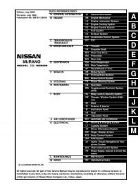
Сборник руководство на английском языке по техническому обслуживанию и ремонту автомобиля Nissan Murano серии Z50 2003-2007 годов выпуска.
- Автор: —
- Издательство: Nissan Motor Co., Ltd.
- Год издания: 2002-2006
- Страниц: —
- Формат: PDF
- Размер: 355,3 Mb
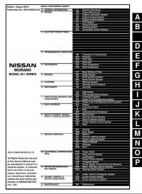
Сборник руководство на английском языке по техническому обслуживанию и ремонту автомобиля Nissan Murano серии Z51 2008-2014 годов выпуска.
- Автор: —
- Издательство: Nissan Motor Co., Ltd.
- Год издания: 2007-2013
- Страниц: —
- Формат: PDF
- Размер: 403,4 Mb

Руководство по эксплуатации и ремонту автомобиля Nissan Murano с 2008 года выпуска с бензиновым двигателем объемом 3,5 л.
- Автор: —
- Издательство: Монолит
- Год издания: —
- Страниц: 344
- Формат: —
- Размер: —
Руководство по эксплуатации и техническому обслуживанию автомобиля Nissan Murano серии Z51.
- Автор: —
- Издательство: Nissan International
- Год издания: 2010
- Страниц: 352
- Формат: PDF
- Размер: 3,4 Mb

Руководство по эксплуатации и техническому обслуживанию автомобиля Nissan Murano с 2008 года выпуска.
- Автор: —
- Издательство: Монолит
- Год издания: —
- Страниц: 370
- Формат: —
- Размер: —

Руководство по эксплуатации и техническому обслуживанию автомобиля Nissan Murano.
- Автор: —
- Издательство: Автонавигатор
- Год издания: —
- Страниц: 268
- Формат: —
- Размер: —

Руководство по эксплуатации, техническому обслуживанию и ремонту автомобиля Nissan Murano 2002-2008 годов выпуска с бензиновым двигателем объемом 3,5 л
- Автор: —
- Издательство: Автонавигатор
- Год издания: —
- Страниц: 544
- Формат: —
- Размер: —

Руководство по техническому обслуживанию и ремонту автомобиля Nissan Murano серии Z52 с 2016 года выпуска с бензиновым двигателем объемом 3,5 л.
- Автор: —
- Издательство: Автонавигатор
- Год издания: —
- Страниц: 502
- Формат: —
- Размер: —

Руководство по техническому обслуживанию и ремонту автомобиля Nissan Murano серии Z51 с 2008 года выпуска с бензиновым двигателем объемом 3,5 л.
- Автор: —
- Издательство: Автонавигатор
- Год издания: —
- Страниц: 304
- Формат: —
- Размер: —

Руководство по техническому обслуживанию и ремонту автомобиля Nissan Murano серии Z51 с 2008 года выпуска с бензиновым двигателем объемом 3,5 л.
- Автор: —
- Издательство: Автонавигатор
- Год издания: —
- Страниц: 510
- Формат: —
- Размер: —

Здесь собраны руководства по эксплуатации автомобилей NISSAN. Даже если Ваш Ниссан уже снят с производства, Вы найдете здесь всю необходимую информацию о его возможностях и уходе за ним. Для просмотра руководства выберите модель Вашего NISSAN. Если соответствующего руководства по автомобилю Ниссан не нашлось, мы всегда рады проконсультировать Вас по телефону.
Регламент ТО по моделям:
Руководство по эксплуатации NISSAN Almera
Руководство по эксплуатации NISSAN Sentra
Руководство по эксплуатации NISSAN Juke
Руководство по эксплуатации NISSAN Murano
Руководство по эксплуатации NISSAN Navara
Руководство по эксплуатации NISSAN Note
Руководство по эксплуатации NISSAN Pathfinder
Руководство по эксплуатации NISSAN Teana
Руководство по эксплуатации NISSAN Tiida
Руководство по эксплуатации NISSAN X-Trail
Руководство по эксплуатации NISSAN NP-300
Руководство по эксплуатации NISSAN Patrol
Руководство по эксплуатации NISSAN Qashqai