
РЕКОМЕНДУЕМЫЕ ЖИДКОСТИ И СМАЗОЧНЫЕ МАТЕРИАЛЫ
РЕКОМЕНДУЕМЫЕ ЖИДКОСТИ И СМАЗОЧНЫЕ МАТЕРИАЛЫ
РЕКОМЕНДУЕМЫЕ ЖИДКОСТИ И СМАЗОЧНЫЕ МАТЕРИАЛЫ
РЕКОМЕНДУЕМЫЕ ЖИДКОСТИ И СМАЗОЧНЫЕ МАТЕРИАЛЫ
РЕКОМЕНДУЕМЫЕ ЖИДКОСТИ И СМАЗОЧНЫЕ МАТЕРИАЛЫ
Описания
Описания
Описания
Описания
Описания
Спецификации
Спецификации
Спецификации
Спецификации
Спецификации
Емкость
Емкость
Емкость
Емкость
Емкость
Сорт: Оригинальное моторное масло Ssangyong
(Утверждено MB Sheet 229,1, либо 229,3, либо
229,31 для DSL/GSL ENG áåç CDPF)
(Утверждено MB Sheet 229,31 äëÿ DSL ENG áåç CDPF)
Вязкость: Список MB No. 224,1
Оригинальный Ssangyong
(Антифриз: SYC-1025, антифриз : вода = 50:50)
Оригинальное масло Ssangyong (CASTROL TQ 95)
Оригинальное масло Ssangyong (CALTEX PED 1712)
Оригинальное масло Ssangyong (ATF DEXRON II)
Оригинальное масло Ssangyong (ATF DEXRON II, III)
Оригинальное масло Ssangyong
(SAE 80W/90, API GL-5)
Оригинальное масло Ssangyong
(SAE 80W/90, API GL-5)
Оригинальное масло Ssangyong (DOT4)
Оригинальное масло Ssangyong (ATF DEXRON II, III)
7,5 л
7,5 л
10,5 ~ 11,0 л
9,5 л
9,5 л
3,6 л
3,4 л
1,4 л
1,4 л
1,4 л
1,9 л
2,0 л
1,8 л
По мере
необходимости
1,0 л
Масло двигателя
Охлаждающая жидкость
Жидкость автоматической коробки
передач
Жидкость ручной
коробки передач
Жидкость корпуса редуктора
Масло
моста
Тормозная жидкость/жидкость для сцепления
Жидкость для механизма усилителя рулевого управления
Передний
Задний
Автоматическая коробка передач
Механическая коробка передач
D20DT
G23D
D20DT
G23D
4A/T
6A/T
4WD
2WD
D20DT Механическая коробка
передач, G23D Механическая
коробка передач
D20DT Автоматическая коробка
передач, G23D Автоматическая
коробка передач
LD
антифриз
ра ре
Не з зной
мост
Уважаемые читатели. Все книги, размещённые в разделе Библиотека, найдены нами в интернете либо сканированы самостоятельно. Некоторые сканы присланы трудолюбивым и благодарными читателями. Основу Библиотеки составляет историческая и техническая литература середины ХХ века. Мы не можем отследить по каждой из книг то, насколько она попадает под защиту закона Об авторском праве и смежных правах. Поэтому не выкладываем литературу относительно недавних годов выпуска, которую ещё можно встретить в магазинах. Наша Библиотека – это именно библиотека, в ней собраны редкие экземпляры, к которым мы относимся (простите уж) не как к предмету чужого бизнеса, а как информационному достоянию человечества. Что, конечно, не исключает нашей готовности немедленно удалить конкретные книги из общего доступа, если на то поступит сколько-нибудь обоснованное требование со стороны владельца тех самых авторских прав. Мы сделаем это безропотно и немедленно, только скажите.

Руководство по эксплуатации SsangYong Actyon Sports New 2012
2012
Скачано: 288
- Manuals
- Brands
- SSANGYONG Manuals
- Automobile
- Actyon Sports II 2012.01
- Manual
-
Contents
-
Table of Contents
-
Troubleshooting
-
Bookmarks
Related Manuals for SSANGYONG Actyon Sports II 2012.01
Summary of Contents for SSANGYONG Actyon Sports II 2012.01
-
Page 1
GENERAL INFORMATION 1. DIMENSIONS……… 2. SPECIFICATION…….. -
Page 3
01-3 0000-00 1. DIMENSIONS Unit: mm Top view 1910 Side view 1790 3060 4990(5070) Front view Rear view 1570 1570… -
Page 4
01-4 ▶ Detailed Dimensions Unit:mm Headlamp Stop/Tail lamp Front fog lamp Back-up lamp Side repeater License plate lamp Tun signal lamp (front) Turn signal lamp (rear) Position lamp Reflector… -
Page 5
01-5 0000-00 Unit:mm… -
Page 6
01-6 2) Vehicle Identification — Engine number — Chassis number The engine number is stamped on the cylinder The chassis number is stamped on the frame block behind the A/C compressor. behind the front right tire. — Chassis number The chassis number is stamped on the frame behind the front right tire. -
Page 7
01-7 0000-00 2. SPECIFICATION 1) Specifications in Unit ( ): Optional item Vehicle weight and gross vehicle weight may vary according to the options and vehicle types. -
Page 8
01-8… -
Page 9
01-9 0000-00 2) Recommended Fluids and Lubricants Use only Ssangyong recommended fluids and lubricants. Do not mix any different types or brands of oils or fluids. This may cause damages. Keep the specified levels when adding or replacing the fluids. -
Page 10
01-10 3) Scheduled Maintenance Services — Diesel Engine… -
Page 11
01-11 0000-00… -
Page 12
01-12… -
Page 13
01-13 0000-00 4) Scheduled Maintenance Services (General) — Diesel Engine… -
Page 14
01-14… -
Page 15
01-15 0000-00… -
Page 16
01-16 5) Scheduled Maintenance Services — Gasoline Engine… -
Page 17
01-17 0000-00… -
Page 18
01-18… -
Page 19
MODIFIED ITEMS 1. EXTERIOR……….2. INTERIOR……….3. MAJOR CHANGES IN ENGINE (RH)..4. MAJOR CHANGES IN ENGINE (LH)..5. MAJOR CHANGES IN CHASSIS….. -
Page 20
02-2 1. EXTERIOR Front view Rear view Tailgate Emblem Radiator garnish grille Hood Reflector Tailgate Front bumper 8310-01 Headlamp 8310-10 Fog lamp 6410-02 Hinge (with spring) Position/Turn signal lamp High/Low beam 7950-08 Emblem Position lamp Turn signal lamp High/Low beam Fog lamp… -
Page 21
02-3 0000-00 Side view Sun roof (sun shade panel: roller type) Front fender Wheel Side sill Deck side panel 7820-22 Washer nozzle 8910-26 Micro pole antenna 8320-01 Rear combination lamp Stop/Tail Stop/Tail lamp lamp Turn signal Turn signal lamp lamp Back-up lamp Back-up lamp… -
Page 22
02-4 2. INTERIOR 2330-01 Intercooler 2130-07 Coolant reservoir Changed the appearance and capacity (2.8 L) Changed the bracket and core size 8410-02 Fuse box in engine compartment 3030-01 Clutch pedal 7410-12 Seat logo Interlock switch Changed the layout of relays Add clutch ECU switch… -
Page 23
02-5 0000-00 3722-02 Gear selector lever (A/T) 7610-01 Instrument panel 8210-01 Instrument cluster 3710-01 Gear shift lever (M/T) -
Page 24
02-6 3. MAJOR CHANGES IN ENGINE (RH) 1719-29 Intake duct and bracket 1225-01 Cylinder head cover & PCV valve T-MAP sensor T-MAP sensor Changed intake duct, air intake direction, Changed the location of blow-by hose and location of T-MAP sensor PCV valve D20DTF (Korando C) 1719-40… -
Page 25
02-7 0000-00 1543-01 Steering pump assembly 1719-09 Acoustic cover Power steering pump Introduced reservoir integrated tpe steering pump Changed the design 1520-21 Coolant outlet port D20DTR (Actyon Sports) Coolant temperature sensor hole Coolant temperature sensor hole Changed the location of coolant temperature sensor and deleted the coolant outlet port from turbocharger 1533-30… -
Page 26
02-8 4. MAJOR CHANGES IN ENGINE (LH) 1729-01 Exhaust manifold 1914-01 Turbocharger Exhaust gas temperature Changed the cooling type (water cooling → air Changed the location of mounting flange and cooling) exhaust gas temperature sensor mounting hole D20DTF (Korando C) 1127-01 Cylinder block Pipe screw… -
Page 27
02-9 0000-00 1336-01 Timing gear case cover 1115-02 Engine mounting bracket Added the belt tension mounting boss 1130-01 Crankshaft assembly D20DTR (Actyon Sports) — Reduced weight — Deleted ring gear 1130-13 Dual mass flywheel 1130-18 Drive plate assembly (A/T) without center with center bearing bearing Changed the location of torque converter… -
Page 28
02-10 5. MAJOR CHANGES IN CHASSIS 4420-01 Stabilizer bar Dual peak bush Introduced dual peak bush 4892-01 ABS/ESP module 4411-01 Shock absorber spring Spring height and rate changed Introduced ESP system Height: 345.7 (4WD), 341.7 (2WD) -
Page 29
02-11 0000-00 3680-01 Automatic transmission Changed the torque conver & torque converter housing due to new engine 2411-01 Introduced DOC to meet EURO III or EURO IV regulation. 2412-02 CDPF Introduced CDPF to meet EURO-5 regulation 3160-01 Manual transmission G23D D20DTR Added 5 and 6-speed transmission… -
Page 31
GENERAL INFORMATION 1. ENGINE LAYOUT……..2. MAJOR COMPONENTS……3. ENGINE COMPARTMENT LAYOUT..4. CAUTION WHEN SERVICING THE ENGINE……….5. STANDARD BOLTS SPECIFICATIONS.. 6. CODING AND INITIALIZATION….SPECIAL SERVICE TOOLS 1. SPECIAL SERVICE TOOLS….2. NORMAL EQUIPMENTS…… -
Page 33
01-3 0000-00 1. ENGINE LAYOUT Front view Rear view Right view Left view… -
Page 34
01-4 2. MAJOR COMPONENTS ▶ Front view Vacuum pump Oil filter assembly Camshaft position sensor Power steering pump pulley Water pump pulley Alternator pulley Idler pulley No. 2 A/C compressor pulley Auto tensioner Idler pulley No. 1 Isolation damper Oil pressure switch ▶… -
Page 35
01-5 0000-00 ▶ Right view Front exhaust gas temperature sensor Oil dipstick tube & gauge assembly E-VGT actuator E-VGT turbocharger Coolant screw plug Oil drain plug ▶ Left view Thermostat assembly Variable swirl valve assembly E-EGR valve E-EGR solenoid valve Oil cooler assembly EGR cooler Electronic throttle body… -
Page 36: Engine Compartment Layout
Always turn the engine off and allow it to cool before starting the maintenance. Regularly check the engine oil level and add Ssangyong genuine engine oil if necessary. Clean the dipstick with clean cloth so that any foreign materials cannot get into the engine.
-
Page 37
2) Specification and Capacity Specification Quality class: Ssangyong genuine engine oil (Total Quartz INEO Engine oil ECS 5W 30, SK ZIC SY 5W 30) or oil Approved by MB Sheet 229.51 Capacity approx. -
Page 38
01-8 4. CAUTION WHEN SERVICING THE ENGINE 1) Cleaness Engine has a lot of precisely machined (grinding, polishing, lapping) surfaces. Thus, there should be great cautions for cleaness when servicing the engine components. Apply the engine oil on the sliding surfaces when assemblying the components. Every component should be disassembled and reassembled in accordance with the correct sequences. -
Page 39
01-9 0000-00 (3) Cautions before service Scalding hot coolant and steam could be blown out under pressure, which could cause serious injury. Never remove the coolant reservoir cap when the engine and radiator are hot. (4) Lubrication system Prolonged exposure to the engine oil make cause a skin cancer or an irritation. Used engine cotains the hazardous material that may cause the skin cancer. -
Page 40
01-10 5. STANDARD BOLTS SPECIFICATIONS Metric bolt strength is embossed on the head of each bolt. The strength of bolt can be classified as 4T, 7T, 8.8T, 10.9T, 11T and 12.9T in general. Observe standard tightening torque during bolt tightening works and can adjust torque to be proper within 15 % if necessary. -
Page 41
01-11 0000-00 6. CODING AND INITIALIZATION 1) Engine Variant Coding Unit Selection Description Remarks PTC auxilary heater For PTC auxilary heater equipped vehicle, select «YES». Glow plug Relay (K-line) Select «AQGS». AQGS (CAN) AQGS (CAN) Transmission 6-speed M/T «DSI 6 AT» is selected Select automatically. -
Page 42
01-12 1. SPECIAL SERVICE TOOLS Name & Part number Tool How to use (on vehicle) Part number: T99410010A Name: Belt tension adjuster Use to release tension without removing belt when replacing pulley or pump. How to use (on engine) Part number: T9941 0010A Name: Flywheel fixing device Use to fix flywheel or drive shaft to prevent engine from… -
Page 43
01-13 0000-00 Name & Part number Tool How to use Part number: Y9922 018 Name: Remover Use to remove the valve stem seal. Part number: Y9922 008 Name: Installer Use to install the valve stem seal. Part number: Y9922 082B, W9911 0230A, Y9922 018 Name: Valve spring complete… -
Page 44
01-14 Name & Part number Tool How to use Part number: Y9922 012 Name: Dial gauge Use: Used to measure the protrusion of piston. Part number: Y9922 0172B Name: Piston install guide Use: Used to slide the piston into cylinder. Part number: W9911 0120A Name: Inserting guide Use: Used to install the rear… -
Page 45
01-15 0000-00 ▶ Components Part name Amount Tool Injector remover set Main bar Cross bar Main bolt holder Ball bearing 부품명 수량 사진 Main nut — A Main bolt — A… -
Page 46
01-16 Part name Amount Tool Injector holder — A Injector — B Injector holder cover Bar holder assembly Support mounting bolt Main support… -
Page 47
01-17 0000-00 2. NORMAL EQUIPMENTS Name & Part number Tool How to use Name: Engine stand (1 tone or more) Use to fix the removed engine or engine with transmission. Name: Engine crane (1 tone or more) Use to move the engine module (including transmission) to working space or engine stand. -
Page 48
01-18 Name & Part number Tool How to use Name: High pressure pump gear & nut remover Use to remove & install the high pressure pump sprocket. Name: Adapter & gauge Use to measure the compression pressure by inserting it into glow plug hole. -
Page 49
02-3 0000-00 1. SPECIFICATION Unit Description Specification Remark Cylinder head Height 142.9 to 143.1 mm Flatness below 0.1 mm Valve protrusion Intake valve 0.1 to 0.7 mm Exhaust valve 0.1 to 0.7 mm Flatness on manifold Intake manifold 0.08 mm side Exhaust manifold 0.08 mm… -
Page 50
02-4 2. TIGHTENING TORQUE Bolt Remark Specified torque Component Size Quantity (Total torque) (Nm) M12×82 55±5Nm, Main bearing cap Not re-usable 180˚ M9×52 40±5Nm, Connecting rod cap 50 to 80 Nm 90˚+10˚ M6×20 10 ± 1 Nm Rear cover M8×35SOC 25 ±… -
Page 51
02-5 0000-00 Specified torque Bolt Remark Component Size (Nm) Quantity (Total torque) M6×16 10±1Nm Hot water inlet pipe M10×90 25±2.5Nm Alternator M10×116 46±4.6Nm M8×25 A/C bracket 7.8~11.8Nm M6×25 10±1Nm A/C sub bracket M8×35 25±2.5Nm Intake manifold M8×110 25±2.5Nm M8×40 25±2.5Nm Oil filter module M8×20 25±2.5Nm… -
Page 52
02-6 Bolt Remark Specified torque Component Size Quantity (Total torque) (Nm) 20±2Nm Glow plug M8×25 10±1Nm Vacuum pump M12×55 85±8.5Nm Timing gear case cover M6×25 10±1Nm M6×45 10±1Nm M6×50 10±1Nm M6×35 10±1Nm Cylinder head cover M6×16 10±1Nm Oil gauge tube 25±2.5Nm Oil filter cap M8×35SOC… -
Page 53
02-7 0000-00 3. CHECK AND INSPECTION 1) Cylinder (1) Compression pressure test ▶ Specified value 16.5 : 1 Compression ratio at normal operating temperature (80˚C) Test condition 32 bar Standard Compression pressure 18 bar Minimum Maximum 3 bar Differential limit between cylinders The compression pressure test is to check the conditions of internal components (piston, piston ring, intake and exhaust vale, cylinder head gasket). -
Page 54
02-8 Crank the engine for approx. 10 seconds by using the start motor. Record the test result and measure the compression pressure of other cylinders with same manner. If the measured value is out of specified value, perform the cylinder pressure leakage test. -
Page 55
02-9 0000-00 (3) Piston protrusion check Position the piston at TDC and measure the piston protrusion from crank case mating surface. Specified value 0.541 to 0.649 mm Measure it at both ends of crankshaft. -
Page 56
02-10 2) Cylinder Head (1) Cylinder head mating surface check ▶ Specified value 142.9 to 143.1 mm Total height «A» 142.4 mm Minimum height after machining 0.08 mm Longitudinal direction Flatness 0.0 mm Transverse direction Parallel deviation of cylinder head below 0.1 mm Peak-to valley of surface 0.004 mm… -
Page 57
02-11 0000-00 4. GUIDELINES ON ENGINE SERVICE To prevent personal injuries and vehicle damages that can be caused by mistakes during engine and unit inspection/repair and to secure optimum engine performance and safety after service works, basic cautions and service work guidelines that can be easily forgotten during engine service works are described in. -
Page 58
02-12 ▶ Fuel and lubrication system Do not allow the fluid and engine oil to make contact with the body paintwork and hoses. If work on the fluid system such as fuel and oil, working area should be well ventilated and smoking should be prohibited. -
Page 59
02-13 0000-00 1. BELT LAYOUT It is single drive type and uses FEAD (Front End Accessories Drive) design to make a compact layout. ▶ Components D20DTR Engine HPS (Hydraulic Power Steering) Crankshaft pulley (DDU) Auto tensioner Tensioner pulley Vacuum pump A/C compressor pulley Alternator pulley Water pump pulley… -
Page 60
02-14 1) Crankshaft Pulley (Isolation Damper) (1) Overview The strut type tensioner automatically adjusts the belt tension to provide the reliability and durability for the system. And, the belt tension is decreased to minimize the friction loss and improve the belt operating noise. (2) Sectional drawing Pulley Axial &… -
Page 61
02-15 0000-00 (3) Features Rubber damper: Decrease crankshaft torsion Improve belt NHV: Reduce unbalance speed to crankshaft due to irregular combustion Minimize noise: Anti-vibration from crankshaft and belt Post bonded type rubber damper: Improve durability of rubber damper… -
Page 62
02-16 2) Belt Tensioner (1) Overview The torque deviation from crankshaft affects the components in belt drive system and the belt movement. The auto tensioner system is to adjust this deviation automatically. In D20DTR engine, one of the mechanical tensioner, pivot damped tensioner is used to keep the damping force, system reliability and durability. -
Page 63: Vacuum Pump
02-17 0000-00 2. VACUUM PUMP Vacuum pump generates the vacuum pressure and supplies it to EGR cooler bypass solenoid. This pump is single vane type and displacement is 210 cc/rev. The lubrication oil is supplied through the hole in hollow shaft. ▶…
-
Page 64
02-18 1) Location 2) Operation The vacuum pump is engaged to the exhaust camshaft. Connection between vacuum pump and exhaust camshaft Oil supply and driving Vacuum pump Exhaust camshaft… -
Page 65: Engine Mounting
02-19 0000-00 3. ENGINE MOUNTING D20DTR engine uses 3-point mounting type that supports the engine and transmission simultaneously. ▶ Components Front mounting insulator (Right side) Front mounting insulator (Left side) Location Insulator Location Insulator Rear mounting insulator…
-
Page 66
02-20 1) Functions Appearance Type and function Front mounting insulator (Right side) Type: Rubber mounting Function: Supports the torque reaction Front mounting insulator (Left side) Type: Rubber mounting Function: Supports the torque reaction Rear mounting insulato Type: Rubber mounting Function: Supports the powertrain rod… -
Page 67
02-21 0000-00 4. INTAKE/EXHAUST MANIFOLD 1) Intake Manifold Intake manifold is installed on the cylinder head with 8 bolts. The variable swirl valve is introduced to improve the EGR gas mixture and turbulence in combustion chamber and to decrease the exhaust gas. -
Page 68
02-22 5. CYLINDER HEAD COVER AND OIL SEPARATOR 1) Cylinder Head Cover The cylinder head cover is made by high strength plastic to reduce the weight. The multi twist type oil separator improves the oil consumption. ▶ Components Front view Cylinder head cover Rear view… -
Page 69
02-23 0000-00 2) Oil Separator (1) Overview Oil separator separates the particle in blow-by gas to minimize the engine oil consumption and reduces the inflow oil from intake system into the combustion chamber. The separated oil returns to oil pan through cylinder head. (2) Layout Oil separator Blow-by outlet hose… -
Page 70: Cylinder Head
02-24 6. CYLINDER HEAD Cylinder head contains cam position sensor, vacuum pump, intake manifold, exhaust manifold and valve assembly. Vacuum pump and the high pressure (HP) pump are driven by Camshaft and valves are install in vertical direction. This enables the compact layout in cylinder head assembly. ▶…
-
Page 71
02-25 0000-00 1) Cylinder Head (1) Overview The cylinder is made by gravity casting and the water jacket is integrated type. The cylinder oil passage is drilled and sealed by cap. The Camshaft bearing cap is also made by casting and installed on the cylinder head. (2) Features Location of Expansion Plugs Front… -
Page 72
02-26 ▶ Closed flow type water jacket (improving cooling performance) 2) Camshaft (1) Overview Hollow type camshaft contains cam, octagon cam, HP pump gear and intake/exhaust gears. Camshaft operates the intake/exhaust valves, vacuum pump and HP pump, and transfers the engine oil to vacuum pump through the internal oil passage. -
Page 73
02-27 0000-00 3) Valve Assembly (Installed in Cylinder Head) (1) Features Automatic valve clearance adjuster by hydraulic pressure (Maintenance Free) — Hydraulic lash Optimized adjustment of valve clearance reduces the valve noise. Roller type finger follower reduces the friction loss. Vertical installation. -
Page 74
02-28 4) Cylinder Head Gasket (1) Features Sealing the cylinder gas pressure — Peak pressure: 190 bar Minimizing the distortion of engine structure (cylinder head, block): profile stopper, backland stopper Material: MLS (Multi Layer Steel), Gasket (3 layers) Thickness of gasket: 3 types (1.2 /1.3 /1.4 mm) Thickness marking Ex: 1.3t (2) Thickness of cylinder head gasket… -
Page 75
02-29 0000-00 7. CHAIN AND GEAR DRIVE SYSTEM D20DTR engine uses single stage chain drive system. Timing chain drives the exhaust side and gear drive the intake side. Timing chain is single bush type. Upper chain drives HP pump connected to intake Camshaft by driving exhaust cam shift sprocke, and lower chain drives oil pump to lubricate the engine. -
Page 76
02-30 2) Timing Chain and Gear (1) Timing chain Simple layout: optimized timing, enhanced Single stage layout: minimized chain load Chain upper bush — Single bush type (112 EA) Chain lower bush — Single bush type (60 EA) (2) Tensioner Tensioner adjusts the chain tension to keep it tight during engine running. -
Page 77
02-31 0000-00 (3) Mechanical Tensioner Assembly Operating principle — Use only spring tension Tensioner type — Compensation and impact absorbing Static and dynamic force — Spring (4) Guide rail The guide rail is used for optimizing the movement of chain drive system. And it also prevents the chain from contacting each other when the chain is loose, and reduces the chain wear. -
Page 78
02-32 (5) Timing gear case cover Timing gear case cover (TGCC) Timing gear case cover Oil seal Screw plug… -
Page 79
02-33 0000-00 ▶ Features Major function: Protecting the chain drive system, minor function: Shielding the chain noise. Install crankshaft front seal and screw plug on the timing gear case cover. Location of chain tensioner screw plug A671 997 01 46 Crankshaft front seal Do not touch the inner lip of crankshaft front seal. -
Page 80: Oil Pan
02-34 8. OIL PAN The oil pan in D20DTR engine improves the NVH. Especially, the oil draining is much easier than before. ▶ Components Oil pan sassembly…
-
Page 81
02-35 0000-00 9. DUAL MASS FLYWHEEL (DMF) & DRIVE PLATE 1) Overview Flywheel is installed on crankshaft. When starting the engine, this functions as follows: Reducing the irregular speed of crankshaft due to unbalanced combustion -> Improving the power train NVH, Improving the driving performance Reducing the clutch noise by using ball bearing… -
Page 82
02-36 3) Operation Compensating the irregular operation of engine: The secondary flywheel operates almost evenly so does not cause gear noises The mass of the primary flywheel is less than conventional flywheel so the engine irregularity increases more (less pulsation absorbing effect). Transaxle protection function: Reduces the torsional vibration to powertrain (transaxle) by reducing the irregularity of engine. -
Page 83
02-37 0000-00 4) Features Reduced vibration noise from the powertrain by blocking the torsional vibrations Enhanced vehicle silence and riding comforts: reduced engine torque fluctuation Reduced shifting shocks Smooth acceleration and deceleration 5) Advantages Improved torque response by using 3-stage type spring: Strengthens the torque response in all ranges (low, medium, and high speed) by applying respective spring constant at each range. -
Page 84
02-38 10. PISTON/CRANKSHAFT/CYLINDER BLOCK The crankshaft and the cylinder block convert the compression pressure to the rotating energy. ▶ Components Cylinder block Piston Connecting rod Crankshaft… -
Page 85
02-39 0000-00 1) Piston (1) Overview Piston assembly contains piston, #1 ring, #2 ring, oil ring, piston pin and snap ring. The expansion energy from engine is transferred to the crankshaft through connecting rod to convert the linear movement to rotating energy. -
Page 86
02-40 (3) Functions Piston transfers the combustion energy from engine to connecting rod. Especially in the direct injection engine such as D20DTF, it provides the combustion space and largely effects to the engine performance and exhaust gas. ▶ Piston ring #1 ring (Top ring) : Prevents the high pressurized combustion gas from leaking into crank chamber, and prevents the engine oil getting into combustion chamber. -
Page 87
02-41 0000-00 Selecting piston oversize Top of piston Top of cylinder block Piston Cylinder bore Engine Part NO Marking NO. 671 030 06 17 671 037 07 01 671 037 08 01 D20DTF 671 037 09 01 671 037 10 01 671 037 11 01… -
Page 88
02-42 2) Connecting Rod (1) Overview Connecting rod converts the reciprocating movement of piston to the rotating movement of crankshaft. The big end is connected to connecting rod bearing and the crank pin journal, and the small end is connected to the piston pin. (2) Components Piston pin bush Connecting rod… -
Page 89
02-43 0000-00 (3) Selection of crankshaft pin journal bearing The connecting rod bearing contains 3 sets of 3 grades in upper and lower sections. Three sets in the table below have nearly same oil clearance (0.015~0.063 mm) of bearing. Identification: Coloe mark on bearing side surface Upper bearing Lower bearing Journal… -
Page 90
02-44 3) Crankshaft (1) Overview Crankshaft is installed on the cylinder block. (2) Arrangement Upper thrust bearing Crankshaft main bearing upper Crankshaft main bearing upper Crank pin journal Main journal Lower thrust bearing Crankshaft main bearing lower Crankshaft main bearing lower… -
Page 91
02-45 0000-00 (3) Selection of crankshaft main bearing Mating surface of crankshaft sprocket Bottom of cylinder block Selection of lower main bearing Selection of upper main bearing Selection of bearing according to pin punch Mark Color Thickness of main & color bearing (mm) Mark Color… -
Page 92
02-46 4) Cylinder Block (1) Overview The major dimensions in D20DTR are similar to D20DT engine. It has two mounting bosses for knock sensor and meets the requirements for EURO5 regulation. (2) Layout Right side Right side Expansion plug Screw plug… -
Page 93
02-47 0000-00 Left side Expansion plug (3) Features For simple manufacturing, the crankcase blow-by gas passage and the oil return hole are made by casting on the cylinder block. -
Page 94
02-48 The bottom side of water jacket is desgined as sine wave to strengthen the structure of crankcase. The main flow of coolant starts from outlet port of water pump and goes along the longitudinal direction of engine. The coolant passage from cylinder head to inlet port of water pump is integrated in cylinder head. -
Page 95
03-3 2210-01 1. SPECIFICATION Description Specification Fuel Diesel Type Fuel heater + priming pump + water separator integrated type Filter type Changeable filter element type Fuel filter Change interval every 50,000 km Water separation interval every 15,000 km Water accumulating capacity 200 cc Heater capacity 250W 13.5V… -
Page 96
03-4 2. MAINTENANCE AND INSPECTION 1) Maintenance Procedures for DI Engine Fuel System Always keep the workshop and lift clean (especially, from dust). Always keep the tools clean (from oil or foreign materials). Wear a clean vinyl apron to prevent the fuzz, dust and foreign materials from getting into fuel system. -
Page 97
03-5 2210-01 Follow the job procedures. If you find a defective component, replace it with new one. Once disconnected, the fuel pipes between HP pump and fuel rail and between fuel rail and each injector should be replaced with new ones. The pipes should be tightened tospecified tightening torques during installation. -
Page 98
03-6 2) Diagnostic Test for Engine Fuel System (1) Overview If a DTC is displayed on the diagnostic device, check the low pressure- and high pressure fuel systems before removing the components. To run the system properly, the electric system must be intact but for the DI engine, the fuel pressure should be measured also when there is a malfunction even after the diagnostic test with a diagnostic device. -
Page 99
03-7 2210-01 (3) Excessive backleak of injector ▶ Excessive injector backleak Occurs when the injector control valve is not sealed due to the entry of the foreign materials. ▶ Example: Entry of foreign materials Burned out and worn HP pump Mechanical damage inside the injector… -
Page 100
03-8 (4) Loss of pump pressure/flow ▶ Loss of HP pump pressure/flow Faulty fuel supply line, or damaged or worn pump causes the lack of flow pressure and flow volume ▶ Example: Air in fuel supply line Excessive load on fuel supply line (←400 mBar) Burned out and mechanical worn pump High temperature of fuel supply (>… -
Page 101
03-9 2210-01 3) DI Engine Fuel System Pressure Test (1) Test device (Tool kit) Device for high pressure Device for low pressure (2) Pre-check Check-tighten fuel supply line Check fuel level in fuel tank Check air in fuel supply line (bubble in fuel supply line or fuel) Check fuel supply line for leaks (low pressure and high pressure) Check that specified fuel is used Check fuel filter for contamination… -
Page 102
03-10 (3) DI Engine Fuel System Check Procedure If several DTCs are output simultaneously, check the electric wiring for open or short circuit. Check the low pressure fuel system and fuel filter and confirm that there are no abnormalities. Carry out the high pressure fuel system check. -
Page 103
03-11 2210-01 (4) Fuel System Check Procedure… -
Page 104
03-12 (5) High Pressure System Pressure Test ▶ Fuel rail pressure test Disconnect the fuel rail pressure sensor connector and then IMV connector. Connect the pressure tester to the fuel rail pressure sensor connector. Crank the engine 2 times for 5 seconds. Read the highest pressure value displayed on the tester display. -
Page 105
03-13 2210-01 ▶ How To Use Pressure Tester Press the «TEST» button on the tester to check if the message «TEST?» is displayed. If the button is pressed again at 4 seconds after starting engine cranking, the highest pressure is displayed on the tester. The fuel rail pressure value can be checked using a diagnostic device. -
Page 106
03-14 (6) Low Pressure System Pressure Test ▶ Inspection procedure All wirings/connectors and fuel lines should be connected and the engine should work properly. Prepare a special tool for low pressure test and clean it thoroughly to prevent foreign materials from entering. Disconnect the key connector for fuel filter connection, and connect both connectors to the fuel filter and hose. -
Page 107
03-15 2210-01 ▶ Static test for backleak of injector Disconnect the injector return hose and cover the openings with caps shaped screw (included in the special tool). Connect the hose of the container for measuring backleak to the return nipple of the injector. -
Page 108
03-16 ▶ Dynamic test for backleak of injector Warm up the engine so that the engine coolant temperature be over 80℃ and star the engine again. Disconnect the injector return hose and cover the openings with caps shaped screw (included in the special tool).. Connect the hose of the container for measuring backleak to the return nipple of the injector. -
Page 109
03-17 2210-01 ▶ HP pump pressure test Prepare a special tool for high pressure test and clean it thoroughly to prevent foreign materials from entering. Disconnect the high pressure fuel supply pipe on the HP pump and install the close rail in the tool kit. -
Page 110
03-18 3. CAUTIONS FOR DI ENGINE 1) Cautions for DI Engine This chapter describes the cautions for DI engine equipped vehicle. This includes the water separation from engine, warning lights, symptoms when engine malfunctioning, causes and actions. DI Engine Comparatively conventional diesel engines, DI engine controls the fuel injection and timing electrically, delivers high power and reduces less emission.. -
Page 111
03-19 2210-01 2) Cleanness (1) Cleanness of DI engine fuel system ▶ Cleanness of DI engine fuel system and service procedures The fuel system for DI engine consists of transfer (low pressure) line and high pressure line. Its highest pressure reaches over 1,800 bar. Some components in injector and HP pump are machined at the micrometer 100 μm of preciseness. -
Page 112: Water In Fuel
03-20 (2) Di engine and its expected problems and remedies can be caused by water in fuel ▶ System supplement against paraffin separation In case of Diesel fuel, paraffin, one of the elements, can be separated from fuel during winter and then can stick on the fuel filter blocking fuel flow and causing difficult starting finally.
-
Page 113
03-21 2210-01 1. OVERVIEW The components in fuel system supply the fuel and generate the high pressure to inject the fuel to each injector. They are controlled by the engine ECU. The common rail fuel injection system consists of fuel tank, fuel line, low pressure line which supplies low pressure fuel to the low pressure pump (including high pressure pump), common rail which distributes and accumulates the high pressurized fuel from the fuel pump, high pressure line which connected to the injector, and the engine control unit (ECU) which calculates the… -
Page 114
03-22 2. SYSTEM LAYOUT AND OPERATION 1) Layout For sensor and actuator control logic, refer to Chapter «Engine Control». Engine ECU (D20DTR) Fuel tank Engine control by various Fuel metering by sender signals HFM sensor Measuring intake air mass and temperature Camshaft position sensor Crankshaft position sensor Injector (C3I) -
Page 115
03-23 2210-01 High pressure pump Accelerator pedal position sensor Plunger type HP pump (1,800 bar) Vane type LP pump (6 bar) Generating high pressurized fuel and supplying it according to Detecting driver’s intention engine rpm, required volume, for speed up/down required pressure Fuel filter assembly Supplying clean fuel/fuel… -
Page 116
03-24 2) Fuel System Flow Diagram The fuel from the fuel tank is supplied to the fuel heater of fuel filter/priming pump and then low pressure generated by the low pressure pump (built into HP pump) is transmitted to the HP pump. The fuel pressure at the HP pump is controlled by the IMV valve, and the maximum allowed pressure is 1,800 bar. -
Page 117
03-25 2210-01 3) Input/Output devices Refer to Chapter «Engine Control». -
Page 118
03-26 The engine ECU calculates the accelerator pedal based on the input signals from various sensors, and controls the overall operation of the vehicle. The ECU receives the signals from various sensor through data line, and performs effective air-fuel ratio control based on these signals. The crankshaft speed (position) sensor measures the engine speed, and the camshaft speed (position) sensor determines the order of injections, and the ECU detects the amount of the accelerator pedal depressed (driver’s will) by receiving the electrical signals from the accelerator… -
Page 119
04-3 1719-00 1. SPECIFICATION Unit Description Specification Filter type Dry, filter element Initial resistance Max. 300 mmAq Air cleaner element Service interval EU; Clean or change every 20,000 km GEN: Clean or change every 15,000 km Weight 103.9 kg Air cleaner assembly -30 ~ 100˚C Operating temperature Core material… -
Page 120
04-4 2. INSPECTION 1) Troubleshooting ▶ When Abnormal Noises are Heard from the Engine Room For the vehicle equipped with DI engine, if a learning noise occurs in each range or other noises occur, the major cause of it is a faulty turbocharger assembly. But an interference issue, poor tightness or loose in the intake and exhaust system also can cause those noises. -
Page 121
04-5 1719-00 3) Troubleshooting Sequence The basic checks for intake system are as follows: ▶ Basic Checks for Intake System Make sure to replace or clean the air cleaner element periodically. Otherwise, engine will be derated or work abnormally because of low intake air volume. Unlike the fuel system, which is a closed circuit, the intake system is an open circuit system. -
Page 122
04-6 1. OVERVIEW The intake system for D20DTR engine is equipped with a throttle body which includes a flap. This flap is controlled by an electrical signal to cut off the intake air entering to the engine when the ignition switch is turned off. Because of this, the shape of the intake manifold has been changed and improved HFM sensor is newly adopted to control the intake air volume more precisely. -
Page 123
04-7 1719-00 1719-02 Swirl control valve Operating variably in accordance with the engine load and rpm.* For more information, refer to Chapter «Engine Control». 1719-01 Intake manifold Passage for variable swirl valve and for intake 1719-16 Electric throttle body * For more information, refer to Chapter «Engine Control». -
Page 124
04-8 3. INPUT/OUTPUT OF INTAKE SYSTEM For more information, refer to Chapter » Engine Control». -
Page 125
04-9 1719-00 4. OPERATING PROCESS ▶ Work Flow… -
Page 126
04-10 1) Types of swirl Swirl: One cylinder has two intake air ports, one is set horizontally and the other one is set vertically. Swirl is the horizontal air flows in cylinder due to the horizontal intake air ports. Tumble: Tumble is the vertical air flows in cylinder due to the vertical intake air port Squish: Squish is the air flows due to the piston head. -
Page 127
04-11 1719-00 Engine speed Swirl valve Amount of Load Remarks swirl Low speed, Increased EGR ratio, better air-fuel below 3,000 Closed Heavy Low load mixture (reduce exhaust gas) High speed, Increase charge efficiency, higher over 3,000 rpm Open Light High load engine power The variable swirl valve actuator operates when turning the ignition switch ON/OFF… -
Page 128
05-3 1729-01 1. TROUBLESHOOTING 1) Work Flow… -
Page 129
05-4 2. CAUTIONS Do not park the vehicle on flammable materials, such as grass, leaves and carpet. Do not touch the catalyst or the exhaust gas ignition system when the engine is running. If a misfire occurs in the combustion chamber or the emission of pollutant exceeds the specified level, the catalyst can be damaged. -
Page 130
05-5 1729-01 1. OVERVIEW This system purifies the exhaust gas generated by the combustion in the engine to reduce the pollutants and noise during that arise during combustion. 2. LAYOUT Exhaust manifold assembly Exhaust front pipe assembly CDPF assembly For more information, refer to Chapter «Engine Control». -
Page 131
05-6 3. OPERATING PROCESS 1) Exhaust Gas Flow 2) Input & Output Devices… -
Page 132
06-3 1914-01 1. SPECIFICATION Unit Description Specification Max. expansion coefficient Max. turbine speed 226,000rpm Turbocharger Max. temperature of turbine 790 ℃ housing Weight 6.5kg E-VGT actuator Operation duty cycle 250Hz… -
Page 133
06-4 2. INSPECTION 1) Cautions During Driving The following lists cautions to take during test drive and on the turbocharger vehicle, which must be considered during the operation. It’s important not to drastically increase the engine rpm starting the engine. It could make rotation at excessive speed even before the journal bearing is lubricated and when the turbocharger rotates in poor oil supply condition, it could cause damage of bearing seizure within few seconds. -
Page 134
06-5 0000-00 2) Inspection of Turbocharger When problem occurs with the turbocharger, it could cause engine power decline, excessive discharge of exhaust gas, outbreak of abnormal noise and excessive consumption of oil. On-board Inspection Check the bolts and nuts foe looseness or missing Check the intake and exhaust manifold for looseness or damage Check the oil supply pipe and drain pipe for damages Check the housing for crack and deterioration… -
Page 135
06-6 3) Inspection of Turbine Thoroughly check the followings. Must absolutely not operate the turbocharger with the compressor outlet and inlet opened as it could damage the turbocharger or be hazardous during inspection. Interference: In case where is trace of interference or smallest damage on the compressor wheel means, most of times, that abrasion has occurred on the journal bearing. -
Page 136
06-7 1914-01 4) Possible Causes of Defect The following tries to understand the defects that can occur with vehicle installed with the turbocharger and to manage the reasons of such defects. In case where oil pan/oil pipe has been contaminated, oil filter is defected and where adhesive of gaskets has been contaminated into the oil line. -
Page 137
06-8 Oil Pump Defect: Rapid over-loaded driving after replacing oil filter and oil and clogging of oil line. -
Page 138
06-9 1914-01 Turbine Side: Inflow of foreign materials from engine Compressor Side: such as air filter, muffler and nut… -
Page 139
06-10 Defects caused by reasons other than that of the turbocharger. -
Page 140
06-11 1914-01 3. TROUBLESHOOTING The followings are cautions to take in handling defects of turbocharger, which must be fully aware 1) Cautions After stopping the engine, check whether the bolts on pipe connecting section are loose as well as the connecting condition of vacuum port and modulator, which is connected to the actuator. -
Page 141
06-12 2) Work Flow for Troubleshooting… -
Page 142
06-13 1914-01… -
Page 143
06-14… -
Page 144
06-15 1914-01… -
Page 145
06-16… -
Page 146
06-17 1914-01 1. SYSTEM DESCRIPTION OF E-VGT (Electric-Variable Geometry Turbine) 1) Overview The E-VGT turbocharger has one shaft where at each ends are installed with two turbines having different angles to connect one end of housing to the intake manifold and the other end to the exhaust manifold. -
Page 147
06-18 2) Features (1) Performance (for EURO V) Enhanced emmission control: By temperature control with CDPF system Target temperature and airflow control (2) E-VGT Actuator (Electric-Actuator) Optimizes the exhaust gas flow rate by controlling the vanes inside the turbine housing with the E-Actuator. -
Page 148
06-19 1914-01 2. COMPONENTS * 세부제어로직은 엔진제어편 참조 E-VGT turbocharger Engine ECU (D20DTR) Accelerator pedal position sensor Atmospheric pressure, RPM signal Improves engine power E-VGT duty control Transfers driver’s will to accelerate to ECU T-MAP sensor HFM sensor Coolant temperature sensor Booster pressure and Improves the engine power Operates the VGT according… -
Page 149
06-20 3. INPUT/OUTPUT DEVICES… -
Page 150: Operating Principles
06-21 1914-01 4. OPERATING PRINCIPLES The E-VGT is designed to get more improved engine power in all ranges by controlling the turbine as follows: 1) How it Works at Low Speed Normal turbocharger cannot get the turbo effect because the amount of exhaust gas is not enough and the flow speed is slow in a low speed zone, but VGT allows the flow passage of exhaust to narrow, resulting in increasing the flow speed of exhaust gas and running the turbine quickly and powerfully.
-
Page 151
06-22 2) How it Works at High Speed In a high speed zone, the amount of exhaust gas increases and it is accompanied with a great force. Therefore, if the inner diameter of venturi is more widened, the turbine in the turbocharger by the releasing force of abundant exhaust gas can deliver a more increased energy to the compressor. -
Page 152
07-3 1543-00 1. SPECIFICATION Unit Specification Oil pump Lubrication system Gear pump, forced circulation Unit Specification Type Inscribed gear Oil pump Lubrication system Gear pump, forced circulation Capacity 63 L at 4,000 rpm Type Inscribed gear 5.8 bar ± 0.3 bar Relief pressure Capacity 63 L at 4,000 rpm… -
Page 153
Recheck the oil level after 5 minutes. Regularly check the engine oil level and add Ssangyong genuine engine oil if necessary. Clean the dipstick with clean cloth so that any foreign materials cannot get into the engine. -
Page 154
07-5 1543-00 1. SYSTEM DESCRIPTION 1) Overview The lubrication system supplies oil to each lubrication section to prevent friction and wear and to remove heat from the friction part. As the engine runs, frictional heat is generated on each lubrication section. If this condition persists, the bearing can be burned and stuck. In other words, it creates an oil film on each sliding surface to convert solid friction to liquid friction in order to minimize wear and prevent temperature increasing on the friction part. -
Page 155
08-3 1520-00 1. SPECIFICATION Unit Description Specification Cooling system Type Water cooling, forced circulation Coolant Capacity approx. 8.5 L Radiator Core size 555W x 582.4H x 27T (over 326,250mm2) Flow type Cross flow Min. cooling capacity over 68,000 kcal/h Antifreeze Type Long life coolant Mixing ratio… -
Page 156
08-4 2. INSPECTION Problem Possible Cause Action Coolant level is — Leak from the radiator — Change the radiator too low — Leak from the coolant auxiliary tank — Change the coolant auxiliary tank — Leak from the heater core — Change the heater — Leak from the coolant hose — Reconnect the hose or replace… -
Page 157
08-5 1520-00 1) Coolant Level Check Park the vehicle on level ground and apply the parking brake. Stop the engine and wait until it is cooled down. The coolant level should be between the MAX and MIN mark on the coolant reservoir. Check the coolant level. -
Page 158
08-6 2) Leak Test Release the pressure in the system by loosening the pressure cap of the coolant reservoir slightly. Then, remove the pressure cap completely. Never open the cap until the coolant temperature becomes under 90℃ to prevent any burn. Add the coolant so that the coolant level is between MAX and MIN mark on the coolant auxiliary tank. -
Page 159
08-7 1520-00 3. CAUTIONS If 100% of anti-freeze is added, the water pump vane can be damaged and thermal conductivity can be decreased resulting in poor circulation in the cooling system which leads to overheated engine. Use of non-recommended coolant could cause damage to the cooling system and overheating of the engine. -
Page 160
08-8 1. SYSTEM DESCRIPTION 1) Overview Coolant reservoir Long life coolant is used. Water pump Sealing Oil filter module Water pump Impeller vane The water pump is driven by the engine drive belt and supplies the coolant to each area of the engine. Thermostat When the engine coolant reaches 90℃, the thermostat… -
Page 161
08-9 1520-00 Coolant temperature sensor Measures the coolant temperature and sends the result to the engine ECU. Electric fan Circulates the fresh air forcibly to exchange heat with the radiator core fin. Radiator Releases heat through fins and cools down the hot coolant as the coolant passes through the tube of the radiator core. -
Page 162
09-3 1451-01 1. SPECIFICATION Unit Description Specification Crankshaft pulley : Alternator pulley 1 : 2.94 Normal output (idling/2200 rpm) 70/120 A Alternator Regulator voltage 14.6 V Length 12.5 mm Brush Wear limit 7 mm Type Battery Capacity 90 AH… -
Page 163
09-4 2. INSPECTION 1) Alternator Output Test Item How to check DTC set value / Action Disconnect the cable connected to the Pass: If the measured current is B terminal on the alternator. Connect 45 A or higher. one end of the ammeter to the B Fail: If the measured current is terminal and the other end to the cable less than 45 A. -
Page 164
09-5 1451-01 2) Troubleshooting for Alternator Item Cause Action Defective alternator voltage regulator Replace the alternator Overcharged battery Defective voltage detection wiring Repair or replace Loose alternator drive belt Adjust the belt tension or replace Poor connection of related circuit or Retighten the loose connection or open circuit repair open circuit… -
Page 165
09-6 3) Checking Battery… -
Page 166
09-7 1451-01 (1) Checking ▶ Using battery tester PASS (11.0 V or more): Explain to the customer that the battery is reusable. Need to be charged (9.0 to 11.0 V): Charge the battery with a charger and reinstall it. Explain it to the customer. -
Page 167
09-8 (3) Starting with jumper cable If the battery is weak or terminated, the battery from another vehicle can be used with jumper cables to start the engine. ▶ Connecting order The positive (+) terminal of the discharged battery The positive (+) terminal of the booster battery The negative (-) terminal of the booster battery Connect one end of the other jumper cable to the body of the discharged vehicle, such as the engine block or a front towing hook. -
Page 168
09-9 1451-01 (4) Maintenance If the charge warning lamp ( ) on the instrument cluster comes on while driving, there is a malfunction in the charge system including the battery. Therefore, carrying out the system check is needed. Make sure that the battery cables are firmly connected. If the terminals are corroded, clean them with a wire brush or sandpapers. -
Page 169
09-10 1. SYSTEM DESCRIPTION 1) Overview The charge system is designed to supply electrical energy to the vehicle while driving, and supplies a constant direct current voltage by converting mechanical rotational movement to electrical energy. The voltage regulator on the back of the alternator controls the generated voltage in all rotating ranges and adjusts the system voltage according to the electric load and ambient temperature change. -
Page 170
09-11 1451-01 2. OPERATING PROCESS 1) Charging Flow… -
Page 171
09-12 2) Charging The alternator uses a new regulator which has three diodes. It consists of the delta stator, rectifier bridge, slip ring and brush. ▶ Charging time according to vehicle conditions and environment Specification : Charging a fully depleted high- capacity battery takes twice or more as long as charging a fully depleted battery for small vehicles. -
Page 172
09-13 1451-01 3. CIRCUIT DIAGRAM… -
Page 173
10-3 1413-00 1. SPECIFICATION Description Specification Glow plug Rated voltage 12 V Operating voltage 6 ~ 16 V 1300°C Maximum temperature 1100°C Operating temperature Glow plug control unit EMS operating voltage 6 ~ 16 V -40°C ~ 110°C Operating temperature Dark current Max. -
Page 174
10-4 1. OVERVIEW The pre-heating system for D20DTR engine has the glow plug to the cylinder head (combustion chamber), and improves the cold start performance and reduces the emission level. The pre-heating resistor (air heater) is used to heat the intake air. This enables the diesel fuel to be ignited in low temperature condition. -
Page 175
10-5 1413-00 2. SYSTEM OPERATION 1) Input/Output Diagram of Glow Plug Control Unit 2) System Diagram… -
Page 176
10-6 3) Circuit Diagram… -
Page 177
10-7 1413-00 4) Operation Glow plug is installed in the cylinder head. It enhances the cold starting performance and reduces the exhaust gas during cold starting. (1) Operation Duty control area: Between 5 and 100% Frequency: 20 Hz Duty ratio = (RMS voltage)² (Battery voltage)²… -
Page 178
10-8 ▶ During cranking: Step 2 and step 3 Step 2: If the ECU receives the cranking signal after pre-heating (step 1), the GCU supplies the voltage of 6.8 V for 1 sec to raise the temperature to 1,100℃. Step 3: The GCU supplies the voltage of 5.1 V to keep the temperature at 1,000°C. Under fixed temperature: The AQGS unit supplies power for 30 seconds (Step 1 + Step 3) if no cranking signal is received after the step 1. -
Page 179
11-3 1461-01 1. SPECIFICATION Description Specification Capacity 12 V, 2.3 kW Engagement Meshed type Rotating direction Clockwise Pinion gear manufacturing Cooled forging Solenoid operating voltage Max. 8 V Weight 2.5 kg Bracket manufacturing Aluminum die casting… -
Page 180
11-4 2. TROUBLESHOOTING Possible Cause Problem Action Low battery voltage Charge or replace Loose, corroded or damaged battery cable Repair or replace Engine will not Faulty starter or open circuit crank Faulty ignition switch or blown fuse Repair or replace Poor engine ground Repair Low battery voltage… -
Page 181
11-5 1461-01 1. SYSTEM DESCRIPTION The starter (start motor) starts the engine with rotational power by converting the electric energy to the mechanical energy. When the engine is cranking, the pinion gear meshes with the ring gear. If the ring gear overruns, the pinion gear clutch overruns to protect the pinion gear. -
Page 182
11-6 2) Circuit Diagram… -
Page 183
12-3 8510-23 1. SYSTEM DESCRIPTION 1) System Description The cruise control is an automatic speed control system that maintains a desired driving speed without using the accelerator pedal. The vehicle speed must be greater than 38 km/h to engage the cruise control. This feature is especially useful for motorway driving. -
Page 184
12-4 2) Traffic Conditions for Using Cruise Control Use the cruise control system only when the traffic is not jammed, driving on motorways or highways where there is no sudden change in the driving condition due to traffic lights, pedestrian, etc. -
Page 185
12-5 8510-23 2. CONFIGURATION 1) Circuit Diagram The engine ECU detects the operating conditions of cruise control system, and monitors the braking performance, vehicle speed, road conditions and ESP system operation. If the engine ECU determines that there are not any problem to drive in cruise control mode, the vehicle can be operated by cruise switch signals (decelerating, accelerating, cruising). -
Page 186
12-6 2) Configuration… -
Page 187
12-7 8510-23 3. OPERATION 1) Setting a Desired Speed To operate the cruise control, accelerate to the desired speed, which must be more than 36 km/h and less than 150 km/h. When the desired speed is reached, push up the ACCEL switch of the cruise control lever or push down the DECEL switch for 1 second per one switching and then release the accelerator pedal slowly. -
Page 188
12-8 2) Accelerating with the Cruise Control System (1) While the cruise control system is running Push up the ACCEL switch of the cruise control lever and hold it until the desired speed is reached without an accelerator pedal intervention. When the desired speed is reached, release the lever. -
Page 189
12-9 8510-23 3) Decelerating with the Cruise Control System (1) While the cruise control system is running Push down the DECEL switch of the cruise control lever and hold it until the desired speed is reached without a brake pedal intervention. But the cruise control system cannot maintain the cruise function at less than 34 km/h. -
Page 190
12-10 4) Recovery of Set Speed (RESUME) Even if the cruise control is cancelled, the previous set cruise speed can be recovered by pulling up the cruise control lever when the current vehicle speed is over 36 km/h without an acceleration intervention. -
Page 191
12-11 8510-23 5) Normal Cancellation of the Cruise Control The cruise control system will be canceled when one or more items of the following conditions are applied; When the brake pedal is depressed or When ESP is activated. When the cruising speed is downed less than 34 km/h When applying the parking brake during driving. -
Page 192
12-12 (1) Abnormal Cancellation of the Cruise Control When the rapid deceleration is applied without braking. When the rapid acceleration is applied without acceleration pedal intervention. When the cruise control lever is faulty. When the brake switch and the brake light switch input signal are implausible. When the cruise control function is cancelled abnormally or intermittent problems occur, stop the vehicle and turn off the ignition switch and remove the key to reset the system. -
Page 193
13-3 1793-00 1. SPECIFICATION Item Specification EGR response time 50 ms Motor Driven by DC motor E-EGR valve Valve EGR gas flow rate 120 kg/h Cooling capacity 8.3 kW or more Cooling fin type Wavy fin E-EGR cooler Cooler type U-shaped Vacuum E-EGR bypass valve… -
Page 194
13-4 1. SYSTEM DESCRIPTION 1) Overview The EGR (Electric-Exhaust Gas Recirculation) valve reduces the NOx emission level by recirculating some of the exhaust gas to the intake system. To meet Euro-V regulation, the capacity and response rate of E-EGR valve in D20DTR engine have been greatly improved. -
Page 195
13-5 1793-00 2) Location and Components HFM sensor E-EGR cooler and bypass valve EGR cooler EGR bypass Used as a main map value to control the EGR. See the section «Engine control» for E-EGR The coolant temperature, engine rpm, engine valve control logic. -
Page 196
13-6 2. OPERATING PROCESS 1) Schematic Diagram… -
Page 197
13-7 1793-00 2) Input/Output Devices… -
Page 198
13-8 3) Control Logic The EGR system controls the EGR amount based on the map values shown below: ※ Main map value: Intake air volume ※ Auxiliary map value: Compensation by the coolant temperature Compensation by the atmospheric pressure: Altitude compensation Compensation by the boost pressure deviation (the difference between the requested value and the measured value of boost pressure) Compensation by the engine load: During sudden acceleration… -
Page 200
14-3 2412-02 1. SPECIFICATION Emission Regulation Euro-V 154.06㎠ Front Area 158 X 124 X 78L Size 158 X 124 X 195L Shell SUS430J1L X 1.5t CDPF Canister End Cone SUS430J1L X 2.0t (Single) Catalyst Capacity 4.2L CDPF Material of Filter AT (Aluminum-Titanium Alloy) -
Page 201
14-4 2. CAUTIONS ▶ Standard pattern of soot accumulation (1) Abnormal Soot Accumulation (2) Normal Soot Combustion ▶ Cautions to protect the catalyst filter Use the designated fuel only. Observe the recommended service intervals of engine oil. Check the engine oil level frequently and add if necessary. Do not idle the vehicle unnecessarily. -
Page 202
14-5 2412-02 (3) Warning Lamp Related to CDPF ▶ CDPF regeneration process (warning lamp NOT illuminated) The CDPF system enters the regeneration mode when the driving distance becomes approx. 600 to 1,200 km (may differ by the driving condition and driving style). Then, the engine ECU performs the CDPF regeneration operation. -
Page 203
14-6 Excessive overload of CDPF (warning lamp illuminated) If the vehicle is driven at a speed of 5 to 10 km/h for an extended period of time, the soot accumulated in the CDPF cannot be burned as the CDPF cannot reach the regeneration temperature. -
Page 204
14-7 2412-02 1. OVERVIEW The DOC (Diesel Oxidation Catalyst) generates CO2 and H2O which are harmless through the oxidation process of CO and HC. And the DPF (Diesel Particulate Filter) collects PM (Particle Matter) and is regenerated to reduce the quantity of particulates, HC and CO. But there is a limitation in reducing the emission of exhaust gas for each system, so the CDPF which combines these two system is applied. -
Page 205
14-8 2. COMPONENT Front temperature sensor CDPF Rear temperature sensor DOC+DPF Measures the Protects the temperature of fuel turbocharger. combustion. Differential pressure Engine ECU Throttle sensor DCM 3.7 valve Calculates the amount of PM collected by reading the pressure difference between before and after Regulates the rate of air the CDPF. -
Page 206
14-9 2412-02 3. INPUT/OUTPUT DEVICES Front temperature sensor: This sensor is installed at the inlet of DOC and detects whether the DOC can burn (oxidize) the post-injected fuel or not. Rear temperature sensor: This sensor is installed at the inlet of DPF and monitors that the temperature of the exhaust gas is kept at 600℃. -
Page 207
14-10 4. POST-INJECTION AND AIR MASS CONTROL A DPS (Differential Pressure Sensor) measures the pressure difference between before and after the CDPF and detects whether the soot is collected in the CDPF or not. If PM is collected in the CDPF (In this case the pressure difference between before and after the CDPF exceeds the specified value. -
Page 208
14-11 2412-02 Front temperature sensor Rear temperature sensor HFM sensor Intake air mass Engine ECU (D20DTR) Measures the temperature of Measure the outlet exhaust gas. temperature of DOC. This sensor is located at the rear side of exhaust manifold and This sensor is located at monitors the temperature of the rear side of DOC and… -
Page 209
14-12 5. OPERATING PROCESS [Configuration and principle of operation] Collecting PM Oxidation (DOC) → Regeneration The exhaust gas passed through the When the exhaust gas enters The engine ECU detects the exhaust manifold into the CDPF assembly, its amount of PM collected by enters into the CDPF CO, HC and PM are reduced the information from the… -
Page 210
14-13 2412-02 1) Oxidation of DOC The DOC oxidizes HC and CO of the exhaust gas in the two-way catalytic converter at 180℃ or more, and performs best at the temperature between 400 and 500℃. The front EGT sensor detects whether the DOC can burn (oxidize) the post-injected fuel or not, and sends the signal to the ECU to maintain the DOC operating temperature between 300 and 500℃. -
Page 211
14-14 2) Collecting PM of DPF There is a filter installed in the DPF and the PM filtered by this filter is burned (regeneration) when the temperature of exhaust gas is increased due to post-injection. The filter has a honeycomb- like structure to capture the particulate matter and the inlet and outlet of each channel are closed alternatively. -
Page 212
14-15 2412-02 3) PM Regeneration of DPF The differential pressure sensor installed in the DPF measures the pressure values of inlet and outlet of CDPF. And the amount of the PM collected in the filter is calculated based on the exhaust temperature, intake air mass flow, booster pressure, etc. -
Page 213
14-16 4) Fuel Injection During CDPF Regeneration… -
Page 214
14-17 2412-02 6. ELECTRIC CIRCUIT DIAGRAM… -
Page 215
15-3 0000-00 1. ENGINE DATA LIST Data Unit Value ℃ 0.436 V (130℃) to 4.896 V (-40℃) Coolant temperature ℃ -40 to 130℃ (varies by ambient air Intake air temperature temperature or engine mode) 750 ± 20 Idle speed Engine load 18~25% Mass air flow kg/h… -
Page 216
15-4 1. MAJOR COMPONENTS Rear EGT sensor Front EGT sensor Glow plug Oxygen sensor Injector (C3I) Differential pressure HFM (air mass/ Camshaft position Variable swirl valve sensor temperature) sensor actuator… -
Page 217
15-5 0000-00 Coolant temperature Fuel temperature EGR valve Fuel rail pressure sensor sensor sensor E-EGR bypass valve E-VGT actuator GCU (Preglow control Water sensor unit) T-MAP sensor Knock sensor Electric throttle body D20DTR ECU (2 ea) -
Page 218
15-6 2. SYSTEM OPERATION 1) Input/Output of ECU (1) ECU Block diagram… -
Page 219
15-7 0000-00 (2) Components for ECU Input -Auto cruise switch — Rear right wheel speed (without ABS) — Refrigerant pressure sensor — Clutch pedal signal — Blower switch signal — Brake pedal signal Crankshaft position Accelerator pedal Throttle position Knock sensor sensor sensor sensor… -
Page 220
15-8 (3) Components for ECU Output E-EGR valve A/C compressor Injector Throttle position sensor E-EGR cooler Variable swirl valve E-VGT actuator IMV valve bypass valve PTC heater Cooling fan — Glow plug unit — Instrument cluster — ABS & ESP unit — TCU — GCU — Self diagnosis… -
Page 221
15-9 0000-00 2) ECU Control (1) Function a. ECU Function ECU receives and analyzes signals from various sensors and then modifies those signals into permissible voltage levels and analyzes to control respective actuators. ECU microprocessor calculates injection period and injection timing proper for engine piston speed and crankshaft angle based on input data and stored specific map to control the engine power and emission gas. -
Page 222
15-10 (2) Fuel injection control a. Multi injection Fuel injection process consists of 3 steps: Main Injection, Pilot Injection, Post Injection Function Produces engine power Injection Main Reduces PM by injecting PM control Pilot 1 After before main injection. Pilot 2 Reduces NOx and noise by Post 1 Reduces PM by enabling fuel… -
Page 223
15-11 0000-00 b. Pilot Injection Injection before main injection. Consists of 1st and 2nd pilot injection, and Pre-injection Inject a small amount of fuel before main injection to make the combustion smooth. Also, called as preliminary injection or ignition injection. This helps to reduce Nox, engine noise and vibration, and to stabilize the idling. -
Page 224
15-12 c. Main Injection The power of the vehicle is determined by the main fuel injection volume. Main injection calculates the fuel volume based on pilot injection. The calculation uses the value for accelerator pedal position, engine rpm, coolant temperature, intake air temperature, boost pressure, boost temperature and atmospheric pressure etc. -
Page 225
15-13 0000-00 (3) Fuel Pressure Control ▶ Fuel Pressure Fuel pressure is controlled by IMV opening according to the calculated value by ECU. ▶ Pressure in the fuel rail is determined according to engine speed and load on the engine. When engine speed and load are high The degree of turbulence is very great and the fuel can be injected at very high pressure in order to optimize combustion. -
Page 226
15-14 (4) Injection Timing Control ▶ Injection timing is determined by the conditions below. Coolant temperature Hot engine — Retarded to reduce Nox Cold engine — Advanced to optimize the combustion Atmospheric pressure Advanced according to the altitude Warming up Advanced during warming up in cold engine Rail pressure Retarded to prevent knocking when the rail pressure is high… -
Page 227
15-15 0000-00 A fourth correction is made according to the pressure error. This correction is used to reduce the injection timing advance when the pressure in the rail is higher than the pressure demand. A fifth correction is made according to the rate of EGR. This correction is used to correct the injection timing advance as a function of the rate of exhaust gas recirculation. -
Page 228
15-16 B. Driver Demand The driver demand is the translation of the pedal position into the fuel demand. It is calculated as a function of the pedal position and of the engine speed. The driver demand is filtered in order to limit the hesitations caused by rapid changes of the pedal position. -
Page 229
15-17 0000-00 C. Idle Speed Controller The idle speed controller consists of 2 principal modules: The first module determines the required idle speed according to: * The operating conditions of the engine (coolant temperature, gear engaged) * Any activation of the electrical consumers (power steering, air conditioning, others) * The battery voltage * The presence of any faults liable to interface with the rail pressure control or the injection control. -
Page 230
15-18 F. Pilot Flow Control The pilot flow represents the amount of fuel injected into the cylinder during the pilot injection. This amount is determined according to the engine speed and the total flow. A first correction is made according to the air and water temperature. This correction allows the pilot flow to be adapted to the operating temperature of the engine. -
Page 231
15-19 0000-00 (6) MDP Learning Control MDP (Minimum Drive Pulse ) refers to the minimum power supply pulse for injection which the injector can perform. It is possible to control the fuel volume for each injector accurately through correct learning for the MDP value. -
Page 232
15-20 C. Learning Conditions Idle MDP learning Drive MDP learning over 60℃ over 60℃ Coolant temperature Idling over 50km/h (over 5 seconds) Vehicle speed 2,000 to 2,500 rpm Engine rpm 0 < Fuel temperature < 80℃ Fuel temperature 2 times for each cylinder (every 2 times for each cylinder Learning 5 seconds) -
Page 233
15-21 0000-00 (7) Knocking Control A. Resetting the pilot injection The knocking control is used to reset the pilot injection flow in closed loop for each injector. This method allows the correction of any injector deviations over a period of time. The principle of use of the knocking control is based on the detection of the combustion noises. -
Page 234
15-22 This is done periodically under certain operating conditions. When the resetting is finished, the new minimum pulse value replaces the value obtained during the previous resetting. The first MDP value is provided by the C3I. Each resetting then allows the closed loop of the MDP to be updated according to the deviation of the injector. -
Page 235
15-23 0000-00 (8) Swirl control A. Overview ▶ Variable swirl valve The strong swirl caused by intake air is important element for anti-locking function in diesel engine. The swirl control valve partially closes the intake port to generate the swirl according to the engine conditions. -
Page 236
15-24 B. Input/Output for variable swirl valve… -
Page 237
15-25 0000-00 C. Types of swirl Swirl: One cylinder has two intake air ports, one is set horizontally and the other one is set vertically. Swirl is the horizontal air flows in cylinder due to the horizontal intake air ports. Tumble: Tumble is the vertical air flows in cylinder due to the vertical intake air port Tumble: Tumble is the vertical air flows in cylinder due to the… -
Page 238
15-26 Engine speed Swirl valve Amount of Load Remarks swirl Low speed, below 3,000 Increased EGR ratio, better air-fuel Closed Heavy Low load mixture (reduce exhaust gas) High speed, over 3,000 rpm Increase charge efficiency, higher Open Light High load engine power The variable swirl valve actuator operates when turning the ignition switch ON/OFF… -
Page 239
15-27 0000-00 (9) EGR control A. Overview The EGR (Electric-Exhaust Gas Recirculation) valve reduces the NOx emission level by recirculating some of the exhaust gas to the intake system. To meet Euro-V regulation, the capacity and response rate of E-EGR valve in D20DTR engine have been greatly improved. -
Page 240
15-28 C. Input/Output of E-EGR system… -
Page 241
15-29 0000-00 D. Bypass control for EGR cooler ▶ Cooler temperature When the coolant temperature is below 70℃, the exhaust gas is bypassed the EGR cooler. ▶ Exhaust gas temperature When the exhaust gas temperature is below 300℃, the exhaust gas is bypassed the EGR cooler. Otherwise, PM could be increased due to too low exhaust gas temperature. -
Page 242
15-30 F. Features As EGR ratio goes up, smoke volume will be As EGR temperature goes up, the higher. But, this lowers the combustion concentration of NOx will be higher. Thus, it chamber temperature and accordingly the is necessary to cool down the exhaust gas. concentration of NOx is decreased. -
Page 243
15-31 0000-00 (10) E-VGT control A. Overview E-VGT (Electric-Variable Geometry Turbine) turbocharger system in D20DTF engine uses the venturi effect that controls the flow rate of exhaust gas by adjusting the passage in turbine housing. The newly adopted DC motor actuator (E-actuator) controls the E-VGT system more precisely and faster. -
Page 244
15-32 C. Input/Output for E-VGT system… -
Page 245
15-33 0000-00 D. E-VGT system control Turbocharger system operates the E-VGT actuator according to the signals for engine epm, accelerator pedal position, atmospheric pressure, T-MAP, coolant temperature and intake air temperature. Turbocharger actuator is performed PWM control by ECU. In general, the boost pressure feedbacks the turbocharger operation and the boost temperature is used for calculating the precise density. -
Page 246
15-34 (11) Wide band oxygen sensor control A. Overview For diesel engine, combustion is not performed at the optimum (theoretically correct) air-fuel ratio and the oxygen concentration is thin in most cases. So the wide-band oxygen sensor is used for this kind of engine, and this sensor is a little different from the one that used for gasoline engine. -
Page 247
15-35 0000-00 C. Input/Output for oxygen sensor… -
Page 248
15-36 D. Oxygen sensor control The wide band oxygen sensor uses ZnO2. It produces the voltage by movement of oxygen ions when there is oxygen concentration difference between exhaust gas and atmosphere. If a certain voltage is applied to the sensor, the movement of oxygen ions occurs regardless of the oxygen density. -
Page 249
15-37 0000-00 (12) Cooling fan control A. Overview of cooling fan and A/C compressor The cooling system maintains the engine temperature at an efficient level during all engine operating conditions. The water pump draws the coolant from the radiator. The coolant then circulates through water jackets in the engine block, the intake manifold, and the cylinder head. -
Page 250
15-38 C. Input/Output for cooling fan and A/C compressor… -
Page 251
15-39 0000-00 D. Cooling fan and A/C compressor control ▶ Conditions for cooling fan The cooling fan module controls the cooling fan relay, high speed relay and low speed relay. The cooling fan is controlled by the series and parallel circuits. Coolant temperature Refrigerant pressure A/C compressor A/C switch… -
Page 252
15-40 (13) High speed A. Overview The supplementary electrical heater is installed in DI engine equipped vehicle as a basic equipment. The PTC system is operated according to two temperature values measured at the coolant temperature sensor and HFM sensor. This device is mounted in the heater air outlet and increase the temperature of air to the passenger compartment. -
Page 253
15-41 0000-00 C. Operation process The ceramic PTC has a feature that the resistance goes up very high at a certain temperature. There are three circuits in PTC heater. Only one circuit is connected when PTC1 relay is ON, and two circuits are connected when PTC2 relay is ON. -
Page 254
15-42 D. Control conditions Operation Operating condition PTC Heater — Coolant temperature < 15℃ PTC HI ON (PTC2) — Coolant temperature 15℃ ≤ 65℃, intake air temperature ≤ -10℃ — Coolant temperature 15℃ < 65 to 60℃, intake air PTC LO ON temperature <-10℃… -
Page 255
15-43 0000-00 (14) Immobilizer control A. Overview The Immobilizer System provides an additional theft deterrent to the vehicle in which it is installed and prevents it from being started by unauthorized persons. The transponder integrated in the key and the engine control unit have the same code. When the ignition key with the integrated transponder is turned to the ON position, the ECU (Engine Control Unit) checks the crypto code of the key and, if correct, allows the vehicle to start the engine. -
Page 256
15-44 ▶ Key approval process When turning the ignition switch to ON position, the power is supplied to BCM and ECU. ECU communicate with the immobilizer key to check if it is valid crypto code. If it is valid, ECU start to control the engine when turning the ignition switch to START position. -
Page 257
15-45 0000-00 (15) CDPF control A. Overview As the solution for environmental regulations and PM Particle Material) of diesel engine, the low emission vehicle is getting popular. This vehicle is equipped with an extra filter to collect the soot and burn it again so that the amount of PM in the exhaust gas passed through the DOC (Diesel Oxidation Catalyst) is reduced. -
Page 258
15-46 C. Input/Output for CDPF control… -
Page 259
15-47 0000-00 D. Operation process When the differential pressure sensor detects the pressure difference between the front and the rear side of CDPF, the sensor sends signal indicating the soot is accumulated and the post injection is performed to raise the temperature of exhaust gas. The amount of fuel injected is determined according to the temperature of exhaust gas detected by the rear temperature sensor. -
Page 260
15-48 E. Cautions Use only specified Engine Oil (approved by MB Sheet 229.51) for CDPF. ▶ Use only specified engine oil (Low Ash Oil) The vehicle equipped with CDPF should use specific engine oil to improve the engine performance and fuel economy, and ensure the service life of CDPF. ▶… -
Page 261
15-49 0000-00 3) Input/Output for CAN communication… -
Page 262
01-3 1113-01 1. DESCRIPTION AND OPERATION 1) Cleanliness and Care An automobile engine is a combination of many machined, honed, polished and lapped surfaces with tolerances that are measured in the ten-thousanths of an inch. When any internal engine parts are serviced, care and cleanliness are important. A liberal coating of enigne oil should be applied to friction areas during assembly, to protect and lubricate the surfaces on initial operation. -
Page 263
01-4 2) On-engine Service Disconnect the negative battery cable before removing or installing any electrical unit, or when a tool or equipment could easily come in contact with exposed electrical terminals. Disconnecting this cable will help prevent personal injury and damage to the vehicle. The ignition must also be in LOCK unless otherwise noted. -
Page 264
01-5 1113-01 2. G23D ENGINE ASSEMBLY Front View Rear View… -
Page 265
01-6 LH Side View RH Side View… -
Page 266
01-7 1113-01 3. G23D ENGINE STRUCTURE Front View Side View… -
Page 267
01-8 ▶ Front View FUNCTION FUNCTION HFM Sensor Intake Manifold Intake Air Duct Cylinder Head Cylinder Head Cover Exhaust Manifold Ignition Coi Dipstick Guide Tube and Gauge Spark Plug Connector Connecting Rod Fuel Distributor Crankshaft Injector Engine Mounting Bracket Exhaust Camshaft Starter Intake Camshaft Crankcase… -
Page 268
01-9 1113-01 4. DIAGNOSTIC INFORMATION AND PROCEDURE 1) Oil Leak Diagnosis Most fluid oil leaks are easily located and repaired by visually finding the leak and replacing or repairing the necessary parts. On some occasions a fluid leak may be difficult to locate or repair. The following procedures may help you in locating and repairing most leaks. -
Page 269
01-10 ▶ Black Light and Dye Method A dye and light kit is available for finding leaks, Refer to the manufacturer’s directions when using the kit. Pour the specified amount of dye into the engine oil fill tube. Operate the vehicle normal operating conditions as directed in the kit. Direct the light toward the suspected area. -
Page 270
01-11 1113-01 2) Compression Pressure Test ▶ Standard Service Data A9912 0012B (001 589 76 21 00) Compression Pressure Tester ▶ Measuring Procedure Warm the engine up to normal operating temperature. Remove the spark plugs using the spark plug wrench. Place the diagram sheet to compression pressure tester A9912 0012B (001 589 76 21 00). -
Page 271
01-12 3) Cylinder Pressure LeakageTest ▶ Permissible Pressure Leakage At Whole Engine Max. 25 % Max. 10 % At Valve and Cylinder Head Gasket Max. 20 % At Piston and Piston Ring ▶ Cylinder Number 1, 4 OT (TDC) UT (BDC 180 °) 2, 3 ▶… -
Page 272
01-13 1113-01 ▶ Leakage Test Warm the engine up to normal operating temperature. Disconnect the negative battery cable. Remove the spark plugs. Check the coolant level by opening the coolant reservoir cap and replenish if insufficient. Open the engine oil filler cap. Connect the tester to air pressure line and adjust the scale of tester. -
Page 273
01-14 5. GENERAL DIAGNOSIS… -
Page 274
01-15 1113-01 ▶ General Diagnosis (Cont’d) -
Page 275
01-16 ▶ General Diagnosis (Cont’d) -
Page 276
01-17 1113-01 ▶ General Diagnosis (Cont’d) -
Page 277
01-18 ▶ General Diagnosis (Cont’d) -
Page 278
01-19 1113-01 6. SPECIFICATIONS 1) Engine Specifications MSE : Engine Control Module 3.53D : 4 Cylinder Version… -
Page 279
01-20 2) Fastener Tightening Specifications… -
Page 280
01-21 1113-01 ▶ Fastener Tightening Specifications (Cont’d) -
Page 281
01-22 2) Performance Curve… -
Page 283
02-3 1713-08 1. SPECIFICATIONS (1) Fastener Tightening Specifications… -
Page 284
03-3 2420-01 1. SPECIFICATION (1) Fastener Tightening Specifications… -
Page 285
03-4 1. DESCRIPTION AND OPERATION 1) Exhaust System When you are inspecting or replacing exhaust system components, make sure there is adequate clearance from all points on the underbody to avoid possible overheating of the floor panel and possible damage to the passenger compartment insulation and trim materials. -
Page 286
03-5 2420-01 ▶ Catalytic Converter and Temperature Catalytic converter has the normal function of purification at a range of the temperature. Because it has a weak point of decreasing of the purification rate in the condition continuous high temperature, it should keep the temperature range of 400 to 500°C for normal condition. -
Page 287
03-6 ▶ Method for Reduction of NOx NOx is generated a great deal in case that combustion temperature and excess air factor are high. EGR valve can decrease NOx (30 to 35% decrease) by making temperature of combustion chamber fall by means of exhaust gas re-circulation. EGR valve is installed on the diesel engine of Musso, Korando, Istana and Rexton. -
Page 288
04-3 2110-01 1. GENERAL SPECIFICATIONS… -
Page 289
04-4 2. FASTENER TIGHTENING SPECIFICATIONS… -
Page 290: Component Locator
04-5 2110-01 1. COMPONENT LOCATOR 1. Reserver Tank 9. Radiator 2. Deaeration Tube 10. Lower Radiator Insulator 3. Inlet Hose 11. Plate 4. Outlet Hose 12. Clip 5. 3 way Hose 13. Upper Radiator Insulator 6. Clamp 14. Bracket 7. Clamp 15.
-
Page 291
04-6 2. DESCRIPTION AND OPERATION 1) General Description The cooling system maintains the engine temperature at an efficient level during all engine operating conditions. When the engine is cold, the cooling system cools the engine slowly or not at all. This slow cooling of the engine allows the engine to warm up quickly. -
Page 292
04-7 2112-01 4) Water Pump The belt-driven centrifugal water pump consists of an impeller, a drive shaft, and a belt pulley. The impeller is supported by a completely sealed bearing. The water pump is serviced as an assembly and, therefore, cannot be disassembled. 5) Thermostat A wax pellet-type thermostat controls the flow of the engine coolant through the engine cooling system. -
Page 293
04-8 The cooling fans are mounted behind the radiator in the engine compartment. The electric cooling fans increase the flow of air across the radiator fins and across the condenser on air conditioned (A/C)-equipped vehicles. This helps to speed cooling when the vehicle is at idle or moving at low speeds. All models have two fans. -
Page 294
04-9 2110-01 3. PWM (PULSE WIDTH MODULATION) ELECTRIC FAN OPERATION 1) Function The PWM (Pulse Width Modulation) high capacity electric fan is installed instead of electric condenser fan to enhance the durability and controllability and reduce noise. 2) Mounting Location Fan shroud PWM unit Electric fan… -
Page 295
04-10 3) PWM Electric Fan (1) Advantages and Disadvantages of the PWM Electric Fan ▶ Advantages Enhanced A/C performance: at low speed, at idling, driving in city Reduction of vibration/noise: fan activated by PWM only when necessary Reduction of engine consuming power (V/Fan driving force) by 4 Hp — Cost saving ▶… -
Page 296
04-11 2112-01 5) Shutting-off Condition of the A/C Compressor ▶ Coolant temperature When coolant temperature is below 20°C or over 115°C, engine speed is below 650 rpm or over 4500 rpm for 4 seconds after engine starting, abrupt acceleration and A/C refrigerant pressure sensor detecting the followings A/C compressor is turned off when the refrigerant pressure is below 2.0 kg/cm2 and then is turned on when the refrigerant pressure is over 2.4 kg/cm2. -
Page 297
1452-01/1462-01/2610-01/1440-01 GENERAL 1. DIAGNOSTIC INFORMATION AND PROCEDURE……… OVERVIEW AND OPERATION PROCESS 1. DESCRIPTION AND OPERATION..REMOVAL AND INSTALLATION 1452-01 GENERATOR REPAIR INSTRUCTIONS……1462-01 STARTER REPAIR INSTRUCTIONS……2610-01 BATTERY REPAIR INSTRUCTIONS……1440-01 SPARK PLUG AND IGNITION COIL REPAIR INSTRUCTIONS.. -
Page 298
05-2… -
Page 299
05-3 1452-01 1. DIAGNOSTIC INFORMATION AND PROCEDURE 1) Ignition System… -
Page 300
05-4 2) Ignition System (Cont’d) -
Page 301
05-5 1452-01 1. DESCRIPTION AND OPERATION 1) Battey The sealed battery is standard on all cars. There are no vent plugs in the cover. The battery is completely sealed, except for two small vent holes in the sides. These vent holes allow the small amount of gas produced in the battery to escape. The battery has the following advantages over conventional batteries: ·… -
Page 302
05-6 (2) Cold Cranking Amperage The cold cranking amperage test is expressed at a battery temperature of -18°C(0°F). The current rating is the minimum amperage, which must be maintained by the battery for 30 seconds at the specified temperature, while meeting a minimum voltage requirement of 7.2 volts. This rating is a measure of cold cranking capacity. -
Page 303
05-7 1452-01 4) Charging a Completely Discharged Battery (Off the Vehicle) Unless this procedure is properly followed, a perfectly good battery may be needlessly replaced. The following procedure should be used to recharge a completely discharged battery: Measure the voltage at the battery terminals with an accurate voltmeter. If the reading is below 10 volts, the charge current will be very low, and it could take some time before the battery accepts the current in excess of a few milliamperes. -
Page 304
05-8 5) Jump Starting Procedure Position the vehicle with the charged battery so that the jumper cables will reach from the charged battery to the battery that requires charging. Turn off the ignition, all the lights, and all the electrical loads in both vehicles. Leave the hazard flasher on if jump starting where there may be other traffic and any other lights needed for the work area. -
Page 305
05-9 1452-01 6) Alternator Alternators are equipped with internal regulators. Unlike three-wire generators, the alternator may be used with only two connections: battery positive and an «D+» terminal to the charge indicator lamp. As with other charging systems, the charge indicator lamp lights when the ignition switch is turned to RUN, and goes out when the engine is running. -
Page 306
05-10 9) Starting System The engine electrical system includes the battery, the ignition, the starter, the generator, and all the related wiring. Diagnostic tables will aid in troubleshooting system faults. When a fault is traced to a particular component, refer to that component section of the service manual. The starting system circuit consists of the battery, the starter motor, the ignition switch, and all the related electrical wiring. -
Page 307
12-3 8510-23 1. SYSTEM DESCRIPTION 1) System Description The cruise control is an automatic speed control system that maintains a desired driving speed without using the accelerator pedal. The vehicle speed must be greater than 38 km/h to engage the cruise control. This feature is especially useful for motorway driving. -
Page 308
12-4 2) Traffic Conditions for Using Cruise Control Use the cruise control system only when the traffic is not jammed, driving on motorways or highways where there is no sudden change in the driving condition due to traffic lights, pedestrian, etc. -
Page 309
12-5 8510-23 2. CONFIGURATION 1) Circuit Diagram The engine ECU detects the operating conditions of cruise control system, and monitors the braking performance, vehicle speed, road conditions and ESP system operation. If the engine ECU determines that there are not any problem to drive in cruise control mode, the vehicle can be operated by cruise switch signals (decelerating, accelerating, cruising). -
Page 310
12-6 2) Configuration… -
Page 311
12-7 8510-23 3. OPERATION 1) Setting a Desired Speed To operate the cruise control, accelerate to the desired speed, which must be more than 36 km/h and less than 150 km/h. When the desired speed is reached, push up the ACCEL switch of the cruise control lever or push down the DECEL switch for 1 second per one switching and then release the accelerator pedal slowly. -
Page 312
12-8 2) Accelerating with the Cruise Control System (1) While the cruise control system is running Push up the ACCEL switch of the cruise control lever and hold it until the desired speed is reached without an accelerator pedal intervention. When the desired speed is reached, release the lever. -
Page 313
12-9 8510-23 3) Decelerating with the Cruise Control System (1) While the cruise control system is running Push down the DECEL switch of the cruise control lever and hold it until the desired speed is reached without a brake pedal intervention. But the cruise control system cannot maintain the cruise function at less than 34 km/h. -
Page 314
12-10 4) Recovery of Set Speed (RESUME) Even if the cruise control is cancelled, the previous set cruise speed can be recovered by pulling up the cruise control lever when the current vehicle speed is over 36 km/h without an acceleration intervention. -
Page 315
12-11 8510-23 5) Normal Cancellation of the Cruise Control The cruise control system will be canceled when one or more items of the following conditions are applied; When the brake pedal is depressed or When ESP is activated. When the cruising speed is downed less than 34 km/h When applying the parking brake during driving. -
Page 316
12-12 (1) Abnormal Cancellation of the Cruise Control When the rapid deceleration is applied without braking. When the rapid acceleration is applied without acceleration pedal intervention. When the cruise control lever is faulty. When the brake switch and the brake light switch input signal are implausible. When the cruise control function is cancelled abnormally or intermittent problems occur, stop the vehicle and turn off the ignition switch and remove the key to reset the system. -
Page 317
01-3 8410-02 1. OVERVIEW The ICM (Integrated Control Module) mounted to the back of the STICS is integrated with the door lock/unlock relay, windshield de-icer relay and turn signal lamp relay. There are four fuse & relay units. 2. MOUNTING LOCATION ▶… -
Page 318
01-4 3. CAPACITY AND NAME OF FUSE AND RELAY IN ENGINE COMPARTMENT The label attached on each fuse box indicates only major fuses and relays. Therefore, there are more fuses and relays than indicated. For details about the connection of fuses and relays, refer to the power distribution circuit diagram on the following pages. -
Page 319
01-5 8410-02 4. CAPACITY AND NAME OF INTERIOR FUSE AND RELAY 1) Interior Fuse and Relay Box on Driver Side… -
Page 320
01-6 2) Interior Fuse and Relay Box on Passenger Side… -
Page 321
01-7 8410-02 5. OPERATING PROCESS OF ICM BOX 1) Overview The following relays are integrated into the ICM (Integrated Control Module) box. Door lock/unlock relay Windshield de-icer relay Turn signal lamp relay 2) Mounting Location ICM box PAS buzzer Turn signal lamp relay Windshield Door lock/ de-icer relay… -
Page 322
01-8 3) Operating Process by Power Supply of ICM Box (1) Door lock relay The power supplied through the No. F53 interior fuse on the left-hand of the engine compartment is on standby on the No. 86 and 87 door lock relay terminals and No. 86 and 87 door unlock relay terminals via the ICM No. -
Page 323
01-9 8410-02 (2) Door unlock relay The supply power is on standby in the same way as the door lock relay, and the STICS activates and/or controls the door unlock relay connected to the ICM No. 6 terminal using the STICS No. A1 terminal depending on the operating conditions. -
Page 324
01-10 (3) Turn signal lamp (Hazard warning lamp operation) The B+ power supplied through the No. F66 interior fuse on the right-hand of the engine compartment is on standby on the No. 30 and 86 hazard warning lamp relay terminals via the ICM No. -
Page 325
01-11 8410-02 (4) Windshield de-icer operation The B+ power supplied through the No. Ef14 fuse and relay box in the engine compartment is on standby on the No. 30 and 86 windshield de-icer relay terminals via the ICM No. 10 terminal. The STICS activates and/or controls the windshield de-icer relay using the No. -
Page 326
02-3 8710-01 1. PERFORMANCE AND SPECIFICATIONS 1) Rated Load & Input Signals ▶ Rated Load Item Rated Load Chime bell / Buzzer DC 12V 350 mA (Inductive load) Front room lamp DC 12V 16W (Lamp load) Rear room lamp DC 12V 8W (Lamp load) Ignition key illumination DC 12V 1.2W (Lamp load) Seat belt indicator… -
Page 327
02-4 ▶ Input Signals Input Signal Name Logic Status IGN1 ON = BAT (IGN ON or START) IGN2 ON = BAT (IGN ON) ALT_D ON = BAT (engine started) Key reminder switch IN = BAT (key in) Driver’s door switch OPEN = GND, CLOSE = OPEN Passenger’s door switch OPEN = GND, CLOSE = OPEN… -
Page 328
02-5 8710-01 Input Signal Name Logic Status Central door lock switch ON = GND, OFF = OPEN Multifunction auto light switch ON = GND, OFF = OPEN Turn signal lamp switch ON = BAT/GND, OFF = OPEN (approx. 5.1 V ~ 9.2 V) Rain sensor ON = GND (DATA), OFF = BAT Telematics… -
Page 329
02-6 1. GENERAL STICS of KORANDO SPORTS, called as RKSTICS (REKES + STICS (Super Time & Integrated Control System)), is almost the same as that of ACTYON SPORTS in terms of its function and role. Inside of Lower IP Cover on Drive STICS unit Side Chime… -
Page 330
02-7 8710-01 1) Wiper and Washer Operations Front Wiping Speed Control Switch FAST: Fast interval SLOW: Slow interval MIST When pulling up the lever, the wiper operates once and the wiper lever returns to the «OFF» position. Stop the operation. AUTO Operates automatically according to the vehicle… -
Page 331
02-8 2) Operation Logic ▶Wiper MIST and Front Washer Coupled Wiper The wiper relay is turned on at 0.3 seconds after from the time when the washer switch is turned on for 0.1 to 0.59 seconds with the ignition switch «ON».If the wiper parking terminal gets off, the wiper relay is turned off. -
Page 332
02-9 8710-01 When the washer switch is turned on for more than 0.6 seconds during the wiper operation by INT switch, the operation in step (2) is performed. When it is turned on for a certain period of time (0.1 to 0.59 seconds), the operation in step (1) is performed. -
Page 333
02-10 ▶Auto Washer and Wiper Switch (AFW) When the auto washer switch is turned on with the ignition switch «ON» and the INT switch «OFF», the washer motor output gets ON for 1 second. If the system recognizes the output signal, the wiper relay output gets ON during 4 cycles and the washer motor output gets ON for 1 second. -
Page 334
02-11 8710-01 The auto washer switch input is overridden during the washer coupled wiper operation. The auto washer switch input is overridden during the auto washer coupled wiper operation. The auto washer switch input is overridden during the rain sensor coupled wiper or vehicle speed sensitive INT wiper operation. -
Page 335
02-12 ▶Rain Sensor Coupled Wiper and Auto Light Control If equipped with RKSTICS rain sensor, it has following operation system. ▶System layout… -
Page 336
02-13 8710-01 ▶INT Switch Auto Position Reminder (Power-Up Reminder Wiper) When turning off and on the auto INT switch, the system drives the wiper motor through LOW relay regardless of communication with rain sensor. When turning the INT-AUTO switch from the «OFF» to «ON» position with the ignition switch in the «ON»… -
Page 337
02-14 ▶Washer Coupled Wiper in Rain Sensing Mode The washer coupled wiper is operated when receiving the washer switch input with the ignition switch and the INT-AUTO switch «ON» in the rain sensing mode. At this moment, the communication with the rain sensor is overridden. However, a washer input is overridden if there is an output for continuous operation. -
Page 338
02-15 8710-01 ▶Sensitivity Control The wiper LOW relay is turned on and the wiper motor runs one cycle when the volume sensitivity is increased (ex: sensitivity 0 ⇒ 1) while the ignition switch and the INT switch is in the «ON» position, and the wiper motor is in «Parked» position). However, the wiper motor can be operated only when the rain sensor detects the «Rain Detected»… -
Page 339
02-16 ▶When the Wiper Parking Signal is abnormal The wiper system continuously outputs the wiper parking signal when the wiper parking terminal is grounded, while the ignition switch is in «ON» position and the INT switch is in «ON» position. ※The wiper motor runs only when the rain sensor requires the wiper operation. -
Page 340
02-17 8710-01 ▶Defective Rain Sensor The wiper relay (LOW) is turned on and the wiper motor runs one cycle when the volume sensitivity is changed to 2 from 3 during receiving the malfunction signal from the rain sensor, while the ignition key is in «ON» position and the wiper switch is in «ON» position. The wiper relay (LOW) is turned on and the wiper motor runs one cycle when the volume sensitivity is changed to 3 from 4 during receiving the malfunction signal from the rain sensor, while the ignition key is in «ON»… -
Page 341
02-18 ▶ TROUBLE SHOOTING Symptom 1. The wiper does not operate one cycle when turning the multifunction wiper switch to the «AUTO» from the «OFF» position or starting the engine while the wiper switch is in the «AUTO» position. When starting the engine with the multifunction wiper switch in the «AUTO» position, the wiper operates one cycle to remind a driver that the wiper switch is in the «AUTO»… -
Page 342
02-19 8710-01 Symptom 5. The wiper does not operate at high speed even in heavy rain. If the wiper does not operate at high speed even in heavy rain, check the pins 1 and 2. In other words, the wiper should operate at high speed when grounding the pins 1 and Symptom 6. -
Page 343
02-20 ▶Auto Light Control The tail lamps and headlamps can be controlled by the communication with the rain sensor only when the auto light switch is in «AUTO» position with the ignition switch «ON». Rain detected headlamp: If it rains heavy which requires the highest INT speed (almost LOW), the headlamps are turned on automatically. -
Page 344
02-21 8710-01 ▶Volume Sensitive INT (Intermittent) Wiper For RKSTICS without the rain sensor, perform the following operation: Controls the wiper intermittent operation by the values from the vehicle speed and the volume (resistance). ˙ Calculates and converts the Intermittent interval automatically by obtaining the INT VOLUME when the ignition switch and the INT switch is in the «ON»… -
Page 345
02-22 [Pause time of vehicle speed sensitive INT wiper] Pause time against vehicle speed Cautions for wiper control 1. Speed sensitive INT (intermittent) wiper The wiper relay continues to output for remaining «ON» time even when the INT switch is turned off during its operation. IGN switch «ON», INT switch «OFF»: Resume the intermittent time when turning «ON»… -
Page 346
02-23 8710-01 ▶Ignition Key Reminder Warning (The function has priority over the «TAILLAMP ON WARNING».) The chime buzzer sounds continuously when opening the driver’s door while the ignition key is in ignition switch. When removing the ignition key or closing the driver’s door during chime buzzer operation, the buzzer stops. -
Page 347
02-24 ▶Ignition Key Reminder The system outputs «UNLOCK» signal for 5 seconds after the driver’s door is opened and the door lock switch is changed to «LOCK» (while the ignition key is in ignition switch). The system outputs «UNLOCK» signal for 5 seconds when the door lock switch is changed to «LOCK»… -
Page 348
02-25 8710-01 ▶All Door Lock Prevention Function when a Door is Open All doors, except the tailgate and hood, output «UNLOCK» signal for 5 seconds when the «LOCK» signal is inputted (while the ignition key is removed and one of any doors is open). When the door is closed during the UNLOCK output for approx. -
Page 349
02-26 ▶Tail Lamp Left On Warning The chime buzzer sounds with the interval of 0.8 second when opening the driver’s door while the tail lamp is turned on and the ignition key is removed. The c/buzzer output stops when turning off the tail lamp and closing the driver’s door. The system outputs «UNLOCK»… -
Page 350
02-27 8710-01 ▶Door Ajar Warning The warning light comes on when opening any door while the vehicle speed is below 10 km/h. The warning light goes off when closing the door under step (1). The warning light blinks when the vehicle speed is over 10 km/h while the warning light is turned on. -
Page 351
02-28 ▶Seat Belt Warning The seat belt warning light comes on and the chime buzzer sounds for 6 seconds when turning the ignition key to «ON» from «OFF». If the seat belt is fastened before turning the ignition key to the the «ON» position, the warning light blinks, however, the chime buzzer does not sound. -
Page 352
02-29 8710-01 ▶Parking Brake Warning The parking brake warning light comes on for approx. 4 seconds when turning the ignition key from the «OFF» to the «ON» position regardless of the vehicle speed and the parking brake switch position. After this 4 seconds, the warning light comes on, goes off or blinks according to the vehicle speed and the parking brake switch position. -
Page 353
02-30 ▶Center Room Lamp Control The overhead console lamp (front room lamp) and the center room lamp come on at 100% when opening the door (driver’s/passenger’s/rear) while the center room lamp switch is at the door coupled/tailgate coupled operating position and the key reminder switch is «OFF». When the door (driver’s/passenger’s/rear) is opened, the front and center room lamps come on at 100% and automatically go off after 30 seconds. -
Page 354
02-31 8710-01 Front Room Lamp: 12V / 8W — 2 EA Center Room Lamp: 12V / 8W — 1 EA Tailgate Driver’s seat Center Room Lamp (Lamp: ON) Center Room Lamp (Door coupled operation) Front room lamp (driver’s or passenger’s) is Center Room Lamp turned on and off when pressing the switch (1 If the switch is at the door coupled position,… -
Page 355
02-32 ▶Ignition Key Hole Illumination The ignition key hole illumination comes on when opening the driver’s door or passenger’s door while the ignition key is removed. The ignition key hole illumination stays on for 10 seconds when closing the door after step (1). -
Page 356
02-33 8710-01 ▶STICS Circuit for Tail Lamp Auto Cut (Battery Saver) ▶Tail Lamp Auto Cut (Battery Saver) The tail lamp is turn on or off according to the operations of the tail lamp switch. The tail lamp relay is turned off (auto cut) when opening and closing the driver’s door after removing the ignition key without turning off the tail lamp. -
Page 357
02-34 ▶STICS Circuit for Front/Rear Defogger Timer… -
Page 358
02-35 8710-01 The defogger system uses the heated glass to remove the moisture and frost on the windows, which can disturb safe driving. The defogger (including de-icer) activates the corresponding switch and the STICS controls the operating time. Tailgate and outside rearview mirror heated glass switch Pressing switch activates tailgate and outside rearview mirror heated glass for… -
Page 359
02-36 ▶Front Defogger Timer The front defogger output is «ON» when turning on the front defogger switch with the engine started (IGN ON) The output stops when turning on the front defogger switch again during its operation. The output is «ON» only for 6 minutes when turning on the front defogger switch within 10 minutes after completion of output for 12 minutes. -
Page 360
02-37 8710-01 ▶Rear Defogger Timer The rear defogger output is «ON» when turning on the rear defogger switch with the engine started (IGN ON) The output stops when turning on the rear defogger switch again during its operation. The output is «ON» only for 6 minutes when turning on the rear defogger switch within 10 minutes after completion of output for 12 minutes. -
Page 361
02-38 ▶Headlamp Control (Escort) The headlamp control supplies the power to headlamp relay for 20 seconds and turns off when receiving the escort signal from the remote control key after receiving the lock signal from the remote control key (armed) with the ignition switch off. If the escort signal is received again during this time, the operation is extended once for 20 seconds. -
Page 362
02-39 8710-01 ▶Door Lock/Unlock Control by Door Lock Switch The door lock system outputs «LOCK» signal for 0.5 seconds when positioning the driver’s or passenger’s door lock knob to the lock from unlock position. The door lock system outputs «UNLOCK» signal for 0.5 seconds when positioning the driver’s or passenger’s door lock knob to the unlock from lock position. -
Page 363
02-40 ▶Door Lock/Unlock Control by Central Door Lock Switch When the central door lock switch is activated, LOCK/UNLOCK output is performed. (However, if the driver’s/passenger’s lock switch is previously locked, UNLOCK output is performed and if the driver’s/passenger’s lock switch is unlocked, LOCK output is performed.) The input of the central door lock switch is overridden in armed mode. -
Page 364
02-41 8710-01 ▶Door Lock/Unlock Control by Remote Control Key The door lock relay output is «ON» for 0.5 seconds when receiving the lock signal from the remote control key. The door unlock relay output is «ON» for 0.5 seconds when receiving the unlock signal from the remote control key. -
Page 365
02-42 ▶Auto Door Lock The door lock system outputs «LOCK» when the vehicle speed maintains over 30 km/h. However, it doesn’t output «LOCK» when all doors are locked or failed. If any of doors is unlocked after outputting «LOCK» in step 1, outputs «LOCK» up to 5 times (except step (1)) at the interval of one second. -
Page 366
02-43 8710-01 ▶Auto Door Unlock (Crash Unlock: Automatic Door Unlock in Collision) The air bag collision signal input cannot be accepted within 7 seconds after turning the ignition key to «ON» position. After this period, the door lock system outputs «UNLOCK» for all doors for 5 seconds from 40 ms after receiving the air bag collision signal. -
Page 367
02-44 ▶Time Lag Power Window Control The power window relay output is «ON» when turning on the ignition switch. The power window relay output is «ON» for 30 seconds when turning off the ignition switch. The power window relay output is «OFF» when opening the driver’s door or the passenger’s door. -
Page 368
02-45 8710-01 3. STICS CONTROL REGARDING THEFT WARNING ALARM 1) Armed mode The followings are definition of DOOR OPEN/CLOSE and DOOR LOCK/UNLOCK in respect of theft deterrent system. DOOR OPEN and DOOR CLOSE DOOR OPEN: Any of all door switches (including engine hood, driver’s door, passenger’s door or rear door) is in «OPEN»… -
Page 369
02-46 2) Description of Theft Deterrent Function (1) Armed mode activation requirements The «LOCK» output is «ON» when the «LOCK» signal is received from transmitter while the ignition key is removed and all doors are closed. The armed mode is activated when the door lock switch is locked (hazard warning flasher blink twice). -
Page 370
02-47 8710-01 (2) Armed mode cancellation requirements Receiving UNLOCK signal from the remote control key or starting the engine. (3) Warning operation requirements When opening the door in armed mode When unlocking the door lock switch in armed mode by other than the remote control key When closing and then opening the door after completion of warning (27 seconds) (4) Warning operation The theft deterrent horn and hazard warning flasher output is «ON»… -
Page 371
02-48 (7) Operation when warning is cancelled Installed Normal Armed Warning Remark Removed Normal RELOCK operation: When the door is not Armed Ready opened or the ignition key is not inserted into ignition Armed switch for 30 seconds after Warning receiving «UNLOCK»… -
Page 372
02-49 8710-01 ▶ Automatic Hazard Warning Lamp Switch (SHP: Safety Hazard Protection) When the automatic hazard warning lamp switch is pressed for approx. 0.1 to 0.59 seconds, the hazard warning lamp blinks 3 times at an interval of 0.35 seconds. When the automatic hazard warning lamp switch is pressed for approx. -
Page 373
02-50 ▶Specifications of Remote Control Key When any of switches on remote control key is pressed, the integrated CPU in remote control key sends the coded control message to the CPU in receiver to control the vehicle. (same as the key of ACTYON SPORTS) Door Unlock and Panic Function Breifly press (below 0.5 sec): Door unlock and theft deterrent… -
Page 374
02-51 8710-01 Battery Replacement Immobilizer & charging key REKES key Key type Specification Lithium-ion PD2032 CR2032 Amount 1 EA 1 EA Battery REKES key Immobilizer & charging key… -
Page 375
02-52 ▶ Specification of Receiver Operating requirements You should remove the ignition key. Code registration requirement You can register the code only using the diagnostic device. Transmitter code registration You can register up to 5 transmission codes to the remote control key. The receiver does not output the received code during registration. -
Page 376
02-53 8710-01 ▶ Door Unlock The door unlock operates when pressing the door switch on the remote control key for longer than 0.5 seconds. The door unlock relay is «ON» for 0.5 seconds when receiving the door unlock message from the remote control key. -
Page 377
02-54 ▶ Remote Panic If you press and hold the door UNLOCK and PANIC button (more than 2 seconds) on the remote control key, the panic function is activated. The vehicle activates the panic alarm by using the horn and hazard warning lamp for 27 seconds when receiving the panic message from the remote control key. -
Page 378
02-55 8710-01 ▶ Remote Escort When you press and hold the door LOCK button (more than 0.5 seconds) the escort function is activated. The headlamp comes on for 20 seconds and goes off automatically, when the escort message is received from the remote control key. ▶… -
Page 379
02-56 ▶ Outside rearview mirror folding/unfolding control If you press the folding/unfoling switch with the ignition switch in «ON» position, the outside rearview mirror is folded or unfolded depending on the previous status. At this time, folding/unfolding outputs are maintained for about 15 to 17 seconds. Even though the ignition switch is turned to «OFF»… -
Page 380
02-57 8710-01 ▶ STICS Outside Rearview Mirror Folding/Unfolding Control Circuit ▶ Sunroof open warning In order to prevent the driver from getting off the vehicle with the sunroof open, the reminder function for the driver is added. This function is activated as follows: If you remove the ignition switch and open the driver’s door with the sunroof open, the chime buzzer sounds. -
Page 381: Circuit Diagram
02-58 4. CIRCUIT DIAGRAM ▶ Circuit Diagram for Wiper…
-
Page 382
02-59 8710-01 ▶ Circuit Diagram for Door Lock Control The door ajar warning lamp in the instrument cluster does not come on even though the tailgate is opened. -
Page 383
02-60 5. REKES Key Coding 1) Operating requirements You should remove the ignition key. 2) Code registration requirement You can register the code only using the diagnostic device. 3) Transmitter code registration You can register up to 2 transmission codes to the remote control key. The receiver does not output the received code during registration. -
Page 384
02-61 8710-01 4) How to Code REKES Key If you replace the REKES key or immobilizer & rechargeable key to new one, you should code the REKES key using the diagnostic device. (maximum 5) Connect the diagnostic device to the vehilce and select the vehicle type and system (RK- STICS). -
Page 385
02-62 The first key coding completion screen is displayed with beep sound as follows: Press ‘Next’ and perform the second remote control key coding in the same way. When the second key coding is completed, the following screen is displayed. Finish the remote control key coding by pressing ‘Previous’. -
Page 386
02-63 0000-00 5) How to Register Transponder Insert the ignition key into the key cylinder and turn it to the «ON» position. Select the vehicle type and system (immobilizer) on the diagnosis program. Select the Transponder registration menu and enter the password. (initial value is «0000») Select «Next». -
Page 387
02-64 Check the progress. If another key should be registered additionally, insert the second key into the key cylinder and press «Next» within 10 seconds since the first transponder coding is complete. -
Page 388
02-65 0000-00 Press «OK» button when the registration is complete. If the registration fails, press «Previous» button and perform the registration procedures again. -
Page 389
02-66 5) Pin Arrangement of Diagnostic Connector Diagnosis connector is installed at the lower driver side instrument panel and it consists of 16 pins. REKES key coding should be done using the diagnostic device. ▶Fuction For Each Terminal Pin No. Function Pin No. -
Page 390
03-3 7010-06 1. SYSTEM CONFIGURATION 1) Components and Locations Immobilizer warning lamp in instrument panel Immobilizer unit Diagnostic connector REKES key… -
Page 391
03-4 2) System Diagram The certification for the immobilizer is performed when turning the ignition switch to the «ON» position after the CAN communication between the ECU and immobilizer is established. -
Page 392
03-5 7010-06 2. OVERVIEW The functions of the immobilizer and the rechargeable key are controlled by the immobilizer & rechargeable unit. Both functions are used in this system. This immobilizer & rechargeable unit starts the engine by communicating with the engine control unit and increases the life of the existing REKES battery by charging the battery of the remote control key. -
Page 393
03-6 3. FUNCTIONS OF IMMOBILIZER & RECHARGEABLE KEY The functions of the immobilizer and rechargeable key are similar to that of the normal REKES key. But, there are the immobilizer function that permits the engine to start only after confirming the encrypted coding and battery charging function. -
Page 395
When two or more immobilizer keys come into contact with (each) other(s). When the key is close to any device sending or receiving electromagnetic fields or waves other than Ssangyong products. When the key is close to any electronic or electric devices such as lighting equipment, security keys or security cards. -
Page 396
03-9 7010-06 ▶ Immobilizer and Warning Lamp Instrument This indicator comes on when the ignition key panel is communicating with the engine control unit (during engine starting) and goes out after starting the engine. ON: In communication Blinks twice at one second intervals: Immobilizer When turning the ignition key to the «ON»… -
Page 397
03-10 2) Rechargeable Key Function (Charging) If the communication between ECU (engine control unit), immobilizer & rechargeable unit and transponder is establisehd successfuly (engine started), the rechargeable Li-ion battery in the transmitter is charged. The charging is made by creating the mutual induced electromotive force in the antenna coil and by supplying the charging current to the battery in the key. -
Page 398
03-11 7010-06 Principal of induced electromotive force Primary magnetic induction coil Secondary magnetic (for charging battery) induction coil 1. If the current flows into the secondary coil, a magnetic field is formed as above. Primary magnetic induction coil Secondary magnetic (for charging battery) induction coil The magnetic field occurred in the secondary coil interrupts the magnetic field in… -
Page 399
03-12 3) Circuit Diagram… -
Page 400
03-13 7010-06 5. REKES OPERATION LOGIC 1) Remote Door Lock When briefly pressing the door lock switch on the remote control key for less than 0.5 seconds, all doors are locked. The system outputs the «LOCK» signal immediately after receiving the door lock message from the remote control key. -
Page 401
03-14 2) Door Unlock When briefly pressing the door unlock switch on the remote control key for less than 0.5 seconds, all doors are unlocked. When receiving the DOOR UNLOCK message from the remote control key, the door unlock relay is turned on for 0.5 seconds. The hazard warning lamps blink once only when all the doors unlocked successfuly. -
Page 402
03-15 7010-06 3) Remote Escort When you press and hold the PANIC button (more than 0.5 seconds) the escort function is activated. The headlamp comes on for 20 seconds and goes off automatically, when the escort message is received from the remote control key. 4) Remote Panic When pressing and holding the PANIC button on the remote control key for more than 2 seconds, the panic function is activated. -
Page 403
04-3 8210-01 1. SPECIFICATIONS Item Specification Rated voltage DC 13.5 V Operating voltage DC 9 V ~ 16 V Checking voltage DC 13.5 V -30℃ ~ +80℃ Operating temperature -40℃ ~ +85℃ Storage temperature Illumination color Dial White Pointer Gear position display in A/T P, R, N, D, 1, 2, 3, 4, 5 and 6 (Left hand of LCD display) -
Page 404
04-4 1. DESCRIPTIONS OF INDICATOR DISPLAY It sends and receives information to/from each unit through CAN communication line. The LCD display and separate ESP ON/OFF indicator are newly added. Tachometer Engine hood open warning light ESP indicator/warning light Battery charge warning light Immobilizer indicator Hazard Indicator Glow indicator… -
Page 405
04-5 8210-01 ▶ System Layout Front view Rear view A. Main connector (white) B. Sub connector (gray) NO.1 NO.10 NO.1 NO.10 NO.11 NO.20 NO.11 NO.20… -
Page 406
04-6 ▶ Connector Pin Arrangement The connector pin sections illustrated below are viewed from the front of the instrument cluster. The arrangement of the pins is the same for both the main connector and the sub connector. Main connector — 20-pin (white) Sub connector — 20-pin (gray) 1. -
Page 407
04-7 8210-01 ▶ Indicators on Instrument Cluster Bulb Symbol Item Power Turning ON condition Type Multifunction Turn signal lamp-L When activating switch switch Multifunction Turn signal lamp-R When activating switch switch 4WD HIGH IGN ON/ CAN signal input indicator Winter mode IGN ON/ CAN signal input indicator Front fog lamp… -
Page 408
04-8 Bulb Symbol Item Power Turning ON condition Type Engine check IGN ON/ CAN signal input warning lamp 4WD LOW IGN ON/ CAN signal input indicator ESP indicator/ IGN ON/ CAN signal input warning light (ESP & buzzer activated) IGN ON/ CAN signal input ESP OFF indicator Brake warning light IGN ON, CAN signal input… -
Page 409
04-9 8210-01 Bulb Symbol Item Power Turning ON condition Type Engine oil pressure warning lamp Signal input Water separator IGN ON/ CAN signal input warning light Engine coolant overheat warning IGN ON/ CAN signal input light Engine hood open Switch ground warning lamp EBD warning light CAN signal input… -
Page 410
04-10 2. CONFIGURATION 1) RPM Gauge The tachometer indicates engine speed in revolutions per minute. Multiply 1,000 to the current number, then it will be the current number of engine revolutions. Under the normal engine operating temperature, the proper idling speed is 700 ~ 800 rpm. The red zone (danger rpm range) starts from 4,500 rpm. -
Page 411
04-11 8210-01 2) Speedometer Gauge The speedometer indicates the vehicle speed by calculating the signals from the rear left and rear right wheel speed sensors through ABS or ESP unit. (For the vehicle without ABS or ESP, the signals are received from the EMS) If the speedometer gauge vibrates, stops at a certain range or makes an abnormal noise, there could be defectives in speedometer. -
Page 412
04-12 The allowable tolerance increases when the tires are worn or the tire pressure is out of specified range. -
Page 413
04-13 8210-01 3) Fuel Level Gauge The fuel level gauge displays the resistance value of the float on the fuel sender in the fuel tank through a pointer. Note that this vehicle doesn’t have a service hole for checking the fuel sender connector in the fuel tank. -
Page 414
04-14 4) Coolant Temperature Gauge The coolant temperature gauge displays the coolant temperature with a pointer. The angle of pointer that changes by coolant temperature is as shown below. Measurement of coolant temperature sensor resistance Measure the resistance between the terminal and the ground with an ohmmeter and replace if the resistance is out of specified range. -
Page 415
04-15 8210-01 5) Description for LCD Display LCD display ▶ Mode Description Change Mode LCD Display Description Order TRIP A The maximum distance value that can be displayed is 999.9 km with increments of 0.1 km. The trip meter is reset to 0.0 km when the value reaches above 999.9 km. -
Page 416
04-16 Change Mode LCD Display Description Order Instant fuel The fuel range is calculated based on the distance consumption driven and fuel consumed every 2 seconds. If the vehicle speed is below 10 km/h or the engine rpm is 200 rpm or less, the instant fuel economy is not displayed. -
Page 417
04-17 8210-01 ▶ Shifting Mode TRIP/reset switch… -
Page 418
04-18 ▶ Brightness of LCD display when turning ON/OFF tail lamp Tail lamp OFF Tail lamp ON Sequen Level Display brightness Brightness Display brightness Brightness ratio ratio ILL1 ILL2 (LCD: 12%) ILL3 (LCD: 19%) ILL4 (LCD: 26%) ILL5 (LCD: 33%) ILL6 100% (LCD: 40%) -
Page 420: Warning Lights And Indicators
04-20 3. WARNING LIGHTS AND INDICATORS Seat belt warning lamp Brake warning light Door ajar warning light The seat belt warning light comes on This warning light comes on This light comes on and the seat belt warning chime and warning buzzer sounds when a door or sounds for 6 seconds when the when the parking brake is…
-
Page 421
04-21 8210-01 ABS Warning Light Low Fuel Level 4WD Indicator Warnig Light This warning light comes on 4WD HIGH Indicator when the ignition switch is This warning light The lamp blinks momentarily during comes on when the turned to «ON» position and the change of driving mode. -
Page 422
04-22 4. SELF-DIAGNOSIS CHECK ▶ How to enter self-diagnosis mode Turn the ignition ON with the TRIP switch pressed. Press and hold the TRIP switch for 5 to 10 sec. with the ignition ON. Press and hold the TRIP switch for less than 10 sec. and then cycle the switch between ON and OFF 5 times within 3 sec. -
Page 423
04-23 8210-01 5. CIRCUIT DIAGRAM… -
Page 424
04-24… -
Page 425
The surface of lamps can get foggy when raining or washing the vehicle. This is normal and is a result of the temperature difference between inner and outer surface of lamp cover. However, if water gets into the lamp, have the system checked at Ssangyong Authorized Service Center. -
Page 426
06-3 8610-08 1. SPECIFICATIONS ▶ Multifunction switch Item Rated load Voltage drop Light 0.1 A Max. 0.25 V Dimmer & passing High beam: 0.3 A / Low beam: 0.3 A Max. 0.25 V / Passing: 0.3 A Turn signal lamp switch 0.5 A Max. -
Page 427
06-4 1. OVERVIEW Outside rearview mirror folding/unfolding Tailgate and outside switch rearview mirror heated Press the FOLD/UNFOLD switch to fold glass switch the outside rearview mirror and press the Pressing switch switch again to unfold the mirror. activates tailgate and outside rearview mirror heated glass for approx. -
Page 428
06-5 8610-08 Major Functions of Multifunction Switch (Added functions) Automatic hazard warning flasher switch ▶ Briefly press: Hazard warning flasher blinks three times. Auto washer switch ▶ Press and hold: Hazard warning flasher blinks ten times. Washer fluid is sprayed on the windshield and the wiper sweeps off 4 times. -
Page 429
07-3 7810-01 1. OVERVIEW The wiper and washer system are controlled by STICS according to driver’s wiper switch operation. And the detection of rain drops by rain sensor is transmitted to STICS as the signal for wiper system control. (saem as KYRON) The characteristics of the wiper and washer system including basic functions of manual wiper are as follows. -
Page 430
07-4 3) Fluidic Washer Nozzle Fluidic Washer Nozzle is applied to the front washer spray system in this vehicle. The inside of nozzle is designed to utilize the fluidic movement. This is a shape of the inside of nozzle. It is designed to change the spraying direction continuously according to the spraying time (fan-shape). -
Page 431
07-5 7810-01 2. CONFIGURATION (INCLUDING RAIN SENSOR) Multifunction wiper and washer switch Rain sensor unit Integrated into the auto light sensor. Auto washer switch Detects and sends amount of rain Pressing the switch makes washer fluid to be drops to STICS sprayed for 2 sec. -
Page 432
07-6 3. FUNCTIONS 1) Wiper and Washer Fluid Switch Operation The wiper operates for 1 cycle when MIST Front Automatic Wiping Speed pushing up the lever. The lever will return Control Switch to the «OFF» position when released. Fast: Fast interval Slow: Slow interval Stop the operation. -
Page 433
07-7 7810-01 2) STICS Control Logic Related to Wiper and Washer ▶ Wiper MIST and Front Washer Coupled Wiper The wiper relay is turned on 0.3 seconds after turning «ON» the washer switch for 0.1 ~ 0.59 seconds with the ignition key «ON», and it is turned off when the parking terminal is turned off. -
Page 434
07-8 When the washer switch is turned on for more than 0.6 seconds during the wiper operation by INT switch, the operation in step (2) is performed. When it is turned on for a certain period of time (0.1 to 0.59 seconds), the operation in step (1) is performed. -
Page 435
07-9 7810-01 4. CIRCUIT DIAGRAM… -
Page 436
08-3 8610-09 1. OVERVIEW The rain sensing wiper unit system doesn’t control the wiper directly. The rain sensing unit detects the amount of rain drops and sends the operating signal to STICS, and STICS drives the wiper directly. Multifunction Wiper Switch: Rain Sensing Unit AUTO and Sensitivity Control (AUTO Light Sensor Integrated Type) -
Page 437
08-4 ▶ STICS The rain sensing unit detects the amount of rain drops and sends the operating signal to STICS, and STICS drives the wiper directly. At this moment, STICS determines the wiper operation mode (washer, MIST, AUTO), then sends the information to the rain sensor. STICS Engine Compartment Fuse Box Wiper relay (HI) -
Page 438
08-5 8610-09 2. FUNCTIONS OF RAIN SENSING WIPER 1) Power-up Reminder Wiper Function When turning off and on the auto INT switch, the system drives the wiper motor through LOW relay regardless of communication with rain sensor. When turning the INT-AUTO switch from the «OFF» to «ON» position with the ignition switch in the «ON»… -
Page 439
08-6 2) Washer Coupled Wiper in Rain Sensing Mode The washer coupled wiper is operated when receiving the washer switch input with the ignition switch «ON» and the auto INT switch «ON» in rain sensing mode. At this moment, the communication with the rain sensor is overridden. However, a washer input is overridden if there is an output for continuous operation. -
Page 440
08-7 8610-09 3) Sensitivity Control The wiper LOW relay is turned on and the wiper motor runs one cycle when the volume sensitivity is increased (ex: sensitivity 0 ⇒ 1) while the ignition switch and the INT switch is in the «ON» position, and the wiper motor is in «Parked» position). However, the wiper motor can be operated only when the rain sensor detects the «Rain Detected»… -
Page 441
08-8 5) When Wiper Parking Signal is Abnormal The wiper system continuously outputs the parking signal of current sensitivity when the parking terminal is grounded (while the ignition key is in «ON» position and the INT switch is in «ON» position). When the parking terminal is fixed to IGN, the wiper system outputs the wiper operating signal for 2 seconds, then continuously outputs the wiper parking signal. -
Page 442
08-9 8610-09 6) Defective Rain Sensor The wiper relay (LOW) is turned on and the wiper motor runs one cycle when the volume sensitivity is changed to 2 from 3 during receiving the malfunction signal from the rain sensor, while the ignition key is in «ON» position and the wiper switch is in «ON» position. The wiper relay (LOW) is turned on and the wiper motor runs one cycle when the volume sensitivity is changed to 3 from 4 during receiving the malfunction signal from the rain sensor, while the ignition key is in «ON»… -
Page 443
08-10 7) Speed Sensitive INT Wiper Controls the wiper intermittent operation by the values from the vehicle speed and the setting value. Calculates and converts the Intermittent interval automatically by obtaining the INT VOLUME when the ignition switch and the INT switch is in the «ON» position. The wipers are operated in vehicle speed sensitive mode as soon as turning the INT auto switch to the «ON»… -
Page 444
08-11 0000-00 ▶ Pause Time Table of Vehicle Speed Coupled INT Wiper ▶ Pause time against vehicle speed ※ Cautions for wiper control Speed sensitive INT (intermittent) wiper The wiper relay continues to output for remaining «ON» time even when the INT switch is turned off during its operation. -
Page 445
08-12 3. OPERATION MODE OF RAIN SENSING WIPER SYSTEM Rain detected headlamp: If it rains heavy which requires the highest INT speed (almost LOW), the headlamps are turned on automatically. Night detected wiping: When the auto light control turns on the headlamps and the rain sensor detects the rain, the wiper sensitivity is automatically increased by one level in comparison with daytime. -
Page 446
09-3 8790-01 1. COMPONENT SPECIFICATIONS The PAS (parking aid system) emits the ultrasonic wave signals from the sensors on the rear bumper at a specific interval and detects the reflected signals from obstacles when reversing. The alarm interval increases as the obstacle approaches. -
Page 447
09-4 2. CAUTIONS Note that the display does not show everything in the rear area. Always check nobody, especially animals and children, is behind the vehicle when parking or reversing. If you can not properly check the vehicle behind, get out of the vehicle and then visually check it. -
Page 448
09-5 8790-01 1. GENERAL INFORMATION 1) Components and Function The parking aid system uses three piezoelectric ceramic sensors inside the rear bumper to measure the vertical and horizontal distances to the obstacles. The parking aid system has a separate unit that sends signal to the buzzer when reverse parking to notify the driver of the distance to obstacle. -
Page 449
09-6 2. ALARM INTERVAL 1) Sensing Distance and Range Sensor detection range Within 20 cm from the ground (Intrinsically, supersonic wave sensors may not detect obstacles within 20 cm from the ground)(Area 1) Obstacles may not be detected within 80 cm from the sensor(Area 2) Sensor may not detect zone within 30 cm from the rear bumper (Area 3) While reversing, if obstacles are within stage 1, the warning beep sounds with long intervals. -
Page 450
09-7 8790-01 2) Troubleshooting When the ignition switch is in IGN1 position STICS (shift lever is in «R» position), the sensor will be diagnosed once. If any malfunction due to an open circuit in sensor or an error in sending/receiving signals, the system warns the driver with audible buzzer sound. -
Page 451
09-8 3. CIRCUIT DIAGRAM… -
Page 452
10-3 8910-00 1. SPECIFICATION Unit Description Specification Rated voltage DC 14.4 V Operating voltage 10.8 ~ 16.0 V General -20˚C ~ 70˚C Operating temperature -40˚C ~ 80˚C Storage temperature FM: 87.5 ~ 108 MHz (50 kHz STEP) Frequency range MW: 522 ~ 1620 kHZ (9 kHz STEP) Radio LW: 144 ~ 290 kHz (1 kHz STEP) Channels… -
Page 453
10-4 1. LAYOUT Remote contro switches on steering wheel USB & AUX module Front door speaker Handsfree microphone… -
Page 454
10-5 8910-00 Micro-pole antanna Rear door speaker Audio… -
Page 455
10-6 2. SWITCH Name and Function RDS setup AF/TA selection Start call USB, AUX, CD selection Power (ON/OFF), Mute, Volume Preset key #1, Intro SCAN Preset key #2, RPT Preset key #3, Random Preset key #4, folder down Preset key #5, folder up Preset key #6, File guide AST, SCAN, TUNE UP/DOWN Eject… -
Page 456
01-3 3680-01 1. GENERAL INFORMATION DSI M78 Automatic Transmission is based on the transmission in the vehicle with D20DT engine for EURO III or EURO IV or EURO V. Differences: changed some components (torque converter and torque converter housing, some pinion gears, sun gear), increased torsional damping force. -
Page 457
01-4 ▶ ▶ Tip switch on steering wheel Gear position display on instrument cluste Driving gear can be adjusted by operating the tip switch after moving the gear select This indicator shows the current position of lever in “M” position. the gear. -
Page 458
01-5 3680-01 2. FEATURES AND SPECIFICATIONS 1) Specifications Description DSI M78 (6-speed) Remarks 3.53:1 Gear ratio 2.14:1 1.48:1 1.16:1 0.87:1 0.68:1 Reverse 3.09:1 Fluid Fuchs FES 209-3292 ATF Transmission fluid Capacity Approx. 9.5 L Change interval Check the fluid at every Under the severe driving 30,000 km or 1 year, and conditions, change the fluid… -
Page 459
01-6 2) Appearance ▶ 4WD Automatic Transmission Torque converter Oil cooler return Oil cooler outlet Inhibiter switch Connector plug Adapter housing Transfer case… -
Page 460
01-7 3680-01 ▶ 2WD Automatic Transmission Torque converter Oil cooler return Oil cooler outlet Inhibiter switch Connector plug Flange for propeller shaft Flange for propeller shaft… -
Page 461
01-8 3) Sectional Diagram Fluid pump Clutch pack Single planetary Double planetary gear-set gear-set Torque converter Valve body Fluid pump Clutch pack Single planetary Double planetary gear-set gear-set Torque converter Valve body… -
Page 462
01-9 3680-01 3. TIGHTENING TORQUE Description Size x Numbers Tightening torque Transfer case housing M12 x 32 54 ~ 68 Etension housing M12 x 32 54 ~ 68 Oil pan M6 x 16 4 ~ 6 Valve body to transmission housing M6 x 26 8 ~ 13 Valve body to transmission housing… -
Page 463
01-10 4. SHIFT PATTERN DIAGRAM… -
Page 464
01-11 3680-01 1. OVERVIEW The six speed automatic (M78) transmission is available in two variants: four wheel drive and two wheel drive. The transmission has the following features: Six Forward Speeds One reverse gear A torque converter with an integral converter lock-up clutch Electronic shift and pressure controls A single planetary gear-set A double planetary gear-set… -
Page 465
01-12 2. FEATURES 1) Features ▶ Early Downshifts with Hard Braking and Skip Shifts When heavy braking is detected, the transmission downshifts early and skips gears to provide increased engine braking to provide gear selection for tip-in. ▶ Gear Hold on Uphill/Downhill If the accelerator pedal is released when travelling uphill, upshifts are prevented to reduce busyness on grades. -
Page 466
01-13 3680-01 2) Cooling System The transmission cooling system ensures rapid warm-up and constant operating temperature resulting in reduced fuel consumption and refined shift quality. It also includes a cooler by-pass within the hydraulic system to allow sufficient cooling and lubrication to the transmission drivetrain in the event of a blockage in the transmission cooler. -
Page 467
01-14 3. MODE DESCRIPTIONS 1) Functions Shift Lock Release Button Hole when Locked in the «P» Position (1) If you cannot move the gear select lever from the «P» position, try to move the lever while pushing down here with a sharp object such as a ballpoint pen. For your safety, turn off the engine and depress the brake pedal before the attempt. -
Page 468
01-15 3680-01 2) Mode “M” (Manual Shift Mode) This allows the driver to define the highest possible gear by selecting «+» or «-» on the gear selector when the lever is in the «M» position. When the lever is first moved to the manual «M» position the transmission will select the lowest possible gear. -
Page 469: Limp Home Mode
01-16 4. LIMP HOME MODE ▶ In case of transmission malfunction If a serious fault occurs in the automatic transmission, the TCU enters the limp home mode to secure safe driving and protect the automatic transmission. As power is no longer supplied to the solenoid, the current basic function (P, R, N, D) is maintained and the 4th gear can be maintained only by the operation of the hydraulic system without electrical operation.
-
Page 470
01-17 3680-01 5. ELECTRONIC CONTROL SYSTEM 1) Overview The transmission control unit (TCU) and its input/output networks control the operations of transmission: Shift timing Line pressure Clutch pressure (shift feel) Torque converter clutch In addition, the TCU receives input signals from certain transmission-related sensors and switches. -
Page 471
01-18 (2) CAN Input/Output TCU receives and sends the data among the units through P-CAN communication. ▶ CAN Input/Output Data between Engine ECU and TCU… -
Page 472
01-19 3680-01 ▶ CAN Input/Output Data between ABS/ESP and TCU ▶ CAN Input/Output Data between TCCU and TCU ▶ CAN Input/Output Data between ICM and TCU… -
Page 473
01-20 3) Transmission Control Monitoring System TCU monitors all input and output signals to identify possible failures. If a fault is detected, TCU activates the safety mode to keep the driver’s safety and the life span of transmission. ▶ Monitoring the Supply Voltage If the battery voltage is too high or too low, the TCU sets the DTC. -
Page 474
01-21 3680-01 ▶ Pressure Modulation To provide a higher level of shift comfort and durability, the hydraulic pressure in the shift related friction elements of the transmission must be matched accurately to the input torque to transmission. This hydraulic pressure is composed of a hydraulically pre-set basic pressure and a control pressure which is set by one of the variable bleed solenoids. -
Page 475
01-22 ▶ Winter Mode (W) When the Winter mode is selected, the second gear is engaged to start off the vehicle easily to prevent wheel spin on slippery surfaces and WINTER mode indicator comes ON. The first gear is not available in this mode. ▶… -
Page 476
01-23 3680-01 6. POWER FLOW Power flows in gears: Power flow — 1st gear (M) Power flow — 1st gear (D) Power flow — 2nd gear (D) Power flow — 2nd gear (D) ? lockup (D) Power flow — 3rd gear (D) Power flow — 4th gear (D) — 4th gear (D) in Limp home mode Power flow — 5th gear (D) Power flow — 6th gear (D) -
Page 477
01-24 ▶ Hydraulic Circuit Diagram… -
Page 478
01-25 3680-01 1) Power Flow — Manual (M Position) ▶ Power Flow Diagram ▶ Functioning elements C2 applied, FSG (Forward Sun Gear) driven Manual 1st gear is not engaged even when B2 applied to hold Rear Planet Carrier moving the manual valve to a certain position. stationary This gear state is obtained electronically by Provides engine breake effect… -
Page 479
01-26 ▶ 1st Gear (M) (3.53:1) -
Page 480
01-27 3680-01 2) Power Flow — 1st Gear (D) ▶ Power Flow Diagram ▶ Functioning elements C2 applied, FSG (Forward Sun Gear) driven 1-2 OWC (One-Way Clutch) operated to hold Rear Planet Carrier stationary ▶ Control S1 ON, S2 OFF S1 ON, C1 shift valve moved to the left end, C1 clutch not engaged C2 shift valve open (S2 OFF), C2 clutch engaged by drive oil Drive oil (for C2 clutch engagement) is regulated by VBS S6… -
Page 481
01-28 ▶ 1st Gear (D) (3.53:1) -
Page 482
01-29 3680-01 3) Power Flow — 2nd Gear (D) ▶ Power Flow Diagram ▶ Functioning elements C2 applied, FSG (Forward Sun Gear) driven B1 applied to hold Rear Planet Carrier stationary ▶ Control S1 ON, S4 ON, S2 OFF S1 ON, C1 shift valve moved to the left end, C1 clutch not engaged C2 shift valve open (S2 OFF), C2 clutch engaged by drive oil Drive oil (for C2 clutch engagement) is regulated by VBS S6 S4 ON, B1 shift valve moved to the left end, B1 band operated… -
Page 483
01-30 ▶ 2nd Gear (D) (2.14:1) -
Page 484
01-31 3680-01 4) Power Flow — 2nd Gear (D) Lock-Up ▶ Power Flow Diagram ▶ Connecting Components Gear Engaged element ratio Lock-up clutch 2.14 Gear ON / OFF solenoids Variable pressure sol. valve-VBS ratio S5(A) S6(A) S7(A) S8(A) S9(A) S10(A) 2.14… -
Page 485
01-32 ▶ 2nd Gear (D) Lock-Up… -
Page 486
01-33 3680-01 5) Power Flow — 3rd Gear (D) ▶ Power Flow Diagram ▶ Functioning elements C2 applied, FSG (Forward Sun Gear) driven C3 clutch cannot be engaged if S7 is OFF C3 applied, Rear Planet Carrier driven and the oil pressure is not supplied to C3 Rear Planet Gear Set is locked and its regulator valve. -
Page 487
01-34 ▶ 3rd Gear (D) (1.48:1) -
Page 488
01-35 3680-01 6) Power Flow — 4th Gear (D) & 4th Gear (D) in Limp Home Mode ▶ Power Flow Diagram ▶ Functioning elements C2 applied, FSG (Forward Sun Gear) driven 4th gear is used as Limp Home Mode. C1 applied, Rear Planet Carrier driven ▶… -
Page 489
01-36 ▶ 4th gear (D) & 4th gear (D) in Limp home mode (1.16:1) -
Page 490
01-37 3680-01 7) Power Flow — 5th Gear (D) ▶ Power Flow Diagram ▶ Functioning elements C1 applied, Rear Planet Carrier driven C3 applied, RSG (Rear Sun Gera) driven ▶ Control S1 OFF, S2 and S3 ON S2 ON, C2 shift valve moved to the left end, C2 clutch not engaged C1 shift valve open (S1 OFF), C1 clutch engaged by drive oil S3 and S7 ON, C3 shift valve moved to the left end, C3 clutch engaged ▶… -
Page 491
01-38 ▶ 5th gear (D) (0.87:1) -
Page 492
01-39 3680-01 Power flow — 6th gear (D) ▶ Power Flow Diagram ▶ Functioning elements C1 applied, Rear Planet Carrier driven B1 applied, RSG (Rear Sun Gera) locked ▶ Control S1 OFF, S2 and S4 ON S3 ON, C2 shift valve moved to the left end, C2 clutch not engaged C1 shift valve open (S1 OFF), C1 clutch engaged by drive oil S4 ON, B1 shift valve moved to the left end, B1 Band engaged ▶…
 -
Page 493
01-40 ▶ 6th gear (D) (0.68:1) -
Page 494
01-41 3680-01 9) Power flow — Reverse (R) ▶ Power Flow Diagram ▶ Functioning elements C3 applied, RSG (Rear Sun Gera) locked B2 applied, Rear Planet Carrier locked ▶ Control S1, S2 and S3 ON Line pressure applied to B2 Band directly through manual valve S3 ON, Pressure to C3 increased or regulated S1 and S2 ON, C1 not engaged in any case ▶… -
Page 495
01-42 ▶ Reverse gear (R) (3.09:1) -
Page 496
01-43 3680-01 10) Power Flow — Reverse (R) Limp Home Mode ▶ Power Flow Diagram ▶ Connecting Components Gear Engaged element ratio Lock-up clutch 3.09 Gear ON / OFF solenoids Variable pressure sol. valve-VBS ratio S5(A) S6(A) S7(A) S8(A) S9(A) S10(A) 3.09… -
Page 497
01-44 ▶ Reverse (R) Limp Home Mode… -
Page 498
01-45 3680-01 11) Power flow — Park (P) ▶ Power Flow Diagram ▶ Connecting Components Gear Engaged element ratio Lock-up clutch Gear ON / OFF solenoids Variable pressure sol. valve-VBS ratio S5(A) S6(A) S7(A) S8(A) S9(A) S10(A) -
Page 499
01-46 ▶ Park… -
Page 500
01-47 3680-01 12) Neutral (N) ▶ Power Flow Diagram ▶ Connecting Components Gear Engaged element ratio Lock-up clutch Gear ON / OFF solenoids Variable pressure sol. valve-VBS ratio S5(A) S6(A) S7(A) S8(A) S9(A) S10(A) -
Page 501
01-48 ▶ Neutral… -
Page 502
02-3 3170-01 1. SPECIFICATION Description Specification Gear ratio 4.489 : 1 2.337 : 1 1.350 : 1 1.000 : 1 0.784 : 1 0.679 : 1 Reverse 4.253 : 1 Synchronizer T: Triple-cone ring type T: Triple-cone T: Triple-cone S: Single-cone D: Double-cone S: Single-cone Reverse… -
Page 503
02-4 2. SPECIAL SERVICE TOOLS Part No. & Name Appearance Description Install the main shaft 1st gear sleeve Part No.: SSM00203- Install the drive pinion assembly front ball bearing Name: Install the main shaft double angular ball Main shaft 1st sleeve bearing installer Install the main shaft reverse sleeve and… -
Page 504
02-5 3170-01 Part No. & Name Appearance Description Install the counter shaft front roller bearing Part No.: SSM00203- Name: Counter shaft bearing installer Part No.: Support the counter shaft when removing the T88310011A-9 roller bearing with a puller Name: Bearing support… -
Page 505
02-6 3. TIGHTENING TORQUE Tightening torque Part name Numbers Adhesive (Nm) 1. Seal bolt (rolling plunger and guide spring) 53.9~67.6 Loctite 2. Guide bolt 14.7~21.5 Loctite 3. Pocket ball bearing bolt 29.4~41.1 Loctite 4. Reverse shift fork retainer bolt 53.9~67.6 Loctite 5. -
Page 506
02-7 3170-01 ▶ 3163161-00 Housing Case — Transmission Breather — Air Retainer — Bearing Pulg — Seal (53.9 ~ 67.6 Nm) Bolt — Seal (19.6 ~ 24.5 Nm) Cylinder assembly — Concentric slave Seal — Oil Plunger — Rolling Bushing Boot Spacer Guide — Oil… -
Page 507
02-8 ▶ 3162-00 Main shaft… -
Page 508
02-9 3170-01 Ring — Snap Ring assembly — Triple cone Ring — Snap Gear assembly — 1st speed Bearing — Ball Sleeve — 1st gear Pinion assembly — Main drive Bearing — Double angular ball Bearing — Needle roller Ring — Snap Ring — Synchronizer Gear — Main shaft 5th Ring — Snap… -
Page 509
02-10 ▶ 33163-00 Counter shaft Ring — Snap Hub — Synchronizer Bearing — Roller Sleeeve — Synchronizer Gear — Counter shaft Ring — Synchronizer Gear — Counter shaft cluster Sleeve — Speed gear Bearing — Roller Bearing — Needle roller Sleeve ?- Speed gear Gear assembly — 6th speed Bearing — Needle roller… -
Page 510
02-11 3170-01 ▶ 3164-00 Adapter assembly Plate — Intermediate Bolt — Seal (19.6 ~ 26.4 Nm) Guide — Oil Shaft — Reverse idler gear Bolt (7.8 ~ 9.8 Nm) Bearing — Needle roller Pin — Dowel Gear — Reverse idler Retainer — Bearing Spacer — Reverse Magnet… -
Page 511
02-12 ▶ 3165-00 Rail and shift fork Shaft assembly — Control Lug _ Reverse shaft Ring — Retainer Fork — Reverse shaft Bearing — Retainer ball Rail — Shaft 5th & 6th Pin — Spring Fork — Shaft 5th & 6th Rail sub assembly — Shaft 1st &… -
Page 512
02-13 3170-01 ▶ 3166-00 Extension housing Lever assembly — Semi remote Bolt — Flange (42.1 ~ 53.9 Nm) Lever — Shift Seal — Oil Boot — Rubber Seal — Oil Ring — Retainer Pin — Dowel O-ring Switch — Neutral (29.4 ~ 34.3 Nm) Bearing Gasket Shim… -
Page 513
02-14 1. OVERVIEW 6-speed M/T Front view Sectional view 1) Characteristics of Transmission Forward and Reverse gears are helical gear. The clutch is operated by concentric slave cylinder (CSC). To prevent the improper gear shift, semi-remote control system has been introduced. To prevent the gears from engaging improperly, the synchronizer mechanisms and independent interlock systems are installed on 1/2 gears, 3/4 gears, 5/6 gears and reverse gear. -
Page 514
02-15 3170-01 2) Sectional Diagram Transmission housing Intermediate plate Extension housing Counter shaft Main shaft Main drive gear 3) Gear Ratio Teeth Gear Final gear ratio Input Output 4.489 2.337 1.350 1.000 0.784 0.679 4.253 Idle: 25… -
Page 515
02-16 2. POWER FLOW 1st speed 2nd speed… -
Page 516
02-17 3170-01 3rd speed 4th speed… -
Page 517
02-18 5th speed 6th speed… -
Page 518
02-19 3170-01 Reverse gear… -
Page 519
02-20 3. SHIFTING MECHANISM High-Force mechanism for reverse gear shift Control shaft Neutral switch Backup lamp switch Lug arrangement Control finger 1st/2nd 3rd/4th 5th/6th… -
Page 520
03-3 3170-01 1. OVERVIEW AND CHARACTERISTICS OF MANUAL TRANSMISSION 1) System Components Inside Front View (1) Features All gears use the helical type and high strength materials. The helical type gear prevents the axial gear missing and provides less noise. The semi-remote control type gear shift mechanism is used to prevent incorrect shifting. -
Page 521
03-4 2. SPECIFICATIONS AND TIGHTENING TORQUE OF MANUAL TRANSMISSION 1) Specifications… -
Page 522
03-5 3170-01 2) Tightening Torque… -
Page 523
03-6 1. MANUAL TRANSMISSION SYSTEM 1) Neutral Switch 0.5 mm 0.5 mm N (Neutral) Switch Outside N Switch Inside N Switch… -
Page 524
03-7 3170-01 2) Function of N Switch (1) Aids a smooth start of the vehicle by raising the RPM during the gear shifting when the engine is cold. When the vehicle is trying to start from the stopped state (vehicle speed below 3 km/h), the N switch determines the shifting timing by using the clutch switch and the N switch. -
Page 525
03-8 (2) Detects the position of the shifting lever for the HDC operation among ABS functions. The HDC function operates only if the M/T shift lever is in forward or reverse position. Please refer to the ABS section for the specific information related to the HDC. ▶… -
Page 527
04-3 3010-01 1. SPECIFICATION Description Specification Operating type Hydraulic type Clutch pedal Type Suspended type Max. operating travel 145 mm 159 ± 5 mm Pedal free play (Longitudinal) Pedal free play (Transverse) 5 ~ 15 mm Clutch disc Type Dry type single diaphragm Outer: Ø250 mm Diameter of facing Inner: Ø160 mm… -
Page 528
04-4 1. OVERVIEW The hydraulic clutch transmits the force required to operate the clutch pedal to the concentric slave cylinder fitted to the clutch housing as a hydraulic pressure. (The hydraulic pressure is transmitted in the following order: Clutch pedal — Clutch master cylinder — Clutch pipe — Clutch damper — Clutch pipe and hose — Concentric slave cylinder — Pressure plate — Flywheel.) If a driver depress the clutch pedal, the hydraulic pressure is generated in the master cylinder. -
Page 529
04-5 3010-01 2. SATIC (SELF ADJUSTING TECHNOLOGY WITH INTEGRATED CASSETTE) 1) System Description ▶ Function On the conventional clutch, the pedal force tends to increase in proportion to the degree of disc run-out. However, the SATIC clutch has the adjusting function which activates the cassette system inserted to the clutch cover to maintain a constant pedal force and clearance when the disc runs out. -
Page 530
04-6 2) Overview ▶ Driving elements The driving elements consist of two flat surfaces machined to a smooth finish. One of these is the rear face of the engine flywheel and the other is the clutch pressure plate. The clutch pressure plate is fitted into a clutch steel cover, which is bolted to the flywheel. ▶… -
Page 531
04-7 3010-01 3) Layout Clutch disc Clutch cover assembly Centering pin Dual mass flywheel (DMF) Concentric slave cylinder… -
Page 532
04-8 3. DUAL MASS FLYWHEEL (DMF) The dual mass flywheel (DMF) is of having a mass divided into two halves. While one mass is connected to the engine crankshaft, which is affected by the mass moment of inertia of the engine, the other mass is affected by one of the transmission. The divided dual masses are connected to the coil spring and damping system internally. -
Page 533
05-3 3310-00 1. SPECIFICATION Description Specification Structure Universal joint with yoke arm and spider Number of spiders Front Part time T/C Rear Three Runout Max. 0.3mm Unbalance Max. 18 g.cm / 4,500 rpm Dimension of front 552.3*Φ63.5 (Compressed) propeller shaft (Length x 603.8*Φ63.5 (Compressed) Dia.) (mm) 1136.0*Φ63.5… -
Page 534
05-4 1. OVERVIEW The propeller shaft transfers the power through the transmission and transfer case to the front/rear axle differential carrier (final reduction gear). It is manufactured by a thin rounded steel pipe to have the strong resisting force against the torsion and bending. -
Page 535
06-2 1. SPECIFICATIONS Location Front Axle Rear Axle Type Manual Auto Manual Auto transmission transmission transmission transmission Torque Gear ratio 4.55R 3.91R 4.55R 3.91R ← ← ← Type Hypoid Ø182.8 mm ← Ø228.6 mm ← Size Gear 28.58 mm ← Offset 30 mm (DYMOS) -
Page 536
07-3 3240-01 1. SPECIFICATIONS Description Specifications Type Part-time transfer case Total length 343 mm Mating surface of front flange 40 mm Weight 32.4 kg (including oil) Oil capacity 1.4 L Oil type ATF DEXRON III Location Transfer case Major element Housing Part-time &… -
Page 537
07-4 1. OVERVIEW By using the planetary gear sets, two-gears shift type part time transfer case achieves direct connection when selecting 4WD «HIGH» and 2.48 of reduction gear ratio when selecting 4WD «LOW». The silent chain in transfer case transfers the output power to front wheels. The simple operation of switches on instrument panel allows to shift between «2H»… -
Page 538
07-5 3240-01 ▶ Operation Description Mode Conditions 2 Wheel drive Rear-wheel drive mode. This is used under (rear wheel) normal or high-speed driving conditions on public roads or highways. 4 Wheel drive This is used under sandy, muddy or snow- (high speed) covered road conditions Driving… -
Page 539
07-6 2. LAYOUT Front axle Front locking hub system (IWE) Front propeller shaft DSI 6-speed automatic transmission Part-time transfer case Rear propeller shaft Rear axle… -
Page 540
07-7 3240-01 1) Components Location Magnet clutch power supply connector (for 1 pin) Transfer case main connector Shift motor connector Transfer case assembly T/C motor Oil drain plug Rear propeller shaft (Tightening torque: 19 ~ 30 Nm) Damper Front propeller shaft Oil filler plug (Tightening torque: 19 ~ 30 Nm) -
Page 541
07-8 3. SYSTEM LAYOUT ▶ ▶ 4WD mode switch Indicators 4H: 4WD HIGH indicator ON 4L: 4WD LOW indicator ON 2H: Indicator OFF System failure: 4WD CHECK 4H: 4 Wheel drive, high speed warning lamp ON 4L: 4 Wheel drive, low speed 2H: 2 Wheel drive TCCU Solenoid valve… -
Page 542
07-9 3240-01 4. IWE LOCKING HUB SYSTEM 1) Overview The vacuum locking hub uses the IWE (Integrated Wheel End) system, and in this system, the vacuum is generated only within the hub actuator. It is structured to transmit power to the front section after the actuator hub is engaged following the release of vacuum from the drive shaft end gear and the hub end gear Operating Process TCCU… -
Page 543
07-10 2) Vacuum System Related to 4WD In 4WD mode, the TCCU blocks the transferring of vacuum pressure from vacuum pump to locking hub by supplying the power to solenoid valve. During 2WD mode, the vacuum pressure from vacuum pump is continuously transmitted to the locking hub system. -
Page 544
07-11 3240-01 5. POWER FLOW Switching 2H, 4H → 4L TCCU Vacuum solenoid Locking hub operation (Released internal vacuum) Transfer case Front propeller shaft Rear propeller shaft Front axle Rear axle Front wheel Rear wheel… -
Page 545
07-12 1) 2H Mode (2 Wheel Drive) ▶ Power Flow Output shaft of Rear wheel transmission Input shaft of transfer case Rear propeller shaft Rear axle ↓ Output shaft of transfer case Rear wheel… -
Page 546
07-13 3240-01 2) 4H Mode (4 Wheel Drive — High Speed) ▶ Power Flow… -
Page 547
07-14 3) 4L Mode (4 Wheel Drive — Low Speed) ▶ Power Flow… -
Page 548
08-3 4411-01 1. SPECIFICATIONS Description Specification Double wishbone Suspension type Coil spring Spring type Front Suspension Reciprocating cylindrical type (gas type) Shock absorber type Torsion bar type Stabilizer bar type 5-link type Suspension type Coil spring Spring type Rear Suspension Reciprocating cylindrical type (gas type) Shock absorber type Torsion bar type… -
Page 549: Front Suspension
08-4 3. SYSTEM LAYOUT AND TIGHTENING TORQUE OF FRONT SUSPENSION ▶ Front View Upper arm assembly Upper arm (on knuckle) nut Shock absorber (to yoke) bolt Tightening torque: 140 ~ 160 Nm Tightening torque: 125 ~ 145 Nm Coil spring Shock absorber Front axle shaft assembly Stabilizer bar assembly…
-
Page 550
08-5 4411-01 ▶ Top View Coil spring mounting nut Tightening torque: 60 ~ 80 Nm Stabilizer bar link upper nut Upper arm (frame side) bolt/nut Tightening torque: 30 ~ 50 Nm Tightening torque: 110 ~ 130 Nm Stabilizer bar link lower nut Stabilizer bar clamp bolt Tightening torque: 110 ~ 130 Nm Tightening torque: 40 ~ 60 Nm… -
Page 551
08-6 4. SYSTEM LAYOUT AND TIGHTENING TORQUE OF REAR SUSPENSION ▶ Lower arm (link) Top View Stabilizer bar link Stabilizer bar Upper arm (link) Shock absorber Lateral rod Axle housing Coil spring seat (upper side) -
Page 552
08-7 4411-01 Stabilizer bar link lower Lower arm bolt/nut Tightening torque: 60 ~ 80 Nm Tightening torque: 150 ~ 180 Nm Stabilizer bar mounting bracket Upper arm bolt/nut Tightening torque: 40 ~ 60 Nm Tightening torque:150~180 Nm Stabilizer bar link upper Tightening torque: 30 ~ 45 Nm Lateral rod Tightening torque: 150 ~ 180 Nm… -
Page 553
08-8 5. TROUBLESHOOTING Problem Cause Action Broken stabilizer bar Replace Vehicle rolling Faulty shock absorber Replace Loosening mounting Retighten Damaged or worn wheel bearing Replace Abnormal noise. Damaged shock absorber Replace Damaged tire Replace Over inflated tire Adjust pressure Faulty shock absorber Replace Loosened wheel nut Tighten as specified torque… -
Page 554
08-9 4411-01 1. SUSPENSION The suspension is the device to connect the axle and vehicle. It absorbs the vibrations and impacts from road surface, which enhances the comforts, driving force, braking force and drivability. Under View (4WD, Automatic Transmission) Front suspension Rear suspension… -
Page 555
08-10 2. FRONT SUSPENSION (DOUBLE WISHBONE) Double wishbone suspension is an independent suspension design using two (occasionally parallel) wishbone-shaped arms to locate the wheel. Each wishbone or arm has two mounting points to the chassis and one joint at the knuckle. The shock absorber and coil spring mount to the wishbones to control vertical movement. -
Page 556
08-11 4411-01 3. REAR SUSPENSION (MULTI LINK TYPE) Multi-link (5-Link) type suspension is the independent suspension. It provides good ride comfort and drivability by reducing the coil spring weight. Also, it increases the space for passenger compartment by lowering the floor. This type of suspension consists of multiple links such as coil spring, shock absorber, upper and lower arms, lateral rod and stabilizer bar. -
Page 557
08-12 4. WHEEL ALIGNMENT The front wheels have specific angle to allow control of the steering wheel with less effort, ensure driving stability, improve steering wheel restoration and steering performance, and minimize the tires wear. 1) Toe-in The difference of measured distances between the front ends of the tires (A) and the rear ends of the tires (B) along the same axle when viewed the wheels from the top Front 2 ±… -
Page 558
08-13 4411-01 2) Camber The angle between the center line of the tire and the vertical line when viewed from the front of the vehicle -0.19° ± 0.25° Camber -0.29° ± 0.25° ▶ Positive camber: Top of the tire is tilted outward The axle is not bent when it is loaded. -
Page 559
08-14 3) Caster The angle between the vertical line and king pin, which fixes the steering knuckle and front axle, (steering column which connects the top and bottom ball joints in the independent axle type) when viewed the tires from the side. 4.4°… -
Page 560
09-3 4850-01 1. SPECIFICATION Unit Description Specification Front brake Type Ventilated disc Ø294 mm Outer diameter of disc Ø43.0 x 2 mm Inner diameter of caliper cylinder Thickness of disc 28 mm (wear limit: 25.4 mm) Area of brake pad Above 60 cm2 Pad wear indicator Mechanical type… -
Page 561
09-4 2. SYSTEM OVERVIEW 1) Terms and Definition CBS: Conventional Brake System ABS: Anti-Lock Brake System EBD: Electronic brake-Force Distribution ESP: Electronic Stability Program ABD: Automatic Braking Differential ASR: Acceleration Slip Regulation AYC: Active Yaw Control (Understeer and Oversteer Control) HBA: Hydraulic Brake Assistant ARP: Active Rollover Protection HSA: Hill Start Assistant… -
Page 562
09-5 4850-01 3) Parts Arrangement Vehicle with CBS Vehicle with ESP Part name Vehicle with ABS/EBD HECU Front wheel speed sensor Applied Applied Rear wheel speed sensor ABS warning lamp EBD indicator Longitudinal G sensor 2WD: N/A, 4WD: Applied Not applied Not applied Sensor cluster (Yaw rate sensor,… -
Page 563
09-6 5) Indicators and Warning Lamps for ABS/ESP Indicator/Warning Lamp Lamp Description EBD warning lamp ON when EBD function is failed ABS warning lamp ON when ABS function is failed ESP indicator Blinking when ESP function is operating ESP OFF indicator ON when the ESP OFF switch is pressed ESP warning lamp ON when ESP function is failed… -
Page 564
09-7 4850-01 3. TROUBLESHOOTING Problem Possible Cause Action Noise or vehicle Incorrectly mounted back plate or caliper Repair vibration when Loosened bolt of back plate or caliper Retighten applied Uneven wear of brake disc Replace Brake pad contamination Clean or replace Sticking brake pad on contact surface Replace Wear or hardening of brake pad… -
Page 565
09-8 Problem Possible Cause Action Increased pedal stroke Air in brake line Bleed air Oil leak Repair Worn brake pad Replace Excessive clearance between push rod and master Adjust cylinder Worn or damaged piston seal Replace Brake dragging Parking brake is not fully released Release Incorrect adjustment of parking brake Adjust… -
Page 566
09-9 4850-01 Problem Cause Action Burning smell Too frequent braking in high driving speed Reduce the use of around tire foot brake/use engine brake Used only foot brake during downhill driving properly Driving with foot on brake pedal Get off the foot from pedal Foreign materials such as dirt or sand in brake system Replace: caliper,… -
Page 567
09-10 ▶ BRAKE OPERATION AND NOISE This section describes the noise phenomena occurred possibly in the brake system operation. Distinguish between the information given below and the actual problems and then, inspect the vehicle and take appropriate measures. Noise symptoms and Causes Symptom 1. -
Page 568: Air Bleeding
09-11 4850-01 4. AIR BLEEDING Never reuse the used brake fluid. Use only specifies brake fluid (DOT 4). Add brake fluid between MAX and MIN lines on the reservoir (0.7 to 0.8 liters). Be careful not to splash the brake fluid on painted area or body. Make sure that any foreign material does not get into brake line.
-
Page 569
09-12 Air bleed screw at rear brake Air bleed screw at rear brake Air bleed screw at front brake Air bleed screw at front brake Repeat the air bleeding procedures until Air bleeding completed clear brake fluid comes out of air bleed Air in brake screw. -
Page 570
09-13 4850-01 5. BRAKE SYSTEM CHECK ▶ Maximum Stroke of Brake Pedal Check the brake pedal with below procedures: Start the engine. Pump the brake pedal around 3 times. Depress the brake pedal with approx. 30 kg and measure the distance (A) between the upper surface of pedal pad and the lower dash panel. -
Page 571
09-14 ▶ Pedal Height Check the pedal height with below procedures: Push rod Start the engine and measure the length Stop lamp (A) between floor mat and pedal. switch If the measured value is out of the specified value, adjust the length. 155mm Specified value (B) Adjust the pedal height with below… -
Page 572
09-15 4850-01 ▶ Pedal Free Play Check the pedal free play with below procedures: Stop the engine. Depress the brake pedal several times to discharge the vacuum pressure of the brake booster. Depress the brake pedal until you feel the resistance, and measure the movement (A). -
Page 573
09-16 ▶ Brake Booster Let the engine run for 1 to 2 minutes and stop it. If the brake pedal stroke is shortened as pumping the brake pedal, the system is normal. If not, the system is defective. Depress the brake pedal several times with engine off. -
Page 574
09-17 4850-01 ▶ Brake Fluid 1. Color Ligh gold (New oil) → Brown → Black 2. Service Interval/Type Change: every 2 years, Type: DOT4 The water in the brake fluid has an adverse effect to the brake system. If the fluid contains around 3% of water, the boiling point of the brake fluid goes down by 25%. -
Page 575
09-18 ▶ Front Brake Pad Thickness Measure the pad thickness and replace it if it is below the wear limit. New pad Wear limit 10.5 mm 2 mm Wera limit point Disc Thickness Measure the disc thickness at over four points. -
Page 576
09-19 4850-01 Clean the dissembled components and visually check the followings: Damage and tear on boot Uneven wear and oil contamination Damage, crack and wear on cylinder body (A) and guide pin (B) Wear, rust and damage on the cylinder and piston Scratch and bending on disc plate… -
Page 577
09-20 ▶ Rear Brake Pad Thickness Remove the front tire. 2. Measure the pad thickness and replace it if it is below the wear limit. New pad Wear limit 10 mm Disc thickness Measure the disc thickness at over four points. -
Page 578
09-21 4850-01 ▶ Parking Brake Check the brake force with below procedures: Count the number of the clicks (notches) when pulling up the parking brake with 19 kg of force. Specified notches If the clicks are over or below the specified value, adjust the clicks to the specified value with the parking brake adjusting nut. -
Page 579
09-22 6. COMPONENTS ▶ Brake Pedal, Master Cylinder and Booster Brake master cylinder assembly Nut — Brake pedal Brake booster assembly Stop lamp switch Brake master cylinder Stopper Nut (12.8~16.7 Nm) Clevis pin Booster mounting seal Snap pin O-ring Bolt — Brake pedal assembly Brake pedal assembly (17.6~21.6 Nm) Brake pedal… -
Page 580
09-23 4850-01 ▶ Brake Pipe Master cylinder primary tube assembly Brake tube mounting clip Master cylinder secondary tube assembly Brake tube mounting holder Front tube assembly Brake tube 2-way connector Front tube assembly Screw 2-way connector tube assembly Rear hose 2-way connector Front brake hose assembly 3-way connector hose tube assembly Front brake hose mounting holder… -
Page 581
09-24 ▶ Front/Rear Brake Assembly Rear brake caliper assembly Front brake caliper assembly Rear brake pad Front brake pad Washer Washer Bolt (52.9~63.7 Nm) Front caliper mounting bolt Rear brake disc (25.5~30.4 Nm) Rear disc brake dust shield Caliper clip set Bolt Rear drum brake assembly Parking brake shoe… -
Page 582
09-25 4850-01 ▶ Parking Brake Parking brake lever assembly Equalizer Nut (9.8~12.7 Nm) Front brake mounting bracket Bolt Parking brake rear cable assembly Parking brake rear cable assembly Bolt (9.8~12.7 Nm) Parking brake cable retaining ring… -
Page 583
09-26 1. OVERVIEW Even though a driver cuts off the power, while driving, the vehicle continues to move due to the law of inertia. Therefore, a braking device is needed to stop the vehicle. The brake system normally uses the frictional discs that converts the kinetic energy to the thermal energy by frictional operation. -
Page 584
09-27 0000-00 ▶ Braking distance & stopping distance Stopping distance = free running distance + braking distance What is stopping distance? A certain distance (free running distance + braking distance) is needed from the moment an obstacle appears ahead until you bring your vehicle to a complete stop. This is called as stopping distance. -
Page 585
09-28 2. SYSTEM LAYOUT Master Cylinder and Booster HECU Brake Pedal Front Brake Assembly Front Wheel Speed Sensor (4WD) -
Page 586
09-29 4850-01 ABS/EBD Indicators Parking Brake Lever Rear Brake Assembly Parking Brake Rear Wheel Speed Sensor (4WD) -
Page 587: Parking Brake
09-30 3. PARKING BRAKE ▶ Front Disc Brake Brake caliper Brake pad Air breather Brake disc Drive shaft Brake hub Lower arm ball joint Upper arm connection 2-way piston Brake caliper Tie rod end connection Knuckle Backing plate Lower arm connection…
-
Page 588
09-31 4850-01 ▶ Rear Disc Brake Air breather Brake caliper Brake pad Brake disc Brake hub Rear shock absorber Brake hose Brake caliper one-way piston Air breather Backing plate… -
Page 589
09-32 4. HYDRAULIC CIRCUIT Brake booster HECU (Hydraulic & Electric Control Unit) Brake fluid reservoir and master cylinder Rear disc brake and caliper Front disc brake and caliper… -
Page 590
09-33 4850-01 5. CIRCUIT DIAGRAM OF STOP LAMP… -
Page 591
10-3 4892-01 1. SPECIFICATION Specification Unit Description Remark HECU Clock frequency 32MHz 50MHz Memory 128KB 256KB S-sensor Operating voltage 4.75~5.25V Installed in IP None (functions -30 ~ 85℃ Operating temperature panel behind in sensor cluster) audio (only for Operating range -1.5 ~ 1.5g 4WD) Output voltage… -
Page 592
10-4 2. OPERATING FREQUENCY 1) Hydraulic and Electronic Control Unit (HECU) RL wheel RR wheel FR wheel FL wheel Master cylinder Hydraulic and Electronic Control Unit (HECU) -
Page 593
10-5 4892-01 2) ABS System Sensor — front wheel speed Sensor — rear wheel speed Screw (7.8~11.8 Nm) Clip — cable holder Clip — sensor cable mounting, rear Plug — blind G-sensor Nut (9.8~10.8 Nm) -
Page 594
10-6 1. SYSTEM OVERVIEW 1) What is ABS? When braking suddenly or braking on slippery roads, the vehicle keeps moving forward but the wheels are locking and not rotating. If these happen, the vehicle may lose stability or rotate resulting in an accident. ABS helps to maintain directional stability and control of the vehicle. ABS is designed to secure more safety and increase the control of steering wheel during emergency braking situation. -
Page 596
10-8 2. COMPONENT G-sensor ABS warning lamp Located on the floor under center fascia. EBD warning lamp (two indicators come on) Rear wheel speed sensor (4WD) Located at both ends of rear axle. Rear caliper assembly (2WD/4WD) Rear disc Located on the knuckle. -
Page 597
10-9 4892-01 ABS hydraulic device and control unit Located near the brake booster in engine compartment. Front wheel speed sensor (4WD) Located on the hub assembly. Front caliper assembly (2WD/4WD) Front disc Located on the knuckle. -
Page 598
10-10 3. ABS CONTROL LOGIC The principal ABS control logic is the determination of the reference speed by choosing one wheel meeting a certain condition, while sensing the speed information from 4 wheel speed sensors when the vehicle is being driven. For example, when the comparison of the reference speed with front right wheel speed shows a slip, the control signal is determined according to whether it’s deceleration or acceleration. -
Page 599
10-11 4892-01 4. WARNING LAMPS ABS warning lamp Brake warning lamp (EBD warning lamp: two indicators come on simultaneously) 1) ABS Warning Lamp ABS warning lamp module indicates the self diagnosis and malfunction. ABS warning lamp ON: When turning the ignition switch to ON position, ABS warning lamp comes on for 3 seconds for self diagnosis and goes off if the system is OK (initialization mode). -
Page 600
10-12 2) EBD (Electronic Brake-force Distribution) Warning Lamp EBD warning lamps (brake warning lamp and ABS warning lamp) come on when the system performs the self diagnosis and when it detects the malfunction of EBD system. However, the brake warning lamp comes on regardless of EBD system when the parking brake is applied. EBD warning lamp ON: When turning the ignition switch to ON position, ABS warning lamp and the brake warning lamp comes on for 3 seconds for self diagnosis and goes off if the system is OK… -
Page 601
10-13 4892-01 5. SYSTEM OPERATION 1) Block Diagram of ABS HECU… -
Page 602
10-14 2) Basic Theory of ABS Function To give you a better understanding of the tasks and functions of ABS, we will first look at the physics principles. (1) Stopping distance The stopping distance depends on the vehicle weight and initial speed when braking starts. This also applies for vehicle with ABS, where ABS always tries to set an optimum brake force on each wheel. -
Page 603
10-15 4892-01 ▶ Slip The brake slip is the difference between the vehicle speed and the wheel circumference speed. If the wheel locks, the slip is greatest, that is 100 %. If the wheel is running freely and un-braked, the slip is the lowest, equal to 0 %. Slip can be calculated from the vehicle speed Vveh and the wheel speed Vw. -
Page 604
10-16 ▶ KAMM circle Before we go into the Kamm circle, you should know that a tire offers a maximum of 100 % transmissibility. It is all the same for the tire whether we require 100 % in the direction of braking or in the direction of the acting lateral force, e.g. -
Page 605
10-17 4892-01 3) Basic ABS Control ▶ Operation of ABS control unit Applications of the ABS control unit The signals produced by the wheel sensors are evaluated in the electronic control unit. From the information received, the control unit must first compute the following variables: Wheel speed Reference speed Deceleration… -
Page 606
10-18 4) ABS Control Pattern △V: Vehicle speed Vref: Vehicle speed reference Vw: Wheel speed The ABS control is performed by comparing the reference speed with each wheel speed. Firstly, it is determined whether the vehicle is in the deceleration or acceleration state using the wheel speed change ratio. -
Page 607
10-19 4892-01 5) EBD (Electronic Brake Force Distribution) System ▶ System description As an add-on logic to the ABS base algorithm, EBD works in a range in which the intervention thresholds for ABS control are not reached yet. EBD ensures that the rear wheels are sensitively monitored for slip with respect to the front axle. If slip is detected, the inlet valves for the rear wheels are switched to pressure hold to prevent a further increase in pressure at the rear-wheel breaks, thus electronically reproducing a pressure-reduction function at the rear-wheel brakes. -
Page 608
10-20 6. HYDRAULIC CIRCUIT OF ABS 1) Normal Brake Operation (ABS is not working) Mode If the driver depress the brake pedal so that the ABS does not operate, the hydraulic pressure in the master cylinder increases through the vacuum booster and it is delivered to the wheel via the normal open inlet valve. -
Page 609
10-21 4892-01 2) DUMP (ABS is working) Mode Even when the hydraulic pressure on each circuit is constant, the wheel can be locked as the wheel speed decreases. This is when the ABS HECU detects the wheel speed and the vehicle speed and gives the optimized braking without locking the wheels. -
Page 610
10-22 3) HOLD (ABS is working) Mode As hydraulic pressure on each wheel increases, the wheel tends to lock. In order to prevent the wheel from locking, the hydraulic valve modulator operates the inlet valve control solenoid to stop increasing the hydraulic pressure by closing the inlet valve. At this moment, the outlet valve is closed. -
Page 611
10-23 4892-01 4) RISE (ABS is working) Mode As the wheel speed increases, the inlet valve opens and the wheel’s pressure increases due to the master cylinder pressure. In addition, the pump circulates the oil in the low pressure chamber to the wheel. -
Page 612
10-24 7. CIRCUIT DIAGRAM… -
Page 613
11-3 4890-10 1. SPECIFICATION Description Unit Specification HECU Clock frequency: 32 MHz Clock frequency: 50 MHz Memory: 128 KB Memory: 256 KB Wheel speed Active type Active type Output: 7~14 sensor Steering wheel None Max. detection angle speed: Pulse duty: 1500 °/Sec 50±10% angle sensor… -
Page 614
11-4 2) Specification of Steering Wheel Angle Sensor Description Specification Operating voltage 9 to 16 V Maximum output current 10 mA ±100°/Sec Maximum detection angle speed -30 to 75 ℃ Operating temperature Supplying voltage 9 to 16 V (battery voltage) Output voltage (HI) approx. -
Page 615
11-5 4890-10 2. SYSTEM LAYOUT ▶ ESP System Sensor — front wheel speed Sensor — rear wheel speed Screw (7.8~11.8 Nm) Clip — cable holder Clip — sensor cable mounting rear Plug — blind HECU Sensor — cluster Nut (9.8~10.8 Nm) ESP OFF switch Steering wheel sensor… -
Page 616
11-6 ▶ HECU (Hydraulic & Electronic Control Unit) to RL wheel to RR wheel to FR wheel to FL wheel to master cylinder Hydraulic & Electronic Control Unit (HECU) -
Page 617
11-7 4890-10 1. OVERVIEW The ESP (Electronic Stability Program) has been developed to help a driver avoid danger of losing control of the vehicle stability due to understeer or oversteer during cornering. The yaw rate sensor, lateral sensor and longitudinal sensor in the sensor cluster and the steering wheel angle sensor under the steering column detect the vehicle conditions when the inner or outer wheels are spinning during oversteer, understeer or cornering. -
Page 618
11-8 2. COMPONENTS HECU assembly Steering wheel angle sensor ESP OFF switch Located near the brake booster in engine compartment and contains Located on column shaft with Located on the left side of the pressure sensor. contact coil. instrument panel. Front wheel speed sensor Sensor cluster Rear wheel speed sensor… -
Page 619
11-9 4890-10 3. PRECAUTIONS The warning lamp flashes and warning beep sounds when the ESP is operating When the ESP operates during vehicle movement, the ESP warning lamp on the instrument panel flashes and beep comes on every 0.1 second. The ESP system is only a supplementary device for comfortable driving. -
Page 620
11-10 4. WARNING LAMPS ABS warning lamp Brake warning lamp ESP OFF indicator ESP warning lamp/indicator EBD warning lamp 1) ABS Warning Lamp ABS warning lamp module indicates the self diagnosis and malfunction. ABS warning lamp ON: When turning the ignition switch to ON position, ABS warning lamp comes on for 3 seconds for self diagnosis and goes off if the system is OK (initialization mode). -
Page 621: Warning Lamp
11-11 4890-10 2) EBD (Electronic Brake-force Distribution) Warning Lamp (Brake Warning Lamp) EBD warning lamp when the system perform the self diagnosis and when it detects the malfunction of EBD system. However, the brake warning lamp comes on regardless of EBD when the parking brake is applied.
-
Page 622
11-12 5. SYSTEM DESCRIPTION 1) Block Diagram of ESP HECU… -
Page 623
11-13 4890-10 2) Operation of ESP System The ESP (Electronic Stability Program) has been developed to help a driver avoid danger of losing control of the vehicle stability due to understeer or oversteer during cornering. The yaw rate sensor, lateral sensor and longitudinal sensor in the sensor cluster and the steering wheel angle sensor under the steering column detect the vehicle conditions when the inner or outer wheels are spinning during oversteer, understeer or cornering. -
Page 624
11-14 ▶ ESP controls during understeer The ESP system recognizes the directional angle with the steering wheel angle sensor and senses the slipping route that occurs reversely against the vehicle cornering direction during understeer with the yaw rate sensor and lateral sensor. Then, the ESP system applies the braking force to the rear inner wheel to compensate the yaw moment value. -
Page 625
11-15 4890-10 3) Vehicle Control During Cornering The figure below shows the vehicle controls by the ESP system under various situations such as when the brake pedal is depressed or not depressed during cornering, when the ABS is operating and when braking without the ABS. It also includes the vehicle conditions when the TCS, a part of the ESP system, is operating. -
Page 626
11-16 4) HBA (Hydraulic Brake Assist System) (1) Purpose HBA (Hydraulic Brake Assist) system helps in an emergency braking situation when the driver applies the brake fast, but not with sufficient pressure, which leads to dangerously long braking distance. ECU recognizes the attempt at full braking and transmits the signal calling for full brake pressure from the hydraulic booster. -
Page 627
11-17 4890-10 5) ARP (Active Roll-Over Protection The ARP (Active Roll-over Protection) system is a safety assistant device that minimizes, by controlling brakes and the engine, the physical tendency of the vehicle rollover during sharp lane changes or U-turns. For the system, software is added to the existing ESP system and no additional device or switch is needed. -
Page 628
11-18 6. HYDRAULIC CIRCUIT OF ESP MCP: Master Cylinder Primary MCS: Master Cylinder Secondary ESV: Electric Shuttle Valve NO: Normal Open NC: Normal Close LPA: Low Pressure Accumulator… -
Page 629
11-19 4890-10 ▶ Circuit description When compared to the vehicle equipped with ABS/EBD only, the internal hydraulic circuit has a normally-open separation valve and a shuttle valve in primary circuit and in secondary circuit. When the vehicle brakes are not applied during engine running or when applying the non-ABS operating brakes, the normally-open separation valve and the inlet valve are open, whereas the normally-closed shuttle valve and the outlet valve are closed. -
Page 630
11-20 1) Idling and Normal Braking Condition In this position, the separation valve and the inlet valve are open (normal open), the electrically operated shuttle valve and the outlet valve are closed. When the brake is applied under these conditions, the brake fluid will be sent to each wheel via the separation valve and inlet valve. -
Page 631
11-21 4890-10 2) DUMP (ESP is working) Mode The pressure decreases just before the wheel speed drops and the wheels are locked. The inlet valve closes and the outlet valve opens as in the ABS HECU and the oil is gathered at the low pressure chamber while no additional oil is being supplied. -
Page 632
11-22 3) HOLD (ESP is working) Mode The Inlet valve and outlet valve will be closed to maintain the pressure in the hydraulic circuit applied at the wheels. By closing the valves, the hydraulic pressure at the wheels will not be lost or supplied any more. -
Page 633
11-23 4890-10 4) RISE (ESP is working) Mode The shuttle valve and inlet valve will be open and the separation valve and outlet valve will be closed. Then, the pump is operated. When ESP operates while the ABS is operating, the pressure will be increased continuously until just before the corresponding wheel gets locked. -
Page 634
11-24 5) Hydraulic Circuit of HBA The above figure shows one front and one rear wheel and the same hydraulic circuit forms as in the ESP operation. When HECU recognizes that it is an emergency and it is required for hard braking, depending on the pressure value of the brake pressure sensor and pressure changes caused by the pressure sensor timing, it operates the pump immediately to apply the brake pressure at the wheels. -
Page 636
11-26 7. CIRCUIT DIAGRAM Only ABS… -
Page 637
11-27 4890-10 Only ESP… -
Page 638
12-3 4610-01 1. SPECIFICATIONS Description Specification Steering wheel Type 4-spoke type Gear box Type Rack and pinion type Gear ratio 40.245 37.59˚ Steering angle Inner 33.48˚ Outer Oil pump Type Vane type 90 ± 3 Maximum pressure (kgf/cm2) Ø115 Pulley size (mm) -40℃~150℃… -
Page 639
12-4 2. SYSTEM LAYOUT 1) Steering Wheel and Column Body assembly — steering wheel Washer Damper — steering wheel Bolt (19.6~24.5 Nm) Screw Bolt (19.6~24.5 Nm) Bolt Bolt — joint (17.6~24.5 Nm) Column & shaft assembly — tilt Washer Shaft assembly — lower Blanking cover — cruise switch Nut (39.2~58.5 Nm) -
Page 640
12-5 4610-01 2) Steering Gear Linkage Linkage assembly — gear & operation ball joint Bolt (100~130 Nm) End assembly — tie rod Nut (100~130 Nm) Boot kit — power steering gear box Bolt (100~130 Nm) Clamp — mounting Nut (100~130 Nm) Rubber — mounting Bolt (100~130 Nm) -
Page 641
12-6 3) Pipe Lines Hose assembly — pump to gear Tube & hose assembly — return Clamp — pipe Nut — well Screw Bolt Hose — return Hose — return… -
Page 642
12-7 4610-01 3. TROUBLESHOOTING Problem Possible Cause Action Movements of steering Unregular wear or binding of steering ball joint Lubricate or replace feels heavy due to lack of lubrication or foreign material insertion Damaged or defective steering gear Replace the steering gear assembly Incorrect steering pinion preload Adjust… -
Page 643
12-8 Problem Possible Cause Action Excessive vibration of Broken steering linkage Replace steering wheel Looseness of steering gear box Retighten (shimming) Broken or binding of steering ball joint Replace Worn or damaged front wheel bearing Replace Damaged wheel or tire Repair or replace Defective suspension Repair or replace… -
Page 644: Inspection And Maintenance
12-9 4610-01 4. INSPECTION AND MAINTENANCE ▶ Gear Preload Check Preload is the term used in mechanical engineering to describe the load applied to a fastener merely as a result of being fastened (and before any external loads are applied) Place the wheels at straight ahead direction.
-
Page 645
12-10 ▶ Free Play Check Start the engine and place the wheels at straight ahead direction. Turn the steering wheel until the tires starts to move and measure the distance on the circumference of the steering wheel. 30 mm Free play If the free play is out of the specified value, check the free play in steering column shaft connection and steering… -
Page 646
12-11 4610-01 ▶ Oil Level Check Check the fluid level on a level ground with the engine turned off. The fluid level should be between the MIN and MAX marks on the reservoir cap gauge. Place the vehicle on a level ground and start the engine and let it run at idle speed. -
Page 647
12-12 ▶ Air Bleeding The air bleeding should be done after servicing the power steering system and when the difference between two measurements (cooled and normal temperature) is prominent. Lift up the vehicle very carefully. Turn the steering wheel to its both ends several times and add the oil up to MAX line in the steering oil reservoir. -
Page 648
12-13 4610-01 ▶ Oil Pump Pressure Check Check the oil pump pressure to locate any Oil pump defect in oil pump. Before checking the pressure, check the oil level and belt tension. Prepare the empty container to collect the spilled oil during the service. -
Page 649
12-14 Measure the oil pressure with the gauge valve fully open. Pressure at no load 3 to 5 bar If the pump pressure is in specified range, the pump is normal. If not, replace the power steering pump Turn the steering wheel righ or left until it stops with the engine idling ans valve fully open. -
Page 650
12-15 4610-01 1. SYSTEM DESCRIPTION The power steering has been designed to make the wheel move more easily than in a manual steering system. The hydraulic power assists the process utilizing hydraulic fluid. The fluid increases pressure in the power steering pump and aids the movement of the steering mechanism. -
Page 651
12-16 2. SYSTEM LAYOUT The steering pump is driven by the engine power through a belt. This pump circulates the power steering oil from the reservoir -> steering pump -> oil supply pipe -> steering gear box -> oil return pipe -> reservoir to perform steering operations Return hose &… -
Page 652
12-17 4610-01 ▶ Oil Flows during Right Turn Oil reservoir To piston pipe From piston pipe Steering pump Piston pipe Piston… -
Page 653
13-3 4170-09 1. SPECIFICATIONS Description Specification Tire 16 inch 225/75R 16 18 inch 255/60R 18 Tire inflation pressure Front: 32 psi Rear: 32 psi (44 psi: when the vehicle is fully laden with luggage) Wheel 16 inch 6.5J x 16 18 inch 7.5J x 18 Balance weight… -
Page 654: Trouble Diagnosis
13-4 3. TROUBLE DIAGNOSIS Problem Possible Cause Action Uneven tire wear Incorrect tire pressure Adjust Unbalanced wheel Adjust Improper location change of tire Change tire location in specified interval Incorrect toe adjustmen Adjust Incorrect wheel bearing preload adjustment Adjust Malfunction of brake syste Adjust Tire squeal, vibration Too low tire pressure…
-
Page 655
13-5 4170-09 4. INSPECTION 1) Appearance Check Symptom Possible Cause Wear at tread edge Insufficient tire inflation pressure or overload Outside Inside Wear at tread center Excessive tire inflation pressure Inside Outside Excessive wear in the outer side of the tread than in the inner side Excessive camber or deflection of knuckle arm Outside… -
Page 656
13-6 Symptom Possible Cause Blade type wear from outer side toward inner side of the tread Excessive toe-in, Deflection of knuckle arm, Difference in tie rod length Outside Inside between left and right sides Blade type wear from inner side toward outer side of the tread Excessive toe-in, Deflection of knuckle arm,… -
Page 657
13-7 4170-09 2) Typical Inspection Tread Inspect the tread condition on the tire surface and various damages resulting from the foreign materials, crack, stone or nail etc. If there is any damage in the tire, repair or replace it. Wear limit Measure the depth of the tire tread. -
Page 658
13-8 Tire inflation pressure Tire inflation pressure Specified value 32 psi Check the tire inflation pressure by Proper Proper Over inspecting the tread width. inflation inflation inflation Maintaining the specified tire ressure is essential for comfortable riding, driving safety, and long tire life. Incorrect inflation pressures will increase tire wear and will Tread width Tread width… -
Page 659
13-9 4170-09 Wheel balance Check the wheel balance when the wheel is unbalanced or the tire is repaired. The total weight of the wheel weight should not exceed 150 g. Ensure that the balance weight installed is not projected over 3mm from the wheel surface. -
Page 660
13-10 5. COMPONENTS Alloy wheel Alloy wheel Steel wheel Cap assembly — wheel Cap assembly — wheel Nut (127.4 ~ 156.8 Nm) Tire… -
Page 661
13-11 4170-09 1. OVERVIEW A radial tire uses a cord angle of 90 degrees. That is, the cord material runs in a radial or direct line from one bead to the other across the tread. In addition, a radial tire has a belt overwrap under the tread surface to provide greater structural stability. -
Page 662
13-12 ▶ Location OVM Tools Jack (pantograph jack) Wheel wrench Jack connection Driver (+, -) Spanner Valve insert Spare tire… -
Page 663
13-13 4170-09 ▶ Structure of Tire Tread This thick layer of rubber provides the interface between the tire and the road. Wear-resistant rubber is used to protect the carcass and belt against fractures and impacts and to deliver a long driving life. -
Page 664
13-14 ▶ Tire Unit Indication Aspect ratio (%) = Nominal section height (H) / Nominal section width (W) X 100 ▶ Tire Inflation Pressure (32 psi) Proper inflation Excessive inflation pressure Low inflation pressure pressure Tread width Tread width Tread width The contact area between the The contact area between The contact area between the… -
Page 665
13-15 4170-09 2. ABNORMAL TIRE SYMPTOM ▶ Standing Wave 32psi Specified tire inflation pressure During driving, the rotating tire repeats deformation and restoring movement in is tread. This happens when the tire pressure is low in high speed driving. However, when the wheel rotating speed is fast, the tire is deformed even before it is restored to its original shape and the trembling wave appears on the tread portion. -
Page 666
13-16 ▶ Hydro Planing When the vehicle is driven on a road surface covered with water at high speed, tires do not contact with the road surface but rotate floating on a thin film of water. It causes brake failure, lower traction force and losing the steering performance. To prevent this, increase the tire inflation pressure, use tires with leaf shape tread which is not worn. -
Page 667: Wheel Balance
13-17 4170-09 3. WHEEL BALANCE If weight is not equally distributed around the wheel, unbalance centrifugal force by the wheel rotation produces vibration. As the centrifugal force is produced proportional to the square of the rotating speed, the wheel weight should be balanced even at high speed. There are two types of the tire and wheel balancing: static and dynamic.
-
Page 668
01-2 1. SPECIFICATIONS Description Specification Core size (mm²) Heater 200 x 165.5 x 25 Capacity (kcal/h) 4,700 Core size (mm²) Evaporator 254.8 x 196.7 x 60 Capacity (kcal/h) 4,700 Blower Supplied power (W) 240 + 10% Max (at12V) 2900 ± 200 Fan speed (rpm) Supply voltage (V) 12.0… -
Page 669
01-3 6810-01 2. COMPONENTS Blower and evaporator assembly Actuator assembly — Temperature Actuator assembly — Intake Actuator assembly — Mode Air filter assembly Heater assembly — PTC Cover — Air filter Control assembly — Heater and A/C control Blower motor assembly Bulb Resistor Insert assembly — Ventilation… -
Page 670
01-4 Condenser assembly O-ring Compressor assembly — A/C Pipe assembly — Liquid No.3 Hose assembly — Discharge Hose assembly — Liquid O-ring Receiver drier and bracket assembly O-ring O-ring O-ring Bracket assembly — A/C compressor Hose assembly — Heater inlet Bolt Hose assembly — Heater outlet Bracket assembly — A/C compressor sub… -
Page 671
01-5 6810-01 Duct assembly — Console front Screw Duct assembly — Console rear Duct assembly — Console foot Duct assembly — Foot… -
Page 672
01-6 3. TROUBLESHOOTING 1) Overview The FATC has a self-diagnosis function that can diagnose the system by itself. Before checking a component, be sure to check the fault code by using the self-diagnosis function. The self- diagnosis consists of 6 steps. The temperature control dial (step 2 to 5) and fan speed dial (step 6) are used to enter each step of the self-diagnosis. -
Page 673
01-7 6810-01 ▶ Step 5 You can check that the temperature value from each temperature sensor is displayed properly in this step. Pressing the defroster switch changes the temperature value that appears on the display in the order as follows: Ambient Interior Intake air temperature… -
Page 674
01-8 (2) Step 2 The sensors and air mix door are checked for proper operation in this step. When the step 2 is started, the number «2», which indicates that the system is in the step 2, apprears on the display and the check for sensors is performed. -
Page 675
01-9 6810-01 (3) Step 3 In this step, you can check the position and condition of the air source door and mode door. To start step 3, turn the temperature control dial lightly toward the right and confirm that the number 3 appears on the display. -
Page 676
01-10 (4) Step 4 In this step, the door position of each actuator, fan speed and operation of the compressor are checked. To enter this step, turn the temperature dial to the right in the step 3. The number, «41», appears on the display as soon as the step 4 is started. -
Page 677
01-11 6810-01 (5) Step 5 In this step, the system checks the temperature sensors used to control the A/C. To enter this step, turn the temperature dial to the right in the step 4. The ambient temperature appears on the display first and the interior temperature appears next and the intake air temperature last. -
Page 678
01-12 (7) How to end self-diagnosis Turn the AUTO switch ON or turn OFF the ignition key. (8) When A/C system is faulty (Initial auto-diagnosis) The fault code for the faulty sensor is not displayed. Therefore you should start the self-diagnosis to check the system. -
Page 679
01-13 6810-01 3) Trouble Diagnosis (1) Duct Temperature Sensor If the fault code for the duct temperature sensor (DTC 3) appears on the display, check the sensor as follows: Remove the duct temperature sensor and measure the resistance between the terminals of the connector (specification: approx. -
Page 680
01-14 (4) Sun-load sensor Remove the sun-load sensor and measure the current between the terminals with the sensor exposed to direct sunlight. Measure the current again in the shade. If this value is lower than the measured value in the sunlight, the sensor is intact. -
Page 681
01-15 6810-01 1. SYSTEM LAYOUT (EXTERIOR) Receiver drier A/C compressor Line and port Ambient temperature sensor Electric fan A/C condenser… -
Page 682
01-16 2. SYSTEM LAYOUT (INTERIOR) Sun-load sensor A/C controller A/C Module assembly Mode door actuator Air mix door actuator… -
Page 683
01-17 6810-01 Air source mode actuator Duct temperature sensor Thermo AMP Power transistor Blower motor assembly A/C filter… -
Page 684
01-18 3. VENTILATION SYSTEM 1) Vent Ports Location — Interior 2) Configuration of Air Duct… -
Page 685
01-19 6810-01 4. A/C MODULE 1) Components Mode door actuator Power transistor PTC heater assembly Thermo AMP Duct temperature sensor Mode door Air mix door actuator Heater core Air source door actuator Air mix door A/C antibacterial filter Evaporator Blower motor Air source door… -
Page 686
01-20 2) Configuration A/C filter Air source Blower unit door case (upper) case Air source door Blower motor actuator assembly Blower unit (lower) case Evaporator Power Transistor Duct temperature A/C cable sensor assembly Thermo AMP Heater unit (right) case Air mix door actuator Lower duct Heater core… -
Page 687
01-21 6810-01 3) Wiring Layout Duct temperature sensor Mode door actuator Air source door actuator Power transistor Air mix door actuator Main wiring connector Thermo AMP Blower motor Interior temperature sensor A/C controller unit… -
Page 689
01-23 6810-01 5. A/C INPUT/OUTPUT DIAGRAM Below diagram shows the input/output mapping between the components of FATC A/C and A/C controller briefly. ▶ A/C compressor control by engine ECU In case of current vehicle models, the system turns ON or OFF the compressor switch according to the refrigerant pressure, ambient temperature and condenser temperature to protect the A/C circuits. -
Page 690
01-24 6. A/C COOLING CYCLE 1) System Flow «Compression -> Condensation -> Expansion -> Evaporation» 2) Functions (1) Compressor Condition: Gas Function: Circulates the refrigerant and increases the pressure and temperature for easier evaporation. (2) Condenser Condition: Gas/Liquid Function: Cools and condenses the refrigerant by using ambient air to liquefy it under high pressure. -
Page 691
01-25 6810-01 3) Description for Each Cycle (1) Compression The evaporated refrigerant in the evaporator enters to the compressor. And the refrigerant gas is compressed until it can be liquefied at ambient temperature. Thus, the low refrigerant pressure is maintained so that the liquid refrigerant can be evaporated actively at low temperature (around 0 ℃). -
Page 692
01-26 7. A/C CIRCUIT DIAGRAM 1) A/C (AUTO): PWM Motor, Compressor, Air Mix Motor, Sun-Load Sensor, Intake Air Temperature Sensor (Thermo AMP) -
Page 693
01-27 6810-01 2) A/C (AUTO): Blower motor (mode, air source), Inside air/Humid sensor, Outside air temperature sensor… -
Page 694
02-3 8810-01 1. CAUTIONS FOR AIR BAG OPERATION When there is any deployed air bag (including seat belt pretensioner), the air bag unit should be replaced. Any DTC (Diagnostic Trouble Code) in the air bag unit should not be cleared since the unit has data for status when the air bag was deployed as well as information related to the air bag deployment. -
Page 695: Operating Range
02-4 2. OPERATING RANGE ▶ In the event of the collision, the air bag will be deployed when the G value detected by the G sensor in the SDM is beyond the impact limit. Seat Belt Pretensioner Operation Seat Belt Status Air Bag Operation Fastened Over reference speed…
-
Page 696: General Warnings
02-5 8810-01 3. GENERAL WARNINGS Do not diagnose the circuit with a circuit tester or attempt to modify any air bag components including the steering wheel, air bag mounting area and harness. Incorrect inspection could cause a problem with an air bag and seat belt pretensioner, and they cannot protect occupants properly.
-
Page 697
02-6 The windshield or windows can be broken due to impact from driver or passenger air bag inflation. When any repairs are needed to the air bag mounting area or its surrounding area, or when an accident has occurred without the air bag deployment, have the air bag system/seat belt pretensioner checked for safety. -
Page 698
02-7 8810-01 1. OVERVIEW For the air bag system in KORANDO SPORTS, the seat belt pretensioners on both sides as well as the driver/passenter air bags are deplyed when the front air bag is deployed like as they did. Collision sensors, a kind of impact G (acceleration) sensor, detect the lateral and longitudinal collisions and determine whether or not to deploy air bags. -
Page 699
02-8 2. CONFIGURATION Air Bag Warning Lamp Driver Air Bag (DAB) Driver side (pretensioner) STICS Seat belt pretensioner 40 ms after receiving the air bag deployment signal at the vehicle speed 3 km/h or higher, it sends out the door UNLOCK signal for 5 seconds. -
Page 700
02-9 8810-01 Passenger Air Bag Upper side Lower side Air Bag Unit (SDM) Passenger pretensioner The collision G sensor is installed inside this. And it sends out signals to deploy the front air bags (driver and passenger air bags) and/or the driver and passenger seat belt retensioners. -
Page 701
02-10 3. OPERATION PROCESS The overall air bag operation process and its functions and roles are broadly explained in this block diagram. This diagram summarizes and highlights the functions adopted by Ssangyoung Motors. 1) Air Bag System Block Diagram… -
Page 702
02-11 8810-01… -
Page 703
02-12 4. DEPLOYMENT 1) Air Bag System Deployment (Firing Loop) According to the collision deceleration rate that each collision G sensor reads, the air bag unit sends out about 2~4 or higher Amp current. This current generates some heat, which fires the detonator in the inflator. -
Page 704
02-13 8810-01 ING KEY SW(*1) Deployment signal Door unlock relay T1 : 200ms T2 : 40ms T3 : 5s ▶ Cautions for Door Lock/Unlock Control The «Unlock» control by air bag signal prevails over any «LOCK» or «UNLOCK» control by other functions. -
Page 705
02-14 5. AIR BAG WARNING LAMP OPERATIONAL CONDITIONS The air bag warning lamp on the instrument panel has a few operational conditions. The following are the conditions: ▶ When Turning the Ignition Switch to ON Position Initially The air bag unit performs a turn-on test when the ignition is turned on initially. The air bag unit flashes the air bag warning lamp 6 times at 1 Hz interval. -
Page 706
02-15 8810-01 6. CIRCUIT DIAGRAM… -
Page 707
04-3 7340-00 1. SPECIFICATIONS Operating voltage 9 ~ 16 V Operating current (open & close) Max. 6 A At no load Max. 2 A Leakage current Max. 1 mA or less 1.2 ± 0.5 sec./100 mm Roof motor operating speed (at opening and closing) Current for up to 26 A and torque Motor overload stop conditions (load) for up to 8.3 Nm… -
Page 708
04-4 1. SYSTEM LAYOUT OPEN TILT Sunroof switch Sunroof assembly Sunroof motor & control unit… -
Page 709
04-5 7340-00 2. OPERATING PROCESS 1) Sunroof Switch ▶ Sunroof operation switch The sunroof switches are included in the overhead console switches and consists of the TILT, CLOSE and OPEN switches. ▷ CLOSE Closes the sunroof. ▷ OPEN Opens the sunroof. Sunroof glass Sun shade blind ▶… -
Page 710
04-6 2) Sunroof Sliding Opening/Closing ▶ Opening sunroof (Sliding open) Auto open When turing the switch to the «OPEN» position briefly, the sunroof is tilted up and opened automatically until it stops. The sunroof operation stops if you operate the switch during its operation. -
Page 711
NO DATA… -
Page 712
NO DATA… -
Page 713
07-3 4110-01 1. DIMENSIONS Unit: mm ▶Major Dimensions Top view 1910 Side view 1790 3060 4990(5070) Front view Rear view 1570 1570… -
Page 714
07-4 ▶ Detailed Dimensions Unit: mm Headlamp Stop/Tail lamp Front fog lamp Back-up lamp Side repeater License plate lamp Front turn signal lamp Rear turn signal lamp Position lamp Reflector… -
Page 715
07-5 4110-01 Unit: mm with trailer hitch… -
Page 716
07-6 2. LIFTING POINTS Lifting point Lifting point… -
Page 717
07-7 4110-01 3. DESIGN FOR IMPROVING NVH 1) Dual Type Dash Panel and Engine Tunnel with Foaming Pad Dash panel Deadening sheet Dash reinforcement Added an additional member to the bottom of dash panel to minimize the possibility of engine retreat when collision. ▶… -
Page 718
07-8 2) Applied BPR (Body Panel Reinforcement) Sealer to the Door Outer Panel Foaming pad Foaming pad Foaming pad… -
Page 719
07-9 4110-01 3) Applying the Asphalt Sheet to the Body Panel (Improved Anti-Vibration)
 Power flow — 6th gear (D) ▶ Power Flow Diagram ▶ Functioning elements C1 applied, Rear Planet Carrier driven B1 applied, RSG (Rear Sun Gera) locked ▶ Control S1 OFF, S2 and S4 ON S3 ON, C2 shift valve moved to the left end, C2 clutch not engaged C1 shift valve open (S1 OFF), C1 clutch engaged by drive oil S4 ON, B1 shift valve moved to the left end, B1 Band engaged ▶…
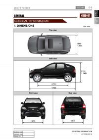
Сборник руководств на английском языке по техническому обслуживанию и ремонту + схемы электрооборудования автомобиля SsangYong Actyon Sports второго поколения.
- Автор: —
- Издательство: SsangYong
- Год издания: 2012/2013
- Страниц: —
- Формат: PDF
- Размер: 155,5 Mb
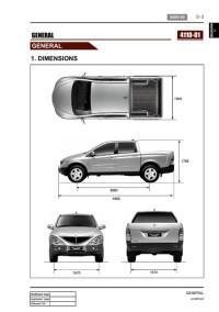
Сборник руководств на английском языке по техническому обслуживанию и ремонту + схемы электрооборудования автомобиля SsangYong Actyon Sports первого поколения.
- Автор: —
- Издательство: SsangYong
- Год издания: 2006-2011
- Страниц: —
- Формат: PDF
- Размер: 987,1 Mb
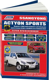
Руководство по техническому обслуживанию и ремонту + каталог расходных запчастей автомобиля SsangYong Actyon Sports с 2006 года выпуска с дизельными двигателями объемом 2,0 л.
- Автор: —
- Издательство: Легион-Автодата
- Год издания: —
- Страниц: 510
- Формат: —
- Размер: —
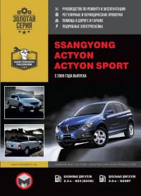
уководство по техническому обслуживанию и ремонту автомобилей SsangYong Actyon и SsangYong Actyon Sports с 2006 года выпуска с бензиновыми и дизельными двигателями.
- Автор: —
- Издательство: Монолит
- Год издания: —
- Страниц: 352
- Формат: —
- Размер: —
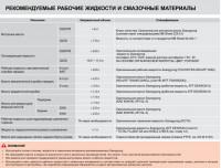
Сборник руководств по эксплуатации и техническому обслуживанию автомобиля SsangYong Actyon Sports второго поколения.
- Автор: —
- Издательство: SsangYong
- Год издания: —
- Страниц: —
- Формат: PDF
- Размер: 21,0 Mb
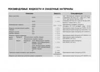
Руководство по эксплуатации и техническому обслуживанию автомобиля SsangYong Actyon Sports первого поколения.
- Автор: —
- Издательство: SsangYong
- Год издания: —
- Страниц: 347
- Формат: PDF
- Размер: 9,9 Mb

ssangyong-rs.ru ® Все права защищены.
© 1997 — 2018 «АЛЬФА — Сервис» — официальный дилер SsangYong (Sollers) в России: SsangYong Actyon, SsangYong Kyron, SsangYong Actyon Sports.
Вся информация, предоставленная на сайте, публичной офертой не является.
Правовая информация