- Manuals
- Brands
- Yamaha Manuals
- Motorcycle
- FJR1300
- Owner’s manual
2004
-
Contents
-
Table of Contents
-
Troubleshooting
-
Bookmarks
Quick Links
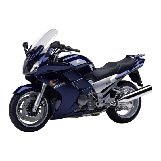
OWNER’S MANUAL
FJR1300
FJR1300A
5JW-28199-E4
Related Manuals for Yamaha FJR1300
Summary of Contents for Yamaha FJR1300
-
Page 1
OWNER’S MANUAL FJR1300 FJR1300A 5JW-28199-E4… -
Page 2
EAU26941 DECLARATION of CONFORMITY Company: MORIC CO., LTD. Address: 1450-6 Mori Mori-Machi Shuchi-gun Shizuoka 437-0292 Japan Hereby declare that the product: Kind of equipment: IMMOBILIZER Type-designation: 5SL-00, 5VS-00, 5VX-00, 3HT-00, 5UX-00, 5UX-10, 5KS-00 and 5KS-10 is in compliance with following norm(s) or documents: R&TTE Directive(1999/5/EC) EN300 330-2 v1.1.1(2001-6), EN60950(2000) Two or Three-Wheel Motor Vehicles Directive(97/24/EC: Chapter 8, EMC) -
Page 3
Yamaha a reputation for dependability. Please take the time to read this manual thoroughly, so as to enjoy all advantages of your FJR1300/FJR1300A. The owner’s manual does not only instruct you in how to operate, inspect and maintain your motorcycle, but also in how to safeguard yourself and others from trouble and injury. -
Page 4: Important Manual Information
This manual should be considered a permanent part of this motorcycle and should remain with it even if the motorcycle is subsequently sold. Yamaha continually seeks advancements in product design and quality. Therefore, while this manual contains the most current product information available at the time of printing, there may be minor discrepancies between your motorcycle and this manual.
-
Page 5
IMPORTANT MANUAL INFORMATION EAU10200 FJR1300/FJR1300A OWNER’S MANUAL ©2004 by Yamaha Motor Co., Ltd. 1st edition, July 2004 All rights reserved. Any reprinting or unauthorized use without the written permission of Yamaha Motor Co., Ltd. is expressly prohibited. Printed in Japan. -
Page 6: Table Of Contents
TABLE OF CONTENTS SAFETY INFORMATION ….1-1 Adjusting the shock absorber Checking the engine idling assembly ……..3-18 speed ……..6-15 DESCRIPTION ……..2-1 Locks for the optional side cases Checking the throttle cable free Left view ……….2-1 and travel trunk ……3-19 play ………..
-
Page 7
TABLE OF CONTENTS Checking the wheel bearings ..6-26 Battery ……….6-26 Replacing the fuses ……6-28 Replacing a headlight bulb …6-29 Replacing a rear turn signal light bulb or a tail/brake light bulb ..6-31 Replacing an auxiliary light bulb …6-31 Troubleshooting ……6-32 Troubleshooting charts ….6-33 MOTORCYCLE CARE AND STORAGE ……….7-1… -
Page 8: Safety Information
SAFETY INFORMATION EAU10281 AND/OR WHEN MADE NECES- • Ride where other motorists can SARY BY MECHANICAL CONDI- see you. Avoid riding in another MOTORCYCLES SINGLE TIONS. motorist’s blind spot. TRACK VEHICLES. THEIR SAFE USE Many accidents involve inexperi- AND OPERATION ARE DEPENDENT Safe riding enced operators.
-
Page 9
Modifications made to this motorcycle other motorists can see you. the single most critical factor in the pre- not approved by Yamaha, or the re- The posture of the operator and vention or reduction of head injuries. moval of original equipment, may ren- passenger is important for proper Always wear an approved helmet. -
Page 10
Maximum load: been specifically designed for use on create instability due to improper FJR1300 201 kg (443 lb) this motorcycle. Since Yamaha cannot weight distribution or aerody- FJR1300A 194 kg (428 lb) test all other accessories that may be namic changes. -
Page 11
SAFETY INFORMATION tor and may limit control ability, Always turn the engine off before or clothing, immediately wash the therefore, such accessories are leaving the motorcycle unattended affected area with soap and water not recommended. and remove the key from the main and change your clothes. -
Page 12: Description
DESCRIPTION EAU10410 Left view 1. Fuse box (page 6-28) 12.Shock absorber assembly rebound damping force adjusting knob (page 3-18) 2. Accessory box (page 3-15) 13.Shock absorber assembly spring preload adjusting lever (page 3-18) 3. Front fork spring preload adjusting bolt (page 3-16) 14.Air filter element (page 6-13) 4.
-
Page 13: Right View
DESCRIPTION EAU10420 Right view 1. Passenger footrest 2. Storage compartment (page 3-15) 3. Coolant reservoir (page 6-12) 4. Battery (page 6-26) 5. Windshield (page 3-8) 6. Main fuse and electronic fuel injection fuse (page 6-28) 7. Front fork compression damping force adjusting screw (page 3-16) 8.
-
Page 14: Controls And Instruments
DESCRIPTION EAU10430 Controls and instruments 1. Clutch lever (page 3-9) 2. Left handlebar switches (page 3-8) 3. Tachometer (page 3-5) 4. Speedometer (page 3-5) 5. Multi-function display (page 3-6) 6. Right handlebar switches (page 3-8) 7. Brake lever (page 3-10) 8.
-
Page 15: Instrument And Control Functions
Do not expose any key to exces- a Yamaha dealer to have them re-reg- sively high temperatures. istered. Do not use the key with the red Do not place any key close to bow for driving.
-
Page 16: Main Switch/Steering Lock
INSTRUMENT AND CONTROL FUNCTIONS EAU10471 EAU26810 To lock the steering Main switch/steering lock All electrical circuits are supplied with power; the meter lighting, taillights and auxiliary lights come on, and the engine can be started. The key cannot be re- moved.
-
Page 17: Indicator And Warning Lights
INSTRUMENT AND CONTROL FUNCTIONS To unlock the steering EAU10910 EAU11002 (Parking) Indicator and warning lights The steering is locked, the taillights and auxiliary lights are on, and the hazard light can be turned on, but all other electrical systems are off. The key can be removed.
-
Page 18
Yamaha dealer check the engine is defective. When this occurs, brake system as soon as possible. EAU11080 have a Yamaha dealer check the self- High beam indicator light “ ” The electrical circuit of the warning light diagnosis system. (See page 3-6 for an… -
Page 19: Speedometer
INSTRUMENT AND CONTROL FUNCTIONS EAU11601 EAU11872 NOTE: Speedometer Tachometer This model is also equipped with a self- diagnosis device for the immobilizer system. If the immobilizer system is de- fective, the indicator will start flashing and the multi-function display will indi- cate an error code when the key is turned to “ON”.
-
Page 20: Multi-Function Display
(1.10 Imp.gal) of fuel remains in the such an error code, note the code num- fuel tank, the display will automatically ber, and then have a Yamaha dealer change to the fuel reserve tripmeter check the vehicle. mode “TRIP F” and start counting the ECA11790 1.
-
Page 21: Anti-Theft Alarm (Optional)
If the multi-function display indicates er- This model can be equipped with an and then have a Yamaha dealer check ror code 52, this could be caused by optional anti-theft alarm by a Yamaha the vehicle.
-
Page 22: Handlebar Switches
INSTRUMENT AND CONTROL FUNCTIONS EAU12343 Right position. To cancel the turn signal Handlebar switches lights, push the switch in after it has re- turned to the center position. Left EAU12492 Windshield position adjusting switch “ ” To move the windshield up, push this switch in direction (a).
-
Page 23: Clutch Lever
INSTRUMENT AND CONTROL FUNCTIONS EAU12500 EAU12731 EAU12830 Horn switch “ ” Hazard switch “ ” Clutch lever Press this switch to sound the horn. EAU12660 Engine stop switch “ ” Set this switch to “ ” before starting the engine. Set this switch to “ ”…
-
Page 24: Shift Pedal
INSTRUMENT AND CONTROL FUNCTIONS Make sure that the appropriate setting EAU12870 EAU26822 Shift pedal Brake lever on the adjusting dial is aligned with the The brake lever is located at the right arrow mark on the clutch lever. handlebar grip. To apply the front The clutch lever is equipped with a brake, pull the lever toward the handle- clutch switch, which is part of the igni-…
-
Page 25: Brake Pedal
This ABS has a test mode which Brake pedal ABS (for ABS models) allows the owner to experience the The Yamaha ABS (Anti-lock Brake pulsating at the brake lever or System) features a dual electronic con- brake pedal when the ABS is oper- trol system, which acts on the front and ating.
-
Page 26: Fuel Tank Cap
INSTRUMENT AND CONTROL FUNCTIONS EAU13070 EAU13210 Fuel tank cap NOTE: Fuel The fuel tank cap cannot be closed un- less the key is in the lock. In addition, the key cannot be removed if the cap is not properly closed and locked. EWA11090 WARNING Make sure that the fuel tank cap is…
-
Page 27: Fuel Tank Breather Hose
Your Yamaha engine has been de- signed to use regular unleaded gaso- line with a research octane number of 91 or higher. If knocking (or pinging) oc-…
-
Page 28: Catalytic Converter
INSTRUMENT AND CONTROL FUNCTIONS EAU13430 EAU14080 Catalytic converter Seats This model is equipped with a catalytic converter in the exhaust chamber. Rider seat EWA10860 WARNING To remove the rider seat 1. Insert the key into the seat lock, The exhaust system is hot after op- eration.
-
Page 29: Storage Compartment
2. Install the rider seat. This storage compartment is designed The accessory box is located beside NOTE: to hold an optional genuine Yamaha U- the meter panel. Make sure that the seats are properly LOCK. (Other locks may not fit.) When NOTE: secured before riding.
-
Page 30: Adjusting The Front Fork
Do not exceed the maximum justing mechanism with the top of the EWA10180 load of FJR1300 201 kg (443 lb) WARNING front fork cap bolt. FJR1300A 194 kg (428 lb) for the Always adjust both fork legs equal- vehicle.
-
Page 31: Specifications
INSTRUMENT AND CONTROL FUNCTIONS Rebound damping force Compression damping force ECA10100 CAUTION: Never attempt to turn an adjusting mechanism beyond the maximum or minimum settings. NOTE: Although the total number of clicks of a damping force adjusting mechanism may not exactly match the above spec- ifications due to small differences in 1.
-
Page 32: Adjusting The Shock Absorber Assembly
INSTRUMENT AND CONTROL FUNCTIONS EAU14911 For riding solo, move the spring preload Rebound damping setting: Adjusting the shock absorber adjusting lever in direction (b). For Minimum (soft): assembly riding with a passenger, move the 20 click(s) in direction (b)* This shock absorber assembly is Standard: spring preload adjusting lever in direc- 10 click(s) in direction (b)*…
-
Page 33: Locks For The Optional Side Cases And Travel Trunk
Yamaha (or does not stay up), otherwise the dealer, these locks can be operated sidestand could contact the ground with the ignition key.
-
Page 34: Ignition Circuit Cut-Off System
INSTRUMENT AND CONTROL FUNCTIONS below and have a Yamaha dealer re- EAU15321 Ignition circuit cut-off system pair it if it does not function proper- The ignition circuit cut-off system (com- prising the sidestand switch, clutch switch and neutral switch) has the fol- lowing functions.
-
Page 35
5. Push the start switch. Does the engine start? The neutral switch may be defective. The motorcycle should not be ridden until checked by a Yamaha dealer. With the engine still running: 6. Move the sidestand up. 7. Keep the clutch lever pulled. -
Page 36: Pre-Operation Checks
PRE-OPERATION CHECKS EAU15591 The condition of a vehicle is the owner’s responsibility. Vital components can start to deteriorate quickly and unexpectedly, even if the vehicle remains unused (for example, as a result of exposure to the elements). Any damage, fluid leakage or loss of tire air pressure could have serious consequences.
-
Page 37: Pre-Operation Check List
• If necessary, add recommended coolant to specified level. 6-12 • Check cooling system for leakage. • Check operation. • If soft or spongy, have Yamaha dealer bleed hydraulic system. • Check brake pads for wear. Front brake • Replace if necessary.
-
Page 38
• Make sure that operation is smooth. • Check cable free play. Throttle grip 6-15, 6-22 • If necessary, have Yamaha dealer adjust cable free play and lubricate cable and grip housing. • Make sure that operation is smooth. Control cables 6-22 •… -
Page 39: Operation And Important Riding Points
Yamaha dealer check the electrical cir- sciousness and death within a described on page 3-20. cuit. short time. Always make sure Never ride with the sidestand 3.
-
Page 40: Shifting
OPERATION AND IMPORTANT RIDING POINTS ECA11040 EAU16671 ECA10260 Shifting CAUTION: CAUTION: For maximum engine life, never ac- Even with the transmission in celerate hard when the engine is the neutral position, do not cold! coast for long periods of time with the engine off, and do not NOTE: tow the motorcycle for long dis-…
-
Page 41: Tips For Reducing Fuel Consumption
If any engine trouble should oc- result in engine overheating must be lights or at railroad crossings). cur during the engine break-in avoided. period, immediately have a Yamaha dealer check the vehi- EAU17121 cle. 0–1000 km (0–600 mi) Avoid prolonged operation above 5000 r/min.
-
Page 42: Parking
OPERATION AND IMPORTANT RIDING POINTS EAU17212 Parking When parking, stop the engine, and then remove the key from the main switch. EWA10310 WARNING Since the engine and exhaust system can become very hot, park in a place where pedestri- ans or children are not likely to touch them.
-
Page 43: Periodic Maintenance And Minor Repair
If you are not familiar with mainte- certain maintenance work correctly. nance work, have a Yamaha dealer do it for you. NOTE: If you do not have the tools or experi- ence required for a particular job, have a Yamaha dealer perform it for you.
-
Page 44: Periodic Maintenance And Lubrication Chart
The annual checks must be performed every year, except if a kilometer-based maintenance is performed in- stead. From 50000 km, repeat the maintenance intervals starting from 10000 km. Items marked with an asterisk should be performed by a Yamaha dealer as they require special tools, data and technical skills. ODOMETER READING (× 1000 km)
-
Page 45
PERIODIC MAINTENANCE AND MINOR REPAIR ODOMETER READING (× 1000 km) ANNUAL ITEM CHECK OR MAINTENANCE JOB CHECK √ √ √ √ 9 * Wheels • Check runout and for damage. • Check tread depth and for damage. • Replace if necessary. √… -
Page 46
PERIODIC MAINTENANCE AND MINOR REPAIR ODOMETER READING (× 1000 km) ANNUAL ITEM CHECK OR MAINTENANCE JOB CHECK √ √ √ √ √ • Check coolant level and vehicle for coolant leakage. 23 * Cooling system • Change. Every 3 years •… -
Page 47: Removing And Installing Panels
PERIODIC MAINTENANCE AND MINOR REPAIR EAU18771 Removing and installing panels The panels shown need to be removed to perform some of the maintenance jobs described in this chapter. Refer to this section each time a panel needs to be removed and installed. 1.
-
Page 48
PERIODIC MAINTENANCE AND MINOR REPAIR 2. Install panel A (to complete the in- EAU33370 Panels E and F stallation of panel B) or panel D (to complete the installation of panel To remove one of the panels 1. Remove the seats. (See page 3-14.) EAU19193 Panel D… -
Page 49: Checking The Spark Plugs
Do Spark plug gap: not attempt to diagnose such problems 0.7–0.8 mm (0.028–0.031 in) yourself. Instead, have a Yamaha deal- er check the vehicle. Clean the surface of the spark plug If a spark plug shows signs of electrode…
-
Page 50: Engine Oil And Oil Filter Cartridge
PERIODIC MAINTENANCE AND MINOR REPAIR EAU19881 2. Place an oil pan under the engine Engine oil and oil filter NOTE: to collect the used oil. The engine oil should be between the cartridge 3. Remove the engine oil filler cap minimum and maximum level marks.
-
Page 51
An oil filter wrench is available at a seated. 43 Nm (4.3 m·kgf, 31 ft·lbf) Yamaha dealer. 6. Install the new oil filter cartridge, 8. Add the specified amount of the 5. Apply a thin coat of engine oil to… -
Page 52: Final Gear Oil
If any page (since the engine oil also or remains on, immediately turn the leakage is found, have a Yamaha deal- lubricates the clutch), do not engine off and have a Yamaha dealer er check and repair the vehicle. In addi- mix any chemical additives.
-
Page 53
PERIODIC MAINTENANCE AND MINOR REPAIR 2. Remove the oil filler bolt, and then Tightening torque: Tightening torque: check the oil level in the final gear Final gear oil filler bolt: Final gear oil filler bolt: case. 23 Nm (2.3 m·kgf, 17 ft·lbf) 23 Nm (2.3 m·kgf, 17 ft·lbf) NOTE: 6. -
Page 54: Coolant
PERIODIC MAINTENANCE AND MINOR REPAIR EAU20070 Coolant NOTE: The coolant should be between the The coolant level should be checked minimum and maximum level marks. before each ride. In addition, the cool- ant must be changed at the intervals specified in the periodic maintenance and lubrication chart.
-
Page 55: Cleaning The Air Filter Element
If water has been added to the 1. Remove panel E. (See page 6-5.) nance and lubrication chart. Have a coolant, have a Yamaha dealer 2. Remove the intake air shroud by Yamaha dealer change the coolant. check the antifreeze content of…
-
Page 56
PERIODIC MAINTENANCE AND MINOR REPAIR out with compressed air as shown. 9. Install the panel. If the air filter element is damaged, replace it. 1. Air filter case cover 2. Screw 4. Pull the air filter element out. 6. Insert the air filter element into the air filter case. -
Page 57: Checking The Engine Idling Speed
To prevent this checked as follows and, if necessary, from occurring, the valve clearance adjusted by a Yamaha dealer at the in- must be adjusted by a Yamaha dealer tervals specified in the periodic mainte- at the intervals specified in the periodic nance and lubrication chart.
-
Page 58: Tires
250 kPa (36 psi) (2.50 kgf/cm²) passenger, cargo, and accesso- FJR1300 90–201 kg (198–443 lb) Tire air pressure ries does not exceed the speci- FJR1300A 90–194 kg (198–428 lb): The tire air pressure should be checked…
-
Page 59
Tire information glass fragments in it, or if the sidewall is Use only the tire valves and cracked, have a Yamaha dealer re- valve cores listed below to place the tire immediately. avoid tire deflation during a high-speed ride. -
Page 60: Cast Wheels
Always adjust the tire air pres- 180/55 ZR17M/C (73W) fore each ride. If any damage is Manufacturer/model: sure according to the operating found, have a Yamaha dealer re- METZELER/MEZ4J conditions. BRIDGESTONE/BT020R N place the wheel. Do not attempt FRONT and REAR:…
-
Page 61: Clutch Lever Free Play
If there is air in the hydraulic 1. Rear brake light switch system, have a Yamaha dealer bleed 2. Rear brake light switch adjusting nut the system before operating the motor- The rear brake light switch, which is ac- cycle.
-
Page 62: Checking The Brake And Clutch Fluid Levels
PERIODIC MAINTENANCE AND MINOR REPAIR indicator groove has almost disap- EAU22680 Clutch Checking the brake and clutch peared, have a Yamaha dealer replace fluid levels the brake pads as a set. Front brake EAU22500 Rear brake pads 1. Minimum level mark…
-
Page 63: Changing The Brake And Clutch
Have a Yamaha dealer change the Use only the recommended quality Brake fluid may deteriorate paint- brake and clutch fluids at the intervals brake fluid, otherwise the rubber ed surfaces or plastic parts.
-
Page 64: Checking And Lubricating The Cables
If a cable is damaged periodic maintenance chart. or does not move smoothly, have a Yamaha dealer check or replace it. Recommended lubricant: Engine oil EWA10720 WARNING…
-
Page 65: Checking And Lubricating The Brake And Clutch Levers
PERIODIC MAINTENANCE AND MINOR REPAIR EAU23140 Recommended lubricant: Recommended lubricant: Checking and lubricating the Lithium-soap-based grease (all-pur- Lithium-soap-based grease (all-pur- brake and clutch levers pose grease) pose grease) Brake lever Clutch lever The operation of the brake and clutch levers should be checked before each ride, and the lever pivots should be lu- bricated if necessary.
-
Page 66: Checking And Lubricating The Centerstand And Sidestand
Lithium-soap-based grease Recommended lubricant: EWA10740 WARNING Lithium-soap-based grease If the centerstand or sidestand does not move up and down smoothly, have a Yamaha dealer check or re- pair it. Recommended lubricant: Lithium-soap-based grease (all-pur- pose grease) 6-24…
-
Page 67: Checking The Front Fork
Securely support the vehicle so that fork does not operate smoothly, damage and excessive oil leakage. there is no danger of it falling over. have a Yamaha dealer check or re- pair it. To check the operation 2. Hold the lower ends of the front 1.
-
Page 68: Checking The Wheel Bearings
There is no need to check the electrolyte or to add distilled water. To charge the battery Have a Yamaha dealer charge the bat- tery as soon as possible if it seems to have discharged. Keep in mind that the 6-26…
-
Page 69
IES OUT OF THE REACH OF If you do not have access to a electrical accessories. CHILDREN. sealed-type (MF) battery charg- have a Yamaha dealer EWA10760 WARNING charge your battery. To store the battery Electrolyte is poisonous and 1. -
Page 70: Replacing The Fuses
PERIODIC MAINTENANCE AND MINOR REPAIR EAU23653 Replacing the fuses 1. Headlight fuse 1. Main fuse 2. Signaling system fuse 2. ABS motor fuse (for ABS models) 1. Electronic fuel injection fuse 3. Ignition fuse 3. ABS motor spare fuse (for ABS models) 2.
-
Page 71: Replacing A Headlight Bulb
Radiator fan fuse: and then remove the headlight 15.0 A 4. If the fuse immediately blows bulb cover. Backup fuse: again, have a Yamaha dealer 10.0 A check the electrical system. Hazard fuse: 7.5 A Parking lighting fuse: 10.0 A Electronic fuel injection fuse: 15.0 A…
-
Page 72
6. Install the panel. from oil, otherwise the transpar- 7. Have a Yamaha dealer adjust the ency of the glass, the luminosity headlight beam if necessary. of the bulb, and the bulb life will be adversely affected. -
Page 73: Replacing A Rear Turn Signal Light Bulb Or A Tail/Brake Light Bulb
PERIODIC MAINTENANCE AND MINOR REPAIR EAU27000 EAU27010 Replacing a rear turn signal Replacing an auxiliary light light bulb or a tail/brake light bulb bulb This model is equipped with two auxil- iary lights. If an auxiliary light bulb burns 1. Remove the passenger seat. (See out, replace it as follows.
-
Page 74: Troubleshooting
The following troubleshooting charts represent quick and easy procedures for checking these vital systems your- self. However, should your motorcycle require any repair, take it to a Yamaha dealer, whose skilled technicians have the necessary tools, experience, and know-how to service the motorcycle properly.
-
Page 75: Troubleshooting Charts
Remove the spark plugs and check the electrodes. The engine does not start. Have a Yamaha dealer check the vehicle. Check the battery. 4. Battery The engine turns over The battery is good.
-
Page 76
Start the engine. If the engine overheats again, have a The coolant level Yamaha dealer check and repair the cooling system. is OK. NOTE: If coolant is not available, tap water can be temporarily used instead, provided that it is changed to the recommended coolant as soon as possible. -
Page 77: Motorcycle Care And Storage
MOTORCYCLE CARE AND STORAGE EAU26060 ucts onto seals, gaskets and wheel thinner, fuel (gasoline), rust re- Care axles. Always rinse the dirt and de- movers or inhibitors, brake flu- While the open design of a motorcycle greaser off with water. id, antifreeze or electrolyte.
-
Page 78
MOTORCYCLE CARE AND STORAGE After normal use ECA10790 5. Touch up minor paint damage CAUTION: Remove dirt with warm water, a mild caused by stones, etc. detergent, and a soft, clean sponge, 6. Wax all painted surfaces. Do not use warm water since it in- and then rinse thoroughly with clean 7. -
Page 79: Storage
Always store your motorcycle in a cool, NOTE: and spark plugs. dry place and, if necessary, protect it Consult a Yamaha dealer for advice on b. Pour a teaspoonful of engine oil against dust with a porous cover. what products to use.
-
Page 80
MOTORCYCLE CARE AND STORAGE 4. Lubricate all control cables and the pivoting points of all levers and pedals as well as of the side- stand/centerstand. 5. Check and, if necessary, correct the tire air pressure, and then lift the motorcycle so that both of its wheels are off the ground. -
Page 81: Specifications
Cooling system: Primary reduction ratio: With oil and fuel: Coolant reservoir capacity (up to the 75/48 (1.563) FJR1300 275.0 kg (606 lb) maximum level mark): Secondary reduction system: FJR1300A 282.0 kg (622 lb) 0.25 L (0.26 US qt) (0.22 Imp.qt)
-
Page 82
Trail: Operation: 250 kPa (36 psi) (2.50 kgf/cm²) 109.0 mm (4.29 in) Right foot operation Loading condition: Front tire: Recommended fluid: FJR1300 90–201 kg (198–443 lb) DOT 4 Type: FJR1300A 90–194 kg (198–428 lb) Front suspension: Tubeless Front: Size: 250 kPa (36 psi) (2.50 kgf/cm²) -
Page 83
SPECIFICATIONS Voltage, capacity: Fuses: 12 V, 12.0 Ah Main fuse: Headlight: 50.0 A Bulb type: Headlight fuse: Halogen bulb 25.0 A Bulb voltage, wattage x quantity: Signaling system fuse: 15.0 A Headlight: 12 V, 60 W/55.0 W × 2 Ignition fuse: 10.0 A Tail/brake light: 12 V, 5.0 W/21.0 W ×… -
Page 84: Consumer Information
Record the key identification number, vehicle identification number and mod- el label information in the spaces pro- vided below for assistance when ordering spare parts from a Yamaha dealer or for reference in case the vehi- cle is stolen. KEY IDENTIFICATION NUMBER: 1.
-
Page 85
1. Model label The model label is affixed to the frame under the rider seat. (See page 3-14.) Record the information on this label in the space provided. This information will be needed when ordering spare parts from a Yamaha dealer. -
Page 86
INDEX Engine trouble warning light ….3-4 ABS (for ABS models) ……3-11 Oil level warning light ……3-4 ABS warning light (for ABS models) ..3-4 Final gear oil ……… 6-10 Accessory box……..3-15 Front and rear brake pads, checking..6-19 Panels, removing and installing ….6-5 Air filter element, cleaning….. -
Page 87
INDEX Tires…………6-16 Tool kit ………… 6-1 Troubleshooting……..6-32 Troubleshooting charts ……6-33 Turn signal indicator lights …… 3-3 Turn signal light or tail/brake light bulb, replacing……….6-31 Turn signal switch……..3-8 Valve clearance ……..6-15 Vehicle identification number….9-1 Wheel bearings, checking …. -
Page 90
YAMAHA MOTOR CO., LTD. PRINTED ON RECYCLED PAPER PRINTED IN JAPAN 2004.08-0.3×1 CR…
This manual is also suitable for:
Fjr1300a

Руководство по эксплуатации и техническому обслуживанию мотоциклов Yamaha FJR1300A.
- Издательство: Yamaha Motor Co., Ltd.
- Год издания: 2010
- Страниц: 105
- Формат: PDF
- Размер: 6,0 Mb

Руководство по эксплуатации и техническому обслуживанию мотоциклов Yamaha FJR1300AS.
- Издательство: Yamaha Motor Co., Ltd.
- Год издания: 2009
- Страниц: 105
- Формат: PDF
- Размер: 4,1 Mb

Сборник руководств на английском языке по эксплуатации и техническому обслуживанию мотоциклов Yamaha моделей FJR13AD(C)/AEV(C)/AEY(C)/AV(C)/AX(C)/AZ(C).
- Издательство: Yamaha Motor Co., Ltd.
- Год издания: 2005-2012
- Страниц: —
- Формат: PDF
- Размер: 23,8 Mb

Сборник руководств на английском языке по эксплуатации и техническому обслуживанию мотоциклов Yamaha моделей FJR1300/A/AP/AS(C)/AT(C)/N/R/RC/S(C)/T(C).
- Издательство: Yamaha Motor Co., Ltd.
- Год издания: 2001-2010
- Страниц: —
- Формат: PDF
- Размер: 64,7 Mb
Руководство на английском языке по ремонту мотоциклов Yamaha моделей FJR1300 и FJR1300N 2001 года выпуска.
- Издательство: Yamaha Motor Co., Ltd.
- Год издания: —
- Страниц: 617
- Формат: PDF
- Размер: 15,2 Mb
Руководство на английском языке по ремонту мотоциклов Yamaha моделей FJR1300A и FJR1300AV 2006 года выпуска.
- Издательство: Yamaha Motor Co., Ltd.
- Год издания: 2006
- Страниц: 586
- Формат: PDF
- Размер: 23,3 Mb
Руководство (дополнение) на английском языке по ремонту мотоциклов Yamaha моделей FJR1300, FJR1300A, FRJ1300AS и FRJ1300S 2004 года выпуска.
- Издательство: Yamaha Motor Co., Ltd.
- Год издания: 2003
- Страниц: 44
- Формат: PDF
- Размер: 1,7 Mb

Сборник руководств на английском, французском, немецком, испанском и итальянском языках по ремонту мотоциклов Yamaha моделей FJR1300, FJR1300A и др.
- Издательство: Yamaha
- Год издания: —
- Страниц: —
- Формат: ISO
- Размер: 1,7 Gb

Не можете найти ответ на свой вопрос в руководстве? Вы можете найти ответ на свой вопрос ниже, в разделе часто задаваемых вопросов о Yamaha FJR1300AS (2018).
Как перевести мили в километры?
В чем разница между топливом E10 и E5?
Какова рекомендуемая частота замены масляного фильтра в двигателе Yamaha?
Как часто следует менять масло в двигателе Yamaha?
Как удалить ржавчину с устройства Yamaha мотоцикл?
Инструкция Yamaha FJR1300AS (2018) доступно в русский?
Не нашли свой вопрос? Задайте свой вопрос здесь
- Manuals
- Brands
- Yamaha Manuals
- Motorcycle
- FJR1300
Manuals and User Guides for Yamaha FJR1300. We have 6 Yamaha FJR1300 manuals available for free PDF download: Service Manual, Owner’s Manual
Yamaha FJR1300 Service Manual (572 pages)
Yamaha Motorcycles Service manual
Brand: Yamaha
|
Category: Motorcycle
|
Size: 20.81 MB
Table of Contents
-
Periodic Checks and
4
-
General Information
5
-
Specifications
5
-
Table of Contents
7
-
-
Periodic Checks and Adjustments
5
-
Chassis
5
-
Engine
5
-
Cooling System
5
-
Fuel Injection System
5
-
Electrical System
5
-
Troubleshooting
17
-
Chapter 1 General Information
19
-
Motorcycle Identification
19
-
Vehicle Identification Number
19
-
Model Code
19
-
-
Features
20
-
Outline
20
-
Fi System
21
-
Components
23
-
Fuel Injection System
35
-
Three-Way Catalytic Converter System
44
-
Air Induction System
48
-
Components
49
-
-
Important Information
53
-
Preparation for Removal and Disassembly
53
-
Replacement Parts
53
-
Gaskets, Oil Seals and O-Rings
53
-
Lock Washers/Plates and Cotter Pins
54
-
Bearings and Oil Seals
54
-
Circlips
54
-
Checking the Connections
55
-
-
Special Tools
56
-
Chapter 2 Specifications
61
-
Spec
61
-
General Specifications
61
-
Engine Specifications
62
-
Chassis Specifications
71
-
Electrical Specifications
75
-
Conversion Table
78
-
General Tightening Torque Specifications
78
-
Tightening Torques
79
-
-
Lubrication Points and Lubricant Types
85
-
Engine Lubrication Points and Lubricant Types
85
-
Chassis Lubrication Points and Lubricant Types
87
-
-
Oil Flow Diagrams
88
-
Cooling System Diagrams
98
-
Cable Routing
102
-
Chapter 3 Periodic Checks and Adjustments
117
-
Introduction
117
-
Periodic Maintenance Chart for the Emission Control System
117
-
General Maintenance and Lubrication Chart
117
-
Chk Adj
117
-
Seats and Fuel Tank
120
-
Seats
120
-
Fuel Tank
121
-
T-Bar
122
-
Removing the Fuel Tank
123
-
Removing the Fuel Pump
123
-
Installing the Fuel Pump
124
-
Installing the Fuel Hose
124
-
Installing the T-Bar
124
-
-
Air Filter Case
125
-
Cowlings and Covers
127
-
Cowlings
127
-
Covers
131
-
-
Engine
132
-
Adjusting the Valve Clearance
132
-
Synchronizing the Throttle Bodies
138
-
Adjusting the Engine Idling Speed
141
-
Adjusting the Throttle Cable Free Play
142
-
Checking the Spark Plugs
144
-
Checking the Ignition Timing
145
-
Measuring the Compression Pressure
147
-
Checking the Engine Oil Level
149
-
Changing the Engine Oil
151
-
Measuring the Engine Oil Pressure
153
-
Adjusting the Clutch Lever
155
-
Checking the Clutch Fluid Level
155
-
Bleeding the Hydraulic Clutch System
156
-
Cleaning the Air Filter Element
158
-
Checking the Throttle Body Joints
159
-
Checking the Fuel and Vacuum Hoses
160
-
Checking the Crankcase Breather Hose
160
-
Checking the Exhaust System
161
-
Checking the Coolant Level
162
-
Checking the Cooling System
163
-
Changing the Coolant
164
-
-
Chassis
167
-
Adjusting the Front Brake
167
-
Adjusting the Rear Brake
168
-
Checking the Brake Fluid Level
169
-
Checking the Brake Pads
170
-
Adjusting the Rear Brake Light Switch
171
-
Checking the Brake Hoses
171
-
Bleeding the Hydraulic Brake System
172
-
Adjusting the Shift Pedal
173
-
Checking the Final Drive Oil Level
174
-
Changing the Final Drive Oil
175
-
Checking and Adjusting the Steering Head
175
-
Checking the Front Fork
177
-
Adjusting the Front Fork Legs
178
-
Adjusting the Rear Shock Absorber Assembly
180
-
Checking the Tires
182
-
Checking the Wheels
183
-
Checking and Lubricating the Cables
184
-
Lubricating the Levers and Pedals
184
-
Lubricating the Sidestand
184
-
Lubricating the Centerstand
185
-
Lubricating the Rear Suspension
185
-
-
Electrical System
186
-
Checking and Charging the Battery
186
-
Checking the Fuses
191
-
Replacing the Headlight Bulbs
193
-
Adjusting the Headlight Beams
194
-
-
Chapter 4 Chassis
197
-
Front Wheel and Brake Discs
197
-
Removing the Front Wheel
199
-
Checking the Front Wheel
199
-
Checking the Brake Discs
201
-
Installing the Front Wheel
202
-
Adjusting the Front Wheel Static Balance
203
-
-
Chas
197
-
Rear Wheel and Brake Disc
205
-
Removing the Rear Wheel
207
-
Checking the Rear Wheel
207
-
Installing the Rear Wheel
208
-
Adjusting the Rear Wheel Static Balance
208
-
-
Front and Rear Brakes
209
-
Front Brake Pads
209
-
Rear Brake Pads
210
-
Replacing the Front Brake Pads
211
-
Replacing the Rear Brake Pads
213
-
Front Brake Master Cylinder
216
-
Rear Brake Master Cylinder
219
-
Disassembling the Front Brake Master Cylinder
222
-
Disassembling the Rear Brake Master Cylinder
222
-
Checking the Front and Rear Brake Master Cylinders
223
-
Assembling and Installing the Front Brake Master Cylinder
224
-
Assembling the Rear Brake Master Cylinder
226
-
Front Brake Calipers
229
-
Rear Brake Caliper
231
-
Disassembling the Front Brake Calipers
233
-
Checking the Front and Rear Brake Calipers
235
-
Assembling and Installing the Front Brake Calipers
236
-
Assembling and Installing the Rear Brake Caliper
238
-
-
Hydraulic Clutch
242
-
Clutch Master Cylinder
242
-
Disassembling the Clutch Master Cylinder
244
-
Checking the Clutch Master Cylinder
246
-
Assembling and Installing the Clutch Master Cylinder
247
-
Clutch Release Cylinder
250
-
Disassembling the Clutch Release Cylinder
251
-
Checking the Clutch Release Cylinder
253
-
Assembling and Installing the Clutch Release Cylinder
253
-
-
Front Fork
256
-
Removing the Front Fork Legs
259
-
Disassembling the Front Fork Legs
259
-
Checking the Front Fork Legs
261
-
Assembling the Front Fork Legs
262
-
Installing the Front Fork Legs
266
-
-
Handlebars
268
-
Left Handlebar
268
-
Right Handlebar
269
-
Removing the Handlebars
270
-
Checking the Handlebars
270
-
Installing the Handlebars
271
-
-
Steering Head
274
-
Removing the Lower Bracket
276
-
Checking the Steering Head
276
-
Installing the Steering Head
277
-
-
Rear Shock Absorber Assembly and Relay Arm
279
-
Handling the Rear Shock Absorber
281
-
Disposing of a Rear Shock Absorber
281
-
Removing the Rear Shock Absorber Assembly
281
-
Checking the Rear Shock Absorber Assembly
282
-
Checking the Connecting Arm and Relay Arm
282
-
Installing the Relay Arm
283
-
Installing the Rear Shock Absorber Assembly
283
-
-
Swingarm
284
-
Removing the Swingarm
286
-
Checking the Swingarm
286
-
Installing the Swingarm
287
-
-
Shaft Drive
289
-
Troubleshooting
289
-
Checking the Final Drive Oil for Contamination and Checking the Shaft Drive for Leaks
292
-
Measuring the Ring Gear Backlash
293
-
Adjusting the Ring Gear Backlash
294
-
Measuring the Ring-Gear-To-Stopper-Bolt Clearance
295
-
Adjusting the Ring-Gear-To-Stopper-Bolt Clearance
295
-
Removing the Left Footrest Bracket
301
-
Disassembling the Final Drive Assembly
301
-
Removing and Installing the Ring Gear Bearings
302
-
Aligning the Final Drive Pinion Gear and Ring Gear
304
-
Checking the Drive Shaft
309
-
Installing the Universal Joint and Final Drive Assembly
309
-
-
Chapter 5 Engine
310
-
Mufflers and Exhaust Pipe Assembly
310
-
Leads and Hoses
311
-
Engine
311
-
Installing the Engine
315
-
-
Eng
310
-
Camshafts
317
-
Cylinder Head Cover
317
-
Camshafts
318
-
Removing the Camshafts
320
-
Checking the Camshafts
321
-
Checking the Camshaft Sprockets
322
-
Checking the Timing Chain Tensioner
323
-
Installing the Camshafts
323
-
-
Cylinder Head
328
-
Removing the Cylinder Head
329
-
Checking the Cylinder Head
329
-
Installing the Cylinder Head
330
-
-
Valves and Valve Springs
332
-
Removing the Valves
333
-
Checking the Valves and Valve Guides
334
-
Checking the Valve Seats
336
-
Checking the Valve Springs
338
-
Checking the Valve Lifters
339
-
Installing the Valves
340
-
-
Generator and Starter Clutch
342
-
Generator Rotor and Starter Clutch
342
-
Stator Assembly
344
-
Removing the Generator
345
-
Removing the Starter Clutch
346
-
Checking the Starter Clutch
346
-
Installing the Starter Clutch
347
-
Installing the Generator
347
-
-
Pickup Coil Rotor
349
-
Removing the Pickup Coil Rotor
351
-
Installing the Pickup Coil Rotor
351
-
-
Clutch
353
-
Clutch Cover
353
-
Clutch
354
-
Removing the Clutch
356
-
Checking the Friction Plates
357
-
Checking the Clutch Plates
358
-
Checking the Clutch Spring Plate
358
-
Checking the Clutch Housing
358
-
Checking the Clutch Boss
359
-
Checking the Pressure Plate
359
-
Checking the Clutch Push Rods
359
-
Checking the Primary Driven Gear
359
-
Installing the Clutch
360
-
-
Shift Shaft
363
-
Checking the Shift Shaft
365
-
Checking the Stopper Lever
365
-
Installing the Shift Shaft
365
-
-
Oil Pan and Oil Pump
367
-
Oil Pump
369
-
Removing the Oil Pan
370
-
Checking the Oil Pump
370
-
Checking the Relief Valve
371
-
Checking the Oil Delivery Pipes
371
-
Checking the Oil Strainer
371
-
Assembling the Oil Pump
371
-
Installing the Oil Pump
372
-
Installing the Oil Strainer
372
-
Installing the Oil Pan
372
-
-
Middle Gear
374
-
Removing the Middle Gear
378
-
Disassembling the Middle Drive Shaft Assembly
379
-
Disassembling the Middle Driven Shaft Assembly
379
-
Checking the Middle Drive Shaft Assembly
379
-
Checking the Middle Driven Shaft Assembly
380
-
Assembling the Middle Drive Shaft Assembly
380
-
Assembling the Middle Driven Shaft Assembly
380
-
Installing the Middle Drive Shaft Assembly
381
-
Installing the Middle Driven Shaft Assembly
382
-
Measuring the Middle Gear Backlash
383
-
Adjusting the Middle Gear Backlash
384
-
Aligning the Middle Gear
387
-
-
Crankcase
390
-
Disassembling the Crankcase
394
-
Checking the Crankcase
395
-
Checking the Bearings and Oil Seals
395
-
Checking the Timing Chain and Oil Pump Drive Chain
396
-
Assembling the Crankcase
396
-
Removing the Connecting Rods and Pistons
401
-
Checking the Cylinders and Pistons
402
-
Checking the Piston Rings
403
-
Checking the Piston Pins
404
-
Checking the Connecting Rods
406
-
Installing the Connecting Rods and Pistons
408
-
-
Crankshaft
412
-
Removing the Crankshaft
413
-
Checking the Crankshaft
413
-
Installing the Crankshaft
416
-
-
Transmission
417
-
Removing the Transmission
423
-
Checking the Shift Forks
423
-
Checking the Shift Drum Assembly
424
-
Checking the Transmission
424
-
Installing the Transmission
426
-
-
Balancers
427
-
Front Balancer
427
-
Rear Balancer
428
-
Checking the Balancer
429
-
Installing the Front Balancer
429
-
Installing the Rear Balancer
431
-
-
Chapter 6 Cooling System
434
-
Cool
434
-
Radiator
434
-
Checking the Radiator
436
-
Installing the Radiator
437
-
-
Oil Cooler
438
-
Checking the Oil Cooler
439
-
Installing the Oil Cooler
439
-
-
Thermostat
441
-
Checking the Thermostat
443
-
Assembling the Thermostat Assembly
444
-
Installing the Thermostat Assembly
444
-
-
Water Pump
445
-
Disassembling the Water Pump
448
-
Checking the Water Pump
448
-
Assembling the Water Pump
449
-
Installing the Water Pump
451
-
-
Chapter 7 Fuel Injection System
452
-
Wiring Diagram
453
-
Ecu’s Self-Diagnostic Function
454
-
Substitute Characteristics Operation Control (Fail-Safe Action)
458
-
Troubleshooting
459
-
Throttle Bodies
484
-
Checking the Injector
488
-
Checking the Throttle Body
488
-
Checking the Pressure Regulator
488
-
Checking the Fuel Pump and Pressure Regulator Operation
489
-
-
Air Induction System
491
-
Air Injection
491
-
Air Cut-Off Valve
491
-
Air Induction System Diagrams
492
-
Air Cut-Off Valve Assembly and Air Induction System Hoses
493
-
Reed Valves
494
-
Checking the Air Induction System
495
-
-
Canister (for California Only)
496
-
Chapter 8
497
-
Elec
497
-
Electrical Components
497
-
Checking Switch Continuity
499
-
Checking the Switches
500
-
Checking the Bulbs and Bulb Sockets
502
-
Types of Bulbs
502
-
Checking the Condition of the Bulbs
502
-
Checking the Condition of the Bulb Sockets
504
-
-
Ignition System
505
-
Circuit Diagram
505
-
Troubleshooting
506
-
Circuit Diagram
510
-
Starting Circuit Cut-Off System Operation
511
-
Troubleshooting
512
-
-
Starter Motor
516
-
Checking the Starter Motor
519
-
Assembling the Starter Motor
521
-
-
Charging System
522
-
Circuit Diagram
522
-
Troubleshooting
523
-
-
Lighting System
525
-
Circuit Diagram
525
-
Troubleshooting
526
-
Checking the Lighting System
528
-
-
Signaling System
532
-
Circuit Diagram
532
-
Troubleshooting
534
-
Checking the Signaling System
535
-
-
Cooling System
542
-
Circuit Diagram
542
-
Troubleshooting
543
-
-
Fuel Injection System
547
-
Circuit Diagram
547
-
Troubleshooting
548
-
Checking the Fuel Pump
554
-
Checking and Adjusting the Throttle
555
-
Position Sensor
555
-
-
Windshield Drive System
559
-
Circuit Diagram
559
-
Troubleshooting
562
-
-
Chapter 9
562
-
Engine
562
-
Fuel System
562
-
-
Starting Problems
562
-
Incorrect Engine Idling Speed
563
-
Engine
563
-
Fuel System
563
-
-
Trbl Shtg
563
-
Electrical Systems
563
-
-
Poor Medium-And-High-Speed Performance
564
-
Engine
564
-
Fuel System
564
-
-
Faulty Gear Shifting
564
-
Shifting Is Difficult
564
-
Shift Pedal Does Not Move
564
-
Jumps out of Gear
564
-
-
Faulty Clutch
565
-
Clutch Slips
565
-
Clutch Drags
565
-
-
Overheating
565
-
Engine
565
-
Cooling System
565
-
Fuel System
565
-
Chassis
565
-
Electrical Systems
565
-
-
Poor Braking Performance
566
-
Faulty Front Fork Legs
566
-
Leaking Oil
566
-
Malfunction
566
-
-
Unstable Handling
567
-
Faulty Lighting or Signaling System
567
-
Headlight Does Not Light
567
-
Headlight Bulb Burnt out
567
-
Tail/Brake Light Does Not Light
567
-
Tail/Brake Light Bulb Burnt out
567
-
Turn Signal Does Not Light
567
-
Turn Signal Blinks Slowly
567
-
Turn Signal Remains Lit
567
-
Turn Signal Blinks Quickly
568
-
Horn Does Not Sound
568
-
Advertisement

YAMAHA FJR1300 Owner’s Manual (112 pages)
2002
Brand: YAMAHA
|
Category: Motorcycle
|
Size: 7.62 MB
Table of Contents
-
Table of Contents
9
-
Important Manual Information
7
-
Give Safety the Right of Way
11
-
Description
13
-
Left View
14
-
Description
15
-
Right View
15
-
Controls and Instruments
16
-
-
-
-
Instrument and Control Functions
17
-
Immobilizer System
18
-
Instrument and Control Functions
19
-
Lock
20
-
Indicator and Warning Lights
21
-
Speedometer
23
-
Tachometer
23
-
Multi-Function Display
24
-
Anti-Theft Alarm (Optional)
26
-
Handlebar Switches
26
-
Clutch Lever
28
-
Shift Pedal
28
-
Brake Lever
29
-
Brake Pedal
29
-
ABS (for FJR1300A Only)
30
-
Fuel Tank Cap
31
-
Fuel
32
-
Fuel Tank Breather Hose
33
-
Catalytic Converter
33
-
Seats
34
-
Storage Compartment
35
-
Accessory Box
36
-
Adjusting the Front Fork
36
-
Adjusting the Shock Absorber Assembly
38
-
Locks for the Optional Side Cases and Travel Trunk
40
-
Sidestand
40
-
Ignition Circuit Cut-Off System
41
-
-
Main Switch/Steering Lock
19
-
Pre-Operation Checks
43
-
Pre-Operation Check List
44
-
-
-
Operation and Important Riding Points
47
-
Starting the Engine
48
-
Operation and Important Riding Points
49
-
Shifting
49
-
Engine Break-In
50
-
Recommended Shift Points (for Switzerland Only)
50
-
Tips for Reducing Fuel Consumption
50
-
Parking
51
-
-
Periodic Maintenance and Minor Repair
53
-
Owner’s Tool Kit
54
-
Periodic Maintenance and Lubrication Chart
55
-
Periodic Maintenance and Minor Repair
55
-
-
Removing and Installing Panels
58
-
Checking the Spark Plugs
60
-
Engine Oil and Oil Filter Cartridge
62
-
Final Gear Oil
65
-
Checking the Coolant Level
66
-
Cleaning the Air Filter Element
68
-
Checking the Engine Idling Speed
69
-
Adjusting the Throttle Cable Free Play
70
-
Adjusting the Valve Clearance
70
-
Tires
70
-
Cast Wheels
73
-
Adjusting the Brake Pedal Position
74
-
Clutch Lever Free Play
74
-
Adjusting the Rear Brake Light Switch
75
-
Checking the Front and Rear Brake Pads
75
-
Checking the Brake and Clutch Fluid Levels
76
-
Changing the Brake and Clutch Fluids
78
-
Checking and Lubricating the Cables
78
-
Checking and Lubricating the Throttle Grip and Cable
78
-
Checking and Lubricating the Brake and Shift Pedals
79
-
Checking and Lubricating the Brake and Clutch Levers
80
-
Checking and Lubricating the Centerstand and Sidestand
80
-
Lubricating the Swingarm Pivots
81
-
Checking the Front Fork
82
-
Checking the Steering
82
-
Checking the Wheel Bearings
83
-
Battery
84
-
Replacing the Fuses
85
-
Replacing a Headlight Bulb
86
-
Replacing an Auxiliary Light Bulb
88
-
Replacing a Rear Turn Signal Light Bulb or a Tail/Brake Light Bulb
89
-
Troubleshooting
89
-
Troubleshooting Charts
90
-
Motorcycle Care and Storage
93
-
Motorcycle Care and Storage
95
-
-
Specifications
99
-
Specifications
100
-
Conversion Table
104
-
-
Consumer Information
105
-
Identification Numbers
106
-
Vehicle Identification Number
106
-
Key Identification Number
106
-
Consumer Information
107
-
Model Label
107
-
-
Yamaha FJR1300 Owner’s Manual (106 pages)
Yamaha Motorcycle User Manual
Brand: Yamaha
|
Category: Motorcycle
|
Size: 6.47 MB
Table of Contents
-
Table of Contents
7
-
Important Manual Information
5
-
Safety Information
9
-
Safe Riding
10
-
Safety Information
11
-
Protective Apparel
12
-
Modifications
12
-
Loading and Accessories
12
-
Gasoline and Exhaust Gas
14
-
Location of Important Labels
16
-
-
Description
17
-
-
Instrument and Control Functions
21
-
Main Switch/Steering Lock
22
-
Indicator and Warning Lights
23
-
Instrument and Control Functions
23
-
Multi-Function Display
24
-
Speedometer
24
-
Tachometer
24
-
Clock Mode
25
-
Self-Diagnosis Device
25
-
-
Handlebar Switches
26
-
Clutch Lever
27
-
Shift Pedal
27
-
Brake Lever
28
-
Brake Pedal
28
-
Fuel Tank Cap
29
-
Catalytic Converter
30
-
Fuel
30
-
Remove/Install Passenger Seat
31
-
Remove/Install Rider Seat
31
-
-
Seats
31
-
Adjusting the Front Fork
32
-
Storage Compartment
32
-
Adjusting the Shock Absorber Assembly
34
-
Matching the Front and Rear Suspension Settings
36
-
Locks for the Optional Side Cases and Travel Trunk
37
-
Sidestand
37
-
Ignition Circuit Cut-Off System
38
-
Pre-Operation Checks
41
-
Pre-Operation Check List
42
-
-
-
Operation and Important Riding Points
45
-
Starting and Warming up a Cold Engine
46
-
Shifting
47
-
Engine Break-In
48
-
Tips for Reducing Fuel Consumption
48
-
Parking
49
-
-
Periodic Maintenance and Minor Repair
51
-
Owner’s Tool Kit
52
-
Periodic Maintenance and Minor Repair
53
-
-
Periodic Maintenance and Lubrication Chart
53
-
Removing and Installing the Cowling and Panels
56
-
Checking the Spark Plugs
59
-
Check Engine Oil Level
60
-
-
Engine Oil and Oil Filter Cartridge
60
-
Change Engine Oil
61
-
-
Final Gear Oil
63
-
Checking the Coolant Level
64
-
Cleaning the Air Filter Element
66
-
Checking the Engine Idling Speed
67
-
Adjusting the Throttle Cable Free Play
68
-
Adjusting the Valve Clearance
68
-
Tires
68
-
Cast Wheels
71
-
Clutch Lever Free Play
71
-
Adjusting the Brake Lever Free Play
72
-
Adjusting the Brake Pedal Position
72
-
Adjusting the Rear Brake Light Switch
73
-
Checking the Front and Rear Brake Pads
73
-
Checking the Brake and Clutch Fluid Levels
74
-
Changing the Brake and Clutch Fluids
75
-
Checking and Lubricating the Cables
75
-
Checking and Lubricating the Brake and Clutch Levers
76
-
Checking and Lubricating the Brake and Shift Pedals
76
-
Checking and Lubricating the Throttle Grip and Cable
76
-
Checking and Lubricating the Centerstand and Sidestand
77
-
Lubricating the Rear Suspension
77
-
Checking the Front Fork
78
-
Checking the Steering
78
-
Checking the Wheel Bearings
79
-
Battery
80
-
Store Battery
80
-
-
Replacing the Fuses
81
-
Replacing a Headlight Bulb
82
-
Replacing a Tail/Brake Light Bulb
83
-
Replacing a Turn Signal Light Bulb
84
-
Troubleshooting
84
-
Troubleshooting Charts
85
-
Motorcycle Care and Storage
87
-
Specifications
93
-
Specifications
94
-
Conversion Table
98
-
-
Consumer Information
99
-
Identification Numbers
100
-
Key Identification Number
100
-
Vehicle Identification Number
100
-
Consumer Information
101
-
Model Label
101
-
-
-
-
Advertisement

YAMAHA FJR1300 Owner’s Manual (104 pages)
2001
Brand: YAMAHA
|
Category: Motorcycle
|
Size: 7.45 MB
Table of Contents
-
Table of Contents
7
-
Important Manual Information
5
-
Give Safety the Right of Way
9
-
Description
11
-
Left View
12
-
Right View
13
-
Controls and Instruments
14
-
-
-
Instrument and Control Functions
15
-
Main Switch/Steering Lock
16
-
Instrument and Control Functions
17
-
Indicator and Warning Lights
17
-
Speedometer
18
-
Tachometer
18
-
Multi-Function Display
19
-
Anti-Theft Alarm (Optional)
20
-
Handlebar Switches
20
-
Clutch Lever
22
-
Shift Pedal
23
-
Brake Lever
23
-
Brake Pedal
24
-
Fuel Tank Cap
24
-
Fuel
25
-
Fuel Tank Breather Hose
26
-
Catalytic Converter
26
-
Seats
26
-
Storage Compartment
27
-
Adjusting the Front Fork
28
-
Rebound/Compression Damping Force
29
-
Adjusting the Shock Absorber Assembly
30
-
Matching the Front and Rear Suspension Settings
32
-
Locks for the Optional Side Cases and Travel Trunk
33
-
Sidestand
33
-
Ignition Circuit Cut-Off System
34
-
-
Pre-Operation Checks
37
-
Pre-Operation Check List
38
-
-
-
Operation and Important Riding Points
41
-
Starting the Engine
42
-
Operation and Important Riding Points
43
-
Shifting
43
-
Engine Break-In
44
-
Recommended Shift Points (for Switzerland Only)
44
-
Tips for Reducing Fuel Consumption
44
-
Parking
45
-
-
Periodic Maintenance and Minor Repair
47
-
Owner’s Tool Kit
48
-
Periodic Maintenance and Lubrication Chart
49
-
Removing and Installing Panels
52
-
Checking the Spark Plugs
54
-
Engine Oil and Oil Filter Cartridge
56
-
Final Gear Oil
59
-
Checking the Coolant Level
60
-
Cleaning the Air Filter Element
62
-
Checking the Engine Idling Speed
63
-
Adjusting the Throttle Cable Free Play
64
-
Adjusting the Valve Clearance
64
-
Tires
64
-
Cast Wheels
67
-
Adjusting the Brake Pedal Position
68
-
Clutch Lever Free Play
68
-
Adjusting the Rear Brake Light Switch
69
-
Checking the Front and Rear Brake Pads
69
-
Checking the Brake and Clutch Fluid Levels
70
-
Changing the Brake and Clutch Fluids
72
-
Checking and Lubricating the Cables
72
-
Checking and Lubricating the Throttle Grip and Cable
72
-
Checking and Lubricating the Brake and Shift Pedals
73
-
Checking and Lubricating the Brake and Clutch Levers
74
-
Checking and Lubricating the Centerstand and Sidestand
74
-
Lubricating the Rear Suspension
75
-
Checking the Front Fork
76
-
Checking the Steering
76
-
Checking the Wheel Bearings
77
-
Battery
78
-
Replacing the Fuses
79
-
Replacing a Headlight Bulb
80
-
Replacing a Tail/Brake Light Bulb
82
-
Replacing a Turn Signal Light Bulb
82
-
Troubleshooting
82
-
Troubleshooting Charts
83
-
Motorcycle Care and Storage
85
-
Motorcycle Care and Storage
87
-
-
Specifications
91
-
Conversion Table
96
-
-
Consumer Information
97
-
Identification Numbers
98
-
Key Identification Number
98
-
Vehicle Identification Number
98
-
Model Label
99
-
-
-
YAMAHA FJR1300 Owner’s Manual (90 pages)
2004
Brand: YAMAHA
|
Category: Motorcycle
|
Size: 7.1 MB
Table of Contents
-
Important Manual Information
4
-
Table of Contents
6
-
Safety Information
8
-
Description
12
-
Left View
12
-
Right View
13
-
Controls and Instruments
14
-
-
Instrument and Control Functions
15
-
Immobilizer System
15
-
Main Switch/Steering Lock
16
-
Indicator and Warning Lights
17
-
Speedometer
19
-
Tachometer
19
-
Multi-Function Display
20
-
Anti-Theft Alarm (Optional)
21
-
Handlebar Switches
22
-
Clutch Lever
23
-
Shift Pedal
24
-
Brake Lever
24
-
Brake Pedal
25
-
ABS (for ABS Models)
25
-
Fuel Tank Cap
26
-
Fuel
26
-
Fuel Tank Breather Hose
27
-
Catalytic Converter
28
-
Seats
28
-
Storage Compartment
29
-
Accessory Box
29
-
Adjusting the Front Fork
30
-
Specifications
31
-
Adjusting the Shock Absorber Assembly
32
-
Locks for the Optional Side Cases and Travel Trunk
33
-
Sidestand
33
-
Ignition Circuit Cut-Off System
34
-
-
Pre-Operation Checks
36
-
Pre-Operation Check List
37
-
-
Operation and Important Riding Points
39
-
Starting the Engine
39
-
Shifting
40
-
Tips for Reducing Fuel Consumption
41
-
Engine Break-In
41
-
Parking
42
-
-
Periodic Maintenance and Minor Repair
43
-
Owner’s Tool Kit
43
-
Periodic Maintenance and Lubrication Chart
44
-
Removing and Installing Panels
47
-
Checking the Spark Plugs
49
-
Engine Oil and Oil Filter Cartridge
50
-
Final Gear Oil
52
-
Coolant
54
-
Cleaning the Air Filter Element
55
-
Checking the Engine Idling Speed
57
-
Checking the Throttle Cable Free Play
57
-
Valve Clearance
57
-
Tires
58
-
Cast Wheels
60
-
Clutch Lever Free Play
61
-
Adjusting the Rear Brake Light Switch
61
-
Checking the Front and Rear Brake Pads
61
-
Checking the Brake and Clutch Fluid Levels
62
-
Changing the Brake and Clutch
63
-
Fluids
63
-
Checking and Lubricating the Cables
64
-
Checking and Lubricating the Throttle Grip and Cable
64
-
Checking and Lubricating the Brake and Shift Pedals
64
-
Checking and Lubricating the Brake and Clutch Levers
65
-
Checking and Lubricating the Centerstand and Sidestand
66
-
Lubricating the Swingarm Pivots
66
-
Lubricating the Rear Suspension
66
-
Checking the Front Fork
67
-
Checking the Steering
67
-
Checking the Wheel Bearings
68
-
Battery
68
-
Replacing the Fuses
70
-
Replacing a Headlight Bulb
71
-
Replacing a Rear Turn Signal Light Bulb or a Tail/Brake Light Bulb
73
-
Replacing an Auxiliary Light Bulb
73
-
Troubleshooting
74
-
Troubleshooting Charts
75
-
-
-
Motorcycle Care and Storage
77
-
Care
77
-
Storage
79
-
-
Specifications
81
-
Consumer Information
84
-
Identification Numbers
84
-
Yamaha FJR1300 Owner’s Manual (50 pages)
Yamaha Motorcycle User Manual
Brand: Yamaha
|
Category: Motorcycle
|
Size: 2.73 MB
Table of Contents
-
Table of Contents
7
-
Important Manual Information
5
-
Safety Information
9
-
Safe Riding
10
-
Protective Apparel
12
-
Modifications
12
-
Loading and Accessories
12
-
Gasoline and Exhaust Gas
14
-
Location of Important Labels
16
-
-
Description
17
-
-
Instrument and Control Functions
21
-
Main Switch/Steering Lock
22
-
Instrument and Control Functions
23
-
-
Indicator and Warning Lights
23
-
Multi-Function Display
24
-
Self-Diagnosis Device
25
-
Clock Mode
25
-
-
Speedometer
24
-
Tachometer
24
-
Handlebar Switches
26
-
Clutch Lever
27
-
Shift Pedal
27
-
Brake Lever
28
-
Brake Pedal
28
-
Fuel Tank Cap
29
-
Catalytic Converter
30
-
Fuel
30
-
Seats
31
-
Remove/Install Passenger Seat
31
-
Remove/Install Rider Seat
31
-
-
Adjusting the Front Fork
32
-
Storage Compartment
32
-
Adjusting the Shock Absorber Assembly
34
-
Matching the Front and Rear Suspension Settings
36
-
Locks for the Optional Side Cases and Travel Trunk
37
-
Sidestand
37
-
Ignition Circuit Cut-Off System
38
-
Pre-Operation Checks
41
-
Operation and Important Riding Points
45
-
Starting and Warming up a Cold Engine
46
-
Shifting
47
-
Tips for Reducing Fuel Consumption
48
-
Engine Break-In
48
-
Parking
49
-
-
Advertisement
Related Products
-
Yamaha FJR1300N
-
Yamaha FJR1300AT(C)
-
Yamaha FJR1300T(C)
-
YAMAHA FJR1300AS
-
YAMAHA FJR1300AS 2011
-
YAMAHA FJR1300A
-
Yamaha FJR1300AP
-
Yamaha FJR1300S(C)
-
Yamaha FJR1300AS(C)
-
Yamaha FJR1300R
Yamaha Categories
Motorcycle
Musical Instrument
Electronic Keyboard
Receiver
Amplifier
More Yamaha Manuals