- Manuals
- Brands
- GeoMax Manuals
- Measuring Instruments
- Zoom10
- User manual
-
Contents
-
Table of Contents
-
Bookmarks
Quick Links
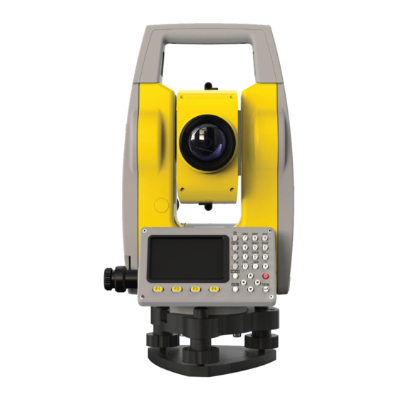
GeoMax Zoom10
User Manual
Version 1.0
English
Related Manuals for GeoMax Zoom10
Summary of Contents for GeoMax Zoom10
-
Page 1
GeoMax Zoom10 User Manual Version 1.0 English… -
Page 2
Product identification The model and serial number of your product are indicated on the type plate. Always refer to this information when you contact your agency or GeoMax authorised service workshop. Trademarks Windows is a registered trademark of Microsoft Corporation in the United States and other •… -
Page 3
NOTICE Removal of battery during operation or shutdown This can result in a file system error and data loss! 003577_001 Precautions: ▶ Do NOT remove the battery during operation of the instrument, or during the shutdown procedure. ▶ Always switch off the instrument by pressing the ON/OFF key, and wait until the instrument has shutdown completely before removing the battery. -
Page 4: Table Of Contents
Table of Contents Safety Directions General Definition of Use Limits of Use Responsibilities Hazards of Use Laser Classification 1.6.1 General 1.6.2 Distancer, Measurements with Reflectors 1.6.3 Distancer, Measurements without Reflectors (NP mode) 1.6.4 Laser Plummet Electromagnetic Compatibility (EMC) FCC Statement, Applicable in U.S. ISED Statement, Applicable in Canada Description of the System System Components…
-
Page 5
Selecting the Orientation 8.5.1 Overview 8.5.2 Manual Orientation 8.5.3 Orientation with Coordinates Application Input and Result Fields Surveying Stakeout Resection Tie Distance Area Remote Height COGO 9.8.1 Starting 9.8.2 COGO Calculation — Inverse Method 9.8.3 COGO Calculation — Traverse Method 9.8.4 COGO Calculation — Intersections 9.8.5… -
Page 6
14.5 Conformity to National Regulations 14.6 Scale Correction 14.7 Reduction Formulas Software Licence Agreement Appendix A Menu Tree Appendix B Glossary Table of Contents… -
Page 7: Safety Directions
Safety Directions General Description The following directions enable the person responsible for the product, and the person who actually uses the equipment, to anticipate and avoid operational hazards. The person responsible for the product must ensure that all users understand these directions and adhere to them.
-
Page 8: Limits Of Use
Responsibilities Manufacturer of the prod- GeoMax AG, CH-9443 Widnau, hereinafter referred to as GeoMax, is responsible for supplying the product, including the user manual and original accessories, in a safe condition. Person responsible for the…
-
Page 9
DANGER Risk of electrocution Because of the risk of electrocution, it is dangerous to use poles, levelling staffs and extensions in the vicinity of electrical installations such as power cables or electrical railways. Precautions: ▶ Keep at a safe distance from electrical installations. If it is essential to work in this environ- ment, first contact the safety authorities responsible for the electrical installations and fol- low their instructions. -
Page 10: Laser Classification
Always prevent access to the product by unauthorised personnel. Product-specific treatment and waste management information is available from GeoMax WARNING Only GeoMax authorised service workshops are entitled to repair these products. Laser Classification 1.6.1 General…
-
Page 11: Distancer, Measurements With Reflectors
☞ According to IEC TR 60825-14 (2004-02), products classified as laser class 1, class 2 and class 3R do not require: laser safety officer involvement, • protective clothes and eyewear, • special warning signs in the laser working area • if used and operated as defined in this User Manual due to the low eye hazard level.
-
Page 12
The laser product described in this section is classified as laser class 3R in accordance with: IEC 60825-1 (2014-05): “Safety of laser products” • Direct intrabeam viewing may be hazardous (low eye hazard level), in particular for deliberate ocular exposure. The beam may cause dazzle, flash-blindness and after-images, particularly under low ambient light conditions. -
Page 13: Laser Plummet
Locations of laser exit apertures Laser beam 19151_001 1.6.4 Laser Plummet General The laser plummet built into the product produces a visible red laser beam which emerges from the bottom of the product. The laser product described in this section is classified as laser class 2 in accordance with: IEC 60825-1 (2014-05): “Safety of laser products”…
-
Page 14: Electromagnetic Compatibility (Emc)
Although the product meets the strict regulations and standards which are in force in this respect, GeoMax cannot completely exclude the possibility that function of the product may be disturbed in such an electromagnetic environment.
-
Page 15: Fcc Statement, Applicable In U
CAUTION Changes or modifications not expressly approved by GeoMax for compliance could void the user’s authority to operate the equipment. Label placement on the…
-
Page 16: Ised Statement, Applicable In Canada
Label placement on the internal battery ZBA10 This device complies with part 15 of the FCC Rules. Operation is subject to the following two conditions: (1) This device may not cause harmful interference, and (2) this device must accept any interference received, including interference that may cause undesired operation.
-
Page 17: Description Of The System
Description of the System System Components Main Components Zoom10 instrument Computer with X-PAD soft- ware Data transfer 19235_001 Component Description Zoom10 instru- An instrument for measuring, calculating and capturing data. Ideally suited ment for tasks from simple surveys to complex applications.
-
Page 18: Instrument Components
Instrument Components Instrument components part 1 of 2 Optical sight Levelling bubble Ports for SD card and mini USB RS232C port Focusing telescope image Eyepiece; focusing graticule Clamping screw Vertical drive 18440_001 Instrument components part 2 of 2 Detachable carrying handle with mounting screw Battery cover Clamping screw…
-
Page 19: User Interface
User Interface Keyboard Alphanumeric keyboard a b c d _@& ± 18644_001 User Key2 Function keys F1 to F4 User Key1 MEAS key FNC key ESC key PAGE key LEFT/RIGHT, UP/DOWN arrow keys Alphanumeric keypad ENT key On/Off key Keys Description Editable fields: To enter text and numerical values.
-
Page 20: Screen
Description MEAS key. Functionality varies depending on key setting and screen context: Measure distance and save • Measure distance • None • LEFT/RIGHT, UP/DOWN arrow keys to navigate or to move cursor. ESC key. Quits a screen or edit mode without saving changes. Returns to next higher level.
-
Page 21: Softkeys
Icon Description Battery level running low. End operating and replace or charge the battery. Battery level is critically low. Instrument shuts down automatically within a few minutes. Compensator is on. Compensator is off. EDM setting Reflector is set to Prism. Mode for measuring to prisms. EDM setting Reflector is set to Non-Prism.
-
Page 22: Operating Principles
Description Clear To delete all characters in the field. Find To search for an entered point. View To display the coordinate and job details of the selected point. If more than one softkey level is available: To toggle through the softkey levels. Operating Principles Turn instrument on/off Use the On/Off key.
-
Page 23: Pointsearch
Selection by number In this example, pressing 2 on the alphanu- meric keypad opens the screen for setting the distance offset. Pointsearch Description Pointsearch is a function used by applications to find measured or fixed points in the memory storage. The pointsearch is limited to the current job.
-
Page 24: Operation
It is normal for the battery to become warm during charging. Using the chargers recom- • mended by GeoMax, it is not possible to charge the battery if the temperature is too high. For new batteries or batteries that have been stored for a long time (> three months), it is •…
-
Page 25
Loosen the clamping screws on the tripod legs, pull out to the required length and tighten the clamps. In order to guarantee a firm foothold sufficiently press the tripod legs into the ground. When pressing the legs into the ground note that the force must be applied along the legs. -
Page 26: Data Storage
To level the instrument precisely, use the elec- tronic level: Centre the electronic level of the first axis by • turning two footscrews. Centre the electronic level for the second • axis by turning the last footscrew. Accept with OK. •…
-
Page 27: Quick-Survey Application
Description of the Main Menu functions Function Description Q-Survey To start measuring immediately. Refer to «4.5 Quick-Survey Application». Program To select and start applications. Refer to «8 Applications — Getting Started». Manage To manage jobs, data, codelists, system memory and USB memory stick files.
-
Page 28
Set the station coordi- ☞ All measurements and coordinate computations are referenced to the set station nates (Q-Survey) coordinates. The station coordinates that are set must include: at least grid coordinates (E, N), and • the station height, if necessary. •… -
Page 29: Distance Measurements — Guidelines For Correct Results
Distance Measurements — Guidelines for Correct Results Description A laser distancer (EDM) is incorporated into the Zoom10 instruments. In all versions, the dis- tance can be determined by using a visible red laser beam which emerges coaxially from the telescope objective. There are two EDM modes:…
-
Page 30
NP measurements When a distance measurement is triggered, the EDM measures to the object which is in the • beam path at that moment. If a temporary obstruction, for example a passing vehicle, heavy rain, fog or snow is between the instrument and the point to be measured, the EDM may measure to the obstruction. -
Page 31: Settings
Settings General Settings Access Select Setting from the Main Menu. Select General from the Setting menu. Press the PAGE key to scroll through the screens of available settings. General settings Example: Screen 1/4 Reset To reset settings to the default values. To save changes and return to previous screen.
-
Page 32
Field Description V-Setting Sets the vertical angle Zenith Zenith=0°; Horizon=90°. Horiz.0 Zenith=270°; Horizon=0°. Vert.90 Zenith=90°; Horizon=0°. Vertical angles are positive above the horizon and neg- ative below it. Slope Zenith=45°=100%; Horizon=0°. Vertical angles are expressed in % with positive above Slope % the horizon and negative below it. -
Page 33: Edm Settings
Field Description ft-in1/8 US feet-inch-1/8 inch [ft]. Dist. Decimal Sets the number of decimal places shown for all distance fields. This set- ting is for data display and does not apply to data export or storage. Distance with three decimals. Distance with four decimals.
-
Page 34
EDM Setting Softkey level 1: ATOMS To enter atmospheric data ppm. Pointer To switch the laser pointer on or off. To save changes and return to previous screen. Softkey level 2: Grid To enter scale and altitude for scale cor- rection. -
Page 35
Allowed range is 500h PA to 1400h PA. The atmospheric correction parameter is calculated based on the entered temperature and pressure values. ☞ When PPM = 0 is selected, the GeoMax standard atmosphere of 1013 hPa, 12°C, and 60% relative humidity is applied. Refraction 0.00, 0.14, 0.20… -
Page 36: Tools
Tools Adjust Description The Tools menu contains tools to be used for the electronic calibration of the instrument. Using these tools helps to maintain the measuring accuracy of the instrument. Select Tools from the Main Menu. Select Adjust from the Tools menu. For detailed information on calibration options, refer to «12 Check &…
-
Page 37: Functions
Functions Overview Description Functions can be accessed by pressing FNC from any measurement screen. FNC opens the func- tions menu and a function can be selected and activated. Functions Function Description Level Activates the laser plummet and electronic level. Refer to «Elec- tronic level and laser plummet».
-
Page 38: Cylindrical Offset
T_Off — L_Off+ L_Off — T_Off+ Measurement point Calculated offset point L_Off+ Length offset, positive L_Off- Length offset, negative T_Off+ Cross offset, positive T_Off- Cross offset, negative 18741_001 Access Press FNC. Select Offset from the functions menu. Distance offset Reset To reset settings to the default values.
-
Page 39
α TSOX_023 Instrument station Centre point of cylindrical object Horizontal angle to a point on the left side of the object Horizontal angle to a point on the right side of the object Distance to the object in the middle between Hz1 and Hz2 Radius of cylinder Azimuth from Hz1 to Hz2 Access… -
Page 40: Angle Offset
Next step Press DONE to return to the previous screen. • Or, press New to continue measuring with the Cylinder Offset function. • 7.2.3 Angle Offset Description This function calculates the target point coordinates if it is not possible to set up the reflector, or to aim at the target point directly.
-
Page 41: Height Transfer
Next step Press DONE to return to the previous screen. • Or, press New to continue measuring with the Angle Offset function. • Height Transfer Description Height transfer is a method for setting up a station. The station is known, a new station height must be computed.
-
Page 42: Hidden Point
Search for a point Enter a point ID. • Press Find to check if a point with this point ID exists. • If there are several points, press the UP/DOWN keys to select a point. • If no point with this point ID exists, enter or measure the coordinates of the point.
-
Page 43: Coding
Access Press FNC. Press the PAGE key to display the second screen. Select Hidden Point from the functions menu. Hidden Point ROD/ED To enter the details of the measuring rod. To enter the details of the measuring rod, press ROD/ED. Rod length: Total length of hidden point rod.
-
Page 44
Select a code from code library Find To search for a code. To enter a new code. To add the data of the currently selected code to the job without linking the code to any measured point. To apply the selected code and return to the currently active application. -
Page 45: Applications — Getting Started
Applications — Getting Started Overview Description Applications are predefined programs, that cover a wide spectrum of surveying duties and facili- tate daily work in the field. The following applications are available: Surveying • Free Station • Tie Distance • Area •…
-
Page 46
Set Job List To display the list of available jobs. To create a job. To confirm the selected job and return to the pre-settings screen. Field Description Name of an existing job to be used. Operator Name of user, if entered. Date Date the selected job was created. -
Page 47: Selecting The Station
Back To go back without saving the entered job data. To save the entered job data and return to the pre-settings screen. The new job is set as current job. Recorded data Once a job is set up, all subsequent recorded data will be stored in this job. If no job was defined and an application was started and a measurement was recorded, then the system automatically creates a new job and names it «DEFAULT».
-
Page 48: Selecting The Orientation
There are several options to set the station coordinates: To search for an existing point, enter a point ID and press Find (refer to «3.6 Pointsearch»). • Select a point from the search result list. Press OK to confirm. To select an existing point, press List. •…
-
Page 49: Orientation With Coordinates
Field Description Azimuth Horizontal direction of the station T.H. Reflector height BS PT Point ID of the backsight point Step by step Aim at the backsight point. Set the orientation by one of the following options: Manually enter the azimuth, reflector height and name of the backsight point. •…
-
Page 50
Measure the backsight point Once the coordinates are set, the «Meas. BS» screen is displayed. To change the EDM settings. Aim at the backsight point and press the ENT key. Set the azimuth by one of the following options: To measure and check the azimuth, press DIST. •… -
Page 51: Application
Application Input and Result Fields Description of fields The following table describes the input and result fields that are found within the firmware appli- cations. These fields are described here once and not repeated in the application chapters. Field Description Application Area Calculated result of polygonal area between the…
-
Page 52
Field Description Application Line Longitudinal offset of the first reference point (P3) Reference Line of the reference line in the direction of the second base point (P2). Positive values are toward the second base point D Line Calculated distance from start point along the ref- Reference Arc erence arc. -
Page 53
Field Description Application Perpendicular offset: Positive if stakeout point is to Reference Line the right of the reference line. DTrav. Perpendicular offset: Stakeout Positive if stakeout point is to the left of the meas- ured point. (←) Negative if stakeout point is to the right of the measured point. -
Page 54: Surveying
Surveying Description Surveying is an application used for the measurement of an unlimited number of points. It is comparable to Q-Survey from the start screen, but data is recorded and it includes pre-settings for the job, station and orientation prior to beginning a survey. Access Select Program (2) from the Main Menu.
-
Page 55
Polar Stakeout mode Instrument station Current position Point to be staked : Difference in horizontal dis- tance DHZ: Difference in direction : Difference in height TSOX_027 Orthogonal to Station Stakeout mode Instrument station Current position Point to be staked DLength: Difference in longitudi- nal distance DTrav.: Difference in perpendicu- lar distance… -
Page 56: Resection
Access Select Program (2) from the Main Menu. Select Stakeout (2) from the Program menu. Complete application pre-settings. Refer to «8 Applications — Getting Started». Select Start to open the application. Stakeout screens Polar Stakeout mode (page 1/3): Softkey level 2 Coord.
-
Page 57
Access Select Program (2) from the Main Menu. Select Resection (3) from the Program menu. Complete application pre-settings. Set Job: refer to «8.3 Selecting the Job». Set Error Limits: refer to «Set error limits». Select Start to open the application. Set error limits Status To activate or deactivate the error limits, press the LEFT/RIGHT keys. -
Page 58: Tie Distance
Result screen Errors To display the standard deviation. Step-by-step To measure another target point, press Back. • To display the standard deviation, press Errors. • To set the station and exit the application, press OK. Tie Distance Description Tie Distance is an application used to compute slope distance, horizontal distance, height differ- ence and azimuth of two target points which are either measured, selected from the memory, or entered using the keypad.
-
Page 59
Access Select Program (2) from the Main Menu. Select Tie Distance (4) from the Program menu. Complete application pre-settings. Refer to «8 Applications — Getting Started». Select Start to open the application. Select Polygonal (1) or Radial (2). Polygonal method Measure target points Aim at the first target point. -
Page 60: Area
Area Description Area is an application used to calculate polygonal areas to a maximum of 20 points connected by straights. The target points have to be measured, selected from memory, or entered manually in a clockwise direction. The calculated area is projected onto the horizontal plane (2D). Instrument station Start point P2-4…
-
Page 61: Remote Height
Result screen To define a new area. Area Graph To display the area graph. Add PT To add a new target point to the existing area. ☞ Perimeter are updated if further area points are added. Remote Height Description Remote Height is an application used to compute points directly above the base prism without a prism at the target point.
-
Page 62: Cogo
☞ To determine an unknown reflector height, press F4 and then H. T.?. Aim at the bottom of the reflector rod. • To start measuring and save the measured values, press ALL or DIST+REC. • Aim at the reflector. • To determine the reflector height, press OK.
-
Page 63: Cogo Calculation — Traverse Method
Inverse Meas. To measure the known point. Result To calculate and display the result. Step-by-Step Set the two known points. To calculate and display the Inverse result, press Result. To save the result, press REC. 9.8.3 COGO Calculation — Traverse Method Access Select Traverse&Inverse (1) from the COGO menu.
-
Page 64: Cogo Calculation — Intersections
Step-by-Step Set the known point. There are several options to set a known point: To measure the known point, enter a point ID and press Meas.. • Enter the reflector height. To start measuring and save the measured values, press ALL or DIST+REC. To search for an existing point, enter a point ID and press Find (refer to «3.6 •…
-
Page 65
Set the second known point. Enter the bearing of the second known point. To calculate the intersection point and display the result, press Result. To save the new point, enter a point ID and press REC. Bearing — Distance Use the BRG-DST subapplication to calculate the intersection point of a line and a circle. The line is defined by a point and a direction. -
Page 66
Distance — Distance Use the DST-DST subapplication to calculate the intersection point of two circles. The circles are defined by the known point as the centre point and the distance from the known point to the COGO point as the radius. As a result, there may be none, one or two intersection points. Known First known point Second known point… -
Page 67: Cogo Calculation — Offsets
Meas. To measure the known point. Result To calculate and display the result. Step-by-Step Set all known points. To calculate the intersection point and display the result, press Result. To save the intersection point, enter a point ID and press REC. 9.8.5 COGO Calculation — Offsets Access…
-
Page 68: Cogo Calculation — Extension Method
Step-by-Step Set the start and end point of the baseline as well as the offset point. To calculate the base point and display the result, press Result. To save the base point, enter a point ID and press REC. Set Point Use the Set Pt subapplication to calculate the coordinates of a new point in relation to a baseline from known longitudinal and offset distances.
-
Page 69: Road
Description Use the Extension subapplication to calculate the extended point from a known base line. Known Start point of baseline End point of baseline Δ L1 Base point for extension Distance P1 to P2 Δ L2 DL1, Extension distance P3 to P4 Unknown TSOX_107 Extended COGO points…
-
Page 70: Horizontal Curve Definition
Manage road files Delete To delete selected road file. To create a road. Close To close currently open road file. Open To open selected road file. Field Description Current Displays name of the currently used/open road file. ☞ To delete the currently used road file, you need to close it first. 9.9.3 Horizontal Curve Definition Description…
-
Page 71
Element Description Start point Negative radius for anti- clockwise direction Positive radius for clockwise direction Arc length 18900_001 Intersection method A horizontal curve can also be defined by entering the intersection point of the curve tangents, the curve radius and the two parameters A1 and A2. The values for radius, A1 and A2 should not be negative. -
Page 72: Vertical Curve Definition
To add a straight line. To add a circular curve. TRNS To add a transition curve. To add a curve using the intersec- tion method. Step-by-Step ☞ When accessing HC list from Road menu, the currently defined road elements are displayed in the «HC list»…
-
Page 73
18912_001 Start point P1, P2, P3 Intersection points Last intersection point Elevation C1, C2, C3, Chainage of respective intersection point L1, L2, L3 Curve length of respective intersection point Access Select Vert. curve list (3) from the Road menu. Define a vertical curve «Vert. -
Page 74: Road Stakeout
«Vert. curve list» screen To select a point, press the UP/DOWN keys. • To view details of the selected point, press View. • To return to the «Vert. curve list» screen, press the ESC key. To edit the data of the selected point, press Edit. To view details of the previous point, press PREV.
-
Page 75
Road stakeout screens As for point stakeout, there are three stakeout modes available. To select the desired stakeout mode, press the PAGE key. Polar Stakeout mode: Orthogonal to Station Stakeout mode: Cartesian Stakeout mode: Road stakeout step-by- ☞ When no stakeout data has been saved before in the current road file, you need to step define the road parameters first. -
Page 76: Stakeout Reference Element
9.10 Stakeout Reference Element 9.10.1 Overview Access Select Program (2) from the Main Menu. Press the PAGE key to display screen 3. Select Reference Element (9) from the Program menu. Complete application pre-settings. Refer to «8 Applications — Getting Started». To display the Reference Element menu, select Start.
-
Page 77
Define the baseline The baseline is fixed by two base points. All points can be either measured, manually entered, or selected from the memory. Defining the baseline Set the first base point. Next step Define the reference line. Define the reference line The baseline can be offset from, either longitudinally, in parallel or vertically, or be rotated around the first base point. -
Page 78
Field Description Ref.Hgt Select an option: • Height differences are computed relative to the height of the first refer- ence point. • Height differences are computed relative to the height of the second refer- ence point. Equal • Height differences are computed along the reference line. None •… -
Page 79
Staking out a grid point To select a grid point, select «Offset» or «chainage» and use the LEFT/RIGHT keys. To select the desired stakeout mode, press the PAGE key. For Polar Stakeout mode, display screen 1/2. • For Orthogonal to Station Stakeout mode, display screen 2/2. •… -
Page 80
Use the UP/DOWN keys to select an editable field. Enter the necessary offset parameters. The software calculates the resulting point coordinates. To start staking the calculated point, press OK. Staking out the calculated point To select the desired stakeout mode, press the PAGE key. For Polar Stakeout mode, display screen 1/2. -
Page 81: Reference Arc
☞ For a detailed description of stakeout modes, refer to «9.3 Stakeout». Polar Stakeout mode Orthogonal to Station Stakeout mode 9.10.3 Reference Arc Description RefArc is an application that allows the user to define a reference arc and then measure line and offset of a point with respect to that arc.
-
Page 82
Define arc by centre and start point Defining the reference arc by centre and start point After starting the RefArc application, choose the method for defining the reference arc. Select Centre, Start Point (1). Set the centre point. Set the start point of the arc in the same way. ☞… -
Page 83
Measure Line&Offset The Measure Line&Offset subapplication calculates longitudinal offsets, parallel offsets and height differences of a measured or stored target point relative to the reference arc. Set the target point. After setting the target point, offsets and height difference are calculated. Application… -
Page 84: Data Management
Data Management 10.1 Overview Access Select Manage (3) from the Main Menu. To select an application in the Manage menu, press a function key, F1 — F4. To toggle through the available screens, press the PAGE key. To manage jobs, select Job (1). Refer to «10.2 Managing Jobs». •…
-
Page 85: Managing Jobs
10.2 Managing Jobs Select, create or delete jobs Delete To delete the selected job. To confirm deletion press Yes. To create a job. View To view the details of the selected job. To set the selected job as the active job and return to the Main Menu.
-
Page 86: Managing Codes
Search results Delete To delete measurement data. Search To display the search mode screen. 10.5 Managing Codes View, create or delete codes Find To search for a code. To enter a new code. Delete To delete the selected code. 10.6 Managing Memory Space View memory space or format memory…
-
Page 87: Data Transfer
Data Transfer 11.1 Overview Access Select Transfer (4) from the Main Menu. To select an application in the Transfer menu, press a function key, F1 or F2. To open the Import menu, select Import (1). Refer to «11.2 Importing Data». •…
-
Page 88: Exporting Data
RS232C port To select the target job. Import To start the import process. USB port To select the target job. Source To select the data file to be imported. Import To start the import process. Importing code data You can import code data to the internal memory using the RS232C port only. To import code data, select Code Data (2) from the Import menu.
-
Page 89: Working With X-Pad
Description The software X-Pad is used for the data exchange between the instrument and a computer. It contains several auxiliary programs in order to support the instrument. ☞ For more information about X-Pad, contact your GeoMax AG representative. Data Transfer…
-
Page 90: Check & Adjust
Overview Description GeoMax instruments are manufactured, assembled and adjusted to a high quality. Quick temper- ature changes, shock or stress can cause deviations and decrease the instrument accuracy. It is therefore recommended to calibrate the instrument from time to time. This can be done in the field by running through specific measurement procedures.
-
Page 91: Adjust Index Error
Menu selection Description Const. Setting Allows to set the values for additive and multiplying constant. Factory set- Allows to reset all instrument settings to the factory default. tings 12.4 Adjust Index Error Vertical index error The vertical circle should read exactly 90° (100 gon) when the line of sight is horizontal. Any deviation from this figure is termed vertical index error.
-
Page 92: Adjust Tilt X / Tilt Y
12.5 Adjust Tilt X / Tilt Y Adjust tilt X or tilt Y Select the respective option in the Adjust menu. Follow the on-screen instructions for adjusting the x-direction or y-direction of the vertical compensator axis. ☞ If the absolute value of the linear coefficient (CoK) is greater than 1.5, recalibrate the compensator.
-
Page 93: Care And Transport
For products for which no container is available use the original packaging or its equivalent. Shipping When transporting the product by rail, air or sea, always use the complete original GeoMax pack- aging, transport container and cardboard box, or its equivalent, to protect against shock and vibration.
-
Page 94
Cables and plugs Keep plugs clean and dry. Blow away any dirt lodged in the plugs of the connecting cables. Care and Transport… -
Page 95: Technical Data
Technical Data 14.1 General Technical Data of the Product Telescope Magnification: Field of View: 1°20′ (2.3 m at 100 m) Minimum Focusing Distance: 1.5 m Reticle: Illuminated Compensator System: Dual-axis ±3′ Working Range: Setting Accuracy: Communication Interface: Standard RS232 • SD card * •…
-
Page 96: Angle Measurement
Centring Accuracy: 1 mm at 1.5 m instrument height. Power supply Battery Type: Rechargeable Li-Ion battery Voltage/Capacity: ZBA10: 7.4 V DC/3000 mAh Operating time with ZBA10: 16 h * (optimal) — continuous angle measurement every 30 s 10 h (typical) Measuring times: About 12000 times New battery at 25°C, 24 h continuously angle measurement mode…
-
Page 97: Conformity To National Regulations
FCC Part 15, 22 and 24 (applicable in US) • regulations Hereby, GeoMax AG declares that the radio equipment type Zoom10 is in compliance • with Directive 2014/53/EU and other applicable European Directives. The full text of the EU declaration of conformity is available at the following Internet address: http://www.geomax-positioning.com/Downloads.htm.
-
Page 98
550 mb 10001050 mb 50°C 50°C 40°C 40°C 30°C 30°C 20°C 20°C 10°C 10°C 0°C 0°C -10°C -10°C -20°C -20°C 550 mb 950 10001050 mb 5000 m4500 40003500 3000 2500 2000 1500 1000 Atmospheric correction °F Atmospheric corrections in ppm with temperature [°F], air pressure [inch Hg] and height [ft] at 60 % relative humidity. -
Page 99: Reduction Formulas
14.7 Reduction Formulas Formulas Mean Sea Level Instrument Reflector Slope distance Horizontal distance Height difference The instrument calculates the slope distance, horizontal distance, and height difference in accordance with the following formulas. Earth curvature (1/R) and mean refraction coefficient (k = 0.13) are automatically taken into account when calculating the horizontal distance and height difference.
-
Page 100
SD * cosζ (1 — k)/2R = 6.83 * 10 -8 [m -1 ] ζ = Vertical circle reading k = 0.13 (mean refraction coefficient) R = 6.378 * 10 6 m (radius of the earth) Technical Data… -
Page 101: Software Licence Agreement
GeoMax. Such software is protected by copyright and other laws and its use is defined and regulated by the GeoMax Software Licence Agreement, which covers aspects such as, but not limited to, Scope of the Licence, Warranty, Intellectual Property Rights, Limitation of Liability, Exclusion of other Assurances, Governing Law and Place of Jurisdiction.
-
Page 102
Appendix A Menu Tree ☞ Depending on local firmware versions the menu items may differ. Menu Tree |—|Q-Survey |—|Program |—|—|Surveying |—|—|Stakeout |—|—|Resection |—|—|Tie Distance |—|—|Area |—|—|Remote Height |—|—|COGO |—|—|Road |—|—|Reference Element |—|Manage |—|—|Job |—|—|Fix Pt. |—|—|Meas. PT |—|—|Code |—|—|Mem. Stat. |—|Transfer |—|—|Import Data |—|—|Export Data… -
Page 103: Appendix B Glossary
Appendix B Glossary Instrument axis = Line of sight / collimation axis Telescope axis = line from the cross hairs to the center of the objective. = Standing axis Vertical rotation axis of the telescope. = Tilting axis Horizontal rotation axis of the telescope.
-
Page 104
Zenith Point on the plumb line above the observer. Crosshairs Glass plate within the telescope with reticle. Line-of-sight error (hori- The line-of-sight error (c) is the deviation from the per- zontal collimation) pendicular between the tilting axis and line of sight. This could be eliminated by measuring in both faces. -
Page 106
879542-1.0.0en Original text © 2019 GeoMax AG, Widnau, Switzerland GeoMax AG www.geomax-positioning.com…
|
Detail Specifications: 1746/1746120-zoom10.pdf file (13 Oct 2022) |
Accompanying Data:
GeoMax Zoom10 Laser Level, Measuring Instruments PDF Operation & User’s Manual (Updated: Thursday 13th of October 2022 10:38:10 AM)
Rating: 4.6 (rated by 63 users)
Compatible devices: ZEL400H+, Zenius5 Series, Zoom 75 Series, Zeta125, Zone80 DG, ZDL700 Series, ZONE60 HG, Zipp20 series.
Recommended Documentation:
Text Version of Operation & User’s Manual
(Ocr-Read Summary of Contents, UPD: 13 October 2022)
-
30, GeoMax Zoom10 • When a distance measurement is triggered, the EDM measures to the object which is in the beam path at that moment. If a temporary obstruction, for example a passing vehicle, heavy rain, fog or snow is between the instrument and the point to be measured, the EDM may measure to the obstruction. • Be sure that the laser beam is not reflected by anything close t…
-
14, 19154-001 b a a Laser beam b Laser exit aperture 1.7 Electromagnetic Compatibility (EMC) The term Electromagnetic Compatibility is taken to mean the capability of the product to function smoothly in an environment where electromagnetic radiation and electrostatic discharges are present, and without causing electromagnetic disturbances to other equipment. WARNING Electromagnetic r…
-
40, GeoMax Zoom10 Next step • Press DONE to return to the previous screen. • Or, press New to continue measuring with the Cylinder Offset function. 7.2.3 Angle Offset This function calculates the target point coordinates if it is not possible to set up the reflector, or to aim at the target point directly. The target point and the measurement point must have the same distan…
-
10, GeoMax Zoom10 WARNING Inappropriate mechanical influences to batteries During the transport, shipping or disposal of batteries it is possible for inappropriate mechanical influences to constitute a fire hazard. Precautions: ▶ Before shipping the product or disposing it, discharge the batteries by the product until they are flat. ▶ When transporting or shipping batteries, the person in charge of th…
-
78, GeoMax Zoom10 Field Description Ref.Hgt Select an option: • PT1 Height differences are computed relative to the height of the first refer- ence point. • PT2 Height differences are computed relative to the height of the second refer- ence point. • Equal Height differences are computed along the reference line. • None Height differences are not computed or shown. Defining the reference line 1. Use the UP/…
-
63, Meas. To measure the known point. Result To calculate and display the result. Step-by-Step 1. Set the two known points. 2. To calculate and display the Inverse result, press Result. 3. To save the result, press REC. 9.8.3 COGO Calculation — Traverse Method 1. Select Traverse&Inverse (1) from the COGO menu. 2. Select Traverse (2). Use the Traverse subapplication to calculate the position o…
-
67, Meas. To measure the known point. Result To calculate and display the result. Step-by-Step 1. Set all known points. 2. To calculate the intersection point and display the result, press Result. 3. To save the intersection point, enter a point ID and press REC. 9.8.5 COGO Calculation — Offsets 1. Select Offsets (3) from the COGO menu. 2. Select an offset method: • DistOff (1). Refer to «Dis…
-
21, Icon Description Battery level running low. End operating and replace or charge the battery. Battery level is critically low. Instrument shuts down automatically within a few minutes. Compensator is on. Compensator is off. EDM setting Reflector is set to Prism. Mode for measuring to prisms. EDM setting Reflector is set to Non-Prism. Mode for measuring to all targets. EDM settin…
-
87, 11 Data Transfer 11.1 Overview 1. Select Transfer (4) from the Main Menu. 2. To select an application in the Transfer menu, press a function key, F1 or F2. • To open the Import menu, select Import (1). Refer to «11.2 Importing Data». • To open the Export menu, select Export (2). Refer to «11.3 Exporting Data». The Transfer function allows dat…
-
100, X SD * cosζ B (1 — k)/2R = 6.83 * 10 -8 [m -1 ] ζ = Vertical circle reading k = 0.13 (mean refraction coefficient) R = 6.378 * 10 6 m (radius of the earth) 100 Technical Data
… -
97, Reflectorless Range * : 350 m Accuracy: 3 mm + 2 ppm Measuring time: 1.5 s * Calculated by Kodak Gray Card white side (90% reflective), exact distance depends on meas- uring object, observation and environment conditions. 14.5 Conformity to National Regulations • FCC Part 15, 22 and 24 (applicable in US) • Hereby, GeoMax AG declares that the radio equipment type Zoom10 is in compliance with D…
-
66, Use the DST-DST subapplication to calculate the intersection point of two circles. The circles are defined by the known point as the centre point and the distance from the known point to the COGO point as the radius. As a result, there may be none, one or two intersection points. TSOX_102 r1 r2 P1 P2 P3 P4 Known P1 First known point P2 Second known point r1 R…
Recommended Instructions:
F57B, 67600 — Big Mouth Juice Extractor, 917.273663, VINO2500SSD


-
© 2003 Siemens Energy & Automation. All rights reserved. The information in this document is believed to be accurate at the time of publication, however, Siemens Energy & Automation assumes no responsibility for errors which mayappear here and reserves the right to make changes without notice. ION is a registered trademark of Power Measurement Ltd. All other trademarks …
9200 5
-
Analyze •Detect•Measure •Control™Orion AplusBenchtop pH and pH/ISE MetersINSTRUCTION MANUALyesno1st2nd4holdincr tech1mode2calibratecal edit5resolutionchannel6slopeelectrodeID3measurestability+ -date/timebeep7printdata logmV8activateset timer0standbyoptionsdata/printmodesalarm9set tempready.Orion 920A+advanced ISE/pH/mV/ORPOrion 410A+, 420A+,520A+, 525A+,710A+, 720A+,920A+™ …
Orion Aplus Series 131
-
Installation and User Guide Instalación y Guía de Usuario Installations-und BenutzerhandbuchInstallation et Guide de l’Utilisateur Installasjons- og brukerveiledningManual do utilizador e instalaçãoInstallation och bruksanvisningGuida per l’installazione e l’usoInstallatie en gebruikershandleiding Power Boost 2-2728-5354-7980-105106-131132-157158-183 …
Power Boost 236
-
Model 3503A112KG TRIAXIAL HIGH AMPLITUDE MEMS SHOCK ACCELEROMETER Installation and Operating Manual For assistance with the operation of this product,contact the PCB Piezotronics, Inc. Toll-free: 716-684-000124-hour SensorLine: 716-684-0001Fax: 716-684-0987E-mail: [email protected]: www.pcb.com …
3503A112KG 11
Additional Information:
Popular Right Now:
Operating Impressions, Questions and Answers:
Приборы для геодезических измерений от компании GeoMax завоёвывают популярность на российском рынке. В продаже есть большой выбор моделей тахеометров: от простых бюджетных вариантов до сложных инженерных версий с операционными системами. Операторам приборов требуется инструкция для тахеометра GeoMax на русском языке. Здесь вы скачаете бесплатную электронную версию в удобном для чтения формате.
Теперь вам не нужно собирать по крупицам информацию о работе оборудования. Для работы со сложным инженерным прибором необходима проверенная информация от производителя. Различные сомнительные переводы и версии от других брендов в лучшем случае приведут к невозможности использования всех функций прибора по максимуму, а в худшем – к травмам персонала и поломкам дорогой техники.
Полезная инструкция к тахеометру GeoMax обязательна для ознакомления перед первым использованием инструмента. Также подробные рекомендации производителя пригодятся в процессе работы. Вы узнаете важные сведения по технике безопасности, получите навыки правильной установки и настройки прибора, узнаете о специфических функциях тахеометра конкретной модели.
Изучение данных, которые содержит инструкция по эксплуатации тахеометра GeoMax, гарантирует точные измерения, заявленные производителем. В каждом документе обязательно указана серия и модель прибора, для которого подходит мануал, и описаны все возможности устройства. Кроме того, здесь содержатся полезные приложения для хранения данных проектов, словарь, сведения о правильных способах транспортировки и хранения инструмента.
Скачайте руководство пользователя для тахеометра GeoMax и используйте документ на флэш-карте или храните данные в ПК. Это удобный вариант, который поможет вам избежать потерь бумажных версий. Если вам больше подходит печатный вариант, то скачайте инструкцию и распечатайте в нужном количестве экземпляров.
Добро пожаловать!
Войдите или зарегистрируйтесь сейчас!
Войти
Geomax Zoom 10 2″ поверки юстировки
Тема в разделе «GeoMax», создана пользователем Roman27, 8 окт 2022.
Fast Quotes
-
 Roman27
- Регистрация:
- 29 сен 2021
- Сообщения:
- 3
- Симпатии:
- 0
Всем привет. Столкнулся с такой проблемой поверка и юстировка тахеометра Geomax Zoom 10 2″. Не могу разобраться в интерфейсе. Как выполнить поверку коллимации и место нуля.
#1
Roman27,
8 окт 2022
-
avianvvКуратор
- Регистрация:
- 28 янв 2021
- Сообщения:
- 913
- Симпатии:
- 406
https://www.google.com/url?sa=t&sou…sQFnoECA8QAQ&usg=AOvVaw1RAZ5kgy-lMIqwIBB9WknZ вот в этой инструкции на страницах 67-68 описано всё. Причём достаточно подробно.
#2
avianvv,
9 окт 2022
alek4mac и zvezdochiot нравится это.
-
SergeichФорумчанин
- Регистрация:
- 21 июл 2010
- Сообщения:
- 358
- Симпатии:
- 128
- Адрес:
-
Москва
avianvv, это инструкция к другим моделям тахеометров.
Во вложении инструкция к Zoom10. Поверки и юстировки с 89 страницы.Вложения:
-
GeoMax_Zoom10_UM_v1-0-0_ru.pdf
- Размер файла:
- 5,1 МБ
- Просмотров:
- 12
#3
Sergeich,
11 окт 2022
avianvv нравится это.
-
Roman27- Регистрация:
- 29 сен 2021
- Сообщения:
- 3
- Симпатии:
- 0
Спасибо за ответы. Но всё таки непонятно как выполняется поверка оси наклона X или Y. При быстрой калибровки компенсатор выгоняю в 0. Захожу в поверку ось наклона Y. Там идёт отклонение 15. По X 0. При выполнении поверки Тах пишет наведитесь F1 верх потом F2 низ потом верх и опять низ. Непонятно куда наводится верх куда низ при этом не отображается измерение F1 и F2 только кнопка ок работает.
#4
Roman27,
11 окт 2022
-
avianvvКуратор
- Регистрация:
- 28 янв 2021
- Сообщения:
- 913
- Симпатии:
- 406
Судя по описанию — поверка неравенства колонок это.
#5
avianvv,
11 окт 2022
-
Roman27- Регистрация:
- 29 сен 2021
- Сообщения:
- 3
- Симпатии:
- 0
Спасибо попробую.
#6
Roman27,
11 окт 2022
-
avianvvКуратор
- Регистрация:
- 28 янв 2021
- Сообщения:
- 913
- Симпатии:
- 406
Возможно. Я всего-то загуглил инструкцию к прибору. Я с Zoom 10 не имел дела довольно давно. Надеюсь что Ваша инструкция к правильному прибору. Я правильно понял, что Вы работаете в Максима-Гео?
#7
avianvv,
11 окт 2022
-
SergeichФорумчанин
- Регистрация:
- 21 июл 2010
- Сообщения:
- 358
- Симпатии:
- 128
- Адрес:
-
Москва
Правильно поняли.
#8
Sergeich,
17 окт 2022
avianvv нравится это.

(Вы должны войти или зарегистрироваться, чтобы ответить.)
Поделиться этой страницей
- Войти через Google
- Log in with VK
- Ваше имя или e-mail:
- У Вас уже есть учётная запись?
-
- Нет, зарегистрироваться сейчас.
- Да, мой пароль:
-
Забыли пароль?
-
Запомнить меня
-
Этот сайт использует файлы cookie. Продолжая пользоваться данным сайтом, Вы соглашаетесь на использование нами Ваших файлов cookie.Accept
Узнать больше.Скрыть объявление