- Manuals
- Brands
- Perkins Manuals
- Engine
- 1104
Manuals and User Guides for Perkins 1104. We have 5 Perkins 1104 manuals available for free PDF download: Disassembly And Assembly, Operation And Maintenance Manual, Workshop Manual
![]()
SEBU9066
March 2014
Operation and
Maintenance
Manual
1104D-E44T and 1104D-E44TA Industrial Engines
NP (Engine)
NR (Engine)

Important Safety Information
Most accidents that involve product operation, maintenance and repair are caused by failure to observe basic safety rules or precautions. An accident can often be avoided by recognizing potentially hazardous situations before an accident occurs. A person must be alert to potential hazards. This person should also have the necessary training, skills and tools to perform these functions properly.
Improper operation, lubrication, maintenance or repair of this product can be dangerous and could result in injury or death.
Do not operate or perform any lubrication, maintenance or repair on this product, until you have read and understood the operation, lubrication, maintenance and repair information.
Safety precautions and warnings are provided in this manual and on the product. If these hazard warnings are not heeded, bodily injury or death could occur to you or to other persons.
The hazards are identified by the “Safety Alert Symbol” and followed by a “Signal Word” such as “DANGER”, “WARNING” or “CAUTION”. The Safety Alert “WARNING” label is shown below.
The meaning of this safety alert symbol is as follows:
Attention! Become Alert! Your Safety is Involved.
The message that appears under the warning explains the hazard and can be either written or pictorially presented.
Operations that may cause product damage are identified by “NOTICE” labels on the product and in this publication.
Perkins cannot anticipate every possible circumstance that might involve a potential hazard. The warnings in this publication and on the product are, therefore, not all inclusive. If a tool, procedure, work method or operating technique that is not specifically recommended by Perkins is used,
you must satisfy yourself that it is safe for you and for others. You should also ensure that the product will not be damaged or be made unsafe by the operation, lubrication, maintenance or repair procedures that you choose.
The information, specifications, and illustrations in this publication are on the basis of information that was available at the time that the publication was written. The specifications, torques, pressures, measurements, adjustments, illustrations, and other items can change at any time. These changes can affect the service that is given to the product. Obtain the complete and most current information before you start any job. Perkins dealers or Perkins distributors have the most current information available.
When replacement parts are required for this product Perkins recommends using Perkins replacement parts.
Failure to heed this warning can lead to premature failures, product damage, personal injury or death.

|
Table of Contents |
|
|
Foreword………………………… ……………………….. |
4 |
|
Safety Section |
|
|
Safety Messages………………….. ………………….. |
5 |
|
General Hazard Information…………… ………….. |
7 |
|
Burn Prevention…………………… …………………… |
8 |
|
Fire Prevention and Explosion Prevention …. … |
9 |
|
Crushing Prevention and Cutting Prevention . . |
11 |
|
Mounting and Dismounting…………… …………… |
11 |
|
High Pressure Fuel Lines ……………. ……………. |
11 |
|
Before Starting Engine …………….. ……………… |
13 |
|
Engine Starting…………………… ………………….. |
13 |
|
Engine Stopping ………………….. …………………. |
14 |
|
Electrical System…………………. …………………. |
14 |
|
Engine Electronics………………… ………………… |
15 |
|
Product Information Section |
|
|
General Information……………….. ……………….. |
16 |
|
Product Identification Information………. ……… |
22 |
|
Operation Section |
|
|
Lifting and Storage………………… ………………… |
24 |
|
Features and Controls……………… ……………… |
26 |
|
Engine Diagnostics………………… ……………….. |
37 |
|
Engine Starting…………………… ………………….. |
44 |
|
Engine Operation…………………. …………………. |
47 |
|
Cold Weather Operation…………….. ……………. |
48 |
|
Engine Stopping ………………….. …………………. |
52 |
|
Maintenance Section |
|
|
Refill Capacities………………….. ………………….. |
54 |
|
Maintenance Recommendations………. ………. |
67 |
|
Maintenance Interval Schedule……….. ……….. |
69 |
|
Warranty Section |
|
|
Warranty Information……………… ……………… |
100 |
|
Reference Information Section |
|
|
Reference Materials ……………… ………………. |
101 |
|
Index Section |
|
|
Index…………………………. ………………………… |
102 |

4
Foreword
Foreword
Literature Information
This manual contains safety, operation instructions,
lubrication and maintenance information. This manual should be stored in or near the engine area in a
literature holder or literature storage area. Read, study and keep it with the literature and engine information.
English is the primary language for all Perkins publications. The English used facilitates translation and consistency.
Some photographs or illustrations in this manual show details or attachments that may be different from your engine. Guards and covers may have been removed for illustrative purposes. Continuing improvement and advancement of product design may have caused changes to your engine which are not included in this manual. Whenever a question arises regarding your engine, or this manual, please consult with your Perkins dealer or your Perkins distributor for the latest available information.
Safety
This safety section lists basic safety precautions. In addition, this section identifies hazardous, warning
situations. Read and understand the basic precautions listed in the safety section before
operating or performing lubrication, maintenance and repair on this product.
Operation
Operating techniques outlined in this manual are basic. They assist with developing the skills and techniques required to operate the engine more efficiently and economically. Skill and techniques develop as the operator gains knowledge of the engine and its capabilities.
The operation section is a reference for operators. Photographs and illustrations guide the operator through procedures of inspecting, starting, operating and stopping the engine. This section also includes a discussion of electronic diagnostic information.
Maintenance
The maintenance section is a guide to engine care. The illustrated, step-by-step instructions are grouped by service hours and/or calendar time maintenance
intervals. Items in the maintenance schedule are referenced to detailed instructions that follow.
SEBU9066
Recommended service should be performed at the appropriate intervals as indicated in the Maintenance Interval Schedule. The actual operating environment of the engine also governs the Maintenance Interval Schedule. Therefore, under extremely severe, dusty, wet or freezing cold operating conditions, more frequent lubrication and maintenance than is specified in the Maintenance Interval Schedule may be necessary.
The maintenance schedule items are organized for a preventive maintenance management program. If the preventive maintenance program is followed, a periodic tune-up is not required. The implementation of a preventive maintenance management program should minimize operating costs through cost avoidances resulting from reductions in unscheduled downtime and failures.
Maintenance Intervals
Perform maintenance on items at multiples of the original requirement. We recommend that the maintenance schedules be reproduced and displayed near the engine as a convenient reminder. We also
recommend that a maintenance record be maintained as part of the engine’s permanent record.
Your authorized Perkins dealer or your Perkins distributor can assist you in adjusting your maintenance schedule to meet the needs of your operating environment.
Overhaul
Major engine overhaul details are not covered in the Operation and Maintenance Manual except for the
interval and the maintenance items in that interval. Major repairs should only be carried out by Perkins
authorized personnel. Your Perkins dealer or your Perkins distributor offers a variety of options regarding overhaul programs. If you experience a major engine failure, there are also numerous after failure overhaul options available. Consult with your Perkins dealer or your Perkins distributor for information regarding these options.
California Proposition 65 Warning
Diesel engine exhaust and some of its constituents
are known to the State of California to cause cancer, birth defects, and other reproductive harm. Battery
posts, terminals and related accessories contain lead and lead compounds. Wash hands after handling.

SEBU9066
Safety Section
i05461290
Safety Messages
There may be several specific warning signs on your engine. The exact location and a description of the warning signs are reviewed in this section. Become familiar with all warning signs.
Ensure that all of the warning signs are legible. Clean the warning signs or replace the warning signs if the
words cannot be read or if the illustrations are not visible. Use a cloth, water, and soap to clean the
warning signs. Do not use solvents, gasoline, or other harsh chemicals. Solvents, gasoline, or harsh
chemicals could loosen the adhesive that secures the warning signs.
Replace any warning sign that is damaged or missing. If a warning sign is attached to a part of the engine that is replaced, install a new warning sign on the replacement part. Your Perkins dealer or your Perkins distributor can provide new warning signs.
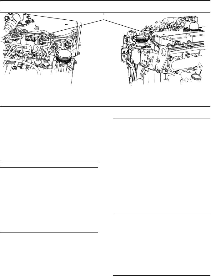
(1) Universal Warning
Do not operate or work on this equipment unless you have read and understand the instructions and warnings in the Operation and Maintenance Manuals. Failure to follow the instructions or heed the warnings could result in serious injury or death.
Typical example
The Universal Warning label (1) is located on both sides of the valve mechanism cover base.
5
Safety Section
Safety Messages
Safety Section
Safety Messages
2 Hand (High Pressure)
Contact with high pressure fuel may cause fluid penetration and burn hazards. High pressure fuel spray may cause a fire hazard. Failure to follow these inspection, maintenance and service instructions may cause personal injury or death.
|
The warning label for the Hand (High Pressure) (2) is |
|
|
a wrap around label that is located on the rear injector |
|
|
Illustration 3 |
line. |
|
g01154858 |
|
|
Typical example |
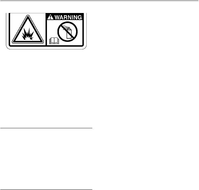
Ether |
Do not use aerosol types of starting aids such as ether. Such use could result in an explosion and personal injury.
Safety Section
General Hazard Information
Typical example
The ether warning label is supplied loose for the original equipment manufacture to install the label.
i05737934
General Hazard Information
Attach a “Do Not Operate” warning tag or a similar warning tag to the start switch or to the controls before you service the equipment or before you repair the equipment.
Wear a hard hat, protective glasses, and other protective equipment, as required.
Do not wear loose clothing or jewelry that can snag on controls or on other parts of the engine.
Make sure that all protective guards and all covers are secured in place on the engine.
Keep the engine free from foreign material. Remove
debris, oil, tools, and other items from the deck, from walkways, and from steps.
Never put maintenance fluids into glass containers. Drain all liquids into a suitable container.
Obey all local regulations for the disposal of liquids.
Use all cleaning solutions with care.
Report all necessary repairs.
Do not allow unauthorized personnel on the equipment.
Ensure that the power supply is disconnected before you work on the bus bar or the glow plugs.
Perform maintenance on the engine with the equipment in the servicing position. Refer to the OEM information for the procedure for placing the equipment in the servicing position.
Pressure Air and Water
Pressurized air and/or water can cause debris and/or hot water to be blown out. This action could result in personal injury.
The direct application of pressurized air or pressurized water to the body could result in personal injury.
When pressurized air and/or water is used for cleaning, wear protective clothing, protective shoes, and eye protection. Eye protection includes goggles or a protective face shield.

8
Safety Section
Burn Prevention
The maximum air pressure for cleaning purposes must be below 205 kPa (30 psi). The maximum water pressure for cleaning purposes must be below
275 kPa (40 psi).
Fluid Penetration
Pressure can be trapped in the hydraulic circuit long after the engine has been stopped. The pressure can cause hydraulic fluid or items such as pipe plugs to escape rapidly if the pressure is not relieved correctly.
Do not remove any hydraulic components or parts until pressure has been relieved or personal injury may occur. Do not disassemble any hydraulic components or parts until pressure has been relieved or personal injury may occur. Refer to the OEM information for any procedures that are required to relieve the hydraulic pressure.
Always use a board or cardboard when you check for a leak. Leaking fluid that is under pressure can penetrate body tissue. Fluid penetration can cause serious injury and possible death. A pin hole leak can cause severe injury. If fluid is injected into your skin, you must get treatment immediately. Seek treatment from a doctor that is familiar with this type of injury.
Containing Fluid Spillage
Care must be taken in order to ensure that fluids are contained during performance of inspection,
maintenance, testing, adjusting, and repair of the engine. Make provision to collect the fluid with a suitable container before any compartment is opened or before any component is disassembled.
•Only use the tools that are suitable for collecting fluids and equipment that is suitable for collecting fluids.
•Only use the tools that are suitable for containing fluids and equipment that is suitable for containing fluids.
Obey all local regulations for the disposal of liquids.
SEBU9066
Static Electricity Hazard when Fueling with Ultra-low Sulfur Diesel Fuel
The removal of sulfur and other compounds in ultralow sulfur diesel fuel (ULSD fuel) decreases the conductivity of ULSD and increases the ability of ULSD to store static charge. Refineries may have treated the fuel with a static dissipating additive. Many factors can reduce the effectiveness of the additive over time. Static charges can build up in ULSD fuel while the fuel is flowing through fuel delivery systems. Static electricity discharge when combustible vapors are present could result in a fire or explosion. Ensure that the entire system used to refuel your machine (fuel supply tank, transfer pump, transfer hose, nozzle, and others) is properly grounded and bonded. Consult with your fuel or fuel system supplier to ensure that the delivery system complies with fueling standards for proper grounding and bonding.
Avoid static electricity risk when fueling. Ultra-low sulfur diesel fuel (ULSD fuel) poses a greater static ignition hazard than earlier diesel formulations with a higher sulfur contents. Avoid death or serious injury from fire or explosion. Consult with your fuel or fuel system supplier to ensure the delivery system is in compliance with fueling standards for proper grounding and bonding practices.
i05302522
Burn Prevention
Do not touch any part of an operating engine. Allow the engine to cool before any maintenance is performed on the engine.
Contact with high pressure fuel may cause fluid penetration and burn hazards. High pressure fuel spray may cause a fire hazard. Failure to follow these inspection, maintenance and service instructions may cause personal injury or death.
NOTICE
The low-pressure fuel system can be pressurized for a time period after the engine has stopped operating. The operating pressure of the low-pressure fuel system can be 500 kPa (73 psi). The secondary fuel filters should be drained before any maintenance of the low-pressure fuel system is carried out.

SEBU9066
After the engine has stopped, you must wait for 60 seconds in order to allow the fuel pressure to be purged from the high-pressure fuel lines before any service or repair is performed on the engine fuel lines.
Allow the pressure to be purged in the air system, in the hydraulic system, in the lubrication system, or in the cooling system before any lines, fittings, or related items are disconnected.
Coolant
When the engine is at operating temperature, the engine coolant is hot. The coolant is also under pressure. The radiator and all lines to the heaters or to the engine contain hot coolant.
Any contact with hot coolant or with steam can cause severe burns. Allow cooling system components to cool before the cooling system is drained.
Check that the coolant level after the engine has stopped and the engine has been allowed to cool.
Ensure that the filler cap is cool before removing the filler cap. The filler cap must be cool enough to touch with a bare hand. Remove the filler cap slowly in order to relieve pressure.
Cooling system conditioner contains alkali. Alkali can cause personal injury. Do not allow alkali to contact the skin, the eyes, or the mouth.
Oils
Hot oil and hot lubricating components can cause personal injury. Do not allow hot oil to contact the skin. Also, do not allow hot components to contact the skin.
Batteries
Electrolyte is an acid. Electrolyte can cause personal injury. Do not allow electrolyte to contact the skin or the eyes. Always wear protective glasses for servicing batteries. Wash hands after touching the batteries and connectors. Use of gloves is recommended.
9
Safety Section
Fire Prevention and Explosion Prevention
i04823662
Fire Prevention and Explosion
Prevention
All fuels, most lubricants, and some coolant mixtures are flammable.
Flammable fluids that are leaking or spilled onto hot surfaces or onto electrical components can cause a fire. Fire may cause personal injury and property damage.
After the emergency stop button is operated, ensure that you allow 15 minutes, before the engine covers are removed.
Determine whether the engine will be operated in an environment that allows combustible gases to be drawn into the air inlet system. These gases could cause the engine to overspeed. Personal injury, property damage, or engine damage could result.
If the application involves the presence of combustible gases, consult your Perkins dealer and/ or your Perkins distributor for additional information about suitable protection devices.
Remove all flammable combustible materials or conductive materials such as fuel, oil, and debris from the engine. Do not allow any flammable combustible
materials or conductive materials to accumulate on the engine.
Store fuels and lubricants in correctly marked containers away from unauthorized persons. Store oily rags and any flammable materials in protective
containers. Do not smoke in areas that are used for storing flammable materials.
Do not expose the engine to any flame.
Exhaust shields (if equipped) protect hot exhaust components from oil or fuel spray in a line, a tube, or
a seal failure. Exhaust shields must be installed correctly.

Safety Section
Fire Prevention and Explosion Prevention
Do not weld on lines or tanks that contain flammable fluids. Do not flame cut lines or tanks that contain flammable fluid. Clean any such lines or tanks
thoroughly with a nonflammable solvent prior to welding or flame cutting.
Wiring must be kept in good condition. Ensure that all electrical wires are correctly routed and securely attached. Check all electrical wires daily. Repair any wires that are loose or frayed before you operate the engine. Clean all electrical connections and tighten all electrical connections.
Eliminate all wiring that is unattached or unnecessary. Do not use any wires or cables that are smaller than the recommended gauge. Do not bypass any fuses and/or circuit breakers.
Arcing or sparking could cause a fire. Secure connections, recommended wiring, and correctly maintained battery cables will help to prevent arcing or sparking.
Contact with high pressure fuel may cause fluid penetration and burn hazards. High pressure fuel spray may cause a fire hazard. Failure to follow these inspection, maintenance and service instructions may cause personal injury or death.
After the engine has stopped, wait for 60 seconds in order to allow the fuel pressure to be purged from the high-pressure fuel lines before any service or repair is performed on the engine fuel lines.
Ensure that the engine is stopped. Inspect all lines and hoses for wear or for deterioration. Properly route all hoses. The lines and hoses must have adequate support and secure clamps.
Properly install oil filters and fuel filters. The filter housings must be tightened to the correct torque. Refer to the Disassembly and Assembly manual for more information.
|
Illustration 10 |
g00704059 |
Use caution when you are refueling an engine. Do not smoke while you are refueling an engine. Do not refuel an engine near open flames or sparks. Always stop the engine before refueling.
|
Illustration 11 |
g02298225 |
Gases from a battery can explode. Keep any open flames or sparks away from the top of a battery. Do not smoke in battery charging areas.
Never check the battery charge by placing a metal object across the terminal posts. Use a voltmeter or a hydrometer.
Incorrect jumper cable connections can cause an explosion that can result in injury. Refer to the Operation Section of this manual for specific instructions.
![]()
Safety Section
Crushing Prevention and Cutting Prevention
Do not charge a frozen battery.Charging a frozen battery may cause an explosion.
The batteries must be kept clean. The covers (if equipped) must be kept on the cells. Use the recommended cables, connections, and battery box covers when the engine is operated.
Fire Extinguisher
Make sure that a fire extinguisher is available. Be familiar with the operation of the fire extinguisher. Inspect the fire extinguisher and service the fire extinguisher regularly. Obey the recommendations on the instruction plate.
Lines, Tubes, and Hoses
Do not bend high-pressure lines. Do not strike highpressure lines. Do not install any lines that are damaged.
Leaks can cause fires. Consult your Perkins dealer or your Perkins distributor for replacement parts.
Replace the parts if any of the following conditions are present:
•High-pressure fuel line or lines are removed.
•End fittings are damaged or leaking.
•Outer coverings are chafed or cut.
•Wires are exposed.
•Outer coverings are ballooning.
•Flexible parts of the hoses are kinked.
•Outer covers have embedded armoring.
•End fittings are displaced.
Make sure that all clamps, guards, and heat shields are installed correctly in order to prevent vibration, rubbing against other parts, and excessive heat.
i02143194
Crushing Prevention and
Cutting Prevention
Support the component correctly when work beneath the component is performed.
Unless other maintenance instructions are provided, never attempt adjustments while the engine is running.
Stay clear of all rotating parts and of all moving parts. Leave the guards in place until maintenance is performed. After the maintenance is performed, reinstall the guards.
Keep objects away from moving fan blades. The fan blades will throw objects or cut objects.
When objects are struck, wear protective glasses in order to avoid injury to the eyes.
Chips or other debris may fly off objects when objects are struck. Before objects are struck, ensure that no one will be injured by flying debris.
i05463929
Mounting and Dismounting
Do not climb on the engine. The engine has not been designed with mounting or dismounting locations.
Refer to the Original Equipment Manufacture (OEM) for the location of foot and hand holds for your specific application.
i05463931
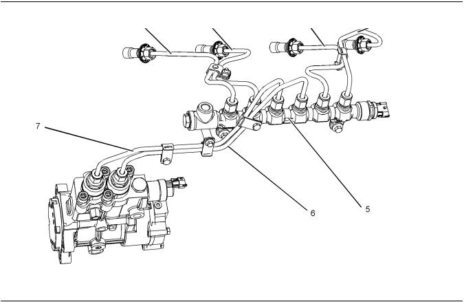
High Pressure Fuel Lines
Contact with high pressure fuel may cause fluid penetration and burn hazards. High pressure fuel spray may cause a fire hazard. Failure to follow these inspection, maintenance and service instructions may cause personal injury or death.
Safety Section
High Pressure Fuel Lines
|
Illustration 12 |
g03452057 |
|
|
(1) High-pressure line |
(4) High-pressure line |
(7) High-pressure supply line |
|
(2) High-pressure line |
(5) High-pressure fuel manifold (rail) |
|
|
(3) High-pressure line |
(6) High-pressure supply line |
The high-pressure fuel lines are the fuel lines that are between the high-pressure fuel pump and the highpressure fuel manifold and the fuel lines that are between the fuel manifold and cylinder head. These
fuel lines are different from fuel lines on other fuel systems.
This difference is because of the following items:
•The high-pressure fuel lines are constantly charged with high pressure.
•The internal pressures of the high-pressure fuel lines are higher than other types of fuel system.
•The high-pressure fuel lines are formed to shape and then strengthened by a special process.
Do not step on the high-pressure fuel lines. Do not deflect the high-pressure fuel lines. Do not bend or strike the high-pressure fuel lines. Deformation or damage of the high-pressure fuel lines may cause a point of weakness and potential failure.
Do not check the high-pressure fuel lines with the engine or the starting motor in operation. After the engine has stopped, allow 90 seconds to pass in order to allow the pressure to be purged before any service or repair is performed on the engine fuel lines.
Do not loosen the high-pressure fuel lines in order to remove air from the fuel system. This procedure is not required.
Visually inspect the high-pressure fuel lines before the engine is started. This inspection should be each day.
If you inspect the engine in operation, always use the proper inspection procedure in order to avoid a fluid penetration hazard. Refer to Operation and Maintenance Manual, “General hazard Information”.

Safety Section
Before Starting Engine
•Inspect the high-pressure fuel lines for damage, deformation, a nick, a cut, a crease, or a dent.
•Do not operate the engine with a fuel leak. If there is a leak, do not tighten the connection in order to stop the leak. The connection must only be tightened to the recommended torque. Refer to Disassembly and Assembly, “Fuel injection lines — Remove and Fuel injection lines — Install”.
•If the high-pressure fuel lines are torqued correctly and the high-pressure fuel lines are leaking, the high-pressure fuel lines must be replaced.
•Ensure that all clips on the high-pressure fuel lines are in place. Do not operate the engine with clips that are damaged, missing, or loose.
•Do not attach any other item to the high-pressure fuel lines.
•Loosened high-pressure fuel lines must be replaced. Also removed high-pressure fuel lines must be replaced. Refer to Disassembly and assembly manual, “Fuel Injection Lines — Install”.
NOTICE
The low-pressure fuel system can be pressurized for a time period after the engine has stopped operating. The operating pressure of the low-pressure fuel system can be 500 kPa (73 psi). The secondary fuel filters should be drained before any maintenance of the low-pressure fuel system is carried out.
i02813489
Before Starting Engine
Before the initial start-up of an engine that is new, serviced or repaired, make provision to shut the engine off, in order to stop an overspeed. This may be accomplished by shutting off the air and/or fuel supply to the engine.
Overspeed shutdown should occur automatically for engines that are controlled electronically. If automatic shutdown does not occur, press the emergency stop button in order to cut the fuel and/or air to the engine.
Inspect the engine for potential hazards.
Before starting the engine, ensure that no one is on, underneath, or close to the engine. Ensure that the area is free of personnel.
If equipped, ensure that the lighting system for the engine is suitable for the conditions. Ensure that all lights work correctly, if equipped.
All protective guards and all protective covers must be installed if the engine must be started in order to perform service procedures. To help prevent an accident that is caused by parts in rotation, work around the parts carefully.
Do not bypass the automatic shutoff circuits. Do not
disable the automatic shutoff circuits. The circuits are provided in order to help prevent personal injury. The
circuits are also provided in order to help prevent engine damage.
See the Service Manual for repairs and for adjustments.
i02251260
Engine Starting
Do not use aerosol types of starting aids such as ether. Such use could result in an explosion and personal injury.
If a warning tag is attached to the engine start switch or to the controls DO NOTstart the engine or move the controls. Consult with the person that attached the warning tag before the engine is started.
All protective guards and all protective covers must be installed if the engine must be started in order to perform service procedures. To help prevent an accident that is caused by parts in rotation, work around the parts carefully.
Start the engine from the operator’s compartment or from the engine start switch.
Always start the engine according to the procedure that is described in the Operation and Maintenance Manual, “Engine Starting” topic in the Operation Section. Knowing the correct procedure will help to prevent major damage to the engine components. Knowing the procedure will also help to prevent personal injury.
To ensure that the jacket water heater (if equipped) and/or the lube oil heater (if equipped) is working correctly, check the water temperature gauge and/or the oil temperature gauge during the heater operation.
Engine exhaust contains products of combustion which can be harmful to your health. Always start the engine and operate the engine in a well ventilated area. If the engine is started in an enclosed area, vent the engine exhaust to the outside.

14
Safety Section
Engine Stopping
Note: The engine is equipped with a device for cold starting. If the engine will be operated in very cold conditions, then an extra cold starting aid may be required. Normally, the engine will be equipped with the correct type of starting aid for your region of operation.
These engines are equipped with a glow plug starting aid in each individual cylinder that heats the intake air in order to improve starting.
i02234873
Engine Stopping
Stop the engine according to the procedure in the Operation and Maintenance Manual, “Engine Stopping (Operation Section)” in order to avoid overheating of the engine and accelerated wear of the engine components.
Use the Emergency Stop Button (if equipped) ONLY in an emergency situation. Do not use the Emergency Stop Button for normal engine stopping. After an emergency stop, DO NOTstart the engine until the problem that caused the emergency stop has been corrected.
Stop the engine if an overspeed condition occurs during the initial start-up of a new engine or an engine that has been overhauled.
To stop an electronically controlled engine, cut the power to the engine and/or shutting off the air supply to the engine.
i05464430
Electrical System
Never disconnect any charging unit circuit or battery circuit cable from the battery when the charging unit is operating. A spark can cause the combustible gases that are produced by some batteries to ignite.
To help prevent sparks from igniting combustible gases that are produced by some batteries, the negative “−” cable should be connected last from the external power source to the primary position for grounding.
Check the electrical wires daily for wires that are loose or frayed. Tighten all loose electrical connections before the engine is started. Repair all frayed electrical wires before the engine is started. See the Operation and Maintenance Manual for specific starting instructions.
SEBU9066
Grounding Practices
|
Illustration 13 |
g03452577 |
(1)Ground to battery
(2)Ground to starting motor
(3)Starting motor to engine block
|
Illustration 14 |
g03452579 |
(4)Battery to ground
(5)Ground to engine block
(6)Primary position for grounding
Correct grounding for the engine electrical system is necessary for optimum engine performance and reliability. Incorrect grounding will result in uncontrolled electrical circuit paths and in unreliable electrical circuit paths.

SEBU9066
Uncontrolled electrical circuit paths can result in damage to the crankshaft bearing journal surfaces and to aluminum components.
Engines that are installed without engine-to-frame ground straps can be damaged by electrical discharge.
To ensure that the engine and the engine electrical systems function correctly, an engine-to-frame ground strap with a direct path to the battery must be used. This path may be provided by way of a direct engine ground to the frame.
The connections for the grounds should be tight and free of corrosion. The engine alternator must be grounded to the negative “-” battery terminal. The wire used must be adequate to handle the full charging current of the alternator.
The power supply connections and the ground connections for the engine electronics should always be from the isolator to the battery.
i05272352
Engine Electronics
Tampering with the electronic system installation or the OEM wiring installation can be dangerous and could result in personal injury or death and/or engine damage.
Electrical Shock Hazard. The electronic unit injectors use DC voltage. The ECM sends this voltage to the electronic unit injectors. Do not come in contact with the harness connector for the electronic unit injectors while the engine is operating. Failure to follow this instruction could result in personal injury or death.
This engine has a comprehensive, programmable Engine Monitoring System . The Electronic Control Module (ECM) monitors the engine operating conditions. If any of the engine parameters extend outside an allowable range, the ECM will initiate an immediate action.
The following actions are available for engine monitoring control:
•Warning
•Derate
•Shutdown
15
Safety Section
Engine Electronics
The following monitored engine operating conditions have the ability to limit engine speed and/or the engine power:
•Engine Coolant Temperature
•Engine Oil Pressure
•Engine Speed
•Intake Manifold Air Temperature
•Intake Manifold Air pressure
The Engine Monitoring package can vary for different engine models and different engine applications. However, the monitoring system and the engine monitoring control will be similar for all engines.
Note: Many of the engine control systems and display modules that are available for Perkins Engines will work in unison with the Engine Monitoring System. Together, the two controls will provide the engine monitoring function for the specific engine application. Refer to the Troubleshooting for more information on the Engine Monitoring System.
Product Information Section
Model View Illustrations
Product Information
Section
General Information
i05536748
Model View Illustrations
The following model views show typical features of the engine Due to individual applications, your engine may appear different from the illustrations.
Turbocharged Aftercooled Engine
|
Illustration 15 |
g03453518 |
Typical example
|
(1) Open Breather System |
(4) Oil Level Gauge (Dipstick) |
(7) Oil Filler |
|
(2) Air Intake |
(5) Location for Oil Sample Valve |
(8) Secondary Fuel Filters |
|
(3) Electronic Control Module |
(6) Oil Filter |

General Information
Model View Illustrations
|
Illustration 16 |
g03453526 |
|
|
Typical example |
||
|
(9) Front Lifting Eye |
(11) Coolant Intake |
(13) Belt |
|
(10) Water Pump |
(12) Tensioner |
(14) Coolant Outlet |
General Information
Model View Illustrations
|
Illustration 17 |
g03453529 |
|
|
Typical example |
||
|
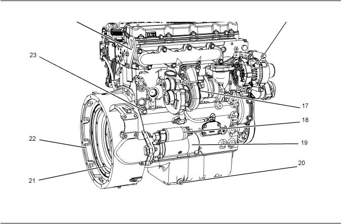
(15) Rear Lifting Eye |
(18) Starter Solenoid |
(21) Flywheel |
|
(16) Alternator |
(19) Starting Motor |
(22) Flywheel Housing |
|
(17) Turbocharger |
(20) Oil Drain Plug |
(23) Coolant Drain Plug |

General Information
Model View Illustrations
Turbocharge Engine View
|
Illustration 18 |
g03506649 |
Typical example
General Information
Product Description
Off Engine Parts and Options
|
Illustration 19 |
g03467856 |
|
|
Typical examples |
||
|
(24) Electric Priming Pump |
(26) Mechanical Priming Pump |
(28) Spin on Crankcase Breather |
|
(25) Primary Fuel Filter |
(27) Primary Fuel Filter |
Note: Item (28) is part of the filtered breather system.
i05536753
Product Description
There are two different variants of this Perkins engine. Engines with prefix NR are turbocharged
aftercooled engines 1104D-E44TA. Engines with prefix NP are turbocharged engines 1104D-E44T.
Engine Specifications
Note: The front end of the engine is opposite the flywheel end of the engine. The left and the right sides of the engine are determined from the flywheel end. The number 1 cylinder is the front cylinder.
|
Illustration 20 |
g01187485 |
Cylinder and valve location
(A)Exhaust valves
(B)Inlet valves
![]()
SEBU9066
Table 1
Engine Specifications
|
Operating Range (rpm) |
900 to 2800(1) |
|
|
Number of Cylinders |
4 In-Line |
|
|
Bore |
105 mm (4.13 inch) |
|
|
Stroke |
127 mm (5 inch) |
|
|
Aspiration |
Turbocharged or |
|
|
Turbocharged Aftercooled |
||
|
Compression Ratio |
16.2:1 |
|
|
Displacement |
4.4 L (268.5 cubic inch) |
|
|
Firing Order |
1-3-4-2 |
|
|
Rotation (flywheel end) |
Counterclockwise |
|
|
Number of valves for each |
4 |
|
|
cylinder |
||
|
Valve Lash Setting (Inlet) |
0.35 mm (0.013 inch) |
|
|
Valve Lash Setting (Exhaust) |
0.35 mm (0.013 inch) |
(1)The operating rpm is dependent on the engine rating, the application, and the configuration of the throttle.
Electronic Engine Features
The engine operating conditions are monitored. The Electronic Control Module (ECM) controls the response of the engine to these conditions and to the demands of the operator. These conditions and operator demands determine the precise control of fuel injection by the ECM. The electronic engine control system provides the following features:
•Engine monitoring
•Engine speed governing
•Control of the injection pressure
•Cold start strategy
•Automatic air/fuel ratio control
•Torque rise shaping
•Injection timing control
•System diagnostics
For more information on electronic engine features, refer to the Operation and Maintenance Manual, “Features and Controls” topic (Operation Section).
21
General Information
Product Description
Engine Diagnostics
The engine has built-in diagnostics in order to ensure that the engine systems are functioning correctly. The operator will be alerted to the condition by a “Stop or Warning” lamp. Under certain conditions, the engine power and the engine speed may be limited. The electronic service tool may be used to display the diagnostic codes.
There are two types of diagnostic codes: active and logged.
Most of the diagnostic codes are logged and stored in
the ECM. For additional information, refer to the Operation and Maintenance Manual, “Engine
Diagnostics” topic (Operation Section).
The ECM provides an electronic governor that controls the injector output in order to maintain the desired engine rpm.
For more information refer to Troubleshooting manual.
Engine Cooling and Lubrication
The cooling system consists of the following components:
•Gear-driven centrifugal water pump
•Water temperature regulator which regulates the engine coolant temperature
•Gear-driven rotor type oil pump
•Oil cooler
The engine lubricating oil is supplied by a rotor type oil pump. The engine lubricating oil is cooled and the engine lubricating oil is filtered. The bypass valve can provide unrestricted flow of lubrication oil to the engine if the oil filter element should become plugged.
Engine efficiency, efficiency of emission controls, and engine performance depend on adherence to proper operation and maintenance recommendations.
Engine performance and efficiency also depend on
the use of recommended fuels, lubrication oils, and coolants. Refer to this Operation and Maintenance
Manual, “Maintenance Interval Schedule” for more information on maintenance items.
Option Section
There are two different types of fuel priming pump available, hand primer or an electrically operated primer. There are two different types of crankcase breather, open breather or filtered open breather.
Product Identification Information
Plate Locations and Film Locations
Product Identification
Information
i05536932
Plate Locations and Film
Locations
|
Illustration 22 |
g02433756 |
Typical example
|
Illustration 21 |
g03453612 |
Perkins engines are identified by an engine serial number.
An example of an engine number is N-
*****R000001X.
|
***** |
The list number for the engine |
|
N- |
Type of engine |
|
R |
Built-in China |
|
000001 |
Engine Serial Number |
|
X |
Year of Manufacture |
Perkins dealers or Perkins distributors need all of these numbers in order to determine the components
that were included with the engine. This information permits accurate identification of replacement part numbers.
Serial Number Plate (1)
The engine serial number plate is located on the left side of the cylinder block to the rear of the front engine mounting.

Product Identification Information
Emissions Certification Film
i05536952
Emissions Certification Film
|
Illustration 23 |
g03506769 |
|
Typical example |
|
|
i05465764 |
(If equipped) Filtered Breather |
Reference Information
Information for the following items may be needed to order parts. Locate the information for your engine. Record the information in the appropriate space. Make a copy of this list for a record. Keep the information for future reference.
Record for Reference
Engine Model
Engine Serial number
Engine Low Idle rpm
Engine Full Load rpm
Primary Fuel Filter
Secondary Fuel Filter Element
Lubrication Oil Filter
Total Lubrication System Capacity
Total Cooling System Capacity
Air Cleaner Element
Drive Belt

24
Operation Section
Product Lifting
Operation Section
Lifting and Storage
i02677363
Product Lifting
|
Illustration 24 |
g00103219 |
NOTICE
Never bend the eyebolts and the brackets. Only load the eyebolts and the brackets under tension. Remember that the capacity of an eyebolt is less as the angle between the supporting members and the object becomes less than 90 degrees.
When it is necessary to remove a component at an angle, only use a link bracket that is properly rated for the weight.
Use a hoist to remove heavy components. Use an adjustable lifting beam to lift the engine. All supporting members (chains and cables) should be parallel to each other. The chains and cables should be perpendicular to the top of the object that is being lifted.
Some removals require lifting the fixtures in order to obtain proper balance and safety.
To remove the engine ONLY, use the lifting eyes that are on the engine.
Lifting eyes are designed and installed for specific engine arrangements. Alterations to the lifting eyes and/or the engine make the lifting eyes and the lifting
fixtures obsolete. If alterations are made, ensure that proper lifting devices are provided. Consult your
Perkins dealer for information regarding fixtures for proper engine lifting.
SEBU9066
i04151489
Product Storage
Perkins are not responsible for damage which may occur when an engine is in storage after a period in service.
Your Perkins dealer or your Perkins distributor can assist in preparing the engine for extended storage periods.
Condition for Storage
The engine must be stored in a water proof building. The building must be kept at a constant temperature. Engines that are filled with Perkins ELC will have coolant protection to an ambient temperature of −36° C (−32.8° F). The engine must not be subjected to extreme variations in temperature and humidity.
Storage Period
An engine can be stored for up to 6 months provided all the recommendation are adhered to.
Storage Procedure
Keep a record of the procedure that has been completed on the engine.
Note: Do not store an engine that has biodiesel in the fuel system.
1.Ensure that the engine is clean and dry.
a.If the engine has been operated using biodiesel, the system must be drained and new filters installed. The fuel tank will require flushing.
b.Fill the fuel system with an acceptable fuel. For more information on acceptable fuels refer to this Operation and Maintenance Manual, “Fluid recommendations”. Operate the engine for 15 minutes in order to remove all biodiesel from the system.
2.Drain any water from the primary filter water separator. Ensure that the fuel tank is full.
3.The engine oil will not need to be drained in order to store the engine. Provided the correct specification of engine oil is used the engine can be stored for up to 6 months. For the correct specification of engine oil refer to this Operation and Maintenance Manual, “Fluid recommendations”.
4.Remove the drive belt from the engine.

SEBU9066
Sealed Coolant System
Ensure that the cooling system is filled with Perkins
ELC, or an antifreeze that meets “ASTM D6210” specification.
Open Cooling System
Ensure that all cooling drain plugs have been opened. Allow the coolant to drain. Install the drain plugs. Place a vapor phase inhibitor into the system. The coolant system must be sealed once the vapor phase inhibitor has been introduced. The effect of the vapor phase inhibitor will be lost if the cooling system is open to the atmosphere.
For maintenance procedures refer to this Operation and Maintenance Manual.
Monthly Checks
The crankshaft must be rotated in order to change the spring loading on the valve train. Rotate the crankshaft more than 180 degrees. Visibly check for damage or corrosion to the engine.
Ensure that the engine is covered completely before storage. Log the procedure in the record for the engine.
25
Lifting and Storage
Product Storage

26
Features and Controls
Alarms and Shutoffs
Features and Controls
i05251301
Alarms and Shutoffs
Shutoffs
The shutoffs are electrically operated or mechanically operated. The electrically operated shutoffs are controlled by the ECM.
Shutoffs are set at critical levels for the following items:
•Operating temperature
•Operating pressure
•Operating level
•Operating rpm
The particular shutoff may need to be reset before the engine will start.
NOTICE
Always determine the cause of the engine shutdown. Make necessary repairs before attempting to restart the engine.
Be familiar with the following items:
•Types and locations of shutoff
•Conditions which cause each shutoff to function
•The resetting procedure that is required to restart the engine
Alarms
The alarms are electrically operated. The operation of the alarms is controlled by the ECM.
The alarm is operated by a sensor or by a switch. When the sensor or the switch is activated, a signal is sent to the ECM. An event code is created by the ECM. The ECM will send a signal in order to illuminate the lamp.
Your engine may be equipped with the following sensors or switches:
Coolant level – The low coolant level switch indicates when the coolant level is low.
Coolant temperature – The coolant temperature sensor indicates high jacket water coolant temperature.
SEBU9066
Intake manifold air temperature – The intake manifold air temperature sensor indicates high intake air temperature.
Intake manifold pressure – The intake manifold pressure sensor checks the rated pressure in the
engine manifold.
Fuel rail pressure – The fuel rail pressure sensor checks for high pressure or low pressure in the fuel rail.
Engine oil pressure – The engine oil pressure sensor indicates when oil pressure drops below rated system pressure, at a set engine speed.
Engine overspeed – The primary speed/timing sensor checks the engine speed. The alarm is activated at 3000 RPM.
Air filter restriction – The switch checks the air filter when the engine is operating.
User-defined switch – This switch can shut down the engine remotely.
Water in fuel switch – This switch checks for water in the primary fuel filter when the engine is operating.
Note: The sensing element of the coolant temperature switch must be submerged in coolant in order to operate.
Engines may be equipped with alarms in order to alert the operator when undesirable operating conditions occur.
NOTICE
When an alarm is activated, corrective measures must be taken before the situation becomes an emergency in order to avoid possible engine damage.
If corrective measures are not taken within a reasonable time, engine damage could result. The
alarm will continue until the condition is corrected. The alarm may need to be reset.
Testing
Turning the keyswitch to the ON position will check the indicator lights on the control panel. All the indicator lights will be illuminated for 2 seconds after the keyswitch is operated. Replace suspect bulbs immediately.
Refer to Troubleshooting for more information.

SEBU9066
i05537598
Gauges and Indicators
Your engine may not have the same gauges or all of the gauges that are described. For more information about the gauge package, see the OEM information.
Gauges provide indications of engine performance. Ensure that the gauges are in good working order. Determine the normal operating range by observing the gauges over a period.
Noticeable changes in gauge readings indicate potential gauge or engine problems. Problems may also be indicated by gauge readings that change even if the readings are within specifications. Determine and correct the cause of any significant change in the readings. Consult your Perkins dealer or your distributor Perkins for assistance.
Some engine applications are equipped with Indicator Lamps. Indicator lamps can be used as a diagnostic aid. There are two lamps. One lamp has an orange lens and the other lamp has a red lens.
These indicator lamps can be used in two ways:
•The indicator lamps can be used to identify the current operational status of the engine. The indicator lamps can also indicate that the engine has a fault. This system is automatically operated via the ignition switch.
•The indicator lamps can be used to identify active diagnostic codes.
Refer to the Troubleshooting Guide, “Indicator Lamps” for further information.
NOTICE
If no oil pressure is indicated, STOP the engine. If maximum coolant temperature is exceeded, STOP the engine. Engine damage can result.
Engine Oil Pressure – The oil pressure should be greatest after a cold engine is started. The typical engine oil pressure with SAE10W40 is 350 to 450 kPa ( 50 to 65 psi) at
rated rpm.
A lower oil pressure is normal at low idle. If the load is stable and the gauge reading changes, perform the following procedure:
1.Remove the load.
2.Stop the engine.
3.Check and maintain the oil level.
27
Features and Controls
Gauges and Indicators
Jacket Water Coolant Temperature – Typical temperature range is 83° to 95°C (181.4° to 171°F). The maximum
allowable temperature at sea level with the pressurized cooling system at 48 kPa (7 psi) is 103 °C (217.4 °F). Higher temperatures may occur under certain conditions. The water temperature reading may vary according to load. The temperature reading should never exceed 7 °C (44.6 °F) below the boiling point for the pressurized system that is being used.
A 100 kPa (14.5 psi) radiator cap may be installed on the cooling system. The temperature of this cooling system must not exceed 112 °C (233.6 °F).
If the engine is operating above the normal range and steam becomes apparent, perform the following procedure:
1.Reduce the load and the engine rpm.
2.Determine if the engine must be shut down immediately or if the engine can be cooled by reducing the load.
3.Inspect the cooling system for leaks.
Tachometer – This gauge indicates engine speed (rpm). When the throttle control lever is moved to the full throttle
position without load, the engine is running at high idle. The engine is running at the full load rpm when the throttle control lever is at the full throttle position with maximum rated load.
NOTICE
To help prevent engine damage, never exceed the high idle rpm. Overspeeding can result in serious damage to the engine. Operation at speeds exceeding high idle rpm should be kept to a minimum.
Ammeter – This gauge indicates the amount of charge or discharge in the battery charging circuit. Operation of the
indicator should be to the ““+”” side of ““0”” (zero).
Fuel Level – This gauge indicates the fuel level in the fuel tank. The fuel level gauge operates when the ““START/
STOP”” switch is in the ““on”” position.
Service Hour Meter – The gauge indicates total operating hours of the engine.
Indicator Lamps
There are four main indicator lamps that are available.

Features and Controls
Gauges and Indicators
•Shutdown Lamp
•Warning Lamp
•Wait to Start Lamp
•Low Oil Pressure Lamp
For information, refer to this manual, “Monitoring System (Table for the Indicator Lamps)” for the sequence of operation of the shutdown lamp and the warning lamp.
The function of the wait to start lamp is automatically controlled at engine start-up.
The function of the low oil pressure lamp is controlled by the engine ECM. If low oil pressure is detected, the lamp will be illuminated. The reason for the illumination of the low-pressure lamp should be investigated immediately.
All lamps will illuminate for 2 seconds in order to check that the lamps are functioning when the keyswitch is turned to the ON position. If any of the lamps stay illuminated, the reason for illumination should be investigated immediately.
The glow plug warning lamp will flash in order to show that the engine is been held at low speed. This function will be performed at engine starting and the duration will depend on ambient temperature and engine temperature.
Instrument panels and Displays
In order to monitor the engine a wide verity of instrument panels are available. These instrument panels can contain the indicator lamps and the gauges for the application.
Also available are mini power displays and performance monitors. These displays and monitors can show the operator the following engine information.
•The system configuration parameters
•The customer specified parameters
•Diagnostic codes
•Event codes
•Coolant temperature
•Oil temperature
•Oil pressure
•Intake temperature
•Intake pressure
•Fuel temperature
Features and Controls
Monitoring System
i02330192
Monitoring System
Table 2
Warning Lamp
Shutdown
Lamp
ON ON
OFF OFF
ON OFF
ON FLASHING
FLASHING OFF
FLASHING FLASHING
ON ON
|
Lamp Status |
Description of lamp status |
Engine Status |
|
Lamp check |
When the engine start switch is turned to the “ON” po- |
The engine has not been |
|
sition both lamps will illuminate for 2 seconds only. |
started. |
|
|
No faults |
There are no active diagnostic faults. |
The engine is running normally. |
|
Active diagnostic |
An active diagnostic fault has been detected. |
The engine is running normally. |
|
fault |
||
|
Active diagnostic |
A serious active diagnostic fault has been detected and |
The engine is running but the |
|
fault |
an engine derate has been invoked. |
engine has been derated. |
|
Warning |
One or more of the engine protection values has been |
The engine is running normally. |
|
exceeded. |
||
|
Derate and |
One or more of the engine protection values has been |
The engine is running but the |
|
warning |
exceeded. |
engine has been derated. |
|
Engine shutdown |
One or more of the engine protection values has been |
The engine is shutdown or shut- |
|
exceeded or a serious active diagnostic fault has been |
down is imminent. |
|
|
detected. |
i05546770
Monitoring System
If the Shutdown mode has been selected and the warning indicator activates, engine shutdown may take as little as 20 seconds from the time the warning indicator is activated. Depending on the application, special precautions should be taken to avoid personal injury. The engine can be restarted following shutdown for emergency maneuvers, if necessary.
NOTICE
The Engine Monitoring System is not a guarantee against catastrophic failures. Programmed delays and derate schedules are designed to minimize false alarms and provide time for the operator to stop the engine.
The following parameters are monitored:
•Coolant temperature
•Intake manifold air temperature
•Intake manifold air pressure
•Oil pressure
•Pressure in the fuel rail
•Engine speed/timing
Programmable Options and
Systems Operation
If the Warning/Derate/Shutdown mode has been selected and the warning indicator activates, bring the engine to a stop whenever possible. Depending on the application, special precautions should be taken to avoid personal injury.
The engine can be programmed to the following modes:

30
Features and Controls
Overspeed
““Warning””
The “Warning” lamp and the warning signal (orange lamp) turn “ON” and the warning signal is activated continuously in order to alert the operator that one or more of the engine parameters is not within normal operating range.
““Warning/Derate”
The “Diagnostic” lamp turns “ON” and the warning signal (red lamp) is activated. After the warning, the engine power will be derated. The warning lamp will begin to flash when the derating occurs.
The engine will be derated if the engine exceeds preset operational limits. The engine derate is achieved by restricting the amount of fuel that is available for each injection. The amount of this reduction of fuel is dependent on the severity of the fault that has caused the engine derate, typically up
to a limit of 50%. This reduction in fuel results in a predetermined reduction in engine power.
““Warning/Derate/Shutdown”
The “Diagnostic” lamp turns “ON” and the warning signal (red lamp) is activated. After the warning, the engine power will be derated. The engine will continue at the rpm of the set derate until a shutdown of the engine occurs. The engine can be restarted after a shutdown for use in an emergency.
A shutdown of the engine may occur in as little as 20 seconds. The engine can be restarted after a shutdown for use in an emergency. However, the cause of the initial shutdown may still exist. The engine may shut down again in as little as 20 seconds.
If there is a signal for low oil pressure or for coolant temperature, there will be a two second delay in order to verify the condition.
For each of the programmed modes, refer to Troubleshooting Guide, “Indicator Lamps” for more information on Indicator Lamps.
For more information or assistance for repairs, consult your Perkins dealer or your Perkins distributor.
i05251914
Overspeed
An overspeed condition is detected by the Electronic Control Module (ECM). The event code E190 will be logged if the engine speed exceeds 3300 rpm. The “DIAGNOSTIC” lamp will indicate a diagnostic fault code. The diagnostic fault code will remain active until the engine speed drops to 2800 rpm.
SEBU9066
i05488609
Sensors and Electrical
Components
The illustrations within the following sections are typical location of the sensors or electrical components for an industrial engine. Specific engines may appear different due to differences in applications.
![]()
Features and Controls
Sensors and Electrical Components
|
Illustration 25 |
g03470316 |
|
|
Typical example |
||
|
(1) Coolant Temperature Sensor |
(4) Connector for Injectors 1 and Injector 2 |
(7) Fuel Rail Pressure Sensor |
|
(2) Inlet Manifold Pressure Sensor |
(5) Connector for Injectors 3 and Injector 4 |
(8) Diagnostic Connector |
|
(3) Bus Bar for Glow Plugs |
(6) Inlet Manifold Temperature Sensor |

Features and Controls
Sensors and Electrical Components
|
Illustration 26 |
g03470317 |
|
|
Typical example |
||
|
(9) Electronic Control Module |
(11) Oil Pressure Sensor |
(13) Solenoid for the high-pressure fuel |
|
(10) Primary Speed/Timing sensor |
(12) Secondary Speed/Timing sensor |
pump |
 Loading…
![]()
SEBU9066
March 2014
Operation and
Maintenance
Manual
1104D-E44T and 1104D-E44TA Industrial Engines
NP (Engine)
NR (Engine)
Important Safety Information
Most accidents that involve product operation, maintenance and repair are caused by failure to observe basic safety rules or precautions. An accident can often be avoided by recognizing potentially hazardous situations before an accident occurs. A person must be alert to potential hazards. This person should also have the necessary training, skills and tools to perform these functions properly.
Improper operation, lubrication, maintenance or repair of this product can be dangerous and could result in injury or death.
Do not operate or perform any lubrication, maintenance or repair on this product, until you have read and understood the operation, lubrication, maintenance and repair information.
Safety precautions and warnings are provided in this manual and on the product. If these hazard warnings are not heeded, bodily injury or death could occur to you or to other persons.
The hazards are identified by the “Safety Alert Symbol” and followed by a “Signal Word” such as “DANGER”, “WARNING” or “CAUTION”. The Safety Alert “WARNING” label is shown below.
The meaning of this safety alert symbol is as follows:
Attention! Become Alert! Your Safety is Involved.
The message that appears under the warning explains the hazard and can be either written or pictorially presented.
Operations that may cause product damage are identified by “NOTICE” labels on the product and in this publication.
Perkins cannot anticipate every possible circumstance that might involve a potential hazard. The warnings in this publication and on the product are, therefore, not all inclusive. If a tool, procedure, work method or operating technique that is not specifically recommended by Perkins is used,
you must satisfy yourself that it is safe for you and for others. You should also ensure that the product will not be damaged or be made unsafe by the operation, lubrication, maintenance or repair procedures that you choose.
The information, specifications, and illustrations in this publication are on the basis of information that was available at the time that the publication was written. The specifications, torques, pressures, measurements, adjustments, illustrations, and other items can change at any time. These changes can affect the service that is given to the product. Obtain the complete and most current information before you start any job. Perkins dealers or Perkins distributors have the most current information available.
When replacement parts are required for this product Perkins recommends using Perkins replacement parts.
Failure to heed this warning can lead to premature failures, product damage, personal injury or death.
|
Table of Contents |
|
|
Foreword………………………… ……………………….. |
4 |
|
Safety Section |
|
|
Safety Messages………………….. ………………….. |
5 |
|
General Hazard Information…………… ………….. |
7 |
|
Burn Prevention…………………… …………………… |
8 |
|
Fire Prevention and Explosion Prevention …. … |
9 |
|
Crushing Prevention and Cutting Prevention . . |
11 |
|
Mounting and Dismounting…………… …………… |
11 |
|
High Pressure Fuel Lines ……………. ……………. |
11 |
|
Before Starting Engine …………….. ……………… |
13 |
|
Engine Starting…………………… ………………….. |
13 |
|
Engine Stopping ………………….. …………………. |
14 |
|
Electrical System…………………. …………………. |
14 |
|
Engine Electronics………………… ………………… |
15 |
|
Product Information Section |
|
|
General Information……………….. ……………….. |
16 |
|
Product Identification Information………. ……… |
22 |
|
Operation Section |
|
|
Lifting and Storage………………… ………………… |
24 |
|
Features and Controls……………… ……………… |
26 |
|
Engine Diagnostics………………… ……………….. |
37 |
|
Engine Starting…………………… ………………….. |
44 |
|
Engine Operation…………………. …………………. |
47 |
|
Cold Weather Operation…………….. ……………. |
48 |
|
Engine Stopping ………………….. …………………. |
52 |
|
Maintenance Section |
|
|
Refill Capacities………………….. ………………….. |
54 |
|
Maintenance Recommendations………. ………. |
67 |
|
Maintenance Interval Schedule……….. ……….. |
69 |
|
Warranty Section |
|
|
Warranty Information……………… ……………… |
100 |
|
Reference Information Section |
|
|
Reference Materials ……………… ………………. |
101 |
|
Index Section |
|
|
Index…………………………. ………………………… |
102 |
4
Foreword
Foreword
Literature Information
This manual contains safety, operation instructions,
lubrication and maintenance information. This manual should be stored in or near the engine area in a
literature holder or literature storage area. Read, study and keep it with the literature and engine information.
English is the primary language for all Perkins publications. The English used facilitates translation and consistency.
Some photographs or illustrations in this manual show details or attachments that may be different from your engine. Guards and covers may have been removed for illustrative purposes. Continuing improvement and advancement of product design may have caused changes to your engine which are not included in this manual. Whenever a question arises regarding your engine, or this manual, please consult with your Perkins dealer or your Perkins distributor for the latest available information.
Safety
This safety section lists basic safety precautions. In addition, this section identifies hazardous, warning
situations. Read and understand the basic precautions listed in the safety section before
operating or performing lubrication, maintenance and repair on this product.
Operation
Operating techniques outlined in this manual are basic. They assist with developing the skills and techniques required to operate the engine more efficiently and economically. Skill and techniques develop as the operator gains knowledge of the engine and its capabilities.
The operation section is a reference for operators. Photographs and illustrations guide the operator through procedures of inspecting, starting, operating and stopping the engine. This section also includes a discussion of electronic diagnostic information.
Maintenance
The maintenance section is a guide to engine care. The illustrated, step-by-step instructions are grouped by service hours and/or calendar time maintenance
intervals. Items in the maintenance schedule are referenced to detailed instructions that follow.
SEBU9066
Recommended service should be performed at the appropriate intervals as indicated in the Maintenance Interval Schedule. The actual operating environment of the engine also governs the Maintenance Interval Schedule. Therefore, under extremely severe, dusty, wet or freezing cold operating conditions, more frequent lubrication and maintenance than is specified in the Maintenance Interval Schedule may be necessary.
The maintenance schedule items are organized for a preventive maintenance management program. If the preventive maintenance program is followed, a periodic tune-up is not required. The implementation of a preventive maintenance management program should minimize operating costs through cost avoidances resulting from reductions in unscheduled downtime and failures.
Maintenance Intervals
Perform maintenance on items at multiples of the original requirement. We recommend that the maintenance schedules be reproduced and displayed near the engine as a convenient reminder. We also
recommend that a maintenance record be maintained as part of the engine’s permanent record.
Your authorized Perkins dealer or your Perkins distributor can assist you in adjusting your maintenance schedule to meet the needs of your operating environment.
Overhaul
Major engine overhaul details are not covered in the Operation and Maintenance Manual except for the
interval and the maintenance items in that interval. Major repairs should only be carried out by Perkins
authorized personnel. Your Perkins dealer or your Perkins distributor offers a variety of options regarding overhaul programs. If you experience a major engine failure, there are also numerous after failure overhaul options available. Consult with your Perkins dealer or your Perkins distributor for information regarding these options.
California Proposition 65 Warning
Diesel engine exhaust and some of its constituents
are known to the State of California to cause cancer, birth defects, and other reproductive harm. Battery
posts, terminals and related accessories contain lead and lead compounds. Wash hands after handling.
SEBU9066
Safety Section
i05461290
Safety Messages
There may be several specific warning signs on your engine. The exact location and a description of the warning signs are reviewed in this section. Become familiar with all warning signs.
Ensure that all of the warning signs are legible. Clean the warning signs or replace the warning signs if the
words cannot be read or if the illustrations are not visible. Use a cloth, water, and soap to clean the
warning signs. Do not use solvents, gasoline, or other harsh chemicals. Solvents, gasoline, or harsh
chemicals could loosen the adhesive that secures the warning signs.
Replace any warning sign that is damaged or missing. If a warning sign is attached to a part of the engine that is replaced, install a new warning sign on the replacement part. Your Perkins dealer or your Perkins distributor can provide new warning signs.
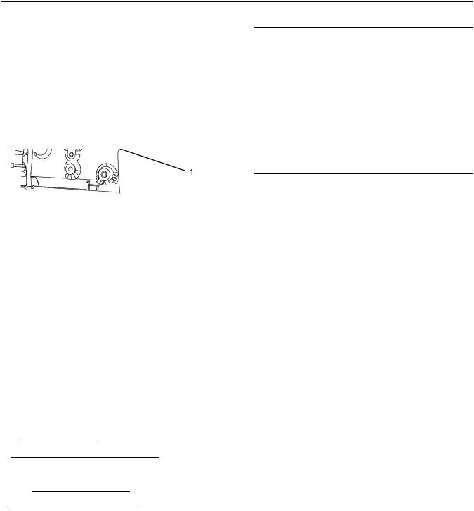
(1) Universal Warning
Do not operate or work on this equipment unless you have read and understand the instructions and warnings in the Operation and Maintenance Manuals. Failure to follow the instructions or heed the warnings could result in serious injury or death.
Typical example
The Universal Warning label (1) is located on both sides of the valve mechanism cover base.
5
Safety Section
Safety Messages
Safety Section
Safety Messages
2 Hand (High Pressure)
Contact with high pressure fuel may cause fluid penetration and burn hazards. High pressure fuel spray may cause a fire hazard. Failure to follow these inspection, maintenance and service instructions may cause personal injury or death.
|
The warning label for the Hand (High Pressure) (2) is |
|
|
a wrap around label that is located on the rear injector |
|
|
Illustration 3 |
line. |
|
g01154858 |
|
|
Typical example |
Ether |
Do not use aerosol types of starting aids such as ether. Such use could result in an explosion and personal injury.
Safety Section
General Hazard Information
Typical example
The ether warning label is supplied loose for the original equipment manufacture to install the label.
i05737934
General Hazard Information
Attach a “Do Not Operate” warning tag or a similar warning tag to the start switch or to the controls before you service the equipment or before you repair the equipment.
Wear a hard hat, protective glasses, and other protective equipment, as required.
Do not wear loose clothing or jewelry that can snag on controls or on other parts of the engine.
Make sure that all protective guards and all covers are secured in place on the engine.
Keep the engine free from foreign material. Remove
debris, oil, tools, and other items from the deck, from walkways, and from steps.
Never put maintenance fluids into glass containers. Drain all liquids into a suitable container.
Obey all local regulations for the disposal of liquids.
Use all cleaning solutions with care.
Report all necessary repairs.
Do not allow unauthorized personnel on the equipment.
Ensure that the power supply is disconnected before you work on the bus bar or the glow plugs.
Perform maintenance on the engine with the equipment in the servicing position. Refer to the OEM information for the procedure for placing the equipment in the servicing position.
Pressure Air and Water
Pressurized air and/or water can cause debris and/or hot water to be blown out. This action could result in personal injury.
The direct application of pressurized air or pressurized water to the body could result in personal injury.
When pressurized air and/or water is used for cleaning, wear protective clothing, protective shoes, and eye protection. Eye protection includes goggles or a protective face shield.
8
Safety Section
Burn Prevention
The maximum air pressure for cleaning purposes must be below 205 kPa (30 psi). The maximum water pressure for cleaning purposes must be below
275 kPa (40 psi).
Fluid Penetration
Pressure can be trapped in the hydraulic circuit long after the engine has been stopped. The pressure can cause hydraulic fluid or items such as pipe plugs to escape rapidly if the pressure is not relieved correctly.
Do not remove any hydraulic components or parts until pressure has been relieved or personal injury may occur. Do not disassemble any hydraulic components or parts until pressure has been relieved or personal injury may occur. Refer to the OEM information for any procedures that are required to relieve the hydraulic pressure.
Always use a board or cardboard when you check for a leak. Leaking fluid that is under pressure can penetrate body tissue. Fluid penetration can cause serious injury and possible death. A pin hole leak can cause severe injury. If fluid is injected into your skin, you must get treatment immediately. Seek treatment from a doctor that is familiar with this type of injury.
Containing Fluid Spillage
Care must be taken in order to ensure that fluids are contained during performance of inspection,
maintenance, testing, adjusting, and repair of the engine. Make provision to collect the fluid with a suitable container before any compartment is opened or before any component is disassembled.
•Only use the tools that are suitable for collecting fluids and equipment that is suitable for collecting fluids.
•Only use the tools that are suitable for containing fluids and equipment that is suitable for containing fluids.
Obey all local regulations for the disposal of liquids.
SEBU9066
Static Electricity Hazard when Fueling with Ultra-low Sulfur Diesel Fuel
The removal of sulfur and other compounds in ultralow sulfur diesel fuel (ULSD fuel) decreases the conductivity of ULSD and increases the ability of ULSD to store static charge. Refineries may have treated the fuel with a static dissipating additive. Many factors can reduce the effectiveness of the additive over time. Static charges can build up in ULSD fuel while the fuel is flowing through fuel delivery systems. Static electricity discharge when combustible vapors are present could result in a fire or explosion. Ensure that the entire system used to refuel your machine (fuel supply tank, transfer pump, transfer hose, nozzle, and others) is properly grounded and bonded. Consult with your fuel or fuel system supplier to ensure that the delivery system complies with fueling standards for proper grounding and bonding.
Avoid static electricity risk when fueling. Ultra-low sulfur diesel fuel (ULSD fuel) poses a greater static ignition hazard than earlier diesel formulations with a higher sulfur contents. Avoid death or serious injury from fire or explosion. Consult with your fuel or fuel system supplier to ensure the delivery system is in compliance with fueling standards for proper grounding and bonding practices.
i05302522
Burn Prevention
Do not touch any part of an operating engine. Allow the engine to cool before any maintenance is performed on the engine.
Contact with high pressure fuel may cause fluid penetration and burn hazards. High pressure fuel spray may cause a fire hazard. Failure to follow these inspection, maintenance and service instructions may cause personal injury or death.
NOTICE
The low-pressure fuel system can be pressurized for a time period after the engine has stopped operating. The operating pressure of the low-pressure fuel system can be 500 kPa (73 psi). The secondary fuel filters should be drained before any maintenance of the low-pressure fuel system is carried out.
SEBU9066
After the engine has stopped, you must wait for 60 seconds in order to allow the fuel pressure to be purged from the high-pressure fuel lines before any service or repair is performed on the engine fuel lines.
Allow the pressure to be purged in the air system, in the hydraulic system, in the lubrication system, or in the cooling system before any lines, fittings, or related items are disconnected.
Coolant
When the engine is at operating temperature, the engine coolant is hot. The coolant is also under pressure. The radiator and all lines to the heaters or to the engine contain hot coolant.
Any contact with hot coolant or with steam can cause severe burns. Allow cooling system components to cool before the cooling system is drained.
Check that the coolant level after the engine has stopped and the engine has been allowed to cool.
Ensure that the filler cap is cool before removing the filler cap. The filler cap must be cool enough to touch with a bare hand. Remove the filler cap slowly in order to relieve pressure.
Cooling system conditioner contains alkali. Alkali can cause personal injury. Do not allow alkali to contact the skin, the eyes, or the mouth.
Oils
Hot oil and hot lubricating components can cause personal injury. Do not allow hot oil to contact the skin. Also, do not allow hot components to contact the skin.
Batteries
Electrolyte is an acid. Electrolyte can cause personal injury. Do not allow electrolyte to contact the skin or the eyes. Always wear protective glasses for servicing batteries. Wash hands after touching the batteries and connectors. Use of gloves is recommended.
9
Safety Section
Fire Prevention and Explosion Prevention
i04823662
Fire Prevention and Explosion
Prevention
All fuels, most lubricants, and some coolant mixtures are flammable.
Flammable fluids that are leaking or spilled onto hot surfaces or onto electrical components can cause a fire. Fire may cause personal injury and property damage.
After the emergency stop button is operated, ensure that you allow 15 minutes, before the engine covers are removed.
Determine whether the engine will be operated in an environment that allows combustible gases to be drawn into the air inlet system. These gases could cause the engine to overspeed. Personal injury, property damage, or engine damage could result.
If the application involves the presence of combustible gases, consult your Perkins dealer and/ or your Perkins distributor for additional information about suitable protection devices.
Remove all flammable combustible materials or conductive materials such as fuel, oil, and debris from the engine. Do not allow any flammable combustible
materials or conductive materials to accumulate on the engine.
Store fuels and lubricants in correctly marked containers away from unauthorized persons. Store oily rags and any flammable materials in protective
containers. Do not smoke in areas that are used for storing flammable materials.
Do not expose the engine to any flame.
Exhaust shields (if equipped) protect hot exhaust components from oil or fuel spray in a line, a tube, or
a seal failure. Exhaust shields must be installed correctly.
Safety Section
Fire Prevention and Explosion Prevention
Do not weld on lines or tanks that contain flammable fluids. Do not flame cut lines or tanks that contain flammable fluid. Clean any such lines or tanks
thoroughly with a nonflammable solvent prior to welding or flame cutting.
Wiring must be kept in good condition. Ensure that all electrical wires are correctly routed and securely attached. Check all electrical wires daily. Repair any wires that are loose or frayed before you operate the engine. Clean all electrical connections and tighten all electrical connections.
Eliminate all wiring that is unattached or unnecessary. Do not use any wires or cables that are smaller than the recommended gauge. Do not bypass any fuses and/or circuit breakers.
Arcing or sparking could cause a fire. Secure connections, recommended wiring, and correctly maintained battery cables will help to prevent arcing or sparking.
Contact with high pressure fuel may cause fluid penetration and burn hazards. High pressure fuel spray may cause a fire hazard. Failure to follow these inspection, maintenance and service instructions may cause personal injury or death.
After the engine has stopped, wait for 60 seconds in order to allow the fuel pressure to be purged from the high-pressure fuel lines before any service or repair is performed on the engine fuel lines.
Ensure that the engine is stopped. Inspect all lines and hoses for wear or for deterioration. Properly route all hoses. The lines and hoses must have adequate support and secure clamps.
Properly install oil filters and fuel filters. The filter housings must be tightened to the correct torque. Refer to the Disassembly and Assembly manual for more information.
|
Illustration 10 |
g00704059 |
Use caution when you are refueling an engine. Do not smoke while you are refueling an engine. Do not refuel an engine near open flames or sparks. Always stop the engine before refueling.
|
Illustration 11 |
g02298225 |
Gases from a battery can explode. Keep any open flames or sparks away from the top of a battery. Do not smoke in battery charging areas.
Never check the battery charge by placing a metal object across the terminal posts. Use a voltmeter or a hydrometer.
Incorrect jumper cable connections can cause an explosion that can result in injury. Refer to the Operation Section of this manual for specific instructions.
![]()
Safety Section
Crushing Prevention and Cutting Prevention
Do not charge a frozen battery.Charging a frozen battery may cause an explosion.
The batteries must be kept clean. The covers (if equipped) must be kept on the cells. Use the recommended cables, connections, and battery box covers when the engine is operated.
Fire Extinguisher
Make sure that a fire extinguisher is available. Be familiar with the operation of the fire extinguisher. Inspect the fire extinguisher and service the fire extinguisher regularly. Obey the recommendations on the instruction plate.
Lines, Tubes, and Hoses
Do not bend high-pressure lines. Do not strike highpressure lines. Do not install any lines that are damaged.
Leaks can cause fires. Consult your Perkins dealer or your Perkins distributor for replacement parts.
Replace the parts if any of the following conditions are present:
•High-pressure fuel line or lines are removed.
•End fittings are damaged or leaking.
•Outer coverings are chafed or cut.
•Wires are exposed.
•Outer coverings are ballooning.
•Flexible parts of the hoses are kinked.
•Outer covers have embedded armoring.
•End fittings are displaced.
Make sure that all clamps, guards, and heat shields are installed correctly in order to prevent vibration, rubbing against other parts, and excessive heat.
i02143194
Crushing Prevention and
Cutting Prevention
Support the component correctly when work beneath the component is performed.
Unless other maintenance instructions are provided, never attempt adjustments while the engine is running.
Stay clear of all rotating parts and of all moving parts. Leave the guards in place until maintenance is performed. After the maintenance is performed, reinstall the guards.
Keep objects away from moving fan blades. The fan blades will throw objects or cut objects.
When objects are struck, wear protective glasses in order to avoid injury to the eyes.
Chips or other debris may fly off objects when objects are struck. Before objects are struck, ensure that no one will be injured by flying debris.
i05463929
Mounting and Dismounting
Do not climb on the engine. The engine has not been designed with mounting or dismounting locations.
Refer to the Original Equipment Manufacture (OEM) for the location of foot and hand holds for your specific application.
i05463931
High Pressure Fuel Lines
Contact with high pressure fuel may cause fluid penetration and burn hazards. High pressure fuel spray may cause a fire hazard. Failure to follow these inspection, maintenance and service instructions may cause personal injury or death.
Safety Section
High Pressure Fuel Lines
|
Illustration 12 |
g03452057 |
|
|
(1) High-pressure line |
(4) High-pressure line |
(7) High-pressure supply line |
|
(2) High-pressure line |
(5) High-pressure fuel manifold (rail) |
|
|
(3) High-pressure line |
(6) High-pressure supply line |
The high-pressure fuel lines are the fuel lines that are between the high-pressure fuel pump and the highpressure fuel manifold and the fuel lines that are between the fuel manifold and cylinder head. These
fuel lines are different from fuel lines on other fuel systems.
This difference is because of the following items:
•The high-pressure fuel lines are constantly charged with high pressure.
•The internal pressures of the high-pressure fuel lines are higher than other types of fuel system.
•The high-pressure fuel lines are formed to shape and then strengthened by a special process.
Do not step on the high-pressure fuel lines. Do not deflect the high-pressure fuel lines. Do not bend or strike the high-pressure fuel lines. Deformation or damage of the high-pressure fuel lines may cause a point of weakness and potential failure.
Do not check the high-pressure fuel lines with the engine or the starting motor in operation. After the engine has stopped, allow 90 seconds to pass in order to allow the pressure to be purged before any service or repair is performed on the engine fuel lines.
Do not loosen the high-pressure fuel lines in order to remove air from the fuel system. This procedure is not required.
Visually inspect the high-pressure fuel lines before the engine is started. This inspection should be each day.
If you inspect the engine in operation, always use the proper inspection procedure in order to avoid a fluid penetration hazard. Refer to Operation and Maintenance Manual, “General hazard Information”.
Safety Section
Before Starting Engine
•Inspect the high-pressure fuel lines for damage, deformation, a nick, a cut, a crease, or a dent.
•Do not operate the engine with a fuel leak. If there is a leak, do not tighten the connection in order to stop the leak. The connection must only be tightened to the recommended torque. Refer to Disassembly and Assembly, “Fuel injection lines — Remove and Fuel injection lines — Install”.
•If the high-pressure fuel lines are torqued correctly and the high-pressure fuel lines are leaking, the high-pressure fuel lines must be replaced.
•Ensure that all clips on the high-pressure fuel lines are in place. Do not operate the engine with clips that are damaged, missing, or loose.
•Do not attach any other item to the high-pressure fuel lines.
•Loosened high-pressure fuel lines must be replaced. Also removed high-pressure fuel lines must be replaced. Refer to Disassembly and assembly manual, “Fuel Injection Lines — Install”.
NOTICE
The low-pressure fuel system can be pressurized for a time period after the engine has stopped operating. The operating pressure of the low-pressure fuel system can be 500 kPa (73 psi). The secondary fuel filters should be drained before any maintenance of the low-pressure fuel system is carried out.
i02813489
Before Starting Engine
Before the initial start-up of an engine that is new, serviced or repaired, make provision to shut the engine off, in order to stop an overspeed. This may be accomplished by shutting off the air and/or fuel supply to the engine.
Overspeed shutdown should occur automatically for engines that are controlled electronically. If automatic shutdown does not occur, press the emergency stop button in order to cut the fuel and/or air to the engine.
Inspect the engine for potential hazards.
Before starting the engine, ensure that no one is on, underneath, or close to the engine. Ensure that the area is free of personnel.
If equipped, ensure that the lighting system for the engine is suitable for the conditions. Ensure that all lights work correctly, if equipped.
All protective guards and all protective covers must be installed if the engine must be started in order to perform service procedures. To help prevent an accident that is caused by parts in rotation, work around the parts carefully.
Do not bypass the automatic shutoff circuits. Do not
disable the automatic shutoff circuits. The circuits are provided in order to help prevent personal injury. The
circuits are also provided in order to help prevent engine damage.
See the Service Manual for repairs and for adjustments.
i02251260
Engine Starting
Do not use aerosol types of starting aids such as ether. Such use could result in an explosion and personal injury.
If a warning tag is attached to the engine start switch or to the controls DO NOTstart the engine or move the controls. Consult with the person that attached the warning tag before the engine is started.
All protective guards and all protective covers must be installed if the engine must be started in order to perform service procedures. To help prevent an accident that is caused by parts in rotation, work around the parts carefully.
Start the engine from the operator’s compartment or from the engine start switch.
Always start the engine according to the procedure that is described in the Operation and Maintenance Manual, “Engine Starting” topic in the Operation Section. Knowing the correct procedure will help to prevent major damage to the engine components. Knowing the procedure will also help to prevent personal injury.
To ensure that the jacket water heater (if equipped) and/or the lube oil heater (if equipped) is working correctly, check the water temperature gauge and/or the oil temperature gauge during the heater operation.
Engine exhaust contains products of combustion which can be harmful to your health. Always start the engine and operate the engine in a well ventilated area. If the engine is started in an enclosed area, vent the engine exhaust to the outside.
14
Safety Section
Engine Stopping
Note: The engine is equipped with a device for cold starting. If the engine will be operated in very cold conditions, then an extra cold starting aid may be required. Normally, the engine will be equipped with the correct type of starting aid for your region of operation.
These engines are equipped with a glow plug starting aid in each individual cylinder that heats the intake air in order to improve starting.
i02234873
Engine Stopping
Stop the engine according to the procedure in the Operation and Maintenance Manual, “Engine Stopping (Operation Section)” in order to avoid overheating of the engine and accelerated wear of the engine components.
Use the Emergency Stop Button (if equipped) ONLY in an emergency situation. Do not use the Emergency Stop Button for normal engine stopping. After an emergency stop, DO NOTstart the engine until the problem that caused the emergency stop has been corrected.
Stop the engine if an overspeed condition occurs during the initial start-up of a new engine or an engine that has been overhauled.
To stop an electronically controlled engine, cut the power to the engine and/or shutting off the air supply to the engine.
i05464430
Electrical System
Never disconnect any charging unit circuit or battery circuit cable from the battery when the charging unit is operating. A spark can cause the combustible gases that are produced by some batteries to ignite.
To help prevent sparks from igniting combustible gases that are produced by some batteries, the negative “−” cable should be connected last from the external power source to the primary position for grounding.
Check the electrical wires daily for wires that are loose or frayed. Tighten all loose electrical connections before the engine is started. Repair all frayed electrical wires before the engine is started. See the Operation and Maintenance Manual for specific starting instructions.
SEBU9066
Grounding Practices
|
Illustration 13 |
g03452577 |
(1)Ground to battery
(2)Ground to starting motor
(3)Starting motor to engine block
|
Illustration 14 |
g03452579 |
(4)Battery to ground
(5)Ground to engine block
(6)Primary position for grounding
Correct grounding for the engine electrical system is necessary for optimum engine performance and reliability. Incorrect grounding will result in uncontrolled electrical circuit paths and in unreliable electrical circuit paths.
SEBU9066
Uncontrolled electrical circuit paths can result in damage to the crankshaft bearing journal surfaces and to aluminum components.
Engines that are installed without engine-to-frame ground straps can be damaged by electrical discharge.
To ensure that the engine and the engine electrical systems function correctly, an engine-to-frame ground strap with a direct path to the battery must be used. This path may be provided by way of a direct engine ground to the frame.
The connections for the grounds should be tight and free of corrosion. The engine alternator must be grounded to the negative “-” battery terminal. The wire used must be adequate to handle the full charging current of the alternator.
The power supply connections and the ground connections for the engine electronics should always be from the isolator to the battery.
i05272352
Engine Electronics
Tampering with the electronic system installation or the OEM wiring installation can be dangerous and could result in personal injury or death and/or engine damage.
Electrical Shock Hazard. The electronic unit injectors use DC voltage. The ECM sends this voltage to the electronic unit injectors. Do not come in contact with the harness connector for the electronic unit injectors while the engine is operating. Failure to follow this instruction could result in personal injury or death.
This engine has a comprehensive, programmable Engine Monitoring System . The Electronic Control Module (ECM) monitors the engine operating conditions. If any of the engine parameters extend outside an allowable range, the ECM will initiate an immediate action.
The following actions are available for engine monitoring control:
•Warning
•Derate
•Shutdown
15
Safety Section
Engine Electronics
The following monitored engine operating conditions have the ability to limit engine speed and/or the engine power:
•Engine Coolant Temperature
•Engine Oil Pressure
•Engine Speed
•Intake Manifold Air Temperature
•Intake Manifold Air pressure
The Engine Monitoring package can vary for different engine models and different engine applications. However, the monitoring system and the engine monitoring control will be similar for all engines.
Note: Many of the engine control systems and display modules that are available for Perkins Engines will work in unison with the Engine Monitoring System. Together, the two controls will provide the engine monitoring function for the specific engine application. Refer to the Troubleshooting for more information on the Engine Monitoring System.
Product Information Section
Model View Illustrations
Product Information
Section
General Information
i05536748
Model View Illustrations
The following model views show typical features of the engine Due to individual applications, your engine may appear different from the illustrations.
Turbocharged Aftercooled Engine
|
Illustration 15 |
g03453518 |
Typical example
|
(1) Open Breather System |
(4) Oil Level Gauge (Dipstick) |
(7) Oil Filler |
|
(2) Air Intake |
(5) Location for Oil Sample Valve |
(8) Secondary Fuel Filters |
|
(3) Electronic Control Module |
(6) Oil Filter |
General Information
Model View Illustrations
|
Illustration 16 |
g03453526 |
|
|
Typical example |
||
|
(9) Front Lifting Eye |
(11) Coolant Intake |
(13) Belt |
|
(10) Water Pump |
(12) Tensioner |
(14) Coolant Outlet |
General Information
Model View Illustrations
|
Illustration 17 |
g03453529 |
|
|
Typical example |
||
|
(15) Rear Lifting Eye |
(18) Starter Solenoid |
(21) Flywheel |
|
(16) Alternator |
(19) Starting Motor |
(22) Flywheel Housing |
|
(17) Turbocharger |
(20) Oil Drain Plug |
(23) Coolant Drain Plug |
General Information
Model View Illustrations
Turbocharge Engine View
|
Illustration 18 |
g03506649 |
Typical example
General Information
Product Description
Off Engine Parts and Options
|
Illustration 19 |
g03467856 |
|
|
Typical examples |
||
|
(24) Electric Priming Pump |
(26) Mechanical Priming Pump |
(28) Spin on Crankcase Breather |
|
(25) Primary Fuel Filter |
(27) Primary Fuel Filter |
Note: Item (28) is part of the filtered breather system.
i05536753
Product Description
There are two different variants of this Perkins engine. Engines with prefix NR are turbocharged
aftercooled engines 1104D-E44TA. Engines with prefix NP are turbocharged engines 1104D-E44T.
Engine Specifications
Note: The front end of the engine is opposite the flywheel end of the engine. The left and the right sides of the engine are determined from the flywheel end. The number 1 cylinder is the front cylinder.
|
Illustration 20 |
g01187485 |
Cylinder and valve location
(A)Exhaust valves
(B)Inlet valves
![]()
SEBU9066
Table 1
Engine Specifications
|
Operating Range (rpm) |
900 to 2800(1) |
|
|
Number of Cylinders |
4 In-Line |
|
|
Bore |
105 mm (4.13 inch) |
|
|
Stroke |
127 mm (5 inch) |
|
|
Aspiration |
Turbocharged or |
|
|
Turbocharged Aftercooled |
||
|
Compression Ratio |
16.2:1 |
|
|
Displacement |
4.4 L (268.5 cubic inch) |
|
|
Firing Order |
1-3-4-2 |
|
|
Rotation (flywheel end) |
Counterclockwise |
|
|
Number of valves for each |
4 |
|
|
cylinder |
||
|
Valve Lash Setting (Inlet) |
0.35 mm (0.013 inch) |
|
|
Valve Lash Setting (Exhaust) |
0.35 mm (0.013 inch) |
(1)The operating rpm is dependent on the engine rating, the application, and the configuration of the throttle.
Electronic Engine Features
The engine operating conditions are monitored. The Electronic Control Module (ECM) controls the response of the engine to these conditions and to the demands of the operator. These conditions and operator demands determine the precise control of fuel injection by the ECM. The electronic engine control system provides the following features:
•Engine monitoring
•Engine speed governing
•Control of the injection pressure
•Cold start strategy
•Automatic air/fuel ratio control
•Torque rise shaping
•Injection timing control
•System diagnostics
For more information on electronic engine features, refer to the Operation and Maintenance Manual, “Features and Controls” topic (Operation Section).
21
General Information
Product Description
Engine Diagnostics
The engine has built-in diagnostics in order to ensure that the engine systems are functioning correctly. The operator will be alerted to the condition by a “Stop or Warning” lamp. Under certain conditions, the engine power and the engine speed may be limited. The electronic service tool may be used to display the diagnostic codes.
There are two types of diagnostic codes: active and logged.
Most of the diagnostic codes are logged and stored in
the ECM. For additional information, refer to the Operation and Maintenance Manual, “Engine
Diagnostics” topic (Operation Section).
The ECM provides an electronic governor that controls the injector output in order to maintain the desired engine rpm.
For more information refer to Troubleshooting manual.
Engine Cooling and Lubrication
The cooling system consists of the following components:
•Gear-driven centrifugal water pump
•Water temperature regulator which regulates the engine coolant temperature
•Gear-driven rotor type oil pump
•Oil cooler
The engine lubricating oil is supplied by a rotor type oil pump. The engine lubricating oil is cooled and the engine lubricating oil is filtered. The bypass valve can provide unrestricted flow of lubrication oil to the engine if the oil filter element should become plugged.
Engine efficiency, efficiency of emission controls, and engine performance depend on adherence to proper operation and maintenance recommendations.
Engine performance and efficiency also depend on
the use of recommended fuels, lubrication oils, and coolants. Refer to this Operation and Maintenance
Manual, “Maintenance Interval Schedule” for more information on maintenance items.
Option Section
There are two different types of fuel priming pump available, hand primer or an electrically operated primer. There are two different types of crankcase breather, open breather or filtered open breather.
Product Identification Information
Plate Locations and Film Locations
Product Identification
Information
i05536932
Plate Locations and Film
Locations
|
Illustration 22 |
g02433756 |
Typical example
|
Illustration 21 |
g03453612 |
Perkins engines are identified by an engine serial number.
An example of an engine number is N-
*****R000001X.
|
***** |
The list number for the engine |
|
N- |
Type of engine |
|
R |
Built-in China |
|
000001 |
Engine Serial Number |
|
X |
Year of Manufacture |
Perkins dealers or Perkins distributors need all of these numbers in order to determine the components
that were included with the engine. This information permits accurate identification of replacement part numbers.
Serial Number Plate (1)
The engine serial number plate is located on the left side of the cylinder block to the rear of the front engine mounting.
Product Identification Information
Emissions Certification Film
i05536952
Emissions Certification Film
|
Illustration 23 |
g03506769 |
|
Typical example |
|
|
i05465764 |
(If equipped) Filtered Breather |
Reference Information
Information for the following items may be needed to order parts. Locate the information for your engine. Record the information in the appropriate space. Make a copy of this list for a record. Keep the information for future reference.
Record for Reference
Engine Model
Engine Serial number
Engine Low Idle rpm
Engine Full Load rpm
Primary Fuel Filter
Secondary Fuel Filter Element
Lubrication Oil Filter
Total Lubrication System Capacity
Total Cooling System Capacity
Air Cleaner Element
Drive Belt
24
Operation Section
Product Lifting
Operation Section
Lifting and Storage
i02677363
Product Lifting
|
Illustration 24 |
g00103219 |
NOTICE
Never bend the eyebolts and the brackets. Only load the eyebolts and the brackets under tension. Remember that the capacity of an eyebolt is less as the angle between the supporting members and the object becomes less than 90 degrees.
When it is necessary to remove a component at an angle, only use a link bracket that is properly rated for the weight.
Use a hoist to remove heavy components. Use an adjustable lifting beam to lift the engine. All supporting members (chains and cables) should be parallel to each other. The chains and cables should be perpendicular to the top of the object that is being lifted.
Some removals require lifting the fixtures in order to obtain proper balance and safety.
To remove the engine ONLY, use the lifting eyes that are on the engine.
Lifting eyes are designed and installed for specific engine arrangements. Alterations to the lifting eyes and/or the engine make the lifting eyes and the lifting
fixtures obsolete. If alterations are made, ensure that proper lifting devices are provided. Consult your
Perkins dealer for information regarding fixtures for proper engine lifting.
SEBU9066
i04151489
Product Storage
Perkins are not responsible for damage which may occur when an engine is in storage after a period in service.
Your Perkins dealer or your Perkins distributor can assist in preparing the engine for extended storage periods.
Condition for Storage
The engine must be stored in a water proof building. The building must be kept at a constant temperature. Engines that are filled with Perkins ELC will have coolant protection to an ambient temperature of −36° C (−32.8° F). The engine must not be subjected to extreme variations in temperature and humidity.
Storage Period
An engine can be stored for up to 6 months provided all the recommendation are adhered to.
Storage Procedure
Keep a record of the procedure that has been completed on the engine.
Note: Do not store an engine that has biodiesel in the fuel system.
1.Ensure that the engine is clean and dry.
a.If the engine has been operated using biodiesel, the system must be drained and new filters installed. The fuel tank will require flushing.
b.Fill the fuel system with an acceptable fuel. For more information on acceptable fuels refer to this Operation and Maintenance Manual, “Fluid recommendations”. Operate the engine for 15 minutes in order to remove all biodiesel from the system.
2.Drain any water from the primary filter water separator. Ensure that the fuel tank is full.
3.The engine oil will not need to be drained in order to store the engine. Provided the correct specification of engine oil is used the engine can be stored for up to 6 months. For the correct specification of engine oil refer to this Operation and Maintenance Manual, “Fluid recommendations”.
4.Remove the drive belt from the engine.
SEBU9066
Sealed Coolant System
Ensure that the cooling system is filled with Perkins
ELC, or an antifreeze that meets “ASTM D6210” specification.
Open Cooling System
Ensure that all cooling drain plugs have been opened. Allow the coolant to drain. Install the drain plugs. Place a vapor phase inhibitor into the system. The coolant system must be sealed once the vapor phase inhibitor has been introduced. The effect of the vapor phase inhibitor will be lost if the cooling system is open to the atmosphere.
For maintenance procedures refer to this Operation and Maintenance Manual.
Monthly Checks
The crankshaft must be rotated in order to change the spring loading on the valve train. Rotate the crankshaft more than 180 degrees. Visibly check for damage or corrosion to the engine.
Ensure that the engine is covered completely before storage. Log the procedure in the record for the engine.
25
Lifting and Storage
Product Storage
26
Features and Controls
Alarms and Shutoffs
Features and Controls
i05251301
Alarms and Shutoffs
Shutoffs
The shutoffs are electrically operated or mechanically operated. The electrically operated shutoffs are controlled by the ECM.
Shutoffs are set at critical levels for the following items:
•Operating temperature
•Operating pressure
•Operating level
•Operating rpm
The particular shutoff may need to be reset before the engine will start.
NOTICE
Always determine the cause of the engine shutdown. Make necessary repairs before attempting to restart the engine.
Be familiar with the following items:
•Types and locations of shutoff
•Conditions which cause each shutoff to function
•The resetting procedure that is required to restart the engine
Alarms
The alarms are electrically operated. The operation of the alarms is controlled by the ECM.
The alarm is operated by a sensor or by a switch. When the sensor or the switch is activated, a signal is sent to the ECM. An event code is created by the ECM. The ECM will send a signal in order to illuminate the lamp.
Your engine may be equipped with the following sensors or switches:
Coolant level – The low coolant level switch indicates when the coolant level is low.
Coolant temperature – The coolant temperature sensor indicates high jacket water coolant temperature.
SEBU9066
Intake manifold air temperature – The intake manifold air temperature sensor indicates high intake air temperature.
Intake manifold pressure – The intake manifold pressure sensor checks the rated pressure in the
engine manifold.
Fuel rail pressure – The fuel rail pressure sensor checks for high pressure or low pressure in the fuel rail.
Engine oil pressure – The engine oil pressure sensor indicates when oil pressure drops below rated system pressure, at a set engine speed.
Engine overspeed – The primary speed/timing sensor checks the engine speed. The alarm is activated at 3000 RPM.
Air filter restriction – The switch checks the air filter when the engine is operating.
User-defined switch – This switch can shut down the engine remotely.
Water in fuel switch – This switch checks for water in the primary fuel filter when the engine is operating.
Note: The sensing element of the coolant temperature switch must be submerged in coolant in order to operate.
Engines may be equipped with alarms in order to alert the operator when undesirable operating conditions occur.
NOTICE
When an alarm is activated, corrective measures must be taken before the situation becomes an emergency in order to avoid possible engine damage.
If corrective measures are not taken within a reasonable time, engine damage could result. The
alarm will continue until the condition is corrected. The alarm may need to be reset.
Testing
Turning the keyswitch to the ON position will check the indicator lights on the control panel. All the indicator lights will be illuminated for 2 seconds after the keyswitch is operated. Replace suspect bulbs immediately.
Refer to Troubleshooting for more information.
SEBU9066
i05537598
Gauges and Indicators
Your engine may not have the same gauges or all of the gauges that are described. For more information about the gauge package, see the OEM information.
Gauges provide indications of engine performance. Ensure that the gauges are in good working order. Determine the normal operating range by observing the gauges over a period.
Noticeable changes in gauge readings indicate potential gauge or engine problems. Problems may also be indicated by gauge readings that change even if the readings are within specifications. Determine and correct the cause of any significant change in the readings. Consult your Perkins dealer or your distributor Perkins for assistance.
Some engine applications are equipped with Indicator Lamps. Indicator lamps can be used as a diagnostic aid. There are two lamps. One lamp has an orange lens and the other lamp has a red lens.
These indicator lamps can be used in two ways:
•The indicator lamps can be used to identify the current operational status of the engine. The indicator lamps can also indicate that the engine has a fault. This system is automatically operated via the ignition switch.
•The indicator lamps can be used to identify active diagnostic codes.
Refer to the Troubleshooting Guide, “Indicator Lamps” for further information.
NOTICE
If no oil pressure is indicated, STOP the engine. If maximum coolant temperature is exceeded, STOP the engine. Engine damage can result.
Engine Oil Pressure – The oil pressure should be greatest after a cold engine is started. The typical engine oil pressure with SAE10W40 is 350 to 450 kPa ( 50 to 65 psi) at
rated rpm.
A lower oil pressure is normal at low idle. If the load is stable and the gauge reading changes, perform the following procedure:
1.Remove the load.
2.Stop the engine.
3.Check and maintain the oil level.
27
Features and Controls
Gauges and Indicators
Jacket Water Coolant Temperature – Typical temperature range is 83° to 95°C (181.4° to 171°F). The maximum
allowable temperature at sea level with the pressurized cooling system at 48 kPa (7 psi) is 103 °C (217.4 °F). Higher temperatures may occur under certain conditions. The water temperature reading may vary according to load. The temperature reading should never exceed 7 °C (44.6 °F) below the boiling point for the pressurized system that is being used.
A 100 kPa (14.5 psi) radiator cap may be installed on the cooling system. The temperature of this cooling system must not exceed 112 °C (233.6 °F).
If the engine is operating above the normal range and steam becomes apparent, perform the following procedure:
1.Reduce the load and the engine rpm.
2.Determine if the engine must be shut down immediately or if the engine can be cooled by reducing the load.
3.Inspect the cooling system for leaks.
Tachometer – This gauge indicates engine speed (rpm). When the throttle control lever is moved to the full throttle
position without load, the engine is running at high idle. The engine is running at the full load rpm when the throttle control lever is at the full throttle position with maximum rated load.
NOTICE
To help prevent engine damage, never exceed the high idle rpm. Overspeeding can result in serious damage to the engine. Operation at speeds exceeding high idle rpm should be kept to a minimum.
Ammeter – This gauge indicates the amount of charge or discharge in the battery charging circuit. Operation of the
indicator should be to the ““+”” side of ““0”” (zero).
Fuel Level – This gauge indicates the fuel level in the fuel tank. The fuel level gauge operates when the ““START/
STOP”” switch is in the ““on”” position.
Service Hour Meter – The gauge indicates total operating hours of the engine.
Indicator Lamps
There are four main indicator lamps that are available.
Features and Controls
Gauges and Indicators
•Shutdown Lamp
•Warning Lamp
•Wait to Start Lamp
•Low Oil Pressure Lamp
For information, refer to this manual, “Monitoring System (Table for the Indicator Lamps)” for the sequence of operation of the shutdown lamp and the warning lamp.
The function of the wait to start lamp is automatically controlled at engine start-up.
The function of the low oil pressure lamp is controlled by the engine ECM. If low oil pressure is detected, the lamp will be illuminated. The reason for the illumination of the low-pressure lamp should be investigated immediately.
All lamps will illuminate for 2 seconds in order to check that the lamps are functioning when the keyswitch is turned to the ON position. If any of the lamps stay illuminated, the reason for illumination should be investigated immediately.
The glow plug warning lamp will flash in order to show that the engine is been held at low speed. This function will be performed at engine starting and the duration will depend on ambient temperature and engine temperature.
Instrument panels and Displays
In order to monitor the engine a wide verity of instrument panels are available. These instrument panels can contain the indicator lamps and the gauges for the application.
Also available are mini power displays and performance monitors. These displays and monitors can show the operator the following engine information.
•The system configuration parameters
•The customer specified parameters
•Diagnostic codes
•Event codes
•Coolant temperature
•Oil temperature
•Oil pressure
•Intake temperature
•Intake pressure
•Fuel temperature
Features and Controls
Monitoring System
i02330192
Monitoring System
Table 2
Warning Lamp
Shutdown
Lamp
ON ON
OFF OFF
ON OFF
ON FLASHING
FLASHING OFF
FLASHING FLASHING
ON ON
|
Lamp Status |
Description of lamp status |
Engine Status |
|
Lamp check |
When the engine start switch is turned to the “ON” po- |
The engine has not been |
|
sition both lamps will illuminate for 2 seconds only. |
started. |
|
|
No faults |
There are no active diagnostic faults. |
The engine is running normally. |
|
Active diagnostic |
An active diagnostic fault has been detected. |
The engine is running normally. |
|
fault |
||
|
Active diagnostic |
A serious active diagnostic fault has been detected and |
The engine is running but the |
|
fault |
an engine derate has been invoked. |
engine has been derated. |
|
Warning |
One or more of the engine protection values has been |
The engine is running normally. |
|
exceeded. |
||
|
Derate and |
One or more of the engine protection values has been |
The engine is running but the |
|
warning |
exceeded. |
engine has been derated. |
|
Engine shutdown |
One or more of the engine protection values has been |
The engine is shutdown or shut- |
|
exceeded or a serious active diagnostic fault has been |
down is imminent. |
|
|
detected. |
i05546770
Monitoring System
If the Shutdown mode has been selected and the warning indicator activates, engine shutdown may take as little as 20 seconds from the time the warning indicator is activated. Depending on the application, special precautions should be taken to avoid personal injury. The engine can be restarted following shutdown for emergency maneuvers, if necessary.
NOTICE
The Engine Monitoring System is not a guarantee against catastrophic failures. Programmed delays and derate schedules are designed to minimize false alarms and provide time for the operator to stop the engine.
The following parameters are monitored:
•Coolant temperature
•Intake manifold air temperature
•Intake manifold air pressure
•Oil pressure
•Pressure in the fuel rail
•Engine speed/timing
Programmable Options and
Systems Operation
If the Warning/Derate/Shutdown mode has been selected and the warning indicator activates, bring the engine to a stop whenever possible. Depending on the application, special precautions should be taken to avoid personal injury.
The engine can be programmed to the following modes:
30
Features and Controls
Overspeed
““Warning””
The “Warning” lamp and the warning signal (orange lamp) turn “ON” and the warning signal is activated continuously in order to alert the operator that one or more of the engine parameters is not within normal operating range.
““Warning/Derate”
The “Diagnostic” lamp turns “ON” and the warning signal (red lamp) is activated. After the warning, the engine power will be derated. The warning lamp will begin to flash when the derating occurs.
The engine will be derated if the engine exceeds preset operational limits. The engine derate is achieved by restricting the amount of fuel that is available for each injection. The amount of this reduction of fuel is dependent on the severity of the fault that has caused the engine derate, typically up
to a limit of 50%. This reduction in fuel results in a predetermined reduction in engine power.
““Warning/Derate/Shutdown”
The “Diagnostic” lamp turns “ON” and the warning signal (red lamp) is activated. After the warning, the engine power will be derated. The engine will continue at the rpm of the set derate until a shutdown of the engine occurs. The engine can be restarted after a shutdown for use in an emergency.
A shutdown of the engine may occur in as little as 20 seconds. The engine can be restarted after a shutdown for use in an emergency. However, the cause of the initial shutdown may still exist. The engine may shut down again in as little as 20 seconds.
If there is a signal for low oil pressure or for coolant temperature, there will be a two second delay in order to verify the condition.
For each of the programmed modes, refer to Troubleshooting Guide, “Indicator Lamps” for more information on Indicator Lamps.
For more information or assistance for repairs, consult your Perkins dealer or your Perkins distributor.
i05251914
Overspeed
An overspeed condition is detected by the Electronic Control Module (ECM). The event code E190 will be logged if the engine speed exceeds 3300 rpm. The “DIAGNOSTIC” lamp will indicate a diagnostic fault code. The diagnostic fault code will remain active until the engine speed drops to 2800 rpm.
SEBU9066
i05488609
Sensors and Electrical
Components
The illustrations within the following sections are typical location of the sensors or electrical components for an industrial engine. Specific engines may appear different due to differences in applications.
![]()
Features and Controls
Sensors and Electrical Components
|
Illustration 25 |
g03470316 |
|
|
Typical example |
||
|
(1) Coolant Temperature Sensor |
(4) Connector for Injectors 1 and Injector 2 |
(7) Fuel Rail Pressure Sensor |
|
(2) Inlet Manifold Pressure Sensor |
(5) Connector for Injectors 3 and Injector 4 |
(8) Diagnostic Connector |
|
(3) Bus Bar for Glow Plugs |
(6) Inlet Manifold Temperature Sensor |
Features and Controls
Sensors and Electrical Components
|
Illustration 26 |
g03470317 |
|
|
Typical example |
||
|
(9) Electronic Control Module |
(11) Oil Pressure Sensor |
(13) Solenoid for the high-pressure fuel |
|
(10) Primary Speed/Timing sensor |
(12) Secondary Speed/Timing sensor |
pump |

Perkins Service and Parts Information System содержит каталоги запасных частей, руководства по диагностике, обслуживанию и ремонту двигателей Perkins общего и промышленного назначения, а так же двигателей для дизельных электростанций.
- Актуальность: 2018
- Система: Windows
- Интерфейс: Многоязычный (русский отсутствует)
- Формат: ISO
- Размер: 5,0 Gb
Руководство на английском языке по техническому обслуживанию и ремонту автомобильных двигателей Perkins Phaser и промышленных двигателей Perkins 1000-й серии.
- Автор: —
- Издательство: Perkins Engines Ltd.
- Год издания: 2002
- Страниц: 440
- Формат: PDF
- Размер: 27,7 Mb
Руководство на английском языке по техническому обслуживанию и ремонту автомобильных дизельных двигателей Perkins моделей 4.99/4.107/4.108.
- Автор: —
- Издательство: Perkins Engines Ltd.
- Год издания: 1983
- Страниц: 114
- Формат: PDF
- Размер: 5,3 Mb
Справочник на английском языке с техническими данными двигателей Perkins объемом до 8,85 л.
- Автор: —
- Издательство: Perkins Engines Ltd.
- Год издания: 1997
- Страниц: 66
- Формат: PDF
- Размер: 1,5 Mb
Руководство на английском языке по техническому обслуживанию и ремонту автомобильных дизельных двигателей Perkins моделей 4.99M/4.107M/4.108M.
- Автор: —
- Издательство: Perkins Engines Ltd.
- Год издания: 1978
- Страниц: 134
- Формат: PDF
- Размер: 9,2 Mb
Руководство по техническому обслуживанию и ремонту двигателя Perkins модели 1104D-E44TA.
- Автор: —
- Издательство: Терция
- Год издания: —
- Страниц: 110
- Формат: —
- Размер: —

Скидки от справочной
При упоминании АСС вы можете получить скидки на запчасти и услуги
- Manuals
- Brands
- Perkins Manuals
- Engine
- 1104D
Manuals and User Guides for Perkins 1104D. We have 2 Perkins 1104D manuals available for free PDF download: Troubleshooting Manual, Operation And Maintenance Manual
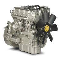
Perkins 1104D Troubleshooting Manual (228 pages)
Industrial Engines
Brand: Perkins
|
Category: Engine
|
Size: 2.66 MB
Table of Contents
-
Table of Contents
3
-
Troubleshooting Section
5
-
Electronic Troubleshooting
5
-
System Overview
5
-
Glossary
8
-
Electronic Service Tools
12
-
Indicator Lamps
14
-
Replacing the ECM
17
-
Self-Diagnostics
18
-
Sensors and Electrical Connectors
18
-
Engine Wiring Information
25
-
ECM Harness Connector Terminals
29
-
Programming Parameters
31
-
Test ECM Mode
31
-
ECM Snapshot
31
-
Factory Passwords
32
-
Factory Passwords Worksheet
33
-
Flash Programming
33
-
Injector Trim File
34
-
Mode Switch Setup
35
-
Throttle Setup
36
-
Multiposition Switch Setup
39
-
Customer Specified Parameters
41
-
Customer Specified Parameters Table
44
-
Customer Specified Parameters Worksheet
45
-
System Configuration Parameters
46
-
Troubleshooting Without a Diagnostic Code
47
-
Alternator Noise
47
-
Alternator will Not Charge
47
-
Battery
48
-
Can Not Reach Top Engine RPM
48
-
Coolant in Engine Oil
50
-
Coolant Temperature Is too High
51
-
ECM will Not Accept Factory Passwords
52
-
ECM will Not Communicate with Other Systems or Display Modules
52
-
Electronic Service Tool will Not Communicate with ECM
52
-
Engine Cranks but will Not Start
53
-
Engine Has Early Wear
56
-
Engine Misfires, Runs Rough or Is Unstable
56
-
Engine Oil in Cooling System
58
-
Engine Speed Does Not Change
59
-
Engine Stalls at Low RPM
60
-
Engine Vibration
61
-
Engine will Not Crank
62
-
Excessive Black Smoke
63
-
Excessive Engine Oil Consumption
65
-
Excessive Fuel Consumption
66
-
Excessive Valve Lash
68
-
Excessive White Smoke
68
-
Intake Air Temperature Is too High
69
-
Intermittent Engine Shutdown
71
-
Intermittent Low Power or Power Cutout
72
-
Low Engine Oil Pressure
73
-
Low Power/Poor or no Response to Throttle
74
-
Mechanical Noise (Knock) in Engine
76
-
Noise Coming from Cylinder
77
-
Troubleshooting with a Diagnostic Code
78
-
Diagnostic Code Cross Reference
78
-
No Diagnostic Codes Detected
80
-
CID 0001 Fmi 02
80
-
CID 0001 Fmi 05
81
-
CID 0001 Fmi 06
81
-
CID 0001 Fmi 07
82
-
CID 0002 Fmi 02
82
-
CID 0002 Fmi 05
83
-
CID 0002 Fmi 06
83
-
CID 0002 Fmi 07
84
-
CID 0003 Fmi 02
84
-
CID 0003 Fmi 05
84
-
CID 0003 Fmi 06
85
-
CID 0003 Fmi 07
85
-
CID 0004 Fmi 02
86
-
CID 0004 Fmi 05
86
-
CID 0004 Fmi 06
87
-
CID 0004 Fmi 07
87
-
CID 0005 Fmi 02
87
-
CID 0005 Fmi 05
88
-
CID 0005 Fmi 06
88
-
CID 0005 Fmi 07
89
-
CID 0006 Fmi 02
89
-
CID 0006 Fmi 05
90
-
CID 0006 Fmi 06
90
-
CID 0006 Fmi 07
91
-
CID 0041 Fmi 03
91
-
CID 0041 Fmi 04
92
-
CID 0091 Fmi 02
92
-
CID 0091 Fmi 03
93
-
CID 0091 Fmi 04
93
-
CID 0091 Fmi 08
94
-
CID 0100 Fmi 03
94
-
CID 0100 Fmi 04
95
-
CID 0100 Fmi 10
95
-
CID 0110 Fmi 03
96
-
CID 0110 Fmi 04
96
-
CID 0168 Fmi 00
96
-
CID 0168 Fmi 01
97
-
CID 0168 Fmi 02
97
-
CID 0172 Fmi 03
98
-
CID 0172 Fmi 04
98
-
CID 0190 Fmi 08
99
-
CID 0247 Fmi 09
99
-
CID 0247 Fmi 12
99
-
CID 0253 Fmi 02
100
-
CID 0261 Fmi 11
100
-
CID 0262 Fmi 03
100
-
CID 0262 Fmi 04
101
-
CID 0268 Fmi 02
101
-
CID 0342 Fmi 08
101
-
CID 0526 Fmi 05
102
-
CID 0526 Fmi 06
102
-
CID 0526 Fmi 07
102
-
CID 0774 Fmi 03
103
-
CID 0774 Fmi 02
103
-
CID 0774 Fmi 04
104
-
CID 0774 Fmi 08
105
-
CID 1639 Fmi 09
105
-
CID 1743 Fmi 02
105
-
CID 1779 Fmi 05
106
-
CID 1779 Fmi 06
106
-
CID 1785 Fmi 03
106
-
CID 1785 Fmi 04
107
-
CID 1785 Fmi 10
107
-
CID 1797 Fmi 03
108
-
CID 1797 Fmi 04
108
-
CID 1834 Fmi 02
108
-
CID 2246 Fmi 06
109
-
Troubleshooting with an Event Code
110
-
Event Codes
110
-
E172 High Air Filter Restriction
110
-
E194 High Exhaust Temperature
110
-
E232 High Fuel/Water Separator Water Level
111
-
E360 Low Engine Oil Pressure
111
-
E361 High Engine Coolant Temperature
113
-
E362 Engine Overspeed
114
-
E396 High Fuel Rail Pressure
115
-
E398 Low Fuel Rail Pressure
115
-
E539 High Intake Manifold Air Temperature
116
-
E2143 Low Engine Coolant Level
117
-
Diagnostic Functional Tests
118
-
Volt Sensor Supply Circuit — Test
118
-
Analog Throttle Position Sensor Circuit — Test
125
-
CAN Data Link Circuit — Test
130
-
Data Link Circuit — Test
133
-
Digital Throttle Position Sensor Circuit — Test
139
-
ECM Memory — Test
146
-
Electrical Connectors — Inspect
147
-
Engine Pressure Sensor Open or Short Circuit — Test
151
-
Engine Speed/Timing Sensor Circuit — Test
158
-
Engine Temperature Sensor Open or Short Circuit — Test
166
-
Fuel Rail Pump Solenoid — Test
171
-
Idle Validation Switch Circuit — Test
176
-
Ignition Keyswitch Circuit and Battery Supply Circuit — Test
181
-
Indicator Lamp Circuit — Test
187
-
Injector Data Incorrect — Test
190
-
Injector Solenoid Circuit — Test
192
-
Mode Selection Circuit — Test
202
-
PTO Switch Circuit — Test
206
-
Starting Aid (Glow Plug) Relay Circuit — Test
210
-
Throttle Switch Circuit — Test
213
-
Wastegate Solenoid — Test
217
-
Index
223
Advertisement
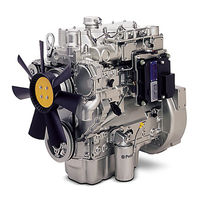
Perkins 1104D Operation And Maintenance Manual (112 pages)
Brand: Perkins
|
Category: Engine
|
Size: 3.89 MB
Advertisement
Related Products
-
Perkins 1104D-E44TA
-
Perkins 1104D-E44T
-
Perkins 1104
-
Perkins 1104E Series
-
Perkins 1104D NH1
-
Perkins 1104D NJ1
-
Perkins 1104AA-44TG
-
Perkins 1106C-E70TA
-
Perkins 1106E Series
-
Perkins 1106AA-70TAG3
Perkins Categories
Engine
Lifting Systems
Personal Care Products
Inverter
Speakers
More Perkins Manuals