-
Contents
-
Table of Contents
-
Bookmarks
Quick Links
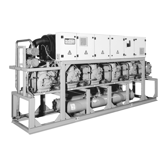
30HZ/HZV 043-280
Water-Cooled/Condenserless
Liquid Chillers
Nominal cooling capacity 30HZ: 134-783 kW
Nominal cooling capacity 30HZV: 126-735 kW
50 Hz
Installation, operation and maintenance instructions
Related Manuals for Carrier Pro-Dialog Plus 30HZ
Summary of Contents for Carrier Pro-Dialog Plus 30HZ
-
Page 1
30HZ/HZV 043-280 Water-Cooled/Condenserless Liquid Chillers Nominal cooling capacity 30HZ: 134-783 kW Nominal cooling capacity 30HZV: 126-735 kW 50 Hz Installation, operation and maintenance instructions… -
Page 2: Table Of Contents
Contents 1 — IntRoDUCtIon …………………………….4 1.1 — Installation safety considerations ……………………….4 1.2 — Equipment and components under pressure ……………………4 1.3 — Maintenance safety considerations ……………………….4 1.4 — Repair safety considerations …………………………5 2 — PRelImInaRy CheCks …………………………6 2.1 — Check equipment received …………………………
-
Page 3
8 — maIn oPtIons anD aCCessoRIes ……………………..24 8.1 — Units for low evaporator outlet temperature applications (options 5 and 6) …………..24 8.2 — Electrical protection to IP44 (option 20)……………………..24 8.3 — High- and low-pressure gauges (option 26) ……………………24 8.4 — Compressor oil pressure safety device …………………….. -
Page 4: Introduction
These products incorporate equipment or components under tightness check and verify with the manufacturer that the pressure, manufactured by Carrier or other manufacturers. circuit integrity has not been impaired. If damage is detected We recommend that you consult your appropriate national…
-
Page 5: Repair Safety Considerations
NOTE: The unit must never be left shut down with the • At least once a year thoroughly inspect the protection liquid line valve closed, as liquid refrigerant can be trapped devices (valves). If the machine operates in a corrosive between this valve and the expansion device.
-
Page 6: Preliminary Checks
Never apply an open flame or live steam to a refrigerant Close the entering and leaving water shutoff valves and container. Dangerous overpressure can result. If it is purge the unit hydronic circuit, before working on the necessary to heat refrigerant, use only warm water. components installed on the circuit (screen filter, pump, water flow switch, etc.).
-
Page 7: Moving And Siting The Unit
2.2 — Moving and siting the unit • Verify that all safety and environmental protection devices and arrangements are in place and comply 2.2.1 — moving with the current European standard. • Verify that all document for pressure containers, cer- See chapter 1.1 “Installation safety considerations”.
-
Page 8: Dimensions, Clearances
3 — DIMENsIONs, ClEaRaNCEs 3.1 — 30hZ/hZV 043-065 3.2 — 30hZ/hZV 091-225 2550…
-
Page 9: 30Hz/Hzv 250-280
3.3 — 30hZ/hZV 250-280 legend 30hZ — units with condenser 2452 1520 Evaporator 2750 1505 2750 1505 Condensers 2630 1915 2940 1915 Clearances required for operation and maintenance 2940 1915 Clearances recommended for heat exchanger tube removal 2940 1915 3550 1915 Power supply 3550…
-
Page 10: Physical And Electrical Data For 30Hz/Hzv
4 — PhysICal aND ElECTRICal DaTa FOR 30hZ/hZV 4.1 — Physical data 30hZ/hZV Net nominal cooling capacity* 30HZ 30HZV Operating weight** 30HZ 1090 1183 1252 2039 2370 2460 2510 2730 2830 3505 3805 4470 4900 30HZV 1018 1672 1960 2000 2040 2260 2300…
-
Page 11: Electrical Data
Power supply frequency variation: ± 2 Hz. accordance with all applicable codes. • The Carrier 30HZ/HZV chillers are designed and built to ensure conformance The neutral (N) conductor must not be connected directly to the unit (if necessary use a transformer).
-
Page 12: Power Supply
The following is only to be used as a guide- refer to the wiring diagrams. line, and does not make Carrier in any way liable. After wire sizing has been completed, using the certified dimensional WARNINg: Operation of the chiller with an improper…
-
Page 13: Application Data
°C Notes For minimum chilled water flow rate For application requiring operation at less than 6.8°C, contact Carrier for unit selection using the Carrier electronic catalog. For operation between 4°C and -15°C, the unit must be equipped with option 5 or 6, and the use of anti-freeze is required.
-
Page 14: Variable Flow Evaporator
5.4 — Variable flow evaporator It is often necessary to add a buffer water tank to the circuit in order to achieve the required volume. The tank must Variable evaporator flow can be used in standard chillers. itself be internally baffled in order to ensure proper mixing The chillers maintain a constant leaving water temperature of the liquid (water or brine).
-
Page 15: Condenser Water Flow Rates
5.7 — Condenser water flow rates 5.8 — Condenser water flow restrictor 30hZ/hZV Passes Minimum flow rate, l/s* Maximum flow rate, l/s** CAUTION: To ensure correct operation of the units, these Closed loop Open loop restrictors must be installed. The restrictor is supplied with 1.20 3.60 14.80…
-
Page 16: Water Connections
In case additives or other fluids than those recommend- ed by Carrier are used, ensure that the fluids are not considered as a gas, and that they belong to class 2, as defined in directive 97/23/EC.
-
Page 17: Water Connections
Tighten in the pairs and instruction will void the Carrier guarantee. sequence indicated according to the size of bolt (see below) using a torque value at the low end of the range given.
-
Page 18: Frost Protection
6.6 — Refrigerant line connections (30hZV) 6.4.2 — Pipe connections After welding the pipes to the flanges previously removed 6.6.1 — Recommendations for the installation of liquid from the water boxes: chillers with remote condensers Reinstall the pipes and tighten lightly to a torque at To guarantee optimum and reliable performance of the the low end of the range.
-
Page 19
6.6.3 — Use of pipe sizing diagrams 6.6.5 — liquid line sizing On page 23 of this document two pipe sizing diagrams are The 30HZV compressors are supplied with an oil that is shown. They allow an estimate of the cooling capacity, corre- fully miscible with refrigerant R-407C in the liquid phase. -
Page 20
Table 1 — R-407C correction factors for copper tube 30hZV saturated suction temperature, °C Cond. temp. °C 2.01 1.36 1.09 1.61 1.34 1.07 1.31 1.30 1.06 1.07 1.26 1.04 0.89 1.23 1.03 0.74 1.19 1.01 2.11 1.27 1.08 1.69 1.23 1.06 1.37 1.19… -
Page 21
Discharge piping legend 1/2” 3/8” 3/4” 7/8” 1-1/8” 1-3/8” 1-5/8” 2-1/8” Cooling capacity (kW) liquid piping legend 3/8” 1/2” 5/8” 3/4” 7/8” 1-1/8” 1-3/8” Cooling capacity (kW) -
Page 22: Operation Of Two Units In Master/Slave Mode
NOTE: Use only oils which have been approved for the compressors. Never use oils which have been exposed to air. Recommended oils: • Carrier specification: PP 47 26 • Mobiloil EAL 68 (original charge) 7.3 — Pressure vessels 7.3.1 — Condensers (30hZ units) The condensers (one per circuit) are shell-and-tube conden- sers.
-
Page 23: Electronic Expansion Device (Exv)
7.4 — Electronic expansion device (EXV) coatings to which they are applied. This is also the case for the products originally supplied by Carrier. These are an option for sizes 30HZ/HZV 043-065. The NOTES: Monitoring during operation, re-qualification,…
-
Page 24: Main Options And Accessories
8 — MaIN OPTIONs aND aCCEssORIEs 8.7 — additional capacity step 30hZ/hZV 043 to 065 (option 94) Depending on the applications for which the units are selected, they can be equipped with options. This chapter Compressor B1 of the 30HZ 043-065 units is equipped with describes the main components that require special infor- a capacity reduction that increases the available capacity mation for correct start-up and maintenance of these units,…
-
Page 25: Maintenance
9 — MaINTENaNCE 9.2 — Maintenance of the refrigerant circuit During the unit operating life the service checks and tests • Keep the unit itself and the space around it clean and must be carried out in accordance with applicable national free of obstructions.
-
Page 26: Electrical Maintenance
apparent and actual subcooling Leak detection is especially important for units charged with refrigerant R-407C. Depending on whether the leak R-407C occurs in the liquid or in the vapour phase, the proportion of the different components in the remaining liquid is not the same.
-
Page 27: Evaporator Maintenance
• the insulating foam is intact and securely in place. be replaced. Check with Carrier the effect upon chiller per- • the sensors are correctly operating, secured and formance of plugging a number of tubes. Carrier will need positioned.
-
Page 28: Corrosion Control
When rebuilding the cooler, new gaskets must always be by a coating of powder or liquid paint. To prevent the risk used. They must conform to the Carrier specification for of blistering corrosion that can appear when moisture compressed gaskets.
-
Page 29: Start-Up Checklist For 30Hz/Hzv Liquid Chillers (Use For Job File)
10 — sTaRT-UP ChECklIsT FOR 30hZ/hZV lIqUID ChIllERs (UsE FOR jOB FIlE) Preliminary information Job name: ………………………………… Location: …………………………………. Installing contractor:………………………………. Distributor: ………………………………..Start-up preformed by: …………………………….equipment Model No………………Serial No………………Compressors Circuit a Circuit b 1. Model No……………… 1. Model No…………….Serial No.
-
Page 30
Unit start-up CWP starter has been properly interlocked with the chiller Oil heaters have been energized for at least 24 hours Oil level is correct All discharge, suction and liquid valves are open Unit has been leak checked (including fittings) Locate, repair, and report any refrigerant leaks …………………………………… -
Page 31
Perform test function (indicate positive result): WARNINg: Once power is supplied to the unit, check the display for any alarms, such as phase reversal. follow the TEST function instructions in the Controls and Troubleshooting literature (follow the procedure in the Controls IOM). Be sure all service valves are open before beginning the compressor test section. -
Page 32
Order No.: 13412-76, 12.2008 — Supersedes order No.: 13412-76, 03.2003. Manufactured by: Carrier SCS, Montluel, France Manufacturer reserves the right to change any product specifications without notice. Printed in the Netherlands…
Предложите, как улучшить StudyLib
(Для жалоб на нарушения авторских прав, используйте
другую форму
)
Ваш е-мэйл
Заполните, если хотите получить ответ
Оцените наш проект
1
2
3
4
5
Pro dialog plus инструкция
Pro dialog plus инструкцияCarrier 30RB Pro-Dialog
=== Скачать файл ===
Pro-Dialog Plus 30RB — это система управления одноконтурными, двухконтурными или трехконтурными жидкостными чиллерами с воздушным охлаждением 30RВ или тепловыми насосами воздух-вода 30RQ. Система Pro-Dialog Plus управляет пуском компрессоров, что необходимо для поддержания нужной температуры воды на входе и выходе теплообменника. В режиме охлаждения система управляет работой вентиляторов для поддержания требуемого давления конденсации в каждом контуре. В тепловых насосах система регулирует и оптимизирует циклы размораживания каждого контура с целью минимизации уменьшения теплопроизводительности. Система Pro-Dialog Plus осуществляет постоянный мониторинг предохранительных устройств для обеспечения их надежной работы. Все системы Pro-Dialog Plus могут работать в трех независимых режимах: В этом случае используется кабель передачи данных для соединения агрегата с коммуникационной шиной CCN. В случае автономной работы системы PRO-DIALOG Plus в режиме местного или дистанционного управления она сохраняет все свои возможности управления, но при этом не предусмотрено использование каких-либо возможностей сети CCN. Электропитание всех плат осуществляется от общей шины 24 В переменного тока с заземленным нулем. При подключении плат к системе электропитания обеспечивайте правильную полярность, поскольку неправильное подключение приводит к повреждению платы. В случае перерыва в подаче электропитания автоматически осуществляется повторный пуск агрегата без внешней команды. Все платы непрерывно осуществляют контроль и индикацию работы своих электронных схем. При нормальной работе на каждой плате светится светодиод. Другая периодичность мерцания светодиода указывает на наличие неисправности платы или программного обеспечения. Датчики давления Для измерения давлений нагнетания и всасывания в каждомконтуре используются электронные датчики двух типов. Термисторы Датчики температуры воды испарителя установлены навходе и выходе. Датчик температуры наружного воздуха установлен под блоком управления. Главная Статьи Контроллеры Производители Advance Ako Alco Controls Carel Carrier Danfoss Dixell Eliwell Emerson Evco Geco Tecnologic Новатек-электро Овен. Carrier 30RB Pro-Dialog Pro-Dialog Plus 30RB — это система управления одноконтурными, двухконтурными или трехконтурными жидкостными чиллерами с воздушным охлаждением 30RВ или тепловыми насосами воздух-вода 30RQ. Узнайте где купить Скачать инструкцию Другие контроллеры Carrier. Контроллеры Advance Advance F Advance F Advance F Advance F Ako Ako — Ako Alco Controls Alco EC Alco ECx Alco ECx Alco ECx Alco ECx Alco ECx Alco EC Alco EC Alco EC Alco EC Alco ECP Alco EXD-U Carel Carel FCM Carel IR33 Carel IRMPX Carel MasterCella Carel mRack Carel MX20 Carel pCO2 Carel PJ32 Carel PJ Eazy Carel PlantWatch Carel pCO3 Carel pCO5 Carel pCO. Carrier Carrier 30RB Pro-Dialog Carrier Transicold ML2 Carrier 30RA Pro-Dialog Carrier 30GX Pro-Dialog. Danfoss Danfoss AK-CC Danfoss AKC 25H1 Danfoss AK-CC Danfoss EKC Danfoss EKC EKC Danfoss EKC Danfoss EKC dt Danfoss EKC A Danfoss EKC A Danfoss EKC T Danfoss EKC Danfoss EKC Danfoss EKC Danfoss EKC Danfoss EKC A Danfoss EKC A1 Danfoss m2 Danfoss AK-PC Danfoss AK-PC Danfoss ERC Danfoss ERC Danfoss ERC Danfoss ERC Danfoss ERC Danfoss AK-PC Danfoss EKC A Danfoss EKD Dixell Dixell XCCD-XCD Dixell XCC Dixell XCXC Dixell XP Dixell XR20C Dixell XR60C Dixell XTC Dixell XBL Dixell XCCX Dixell XMK — XMK Dixell XMD Dixell XMK — XMK Dixell XR10CX Dixell XR75CX Dixell XW30LH — XW30LRH. Emerson Emerson EC Emerson EC Emerson EC Emerson EC Emerson EC Emerson EC Emerson EC Emerson EC Emerson EC Emerson EC Emerson EC Emerson EC Emerson EC Emerson EC Emerson EC Emerson EC Emerson EC Emerson EC Emerson EC Emerson EC Emerson EC Emerson EC Emerson EC Evco Evco EC Evco EV Evco EV Evco EVK Evco EVK, EVK Evco EVK Evco EVK, EVK Evco EVK, EVK Evco EVK, EVK Evco EVK, EVK Evco EVKB21 Evco EVKB23, EVKB33 Evco EVK Evco EVK Geco Geco GX P00 Geco G Geco GP07 Geco GP00 Geco GP04 Geco GP05 Geco GP00 Geco GP01 Geco GP02 Geco GP07 Geco GP00 Geco GP09 Geco GP Tecnologic Technologic TDF 12 Technologic TLY 29 Technologic TLY 35 Technologic X33H Technologic Y Новатек-электро Новатек МСК Новатек МСК Новатек МСК Новатек МСК Новатек MCK Новатек MCK Новатек ТР Новатек ТР Новатек ТР Новатек МСК Овен Овен ТРМ Овен ТРМ Овен 2ТРМ1 Овен ТРМ1 Овен ТРМ10 Овен ТРМ12 Овен ТРМ Овен ТРМ Овен ТРМ Овен ТРМ Овен ТРМ Автоматика Becool Becool BC-TP Becool BС-ОМ1 Becool BС-ОМ2 Becool BC-HP BC-LP Becool BC-EMV. Рекламные возможности cтоимость и условия размещения рекламы на сайте.
Во сколько квн
Сколько стоит грамм золота в ювелирных магазинах
Отличные характеристики с места работы
Определение критических контрольных точек
Где можно скачать cs 1.6
Где сейчас наталья медведева
План счетов 83 счет
Лечение гастрита подорожником
План маркетинг грузоперевозки