
Выберите категорию материалов поддержки
-
Поиск драйверов последней версии для вашего продукта
-
ПО для удобства использования наших продуктов
-
Полезные руководства для эффективного использования продукта
-
Поиск встроенного ПО последней версии для вашего продукта
-
Нужна помощь? Посмотрите раздел часто задаваемых вопросов
-
Посмотрите последние новости о вашем продукте
-
Найдите решения в соответствии с отображаемым на продукте кодом ошибки
-
Технические характеристики
Ознакомьтесь с техническими характеристиками вашего продукта
Left Right
Вам также может понадобиться…

Переработка
Узнайте больше о программе утилизации картриджей Canon
или


- Manuals
- Brands
- Canon Manuals
- Printer
- iPF605 — imagePROGRAF Color Inkjet Printer
- Service manual
-
Contents
-
Table of Contents
-
Troubleshooting
-
Bookmarks
Quick Links
Service Manual
iPF600 series
iPF605
Aug 13 2008
Related Manuals for Canon iPF605
Summary of Contents for Canon iPF605
-
Page 1: Service Manual
Service Manual iPF600 series iPF605 Aug 13 2008…
-
Page 3
Canon will release technical information as the need arises. In the event of major changes in the contents of this manual over a long or short period, Canon will issue a new edition of this manual. -
Page 4: Symbols Used
Introduction Symbols Used This documentation uses the following symbols to indicate special information: Symbol Description Indicates an item of a non-specific nature, possibly classified as Note, Caution, or Warning. Indicates an item requiring care to avoid electric shocks. Indicates an item requiring care to avoid combustion (fire). Indicates an item prohibiting disassembly to avoid electric shocks or problems.
-
Page 5
Introduction The following rules apply throughout this Service Manual: 1. Each chapter contains sections explaining the purpose of specific functions and the relationship between electrical and mechanical systems with refer- ence to the timing of operation. In the diagrams, represents the path of mechanical drive; where a signal name accompanies the symbol , the arrow indicates the direction of the electric signal. -
Page 7: Table Of Contents
Contents Contents Chapter 1 PRODUCT DESCRIPTION 1.1 Product Overview ……………………….1- 1 1.1.1 Product Overview …………………………1- 1 1.2 Features …………………………1- 2 1.2.1 Features ……………………………. 1- 2 1.2.2 Printhead …………………………… 1- 2 1.2.3 Ink Tank…………………………….. 1- 2 1.2.4 Cutter…………………………….1- 2 1.2.5 Roll Feed Unit…………………………..
-
Page 8
Contents 2.2 Firmware …………………………2- 5 2.2.1 Operation Sequence at Power-on……………………..2- 5 2.2.2 Operation Sequence at Power-off……………………..2- 6 2.2.3 Print Control …………………………..2- 7 2.2.4 Print Position Adjustment Function ……………………2- 12 2.2.5 Head Management …………………………2- 12 2.2.6 Printhead Overheating Protection Control ………………….2- 12 2.2.7 Pause between Pages ……………………….2- 12 2.2.8 White Raster Skip …………………………2- 12 2.2.9 Sleep Mode…………………………..2- 12… -
Page 9
Contents 3.2.2 Reinstalling the Printer ……………………….3- 20 3.2.2.1 Reinstalling the Printer…………………………..3- 20 Chapter 4 DISASSEMBLY/REASSEMBLY 4.1 Service Parts …………………………4- 1 4.1.1 Service Parts …………………………..4- 1 4.2 Disassembly/Reassembly………………………4- 2 4.2.1 Disassembly/Reassembly ……………………….4- 2 4.3 Points to Note on Disassembly and Reassembly ………………4- 2 4.3.1 Note on locations prohibited from disassembly ………………….. -
Page 10
Contents 6.4 Service Tools……………………….6- 17 6.4.1 Tool List ……………………………6- 17 Chapter 7 SERVICE MODE 7.1 Service Mode ……………………….. 7- 1 7.1.1 Service Mode Operation ……………………….7- 1 7.1.2 Map of the Service Mode ……………………….7- 2 7.1.3 Details of Service Mode ……………………….7- 7 7.1.4 Sample Printout …………………………7- 15 7.2 Special Mode………………………. -
Page 11: Chapter 1 Product Description
Chapter 1 PRODUCT DESCRIPTION…
-
Page 13
Contents Contents 1.1 Product Overview …………………………..1-1 1.1.1 Product Overview …………………………….1-1 1.2 Features …………………………….1-2 1.2.1 Features ………………………………..1-2 1.2.2 Printhead ……………………………….. 1-2 1.2.3 Ink Tank ………………………………… 1-2 1.2.4 Cutter………………………………..1-2 1.2.5 Roll Feed Unit………………………………1-2 1.2.6 Stand ………………………………..1-4 1.2.7 IEEE1394 (FireWire) Board ………………………….. 1-4 1.2.8 Consumables ……………………………… -
Page 15: Product Overview
Chapter 1 1.1 Product Overview 1.1.1 Product Overview 0019-6060 This printer is capable of printing on A4- to A1-size cut sheets and its maximum print width is 24 inches. This printer is a desktop large-format printer five-colors (dye- and pigment-based colors) printer that can be used to print office documents as well as handy POP and posters. An roll feed unit is equipped for printing on roll media.
-
Page 16: Features
— Data scanned using CanoScan can be easily printed on large-size paper just like a dedicated copier. Just pressing the Start button allows you to blow up an original of up to A3 size in collaboration with Canon Image RUNNER.
-
Page 17: Roll Feed Unit
Chapter 1 1.2.5 Roll Feed Unit 0013-2512 Roll Feed Unit The roll feed unit is optionally available to use roll media with this printer. F-1-6 Roll holder set This set consists of roll holder, holder stopper, 3-inch paper tube attachment, and borderless printing spacer (commonly used for 2-inch paper tube and 3-inch paper tube).
-
Page 18: Stand
Chapter 1 1.2.6 Stand 0016-8107 Stand (Option) It is a stand that puts the printer. Equipped with casters so that the printer can be easily moved. The output stacker included with stand can use by the two ways of the regular position or extended position. F-1-11 MEMO: — Use the output stacker in the regular position [A].
-
Page 19: Consumables
Chapter 1 1.2.8 Consumables 0016-8109 Printhead The consumable print head is the same as that supplied with the printer. F-1-14 Ink Tanks The consumable ink tanks are available in five colors (matte black, black, cyan, magenta, and yellow). They are the same as those supplied with the printer. Each ink tank must be replaced with a new one six month after you have opened the package.
-
Page 20: Product Specifications
Chapter 1 1.3 Product Specifications 1.3.1 Product Specifications 0019-6063 Type Bubble jet large-sized paper printer Feeding system Automatic feeding of one roll media/One cut sheet (manual feed from front)/One cut sheet (manual feed from top) Feeding capacity — Roll media One roll at the back/Outer diameter of roll: 150 mm or less/Inner diameter of paper tube: 2 or 3 inches — Cut sheet…
-
Page 21
Chapter 1 Firmware Flash ROM (update from USB or Ethernet, IEEE1394) — Printer description language GARO (Graphic Arts language with Raster Operation), HP-GL/2, HP Interface USB2.0, Ethernet, IEEE1394 (option) Operation panel LCD (160 X 128 dots), 12 keys, 5 LEDs — Panel language English — Message language… -
Page 22: Detailed Specifications
Chapter 1 1.4 Detailed Specifications 1.4.1 Print Speed and Direction 0019-6076 T-1-2 Print Print Print- Used BK Media Type Print Priority Printing Direction Resolution Quality Pass (dpi) Plain Paper/ Plain Paper Office Document Standard Bi-directional 1200×1200 Recycled Paper Line Document/ Draft Bi-directional 1200×1200…
-
Page 23
Chapter 1 Print Print Print- Used BK Media Type Print Priority Printing Direction Resolution Quality Pass (dpi) Coated Paper Coated Paper Line Document/ Draft Bi-directional 1200×1200 Text Standard Bi-directional 1200×1200 High Bi-directional 1200×1200 Image Standard Bi-directional 1200×1200 High Bi-directional 2400×1200 Highest Bi-directional 2400×1200… -
Page 24
Chapter 1 Print Print Print- Used BK Media Type Print Priority Printing Direction Resolution Quality Pass (dpi) Photo Paper Premium Coated Paper Line Document/ Draft Bi-directional 1200×1200 Text Standard Bi-directional 1200×1200 High Bi-directional 1200×1200 Image Standard Bi-directional 1200×1200 High Bi-directional 2400×1200 Highest Bi-directional… -
Page 25
Chapter 1 Print Print Print- Used BK Media Type Print Priority Printing Direction Resolution Quality Pass (dpi) Proofing Paper Proofing Paper Image Standard Bi-directional 1200×1200 High Bi-directional 2400×1200 Highest Bi-directional 2400×1200 Professional Proof and Photo Glossy 195g Image Standard Bi-directional 1200×1200 High Bi-directional… -
Page 26: Interface Specifications
Chapter 1 1.4.2 Interface Specifications 0012-6200 a. USB (standard) (1) Interface type USB 2.0 Hi-Speed (Full speed (12 Mbits/sec), High speed (480 Mbits/sec)) (2) Data transfer system Control transfer Bulk transfer (3) Signal level Compliant with the USB standard. (4) Interface cable Twisted-pair shielded cable, 5.0 m max.
-
Page 27: Names And Functions Of Components
Chapter 1 1.5 Names and Functions of Components 1.5.1 Front 0016-8143 [13] [12] [11] [10] F-1-17 [1] Top cover Open this cover when installing the printhead or remove the media jammed inside the printer. [2] Ink tank cover Open this cover when replacing ink tanks. [3] Cutter A round-blade cutter cuts roll media automatically.
-
Page 28: Rear
Chapter 1 1.5.2 Rear 0016-8147 F-1-18 [1] Expansion board slot Insert the IEEE1394 (FireWire) expansion board (option) in this slot. [2] USB port Connect the USB cable to this port. [3] Ethernet connector Connect the Ethernet cable to this connector. [4] Power connector Connect the power cord to this connector.
-
Page 29: Manual Loading Area
Chapter 1 1.5.4 Manual Loading Area 0016-8152 F-1-20 [1] Paper tray cover In loading paper in a paper tray, open this cover. [2] Paper support In loading paper in a paper tray, open the paper tray cover and then this tray. [3] Width guides In loading cut sheet, move the guide to adjust to the paper size.
-
Page 30: Roll Feed Unit Cover (Inside)
Chapter 1 1.5.5 Roll Feed Unit Cover (Inside) 0016-8154 F-1-21 [1] Roller holder Set roll media on this holder. [2] Holder stopper Use to secure roll media to the roller holder. [3] Roller holder slot Set the roller holder in this guide groove. 1.5.6 Carriage 0012-6338 F-1-22…
-
Page 31: Inside
Chapter 1 1.5.7 Inside 0016-8159 F-1-23 [1] Maintenance cartridge Absorbs excess ink 1-17…
-
Page 32: Basic Operation
Chapter 1 1.6 Basic Operation 1.6.1 Operation Panel 0013-0043 This section explains the functions of the buttons and the meanings of the LEDs on the operation panel. [18] [17] [16] [15] [14] [13] [10] [11] [12] F-1-24 [1] Data lamp Blinking: Indicates that a print job is being received or processed if the printer is printing, or that a print job has paused or firmware data is being if the printer is not printing.
-
Page 33: Main Menu
Chapter 1 1.6.2 Main Menu 0019-6077 The printer has a Main menu which includes a menu related to maintenance such as adjustment of ink ejection position of each nozzle and head cleaning, a menu related to printing settings such as auto cutting and ink drying time, and a menu related to parameters such as a message language. 1.
-
Page 34
Chapter 1 2. Main Menu The structure of the main menu is as follows. Values at right indicated by an asterisk «*» are the defaults. T-1-3 First Level Second Level Third Level Fourth Level Fifth Level [Paper Cut] [No]* [Yes] [Rep. -
Page 35
Chapter 1 T-1-4 First Level Second Level Third Level Fourth Level Fifth Level [Media Menu] [Manual Paper Size] [Legal (8.5″X14″)] [24″X36″(ARCH D)] [18″X24″(ARCH C)] [12″X18″(ARCH B)] [9″X12″(ARCH A)] [DIN C2] [DIN C3] [DIN C4] [20″x24″] [18″x22″] [14″x17″] [12″x16″] [10″X12″] [10″X15″] [16″x20″] [20″X30″] [13″X22″]… -
Page 36
Chapter 1 T-1-5 First Level Second Level Third Level Fourth Level Fifth Level [Media Menu] [Roll Media Type](*1) [Plain Paper](*5) [Plain Paper HQ](*5) [Plain Paper HG](*5) [All Plain Paper Conserve MBK](*5) [Recycled Coated](*5) [Coated Paper](*5) [HW Coated](*5) [Ex HW Coated](*5) [Premium MatteP](*5) [Glossy Photo](*5) [Semi-Gl Photo](*5) -
Page 37
Chapter 1 T-1-6 First Level Second Level Third Level Fourth Level Fifth Level [Paper Details] (The paper type is displayed [Feed Priority] [Automatic]* here.) (*5) [Band Joint] [Print Length] [Adjust Length] -0.70 to 0.70 [Head Height] [Automatic]* [Highest] [High] [Standard] [LowLow] [Lowest] [Skew Check Lv.]… -
Page 38
Chapter 1 T-1-7 First Level Second Level Third Level Fourth Level Fifth Level [GL2 Settings] [Print Quality] [Draft] [Standard]* [High] [Input Resolution] [600dpi]* [300dpi] [Media Source] [Automatic]* [Roll Paper] [Manual] [Conserve Paper] [Off] [On]* [End Point Shape] [Software]* [Rounded] [Smoothing] [Software]* [Smooth] [Line Width]… -
Page 39
Chapter 1 T-1-8 First Level Second Level Third Level Fourth Level Fifth Level [Interface Setup] [EOP Timer] [10 sec.] [30 sec.] [1 min.] [2 min.] [5 min.] [10 min.]* [30 min.] [60 min.] [TCP/IP] [IP Mode] [Automatic] [Manual]* [Protocol](*4) [DHCP] [On] [Off]* [BOOTP]… -
Page 40
Chapter 1 T-1-9 First Level Second Level Third Level Fourth Level Fifth Level [Maintenance] [Repl. maint. cart.] [No] [Yes] [Replace P.head] [No] [Yes] [Move Printer] [No] [Yes] [Clean Platen] [No] [Yes] [System Setup] [Warning] [Buzzer] [Off] [On]* [Detect Mismatch] [Pause] [Warning] [None]* [Keep Media Size]… -
Page 41
Chapter 1 T-1-10 First Level Second Level Third Level Fourth Level Fifth Level [System Setup] [Time Zone] [0: London (GMT)] [+1: Paris, Rome] [+2: Athens, Cairo] [+3: Moscow] [+4: Eerenan, Baku] [+5: Islamabad] [+6: Dacca] [+7: Bangkok] [+8: Hong Kong] [+9: Tokyo, Seoul] [+10: Canberra] [+11: NewCaledonia]… -
Page 42
Chapter 1 T-1-11 First Level Second Level Third Level Fourth Level Fifth Level [Test Print] [Status Print] [No] [Yes] [Media Details] [No] [Yes] [Print Job Log] [No] [Yes] [Menu Map] [No] [Yes] [Nozzle Check] [No] [Yes] [Information] [System Info] [Error Log] [########-####] [Job Log] (Choose from information… -
Page 43
Chapter 1 3. Main menu during printing The structure of the main menu during printing is as follows. T-1-12 First Level Second Level Third Level Fourth Level Fifth Level [Menu Durng Prtng] [Head Cleaning] [Head Cleaning A] [Head Cleaning B] [Fine Band Adj.] -5 to 5 [Information]… -
Page 44
Chapter 1 4. Main Menu Settings Main menu items are described in the following tables. T-1-13 Setting Item Description, Instructions [Paper Cut] Displayed if a roll is loaded. Choose Yes to cut the roll at the current position. The paper will be fed, if necessary, so that the sheet is at least 10 cm (39.4 in.)long after the cut. -
Page 45
Chapter 1 [Paper Details] T-1-15 Setting Item Description, Instructions (The paper type is displayed here.) [Roll DryingTime] Specify the time to wait for the ink to dry for each sheet. [Scan Wait Time] Specify the time to wait for the ink to dry between each scan in bidirectional printing, in consideration of how quickly the paper absorbs ink. -
Page 46
[Advanced Adj.] Choose this option when using paper other than genuine Canon paper, or paper for purposes other than checking output. Choose Yes to have the printer print and read a test pattern for band adjustment, based on which the printer automatically adjusts the feed amount. -
Page 47
Chapter 1 [System Setup] T-1-20 Setting Item Description, Instructions [Warning] [Buzzer] Set the buzzer. Choose On for the buzzer to sound in case of errors. [Detect Mismatch] Choose Warning for notification (display of a warning message) during printing if the paper type specified in the printer menu does not match the paper type in the printer driver. -
Page 48
Chapter 1 5. Main Menu Settings (During Printing) Main menu items during printing are described in the following tables. T-1-22 Setting Item Description, Instructions [Head Cleaning] Specify Printhead cleaning options. Choose Head Cleaning A if printing is faint, oddly colored, or contains foreign substances. Choose Head Cleaning B if no ink is printed at all, or if printing is not improved by Head Cleaning A . -
Page 49: Safety And Precautions
Chapter 1 1.7 Safety and Precautions 1.7.1 Safety Precautions 1.7.1.1 Moving Parts 0013-5092 Moving parts of the printer include the carriage unit driven by the carriage motor, the carriage belt, the ink tube, the flexible cable, the feed roller drives the feed motor, the pinch roller, and the purge unit driven by the purge motor.
-
Page 50
Chapter 1 — Although the ink is not harmful to the human body, it contains organic solvents. Ink may contaminate the surrounding parts. Carry out the work with due caution. If your hands are stained with ink, wash them with a plenty of water. Be careful not to allow the ink to get into your mouth or eyes. -
Page 51: Electric Parts
Chapter 1 1.7.1.3 Electric Parts 0019-6084 The electric parts of the printer are activated when the printer is connected to the AC power supply. At the left rear of the printer are the main controller, power supply, and interface connector. The carriage PCB is incorporated in the carriage unit, and the operation panel is on the upper right top cover.
-
Page 52: Ink Tank
Chapter 1 F-1-29 T-1-24 [1] knob [4] nozzles [2] protective cap 1 [5] Electrical contact [3] protective cap 2 [6] ink port 2. Capping The printer will perform the capping operation when printing has ended or during standby due to an error, in order to protect the printhead and avoid ink leakage. If the power cord is accidentally unplugged, turn off the Power button, reconnect the power cord, and then turn on the Power button.
-
Page 53: Handling The Printer
Chapter 1 2. Handling the Ink Tank To prevent foreign matter from entering the ink flow path and causing ink suction and printing problems, never touch the ink port and contacts of the ink tank. When you press down the ink tank lock lever, the needle enters the ink port, allowing ink to flow between the printer and ink tank. Do not raise or lower the ink tank lock lever except when replacing the ink tank.
-
Page 54
Chapter 1 2. Fixing the Carriage After completion of printing, the carriage is mechanically locked by the lock arm in the purge unit at the same moment the printhead is capped. Before transporting the printer, secure the carriage at its home position using belt stoppers[1] so that the carriage does not become separated from the lock arm and damage or ink does not leak. -
Page 55
Chapter 1 4. Contact of Linear Scale/Carriage Shaft Please do not touch a linear scale and the carriage shaft when the inside of the top cover is opened, and execute maintenance. When touching a linear scale and the carriage shaft, it might cause defective movement of the carriage and a defective print. F-1-34 [1] Linear Scale [2] Carriage Shaft… -
Page 56: Precautions When Servicing Printer
Chapter 1 1.7.3 Precautions When Servicing Printer 1.7.3.1 Notes on the Data Stored in the Printer 0013-3742 This printer counts the print length, number of ink tank replacements, number of cleaning operations, number of cutter operations, and so on and stores them in the main controller’s EEPROM as a service mode counter.
-
Page 57
Chapter 1 1-43… -
Page 59: Chapter 2 Technical Reference
Chapter 2 TECHNICAL REFERENCE…
-
Page 61
Contents Contents 2.1 Basic Operation Outline…………………………2-1 2.1.1 Printer Diagram……………………………… 2-1 2.1.2 Print Signal Sequence ……………………………. 2-2 2.1.3 Print Driving ………………………………2-3 2.2 Firmware …………………………….2-5 2.2.1 Operation Sequence at Power-on…………………………2-5 2.2.2 Operation Sequence at Power-off …………………………2-6 2.2.3 Print Control………………………………2-7 2.2.4 Print Position Adjustment Function………………………. -
Page 62
Contents 2.4.3.1 Carriage PCB components……………………………… 2-40 2.4.4 Motor Driver ………………………………2-41 2.4.4.1 Roll feed unit PCB components…………………………….2-41 2.4.5 Maintenance Cartridge Relay PCB……………………….2-41 2.4.5.1 Maintenance cartridge relay PCB components……………………….. 2-41 2.4.6 Power Supply ………………………………. 2-41 2.4.6.1 Power supply block diagram…………………………….2-41 2.5 Detection Functions with Sensors …………………….. -
Page 63: Basic Operation Outline
Chapter 2 2.1 Basic Operation Outline 2.1.1 Printer Diagram 0019-6087 Shown below is a printer diagram. Main controller PCB IC601/IC602 IC603/IC604 IC301/IC302 SDRAM J1801 IC802 IC701 Power supply PCB EEPROM FLASH ROM J101 Operation panel PCB IC803 ASIC Maintenance cartridge BAT 801 relay PCB Lithium battery…
-
Page 64: Print Signal Sequence
Chapter 2 2.1.2 Print Signal Sequence 0017-4696 The signal sequence from when the printer receives the print signals until printing starts is shown in Figure. Image data Host computer Mask pattern data Heat pulse Printer driver Command data PCI bus Data bus Universal sirial bus Interface unit…
-
Page 65: Print Driving
Chapter 2 2.1.3 Print Driving 0012-6491 Print and control signals are transferred via the carriage PCB to the printheads to discharge inks from the nozzle assembly at printing. Each printhead has 12 trains of nozzles arranged in a zigzag pattern. This printer uses one printhead.
-
Page 66
Chapter 2 2. Print drive timing Each printhead houses 12 trains of nozzles, which share the same data transfer clock (Hx-CLK) and data latch pulses (Hx-LT). Even-numbered nozzle data (Hx-x-DATA-x-EV), odd-numbered nozzle data (Hx-x-DATA-x-OD) and the Heat Enable (Hx-x-HE-x) signal are generated for each nozzle train and controlled individually. -
Page 67: Firmware
Chapter 2 2.2 Firmware 2.2.1 Operation Sequence at Power-on 0012-6493 Shown below is the flowchart of the initialization sequence from the moment the power is turned on to the moment the printer enters the online state. The time required for initialization is less than 1 minute*. * This time does not include the time required for supplying ink and cleaning which takes place after the printer has been left unused for an extended period of time.
-
Page 68: Operation Sequence At Power-Off
Chapter 2 2.2.2 Operation Sequence at Power-off 0012-6494 Turning off the power cuts off the voltage to all drive systems. At this time, the firmware starts the power-off sequence as shown below. This printer immediately suspends all operations in progress and stops whenever the power cord is unplugged or a cover such as the top cover is opened. In this case, the printer may stop without capping the print head.
-
Page 69: Print Control
Chapter 2 2.2.3 Print Control 0019-6089 1. Print mode This printer is capable of fast, high-quality printing without blur and non-uniform density by changing the carriage operation, media feeding, other printing methods according to the selected media type, print quality, print data and so on. Printing is performed for each color using a maximum of 16 paths in each print mode according to the selected print quality.
-
Page 70
Chapter 2 T-2-2 Print Print Print- Used BK Media Type Print Priority Printing Direction Resolution Quality Pass (dpi) Plain Paper/ Plain Paper Office Document Standard Bi-directional 1200×1200 Recycled Paper Line Document/ Draft Bi-directional 1200×1200 Text Standard Bi-directional 1200×1200 High Single-directional 1200×1200 Image Draft… -
Page 71
Chapter 2 Print Print Print- Used BK Media Type Print Priority Printing Direction Resolution Quality Pass (dpi) Coated Paper Coated Paper Line Document/ Draft Bi-directional 1200×1200 Text Standard Bi-directional 1200×1200 High Bi-directional 1200×1200 Image Standard Bi-directional 1200×1200 High Bi-directional 2400×1200 Highest Bi-directional 2400×1200… -
Page 72
Chapter 2 Print Print Print- Used BK Media Type Print Priority Printing Direction Resolution Quality Pass (dpi) Photo Paper Premium Coated Paper Line Document/ Draft Bi-directional 1200×1200 Text Standard Bi-directional 1200×1200 High Bi-directional 1200×1200 Image Standard Bi-directional 1200×1200 High Bi-directional 2400×1200 Highest Bi-directional… -
Page 73
Chapter 2 Print Print Print- Used BK Media Type Print Priority Printing Direction Resolution Quality Pass (dpi) Proofing Paper Proofing Paper Image Standard Bi-directional 1200×1200 High Bi-directional 2400×1200 Highest Bi-directional 2400×1200 Professional Proof and Photo Glossy 195g Image Standard Bi-directional 1200×1200 High Bi-directional… -
Page 74: Print Position Adjustment Function
Chapter 2 2.2.4 Print Position Adjustment Function 0012-6498 This printer has a printing position adjusting function to adjust the lateral and longitudinal printing positions and bidirectional printing position of the printhead mounted on the carriage as well as the media feed amount. The printing position can be adjusted in two ways: «automatic adjustment»…
-
Page 75
Chapter 2 Printhead Carriage unit Ink tank unit Pinch roller Feed roller Maintenance cartridge Ink tube Purge unit F-2-7 2-13… -
Page 76: Ink Passage
Chapter 2 2.3.2 Ink Passage 2.3.2.1 Ink Passage 2.3.2.1.1 Overview of Ink Passage 0017-4721 The ink passage consists of ink tanks, printhead, cap, waste ink collection unit, ink tubes for connecting the mechanical components, and an ink suction pump which is operated to suck ink.
-
Page 77: Ink Tank Unit
Chapter 2 2.3.2.2 Ink Tank Unit 2.3.2.2.1 Structure of Ink Tank Unit 0013-5200 a) Ink tank Each ink tank contains 130 ml of ink (the starter ink tank supplied with the printer contains 90 ml of ink) for each color. The amount of ink is memorized in the EEPROM mounted to the ink tank.
-
Page 78
Chapter 2 f) Ink supply valve The ink supply valve is located between the ink tank and ink tube to prevent ink leakage from occurring when the ink tube on the ink tank side is opened during replacement of the ink tank. The ink supply valve is opened and closed by the valve open/close mechanism which is driven by the valve motor. -
Page 79: Carriage Unit
Chapter 2 2.3.2.3 Carriage Unit 2.3.2.3.1 Functions of Carriage Unit 0013-4834 a) Printhead mounting function The carriage mechanically locks the printhead and is connected to the printhead via the terminals on the carriage PCB. b) Control function The carriage incorporates a carriage PCB that relays the signal from the main controller, a linear encoder that generates a print timing signal based on the detected carriage position, and a multi sensor that detects the media width and skewing to adjust the registration and height.
-
Page 80: Structure Of Carriage Unit
Chapter 2 2.3.2.3.2 Structure of Carriage Unit 0013-4891 a) Printhead mounting unit The printhead is secured to the carriage by the printhead fixer lever. When the printhead is secured to the carriage, the signal contact of the carriage PCB touches the signal contact point of the printhead, allowing print signals to be transmitted.
-
Page 81
Chapter 2 Carriage PCB Linear encoder Shaft cleaner Multi sensor Shaft cleaner Multi sensor reference plate Linear scale Carriage height changing cam Head management sensor unit Lift cam sensor Lift motor F-2-12 e) Printhead maintenance unit The printer performs the printhead cleaning operation at the home position of the carriage. The purge motor is used for wiping. -
Page 82: Printhead
Chapter 2 2.3.2.4 Printhead 2.3.2.4.1 Structure of Printhead 0013-4821 A printhead incorporates six nozzle arrays. Each nozzle can be controlled individually so that a six-color discharge action can be performed by a single printhead. a) Nozzle arrays A total of 2560 nozzles are arranged in a two-column staggered pattern. In each column, 1280 nozzles are arranged in a staggered pattern at intervals of 600 dpi, forming a 2560-nozzle arranged at intervals of 1200 dpi.
-
Page 83: Purge Unit
Chapter 2 2.3.2.5 Purge Unit 2.3.2.5.1 Functions of Purge Unit 0013-5334 To maintain high print quality, the purge unit performs maintenance of the nozzles o the printhead. The purge unit supports a capping function, cleaning function, and ink supply function. a) Capping function The capping function presses the cap of the purge unit against the face plate on the nozzle section of the printhead to prevent nozzle drying and dust adhesion.
-
Page 84
Chapter 2 Details of the cleaning function are shown in the table below. Name of Service mode Cleaning mode or PRINT INF Operation Description of cleaning (Name of Main Menu) Cleaning 1 CLN-A-1/CLN-M-1 Normal cleaning Removes dried ink from nozzles, thick ink accumulated on the (Head Cleaning A) face, and paper particles. -
Page 85
Chapter 2 Cleaning operation timings are as follows. Consumption Printer status Cleaning operation (typ.)*1 Standby 168 hours elapsed capped Cleaning 1 (Normal Cleaning) At least 720 hours elapsed since the last session of Cleaning 2, 3, 6 or 10 (360 hours after initial Cleaning 6 (Normal installation) (strong) Cleaning) -
Page 86: Structure Of Purge Unit
Chapter 2 2.3.2.5.2 Structure of Purge Unit 0013-4307 Purge unit F-2-15 a) Cap unit The cap unit is used to cap the print head nozzles during capping and cleaning. The portion that touches the face plate is made from rubber. Two caps are arranged for the printhead (six arrays of nozzles) installed in the carriage.
-
Page 87
Chapter 2 b) Wiper unit The wiper unit operated by the purge motor wipes the print head face. The printer is provided with a pair of wiper blades for better wiping performance. The wiping operation is performed by a «slide wipe» method by which the purge motor rotates (in the normal direction) to slide the wiper blade via the wiper cam. It is performed by a constant-speed movement toward the front of the printer as viewed from the printer front. -
Page 88: Maintenance Cartridge
Chapter 2 2.3.2.6 Maintenance Cartridge 2.3.2.6.1 Maintenance Cartridge 0013-4160 a) Maintenance cartridge The maintenance cartridge can contain up to approximately 778 ml (approx. 830 g ) of waste ink (including the moisture evaporation in the waste ink). b) Detection of waste ink in maintenance cartridge The quantity of waste ink in the maintenance cartridge is measured by counting dots.
-
Page 89: Air Flow
Chapter 2 2.3.2.7 Air Flow 2.3.2.7.1 Air flow 0013-4162 This printer has two fans, a mist fan used to collect mist and a suction fan used to suck media onto the platen. Ink mist that floats inside the printer and ink splashes from the media are collected in the filter through the front duct and the air flow path inside the printer by the driving of the mist fan, thus preventing mist from discharged outside the printer.
-
Page 90: Paper Path
Chapter 2 2.3.3 Paper Path 2.3.3.1 Outline 2.3.3.1.1 Overview of Paper Path 0016-8200 The paper path consist of roll feed unit, feed roller unit, pinch roller drive unit that applies/releases pressure to/from the pinch roller, spur drive unit that moves the spur up/down, and various sensors that detect the media feed status, allowing media to be fed in three ways, fed, and ejected.
-
Page 91: Paper Path
Chapter 2 2.3.3.2 Paper Path 2.3.3.2.1 Structure of Roll Media Pick-up Unit 0016-8203 When the roll media sensor detects media loaded with the printer powered, the roll media pick-up roller touches the media to rotate the roll media feed roller, thus feeding the roll media onto the platen.
-
Page 92: Structure Of Manual Feed Unit
Chapter 2 2.3.3.2.2 Structure of Manual Feed Unit 0019-6101 a) Manual feed (from front) The cut sheet fed from the front (ejection unit) of the printer is fed to the rear of the printer [1], and then fed onto to platen [2] for printing. F-2-25 This method of feeding paper can be used only when an accept media type is selected from the Manual Feed menu in the use mode.
-
Page 93
Chapter 2 The pick-up timing of the paper fed to the rear of the printer is controlled by the paper detection sensor. Paper detection sensor F-2-27 b) Manual feed (from rear) The paper loaded in the paper tray provided at the rear of the printer is fed onto the platen for printing. This method of feeding paper can be used only when an acceptable media type is selected from the Manual Feed menu in the user mode. -
Page 94: Manual Feed (From Front) Sequence
Chapter 2 2.3.3.2.3 Manual Feed (from Front) Sequence 0013-4174 This sequence can be performed according to the messages shown on the operation panel only when a specific type of media is selected after selecting the manual feed mode from the menu shown on the operation panel. When a cut sheet is loaded according to the message shown on the operation panel, the printer performs various adjustments and detection using the multi sensor and then feeds the cut sheet to the rear of the printer.
-
Page 95: Structure Of Feed Roller Unit
Chapter 2 2.3.3.2.5 Structure of Feed Roller Unit 0013-4178 The feed roller unit consists of media feeding mechanisms such as feed rollers driven by the feed motor and the pinch roller unit operating in conjunction with the feed rollers. While being held flat on the platen, media is fed horizontally under the printhead. The feed roller unit has a sensor that detects the media feed status and a sensor that detects the status of the mechanisms that constitute the paper path.
-
Page 96: Feed Roller Eccentricity Detection Function
Chapter 2 2.3.3.2.6 Feed Roller Eccentricity Detection Function 0013-4206 Media are fed by the feed roller at regular intervals. Irregular feeding of media due to the feed roller eccentricity problem, irregular printing can occur in the media feeding direction periodically. To prevent this, the feed error encoder and feed roller HP sensor detect the presence and amount of feed roller eccentricity every rotation of the feed roller.
-
Page 97: Structure Of Ejection Spur
Chapter 2 2.3.3.2.7 Structure of Ejection Spur 0013-4208 a) Outline The ejection spur unit consists of a spur, a spur motor that moves the spur, a spur cam sensor, and an eject roller. b) Spur lift mechanism The spur must be moved up and down according to the selected media type and feed mode. The spur motor and spur cam sensor are used to control the spur stop position.
-
Page 98: Cutter Unit
Chapter 2 2.3.3.3 Cutter Unit 2.3.3.3.1 Structure of Cutter unit 0019-6102 If roll media are used, the cutter unit attached on the front of the spur unit cuts the leading end of the media on loading and cuts the media on ejection. Whether to perform cutting or not is determined by the choice of the main menu and the specifications of the printer driver.
-
Page 99: Printer Electrical System
Chapter 2 2.4 Printer Electrical System 2.4.1 Outline 2.4.1.1 Overview 0019-6103 The printer electrical system consists of the main controller PCB and power supply PCB which are mounted on the left side of the printer, the carriage PCB and print head which are mounted in the carriage, and other electrical components such as the operation panel, sensors, and motors. The main controller PCB manages the image data processing and the entire electrical system, and controls relay PCBs and driver functions.
-
Page 100
Chapter 2 Power supply Main controller PCB +26V generation function IC1501/IC1701 AC inlet IC1601-IC1603 +21.5V generation function Power supply control function IC601/IC602 IC603/IC604 BAT801 IC301/IC302 Lithium battery SDRAM IC803 IC802 EEPROM Host computer Interface IC1201 control function LAN Controller Carriage PCB Linear encoder Linear encoder detection function Head… -
Page 101: Main Controller
Chapter 2 2.4.2 Main Controller 2.4.2.1 Main controller components 0019-6104 IC802 IC803 BAT801 BAT801 IC301 IC301 IC302 IC302 IC3101 IC3101 IC701 IC701 IC601 IC602 IC603 IC604 IC2801 IC2801 IC1201 IC2901 IC2901 IC3001 IC3001 F-2-38 a) ASIC (IC1/IC2) The ASIC with a 16-bit internal bus is driven in sync with the 66 MHz external clock. It supports the following functions: Image processing unit This unit converts the RGB multi-value image data or CMYK multi-value data received from the host computer through the interface connector to the binary image data for the ink colors used.
-
Page 102: Carriage Relay Pcb
Chapter 2 This function controls read operation by the head DI sensor. Multi sensor control function This function controls the LED, adjusts the gain, and controls obtainment of the reading for the multi sensor. EEPROM control function This function controls the EEPROMs of individual ink tanks, the maintenance cartridge EEPROM, the EEPROM on the maintenance cartridge relay PCB, and the head EEPROM in addition to the on-board EEPROM.
-
Page 103: Motor Driver
Chapter 2 2.4.4 Motor Driver 2.4.4.1 Roll feed unit PCB components 0013-4323 IC 1 F-2-40 a) Driver IC (IC1) Roll motor drive function This function controls the roll motor based on the control signals from the main controller. Sensor relay function This function relays the input signals from the roll cam sensor and roll media sensor to the main controller PCB.
-
Page 104: Detection Functions With Sensors
Chapter 2 2.5 Detection Functions with Sensors 2.5.1 Sensors for covers 0013-5203 Top cover sensor Ink tank cover switch F-2-43 Top cover sensor The photo-interrupter-type top cover sensors detect opening and closing of the top cover. When the top cover is closed, the sensor light is shielded by the sensor arm, thus notifying the sensor of closing the cover. Ink tank cover switch The micro-switch-type ink tank cover switch detects opening and closing of the ink tank cover.
-
Page 105: Ink Passage System
Chapter 2 2.5.2 Ink passage system 0013-5204 Purge unit Pump cam sensor Valve open/closed detection sensor Pump encoder sensor Head management sensor F-2-44 Pump cam sensor The photo-interrupter-type pump cam sensor detects that the sensor light is shielded or unshielded by the rotary cam. The sensor detects the purge unit capping and wiping states with the combination of the state detected by the pump cam and the state of pump motor rotation control performed by the pump encoder.
-
Page 106
Chapter 2 Pump encoder sensor The pump encoder is a photo-interruptive type sensor. It reads the slits on the pump motor’s encoder film to control the amount of pump motor rotation. Slits Sensor F-2-46 Valve open/closed detection sensor The photo-interrupter-type valve open/closed detection sensor detects the valve cam state. When the link that operates in conjunction with the valve cam shields light, this sensor detects that the ink supply valve has been opened. -
Page 107: Carriage System
Chapter 2 2.5.3 Carriage system 0013-5205 Linear encoder sensor Multi sensor Lift cam sensor F-2-49 Multi sensor The photo-reflection-type multi sensor is composed of four LEDs (red, blue, green and infrared) and two light-sensitive sensors. It detects the leading edge, skewing, and width of media and is used for adjustment of the registration, and head height.
-
Page 108: Paper Path System
Chapter 2 The diode voltage that changes with the nozzle unit temperature is reported to the main controller via the carriage PCB. The detected head temperature is used to control the head operation and to detect abnormal head temperatures. Printhead contact detection The printhead contact status is detected by testing the electrical conductivity.
-
Page 109
Chapter 2 Feed roller encoder sensor Feed roller HP sensor F-2-52 Feed roller HP sensor The feed roller HP sensor detects the change from the white portion (unshielded sensor light) to black portion (shielded sensor light) of the encoder film on the feed roller, thus setting the home position for feed roller eccentricity compensation. -
Page 110: Others
Chapter 2 2.5.5 Others 0013-5249 Temperature/humidity sensor F-2-54 Temperature/humidity sensor This sensor detects the temperature and humidity around the printer so that the measured values are used for head height adjustment, idle discharge control, waste ink evaporation amount calculation, and suction fan control. 2-48…
-
Page 111: Installation
Chapter 3 INSTALLATION…
-
Page 113
Contents Contents 3.1 Installation…………………………….3-1 3.1.1 Making Pre-Checks…………………………….3-1 3.1.1.1 Making Pre-Checks………………………………..3-1 3.1.2 Unpacking and Installation …………………………..3-1 3.1.2.1 Unpacking and Installation ……………………………….3-1 3.1.2.2 Installing the Stand………………………………..3-9 3.1.3 Checking the Images/Operations …………………………. 3-18 3.1.3.1 Checking the Image and Operation…………………………..3-18 3.2 Transporting the Printer ………………………….3-19 3.2.1 Transporting the Printer ………………………….. -
Page 115: Making Pre-Checks
Chapter 3 3.1 Installation 3.1.1 Making Pre-Checks 3.1.1.1 Making Pre-Checks 0019-6113 Package dimensions and weight are as follows. Main body (with a palette): 1140 (W) mm x 914 (D) mm x 645 (H) mm, Approx. 69 kg +300mm +300mm +150mm +800mm +150mm F-3-1…
-
Page 116
Chapter 3 (1) Check to see that none of the accessories is missing. F-3-4 [1] Printer [2] Power Cord [3] Printhead [4] Sample paper [5] Roll Holder Set [6] Starter ink tanks [7] Cleaning brush [8] Reference Guides [9] CD-ROM… -
Page 117
Chapter 3 (2) Unpack the printer and remove the packaging material. F-3-5 (3) Grasaping the carrying handles [1] on the left and right side of the bottom, place the printer on a level place such as a table. F-3-6 (4) The Roll Feed Unit [1] is preinstalled on the printer. Peel away the tape and remove the Roll Holder [2] and protective material from the Roll Feed Unit. Also remove the tape on the two Holder Stoppers attached to the Roll Holder, and then remove the Holder Stoppers from the Roll Holder. -
Page 118
Chapter 3 (6) Lift the Belt Stopper [2] of the Carriage Shaft [1] and pull it forward to remove it. F-3-9 MEMO: — You will need the Belt Stopper if you move the printer to another location. Do not discard the Belt Stopper you have removed. — When you open the Top Cover, you will find a Cleaning Brush [3] on the right side. -
Page 119
Chapter 3 (11) Pull the Printhead Fixer Lever forward to open it completely. F-3-14 (12) Pull up the Printhead Fixer Cover to open it completely. F-3-15 (13) Holding the Printhead by the grips [1], remove it from the case. F-3-16 — When handling the Printhead, always hold it by the grips [1]. -
Page 120
Chapter 3 (15) With the nozzles facing down and the metal contacts toward the back, insert the Printhead into the Carriage. Carefully push the Printhead firmly into the Car- riage, ensuring that the nozzles and metal contacts do not touch the Carriage. F-3-19 (16) Pull the Printhead Fixer Cover down toward the front to lock the Printhead in place. -
Page 121
Chapter 3 (20) Press the tip of the Ink Tank Lock Lever of the color for installation and open the Ink Tank Lock Lever. F-3-24 (21) Before removing the Ink Tank from the pouch, shake it gently seven or eight times. Agitate the ink in the Ink Tank by rotating your wrist to turn the Ink Tank upside-down and right side up repeatedly. -
Page 122
Chapter 3 (24) Close the Ink Tank Lock Lever until it clicks. Make sure the Ink Lamp is lit in red. F-3-29 (25) Repeat steps 20-24 to install all Ink Tanks. (26) Close the Ink Tank Cover. F-3-30 (27) After all Printheads and Ink Tanks are installed, Keep Cover Closed is shown on the Display Screen. The system now automatically fills with ink. This process takes about 8 minutes. -
Page 123: Installing The Stand
Chapter 3 3.1.2.2 Installing the Stand 0016-8538 Stand assembly requires two or more people. a. Package Contents [11] [12] [13] [14] [10] [19] [15] [16] [17] [18] F-3-31 [1] Stand L [2] Stand R [3] Stand Stay [4] Output Stacker [5] Stand Board [6] Basket Bolts (2pcs.) [7] Basket Decorative Nuts (2pcs.)
-
Page 124
Chapter 3 b. Assembling the Stand (1) Position the Stand L [1] and Stand R [2] so that the Basket Fasteners are on the front, facing out. F-3-32 (2) Hold the Stand Stay [1] with the surface marked «R» facing back. Insert it fully into the grooves of the Stand L [2] and Stand R [3] until it stops. F-3-33 Be careful not to put your fingers between the Stand Stay fixtures and the groove of Stand. -
Page 125
Chapter 3 (3) To secure the Stand Stay [2], use the M10 side of the Wrench [1] to tighten hex nuts in four positions on the top and bottom of both sides. F-3-35 (4) Put the Stand Board [1] on the Stand, aligning the right side of the Stand Board [2] with the right side of the Stand [3]. F-3-36 Be careful not to pinch your fingers between the Stand Board and Stand. -
Page 126
Chapter 3 c. Assembling the Output Stacker (1) Insert Basket Rod #1 [1] in the Basket Fastener so that the hole [2] of Basket Rod #1 and the hole [3] of the Basket Fastener on the right are aligned and the Support Rod Holder [4] faces up. -
Page 127
Chapter 3 (4) As in steps 1 to 3, insert Basket Rod #1 [1] in the Basket Fastener on the left so that the Support Rod Holder faces up. Secure it with Basket Bolts [2] and Basket Decorative Nuts [3]. F-3-41 (5) Hang the hooks of the top of the Basket Arms [1] over the grooves [3] on the top of the Stand Stay [2], and hang the hooks of the bottom of the Basket Arms on the bottom of the Stand Stay. -
Page 128
Chapter 3 (7) Insert Basket Rod Caps [1] on both ends of Basket Rod #2 [2] until they cover the lines [3]. F-3-44 (8) Insert Basket Rod Caps [2] on both ends of Basket Rod #1 [1] until they cover the lines [3]. F-3-45 (9) Insert Basket Rod #3 [1] in the holder groove [3] on the bottom of the Basket Arm [2]. -
Page 129
Chapter 3 (10) Hang the holes [2] in the back of the Output Stacker [1] on both sides over the hooks [4] on the top of the Basket Arms [3], and then hang the loops [5] in the middle of the Output Stacker on both sides over the hooks [6] in the middle of the Basket Arms. F-3-47 (11) Insert the Support Rod [1] in the insertion slot [2] of the Support Rod Holder. -
Page 130
Chapter 3 d. Installing the Printer — Moving the printer requires at least three people. Be careful to avoid back strain and other injuries. F-3-49 — When moving the printer, grasp the carrying handles [1] on the left and right side of the bottom. Holding other portions can drop the printer and you may be injured. -
Page 131
Chapter 3 (3) To secure the printer to the stand, use the provided Allen Wrench [2] to tighten the two long Main Unit Securing Bolts [1] firmly on either side from under the printer. F-3-53 (4) Assemble the Accessory Box [1] and use the Velcro Tape [2] to attach it to the Stand. F-3-54 3-17… -
Page 132: Checking The Images/Operations
Chapter 3 3.1.3 Checking the Images/Operations 3.1.3.1 Checking the Image and Operation 0013-4090 Do the paper set and the driver installation, and do the test print. 3-18…
-
Page 133: Transporting The Printer
Chapter 3 3.2 Transporting the Printer 3.2.1 Transporting the Printer 3.2.1.1 Transporting the Printer 0016-8588 When transporting the printer, the printhead must be capped and stay in the carriage. In spite of this precaution, shocks incurred during transportation can damage the printhead. Print the nozzle check pattern before making preparations for transporting the printer, pint the nozzle check pattern again after installing the printer at the new lo- cation, and then compare the two printouts.
-
Page 134: Reinstalling The Printer
Chapter 3 3.2.2 Reinstalling the Printer 3.2.2.1 Reinstalling the Printer 0013-4210 1. When installing the printer after moving it on the same floor having no step If you have moved the printer to the installation site on the same floor having no step without draining ink, check the operation test pattern. 2.
-
Page 135
Chapter 4 DISASSEMBLY/REASSEMBLY… -
Page 137
Contents Contents 4.1 Service Parts……………………………..4-1 4.1.1 Service Parts………………………………4-1 4.2 Disassembly/Reassembly………………………….4-2 4.2.1 Disassembly/Reassembly…………………………..4-2 4.3 Points to Note on Disassembly and Reassembly ………………….4-2 4.3.1 Note on locations prohibited from disassembly……………………… 4-2 4.3.2 Moving the carriage manually …………………………4-2 4.3.3 Units requiring draining of ink …………………………4-2 4.3.4 External Covers……………………………… -
Page 139: Service Parts
Chapter 4 4.1 Service Parts 4.1.1 Service Parts 0012-6347 The service parts indicated below require careful handling. 1. Keep all packages with the warning not to turn over. Pay careful attention to all individually packaged service part (carriage unit, purge unit, ink tank unit, and other parts) boxes marked «This side up» and handle appropriately.
-
Page 140: Chapter 4 Disassembly/Reassembly
Chapter 4 4.2 Disassembly/Reassembly 4.2.1 Disassembly/Reassembly 0016-9450 For the procedure for disassembly/reassembly of the components excluding the major components, refer to the parts catalog. Illustrations in the parts catalog are assigned illustration numbers according to the order in which parts are disassembled. 4.3 Points to Note on Disassembly and Reassembly 4.3.1 Note on locations prohibited from disassembly 0012-6349…
-
Page 141: External Covers
Chapter 4 4.3.4 External Covers 0019-6233 a) Left/right circle cover Removing the left/right circle cover 1) When removing the left circle cover [1], turn it in the direction of the arrow. F-4-4 2) When removing the right circle cover[1], turn it in the direction of the arrow. F-4-5…
-
Page 142
Chapter 4 Attaching the left/right circle cover 1) When attaching the left circle cover, fit it in place with the three hooks[1] up and turn it toward the rear side of the printer. When attaching the right circle cover, fit it in place with the two hooks[2] up and turn it toward the rear side of the printer. F-4-6 b) Roll Feed Unit Removing the roll feed unit… -
Page 143
Chapter 4 c) Tank cover Removing the tank cover 1) When removing the tank cover[4], open the top cover, and then remove the roll feed unit and left circle cover. 2) Open the tank cover[4], remove the three screws[1], and then release the three hooks[2] while opening the hook[3] outward. F-4-8 d) Left cover Removing the left cover… -
Page 144
Chapter 4 e) Output guide Removing the output guide 1) To remove the output guide[2], pull it by holding the handles[1]. F-4-10 f) Lower rear left cover Removing the lower rear left cover 1) Remove the screw[1] to remove the lower rear left cover[2]. F-4-11… -
Page 145
Chapter 4 g) Lower rear cover Removing the lower rear cover 1) When removing the lower rear cover[2], remove the two screws[1] and then remove it. F-4-12 h) Left rear cover Removing the left rear cover 1) When removing the left rear cover[2], open the top cover, and then remove the roll feed unit, left circle cover, tank cover, left cover, lower rear cover, and lower rear left cover. -
Page 146
Chapter 4 j) Right upper cover Removing the right upper cover 1) When removing the right upper cover[2], open the top cover, and then remove the right circle cover. 2) Release the two hooks[1], and then remove the right upper cover[2]. F-4-15 k) Operation panel Removing the operation panel… -
Page 147
Chapter 4 2) Remove the exhaust filter[2] while pushing the hook[1]. F-4-18 m) Mist filter Removing the mist filter 1) When removing the mist filter[2], open the top cover, and then remove the right circle cover. 2) Removing the screw[1], and then remove the mist filter[2]. F-4-19 n) Right cover Removing the right cover… -
Page 148
Chapter 4 Note on attaching the right cover Be careful in attaching the right cover not to press the ink tubes with the edges of the cover. F-4-21 o) Right front cover Removing the right front cover 1) When removing the right front cover[2], open the top cover, and then remove the roll feed unit, output guide, right circle cover, operation panel, exhaust filter, right cover, and lower rear cover. -
Page 149
Chapter 4 q) Upper rear cover Removing the upper rear cover 1) When removing the upper rear cover[2], open the top cover, and then remove the roll feed unit, left circle cover, tank cover, left cover, right circle cover, right upper cover, operation panel, exhaust filter, right cover, and lower rear cover. -
Page 150
Chapter 4 r) Upper front cover Removing the upper front cover 1) When removing the upper front cover[3], open the top cover, and then remove left circle cover, tank cover, left cover, right circle cover, right upper cover, op- eration panel, right cover, and exhaust filter. 2) Remove the two screws[1], and then remove the upper front cover[3] while releasing the three hooks[2]. -
Page 151
Chapter 4 t) Left back cover Removing the left back cover 1) When removing the left back cover[1], open the top cover, and then remove the roll feed unit, left circle cover, tank cover, left cover, lower rear cover, lower rear left cover, and left rear cover. -
Page 152
Chapter 4 v) Lower back cover Removing the lower back cover 1) When removing the lower back cover[2], open the top cover, and then remove the roll feed unit, left circle cover, tank cover, left cover, lower rear cover, lower rear left cover, left rear cover, right circle cover, right upper cover, operation panel, exhaust filter, and right cover. -
Page 153
Chapter 4 y) Cover support plate (left) Rmoving the cover support plate (left) 1) When removing the cover support plate (left)[2], open the top cover, and then remove the roll feed unit, left circle cover, tank cover, left front cover, left cover, right circle cover, right upper cover, operation panel, exhaust filter, right cover, lower rear cover, rear cover, upper rear cover, upper front cover, and lower front cover. -
Page 154: Driving Unit
Chapter 4 4.3.5 Driving Unit 0012-6368 a) Feed motor Removing the feed motor 1) When removing the feed motor[1], remove the main controller support plate. Refer to DISASSEMBLY/REASSEMBLY > Points to Note on Disassembly and Reassembly > PCBs 2) Loosen the two screws[2], and then remove the timing belt[3] from the pulley. 3) Remove the two screws[4] and connector[5], and then remove the feed motor[1].
-
Page 155: Cutter
Chapter 4 4.3.6 Cutter 0016-8468 a) Removing the cutter unit 1) When removing the cutter unit, open the top cover, and then remove the roll feed unit, output guide, left and right circle covers, tank cover, left front cover, right upper cover, operation panel, exhaust filter, lower rear cover, right cover, right front cover, upper front cover, lower front cover.
-
Page 156
Chapter 4 3) Remove the screw[1] and clamp[2] and slide cutter unit[3] to left obliquely upward out of position. F-4-36 b) Points to note on Disassembly an Reassembly of Cutter unit 1) When disassembling or reassembling the cutter unit, align the cutter unit roller with the grooves[1] in the cutter lifter unit and cutter drive unit. F-4-37 c) Removing the cutter mounting plate 1) Remove the cutter unit. -
Page 157
Chapter 4 d) Removing the cutter drive unit 1) Remove the cutter unit. 2) Remove the two screws[1] and two connectors[2] and free the harness from harness guide [3] to remove the cutter drive unit[4]. F-4-39 4-19… -
Page 158: Carriage Unit
Chapter 4 4.3.7 Carriage Unit 0017-5630 a) Removing the carriage unit 1) Drain the ink. Refer to DISASSEMBLY/REASSEMBLY > Points to Note on Disassembly and Reassembly > Draining the Ink. 2) Turn off the power, and then move the carriage over the platen. Refer to DISASSEMBLY/REASSEMBLY >…
-
Page 159
Chapter 4 The flexible cable connectors[2] are provided with a locking mechanism. When disconnecting or reconnecting the flexible cable, be sure to release the lock. Oth- erwise, the flexible cable can damage, resulting in malfunction. Insert the flat-head screwdriver[3] into the part shown to release the hook[2] and then remove the flexible cable retainer[1]. (If flexible cable retainer[1] is marked with index[A], insert the flat-head screw driver to meet the index.) F-4-44 9) Turn the gear[1] so that the sensor flag of the lift gear[2] leaves the interrupt position of the lift cam sensor[3], then remove the ring[4], the lift gear[2] and the…
 -
Page 160
Chapter 4 b) Points to Note on disassembly and Reassembly of Carriage Unit 1) Align the mark on the gear[3] with the mark on the bushing[4]. Align the mark on the lift gear[1] with the mark on the gear[2] to remove the ring[5]. F-4-46 2) Install the linear scale with its R-mark [1] located on the right side of the unit. -
Page 161
Chapter 4 c) Note on attaching the flexible cable 1) Insert the flexible cable[2] through the three claws[1] in the flexible cable retainer. F-4-49 2) Lightly fold the flexible cable in its marked area[1] and pass it through claws[2]. F-4-50 3) Insert folded flexible cable [1] through three claws [2]. -
Page 162
Chapter 4 5) Having installed the flexible cable retainer, align and flatten the flexible cables. 6) Attach the flexible guide sheet[1] over the flexible cable while bumping its rear side against the side plate. F-4-52 d) Multi Sensor Recalibration Since multi sensor has individual electrical specificity, the following are recalibrated at the factory, namely, the optical axis of the sensor, the sensor gain for meas- uring the printhead height and sensor calibration. -
Page 163
Chapter 4 e) Adjusting the wire roller To prevent the wire roller mounted on the carriage from contacting the duct and others during carriage operation, perform the following adjusutment whenever tou have removed or replaced the carriage unit. This adjustment is not required when you have replaced only the multi sensor. — Make adjustments with the carriage lock released. -
Page 164
Chapter 4 5) Install the carriage wire tool [1] in position with its leaf spring being attached to the top of mist fan [2]. F-4-55 6) Moving the carriage, adjust the height of the wire guide to bring its roller [1] into contact with the top of carriage wire tool [2]. F-4-56 7) Secure the roller retainer [1] with the clip [3] in contact with the top of roller [2]. -
Page 165
Chapter 4 Retighten the two screws [1] loosened in Step 2) to secure the wire guide. F-4-58 9) Pass the ink tubes through the wire guides. 4-27… -
Page 166: Feeder Unit
Chapter 4 4.3.8 Feeder Unit 0019-6264 a) Removing the pinch roller 1) Remove the rear cover. 2) When removing the pinch roller, press down the pinch roller unit[1] in the direction of the arrow. F-4-59 3) Remove the pinch roller[1]. F-4-60 b) Removing the spur unit 1) When removing the spur unit, first open the top cover, and then remove the left and right circle covers, tank cover, right upper cover, operation panel, lower rear…
-
Page 167
Chapter 4 3) Remove the three screws[2], and then remove the two tube guides[1]. Remove the ink tube[3] from the front duct[4]. F-4-62 4) Remove the front duct[2] by removing the four screws[1]. F-4-63 5) Turn the pulley[1] in the direction of the arrow so that the spur unit[2] is at the top position. F-4-64 4-29… -
Page 168
Chapter 4 6) While pressing down the protrusion[A], slide the spur unit[1] in the direction of the arrow to remove it. F-4-65 c) Handling the Feed Roller The feed roller is an important mechanical component of the printer. Follow the precaution below when handring it. — Do not touch the feed roller surface(coated surface). -
Page 169: Roll Feed Unit
Chapter 4 4.3.9 Roll Feed Unit 0013-4377 a) Removing the roll motor 1) When removing the roll motor, remove the roll feed unit[2] from the main body, and then remove the right cover[3] by removing the two screws[1]. F-4-66 2) Remove the four screws[1], and then remove the left cover[2] and paper tray[3]. F-4-67 3) Remove the three screws[1], and then remove the right inner cover[2].
-
Page 170
Chapter 4 4) Remove the two screws[1], and then remove the roll motor[2]. F-4-69 b) Removing the roll feed unit 1) When removing the roll motor, remove the roll feed unit[2] from the main body, and then remove the right cover[3] by removing the two screws[1]. F-4-70 2) Remove the four screws[1], and then remove the left cover[2] and paper tray[3]. -
Page 171
Chapter 4 3) Remove the three screws[1], and then remove the right inner cover[2]. F-4-72 4) Remove the two screws[1], and then remove the roll feed unit PCB[2]. F-4-73 4-33… -
Page 172: Purge Unit
Chapter 4 4.3.10 Purge Unit 0013-2180 a) Removing the purge unit 1) Turn the gear[1] of the purge unit[3] in the direction of the arrow to unlock and uncap the carriage. Next, move the carriage[2] onto the platen. F-4-74 2) Remove the connector[1] from the rear of the unit to free the harness from the harness guide. F-4-75 4-34…
-
Page 173
Chapter 4 3) Remove the three screws[3] and press two claws[1] in the joint of the waste ink tube in the arrow direction to remove the purge unit[2]. F-4-76 b) Precaution for mounting the purge unit 1) When attaching the waste ink tube, make sure that the waste ink tube has been firmly attached with the two projections[1] of the joint engaging to the each hook[2]. -
Page 174
Chapter 4 2) When mounting the purge unit, pull out the waste ink tube[1] from the back of the printer to the position where the marking is visible. It the waste ink tube is not pulled out to the marking position, it may bend and cause ink leakage. Make sure that there is no break or the twist of the waste ink tube from the front of the printer. -
Page 175: Waste Ink Collection Unit
Chapter 4 4.3.11 Waste Ink Collection Unit 0013-4188 a) Removing the waste ink box 1) When removing the waste ink box, first remove the cassette and output tray. 2) Remove the two screws[1] and connector cover[2]. F-4-80 3) Disconnect the connector[2], and then remove the waste ink box[1]. F-4-81 b) Removing the mist fan 1) When removing the mist fan, first open the top cover, and then remove the output tray, right circle cover, right upper cover, operation panel, mist filter, filter…
-
Page 176
Chapter 4 2) Remove the three screws[2], and then remove the two tube guide[1]. Remove the ink tube[3] from the guide of the front duct[4]. F-4-83 3) Remove the front duct[2] by removing the four screws[1]. F-4-84 4) Remove the platen(front)[2] by removing the six screws[1]. F-4-85 4-38… -
Page 177
Chapter 4 5) Remove the four screws[1] and four bushings[2]. F-4-86 6) Disconnect the two waste ink tubes[3] and remove the nine screws[2] and five bushings[3] and two bushing covers[4] and two springs[5], and then remove the platen duct[6]. F-4-87 d) Note on attaching ink tubes to the front duct In attaching ink tubes to the front guides, insert joint [1] into guide [2] first and then attach them to the guides, making sure that the tubes are not broken or twisted. -
Page 178: Ink Tank Unit
Chapter 4 4.3.12 Ink Tank Unit 0019-6265 a) Removing the ink tank unit 1) Drain the ink. Refer to DISASSEMBLY/REASSEMBLY > Points to Note on Disassembly and Reassembly > Draining the ink. 2) Remove the output guide, left and right circle covers, tank cover, left and right covers, left and right front covers, right upper cover, operation panel, mist filter, filter cover, filter, lower rear cover, upper front cover, and lower front cover.
-
Page 179
Chapter 4 Refer to DISASSEMBLY/REASSEMBLY > Point to Note on Disassembly and Reassembly > Cutter 7) Remove the two screws[1], and then remove the support plate[2]. F-4-92 Remove the two screws[1], and then remove the ink tank unit R[2]. F-4-93 9) Remove the two screws[1], and then remove the ink tank unit F[2]. -
Page 180
Chapter 4 1) When removing the valve motor unit, remove the ink tank cover. 2) Remove the two screws[1], disconnect the the two connectors[2], and then remove the valve motor unit[3]. F-4-95 4-42… -
Page 181: Head Management Sensor
Chapter 4 4.3.13 Head Management Sensor 0013-3845 a) Removing the head management sensor 1) Remove the screw[1], disconnect the connector[2], and then remove the head management sensor[3]. F-4-96 b) Procedure after replacing the head management sensor Since the distance between the head management sensor and the carriage unit varies among printers, the optical axis is factory-adjusted to adjust the non-discharging detection position.
-
Page 182: Pcbs
Chapter 4 4.3.15 PCBs 0020-1948 Do not replace the main controller PCB and maintenance cartridge relay PCB(ROM board) at the same time. These PCBs store important data such as settings and carriage drive time. Before replacement of either PCB, the data stored in it is moved to the other PCB through internal communication so that it can be taken over to the new PCB automatically.
-
Page 183
Chapter 4 5) Remove the ten screws[1] and free the harness from harness guide[2] to remove the main controller PCB[3]. F-4-100 b) Removing the main controller mounting plate 1) Remove the main controller PCB. 2) Free the harness from the harness guide. 3) Remove the screw [1] and remove the flexible guide [2]. -
Page 184
Chapter 4 c) Note on installing the cable holder In installing the cable holder, secure ferrite core [1] to the flexible cable on the carriage with the cable holder before hooking the flexible cable from the operation panel at the three claws [2]. F-4-103 d) Removing the power supply PCB 1) To remove the power supply PCB, open the top cover and remove the roll feed unit, left circle cover, tank cover, left cover, lower rear cover, lower rear left cover… -
Page 185
Chapter 4 6) Select «MC BOARD», and then press the ok button. 7) Check that «TURN POWER OFF» appears on the display, and then turn off the printer. Turn on the printer. 9) Check the firmware version. If the firmware is not the latest version, update. 4-47… -
Page 186: Opening The Cap/Moving The Wiper Unit
Chapter 4 4.3.16 Opening the Cap/Moving the Wiper Unit 0017-5590 This section explains how to open the cap and ink supply valve manualy. To move the carriage with the power off, you need to release the carriage lock pin and cap manually. 1.
-
Page 187
Chapter 4 2. Moving the Wiper Unit 1) Open the top cover, and then remove the roll feed unit, output guide, right circle cover, right upper cover, operation panel, mist filter, exhaust filter, right cover, right front cover, cover guide, cover plate(right). Refer to DISASSEMBLY/REASSEMBLY >… -
Page 188: Opening/Closing The Ink Supply Valve
Chapter 4 4.3.17 Opening/Closing the Ink Supply Valve 0012-6413 1) Open the top cover, and then remove the left circle cover and tank cover. 2) To open the ink supply valve, turn the cam [2] in the direction of the arrow and press the link [1]. F-4-108 — If the tube is full of ink, releasing the printhead lock lever with the ink supply valve open can cause the ink to flow back to the ink supply unit, resulting in leakage of ink from the ink supply needle.
-
Page 189: Draining The Ink
Chapter 4 4.3.18 Draining the Ink 0017-5591 There are two methods of removing the ink, a manual methtod and an automatic method. There the ink is drained, the ink inside the ink passage totaling about 36g(about 6g x 6colors) is drained as waste ink. To prevent ink leakage, be sure to drain the ink inside the ink passage before transporting the printer again.
-
Page 190: Applying The Grease
Chapter 4 4.4 Applying the Grease 4.4.1 Applying the Grease 0019-6268 Some parts require application of grease when replaced. Apply the grease(special tool) listed below. Smear the grease lightly and evenly with a flat brush or the like. For the printer disassembly/reassembly method, refer to «DISASSEMBLY/REASSEMBLY» and «parts catalog». Do not apply the grease to locations in which not designated grease may cause poor print quality.
-
Page 191
Chapter 4 a) Carriage unit 1) Joint base Molykote PG-641 Approx. 12mg Molykote PG-641 Approx. 6mg F-4-111 2) Shaft cleaner/oil pad EU-1 F-4-112 4-53… -
Page 192
Chapter 4 b) Eject roller unit 3) Eject roller bearing 4) Eject roller center bearing Molykote PG-641 Approx. 12mg Molykote PG-641 Approx. 12mg (One location on A2 (17″) model and two location on A1 (24″) model) Molykote PG-641 Approx. 12mg F-4-113 4-54… -
Page 193
Chapter 4 c) Spur unit 5) Spur cam Molykote PG-641 Approx. 20mg F-4-114 d) Pinch roller unit 6) Pinch roller unit release shaft (Five location A2 (17″) model and seven location A1 (24″) model) Molykote PG-641 Approx. 12mg F-4-115 4-55… -
Page 194: Adjustment And Setup Items
Chapter 4 4.5 Adjustment and Setup Items 4.5.1 Adjustment Item List 0016-9220 The following adjustment procedures need to be performed when the parts have been replaced or remove and then reinstalled: T-4-1 Adjustment item Adjustment timing Multi sensor recalibration Multi sensor replacement/removal Carriage unit replacement/removal Adjusting wire roller Wire guide replacement/removal…
-
Page 195
Chapter 4 b) Adjusting the wire roller To prevent the wire roller mounted on the carriage from contacting the duct and others during carriage operation, perform the following adjusutment whenever you have removed or replaced the carriage unit. This adjustment is not required when you have replaced only the multi sensor. — Make adjustments with the carriage lock released. -
Page 196
Chapter 4 5) Install the carriage wire tool [1] in position with its leaf spring being attached to the top of mist fan [2]. F-4-118 6) Moving the carriage, adjust the height of the wire guide to bring its roller [1] into contact with the top of carriage wire tool [2]. F-4-119 7) Secure the roller retainer [1] with the clip [3] in contact with the top of roller [2]. -
Page 197: Procedure After Replacing The Head Management Sensor
Retighten the two screws [1] loosened in Step 2) to secure the wire guide. F-4-121 9) Pass the ink tubes through the wire guides. 4.5.3 Procedure after Replacing the Head Management Sensor 0012-6487 Since the distance between the head management sensor and the carriage unit varies among printers, the optical axis is factory-adjusted to adjust the non- discharging detection position. -
Page 199: Chapter 5 Maintenance
Chapter 5 MAINTENANCE…
-
Page 201
Contents Contents 5.1 Periodic Replacement Parts ……………………….5-1 5.1.1 Periodic Replacement Parts …………………………… 5-1 5.2 Consumable Parts…………………………..5-1 5.2.1 Consumable Parts…………………………….5-1 5.3 Periodic Maintenance…………………………5-2 5.3.1 Periodic Maintenance…………………………….. 5-2… -
Page 203: Periodic Replacement Parts
Chapter 5 5.1 Periodic Replacement Parts 5.1.1 Periodic Replacement Parts 0013-4084 T-5-1 Level Periodic Replacement part User None Service None Personnel 5.2 Consumable Parts 5.2.1 Consumable Parts 0019-6270 T-5-2 Consumables Service Mode Life sheets/ Name Part number Q’ty PARTS xx COUNTER x States (Error Code) Service…
-
Page 204: Periodic Maintenance
Chapter 5 5.3 Periodic Maintenance 5.3.1 Periodic Maintenance 0019-6271 T-5-3 Level Periodic maintenance User Cleaning of ink mist and other substances(about once each month Service personnel None a) Printer cleaning To keep up with print quality and prevent troubles, clean the printer about once each month. 1) Wipe the external surfaces of the printer with a cloth moistened with water and then wrung tight and then dry them finally with a dry cloth.
-
Page 205
Chapter 5 Wipe off dirt inside the top cover with a cloth moistened with water and then wrung tight. Wipe off ink smears from the entire surface of the platen, the pinch roller unit, the borderless printing ink grooves and else. F-5-3 — Do not dry the interiors of the top cover with a dry cloth. -
Page 206
9) Remove the roll feed unit and fold plain paper [1] two to three times and then insert through the printer rear into the underside [2] of the pinch roller unit to wipe off dirt on the pinch roller unit. F-5-5… -
Page 207: Troubleshooting
Chapter 6 TROUBLESHOOTING…
-
Page 209
Contents Contents 6.1 Troubleshooting …………………………..6-1 6.1.1 Outline………………………………..6-1 6.1.1.1 Outline of Troubleshooting ……………………………….6-1 6.2 Location of Connectors and Pin Arrangement…………………..6-1 6.2.1 Main controller PCB …………………………….6-1 6.2.2 Carriage PCB ………………………………6-9 6.2.3 Power supply………………………………6-14 6.2.4 Roll feed unit PCB …………………………….6-15 6.3 Version Up ……………………………..6-16 6.3.1 Firmware Update Tool ………………………….. -
Page 211: Outline
Chapter 6 6.1 Troubleshooting 6.1.1 Outline 6.1.1.1 Outline of Troubleshooting 0012-6598 1. Outline Troubles subject to troubleshooting are classified into those shown on the display (warning, error, and service call) and those not shown on the display. 2. Precautions for Troubleshooting 1) Check the environmental conditions and the media used for printing.
-
Page 212
Chapter 6 J1001 (IEEE1394 board) Pin Number Signal name IN/OUT Function +3.3V Power supply (+3.3V) N.C. N.C. PME# Power management enable signal INTA# Interrupt signal RST# PCI reset signal PCI clock signal GNT# Grant signal REQ# Request signal AD31 IN/OUT Address and data signal 31 AD30 IN/OUT… -
Page 213
Chapter 6 J1001 (IEEE1394 board) Pin Number Signal name IN/OUT Function IN/OUT Address and data signal 02 IN/OUT Address and data signal 01 IN/OUT Address and data signal 00 HDD_LED N.C. Power supply (+5V) Power supply (+5V) Power supply (+5V) +3.3V Power supply (+3.3V) +3.3V… -
Page 214
Chapter 6 J2511 (spur motor, spur cam sensor, mist fan, cutter motor, cutter right position sensor) Pin Number Signal name IN/OUT Function MIST_FAN_LOCK Mist fan lock signal MIST_FAN_PWM Mist fan duty control signal T-6-6 J2512 (suction fan, maintenance cartridge relay PCB, paper detection sensor, lift cam sensor) Pin Number Signal name IN/OUT… -
Page 215
Chapter 6 T-6-10 J3011 (lift motor, head management sensor, purge motor, pump encoder sensor, pump cam sensor) Pin Number Signal name IN/OUT Function LIFT_OUTCOM Lift motor Power supply LIFT_OUTAP Lift motor drive signal AP LIFT_OUTAM Lift motor drive signal AM LIFT_OUTBP Lift motor drive signal BP LIFT_OUTBM… -
Page 216
Chapter 6 T-6-13 J3211 (valve open/closed detection sensor, valve motor, feed roller HP sensor, feed roller ensoder sensor) Pin Number Signal name IN/OUT Function SNS_3V Power supply (+3.3V) VALVE_DETECT_SNS Valve open/closed detection sensor output signal VALVE_MOTOR_AM Valve motor drive signal AM VALVE_MOTOR_AP Valve motor drive signal AP LF_HP_SNS_3V… -
Page 217
Chapter 6 J3701 (to carriage PCB) Pin Number Signal name IN/OUT Function H1-E-DATA-8-OD Odd head L data signal 8(E) H1-F-DATA-10-OD Odd head L data signal 10(F) H1-E-DATA-9-OD Odd head L data signal 9(E) H1-F-HE-10 Head L heat enable signal10(F) H1-F-DATA-11-OD Odd head L data signal 11(F) H1-F-HE-11 Head L heat enable signal11(F) -
Page 218
Chapter 6 J3801 (to carriage PCB) Pin Number Signal name IN/OUT Function H1-C-HE-5 Head L heat enable signal 5(C) H1-C-DATA-5-OD Odd head L data signal5(C) H1_CLK Head L clock signal HEAD_3V Power supply (+3V) HEAD_3V Power supply (+3V) H1_LT Head L latch signal H-DASH_LICC2_B Analogue switch/AD triggar H1-C-DATA-5-EV… -
Page 219: Carriage Pcb
Chapter 6 6.2.2 Carriage PCB 0017-5655 F-6-2 T-6-19 Pin Number Signal name IN/OUT Function ENCODER_B Linear encoder detection signal B ENCODER_A Linear encoder detection signal A H1_5V Power supply (+5V) T-6-20 Pin Number Signal name IN/OUT Function 3.3V Power supply (+3V) EEPROM control signal (clock) IN/OUT EEPROM control signal (data)
-
Page 220
Chapter 6 Pin Number Signal name IN/OUT Function Power supply (+21.5V) T-6-22 Pin Number Signal name IN/OUT Function ENCODER_A Linear encoder output signalA SNS_5V Power supply (+5V) ENCODER_B Linear encoder output signalB SNS_5V Power supply (+5V) H1-C-DATA-4-OD Odd head L data signal 4(C) H1-C-HE-4 Head L heat enable signal8(E) H1-B-DATA-3-OD… -
Page 221
Chapter 6 T-6-23 Pin Number Signal name IN/OUT Function H1-B-HE-2 Head L heat enable signal 2(B) H1-A-DATA-1-OD Odd head L data signal 1(A) H1-A-DATA-0-OD Odd head L data signal 0(A) H1-A-HE-0 Head L heat enable signal 0(A) H1-A-DATA-0-EV Even head L data signal 0(A) H1-A-HE-1 Head L heat enable signal 1(A) H1-A-DATA-1-EV… -
Page 222
Chapter 6 Pin Number Signal name IN/OUT Function H1-A-HE-1 Head L heat enable signal 1(A) Power supply (+21.5V) Power supply (+21.5V) Power supply (+21.5V) Power supply (+21.5V) Power supply (+21.5V) H1-E-DATA-9-OD Odd head L data signal 9(E) H1-F-HE-11 Head L heat enable signal11(F) H1-E-DIA1 Heal L DI sensor signal 1(E) H1-D-DIA1… -
Page 223
Chapter 6 Pin Number Signal name IN/OUT Function H1-A-DATA-0-OD Odd head L data signal0(A) 6-13… -
Page 224: Power Supply
Chapter 6 6.2.3 Power supply 0013-3767 F-6-3 T-6-25 Pin Number Signal name IN/OUT Function AC(H) Power supply (AC 120V or AC 230V) AC(H) Power supply (AC 120V or AC 230V) T-6-26 CN2 (Connect to Main controller PCB) Pin Number Signal name IN/OUT Function HD1_VHFBH…
-
Page 225: Roll Feed Unit Pcb
Chapter 6 6.2.4 Roll feed unit PCB 0013-3771 F-6-4 T-6-27 J1 (Connect to Main controller PCB) Pin Number Signal name IN/OUT Function ROLL_CLK Roll motor driver clock signal ROLL_DAT Roll motor driver data signal ROLL_STB Roll motor driver strobe signal /ROLL_SLEEP Roll motor driver sleep signal Power supply (+26V)
-
Page 226: Version Up
Chapter 6 6.3 Version Up 6.3.1 Firmware Update Tool 0013-3917 Use of the following tools allows you to update the firmware of the main controller incorporated in the printer. — imagePROGRAF Firmware Update Tool — L Printer Service Tool 1. imagePROGRAF Firmware Update Tool imagePROGRAF Firmware Update Tool is the same as that for user.
-
Page 227: Service Tools
Chapter 6 6.4 Service Tools 6.4.1 Tool List 0013-4006 T-6-30 General-purpose tools Remarks Long Phillips screwdriver Inserting and removing screws Phillips screwdriver Inserting and removing screws Flat-head screwdriver Removing the E-ring Needle-nose pliers Inserting and removing the spring parts Hex key wrench Inserting and removing hexagonal screws Flat brush Applying grease…
-
Page 229: Service Mode
Chapter 7 SERVICE MODE…
-
Page 231
Contents Contents 7.1 Service Mode ……………………………7-1 7.1.1 Service Mode Operation …………………………..7-1 7.1.2 Map of the Service Mode…………………………..7-2 7.1.3 Details of Service Mode…………………………..7-7 7.1.4 Sample Printout…………………………….7-15 7.2 Special Mode…………………………..7-20 7.2.1 Special Modes for Servicing …………………………7-20… -
Page 233: Service Mode Operation
Chapter 7 7.1 Service Mode 7.1.1 Service Mode Operation 0013-2121 a) How to enter the Service mode Enter the Service mode following the procedure below. 1) Turn off the printer. 2) Turn on the printer while holding down the [Paper Source] button and [Information] button. * Keep pressing the above buttons until «Initializing»…
-
Page 234: Map Of The Service Mode
Chapter 7 7.1.2 Map of the Service Mode 0019-6274 The hierarchy of menus and parameters in the Service mode is shown below. T-7-1 First Level Second Level Third Level Fourth Level Fifth Level DISPLAY PRINTINF YES/NO : Select YES to execute print SYSTEM TYPE…
-
Page 235
Chapter 7 T-7-2 First Level Second Level Third Level Fourth Level Fifth Level COUNTER PRINTER LIFE TTL LIFE ROLL LIFE CUTSHEET LIFE A LIFE F POWER ON W-INK CUTTER WIPE CARRIAGE PRINT CR COUNT CR DIST. PRINT COUNT PURGE CLN-A-1 CLN-A-2 CLN-A-3 CLN-A-6… -
Page 236
Chapter 7 T-7-3 First Level Second Level Third Level Fourth Level Fifth Level COUNTER EXCHANGE CUTTER EXC. MTC EXC. HEAD EXC. BOARD EXC.(M/B) UNIT A EXC. UNIT B EXC. UNIT D EXC. UNIT F EXC. UNIT H EXC. UNIT L EXC. UNIT P EXC. -
Page 237
Chapter 7 T-7-4 First Level Second Level Third Level Fourth Level Fifth Level COUNTER MEDIA 1 NAME ROLL ROLL CUTSHEET CUTSHEET MEDIA 7 NAME ROLL ROLL CUTSHEET CUTSHEET MEDIA OTHER NAME ROLL ROLL CUTSHEET CUTSHEET MEDIASIZE1 ROLL P-SQ 24-36 P-SQ 24-36 P-SQ 17-24 P-SQ 17-24 P-SQ -17… -
Page 238
Chapter 7 T-7-5 First Level Second Level Third Level Fourth Level Fifth Level COUNTER MEDIASIZE2 CUT D-SQ 24-36 D-SQ 24-36 D-SQ 17-24 D-SQ 17-24 D-SQ -17 D-SQ -17 D-CNT 24-36 D-CNT 17-24 D-CNT -17 HEAD DOT CNT. 1 HEAD DOT CNT. 2 PARTS CNT. -
Page 239: Details Of Service Mode
Display Description Unit Serial number of printer TYPE Type setting on main controller PCB * iPF605 is represented by 24. LF TYPE Feed roller type: 0 or 1 Ambient temperature degrees C SIZE LF Detected size of loaded media (feed direction) 0 is always detected for the roll media.
-
Page 240
Chapter 7 b) I/O DISPLAY The information of each sensor and switch is shown in the display. Sensor and switch status is shown in the display. ON=1 OFF or not used=0 ON = 1 OFF or not used = 0 Screen 1 T-7-9 Upper row… -
Page 241
Chapter 7 c) ADJUST Performs adjustments and prints the adjustment and check patterns necessary for adjusting the printer parts. 1) PRINT PATTERN T-7-12 Display Description NOZZLE 1 Prints the nozzle check pattern by single direction/ single pass without using the non- discharging back up. -
Page 242
Chapter 7 d) REPLACE 1) CUTTER This mode is for replacing the cutter unit. e) COUNTER Displays the life (operation frequency and time) of each unit, print counts for each media type, and else. The count values can be printed from [PRINT INF]. 1) PRINTER: Counters related to product life T-7-14 Display… -
Page 243
Chapter 7 4) CLEAR: Counters related to counter initialization T-7-17 Display Description Unit CLR-INK CONSUME Cumulative count of ink section consumption amount clearing Times CLR-CUTTER EXC. Cumulative count of cutter replacement count clearing Times CLR-MTC EXC. Cumulative count of maintenance cartridge replacement count clearing Times CLR-HEAD EXC. -
Page 244
Chapter 7 INK-USE2: Counters related to ink consumption T-7-21 Display Description Unit INK-USE2(XX) XX: Ink color Consumption amount of generic ink of the currently installed ink tank. INK-USE2(TTL) Total consumption amount of generic ink of the currently installed ink tanks N-INK-USE2(XX) XX: Ink color Consumption amount of refilled ink of the currently installed ink tank… -
Page 245
Chapter 7 13) MEDIASIZE2 ROLL: Counters related to roll media printing T-7-26 Display Description Unit D-SQ 24-36 Cumulative print area of paper equal to or larger than 24 inches but less than 36 inches (data size) m2/Sq.f D-SQ 17-24 Cumulative print area of paper equal to or larger than 17 inches but less than 24 inches (data size) m2/Sq.f D-SQ -17 Cumulative print area of paper less than 17 inches (data size) -
Page 246
Chapter 7 18) PARTS CNT. : Counter related to consumable parts T-7-31 Display Description Unit COUNTER x x: Unit number of consumable parts Day(s) (For detail, refer to «Maintenance and Inspection» > «Consumable Parts») Display the status and the days passed since the counter resetting. — Status OK: Use rate (until part replacement) of all consumable parts included in each unit are below 90%. -
Page 247
Chapter 7 f) SETTING Make various settings. 1) Pth Turn on or off the head pulse rank control function. Default: OFF 2) RTC Set RTC (real time clock) after replacing the lithium battery on the main controller PCB. T-7-32 Display Description DATE yyyy/mm/dd… -
Page 248: Sample Printout
Chapter 7 7.1.4 Sample Printout 0019-6276 a) PRINTINF A sample printout that is produced by executing [SERVICE MODE] > [DISPLAY] > [PRINTINF] is shown below, along with instructions about how to interpret it. xxxx PRINT INF Firm:00.49 Boot:00.31 MIT(DBF):9303 MIT(DB):1.02 S/N:DF029090 SYSTEM TYPE:DF029090 24 0 TMP:26 SIZE_LF: 0.0 SIZE_CR: 514.3…
-
Page 249
Chapter 7 (1) Version numbers of the firmware installed in the printer, boot ROM, and MIT DB format (2) Printer information For more item details, see «Detail of Service Mode» > «a) Display». (3) Counter information For more item details, see «Detail of Service Mode» > «e) Counter». (a) Consumables status (b) Number of days elapsed since the counter was last reset (c) Counter value… -
Page 250
Chapter 7 b) NOZZLE 1 A sample printout that is produced by executing [SERVICE MODE]> [ADJUST]> [PRINT PATTERN]> [NOZZLE 1] is shown below. Nozzle Check Pattern SERVICE F-7-2 c) NOZZLE 2/NOZZLE 3 A sample printout that is produced by executing [SERVICE MODE]> [ADJUST]> [PRINT PATTERN]> [NOZZLE 2] or [NOZZLE 3]is shown below. F-7-3 d) OPTICAL AXIS A sample printout that is produced by executing [SERVICE MODE]>… -
Page 251
DETAIL A sample printout that is produced by executing [SERVICE MODE]> [ADJUST]> [HEAD ADJ.] > [AUTO HEAD ADJ]> [DETAIL] is shown below. Printhead Adjustment Pattern A-11 A-10 A-12 Canon imagePROGRAF iPF600 Printhead Adjustment Pattern D-10 D-11 D-12 F-7-5 7-19… -
Page 252
Chapter 7 f) BASIC A sample printout that is produced by executing [SERVICE MODE]> [ADJUST]> [HEAD ADJ.] > [AUTO HEAD ADJ]> [BASIC] is shown below. Printhead Adjustment Pattern D-10 D-11 D-12 F-7-6 7-20… -
Page 253: Special Mode
7.2 Special Mode 7.2.1 Special Modes for Servicing 0013-2122 This printer supports the following special modes in addition to the service mode: — PCB replacement mode — Download mode — Counter display mode 1. PCB replacement mode This mode is used when replacing the main PCB or MC relay PCB. By executing this mode, — Backup data of the settings and counter values stored in the MC relay PCB are moved to the new main PCB.
-
Page 255: Chapter 8 Error Code
Chapter 8 ERROR CODE…
-
Page 257
Contents Contents 8.1 Outline………………………………8-1 8.1.1 Outline………………………………..8-1 8.2 Warning Table…………………………..8-2 8.2.1 Warnings ……………………………….. 8-2 8.3 Error Table …………………………….8-3 8.3.1 Error Code List ……………………………… 8-3 8.4 Sevice Call Table …………………………..8-8 8.4.1 Service Call Errors …………………………….8-8… -
Page 259: Outline
Chapter 8 8.1 Outline 8.1.1 Outline 0012-6681 The printer indicates errors using the display and LEDs. If an error occurs during printing, the printer status is also displayed on the status monitor of the printer driver. The following three types of errors are displayed on the display: — Warning Status where the print operation can be continued without remedying the cause of the problem.
-
Page 260: Warning Table
Chapter 8 8.2 Warning Table 8.2.1 Warnings 0019-6278 * Codes represent the numbers that are displayed in DISPLAY in service mode and that are recorded in PRINTINF. Messages that are not accompanied by a code indication are not logged. T-8-2 Display massage Code* Condition detected…
-
Page 261: Error Table
Chapter 8 8.3 Error Table 8.3.1 Error Code List 0019-6284 * Codes represent the numbers that are displayed in DISPLAY in service mode. If the same message is displayed when the printer is turned off, then back on, take action as recommended in the Action column. T-8-3 Display massage Code*…
-
Page 262
Chapter 8 Display massage Code* Condition detected Action Paper size not detected. 03010000-200A Unable to detect the paper width (Paper Reload the paper loaded at an improper position) Press Load/Eject and reload the paper. Paper jam. 03010000-2E27 Paper jam during feeding/printing/ejection Reload the paper Press Load/Eject and reload the paper. -
Page 263
Chapter 8 Display massage Code* Condition detected Action Hardware error. 03130031-2F23 Purge motor error Check the purge unit. 03130031-2E23 Pump inoperable Turn off printer, wait, then turn on again. Hardware error. 03130031-2F25 Unable to detect the carriage motor home Check the carriage unit. Check the linear encoder for 03130031-2E25 position smears. -
Page 264
Chapter 8 Display massage Code* Condition detected Action Unknown file. 03900001-4049 ROM data for another model has been Transmit valid ROM data. Check file format. transferred. Turn off printer, wait a while, then turn it on again. Unknown file. 03900001-4042 MIT data transfer failure Verify the validity of MID data before transferring it. -
Page 265
Chapter 8 Display massage Code* Condition detected Action Ink tank error. 03830203-2543 C ink tank ID error Replace with a valid C ink tank Press OK and replace ink tank. Ink tank error. 03830206-2546 MBk ink tank ID error Replace with a valid MBk ink tank Press OK and replace ink tank. -
Page 266: Sevice Call Table
Chapter 8 8.4 Sevice Call Table 8.4.1 Service Call Errors 0013-2081 *Codes correspond to the numbers shown on the DISPLAY in the service mode. T-8-4 Code* Description Action E141-4046 Number of recovery rotations reaching Replace the purge kit, and then clear the parts counter in 50,000 or more the service mode.
-
Page 267
Aug 13 2008…
 Insert the flat-head screwdriver[3] into the part shown to release the hook[2] and then remove the flexible cable retainer[1]. (If flexible cable retainer[1] is marked with index[A], insert the flat-head screw driver to meet the index.) F-4-44 9) Turn the gear[1] so that the sensor flag of the lift gear[2] leaves the interrupt position of the lift cam sensor[3], then remove the ring[4], the lift gear[2] and the…
 Download
Table of Contents
Add to my manuals
Share
URL of this page:
HTML Link:
Bookmark this page
Manual will be automatically added to «My Manuals»
Print this page
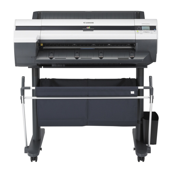
- Manuals
- Brands
- Canon Manuals
- Printer
- iPF605 — imagePROGRAF Color Inkjet Printer
- User manual
Large format printer
Hide thumbs
Also See for imagePROGRAF iPF605:
- Service manual (268 pages)
- Manual (4 pages)
- Technical documents (2 pages)
,
,
1
2
3
4
5
6
7
8
9
10
11
12
13
14
15
16
17
18
19
20
21
22
23
24
25
26
27
28
29
30
31
32
33
34
35
36
37
38
39
40
41
42
43
44
45
46
47
48
49
50
51
52
53
54
55
56
57
58
59
60
61
62
63
64
65
66
67
68
69
70
71
72
73
74
75
76
77
78
79
80
81
82
83
84
85
86
87
88
89
90
91
92
93
94
95
96
97
98
99
100
101
102
103
104
105
106
107
108
109
110
111
112
113
114
115
116
117
118
119
120
121
122
123
124
125
126
127
128
129
130
131
132
133
134
135
136
137
138
139
140
141
142
143
144
145
146
147
148
149
150
151
152
153
154
155
156
157
158
159
160
161
162
163
164
165
166
167
168
169
170
171
172
173
174
175
176
177
178
179
180
181
182
183
184
185
186
187
188
189
190
191
192
193
194
195
196
197
198
199
200
201
202
203
204
205
206
207
208
209
210
211
212
213
214
215
216
217
218
219
220
221
222
223
224
225
226
227
228
229
230
231
232
233
234
235
236
237
238
239
240
241
242
243
244
245
246
247
248
249
250
251
252
253
254
255
256
257
258
259
260
261
262
263
264
265
266
267
268
269
270
271
272
273
274
275
276
277
278
279
280
281
282
283
284
285
286
287
288
289
290
291
292
293
294
295
296
297
298
299
300
301
302
303
304
305
306
307
308
309
310
311
312
313
314
315
316
317
318
319
320
321
322
323
324
325
326
327
328
329
330
331
332
333
334
335
336
337
338
339
340
341
342
343
344
345
346
347
348
349
350
351
352
353
354
355
356
357
358
359
360
361
362
363
364
365
366
367
368
369
370
371
372
373
374
375
376
377
378
379
380
381
382
383
384
385
386
387
388
389
390
391
392
393
394
395
396
397
398
399
400
401
402
403
404
405
406
407
408
409
410
411
412
413
414
415
416
417
418
419
420
421
422
423
424
425
426
427
428
429
430
431
432
433
434
435
436
437
438
439
440
441
442
443
444
445
446
447
448
449
450
451
452
453
454
455
456
457
458
459
460
461
462
463
464
465
466
467
468
469
470
471
472
473
474
475
476
477
478
479
480
481
482
483
484
485
486
487
488
489
490
491
492
493
494
495
496
497
498
499
500
501
502
503
504
505
506
507
508
509
510
511
512
513
514
515
516
517
518
519
520
521
522
523
524
525
526
527
528
529
530
531
532
533
534
535
536
537
538
539
540
541
542
543
544
545
546
547
548
549
550
551
552
553
554
555
556
557
558
559
560
561
562
563
564
565
566
567
568
569
570
571
572
573
574
575
576
577
578
-
page
of
578/
578 -
Contents
-
Table of Contents
-
Troubleshooting
-
Bookmarks
Table of Contents
-
Table of Contents
-
User Manual
-
-
Table of Contents
-
Introduction
-
How to Use this Manual
-
About this User Manual
-
Searching Topics
-
HTML Version of the Manual for Printing
-
Printing a Group of Topics in the Manual
-
Printing Selected Topics
-
-
-
Printer Parts
-
Pr�Nter Parts
-
Front
-
Back
-
Top Cover (Ins�De)
-
Tray Feed Area
-
Carr�Age
-
Roll Feed Un�T Cover (Ins�De)
-
Ink Tank Cover (Ins�De)
-
Vents
-
Control Panel
-
-
Control Panel
-
Turning the Printer on and off
-
Turning the Printer off
-
Printer Modes
-
Mode Transition
-
Online, and State of the Control Panel
-
Menu Mode, and State of the Control Panel
-
Switching Modes
-
Switching to Menu Mode
-
Printer Menu Operations
-
Main Menu Operations
-
Accessing Menus
-
Specifying Menu Items
-
Executing Menu Commands
-
Specifying Numerical Values
-
Menu Structure
-
Main Menu During Printing
-
Main Menu Settings
-
Media Menu
-
Paper Details
-
Gl2 Settings
-
Adjust Printer
-
Interface Setup
-
System Setup
-
Ma�N Menu Sett�Ngs (Dur�Ng Pr�Nt�Ng)
-
-
Main Menu Settings (During Printing)
-
Information of the Loaded Paper
-
Printer Information
-
Submenu Display
-
Printing Status Print Reports
-
Status Print
-
-
Optional Accessories
-
Stand
-
IEEE 1394 Expansion Board
-
Roll Holder Set
-
-
Printer Specifications
-
Specifications
-
Printing Performance
-
Basic Environmental Performance
-
Packaging Materials
-
Print Area
-
-
-
Basic Printing Workflow
-
Printing Procedure
-
Printing Options Using Rolls and Sheets
-
Sheet Printing
-
Loading and Printing on Rolls
-
Load�Ng and Pr�Nt�Ng on Sheets �N the Paper Feed Slot
-
Printing from Windows
-
Printing from Mac os X
-
Registering the Printer
-
Printing from the Application Software
-
-
Canceling Print Jobs
-
Canceling Print Jobs from the Control Panel
-
Canceling Print Jobs from Windows
-
Cancel�Ng Pr�Nt Jobs from Mac os X
-
-
-
Handling Paper
-
Paper
-
Types of Paper
-
Viewing the Paper Reference Guide
-
Updating Paper Information
-
Paper Sizes
-
-
Handling Rolls
-
Select�Ng the Paper Source
-
Select�Ng the Paper Type (Roll)
-
Spec�Fy�Ng the Paper Length (Roll)
-
-
Specifying the Paper Length (Roll)
-
Loading Rolls on the Roll Holder
-
Loading Rolls in the Roll Feed Unit
-
Loading Rolls in the Printer
-
Removing the Roll from the Printer
-
Removing Rolls from the Roll Feed Unit
-
Removing Rolls from the Roll Holder
-
Clearing Jammed Roll Paper
-
Clear�Ng Jammed Paper (Paper Feed Slot)
-
Feeding Roll Paper Manually
-
Detection of the Remaining Roll Paper
-
Specifying the Ink Drying Time for Rolls
-
Mac os X
-
Specifying the Cutting Method for Rolls
-
Eject (Waiting for Ink to Dry after Printing)
-
Cutting the Leading Edge of Roll Paper Automatically
-
Reducing Dust from Cutting Rolls
-
Roll Holder Set
-
Attaching Accessories to the Roll Holder
-
Mounting the 3-Inch Paper Core Attachment
-
Removing the 3-Inch Paper Core Attachment
-
Attaching the Spacer for Borderless Printing
-
Removing the Spacer for Borderless Printing
-
Feeding Paper from the Roll Feed Unit
-
Removing the Roll Feed Unit
-
Installing the Roll Feed Unit
-
-
Handling Sheets
-
Select�Ng the Paper Source
-
Select�Ng the Paper Type (Sheet)
-
Select�Ng the Paper S�Ze (Sheet)
-
Loading Paper in the Top Paper Feed Slot
-
Loading Sheets Manually
-
Removing Sheets from the Top Paper Feed Slot
-
Remov�Ng Heavywe�Ght Paper from the Front Paper Feed Slot
-
Clear�Ng Jammed Paper from the Tray
-
-
Output Stacker
-
Output Stacker Precautions
-
Using the Output Stacker
-
-
-
Working with Various Print Jobs
-
Printing Photos and Images
-
Easy Settings
-
Pr�Nt�Ng Photos and Images (W�Ndows)
-
Pr�Nt�Ng Photos and Images
-
Pr�Nt�Ng Photos and Images (W�Ndows)
-
Pr�Nt�Ng Photos and Images (Mac os X)
-
-
Printing Cad Drawings
-
Pr�Nt�Ng CAD Draw�Ngs
-
Print Targets for Line Drawings and Text
-
Pr�Nt�Ng L�Ne Draw�Ngs and Text (W�Ndows)
-
Printing Line Drawings and Text
-
Pr�Nt�Ng L�Ne Draw�Ngs and Text (W�Ndows)
-
Pr�Nt�Ng L�Ne Draw�Ngs and Text (Mac os X)
-
HP-GL/2 Pr�Nt�Ng
-
-
Printing Office Documents
-
Printing Office Documents (Windows)
-
Printing Office Documents (Mac os X)
-
-
Using the Printer with a Color Imagerunner
-
Pr�Nt�Ng Enlargements of Scanned Or�G�Nals from a Color �Magerunner
-
Pr�Nt�Ng Enlargements of Scanned Or�G�Nals from a Color �Magerunner (W�Ndows)
-
Pr�Nt�Ng Enlargements of Scanned Or�G�Nals from a Color �Magerunner (Mac os X)
-
-
-
Enhanced Printing Options
-
Adjusting Images
-
Adjusting the Color in the Printer Driver
-
Color Mode
-
-
Color Adjustment
-
F�Ne-Tun�Ng Colors of Photos and Images (W�Ndows)
-
F�Ne-Tun�Ng Colors of Photos and Images (Mac os X)
-
Advanced Settings
-
For Printing
-
G�V�Ng Pr�Or�Ty to Part�Cular Graph�C Elements and Colors for Pr�Nt�Ng
-
Print Priority
-
Color Settings
-
Print Quality
-
Enhancing Printing Quality
-
Choos�Ng the Document Type and Pr�Nt�Ng Cond�T�Ons (W�Ndows)
-
Choos�Ng the Document Type and Pr�Nt�Ng Cond�T�Ons (Mac os X)
-
-
Choosing Paper for Printing
-
Choosing a Paper for Printing
-
If the Paper Type Is Not Listed for Selection
-
Media Type
-
Select�Ng the Paper Type (Roll)
-
Select�Ng the Paper Type (Sheet)
-
Specifying Paper in the Printer Driver
-
Spec�Fy�Ng Paper �N the Pr�Nter Dr�Ver (W�Ndows)
-
Spec�Fy�Ng Paper �N the Pr�Nter Dr�Ver (Mac os X)
-
Printing Enlargements or Reductions
-
-
Resizing Originals to Match the Paper Size
-
Resizing Originals to Match the Paper Size (Windows)
-
Resizing Originals to Match the Paper Size (Mac os X)
-
-
Resizing Originals to Fit the Roll Width
-
Resizing Originals to Fit the Roll Width (Windows)
-
Resizing Originals to Fit the Roll Width (Mac os X)
-
-
Resizing Originals by Entering a Scaling Value
-
Resizing Originals by Entering a Scaling Value (Windows)
-
Resizing Originals by Entering a Scaling Value (Mac Os)
-
Printing at Full Size
-
Printing on Oversized Paper
-
Printing at Full Size (Windows)
-
Printing at Full Size (Mac os X)
-
Borderless Printing at Actual Size
-
Borderless Printing on Paper of Equivalent Size
-
Borderless Printing by Resizing Originals to Match the
-
Printing Banners or at Other Non-Standard Sizes
-
Printing Vertical/Horizontal Banners
-
Registering a Custom Paper Size
-
Creating the Banner in the Application
-
Printing the Banner
-
Register a Custom Page Size
-
Print the Banner
-
Printing on Non-Standard Paper Sizes
-
Printing by Using Custom Size
-
Printing by Using Custom Paper Size
-
Printing on Non-Standard Paper Sizes (Mac os X)
-
Free Layout (Windows)
-
Printing Multiple Originals Next to each Other
-
Tiling and Multiple Pages Per Sheet
-
Imageprograf Free Layout (Macintosh)
-
Printing Multiple Originals Next to each Other (Windows)
-
Printing Multiple Pages Continuously
-
Roll Paper (Banner)
-
Printing Multiple Pages Continuously (Windows)
-
Printing Multiple Pages Continuously (Mac os X)
-
Printing Multiple Pages Per Sheet
-
Printing Multiple Pages Per Sheet (Windows)
-
Printing Multiple Pages Per Sheet (Mac os X)
-
Printing Posters in Sections
-
Printing Large Posters (Windows)
-
Centering Originals
-
Printing Originals Centered on Rolls
-
Printing Originals Centered on Rolls (Windows)
-
Printing Originals Centered on Rolls (Mac os X)
-
Printing Originals Centered on Sheets
-
Printing Originals Centered on Sheets (Windows)
-
Printing Originals Centered on Sheets (Mac os X)
-
Conserving Roll Paper
-
Rotate Page 90 Degrees (Conserve Paper)
-
Conserving Roll Paper by Rotating Originals 90 Degrees
-
Checking Images before Printing
-
Preview (Macintosh)
-
Checking the Layout in a Preview before Printing
-
Other Useful Settings
-
Printing with Watermarks
-
Printing with Watermarks-Copy, File Copy, and so on
-
Making the Original Orientation Match the Paper Orientation
-
Rotate 180 Degrees
-
Making the Original Orientation Match the Paper Orientation (Windows)
-
-
Making the Original Orientation Match the Paper
-
Orientation (Mac os X)
-
Using Favorites
-
Automatic Cutting
-
Cutting Roll Paper after Printing
-
Cutting Roll Paper after Printing (Windows)
-
Cutting Roll Paper after Printing (Mac os X)
-
-
Windows Software
-
Printer Driver
-
Accessing the Printer Driver Dialog Box from Applications (Windows)
-
-
Main Sheet (Windows)
-
Media Detailed Settings Dialog Box (Windows)
-
View Settings Dialog Box for the Printing Application
-
Color Adjustment Sheet: Color (Windows)
-
Driver Matching Mode
-
-
Matching Sheet (Windows)
-
ICC Matching Mode, Driver ICM Mode and Host ICM Mode
-
Page Setup Sheet (Windows)
-
Paper Size Options Dialog Box (Windows)
-
-
Layout Sheet (Windows)
-
Page Options Dialog Box (Windows)
-
Special Settings Dialog Box (Windows)
-
Favorites Sheet (Windows)
-
Utility Sheet (Windows)
-
Support Sheet (Windows)
-
Device Settings Sheet (Windows)
-
-
Settings Summaries Dialog Box (Windows)
-
Status Monitor
-
Imageprograf Status Monitor (Windows)
-
Digital Photo Front-Access
-
Edit Using Posterartist
-
Using Posterartist to Compose Originals
-
Device Setup Utility
-
Imageprograf Device Setup Utility
-
Installing Imageprograf Device Setup Utility
-
-
Mac os X Software
-
Printer Driver Settings (Mac os X)
-
Main Pane (Mac os X)
-
Media Detailed Settings Dialog Box (Mac os X)
-
Color Adjustment Pane: Color
-
Color Settings Pane: Color (Mac os X)
-
Matching Pane
-
Color Adjustment Pane: Monochrome
-
Color Settings Pane: Monochrome (Mac os X)
-
-
Page Setup Pane (Mac os X)
-
Utility Pane (Mac os X)
-
Additional Settings Pane (Mac os X)
-
-
Support Pane (Mac os X)
-
Imageprograf Printmonitor (Macintosh)
-
Network Environment
-
System Requirements
-
Using Remoteui
-
Specifying Printer-Related Information
-
Initializing the Network Settings
-
Network Setting (Windows)
-
Sharing the Printer in Windows
-
Specifying the Printer’s Frame Type
-
Specifying the Frame Type Using the Printer Control Panel
-
Choosing the Type of Print Services
-
Specifying Netware Print Services
-
Specifying Netware Protocols
-
Activating Appletalk on the Printer
-
Adjusting the Printhead
-
Adjusting the Printhead Alignment Automatically
-
Correcting Print Misalignment
-
Adjusting the Printhead Alignment Manually
-
Adjusting the Printhead Height
-
Adjusting the Feed Amount
-
Adjusting the Feed Amount Automatically
-
Adjusting the Feed Amount Manually
-
Adjusting the Measurement Scale for Better Accuracy
-
Adjusting Color on the Trailing Edge of Sheets
-
Adjusting the Vacuum Strength
-
-
Ink Tanks
-
Compatible Ink Tank
-
Precautions When Handling an Ink Tank
-
Replacing Ink Tanks
-
Replacing an Ink Tank
-
Checking Ink Tank Levels
-
-
When to Replace Ink Tanks
-
Checking the Print Quality
-
Improving the Print Quality
-
Checking for Nozzle Clogging
-
Cleaning the Printhead
-
Compatible Printhead
-
Precautions When Handling the Printhead
-
Replacing the Printhead
-
When to Replace the Printhead
-
Compatible Maintenance Cartridge
-
Maintenance Cartridge
-
Replacing the Maintenance Cartridge
-
Checking the Remaining Maintenance Cartridge Capacity
-
When to Replace the Maintenance Cartridge
-
-
The Display Screen
-
Cleaning the Printer
-
Cleaning the Printer Exterior
-
Cleaning Inside the Top Cover
-
Cleaning the Paper Retainer
-
Other Maintenance
-
Preparing to Transfer the Printer
-
Updating the Firmware
-
Frequently Asked Questions
-
Problems Regarding Paper
-
Roll Paper Cannot be Inserted into the Paper Feed Slot
-
-
Cannot Load Sheets
-
Paper Is Not Cut Straight
-
-
Paper Cannot be Cut
-
Depression on the Leading Edge Is Left
-
Printing Does Not Start
-
The Data Lamp on the Control Panel Does Not Light up
-
The Printer Does Not Respond Even if Print Jobs Are Sent
-
An Error Message Is Shown on the Display Screen
-
The Printer Ejects Blank, Unprinted Paper
-
The Printer Stops During a Print Job
-
Printing Is Faint
-
Problems with the Printing Quality
-
Paper Rubs against the Printhead
-
The Edges of the Paper Are Dirty
-
The Back Side of the Paper Is Dirty
-
The Surface of the Paper Is Dirty
-
Printed Colors Are Inaccurate
-
Banding in Different Colors Occurs
-
Colors in Printed Images Are Uneven
-
Documents Are Printed Crooked
-
Documents Are Printed in Monochrome
-
Image Edges Are Blurred or White Banding Occurs
-
The Contrast Becomes Uneven During Printing
-
The Length of Printed Images Is Inaccurate
-
Line Thickness Is Not Uniform (Windows)
-
Lines Are Misaligned
-
Printing Mode
-
Cannot Connect the Printer to the Network
-
Cannot Print over a Network
-
Cannot Print over a Tcp/Ip Network
-
Cannot Print over a Netware Network
-
Cannot Print over Appletalk or Bonjour Networks
-
Installation Problems
-
Removing Installed Printer Drivers
-
Removing Printer Drivers (Windows)
-
-
Hp-Gl/2 Problems
-
Hp-Gl/2 Printing Takes a Long Time
-
Replotting with Hp-Gl/2 Jobs Is Not Possible
-
If the Printer Makes a Strange Sound
-
The Printer Consumes a Lot of Ink
-
The Printer Does Not Go on
-
Disabling Ink Level Detection
-
Ink Level Detection
-
Error Message
-
Responding to Messages
-
-
Error Messages
-
Other Messages
-
Error Messages
-
Messages Regarding Paper
-
-
Troubleshooting
-
Paper Mismatch
-
Papr Type Mismatch
-
Paper Size Not Detected
-
Papr Size Mismatch
-
Roll Printing Is Selected
-
This Paper Cannot be Used
-
Roll Printing Is Selected, but Sheets Are Loaded
-
The Roll Is Empty
-
Manual Printing Is Selected, but a Roll Is Loaded
-
Sheet Printing Is Selected
-
-
Paper Jam
-
Paper Loaded Askew
-
Cannot Detect Papr
-
Cannot Feed Paper
-
Cannot Cut Paper
-
End of Paper Feed
-
Borderless Printng Not Possible
-
Check Roll Width and Spacers
-
Check Supported Paper
-
Messages Regarding Ink
-
No Ink Left
-
-
Ink Level: Check
-
No Ink Tank Loaded
-
-
Ink Tank Error
-
Use Another Paper
-
Messages Regarding Printing or Adjusment
-
-
Cannot Adjust Band
-
Cannot Adjust Printhead
-
Messages Regarding Printheads
-
Phead Needs Cleaning
-
Problem with Printhead
-
Printhead Error
-
Maintenance Cartridge Full
-
Maintenance Cartridge Problem
-
Messages Regarding the Maintenance Cartridge
-
No Maintenance Cartridge
-
No Maintenance Cartridge Capacity
-
Prepare for Maint Cart Replacement
-
Gl2: W0502 the Parameter Is out of Range
-
Gl2: W0504 this Command Is Not Supported
-
There Is no Data
-
Other Messages
-
-
ERROR Exxx-XXXX (X Represents a Letter or Number)
-
Hardware Error. XXXXXXXX-XXXX (X Represents a Letter or Number)
-
Garo Wxxxx (X Represents a Number)
-
Top Cover Is Open
-
-
Prepare for Parts Replacement
-
Multi-Sensor Error
-
Parts Replacement Time Has Passed
-
-
Cannot Print as Specified
-
Configuring the IP Address Using Imageprograf Device Setup Utility
-
Confirming Print Settings (Mac os X)
-
Configuring the IP Address on the Printer
-
Configuring the IP Address Using the Printer Control Panel
-
Configuring the IP Address Using ARP and PING Commands
-
Configuring the Printer’s TCP/IP Network Settings
-
Configuring the Printer’s Appletalk Network Settings
-
Configuring the Printer’s Netware Network Settings
-
Configuring the Communication Mode Manually
-
Configuring Netware Network Settings
-
Email Notification When Printing Is Finished or Errors Occur
-
Insufficient Paper for Job
-
Ink Insufficient
-
The Display Screen Indicates the System Is Filling with Ink
-
-
Unknown File
-
-
Advertisement
Quick Links
x
Download this manual
507
To Replace Maintenance Cartridge
See also:
Troubleshooting Manual, Service Manual
L a r g e F o r m a t Pr int er
User Manual
ENG
Table of Contents
Previous Page
Next Page
- 1
- 2
- 3
- 4
- 5
Advertisement
Chapters
-
Table of Contents
3 -
Table of Contents
8
Table of Contents
Related Manuals for Canon imagePROGRAF iPF605
-
Printer Canon iPF605 Service Manual
(268 pages)
-
Printer Canon iPF9000S Troubleshooting Manual
Ipf5000, ipf700, ipf8000, ipf800, ipf650/750 series (184 pages)
-
All in One Printer Canon imagePROGRAF iPF5100 Brochure
Imageprograf full-line brochure (16 pages)
-
Printer Canon imagePROGRAF iPF500 Brochure & Specs
Large-format printers (12 pages)
-
Printer Canon imagePROGRAF iPF500 Brochure & Specs
Large format printers (10 pages)
-
Printer Canon iPF605 Manual
How to replace the printhead (4 pages)
-
Printer Canon imagePROGRAF iPF605 Technical Documents
Large-format printing (2 pages)
-
Printer Canon imagePROGRAF iPF6000S Brochure & Specs
Large format printers (2 pages)


-
Printer Canon imagePROGRAF iPF6000S Brochure & Specs
Ipf s-series (8 pages)
-
Printer Canon imagePROGRAF iPF6000S User Manual
Large format printer (730 pages)
-
Printer Canon imagePROGRAF iPF6000S User Manual
Large format printer (730 pages)
-
Printer Canon imageprograf ipf600 Service Manual
(17 pages)
-
Printer Canon iPF600 series Service Manual
(274 pages)
-
Printer Canon imagePROGRAF iPF6100 Brochure & Specs
Canon imageprograf ipf6100: supplementary guide (8 pages)
-
Printer Canon imagePROGRAF iPF6100 User Manual
Large format printer (736 pages)
-
Printer Canon iPF6100 Service Manual
Canon ipf6000 series laser printers service manual (452 pages)


Related Products for Canon imagePROGRAF iPF605
- Canon iPF6000S — imagePROGRAF Color Inkjet Printer
- Canon IPF600
- Canon iPF650 — imagePROGRAF Color Inkjet Printer
- Canon iPF610 — imagePROGRAF Color Inkjet Printer
- Canon imagePROGRAF iPF6200
- Canon imagePROGRAF iPF6350
- Canon imagePROGRAF iPF6300
- Canon imagePROGRAF iPF6300S
- Canon imagePROGRAF iPF6400
- Canon imagePROGRAF iPF6400SE
- Canon image Prograf iPF 685 Series
- Canon image Prograf iPF680 Series
- Canon IPF670
- Canon iPF671
- Canon iPF6410SE
- Canon iPF6410S
Table of Contents

- 1
- 2
- 3
- 4
- 5
- 6
- 7
- 8
- 9
- 10
- 11
- 12
- 13
- 14
- 15
- 16
- 17
- 18
- 19
- 20
- 21
- 22
- 23
- 24
- 25
- 26
- 27
- 28
- 29
- 30
- 31
- 32
- 33
- 34
- 35
- 36
- 37
- 38
- 39
- 40
- 41
- 42
- 43
- 44
- 45
- 46
- 47
- 48
- 49
- 50
- 51
- 52
- 53
- 54
- 55
- 56
- 57
- 58
- 59
- 60
- 61
- 62
- 63
- 64
- 65
- 66
- 67
- 68
- 69
- 70
- 71
- 72
- 73
- 74
- 75
- 76
- 77
- 78
- 79
- 80
- 81
- 82
- 83
- 84
- 85
- 86
- 87
- 88
- 89
- 90
- 91
- 92
- 93
- 94
- 95
- 96
- 97
- 98
- 99
- 100
- 101
- 102
- 103
- 104
- 105
- 106
- 107
- 108
- 109
- 110
- 111
- 112
- 113
- 114
- 115
- 116
- 117
- 118
- 119
- 120
- 121
- 122
- 123
- 124
- 125
- 126
- 127
- 128
- 129
- 130
- 131
- 132
- 133
- 134
- 135
- 136
- 137
- 138
- 139
- 140
- 141
- 142
- 143
- 144
- 145
- 146
- 147
- 148
- 149
- 150
- 151
- 152
- 153
- 154
- 155
- 156
- 157
- 158
- 159
- 160
- 161
- 162
- 163
- 164
- 165
- 166
- 167
- 168
- 169
- 170
- 171
- 172
- 173
- 174
- 175
- 176
- 177
- 178
- 179
- 180
- 181
- 182
- 183
- 184
- 185
- 186
- 187
- 188
- 189
- 190
- 191
- 192
- 193
- 194
- 195
- 196
- 197
- 198
- 199
- 200
- 201
- 202
- 203
- 204
- 205
- 206
- 207
- 208
- 209
- 210
- 211
- 212
- 213
- 214
- 215
- 216
- 217
- 218
- 219
- 220
- 221
- 222
- 223
- 224
- 225
- 226
- 227
- 228
- 229
- 230
- 231
- 232
- 233
- 234
- 235
- 236
- 237
- 238
- 239
- 240
- 241
- 242
- 243
- 244
- 245
- 246
- 247
- 248
- 249
- 250
- 251
- 252
- 253
- 254
- 255
- 256
- 257
- 258
- 259
- 260
- 261
- 262
- 263
- 264
- 265
- 266
- 267
- 268
- 269
- 270
- 271
- 272
- 273
- 274
- 275
- 276
- 277
- 278
- 279
- 280
- 281
- 282
- 283
- 284
- 285
- 286
- 287
- 288
- 289
- 290
- 291
- 292
- 293
- 294
- 295
- 296
- 297
- 298
- 299
- 300
- 301
- 302
- 303
- 304
- 305
- 306
- 307
- 308
- 309
- 310
- 311
- 312
- 313
- 314
- 315
- 316
- 317
- 318
- 319
- 320
- 321
- 322
- 323
- 324
- 325
- 326
- 327
- 328
- 329
- 330
- 331
- 332
- 333
- 334
- 335
- 336
- 337
- 338
- 339
- 340
- 341
- 342
- 343
- 344
- 345
- 346
- 347
- 348
- 349
- 350
- 351
- 352
- 353
- 354
- 355
- 356
- 357
- 358
- 359
- 360
- 361
- 362
- 363
- 364
- 365
- 366
- 367
- 368
- 369
- 370
- 371
- 372
- 373
- 374
- 375
- 376
- 377
- 378
- 379
- 380
- 381
- 382
- 383
- 384
- 385
- 386
- 387
- 388
- 389
- 390
- 391
- 392
- 393
- 394
- 395
- 396
- 397
- 398
- 399
- 400
- 401
- 402
- 403
- 404
- 405
- 406
- 407
- 408
- 409
- 410
- 411
- 412
- 413
- 414
- 415
- 416
- 417
- 418
- 419
- 420
- 421
- 422
- 423
- 424
- 425
- 426
- 427
- 428
- 429
- 430
- 431
- 432
- 433
- 434
- 435
- 436
- 437
- 438
- 439
- 440
- 441
- 442
- 443
- 444
- 445
- 446
- 447
- 448
- 449
- 450
- 451
- 452
- 453
- 454
- 455
- 456
- 457
- 458
- 459
- 460
- 461
- 462
- 463
- 464
- 465
- 466
- 467
- 468
- 469
- 470
- 471
- 472
- 473
- 474
- 475
- 476
- 477
- 478
- 479
- 480
- 481
- 482
- 483
- 484
- 485
- 486
- 487
- 488
- 489
- 490
- 491
- 492
- 493
- 494
- 495
- 496
- 497
- 498
- 499
- 500
- 501
- 502
- 503
- 504
- 505
- 506
- 507
- 508
- 509
- 510
- 511
- 512
- 513
- 514
- 515
- 516
- 517
- 518
- 519
- 520
- 521
- 522
- 523
- 524
- 525
- 526
- 527
- 528
- 529
- 530
- 531
- 532
- 533
- 534
- 535
- 536
- 537
- 538
- 539
- 540
- 541
- 542
- 543
- 544
- 545
- 546
- 547
- 548
- 549
- 550
- 551
- 552
- 553
- 554
- 555
- 556
- 557
- 558
- 559
- 560
- 561
- 562
- 563
- 564
- 565
- 566
- 567
- 568
- 569
- 570
- 571
- 572
- 573
- 574
- 575
- 576
- 577
- 578
- 579
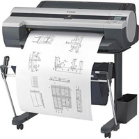
Select your support content

-
Find the latest drivers for your product
-
Software to improve your experience with our products
-
Useful guides to help you get the best out of your product
-
Find the latest firmware for your product
-
Need help? Check out our frequently asked questions
-
Check out the latest news about your product
-
Find solutions to the error code displayed on your product
-
Read the technical specifications for your product
Left Right
You might also like

Contact Us
Contact us for telephone or e-mail support

Recycling
Learn more about Canon’s Cartridge Recycling Programme
or

 Canon
Canon
Have Your Say
Please complete a 1 minute survey to help us improve our support website experience

User Manual
ENG
L a r g e F o r m a t P r i n t e r

Select your support content

-
Find the latest drivers for your product
-
Software to improve your experience with our products
-
Useful guides to help you get the best out of your product
-
Find the latest firmware for your product
-
Need help? Check out our frequently asked questions
-
Check out the latest news about your product
-
Find solutions to the error code displayed on your product
-
Read the technical specifications for your product
Left Right
You might also like

Contact Us
Contact us for telephone or e-mail support
or

 Canon
Canon
Have Your Say
Please complete a 1 minute survey to help us improve our support website experience