Digital Pressure Switch
Operation Manual
ISE 5
Thank you for purchasing an SMC ISE35 Series Digital Pressure Switch.
Please read this manual carefully before operating the product and make sure you
understand its capabilities and limitations.
Please keep this manual handy for future reference.
To obtain more detailed information about operating this product, please
refer to the SMC website (URL http://www.smcworld.com) or contact SMC
directly.
Safety Instructions
These safety instructions are intended to prevent hazardous situations and/or
equipment damage.
These instructions indicate the level of potential hazard with the labels of
«Caution», «Warning» or «Danger». They are all important notes for safety and must
be followed in addition to International standards (ISO/IEC) and other safety
regulations.
CAUTION indicates a hazard with a low level of risk
Caution:
which, if not avoided, could result in minor or
moderate injury.
WARNING indicates a hazard with a medium level of
Warning:
risk which, if not avoided, could result in death or
serious injury.
DANGER indicates a hazard with a high level of risk
Danger:
which, if not avoided, will result in death or serious
injury.
Operator
This operation manual is intended for those who have knowledge of machinery
using pneumatic equipment, and have sufficient knowledge of assembly,
operation and maintenance of such equipment. Only those persons are
allowed to perform assembly, operation and maintenance.
Read and understand this operation manual carefully before assembling,
operating or providing maintenance to the product.
Safety Instructions
Warning
Do not disassemble, modify (including changing the printed circuit board) or repair.
An injury or failure can result.
Do not operate the product outside of the specifications.
Do not use for flammable or harmful fluids.
Fire, malfunction, or damage to the product can result.
Verify the specifications before use.
Do not operate in an atmosphere containing flammable or explosive gases.
Fire or an explosion can result.
This product is not designed to be explosion proof.
Do not use the product in a place where static electricity is a problem.
Otherwise it can cause failure or malfunction of the system.
If using the product in an interlocking circuit:
•Provide a double interlocking system, for example a mechanical system
•Check the product regularly for proper operation
Otherwise malfunction can result, causing an accident.
The following instructions must be followed during maintenance:
•Turn off the power supply
•Stop the air supply, exhaust the residual pressure and verify that the air is released before performing
maintenance work
Otherwise an injury can result.
Caution
Do not touch the terminals and connectors while the power is on.
Otherwise electric shock, malfunction or damage to the product can result.
After maintenance is complete, perform appropriate functional inspections and leak tests.
Stop operation if the equipment does not function properly or there is a leakage of fluid.
When leakage occurs from parts other than the piping, the product might be faulty.
Disconnect the power supply and stop the fluid supply.
Do not apply fluid under leaking conditions.
Safety cannot be assured in the case of unexpected malfunction.
NOTE
•The direct current power supply to be used should be UL approved as follows:
Circuit (of Class2) which is of maximum 30 Vrms (42.4 V peak), with UL1310
Class2 power supply unit or UL1585 Class2 transformer.
•The product is a
approved product only if it has a
mark on the body.
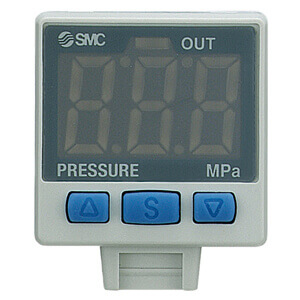
Summary of Product parts
Names of individual parts
Indication LED
button (DOWN)
3-digit LED
button (SET)
button (DOWN)
button (UP)
button (SET)
button (UP)
ISE35-N-
ISE35-R-
Indication LED (green): Displays the switch condition.
3-digit LED: Displays the current status of pressure, setting mode and error code.
Four display modes can be selected: display always in red or green,
or display changing from green to red, or red to green, according to
the output status.
button (UP): Selects the mode or increases the ON/OFF set value.
Press this button to change to the peak display mode.
button (DOWN): Selects the mode or decreases the ON/OFF set value.
Press this button to change to the bottom display mode.
button (SET): Press this button to change to another mode and to set a value.
Mounting and Installation
Wiring
Connection
Connections should only be made with the power supply turned off.
Use separate routes for the Pressure switch wiring and any power or high
voltage wiring. Otherwise, malfunction may result due to noise.
Ensure that the FG terminal is connected to ground when using a
commercially available switch-mode power supply. When a switch-mode
power supply is connected to the product, switching noise will be
superimposed and the product specification can no longer be met. This can
be prevented by inserting a noise filter, such as a line noise filter and ferrite
core, between the switch-mode power supply and the product, or by using a
series power supply instead of the switch-mode power supply.
Refer to the product catalogue or SMC website
(URL http://www.smcworld.com) for more information about wiring.
Connector
Connecting / Disconnecting
When mounting the connector, insert it straight into the socket, holding the
lever and connector body, and push the connector until the lever hooks into
the housing, and locks.
When removing the connector, press down the lever to release the hook
from the housing and pull the connector straight out.
Body of switch
Pin
Lever
Lead wire (Blue)
Rubber cover
Lead wire with connector
(with rubber cover)
(Model: ZS-32-A)
Connector
Lead wire (Brown)
Pressure Setting
Measurement mode
The power is supplied.
The measurement mode
is the condition where the
The symbol to show the indication
pressure is detected and
unit appears for approx. 1 s.
displayed, and the
Indication unit: M Indication unit: P Indication unit: Nil
switch function is
operating.
This is the basic mode,
and the other modes
should be selected for
Measurement starts and the
setting changes and other
current pressure is displayed.
function settings.
Operation
When the pressure exceeds the set value,
0.35
the Pressure switch will turn ON. When the
pressure falls below the set value by the
0.34
amount of hysteresis or more, the
Pressure switch will turn OFF. As a default
setting, the Pressure switch is set to turn
ON when the pressure exceeds 0.35 MPa,
and turn OFF when it is below 0.34 MPa.
1 s
If this condition,
Switch ON
shown to the right, is
At normally open mode
Switch OFF
acceptable, then keep
Time [s]
these settings.
<How to perform>
1. Press the
button in the measurement mode to display set values.
Normally open
Displays in turn
or
Normally closed
(Default)
2. Press the
or
button to change the set value.
The
button is to increase and the
button is to decrease.
Press the
button once to increase by one digit, and press it continuously
to keep increasing the set value.
Press the
button once to decrease by one digit, and press it continuously
to keep decreasing the set value.
3. Press the
button to complete the setting.
The Pressure switch operates within a set pressure range during window
_
_
comparator mode. Set P
L, P_L (switch lower limit) and P
H, P_H (switch upper
limit) with the setting procedure above.
Function Setting
Default setting
At the time of shipment, the following settings are provided.
If the setting is acceptable, keep it for use.
When the
button is pressed for 2 seconds or longer, the parameter settings
can be changed.
Refer to the SMC website (URL http://www.smcworld.com) for more detailed
information about setting changes, or contact SMC.
Setting item
Default setting
Switch output
Selects whether or not the Pressure switch output is made available.
ON
If the switch output is unnecessary, it is available just like a pressure gauge.
Display colour
ON: Green
Selects the display colour.
OFF: Red
Response time
1 s
Sets a response time to prevent chattering in the output.
Operation mode
Hysteresis mode
Selects the mode to operate the Pressure switch.
Hysteresis
0.01 MPa (1 psi)
Output type
Normally open
Sets the method to generate the switch output.
Power saving mode
OFF
Selects the power saving mode.
Security code input
OFF
Selects the security code option for key lock.
The value in ( ) is for the indication unit «P».
Setting of special function
Setting item
Display reverse mode
Selects the reverse display mode
Indication unit (available with unit conversion function)
NOTE
When the default setting is changed, since the different setting item appears
in order depending on how many times the
button is pressed, confirm the
item which needs to be set appears correctly and prevent undesired setting.
Other Settings
Peak / Bottom hold display
Zero clear
Key lock
To set each of these functions, refer to the SMC website
(URL http://www.smcworld.com) for more detailed information, or contact SMC.
Maintenance
How to reset the product after a power cut or forcible de-energizing
The setting of the product will be retained as it was before a power cut or
de-energizing.
The output condition is also basically recovered to that before a power cut or
de-energizing, but may change depending on the operating environment.
Therefore, check the safety of the whole installation before operating the product. If
1 s
the installation is using accurate control, wait until the product has warmed up
(approximately 20 to 30 minutes).
Mounting on to a regulator
Cut the power supply to the Pressure switch when assembling. Also, turn the set
pressure of the regulator to zero.
Mount O-ring to the O-ring groove of the regulator. Attention should be taken not
to damage the O-ring.
Set the adapter with 2 set screws.
Recommended tightening torque:
Modular AR/AW series
0.6±0.05 Nm
ARM10/11 series
0.32±0.03 Nm
Mount the main body of the Pressure switch.
Insert the lock pin to the adapter to the end firmly.
Supply pressure slowly, and ensure no air leaks.
The Pressure switch can be assembled rotated 180 degrees.
Digital Pressure Switch
Set screw
Adapter
O-ring
Lock pin
Regulator
Troubleshooting
Error indication
This function is to display error location and content when a problem or an error
occurs.
Error name
Error display
Error type
Turn the power off and remove the
Over current
The switch output load current is more
cause of the over current. Then turn
error
than 80 mA.
the power on.
During the zero clear operation, pressure
above ±10%F.S. has been applied. After
Perform zero clear operation again
Residual
3 s, the mode will reset to the
after restoring the applied pressure
pressure
measurement mode. The zero clear
to an atmospheric pressure
error
range can vary ±1 digit with individual
condition.
product differences.
Pressure has exceeded the upper limit of
Pressurizing
the set pressure range.
Reset applied pressure to a level
error
within the set pressure range.
Pressure has exceeded the lower limit of
the set pressure range.
Turn the power off and turn it on
Displayed in the case of an internal data
again.
System error
error.
If resetting fails, an investigation by
SMC Corporation will be required.
If the error can not be reset after the above measures are taken, then please
contact SMC.
Refer to the SMC website (URL http://www.smcworld.com) for more information
about troubleshooting.
Specifications
Outline with Dimensions (in mm)
Refer to the product catalogue or SMC website (URL http://www.smcworld.com) for
more information about the product specifications and outline dimensions.
URL http://www.smcworld.com
Akihabara UDX 15F, 4-14-1, Sotokanda, Chiyoda-ku, Tokyo 101-0021, JAPAN
Phone: +81 3-5207-8249 Fax: +81 3-5298-5362
Note: Specifications are subject to change without prior notice and any obligation on the part of the manufacturer.
© 2011 SMC Corporation All Rights Reserved
Troubleshooting method

Barcode Scanner
- Главная
- Продукция
- …
- _any_~cfg
- Главная
- Продукция
- …
- Датчики и реле
- Датчики давления
- ISE35
- ISE35, Цифровой датчик давления, встроенный в регулятор тип
Каталог продукции
ISE35, Цифровой датчик давления, встроенный в регулятор тип
Для просмотра продукта в выбранной конфигурации нажмите «Посмотреть 3D»
- Встраиваемое реле давления с цифровой индикацией
- Для установки на регуляторы давления AC /AR /AW /ARM /ARP
- Применяется для сред: воздух, некоррозионные газы, невоспламеняемые газы
- Диапазон давлений: -0.1 ~ 1 МПа
- Воспроизводимость: ±1 % полной шкалы
- Электроподвод: сверху/снизу
- Рекомендуемые исполнения
- Конфигуратор
Выберите значения из выпадающих списков для отображения соответствующих артикулов. Это не точный поиск, пожалуйста, смотрите «Подробнее» или воспользуйтесь функцией «Сравнить» для получения более детальной информации
Список может быть изменен без предварительного уведомления
Показаны с ?
по ?
из ?
записей
20 |
50 |
100
Normally on stock
Модификации конца штока
Лучшие цены и срокиМы предоставляем лучшие цены и сроки за счёт прямых поставок от производителей
Профессиональная техподдержкаПрофессиональные инженеры окажут вам высококачественную техническую поддержку по любому вопросу
Ответ в течение 24 часовМы ценим время наших клиентов, поэтому обрабатываем заявки в течение 24 часов
Индивидуальный подходНе бывает одинаковых задач и ситуаций, поэтому к каждой заявке у нас индивидуальный подход
- Цена и наличие
- Datasheet PDF
ISE35-N-65 Поставщик
Поставщик
(2 позиции)
Посмотреть все цены компонентов.
 обновление
валюта:
Налог может быть рассчитан при выборе юаня.
количество:
Введите количество, чтобы рассчитать общую стоимость.
НДС %
| Поставщик | Страна | Наличии | Поставки (день) | MOQ | Валюта | 1+ | 10+ | 100+ | 1K+ | 10K+ | Купить | |
|
AiPCBA |
China | 266 | Immediate | 1 | USD | 101.3 | 101.3 | 101.3 | 101.3 | 101.3 | Купить | |
|
Allied Electronics |
USA | 0 | Ближайшие | 1 | USD | 101.3 | 101.3 | 101.3 | 101.3 | 101.3 | Запрос |
ISE35-N-65 Характеристики
Продукта обзор
SMC ISE35-N-65 pressure switch, ISE30/ISE30A PRESSURE SWITCH
The ISE3 series is a digital pressure switch (for positive pressure) with LCD readout for general pneumatics purposes. The ISE3 digital pressure switch allows the calibration of two independent outputs. Modular version can be integrated with ZX system.
Allied Electronics:
PRESSURE SWITCH
Просмотреть все
ISE35-N-65 параметры, ISE35-N-65 datasheet на русском PDF и ISE35-N-65 схема включения, Скачать вручную. Ты можешь использовать ISE35-N-65 даташит на русском поиск датчик ISE35-N-65 характеристики схема подключения и ISE35-N-65 характеристики. понимать ISE35-N-65 схема включения как работает и ISE35-N-65 Описание какие на русском. ISE35-N-65 чем заменить: ISE35-N-65 аналог отечественный и ISE35-N-65 аналоги. FindIC Может предоставить ISE35-N-65 купить, ISE35-N-65 reference manual на русском.
© 2019 SALUTEH
Продвижение сайта
Сайт не является интернет-магазином. Цены и наличие, а также иные параметры товара не являются офертой, а носят информационный характер. С физическими лицами не работаем. Регионы поставки: Москва, Санкт-Петербург, Новосибирск