47 файлов
-
Сортировка
- Фильтрация
-

Бесплатный
-
Бесплатный
wk2 2011-2013 user manual
РУКОВОДСТВО ПО ЭКСПЛУАТАЦИИ WK2 2011-2013 (Рус)
Автор
Nidjat
в отличии от версии которая в сети здесь присуствуют все страницы и это не скан а сам оригинал с офф ресурса.
583 раза скачали
-
Бесплатный
wk2 2014-2018 user manual
Grand Cherokee 2014-2017 RUS Руководство по эксплуатации
Автор
demos_s
Руководство по эксплуатации Jeep Grand Cherokee 2014 (рестайл) в хорошем качестве
3 158 раз скачали
-
2011 wk2 parts
Автор
wsaiuz
Запчасти по VIN
1 218 раз скачали
-
Grand Cherokee 2011-2013 Инструкция к МАФОНУ (рус)
Автор
Danko
Руководство по эксплуатации мультимедийной системы Jeep Grand Cherokee WK2 на русском языке
2 853 раза скачали
-
MOPAR 2012 ACCESSORIES DATABOOK SEPTEMBER 2011 EDITION
Автор
GrandFa
Каталог аксессуаров Мопар к 2012 модельному году
выпуск сентябрь 2011681 раз скачали
-
Руководство по ремонту АКПП ZF
Автор
Giraffe
Во вложении файл по ремонту АКПП, в том числе гидроблок, пакеты и остальное.
22 раза скачали
-
SM_71 2016 Grand Cherokee – SYSTEM WIRING DIAGRAMS
Автор
ALISA1986
Wirning Diagrams SM 71 2016 GRAND CHEROKEE
109 раз скачали
0 комментариев
Отправлено 12 марта, 2021
-
Допуски Fiat
Автор
srs3491
Допуски Fiat для масел в ДВС
137 раз скачали
-
Масла, которые производятся в России
Автор
srs3491
В этом файле указаны декларации соответствия масел различных брэндов, которые производятся на территории России. Так же указана ссылка, по которой можно проверить подлинность любой декларации соответствия ТР ТС
107 раз скачали
0 комментариев
Отправлено 2 февраля, 2020
-
2011 ENGINE 3.0L Turbo Diesel — Service Information -инструкция по ремонту (англ.)
Автор
Гость
Это инструкция по ремонту дизельного двигателя, правда на английском языке, мне прислал дизелист Дариус из Литвы (спасибо ему за это!) , там очень много информации, в частности все размеры вкладышей, шеек , моменты и порядок затяжек валов. поддонов, крышек и т.д.
246 раз скачали
0 комментариев
Отправлено 16 июля, 2019
-
Бесплатный
Инструкция и каталог по подбору фильтров-поддонов АКПП для замены масла.
Автор
Гость
Официальная инструкция по замене масла в акпп в 8-ступенчатых акпп ZF
845 раз скачали
-
Бесплатный
Снятие передней юбки бампера на WK2
Автор
sdolina
Как снять и поставить переднюю юбку бампера WK2 без снятия бампера
615 раз скачали
-
Бесплатный
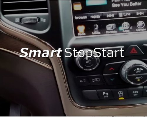
Модуль отключения Start Stop
Автор
sdolina
Описание работы модуля SmartStopStart
Авто запоминает выбор пользователя. По умолчанию стоит включено с модулем при старте авто будет та настройка которую выбрал пользователь.
314 раза скачали
0 комментариев
Отправлено 19 декабря, 2018
-
РУКОВОДСТВО ПО ЭКСПЛУАТАЦИИ Uconnect2014-2018 (Рус)
Автор
Nidjat
здесь 6 файла на все версии Uconnect(2014-2018).radio.nav.
750 раз скачали
-
Бесплатный
-
0 комментариев
Отправлено 10 июня, 2018
-
Бесплатный
0 комментариев
Обновлено 8 мая, 2021
-
Джип не заводится
Автор
Цитрамон
Залип стартер
111 раз скачали
0 комментариев
Отправлено 27 мая, 2018
-
JGC WK2 2014 Workshop Service & Repair Manual
Автор
xmo97
Не обращайте внимания, что в титуле 2014 Jeep Grand Cherokee SRT
На самом деле там все двигатели
3.0 бензин
3.0 дизель
3.6 бензин
5.7 бензин
6.4 бензин
5934 страниц
1 040 раз скачали
-
Jeep GC WK2 2011-2013 Service&Repair Manual (corrected) Part 2
Автор
CYREX
Jeep GC WK2 2011-2013 Service&Repair Manual (corrected) Part 2
2 492 раза скачали
0 комментариев
Отправлено 29 февраля, 2016
-
Jeep GC WK2 2011-2013 Service&Repair Manual (corrected) Part 1
Автор
CYREX
Jeep GC WK2 2011-2013 Service&Repair Manual (corrected) Part 1
1 224 раза скачали
-
JGC WK2 2011-2013 Workshop Service & Repair Manual
Автор
CYREX
JGC WK2 2011-2013 Workshop Service & Repair Manual
1 469 раз скачали
-
Мануал по апдэйту Uconnect до версии 14.25.5
Автор
Shadow_ridez
Мануал по апдэйту Uconnect 8.4AN и 8.4A на Grand Cherokee 2013 и 2014. Сам файл апдэйта занимает 1,3 Гб, сюда вывесить не могу (ограничение на файлы 146 Мб).
526 раз скачали


- Manuals
- Brands
- Jeep Manuals
- Automobile
- 2011 WK2 Grand Cherokee
- Owner’s manual
-
Contents
-
Table of Contents
-
Bookmarks
Related Manuals for Jeep 2011 WK2 Grand Cherokee
Summary of Contents for Jeep 2011 WK2 Grand Cherokee
-
Page 3: Table Of Contents
TABLE OF CONTENTS …………..3 INTRODUCTION .
-
Page 5: Introduction
INTRODUCTION • INTRODUCTION ……4 • ROLLOVER WARNING ……4 •…
-
Page 6: Introduction
INTRODUCTION As with other vehicles of this type, failure to The manufacturer and its distributors are vitally operate this vehicle correctly may result in loss interested in your complete satisfaction with Congratulations on selecting your new Chrysler of control or a collision. Be sure to read the this vehicle.
-
Page 7: Important Notice
Do not attempt sharp turns, abrupt maneuvers, IMPORTANT NOTICE The manufacturer reserves the right to make or other unsafe driving actions that can cause changes in design and specifications, and/or ALL MATERIAL CONTAINED IN THIS PUBLI- loss of vehicle control. Failure to operate this to make additions to or improvements in its CATION IS BASED ON THE LATEST INFORMA- vehicle safely may result in a collision, rollover…
-
Page 8: How To Use This Manual
an individual operating permit was issued for installation or use of non-manufacturer parts, HOW TO USE THIS MANUAL the vehicle after the attachment or installation components, equipment, materials, or addi- Consult the Table of Contents to determine of such parts, it cannot be implicitly assumed tives.
-
Page 10: Warnings And Cautions
WARNINGS AND CAUTIONS VEHICLE IDENTIFICATION NUMBER This Owner’s Manual contains WARNINGS The Vehicle Identification Number (VIN) is against operating procedures that could result found on a plate located on the left front corner in a collision or bodily injury. It also contains of the instrument panel pad, visible from out- CAUTIONS against procedures that could re- side of the vehicle through the windshield.
-
Page 11: Things To Know Before Starting Your Vehicle
THINGS TO KNOW BEFORE STARTING YOUR VEHICLE • A WORD ABOUT YOUR KEYS ….12 • Wireless Ignition Node (WIN) ….12 •…
-
Page 12
• To Lock The Doors ……18 • Remote Open Window Feature — If Equipped ..18 •… -
Page 13
• Automatic Locking Retractor Mode (ALR) — If Equipped ……34 • Seat Belt Pretensioners . -
Page 14: A Word About Your Keys
A WORD ABOUT YOUR KEYS NOTE: Key Fob Your vehicle uses a keyless ignition system. The Key Fob operates the ignition switch. Insert With the Keyless Enter-N-Go feature, the This system consists of a Key Fob with Remote the square end of the key fob into the ignition Electronic Vehicle Information Center (EVIC) Keyless Entry (RKE) transmitter and a Wireless switch located on the instrument panel and…
-
Page 15: Removing Key Fob From Ignition
NOTE: CAUTION! • If you try to remove the Key Fob before • If your vehicle battery becomes low or you place the shift lever in PARK, it may dead, your Key Fob will become locked in become trapped temporarily in the igni- the ignition.
-
Page 16: Key-In-Ignition Reminder
Key-In-Ignition Reminder The system uses the factory-mated Key Fob WARNING! with Remote Keyless Entry (RKE) transmitter Opening the driver’s door when the Key Fob is • Never leave children alone in a vehicle. and Wireless Ignition Node (WIN) to prevent in the ignition and the ignition switch position is Leaving unattended children in a vehicle is unauthorized vehicle operation.
-
Page 17: Replacement Keys
General Information CAUTION! CAUTION! The Sentry Key operates on a carrier fre- • Always remove the Key Fobs from the The Sentry Key Immobilizer system is not quency of 433.92 MHz. The Sentry Key Immo- compatible with some after-market remote vehicle and lock all doors when leaving the bilizer system is subject to the following condi- starting systems.
-
Page 18: To Arm The System
To Arm The System while the driver or passenger door is open, door handle (refer to “Keyless Enter-N-Go” in press the lock button on the front driver or “Things To Know Before Starting Your Vehicle” Vehicles Not Equipped With Keyless passenger door handle with a valid key fob in for further information) with a valid key fob in Enter-N-Go…
-
Page 19: Illuminated Entry
ILLUMINATED ENTRY NOTE: To Unlock The Doors The interior lights come on when you open any Press and release the UNLOCK button on the Inserting the Key Fob with RKE transmitter door or use the Remote Keyless Entry (RKE) RKE transmitter once to unlock the driver’s into the ignition switch disables the system transmitter to unlock any door.
-
Page 20: To Lock The Doors
Flash Lights With Remote Key Lock To Lock The Doors NOTE: This feature will cause the turn signal lights to • Perchlorate Material — special handling Press and release the LOCK button on the flash when the doors are locked or unlocked transmitter to lock all doors.
-
Page 21
pry the two halves of the RKE transmitter apart. 3. Remove and replace the battery. When re- 2. Closeness to a radio transmitter such as a Make sure not to damage the seal during placing the battery, match the + sign on the radio station tower, airport transmitter, and removal. -
Page 22: Power Door Locks
Automatic Door Locks — If Equipped WARNING! If this feature is selected, your door locks will • For personal security and safety in the lock automatically when the vehicle speed is event of an accident, lock the vehicle doors above 15 mph (24 km/h) and all doors are when you drive, as well as when you park closed.
-
Page 23: Child-Protection Door Lock System — Rear Doors
Child-Protection Door Lock WARNING! System — Rear Doors Avoid trapping anyone in a vehicle in a colli- To provide a safer environment for small chil- sion. Remember that the rear doors can only dren riding in the rear seats, the rear doors are be opened from the outside when the Child- equipped with Child-Protection Door Lock sys- Protection locks are engaged (locked).
-
Page 24
(Customer-Programmable Features)” in To Unlock From The Passenger Side: “Understanding Your Instrument Panel” With a valid Passive Entry RKE transmitter for further information. within 5 ft (1.5 m) of the passenger door handle, • If a passive entry door handle has not grab the front passenger door handle to unlock all four doors automatically. -
Page 25
If one of the vehicle doors is open and the door To Lock The Vehicle’s Doors panel switch is used to lock the vehicle, once The front door handles have LOCK buttons all open doors have been closed, the vehicle located on the outside of the handle. -
Page 26: Windows
NOTE: WARNING! • After pressing the door handle LOCK but- Never leave children in a vehicle with the key ton, you must wait two seconds before in the ignition switch or leave a vehicle with you can lock or unlock the doors, using Keyless Enter-N-Go in the ACC or ON/RUN either passive entry door handle.
-
Page 27: Wind Buffeting
The power window switches remain active for pens, pull the switch lightly to the first Window Lockout Button 10 minutes after the ignition has been turned detent and hold it to close the window manu- The Window Lockout button on the driver’s OFF.
-
Page 28: Liftgate
open positions. This is a normal occurrence Once the liftgate flipper glass has been WARNING! and can be minimized. If the buffeting occurs opened, connection to the rear window wiper is Driving with the liftgate open can allow poi- with the sunroof open, adjust the sunroof open- interrupted, preventing activation of the rear sonous exhaust gases into your vehicle.
-
Page 29: Power Liftgate — If Equipped
Power Liftgate — If Equipped flash twice to signal that the liftgate is opening will automatically reverse to the closed or or closing (if Flash Lamps with Lock is enabled open position, provided it meets suffi- The power liftgate may be opened in the EVIC) and the liftgate chime will be cient resistance.
-
Page 30: Occupant Restraints
• The power liftgate will not operate in tem- • Supplemental Side Airbag Inflatable Cur- WARNING! (Continued) peratures below 22°F ( 30°C) or tem- tains (SABIC) for the driver and passengers • If you are required to drive with the liftgate peratures above 150°F (65°C).
-
Page 31: Lap/Shoulder Belts
child restraint systems. For more information, Buckle up even though you are an excellent WARNING! refer to ISOFIX — Child Seat Anchorage Sys- driver, even on short trips. Someone on the • No modifications or additions should be tem. road may be a poor driver and cause an made by the user which will either prevent accident that includes you.
-
Page 32: Lap/Shoulder Belt Operating Instructions
WARNING! (Continued) WARNING! (Continued) WARNING! (Continued) • Care should be taken to avoid contamina- • Wearing a seat belt incorrectly is danger- • It is dangerous to ride in a cargo area, tion of the webbing with polishes, oils and ous.
-
Page 33
WARNING! WARNING! (Continued) • A belt that is buckled into the wrong buckle • A shoulder belt placed behind you will not will not protect you properly. The lap portion protect you from injury during an accident. could ride too high on your body, possibly You are more likely to hit your head in a causing internal injuries. -
Page 34: Lap/Shoulder Belt Untwisting Procedure
6. To release the belt, push the red button on 2. At about 6 to 12 in (15 to 30 cm) above the WARNING! (Continued) the buckle. The belt will automatically retract to latch plate, grasp and twist the belt webbing •…
-
Page 35: Energy Management Feature
verify the shoulder belt anchorage is Seat Belts In Passenger Seating latched, pull downward on the shoulder belt Positions anchorage until it is locked into position. The seat belts in the passenger seating posi- tions are equipped with Automatic Locking Energy Management Feature Retractors (ALR) which are used to secure a This vehicle has a safety belt system with an…
-
Page 36: If Equipped
section so as to not activate the ALR. If the ALR 2. Grasp the shoulder portion and pull down- Seat Belt Pretensioners is activated you will hear a ratcheting sound as ward until the entire belt is extracted. The seat belts for both front seating positions the belt retracts.
-
Page 37: Supplemental Active Head Restraints (Ahr)
Supplemental Active Head NOTE: CAUTION! Restraints (AHR) The Active Head Restraints (AHR) may or All occupants, including the driver, should not These head restraints are passive, deployable may not deploy in the event of a front or side operate a vehicle or sit in a vehicle’s seat until components, and vehicles with this equipment impact.
-
Page 38: Enhanced Seat Belt Use Reminder System (Beltalert )
1. Grasp the deployed AHR from the rear seat. 4. The AHR front soft foam and trim half should lock into the back decorative plastic half. 1 — Downward Movement 2 — Rearward Movement Hand Positioning Points On AHR AHR In Reset Position 2.
-
Page 39: Seat Belts And Pregnant Women
front passenger BeltAlert ) to fasten their seat- pet carriers that are secured by seat belts, and Supplemental Restraint System belts. This feature is active whenever the igni- cargo is properly stowed. (SRS) — Airbags tion is on. If the driver or front seat passenger is This vehicle has Advanced Front Airbags for NOTE: unbelted, the Seat Belt Reminder Light will turn…
-
Page 40
This vehicle may be equipped with a driver Airbag System Components and/or front passenger seat belt buckle switch Your vehicle may be equipped with the follow- that detects whether the driver or front passen- ing airbag system components: ger seat belt is fastened. The seat belt buckle •… -
Page 41: Advanced Front Airbag Features
Advanced Front Airbag Features WARNING! (Continued) The Advanced Front Airbag system has multi- • Do not put anything on or around the airbag stage driver and front passenger airbags. This covers or attempt to open them manually. system provides output appropriate to the se- You may damage the airbags and you verity and type of collision as determined by could be injured because the airbags may…
-
Page 42
• Being too close to the SAB and SABIC the potential for side-impact head injuries. The WARNING! (Continued) curtains deploy downward, covering both win- airbags during deployment could cause • If your vehicle is equipped with SABIC dows on the impact side. you to be severely injured or killed. -
Page 43
driver and front passenger. Side airbags also restraints or belt-positioning booster seats WARNING! work with seat belts to improve occupant pro- should ride properly buckled up in the rear • Relying on the airbags alone could lead to tection. seat. Never allow children to slide the shoulder more severe injuries in a collision. -
Page 44: Airbag Deployment Sensors And Controls
Airbag Deployment Sensors And The Advanced Front Airbags and Supplemen- the ACC position, or not in the ignition, the tal Driver Side Knee Airbag will not deploy in all airbag system is not on and the airbags will not Controls frontal collisions, including some that may pro- inflate.
-
Page 45
about 50 to 70 milliseconds. This is about half Supplemental Seat-Mounted Side Airbag WARNING! of the time it takes to blink your eyes. The (SAB) Inflator Units Ignoring the Airbag Warning Light in your airbags then quickly deflate while helping to The Supplemental Seat-Mounted Side Airbags instrument panel could mean you won’t have restrain the driver and front passenger. -
Page 46
pending on the severity and type of collision. In Front And Side Impact Sensors If A Deployment Occurs these events, the ORC will deploy the SABIC In front and side impacts, impact sensors can The Advanced Front Airbags are designed to only on the impact side of the vehicle. -
Page 47
• As the airbags deflate, you may see some Maintaining Your Airbag System WARNING! (Continued) smoke-like particles. The particles are a normal • Do not attempt to modify any part of your by-product of the process that generates the WARNING! airbag system. -
Page 48: Event Data Recorder (Edr)
signed to be maintenance free, if any of the Event Data Recorder (EDR) NOTE: following occurs, have an authorized dealer This vehicle is equipped with an event data EDR data are recorded by your vehicle only service the airbag system immediately. recorder (EDR).
-
Page 49: Child Restraints
• The infant carrier is only used rearward- Child Restraints WARNING! (Continued) facing in the vehicle. It is recommended for Everyone in your vehicle needs to be buckled • In a collision, an unrestrained child, even a children who weigh up to about 9 kg (20 lbs). up at all times, including babies and children.
-
Page 50
• The restraint must be appropriate for your also held in the vehicle by the lap/shoulder belt WARNING! (Continued) child’s weight and height. Check the label on or the ISOFIX child restraint anchorage system • Improper installation can lead to failure of the restraint for weight and height limits. -
Page 51
• Check belt fit periodically. A child’s squirm- ISOFIX-compatible child restraint systems are Installing The ISOFIX-Compatible Child ing or slouching can move the belt out of now available. Child restraints having tether Restraint System position. straps and hooks for connection to the top We urge you to carefully follow the directions of tether anchorages, have been available for the manufacturer when installing your child… -
Page 52
In addition, there are top tether strap anchor- rear-facing infant restraints will also be ages behind each rear seating position located equipped with a tether strap, a hook for attach- on the back of the outboard seats. To access ment to the tether strap anchorage and a the top tether strap anchorages behind the rear means of adjusting the tension of the strap. -
Page 53
cinching latch plate will keep the belt tight; tether that secures the arm rest in the upward WARNING! however, any seat belt system will loosen with position. To access the center seat arm rest Improper installation of a child restraint to the time, so check the belt occasionally and pull it tether first lower the arm rest. -
Page 54
Pull down on the tether to unhook it from the For center seating position route the tether plastic seat backing, then raise the armrest and strap over the seatback and headrest then attach the tether hook to the strap located on attach the hook to the tether anchor located on the front of the arm rest. -
Page 55: Engine Break-In Recommendations
ENGINE BREAK-IN A new engine may consume some oil during its WARNING! first few thousand miles (kilometers) of opera- RECOMMENDATIONS • An incorrectly anchored tether strap could tion. This should be considered a normal part A long break-in period is not required for the lead to increased head motion and possible of the break-in and not interpreted as an indi- engine and drivetrain (transmission and axle) in…
-
Page 56: Exhaust Gas
If it is necessary to sit in a parked vehicle with Safety Checks You Should Make WARNING! (Continued) the engine running, adjust your heating or Inside The Vehicle • It is extremely dangerous to ride in a cargo cooling controls to force outside air into the Seat Belts area, inside or outside of a vehicle.
-
Page 57: Vehicle
against the windshield. See your authorized Periodic Safety Checks You Should WARNING! (Continued) dealer for service if your defroster is inoper- Make Outside The Vehicle • Never put floor mats or other floor cover- able. Tires ings on top of already installed floor mats. Floor Mat Safety Information Examine tires for excessive tread wear and Additional floor mats and other coverings…
-
Page 59: Understanding The Features Of Your Vehicle
UNDERSTANDING THE FEATURES OF YOUR VEHICLE • MIRRORS ……. . 65 •…
-
Page 60
• Operation ……73 • Phone Call Features ….. . . 77 •… -
Page 61
• DRIVER MEMORY SEAT — IF EQUIPPED … . 101 • Setting Memory Positions and Linking Remote Keyless Entry Transmitter to Memory ….101 •… -
Page 62
• Multifunction Lever ….. . . 109 • Turn Signals ……109 •… -
Page 63
• ADAPTIVE CRUISE CONTROL (ACC) — IF EQUIPPED ..116 • Adaptive Cruise Control (ACC) Operation ..117 • Activating Adaptive Cruise Control (ACC) ..118 •… -
Page 64
• ParkSense System Usage Precautions … 134 • PARKVIEW REAR BACK UP CAMERA — IF EQUIPPED . . . 136 • Turning ParkView On Or Off — With Navigation/ Multimedia Radio ……137 •… -
Page 65
• Venting Sunroof – Express ….141 • Closing Sunroof – Express ….141 •… -
Page 66
• Cargo Tie-Down Hooks ….. 148 • REAR WINDOW FEATURES ….148 •… -
Page 67: Automatic Dimming Mirror — If Equipped
MIRRORS Automatic Dimming Mirror — CAUTION! If Equipped Inside Day/Night Mirror To avoid damage to the mirror during clean- This mirror automatically adjusts for headlight A single ball joint mirror is provided in the ing, never spray any cleaning solution directly glare from vehicles behind you.
-
Page 68: Power Outside Mirrors
Power Outside Mirrors Power mirror preselected positions can be con- WARNING! trolled by the optional Memory Seat Feature. The power mirror switch is located on the Vehicles and other objects seen in the pas- Refer to “Driver Memory Seat” in “Understand- driver-side door trim panel.
-
Page 69: Blind Spot Monitoring — If Equipped
unfold. The mirrors must be fully open or BLIND SPOT MONITORING — forward gear or REVERSE and enters stand by closed for this feature to operate properly, mode when the vehicle is in PARK. IF EQUIPPED and must be manually opened or closed if The Blind Spot Monitoring (BSM) system uses The BSM detection zone covers approximately necessary.
-
Page 70
BSM warning light remaining illuminated Entering From The Side the entire time the vehicle is in a forward Vehicles that move into your adjacent lanes gear. from either side of the vehicle. The area on the rear fascia where the radar sensors are located must remain free of snow, ice, and dirt/road contamination so that the BSM system can function properly. -
Page 71
The BSM system is designed not to issue an alert on stationary objects such as guardrails, posts, walls, foliage, berms, etc. However, oc- casionally the system may alert on such ob- jects. This is normal operation and your vehicle does not require service. Rear Monitoring Overtaking/Approaching Overtaking Traffic… -
Page 72: Rear Cross Path
The BSM system will not alert you of objects WARNING! that are traveling in the opposite direction of the The Blind Spot Monitoring system is only an vehicle in adjacent lanes. aid to help detect objects in the blind spot zones.
-
Page 73: Modes Of Operation
When RCP is on and the vehicle is in REVERSE, Blind Spot Alert NOTE: the driver is alerted using both the visual and When operating in Blind Spot Alert mode, the • Whenever an audible alert is requested by audible alarms, including reducing the radio BSM system will provide a visual alert in the the BSM system, the radio volume is re- volume.
-
Page 74: Uconnect™ Phone — If Equipped
Astronomy Zone — System Temporarily Uconnect™ Phone allows you to transfer calls WARNING! Unavailable between the Uconnect™ Phone and your mo- Any voice commanded system should be When the vehicle enters this zone the blind bile phone as you enter or exit your vehicle and used only in safe driving conditions following spot system will become temporarily unavail- enables you to mute the Uconnect™…
-
Page 75: Compatible Phones
“Setup” and then “Phone Pairing”, the you ask for help. following compound command can be said: • www.dodge.com/uconnect To activate the Uconnect™ Phone from idle, “Setup Phone Pairing”. simply press the button and follow the • www.jeep.com/uconnect audible prompts for directions. All Uconnect™…
-
Page 76
• When prompted, after the beep, say “Pair a Phone sessions begin with a press of the the priority 3 mobile phone when you make a Phone” and follow the audible prompts. call. You can select to use a lower priority button on the radio control head. -
Page 77
• After the “Ready” prompt and the following Command and it is recommended. For ex- Phonebook Download — Automatic beep, say the name of the person you want ample, say “Robert Smith” or “Robert” in- Phonebook Transfer From Mobile Phone to call. -
Page 78
• Press the can be used. Until then, if available, the Owners’ Manual for specific instructions on button to begin. previously downloaded phonebook is avail- how to send these entries from your phone. • After the “Ready” prompt and the following able for use. -
Page 79: Phone Call Features
• Automatic downloaded phonebook entries • The Uconnect™ Phone will play the names NOTE: cannot be deleted or edited. of all the phonebook entries, including the Editing phonebook entries is recommended downloaded phonebook entries, if available. when the vehicle is not in motion. Delete/Erase “All”…
-
Page 80
Answer Or Reject An Incoming Call — Making A Second Call While Current Call In Conference Call No Call Currently In Progress Progress When two calls are in progress (one active and When you receive a call on your mobile phone, To make a second call while you are currently one on hold), press and hold the button… -
Page 81: Uconnect™ Phone Features
• After the ignition key is switched to OFF, a Redial NOTE: call can continue on the Uconnect™ Phone After every Uconnect™ Phone language • Press the button to begin. for a certain duration, after which the call is change operation, only the language- •…
-
Page 82
NOTE: NOTE: When calling a number with your Uconnect™ • The default number is 112. The number Phone that normally requires you to enter in a The Breakdown service number has to be touch-tone sequence on your mobile phone dialed may not be applicable with the setup before using. -
Page 83
• After the “Ready” prompt and the following NOTE: NOTE: • You may not hear all of the tones due to beep, say: Certain brands of mobile phones do not mobile phone network configurations; send the dial ring to the Uconnect™ Phone −… -
Page 84: Advanced Phone Connectivity
• After the “Ready” prompt and the following • The selected phone will be used for the next Advanced Phone Connectivity beep, say “Setup Phone Pairing”. phone call. If the selected phone is not Transfer Call To And From Mobile Phone available, the Uconnect™…
-
Page 85
• Performance is maximized under: Voice Training This procedure may be repeated with a new For users experiencing difficulty with the user. The system will adapt to the last trained • low-to-medium blower setting, Uconnect™ Phone recognizing their voice voice only. •… -
Page 86
• Numbers must be spoken in single digits. • Performance, such as audio clarity, echo, • After the “Ready” prompt and the following “800” must be spoken “eight-zero-zero” not and loudness to a large degree rely on the beep, say “SMS Read” or “Read Messages”. “eight hundred”. -
Page 87
• After the “Ready” prompt and the following List of Preset Messages: 13. I’ll be late beep, say “Setup, Incoming Message An- 1. Yes 14. Are you there yet? nouncement”, you will then be given a 2. No 15. Where are we meeting? choice to change it. -
Page 91
Voice Commands Voice Commands Voice Commands Primary Alternate(s) Primary Alternate(s) Primary Alternate(s) zero download pager beeper Dutch Nederlands pair a phone edit phone pairing pairing three emergency phonebook phonebook four English previous five delete all erase all redial Espanol select phone select seven Francais… -
Page 92: Voice Command — If Equipped
VOICE COMMAND — IF EQUIPPED When you press the Voice Command These commands are universal and can be used from any menu. All other commands can button, you will hear a beep. The beep is your Voice Command System Operation be used depending upon the active applica- signal to give a command.
-
Page 93
• “Next Station” (to select the next station) • “Main Menu” (to switch to the main menu) 2. Say a command (e.g., “Help”). • “Previous Station” (to select the previous 3. Use the ON/OFF VOLUME rotary knob to Memo adjust the volume to a comfortable level while station) To switch to the voice recorder mode, say the Voice Command system is speaking. -
Page 94: Voice Training
• “Language Italian” − “Delete” (to delete a memo) completed when the vehicle is parked, engine running, all windows closed, and the blower fan • “Delete All” (to delete all memos) • “Tutorial” switched off. This procedure may be repeated •…
-
Page 95: Power Seats — If Equipped
Power Seats — If Equipped Adjusting The Seat Forward Or Rearward WARNING! The seat can be adjusted both forward and Some models may be equipped with a power • Adjusting a seat while driving may be dan- rearward. Push the seat switch forward or rear- driver seat.
-
Page 96: Passenger Power Seat — If Equipped
Passenger Power Seat — Tilting The Seat Up Or Down CAUTION! The angle of the seat cushion can be adjusted If Equipped Do not place any article under a power seat or up or down. Pull upward or push downward on Some models are equipped with a six-way impede its ability to move as it may cause the front of the seat switch, the front of the seat…
-
Page 97: Heated Seats — If Equipped
Heated Seats — If Equipped WARNING! On some models, the front and rear seats may Do not ride with the seatback reclined so that be equipped with heaters in both the seat the shoulder belt is no longer resting against cushions and seatbacks.
-
Page 98
Press the switch once to select The heated seat switches for each heater are CAUTION! HIGH-level heating. Press the located on the rear of the center console. Repeated overheating of the seat could dam- switch a second time to select You can choose from HIGH, LOW or OFF heat age the heating element and/or degrade the LOW-level heating. -
Page 99: Ventilated Seats — If Equipped
change. The LOW-level setting will turn OFF will turn the ventilated seat OFF. When HIGH WARNING! automatically after a maximum of 45 minutes. speed is selected both lights on the switch will The head restraints for all occupants must be be illuminated.
-
Page 100
pant Restraints” in “Things To Know Before NOTE: Starting Your Vehicle” for further information. • The head restraints should only be re- moved by qualified technicians, for ser- To raise the head restraint, pull upward on the vice purposes only. If either of the head head restraint. -
Page 101
The center head restraint has limited adjust- NOTE: WARNING! (Continued) ment. Lift upward on the head restraint to raise For proper routing of a Child Seat Tether • Active Head Restraints may be deployed if it, or push downward on the head restraint to refer to “Occupant Restraints”… -
Page 102
1. Pull upward on the release lever to release 2. Fold the rear seat completely forward. WARNING! the seat. • Be certain that the seatback is securely locked into position. If the seatback is not securely locked into position the seat will not provide the proper stability for child seats and/or passengers. -
Page 103: Driver Memory Seat — If Equipped
Reclining Rear Seat Setting Memory Positions and To recline the seatback, lift the lever located on Linking Remote Keyless Entry the outboard side of the seat, lean back and Transmitter to Memory release the lever at the desired position. To NOTE: return the seatback, lift the lever, lean forward and release the lever.
-
Page 104: To Disable A Rke Transmitter Linked To Memory
5. Turn the ignition switch to the OFF position 11. Repeat the above steps to set the next cancelled, the driver’s seat, and driver’s mirror and remove the key. memory position using the other numbered stop moving. A delay of one second will occur memory button or to link another RKE transmit- before another recall can be selected.
-
Page 105: To Open And Close The Hood
• The seat shall move to the position located NOTE: hicle Information Center (EVIC). Refer to 0.3 in (8 mm) forward of the rear stop if the “Electronic Vehicle Information Center Once programmed, all RKE transmitters starting position is between 1 in to 2.5 in (23 (EVIC)/Customer-Programmable Features”…
-
Page 106: Headlight Switch
2. Then reach under the hood and pull upward WARNING! on the safety latch and lift the hood. Be sure the hood is fully latched before driving your vehicle. If the hood is not fully latched, it could open when the vehicle is in motion and block your vision.
-
Page 107: Headlights On Automatically With Wipers
Plastic is not as scratch resistant as glass NOTE: NOTE: and therefore different lens cleaning pro- The engine must be running before the When your headlights come on during the cedures must be followed. headlights will turn on in the Automatic daytime, the instrument panel lights will •…
-
Page 108
To Activate NOTE: Broken, muddy, or obstructed headlights 1. Enable the Automatic High Beams. Refer to and taillights of vehicles in the field of view “Electronic Vehicle Information Center (EVIC)/ will cause headlights to remain on longer Customer-Programmable Features” in “Under- (closer to the vehicle). -
Page 109: Headlight Delay
Remove the left and right Daytime Running Headlight Delay Front And Rear Fog Lights — Lamp relays and reinstall the PDC cover. To aid in your exit, your vehicle is equipped with If Equipped a headlight delay that will leave the headlights The front and rear fog lights may be operated on for approximately 90 seconds.
-
Page 110: Interior Lights
Interior Lights If the headlights remain on while the ignition is cycled OFF, the exterior lights will automatically Courtesy and dome lights are turned on when turn off after eight minutes. If the headlights are the front doors are opened, when the dimmer turned on and left on for eight minutes while the control (rotating wheel on the right side of the ignition is OFF, the exterior lights will automati-…
-
Page 111: Turn Signals
Each light can be turned on by pressing a Turn Signals switch on either side of the console. These Move the multifunction lever up or down and buttons are backlit for night time visibility. To the arrows on each side of the instrument turn the lights off, press the switch a second cluster flash to show proper operation of the time.
-
Page 112: High/Low Beam Switch
High/Low Beam Switch Push the multifunction lever toward the instru- ment panel to switch the headlights to high beam. Pulling the multifunction back toward the steering wheel will turn the low beams back on, or shut the high beams off. WINDSHIELD WIPERS AND WASHERS The windshield wiper/washer control lever is…
-
Page 113: Intermittent Wiper System
Intermittent Wiper System Windshield Washer Operation WARNING! Use one of the four intermittent wiper settings To use the washer, push on the end of the lever Sudden loss of visibility through the windshield when weather conditions make a single wiping (toward the steering wheel) and hold while could lead to a collision.
-
Page 114: Rain Sensing Wipers — If Equipped
• Use of Rain-X Rain Sensing Wipers — If Equipped or products containing greater than 5 mph (8 km/h), or the shift lever wax or silicone may reduce Rain Sensing is moved out of the NEUTRAL position. This feature senses moisture on the windshield performance.
-
Page 115: Heated Steering Wheel — If Equipped
ward or downward as desired. To lengthen or WARNING! shorten the steering column, pull the steering Do not adjust the steering column while driv- wheel outward or push it inward as desired. To ing. Adjusting the steering column while driv- lock the steering column in position, push the ing or driving with the steering column un- control handle upward until fully engaged.
-
Page 116
Press the switch to turn WARNING! on the heated steering • Persons who are unable to feel pain to the wheel. The light on the skin because of advanced age, chronic switch will illuminate to illness, diabetes, spinal cord injury, medi- indicate steering cation, alcohol use, exhaustion, or other… -
Page 117: To Activate
To Activate NOTE: Pressing the RES (+) button once will result in a 1 mph (2 km/h) increase in set speed. Each Push the ON/OFF button. The Cruise Indicator The vehicle should be traveling at a steady subsequent tap of the button results in an Light in the instrument cluster will illuminate.
-
Page 118: Adaptive Cruise Control (Acc) — If Equipped
NOTE: ADAPTIVE CRUISE CONTROL WARNING! (ACC) — IF EQUIPPED The Electronic Speed Control system main- • Adaptive Cruise Control (ACC) is a conve- tains speed up and down hills. A slight Adaptive Cruise Control (ACC) increases the nience system. It is not a substitute for speed change on moderate hills is normal.
-
Page 119
You can change the mode by using the Cruise WARNING! (Continued) WARNING! (Continued) Control buttons. The two control modes func- • When towing a trailer up or down steep − Does not predict the lane curvature or tion differently. Always confirm which mode is the movement of preceding vehicles and slopes. -
Page 120
• When pushing the RES + button without a NOTE: WARNING! previously set speed in memory. Any chassis/suspension modifications to Leaving the Adaptive Cruise Control (ACC) the vehicle will effect the performance of the To Activate system on when not in use is dangerous. You Adaptive Cruise Control. -
Page 121: To Cancel
Remove your foot from the accelerator pedal. If To Cancel you do not, the vehicle may continue to accel- The system will disable ACC without erasing erate beyond the set speed. If this occurs: the memory if: • The message “DRIVER OVERRIDE” will dis- •…
-
Page 122: Setting The Following Distance In Acc
• The ACC system can only apply a maxi- NOTE: Pressing the RES + button once will result in a 0.6 mph (1 km/h) increase in set speed. Each mum of 25% of the vehicle’s braking ca- You can resume ACC from a minimum of subsequent tap of the button results in an pability and will not bring the vehicle to a 18 mph (30 km/h).
-
Page 123
The vehicle will then maintain the set distance until: • The vehicle ahead accelerates to a speed above the set speed. • The vehicle ahead moves out of your lane or view of the sensor. • The vehicle ahead slows to a speed below 15 mph (24 km/h) and the system automati- cally disengages itself. -
Page 124
tinues to apply its maximum braking capacity. Menu Button When this occurs, you should immediately ap- Press the MENU button (located ply the brakes as needed to maintain a safe on the steering wheel) repeatedly distance from the vehicle ahead. until one of the following displays in the EVIC: Adaptive Cruise Control Off… -
Page 125: Display Warnings And Maintenance
The EVIC will return to the last display To keep the ACC System operating properly, it selected after five seconds of no ACC is important to note the following maintenance display activity. items: • Always keep the sensor clean. Carefully Display Warnings And Maintenance wipe the sensor lens with a soft cloth.
-
Page 126
NOTE: To remove the sensor follow these instructions: NOTE: • If the “Clean Radar Sensor In Front Of When the sensor is removed, Adaptive 1. Unplug the connector by depressing the two Vehicle” message occurs frequently (e.g. Cruise Control, Normal Cruise Control, and tabs on the connector and pulling it out. -
Page 127: Precautions While Driving With Acc
Service ACC Warning Adding A Trailer Hitch Turns And Bends If the system turns off, and the EVIC displays The weight of a trailer/hitch may affect the In turns or bends, ACC may detect a vehicle “ACC/FCW Unavailable Service Radar Sen- performance of ACC.
-
Page 128
Using ACC On Hills ACC system to take action. ACC will not detect When driving on hills, ACC may not detect a a vehicle until it is completely in the lane. There vehicle in your lane. Depending on the speed, will not be sufficient distance to the lane- vehicle load, traffic conditions, and the steep- changing vehicle. -
Page 129: Normal (Fixed Speed) Cruise Control Mode
system was in the ACC OFF position. To switch To Vary The Speed Setting back to Adaptive Cruise Control mode, press There are two ways to change the set speed: the MODE button a second time. • Use the accelerator pedal to adjust the ve- hicle to the desired speed and press the SET WARNING! — button.
-
Page 130: Forward Collision Warning — If Equipped
To Turn Off FCW monitors the information from the forward WARNING! The system will turn off and erase the set speed looking sensor as well as the Electronic Brake Forward Collision Warning (FCW) is not in- in memory if: Controller (EBC), wheel speed sensors, i.e., to tended to avoid a collision on its own, nor can calculate a probable rear-end collision.
-
Page 131
NOTE: In the “Off” setting FCW OFF will be dis- played in the EVIC. Example Only Example Only Changing the FCW status to the “Near” setting, Changing the FCW status to “Off” prevents the allows the system to warn you of a possible system from warning you of a possible collision FCW Off Example collision with the vehicle in front of you when… -
Page 132: Parksense Sensors
• FCW will be disabled like ACC below with If ParkSense is enabled at one of these shift the unavailable screens. lever positions, the system will remain active until the vehicle speed is increased to approxi- FCW Unavailable Warning mately 11 mph (18 km/h) or above. The system If the system turns off, and the EVIC displays will become active again if the vehicle speed is “ACC/FCW Unavailable, Vehicle System Error”,…
-
Page 133: Parksense Warning Display
ParkSense Warning Display or when the vehicle is in DRIVE and an obstacle has been detected. The ParkSense Warning screen will only be displayed if Sound and Display is selected from the Customer-Programmable Features section of the Electronic Vehicle Information Center (EVIC).
-
Page 134
The system will indicate a detected obstacle by showing three solid arcs and will produce a one-half second tone. As the vehicle moves closer to the object the EVIC display will show fewer arcs and the sound tone will change from slow, to fast, to continuous. -
Page 135: Enabling And Disabling Parksense
WARNING ALERTS Rear Distance (in/cm) Greater than 79 in 79-39 in 39-25 in 25-12 in Less Than 12 in (200 cm) (200-100 cm) (100-65 cm) (65-30 cm) (30 cm) Front Distance (in/cm) Greater than 47 in 47-39 in 39-25 in 25-12 in Less Than 12 in (120 cm)
-
Page 136: Parksense System Usage Precautions
uses six sensors located in the front bumper system has detected a faulted condition, the ParkSense System Usage fascia to scan for obstacles up to 47 in EVIC will display the “CLEAN PARK ASSIST Precautions (120 cm) away from the front bumper fascia. SENSORS”…
-
Page 137
• Clean the ParkSense sensors regularly, CAUTION! WARNING! taking care not to scratch or damage • ParkSense is only a parking aid and it is • Drivers must be careful when backing up them. The sensors must not be covered unable to recognize every obstacle, includ- even when using the ParkSense Park… -
Page 138: Parkview Rear Back Up Camera — If Equipped
PARKVIEW REAR BACK UP When displayed, static grid lines will illustrate WARNING! (Continued) the width of the vehicle while a dashed center- CAMERA — IF EQUIPPED • Before using the ParkSense Park Assist line will indicate the center of the vehicle to Your vehicle may be equipped with the Park- System, it is strongly recommended that assist with aligning to a hitch/receiver.
-
Page 139: Overhead Console
Turning ParkView On Or Off — WARNING! CAUTION! (Continued) Without Navigation/Multimedia Radio • To avoid vehicle damage, the vehicle must Drivers must be careful when backing up even 1. Press the “menu” hard-key. when using the ParkView Rear Back Up be driven slowly when using ParkView to Camera.
-
Page 140: Courtesy/Reading Lights
Courtesy/Reading Lights Sunglasses Storage Located on the overhead console are two At the rear of the console a compartment is courtesy/reading lights. Press the lens to turn provided for the storage of a pair of sun- these lights on. Press a second time to turn the glasses.
-
Page 141: Closing Sunroof — Express
remain in a partially opened condition until the vent position. This is called “Express Vent”, and WARNING! (Continued) switch is pushed and held rearward again. it will occur regardless of sunroof position. • In a collision, there is a greater risk of being During Express Vent operation, any movement Closing Sunroof —…
-
Page 142
Sunroof Maintenance WARNING! (Continued) Use only a nonabrasive cleaner and a soft cloth • In a collision, there is a greater risk of being to clean the glass panel. thrown from a vehicle with an open sunroof. Ignition OFF Operation You could also be seriously injured or killed. -
Page 143: Venting Sunroof – Express
Venting Sunroof – Express of the middle position, it will move to the middle shade movement will continue only as long as position then stop. If the shade is at or rearward the switch is continuously held. Whenever the Press the center “Vent” button on the sunroof of the middle position, it will move to the full switch is released, any sunroof or shade move- switch for less than one second and release,…
-
Page 144: Pinch Protect Override Cancellation
Method 2: If three consecutive sunroof or Sunroof Maintenance symbol to indicate how the outlet is powered. shade close attempts result in Pinch Protect Power outlets labeled with a “key” are powered Use only a non-abrasive cleaner and a soft reversals, the fourth close attempt will be a when the ignition switch is in the ON or ACC cloth to clean the glass panel.
-
Page 145
Front Power Outlet Center Console Outlet Power Outlet Fuse Locations 1 — M7 Fuse 20 A Yellow Power Outlet Right In addition to the front power outlet, there is The rear power outlet is located in the right rear Rear Quarter Panel also a power outlet located in the storage area cargo area. -
Page 146
There are two cupholders for the rear seat WARNING! (Continued) CAUTION! (Continued) passengers located in the fold-down center • Close the lid when not in use and while • After the use of high power draw accesso- armrest. driving the vehicle. ries, or long periods of the vehicle not being •… -
Page 147: Door Storage
Door Storage Large storage areas are built into the door panels for easy access. Glove Compartment Storage Compartment To open the glove compartment, pull outward To open the upper storage compartment, pull on the latch and lower the glove box door. upward on the small latch located on the lid.
-
Page 148: Cargo Storage Bins
Lift upward on the larger of the latches to Cargo Storage Bins access the lower storage compartment. There are four removable storage bins located in the rear cargo area. There are two storage bins located on either side of the cargo area. Press And Release To operate the flashlight, press the switch once for high, twice for low, and a third time to return…
-
Page 149: Retractable Cargo Area Cover — If Equipped
Retractable Cargo Area Cover — If Equipped NOTE: The purpose of this cover is for privacy, not to secure loads. It will not prevent cargo from shifting or protect passengers from loose cargo. To cover the cargo area: 1. Grasp the cover at the center handle. Pull it Tether Strap over the cargo area.
-
Page 150: Cargo Tie-Down Hooks
Cargo Tie-Down Hooks WARNING! (Continued) WARNING! (Continued) The cargo tie-downs, located on the cargo area • Cargo tie-down hooks are not safe anchors • Place as much cargo as possible in front of floor, should be used to safely secure loads for a child seat tether strap.
-
Page 151: Rear Window Defroster
the OFF position and the wipers will cycle two off after approximately 10 minutes. For an ad- times before returning to the parked position. ditional five minutes of operation, press the button a second time. NOTE: NOTE: As a protective measure, the pump will stop if the switch is held for more than 20 sec- To prevent excessive battery drain, use the onds.
-
Page 152: Roof Luggage Rack — If Equipped
ROOF LUGGAGE RACK — Distribute cargo weight evenly on the roof rack NOTE: crossbars. The roof rack does not increase the • To help control wind noise when the IF EQUIPPED total load carrying capacity of the vehicle. Be The crossbars and siderails are designed to crossbars are not in use, place the front sure the total load of cargo inside the vehicle carry the weight on vehicles equipped with a…
-
Page 153
CAUTION! CAUTION! (Continued) WARNING! • To prevent damage to the roof of your • Long loads which extend over the wind- Cargo must be securely tied before driving vehicle, do not carry any loads on the roof shield, such as wood panels or surfboards, your vehicle. -
Page 155: Understanding Your Instrument Panel
UNDERSTANDING YOUR INSTRUMENT PANEL • INSTRUMENT PANEL FEATURES ….156 • INSTRUMENT CLUSTER ….. . 157 •…
-
Page 156
• Keyless Enter-N-Go Display — If Equipped ..174 • Compass / Temperature Display ….174 • Customer-Programmable Features (System Setup) ..177 •… -
Page 157
• CLIMATE CONTROLS ……186 • Dual-Zone Automatic Temperature Control (ATC) — If Equipped ……186 •… -
Page 158: Instrument Panel Features
INSTRUMENT PANEL FEATURES 1 — Air Outlet 5 — Climate Controls 9 — Fuel Door Release 2 — Instrument Cluster 6 — Lower Switch Bank 10 — Headlight Switch 3 — Radio 7 — Storage Bin 11 — Hood Release 4 —…
-
Page 159: Instrument Cluster
INSTRUMENT CLUSTER…
-
Page 160: Instrument Cluster Descriptions
INSTRUMENT CLUSTER turning the key from OFF to ON/RUN, have the WARNING! condition checked promptly. DESCRIPTIONS A malfunctioning catalytic converter, as refer- Certain conditions such as a loose or missing 1. Tachometer enced above, can reach higher temperatures gas cap, poor fuel quality, etc., may illuminate Indicates the engine speed in revolutions per than in normal operating conditions.
-
Page 161
than 30 mph (48 km/h), see your authorized 6. Turn Signal Indicator 10. Electronic Vehicle Information Center dealer as soon as possible to have the problem The arrows will flash with the exterior turn (EVIC) Display/Odometer Display diagnosed and corrected. signals when the turn signal lever is op- The odometer display shows the total distance erated. -
Page 162
11. Tire Pressure Monitoring Telltale Light Please note that the TPMS is not a substitute for replacement or alternate tires and wheels allow Each tire, including the spare (if proper tire maintenance, and it is the driver’s the TPMS to continue to function properly. provided), should be checked responsibility to maintain correct tire pressure, monthly, when cold and inflated to… -
Page 163
13. Seat Belt Reminder Light malfunction or that a problem with the Brake If brake failure is indicated, immediate repair is When the ignition switch is first turned Booster has been detected by the Anti-Lock necessary. to ON/RUN, this light will turn on for Brake System (ABS) / Electronic Stability Pro- four to eight seconds as a bulb check. -
Page 164
The light also will turn on when the parking turned to the ON/RUN position, have the light 19. Fuel Gauge brake is applied with the ignition switch in the inspected by an authorized dealer. The pointer shows the level of fuel in the fuel ON/RUN position. -
Page 165: Electronic Vehicle Information Center (Evic)
23. Electronic Stability Control (ESC) OFF should not be allowed to exceed the upper 26. Rear Fog Light Indicator Indicator Light — If Equipped limits of the normal operating range. This indicator will illuminate when the This light indicates the Electronic rear fog lights are on.
-
Page 166: Electronic Vehicle Information Center (Evic) Displays
The EVIC consists of the following: UP Button Electronic Vehicle Information Press and release the UP button to Center (EVIC) Displays • System Status scroll upward through the main When the appropriate conditions exist, the • Vehicle Information Warning Message Dis- menus (Fuel Economy, Vehicle EVIC displays the following messages: plays…
-
Page 167
• Blind spot detection unavailable • ACC Set — After setting the desired speed • Brake — If the ACC system predicts that its in the ACC system. Refer to “Adaptive Cruise maximum braking level is not sufficient to • Blind spot system off Control (ACC)”… -
Page 168
• Memory 1 profile recall • TERRAIN SETTINGS — SPORT from an authorized dealer. Refer to “Adaptive Cruise Control (ACC)” in “Understanding • Memory 2 profile recall • Sport Not Available in 4 Low 4 High is The Features Of Your Vehicle” (if equipped). Required •… -
Page 169: Evic White Telltale Lights
• Off Road Ride Height Level 2 — This mes- • Reduce Speed To Maintain Selected Ride EVIC White Telltale Lights sage is displayed (for 5 seconds) when the Height — This message is displayed in ad- This area will show reconfigurable white cau- vehicle has achieved the Off Road Height vance warning to the driver that the vehicle tion telltales.
-
Page 170: Evic Amber Telltale Lights
• Adaptive Cruise Control (ACC) ON • Wait To Start Light — Diesel Only return to normal operation. Refer to “Power This light will turn on when the Steering” in “Starting and Operating” for further This light will illuminate when the igni- ACC is ON.
-
Page 171: Evic Red Telltale Lights
• Low Fuel Light • SERV 4WD • Liftgate Flipper Glass Ajar When the fuel level reaches approxi- The SERV 4WD light monitors the This light will turn on to indicate mately 3.0 gal (11.0 L) this light will turn electric shift 4WD system.
-
Page 172
• Transmission Temperature Light non-essential electrical devices or increase en- see an authorized dealer for service as soon as gine speed (if at idle). If the charging system possible. If the light is flashing when the engine This light indicates that there is light remains on, it means that the vehicle is is running, immediate service is required and excessive transmission fluid tem-… -
Page 173: Engine Oil Change Indicator System
Unless reset, this message will continue to Fuel Economy WARNING! display each time you turn the ignition switch to Press and release the UP or DOWN button until If the Transmission Temperature Warning the ON/RUN position. To turn off the message “Fuel Economy”…
-
Page 174: Vehicle Speed
The FUEL SAVER MODE message will display estimated distance is determined by a NOTE: above the average fuel economy in the EVIC weighted average of the instantaneous and Changing the unit of measure in the Vehicle display. This message will appear whenever average fuel economy, according to the current Speed menu will not change the unit of MDS (if equipped) allows the engine to operate…
-
Page 175: Units
Elapsed Time Vehicle Info the UP/DOWN buttons until one of the following Shows the total elapsed time of travel since the System Status messages displays in the EVIC: (Customer Information Features) last reset when the ignition switch is in the ACC Press and release the UP or DOWN button until •…
-
Page 176: Keyless Enter-N-Go Display — If Equipped
NOTE: NOTE: perature readings are not updated when the • Tires heat up during normal driving con- vehicle is not moving. Under certain conditions, the display may ditions. Heat will cause the tire pressure be superseded by another display of higher Automatic Compass Calibration to increase from 2 to 6 psi (14 to 41 kPa) priority.
-
Page 177
Manual Compass Calibration 4. Press and release the SELECT button to the compass will automatically compensate for If the compass appears erratic and the CAL start the calibration. The “CAL” indicator will be the differences, and provide the most accurate indicator does not appear in the EVIC display, displayed in the EVIC. -
Page 178
Compass Variance Map… -
Page 179: Customer-Programmable Features (System Setup)
1. Turn the ignition switch ON. Use the UP or DOWN button to display one of Auto Unlock Doors the following choices. When this feature is selected, all doors will 2. Press the UP or DOWN button until the unlock when the vehicle is stopped and the Setup (Customer-Programmable Features)
-
Page 180
NOTE: will recall memory profiles. To make your selec- Headlamps with Wipers (Available with tion, press and release the SELECT button a Automatic Headlamps Only) If the vehicle is equipped with Keyless check-mark appears next to the feature show- When this feature is selected, and the headlight Enter-N-Go (Passive Entry) and the EVIC is ing the system has been activated or the switch is in the AUTO position, the headlights… -
Page 181
ton until a check-mark appears next to the Key-Off Power Delay Display Fuel Saver— If Equipped feature showing the system has been activated When this feature is selected, the power win- The “ECO” message is located in the or the check-mark is removed, showing the dow switches, radio, hands-free system (if Compass/Temperature display, this message system has been deactivated. -
Page 182
has been deactivated. Refer to “Lights/ Blind Spot Alert Forward Collision Warning SmartBeam™ — If Equipped” in “Understand- There are three selections when operating The Forward Collision Warning (FCW) feature ing The Features Of Your Vehicle” for further Blind Spot Alert. By pressing and releasing the can be can be set to Far, set to Near or turned information. -
Page 183: Sound Systems
Calibrate Compass iPod control supports Mini, 4G, Photo, Nano, Refer to “Compass Display” for more informa- 5G iPod and iPhone devices. Some iPod tion. software versions may not fully support the iPod control features. Please visit Apple’s Compass Variance website for software updates. Refer to “Compass Display”…
-
Page 184: Using This Feature
• A single press backward << RW or forward Using This Feature Play Mode FF >> will jump backward or forward re- By using iPod cable or external USB device to When switched to iPod /USB/MP3 control spectively, for five seconds. connect to USB port: mode, the iPod or external USB device auto- matically starts Play mode.
-
Page 185: List Or Browse Mode
• To Exit List mode without selecting a sired track, when it is playing the track, press playing the track. Turning the TUNE con- the SCAN button again. During Scan mode, trol knob fast will scroll through the list track, press the same PRESET button pressing the <<…
-
Page 186: Bluetooth Streaming Audio (Btsa)
Play Mode Previous Track CAUTION! (Continued) When switched to BTSA mode, some audio Use the SEEK DOWN button, or press the VR • Placing items on the iPod or external USB devices can start playing music over the vehi- button on the radio and say “Previous Track” to device, or connections to the iPod cle’s audio system, but some devices require jump to the previous track music on your cel-…
-
Page 187: Steering Wheel Audio Controls
STEERING WHEEL AUDIO Pressing the center button will make the radio switch between the various modes available CONTROLS (AM/FM/SAT/CD/HDD/AUX/VES, etc.). The remote sound system controls are located on the rear surface of the steering wheel. The left-hand control is a rocker-type switch Reach behind the wheel to access the with a pushbutton in the center.
-
Page 188: Cd/Dvd Disc Maintenance
ous track if it is within one second after the 6. Do not expose the disc to direct sunlight. CLIMATE CONTROLS current track begins to play. The Air Conditioning and Heating System is 7. Do not store the disc where temperatures designed to make you comfortable in all types If you press the switch up or down twice, it may become too high.
-
Page 189
4. Mode Display 9. Passenger Temperature Control Down This display shows the current Mode selection Button (Panel, Bi-Level, Floor, Mix). Provides the passenger with independent tem- perature control. Push the button for cooler 5. Blower Control Display temperature settings. This display shows the current Blower speed selection. -
Page 190
13. Mode Control Button tons. Once the desired temperature is dis- Manual Operation Press and release to select between Modes played, the system will achieve and automati- This system offers a full complement of manual (Panel, Bi-Level, Floor, Mix). Performing this cally maintain that comfort level. -
Page 191
The operator can also select the direction of the Floor Mode Air Conditioning (A/C) airflow by selecting one of the following posi- Air comes from the floor outlets. A slight The Air Conditioning (A/C) button allows the tions. amount of air is directed through the de- operator to manually activate or deactivate the frost and side window demister outlets. -
Page 192
will illuminate when this button is selected. As the temperature gets colder, it may be Your air conditioning system is also equipped Push the button a second time to turn off the necessary to direct air onto the windshield. with an automatic recirculation system. When Recirculation mode LED and allow outside air Adjust the temperature control and blower the system senses a heavy load or high heat… -
Page 193
Operating Tips Chart… -
Page 195: Starting And Operating
STARTING AND OPERATING • STARTING PROCEDURES ….. 198 • Automatic Transmission ….198 •…
-
Page 196
• Shifting Procedures ….. . 209 • Quadra-Drive II System – If Equipped … 210 •… -
Page 197
• 5.7L Engine ……219 • Power Steering Fluid Check ….219 •… -
Page 198
• High Speed Operation ….. 229 • Radial-Ply Tires ……229 •… -
Page 199
• TRAILER TOWING ……241 • Common Towing Definitions ….241 •… -
Page 200: Starting Procedures
STARTING PROCEDURES Do not press the accelerator. Use the Fob with CAUTION! Integrated Key to briefly turn the ignition switch Before starting your vehicle, adjust your seat, Damage to the transmission may occur if the to the START position and release it as soon as adjust the inside and outside mirrors, fasten following precautions are not observed: the starter engages.
-
Page 201: Normal Starting
Installing and Removing the ENGINE Normal Starting onds and vehicle speed must be above 5 mph START/STOP Button (8 km/h) before the engine will shut off. The Using the ENGINE START/STOP Button ignition switch position will remain in the ACC Installing the Button NOTE: position until the shift lever is in PARK and the…
-
Page 202
ignition switch positions without starting the If Engine Fails To Start Clearing a Flooded Engine vehicle and use the accessories follow these (Using ENGINE START/STOP Button) steps. If the engine fails to start after you have fol- WARNING! lowed the “Normal Starting” or “Extreme Cold •… -
Page 203: After Starting
LOCK position, wait 10 to 15 seconds, then Battery Blanket Usage repeat the “Normal Starting” procedure. A battery loses 60% of its cranking power as the battery temperature decreases to 0°F (-18°C). For the same decrease in temperature, CAUTION! the engine requires twice as much power to To prevent damage to the starter, wait 10 to crank at the same RPM.
-
Page 204
seconds or more, depending on engine tem- the unburned fuel can enter the crankcase, that the fuel may not burn completely. Incom- perature. When the “Wait To Start Light” goes diluting the oil and causing rapid wear to the plete combustion allows carbon and varnish to out, the engine is ready to start. -
Page 205: Brake/Transmission Shift Interlock System
AUTOMATIC TRANSMISSION Brake/Transmission Shift Interlock WARNING! System It is dangerous to move the shift lever out of This vehicle is equipped with a Brake Transmis- CAUTION! PARK or NEUTRAL if the engine speed is sion Shift Interlock System (BTSI) that holds the Damage to the transmission may occur if the higher than idle speed.
-
Page 206
the ignition switch to the LOCK position NOTE: WARNING! (Continued) before restarting. Transmission gear en- Towing the vehicle, coasting, or driving for • It is dangerous to move the shift lever out of gagement may be delayed after restarting any other reason with the shift lever in PARK or NEUTRAL if the engine speed is the engine if the ignition switch is not turned NEUTRAL can result in severe transmission… -
Page 207
NOTE: 5.7L Engine WARNING! • If you pull and hold (not tap) the shift lever On vehicles equipped with the 5.7L engine, Do not downshift for additional engine braking use of ERS (or TOW/HAUL mode) also enables to the left (-), the transmission will down- on a slippery surface. -
Page 208
gears for 5.7L engine). The transmission will During cold temperature operation you may switch. This will improve performance and re- automatically shift to Overdrive, if the following notice delayed upshifts, depending on en- duce the potential for transmission overheating conditions are present: gine and transmission temperature. -
Page 209
In high ambient temperatures with sustained 5. Move the shift lever to the desired gear gine coolant are warm [usually after 1 to high engine speed and load, an upshift, fol- range. 3 miles (1.6 to 4.8 km) of driving]. Because lowed shortly thereafter by a downshift, may the engine speed is higher when the If the problem is no longer detected, the trans-… -
Page 210: Four-Wheel Drive Operation
FOUR-WHEEL DRIVE OPERATION When additional traction is required, the 4WD WARNING! LOW position can be used to lock the front and Quadra-Trac II Operating You or others could be injured if you leave the rear driveshafts together and force the front Instructions/Precautions vehicle unattended with the transfer case in and rear wheels to rotate at the same speed.
-
Page 211: Shifting Procedures
NOTE: Shifting Procedures NOTE: Refer to “Selec-Terrain – If Equipped” in If shift conditions/interlocks are not met, or 4WD HI to 4WD LOW “Starting and Operating” for further infor- a transfer case motor temperature protec- With the vehicle at speeds of 0 to 3 mph (0 to mation on the various positions and their tion condition exists, a “For 4×4 Low Slow 5 km/h), the ignition switch in the ON position or…
-
Page 212: Quadra-Drive Ii System – If Equipped
(EVIC). Refer to “Electronic Vehicle Infor- solid) when the NEUTRAL shift is complete. A tion Center (EVIC). Refer to “Electronic Ve- mation Center (EVIC)” in “Understanding “To Tow Vehicle Safely, Read Neutral Shift Pro- hicle Information Center (EVIC)” in “Under- Your Instrument Panel”…
-
Page 213: Selec-Terrain™ — If Equipped
SELEC-TERRAIN™ — IF EQUIPPED hicle. The Electronic Stability Control will set eration over two-wheel drive vehicles. If to allow more driver control of vehicle while equipped with air suspension, the level will Description maintaining safe handling controls. The ve- change to NRH. Selec-Terrain™…
-
Page 214: Quadra-Lift™ — If Equipped
Electronic Vehicle Information button once from the NRH position while the vehicle speed is below 48 mph (77 km/h). Center (EVIC) Display Messages When in the OR1 position, if the vehicle When the appropriate conditions exist, a mes- speed remains between 40 mph (64 km/h) sage will appear in the EVIC display.
-
Page 215
the vehicle. The vehicle will automatically speed remains between 15 mph (24 km/h) the vehicle will move up first and then the front. enter Aero Mode when the vehicle speed and 25 mph (40 km/h) for greater than When lowering the vehicle, the front will move remains between 62 mph (100 km/h) and 60 seconds, or the vehicle speed exceeds down first and then the rear. -
Page 216
are flashing on the Up button the lowest solid operate the same for automatic changes and WARNING! indicator lamp is the position the system is user requested changes. The air suspension system uses a high pres- working to achieve. • Off-Road 2 (OR2) – Indicator lamps 4, 5, and sure volume of air to operate the system. -
Page 217: Quadra-Lift™ – If Equipped
change will be paused until the vehicle to operate this vehicle correctly may result in Quadra-Lift™ – If Equipped speed either goes below 15 mph (24 km/h) loss of control or vehicle rollover. When off-roading, it is recommended that the and the height change continues to Park lowest useable vehicle height that will clear the OFF-ROAD DRIVING TIPS…
-
Page 218: Driving Through Water
Driving Through Water Driving through water more than a few inches/ Maintenance centimeters deep will require extra caution to After driving through deep water, inspect your Although your vehicle is capable of driving ensure safety and prevent damage to your vehicle fluids and lubricants (engine oil, trans- through water, there are a number of precau- vehicle.
-
Page 219: Hill Climbing
Hill Climbing When descending mountains or hills, repeated WARNING! braking can cause brake fade with loss of NOTE: If the engine stalls, you lose forward motion, braking control. Avoid repeated heavy braking or cannot make it to the top of a steep hill or Before attempting to climb a hill, determine by downshifting the transmission whenever the conditions at the crest and/or on the…
-
Page 220: Power Steering
• Check for accumulations of plants or brush. POWER STEERING dealer for service. It is likely the vehicle has lost These things could be a fire hazard. They power steering assistance. Refer to “Electronic 3.6L Engine and 3.0L Diesel Engine might hide damage to fuel lines, brake hoses, Vehicle Information (EVIC)”…
-
Page 221
• If the condition persists, see your autho- This noise should be considered normal, CAUTION! rized dealer for service. and it does not in any way damage the Do not use chemical flushes in your power steering system. 5.7L Engine steering system as the chemicals can dam- The standard power steering system will give age your power steering components. -
Page 222: Parking Brake
MULTI-DISPLACEMENT SYSTEM When parking on a hill, it is important to turn the front wheels toward the curb on a downhill (MDS) (IF EQUIPPED) — 5.7L grade and away from the curb on an uphill ENGINE ONLY grade. Apply the parking brake before placing This feature offers improved fuel economy by the shift lever in PARK, otherwise the load on shutting off four of the engine’s eight cylinders…
-
Page 223: Electronic Brake Control System
ELECTRONIC BRAKE CONTROL WARNING! (Continued) WARNING! SYSTEM • Be sure the parking brake is fully disen- The ABS cannot prevent the natural laws of Your vehicle is equipped with an advanced gaged before driving; failure to do so can physics from acting on the vehicle, nor can it electronic brake control system that includes lead to brake failure and an accident.
-
Page 224: Brake Assist System (Bas)
tem will apply the brake of the spinning wheel. ERM can only reduce the chance of wheel lift WARNING! This will allow more engine torque to be applied occurring during severe or evasive driving ma- The BAS cannot prevent the natural laws of to the wheel that is not spinning.
-
Page 225: Electronic Stability Control (Esc)
Electronic Stability Control (ESC) to flash as soon as the tires lose traction and The ESC system has two available operating the ESC system becomes active. The “ESC modes in 4WD HIGH range, and one operating This system enhances directional control and Activation/Malfunction Indicator Light”…
-
Page 226: Trailer Sway Control (Tsc)
required to gain traction. To turn ESC on again, momentarily pressing the “ESC OFF” information. When TSC is functioning, the “ESC momentarily press the “ESC OFF” switch. This switch. This may be done while the vehicle Activation/Malfunction Indicator Light” will will restore the normal “ESC On”…
-
Page 227
HSA Activation Criteria Towing With HSA WARNING! (Continued) The following criteria must be met in order for HSA will provide assistance when starting on a • HSA is not a parking brake. If you stop the HSA to activate: grade when pulling a trailer. vehicle on a hill without putting the trans- •… -
Page 228: Ready Alert Braking
Ready Alert Braking Hill Descent Control (HDC) — hill speed to the selected level when necessary on grades greater than approximately 8%. It Ready Alert Braking may reduce the time re- Four-Wheel Drive Models With will usually not activate on level ground. quired to reach full braking during emergency MP3023 Two-Speed Transfer Case braking situations.
-
Page 229
4WD Low Range Set Speeds The “ESC Activation/Malfunction Indicator WARNING! Light” (located in the instrument cluster) starts • 1st = 1 mph (1.6 km/h) HDC is only intended to assist the driver in to flash as soon as the tires lose traction and •… -
Page 230: Tire Inflation Pressures
The “ESC OFF Indicator Light” in- Unequal tire pressures can cause erratic and WARNING! (Continued) dicates the Electronic Stability unpredictable steering response. • Unequal tire pressures can cause steering Control (ESC) is off. Unequal tire pressure from side to side may problems.
-
Page 231: High Speed Operation
Tire pressures may increase from 2 to 6 psi Tire Spinning WARNING! (0.14 to 0.41 bar) [14 to 41 kPa] during opera- When stuck in mud, sand, snow, or ice condi- Using tires of different size and type (M+S, tion. DO NOT reduce this normal pressure tions, do not spin your vehicle’s wheels above Snow) between front and rear axles can buildup.
-
Page 232: Treadwear Indicators
CAUTION! (Continued) WARNING! • Drive cautiously and avoid severe turns Tires and the spare tire should be replaced and large bumps, especially with a loaded after six years, regardless of the remaining vehicle. tread. Failure to follow this warning can result •…
-
Page 233: Directional Tread Pattern Tires — If Equipped
arrows on the side wall of the tire. The full size WARNING! WARNING! (Continued) spare tire is mounted as a direct replacement • Do not use a tire, wheel size or rating other • Overloading your tires is dangerous. Like for the right side of the vehicle.
-
Page 234: Tire Pressure Monitor System (Tpms)
reasons for any rapid or unusual wear should TIRE PRESSURE MONITOR SYSTEM The TPMS will continue to warn the driver of low be corrected prior to rotation being performed. tire pressure as long as the condition exists, (TPMS) and will not turn off until the tire pressure is at or The Tire Pressure Monitoring System (TPMS) NOTE: above recommended cold tire pressure.
-
Page 235: Base System
cause the tire pressure to rise to approximately the level to trigger the display of the TPM CAUTION! (Continued) 28 psi (193 kPa), but the TPM Telltale and the Telltale and the “TIRE LOW PRESSURE” • After inspecting or adjusting the tire pres- “TIRE LOW PRESSURE”…
-
Page 236
A low spare tire will not cause the “Tire Pressure will sound. If the ignition switch is cycled, this message will be displayed in the instrument Monitoring Telltale Light” to illuminate, a warn- sequence will repeat, providing the system cluster, and the “Tire Pressure Monitoring ing message to appear, or the chime to sound. -
Page 237: Premium System — If Equipped
Premium System – If Equipped Tire Pressure Monitoring Low Pressure Should a low tire condition occur on any of the Warnings four active road tire(s), you should stop as soon The Tire Pressure Monitor System (TPMS) uses When one or more of the four active road tire as possible, and inflate the low tire(s) that is wireless technology with wheel rim-mounted pressures are low, the “TPM Telltale Light”…
-
Page 238
NOTE: 2. Installing some form of aftermarket window pressure below the low-pressure warning tinting that affects radio wave signals. limit, upon the next ignition switch cycle, a Your system can be set to display pressure chime will sound, the TPM Telltale Light units in PSI, kPa, or BAR. -
Page 239: Tpms Deactivation
road tires. The vehicle may need to be driven To reactivate the TPMS, replace all four wheel 5.7L Engine for up to 20 minutes above 15 mph (24 km/h) in and tire assemblies (road tires) with tires Theses engines are designed to meet all emis- order for the TPMS to receive this information.
-
Page 240
turer recommends the use of gasoline that CAUTION! CAUTION! meets the WWFC specifications if they are Do not use gasolines containing Methanol or Use of fuel with Ethanol content higher than available. E-85 Ethanol. Use of these blends may result 10% may result in engine malfunction, starting Besides using unleaded gasoline with the in starting and driveability problems and may… -
Page 241: Fuel Requirements — Diesel Engine
performance in some vehicles. The manufac- WARNING! WARNING! (Continued) turer recommends that gasoline without MMT • Keep the liftgate closed when driving your Carbon monoxide (CO) in exhaust gases is be used in your vehicle. The MMT content of deadly. Follow the precautions below to pre- vehicle to prevent carbon monoxide and gasoline may not be indicated on the gasoline vent carbon monoxide poisoning:…
-
Page 242: Adding Fuel
ADDING FUEL CAUTION! Fuel Filler Cap (Gas Cap) The manufacturer requires that you must fuel The gas cap is located behind the locking fuel this vehicle with Ultra Low Sulfur Highway filler door, on the driver’s side of the vehicle. If Diesel fuel (15 ppm Sulfur maximum) and the gas cap is lost or damaged, be sure the prohibits the use of Low Sulfur Highway Die-…
-
Page 243: Loose Fuel Filler Cap Message
• If the gas cap is not tighten properly, the TRAILER TOWING CAUTION! (Continued) MIL will come on. Be sure the gas cap is In this section you will find safety tips and • To avoid fuel spillage and overfilling, do not tightened every time the vehicle is refu- information on limits to the type of towing you “top off”…
-
Page 244
Gross Trailer Weight (GTW) NOTE: Trailer Tongue Weight (TW) The GTW is the weight of the trailer plus the The TW is the downward force exerted on the The GCWR rating includes a 150 lbs (68 kg) weight of all cargo, consumables and equip- hitch ball by the trailer. -
Page 245
Maximum trailer towing speed is limited to 62 mph (100 km/h) unless local laws require a lower speed. Towing figures applicable when fitted with a Note 1 – Trailer tongue weight is subject to genuine MOPAR towbar by an authorized operating conditions — see table below Jeep dealer. -
Page 246: Trailer And Tongue Weight
The table below provides a guide to the maximum trailer tongue weights for a given operating condition (See Note 2). Up to 3 occupants with luggage 772 lbs (350 kg) 4 occupants with luggage 655 lbs (297 kg) 5 occupants with luggage 500 lbs (227 kg) Note 2 –…
-
Page 247: Towing Requirements
Towing Requirements WARNING! WARNING! (Continued) To promote proper break-in of your new vehicle • Vehicles with trailers should not be parked Improper towing can lead to an injury acci- drivetrain components, the following guidelines dent. Follow these guidelines to make your on a hill.
-
Page 248: Towing Tips
Towing Requirements – Tires Towing Requirements – Trailer Brakes WARNING! − Proper tire inflation pressures are essential to − Do not interconnect the hydraulic brake sys- • Do not connect trailer brakes to your vehi- the safe and satisfactory operation of your tem or vacuum system of your vehicle with cle’s hydraulic brake lines.
-
Page 249
Automatic Transmission NOTE: Cooling System The DRIVE range can be selected when tow- To reduce potential for engine and transmission Check the transmission fluid level before ing. However, if frequent shifting occurs while in overheating, take the following actions: towing (5.7L engine). this range, the TOW/HAUL mode (if equipped), −… -
Page 250: Recreational Towing (Behind Motorhome, Etc)
RECREATIONAL TOWING (BEHIND MOTORHOME, ETC.) Towing This Vehicle Behind Another Vehicle Towing Condition Wheel OFF the Ground Four-Wheel Drive Models See Instructions • Transmission in PARK Flat Tow NONE • Transfer case in NEUTRAL (N) • Tow in forward direction Front NOT ALLOWED Dolly Tow…
-
Page 251
Shifting Into NEUTRAL (N) 1. Bring the vehicle to a complete stop and CAUTION! (Continued) shift the transmission to PARK. • Before recreational towing, perform the WARNING! 2. Turn OFF the ignition. procedure outlined under “Shifting into You or others could be injured if you leave the NEUTRAL (N)”… -
Page 252
“Electronic Vehicle Information Center (EVIC)” 11. Turn OFF the engine and leave the ignition NOTE: in “Understanding Your Instrument Panel” for switch in the unlocked OFF position. • Steps 1 through 6 are requirements that further information. must be met prior to pressing the NEU- 12. -
Page 253
Shifting Out Of NEUTRAL (N) when shift is complete. The “FOUR WHEEL 9. Shift the transmission into PARK. Use the following procedure to prepare your DRIVE SYSTEM IN NEUTRAL” message will no 10. Release the brake pedal. vehicle for normal usage. longer be displayed on the EVIC (Electronic 11. -
Page 254
NOTE: NEUTRAL (N) indicator light will flash erable. If the ignition switch is not in the • Steps 1 through 7 are requirements that continuously until all requirements are ON/RUN position, the shift will not take met or until the NEUTRAL (N) button is place and no position indicator lights will must be met prior to pressing the NEU- released. -
Page 255: What To Do In Emergencies
WHAT TO DO IN EMERGENCIES • HAZARD WARNING FLASHERS ….254 • IF YOUR ENGINE OVERHEATS ….254 •…
-
Page 256: Hazard Warning Flashers
HAZARD WARNING FLASHERS IF YOUR ENGINE OVERHEATS CAUTION! The Hazard Warning flasher switch is located In any of the following situations, you can Driving with a hot cooling system could dam- on the switch bank just above the climate reduce the potential for overheating by taking age your vehicle.
-
Page 257: Jacking And Tire Changing
JACKING AND TIRE CHANGING Jack Location WARNING! The scissor-type jack and tire changing tools Do not attempt to change a tire on the side of are located in rear cargo area, below the load WARNING! the vehicle closest to moving traffic, pull far floor.
-
Page 258: Jacking Instructions
7. For vehicle equipped with Quadra-Lift refer 1. Remove the spare tire, jack, and tools from WARNING! (Continued) to “Quadra-Lift — If Equipped” in “Starting and storage. • Do not get under the vehicle when it is on a Operating” for further information on disabling 2.
-
Page 259
4. For a front tire, place the jack and protective cap on the body flange just behind the front tire (as indicated by the triangular lift point symbol on the sill molding). Do not raise the vehicle until you are sure the jack is fully engaged. Front Jacking Location Lift Point Symbol On Sill Molding 5. -
Page 260
just clears the surface and enough clearance is 10. Finish tightening the lug nuts. Push down 13. Have the aluminum road wheel and tire obtained to install the spare tire. Minimum tire on the wrench while tightening for increased repaired as soon as possible, properly secure lift provides maximum stability. -
Page 261: Preparations For Jump-Start
Preparations For Jump-Start CAUTION! WARNING! The battery in your vehicle is located under the • Take care to avoid the radiator cooling fan Do not use a portable battery booster pack or passenger’s front seat. There are remote loca- any other booster source with a system volt- whenever the hood is raised.
-
Page 262: Jump-Starting Procedure
4. If using another vehicle to jump-start the 1. Connect the positive (+) end of the jumper Once the engine is started, remove the jumper battery, park the vehicle within the jumper cable to the remote positive (+) post of the cables in the reverse sequence: cables reach, set the parking brake and make discharged vehicle.
-
Page 263: Shift Lever Override
CAUTION! WARNING! Accessories that can be plugged into the Stand clear of vehicles when pulling with tow vehicle power outlets draw power from the eyes. Tow straps and chains may break, caus- vehicle’s battery, even when not in use (i.e., ing serious injury.
-
Page 264: Towing A Disabled Vehicle
TOWING A DISABLED VEHICLE NOTE: vehicle cannot be lowered to the Park level (for example, engine will not run), tie-downs This section describes procedures for towing a Vehicles equipped with Quadra-Lift™ must must be fastened to the axles (not to the disabled vehicle using a commercial wrecker be lowered to the Park (lowest) level, and body).
-
Page 265: Four-Wheel Drive Vehicles
The only approved method of towing without Refer to “Recreational Towing” in “Starting and CAUTION! the ignition key is with a flatbed truck. Proper Operating” for further information. • Do not attempt to use sling type equipment towing equipment is necessary to prevent when towing.
-
Page 267: Maintaining Your Vehicle
MAINTAINING YOUR VEHICLE • ENGINE COMPARTMENT – 3.6L ….268 • ENGINE COMPARTMENT – 5.7L ….269 •…
-
Page 268
• Body Lubrication ……276 • Windshield Wiper Blades ….276 •… -
Page 269
• Rear Fascia Mounted Fog Lamp ….295 • Center High-Mounted Stop Lamp (CHMSL) ..295 • Rear License Lamp ….. . . 295 •… -
Page 270: Engine Compartment – 3.6L
ENGINE COMPARTMENT – 3.6L 1 — Totally Integrated Power Module (Fuses) 6 — Air Cleaner Filter 2 — Engine Oil Dipstick 7 — Washer Fluid Reservoir 3 — Engine Oil Fill 8 — Coolant Pressure Cap (Radiator) 4 — Brake Fluid Reservoir 9 —…
-
Page 271: Engine Compartment – 5.7L
ENGINE COMPARTMENT – 5.7L 1 — Totally Integrated Power Module (Fuses) 6 — Washer Fluid Reservoir 2 — Automatic Transmission Dipstick 7 — Engine Oil Dipstick 3 — Engine Oil Fill 8 — Coolant Pressure Cap (Radiator) 4 — Brake Fluid Reservoir 9 —…
-
Page 272: Engine Compartment – 3.0L Diesel
ENGINE COMPARTMENT – 3.0L DIESEL 1 — Engine Oil Dipstick 5 — Washer Fluid Reservoir 2 — Engine Oil Fill 6 — Engine Coolant Reservoir 3 — Brake Fluid Reservoir 7 — Totally Integrated Power Module (Fuses) 4 — Engine Air Cleaner Filter…
-
Page 273: Onboard Diagnostic System – Obd Ii
ONBOARD DIAGNOSTIC SYSTEM – message. If the problem continues, the mes- CAUTION! sage will appear the next time the vehicle is OBD II • Prolonged driving with the MIL on could started. Your vehicle is equipped with a sophisticated cause further damage to the emission con- onboard diagnostic system called OBD II.
-
Page 274: Engine Oil – Gasoline Engines
Engine Oil – Gasoline Engines NOTE: CAUTION! Under no circumstances should oil change • Failure to properly maintain your vehicle or Checking Oil Level intervals exceed 7,500 miles (12 000 km) or To assure proper lubrication of your vehicle’s perform repairs and service when neces- six months whichever comes first.
-
Page 275: Engine Oil – Diesel Engine
Engine Oil Viscosity – 5.7L Engine Engine Oil Viscosity CAUTION! SAE 5W-20 engine oil is recommended for all Do not use chemical flushes in your engine oil operating temperatures. This engine oil im- CAUTION! as the chemicals can damage your engine. proves low temperature starting and vehicle Your vehicle is equipped with an advanced Such damage is not covered by the New…
-
Page 276: Synthetic Engine Oils
Synthetic Engine Oils Engine Oil Filter Selection Engine Air Cleaner Filter Selection The manufacturer’s engines have a full-flow The quality of replacement engine air cleaner You may use synthetic engine oils provided the type disposable oil filter. Use a filter of this type filters varies considerably.
-
Page 277: Air Conditioner Maintenance
WARNING! (Continued) CAUTION! (Continued) WARNING! • Battery gas is flammable and explosive. • If a “fast charger” is used while battery is in • Use only refrigerants and compressor lubri- Keep flame or sparks away from the bat- the vehicle, disconnect both vehicle battery cants approved by the manufacturer for tery.
-
Page 278: Windshield Wiper Blades
facturer recommends that air conditioning ser- Windshield Wiper Blades Rear Wiper Blade Removal/Installation vice be performed by authorized dealers or Clean the rubber edges of the wiper blades 1. Lift the pivot cap on the rear wiper arm other service facilities using recovery and recy- and the windshield periodically with a sponge upward, this will allow the rear wiper blade to cling equipment.
-
Page 279: Adding Washer Fluid
3. Grab the bottom of the wiper blade and Adding Washer Fluid Exhaust System rotate it forward to unsnap the blade pivot pin The fluid reservoir for the windshield washers The best protection against carbon monoxide from the wiper blade holder. and the rear window washer is shared.
-
Page 280
WARNING! CAUTION! WARNING! Exhaust gases can injure or kill. They contain Damage to the catalytic converter can result if A hot exhaust system can start a fire if you carbon monoxide (CO), which is colorless and your vehicle is not kept in proper operating park over materials that can burn. -
Page 281: Cooling System
To minimize the possibility of catalytic converter Engine Coolant Checks recovery bottle. DO NOT REMOVE THE COOL- damage: Check the engine coolant (antifreeze) protec- ANT PRESSURE CAP WHEN THE COOLING tion every 12 months (before the onset of SYSTEM IS HOT. •…
-
Page 282
• Use only high purity water such as distilled Adding Coolant CAUTION! Your vehicle has been built with an improved or deionized water when mixing the water/ • Mixing of engine coolant (antifreeze), other engine coolant (antifreeze) that allows ex- engine coolant (antifreeze) solution. -
Page 283
tainers or allow it to remain in puddles on the Points To Remember WARNING! ground. If ingested by a child or pet, seek • The warning words DO NOT OPEN HOT NOTE: emergency assistance immediately. Clean up When the vehicle is stopped after a few on the cooling system pressure cap are a any ground spills immediately. -
Page 284: Brake System
• If frequent engine coolant (antifreeze) addi- Brake System dots. Do not add fluid above the MAX mark, tions are required, or if the level in the because leakage may occur at the cap. In order to assure brake system performance, coolant recovery bottle does not drop when all brake system components should be peri- With disc brakes, the fluid level can be ex-…
-
Page 285: Front/Rear Axle Fluid
Front/Rear Axle Fluid Rear Axle Fluid Level Check WARNING! (Continued) The rear axle oil level needs to be between For normal service, periodic fluid level checks • To avoid contamination from foreign matter 1/8 in (3 mm) below the bottom of the fill hole are not required.
-
Page 286: Transfer Case
Transfer Case Automatic Transmission Special Additives Automatic Transmission Fluid (ATF) is an engi- Fluid Level Check Selection of Lubricant neered product and its performance may be Inspect the transfer case for fluid leaks. If a fluid It is important that the proper lubricant is used impaired by supplemental additives.
-
Page 287
normal operating temperature the fluid cannot two minutes for the oil to fully drain into the CAUTION! be held comfortably between the fingertips. transmission before rechecking the fluid level. • Using a transmission fluid other than the To check the fluid level properly, the following NOTE: manufacturer’s recommended fluid may procedure must be used:… -
Page 288: Appearance Care And Protection From Corrosion
• Stone and gravel impact. fluid, make certain that the dipstick cap is CAUTION! properly reseated. It is normal for the dipstick • Insects, tree sap and tar. • Do not use abrasive or strong cleaning cap to spring back slightly from its fully seated •…
-
Page 289
hicle repaired as soon as possible. The cost matic car washes that use acidic solutions or Interior Care of such repairs is considered the responsi- harsh brushes that may damage the wheels’ Use MOPAR Total Clean or equivalent to clean bility of the owner. -
Page 290: Totally Integrated Power Module
clean your leather upholstery. Application of a Glass Surfaces Seat Belt Maintenance leather conditioner is not required to maintain All glass surfaces should be cleaned on a Do not bleach, dye or clean the belts with the original condition. regular basis with MOPAR Glass Cleaner or chemical solvents or abrasive cleaners.
-
Page 291
Cavity Car- Mini Description Cavity Car- Mini Description tridge Fuse tridge Fuse Fuse Fuse 40 Amp Antilock Brakes 40 Amp Front Cabin Green Pump/Stability Green Fan/Blower Control System 40 Amp Starter Motor 30 Amp Antilock Brakes Green Solenoid Pink Valve/Stability 20 Amp Powertrain Control System… -
Page 292
Cavity Car- Mini Description Cavity Car- Mini Description Cavity Car- Mini Description tridge Fuse tridge Fuse tridge Fuse Fuse Fuse Fuse 20 Amp Electronic Limit 10 Amp Heating, Venti- 20 Amp Power Seat Yellow Slip Differential/ lation & Air Yellow Module(s)/ Air Suspension Conditioning… -
Page 293
Cavity Car- Mini Description Cavity Car- Mini Description Cavity Car- Mini Description tridge Fuse tridge Fuse tridge Fuse Fuse Fuse Fuse 10 Amp Horns (Low/ 10 Amp Tire Pressure 20 Amp Power Outlet High) – Right Monitor Yellow 10 Amp Horns (Low/ 15 Amp J1962 Diag… -
Page 294: Replacement Bulbs
• Anytime you store your vehicle, or keep it out Exterior Lights Bulb Type CAUTION! (Continued) of service (i.e. vacation) for two weeks or Rear Turn Signal Lamps . . 7440NA (WY21W) • When replacing a blown fuse, it is important more, run the air conditioning system at idle Auxiliary Liftgate Tail Lamps .
-
Page 295: Bulb Replacement
BULB REPLACEMENT more white after approximately 10 seconds, CAUTION! as the system charges. High Intensity Discharge Headlamps Do not touch the new bulb with your fingers. Halogen Headlamps – If Equipped (HID) – If Equipped Oil contamination will severely shorten bulb The headlamps are a type of high voltage life.
-
Page 296: Rear Tail, Stop, And Turn Signal Lamps
4. Open the flipper glass. CAUTION! (Continued) • Always use the correct bulb size and type 5. Pull up glass seal at bottom of window opening. for replacement. An incorrect bulb size or type may overheat and cause damage to 6.
-
Page 297
12. Reinstall the socket(s) 5. Reinstall the socket. Rear License Lamp 13. Reverse process to reinstall the liftgate 6. Hook inboard side of the lamp into the fascia 1. Use a screw driver to gently pry against the trim. pocket. side of the snap tab to remove the license lamp lens. -
Page 298
FLUID CAPACITIES U.S. Metric Fuel (Approximate) All Engines 24 Gallons 91 Liters Engine Oil with Filter 3.6L Engine (SAE 5W-30, API Certified) 6 Quarts 5.6 Liters 5.7L Engine (SAE 5W-20, API Certified) 7 Quarts 6.6 Liters 3.0L Diesel Engine (SAE 5W-30 Synthetic, API Certified Low Ash) 10 Quarts 9.5 Liters Cooling System *… -
Page 299
FLUIDS, LUBRICANTS, AND GENUINE PARTS Engine Component Fluid, Lubricant, or Genuine Part Engine Coolant MOPAR Antifreeze/Coolant 5 Year/100,000 Mile Formula HOAT (Hybrid Organic Additive Technol- ogy) or equivalent. Engine Oil – Non ACEA Categories (3.6L En- Use API Certified SAE 5W-30 engine oil, meeting the requirements of Chrysler Material Standard gine) MS-6395. -
Page 300
Component Fluid, Lubricant, or Genuine Part Engine Oil Filter MOPAR Engine Oil Filter or equivalent. Spark Plugs – 3.6L Engine RER8ZWYCB4 (Gap 0.031 in [0.79 mm]) Spark Plugs – 5.7L Engine LZFR5C–11G (Gap 0.043 in [1.09 mm]) Fuel Selection – 3.6L Engine 91 Octane Fuel Selection –… -
Page 301
Chassis Component Fluid, Lubricant, or Genuine Part Automatic Transmission MOPAR ATF+4 Automatic Transmission Fluid or equivalent licensed ATF+4 product. Transfer Case MOPAR ATF+4 Automatic Transmission Fluid or equivalent licensed ATF+4 product. Axle Differential (Front-Rear) MOPAR Synthetic Gear & Axle Lubricant SAE 75W-140 (API-GL5) or equivalent with friction modifier additive. -
Page 303: Maintenance Schedules
MAINTENANCE SCHEDULES • MAINTENANCE SCHEDULES ….302…
-
Page 304
MAINTENANCE SCHEDULES Refer to the “Service and Warranty Handbook” for maintenance schedules. -
Page 305: If You Need Consumer Assistance
IF YOU NEED CONSUMER ASSISTANCE • IF YOU NEED ASSISTANCE ….306 • ARGENTINA ……306 •…
-
Page 306
• DOMINICAN REPUBLIC ….308 • ECUADOR ……308 •… -
Page 307
• POLAND ……310 • PORTUGAL ……310 •… -
Page 308
• Service history of your vehicle. IF YOU NEED ASSISTANCE BALANCE OF THE CARIBBEAN The manufacturer distributors are vitally inter- Interamericana Trading Company • An accurate description of the problem and ested in your satisfaction with their products Warrens, St. Michael the conditions under which it occurs. -
Page 309
BRAZIL CHINA CROATIA Chrysler do Brasil Chrysler Group (China) Sales Limited EUROLINE d.o.o. Av. Alfred Jurzykowski, 562 16F,Gemdale Plaza Tower A Kovinska 5 09680-900 São Bernardo do Campo-S.P No.91 Jian Guo Road 10 000 Zagreb Tel: 55 11 4173 6611 Chaoyang District Tel.: 385 1 3441 111 Fax: 55 11 4173 9200… -
Page 310
Tel.: 06 266 050 Telefax +49 (0)30 2690 3999 Fax: 06 266 066 ECUADOR GRAND DUCHY OF LUXEMBOURG FINLAND Chrysler Jeep Automotriz del Ecuador TNT MAILFAST Av. Juan Tanca Marengo km. 4.5 Chrysler FinlandOy C/O Chrysler Belgium/Luxembourg Guayaquil, Ecuador Ristipellontie 5 BRU/BRU/37850 Tel.: (593) 4 225 7935… -
Page 311
GUATEMALA ITALY NEW ZEALAND Grupo Q del Guatemala Chrysler Italia S.r.l. Chrysler New Zealand Edificio Grupo Q, calle Mariscal Cruz 9-04, Via Giulio Vincenzo Bona, 110 Private Bag 14907 Zona 4, 00156 Roma Panmure New Zealand Ciudad de Guatemala, Guatemala Tel: 06 41442812 Tel: 09573 7800 Tel.: +502 6685 9500… -
Page 312
Fax: (51-1) 712 2002 Fax: 7877823345 SPAIN POLAND Chrysler España S.L. ROMANIA Chrysler Polska Sp. z o.o. Dpto. De Atención al Cliente Chrysler, Jeep y S.C. Auto Rom S.R.L. ul. Gotlieba Daimlera 1 Dodge Bucuresti 02-480 Warszawa Apdo. De Correos 24 Bd. -
Page 313
(58) 241-6132773 Montevideo, Uruguay TURKEY Fax: (58) 241-6132743 Tel: (598-2) 401 7818 Chrysler Jeep Tic. A.S. Fax: (598-2) 402 2666 TEM Otoyolu , Hadimkoy Cikisi 34900 Buyukcekmece — Istanbul Tel : + 90 — 212 — 867 40 00 Fax : + 90 — 212 — 867 44 63… -
Page 317: Index
INDEX…
-
Page 318
Adaptive Cruise Control (ACC) Assist, Hill Start ….224 Brake Fluid ….282 (Cruise Control) . -
Page 319
Cargo Light ….146 Coolant Level ….281 Disposal Cargo Tie-Downs . -
Page 320
Emergency, In Case of Enhanced Accident Response Feature . . 44 Fog Light Service … . . 293 Hazard Warning Flasher ..254 Entry System, Illuminated . -
Page 321
Gas Cap (Fuel Filler Cap) ..240,241,271 Heated Seats ….95 Jack Location ….255 Gasoline (Fuel) . -
Page 322
Anti-Lock ….162 Rear Servicing ….294 Malfunction Indicator Light Automatic Headlights ..105 Rear Tail . -
Page 323
New Vehicle Break-In Period ..53 Overdrive OFF Switch … 205 Preparation for Jacking ..255 Overhead Console . -
Page 324
Recreational Towing … . 248 Seat Belts ….29,54 Service Assistance … . 306 Shifting into Transfer Case Neutral Adjustable Upper Shoulder Service Engine Soon Light… -
Page 325
Steering Tip Start ….202 Trailer Sway Control (TSC) ..224 Power ….218,219 Tires . -
Page 326
Untwisting Procedure, Seat Belt ..32 Voice Recognition System (VR) ..90 Wind Buffeting … 25,139,142 Upholstery Care ….287 Window Fogging .
Комментарии
5
Войдите или зарегистрируйтесь, чтобы писать комментарии, задавать вопросы и участвовать в обсуждении.
Войти
Зарегистрироваться

Vadimych97
Я езжу на Jeep Grand Cherokee (WK2)
Есть на бумаге такая)
1 месяц

Talakanec
Я езжу на Nissan Murano II
Комментарий удалён
В ЛС написал вам. По почте такой объем не отправить.
1 месяц
Talakanec
Я езжу на Nissan Murano II
Есть. Без проблем скину.
1 месяц
Talakanec
Я езжу на Nissan Murano II
Только осторожно. В ней очень много неточностей. Сравнивали с оригиналом на английском языке. Лично я пожалел, что купил её.
1 месяц

Sabium
Автор
Я езжу на Jeep Grand Cherokee (WK2)
На сегодняшний день альтернативы данной книги не нашёл. У вас есть оригинал на английском языке? Не желаете поделиться?
1 месяц
View, print and download for free: JEEP GRAND CHEROKEE 2011 Руководство по эксплуатации и техобслуживанию (in Russian), 338 Pages, PDF Size: 5.47 MB. Search in JEEP GRAND CHEROKEE 2011 Руководство по эксплуатации и техобслуживанию (in Russian) online. CarManualsOnline.info is the largest online database of car user manuals. JEEP GRAND CHEROKEE 2011 Руководство по эксплуатации и техобслуживанию (in Russian) PDF Download. 7
—
All product names, logos, and brands are property of their respective owners.
Privacy Policy | About Us & Contact
инструкцияJeep Grand Cherokee (2011)

1006406.ps 11RHR-526-AB Chrysler 1″ gutter 06/21/2011 14:55:46
Chrysler Group LLC
11RHR-526-AB First Edition Printed in U.S.A.
MEDIA CENTER 730N (RHR)
MEDIA CENTER 730N (RHR)
USER’S MANUAL
USER’S MANUAL
MEDIA CENTER 730N (RHR)
MEDIA CENTER 730N (RHR)
USER’S MANUAL
USER’S MANUAL
Chrysler Group LLC
11RHR-526-AB First Edition Printed in U.S.A.
Посмотреть инструкция для Jeep Grand Cherokee (2011) бесплатно. Руководство относится к категории автомобили, 12 человек(а) дали ему среднюю оценку 8.3. Руководство доступно на следующих языках: английский. У вас есть вопрос о Jeep Grand Cherokee (2011) или вам нужна помощь? Задайте свой вопрос здесь
- USER AGREEMENT
- MEDIA CENTER 730N (RHR)
Главная
| Jeep | |
| Grand Cherokee (2011) | |
| автомобиль | |
| английский | |
| Руководство пользователя (PDF), Руководство по эксплуатации и уходу (PDF) |
Не можете найти ответ на свой вопрос в руководстве? Вы можете найти ответ на свой вопрос ниже, в разделе часто задаваемых вопросов о Jeep Grand Cherokee (2011).
Как перевести мили в километры?
Где я могу узнать идентификационный номер транспортного средства Jeep?
Что такое идентификационный номер транспортного средства (VIN)?
Когда транспортному средству Jeep требуется техническое обслуживание?
Когда следует заменять тормозную жидкость на Jeep?
В чем разница между топливом E10 и E5?
Одна или несколько дверей не открываются изнутри. Что мне делать?
Автомобильный радиоприемник не включается, что делать?
Инструкция Jeep Grand Cherokee (2011) доступно в русский?
Не нашли свой вопрос? Задайте свой вопрос здесь