
— 2 —
1 Изделие и назначение
Термометры сопротивления JUMO используются как технические средства измерения в жидкой и
газообразной среде, а также при очистке от пыли с видом взрывозащиты «искробезопасная
электрическая цепь» «i», герметичной конструкцией «d» или повышенной безопасностью «e».
Составные части термометров: защитная арматура с различными соединениями, соединительная
головка или линия и, в зависимости от типа, сменная измерительная вставка. Вся арматура (детали,
связанные с процессом) проходит испытание на герметичность. В арматуру устанавливаются
температурные датчики Pt100 в соответствии с EN 60751 с классами допусков A или B с двух-, трех
или четырехпроводными схемами (см. главу 8 «Способы подключения термометров сопротивления»).
Возможно использование этих датчиков с более высокой опорной величиной (Pt500; Pt1000; Pt2000;
Pt5000). Кроме того, могут быть использованы другие отрицательные ТКС, например,
полупроводниковые термодатчики или другие положительные ТКС. Также возможны исполнения с
двумя или тремя измерительными контурами. Для передачи результатов измерений типовым
сигналом (например, 4 … 20 мA) в соединительную головку может быть встроен преобразователь.
Они отвечают требованиям группы взрывоопасности II, категории 1 G и 1 D, а также 2 G и 2 D.
Поэтому они пригодны для использования во взрывоопасных областях зоны 1 и 2 для газов (Gas), а
также зоны 21 и 22 для пыли (Dust). При этом труба датчика при определенных условиях может
достигать также зоны 0 или 20 (разделение зон).
Соответствующие свойства, зависящие от термометра, указаны в соответствующем
техническом паспорте/на чертеже (см. Приложение) и/или в этом руководстве по эксплуатации.
В зависимости от потребности применения и задачи измерения термометры сопротивления могут
поставляться с различными соединительными головками, различными вариантами соединений,
подходящими защитными гильзами, с измерительной вставкой или без нее, а также со
смонтированными соединительными линиями.
Термометры сопротивления с видом взрывозащиты Ex «i» сертифицированы для подсоединения к
искробезопасным электрическим контурам категории ib (для применения в зоне 1 и 2, с разделительным
элементом в зоне 0), а также категории ia (для применения трубы датчика в зоне 0, 1 и 2).
Термометры сопротивления в герметичной конструкции (соединительная головка и кабельный ввод),
а также повышенной безопасности оснащены также измерительными вставками в искробезопасном
исполнении для подсоединения к искробезопасным электрическим контурам.
При подключении к неискробезопасным электрическим контурам пользователь должен ограничивать
подаваемую мощность таким образом, чтобы не было превышения максимального нагрева
поверхности согласно температурному классу за вычетом безопасного расстояния.
См. также главу 5 «Технические характеристики» этого руководства по эксплуатации.
2 Маркировка
Тип используемого термометра сопротивления указан на заводской табличке или соединительной
головке. Каждому термометру сопротивления с собственной маркировкой (например, 90.2800.9101)
присвоен чертеж, зависящий от датчика, или технический паспорт. Благодаря соответствующей
маркировке все датчики однозначно идентифицируются и отзываются. Значения, зависящие от
датчика, см. в чертеже, техническом паспорте и/или на наклейке этого руководства по эксплуатации.
3 Указания по безопасности
Технические характеристики для использования прибора во взрывоопасных областях приведены на
соответствующих чертежах, в соответствующем техническом паспорте и/или на наклейке этого
руководства по эксплуатации.
Термометры сопротивления следует применять по назначению только в исправном и чистом виде!
Внесение изменений в конструкцию термометров сопротивления запрещается. В противном случае
невозможно гарантировать безупречное функционирование. Кроме того, гарантийные обязательства
теряют силу. При замене сменных измерительных вставок следует использовать только
оригинальные части JUMO того же типа.
Термометр сопротивления Ex «i» для использования во взрывоопасной среде Целевая группа: Опытные электрики в соответствии с директивой ЕС 1999/92/EG и лица, прошедшие инструктаж B 902820.0.2 B 902821.0.2 B 902xxx.0.2 Руководство по эксплуатации 2012-06-28/00594668
Содержание 1 Изделие и назначение………………………………………………………………………………………………………..2 2 Маркировка
1 Изделие и назначение Термометры сопротивления JUMO используются как искробезопасное и/или герметическое оборудование для измерения температуры в жидких и газообразных средах, а также при пыли. Составные части термометров: защитная арматура с различными соединениями, соединительная головка или
При установке и работе с термометрами сопротивления, а также при монтаже на месте установки следует соблюдать национальные правила по безопасности и правила предупреждения несчастных случаев. В дальнейшем за соблюдением законодательных предписаний отвечает сторона, эксплуатирующая устройство. При
Температурный класс Температура воспламенения горючих материалов > 450 °C > 300 < 450 °C > 200 < 300 °C > 135 < 200 °C > 100 < 135 °C > 85 < 100 °C Максимальная температура поверхности оборудования1 450 °C 300 °C 200 °C 135 °C 100 °C 85 °C T1 T2 T3 T4 T5 T6 Таблица 2. Температурные классы
Пример 1. Термометр следует использовать в температурном классе T4 (максимальная температура 135 °C, предел следует снизить на 5 K для безопасности); Константа защитной трубы SK = 80 K/Вт Максимальная мощность электроцепи P = 0,5 Вт TS = 130 °C – 0,5 Вт × 80 K/Вт TS = 130 °C – 40 K = 90 °C
5.3 Вид взрывозащиты герметичной конструкцией «d» Детали, которые могут поджечь взрывоопасную атмосферу, расположены в герметичном корпусе (здесь соединительная головка с кабельным вводом), выдерживающем внутри давление при взрыве взрывоопасной смеси и предотвращающем перенос взрыва на
Температура воспламенения или температура тления имеющейся отложившейся пыли или смеси пыли и воздуха определяется или вычисляется эксплуатирующей стороной! Максимально допустимая температура поверхности оборудования в °C 400 Температура тления при толщине слоя 5 мм 400 °C T5 мм 300 320 °C T5
6 Установка При установке/эксплуатации следует соблюдать соответствующие действующие европейские и национальные правила. Большое значение имеют общие технические правила и данное руководство по эксплуатации. Термометры сопротивления JUMO предназначены для измерения температуры во взрывоопасных
8 Способы подключения термометров сопротивления (в равной мере для термометров сопротивления с головкой и проводкой JUMO) Также возможна реализация комбинаций следующих схем, например, 2× трёхпроводная схема и 1× двухпроводная схема. Двухпроводная схема Трехпроводная схема Четырехпроводная схема 2×
-802*PE+ &R.* 0RULW]-XFKKHLP6WUD¡H )XOGD*HUPDQ ̹͕͔͌͒͌͛ ̹͇͌͒͌͛͑͘ ͙͕͔͔͇͖͕͙͇̈́͒͌͑͗ͦ͞ ̯͔͙͔͙͌͗͌ PDLO#MXPRQHW ZZZMXPRQHW ̧͖͕͙͇͉͋͗͌͑͘͘͏ 0DFNHQURGWVWUD¡H )XOGD*HUPDQ ̶͕͙͕͉͇͐͋͗͌͘͢͞ )XOGD*HUPDQ ̶͙͇͉͗͌͋͘͏̷͙͙͉͕͉͕͌͒ͣ͘͘͘͏͏

— 9 —
8 Способы подключения термометров сопротивления
(в равной мере для термометров сопротивления с головкой и проводкой JUMO)
Также возможна реализация комбинаций следующих схем, например, 2× трёхпроводная схема и
1× четырехпроводная схема.
Двухпроводная схема
Трехпроводная схема
Четырехпроводная схема
2× двухпроводная схема
2× трехпроводная схема
2× четырехпроводная схема
3× двухпроводная схема
![]()
|
JUMO GmbH & Co. KG |
JUMO Instrument Co. Ltd. |
JUMO Process Control, Inc. |
|||||
|
Delivery address:Mackenrodtstraße 14, |
JUMO House |
8 Technology Boulevard |
|||||
|
36039 Fulda, Germany |
Temple Bank, Riverway |
Canastota, NY 13032, USA |
|||||
|
Postal address: |
36035 Fulda, Germany |
Harlow, Essex CM20 2DY, UK |
Phone: |
315-697-JUMO |
|||
|
Phone: |
+49 |
661 6003-0 |
Phone: |
+44 1279 635533 |
1-800-554-JUMO |
||
|
Fax: |
+49 |
661 6003-607 |
Fax: |
+44 1279 635262 |
Fax: |
315-697-5867 |
|
|
e-mail: |
mail@jumo.net |
e-mail: |
sales@jumo.co.uk |
e-mail: |
info@jumo.us |
||
|
Internet: |
www.jumo.net |
Internet: www.jumo.co.uk |
Internet: www.jumo.us |
||||
|
Data sheet 902820 |
Page 1/15 |
||||||
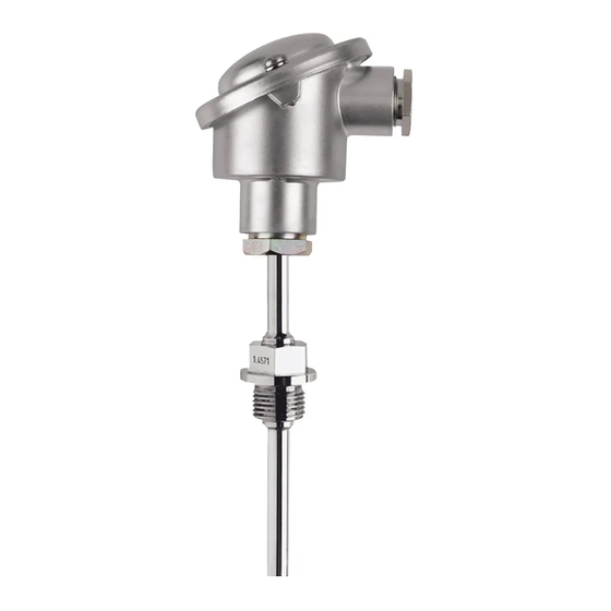
RTD temperature probe for process technology with ATEX approval
■For temperatures from -200 to +600 °C
■with thermowells made of stainless steel, titanium, tantalum, Inconel and Hastelloy
■available with two-wire transmitter (4 to 20 mA/HART®) in Ex version
■ II 1/2 G Ex ia IIC T1 to T6 (or Ex ib IIC T1 to T6)1
 II 1/2 D Ex iaD 20/21 T80 °C to T400 °C (or …ib…)1
 II 1/2 G Ex d IIC T1 to T61
 II 1/2 D Ex tb A20/21 IP66 T80 °C to T400 °C1
■with replaceable measuring insert (not for ATEX-basic types)
RTD temperature probes for process technology (chemical and petrochemical plants, pressure vessels, etc.) are preferentially used for measuring temperatures in liquids and gases. These RTD temperature probes consist of a protection fitting per DIN 43763with various process connection options, a terminal head and a replaceable measuring insert. The protection fitting is made of material 1.4571 as standard. Other materials are available for special applications. All fittings are manufactured in accordance with the pressure vessel regulations and subjected to a pressure and leakage test. The measuring insert is normally fitted with a Pt100 temperature sensor as per DIN EN 60751, Class B in 2-wirecircuit; versions with two Pt100 measuring circuits are also available as well as 3- and 4-wire circuits. An programmable transmitter can be integrated for measurement transmission with a 4 to 20 mA or via the HART® interface. Versions with flameproof enclosure or intrinsic safety are available for temperature measurement in areas with an explosion hazard. For documentation purposes, the device parameters (measurement tolerance, material, etc.) can be certified with a works test certificate.
Push-in and screw-in RTD temperature probes with connecting cable and ATEX approval can be provided on request.
Technical data
|
Terminal head |
Form B DIN 43729, die-cast aluminum, M 20×1.5; IP65, ambient temperature -40 to +100 °C |
|
Form BUZ, die-cast aluminum, M 20×1.5; IP65, ambient temperature -40 to +100 °C |
|
|
Form BUZH, die-cast aluminum, M 20×1.5; IP65, ambient temperature -40 to +100 °C |
|
|
Form BBKS, plastic (PA 6), M 20×1.5; IP54, ambient temperature -30 to +130 °C |
|
|
Form BEGF, stainless steel 1.4541, M 20×1.5, IP65, ambient temperature -40 to +100 °C |
|
|
Form XD-AD (EEx d ATEX), die-cast aluminum, M 20×1.5; IP66, |
|
|
ambient temperature -50 to +100 °C |
|
|
Caution: reduced ambient temperature range when using transmitters, |
|
|
data sheets 707010, 707030 and 707060 |
|
|
Extension tube |
Stainless steel 1.4571, length 130 mm (150 mm for type 902820/50…/51…) |
|
Process connection |
thread, stainless steel 1.4571 |
|
flange, stainless steel 1.4571 |
|
|
Sheath, stainless steel 1.4571 or steel 1.7335 |
|
|
highly corrosion-resistant materials/coatings are optionally available |
|
|
Sheath |
Stainless steel 1.4571, Ø 9 mm, Ø 11 mm, Ø 12 mm |
|
highly corrosion-resistant materials/coatings are optionally available |
|
|
Measuring insert |
Replaceable, Pt100 temperature probe, DIN EN 60751, class B, 2-wire circuit |
|
Response times |
t0.9 approx. 50 s, in water 0.4 m/s, Ø 9 mm |
|
Transmitter |
analog transmitter, 4 to 20 mA output, data sheet 707030 |
|
analog transmitter, 0 to 10 V output, data sheet 707030 |
|
|
programmable transmitter, 4 to 20 mA/20 to 4 mA output, data sheet 707010 |
|
|
programmable transmitter, 4 to 20 mA output and HART® interface, data sheet 707010 |
|
|
Wtrans B programmable head transducer with radio transmission, data sheet 707060 |
|
|
(do not use in Ex-areas), (suitable Wtrans receivers, data sheet 902931) |
|
|
Accessories |
Sheath, data sheet 909710 (909721) |
|
DIN versions |
DIN 43765 Form B1, B2, B3, load capacity, see diagram 1 |
|
DIN 43766 Form C1, C2, load capacity, see diagram 2 |
|
|
DIN 43767 Form D1, D2, D4, D5, load capacity, see diagram 3 |
|
|
DIN 43771 Form G1, G2, G3, load capacity, see diagram 4 |
1Explosion protection: The maximum product specific explosion protection depends of the RTD temperature probe design. For an exact classification of the RTD temperature probe, please refer to Operating Manual B 90.2820.
2014-03-06/00386333

|
JUMO GmbH & Co. KG |
JUMO Instrument Co. Ltd. |
JUMO Process Control, Inc. |
|||||
|
Delivery address:Mackenrodtstraße 14, |
JUMO House |
8 Technology Boulevard |
|||||
|
36039 Fulda, Germany |
Temple Bank, Riverway |
Canastota, NY 13032, USA |
|||||
|
Postal address: |
36035 Fulda, Germany |
Harlow, Essex CM20 2DY, UK |
Phone: |
315-697-JUMO |
|||
|
Phone: |
+49 |
661 6003-0 |
Phone: |
+44 1279 635533 |
1-800-554-JUMO |
||
|
Fax: |
+49 |
661 6003-607 |
Fax: |
+44 1279 635262 |
Fax: |
315-697-5867 |
|
|
e-mail: |
mail@jumo.net |
e-mail: |
sales@jumo.co.uk |
e-mail: |
info@jumo.us |
||
|
Internet: |
www.jumo.net |
Internet: www.jumo.co.uk |
Internet: www.jumo.us |
||||
|
Data sheet 902820 |
Page 2/15 |
||||||
|
Diagram 1: |
Diagram 2: |
Diagram 3: |
|
Permissible flow velocity |
Permissible flow velocity |
Form D1; D4 permissible flow velocity |
for air and superheated steam: up to 25 m/s for air and superheated steam: up to 40 m/s for air, water, superheated steam: up to
|
for water: up to 3 m/s |
for water: up to 5 m/s |
60 m/s |
|
Permissible tightening torque: 50 Nm |
Permissible tightening torque: 100 Nm |
Form D2; D5 permissible flow velocity |
|
for air: up to 60 m/s |
||
|
for water, superheated steam: up to 30 m/s |
Diagram 4:
Permissible flow velocity
for superheated steam: up to 40 m/s for water: up to 5 m/s
for air: up to 400 °C
|
Type |
DIN Form |
D |
L2 |
EL |
Thread |
|
902820/10 |
B1 |
9 |
— |
160 |
G 1/2 |
|
902820/10 |
B2 |
9 |
— |
250 |
G 1/2 |
|
902820/10 |
B3 |
9 |
— |
400 |
G 1/2 |
|
902820/10 |
C1 |
11 |
— |
160 |
G 1 |
|
902820/10 |
C2 |
11 |
— |
250 |
G 1 |
|
902820/11 |
G1 |
9 |
— |
160 |
G 1 |
|
Type |
DIN Form |
D |
L2 |
EL |
Thread |
|
902820/11 |
G2 |
9 |
— |
220 |
G 1 |
|
902820/11 |
G3 |
9 |
— |
280 |
G 1 |
|
902820/50 |
D1 |
12,5 |
140 |
65 |
— |
|
902820/50 |
D2 |
12,5 |
200 |
125 |
— |
|
902820/51 |
D4 |
12,5 |
200 |
65 |
— |
|
902820/51 |
D5 |
12,5 |
260 |
125 |
— |
2014-03-06/00386333

|
JUMO GmbH & Co. KG |
JUMO Instrument Co. Ltd. |
JUMO Process Control, Inc. |
|||||
|
Delivery address:Mackenrodtstraße 14, |
JUMO House |
8 Technology Boulevard |
|||||
|
36039 Fulda, Germany |
Temple Bank, Riverway |
Canastota, NY 13032, USA |
|||||
|
Postal address: |
36035 Fulda, Germany |
Harlow, Essex CM20 2DY, UK |
Phone: |
315-697-JUMO |
|||
|
Phone: |
+49 |
661 6003-0 |
Phone: |
+44 1279 635533 |
1-800-554-JUMO |
||
|
Fax: |
+49 |
661 6003-607 |
Fax: |
+44 1279 635262 |
Fax: |
315-697-5867 |
|
|
e-mail: |
mail@jumo.net |
e-mail: |
sales@jumo.co.uk |
e-mail: |
info@jumo.us |
||
|
Internet: |
www.jumo.net |
Internet: www.jumo.co.uk |
Internet: www.jumo.us |
||||
|
Data sheet 902820 |
Page 3/15 |
||||||
Dimensions
|
Basic type 902820/10 |
Basic type 902820/20 |
Basic type 902820/50 |
|||||||||||||||||||||||||||||||||||||||||||||||||||||||||||||||||||
|
Basic type 902820/11 |
Basic type 902820/21 |
Basic type 902820/51 |
2014-03-06/00386333

|
JUMO GmbH & Co. KG |
JUMO Instrument Co. Ltd. |
JUMO Process Control, Inc. |
|||||
|
Delivery address:Mackenrodtstraße 14, |
JUMO House |
8 Technology Boulevard |
|||||
|
36039 Fulda, Germany |
Temple Bank, Riverway |
Canastota, NY 13032, USA |
|||||
|
Postal address: |
36035 Fulda, Germany |
Harlow, Essex CM20 2DY, UK |
Phone: |
315-697-JUMO |
|||
|
Phone: |
+49 |
661 6003-0 |
Phone: |
+44 1279 635533 |
1-800-554-JUMO |
||
|
Fax: |
+49 |
661 6003-607 |
Fax: |
+44 1279 635262 |
Fax: |
315-697-5867 |
|
|
e-mail: |
mail@jumo.net |
e-mail: |
sales@jumo.co.uk |
e-mail: |
info@jumo.us |
||
|
Internet: |
www.jumo.net |
Internet: www.jumo.co.uk |
Internet: www.jumo.us |
||||
|
Data sheet 902820 |
Page 4/15 |
||||||
Dimensions
|
terminal head Form BUZ |
terminal head Form BUZH |
terminal head Form BBKS |
||||||||||||||||||||||||||||||||||||||||||||||||||||||||
|
extra code 320 |
extra code 321 |
extra code 324 |
||||||||||||||||||||||||||||||||||||||||||||||||||||||||
|
Terminal head Form BEGF |
Terminal head Form XD-AD |
|
extra code 397 |
extra code 399 |
2014-03-06/00386333

|
JUMO GmbH & Co. KG |
JUMO Instrument Co. Ltd. |
JUMO Process Control, Inc. |
|||||
|
Delivery address:Mackenrodtstraße 14, |
JUMO House |
8 Technology Boulevard |
|||||
|
36039 Fulda, Germany |
Temple Bank, Riverway |
Canastota, NY 13032, USA |
|||||
|
Postal address: |
36035 Fulda, Germany |
Harlow, Essex CM20 2DY, UK |
Phone: |
315-697-JUMO |
|||
|
Phone: |
+49 |
661 6003-0 |
Phone: |
+44 1279 635533 |
1-800-554-JUMO |
||
|
Fax: |
+49 |
661 6003-607 |
Fax: |
+44 1279 635262 |
Fax: |
315-697-5867 |
|
|
e-mail: |
mail@jumo.net |
e-mail: |
sales@jumo.co.uk |
e-mail: |
info@jumo.us |
||
|
Internet: |
www.jumo.net |
Internet: www.jumo.co.uk |
Internet: www.jumo.us |
||||
|
Data sheet 902820 |
Page 5/15 |
||||||
Order specifications: RTD temperature probes for process technology
(1)Basic type
|
902820/10 |
Screw-in RTD temperature probes |
|
|
with continuous sheath |
||
(2)Operating temperature in °C
x 150 -200 to +600 °C (wire-wound temperature sensor)
x402 -50 to +400 °C (thin-film temperature sensor)
x415 -50 to +600 °C (thin-film temperature sensor)
(3)Measuring insert
x1001 1x Pt100 in 3-wire-circuit
x1003 1x Pt100 in 2-wire circuit
x1011 1x Pt100 in 4-wire circuit
x2001 2x Pt100 in 3-wire circuit
x2003 2x Pt100 in 2-wire circuit
x2011 2x Pt100 in 4-wire circuit (only with terminal head Form BUZH)
(4)Tolerance class as per DIN EN 60751
x1 Class B (standard)
x2 Class A
x3 Class AA (1/3 DIN B)
(5)Sheath diameter D in mm
x9 Ø 9 x 1 mm
x11 Ø 11 x 2 mm
(6)Fitting length EL in mm (100 to 1000)
|
x |
160 |
160 mm |
|
x |
250 |
250 mm |
|
x |
400 |
400 mm |
|
x |
… |
Specification in plain text (50 mm steps) |
(7)Process connection
x 104 Screw-connection G 1/2
x106 Screw connection G 1
x144 Screw connection (thread) 1/2-14NPT
x146 Screw connection (thread) 1-11.5NPT
(8)Sheathmaterial
x26 stainless steel 1.4571
x60 titanium, on request
x81 Inconel, on request
x82 Hastelloy, on request
(9)Extra codes
x320 terminal head Form BUZ
x321 terminal head Form BUZH
x324 terminal head Form BBKS
x330 1x analog transmitter, 4 to 20 mA output2, data sheet 707030 (not with extra code 362)
x331 1x transmitter programmable output 4 to 20 mA/20 to 4 mA3, data sheet 707010
x333 1x analog transmitter, 0 to 10 V output2, data sheet 707030 (not with extra code 362)
x336 1x programmable transmitter, 4 to 20 mA output3 and HART® interface, data sheet 707010
x365 acceptance test certificate 3.1 DIN EN 10204 insulation resistance
x367 acceptance test certificate 3.1 DIN EN 10204 pressure test
x368 acceptance test certificate 3.1 DIN EN 10204 leakage test
x374 acceptance test certificate 3.1 DIN EN 10204 material
x562 parts in contact with medium with PTFE covering, on request
x563 parts in contact with medium with HALAR coating, on request
x859 1x Wtrans B programmable head transducer with radio transmission, data sheet 707060
|
Order code |
(1) |
— |
(2) |
— |
(3) |
— |
(4) |
— |
(5) |
— |
(6) |
— |
(7) |
— |
(8) |
/ |
(9) |
,…1 |
|
Order example |
902820/10 |
— |
402 |
— |
1001 — |
1 |
— |
9 |
— |
250 — |
104 — |
26 |
/ |
000 |
1 List extra codes in sequence, separated by commas.
2 Specify measuring range in plain text.
3 Specify measuring range and output signal in plain text. 2014-03-06/00386333
(скачивание инструкции бесплатно)
Формат файла: PDF
Доступность: Бесплатно как и все руководства на сайте. Без регистрации и SMS.
Дополнительно: Чтение инструкции онлайн

Термометр
сопротивления
Ex «i»
для
использования
во взрывоопасной среде
Целевая
группа
:
Опытные
электрики
в
соответствии
с
директивой
ЕС
1999/92/EG
и
лица
,
прошедшие
инструктаж
B 902820.0.2
B 902821.0.2
B 902xxx.0.2
Руководство
по
эксплуатации
2012-06-28/00594668
Страница:
(1 из 12)
навигация

1

2

3

4

5

6

7

8

9

10

11

12
Оглавление инструкции
- Страница 1 из 13
Термометр сопротивления Ex «i» для использования во взрывоопасной среде Целевая группа: Опытные электрики в соответствии с директивой ЕС 1999/92/EG и лица, прошедшие инструктаж B 902820.0.2 B 902821.0.2 B 902xxx.0.2 Руководство по эксплуатации 2012-06-28/00594668 - Страница 2 из 13
Содержание 1 Изделие и назначение………………………………………………………………………………………………………..2 2 Маркировка - Страница 3 из 13
1 Изделие и назначение Термометры сопротивления JUMO используются как искробезопасное и/или герметическое оборудование для измерения температуры в жидких и газообразных средах, а также при пыли. Составные части термометров: защитная арматура с различными соединениями, соединительная головка или - Страница 4 из 13
При установке и работе с термометрами сопротивления, а также при монтаже на месте установки следует соблюдать национальные правила по безопасности и правила предупреждения несчастных случаев. В дальнейшем за соблюдением законодательных предписаний отвечает сторона, эксплуатирующая устройство. При - Страница 5 из 13
Температурный класс Температура воспламенения горючих материалов > 450 °C > 300 < 450 °C > 200 < 300 °C > 135 < 200 °C > 100 < 135 °C > 85 < 100 °C Максимальная температура поверхности оборудования1 450 °C 300 °C 200 °C 135 °C 100 °C 85 °C T1 T2 T3 T4 T5 T6 Таблица 2. Температурные классы - Страница 6 из 13
Пример 1. Термометр следует использовать в температурном классе T4 (максимальная температура 135 °C, предел следует снизить на 5 K для безопасности); Константа защитной трубы SK = 80 K/Вт Максимальная мощность электроцепи P = 0,5 Вт TS = 130 °C – 0,5 Вт × 80 K/Вт TS = 130 °C – 40 K = 90 °C - Страница 7 из 13
5.3 Вид взрывозащиты герметичной конструкцией «d» Детали, которые могут поджечь взрывоопасную атмосферу, расположены в герметичном корпусе (здесь соединительная головка с кабельным вводом), выдерживающем внутри давление при взрыве взрывоопасной смеси и предотвращающем перенос взрыва на - Страница 8 из 13
Температура воспламенения или температура тления имеющейся отложившейся пыли или смеси пыли и воздуха определяется или вычисляется эксплуатирующей стороной! Максимально допустимая температура поверхности оборудования в °C 400 Температура тления при толщине слоя 5 мм 400 °C T5 мм 300 320 °C T5 - Страница 9 из 13
6 Установка При установке/эксплуатации следует соблюдать соответствующие действующие европейские и национальные правила. Большое значение имеют общие технические правила и данное руководство по эксплуатации. Термометры сопротивления JUMO предназначены для измерения температуры во взрывоопасных - Страница 10 из 13
8 Способы подключения термометров сопротивления (в равной мере для термометров сопротивления с головкой и проводкой JUMO) Также возможна реализация комбинаций следующих схем, например, 2× трёхпроводная схема и 1× двухпроводная схема. Двухпроводная схема Трехпроводная схема Четырехпроводная схема 2× - Страница 11 из 13
- Страница 12 из 13
-802*PE+ &R.* 0RULW]-XFKKHLP6WUD¡H )XOGD*HUPDQ ̹͕͔͌͒͌͛ ̹͇͌͒͌͛͑͘ ͙͕͔͔͇͖͕͙͇̈́͒͌͑͗ͦ͞ ̯͔͙͔͙͌͗͌ PDLO#MXPRQHW ZZZMXPRQHW ̧͖͕͙͇͉͋͗͌͑͘͘͏ 0DFNHQURGWVWUD¡H )XOGD*HUPDQ ̶͕͙͕͉͇͐͋͗͌͘͢͞ )XOGD*HUPDQ ̶͙͇͉͗͌͋͘͏̷͙͙͉͕͉͕͌͒ͣ͘͘͘͏͏ - Страница 13 из 13
- << Предыдущая
- Следующая >>

Термометр сопротивления, Ex «e» для использования во взрывоопасной среде в инструкции по эксплуатации JUMO 902820 PROCESStemp RTD Temperature Probe for Process Technology (Also with ATEX Approval) Ex e Operating Manual
Термометр сопротивления
Ex «e» для использования во взрывоопасной среде
Целевая группа:
Опытные электрики в соответствии с директивой ЕС 1999/92/EG
и лица прошедшие инструктаж
B 902820.0.1 B 902821.0.1 B 902xxx.0.1
Руководство по эксплуатации
2012-06-28/00594666
- << Предыдущая
- Следующая >>
-
Contents
-
Table of Contents
-
Troubleshooting
-
Bookmarks
Quick Links
Installing and Using
JUMO Thermometers
Operating Manual
90000000T90Z001K000
V1.00/EN/00759990/2022-01-20
Related Manuals for JUMO 902020/10
Summary of Contents for JUMO 902020/10
-
Page 1
Installing and Using JUMO Thermometers Operating Manual 90000000T90Z001K000 V1.00/EN/00759990/2022-01-20… -
Page 3: Table Of Contents
Contents Contents Basic information ……….5 Safety information .
-
Page 4
Contents 8.2.4 Mineral-insulated thermocouples and RTD temperature probes …..33 8.2.5 Surface probe for surface measurements……..33 8.2.6 Special installation situations . -
Page 5: Basic Information
Basic information 1 Basic information Safety information 1.1.1 Warning symbols DANGER! This symbol indicates that personal injury from electrocution may occur if the appropriate precaution- ary measures are not taken. WARNING! This symbol in connection with the signal word indicates that personal injury may occur if the respective precautionary measures are not carried out.
-
Page 6: Intended Use
1 Basic information Intended use NOTE! To ensure operational safety, it is essential to use the thermometers properly and install them correctly. Before carrying out installation work, it is therefore crucial to familiarize yourself with the thermometer, its proper use, and the installation process. This document is a key reference work in this respect, along with product-specific operating manuals in individual cases.
-
Page 7: Introduction
Improperly performed work will result in personal injury or damage to property. As a basic principle, installation and startup work for JUMO thermometers may only be performed by qualified and authorized personnel who strictly follow this manual, the relevant standards and le- gal regulations, the safety provisions, and the application-specific certificates.
-
Page 8
2 Introduction Factor RTD temperature probe Thermocouple Cold junction Not required Required Measuring current supplied Yes Measuring point Sensor Pair of thermal wires Signal output Resistance Voltage However, pronounced drift effects from approx. 400 °C Depends on the operating temperatures… -
Page 9: Rtd Temperature Probe
RTD temperature probe 3 RTD temperature probe Design An RTD temperature probe essentially comprises a temperature sensor, connection lines, and a protec- tion tube. The temperature sensor is connected to a connection line/connection wires, insulated, and in- serted into a protection tube (usually filled with a heat-conducting medium). The connection side can be designed as a line end that has been kept free, or designed with a terminal head, with a connector, etc.
-
Page 10
3 RTD temperature probe Measuring insert • Contains the temperature sensor • Replaceable or permanently installed • Version with connection socket or transmitter is commonly found Example schematic of the construction of a measuring insert for RTD temperature probes: Connection points Sensor Protection tube Filled with heat-conducting medium… -
Page 11
3 RTD temperature probe Variant with connection line Protection tube • In contact with the process • Protects the measuring insert against the medium (pressure, flow, etc.) • On versions with immersion sleeves, the need to open the process can be avoided, for example to replace the thermometer or measuring insert Process connection •… -
Page 12: Operating Principle
3 RTD temperature probe Operating principle RTD temperature probes take advantage of the temperature-dependent change in the resistance of the metals. For PTC resistors (PTC; positive temperature coefficient) such as platinum, the resistance in- creases as the temperature rises. Resistance/ohm Temperature/°C For thermistors (NTC;…
-
Page 13: Sensor Types
3 RTD temperature probe Sensor types Sensors come in different versions. We essentially distinguish between thin-film sensors and sensors with a solid wire winding. The most common sensors are shown below. Platinum-chip temperature sensors with connection wires, type PCA…
-
Page 14
3 RTD temperature probe Platinum-ceramic temperature sensors, type PK Platinum-chip temperature sensors on an epoxy PCB, type PCSE… -
Page 15: Tolerance Classes
3 RTD temperature probe Tolerance classes Change in tolerance depending on the measurement temperature (thin film) Measurement temperature/°C 1/3 Class B Class A Class B Class 0.5 Tolerance classes – temperature validity range (from DIN EN 60751) Tolerance class Sensor category Temperature range Tolerance F 0.1…
-
Page 16: Circuit Types
3 RTD temperature probe Circuit types 3.5.1 Two-wire circuit The two-wire circuit is the simplest circuit type for RTD temperature probes. Three and four-wire circuits are also used to enable more accurate measurements. With two-wire circuits, the line resistance influences the measurement result. This means that to obtain accurate measurement results, the line resistance must be deducted or needs to be corrected at the evaluation electronics;…
-
Page 17: Thermocouples
Thermocouples 4 Thermocouples Design A thermocouple essentially comprises a pair of thermal wires, which can be insulated and are inserted into protection tubes. The thermal wires are connected to thermal or compensating cables. Their con- nection side can be designed as a line end that has been kept free, or designed with a terminal head, with a connector, etc.
-
Page 18
4 Thermocouples Variant with terminal head Protection tube • In contact with the process • Protects the measuring insert against the medium (pressure, flow, etc.) • On versions with immersion sleeves, the need to open the process can be avoided, for example to replace the thermometer or measuring insert Process connection •… -
Page 19: Operating Principle
4 Thermocouples Thermocouples may be insulated or non-insulated/grounded. Insulated construction Non-insulated construction The non-insulated construction produces faster response times. However, no electrical insulation and no galvanic isolation between the thermocouple and the protection tube can be provided here. Take this into account when connecting the thermocouple, so as to prevent potential entrainments, etc.
-
Page 20: Thermocouple Types
4 Thermocouples Thermocouple types Below you will find a table of thermocouples listing standardized voltage series and limit deviations. In this context, the maximum temperature is the temperature up to which the limit deviations have been defined. The voltage series has been standardized up to the temperature listed under «Defined up to.» Thermocouples according to DIN EN 60584/IEC 584 Element Maximum…
-
Page 21: Type K Thermocouples
4 Thermocouples Limit deviations according to DIN EN 60584 Thermo- Admissible limit deviations (±°C) Validity limits for temperature (°C) couple Class 1 Class 2 Class 3 Class 1 Class 2 Class 3 type Type T 0.5 °C or 1 °C or 1 °C or -40 to +350 -40 to +350…
-
Page 22: Lines
Lines 5 Lines All lines used must be in perfect electrical order and must not exhibit any damage. Corrosion, humidity, or pollutants on the lines must be prevented and removed if required. Lines with glass fiber insulation or wire mesh may only be used in dry areas. In this case, the presence of moisture can cause shunts or the formation of additional galvanic elements.
-
Page 23
5 Lines An almost constant error is produced with two-wire circuits depending on the stranded wire cross section and the line length. This error can be corrected at the evaluation unit (by using zero point correction, for example). However, the resistance of the connection line also depends on the temperature. This addi- tional influence cannot be taken into account. -
Page 24: Lines Of Thermocouples
5 Lines Lines of thermocouples Thermal cables or compensating cables can be used for thermocouples. Thermal and compensating cables differ as follows: Thermal cables are made of the same material as the element itself. Compensating cables are made of special materials with identical thermoelectric features in restricted temperature ranges.
-
Page 25
5 Lines Color coding for elements according to DIN EN 60584 Element Type Sheath Positive leg Negative leg Cu-CuNi «T» Brown Brown White Fe-CuNi «J» Black Black White NiCr-Ni «K» Green Green White NiCrSi-NiSi «N» Pink Pink White NiCr-CuNi «E» Lilac Lilac White… -
Page 26
5 Lines Color coding for elements according to ANSI MC96.1 (USA) – compensating cable Element Type Sheath Positive leg Negative leg Cu-CuNi «T» Green Black Fe-CuNi «J» Black White NiCr-Ni «K» Yellow Yellow NiCrSi-NiSi «N» Orange Orange NiCr-CuNi «E» Purple Purple Pt10Rh-Pt «S»… -
Page 27: Cable Ends And Connectors
5 Lines Cable ends and connectors Some examples of the cable ends and connectors used for thermometers are shown below: Bare Ferrules Ring cable lug Forked cable lug Some examples of parts used as connectors are shown below: LEMO connector Thermo connector/coupling M12 connector JST terminal strip…
-
Page 28: Protection Tubes
Protection tubes 6 Protection tubes Various parameters (such as temperature, pressure, and oscillations) place loads on thermometers and their protection fittings. The protection fittings must therefore be designed accordingly. The variables in this respect include the material, insertion length, and diameter. DIN 43772 contains an overview of various metal protection tubes for thermocouples and RTD tempera- ture probes.
-
Page 29: Transmitter
Transmitter 7 Transmitter Transmitters convert the sensor signal into a standardized, temperature-linear current or voltage signal. The advantage of two-wire transmitters is that they amplify the signal, making it much less sensitive to interference. Several design types are available for positioning the transmitter as required. To make the signal less susceptible to interference, the section covered by the non-amplified signal should be kept as short as possible.
-
Page 30: Handling
Handling 8 Handling Transport Avoid vibrations when transporting the thermometer. Also ensure that the thermometer is not exposed to humidity. When the goods are received, check whether the packaging and thermometer are free of transport dam- age and mechanical damage. If you discover damage, do not use the thermometer. The devices must be stored properly.
-
Page 31: Installation Location And Alignment
8 Handling 8.2.1 Installation location and alignment To ensure ease of access in the installation location, sockets are often used to mount the thermometers. Please note the following for the mounting work: The larger the immersion depth into the measurement medium, the more accurate the measurement re- sult will be as heat conduction errors will be reduced.
-
Page 32: Screw-In Thermometer
8 Handling Avoid twisted and/or tensioned lines. For this reason, always route connection lines correctly. Route con- nection lines separately from the lines of the power electronics. The area around the thermometer must also be kept clean because aggressive media in particular could chemically attack the thermometer, potentially damaging the construction.
-
Page 33: Welded-Stem Thermometer
8 Handling 8.2.3 Welded-stem thermometer The quality of the welded joint plays a crucial role in determining the leak-tightness and strength of the construction. WARNING! Personal injury and damage to property due to a poor-quality welded joint! Poor-quality welded joints in combination with high pressure or overheating can cause leaks. If touched, these can cause burns or destroy the device.
-
Page 34: Special Installation Situations
8 Handling 8.2.6 Special installation situations When measuring temperatures below the ambient temperature, it is important to prevent condensate for- mation in the area of the electrical connection. Mount the line inputs and sealing areas such that any condensate that is formed can drain away. When routing the connection line, likewise bear in mind the possibility of moisture forming (from conden- sation, rainfall, etc.).
-
Page 35: Electrical Connection
The terminal assignment must be implemented according to the connection diagram. If there is no con- nection diagram for a thermometer (such as those with a connection line), the table in chapter 9.1 «Connection types», Page 39 shows the relevant terminal assignment. Customer-specific terminal assignments may differ from the JUMO standards. NOTICE! Incorrect measurement results! Incorrect polarity will cause major measurement deviations.
-
Page 36: Functional Test
8 Handling Functional test Startup checklist Is the thermometer suitable for the ambient temperatures? Is the thermometer suitable for the maximum operating temperature? Is the thermometer suitable for the maximum operating pressure? Is the protection tube resistant to the environment (chemicals, particles, etc.)? Has the thermometer’s IP protection type been selected correctly? Is the connection area in an area with a uniform, constant temperature, particularly for thermocou- ples?
-
Page 37: Maintenance
8 Handling Maintenance To ensure the thermometers work reliably, their functionality must be checked at regular intervals. This check should look at the functionality of the measuring circuits and whether there is any damage to the protection tubes. Individual items from the functional check (chapter 8.3 «Functional test», Page 36) can be repeated if re- quired.
-
Page 38: Dismounting
8 Handling Dismounting WARNING! Risk of electric shocks! There is a risk of serious injury or even death. Before dismounting the device, switch off the voltage supply and release the electrical connections. Release process connections only when the device has been acclimatized and depressurized. Ad- just the temperature of the pipe/process in line with the ambient temperature.
-
Page 39: General Product Information
9 General product information Connection types To ensure consistent terminal assignments for all measuring probe versions, JUMO RTD temperature probes and thermocouples are manufactured according to an in-house standard. This is a standard specification. Differing specifications are possible if desired by the customer. Observe the connection di- agrams.
-
Page 40
9 General product information Connection coding – lines 3-conductor line 1x three-wire Color sequence (DIN 47100): white, brown, green Color sequence (VDE 0293-0): black, blue, brown Color sequence (DIN 47100): red, red/blue, white Color sequence (IEC 751): red, red, white Color sequence: black, black, white Color sequence:… -
Page 41
9 General product information 5-conductor line 1x three-wire 1x four-wire 2x Pt Color sequence (DIN 47100): white, brown, green, yellow, gray 6-conductor line 2x three-wire 3x Pt Color sequence (DIN 47100): white, brown, green, yellow, gray, pink Color sequence (VDE 0293-0): black, black, black, red, blue, transparent… -
Page 42: Troubleshooting
Troubleshooting 10 Troubleshooting Specific errors for thermocouples Error Possible cause Remedy Indicating device displays room Thermocouple or line interrupted Replace measuring insert temperature Only the amount is correct on the Incorrect polarity on the indicat- Change the polarity display ing device Displayed temperature is much Incorrect polarity of the compen- Change the polarity…
-
Page 43
In particular, it is important to consider the specific installation situation in each case. It may be necessary or advisable to consult qualified personnel and the Technical Support team from JUMO. The contact addresses and telephone numbers can be found on the last page… -
Page 44: Maintenance, Cleaning, Returns, And Disposal
Maintenance, cleaning, returns, and disposal 11 Maintenance, cleaning, returns, and disposal 11.1 Maintenance The RTD temperature probes and thermocouples require no maintenance. We recommend checking them at regular intervals. 11.2 Cleaning NOTE! Avoid damage to the device due to improper cleaning. Do not damage the RTD temperature probes or thermocouples, in particular the parts in contact with the medium.
-
Page 45: Further Information And Downloads
12 Further information and downloads Also consult the data sheet and, if available, the product-specific operating manual in individual cases. In addition to this manual, further information can be found in the download center at www.jumo.net: • Electrical Temperature Measurement with thermocouples and resistance thermometers;…
-
Page 46
12 Further information and downloads… -
Page 48
JUMO GmbH & Co. KG JUMO Instrument Co. Ltd. JUMO Process Control, Inc. Street address: JUMO House 6724 Joy Road Moritz-Juchheim-Straße 1 Temple Bank, Riverway East Syracuse, NY 13057, USA 36039 Fulda, Germany Harlow, Essex, CM20 2DY, UK Delivery address:…