- Manuals
- Brands
- Juniper Manuals
- Switch
- EX2200 Series
- User manual
-
Contents
-
Table of Contents
-
Bookmarks
Related Manuals for Juniper EX2200
Summary of Contents for Juniper EX2200
-
Page 1
Complete Hardware Guide for EX2200 Ethernet Switches Modified: 2015-06-23 Revision 16 Copyright © 2015, Juniper Networks, Inc. -
Page 2
END USER LICENSE AGREEMENT The Juniper Networks product that is the subject of this technical documentation consists of (or is intended for use with) Juniper Networks software. Use of such software is subject to the terms and conditions of the End User License Agreement (“EULA”) posted at http://www.juniper.net/support/eula.html. -
Page 3: Table Of Contents
EX2200 Switches Hardware Overview ……..3…
-
Page 4
Mounting an EX2200 Switch on a Wall ……. . . -
Page 5
Performing Initial Configuration ……..135 EX2200 Switch Default Configuration ……..135 Connecting and Configuring an EX Series Switch (CLI Procedure) . -
Page 6
Installation Instructions Warning ……..181 Chassis Lifting Guidelines for EX2200 Switches ……183 Ramp Warning . -
Page 7
EX2200-C Switch Models …….. -
Page 8
Inlet on an EX2200 Switch …….. -
Page 9
Returning the Switch or Switch Components ……159 Figure 59: Location of the Serial Number ID Label on EX2200 Switches ..161… -
Page 10
Complete Hardware Guide for EX2200 Ethernet Switches Copyright © 2015, Juniper Networks, Inc. -
Page 11
Table 19: Optical interface Support and Copper Interface Support for SFP Transceivers in EX2200-C Switches ……. . . 52… -
Page 12
Table 28: Parts List for EX2200 Switches ……. . 87… -
Page 13: About The Documentation
Junos OS Release Notes. ® To obtain the most current version of all Juniper Networks technical documentation, see the product documentation page on the Juniper Networks website at http://www.juniper.net/techpubs/ Documentation Conventions Table 1 on page xiv defines the notice icons used in this guide.
-
Page 14: Table 1: Notice Icons
Complete Hardware Guide for EX2200 Ethernet Switches Table 1: Notice Icons Icon Meaning Description Informational note Indicates important features or instructions. Caution Indicates a situation that might result in loss of data or hardware damage. Warning Alerts you to the risk of personal injury or death.
-
Page 15: Documentation Feedback
You can provide feedback by using either of the following methods: Requesting Technical Support Technical product support is available through the Juniper Networks Technical Assistance Center (JTAC). If you are a customer with an active J-Care or Partner Support Service Copyright © 2015, Juniper Networks, Inc.
-
Page 16: Self-Help Online Tools And Resources
7 days a week, 365 days a year. Self-Help Online Tools and Resources For quick and easy problem resolution, Juniper Networks has designed an online self-service portal called the Customer Support Center (CSC) that provides you with the following features: Find CSC offerings: http://www.juniper.net/customers/support/…
-
Page 17: Switch And Components Overview And Specifications
PART 1 Switch and Components Overview and Specifications EX2200 Switch Overview on page 3 Component Descriptions on page 13 Component Specifications on page 21 Copyright © 2015, Juniper Networks, Inc.
-
Page 18
Complete Hardware Guide for EX2200 Ethernet Switches Copyright © 2015, Juniper Networks, Inc. -
Page 19: Ex2200 Switch Overview
Rear Panel of an EX2200 Switch on page 7 EX2200 Switches First View EX2200 switches are available in models with 12 , 24, or 48 built-in network ports. The compact, fanless model, EX2200-C switches have 12 network ports. Copyright © 2015, Juniper Networks, Inc.
-
Page 20: Uplink Ports
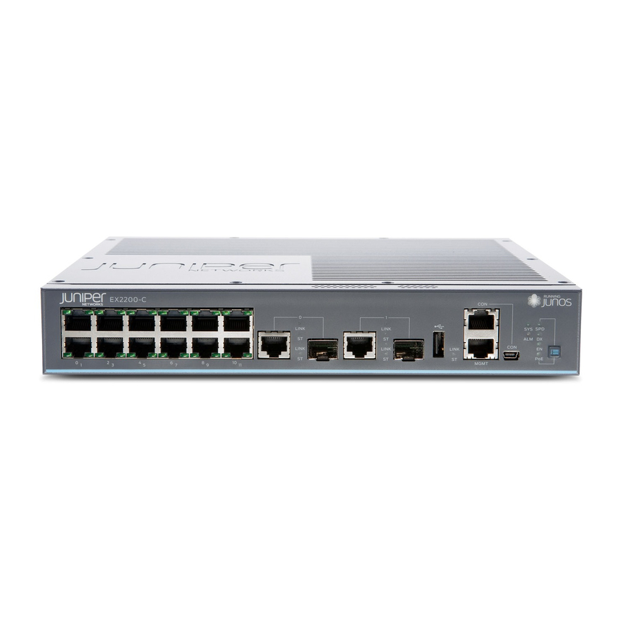
Each EX2200 switch except the EX2200-C switch model has an RJ-45 console port that accepts a cable with RJ-45 connector. The EX2200-C switch has two console ports: an RJ-45 port and a Mini-USB Type-B port. The RJ-45 console port accepts a cable with an RJ-45 connector and the Mini-USB Type-B console port accepts a Mini-B plug (5-pin) connector to connect to the console management device.
-
Page 21: Cable Guard
Surface” on page Security Slots Each EX2200-C switch model has security slots on the left and right panels of the chassis. The security slots allow you to lock and secure the chassis in the installation site using a standard cable lock . See “Mounting an EX2200 Switch on a Desk or Other Level Surface”…
-
Page 22: Front Panel Of An Ex2200 Switch
Complete Hardware Guide for EX2200 Ethernet Switches Front Panel of an EX2200 Switch The front panel of an EX2200 switch except the EX2200-C switch models consists of the following components: Network ports—depending on the switch model, either of: 24 or 48 10/100/1000BASE-T Gigabit Ethernet ports, with Power over Ethernet…
-
Page 23: Rear Panel Of An Ex2200 Switch
Figure 4: Front Panel of an EX2200-C Switch with 12 Gigabit Ethernet Ports (non-PoE) Rear Panel of an EX2200 Switch The rear panel of the EX2200 switch except the EX2200-C switch models consists of the following components: Management Ethernet port USB port Copyright ©…
-
Page 24: Figure 5: Rear Panel Of An Ex2200 Switch With Ac Power Supply
AC power cord inlet or DC power terminals Figure 5 on page 8 shows the rear panel of an EX2200 switch with an AC power supply. All EX2200 switches except the EX2200-C switch model have three exhaust openings on the rear panel. The two exhaust openings on the left have fans behind them and are open.
-
Page 25: Ex2200 Switch Models
Site Preparation Checklist for EX2200 Switches on page 61 EX2200 Switch Models The EX2200 switch is available with 12, 24, or 48 built-in network ports with full Power over Ethernet (PoE) capability (all 12, 24, or 48 built-in network ports support PoE) or no PoE capability.
-
Page 26: Ex2200 Switch Hardware And Cli Terminology Mapping
Installing and Connecting an EX2200 Switch on page 85 EX2200 Switch Hardware and CLI Terminology Mapping This topic describes the hardware terms used in EX2200 switch documentation and the corresponding terms used in the Junos OS command line interface (CLI). See…
-
Page 27
Chapter 1: EX2200 Switch Overview Table 5: CLI Equivalents of Terms Used in Documentation for EX2200 Switches (continued) Hardware Item (as Description (as Value (as displayed Item in Additional displayed in the CLI) displayed in the CLI) in the CLI) -
Page 28
Complete Hardware Guide for EX2200 Ethernet Switches Table 5: CLI Equivalents of Terms Used in Documentation for EX2200 Switches (continued) Hardware Item (as Description (as Value (as displayed Item in Additional displayed in the CLI) displayed in the CLI) in the CLI) -
Page 29: Component Descriptions
Cooling System and Airflow in an EX2200 Switch on page 19 Chassis Status LEDs in EX2200 Switches The front panel of an EX2200 switch has two chassis status LEDs labeled SYS and ALM on the far right side of the panel. See…
-
Page 30: Network Port And Uplink Port Leds In Ex2200 Switches
Understanding Alarm Types and Severity Levels on EX Series Switches Network Port and Uplink Port LEDs in EX2200 Switches Each network port and uplink port on the front panel of an EX2200 switch has two LEDs that indicate link/activity and port status. Each dual-purpose uplink port in an EX2200-C switch has two pairs of LEDs that indicate the link/activity status, one pair for each of the two ports that constitute the dual-purpose uplink port.
-
Page 31: Figure 10: Leds On The Uplink Ports And Port Status Mode Leds In An Ex2200 Switch Except The Ex2200-C Switch Model
Port status mode LEDs Dual-purpose uplink ports Table 7 on page 15 describes the Link/Activity LED. Table 7: Link/Activity LED on the Network Ports and Uplink Ports in EX2200 Switches Color State and Description Link/Activity Green Blinking—The port and the link are active, and there is link activity.
-
Page 32: Table 8: Status Led On The Network Ports, Uplink Ports, And Dual-Purpose Uplink Ports In Ex2200 Switches
Three blinks per second—1000 Mbps The speed indicators for uplink ports are: On steadily—1000 Mbps Off—10/100 Mbps The speed indicators for dual-purpose uplink ports of EX2200-C switch model are: One blink per second—10 Mbps Two blinks per second—100 Mbps Three blinks per second—1000 Mbps Duplex mode Indicates the duplex mode.
-
Page 33: Management Port Leds In Ex2200 Switches
Configuring Gigabit Ethernet Interfaces (J-Web Procedure) Management Port LEDs in EX2200 Switches The management port on an EX2200 switch has two LEDs that indicate link/activity and port status. The EX2200 switches except the EX2200-C switch models have the management port on the rear panel and the EX2200-C switch has the management port on the front panel.
-
Page 34: Power Supply In Ex2200 Switches
Power Supply in EX2200 Switches The power supply in EX2200 switches is built in along the rear panel of the chassis, with an AC power cord inlet or DC power terminals on the rear panel to connect power to the switch.
-
Page 35: Cooling System And Airflow In An Ex2200 Switch
In the PoE models of these switches, there is an additional fan in the power supply. In the EX2200-C switch the cooling is done by the vents on top and sides of the chassis in non-PoE models and by heatsinks in PoE+ models. Do not block the vents on the chassis.
-
Page 36: Airflow Direction In Poe Models Of Ex2200 Switches, Except For The Ex2200-C Models
Complete Hardware Guide for EX2200 Ethernet Switches Airflow Direction in PoE Models of EX2200 switches, Except for the EX2200-C Models Figure 15 on page 20 shows the airflow in PoE models of EX2200 switches, except EX2200-C models. Figure 15: Airflow Through PoE Models of EX2200 Switches Except the…
-
Page 37: Component Specifications
USB Port Specifications for an EX Series Switch on page 21 Mini-USB Port Specifications for an EX2200 Switch on page 22 Network Port Connector Pinout Information for an EX2200 Switch on page 23 Console Port Connector Pinout Information for an EX Series Switch on page 23…
-
Page 38: Mini-Usb Port Specifications For An Ex2200 Switch
Booting an EX Series Switch Using a Software Package Stored on a USB Flash Drive Mini-USB Port Specifications for an EX2200 Switch The EX2200-C switch, the compact, fanless model, has two management console ports: an RJ-45 port, and a Mini-USB Type-B port.
-
Page 39: Network Port Connector Pinout Information For An Ex2200 Switch
Configuring the Console Port Type (CLI Procedure) Network Port Connector Pinout Information for an EX2200 Switch A network port on an EX2200 switch uses an RJ-45 connector to connect to a device. The port uses an autosensing RJ-45 connector to support a 10/100/1000Base-T connection.
-
Page 40: Table 14: Ex Series Switches Console Port Connector Pinout Information
Complete Hardware Guide for EX2200 Ethernet Switches Table 14 on page 24 provides the pinout information for the RJ-45 console connector. An RJ-45 cable and an RJ-45 to DB-9 serial port adapter are supplied with the switch. NOTE: If your laptop or PC does not have a DB-9 male connector pin and you…
-
Page 41: Rj-45 To Db-9 Serial Port Adapter Pinout Information For A Switch
Connecting and Configuring an OCX1100 Switch (CLI Procedure) Management Port Connector Pinout Information for an EX2200 Switch The management port on an EX2200 switch uses an RJ-45 connector to connect to a management device for out-of-band management. The port uses an autosensing RJ-45 connector to support a 10/100Base-T connection.
-
Page 42: Pluggable Transceivers Supported On Ex2200 Switches
Connecting a Switch to a Network for Out-of-Band Management on page 127 Pluggable Transceivers Supported on EX2200 Switches Uplink ports and dual-purpose uplink ports on the front panel in EX2200 switches support SFP transceivers. This topic describes the optical interfaces supported for those transceivers.
-
Page 43: Table 17: Optical Interface Support And Copper Interface Support For Gigabit Ethernet Sfp Transceivers In Ex2200 Switches Except Ex2200-C
(SMF) and multimode fiber-optic (MMF) cables and over the copper interface for SFP transceivers: Table 17 on page 27—Optical interface support and copper interface support for Gigabit Ethernet SFP transceivers in EX2200 switches except EX2200-C switches. Table 18 on page 46—Optical interface support for Fast Ethernet SFP transceivers except EX2200-C switches.
-
Page 44
Complete Hardware Guide for EX2200 Ethernet Switches Table 17: Optical interface Support and Copper Interface Support for Gigabit Ethernet SFP Transceivers in EX2200 Switches Except EX2200-C Switches (continued) Ethernet Standard Specification Value 1000BASE-SX Model number EX-SFP-1GE-SX Rate 1000 Mbps Connector type… -
Page 45
Chapter 3: Component Specifications Table 17: Optical interface Support and Copper Interface Support for Gigabit Ethernet SFP Transceivers in EX2200 Switches Except EX2200-C Switches (continued) Ethernet Standard Specification Value 1000BASE-LX Model number EX-SFP-1GE-LX Rate 1000 Mbps Connector type Fiber count… -
Page 46
Complete Hardware Guide for EX2200 Ethernet Switches Table 17: Optical interface Support and Copper Interface Support for Gigabit Ethernet SFP Transceivers in EX2200 Switches Except EX2200-C Switches (continued) Ethernet Standard Specification Value 1000BASE-BX-U Model number EX-SFP-GE10KT13R14 Rate 1000 Mbps Connector type… -
Page 47
Chapter 3: Component Specifications Table 17: Optical interface Support and Copper Interface Support for Gigabit Ethernet SFP Transceivers in EX2200 Switches Except EX2200-C Switches (continued) Ethernet Standard Specification Value 1000BASE-BX-D Model number EX-SFP-GE10KT14R13 Rate 1000 Mbps Connector type Fiber count… -
Page 48
Complete Hardware Guide for EX2200 Ethernet Switches Table 17: Optical interface Support and Copper Interface Support for Gigabit Ethernet SFP Transceivers in EX2200 Switches Except EX2200-C Switches (continued) Ethernet Standard Specification Value 1000BASE-BX-U Model number EX-SFP-GE10KT13R15 Rate 1000 Mbps Connector type… -
Page 49
Chapter 3: Component Specifications Table 17: Optical interface Support and Copper Interface Support for Gigabit Ethernet SFP Transceivers in EX2200 Switches Except EX2200-C Switches (continued) Ethernet Standard Specification Value 1000BASE-BX-D Model number EX-SFP-GE10KT15R13 Rate 1000 Mbps Connector type Fiber count… -
Page 50
Complete Hardware Guide for EX2200 Ethernet Switches Table 17: Optical interface Support and Copper Interface Support for Gigabit Ethernet SFP Transceivers in EX2200 Switches Except EX2200-C Switches (continued) Ethernet Standard Specification Value 1000BASE-BX-U Model number EX-SFP-GE40KT13R15 Rate 1000 Mbps Connector type… -
Page 51
Chapter 3: Component Specifications Table 17: Optical interface Support and Copper Interface Support for Gigabit Ethernet SFP Transceivers in EX2200 Switches Except EX2200-C Switches (continued) Ethernet Standard Specification Value 1000BASE-BX-D Model number EX-SFP-GE40KT15R13 Rate 1000 Mbps Connector type Fiber count… -
Page 52
Complete Hardware Guide for EX2200 Ethernet Switches Table 17: Optical interface Support and Copper Interface Support for Gigabit Ethernet SFP Transceivers in EX2200 Switches Except EX2200-C Switches (continued) Ethernet Standard Specification Value 1000BASE-LX Model number EX-SFP-1GE-LX40K Rate 1000 Mbps Connector type… -
Page 53
Chapter 3: Component Specifications Table 17: Optical interface Support and Copper Interface Support for Gigabit Ethernet SFP Transceivers in EX2200 Switches Except EX2200-C Switches (continued) Ethernet Standard Specification Value 1000BASE-LH (or Model number EX-SFP-1GE-LH 1000BASE-ZX) Rate 1000 Mbps Connector type… -
Page 54
Complete Hardware Guide for EX2200 Ethernet Switches Table 17: Optical interface Support and Copper Interface Support for Gigabit Ethernet SFP Transceivers in EX2200 Switches Except EX2200-C Switches (continued) Ethernet Standard Specification Value 1000BASE-LX Model number EX-SFP-GE80KCW1470 Rate 1000 Mbps Connector type… -
Page 55
Chapter 3: Component Specifications Table 17: Optical interface Support and Copper Interface Support for Gigabit Ethernet SFP Transceivers in EX2200 Switches Except EX2200-C Switches (continued) Ethernet Standard Specification Value 1000BASE-LX Model number EX-SFP-GE80KCW1490 Rate 1000 Mbps Connector type Fiber count… -
Page 56
Complete Hardware Guide for EX2200 Ethernet Switches Table 17: Optical interface Support and Copper Interface Support for Gigabit Ethernet SFP Transceivers in EX2200 Switches Except EX2200-C Switches (continued) Ethernet Standard Specification Value 1000BASE-LX Model number EX-SFP-GE80KCW1510 Rate 1000 Mbps Connector type… -
Page 57
Chapter 3: Component Specifications Table 17: Optical interface Support and Copper Interface Support for Gigabit Ethernet SFP Transceivers in EX2200 Switches Except EX2200-C Switches (continued) Ethernet Standard Specification Value 1000BASE-LX Model number EX-SFP-GE80KCW1530 Rate 1000 Mbps Connector type Fiber count… -
Page 58
Complete Hardware Guide for EX2200 Ethernet Switches Table 17: Optical interface Support and Copper Interface Support for Gigabit Ethernet SFP Transceivers in EX2200 Switches Except EX2200-C Switches (continued) Ethernet Standard Specification Value 1000BASE-LX Model number EX-SFP-GE80KCW1550 Rate 1000 Mbps Connector type… -
Page 59
Chapter 3: Component Specifications Table 17: Optical interface Support and Copper Interface Support for Gigabit Ethernet SFP Transceivers in EX2200 Switches Except EX2200-C Switches (continued) Ethernet Standard Specification Value 1000BASE-LX Model number EX-SFP-GE80KCW1570 Rate 1000 Mbps Connector type Fiber count… -
Page 60
Complete Hardware Guide for EX2200 Ethernet Switches Table 17: Optical interface Support and Copper Interface Support for Gigabit Ethernet SFP Transceivers in EX2200 Switches Except EX2200-C Switches (continued) Ethernet Standard Specification Value 1000BASE-LX Model number EX-SFP-GE80KCW1590 Rate 1000 Mbps Connector type… -
Page 61
Chapter 3: Component Specifications Table 17: Optical interface Support and Copper Interface Support for Gigabit Ethernet SFP Transceivers in EX2200 Switches Except EX2200-C Switches (continued) Ethernet Standard Specification Value 1000BASE-LX Model number EX-SFP-GE80KCW1610 Rate 1000 Mbps Connector type Fiber count… -
Page 62: Table 18: Optical Interface Support For Fast Ethernet Sfp Transceivers In Ex2200 Switches Except Ex2200-C Switches
Complete Hardware Guide for EX2200 Ethernet Switches Table 18: Optical interface Support for Fast Ethernet SFP Transceivers in EX2200 Switches Except EX2200-C Switches Ethernet Standard Specification Value 100BASE-FX Model number EX-SFP-1FE-FX Rate 100 Mbps Connector type Fiber count Dual Transmitter wavelength…
-
Page 63
Chapter 3: Component Specifications Table 18: Optical interface Support for Fast Ethernet SFP Transceivers in EX2200 Switches Except EX2200-C Switches (continued) Ethernet Standard Specification Value 100BASE-LX Model number EX-SFP-1FE-LX Rate 100 Mbps Connector type Fiber count Dual Transmitter wavelength 1310 nm Minimum launch power –15 dBm… -
Page 64
Complete Hardware Guide for EX2200 Ethernet Switches Table 18: Optical interface Support for Fast Ethernet SFP Transceivers in EX2200 Switches Except EX2200-C Switches (continued) Ethernet Standard Specification Value 100BASE-BX-U Model number EX-SFP-FE20KT13R15 Rate 100 Mbps Connector type Fiber count Single… -
Page 65
Chapter 3: Component Specifications Table 18: Optical interface Support for Fast Ethernet SFP Transceivers in EX2200 Switches Except EX2200-C Switches (continued) Ethernet Standard Specification Value 100BASE-BX-D Model number EX-SFP-FE20KT15R13 Rate 100 Mbps Connector type Fiber count Single Transmitter wavelength 1550 nm… -
Page 66
Complete Hardware Guide for EX2200 Ethernet Switches Table 18: Optical interface Support for Fast Ethernet SFP Transceivers in EX2200 Switches Except EX2200-C Switches (continued) Ethernet Standard Specification Value 100BASE-LX40K Model number EX-SFP-1FE-LX40K Rate 100 Mbps Connector type Fiber count Dual… -
Page 67
Chapter 3: Component Specifications Table 18: Optical interface Support for Fast Ethernet SFP Transceivers in EX2200 Switches Except EX2200-C Switches (continued) Ethernet Standard Specification Value 100BASE-LH (or Model number EX-SFP-1FE-LH 100BASE-ZX) Rate 100 Mbps Connector type Fiber count Dual Transmitter wavelength… -
Page 68: Table 19: Optical Interface Support And Copper Interface Support For Sfp
Complete Hardware Guide for EX2200 Ethernet Switches Table 19: Optical interface Support and Copper Interface Support for SFP Transceivers in EX2200-C Switches Ethernet Standard Specification Value 1000BASE-SX Model number EX-SFP-1GE-SX Rate 1000 Mbps Connector type Fiber count Dual Transmitter wavelength…
-
Page 69
Fiber type Core/Cladding size – Modal bandwidth – Transmitter wavelength 850 nm Distance 550 m (1804 ft) Software required Junos OS for EX Series switches, Release 11.3 or later Support for Virtual Chassis configuration Copyright © 2015, Juniper Networks, Inc. -
Page 70
Complete Hardware Guide for EX2200 Ethernet Switches Table 19: Optical interface Support and Copper Interface Support for SFP Transceivers in EX2200-C Switches (continued) Ethernet Standard Specification Value Extended Temp SFP Model number EX-SFP-1FE-FX-EX 100BASE-FX Rate 1000 Mbps Connector type Fiber count –… -
Page 71
Fiber type Core/Cladding size 62.5/125 µm Fiber grade FDDI/OM1 Modal bandwidth 500 MHz/km Distance 2 km (1.2 miles) Software required Junos OS for EX Series switches, Release 11.3 or later Support for Virtual Chassis configuration Copyright © 2015, Juniper Networks, Inc. -
Page 72
Complete Hardware Guide for EX2200 Ethernet Switches Table 19: Optical interface Support and Copper Interface Support for SFP Transceivers in EX2200-C Switches (continued) Ethernet Standard Specification Value 1000BASE-LX Model number EX-SFP-1GE-LX Rate 1000 Mbps Connector type Fiber count Dual Transmitter wavelength… -
Page 73
Junos OS for EX Series switches, Release 11.3 or later Support for Virtual Chassis configuration Related EX2200 Switches Hardware Overview on page 3 Documentation Installing a Transceiver in an EX Series Switch on page 113 Removing a Transceiver from a Switch on page 149… -
Page 74
Complete Hardware Guide for EX2200 Ethernet Switches Copyright © 2015, Juniper Networks, Inc. -
Page 75
PART 2 Planning for Switch Installation Site Preparation on page 61 Mounting and Clearance Requirements on page 71 Cable Specifications on page 77 Planning Power Requirements on page 79 Copyright © 2015, Juniper Networks, Inc. -
Page 76
Complete Hardware Guide for EX2200 Ethernet Switches Copyright © 2015, Juniper Networks, Inc. -
Page 77: Site Preparation
CHAPTER 4 Site Preparation Site Preparation Checklist for EX2200 Switches on page 61 General Site Guidelines on page 62 Site Electrical Wiring Guidelines on page 63 Environmental Requirements and Specifications for EX Series Switches on page 65 Site Preparation Checklist for EX2200 Switches…
-
Page 78: General Site Guidelines
General Safety Guidelines and Warnings on page 169 Documentation General Site Guidelines on page 62 Installing and Connecting an EX2200 Switch on page 85 Mounting an EX2200 Switch on page 88 General Site Guidelines This topic applies to hardware devices in the EX Series product family, which includes EX Series switches, the EX Series Redundant Power System (RPS), and the XRE200 External Routing Engine.
-
Page 79: Site Electrical Wiring Guidelines
Table 21 on page 64 describes the factors you must consider while planning the electrical wiring at your site. WARNING: It is particularly important to provide a properly grounded and shielded environment and to use electrical surge-suppression devices. Copyright © 2015, Juniper Networks, Inc.
-
Page 80: Table 21: Site Electrical Wiring Guidelines
Documentation General Electrical Safety Guidelines and Warnings on page 197 Prevention of Electrostatic Discharge Damage on page 198 Power Supply in EX2200 Switches on page 18 Power Supply in EX3200 Switches Power Supply in EX3300 Switches Power Supply in EX4200 Switches…
-
Page 81: Environmental Requirements And Specifications For Ex Series Switches
Table 22 on page 66 provides the required environmental conditions for normal switch operation. Copyright © 2015, Juniper Networks, Inc.
-
Page 82: Table 22: Ex Series Switch Environmental Tolerances
Complete Hardware Guide for EX2200 Ethernet Switches Table 22: EX Series Switch Environmental Tolerances Environment Tolerance Switch or device Altitude Relative Humidity Temperature Seismic EX2200-C No performance Normal operation ensured Normal operation ensured in the Complies with Zone 4 degradation up to in relative humidity range of temperature range 32°…
-
Page 83
10,000 feet (3048 5% through 90% 104° F (0° C through 40° C) requirements as per meters) (noncondensing) GR-63. Nonoperating storage temperature in shipping container: –40° F (–40° C) to 158° F (70° C) Copyright © 2015, Juniper Networks, Inc. -
Page 84
Articles 110–16, 110–17, and 110–18 of the National Electrical Code, ANSI/NFPA 70. Related Clearance Requirements for Airflow and Hardware Maintenance for EX2200 Switches Documentation on page 74 Clearance Requirements for Airflow and Hardware Maintenance for EX3200 Switches… -
Page 85
Clearance Requirements for Airflow and Hardware Maintenance for an EX8216 Switch Clearance Requirements for Airflow and Hardware Maintenance for an EX9204 Switch Clearance Requirements for Airflow and Hardware Maintenance for an EX9208 Switch Clearance Requirements for Airflow and Hardware Maintenance for an EX9214 Switch Copyright © 2015, Juniper Networks, Inc. -
Page 86
Complete Hardware Guide for EX2200 Ethernet Switches Copyright © 2015, Juniper Networks, Inc. -
Page 87: Mounting And Clearance Requirements
Rack Requirements for EX2200 Switches on page 71 Cabinet Requirements for EX2200 Switches on page 72 Requirements for Mounting an EX2200 Switch on a Desktop or Wall on page 73 Clearance Requirements for Airflow and Hardware Maintenance for EX2200 Switches on page 74 Rack Requirements for EX2200 Switches You can mount the EX2200 switches on two-post racks or four-post racks.
-
Page 88: Cabinet Requirements For Ex2200 Switches
Mounting an EX2200 Switch on Two Posts of a Rack or Cabinet on page 95 Mounting an EX2200 Switch on Four Posts of a Rack or Cabinet on page 98 Mounting an EX2200 Switch in a Recessed Position in a Rack or Cabinet on page 102 Cabinet Requirements for EX2200 Switches You can mount the switch in a cabinet that contains a 19-in.
-
Page 89: Requirements For Mounting An Ex2200 Switch On A Desktop Or Wall
Mounting an EX2200 Switch on Four Posts of a Rack or Cabinet on page 98 Mounting an EX2200 Switch in a Recessed Position in a Rack or Cabinet on page 102 Requirements for Mounting an EX2200 Switch on a Desktop or Wall You can install the switch on a desktop or wall.
-
Page 90: Switches
Insert the screws into wall studs wherever possible to provide added support for the chassis. Use the wall-mount kit from Juniper Networks to mount the switch on a wall. The wall-mount kit is not part of the standard package and must be ordered separately.
-
Page 91: Figure 17: Clearance Requirements For Airflow And Hardware Maintenance For
For the cooling system to function properly, the airflow around the chassis must be unrestricted. Figure 18 on page 75 shows the airflow in PoE models of EX2200 switches, except for EX2200-C models. Figure 19 on page 76 shows the airflow non-PoE models of EX2200 switches, except for EX2200-C models.
-
Page 92: Figure 19: Airflow Through Non-Poe Models Of Ex2200 Switches Except Ex2200-C Switch Models
Fans Chassis rear If you are mounting an EX2200 switch in a rack or cabinet with other equipment, or if you are placing it on the desktop or floor near other equipment, ensure that the exhaust from other equipment does not blow into the intake vents of the chassis.
-
Page 93: Cable Specifications
Fiber-Optic Cable to a Switch” on page 133. Related Management Port Connector Pinout Information for an EX2200 Switch on page 25 Documentation Console Port Connector Pinout Information for an EX Series Switch on page 23 EX2200 Switches Hardware Overview on page 3…
-
Page 94
Complete Hardware Guide for EX2200 Ethernet Switches Copyright © 2015, Juniper Networks, Inc. -
Page 95: Planning Power Requirements
AC Power Cord Specifications for EX2200 Switches on page 80 Power Specifications for EX2200 Switches This topic describes the power supply electrical specifications for EX2200 switches. Table 25 on page 79 provides the AC power supply electrical specifications for EX2200 switches.
-
Page 96: Ac Power Cord Specifications For Ex2200 Switches
Complete Hardware Guide for EX2200 Ethernet Switches NOTE: EX2200 switches with DC power supply do not provide PoE. NOTE: For DC power supplies, we recommend that you provide at least 3.5 A at 48 VDC and use a facility circuit breaker rated for 10 A minimum. Doing so…
-
Page 97: Figure 20: Ac Plug Types
Table 27 on page Figure 20: AC Plug Types Related Power Supply in EX2200 Switches on page 18 Documentation General Safety Guidelines and Warnings on page 169 General Electrical Safety Guidelines and Warnings on page 197 Prevention of Electrostatic Discharge Damage on page 198…
-
Page 98
Complete Hardware Guide for EX2200 Ethernet Switches Copyright © 2015, Juniper Networks, Inc. -
Page 99: Installing And Connecting The Switch And Switch Components
PART 3 Installing and Connecting the Switch and Switch Components Installing the Switch on page 85 Installing Switch Components on page 113 Connecting the Switch on page 117 Performing Initial Configuration on page 135 Copyright © 2015, Juniper Networks, Inc.
-
Page 100
Complete Hardware Guide for EX2200 Ethernet Switches Copyright © 2015, Juniper Networks, Inc. -
Page 101: Installing The Switch
Mounting an EX2200 Switch on Four Posts of a Rack or Cabinet on page 98 Mounting an EX2200 Switch in a Recessed Position in a Rack or Cabinet on page 102 Mounting an EX2200 Switch on a Wall on page 102…
-
Page 102: Unpacking An Ex2200 Switch
Complete Hardware Guide for EX2200 Ethernet Switches “Mounting an EX2200 Switch On or Under a Desk Using Screws” on page 92 (using the desk/wall mounting screws) “Mounting an EX2200 Switch Using the Magnet Mount” on page 109 (using the separately orderable magnet sheet) Follow instructions in “Connecting Earth Ground to an EX Series Switch”…
-
Page 103: Parts Inventory (Packing List) For An Ex2200 Switch
Connecting and Configuring an EX Series Switch (J-Web Procedure) on page 142 Parts Inventory (Packing List) for an EX2200 Switch The EX2200 switches are shipped in a cardboard carton, secured with foam packing material. The carton also contains an accessory box.
-
Page 104: Mounting An Ex2200 Switch
Table 28: Parts List for EX2200 Switches (continued) Component Quantity RJ-45 cable and RJ-45 to DB-9 serial port adapter Cable guard and 3 number-8 Phillips truss-head screws (EX2200-C models only and separately orderable) Quick Start installation instructions Juniper Networks Product Warranty End User License Agreement…
-
Page 105: Mounting An Ex2200 Switch On A Desk Or Other Level Surface
Mounting an EX2200 Switch on a Desk or Other Level Surface You can mount an EX2200 switch on a desk or other level surface by using the four rubber feet that are shipped with the switch. The rubber feet stabilize the chassis.
-
Page 106: Figure 21: Attaching Rubber Feet To A Switch Chassis
“Chassis Lifting Guidelines for EX2200 Switches” on page 183. NOTE: Do not block the vents on the top of the EX2200-C switches. Doing this can lead to overheating of the switch chassis. Ensure that you have the following parts and tools available:…
-
Page 107: Figure 22: Attaching A Cable Guard To An Ex2200-C Switch
Figure 22 on page Figure 22: Attaching a Cable Guard to an EX2200-C Switch (Optional; applies only to EX2200-C models) Attach the standard cable lock to the security slots on the both sides of the switch: Rope the cable to a desk or a rack and set the lock to unlocked position.
-
Page 108: Mounting An Ex2200 Switch On Or Under A Desk Using Screws
This topic applies only to the EX2200-C switch, the compact, fanless model. You can mount an EX2200-C switch on or under a desk or other level surface by using the flexible mounting slots on the bottom of the chassis to secure the switch.
-
Page 109: Figure 24: Measurements For Installing Mounting Screws For Ex2200-C
Chapter 8: Installing the Switch Figure 24: Measurements for Installing Mounting Screws for EX2200-C Switch Drill hole A and install a mounting screw. Drill hole B 9.52 in. (22.1 cm) on a level line from hole A and install a mounting screw.
-
Page 110: Figure 25: Mounting The Ex2200-C Switch On Or Under A Desk Using Screws
Complete Hardware Guide for EX2200 Ethernet Switches Figure 25: Mounting the EX2200-C Switch On or Under a Desk Using Screws (Optional) Attach the cable guard to protect cable connections: Use the 3 truss-head screws to attach the cable guard to the bottom of the chassis.
-
Page 111: Mounting An Ex2200 Switch On Two Posts Of A Rack Or Cabinet
Mounting an EX2200 Switch on Two Posts of a Rack or Cabinet You can mount all EX2200 switches on two posts of a two-post or a four-post 19-in. rack or cabinet using the mounting brackets and screws provided with all EX2200 switches except the EX2200-C switches.
-
Page 112
Screws to secure the chassis to the rack (not provided) 2-in.-recess front brackets from the separately orderable four-post rack-mount kit if you will mount the switch in a recessed position (not applicable for EX2200-C switches). NOTE: One person must be available to lift the switch while another secures the switch to the rack. -
Page 113: Figure 28: Attaching The Mounting Bracket Along The Front Of The Switch
Chapter 8: Installing the Switch To mount the switch on two posts of a two-post or a four-post rack: Remove the switch from the shipping carton (see “Unpacking an EX2200 Switch” on page 86). Place the switch on a flat, stable surface.
-
Page 114: Mounting An Ex2200 Switch On Four Posts Of A Rack Or Cabinet
Connecting and Configuring an EX Series Switch (CLI Procedure) on page 139 Connecting and Configuring an EX Series Switch (J-Web Procedure) on page 142 Mounting an EX2200 Switch in a Recessed Position in a Rack or Cabinet on page 102 Rack-Mounting and Cabinet-Mounting Warnings on page 184…
-
Page 115
Chapter 8: Installing the Switch NOTE: If you need to mount an EX2200 switch except the EX2200-C switch model in a recessed position on either a two-post rack or a four-post rack, you can use the 2-in.-recess front-mounting brackets provided in the separately orderable four-post rack-mount kit. -
Page 116: Figure 30: Attaching The Front-Mounting Bracket To The Side Mounting-Rail
Complete Hardware Guide for EX2200 Ethernet Switches Figure 30: Attaching the Front-Mounting Bracket to the Side Mounting-Rail 1— Side mounting-rail 2— Front-mounting bracket Place the switch on a flat, stable surface. Align the side mounting-rails along the side panels of the switch chassis. Align the two holes in the rear of the side mounting-rails with the two holes on the rear of the side panel.
-
Page 117: Figure 32: Mounting The Switch To The Front Posts Of A Rack
Related Mounting an EX2200 Switch on Two Posts of a Rack or Cabinet on page 95 Documentation Connecting Earth Ground to an EX Series Switch on page 117…
-
Page 118: Mounting An Ex2200 Switch In A Recessed Position In A Rack Or Cabinet
Connecting and Configuring an EX Series Switch (CLI Procedure) on page 139 Connecting and Configuring an EX Series Switch (J-Web Procedure) on page 142 Mounting an EX2200 Switch in a Recessed Position in a Rack or Cabinet on page 102 Rack-Mounting and Cabinet-Mounting Warnings on page 184…
-
Page 119
Chapter 8: Installing the Switch When mounting an EX2200 switch chassis in a vertical position, orient the front panel of the chassis downward to ensure proper airflow and meet safety requirements in the event of a fire. When wall mounting Power over Ethernet (PoE) models (EX2200-24P… -
Page 120: Figure 34: Attaching Wall-Mount Brackets To A Switch Chassis
Complete Hardware Guide for EX2200 Ethernet Switches Figure 34: Attaching Wall-Mount Brackets to a Switch Chassis Baffle for PoE Models (EX2200-24P and EX2200-48P) Rear panel Front panel If you are mounting two switches together, align the second switch on top of the first and attach it to the mounting brackets using two additional wall-mount bracket screws on each side.
-
Page 121: Mounting An Ex2200-C Switch On A Wall
Mounting an EX2200-C Switch on a Wall You can mount an EX2200-C switch, the compact, fanless model, on a wall by using the flexible mounting slots on the bottom of the chassis to fix to the screws on the wall.
-
Page 122
NOTE: Do not block the vents on the top of the EX2200-C switches. Doing this can lead to overheating of the switch chassis. Before mounting the switch on a wall: Verify that the site meets the requirements described in “Site Preparation Checklist… -
Page 123: Figure 37: Measurements For Installing Mounting Screws For The Ex2200-C
Chapter 8: Installing the Switch Figure 37: Measurements for Installing Mounting Screws for the EX2200-C Switch Drill hole A and install a mounting screw. Drill hole B 9.53 in. (24.2 cm) on a level line from hole A and install a mounting screw.
-
Page 124: Figure 38: Mounting The Ex2200-C Switch On A Wall Using Screws
Complete Hardware Guide for EX2200 Ethernet Switches Figure 38: Mounting the EX2200-C Switch on a Wall Using Screws (Optional) Attach the optional cable guard to protect cable connections: Use the 3 truss-head screws to attach the cable guard to the bottom of the chassis.
-
Page 125: Mounting An Ex2200 Switch Using The Magnet Mount
Mounting an EX2200 Switch Using the Magnet Mount This topic applies only to the EX2200-C switch, the compact, fanless model. You can mount an EX2200-C switch on or under a surface made of ferrous material using the separately orderable magnet sheet.
-
Page 126
Read “General Safety Guidelines and Warnings” on page 169, with particular attention “Chassis Lifting Guidelines for EX2200 Switches” on page 183. Remove the switch from the shipping carton (see “Unpacking an EX2200 Switch” on page 86). -
Page 127: Figure 41: Mounting An Ex2200-C Switch Using Magnet Mount
Chapter 8: Installing the Switch Figure 41: Mounting an EX2200-C Switch Using Magnet Mount Magnetic surface Magnet mount (Optional) Attach the cable guard to protect cable connections: Use the 3 truss-head screws to attach the cable guard to the bottom of the chassis.
-
Page 128: Figure 42: Attaching A Cable Guard To An Ex2200-C Switch
Complete Hardware Guide for EX2200 Ethernet Switches Figure 42: Attaching a Cable Guard to an EX2200-C Switch (Optional) Attach the standard cable lock to the security slots on the both sides of the switch Rope the cable to a desk or a rack and set the lock to unlocked position.
-
Page 129: Installing Switch Components
CAUTION: If you are having a problem running a Juniper Networks device that is using a third-party optic or cable, the Juniper Networks Technical Assistance Center (JTAC) can help you diagnose the source of the problem. Your JTAC engineer might recommend that you check the third-party optic or cable and potentially replace it with an equivalent Juniper Networks optic or cable that is qualified for the device.
-
Page 130
Complete Hardware Guide for EX2200 Ethernet Switches Before you begin installing a transceiver in an EX Series switch, ensure that you have taken the necessary precautions for safe handling of lasers (see “Laser and LED Safety Guidelines and Warnings for Switches” on page 175). -
Page 131: Figure 44: Installing A Transceiver In An Ex Series Switch
Figure 44: Installing a Transceiver in an EX Series Switch 1— Ejector lever Related Removing a Transceiver from a Switch on page 149 Documentation Connecting a Fiber-Optic Cable to a Switch on page 133 Pluggable Transceivers Supported on EX Series Switches Copyright © 2015, Juniper Networks, Inc.
-
Page 132
Complete Hardware Guide for EX2200 Ethernet Switches Copyright © 2015, Juniper Networks, Inc. -
Page 133: Connecting The Switch
Connecting a Switch to a Network for Out-of-Band Management on page 127 Connecting a Switch to a Management Console on page 129 Connecting an EX2200 Switch to a Management Console Using Mini-USB Type-B Console Port on page 131 Connecting a Fiber-Optic Cable to a Switch on page 133…
-
Page 134: Parts And Tools Required For Connecting An Ex Series Switch To Earth Ground
Complete Hardware Guide for EX2200 Ethernet Switches Parts and Tools Required for Connecting an EX Series Switch to Earth Ground Table 30 on page 118 lists the earthing terminal location, grounding cable requirements, grounding lug specifications, screws and washers required, and the screwdriver needed for connecting a switch to earth ground.
-
Page 135
Two ¼-20 Phillips (+) chassis minimum 60°C wire, LCD2-14A-Q or x 0.5 in. screws number 2 or as permitted by equivalent with #¼” the local code —provided split-washer —provided Two #¼” flat washers— provided Copyright © 2015, Juniper Networks, Inc. -
Page 136: Switch
Special Instructions EX3200 NOTE: Some early variants of EX3200 switches for which the Juniper Networks model number on the label next to the protective earthing terminal is from 750-021xxx through 750-030xxx require 10-24x.25 in. screws. Copyright © 2015, Juniper Networks, Inc.
-
Page 137: Figure 45: Connecting The Grounding Lug To A Switch Mounted On Four Posts Of
Special Instructions EX4200 NOTE: Some early variants of EX4200 switches for which the Juniper Networks model number on the label next to the protective earthing terminal is from 750-021xxx through 750-030xxx require 10-24x.25 in. screws. NOTE: The protective earthing terminal on an EX4200 switch mounted on four posts of a rack is accessible through the slot on the left rear bracket only if the rack is 27.5 in.
-
Page 138: Connecting Earth Ground To An Ex Series Switch
Ensure that the cable does not drape where people could trip over it. Related Connecting AC Power to an EX2200 Switch on page 123 Documentation Connecting DC Power to an EX2200 Switch on page 125 Connecting AC Power to an EX3200 Switch…
-
Page 139: Connecting Ac Power To An Ex2200 Switch
Grounded Equipment Warning on page 189 Connecting AC Power to an EX2200 Switch The power supply in an EX2200 switch is located on the rear panel. Ensure that you have the following parts and tools available: A power cord appropriate for your geographical location A power cord retainer clip Ensure that you have connected the switch chassis to earth ground.
-
Page 140: Figure 47: Connecting An Ac Power Cord Retainer Clip To The Ac Power Cord Inlet On An Ex2200 Switch
Complete Hardware Guide for EX2200 Ethernet Switches To connect AC power to the switch: Squeeze the two sides of the power cord retainer clip and insert the L-shaped ends of the wire clip into the holes in the bracket on each side of the AC power cord inlet…
-
Page 141: Connecting Dc Power To An Ex2200 Switch
Connecting and Configuring an EX Series Switch (CLI Procedure) on page 139 Documentation Connecting and Configuring an EX Series Switch (J-Web Procedure) on page 142 Power Supply in EX2200 Switches on page 18 Connecting DC Power to an EX2200 Switch The power supply is built in along the rear panel.
-
Page 142: Figure 49: Securing Ring Lugs To The Terminals On The Dc Power Supply
Complete Hardware Guide for EX2200 Ethernet Switches Ensure that you have the following parts and tools available: DC power source cables (14 AWG) with ring lug (Molex 0190700067 or equivalent) (not provided) attached to them by a licensed electrician Phillips (+) screwdriver, number 2…
-
Page 143: Connecting A Switch To A Network For Out-Of-Band Management
Documentation Connecting and Configuring an EX Series Switch (J-Web Procedure) on page 142 Power Supply in EX2200 Switches on page 18 Connecting a Switch to a Network for Out-of-Band Management This topic applies to multiple hardware devices in the EX Series product family, which includes EX Series switches and the XRE200 External Routing Engine.
-
Page 144: Figure 50: Ethernet Cable Connector
Complete Hardware Guide for EX2200 Ethernet Switches Ensure that you have an Ethernet cable with an RJ-45 connector available. One such cable is provided with the device. Figure 50 on page 128 shows the RJ-45 connector of the Ethernet cable supplied with the device.
-
Page 145: Connecting A Switch To A Management Console
Connecting a Switch to a Management Console on page 129 Documentation Management Port Connector Pinout Information for an EX2200 Switch on page 25 Management Port Connector Pinout Information for an EX3200 Switch Management Port Connector Pinout Information for an EX3300 Switch…
-
Page 146: Figure 52: Ethernet Cable Connector
Complete Hardware Guide for EX2200 Ethernet Switches to the management console or to a console server. The console port accepts a cable with an RJ-45 connector. Ensure that you have an Ethernet cable with an RJ-45 connector available. An RJ-45 cable and an RJ-45 to DB-9 serial port adapter are supplied with the device.
-
Page 147: Connecting An Ex2200 Switch To A Management Console Using Mini-Usb Type-B Console Port
If your laptop or PC does not have a DB-9 male connector pin or RJ-45 connector pin, you can connect your laptop or PC directly to an EX2200–C switch using a mini-USB cable that has a Standard-A USB connector on one end and a Mini-USB Type-B (5 pin) connector on the other end.
-
Page 148
Complete Hardware Guide for EX2200 Ethernet Switches For information about configuring and managing an EX2200–C switch using the RJ-45 console port, see “Connecting a Switch to a Management Console” on page 129. Before you begin connecting an EX2200–C switch using Mini-USB Type-B console port: Ensure that the USB to Serial driver is installed on the host machine. -
Page 149: Connecting A Fiber-Optic Cable To A Switch
Do not let fiber-optic cables hang free from the connector. Do not allow fastened loops of cables to dangle, which stresses the cables at the fastening point. Copyright © 2015, Juniper Networks, Inc.
-
Page 150
Complete Hardware Guide for EX2200 Ethernet Switches Related Disconnecting a Fiber-Optic Cable from a Switch on page 152 Documentation Installing a Transceiver in an EX Series Switch on page 113 Maintaining Fiber-Optic Cables in Switches on page 155 Pluggable Transceivers Supported on EX Series Switches… -
Page 151: Performing Initial Configuration
See Reverting to the Default Factory Configuration for the EX Series Switch. The following factory default configuration file is for an EX2200 switch with 24 ports, all of which have PoE capability:…
-
Page 152
Complete Hardware Guide for EX2200 Ethernet Switches file messages { any notice; authorization info; file interactive-commands { interactive-commands any; commit { factory-settings { reset-chassis-lcd-menu; reset-virtual-chassis-configuration; interfaces { ge-0/0/0 { unit 0 { family ethernet-switching; ge-0/0/1 { unit 0 { family ethernet-switching;… -
Page 153
{ unit 0 { family ethernet-switching; ge-0/0/15 { unit 0 { family ethernet-switching; ge-0/0/16 { unit 0 { family ethernet-switching; ge-0/0/17 { unit 0 { family ethernet-switching; ge-0/0/18 { unit 0 { family ethernet-switching; Copyright © 2015, Juniper Networks, Inc. -
Page 154
Complete Hardware Guide for EX2200 Ethernet Switches ge-0/0/19 { unit 0 { family ethernet-switching; ge-0/0/20 { unit 0 { family ethernet-switching; ge-0/0/21 { unit 0 { family ethernet-switching; ge-0/0/22 { unit 0 { family ethernet-switching; ge-0/0/23 { unit 0 { family ethernet-switching;… -
Page 155: Connecting And Configuring An Ex Series Switch (Cli Procedure)
There are two ways to connect and configure an EX Series switch: one method is through the console by using the CLI and the other is by using the J-Web interface. NOTE: EX2200-24T-4G-DC switches do not support switch connection and configuration through the J-Web interface. This topic describes the CLI procedure.
-
Page 156
See Switch Fabric and Routing Engine (SRE) Module in an EX8208 Switch. See Routing Engine (RE) Module in an EX8216 Switch. NOTE: In EX2200-C, EX4300, and EX4550 switches, you can also use the Mini-USB Type-B console port to connect to a laptop or PC. For EX2200-C switches, see “Connecting an EX2200 Switch to a… -
Page 157
Related Connecting and Configuring an EX Series Switch (J-Web Procedure) on page 142 Documentation Installing and Connecting an EX2200 Switch on page 85 Installing and Connecting an EX3200 Switch Installing and Connecting an EX3300 Switch Installing and Connecting an EX4200 Switch… -
Page 158: Connecting And Configuring An Ex Series Switch (J-Web Procedure)
The switch exits EZSetup after 10 minutes and reverts to the factory default configuration, and the PC loses connectivity to the switch. EX2200 and EX2200-C switch—The LEDs on the network ports on the front panel blink when the switch is in the initial setup mode.
-
Page 159
To connect and configure the switch by using the J-Web interface: Transition the switch into initial setup mode: EX2200 and EX2200-C switch—Press the mode button located on the lower right corner of the front panel for 10 seconds. EX3200, EX3300, EX4200, EX4300, EX4500, EX4550, EX6200, or EX8200 switch—Use the… -
Page 160
Complete Hardware Guide for EX2200 Ethernet Switches EX6200 switch—Connect the cable to one of the ports labeled on the Switch MGMT Fabric and Routing Engine (SRE) module in slot 4 or 5 in an EX6210 switch. EX8200 switch—Connect the cable to the port labeled… -
Page 161
Related Connecting and Configuring an EX Series Switch (CLI Procedure) on page 139 Documentation Installing and Connecting an EX2200 Switch on page 85 Installing and Connecting an EX3200 Switch Installing and Connecting an EX3300 Switch Installing and Connecting an EX4200 Switch… -
Page 162
Complete Hardware Guide for EX2200 Ethernet Switches Copyright © 2015, Juniper Networks, Inc. -
Page 163: Removing Switch Components
PART 4 Removing Switch Components Removing Switch Components on page 149 Copyright © 2015, Juniper Networks, Inc.
-
Page 164
Complete Hardware Guide for EX2200 Ethernet Switches Copyright © 2015, Juniper Networks, Inc. -
Page 165: Removing Switch Components
Label the cable connected to the transceiver so that you can reconnect it correctly. WARNING: Do not look directly into a fiber-optic transceiver or into the ends of fiber-optic cables. Fiber-optic transceivers and fiber-optic cables connected to transceivers emit laser light that can damage your eyes. Copyright © 2015, Juniper Networks, Inc.
-
Page 166
Complete Hardware Guide for EX2200 Ethernet Switches WARNING: Do not leave a fiber-optic transceiver uncovered except when inserting or removing a cable. The rubber safety cap keeps the port clean and prevents accidental exposure to laser light. CAUTION: Do not bend fiber-optic cables beyond their minimum bend radius. -
Page 167: Figure 58: Removing A Transceiver From A Switch
Place the transceiver in the antistatic bag or on the antistatic mat placed on a flat, stable surface. Place the dust cover over the empty port. Related Installing a Transceiver in an EX Series Switch on page 113 Documentation Pluggable Transceivers Supported on EX Series Switches Copyright © 2015, Juniper Networks, Inc.
-
Page 168: Disconnecting A Fiber-Optic Cable From A Switch
Complete Hardware Guide for EX2200 Ethernet Switches Installing a Transceiver in an OCX1100 Switch Pluggable Transceivers Supported on OCX1100 Switches Disconnecting a Fiber-Optic Cable from a Switch EX Series switches and OCX1100 switches have field-replaceable unit (FRU) optical transceivers to which you can connect fiber-optic cables.
-
Page 169: Switch And Component Maintenance
PART 5 Switch and Component Maintenance Routine Maintenance on page 155 Copyright © 2015, Juniper Networks, Inc.
-
Page 170
Complete Hardware Guide for EX2200 Ethernet Switches Copyright © 2015, Juniper Networks, Inc. -
Page 171: Routine Maintenance
After cleaning the transceiver, make sure that the connector tip of the fiber-optic cable is clean. Use only an approved alcohol-free fiber-optic cable cleaning kit such ® as the Opptex Cletop-S Fiber Cleaner. Follow the directions in the cleaning kit you use. Copyright © 2015, Juniper Networks, Inc.
-
Page 172
Complete Hardware Guide for EX2200 Ethernet Switches Related Connecting a Fiber-Optic Cable to a Switch on page 133 Documentation Laser and LED Safety Guidelines and Warnings for Switches on page 175 Pluggable Transceivers Supported on EX Series Switches Pluggable Transceivers Supported on OCX1100 Switches… -
Page 173: Returning Hardware
PART 6 Returning Hardware Returning the Switch or Switch Components on page 159 Copyright © 2015, Juniper Networks, Inc.
-
Page 174
Complete Hardware Guide for EX2200 Ethernet Switches Copyright © 2015, Juniper Networks, Inc. -
Page 175: Returning The Switch Or Switch Components
Packing an EX2200 Switch or Component for Shipping on page 163 Returning an EX2200 Switch or Component for Repair or Replacement If you need to return an EX2200 switch or hardware component to Juniper Networks for repair or replacement, follow this procedure: Determine the serial number of the component.
-
Page 176: Locating The Serial Number On An Ex2200 Switch Or Component
PS 550W AC Fan Tray Fan Tray Locating the Chassis Serial Number ID Label on an EX2200 Switch EX2200 switches have serial number ID labels located on the rear panel of the chassis (see Figure 59 on page 161). Copyright © 2015, Juniper Networks, Inc.
-
Page 177: Contacting Customer Support To Obtain Return Materials Authorization For Switches
Returning an EX2200 Switch or Component for Repair or Replacement on page 159 Contacting Customer Support to Obtain Return Materials Authorization for Switches If you are returning a switch or hardware component to Juniper Networks for repair or replacement, obtain a Return Materials Authorization (RMA) from Juniper Networks Technical Assistance Center (JTAC).
-
Page 178
The support representative validates your request and issues an RMA number for return of the component. Related Packing an EX2200 Switch or Component for Shipping on page 163 Documentation Packing an EX3200 Switch or Component for Shipping Packing an EX3300 Switch or Component for Shipping… -
Page 179: Packing An Ex2200 Switch Or Component For Shipping
Returning an OCX1100 Switch or Component for Repair or Replacement Packing an EX2200 Switch or Component for Shipping If you are returning an EX2200 switch or component to Juniper Networks for repair or replacement, pack the item as described in this topic.
-
Page 180: Packing A Switch For Shipping
Complete Hardware Guide for EX2200 Ethernet Switches Packing a Switch for Shipping To pack a switch for shipping: On the console or other management device connected to the switch, enter the CLI operational mode and issue the following command to shut down the switch software: user@switch>…
-
Page 181
Chapter 14: Returning the Switch or Switch Components Related Returning an EX2200 Switch or Component for Repair or Replacement on page 159 Documentation Copyright © 2015, Juniper Networks, Inc. -
Page 182
Complete Hardware Guide for EX2200 Ethernet Switches Copyright © 2015, Juniper Networks, Inc. -
Page 183: Safety Information
PART 7 Safety Information General Safety Information on page 169 Radiation and Laser Warnings on page 175 Installation and Maintenance Safety Information on page 181 Power and Electrical Safety Information on page 197 Copyright © 2015, Juniper Networks, Inc.
-
Page 184
Complete Hardware Guide for EX2200 Ethernet Switches Copyright © 2015, Juniper Networks, Inc. -
Page 185: General Safety Information
Do not perform any actions that create a potential hazard to people or make the equipment unsafe. Never attempt to lift an object that is too heavy for one person to handle. Never install or manipulate wiring during electrical storms. Copyright © 2015, Juniper Networks, Inc.
-
Page 186: Definitions Of Safety Warning Levels
Complete Hardware Guide for EX2200 Ethernet Switches Never install electrical jacks in wet locations unless the jacks are specifically designed for wet environments. Operate the device only when it is properly grounded. Ensure that the separate protective earthing terminal provided on this device is permanently connected to earth.
-
Page 187
å unngå ulykker. Aviso Este símbolo de aviso indica perigo. Encontra-se numa situação que lhe poderá causar danos físicos. Antes de começar a trabalhar com qualquer equipamento, familiarize-se com os perigos relacionados com circuitos Copyright © 2015, Juniper Networks, Inc. -
Page 188: Fire Safety Requirements
In addition, you should establish procedures to protect your equipment in the event of a fire emergency. Juniper Networks products should be installed in an environment suitable for electronic equipment. We recommend that fire suppression equipment be available in the event of a fire in the vicinity of the equipment and that all local fire, safety, and electrical codes and ordinances be observed when you install and operate your equipment.
-
Page 189: Qualified Personnel Warning
To keep warranties effective, do not use a dry chemical fire extinguisher to control a fire at or near a Juniper Networks switch or other network device provided by Juniper. If a dry chemical fire extinguisher is used, the unit is no longer eligible for coverage under a service agreement.
-
Page 190: Warning Statement For Norway And Sweden
Complete Hardware Guide for EX2200 Ethernet Switches Attention Tout installation ou remplacement de l’appareil doit être réalisé par du personnel qualifié et compétent. Warnung Gerät nur von geschultem, qualifiziertem Personal installieren oder auswechseln lassen. Avvertenza Solo personale addestrato e qualificato deve essere autorizzato ad installare o sostituire questo apparecchio.
-
Page 191: Radiation And Laser Warnings
Unterminated optical connectors can emit invisible laser radiation. The lens in the human eye focuses all the laser power on the retina, so focusing the eye directly on a laser source—even a low-power laser—could permanently damage the eye. Copyright © 2015, Juniper Networks, Inc.
-
Page 192: Class 1 Laser Product Warning
Complete Hardware Guide for EX2200 Ethernet Switches Class 1 Laser Product Warning WARNING: Class 1 laser product. Waarschuwing Klasse-1 laser produkt. Varoitus Luokan 1 lasertuote. Attention Produit laser de classe I. Warnung Laserprodukt der Klasse 1. WARNING: Avvertenza Prodotto laser di Classe 1.
-
Page 193: Laser Beam Warning
ópticos. WARNING: ¡Atención! No mirar fijamente el haz ni observarlo directamente con instrumentos ópticos. WARNING: Varning! Rikta inte blicken in mot strålen och titta inte direkt på den genom optiska instrument. Copyright © 2015, Juniper Networks, Inc.
-
Page 194: Radiation From Open Port Apertures Warning
Complete Hardware Guide for EX2200 Ethernet Switches Related General Safety Guidelines and Warnings on page 169 Documentation Radiation from Open Port Apertures Warning on page 178 Installation Instructions Warning on page 181 Grounded Equipment Warning on page 189 Pluggable Transceivers Supported on EX Series Switches…
-
Page 195
Laser and LED Safety Guidelines and Warnings for Switches on page 175 Installation Instructions Warning on page 181 Grounded Equipment Warning on page 189 Laser and LED Safety Guidelines and Warnings for the QFX Series Copyright © 2015, Juniper Networks, Inc. -
Page 196
Complete Hardware Guide for EX2200 Ethernet Switches Copyright © 2015, Juniper Networks, Inc. -
Page 197: Installation And Maintenance Safety Information
Installation and Maintenance Safety Information Installation Instructions Warning on page 181 Chassis Lifting Guidelines for EX2200 Switches on page 183 Ramp Warning on page 183 Rack-Mounting and Cabinet-Mounting Warnings on page 184 Wall-Mounting Warnings for EX2200 Switches on page 189…
-
Page 198
Laser and LED Safety Guidelines and Warnings for the QFX Series Grounded Equipment Warning on page 189 Connecting AC Power to an EX2200 Switch on page 123 Connecting AC Power to an EX3200 Switch Connecting AC Power to an EX3300 Switch… -
Page 199: Chassis Lifting Guidelines For Ex2200 Switches
Connecting AC Power to a QFX5100 Device Connecting DC Power to a QFX5100 Device Chassis Lifting Guidelines for EX2200 Switches Observe the following guidelines for lifting and moving an EX2200 switch: Before installing the switch, read the guidelines in “Site Preparation Checklist for EX2200 Switches”…
-
Page 200: Rack-Mounting And Cabinet-Mounting Warnings
Complete Hardware Guide for EX2200 Ethernet Switches WARNING: When installing the device, do not use a ramp inclined at more than 10 degrees. Waarschuwing Gebruik een oprijplaat niet onder een hoek van meer dan 10 graden. Varoitus Älä käytä sellaista kaltevaa pintaa, jonka kaltevuus ylittää 10 astetta.
-
Page 201
Les directives ci-dessous sont destinées à assurer la protection du personnel: Le rack sur lequel est monté le Juniper Networks switch doit être fixé à la structure du bâtiment. Si cette unité constitue la seule unité montée en casier, elle doit être placée dans le bas. -
Page 202
Le seguenti direttive vengono fornite per garantire la sicurezza personale: Il Juniper Networks switch deve essere installato in un telaio, il quale deve essere fissato alla struttura dell’edificio. Questa unità deve venire montata sul fondo del supporto, se si tratta dell’unica unità… -
Page 203
Para garantizar su seguridad, proceda según las siguientes instrucciones: El Juniper Networks switch debe instalarse en un bastidor fijado a la estructura del edificio. Colocar el equipo en la parte inferior del bastidor, cuando sea la única unidad en el mismo. -
Page 204
Complete Hardware Guide for EX2200 Ethernet Switches Juniper Networks switch måste installeras i en ställning som är förankrad i byggnadens struktur. Om denna enhet är den enda enheten på ställningen skall den installeras längst ned på ställningen. Om denna enhet installeras på en delvis fylld ställning skall ställningen fyllas nedifrån och upp, med de tyngsta enheterna längst ned på… -
Page 205: Wall-Mounting Warnings For Ex2200 Switches
Mounting a QFX5100 Device in a Rack or Cabinet Wall-Mounting Warnings for EX2200 Switches WARNING: When mounting an EX2200 switch chassis in a vertical position, orient the front panel of the chassis downward to ensure proper airflow and meet safety requirements in the event of a fire.
-
Page 206: Maintenance And Operational Safety Guidelines And Warnings
Complete Hardware Guide for EX2200 Ethernet Switches Aviso Este equipamento deverá estar ligado à terra. Certifique-se que o host se encontra ligado à terra durante a sua utilização normal. ¡Atención! Este equipo debe conectarse a tierra. Asegurarse de que el equipo principal esté…
-
Page 207: Jewelry Removal Warning
Varoitus Ennen kuin työskentelet voimavirtajohtoihin kytkettyjen laitteiden parissa, ota pois kaikki korut (sormukset, kaulakorut ja kellot mukaan lukien). Metalliesineet kuumenevat, kun ne ovat yhteydessä sähkövirran ja maan kanssa, ja ne voivat aiheuttaa vakavia palovammoja tai hitsata metalliesineet kiinni liitäntänapoihin. Copyright © 2015, Juniper Networks, Inc.
-
Page 208: Lightning Activity Warning
Complete Hardware Guide for EX2200 Ethernet Switches Attention Avant d’accéder à cet équipement connecté aux lignes électriques, ôter tout bijou (anneaux, colliers et montres compris). Lorsqu’ils sont branchés à l’alimentation et reliés à la terre, les objets métalliques chauffent, ce qui peut provoquer des blessures graves ou souder l’objet métallique aux bornes.
-
Page 209: Operating Temperature Warning
104° F (40° C) for EX6200 switches, EX8208 switches, EX8216 switches, QFX Series devices, OCX1100 switches, and XRE200 External Routing Engines and 113° F (45° C) for EX2200, EX3300, EX3200, EX4200, EX4300, EX4500, and EX4550 switches. To prevent airflow restriction, allow at least 6 in.
-
Page 210: Product Disposal Warning
15,2 cm à volta das aberturas de ventilação. ¡Atención! Para impedir que un encaminador de la serie Juniper Networks switch se recaliente, no lo haga funcionar en un área en la que se supere la temperatura ambiente máxima recomendada de 40°…
-
Page 211
Laser and LED Safety Guidelines and Warnings for Switches on page 175 Laser and LED Safety Guidelines and Warnings for the QFX Series Installation Instructions Warning on page 181 Grounded Equipment Warning on page 189 Copyright © 2015, Juniper Networks, Inc. -
Page 212
Complete Hardware Guide for EX2200 Ethernet Switches Copyright © 2015, Juniper Networks, Inc. -
Page 213: Power And Electrical Safety Information
The intrabuilding ports on the device are suitable for connection to intrabuilding or unexposed wiring or cabling only. The addition of primary protectors is not sufficient protection for connecting these interfaces metallically to OSP wiring. Copyright © 2015, Juniper Networks, Inc.
-
Page 214: Prevention Of Electrostatic Discharge Damage
Complete Hardware Guide for EX2200 Ethernet Switches CAUTION: Before removing or installing components of a device, attach an electrostatic discharge (ESD) grounding strap to an ESD point and place the other end of the strap around your bare wrist. Failure to use an ESD grounding strap could result in damage to the switch.
-
Page 215: Figure 60: Placing A Component Into An Antistatic Bag
199). If you are returning a component, place it in an antistatic bag before packing it. Figure 60: Placing a Component into an Antistatic Bag CAUTION ELECTROSTATIC SENSITIVE DEVICES DO NOT OPEN OR HANDLE EXCEPT AT A STATIC-FREE WORKSTATION Copyright © 2015, Juniper Networks, Inc.
-
Page 216: Ac Power Electrical Safety Guidelines
Complete Hardware Guide for EX2200 Ethernet Switches CAUTION: ANSI/TIA/EIA-568 cables such as Category 5e and Category 6 can get electrostatically charged. To dissipate this charge, always ground the cables to a suitable and safe earth ground before connecting them to the system.
-
Page 217
Documentation General Electrical Safety Guidelines and Warnings on page 197 Multiple Power Supplies Disconnection Warning Connecting AC Power to an EX2200 Switch on page 123 Connecting AC Power to an EX3200 Switch Connecting AC Power to an EX3300 Switch Connecting AC Power to an EX4200 Switch… -
Page 218: Ac Power Disconnection Warning
Complete Hardware Guide for EX2200 Ethernet Switches Connecting AC Power to an EX4300 Switch Connecting AC Power to an EX4500 Switch Connecting AC Power to an EX4550 Switch Connecting AC Power to an EX4600 Switch Connecting AC Power to an EX6200 Switch…
-
Page 219: Dc Power Electrical Safety Guidelines
This topic applies to hardware devices in the EX Series product family, which includes EX Series switches and the XRE200 External Routing Engine. This topic also applies to hardware devices in the QFX Series and to OCX1100 switches. Copyright © 2015, Juniper Networks, Inc.
-
Page 220
To supply sufficient power, terminate the DC input wiring on a facility DC source that is capable of supplying: Minimum of 7.5 A at –48 VDC for EX2200 and EX3300 switches Minimum of 8 A at –48 VDC for EX3200 and EX4200 switches Minimum of 20 A at –48 VDC for EX4300, EX4500, and EX4550 switches… -
Page 221: Dc Power Disconnection Warning
DC Power Wiring Sequence Warning on page 208 DC Power Wiring Terminations Warning on page 210 Connecting DC Power to an EX2200 Switch on page 125 Connecting DC Power to an EX3200 Switch Connecting DC Power to an EX4200 Switch…
-
Page 222
Complete Hardware Guide for EX2200 Ethernet Switches Waarschuwing Voordat u een van de onderstaande procedures uitvoert, dient u te controleren of de stroom naar het gelijkstroom circuit uitgeschakeld is. Om u ervan te verzekeren dat alle stroom UIT is geschakeld, kiest u op het… -
Page 223: Dc Power Grounding Requirements And Warning
Warnung Der Erdanschluß muß bei der Installation der Einheit immer zuerst hergestellt und zuletzt abgetrennt werden. Avvertenza In fase di installazione dell’unità, eseguire sempre per primo il collegamento a massa e disconnetterlo per ultimo. Copyright © 2015, Juniper Networks, Inc.
-
Page 224: Dc Power Wiring Sequence Warning
Complete Hardware Guide for EX2200 Ethernet Switches Advarsel Når enheten installeres, må jordledningen alltid tilkobles først og frakobles sist. Aviso Ao instalar a unidade, a ligação à terra deverá ser sempre a primeira a ser ligada, e a última a ser desligada.
-
Page 225
Documentation General Electrical Safety Guidelines and Warnings on page 197 DC Power Electrical Safety Guidelines on page 203 DC Power Disconnection Warning on page 205 DC Power Grounding Requirements and Warning on page 207 Copyright © 2015, Juniper Networks, Inc. -
Page 226: Dc Power Wiring Terminations Warning
Complete Hardware Guide for EX2200 Ethernet Switches DC Power Wiring Terminations Warning on page 210 DC Power Wiring Terminations Warning This topic applies to hardware devices in the EX Series product family, which includes EX Series switches and the XRE200 External Routing Engine.
-
Page 227: Tn Power Warning
Waarschuwing Het apparaat is ontworpen om te functioneren met TN energiesystemen. Varoitus Koje on suunniteltu toimimaan TN-sähkövoimajärjestelmien yhteydessä. Attention Ce dispositif a été conçu pour fonctionner avec des systèmes d’alimentation TN. Warnung Das Gerät ist für die Verwendung mit TN-Stromsystemen ausgelegt. Copyright © 2015, Juniper Networks, Inc.
-
Page 228: Action To Take After An Electrical Accident
Complete Hardware Guide for EX2200 Ethernet Switches Avvertenza Il dispositivo è stato progettato per l’uso con sistemi di alimentazione TN. Advarsel Utstyret er utfomet til bruk med TN-strømsystemer. Aviso O dispositivo foi criado para operar com sistemas de corrente TN.
-
Page 229: Compliance Information
PART 8 Compliance Information Compliance Information on page 215 Copyright © 2015, Juniper Networks, Inc.
-
Page 230
Complete Hardware Guide for EX2200 Ethernet Switches Copyright © 2015, Juniper Networks, Inc. -
Page 231: Compliance Information
Compliance Statements for EMC Requirements for EX Series Switches on page 216 Compliance Statements for Acoustic Noise for EX Series Switches on page 220 Declaration of Conformity for EX2200 Switches on page 221 Agency Approvals for EX Series Switches This topic applies to hardware devices in the EX Series product family, which includes EX Series switches, the EX Series Redundant Power System (RPS), and the XRE200 External Routing Engine.
-
Page 232: Compliance Statements For Emc Requirements For Ex Series Switches
Complete Hardware Guide for EX2200 Ethernet Switches EN 61000-3-2 Power Line Harmonics EN 61000-3-3 Voltage Fluctuations and Flicker EN 61000-4-2 ESD EN 61000-4-3 Radiated Immunity EN 61000-4-4 EFT EN 61000-4-5 Surge EN 61000-4-6 Low Frequency Common Immunity EN 61000-4-11 Voltage Dips and Sags…
-
Page 233: European Community
Japan The preceding translates as follows: This is a Class A device. In a domestic environment this device might cause radio interference, in which case the user needs to take adequate measures. VCCI-A Copyright © 2015, Juniper Networks, Inc.
-
Page 234: Korea
Complete Hardware Guide for EX2200 Ethernet Switches Korea Korean Class A Warning The preceding translates as follows: This equipment is Industrial (Class A) electromagnetic wave suitability equipment and seller or user should take notice of it, and this equipment is to be used in the places except…
-
Page 235: Nonregulatory Environmental Standards
The battery return connection is to be treated as an Isolated DC return (DC-I), as defined in GR-1089-CORE. Related Agency Approvals for EX Series Switches on page 215 Documentation Compliance Statements for Acoustic Noise for EX Series Switches on page 220 Copyright © 2015, Juniper Networks, Inc.
-
Page 236: Compliance Statements For Acoustic Noise For Ex Series Switches
Complete Hardware Guide for EX2200 Ethernet Switches Compliance Statements for Acoustic Noise for EX Series Switches This topic applies to hardware devices in the EX Series product family, which includes EX Series switches, the EX Series Redundant Power System (RPS), and the XRE200 External Routing Engine.
-
Page 237: Declaration Of Conformity For Ex2200 Switches
Chapter 19: Compliance Information Declaration of Conformity for EX2200 Switches Copyright © 2015, Juniper Networks, Inc.
-
Page 238
Complete Hardware Guide for EX2200 Ethernet Switches Related Agency Approvals for EX Series Switches on page 215 Documentation Compliance Statements for EMC Requirements for EX Series Switches on page 216 Compliance Statements for Acoustic Noise for EX Series Switches on page 220…
-
Contents
-
Table of Contents
-
Bookmarks
Related Manuals for Juniper EX2200 Series
Summary of Contents for Juniper EX2200 Series
-
Page 1
Complete Hardware Guide for EX2200 Ethernet Switches Published: 2011-11-15 Revision 7 Copyright © 2011, Juniper Networks, Inc. -
Page 2: Revision
Products made or sold by Juniper Networks or components thereof might be covered by one or more of the following patents that are owned by or licensed to Juniper Networks: U.S. Patent Nos. 5,473,599, 5,905,725, 5,909,440, 6,192,051, 6,333,650, 6,359,479, 6,406,312, 6,429,706, 6,459,579, 6,493,347, 6,538,518, 6,538,899, 6,552,918, 6,567,902, 6,578,186, and 6,590,785.
-
Page 3
END USER LICENSE AGREEMENT The Juniper Networks product that is the subject of this technical documentation consists of (or is intended for use with) Juniper Networks software. Use of such software is subject to the terms and conditions of the End User License Agreement (“EULA”) posted at http://www.juniper.net/support/eula.html… -
Page 4
Copyright © 2011, Juniper Networks, Inc. -
Page 5: Table Of Contents
EX2200 Switches Hardware Overview ……..3…
-
Page 6
Mounting an EX2200 Switch on a Wall ……. . . -
Page 7
Performing Initial Configuration ……..125 EX2200 Switch Default Configuration ……..125 Connecting and Configuring an EX Series Switch (CLI Procedure) . -
Page 8
Installation Instructions Warning ……..165 Chassis Lifting Guidelines for EX2200 Switches ……166 Ramp Warning . -
Page 9
EX2200-C Switch Models …….. -
Page 10
Inlet on an EX2200 Switch …….. -
Page 11
Removing Switch Components …….. -
Page 12
Complete Hardware Guide for EX2200 Ethernet Switches Copyright © 2011, Juniper Networks, Inc. -
Page 13: List Of Tables
Table 16: Optical Interface Support and Copper Interface Support for SFP Transceivers in EX2200-C Switches ……. . 43…
-
Page 14
Table 25: Parts List for EX2200 Switches ……. . 73… -
Page 15: About This Topic Collection
Software features for EX Series switches are listed by platform and by Junos OS release in a standalone document. See This guide, Complete Hardware Guide for EX2200 Ethernet Switches, collects together information about the EX2200 switches. The release notes are at http://www.juniper.net/techpubs/en_US/junos11.4/…
-
Page 16
Complete Hardware Guide for EX2200 Ethernet Switches Title Complete Hardware Guide for EX4200 Ethernet Switches Complete Hardware Guide for EX4500 Ethernet Switches Complete Hardware Guide for EX6210 Ethernet Switches Complete Hardware Guide for EX8208 Ethernet Switches Complete Hardware Guide for EX8216 Ethernet Switches Complete Hardware Guide for the XRE200 External Routing Engine ®… -
Page 17: Downloading Software
OS for EX Series Ethernet Switches, Release 11.4: User Interfaces Downloading Software You can download Junos OS for EX Series switches from the Download Software area http://www.juniper.net/customers/support/ Copyright © 2011, Juniper Networks, Inc. About This Topic Collection Description . To download the software, you must…
-
Page 18: Documentation Symbols Key
Complete Hardware Guide for EX2200 Ethernet Switches have a Juniper Networks user account. For information about obtaining an account, see http://www.juniper.net/entitlement/setupAccountInfo.do Documentation Symbols Key Notice Icons Icon Meaning Informational note Caution Warning Laser warning Text and Syntax Conventions Convention Bold text like this…
-
Page 19: Documentation Feedback
Document URL or title Page number if applicable Software version Your name and company Copyright © 2011, Juniper Networks, Inc. Description Enclose optional keywords or variables. Indicates a choice between the mutually exclusive keywords or variables on either side of the symbol. The set of choices is often enclosed in parentheses for clarity.
-
Page 20: Requesting Technical Support
7 days a week, 365 days a year. Self-Help Online Tools and Resources For quick and easy problem resolution, Juniper Networks has designed an online self-service portal called the Customer Support Center (CSC) that provides you with the following features:…
-
Page 21: Switch And Components Overview And Specifications
PART 1 Switch and Components Overview and Specifications EX2200 Switch Overview on page 3 Component Descriptions on page 13 Component Specifications on page 21 Copyright © 2011, Juniper Networks, Inc.
-
Page 22
Complete Hardware Guide for EX2200 Ethernet Switches Copyright © 2011, Juniper Networks, Inc. -
Page 23: Ex2200 Switch Overview
Layer 2 and Layer 3 switching, routing, and security services. The same Junos OS code base that runs on EX Series switches also runs on all Juniper Networks J Series, M Series, MX Series, and T Series routers and SRX Series services gateways.
-
Page 24: Uplink Ports
Surface” on page Security Slots Each EX2200-C switch model has security slots on the left and right panels of the chassis. The security slots allow you to lock and secure the chassis in the installation site using “Mounting an EX2200 Switch on a Desk or Other Level “Optical Interface…
-
Page 25: Power Over Ethernet (Poe) Ports
The remainder of this topic uses the term PoE to refer to both PoE and PoE+ unless there is a need to distinguish between the two. Front Panel of an EX2200 Switch The front panel of an EX2200 switch except the EX2200-C switch models consists of the following components: Network ports—depending on the switch model, either of:…
-
Page 26: Figure 1: Front Panel Of An Ex2200 Switch With 48 Gigabit Ethernet Ports
Complete Hardware Guide for EX2200 Ethernet Switches Figure 1: Front Panel of an EX2200 Switch with 48 Gigabit Ethernet Ports Figure 2: Front Panel of an EX2200 Switch with 24 Gigabit Ethernet Ports The front panel of an EX2200-C switch consists of the following components: Network ports—depending on the switch model, either of:…
-
Page 27: Rear Panel Of An Ex2200 Switch
Figure 4: Front Panel of an EX2200-C Switch with 12 Gigabit Ethernet Ports (non-PoE) Rear Panel of an EX2200 Switch The rear panel of the EX2200 switch except the EX2200-C switch models consists of the following components: Management Ethernet port…
-
Page 28: Ex2200 Switch Models
Site Preparation Checklist for EX2200 Switches on page 51 EX2200 Switch Models The EX2200 switch is available with 12, 24, or 48 built-in network ports with full Power over Ethernet (PoE) capability (all 12, 24, or 48 built-in network ports support PoE) or no PoE capability.
-
Page 29: Chassis Physical Specifications For Ex2200 Switches
Related EX2200 Switches Hardware Overview on page 3 Documentation Chassis Physical Specifications for EX2200 Switches The EX2200 switch chassis is a rigid sheet-metal structure that houses the hardware components. switch chassis. Table 2: Physical Specifications of the EX2200 Switch Chassis…
-
Page 30: Ex2200 Switch Hardware And Cli Terminology Mapping
Installing and Connecting an EX2200 Switch on page 71 EX2200 Switch Hardware and CLI Terminology Mapping This topic describes the hardware terms used in EX2200 switch documentation and the corresponding terms used in the Junos OS command line interface (CLI). See…
-
Page 31
Table 3: CLI Equivalents of Terms Used in Documentation for EX2200 Switches (continued) Hardware Item (as Description (as displayed in the CLI) displayed in the CLI) One of the following: 12x 10/100/1000 BASE-T 24x 10/100/1000 BASE-T 48x 10/100/1000 BASE-T One of the following:… -
Page 32
Complete Hardware Guide for EX2200 Ethernet Switches Copyright © 2011, Juniper Networks, Inc. -
Page 33: Component Descriptions
Cooling System and Airflow in an EX2200 Switch on page 19 Chassis Status LEDs in EX2200 Switches The front panel of an EX2200 switch has two chassis status LEDs labeled SYS and ALM on the far right side of the panel. See…
-
Page 34: Network Port And Uplink Port Leds In Ex2200 Switches
Understanding Alarm Types and Severity Levels on EX Series Switches Network Port and Uplink Port LEDs in EX2200 Switches Each network port and uplink port on the front panel of an EX2200 switch has two LEDs that indicate link/activity and port status. Each dual-purpose uplink port in an EX2200-C switch has two pairs of LEDs that indicate the link/activity status, one pair for each of the two ports that constitute the dual-purpose uplink port.
-
Page 35: Figure 10: Leds On The Uplink Ports And Port Status Mode Leds In An Ex2200 Switch Except The Ex2200-C Switch Model
Port 1 Figure 11: Port status mode LEDs of the Dual-purpose uplink Ports of an EX2200-C Switch Table 5 on page 15 Table 5: Link/Activity LED on the Network Ports and Uplink Ports in EX2200 Switches Color Link/Activity Green Figure 9 on page indicate the status of one of the four port parameters—speed, duplex mode, administrative…
-
Page 36: Table 6: Status Led On The Network Ports, Uplink Ports, And Dual-Purpose Uplink Ports In Ex2200 Switches
Three blinks per second—1000 Mbps The speed indicators for uplink ports are: On steadily—1000 Mbps Off—10/100 Mbps The speed indicators for dual-purpose uplink ports of EX2200-C switch model are: One blink per second—10 Mbps Two blinks per second—100 Mbps Three blinks per second—1000 Mbps Indicates the duplex mode.
-
Page 37: Management Port Leds In Ex2200 Switches
Configuring Gigabit Ethernet Interfaces (J-Web Procedure) Management Port LEDs in EX2200 Switches The management port on an EX2200 switch has two LEDs that indicate link/activity and port status. The EX2200 switches except the EX2200-C switch models have the management port on the rear panel and the EX2200-C switch has the management port on the front panel.
-
Page 38: Power Supply In Ex2200 Switches
Power Supply in EX2200 Switches The power supply in EX2200 switches is built in along the rear panel of the chassis, with an AC power cord inlet or DC power terminals on the rear panel to connect power to the switch.
-
Page 39: Cooling System And Airflow In An Ex2200 Switch
In the PoE models of these switches, there is an additional fan in the power supply. In the EX2200-C switch the cooling is done by the vents on top and sides of the chassis in non-PoE models and by heatsinks in PoE+ models. Do not block the vents on the chassis.
-
Page 40: Figure 15: Airflow Through Poe Models Of Ex2200 Switches Except The Ex2200-C Switch Models
Complete Hardware Guide for EX2200 Ethernet Switches Figure 15: Airflow Through PoE Models of EX2200 Switches Except the EX2200-C Switch Models Under normal operating conditions, the fans operate at a moderate speed to reduce noise. Temperature sensors in the chassis monitor the temperature within the chassis.
-
Page 41: Component Specifications
USB Port Specifications for an EX Series Switch on page 21 Mini-USB Port Specifications for an EX2200 Switch on page 22 Network Port Connector Pinout Information for an EX2200 Switch on page 23 Console Port Connector Pinout Information for an EX Series Switch on page 23…
-
Page 42: Mini-Usb Port Specifications For An Ex2200 Switch
Booting an EX Series Switch Using a Software Package Stored on a USB Flash Drive Mini-USB Port Specifications for an EX2200 Switch The EX2200-C switch, the compact, fanless model, has two management console ports: an RJ-45 port, and a Mini-USB Type-B port.
-
Page 43: Network Port Connector Pinout Information For An Ex2200 Switch
Network Port Connector Pinout Information for an EX2200 Switch A network port on an EX2200 switch uses an RJ-45 connector to connect to a device. The port uses an autosensing RJ-45 connector to support a 10/100/1000Base-T connection. Two LEDs on the port indicate link/activity on the port and the port status.
-
Page 44: Management Port Connector Pinout Information For An Ex2200 Switch
Connecting an EX Series Switch to a Management Console on page 115 Configuring the Console Port Type (CLI Procedure) Management Port Connector Pinout Information for an EX2200 Switch The management port on an EX2200 switch uses an RJ-45 connector to connect to a management device for out-of-band management. NOTE:…
-
Page 45: Optical Interface Support In Ex2200 Switches
Connecting an EX Series Switch to a Network for Out-of-Band Management on page 113 Optical Interface Support in EX2200 Switches Uplink ports and dual-purpose uplink ports on the front panel in EX2200 switches support SFP transceivers. This topic describes the optical interfaces supported for those transceivers.
-
Page 46: Table 14: Optical Interface Support And Copper Interface Support For Gigabit Ethernet Sfp Transceivers In Ex2200 Switches Except Ex2200-C
Complete Hardware Guide for EX2200 Ethernet Switches Table 14: Optical Interface Support and Copper Interface Support for Gigabit Ethernet SFP Transceivers in EX2200 Switches except EX2200-C Switches Ethernet Standard Specification 1000BASE-T Model Number Rate Connector Type Transmitter Wavelength Minimum Launch Power…
-
Page 47
Table 14: Optical Interface Support and Copper Interface Support for Gigabit Ethernet SFP Transceivers in EX2200 Switches except EX2200-C Switches (continued) Ethernet Standard Specification 1000BASE-SX Model Number Rate Connector Type Fiber Count Transmitter Wavelength Minimum Launch Power Maximum Launch Power… -
Page 48
Complete Hardware Guide for EX2200 Ethernet Switches Table 14: Optical Interface Support and Copper Interface Support for Gigabit Ethernet SFP Transceivers in EX2200 Switches except EX2200-C Switches (continued) Ethernet Standard Specification 1000BASE-LX Model Number Rate Connector Type Fiber Count Transmitter Wavelength… -
Page 49
Table 14: Optical Interface Support and Copper Interface Support for Gigabit Ethernet SFP Transceivers in EX2200 Switches except EX2200-C Switches (continued) Ethernet Standard Specification 1000BASE-BX-U Model Number Rate Connector Type Fiber Count Transmitter Wavelength Receiver Wavelength Minimum Launch Power Maximum Launch Power… -
Page 50
Complete Hardware Guide for EX2200 Ethernet Switches Table 14: Optical Interface Support and Copper Interface Support for Gigabit Ethernet SFP Transceivers in EX2200 Switches except EX2200-C Switches (continued) Ethernet Standard Specification 1000BASE-BX-D Model Number Rate Connector Type Fiber Count Transmitter Wavelength… -
Page 51
Table 14: Optical Interface Support and Copper Interface Support for Gigabit Ethernet SFP Transceivers in EX2200 Switches except EX2200-C Switches (continued) Ethernet Standard Specification 1000BASE-BX-U Model Number Rate Connector Type Fiber Count Transmitter Wavelength Receiver Wavelength Minimum Launch Power Maximum Launch Power… -
Page 52
Complete Hardware Guide for EX2200 Ethernet Switches Table 14: Optical Interface Support and Copper Interface Support for Gigabit Ethernet SFP Transceivers in EX2200 Switches except EX2200-C Switches (continued) Ethernet Standard Specification 1000BASE-BX-D Model Number Rate Connector Type Fiber Count Transmitter Wavelength… -
Page 53
Table 14: Optical Interface Support and Copper Interface Support for Gigabit Ethernet SFP Transceivers in EX2200 Switches except EX2200-C Switches (continued) Ethernet Standard Specification 1000BASE-BX-U Model Number Rate Connector Type Fiber Count Transmitter Wavelength Receiver Wavelength Minimum Launch Power Maximum Launch Power… -
Page 54
Complete Hardware Guide for EX2200 Ethernet Switches Table 14: Optical Interface Support and Copper Interface Support for Gigabit Ethernet SFP Transceivers in EX2200 Switches except EX2200-C Switches (continued) Ethernet Standard Specification 1000BASE-BX-D Model Number Rate Connector Type Fiber Count Transmitter Wavelength… -
Page 55
Table 14: Optical Interface Support and Copper Interface Support for Gigabit Ethernet SFP Transceivers in EX2200 Switches except EX2200-C Switches (continued) Ethernet Standard Specification 1000BASE-LX Model Number Rate Connector Type Fiber Count Transmitter Wavelength Minimum Launch Power Maximum Launch Power… -
Page 56
Complete Hardware Guide for EX2200 Ethernet Switches Table 14: Optical Interface Support and Copper Interface Support for Gigabit Ethernet SFP Transceivers in EX2200 Switches except EX2200-C Switches (continued) Ethernet Standard Specification 1000BASE-LH (or Model Number 1000BASE-ZX) Rate Connector Type Fiber Count… -
Page 57: Table 15: Optical Interface Support For Fast Ethernet Sfp Transceivers In Ex2200 Switches Except Ex2200-C Switches
Table 15: Optical Interface Support for Fast Ethernet SFP Transceivers in EX2200 Switches except EX2200-C Switches Ethernet Standard Specification 100BASE-FX Model Number Rate Connector Type Fiber Count Transmitter Wavelength Minimum Launch Power Maximum Launch Power Minimum Receiver Sensitivity Maximum Input Power…
-
Page 58
Complete Hardware Guide for EX2200 Ethernet Switches Table 15: Optical Interface Support for Fast Ethernet SFP Transceivers in EX2200 Switches except EX2200-C Switches (continued) Ethernet Standard Specification 100BASE-LX Model Number Rate Connector Type Fiber Count Transmitter Wavelength Minimum Launch Power… -
Page 59
Table 15: Optical Interface Support for Fast Ethernet SFP Transceivers in EX2200 Switches except EX2200-C Switches (continued) Ethernet Standard Specification 100BASE-BX-U Model Number Rate Connector Type Fiber Count Transmitter Wavelength Receiver Wavelength Minimum Launch Power Maximum Launch Power Minimum Receiver Sensitivity… -
Page 60
Complete Hardware Guide for EX2200 Ethernet Switches Table 15: Optical Interface Support for Fast Ethernet SFP Transceivers in EX2200 Switches except EX2200-C Switches (continued) Ethernet Standard Specification 100BASE-BX-D Model Number Rate Connector Type Fiber Count Transmitter Wavelength Receiver Wavelength Minimum Launch Power… -
Page 61
Table 15: Optical Interface Support for Fast Ethernet SFP Transceivers in EX2200 Switches except EX2200-C Switches (continued) Ethernet Standard Specification 100BASE-LX40K Model Number Rate Connector Type Fiber Count Transmitter Wavelength Minimum Launch Power Maximum Launch Power Minimum Receiver Sensitivity Maximum Input Power… -
Page 62
Complete Hardware Guide for EX2200 Ethernet Switches Table 15: Optical Interface Support for Fast Ethernet SFP Transceivers in EX2200 Switches except EX2200-C Switches (continued) Ethernet Standard Specification 100BASE-LH (or Model Number 100BASE-ZX) Rate Connector Type Fiber Count Transmitter Wavelength Minimum Launch Power… -
Page 63: Table 16: Optical Interface Support And Copper Interface Support For Sfp Transceivers In Ex2200-C Switches
Maximum Launch Power Minimum Receiver Sensitivity Maximum Input Power Fiber Type Core/Cladding Size Fiber Grade Modal Bandwidth Distance Software Required Copyright © 2011, Juniper Networks, Inc. Chapter 3: Component Specifications Value EX-SFP-1GE-SX 1000 Mbps Dual 850 nm –9.5 dBm –3 dBm –21 dBm…
-
Page 64
Complete Hardware Guide for EX2200 Ethernet Switches Table 16: Optical Interface Support and Copper Interface Support for SFP Transceivers in EX2200-C Switches (continued) Ethernet Standard Specification Extended Temp SFP Model Number 1000BASE-SX Rate Connector Type Fiber Count Transmitter Wavelength Minimum Launch Power… -
Page 65
Maximum Input Power Fiber Type Core/Cladding Size Modal Bandwidth Transmitter Wavelength Distance Software Required Copyright © 2011, Juniper Networks, Inc. Chapter 3: Component Specifications Value EX-SFP-1FE-FX-EXT 1000 Mbps 1310 nm 2 km (1.2 miles) Junos OS for EX Series switches, Release 11.3… -
Page 66
Complete Hardware Guide for EX2200 Ethernet Switches Table 16: Optical Interface Support and Copper Interface Support for SFP Transceivers in EX2200-C Switches (continued) Ethernet Standard Specification 100BASE-FX Model Number Rate Connector Type Fiber Count Transmitter Wavelength Minimum Launch Power Maximum Launch Power… -
Page 67
Minimum Launch Power Maximum Launch Power Minimum Receiver Sensitivity Maximum Input Power Fiber Type Core/Cladding Size Modal Bandwidth Distance Software Required Copyright © 2011, Juniper Networks, Inc. Chapter 3: Component Specifications Value EX-SFP-1GE-LX 1000 Mbps Dual 1310 nm –9.5 dBm –3 dBm –25 dBm… -
Page 68
Complete Hardware Guide for EX2200 Ethernet Switches Table 16: Optical Interface Support and Copper Interface Support for SFP Transceivers in EX2200-C Switches (continued) Ethernet Standard Specification 1000BASE-LH (or Model Number 1000BASE-ZX) Rate Connector Type Fiber Count Transmitter Wavelength Minimum Launch Power… -
Page 69: Planning For Switch Installation
PART 2 Planning for Switch Installation Site Preparation on page 51 Mounting and Clearance Requirements on page 57 Cable Specifications on page 63 Planning Power Requirements on page 65 Copyright © 2011, Juniper Networks, Inc.
-
Page 70
Complete Hardware Guide for EX2200 Ethernet Switches Copyright © 2011, Juniper Networks, Inc. -
Page 71: Site Preparation
CHAPTER 4 Site Preparation Site Preparation Checklist for EX2200 Switches on page 51 General Site Guidelines on page 52 Site Electrical Wiring Guidelines on page 53 Environmental Requirements and Specifications for EX Series Switches on page 54 Site Preparation Checklist for EX2200 Switches The checklist in preparing a site for EX2200 switch installation.
-
Page 72: General Site Guidelines
General Safety Guidelines and Warnings on page 155 Documentation General Site Guidelines on page 52 Installing and Connecting an EX2200 Switch on page 71 Mounting an EX2200 Switch on page 74 General Site Guidelines This topic applies to hardware devices in the EX Series product family, which includes switches and the XRE200 External Routing Engine.
-
Page 73: Site Electrical Wiring Guidelines
Electromagnetic pulses (EMPs) caused by lightning damages unshielded conductors and electronic devices. Copyright © 2011, Juniper Networks, Inc. describes the factors you must consider while planning the electrical WARNING: It is particularly important to provide a properly grounded and shielded environment and to use electrical surge-suppression devices.
-
Page 74: Environmental Requirements And Specifications For Ex Series Switches
AC Power Supply in a QFX3500 Switch Environmental Requirements and Specifications for EX Series Switches The switch must be installed in a rack or cabinet housed in a dry, clean, well-ventilated, and temperature-controlled environment. Ensure that these environmental guidelines are followed: The site must be as dust-free as possible, because dust can clog air intake vents and filters, reducing the efficiency of the switch cooling system.
-
Page 75: Table 19: Ex Series Switch Environmental Tolerances
Maintain ambient airflow for normal switch operation. If the airflow is blocked or restricted, or if the intake air is too warm, the switch might overheat, leading to the switch temperature monitor shutting down the switch to protect the hardware components.
-
Page 76
Complete Hardware Guide for EX2200 Ethernet Switches Clearance Requirements for Airflow and Hardware Maintenance for EX4200 Switches Clearance Requirements for Airflow and Hardware Maintenance for EX4500 Switches Clearance Requirements for Airflow and Hardware Maintenance for an EX6210 Switch Clearance Requirements for Airflow and Hardware Maintenance for an EX8208 Switch Clearance Requirements for Airflow and Hardware Maintenance for an EX8216 Switch Copyright ©… -
Page 77: Mounting And Clearance Requirements
The rack must meet the strength requirements to support the weight of the chassis. Mounting bracket hole The holes in the mounting brackets are spaced at 1 U (1.75 in. or 4.45 cm), so that the switch can spacing be mounted in any rack that provides holes spaced at that distance.
-
Page 78: Cabinet Requirements For Ex2200 Switches
Mounting an EX2200 Switch on Two Posts of a Rack or Cabinet on page 81 Mounting an EX2200 Switch on Four Posts of a Rack or Cabinet on page 84 Mounting an EX2200 Switch in a Recessed Position in a Rack or Cabinet on page 88 Cabinet Requirements for EX2200 Switches You can mount the switch in a cabinet that contains a 19-in.
-
Page 79: Table 21: Cabinet Requirements And Specifications For The Switch
Mounting an EX2200 Switch on Two Posts of a Rack or Cabinet on page 81 Mounting an EX2200 Switch on Four Posts of a Rack or Cabinet on page 84 Mounting an EX2200 Switch in a Recessed Position in a Rack or Cabinet on page 88 Copyright © 2011, Juniper Networks, Inc.
-
Page 80: Requirements For Mounting An Ex2200 Switch On A Desktop Or Wall
Insert the screws into wall studs wherever possible to provide added support for the chassis. Use the wall-mount kit from Juniper Networks to mount the switch on a wall. The wall-mount kit is not part of the standard package and must be ordered separately.
-
Page 81: Figure 17: Clearance Requirements For Airflow And Hardware Maintenance For
(22.1 cm) (26.9 cm) (48.2 cm) 6″ (15.2 cm) Mounting bracket for airflow shows the airflow in PoE models of EX2200 switches, except for Figure 19 on page 62 shows the airflow non-PoE models of EX2200 Chassis front Fans Chassis rear…
-
Page 82: Figure 19: Airflow Through Non-Poe Models Of Ex2200 Switches Except Ex2200-C Switch Models
Figure 19: Airflow Through Non-PoE Models of EX2200 Switches Except EX2200-C Switch Models If you are mounting an EX2200 switch in a rack or cabinet with other equipment, or if you are placing it on the desktop or floor near other equipment, ensure that the exhaust from other equipment does not blow into the intake vents of the chassis.
-
Page 83: Cable Specifications
For instructions on connecting a fiber-optic cable to the switch, see Fiber-Optic Cable to an EX Series Switch” on page Related Management Port Connector Pinout Information for an EX2200 Switch on page 24 Documentation Console Port Connector Pinout Information for an EX Series Switch on page 23 EX2200 Switches Hardware Overview on page 3 Copyright ©…
-
Page 84
Complete Hardware Guide for EX2200 Ethernet Switches Copyright © 2011, Juniper Networks, Inc. -
Page 85: Planning Power Requirements
Power Specifications for EX2200 Switches on page 65 AC Power Cord Specifications for EX2200 Switches on page 66 Power Specifications for EX2200 Switches This topic describes the power supply electrical specifications for EX2200 switches. Table 22 on page 65 switches.
-
Page 86: Ac Power Cord Specifications For Ex2200 Switches
Complete Hardware Guide for EX2200 Ethernet Switches Related AC Power Cord Specifications for EX2200 Switches on page 66 Documentation Power Supply in EX2200 Switches on page 18 General Safety Guidelines and Warnings on page 155 General Electrical Safety Guidelines and Warnings on page 179 AC Power Cord Specifications for EX2200 Switches A detachable AC power cord is supplied with the AC power supplies.
-
Page 87: Figure 20: Ac Plug Types
Table 24 on page Figure 20: AC Plug Types Related Power Supply in EX2200 Switches on page 18 Documentation General Safety Guidelines and Warnings on page 155 General Electrical Safety Guidelines and Warnings on page 179 Prevention of Electrostatic Discharge Damage on page 180 Copyright ©…
-
Page 88
Complete Hardware Guide for EX2200 Ethernet Switches Copyright © 2011, Juniper Networks, Inc. -
Page 89: Installing And Connecting The Switch And Switch Components
PART 3 Installing and Connecting the Switch and Switch Components Installing the Switch on page 71 Installing Switch Components on page 99 Connecting the Switch on page 103 Performing Initial Configuration on page 125 Copyright © 2011, Juniper Networks, Inc.
-
Page 90
Complete Hardware Guide for EX2200 Ethernet Switches Copyright © 2011, Juniper Networks, Inc. -
Page 91: Installing The Switch
Mounting an EX2200 Switch on Four Posts of a Rack or Cabinet on page 84 Mounting an EX2200 Switch in a Recessed Position in a Rack or Cabinet on page 88 Mounting an EX2200 Switch on a Wall on page 88…
-
Page 92: Unpacking An Ex2200 Switch
Complete Hardware Guide for EX2200 Ethernet Switches “Mounting an EX2200 Switch On or Under a Desk Using Screws” on page 78 the desk/wall mounting screws) “Mounting an EX2200 Switch Using the Magnet Mount” on page 94 separately orderable magnet sheet)
-
Page 93: Parts Inventory (Packing List) For An Ex2200 Switch
Connecting and Configuring an EX Series Switch (J-Web Procedure) on page 131 Parts Inventory (Packing List) for an EX2200 Switch The EX2200 switches are shipped in a cardboard carton, secured with foam packing material. The carton also contains an accessory box.
-
Page 94: Mounting An Ex2200 Switch
Table 25: Parts List for EX2200 Switches (continued) Component RJ-45 cable and RJ-45 to DB-9 serial port adapter Cable guard and 3 number-8 Phillips truss-head screws (EX2200-C models only and separately orderable) Quick Start installation instructions Juniper Networks Product Warranty…
-
Page 95: Mounting An Ex2200 Switch On A Desk Or Other Level Surface
Mounting an EX2200 Switch on a Desk or Other Level Surface You can mount an EX2200 switch on a desk or other level surface by using the four rubber feet that are shipped with the switch. The rubber feet stabilize the chassis.
-
Page 96: Figure 21: Attaching Rubber Feet To A Switch Chassis
Turn the chassis right side up on the desk or the level surface. Figure 21: Attaching Rubber Feet to a Switch Chassis (Optional; applies only to EX2200-C models) Attach the cable guard to protect cable connections: Use the 3 truss-head screws to attach the cable guard to the bottom of the chassis.
-
Page 97: Figure 22: Attaching A Cable Guard To An Ex2200-C Switch
Figure 22: Attaching a Cable Guard to an EX2200-C Switch (Optional; applies only to EX2200-C models) Attach the standard cable lock to the security slots on the both sides of the switch: Rope the cable to a desk or a rack and set the lock to unlocked position.
-
Page 98: Mounting An Ex2200 Switch On Or Under A Desk Using Screws
This topic applies only to the EX2200-C switch, the compact, fanless model. You can mount an EX2200-C switch on or under a desk or other level surface by using the flexible mounting slots on the bottom of the chassis to secure the switch.
-
Page 99: Figure 24: Measurements For Installing Mounting Screws For Ex2200-C
Figure 24: Measurements for Installing Mounting Screws for EX2200-C Switch .536 » (1.36 cm) 3.98 » (10.13 cm) Drill hole A and install a mounting screw. Drill hole B 9.52 in. (22.1 cm) on a level line from hole A and install a mounting screw.
-
Page 100: Figure 25: Mounting The Ex2200-C Switch On Or Under A Desk Using Screws
Complete Hardware Guide for EX2200 Ethernet Switches Figure 25: Mounting the EX2200-C Switch On or Under a Desk Using Screws (Optional) Attach the cable guard to protect cable connections: Use the 3 truss-head screws to attach the cable guard to the bottom of the chassis.
-
Page 101: Mounting An Ex2200 Switch On Two Posts Of A Rack Or Cabinet
Mounting an EX2200 Switch on Two Posts of a Rack or Cabinet You can mount an EX2200 switch on two posts of a 19-in. rack or cabinet by using the mounting brackets provided with the switch. (The remainder of this topic uses “rack” to mean “rack or cabinet”.)
-
Page 102
Complete Hardware Guide for EX2200 Ethernet Switches You can mount an EX2200 switch except the EX2200-C switch model on four posts of a four-post rack by using the mounting brackets provided with the separately orderable four-post rack-mount kit. See Cabinet” on page… -
Page 103: Figure 28: Attaching The Mounting Bracket Along The Front Of The Switch
Insert a screw in each hole and tighten the screws. Have one person grasp both sides of the switch, lift the switch, and position it in the rack, aligning the mounting bracket holes with the threaded holes in the rack or cabinet rail.
-
Page 104: Mounting An Ex2200 Switch On Four Posts Of A Rack Or Cabinet
Connecting and Configuring an EX Series Switch (CLI Procedure) on page 129 Connecting and Configuring an EX Series Switch (J-Web Procedure) on page 131 Mounting an EX2200 Switch in a Recessed Position in a Rack or Cabinet on page 88 Rack-Mounting and Cabinet-Mounting Warnings on page 167…
-
Page 105
Read “General Safety Guidelines and Warnings” on page “Chassis Lifting Guidelines for EX2200 Switches” on page Ensure that you have the following parts and tools available: Phillips (+) screwdriver, number 2 6 Phillips 4-40 flat-head mounting screws (provided with the four-post rack-mount… -
Page 106: Figure 30: Attaching The Front Bracket To The Side-Rail Bracket
Have one person grasp both sides of the switch, lift the switch, and position it in the rack, aligning the side-rail bracket holes with the threaded holes in the front post of the rack.
-
Page 107: Figure 32: Mounting The Switch To The Front Posts Of A Rack
Figure 32: Mounting the Switch to the Front Posts of a Rack Have a second person secure the front of the switch to the rack by using the appropriate screws for your rack. Slide the rear brackets into the side-rail brackets. See…
-
Page 108: Mounting An Ex2200 Switch In A Recessed Position In A Rack Or Cabinet
Complete Hardware Guide for EX2200 Ethernet Switches Mounting an EX2200 Switch in a Recessed Position in a Rack or Cabinet on page 88 Rack-Mounting and Cabinet-Mounting Warnings on page 167 Mounting an EX2200 Switch in a Recessed Position in a Rack or Cabinet You can mount an EX2200 switch except the EX2200-C switch model in a rack or cabinet such that the switch is recessed inside the rack from the rack front by 2 inches.
-
Page 109: Figure 34: Attaching Wall-Mount Brackets To A Switch Chassis
Figure 34: Attaching Wall-Mount Brackets to a Switch Chassis If you are mounting two switches together, align the second switch on top of the first and attach it to the mounting brackets using two additional wall-mount bracket screws on each side.
-
Page 110: Figure 35: Measurements For Installing Mounting Screws
5.98 in. (15.2 cm) Lift the unit (one switch or two) by grasping each side, and hang the unit by attaching the brackets to the mounting screws as shown in For PoE models, install the baffle by attaching it to screws E and F.
-
Page 111: Mounting An Ex2200-C Switch On A Wall
Mounting an EX2200-C Switch on a Wall You can mount an EX2200-C switch, the compact, fanless model, on a wall by using the flexible mounting slots on the bottom of the chassis to fix to the screws on the wall.
-
Page 112: Figure 37: Measurements For Installing Mounting Screws For The Ex2200-C
Remove the switch from the shipping carton (see page 72). Drill three holes A, B, and C on the wall as shown in Figure 37: Measurements for Installing Mounting Screws for the EX2200-C Switch .536 » (1.36 cm) 3.98 «…
-
Page 113: Figure 38: Mounting The Ex2200-C Switch On A Wall Using Screws
Figure 38: Mounting the EX2200-C Switch on a Wall Using Screws (Optional) Attach the optional cable guard to protect cable connections: Use the 3 truss-head screws to attach the cable guard to the bottom of the chassis. Use the thumbscrews to tighten or loosen the guard to allow you to insert cables.
-
Page 114: Mounting An Ex2200 Switch Using The Magnet Mount
Mounting an EX2200 Switch Using the Magnet Mount This topic applies only to the EX2200-C switch, the compact, fanless model. You can mount an EX2200-C switch on or under a surface made of ferrous material using the separately orderable magnet sheet.
-
Page 115
Place the desk in its permanent location, allowing adequate clearance for airflow and maintenance, and secure it to the building structure. Read “General Safety Guidelines and Warnings” on page “Chassis Lifting Guidelines for EX2200 Switches” on page Remove the switch from the shipping carton (see page 72). -
Page 116: Figure 41: Mounting An Ex2200-C Switch Using Magnet Mount
Complete Hardware Guide for EX2200 Ethernet Switches Figure 41: Mounting an EX2200-C Switch Using Magnet Mount (Optional) Attach the cable guard to protect cable connections: Use the 3 truss-head screws to attach the cable guard to the bottom of the chassis.
-
Page 117: Figure 42: Attaching A Cable Guard To An Ex2200-C Switch
Figure 42: Attaching a Cable Guard to an EX2200-C Switch (Optional) Attach the standard cable lock to the security slots on the both sides of the switch Rope the cable to a desk or a rack and set the lock to unlocked position.
-
Page 118
Complete Hardware Guide for EX2200 Ethernet Switches Copyright © 2011, Juniper Networks, Inc. -
Page 119: Installing Switch Components
(FRUs): You can remove and replace them without powering off the switch or disrupting switch functions. Use only optical transceivers and optical connectors purchased from Juniper Networks for your EX Series switches. Before you begin installing a transceiver in an EX Series switch, ensure that you have taken the necessary precautions for safe handling of lasers (see Guidelines and Warnings for EX Series Switches”…
-
Page 120: Figure 44: Installing A Transceiver In An Ex Series Switch
Complete Hardware Guide for EX2200 Ethernet Switches To install a transceiver in an EX Series switch: Remove the transceiver from its bag. Check to see whether the transceiver is covered by a rubber safety cap. If it is not, cover the transceiver with a rubber safety cap.
-
Page 121
Removing a Transceiver from an EX Series Switch on page 137 Documentation Connecting a Fiber-Optic Cable to an EX Series Switch on page 121 Optical Interface Support in EX2200 Switches on page 25 Optical Interface Support in EX3200 Switches Optical Interface Support in EX3300 Switches… -
Page 122
Complete Hardware Guide for EX2200 Ethernet Switches Copyright © 2011, Juniper Networks, Inc. -
Page 123: Connecting The Switch
Connecting the Switch Connecting Earth Ground to an EX Series Switch on page 103 Connecting AC Power to an EX2200 Switch on page 109 Connecting DC Power to an EX2200 Switch on page 110 Connecting an EX Series Switch to a Network for Out-of-Band Management on page 113…
-
Page 124: Connecting Earth Ground To An Ex2200, Ex3200, Or Ex3300 Switch
Connecting Earth Ground to an EX8216 Switch on page 108 Connecting Earth Ground to an EX2200, EX3200, or EX3300 Switch The protective earthing terminal is located on the rear of the chassis in an EX2200 switch, EX3200 switch, and in an EX3300 switch.
-
Page 125: Connecting Earth Ground To An Ex4500 Switch
An AC-powered EX Series switch chassis gets additional grounding when you plug the power supply in the switch into a grounded AC power outlet by using an AC power cord appropriate for your geographical location. See AC Power Cord Specifications for an EX4500 Switch.
-
Page 126: Connecting Earth Ground To An Ex6210 Switch
An AC-powered EX Series switch chassis gets additional grounding when you plug the power supply in the switch into a grounded AC power outlet by using an AC power cord appropriate for your geographical location. See AC Power Cord Specifications for an EX6200 Switch.
-
Page 127: Connecting Earth Ground To An Ex8208 Switch
An AC-powered EX Series switch chassis gets additional grounding when you plug the power supply in the switch into a grounded AC power outlet by using an AC power cord appropriate for your geographical location. See AC Power Cord Specifications for an EX8200 Switch.
-
Page 128: Connecting Earth Ground To An Ex8216 Switch
An AC-powered EX Series switch chassis gets additional grounding when you plug the power supply in the switch into a grounded AC power outlet by using an AC power cord appropriate for your geographical location. See AC Power Cord Specifications for an EX8200 Switch.
-
Page 129: Connecting Ac Power To An Ex2200 Switch
Grounded Equipment Warning on page 172 Connecting AC Power to an EX2200 Switch The power supply in an EX2200 switch is located on the rear panel. Ensure that you have the following parts and tools available: A power cord appropriate for your geographical location A power cord retainer clip Ensure that you have connected the switch chassis to earth ground.
-
Page 130: Connecting Dc Power To An Ex2200 Switch
Turn the nut until it is tight against the base of the coupler and the slot in the nut is turned 90° from the top of the switch (see If the AC power source outlet has a power switch, set it to the OFF (0) position. Insert the power cord plug into an AC power source outlet.
-
Page 131
Grounding is required for DC systems and recommended for AC systems. An AC-powered switch gets additional grounding when you plug the power supply in the switch into a grounded AC power outlet by using the AC power cord appropriate for your geographical location. -
Page 132: Figure 49: Securing Ring Lugs To The Terminals On The Dc Power Supply
Complete Hardware Guide for EX2200 Ethernet Switches To connect DC power to the switch: Ensure that the input circuit breaker is open so that the cable leads will not become active while you are connecting DC power. Grasp the plastic cover in the middle, gently flex it outwards, and pull it out. Save the cover.
-
Page 133: Connecting An Ex Series Switch To A Network For Out-Of-Band Management
Documentation Connecting and Configuring an EX Series Switch (J-Web Procedure) on page 131 Power Supply in EX2200 Switches on page 18 Connecting an EX Series Switch to a Network for Out-of-Band Management This topic applies to multiple hardware devices in the EX Series product family, which includes switches and the XRE200 External Routing Engine.
-
Page 134: Figure 50: Ethernet Cable Connector
Related Connecting an EX Series Switch to a Management Console on page 115 Documentation Management Port Connector Pinout Information for an EX2200 Switch on page 24 Management Port Connector Pinout Information for an EX3200 Switch port on different devices: MGMT…
-
Page 135: Connecting An Ex Series Switch To A Management Console
Connecting an EX Series Switch to a Management Console Using RJ-45 Console Port on page 115 Connecting an EX2200 Switch to a Management Console Using Mini-USB Type-B Console Port on page 117 Connecting an EX Series Switch to a Management Console Using RJ-45 Console Port This topic applies to multiple hardware devices in the EX Series product family, which includes switches and the XRE200 External Routing Engine.
-
Page 136: Figure 53: Connecting An Ex Series Switch To A Management Console Through
Complete Hardware Guide for EX2200 Ethernet Switches To connect the device to a management console (see 54 on page Connect one end of the Ethernet cable into the console port (labeled CONSOLE For the location of the “EX2200 Switches Hardware Overview” on page See Rear Panel of an EX3200 Switch.
-
Page 137: Connecting An Ex2200 Switch To A Management Console Using Mini-Usb Type-B Console Port
This section describes the process of connecting an EX2200-C switch to the management console using the Mini-USB Type-B console port. You can also configure and manage an EX2200-C switch using the RJ-45 console port. By default, the RJ-45 port is set as an active console port and the Mini-USB Type-B port is the passive console port.
-
Page 138: Setting The Serial Console Speed For The Switch
You are prompted with: Hit [Enter] to boot immediately, or space bar for command prompt. Press the Spacebar to pause the switch in the loader state (after the Junos OS has loaded on the switch but before the software starts).
-
Page 139: Configuring The Modem
Data bits Parity Stop bits Flow control In the HyperTerminal window, type Copyright © 2011, Juniper Networks, Inc. prompt reappears. NOTE: The following procedure uses Hayes-compatible-modem commands to configure the modem. If your modem is not Hayes-compatible, see the documentation for your modem for the equivalent modem commands.
-
Page 140: Connecting The Modem To The Console Port
The modem sends an OK message. The modem is now ready to be connected to the switch. Connecting the Modem to the Console Port The console port on every EX Series switch accepts a cable with an RJ-45 connector. Figure 55 on page 120 switch.
-
Page 141: Connecting A Fiber-Optic Cable To An Ex Series Switch
EX Series switches have field-replaceable unit (FRU) optical transceivers to which you can connect fiber-optic cables. Before you begin connecting a fiber-optic cable to an optical transceiver installed in an EX Series switch, ensure that you have taken the necessary precautions for safe handling of lasers (see on page 161).
-
Page 142: Figure 56: Connecting A Fiber-Optic Cable To An Optical Transceiver Installed In
Complete Hardware Guide for EX2200 Ethernet Switches To connect a fiber-optic cable to an optical transceiver installed in an EX Series switch: If the fiber-optic cable connector is covered by a rubber safety cap, remove the cap. Save the cap.
-
Page 143
Chapter 10: Connecting the Switch Optical Interface Support in EX4500 Switches Optical Interface Support in EX6200 Switches Optical Interface Support in EX8200 Switches Copyright © 2011, Juniper Networks, Inc. -
Page 144
Complete Hardware Guide for EX2200 Ethernet Switches Copyright © 2011, Juniper Networks, Inc. -
Page 145: Performing Initial Configuration
See Reverting to the Default Factory Configuration for the EX Series Switch. The following factory default configuration file is for an EX2200 switch with 24 ports, all of which have PoE capability:…
-
Page 146
Complete Hardware Guide for EX2200 Ethernet Switches file messages { any notice; authorization info; file interactive-commands { interactive-commands any; commit { factory-settings { reset-chassis-lcd-menu; reset-virtual-chassis-configuration; interfaces { ge-0/0/0 { unit 0 { ge-0/0/1 { unit 0 { ge-0/0/2 { unit 0 {… -
Page 147
{ unit 0 { ge-0/0/16 { unit 0 { ge-0/0/17 { unit 0 { ge-0/0/18 { unit 0 { Copyright © 2011, Juniper Networks, Inc. family ethernet-switching; family ethernet-switching; family ethernet-switching; family ethernet-switching; family ethernet-switching; family ethernet-switching; family ethernet-switching;… -
Page 148
Complete Hardware Guide for EX2200 Ethernet Switches ge-0/0/19 { unit 0 { ge-0/0/20 { unit 0 { ge-0/0/21 { unit 0 { ge-0/0/22 { unit 0 { ge-0/0/23 { unit 0 { ge-0/1/0 { unit 0 { ge-0/1/1 { unit 0 {… -
Page 149: Connecting And Configuring An Ex Series Switch (Cli Procedure)
EX2200 Switches Hardware Overview on page 3 Connecting and Configuring an EX Series Switch (CLI Procedure) There are two ways to connect and configure an EX Series switch: one method is through the console using the command-line interface (CLI) and the other is using the J-Web interface.
-
Page 150
SSH is enabled. Use the Management Options page to select the management scenario: NOTE: In EX2200-C switch models, you can also use Mini-USB Type-B console port to connect to a laptop or PC. See Switch to a Management Console” on page… -
Page 151: Connecting And Configuring An Ex Series Switch (J-Web Procedure)
PIC mode to intraconnect. You can now log in with the CLI or the J-Web interface to continue configuring the switch. If you use the J-Web interface to continue configuring the switch, the Web session is redirected to the new management IP address.
-
Page 152: Figure 57: Lcd Panel In An Ex3200, Ex4200, Ex4500, Or Ex8200 Switch
To connect and configure the switch using the J-Web interface: Transition the switch into initial setup mode: EX2200 switch—Press the mode button located on the lower right corner of the front panel for 10 seconds. EX3200, EX4200, EX4500, or EX8200 switch—Use the Menu and Enter buttons…
-
Page 153
Routing Engine (RE) module in slot RE0 in an EX8216 switch. These ports are configured as the DHCP server with the default IP address, The switch can assign an IP address to the management PC in the IP address range 192.168.1.2 From the PC, open a Web browser, type http://192.168.1.1 in the address field, and… -
Page 154
PIC mode to intraconnect. You can now log in using the CLI or the J-Web interface to continue configuring the switch. If you use the J-Web interface to continue configuring the switch, the Web session is redirected to the new management IP address. -
Page 155: Removing Switch Components
PART 4 Removing Switch Components Removing Switch Components on page 137 Copyright © 2011, Juniper Networks, Inc.
-
Page 156
Complete Hardware Guide for EX2200 Ethernet Switches Copyright © 2011, Juniper Networks, Inc. -
Page 157: Removing Switch Components
(FRUs): You can remove and replace them without powering off the switch or disrupting switch functions. Before you begin removing a transceiver from an EX Series switch, ensure that you have taken the necessary precautions for safe handling of lasers (see Guidelines and Warnings for EX Series Switches”…
-
Page 158
Complete Hardware Guide for EX2200 Ethernet Switches Remove the cable connected to the transceiver (see Cable from an EX Series Switch” on page each fiber-optic cable connector with a rubber safety cap immediately after disconnecting the fiber-optic cables. Using your fingers, pull the ejector lever on the transceiver to unlock the transceiver. -
Page 159: Disconnecting A Fiber-Optic Cable From An Ex Series Switch
Related Installing a Transceiver in an EX Series Switch on page 99 Documentation Optical Interface Support in EX2200 Switches on page 25 Optical Interface Support in EX3200 Switches Optical Interface Support in EX3300 Switches Optical Interface Support in EX4200 Switches…
-
Page 160
Removing a Transceiver from an EX Series Switch on page 137 Maintaining Fiber-Optic Cables in EX Series Switches on page 143 Optical Interface Support in EX2200 Switches on page 25 Optical Interface Support in EX3200 Switches Optical Interface Support in EX3300 Switches… -
Page 161: Switch And Component Maintenance
PART 5 Switch and Component Maintenance Routine Maintenance on page 143 Copyright © 2011, Juniper Networks, Inc.
-
Page 162
Complete Hardware Guide for EX2200 Ethernet Switches Copyright © 2011, Juniper Networks, Inc. -
Page 163: Routine Maintenance
Use only an approved alcohol-free fiber-optic cable cleaning kit such as the Opptex Cletop-S Related Connecting a Fiber-Optic Cable to an EX Series Switch on page 121 Documentation Laser and LED Safety Guidelines and Warnings for EX Series Switches on page 161 Copyright ©…
-
Page 164
Complete Hardware Guide for EX2200 Ethernet Switches Optical Interface Support in EX2200 Switches on page 25 Optical Interface Support in EX3200 Switches Optical Interface Support in EX3300 Switches Optical Interface Support in EX4200 Switches Optical Interface Support in EX4500 Switches… -
Page 165: Returning Hardware
PART 6 Returning Hardware Returning the Switch or Switch Components on page 147 Copyright © 2011, Juniper Networks, Inc.
-
Page 166
Complete Hardware Guide for EX2200 Ethernet Switches Copyright © 2011, Juniper Networks, Inc. -
Page 167: Returning The Switch Or Switch Components
Packing an EX2200 Switch or Component for Shipping on page 150 Returning an EX2200 Switch or Component for Repair or Replacement If you need to return an EX2200 switch or hardware component to Juniper Networks for repair or replacement, follow this procedure: Determine the serial number of the component.
-
Page 168: Locating The Serial Number On An Ex2200 Switch Or Component
PIC 1 Power Supply 0 Fan Tray Locating the Chassis Serial Number ID Label on an EX2200 Switch EX2200 switches have serial number ID labels located on the rear panel of the chassis (see Figure 59 on page NOTE: If you want to find the serial number on the physical switch component, you will need to remove the component from the switch chassis, for which you must have the required parts and tools available.
-
Page 169: Contacting Customer Support To Obtain Return Materials Authorization For Ex
Contacting Customer Support to Obtain Return Materials Authorization for EX Series Switches If you are returning a switch or hardware component to Juniper Networks for repair or replacement, obtain a Return Materials Authorization (RMA) from Juniper Networks Technical Assistance Center (JTAC).
-
Page 170: Packing An Ex2200 Switch Or Component For Shipping
Returning an EX8200 Switch or Component for Repair or Replacement Packing an EX2200 Switch or Component for Shipping If you are returning an EX2200 switch or component to Juniper Networks for repair or replacement, pack the item as described in this topic.
-
Page 171: Packing A Switch For Shipping
Remove all optical transceivers installed in the switch. See from an EX Series Switch” on page If the switch is mounted on a wall or on two posts, have one person hold the switch while another person unscrews and removes the mounting screws.
-
Page 172: Packing Switch Components For Shipping
Close the top of the cardboard shipping carton and seal it with packing tape. Write the RMA number on the exterior of the carton to ensure proper tracking. Related Returning an EX2200 Switch or Component for Repair or Replacement on page 147 Documentation Copyright © 2011, Juniper Networks, Inc.
-
Page 173: Safety Information
PART 7 Safety Information General Safety Information on page 155 Radiation and Laser Warnings on page 161 Installation and Maintenance Safety Information on page 165 Power and Electrical Safety Information on page 179 Copyright © 2011, Juniper Networks, Inc.
-
Page 174
Complete Hardware Guide for EX2200 Ethernet Switches Copyright © 2011, Juniper Networks, Inc. -
Page 175: General Safety Information
Do not perform any actions that create a potential hazard to people or make the equipment unsafe. Never attempt to lift an object that is too heavy for one person to handle. Never install or manipulate wiring during electrical storms. Copyright © 2011, Juniper Networks, Inc.
-
Page 176: Definitions Of Safety Warning Levels
Complete Hardware Guide for EX2200 Ethernet Switches Never install electrical jacks in wet locations unless the jacks are specifically designed for wet environments. Operate the device only when it is properly grounded. Ensure that the separate protective earthing terminal provided on this device is permanently connected to earth.
-
Page 177
Copyright © 2011, Juniper Networks, Inc. CAUTION: You need to observe the specified guidelines to avoid minor injury or discomfort to you or severe damage to the device. WARNING: This symbol alerts you to the risk of personal injury from a laser. -
Page 178: Fire Safety Requirements
In addition, you should establish procedures to protect your equipment in the event of a fire emergency. Juniper Networks products should be installed in an environment suitable for electronic equipment. We recommend that fire suppression equipment be available in the event of a fire in the vicinity of the equipment and that all local fire, safety, and electrical codes and ordinances be observed when you install and operate your equipment.
-
Page 179: Qualified Personnel Warning
To keep warranties effective, do not use a dry chemical fire extinguisher to control a fire at or near a Juniper Networks switch or other network device provided by Juniper. If a dry chemical fire extinguisher is used, the unit is no longer eligible for coverage under a service agreement.
-
Page 180: Warning Statement For Norway And Sweden
Complete Hardware Guide for EX2200 Ethernet Switches Related General Safety Guidelines and Warnings on page 155 Documentation General Electrical Safety Guidelines and Warnings on page 179 AC Power Electrical Safety Guidelines on page 182 DC Power Electrical Safety Guidelines on page 184…
-
Page 181: Radiation And Laser Warnings
Do not examine unterminated optical ports with optical instruments. Avoid direct exposure to the beam. Class 1 Laser Product Warning Copyright © 2011, Juniper Networks, Inc. WARNING: Unterminated optical connectors can emit invisible laser radiation. The lens in the human eye focuses all the laser power on the retina, so focusing the eye directly on a laser source—even a low-power…
-
Page 182: Laser Beam Warning
Complete Hardware Guide for EX2200 Ethernet Switches Laser Beam Warning Waarschuwing Klasse-1 laser produkt. Varoitus Luokan 1 lasertuote. Attention Produit laser de classe I. Warnung Laserprodukt der Klasse 1. WARNING: Avvertenza Prodotto laser di Classe 1. Advarsel Laserprodukt av klasse 1.
-
Page 183: Radiation From Open Port Apertures Warning
Radiation from Open Port Apertures Warning on page 163 Installation Instructions Warning on page 165 Grounded Equipment Warning on page 172 Optical Interface Support in EX2200 Switches on page 25 Optical Interface Support in EX3200 Switches Optical Interface Support in EX3300 Switches…
-
Page 184
Complete Hardware Guide for EX2200 Ethernet Switches Related General Safety Guidelines and Warnings on page 155 Documentation Laser and LED Safety Guidelines and Warnings for EX Series Switches on page 161 Installation Instructions Warning on page 165 Grounded Equipment Warning on page 172… -
Page 185: Installation And Maintenance Safety Information
Installation and Maintenance Safety Information Installation Instructions Warning on page 165 Chassis Lifting Guidelines for EX2200 Switches on page 166 Ramp Warning on page 167 Rack-Mounting and Cabinet-Mounting Warnings on page 167 Wall-Mounting Warnings for EX2200 Switches on page 171…
-
Page 186: Chassis Lifting Guidelines For Ex2200 Switches
Laser and LED Safety Guidelines and Warnings for the QFX Series Connecting AC Power to a QFX3500 Switch Chassis Lifting Guidelines for EX2200 Switches Observe the following guidelines for lifting and moving an EX2200 switch: Before installing the switch, read the guidelines in Switches” on page 51 environmental, and clearance requirements.
-
Page 187: Ramp Warning
General Safety Guidelines and Warnings on page 155 Documentation Installation Instructions Warning on page 165 Mounting an EX2200 Switch on page 74 Ramp Warning This topic applies to hardware devices in the EX Series product family, which includes switches and the XRE200 External Routing Engine.
-
Page 188
De onderstaande richtlijnen worden verstrekt om uw veiligheid te verzekeren: De Juniper Networks switch moet in een stellage worden geïnstalleerd die aan een bouwsel is verankerd. Dit toestel dient onderaan in het rek gemonteerd te worden als het toestel het enige in het rek is. -
Page 189
Les directives ci-dessous sont destinées à assurer la protection du personnel: Le rack sur lequel est monté le Juniper Networks switch doit être fixé à la structure du bâtiment. Si cette unité constitue la seule unité montée en casier, elle doit être placée dans le bas. -
Page 190
Vær nøye med at systemet er stabilt. Følgende retningslinjer er gitt for å verne om sikkerheten: Juniper Networks switch må installeres i et stativ som er forankret til bygningsstrukturen. Denne enheten bør monteres nederst i kabinettet hvis dette er den eneste enheten i kabinettet. -
Page 191: Wall-Mounting Warnings For Ex2200 Switches
WARNING: When mounting an EX2200 switch chassis in a vertical position, orient the front panel of the chassis downward to ensure proper airflow and meet safety requirements in the event of a fire.
-
Page 192: Grounded Equipment Warning
Complete Hardware Guide for EX2200 Ethernet Switches Related Mounting an EX2200 Switch on a Wall on page 88 Documentation Grounded Equipment Warning This topic applies to hardware devices in the EX Series product family, which includes switches and the XRE200 External Routing Engine.
-
Page 193: Jewelry Removal Warning
Lightning Activity Warning on page 174 Operating Temperature Warning on page 175 Product Disposal Warning on page 176 Jewelry Removal Warning Copyright © 2011, Juniper Networks, Inc. Chapter 17: Installation and Maintenance Safety Information WARNING: Before working on equipment that is connected to power lines, remove jewelry, including rings, necklaces, and watches.
-
Page 194: Lightning Activity Warning
Complete Hardware Guide for EX2200 Ethernet Switches Lightning Activity Warning Aviso Antes de trabalhar em equipamento que esteja ligado a linhas de corrente, retire todas as jóias que estiver a usar (incluindo anéis, fios e relógios). Os objectos metálicos aquecerão em contacto com a corrente e em contacto com a ligação à…
-
Page 195: Operating Temperature Warning
104° F (40° C) for EX6200 switches, EX8208 switches, EX8216 switches, QFX Series devices, and XRE200 External Routing Engines and 113° F (45° C) for EX2200, EX3300, EX3200, EX4200, and EX4500 switches. To prevent airflow restriction, allow at least 6 in. (15.2 cm) of clearance around the ventilation openings.
-
Page 196: Product Disposal Warning
General Electrical Safety Guidelines and Warnings on page 179 AC Power Electrical Safety Guidelines on page 182 ¡Atención! Para impedir que un encaminador de la serie Juniper Networks switch se recaliente, no lo haga funcionar en un área en la que se supere la temperatura ambiente máxima recomendada de 40°…
-
Page 197
Laser and LED Safety Guidelines and Warnings for EX Series Switches on page 161 Installation Instructions Warning on page 165 Grounded Equipment Warning on page 172 Laser and LED Safety Guidelines and Warnings for the QFX Series Copyright © 2011, Juniper Networks, Inc. -
Page 198
Complete Hardware Guide for EX2200 Ethernet Switches Copyright © 2011, Juniper Networks, Inc. -
Page 199: Power And Electrical Safety Information
This topic applies to hardware devices in the EX Series product family, which includes switches and the XRE200 External Routing Engine. This topic also applies to hardware devices in the QFX Series. Copyright © 2011, Juniper Networks, Inc. WARNING: Certain ports on the device are designed for use as intrabuilding…
-
Page 200: Prevention Of Electrostatic Discharge Damage
Evaluated to the TN power system. Canada—Canadian Electrical Code, Part 1, CSA C22.1. Locate the emergency power-off switch for the room in which you are working so that if an electrical accident occurs, you can quickly turn off the power.
-
Page 201: Figure 60: Place A Component Into An Antistatic Bag
Figure 60: Place a Component into an Antistatic Bag Copyright © 2011, Juniper Networks, Inc. Chapter 18: Power and Electrical Safety Information 181) in one hand and touch the exposed, bare metal of the device with the…
-
Page 202: Ac Power Electrical Safety Guidelines
Complete Hardware Guide for EX2200 Ethernet Switches Related General Safety Guidelines and Warnings on page 155 Documentation EX2200 Switches Hardware Overview on page 3 See Rear Panel of an EX3200 Switch for the ESD point location. See Rear Panel of an EX3300 Switch for the ESD point location.
-
Page 203: Ac Power Disconnection Warning
Documentation General Electrical Safety Guidelines and Warnings on page 179 Multiple Power Supplies Disconnection Warning Connecting AC Power to an EX2200 Switch on page 109 Connecting AC Power to an EX3200 Switch Connecting AC Power to an EX3300 Switch Connecting AC Power to an EX4200 Switch…
-
Page 204: Dc Power Electrical Safety Guidelines
Complete Hardware Guide for EX2200 Ethernet Switches Related General Safety Guidelines and Warnings on page 155 Documentation General Electrical Safety Guidelines and Warnings on page 179 AC Power Electrical Safety Guidelines on page 182 DC Power Electrical Safety Guidelines This topic applies to hardware devices in the EX Series product family, which includes switches and the XRE200 External Routing Engine.
-
Page 205
To supply sufficient power, terminate the DC input wiring on a facility DC source that is capable of supplying: Minimum of 7.5 A at –48 VDC for EX2200 and EX3300 switches Minimum of 8 A at –48 VDC for EX3200 and EX4200 switches Minimum of 50 A at –48 VDC for EX6210 switches… -
Page 206: Dc Power Disconnection Warning
DC Power Wiring Sequence Warning on page 189 DC Power Wiring Terminations Warning on page 190 Connecting DC Power to an EX2200 Switch on page 110 Connecting DC Power to an EX3200 Switch Connecting DC Power to an EX4200 Switch…
-
Page 207
DC Power Grounding Requirements and Warning on page 188 DC Power Wiring Sequence Warning on page 189 DC Power Wiring Terminations Warning on page 190 Copyright © 2011, Juniper Networks, Inc. Chapter 18: Power and Electrical Safety Information sämtlicher Strom abgestellt ist, machen Sie auf der Schalttafel den Unterbrecher für die Gleichstromschaltung ausfindig, stellen Sie den… -
Page 208: Dc Power Grounding Requirements And Warning
Complete Hardware Guide for EX2200 Ethernet Switches DC Power Grounding Requirements and Warning This topic applies to hardware devices in the EX Series product family, which includes switches and the XRE200 External Routing Engine. An insulated grounding conductor that is identical in size to the grounded and ungrounded branch circuit supply conductors but is identifiable by green and yellow stripes is installed as part of the branch circuit that supplies the device.
-
Page 209: Dc Power Wiring Sequence Warning
DC Power Wiring Sequence Warning This topic applies to hardware devices in the EX Series product family, which includes switches and the XRE200 External Routing Engine. Copyright © 2011, Juniper Networks, Inc. Chapter 18: Power and Electrical Safety Information WARNING: Wire the DC power supply using the appropriate lugs.
-
Page 210: Dc Power Wiring Terminations Warning
Complete Hardware Guide for EX2200 Ethernet Switches Related General Safety Guidelines and Warnings on page 155 Documentation General Electrical Safety Guidelines and Warnings on page 179 DC Power Electrical Safety Guidelines on page 184 DC Power Disconnection Warning on page 186…
-
Page 211
DC Power Grounding Requirements and Warning on page 188 DC Power Wiring Sequence Warning on page 189 Copyright © 2011, Juniper Networks, Inc. Chapter 18: Power and Electrical Safety Information Attention Quand des fils torsadés sont nécessaires, utiliser des douilles terminales homologuées telles que celles à… -
Page 212: Tn Power Warning
Complete Hardware Guide for EX2200 Ethernet Switches TN Power Warning This topic applies to hardware devices in the EX Series product family, which includes switches and the XRE200 External Routing Engine. This topic also applies to hardware devices in the QFX Series.
-
Page 213
General Safety Guidelines and Warnings on page 155 Documentation General Electrical Safety Guidelines and Warnings on page 179 AC Power Electrical Safety Guidelines on page 182 DC Power Electrical Safety Guidelines on page 184 Copyright © 2011, Juniper Networks, Inc. Chapter 18: Power and Electrical Safety Information… -
Page 214
Complete Hardware Guide for EX2200 Ethernet Switches Copyright © 2011, Juniper Networks, Inc. -
Page 215: Compliance Information
PART 8 Compliance Information Compliance Information on page 197 Copyright © 2011, Juniper Networks, Inc.
-
Page 216
Complete Hardware Guide for EX2200 Ethernet Switches Copyright © 2011, Juniper Networks, Inc. -
Page 217: Compliance Information
Compliance Statements for EMC Requirements for EX Series Switches on page 198 Compliance Statements for Acoustic Noise for EX Series Switches on page 201 Declaration of Conformity for EX2200 Switches on page 202 Agency Approvals for EX Series Switches This topic applies to hardware devices in the EX Series product family, which includes switches and the XRE200 External Routing Engine.
-
Page 218: Compliance Statements For Emc Requirements For Ex Series Switches
Complete Hardware Guide for EX2200 Ethernet Switches EN 300386 EN 61000-3-2 Power Line Harmonics EN 61000-3-3 Voltage Fluctuations and Flicker EN 61000-4-2 ESD EN 61000-4-3 Radiated Immunity EN 61000-4-4 EFT EN 61000-4-5 Surge EN 61000-4-6 Low Frequency Common Immunity EN 61000-4-11 Voltage Dips and Sags…
-
Page 219: European Community
VCCI-A Korea The preceding translates as follows: Copyright © 2011, Juniper Networks, Inc. CAUTION: Users should not attempt to make electrical ground connections by themselves, but should contact the appropriate inspection authority or an electrician, as appropriate.
-
Page 220: United States
Complete Hardware Guide for EX2200 Ethernet Switches This equipment is Industrial (Class A) electromagnetic wave suitability equipment and seller or user should take notice of it, and this equipment is to be used in the places except for home United States The device has been tested and found to comply with the limits for a Class A digital device, pursuant to Part 15 of the FCC Rules.
-
Page 221: Compliance Statements For Acoustic Noise For Ex Series Switches
The emitted sound pressure is below 70 dB(A) per EN ISO 7779. Related Agency Approvals for EX Series Switches on page 197 Documentation Compliance Statements for EMC Requirements for EX Series Switches on page 198 Copyright © 2011, Juniper Networks, Inc. Chapter 19: Compliance Information…
-
Page 222: Declaration Of Conformity For Ex2200 Switches
Complete Hardware Guide for EX2200 Ethernet Switches Declaration of Conformity for EX2200 Switches Copyright © 2011, Juniper Networks, Inc.
-
Page 223
Agency Approvals for EX Series Switches on page 197 Documentation Compliance Statements for EMC Requirements for EX Series Switches on page 198 Compliance Statements for Acoustic Noise for EX Series Switches on page 201 Copyright © 2011, Juniper Networks, Inc. -
Page 224
Complete Hardware Guide for EX2200 Ethernet Switches Copyright © 2011, Juniper Networks, Inc.
Скачать файл PDF «Juniper Networks EX2200 Инструкция по эксплуатации» (3.02 Mb)
Популярность:
25731 просмотры
Подсчет страниц:
176 страницы
Тип файла:
Размер файла:
3.02 Mb
Juniper Manuals and Guides:
The main types of Juniper EX2200 instructions: user guide — rules of useing and characteristics, service manual — repair, diagnostics, maintenance, operation manual — description of the main functions of Juniper EX2200 equipment, etc.
Most of the instructions, that you can see on the site are uploaded by our users. If you have available a manual or document for Juniper EX2200, which is currently not on the site or present in a different language version, we ask you to upload your document on website, using the «uploading form» available to all registered users.

EX2200 and EX2200-C Switches Hardware Guide
Modified: 2017-07-05
Copyright © 2017, Juniper Networks, Inc.

Juniper Networks, Inc.
1133 Innovation Way
Sunnyvale, California 94089
USA
408-745-2000
www.juniper.net
Copyright © 2017, Juniper Networks, Inc. All rights reserved.
Juniper Networks, Junos, Steel-Belted Radius, NetScreen, and ScreenOS are registered trademarks of Juniper Networks, Inc. in the United
States and other countries. The Juniper Networks Logo, the Junos logo, and JunosE are trademarks of Juniper Networks, Inc. All other
trademarks, service marks, registered trademarks, or registered service marks are the property of their respective owners.
Juniper Networks assumes no responsibility for any inaccuracies in this document. Juniper Networks reserves the right to change, modify,
transfer, or otherwise revise this publication without notice.
EX2200 and EX2200-C Switches Hardware Guide
Copyright © 2017, Juniper Networks, Inc.
All rights reserved.
The information in this document is current as of the date on the title page.
YEAR 2000 NOTICE
Juniper Networks hardware and software products are Year 2000 compliant. Junos OS has no known time-related limitationsthrough the
year 2038. However, the NTP application is known to have some difficulty in the year 2036.
END USER LICENSE AGREEMENT
The Juniper Networks product that is the subject of this technical documentation consists of (or is intended for use with) Juniper Networks
software. Use of such software is subject tothe terms and conditions of the End User License Agreement (“EULA”) posted at
http://www.juniper.net/support/eula.html. By downloading, installing or using such software, you agree to the terms and conditions of
that EULA.
Copyright © 2017, Juniper Networks, Inc.ii

Table of Contents
About the Documentation . . . . . . . . . . . . . . . . . . . . . . . . . . . . . . . . . . . . . . . . . . . . xv
Documentation and Release Notes . . . . . . . . . . . . . . . . . . . . . . . . . . . . . . . . . xv
Supported Platforms . . . . . . . . . . . . . . . . . . . . . . . . . . . . . . . . . . . . . . . . . . . . . xv
Documentation Conventions . . . . . . . . . . . . . . . . . . . . . . . . . . . . . . . . . . . . . . xv
Documentation Feedback . . . . . . . . . . . . . . . . . . . . . . . . . . . . . . . . . . . . . . . . xvii
Requesting Technical Support . . . . . . . . . . . . . . . . . . . . . . . . . . . . . . . . . . . . xviii
Self-Help Online Tools and Resources . . . . . . . . . . . . . . . . . . . . . . . . . . xviii
Opening a Case with JTAC . . . . . . . . . . . . . . . . . . . . . . . . . . . . . . . . . . . . xviii
Part 1 Overview
Chapter 1 System Overview . . . . . . . . . . . . . . . . . . . . . . . . . . . . . . . . . . . . . . . . . . . . . . . . . . . 3
EX2200 Switches Hardware Overview . . . . . . . . . . . . . . . . . . . . . . . . . . . . . . . . . . . 3
EX2200 Switches First View . . . . . . . . . . . . . . . . . . . . . . . . . . . . . . . . . . . . . . . . 3
Uplink Ports . . . . . . . . . . . . . . . . . . . . . . . . . . . . . . . . . . . . . . . . . . . . . . . . . . . . . 4
Console Port . . . . . . . . . . . . . . . . . . . . . . . . . . . . . . . . . . . . . . . . . . . . . . . . . . . . 4
Cable Guard . . . . . . . . . . . . . . . . . . . . . . . . . . . . . . . . . . . . . . . . . . . . . . . . . . . . 5
Security Slots . . . . . . . . . . . . . . . . . . . . . . . . . . . . . . . . . . . . . . . . . . . . . . . . . . . 5
Power over Ethernet (PoE) Ports . . . . . . . . . . . . . . . . . . . . . . . . . . . . . . . . . . . . 5
Front Panel of an EX2200 Switch . . . . . . . . . . . . . . . . . . . . . . . . . . . . . . . . . . . 6
Rear Panel of an EX2200 Switch . . . . . . . . . . . . . . . . . . . . . . . . . . . . . . . . . . . . 8
EX2200 Switch Models . . . . . . . . . . . . . . . . . . . . . . . . . . . . . . . . . . . . . . . . . . . . . . . 9
EX2200 Switch Hardware and CLI Terminology Mapping . . . . . . . . . . . . . . . . . . . 10
Chapter 2 Chassis Components and Descriptions . . . . . . . . . . . . . . . . . . . . . . . . . . . . . . . 13
Chassis Physical Specifications for EX2200 Switches . . . . . . . . . . . . . . . . . . . . . . 13
Chassis Status LEDs in EX2200 Switches . . . . . . . . . . . . . . . . . . . . . . . . . . . . . . . . 14
Management Port LEDs in EX2200 Switches . . . . . . . . . . . . . . . . . . . . . . . . . . . . . 15
Network Port and Uplink Port LEDs in EX2200 Switches . . . . . . . . . . . . . . . . . . . . 16
Chapter 3 Cooling System and Airflow . . . . . . . . . . . . . . . . . . . . . . . . . . . . . . . . . . . . . . . . 19
Cooling System and Airflow in an EX2200 Switch . . . . . . . . . . . . . . . . . . . . . . . . . 19
Airflow Direction in Non-PoE Models of EX2200 Switches, Except for the
EX2200-C Models . . . . . . . . . . . . . . . . . . . . . . . . . . . . . . . . . . . . . . . . . . . 19
Airflow Direction in PoE Models of EX2200 switches, Except for the
EX2200-C Models . . . . . . . . . . . . . . . . . . . . . . . . . . . . . . . . . . . . . . . . . . . 20
Chapter 4 Power Supplies . . . . . . . . . . . . . . . . . . . . . . . . . . . . . . . . . . . . . . . . . . . . . . . . . . . 23
Power Supply in EX2200 Switches . . . . . . . . . . . . . . . . . . . . . . . . . . . . . . . . . . . . . 23
iiiCopyright © 2017, Juniper Networks, Inc.

EX2200 and EX2200-C Switches Hardware Guide
Chapter 5 Viewing System Information . . . . . . . . . . . . . . . . . . . . . . . . . . . . . . . . . . . . . . . . 25
Dashboard for EX Series Switches . . . . . . . . . . . . . . . . . . . . . . . . . . . . . . . . . . . . . 25
Graphical Chassis Viewer . . . . . . . . . . . . . . . . . . . . . . . . . . . . . . . . . . . . . . . . . 26
System Information Panel . . . . . . . . . . . . . . . . . . . . . . . . . . . . . . . . . . . . . . . . 27
Health Status Panel . . . . . . . . . . . . . . . . . . . . . . . . . . . . . . . . . . . . . . . . . . . . . 29
Capacity Utilization Panel . . . . . . . . . . . . . . . . . . . . . . . . . . . . . . . . . . . . . . . . . 31
Alarms Panel . . . . . . . . . . . . . . . . . . . . . . . . . . . . . . . . . . . . . . . . . . . . . . . . . . . 31
File System Usage . . . . . . . . . . . . . . . . . . . . . . . . . . . . . . . . . . . . . . . . . . . . . . . 32
Chassis Viewer . . . . . . . . . . . . . . . . . . . . . . . . . . . . . . . . . . . . . . . . . . . . . . . . . 32
Part 2 Site Planning, Preparation, and Specifications
Chapter 6 Preparation Overview . . . . . . . . . . . . . . . . . . . . . . . . . . . . . . . . . . . . . . . . . . . . . . 47
Site Preparation Checklist for EX2200 Switches . . . . . . . . . . . . . . . . . . . . . . . . . . 47
Environmental Requirements and Specifications for EX Series Switches . . . . . . 48
General Site Guidelines . . . . . . . . . . . . . . . . . . . . . . . . . . . . . . . . . . . . . . . . . . . . . . 53
Site Electrical Wiring Guidelines . . . . . . . . . . . . . . . . . . . . . . . . . . . . . . . . . . . . . . . 53
Chassis Physical Specifications for EX2200 Switches . . . . . . . . . . . . . . . . . . . . . . 54
Requirements for Mounting an EX2200 Switch on a Desktop or Wall . . . . . . . . . 55
Rack Requirements . . . . . . . . . . . . . . . . . . . . . . . . . . . . . . . . . . . . . . . . . . . . . . . . . 55
Cabinet Requirements . . . . . . . . . . . . . . . . . . . . . . . . . . . . . . . . . . . . . . . . . . . . . . . 56
Clearance Requirements for Airflow and Hardware Maintenance for EX2200
Switches . . . . . . . . . . . . . . . . . . . . . . . . . . . . . . . . . . . . . . . . . . . . . . . . . . . . . . 57
Chapter 7 Power Specifications and Requirements . . . . . . . . . . . . . . . . . . . . . . . . . . . . . 61
Power Specifications for EX2200 Switches . . . . . . . . . . . . . . . . . . . . . . . . . . . . . . 61
AC Power Cord Specifications for EX2200 Switches . . . . . . . . . . . . . . . . . . . . . . . 62
Calculating the EX Series Switch Fiber-Optic Cable Power Budget . . . . . . . . . . . 64
Calculating the EX Series Switch Fiber-Optic Cable Power Margin . . . . . . . . . . . . 64
Chapter 8 Transceiver and Cable Specifications . . . . . . . . . . . . . . . . . . . . . . . . . . . . . . . . 67
Pluggable Transceivers Supported on EX2200 Switches . . . . . . . . . . . . . . . . . . . . 67
Pluggable Transceivers Supported on EX Series Switches . . . . . . . . . . . . . . . . . . 68
Management Cable Specifications . . . . . . . . . . . . . . . . . . . . . . . . . . . . . . . . . . . . . 69
Understanding EX Series Switches Fiber-Optic Cable Signal Loss, Attenuation,
and Dispersion . . . . . . . . . . . . . . . . . . . . . . . . . . . . . . . . . . . . . . . . . . . . . . . . . 70
Signal Loss in Multimode and Single-Mode Fiber-Optic Cable . . . . . . . . . . . 70
Attenuation and Dispersion in Fiber-Optic Cable . . . . . . . . . . . . . . . . . . . . . . 70
Chapter 9 Pinout Specifications . . . . . . . . . . . . . . . . . . . . . . . . . . . . . . . . . . . . . . . . . . . . . . 73
Console Port Connector Pinout Information . . . . . . . . . . . . . . . . . . . . . . . . . . . . . . 73
Mini-USB Port Pinout Specifications . . . . . . . . . . . . . . . . . . . . . . . . . . . . . . . . . . . . 74
USB Port Specifications for an EX Series Switch . . . . . . . . . . . . . . . . . . . . . . . . . . 74
RJ-45 Management Port Connector Pinout Information . . . . . . . . . . . . . . . . . . . . 76
RJ-45 Port, QSFP+ Port, SFP+ Port, and SFP Port Connector Pinout
Information . . . . . . . . . . . . . . . . . . . . . . . . . . . . . . . . . . . . . . . . . . . . . . . . . . . . 76
RJ-45 to DB-9 Serial Port Adapter Pinout Information . . . . . . . . . . . . . . . . . . . . . . 81
Copyright © 2017, Juniper Networks, Inc.iv

Table of Contents
Part 3 Initial Installation and Configuration
Chapter 10 Unpacking the Switch . . . . . . . . . . . . . . . . . . . . . . . . . . . . . . . . . . . . . . . . . . . . . 85
Unpacking an EX2200 Switch . . . . . . . . . . . . . . . . . . . . . . . . . . . . . . . . . . . . . . . . . 85
Parts Inventory (Packing List) for an EX2200 Switch . . . . . . . . . . . . . . . . . . . . . . 86
Registering Products—Mandatory for Validating SLAs . . . . . . . . . . . . . . . . . . . . . . 87
Chapter 11 Installing the Switch . . . . . . . . . . . . . . . . . . . . . . . . . . . . . . . . . . . . . . . . . . . . . . 89
Installing and Connecting an EX2200 Switch . . . . . . . . . . . . . . . . . . . . . . . . . . . . 89
Mounting an EX2200 Switch . . . . . . . . . . . . . . . . . . . . . . . . . . . . . . . . . . . . . . . . . 90
Mounting an EX2200 Switch on a Desk or Other Level Surface . . . . . . . . . . . . . . 92
Mounting an EX2200 Switch on Two Posts of a Rack or Cabinet . . . . . . . . . . . . . 94
Mounting an EX2200 Switch on Four Posts of a Rack or Cabinet . . . . . . . . . . . . . 97
Mounting an EX2200 Switch in a Recessed Position in a Rack or Cabinet . . . . . 100
Mounting an EX2200 Switch on a Wall . . . . . . . . . . . . . . . . . . . . . . . . . . . . . . . . . 101
Mounting an EX2200 Switch Except the EX2200-C Model on a Wall . . . . . . 101
Mounting an EX2200-C Switch on a Wall . . . . . . . . . . . . . . . . . . . . . . . . . . . 104
Mounting an EX2200 Switch On or Under a Desk Using Screws . . . . . . . . . . . . . 107
Mounting an EX2200 Switch Using the Magnet Mount . . . . . . . . . . . . . . . . . . . . . 110
Chapter 12 Connecting the Switch to Power . . . . . . . . . . . . . . . . . . . . . . . . . . . . . . . . . . . . 115
Connecting Earth Ground to an EX Series Switch . . . . . . . . . . . . . . . . . . . . . . . . . 115
Parts and Tools Required for Connecting an EX Series Switch to Earth
Ground . . . . . . . . . . . . . . . . . . . . . . . . . . . . . . . . . . . . . . . . . . . . . . . . . . . . 115
Special Instructions to Follow Before Connecting Earth Ground to a
Switch . . . . . . . . . . . . . . . . . . . . . . . . . . . . . . . . . . . . . . . . . . . . . . . . . . . . 118
Connecting Earth Ground to an EX Series Switch . . . . . . . . . . . . . . . . . . . . . 120
Connecting AC Power to an EX2200 Switch . . . . . . . . . . . . . . . . . . . . . . . . . . . . . 121
Connecting DC Power to an EX2200 Switch . . . . . . . . . . . . . . . . . . . . . . . . . . . . . 123
Chapter 13 Connecting the Switch to the Network . . . . . . . . . . . . . . . . . . . . . . . . . . . . . . 127
Connecting a Device to a Network for Out-of-Band Management . . . . . . . . . . . . 127
Connecting a Device to a Management Console by Using an RJ-45
Connector . . . . . . . . . . . . . . . . . . . . . . . . . . . . . . . . . . . . . . . . . . . . . . . . . . . . 128
ConnectinganEX Series Switchto a Management Console by Using the Mini-USB
Type-B Console Port . . . . . . . . . . . . . . . . . . . . . . . . . . . . . . . . . . . . . . . . . . . . 129
Connecting a Fiber-Optic Cable . . . . . . . . . . . . . . . . . . . . . . . . . . . . . . . . . . . . . . . 131
Chapter 14 Performing Initial Configuration . . . . . . . . . . . . . . . . . . . . . . . . . . . . . . . . . . . . 133
EX2200 Switch Default Configuration . . . . . . . . . . . . . . . . . . . . . . . . . . . . . . . . . . 133
Connecting and Configuring an EX Series Switch (CLI Procedure) . . . . . . . . . . . . 137
Connecting and Configuring an EX Series Switch (J-Web Procedure) . . . . . . . . . 140
Part 4 Installing, Maintaining, and Replacing Components
Chapter 15 Replacing Transceiver . . . . . . . . . . . . . . . . . . . . . . . . . . . . . . . . . . . . . . . . . . . . . 147
Installing a Transceiver . . . . . . . . . . . . . . . . . . . . . . . . . . . . . . . . . . . . . . . . . . . . . . 147
Removing a Transceiver . . . . . . . . . . . . . . . . . . . . . . . . . . . . . . . . . . . . . . . . . . . . . 149
vCopyright © 2017, Juniper Networks, Inc.

EX2200 and EX2200-C Switches Hardware Guide
Chapter 16 Maintaining and Replacing Fiber-Optic Cable . . . . . . . . . . . . . . . . . . . . . . . . 153
Connecting a Fiber-Optic Cable . . . . . . . . . . . . . . . . . . . . . . . . . . . . . . . . . . . . . . . 153
Disconnecting a Fiber-Optic Cable from a Device . . . . . . . . . . . . . . . . . . . . . . . . . 154
Maintaining Fiber-Optic Cables . . . . . . . . . . . . . . . . . . . . . . . . . . . . . . . . . . . . . . . 155
Chapter 17 Contacting Customer Support and Returning the Chassis or
Components . . . . . . . . . . . . . . . . . . . . . . . . . . . . . . . . . . . . . . . . . . . . . . . . . . . . . 157
Returning an EX2200 Switch or Component for Repair or Replacement . . . . . . . 157
Locating the Serial Number on an EX2200 Switch or Component . . . . . . . . . . . 158
Listing the Switch and Components Details with the CLI . . . . . . . . . . . . . . . 158
Locating the Chassis Serial Number ID Label on an EX2200 Switch . . . . . . 158
Contacting Customer Support to Obtain Return Material Authorization . . . . . . . 159
Packing an EX2200 Switch or Component for Shipping . . . . . . . . . . . . . . . . . . . 160
Packing a Switch for Shipping . . . . . . . . . . . . . . . . . . . . . . . . . . . . . . . . . . . . 160
Packing Switch Components for Shipping . . . . . . . . . . . . . . . . . . . . . . . . . . . 161
Part 5 Troubleshooting
Chapter 18 Alarms and Syslog Messages . . . . . . . . . . . . . . . . . . . . . . . . . . . . . . . . . . . . . . 165
Understanding Alarm Types and Severity Levels on EX Series Switches . . . . . . . 165
Chassis Component Alarm Conditions on EX2200 Switches . . . . . . . . . . . . . . . 166
Checking Active Alarms with the J-Web Interface . . . . . . . . . . . . . . . . . . . . . . . . . 172
Monitoring System Log Messages . . . . . . . . . . . . . . . . . . . . . . . . . . . . . . . . . . . . . 173
Part 6 Safety and Compliance Information
Chapter 19 General Safety Guidelines and Warnings . . . . . . . . . . . . . . . . . . . . . . . . . . . . 181
General Safety Guidelines and Warnings . . . . . . . . . . . . . . . . . . . . . . . . . . . . . . . . 181
Definitions of Safety Warning Levels . . . . . . . . . . . . . . . . . . . . . . . . . . . . . . . . . . . 182
Qualified Personnel Warning . . . . . . . . . . . . . . . . . . . . . . . . . . . . . . . . . . . . . . . . . 184
Warning Statement for Norway and Sweden . . . . . . . . . . . . . . . . . . . . . . . . . . . . 185
Chapter 20 Fire Safety Requirements . . . . . . . . . . . . . . . . . . . . . . . . . . . . . . . . . . . . . . . . . . 187
Fire Safety Requirements . . . . . . . . . . . . . . . . . . . . . . . . . . . . . . . . . . . . . . . . . . . . 187
Chapter 21 Installation Safety Guidelines and Warnings . . . . . . . . . . . . . . . . . . . . . . . . . 189
Installation Instructions Warning . . . . . . . . . . . . . . . . . . . . . . . . . . . . . . . . . . . . . . 189
Chassis Lifting Guidelines . . . . . . . . . . . . . . . . . . . . . . . . . . . . . . . . . . . . . . . . . . . 190
Restricted Access Warning . . . . . . . . . . . . . . . . . . . . . . . . . . . . . . . . . . . . . . . . . . . 190
Ramp Warning . . . . . . . . . . . . . . . . . . . . . . . . . . . . . . . . . . . . . . . . . . . . . . . . . . . . 192
Rack-Mounting and Cabinet-Mounting Warnings . . . . . . . . . . . . . . . . . . . . . . . . . 192
Wall-Mounting Warnings for EX2200 Switches . . . . . . . . . . . . . . . . . . . . . . . . . . 196
Grounded Equipment Warning . . . . . . . . . . . . . . . . . . . . . . . . . . . . . . . . . . . . . . . 196
Chapter 22 Radiation and Laser Safety Guidelines and Warnings . . . . . . . . . . . . . . . . . 199
Laser and LED Safety Guidelines and Warnings . . . . . . . . . . . . . . . . . . . . . . . . . . 199
General Laser Safety Guidelines . . . . . . . . . . . . . . . . . . . . . . . . . . . . . . . . . . . 199
Class 1 Laser Product Warning . . . . . . . . . . . . . . . . . . . . . . . . . . . . . . . . . . . . 200
Class 1 LED Product Warning . . . . . . . . . . . . . . . . . . . . . . . . . . . . . . . . . . . . . 200
Laser Beam Warning . . . . . . . . . . . . . . . . . . . . . . . . . . . . . . . . . . . . . . . . . . . 200
Radiation from Open Port Apertures Warning . . . . . . . . . . . . . . . . . . . . . . . . . . . 201
Copyright © 2017, Juniper Networks, Inc.vi

Table of Contents
Chapter 23 Maintenance and Operational Safety Warnings . . . . . . . . . . . . . . . . . . . . . . 203
Maintenance and Operational Safety Guidelines and Warnings . . . . . . . . . . . . . 203
Battery Handling Warning . . . . . . . . . . . . . . . . . . . . . . . . . . . . . . . . . . . . . . . 203
Jewelry Removal Warning . . . . . . . . . . . . . . . . . . . . . . . . . . . . . . . . . . . . . . . 204
Lightning Activity Warning . . . . . . . . . . . . . . . . . . . . . . . . . . . . . . . . . . . . . . . 205
Operating Temperature Warning . . . . . . . . . . . . . . . . . . . . . . . . . . . . . . . . . . 206
Product Disposal Warning . . . . . . . . . . . . . . . . . . . . . . . . . . . . . . . . . . . . . . . 207
Chapter 24 Electrical Safety Guidelines and Warnings . . . . . . . . . . . . . . . . . . . . . . . . . . 209
General Electrical Safety Guidelines and Warnings . . . . . . . . . . . . . . . . . . . . . . . 209
Action to Take After an Electrical Accident . . . . . . . . . . . . . . . . . . . . . . . . . . . . . . 210
Prevention of Electrostatic Discharge Damage . . . . . . . . . . . . . . . . . . . . . . . . . . . 211
AC Power Electrical Safety Guidelines . . . . . . . . . . . . . . . . . . . . . . . . . . . . . . . . . . 212
AC Power Disconnection Warning . . . . . . . . . . . . . . . . . . . . . . . . . . . . . . . . . . . . . 213
DC Power Electrical Safety Guidelines for Switches . . . . . . . . . . . . . . . . . . . . . . . 214
DC Power Disconnection Warning . . . . . . . . . . . . . . . . . . . . . . . . . . . . . . . . . . . . . 217
DC Power Grounding Requirements and Warning . . . . . . . . . . . . . . . . . . . . . . . . . 218
DC Power Wiring Sequence Warning . . . . . . . . . . . . . . . . . . . . . . . . . . . . . . . . . . . 219
DC Power Wiring Terminations Warning . . . . . . . . . . . . . . . . . . . . . . . . . . . . . . . . 221
Multiple Power Supplies Disconnection Warning . . . . . . . . . . . . . . . . . . . . . . . . . 222
TN Power Warning . . . . . . . . . . . . . . . . . . . . . . . . . . . . . . . . . . . . . . . . . . . . . . . . . 222
Chapter 25 Agency Approvals and Compliance Statements . . . . . . . . . . . . . . . . . . . . . 225
Agency Approvals for EX Series Switches . . . . . . . . . . . . . . . . . . . . . . . . . . . . . . . 225
Compliance Statements for EMC Requirements for EX Series Switches . . . . . . 226
Canada . . . . . . . . . . . . . . . . . . . . . . . . . . . . . . . . . . . . . . . . . . . . . . . . . . . . . . 226
European Community . . . . . . . . . . . . . . . . . . . . . . . . . . . . . . . . . . . . . . . . . . . 227
Israel . . . . . . . . . . . . . . . . . . . . . . . . . . . . . . . . . . . . . . . . . . . . . . . . . . . . . . . . . 227
Japan . . . . . . . . . . . . . . . . . . . . . . . . . . . . . . . . . . . . . . . . . . . . . . . . . . . . . . . . 227
Korea . . . . . . . . . . . . . . . . . . . . . . . . . . . . . . . . . . . . . . . . . . . . . . . . . . . . . . . . 228
United States . . . . . . . . . . . . . . . . . . . . . . . . . . . . . . . . . . . . . . . . . . . . . . . . . 228
FCC Part 15 Statement . . . . . . . . . . . . . . . . . . . . . . . . . . . . . . . . . . . . . . . . . . 228
Nonregulatory Environmental Standards . . . . . . . . . . . . . . . . . . . . . . . . . . . 229
Compliance Statements for Acoustic Noise for EX Series Switches . . . . . . . . . . 230
viiCopyright © 2017, Juniper Networks, Inc.

EX2200 and EX2200-C Switches Hardware Guide
Copyright © 2017, Juniper Networks, Inc.viii

List of Figures
Part 1 Overview
Chapter 1 System Overview . . . . . . . . . . . . . . . . . . . . . . . . . . . . . . . . . . . . . . . . . . . . . . . . . . . 3
Figure 1: Front Panel of an EX2200 Switch with 48 Gigabit Ethernet Ports . . . . . . 6
Figure 2: Front Panel of an EX2200 Switch with 24 Gigabit Ethernet Ports . . . . . . 6
Figure 3: Front Panel of an EX2200-C Switch with 12 Gigabit Ethernet Ports
(PoE+) . . . . . . . . . . . . . . . . . . . . . . . . . . . . . . . . . . . . . . . . . . . . . . . . . . . . . . . . . 7
Figure 4: Front Panel of an EX2200-C Switch with 12 Gigabit Ethernet Ports
(non-PoE) . . . . . . . . . . . . . . . . . . . . . . . . . . . . . . . . . . . . . . . . . . . . . . . . . . . . . . 7
Figure 5: Rear Panel of an EX2200 Switch with AC Power Supply . . . . . . . . . . . . . 8
Figure 6: Rear Panel of an EX2200-C-12P Switch with Heatsink . . . . . . . . . . . . . . . 9
Chapter 2 Chassis Components and Descriptions . . . . . . . . . . . . . . . . . . . . . . . . . . . . . . . 13
Figure 7: Chassis Status LEDs in an EX2200 Switch Except the EX2200-C
Switch . . . . . . . . . . . . . . . . . . . . . . . . . . . . . . . . . . . . . . . . . . . . . . . . . . . . . . . . 14
Figure 8: Chassis Status LEDs in an EX2200-C Switch . . . . . . . . . . . . . . . . . . . . . . 14
Figure 9: LEDs on the Management Port on an EX2200 Switch Except the
EX2200-C Switch Model . . . . . . . . . . . . . . . . . . . . . . . . . . . . . . . . . . . . . . . . . . 15
Figure 10: LEDs on the Management Port on an EX2200-C Switch . . . . . . . . . . . . 15
Figure 11: LEDs on the Network Port . . . . . . . . . . . . . . . . . . . . . . . . . . . . . . . . . . . . . 16
Figure 12: LEDs on the Uplink Ports and Port Status Mode LEDs in an EX2200
Switch Except the EX2200-C Switch Model . . . . . . . . . . . . . . . . . . . . . . . . . . 16
Figure 13: Port Status Mode LEDs of the Dual-Purpose Uplink Ports of an
EX2200-C Switch . . . . . . . . . . . . . . . . . . . . . . . . . . . . . . . . . . . . . . . . . . . . . . . . 17
Chapter 3 Cooling System and Airflow . . . . . . . . . . . . . . . . . . . . . . . . . . . . . . . . . . . . . . . . 19
Figure 14: Airflow Through Non-PoE Models of EX2200 Switches Except the
EX2200-C Switch Model . . . . . . . . . . . . . . . . . . . . . . . . . . . . . . . . . . . . . . . . . 20
Figure15: AirflowThrough PoE Models of EX2200 SwitchesExceptthe EX2200-C
Switch Models . . . . . . . . . . . . . . . . . . . . . . . . . . . . . . . . . . . . . . . . . . . . . . . . . . 21
Part 2 Site Planning, Preparation, and Specifications
Chapter 6 Preparation Overview . . . . . . . . . . . . . . . . . . . . . . . . . . . . . . . . . . . . . . . . . . . . . . 47
Figure 16: Clearance Requirements for Airflow and Hardware Maintenance for
EX2200 Switches Except EX2200-C Switch Models . . . . . . . . . . . . . . . . . . . 57
Figure 17: Clearance Requirements for Airflow and Hardware Maintenance for
EX2200-C Switch Models . . . . . . . . . . . . . . . . . . . . . . . . . . . . . . . . . . . . . . . . 58
Figure 18: Airflow Through PoE Models of EX2200 Switches Except EX2200-C
Switch Models . . . . . . . . . . . . . . . . . . . . . . . . . . . . . . . . . . . . . . . . . . . . . . . . . 58
Figure 19: Airflow Through Non-PoE Models of EX2200 Switches Except
EX2200-C Switch Models . . . . . . . . . . . . . . . . . . . . . . . . . . . . . . . . . . . . . . . . 59
ixCopyright © 2017, Juniper Networks, Inc.

EX2200 and EX2200-C Switches Hardware Guide
Chapter 7 Power Specifications and Requirements . . . . . . . . . . . . . . . . . . . . . . . . . . . . . 61
Figure 20: AC Plug Types . . . . . . . . . . . . . . . . . . . . . . . . . . . . . . . . . . . . . . . . . . . . . 63
Part 3 Initial Installation and Configuration
Chapter 11 Installing the Switch . . . . . . . . . . . . . . . . . . . . . . . . . . . . . . . . . . . . . . . . . . . . . . 89
Figure 21: Attaching Rubber Feet to a Switch Chassis . . . . . . . . . . . . . . . . . . . . . . 93
Figure 22: Attaching a Cable Guard to an EX2200-C Switch . . . . . . . . . . . . . . . . . 93
Figure 23: Securing the EX2200-C Switch Using Security Slots . . . . . . . . . . . . . . 94
Figure 24: Attaching the Mounting Bracket Along the Front of the Switch . . . . . . 96
Figure 25: Mounting the Switch on Two Posts of a Rack . . . . . . . . . . . . . . . . . . . . 96
Figure 26: Attaching the Front-Mounting Bracket to the Side Mounting-Rail . . . . 98
Figure 27: Attaching the Side Mounting-Rail to the Switch Chassis . . . . . . . . . . . 99
Figure 28: Mounting the Switch to the Front Posts of a Rack . . . . . . . . . . . . . . . . 99
Figure 29: Sliding the Rear Mounting-Blades into the Side Mounting-Rail . . . . . 100
Figure 30: Attaching Wall-Mount Brackets to a Switch Chassis . . . . . . . . . . . . . . 102
Figure 31: Measurements for Installing Mounting Screws . . . . . . . . . . . . . . . . . . . 103
Figure 32: Mounting the Switch on a Wall . . . . . . . . . . . . . . . . . . . . . . . . . . . . . . . 104
Figure 33: Measurements for Installing Mounting Screws for the EX2200-C
Switch . . . . . . . . . . . . . . . . . . . . . . . . . . . . . . . . . . . . . . . . . . . . . . . . . . . . . . . 105
Figure 34: Mounting the EX2200-C Switch on a Wall Using Screws . . . . . . . . . . 106
Figure 35: Attaching a Cable Guard to an EX2200-C Switch . . . . . . . . . . . . . . . . 106
Figure 36: Securing the EX2200-C Switch Using Security Slots . . . . . . . . . . . . . . 107
Figure 37: Measurements for Installing Mounting Screws for EX2200-C
Switch . . . . . . . . . . . . . . . . . . . . . . . . . . . . . . . . . . . . . . . . . . . . . . . . . . . . . . . 108
Figure 38: Mounting the EX2200-C Switch On or Under a Desk Using Screws . . 109
Figure 39: Attaching a Cable Guard to an EX2200-C Switch . . . . . . . . . . . . . . . . 110
Figure 40: Securing the EX2200-C Switch Using Security Slots . . . . . . . . . . . . . . 110
Figure 41: Mounting an EX2200-C Switch Using Magnet Mount . . . . . . . . . . . . . . 112
Figure 42: Attaching a Cable Guard to an EX2200-C Switch . . . . . . . . . . . . . . . . . 113
Figure 43: Securing the EX2200-C Switch Using Security Slots . . . . . . . . . . . . . . 113
Chapter 12 Connecting the Switch to Power . . . . . . . . . . . . . . . . . . . . . . . . . . . . . . . . . . . . 115
Figure 44: Connecting the Grounding Lug to a Switch Mounted on Four Posts of
a Rack . . . . . . . . . . . . . . . . . . . . . . . . . . . . . . . . . . . . . . . . . . . . . . . . . . . . . . . . 119
Figure 45: Connecting a Grounding Cable to an EX Series Switch . . . . . . . . . . . . 120
Figure 46: Connecting an AC Power Cord Retainer Clip to the AC Power Cord
Inlet on an EX2200 Switch . . . . . . . . . . . . . . . . . . . . . . . . . . . . . . . . . . . . . . . 122
Figure 47: Connecting an AC Power Cord to the AC Power Cord Inlet on an
EX2200 Switch . . . . . . . . . . . . . . . . . . . . . . . . . . . . . . . . . . . . . . . . . . . . . . . . 123
Figure 48: Securing Ring Lugs to the Terminals on the DC Power Supply . . . . . . 125
Chapter 13 Connecting the Switch to the Network . . . . . . . . . . . . . . . . . . . . . . . . . . . . . . 127
Figure 49: RJ-45 Connector on an Ethernet Cable . . . . . . . . . . . . . . . . . . . . . . . . . 127
Figure 50: Connecting a Device to a Network for Out-of-Band Management . . . 128
Figure 51: RJ-45 Connector on an Ethernet Cable . . . . . . . . . . . . . . . . . . . . . . . . . 128
Figure 52: Connecting a Device to a Management Console Through a Console
Server . . . . . . . . . . . . . . . . . . . . . . . . . . . . . . . . . . . . . . . . . . . . . . . . . . . . . . . . 129
Figure 53: Connecting a Device Directly to a Management Console . . . . . . . . . . . 129
Copyright © 2017, Juniper Networks, Inc.x

List of Figures
Figure 54: Connecting a Fiber-Optic Cable to an Optical Transceiver Installed in
a Device . . . . . . . . . . . . . . . . . . . . . . . . . . . . . . . . . . . . . . . . . . . . . . . . . . . . . . . 131
Chapter 14 Performing Initial Configuration . . . . . . . . . . . . . . . . . . . . . . . . . . . . . . . . . . . . 133
Figure 55: LCD Panel in an EX3200, EX4200, EX4500, EX4550, or EX8200
Switch . . . . . . . . . . . . . . . . . . . . . . . . . . . . . . . . . . . . . . . . . . . . . . . . . . . . . . . . 141
Figure 56: LCD Panel in an EX4300 Switch . . . . . . . . . . . . . . . . . . . . . . . . . . . . . . 141
Part 4 Installing, Maintaining, and Replacing Components
Chapter 15 Replacing Transceiver . . . . . . . . . . . . . . . . . . . . . . . . . . . . . . . . . . . . . . . . . . . . . 147
Figure 57: Installing a Transceiver . . . . . . . . . . . . . . . . . . . . . . . . . . . . . . . . . . . . . 149
Figure 58: Removing an SFP, SFP+, XFP, or a QSFP+ Transceiver . . . . . . . . . . . . 151
Chapter 16 Maintaining and Replacing Fiber-Optic Cable . . . . . . . . . . . . . . . . . . . . . . . . 153
Figure 59: Connecting a Fiber-Optic Cable to an Optical Transceiver Installed in
a Device . . . . . . . . . . . . . . . . . . . . . . . . . . . . . . . . . . . . . . . . . . . . . . . . . . . . . . 154
Chapter 17 Contacting Customer Support and Returning the Chassis or
Components . . . . . . . . . . . . . . . . . . . . . . . . . . . . . . . . . . . . . . . . . . . . . . . . . . . . . 157
Figure 60: Location of the Serial Number ID Label on EX2200 Switches . . . . . . 159
Part 6 Safety and Compliance Information
Chapter 24 Electrical Safety Guidelines and Warnings . . . . . . . . . . . . . . . . . . . . . . . . . . 209
Figure 61: Placing a Component into an Antistatic Bag . . . . . . . . . . . . . . . . . . . . . 212
xiCopyright © 2017, Juniper Networks, Inc.

EX2200 and EX2200-C Switches Hardware Guide
Copyright © 2017, Juniper Networks, Inc.xii

List of Tables
About the Documentation . . . . . . . . . . . . . . . . . . . . . . . . . . . . . . . . . . . . . . . . . . xv
Table 1: Notice Icons . . . . . . . . . . . . . . . . . . . . . . . . . . . . . . . . . . . . . . . . . . . . . . . . . xvi
Table 2: Text and Syntax Conventions . . . . . . . . . . . . . . . . . . . . . . . . . . . . . . . . . . xvi
Part 1 Overview
Chapter 1 System Overview . . . . . . . . . . . . . . . . . . . . . . . . . . . . . . . . . . . . . . . . . . . . . . . . . . . 3
Table 3: EX2200 Switch Models . . . . . . . . . . . . . . . . . . . . . . . . . . . . . . . . . . . . . . . . 9
Table 4: CLI Equivalents of Terms Used in Documentation for EX2200
Chapter 2 Chassis Components and Descriptions . . . . . . . . . . . . . . . . . . . . . . . . . . . . . . . 13
Table 5: Physical Specifications of the EX2200 Switch Chassis . . . . . . . . . . . . . . . 13
Table 6: Chassis Status LEDs in an EX2200 Switch . . . . . . . . . . . . . . . . . . . . . . . . 14
Table 7: Link/Activity LED on the Management Port on EX2200 Switches . . . . . . 15
Table 8: Status LED on the Management Port on EX2200 Switches . . . . . . . . . . . 16
Table 9: Link/Activity LED on the Network Ports and Uplink Ports in EX2200
Table 10: Status LED on the Network Ports, Uplink Ports, and Dual-Purpose
Chapter 4 Power Supplies . . . . . . . . . . . . . . . . . . . . . . . . . . . . . . . . . . . . . . . . . . . . . . . . . . . 23
Table 11: Power Consumed by EX2200 Switches . . . . . . . . . . . . . . . . . . . . . . . . . . 23
Chapter 5 Viewing System Information . . . . . . . . . . . . . . . . . . . . . . . . . . . . . . . . . . . . . . . . 25
Table 12: Details of a Virtual Chassis Member Switch . . . . . . . . . . . . . . . . . . . . . . 26
Table 13: Status of a Member Switch in a Virtual Chassis . . . . . . . . . . . . . . . . . . . . 27
Table 14: System Information . . . . . . . . . . . . . . . . . . . . . . . . . . . . . . . . . . . . . . . . . . 27
Table 15: Health Status . . . . . . . . . . . . . . . . . . . . . . . . . . . . . . . . . . . . . . . . . . . . . . 29
Table 16: Capacity Utilization . . . . . . . . . . . . . . . . . . . . . . . . . . . . . . . . . . . . . . . . . . 31
Table 17: Chassis Viewer for EX2200 Switches . . . . . . . . . . . . . . . . . . . . . . . . . . . . 32
Table 18: Chassis Viewer for EX2200-C Switches . . . . . . . . . . . . . . . . . . . . . . . . . . 33
Table 19: Chassis Viewer for EX3200, EX3300, and EX4200 Switches . . . . . . . . . 33
Table 20: Chassis Viewer for EX4300 Switches . . . . . . . . . . . . . . . . . . . . . . . . . . . 35
Table 21: Chassis Viewer for EX4500 Switches . . . . . . . . . . . . . . . . . . . . . . . . . . . 36
Table 22: Chassis Viewer for EX4550 Switches . . . . . . . . . . . . . . . . . . . . . . . . . . . 37
Table 23: Chassis Viewer for EX4600 Switches . . . . . . . . . . . . . . . . . . . . . . . . . . . 39
Table 24: Chassis Viewer for EX6210 Switches . . . . . . . . . . . . . . . . . . . . . . . . . . . . 39
Table 25: Chassis Viewer for EX8208 Switches . . . . . . . . . . . . . . . . . . . . . . . . . . . 40
Table 26: Chassis Viewer for EX8216 Switches . . . . . . . . . . . . . . . . . . . . . . . . . . . . 42
Table 27: Chassis Viewer for XRE200 External Routing Engines . . . . . . . . . . . . . . 42
Switches . . . . . . . . . . . . . . . . . . . . . . . . . . . . . . . . . . . . . . . . . . . . . . . . . . . . . . 10
Switches . . . . . . . . . . . . . . . . . . . . . . . . . . . . . . . . . . . . . . . . . . . . . . . . . . . . . . . 17
Uplink Ports in EX2200 Switches . . . . . . . . . . . . . . . . . . . . . . . . . . . . . . . . . . . 17
xiiiCopyright © 2017, Juniper Networks, Inc.

EX2200 and EX2200-C Switches Hardware Guide
Part 2 Site Planning, Preparation, and Specifications
Chapter 6 Preparation Overview . . . . . . . . . . . . . . . . . . . . . . . . . . . . . . . . . . . . . . . . . . . . . . 47
Table 28: Site Preparation Checklist . . . . . . . . . . . . . . . . . . . . . . . . . . . . . . . . . . . . 47
Table 29: EX Series Switch Environmental Tolerances . . . . . . . . . . . . . . . . . . . . . 49
Table 30: Site Electrical Wiring Guidelines . . . . . . . . . . . . . . . . . . . . . . . . . . . . . . . 53
Table 31: Physical Specifications of the EX2200 Switch Chassis . . . . . . . . . . . . . 54
Table 32: Rack Requirements and Specifications . . . . . . . . . . . . . . . . . . . . . . . . . . 55
Table 33: Cabinet Requirements and Specifications . . . . . . . . . . . . . . . . . . . . . . . 56
Chapter 7 Power Specifications and Requirements . . . . . . . . . . . . . . . . . . . . . . . . . . . . . 61
Table 34: AC Power Supply Electrical Specifications for EX2200 Switches . . . . . 61
Table 35: DC Power Supply Electrical Specifications for EX2200 Switches . . . . . 61
Table 36: AC Power Cord Specifications . . . . . . . . . . . . . . . . . . . . . . . . . . . . . . . . . 63
Table 37: Estimated Values for Factors Causing Link Loss . . . . . . . . . . . . . . . . . . 65
Chapter 8 Transceiver and Cable Specifications . . . . . . . . . . . . . . . . . . . . . . . . . . . . . . . . 67
Table 38: Specifications of Cables to Connect to Management Devices . . . . . . . 69
Chapter 9 Pinout Specifications . . . . . . . . . . . . . . . . . . . . . . . . . . . . . . . . . . . . . . . . . . . . . . 73
Table 39: Console Port Connector Pinout Information . . . . . . . . . . . . . . . . . . . . . . 73
Table 40: Mini-USB Type-B Console Port Pinout Information . . . . . . . . . . . . . . . . 74
Table 41: RJ-45 Management Port Connector Pinout Information . . . . . . . . . . . . . 76
Table 42: 10/100/1000BASE-T Ethernet Network Port Connector Pinout
Information . . . . . . . . . . . . . . . . . . . . . . . . . . . . . . . . . . . . . . . . . . . . . . . . . . . . 76
Table 43: SFP Network Port Connector Pinout Information . . . . . . . . . . . . . . . . . . 77
Table 44: SFP+ Network Port Connector Pinout Information . . . . . . . . . . . . . . . . 78
Table 45: QSFP+ Network Port Connector Pinout Information . . . . . . . . . . . . . . . 79
Table 46: RJ-45 to DB-9 Serial Port Adapter Pinout Information . . . . . . . . . . . . . . 81
Part 3 Initial Installation and Configuration
Chapter 10 Unpacking the Switch . . . . . . . . . . . . . . . . . . . . . . . . . . . . . . . . . . . . . . . . . . . . . 85
Table 47: Parts List for EX2200 Switches . . . . . . . . . . . . . . . . . . . . . . . . . . . . . . . . 86
Chapter 11 Installing the Switch . . . . . . . . . . . . . . . . . . . . . . . . . . . . . . . . . . . . . . . . . . . . . . 89
Table 48: EX2200 Switch Mounting Methods . . . . . . . . . . . . . . . . . . . . . . . . . . . . 90
Chapter 12 Connecting the Switch to Power . . . . . . . . . . . . . . . . . . . . . . . . . . . . . . . . . . . . 115
Table 49: Parts and Tools Required for Connecting an EX Series Switch to Earth
Ground . . . . . . . . . . . . . . . . . . . . . . . . . . . . . . . . . . . . . . . . . . . . . . . . . . . . . . . 116
Table 50: Special Instructions to Follow Before Connecting Earth Ground to a
Switch . . . . . . . . . . . . . . . . . . . . . . . . . . . . . . . . . . . . . . . . . . . . . . . . . . . . . . . . 118
Part 5 Troubleshooting
Chapter 18 Alarms and Syslog Messages . . . . . . . . . . . . . . . . . . . . . . . . . . . . . . . . . . . . . . 165
Table 51: Alarm Terms . . . . . . . . . . . . . . . . . . . . . . . . . . . . . . . . . . . . . . . . . . . . . . . 165
Table 52: Chassis Component Alarm Conditions on EX2200 Switches . . . . . . . . 167
Table 53: Summary of Key Alarm Output Fields . . . . . . . . . . . . . . . . . . . . . . . . . . 173
Table 54: Filtering System Log Messages . . . . . . . . . . . . . . . . . . . . . . . . . . . . . . . 174
Table 55: Viewing System Log Messages . . . . . . . . . . . . . . . . . . . . . . . . . . . . . . . . 176
Copyright © 2017, Juniper Networks, Inc.xiv

About the Documentation
•
Documentation and Release Notes on page xv
•
Supported Platforms on page xv
•
Documentation Conventions on page xv
•
Documentation Feedback on page xvii
•
Requesting Technical Support on page xviii
Documentation and Release Notes
To obtain the most current version of all Juniper Networks®technical documentation,
see the product documentation page on the Juniper Networks website at
http://www.juniper.net/techpubs/.
If the information in the latest release notes differs from the information in the
documentation, follow the product Release Notes.
Juniper Networks Books publishes books by Juniper Networks engineers and subject
matter experts. These books go beyond the technical documentation to explore the
nuances of network architecture, deployment, and administration. The current list can
be viewed at http://www.juniper.net/books.
Supported Platforms
For the features described in this document, the following platforms are supported:
•
EX2200
Documentation Conventions
Table 1 on page xvi defines notice icons used in this guide.
xvCopyright © 2017, Juniper Networks, Inc.
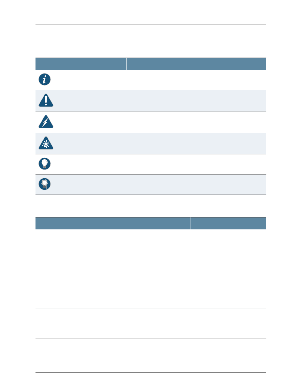
EX2200 and EX2200-C Switches Hardware Guide
Table 1: Notice Icons
DescriptionMeaningIcon
Indicates important features or instructions.Informational note
Indicates a situation that might result in loss of data or hardware damage.Caution
Alerts you to the risk of personal injury or death.Warning
Alerts you to the risk of personal injury from a laser.Laser warning
Indicates helpful information.Tip
Table 2 on page xvi defines the text and syntax conventions used in this guide.
Table 2: Text and Syntax Conventions
Represents text that you type.Bold text like this
Fixed-width text like this
Italic text like this
Italic text like this
Represents output that appears on the
terminal screen.
•
Introduces or emphasizes important
new terms.
•
Identifies guide names.
•
Identifies RFC and Internet draft titles.
Represents variables (options for which
you substitute a value) in commands or
configuration statements.
Alerts you to a recommended use or implementation.Best practice
ExamplesDescriptionConvention
To enter configuration mode, type the
configure command:
user@host> configure
user@host> show chassis alarms
No alarms currently active
•
A policy term is a named structure
that defines match conditions and
actions.
•
Junos OS CLI User Guide
•
RFC 1997,BGP Communities Attribute
Configure the machine’s domain name:
[edit]
root@# set system domain-name
domain-name
Copyright © 2017, Juniper Networks, Inc.xvi

Table 2: Text and Syntax Conventions (continued)
Text like this
Represents names of configuration
statements, commands, files, and
directories;configurationhierarchy levels;
or labels on routing platform
components.
About the Documentation
ExamplesDescriptionConvention
•
To configure a stub area, include the
stub statement at the [edit protocols
ospf area area-id] hierarchy level.
•
The console port is labeled CONSOLE.
stub <default-metric metric>;Encloses optional keywords or variables.< > (angle brackets)
| (pipe symbol)
# (pound sign)
[ ] (square brackets)
Indention and braces ( { } )
; (semicolon)
GUI Conventions
Bold text like this
Indicatesa choice between the mutually
exclusivekeywordsor variables on either
side of the symbol. The set of choices is
often enclosed in parentheses for clarity.
same line as the configurationstatement
to which it applies.
Encloses a variable for which you can
substitute one or more values.
Identifies a level in the configuration
hierarchy.
Identifies a leaf statement at a
configuration hierarchy level.
Representsgraphicaluser interface(GUI)
items you click or select.
broadcast | multicast
(string1 | string2 | string3)
rsvp { # Required for dynamic MPLS onlyIndicates a comment specified on the
community name members [
community-ids ]
[edit]
routing-options {
static {
route default {
nexthop address;
retain;
}
}
}
•
In the Logical Interfaces box, select
All Interfaces.
•
To cancel the configuration, click
Cancel.
> (bold right angle bracket)
Documentation Feedback
We encourage you to provide feedback, comments, and suggestions so that we can
improve the documentation. You can provide feedback by using either of the following
methods:
•
Online feedback rating system—On any page of the Juniper Networks TechLibrary site
at http://www.juniper.net/techpubs/index.html,simply click the stars to ratethe content,
and use the pop-up form to provide us with information about your experience.
Alternately, you can use the online feedback form at
http://www.juniper.net/techpubs/feedback/.
Separates levels in a hierarchy of menu
selections.
In the configuration editor hierarchy,
select Protocols>Ospf.
xviiCopyright © 2017, Juniper Networks, Inc.

EX2200 and EX2200-C Switches Hardware Guide
•
E-mail—Sendyourcomments to techpubs-comments@juniper.net.Include the document
or topic name, URL or page number, and software version (if applicable).
Requesting Technical Support
Technicalproduct support is availablethrough the Juniper NetworksTechnicalAssistance
Center (JTAC). If you are a customer with an active J-Care or Partner Support Service
support contract, or are covered under warranty, and need post-sales technical support,
you can access our tools and resources online or open a case with JTAC.
•
JTAC policies—For a complete understanding of our JTAC procedures and policies,
review the JTAC User Guide located at
http://www.juniper.net/us/en/local/pdf/resource-guides/7100059-en.pdf.
•
Product warranties—For product warranty information, visit
http://www.juniper.net/support/warranty/.
•
JTAC hours of operation—The JTAC centers have resources available 24 hours a day,
7 days a week, 365 days a year.
Self-Help Online Tools and Resources
For quick and easy problem resolution, Juniper Networks has designed an online
self-service portal called the Customer Support Center (CSC) that provides you with the
following features:
•
Find CSC offerings: http://www.juniper.net/customers/support/
•
Search for known bugs: http://www2.juniper.net/kb/
•
Find product documentation: http://www.juniper.net/techpubs/
•
Find solutions and answer questions using our Knowledge Base: http://kb.juniper.net/
•
Download the latest versions of software and review release notes:
http://www.juniper.net/customers/csc/software/
•
Search technical bulletins for relevant hardware and software notifications:
http://kb.juniper.net/InfoCenter/
•
Join and participate in the Juniper Networks Community Forum:
http://www.juniper.net/company/communities/
•
Open a case online in the CSC Case Management tool: http://www.juniper.net/cm/
To verify service entitlementby product serial number, use our Serial Number Entitlement
(SNE) Tool: https://tools.juniper.net/SerialNumberEntitlementSearch/
Opening a Case with JTAC
You can open a case with JTAC on the Web or by telephone.
•
Use the Case Management tool in the CSC at http://www.juniper.net/cm/.
•
Call 1-888-314-JTAC (1-888-314-5822 toll-free in the USA, Canada, and Mexico).
Copyright © 2017, Juniper Networks, Inc.xviii

About the Documentation
For international or direct-dial options in countries without toll-free numbers, see
http://www.juniper.net/support/requesting-support.html.
xixCopyright © 2017, Juniper Networks, Inc.

EX2200 and EX2200-C Switches Hardware Guide
Copyright © 2017, Juniper Networks, Inc.xx

PART 1
Overview
•
System Overview on page 3
•
Chassis Components and Descriptions on page 13
•
Cooling System and Airflow on page 19
•
Power Supplies on page 23
•
Viewing System Information on page 25
1Copyright © 2017, Juniper Networks, Inc.

EX2200 and EX2200-C Switches Hardware Guide
Copyright © 2017, Juniper Networks, Inc.2

CHAPTER 1
System Overview
•
EX2200 Switches Hardware Overview on page 3
•
EX2200 Switch Models on page 9
•
EX2200 Switch Hardware and CLI Terminology Mapping on page 10
EX2200 Switches Hardware Overview
Juniper Networks EX Series Ethernet Switches provide scalable connectivity for the
enterprise market, including branch offices, campus locations, and data centers. The
switches run the Juniper Networks Junos operating system (Junos OS), which provides
Layer 2 and Layer 3 switching, routing, and security services. The same Junos OS code
base that runs on EX Series switches also runs on all Juniper Networks M Series, MX
Series, and T Series routers and SRX Series Services Gateways.
Juniper Networks EX2200 Ethernet Switches provide connectivity for low-density
environments.
This topic describes:
•
EX2200 Switches First View on page 3
•
Uplink Ports on page 4
•
Console Port on page 4
•
Cable Guard on page 5
•
Security Slots on page 5
•
Power over Ethernet (PoE) Ports on page 5
•
Front Panel of an EX2200 Switch on page 6
•
Rear Panel of an EX2200 Switch on page 8
EX2200 Switches First View
EX2200 switches are available in models with 12 , 24, or 48 built-in network ports. The
compact, fanless model, EX2200-C switches have 12 network ports.
3Copyright © 2017, Juniper Networks, Inc.

EX2200 and EX2200-C Switches Hardware Guide
EX2200 switches provide:
•
Up to four uplink ports
•
12 (compact, fanless model), 24, or 48 built-in networkports with 10/100/1000BASE-T
Gigabit Ethernet connectors
•
Virtual Chassis capability—Starting with Junos OS Release 12.2, you can connect up to
four EX2200 switches (including EX2200-C switches) together to form one unit that
you manage as a single chassis, called a Virtual Chassis. For information about
understanding and configuring Virtual Chassis, see Virtual Chassis Feature Guide for
EX2200, EX3300, EX4200, EX4500 and EX4550 Switches.
•
Power over Ethernet (PoE or PoE+) on all network ports (in PoE-capable models)
Uplink Ports
Each EX2200 switch except the EX2200-C switch model has four uplink ports that
support 1-gigabit small form-factor pluggable (SFP) transceivers for use with fiber
connections and copper connections.
Console Port
Each EX2200-C switch has two dual-purpose uplink ports. Each dual uplink port consists
of an RJ-45 port (in which you can connect a copper Ethernet cable) and an SFP port
(into which you can plug a transceiver). Only one of the ports can be active at a time. By
default, if you connect a copper Ethernet cable to the RJ-45 port, this port becomes the
active port provided that there is no connection made on the other port. If you plug a
transceiver into the SFP port, this port becomes the active port whether or not a copper
Ethernet cable is connected to the other port. You can change this default behavior by
explicitly configuring a media type—copper or fiber—for the dual-purpose port by using
the media-type command. For more information, see Configuring the Media Type on
Dual-Purpose Uplink Ports (CLI Procedure).
You can use an SFP uplink port connection between EX2200 switches to interconnect
the switches into an EX2200 Virtual Chassis. For this, you must explicitly configure an
SFP port each on the switches to be connected as a VCP. See Setting an Uplink Port on
an EX Series Switch as a Virtual Chassis Port (CLI Procedure).
For information about the supported optical and copper interfaces, see “Pluggable
Transceivers Supported on EX2200 Switches” on page 67.
Each EX2200 switch exceptthe EX2200-C switch model has an RJ-45console port that
accepts a cable with RJ-45 connector.
The EX2200-C switch has two console ports: an RJ-45 port and a Mini-USB Type-B port.
The RJ-45 console port accepts a cable with an RJ-45 connector and the Mini-USB
Type-B console port accepts a Mini-B plug (5-pin) connector to connect to the console
management device. The switch activates only one console port at a time, either the
RJ-45 console port or the Mini USB type-B console port. By default, the RJ-45 port is the
active console port and the Mini-USB Type-B port is the passive console port. You can
change the default setting of a console port by using the port-type command. See
Configuring the Console Port Type (CLI Procedure).
Copyright © 2017, Juniper Networks, Inc.4

Cable Guard
On an EX2200-C switch model, you can install a cable guard to secure the cables
connected to the switch. The cable guard has slots in the front of it through which you
can pass all the cables to prevent them from being accidently unplugged or removed
after they are connected. See “Mounting an EX2200 Switch on a Desk or Other Level
Surface” on page 92.
Security Slots
Each EX2200-C switch model has security slots on the left and right panels of the chassis.
Use the security slots tolock and secure the chassis in the installationsite with a standard
cable lock . See “Mounting an EX2200 Switch on a Desk or Other Level Surface” on
page 92.
Power over Ethernet (PoE) Ports
EX2200 switches are available in models with or without PoE/PoE+ capability. Models
that support PoE/PoE+ provide that support on all network ports. PoE ports provide
electrical current to devices—such as IP phones, wireless access points, and security
cameras—through network cables, thus eliminating the need for separate power cords
for those devices.
Chapter 1: System Overview
EX2200 switches with DC power supply do not provide PoE.
NOTE: Starting with Junos OS Release 12.2R1, PoE commands are enabled
on all non-PoE-capable EX2200 switch models. The PoE commands do not
provide any meaningful information on standalone non-PoE-capable switch
models. However, in an EX2200 Virtual Chassis, you can execute PoE
commands from a non-PoE-capable switch that is the master, to configure
PoE on PoE-capable Virtual Chassis members.
PoE-capable EX2200 switches running Junos OS Release 10.3 or later support powered
devices that comply with IEEE 802.3af (PoE) and IEEE 802.3at (PoE+).
NOTE: IEEE 802.3at class 4 powered devices require category 5 or higher
Ethernet cables.
EX2200 switches running Junos OS Release 10.2 or earlier support powered devices that
comply with IEEE 802.3af (PoE).
The remainder of this topicuses the term PoE to refer to both PoE and PoE+ unless there
is a need to distinguish between the two.
5Copyright © 2017, Juniper Networks, Inc.
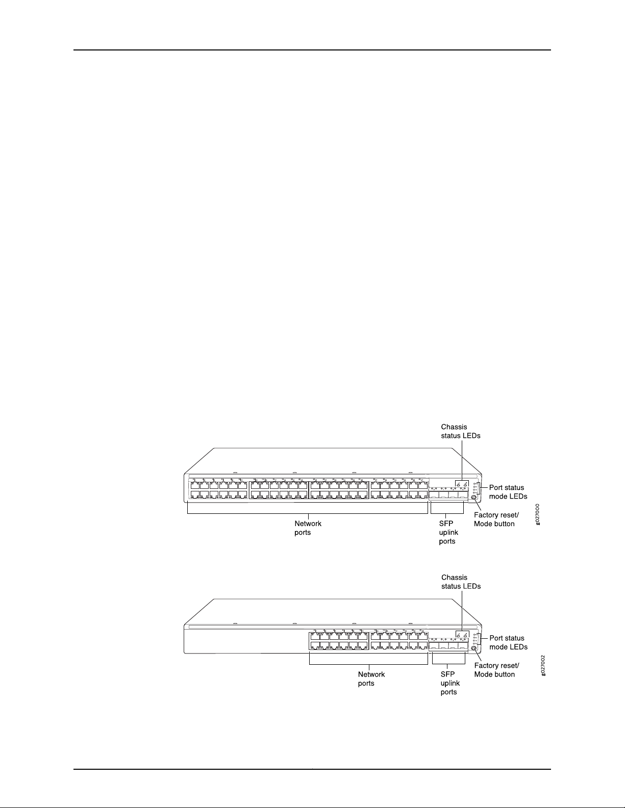
EX2200 and EX2200-C Switches Hardware Guide
Front Panel of an EX2200 Switch
The front panel of an EX2200 switch except the EX2200-C switch models consists of
the following components:
•
Network ports—depending on the switch model, either of:
•
24 or 48 10/100/1000BASE-T Gigabit Ethernet ports, with Power over Ethernet
(PoE) not available in EX2200-24T, EX2200-24T-DC, and EX2200-48T models
•
24 or 48 10/100/1000BASE-T Gigabit Ethernet ports, with Power over Ethernet
(PoE) available in EX2200-24P and EX2200-48P models
•
4 built-in SFP uplink ports. You can use these ports to forward network traffic or
configure them into Virtual Chassis ports (VCPs) to interconnect EX2200 switches
into a Virtual Chassis.
•
2 chassis status LEDs
•
4 port status mode LEDs
•
Factory reset/Mode button
Figure 1 on page 6 shows the front panel of an EX2200 switch with 48 Gigabit Ethernet
ports. Figure 2 on page 6 shows the front panel of an EX2200 switch with 24 Gigabit
Ethernet ports.
Figure 1: Front Panel of an EX2200 Switch with 48 Gigabit Ethernet Ports
Figure 2: Front Panel of an EX2200 Switch with 24 Gigabit Ethernet Ports
Copyright © 2017, Juniper Networks, Inc.6
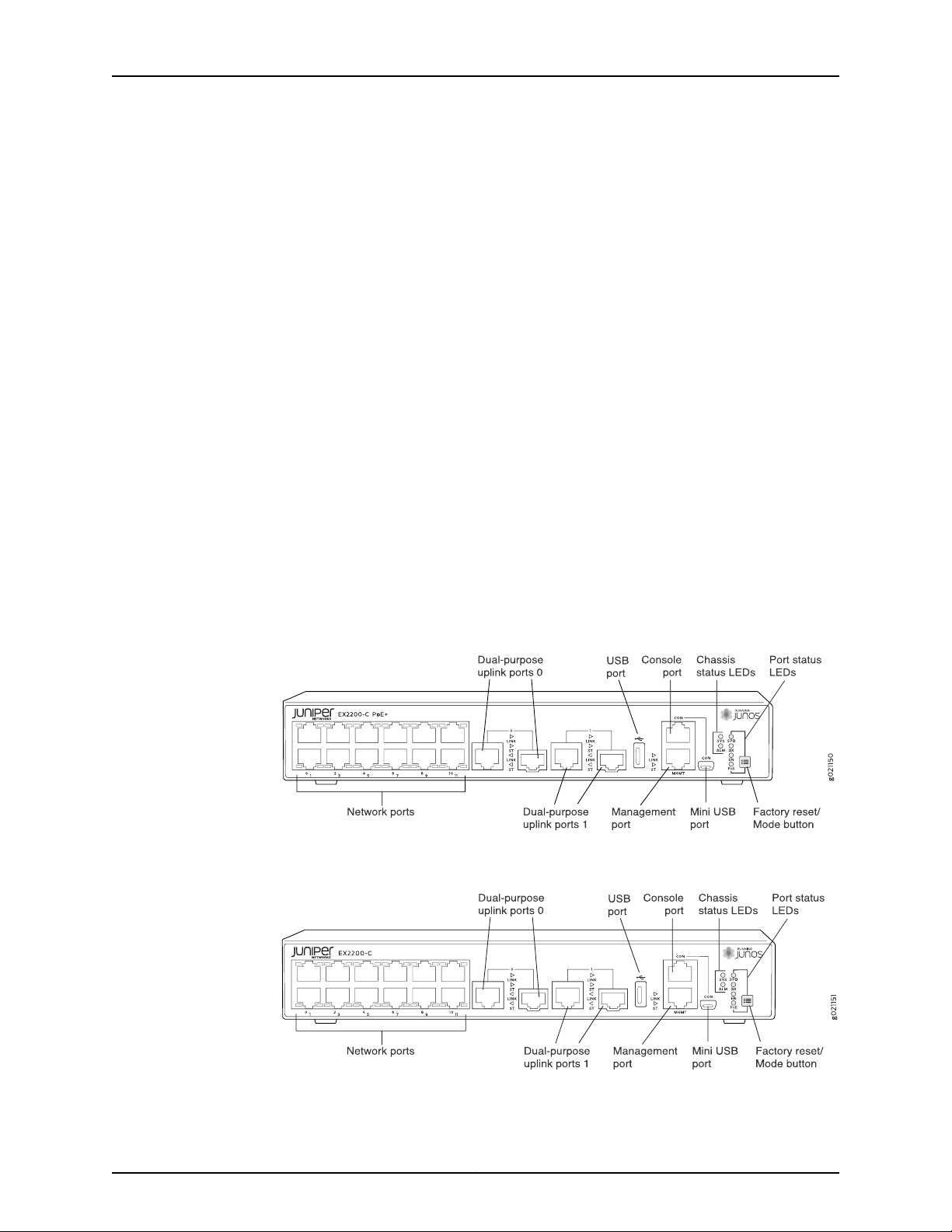
Chapter 1: System Overview
The front panel of an EX2200-C switch consists of the following components:
•
Network ports—depending on the switch model, either of:
•
12 10/100/1000BASE-T Ethernet ports, (PoE+) in EX2200-C-12P
•
12 10/100/1000BASE-T Ethernet ports, (non-PoE) in EX2200-C-12T
•
2 built-in dual-purpose uplink ports, each of which includes one 10/100/1000 RJ-45
Ethernet port and one SFP port
•
1 USB port
•
1 Mini-USB console port
•
1 RJ-45 console port
•
1 Management Ethernet port
•
2 chassis status LEDs
•
4 port status mode LEDs in PoE+ and 3 port status mode LEDs in non-PoE
•
Factory reset/Mode button
Figure 3 on page 7 shows the front panel of an EX2200-C switch with 12 Gigabit Ethernet
PoE+ ports and Figure 4 on page 7 shows the front panel of an EX2200-C switch with
12 Gigabit Ethernet non-PoE ports.
Figure 3: Front Panel of an EX2200-C Switch with 12 Gigabit Ethernet
Ports (PoE+)
Figure 4: Front Panel of an EX2200-C Switch with 12 Gigabit Ethernet
Ports (non-PoE)
7Copyright © 2017, Juniper Networks, Inc.
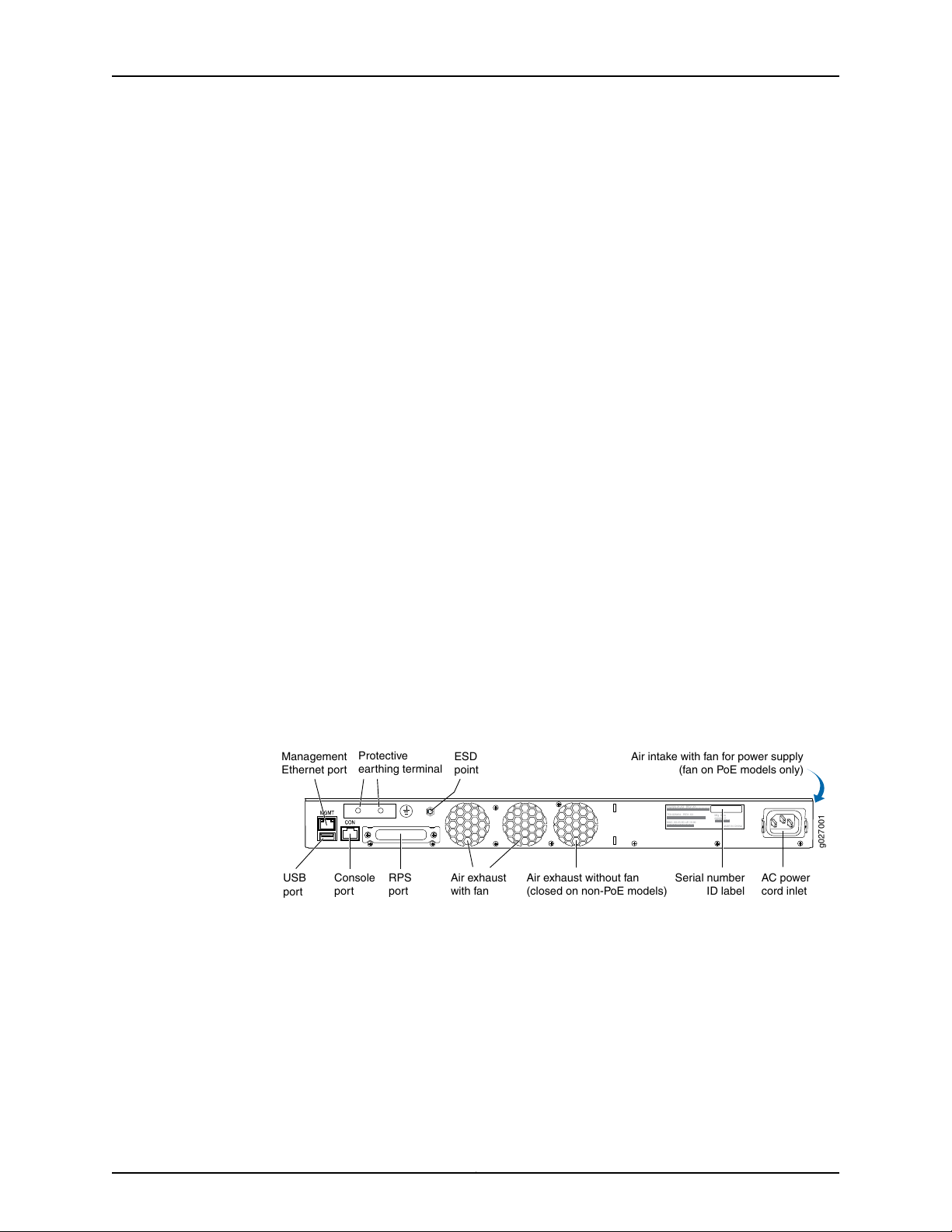
g027001
USB
port
Management
Ethernet por t
Console RPS
port
port
Protective
earthing terminal
Air exhaust without fan
(closed on non-PoE models)
Air exhaust
with fan
AC power
cord inlet
ESD
point
EX2200-24-4G REV: X1
750-026464 REV: X3
MAC:00:23:9C:oE:19:00
Mfg.Date
20090227
MADEIN CHINA
Serial number
ID label
Air intake with fan for power supply
(fan on PoE models only)
EX2200 and EX2200-C Switches Hardware Guide
Rear Panel of an EX2200 Switch
The rear panel of the EX2200 switch except the EX2200-C switch models consists of
the following components:
•
Management Ethernet port
•
USB port
•
Console port
•
Protective earthing terminal
•
Redundant power system (RPS) port
•
ESD point
•
Air exhaust
•
Serial number ID label
•
AC power cord inlet or DC power terminals
Figure 5 on page 8 shows the rear panel of an EX2200 switch with an AC power supply.
All EX2200 switches except the EX2200-C switch model have three exhaust openings
on the rear panel. The two exhaust openings on the left have fans behind them and are
open. The exhaust opening on the right has no fan within it. This opening is exposed on
Power over Ethernet (PoE) models and sealed on non-PoE models. On PoE models, this
opening exhausts the air from the fan at the air intake for the power supply on the side
panel.
The power cord retainer clips extend out of the chassis by 3 in.
Figure 5: Rear Panel of an EX2200 Switch with AC Power Supply
The rear panel of an EX2200-C switch consists of the following components:
•
Protective earthing terminal
•
ESD point
•
Serial number ID label
•
AC power cord inlet
•
Heatsink—only in PoE+ models
Copyright © 2017, Juniper Networks, Inc.8
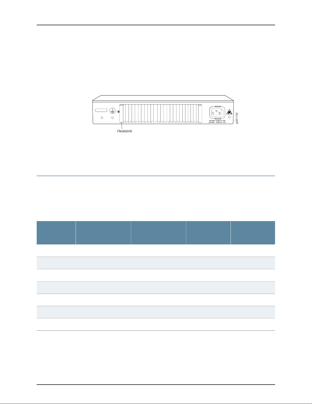
Chapter 1: System Overview
Figure 6 on page 9 shows the rear panel of an EX2200-C-12P switch with heatsink.
EX2200-C switches being fanless models have no exhaust openings. The switch has
vents on the top and on both the sides of the chassis. The PoE+ models have a heatsink
installed in the rear panel to dissipate the heat, while non-PoE models have no heatsink.
Figure 6: Rear Panel of an EX2200-C-12P Switch with Heatsink
Related
Documentation
EX2200 Switch Models on page 9•
• Site Preparation Checklist for EX2200 Switches on page 47
EX2200 Switch Models
The EX2200 switch is available with 12, 24, or 48 built-in network ports with full Power
over Ethernet (PoE)capability (all 12, 24, or 48 built-in network ports support PoE) or no
PoE capability. EX2200 switches with DC power supply do not provide PoE.
Table 3 on page 9 lists the EX2200 switch models.
Table 3: EX2200 Switch Models
Ports in Which PoE is
AvailableAccess PortsModel
Maximum System
PowerAvailablefor
PoE
First Junos OS
Release
11.3R1––12 Gigabit EthernetEX2200-C-12T-2G
11.3R1100 WAll 12 ports12 Gigabit EthernetEX2200-C-12P-2G
10.1R1––24 Gigabit EthernetEX2200-24T-4G
10.1R1405 WAll 24 ports24 Gigabit EthernetEX2200-24P-4G
Related
Documentation
10.1R1––24 Gigabit EthernetEX2200-24T-4G-DC
10.1R1––48 Gigabit EthernetEX2200-48T-4G
10.1R1405 WAll 48 ports48 Gigabit EthernetEX2200-48P-4G
EX2200 Switches Hardware Overview on page 3•
9Copyright © 2017, Juniper Networks, Inc.

EX2200 and EX2200-C Switches Hardware Guide
EX2200 Switch Hardware and CLI Terminology Mapping
This topic describes the hardware terms used in EX2200 switch documentation and the
corresponding terms used in the Junos OS command line interface (CLI). See
Table 4 on page 10.
Table 4: CLI Equivalents of Terms Used in Documentation for EX2200 Switches
Hardware Item (as
displayed in the CLI)
Chassis
FPC (n)
Description (as
displayed in the CLI)
•
EX2200-C-12T-2G
•
EX2200-C-12P-2G
•
EX2200-24T-4G
•
EX2200-24P-4G
•
EX2200-24T-4G-DC
•
EX2200-48T-4G
•
EX2200-48P-4G
the Flexible PIC
Concentrator (FPC)
One of the following:
•
EX2200-C-12T-2G
•
EX2200-C-12P-2G
•
EX2200-24T-4G
•
EX2200-24P-4G
•
EX2200-24T-4G-DC
•
EX2200-48T-4G
•
EX2200-48P-4G
Value (as displayed
in the CLI)
Value of n is always 0.Abbreviated name of
Item in
Documentation
Switch chassis–One of the following:
The switch does not
have actual FPCs. In
this case, FPC refers to
the switch itself.
Additional
Information
“Chassis Physical
Specifications for
EX2200 Switches” on
page 13
Understanding Interface
Naming Conventions on
EX Series Switches
PIC (n)
Abbreviated name of
the Physical Interface
Card (PIC)
•
12x 10/100/1000
BASE-T
•
24x 10/100/1000
BASE-T
•
48x 10/100/1000
BASE-T
n is a value in the range
of 0–1.
PIC 0One of the following:
The switch does not
have actual PIC
devices; see entries for
PIC 0 through PIC 1 for
the equivalent item on
the switch.
Built-in network ports
on the front panel of
the switch
Copyright © 2017, Juniper Networks, Inc.10
Understanding Interface
Naming Conventions on
EX Series Switches
“EX2200 Switches
Hardware Overview”
on page 3

Chapter 1: System Overview
Table 4: CLI Equivalents of Terms Used in Documentation for EX2200 Switches (continued)
Hardware Item (as
displayed in the CLI)
Xcvr (n)
Fan
Description (as
displayed in the CLI)
•
2x (10/100/1000
BASE-T or GE SFP)
or
•
2x (100/1000
BASE-X)
•
4x GE SFP
Abbreviated name of
the transceiver
NOTE: EX2200-C
switches are fanless
models.
Value (as displayed
in the CLI)
PIC 1One of the following:
to the number of the
port in which the
transceiver is installed.
Item in
Documentation
Built-in uplink ports
and dual-purpose
uplink ports on the
front panel of the
switch
Optical transceiversn is a value equivalent
AC power supplyValue of n is always 0.Built-in power supplyPower supply (n)
Fan–Fan
Additional
Information
“EX2200 Switches
Hardware Overview”
on page 3
“Pluggable
Transceivers
Supported on EX2200
Switches” on page 67
“Power Supply in
EX2200 Switches” on
page 23
“Cooling System and
Airflow in an EX2200
Switch” on page 19
Related
Documentation
• EX2200 Switches Hardware Overview on page 3
11Copyright © 2017, Juniper Networks, Inc.

EX2200 and EX2200-C Switches Hardware Guide
Copyright © 2017, Juniper Networks, Inc.12

CHAPTER 2
Chassis Components and Descriptions
•
Chassis Physical Specifications for EX2200 Switches on page 13
•
Chassis Status LEDs in EX2200 Switches on page 14
•
Management Port LEDs in EX2200 Switches on page 15
•
Network Port and Uplink Port LEDs in EX2200 Switches on page 16
Chassis Physical Specifications for EX2200 Switches
The EX2200 switch chassis is a rigid sheet-metal structure that houses the hardware
components. Table 5 on page 13 summarizes the physical specifications of the EX2200
switch chassis.
Table 5: Physical Specifications of the EX2200 Switch Chassis
EX2200-C ValueEX2200 ValueDescription
1.75 in. (4.4 cm)1.75 in. (4.45 cm)Chassis height
Chassis width
Weight
Documentation
Related
•
17.5 in. (44.5 cm)
•
19 in. (48.2 cm) with mounting brackets
attached
10.5 in. (26.7 cm)Chassis depth
•
EX2200-24T: 6 lb (2.7 kg)
•
EX2200-24P: 8 lb (3.6 kg)
•
EX2200-24T-DC: 6 lb (2.7 kg)
•
EX2200-48T: 8 lb (3.6 kg)
•
EX2200-48P: 10 lb (4.5 kg)
•
10.6 in. (26.92 cm)
•
19 in. (48.26 cm) with mounting brackets
•
EX2200-C-12T: 9.0 in. (22.8 cm)
•
EX2200-C-12P: 9.4 in. (23.8 cm)
•
EX2200-C-12T: 4.6 lb (2.1 kg)
•
EX2200-C-12P: 6.4 lb (2.9 kg)
Rack Requirements on page 55•
• Cabinet Requirements on page 56
• Mounting an EX2200 Switch on page 90
• Installing and Connecting an EX2200 Switch on page 89
13Copyright © 2017, Juniper Networks, Inc.
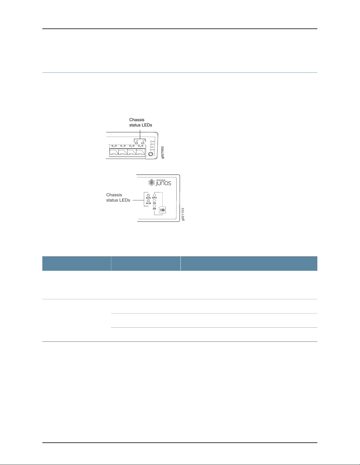
g027003
0 1 2
SYS
ALM
SPD
DX
EN
POE
3
Chassis
status LEDs
g021153
Chassis
status LEDs
EX2200 and EX2200-C Switches Hardware Guide
Chassis Status LEDs in EX2200 Switches
The front panel of an EX2200 switch has two chassis status LEDs labeled SYS and ALM
on the far right side of the panel. See Figure 7 on page 14 and Figure 8 on page 14.
Figure 7: Chassis Status LEDs in an EX2200 Switch Except the EX2200-C
Switch
Figure 8: Chassis Status LEDs in an EX2200-C Switch
Table 6 on page 14 describes the chassis status LEDs in an EX2200 switch, their colors
and states, and the status they indicate.
Table 6: Chassis Status LEDs in an EX2200 Switch
State and DescriptionColorLED Label
GreenSYS
A major alarm (red) indicates a critical error condition that requires immediate action.
A minor alarm (amber) indicates a noncritical condition that requires monitoring or
maintenance. A minor alarm that is left unchecked might cause interruption in service or
performance degradation.
Both LEDs can be lit simultaneously.
•
•
•
There is no alarm or the switch is halted.UnlitALM
There is a minor alarm.Amber
There is a major alarm.Red
On steadily—The switch is functioning normally.
Blinking—The switch is booting.
Off—The switch is powered off or is halted.
You can view the colors of the two LEDs remotely through the CLI by issuing the
operational mode command show chassis led.
Copyright © 2017, Juniper Networks, Inc.14
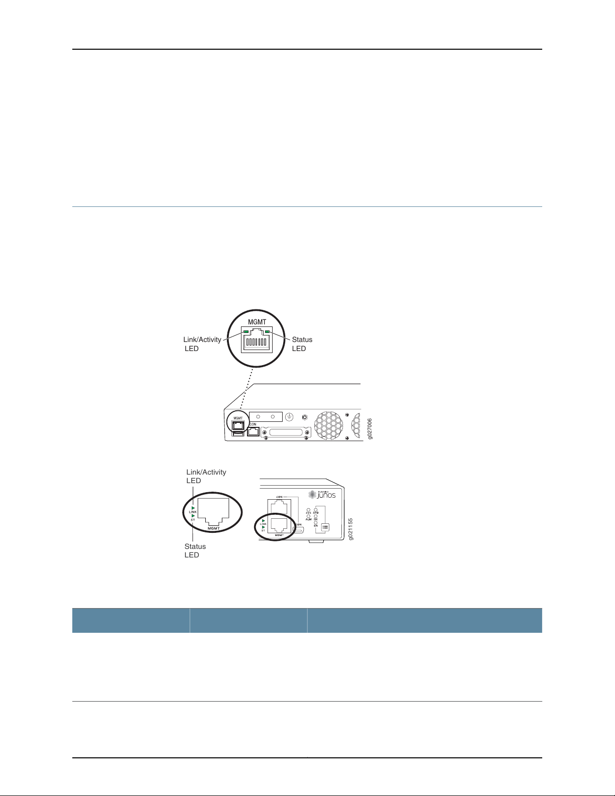
g027006
Link/Activity
LED
Status
LED
g021155
Status
LED
Link/Activity
LED
Chapter 2: Chassis Components and Descriptions
Related
Documentation
EX2200 Switches Hardware Overview on page 3•
• Chassis Component Alarm Conditions on EX2200 Switches on page 166
• Checking Active Alarms with the J-Web Interface on page 172
• Understanding Alarm Types and Severity Levels on EX Series Switches on page 165
Management Port LEDs in EX2200 Switches
The management port on an EX2200 switchhas two LEDs that indicate link/activityand
port status. The EX2200 switches except the EX2200-C switch models have the
management port on the rear panel and the EX2200-C switchhas the management port
on the front panel. See Figure 9 on page 15 and Figure 10 on page 15.
Figure 9: LEDs on the Management Port on an EX2200 Switch Except the
EX2200-C Switch Model
Figure 10: LEDs on the Management Port on an EX2200-C Switch
Table 7 on page 15 describes the Link/Activity LED.
Table 7: Link/Activity LED on the Management Port on EX2200 Switches
State and DescriptionColorLED
•
GreenLink/Activity
Blinking—The port and the link are active, and there is link
activity.
•
On steadily—The port and the link are active, but there is no
link activity.
•
Off—The port is not active.
15Copyright © 2017, Juniper Networks, Inc.
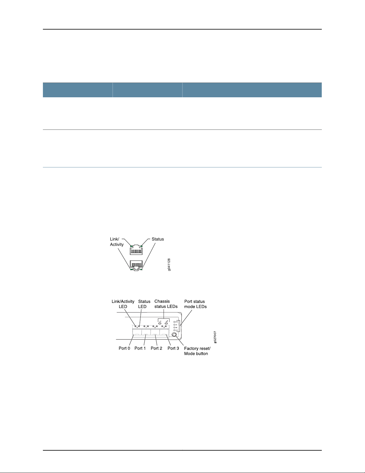
g041128
Link/
Activity
Status
EX2200 and EX2200-C Switches Hardware Guide
Table 8 on page 16 describes the Status LED.
Table 8: Status LED on the Management Port on EX2200 Switches
State and DescriptionColorLED
Indicates the speed. The speed indicators are:
•
One blink per second—10 Mbps
•
Two blinks per second—100 Mbps
Related
GreenStatus
Connecting a Device to a Network for Out-of-Band Management on page 127•
Documentation
Network Port and Uplink Port LEDs in EX2200 Switches
Each network port and uplink port on the front panel of an EX2200 switch has two LEDs
that indicate link/activity and port status. Each dual-purpose uplink port in an EX2200-C
switch has two pairs of LEDs that indicate the link/activity status, one pair for each of
the two ports that constitute the dual-purpose uplink port. See Figure 11 on page 16,
Figure 12 on page 16, and Figure 13 on page 17.
Figure 11: LEDs on the Network Port
Figure 12: LEDs on the Uplink Ports and Port Status Mode LEDs in an
EX2200 Switch Except the EX2200-C Switch Model
Copyright © 2017, Juniper Networks, Inc.16
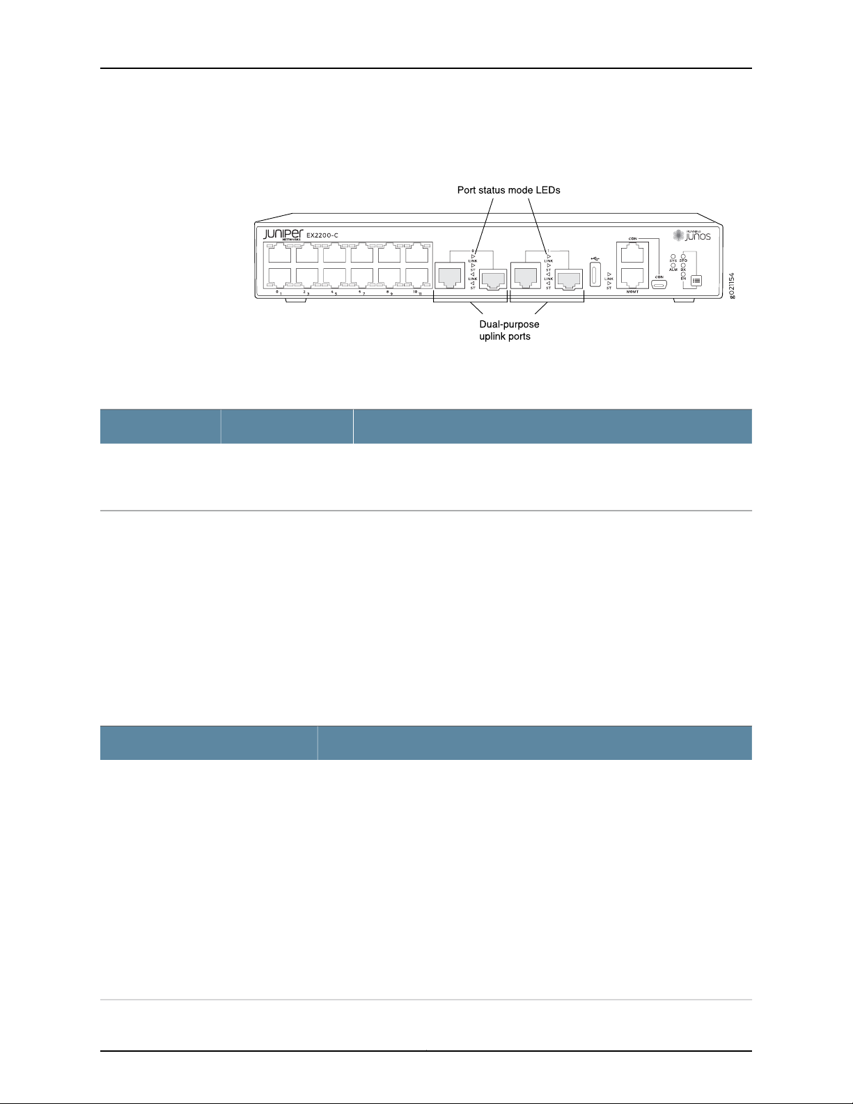
Chapter 2: Chassis Components and Descriptions
Figure 13: Port Status Mode LEDs of the Dual-Purpose Uplink Ports of an
EX2200-C Switch
Table 9 on page 17 describes the Link/Activity LED.
Table 9: Link/Activity LED on the Network Ports and Uplink Ports in EX2200 Switches
State and DescriptionColorLED
•
GreenLink/Activity
Blinking—The port and the link are active, and there is link activity.
•
On steadily—The port and the link are active, but there is no link activity.
•
Off—The port is not active.
In Figure 11 on page 16, Figure 12 on page 16, and Figure 13 on page 17 show the LEDs that
indicatethe status of one of the fourport parameters—speed, duplex mode, administrative
status, and Power over Ethernet (PoE) status. Use the Factory reset/Mode button below
the LED labeled POE on the far right side of the front panel to toggle the Status LED to
show the different port parameters. You can tell which port parameter is indicated by
the Status LED by looking at which port status mode LED (SPD, DX, EN, and POE) is lit.
(See Figure 12 on page 16).
Table 10 on page 17 describes the Status LED.
Table 10: Status LED on the Network Ports, Uplink Ports, and Dual-Purpose Uplink Ports in
EX2200 Switches
State and DescriptionPort Parameters
Speed
Indicates the speed. The speed indicators for network ports are:
•
One blink per second—10 Mbps
•
Two blinks per second—100 Mbps
•
Three blinks per second—1000 Mbps
The speed indicators for uplink ports are:
•
On steadily—1000 Mbps
•
Off—10/100 Mbps
The speed indicators for dual-purpose uplink ports of EX2200-C switch model are:
•
One blink per second—10 Mbps
•
Two blinks per second—100 Mbps
•
Three blinks per second—1000 Mbps
17Copyright © 2017, Juniper Networks, Inc.

EX2200 and EX2200-C Switches Hardware Guide
Table 10: Status LED on the Network Ports, Uplink Ports, and Dual-Purpose Uplink Ports in
EX2200 Switches (continued)
State and DescriptionPort Parameters
Duplex mode
Administrative status
PoE status
Indicates the duplex mode. The status indicators are:
•
On steadily—Port is set to full-duplex mode.
•
Off—Port is set to half-duplex mode.
Indicates the administrative status. The status indicators are:
•
On steadily—Port is administratively enabled.
•
Off—Port is administratively disabled.
Indicates the PoE status. The status indicators for network ports are:
•
On steadily—PoE is availableon the port, a device that draws power from the port
is connected to the port, and the device is drawing power from the port.
•
Blinking—PoEis available on the port, but no power is drawn from the port because
of one of the following:
•
No device that draws power from the port is connected to the port.
•
A device that drawspowerfrom the port is connectedto the port, but the device
is not drawing any power from the port.
•
Off—PoE is not available on the port.
NOTE: PoE Status LED is available on the following EX2200 switch models:
•
EX2200-C-12P
•
EX2200-24P
•
EX2200-48P
PoE is not availableon uplink ports; therefore,the LED for those ports is always unlit.
Related
Documentation
You can tell which port parameter is indicatedby the StatusLED on network ports, uplink
ports, and dual-purpose uplink ports by issuing the operational mode command show
chassis led.
• EX2200 Switches Hardware Overview on page 3
• Configuring Gigabit Ethernet Interfaces (CLI Procedure)
• Configuring Gigabit Ethernet Interfaces (J-Web Procedure)
Copyright © 2017, Juniper Networks, Inc.18

CHAPTER 3
Cooling System and Airflow
•
Cooling System and Airflow in an EX2200 Switch on page 19
Cooling System and Airflow in an EX2200 Switch
Thecooling system in EX2200 switches,exceptEX2200-C, the compact, fanless models,
consists of two fans along the rear of the chassis that provide side-to-rearchassis cooling.
In the PoE models of these switches, there is an additional fan in the power supply.
In the EX2200-C switch the cooling is done by the vents on top and sides of the chassis
in non-PoE models and by heatsinks in PoE+ models. Do not block the vents on the
chassis. Doing this can lead to overheating of the switch chassis
This topic describes:
•
Airflow Direction in Non-PoE Models of EX2200 Switches, Except for the EX2200-C
Models on page 19
•
Airflow Direction in PoE Models of EX2200 switches, Except for the EX2200-C
Models on page 20
Airflow Direction in Non-PoE Models of EX2200 Switches, Except for the EX2200-C Models
Figure 14 on page 20 shows the airflow in non-PoE models of EX2200 switches, except
for the EX2200-C models.
19Copyright © 2017, Juniper Networks, Inc.
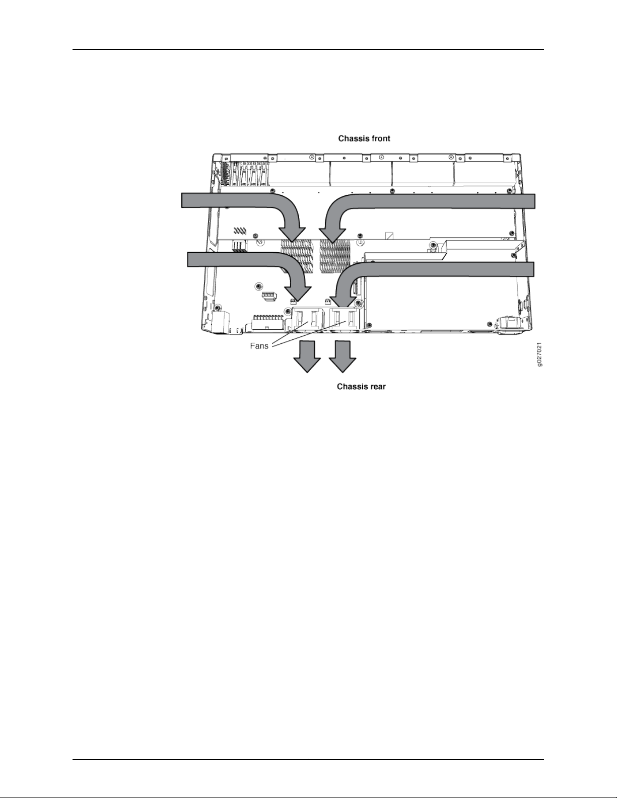
EX2200 and EX2200-C Switches Hardware Guide
Figure 14: Airflow Through Non-PoE Models of EX2200 Switches Except
the EX2200-C Switch Model
Airflow Direction in PoE Models of EX2200 switches, Except for the EX2200-C Models
Figure 15 on page 21 shows the airflow in PoE models of EX2200 switches, except
EX2200-C models.
Copyright © 2017, Juniper Networks, Inc.20
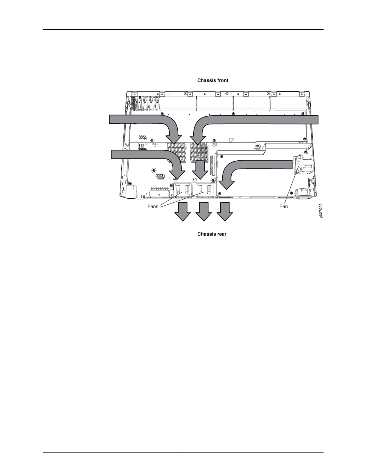
Chapter 3: Cooling System and Airflow
Figure 15: Airflow Through PoE Models of EX2200 Switches Except the
EX2200-C Switch Models
Related
Documentation
Under normal operating conditions, the fans operate at a moderate speed to reduce
noise. Temperature sensors in the chassis monitor the temperature within the chassis.
If any fan fails or if the temperature inside the chassis rises above the threshold, the
switch raises an alarm and all functioning fans operate at a higher speed than normal.
If the temperature inside the chassis rises above the threshold, the switch shuts down
automatically.
• EX2200 Switches Hardware Overview on page 3
• Chassis Status LEDs in EX2200 Switches on page 14
• Understanding Alarm Types and Severity Levels on EX Series Switches on page 165
• Prevention of Electrostatic Discharge Damage on page 211
21Copyright © 2017, Juniper Networks, Inc.

EX2200 and EX2200-C Switches Hardware Guide
Copyright © 2017, Juniper Networks, Inc.22

CHAPTER 4
Power Supplies
•
Power Supply in EX2200 Switches on page 23
Power Supply in EX2200 Switches
The power supply in EX2200 switches is built in along the rear panel of the chassis, with
an AC power cord inlet or DC power terminals on the rear panel to connect power to the
switch.
Table 11 on page 23 lists the power consumed by each EX2200 switch model. The
maximum power available on a PoE port is 30 W for switches running Junos OS Release
10.3 or later and 15.4 W for switches running Junos OS Release 10.2 or earlier.
Table 11: Power Consumed by EX2200 Switches
Related
Documentation
Number of PoE-Enabled
PortsModel Number
12EX2200-C-12P
24EX2200-24P
48EX2200-48P
• AC Power Cord Specifications for EX2200 Switches on page 62
• EX2200 Switches Hardware Overview on page 3
• Power Specifications for EX2200 Switches on page 61
Maximum Power
Consumed by the Switch
drawn)
drawn)
drawn)
Maximum PoE Power
Available
–30 W–EX2200-C-12T
100 W30 W (when no PoE power is
–50 W–EX2200-24T
405 W60 W (when no PoE power is
–50 W–EX2200-24T-DC
–76 W–EX2200-48T
405 W91 W (when no PoE power is
23Copyright © 2017, Juniper Networks, Inc.

EX2200 and EX2200-C Switches Hardware Guide
• Connecting AC Power to an EX2200 Switch on page 121
• Connecting DC Power to an EX2200 Switch on page 123
• Connecting Earth Ground to an EX Series Switch on page 115
Copyright © 2017, Juniper Networks, Inc.24

CHAPTER 5
Viewing System Information
•
Dashboard for EX Series Switches on page 25
Dashboard for EX Series Switches
NOTE: This topic applies only to the J-Web Application package.
When you log in to the J-Web user interface, the dashboard for the Juniper Networks EX
Series Ethernet Switches appears. Use the dashboard to view system information.
The Update Available window appears if there is a latestupdate of the J-WebApplication
package available on the Juniper Networks server. This window is enabled by the auto
update feature of J-Web.
NOTE:
•
The Update Available window will not appear when you log in, if you have
not selected the Check for updates automaticallyon every login in the Update
Preference section in the Maintain > Update J-Web side pane. By default,
the Check for update automatically on every login is selected.
•
If you choose Update Later, you can update to the latestJ-WebApplication
package by clicking the orange icon next to Update Available on the top
pane of the J-Web interface or through Maintain > Update J-Web.
The dashboard comprises a graphical chassis viewer and four panels.
This topic describes:
•
Graphical Chassis Viewer on page 26
•
System Information Panel on page 27
•
Health Status Panel on page 29
•
Capacity Utilization Panel on page 31
•
Alarms Panel on page 31
25Copyright © 2017, Juniper Networks, Inc.

EX2200 and EX2200-C Switches Hardware Guide
•
File System Usage on page 32
•
Chassis Viewer on page 32
Graphical Chassis Viewer
The Dashboard panel displays a graphical view of the chassis of a switch. In a Virtual
Chassis, it displays a graphical view of each member switch.
In a Virtual Chassis, the defaultvalues are shown on the Dashboard panel when no chassis
image is clicked. The panel displays the value for a switch if you click its image.
NOTE: If the member switch is not present, inactive, or not provisioned, you
cannot expand the member switch image.
In J-Web Application package Release 14.1X53-A2, you can form a Virtual
Chassisusing EX4600 and EX4300 switches. Whenin a mixed VirtualChassis
consisting of EX4600 switches and EX4300 switches, the EX4600 switches
can be the master,backup, or in the linecard role, while the EX4300 switches
must be in the linecard role.
Table 12 on page 26 lists the details that are displayed on each member switch.
Table 12: Details of a Virtual Chassis Member Switch
ExampleDetails
EX3300Model number of the member switch
Assigned ID that applies to the entire Virtual Chassis
configuration
Role of the member switch
Status of the member switch
The status of the member switch is displayed on the image of the switch. If the member
switchappears dimmed, it means the switch is not present, is inactive, or is not provisioned
in the Virtual Chassis. If the member switch does not appear dimmed, it means the switch
is present and is active.
ID 2
NOTE: If the member switch is not provisioned, the serial number
of the switch is displayed instead of its ID.
Master
Possible roles are: Master, Backup, or Linecard
Prsnt
Possible statuses are: Prsnt, NotPrsnt, Inactive, or Unprvsnd
Table 13 on page 27 describes the possible status of a member switch.
Copyright © 2017, Juniper Networks, Inc.26

Table 13: Status of a Member Switch in a Virtual Chassis
It means the member switchIt appears asIf the member switch is
Chapter 5: Viewing System Information
Not present
Inactive
Not provisioned
PrsntPresent
NotPrsnt
dimmed and
Inactive
dimmed and
Unprvsnd
Has established physical and logical connections with Virtual
Chassis member switches.
Has been disconnected from the existing Virtual Chassis.dimmed and
Has established physical connections, but is unable to establish
logical connections.
Cannot synchronize with the existing preprovisioned Virtual
Chassis.
Click Rear View for a graphical view of the rear panel of the switch.
Click Preferences to choose which panels must be displayed and set the refresh interval
forchassis viewer information.Click OK to save your changes and return to the dashboard
or click Cancel to return to the dashboard without saving changes.
NOTE: You can drag the various panels to different locations in the J-Web
window.
System Information Panel
Table 14: System Information
System name
Device model
DescriptionField
Indicates the local name of the EX Series switch. The local
name of the EX Series switches changes when an individual
image is clicked.
Indicatesthe model of the EX Series switch. In a Virtual Chassis
configuration,toindicatethe model of a switch, click the image
of that switch.
NOTE: In a Virtual Chassis setup for an EX6210, EX8208, or
EX8216 switch, the Device model field displays details of the
master Routing Engine. To view details of a member, select it.
27Copyright © 2017, Juniper Networks, Inc.

EX2200 and EX2200-C Switches Hardware Guide
Table 14: System Information (continued)
DescriptionField
Inventory details
Indicates the following:
•
For EX3200 switches; and for EX2200, EX2200-C, EX3300,
EX4200, EX4300, EX4500, EX4550, and EX4600 switches
that are not configured as Virtual Chassis, the value
displayed in Inventory details field is always 1 FPC. FPC is a
legacy term for a slot in a large Juniper Networks chassis;
which simply refers to the standalone switch.
•
For EX2200 and EX2200-C switches configuredas a Virtual
Chassis, the value displayed in the Inventory details field is
1–4 FPC, with the number corresponding to the number of
member switches.
•
For EX3300 switches configured as a Virtual Chassis, the
value displayed in the Inventory details field is 1–6 FPC, with
the number corresponding to the number of member
switches.
NOTE: For Junos OS Release14.1X53-D10and later,EX3300
switches configured as a Virtual Chassis display the value
1–10 FPC in the Inventory details field.
•
For EX4200, EX4500, EX4550, and EX4600 switches
configured as a Virtual Chassis, the value displayed in the
Inventory details field is 1–10 FPC, with the number
corresponding to the number of member switches.
•
For EX6210 switches, the values displayed in the Inventory
details field are 1–2 CB and 1–9 FPC. CB, or Control Board,
refers to the SRE module. FPC refers to line cards and the
FPC within the CB.
•
For an EX8208 switch, the values displayed in Inventory
details field are 1–3 CB and 0–8 FPC. CB, or Control Board,
refers to SRE and SF modules. FPC refers to line cards.
•
For EX8216 switches, the values displayed in Inventory
details field are 1–2 CB and 0–16 FPC. CB, or Control Board,
refers to RE modules and FPC refers to line cards.
•
For an XRE200 External Routing Engine in an EX8200 Virtual
Chassis, the value displayed in Inventory details is 1 XRE.
XRE refers to RE modules. For XRE200 External Routing
Engines configured as a Virtual Chassis, the values displayed
in Inventory details are 1–2 XRE and 0–4 LCC, where LCC
refers to the EX8200 line card chassis.
Junos image
Boot image
Indicatesthe version of the Junos OS image. In a Virtual Chassis
configuration, the Junos OS image of the master switch is
displayed by default. To display the Junos OS image of a
specific switch, click the image of that switch.
Indicatesthe version of the boot image that is used. In a Virtual
Chassis configuration, the boot image of the master switch is
displayed by default. To display the boot image of a specific
switch, click the image of that switch.
Copyright © 2017, Juniper Networks, Inc.28

Table 14: System Information (continued)
Chapter 5: Viewing System Information
DescriptionField
Device uptime
Indicates the time since the last reboot. In a Virtual Chassis
configuration,to displaythe uptime of the specific switch, click
the image of that switch.
Indicates the time when the switch was last configured.Last configured time
Health Status Panel
Table 15: Health Status
DescriptionField
EX2200, EX2200-C, EX3200, EX3300, EX4200, and EX4300 Switches
Memory util.
Flash
Indicates the memory used in the Routing Engine. In a Virtual Chassis configuration, the memory
utilization value of the master Routing Engine is displayed.
NOTE: In EX4300 and EX4600 Virtual Chassis, to display the Routing Engine memory utilization of
the master or backup, click the respective image. J-Web is supported on EX4600 switches only in
J-Web Application package Release 14.1X53-A2.
Indicates the usage and capacity of internal flash memory and any external USB flash drive.
NOTE: In EX4300 Virtual Chassis, the flash memory utilization of the master switch is displayed by
default. To display the flash memory utilization along with the internal and external flash memory
utilization details for each switch or line card, mouse over individual switch or line card images.
In EX4600 Virtual Chassis, to display the flashmemory utilization along with the internal and external
flash memory utilization details of each switch or line card mouse over the green-colored indicator.
Temp.
CPU load
Indicates the chassis temperature status. Temperatures are listed in Celsius and the corresponding
Fahrenheit values.
NOTE: The Temp field is unavailable for a standalone EX2200-C switch.
The Temp field is dynamically available for an EX2200 Virtual Chassis switch based on the model
of the member clicked.
NOTE: In EX4300 Virtual Chassis, the temperature of the master Routing Engine is displayed by
default. To display the temperature of the Routing Engine of any switch, click the image of that
switch.
In EX4600 Virtual Chassis, to display the temperature of the Routing Engine of each switch, mouse
over the green-colored indicator.
Indicates the average CPU usage over 15 minutes. In a Virtual Chassis configuration, on loading the
master or backup switch, the CPU load for that switch’s Routing Engine is displayed by default. To
display the CPU load for a specific switch’s Routing Engine, click the image of that switch.
29Copyright © 2017, Juniper Networks, Inc.

EX2200 and EX2200-C Switches Hardware Guide
Table 15: Health Status (continued)
DescriptionField
Fan status
Indicates the status of the fans in the fan tray. The possible values are OK, Failed, and Absent. In a
Virtual Chassis configuration, the fan status of the master switch is displayed by default. To display
the fan status for any switch , click the image of that switch.
NOTE: The Fan status field is unavailable for a standalone EX2200-C switch.
The Fan status field is dynamically available for an EX2200 Virtual Chassis switch based on the
model of the member clicked.
In EX4600 Virtual Chassis, mouse over the fan icon to display the fan status of all the switches.
EX4500 and EX4550 Switches
Memory util.
Temp.
Fan status
Indicates the memory used in the Routing Engine. In a Virtual Chassis configuration, the memory
utilization value of the master Routing Engine is displayed.
Indicates the usage and capacity of internal flash memory and any external USB flash drive.Flash
Indicates the chassis temperature status. Temperatures in the dashboard are listed in Celsius and
the corresponding Fahrenheit values.
NOTE: The Temp field is unavailable for an EX4500 switch.
Indicates the average CPU usage over 15 minutes.CPU load
Indicates the status of the fans in the fan tray. The possible values are OK, Failed, and Absent. This
field also indicates the direction of airflow of the fan tray. The possible values are Front to back and
Back to front.
EX6210 Switches
Memory util.
EX8208 Switches
Memory util.
EX8216 Switches
Indicates the memory used in the master Routing Engine. Click the backup Routing Engine to view
the memory used in the backup Routing Engine.
Indicates the average CPU usage over 15 minutes.CPU load
Indicates the usage and capacity of internal flash memory and any external USB flash drive.Flash
Indicates the status of the fans in the fan tray. The possible values are OK, Failed, and Absent.Fan status
Indicatesthememory used in the externalRoutingEngine. In an EX8200 Virtual Chassis, the memory
utilization value of the XRE200 External Routing Engine in the master role is displayed. Click the
XRE200 External Routing Engine in the backup role to view the memory used in the backup external
Routing Engine.
Indicates the average CPU usage over 15 minutes.CPU load
Indicates the usage and capacity of internal flash memory and any external USB flash drive.Flash
Copyright © 2017, Juniper Networks, Inc.30
 Loading…