инструкцияJVC KD-DV4202

ENGLISH
DEUTSCHFRANÇAIS
NEDERLANDS
DVD/CD RECEIVER
DVD-/CD-RECEIVER
RECEPTEUR DVD/CD
DVD/CD-RECEIVER
KD-DV4202/KD-DV4201
For installation and connections, refer to the separate manual.
Für den Einbau und die Anschlüsse siehe das eigenständige Handbuch.
Pour l’installation et les raccordements, se référer au manuel séparé.
Bijzonderheden over de installatie en aansluiting van het apparaat vindt u in de desbetreffende
handleiding.
INSTRUCTIONS
BEDIENUNGSANLEITUNGMANUEL D’INSTRUCTIONSGEBRUIKSAANWIJZING
GET0372-001A
[E]
For canceling the display demonstration, see page 5.
Zum Abbrechen der Displaydemonstration siehe Seite 5.
Pour annuler la démonstration des affichages, référez-vous à la page 5.
Zie bladzijde 5 voor het annuleren van de displaydemonstratie.
Cover_KD-DV4202_001A_3.indd 2Cover_KD-DV4202_001A_3.indd 2 12/8/05 5:01:29 PM12/8/05 5:01:29 PM
Посмотреть инструкция для JVC KD-DV4202 бесплатно. Руководство относится к категории автомагнитолы, 1 человек(а) дали ему среднюю оценку 7.8. Руководство доступно на следующих языках: английский. У вас есть вопрос о JVC KD-DV4202 или вам нужна помощь? Задайте свой вопрос здесь
Главная
Не можете найти ответ на свой вопрос в руководстве? Вы можете найти ответ на свой вопрос ниже, в разделе часто задаваемых вопросов о JVC KD-DV4202.
Не нашли свой вопрос? Задайте свой вопрос здесь
-
Contents
-
Table of Contents
-
Troubleshooting
-
Bookmarks
Available languages
-
EN
-
FR
Quick Links
DVD/CD RECEIVER
RECEPTEUR DVD/CD
KD-DV4202/KD-DV4201
For canceling the display demonstration, see page 5.
Pour annuler la démonstration des affichages, référez-vous à la page 5.
For installation and connections, refer to the separate manual.
Pour l’installation et les raccordements, se référer au manuel séparé.
INSTRUCTIONS
MANUEL D’INSTRUCTIONS
GET0372-003A
[EU]
Chapters
Summary of Contents for JVC KD-DV4202
Смотреть руководство для JVC KD-DV4202 ниже. Все руководства на ManualsCat.com могут просматриваться абсолютно бесплатно. Нажав кнопку «Выбор языка» вы можете изменить язык руководства, которое хотите просмотреть.

MANUALSCAT | RU
Вопросы и ответы
У вас есть вопрос о JVC KD-DV4202, но вы не можете найти ответ в пользовательском руководстве? Возможно, пользователи ManualsCat.com смогут помочь вам и ответят на ваш вопрос. Заполните форму ниже — и ваш вопрос будет отображаться под руководством для JVC KD-DV4202. Пожалуйста, убедитесь, что вы опишите свои трудности с JVC KD-DV4202 как можно более детально. Чем более детальным является ваш вопрос, тем более высоки шансы, что другой пользователь быстро ответит на него. Вам будет автоматически отправлено электронное письмо, чтобы проинформировать вас, когда кто-то из пользователей ответит на ваш вопрос.
Задать вопрос о JVC KD-DV4202
- Бренд:
- JVC
- Продукт:
- автомагнитолы
- Модель/название:
- KD-DV4202
- Тип файла:
- Доступные языки:
- голландский, английский, немецкий, французский, Индонезийский
Сопутствующие товары JVC KD-DV4202
На этой странице вы можете совершенно бесплатно скачать Инструкция по эксплуатации JVC KD-DV4202.
У документа PDF Инструкция по эксплуатации 6 страниц, а его размер составляет 475 Kb.
Читать онлайн Автомобильные стереосистемы JVC KD-DV4202 Инструкция по эксплуатации

Скачать файл PDF «JVC KD-DV4202 Инструкция по эксплуатации» (475 Kb)
Популярность:
388 просмотры
Подсчет страниц:
6 страницы
Тип файла:
Размер файла:
475 Kb
Прочие инструкции JVC KD-DV4202
Прочие инструкции JVC Автомобильные стереосистемы
-

-
-
-
-
JVC KV-M700 Мануал
Популярность:
0 просмотры
Подсчет страниц:
1 страницы
Тип файла:
PDF
Размер файла:
558 Kb
-
-
-
JVC KV-M700 Мануал
Популярность:
0 просмотры
Подсчет страниц:
4 страницы
Тип файла:
PDF
Размер файла:
347 Kb
-
-


Прочие инструкции JVC


KD-DV4202/KD-DV4201
Installation/Connection Manual
Manuel d’installation/raccordement
GET0372-007A
[EU]
1
ENGLISH
This unit is designed to operate on 12 V DC, NEGATIVE ground electrical systems. If your vehicle
does not have this system, a voltage inverter is required, which can be purchased at JVC IN-CAR
ENTERTAINMENT dealers.
WARNINGS
To prevent accidents and damage:
• DO NOT install any unit in locations where;
– it may obstruct the steering wheel and gearshift lever operations.
– it may obstruct the operation of safety devices such as air bags.
– it may obstruct visibility.
• DO NOT operate the unit while driving.
• If you need to operate the unit while driving, be sure to look ahead carefully.
• The driver must not watch the monitor while driving.
If the parking brake is not engaged, “DRIVER MUST NOT WATCH THE MONITOR WHILE
DRIVING.” appears on the monitor, and no playback picture will be shown.
– This warning appears only when the parking brake wire is connected to the parking brake
system built in the car.
To prevent short circuits, we recommend that you disconnect the battery’s negative terminal and make all
electrical connections before installing the unit.
• Be sure to ground this unit to the car’s chassis again after installation.
Notes:
• Replace the fuse with one of the specified rating. If the fuse blows frequently, consult your JVC IN-CAR
ENTERTAINMENT dealer.
• It is recommended to connect to the speakers with maximum power of more than 45 W (both at
the rear and at the front, with an impedance of 4
Ω to 8 Ω). If the maximum power is less than
45 W, change “AMP GAIN” setting to prevent the speakers from being damaged (see page 24 of the
INSTRUCTIONS).
• To prevent short-circuit, cover the terminals of the UNUSED leads with insulating tape.
• The heat sink becomes very hot after use. Be careful not to touch it when removing this unit.
FRANÇAIS
Cet appareil est conçu pour fonctionner sur des sources de courant continu de 12 V à masse NEGATIVE.
Si votre véhicule n’offre pas ce type d’alimentation, il vous faut un convertisseur de tension, que vous pouvez
acheter chez un revendeur d’autoradios JVC.
AVERTISSEMENTS
Pour éviter tout accident et tout dommage:
• N’INSTALLEZ aucun élément dans les endroits suivants;
– Il peut gêner l’utilisation du volant ou du levier de vitesse.
– Il peut gêner le fonctionnement de dispositifs de sécurité tels que les coussins de sécurité.
– où il peut gêner la visibilité.
• NE manipulez pas l’appareil quand vous conduisez.
• Si vous devez commander l’appareil pendant que vous conduisez, assurez-vous de bien
regarder devant vous.
• Le conducteur ne doit pas regarder le moniteur lorsqu’il conduit.
Si le frein de stationnement n’est pas mis, “LE CONDUCTEUR NE DOIT PAS REGARDER LE
MONITEUR EN CONDUISANT.” apparaît sur le moniteur et l’image de lecture n’apparaît pas.
– Cet avertissement apparaît uniquement quand le fil du frein de stationnement est connecté
au système de frein de stationnement intégré à la voiture.
Pour éviter tout court-circuit, nous vous recommandons de débrancher la borne négative de la batterie et
d’effectuer tous les raccordements électriques avant d’installer l’appareil.
• Assurez-vous de raccorder de nouveau la mise à la masse de cet appareil au châssis de la
voiture après l’installation.
Remarques:
• Remplacer le fusible par un de la valeur précisée. Si le fusible saute souvent, consulter votre revendeur
d’autoradios JVC.
• Il est recommandé de connecter des enceintes avec une puissance de plus de 45 W (les enceintes arrière
et les enceintes avant, avec une impédance comprise entre 4
Ω et 8 Ω). Si la puissance maximum est
inférieure à 45 W, changez “AMP GAIN” pour éviter d’endommager vos enceintes (voir page 24 du
MANUAL D’INSTRUCTIONS).
• Pour éviter les court-circuits, couvrir les bornes des fils qui ne sont PAS UTILISÉS avec de la bande
isolante.
• Le dissipateur de chaleur devient très chaud après usage. Faire attention de ne pas le toucher en retirant
cet appareil.
Heat sink
Dissipateur de chaleur
© 2005 Victor Company of Japan, Limited
1205DTSMDTJEIN
EN, FR
PRECAUTIONS on power supply and speaker connections:
• DO NOT connect the speaker leads of the power cord to the car battery; otherwise, the unit
will be seriously damaged.
• BEFORE connecting the speaker leads of the power cord to the speakers, check the speaker wiring in
your car.
PRECAUTIONS sur l’alimentation et la connexion des enceintes:
• NE CONNECTEZ PAS les fils d’enceintes du cordon d’alimentation à la batterie; sinon,
l’appareil serait sérieusement endommagé.
• AVANT de connecter les fils d’enceintes du cordon d’alimentation aux enceintes, vérifiez le câblage des
enceintes de votre voiture.
TROUBLESHOOTING
• The fuse blows.
* Are the red and black leads connected correctly?
• Power cannot be turned on.
* Is the yellow lead connected?
• No sound from the speakers.
* Is the speaker output lead short-circuited?
• Sound is distorted.
* Is the speaker output lead grounded?
* Are the “–” terminals of L and R speakers grounded in common?
• Noise interfere with sounds.
* Is the rear ground terminal connected to the car’s chassis using shorter and thicker cords?
• Unit becomes hot.
* Is the speaker output lead grounded?
* Are the “–” terminals of L and R speakers grounded in common?
• This unit does not work at all.
* Have you reset your unit?
EN CAS DE DIFFICULTES
• Le fusible saute.
* Les fils rouge et noir sont-ils racordés correctement?
• L’appareil ne peut pas être mise sous tension.
* Le fil jaune est-elle raccordée?
• Pas de son des enceintes.
* Le fil de sortie d’enceinte est-il court-circuité?
• Le son est déformé.
* Le fil de sortie d’enceinte est-il à la masse?
* Les bornes “–” des enceintes gauche et droit sont-elles mises ensemble à la masse?
• Interférence avec les sons.
* La prise arrière de mise à la terre est-elle connectée au châssis de la voiture avec un cordon court et épais?
• L’appareil devient chaud.
* Le fil de sortie d’enceinte est-il à la masse?
* Les bornes “–” des enceintes gauche et droit sont-elles mises ensemble à la masse?
• Cet appareil ne fonctionne pas du tout.
* Avez-vous réinitialisé votre appareil?
About sounds reproduced through the rear terminals
• Through the analog terminals (Speaker out/LINE OUT):
2-channel signal is emitted.
When playing a multi-channel encoded disc, multi-channel signals are downmixed. (AUDIO—
DOWN MIX: see page 26 of the INSTRUCTIONS.)
• Through DIGITAL OUT (optical):
Digital signals (Linear PCM, Dolby Digital*
1
, DTS*
2
, MPEG Audio) are emitted through this terminal.
(For more details, see page 26 of the INSTRUCTIONS.)
To reproduce multi-channel sounds such as Dolby Digital and DTS, connect an amplifier or a decoder
compatible with these multi-channel sources to this terminal, and set “DIGITAL AUDIO OUTPUT”
correctly. (See page 26 of the INSTRUCTIONS.)
*
1
Manufactured under license from Dolby Laboratories. Dolby and the double-D symbol are trademarks of Dolby
Laboratories.
*
2
“DTS” and “DTS 2.0 + Digital Out” are trademarks of Digital Theater Systems, Inc.
À propos des sons reproduits par les prises arrière
• Par les prises analogiques (Sortie des enceintes/LINE OUT):
Un signal à 2 canaux est sorti.
Lors de la lecture d’un disque codé multicanaux, les signaux multicanaux sont sous mixés. (AUDIO—
MIXAGE DEMULTIPLICATION: voir page 26 du MANUAL D’INSTRUCTIONS).
• Par la sortie DIGITAL OUT (optique):
Les signaux numériques (Linear PCM, Dolby Digital *
1
, DTS *
2
, MPEG Audio) sont sortis par cette
prise. (Pour plus de détails, voir page 26 du MANUAL D’INSTRUCTIONS).
Pour reproduire les sons multicanaux, Dolby Digital ou DTS par exemple, connectez à cette prise un
amplificateur ou un décodeur compatible avec ces sources multicanaux, et réglez “SORTIE AUDIO
NUM.” correctement. (Voir page 26 du MANUAL D’INSTRUCTIONS).
*
1
Fabriqué sous licence de Dolby Laboratories. Le terme Dolby et le sigle double D sont des marques commerciales de
Dolby Laboratories.
*
2
“DTS” et “DTS 2.0 + Digital Out” sont des marques de commerce de Digital Theater Systems, Inc.
Instal1-2_DV4202_007A_f.indd 1
Instal1-2_DV4202_007A_f.indd 1
12/15/05 9:18:26 AM
12/15/05 9:18:26 AM
- Главная
-
JVC
-
Автомобильные стереосистемы
-
KD-DV4202
На этой странице вы найдёте полный список документов на Автомобильные стереосистемы JVC KD-DV4202.
Выберите необходимый PDF файл.
-
Автомобильные стереосистемы
JVC KD-DV4202 Инструкция по эксплуатацииТип файла
PDFРазмер
475 KbКол-во страниц
6Просмотров
388Download / Read online
-
Автомобильные стереосистемы
JVC KD-DV4202 Инструкция по эксплуатацииТип файла
PDFРазмер
419 KbКол-во страниц
4Просмотров
142Download / Read online

- 1
Другие JVC Автомобильные стереосистемы
-
JVC KD-R520 Руководство пользователя
PDF файлов
6Просмотров
13095 -
JVC KD-R45 Инструкция по эксплуатации
PDF файлов
1Просмотров
12984 -
JVC KD-AR7000 Руководство пользователя
PDF файлов
4Просмотров
11490 -
JVC KD-R418 Инструкция по эксплуатации
PDF файлов
1Просмотров
10597 -
JVC KD-AVX1 Руководство пользователя
PDF файлов
3Просмотров
9854 -
JVC KD-G240 Инструкция по эксплуатации
PDF файлов
1Просмотров
9367
Другие устройства JVC
-
Цифровые ресиверы
JVC KD-X50BT Руководство пользователяPDF файлов
4Просмотров
27356 -
Автомобильные видеосистемы
JVC KW-NX7000 Руководство пользователяPDF файлов
5Просмотров
24536 -
Ресиверы
JVC KW-AVX640 Руководство пользователяPDF файлов
5Просмотров
14950 -
Цифровые камеры
JVC DOME CAMERA VN-C215V4U Руководство пользователяPDF файлов
2Просмотров
14583 -
Ресиверы
JVC KW-NX7000BT Руководство пользователяPDF файлов
4Просмотров
13939 -
Ресиверы
JVC KW-AVX740 Руководство пользователяPDF файлов
5Просмотров
13626
Вопросы
-
слабая батарея
Ноутбуки
Acer
1310
Alex 12.02.2016 17:26
Ранее вы смотрели
Производители
CLO Systems
Culinair
Datamax
Dynamat
Gladiator Garageworks
Jensen Tools
Keurig
Laney Amplification
Moyer Diebel
O2 Innovations
Типы устройств
Респираторное оборудование
Стиральные машины с сушкой
Плиткорезы
Инструменты для отделочных работ
Краски
Лампочки индикаторы
Усиленные
Устройства медицинской диагностики с дисплеем
Разрыхлители
LED HDTV
Устройства
ABC Office IDEAL 2601
Canon C30
Canon MultiPASS C530
Cooper Lighting PM424cb
Graco 3A0539L750cc 1000cc 1500cc and 2000cc
Harbor Freight Tools 94531
Heat Controller HDG
Kustom Arrow 16DFX
Philips 42PF9631D
Victory Refrigeration RFS-1D-S7
freeuserguide.ru
About Us
Contacts
Disclamers
Privacy Policy
Эта страница полезна для вас? Поделитесь ссылкой:
![]()
SERVICE MANUAL
DVD/CD RECEIVER
KD-DV4200J,KD-DV4201E,KD-DV4201EU, KD-DV4202E,KD-DV4202EU,KD-DV4203UI, KD-DV4204UI,KD-DV4205U,KD-DV4205UN, KD-DV4205UT,KD-DV4205A,KD-DV4206U, KD-DV4206UN,KD-DV4206UT,KD-DV4206A,
KD-DV4207EE
Lead free solder used in the board (material : Sn-Ag-Cu, melting point : 219 Centigrade)
TABLE OF CONTENTS
1 PRECAUTIONS . . . . . . . . . . . . . . . . . . . . . . . . . . . . . . . . . . . . . . . . . . . . . . . . . . . . . . . . . . . . . . . . . . . . . . . 1-7 2 SPECIFIC SERVICE INSTRUCTIONS . . . . . . . . . . . . . . . . . . . . . . . . . . . . . . . . . . . . . . . . . . . . . . . . . . . . . 1-10 3 DISASSEMBLY . . . . . . . . . . . . . . . . . . . . . . . . . . . . . . . . . . . . . . . . . . . . . . . . . . . . . . . . . . . . . . . . . . . . . . 1-11 4 ADJUSTMENT . . . . . . . . . . . . . . . . . . . . . . . . . . . . . . . . . . . . . . . . . . . . . . . . . . . . . . . . . . . . . . . . . . . . . . . 1-25 5 TROUBLESHOOTING . . . . . . . . . . . . . . . . . . . . . . . . . . . . . . . . . . . . . . . . . . . . . . . . . . . . . . . . . . . . . . . . . 1-31
COPYRIGHT © 2006 Victor Company of Japan, Limited

SPECIFICATION
KD-DV4200
AUDIO AMPLIFIER SECTION
|
Power Output |
17 W RMS × 4 Channels at 4 Ω |
and 1% THD+N |
|||
|
Signal to Noise Ratio |
80 dBA (reference: 1 W into 4 Ω |
) |
|||
|
Load Impedance |
4 Ω (4 Ω to 8 Ω allowance) |
||||
|
Tone Control Range |
Bass |
±10 dB at 100Hz |
|||
|
Treble |
±10 dB at 10kHz |
||||
|
Audio Output Level |
Digital (DIGITAL OUT: Optical) |
Signal wave length : 660 nm |
|||
|
Output level : -21 dBm to -15 dBm |
|||||
|
Line-Out Level/Impedance |
2.0 V/20 kΩ load (full scale) |
||||
|
Output Impedance |
1 kΩ |
||||
|
Color System |
NTSC |
||||
|
Video Output (composite) |
1 Vp-p/75 Ω |
||||
|
Other Terminals |
CD changer |
||||
|
TUNER SECTION |
|||||
|
Frequency Range |
FM |
87.5 MHz to 107.9 MHz (with channel interval set to 100 kHz or 200 kHz) |
|||
|
87.5 MHz to 108.0 MHz (with channel interval set to 50 kHz) |
|||||
|
AM |
530 kHz to 1 710 kHz (with channel interval set to 10 kHz) |
||||
|
531 kHz to 1 602 kHz (with channel interval set to 9 kHz) |
|||||
|
FM Tuner |
Usable Sensitivity |
11.3 dBf (1.0 µV/75 Ω ) |
|||
|
50 dB Quieting Sensitivity |
16.3 dBf (1.8 µV/75 Ω ) |
||||
|
Alternate Channel Selectivity (400 kHz) |
65 dB |
||||
|
Frequency Response |
40 Hz to 15 000 Hz |
||||
|
Stereo Separation |
35 dB |
||||
|
AM Tuner |
Sensitivity |
20 µV |
|||
|
Selectivity |
35 dB |
||||
|
DVD/CD PLAYER SECTION |
|||||
|
Signal Detection System |
Non-contact optical pickup (semiconductor laser) |
||||
|
Number of Channels |
2 channels (stereo) |
||||
|
Frequency Response |
DVD, fs=48 kHz |
16 Hz to 22 000 Hz |
|||
|
DVD, fs=96 kHz |
16 Hz to 44 000 Hz |
||||
|
VCD, CD, MP3, WMA |
16 Hz to 20 000 Hz |
||||
|
Dynamic Range |
96 dB |
||||
|
Signal-to-Noise Ratio |
98 dB |
||||
|
Wow and Flutter |
Less than measurable limit |
||||
|
MP3 (MPEG Audio Layer 3) |
Bit Rate |
32 kbps — 320 kbps |
|||
|
Sampling frequency |
MPEG-1 : 48 kHz, 44.1 kHz, 32 kHz |
||||
|
MPEG-2 : 24 kHz, 22.05 kHz, 16 kHz |
|||||
|
WMA (Windows Media® Audio) |
Bit Rate |
32 kbps -192 kbps |
|||
|
Sampling frequency |
48 kHz, 44.1 kHz, 32 kHz |
||||
|
GENERAL |
|||||
|
Power Requirement |
Operating Voltage |
DC 14.4 V (11 V to 16 V allowance) |
|||
|
Grounding System |
Negative ground |
||||
|
Allowable Operating Temperature |
0°C to +40°C (32°F to 104°F) |
||||
|
Dimensions (W × H × D) |
Installation Size (approx.) |
182 mm × |
52 mm × |
158 mm |
|
|
(7-3/16″ × |
2-1/16″ × |
6-1/4″) |
|||
|
Panel Size (approx.) |
188 mm × |
58 mm × |
11 mm |
||
|
(7-7/16″ × |
2-5/16″ × |
7/16″) |
|||
|
Mass (approx.) |
1.7 kg (3.7 lbs) (excluding accessories) |
||||
1-2 (No.MA248)

KD-DV4201/KD-DV4202
AUDIO AMPLIFIER SECTION
|
Maximum Power Output |
Front/Rear |
45 W per channel |
||
|
Continuous Power Output |
Front/Rear |
17 W per channel into 4 Ω , 40 Hz to 20 000 Hz at no more than 0.8% total har- |
||
|
(RMS) |
monic distortion |
|||
|
Load Impedance |
4 Ω (4 Ω |
to 8 Ω allowance) |
||
|
Tone Control Range |
Bass/Treble |
±10 dB at 100 Hz/±10 dB at 10 kHz |
||
|
Frequency Response |
40 Hz to 20 000 Hz |
|||
|
Signal-to-Noise Ratio |
70 dB |
|||
|
Audio Output Level |
Digital (DIGITAL OUT: Optical) |
Signal wave length : 660 nm |
||
|
Output level : -21 dBm to -15 dBm |
||||
|
Line-Out Level/Impedance |
2.0 V/20 kΩ load (full scale) |
|||
|
Output Impedance |
1 kΩ |
|||
|
Color System |
PAL |
|||
|
Video Output (composite) |
1 Vp-p/75 Ω |
|||
|
Other Terminals |
CD changer, Steering wheel remote input |
|||
|
TUNER SECTION |
||||
|
Frequency Range |
FM |
87.5 MHz to 108.0 MHz |
||
|
AM |
(MW) 522 kHz to 1 620 kHz |
|||
|
(LW) 144 kHz to 279 kHz |
||||
|
FM Tuner |
Usable Sensitivity |
11.3 dBf (1.0 µV/75 Ω ) |
||
|
50 dB Quieting Sensitivity |
16.3 dBf (1.8 µV/75 Ω ) |
|||
|
Alternate Channel Selectivity (400 kHz) |
65 dB |
|||
|
Frequency Response |
40 Hz to 15 000 Hz |
|||
|
Stereo Separation |
30 dB |
|||
|
MW Tuner |
Sensitivity/Selectivity |
20 µV/35 dB |
||
|
LW Tuner |
Sensitivity |
50 µV |
||
|
DVD/CD PLAYER SECTION |
||||
|
Signal Detection System |
Non-contact optical pickup (semiconductor laser) |
|||
|
Number of Channels |
2 channels (stereo) |
|||
|
Frequency Response |
DVD, fs=48 kHz |
16 Hz to 22 000 Hz |
||
|
DVD, fs=96 kHz |
16 Hz to 44 000 Hz |
|||
|
VCD/CD/MP3/WMA |
16 Hz to 20 000 Hz |
|||
|
Dynamic Range |
96 dB |
|||
|
Signal-to-Noise Ratio |
98 dB |
|||
|
Wow and Flutter |
Less than measurable limit |
|||
|
MP3 |
Bit Rate |
32 kbps — 320 kbps |
||
|
Sampling Frequency |
48 kHz, 44.1 kHz, 32 kHz |
|||
|
WMA |
Bit Rate |
32 kbps — 192 kbps |
||
|
Sampling Frequency |
MPEG-1 : 48 kHz, 44.1 kHz, 33 kHz |
|||
|
MPEG-2 : 24 kHz, 22.05 kHz, 16 kHz |
||||
|
GENERAL |
||||
|
Power Requirement |
Operating Voltage |
DC 14.4 V (11 V to 16 V allowance) |
||
|
Grounding System |
Negative ground |
|||
|
Allowable Operating Temperature |
0°C to +40°C |
|||
|
Dimensions (W × H × D) |
Installation Size (approx.) |
182 mm × |
52 mm × |
158 mm |
|
Panel Size (approx.) |
188 mm × |
58 mm × |
11 mm |
|
|
Mass (approx.) |
1.6 kg (excluding accessories) |
|||
(No.MA248)1-3

KD-DV4203/KD-DV4204/KD-DV4205/KD-DV4206
AUDIO AMPLIFIER SECTION
|
Maximum Power Output |
Front/Rear |
50 W per channel |
||
|
Continuous Power Output |
Front/Rear |
19 W per channel into 4 Ω , 40 Hz to 20 000 Hz at no more than 0.8% |
||
|
(RMS) |
total harmonic distortion |
|||
|
Load Impedance |
4 Ω (4 Ω |
to 8 Ω allowance) |
||
|
Tone Control Range |
Bass/Treble |
±10 dB at 100 Hz/±10 dB at 10 kHz |
||
|
Frequency Response |
40 Hz to 20 000 Hz |
|||
|
Signal-to-Noise Ratio |
70 dB |
|||
|
Audio Output Level |
Digital (DIGITAL OUT: Optical) |
Signal wave length : 660 nm |
||
|
Output level : -21 dBm to -15 dBm |
||||
|
Line-Out Level/Impedance |
2.0 V/20 kΩ load (full scale) |
|||
|
Output Impedance |
1 kΩ |
|||
|
Color System |
PAL/NTSC |
|||
|
Video Output (composite) |
1 Vp-p/75 Ω |
|||
|
Other Terminal |
CD changer |
|||
|
TUNER SECTION |
||||
|
Frequency Range |
FM |
87.5 MHz to 108.0 MHz |
||
|
AM |
531 kHz to 1 602 kHz |
|||
|
FM Tuner |
Usable Sensitivity |
11.3 dBf (1.0 µV/75 Ω ) |
||
|
50 dB Quieting Sensitivity |
16.3 dBf (1.8 µV/75 Ω ) |
|||
|
Alternate Channel Selectivity (400 kHz) |
65 dB |
|||
|
Frequency Response |
40 Hz to 15 000 Hz |
|||
|
Stereo Separation |
30 dB |
|||
|
AM Tuner |
Sensitivity/Selectivity |
20 µV/35 dB |
||
|
DVD/CD PLAYER SECTION |
||||
|
Signal Detection System |
Non-contact optical pickup (semiconductor laser) |
|||
|
Number of Channels |
2 channels (stereo) |
|||
|
Frequency Response |
DVD, fs=48 kHz |
16 Hz to 22 000 Hz |
||
|
DVD, fs=96 kHz |
16 Hz to 44 000 Hz |
|||
|
VCD/CD/MP3/WMA |
16 Hz to 20 000 Hz |
|||
|
Dynamic Range |
96 dB |
|||
|
Signal-to-Noise Ratio |
98 dB |
|||
|
Wow and Flutter |
Less than measurable limit |
|||
|
MP3 |
Bit Rate |
32 kbps — 320 kbps |
||
|
Sampling Frequency |
48 kHz, 44.1 kHz, 32 kHz |
|||
|
WMA |
Bit Rate |
32 kbps — 192 kbps |
||
|
Sampling Frequency |
MPEG-1 : 48 kHz, 44.1 kHz, 33 kHz |
|||
|
MPEG-2 : 24 kHz, 22.05 kHz, 16 kHz |
||||
|
GENERAL |
||||
|
Power Requirement |
Operating Voltage |
DC 14.4 V (11 V to 16 V allowance) |
||
|
Grounding System |
Negative ground |
|||
|
Allowable Operating Temperature |
0°C to +40°C |
|||
|
Dimensions (W × H × D) |
Installation Size (approx.) |
182 mm × |
52 mm × |
158 mm |
|
Panel Size (approx.) |
188 mm × |
58 mm × |
11 mm |
|
|
Mass (approx.) |
1.6 kg (excluding accessories) |
|||
1-4 (No.MA248)

KD-DV4207
AUDIO AMPLIFIER SECTION
|
Maximum Power Output |
Front/Rear |
50 W per channel |
||
|
Continuous Power Output |
Front/Rear |
19 W per channel into 4 Ω , 40 Hz to 20 000 Hz at no more than 0.8% |
||
|
(RMS) |
total harmonic distortion |
|||
|
Load Impedance |
4 Ω (4 Ω |
to 8 Ω allowance) |
||
|
Tone Control Range |
Bass/Treble |
±10 dB at 100 Hz/±10 dB at 10 kHz |
||
|
Frequency Response |
40 Hz to 20 000 Hz |
|||
|
Signal-to-Noise Ratio |
70 dB |
|||
|
Audio Output Level |
Digital (DIGITAL OUT: Optical) |
Signal wave length : 660 nm |
||
|
Output level : -21 dBm to -15 dBm |
||||
|
Line-Out Level/Impedance |
2.0 V/20 kΩ load (full scale) |
|||
|
Output Impedance |
1 kΩ |
|||
|
Color System |
PAL |
|||
|
Video Output (composite) |
1 Vp-p/75 Ω |
|||
|
Other Terminals |
CD changer |
|||
|
TUNER SECTION |
||||
|
Frequency Range |
FM1 /FM2 |
87.5 MHz to 108.0 MHz |
||
|
FM3 |
65.00 MHz to 74.00 MHz |
|||
|
AM |
(MW) 522 kHz to 1 620 kHz |
|||
|
(LW) 144 kHz to 279 kHz |
||||
|
FM Tuner |
Usable Sensitivity |
11.3 dBf (1.0 µV/75 Ω ) |
||
|
50 dB Quieting Sensitivity |
16.3 dBf (1.8 µV/75 Ω ) |
|||
|
Alternate Channel Selectivity (400 kHz) |
65 dB |
|||
|
Frequency Response |
40 Hz to 15 000 Hz |
|||
|
Stereo Separation |
30 dB |
|||
|
MW Tuner |
Sensitivity/Selectivity |
20 µV/35 dB |
||
|
LW Tuner |
Sensitivity |
50 µV |
||
|
DVD/CD PLAYER SECTION |
||||
|
Signal Detection System |
Non-contact optical pickup (semiconductor laser) |
|||
|
Number of Channels |
2 channels (stereo) |
|||
|
Frequency Response |
DVD, fs=48 kHz |
16 Hz to 22 000 Hz |
||
|
DVD, fs=96 kHz |
16 Hz to 44 000 Hz |
|||
|
VCD/CD/MP3/WMA |
16 Hz to 20 000 Hz |
|||
|
Dynamic Range |
96 dB |
|||
|
Signal-to-Noise Ratio |
98 dB |
|||
|
Wow and Flutter |
Less than measurable limit |
|||
|
MP3 |
Bit Rate |
32 kbps — 320 kbps |
||
|
Sampling Frequency |
48 kHz, 44.1 kHz, 32 kHz |
|||
|
WMA |
Bit Rate |
32 kbps — 192 kbps |
||
|
Sampling Frequency |
MPEG-1 : 48 kHz, 44.1 kHz, 33 kHz |
|||
|
MPEG-2 : 24 kHz, 22.05 kHz, 16 kHz |
||||
|
GENERAL |
||||
|
Power Requirement |
Operating Voltage |
DC 14.4 V (11 V to 16 V allowance) |
||
|
Grounding System |
Negative ground |
|||
|
Allowable Operating Temperature |
0°C to +40°C |
|||
|
Dimensions (W × H × D) |
Installation Size (approx.) |
182 mm × |
52 mm × |
158 mm |
|
Panel Size (approx.) |
188 mm × |
58 mm × |
11 mm |
|
|
Mass (approx.) |
1.6 kg (excluding accessories) |
|||
(No.MA248)1-5
•«DVD Logo» is a trademark of DVD Format/Logo Licensing Corporation registered in the US, Japan and other countries.
•Microsoft and Windows Media are either registered trademarks or trademarks of Microsoft Corporation in the United States and/ or other countries.
•Manufactured under license from Dolby Laboratories. Dolby and the double-D symbol are trademarks of Dolby Laboratories.
•«DTS» and «DTS 2.0 + Digital Out» are registered trademarks of Digital Theater Systems, Inc.
•iPod is a trademark of Apple Computer, inc., registered in the U.S. and other countries.
•«SIRIUS» and the SIRIUS dog logo are registered trademarks of SIRIUS Satellite Radio Inc.
•XM and its corresponding logos are registered trademarks of XM Satellite Radio Inc.
•«SAT Radio,» the SAT Radio logo and all related marks are trademarks of SIRIUS Satellite Radio Inc., and XM Satellite Radio, Inc.
•Design and specifi cations are subject to change without notice.
1-6 (No.MA248)
SECTION 1
PRECAUTIONS
1.1Safety Precautions
!


 Burrs formed during molding may be left over on some parts of the chassis. Therefore,
pay attention to such burrs in the case of preforming repair of this system.
|
! |
Please use enough caution not to see the beam directly or touch it in case of an |
|
adjustment or operation check. |
|
(No.MA248)1-7

1.2Preventing static electricity
Electrostatic discharge (ESD), which occurs when static electricity stored in the body, fabric, etc. is discharged, can destroy the laser diode in the traverse unit (optical pickup). Take care to prevent this when performing repairs.
1.2.1Grounding to prevent damage by static electricity
Static electricity in the work area can destroy the optical pickup (laser diode) in devices such as DVD players. Be careful to use proper grounding in the area where repairs are being performed.
(1)Ground the workbench
Ground the workbench by laying conductive material (such as a conductive sheet) or an iron plate over it before placing the traverse unit (optical pickup) on it.
(2)Ground yourself
Use an anti-static wrist strap to release any static electricity built up in your body.
(caption)
Anti-static wrist strap
1M
Conductive material (conductive sheet) or iron plate
(3)Handling the optical pickup
•In order to maintain quality during transport and before installation, both sides of the laser diode on the replacement optical pickup are shorted. After replacement, return the shorted parts to their original condition.
(Refer to the text.)
•Do not use a tester to check the condition of the laser diode in the optical pickup. The tester’s internal power source can easily destroy the laser diode.
1.3Handling the traverse unit (optical pickup)
(1)Do not subject the traverse unit (optical pickup) to strong shocks, as it is a sensitive, complex unit.
(2)Cut off the shorted part of the flexible cable using nippers, etc. after replacing the optical pickup. For specific details, refer to the replacement procedure in the text. Remove the anti-static pin when replacing the traverse unit. Be careful not to take too long a time when attaching it to the connector.
(3)Handle the flexible cable carefully as it may break when subjected to strong force.
(4)It is not possible to adjust the semi-fixed resistor that adjusts the laser power. Do not turn it.
1.4Attention when traverse unit is decomposed
*Please refer to «Disassembly method» in the text for the DVD pickup unit.
•Apply solder to the short land before the flexible wire is disconnected from the connector on the DVD pickup unit. (If the flexible wire is disconnected without applying solder, the DVD pickup may be destroyed by static electricity.)
•In the assembly, be sure to remove solder from the short land after connecting the flexible wire.
Flexible wire
CN101
Short-circuit points
Mechanism control board
1-8 (No.MA248)
1.5Important for laser products
1.CLASS 1 LASER PRODUCT
2.DANGER : Invisible laser radiation when open and inter lock failed or defeated. Avoid direct exposure to beam.
3.CAUTION : There are no serviceable parts inside the Laser Unit. Do not disassemble the Laser Unit. Replace the complete Laser Unit if it malfunctions.
4.CAUTION : The CD,MD and DVD player uses invisible laser radiation and is equipped with safety switches which prevent emission of radiation when the drawer is open and the safety interlocks have failed or are defeated. It is dangerous to defeat the safety switches.
5.CAUTION : If safety switches malfunction, the laser is able
to function.
6.CAUTION : Use of controls, adjustments or performance of procedures other than those specified here in may result in hazardous radiation exposure.
|
! |
Please use enough caution not to |
||||
|
see the beam directly or touch it |
|||||
|
in case of an adjustment or operation |
|||||
|
check. |
|||||
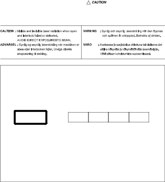
REPRODUCTION AND POSITION OF LABELS
WARNING LABEL
CAUTION : Visible and Invisible laser radiation when open and interlock failed or defeated. AVOID DIRECT EXPOSURE TO BEAM. (e)
ADVARSEL : Synlig og usynlig laserstråling når maskinen er åben eller interlocken fejeler. Undgå direkte eksponering til stråling. (d)
VARNING : Synlig och osynling laserstrålning när den öppnas och spärren är urkopplad. Betrakta ej strålen. (s)
VARO : Avattaessa ja suojalukitus ohitettuna tai viallisena olet alttiina näkyvälle ja näkymättömälle lasersäteilylle. Vältä säteen kohdistumista suoraan itseesi. (f)
(No.MA248)1-9
SECTION 2
SPECIFIC SERVICE INSTRUCTIONS
This service manual does not describe SPECIFIC SERVICE INSTRUCTIONS.
1-10 (No.MA248)
![]()
|
SECTION 3 |
|
|
DISASSEMBLY |
|
|
3.1 Main body section |
|
|
3.1.1 Removing the front panel assembly |
|
|
(See Fig.1) |
|
|
Push the detach button in the lower left part of the front panel as- |
|
|
sembly and remove the front panel assembly. |
Front panel assembly |
Detach button
Fig.1
3.1.2Removing the bottom cover (See Fig.1)
|
Reference: |
|||
|
Remove the front panel assembly as required. |
Bottom cover |
||
|
(1) |
Release the two joints a, two joints b and joint c. |
b |
a |
|
(2) |
Remove the bottom cover from the main body. |
Caution:
Do not damage the main board when releasing the joints using a screwdriver or a similar tool.

 a b
a b 
c
Fig.2
3.1.3Removing the front chassis assembly (See Fig.3)
|
• Remove the front panel assembly and bottom cover. |
|||
|
(1) |
From the both sides of the main body, remove the two |
d |
e |
|
screws A attaching the front chassis assembly. |
|||
|
(2) |
Release the two joints d and two joints e. |
A A
Front chassis assembly
Fig.3
(No.MA248)1-11
3.1.4Removing the side heat sink (See Fig.4)
Reference:
Remove the front panel and front chassis assemblies as required.
From the left side of the main body, remove the two screws B and three screws C attaching the side heat sink.
B
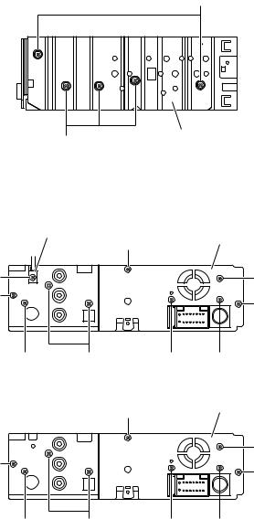
3.1.5Removing the rear bracket (See Fig.5)
•Remove the bottom cover.
(1)From the back side of the main body, remove the screws D, screw E, tow screws F, three screws G and screw H attaching the rear bracket.
(2)Remove the rear bracket.
Reference:
The quantity of screws D differs by each model.
Side heat sink
C
Fig.4
|
Cable holder |
G |
Rear bracket |
|
|
D |
D |
||
|
G |
G |
||
|
E |
F |
D |
H |
|
(For KD-DV4201 and KD-DV4202) |
|||
|
G |
Rear bracket |
||
|
D |
|||
|
G |
G |
||
|
E |
F |
D |
H |
|
Fig.5 |
1-12 (No.MA248)
3.1.6Removing the main board (See Figs.5 and 6)
•Remove the front panel assembly, bottom cover, front chassis assembly and side heat sink.
Reference:
Remove the rear bracket as required.
(1)From the back side of the main body, remove the three screws G attaching the main board. (See Fig.5.)
(2)From the bottom side of the main body, remove the three screws J attaching the main board. (See Fig.6.)
(3)Disconnect the connector CN961 on the main board from the DVD mechanism assembly and take out the main board from the main body. (See Fig.6.)
3.1.7Removing the DVD mechanism assembly (See Fig.7)
•Remove the front panel assembly, bottom cover, front chassis assembly, side heat sink and main board.
(1)From the inside of the top chassis, remove the three screws K attaching the DVD mechanism assembly.
(2)Take out the DVD mechanism assembly from the top chassis.
CN961
J 
 J
J
 J
J
Main board
Fig.6
DVD mechanism assembly
K


 K
K
(No.MA248)1-13

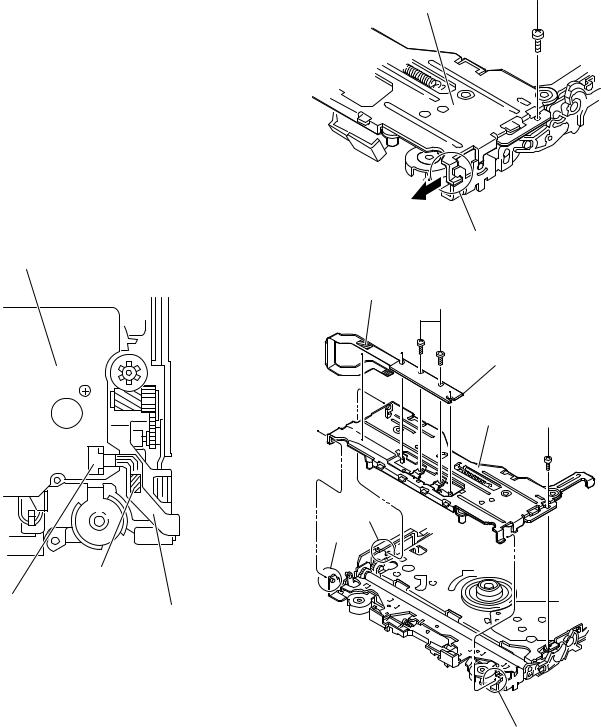
3.1.8 Removing the main sub board (See Figs.8 to 10)
•Remove the front panel assembly, bottom cover, front chassis assembly, side heat sink, main board and DVD mechanism assembly.
(1)From the top side of the DVD mechanism assembly, remove the two screws M attaching the dust cover. (See Fig.8.)
(2)Remove the dust cover from the DVD mechanism assembly. (See Fig.8.)
Reference:
When attaching the dust cover, align the joints f in the holes of the dust cover before attaching the screws M. (See Fig.8.)
(3)Release the lock of the connector CN962 on the main sub board and disconnect the card wire. (See Fig.9.)
(4)Bend the joint g in the direction of the arrow. (See Fig.9.)
(5)Remove the two screws N attaching the main sub board and remove the main sub board from the DVD mechanism assembly. (See Fig.9.)
Reference:
•When attaching the main sub board, align the joints h in the holes of the main sub board before attaching the screws N. (See Fig.9.)
•When the resolution of DVD mechanism assembly is done sequentially, remove the two screws P attaching the support bracket. (See Fig.10.)
•Remove the card wire from the connector CN401 as required. (See Fig.10.)
DVD mechanism assembly
f
M
f
DVD mechanism assembly
CN962
h Lock g
N
h
Main sub board
Fig.9
Support bracket
CN401

3.1.9Removing the switch board (See Figs. 11 to 13)
•Remove the front panel assembly.
(1)From the back side of the front panel assembly, remove the four screws Q attaching the rear cover. (See Fig.11.)
(2)Release the joints j attaching the rear cover to the front panel assembly. (See Fig.12.)
(3)Release the joint k and take out the switch board while lifting the switch board from the front panel assembly little by little. (See Fig.13.)
Reference:
Remove the volume knob from the front side of the front panel assembly at the same time.
Note:
Do not lose the compression springs when removing the switch board. (See Fig.13.)
Q
Q Q
Fig.11
Joints j
Rear cover
|
Joints j |
Joints j |
Joints j |
||||||||||||||
|
Fig.12 |
||||||||||||||||
|
Front panel assembly |
||||||||||||||||
|
Switch board |
Joint k |
Fig.13
(No.MA248)1-15

3.2DVD mechanism assembly
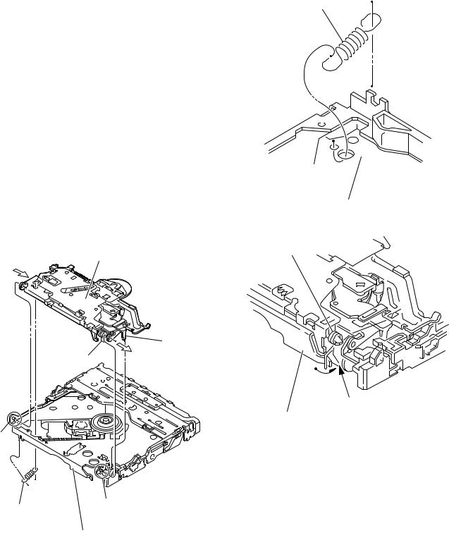
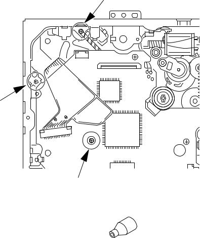
3.2.1Removing the mechanism control board (See Fig.1)
Caution:
Before disconnecting the flexible wire extending from the DVD pickup, solder the short-circuit point on the flexible wire using a grounding soldering iron. If you do not follow this instruction, the DVD pickup may be damaged.
(1)Turn over the body, and solder the short-circuit points on the flexible wire extending from the DVD pickup.
(2)Disconnect the flexible wire from connector CN101 on the mechanism control board.
(3)Disconnect the card wire from connector CN201 on the mechanism control board.
(4)Disconnect the flexible wire from connector CN202 on the mechanism control board.
(5)Unsolder two soldered points a on the mechanism control board and remove the wire extending from the feed motor.
(6)Remove the screw A attaching the lug wire.
(7)Remove the two screws B and screw C attaching the mechanism control board.
Caution:
•As the flexible wire to be connected to CN101, make sure to attach it to the mechanism control board using a double tape.
•After reassembling, unsolder the short-circuit points.
|
Flexible wire |
Lug wire |
||
|
A |
B |
Feed motor |
|
|
Double tape |
|||
a
CN101
C
B
Short-circuit points
CN201 CN202
Mechanism control board
Fig.1
1-16 (No.MA248)

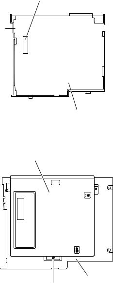
3.2.2Removing the top cover (See Fig.2)
(1)Remove the two screws D attaching the top cover on the back of the body.
(2)Remove the top cover upward.
Reference:
When reassembling, set part b of the top cover under the bending part c of the chassis frame.
3.2.3 Removing the mechanism section (See Fig.2 to 4)
•Remove the top cover.
(1)From the bottom of the body, remove the screw E attaching the lug wire. (See Fig.2.)
(2)Remove the two screws F attaching the right and left stoppers on the front side. (See Fig.2.)
(3)Remove the two floating springs on the bottom of the body. (See Fig.3.)
(4)Move the mechanism section upward and remove from the chassis frame.
The three damper springs come off from the dampers. (See Fig.4.)
Caution:
•When reassembling, reattach the damper spring to the damper respectively and insert the three shafts on the bottom of the mechanism to the dampers.
•Before inserting the shaft to the dampers, apply IPA to the hole of damper.
D
Top cover
D
b
Stopper
Stopper
F
Lug wire
Fig.2
Floating spring
Fig.3
Mechanism section
Damper SP.(F)
(Silver)  Damper SP.(R)
(Red)
Damper (R) (Purple)
Damper (F) (Black)
Damper SP.(F)
(Silver) Damper (F) Chassis frame (Black)
Fig.4
(No.MA248)1-17
3.2.4 Removing the clamper unit (See Fig.5 to 7)
•Remove the top cover and the mechanism section.
(1)Remove the clamper2 spring on the bottom of the mechanism section. (See Figs.5.and 6.)
(2)Release the part d of the clamper spring from the bending part of the chassis base assembly. (See Fig.7.)
(3)Move the clamper unit in the direction of the arrow and turn. Release the two joints e and f, then remove the clamper unit upward. (See Fig.6.)
3.2.5 Reattaching the clamper unit (See Fig.5 to 9)
(1)Attach the clamper spring to the clamper unit. (See Fig.8.)
(2)Move the clamper unit to set the side joints e and f to each boss of the chassis base assembly. Make sure that part g is inserted to the notch of the chassis base assembly. (See Figs.5 and 9.)
(3)Move the part d of the clamper spring to the outside of the bending part of the chassis base assembly. (See Fig.7.)
(4)Attach the clamper2 spring to the chassis base assembly. (See Figs.5 and 6.)
Caution:
When reattaching, temporarily hook the end of the clamper spring as shown in the figure to make the work easy. (See Fig.8.)
Clamper unit
g
Clamper spring
f
e
Clamper2 spring
Chassis base assembly
Fig.5
Clamper2 spring
Chassis base assembly
Fig.6
Clamper spring
d
Chassis base assembly
Fig.7
1-18 (No.MA248)

Clamper unit
Clamper spring
Fig.8
Clamper unit
g
Notch
Fig.9
(No.MA248)1-19
3.2.6 Removing the front unit (See Fig.10 to 12)
•Remove the top cover and the mechanism section.
(1)Disconnect the flexible wire from connector CN202 on the mechanism control board at the bottom of the body. (See Fig.10.)
(2)Remove the screw G attaching the front unit on the top of the body. (See Fig.11.)
(3)Move the front unit toward the front to release joint h, and release two joints i and j on the right side of the chassis base assembly. Then remove the front unit upward. (See Figs.11 and 12.)
(4)Remove the two screws H attaching the switch board. (See Fig.12.)
Reference:
You can remove the switch board only without removing the front unit.
Caution:
When reassembling, attach the flexible wire extending from the switch board using the double tape. (See Figs.10 and 12.)
Mechanism control board
Double tape
CN202
Flexible wire
Fig.10
G
Front unit
h
Fig.11
Double tape
H
Switch board
Front unit G
j
i
h
Fig.12
1-20 (No.MA248)
![]()
3.2.7Removing the loading arm assembly (See Fig.13 , 14)
•Remove the top cover, the mechanism section and the front unit.
(1)From the top of the body, move the loading arm assembly from the front side upward, and release the bosses from the right and left joints k and m of the chassis base assembly.
(2)Release the boss from notch n of the connect arm on the right side of the body, and release the boss from notch p of the slide cam assembly on the left side.
m
Loading arm assembly
k n
Fig.13
Loading arm assembly
Side cam assembly
p
m
k
n
Connect arm
Fig.14
(No.MA248)1-21

|
3.2.8 Removing the rod (L)(R)/roller assembly |
||
|
(See Fig.15 and 16) |
||
|
• Remove the top cover, the mechanism section, the front unit |
||
|
and the loading arm assembly. |
Collar |
Collar |
(1)Release the rod (L) and (R) from the joints q at the bottom of the loading arm assembly (See Fig.15.)
|
(2) Remove the roller assembly from the loading arm assem- |
||
|
bly. (See Fig.16.) |
||
|
(3) Remove the two collars and washer from the roller assem- |
Rod(R) |
Rod(L) |
|
bly. (See Fig.16.) |
||
|
Caution: |
||
|
After attaching the loading arm assembly to the roller assem- |
||
|
bly, attach the rod (L) and (R). Attach the rods to the right and |
||
|
left collars of the roller. (See Fig.15.) |
||
|
When reattaching the rod (L) and (R) to the loading arm as- |
||
|
sembly, engage each joint as shown in Fig.15. As joints q of |
|
the rod (L), let the rod through q before reattaching it. |
q |
|||
|
q |
||||
|
q |
q |
|||
|
Rod(R) |
Rod(L) |
|||
|
q |
q |
|||
|
Loading arm assembly |
||||
|
Fig.15 |
Collar
Washer
Roller assembly
Rod(R)
Collar
Rod(L)
Loading arm assembly
Fig.16
1-22 (No.MA248)
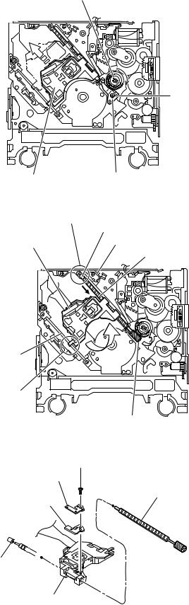
3.2.9Removing the DVD pickup assembly (See Fig.17 to 19)
•Remove the mechanism control board.
(1)From the bottom of the body, turn the feed gear in the direction of the arrow to move the DVD pickup outwards. (See Fig.17.)
(2)Remove the screw J attaching the thrust spring. (See Fig.17.)
(3)Remove the DVD pickup assembly upward on the L.S.gear side and release from sub shaft at joint r. Move the lead screw of the DVD pickup assembly in the direction of the arrow to release from joint s. (See Fig.18.)
Caution:
•When releasing the lead screw at joint s, the L.S.collar comes off at the end of the lead screw. When reassembling, reattach the L.S.collar to the lead screw and engage joint s. (See Fig.18.)
•When reattaching the L.S.collar, reattach it to the point s of the lead screw, and to the rod (M). Make sure that the L.S.collar is set on the rod (M) spring. (See Fig.18.)
(4)Remove the screw K attaching the rack spring/ rack plate on the DVD pickup. (See Fig.19.)
(5)Pull out the lead screw. (See Fig.19.)
Caution:
Perform adjustment after replacing the pickup.
Feed gear
J
|
DVD Pickup assembly |
Thrust spring |
|
|
Fig.17 |
||
|
s |
||
|
L.S.collar |
||
|
DVD Pickup assembly |
Rod(M) |
|
|
Lead screw |
Sub shaft
r
L.S.gear
Fig.18
K
Rack spring
Lead screw
Rack plate
L.S.collar
DVD Pickup
Fig.19
(No.MA248)1-23
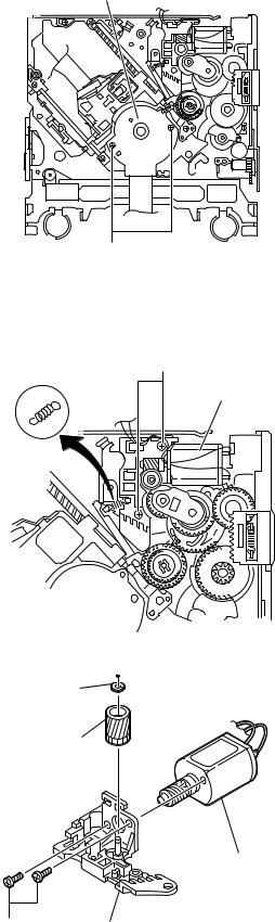
|
3.2.10 Removing the spindle motor |
|
|
(See Fig.20) |
|
|
• Remove the mechanism control board. |
|
|
Remove the two screws L attaching the spindle motor on the |
Spindle motor |
|
bottom of the body. |
|
|
Caution: |
|
|
Perform adjustment when reattaching the spindle motor. |
3.2.11Removing the feed motor assembly (See Fig.21 and 22)
•Remove the mechanism control board.
(1)Remove the feed TRI. spring on the bottom of the body. (See Fig.21.)
(2)Remove the two screws M attaching the feed motor assembly. (See Fig.21.)
(3)Remove the slit washer from the motor H. assembly and
pull out the worm wheel. (See Fig.22.)
Remove the two screws N attaching the feed motor. (See Fig.22.)
M
Feed TRI. spring
Feed motor assembly
Fig.21
Slit washer
Worm wheel
Feed motor

SECTION 4 ADJUSTMENT
4.1Test instruments required for adjustment
(1)Digital oscilloscope (100MHz)
(2)Jitter meter
(3)Digital tester
(4)Electric voltmeter
(5)Tracking offset meter
(6)Test Disc : VT501 or VT502
(7)Extension studs : STDV001-3P
(8)Extension cable : EXTDV002-30P
4.3Connection method
4.2Standard measuring conditions
|
Power supply voltage |
DC14.4V(11 to 16V) |
|
Load impedance |
4Ω (2 Speakers connection) |
|
Line Output |
20KΩ |
Caution:
Be sure to attach the heat sink and rear bracket onto the power amplifier IC and regulator IC respectively, before supply the power. If voltage is applied without attaching these parts, the power amplifier IC and regulator IC will be destroyed by heat.
Connection procedure
(1)Attach the front chassis assembly to the main board.
(2)Connect the front panel assembly to the main board.
(3)Attach the heat sink and rear bracket to the main board.
(4)Attach the extension studs to the DVD mechanism assembly.
(5)Connect the DVD mechanism assembly and the main board with a extension cable.
Extension cable
EXTDV002-30P
Heat sink
Rear bracket
Main board
Extension stud
STDV001-3P
Extension studs
STDV001-3P
(No.MA248)1-25
After replacing the pickup, set the unit in the service mode to display a jitter value on the LCD. Confirm that the jitter value measured with a jitter meter is within 12% of the jitter value displayed on the LCD. If it is within 12%, then adjustment is not necessary. Please note that a jitter value displayed on the LCD is hex data. Refer to the corresponding decimal notation value using the Jitter Conversion Table and confirm it with the measured value.
Fix the screws «a«, «b» and «c» with screw lock paint.
If the measured jitter value is outside the 12% tolerance range, perform the following adjustments.
c
b
a
Jitter value adjustment procedure (Pickup horizontal level adjustment relative to the DVD recording surface)
(For the adjustment tool use a 3 mm wrench and not a screwdriver, this procedure will make the adjustment easier.
3 mm wrench
(1)Set the unit to the service mode and display a jitter value (hex data) on the LCD.
(2)Turn each of the screws a, b and c, by a half-turn per step, in the direction that reduces the jitter value in order to minimize it.
(Do not turn a screw more than a half turn at a time, but adjust the screw in the cycle of same level turn by pair of b+c→ pair of a+b.)
(3) After completing the adjustment, secure the screws with screw lock paint.
1-26 (No.MA248)
 Loading…
You can only view or download manuals with
Sign Up and get 5 for free
Upload your files to the site. You get 1 for each file you add
Get 1 for every time someone downloads your manual
Buy as many as you need