- Manuals
- Brands
- YOKOGAWA Manuals
- Test Equipment
- CA71 HANDY CAL
- User manual
-
Contents
-
Table of Contents
-
Troubleshooting
-
Bookmarks
Quick Links
User’s
Manual
IM CA71-E
Store this manual in an easily accessible
place for quick reference.
Model CA51, CA71
HANDY CAL
(Calibrator)
IM CA71-E
9th Edition: Oct. 2017 (YMI)
Related Manuals for YOKOGAWA CA71 HANDY CAL
Summary of Contents for YOKOGAWA CA71 HANDY CAL
-
Page 1
User’s Model CA51, CA71 Manual HANDY CAL (Calibrator) IM CA71-E Store this manual in an easily accessible place for quick reference. IM CA71-E 9th Edition: Oct. 2017 (YMI) -
Page 2: Introduction
Introduction Thank you for purchasing the CA51/CA71 HANDY CAL Calibrator. This User’s Manual explains the functions of the CA51 and CA71, as well as the operating methods and handling precautions. Before using this product, thoroughly read this manual to understand how to use it properly.
-
Page 3
Introduction ■ Notes ● This manual exclusively describes the CA71, which is more multifunctional than the CA51. The CA51 has no temperature measurement and communication functions. ● The contents of this manual are subject to change without prior notice for reasons of improvements in performance and/or functionality. -
Page 4: Checking Items In The Package
Checking Items in the Package After opening the package, check the product as follows before use. If the delivered product is the wrong model, any item is missing, or there are visible defects, contact the vendor from which you purchased the product. Main Unit Check the model (specifications) codes in the MODEL and SUFFIX fields of the nameplate at the back of the instrument to ensure that…
-
Page 5
Checking Items in the Package Standard Accessories Make sure that the package contains all the accessories listed below and that they are all free from any damage. Carrying case Lead cables Lead cables for (93016) for source measurement (98020) (RD031) Terminal adapter AA-size (LR6) User’s manual… -
Page 6
Checking Items in the Package Product Part Number Remarks AC adapter 94012 For 100 VAC AC adapter 94013 For 120 VAC AC adapter 94016 For 220 to 240 VAC For reference junction compensation RJ sensor B9108WA B9108XA Accessories case Communication cable 91017 (For CA71 only) (RS232) -
Page 7: Precautions For Safe Use Of The Instrument
This manual is an essential part of the product; keep it a safe place for future reference. YOKOGAWA is by no means liable for any damage resulting from use of the instrument in contradiction to these cautionary notes.
-
Page 8
Precautions for Safe Use of the Instrument NOTE Draws attention to information essential for understanding the operation and features. Provides additional information to complement the present topic. Damage to the instrument or personal injury or even loss of life may result from electrical shock or other factors. To avoid this, follow the precautions below. -
Page 9
For high-voltage measurement, always use the lead cable for measurement. • Do Not Remove the Casing or Disassemble Only Yokogawa service personnel are authorized to remove the casing or disassemble or modify the instrument. Do not attempt to repair the instrument yourself, as doing so is extremely dangerous. -
Page 10
• To prevent the possibility electrical shock or fire, be sure to use the AC adapter and the power cord supplied by YOKOGAWA. Additionally, do not use the AC adapter and the power cord supplied with this instrument with another instrument. -
Page 11: Table Of Contents
Contents Introduction ……..i Checking Items in the Package .
-
Page 12
Contents 5. Measurement ……..5-1 Connecting Cables to Terminals ….. . . 5-2 Measuring 300 V AC-range Voltage, DC Voltage, AC Voltage or DC Current . -
Page 13
Contents 8. Communication Function — CA71 only — ….8-1 Cables Connection and Interface Specifications ..8-1 Setting the Mode. -
Page 14: Functions
1. Functions ■ Block Diagram IM CA71-E…
-
Page 15
1. Functions ■ Main Functions • Source The calibrator sources a voltage, current, resistance, thermocouple (TC), RTD, frequency or pulse signal at a preset level. Function Description DC voltage Sources a DC voltage signal in the 100 mV, 1 V, 10 V or 30 V range. -
Page 16
1. Functions • Measurement Independent of the source function, the calibrator measures DC voltage, AC voltage, DC current and resistance signals, a temperature signal based on a thermocouple (TC) or RTD, as well as frequency and the number of pulses. Function Description DC voltage… -
Page 17
1. Functions • Power Supply The calibrator operates on AA-size (LR6) alkaline batteries or the optional AC adapter. IM CA71-E… -
Page 18: Names And Functions Of Parts
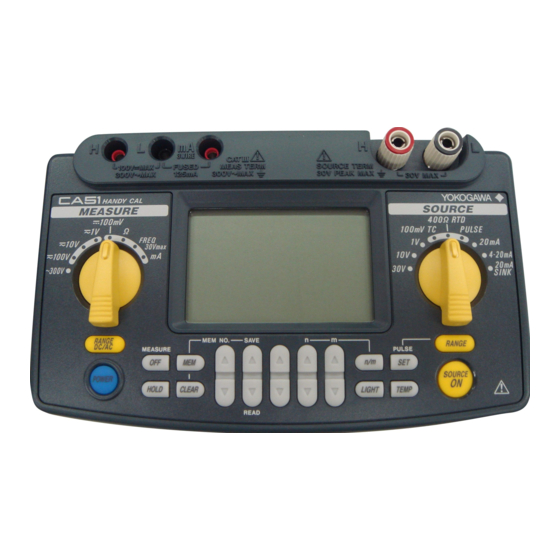
2. Names and Functions of Parts MEASURE SOURCE IM CA71-E…
-
Page 19
2. Names and Functions of Parts ■ Front Panel 1) POWER Key Turns on/off the power supply. 2) LIGHT Key Turns on/off the backlight of the LCD. MEASURE Mode – Functions for Measurement 3) DC Voltage, AC Voltage, Resistance and Pulse Input Terminals Serve as H (positive) and L (negative) input terminals when you measure DC voltage, AC voltage, resistance, and pulse signals. -
Page 20
2. Names and Functions of Parts MEASURE OFF Key Turns on/off the MEASURE mode. Turning off the mode causes the measured value shown on the LCD to disappear. If the MEASURE mode is not in use and therefore turned off, the power to the measurement circuit within the calibrator is also turned off.
 -
Page 21
2. Names and Functions of Parts 16) TEMP Key Allows you to monitor temperature by selecting from the room temperature (°C), reference junction temperature (°C), thermocouple (mV) and RTD (Ω) options. 17) n/m Key Turns on/off the divided output function (n/m). Output Setting Keys Set the output value of a source function. -
Page 22
2. Names and Functions of Parts ■ Side and Rear Panels 20) FUSE A holder for housing a fuse that protects the input during DC current measurement. 21) R.J.INPUT A connector to which the external reference junction compensation sensor is connected. 22) AC Adapter Connection Jack 23) Battery Holder Opening the cover reveals the battery holder and DIP switch. -
Page 23
2. Names and Functions of Parts g) MEM NO. indicator Shows a memory number when the memory function is selected. h) AUTO STEP indicator Comes on when the auto step function is selected. Divided output function (n/m) indicator Comes on when the divided output function (n/m) is selected. The most significant two digits “18”… -
Page 24: Before Starting Source/Measurement
3. Before Starting Source/Measurement ■ Operating Precautions Precautions for Safe Use of the Instrument ● When using the instrument for the first time, be sure to read the instructions given on pages v to viii of the section, “Precautions for Safe Use of the Instrument.”…
-
Page 25
3. Before Starting Source/Measurement ● Before cleaning the instrument’s case or operation panel disconnect the power cord plug from the wall outlet if you are using an AC adapter. Use a soft, clean cloth soaked in water and tightly squeezed to gently wipe the outer surfaces of the instrument. -
Page 26
3. Before Starting Source/Measurement NOTE • Use the instrument under the following environmental conditions if precise source or measurement is your requirement: Ambient temperature range: 23±5°C; ambient humidity range: 20 to 80% RH (non-condensing) When using the instrument within a temperature range of 0 to 18°C or 28 to 50°C, add a value based on the temperature coefficient shown in Chapter 12, “Specifications (page 12-1),”… -
Page 27
3. Before Starting Source/Measurement Step 1: Remove the lead cables and AC adapter and turn off the calibrator before you begin installing batteries. Step 2: Remove the battery holder cover by sliding it in the direction indicated by → OPEN. Step 3: Install four AA-size (LR6) alkaline batteries in the battery holder with their positive and negative electrodes positioned correctly as indicated on the holder. -
Page 28
• To prevent the possibility electrical shock or fire, be sure to use the AC adapter and the power cord supplied by YOKOGAWA. Additionally, do not use the AC adapter and the power cord supplied with this instrument with another instrument. -
Page 29
3. Before Starting Source/Measurement ■ Turning On/Off the Power CAUTION To verify the instrument’s functionality, check that the measured value is updated after turning on the power. If the measured value is not updated, the reading will be incorrect and may lead to possible electrical shock or personal injury. -
Page 30
3. Before Starting Source/Measurement Turning On/Off MEASURE Mode Pressing the key after power-on turns off the MEASURE mode. • If the MEASURE mode is not needed and therefore turned off, power to the measurement circuit is also turned off within the calibrator. -
Page 31
3. Before Starting Source/Measurement ■ Operating Environment Operating Environment Ambient Temperature and Humidity Use the CA51/71 in the following environment: • Ambient temperature: 0 to 50°C • Ambient humidity: 20 to 80 % RH (no condensation) • Location: indoors • Operating altitude: 2000 m max. above sea level. ■… -
Page 32
3. Before Starting Source/Measurement Pollution Degree The pollution degree of the CA51 or CA71 in the operating environment is 2. Pollution Degree applies to the degree of adhesion of a solid, liquid, or gas which deteriorates withstand voltage or surface resistivity. Pollution Degree 2 applies to normal indoor atmospheres. -
Page 33: Source
4. Source From the calibrator, you can source a DC voltage, DC current, SINK current, resistance, thermocouple, RTD, frequency or pulse signal. WARNING • To avoid electrical shock, do not apply any voltage above 30 V to the output terminals. Always use the calibrator in locations with a voltage to ground below 30 V.
-
Page 34: Connecting Cables To Terminals
4.1 Connecting Cables to Terminals 4.1 Connecting Cables to Terminals CAUTION Tighten the output terminal knob by hand. Do not use a tool or the like. Tightening the knob using a tool or the like maydamage the terminal, resulting in the disability of normal generation. Before storing the instrument in the carrying case, tighten the output terminal knob.
-
Page 35: Sourcing Dc Voltage, Dc Current Or Sink Current Signal
4.2 Sourcing DC Voltage, DC Current or SINK Current Signal 4.2 Sourcing DC Voltage, DC Current or SINK Current Signal 4.2.1 Sourcing DC Voltage or DC Current Signal Step 1: Using the Function selector switch, select the desired source function from Step 2: The LCD shows the default value and unit of the source function.
-
Page 36: Ma Function
4.2 Sourcing DC Voltage, DC Current or SINK Current Signal If either of the following cases applies, the protection circuit works to turn off the output. • The output terminals or the lead cables for source connected to the output terminals are short-circuited or an excessive load current has flowed through the cables when a voltage is being output.
-
Page 37: Ma Sink Function
4.2 Sourcing DC Voltage, DC Current or SINK Current Signal 4.2.3 20 mA SINK Function The 20 mA SINK function can draw a preset amount of current from an external voltage source to the H terminal. Thus, you can use the calibrator in a loop test, for example, as a simulator for two-wire transmitters.
-
Page 38: Using As 24-V Loop Power Supply
4.2 Sourcing DC Voltage, DC Current or SINK Current Signal 4.2.4 Using As 24-V Loop Power Supply A maximum load current of 22 mA can be drawn from the calibrator by selecting the 30 V range and setting the sourced voltage to 24 V. With this function, you can use the calibrator as a loop power supply in place of the distributor in a two-wire loop, as shown in the following figure.
-
Page 39: Sourcing Resistance Or Rtd Signal
4.3 Sourcing Resistance or RTD Signal 4.3 Sourcing Resistance or RTD Signal • The calibrator sources a resistance signal by 1) receiving the resistance-measuring current I supplied from the device being calibrated, such as a resistance meter or RTD thermometer, and 2) delivering the voltage V = R ×…
-
Page 40
4.3 Sourcing Resistance or RTD Signal ■ Output Method Based on Three-wire Connection Attach another lead cable to the L output terminal, as shown in the following figure. The output is provided through the three wires, H, L and L’. Connect these three wires to the device being calibrated. Three-wire measuring equipment SOURCE CA71… -
Page 41: Sourcing Thermocouple (Tc) Signals
4.4 Sourcing Thermocouple (TC) Signals 4.4 Sourcing Thermocouple (TC) Signals 4.4.1 When RJ Sensor Is Used (Making Use of Reference Junction Compensation) To calibrate a device with built-in reference junction temperature compensation by sourcing a thermoelectromotive force with the calibrator without using any external 0°C reference junction compensation means, use the optional RJ sensor (P/N: B9108WA).
-
Page 42
4.4 Sourcing Thermocouple (TC) Signals Step 5: Set the output value digit by digit using each pair of output setting keys. Each pair of keys corresponds to each digit of the LCD reading. Each press of the key increases or decreases the digit. -
Page 43
4.4 Sourcing Thermocouple (TC) Signals The calibrator has a built-in RJ sensor (INT RJ) that compensates for the measured reference junction temperature. You can generate thermoelectromotive force that is based on the measured temperature from the calibrator’s output terminal and roughly check the measurement (reading) on the thermometer under verification. -
Page 44: When No Rj Sensor Is Used
4.4 Sourcing Thermocouple (TC) Signals 4.4.2 When No RJ Sensor Is Used From the output terminals, the calibrator sources a thermoelectromotive force corresponding to the preset temperature of a selected thermocouple. The thermoelectromotive force is sourced with reference to 0°C. Step 1: Using the function selector switch, select Step 2: Using the key, select the type of thermocouple.
-
Page 45: Sourcing Pulse Signals
4.5 Sourcing Pulse Signals 4.5 Sourcing Pulse Signals You can source a preset type of continuous pulse train, a pulse signal with a preset frequency, or the preset number of pulses. Amplitude setpoint Continued Frequency-based signal Source of number of pulses n = Preset number OFF ON of pulses…
-
Page 46
4.5 Sourcing Pulse Signals Step 5: Set the output value digit by digit using each pair of output setting keys. Each pair of keys corresponds to each digit of the LCD reading. Each press of the key increases or decreases the digit. Increasing the digit from 9 or decreasing it from 0 causes the digit to overflow or underflow, allowing you to set the output value without interruption. -
Page 47: Sourcing The Preset Number Of Pulses
4.5 Sourcing Pulse Signals 4.5.2 Sourcing the Preset Number of Pulses (Pulse Cycle) Step 1: Using the function selector switch, select The LCD shows the default frequency Step 2: Using the key, set the frequency range. Each press of key cycles through the 500.0 Hz, 1000 Hz and 10 kHz options.
-
Page 48
4.5 Sourcing Pulse Signals Step 7: Set the number of pulses value digit by digit using each pair output setting keys. Each press of the key increases or decreases the digit. Increasing the digit from 9 or decreasing it from 0 causes the digit to overflow or underflow, allowing you to set the output value without interruption. -
Page 49: Using The Contact Output
4.5 Sourcing Pulse Signals 4.5.3 Using the Contact Output You can turn on or off the output terminals. This setting is possible for both the mode of sourcing a continuous pulse train and the mode of sourcing a given number of pulses. An FET is used as the contact switching device.
-
Page 50
4.5 Sourcing Pulse Signals Step 7: Pressing the key causes the indicator on the LCD to change from . The output terminals turn on and off at the preset frequency. Step 8: To turn off the output, press the key once again. appears on the LCD and the output terminals are open-circuited. -
Page 51: Divided Output Function (N/M)
4.6 Divided Output Function (n/m) 4.6 Divided Output Function (n/m) The divided output function (n/m) outputs a value n/m times the setpoint of a voltage, current, resistance, thermocouple or RTD signal. Thus, the output value is defined as: Output value = Main setpoint × (n/m) Keys and labels related to divided output function (n/m) For details on how to set the sourced signal level of each range, see Sections 4.2, “Sourcing DC Voltage, DC Current or SINK…
-
Page 52: Sweep Function
4.7 Sweep Function Step 6: Pressing the key causes the indicator on the LCD to change from The calibrator sources a (main setpoint) × (n/m) signal between the output terminals for each range selected. Step 7: To turn off the output, press the key once again.
-
Page 53: Temperature Monitor Function
4.9 Temperature Monitor Function 4.9 Temperature Monitor Function Using the key, you can show the monitored temperature on the LCD, as described below. ■ When the Voltage, Current, Resistance or Pulse (Continuous Pulse Train or Number of Pulses) Range Is Selected The reading of a sourced signal remains changed to the temperature detected by the built-in temperature sensor of the calibrator as long as the…
-
Page 54: Measurement
5. Measurement WARNING ● In an application where the calibrator is used together with the supplied lead cables for measurement, the maximum allowable voltage from the input terminals to ground is 300 V. To avoid electrical shock, do NOT use the calibrator at any voltage exceeding this maximum.
-
Page 55: Connecting Cables To Terminals
5.1 Connecting Cables to Terminals 5.1 Connecting Cables to Terminals ■ For DC voltage, AC voltage, resistance, frequency or pulse signal Step 1: Connect the red lead cable for measurement (P/N: RD031) to the H input terminal and the black lead cable to the L input terminal.
-
Page 56
5.1 Connecting Cables to Terminals CAUTION • Before connecting the calibrator to the device under test, cut off the power to the device. • Do not apply any voltage or current exceeding the allowable voltage (300 V) or current (120 mA). Otherwise, there will be a danger of not only damage to the instrument but also personal injury due to electrical shock. -
Page 57: Measuring 300 V Ac-Range Voltage, Dc Voltage, Ac Voltage Or Dc Current
5.2 Measuring 300 V AC-range Voltage, DC Voltage, AC Voltage or DC Current Terminal adapter (99021) WARNING The allowable voltage to ground when the included terminal adapter is attached to the input terminals is 30 Vpeak maximum. Lead cables for measurement (RD031) 5.2 Measuring 300 V AC-range Voltage, DC Voltage, AC Voltage or DC Current…
-
Page 58: Measuring Dc Or Ac Voltage
5.2 Measuring 300 V AC-range Voltage, DC Voltage, AC Voltage or DC Current 5.2.2 Measuring DC or AC Voltage Step 1: Using the function selector switch, select the measurement function you want to use from Step 2: Using the key, select either DC or AC. The DC or AC symbol appears on the LCD.
-
Page 59: Measuring Resistance Or Rtd (Ca71 Only) Signal
5.3 Measuring Resistance or RTD (CA71 only) Signal 5.3 Measuring Resistance or RTD (CA71 only) Signal Step 1: Using the function selector switch, select Step 2: Using the key, select the range. Pressing the key cycles through the 400 Ω, Pt100 and JPt100 options.
-
Page 60: Measuring Temperature With Thermocouple (Tc) — Ca71 Only
5.4 Measuring Temperature with Thermocouple (TC) — CA71 only — 5.4 Measuring Temperature with Thermocouple (TC) — CA71 only — NOTE Use the terminal adapter in locations where any voltage higher than 30 V will never be imposed on the measuring circuit. Step 1: Using the function selector switch, select Step 2: Using the key, select the type of thermocouple.
-
Page 61: Measuring Frequency Or Pulses
5.5 Measuring Frequency or Pulses 5.5 Measuring Frequency or Pulses 5.5.1 Operating the Calibrator for Frequency Measurement Step 1: Using the function selector switch, select Step 2: Using the key, select 100 Hz, 1000 Hz or 10 kHz. Pressing the key cycles through the 100 Hz, 1000 Hz, 10 kHz, CPM and CPH options.
-
Page 62
5.5 Measuring Frequency or Pulses NOTE • If you press the key after the completion of counting while the indicator is lit, the calibrator restarts counting from 0. • If you press the key halfway before the selected time (one minute or one hour) expires, the calibrator stops counting at that moment. -
Page 63: Memory Functions
6. Memory Functions The built-in memory has the following four functions. With a pair of sourced and measured signal values in a set, the calibrator can handle a maximum of 50 sets of data (hereinafter simply referred to as data) by means of its built-in memory.
-
Page 64: Saving Data Into Memory
6.1 Saving Data into Memory 6.1 Saving Data into Memory 6.1.1 Saving Data in the Order of Memory Numbers Step 1: Press the key. The indicator on the LCD turns on. At this point, the indicator shows a memory number immediately following the one most recently used to save data.
-
Page 65
6.1 Saving Data into Memory ndicates the memory number with which data is already saved. All these are not yet used. (Case I) 01 02 03 04 05 06 07 08 09 10 11 12 13 14 15 16 49 50 Indication when selected MEM No.07 These are not yet used. -
Page 66: Saving Data By Selecting Desired Memory Number
6.1 Saving Data into Memory 6.1.2 Saving Data by Selecting Desired Memory Number Step 1: Press the key. The indicator on the LCD turns on. Step 2: Using the pair of key, select the desired memory number (address). Step 3: Pressing the key saves the sourced and measured (currently on-display) signal values at that moment into the area with the selected memory number (address).
-
Page 67: Reading Data From Memory
6.1 Saving Data into Memory NOTE To stop overwriting the data, press the key one time. This cancels saving data, reverting to the original state of being able to save/read data to/from memory. To cancel the memory mode (saving/reading), press the key one more time.
-
Page 68: Clearing Data In Memory
6.3 Clearing Data in Memory 6.3 Clearing Data in Memory 6.3.1 Clearing Data by Selecting Desired Memory Number Step 1: Press the key once. The indicator on the LCD turns on. Step 2: Using the pair of key, select the memory number whose data you want to clear.
-
Page 69: Clearing All In-Memory Data Globally
6.3 Clearing Data in Memory 6.3.2 Clearing All In-Memory Data Globally Step 1: Press the key once. indicator on the LCD turns on. Step 2: Hold down the key for at least five seconds. The LCD shows the alarm indication. Step 3: Pressing the key once again clears all of the data in memory.
-
Page 70: Functions Provided By Dip Switch
7. Functions Provided by DIP Switch By configuring the DIP switch, you can use the functions listed below. The DIP switch can be found by removing the battery holder cover at the back of the calibrator. CAUTION Turn off the calibrator before you change the DIP switch configuration. Factory Setting DIP Swich Description…
-
Page 71: Sweep Function
7.1 Sweep Function 7.1 Sweep Function The sweep function lets you linearly change the calibrator output as shown in the following figure. The SOURCE ON The SOURCE OFF indication blinks. indication blinks. Setpoint Sourced-value reading Actual output SOURCE ON Press Press key operation (ON)
-
Page 72
7.1 Sweep Function Step 6: Using the pair of keys, set the upper limit of the signal to be output. The lower limit is set to a value predetermined depending on the selected range. Step 7: Pressing the key initiates sweeping and the output value begins to increase. -
Page 73: Auto Step Function
7.2 Auto Step Function 7.2 Auto Step Function The auto step function automatically changes the variable n of the n/m output in a step-by-step manner, as shown in the following figure, when the divided output function (n/m) is selected. Sourced-value reading Setpoint Actual output Stepping time setpoint…
-
Page 74
7.2 Auto Step Function Step 8: Using each pair of keys, set the value of the denominator m and the starting setpoint of the enumerator n. (See Section 4.6, «Divided Output Function (n/m), for further details.) The starting setpoint is the minimum of the variable n for auto step operation. -
Page 75: Selecting The Int Rj Function
7.3 Selecting the INT RJ Function 7.3 Selecting the INT RJ Function The INT RJ function compensates for the measured reference junction temperature by using the calibrator’s built-in RJ sensor. The function enables you to generate thermoelectromotive force that is based on the measured temperature from the calibrator’s output terminal.
-
Page 76: Selecting The Ipts-68 Function
7.4 Selecting the IPTS-68 Function 7.4 Selecting the IPTS-68 Function By placing switch 4 (IPTS-68 switch) in the ON (right-side) position, you can select the IPTS-68 temperature scale when you choose the type-K, E, J, T, N, R, S or B thermocouple or the Pt100 RTD. Placing the switch in the OFF position results in the selection of the ITS-90 temperature scale.
-
Page 77: Communication Function — Ca71 Only
8. Communication Function — CA71 only — You can configure the calibrator from a personal computer just as you do with the calibrator’s panel keys (except for turning on/off the power, configuring the function selector switch, and setting the communication function). You can also verify the setpoint, measured value and status of the calibrator.
-
Page 78: Setting The Mode
8.2 Setting the Mode 8.2 Setting the Mode Step 1: Press the key while simultaneously holding down the key. The LCD shows in its upper section and either in its lower section. Step 2: Using the pair of keys, select Step 3: Press the key to confirm your mode selection.
-
Page 79: Data Format
8.4 Data Format When communication is in progress, the indicator blinks, telling you data is being output. Care must be taken therefore, since the hold function of the MEASURE mode is disabled if you select 8.4 Data Format Data is output from the calibrator in the following format. Source: Function Range…
-
Page 80: Commands
8.6 Commands 8.6 Commands Command Description Turns the back lighting on and off/queries the current setting. Moves down the “m-th” digit of the sourced setpoint by one digit. Moves up the “m-th” digit of the sourced setpoint by one digit. Enables/Disables the output data header/queries the current setting.
-
Page 81: Detailed Description Of Commands
8.7 Detailed Description of Commands 8.7 Detailed Description of Commands Turns the back lighting on and off /queries the When normal current setting. condition Syntax for setting BLm<delimiter> Syntax for query BL?<delimiter> ⇒ Response: BLm<delimiter> Description of parameter m=0: Off m=1: On Moves down the “m-th”…
-
Page 82
8.7 Detailed Description of Commands When normal Queries the measurement function. condition Syntax for query MF? <delimiter> ⇒ Response: MFm<delimiter> Description of parameter m: Measurement function m=0: 300V AC m=1: 100V m=2: 10V m=3: 1V m=4: 100mV m=5: Resistance m=6: Frequency m=7: Current When normal On/Off of measurement/queries the current setting. -
Page 83
8.7 Detailed Description of Commands When normal Outputs measured value. condition/adjustment Syntax for setting OD<delimiter> ⇒ Response: ODabcde<delimiter> Description of parameter <Header section> (Output only when the header is set to “enabled”.) a= V: Voltage A: Current O: Resistance T: Temperature F: Frequency b= DC: Direct current AC: Alternating current… -
Page 84
8.7 Detailed Description of Commands When normal Sets sourced setpoint/queries the current setting. condition Syntax for setting SDm<delimiter> Syntax for query SD?<delimiter> ⇒ Response: SDm<delimiter> Description of parameter m: Sourced setpoint (7 digits) ex. +1.0000 When normal Queries the source function. condition Syntax for query SF? <delimiter>… -
Page 85
8.7 Detailed Description of Commands Switches between the normal and adjustment When normal modes/queries the current setting. condition/adjustment Syntax for setting SYm<delimiter> Syntax for query SY ?<delimiter> ⇒ Response: SYm<delimiter> Description of parameter m: Mode m=0: Normal mode m=1: Adjustment mode Sets the sourced setpoint/queries the current When adjustment setting. -
Page 86
8.7 Detailed Description of Commands Queries the measurement function. When adjustment Syntax for query CMF?<delimiter> ⇒ Response: CMFm<delimiter> Description of parameter m: Measurement function m=0: AC 300V m=1: 100V m=2: 10V m=3: 1V m=4: 100mV m=5: Resistance m=6: Frequency m=7: Current Queries the source function. -
Page 87
8.7 Detailed Description of Commands Sets divided output (n/m) mode/queries the current When normal setting. condition Syntax for setting MNm<delimiter> Syntax for query MN?<delimiter> ⇒ Response: MNm<delimiter> Description of parameter m: n/m mode m=0: Off m=1: On Sets n/m values in divided output (n/m) mode/ When normal condition queries the current setting. -
Page 88: Troubleshooting
9. Troubleshooting ■ Failure Checklist Troubleshoot the cause of any problem using the following checklist. Should the problem persist even if you have taken the given corrective action or if you notice any problem not listed herein, contact the vender from which you purchased the instrument. Problem Corrective Action The LCD shows nothing even…
-
Page 89: Method Of Calibrator Adjustment
10. Method of Calibrator Adjustment To maintain the calibrator at high accuracy levels, it is advisable that the calibrator be calibrated once a year. If the calibrator needs to be readjusted, follow the procedure described below. For a service of calibration or readjustment, contact the vender from which you purchased the instrument.
-
Page 90
10.1 Calibration Standard Selection and Environmental Requirements Measurement Functions Function Range Standard’s Measuring to Be to Be Accuracy Remarks Name Range Adjusted Adjusted ±(0.0025%+1 μV) 100 mV 100 mV ±(0.0025%+20 μV) 10 V 10 V ±(0.0025%+0.2 mV) High-precision 30 V 30 V ±(0.005%+2 mV) calibrator… -
Page 91: Adjusting Source Functions
10.2 Adjusting Source Functions 10.2 Adjusting Source Functions Table 10.1 Adjustment Points of Source Functions Adjustment Points * Range Remarks CAL 0 CAL FS 100 mV 100 mV 10 V 10 V 30 V 30 V See the figure below. 20 mA 20 mA See the figure below.
-
Page 92
10.2 Adjusting source Functions Step 3: From Table 10.1, select the range you want to adjust. Then, point the function selector switch to that range and press the key. Step 4: Conform that the symbol is appearing on the LCD. Step 5: Read the calibrator output on the calibration standard. -
Page 93
10.2 Adjusting source Functions NOTE • Saving to memory results in the overwriting of existing data. Be extremely careful since the previous adjustment setpoints are cleared. • Both the thermocouple and RTD ranges are adjusted at the same time when the 100 mV and 400 Ω ranges are adjusted. With the CAL mode selected, press the key while holding down key. -
Page 94: Adjusting Measurement Functions
10.3 Adjusting Measurement Functions 10.3 Adjusting Measurement Functions Table 10.2 Adjustment Setpoints of Measurement Functions Adjustment Points * Range Remarks CAL 0 CAL FS DC 100 mV 100 mV DC 1 V DC 10 V 10 V DC 100 V 100 V DC 20 mA 20 mA…
-
Page 95
10.3 Adjusting Measurement Functions CAL-mode Operation Keys and Display Indications Step 4: Apply the CAL FS adjustment setpoint input of each range in Table 10.2 from the calibration standard to the H and L input terminals of the calibrator. Step 5: Pressing the key confirms the CAL FS adjustment setpoint. -
Page 96: Adjusting Ac Voltage And Resistance
10.3 Adjusting Measurement Functions 10.3.2 Adjusting AC Voltage and Resistance (400 Ω) Ranges Step 1: Press the key while simultaneously holding down the key. The LCD shows Step 2: Pressing the highest-order key causes the LCD to show Step 3: Pressing the key enters the measurement CAL mode.
-
Page 97: Notes On The Adjustment Of
10.3 Adjusting Measurement Functions Step 9: The 0 and FS symbols stop blinking, causing the calibrator to return to the state discussed in step 4. Using the measurement range setting rotary switch, select the next range. By repeating steps 4 to 8, you can adjust the measurement function assigned to that range.
-
Page 98: Using Accessories
11. Using Accessories When attaching accessories to the calibrator, refer to the following figure. When connecting the included terminal adapter, make sure the adapter is positioned in the correct orientation. Terminal adapter (99021) WARNING The allowable voltage to ground when the included terminal adapter is attached to the input terminals is Black Black…
-
Page 99: Specifications
12. Specifications (1) Signal sourcing unit range and accuracy (for both CA51 and CA71) ±(% of setting + μV, mV, mA, Ω or °C) Accuracy Parameter Reference Range Remarks Resolution (23±5°C per year) 100 mV — 10.00 –110.00 mV ±(0.02% + 15 μV) 10 μV 0 –…
-
Page 100
12. Specifications (2) Measurement unit range and accuracy (for both CA51 and CA71) Accuracy: ±(% of reading + µV, mV, µA, Ω or dgt (digit)) Accuracy Resolution Parameter Reference Range Remarks (23±5°C per year) ±(0.025% + 20 µV) 10 µV 100 mV 0 –… -
Page 101
12. Specifications ■ Genelal Specifications Signal sourcing unit Approx. 1 second response time: (time between start of voltage change and when voltage enters accuracy range) Signal sourcing unit Approx. 32 V voltage limiter: Signal sourcing unit Approx. 25 mA current limiter: Output = setting ×… -
Page 102
12. Specifications Operating temperatur and humidity 0 to 50°C, 20 to 80% RH (no condensation) ranges: Storage temperature and humidity -20 to 50°C, 90% RH or less (no condensation) ranges: External dimensions: Approx. 190 (W) × 120 (H) × 55 (D) mm Weight: Approx. -
Page 103
Lead cables for source (98020), Lead cables for measurement (RD031), RS232 Communication cable (91017) and RJ sensor (B9108WA): attach a sleeve clamp ferrite core (YOKOGAWA B9108WC, Morimiya electric Co. MSFC6KEX) toward the main body of the instrument. Environmental standard: EN 50581… -
Page 104
12. Specifications Unit: mm (approx. inches) 54.5 (2.15) 193 (7.61) 51 (2.01) Note: This figure shows the CA71, but there is no difference in exterior from the CA51. 12-6 IM CA71-E… -
Page 105: Sales In Each Coutry Or Region
“Monitoring and Control instruments” product. When disposing products in the EU, contact your local Yokogawa Europe B.V. office. Do not dispose in domestic household waste. 13.2 How to Replace and Dispose the Batteries EU Battery Directive (This directive is valid only in the EU.)
-
Page 106: Authorized Representative In The Eea
13.3 Authorized Representative in the EEA 13.3 Authorized Representative in the EEA Yokogawa Europe B.V. is the Authorized Representative of Yokogawa Test & Measurement Corporation for this Product in the EEA. (EEA: European Economic Area) To contact Yokogawa Europe B.V., see the separate list of worldwide contacts, PIM 113-01Z2.
-
Page 107: For The Pollution Control Of Electronic And Electrical Products Of The People’s Republic Of China
13.4 For the Pollution Control of Electronic and Electrical Products of the People’s Republic of China 13.4 For the Pollution Control of Electronic and Electrical Products of the People’s Republic of China This manual is valid only in China. 产品中有害物质的名称及含量 有害物质…
-
Page 108: Appendix 1 Reference Junction Compensation
Appendix 1 Reference Junction Compensation Standard thermocouple tables give 0°C as the temperature of the reference junction. Normally, the input terminal part (reference junction) of a thermometer (device under calibration) is at room temperature. (This results in an error equivalent to the difference between 0°C and room temperature.) Reference junction compensation means measuring (detecting) the temperature of the reference junction, calculating the temperature…
-
Page 109
A cold junction compensator can be used when, for example, it is not possible to use an RJ sensor. The use of a cold junction compensator enables the reference junction to be 0°C. Cold junction compensator: Yokogawa T-MJ or the equivalent Device under calibration (thermometer)
 MEASURE OFF Key Turns on/off the MEASURE mode. Turning off the mode causes the measured value shown on the LCD to disappear. If the MEASURE mode is not in use and therefore turned off, the power to the measurement circuit within the calibrator is also turned off.
 О файле
Руководство по эксплуатации на «Калибраторы электрических сигналов СА11Е, СА12Е, СА51, СА71, СА150, СА450». Регистрационный № 53468-13
Поделиться
- Manuals
- Brands
- YOKOGAWA Manuals
- Test Equipment
- CA71 HANDY CAL
Manuals and User Guides for YOKOGAWA CA71 HANDY CAL. We have 2 YOKOGAWA CA71 HANDY CAL manuals available for free PDF download: User Manual
Назначение
Калибраторы электрических сигналов СА11Е, СА12Е, СА51, СА71, СА150, СА450 (далее — калибраторы) предназначены для измерения и воспроизведения напряжения постоянного и переменного тока, силы постоянного тока, частоты переменного тока, электрического сопротивления постоянному току (в том числе от термопар и термопреобразователей сопротивления).
Описание
Калибраторы представляют собой портативные электрические приборы с расположенными на передней панели жидкокристаллическим дисплеем с регулируемой подсветкой и клавишами, которые группируются в соответствии с их функциями.
Калибраторы различных моделей отличаются функциональными возможностями, метрологическими и техническими характеристиками. Функциональные возможности калибраторов в зависимости от модели приведены в таблице 1.
Питание калибраторов осуществляется как от батарей, так и от сети переменного тока при использовании специального адаптера. Наличие во всех калибраторах, кроме СА12Е, встроенного источника питания постоянного тока 24 В позволяет использовать калибраторы в качестве источника питания для датчиков.
На рисунке 1 приведён общий вид калибраторов CA11E, CA12E, на рисунке 2 приведена схема пломбирования калибраторов CA11E, CA12E.
Вид сзади (со снятой задней крышкой)
Место нанесения поверительной наклейки
Таблица 1
|
Функция |
СА11Е |
СА12Е |
СА51 |
СА71 |
СА150 |
СА450 |
|
Измерение напряжения постоянного тока |
+ |
+ |
+ |
+ |
+ |
+ |
|
Измерение силы постоянного тока |
+ |
— |
+ |
+ |
+ |
+ |
|
Измерение сопротивления постоянному току |
— |
+ |
+ |
+ |
+ |
+ |
|
Измерение напряжения переменного тока |
— |
— |
+ |
+ |
— |
+ |
|
Измерение частоты |
— |
— |
+ |
+ |
+ |
+ |
|
Воспроизведение напряжения постоянного тока |
+ |
+ |
+ |
+ |
+ |
— |
|
Воспроизведение силы постоянного тока |
+ |
— |
+ |
+ |
+ |
+ |
|
Воспроизведение сопротивления постоянному току |
— |
+ |
+ |
+ |
+ |
— |
|
Воспроизведение частоты |
— |
— |
+ |
+ |
+ |
— |
|
Измерение сигналов термопар |
— |
+ |
— |
+ |
+ |
— |
|
Воспроизведение сигналов термопар |
— |
+ |
+ |
+ |
+ |
— |
|
Измерение сигналов термометров сопротивления |
— |
+ |
— |
+ |
+ |
— |
|
Воспроизведение сигналов термометров сопротивления |
— |
+ |
+ |
+ |
+ |
— |
Калибраторы CA51, CA71, CA150, CA450 состоят из двух рабочих секций (измерение и воспроизведение), работающих независимо друг от друга и гальванически развязанных. Это позволяет использовать калибраторы для одновременного воспроизведения выходного сигнала и измерения входного сигнала. На рисунке 3 приведён общий вид калибраторов CA51, CA71, CA150, 4 — общий вид калибратора CA450, на рисунке 5 -схема пломбирования калибраторов CA51, CA71, CA150, CA450.
Т аблица 2
|
Кали братор |
Наименова ние программ ного обеспечения |
Идентифи кационное наименова ние программ ного обеспечения |
Номер версии (идентификационный номер) программного обеспечения |
Цифровой идентификатор программного обеспечения |
Алгоритм вычисления цифрового идентифи катора |
|
СА11Е, СА12Е |
БПО |
Не используется |
Не ниже 1.00 |
Зависит от версии |
MD5 |
|
СА51, СА71 |
Не ниже 1.17 |
||||
|
СА150 |
Не ниже 1.02 |
||||
|
СА450 |
Не ниже 1.00 |
Программное обеспечение
Для преобразования измеренных аналоговых сигналов в цифровой код и преобразование цифрового кода в аналоговую форму используются алгоритмы, реализованные в базовом программном обеспечении (БПО) и записанные в постоянной памяти калибраторов. Базовое программное обеспечение (БПО) устанавливается в энергонезависимую память на заводе изготовителе во время производственного цикла. Оно недоступно пользователю и не подлежит изменению на протяжении всего времени функционирования изделия, что соответствует уровню защиты «А» в соответствии с МИ 3286-2010.
Метрологические характеристики калибраторов нормированы с учетов влияния на них БПО.
Идентификационные данные метрологически значимого ПО приведены в таблице 2.
Технические характеристики
Основные метрологические и технические характеристики калибраторов указаны в таблицах 3-10, технические — в таблице 11.
В таблицах 3-10:
1) Х — измеренное или установленное значение /100%;
2) Допускаемый температурный коэффициент составляет ± (0,2 До)/ °С для СА51, СА71 и ± (0,1 До)/ °С для остальных моделей, кроме режимов, указанных в примечании к таблице 3;
3) Во всех таблицах допуск на основную погрешность для каждого типа термопары указан без учёта погрешности канала компенсации температуры холодного спая.
4) Характеристики канала компенсации температуры холодного спая термопары:
— диапазон измерений температуры — от минус 10 °С до плюс 50 °С;
— пределы допускаемой абсолютной погрешности канала компенсации температуры холодного спая составляют:
± 0,5 °С в диапазоне температуры от 18 °С до 28 °С (в диапазоне температур от
0 °С до 40 °С для ТХК (L));
± 1 °С в диапазоне от минус 10 до плюс 18 °С и в диапазоне от 28 до 50 °С.
Таблица 3 — Основные метрологические характеристики калибраторов СА11Е
|
Функция |
Диапазоны сигналов |
Разрешающая способность |
Пределы допускаемой основной погрешности, До |
|
|
Воспроизведение |
(0 • |
.. 30) В |
10 мВ |
± (0,05 % Х + 20 мВ) |
|
напряжения |
(0 • |
.. 11) В |
1 мВ |
± (0,05 % Х + 2 мВ) |
|
постоянного тока |
(1 |
.. 5) В |
шаг 1 В |
|
|
(0 . |
• 1,1) В |
0,1 мВ |
± (0,05 % Х + 0,2 мВ) |
|
|
(0 … |
110) мВ |
0,01 мВ |
± (0,05 % Х + 50 мкВ) |
|
|
Воспроизведение |
(0 .. |
24) мА |
1 мкА |
± (0,05 % Х + 4 мкА) |
|
силы постоянного |
(4 •• |
20) мА |
шаг 4 мА |
|
|
тока |
(0,1 . |
.. 24) мА |
1 мкА |
± (0,1 % Х + 4 мкА) |
|
Измерение |
(- 30 |
.. + 30) В |
10 мВ |
± (0,05 % Х + 20 мВ) |
|
напряжения |
(- 11 |
.. + 11) В |
1 мВ |
± (0,05 % Х + 2 мВ) |
|
постоянного тока |
(- 1,1 |
…+ 1,1) В |
0,1 мВ |
± (0,05 % Х + 0,2 мВ) |
|
(- 110 . |
. + 110) мВ |
0,01 мВ |
± (0,05 % Х + 0,07 мВ) |
|
|
Измерение силы постоянного тока |
(- 24 .. |
. + 24) мА |
1 мкА |
± (0,05 % Х + 4 мкА) |
Примечание к таблице 3: допускаемый температурный коэффициент для диапазона воспроизведения (0 …110) мВ и измерения (- 110 … + 110) мВ находится в пределах ± (0,005 % Х + 10 мкВ)/ °С.
|
Тип вход ного сигнала |
Диапазоны |
Разре шающая способ ность |
Пределы допускаемой основной погрешности |
|
|
в режиме воспроизведений |
в режиме измерений |
|||
|
ТХА (К) |
(- 200…+ 1372) °С |
0,1 °С |
± (0,05 % Х + 1,0 °С) при температуре > — 100 °С ± (0,05 % Х + 2,0 °С) при температуре < — 100 °С |
± (0,07 % Х + 1,5 °С) при температуре > — 100°С ± (0,07 % Х + 2,0 °С) при температуре <-100 °С |
|
ТХКн (E) |
(- 200…+ 1000) °С |
|||
|
ТЖК (J) |
(- 200…+ 1200) °С |
|||
|
ТМК (T) |
(- 200… + 400) °С |
|||
|
ТНН (N) |
(- 200…+ 1300) °С |
|||
|
ТПП (R), (S) |
С ° 0) О (0 |
1°С |
± (0,05 % Х + 3 °С) |
± (0,07 % Х + 3 °С) |
|
С ° 00 6 7 0 0 |
± (0,05 % Х + 2 °С) |
± (0,07 % Х + 2 °С) |
||
|
ТПР (В) |
(600 … 1000)°С |
1°С |
± (0,05 % Х + 4 °С) |
± (0,07 % Х + 4 °С) |
|
(1000 … 1800)°С |
± (0,05 % Х + 3 °С) |
± (0,07 % Х + 3 °С) |
||
|
L |
(- 200 … + 900) °С |
0,1 °С |
± (0,05 % Х + 0,5 °С) при температуре > 0 °С ± (0,05 % Х + 1,0 °С) при температуре < 0 °С |
± (0,07 % Х + 1,5 °С) при температуре > 0 °С ± (0,07 % Х + 2,0 °С) при температуре < 0 °С |
|
U |
(- 200… + 400) °С |
|||
|
100 мВ |
(- 10 … + 110) мВ |
10 мкВ |
± (0,05 % Х +30 мкВ) |
— |
|
(- 110 …+ 110) мВ |
— |
± (0,05 % Х +30 мкВ) |
||
|
Pt 100 |
(- 200 … + 850) °С |
0,1 °С |
± (0,05 % Х + 0,6 °С) |
± (0,05 % Х + 0,6 °С) |
|
400 Ом |
(0 … 400) Ом |
0,1 Ом |
± (0,05 % Х+ 0,2 Ом) |
± (0,05 % Х+ 0,2 Ом) |
Таблица 5 — Воспроизведение / измерение сигналов термопар (для СА51, CA71)
|
Разре |
Пределы допускаемой основной погрешности |
||||
|
Тип термопары |
Диапазоны, °С |
шающая способ ность, °С |
В режиме воспроизведения |
В режиме измерения (только для СА71) |
|
|
ТХА (К) |
— 200 |
.. 1372 |
0,1 |
± (0,02 % Х + 0,5 °С) |
± (0,05 % Х + 1,5 °С) при температуре |
|
ТХКн (Е) |
-200 |
.. 1000 |
0,1 |
при температуре > -100 °С |
|
|
ТЖК (J) |
-200 |
.. 1200 |
0,1 |
± (0,02 % Х + 1,0 °С) при температуре < -100 °С |
> -100 °С |
|
ТМК (Т) |
-200 |
… 400 |
0,1 |
± (0,02 % Х + 0,5 °С) |
± (0,05 % Х + 2,0 °С) |
|
ТНН (N) |
-200 |
.. 1300 |
0,1 |
при температуре > 0 °С |
при температуре |
|
L |
-200 |
… 900 |
0,1 |
± (0,02 % Х + 1,0 °С) |
< -1 0 О ° О |
|
U |
-200 |
… 400 |
0,1 |
при температуре < 0 °С |
|
|
ТПР(8), (R) |
0 .. |
1768 |
1 |
± (0,02 % Х +2,5 °С) при температуре < 100 °С ± (0,02 % Х + 1,5 °С) при температуре > 100 °С |
± (0,05 % Х + 2 °С) при температуре >100°С |
|
ТПП (B) |
600 |
. 1800 |
1 |
± (0,02 % Х + 2 °С) при температуре < 1000 °С ± (0,02 % Х + 1,5 °С) при температуре > 1000 °С |
± (0,05 % Х + 3 °С) при температуре <100°С |
|
Функция |
Диапазоны сигналов |
Разрешающая способность |
Пределы допускаемой основной погрешности |
|
Воспроизведение напряжения постоянного тока |
В м 0) 0 — |
10 мкВ |
± (0,02 % Х + 15 мкВ) |
|
(0.1,1) В |
0,1 мВ |
± (0,02 % Х + 0,1 мВ) |
|
|
(0.11) В |
1 мВ |
± (0,02 % Х + 1 мВ) |
|
|
(0.30) В |
10 мВ |
± (0,02 % Х + 10 мВ) |
|
|
Воспроизведение силы постоянного тока |
(0.24) мА |
1 мкА |
± (0,025 % Х + 3 мкА) |
|
(4.20) мА |
4 мА |
||
|
(0,1.24) мА |
1 мкА |
± (0,05 % Х + 3 мкА) |
|
|
Воспроизведение сопротивления постоянному току |
(0.400) Ом |
0,01 Ом |
± (0,025 % Х + 0,1 Ом) |
|
Воспроизведение частоты и импульсных циклов |
(1.500) Гц |
0,1 Гц |
± 0,2 Гц |
|
(90.1100) Гц |
1 Гц |
± 1 Гц |
|
|
(0,9 кГц.11) кГц |
0,1 кГц |
± 0,1 кГц |
|
|
(1.99999) циклов |
1 цикл |
— |
|
|
Измерение напряжения постоянного тока |
(0.± 110) мВ |
10 мкВ |
± (0,025 % Х + 20 мкВ) |
|
(0.± 1,1) В |
0,1 мВ |
± (0,025 % Х + 0,2 мВ) |
|
|
(0.± 11) В |
1 мВ |
± (0,025 % Х + 2 мВ) |
|
|
(0.± 110) В |
0,01 В |
± (0,05 % Х + 20 мВ) |
|
|
Измерение силы постоянного тока |
(0. ± 24) мА |
1 мкА |
± (0,025 % Х + 4 мкА) |
|
(0.± 100) мА |
10 мкА |
± (0,04 % Х + 30 мкА) |
|
|
Измерение сопротивления постоянному току (3-х проводное соединение) |
(0.400) Ом |
0,01 Ом |
± (0,05 % Х + 0,1 Ом) |
|
Измерение напряжения переменного тока в диапазоне частот от 45 Гц до 65 Гц |
(0.1,1) В |
1 мВ |
± (0,5 % Х + 5 мВ) |
|
(0.11) В |
0,01 В |
± (0,5 % Х + 0,05 В) |
|
|
В 0) (0 |
0,1 В |
± (0,5 % Х + 0,5 В) |
|
|
(0.300) В |
1 В |
± (0,5 % Х + 2 В) |
|
|
Измерение частоты, счет импульсов |
(1.100) Гц |
0,01 Гц |
± 0,02 Гц |
|
(1.1000) Гц |
0,1 Гц |
± 0,2 Гц |
|
|
ц Г к 01 ,0 (0, |
0,001 кГц |
± 0,002 кГц |
|
|
(0.99999) СРМ |
1 СРМ |
— |
|
|
(0.99999) СРН |
1 СРН |
— |
Примечания к таблице 6:
СРМ — количество импульсов в минуту, СРН — количество импульсов в час.
Таблица 7- Воспроизведение / измерение сигналов термометров сопротивления (СА51, СА71, СА150)_
|
Тип термометра сопротивления |
Диапазоны, °С |
Разрешающая способность, °С |
Пределы допускаемой основной погрешности |
|
|
В режиме воспроизведения |
В режиме измерения (кроме СА51) |
|||
|
Pt100 W=1,385 W=1,391 |
-200 … 850 |
0,1 |
± (0,025 % Х + 0,3 °С) |
± (0,05 % Х + 0,6 °С) |
|
-200 … 500 |
Примечание к таблице7: использовать трехпроводное соединение.
Таблица 8- Воспроизведение / измерение сигналов термопар (для СА150)
|
Тип термо пары |
Диапазоны, °С |
Разрешающая способность, °С |
Пределы допускаемой основной погрешности |
|
|
В режиме воспроизведения |
В режиме измерения |
|||
|
ТХА (К) |
— 2 О О — 0 о |
0,1 |
± (0,02 % Х + 0,8 °С) |
± (0,05 % Х + 1,5 °С) при температуре от минус 100 °С и выше ± (0,05 % Х + 2,0 °С) при температуре от минус 100 °С и ниже |
|
2 7 3 0 0 — |
± (0,02 % Х + 0,5 °С) |
|||
|
ТХКн (Е) |
0 0 — 0 0 2 — |
0,1 |
± (0,02 % Х + 0,6 °С) |
|
|
— 0 о 0 о о |
± (0,02 % Х + 0,4 °С) |
|||
|
ТЖК (J) |
0 0 — 0 0 2 — |
0,1 |
± (0,02 % Х + 0,7 °С) |
|
|
— 0 о 2 о о |
± (0,02 % Х + 0,4 °С) |
|||
|
ТМК (Т) |
0 0 — 0 0 2 — |
0,1 |
± (0,02 % Х + 0,8 °С) |
|
|
— 0 о 4 о о |
± (0,02 % Х + 0,5 °С) |
|||
|
ТНН (N) |
-200 … 0 |
0,1 |
± (0,02 % Х + 1,0 °С) |
|
|
0 3 О о |
± (0,02 % Х + 0,5 °С) |
|||
|
L |
-200 … 900 |
0,1 |
± (0,02 % Х + 0,5 °С) |
|
|
U |
-200 … 0 |
0,1 |
± (0,02 % Х + 0,7 °С) |
|
|
0 … 400 |
± (0,02 % Х + 0,5 °С) |
|||
|
ТПР (B) |
6 О О 0 о о |
1 |
± (0,02 % Х + 1,5 °С) |
± (0,05 % Х + 3 °С) |
|
0 2 8 0 0 0 |
± (0,02 % Х + 1,0 °С) |
± (0,05 % Х + 2 °С) |
||
|
ТПП (R), (S) |
0 0 о |
1 |
± (0,02 % Х + 2,0 °С) |
± (0,05 % Х + 3 °С) |
|
8 6 7 0 0 |
± (0,02 % Х + 1,2 °С) |
± (0,05 % Х + 2 °С) |
||
|
ТХК (L) для опции «/R» |
0 0 — 0 0 2 — |
0,1 |
± (0,02 % Х + 0,5 °С) |
± (0,02 % Х + 2,0 °С) |
|
— 0 о 8 о о |
± (0,02 % Х + 0,3 °С) |
± (0,02 % Х + 1,5 °С) |
|
Функция |
Услов ный диапазон |
Диапазон измерения / воспроизведения |
Разреша ющая способ ность |
Пределы допускаемой основной погрешности |
|
Воспроизведение напряжения постоянного тока |
100 мВ |
(0 . ± 110) мВ |
1 мкВ |
± (0,02 % Х + 10 мкВ) |
|
1 В |
(0 . ± 1,1) В |
10 мкВ |
± (0,02 % Х + 0,05 мВ) |
|
|
10 В |
(0 . ± 11) В |
0,1 мВ |
± (0,02 % Х + 0,5 мВ) |
|
|
30 В |
(0 . ± 30) В |
10 мВ |
± (0,02 % Х + 10 мВ) |
|
|
Воспроизведение силы постоянного тока |
20 мА |
(0 … +22) мА |
1 мкА |
± (0,025 % Х + 3 мкА) |
|
(0 … -22) мА |
1 мкА |
± (0,025% Х + 6 мкА) |
||
|
Воспроизведение сопротивления постоянному току |
500 Ом |
(0 … 550) Ом |
0,01 Ом |
± (0,02 % Х + 0,1 Ом) |
|
5 кОм |
(0 … 5,5) кОм |
0,1 Ом |
± (0,05 % Х + 1,5 Ом) |
|
|
50 кОм |
(0 … 55 кОм |
1 Ом |
± (0,1 % Х + 50 Ом) |
|
|
Воспроизведение импульсов |
100 Гц |
ц Г 0) |
0,01 Гц |
± 0,05 Гц |
|
1000 Гц |
(90.1100) Гц |
0,1 Гц |
± 0,5 Гц |
|
|
10 кГц |
(0,9.11) кГц |
0,1 кГц |
± 0,1 кГц |
|
|
50 кГц |
(9..50) кГц |
1 кГц |
± 1 кГц |
|
|
А СРМ |
С «в 1 2 = ) |
0,1 СРМ |
± 0,5 СРМ |
|
|
Измерение напряжения постоянного тока |
500 мВ |
(0 . ± 500) мВ |
10 мкВ |
± (0,02 % Х + 50 мкВ) |
|
5 В |
(0 . ± 5) В |
0,1 мВ |
± (0,02 % Х + 0,5 мВ) |
|
|
35 В |
(0 . ± 35) В |
1 мВ |
± (0,025 % Х + 5 мВ) |
|
|
Измерение силы постоянного тока |
20 мА |
(0 . ± 20) мА |
1 мкА |
± (0,025 % Х + 4 мкА) |
|
100 мА |
(0 . ± 100) мА |
10 мкА |
± (0,04 % Х + 30 мкА) |
|
|
Измерение сопротивления постоянному току |
500 Ом |
(0 . 500) Ом |
0,01 Ом |
± (0,055 % Х + 0,075 Ом) |
|
5 кОм |
(0 . 5) кОм |
0,1 Ом |
± (0,055 % Х + 0,75 Ом) |
|
|
50 кОм |
(0 … 50) кОм |
1 Ом |
± (0,055 % Х + 10 Ом) |
|
|
Измерение частоты |
100 Гц |
ц Г 0) |
0,01 Гц |
± 0,02 Гц |
|
1000 Гц |
(1 . 1100) Гц |
0,1 Гц |
± 0,2 Гц |
|
|
10 кГц |
(0,001 .11) кГц |
0,001 кГц |
± 0,002 кГц |
Примечание к таблице 9: * СРМ — количество импульсов в минуту;
|
Таблица 1 |
0 — Основные метрологические характеристики калибраторов СА450 |
||
|
Функция |
Диапазоны сигналов |
Разреша ющая способ ность |
Пределы допускаемой основной погрешности, До |
|
Измерение напряжения постоянного тока |
(-600 … 600) мВ |
0,1 мВ |
± (0,09 % Х+ 0,2 мВ) |
|
В 6) 6 — |
0,001 В |
± (0,09 % Х + 0,001 В) |
|
|
(- 60 … 60) В |
0,01 В |
± (0,09 % Х + 0,01 В) |
|
|
(- 600 … 600) В |
0,1 В |
± (0,09 % Х + 0,1 В) |
|
|
— 0 О О 0 о ) В |
1 В |
± (0,1 % Х + 1 В) |
|
|
Измерение напряжения переменного тока1) |
(0 … 600) мВ |
0,1 мВ |
± (0,5 % Х + 0,5 мВ), f = 50/60Гц; ± (1,0 % Х + 0,5 мВ), f = (40.500) Гц; ± (1,5 % Х + 0,5 мВ), f = (0,5.1) кГц |
|
В 6) (0 |
0,001 В |
± (0,5 % Х + 0,005 В), f = 50/60Гц; ± (1,0 % Х + 0,005 В), f = (40.500) Гц; ± (1,5 % Х + 0,005 В), f = (0,5.1) кГц |
|
|
(0 … 60) В |
0,01 В |
± (0,5 % Х + 0,05 В), f = 50/60Гц; ± (1,0 % Х + 0,05 В), f = (40.500) Гц; ± (1,5 % Х + 0,05 В), f = (0,5.1) кГц |
|
|
(0 … 600) В |
0,1 В |
± (0,5 % Х + 0,5 В), f = 50/60Гц; ± (1,0 % Х + 0,5 В), f = (40.500) Гц; ± (1,5 % Х + 0,5 В), f = (0,5.1) кГц |
|
|
0 0 О ) В |
1 В |
± (0,5 % Х + 5 В), f = 50/60Гц; ± (1,0 % Х + 5 В), f = (40.500) Гц |
|
|
Измерение силы постоянного тока |
(- 30 … 30) мА |
0,001 мА |
± (0,05 % Х + 0,002 мА) |
|
(- 100 … 100) мА2) |
0,01 мА |
± (0,05 % Х + 0,02 мА) |
|
|
Измерение сопротивления постоянному току |
(0 … 600) Ом |
0,1 Ом |
± (0,2 % Х + 0,2 Ом) |
|
(0 .6) кОм |
0,001 кОм |
± (0,2 % Х + 0,001 кОм) |
|
|
(0 .60) кОм |
0,01 кОм |
± (0,2 % Х + 0,01 кОм) |
|
|
(0 .600) кОм |
0,1 кОм |
± (0,2 % Х + 0,1 кОм) |
|
|
(0 .6) МОм |
0,001 МОм |
± (0,35 % Х + 0,003 МОм) |
|
|
(0 .60) МОм |
0,01 МОм |
± (1 % Х + 0,02 МОм) — для диапазона от 0 до 40 МОм; ± (2 % Х + 0,02 МОм) — для диапазона от 40 до 60 МОм |
|
|
Измерение частоты периодических сигналов |
(10 .199,99) Гц |
0,01 Гц |
± (0,005 % Х + 0,01 Гц) |
|
(90 .1999,9) Гц |
0,1 Гц |
± (0,005 % Х + 0,1 Гц) |
|
|
(0,9 .19,999) кГц |
0,001 кГц |
± (0,005 % Х + 0,001 кГц) |
|
|
Воспроизведение силы постоянного тока |
(0.20) мА |
0,001 мА |
± 0,05 % от диапазона |
Примечания к таблице 10:
1) Погрешности нормируются для значений напряжений, больших 0,05 от установленного предела измерения (до 600 В включительно), и больших 200 В для предела 1000 В.
Таблица 11 — Технические характеристики калибраторов
2) При использовании выхода LOOP POWER допускается только диапазон 30 мА.
|
Параметр |
СА11Е, СА12Е |
СА51, СА71 |
СА150 |
СА450 |
|
Максимальное число разрядов индикаторов |
5 |
4 |
5 |
|
|
Масса, кг, не более |
0,44 |
0,73 |
1,0 |
0,6 |
|
Габаритные размеры, мм, не более |
92х192х42 |
190х120х55 |
124х251х70 |
90х192х49 |
|
питан ие |
Постоянный ток |
6 В |
12 В или батарея |
6 В |
|
Переменн ый ток |
напряжение |
220 В ± 10 % |
||
|
частота |
50 Гц ± 2 % |
|||
|
Т емпература транспортирования и хранения, °С |
— 20 … + 50 |
— 20 … + 60 |
— 40 … + 70 |
|
|
Рабочие условия |
температура, °С |
0 … + 50 |
0. + 40 |
— 20 … + 55 |
|
влажность*, % |
(20 … 80) % (не более 70 % при температуре > 40 °С) |
|||
|
Нормальные условия |
температура, °С |
23 ± 5 |
||
|
влажность*, % |
5 7 5 4 |
Примечание к таблице 11: * — без конденсации влаги.
Знак утверждения типа
Знак утверждения типа наносится на титульный лист руководства по эксплуатации типографским способом.
Комплектность
В комплект поставки калибраторов входят:
Калибратор (по заказу) руководство по эксплуатации методика поверки датчик RJ (опционально) комплект ЗИП
дополнительные принадлежности (по заказу).
Поверка
осуществляется по документу МП 53468-13 «Калибраторы электрических сигналов СА11Е СА12Е, СА51, СА71, СА150, СА450. Методика поверки», утверждённому ГЦИ СИ ФГУП «ВНИИМС» 11.01.2013.
Перечень оборудования для поверки: калибратор универсальный Fluke 5520A (воспроизведение напряжения постоянного тока DU= = ± (0,000018 х U + 1,5 мВ), воспроизведение напряжения переменного тока Аи^ = ± (0,0008 х U + 6 мкВ), воспроизведение силы постоянного тока Ai= = ± (0,0001×1 + 25 мкА), воспроизведение сопротивления AR = ± (0,004 х 10-2 х R + 0,001 Ом), воспроизведение частоты периодических сигналов AF = ± (2,5 х 10-6 х F + 5 мкГц)) калибратор — вольтметр универсальный В1-28 (Au = ± (0,003 % U + 0,0003 % U); Ai = ± (0,006 % I + 0,002 % 1м)), компаратор напряжений Р3001М1 (кл.т. 0,0005), омметр цифровой Щ 306-1 (кл.т. 0,005/0,001), мера электрического сопротивления постоянного тока многозначная Р 3026-1 (кл.т. 0,002/1,5.10-6).
Сведения о методах измерений
Методы измерений приведены в Руководствах по эксплуатации на калибраторы электрических сигналов СА11Е, СА12Е, СА51, СА71, СА150, СА450.
Нормативные документы, устанавливающие требования к калибраторам электрических сигналов СА11Е, СА12Е, СА51, СА71, СА150, СА450:
ГОСТ 22261-94. ЕССП. Средства измерения электрических и магнитных величин. Общие технические условия.
ГОСТ 14014-91. Приборы и преобразователи измерительные цифровые напряжения, тока, сопротивления. Общие технические требования.
ГОСТ 8.028-86 Государственная система обеспечения единства измерений. Государственный первичный эталон и государственная поверочная схема для средств измерений электрического сопротивления.
ГОСТ 8.027-2001 Государственная система обеспечения единства измерений. Государственная поверочная схема для средств измерений постоянного электрического напряжения и электродвижущей силы.
Рекомендации к применению
— выполнение работ по оценке соответствия промышленной продукции и продукции других видов, а также иных объектов установленным законодательством Российской Федерации обязательным требованиям.
Описание калибратора электрических сигналов СА71:
Портативный калибратор CA71 предназначен для тестирования цепей питания датчиков, калибровки КИП, цифровых мультиметров, регистраторов и другого измерительного оборудования, лабораторной настройки электронного оборудования. Наличие у CA71 интерфейса подключения к ПК и функции измерения сигналов от термопреобразователей.
Особенности калибратора электрических сигналов СА71:
- Выход 24 В постоянного тока для питания датчика;
- Имитация датчика;
- Пропорциональный выход;
- Пошаговое изменение сигнала;
- Измерение напряжения переменного тока (в том числе сетевого);
- Одновременное независимое генерирование частотного и импульсного сигналов;
- Одновременное независимое генерирование и измерение напряжения, тока, сопротивления, температуры (измерение и имитация сигналов т/п или т/с), частоты и импульсных сигналов;
- Интерфейс RS232C для программирования, обмена данными с ПК и печати на принтер;
- Многофункциональный термометр для всех типов измерений (включая 3-проводное подключение термосопротивлений);
- Встроенный датчик для компенсации температуры холодного спая;
- Подсветка экрана, работа от батареек AA класса и Ni-Cd батарей.