![]()
- previous post: Manual Yamaha XVZ 1300 Royal Venture
- next post: Manual Suzuki DL650 A
Нужна консультация?
Мы перезвоним!

© GARANT.MOTO . Все права защищены. All rights reserved.
Дизайн и разработка: Pixel ◆ Perfect
#1
![]()
motogad
- Пол:Мужчина
- Город:Москва ВАО
- Мото:Kawasaki Ninja ZX6R
Отправлено 18 Август 2008 — 18:34
Все мануалы которые у нас есть ниже по теме
Сообщение отредактировал max232: 31 Январь 2014 — 13:53
- bktspro, Michaelgrorm, SCpraics и 2 другим это нравится
- Наверх
#2
![]()
max232
max232
- Пол:Мужчина
- Страна:Россия
- Город:Елец, Липецкая область
- Мото:zx-10r `08
Отправлено 09 Январь 2014 — 21:19
Просьба к обладателям мануалов которых нет в списке,
мы будем признательны если вы с нами поделитесь.
Руководство по ремонту демпфера Ohlins
Каталог з/ч Kawasaki
Руководство по эксплуатации Kawasaki Ninja H2 (ZX1000NF) 2014-
Руководство по эксплуатации Kawasaki Ninja H2 SX (ZX1000NF) 2017- (РУС) НОВОЕ! Спасибо Mikhail72
Руководство по ремонту KNinja H2 SX 2018- НОВОЕ! Спасибо belenkiy
Руководство по ремонту Kawasaki ZZR1400, ZZR1400 ABS, Ninja ZX-14 2012-2013 (РУС) НОВОЕ! Спасибо Назарий
Руководство пользователя Kawasaki ZZR1400, ZZR1400 ABS, Ninja ZX-14 2012- (РУС) НОВОЕ! Спасибо Ewil Dwarf
Руководство по ремонту Kawasaki ZZR1400, ZZR1400 ABS, Ninja ZX-14 2010-2011
Руководство по ремонту Kawasaki ZZR1400, ZZR1400 ABS, Ninja ZX-14 2008-2009
Руководство по ремонту Kawasaki ZZR1400, ZZR1400 ABS, Ninja ZX-14 2006-2007
Руководство по ремонту Ninja ZX-12R 2002-2005
Руководство по ремонту Ninja ZX-12R 2000-2001
Руководство по ремонту Kawasaki Ninja ZX-10R, Ninja ZX-10R ABS 2016-2017 НОВОЕ!
Руководство по ремонту Kawasaki Ninja ZX-10R, Ninja ZX-10R ABS 2013-2015
Руководство по ремонту Kawasaki Ninja ZX-10R, Ninja ZX-10R ABS 2011-2012
Руководство по эксплуатации (РУС) Kawasaki Ninja ZX-10R 2011-2012
Руководство по эксплуатации (EN) Kawasaki Ninja ZX-10R 2008-2010
Руководство по ремонту Kawasaki Ninja ZX-10R 2008-2010
Руководство по ремонту Kawasaki Ninja ZX-10R 2006-2007
Руководство по ремонту Kawasaki Ninja ZX-10R 2004-2005
Руководство по ремонту Kawasaki Ninja ZX-10 1988-1990
Руководство по ремонту Kawasaki ZX-9R 1998 — 1999
Руководство по ремонту Kawasaki ZX-9R 1998 — 1999 RUS
Руководство по ремонту Kawasaki ZX-9R 1994-1997
Руководство по ремонту Kawasaki ZX-9R (Ger) 2002-2003
Руководство по ремонту Kawasaki ZX750 (ZXR-750) 1989-1996, ZX750 (Ninja ZX-7)1989-1995
Руководство по ремонту Kawasaki Ninja ZX-7R, ZX-7RR 1996-2003
Руководство по ремонту Kawasaki Ninja ZX-6R, Ninja ZX-6R ABS 2013
Руководство по ремонту (РУС пер.Viktor72) Kawasaki Ninja ZX-6R, Ninja ZX-6R ABS 2013
Руководство по ремонту Kawasaki Ninja ZX-6R 2009-2011
Руководство по ремонту Kawasaki ZX-6R 2007-2008
Руководство по ремонту Kawasaki Ninja ZX-6R 2005-2006
Руководство по ремонту Kawasaki Ninja ZX–6R, ZX-6RR 2003-2004
Руководство по ремонту Kawasaki Ninja ZX-6R 2001-2002
Руководство по ремонту Kawasaki Ninja ZX-6R 2001-2002 (РУС) НОВОЕ! Спасибо Vjaceslav
Руководство по ремонту Kawasaki Ninja ZX–6R, 98-99
Руководство по ремонту Kawasaki Ninja ZX-6R 95-97
Руководство по ремонту Kawasaki ZXR400 (zx-4), ZX400-H2 1989-1990
Руководство по ремонту Kawasaki ZXR400 (zx-4), ZX400 L1-L8 1991-1998
Руководство по ремонту Kawasaki ZXR400(zx-4), ZX400 G1,G1A,G1B 1988
Руководство по ремонту Kawasaki Ninja 250 2008-2012
Руководство пользователя Kawasaki Ninja 250 (РУС) 2008-2012
Руководство по ремонту Kawasaki Ninja 300, Ninja 300 ABS 2013-
Руководство по эксплуатации (РУС) Kawasaki Ninja 300, Ninja 300 ABS 2013-
Дорожные мотоциклы Kawasaki. Общее руководство по эксплуатации (РУС) 2012-
Руководство по ремонту Kawasaki ER-6n, ER-6n ABS 2012-
Руководство по эксплуатации (РУС) Kawasaki ER-6n, ER-6n ABS 2012-
Руководство по ремонту Kawasaki ER-6n, ER-6n ABS 2009-2011
Руководство по ремонту Kawasaki ER-6n, ER-6n ABS 2006-2008
Руководство по ремонту Kawasaki Ninja 650, Ninja 650 ABS, ER-6f, ER-6f ABS 2012-
Руководство по эксплуатации (РУС) Kawasaki Ninja 650, Ninja 650 ABS, ER-6f, ER-6f ABS 2012-
Руководство по ремонту Kawasaki Ninja 650, Ninja 650 ABS, ER-6f, ER-6f ABS 2009-2011
Руководство по ремонту Kawasaki NINJA 650R, ER-6f, ER-6f ABS 2006-2008
Руководство по ремонту Kawasaki ER500 C1-C5
2001 ER500-C1 37Kw
2001 ER500-D1 25kw
2002 ER500-C2 37Kw
2003 ER500-C3 37Kw
2004 ER500-C4 катализатор -1Kw
2005 ER500-C5 модифицирован выхлоп, авто выключение/включение света
Руководство по ремонту Kawasaki Z1000, Z1000 ABS 2017- НОВОЕ! Спасибо Назарий
Руководство по ремонту Kawasaki Z1000SX Ninja 1000 2017- НОВОЕ! Спасибо Ghost1195
Руководство по ремонту Kawasaki Z1000SX, Z1000SX ABS, Ninja 1000, Ninja 1000 ABS 2014-2016 НОВОЕ! Спасибо alexus1313
Руководство по ремонту Kawasaki Z1000SX, Z1000SX ABS, Ninja 1000, Ninja 1000 ABS 2011-2013 НОВОЕ! Спасибо Glareone
Руководство по ремонту Kawasaki Z1000, Z1000 ABS 2014-2016
Руководство по ремонту Kawasaki Z1000, Z1000 ABS 2010-2013
Руководство по эксплуатации (РУС) Kawasaki Z1000SX, Z1000SX ABS 2010-2013
Руководство по ремонту Kawasaki Z1000, Z1000 ABS 2007-2009
Руководство по ремонту Kawasaki Z1000 2003-2006
Руководство по ремонту Kawasaki Z900, Z900 ABS, ZR900 2017- НОВОЕ! Спасибо ev6en!
Руководство по ремонту Kawasaki Z800 2013-
Инструкция по эксплуатации Kawasaki Z800 (РУС) 2013-
Инструкция по эксплуатации Kawasaki Z750R (РУС) 2011
Руководство по ремонту Kawasaki Z750S 2005-2006
Руководство по ремонту Kawasaki Z750 2003-2006
Руководство по ремонту Kawasaki Z750, Z750 ABS 2007-2010
Руководство по ремонту Kawasaki Z750R, Z750R ABS 2011- 2012 РОЗЫСК!
Инструкция по эксплуатации Kawasaki Z400 ABS (РУС) 2019- НОВОЕ! Спасибо Бродячий Кот!
Kawasaki 1400GTR, CONCOURS 14 ABS, CONCOURS 14 2010-2014 РОЗЫСК
Kawasaki 1400GTR, CONCOURS 14 ABS, CONCOURS 14 2008-2009
Руководство по эксплуатации (РУС) Kawasaki 1400GTR 2010
Руководство по ремонту Kawasaki VERSYS 650 VERSYS 650 ABS 2015-2016
Руководство по ремонту Kawasaki VERSYS 650 VERSYS 650 ABS 2010-2014
Руководство по ремонту Kawasaki VERSYS 650 2007-2009
Руководство по ремонту Kawasaki VERSYS 1000 2012-2014
Руководство по эксплуатации (РУС) Kawasaki VERSYS 1000 2012-2014
Руководство по эксплуатации (РУС) Kawasaki VERSYS 1000 SE 2019 — НОВОЕ!
Руководство по эксплуатации (РУС) Kawasaki VULCAN S VULCAN S ABS 2015- НОВОЕ! Спасибо offlineb!
Руководство по эксплуатации (РУС) Kawasaki W800 2012-
Руководство по эксплуатации (РУС) Kawasaki KLX250
Руководство по эксплуатации (ENG) Kawasaki KLX150L 2014- НОВОЕ!Спасибо roy0864!
Руководство по эксплуатации (РУС) Kawasaki 1000GTR ZG1000-A1 1986
Все что у нас есть выложено здесь, и мы больше ничего от Вас не прячем. Затрудните себя хотя бы поиском в списке мануала для своей модели мотоцикла.
По этим ссылкам расположены 2 архива по гигабайту с мануалами которых нет в вышеуказанном списке.
http://yadi.sk/d/yrnnmcxJJ9wxG
http://yadi.sk/d/nxb6nuh_J9x52
Эта ссылка на теже мануалы с возможностью не скачивать архивы целиком https://yadi.sk/d/OzesQZ8RUrXPE
- mrkvch, EnergyControl, Walazar и еще 1 это нравится
- Наверх
#3
![]()
Smart
Smart
- Пол:Мужчина
- Страна:Россия
- Город:Митино
- Мото:9-ka 1999г—>9-ka 2001г
Отправлено 17 Январь 2014 — 11:26
По ссылке https://yadi.sk/d/I61_p9A6mdk6m находятся мануалы на следующие модели которые не вошли в список выложенный выше.
Kawasaki ZZR1100 & ZX11 1993-2001
Kawasaki NINJA 250 86-07
Kawasaki GPZ400-550 & Z400F-FII & Z500F-550F 83-85 Service Manual
Kawasaki GPZ-500,600,ZX-500-A1,ZX-600-A1 Service Manual
Kawasaki GPZ-500S 86-94 Service Manual
Kawasaki GPZ-600R/GPX-600R/Ninja 600R/RX/GPX-750R/Ninja 750R
Kawasaki GPZ-750 Turbo 1984 Service Manual
Kawasaki GPZ900R 1984-1990 Workshop Manual
Kawasaki GPZ-1000RX,GPZ-900R Service Manual
Kawasaki GPZ-1100E Service Manual
Kawasaki GTR-1400 2014 Service Manual
Kawasaki KDX200 89-94 Service Manual
Kawasaki KH250-400 72-76
Kawasaki KLV1000-A1 2004 Service Manual
Kawasaki KLX650
Kawasaki KR250
Kawasaki KX250F 2004 Service Manual
Kawasaki KX450F 2006 Service Manual
Kawasaki KZ400 1974 Service Manual
Kawasaki KZ440 Service Manual
Kawasaki VN1500 87-99 Service Manual
Kawasaki VN1600-A1&A2 2003 Service Manual
Kawasaki VN2000-A1 2003 Service Manual
Kawasaki VN750 Manual and Parts
Kawasaki ZZR250 90-96 Service Manual
Kawasaki A Series Rotary Valve Twins 250,350,500 69-71 Workshop Manual
Kawasaki EN450,EN500,EN454,LTD500 Vulcan 85-04 Service Manual
Kawasaki ER-5 2004 Service Manual
Kawasaki ER-5 1997 Service Manual(DE)
Kawasaki VN800 Vulcan 96-04 Service Manual
Kawasaki VN900 Vulcan Classic 2006 Service Manual
Kawasaki W650 ’99 Service Manual (German)
Kawasaki ZR1100A,Zephir-1100 Service Manual
Kawasaki ZRX1200R,ZRX1200S 2001-2007 Service Manual
Kawasaki ZR550,ZR750 Zephyr 1990 Service Manual
Kawasaki ZR-7S,ZR-750H1 Service Manual
Kawasaki ZXR400R Kit 1989 Service Manual
Kawasaki ZXR400L Service Manual
Kawasaki ZXR750R,ZXR750J,ZXR750K Service Manual
Kawasaki ZXR750 Racing Kit 1992 Service Manual
Kawasaki ZX-10 Ninja 1988-1990 Service Manual
Kawasaki ZZR1200 ’03 Service Manual (German)
Kawasaki Z1 1972 Service Manual
Kawasaki KLE500 Service Manual
Kawasaki ZRX1200 Service Manual(German)
Kawasaki KLX110 Service Manual
Kawasaki ZXR 250 Service Manual 1997
- sem01 и Walazar это нравится
- Наверх
#4
![]()
albert8121984
albert8121984
-

- Members
-
- 35 сообщений
Прохожий


- Пол:Мужчина
- Страна:Россия
- Город:Москва СВАО(Алтуфьево), (КБР г.Прохладный)
- Мото:Kawasaki Z1000SX, (Versys 650B-08г), (ZX-6R 636 05г.) (ZZR 400 — 2)
Отправлено 16 Октябрь 2015 — 14:29
Пользуюсь сайтом ManualsLib – Search For Manuals Online.
Если что-то не понятно с помощью googla можно перевести страничку.
- Cher Tannov это нравится
- Наверх
#5
![]()
Cher Tannov
Cher Tannov
-
Вконтакте:
- Пол:Мужчина
- Страна:Россия
- Город:Москва, Чер Танново
- Мото:ER-6F ’12
Отправлено 06 Апрель 2016 — 10:32
Каталог Hiflo по масляным и воздушным фильтрам: https://yadi.sk/i/8FAFZ19PqmkhH
Немало каталогов и мануалов на тайском сайте Кавасаки.
http://www.kawasaki….c&page=download
ONLINE КАТАЛОГИ
Каталоги производителей, представленных в наших магазинах. Ссылки открываются в новом окне.
HIFLOFILTRO — Воздушные и маслянные фильтры
MOTUL — Моторные масла и мотохимия
JTSPROKETS — Звёзды и цепи привода
LUCAS TRW — Тормозные колодки
FERODO — Тормозные колодки
NGK — Свечи зажигания
ARIETE — Сальники и пыльники вилки
ALL BALLS RACING — Подшипники рулевой колонки
Сообщение отредактировал Cher Tannov: 06 Май 2016 — 11:35
- Coreydus и gtaemblem.club это нравится
- Наверх
#6
![]()
max232
max232
- Пол:Мужчина
- Страна:Россия
- Город:Елец, Липецкая область
- Мото:zx-10r `08
Отправлено 19 Сентябрь 2019 — 15:43
Ребята, думаю навести в этом разделе порядок.
Если просто так скидывать ссылки, без указания точной модели для разных рынков,от какого года до какого года, сервисный мануал/руководство по эксплуатации, на каком языке.
Этот раздел очень быстро превратиться в помойку в котором невозможно ничего найти.
Зачастую люди кидают ссылки на то что у нас уже есть.
Очень много мото для разных рынков называются по разному.
Я вроде недалекий человек от мото, но и мне не просто разобраться какие модели одинаковые а какие нет.
Пожалуйста, если у вас есть чем поделиться указывайте как минимум следующую информацию:
1. точная модель мотоцикла
2. модельный год. (от какого года и ДО какого года)
3. Сервисный мануал или руководство по эксплуатации
4. На каком языке издание
5. Ссылка
БЕЗ УКАЗАНИЯ ЭТОЙ ИНФОРМАЦИИ Я БУДУ УДАЛЯТЬ ПОСТЫ
- Наверх
#7
![]()
ведьмак 24
ведьмак 24
-
- Читатели
- 1 сообщений

- Пол:Мужчина
- Страна:россия
- Город:иркутск
- Мото:кавасаки илиминатор VN250
Отправлено 22 Октябрь 2020 — 09:40
а не подскажеш где найти мануал на кавасаки илименатор вн 250,нигде найти не могу
- Наверх
#8
![]()
max232
max232
- Пол:Мужчина
- Страна:Россия
- Город:Елец, Липецкая область
- Мото:zx-10r `08
Отправлено 13 Апрель 2021 — 12:14
а не подскажеш где найти мануал на кавасаки илименатор вн 250,нигде найти не могу
https://www.ebay.com.au/p/2185422503
- Наверх
#9
![]()
Назарий
Назарий
-
- Читатели
- 6 сообщений

- Пол:Мужчина
- Страна:Россия
- Город:Москва
- Мото:Z1000
Отправлено 18 Август 2021 — 16:39
- Наверх
#10
![]()
max232
max232
- Пол:Мужчина
- Страна:Россия
- Город:Елец, Липецкая область
- Мото:zx-10r `08
Отправлено 19 Август 2021 — 00:27
- Наверх
#11
![]()
Lavarock
Lavarock
-
- Читатели
- 1 сообщений

- Пол:Мужчина
- Страна:Россия
- Город:Сочи
- Мото:z650
Отправлено 14 Декабрь 2021 — 21:53
Помогите найти мануал на Z650 2017 год
- Наверх
#12
![]()
advokat56
advokat56
-
- Читатели
- 1 сообщений

- Пол:Мужчина
- Страна:РФ
- Город:Оренбург
- Мото:Ninja 1000SX
Отправлено 25 Январь 2022 — 18:44
Доброе время суток! Поменял свой мот на Ninja 1000SX 2020 г. долго искал мануал на русском. Нашел делюсь. https://e-kawasaki.r…ba66894759a.pdf
- Наверх
#13
![]()
belenkiy
belenkiy
-
- Читатели
- 3 сообщений

- Пол:Мужчина
- Страна:Россия
- Город:Москва
- Мото:fz6r
Отправлено 15 Май 2022 — 18:50
Руководство по ремонту — Kawasaki h2 2018
https://1drv.ms/b/s!…-l2jLg?e=kLBago
К сожалени к SX не смог найти
- Наверх
#14
![]()
max232
max232
- Пол:Мужчина
- Страна:Россия
- Город:Елец, Липецкая область
- Мото:zx-10r `08
Отправлено 15 Май 2022 — 22:10
По вашей ссылке именно SX
Я добавил к списку. спасибо!
- Наверх
#15
![]()
Denisik
Denisik
-
- Читатели
- 1 сообщений

- Пол:Мужчина
- Страна:Россия
- Город:Вологда
- Мото:Z250
Отправлено 16 Сентябрь 2022 — 10:20
Руководство по эксплуатации Kawasaki Z250
https://disk.yandex…./zXaOezF2k7TSSQ
- Наверх
#16
![]()
L0ckhead
L0ckhead
-
- Members
-
- 20 сообщений
Прохожий

- Пол:Мужчина
- Страна:Россия
- Город:Краснознаменск
- Мото:Kawasaki Ninja 1000 sx
Отправлено 26 Март 2023 — 20:52
Мб кому пригодится мануал на ninja 1000 sx 2020+ Файл можно получить по ссылке:
Ninja 1000 sx.pdf
https://disk.yandex…./ddmFwjH-2Lc4Yg
- Наверх
#17
![]()
L0ckhead
L0ckhead
-
- Members
-
- 20 сообщений
Прохожий
- Пол:Мужчина
- Страна:Россия
- Город:Краснознаменск
- Мото:Kawasaki Ninja 1000 sx
Отправлено 26 Март 2023 — 20:53
Дубль
- Наверх
#18
![]()
AnDrRew
AnDrRew
-
- Читатели
- 4 сообщений

- Пол:Мужчина
- Страна:Russia
- Город:Moscow
- Мото:Ninja 1000
Отправлено 08 Апрель 2023 — 14:39
На manualslib больше нет наших мануалов((
Пока искал сервис мануал для своего мотоцикла нашёл:
Руководство пользователя z1000sx ninja1000 2017-19 на русском языке
https://docviewer.ya…m89MCJ9&lang=ru
- Наверх
#19
![]()
AnDrRew
AnDrRew
-
- Читатели
- 4 сообщений
- Пол:Мужчина
- Страна:Russia
- Город:Moscow
- Мото:Ninja 1000
Отправлено 08 Апрель 2023 — 14:40
На manualslib больше нет наших мануалов((
Пока искал сервис мануал для своего мотоцикла нашёл:
Руководство пользователя z1000sx ninja1000 2017-19 на русском языке
https://mot63.ru/upl…6e444596981.pdf
- Наверх
Kawasaki ER6N 2006-2008 — Service manual (EN, 8.9 MB)
Kawasaki GPZ600R/500R service manual (EN, 39.1 MB)
Kawasaki KLE500 Service Manual (EN, 7.7 MB)
Kawasaki Ninja 250 service manual (EN, 8.9 MB)
Kawasaki Ninja 250R Motorcycle Service Manual 08-12 (EN, 9.1 MB)
Kawasaki Ninja ZX-6R 2007-2008 Service Manual (EN, 13.9 MB)
Kawasaki Ninja ZX-6R 2009 — Service Manual (EN, 15.2 MB)
Kawasaki Ninja ZX–6R/RR service manual 2003-2004 (EN, 8.6 MB)
Kawasaki Versys 650 07-09 Motorcycle Service Manual ( Кавасаки Версус 650 07-09 года, Инструкция по эксплуатации) (EN, 13.7 MB)
Kawasaki Versys 650 2010-2014 Севрис мануал на английском (EN, 14.7 MB)
Kawasaki VN1600 Mean Streak Service Manual (EN, 13.6 MB)
Kawasaki Vulcan EN 500 service manual (96-08) (EN, 8.0 MB)
Kawasaki Vulcan VN 1500 Classic service manual (EN, 13.8 MB)
Kawasaki Vulcan VN 1500 Classic Tourer service manual (98-01) (EN, 24.4 MB)
Kawasaki Vulcan VN 1500 Mean Streak service manual (EN, 46.9 MB)
Kawasaki Vulcan VN 1600 Mean Streak service manual 2004 (EN, 13.1 MB)
Kawasaki Vulcan VN 1600 Nomad service manual 2004 (EN, 14.7 MB)
Kawasaki Vulcan VN 1700 Voyager service manual (EN, 18.5 MB)
Kawasaki Vulcan VN 1700 Voyager service manual (11-12) (EN, 15.6 MB)
Kawasaki Vulcan VN 2000 parts catalog (2004) (EN, 2.1 MB)
Kawasaki Vulcan VN 2000 service manual (2004) (EN, 12.6 MB)
Kawasaki Vulcan VN 800 руководство по ремонту глава 2 (RU, 2.3 MB)
Kawasaki Vulcan VN 800 руководство по ремонту глава 3 (RU, 13.6 MB)
Kawasaki Vulcan VN 900 Classic service manual (EN, 5.7 MB)
Kawasaki Vulcan VN 900 Custom service manual (EN, 16.7 MB)
Kawasaki Vulcan VN 900 cправочник по продукции (RU, 0.7 MB)
Kawasaki W650 Service Manual (EN, 9.0 MB)
Kawasaki W800 service manual (EN, 11.2 MB)
Kawasaki Z1000 — 2003 User Manual (EN, 10.5 MB)
Kawasaki Z750 Service manual 2003-2006 (EN, 9.8 MB)
Kawasaki z800 service manual (EN, 15.3 MB)
Kawasaki ZL600 service manual (EN, 17.9 MB)
Kawasaki ZX10R service manual 08 (EN, 14.7 MB)
Kawasaki ZX900 Engine Family Supplement (RU, 4.2 MB)
Kawasaki ZZR-1400A, ZX-14, Motorcycle Service Manual (EN, 16.0 MB)
Kawasaki ZZR1400/ZX14 service manual (06-11) (EN, 16.4 MB)
Kawasaki ZZR1400/ZX14 service manual (2012-) (EN, 16.0 MB)
ZX-10R_2011 руководство по зксплуатации (RU, 6.4 MB)
ZX10R 2006-07 Racing Kit Manual (EN, 2.5 MB)
ZX10R 2006-2007 Repair Manual (EN, 14.3 MB)
Руководство по эксплуатации ER-6N (RU, 6.8 MB)
Руководство по эксплуатации Kawasaki ER-6F(2013) (RU, 5.4 MB)
Руководство по эксплуатации Kawasaki KLX 250(2013) (RU, 5.5 MB)
Руководство по эксплуатации Kawasaki Ninja 250 R (2013) (RU, 1.8 MB)
Руководство по эксплуатации Kawasaki Ninja 300(2013) (RU, 4.1 MB)
Руководство по эксплуатации Kawasaki W 800(2013) (RU, 6.1 MB)
Руководство по эксплуатации Kawasaki Z 1000(2013) (RU, 4.7 MB)
Руководство по эксплуатации Kawasaki Z 750(2013) (RU, 5.2 MB)
Руководство по эксплуатации Kawasaki Z 800(2013) (RU, 4.7 MB)
Руководство по эксплуатации Kawasaki ZX-10R(2013) (RU, 6.4 MB)
Руководство пользователя Kawasaki EX250 (RU, 1.8 MB)
Руководство пользователя Kawasaki Z650 (RU, 4.1 MB)
Руководство пользователя Versys 2010-13 (RU, 6.8 MB)
Техническое обслуживание Kawasaki ZZR 600 Часть 1 — Ежедневные проверки (RU, 7.9 MB)
Техническое обслуживание Kawasaki ZZR 600 Часть 2 — Обслуживание (RU, 51.6 MB)
![]()
ORIGINAL FACTORY SERVICE MANUALS
http://myxmanuals.infinitehosting.net/
Thank-you for downloading this manual from Myx manuals. Please come back and see us again. Manuals are updated regularly. If you have a manual you think we should have, please drop us a line, and we will give it a home. Thanks.
myxstore@gmail.com
LEGAL NOTE
This is an electronic backup of the Original Factory Service Manual. You should own the original manual to be able to download this backup.

Ninja ZX-6R
Motorcycle
Service Manual

Quick Reference Guide
This quick reference guide will assist you in locating a desired topic or procedure.
•Bend the pages back to match the black tab of the desired chapter number with the black tab on the edge at each table of contents page.
•Refer to the sectional table of contents for the exact pages to locate the specific topic required.
|
General Information |
1 |
j |
|
Periodic Maintenance |
2 |
j |
|
Fuel System (DFI) |
3 |
j |
|
Cooling System |
4 |
j |
|
Engine Top End |
5 |
j |
|
Clutch |
6 |
j |
|
Engine Lubrication System |
7 |
j |
|
Engine Removal/Installation |
8 |
j |
|
Crankshaft/Transmission |
9 |
j |
|
Wheels/Tires |
10 |
j |
|
Final Drive |
11 |
j |
|
Brakes |
12 |
j |
|
Suspension |
13 |
j |
|
Steering |
14 |
j |
|
Frame |
15 |
j |
|
Electrical System |
16 |
j |
|
Appendix |
17 |
j |

Ninja ZX-6R
Motorcycle
Service Manual
All rights reserved. No parts of this publication may be reproduced, stored in a retrieval system, or transmitted in any form or by any means, electronic mechanical photocopying, recording or otherwise, without the prior written permission of Quality Assurance Department/Consumer Products & Machinery Company/Kawasaki Heavy Industries, Ltd., Japan.
No liability can be accepted for any inaccuracies or omissions in this publication, although every possible care has been taken to make it as complete and accurate as possible.
The right is reserved to make changes at any time without prior notice and without incurring an obligation to make such changes to products manufactured previously. See your Motorcycle dealer for the latest information on product improvements incorporated after this publication.
All information contained in this publication is based on the latest product information available at the time of publication. Illustrations and photographs in this publication are intended for reference use only and may not depict actual model component parts.
|
© 2004 Kawasaki Heavy Industries, Ltd. |
First Edition (1): Sep. 30, 2004 (M) |
LIST OF ABBREVIATIONS
|
A |
ampere(s) |
lb |
pound(s) |
|
ABDC |
after bottom dead center |
m |
meter(s) |
|
AC |
alternating current |
min |
minute(s) |
|
ATDC |
after top dead center |
N |
newton(s) |
|
BBDC |
before bottom dead center |
Pa |
pascal(s) |
|
BDC |
bottom dead center |
PS |
horsepower |
|
BTDC |
before top dead center |
psi |
pound(s) per square inch |
|
°C |
degree(s) Celsius |
r |
revolution |
|
DC |
direct current |
rpm |
revolution(s) per minute |
|
F |
farad(s) |
TDC |
top dead center |
|
°F |
degree(s) Fahrenheit |
TIR |
total indicator reading |
|
ft |
foot, feet |
V |
volt(s) |
|
g |
gram(s) |
W |
watt(s) |
|
h |
hour(s) |
Ω |
ohm(s) |
|
L |
liter(s) |
Read OWNER’S MANUAL before operating.

EMISSION CONTROL INFORMATION
To protect the environment in which we all live, Kawasaki has incorporated crankcase emission (1) and exhaust emission (2) control systems in compliance with applicable regulations of the United States Environmental Protection Agency and California Air Resources Board. Additionally, Kawasaki has incorporated an evaporative emission control system (3) in compliance with applicable regulations of the California Air Resources Board on vehicles sold in California only.
1. Crankcase Emission Control System
This system eliminates the release of crankcase vapors into the atmosphere. Instead, the vapors are routed through an oil separator to the inlet side of the engine. While the engine is operating, the vapors are drawn into combustion chamber, where they are burned along with the fuel and air supplied by the fuel injection system.
2. Exhaust Emission Control System
This system reduces the amount of pollutants discharged into the atmosphere by the exhaust of this motorcycle. The fuel, ignition, and exhaust systems of this motorcycle have been carefully designed and constructed to ensure an efficient engine with low exhaust pollutant levels.
The exhaust system of this model motorcycle manufactured primarily for sale in California includes a catalytic converter system.
3. Evaporative Emission Control System
Vapors caused by fuel evaporation in the fuel system are not vented into the atmosphere. Instead, fuel vapors are routed into the running engine to be burned, or stored in a canister when the engine is stopped. Liquid fuel is caught by a vapor separator and returned to the fuel tank.
The Clean Air Act, which is the Federal law covering motor vehicle pollution, contains what is commonly referred to as the Act’s “tampering provisions”.
“Sec. 203(a) The following acts and the causing thereof are prohibited…
(3)(A) for any person to remove or render inoperative any device or element of design installed on or in a motor vehicle or motor vehicle engine in compliance with regulations under this title prior to its sale and delivery to the ultimate purchaser, or for any manufacturer or dealer knowingly to remove or render inoperative any such device or element of design after such sale and delivery to the ultimate purchaser.
(3)(B) for any person engaged in the business of repairing, servicing, selling, leasing, or trading motor vehicles or motor vehicle engines, or who operates a fleet of motor vehicles knowingly to remove or render inoperative any device or element of design installed on or in a motor vehicle or motor vehicle engine in compliance with regulations under this title following its sale and delivery to the ultimate purchaser…”
NOTE
○The phrase “remove or render inoperative any device or element of design” has been generally interpreted as follows.
1.Tampering does not include the temporary removal or rendering inoperative of devices or elements of design in order to perform maintenance.
2.Tampering could include.
a.Maladjustment of vehicle components such that the emission standards are exceeded.
b.Use of replacement parts or accessories which adversely affect the performance or durability of the motorcycle.
c.Addition of components or accessories that result in the vehicle exceeding the standards.
d.Permanently removing, disconnecting, or rendering inoperative any component or element of design of the emission control systems.
WE RECOMMEND THAT ALL DEALERS OBSERVE THESE PROVISIONS OF FEDERAL LAW, THE VIOLATION OF WHICH IS PUNISHABLE BY CIVIL PENALTIES NOT EXCEEDING $10 000 PER VIOLATION.

TAMPERING WITH NOISE CONTROL SYSTEM PROHIBITED
Federal law prohibits the following acts or the causing thereof. (1) The removal or rendering inoperative by any person other than for purposes of maintenance, repair, or replacement, of any device or element of design incorporated into any new vehicle for the purpose of noise control prior to its sale or delivery to the ultimate purchaser or while it is in use, or (2) the use of the vehicle after such device or element of design has been removed or rendered inoperative by any person.
Among those acts presumed to constitute tampering are the acts listed below.
•Replacement of the original exhaust system or muffler with a component not in compliance with Federal regulations.
•Removal of the muffler(s) or any internal portion of the muffler(s).
•Removal of the air box or air box cover.
•Modifications to the muffler(s) or air inlet system by cutting, drilling, or other means if such modifications result in increased noise levels.
Foreword
This manual is designed primarily for use by trained mechanics in a properly equipped shop. However, it contains enough detail and basic information to make it useful to the owner who desires to perform his own basic maintenance and repair work. A basic knowledge of mechanics, the proper use of tools, and workshop procedures must be understood in order to carry out maintenance and repair satisfactorily. Whenever the owner has insufficient experience or doubts his ability to do the work, all adjustments, maintenance, and repair should be carried out only by qualified mechanics.
In order to perform the work efficiently and to avoid costly mistakes, read the text, thoroughly familiarize yourself with the procedures before starting work, and then do the work carefully in a clean area. Whenever special tools or equipment are specified, do not use makeshift tools or equipment. Precision measurements can only be made if the proper instruments are used, and the use of substitute tools may adversely affect safe operation.
For the duration of the warranty period, we recommend that all repairs and scheduled maintenance be performed in accordance with this service manual. Any owner maintenance or repair procedure not performed in accordance with this manual may void the warranty.
To get the longest life out of your vehicle.
•Follow the Periodic Maintenance Chart in the Service Manual.
•Be alert for problems and non-scheduled maintenance.
•Use proper tools and genuine Kawasaki Motorcycle parts. Special tools, gauges, and testers that are necessary when servicing Kawasaki motorcycles are introduced by the Special Tool Catalog or Manual. Genuine parts provided as spare parts are listed in the Parts Catalog.
•Follow the procedures in this manual carefully. Don’t take shortcuts.
•Remember to keep complete records of maintenance and repair with dates and any new parts installed.
How to Use This Manual
In preparing this manual, we divided the product into its major systems. These systems became the manual’s chapters. All information for a particular system from adjustment through disassembly and inspection is located in a single chapter.
The Quick Reference Guide shows you all of the product’s system and assists in locating their chapters. Each chapter in turn has its own comprehensive Table of Contents.
The Periodic Maintenance Chart is located in the Periodic Maintenance chapter. The chart gives a time schedule for required maintenance operations.
If you want spark plug information, for example, go to the Periodic Maintenance Chart first. The chart tells you how frequently to clean and gap the plug. Next, use the Quick Reference Guide to locate the Periodic Maintenance chapter. Then, use the Table of Contents on the first page of the chapter to find the Spark Plug section.
Whenever you see these WARNING and CAUTION symbols, heed their instructions! Always follow safe operating and maintenance practices.

 WARNING
This warning symbol identifies special instructions or procedures which, if not correctly followed, could result in personal injury, or loss of life.
CAUTION
This caution symbol identifies special instructions or procedures which, if not strictly observed, could result in damage to or destruction of equipment.
This manual contains four more symbols (in addition to WARNING and CAUTION) which will help you distinguish different types of information.
NOTE
○This note symbol indicates points of particular interest for more efficient and convenient operation.
•Indicatesdone. a procedural step or work to be ○Indicates a procedural sub-step or how to do the work of the procedural step it follows. It
also precedes the text of a NOTE.
 Indicates a conditional step or what action to take based on the results of the test or inspection in the procedural step or sub-step it follows.
In most chapters an exploded view illustration of the system components follows the Table of Contents. In these illustrations you will find the instructions indicating which parts require specified tightening torque, oil, grease or a locking agent during assembly.
GENERAL INFORMATION 1-1
General Information |
1 |
|
Table of Contents |
|
|
Before Servicing ……………………………………………………………………………………………………… |
1-2 |
|
Model Identification………………………………………………………………………………………………….. |
1-7 |
|
General Specifications……………………………………………………………………………………………… |
1-9 |
|
Unit Conversion Table ……………………………………………………………………………………………… |
1-12 |
1-2 GENERAL INFORMATION
Before Servicing
Before starting to perform an inspection service or carry out a disassembly and reassembly operation on a motorcycle, read the precautions given below. To facilitate actual operations, notes, illustrations, photographs, cautions, and detailed descriptions have been included in each chapter wherever necessary. This section explains the items that require particular attention during the removal and reinstallation or disassembly and reassembly of general parts.
Especially note the following.
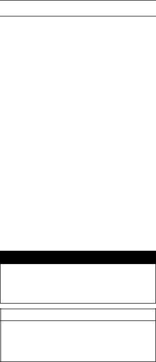
Battery Ground
Before completing any service on the motorcycle, disconnect the battery cables from the battery to prevent the engine from accidentally turning over. Disconnect the ground cable (–) first and then the positive (+). When completed with the service, first connect the positive (+) cable to the positive (+) terminal of the battery then the negative (–) cable to the negative terminal.
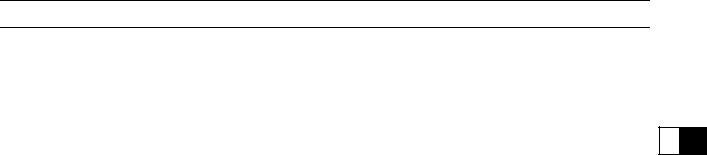
Edges of Parts
Lift large or heavy parts wearing gloves to prevent injury from possible sharp edges on the parts.
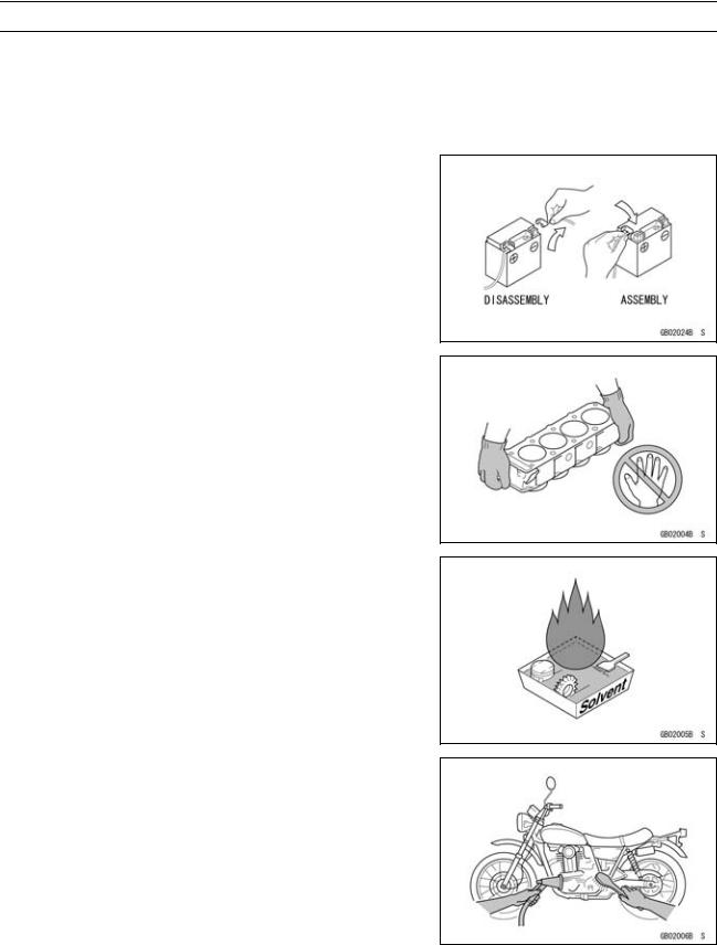
Solvent
Use a high-flush point solvent when cleaning parts. High -flush point solvent should be used according to directions of the solvent manufacturer.
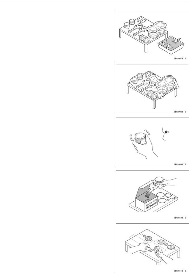
Cleaning vehicle before disassembly
Clean the vehicle thoroughly before disassembly. Dirt or other foreign materials entering into sealed areas during vehicle disassembly can cause excessive wear and decrease performance of the vehicle.
GENERAL INFORMATION 1-3
Before Servicing
Arrangement and Cleaning of Removed Parts
Disassembled parts are easy to confuse. Arrange the parts according to the order the parts were disassembled and clean the parts in order prior to assembly.
Storage of Removed Parts
After all the parts including subassembly parts have been cleaned, store the parts in a clean area. Put a clean cloth or plastic sheet over the parts to protect from any foreign materials that may collect before re-assembly.
Inspection
Reuse of worn or damaged parts may lead to serious accident. Visually inspect removed parts for corrosion, discoloration, or other damage. Refer to the appropriate sections of this manual for service limits on individual parts. Replace the parts if any damage has been found or if the part is beyond its service limit.
Replacement Parts
Replacement Parts must be KAWASAKI genuine or recommended by KAWASAKI. Gaskets, O-rings, oil seals, grease seals, circlips or cotter pins must be replaced with new ones whenever disassembled.
Assembly Order
In most cases assembly order is the reverse of disassembly, however, if assembly order is provided in this Service Manual, follow the procedures given.
1-4 GENERAL INFORMATION
Before Servicing
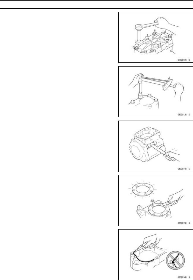
Tightening Sequence
Generally, when installing a part with several bolts, nuts, or screws, start them all in their holes and tighten them to a snug fit. Then tighten them according to the specified sequence to prevent case warpage or deformation which can lead to malfunction. Conversely when loosening the bolts, nuts, or screws, first loosen all of them by about a quarter turn and then remove them. If the specified tightening sequence is not indicated, tighten the fasteners alternating diagonally.
Tightening Torque
Incorrect torque applied to a bolt, nut, or screw may lead to serious damage. Tighten fasteners to the specified torque using a good quality torque wrench.
Force
Use common sense during disassembly and assembly, excessive force can cause expensive or hard to repair damage. When necessary, remove screws that have a non -permanent locking agent applied using an impact driver. Use a plastic-faced mallet whenever tapping is necessary.
Gasket, O-ring
Hardening, shrinkage, or damage of both gaskets and O-rings after disassembly can reduce sealing performance. Remove the old gaskets and clean the sealing surfaces thoroughly so that no gasket material or other material remains. Install the new gaskets and replace the used O-rings when re-assembling
Liquid Gasket, Non-permanent Locking Agent
For applications that require Liquid Gasket or a Non-permanent Locking Agent, clean the surfaces so that no oil residue remains before applying liquid gasket or non-permanent locking agent. Do not apply them excessively. Excessive application can clog oil passages and cause serious damage.
GENERAL INFORMATION 1-5
Before Servicing
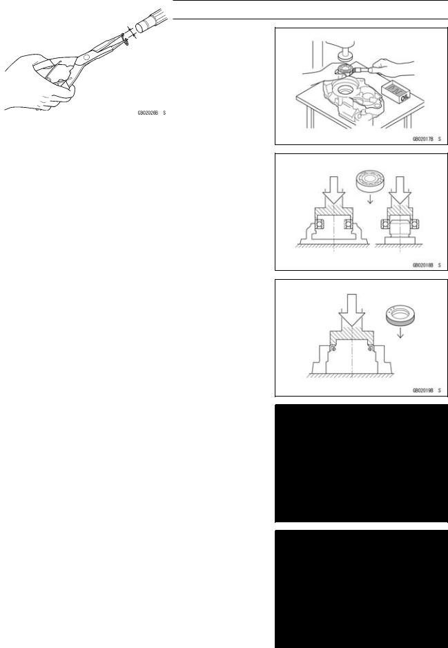
Press
For items such as bearings or oil seals that must be pressed into place, apply small amount of oil to the contact area. Be sure to maintain proper alignment and use smooth movements when installing.
Ball Bearing and Needle Bearing
Do not remove pressed ball or needle unless removal is absolutely necessary. Replace with new ones whenever removed. Press bearings with the manufacturer and size marks facing out. Press the bearing into place by putting pressure on the correct bearing race as shown.
Pressing the incorrect race can cause pressure between the inner and outer race and result in bearing damage.
Oil Seal, Grease Seal
Do not remove pressed oil or grease seals unless removal is necessary. Replace with new ones whenever removed. Press new oil seals with manufacture and size marks facing out. Make sure the seal is aligned properly when installing.
Apply specified grease to the lip of seal before installing the seal.
Circlips, Cotter Pins
Replace the circlips or cotter pins that were removed with new ones. Take care not to open the clip excessively when installing to prevent deformation.

1-6 GENERAL INFORMATION
Before Servicing
Lubrication
It is important to lubricate rotating or sliding parts during assembly to minimize wear during initial operation. Lubrication points are called out throughout this manual, apply the specific oil or grease as specified.
Direction of Engine Rotation
When rotating the crankshaft by hand, the free play amount of rotating direction will affect the adjustment. Rotate the crankshaft to positive direction (clockwise viewed from output side).
Electrical Wires
A two-color wire is identified first by the primary color and then the stripe color. Unless instructed otherwise, electrical wires must be connected to those of the same color.
GENERAL INFORMATION 1-7
Model Identification
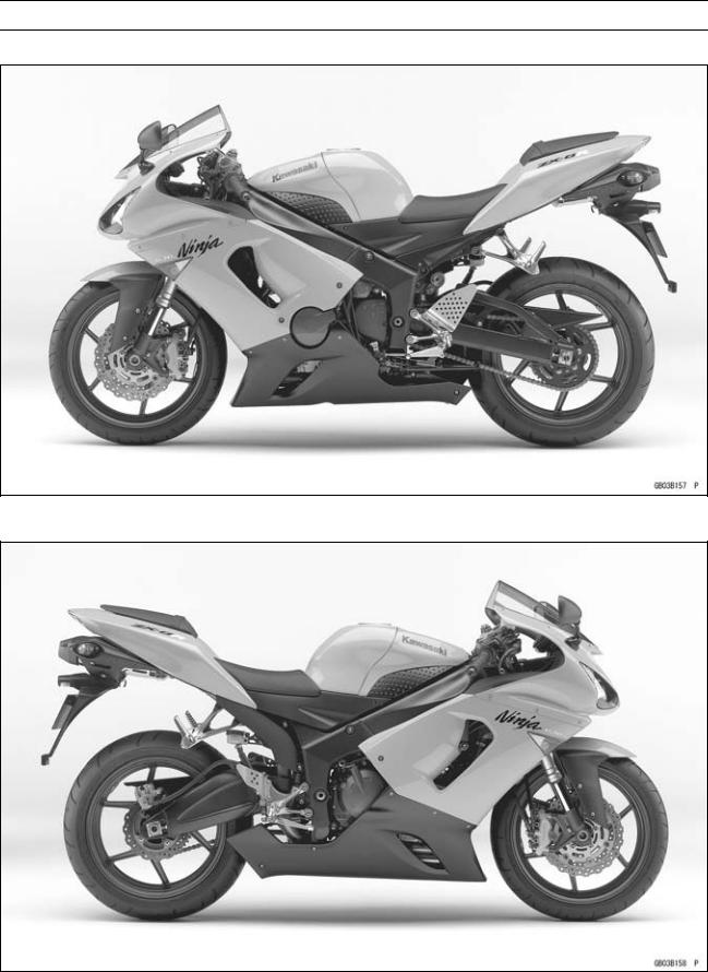
ZX636-C1 (Europe) Left Side View
ZX636-C1 (Europe) Right Side View
1-8 GENERAL INFORMATION
Model Identification
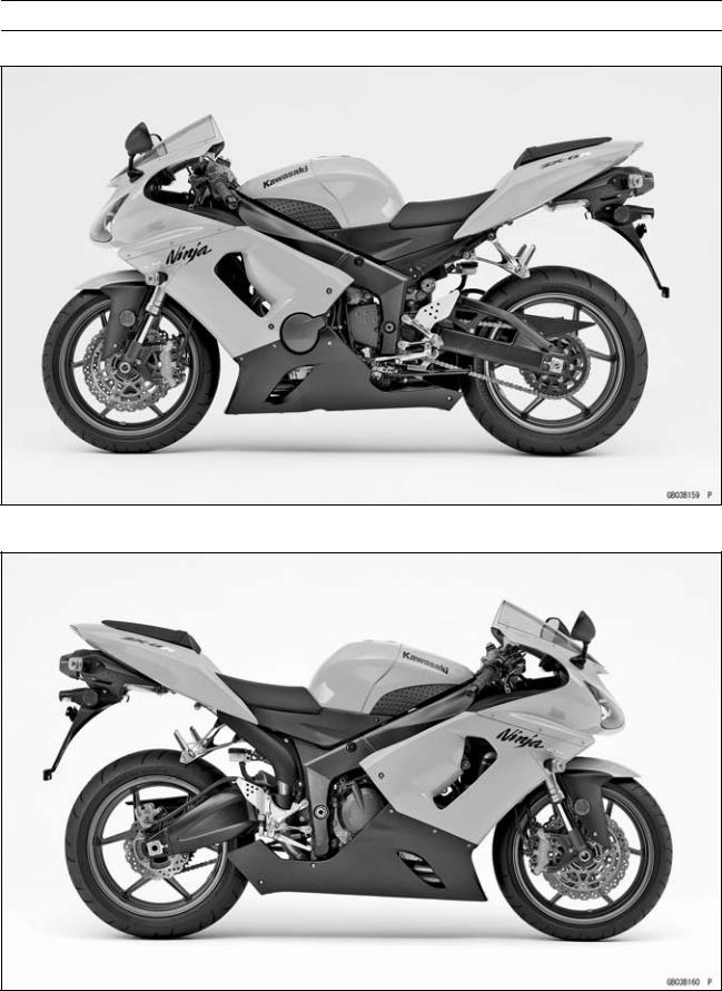
ZX636-C1 (US and Canada) Left Side View
ZX636-C1 (US and Canada) Right Side View
|
GENERAL INFORMATION 1-9 |
|
|
General Specifications |
|
|
Items |
ZX636-C1 (Ninja ZX-6R) |
|
Dimensions |
|
|
Overall Length |
2 065 mm (81.3 in.) |
|
Overall Width |
715 mm (28.1 in.) |
|
Overall Height |
1 110 mm (43.7 in.) |
|
Wheelbase |
1 390 mm (54.7 in.) |
|
Road Clearance |
120 mm (4.7 in.) |
|
Seat Height |
820 mm (32.3 in.) |
|
Dry Mass |
164 kg (362 lb) |
|
Curb Mass: |
|
|
Front |
95 kg (209 lb) |
|
Rear |
97 kg (214 lb) |
|
Fuel Tank Capacity |
17 L (4.5 US gal) |
|
Performance |
|
|
Minimum Turning Radius |
3.3 m (10.8 ft) |
|
Engine |
|
|
Type |
4-stroke, DOHC, 4-cylinder |
|
Cooling System |
Liquid-cooled |
|
Bore and Stroke |
68.0 × 43.8 mm (2.7 × 1.7 in.) |
|
Displacement |
636 mL (38.8 cu in.) |
|
Compression Ratio |
12.9 : 1 |
|
Maximum Horsepower |
95.5 kW (130 PS) @14 000 r/min (rpm), |
|
(FR) 78.2 kW (106 PS) @13 000 r/min (rpm), |
|
|
(MY) 90.8 kW (123 PS) @12 500 r/min (rpm), |
|
|
(CA), (CAL), (US) – – – |
|
|
Maximum Torque |
70.5 N·m (7.1 kgf·m, 52 ft·lb) @11 500 r/min (rpm), |
|
(FR) 63 N·m (6.4 kgf·m, 46 ft·lb) @11 500 r/min (rpm), |
|
|
(CA), (CAL), (US) – – – |
|
|
Carburetion System |
FI (Fuel injection) |
|
Primary: KEIHIN TTK 38 × 4 |
|
|
Secondary: KEIHIN Multihole (3 holes) × 4 |
|
|
Starting System |
Electric starter |
|
Ignition System |
Battery and coil (transistorized) |
|
Timing Advance |
Electronically advanced (digital igniter in ECU) |
|
Ignition Timing |
From 12.5° BTDC @1 300 r/min (rpm) to 35° BTDC @4 600 r/min |
|
(rpm) |
|
|
Spark Plug |
NGK CR9E |
|
Cylinder Numbering Method |
Left to right, 1-2-3-4 |
|
Firing Order |
1-2-4-3 |
|
Valve Timing: |
|
|
Inlet: |
|
|
Open |
59° BTDC |
|
Close |
81° ABDC |
|
Duration |
320° |
|
Exhaust: |
|
|
Open |
61° BBDC |
|
Close |
31° ATDC |
![]()
1-10 GENERAL INFORMATION
General Specifications
|
Items |
ZX636-C1 (Ninja ZX-6R) |
|
Duration |
272° |
|
Lubrication System |
Forced lubrication (wet sump with cooler) |
|
Engine Oil: |
|
|
Type |
API SE, SF or SG |
|
API SH or SJ with JASO MA |
|
|
Viscosity |
SAE10W-40 |
|
Capacity |
4.0 L (4.2 US qt) |
|
Drive Train |
|
|
Primary Reduction System: |
|
|
Type |
Gear |
|
Reduction Ratio |
1.891 (87/46) |
|
Clutch Type |
Wet multi disc |
|
Transmission: |
|
|
Type |
6-speed, constant mesh, return shift |
|
Gear Ratios: |
|
|
1st |
2.923 (38/13) |
|
2nd |
2.055 (37/18) |
|
3rd |
1.666 (35/21) |
|
4th |
1.450 (29/20) |
|
5th |
1.272 (28/22) |
|
6th |
1.153 (30/26) |
|
Final Drive System: |
|
|
Type |
Chain drive |
|
Reduction Ratio |
2.866 (43/15) |
|
Overall Drive Ratio |
6.255 @Top gear |
|
Frame |
|
|
Type |
Tubular, diamond |
|
Caster (Rake Angle) |
25° |
|
Trail |
106 mm (4.2 in.) |
|
Front Tire: |
|
|
Type |
Tubeless |
|
Size |
120/65 ZR17 M/C (56 W) |
|
Rear Tire: |
|
|
Type |
Tubeless |
|
Size |
180/55 ZR17 M/C (73 W) |
|
Front Suspension: |
|
|
Type |
Telescopic fork (upside-down) |
|
Wheel Travel |
120 mm (4.7 in.) |
|
Rear Suspension: |
|
|
Type |
Swingarm (uni-trak) |
|
Wheel Travel |
135 mm (5.3 in.) |
|
Brake Type: |
|
|
Front |
Dual discs |
|
Rear |
Single disc |
|
GENERAL INFORMATION 1-11 |
||
|
General Specifications |
||
|
Items |
ZX636-C1 (Ninja ZX-6R) |
|
|
Electrical Equipment |
||
|
Battery |
12 V 8 Ah |
|
|
Headlight: |
||
|
Type |
Semi-sealed beam |
|
|
Bulb: |
||
|
High |
12 |
V 55 W (quartz-halogen) × 2 |
|
Low |
12 |
V 55 W (quartz-halogen) |
|
Tail/Brake Light |
12 |
V 0.5/4.1 W (LED) |
|
Alternator: |
||
|
Type |
Three-phase AC |
|
|
Rated Output |
22.5 A/14 V @5 000 r/min (rpm) |
Specifications subject to change without notice, and may not apply to every country. CA: Canada Model
CAL: California Model
FR: France Model
MY: Malaysia Model US: United States Model
1-12 GENERAL INFORMATION
Unit Conversion Table
Prefixes for Units |
Units of Length |
|
Prefix |
Symbol |
Power |
||
|
mega |
M |
× 1 000 |
000 |
|
|
kilo |
k |
× |
1 000 |
|
|
centi |
c |
× |
0.01 |
|
|
milli |
m |
0.001 |
||
|
× |
||||
|
micro |
µ |
× 0.000001 |
Units of Mass
|
kg |
× |
2.205 |
= |
lb |
|
g |
× |
0.03527 |
= |
oz |
|
km |
× |
0.6214 |
= |
mile |
|
m |
× |
3.281 |
= |
ft |
|
mm |
× |
0.03937 |
= |
in |
Units of Torque
|
N·m |
× |
0.1020 |
= |
kgf·m |
|
N·m |
× |
0.7376 |
= |
ft·lb |
|
N·m |
× |
8.851 |
= |
in·lb |
|
kgf·m |
× |
9.807 |
= |
N·m |
|
kgf·m |
× |
7.233 |
= |
ft·lb |
|
kgf·m |
× |
86.80 |
= |
in·lb |
Units of Volume
|
L |
× |
0.2642 |
= |
gal (US) |
|
L |
× |
0.2200 |
= |
gal (imp) |
|
L |
× |
1.057 |
= |
qt (US) |
|
L |
× |
0.8799 |
= |
qt (imp) |
|
L |
× |
2.113 |
= |
pint (US) |
|
L |
× |
1.816 |
= |
pint (imp) |
|
mL |
× |
0.03381 |
= |
oz (US) |
|
mL |
× |
0.02816 |
= |
oz (imp) |
|
mL |
× |
0.06102 |
= |
cu in |
Units of Force
|
N |
× |
0.1020 |
= |
kg |
|
N |
× |
0.2248 |
= |
lb |
|
kg |
× |
9.807 |
= |
N |
|
kg |
× |
2.205 |
= |
lb |
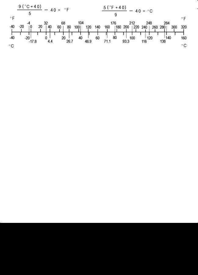
Units of Temperature
Units of Pressure
|
kPa |
× |
0.01020 |
= |
kgf/cm² |
|
kPa |
× |
0.1450 |
= |
psi |
|
kPa |
× |
0.7501 |
= |
cmHg |
|
kgf/cm² |
× |
98.07 |
= |
kPa |
|
kgf/cm² |
× |
14.22 |
= |
psi |
|
cmHg |
× |
1.333 |
= |
kPa |
Units of Speed
km/h × 0.6214 = mph
Units of Power
|
kW |
× |
1.360 |
= |
PS |
|
kW |
× |
1.341 |
= |
HP |
|
PS |
× |
0.7355 |
= |
kW |
|
PS |
× |
0.9863 |
= |
HP |

PERIODIC MAINTENANCE 2-1
Periodic Maintenance
|
Periodic Maintenance Chart (United States, Canada Model)…………………………………………. |
2-3 |
|
Periodic Maintenance Chart (Other than United States, Canada Model)…………………………. |
2-6 |
|
Torque and Locking Agent………………………………………………………………………………………… |
2-9 |
|
Specifications …………………………………………………………………………………………………………. |
2-15 |
|
Special Tools ………………………………………………………………………………………………………….. |
2-17 |
|
Maintenance Procedure …………………………………………………………………………………………… |
2-18 |
|
Fuel System (DFI)…………………………………………………………………………………………………. |
2-18 |
|
Throttle Control System Inspection……………………………………………………………………….. |
2-18 |
|
Engine Vacuum Synchronization Inspection…………………………………………………………… |
2-18 |
|
Idle Speed Inspection …………………………………………………………………………………………. |
2-22 |
|
Idle Speed Adjustment………………………………………………………………………………………… |
2-22 |
|
Fuel Hose Damage and Installation Condition Inspection ………………………………………… |
2-22 |
|
Evaporative Emission Control System (California Model) …………………………………………… |
2-23 |
|
Evaporative Emission Control System Inspection …………………………………………………… |
2-23 |
|
Cooling System…………………………………………………………………………………………………….. |
2-24 |
|
Coolant Level Inspection……………………………………………………………………………………… |
2-24 |
|
Radiator Hose Damage and Installation Condition Inspection…………………………………… |
2-24 |
|
Engine Top End ……………………………………………………………………………………………………. |
2-25 |
|
Valve Clearance Inspection …………………………………………………………………………………. |
2-25 |
|
Valve Clearance Adjustment………………………………………………………………………………… |
2-26 |
|
Air Suction System ……………………………………………………………………………………………….. |
2-29 |
|
Air Suction System Damage Inspection…………………………………………………………………. |
2-29 |
|
Clutch………………………………………………………………………………………………………………….. |
2-29 |
|
Clutch Operation Inspection ………………………………………………………………………………… |
2-29 |
|
Wheels/Tires………………………………………………………………………………………………………… |
2-30 |
|
Air Pressure Inspection……………………………………………………………………………………….. |
2-30 |
|
Wheel/Tire Damage Inspection…………………………………………………………………………….. |
2-30 |
|
Tire Tread Wear Inspection …………………………………………………………………………………. |
2-30 |
|
Wheel Bearing Damage Inspection ………………………………………………………………………. |
2-31 |
|
Drive Train …………………………………………………………………………………………………………… |
2-32 |
|
Drive Chain Lubrication Condition Inspection …………………………………………………………. |
2-32 |
|
Drive Chain Slack Inspection ……………………………………………………………………………….. |
2-32 |
|
Drive Chain Slack Adjustment ……………………………………………………………………………… |
2-33 |
|
Wheel Alignment Inspection ………………………………………………………………………………… |
2-34 |
|
Drive Chain Wear Inspection ……………………………………………………………………………….. |
2-34 |
|
Chain Guide Wear Inspection ………………………………………………………………………………. |
2-35 |
|
Brake System ………………………………………………………………………………………………………. |
2-35 |
|
Brake Fluid Leak (Brake Hose and Pipe) Inspection ……………………………………………….. |
2-35 |
|
Brake Hose Damage and Installation Condition Inspection………………………………………. |
2-35 |
|
Brake Operation Inspection …………………………………………………………………………………. |
2-35 |
|
Brake Fluid Level Inspection………………………………………………………………………………… |
2-36 |
|
Brake Pad Wear Inspection …………………………………………………………………………………. |
2-36 |
|
Brake Light Switch Operation Inspection ……………………………………………………………….. |
2-36 |
|
Suspensions ………………………………………………………………………………………………………… |
2-37 |
|
Front Forks/Rear Shock Absorber Operation Inspection ………………………………………….. |
2-37 |
|
Front Fork Oil Leak Inspection……………………………………………………………………………… |
2-38 |

2-2 PERIODIC MAINTENANCE
|
Rear Shock Absorber Oil Leak Inspection ……………………………………………………………… |
2-38 |
|
Rocker Arm Operation Inspection…………………………………………………………………………. |
2-38 |
|
Tie-Rod Operation Inspection ………………………………………………………………………………. |
2-38 |
|
Steering System …………………………………………………………………………………………………… |
2-39 |
|
Steering Play Inspection ……………………………………………………………………………………… |
2-39 |
|
Steering Play Adjustment…………………………………………………………………………………….. |
2-39 |
|
Steering Stem Bearing Lubrication ……………………………………………………………………….. |
2-40 |
|
Electrical System ………………………………………………………………………………………………….. |
2-40 |
|
Spark Plug Clean and Gap Inspection…………………………………………………………………… |
2-40 |
|
Lights and Switches Operation Inspection……………………………………………………………… |
2-42 |
|
Headlight Aiming Inspection ………………………………………………………………………………… |
2-44 |
|
Side Stand Switch Operation Inspection………………………………………………………………… |
2-45 |
|
Engine Stop Switch Operation Inspection………………………………………………………………. |
2-46 |
|
Others…………………………………………………………………………………………………………………. |
2-47 |
|
Chassis Parts Lubrication …………………………………………………………………………………… |
2-47 |
|
Bolts, Nuts and Fasteners Tightness Inspection……………………………………………………… |
2-48 |
|
Replacement Parts ……………………………………………………………………………………………….. |
2-50 |
|
Air Cleaner Element Replacement………………………………………………………………………… |
2-50 |
|
Fuel Hose Replacement ……………………………………………………………………………………… |
2-50 |
|
Coolant Change …………………………………………………………………………………………………. |
2-52 |
|
Radiator Hose and O-ring Replacement………………………………………………………………… |
2-54 |
|
Engine Oil Change……………………………………………………………………………………………… |
2-55 |
|
Oil Filter Replacement ………………………………………………………………………………………… |
2-55 |
|
Brake Hose and Pipe Replacement………………………………………………………………………. |
2-56 |
|
Brake Fluid Change ……………………………………………………………………………………………. |
2-56 |
|
Master Cylinder Rubber Parts Replacement ………………………………………………………….. |
2-58 |
|
Caliper Rubber Parts Replacement ………………………………………………………………………. |
2-59 |
|
Spark Plug Replacement …………………………………………………………………………………….. |
2-62 |

PERIODIC MAINTENANCE 2-3
Periodic Maintenance Chart (United States, Canada Model)
The scheduled maintenance must be done in accordance with this chart to keep the motorcycle in good running condition.The initial maintenance is vitally important and must not be neglected.
Periodic Inspection
|
FREQUENCY |
Whichever |
* ODOMETER READING |
||||||||||||
|
comes |
× 1 000 km |
See |
||||||||||||
|
first |
(× 1 000 mile) |
|||||||||||||
|
Page |
||||||||||||||
|
1 |
6 |
12 |
18 |
24 |
30 |
36 |
||||||||
|
INSPECTION |
Every |
(0.6) |
(4) |
(7.5) |
(12) |
(15) |
(20) |
(24) |
||||||
|
Fuel System |
||||||||||||||
|
Throttle control system (play, smooth |
year |
• |
• |
• |
• |
2-18 |
||||||||
|
return, no drag)-inspect |
||||||||||||||
|
Engine vacuum synchronization-inspect |
• |
• |
• |
2-18 |
||||||||||
|
Idle speed-inspect |
• |
• |
• |
• |
2-22 |
|||||||||
|
Fuel leak (fuel hose and pipe)-inspect |
year |
• |
• |
• |
• |
2-22 |
||||||||
|
Fuel hose and pipe damage-inspect |
year |
• |
• |
• |
• |
2-22 |
||||||||
|
Fuel hose and pipe installation |
year |
• |
• |
• |
• |
2-22 |
||||||||
|
condition-inspect |
||||||||||||||
|
Evaporative Emission Control System |
||||||||||||||
|
(CAL) |
||||||||||||||
|
Evaporative emission control system |
• |
• |
• |
• |
• |
• |
• |
2-23 |
||||||
|
function-inspect |
||||||||||||||
|
Cooling System |
||||||||||||||
|
Coolant level-inspect |
• |
• |
• |
• |
2-24 |
|||||||||
|
Coolant leak (radiator hose and |
year |
• |
• |
• |
• |
2-24 |
||||||||
|
pipe)-inspect |
||||||||||||||
|
Radiator hose damage-inspect |
year |
• |
• |
• |
• |
2-24 |
||||||||
|
Radiator hose installation condition |
year |
• |
• |
• |
• |
2-24 |
||||||||
|
-inspect |
||||||||||||||
|
Engine Top End |
||||||||||||||
|
Valve clearance-inspect |
• |
2-25 |
||||||||||||
|
Air Suction System |
||||||||||||||
|
Air suction system damage-inspect |
• |
• |
• |
2-29 |
||||||||||
|
Clutch |
||||||||||||||
|
Clutch operation (play, disengagement, |
• |
• |
• |
• |
2-29 |
|||||||||
|
engagement)-inspect |
||||||||||||||
|
Wheels and Tires |
||||||||||||||
|
Tire air pressure-inspect |
year |
• |
• |
• |
2-30 |
|||||||||
|
Wheel/tire damage-inspect |
• |
• |
• |
2-30 |
||||||||||
|
Tire tread wear, abnormal wear-inspect |
• |
• |
• |
2-30 |
||||||||||
|
Wheel bearing damage-inspect |
year |
• |
• |
• |
2-31 |
|||||||||
|
Drive Train |
||||||||||||||
|
Drive chain lubrication condition-inspect # |
Every 600 km (400 mile) |
2-32 |
||||||||||||
|
Drive chain slack-inspect # |
Every 1 000 km (600 mile) |
2-32 |
||||||||||||
|
Drive chain wear-inspect # |
• |
• |
• |
2-34 |
||||||||||
|
Drive chain guide wear-inspect |
• |
• |
• |
2-35 |
2-4 PERIODIC MAINTENANCE
Periodic Maintenance Chart (United States, Canada Model)
|
FREQUENCY |
Whichever |
* ODOMETER READING |
|||||||||||
|
comes |
× 1 000 km |
See |
|||||||||||
|
first |
(× 1 000 mile) |
||||||||||||
|
Page |
|||||||||||||
|
1 |
6 |
12 |
18 |
24 |
30 |
36 |
|||||||
|
INSPECTION |
Every |
(0.6) |
(4) |
(7.5) |
(12) |
(15) |
(20) |
(24) |
|||||
|
Brake System |
|||||||||||||
|
Brake fluid leak (brake hose and |
year |
• |
• |
• |
• |
• |
• |
• |
2-35 |
||||
|
pipe)-inspect |
|||||||||||||
|
Brake hose and pipe damage-inspect |
year |
• |
• |
• |
• |
• |
• |
• |
2-35 |
||||
|
Brake pad wear-inspect # |
• |
• |
• |
• |
• |
• |
2-36 |
||||||
|
Brake hose installation condition-inspect |
year |
• |
• |
• |
• |
• |
• |
• |
2-35 |
||||
|
Brake fluid level-inspect |
6 months |
• |
• |
• |
• |
• |
• |
• |
2-36 |
||||
|
Brake operation (effectiveness, play, no |
year |
• |
• |
• |
• |
• |
• |
• |
2-35 |
||||
|
drag)-inspect |
|||||||||||||
|
Brake light switch operation-inspect |
• |
• |
• |
• |
• |
• |
• |
2-36 |
|||||
|
Suspensions |
|||||||||||||
|
Front forks/rear shock absorber operation |
• |
• |
• |
2-37 |
|||||||||
|
(damping and smooth stroke)-inspect |
|||||||||||||
|
Front forks/rear shock absorber oil |
year |
• |
• |
• |
2-38 |
||||||||
|
leak-inspect |
|||||||||||||
|
Rocker arm operation-inspect |
• |
• |
• |
2-38 |
|||||||||
|
Tie-Rods operation-inspect |
• |
• |
• |
2-38 |
|||||||||
|
Steering System |
|||||||||||||
|
Steering play-inspect |
year |
• |
• |
• |
• |
2-39 |
|||||||
|
Steering stem bearings-lubricate |
2 years |
• |
2-40 |
||||||||||
|
Electrical System |
|||||||||||||
|
Spark plug condition – inspect |
• |
• |
• |
2-40 |
|||||||||
|
Lights and switches operation-inspect |
year |
• |
• |
• |
2-42 |
||||||||
|
Headlight aiming-inspect |
year |
• |
• |
• |
2-44 |
||||||||
|
Side stand switch operation-inspect |
year |
• |
• |
• |
2-45 |
||||||||
|
Engine stop switch operation-inspect |
year |
• |
• |
• |
2-46 |
||||||||
|
Others |
|||||||||||||
|
Chassis parts-lubricate |
year |
• |
• |
• |
2-47 |
||||||||
|
Bolts and nuts tightness-inspect |
• |
• |
• |
• |
2-48 |
*: For higher odometer readings, repeat at the frequency interval established here.
#: Service more frequently when operating in severe conditions; dusty, wet, muddy, high speed or frequent starting/stopping.
CAL: California Model
PERIODIC MAINTENANCE 2-5
Periodic Maintenance Chart (United States, Canada Model)
Periodic Replacement Parts
|
FREQUENCY |
Whichever |
* ODOMETER READING |
||||||||||
|
come |
× 1 000 km |
See |
||||||||||
|
first |
(× 1 000 mile) |
|||||||||||
|
Page |
||||||||||||
|
1 |
12 |
24 |
36 |
48 |
||||||||
|
CHANGE/REPLACE ITEM |
Every |
(0.6) |
(7.5) |
(15) |
(24) |
(30) |
||||||
|
Air cleaner element # |
Every 18 000 km (12 000 mile) |
2-50 |
||||||||||
|
Fuel hose |
4 years |
• |
2-50 |
|||||||||
|
Coolant |
3 years |
• |
2-52 |
|||||||||
|
Radiator hose and O-ring |
3 years |
• |
2-54 |
|||||||||
|
Engine oil # |
year |
• |
• |
• |
• |
• |
2-55 |
|||||
|
Oil filter |
year |
• |
• |
• |
• |
• |
2-55 |
|||||
|
Brake hose and pipe |
4 years |
• |
2-56 |
|||||||||
|
Brake fluid |
2 years |
• |
• |
2-56 |
||||||||
|
Rubber parts of master cylinder and caliper |
4 years |
• |
2-58, |
|||||||||
|
2-59 |
||||||||||||
|
Spark plug |
• |
• |
• |
• |
2-62 |
*: For higher odometer readings, repeat at the frequency interval established here.
#: Service more frequently when operating in severe conditions; dusty, wet, muddy, high speed or frequent starting/stopping.
2-6 PERIODIC MAINTENANCE
Periodic Maintenance Chart (Other than United States, Canada Model)
The scheduled maintenance must be done in accordance with this chart to keep the motorcycle in good running condition.The initial maintenance is vitally important and must not be neglected.
Periodic Inspection
|
FREQUENCY |
Whichever |
* ODOMETER READING |
||||||||||||
|
comes |
× 1 000 km |
See |
||||||||||||
|
first |
(× 1 000 mile) |
|||||||||||||
|
Page |
||||||||||||||
|
1 |
6 |
12 |
18 |
24 |
30 |
36 |
||||||||
|
INSPECTION |
Every |
(0.6) |
(4) |
(7.5) |
(12) |
(15) |
(20) |
(24) |
||||||
|
Fuel System |
||||||||||||||
|
Throttle control system (play, smooth |
year |
• |
• |
• |
• |
2-18 |
||||||||
|
return, no drag)-inspect |
||||||||||||||
|
Engine vacuum synchronization-inspect |
• |
• |
• |
2-18 |
||||||||||
|
Idle speed-inspect |
• |
• |
• |
• |
2-22 |
|||||||||
|
Fuel leak (fuel hose and pipe)-inspect |
year |
• |
• |
• |
• |
2-22 |
||||||||
|
Fuel hose and pipe damage-inspect |
year |
• |
• |
• |
• |
2-22 |
||||||||
|
Fuel hose and pipe installation |
year |
• |
• |
• |
• |
2-22 |
||||||||
|
condition-inspect |
||||||||||||||
|
Cooling System |
||||||||||||||
|
Coolant level-inspect |
• |
• |
• |
• |
2-23 |
|||||||||
|
Coolant leak (radiator hose and |
year |
• |
• |
• |
• |
2-24 |
||||||||
|
pipe)-inspect |
||||||||||||||
|
Radiator hose damage-inspect |
year |
• |
• |
• |
• |
2-24 |
||||||||
|
Radiator hose installation condition |
year |
• |
• |
• |
• |
2-24 |
||||||||
|
-inspect |
||||||||||||||
|
Engine Top End |
||||||||||||||
|
Valve clearance-inspect |
Every 42 000 km (26 000 mile) |
2-25 |
||||||||||||
|
Air Suction System |
||||||||||||||
|
Air suction system damage-inspect |
• |
• |
• |
2-29 |
||||||||||
|
Clutch |
||||||||||||||
|
Clutch operation (play, disengagement, |
• |
• |
• |
• |
2-29 |
|||||||||
|
engagement)-inspect |
||||||||||||||
|
Wheels and Tires |
||||||||||||||
|
Tire air pressure-inspect |
year |
• |
• |
• |
2-30 |
|||||||||
|
Wheel/tire damage-inspect |
• |
• |
• |
2-30 |
||||||||||
|
Tire tread wear, abnormal wear-inspect |
• |
• |
• |
2-30 |
||||||||||
|
Wheel bearing damage-inspect |
year |
• |
• |
• |
2-31 |
|||||||||
|
Drive Train |
||||||||||||||
|
Drive chain lubrication condition-inspect |
Every 600 km (400 mile) |
2-32 |
||||||||||||
|
# |
||||||||||||||
|
Drive chain slack-inspect # |
Every 1 000 km (600 mile) |
2-32 |
||||||||||||
|
Drive chain wear-inspect # |
• |
• |
• |
2-34 |
||||||||||
|
Drive chain guide wear-inspect |
• |
• |
• |
2-35 |
||||||||||
|
Brake System |
||||||||||||||
|
Brake fluid leak (brake hose and |
year |
• |
• |
• |
• |
• |
• |
• |
2-35 |
|||||
|
pipe)-inspect |

PERIODIC MAINTENANCE 2-7
Periodic Maintenance Chart (Other than United States, Canada Model)
|
FREQUENCY |
Whichever |
* ODOMETER READING |
|||||||||||
|
comes |
× 1 000 km |
See |
|||||||||||
|
first |
(× 1 000 mile) |
||||||||||||
|
Page |
|||||||||||||
|
1 |
6 |
12 |
18 |
24 |
30 |
36 |
|||||||
|
INSPECTION |
Every |
(0.6) |
(4) |
(7.5) |
(12) |
(15) |
(20) |
(24) |
|||||
|
Brake hose and pipe damage-inspect |
year |
• |
• |
• |
• |
• |
• |
• |
2-35 |
||||
|
Brake pad wear-inspect # |
• |
• |
• |
• |
• |
• |
2-36 |
||||||
|
Brake hose installation condition-inspect |
year |
• |
• |
• |
• |
• |
• |
• |
2-35 |
||||
|
Brake fluid level-inspect |
6 months |
• |
• |
• |
• |
• |
• |
• |
2-36 |
||||
|
Brake operation (effectiveness, play, no |
year |
• |
• |
• |
• |
• |
• |
• |
2-35 |
||||
|
drag)-inspect |
|||||||||||||
|
Brake light switch operation-inspect |
• |
• |
• |
• |
• |
• |
• |
2-36 |
|||||
|
Suspensions |
|||||||||||||
|
Front forks/rear shock absorber |
• |
• |
• |
2-37 |
|||||||||
|
operation (damping and smooth |
|||||||||||||
|
stroke)-inspect |
|||||||||||||
|
Front forks/rear shock absorber oil |
year |
• |
• |
• |
2-38 |
||||||||
|
leak-inspect |
|||||||||||||
|
Rocker arm operation-inspect |
• |
• |
• |
2-38 |
|||||||||
|
Tie-Rods operation-inspect |
• |
• |
• |
2-38 |
|||||||||
|
Steering System |
|||||||||||||
|
Steering play-inspect |
year |
• |
• |
• |
• |
2-39 |
|||||||
|
Steering stem bearings-lubricate |
2 years |
• |
2-40 |
||||||||||
|
Electrical System |
|||||||||||||
|
Spark plug condition – inspect |
• |
• |
• |
2-40 |
|||||||||
|
Lights and switches operation-inspect |
year |
• |
• |
• |
2-42 |
||||||||
|
Headlight aiming-inspect |
year |
• |
• |
• |
2-44 |
||||||||
|
Side stand switch operation-inspect |
year |
• |
• |
• |
2-45 |
||||||||
|
Engine stop switch operation-inspect |
year |
• |
• |
• |
2-46 |
||||||||
|
Others |
|||||||||||||
|
Chassis parts-lubricate |
year |
• |
• |
• |
2-47 |
||||||||
|
Bolts and nuts tightness-inspect |
• |
• |
• |
• |
2-48 |
*: For higher odometer readings, repeat at the frequency interval established here.
#: Service more frequently when operating in severe conditions; dusty, wet, muddy, high speed or frequent starting/stopping.
![]()
2-8 PERIODIC MAINTENANCE
Periodic Maintenance Chart (Other than United States, Canada Model)
Periodic Replacement Parts
|
FREQUENCY |
Whichever |
* ODOMETER READING |
||||||||||
|
come |
× 1 000 km |
See |
||||||||||
|
first |
(× 1 000 mile) |
|||||||||||
|
Page |
||||||||||||
|
1 |
12 |
24 |
36 |
48 |
||||||||
|
CHANGE/REPLACE ITEM |
Every |
(0.6) |
(7.5) |
(15) |
(24) |
(30) |
||||||
|
Air cleaner element # |
Every 18 000 km (12 000 mile) |
2-50 |
||||||||||
|
Fuel hose |
4 years |
• |
2-50 |
|||||||||
|
Coolant |
3 years |
• |
2-52 |
|||||||||
|
Radiator hose and O-ring |
3 years |
• |
2-54 |
|||||||||
|
Engine oil # |
year |
• |
• |
• |
• |
• |
2-55 |
|||||
|
Oil filter |
year |
• |
• |
• |
• |
• |
2-55 |
|||||
|
Brake hose and pipe |
4 years |
• |
2-56 |
|||||||||
|
Brake fluid |
2 years |
• |
• |
2-56 |
||||||||
|
Rubber parts of master cylinder and caliper |
4 years |
• |
2-58, |
|||||||||
|
2-59 |
||||||||||||
|
Spark plug |
• |
• |
• |
• |
2-62 |
*: For higher odometer readings, repeat at the frequency interval established here.
#: Service more frequently when operating in severe conditions; dusty, wet, muddy, high speed or frequent starting/stopping.

PERIODIC MAINTENANCE 2-9
Torque and Locking Agent
The following tables list the tightening torque for the major fasteners requiring use of a non-permanent locking agent or silicone sealant etc.
Letters used in the “Remarks” column mean:
AL: Tighten the two clamp bolts alternately two times to ensure even tightening torque.
G:Apply grease to the threads.
L:Apply a non-permanent locking agent to the threads. MO: Apply molybdenum disulfide grease oil solution.
R:Replacement Parts
S:Tighten the fasteners following the specified sequence. SI: Apply silicone grease.
SS:Apply silicone sealant.
|
Fastener |
Torque |
Remarks |
|||
|
N·m |
kgf·m |
ft·lb |
|||
|
Fuel System |
|||||
|
Air Cleaner Housing Clamp Bolts |
2.0 |
0.20 |
17 in·lb |
||
|
Air Cleaner Housing Mounting Bolt |
6.9 |
0.70 |
61 in·lb |
||
|
Air Inlet Duct Mounting Bolts |
6.9 |
0.70 |
61 in·lb |
L |
|
|
Canister Bracket Mounting Bolt (M6) |
6.9 |
0.70 |
61 in·lb |
||
|
Canister Bracket Mounting Bolt (M5) |
0.4 |
0.04 |
4 in·lb |
||
|
Camshaft Position Sensor Bolt |
12 |
1.2 |
104 in·lb |
||
|
Crankshaft Sensor Bolts |
5.9 |
0.60 |
52 in·lb |
||
|
Delivery Pipe Mounting Screws (Nozzle Assy) |
3.4 |
0.35 |
30 in·lb |
||
|
Delivery Pipe Mounting Screws (Throttle Body) |
3.4 |
0.35 |
30 in·lb |
||
|
Exhaust Butterfly Valve Actuator Mounting Bolts |
6.9 |
0.70 |
61 in·lb |
||
|
Exhaust Butterfly Valve Actuator Pulley Bolt |
4.9 |
0.50 |
43 in·lb |
||
|
Fuel Hose Mounting Screw |
4.9 |
0.50 |
43 in·lb |
||
|
Fuel Pump Bolts |
9.8 |
1.0 |
87 in·lb |
L, S |
|
|
Nozzle Assy Mounting Bolts |
6.9 |
0.70 |
61 in·lb |
||
|
Separator Bracket Mounting Bolt |
0.8 |
0.08 |
7 in·lb |
||
|
Throttle Body Assembly Holder Clamp Bolts |
3.0 |
0.30 |
27 in·lb |
||
|
Throttle Body Holder Bolts |
12 |
1.2 |
104 in·lb |
L |
|
|
Throttle Cable Holder Bolt |
3.9 |
0.40 |
35 in·lb |
||
|
Vehicle-down Sensor Bolts |
5.9 |
0.60 |
52 in·lb |
||
|
Water Temperature Sensor |
25 |
2.5 |
18 |
SS |
|
|
Cooling System |
|||||
|
Coolant By-pass Fitting Bolt |
8.8 |
0.90 |
78 in·lb |
L |
|
|
Coolant Drain Bolt (Cylinder) |
9.8 |
1.0 |
87 in·lb |
||
|
Coolant Drain Bolt (Water Pump) |
8.8 |
0.90 |
78 in·lb |
||
|
Coolant Reserve Tank Mounting Bolts |
6.9 |
0.70 |
61 in·lb |
||
|
Impeller Bolt |
9.8 |
1.0 |
87 in·lb |
||
|
Oil Cooler Mounting Bolts |
12 |
1.2 |
104 in·lb |
S |
|
|
Radiator Bracket Mounting Bolt |
6.9 |
0.70 |
61 in·lb |
||
|
Radiator Lower Bolt |
6.9 |
61 in·lb |
|||
|
0.70 |
|||||
|
Radiator Upper Bolt |
12 |
1.2 |
104 in·lb |
||
|
Thermostat Housing Cover Bolts |
5.9 |
0.60 |
52 in·lb |
||
|
Water Hose Clamp Screws |
2.0 |
0.20 |
17 in·lb |

2-10 PERIODIC MAINTENANCE
Torque and Locking Agent
|
Fastener |
Torque |
Remarks |
|||
|
N·m |
kgf·m |
ft·lb |
|||
|
Water Hose Fitting Bolts |
12 |
1.2 |
104 in·lb |
||
|
Water Pump Cover Bolts |
12 |
1.2 |
104 in·lb |
L |
|
|
Water Temperature Sensor |
25 |
2.5 |
18 |
SS |
|
|
Engine Top End |
|||||
|
Air Suction Valve Cover Bolts |
12 |
1.2 |
104 in·lb |
L |
|
|
Camshaft Cap Bolts |
12 |
1.2 |
104 in·lb |
S |
|
|
Camshaft Chain Tensioner Cap Bolt |
20 |
2.0 |
15 |
||
|
Camshaft Chain Tensioner Mounting Bolts |
11 |
1.1 |
97 in·lb |
||
|
Cam Sprocket Mounting Bolts |
15 |
1.5 |
11 |
L |
|
|
Coolant Drain Bolt (Cylinder) |
9.8 |
1.0 |
87 in·lb |
||
|
Crankshaft Sensor Cover Bolts |
9.8 |
1.0 |
87 in·lb |
L (1) |
|
|
Cylinder Head Bolts (M9) |
39 |
4.0 |
29 |
MO, S |
|
|
Cylinder Head Bolts (M6) |
12 |
1.2 |
104 in·lb |
S |
|
|
Cylinder Head Cover Bolts |
9.8 |
1.0 |
87 in·lb |
||
|
Exhaust Butterfly Valve Actuator Mounting Bolts |
6.9 |
0.70 |
61 in·lb |
||
|
Exhaust Butterfly Valve Actuator Pulley Bolt |
4.9 |
0.50 |
43 in·lb |
||
|
Exhaust Butterfly Valve Cable Adjuster Locknuts |
6.9 |
0.70 |
61 in·lb |
||
|
Exhaust Butterfly Valve Cable Locknuts |
6.9 |
0.70 |
61 in·lb |
||
|
Exhaust Butterfly Valve Cover Bolt |
6.9 |
0.70 |
61 in·lb |
||
|
Exhaust Pipe Clamp Bolt |
17 |
1.7 |
12 |
||
|
Exhaust Pipe Manifold Holder Nuts |
17 |
1.7 |
12 |
||
|
Exhaust Pipe Mounting Bolt |
25 |
2.5 |
18 |
||
|
Front Camshaft Chain Guide Bolt (Lower) |
12 |
1.2 |
104 in·lb |
||
|
Front Camshaft Chain Guide Bolt (Upper) |
25 |
2.5 |
18 |
||
|
Muffler Body Clamp Bolt |
17 |
1.7 |
12 |
||
|
Muffler Body Mounting Bolts |
25 |
2.5 |
18 |
||
|
Muffler Rear Cover Bolts |
6.9 |
0.70 |
61 in·lb |
||
|
Muffler Upper Cover Bolts |
6.9 |
0.70 |
61 in·lb |
||
|
Rear Camshaft Chain Guide Bolt |
25 |
2.5 |
18 |
||
|
Spark Plugs |
13 |
1.3 |
113 in·lb |
||
|
Throttle Body Assy Holder Clamp Bolts |
2.9 |
0.30 |
26 in·lb |
||
|
Throttle Body Holder Bolts |
12 |
1.2 |
104 in·lb |
L |
|
|
Water Passage Plug (Left) |
20 |
2.0 |
15 |
L |
|
|
Water Passage Plugs (Upper) |
20 |
2.0 |
15 |
L |
|
|
Clutch |
|||||
|
Clutch Cover Bolt (M6, L = 50 mm) |
12 |
1.2 |
104 in·lb |
||
|
Clutch Cover Bolt (M6, L = 40 mm) |
12 |
1.2 |
104 in·lb |
L (1) |
|
|
Clutch Cover Bolts (M6, L = 30 mm) |
12 |
1.2 |
104 in·lb |
L (1) |
|
|
Clutch Hub Nut |
135 |
14 |
100 |
R |
|
|
Clutch Lever Clamp Bolts |
7.8 |
0.80 |
69 in·lb |
S |
|
|
Clutch Spring Bolts |
8.8 |
0.90 |
78 in·lb |
||
|
Oil Filler Plug |
1.5 |
0.15 |
13 in·lb |
||
|
Sub Clutch Hub Bolts |
25 |
2.5 |
18 |
L |

PERIODIC MAINTENANCE 2-11
Torque and Locking Agent
|
Fastener |
Torque |
Remarks |
|||
|
N·m |
kgf·m |
ft·lb |
|||
|
Engine Lubrication System |
|||||
|
Coolant Drain Bolt (Water Pump) |
8.8 |
0.90 |
78 in·lb |
||
|
Engine Oil Drain Bolt |
29 |
3.0 |
22 |
||
|
Impeller Bolt |
9.8 |
1.0 |
87 in·lb |
||
|
Oil Cooler Mounting Bolts |
12 |
1.2 |
104 in·lb |
S |
|
|
Oil Filter |
31 |
3.2 |
23 |
EO, R |
|
|
Oil Filter Mounting Bolt |
25 |
2.5 |
18 |
L |
|
|
Oil Jet Nozzle Bolts |
6.9 |
0.70 |
61 in·lb |
L |
|
|
Oil Pan Bolts |
9.8 |
1.0 |
87 in·lb |
||
|
Oil Pan Clamp Bolt |
9.8 |
1.0 |
87 in·lb |
||
|
Oil Passage Plug (Left Side) |
20 |
2.0 |
15 |
L |
|
|
Oil Passage Plug (Right Side) |
15 |
1.5 |
11 |
||
|
Oil Pipe Bolts |
12 |
1.2 |
104 in·lb |
||
|
Oil Pressure Relief Valve |
15 |
1.5 |
11 |
L |
|
|
Oil Pressure Switch |
15 |
1.5 |
11 |
SS |
|
|
Oil Pressure Switch Terminal Bolt |
1.5 |
0.15 |
13 in·lb |
||
|
Water Hose Clamp Screws |
2.0 |
0.20 |
17 in·lb |
||
|
Water Pump Cover Bolts |
12 |
1.2 |
104 in·lb |
L |
|
|
Engine Removal/Installation |
|||||
|
Adjusting Collar Locknut |
49 |
5.0 |
36 |
S |
|
|
Lower Engine Mounting Bolt |
10 |
1.0 |
87 in·lb |
S |
|
|
Lower Engine Mounting Nut |
44 |
4.5 |
33 |
S |
|
|
Middle Engine Mounting Bolt |
10 |
1.0 |
87 in·lb |
S |
|
|
Middle Engine Mounting Nut |
44 |
4.5 |
33 |
S |
|
|
Upper Engine Mounting Bolts |
44 |
4.5 |
33 |
S |
|
|
Crankshaft/Transmission |
|||||
|
Breather Plate Bolts |
5.9 |
0.60 |
52 in·lb |
L |
|
|
Connecting Rod Big End Nuts |
see the text |
← |
← |
← |
|
|
Crankcase Bolts (M8) |
31 |
3.2 |
23 |
MO, S |
|
|
Crankcase Bolts (M7, L = 38 mm) |
27 |
2.8 |
20 |
S |
|
|
Crankcase Bolt (M7, L = 70 mm) |
20 |
2.0 |
14 |
S |
|
|
Crankcase Bolts (M6, L = 65 mm) |
12 |
1.2 |
104 in·lb |
S |
|
|
Crankcase Bolts (M6, L = 50 mm) |
12 |
1.2 |
104 in·lb |
S |
|
|
Crankcase Bolts (M6, L = 38 mm) |
12 |
1.2 |
104 in·lb |
S |
|
|
Crankcase Bolt (M6, L = 95 mm) |
12 |
1.2 |
104 in·lb |
S |
|
|
Crankcase Bolt (M6, L = 85 mm) |
12 |
1.2 |
104 in·lb |
S |
|
|
Crankcase Bolt (M6, L = 35 mm) |
12 |
1.2 |
104 in·lb |
S |
|
|
Neutral Switch |
15 |
1.5 |
11 |
L |
|
|
Gear Positioning Lever Bolt |
12 |
1.2 |
104 in·lb |
||
|
Harness Clamp Bolt |
8.8 |
0.90 |
78 in·lb |
L |
|
|
Oil Passage Plug (Left Side) |
20 |
2.0 |
15 |
L |
|
|
Oil Passage Plug (Right Side) |
15 |
1.5 |
11 |
||
|
Oil Pressure Switch |
15 |
1.5 |
11 |
SS |

2-12 PERIODIC MAINTENANCE
Torque and Locking Agent
|
Fastener |
Torque |
Remarks |
|||
|
N·m |
kgf·m |
ft·lb |
|||
|
Oil Pressure Switch Terminal Bolt |
1.5 |
0.15 |
13 in·lb |
||
|
Plate Screws |
5.9 |
0.60 |
52 in·lb |
L |
|
|
Shift Drum Bearing Holder Bolts |
12 |
1.2 |
104 in·lb |
L |
|
|
Shift Drum Cam Holder Bolt |
12 |
1.2 |
104 in·lb |
L |
|
|
Shift Lever Bolt |
6.9 |
0.70 |
61 in·lb |
||
|
Shift Pedal Mounting Bolt |
25 |
2.5 |
18 |
||
|
Shift Shaft Return Spring Pin |
28 |
2.9 |
21 |
L |
|
|
Tie-Rod Locknuts |
6.9 |
0.70 |
61 in·lb |
||
|
Wheels/Tires |
|||||
|
Front Axle Clamp Bolts |
20 |
2.0 |
15 |
AL |
|
|
Front Axle Nut |
127 |
13 |
94 |
||
|
Rear Axle Nut |
127 |
13 |
94 |
||
|
Final Drive |
|||||
|
Engine Sprocket Cover Bolts |
6.9 |
0.70 |
61 in·lb |
||
|
Engine Sprocket Nut |
125 |
13 |
92 |
MO |
|
|
Rear Axle Nut |
127 |
13 |
94 |
||
|
Rear Sprocket Nuts |
59 |
6.0 |
43 |
||
|
Brakes |
|||||
|
Bleed Valves |
7.8 |
0.80 |
69 in·lb |
||
|
Brake Hose Banjo Bolts |
34 |
||||
|
3.5 |
25 |
||||
|
Brake Lever Pivot Bolt |
1.0 |
0.10 |
9 in·lb |
SI |
|
|
Brake Lever Pivot Bolt Locknut |
5.9 |
0.60 |
52 in·lb |
||
|
Brake Pedal Bolt |
8.8 |
0.90 |
78 |
||
|
Front Brake Light Switch Screw |
1.2 |
0.12 |
10 in·lb |
||
|
Front Brake Reservoir Cap Stopper Screw |
1.2 |
0.12 |
10 in·lb |
||
|
Front Brake Disc Mounting Bolts |
27 |
2.8 |
20 |
L |
|
|
Front Brake Pad Pins |
15 |
1.5 |
11 |
||
|
Front Caliper Assembly Bolts |
22 |
2.2 |
16 |
||
|
Front Caliper Mounting Bolts |
34 |
3.5 |
25 |
||
|
Front Master Cylinder Bleed Valve |
5.9 |
0.60 |
52 in·lb |
||
|
Front Master Cylinder Clamp Bolts |
8.8 |
0.90 |
78 in·lb |
S |
|
|
Rear Brake Disc Mounting Bolts |
27 |
2.8 |
20 |
L |
|
|
Rear Caliper Mounting Bolts |
25 |
2.5 |
18 |
||
|
Rear Master Cylinder Mounting Bolts |
25 |
2.5 |
18 |
||
|
Rear Master Cylinder Push Rod Locknut |
18 |
1.8 |
13 |
||
|
Suspension |
|||||
|
Front Axle Clamp Bolts |
20 |
2.0 |
15 |
AL |
|
|
Front Fork Bottom Allen Bolts |
35 |
3.5 |
26 |
L |
|
|
Front Fork Clamp Bolts (Lower) |
25 |
2.5 |
18 |
AL |
|
|
Front Fork Clamp Bolts (Upper) |
20 |
2.0 |
15 |
||
|
Front Fork Top Plugs |
35 |
3.5 |
26 |
||
|
Piston Rod Nuts |
|||||
|
20 |
2.0 |
15 |
|||
|
Rear Shock Absorber Bracket Nut |
59 |
6.0 |
43 |

PERIODIC MAINTENANCE 2-13
Torque and Locking Agent
|
Fastener |
Torque |
Remarks |
|||
|
N·m |
kgf·m |
ft·lb |
|||
|
Rear Shock Absorber Nut (Lower) |
34 |
3.5 |
25 |
||
|
Rear Shock Absorber Nut (Upper) |
34 |
3.5 |
25 |
||
|
Swingarm Pivot Adjusting Collar |
20 |
2.0 |
15 |
||
|
Swingarm Pivot Adjusting Collar Locknut |
98 |
10 |
72 |
||
|
Swingarm Pivot Shaft Nut |
108 |
11 |
81 |
||
|
Tie-Rod Nuts |
59 |
6.0 |
43 |
||
|
Uni-Trak Rocker Arm Nut |
34 |
3.5 |
25 |
||
|
Steering |
|||||
|
Front Fork Clamp Bolts (Lower) |
25 |
2.5 |
18 |
AL |
|
|
Front Fork Clamp Bolts (Upper) |
20 |
2.0 |
15 |
||
|
Handlebar Bolts |
25 |
2.5 |
18 |
||
|
Handlebar Position Bolts |
9.8 |
1.0 |
87 in·lb |
L |
|
|
Steering Stem Head Nut |
78 |
8.0 |
58 |
||
|
Steering Stem Nut |
20 |
2.0 |
15 |
||
|
Switch Housing Screws |
3.5 |
0.36 |
31 in·lb |
||
|
Frame |
|||||
|
Air Inlet Duct Mounting Bolts |
6.9 |
0.70 |
61 |
L |
|
|
Front Fender Mounting Bolts |
3.9 |
35 in·lb |
|||
|
0.40 |
|||||
|
Front Footpeg Bracket Bolts |
25 |
2.5 |
18 |
||
|
Rear Footpeg Bracket Bolts |
25 |
2.5 |
18 |
||
|
Rear Frame Bolts |
59 |
6.0 |
44 |
L (2) |
|
|
Side Stand Bolt |
44 |
4.5 |
32 |
G |
|
|
Side Stand Bracket Bolts |
49 |
5.0 |
36 |
L |
|
|
Side Stand Switch Bolt |
8.8 |
0.90 |
78 in·lb |
L |
|
|
Side Stand Switch Bracket Bolt |
3.9 |
0.40 |
35 in·lb |
L |
|
|
Windshield Mounting Bolts |
4 in·lb |
||||
|
0.4 |
0.04 |
||||
|
Electrical System |
|||||
|
Alternator Cover Bolts |
12 |
1.2 |
104 in·lb |
||
|
Alternator Lead Holding Plate Bolts |
6.9 |
0.70 |
61 in·lb |
L |
|
|
Alternator Rotor Bolt |
110 |
11 |
81 |
||
|
Camshaft Position Sensor Bolt |
12 |
1.2 |
104 in·lb |
||
|
Crankshaft Sensor Bolts |
5.9 |
0.60 |
52 in·lb |
||
|
Crankshaft Sensor Cover Bolts |
9.8 |
1.0 |
87 in·lb |
L (1) |
|
|
Engine Ground Lead Terminal Bolt |
9.8 |
1.0 |
87 in·lb |
||
|
Front Brake Light Switch Screw |
1.2 |
0.12 |
10 in·lb |
||
|
Front Turn Signal Light Lens Screws |
1.0 |
0.10 |
9 in·lb |
||
|
Front Turn Signal Light Mounting Screws |
1.2 |
0.12 |
10 in·lb |
||
|
Headlight Mounting Screws |
1.2 |
0.12 |
10 in·lb |
||
|
Licence Light Assembly Screws |
0.9 |
0.09 |
8 in·lb |
||
|
Licence Light Mounting Screws |
1.2 |
0.12 |
10 in·lb |
||
|
Meter Mounting Screws |
1.2 |
0.12 |
10 in·lb |
||
|
Neutral Switch |
15 |
1.5 |
11 |
L |
|
|
Rear Turn Signal Light Lens Screws |
1.0 |
0.10 |
9 in·lb |

2-14 PERIODIC MAINTENANCE
Torque and Locking Agent
|
Fastener |
Torque |
Remarks |
||||
|
N·m |
kgf·m |
ft·lb |
||||
|
Rear Turn Signal Light Mounting Screws |
1.2 |
0.12 |
10 in·lb |
|||
|
Regulator/Rectifier Bolts |
6.9 |
0.70 |
61 |
in·lb |
||
|
Side Stand Switch Bolt |
8.8 |
0.90 |
78 in·lb |
L |
||
|
Side Stand Switch Bracket Bolt |
3.9 |
0.40 |
35 in·lb |
L |
||
|
Spark Plugs |
13 |
1.3 |
115 in·lb |
|||
|
Speed Sensor Bolt |
12 |
1.2 |
104 in·lb |
|||
|
Stator Coil Bolts |
12 |
1.2 |
104 in·lb |
L |
||
|
Starter Motor Cable Terminal Bolt |
2.7 |
0.28 |
24 |
in·lb |
||
|
Starter Motor Clutch Bolts |
34 |
3.5 |
25 |
L |
||
|
Starter Motor Mounting Bolts |
11 |
1.1 |
97 |
in·lb |
||
|
Starter Relay Cable Terminal Bolts |
3.9 |
0.40 |
35 |
in·lb |
||
|
Switch Housing Screws |
3.5 |
0.36 |
31 in·lb |
|||
|
Tail/Brake Light Mounting Screws |
4.0 |
0.40 |
35 in·lb |
|||
|
Timing Rotor Bolt |
45 |
|||||
|
4.5 |
33 |
|||||
|
Vehicle-down Sensor Bolts |
5.9 |
0.60 |
52 in·lb |
|||
|
Water Temperature Sensor |
25 |
2.5 |
18 |
SS |
The table below, relating tightening torque to thread diameter, lists the basic torque for the bolts and nuts. Use this table for only the bolts and nuts which do not require a specific torque value. All of the values are for use with dry solvent-cleaned threads.
Basic Torque for General Fasteners
|
Threads |
Torque |
||||||||
|
Diameter (mm) |
N·m |
kgf·m |
ft·lb |
||||||
|
5 |
3.4 |
4.9 |
0.35 |
0.50 |
30 |
43 in·lb |
|||
|
6 |
5.9 |
7.8 |
0.60 |
0.80 |
52 |
69 in·lb |
|||
|
14 19 |
1.4 1.9 |
10 |
13.5 |
||||||
|
8 |
|||||||||
|
10 |
25 |
34 |
2.6 |
3.5 |
19 |
25 |
|||
|
12 |
44 |
61 |
4.5 |
6.2 |
33 |
45 |
|||
|
14 |
73 |
98 |
7.4 |
10.0 |
54 |
72 |
|||
|
16 |
115 |
155 |
11.5 |
16.0 |
83 |
115 |
|||
|
18 |
165 |
225 |
17.0 |
23.0 |
125 |
165 |
|||
|
20 |
225 |
325 |
23.0 |
33.0 |
165 |
240 |

PERIODIC MAINTENANCE 2-15
Specifications
|
Item |
Standard |
Service Limit |
||
|
Fuel System |
||||
|
Throttle Grip Free Play |
2 3 mm (0.08 0.12 in.) |
– – – |
||
|
Idle Speed |
1 300 ±50 r/min (rpm) |
– – – |
||
|
Throttle Body Vacuum |
27.3 ±1.3 kPa (205 ±10 mmHg) at idle speed |
– – – |
||
|
Air Cleaner Element |
Viscous paper element |
– – – |
||
|
Cooling System |
||||
|
Coolant: |
||||
|
Type (Recommended) |
Permanent type antifreeze |
– – – |
||
|
Color |
Green |
– – – |
||
|
Mixed Ratio |
Soft water 50%, coolant 50% |
– – – |
||
|
Freezing Point |
–35°C (–31°F) |
– – – |
||
|
Total Amount |
2.6 L (2.7 US qt) |
– – – |
||
|
Engine Top End |
||||
|
Valve Clearance: |
||||
|
Exhaust |
0.22 |
0.31 mm (0.0087 |
0.0122 in.) |
– – – |
|
Inlet |
0.11 |
0.19 mm (0.0043 |
0.0075 in.) |
– – – |
|
Clutch |
||||
|
Clutch Lever Free Play |
2 3 mm (0.08 0.12 in.) |
– – – |
||
|
Engine Lubrication System |
||||
|
Engine Oil: |
||||
|
Type |
API SE, SF or SG |
– – – |
||
|
API SH or SJ with JASO MA |
||||
|
Viscosity |
SAE 10W-40 |
– – – |
||
|
Capacity |
3.4 L (3.6 US qt) (when filter is not removed) |
– – – |
||
|
3.6 L (3.8 US qt) (when filter is removed) |
– – – |
|||
|
4.0 L (4.2 US qt) (when engine is completely dry) |
– – – |
|||
|
Level |
Between upper and lower level lines (Wait 2 3 |
– – – |
||
|
minutes after idling or running) |
||||
|
Tires |
||||
|
Tread Depth: |
||||
|
Front |
BRIDGESTONE: 3.6 mm (0.14 in.) |
1 mm (0.04 in.), |
||
|
(AT, CH, DE) 1.6 |
||||
|
mm (0.06 in.) |
||||
|
Rear |
BRIDGESTONE: 5.8 mm (0.23 in.) |
Up to 130 km/h |
||
|
(80 mph): 2 mm |
||||
|
(0.08 in.), Over |
||||
|
130 km/h (80 |
||||
|
mph): 3 mm (0.12 |
||||
|
in.) |
||||
|
Air Pressure (when Cold): |
||||
|
Front |
Up to 180 kg (397 lb) load: 250 kPa (2.5 kgf/cm², |
– – – |
||
|
36 psi) |
||||
|
Rear |
Up to 180 kg (397 lb) load: 290 kPa (2.9 kgf/cm², |
– – – |
||
|
42 psi) |
||||

2-16 PERIODIC MAINTENANCE
Specifications
|
Item |
Standard |
Service Limit |
|
Final Drive |
||
|
Drive Chain Slack |
30 35 mm (1.2 1.4 in.) |
– – – |
|
Drive Chain Wear (20-link |
317.5 318.2 mm (12.50 12.53 in.) |
323 mm (12.7 in.) |
|
Length) |
||
|
Standard Chain: |
||
|
Make |
ENUMA |
– – – |
|
Type |
EK520MVXL |
– – – |
|
Link |
110 links |
– – – |
|
Brakes |
||
|
Brake Fluid: |
||
|
Grade |
DOT4 |
– – – |
|
Brake Pad Lining |
||
|
Thickness: |
||
|
Front |
4.0 mm (0.16 in.) |
1 mm (0.04 in.) |
|
Rear |
5.0 mm (0.20 in.) |
1 mm (0.04 in.) |
|
Brake Light Timing: |
||
|
Front |
Pulled ON |
– – – |
|
Rear |
On after about 10 mm (0.39 in.) of pedal travel |
– – – |
|
Electrical System |
||
|
Spark Plug Gap |
0.7 0.8 mm (0.028 0.031 in.) |
– – – |
|
AT: Austria |
||
|
CH: Switzerland |
||
|
DE: Germany |
||
|
US: United States |

PERIODIC MAINTENANCE 2-17
Special Tools
Inside Circlip Pliers: 57001-143
Pilot Screw Adjuster, C: 57001-1292
Steering Stem Nut Wrench: 57001-1100
Extension Tube: 57001-1578
|
Jack: |
Jack Attachment: |
|
|
57001-1238 |
57001-1608 |
|
Oil Filter Wrench: 57001-1249
![]()
2-18 PERIODIC MAINTENANCE
Maintenance Procedure
Fuel System (DFI)
Throttle Control System Inspection
•Check the throttle grip free play [A].
 If the free play is incorrect, adjust the throttle cables.
Throttle Grip Free Play
Standard: 2 3 mm (0.08 0.12 in.)
•Check that the throttle grip [B] moves smoothly from full open to close, and the throttle closes quickly and completely by the return spring in all steering positions.
 If the throttle grip does not return properly, check the throttle cables routing, grip free play, and cable damage. Then lubricate the throttle cable.
•Run the engine at the idle speed, and turn the handlebar all the way to the right and left to ensure that the idle speed does not change.
 If the idle speed increases, check the throttle cable free play and the cable routing.
 If necessary, adjust the throttle cable as follows.
•Loosen the locknuts [A] [B].
•Screw both throttle cable adjusters [C] [D] to give the throttle grip plenty of play.
•Turn the decelerator cable adjuster [C] until 2 3 mm (0.08 0.12 in.) of throttle grip play is obtained.
•Tighten the locknut [A].
•Turn the accelerator cable adjuster [D] until 2 3 mm (0.08 0.12 in.) of throttle grip play is obtained.
•Tighten the locknut [B].
 If the free play cannot be adjusted with the adjusters, replace the cable.
Engine Vacuum Synchronization Inspection
NOTE
○These procedures are explained on the assumption that the inlet and exhaust systems of the engine are in good condition.
•Situate the motorcycle so that it is vertical.
•Remove the fuel tank (see Fuel Tank Removal in the Fuel System (DFI) chapter).
•Pull off the vacuum hoses and the rubber cap(s) from the right fitting of each throttle body.
•Pull off the vacuum switch valve hose (thick) [A] from the air cleaner housing [B].
CAUTION
Do not remove the inlet air pressure sensor hoses on the left fitting of each throttle body.

PERIODIC MAINTENANCE 2-19
Maintenance Procedure
•Connect a commercially available vacuum gauge [A] to these right fittings of the throttle body as shown.
Front [B]
•Connect a highly accurate tachometer to one of the stick coil primary leads.
•Plug:Vacuum Switch Valve Hose (Thick) and its Air Cleaner Housing Hole
Vacuum Switch Valve Vacuum Hose Ends [C]
•Install:
Air Cleaner Housing [A] (see Air Cleaner Housing Removal in the Fuel System (DFI) chapter)
Tachometer [B] Vacuum Gauge [C]
•Connect:Extension Tube [D]
Special Tool — Extension Tube: 57001-1578
•Start the engine and warm it up thoroughly.
•Check the idle speed.
•Open and close the throttle.
 If the idle speed is out of the specified range, adjust it.
CAUTION
Do not measure the idle speed by the tachometer of the meter unit.
•While idling the engine, inspect the engine vacuum, using the vacuum gauge [B].
Engine Vacuum
Standard: 27.3 ±1.333 kPa (205 ±10 mmHg) at Idle Speed 1 300 ±50 r/min (rpm)

2-20 PERIODIC MAINTENANCE
Maintenance Procedure
 If any vacuum is not within the specifications, first synchronize the balance of the left (#1, #2) and right (#3, #4) assemblies.
Example:
#1: 165 mmHg #2: 190 mmHg #3: 170 mmHg #4: 200 mmHg
•With the engine at the correct idle speed, equalize the lower vacuum of #3 and #4 (example 170 mmHg) to the lower vacuum of #1 and #2 (example 165 mmHg) by turning the center adjusting screw [A].
Special Tool — Pilot Screw Adjuster, C: 57001-1292
Front [B]
NOTE
○After adjustment, the final vacuum measurement between the lowest throttle valves may not be 165 mmHg (in this example). The goal is to have the lower two vacuums between the left (#1 and #2) and right (#3 and #4) banks be the same.
•Open and close the throttle after each measurement and adjust the idle speed as necessary.
•Once the throttle valves have been synchronized, inspect the main throttle sensor’s output voltage to ensure proper operation (procedure is at the end of this section).
 If any one vacuum measurement is out of the standard measurement after left and right synchronization, turn in the bypass screws [A] until it seats fully but not tightly.
Front [B]
CAUTION
Do not over tighten them. They could be damaged, requiring replacement.
•Turn out the bypass screw of the higher vacuum between #1 and #2 to the lower vacuum.
•Turn out the bypass screw of the higher vacuum between #3 and #4 to the lower vacuum.
•Open and close the throttle valves after each measurement and adjust the idle speed as necessary.
•Inspect the vacuums as before.
 If all vacuums are within the specification, finish the engine vacuum synchronization.
 If any vacuum can not be adjusted within the specification, remove the bypass screws #1 #4 and clean them.

PERIODIC MAINTENANCE 2-21
Maintenance Procedure
•Remove the bypass screw [A], spring [B], washer [C] and O-ring [D].
○Check the bypass screw and its hole for carbon deposits.  If any carbon accumulates, wipe the carbon off the bypass screw and the hole, using a cotton pad penetrated with a high-flash point solvent.
○Replace the O-ring with a new one.
○Check the tapered portion [E] of the bypass screw for wear or damage.
 If the bypass screw is worn or damaged, replace it.
•Turn in the bypass screw until it seats fully but not tightly.
•Repeat the same procedure for other bypass screws.
•Repeat the synchronization.
 If the vacuums are correct, check the output voltage of the main throttle sensor (see Output Voltage Inspection of the Main Throttle Sensor in the Fuel System (DFI) chapter).
Main Throttle Sensor Output Voltage
Connections to ECU
Meter (+) → Y/W lead (terminal 7)
Meter (–) → BR/BK lead (terminal 28)
Standard: 1.02 1.06 V DC (at idle throttle opening)
 If the output voltage is out of the range, check the throttle input voltage (see Input Voltage Inspection of the Main Throttle Sensor in the Fuel System (DFI) chapter).
•Remove the vacuum gauge hoses and install the vacuum hoses [A] and rubber caps [B] on the original position as shown.
Front [C]
Except California Model [D] California Model [E] Separator [F]
Canister [G]

2-22 PERIODIC MAINTENANCE
Maintenance Procedure
Idle Speed Inspection
•Start the engine and warm it up thoroughly.
•With[A]. the engine idling, turn the handlebar to both sides
 If handlebar movement changes the idle speed, the throttle cables may be improperly adjusted or incorrectly routed, or damaged. Be sure to correct any of these conditions before riding (see Cable, Wire, and Hose Routing section in the Appendix chapter).

 WARNING
Operation with improperly adjusted, incorrectly routed, or damaged cables could result in an unsafe riding condition.
•Check the idle speed.
 If the idle speed is out of specified range, adjust it.
Idle Speed
Standard: 1 300 ±50 r/min (rpm)
Idle Speed Adjustment
•Start the engine and warm it up thoroughly.
•Turn the adjusting screw [A] until the idle speed is correct. ○Open and close the throttle a few times to make sure that the idle speed is within the specified range. Readjust if
necessary.
Fuel Hose Damage and Installation Condition Inspection
○The motorcycle is not properly handled, the high pressure inside the fuel line can cause fuel to leak or the hose to burst. Remove the fuel tank (see Fuel Tank Removal in the Fuel System (DFI) chapter) and check the fuel hose [A].
 Replace the fuel hose if any fraying, cracks [B] or bulges
[C] are noticed.
•Check that the hose joints are securely connected.
•When installing the fuel hose, avoid sharp bending, kinking, flattening or twisting.
 Replace the hose if it has been sharply bent or kinked.

PERIODIC MAINTENANCE 2-23
Maintenance Procedure
Evaporative Emission Control System (California Model)
Evaporative Emission Control System Inspection
•Inspect the canister as follows. ○Remove:
Left Upper Inner Fairing (see Upper Inner Fairing Removal in the Frame chapter)
○Remove the canister [A], and disconnect the hoses from the canister.
○Visually inspect the canister for cracks or other damage.
 If the canister has any cracks or bad damage, replace it with a new one.
NOTE
○The canister is designed to work well through the motorcycle’s life without any maintenance if it is used under normal conditions.
•Check the liquid/vapor separator as follows. ○Remove:
Left Center Fairing (see Center Fairing Removal in the Frame chapter)
○Disconnect the hoses from the separator, and remove the separator [A] from the motorcycle left side.
○Visually inspect the separator for cracks and other damage.
 If the separator has any cracks or damage, replace it with a new one.
○To prevent the gasoline from flowing into or out of the canister, hold the separator perpendicular to the ground.
•Check the hoses of the evaporative emission control system as follows.
○Check that the hoses are securely connected and clips are in position.
○Replace any kinked, deteriorated or damaged hoses. ○Route the hoses according to Cable, Wire, and Hose
Routing section in the Appendix chapter.
○When installing the hoses, avoid sharp bending, kinking, flattening or twisting, and route the hoses with a minimum of bending so that the emission flow will not be obstructed.

2-24 PERIODIC MAINTENANCE
Maintenance Procedure
Cooling System
Coolant Level Inspection
NOTE
○Check the level when the engine is cold (room or ambient temperature).
•Check the coolant level in the reserve tank [A] with the motorcycle held perpendicular (Do not use the side stand).
 If the coolant level is lower than the “L” level line [B], unscrew the reserve tank cap and add coolant to the “F” level line [C].
“L”: low “F”: full
CAUTION
For refilling, add the specified mixture of coolant and soft water. Adding water alone dilutes the coolant and degrades its anticorrosion properties. The diluted coolant can attack the aluminum engine parts. In an emergency, soft water alone can be added. But the diluted coolant must be returned to the correct mixture ratio within a few days.
If coolant must be added often or the reservoir tank has run completely dry, there is probably leakage in the cooling system. Check the system for leaks.
Coolant ruins painted surfaces. Immediately wash away any coolant that spills on the frame, engine, wheels or other painted parts.
Radiator Hose Damage and Installation Condition Inspection
○The high pressure inside the radiator hose can cause coolant to leak [A] or the hose to burst if the line is not properly maintained. Visually inspect the hoses for signs of deterioration. Squeeze the hoses. A hose should not be hard and brittle, nor should it be soft or swollen.
 Replace the hose if any fraying, cracks [B] or bulges [C] are noticed.
•Check that the hoses are securely connected and clamps are tightened correctly.
Torque — Radiator Hose Clamp Screws: 2.0 N·m (0.20 kgf·m, 17 in·lb)

PERIODIC MAINTENANCE 2-25
Maintenance Procedure
Engine Top End
Valve Clearance Inspection
NOTE
○Valve clearance must be checked and adjusted when the engine is cold (at room temperature).
•Remove:
Lower Fairings (see Lower Fairing Removal in the Frame chapter)
Crankshaft Sensor Cover (see Crankshaft Sensor Removal in the Electrical System chapter)
Cylinder Head Cover (see Cylinder Head Cover Removal in the Engine Top End chapter)
•Position the crankshaft at #1, 4 piston TDC. TDC Mark [A] for #1, 4 Pistons
Timing Mark [B] (Crankcase Halves Mating Surface)
•Using a thickness gauge [A], measure the valve clearance between the cam and the valve lifter.
Valve Clearance
Standard:
Exhaust 0.22 0.31 mm (0.0087 0.0122 in.)
|
Inlet |
0.11 0.19 mm (0.0043 0.0075 in.) |
NOTE
○Thickness gauge is horizontally inserted on the valve lifter.
Appropriateness [A] Inadequacy [B] Thickness Gauge [C] Horizontally Inserts [D] Cam [E]
Valve Lifter [F]
Hits the Valve Lifter Ahead [G]

2-26 PERIODIC MAINTENANCE
Maintenance Procedure
○When positioning #1 piston TDC at the end of the compression stroke.
Inlet Valve Clearance of #1 and #3 Cylinders Exhaust Valve Clearance of #1 and #2 Cylinders Measuring Valve [A]
○When positioning #4 piston TDC at the end of the compression stroke.
Inlet Valve Clearance of #2 and #4 Cylinders Exhaust Valve Clearance of #3 and #4 Cylinders Measuring Valve [A]
 If the valve clearance is not within the specified range, first record the clearance, and then adjust it.
Valve Clearance Adjustment
•To change the valve clearance, remove the camshaft chain tensioner, camshafts and valve lifters (see appropriate chapters). Replace the shim with one of a different thickness.
NOTE
○Mark and record the valve lifter and shim locations so they can be reinstalled in their original positions.
○If there is no clearance, select a shim which is several sizes smaller and then measure the clearance.
•To select a new shim which brings the valve clearance within the specified range, refer to the Valve Clearance Adjustment Charts.
•Apply a thin coat of engine oil to the valve lifter surface and install the lifter.
•Install the camshafts. Be sure to time the camshafts properly (see Camshaft Installation in the Engine Top End chapter).
•Remeasure any valve clearance that was adjusted. Readjust if necessary.
CAUTION
Do not put shim stock under the shim. This may cause the shim to pop out at high rpm, causing extensive engine damage. Do not grind the shim. This may cause it to fracture, causing extensive engine damage.
 User Manual")
PERIODIC MAINTENANCE 2-27
Maintenance Procedure
VALVE CLEARANCE ADJUSTMENT CHART INLET VALVE
1.Measure the clearance (when engine is cold).
2.Check present shim size.
3.Match clearance in vertical column with present shim size in horizontal column.
4.Install the shim specified where the lines intersect. This shim will give the proper clearance.
Example:
Present shim is 3.05 mm.
Measured clearance is 0.35 mm.
Replace 3.05 mm shim with 3.25 mm shim.
5.Remeasure the valve clearance and readjust if necessary.

- Регистрация
- Войти
Инструкции » Мототехника » KAWASAKI
|
Всего инструкций в разделе: 53 |
|
Сервис мануал для мотоцикла KAWASAKI содержит много полезной информации по обслуживанию, эксплуатации и ремонту. |


| инструкция | устройство | размер |
| KAWASAKI ZZ-R250 (1990-1996) | мотоцикл | 27.23 MB |
| KAWASAKI NINJA ZX12R (2000) | мотоцикл | 112.14 MB |
| KAWASAKI ZX1200 (2002-2004) | мотоцикл | 13.35 MB |
| KAWASAKI NINJA ZX-12R (2002-2004) | мотоцикл | 13.35 MB |
| KAWASAKI NINJA ZX-10R (2004) | мотоцикл | 51.93 MB |
| KAWASAKI ZX9R | мотоцикл | 35.08 MB |
| KAWASAKI Z1000 (2003) | мотоцикл | 10.69 MB |
| KAWASAKI Z750S (2004) | мотоцикл | 11.32 MB |
| KAWASAKI VN2000 (2003) | мотоцикл | 13.29 MB |
| KAWASAKI VULCAN 2000 (2003) | мотоцикл | 13.29 MB |
| KAWASAKI VN1600 CLASSIC (2003) | мотоцикл | 12.83 MB |
| KAWASAKI VULCAN 1600 CLASSIC (2003) | мотоцикл | 12.83 MB |
| KAWASAKI VN1500 (1987-1999) | мотоцикл | 59.49 MB |
| KAWASAKI VULCAN VN750 (2000) | мотоцикл | 97.43 MB |
| KAWASAKI VULCAN 800 (1996-2004) | мотоцикл | 176.20 MB |
| KAWASAKI VN800 (1996-2004) | мотоцикл | 176.20 MB |
| KAWASAKI Versys (2006) | мотоцикл | 13.75 MB |
| KAWASAKI NINJA ZX-10 (1988-1990) | мотоцикл | 172.95 MB |
| KAWASAKI NINJA ZX-7RR (1997-2003) | мотоцикл | 189.81 MB |
| KAWASAKI NINJA ZX-7R (1997-2003) | мотоцикл | 189.81 MB |
| KAWASAKI NINJA ZX6RR (2003-2004) | мотоцикл | 148.96 MB |
| KAWASAKI NINJA ZX-6R (2005) | мотоцикл | 12.04 MB |
| KAWASAKI NINJA ZX-6R (2000-2002) | мотоцикл | 19.14 MB |
| KAWASAKI NINJA GPX250R (1988-2005) | мотоцикл | 36.54 MB |
| KAWASAKI KZ400 (1974) | мотоцикл | 258.87 MB |
| KAWASAKI KX450F (2006) | мотоцикл | 7.49 MB |
| KAWASAKI KX250F (2004) | мотоцикл | 7.71 MB |
| KAWASAKI KR250 | мотоцикл | 46.62 MB |
| KAWASAKI KLX650 | мотоцикл | 1.76 MB |
| KAWASAKI KLV1000 (2004) | мотоцикл | 14.85 MB |
| KAWASAKI WORKHORSE 250 (2003) | квадроцикл | 6.33 MB |
| KAWASAKI BAYOU 250 (2003) | квадроцикл | 6.33 MB |
| KAWASAKI KLF 250 (2003) | квадроцикл | 6.33 MB |
| KAWASAKI KLE500 (2004) | мотоцикл | 7.71 MB |
| KAWASAKI S3 (1974-1976) | мотоцикл | 17.19 MB |
| KAWASAKI S2 (1972-1973) | мотоцикл | 17.19 MB |
| KAWASAKI KH400 (1974-1976) | мотоцикл | 17.19 MB |
| KAWASAKI KH250 (1972-1976) | мотоцикл | 17.19 MB |
| KAWASAKI KDX200 (1989-1994) | мотоцикл | 20.38 MB |
| KAWASAKI GPZ900R (1984-1990) | мотоцикл | 22.92 MB |
| KAWASAKI Z550F (1983-1985) | мотоцикл | 12.55 MB |
| KAWASAKI Z500F (1983-1985) | мотоцикл | 12.55 MB |
| KAWASAKI Z400 F-FII (1983-1985) | мотоцикл | 12.55 MB |
| KAWASAKI GPZ400-550 (1983-1985) | мотоцикл | 12.55 MB |
| KAWASAKI NINJA EX250R (1987) | мотоцикл | 26.81 MB |
| KAWASAKI GPX250R (1987) | мотоцикл | 26.81 MB |
| KAWASAKI GPX250R (1988) | мотоцикл | 31.87 MB |
| KAWASAKI NINJA EX250R (1988) | мотоцикл | 31.87 MB |
| KAWASAKI ER5 (2004) | мотоцикл | 7.07 MB |
| KAWASAKI ER-6f (2005) | мотоцикл | 12.56 MB |
«— 1 2 —»
Что удобнее для чтения книг?
Планшет
Электронная книга
Смартфон
Книга в бумажном переплёте
Не читаю книг

© 2010- ManualBase.ru
- Статьи
- О сайте
- Помощь
- Контакты
- Пользовательское соглашение
- Политика обработки персональных данных
© 2010- ManualBase.ru