Материал из BikesWiki — энциклопедия японских мотоциклов
Перейти к: навигация, поиск

Kawasaki Z1000
Ниже представлены прямые ссылки на скачку сервисной документации.
Для Kawasaki Z1000
- Сервисный мануал (Service Manual) на Kawasaki Z1000 (2003-2006)
- Сервисный мануал (Service Manual) на Kawasaki Z1000 (2007-2009)
- Сервисный мануал (Service Manual) на Kawasaki Z1000 (2010-2013)
- Сервисный мануал (Service Manual) на Kawasaki Z1000 (2014-2015)
- Руководство пользователя (Owners Manual) на Kawasaki Z1000SX (на русском)
Обзор модели
- Kawasaki Z1000
Источник — «https://bikeswiki.ru/index.php?title=Kawasaki_Z1000:_мануалы&oldid=9712»
Категория:
- Сервисная документация
Материал из BikesWiki — энциклопедия японских мотоциклов
Перейти к: навигация, поиск
Kawasaki Z1000
Ниже представлены прямые ссылки на скачку сервисной документации.
- Сервисный мануал (Service Manual) на Kawasaki Z1000 (2003-2006)
- Сервисный мануал (Service Manual) на Kawasaki Z1000 (2007-2009)
- Сервисный мануал (Service Manual) на Kawasaki Z1000 (2010-2013)
- Сервисный мануал (Service Manual) на Kawasaki Z1000 (2014-2015)
- Руководство пользователя (Owners Manual) на Kawasaki Z1000SX (на русском)
Обзор модели
- Kawasaki Z1000
Источник — «https://bikeswiki.ru/index.php?title=Kawasaki_Z1000:_мануалы&oldid=9712»
Категория:
- Сервисная документация
#1
![]()
motogad
- Пол:Мужчина
- Город:Москва ВАО
- Мото:Kawasaki Ninja ZX6R
Отправлено 18 Август 2008 — 18:34
Все мануалы которые у нас есть ниже по теме
Сообщение отредактировал max232: 31 Январь 2014 — 13:53
- bktspro, Michaelgrorm, SCpraics и 2 другим это нравится
- Наверх
#2
![]()
max232
max232
- Пол:Мужчина
- Страна:Россия
- Город:Елец, Липецкая область
- Мото:zx-10r `08
Отправлено 09 Январь 2014 — 21:19
Просьба к обладателям мануалов которых нет в списке,
мы будем признательны если вы с нами поделитесь.
Руководство по ремонту демпфера Ohlins
Каталог з/ч Kawasaki
Руководство по эксплуатации Kawasaki Ninja H2 (ZX1000NF) 2014-
Руководство по эксплуатации Kawasaki Ninja H2 SX (ZX1000NF) 2017- (РУС) НОВОЕ! Спасибо Mikhail72
Руководство по ремонту KNinja H2 SX 2018- НОВОЕ! Спасибо belenkiy
Руководство по ремонту Kawasaki ZZR1400, ZZR1400 ABS, Ninja ZX-14 2012-2013 (РУС) НОВОЕ! Спасибо Назарий
Руководство пользователя Kawasaki ZZR1400, ZZR1400 ABS, Ninja ZX-14 2012- (РУС) НОВОЕ! Спасибо Ewil Dwarf
Руководство по ремонту Kawasaki ZZR1400, ZZR1400 ABS, Ninja ZX-14 2010-2011
Руководство по ремонту Kawasaki ZZR1400, ZZR1400 ABS, Ninja ZX-14 2008-2009
Руководство по ремонту Kawasaki ZZR1400, ZZR1400 ABS, Ninja ZX-14 2006-2007
Руководство по ремонту Ninja ZX-12R 2002-2005
Руководство по ремонту Ninja ZX-12R 2000-2001
Руководство по ремонту Kawasaki Ninja ZX-10R, Ninja ZX-10R ABS 2016-2017 НОВОЕ!
Руководство по ремонту Kawasaki Ninja ZX-10R, Ninja ZX-10R ABS 2013-2015
Руководство по ремонту Kawasaki Ninja ZX-10R, Ninja ZX-10R ABS 2011-2012
Руководство по эксплуатации (РУС) Kawasaki Ninja ZX-10R 2011-2012
Руководство по эксплуатации (EN) Kawasaki Ninja ZX-10R 2008-2010
Руководство по ремонту Kawasaki Ninja ZX-10R 2008-2010
Руководство по ремонту Kawasaki Ninja ZX-10R 2006-2007
Руководство по ремонту Kawasaki Ninja ZX-10R 2004-2005
Руководство по ремонту Kawasaki Ninja ZX-10 1988-1990
Руководство по ремонту Kawasaki ZX-9R 1998 — 1999
Руководство по ремонту Kawasaki ZX-9R 1998 — 1999 RUS
Руководство по ремонту Kawasaki ZX-9R 1994-1997
Руководство по ремонту Kawasaki ZX-9R (Ger) 2002-2003
Руководство по ремонту Kawasaki ZX750 (ZXR-750) 1989-1996, ZX750 (Ninja ZX-7)1989-1995
Руководство по ремонту Kawasaki Ninja ZX-7R, ZX-7RR 1996-2003
Руководство по ремонту Kawasaki Ninja ZX-6R, Ninja ZX-6R ABS 2013
Руководство по ремонту (РУС пер.Viktor72) Kawasaki Ninja ZX-6R, Ninja ZX-6R ABS 2013
Руководство по ремонту Kawasaki Ninja ZX-6R 2009-2011
Руководство по ремонту Kawasaki ZX-6R 2007-2008
Руководство по ремонту Kawasaki Ninja ZX-6R 2005-2006
Руководство по ремонту Kawasaki Ninja ZX–6R, ZX-6RR 2003-2004
Руководство по ремонту Kawasaki Ninja ZX-6R 2001-2002
Руководство по ремонту Kawasaki Ninja ZX-6R 2001-2002 (РУС) НОВОЕ! Спасибо Vjaceslav
Руководство по ремонту Kawasaki Ninja ZX–6R, 98-99
Руководство по ремонту Kawasaki Ninja ZX-6R 95-97
Руководство по ремонту Kawasaki ZXR400 (zx-4), ZX400-H2 1989-1990
Руководство по ремонту Kawasaki ZXR400 (zx-4), ZX400 L1-L8 1991-1998
Руководство по ремонту Kawasaki ZXR400(zx-4), ZX400 G1,G1A,G1B 1988
Руководство по ремонту Kawasaki Ninja 250 2008-2012
Руководство пользователя Kawasaki Ninja 250 (РУС) 2008-2012
Руководство по ремонту Kawasaki Ninja 300, Ninja 300 ABS 2013-
Руководство по эксплуатации (РУС) Kawasaki Ninja 300, Ninja 300 ABS 2013-
Дорожные мотоциклы Kawasaki. Общее руководство по эксплуатации (РУС) 2012-
Руководство по ремонту Kawasaki ER-6n, ER-6n ABS 2012-
Руководство по эксплуатации (РУС) Kawasaki ER-6n, ER-6n ABS 2012-
Руководство по ремонту Kawasaki ER-6n, ER-6n ABS 2009-2011
Руководство по ремонту Kawasaki ER-6n, ER-6n ABS 2006-2008
Руководство по ремонту Kawasaki Ninja 650, Ninja 650 ABS, ER-6f, ER-6f ABS 2012-
Руководство по эксплуатации (РУС) Kawasaki Ninja 650, Ninja 650 ABS, ER-6f, ER-6f ABS 2012-
Руководство по ремонту Kawasaki Ninja 650, Ninja 650 ABS, ER-6f, ER-6f ABS 2009-2011
Руководство по ремонту Kawasaki NINJA 650R, ER-6f, ER-6f ABS 2006-2008
Руководство по ремонту Kawasaki ER500 C1-C5
2001 ER500-C1 37Kw
2001 ER500-D1 25kw
2002 ER500-C2 37Kw
2003 ER500-C3 37Kw
2004 ER500-C4 катализатор -1Kw
2005 ER500-C5 модифицирован выхлоп, авто выключение/включение света
Руководство по ремонту Kawasaki Z1000, Z1000 ABS 2017- НОВОЕ! Спасибо Назарий
Руководство по ремонту Kawasaki Z1000SX Ninja 1000 2017- НОВОЕ! Спасибо Ghost1195
Руководство по ремонту Kawasaki Z1000SX, Z1000SX ABS, Ninja 1000, Ninja 1000 ABS 2014-2016 НОВОЕ! Спасибо alexus1313
Руководство по ремонту Kawasaki Z1000SX, Z1000SX ABS, Ninja 1000, Ninja 1000 ABS 2011-2013 НОВОЕ! Спасибо Glareone
Руководство по ремонту Kawasaki Z1000, Z1000 ABS 2014-2016
Руководство по ремонту Kawasaki Z1000, Z1000 ABS 2010-2013
Руководство по эксплуатации (РУС) Kawasaki Z1000SX, Z1000SX ABS 2010-2013
Руководство по ремонту Kawasaki Z1000, Z1000 ABS 2007-2009
Руководство по ремонту Kawasaki Z1000 2003-2006
Руководство по ремонту Kawasaki Z900, Z900 ABS, ZR900 2017- НОВОЕ! Спасибо ev6en!
Руководство по ремонту Kawasaki Z800 2013-
Инструкция по эксплуатации Kawasaki Z800 (РУС) 2013-
Инструкция по эксплуатации Kawasaki Z750R (РУС) 2011
Руководство по ремонту Kawasaki Z750S 2005-2006
Руководство по ремонту Kawasaki Z750 2003-2006
Руководство по ремонту Kawasaki Z750, Z750 ABS 2007-2010
Руководство по ремонту Kawasaki Z750R, Z750R ABS 2011- 2012 РОЗЫСК!
Инструкция по эксплуатации Kawasaki Z400 ABS (РУС) 2019- НОВОЕ! Спасибо Бродячий Кот!
Kawasaki 1400GTR, CONCOURS 14 ABS, CONCOURS 14 2010-2014 РОЗЫСК
Kawasaki 1400GTR, CONCOURS 14 ABS, CONCOURS 14 2008-2009
Руководство по эксплуатации (РУС) Kawasaki 1400GTR 2010
Руководство по ремонту Kawasaki VERSYS 650 VERSYS 650 ABS 2015-2016
Руководство по ремонту Kawasaki VERSYS 650 VERSYS 650 ABS 2010-2014
Руководство по ремонту Kawasaki VERSYS 650 2007-2009
Руководство по ремонту Kawasaki VERSYS 1000 2012-2014
Руководство по эксплуатации (РУС) Kawasaki VERSYS 1000 2012-2014
Руководство по эксплуатации (РУС) Kawasaki VERSYS 1000 SE 2019 — НОВОЕ!
Руководство по эксплуатации (РУС) Kawasaki VULCAN S VULCAN S ABS 2015- НОВОЕ! Спасибо offlineb!
Руководство по эксплуатации (РУС) Kawasaki W800 2012-
Руководство по эксплуатации (РУС) Kawasaki KLX250
Руководство по эксплуатации (ENG) Kawasaki KLX150L 2014- НОВОЕ!Спасибо roy0864!
Руководство по эксплуатации (РУС) Kawasaki 1000GTR ZG1000-A1 1986
Все что у нас есть выложено здесь, и мы больше ничего от Вас не прячем. Затрудните себя хотя бы поиском в списке мануала для своей модели мотоцикла.
По этим ссылкам расположены 2 архива по гигабайту с мануалами которых нет в вышеуказанном списке.
http://yadi.sk/d/yrnnmcxJJ9wxG
http://yadi.sk/d/nxb6nuh_J9x52
Эта ссылка на теже мануалы с возможностью не скачивать архивы целиком https://yadi.sk/d/OzesQZ8RUrXPE
- mrkvch, EnergyControl, Walazar и еще 1 это нравится
- Наверх
#3
![]()
Smart
Smart
- Пол:Мужчина
- Страна:Россия
- Город:Митино
- Мото:9-ka 1999г—>9-ka 2001г
Отправлено 17 Январь 2014 — 11:26
По ссылке https://yadi.sk/d/I61_p9A6mdk6m находятся мануалы на следующие модели которые не вошли в список выложенный выше.
Kawasaki ZZR1100 & ZX11 1993-2001
Kawasaki NINJA 250 86-07
Kawasaki GPZ400-550 & Z400F-FII & Z500F-550F 83-85 Service Manual
Kawasaki GPZ-500,600,ZX-500-A1,ZX-600-A1 Service Manual
Kawasaki GPZ-500S 86-94 Service Manual
Kawasaki GPZ-600R/GPX-600R/Ninja 600R/RX/GPX-750R/Ninja 750R
Kawasaki GPZ-750 Turbo 1984 Service Manual
Kawasaki GPZ900R 1984-1990 Workshop Manual
Kawasaki GPZ-1000RX,GPZ-900R Service Manual
Kawasaki GPZ-1100E Service Manual
Kawasaki GTR-1400 2014 Service Manual
Kawasaki KDX200 89-94 Service Manual
Kawasaki KH250-400 72-76
Kawasaki KLV1000-A1 2004 Service Manual
Kawasaki KLX650
Kawasaki KR250
Kawasaki KX250F 2004 Service Manual
Kawasaki KX450F 2006 Service Manual
Kawasaki KZ400 1974 Service Manual
Kawasaki KZ440 Service Manual
Kawasaki VN1500 87-99 Service Manual
Kawasaki VN1600-A1&A2 2003 Service Manual
Kawasaki VN2000-A1 2003 Service Manual
Kawasaki VN750 Manual and Parts
Kawasaki ZZR250 90-96 Service Manual
Kawasaki A Series Rotary Valve Twins 250,350,500 69-71 Workshop Manual
Kawasaki EN450,EN500,EN454,LTD500 Vulcan 85-04 Service Manual
Kawasaki ER-5 2004 Service Manual
Kawasaki ER-5 1997 Service Manual(DE)
Kawasaki VN800 Vulcan 96-04 Service Manual
Kawasaki VN900 Vulcan Classic 2006 Service Manual
Kawasaki W650 ’99 Service Manual (German)
Kawasaki ZR1100A,Zephir-1100 Service Manual
Kawasaki ZRX1200R,ZRX1200S 2001-2007 Service Manual
Kawasaki ZR550,ZR750 Zephyr 1990 Service Manual
Kawasaki ZR-7S,ZR-750H1 Service Manual
Kawasaki ZXR400R Kit 1989 Service Manual
Kawasaki ZXR400L Service Manual
Kawasaki ZXR750R,ZXR750J,ZXR750K Service Manual
Kawasaki ZXR750 Racing Kit 1992 Service Manual
Kawasaki ZX-10 Ninja 1988-1990 Service Manual
Kawasaki ZZR1200 ’03 Service Manual (German)
Kawasaki Z1 1972 Service Manual
Kawasaki KLE500 Service Manual
Kawasaki ZRX1200 Service Manual(German)
Kawasaki KLX110 Service Manual
Kawasaki ZXR 250 Service Manual 1997
- sem01 и Walazar это нравится
- Наверх
#4
![]()
albert8121984
albert8121984
-

- Members
-
- 35 сообщений
Прохожий


- Пол:Мужчина
- Страна:Россия
- Город:Москва СВАО(Алтуфьево), (КБР г.Прохладный)
- Мото:Kawasaki Z1000SX, (Versys 650B-08г), (ZX-6R 636 05г.) (ZZR 400 — 2)
Отправлено 16 Октябрь 2015 — 14:29
Пользуюсь сайтом ManualsLib – Search For Manuals Online.
Если что-то не понятно с помощью googla можно перевести страничку.
- Cher Tannov это нравится
- Наверх
#5
![]()
Cher Tannov
Cher Tannov
-
Вконтакте:
- Пол:Мужчина
- Страна:Россия
- Город:Москва, Чер Танново
- Мото:ER-6F ’12
Отправлено 06 Апрель 2016 — 10:32
Каталог Hiflo по масляным и воздушным фильтрам: https://yadi.sk/i/8FAFZ19PqmkhH
Немало каталогов и мануалов на тайском сайте Кавасаки.
http://www.kawasaki….c&page=download
ONLINE КАТАЛОГИ
Каталоги производителей, представленных в наших магазинах. Ссылки открываются в новом окне.
HIFLOFILTRO — Воздушные и маслянные фильтры
MOTUL — Моторные масла и мотохимия
JTSPROKETS — Звёзды и цепи привода
LUCAS TRW — Тормозные колодки
FERODO — Тормозные колодки
NGK — Свечи зажигания
ARIETE — Сальники и пыльники вилки
ALL BALLS RACING — Подшипники рулевой колонки
Сообщение отредактировал Cher Tannov: 06 Май 2016 — 11:35
- Coreydus и gtaemblem.club это нравится
- Наверх
#6
![]()
max232
max232
- Пол:Мужчина
- Страна:Россия
- Город:Елец, Липецкая область
- Мото:zx-10r `08
Отправлено 19 Сентябрь 2019 — 15:43
Ребята, думаю навести в этом разделе порядок.
Если просто так скидывать ссылки, без указания точной модели для разных рынков,от какого года до какого года, сервисный мануал/руководство по эксплуатации, на каком языке.
Этот раздел очень быстро превратиться в помойку в котором невозможно ничего найти.
Зачастую люди кидают ссылки на то что у нас уже есть.
Очень много мото для разных рынков называются по разному.
Я вроде недалекий человек от мото, но и мне не просто разобраться какие модели одинаковые а какие нет.
Пожалуйста, если у вас есть чем поделиться указывайте как минимум следующую информацию:
1. точная модель мотоцикла
2. модельный год. (от какого года и ДО какого года)
3. Сервисный мануал или руководство по эксплуатации
4. На каком языке издание
5. Ссылка
БЕЗ УКАЗАНИЯ ЭТОЙ ИНФОРМАЦИИ Я БУДУ УДАЛЯТЬ ПОСТЫ
- Наверх
#7
![]()
ведьмак 24
ведьмак 24
-
- Читатели
- 1 сообщений

- Пол:Мужчина
- Страна:россия
- Город:иркутск
- Мото:кавасаки илиминатор VN250
Отправлено 22 Октябрь 2020 — 09:40
а не подскажеш где найти мануал на кавасаки илименатор вн 250,нигде найти не могу
- Наверх
#8
![]()
max232
max232
- Пол:Мужчина
- Страна:Россия
- Город:Елец, Липецкая область
- Мото:zx-10r `08
Отправлено 13 Апрель 2021 — 12:14
а не подскажеш где найти мануал на кавасаки илименатор вн 250,нигде найти не могу
https://www.ebay.com.au/p/2185422503
- Наверх
#9
![]()
Назарий
Назарий
-
- Читатели
- 6 сообщений

- Пол:Мужчина
- Страна:Россия
- Город:Москва
- Мото:Z1000
Отправлено 18 Август 2021 — 16:39
- Наверх
#10
![]()
max232
max232
- Пол:Мужчина
- Страна:Россия
- Город:Елец, Липецкая область
- Мото:zx-10r `08
Отправлено 19 Август 2021 — 00:27
- Наверх
#11
![]()
Lavarock
Lavarock
-
- Читатели
- 1 сообщений

- Пол:Мужчина
- Страна:Россия
- Город:Сочи
- Мото:z650
Отправлено 14 Декабрь 2021 — 21:53
Помогите найти мануал на Z650 2017 год
- Наверх
#12
![]()
advokat56
advokat56
-
- Читатели
- 1 сообщений

- Пол:Мужчина
- Страна:РФ
- Город:Оренбург
- Мото:Ninja 1000SX
Отправлено 25 Январь 2022 — 18:44
Доброе время суток! Поменял свой мот на Ninja 1000SX 2020 г. долго искал мануал на русском. Нашел делюсь. https://e-kawasaki.r…ba66894759a.pdf
- Наверх
#13
![]()
belenkiy
belenkiy
-
- Читатели
- 3 сообщений

- Пол:Мужчина
- Страна:Россия
- Город:Москва
- Мото:fz6r
Отправлено 15 Май 2022 — 18:50
Руководство по ремонту — Kawasaki h2 2018
https://1drv.ms/b/s!…-l2jLg?e=kLBago
К сожалени к SX не смог найти
- Наверх
#14
![]()
max232
max232
- Пол:Мужчина
- Страна:Россия
- Город:Елец, Липецкая область
- Мото:zx-10r `08
Отправлено 15 Май 2022 — 22:10
По вашей ссылке именно SX
Я добавил к списку. спасибо!
- Наверх
#15
![]()
Denisik
Denisik
-
- Читатели
- 1 сообщений

- Пол:Мужчина
- Страна:Россия
- Город:Вологда
- Мото:Z250
Отправлено 16 Сентябрь 2022 — 10:20
Руководство по эксплуатации Kawasaki Z250
https://disk.yandex…./zXaOezF2k7TSSQ
- Наверх
#16
![]()
L0ckhead
L0ckhead
-
- Members
-
- 20 сообщений
Прохожий

- Пол:Мужчина
- Страна:Россия
- Город:Краснознаменск
- Мото:Kawasaki Ninja 1000 sx
Отправлено 26 Март 2023 — 20:52
Мб кому пригодится мануал на ninja 1000 sx 2020+ Файл можно получить по ссылке:
Ninja 1000 sx.pdf
https://disk.yandex…./ddmFwjH-2Lc4Yg
- Наверх
#17
![]()
L0ckhead
L0ckhead
-
- Members
-
- 20 сообщений
Прохожий
- Пол:Мужчина
- Страна:Россия
- Город:Краснознаменск
- Мото:Kawasaki Ninja 1000 sx
Отправлено 26 Март 2023 — 20:53
Дубль
- Наверх
#18
![]()
AnDrRew
AnDrRew
-
- Читатели
- 4 сообщений

- Пол:Мужчина
- Страна:Russia
- Город:Moscow
- Мото:Ninja 1000
Отправлено 08 Апрель 2023 — 14:39
На manualslib больше нет наших мануалов((
Пока искал сервис мануал для своего мотоцикла нашёл:
Руководство пользователя z1000sx ninja1000 2017-19 на русском языке
https://docviewer.ya…m89MCJ9&lang=ru
- Наверх
#19
![]()
AnDrRew
AnDrRew
-
- Читатели
- 4 сообщений
- Пол:Мужчина
- Страна:Russia
- Город:Moscow
- Мото:Ninja 1000
Отправлено 08 Апрель 2023 — 14:40
На manualslib больше нет наших мануалов((
Пока искал сервис мануал для своего мотоцикла нашёл:
Руководство пользователя z1000sx ninja1000 2017-19 на русском языке
https://mot63.ru/upl…6e444596981.pdf
- Наверх
Руководство на английском языке по техническому обслуживанию и ремонту мотоциклов Kawasaki серии Z.
- Издательство: Kawasaki Heavy Industries, Ltd.
- Год издания: 1972
- Страниц: 160
- Формат: PDF
- Размер: 26,8 Mb
Руководство (дополнение) на английском языке по техническому обслуживанию и ремонту мотоциклов Kawasaki GPZ400/GPZ550/Z400F/Z400F-II/Z500F/Z550F.
- Издательство: Kawasaki Heavy Industries, Ltd.
- Год издания: 1984
- Страниц: 126
- Формат: PDF
- Размер: 9,9 Mb
Руководство на английском языке по техническому обслуживанию и ремонту мотоциклов Kawasaki KZ650 и Z650 с 1976 года выпуска.
- Издательство: Haynes Publishing
- Год издания: 1978
- Страниц: 132
- Формат: PDF
- Размер: 27,0 Mb

Руководство на английском языке по техническому обслуживанию и ремонту мотоциклов Kawasaki Z750.
- Издательство: Kawasaki Heavy Industries, Ltd.
- Год издания: 2007
- Страниц: 681
- Формат: PDF
- Размер: 13,0 Mb

Руководство на английском языке по техническому обслуживанию и ремонту мотоциклов Kawasaki Z750S.
- Издательство: Kawasaki Heavy Industries, Ltd.
- Год издания: 2004
- Страниц: 571
- Формат: PDF
- Размер: 11,3 Mb

Руководство на английском языке по техническому обслуживанию и ремонту мотоциклов Kawasaki Z1000.
- Издательство: Kawasaki Heavy Industries, Ltd.
- Год издания: 2003
- Страниц: 515
- Формат: PDF
- Размер: 10,7 Mb

Руководство по эксплуатации и техническому обслуживанию мотоциклов Kawasaki Z750R.
- Издательство: Kawasaki Heavy Industries, Ltd.
- Год издания: 2011
- Страниц: 173
- Формат: PDF
- Размер: 5,2 Mb

Руководство по эксплуатации и техническому обслуживанию мотоциклов Kawasaki Z800.
- Издательство: Kawasaki Heavy Industries, Ltd.
- Год издания: —
- Страниц: 158
- Формат: PDF
- Размер: 4,7 Mb

Руководство по эксплуатации и техническому обслуживанию мотоциклов Kawasaki Z1000SX.
- Издательство: Kawasaki Heavy Industries, Ltd.
- Год издания: 2011
- Страниц: 172
- Формат: PDF
- Размер: 4,7 Mb

Материал из BikesWiki — энциклопедия японских мотоциклов
Перейти к: навигация, поиск
Kawasaki Z1000
Ниже представлены прямые ссылки на скачку сервисной документации.
- Сервисный мануал (Service Manual) на Kawasaki Z1000 (2003-2006)
- Сервисный мануал (Service Manual) на Kawasaki Z1000 (2007-2009)
- Сервисный мануал (Service Manual) на Kawasaki Z1000 (2010-2013)
- Сервисный мануал (Service Manual) на Kawasaki Z1000 (2014-2015)
- Руководство пользователя (Owners Manual) на Kawasaki Z1000SX (на русском)
Обзор модели
- Kawasaki Z1000
Источник — «https://bikeswiki.ru/index.php?title=Kawasaki_Z1000:_мануалы&oldid=9712»
Категория:
- Сервисная документация
![]()
- previous post: Manual Yamaha XVZ 1300 Royal Venture
- next post: Manual Suzuki DL650 A
Нужна консультация?
Мы перезвоним!

© GARANT.MOTO . Все права защищены. All rights reserved.
Дизайн и разработка: Pixel ◆ Perfect
Kawasaki ER6N 2006-2008 — Service manual (EN, 8.9 MB)
Kawasaki GPZ600R/500R service manual (EN, 39.1 MB)
Kawasaki KLE500 Service Manual (EN, 7.7 MB)
Kawasaki Ninja 250 service manual (EN, 8.9 MB)
Kawasaki Ninja 250R Motorcycle Service Manual 08-12 (EN, 9.1 MB)
Kawasaki Ninja ZX-6R 2007-2008 Service Manual (EN, 13.9 MB)
Kawasaki Ninja ZX-6R 2009 — Service Manual (EN, 15.2 MB)
Kawasaki Ninja ZX–6R/RR service manual 2003-2004 (EN, 8.6 MB)
Kawasaki Versys 650 07-09 Motorcycle Service Manual ( Кавасаки Версус 650 07-09 года, Инструкция по эксплуатации) (EN, 13.7 MB)
Kawasaki Versys 650 2010-2014 Севрис мануал на английском (EN, 14.7 MB)
Kawasaki VN1600 Mean Streak Service Manual (EN, 13.6 MB)
Kawasaki Vulcan EN 500 service manual (96-08) (EN, 8.0 MB)
Kawasaki Vulcan VN 1500 Classic service manual (EN, 13.8 MB)
Kawasaki Vulcan VN 1500 Classic Tourer service manual (98-01) (EN, 24.4 MB)
Kawasaki Vulcan VN 1500 Mean Streak service manual (EN, 46.9 MB)
Kawasaki Vulcan VN 1600 Mean Streak service manual 2004 (EN, 13.1 MB)
Kawasaki Vulcan VN 1600 Nomad service manual 2004 (EN, 14.7 MB)
Kawasaki Vulcan VN 1700 Voyager service manual (EN, 18.5 MB)
Kawasaki Vulcan VN 1700 Voyager service manual (11-12) (EN, 15.6 MB)
Kawasaki Vulcan VN 2000 parts catalog (2004) (EN, 2.1 MB)
Kawasaki Vulcan VN 2000 service manual (2004) (EN, 12.6 MB)
Kawasaki Vulcan VN 800 руководство по ремонту глава 2 (RU, 2.3 MB)
Kawasaki Vulcan VN 800 руководство по ремонту глава 3 (RU, 13.6 MB)
Kawasaki Vulcan VN 900 Classic service manual (EN, 5.7 MB)
Kawasaki Vulcan VN 900 Custom service manual (EN, 16.7 MB)
Kawasaki Vulcan VN 900 cправочник по продукции (RU, 0.7 MB)
Kawasaki W650 Service Manual (EN, 9.0 MB)
Kawasaki W800 service manual (EN, 11.2 MB)
Kawasaki Z1000 — 2003 User Manual (EN, 10.5 MB)
Kawasaki Z750 Service manual 2003-2006 (EN, 9.8 MB)
Kawasaki z800 service manual (EN, 15.3 MB)
Kawasaki ZL600 service manual (EN, 17.9 MB)
Kawasaki ZX10R service manual 08 (EN, 14.7 MB)
Kawasaki ZX900 Engine Family Supplement (RU, 4.2 MB)
Kawasaki ZZR-1400A, ZX-14, Motorcycle Service Manual (EN, 16.0 MB)
Kawasaki ZZR1400/ZX14 service manual (06-11) (EN, 16.4 MB)
Kawasaki ZZR1400/ZX14 service manual (2012-) (EN, 16.0 MB)
ZX-10R_2011 руководство по зксплуатации (RU, 6.4 MB)
ZX10R 2006-07 Racing Kit Manual (EN, 2.5 MB)
ZX10R 2006-2007 Repair Manual (EN, 14.3 MB)
Руководство по эксплуатации ER-6N (RU, 6.8 MB)
Руководство по эксплуатации Kawasaki ER-6F(2013) (RU, 5.4 MB)
Руководство по эксплуатации Kawasaki KLX 250(2013) (RU, 5.5 MB)
Руководство по эксплуатации Kawasaki Ninja 250 R (2013) (RU, 1.8 MB)
Руководство по эксплуатации Kawasaki Ninja 300(2013) (RU, 4.1 MB)
Руководство по эксплуатации Kawasaki W 800(2013) (RU, 6.1 MB)
Руководство по эксплуатации Kawasaki Z 1000(2013) (RU, 4.7 MB)
Руководство по эксплуатации Kawasaki Z 750(2013) (RU, 5.2 MB)
Руководство по эксплуатации Kawasaki Z 800(2013) (RU, 4.7 MB)
Руководство по эксплуатации Kawasaki ZX-10R(2013) (RU, 6.4 MB)
Руководство пользователя Kawasaki EX250 (RU, 1.8 MB)
Руководство пользователя Kawasaki Z650 (RU, 4.1 MB)
Руководство пользователя Versys 2010-13 (RU, 6.8 MB)
Техническое обслуживание Kawasaki ZZR 600 Часть 1 — Ежедневные проверки (RU, 7.9 MB)
Техническое обслуживание Kawasaki ZZR 600 Часть 2 — Обслуживание (RU, 51.6 MB)

- Регистрация
- Войти
Инструкции » Мототехника » KAWASAKI
|
Всего инструкций в разделе: 53 |
|
Сервис мануал для мотоцикла KAWASAKI содержит много полезной информации по обслуживанию, эксплуатации и ремонту. |
Отсортировать по: Названию 

| инструкция | устройство | размер |
| KAWASAKI ZZ-R250 (1990-1996) | мотоцикл | 27.23 MB |
| KAWASAKI NINJA ZX12R (2000) | мотоцикл | 112.14 MB |
| KAWASAKI ZX1200 (2002-2004) | мотоцикл | 13.35 MB |
| KAWASAKI NINJA ZX-12R (2002-2004) | мотоцикл | 13.35 MB |
| KAWASAKI NINJA ZX-10R (2004) | мотоцикл | 51.93 MB |
| KAWASAKI ZX9R | мотоцикл | 35.08 MB |
| KAWASAKI Z1000 (2003) | мотоцикл | 10.69 MB |
| KAWASAKI Z750S (2004) | мотоцикл | 11.32 MB |
| KAWASAKI VN2000 (2003) | мотоцикл | 13.29 MB |
| KAWASAKI VULCAN 2000 (2003) | мотоцикл | 13.29 MB |
| KAWASAKI VN1600 CLASSIC (2003) | мотоцикл | 12.83 MB |
| KAWASAKI VULCAN 1600 CLASSIC (2003) | мотоцикл | 12.83 MB |
| KAWASAKI VN1500 (1987-1999) | мотоцикл | 59.49 MB |
| KAWASAKI VULCAN VN750 (2000) | мотоцикл | 97.43 MB |
| KAWASAKI VULCAN 800 (1996-2004) | мотоцикл | 176.20 MB |
| KAWASAKI VN800 (1996-2004) | мотоцикл | 176.20 MB |
| KAWASAKI Versys (2006) | мотоцикл | 13.75 MB |
| KAWASAKI NINJA ZX-10 (1988-1990) | мотоцикл | 172.95 MB |
| KAWASAKI NINJA ZX-7RR (1997-2003) | мотоцикл | 189.81 MB |
| KAWASAKI NINJA ZX-7R (1997-2003) | мотоцикл | 189.81 MB |
| KAWASAKI NINJA ZX6RR (2003-2004) | мотоцикл | 148.96 MB |
| KAWASAKI NINJA ZX-6R (2005) | мотоцикл | 12.04 MB |
| KAWASAKI NINJA ZX-6R (2000-2002) | мотоцикл | 19.14 MB |
| KAWASAKI NINJA GPX250R (1988-2005) | мотоцикл | 36.54 MB |
| KAWASAKI KZ400 (1974) | мотоцикл | 258.87 MB |
| KAWASAKI KX450F (2006) | мотоцикл | 7.49 MB |
| KAWASAKI KX250F (2004) | мотоцикл | 7.71 MB |
| KAWASAKI KR250 | мотоцикл | 46.62 MB |
| KAWASAKI KLX650 | мотоцикл | 1.76 MB |
| KAWASAKI KLV1000 (2004) | мотоцикл | 14.85 MB |
| KAWASAKI WORKHORSE 250 (2003) | квадроцикл | 6.33 MB |
| KAWASAKI BAYOU 250 (2003) | квадроцикл | 6.33 MB |
| KAWASAKI KLF 250 (2003) | квадроцикл | 6.33 MB |
| KAWASAKI KLE500 (2004) | мотоцикл | 7.71 MB |
| KAWASAKI S3 (1974-1976) | мотоцикл | 17.19 MB |
| KAWASAKI S2 (1972-1973) | мотоцикл | 17.19 MB |
| KAWASAKI KH400 (1974-1976) | мотоцикл | 17.19 MB |
| KAWASAKI KH250 (1972-1976) | мотоцикл | 17.19 MB |
| KAWASAKI KDX200 (1989-1994) | мотоцикл | 20.38 MB |
| KAWASAKI GPZ900R (1984-1990) | мотоцикл | 22.92 MB |
| KAWASAKI Z550F (1983-1985) | мотоцикл | 12.55 MB |
| KAWASAKI Z500F (1983-1985) | мотоцикл | 12.55 MB |
| KAWASAKI Z400 F-FII (1983-1985) | мотоцикл | 12.55 MB |
| KAWASAKI GPZ400-550 (1983-1985) | мотоцикл | 12.55 MB |
| KAWASAKI NINJA EX250R (1987) | мотоцикл | 26.81 MB |
| KAWASAKI GPX250R (1987) | мотоцикл | 26.81 MB |
| KAWASAKI GPX250R (1988) | мотоцикл | 31.87 MB |
| KAWASAKI NINJA EX250R (1988) | мотоцикл | 31.87 MB |
| KAWASAKI ER5 (2004) | мотоцикл | 7.07 MB |
| KAWASAKI ER-6f (2005) | мотоцикл | 12.56 MB |
«— 1 2 —»
Что удобнее для чтения книг?
Планшет
Электронная книга
Смартфон
Книга в бумажном переплёте
Не читаю книг

© 2010- ManualBase.ru
- Статьи
- О сайте
- Помощь
- Контакты
© 2010- ManualBase.ru
·  СКАЧАТЬ МАНУАЛ ДЛЯ KAWASAKI Kawasaki (7 Мб)
Название: Общее руководство по эксплуатации Kawasaki 
Автор: Производитель
Формат: pdf
Размер: 7,0 МБ
Качество: Хорошее
Язык: Русский
Жанр: Мото-мануал
Издательство: Напечатано в Таиланде
Страниц: 520
Год издания: 2012
Описание: Общее руководство по обслуживанию и эксплуатации дорожных мотоциклов марки Кавасаки на русском языке.
СКАЧАТЬ БЕСПЛАТНО МАНУАЛ ДЛЯ KAWASAKI ZZ-R1100 (312.0Kb)
Название: Инструкция пользователя Kawasaki ZZ-R1100 
Автор: Производитель
Формат: doc
Размер: 0,3 МБ
Качество: Отличное
Язык: Русский
Жанр: Мото-мануал
Издательство: Напечатано в России
Страниц: 26
Год издания: 1998
Описание: Руководство по обслуживанию и эксплуатации мотоцикла Кавасаки ZZ-R1100 на русском языке и без картинок ((.
СКАЧАТЬ БЕСПЛАТНО МАНУАЛ ДЛЯ KAWASAKI Z1000SX (4.66Mb)
Название: Руководство по эксплуатации Kawasaki Z1000SX 
Автор: Производитель
Формат: pdf
Размер: 4,7 МБ
Качество: Хорошее
Язык: Русский
Жанр: Мото-мануал
Издательство: Напечатано в Таиланде
Страниц: 172
Год издания: 2011
Описание: Руководство по обслуживанию и эксплуатации мотоцикла Кавасаки Z1000SX на русском языке.
СКАЧАТЬ БЕСПЛАТНО МАНУАЛ ДЛЯ KAWASAKI Z800 (4.73Mb)
Название: Руководство по эксплуатации Kawasaki Z800

Автор: Производитель
Формат: pdf
Размер: 4,7 МБ
Качество: Хорошее
Язык: Русский
Жанр: Мото-мануал
Издательство: Напечатано в Таиланде
Страниц: 158
Год издания: 2011
Описание: Руководство по обслуживанию и эксплуатации мотоцикла Кавасаки Z800 на русском языке.
СКАЧАТЬ БЕСПЛАТНО МАНУАЛ ДЛЯ KAWASAKI Z750R (5.22Mb)
Название: Руководство по эксплуатации Kawasaki Z750R
Автор: Производитель
Формат: pdf
Размер: 5,2 МБ
Качество: Хорошее
Язык: Русский
Жанр: Мото-мануал
Издательство: Напечатано в Таиланде
Страниц: 173
Год издания: 2011
Описание: Руководство по обслуживанию и эксплуатации мотоцикла Кавасаки Z750R на русском языке.
СКАЧАТЬ БЕСПЛАТНО МАНУАЛ ДЛЯ KAWASAKI VERSYS1000 (5.73Mb)
Название: Руководство по эксплуатации Kawasaki VERSYS1000
Автор: Производитель
Формат: pdf
Размер: 5,7 МБ
Качество: Хорошее
Язык: Русский
Жанр: Мото-мануал
Издательство: Напечатано в Таиланде
Страниц: 197
Год издания: 2011
Описание: Руководство по обслуживанию и эксплуатации мотоцикла Кавасаки VERSYS1000 на русском языке.
СКАЧАТЬ БЕСПЛАТНО МАНУАЛ ДЛЯ KAWASAKI Ninja ZX-10R (6.45Mb)
Название: Руководство по эксплуатации Kawasaki Ninja ZX-10R
Автор: Производитель
Формат: pdf
Размер: 6,4 МБ
Качество: Хорошее
Язык: Русский
Жанр: Мото-мануал
Издательство: Напечатано в Таиланде
Страниц: 207
Год издания: 2011
Описание: Руководство по обслуживанию и эксплуатации мотоцикла Кавасаки Ninja ZX-10R на русском языке.
СКАЧАТЬ БЕСПЛАТНО МАНУАЛ ДЛЯ KAWASAKI Ninja 300 (3.90Mb)
Название: Руководство по эксплуатации Kawasaki Ninja 300

Автор: Производитель
Формат: pdf
Размер: 3,9 МБ
Качество: Хорошее
Язык: Русский
Жанр: Мото-мануал
Издательство: Напечатано в Таиланде
Страниц: 141
Год издания: 2012
Описание: Руководство по обслуживанию и эксплуатации мотоцикла Кавасаки Ninja 300 на русском языке.
СКАЧАТЬ БЕСПЛАТНО МАНУАЛ ДЛЯ KAWASAKI Ninja 250R (1.84Mb)
Название: Руководство по эксплуатации Kawasaki Ninja 250R
Автор: Производитель
Формат: pdf
Размер: 1,8 МБ
Качество: Хорошее
Язык: Русский
Жанр: Мото-мануал
Издательство: Напечатано в Таиланде
Страниц: 148
Год издания: 2010
Описание: Руководство по обслуживанию и эксплуатации мотоцикла Кавасаки Ninja 250R на русском языке.
СКАЧАТЬ БЕСПЛАТНО МАНУАЛ ДЛЯ KAWASAKI KLX250 (5.54Mb)
Название: Руководство по эксплуатации Kawasaki KLX250

Автор: Производитель
Формат: pdf
Размер: 5,5 МБ
Качество: Хорошее
Язык: Русский
Жанр: Мото-мануал
Издательство: Напечатано в России
Страниц: 147
Год издания: 2011
Описание: Руководство по обслуживанию и эксплуатации кроссового мотоцикла Кавасаки KLX250 на русском языке.
СКАЧАТЬ БЕСПЛАТНО МАНУАЛ ДЛЯ KAWASAKI ER-6n (6.76Mb)
Название: Руководство по эксплуатации Kawasaki ER-6n
Автор: Производитель
Формат: pdf
Размер: 6,8 МБ
Качество: Хорошее
Язык: Русский
Жанр: Мото-мануал
Издательство: Напечатано в России
Страниц: 163
Год издания: 2011
Описание: Руководство по обслуживанию и эксплуатации мотоцикла Кавасаки ER-6n на русском языке.
СКАЧАТЬ БЕСПЛАТНО МАНУАЛ ДЛЯ KAWASAKI ER-6f (5.44Mb)
Название: Руководство по эксплуатации Kawasaki ER-6f
Автор: Производитель
Формат: pdf
Размер: 5,4 МБ
Качество: Хорошее
Язык: Русский
Жанр: Мото-мануал
Издательство: Напечатано в России
Страниц: 166
Год издания: 2011
Описание: Руководство по обслуживанию и эксплуатации мотоцикла Кавасаки ER-6f на русском языке.
· СКАЧАТЬ МАНУАЛ ДЛЯ KAWASAKI ZZR 600 (400) (248,1 МБ)
Название: Руководство по ремонту Kawasaki ZZR 600 (400)
Автор: Производитель
Формат: rar/pdf/doc
Размер: 248,1 МБ (яндекс диск)
Качество: Хорошее
Язык: Русский
Жанр: Мото-мануал
Издательство:
Страниц: Много
Описание: Руководство по ремонту, обслуживанию и эксплуатации мотоцикла Кавасаки ZZR 600/400 на русском языке.
OWNER CENTER |

Welcome, Kawasaki owners. Access the information and tools you need to get the most out of your vehicle.
OWNER CENTER |
Welcome, Kawasaki owners. Access the information and tools you need to get the most out of your vehicle.
Kawasaki ER6N 2006-2008 — Service manual (EN, 8.9 MB)
Kawasaki GPZ600R/500R service manual (EN, 39.1 MB)
Kawasaki KLE500 Service Manual (EN, 7.7 MB)
Kawasaki Ninja 250 service manual (EN, 8.9 MB)
Kawasaki Ninja 250R Motorcycle Service Manual 08-12 (EN, 9.1 MB)
Kawasaki Ninja ZX-6R 2007-2008 Service Manual (EN, 13.9 MB)
Kawasaki Ninja ZX-6R 2009 — Service Manual (EN, 15.2 MB)
Kawasaki Ninja ZX–6R/RR service manual 2003-2004 (EN, 8.6 MB)
Kawasaki Versys 650 07-09 Motorcycle Service Manual ( Кавасаки Версус 650 07-09 года, Инструкция по эксплуатации) (EN, 13.7 MB)
Kawasaki Versys 650 2010-2014 Севрис мануал на английском (EN, 14.7 MB)
Kawasaki VN1600 Mean Streak Service Manual (EN, 13.6 MB)
Kawasaki Vulcan EN 500 service manual (96-08) (EN, 8.0 MB)
Kawasaki Vulcan VN 1500 Classic service manual (EN, 13.8 MB)
Kawasaki Vulcan VN 1500 Classic Tourer service manual (98-01) (EN, 24.4 MB)
Kawasaki Vulcan VN 1500 Mean Streak service manual (EN, 46.9 MB)
Kawasaki Vulcan VN 1600 Mean Streak service manual 2004 (EN, 13.1 MB)
Kawasaki Vulcan VN 1600 Nomad service manual 2004 (EN, 14.7 MB)
Kawasaki Vulcan VN 1700 Voyager service manual (EN, 18.5 MB)
Kawasaki Vulcan VN 1700 Voyager service manual (11-12) (EN, 15.6 MB)
Kawasaki Vulcan VN 2000 parts catalog (2004) (EN, 2.1 MB)
Kawasaki Vulcan VN 2000 service manual (2004) (EN, 12.6 MB)
Kawasaki Vulcan VN 800 руководство по ремонту глава 2 (RU, 2.3 MB)
Kawasaki Vulcan VN 800 руководство по ремонту глава 3 (RU, 13.6 MB)
Kawasaki Vulcan VN 900 Classic service manual (EN, 5.7 MB)
Kawasaki Vulcan VN 900 Custom service manual (EN, 16.7 MB)
Kawasaki Vulcan VN 900 cправочник по продукции (RU, 0.7 MB)
Kawasaki W650 Service Manual (EN, 9.0 MB)
Kawasaki W800 service manual (EN, 11.2 MB)
Kawasaki Z1000 — 2003 User Manual (EN, 10.5 MB)
Kawasaki Z750 Service manual 2003-2006 (EN, 9.8 MB)
Kawasaki z800 service manual (EN, 15.3 MB)
Kawasaki ZL600 service manual (EN, 17.9 MB)
Kawasaki ZX10R service manual 08 (EN, 14.7 MB)
Kawasaki ZX900 Engine Family Supplement (RU, 4.2 MB)
Kawasaki ZZR-1400A, ZX-14, Motorcycle Service Manual (EN, 16.0 MB)
Kawasaki ZZR1400/ZX14 service manual (06-11) (EN, 16.4 MB)
Kawasaki ZZR1400/ZX14 service manual (2012-) (EN, 16.0 MB)
ZX-10R_2011 руководство по зксплуатации (RU, 6.4 MB)
ZX10R 2006-07 Racing Kit Manual (EN, 2.5 MB)
ZX10R 2006-2007 Repair Manual (EN, 14.3 MB)
Руководство по эксплуатации ER-6N (RU, 6.8 MB)
Руководство по эксплуатации Kawasaki ER-6F(2013) (RU, 5.4 MB)
Руководство по эксплуатации Kawasaki KLX 250(2013) (RU, 5.5 MB)
Руководство по эксплуатации Kawasaki Ninja 250 R (2013) (RU, 1.8 MB)
Руководство по эксплуатации Kawasaki Ninja 300(2013) (RU, 4.1 MB)
Руководство по эксплуатации Kawasaki W 800(2013) (RU, 6.1 MB)
Руководство по эксплуатации Kawasaki Z 1000(2013) (RU, 4.7 MB)
Руководство по эксплуатации Kawasaki Z 750(2013) (RU, 5.2 MB)
Руководство по эксплуатации Kawasaki Z 800(2013) (RU, 4.7 MB)
Руководство по эксплуатации Kawasaki ZX-10R(2013) (RU, 6.4 MB)
Руководство пользователя Kawasaki EX250 (RU, 1.8 MB)
Руководство пользователя Kawasaki Z650 (RU, 4.1 MB)
Руководство пользователя Versys 2010-13 (RU, 6.8 MB)
Техническое обслуживание Kawasaki ZZR 600 Часть 1 — Ежедневные проверки (RU, 7.9 MB)
Техническое обслуживание Kawasaki ZZR 600 Часть 2 — Обслуживание (RU, 51.6 MB)
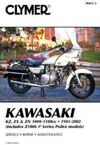
Руководство на английском языке по техническому обслуживанию и ремонту мотоциклов Kawasaki серий KZ, ZX и ZN 1981-2002 годов выпуска с двигателями объемом 1000-1100 cc.
- Издательство: Clymer
- Год издания: 2003
- Страниц: 378
- Формат: PDF
- Размер: 43,5 Mb
Руководство на английском языке по техническому обслуживанию и ремонту мотоциклов Kawasaki Ninja ZX-6R.
- Издательство: Kawasaki Heavy Industries, Ltd.
- Год издания: 1997
- Страниц: 370
- Формат: PDF
- Размер: 64,3 Mb

Руководство на английском языке по техническому обслуживанию и ремонту мотоциклов Kawasaki Ninja ZX-6R 2000-2002 годов выпуска.
- Издательство: Kawasaki Heavy Industries, Ltd.
- Год издания: —
- Страниц: 332
- Формат: PDF
- Размер: 19,1 Mb

Руководство на английском языке по техническому обслуживанию и ремонту мотоциклов Kawasaki Ninja ZX-6R.
- Издательство: Kawasaki Heavy Industries, Ltd.
- Год издания: 2007
- Страниц: 663
- Формат: PDF
- Размер: 12,0 Mb
Руководство на английском языке по техническому обслуживанию и ремонту мотоциклов Kawasaki Ninja ZX-6R и ZX-6RR 2003-2004 годов выпуска.
- Издательство: Kawasaki Heavy Industries, Ltd.
- Год издания: —
- Страниц: 514
- Формат: PDF
- Размер: 42,5 Mb

Руководство на английском языке по техническому обслуживанию и ремонту мотоциклов Kawasaki Ninja ZX-6RR.
- Издательство: Kawasaki Heavy Industries, Ltd.
- Год издания: 2004
- Страниц: 519
- Формат: PDF
- Размер: 10,1 Mb
Руководство на английском языке по подготовке к гонкам мотоциклов Kawasaki ZX-6RR.
- Издательство: Kawasaki Heavy Industries, Ltd.
- Год издания: 2005
- Страниц: 63
- Формат: PDF
- Размер: 7,5 Mb
Руководство на английском языке по техническому обслуживанию и ремонту мотоциклов Kawasaki Ninja ZX-7R и ZX-7RR.
- Издательство: Kawasaki Heavy Industries, Ltd.
- Год издания: —
- Страниц: 364
- Формат: PDF
- Размер: 38,7 Mb
Руководство на английском языке по подготовке к гонкам мотоциклов Kawasaki ZX-7R м ZXR750R 1992 года выпуска.
- Издательство: Kawasaki Heavy Industries, Ltd.
- Год издания: 1991
- Страниц: 69
- Формат: PDF
- Размер: 148,4 Mb
Руководство на английском языке по подготовке к гонкам мотоциклов Kawasaki ZX-7RR 1998 года выпуска.
- Издательство: Kawasaki Heavy Industries, Ltd.
- Год издания: 1997
- Страниц: 107
- Формат: PDF
- Размер: 138,0 Mb

Руководство на испанском языке по эксплуатации и техническому обслуживанию мотоциклов Kawasaki Ninja ZX-9R.
- Издательство: —
- Год издания: —
- Страниц: 174
- Формат: PDF
- Размер: 3,3 Mb
Сборник руководств на английском языке по техническому обслуживанию и ремонту мотоциклов Kawasaki Ninja ZX-9R.
- Издательство: Kawasaki Heavy Industries, Ltd.
- Год издания: —
- Страниц: 307/322
- Формат: PDF
- Размер: 161,3 Mb
Руководство на английском языке по техническому обслуживанию и ремонту мотоциклов Kawasaki ZX-10 и Ninja ZX-10.
- Издательство: Kawasaki Heavy Industries, Ltd.
- Год издания: 1989
- Страниц: 231
- Формат: PDF
- Размер: 162,0 Mb

Руководство на английском языке по техническому обслуживанию и ремонту мотоциклов Kawasaki Ninja ZX-10R.
- Издательство: Kawasaki Heavy Industries, Ltd.
- Год издания: 2008
- Страниц: 694
- Формат: PDF
- Размер: 14,7 Mb
Руководство на английском языке по подготовке к гонкам мотоциклов Kawasaki ZX-10R 2006 года выпуска.
- Издательство: Kawasaki Heavy Industries, Ltd.
- Год издания: 2006
- Страниц: 82
- Формат: PDF
- Размер: 2,5 Mb
Руководство по эксплуатации и техническому обслуживанию мотоциклов Kawasaki Ninja ZX-10R.
- Издательство: Kawasaki Heavy Industries, Ltd.
- Год издания: 2011
- Страниц: 207
- Формат: PDF
- Размер: 6,4 Mb

Руководство на английском языке по техническому обслуживанию и ремонту мотоциклов Kawasaki Ninja ZX-11 и ZZ-R1100 1993-2001 годов выпуска.
- Издательство: Kawasaki Heavy Industries, Ltd.
- Год издания: —
- Страниц: —
- Формат: JPG
- Размер: 62,4 Mb

Руководство на английском языке по техническому обслуживанию и ремонту мотоциклов Kawasaki Ninja ZX-12R.
- Издательство: Kawasaki Heavy Industries, Ltd.
- Год издания: 2004
- Страниц: 613
- Формат: PDF
- Размер: 11,3 Mb

Руководство на немецком языке по техническому обслуживанию и ремонту мотоциклов Kawasaki Ninja ZX-12R (ZX1200-A).
- Издательство: Kawasaki Motoren GmbH
- Год издания: 2000
- Страниц: 431
- Формат: PDF
- Размер: 149,8 Mb

Руководство на немецком языке по техническому обслуживанию и ремонту мотоциклов Kawasaki ZX-12R (ZX1200B).
- Издательство: Kawasaki Motors Europe
- Год издания: 2002
- Страниц: 451
- Формат: PDF
- Размер: 38,7 Mb

Руководство на английском языке по техническому обслуживанию и ремонту мотоциклов Kawasaki Ninja ZX-14 и ZZR1400.
- Издательство: Kawasaki Heavy Industries, Ltd.
- Год издания: 2006
- Страниц: 703
- Формат: PDF
- Размер: 13,6 Mb
Руководство на английском языке по техническому обслуживанию и ремонту мотоциклов Kawasaki ZX400-H2
- Издательство: Kawasaki Heavy Industries, Ltd.
- Год издания: —
- Страниц: —
- Формат: PDF
- Размер: 46,6 Mb
Руководство на немецком языке по техническому обслуживанию и ремонту мотоциклов Kawasaki ZX500-A1 и ZX600-A1.
- Издательство: —
- Год издания: —
- Страниц: 234
- Формат: PDF
- Размер: 19,9 Mb

Руководство на английском языке по техническому обслуживанию и ремонту мотоциклов Kawasaki KZ500/KZ550/ZX550 1979-1985 годов выпуска.
- Издательство: Clymer
- Год издания: —
- Страниц: 341
- Формат: PDF
- Размер: 12,0 Mb
Руководство на английском языке по техническому обслуживанию и ремонту мотоциклов Kawasaki ZX600/ZZR600/Ninja ZX-6 1990-2000 годов выпуска.
- Издательство: Haynes Publishing
- Год издания: 2001
- Страниц: —
- Формат: JPG
- Размер: 57,7 Mb

Руководство на английском языке по техническому обслуживанию и ремонту мотоциклов Kawasaki ZX600/ZX636 (ZX-6R) 1995-2002 годов выпуска.
- Издательство: Haynes Publishing
- Год издания: 2003
- Страниц: 272
- Формат: PDF
- Размер: 171,0 Mb
Руководство на английском языке по техническому обслуживанию и ремонту мотоциклов Kawasaki GPX600R/GPX750R/GPZ600R/Ninja 600R/Ninja 600RX/Ninja 750R/ZX600/ZX750 1985-1987 годов выпуска.
- Издательство: Haynes Publishing
- Год издания: 1999
- Страниц: 265
- Формат: PDF
- Размер: 77,0 Mb

Руководство на английском языке по техническому обслуживанию и ремонту мотоциклов Kawasaki ZX750 (ZXR750) 1989-1996 и ZX750 (Ninja ZX-7) 1989-1995 годов выпуска.
- Издательство: Haynes Publishing
- Год издания: 1998
- Страниц: 341
- Формат: PDF
- Размер: 36,7 Mb
Руководство на немецком языке по техническому обслуживанию и ремонту мотоциклов Kawasaki ZX750J/ZX750K/ZXR750/ZXR750R.
- Издательство: —
- Год издания: —
- Страниц: 282
- Формат: PDF
- Размер: 23,4 Mb
Руководство на немецком языке по техническому обслуживанию и ремонту мотоциклов Kawasaki GPX750R/ZX750F.
- Издательство: Kawasaki Heavy Industries, Ltd.
- Год издания: —
- Страниц: 192
- Формат: PDF
- Размер: 11,4 Mb
Руководство на английском языке по техническому обслуживанию и ремонту мотоциклов Kawasaki ZX900-A1.
- Издательство: Kawasaki Heavy Industries, Ltd.
- Год издания: —
- Страниц: 293
- Формат: PDF
- Размер: 22,9 Mb
Руководство на английском языке по техническому обслуживанию и ремонту мотоциклов Kawasaki ZX900-C1 и ZX900-D1.
- Издательство: Kawasaki Heavy Industries, Ltd.
- Год издания: —
- Страниц: 307
- Формат: PDF
- Размер: 27,9 Mb
Руководство на немецком языке по техническому обслуживанию и ремонту мотоциклов Kawasaki GPZ1000RX (ZX1000-A1).
- Издательство: Kawasaki Heavy Industries, Ltd.
- Год издания: —
- Страниц: 130
- Формат: PDF
- Размер: 20,8 Mb
Руководство на немецком языке по техническому обслуживанию и ремонту мотоциклов Kawasaki GPZ1100 (ZX1100E).
- Издательство: Kawasaki Heavy Industries, Ltd.
- Год издания: —
- Страниц: 327
- Формат: PDF
- Размер: 10,9 Mb
- Регистрация
- Войти
Инструкции » Мототехника » KAWASAKI
|
Всего инструкций в разделе: 53 |
|
Сервис мануал для мотоцикла KAWASAKI содержит много полезной информации по обслуживанию, эксплуатации и ремонту. |
Отсортировать по: Названию
| инструкция | устройство | размер |
| KAWASAKI ZZ-R250 (1990-1996) | мотоцикл | 27.23 MB |
| KAWASAKI NINJA ZX12R (2000) | мотоцикл | 112.14 MB |
| KAWASAKI ZX1200 (2002-2004) | мотоцикл | 13.35 MB |
| KAWASAKI NINJA ZX-12R (2002-2004) | мотоцикл | 13.35 MB |
| KAWASAKI NINJA ZX-10R (2004) | мотоцикл | 51.93 MB |
| KAWASAKI ZX9R | мотоцикл | 35.08 MB |
| KAWASAKI Z1000 (2003) | мотоцикл | 10.69 MB |
| KAWASAKI Z750S (2004) | мотоцикл | 11.32 MB |
| KAWASAKI VN2000 (2003) | мотоцикл | 13.29 MB |
| KAWASAKI VULCAN 2000 (2003) | мотоцикл | 13.29 MB |
| KAWASAKI VN1600 CLASSIC (2003) | мотоцикл | 12.83 MB |
| KAWASAKI VULCAN 1600 CLASSIC (2003) | мотоцикл | 12.83 MB |
| KAWASAKI VN1500 (1987-1999) | мотоцикл | 59.49 MB |
| KAWASAKI VULCAN VN750 (2000) | мотоцикл | 97.43 MB |
| KAWASAKI VULCAN 800 (1996-2004) | мотоцикл | 176.20 MB |
| KAWASAKI VN800 (1996-2004) | мотоцикл | 176.20 MB |
| KAWASAKI Versys (2006) | мотоцикл | 13.75 MB |
| KAWASAKI NINJA ZX-10 (1988-1990) | мотоцикл | 172.95 MB |
| KAWASAKI NINJA ZX-7RR (1997-2003) | мотоцикл | 189.81 MB |
| KAWASAKI NINJA ZX-7R (1997-2003) | мотоцикл | 189.81 MB |
| KAWASAKI NINJA ZX6RR (2003-2004) | мотоцикл | 148.96 MB |
| KAWASAKI NINJA ZX-6R (2005) | мотоцикл | 12.04 MB |
| KAWASAKI NINJA ZX-6R (2000-2002) | мотоцикл | 19.14 MB |
| KAWASAKI NINJA GPX250R (1988-2005) | мотоцикл | 36.54 MB |
| KAWASAKI KZ400 (1974) | мотоцикл | 258.87 MB |
| KAWASAKI KX450F (2006) | мотоцикл | 7.49 MB |
| KAWASAKI KX250F (2004) | мотоцикл | 7.71 MB |
| KAWASAKI KR250 | мотоцикл | 46.62 MB |
| KAWASAKI KLX650 | мотоцикл | 1.76 MB |
| KAWASAKI KLV1000 (2004) | мотоцикл | 14.85 MB |
| KAWASAKI WORKHORSE 250 (2003) | квадроцикл | 6.33 MB |
| KAWASAKI BAYOU 250 (2003) | квадроцикл | 6.33 MB |
| KAWASAKI KLF 250 (2003) | квадроцикл | 6.33 MB |
| KAWASAKI KLE500 (2004) | мотоцикл | 7.71 MB |
| KAWASAKI S3 (1974-1976) | мотоцикл | 17.19 MB |
| KAWASAKI S2 (1972-1973) | мотоцикл | 17.19 MB |
| KAWASAKI KH400 (1974-1976) | мотоцикл | 17.19 MB |
| KAWASAKI KH250 (1972-1976) | мотоцикл | 17.19 MB |
| KAWASAKI KDX200 (1989-1994) | мотоцикл | 20.38 MB |
| KAWASAKI GPZ900R (1984-1990) | мотоцикл | 22.92 MB |
| KAWASAKI Z550F (1983-1985) | мотоцикл | 12.55 MB |
| KAWASAKI Z500F (1983-1985) | мотоцикл | 12.55 MB |
| KAWASAKI Z400 F-FII (1983-1985) | мотоцикл | 12.55 MB |
| KAWASAKI GPZ400-550 (1983-1985) | мотоцикл | 12.55 MB |
| KAWASAKI NINJA EX250R (1987) | мотоцикл | 26.81 MB |
| KAWASAKI GPX250R (1987) | мотоцикл | 26.81 MB |
| KAWASAKI GPX250R (1988) | мотоцикл | 31.87 MB |
| KAWASAKI NINJA EX250R (1988) | мотоцикл | 31.87 MB |
| KAWASAKI ER5 (2004) | мотоцикл | 7.07 MB |
| KAWASAKI ER-6f (2005) | мотоцикл | 12.56 MB |
«— 1 2 —»
Что удобнее для чтения книг?
Планшет
Электронная книга
Смартфон
Книга в бумажном переплёте
Не читаю книг
© 2010- ManualBase.ru
- Статьи
- О сайте
- Помощь
- Контакты
© 2010- ManualBase.ru
|
Title |
File Size |
Download Links |
|
Kawasaki 1000GTR/ZG1000-A1 Owner’s Manual.doc |
2.6Mb |
Download |
|
Kawasaki 250 HS Owner’s Manual.pdf |
5.8Mb |
Download |
|
Kawasaki 750 Turbo Service Manual.pdf |
25Mb |
Download |
|
Kawasaki A Series 1969-1971 Workshop Manual.pdf |
48.4Mb |
Download |
|
Kawasaki BAYOU 250/Workhorse 250/KLF 250 ATV Service Manual.pdf |
6.3Mb |
Download |
|
Kawasaki Brute Force 750/KVF 750 ATV Service Manual.pdf |
6.3Mb |
Download |
|
Kawasaki Brute Force Owner’s Manual.pdf |
1.8Mb |
Download |
|
Kawasaki Concours 1000GTR Service Manual.rar |
139.5Mb |
Download |
|
Kawasaki EL250 Eliminator Service Manual.pdf |
28.4Mb |
Download |
|
Kawasaki Eliminator Bn125 Service Manual.pdf |
265.5kb |
Download |
|
Kawasaki EN450 Twins Workshop Manual.pdf |
48.9Mb |
Download |
|
Kawasaki ER-6f ABS Service Manual.pdf |
13.3Mb |
Download |
|
Kawasaki Er-6n Workshop Manual.pdf |
10.7Mb |
Download |
|
Kawasaki FH541V Service Manual.pdf |
3.1Mb |
Download |
|
Kawasaki KLF 250 Service Manual.pdf |
6.6Mb |
Download |
|
Kawasaki KLR650/KLR500 Service Manual.docx |
4.1Mb |
Download |
|
Kawasaki KR 150 Parts Catalog.pdf |
4.8Mb |
Download |
|
Kawasaki KR 150 Service Manual.pdf |
14Mb |
Download |
|
Kawasaki KX125 Service Manual.pdf |
33.9Mb |
Download |
|
Kawasaki Ninja ZX-10 Service Manual.pdf |
173.2Mb |
Download |
|
Kawasaki Ninja ZX-11 Service Manual.pdf |
17.1Mb |
Download |
|
Kawasaki NINJA ZX-14 Service Manual.pdf |
16.9Mb |
Download |
|
Kawasaki Ninja ZX–6R Service Manual.pdf |
9.1Mb |
Download |
|
Kawasaki PRAIRIE 360 Service Manual.pdf |
32.1Mb |
Download |
|
Kawasaki pump schematic.pdf |
3.6Mb |
Download |
|
Kawasaki VN 750 Service Manual.pdf |
101.8Mb |
Download |
|
Kawasaki VN800 Service Manual.pdf |
42.7Mb |
Download |
|
Kawasaki VN900 Custom Service Manual.pdf |
16.7Mb |
Download |
|
Kawasaki Vulcan 1700 Vaquero Service Manual.pdf |
15.6Mb |
Download |
|
Kawasaki Vulcan 1700 Voyager ABS Service Manual.pdf |
18.5Mb |
Download |
|
Kawasaki VULCAN 2000 Service Manual.pdf |
15.2Mb |
Download |
|
Kawasaki z series Workshop Manual.pdf |
29.5Mb |
Download |
|
Kawasaki Z750S Service Manual.pdf |
12Mb |
Download |
|
Kawasaki ZR-7 S (ZR 750-H1) Motorcycle Service Manual.pdf |
118.6Mb |
Download |
|
Kawasaki ZX-12R Service Manual.pdf |
14.1Mb |
Download |
|
Kawasaki ZX-7R Service Manual.pdf |
43.4Mb |
Download |
|
Kawasaki ZX600 Service Repair Manual 1985.pdf |
81.6Mb |
Download |
|
Kawasaki ZX6R Ninja Motorcycle Service Manual.pdf |
80.8Mb |
Download |
|
Kawasaki ZX900-C1 Service Manual.pdf |
35.8Mb |
Download |
Kawasaki is a global brand specializing in the production of various equipment. In addition to the usual motorcycles, the company produces aircraft, ships and other large
equipment using the most modern technologies. The Kawasaki company, whose history has long roots, remains one of the prominent players in the market for the production of various equipment.
Kawasaki company began to produce motorcycles quite late, skipping the 50s of the last century, when the entire industry in Japan began to increase its pace of development. It
was during this time period that the transition began not only to the Asian market, but also to the countries of Europe and America. The initial goal of all firms in Japan engaged in the
production of various equipment was the desire to provide the population with the equipment that could be some kind of alternative to public transport. Obviously, in the early years, the results
could hardly have been high, but the growth trend, of course, was outlined.
The refinement of technological processes, and then participation in various world competitions, laid the foundation for the formation of future success.
The founder of the company is Shozo Kawasaki, who comes from the family of a simple kimono seller. The beginning of Shozo’s career was not at all connected with motor vehicles, he started with
the job of a seller, later got a merchant ship. 1876 in the life of Shozo was marked by the fact that he opens his own shipyard and begins to occupy a leading position in the sugar trade.
The history of kawasaki dates back to the shipyard that was founded by Shouzo Kawasaki. Gradually, this company expanded, starting its activities in other industries, including civil and railway
construction. In 1911, the company focused on organizing shipping, and then the company began building aircraft and its components. The Chinese-Japanese war gave a new impetus Kawasaki’s business
development, making it possible to provide repairs to all military vessels and other equipment. After the war, Shozo Kawasaki decides to make Kozhiro Matsukata, who became the first president of
the Kawasaki concern, as manager. This position was assigned to him for thirty-two years, during which time he introduced an 8-hour work week, which was an innovation in those days.
Since the moment when Japan began active hostilities, Kawasaki became the main supplier of various equipment for the army. The situation changed radically after the war, then the
company experienced a real decline in its production. The first gaps of the upcoming progress appeared in 1950, when the first engine was designed at one of the plants. In 1951, production
technologies for 2-stroke and 4-stroke engines were installed, which were installed on bicycles from the Noriz company.
1954 — More than two hundred Bikescooter KV-2 scooters were released. The next step of the company was the joint production of Meihazu 60 — a bicycle with an outboard engine.

1957 — during this period, mass production and production of motorcycle equipment begins. Initially, they went under the Meihazu brand, but since 1961, the Kawasaki brand was finally approved.
1966 — expansion begins on the American market, however, this does not bring definite success. And in 1975 this process was slightly stopped and the company decided to return to the Japanese
market.
In 1966, the first Samurai kawasaki motorcycles appeared, equipped with a special dual pipe system located at the rear. The motorcycle had an engine of 90 cm3 and a 5-speed gearbox. This model
was a true leader for five years, until Honda began to produce motorcycles of this type.

1968 — this date became the moment of mass production of Mach III motorcycles, samples of which immediately began to be delivered to European countries. This model was a real discovery among
motorcycles of this type, having engines with a volume of 500 cm3. 1973 — The company launches the H2 750 Mach IV with an improved design.

Following the success of the MachIII, the company launches the new Z1 motorcycle, which is widely recognized. Without stopping at this, the designers begin to work on the continuation of the
series and release the Z2. There are no special differences between them, except for the engine, which was reduced to 750 cm3.

1977 was marked by the fact that the production of Z1000 and Z1000LTD, having a volume of about 1016 cm3, was started. The production of the Z650C begins, which is distinguished by titanium
wheels and an engine capacity of 652 cm3. 1978 — The Z400 was equipped with a 6-speed gearbox, and Z650SR motorcycles were also produced. 1979 — Kawasaki launches the ZI3000, which has a 6-speed
gearbox and a 1286 cm3 engine. Being a rather bulky machine, this model nevertheless aroused considerable interest among buyers.

1983 — release of the AR 125 model begins, having a volume of 125 cm3. A 6-speed gearbox and a liquid-based cooling system make it one of the most popular models of the time. In 1985, continued
growth in the production of 4-stroke motorcycles. So, the LTD450 based on the Ninja engine was born. 1988 — the engine is increased to one thousand cm3, resulting in the appearance of the ZX10
model, which has an aluminum frame in the design. The end of the 80s was marked by an increased interest in “retro” models, when the nostalgic design was combined with the latest technological
innovations.

At this time, production work focused on sports types of motorcycles began to develop rapidly. On the basis of Kawasaki, the ZZ-R appeared, which belongs to the class of machines with a volume of
up to one thousand cm3. Along the way, the retro style in the development of motorcycles developed, for example, the ZXR bike was released, combining the original design and powerful
technological “stuffing.” 1992 — the Estrella bike belonging to the category of motorcycles up to 249 cm3 was born. This model has become very popular in Japan, as evidenced by the high sales
figures recorded at that time. 1998 — a model with a volume of 125 cm3 and a 4-stroke engine is produced. At the same time in the United States, Vulcan Nomad, a motorcycle with a 2-cylinder
engine, was in full swing. 1999 — release of the Drifter model, which has the design of past years. In general, the end of the century for the company Kawasaki was marked by the release of models
based on the improvement of already released motorcycles, thus practically stopping the serial production of new models.

Big victories began in 1969, when the first competition was won. This success belonged to Dave Simmonds, who defeated his rivals on a 125 cm3 Kawasaki motorcycle. From 1978 and for four years,
Kawasaki showed quite decent results in races, which, however, did not lead to any triumph in competitions. In 2002, the first race was carried out as part of the MotoGP competition. However,
neither this race nor its subsequent ones led to the expected victories and successes, which led to the fact that in 2009 it was decided to withdraw from the competition. The company was more
successful in superbike competitions.
#1
![]()
motogad
- Пол:Мужчина
- Город:Москва ВАО
- Мото:Kawasaki Ninja ZX6R
Отправлено 18 Август 2008 — 18:34
Все мануалы которые у нас есть ниже по теме
Сообщение отредактировал max232: 31 Январь 2014 — 13:53
- bktspro, Michaelgrorm, SCpraics и 2 другим это нравится
- Наверх
#2
![]()
max232
max232
- Пол:Мужчина
- Страна:Россия
- Город:Елец, Липецкая область
- Мото:zx-10r `08
Отправлено 09 Январь 2014 — 21:19
Просьба к обладателям мануалов которых нет в списке,
мы будем признательны если вы с нами поделитесь.
Руководство по ремонту демпфера Ohlins
Каталог з/ч Kawasaki
Руководство по эксплуатации Kawasaki Ninja H2 (ZX1000NF) 2014-
Руководство по эксплуатации Kawasaki Ninja H2 SX (ZX1000NF) 2017- (РУС) НОВОЕ! Спасибо Mikhail72
Руководство по ремонту KNinja H2 SX 2018- НОВОЕ! Спасибо belenkiy
Руководство по ремонту Kawasaki ZZR1400, ZZR1400 ABS, Ninja ZX-14 2012-2013 (РУС) НОВОЕ! Спасибо Назарий
Руководство пользователя Kawasaki ZZR1400, ZZR1400 ABS, Ninja ZX-14 2012- (РУС) НОВОЕ! Спасибо Ewil Dwarf
Руководство по ремонту Kawasaki ZZR1400, ZZR1400 ABS, Ninja ZX-14 2010-2011
Руководство по ремонту Kawasaki ZZR1400, ZZR1400 ABS, Ninja ZX-14 2008-2009
Руководство по ремонту Kawasaki ZZR1400, ZZR1400 ABS, Ninja ZX-14 2006-2007
Руководство по ремонту Ninja ZX-12R 2002-2005
Руководство по ремонту Ninja ZX-12R 2000-2001
Руководство по ремонту Kawasaki Ninja ZX-10R, Ninja ZX-10R ABS 2016-2017 НОВОЕ!
Руководство по ремонту Kawasaki Ninja ZX-10R, Ninja ZX-10R ABS 2013-2015
Руководство по ремонту Kawasaki Ninja ZX-10R, Ninja ZX-10R ABS 2011-2012
Руководство по эксплуатации (РУС) Kawasaki Ninja ZX-10R 2011-2012
Руководство по эксплуатации (EN) Kawasaki Ninja ZX-10R 2008-2010
Руководство по ремонту Kawasaki Ninja ZX-10R 2008-2010
Руководство по ремонту Kawasaki Ninja ZX-10R 2006-2007
Руководство по ремонту Kawasaki Ninja ZX-10R 2004-2005
Руководство по ремонту Kawasaki Ninja ZX-10 1988-1990
Руководство по ремонту Kawasaki ZX-9R 1998 — 1999
Руководство по ремонту Kawasaki ZX-9R 1998 — 1999 RUS
Руководство по ремонту Kawasaki ZX-9R 1994-1997
Руководство по ремонту Kawasaki ZX-9R (Ger) 2002-2003
Руководство по ремонту Kawasaki ZX750 (ZXR-750) 1989-1996, ZX750 (Ninja ZX-7)1989-1995
Руководство по ремонту Kawasaki Ninja ZX-7R, ZX-7RR 1996-2003
Руководство по ремонту Kawasaki Ninja ZX-6R, Ninja ZX-6R ABS 2013
Руководство по ремонту (РУС пер.Viktor72) Kawasaki Ninja ZX-6R, Ninja ZX-6R ABS 2013
Руководство по ремонту Kawasaki Ninja ZX-6R 2009-2011
Руководство по ремонту Kawasaki ZX-6R 2007-2008
Руководство по ремонту Kawasaki Ninja ZX-6R 2005-2006
Руководство по ремонту Kawasaki Ninja ZX–6R, ZX-6RR 2003-2004
Руководство по ремонту Kawasaki Ninja ZX-6R 2001-2002
Руководство по ремонту Kawasaki Ninja ZX-6R 2001-2002 (РУС) НОВОЕ! Спасибо Vjaceslav
Руководство по ремонту Kawasaki Ninja ZX–6R, 98-99
Руководство по ремонту Kawasaki Ninja ZX-6R 95-97
Руководство по ремонту Kawasaki ZXR400 (zx-4), ZX400-H2 1989-1990
Руководство по ремонту Kawasaki ZXR400 (zx-4), ZX400 L1-L8 1991-1998
Руководство по ремонту Kawasaki ZXR400(zx-4), ZX400 G1,G1A,G1B 1988
Руководство по ремонту Kawasaki Ninja 250 2008-2012
Руководство пользователя Kawasaki Ninja 250 (РУС) 2008-2012
Руководство по ремонту Kawasaki Ninja 300, Ninja 300 ABS 2013-
Руководство по эксплуатации (РУС) Kawasaki Ninja 300, Ninja 300 ABS 2013-
Дорожные мотоциклы Kawasaki. Общее руководство по эксплуатации (РУС) 2012-
Руководство по ремонту Kawasaki ER-6n, ER-6n ABS 2012-
Руководство по эксплуатации (РУС) Kawasaki ER-6n, ER-6n ABS 2012-
Руководство по ремонту Kawasaki ER-6n, ER-6n ABS 2009-2011
Руководство по ремонту Kawasaki ER-6n, ER-6n ABS 2006-2008
Руководство по ремонту Kawasaki Ninja 650, Ninja 650 ABS, ER-6f, ER-6f ABS 2012-
Руководство по эксплуатации (РУС) Kawasaki Ninja 650, Ninja 650 ABS, ER-6f, ER-6f ABS 2012-
Руководство по ремонту Kawasaki Ninja 650, Ninja 650 ABS, ER-6f, ER-6f ABS 2009-2011
Руководство по ремонту Kawasaki NINJA 650R, ER-6f, ER-6f ABS 2006-2008
Руководство по ремонту Kawasaki ER500 C1-C5
2001 ER500-C1 37Kw
2001 ER500-D1 25kw
2002 ER500-C2 37Kw
2003 ER500-C3 37Kw
2004 ER500-C4 катализатор -1Kw
2005 ER500-C5 модифицирован выхлоп, авто выключение/включение света
Руководство по ремонту Kawasaki Z1000, Z1000 ABS 2017- НОВОЕ! Спасибо Назарий
Руководство по ремонту Kawasaki Z1000SX Ninja 1000 2017- НОВОЕ! Спасибо Ghost1195
Руководство по ремонту Kawasaki Z1000SX, Z1000SX ABS, Ninja 1000, Ninja 1000 ABS 2014-2016 НОВОЕ! Спасибо alexus1313
Руководство по ремонту Kawasaki Z1000SX, Z1000SX ABS, Ninja 1000, Ninja 1000 ABS 2011-2013 НОВОЕ! Спасибо Glareone
Руководство по ремонту Kawasaki Z1000, Z1000 ABS 2014-2016
Руководство по ремонту Kawasaki Z1000, Z1000 ABS 2010-2013
Руководство по эксплуатации (РУС) Kawasaki Z1000SX, Z1000SX ABS 2010-2013
Руководство по ремонту Kawasaki Z1000, Z1000 ABS 2007-2009
Руководство по ремонту Kawasaki Z1000 2003-2006
Руководство по ремонту Kawasaki Z900, Z900 ABS, ZR900 2017- НОВОЕ! Спасибо ev6en!
Руководство по ремонту Kawasaki Z800 2013-
Инструкция по эксплуатации Kawasaki Z800 (РУС) 2013-
Инструкция по эксплуатации Kawasaki Z750R (РУС) 2011
Руководство по ремонту Kawasaki Z750S 2005-2006
Руководство по ремонту Kawasaki Z750 2003-2006
Руководство по ремонту Kawasaki Z750, Z750 ABS 2007-2010
Руководство по ремонту Kawasaki Z750R, Z750R ABS 2011- 2012 РОЗЫСК!
Инструкция по эксплуатации Kawasaki Z400 ABS (РУС) 2019- НОВОЕ! Спасибо Бродячий Кот!
Kawasaki 1400GTR, CONCOURS 14 ABS, CONCOURS 14 2010-2014 РОЗЫСК
Kawasaki 1400GTR, CONCOURS 14 ABS, CONCOURS 14 2008-2009
Руководство по эксплуатации (РУС) Kawasaki 1400GTR 2010
Руководство по ремонту Kawasaki VERSYS 650 VERSYS 650 ABS 2015-2016
Руководство по ремонту Kawasaki VERSYS 650 VERSYS 650 ABS 2010-2014
Руководство по ремонту Kawasaki VERSYS 650 2007-2009
Руководство по ремонту Kawasaki VERSYS 1000 2012-2014
Руководство по эксплуатации (РУС) Kawasaki VERSYS 1000 2012-2014
Руководство по эксплуатации (РУС) Kawasaki VERSYS 1000 SE 2019 — НОВОЕ!
Руководство по эксплуатации (РУС) Kawasaki VULCAN S VULCAN S ABS 2015- НОВОЕ! Спасибо offlineb!
Руководство по эксплуатации (РУС) Kawasaki W800 2012-
Руководство по эксплуатации (РУС) Kawasaki KLX250
Руководство по эксплуатации (ENG) Kawasaki KLX150L 2014- НОВОЕ!Спасибо roy0864!
Руководство по эксплуатации (РУС) Kawasaki 1000GTR ZG1000-A1 1986
Все что у нас есть выложено здесь, и мы больше ничего от Вас не прячем. Затрудните себя хотя бы поиском в списке мануала для своей модели мотоцикла.
По этим ссылкам расположены 2 архива по гигабайту с мануалами которых нет в вышеуказанном списке.
http://yadi.sk/d/yrnnmcxJJ9wxG
http://yadi.sk/d/nxb6nuh_J9x52
Эта ссылка на теже мануалы с возможностью не скачивать архивы целиком https://yadi.sk/d/OzesQZ8RUrXPE
- mrkvch, EnergyControl, Walazar и еще 1 это нравится
- Наверх
#3
![]()
Smart
Smart
- Пол:Мужчина
- Страна:Россия
- Город:Митино
- Мото:9-ka 1999г—>9-ka 2001г
Отправлено 17 Январь 2014 — 11:26
По ссылке https://yadi.sk/d/I61_p9A6mdk6m находятся мануалы на следующие модели которые не вошли в список выложенный выше.
Kawasaki ZZR1100 & ZX11 1993-2001
Kawasaki NINJA 250 86-07
Kawasaki GPZ400-550 & Z400F-FII & Z500F-550F 83-85 Service Manual
Kawasaki GPZ-500,600,ZX-500-A1,ZX-600-A1 Service Manual
Kawasaki GPZ-500S 86-94 Service Manual
Kawasaki GPZ-600R/GPX-600R/Ninja 600R/RX/GPX-750R/Ninja 750R
Kawasaki GPZ-750 Turbo 1984 Service Manual
Kawasaki GPZ900R 1984-1990 Workshop Manual
Kawasaki GPZ-1000RX,GPZ-900R Service Manual
Kawasaki GPZ-1100E Service Manual
Kawasaki GTR-1400 2014 Service Manual
Kawasaki KDX200 89-94 Service Manual
Kawasaki KH250-400 72-76
Kawasaki KLV1000-A1 2004 Service Manual
Kawasaki KLX650
Kawasaki KR250
Kawasaki KX250F 2004 Service Manual
Kawasaki KX450F 2006 Service Manual
Kawasaki KZ400 1974 Service Manual
Kawasaki KZ440 Service Manual
Kawasaki VN1500 87-99 Service Manual
Kawasaki VN1600-A1&A2 2003 Service Manual
Kawasaki VN2000-A1 2003 Service Manual
Kawasaki VN750 Manual and Parts
Kawasaki ZZR250 90-96 Service Manual
Kawasaki A Series Rotary Valve Twins 250,350,500 69-71 Workshop Manual
Kawasaki EN450,EN500,EN454,LTD500 Vulcan 85-04 Service Manual
Kawasaki ER-5 2004 Service Manual
Kawasaki ER-5 1997 Service Manual(DE)
Kawasaki VN800 Vulcan 96-04 Service Manual
Kawasaki VN900 Vulcan Classic 2006 Service Manual
Kawasaki W650 ’99 Service Manual (German)
Kawasaki ZR1100A,Zephir-1100 Service Manual
Kawasaki ZRX1200R,ZRX1200S 2001-2007 Service Manual
Kawasaki ZR550,ZR750 Zephyr 1990 Service Manual
Kawasaki ZR-7S,ZR-750H1 Service Manual
Kawasaki ZXR400R Kit 1989 Service Manual
Kawasaki ZXR400L Service Manual
Kawasaki ZXR750R,ZXR750J,ZXR750K Service Manual
Kawasaki ZXR750 Racing Kit 1992 Service Manual
Kawasaki ZX-10 Ninja 1988-1990 Service Manual
Kawasaki ZZR1200 ’03 Service Manual (German)
Kawasaki Z1 1972 Service Manual
Kawasaki KLE500 Service Manual
Kawasaki ZRX1200 Service Manual(German)
Kawasaki KLX110 Service Manual
Kawasaki ZXR 250 Service Manual 1997
- sem01 и Walazar это нравится
- Наверх
#4
![]()
albert8121984
albert8121984
-
- Members
-
- 35 сообщений
Прохожий
- Пол:Мужчина
- Страна:Россия
- Город:Москва СВАО(Алтуфьево), (КБР г.Прохладный)
- Мото:Kawasaki Z1000SX, (Versys 650B-08г), (ZX-6R 636 05г.) (ZZR 400 — 2)
Отправлено 16 Октябрь 2015 — 14:29
Пользуюсь сайтом ManualsLib – Search For Manuals Online.
Если что-то не понятно с помощью googla можно перевести страничку.
- Cher Tannov это нравится
- Наверх
#5
![]()
Cher Tannov
Cher Tannov
-
Вконтакте:
- Пол:Мужчина
- Страна:Россия
- Город:Москва, Чер Танново
- Мото:ER-6F ’12
Отправлено 06 Апрель 2016 — 10:32
Каталог Hiflo по масляным и воздушным фильтрам: https://yadi.sk/i/8FAFZ19PqmkhH
Немало каталогов и мануалов на тайском сайте Кавасаки.
http://www.kawasaki….c&page=download
ONLINE КАТАЛОГИ
Каталоги производителей, представленных в наших магазинах. Ссылки открываются в новом окне.
HIFLOFILTRO — Воздушные и маслянные фильтры
MOTUL — Моторные масла и мотохимия
JTSPROKETS — Звёзды и цепи привода
LUCAS TRW — Тормозные колодки
FERODO — Тормозные колодки
NGK — Свечи зажигания
ARIETE — Сальники и пыльники вилки
ALL BALLS RACING — Подшипники рулевой колонки
Сообщение отредактировал Cher Tannov: 06 Май 2016 — 11:35
- Coreydus и gtaemblem.club это нравится
- Наверх
#6
![]()
max232
max232
- Пол:Мужчина
- Страна:Россия
- Город:Елец, Липецкая область
- Мото:zx-10r `08
Отправлено 19 Сентябрь 2019 — 15:43
Ребята, думаю навести в этом разделе порядок.
Если просто так скидывать ссылки, без указания точной модели для разных рынков,от какого года до какого года, сервисный мануал/руководство по эксплуатации, на каком языке.
Этот раздел очень быстро превратиться в помойку в котором невозможно ничего найти.
Зачастую люди кидают ссылки на то что у нас уже есть.
Очень много мото для разных рынков называются по разному.
Я вроде недалекий человек от мото, но и мне не просто разобраться какие модели одинаковые а какие нет.
Пожалуйста, если у вас есть чем поделиться указывайте как минимум следующую информацию:
1. точная модель мотоцикла
2. модельный год. (от какого года и ДО какого года)
3. Сервисный мануал или руководство по эксплуатации
4. На каком языке издание
5. Ссылка
БЕЗ УКАЗАНИЯ ЭТОЙ ИНФОРМАЦИИ Я БУДУ УДАЛЯТЬ ПОСТЫ
- Наверх
#7
![]()
ведьмак 24
ведьмак 24
-
- Читатели
- 1 сообщений
- Пол:Мужчина
- Страна:россия
- Город:иркутск
- Мото:кавасаки илиминатор VN250
Отправлено 22 Октябрь 2020 — 09:40
а не подскажеш где найти мануал на кавасаки илименатор вн 250,нигде найти не могу
- Наверх
#8
![]()
max232
max232
- Пол:Мужчина
- Страна:Россия
- Город:Елец, Липецкая область
- Мото:zx-10r `08
Отправлено 13 Апрель 2021 — 12:14
а не подскажеш где найти мануал на кавасаки илименатор вн 250,нигде найти не могу
https://www.ebay.com.au/p/2185422503
- Наверх
#9
![]()
Назарий
Назарий
-
- Читатели
- 6 сообщений
- Пол:Мужчина
- Страна:Россия
- Город:Москва
- Мото:Z1000
Отправлено 18 Август 2021 — 16:39
- Наверх
#10
![]()
max232
max232
- Пол:Мужчина
- Страна:Россия
- Город:Елец, Липецкая область
- Мото:zx-10r `08
Отправлено 19 Август 2021 — 00:27
- Наверх
#11
![]()
Lavarock
Lavarock
-
- Читатели
- 1 сообщений
- Пол:Мужчина
- Страна:Россия
- Город:Сочи
- Мото:z650
Отправлено 14 Декабрь 2021 — 21:53
Помогите найти мануал на Z650 2017 год
- Наверх
#12
![]()
advokat56
advokat56
-
- Читатели
- 1 сообщений
- Пол:Мужчина
- Страна:РФ
- Город:Оренбург
- Мото:Ninja 1000SX
Отправлено 25 Январь 2022 — 18:44
Доброе время суток! Поменял свой мот на Ninja 1000SX 2020 г. долго искал мануал на русском. Нашел делюсь. https://e-kawasaki.r…ba66894759a.pdf
- Наверх
#13
![]()
belenkiy
belenkiy
-
- Читатели
- 3 сообщений
- Пол:Мужчина
- Страна:Россия
- Город:Москва
- Мото:fz6r
Отправлено 15 Май 2022 — 18:50
Руководство по ремонту — Kawasaki h2 2018
https://1drv.ms/b/s!…-l2jLg?e=kLBago
К сожалени к SX не смог найти
- Наверх
#14
![]()
max232
max232
- Пол:Мужчина
- Страна:Россия
- Город:Елец, Липецкая область
- Мото:zx-10r `08
Отправлено 15 Май 2022 — 22:10
По вашей ссылке именно SX
Я добавил к списку. спасибо!
- Наверх
#15
![]()
Denisik
Denisik
-
- Читатели
- 1 сообщений
- Пол:Мужчина
- Страна:Россия
- Город:Вологда
- Мото:Z250
Отправлено 16 Сентябрь 2022 — 10:20
Руководство по эксплуатации Kawasaki Z250
https://disk.yandex…./zXaOezF2k7TSSQ
- Наверх
#16
![]()
L0ckhead
L0ckhead
-
- Members
-
- 20 сообщений
Прохожий
- Пол:Мужчина
- Страна:Россия
- Город:Краснознаменск
- Мото:Kawasaki Ninja 1000 sx
Отправлено 26 Март 2023 — 20:52
Мб кому пригодится мануал на ninja 1000 sx 2020+ Файл можно получить по ссылке:
Ninja 1000 sx.pdf
https://disk.yandex…./ddmFwjH-2Lc4Yg
- Наверх
#17
![]()
L0ckhead
L0ckhead
-
- Members
-
- 20 сообщений
Прохожий
- Пол:Мужчина
- Страна:Россия
- Город:Краснознаменск
- Мото:Kawasaki Ninja 1000 sx
Отправлено 26 Март 2023 — 20:53
Дубль
- Наверх
#18
![]()
AnDrRew
AnDrRew
-
- Читатели
- 4 сообщений
- Пол:Мужчина
- Страна:Russia
- Город:Moscow
- Мото:Ninja 1000
Отправлено 08 Апрель 2023 — 14:39
На manualslib больше нет наших мануалов((
Пока искал сервис мануал для своего мотоцикла нашёл:
Руководство пользователя z1000sx ninja1000 2017-19 на русском языке
https://docviewer.ya…m89MCJ9&lang=ru
- Наверх
#19
![]()
AnDrRew
AnDrRew
-
- Читатели
- 4 сообщений
- Пол:Мужчина
- Страна:Russia
- Город:Moscow
- Мото:Ninja 1000
Отправлено 08 Апрель 2023 — 14:40
На manualslib больше нет наших мануалов((
Пока искал сервис мануал для своего мотоцикла нашёл:
Руководство пользователя z1000sx ninja1000 2017-19 на русском языке
https://mot63.ru/upl…6e444596981.pdf
- Наверх
| Название: | Размер: | Посещения: |
| Kawasaki el 250 руководство по эксплуатации | 3.32 MB | 44557 |
| Kawasaki EL 250 часть спискаs | 1.24 MB | 15931 |
| Kawasaki EL250E монтажная схема | 222.04 Kb | 15775 |
| Kawasaki EN 450 EN 500 454 LTD 500 Vulcan 85 04 | 48.11 MB | 82186 |
| Kawasaki ER 5 руководство по ремонту | 85.90 MB | 49823 |
| Kawasaki er 650 руководство по эксплуатации | 8.89 MB | 24564 |
| Kawasaki er 6f руководство по ремонту | 10.81 MB | 33439 |
| Kawasaki er5 2004 руководство по ремонту | 6.15 MB | 18649 |
| Kawasaki EX 500 GPZ 500 S 1987 1993 руководство по ремонту | 26.63 MB | 34231 |
| Kawasaki gpx 250 r ninja ex 250 f2 f19 1988 2005 руководство по ремонту suplimentar | 31.72 MB | 26230 |
| Kawasaki gpx 600 r zx 600 c4 1991 часть списка | 3.02 MB | 22094 |
| Kawasaki GPX 750 R ZX 750 F1 руководство по ремонту | 10.91 MB | 35879 |
| Kawasaki GPX 750R | 2.28 MB | 18017 |
| Kawasaki gpz 1000 rx gpz 900 r руководство по ремонту suplimentar | 20.16 MB | 37065 |
| Kawasaki gpz 1100 e руководство по ремонту | 10.72 MB | 34296 |
| Kawasaki GPz 400 550 Z 400 500 550 1983 1985 руководство по ремонту | 10.26 MB | 50208 |
| Kawasaki gpz 500 600 zx 500 a1 zx 600 a1 руководство по ремонту | 19.56 MB | 27997 |
| Kawasaki Gpz 500 S 86 94 | 10.51 MB | 29007 |
| Kawasaki gpz 600 r gpx 600 r ninja 600 r rx gpx 750 r ninja 750 r 1985 1997 руководство по ремонту | 81.45 MB | 53754 |
| Kawasaki gpz 750 turbo 1984 руководство по ремонту | 25.02 MB | 21347 |
| Kawasaki GPZ 900R ZX900A | 44.85 MB | 25453 |
| Kawasaki gtr 1000 concours 1989 2000 руководство по ремонту | 26.89 MB | 25677 |
| Kawasaki gtr 1400 руководство по ремонту | 17.64 MB | 45423 |
| Kawasaki kaf 400 mule 600 610 4×4 2005 руководство по ремонту | 7.50 MB | 12378 |
| Kawasaki kaf 620 mule 3010 4×4 2005 руководство по ремонту | 7.90 MB | 12466 |
| Kawasaki kdx 200 1989 1994 руководство по ремонту | 16.57 MB | 22604 |
| Kawasaki kfx 700 v a1 force 2004 руководство по ремонту | 7.48 MB | 15307 |
| Kawasaki kfx 700 часть списка | 12.07 MB | 11722 |
| Kawasaki kle 500 manual | 6.62 MB | 59821 |
| Kawasaki kle 500 часть списка | 1.73 MB | 18442 |
| Kawasaki klf 250 a1 3 2003 2005 руководство по ремонту | 5.45 MB | 13156 |
| Kawasaki klr 250 kl 250 d руководство по ремонту | 42.83 MB | 37125 |
| Kawasaki klr 500 650 1987 2004 руководство по ремонту suplimentar | 16.74 MB | 22235 |
| Kawasaki klr 500 650 руководство по ремонту | 18.23 MB | 25708 |
| Kawasaki klr 600 E | 34.08 MB | 14398 |
| Kawasaki klr 600 руководство по ремонту | 29.22 MB | 21919 |
| Kawasaki klr 600 руководство по ремонту suplimentar | 4.87 MB | 12466 |
| Kawasaki klv 1000 a1 2004 руководство по ремонту | 13.66 MB | 10503 |
| Kawasaki KLV 1000A 2004 | 260.30 Kb | 9117 |
| Kawasaki klx 250 300 1997 руководство по ремонту suplimentar | 11.76 MB | 22657 |
| Kawasaki klx 650 1993 руководство по ремонту | 17.02 MB | 26422 |
| Kawasaki KLX 750 | 134.08 MB | 10630 |
| Kawasaki kr1 руководство по ремонту | 64.60 MB | 11235 |
| Kawasaki kvf 360 prairie 360 2003 руководство по ремонту | 30.41 MB | 26884 |
| Kawasaki kvf 750 a b1 brute force 2005 руководство по ремонту | 9.88 MB | 24432 |
| Kawasaki kx 125 250 руководство по ремонту | 5.02 MB | 61454 |
| Kawasaki kx 250 f 2006 руководство по ремонту | 6.31 MB | 27071 |
| Kawasaki kx 250 n руководство по ремонту | 5.96 MB | 29571 |
| Kawasaki kxf 700 руководство по ремонту | 54.09 MB | 11481 |
| Kawasaki kz 1300 1979 1983 руководство по ремонту | 295.59 MB | 16339 |
| Kawasaki kz 1300 руководство по эксплуатации | 32.76 MB | 15506 |
| Kawasaki kz 400 1974 руководство по ремонту | 248.31 MB | 17663 |
| Kawasaki kz 650 руководство по ремонту | 26.91 MB | 22785 |
| Kawasaki kz 750 руководство по ремонту | 42.05 MB | 30719 |
| Kawasaki KZ500 550 GPZ ZX 550 79 85 руководство по ремонту | 11.73 MB | 21183 |
| Kawasaki Ninja ZX 10R 03 руководство по ремонту | 172.11 MB | 12469 |
| Kawasaki Ninja ZX 6R 2000 2002 руководство по ремонту | 80.74 MB | 21505 |
| Kawasaki Ninja ZX 6R 98 99 | 64.23 MB | 23046 |
| Kawasaki Ninja ZX 7R руководство по ремонту | 31.83 MB | 22528 |
| Kawasaki Ninja ZX 9R руководство по ремонту | 113.33 MB | 34092 |
| Kawasaki versys руководство по ремонту | 117.69 MB | 22378 |
| Kawasaki vn 1500 1987 1999 руководство по ремонту | 34.87 MB | 31816 |
| Kawasaki vn 1600 vulcan 2003 руководство по ремонту | 11.92 MB | 17451 |
| Kawasaki vn 2000 2003 руководство по ремонту | 11.58 MB | 14708 |
| Kawasaki vn 500 vulcan 1985 2004 руководство по ремонту | 48.11 MB | 20781 |
| Kawasaki VN 800 Vulcan 96 04 руководство по ремонту | 42.22 MB | 44333 |
| Kawasaki vn 900 vulcan classic 2006 руководство по ремонту | 10.97 MB | 24112 |
| Kawasaki Vulcan 1500 | 1.48 MB | 33202 |
| Kawasaki Vulcan VN 750A Manual Parts | 68.15 MB | 24513 |
| Kawasaki z 1 1972 руководство по ремонту | 27.18 MB | 15607 |
| Kawasaki z 1000 2003 руководство по ремонту | 9.25 MB | 15079 |
| Kawasaki z 1000 2003 часть списка | 3.20 MB | 10095 |
| KAWASAKI Z 750 | 8.40 MB | 27502 |
| Kawasaki z 750 2003 руководство по ремонту | 8.41 MB | 18845 |
| Kawasaki z 750 2007 2008 руководство по ремонту | 13.28 MB | 37577 |
| Kawasaki Z1000 2003 руководство по ремонту | 9.25 MB | 17644 |
| Kawasaki Z750 2003 руководство по ремонту | 8.41 MB | 14996 |
| Kawasaki Zephyr 550B Users Manual | 4.33 MB | 17778 |
| Kawasaki zl 400 часть списка | 1.57 MB | 16707 |
| Kawasaki zl 600 b монтажная схема | 156.64 Kb | 12186 |
| Kawasaki zl 600 руководство по эксплуатации | 3.02 MB | 20798 |
| Kawasaki zl 750 часть списка | 1.27 MB | 10965 |
| Kawasaki zl 900 руководство по эксплуатации | 7.49 MB | 14167 |
| Kawasaki zr 1100 a руководство по ремонту | 18.80 MB | 14753 |
| Kawasaki zr 550 750 zephyr 1990 1997 руководство по ремонту | 161.19 MB | 42184 |
| Kawasaki zr 7s zr 750 h1 руководство по ремонту | 116.41 MB | 27665 |
| Kawasaki ZR1100A Zephir 1100 | 18.80 MB | 19593 |
| Kawasaki zrx 1100 zr 1100 c руководство по ремонту | 16.75 MB | 36270 |
| Kawasaki ZRX 1200 A B C | 15.19 MB | 18616 |
| Kawasaki zrx 1200 r s 2001 2007 руководство по ремонту | 29.83 MB | 24482 |
| Kawasaki ZRX 1200 R S руководство по ремонту 2001 2006 | 29.83 MB | 17144 |
| Kawasaki zx 10 ninja 1988 1990 руководство по ремонту | 164.01 MB | 23961 |
| Kawasaki zx 10 r ninja 2003 руководство по ремонту | 95.44 MB | 9131 |
| Kawasaki zx 10 r ninja 2004 2005 руководство по ремонту | 172.11 MB | 15967 |
| Kawasaki zx 10 r ninja 2006 2007 руководство по ремонту | 12.99 MB | 18766 |
| Kawasaki ZX 10R Ninja 2004 руководство по ремонту | 172.11 MB | 11363 |
| Kawasaki zx 12 r b 2003 руководство по ремонту | 40.06 MB | 13192 |
| Kawasaki ZX 12R 2000 руководство по ремонту | 108.76 MB | 15021 |
| Kawasaki ZX 12R Ninja ZX 1200 A | 150.47 MB | 14070 |
| Kawasaki zx 6 r 2005 руководство по ремонту | 10.22 MB | 14406 |
| Kawasaki zx 6 r 2007 руководство по ремонту | 12.31 MB | 18414 |
| Kawasaki zx 6 r rr ninja 2003 2004 руководство по ремонту | 44.47 MB | 16083 |
| Kawasaki ZX 6 RR 2003 2004 руководство по ремонту | 142.01 MB | 13197 |
| Kawasaki zx 600 750 руководство по ремонту | 71.03 MB | 13122 |
| Kawasaki ZX 600 GPZ GPX 750 Fours Service and руководство по ремонту | 71.03 MB | 15096 |
| Kawasaki ZX 6R 00 02 руководство по ремонту | 80.70 MB | 14805 |
| Kawasaki zx 6r 1998 1999 руководство по ремонту | 64.23 MB | 18958 |
| Kawasaki zx 6r 2005 руководство по ремонту assembly | 4.79 MB | 9917 |
| Kawasaki zx 6r 2005 часть списка | 2.72 MB | 9042 |
| Kawasaki ZX 6r 95 02 haynes | 170.79 MB | 16534 |
| Kawasaki ZX 6R Ninja | 10.21 MB | 16745 |
| Kawasaki zx 6r p7f руководство по ремонту | 12.31 MB | 11331 |
| Kawasaki ZX 6R руководство по ремонту 2005 | 17.72 MB | 12062 |
| Kawasaki ZX 6RR Racing Kit Manual 2005 | 7.33 MB | 9429 |
| Kawasaki zx 7 r rr руководство по ремонту | 39.41 MB | 13836 |
| Kawasaki ZX 7R 96 03 руководство по ремонту | 187.14 MB | 19262 |
| Kawasaki zx 9 r 1998 руководство по ремонту | 44.37 MB | 13360 |
| Kawasaki zx 9 r b1 b4 1994 1997 руководство по ремонту | 133.23 MB | 16676 |
| Kawasaki ZX 9R | 3.07 MB | 13506 |
| Kawasaki ZX 9R 1998 1999 | 29.27 MB | 18312 |
| Kawasaki zx 9r e2 2001 часть списка | 5.21 MB | 10785 |
| Kawasaki zx 9r f1 2002 часть списка | 3.57 MB | 10482 |
| Kawasaki zxr 250 1997 руководство по ремонту | 55.88 MB | 17839 |
| Kawasaki ZXR 400 L | 18.08 MB | 22562 |
| Kawasaki ZXR 400H Service руководство по ремонту | 28.04 MB | 19220 |
| Kawasaki zxr 750 1989 1996 руководство по ремонту | 37.17 MB | 34148 |
| Kawasaki zxr 750 r j k руководство по ремонту | 24.05 MB | 35526 |
| Kawasaki zxr 750 racing kit manual 1992 | 148.38 MB | 16153 |
| Kawasaki ZZR 1100 ZX 11 1993 2001 | 123.44 MB | 28534 |
| Kawasaki zzr 1400 2006 руководство по ремонту | 15.03 MB | 20321 |
| Kawasaki ZZR 250 1990 1996 руководство по ремонту Supplement | 25.29 MB | 25173 |
| Kawasaki ZZR 600 Service руководство по ремонту | 59.80 MB | 74766 |
| Kawasaki zzr 600 zx 6 r ninja zx 600 d e 1990 2000 руководство по ремонту | 53.01 MB | 31363 |
| Kawasaki ZZR 600 ZX 600 E3 часть спискаs | 1.67 MB | 16612 |
Руководство на английском языке по техническому обслуживанию и ремонту мотоциклов Kawasaki серии Z.
- Издательство: Kawasaki Heavy Industries, Ltd.
- Год издания: 1972
- Страниц: 160
- Формат: PDF
- Размер: 26,8 Mb
Руководство (дополнение) на английском языке по техническому обслуживанию и ремонту мотоциклов Kawasaki GPZ400/GPZ550/Z400F/Z400F-II/Z500F/Z550F.
- Издательство: Kawasaki Heavy Industries, Ltd.
- Год издания: 1984
- Страниц: 126
- Формат: PDF
- Размер: 9,9 Mb
Руководство на английском языке по техническому обслуживанию и ремонту мотоциклов Kawasaki KZ650 и Z650 с 1976 года выпуска.
- Издательство: Haynes Publishing
- Год издания: 1978
- Страниц: 132
- Формат: PDF
- Размер: 27,0 Mb
Руководство на английском языке по техническому обслуживанию и ремонту мотоциклов Kawasaki Z750.
- Издательство: Kawasaki Heavy Industries, Ltd.
- Год издания: 2007
- Страниц: 681
- Формат: PDF
- Размер: 13,0 Mb
Руководство на английском языке по техническому обслуживанию и ремонту мотоциклов Kawasaki Z750S.
- Издательство: Kawasaki Heavy Industries, Ltd.
- Год издания: 2004
- Страниц: 571
- Формат: PDF
- Размер: 11,3 Mb
Руководство на английском языке по техническому обслуживанию и ремонту мотоциклов Kawasaki Z1000.
- Издательство: Kawasaki Heavy Industries, Ltd.
- Год издания: 2003
- Страниц: 515
- Формат: PDF
- Размер: 10,7 Mb
Руководство по эксплуатации и техническому обслуживанию мотоциклов Kawasaki Z750R.
- Издательство: Kawasaki Heavy Industries, Ltd.
- Год издания: 2011
- Страниц: 173
- Формат: PDF
- Размер: 5,2 Mb
Руководство по эксплуатации и техническому обслуживанию мотоциклов Kawasaki Z800.
- Издательство: Kawasaki Heavy Industries, Ltd.
- Год издания: —
- Страниц: 158
- Формат: PDF
- Размер: 4,7 Mb
Руководство по эксплуатации и техническому обслуживанию мотоциклов Kawasaki Z1000SX.
- Издательство: Kawasaki Heavy Industries, Ltd.
- Год издания: 2011
- Страниц: 172
- Формат: PDF
- Размер: 4,7 Mb
#1
![]()
motogad
- Пол:Мужчина
- Город:Москва ВАО
- Мото:Kawasaki Ninja ZX6R
Отправлено 18 Август 2008 — 18:34
Все мануалы которые у нас есть ниже по теме
Сообщение отредактировал max232: 31 Январь 2014 — 13:53
- bktspro, Michaelgrorm, SCpraics и 2 другим это нравится
- Наверх
#2
![]()
max232
max232
- Пол:Мужчина
- Страна:Россия
- Город:Елец, Липецкая область
- Мото:zx-10r `08
Отправлено 09 Январь 2014 — 21:19
Просьба к обладателям мануалов которых нет в списке,
мы будем признательны если вы с нами поделитесь.
Руководство по ремонту демпфера Ohlins
Каталог з/ч Kawasaki
Руководство по эксплуатации Kawasaki Ninja H2 (ZX1000NF) 2014-
Руководство по эксплуатации Kawasaki Ninja H2 SX (ZX1000NF) 2017- (РУС) НОВОЕ! Спасибо Mikhail72
Руководство по ремонту KNinja H2 SX 2018- НОВОЕ! Спасибо belenkiy
Руководство по ремонту Kawasaki ZZR1400, ZZR1400 ABS, Ninja ZX-14 2012-2013 (РУС) НОВОЕ! Спасибо Назарий
Руководство пользователя Kawasaki ZZR1400, ZZR1400 ABS, Ninja ZX-14 2012- (РУС) НОВОЕ! Спасибо Ewil Dwarf
Руководство по ремонту Kawasaki ZZR1400, ZZR1400 ABS, Ninja ZX-14 2010-2011
Руководство по ремонту Kawasaki ZZR1400, ZZR1400 ABS, Ninja ZX-14 2008-2009
Руководство по ремонту Kawasaki ZZR1400, ZZR1400 ABS, Ninja ZX-14 2006-2007
Руководство по ремонту Ninja ZX-12R 2002-2005
Руководство по ремонту Ninja ZX-12R 2000-2001
Руководство по ремонту Kawasaki Ninja ZX-10R, Ninja ZX-10R ABS 2016-2017 НОВОЕ!
Руководство по ремонту Kawasaki Ninja ZX-10R, Ninja ZX-10R ABS 2013-2015
Руководство по ремонту Kawasaki Ninja ZX-10R, Ninja ZX-10R ABS 2011-2012
Руководство по эксплуатации (РУС) Kawasaki Ninja ZX-10R 2011-2012
Руководство по эксплуатации (EN) Kawasaki Ninja ZX-10R 2008-2010
Руководство по ремонту Kawasaki Ninja ZX-10R 2008-2010
Руководство по ремонту Kawasaki Ninja ZX-10R 2006-2007
Руководство по ремонту Kawasaki Ninja ZX-10R 2004-2005
Руководство по ремонту Kawasaki Ninja ZX-10 1988-1990
Руководство по ремонту Kawasaki ZX-9R 1998 — 1999
Руководство по ремонту Kawasaki ZX-9R 1998 — 1999 RUS
Руководство по ремонту Kawasaki ZX-9R 1994-1997
Руководство по ремонту Kawasaki ZX-9R (Ger) 2002-2003
Руководство по ремонту Kawasaki ZX750 (ZXR-750) 1989-1996, ZX750 (Ninja ZX-7)1989-1995
Руководство по ремонту Kawasaki Ninja ZX-7R, ZX-7RR 1996-2003
Руководство по ремонту Kawasaki Ninja ZX-6R, Ninja ZX-6R ABS 2013
Руководство по ремонту (РУС пер.Viktor72) Kawasaki Ninja ZX-6R, Ninja ZX-6R ABS 2013
Руководство по ремонту Kawasaki Ninja ZX-6R 2009-2011
Руководство по ремонту Kawasaki ZX-6R 2007-2008
Руководство по ремонту Kawasaki Ninja ZX-6R 2005-2006
Руководство по ремонту Kawasaki Ninja ZX–6R, ZX-6RR 2003-2004
Руководство по ремонту Kawasaki Ninja ZX-6R 2001-2002
Руководство по ремонту Kawasaki Ninja ZX-6R 2001-2002 (РУС) НОВОЕ! Спасибо Vjaceslav
Руководство по ремонту Kawasaki Ninja ZX–6R, 98-99
Руководство по ремонту Kawasaki Ninja ZX-6R 95-97
Руководство по ремонту Kawasaki ZXR400 (zx-4), ZX400-H2 1989-1990
Руководство по ремонту Kawasaki ZXR400 (zx-4), ZX400 L1-L8 1991-1998
Руководство по ремонту Kawasaki ZXR400(zx-4), ZX400 G1,G1A,G1B 1988
Руководство по ремонту Kawasaki Ninja 250 2008-2012
Руководство пользователя Kawasaki Ninja 250 (РУС) 2008-2012
Руководство по ремонту Kawasaki Ninja 300, Ninja 300 ABS 2013-
Руководство по эксплуатации (РУС) Kawasaki Ninja 300, Ninja 300 ABS 2013-
Дорожные мотоциклы Kawasaki. Общее руководство по эксплуатации (РУС) 2012-
Руководство по ремонту Kawasaki ER-6n, ER-6n ABS 2012-
Руководство по эксплуатации (РУС) Kawasaki ER-6n, ER-6n ABS 2012-
Руководство по ремонту Kawasaki ER-6n, ER-6n ABS 2009-2011
Руководство по ремонту Kawasaki ER-6n, ER-6n ABS 2006-2008
Руководство по ремонту Kawasaki Ninja 650, Ninja 650 ABS, ER-6f, ER-6f ABS 2012-
Руководство по эксплуатации (РУС) Kawasaki Ninja 650, Ninja 650 ABS, ER-6f, ER-6f ABS 2012-
Руководство по ремонту Kawasaki Ninja 650, Ninja 650 ABS, ER-6f, ER-6f ABS 2009-2011
Руководство по ремонту Kawasaki NINJA 650R, ER-6f, ER-6f ABS 2006-2008
Руководство по ремонту Kawasaki ER500 C1-C5
2001 ER500-C1 37Kw
2001 ER500-D1 25kw
2002 ER500-C2 37Kw
2003 ER500-C3 37Kw
2004 ER500-C4 катализатор -1Kw
2005 ER500-C5 модифицирован выхлоп, авто выключение/включение света
Руководство по ремонту Kawasaki Z1000, Z1000 ABS 2017- НОВОЕ! Спасибо Назарий
Руководство по ремонту Kawasaki Z1000SX Ninja 1000 2017- НОВОЕ! Спасибо Ghost1195
Руководство по ремонту Kawasaki Z1000SX, Z1000SX ABS, Ninja 1000, Ninja 1000 ABS 2014-2016 НОВОЕ! Спасибо alexus1313
Руководство по ремонту Kawasaki Z1000SX, Z1000SX ABS, Ninja 1000, Ninja 1000 ABS 2011-2013 НОВОЕ! Спасибо Glareone
Руководство по ремонту Kawasaki Z1000, Z1000 ABS 2014-2016
Руководство по ремонту Kawasaki Z1000, Z1000 ABS 2010-2013
Руководство по эксплуатации (РУС) Kawasaki Z1000SX, Z1000SX ABS 2010-2013
Руководство по ремонту Kawasaki Z1000, Z1000 ABS 2007-2009
Руководство по ремонту Kawasaki Z1000 2003-2006
Руководство по ремонту Kawasaki Z900, Z900 ABS, ZR900 2017- НОВОЕ! Спасибо ev6en!
Руководство по ремонту Kawasaki Z800 2013-
Инструкция по эксплуатации Kawasaki Z800 (РУС) 2013-
Инструкция по эксплуатации Kawasaki Z750R (РУС) 2011
Руководство по ремонту Kawasaki Z750S 2005-2006
Руководство по ремонту Kawasaki Z750 2003-2006
Руководство по ремонту Kawasaki Z750, Z750 ABS 2007-2010
Руководство по ремонту Kawasaki Z750R, Z750R ABS 2011- 2012 РОЗЫСК!
Инструкция по эксплуатации Kawasaki Z400 ABS (РУС) 2019- НОВОЕ! Спасибо Бродячий Кот!
Kawasaki 1400GTR, CONCOURS 14 ABS, CONCOURS 14 2010-2014 РОЗЫСК
Kawasaki 1400GTR, CONCOURS 14 ABS, CONCOURS 14 2008-2009
Руководство по эксплуатации (РУС) Kawasaki 1400GTR 2010
Руководство по ремонту Kawasaki VERSYS 650 VERSYS 650 ABS 2015-2016
Руководство по ремонту Kawasaki VERSYS 650 VERSYS 650 ABS 2010-2014
Руководство по ремонту Kawasaki VERSYS 650 2007-2009
Руководство по ремонту Kawasaki VERSYS 1000 2012-2014
Руководство по эксплуатации (РУС) Kawasaki VERSYS 1000 2012-2014
Руководство по эксплуатации (РУС) Kawasaki VERSYS 1000 SE 2019 — НОВОЕ!
Руководство по эксплуатации (РУС) Kawasaki VULCAN S VULCAN S ABS 2015- НОВОЕ! Спасибо offlineb!
Руководство по эксплуатации (РУС) Kawasaki W800 2012-
Руководство по эксплуатации (РУС) Kawasaki KLX250
Руководство по эксплуатации (ENG) Kawasaki KLX150L 2014- НОВОЕ!Спасибо roy0864!
Руководство по эксплуатации (РУС) Kawasaki 1000GTR ZG1000-A1 1986
Все что у нас есть выложено здесь, и мы больше ничего от Вас не прячем. Затрудните себя хотя бы поиском в списке мануала для своей модели мотоцикла.
По этим ссылкам расположены 2 архива по гигабайту с мануалами которых нет в вышеуказанном списке.
http://yadi.sk/d/yrnnmcxJJ9wxG
http://yadi.sk/d/nxb6nuh_J9x52
Эта ссылка на теже мануалы с возможностью не скачивать архивы целиком https://yadi.sk/d/OzesQZ8RUrXPE
- mrkvch, EnergyControl, Walazar и еще 1 это нравится
- Наверх
#3
![]()
Smart
Smart
- Пол:Мужчина
- Страна:Россия
- Город:Митино
- Мото:9-ka 1999г—>9-ka 2001г
Отправлено 17 Январь 2014 — 11:26
По ссылке https://yadi.sk/d/I61_p9A6mdk6m находятся мануалы на следующие модели которые не вошли в список выложенный выше.
Kawasaki ZZR1100 & ZX11 1993-2001
Kawasaki NINJA 250 86-07
Kawasaki GPZ400-550 & Z400F-FII & Z500F-550F 83-85 Service Manual
Kawasaki GPZ-500,600,ZX-500-A1,ZX-600-A1 Service Manual
Kawasaki GPZ-500S 86-94 Service Manual
Kawasaki GPZ-600R/GPX-600R/Ninja 600R/RX/GPX-750R/Ninja 750R
Kawasaki GPZ-750 Turbo 1984 Service Manual
Kawasaki GPZ900R 1984-1990 Workshop Manual
Kawasaki GPZ-1000RX,GPZ-900R Service Manual
Kawasaki GPZ-1100E Service Manual
Kawasaki GTR-1400 2014 Service Manual
Kawasaki KDX200 89-94 Service Manual
Kawasaki KH250-400 72-76
Kawasaki KLV1000-A1 2004 Service Manual
Kawasaki KLX650
Kawasaki KR250
Kawasaki KX250F 2004 Service Manual
Kawasaki KX450F 2006 Service Manual
Kawasaki KZ400 1974 Service Manual
Kawasaki KZ440 Service Manual
Kawasaki VN1500 87-99 Service Manual
Kawasaki VN1600-A1&A2 2003 Service Manual
Kawasaki VN2000-A1 2003 Service Manual
Kawasaki VN750 Manual and Parts
Kawasaki ZZR250 90-96 Service Manual
Kawasaki A Series Rotary Valve Twins 250,350,500 69-71 Workshop Manual
Kawasaki EN450,EN500,EN454,LTD500 Vulcan 85-04 Service Manual
Kawasaki ER-5 2004 Service Manual
Kawasaki ER-5 1997 Service Manual(DE)
Kawasaki VN800 Vulcan 96-04 Service Manual
Kawasaki VN900 Vulcan Classic 2006 Service Manual
Kawasaki W650 ’99 Service Manual (German)
Kawasaki ZR1100A,Zephir-1100 Service Manual
Kawasaki ZRX1200R,ZRX1200S 2001-2007 Service Manual
Kawasaki ZR550,ZR750 Zephyr 1990 Service Manual
Kawasaki ZR-7S,ZR-750H1 Service Manual
Kawasaki ZXR400R Kit 1989 Service Manual
Kawasaki ZXR400L Service Manual
Kawasaki ZXR750R,ZXR750J,ZXR750K Service Manual
Kawasaki ZXR750 Racing Kit 1992 Service Manual
Kawasaki ZX-10 Ninja 1988-1990 Service Manual
Kawasaki ZZR1200 ’03 Service Manual (German)
Kawasaki Z1 1972 Service Manual
Kawasaki KLE500 Service Manual
Kawasaki ZRX1200 Service Manual(German)
Kawasaki KLX110 Service Manual
Kawasaki ZXR 250 Service Manual 1997
- sem01 и Walazar это нравится
- Наверх
#4
![]()
albert8121984
albert8121984
-
- Members
-
- 35 сообщений
Прохожий
- Пол:Мужчина
- Страна:Россия
- Город:Москва СВАО(Алтуфьево), (КБР г.Прохладный)
- Мото:Kawasaki Z1000SX, (Versys 650B-08г), (ZX-6R 636 05г.) (ZZR 400 — 2)
Отправлено 16 Октябрь 2015 — 14:29
Пользуюсь сайтом ManualsLib – Search For Manuals Online.
Если что-то не понятно с помощью googla можно перевести страничку.
- Cher Tannov это нравится
- Наверх
#5
![]()
Cher Tannov
Cher Tannov
-
Вконтакте:
- Пол:Мужчина
- Страна:Россия
- Город:Москва, Чер Танново
- Мото:ER-6F ’12
Отправлено 06 Апрель 2016 — 10:32
Каталог Hiflo по масляным и воздушным фильтрам: https://yadi.sk/i/8FAFZ19PqmkhH
Немало каталогов и мануалов на тайском сайте Кавасаки.
http://www.kawasaki….c&page=download
ONLINE КАТАЛОГИ
Каталоги производителей, представленных в наших магазинах. Ссылки открываются в новом окне.
HIFLOFILTRO — Воздушные и маслянные фильтры
MOTUL — Моторные масла и мотохимия
JTSPROKETS — Звёзды и цепи привода
LUCAS TRW — Тормозные колодки
FERODO — Тормозные колодки
NGK — Свечи зажигания
ARIETE — Сальники и пыльники вилки
ALL BALLS RACING — Подшипники рулевой колонки
Сообщение отредактировал Cher Tannov: 06 Май 2016 — 11:35
- Coreydus и gtaemblem.club это нравится
- Наверх
#6
![]()
max232
max232
- Пол:Мужчина
- Страна:Россия
- Город:Елец, Липецкая область
- Мото:zx-10r `08
Отправлено 19 Сентябрь 2019 — 15:43
Ребята, думаю навести в этом разделе порядок.
Если просто так скидывать ссылки, без указания точной модели для разных рынков,от какого года до какого года, сервисный мануал/руководство по эксплуатации, на каком языке.
Этот раздел очень быстро превратиться в помойку в котором невозможно ничего найти.
Зачастую люди кидают ссылки на то что у нас уже есть.
Очень много мото для разных рынков называются по разному.
Я вроде недалекий человек от мото, но и мне не просто разобраться какие модели одинаковые а какие нет.
Пожалуйста, если у вас есть чем поделиться указывайте как минимум следующую информацию:
1. точная модель мотоцикла
2. модельный год. (от какого года и ДО какого года)
3. Сервисный мануал или руководство по эксплуатации
4. На каком языке издание
5. Ссылка
БЕЗ УКАЗАНИЯ ЭТОЙ ИНФОРМАЦИИ Я БУДУ УДАЛЯТЬ ПОСТЫ
- Наверх
#7
![]()
ведьмак 24
ведьмак 24
-
- Читатели
- 1 сообщений
- Пол:Мужчина
- Страна:россия
- Город:иркутск
- Мото:кавасаки илиминатор VN250
Отправлено 22 Октябрь 2020 — 09:40
а не подскажеш где найти мануал на кавасаки илименатор вн 250,нигде найти не могу
- Наверх
#8
![]()
max232
max232
- Пол:Мужчина
- Страна:Россия
- Город:Елец, Липецкая область
- Мото:zx-10r `08
Отправлено 13 Апрель 2021 — 12:14
а не подскажеш где найти мануал на кавасаки илименатор вн 250,нигде найти не могу
https://www.ebay.com.au/p/2185422503
- Наверх
#9
![]()
Назарий
Назарий
-
- Читатели
- 6 сообщений
- Пол:Мужчина
- Страна:Россия
- Город:Москва
- Мото:Z1000
Отправлено 18 Август 2021 — 16:39
- Наверх
#10
![]()
max232
max232
- Пол:Мужчина
- Страна:Россия
- Город:Елец, Липецкая область
- Мото:zx-10r `08
Отправлено 19 Август 2021 — 00:27
- Наверх
#11
![]()
Lavarock
Lavarock
-
- Читатели
- 1 сообщений
- Пол:Мужчина
- Страна:Россия
- Город:Сочи
- Мото:z650
Отправлено 14 Декабрь 2021 — 21:53
Помогите найти мануал на Z650 2017 год
- Наверх
#12
![]()
advokat56
advokat56
-
- Читатели
- 1 сообщений
- Пол:Мужчина
- Страна:РФ
- Город:Оренбург
- Мото:Ninja 1000SX
Отправлено 25 Январь 2022 — 18:44
Доброе время суток! Поменял свой мот на Ninja 1000SX 2020 г. долго искал мануал на русском. Нашел делюсь. https://e-kawasaki.r…ba66894759a.pdf
- Наверх
#13
![]()
belenkiy
belenkiy
-
- Читатели
- 3 сообщений
- Пол:Мужчина
- Страна:Россия
- Город:Москва
- Мото:fz6r
Отправлено 15 Май 2022 — 18:50
Руководство по ремонту — Kawasaki h2 2018
https://1drv.ms/b/s!…-l2jLg?e=kLBago
К сожалени к SX не смог найти
- Наверх
#14
![]()
max232
max232
- Пол:Мужчина
- Страна:Россия
- Город:Елец, Липецкая область
- Мото:zx-10r `08
Отправлено 15 Май 2022 — 22:10
По вашей ссылке именно SX
Я добавил к списку. спасибо!
- Наверх
#15
![]()
Denisik
Denisik
-
- Читатели
- 1 сообщений
- Пол:Мужчина
- Страна:Россия
- Город:Вологда
- Мото:Z250
Отправлено 16 Сентябрь 2022 — 10:20
Руководство по эксплуатации Kawasaki Z250
https://disk.yandex…./zXaOezF2k7TSSQ
- Наверх
#16
![]()
L0ckhead
L0ckhead
-
- Members
-
- 20 сообщений
Прохожий
- Пол:Мужчина
- Страна:Россия
- Город:Краснознаменск
- Мото:Kawasaki Ninja 1000 sx
Отправлено 26 Март 2023 — 20:52
Мб кому пригодится мануал на ninja 1000 sx 2020+ Файл можно получить по ссылке:
Ninja 1000 sx.pdf
https://disk.yandex…./ddmFwjH-2Lc4Yg
- Наверх
#17
![]()
L0ckhead
L0ckhead
-
- Members
-
- 20 сообщений
Прохожий
- Пол:Мужчина
- Страна:Россия
- Город:Краснознаменск
- Мото:Kawasaki Ninja 1000 sx
Отправлено 26 Март 2023 — 20:53
Дубль
- Наверх
#18
![]()
AnDrRew
AnDrRew
-
- Читатели
- 4 сообщений
- Пол:Мужчина
- Страна:Russia
- Город:Moscow
- Мото:Ninja 1000
Отправлено 08 Апрель 2023 — 14:39
На manualslib больше нет наших мануалов((
Пока искал сервис мануал для своего мотоцикла нашёл:
Руководство пользователя z1000sx ninja1000 2017-19 на русском языке
https://docviewer.ya…m89MCJ9&lang=ru
- Наверх
#19
![]()
AnDrRew
AnDrRew
-
- Читатели
- 4 сообщений
- Пол:Мужчина
- Страна:Russia
- Город:Moscow
- Мото:Ninja 1000
Отправлено 08 Апрель 2023 — 14:40
На manualslib больше нет наших мануалов((
Пока искал сервис мануал для своего мотоцикла нашёл:
Руководство пользователя z1000sx ninja1000 2017-19 на русском языке
https://mot63.ru/upl…6e444596981.pdf
- Наверх
Kawasaki ER6N 2006-2008 — Service manual (EN, 8.9 MB)
Kawasaki GPZ600R/500R service manual (EN, 39.1 MB)
Kawasaki KLE500 Service Manual (EN, 7.7 MB)
Kawasaki Ninja 250 service manual (EN, 8.9 MB)
Kawasaki Ninja 250R Motorcycle Service Manual 08-12 (EN, 9.1 MB)
Kawasaki Ninja ZX-6R 2007-2008 Service Manual (EN, 13.9 MB)
Kawasaki Ninja ZX-6R 2009 — Service Manual (EN, 15.2 MB)
Kawasaki Ninja ZX–6R/RR service manual 2003-2004 (EN, 8.6 MB)
Kawasaki Versys 650 07-09 Motorcycle Service Manual ( Кавасаки Версус 650 07-09 года, Инструкция по эксплуатации) (EN, 13.7 MB)
Kawasaki Versys 650 2010-2014 Севрис мануал на английском (EN, 14.7 MB)
Kawasaki VN1600 Mean Streak Service Manual (EN, 13.6 MB)
Kawasaki Vulcan EN 500 service manual (96-08) (EN, 8.0 MB)
Kawasaki Vulcan VN 1500 Classic service manual (EN, 13.8 MB)
Kawasaki Vulcan VN 1500 Classic Tourer service manual (98-01) (EN, 24.4 MB)
Kawasaki Vulcan VN 1500 Mean Streak service manual (EN, 46.9 MB)
Kawasaki Vulcan VN 1600 Mean Streak service manual 2004 (EN, 13.1 MB)
Kawasaki Vulcan VN 1600 Nomad service manual 2004 (EN, 14.7 MB)
Kawasaki Vulcan VN 1700 Voyager service manual (EN, 18.5 MB)
Kawasaki Vulcan VN 1700 Voyager service manual (11-12) (EN, 15.6 MB)
Kawasaki Vulcan VN 2000 parts catalog (2004) (EN, 2.1 MB)
Kawasaki Vulcan VN 2000 service manual (2004) (EN, 12.6 MB)
Kawasaki Vulcan VN 800 руководство по ремонту глава 2 (RU, 2.3 MB)
Kawasaki Vulcan VN 800 руководство по ремонту глава 3 (RU, 13.6 MB)
Kawasaki Vulcan VN 900 Classic service manual (EN, 5.7 MB)
Kawasaki Vulcan VN 900 Custom service manual (EN, 16.7 MB)
Kawasaki Vulcan VN 900 cправочник по продукции (RU, 0.7 MB)
Kawasaki W650 Service Manual (EN, 9.0 MB)
Kawasaki W800 service manual (EN, 11.2 MB)
Kawasaki Z1000 — 2003 User Manual (EN, 10.5 MB)
Kawasaki Z750 Service manual 2003-2006 (EN, 9.8 MB)
Kawasaki z800 service manual (EN, 15.3 MB)
Kawasaki ZL600 service manual (EN, 17.9 MB)
Kawasaki ZX10R service manual 08 (EN, 14.7 MB)
Kawasaki ZX900 Engine Family Supplement (RU, 4.2 MB)
Kawasaki ZZR-1400A, ZX-14, Motorcycle Service Manual (EN, 16.0 MB)
Kawasaki ZZR1400/ZX14 service manual (06-11) (EN, 16.4 MB)
Kawasaki ZZR1400/ZX14 service manual (2012-) (EN, 16.0 MB)
ZX-10R_2011 руководство по зксплуатации (RU, 6.4 MB)
ZX10R 2006-07 Racing Kit Manual (EN, 2.5 MB)
ZX10R 2006-2007 Repair Manual (EN, 14.3 MB)
Руководство по эксплуатации ER-6N (RU, 6.8 MB)
Руководство по эксплуатации Kawasaki ER-6F(2013) (RU, 5.4 MB)
Руководство по эксплуатации Kawasaki KLX 250(2013) (RU, 5.5 MB)
Руководство по эксплуатации Kawasaki Ninja 250 R (2013) (RU, 1.8 MB)
Руководство по эксплуатации Kawasaki Ninja 300(2013) (RU, 4.1 MB)
Руководство по эксплуатации Kawasaki W 800(2013) (RU, 6.1 MB)
Руководство по эксплуатации Kawasaki Z 1000(2013) (RU, 4.7 MB)
Руководство по эксплуатации Kawasaki Z 750(2013) (RU, 5.2 MB)
Руководство по эксплуатации Kawasaki Z 800(2013) (RU, 4.7 MB)
Руководство по эксплуатации Kawasaki ZX-10R(2013) (RU, 6.4 MB)
Руководство пользователя Kawasaki EX250 (RU, 1.8 MB)
Руководство пользователя Kawasaki Z650 (RU, 4.1 MB)
Руководство пользователя Versys 2010-13 (RU, 6.8 MB)
Техническое обслуживание Kawasaki ZZR 600 Часть 1 — Ежедневные проверки (RU, 7.9 MB)
Техническое обслуживание Kawasaki ZZR 600 Часть 2 — Обслуживание (RU, 51.6 MB)
Kawasaki Z1000 Service Repair Manuals on Motor Era

Motor Era offers service repair manuals for your Kawasaki Z1000 — DOWNLOAD your manual now! Kawasaki Z1000 service repair manuals
Complete list of Kawasaki Z1000 motorcycle service repair manuals:
- Kawasaki Z1000 ZR1000 2003-2006 Workshop Service Repair Manual
- Kawasaki Z1000 2007-2009 Workshop Service Repair Manual
- Kawasaki Z1000 2010-2013 Workshop Service Repair Manual
- Kawasaki Z1000 2003-2006 Workshop Service Repair Manual
- KAWASAKI Z1000 1981 (Z1000-J1) SERVICE MANUAL
- KAWASAKI Z1000 1981 (Z1000-K1) SERVICE MANUAL
- KAWASAKI Z1000 1982 (Z1000-K2) SERVICE MANUAL
- KAWASAKI Z1000 1982 (Z1000-J2) SERVICE MANUAL
- KAWASAKI Z1000 1982 (Z1000-R1) SERVICE MANUAL
- KAWASAKI Z1000 1983 (Z1000-J3) SERVICE MANUAL
- KAWASAKI Z1000 1983 (Z1000-R2) SERVICE MANUAL
- KAWASAKI Z1000 2003-2004 SERVICE MANUAL
- Kawasaki Z1000 2003 2004 Workshop Service Repair Manual
- Kawasaki Z1000 2003 2004 Factory Service Repair Manual PDF
- Kawasaki KZ1000 Z1000 1981-1983 Service Repair Manual
- Kawasaki Z1000 ZR1000 2003-2006 Service Repair Manual
- Kawasaki Z1000-J1 1981 Workshop Service Repair Manual
- Kawasaki Z1000-J2 1982 Workshop Service Repair Manual
- Kawasaki Z1000-J3 1983 Workshop Service Repair Manual
- Kawasaki Z1000-K1 1981 Workshop Service Repair Manual
- Kawasaki Z1000-K2 1982 Workshop Service Repair Manual
- Kawasaki Z1000-R1 1982 Workshop Service Repair Manual
- Kawasaki Z1000-R2 1983 Workshop Service Repair Manual
- Kawasaki Z1000-J1 1981 Workshop Repair Service Manual PDF
- Kawasaki Z1000-J2 1982 Workshop Repair Service Manual PDF
- Kawasaki Z1000-J3 1983 Workshop Repair Service Manual PDF
- Kawasaki Z1000-K1 1981 Workshop Repair Service Manual PDF
- Kawasaki Z1000-K2 1982 Workshop Repair Service Manual PDF
- Kawasaki Z1000-R1 1982 Workshop Repair Service Manual PDF
- Kawasaki Z1000-R2 1983 Workshop Repair Service Manual PDF
- Kawasaki Z1000-J1 1981 Factory Service Repair Manual PDF
- Kawasaki Z1000-J2 1982 Factory Service Repair Manual PDF
- Kawasaki Z1000-J3 1983 Factory Service Repair Manual PDF
- Kawasaki Z1000-K1 1981 Factory Service Repair Manual PDF
- Kawasaki Z1000-K2 1982 Factory Service Repair Manual PDF
- Kawasaki Z1000-R1 1982 Factory Service Repair Manual PDF
- Kawasaki Z1000-R2 1983 Factory Service Repair Manual PDF
- Kawasaki Z1000-J1 1981 Service Repair Workshop Manual
- Kawasaki Z1000-J2 1982 Service Repair Workshop Manual
- Kawasaki Z1000-J3 1983 Service Repair Workshop Manual
- Kawasaki Z1000-K1 1981 Service Repair Workshop Manual
- Kawasaki Z1000-K2 1982 Service Repair Workshop Manual
- Kawasaki Z1000-R1 1982 Service Repair Workshop Manual
- Kawasaki Z1000-R2 1983 Service Repair Workshop Manual
- Kawasaki Z1000 2007-2009 All Service Manual Repair
- Kawasaki Z1000 2010-2013 All Service Manual Repair
- Kawasaki Z1000 ZR1000 2003-2006 All Service Manual Repair
- Kawasaki Z1000 2003 2004 Service Repair Manual PDF
- Kawasaki Z1000-J1 1981 Service Repair Manual PDF
- Kawasaki Z1000-J2 1982 Service Repair Manual PDF
- Kawasaki Z1000-J3 1983 Service Repair Manual PDF
- Kawasaki Z1000-K1 1981 Service Repair Manual PDF
- Kawasaki Z1000-K2 1982 Service Repair Manual PDF
- Kawasaki Z1000-R1 1982 Service Repair Manual PDF
- Kawasaki Z1000-R2 1983 Service Repair Manual PDF
- Kawasaki Z1000 2003-2006 Factory Service Repair Manual
- Kawasaki Z1000 ZR1000 2003-2006 Workshop Service Manual
- Kawasaki Z1000 ZR1000 2003-2006 Full Service Repair Manual
- Kawasaki Z1000 ZR1000 2003 Full Service Repair Manual
- Kawasaki Z1000 ZR1000 2004 Full Service Repair Manual
- Kawasaki Z1000 ZR1000 2005 Full Service Repair Manual
- Kawasaki Z1000 ZR1000 2006 Full Service Repair Manual
- Kawasaki Z1000 2007-2009 Full Service Repair Manual
- Kawasaki Z1000 2010-2013 Full Service Repair Manual
- Kawasaki Z1000 2007-2009 WSM Service Manual Repair
- Kawasaki Z1000 2010-2013 WSM Service Manual Repair
- Kawasaki Z1000 2007-2009 Workshop Service Manual Repair
- Kawasaki Z1000 2010-2013 Workshop Service Manual Repair
- Kawasaki Z1000 ZR1000 2003-2006 WSM Service Manual Repair
- Kawasaki Z1000 2003-2006 Workshop Service Manual Repair
- Kawasaki Z1000 2007-2009 Factory Service Repair Manual
- Kawasaki Z1000 2010-2013 Factory Service Repair Manual
- Kawasaki Z1000 2003-2006 WSM Service Manual Repair
- Kawasaki Z1000 2003-2006 Full Service Repair Manual
- Kawasaki Z1000 2003 2004 2005 2006 Workshop Service Manual
- Kawasaki 2003-2006 Z1000 Repair Service Manual
- Kawasaki 2007-2009 Z1000 Z1000 ABS Repair Service Manual
- Kawasaki 2010-2013 Z1000 Z1000 ABS Repair Service Manual
- Kawasaki Z1000 KZ1000 1981-1983 Workshop Service Manual
- Kawasaki Z1000 2003 2004 Workshop Service Manual for Repair
- Kawasaki Z1000 ZR1000 2003 Repair Service Manual
- Kawasaki Z1000 ZR1000 2004 Repair Service Manual
- Kawasaki Z1000 ZR1000 2005 Repair Service Manual
- Kawasaki Z1000 ZR1000 2006 Repair Service Manual
- Kawasaki Z1000 2003 2004 2005 2006 Workshop Service Manual
- Kawasaki Z1000 ZR1000 2003-2006 Repair PDF Service Manual
- Kawasaki 2014-2015 Z1000 Z1000 ABS Repair Service Manual
- Kawasaki Z1000 KZ1000 1981 1982 1983 Workshop Service Manual
- Kawasaki Z1000 2007-2009 Repair Service Manual
- Kawasaki Z1000 2010-2013 Repair Service Manual
- Kawasaki Z1000 2007-2009 Factory Service Manual Repair
- Kawasaki Z1000 2010-2013 Factory Service Manual Repair
- Kawasaki Z1000 2003-2006 Repair Service Manual
- KAWASAKI Z1000 Service Manual
- 2003-2009 Kawasaki Z1000 Workshop Service Repair Manual
- Kawasaki Z1000 2003-2009 Repair Service Manual
- Kawasaki Z1000 Service Repair Manual
- Kawasaki Z1000 ZR1000D 2010-2013 Service Repair Manual
- Kawasaki Z1000 2003-2009 Service Repair Manual
- Kawasaki Z1000 ABS 2010-2013 Motorcycle Service Repair Manual
- 2007-2009 Kawasaki Z1000, Z1000 ABS Service Repair Workshop Manual DOWNLOAD
- 2010-2013 Kawasaki Z1000, Z1000 ABS Workshop Service Repair Manual DOWNLOAD 10 11 12 13
- Kawasaki Z1000 2003-2009 Service Repair Manual Download
- Kawasaki Z1000 2000 Factory Service Repair Manual
- Kawasaki Z1000 2001 Factory Service Repair Manual
- Kawasaki Z1000 2002 Factory Service Repair Manual
- Kawasaki Z1000 2003 Factory Service Repair Manual
- Kawasaki Z1000 2004 Factory Service Repair Manual
- Kawasaki Z1000SX ABS 2011 — 2013 Workshop Repair Manual
- 2007 — 2009 KAWASAKI Z1000 ABS Repair Service Manual Motorcycle PDF Download
- 2007 Kawasaki Z1000 Service Repair Workshop Manual Download
- 2003-2004 Kawasaki ZR1000A Z1000 Service Repair Workshop Manual DOWNLOAD (2003 2004)
- 2003 2004 Kawasaki Z1000 Service Repair Factory Manual INSTANT DOWNLOAD
- 2003-2006 Kawasaki ZR1000A Z1000 Service Repair Manual INSTANT DOWNLOAD (2003 2004 2005 2006)
- 2007-2009 Z1000 Kawasaki ZR1000B Service Repair Manual INSTANT DOWNLOAD (2007 2008 2009)
- 2010-2013 Z1000 Kawasaki ZR1000D Service Repair Manual INSTANT DOWNLOAD (2010 2011 2012 2013)
- 2003 — 2006 KAWASAKI Z1000 Repair Service Manual and Parts Manual PDF Download
- 2007 — 2009 KAWASAKI Z1000 Repair Service Manual Workshop Manual PDF Download
- 2003-2006 KAWASAKI Z1000 Service Manual PDF Repair Manual KVF650 Download
- 2007 Kawasaki Z1000 Service Repair Manual INSTANT DOWNLOAD
- 2003 2004 Kawasaki Z1000 ZR1000 Service Repair Manual INSTANT DOWNLOAD
- 2003-2006 Kawasaki Z1000 ZR1000 Service Repair Workshop Manual DOWNLOAD
- Kawasaki Z1000 Z1000 ABS 2010-2014 Service Repair Workshop Manual Download PDF
- Kawasaki Z1000 & Z1000 ABS Motorcycle Complete Workshop Service Repair Manual 2010 2011 2012 2013 2014
- Kawasaki Z1000 & Z1000 ABS Motorcycle Complete Workshop Service Repair Manual 2014 2015
- Kawasaki Z1000 Z1000 ABS Motorcycle 2014-2015 Service Repair Workshop Manual Download Pdf
- Kawasaki Z1000 Z1000 ABS Motorcycle 2010-2013 Service Repair Workshop Manual Download Pdf
- Kawasaki Z1000, Z1000 ABS Complete Workshop Service Repair Manual 2010 2011 2012 2013
- 2007 Kawasaki Z1000 Motorcycle Workshop Repair Service Manual BEST DOWNLOAD
- 2007 Kawasaki Z1000 Motorcycle Workshop Repair Service Manual BEST DOWNLOAD in ITALIAN
- 2003-2004 2003-2004 Kawasaki Z1000 Motorcycle Workshop Repair Service Manual BEST DOWNLOAD Z1000 Motorcycle Workshop Repair Service
- 2003 Kawasaki Z1000 Motorcycle Workshop Repair Service Manual in ITALIAN
- 2010-2013 Kawasaki Z1000 ABS Service Repair Manual INSTANT DOWNLOAD
- 2014-2015 Kawasaki Z1000,1000 ABS Workshop Service Repair Manual DOWNLOAD 14 15
- 2003-2006 Kawasaki Z1000 Workshop Service Repair Manual DOWNLOAD 03 04 05 06
- 2007 — 2009 Kawasaki Z1000 ABS Service Repair Manual
- 2003-2006 KAWASAKI Z1000 Service Repair Manual Motorcycle PDF Download
- 2007-2009 Kawasaki Z1000 ABS Service Repair Manual INSTANT DOWNLOAD
- 2003-2004 Kawasaki Z1000 (ZR1000-A1, ZR1000-A2) Motorcycle Workshop Repair Service Manual
- 2010-2013 Kawasaki Z1000 ABS Service Repair Manual Motorcycle PDF Download
- 2007-2009 Kawasaki Z1000 ABS Service Repair Manual Motorcycle PDF Download
- 2003-2006 Kawasaki Z1000 Service Repair Manual INSTANT DOWNLOAD
- Kawasaki Z1000 2003 Digital Service Repair Manual
- Kawasaki Z1000 2004 Digital Service Repair Manual
- Kawasaki Z1000 2005 Digital Service Repair Manual
- Kawasaki Z1000 2006 Digital Service Repair Manual
- Kawasaki Z1000 2007 Digital Service Repair Manual
- Kawasaki Z1000 2008 Digital Service Repair Manual
- Kawasaki Z1000 2009 Digital Service Repair Manual
- KAWASAKI Z1000 2003-2007 Motorcycle REPAIR MANUAL
- Kawasaki Z1000 2003 2004 service manual
- 2003-2004 Kawasaki ZR1000A Z1000 Service Repair Manual DOWNLOAD ( 03 04 )
- 2007 Kawasaki Z1000 Service Repair Manual DOWNLOAD 07
- 2003 2004 Kawasaki Z1000 Service Repair Manual INSTANT DOWNLOAD
- 2003-2004 Kawasaki Z1000 ZR1000 Service Repair Manual DOWNLOAD 03 04
- 2002-2003 Kawasaki Z1000 Workshop Repair manual DOWNLOAD
- KAWASAKI Z1000 MOTORCYCLE SERVICE REPAIR MANUAL 2003 2004 DOWNLOAD!!!
- KAWASAKI Z1000 MOTORCYCLE SERVICE & REPAIR MANUAL (2003 2004) — DOWNLOAD!
- 2013 Kawasaki Z1000 ABS Service Repair Manual
- 2003-2004 Kawasaki ZR1000A Z1000 Workshop Service Repair Manual DOWNLOAD ( ZR1000-A1 ZR1000-A2 )
- Kawasaki Z1000 2014 2015 Factory Workshop Service Manual
- Kawasaki Z1000 ABS 2010 — 2013 Workshop Service Manual
- Kawasaki Z1000 2003 — 2004 Workshop Service Manual
- Kawasaki Z1000 ZR 1000cc 2003-2004 PDF Service & Repair Manual Download
- Kawasaki Z1000 ZR 1000cc 2003-2004 PDF Factory Service & Work Shop Manual Download
- Kawasaki Z1000 ZR 2003-2004 PDF Factory Service & Work Shop Manual Download
- Kawasaki Z1000 ABS Complete Workshop Service Repair Manual 2013 2014 2015 2016
- Kawasaki Z1000 ABS 2013-2015 Service & Repair Manual Download PDF
- 2003 2004 Kawasaki Z1000 Service Repair Manual Instant Download
- Kawasaki Z1000 ZR1000 Motorcycle Complete Workshop Service Repair Manual 2003 2004 2005 2006
- Kawasaki Z1000 ZR1000 Motorcycle Complete Workshop Service Repair Manual 2003 2004
- Kawasaki Z1000 & Z1000 ABS ZR1000 Motorcycle Complete Workshop Service Repair Manual 2007 2008 2009
- 2007 Kawasaki Z1000, Z1000 ABS (ZR1000B7F, ZR1000C7F) Motorcycle Workshop Repair Service Manual
- KAWASAKI ZR1000 & Z1000 ABS BIKE 2002-2016 WORKSHOP MANUAL
- KAWASAKI ZR1000 Z1000 ABS 2002-2016 WORKSHOP SERVICE MANUAL
- Kawasaki KZ, ZX & ZN 1000-1100cc 1981-2002 Motorcycle Workshop Repair Service Manual 1982 1983 1984 1985 1986 1987 1988 1989 1990 1991 1992 1993 1994 1995 1996 1997 1998 1999 2000 2001
- KAWASAKI ZR1000 Z1000 ABS 2002-2016 WORKSHOP SERVICE MANUAL
- Kawasaki Z1000 / 1000 ABS Workshop Service & Repair Manual 2010-2013 # 1 Download
- Kawasaki Z1000 2007 Factory Workshop Service Repair Manual
- Kawasaki Z1000 2008 Factory Workshop Service Repair Manual
- Kawasaki Z1000 2010 Factory Workshop Service Repair Manual
- Kawasaki Z1000 2011 Factory Workshop Service Repair Manual
- Kawasaki Z1000 2012 Factory Workshop Service Repair Manual
- Kawasaki Z1000 2013 Factory Workshop Service Repair Manual
- KAWASAKI Z1000 REPAIR MANUAL 2003-2007 DOWNLOAD
- Kawasaki Z1000 (ZR1000-A1) Motorcycle Service & Repair Manual 2005 (Searchable, Printable PDF)
- 2007-2008 Kawasaki Z1000(ABS) Workshop Repair manual
- 2003 Kawasaki Z1000 Service Manual Download
- 2004 Kawasaki Z1000 Service Manual Download
- 2005 Kawasaki Z1000 Service Manual Download
- 2006 Kawasaki Z1000 Service Manual Download
- 2007 Kawasaki Z1000 Service Manual Download
- 2007-2008 Kawasaki Z1000/Z1000 ABS Workshop Service Repair Manual DOWNLOAD
- Kawasaki Z1000 Workshop Service & Repair Manual 2003-2004 # 1 Download
- Kawasaki Z1000 service manual
- Kawasaki Z1000 2003 Factory Service Manual Download
- Kawasaki Z1000 2004 Factory Service Manual Download
- Kawasaki Z1000 2005 Factory Service Manual Download
- Kawasaki Z1000 2006 Factory Service Repair Manual Download
- Kawasaki Z1000 2007 Factory Service Repair Manual Download
- Kawasaki Z1000 owners manual. 2011
- Kawasaki Z1000 Service Manual
- 2003 2004 Kawasaki Z1000 Motorcycle * Factory Service / Repair/ Workshop Manual Instant Download! — Years 03 04
- 2003-2004 Kawasaki Z1000 Service Repair Manual Download
- Kawasaki Motorcycle 2003 Z1000 service manual
- 2000-2003 Kawasaki Z1000 Factory Service Repair Manual 2001 2002
- 2002-2003 Kawasaki Z1000 Factory Service Repair Manual
- 2000-2004 Kawasaki Z1000 Factory Service Repair Manual 2001 2002 2003
- 2007 — 2008 Kawasaki Z1000 Factory Service Manual Download
- 2003 2004 Kawasaki Z1000 Service Repair Manual DOWNLOAD
- Kawasaki Z1000 Service Manual
- 2003-2006 Z1000 service repair manual
- 2003 Kawasaki Z1000 Repair Service Manual
- 2003 Kawasaki Z1000 Factory Service Manual Download
- 2003 Kawasaki Z1000 ZR1000-A1 Motorcycle Workshop Service Manual
- Kawasaki Z1000 Service Manual
- Kawasaki Z1000 2003 2004 2005 2006 2007 Workshop Service Repair Manual Pdf Download
- Kawasaki Z1000 2003 Service Repair Manual Download
- Kawasaki Z1000 2003-2004 Service Repair Manual
- Kawasaki Z1000 2005 Service Repair Manual
- 2003 Kawasaki Z1000 Service Manual German
- Z1000, ABS, ZR1000, 2010 KAWASAKI SERVICE REPAIR MANUAL
- Z1000, ZR1000, 2003-06 KAWASAKI SERVICE REPAIR MANUAL
- Z1000, ZR1000, 2003-10 KAWASAKI SERVICE REPAIR MANUAL
- Z1000, ZR1000 2003-04 KAWASAKI SERVICE REPAIR MANUAL
- KAWASAKI Z1000 ABS 2002-2008 BIKE WORKSHOP SERVICE MANUAL
- DOWNLOAD SERVICE MANUAL 2010 2012 Z1000
- Kawasaki Z1000 Service & Repair Workshop Manual
- KAWASAKI Z1000 ABS ZR1000 DIGITAL WORKSHOP REPAIR MANUAL 2007-2009
- KAWASAKI Z1000 2003 SERVICE Workshop Repair MANUAL Download
- Kawasaki Z1000 Workshop Manual Download
- KAWASAKI Z1000 ABS 2002-2008 BIKE WORKSHOP SERVICE MANUAL
- Kawasaki Z1000 2002-2006 Service Repair Manual
- Kawasaki Z1000 Service Manual
- Kawasaki Z1000, Z1000 ABS 2010 2011 2012 2013 Service Repair Workshop Manual
- KAWASAKI Z1000 ABS Motorcycle 2007 2008 2009 Service Repair Manual
- Kawasaki Z1000 2010 2012 SERVICE MANUAL
- Kawasaki Z1000 ABS 2010 2011 2012 2013 Workshop Service Manual
- Kawasaki Z1000 ABS 2010 2011 2012 2013 Motorcycle Service Repair Manual
- 2007-2009 Kawasaki Z1000, Z1000 ABS Workshop Service Repair Manual DOWNLOAD 07 08 09
- 2000-2003 Kawasaki Z1000 Service & Repair Manual Download
- 2003-2006 Kawasaki Z1000 Workshop Service Repair Manual DOWNLOAD 03 04 05 06
- Kawasaki Z1000 Workshop 2003 — 2004 Service Manual
- KAWASAKI Z1000 Z1000 ABS ZR1000 SERVICE REPAIR MANUAL 2007-2009
- KAWASAKI Z1000 Z1000 ABS ZR1000 FULL SERVICE & REPAIR MANUAL 2007-2009
- Kawasaki Z1000 R1 R2 Master Parts Manual
- 2003 KAWASAKI Z1000 SERVICE MANUAL
- Kawasaki Z1000 ABS Service Repair Manual 2007 — 2009
- Kawasaki Z1000 2003-2004 Service Repair Manual
- KAWASAKI Z1000 ZR1000 MOTORCYCLE SERVICE REPAIR MANUAL 2003-2006
- KAWASAKI Z1000 SERVICE MANUAL
- KAWASAKI Z1000 Z1000 ABS ZR1000 SERVICE REPAIR MANUAL 2007-2009
- Kawasaki Z1000 2003-2009 Factory Service Repair Manual Download Pdf
- Kawasaki Z1000 2003-2009 Factory Service Repair Manual Download PDF
- Kawasaki 2003 Z1000 Motorcycle Service Repair Manual
- KAWASAKI Z1000 ZR1000 MOTORCYCLE FULL SERVICE & REPAIR MANUAL 2003-2006
- KAWASAKI Z1000 ZR1000 FULL SERVICE & REPAIR MANUAL 2003-2004
- Kawasaki Z1000 2003-2006 Service Repair Manual PDF
- Kawasaki Z1000 2007-2009 Service Repair Manual PDF
- Kawasaki Z1000 2010-2013 Service Repair Manual PDF
- Kawasaki-Z1000 Service Manual 2003
- Kawasaki Z1000 2003-2004 Service Repair Manual Download
- KAWASAKI Z1000 ZR1000 MOTORCYCLE SERVICE REPAIR MANUAL DOWNLOAD 2003-2006
- KAWASAKI Z1000 ABS ZR1000 SERVICE REPAIR PDF MANUAL DOWNLOAD 2007-2009
- KAWASAKI Z1000 ZR1000 MOTORCYCLE SERVICE REPAIR MANUAL 2003-2006
- 2003 Kawasaki Z1000 Service Manual
- Kawasaki Z1000 2003-2011 Full Repair Manual
- Kawasaki Z1000 Service Repair Manual
 Loading…
![]()
Z1000SX
Z1000SX ABS
Ninja 1000
Ninja 1000 ABS
Motorcycle
Service Manual

Quick Reference Guide
This quick reference guide will assist you in locating a desired topic or procedure.
•Bend the pages back to match the black tab of the desired chapter number with the black tab on the edge at each table of contents page.
•Refer to the sectional table of contents for the exact pages to locate the specific topic required.
|
General Information |
1 |
j |
|
Periodic Maintenance |
2 |
j |
|
Fuel System (DFI) |
3 |
j |
|
Cooling System |
4 |
j |
|
Engine Top End |
5 |
j |
|
Clutch |
6 |
j |
|
Engine Lubrication System |
7 |
j |
|
Engine Removal/Installation |
8 |
j |
|
Crankshaft/Transmission |
9 |
j |
|
Wheels/Tires |
10 |
j |
|
Final Drive |
11 |
j |
|
Brakes |
12 |
j |
|
Suspension |
13 |
j |
|
Steering |
14 |
j |
|
Frame |
15 |
j |
|
Electrical System |
16 |
j |
|
Appendix |
17 |
j |

Z1000SX
Z1000SX ABS
Ninja 1000
Ninja 1000 ABS
Motorcycle
Service Manual
All rights reserved. No parts of this publication may be reproduced, stored in a retrieval system, or transmitted in any form or by any means, electronic mechanical photocopying, recording or otherwise, without the prior written permission of Quality Assurance Division/Motorcycle & Engine Company/Kawasaki Heavy Industries, Ltd., Japan.
No liability can be accepted for any inaccuracies or omissions in this publication, although every possible care has been taken to make it as complete and accurate as possible.
The right is reserved to make changes at any time without prior notice and without incurring an obligation to make such changes to products manufactured previously. See your Motorcycle dealer for the latest information on product improvements incorporated after this publication.
All information contained in this publication is based on the latest product information available at the time of publication. Illustrations and photographs in this publication are intended for reference use only and may not depict actual model component parts.
|
© 2010 Kawasaki Heavy Industries, Ltd. |
2nd Edition (0) : Jun. 20, 2011 |

LIST OF ABBREVIATIONS
|
A |
ampere(s) |
lb |
pound(s) |
|
ABDC |
after bottom dead center |
m |
meter(s) |
|
AC |
alternating current |
min |
minute(s) |
|
ATDC |
after top dead center |
N |
newton(s) |
|
BBDC |
before bottom dead center |
Pa |
pascal(s) |
|
BDC |
bottom dead center |
PS |
horsepower |
|
BTDC |
before top dead center |
psi |
pound(s) per square inch |
|
°C |
degree(s) Celsius |
r |
revolution |
|
DC |
direct current |
rpm |
revolution(s) per minute |
|
F |
farad(s) |
TDC |
top dead center |
|
°F |
degree(s) Fahrenheit |
TIR |
total indicator reading |
|
ft |
foot, feet |
V |
volt(s) |
|
g |
gram(s) |
W |
watt(s) |
|
h |
hour(s) |
Ω |
ohm(s) |
|
L |
liter(s) |
COUNTRY AND AREA CODES
|
AT |
Austria |
|
AU |
Australia |
|
BR |
Brazil |
|
CA |
Canada |
|
CAL |
California |
|
CH |
Switzerland |
|
DE |
Germany |
|
GB |
United Kingdom |
|
SEA-B1 |
Southeast Asia B1 (with Evaporative |
|
Emission Control System) |
|
|
SEA-B2 |
Southeast Asia B2 |
|
US |
United States |
|
WVTA |
WVTA Model with Honeycomb |
|
(FULL H) |
Catalytic Converter (Full Power) |
|
GB WVTA |
WVTA Model with Honeycomb Catalytic |
|
(FULL H) |
Converter (Left Side Traffic, Full Power) |
|
WVTA |
WVTA Model with Honeycomb |
|
(78.2 H) |
Catalytic Converter (78.2 Kw Power) |

EMISSION CONTROL INFORMATION
To protect the environment in which we all live, Kawasaki has incorporated crankcase emission (1) and exhaust emission (2) control systems in compliance with applicable regulations of the United States Environmental Protection Agency and California Air Resources Board. Additionally, Kawasaki has incorporated an evaporative emission control system (3) in compliance with applicable regulations of the California Air Resources Board on vehicles sold in California only.
1. Crankcase Emission Control System
This system eliminates the release of crankcase vapors into the atmosphere. Instead, the vapors are routed through an oil separator to the intake side of the engine. While the engine is operating, the vapors are drawn into combustion chamber, where they are burned along with the fuel and air supplied by the fuel injection system.
2. Exhaust Emission Control System
This system reduces the amount of pollutants discharged into the atmosphere by the exhaust of this motorcycle. The fuel, ignition, and exhaust systems of this motorcycle have been carefully designed and constructed to ensure an efficient engine with low exhaust pollutant levels.
The exhaust system of this model motorcycle manufactured primarily for sale in California includes a catalytic converter system.
3. Evaporative Emission Control System
Vapors caused by fuel evaporation in the fuel system are not vented into the atmosphere. Instead, fuel vapors are routed into the running engine to be burned, or stored in a canister when the engine is stopped. Liquid fuel is caught by a vapor separator and returned to the fuel tank.
The Clean Air Act, which is the Federal law covering motor vehicle pollution, contains what is commonly referred to as the Act’s “tampering provisions”.
“Sec. 203(a) The following acts and the causing thereof are prohibited.
(3)(A) for any person to remove or render inoperative any device or element of design installed on or in a motor vehicle or motor vehicle engine in compliance with regulations under this title prior to its sale and delivery to the ultimate purchaser, or for any manufacturer or dealer knowingly to remove or render inoperative any such device or element of design after such sale and delivery to the ultimate purchaser.
(3)(B) for any person engaged in the business of repairing, servicing, selling, leasing, or trading motor vehicles or motor vehicle engines, or who operates a fleet of motor vehicles knowingly to remove or render inoperative any device or element of design installed on or in a motor vehicle or motor vehicle engine in compliance with regulations under this title following its sale and delivery to the ultimate purchaser…”
NOTE
○The phrase “remove or render inoperative any device or element of design” has been generally interpreted as follows.
1.Tampering does not include the temporary removal or rendering inoperative of devices or elements of design in order to perform maintenance.
2.Tampering could include.
a.Maladjustment of vehicle components such that the emission standards are exceeded.
b.Use of replacement parts or accessories which adversely affect the performance or durability of the motorcycle.
c.Addition of components or accessories that result in the vehicle exceeding the standards.
d.Permanently removing, disconnecting, or rendering inoperative any component or element of design of the emission control systems.
WE RECOMMEND THAT ALL DEALERS OBSERVE THESE PROVISIONS OF FEDERAL LAW, THE VIOLATION OF WHICH IS PUNISHABLE BY CIVIL PENALTIES NOT EXCEEDING $10 000 PER VIOLATION.

TAMPERING WITH NOISE CONTROL SYSTEM PROHIBITED
Federal law prohibits the following acts or the causing thereof. (1) The removal or rendering inoperative by any person other than for purposes of maintenance, repair, or replacement, of any device or element of design incorporated into any new vehicle for the purpose of noise control prior to its sale or delivery to the ultimate purchaser or while it is in use, or (2) the use of the vehicle after such device or element of design has been removed or rendered inoperative by any person.
Among those acts presumed to constitute tampering are the acts listed below.
•Replacement of the original exhaust system or muffler with a component not in compliance with Federal regulations.
•Removal of the muffler(s) or any internal portion of the muffler(s).
•Removal of the air box or air box cover.
•Modifications to the muffler(s) or air intake system by cutting, drilling, or other means if such modifications result in increased noise levels.

Foreword
This manual is designed primarily for use by trained mechanics in a properly equipped shop. However, it contains enough detail and basic information to make it useful to the owner who desires to perform his own basic maintenance and repair work. A basic knowledge of mechanics, the proper use of tools, and workshop procedures must be understood in order to carry out maintenance and repair satisfactorily. Whenever the owner has insufficient experience or doubts his ability to do the work, all adjustments, maintenance, and repair should be carried out only by qualified mechanics.
In order to perform the work efficiently and to avoid costly mistakes, read the text, thoroughly familiarize yourself with the procedures before starting work, and then do the work carefully in a clean area. Whenever special tools or equipment are specified, do not use makeshift tools or equipment. Precision measurements can only be made if the proper instruments are used, and the use of substitute tools may adversely affect safe operation.
For the duration of the warranty period, we recommend that all repairs and scheduled maintenance be performed in accordance with this service manual. Any owner maintenance or repair procedure not performed in accordance with this manual may void the warranty.
To get the longest life out of your vehicle.
•Follow the Periodic Maintenance Chart in the Service Manual.
•Be alert for problems and non-scheduled maintenance.
•Use proper tools and genuine Kawasaki Motorcycle parts. Special tools, gauges, and testers that are necessary when servicing Kawasaki motorcycles are introduced by the Service Manual. Genuine parts provided as spare parts are listed in the Parts Catalog.
•Follow the procedures in this manual carefully. Don’t take shortcuts.
•Remember to keep complete records of maintenance and repair with dates and any new parts installed.
How to Use This Manual
In this manual, the product is divided into its major systems and these systems make up the manual’s chapters. The Quick Reference
Guide shows you all of the product’s system and assists in locating their chapters. Each chapter in turn has its own comprehensive Table of Contents.
For example, if you want ignition coil information, use the Quick Reference Guide to locate the Electrical System chapter. Then, use the Table of Contents on the first page of the chapter to find the Ignition Coil section.
Whenever you see symbols, heed their instructions! Always follow safe operating and maintenance practices.

 DANGER
DANGER indicates a hazardous situation which, if not avoided, will result in death or serious injury.
 WARNING
WARNING indicates a hazardous situation which, if not avoided, could result in death or serious injury.
NOTICE
NOTICE is used to address practices not related to personal injury.
This manual contains four more symbols which will help you distinguish different types of information.
NOTE
○This note symbol indicates points of particular interest for more efficient and convenient operation.
•Indicatesdone. a procedural step or work to be ○Indicates a procedural sub-step or how to do the work of the procedural step it follows. It
also precedes the text of a NOTE.
 Indicates a conditional step or what action to take based on the results of the test or inspection in the procedural step or sub-step it follows.
In most chapters an exploded view illustration of the system components follows the Table of Contents. In these illustrations you will find the instructions indicating which parts require specified tightening torque, oil, grease or a locking agent during assembly.
![]()
GENERAL INFORMATION 1-1
General Information |
|
|
Table of Contents |
|
|
1 |
|
|
Before Servicing ……………………………………………………………………………………………………… |
1-2 |
|
Model Identification………………………………………………………………………………………………….. |
1-7 |
|
General Specifications……………………………………………………………………………………………… |
1-10 |
|
Unit Conversion Table ……………………………………………………………………………………………… |
1-13 |
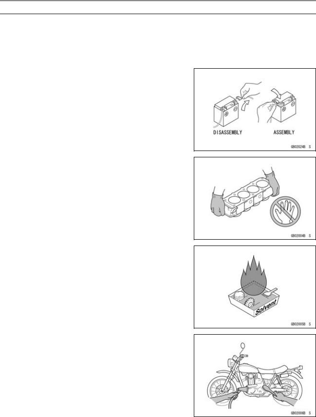
1-2 GENERAL INFORMATION
Before Servicing
Before starting to perform an inspection service or carry out a disassembly and reassembly operation on a motorcycle, read the precautions given below. To facilitate actual operations, notes, illustrations, photographs, cautions, and detailed descriptions have been included in each chapter wherever necessary. This section explains the items that require particular attention during the removal and reinstallation or disassembly and reassembly of general parts.
Especially note the following.
Battery Ground
Before completing any service on the motorcycle, disconnect the battery cables from the battery to prevent the engine from accidentally turning over. Disconnect the ground cable (–) first and then the positive (+). When completed with the service, first connect the positive (+) cable to the positive (+) terminal of the battery then the negative (–) cable to the negative terminal.
Edges of Parts
Lift large or heavy parts wearing gloves to prevent injury from possible sharp edges on the parts.
Solvent
Use a high-flush point solvent when cleaning parts. High -flush point solvent should be used according to directions of the solvent manufacturer.
Cleaning Vehicle before Disassembly
Clean the vehicle thoroughly before disassembly. Dirt or other foreign materials entering into sealed areas during vehicle disassembly can cause excessive wear and decrease performance of the vehicle.

GENERAL INFORMATION 1-3
Before Servicing
Arrangement and Cleaning of Removed Parts
Disassembled parts are easy to confuse. Arrange the parts according to the order the parts were disassembled and clean the parts in order prior to assembly.
Storage of Removed Parts
After all the parts including subassembly parts have been cleaned, store the parts in a clean area. Put a clean cloth or plastic sheet over the parts to protect from any foreign materials that may collect before re-assembly.
Inspection
Reuse of worn or damaged parts may lead to serious accident. Visually inspect removed parts for corrosion, discoloration, or other damage. Refer to the appropriate sections of this manual for service limits on individual parts. Replace the parts if any damage has been found or if the part is beyond its service limit.
Replacement Parts
Replacement parts must be KAWASAKI genuine or recommended by KAWASAKI. Gaskets, O-rings, oil seals, grease seals, circlips, cotter pins or self-locking nuts must be replaced with new ones whenever disassembled.
Assembly Order
In most cases assembly order is the reverse of disassembly, however, if assembly order is provided in this Service Manual, follow the procedures given.

1-4 GENERAL INFORMATION
Before Servicing
Tightening Sequence
Generally, when installing a part with several bolts, nuts, or screws, start them all in their holes and tighten them to a snug fit. Then tighten them according to the specified sequence to prevent case warpage or deformation which can lead to malfunction. Conversely when loosening the bolts, nuts, or screws, first loosen all of them by about a quarter turn and then remove them. If the specified tightening sequence is not indicated, tighten the fasteners alternating diagonally.
Tightening Torque
Incorrect torque applied to a bolt, nut, or screw may lead to serious damage. Tighten fasteners to the specified torque using a good quality torque wrench.
Force
Use common sense during disassembly and assembly, excessive force can cause expensive or hard to repair damage. When necessary, remove screws that have a non -permanent locking agent applied using an impact driver. Use a plastic-faced mallet whenever tapping is necessary.
Gasket, O-ring
Hardening, shrinkage, or damage of both gaskets and O-rings after disassembly can reduce sealing performance. Remove old gaskets and clean the sealing surfaces thoroughly so that no gasket material or other material remains. Install the new gaskets and replace the used O-rings when re-assembling.
Liquid Gasket, Non-permanent Locking Agent
For applications that require Liquid Gasket or a Non-permanent Locking Agent, clean the surfaces so that no oil residue remains before applying liquid gasket or non-permanent locking agent. Do not apply them excessively. Excessive application can clog oil passages and cause serious damage.

GENERAL INFORMATION 1-5
Before Servicing
Press
For items such as bearings or oil seals that must be pressed into place, apply small amount of oil to the contact area. Be sure to maintain proper alignment and use smooth movements when installing.
Ball Bearing and Needle Bearing
Do not remove pressed ball or needle unless removal is absolutely necessary. Replace with new ones whenever removed. Press bearings with the manufacturer and size marks facing out. Press the bearing into place by putting pressure on the correct bearing race as shown.
Pressing the incorrect race can cause pressure between the inner and outer race and result in bearing damage.
Oil Seal, Grease Seal
Do not remove pressed oil or grease seals unless removal is necessary. Replace with new ones whenever removed. Press new oil seals with manufacture and size marks facing out. Make sure the seal is aligned properly when installing.
Apply specified grease to the lip of seal before installing the seal.
Circlips, Cotter Pins
Replace the circlips or cotter pins that were removed with new ones. Take care not to open the clip excessively when installing to prevent deformation.
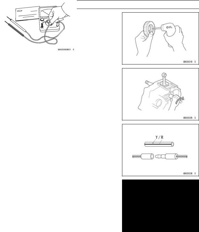
1-6 GENERAL INFORMATION
Before Servicing
Lubrication
It is important to lubricate rotating or sliding parts during assembly to minimize wear during initial operation. Lubrication points are called out throughout this manual, apply the specific oil or grease as specified.
Direction of Engine Rotation
When rotating the crankshaft by hand, the free play amount of rotating direction will affect the adjustment. Rotate the crankshaft to positive direction (clockwise viewed from output side).
Electrical Wires
A two-color wire is identified first by the primary color and then the stripe color. Unless instructed otherwise, electrical wires must be connected to those of the same color.
Instrument
Use a meter that has enough accuracy for an accurate measurement. Read the manufacture’s instructions thoroughly before using the meter. Incorrect values may lead to improper adjustments.

GENERAL INFORMATION 1-7
Model Identification
ZX1000GB (United States and Canada) Left Side View
ZX1000GB (United States and Canada) Right Side View
|
Frame Number |
Engine Number |
|
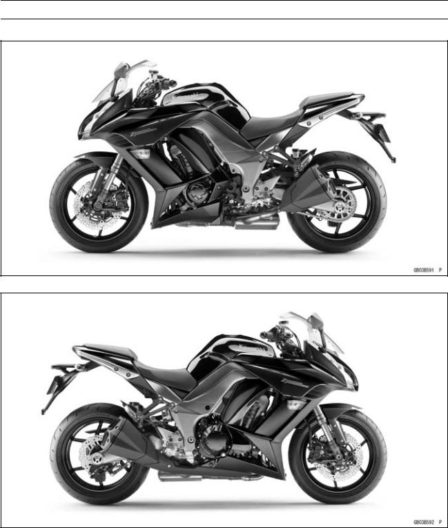
1-8 GENERAL INFORMATION
Model Identification
ZX1000GB (Europe) Left Side View
ZX1000GB (Europe) Right Side View

GENERAL INFORMATION 1-9
Model Identification
ZX1000HB Left Side View
ZX1000HB Right Side View

1-10 GENERAL INFORMATION
General Specifications
|
Items |
ZX1000GB GC/HB HC |
|
Dimensions |
|
|
Overall Length |
2 105 mm (82.87 in.) |
|
Overall Width |
790 mm (31.1 in.) |
|
Overall Height/High Position |
1 170 mm (40.06 in.)/1 230 mm (48.43 in.) |
|
Wheelbase |
1 445 mm (56.89 in.) |
|
Road Clearance |
135 mm (5.31 in.) |
|
Seat Height |
820 mm (32.28 in.) |
|
Curb Mass: |
|
|
ZX1000G |
228 kg (503 lb) |
|
ZX1000H |
231 kg (509 lb) |
|
Front: |
|
|
ZX1000G |
117 kg (258 lb) |
|
ZX1000H |
118 kg (260 lb) |
|
Rear: |
|
|
ZX1000G |
111 kg (245 lb) |
|
ZX1000H |
113 kg (249 lb) |
|
Fuel Tank Capacity |
19 L (5.0 US gal.) |
|
Performance |
|
|
Minimum Turning Radius |
3.1 m (10.1 ft) |
|
Engine |
|
|
Type |
4-stroke, DOHC, 4-cylinder |
|
Cooling System |
Liquid-cooled |
|
Bore and Stroke |
77.0 × 56.0 mm (3.03 × 2.20 in.) |
|
Displacement |
1 043 cm³ (63.64 cu in.) |
|
Compression Ratio |
11.8 : 1 |
|
Maximum Horsepower |
101.5 kW (138 PS) @9 600 r/min (rpm) |
|
(SEA-B1/B2) 100 kW (136 PS) @9 000 r/min (rpm) |
|
|
(WVTA (78.2 H)) 78.2 kW (106 PS) @9 100 r/min (rpm) |
|
|
(CA, US) – – – |
|
|
Maximum Torque |
110 N·m (11.2 kgf·m, 81.1 ft·lb) @7 800 r/min (rpm) |
|
(WVTA (78.2 H)) 95 N·m (9.7 kgf·m, 70 ft·lb) @7 500 r/min (rpm) |
|
|
(CA, US) – – – |
|
|
Carburetion System |
FI (Fuel Injection) KEIHIN TTK38 × 4 |
|
Starting System |
Electric starter |
|
Ignition System |
Battery and coil (transistorized) |
|
Timing Advance |
Electronically advanced (digital igniter) |
|
Ignition Timing |
From 10° BTDC @1 100 r/min (rpm) to 40.2° BTDC |
|
@5 200 r/min (rpm) |
|
|
Spark Plug |
NGK CR9EIA-9 |
|
Cylinder Numbering Method |
Left to right, 1-2-3-4 |
|
Firing Order |
1-2-4-3 |
|
Valve Timing: |
|
|
Intake: |
|
|
Open |
31° BTDC |
|
Close |
65° ABDC |
|
GENERAL INFORMATION 1-11 |
|
|
General Specifications |
|
|
Items |
ZX1000GB GC/HB HC |
|
Duration |
276° |
|
Exhaust: |
|
|
Open |
58° BBDC |
|
Close |
18° ATDC |
|
Duration |
256° |
|
Lubrication System |
Forced lubrication (wet sump) |
|
Engine Oil: |
|
|
Type |
API SG, SH, SJ, SL or SM with JASO MA, MA1 or MA2 |
|
Viscosity |
SAE 10W-40 |
|
Capacity |
4.0 L (4.2 US qt) |
|
Drive Train |
|
|
Primary Reduction System: |
|
|
Type |
Gear |
|
Reduction Ratio |
1.627 (83/51) |
|
Clutch Type |
Wet multi disc |
|
Transmission: |
|
|
Type |
6-speed, constant mesh, return shift |
|
Gear Ratios: |
|
|
1st |
2.600 (39/15) |
|
2nd |
1.950 (39/20) |
|
3rd |
1.600 (24/15) |
|
4th |
1.389 (25/18) |
|
5th |
1.238 (26/21) |
|
6th |
1.136 (25/22) |
|
Final Drive System: |
|
|
Type |
Chain drive |
|
Reduction Ratio |
2.733 (41/15) |
|
Overall Drive Ratio |
5.055 @Top gear |
|
Frame |
|
|
Type |
Tubular, diamond |
|
Caster (Rake Angle) |
24.5° |
|
Trail |
102 mm (4.02 in.) |
|
Front Tire: |
|
|
Type |
Tubeless |
|
Size |
120/70 ZR17 M/C (58W) |
|
Rim Size |
J17M/C × MT3.50 |
|
Rear Tire: |
|
|
Type |
Tubeless |
|
Size |
190/50 ZR17 M/C (73W) |
|
Rim Size |
J17M/C × MT6.00 |
|
Front Suspension: |
|
|
Type |
Telescopic fork (upside-down) |
|
Wheel Travel |
120 mm (4.72 in.) |

1-12 GENERAL INFORMATION
General Specifications
|
Items |
ZX1000GB GC/HB HC |
|
Rear Suspension: |
|
|
Type |
Swingarm |
|
Wheel Travel |
138 mm (5.43 in.) |
|
Brake Type: |
|
|
Front |
Dual discs |
|
Rear |
Single disc |
|
Electrical Equipment |
|
|
Battery |
12 V 8 Ah |
|
Headlight: |
|
|
Type |
Semi-sealed beam |
|
High Beam |
12 V 55 W |
|
Low Beam |
12 V 55 W |
|
Tail/Brake Light |
LED |
|
Alternator: |
|
|
Type |
Three-phase AC |
Specifications are subject to change without notice, and may not apply to every country.
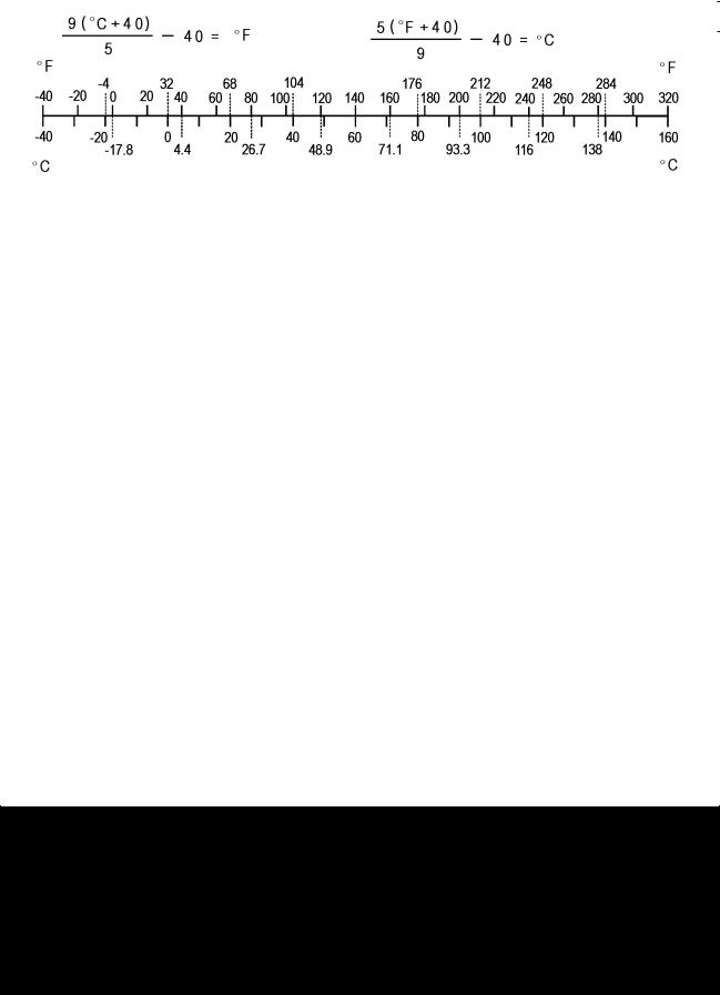
GENERAL INFORMATION 1-13
Unit Conversion Table
|
Prefixes for Units: |
Units of Length: |
|
Prefix |
Symbol |
Power |
||
|
mega |
M |
× 1 000 |
000 |
|
|
kilo |
k |
× |
1 000 |
|
|
centi |
c |
× |
0.01 |
|
|
milli |
m |
× |
0.001 |
|
|
micro |
µ |
× 0.000001 |
Units of Mass:
|
kg |
× |
2.205 |
= |
lb |
|
g |
× |
0.03527 |
= |
oz |
Units of Volume:
|
L |
× |
0.2642 |
= |
gal (US) |
|
L |
× |
0.2200 |
= |
gal (IMP) |
|
L |
× |
1.057 |
= |
qt (US) |
|
L |
× |
0.8799 |
= |
qt (IMP) |
|
L |
× |
2.113 |
= |
pint (US) |
|
L |
× |
1.816 |
= |
pint (IMP) |
|
mL |
× |
0.03381 |
= |
oz (US) |
|
mL |
× |
0.02816 |
= |
oz (IMP) |
|
mL |
× |
0.06102 |
= |
cu in |
Units of Force:
|
N |
× |
0.1020 |
= |
kg |
|
N |
× |
0.2248 |
= |
lb |
|
kg |
× |
9.807 |
= |
N |
|
kg |
× |
2.205 |
= |
lb |
|
km |
× |
0.6214 |
= |
mile |
|
m |
× |
3.281 |
= |
ft |
|
mm |
× |
0.03937 |
= |
in |
Units of Torque:
|
N·m |
× |
0.1020 |
= |
kgf·m |
|
N·m |
× |
0.7376 |
= |
ft·lb |
|
N·m |
× |
8.851 |
= |
in·lb |
|
kgf·m |
× |
9.807 |
= |
N·m |
|
kgf·m |
× |
7.233 |
= |
ft·lb |
|
kgf·m |
× |
86.80 |
= |
in·lb |
Units of Pressure:
|
kPa |
× |
0.01020 |
= |
kgf/cm² |
|
kPa |
× |
0.1450 |
= |
psi |
|
kPa |
× |
0.7501 |
= |
cmHg |
|
kgf/cm² |
× |
98.07 |
= |
kPa |
|
kgf/cm² |
× |
14.22 |
= |
psi |
|
cmHg |
× |
1.333 |
= |
kPa |
Units of Speed:
km/h × 0.6214 = mph
Units of Power:
|
kW |
× |
1.360 |
= |
PS |
|
kW |
× |
1.341 |
= |
HP |
|
PS |
× |
0.7355 |
= |
kW |
|
PS |
× |
0.9863 |
= |
HP |
Units of Temperature:

PERIODIC MAINTENANCE 2-1
Periodic Maintenance
Table of Contents
|
Periodic Maintenance Chart ……………………………………………………………………………………… |
2-3 |
||
|
Torque and Locking Agent………………………………………………………………………………………… |
2-7 |
2 |
|
|
Specifications |
2-13 |
||
|
Special Tools ………………………………………………………………………………………………………….. |
2-15 |
||
|
Periodic Maintenance Procedures……………………………………………………………………………… |
2-17 |
||
|
Fuel System (DFI)…………………………………………………………………………………………………. |
2-17 |
||
|
Throttle Control System Inspection……………………………………………………………………….. |
2-17 |
||
|
Engine Vacuum Synchronization Inspection…………………………………………………………… |
2-17 |
||
|
Idle Speed Inspection …………………………………………………………………………………………. |
2-21 |
||
|
Idle Speed Adjustment………………………………………………………………………………………… |
2-22 |
||
|
Fuel Hose Inspection (fuel leak, damage, installation condition) ……………………………….. |
2-22 |
||
|
Evaporative Emission Control System (CAL and SEA-B1 Models) Inspection…………….. |
2-23 |
||
|
Cooling System…………………………………………………………………………………………………….. |
2-24 |
||
|
Coolant Level Inspection……………………………………………………………………………………… |
2-24 |
||
|
Radiator Hose and Pipe Inspection (coolant leak, damage, installation condition) ………. |
2-24 |
||
|
Engine Top End ……………………………………………………………………………………………………. |
2-24 |
||
|
Valve Clearance Inspection …………………………………………………………………………………. |
2-24 |
||
|
Valve Clearance Adjustment………………………………………………………………………………… |
2-26 |
||
|
Air Suction System Damage Inspection…………………………………………………………………. |
2-29 |
||
|
Clutch………………………………………………………………………………………………………………….. |
2-30 |
||
|
Clutch Operation Inspection…………………………………………………………………………………. |
2-30 |
||
|
Wheels/Tires………………………………………………………………………………………………………… |
2-31 |
||
|
Air Pressure Inspection……………………………………………………………………………………….. |
2-31 |
||
|
Wheel/Tire Damage Inspection…………………………………………………………………………….. |
2-31 |
||
|
Tire Tread Wear Inspection………………………………………………………………………………….. |
2-31 |
||
|
Wheel Bearing Damage Inspection ………………………………………………………………………. |
2-32 |
||
|
Final Drive……………………………………………………………………………………………………………. |
2-33 |
||
|
Drive Chain Lubrication Condition Inspection …………………………………………………………. |
2-33 |
||
|
Drive Chain Slack Inspection ……………………………………………………………………………….. |
2-33 |
||
|
Drive Chain Slack Adjustment ……………………………………………………………………………… |
2-34 |
||
|
Wheel Alignment Inspection ………………………………………………………………………………… |
2-34 |
||
|
Wheel Alignment Adjustment……………………………………………………………………………….. |
2-34 |
||
|
Drive Chain Wear Inspection ……………………………………………………………………………….. |
2-35 |
||
|
Chain Guide Wear Inspection ………………………………………………………………………………. |
2-35 |
||
|
Brakes…………………………………………………………………………………………………………………. |
2-36 |
||
|
Brake Fluid Leak (Brake Hose and Pipe) Inspection ……………………………………………….. |
2-36 |
||
|
Brake Hose and Pipe Damage and Installation Condition Inspection…………………………. |
2-37 |
||
|
Brake Operation Inspection …………………………………………………………………………………. |
2-37 |
||
|
Brake Fluid Level Inspection………………………………………………………………………………… |
2-37 |
||
|
Brake Pad Wear Inspection …………………………………………………………………………………. |
2-38 |
||
|
Brake Light Switch Operation Inspection ……………………………………………………………….. |
2-39 |
||
|
Suspension………………………………………………………………………………………………………….. |
2-40 |
||
|
Front Forks/Rear Shock Absorber Operation Inspection ………………………………………….. |
2-40 |
||
|
Front Fork Oil Leak Inspection……………………………………………………………………………… |
2-40 |
||
|
Rear Shock Absorber Oil Leak Inspection ……………………………………………………………… |
2-40 |
||
|
Rocker Arm Operation Inspection…………………………………………………………………………. |
2-40 |
||
|
Tie-Rod Operation Inspection ………………………………………………………………………………. |
2-41 |
||
|
Steering ………………………………………………………………………………………………………………. |
2-41 |
||
|
Steering Play Inspection ……………………………………………………………………………………… |
2-41 |
||
|
Steering Play Adjustment…………………………………………………………………………………….. |
2-41 |

2-2 PERIODIC MAINTENANCE
|
Steering Stem Bearing Lubrication ……………………………………………………………………….. |
2-43 |
|
Electrical System ………………………………………………………………………………………………….. |
2-44 |
|
Lights and Switches Operation Inspection……………………………………………………………… |
2-44 |
|
Headlight Aiming Inspection ………………………………………………………………………………… |
2-46 |
|
Sidestand Switch Operation Inspection …………………………………………………………………. |
2-47 |
|
Engine Stop Switch Operation Inspection………………………………………………………………. |
2-48 |
|
Others…………………………………………………………………………………………………………………. |
2-49 |
|
Chassis Parts Lubrication ……………………………………………………………………………………. |
2-49 |
|
Bolts, Nuts and Fasteners Tightness Inspection……………………………………………………… |
2-51 |
|
Replacement Parts ……………………………………………………………………………………………….. |
2-52 |
|
Air Cleaner Element Replacement………………………………………………………………………… |
2-52 |
|
Fuel Hose Replacement ……………………………………………………………………………………… |
2-52 |
|
Coolant Change …………………………………………………………………………………………………. |
2-54 |
|
Radiator Hose and O-ring Replacement………………………………………………………………… |
2-56 |
|
Engine Oil Change……………………………………………………………………………………………… |
2-57 |
|
Oil Filter Replacement ………………………………………………………………………………………… |
2-57 |
|
Brake Hose Replacement ……………………………………………………………………………………. |
2-58 |
|
Brake Fluid Change ……………………………………………………………………………………………. |
2-59 |
|
Master Cylinder Rubber Parts Replacement ………………………………………………………….. |
2-61 |
|
Caliper Rubber Parts Replacement ………………………………………………………………………. |
2-62 |
|
Spark Plug Replacement …………………………………………………………………………………….. |
2-66 |
PERIODIC MAINTENANCE 2-3
Periodic Maintenance Chart
The scheduled maintenance must be done in accordance with this chart to keep the motorcycle in good running condition.The initial maintenance is vitally important and must not be neglected.
Periodic Inspection
|
FREQUENCY |
Whichever |
* ODOMETER READING |
|||||||||||||
|
comes |
× 1 000 km |
See |
|||||||||||||
|
first |
(× 1 000 mile) |
||||||||||||||
|
Page |
|||||||||||||||
|
1 |
6 |
12 |
18 |
24 |
30 |
36 |
|||||||||
|
ITEM |
Every |
(0.6) |
(3.75) |
(7.5) |
(11.25) |
(15) |
(18.75) |
(22.5) |
|||||||
|
Fuel System |
|||||||||||||||
|
Throttle control system (play, |
year |
• |
• |
• |
• |
2-17 |
|||||||||
|
smooth return, no drag) — inspect |
|||||||||||||||
|
Engine vacuum synchronization — |
• |
• |
• |
2-17 |
|||||||||||
|
inspect |
|||||||||||||||
|
Idle speed — inspect |
• |
• |
• |
• |
2-21 |
||||||||||
|
Fuel leak (fuel hose and pipe) — |
year |
• |
• |
• |
• |
2-22 |
|||||||||
|
inspect |
|||||||||||||||
|
Fuel hose and pipe damage — |
year |
• |
• |
• |
• |
2-22 |
|||||||||
|
inspect |
|||||||||||||||
|
Fuel hose and pipe installation |
year |
• |
• |
• |
• |
2-22 |
|||||||||
|
condition — inspect |
|||||||||||||||
|
Evaporative emission control |
• |
• |
• |
• |
• |
• |
• |
2-23 |
|||||||
|
system function (CAL), (SEA-B1) |
|||||||||||||||
|
— inspect |
|||||||||||||||
|
Cooling System |
|||||||||||||||
|
Coolant level — inspect |
• |
• |
• |
• |
2-24 |
||||||||||
|
Coolant leak (water hose and |
year |
• |
• |
• |
• |
2-24 |
|||||||||
|
pipe) — inspect |
|||||||||||||||
|
Water hose damage — inspect |
year |
• |
• |
• |
• |
2-24 |
|||||||||
|
Water hose installation condition — |
year |
• |
• |
• |
• |
2-24 |
|||||||||
|
inspect |
|||||||||||||||
|
Engine Top End |
|||||||||||||||
|
US, CA, CAL |
• |
2-24 |
|||||||||||||
|
Model |
|||||||||||||||
|
Valve clearance — |
|||||||||||||||
|
Other than |
|||||||||||||||
|
inspect |
Every 42 000 km (26 250 mile) |
2-24 |
|||||||||||||
|
US, CA, CAL |
|||||||||||||||
|
Models |
|||||||||||||||
|
Air suction system damage — |
• |
• |
• |
2-29 |
|||||||||||
|
inspect |
|||||||||||||||
|
Clutch |
|||||||||||||||
|
Clutch operation (play, |
• |
• |
• |
• |
2-30 |
||||||||||
|
disengagement, engagement) — |
|||||||||||||||
|
inspect |
|||||||||||||||
|
Wheels and Tires |
|||||||||||||||
|
Tire air pressure — inspect |
year |
• |
• |
• |
2-31 |
||||||||||
|
Wheel/tire damage — inspect |
• |
• |
• |
2-31 |
|||||||||||
|
Tire tread wear, abnormal wear — |
• |
• |
• |
2-31 |
|||||||||||
|
inspect |
|||||||||||||||
|
Wheel bearing damage — inspect |
year |
• |
• |
• |
2-32 |

2-4 PERIODIC MAINTENANCE
Periodic Maintenance Chart
|
FREQUENCY |
Whichever |
* ODOMETER READING |
|||||||||||
|
comes |
× 1 000 km |
See |
|||||||||||
|
first |
(× 1 000 mile) |
||||||||||||
|
Page |
|||||||||||||
|
1 |
6 |
12 |
18 |
24 |
30 |
36 |
|||||||
|
ITEM |
Every |
(0.6) |
(3.75) |
(7.5) |
(11.25) |
(15) |
(18.75) |
(22.5) |
|||||
|
Final Drive |
|||||||||||||
|
Drive chain lubrication condition — |
Every 600 km (400 mile) |
2-33 |
|||||||||||
|
inspect # |
|||||||||||||
|
Drive chain slack — inspect # |
Every 1 000 km (600 mile) |
2-33 |
|||||||||||
|
Drive chain wear — inspect # |
• |
• |
• |
2-35 |
|||||||||
|
Drive chain guide wear — inspect |
• |
• |
• |
2-35 |
|||||||||
|
Brakes |
|||||||||||||
|
Brake fluid leak (brake hose and |
year |
• |
• |
• |
• |
• |
• |
• |
2-36 |
||||
|
pipe) — inspect |
|||||||||||||
|
Brake hose and pipe damage — |
year |
• |
• |
• |
• |
• |
• |
• |
2-37 |
||||
|
inspect |
|||||||||||||
|
Brake hose and pipe installation |
year |
• |
• |
• |
• |
• |
• |
• |
2-37 |
||||
|
condition — inspect |
|||||||||||||
|
Brake operation (effectiveness, |
year |
• |
• |
• |
• |
• |
• |
• |
2-37 |
||||
|
play, no drag) — inspect |
|||||||||||||
|
Brake fluid level — inspect |
6 |
• |
• |
• |
• |
• |
• |
• |
2-37 |
||||
|
months |
|||||||||||||
|
Brake pad wear — inspect # |
• |
• |
• |
• |
• |
• |
2-38 |
||||||
|
Brake light switch operation — |
• |
• |
• |
• |
• |
• |
• |
2-39 |
|||||
|
inspect |
|||||||||||||
|
Suspension |
|||||||||||||
|
Front forks/rear shock absorber |
• |
• |
• |
2-40 |
|||||||||
|
operation (damping and smooth |
|||||||||||||
|
stroke) — inspect |
|||||||||||||
|
Front forks/rear shock absorber |
year |
• |
• |
• |
2-40 |
||||||||
|
oil leak — inspect |
|||||||||||||
|
Rocker arm operation — inspect |
• |
• |
• |
2-40 |
|||||||||
|
Tie-rods operation — inspect |
• |
• |
• |
2-41 |
|||||||||
|
Steering |
|||||||||||||
|
Steering play — inspect |
year |
• |
• |
• |
• |
2-41 |
|||||||
|
Steering stem bearings — lubricate |
2 years |
• |
2-43 |
||||||||||
|
Electrical System |
|||||||||||||
|
Lights and switches operation — |
year |
• |
• |
• |
2-44 |
||||||||
|
inspect |
|||||||||||||
|
Headlight aiming — inspect |
year |
• |
• |
• |
2-46 |
||||||||
|
Sidestand switch operation — |
year |
• |
• |
• |
2-47 |
||||||||
|
inspect |
|||||||||||||
|
Engine stop switch operation — |
year |
• |
• |
• |
2-48 |
||||||||
|
inspect |
|||||||||||||
|
Others |
|||||||||||||
|
Chassis parts — lubricate |
year |
• |
• |
• |
2-49 |
||||||||
|
Bolts and nuts tightness — inspect |
• |
• |
• |
• |
2-51 |

PERIODIC MAINTENANCE 2-5
Periodic Maintenance Chart
#: Service more frequently when operating in severe conditions; dusty, wet, muddy, high speed or frequent starting/stopping.
*: For higher odometer readings, repeat at the frequency interval established here.
2-6 PERIODIC MAINTENANCE
Periodic Maintenance Chart
Periodic Replacement Parts
|
FREQUENCY |
Whichever |
* ODOMETER READING |
||||||||||
|
comes |
× 1 000 km |
See |
||||||||||
|
first |
(× 1 000 mile) |
|||||||||||
|
Page |
||||||||||||
|
1 |
12 |
24 |
36 |
48 |
||||||||
|
ITEM |
Every |
(0.6) |
(7.5) |
(15) |
(22.5) |
(30) |
||||||
|
Air cleaner element # — replace |
Every 18 000 km (11 250 mile) |
2-52 |
||||||||||
|
Fuel hose — replace |
5 years |
2-52 |
||||||||||
|
Coolant — change |
3 years |
• |
2-54 |
|||||||||
|
Radiator hose and O-ring — replace |
3 years |
• |
2-56 |
|||||||||
|
Engine oil # — change |
year |
• |
• |
• |
• |
• |
2-57 |
|||||
|
Oil filter — replace |
year |
• |
• |
• |
• |
• |
2-57 |
|||||
|
Brake hose — replace |
4 years |
• |
2-58 |
|||||||||
|
Brake fluid — change |
2 years |
• |
• |
2-59 |
||||||||
|
Rubber parts of master cylinder and caliper — |
4 years |
• |
2-61, |
|||||||||
|
replace |
2-62 |
|||||||||||
|
Spark plug — replace |
• |
• |
• |
• |
2-66 |
#: Service more frequently when operating in severe conditions; dusty, wet, muddy, high speed or frequent starting/stopping.
*: For higher odometer readings, repeat at the frequency interval established here.
![]()
PERIODIC MAINTENANCE 2-7
Torque and Locking Agent
The following tables list the tightening torque for the major fasteners requiring use of a non-permanent locking agent or silicone sealant etc.
Letters used in the “Remarks” column mean:
AL: Tighten the two clamp bolts alternately two times to ensure even tightening torque. G: Apply grease.
L: Apply a non-permanent locking agent. MO: Apply molybdenum disulfide oil solution.
(mixture of the engine oil and molybdenum disulfide grease in a weight ratio 10 : 1)
R:Replacement Parts
S:Follow the specified tightening sequence. Si: Apply silicone grease (ex. PBC grease).
SS: Apply silicone sealant.
|
Fastener |
Torque |
Remarks |
|||
|
N·m |
kgf·m |
ft·lb |
|||
|
Fuel System (DFI) |
|||||
|
Upper Air Cleaner Housing Screws |
1.1 |
0.11 |
9.7 in·lb |
||
|
Throttle Body Assy Holder Clamp Bolts |
2.9 |
0.30 |
26 in·lb |
||
|
Air Cleaner Duct Clamp Bolts |
2.0 |
0.20 |
18 in·lb |
||
|
Delivery Pipe Assy Mounting Screws |
3.4 |
0.35 |
30 in·lb |
||
|
Oxygen Sensor (Equipped Models) |
44 |
4.5 |
32 |
||
|
Intake Air Temperature Sensor Mounting Screw |
1.2 |
0.12 |
11 in·lb |
||
|
Water Temperature Sensor |
30 |
3.0 |
22 |
||
|
Exhaust Butterfly Valve Actuator Pulley Bolt |
5.0 |
0.51 |
44 in·lb |
||
|
Exhaust Butterfly Valve Actuator Mounting |
1.2 |
0.12 |
11 in·lb |
||
|
Screws |
|||||
|
Fuel Pump Bolts |
9.8 |
1.0 |
87 in·lb |
L |
|
|
Cooling System |
|||||
|
Hot Windshield Mounting Bolts |
9.8 |
1.0 |
87 in·lb |
||
|
Coolant By-pass Fitting Bolt |
8.8 |
0.90 |
78 in·lb |
L |
|
|
Thermostat Housing Bolts |
5.9 |
0.60 |
52 in·lb |
L |
|
|
Radiator (Water) Hose Clamp Screws |
2.9 |
0.30 |
26 in·lb |
||
|
Water Pipe Bolts |
12 |
1.2 |
106 in·lb |
L |
|
|
Water Pump Impeller Bolt |
9.8 |
1.0 |
87 in·lb |
||
|
Water Pump Cover Bolts |
11 |
1.1 |
97 in·lb |
||
|
Coolant Drain Bolt |
11 |
1.1 |
97 in·lb |
||
|
Engine Top End |
|||||
|
Air Suction Valve Cover Bolts |
9.8 |
1.0 |
87 in·lb |
L |
|
|
Spark Plugs |
13 |
1.3 |
115 in·lb |
||
|
Cylinder Head Cover Bolts |
9.8 |
1.0 |
87 in·lb |
S |
|
|
Hot Windshield Mounting Bolts |
9.8 |
1.0 |
87 in·lb |
||
|
Camshaft Sprocket Bolts |
15 |
1.5 |
11 |
L |
|
|
Front Camshaft Chain Guide Bolt (Upper) |
25 |
2.5 |
18 |
||
|
Rear Camshaft Chain Guide Bolt |
25 |
2.5 |
18 |
||
|
Front Camshaft Chain Guide Bolt (Lower) |
12 |
1.2 |
106 in·lb |
||
|
Throttle Body Assy Holder Bolts |
12 |
1.2 |
106 in·lb |
L |

2-8 PERIODIC MAINTENANCE
Torque and Locking Agent
|
Fastener |
Torque |
Remarks |
|||
|
N·m |
kgf·m |
ft·lb |
|||
|
Cylinder Head Bolts (M6) |
12 |
1.2 |
106 in·lb |
S |
|
|
Upper Camshaft Chain Guide Bolts |
12 |
1.2 |
106 in·lb |
S |
|
|
Plugs |
19.6 |
2.0 |
14 |
L |
|
|
Camshaft Cap Bolts |
12 |
1.2 |
106 in·lb |
S |
|
|
Cylinder Head Bolts (M10) (First) |
20 |
2.0 |
15 |
S, MO |
|
|
Cylinder Head Bolts (M10) (Final) |
54 |
5.5 |
40 |
S, MO |
|
|
Camshaft Chain Tensioner Mounting Bolts |
11 |
1.1 |
97 in·lb |
||
|
Camshaft Chain Tensioner Cap Bolt |
20 |
2.0 |
15 |
||
|
Exhaust Butterfly Valve Actuator Pulley Bolt |
5.0 |
0.51 |
44 in·lb |
||
|
Exhaust Butterfly Valve Actuator Bolts |
1.2 |
0.12 |
11 in·lb |
||
|
Muffler Body Mounting Bolts |
34 |
3.5 |
25 |
||
|
Premuffler Chamber Mounting Bolt |
34 |
3.5 |
25 |
||
|
Muffler Body Clamp Bolts |
21 |
2.1 |
15 |
||
|
Clutch |
|||||
|
Clutch Lever Assembly Clamp Bolts |
7.8 |
0.80 |
69 in·lb |
S |
|
|
Clutch Cover Bolts |
9.8 |
1.0 |
87 in·lb |
||
|
Oil Filler Plug |
2.0 |
0.20 |
18 in·lb |
||
|
Clutch Spring Bolts |
9.0 |
0.90 |
80 in·lb |
||
|
Clutch Hub Nut |
135 |
13.8 |
99.6 |
R |
|
|
Engine Lubrication System |
|||||
|
Oil Filler Plug |
2.0 |
0.20 |
18 in·lb |
||
|
Oil Cooler Bolts |
12 |
1.2 |
106 in·lb |
||
|
Oil Passage Plug |
20 |
2.0 |
15 |
L |
|
|
Radiator (Water) Hose Clamp Screws |
3.0 |
0.31 |
27 in·lb |
||
|
Oil Pressure Switch |
15 |
1.5 |
11 |
SS |
|
|
Oil Pressure Relief Valve |
15 |
1.5 |
11 |
L |
|
|
Oil Filter |
17 |
1.7 |
13 |
G, R |
|
|
Oil Filter Pipe |
25 |
2.5 |
18 |
L |
|
|
Oil Pan Bolts |
12 |
1.2 |
106 in·lb |
S |
|
|
Engine Oil Drain Bolt |
29 |
3.0 |
21 |
||
|
Engine Removal/Installation |
|||||
|
Upper Engine Bracket Bolts |
44 |
4.5 |
32 |
S |
|
|
Lower Engine Bracket Bolts |
59 |
6.0 |
44 |
S |
|
|
Upper Adjusting Collar |
9.8 |
1.0 |
87 in·lb |
S |
|
|
Upper Engine Mounting Bolt (L = 65) |
44 |
4.5 |
32 |
S |
|
|
Upper Adjusting Collar Locknut |
49 |
5.0 |
36 |
S |
|
|
Upper Engine Mounting Bolt (L = 40) |
44 |
4.5 |
32 |
S |
|
|
Lower Engine Mounting Nut |
44 |
4.5 |
32 |
S |
|
|
Lower Adjusting Collar Locknut |
49 |
5.0 |
36 |
S |
|
|
Middle Engine Bracket Bolts |
25 |
2.5 |
18 |
L, S |
|
|
Middle Engine Mounting Nut |
44 |
4.5 |
32 |
S |
|
|
Lower Adjusting Collar |
9.8 |
1.0 |
87 in·lb |
S |
|

PERIODIC MAINTENANCE 2-9
Torque and Locking Agent
|
Fastener |
Torque |
Remarks |
|||
|
N·m |
kgf·m |
ft·lb |
|||
|
Crankshaft/Transmission |
|||||
|
Balancer Shaft Clamp Bolt |
9.8 |
1.0 |
87 in·lb |
||
|
Balancer Shaft Lever Bolt |
25 |
2.5 |
18 |
L |
|
|
Breather Side Plate Bolt |
5.9 |
0.60 |
52 in·lb |
L |
|
|
Connecting Rod Big End Nuts |
see the text |
← |
← |
MO |
|
|
Breather Plate Bolts |
9.8 |
1.0 |
87 in·lb |
L |
|
|
Shift Drum Bearing Holder Bolts |
12 |
1.2 |
106 in·lb |
L |
|
|
Oil Passage Plugs |
20 |
2.0 |
15 |
L |
|
|
Oil Passage Plug |
9.8 |
1.0 |
87 in·lb |
||
|
Starter Motor Clutch Bolts |
12 |
1.2 |
106 in·lb |
L |
|
|
Crankcase Bolts (M7) |
20 |
2.0 |
15 |
S |
|
|
Crankcase Bolts (M9) |
42 |
4.2 |
31 |
S, MO |
|
|
Crankcase Bolts (M6) |
20 |
2.0 |
15 |
S |
|
|
Crankcase Bolts (M8) |
27 |
2.8 |
20 |
S |
|
|
Gear Positioning Lever Bolt |
12 |
1.2 |
106 in·lb |
||
|
Shift Drum Cam Bolt |
12 |
1.2 |
106 in·lb |
L |
|
|
Neutral Switch |
15 |
1.5 |
11 |
||
|
Shift Shaft Return Spring Pin |
39 |
4.0 |
29 |
L |
|
|
Shift Pedal Mounting Bolt |
25 |
2.5 |
18 |
||
|
Wheels/Tires |
|||||
|
Front Axle Clamp Bolt |
20 |
2.0 |
15 |
AL |
|
|
Front Axle |
108 |
11.0 |
79.7 |
||
|
Rear Axle Nut |
98 |
10 |
72 |
||
|
Final Drive |
|||||
|
Engine Sprocket Nut |
125 |
12.7 |
92.2 |
MO |
|
|
Drive Chain Guide Bolts |
9.8 |
1.0 |
87 in·lb |
||
|
Speed Sensor Mounting Bolt |
6.9 |
0.70 |
61 in·lb |
L |
|
|
Chain Adjuster Clamp Bolts |
64 |
6.5 |
47 |
||
|
Rear Sprocket Nuts |
59 |
6.0 |
44 |
||
|
Brakes |
|||||
|
Front Master Cylinder Reservoir Cap Stopper |
1.2 |
0.12 |
11 in·lb |
||
|
Screw |
|||||
|
Brake Lever Pivot Bolt |
1.0 |
0.10 |
8.8 in·lb |
Si |
|
|
Front Master Cylinder Bleed Valve |
5.4 |
0.55 |
48 in·lb |
||
|
Front Master Cylinder Clamp Bolts |
11 |
1.1 |
97 in·lb |
S |
|
|
Brake Lever Pivot Bolt Locknut |
5.9 |
0.60 |
52 in·lb |
||
|
Front Brake Light Switch Screw |
1.2 |
0.12 |
11 in·lb |
||
|
Brake Hose Banjo Bolts |
25 |
2.5 |
18 |
||
|
Front Caliper Assembly Bolts |
22 |
2.2 |
16 |
||
|
Front Caliper Mounting Bolts |
34 |
3.5 |
25 |
||
|
Bleed Valves |
7.8 |
0.80 |
69 in·lb |
||
|
Front Brake Pad Pins |
15 |
1.5 |
11 |
||
|
Front Brake Disc Mounting Bolts |
27 |
2.8 |
20 |
L |

2-10 PERIODIC MAINTENANCE
Torque and Locking Agent
|
Fastener |
Torque |
Remarks |
|||
|
N·m |
kgf·m |
ft·lb |
|||
|
Rear Master Cylinder Mounting Bolts |
25 |
2.5 |
18 |
||
|
Brake Pedal Bolt |
8.8 |
0.90 |
78 in·lb |
L |
|
|
Rear Master Cylinder Push Rod Locknut |
17 |
1.7 |
12 |
||
|
Rear Brake Disc Mounting Bolts |
27 |
2.8 |
20 |
L |
|
|
Rear Caliper Mounting Bolts |
25 |
2.5 |
18 |
||
|
Brake Pipe Joint Nuts |
18 |
1.8 |
13 |
||
|
Rear Brake Disc Mounting Bolts (ABS Equipped |
27 |
2.8 |
20 |
L |
|
|
Models) |
|||||
|
Suspension |
|||||
|
Upper Front Fork Clamp Bolts |
20 |
2.0 |
15 |
||
|
Lower Front Fork Clamp Bolts |
25 |
2.5 |
18 |
AL |
|
|
Piston Rod Nuts |
20 |
2.0 |
15 |
||
|
Front Fork Top Plugs |
34 |
3.5 |
25 |
||
|
Front Axle Clump Bolts |
20 |
2.0 |
15 |
AL |
|
|
Front Fork Bottom Allen Bolts |
35 |
3.6 |
26 |
||
|
Rear Shock Absorber Bolt (Upper) |
34 |
3.5 |
25 |
||
|
Tie-rod Nuts |
34 |
3.5 |
25 |
R |
|
|
Rear Shock Absorber Nut (Lower) |
34 |
3.5 |
25 |
R |
|
|
Rocker Arm Nut |
34 |
3.5 |
25 |
R |
|
|
Swingarm Pivot Adjusting Collar Locknut |
98 |
10 |
72 |
||
|
Swingarm Pivot Shaft Nut |
108 |
11.0 |
79.7 |
||
|
Torque Link Nuts |
|||||
|
34 |
3.5 |
25 |
|||
|
Steering |
|||||
|
Left Switch Housing Screws |
3.5 |
0.36 |
31 in·lb |
||
|
Upper Front Fork Clamp Bolts |
25 |
2.5 |
18 |
||
|
Handlebar Holder Bolts |
25 |
2.5 |
18 |
||
|
Handlebar Bolts |
34 |
3.5 |
25 |
L |
|
|
Right Switch Housing Screws |
3.5 |
0.36 |
31 in·lb |
||
|
Steering Stem Head Bolt |
108 |
11.0 |
79.7 |
||
|
Steering Stem Nut |
25 |
2.5 |
18 |
||
|
Lower Front Fork Clamp Bolts |
20 |
2.0 |
15 |
AL |
|
|
Frame |
|||||
|
Lower Fairing Upper Assembly Screws |
1.2 |
0.12 |
11 in·lb |
||
|
Lower Fairing Lower Assembly Screws |
1.2 |
0.12 |
11 in·lb |
||
|
Front Fender Mounting Bolts |
3.9 |
0.40 |
35 in·lb |
||
|
Stay Assembly Mounting Bolts |
6.9 |
0.70 |
61 in·lb |
||
|
Stopper Mounting Bolts |
4.2 |
0.42 |
37 in·lb |
L |
|
|
Rear Frame Bracket Bolts |
44 |
4.5 |
32 |
||
|
Front Footpeg Bracket Bolts |
25 |
2.5 |
18 |
||
|
Rear Footpeg Bracket Bolts |
25 |
2.5 |
18 |
||
|
Rear Frame Bolts |
25 |
2.5 |
18 |
L |
|
|
Sidestand Switch Bolt |
8.8 |
0.90 |
78 in·lb |
L |
|
|
Sidestand Bracket Bolts |
49 |
5.0 |
36 |
L |

PERIODIC MAINTENANCE 2-11
Torque and Locking Agent
|
Fastener |
Torque |
Remarks |
|||
|
N·m |
kgf·m |
ft·lb |
|||
|
Sidestand Bolt |
44 |
4.5 |
32 |
||
|
Grab Rail Mounting Bolts |
25 |
2.5 |
18 ft·lb |
||
|
Electrical System |
|||||
|
Switch Housing Screws |
3.5 |
0.36 |
31 in·lb |
||
|
Oxygen Sensor (Equipped Models) |
44 |
4.5 |
32 |
||
|
Front Brake Light Switch Screw |
1.2 |
0.12 |
11 in·lb |
||
|
Front Turn Signal Light Mounting Screws |
1.2 |
0.12 |
11 in·lb |
||
|
Licence Plate Light Mounting Screws |
1.2 |
0.12 |
11 in·lb |
||
|
Intake Air Temperature Sensor Mounting Screw |
1.2 |
0.12 |
11 in·ib |
||
|
Spark Plugs |
13 |
1.3 |
115 in·lb |
||
|
Crankshaft Sensor Cover Bolts |
12 |
1.2 |
106 in·lb |
||
|
Water Temperature Sensor |
30 |
3.0 |
22 |
||
|
Timing Rotor Bolt |
39 |
4.0 |
29 |
||
|
Crankshaft Sensor Bolts |
5.9 |
0.60 |
52 in·lb |
||
|
Starter Motor Cable Terminal Nut |
5.9 |
0.60 |
52 in·lb |
||
|
Starter Motor Terminal Locknut |
11 |
1.1 |
97 in·lb |
||
|
Starter Motor Mounting Bolts |
9.8 |
1.0 |
87 in·lb |
||
|
Alternator Rotor Bolt |
155 |
15.8 |
114 |
||
|
Stator Coil Bolts |
12 |
1.2 |
106 in·ib |
L |
|
|
Starter Motor Through Bolts |
4.9 |
0.50 |
43 in·lb |
||
|
Brush Holder Screw |
3.8 |
0.39 |
34 in·ib |
||
|
Oil Pressure Switch |
15 |
1.5 |
11 |
SS |
|
|
Oil Pressure Switch Terminal Bolt |
2.0 |
0.20 |
18 in·ib |
G |
|
|
Alternator Cover Bolts |
12 |
1.2 |
106 in·lb |
||
|
Alternator Lead Holding Plate Bolt |
12 |
1.2 |
106 in·ib |
L |
|
|
Neutral Switch |
15 |
1.5 |
11 |
||
|
Engine Ground Cable Terminal Bolt |
9.8 |
1.0 |
87 in·lb |
||
|
Sidestand Switch Bolt |
8.8 |
0.90 |
78 in·lb |
L |
|
|
Speed Sensor Mounting Bolt |
6.9 |
0.70 |
61 in·lb |
L |

2-12 PERIODIC MAINTENANCE
Torque and Locking Agent
The table below, relating tightening torque to thread diameter, lists the basic torque for the bolts and nuts. Use this table for only the bolts and nuts which do not require a specific torque value. All of the values are for use with dry solvent-cleaned threads.
Basic Torque for General Fasteners
|
Threads Diameter |
Torque |
||||||||
|
(mm) |
N·m |
kgf·m |
ft·lb |
||||||
|
5 |
3.4 |
4.9 |
0.35 |
0.50 |
30 |
43 in·lb |
|||
|
6 |
5.9 |
7.8 |
0.60 |
0.80 |
52 |
69 in·lb |
|||
|
8 |
14 |
19 |
1.4 |
1.9 |
10.0 |
13.5 |
|||
|
10 |
25 |
34 |
2.6 |
3.5 |
19.0 |
25 |
|||
|
12 |
44 |
61 |
4.5 |
6.2 |
33 |
45 |
|||
|
14 |
73 |
98 |
7.4 |
10.0 |
54 |
72 |
|||
|
16 |
115 |
155 |
11.5 |
16.0 |
83 |
115 |
|||
|
18 |
165 |
225 |
17.0 |
23.0 |
125 |
165 |
|||
|
20 |
225 |
325 |
23.0 |
33.0 |
165 |
240 |

PERIODIC MAINTENANCE 2-13
Specifications
|
Item |
Standard |
Service Limit |
||
|
Fuel System (DFI) |
||||
|
Throttle Grip Free Play |
2 3 mm (0.08 0.12 in.) |
– – – |
||
|
Idle Speed |
1 100 ±50 r/min (rpm) |
– – – |
||
|
Bypass Screws (Turn Out) |
2 1/2 (for reference) |
– – – |
||
|
Throttle Body Vacuum |
40.7 ±1.3 kPa (305 ±10 mmHg) at idle |
– – – |
||
|
speed |
||||
|
Air Cleaner Element |
Viscous paper element |
– – – |
||
|
Cooling System |
||||
|
Coolant: |
||||
|
Type (Recommended) |
Permanent type of antifreeze |
– – – |
||
|
Color |
Green |
– – – |
||
|
Mixed Ratio |
Soft water 50%, Coolant 50% |
– – – |
||
|
Freezing Point |
–35°C (–31°F) |
– – – |
||
|
Total Amount |
2.9 L (3.1 US qt) |
– – – |
||
|
Engine Top End |
||||
|
Valve Clearance: |
||||
|
Exhaust |
0.22 |
0.31 mm (0.0087 |
0.0122 in.) |
– – – |
|
Intake |
0.15 |
0.24 mm (0.0059 |
0.0094 in.) |
– – – |
|
Clutch |
||||
|
Clutch Lever Free Play |
2 3 mm (0.08 0.12 in.) |
– – – |
||
|
Engine Lubrication System |
||||
|
Engine Oil: |
||||
|
Type |
API SG, SH, SJ, SL or SM with JASO |
– – – |
||
|
MA, MA1 or MA2 |
||||
|
Viscosity |
SAE 10W-40 |
– – – |
||
|
Capacity |
3.2 L (3.4 US qt) (when filter is not |
– – – |
||
|
removed) |
||||
|
3.8 L (4.0 US qt) (when filter is removed) |
– – – |
|||
|
4.0 L (4.2 US qt) (when engine is |
– – – |
|||
|
completely dry) |
||||
|
Wheels/Tires |
||||
|
Tread Depth: |
||||
|
Front |
3.6 mm (0.14 in.) |
1 mm (0.04 in.), |
||
|
(AT, CH, DE) |
||||
|
1.6 mm (0.06 in.) |
||||
|
Rear |
5.3 mm (0.21 in.) |
Up to 130 km/h (80 mph): |
||
|
2 mm (0.08 in.), |
||||
|
Over 130 km/h (80 mph): |
||||
|
3 mm (0.12 in.) |
||||
|
Air Pressure (when Cold): |
||||
|
Front |
Up to 180 kg (397 lb) load: |
– – – |
||
|
250 kPa (2.5 kgf/cm², 36 psi) |
||||
|
Rear |
Up to 180 kg (397 lb) load: |
– – – |
||
|
290 kPa (2.9 kgf/cm², 42 psi) |
||||
|
Final Drive |
||||
|
Drive Chain Slack |
20 30 mm (0.8 1.2 in.) |
– – – |

2-14 PERIODIC MAINTENANCE
Specifications
|
Item |
Standard |
Service Limit |
|
Drive Chain Wear (20-link |
317.5 318.2 mm (12.50 12.53 in.) |
319 mm (12.56 in.) |
|
Length) |
||
|
Standard Chain: |
||
|
Make |
ENUMA |
– – – |
|
Type |
EK525ZX |
– – – |
|
Link |
112 Links |
– – – |
|
Brakes |
||
|
Brake Fluid: |
||
|
Grade |
DOT4 |
– – – |
|
Brake Pad Lining |
||
|
Thickness: |
||
|
Front |
4.0 mm (0.16 in.) |
1 mm (0.04 in.) |
|
Rear |
5.0 mm (0.20 in.) |
1 mm (0.04 in.) |
|
Brake Light Timing: |
||
|
Front |
Pulled ON |
– – – |
|
Rear |
ON after about 10 mm (0.39 in.) of |
– – – |
|
pedal travel |
||
|
Electrical System |
||
|
Spark Plug: |
||
|
Type |
NGK CR9EIA-9 |
– – – |

PERIODIC MAINTENANCE 2-15
Special Tools
Inside Circlip Pliers: 57001-143
Attachment Jack: 57001-1252
Steering Stem Nut Wrench: 57001-1100
Spark Plug Wrench, Hex 16: 57001-1262
|
Jack: |
Vacuum Gauge: |
|
|
57001-1238 |
57001-1369 |
|
Pilot Screw Adjuster, A: 57001-1239
Throttle Sensor Setting Adapter: 57001-1538
|
Oil Filter Wrench: |
Fuel Hose: |
|
|
57001-1249 |
57001-1607 |
|

2-16 PERIODIC MAINTENANCE
Special Tools
Jack Attachment: 57001-1608
![]()
PERIODIC MAINTENANCE 2-17
Periodic Maintenance Procedures
Fuel System (DFI)
Throttle Control System Inspection
•Check that the throttle grip [A] moves smoothly from full open to close, and the throttle closes quickly and com-
pletely by the return spring in all steering positions.
 If the throttle grip does not return properly, check the throttle cable routing, grip free play, and cable damage. Then lubricate the throttle cable.
•Check the throttle grip free play [B].
Throttle Grip Free Play
Standard: 2 3 mm (0.08 0.12 in.)
 If the free play is incorrect, adjust the throttle cable as follows.
•Loosen the locknuts [A] [B].
•Screw both throttle cable adjusters [C] [D] to give the throttle grip plenty of play.
•Turn the decelerator cable adjuster [C] until 2 3 mm (0.08 0.12 in.) of throttle grip play is obtained.
•Tighten the locknut [A].
•Turn the accelerator cable adjuster [D] until 2 3 mm (0.08 0.12 in.) of throttle grip play is obtained.
•Tighten the locknut [B].
 If the free play can not be adjusted with the adjusters, replace the cable.
Engine Vacuum Synchronization Inspection
NOTE
○These procedures are explained on the assumption that the intake and exhaust systems of the engine are in good condition.
•Situate the motorcycle so that it is vertical.
•Remove the air cleaner housing (see Air Cleaner Housing Removal in the Fuel System (DFI) chapter).
•Pull off the rubber caps [A] and vacuum hose [B] from the fittings of each throttle body.
•For the California and Southeast Asia Models, pull off the vacuum hose [A].

2-18 PERIODIC MAINTENANCE
Periodic Maintenance Procedures
•Plug the vacuum hose end [A].
•Connect a vacuum gauge (special tool) and hoses [A] to the fittings on the throttle body.
Special Tool — Vacuum Gauge: 57001-1369
•Connect a highly accurate tachometer [B] to one of the stick coil primary leads.
•Plug the air switching valve hose end [A] and air cleaner housing fitting [B].
•Install the air cleaner housing (see Air Cleaner Housing Installation in the Fuel System (DFI) chapter).
•Remove the fuel hose (see Fuel Hose Replacement).
•Connect the following parts temporary. Fuel Pump Lead Connector [A]
Fuel Hose [B]
Special Tool — Fuel Hose: 57001-1607

PERIODIC MAINTENANCE 2-19
Periodic Maintenance Procedures
•Start the engine and warm it up thoroughly.
•Check[A]. the idle speed, using a highly accurate tachometer
Idle Speed
Standard: 1 100 ±50 r/min (rpm)
 If the idle speed is out of the specified range, adjust it with the adjusting screw (see Idle Speed Adjustment).
NOTICE
Do not measure the idle speed by the tachometer of the meter unit.
•While idling the engine, inspect the throttle body vacuum, using the vacuum gauge [B].
Throttle Body Vacuum
Standard: 40.7 ±1.3 kPa (305 ±10 mmHg) at idle speed
 If any vacuum is not within specifications, first synchronize the balance of the left (#1, #2 throttle valves) and right (#3, #4 throttle valves) assemblies.
Example:
#1: 260 mmHg #2: 300 mmHg #3: 250 mmHg #4: 280 mmHg
•With the engine at the correct idle speed, equalize higher vacuum of #1 or #2 (for example 300 mmHg) to higher vacuum of #3 or #4 (for example 280 mmHg) by turning the center adjusting screw [A].
NOTE
○After adjustment, the final vacuum measurement between the highest throttle valves may not be 290 mmHg (for example). The goal is to have the highest two vacuums between the left (#1 and #2) and right (#3 and #4) banks be the same.
•Open and close the throttle after each measurement, and adjust the idle speed as necessary.
•Once the throttle valves have been synchronized, inspect output voltage of the main throttle sensor to ensure proper operation (procedure is explained at the end of this section).

2-20 PERIODIC MAINTENANCE
Periodic Maintenance Procedures
 If any one vacuum measurement is out of the specified range after left (#1, #2) and right (#2, #3) synchronization, adjust the bypass screws [A].
Special Tool — Pilot Screw Adjuster, A [B]: 57001-1239
•Adjust the lower vacuum between #1 and #2 to the higher vacuum of #1 and #2.
•Adjust the lower vacuum between #3 and #4 to the higher vacuum of #3 and #4.
•Open and close the throttle valves after each measurement, and adjust the idle speed as necessary.
•Check the vacuums as before.
 If all vacuums are within the specification range, finish the engine vacuum synchronization.
 If any vacuum can not be adjusted within the specification, remove the bypass screws #1 #4 and clean them.
•Turn in the bypass screw [A] with counting the number of turns until it seals fully but not tightly. Record the number of turns.
NOTICE
Do not over tighten them. They could be damaged, requiring replacement.
•Remove:Bypass Screw
Spring [B]
Washer [C]
O-ring [D]
•Check the bypass screw and its hole for carbon deposits.  If any carbons accumulate, wipe the carbons off from the bypass screw and the hole, using a cotton pad penetrated with a high-flash point solvent.
•Replace the O-ring with a new one.
•Check the tapered portion [E] of the bypass screw for wear or damage.
 If the bypass screw is worn or damaged, replace it.
•Turn in the bypass screw until it seats fully but not tightly.

PERIODIC MAINTENANCE 2-21
Periodic Maintenance Procedures
•Back out the same number of turns counted when first turned in. This is to set the screw to its original position.
NOTE
○A throttle body has different “turns out” of the bypass screw for each individual unit. On setting the bypass screw, use the “turns out” determined during disassembly.
•Repeat the same procedure for other bypass screws.
•Repeat the synchronization.
 If the vacuums are correct, check the output voltage of the main throttle sensor (see Main Throttle Sensor Output Voltage Inspection in the Fuel System (DFI) chapter).
Special Tool — Throttle Sensor Setting Adapter: 57001 -1538
Main Throttle Sensor Output Voltage
Connections to Adapter:
Digital Meter (+) → W (sensor BL/W) lead
Digital Meter (–) → BK (sensor BR/BK) lead
Standard: DC 0.985 1.015 V at idle throttle opening
 If the output voltage is out of the standard, check the input voltage of the main throttle sensor (see Main Throttle Sensor Input Voltage Inspection in the Fuel System (DFI) chapter).
•Remove the vacuum gauge hoses and install the rubber caps on the original position.
•For the California and Southeast Asia Models, install the vacuum hoses.
○Run the vacuum hoses according to Cable, Wire, and Hose Routing section in the Appendix chapter. Refer to the diagram of the evaporative emission control system in the Fuel System (DFI) chapter too.
Idle Speed Inspection
•Start the engine and warm it up thoroughly.
•With[A]. the engine idling, turn the handlebar to both sides
 If handlebar movement changes the idle speed, the throttle cables may be improperly adjusted or incorrectly routed or damaged. Be sure to correct any of these conditions before riding (see Throttle Control System Inspection and Cable, Wire, and Hose Routing section in the Appendix chapter).
 WARNING
Operation with improperly adjusted, incorrectly routed or damaged cables could result in an unsafe riding condition. Follow the service manual to be make sure to correct any of these conditions.
•Check the idle speed.
Idle Speed
Standard: 1 100 ±50 r/min (rpm)
 If the idle speed is out of the specified range, adjust it.

2-22 PERIODIC MAINTENANCE
Periodic Maintenance Procedures
Idle Speed Adjustment
•Start the engine and warm it up thoroughly.
•Turn the adjusting screw [A] until the idle speed is correct. ○Open and close the throttle a few times to make sure that the idle speed is within the specified range. Readjust if
necessary.
Fuel Hose Inspection (fuel leak, damage, installation condition)
○If the motorcycle is not properly handled, the high pressure inside the fuel line can cause fuel to leak [A] or the hose to burst. Support the fuel tank with a suitable bar (see Fuel Hose Replacement) and check the fuel hoses.  Replace the hose if any fraying, cracks [B] or bulges [C] are noticed.
•Check that the hoses are routed according to Cable, Wire, and Hose Routing section in the Appendix chapter.
 Replace the hose if it has been sharply bent or kinked. Hose Joints [A]
Fuel Hose [B]
•Check that the hose joints are securely connected. ○Push and pull [A] the hose joint [B] back and forth more
than two times, and make sure it is locked and does not come off.
Fuel Pump Side [C] Throttle Body Assy Side [D]
 WARNING
Leaking fuel can cause a fire or explosion resulting in serious burns. Make sure the hose joint is installed correctly on the delivery pipe.
 If it comes off, reinstall the hose joint.

PERIODIC MAINTENANCE 2-23
Periodic Maintenance Procedures
Evaporative Emission Control System (CAL and
SEA-B1 Models) Inspection
•Inspect the canister as follows.
○Remove the front seat (see Front Seat Removal in the Frame chapter).
○Remove the canister [A], and disconnect the hoses from the canister.
○Visually inspect the canister for cracks or other damage.
 If the canister has any cracks or bad damage, replace it with a new one.
NOTE
○The canister is designed to work well through the motorcycle’s life without any maintenance if it is used under normal conditions.
•Check the liquid/vapor separator as follows.
○Lift up the fuel tank front side, and support the fuel tank with the suitable bar (see Fuel Hose Replacement).
○Disconnect the hoses from the separator, and remove the separator [A] from the motorcycle right side.
○Visually inspect the separator for cracks and other damage.
 If the separator has any cracks or damage, replace it with a new one.
○To prevent the gasoline from flowing into or out of the canister, hold the separator perpendicular to the ground.
•Check the hoses of the evaporative emission control system as follows.
○Check that the hoses are securely connected and clips are in position.
○Replace any kinked, deteriorated or damaged hoses. ○Run the hoses according to Cable, Wire, and Hose Rout-
ing section in the Appendix chapter. Refer to the diagram of the evaporative emission control system in the Fuel System (DFI) chapter too.
○When installing the hoses, avoid sharp bending, kinking, flattening or twisting, and route the hoses with a minimum of bending so that the emission flow will not be obstructed.

2-24 PERIODIC MAINTENANCE
Periodic Maintenance Procedures
Cooling System
Coolant Level Inspection
NOTE
○Check the level when the engine is cold (room or ambient temperature).
•Check the coolant level in the reserve tank [A] with the motorcycle held perpendicular (Do not use the side-
stand.).
 If the coolant level is lower than the “L” level line [B], unscrew the reserve tank cap and add coolant to the “F” level line [C].
“L”: low “F”: full
NOTICE
For refilling, add the specified mixture of coolant and soft water. Adding water alone dilutes the coolant and degrades its anticorrosion properties. The diluted coolant can attack the aluminum engine parts. In an emergency, soft water alone can be added. But the diluted coolant must be returned to the correct mixture ratio within a few days.
If coolant must be added often or the reservoir tank has run completely dry, there is probably leakage in the cooling system. Check the system for leaks.
Coolant ruins painted surfaces. Immediately wash away any coolant that spills on the frame, engine, wheels or other painted parts.
Radiator Hose and Pipe Inspection (coolant leak, damage, installation condition)
○The high pressure inside the radiator hose can cause coolant to leak [A] or the hose to burst if the line is not properly maintained.
•Visually inspect the hoses for signs of deterioration. Squeeze the hoses. A hose should not be hard and
brittle, nor should it be soft or swollen.
 Replace the hose if any fraying, cracks [B] or bulges [C] are noticed.
•Check that the hoses are securely connected and clamps are tightened correctly.
Torque — Radiator (Water) Hose Clamp Screws: 2.9 N·m (0.30 kgf·m, 26 in·lb)
Engine Top End
Valve Clearance Inspection
NOTE
○Valve clearance must be checked and adjusted when the engine is cold (room temperature).
•Remove:Crankshaft Sensor Cover (see Crankshaft Sensor Removal in the Electrical System chapter)
Cylinder Head Cover (see Cylinder Head Cover Removal in the Engine Top End chapter)

PERIODIC MAINTENANCE 2-25
Periodic Maintenance Procedures
•Turn the crankshaft, align the #1, 4 mark on the timing rotor with the crankcase timing mark.
TDC Mark [A] for #1, 4 Pistons
Timing Mark [B] (Crankcase Halves Mating Surface)
•Using the thickness gauge [A], measure the valve clearance between the cam and the valve lifter.
Valve Clearance
Standard:
|
Exhaust |
0.22 |
0.31 mm (0.0087 |
0.0122 in.) |
|
Intake |
0.15 |
0.24 mm (0.0059 |
0.0094 in.) |
NOTE
○Thickness gauge is horizontally inserted on the valve lifter.
Appropriateness [A] Inadequacy [B] Thickness Gauge [C] Horizontally Inserts [D] Cam [E]
Valve Lifter [F]
Hits the Valve Lifter Ahead [G]
○When positioning #4 piston TDC at the end of the compression stroke:
Intake Valve Clearance of #2 and #4 Cylinders Exhaust Valve Clearance of #3 and #4 Cylinders Measuring Valve [A]
○When positioning #1 piston TDC at the end of the compression stroke:
Intake Valve Clearance of #1 and #3 Cylinders Exhaust Valve Clearance of #1 and #2 Cylinders Measuring Valve [A]
 If the valve clearance is not within the specified range, first record the clearance, and then adjust it.

2-26 PERIODIC MAINTENANCE
Periodic Maintenance Procedures
Valve Clearance Adjustment
•To change the valve clearance, remove the camshaft chain tensioner, camshafts and valve lifters. Replace the shim with one of a different thickness.
NOTE
○Mark and record the locations of the valve lifters and shims so that they can be reinstalled in their original positions.
○Besides the standard shims in the valve clearance adjustment charts, the following shims may be installed at the factory. Although they are not available as spare parts, they can be used to adjust valve clearance.
Adjustment Shims
Thickness
3.225 mm
3.275 mm
3.325 mm
2.675 mm
2.725 mm
2.775 mm
2.825 mm
2.875 mm
2.925 mm
2.975 mm
3.025 mm
3.075 mm
3.125 mm
3.175 mm
•Clean the shim to remove any dust or oil.
•Measure the thickness of the removed shim [A].
![]()
Z1000SX
Z1000SX ABS
Ninja 1000
Ninja 1000 ABS
Motorcycle
Service Manual
Quick Reference Guide
This quick reference guide will assist you in locating a desired topic or procedure.
•Bend the pages back to match the black tab of the desired chapter number with the black tab on the edge at each table of contents page.
•Refer to the sectional table of contents for the exact pages to locate the specific topic required.
|
General Information |
1 |
j |
|
Periodic Maintenance |
2 |
j |
|
Fuel System (DFI) |
3 |
j |
|
Cooling System |
4 |
j |
|
Engine Top End |
5 |
j |
|
Clutch |
6 |
j |
|
Engine Lubrication System |
7 |
j |
|
Engine Removal/Installation |
8 |
j |
|
Crankshaft/Transmission |
9 |
j |
|
Wheels/Tires |
10 |
j |
|
Final Drive |
11 |
j |
|
Brakes |
12 |
j |
|
Suspension |
13 |
j |
|
Steering |
14 |
j |
|
Frame |
15 |
j |
|
Electrical System |
16 |
j |
|
Appendix |
17 |
j |
Z1000SX
Z1000SX ABS
Ninja 1000
Ninja 1000 ABS
Motorcycle
Service Manual
All rights reserved. No parts of this publication may be reproduced, stored in a retrieval system, or transmitted in any form or by any means, electronic mechanical photocopying, recording or otherwise, without the prior written permission of Quality Assurance Division/Motorcycle & Engine Company/Kawasaki Heavy Industries, Ltd., Japan.
No liability can be accepted for any inaccuracies or omissions in this publication, although every possible care has been taken to make it as complete and accurate as possible.
The right is reserved to make changes at any time without prior notice and without incurring an obligation to make such changes to products manufactured previously. See your Motorcycle dealer for the latest information on product improvements incorporated after this publication.
All information contained in this publication is based on the latest product information available at the time of publication. Illustrations and photographs in this publication are intended for reference use only and may not depict actual model component parts.
|
© 2010 Kawasaki Heavy Industries, Ltd. |
2nd Edition (0) : Jun. 20, 2011 |
LIST OF ABBREVIATIONS
|
A |
ampere(s) |
lb |
pound(s) |
|
ABDC |
after bottom dead center |
m |
meter(s) |
|
AC |
alternating current |
min |
minute(s) |
|
ATDC |
after top dead center |
N |
newton(s) |
|
BBDC |
before bottom dead center |
Pa |
pascal(s) |
|
BDC |
bottom dead center |
PS |
horsepower |
|
BTDC |
before top dead center |
psi |
pound(s) per square inch |
|
°C |
degree(s) Celsius |
r |
revolution |
|
DC |
direct current |
rpm |
revolution(s) per minute |
|
F |
farad(s) |
TDC |
top dead center |
|
°F |
degree(s) Fahrenheit |
TIR |
total indicator reading |
|
ft |
foot, feet |
V |
volt(s) |
|
g |
gram(s) |
W |
watt(s) |
|
h |
hour(s) |
Ω |
ohm(s) |
|
L |
liter(s) |
COUNTRY AND AREA CODES
|
AT |
Austria |
|
AU |
Australia |
|
BR |
Brazil |
|
CA |
Canada |
|
CAL |
California |
|
CH |
Switzerland |
|
DE |
Germany |
|
GB |
United Kingdom |
|
SEA-B1 |
Southeast Asia B1 (with Evaporative |
|
Emission Control System) |
|
|
SEA-B2 |
Southeast Asia B2 |
|
US |
United States |
|
WVTA |
WVTA Model with Honeycomb |
|
(FULL H) |
Catalytic Converter (Full Power) |
|
GB WVTA |
WVTA Model with Honeycomb Catalytic |
|
(FULL H) |
Converter (Left Side Traffic, Full Power) |
|
WVTA |
WVTA Model with Honeycomb |
|
(78.2 H) |
Catalytic Converter (78.2 Kw Power) |
EMISSION CONTROL INFORMATION
To protect the environment in which we all live, Kawasaki has incorporated crankcase emission (1) and exhaust emission (2) control systems in compliance with applicable regulations of the United States Environmental Protection Agency and California Air Resources Board. Additionally, Kawasaki has incorporated an evaporative emission control system (3) in compliance with applicable regulations of the California Air Resources Board on vehicles sold in California only.
1. Crankcase Emission Control System
This system eliminates the release of crankcase vapors into the atmosphere. Instead, the vapors are routed through an oil separator to the intake side of the engine. While the engine is operating, the vapors are drawn into combustion chamber, where they are burned along with the fuel and air supplied by the fuel injection system.
2. Exhaust Emission Control System
This system reduces the amount of pollutants discharged into the atmosphere by the exhaust of this motorcycle. The fuel, ignition, and exhaust systems of this motorcycle have been carefully designed and constructed to ensure an efficient engine with low exhaust pollutant levels.
The exhaust system of this model motorcycle manufactured primarily for sale in California includes a catalytic converter system.
3. Evaporative Emission Control System
Vapors caused by fuel evaporation in the fuel system are not vented into the atmosphere. Instead, fuel vapors are routed into the running engine to be burned, or stored in a canister when the engine is stopped. Liquid fuel is caught by a vapor separator and returned to the fuel tank.
The Clean Air Act, which is the Federal law covering motor vehicle pollution, contains what is commonly referred to as the Act’s “tampering provisions”.
“Sec. 203(a) The following acts and the causing thereof are prohibited.
(3)(A) for any person to remove or render inoperative any device or element of design installed on or in a motor vehicle or motor vehicle engine in compliance with regulations under this title prior to its sale and delivery to the ultimate purchaser, or for any manufacturer or dealer knowingly to remove or render inoperative any such device or element of design after such sale and delivery to the ultimate purchaser.
(3)(B) for any person engaged in the business of repairing, servicing, selling, leasing, or trading motor vehicles or motor vehicle engines, or who operates a fleet of motor vehicles knowingly to remove or render inoperative any device or element of design installed on or in a motor vehicle or motor vehicle engine in compliance with regulations under this title following its sale and delivery to the ultimate purchaser…”
NOTE
○The phrase “remove or render inoperative any device or element of design” has been generally interpreted as follows.
1.Tampering does not include the temporary removal or rendering inoperative of devices or elements of design in order to perform maintenance.
2.Tampering could include.
a.Maladjustment of vehicle components such that the emission standards are exceeded.
b.Use of replacement parts or accessories which adversely affect the performance or durability of the motorcycle.
c.Addition of components or accessories that result in the vehicle exceeding the standards.
d.Permanently removing, disconnecting, or rendering inoperative any component or element of design of the emission control systems.
WE RECOMMEND THAT ALL DEALERS OBSERVE THESE PROVISIONS OF FEDERAL LAW, THE VIOLATION OF WHICH IS PUNISHABLE BY CIVIL PENALTIES NOT EXCEEDING $10 000 PER VIOLATION.
TAMPERING WITH NOISE CONTROL SYSTEM PROHIBITED
Federal law prohibits the following acts or the causing thereof. (1) The removal or rendering inoperative by any person other than for purposes of maintenance, repair, or replacement, of any device or element of design incorporated into any new vehicle for the purpose of noise control prior to its sale or delivery to the ultimate purchaser or while it is in use, or (2) the use of the vehicle after such device or element of design has been removed or rendered inoperative by any person.
Among those acts presumed to constitute tampering are the acts listed below.
•Replacement of the original exhaust system or muffler with a component not in compliance with Federal regulations.
•Removal of the muffler(s) or any internal portion of the muffler(s).
•Removal of the air box or air box cover.
•Modifications to the muffler(s) or air intake system by cutting, drilling, or other means if such modifications result in increased noise levels.
Foreword
This manual is designed primarily for use by trained mechanics in a properly equipped shop. However, it contains enough detail and basic information to make it useful to the owner who desires to perform his own basic maintenance and repair work. A basic knowledge of mechanics, the proper use of tools, and workshop procedures must be understood in order to carry out maintenance and repair satisfactorily. Whenever the owner has insufficient experience or doubts his ability to do the work, all adjustments, maintenance, and repair should be carried out only by qualified mechanics.
In order to perform the work efficiently and to avoid costly mistakes, read the text, thoroughly familiarize yourself with the procedures before starting work, and then do the work carefully in a clean area. Whenever special tools or equipment are specified, do not use makeshift tools or equipment. Precision measurements can only be made if the proper instruments are used, and the use of substitute tools may adversely affect safe operation.
For the duration of the warranty period, we recommend that all repairs and scheduled maintenance be performed in accordance with this service manual. Any owner maintenance or repair procedure not performed in accordance with this manual may void the warranty.
To get the longest life out of your vehicle.
•Follow the Periodic Maintenance Chart in the Service Manual.
•Be alert for problems and non-scheduled maintenance.
•Use proper tools and genuine Kawasaki Motorcycle parts. Special tools, gauges, and testers that are necessary when servicing Kawasaki motorcycles are introduced by the Service Manual. Genuine parts provided as spare parts are listed in the Parts Catalog.
•Follow the procedures in this manual carefully. Don’t take shortcuts.
•Remember to keep complete records of maintenance and repair with dates and any new parts installed.
How to Use This Manual
In this manual, the product is divided into its major systems and these systems make up the manual’s chapters. The Quick Reference
Guide shows you all of the product’s system and assists in locating their chapters. Each chapter in turn has its own comprehensive Table of Contents.
For example, if you want ignition coil information, use the Quick Reference Guide to locate the Electrical System chapter. Then, use the Table of Contents on the first page of the chapter to find the Ignition Coil section.
Whenever you see symbols, heed their instructions! Always follow safe operating and maintenance practices.
DANGER
DANGER indicates a hazardous situation which, if not avoided, will result in death or serious injury.
WARNING
WARNING indicates a hazardous situation which, if not avoided, could result in death or serious injury.
NOTICE
NOTICE is used to address practices not related to personal injury.
This manual contains four more symbols which will help you distinguish different types of information.
NOTE
○This note symbol indicates points of particular interest for more efficient and convenient operation.
•Indicatesdone. a procedural step or work to be ○Indicates a procedural sub-step or how to do the work of the procedural step it follows. It
also precedes the text of a NOTE.
Indicates a conditional step or what action to take based on the results of the test or inspection in the procedural step or sub-step it follows.
In most chapters an exploded view illustration of the system components follows the Table of Contents. In these illustrations you will find the instructions indicating which parts require specified tightening torque, oil, grease or a locking agent during assembly.
![]()
GENERAL INFORMATION 1-1
General Information |
|
|
Table of Contents |
|
|
1 |
|
|
Before Servicing ……………………………………………………………………………………………………… |
1-2 |
|
Model Identification………………………………………………………………………………………………….. |
1-7 |
|
General Specifications……………………………………………………………………………………………… |
1-10 |
|
Unit Conversion Table ……………………………………………………………………………………………… |
1-13 |
1-2 GENERAL INFORMATION
Before Servicing
Before starting to perform an inspection service or carry out a disassembly and reassembly operation on a motorcycle, read the precautions given below. To facilitate actual operations, notes, illustrations, photographs, cautions, and detailed descriptions have been included in each chapter wherever necessary. This section explains the items that require particular attention during the removal and reinstallation or disassembly and reassembly of general parts.
Especially note the following.
Battery Ground
Before completing any service on the motorcycle, disconnect the battery cables from the battery to prevent the engine from accidentally turning over. Disconnect the ground cable (–) first and then the positive (+). When completed with the service, first connect the positive (+) cable to the positive (+) terminal of the battery then the negative (–) cable to the negative terminal.
Edges of Parts
Lift large or heavy parts wearing gloves to prevent injury from possible sharp edges on the parts.
Solvent
Use a high-flush point solvent when cleaning parts. High -flush point solvent should be used according to directions of the solvent manufacturer.
Cleaning Vehicle before Disassembly
Clean the vehicle thoroughly before disassembly. Dirt or other foreign materials entering into sealed areas during vehicle disassembly can cause excessive wear and decrease performance of the vehicle.
GENERAL INFORMATION 1-3
Before Servicing
Arrangement and Cleaning of Removed Parts
Disassembled parts are easy to confuse. Arrange the parts according to the order the parts were disassembled and clean the parts in order prior to assembly.
Storage of Removed Parts
After all the parts including subassembly parts have been cleaned, store the parts in a clean area. Put a clean cloth or plastic sheet over the parts to protect from any foreign materials that may collect before re-assembly.
Inspection
Reuse of worn or damaged parts may lead to serious accident. Visually inspect removed parts for corrosion, discoloration, or other damage. Refer to the appropriate sections of this manual for service limits on individual parts. Replace the parts if any damage has been found or if the part is beyond its service limit.
Replacement Parts
Replacement parts must be KAWASAKI genuine or recommended by KAWASAKI. Gaskets, O-rings, oil seals, grease seals, circlips, cotter pins or self-locking nuts must be replaced with new ones whenever disassembled.
Assembly Order
In most cases assembly order is the reverse of disassembly, however, if assembly order is provided in this Service Manual, follow the procedures given.
1-4 GENERAL INFORMATION
Before Servicing
Tightening Sequence
Generally, when installing a part with several bolts, nuts, or screws, start them all in their holes and tighten them to a snug fit. Then tighten them according to the specified sequence to prevent case warpage or deformation which can lead to malfunction. Conversely when loosening the bolts, nuts, or screws, first loosen all of them by about a quarter turn and then remove them. If the specified tightening sequence is not indicated, tighten the fasteners alternating diagonally.
Tightening Torque
Incorrect torque applied to a bolt, nut, or screw may lead to serious damage. Tighten fasteners to the specified torque using a good quality torque wrench.
Force
Use common sense during disassembly and assembly, excessive force can cause expensive or hard to repair damage. When necessary, remove screws that have a non -permanent locking agent applied using an impact driver. Use a plastic-faced mallet whenever tapping is necessary.
Gasket, O-ring
Hardening, shrinkage, or damage of both gaskets and O-rings after disassembly can reduce sealing performance. Remove old gaskets and clean the sealing surfaces thoroughly so that no gasket material or other material remains. Install the new gaskets and replace the used O-rings when re-assembling.
Liquid Gasket, Non-permanent Locking Agent
For applications that require Liquid Gasket or a Non-permanent Locking Agent, clean the surfaces so that no oil residue remains before applying liquid gasket or non-permanent locking agent. Do not apply them excessively. Excessive application can clog oil passages and cause serious damage.
GENERAL INFORMATION 1-5
Before Servicing
Press
For items such as bearings or oil seals that must be pressed into place, apply small amount of oil to the contact area. Be sure to maintain proper alignment and use smooth movements when installing.
Ball Bearing and Needle Bearing
Do not remove pressed ball or needle unless removal is absolutely necessary. Replace with new ones whenever removed. Press bearings with the manufacturer and size marks facing out. Press the bearing into place by putting pressure on the correct bearing race as shown.
Pressing the incorrect race can cause pressure between the inner and outer race and result in bearing damage.
Oil Seal, Grease Seal
Do not remove pressed oil or grease seals unless removal is necessary. Replace with new ones whenever removed. Press new oil seals with manufacture and size marks facing out. Make sure the seal is aligned properly when installing.
Apply specified grease to the lip of seal before installing the seal.
Circlips, Cotter Pins
Replace the circlips or cotter pins that were removed with new ones. Take care not to open the clip excessively when installing to prevent deformation.
1-6 GENERAL INFORMATION
Before Servicing
Lubrication
It is important to lubricate rotating or sliding parts during assembly to minimize wear during initial operation. Lubrication points are called out throughout this manual, apply the specific oil or grease as specified.
Direction of Engine Rotation
When rotating the crankshaft by hand, the free play amount of rotating direction will affect the adjustment. Rotate the crankshaft to positive direction (clockwise viewed from output side).
Electrical Wires
A two-color wire is identified first by the primary color and then the stripe color. Unless instructed otherwise, electrical wires must be connected to those of the same color.
Instrument
Use a meter that has enough accuracy for an accurate measurement. Read the manufacture’s instructions thoroughly before using the meter. Incorrect values may lead to improper adjustments.
GENERAL INFORMATION 1-7
Model Identification
ZX1000GB (United States and Canada) Left Side View
ZX1000GB (United States and Canada) Right Side View
|
Frame Number |
Engine Number |
|
1-8 GENERAL INFORMATION
Model Identification
ZX1000GB (Europe) Left Side View
ZX1000GB (Europe) Right Side View
GENERAL INFORMATION 1-9
Model Identification
ZX1000HB Left Side View
ZX1000HB Right Side View
1-10 GENERAL INFORMATION
General Specifications
|
Items |
ZX1000GB GC/HB HC |
|
Dimensions |
|
|
Overall Length |
2 105 mm (82.87 in.) |
|
Overall Width |
790 mm (31.1 in.) |
|
Overall Height/High Position |
1 170 mm (40.06 in.)/1 230 mm (48.43 in.) |
|
Wheelbase |
1 445 mm (56.89 in.) |
|
Road Clearance |
135 mm (5.31 in.) |
|
Seat Height |
820 mm (32.28 in.) |
|
Curb Mass: |
|
|
ZX1000G |
228 kg (503 lb) |
|
ZX1000H |
231 kg (509 lb) |
|
Front: |
|
|
ZX1000G |
117 kg (258 lb) |
|
ZX1000H |
118 kg (260 lb) |
|
Rear: |
|
|
ZX1000G |
111 kg (245 lb) |
|
ZX1000H |
113 kg (249 lb) |
|
Fuel Tank Capacity |
19 L (5.0 US gal.) |
|
Performance |
|
|
Minimum Turning Radius |
3.1 m (10.1 ft) |
|
Engine |
|
|
Type |
4-stroke, DOHC, 4-cylinder |
|
Cooling System |
Liquid-cooled |
|
Bore and Stroke |
77.0 × 56.0 mm (3.03 × 2.20 in.) |
|
Displacement |
1 043 cm³ (63.64 cu in.) |
|
Compression Ratio |
11.8 : 1 |
|
Maximum Horsepower |
101.5 kW (138 PS) @9 600 r/min (rpm) |
|
(SEA-B1/B2) 100 kW (136 PS) @9 000 r/min (rpm) |
|
|
(WVTA (78.2 H)) 78.2 kW (106 PS) @9 100 r/min (rpm) |
|
|
(CA, US) – – – |
|
|
Maximum Torque |
110 N·m (11.2 kgf·m, 81.1 ft·lb) @7 800 r/min (rpm) |
|
(WVTA (78.2 H)) 95 N·m (9.7 kgf·m, 70 ft·lb) @7 500 r/min (rpm) |
|
|
(CA, US) – – – |
|
|
Carburetion System |
FI (Fuel Injection) KEIHIN TTK38 × 4 |
|
Starting System |
Electric starter |
|
Ignition System |
Battery and coil (transistorized) |
|
Timing Advance |
Electronically advanced (digital igniter) |
|
Ignition Timing |
From 10° BTDC @1 100 r/min (rpm) to 40.2° BTDC |
|
@5 200 r/min (rpm) |
|
|
Spark Plug |
NGK CR9EIA-9 |
|
Cylinder Numbering Method |
Left to right, 1-2-3-4 |
|
Firing Order |
1-2-4-3 |
|
Valve Timing: |
|
|
Intake: |
|
|
Open |
31° BTDC |
|
Close |
65° ABDC |
|
GENERAL INFORMATION 1-11 |
|
|
General Specifications |
|
|
Items |
ZX1000GB GC/HB HC |
|
Duration |
276° |
|
Exhaust: |
|
|
Open |
58° BBDC |
|
Close |
18° ATDC |
|
Duration |
256° |
|
Lubrication System |
Forced lubrication (wet sump) |
|
Engine Oil: |
|
|
Type |
API SG, SH, SJ, SL or SM with JASO MA, MA1 or MA2 |
|
Viscosity |
SAE 10W-40 |
|
Capacity |
4.0 L (4.2 US qt) |
|
Drive Train |
|
|
Primary Reduction System: |
|
|
Type |
Gear |
|
Reduction Ratio |
1.627 (83/51) |
|
Clutch Type |
Wet multi disc |
|
Transmission: |
|
|
Type |
6-speed, constant mesh, return shift |
|
Gear Ratios: |
|
|
1st |
2.600 (39/15) |
|
2nd |
1.950 (39/20) |
|
3rd |
1.600 (24/15) |
|
4th |
1.389 (25/18) |
|
5th |
1.238 (26/21) |
|
6th |
1.136 (25/22) |
|
Final Drive System: |
|
|
Type |
Chain drive |
|
Reduction Ratio |
2.733 (41/15) |
|
Overall Drive Ratio |
5.055 @Top gear |
|
Frame |
|
|
Type |
Tubular, diamond |
|
Caster (Rake Angle) |
24.5° |
|
Trail |
102 mm (4.02 in.) |
|
Front Tire: |
|
|
Type |
Tubeless |
|
Size |
120/70 ZR17 M/C (58W) |
|
Rim Size |
J17M/C × MT3.50 |
|
Rear Tire: |
|
|
Type |
Tubeless |
|
Size |
190/50 ZR17 M/C (73W) |
|
Rim Size |
J17M/C × MT6.00 |
|
Front Suspension: |
|
|
Type |
Telescopic fork (upside-down) |
|
Wheel Travel |
120 mm (4.72 in.) |
1-12 GENERAL INFORMATION
General Specifications
|
Items |
ZX1000GB GC/HB HC |
|
Rear Suspension: |
|
|
Type |
Swingarm |
|
Wheel Travel |
138 mm (5.43 in.) |
|
Brake Type: |
|
|
Front |
Dual discs |
|
Rear |
Single disc |
|
Electrical Equipment |
|
|
Battery |
12 V 8 Ah |
|
Headlight: |
|
|
Type |
Semi-sealed beam |
|
High Beam |
12 V 55 W |
|
Low Beam |
12 V 55 W |
|
Tail/Brake Light |
LED |
|
Alternator: |
|
|
Type |
Three-phase AC |
Specifications are subject to change without notice, and may not apply to every country.
GENERAL INFORMATION 1-13
Unit Conversion Table
|
Prefixes for Units: |
Units of Length: |
|
Prefix |
Symbol |
Power |
||
|
mega |
M |
× 1 000 |
000 |
|
|
kilo |
k |
× |
1 000 |
|
|
centi |
c |
× |
0.01 |
|
|
milli |
m |
× |
0.001 |
|
|
micro |
µ |
× 0.000001 |
Units of Mass:
|
kg |
× |
2.205 |
= |
lb |
|
g |
× |
0.03527 |
= |
oz |
Units of Volume:
|
L |
× |
0.2642 |
= |
gal (US) |
|
L |
× |
0.2200 |
= |
gal (IMP) |
|
L |
× |
1.057 |
= |
qt (US) |
|
L |
× |
0.8799 |
= |
qt (IMP) |
|
L |
× |
2.113 |
= |
pint (US) |
|
L |
× |
1.816 |
= |
pint (IMP) |
|
mL |
× |
0.03381 |
= |
oz (US) |
|
mL |
× |
0.02816 |
= |
oz (IMP) |
|
mL |
× |
0.06102 |
= |
cu in |
Units of Force:
|
N |
× |
0.1020 |
= |
kg |
|
N |
× |
0.2248 |
= |
lb |
|
kg |
× |
9.807 |
= |
N |
|
kg |
× |
2.205 |
= |
lb |
|
km |
× |
0.6214 |
= |
mile |
|
m |
× |
3.281 |
= |
ft |
|
mm |
× |
0.03937 |
= |
in |
Units of Torque:
|
N·m |
× |
0.1020 |
= |
kgf·m |
|
N·m |
× |
0.7376 |
= |
ft·lb |
|
N·m |
× |
8.851 |
= |
in·lb |
|
kgf·m |
× |
9.807 |
= |
N·m |
|
kgf·m |
× |
7.233 |
= |
ft·lb |
|
kgf·m |
× |
86.80 |
= |
in·lb |
Units of Pressure:
|
kPa |
× |
0.01020 |
= |
kgf/cm² |
|
kPa |
× |
0.1450 |
= |
psi |
|
kPa |
× |
0.7501 |
= |
cmHg |
|
kgf/cm² |
× |
98.07 |
= |
kPa |
|
kgf/cm² |
× |
14.22 |
= |
psi |
|
cmHg |
× |
1.333 |
= |
kPa |
Units of Speed:
km/h × 0.6214 = mph
Units of Power:
|
kW |
× |
1.360 |
= |
PS |
|
kW |
× |
1.341 |
= |
HP |
|
PS |
× |
0.7355 |
= |
kW |
|
PS |
× |
0.9863 |
= |
HP |
Units of Temperature:
PERIODIC MAINTENANCE 2-1
Periodic Maintenance
Table of Contents
|
Periodic Maintenance Chart ……………………………………………………………………………………… |
2-3 |
||
|
Torque and Locking Agent………………………………………………………………………………………… |
2-7 |
2 |
|
|
Specifications |
2-13 |
||
|
Special Tools ………………………………………………………………………………………………………….. |
2-15 |
||
|
Periodic Maintenance Procedures……………………………………………………………………………… |
2-17 |
||
|
Fuel System (DFI)…………………………………………………………………………………………………. |
2-17 |
||
|
Throttle Control System Inspection……………………………………………………………………….. |
2-17 |
||
|
Engine Vacuum Synchronization Inspection…………………………………………………………… |
2-17 |
||
|
Idle Speed Inspection …………………………………………………………………………………………. |
2-21 |
||
|
Idle Speed Adjustment………………………………………………………………………………………… |
2-22 |
||
|
Fuel Hose Inspection (fuel leak, damage, installation condition) ……………………………….. |
2-22 |
||
|
Evaporative Emission Control System (CAL and SEA-B1 Models) Inspection…………….. |
2-23 |
||
|
Cooling System…………………………………………………………………………………………………….. |
2-24 |
||
|
Coolant Level Inspection……………………………………………………………………………………… |
2-24 |
||
|
Radiator Hose and Pipe Inspection (coolant leak, damage, installation condition) ………. |
2-24 |
||
|
Engine Top End ……………………………………………………………………………………………………. |
2-24 |
||
|
Valve Clearance Inspection …………………………………………………………………………………. |
2-24 |
||
|
Valve Clearance Adjustment………………………………………………………………………………… |
2-26 |
||
|
Air Suction System Damage Inspection…………………………………………………………………. |
2-29 |
||
|
Clutch………………………………………………………………………………………………………………….. |
2-30 |
||
|
Clutch Operation Inspection…………………………………………………………………………………. |
2-30 |
||
|
Wheels/Tires………………………………………………………………………………………………………… |
2-31 |
||
|
Air Pressure Inspection……………………………………………………………………………………….. |
2-31 |
||
|
Wheel/Tire Damage Inspection…………………………………………………………………………….. |
2-31 |
||
|
Tire Tread Wear Inspection………………………………………………………………………………….. |
2-31 |
||
|
Wheel Bearing Damage Inspection ………………………………………………………………………. |
2-32 |
||
|
Final Drive……………………………………………………………………………………………………………. |
2-33 |
||
|
Drive Chain Lubrication Condition Inspection …………………………………………………………. |
2-33 |
||
|
Drive Chain Slack Inspection ……………………………………………………………………………….. |
2-33 |
||
|
Drive Chain Slack Adjustment ……………………………………………………………………………… |
2-34 |
||
|
Wheel Alignment Inspection ………………………………………………………………………………… |
2-34 |
||
|
Wheel Alignment Adjustment……………………………………………………………………………….. |
2-34 |
||
|
Drive Chain Wear Inspection ……………………………………………………………………………….. |
2-35 |
||
|
Chain Guide Wear Inspection ………………………………………………………………………………. |
2-35 |
||
|
Brakes…………………………………………………………………………………………………………………. |
2-36 |
||
|
Brake Fluid Leak (Brake Hose and Pipe) Inspection ……………………………………………….. |
2-36 |
||
|
Brake Hose and Pipe Damage and Installation Condition Inspection…………………………. |
2-37 |
||
|
Brake Operation Inspection …………………………………………………………………………………. |
2-37 |
||
|
Brake Fluid Level Inspection………………………………………………………………………………… |
2-37 |
||
|
Brake Pad Wear Inspection …………………………………………………………………………………. |
2-38 |
||
|
Brake Light Switch Operation Inspection ……………………………………………………………….. |
2-39 |
||
|
Suspension………………………………………………………………………………………………………….. |
2-40 |
||
|
Front Forks/Rear Shock Absorber Operation Inspection ………………………………………….. |
2-40 |
||
|
Front Fork Oil Leak Inspection……………………………………………………………………………… |
2-40 |
||
|
Rear Shock Absorber Oil Leak Inspection ……………………………………………………………… |
2-40 |
||
|
Rocker Arm Operation Inspection…………………………………………………………………………. |
2-40 |
||
|
Tie-Rod Operation Inspection ………………………………………………………………………………. |
2-41 |
||
|
Steering ………………………………………………………………………………………………………………. |
2-41 |
||
|
Steering Play Inspection ……………………………………………………………………………………… |
2-41 |
||
|
Steering Play Adjustment…………………………………………………………………………………….. |
2-41 |
2-2 PERIODIC MAINTENANCE
|
Steering Stem Bearing Lubrication ……………………………………………………………………….. |
2-43 |
|
Electrical System ………………………………………………………………………………………………….. |
2-44 |
|
Lights and Switches Operation Inspection……………………………………………………………… |
2-44 |
|
Headlight Aiming Inspection ………………………………………………………………………………… |
2-46 |
|
Sidestand Switch Operation Inspection …………………………………………………………………. |
2-47 |
|
Engine Stop Switch Operation Inspection………………………………………………………………. |
2-48 |
|
Others…………………………………………………………………………………………………………………. |
2-49 |
|
Chassis Parts Lubrication ……………………………………………………………………………………. |
2-49 |
|
Bolts, Nuts and Fasteners Tightness Inspection……………………………………………………… |
2-51 |
|
Replacement Parts ……………………………………………………………………………………………….. |
2-52 |
|
Air Cleaner Element Replacement………………………………………………………………………… |
2-52 |
|
Fuel Hose Replacement ……………………………………………………………………………………… |
2-52 |
|
Coolant Change …………………………………………………………………………………………………. |
2-54 |
|
Radiator Hose and O-ring Replacement………………………………………………………………… |
2-56 |
|
Engine Oil Change……………………………………………………………………………………………… |
2-57 |
|
Oil Filter Replacement ………………………………………………………………………………………… |
2-57 |
|
Brake Hose Replacement ……………………………………………………………………………………. |
2-58 |
|
Brake Fluid Change ……………………………………………………………………………………………. |
2-59 |
|
Master Cylinder Rubber Parts Replacement ………………………………………………………….. |
2-61 |
|
Caliper Rubber Parts Replacement ………………………………………………………………………. |
2-62 |
|
Spark Plug Replacement …………………………………………………………………………………….. |
2-66 |
PERIODIC MAINTENANCE 2-3
Periodic Maintenance Chart
The scheduled maintenance must be done in accordance with this chart to keep the motorcycle in good running condition.The initial maintenance is vitally important and must not be neglected.
Periodic Inspection
|
FREQUENCY |
Whichever |
* ODOMETER READING |
|||||||||||||
|
comes |
× 1 000 km |
See |
|||||||||||||
|
first |
(× 1 000 mile) |
||||||||||||||
|
Page |
|||||||||||||||
|
1 |
6 |
12 |
18 |
24 |
30 |
36 |
|||||||||
|
ITEM |
Every |
(0.6) |
(3.75) |
(7.5) |
(11.25) |
(15) |
(18.75) |
(22.5) |
|||||||
|
Fuel System |
|||||||||||||||
|
Throttle control system (play, |
year |
• |
• |
• |
• |
2-17 |
|||||||||
|
smooth return, no drag) — inspect |
|||||||||||||||
|
Engine vacuum synchronization — |
• |
• |
• |
2-17 |
|||||||||||
|
inspect |
|||||||||||||||
|
Idle speed — inspect |
• |
• |
• |
• |
2-21 |
||||||||||
|
Fuel leak (fuel hose and pipe) — |
year |
• |
• |
• |
• |
2-22 |
|||||||||
|
inspect |
|||||||||||||||
|
Fuel hose and pipe damage — |
year |
• |
• |
• |
• |
2-22 |
|||||||||
|
inspect |
|||||||||||||||
|
Fuel hose and pipe installation |
year |
• |
• |
• |
• |
2-22 |
|||||||||
|
condition — inspect |
|||||||||||||||
|
Evaporative emission control |
• |
• |
• |
• |
• |
• |
• |
2-23 |
|||||||
|
system function (CAL), (SEA-B1) |
|||||||||||||||
|
— inspect |
|||||||||||||||
|
Cooling System |
|||||||||||||||
|
Coolant level — inspect |
• |
• |
• |
• |
2-24 |
||||||||||
|
Coolant leak (water hose and |
year |
• |
• |
• |
• |
2-24 |
|||||||||
|
pipe) — inspect |
|||||||||||||||
|
Water hose damage — inspect |
year |
• |
• |
• |
• |
2-24 |
|||||||||
|
Water hose installation condition — |
year |
• |
• |
• |
• |
2-24 |
|||||||||
|
inspect |
|||||||||||||||
|
Engine Top End |
|||||||||||||||
|
US, CA, CAL |
• |
2-24 |
|||||||||||||
|
Model |
|||||||||||||||
|
Valve clearance — |
|||||||||||||||
|
Other than |
|||||||||||||||
|
inspect |
Every 42 000 km (26 250 mile) |
2-24 |
|||||||||||||
|
US, CA, CAL |
|||||||||||||||
|
Models |
|||||||||||||||
|
Air suction system damage — |
• |
• |
• |
2-29 |
|||||||||||
|
inspect |
|||||||||||||||
|
Clutch |
|||||||||||||||
|
Clutch operation (play, |
• |
• |
• |
• |
2-30 |
||||||||||
|
disengagement, engagement) — |
|||||||||||||||
|
inspect |
|||||||||||||||
|
Wheels and Tires |
|||||||||||||||
|
Tire air pressure — inspect |
year |
• |
• |
• |
2-31 |
||||||||||
|
Wheel/tire damage — inspect |
• |
• |
• |
2-31 |
|||||||||||
|
Tire tread wear, abnormal wear — |
• |
• |
• |
2-31 |
|||||||||||
|
inspect |
|||||||||||||||
|
Wheel bearing damage — inspect |
year |
• |
• |
• |
2-32 |
2-4 PERIODIC MAINTENANCE
Periodic Maintenance Chart
|
FREQUENCY |
Whichever |
* ODOMETER READING |
|||||||||||
|
comes |
× 1 000 km |
See |
|||||||||||
|
first |
(× 1 000 mile) |
||||||||||||
|
Page |
|||||||||||||
|
1 |
6 |
12 |
18 |
24 |
30 |
36 |
|||||||
|
ITEM |
Every |
(0.6) |
(3.75) |
(7.5) |
(11.25) |
(15) |
(18.75) |
(22.5) |
|||||
|
Final Drive |
|||||||||||||
|
Drive chain lubrication condition — |
Every 600 km (400 mile) |
2-33 |
|||||||||||
|
inspect # |
|||||||||||||
|
Drive chain slack — inspect # |
Every 1 000 km (600 mile) |
2-33 |
|||||||||||
|
Drive chain wear — inspect # |
• |
• |
• |
2-35 |
|||||||||
|
Drive chain guide wear — inspect |
• |
• |
• |
2-35 |
|||||||||
|
Brakes |
|||||||||||||
|
Brake fluid leak (brake hose and |
year |
• |
• |
• |
• |
• |
• |
• |
2-36 |
||||
|
pipe) — inspect |
|||||||||||||
|
Brake hose and pipe damage — |
year |
• |
• |
• |
• |
• |
• |
• |
2-37 |
||||
|
inspect |
|||||||||||||
|
Brake hose and pipe installation |
year |
• |
• |
• |
• |
• |
• |
• |
2-37 |
||||
|
condition — inspect |
|||||||||||||
|
Brake operation (effectiveness, |
year |
• |
• |
• |
• |
• |
• |
• |
2-37 |
||||
|
play, no drag) — inspect |
|||||||||||||
|
Brake fluid level — inspect |
6 |
• |
• |
• |
• |
• |
• |
• |
2-37 |
||||
|
months |
|||||||||||||
|
Brake pad wear — inspect # |
• |
• |
• |
• |
• |
• |
2-38 |
||||||
|
Brake light switch operation — |
• |
• |
• |
• |
• |
• |
• |
2-39 |
|||||
|
inspect |
|||||||||||||
|
Suspension |
|||||||||||||
|
Front forks/rear shock absorber |
• |
• |
• |
2-40 |
|||||||||
|
operation (damping and smooth |
|||||||||||||
|
stroke) — inspect |
|||||||||||||
|
Front forks/rear shock absorber |
year |
• |
• |
• |
2-40 |
||||||||
|
oil leak — inspect |
|||||||||||||
|
Rocker arm operation — inspect |
• |
• |
• |
2-40 |
|||||||||
|
Tie-rods operation — inspect |
• |
• |
• |
2-41 |
|||||||||
|
Steering |
|||||||||||||
|
Steering play — inspect |
year |
• |
• |
• |
• |
2-41 |
|||||||
|
Steering stem bearings — lubricate |
2 years |
• |
2-43 |
||||||||||
|
Electrical System |
|||||||||||||
|
Lights and switches operation — |
year |
• |
• |
• |
2-44 |
||||||||
|
inspect |
|||||||||||||
|
Headlight aiming — inspect |
year |
• |
• |
• |
2-46 |
||||||||
|
Sidestand switch operation — |
year |
• |
• |
• |
2-47 |
||||||||
|
inspect |
|||||||||||||
|
Engine stop switch operation — |
year |
• |
• |
• |
2-48 |
||||||||
|
inspect |
|||||||||||||
|
Others |
|||||||||||||
|
Chassis parts — lubricate |
year |
• |
• |
• |
2-49 |
||||||||
|
Bolts and nuts tightness — inspect |
• |
• |
• |
• |
2-51 |
PERIODIC MAINTENANCE 2-5
Periodic Maintenance Chart
#: Service more frequently when operating in severe conditions; dusty, wet, muddy, high speed or frequent starting/stopping.
*: For higher odometer readings, repeat at the frequency interval established here.
2-6 PERIODIC MAINTENANCE
Periodic Maintenance Chart
Periodic Replacement Parts
|
FREQUENCY |
Whichever |
* ODOMETER READING |
||||||||||
|
comes |
× 1 000 km |
See |
||||||||||
|
first |
(× 1 000 mile) |
|||||||||||
|
Page |
||||||||||||
|
1 |
12 |
24 |
36 |
48 |
||||||||
|
ITEM |
Every |
(0.6) |
(7.5) |
(15) |
(22.5) |
(30) |
||||||
|
Air cleaner element # — replace |
Every 18 000 km (11 250 mile) |
2-52 |
||||||||||
|
Fuel hose — replace |
5 years |
2-52 |
||||||||||
|
Coolant — change |
3 years |
• |
2-54 |
|||||||||
|
Radiator hose and O-ring — replace |
3 years |
• |
2-56 |
|||||||||
|
Engine oil # — change |
year |
• |
• |
• |
• |
• |
2-57 |
|||||
|
Oil filter — replace |
year |
• |
• |
• |
• |
• |
2-57 |
|||||
|
Brake hose — replace |
4 years |
• |
2-58 |
|||||||||
|
Brake fluid — change |
2 years |
• |
• |
2-59 |
||||||||
|
Rubber parts of master cylinder and caliper — |
4 years |
• |
2-61, |
|||||||||
|
replace |
2-62 |
|||||||||||
|
Spark plug — replace |
• |
• |
• |
• |
2-66 |
#: Service more frequently when operating in severe conditions; dusty, wet, muddy, high speed or frequent starting/stopping.
*: For higher odometer readings, repeat at the frequency interval established here.
![]()
PERIODIC MAINTENANCE 2-7
Torque and Locking Agent
The following tables list the tightening torque for the major fasteners requiring use of a non-permanent locking agent or silicone sealant etc.
Letters used in the “Remarks” column mean:
AL: Tighten the two clamp bolts alternately two times to ensure even tightening torque. G: Apply grease.
L: Apply a non-permanent locking agent. MO: Apply molybdenum disulfide oil solution.
(mixture of the engine oil and molybdenum disulfide grease in a weight ratio 10 : 1)
R:Replacement Parts
S:Follow the specified tightening sequence. Si: Apply silicone grease (ex. PBC grease).
SS: Apply silicone sealant.
|
Fastener |
Torque |
Remarks |
|||
|
N·m |
kgf·m |
ft·lb |
|||
|
Fuel System (DFI) |
|||||
|
Upper Air Cleaner Housing Screws |
1.1 |
0.11 |
9.7 in·lb |
||
|
Throttle Body Assy Holder Clamp Bolts |
2.9 |
0.30 |
26 in·lb |
||
|
Air Cleaner Duct Clamp Bolts |
2.0 |
0.20 |
18 in·lb |
||
|
Delivery Pipe Assy Mounting Screws |
3.4 |
0.35 |
30 in·lb |
||
|
Oxygen Sensor (Equipped Models) |
44 |
4.5 |
32 |
||
|
Intake Air Temperature Sensor Mounting Screw |
1.2 |
0.12 |
11 in·lb |
||
|
Water Temperature Sensor |
30 |
3.0 |
22 |
||
|
Exhaust Butterfly Valve Actuator Pulley Bolt |
5.0 |
0.51 |
44 in·lb |
||
|
Exhaust Butterfly Valve Actuator Mounting |
1.2 |
0.12 |
11 in·lb |
||
|
Screws |
|||||
|
Fuel Pump Bolts |
9.8 |
1.0 |
87 in·lb |
L |
|
|
Cooling System |
|||||
|
Hot Windshield Mounting Bolts |
9.8 |
1.0 |
87 in·lb |
||
|
Coolant By-pass Fitting Bolt |
8.8 |
0.90 |
78 in·lb |
L |
|
|
Thermostat Housing Bolts |
5.9 |
0.60 |
52 in·lb |
L |
|
|
Radiator (Water) Hose Clamp Screws |
2.9 |
0.30 |
26 in·lb |
||
|
Water Pipe Bolts |
12 |
1.2 |
106 in·lb |
L |
|
|
Water Pump Impeller Bolt |
9.8 |
1.0 |
87 in·lb |
||
|
Water Pump Cover Bolts |
11 |
1.1 |
97 in·lb |
||
|
Coolant Drain Bolt |
11 |
1.1 |
97 in·lb |
||
|
Engine Top End |
|||||
|
Air Suction Valve Cover Bolts |
9.8 |
1.0 |
87 in·lb |
L |
|
|
Spark Plugs |
13 |
1.3 |
115 in·lb |
||
|
Cylinder Head Cover Bolts |
9.8 |
1.0 |
87 in·lb |
S |
|
|
Hot Windshield Mounting Bolts |
9.8 |
1.0 |
87 in·lb |
||
|
Camshaft Sprocket Bolts |
15 |
1.5 |
11 |
L |
|
|
Front Camshaft Chain Guide Bolt (Upper) |
25 |
2.5 |
18 |
||
|
Rear Camshaft Chain Guide Bolt |
25 |
2.5 |
18 |
||
|
Front Camshaft Chain Guide Bolt (Lower) |
12 |
1.2 |
106 in·lb |
||
|
Throttle Body Assy Holder Bolts |
12 |
1.2 |
106 in·lb |
L |
2-8 PERIODIC MAINTENANCE
Torque and Locking Agent
|
Fastener |
Torque |
Remarks |
|||
|
N·m |
kgf·m |
ft·lb |
|||
|
Cylinder Head Bolts (M6) |
12 |
1.2 |
106 in·lb |
S |
|
|
Upper Camshaft Chain Guide Bolts |
12 |
1.2 |
106 in·lb |
S |
|
|
Plugs |
19.6 |
2.0 |
14 |
L |
|
|
Camshaft Cap Bolts |
12 |
1.2 |
106 in·lb |
S |
|
|
Cylinder Head Bolts (M10) (First) |
20 |
2.0 |
15 |
S, MO |
|
|
Cylinder Head Bolts (M10) (Final) |
54 |
5.5 |
40 |
S, MO |
|
|
Camshaft Chain Tensioner Mounting Bolts |
11 |
1.1 |
97 in·lb |
||
|
Camshaft Chain Tensioner Cap Bolt |
20 |
2.0 |
15 |
||
|
Exhaust Butterfly Valve Actuator Pulley Bolt |
5.0 |
0.51 |
44 in·lb |
||
|
Exhaust Butterfly Valve Actuator Bolts |
1.2 |
0.12 |
11 in·lb |
||
|
Muffler Body Mounting Bolts |
34 |
3.5 |
25 |
||
|
Premuffler Chamber Mounting Bolt |
34 |
3.5 |
25 |
||
|
Muffler Body Clamp Bolts |
21 |
2.1 |
15 |
||
|
Clutch |
|||||
|
Clutch Lever Assembly Clamp Bolts |
7.8 |
0.80 |
69 in·lb |
S |
|
|
Clutch Cover Bolts |
9.8 |
1.0 |
87 in·lb |
||
|
Oil Filler Plug |
2.0 |
0.20 |
18 in·lb |
||
|
Clutch Spring Bolts |
9.0 |
0.90 |
80 in·lb |
||
|
Clutch Hub Nut |
135 |
13.8 |
99.6 |
R |
|
|
Engine Lubrication System |
|||||
|
Oil Filler Plug |
2.0 |
0.20 |
18 in·lb |
||
|
Oil Cooler Bolts |
12 |
1.2 |
106 in·lb |
||
|
Oil Passage Plug |
20 |
2.0 |
15 |
L |
|
|
Radiator (Water) Hose Clamp Screws |
3.0 |
0.31 |
27 in·lb |
||
|
Oil Pressure Switch |
15 |
1.5 |
11 |
SS |
|
|
Oil Pressure Relief Valve |
15 |
1.5 |
11 |
L |
|
|
Oil Filter |
17 |
1.7 |
13 |
G, R |
|
|
Oil Filter Pipe |
25 |
2.5 |
18 |
L |
|
|
Oil Pan Bolts |
12 |
1.2 |
106 in·lb |
S |
|
|
Engine Oil Drain Bolt |
29 |
3.0 |
21 |
||
|
Engine Removal/Installation |
|||||
|
Upper Engine Bracket Bolts |
44 |
4.5 |
32 |
S |
|
|
Lower Engine Bracket Bolts |
59 |
6.0 |
44 |
S |
|
|
Upper Adjusting Collar |
9.8 |
1.0 |
87 in·lb |
S |
|
|
Upper Engine Mounting Bolt (L = 65) |
44 |
4.5 |
32 |
S |
|
|
Upper Adjusting Collar Locknut |
49 |
5.0 |
36 |
S |
|
|
Upper Engine Mounting Bolt (L = 40) |
44 |
4.5 |
32 |
S |
|
|
Lower Engine Mounting Nut |
44 |
4.5 |
32 |
S |
|
|
Lower Adjusting Collar Locknut |
49 |
5.0 |
36 |
S |
|
|
Middle Engine Bracket Bolts |
25 |
2.5 |
18 |
L, S |
|
|
Middle Engine Mounting Nut |
44 |
4.5 |
32 |
S |
|
|
Lower Adjusting Collar |
9.8 |
1.0 |
87 in·lb |
S |
|
PERIODIC MAINTENANCE 2-9
Torque and Locking Agent
|
Fastener |
Torque |
Remarks |
|||
|
N·m |
kgf·m |
ft·lb |
|||
|
Crankshaft/Transmission |
|||||
|
Balancer Shaft Clamp Bolt |
9.8 |
1.0 |
87 in·lb |
||
|
Balancer Shaft Lever Bolt |
25 |
2.5 |
18 |
L |
|
|
Breather Side Plate Bolt |
5.9 |
0.60 |
52 in·lb |
L |
|
|
Connecting Rod Big End Nuts |
see the text |
← |
← |
MO |
|
|
Breather Plate Bolts |
9.8 |
1.0 |
87 in·lb |
L |
|
|
Shift Drum Bearing Holder Bolts |
12 |
1.2 |
106 in·lb |
L |
|
|
Oil Passage Plugs |
20 |
2.0 |
15 |
L |
|
|
Oil Passage Plug |
9.8 |
1.0 |
87 in·lb |
||
|
Starter Motor Clutch Bolts |
12 |
1.2 |
106 in·lb |
L |
|
|
Crankcase Bolts (M7) |
20 |
2.0 |
15 |
S |
|
|
Crankcase Bolts (M9) |
42 |
4.2 |
31 |
S, MO |
|
|
Crankcase Bolts (M6) |
20 |
2.0 |
15 |
S |
|
|
Crankcase Bolts (M8) |
27 |
2.8 |
20 |
S |
|
|
Gear Positioning Lever Bolt |
12 |
1.2 |
106 in·lb |
||
|
Shift Drum Cam Bolt |
12 |
1.2 |
106 in·lb |
L |
|
|
Neutral Switch |
15 |
1.5 |
11 |
||
|
Shift Shaft Return Spring Pin |
39 |
4.0 |
29 |
L |
|
|
Shift Pedal Mounting Bolt |
25 |
2.5 |
18 |
||
|
Wheels/Tires |
|||||
|
Front Axle Clamp Bolt |
20 |
2.0 |
15 |
AL |
|
|
Front Axle |
108 |
11.0 |
79.7 |
||
|
Rear Axle Nut |
98 |
10 |
72 |
||
|
Final Drive |
|||||
|
Engine Sprocket Nut |
125 |
12.7 |
92.2 |
MO |
|
|
Drive Chain Guide Bolts |
9.8 |
1.0 |
87 in·lb |
||
|
Speed Sensor Mounting Bolt |
6.9 |
0.70 |
61 in·lb |
L |
|
|
Chain Adjuster Clamp Bolts |
64 |
6.5 |
47 |
||
|
Rear Sprocket Nuts |
59 |
6.0 |
44 |
||
|
Brakes |
|||||
|
Front Master Cylinder Reservoir Cap Stopper |
1.2 |
0.12 |
11 in·lb |
||
|
Screw |
|||||
|
Brake Lever Pivot Bolt |
1.0 |
0.10 |
8.8 in·lb |
Si |
|
|
Front Master Cylinder Bleed Valve |
5.4 |
0.55 |
48 in·lb |
||
|
Front Master Cylinder Clamp Bolts |
11 |
1.1 |
97 in·lb |
S |
|
|
Brake Lever Pivot Bolt Locknut |
5.9 |
0.60 |
52 in·lb |
||
|
Front Brake Light Switch Screw |
1.2 |
0.12 |
11 in·lb |
||
|
Brake Hose Banjo Bolts |
25 |
2.5 |
18 |
||
|
Front Caliper Assembly Bolts |
22 |
2.2 |
16 |
||
|
Front Caliper Mounting Bolts |
34 |
3.5 |
25 |
||
|
Bleed Valves |
7.8 |
0.80 |
69 in·lb |
||
|
Front Brake Pad Pins |
15 |
1.5 |
11 |
||
|
Front Brake Disc Mounting Bolts |
27 |
2.8 |
20 |
L |
2-10 PERIODIC MAINTENANCE
Torque and Locking Agent
|
Fastener |
Torque |
Remarks |
|||
|
N·m |
kgf·m |
ft·lb |
|||
|
Rear Master Cylinder Mounting Bolts |
25 |
2.5 |
18 |
||
|
Brake Pedal Bolt |
8.8 |
0.90 |
78 in·lb |
L |
|
|
Rear Master Cylinder Push Rod Locknut |
17 |
1.7 |
12 |
||
|
Rear Brake Disc Mounting Bolts |
27 |
2.8 |
20 |
L |
|
|
Rear Caliper Mounting Bolts |
25 |
2.5 |
18 |
||
|
Brake Pipe Joint Nuts |
18 |
1.8 |
13 |
||
|
Rear Brake Disc Mounting Bolts (ABS Equipped |
27 |
2.8 |
20 |
L |
|
|
Models) |
|||||
|
Suspension |
|||||
|
Upper Front Fork Clamp Bolts |
20 |
2.0 |
15 |
||
|
Lower Front Fork Clamp Bolts |
25 |
2.5 |
18 |
AL |
|
|
Piston Rod Nuts |
20 |
2.0 |
15 |
||
|
Front Fork Top Plugs |
34 |
3.5 |
25 |
||
|
Front Axle Clump Bolts |
20 |
2.0 |
15 |
AL |
|
|
Front Fork Bottom Allen Bolts |
35 |
3.6 |
26 |
||
|
Rear Shock Absorber Bolt (Upper) |
34 |
3.5 |
25 |
||
|
Tie-rod Nuts |
34 |
3.5 |
25 |
R |
|
|
Rear Shock Absorber Nut (Lower) |
34 |
3.5 |
25 |
R |
|
|
Rocker Arm Nut |
34 |
3.5 |
25 |
R |
|
|
Swingarm Pivot Adjusting Collar Locknut |
98 |
10 |
72 |
||
|
Swingarm Pivot Shaft Nut |
108 |
11.0 |
79.7 |
||
|
Torque Link Nuts |
|||||
|
34 |
3.5 |
25 |
|||
|
Steering |
|||||
|
Left Switch Housing Screws |
3.5 |
0.36 |
31 in·lb |
||
|
Upper Front Fork Clamp Bolts |
25 |
2.5 |
18 |
||
|
Handlebar Holder Bolts |
25 |
2.5 |
18 |
||
|
Handlebar Bolts |
34 |
3.5 |
25 |
L |
|
|
Right Switch Housing Screws |
3.5 |
0.36 |
31 in·lb |
||
|
Steering Stem Head Bolt |
108 |
11.0 |
79.7 |
||
|
Steering Stem Nut |
25 |
2.5 |
18 |
||
|
Lower Front Fork Clamp Bolts |
20 |
2.0 |
15 |
AL |
|
|
Frame |
|||||
|
Lower Fairing Upper Assembly Screws |
1.2 |
0.12 |
11 in·lb |
||
|
Lower Fairing Lower Assembly Screws |
1.2 |
0.12 |
11 in·lb |
||
|
Front Fender Mounting Bolts |
3.9 |
0.40 |
35 in·lb |
||
|
Stay Assembly Mounting Bolts |
6.9 |
0.70 |
61 in·lb |
||
|
Stopper Mounting Bolts |
4.2 |
0.42 |
37 in·lb |
L |
|
|
Rear Frame Bracket Bolts |
44 |
4.5 |
32 |
||
|
Front Footpeg Bracket Bolts |
25 |
2.5 |
18 |
||
|
Rear Footpeg Bracket Bolts |
25 |
2.5 |
18 |
||
|
Rear Frame Bolts |
25 |
2.5 |
18 |
L |
|
|
Sidestand Switch Bolt |
8.8 |
0.90 |
78 in·lb |
L |
|
|
Sidestand Bracket Bolts |
49 |
5.0 |
36 |
L |
PERIODIC MAINTENANCE 2-11
Torque and Locking Agent
|
Fastener |
Torque |
Remarks |
|||
|
N·m |
kgf·m |
ft·lb |
|||
|
Sidestand Bolt |
44 |
4.5 |
32 |
||
|
Grab Rail Mounting Bolts |
25 |
2.5 |
18 ft·lb |
||
|
Electrical System |
|||||
|
Switch Housing Screws |
3.5 |
0.36 |
31 in·lb |
||
|
Oxygen Sensor (Equipped Models) |
44 |
4.5 |
32 |
||
|
Front Brake Light Switch Screw |
1.2 |
0.12 |
11 in·lb |
||
|
Front Turn Signal Light Mounting Screws |
1.2 |
0.12 |
11 in·lb |
||
|
Licence Plate Light Mounting Screws |
1.2 |
0.12 |
11 in·lb |
||
|
Intake Air Temperature Sensor Mounting Screw |
1.2 |
0.12 |
11 in·ib |
||
|
Spark Plugs |
13 |
1.3 |
115 in·lb |
||
|
Crankshaft Sensor Cover Bolts |
12 |
1.2 |
106 in·lb |
||
|
Water Temperature Sensor |
30 |
3.0 |
22 |
||
|
Timing Rotor Bolt |
39 |
4.0 |
29 |
||
|
Crankshaft Sensor Bolts |
5.9 |
0.60 |
52 in·lb |
||
|
Starter Motor Cable Terminal Nut |
5.9 |
0.60 |
52 in·lb |
||
|
Starter Motor Terminal Locknut |
11 |
1.1 |
97 in·lb |
||
|
Starter Motor Mounting Bolts |
9.8 |
1.0 |
87 in·lb |
||
|
Alternator Rotor Bolt |
155 |
15.8 |
114 |
||
|
Stator Coil Bolts |
12 |
1.2 |
106 in·ib |
L |
|
|
Starter Motor Through Bolts |
4.9 |
0.50 |
43 in·lb |
||
|
Brush Holder Screw |
3.8 |
0.39 |
34 in·ib |
||
|
Oil Pressure Switch |
15 |
1.5 |
11 |
SS |
|
|
Oil Pressure Switch Terminal Bolt |
2.0 |
0.20 |
18 in·ib |
G |
|
|
Alternator Cover Bolts |
12 |
1.2 |
106 in·lb |
||
|
Alternator Lead Holding Plate Bolt |
12 |
1.2 |
106 in·ib |
L |
|
|
Neutral Switch |
15 |
1.5 |
11 |
||
|
Engine Ground Cable Terminal Bolt |
9.8 |
1.0 |
87 in·lb |
||
|
Sidestand Switch Bolt |
8.8 |
0.90 |
78 in·lb |
L |
|
|
Speed Sensor Mounting Bolt |
6.9 |
0.70 |
61 in·lb |
L |
2-12 PERIODIC MAINTENANCE
Torque and Locking Agent
The table below, relating tightening torque to thread diameter, lists the basic torque for the bolts and nuts. Use this table for only the bolts and nuts which do not require a specific torque value. All of the values are for use with dry solvent-cleaned threads.
Basic Torque for General Fasteners
|
Threads Diameter |
Torque |
||||||||
|
(mm) |
N·m |
kgf·m |
ft·lb |
||||||
|
5 |
3.4 |
4.9 |
0.35 |
0.50 |
30 |
43 in·lb |
|||
|
6 |
5.9 |
7.8 |
0.60 |
0.80 |
52 |
69 in·lb |
|||
|
8 |
14 |
19 |
1.4 |
1.9 |
10.0 |
13.5 |
|||
|
10 |
25 |
34 |
2.6 |
3.5 |
19.0 |
25 |
|||
|
12 |
44 |
61 |
4.5 |
6.2 |
33 |
45 |
|||
|
14 |
73 |
98 |
7.4 |
10.0 |
54 |
72 |
|||
|
16 |
115 |
155 |
11.5 |
16.0 |
83 |
115 |
|||
|
18 |
165 |
225 |
17.0 |
23.0 |
125 |
165 |
|||
|
20 |
225 |
325 |
23.0 |
33.0 |
165 |
240 |
PERIODIC MAINTENANCE 2-13
Specifications
|
Item |
Standard |
Service Limit |
||
|
Fuel System (DFI) |
||||
|
Throttle Grip Free Play |
2 3 mm (0.08 0.12 in.) |
– – – |
||
|
Idle Speed |
1 100 ±50 r/min (rpm) |
– – – |
||
|
Bypass Screws (Turn Out) |
2 1/2 (for reference) |
– – – |
||
|
Throttle Body Vacuum |
40.7 ±1.3 kPa (305 ±10 mmHg) at idle |
– – – |
||
|
speed |
||||
|
Air Cleaner Element |
Viscous paper element |
– – – |
||
|
Cooling System |
||||
|
Coolant: |
||||
|
Type (Recommended) |
Permanent type of antifreeze |
– – – |
||
|
Color |
Green |
– – – |
||
|
Mixed Ratio |
Soft water 50%, Coolant 50% |
– – – |
||
|
Freezing Point |
–35°C (–31°F) |
– – – |
||
|
Total Amount |
2.9 L (3.1 US qt) |
– – – |
||
|
Engine Top End |
||||
|
Valve Clearance: |
||||
|
Exhaust |
0.22 |
0.31 mm (0.0087 |
0.0122 in.) |
– – – |
|
Intake |
0.15 |
0.24 mm (0.0059 |
0.0094 in.) |
– – – |
|
Clutch |
||||
|
Clutch Lever Free Play |
2 3 mm (0.08 0.12 in.) |
– – – |
||
|
Engine Lubrication System |
||||
|
Engine Oil: |
||||
|
Type |
API SG, SH, SJ, SL or SM with JASO |
– – – |
||
|
MA, MA1 or MA2 |
||||
|
Viscosity |
SAE 10W-40 |
– – – |
||
|
Capacity |
3.2 L (3.4 US qt) (when filter is not |
– – – |
||
|
removed) |
||||
|
3.8 L (4.0 US qt) (when filter is removed) |
– – – |
|||
|
4.0 L (4.2 US qt) (when engine is |
– – – |
|||
|
completely dry) |
||||
|
Wheels/Tires |
||||
|
Tread Depth: |
||||
|
Front |
3.6 mm (0.14 in.) |
1 mm (0.04 in.), |
||
|
(AT, CH, DE) |
||||
|
1.6 mm (0.06 in.) |
||||
|
Rear |
5.3 mm (0.21 in.) |
Up to 130 km/h (80 mph): |
||
|
2 mm (0.08 in.), |
||||
|
Over 130 km/h (80 mph): |
||||
|
3 mm (0.12 in.) |
||||
|
Air Pressure (when Cold): |
||||
|
Front |
Up to 180 kg (397 lb) load: |
– – – |
||
|
250 kPa (2.5 kgf/cm², 36 psi) |
||||
|
Rear |
Up to 180 kg (397 lb) load: |
– – – |
||
|
290 kPa (2.9 kgf/cm², 42 psi) |
||||
|
Final Drive |
||||
|
Drive Chain Slack |
20 30 mm (0.8 1.2 in.) |
– – – |
2-14 PERIODIC MAINTENANCE
Specifications
|
Item |
Standard |
Service Limit |
|
Drive Chain Wear (20-link |
317.5 318.2 mm (12.50 12.53 in.) |
319 mm (12.56 in.) |
|
Length) |
||
|
Standard Chain: |
||
|
Make |
ENUMA |
– – – |
|
Type |
EK525ZX |
– – – |
|
Link |
112 Links |
– – – |
|
Brakes |
||
|
Brake Fluid: |
||
|
Grade |
DOT4 |
– – – |
|
Brake Pad Lining |
||
|
Thickness: |
||
|
Front |
4.0 mm (0.16 in.) |
1 mm (0.04 in.) |
|
Rear |
5.0 mm (0.20 in.) |
1 mm (0.04 in.) |
|
Brake Light Timing: |
||
|
Front |
Pulled ON |
– – – |
|
Rear |
ON after about 10 mm (0.39 in.) of |
– – – |
|
pedal travel |
||
|
Electrical System |
||
|
Spark Plug: |
||
|
Type |
NGK CR9EIA-9 |
– – – |
PERIODIC MAINTENANCE 2-15
Special Tools
Inside Circlip Pliers: 57001-143
Attachment Jack: 57001-1252
Steering Stem Nut Wrench: 57001-1100
Spark Plug Wrench, Hex 16: 57001-1262
|
Jack: |
Vacuum Gauge: |
|
|
57001-1238 |
57001-1369 |
|
Pilot Screw Adjuster, A: 57001-1239
Throttle Sensor Setting Adapter: 57001-1538
|
Oil Filter Wrench: |
Fuel Hose: |
|
|
57001-1249 |
57001-1607 |
|
2-16 PERIODIC MAINTENANCE
Special Tools
Jack Attachment: 57001-1608
![]()
PERIODIC MAINTENANCE 2-17
Periodic Maintenance Procedures
Fuel System (DFI)
Throttle Control System Inspection
•Check that the throttle grip [A] moves smoothly from full open to close, and the throttle closes quickly and com-
pletely by the return spring in all steering positions.
If the throttle grip does not return properly, check the throttle cable routing, grip free play, and cable damage. Then lubricate the throttle cable.
•Check the throttle grip free play [B].
Throttle Grip Free Play
Standard: 2 3 mm (0.08 0.12 in.)
If the free play is incorrect, adjust the throttle cable as follows.
•Loosen the locknuts [A] [B].
•Screw both throttle cable adjusters [C] [D] to give the throttle grip plenty of play.
•Turn the decelerator cable adjuster [C] until 2 3 mm (0.08 0.12 in.) of throttle grip play is obtained.
•Tighten the locknut [A].
•Turn the accelerator cable adjuster [D] until 2 3 mm (0.08 0.12 in.) of throttle grip play is obtained.
•Tighten the locknut [B].
If the free play can not be adjusted with the adjusters, replace the cable.
Engine Vacuum Synchronization Inspection
NOTE
○These procedures are explained on the assumption that the intake and exhaust systems of the engine are in good condition.
•Situate the motorcycle so that it is vertical.
•Remove the air cleaner housing (see Air Cleaner Housing Removal in the Fuel System (DFI) chapter).
•Pull off the rubber caps [A] and vacuum hose [B] from the fittings of each throttle body.
•For the California and Southeast Asia Models, pull off the vacuum hose [A].
2-18 PERIODIC MAINTENANCE
Periodic Maintenance Procedures
•Plug the vacuum hose end [A].
•Connect a vacuum gauge (special tool) and hoses [A] to the fittings on the throttle body.
Special Tool — Vacuum Gauge: 57001-1369
•Connect a highly accurate tachometer [B] to one of the stick coil primary leads.
•Plug the air switching valve hose end [A] and air cleaner housing fitting [B].
•Install the air cleaner housing (see Air Cleaner Housing Installation in the Fuel System (DFI) chapter).
•Remove the fuel hose (see Fuel Hose Replacement).
•Connect the following parts temporary. Fuel Pump Lead Connector [A]
Fuel Hose [B]
Special Tool — Fuel Hose: 57001-1607
PERIODIC MAINTENANCE 2-19
Periodic Maintenance Procedures
•Start the engine and warm it up thoroughly.
•Check[A]. the idle speed, using a highly accurate tachometer
Idle Speed
Standard: 1 100 ±50 r/min (rpm)
If the idle speed is out of the specified range, adjust it with the adjusting screw (see Idle Speed Adjustment).
NOTICE
Do not measure the idle speed by the tachometer of the meter unit.
•While idling the engine, inspect the throttle body vacuum, using the vacuum gauge [B].
Throttle Body Vacuum
Standard: 40.7 ±1.3 kPa (305 ±10 mmHg) at idle speed
If any vacuum is not within specifications, first synchronize the balance of the left (#1, #2 throttle valves) and right (#3, #4 throttle valves) assemblies.
Example:
#1: 260 mmHg #2: 300 mmHg #3: 250 mmHg #4: 280 mmHg
•With the engine at the correct idle speed, equalize higher vacuum of #1 or #2 (for example 300 mmHg) to higher vacuum of #3 or #4 (for example 280 mmHg) by turning the center adjusting screw [A].
NOTE
○After adjustment, the final vacuum measurement between the highest throttle valves may not be 290 mmHg (for example). The goal is to have the highest two vacuums between the left (#1 and #2) and right (#3 and #4) banks be the same.
•Open and close the throttle after each measurement, and adjust the idle speed as necessary.
•Once the throttle valves have been synchronized, inspect output voltage of the main throttle sensor to ensure proper operation (procedure is explained at the end of this section).
2-20 PERIODIC MAINTENANCE
Periodic Maintenance Procedures
If any one vacuum measurement is out of the specified range after left (#1, #2) and right (#2, #3) synchronization, adjust the bypass screws [A].
Special Tool — Pilot Screw Adjuster, A [B]: 57001-1239
•Adjust the lower vacuum between #1 and #2 to the higher vacuum of #1 and #2.
•Adjust the lower vacuum between #3 and #4 to the higher vacuum of #3 and #4.
•Open and close the throttle valves after each measurement, and adjust the idle speed as necessary.
•Check the vacuums as before.
If all vacuums are within the specification range, finish the engine vacuum synchronization.
If any vacuum can not be adjusted within the specification, remove the bypass screws #1 #4 and clean them.
•Turn in the bypass screw [A] with counting the number of turns until it seals fully but not tightly. Record the number of turns.
NOTICE
Do not over tighten them. They could be damaged, requiring replacement.
•Remove:Bypass Screw
Spring [B]
Washer [C]
O-ring [D]
•Check the bypass screw and its hole for carbon deposits. If any carbons accumulate, wipe the carbons off from the bypass screw and the hole, using a cotton pad penetrated with a high-flash point solvent.
•Replace the O-ring with a new one.
•Check the tapered portion [E] of the bypass screw for wear or damage.
If the bypass screw is worn or damaged, replace it.
•Turn in the bypass screw until it seats fully but not tightly.
PERIODIC MAINTENANCE 2-21
Periodic Maintenance Procedures
•Back out the same number of turns counted when first turned in. This is to set the screw to its original position.
NOTE
○A throttle body has different “turns out” of the bypass screw for each individual unit. On setting the bypass screw, use the “turns out” determined during disassembly.
•Repeat the same procedure for other bypass screws.
•Repeat the synchronization.
If the vacuums are correct, check the output voltage of the main throttle sensor (see Main Throttle Sensor Output Voltage Inspection in the Fuel System (DFI) chapter).
Special Tool — Throttle Sensor Setting Adapter: 57001 -1538
Main Throttle Sensor Output Voltage
Connections to Adapter:
Digital Meter (+) → W (sensor BL/W) lead
Digital Meter (–) → BK (sensor BR/BK) lead
Standard: DC 0.985 1.015 V at idle throttle opening
If the output voltage is out of the standard, check the input voltage of the main throttle sensor (see Main Throttle Sensor Input Voltage Inspection in the Fuel System (DFI) chapter).
•Remove the vacuum gauge hoses and install the rubber caps on the original position.
•For the California and Southeast Asia Models, install the vacuum hoses.
○Run the vacuum hoses according to Cable, Wire, and Hose Routing section in the Appendix chapter. Refer to the diagram of the evaporative emission control system in the Fuel System (DFI) chapter too.
Idle Speed Inspection
•Start the engine and warm it up thoroughly.
•With[A]. the engine idling, turn the handlebar to both sides
If handlebar movement changes the idle speed, the throttle cables may be improperly adjusted or incorrectly routed or damaged. Be sure to correct any of these conditions before riding (see Throttle Control System Inspection and Cable, Wire, and Hose Routing section in the Appendix chapter).
WARNING
Operation with improperly adjusted, incorrectly routed or damaged cables could result in an unsafe riding condition. Follow the service manual to be make sure to correct any of these conditions.
•Check the idle speed.
Idle Speed
Standard: 1 100 ±50 r/min (rpm)
If the idle speed is out of the specified range, adjust it.
2-22 PERIODIC MAINTENANCE
Periodic Maintenance Procedures
Idle Speed Adjustment
•Start the engine and warm it up thoroughly.
•Turn the adjusting screw [A] until the idle speed is correct. ○Open and close the throttle a few times to make sure that the idle speed is within the specified range. Readjust if
necessary.
Fuel Hose Inspection (fuel leak, damage, installation condition)
○If the motorcycle is not properly handled, the high pressure inside the fuel line can cause fuel to leak [A] or the hose to burst. Support the fuel tank with a suitable bar (see Fuel Hose Replacement) and check the fuel hoses. Replace the hose if any fraying, cracks [B] or bulges [C] are noticed.
•Check that the hoses are routed according to Cable, Wire, and Hose Routing section in the Appendix chapter.
Replace the hose if it has been sharply bent or kinked. Hose Joints [A]
Fuel Hose [B]
•Check that the hose joints are securely connected. ○Push and pull [A] the hose joint [B] back and forth more
than two times, and make sure it is locked and does not come off.
Fuel Pump Side [C] Throttle Body Assy Side [D]
WARNING
Leaking fuel can cause a fire or explosion resulting in serious burns. Make sure the hose joint is installed correctly on the delivery pipe.
If it comes off, reinstall the hose joint.
PERIODIC MAINTENANCE 2-23
Periodic Maintenance Procedures
Evaporative Emission Control System (CAL and
SEA-B1 Models) Inspection
•Inspect the canister as follows.
○Remove the front seat (see Front Seat Removal in the Frame chapter).
○Remove the canister [A], and disconnect the hoses from the canister.
○Visually inspect the canister for cracks or other damage.
If the canister has any cracks or bad damage, replace it with a new one.
NOTE
○The canister is designed to work well through the motorcycle’s life without any maintenance if it is used under normal conditions.
•Check the liquid/vapor separator as follows.
○Lift up the fuel tank front side, and support the fuel tank with the suitable bar (see Fuel Hose Replacement).
○Disconnect the hoses from the separator, and remove the separator [A] from the motorcycle right side.
○Visually inspect the separator for cracks and other damage.
If the separator has any cracks or damage, replace it with a new one.
○To prevent the gasoline from flowing into or out of the canister, hold the separator perpendicular to the ground.
•Check the hoses of the evaporative emission control system as follows.
○Check that the hoses are securely connected and clips are in position.
○Replace any kinked, deteriorated or damaged hoses. ○Run the hoses according to Cable, Wire, and Hose Rout-
ing section in the Appendix chapter. Refer to the diagram of the evaporative emission control system in the Fuel System (DFI) chapter too.
○When installing the hoses, avoid sharp bending, kinking, flattening or twisting, and route the hoses with a minimum of bending so that the emission flow will not be obstructed.
2-24 PERIODIC MAINTENANCE
Periodic Maintenance Procedures
Cooling System
Coolant Level Inspection
NOTE
○Check the level when the engine is cold (room or ambient temperature).
•Check the coolant level in the reserve tank [A] with the motorcycle held perpendicular (Do not use the side-
stand.).
If the coolant level is lower than the “L” level line [B], unscrew the reserve tank cap and add coolant to the “F” level line [C].
“L”: low “F”: full
NOTICE
For refilling, add the specified mixture of coolant and soft water. Adding water alone dilutes the coolant and degrades its anticorrosion properties. The diluted coolant can attack the aluminum engine parts. In an emergency, soft water alone can be added. But the diluted coolant must be returned to the correct mixture ratio within a few days.
If coolant must be added often or the reservoir tank has run completely dry, there is probably leakage in the cooling system. Check the system for leaks.
Coolant ruins painted surfaces. Immediately wash away any coolant that spills on the frame, engine, wheels or other painted parts.
Radiator Hose and Pipe Inspection (coolant leak, damage, installation condition)
○The high pressure inside the radiator hose can cause coolant to leak [A] or the hose to burst if the line is not properly maintained.
•Visually inspect the hoses for signs of deterioration. Squeeze the hoses. A hose should not be hard and
brittle, nor should it be soft or swollen.
Replace the hose if any fraying, cracks [B] or bulges [C] are noticed.
•Check that the hoses are securely connected and clamps are tightened correctly.
Torque — Radiator (Water) Hose Clamp Screws: 2.9 N·m (0.30 kgf·m, 26 in·lb)
Engine Top End
Valve Clearance Inspection
NOTE
○Valve clearance must be checked and adjusted when the engine is cold (room temperature).
•Remove:Crankshaft Sensor Cover (see Crankshaft Sensor Removal in the Electrical System chapter)
Cylinder Head Cover (see Cylinder Head Cover Removal in the Engine Top End chapter)
PERIODIC MAINTENANCE 2-25
Periodic Maintenance Procedures
•Turn the crankshaft, align the #1, 4 mark on the timing rotor with the crankcase timing mark.
TDC Mark [A] for #1, 4 Pistons
Timing Mark [B] (Crankcase Halves Mating Surface)
•Using the thickness gauge [A], measure the valve clearance between the cam and the valve lifter.
Valve Clearance
Standard:
|
Exhaust |
0.22 |
0.31 mm (0.0087 |
0.0122 in.) |
|
Intake |
0.15 |
0.24 mm (0.0059 |
0.0094 in.) |
NOTE
○Thickness gauge is horizontally inserted on the valve lifter.
Appropriateness [A] Inadequacy [B] Thickness Gauge [C] Horizontally Inserts [D] Cam [E]
Valve Lifter [F]
Hits the Valve Lifter Ahead [G]
○When positioning #4 piston TDC at the end of the compression stroke:
Intake Valve Clearance of #2 and #4 Cylinders Exhaust Valve Clearance of #3 and #4 Cylinders Measuring Valve [A]
○When positioning #1 piston TDC at the end of the compression stroke:
Intake Valve Clearance of #1 and #3 Cylinders Exhaust Valve Clearance of #1 and #2 Cylinders Measuring Valve [A]
If the valve clearance is not within the specified range, first record the clearance, and then adjust it.
2-26 PERIODIC MAINTENANCE
Periodic Maintenance Procedures
Valve Clearance Adjustment
•To change the valve clearance, remove the camshaft chain tensioner, camshafts and valve lifters. Replace the shim with one of a different thickness.
NOTE
○Mark and record the locations of the valve lifters and shims so that they can be reinstalled in their original positions.
○Besides the standard shims in the valve clearance adjustment charts, the following shims may be installed at the factory. Although they are not available as spare parts, they can be used to adjust valve clearance.
Adjustment Shims
Thickness
3.225 mm
3.275 mm
3.325 mm
2.675 mm
2.725 mm
2.775 mm
2.825 mm
2.875 mm
2.925 mm
2.975 mm
3.025 mm
3.075 mm
3.125 mm
3.175 mm
•Clean the shim to remove any dust or oil.
•Measure the thickness of the removed shim [A].
Loading…
#1
![]()
motogad
- Пол:Мужчина
- Город:Москва ВАО
- Мото:Kawasaki Ninja ZX6R
Отправлено 18 Август 2008 — 18:34
Все мануалы которые у нас есть ниже по теме
Сообщение отредактировал max232: 31 Январь 2014 — 13:53
- bktspro, Michaelgrorm, SCpraics и 2 другим это нравится
- Наверх
#2
![]()
max232
max232
- Пол:Мужчина
- Страна:Россия
- Город:Елец, Липецкая область
- Мото:zx-10r `08
Отправлено 09 Январь 2014 — 21:19
Просьба к обладателям мануалов которых нет в списке,
мы будем признательны если вы с нами поделитесь.
Руководство по ремонту демпфера Ohlins
Каталог з/ч Kawasaki
Руководство по эксплуатации Kawasaki Ninja H2 (ZX1000NF) 2014-
Руководство по эксплуатации Kawasaki Ninja H2 SX (ZX1000NF) 2017- (РУС) НОВОЕ! Спасибо Mikhail72
Руководство по ремонту KNinja H2 SX 2018- НОВОЕ! Спасибо belenkiy
Руководство по ремонту Kawasaki ZZR1400, ZZR1400 ABS, Ninja ZX-14 2012-2013 (РУС) НОВОЕ! Спасибо Назарий
Руководство пользователя Kawasaki ZZR1400, ZZR1400 ABS, Ninja ZX-14 2012- (РУС) НОВОЕ! Спасибо Ewil Dwarf
Руководство по ремонту Kawasaki ZZR1400, ZZR1400 ABS, Ninja ZX-14 2010-2011
Руководство по ремонту Kawasaki ZZR1400, ZZR1400 ABS, Ninja ZX-14 2008-2009
Руководство по ремонту Kawasaki ZZR1400, ZZR1400 ABS, Ninja ZX-14 2006-2007
Руководство по ремонту Ninja ZX-12R 2002-2005
Руководство по ремонту Ninja ZX-12R 2000-2001
Руководство по ремонту Kawasaki Ninja ZX-10R, Ninja ZX-10R ABS 2016-2017 НОВОЕ!
Руководство по ремонту Kawasaki Ninja ZX-10R, Ninja ZX-10R ABS 2013-2015
Руководство по ремонту Kawasaki Ninja ZX-10R, Ninja ZX-10R ABS 2011-2012
Руководство по эксплуатации (РУС) Kawasaki Ninja ZX-10R 2011-2012
Руководство по эксплуатации (EN) Kawasaki Ninja ZX-10R 2008-2010
Руководство по ремонту Kawasaki Ninja ZX-10R 2008-2010
Руководство по ремонту Kawasaki Ninja ZX-10R 2006-2007
Руководство по ремонту Kawasaki Ninja ZX-10R 2004-2005
Руководство по ремонту Kawasaki Ninja ZX-10 1988-1990
Руководство по ремонту Kawasaki ZX-9R 1998 — 1999
Руководство по ремонту Kawasaki ZX-9R 1998 — 1999 RUS
Руководство по ремонту Kawasaki ZX-9R 1994-1997
Руководство по ремонту Kawasaki ZX-9R (Ger) 2002-2003
Руководство по ремонту Kawasaki ZX750 (ZXR-750) 1989-1996, ZX750 (Ninja ZX-7)1989-1995
Руководство по ремонту Kawasaki Ninja ZX-7R, ZX-7RR 1996-2003
Руководство по ремонту Kawasaki Ninja ZX-6R, Ninja ZX-6R ABS 2013
Руководство по ремонту (РУС пер.Viktor72) Kawasaki Ninja ZX-6R, Ninja ZX-6R ABS 2013
Руководство по ремонту Kawasaki Ninja ZX-6R 2009-2011
Руководство по ремонту Kawasaki ZX-6R 2007-2008
Руководство по ремонту Kawasaki Ninja ZX-6R 2005-2006
Руководство по ремонту Kawasaki Ninja ZX–6R, ZX-6RR 2003-2004
Руководство по ремонту Kawasaki Ninja ZX-6R 2001-2002
Руководство по ремонту Kawasaki Ninja ZX-6R 2001-2002 (РУС) НОВОЕ! Спасибо Vjaceslav
Руководство по ремонту Kawasaki Ninja ZX–6R, 98-99
Руководство по ремонту Kawasaki Ninja ZX-6R 95-97
Руководство по ремонту Kawasaki ZXR400 (zx-4), ZX400-H2 1989-1990
Руководство по ремонту Kawasaki ZXR400 (zx-4), ZX400 L1-L8 1991-1998
Руководство по ремонту Kawasaki ZXR400(zx-4), ZX400 G1,G1A,G1B 1988
Руководство по ремонту Kawasaki Ninja 250 2008-2012
Руководство пользователя Kawasaki Ninja 250 (РУС) 2008-2012
Руководство по ремонту Kawasaki Ninja 300, Ninja 300 ABS 2013-
Руководство по эксплуатации (РУС) Kawasaki Ninja 300, Ninja 300 ABS 2013-
Дорожные мотоциклы Kawasaki. Общее руководство по эксплуатации (РУС) 2012-
Руководство по ремонту Kawasaki ER-6n, ER-6n ABS 2012-
Руководство по эксплуатации (РУС) Kawasaki ER-6n, ER-6n ABS 2012-
Руководство по ремонту Kawasaki ER-6n, ER-6n ABS 2009-2011
Руководство по ремонту Kawasaki ER-6n, ER-6n ABS 2006-2008
Руководство по ремонту Kawasaki Ninja 650, Ninja 650 ABS, ER-6f, ER-6f ABS 2012-
Руководство по эксплуатации (РУС) Kawasaki Ninja 650, Ninja 650 ABS, ER-6f, ER-6f ABS 2012-
Руководство по ремонту Kawasaki Ninja 650, Ninja 650 ABS, ER-6f, ER-6f ABS 2009-2011
Руководство по ремонту Kawasaki NINJA 650R, ER-6f, ER-6f ABS 2006-2008
Руководство по ремонту Kawasaki ER500 C1-C5
2001 ER500-C1 37Kw
2001 ER500-D1 25kw
2002 ER500-C2 37Kw
2003 ER500-C3 37Kw
2004 ER500-C4 катализатор -1Kw
2005 ER500-C5 модифицирован выхлоп, авто выключение/включение света
Руководство по ремонту Kawasaki Z1000, Z1000 ABS 2017- НОВОЕ! Спасибо Назарий
Руководство по ремонту Kawasaki Z1000SX Ninja 1000 2017- НОВОЕ! Спасибо Ghost1195
Руководство по ремонту Kawasaki Z1000SX, Z1000SX ABS, Ninja 1000, Ninja 1000 ABS 2014-2016 НОВОЕ! Спасибо alexus1313
Руководство по ремонту Kawasaki Z1000SX, Z1000SX ABS, Ninja 1000, Ninja 1000 ABS 2011-2013 НОВОЕ! Спасибо Glareone
Руководство по ремонту Kawasaki Z1000, Z1000 ABS 2014-2016
Руководство по ремонту Kawasaki Z1000, Z1000 ABS 2010-2013
Руководство по эксплуатации (РУС) Kawasaki Z1000SX, Z1000SX ABS 2010-2013
Руководство по ремонту Kawasaki Z1000, Z1000 ABS 2007-2009
Руководство по ремонту Kawasaki Z1000 2003-2006
Руководство по ремонту Kawasaki Z900, Z900 ABS, ZR900 2017- НОВОЕ! Спасибо ev6en!
Руководство по ремонту Kawasaki Z800 2013-
Инструкция по эксплуатации Kawasaki Z800 (РУС) 2013-
Инструкция по эксплуатации Kawasaki Z750R (РУС) 2011
Руководство по ремонту Kawasaki Z750S 2005-2006
Руководство по ремонту Kawasaki Z750 2003-2006
Руководство по ремонту Kawasaki Z750, Z750 ABS 2007-2010
Руководство по ремонту Kawasaki Z750R, Z750R ABS 2011- 2012 РОЗЫСК!
Инструкция по эксплуатации Kawasaki Z400 ABS (РУС) 2019- НОВОЕ! Спасибо Бродячий Кот!
Kawasaki 1400GTR, CONCOURS 14 ABS, CONCOURS 14 2010-2014 РОЗЫСК
Kawasaki 1400GTR, CONCOURS 14 ABS, CONCOURS 14 2008-2009
Руководство по эксплуатации (РУС) Kawasaki 1400GTR 2010
Руководство по ремонту Kawasaki VERSYS 650 VERSYS 650 ABS 2015-2016
Руководство по ремонту Kawasaki VERSYS 650 VERSYS 650 ABS 2010-2014
Руководство по ремонту Kawasaki VERSYS 650 2007-2009
Руководство по ремонту Kawasaki VERSYS 1000 2012-2014
Руководство по эксплуатации (РУС) Kawasaki VERSYS 1000 2012-2014
Руководство по эксплуатации (РУС) Kawasaki VERSYS 1000 SE 2019 — НОВОЕ!
Руководство по эксплуатации (РУС) Kawasaki VULCAN S VULCAN S ABS 2015- НОВОЕ! Спасибо offlineb!
Руководство по эксплуатации (РУС) Kawasaki W800 2012-
Руководство по эксплуатации (РУС) Kawasaki KLX250
Руководство по эксплуатации (ENG) Kawasaki KLX150L 2014- НОВОЕ!Спасибо roy0864!
Руководство по эксплуатации (РУС) Kawasaki 1000GTR ZG1000-A1 1986
Все что у нас есть выложено здесь, и мы больше ничего от Вас не прячем. Затрудните себя хотя бы поиском в списке мануала для своей модели мотоцикла.
По этим ссылкам расположены 2 архива по гигабайту с мануалами которых нет в вышеуказанном списке.
http://yadi.sk/d/yrnnmcxJJ9wxG
http://yadi.sk/d/nxb6nuh_J9x52
Эта ссылка на теже мануалы с возможностью не скачивать архивы целиком https://yadi.sk/d/OzesQZ8RUrXPE
- mrkvch, EnergyControl, Walazar и еще 1 это нравится
- Наверх
#3
![]()
Smart
Smart
- Пол:Мужчина
- Страна:Россия
- Город:Митино
- Мото:9-ka 1999г—>9-ka 2001г
Отправлено 17 Январь 2014 — 11:26
По ссылке https://yadi.sk/d/I61_p9A6mdk6m находятся мануалы на следующие модели которые не вошли в список выложенный выше.
Kawasaki ZZR1100 & ZX11 1993-2001
Kawasaki NINJA 250 86-07
Kawasaki GPZ400-550 & Z400F-FII & Z500F-550F 83-85 Service Manual
Kawasaki GPZ-500,600,ZX-500-A1,ZX-600-A1 Service Manual
Kawasaki GPZ-500S 86-94 Service Manual
Kawasaki GPZ-600R/GPX-600R/Ninja 600R/RX/GPX-750R/Ninja 750R
Kawasaki GPZ-750 Turbo 1984 Service Manual
Kawasaki GPZ900R 1984-1990 Workshop Manual
Kawasaki GPZ-1000RX,GPZ-900R Service Manual
Kawasaki GPZ-1100E Service Manual
Kawasaki GTR-1400 2014 Service Manual
Kawasaki KDX200 89-94 Service Manual
Kawasaki KH250-400 72-76
Kawasaki KLV1000-A1 2004 Service Manual
Kawasaki KLX650
Kawasaki KR250
Kawasaki KX250F 2004 Service Manual
Kawasaki KX450F 2006 Service Manual
Kawasaki KZ400 1974 Service Manual
Kawasaki KZ440 Service Manual
Kawasaki VN1500 87-99 Service Manual
Kawasaki VN1600-A1&A2 2003 Service Manual
Kawasaki VN2000-A1 2003 Service Manual
Kawasaki VN750 Manual and Parts
Kawasaki ZZR250 90-96 Service Manual
Kawasaki A Series Rotary Valve Twins 250,350,500 69-71 Workshop Manual
Kawasaki EN450,EN500,EN454,LTD500 Vulcan 85-04 Service Manual
Kawasaki ER-5 2004 Service Manual
Kawasaki ER-5 1997 Service Manual(DE)
Kawasaki VN800 Vulcan 96-04 Service Manual
Kawasaki VN900 Vulcan Classic 2006 Service Manual
Kawasaki W650 ’99 Service Manual (German)
Kawasaki ZR1100A,Zephir-1100 Service Manual
Kawasaki ZRX1200R,ZRX1200S 2001-2007 Service Manual
Kawasaki ZR550,ZR750 Zephyr 1990 Service Manual
Kawasaki ZR-7S,ZR-750H1 Service Manual
Kawasaki ZXR400R Kit 1989 Service Manual
Kawasaki ZXR400L Service Manual
Kawasaki ZXR750R,ZXR750J,ZXR750K Service Manual
Kawasaki ZXR750 Racing Kit 1992 Service Manual
Kawasaki ZX-10 Ninja 1988-1990 Service Manual
Kawasaki ZZR1200 ’03 Service Manual (German)
Kawasaki Z1 1972 Service Manual
Kawasaki KLE500 Service Manual
Kawasaki ZRX1200 Service Manual(German)
Kawasaki KLX110 Service Manual
Kawasaki ZXR 250 Service Manual 1997
- sem01 и Walazar это нравится
- Наверх
#4
![]()
albert8121984
albert8121984
-
- Members
-
- 35 сообщений
Прохожий
- Пол:Мужчина
- Страна:Россия
- Город:Москва СВАО(Алтуфьево), (КБР г.Прохладный)
- Мото:Kawasaki Z1000SX, (Versys 650B-08г), (ZX-6R 636 05г.) (ZZR 400 — 2)
Отправлено 16 Октябрь 2015 — 14:29
Пользуюсь сайтом ManualsLib – Search For Manuals Online.
Если что-то не понятно с помощью googla можно перевести страничку.
- Cher Tannov это нравится
- Наверх
#5
![]()
Cher Tannov
Cher Tannov
-
Вконтакте:
- Пол:Мужчина
- Страна:Россия
- Город:Москва, Чер Танново
- Мото:ER-6F ’12
Отправлено 06 Апрель 2016 — 10:32
Каталог Hiflo по масляным и воздушным фильтрам: https://yadi.sk/i/8FAFZ19PqmkhH
Немало каталогов и мануалов на тайском сайте Кавасаки.
http://www.kawasaki….c&page=download
ONLINE КАТАЛОГИ
Каталоги производителей, представленных в наших магазинах. Ссылки открываются в новом окне.
HIFLOFILTRO — Воздушные и маслянные фильтры
MOTUL — Моторные масла и мотохимия
JTSPROKETS — Звёзды и цепи привода
LUCAS TRW — Тормозные колодки
FERODO — Тормозные колодки
NGK — Свечи зажигания
ARIETE — Сальники и пыльники вилки
ALL BALLS RACING — Подшипники рулевой колонки
Сообщение отредактировал Cher Tannov: 06 Май 2016 — 11:35
- Coreydus и gtaemblem.club это нравится
- Наверх
#6
![]()
max232
max232
- Пол:Мужчина
- Страна:Россия
- Город:Елец, Липецкая область
- Мото:zx-10r `08
Отправлено 19 Сентябрь 2019 — 15:43
Ребята, думаю навести в этом разделе порядок.
Если просто так скидывать ссылки, без указания точной модели для разных рынков,от какого года до какого года, сервисный мануал/руководство по эксплуатации, на каком языке.
Этот раздел очень быстро превратиться в помойку в котором невозможно ничего найти.
Зачастую люди кидают ссылки на то что у нас уже есть.
Очень много мото для разных рынков называются по разному.
Я вроде недалекий человек от мото, но и мне не просто разобраться какие модели одинаковые а какие нет.
Пожалуйста, если у вас есть чем поделиться указывайте как минимум следующую информацию:
1. точная модель мотоцикла
2. модельный год. (от какого года и ДО какого года)
3. Сервисный мануал или руководство по эксплуатации
4. На каком языке издание
5. Ссылка
БЕЗ УКАЗАНИЯ ЭТОЙ ИНФОРМАЦИИ Я БУДУ УДАЛЯТЬ ПОСТЫ
- Наверх
#7
![]()
ведьмак 24
ведьмак 24
-
- Читатели
- 1 сообщений
- Пол:Мужчина
- Страна:россия
- Город:иркутск
- Мото:кавасаки илиминатор VN250
Отправлено 22 Октябрь 2020 — 09:40
а не подскажеш где найти мануал на кавасаки илименатор вн 250,нигде найти не могу
- Наверх
#8
![]()
max232
max232
- Пол:Мужчина
- Страна:Россия
- Город:Елец, Липецкая область
- Мото:zx-10r `08
Отправлено 13 Апрель 2021 — 12:14
а не подскажеш где найти мануал на кавасаки илименатор вн 250,нигде найти не могу
https://www.ebay.com.au/p/2185422503
- Наверх
#9
![]()
Назарий
Назарий
-
- Читатели
- 6 сообщений
- Пол:Мужчина
- Страна:Россия
- Город:Москва
- Мото:Z1000
Отправлено 18 Август 2021 — 16:39
- Наверх
#10
![]()
max232
max232
- Пол:Мужчина
- Страна:Россия
- Город:Елец, Липецкая область
- Мото:zx-10r `08
Отправлено 19 Август 2021 — 00:27
- Наверх
#11
![]()
Lavarock
Lavarock
-
- Читатели
- 1 сообщений
- Пол:Мужчина
- Страна:Россия
- Город:Сочи
- Мото:z650
Отправлено 14 Декабрь 2021 — 21:53
Помогите найти мануал на Z650 2017 год
- Наверх
#12
![]()
advokat56
advokat56
-
- Читатели
- 1 сообщений
- Пол:Мужчина
- Страна:РФ
- Город:Оренбург
- Мото:Ninja 1000SX
Отправлено 25 Январь 2022 — 18:44
Доброе время суток! Поменял свой мот на Ninja 1000SX 2020 г. долго искал мануал на русском. Нашел делюсь. https://e-kawasaki.r…ba66894759a.pdf
- Наверх
#13
![]()
belenkiy
belenkiy
-
- Читатели
- 3 сообщений
- Пол:Мужчина
- Страна:Россия
- Город:Москва
- Мото:fz6r
Отправлено 15 Май 2022 — 18:50
Руководство по ремонту — Kawasaki h2 2018
https://1drv.ms/b/s!…-l2jLg?e=kLBago
К сожалени к SX не смог найти
- Наверх
#14
![]()
max232
max232
- Пол:Мужчина
- Страна:Россия
- Город:Елец, Липецкая область
- Мото:zx-10r `08
Отправлено 15 Май 2022 — 22:10
По вашей ссылке именно SX
Я добавил к списку. спасибо!
- Наверх
#15
![]()
Denisik
Denisik
-
- Читатели
- 1 сообщений
- Пол:Мужчина
- Страна:Россия
- Город:Вологда
- Мото:Z250
Отправлено 16 Сентябрь 2022 — 10:20
Руководство по эксплуатации Kawasaki Z250
https://disk.yandex…./zXaOezF2k7TSSQ
- Наверх
#16
![]()
L0ckhead
L0ckhead
-
- Members
-
- 20 сообщений
Прохожий
- Пол:Мужчина
- Страна:Россия
- Город:Краснознаменск
- Мото:Kawasaki Ninja 1000 sx
Отправлено 26 Март 2023 — 20:52
Мб кому пригодится мануал на ninja 1000 sx 2020+ Файл можно получить по ссылке:
Ninja 1000 sx.pdf
https://disk.yandex…./ddmFwjH-2Lc4Yg
- Наверх
#17
![]()
L0ckhead
L0ckhead
-
- Members
-
- 20 сообщений
Прохожий
- Пол:Мужчина
- Страна:Россия
- Город:Краснознаменск
- Мото:Kawasaki Ninja 1000 sx
Отправлено 26 Март 2023 — 20:53
Дубль
- Наверх
#18
![]()
AnDrRew
AnDrRew
-
- Читатели
- 4 сообщений
- Пол:Мужчина
- Страна:Russia
- Город:Moscow
- Мото:Ninja 1000
Отправлено 08 Апрель 2023 — 14:39
На manualslib больше нет наших мануалов((
Пока искал сервис мануал для своего мотоцикла нашёл:
Руководство пользователя z1000sx ninja1000 2017-19 на русском языке
https://docviewer.ya…m89MCJ9&lang=ru
- Наверх
#19
![]()
AnDrRew
AnDrRew
-
- Читатели
- 4 сообщений
- Пол:Мужчина
- Страна:Russia
- Город:Moscow
- Мото:Ninja 1000
Отправлено 08 Апрель 2023 — 14:40
На manualslib больше нет наших мануалов((
Пока искал сервис мануал для своего мотоцикла нашёл:
Руководство пользователя z1000sx ninja1000 2017-19 на русском языке
https://mot63.ru/upl…6e444596981.pdf
- Наверх
Z1000 Motorcycle Service Manual
Quick Reference Guide This quick reference guide will assist you in locating a desired topic or procedure. •Bend the pages back to match the black tab of the desired chapter number with the black tab on the edge at each table of contents page. •Refer to the sectional table of contents for the exact
Z1000 Motorcycle Service Manual All rights reserved. No parts of this publication may be reproduced, stored in a retrieval system, or transmitted in any form or by any means, electronic mechanical photocopying, recording or otherwise, without the prior written permission of Quality Assurance
LIST OF ABBREVIATIONS A ABDC AC ATDC BBDC BDC BTDC °C DC F °F ft g h L ampere(s) after bottom dead center alternating current after top dead center before bottom dead center bottom dead center before top dead center degree(s) Celsius direct current farad(s) degree(s) Fahrenheit foot, feet gram(s)
EMISSION CONTROL INFORMATION To protect the environment in which we all live, Kawasaki has incorporated crankcase emission (1) and exhaust emission (2) control systems in compliance with applicable regulations of the United States Environmental Protection Agency and California Air Resources Board.
WE RECOMMEND THAT ALL DEALERS OBSERVE THESE PROVISIONS OF FEDERAL LAW, THE VIOLATION OF WHICH IS PUNISHABLE BY CIVIL PENALTIES NOT EXCEEDING $10,000 PER VIOLATION. TAMPERING WITH NOISE CONTROL SYSTEM PROHIBITED Federal law prohibits the following acts or the causing thereof: (1) The removal or
Foreword This manual is designed primarily for use by trained mechanics in a properly equipped shop. However, it contains enough detail and basic information to make it useful to the owner who desires to perform his own basic maintenance and repair work. A basic knowledge of mechanics, the proper
NOTE ○This note symbol indicates points of particular interest for more efficient and convenient operation. a procedural step or work to be • Indicates done. ○Indicates a procedural sub-step or how to do the work of the procedural step it follows. It also precedes the text of a NOTE. Indicates a
GENERAL INFORMATION 1-1 General Information 1 Table of Contents Before Servicing ……………………………………………………………………………………………………… Model
1-2 GENERAL INFORMATION Before Servicing Before starting to perform an inspection service or carry out a disassembly and reassembly operation on a motorcycle, read the precautions given below. To facilitate actual operations, notes, illustrations, photographs, cautions, and detailed descriptions
GENERAL INFORMATION 1-3 Before Servicing Arrangement and Cleaning of Removed Parts Disassembled parts are easy to confuse. Arrange the parts according to the order the parts were disassembled and clean the parts in order prior to assembly. Storage of Removed Parts After all the parts including
1-4 GENERAL INFORMATION Before Servicing Tightening Sequence Bolts, nuts, or screws must be tightened according to the specified sequence to prevent case warpage or deformation which can lead to malfunction. If the specified tightening sequence is not indicated, tighten the fasteners alternating
GENERAL INFORMATION 1-5 Before Servicing Press For items such as bearings or oil seals that must be pressed into place, apply small amount of oil to the contact area. Be sure to maintain proper alignment and use smooth movements when installing. Ball Bearing and Needle Bearing Do not remove pressed
1-6 GENERAL INFORMATION Before Servicing Direction of Engine Rotation When rotating the crankshaft by hand, the free play amount of rotating direction will affect the adjustment. Rotate the crankshaft to positive direction (clockwise viewed from output side). Electrical Wires A two-color wire is
GENERAL INFORMATION 1-7 Model Identification ZR1000–A1 Left Side View: ZR1000–A1 Right Side View:
1-8 GENERAL INFORMATION General Specifications ZR1000–A1 ∼ Items Dimensions: Overall length 2 080 mm (81.9 in.) Overall width 770 mm (30.3 in.) Overall height 1 055 mm (41.5 in.) Wheelbase 1 420 mm (55.9 in.) Road clearance 145 mm (5.7 in.) Seat height 820 mm (32.3 in.) Dry mass 198 kg (410.1 lb)
GENERAL INFORMATION 1-9 General Specifications ZR1000–A1 ∼ Items Lubrication system Engine oil: Type Viscosity Capacity Drive Train: Primary reduction system: Type Reduction ratio Clutch type Transmission: Type Gear ratios: 1st 2nd 3rd 4th 5th 6th Final drive system: Type Reduction ratio Overall
1-10 GENERAL INFORMATION General Specifications ZR1000–A1 ∼ Items Tail/brake light 12 V 0.5/3.8 W (LED) (US, CA, Cal) 12 V 0.5/5W (LED) Alternator: Type Three-phase AC Rated output 24 A/ 14 V @5 000 r/min (rpm) Specifications are subject to change without notice, and may not apply to every country.
GENERAL INFORMATION 1-11 Technical Information – Air Inlet System Subthrottle Control System The ZR1000–A1 ∼ employs large bore throttle bodies to increase power output. However, sudden changes in throttle opening can cause hesitation and jerky throttle response with a single butterfly valve in a
1-12 GENERAL INFORMATION Technical Information – Air Inlet System Operation The subthrottle control system consists of the subthrottle valve, subthrottle valve actuator with a stepping motor built in it, ECU, and subthrottle sensor. The subthrottle valve is built in the each throttle body. The
GENERAL INFORMATION 1-13 Technical Information – New Ignition Interlock Sidestand Outline The New Ignition Interlock Sidestand System applied to ZR1000–A1 models that cannot function if gears are engaged and/or the sidestand is not lifted upward even though clutch lever pulled in, which differs
1-14 GENERAL INFORMATION Technical Information – Tail/Brake Lights Employing LED Outline This model employs a tail/brake light containing 21 Light Emitting Diodes (LED). The LED emits luminous beams over a longer life span than those emitted from a traditional electric heated bulb (more than 5
GENERAL INFORMATION 1-15 Technical Information – Tail/Brake Lights Employing LED The emitting color differs according to the materials of semi-conductors. Materials of Semi-Conductor and Emitting Color Materials of Semi-Conductor GaAsP, GaAlAs Emitting Color Red GaP Green GaN Blue Ga: Gallium As:
1-16 GENERAL INFORMATION Technical Information — KLEEN (KAWASAKI LOW EXHAUST EMISSION SYSTEM) Since the emission regulations become more severe, Kawasaki has adopted a type of simplified KLEEN, which have no catalyst protection system, according to each regulation of different countries. The
GENERAL INFORMATION 1-17 Unit Conversion Table Prefixes for Units: Prefix mega kilo centi milli micro Symbol M k c m µ Units of Length: × × × × × Power 1 000 000 1 000 0.01 0.001 0.000001 Units of Mass: kg g × × 2.205 0.03527 = = lb oz = = = = = = = = = gal (US) gal (imp) qt (US) qt (imp) pint (US)
PERIODIC MAINTENANCE 2-1 Periodic Maintenance 2 Table of Contents Periodic Maintenance Chart ………….. Torque and Locking Agent…………….. Specifications ……………………………… Special Tools ………………………………. Periodic Maintenance Procedures….. Fuel
2-2 PERIODIC MAINTENANCE Periodic Maintenance Chart The scheduled maintenance must be done in accordance with this chart to keep the motorcycle in good running condition. The initial maintenance is vitally important and must not be neglected. FREQUENCY Whichever comes first → ↓ OPERATION Spark plug
PERIODIC MAINTENANCE 2-3 Periodic Maintenance Chart FREQUENCY Whichever comes first → ↓ OPERATION Clutch-adjust † Every Radiator hoses, connections — inspect † Brake fluid — change Brake master cylinder cup and dust seal — replace 2 years Coolant — change 2 years Caliper piston seal and dust seal
2-4 PERIODIC MAINTENANCE Torque and Locking Agent The following tables list the tightening torque for the major fasteners requiring use of a non -permanent locking agent or liquid gasket. Letters used in the “Remarks” column mean: L: Apply a non-permanent locking agent to the threads. G: Apply
PERIODIC MAINTENANCE 2-5 Torque and Locking Agent Fastener Water pump drain bolt Water pipe bolts Thermostat housing ground bolt Thermostat bracket bolt Radiator upper bolts Radiator lower bolts Radiator screen bolt Coolant reserve tank screws Radiator fan switch Water temperature sensor Engine Top
2-6 PERIODIC MAINTENANCE Torque and Locking Agent Fastener Engine Lubrication: Oil filler plug Engine drain plug Oil filter (cartridge type, P/No.16097–1070) Oil filter (cartridge type, P/No.16097–0002) Oil cooler mounting bolt Oil pan bolts Oil pipe holder bolts Oil pressure relief valve Oil
PERIODIC MAINTENANCE 2-7 Torque and Locking Agent Fastener Wheels/Tires: Front axle clamp bolt Front axle Rear axle nut Final Drive: Engine sprocket nut Engine sprocket cover bolts Engine sprocket cover damper bolt Rear sprocket nuts Speed sensor bolt Brakes: Bleed valves Front brake hose joint
2-8 PERIODIC MAINTENANCE Torque and Locking Agent Fastener Handlebar lower clamp nuts Handlebar switch housing screws Frame: Footpeg holder bolts Muffler mounting bolts Side stand bolt Side stand switch bolt Windshield screws Front fender bolts Electrical System: Spark plugs Alternator rotor bolt
PERIODIC MAINTENANCE 2-9 Specifications Item Fuel System: Throttle grip free play Idle speed Bypass screws (turn out) Engine vacuum Air cleaner element Cooling System: Coolant: Type (recommended) Color Mixed ratio Freezing point Total amount Engine Top End: Valve clearance Inlet Exhaust Clutch:
2-10 PERIODIC MAINTENANCE Specifications Item Air pressure: (when cold) Front Rear Final Drive: Drive chain slack Drive chain (20-link length) Brakes: Brake fluid: Grade Brake pad lining thickness: Front Rear Brake light timing: Front Rear Electrical System: Spark plug gap AT: Republic of Austria
PERIODIC MAINTENANCE 2-11 Special Tools Steering Stem Nut Wrench: 57001–1100 Pilot Screw Adjuster, C: 57001–1292 Jack: 57001–1238 Hand Tester: 57001–1394 Oil Filter Wrench: 57001–1249 Spark Plug Wrench (Owner’s Tool): 92110–1132
2-12 PERIODIC MAINTENANCE Periodic Maintenance Procedures Fuel System (DFI) Fuel Hose and Connection Inspection ○The fuel hoses are designed to be used throughout the motorcycle’s life without any maintenance, however, if the motorcycle is not properly handled, the high pressure inside the fuel
PERIODIC MAINTENANCE 2-13 Periodic Maintenance Procedures Throttle Control System Inspection Throttle Grip Play Inspection Check the throttle grip free play [A]. If the free play is incorrect, adjust the throttle cable (see below). • Throttle Grip Free Play Standard: 2 ∼ 3 mm (0.08 ∼ 0.12 in.) that
2-14 PERIODIC MAINTENANCE Periodic Maintenance Procedures Throttle Bore Cleaning Check the throttle bore for cleanliness as follows: ○Remove the throttle body assy (see Fuel System (DFI) chapter). ○Check the main throttle valves and throttle bores [A] for carbon deposits by opening the main valves.
PERIODIC MAINTENANCE 2-15 Periodic Maintenance Procedures Engine Vacuum Synchronization Inspection NOTE ○These procedures are explained on the assumption that the inlet and exhaust systems of the engine are in good condition. the motorcycle so that it is vertical. • Situate Remove fuel tank (see
2-16 PERIODIC MAINTENANCE Periodic Maintenance Procedures the fuel tank (see Fuel System (DFI) chapter). • Install Start the and warm it up thoroughly. • Check theengine idle speed. • Tachometer [A] If the idle speed is out of the specified range, adjust it. CAUTION Do not measure the idle speed by
PERIODIC MAINTENANCE 2-17 Periodic Maintenance Procedures If any one vacuum measurement is out of the standard measurement after synchronization, adjust the bypass screws [A]. Front [B] Special Tool — Pilot Screw Adjuster, C: 57001-1292 the lowest vacuum between #1 and #2 to the high• Adjust est of
2-18 PERIODIC MAINTENANCE Periodic Maintenance Procedures out the same number of turns counted when first • Back turned in. This is to set the screw to its original position. NOTE ○A throttle body has different “turns out” of the bypass screw for each individual unit. When setting the bypass screw,
PERIODIC MAINTENANCE 2-19 Periodic Maintenance Procedures Air Cleaner Element Cleaning NOTE ○In dusty areas, the element should be cleaned more frequently than the recommended interval. ○After riding through rain or on muddily roads, the element should be cleaned immediately. WARNING If dirt or
2-20 PERIODIC MAINTENANCE Periodic Maintenance Procedures the element by tapping it lightly to loosen dust. • Clean Blow away the remaining dust by applying compressed • air [A] from the outside to the inside (from the clean side • to the dirty side). Visually inspect the element for no tears or no
PERIODIC MAINTENANCE 2-21 Periodic Maintenance Procedures ○Disconnect the hoses from the separator, and remove the separator [A] from the motorcycle left side. Front [B] ○Visually inspect the separator for cracks and other damage. If the separator has any cracks or damage, replace it with a new
2-22 PERIODIC MAINTENANCE Periodic Maintenance Procedures the fuel tank (see Fuel System (DFI) chapter). • Remove Remove the radiator cap [A] in two steps. First turn the • cap counterclockwise to the first stop. Then push and turn it further in the same direction and remove the cap. ○The coolant
PERIODIC MAINTENANCE 2-23 Periodic Maintenance Procedures the air bleeder bolt [A] on the thermostat housing. • Loosen Front [B] the coolant into the radiator until the coolant • Replenish begins to flow out the air bleeder bolt hole (that is, all the • remaining air is forced out). Tap the
2-24 PERIODIC MAINTENANCE Periodic Maintenance Procedures Valve Clearance Inspection NOTE ○Valve clearance must be checked and adjusted when the engine is cold (at room temperature). • Remove: Lower Fairings (see Frame chapter) Pickup Coil Cover Cylinder Head Cover (see Cylinder Head Cover Removal)
PERIODIC MAINTENANCE 2-25 Periodic Maintenance Procedures Valve Clearance Adjustment change the valve clearance, remove the camshaft • To chain tensioner, camshafts and valve lifters. Replace the shim with one of a different thickness. NOTE ○Mark and record the valve lifter and shim locations so
2-26 PERIODIC MAINTENANCE Periodic Maintenance Procedures VALVE CLEARANCE ADJUSTMENT CHART INLET VALVE 1. 2. 3. 4. Measure the clearance (when engine is cold). Check present shim size. Match clearance in vertical column with present shim size in horizontal column. Install the shim specified where
PERIODIC MAINTENANCE 2-27 Periodic Maintenance Procedures VALVE CLEARANCE ADJUSTMENT CHART EXHAUST VALVE 1. 2. 3. 4. Measure the clearance (when engine is cold). Check present shim size. Match clearance in vertical column with present shim size in horizontal column. Install the shim specified where
2-28 PERIODIC MAINTENANCE Periodic Maintenance Procedures Clutch Clutch Adjust Inspection the clutch lever just enough to take up the free play • Pull [A]. the gap between the lever and the lever holder. • Measure If the gap is too wide, the clutch may not release fully. If the gap is too narrow,
PERIODIC MAINTENANCE 2-29 Periodic Maintenance Procedures Engine Lubrication System Engine Oil Change the motorcycle so that it is vertical after warming • Situate up the engine. the engine drain plug [A] to drain the oil. •○Remove The oil in the oil filter can be drained by removing the filter •
2-30 PERIODIC MAINTENANCE Periodic Maintenance Procedures Wheels/Tires Tire Inspection As the tire tread wears down, the tire becomes more susceptible to puncture and failure. An accepted estimate is that 90 % of all tire failures occur during the last 10 % of tread life (90 % worn). So it is false
PERIODIC MAINTENANCE 2-31 Periodic Maintenance Procedures Air Pressure Inspection/Adjustment the air valve cap. • Remove the tire air pressure with an air pressure gauge • Measure [A] when the tires are cold (that is, when the motorcycle has not been ridden more than a mile during the past 3
2-32 PERIODIC MAINTENANCE Periodic Maintenance Procedures both chain adjuster locknuts securely. • Tighten Tighten the axle nut. • Torque — Rear Axle Nut: 127 N·m (13 kgf·m, 94 ft·lb) the wheel, measure the chain slack again at the tight• Turn est position, and readjust if necessary. • Insert a new
PERIODIC MAINTENANCE 2-33 Periodic Maintenance Procedures the rear wheel to inspect the drive chain for dam• Rotate aged rollers, and loose pins and links. • • If there is any irregularity, replace the drive chain. Lubricate the drive chain if it appears dry. Stretch the chain taut by hanging a 98
2-34 PERIODIC MAINTENANCE Periodic Maintenance Procedures oil to the sides of the rollers so that oil will penetrate • Apply to the rollers and bushings. Apply the oil to the O-rings so • that the O-rings will be coated with oil. Wipe off any excess oil. Oil Applied Areas [A] O-ring [B] Brakes
PERIODIC MAINTENANCE 2-35 Periodic Maintenance Procedures • If it does not, adjust and inspect the brake light switch. While holding the switch body, turn the adjusting nut [A] to adjust the switch. CAUTION To avoid damaging the electrical connections inside the switch, be sure that the switch body
2-36 PERIODIC MAINTENANCE Periodic Maintenance Procedures Master Cylinder Inspection (Visual Inspection) the front and rear master cylinders. • Disassemble there are no scratches, rust or pitting on the that • Check inner wall [A] of each master cylinder and on the outside • of each piston [B]. If
PERIODIC MAINTENANCE 2-37 Periodic Maintenance Procedures Level Inspection that the brake fluid level in the front brake reservoir • Check [A] is above the lower level line [B]. NOTE ○Hold the reservoir horizontal by turning the handlebar when checking brake fluid level. If the fluid level is lower
2-38 PERIODIC MAINTENANCE Periodic Maintenance Procedures the brake fluid reservoir. • Level Remove reservoir cap and diaphragm. • Remove the the • caliper. rubber cap from the bleed valve [A] on the a clear plastic hose [B] to the bleed valve, and run • Attach the other end of the hose into a
PERIODIC MAINTENANCE 2-39 Periodic Maintenance Procedures Brake Line Bleeding The brake fluid has a very low compression coefficient so that almost all the movement of the brake lever or pedal is transmitted directly to the caliper for braking action. Air, however, is easily compressed. When air
2-40 PERIODIC MAINTENANCE Periodic Maintenance Procedures the brake line and the caliper: •○Bleed Repeat this operation until no more air can be seen com- ing out into the plastic hose. 1. Pump the brake lever until it becomes hard, and apply the brake and hold it [A]. 2. Quickly open and close [B]
PERIODIC MAINTENANCE 2-41 Periodic Maintenance Procedures WARNING When working with the disc brake, observe the precautions listed below. 1. Never reuse old brake fluid. 2. Do not use fluid from a container that has been left unsealed or that has been open for a long time. 3. Do not mix two types
2-42 PERIODIC MAINTENANCE Periodic Maintenance Procedures Suspension Front Fork Oil Leak Check inspect the front forks [A] for oil leakage, scoring • Visually or scratches on the outer surface of the inner tubes. Replace or repair any defective parts, if necessary. Rear Shock Absorber Oil Leak
PERIODIC MAINTENANCE 2-43 Periodic Maintenance Procedures Steering Steering Inspection • Lift the front wheel off the ground using the jack. Special Tool — Jack: 57001–1238 the front wheel pointing straight ahead, alternately • With tap each end of the handlebar. The front wheel should • swing
2-44 PERIODIC MAINTENANCE Periodic Maintenance Procedures • Adjust the steering. Special Tool — Steering Stem Nut Wrench: 57001–1100 [B] If the steering is too tight, loosen the stem nut [A] a fraction of a turn. If the steering is too loose, tighten the stem nut a fraction of a turn. NOTE ○Turn
PERIODIC MAINTENANCE 2-45 Periodic Maintenance Procedures the thermostat bracket bolt [A]. •○Unscrew If removing the spark plug #2 or #3. • Disconnect: Stick Coil Connectors [A] Pull the stick coil #1 [B]. • Takeout out the camshaft position sensor connector [C] from • the bracket. • Pull out the
2-46 PERIODIC MAINTENANCE Periodic Maintenance Procedures the spark plug, preferably in a sandblasting device, • Clean and then clean off any abrasive particles. The plug may • also be cleaned using a high-flash point solvent and a wire brush or other tool. If the spark plug center electrode [A]
PERIODIC MAINTENANCE 2-47 Periodic Maintenance Procedures General Lubrication Lubrication lubricating each part, clean off any rusty spots with • Before rust remover and wipe off any grease, oil, dirt, or grime. • Lubricate the points listed below with indicated lubricant. ○Whenever NOTE the
2-48 PERIODIC MAINTENANCE Periodic Maintenance Procedures Nut, Bolt, and Fastener Tightness Tightness Inspection the tightness of the bolts and nuts listed here. Also, • Check check to see that each cotter pin is in place and in good condition. NOTE ○For the engine fasteners, check the tightness of
FUEL SYSTEM (DFI) 3-1 Fuel System (DFI) Table of Contents Exploded View…………………………….. DFI Parts Location……………………….. DFI Wiring Diagram ……………………… Specifications ……………………………… Special Tools
3-2 FUEL SYSTEM (DFI) ECU Installation ……………………… ECU Power Supply Inspection….. DFI Power Source ……………………….. ECU Fuse Removal ………………… ECU Fuse Installation ……………… ECU Fuse Inspection ………………. ECU Main Relay Removal
FUEL SYSTEM (DFI) 3-3 Exploded View Clifornia Evaporative Emission Control System 1. Canister 2. Separator 3. Right fitting of throttle body #2 4. Right fitting of throttle body #3 5. Canister purge hose (green) 6. Fuel return hose (left, red) 7. Fuel tank breather hose (right, blue) 8. Separator
3-4 FUEL SYSTEM (DFI) Exploded View
FUEL SYSTEM (DFI) 3-5 Exploded View No. Fastener Torque N·m kgf·m ft·lb 1 Throttle cable plate bolt 6 0.6 52 in·lb 2 Throttle body cover bolts 7 0.7 61 in·lb 3 Throttle assy holder clamp bolts 2 0.2 17 in·lb 4 Choke link holder screws 2.1 0.21 18 in·lb 5 Delivery pipe screws 3.4 0.35 30 in·lb 6
3-6 FUEL SYSTEM (DFI) Exploded View
FUEL SYSTEM (DFI) 3-7 Exploded View No. Fastener Torque N·m kgf·m ft·lb 1 Inlet air pressure sensor bolt 12 1.2 104 in·lb 2 Water temperature sensor 25 2.5 18 3 Vehicle downsensor bolts 2 0.2 17 in·lb 4 Camshaft position sensor bolt 12 1.2 104 in·lb 5 Camshaft position sensor rotor bolt 12 1.2 104
3-8 FUEL SYSTEM (DFI) DFI Parts Location DFI: DFI Parts (this chapter) F: Front 1. Water temperature Sensor (DFI) 2. Inlet Air Pressure Sensor (DFI) 3. Injectors (DFI) 4. Fuel Pump (DFI) 5. Inlet Air Temperature Sensor (DFI) 6. Sealed Battery 7. Junction Box 8. 9. 10. 11. 12. 13. 14. 15. ECU Fuse
FUEL SYSTEM (DFI) 3-9 DFI Parts Location [1], [2], [10], [13], [22] and [24] are not included.
3-10 FUEL SYSTEM (DFI) DFI Wiring Diagram
FUEL SYSTEM (DFI) 3-11 DFI Wiring Diagram Terminal Names 1. Power Supply to Sensors (inlet air pressure, atmospheric pressure, and throttle sensors) from ECU. 2. Main Throttle Sensor Signal 3. Subthrottle Sensor Signal for ECU 4. Atmospheric Pressure Sensor Signal 5. Water Temperature Sensor Signal
3-12 FUEL SYSTEM (DFI) Specifications Item Digital Fuel Injection System Idle Speed Throttle Assy: Type Bore ECU (Electronic Control Unit): Make Type Usable engine speed Fuel Pressure (high pressure line): Right after Ignition switch ON After 3 sec from Ignition switch ON With engine idling Fuel
FUEL SYSTEM (DFI) 3-13 Specifications Item Detection time Output voltage Subthrottle Sensor: Input Voltage Output voltage at idle throttle opening Output voltage at full throttle opening Resistance Subthrottle Valve Actuator: Resistance Input voltage Throttle Grip and Cables Throttle grip free play
3-14 FUEL SYSTEM (DFI) Special Tools Oil Pressure Gauge: 57001–125 Fuel Pressure Gauge Adapter: 57001–1417 Carburetor Drain Plug Wrench, Hex 3: 57001–1269 Needle Adapter Set: 57001–1457 Fork Oil Level Gauge: 57001–1290 Throttle Sensor Setting Adapter: 57001–1538 Hand Tester: 57001–1394 Sensor
FUEL SYSTEM (DFI) 3-15 DFI Servicing Precautions There are a number of important precautions that should be followed servicing the DFI system. ○This DFI system is designed to be used with a 12 V sealed battery as its power source. Do not use any other battery except for a 12 V sealed battery as a
3-16 FUEL SYSTEM (DFI) DFI Servicing Precautions ○To maintain the correct fuel/air mixture (F/A), there must be no inlet air leaks in the DFI system. Be sure to install the oil filler plug [A] after filling the engine oil. Clutch Cover [B] Front [C] Torque — Oil Filler Plug: 1.5 N·m (0.15 kgf·m, 13
FUEL SYSTEM (DFI) 3-17 Troubleshooting the DFI System Outline When an abnormality in the system occurs, the FI indicator LED (Light Emitting Diode) light goes on to alert the rider on the meter panel. In addition, the condition of the problem is stored in the memory of the ECU (electronic control
3-18 FUEL SYSTEM (DFI) Troubleshooting the DFI System ○The DFI part connectors [A] have seals [B], including the • ECU. Join the connector and insert the needle adapters (special tool) [C] inside the seal [B] from behind the connector until the adapter reaches the terminal. Special Tool — Needle
FUEL SYSTEM (DFI) 3-19 Troubleshooting the DFI System each connector [A] apart and inspect it for corrosion, • Pull dirt, and damage. If the connector is corroded or dirty, clean it carefully. If it is damaged, replace it. Connect the connectors securely. Check the wiring for continuity. ○Use the
3-20 FUEL SYSTEM (DFI) Troubleshooting the DFI System ○There are two ways to inspect the DFI system. One is voltage Check Method and the other is Resistance Check Method. (Voltage Check Method) ○This method is conducted by measuring the input voltage [B] to a sensor [A] first, and then the output
FUEL SYSTEM (DFI) 3-21 Troubleshooting the DFI System DFI Diagnosis Flow Chart Inquiries to Rider ○Each rider reacts to problems in different ways, so it is important to confirm what kind of symptoms the rider has encountered. ○Try to find out exactly what problem occurred under exactly what
3-22 FUEL SYSTEM (DFI) Troubleshooting the DFI System Sample Diagnosis Sheet Rider name: Model: Registration No. (license plate No.): Year of initial registration: Engine No.: Date problem occurred: Frame No.: Mileage: Environment when problem occurred. Weather □ fine, □ cloudy, □ rain, □ snow, □
FUEL SYSTEM (DFI) 3-23 Troubleshooting the DFI System Poor running at low speed □ choke lever pulled out fully (push it in fully) □ very low choke speed (adjust choke cable) □ very low idle speed, □ very high idle speed, □ rough idle speed □ battery voltage is low (charge the battery) □ spark plug
3-24 FUEL SYSTEM (DFI) DFI System Troubleshooting Guide NOTE ○This is not an exhaustive list, giving every possible cause for each problem listed. It is meant as a rough guide to assist the troubleshooting for some of the more common difficulties. simply ○The ECU may be involved in the DFI
FUEL SYSTEM (DFI) 3-25 DFI System Troubleshooting Guide Symptoms or possible Causes Ignition and engine stop switches not ON Clutch lever not pulled in and gear not in neutral whether sidestand up or not Though clutch lever pulled in, sidestand up and gear not in neutral Vehicle-down sensor coming
3-26 FUEL SYSTEM (DFI) DFI System Troubleshooting Guide Symptoms or possible Causes Piston ring /groove clearance excessive Cylinder head gasket damaged Cylinder head warped No valve clearance Valve guide worn Valve spring broken or weak Valve not seating properly (valve bent, worn or carbon
FUEL SYSTEM (DFI) 3-27 DFI System Troubleshooting Guide Symptoms or Possible Causes Atmospheric pressure sensor trouble Fuel pressure too low or too high Battery voltage low Incorrect idle speed : Water temperature sensor trouble Main throttle sensor trouble Engine stalls easily : Fuel pump trouble
3-28 FUEL SYSTEM (DFI) DFI System Troubleshooting Guide Symptoms or Possible Causes Subthrottle sensor trouble Subthrottle valve actuator trouble Water temperature sensor trouble Atmospheric pressure sensor trouble Inlet air pressure sensor trouble Loose injector connectors Crankshaft sensor
FUEL SYSTEM (DFI) 3-29 DFI System Troubleshooting Guide Symptoms or Possible Causes Spark plug dirty, broken or gap maladjusted Too low fuel pressure Fuel pump trouble Main throttle sensor trouble Inlet air temperature sensor trouble Water temperature sensor trouble Atmospheric pressure sensor
3-30 FUEL SYSTEM (DFI) DFI System Troubleshooting Guide Poor Running or No Power at High Speed: Symptoms or Possible Causes Firing incorrect : Spark plug dirty, broken or maladjusted Spark plug cap trouble Spark plug cap shorted or not in good contact Spark plug incorrect IC igniter in ECU trouble
FUEL SYSTEM (DFI) 3-31 DFI System Troubleshooting Guide Symptoms or Possible Causes Actions (chapter) Fuel poor quality or incorrect (Use the gasoline Change fuel (see chapter 3). recommended in the Owner’s Manual) Spark plug incorrect Replace it with the correct plug (see chapter 16). Stick coil
3-32 FUEL SYSTEM (DFI) DFI System Troubleshooting Guide Symptoms or Possible Causes Too low fuel pressure Water temperature sensor trouble Inlet air temperature sensor trouble Actions (chapter) Inspect fuel line and fuel pump (see chapter 3). Inspect and replace (see chapter 3). Inspect and replace
FUEL SYSTEM (DFI) 3-33 Self-Diagnosis Self-diagnosis Outline The self-diagnosis system has three modes and can be switched to another mode by grounding the self-diagnosis terminal. User Mode: The ECU notifies the rider of troubles in DFI system and ignition system by lighting the FI indicator when
3-34 FUEL SYSTEM (DFI) Self-Diagnosis enter the self-diagnosis dealer mode 2, open [B] and • To ground [A] the lead more than five times [F] within 2 seconds [C] after the lead is first grounded, and then keep it grounded continuously [D] for more than 2 seconds. ○Count the blinks of the LED light
FUEL SYSTEM (DFI) 3-35 Self-Diagnosis
3-36 FUEL SYSTEM (DFI) Self-Diagnosis How to Read Service Codes ○Service codes are shown by a series of long and short blinks of the FI indicator LED light as shown below. ○Read 10th digit and unit digit as the FI indicator LED light blinks. ○When there are a number of problems, all the service
FUEL SYSTEM (DFI) 3-37 Self-Diagnosis Service Code Table Service Code FI Indicator LED Light 11 Problems Main throttle sensor malfunction, wiring open or short Inlet air pressure sensor malfunction, wiring open or short Inlet air temperature sensor malfunction, wiring open or short Water
3-38 FUEL SYSTEM (DFI) Self-Diagnosis Backups ○The ECU takes the following measures to prevent engine damage when the DFI or the ignition system parts have troubles. Service Codes Parts 11 Main Throttle Sensor 12 Inlet Air Pressure Sensor 13 14 15 21 23 24 and 25 31 32 Inlet Air Temperature Sensor
FUEL SYSTEM (DFI) 3-39 Self-Diagnosis Service Codes 51 52 53 54 62 Output Signal Usable Range or Criteria The stick coil primary Stick Coil winding must send #1 (Ignition signals (output voltage) Coil)* continuously to the ECU. The stick coil primary Stick Coil winding must send #2 (Ignition
3-40 FUEL SYSTEM (DFI) Main Throttle Sensor (Service Code 11) Main Throttle Sensor Removal/Adjustment CAUTION Do not remove or adjust the main throttle sensor [A] since it has been adjusted and set with precision at the factory. Never drop the sensor, especially on a hard surface. Such a shock to
FUEL SYSTEM (DFI) 3-41 Main Throttle Sensor (Service Code 11) Output Voltage Inspection the output voltage at the main throttle sensor • Measure in the same way as input voltage inspection, Note the • following. Disconnect the main throttle sensor (gray) [A] and connect the harness adapter [B]
3-42 FUEL SYSTEM (DFI) Main Throttle Sensor (Service Code 11) Resistance Inspection the ignition switch OFF. • Turn the main throttle sensor connector. • Disconnect a digital meter [A] to the main throttle sensor • Connect connector [B]. • Measure the main throttle sensor resistance. Main Throttle
FUEL SYSTEM (DFI) 3-43 Inlet Air Pressure Sensor (Service Code 12) CAUTION Never drop the sensor, especially on a hard surface. Such a shock to the part can damage it. Removal • Remove: Fuel Tank (see Fuel System chapter) • Water Temperature Sensor Connector [A] Inlet Air Pressure Sensor Bolt [B]
3-44 FUEL SYSTEM (DFI) Inlet Air Pressure Sensor (Service Code 12) Output Voltage Inspection NOTE ○The output voltage changes according to the local atmospheric pressure. the output voltage at the ECU in the same way • Measure as input voltage inspection. Note the following. Inlet Air Pressure
FUEL SYSTEM (DFI) 3-45 Inlet Air Pressure Sensor (Service Code 12) ○Turn the ignition switch ON. ○Measure the inlet air pressure sensor output voltage from various vacuum readings, while pulling the handle of the fork oil level gauge. ○Check the inlet air pressure sensor output voltage, using the
3-46 FUEL SYSTEM (DFI) Inlet Air Pressure Sensor (Service Code 12) Pv = 24 ∼ 55 cmHg
FUEL SYSTEM (DFI) 3-47 Inlet Air Pressure Sensor (Service Code 12) Pv = 55 ∼ 86 cmHg Vv: Inlet Air Pressure Sensor Output Voltage (V) (Digital Meter Reading) Pv: Throttle Vacuum Pressure (absolute) Ps: Standard Atmospheric Pressure (absolute) A. ECU C. Inlet Air Pressure Sensor ID: Idling TO:
3-48 FUEL SYSTEM (DFI) Inlet Air Temperature Sensor (Service Code 13) Removal/Installation CAUTION Never drop the sensor, especially on a hard surface. Such a shock to the sensor can damage it. the fuel tank (see Fuel Tank Removal). • Remove the connector [A] from the inlet air tempera• Disconnect
FUEL SYSTEM (DFI) 3-49 Inlet Air Temperature Sensor (Service Code 13) Sensor Resistance Inspection the inlet air temperature sensor (see this sec• Remove tion). the sensor [A] in a container of machine oil so • Suspend that the heat-sensitive portion is submerged. a thermometer [B] with the
3-50 FUEL SYSTEM (DFI) Water Temperature Sensor (Service Code 14) Removal/Installation CAUTION Never drop the sensor, especially on a hard surface. Such a shock to the sensor can damage it. the fuel tank (see Fuel Tank Removal). • Remove the coolant about 200 mL (6.76 US oz). • Drain the sensor
FUEL SYSTEM (DFI) 3-51 Water Temperature Sensor (Service Code 14) A. ECU D. Water Temperature Sensor V. Coolant Temperature Gauge in Tachometer Sensor Resistance Inspection the water temperature sensor (see this section). • Remove Refer to the System chapter for water temper• ature sensorElectrical
3-52 FUEL SYSTEM (DFI) Atmospheric Pressure Sensor (Service Code 15) CAUTION Never drop the sensor, especially on a hard surface. Such a shock to the sensor can damage it. NOTE ○The atmospheric pressure sensor is the same part as the inlet air pressure sensor except that the inlet air pressure
FUEL SYSTEM (DFI) 3-53 Atmospheric Pressure Sensor (Service Code 15) Output Voltage Inspection the output voltage at the ECU in the same way • Measure as input voltage inspection. Note the following. Digital Meter [A] ECU Connector [B] Atmospheric Pressure Sensor Output Voltage Connections to ECU
3-54 FUEL SYSTEM (DFI) Atmospheric Pressure Sensor (Service Code 15) Va: Atmospheric Pressure Sensor Output Voltage (v) H: Altitude (m or feet) A. ECU E. Atmospheric Pressure Sensor ST: Standard of Sensor Output Voltage (v) UR: Usable Range of Sensor Output Voltage (v)
FUEL SYSTEM (DFI) 3-55 Crankshaft Sensor (Service Code 21) Start the engine and switch the diagnosis mode to Dealer 1 mode to know all the problem that the DFI system has at the time of self-diagnosis. If the engine cannot be started, the self-diagnosis system does not detect dynamic condition of
3-56 FUEL SYSTEM (DFI) Camshaft Position Sensor (Service Code 23) Start the engine and switch the diagnosis mode to Dealer 1 mode to know all the problem that the DFI system has at the time of self-diagnosis. If the engine cannot be started, the self-diagnosis system does not detect dynamic
FUEL SYSTEM (DFI) 3-57 Speed Sensor (Service Code 24, 25) Speed Sensor Removal/Installation the Switches and Sensors section in the Electrical • See System chapter. Speed Sensor Inspection the Switches and Sensors section in the Electrical • See System chapter. Input Voltage Inspection NOTE ○Be
3-58 FUEL SYSTEM (DFI) Speed Sensor (Service Code 24, 25) the speed sensor connector [A] and connect • Disconnect the harness adapter [B] between the harness connector • and speed sensor connector. Engine Sprocket Cover [C] Connect a digital meter to the harness adapter leads. Special Tool —
FUEL SYSTEM (DFI) 3-59 Vehicle-down Sensor (Service Code 31) Removal CAUTION Never drop the down-sensor, especially on a hard surface. Such a shock to the sensor can damage it. • Remove: Connection and Vehicle-down Sensor [A] Bolts and Washers [B] Front [C] Installation • The UP mark [A] of the
3-60 FUEL SYSTEM (DFI) Vehicle-down Sensor (Service Code 31) the ignition switch OFF. • Turn Remove sensor. • Connect athedigital • dle adapter set [B].volt meter [A] to the connector with neeSpecial Tool — Needle Adapter Set: 57001–1457 Vehicle-down Sensor Output Voltage Connections to Sensor
FUEL SYSTEM (DFI) 3-61 Vehicle-down Sensor (Service Code 31) A. ECU S. ECU Main Relay T. Ignition Switch a. ECU Fuse 15A b. Vehicle-down Sensor d. Starter Relay f. Sealed Battery j. Joint Connector B k. Main Fuse 30 A
3-62 FUEL SYSTEM (DFI) Subthrottle Sensor (Service Code 32) Subthrottle Sensor Removal/Adjustment CAUTION Do not remove or adjust the subthrottle sensor [A] since it has been adjusted and set with precision at the factory. Never drop the sensor, especially on a hard surface. Such a shock to the
FUEL SYSTEM (DFI) 3-63 Subthrottle Sensor (Service Code 32) Output Voltage Inspection the throttle body assy (see Throttle Body Assy • Remove Removal). the output voltage at the subthrottle sensor in • Measure the same way as input voltage inspection. Note the fol- • lowing. Disconnect the
3-64 FUEL SYSTEM (DFI) Subthrottle Sensor (Service Code 32) Resistance Inspection the ignition switch OFF. • Turn the subthrottle sensor connector. • Disconnect a digital meter [A] to the subthrottle sensor con• Connect nector [B]. • Measure the subthrottle sensor resistance. Throttle Sensor
FUEL SYSTEM (DFI) 3-65 Stick Coils (#1, #2, #3, #4: Service Code 51, 52, 53, 54) Stick Stick Stick Stick Coil Coil Coil Coil #1: #2: #3: #4: Ignition Ignition Ignition Ignition Coil (Service Coil (Service Coil (Service Coil (Service Code Code Code Code 51) 52) 53) 54) Removal/Installation CAUTION
3-66 FUEL SYSTEM (DFI) Stick Coils (#1, #2, #3, #4: Service Code 51, 52, 53, 54) A. ECU M. Stick Coils N. Engine Stop Switch T. Ignition Switch X. Ignition Fuse 10 A Y. Junction Box d. Starter Relay e. Joint Connector D f. Sealed Battery k. Main Fuse 30 A
FUEL SYSTEM (DFI) 3-67 Subthrottle Valve Actuator (Service Code 62) Subthrottle Valve Actuator Removal CAUTION Do not remove the subthrottle valve actuator [A] since it has been adjusted and set with precision at the factory. Never drop the actuator , especially on a hard surface. Such a shock to
3-68 FUEL SYSTEM (DFI) Subthrottle Valve Actuator (Service Code 62) Input Voltage Inspection NOTE ○Be sure the battery is fully charged. the ignition switch OFF. • Turn Remove • Removal).the throttle body assy (see Throttle Body Assy the peak voltage adapter [A] and a digital meter • Connect [B] to
FUEL SYSTEM (DFI) 3-69 FI Indicator LED Light Inspection Flow Chart
3-70 FUEL SYSTEM (DFI) FI Indicator LED Light LED Light Inspection the meter unit (see Electrical System chapter). • Remove two auxiliary leads, supply battery power to the FI • Using indicator LED light [A]. 12 V Battery [B] FI Indicator LED Light Check Connector: Meter Connector [C]
FUEL SYSTEM (DFI) 3-71 ECU CAUTION Never drop the ECU, especially on a hard surface. Such a shock to the ECU can damage it. ECU Identification ○Most countries have their own regulations, so each ECU has different characteristic. So, do not confuse ECU’s with each other and use only the ECU’s for
3-72 FUEL SYSTEM (DFI) ECU If the rubber protector [A] is removed, install it. ECU [B] ECU Power Supply Inspection inspect the terminals [A] of the ECU connectors. • Visually If the connector is clogged with mud or dust, blow it off with compressed air. Replace the main harness if the terminals of
FUEL SYSTEM (DFI) 3-73 ECU the ECU power source voltage with a digital meter • Check [A]. ○Position the terminal in accordance with terminal numbers of ECU connectors [B] in this chapter figure. Battery [C] ECU Power Source Inspection Meter between Terminal 13 (W/Y) and Connections: Battery (–)
3-74 FUEL SYSTEM (DFI) DFI Power Source ECU Fuse Removal to the Electrical System chapter for the ECU fuse • Refer removal. ECU Fuse Installation • If a fuse fails during operation, inspect the DFI system to determine the cause, and then replace it with a new fuse of proper amperage. Refer to the
FUEL SYSTEM (DFI) 3-75 Fuel Line Fuel Pressure Inspection NOTE ○This inspection can determine which trouble the DFI system has, mechanical or electrical trouble. ○It is preferable to measure the fuel pressure while running the motorcycle just when trouble occurred in order to know symptom well. ○Be
3-76 FUEL SYSTEM (DFI) Fuel Line the engine, and let it idle. • Start Measure the fuel pressure with the engine idling. • Fuel Pressure (idling) Standard: 310 kPa (3.2 kgf/cm², 46 psi) NOTE ○The gauge needle will fluctuate. Read the pressure at the average of the maximum and minimum indications. •
FUEL SYSTEM (DFI) 3-77 Fuel Line the fuel tank cap [A] to lower the pressure in the • Open tank. Front [B] sure to place a piece of cloth around the fuel pump • Be outlet hose. the fuel pump outlet hose [A] from the fuel pump • Remove [B] and the delivery pipe [C] (see Fuel Pump Removal). Front [D]
3-78 FUEL SYSTEM (DFI) Fuel Pump Fuel Pump Removal CAUTION Never drop the fuel pump, especially on a hard surface. Such a shock to the pump can damage it. WARNING Gasoline is extremely flammable and can be explosive under certain conditions. Make sure the area is well-ventilated and free from any
FUEL SYSTEM (DFI) 3-79 Fuel Pump • Replace the fuel pump gasket [A] with a new one. that the fuel pump (–) terminal [A] and band [B] are • Check in place. • • • Front [C] Apply a non-permanent locking agent to the threads of the fuel pump bolts. Tighten the fuel pump bolts to a snug fit, following
3-80 FUEL SYSTEM (DFI) Fuel Pump the hand tester (25 V DC) to the fuel pump con• Connect nector [A] with needle adapter set. Front [B] Special Tools — Hand Tester: 57001–1394 Needle Adapter Set: 57001–1457 ○Measure the operating voltage with the engine stopped, and with the connector joined. Turn
FUEL SYSTEM (DFI) 3-81 Fuel Pump Fuel Pump Relay Removal CAUTION Never drop the relay, especially on a hard surface. Such a shock to the relay can damage it. the seat cover (see Frame chapter). • Remove the fuel pump relay [A] from the tongue of the • Remove storage compartment. the connector. •
3-82 FUEL SYSTEM (DFI) Fuel Injectors Removal/Installation • Refer to the Throttle Body Assy Disassembly/Assembly. Audible Inspection the engine. • Start Apply of a screwdriver [A] to the injector [C]. Put • the griptheendtiponto your ear, and listen whether the injector is clicking or not. ○A
FUEL SYSTEM (DFI) 3-83 Fuel Injectors Output Voltage Inspection the ignition switch OFF. • Turn the ECU (see ECU section). • Remove Connect a digital voltmeter [A] to the ECU connector [B] • with the needle adapter set [C]. Special Tool — Needle Adapter Set: 57001–1457 Injector Output Voltage
3-84 FUEL SYSTEM (DFI) Fuel Injectors Injector Signal Test two test light sets with male terminals as shown. • Prepare of Rating Bulb [A]: 12 V × 3 ∼ 3.4 W Terminal Width [B]: 1.8 mm (0.071 in.) Terminal Thickness [C]: 0.8 mm (0.031 in.) CAUTION Do not use larger terminals than specified above. A
FUEL SYSTEM (DFI) 3-85 Fuel Injectors Injector Resistance Inspection the fuel tank (see Fuel Tank Removal). • Remove the connector from the injector [A] (see Throt• Disconnect tle Body Assy Disassembly/Assembly). the injector resistance with the hand tester [B]. • Measure Front [C] Special Tool —
3-86 FUEL SYSTEM (DFI) Fuel Injectors the injector fuel line for leakage as follows: •○Check Connect a commercially available vacuum/pressure pump [A] to the nipple of the delivery pipe [B] with a high-pressure fuel hose [C] (both ends connected with the clamps [D]) as shown. Torque — Fuel Hose
FUEL SYSTEM (DFI) 3-87 Fuel Injectors A. ECU K. Fuel Injectors N. Engine Stop Switch T. Ignition Switch X. Ignition Fuse 10 A Y. Junction Box Z. Fuel Pump Relay (for fuel pump an injectors) d. Starter Relay e. Joint Connector C f. Sealed Battery j. Joint Connector B k. Main Fuse 30 A
3-88 FUEL SYSTEM (DFI) Throttle Grip and Cables Throttle Grip Play Inspection/Adjustment to the Throttle Control System Inspection in the Pe• Refer riodic Maintenance chapter. Choke Lever Operation ○Do not use the choke lever except when the engine has a starting difficulty like in cold weather (10
FUEL SYSTEM (DFI) 3-89 Throttle Body Assy Idle Speed Inspection/Adjustment to the Idle Speed Inspection in the Periodic Main• Refer tenance chapter . Throttle Bore Cleaning to the Throttle Control System Inspection in the Pe• Refer riodic Maintenance chapter. Engine Vacuum Inspection/Adjustment
3-90 FUEL SYSTEM (DFI) Throttle Body Assy • Loosen: Throttle Assy Holder Clamp Bolts [A] Air Cleaner Duct Clamp Bolts [B] Special Tool — Carburetor Drain Plug Wrench, Hex 3: 57001–1269 • Remove: Right and Left Side Covers (see Frame chapter) Coolant Reserve Tank (see Coolant Change in the Periodic
FUEL SYSTEM (DFI) 3-91 Throttle Body Assy the bolt [A] and the throttle cable plate [B] from • Remove the throttle body front side. the throttle cable lower ends from the throttle • Remove pulley. • Remove: Choke Cable Upper End (From choke lever) • Choke Cable Lower End [A] Throttle Body #2 [B]
3-92 FUEL SYSTEM (DFI) Throttle Body Assy a thin coating of grease to the throttle cable upper • Apply ends. the upper ends of the throttle cables in the grip (see • Install Throttle Body Assy Removal). the projection [A] of the right switch housing into the • Fit hole [B] of the handlebar (front
FUEL SYSTEM (DFI) 3-93 Throttle Body Assy CAUTION Never drop the injector, especially on a hard surface. Such a shock to the injector can damage it. out [A] the injectors along with the delivery pipe [B]. • Pull If necessary, remove the injectors from the delivery pipe. Replace the O-rigs of the
3-94 FUEL SYSTEM (DFI) Air Cleaner Element Removal/Installation to the Air Cleaner Element Cleaning in the Periodic • Refer Maintenance chapter. Air Cleaner Oil Draining A drain hose is connected to the bottom of the air cleaner to drain water or oil accumulated in the cleaner part. Visually check
FUEL SYSTEM (DFI) 3-95 Fuel Tank Fuel Tank Removal WARNING Gasoline is extremely flammable and can be explosive under certain conditions. Make sure the area is well-ventilated and free from any source of flame or sparks; this includes any appliance with a pilot light. Do not smoke. Turn the
3-96 FUEL SYSTEM (DFI) Fuel Tank sure to place a piece of cloth [A] around the fuel hose • Be pump outlet joint [B]. pinching the hose joint locks [C] with fingers, pull • While the joint out along the delivery pipe. Front [D] WARNING Be prepared for fuel spillage; any spilled fuel must be
FUEL SYSTEM (DFI) 3-97 Fuel Tank Fuel Tank Installation the above WARNING (see Fuel Tank Removal). • Note the hoses correctly (see Appendix chapter). • Route Check the rubber dampers [A] are on the frame and • the fuelthat tank. Front [B] that the dampers [A] are in place on the fuel tank • Check
3-98 FUEL SYSTEM (DFI) Fuel Tank Fuel Tank and Cap Inspection inspect the gasket [A] on the tank cap for any • Visually damage. • Replace the gasket if it is damaged. Check to see if the water drain pipe [B] and fuel breather pipe [C] in the tank are not clogged. Check the tank cap breather also.
FUEL SYSTEM (DFI) 3-99 Evaporative Emission Control System Parts Removal/Installation WARNING Gasoline is extremely flammable and can be explosive under certain conditions. Turn the ignition switch OFF. Do not smoke. Make sure the area is well-ventilated and free from any source of flame or sparks;
3-100 FUEL SYSTEM (DFI) Evaporative Emission Control System Separator Operation Test WARNING Gasoline is extremely flammable and can be explosive under certain conditions. Turn the ignition switch OFF. Do not smoke. Make sure the area is well-ventilated and free from any source of flame or sparks;
COOLING SYSTEM 4-1 Cooling System Table of Contents Exploded View………………………………………………………………………………………………………… Coolant Flow
4-2 COOLING SYSTEM Exploded View
COOLING SYSTEM 4-3 Exploded View No. Fastener Torque N·m kgf·m ft·lb 2 0.2 17 in·lb 1 Radiator hose clamp screws 2 Thermostat air bleeder bolt 7.8 0.80 69 in·lb 3 Radiator fan bolts 8.3 0.85 74 in·lb 4 Water pump impeller bolt 9.8 1.0 87 in·lb 5 Water pump cover bolts 11 1.1 95 in·lb 6 Water pump
4-4 COOLING SYSTEM Coolant Flow Chart
COOLING SYSTEM 4-5 Coolant Flow Chart 1. Drain Bolt 2. Water Pump 3. Cylinder Jacket 4. Cylinder Head Jacket 5. Thermostat Housing 6. Thermostat Air Bleeder Bolt 7. Radiator Cap 8. Radiator 9. Oil Filter 10. Outlet Hose 11. Inlet Hose 12. Oil Cooler 13. Reserve Tank 14. Reserve Tank Hose 15.
4-6 COOLING SYSTEM Specifications Item Standard Coolant provided when shipping: Type (recommended) Permanent type of antifreeze (soft water and ethylene glycol plus corrosion and rust inhibitor chemicals for aluminum engines and radiators) Color Green Mixed ratio Soft water 50%, coolant 50%
COOLING SYSTEM 4-7 Special Tool Bearing Driver Set: 57001–1129 Bearing Driver: 57001–382 Kawasaki Bond (Silicone Sealant): 56019–120
4-8 COOLING SYSTEM Coolant Coolant Deterioration Inspection the left side cover (see Frame chapter). • Remove inspect the coolant [A] in the reserve tank. • Visually Front [B] If whitish cotton-like wafts are observed, aluminum parts in the cooling system are corroded. If the coolant is brown, iron
COOLING SYSTEM 4-9 Coolant Pressure Testing the fuel tank (see Fuel System (DFI) chapter). • Remove the radiator cap, and install a cooling system • Remove pressure tester [A] on the filler neck [B]. NOTE ○Wet the cap sealing surfaces with water or coolant to prevent pressure leaks. up pressure in
4-10 COOLING SYSTEM Water Pump Water Pump Removal to Oil Pump Removal in the Engine Lubrication Sys• Refer tem chapter. Water Pump [A] Front [B] Water Pump Installation to Oil Pump Installation in the Engine Lubrication • Refer System chapter. Water Pump Inspection the drainage outlet passage [A]
COOLING SYSTEM 4-11 Water Pump sure to replace the mechanical seal, oil seal, and O • Be -ring with new ones because these parts will be damaged • • • • by removal. Apply plenty of high temperature grease to the oil seal lips. Apply oil to the outer circumference of the oil seal. Press the oil seal
4-12 COOLING SYSTEM Radiator Radiator Removal WARNING The radiator fan is connected directly to the battery. The radiator fan may start even if the ignition switch is off. NEVER TOUCH THE RADIATOR FAN UNTIL THE RADIATOR FAN CONNECTOR IS DISCONNECTED. TOUCHING THE FAN BEFORE THE CONNECTOR IS
COOLING SYSTEM 4-13 Radiator necessary, remove: • IfRadiator Fan Mounting Bolts [A] Radiator Fan [B] Radiator Inspection the radiator core. • Check If there are obstructions to air flow, remove them. If the corrugated fins [A] are deformed, carefully straighten them. If the air passages of the
4-14 COOLING SYSTEM Radiator • Install the cap [A] on a cooling system pressure tester [B]. NOTE ○Wet the cap sealing surfaces with water or coolant to prevent pressure leaks. the pressure gauge, pump the pressure tester • Watching to build up the pressure until the relief valve opens: the gauge
COOLING SYSTEM 4-15 Thermostat Thermostat Removal • Remove: Coolant : Drain about 200 mL • Fuel Tank (see Fuel System (DFI) chapter) Thermostat Bracket Bolt [A] Water Temperature Sensor Connector [B] Three Water Hoses [C] Remove the thermostat housing [D]. Front [E] the screws [A], take off the cap
4-16 COOLING SYSTEM Thermostat check valve opening temperature, suspend the ther• To mostat [A] in a container of water and raise the temperature of the water. ○The thermostat must be completely submerged and must not touch the container sides or bottom. Suspend an accurate thermometer [B] in the
COOLING SYSTEM 4-17 Hose and Pipes Hose Installation the hoses and pipes, being careful to follow bend• Install ing direction. Avoid sharp bending, kinking, flattening or twisting. Run the hoses in accordance with the Cable, Wire, and Hose Routing section in the Appendix chapter. Wet the internal
4-18 COOLING SYSTEM Radiator Fan Switch, Water Temperature Sensor CAUTION The fan switch or the water temperature sensor should never be allowed to fall on a hard surface. Such a shock to their parts can damage them. Radiator Fan Switch Removal the coolant (see Coolant Change in the Periodic •
ENGINE TOP END 5-1 Engine Top End Table of Contents Exploded View…………………………….. Specifications ……………………………… Special Tools and Sealant …………….. Clean Air System…………………………. Air Suction Valve Removal……….. Air Suction Valve
5-2 ENGINE TOP END Exploded View
ENGINE TOP END 5-3 Exploded View No. Fastener Torque N·m kgf·m ft·lb 1 Air suction valve cover bolts 10 1.0 87 in·lb 2 Cylinder head cover bolts 10 1.0 87 in·lb 3 Camshaft cap bolts (L=45 mm) 12 1.2 104 in·lb 4 Camshaft cap bolts (L=40 mm) 12 1.2 104 in·lb 5 Cylinder head bolts (M10 new bolts) 54
5-4 ENGINE TOP END Exploded View
ENGINE TOP END 5-5 Exploded View No. Fastener Torque N·m kgf·m ft·lb 1 Coolant Drain Plug (Cylinder) 10 1.0 87 in·lb 2 Exhaust pipe manifold holder nuts 17 1.7 12 3 Muffler body clamp bolts 17 1.7 12 4 Muffler body mounting bolts and nuts 34 35 25 5 Crankshaft sensor cover bolts 11 1.1 95 in·lb
5-6 ENGINE TOP END Specifications Item Clean Air System: Vacuum switch valve closing pressure: Camshafts: Cam height: Exhaust Inlet Camshaft journal, camshaft cap clearance Camshaft journal diameter Camshaft bearing inside diameter Camshaft runout Cylinder Head: Cylinder compression Valve head
ENGINE TOP END 5-7 Specifications Item Valve/valve guide clearance (wobble method): Exhaust Inlet Valve seat cutting angle Valve seating surface: Width: Exhaust Inlet Outside diameter: Exhaust Inlet Valve spring free length: Exhaust Inlet Cylinder, Piston: Cylinder inside diameter Standard 0.09 ∼
5-8 ENGINE TOP END Special Tools and Sealant Compression Gauge: 57001–221 Valve Seat Cutter, 32° 57001–1119 28: Valve Spring Compressor Assembly: 57001–241 Valve Seat Cutter, 32° 57001–1120 30: Piston Pin Puller Assembly: 57001–910 Valve Seat Cutter, 60° 57001–1123 30: Valve Seat Cutter, 45°
ENGINE TOP END 5-9 Special Tools and Sealant Valve Spring Compressor Adapter, 57001–1202 22: Valve Seat Cutter Holder, 57001–1330 4.5: Spark Plug Wrench, Hex 16: 57001–1262 Valve Guide Reamer, 57001–1333 Fork Oil Level Gauge: 57001–1290 Valve Seat Cutter, 60° 57001–1334 Compression Gauge Adapter,
5-10 ENGINE TOP END Clean Air System Air Suction Valve Removal • Remove: Fuel Tank (see Fuel System (DFI) chapter) Connector [A] (from Clamp [B]) Air Suction Valve Cover Bolts [C] and Clamp Air Suction Valve Cover [D] Air Suction Valve Air Suction Valve Installation the air suction valve [A] so
ENGINE TOP END 5-11 Clean Air System Vacuum Switch Valve Test • Remove: Fuel Tank (see Fuel System (DFI) chapter) • Vacuum Switch Valve Connect a vacuum gauge [A] and syringe [B] or fork oil level gauge to the vacuum hoses as shown. Special Tool — Fork Oil Level Gauge: 57001–1290 Air Flow [C] raise
5-12 ENGINE TOP END Cylinder Head Cover Cylinder Head Cover Removal • Remove: Fuel Tank (see Fuel System (DFI) chapter) Vacuum Switch Valve and Hoses Stick Coils (see Electrical System chapter) Air Suction Valve Covers [A] the cylinder head cover bolts [A] and take off the • Remove cover. Cylinder
ENGINE TOP END 5-13 Cylinder Head Cover the washer [A] with the metal side faces upward. • Install Tighten: • Torque — Cylinder Head Cover Bolts [B]: 10 N·m (1.0 kgf·m, 87 in·lb)
5-14 ENGINE TOP END Camshaft Chain Tensioner Camshaft Chain Tensioner Removal CAUTION This is a non-return type camshaft chain tensioner. The push rod does not return to its original position once it moves out to take up camshaft chain slack. Observe all the rules listed below: When removing the
ENGINE TOP END 5-15 Camshaft, Camshaft Chain Camshaft Removal • Remove: Fuel Tank (see Fuel System (DFI) chapter) Stick Coils (see Electrical System) Cylinder Head Cover (see Cylinder Head Cover Removal) Pickup Coil Cover the crankshaft at #1, 4 piston TDC. • Position [A] TDC mark for #1, 4 Pistons
5-16 ENGINE TOP END Camshaft, Camshaft Chain engine oil to all cam parts and journals. • Apply If a new camshaft is to be used, apply a thin coat of molyb• denum disulfide grease to the cam surfaces. NOTE ○The exhaust camshaft has a 030 EX mark [A] and the inlet camshaft has a 030 IN mark [B]. Be
ENGINE TOP END 5-17 Camshaft, Camshaft Chain Camshaft, Camshaft Cap Wear • Remove: Camshaft Chain Guide • • • Camshaft Cap Cut strips of plastigage to journal width. Place a strip on each journal parallel to the camshaft installed in the correct position. Measure each clearance between the camshaft
5-18 ENGINE TOP END Camshaft, Camshaft Chain Camshaft Chain Removal the crankcase (see Crankshaft/Transmission chap• Split ter). the camshaft chain [A] from the crankshaft • Remove sprocket.
ENGINE TOP END 5-19 Cylinder Head Cylinder Compression Measurement NOTE ○Use the battery which is fully charged. up the engine thoroughly. • Warm Stop the • Remove: engine. • Seats (see Frame chapter) Fuel Tank (see Fuel System (DFI) chapter) Stick Coils Spark Plugs Owners Tool — Spark Plug Wrench,
5-20 ENGINE TOP END Cylinder Head Cylinder Head Removal the coolant (see Cooling System chapter). • Drain • Remove: Exhaust Pipes (see Exhaust Pipe Removal) Coolant Drain Bolt [A] (cylinder) • Remove: Cylinder Head Cover (see Cylinder Head Cover Removal) Camshaft Position Sensor (see Electrical
ENGINE TOP END 5-21 Cylinder Head • Install: Front Camshaft Chain Guide [A] • O-ring [B] Collar [C] Tighten: Torque — Front Camshaft Chain Guide Bolt (Upper) [D]: 25 N·m (2.5 kgf·m, 18 ft·lb) Front Camshaft Chain Guide Bolt (Lower) [E]: 12 N·m (1.2 kgf·m, 104 in·lb) • Install: Rear Camshaft Chain
5-22 ENGINE TOP END Valves Valve Clearance Inspection to the Engine Top End in the Periodic Maintenance • Refer chapter. Valve Clearance Adjustment to the Engine Top End in the Periodic Maintenance • Refer chapter. Valve Removal the cylinder head (see Cylinder Head Removal). • Remove Remove valve
ENGINE TOP END 5-23 Valves Valve Guide Installation oil to the valve guide outer surface before installa• Apply tion. the area around the valve guide hole to about 120 ∼ • Heat 150 °C (248 ∼ 302 °F). the valve guide in from the top of the head using the • Drive valve guide arbor. The flange stops
5-24 ENGINE TOP END Valves Valve Seat Inspection the valve (see Valve Removal). • Remove the valve seating surface [A] between the valve [B] • Check and valve seat [C]. ○Measure the outside diameter [D] of the seating pattern on the valve seat. If the outside diameter is too large or too small,
ENGINE TOP END 5-25 Valves Seat Cutter Operation Care: 1. This valve seat cutter is developed to grind the valve for repair. Therefore the cutter must not be used for other purposes than seat repair. 2. Do not drop or shock the valve seat cutter, or the diamond particles may fall off. 3. Do not
5-26 ENGINE TOP END Valves the outside diameter of the seating surface with • Measure a vernier caliper. If the outside diameter of the seating surface is too small, repeat the 45° grind until the diameter is within the specified range. Widened Width [A] of engagement by machining with 45° cutter
ENGINE TOP END 5-27 Valves If the seat width is too wide, make the 60° [A] grind described below. If the seat width is within the specified range, lap the valve to the seat as described below. Grind the seat at a 60° angle until the seat width is within the specified range. ○To make the 60° grind,
5-28 ENGINE TOP END Valves
ENGINE TOP END 5-29 Cylinder, Pistons Cylinder Removal • Remove: Cylinder Head (see Cylinder Head Removal) • Water Hose [A] Remove the cylinder [B]. Cylinder Installation NOTE ○If a new cylinder is used, use new piston ring. the pins [A] and new cylinder gasket [B]. • Install • Apply engine oil to
5-30 ENGINE TOP END Cylinder, Pistons • Remove the piston pins. Special Tool — Piston Pin Puller Assembly: 57001–910 [A] • Remove the pistons. spread the ring opening with your thumbs and • Carefully then push up on the opposite side of the ring [A] to remove • it. Remove the 3-piece oil ring with
ENGINE TOP END 5-31 Cylinder, Pistons NOTE ○If a new piston is used, use new piston ring. the piston with its hollow facing forward. • Install pin snap ring into the side of the piston Fit a new • so that thepiston ring opening [A] does not coincide with the slit [B] of the piston pin hole. ○Apply
5-32 ENGINE TOP END Cylinder, Pistons Piston Ring Groove Width the piston ring groove width. •○Measure Use a vernier caliper at several points around the piston. Piston Ring Groove Width Standard Top [A] 0.83 ∼ 0.85 mm (0.0327 ∼ 0.0335 in.) 0.82 ∼ 0.84 mm Second [B] (0.0323 ∼ 0.0331 in.) Service
ENGINE TOP END 5-33 Throttle Body Holder Throttle Body Holder Installation sure to install the O-rings [A]. • Be the clamps [B] as shown and so that its hole fit on • Install the projection [C] of the holder. • Tighten: Torque — Throttle Body Holder Bolts [D]: 12 N·m (1.2 kgf·m, 104 in·lb) Throttle
5-34 ENGINE TOP END Muffler WARNING To avoid a serious burn, do not remove the mufflers when the engine is still hot. Wait until the mufflers cool down. Muffler Body Removal • Remove: Muffler Body Clamp Bolts [A] Muffler Body Mounting Bolts [B] Muffler Body [C] Exhaust Pipe Removal • Remove:
ENGINE TOP END 5-35 Muffler ○Install the muffler body clamp bolts as shown. [L] Upper Side [M] Inside [N] Connection Part Detail warm up the engine, wait until the engine • Thoroughly cools down, and retighten all the bolts and nuts.
CLUTCH 6-1 Clutch Table of Contents Exploded View………………………………………………………………………………………………………… Specifications
6-2 CLUTCH Exploded View
CLUTCH 6-3 Exploded View No. Fastener Torque N·m kgf·m ft·lb 1 Clutch lever clamp bolts 7.9 0.8 69 in·lb 2 Clutch cover bolts (L = 32 mm) 11 1.1 95 in·lb 3 Clutch cover bolts (L = 45 mm) 11 1.1 95 in·lb 4 Clutch cover bolts (L = 30 mm) 11 1.1 95 in·lb 5 Clutch cover bolts 11 1.1 95 in·lb 6 Oil
6-4 CLUTCH Specifications Item Standard Service Limit 2 ∼ 3 mm (0.08 ∼ 0.12 in.) — — — Clutch plate assembly 48.4 ∼ 49.0 mm (1.91 ∼ 1.93 in.) — — — Friction plate thickness 2.72 ∼ 2.88 mm (0.107 ∼ 0.113 in.) 2.4 mm (0.094 in.) Friction and steel plate warp 0.2 mm (0.008 in.) or less 0.3 mm (0.012
CLUTCH 6-5 Special Tools and Sealant Inside Circlip Pliers: 57001–143 Clutch Holder: 57001–1243 Kawasaki Bond (Silicone Sealant): 56019–120
6-6 CLUTCH Clutch Lever and Cable Clutch Lever Free Play Inspection to the Clutch Adjust Inspection in the Periodic Main• Refer tenance chapter. Clutch Lever Free Play Adjustment to the Clutch Adjust Inspection in the Periodic Main• Refer tenance chapter. Cable Removal the dust cover [A] at the
CLUTCH 6-7 Clutch Cover Clutch Cover Removal • Remove: Engine Oil (drain, see Engine Oil Change section in the Periodic Maintenance chapter) Clutch Cable Lower End [A] Clutch Cover Mounting Bolts [B] Clutch Cable Bracket [C] the release lever [A] toward the rear as shown, and • Turn remove the
6-8 CLUTCH Clutch Cover spring [A] as shown. • Fit[B]theViewed from Rear [C] Release Shaft [D] Clutch Cover Clutch Cover Disassembly • Remove: Oil Seal [A] Needle Bearings • Remove: Circlip [A] Special Tool — Inside Circlip Pliers [B]: 57001–143 • Remove: Oil Level Gauge [C] Clutch Cover Assembly •
CLUTCH 6-9 Clutch Clutch Removal • Remove: Engine Oil (drain, see Engine Oil Change section in the Periodic Maintenance chapter) Clutch Cover (see Clutch Cover Removal) Clutch Spring Bolts [A] Clutch Springs Clutch Spring Plate [B] (with thrust bearing and pusher [C]) • Remove: Friction Plates,
6-10 CLUTCH Clutch ○Install the spacer [A] so that the tapered side [B] faces inward. ○Install the washer [A] so that the OUT SIDE mark faces outward. ○Replace the clutch hub nut with a new one. ○Holding the clutch hub, tighten the clutch hub nut. Special Tool — Clutch Holder: 57001–1243 Torque —
CLUTCH 6-11 Clutch molybdenum disulfide grease to the pusher ends • Apply [A] and install the pusher [B]. engine oil to the needle bearing [C] and install it. • Apply Install the washer [D]. • the mark [A] of the clutch spring plate [B] with the • Align groove [C] of the clutch hub. the clutch
6-12 CLUTCH Clutch Clutch Plate Assembly Adjustment the clutch plate assembly length, and then re• Inspect place the steel plate(s) which brings the length within the • • specified range. Remove: Spring Bolts Spring Holders Springs Spring Plate Replace the following steel plate(s). Part No.
ENGINE LUBRICATION SYSTEM 7-1 Engine Lubrication System Table of Contents Exploded View………………………………………………………………………………………………………… Engine Oil Flow
7-2 ENGINE LUBRICATION SYSTEM Exploded View
ENGINE LUBRICATION SYSTEM 7-3 Exploded View No. Fastener Torque N·m kgf·m ft·lb Remarks 1 Oil filler plug 1.5 0.15 13 in·lb 2 Engine drain plug 20 2.0 14.5 3 Oil filter (cartridge type, P/No. 16097–1070) 26 2.7 20 EO, R 3 Oil filter (cartridge type, P/No. 16097–0002) 31 3.2 23 EO, R 4 Oil cooler
7-4 ENGINE LUBRICATION SYSTEM Engine Oil Flow Chart
ENGINE LUBRICATION SYSTEM 7-5 Engine Oil Flow Chart 1. Camshaft Oil Passage 2. Oil Passage Hole in Alternator Rotor Bolt 3. Starter Clutch Oil Passage Hole 4. Main Oil Passage 5. Crankshaft Oil Passage 6. Oil Filter 7. Oil Cooler 8. Oil Pressure Switch 9. Oil Pipe 10. Oil Pump 11. To Drive Shaft
7-6 ENGINE LUBRICATION SYSTEM Specifications Item Standard Engine Oil: Type API SE, SF or SG API SH or SJ with JASO MA Viscosity SAE 10W-40 Capacity: 3.1 L (3.3 US gt) (when filter is not removed) 3.3 L (3.5 US gt) (when filter is removed) 3.8 L (4.0 US gt) (when engine is completely dry) Level
ENGINE LUBRICATION SYSTEM 7-7 Special Tools and Sealant Oil Pressure Gauge, 10 kgf/cm²: 57001–164 Kawasaki Bond (Silicone Sealant): 56019–120 Oil Pressure Gauge Adapter, PT3/8: 57001–1233 Oil Filter Wrench: 57001–1249
7-8 ENGINE LUBRICATION SYSTEM Engine Oil and Oil Filter WARNING Motorcycle operation with insufficient, deteriorated, or contaminated engine oil will cause accelerated wear and may result in engine or transmission seizure, accident, and injury. Oil Level Inspection that the engine oil level is
ENGINE LUBRICATION SYSTEM 7-9 Oil Pan Oil Pan Removal • Remove: Engine Oil (drain, see Periodic Maintenance chapter) Muffler (see Engine Top End chapter) Oil Pan Bolts [A] Oil Pan [B] ○Remove the oil pipe [A], oil pressure relief valve [B] and oil screen [C] as necessary. Oil Pan Installation the
7-10 ENGINE LUBRICATION SYSTEM Oil Pressure Relief Valve Oil Pressure Relief Valve Removal • See Oil Pan Removal. Oil Pressure Relief Valve Installation • See Oil Pan Installation. Oil Pressure Relief Valve Inspection to see if the valve [A] slides smoothly when push• Check ing it in with a wooden
ENGINE LUBRICATION SYSTEM 7-11 Oil Pump Oil Pump Removal • Drain: Coolant (see Periodic Maintenance chapter) • Engine Oil (see Periodic Maintenance chapter) Remove: Water Hose [A] Water Pipe Fitting Bolts [B] Water Pipes [C] • Remove: Water Pump Cover Bolts [A] Clamp [B] Water Pump Cover [C] •
7-12 ENGINE LUBRICATION SYSTEM Oil Pump the pin [A] of the oil pump cover [B] into the hole [C] in • Fit the crankcase. • Install: Pins [A] Water Pump Body [B] • Install: Impeller [A] and Bolt [B] • Tighten: Torque — Water Pump Impeller Bolt: 10 N·m (1.0 kgf·m, 87 in·lb) • Install: Pins [C] Water
ENGINE LUBRICATION SYSTEM 7-13 Oil Pump Oil Pump Drive Gear Removal • Remove: Clutch (see Clutch chapter) Oil Pan (see Oil Pan Removal) Circlip [A] and Washer [B] Oil Pump Drive Gear [C] Oil Pump Drive Gear Installation molybdenum disulfide oil solution to the journal por• Apply tions [A] on the
7-14 ENGINE LUBRICATION SYSTEM Oil Cooler Oil Cooler Removal • Drain: Coolant (see Periodic Maintenance chapter) • Engine Oil (see Periodic Maintenance chapter) Remove: Oil Filter (see Periodic Maintenance chapter) Water Hose [A] Oil Cooler Mounting Bolt [B] and Washer Oil Cooler [C] and Water Hose
ENGINE LUBRICATION SYSTEM 7-15 Oil Pressure Measurement Oil Pressure Measurement the oil passage plug, and attach the adapter [A] • Remove and gauge [B] to the plug hole. Special Tools — Oil Pressure Gauge, 10 kgf/cm²: 57001–164 Oil Pressure Gauge Adapter, PT 3/8: 57001–1233 the engine and warm up
7-16 ENGINE LUBRICATION SYSTEM Oil Pressure Switch Oil Pressure Switch Removal • Remove: Engine Oil (drain, see Periodic Maintenance chapter) Switch Cover [A] Switch Terminal [B] Oil Pressure Switch [C] Oil Pressure Switch Installation silicone sealant to the threads of the oil pressure • Apply
ENGINE REMOVAL/INSTALLATION 8-1 Engine Removal/Installation Table of Contents Exploded View………………………………………………………………………………………………………… Special Tools
8-2 ENGINE REMOVAL/INSTALLATION Exploded View
ENGINE REMOVAL/INSTALLATION 8-3 Exploded View No. Fastener Torque N·m kgf·m ft·lb Remarks 1 Adjusting collar locknut 49 5.0 36 S 2 Upper engine mounting bolts 44 4.5 32 S 3 Rear engine bracket bolts 25 2.5 18 S 4 Front engine bracket bolts 44 4.5 32 S 5 Middle engine mounting nut 44 4.5 32 S 6
8-4 ENGINE REMOVAL/INSTALLATION Special Tools Carburetor Drain Plug Wrench, Hex3: 57001–1269 Engine Mount Nut Wrench: 57001–1450
ENGINE REMOVAL/INSTALLATION 8-5 Engine Removal/Installation Engine Removal • Support the rear part of the swingarm with a stand [A]. the brake lever slowly and hold it with a band • Squeeze [A]. WARNING Be sure to hold the front brake when removing the engine, or the motorcycle may fall over. It
8-6 ENGINE REMOVAL/INSTALLATION Engine Removal/Installation • Remove: Radiator Hose Clamp [A] (Loosen) Radiator Hose [B] Oil Cooler Water Hose Clamp [C] (Loosen) Oil Cooler Water Hose [D] Radiator Bolt [E] (Loosen) Radiator Bracket Bolt [F] • Disconnect Crankshaft Sensor Lead Connector (see
ENGINE REMOVAL/INSTALLATION 8-7 Engine Removal/Installation • Remove: Camshaft Position Sensor Connector [A] Injector Harness Connector [B] Coolant Reserve Tank [A] (see Cooling System chapter) Air Cleaner Housing Bolt [B] Vacuum Switch Valve Hose [C] • Remove: Vacuum Switch Valve Tube [A] Inlet
8-8 ENGINE REMOVAL/INSTALLATION Engine Removal/Installation the engine with a suitable stand [A]. •○Support Put a plank [B] onto the suitable stand for engine balance. • Remove: Right and Left Engine Upper Mounting Bolts [A] Front Engine Bracket Bolts [B] Front Engine Bracket [C] the middle and
ENGINE REMOVAL/INSTALLATION 8-9 Engine Removal/Installation the Hexagon Wrench, turn the adjusting collar [A] • Using counter clockwise to mark the gap between the engine and flame adjusting collar. • Remove the drive chain [A] from the output shaft [B]. the rear portion of the engine a little and
8-10 ENGINE REMOVAL/INSTALLATION Engine Removal/Installation the engine mounting bolts and nuts, following the • Install specified installing sequence. ○First, hang the drive chain over the output shaft just before moving the engine into its final position in the frame. ○Second, insert the lower
ENGINE REMOVAL/INSTALLATION 8-11 Engine Removal/Installation ○Ninth, temporarily install: Front Engine Bracket [A] Front Right Engine Mounting Bolt [B] ○Tenth, tighten the rear bracket bolts. Torque — Rear Engine Bracket Bolts: 25 N·m (2.5 kgf·m, 18 ft·lb) ○Eleventh, tighten securely: Middle Engine
CRANKSHAFT/TRANSMISSION 9-1 Crankshaft/Transmission Table of Contents Exploded View…………………………….. Specifications ……………………………… Special Tools and Sealant …………….. Crankcase Splitting………………………. Crankcase Splitting
9-2 CRANKSHAFT/TRANSMISSION Exploded View
CRANKSHAFT/TRANSMISSION 9-3 Exploded View No. Fastener Torque N·m kgf·m ft·lb Remarks 1 Breather plate bolts 10 1.0 87 in·lb L 2 Crankcase bolts (M9, L=81 mm) 42 4.3 31 MO,S 3 Crankcase bolts (M9, L=95 mm) 49 5.0 36 MO,S 4 Crankcase bolts (M8) 27 2.8 20 S 5 Crankcase bolts (M7) 20 2.0 14.5 S 6
9-4 CRANKSHAFT/TRANSMISSION Exploded View
CRANKSHAFT/TRANSMISSION 9-5 Exploded View No. Fastener Torque N·m kgf·m ft·lb Remarks 1 Shift pedal mounting bolt 34 3.5 25 2 Gear positioning lever bolt 12 1.2 104 in·lb 3 Shift shaft return spring pin 29 3.0 22 L 4 Shift drum cam holder bolt 12 1.2 104 in·lb L 5 Footpeg bracket bolts 34 3.5 25 L
9-6 CRANKSHAFT/TRANSMISSION Specifications Item Crankshaft, Connecting Rods: Connecting rod bend Standard — Connecting rod twist — Connecting rod big end side clearance 0.13 ∼ 0.38 mm (0.0051 ∼ 0.0150 in.) 0.041 ∼ 0.071 mm (0.0016 ∼ 0.0028 in.) 34.984 ∼ 35.000 mm (1.3773 ∼ 1.3780 in.) 34.984 ∼
CRANKSHAFT/TRANSMISSION 9-7 Specifications Item Standard TIR 0.02 mm (0.0008 in.) or less Crankshaft runout Crankshaft main bearing insert/journal clearance 0.020 ∼ 0.044 mm (0.0008 ∼ 0.0017 in.) main journal diameter: 32.984 ∼ 33.000 mm Crankshaft (1.2986 ∼ 1.2992 in.) Marking None 32.984 ∼ 32.992
9-8 CRANKSHAFT/TRANSMISSION Special Tools and Sealant Bearing Puller: 57001–135 Kawasaki Bond (Silicone Sealant): 56019–120 Bearing Puller Adapter: 57001–317 Kawasaki Bond (Silicone Sealant): 92104–1063
CRANKSHAFT/TRANSMISSION 9-9 Crankcase Splitting Crankcase Splitting the engine (see Engine Removal/Installation • Remove chapter). the engine on a clean surface and hold the engine • Set steady while parts are being removed. • Remove: Crankshaft Sensor (see Electrical System chapter) Clutch (see
9-10 CRANKSHAFT/TRANSMISSION Crankcase Splitting liquid gasket to the breather plate mating surface • Apply [A] 1 to 1.5 mm (0.04 to 0.06 in.) thick, and then install the breather plate. Sealant — Three Bond: 1207B a non-permanent locking agent to the threads and • Apply tighten the bolts [A].
CRANKSHAFT/TRANSMISSION 9-11 Crankcase Splitting liquid gasket [A] to the mating surface of the lower • Apply crankcase half. Sealant — Kawasaki Bond (Silicone Sealant): 92104–1063 CAUTION Do not apply liquid gasket around the crankshaft main bearing inserts, and oil passage holes. • Fit the lower
9-12 CRANKSHAFT/TRANSMISSION Crankshaft and Connecting Rods Crankshaft Removal the crankcase (see Crankcase Splitting). • Split • Remove the crankshaft [A]. Crankshaft Installation CAUTION If the crankshaft, bearing inserts, or crankcase halves are replaced with new ones, select the bearing inserts
CRANKSHAFT/TRANSMISSION 9-13 Crankshaft and Connecting Rods molybdenum disulfide grease [A] to the outer sur• Apply face of the upper insert and the inner surface of the connecting rod big end. Apply molybdenum disulfide oil [B] to the inner surfaces of upper and lower bearing inserts. ○The
9-14 CRANKSHAFT/TRANSMISSION Crankshaft and Connecting Rods (1) Bolt Length Measurement Method Be sure to clean the bolts, nuts, and connecting rods thoroughly with a high-flash point solvent, because the new connecting rods, bolts, and nuts are treated with an anti-rust solution. • WARNING Clean
CRANKSHAFT/TRANSMISSION 9-15 Crankshaft and Connecting Rods (2) Rotation Angle Method If you don’t have a point micrometer, you may tighten the nuts using the “Rotation Angle Method”. Be sure to clean the bolts and nuts thoroughly with a high -flash point solvent, because the new bolts and nuts are
9-16 CRANKSHAFT/TRANSMISSION Crankshaft and Connecting Rods Connecting Rod Bend the connecting rod big end bearing inserts, and • Remove the connecting rod big end cap. reinstall an arbor [A] of the same diameter as the connect• Select ing rod big end, and insert the arbor through the connect- • •
CRANKSHAFT/TRANSMISSION 9-17 Crankshaft and Connecting Rods Connecting Rod Big End Bearing Insert/Crankpin Wear the bearing insert/crankpin [B] clearance with • Measure plastigage [A]. ○Tighten the big end nuts to the specified torque (see Connecting Rod Installation). NOTE ○Do not move the
9-18 CRANKSHAFT/TRANSMISSION Crankshaft and Connecting Rods Connecting Rod Big End Inside Diameter Marks None 38.000mm ∼ 38.008mm (1.4961 ∼ 1.4964 in.) 38.009 ∼ 38.016 mm (1.4964 ∼ 1.4967 in.) Big End Cap [A] Connecting Rod [B] Weight Mark, Alphabet [C] Diameter Mark (Around Weight Mark) [D]: “
CRANKSHAFT/TRANSMISSION 9-19 Crankshaft and Connecting Rods Crankshaft Main Bearing Insert/Journal Wear a plastigage (press gauge) [A], measure the bear• Using ing insert/journal [B] clearance. NOTE ○Tighten the crankcase bolts to the specified torque (see Crankcase Assembly). ○Do not turn the
9-20 CRANKSHAFT/TRANSMISSION Crankshaft and Connecting Rods the main bearing inside diameter, and mark the • Measure upper crankcase half in accordance with the inside diam- • eter. Crankcase Main Bearing Inside Diameter Marks : » » or no mark. Tighten the crankcase bolts to the specified torque
CRANKSHAFT/TRANSMISSION 9-21 Starter Motor Clutch Starter Motor Clutch Removal/Installation to the Alternator Rotor Removal and Installation in • Refer the Electrical System chapter. Starter Motor Clutch Assembly sure to install the one-way clutch [A] so that its flange • Be [B] fits in the holder
9-22 CRANKSHAFT/TRANSMISSION Transmission Shift Pedal Removal [A] the position of the shift lever [B] on the shift shaft • Mark so that it can be installed later in the same position. • Remove: Shift Lever Bolt [C] Shift Lever • Remove: Footpeg Bracket Bolts [A] Muffler Mounting Bolt [B] Footpeg
CRANKSHAFT/TRANSMISSION 9-23 Transmission the footpeg bracket [A]. • Install Apply non-permanent locking agent • bracketabolts [B]. Tighten: • to the footpeg Torque — Footpeg bracket Bolts: 34 N·m (3.5 kgf·m, 25 ft·lb) Muffler Mounting Bolt and Nut [C]: 29 N·m (3.0 kgf·m, 22 ft·lb) the shift lever
9-24 CRANKSHAFT/TRANSMISSION Transmission • Remove: Gear Positioning Lever Bolt [A] Gear Positioning Lever [B], Collar and spring External Shift Mechanism Installation the gear positioning lever [A] as shown. • Install Spring [B] • Collar [C] Bolt [D] Tighten: Torque — Gear Positioning Lever Bolt:
CRANKSHAFT/TRANSMISSION 9-25 Transmission Transmission Shaft Removal the crankcase (see Crankcase Splitting). • Split • Remove the drive shaft [A] and output shaft [B]. Transmission Shaft Installation to see that the set pins [A] and set rings [B] are in • Check place. the drive shaft and output
9-26 CRANKSHAFT/TRANSMISSION Transmission • Remove the ball bearing [A] from each shafts. Special Tools — Bearing Puller: 57001–135 [B] Bearing Puller Adapter: 57001–317 [C] • Discard the bearing. Transmission Shaft Assembly engine oil to the sliding surfaces on the transmis• Apply sion shafts,
CRANKSHAFT/TRANSMISSION 9-27 Transmission NOTE ○When the toothed washers [28] [29] are assembled onto the output shaft, note the following. ○When the tangs [A] of the toothed washer [29] shall be assembled, they should be installed into the notch [B] of the toothed washer [28]. ○Fit the steel balls
9-28 CRANKSHAFT/TRANSMISSION Transmission 1. 1st Gear 2. 2nd Gear 3. 3rd Gear 4. 4th Gear 5. 5th Gear 6. 6th (Top) Gear 7. Toothed Washer, 31 mm (1.22 in.) 8. Thrust Washer, 30 mm (1.18 in.) 9. Circlip 10. Circlip 11. Bushing 12. Bushing 13. Needle Bearing 14. Needle Bearing 15. Bearing Outer Race
CRANKSHAFT/TRANSMISSION 9-29 Transmission Shift Drum and Fork Installation the shift rods [A], noting the groove position. The • Install rods are identical. the one with shortest ears [B] on the drive shaft • Position and place the pin in the center groove in the shift drum [C]. ○The two forks [D]
9-30 CRANKSHAFT/TRANSMISSION Transmission Shift Fork/Gear Groove Wear the thickness of the shift fork ears [A], and mea• Measure width [B] of the gear grooves. sure the If the thickness of a shift fork ear is less than the service limit, the shift fork must be replaced. Shift Fork Ear Thickness
WHEELS/TIRES 10-1 Wheels/Tires Table of Contents Exploded View………………………………………………………………………………………………………… Specifications
10-2 WHEELS/TIRES Exploded View
WHEELS/TIRES 10-3 Exploded View No. Fastener Torque N·m kgf·m ft·lb 1 Front axle clamp bolt 20 2.0 15 2 Front axle 127 13 94 3 Rear axle nut 127 13 94 G: Apply grease. R: Replacement Parts WL: Apply soap and water solution or rubber lubricant. Remarks
10-4 WHEELS/TIRES Specifications Item Wheels (Rims): Rim runout: Axial Radial Standard —— Axle runout/100 mm (3.94 TIR 0.05 mm (0.0020 in.) or less in.) Wheel balance Balance weights Tires: Air pressure: (when cold) Front Tread depth: Front Rear 10 g (0.35 US oz) or less 10 g (0.35 US oz), 20 g
WHEELS/TIRES 10-5 Special Tools Bearing Driver Set: 57001–1129 Bearing Remover Head, 57001–1346 25 × Jack: 57001–1238 Bearing Remover Shaft, 57001–1377 13: 28:
10-6 WHEELS/TIRES Wheels (Rims) Front Wheel Removal • Remove: Brake Caliper Mounting Bolts [A] • Loosen: Right Side Axle Clamp Bolt [A] Axle [B] • Raise the front wheel off the ground. Special Tool — Jack: 57001–1238 out the axle to the right and drop the front wheel out • Pull of the forks.
WHEELS/TIRES 10-7 Wheels (Rims) • Tighten the axle. Torque — Front Axle: 127 N·m (13 kgf·m, 94 ft·lb) tightening the clamp bolt on the right front fork leg, • Before pump the front fork up and down 4 or 5 times to allow the right front fork leg to seat on the front axle. NOTE ○Put a block in front
10-8 WHEELS/TIRES Wheels (Rims) • Remove: Caliper Mounting Bolts [A] Caliper [B] the drive chain [A] from the rear sprocket toward • Remove the left. the rear wheel back and remove the wheel from the • Move rear caliper. • Remove the rear wheel. CAUTION Do not lay the wheel on the ground with the
WHEELS/TIRES 10-9 Wheels (Rims) • Bend the cotter pin [A] over the nut [B]. WARNING If the rear axle nut is not securely tightened or the cotter pin is not installed, an unsafe riding condition may result. the drive chain slack after installation (see Final • Adjust Drive chapter). • Check the rear
10-10 WHEELS/TIRES Wheels (Rims) Axle Inspection inspect the front and rear axle for damages. • Visually If the axle is damaged or bent, replace it. the axle in V blocks that are 100 mm (3.94 in.) [A] • Place apart, and set a dial gauge [B] on the axle at a point halfway between the blocks. Turn
WHEELS/TIRES 10-11 Wheels (Rims) (b) When the tire is on the rim. Pry [A] the balance weight off the rim flange using a regular tip screwdriver as shown in the figure. ○Insert a tip of the screwdriver between the tire bead [B] and weight blade [C] until the end of the tip reaches the end of the
10-12 WHEELS/TIRES Wheels (Rims) required total weight exceeds 20 g (0.71 US oz), in• When stall balance weight at both sides of rim flange as shown. Required Total Weight: g (US oz) One Side [A] Other Side [B] 20 (0.71) 10 (0.35) 10 (0.35) 30 (1.06) 20 (0.71) 10 (0.35) 40 (1.41) 20 (0.71) 20
WHEELS/TIRES 10-13 Tires Air Pressure Inspection/Adjustment to the Air Pressure Inspection/Adjustment in the Pe• Refer riodic Maintenance chapter. Tire Inspection to the Tire Inspection in the Periodic Maintenance • Refer chapter. Tire Removal • Remove: Wheel (see Front Wheel Removal, • Rear Wheel
10-14 WHEELS/TIRES Tires a new valve in the rim. •○Install Remove the valve cap, lubricate the stem seal with a soap and water solution or rubber lubricant, and pull [B] the valve stem [A] through the rim from the inside out until it snaps into place. CAUTION Do not use engine oil or petroleum
WHEELS/TIRES 10-15 Tires to see that the rim lines [A] on both sides of the tire • Check sidewalls are parallel with the rim flanges. If the rim flanges and tire sidewall rim lines are not parallel, remove the valve core. Lubricate the rim flanges and tire beads. Install the valve core and inflate
10-16 WHEELS/TIRES Hub Bearing Hub Bearing Removal the wheel, and take out the following. • Remove Collars • Coupling (out of rear hub) Grease Seals Circlips Use the bearing remover to remove the hub bearings [A]. CAUTION Do not lay the wheel on the ground with the disc facing down. This can damage
FINAL DRIVE 11-1 Final Drive Table of Contents Exploded View………………………………………………………………………………………………………… Specifications
11-2 FINAL DRIVE Exploded View
FINAL DRIVE 11-3 Exploded View No. Fastener Torque N·m kgf·m ft·lb Remarks 1 Engine sprocket cover bolts 9.8 1.0 87 in·lb 2 Engine sprocket nut 127 13 94 3 Rear sprocket nut 59 6.0 43 4 Engine sprocket cover damper bolts 6.9 0.7 61 in·lb L 5 Speed sensor bolt 6.9 0.7 61 in·lb L 6 Rear axle nut 127
11-4 FINAL DRIVE Specifications Item Standard Service Limit Drive Chain: Chain slack 20 ∼ 30 mm (0.8 ∼ 1.2 in.) 20-link length 317.5 ∼ 318.2 mm (12.50 ∼ 12.53 in.) — — 323 mm (12.7 in.) Standard chain Make ENUMA — — — Type EK525UVXL2, Endless — — — Link 112 links — — — Sprockets: Rear sprocket warp
FINAL DRIVE 11-5 Special Tools Bearing Driver Set: 57001–1129 Jack: 57001–1238
11-6 FINAL DRIVE Drive Chain Drive Chain Slack Inspection to the Drive Chain Slack Inspection in the Periodic • Refer Maintenance chapter. Drive Chain Slack Adjustment to the Drive Chain Slack Adjustment in the Periodic • Refer Maintenance chapter. Wheel Alignment Inspection/Adjustment to the Wheel
FINAL DRIVE 11-7 Drive Chain EK JOINT TOOL #50 Body [A] Handlebar [B] Cutting and Riveting Pin [C] For Cutting [D] For Riveting [E] Plate Holder (A) [F] Plate Holder (B) [G] Gauge [H] [A] pin head to make it flat. • Grind Set cutting and riveting pin [B] as shown. • pin holder until it touches
11-8 FINAL DRIVE Drive Chain plate holder (A) [A] and plate holder (B) [B] on the • Set body. plate holder (A) to link plate. • Fit Turn holder by hand until plate holder (B) touches the • otherpin link plate. pin holder by wrench clockwise until two pins of link • Turn come into groove of plate
FINAL DRIVE 11-9 Drive Chain wrench clockwise until tip of riveting pin hits of link • Turn pin. it. • Rivet Some work for the other link pin. • staking, check the staked area of the link pin for • After cracks. the outside diameter [A] of the link pin and link • Measure plates outside width [B].
11-10 FINAL DRIVE Sprocket, Coupling Engine Sprocket Removal • Remove: Speed Sensor [A] Connector Engine Sprocket Cover Bolts [B] Engine Sprocket Cover [C] with Speed Sensor out the bended washer [A]. • Flatten Remove the engine sprocket nut [B] and washer. • NOTE ○When loosening the engine
FINAL DRIVE 11-11 Sprocket, Coupling Rear Sprocket Removal • Remove the rear wheel (see Wheels/Tires chapter). CAUTION Do not lay the wheel on the ground with the disc facing down. This can damage or warp the disc. Place blocks under the wheel so that the disc does not touch the ground. the rear
11-12 FINAL DRIVE Sprocket, Coupling the grease seal with a new one. • Replace Press in the seal so that the seal surface is flush • with the end grease of the hole. ○Apply high temperature grease to the grease seal lips. Special Tool — Bearing Driver Set : 57001–1129 Coupling Installation the
FINAL DRIVE 11-13 Sprocket, Coupling Sprocket Wear Inspection inspect the engine and rear sprocket teeth for • Visually wear and damage. If the teeth are worn as illustrated, replace the sprocket, and inspect the drive chain wear (see Drive Chain Wear Inspection). [A] Worn Tooth (Engine Sprocket)
BRAKES 12-1 Brakes Table of Contents Exploded View…………………………….. Specifications ……………………………… Special Tool ………………………………… Brake Lever, Brake Pedal……………… Brake Lever Position Adjustment. Brake Pedal Position Inspection
12-2 BRAKES Exploded View
BRAKES 12-3 Exploded View No. Fastener Torque N·m kgf·m ft·lb 1 Front caliper mounting bolts 25 2.5 18 2 Brake hose banjo bolt 25 2.5 18 3 Bleed valve 7.8 0.80 69 in·lb 4 Front caliper assembly bolts 22 2.2 16 5 Front brake pad pin bolt 17 1.7 12 6 Brake lever pivot bolt 1.0 0.10 9 in·lb 7 Brake
12-4 BRAKES Exploded View
BRAKES 12-5 Exploded View No. Fastener Torque N·m kgf·m ft·lb 1 Rear master cylinder push lod locknut 18 1.8 13 2 Rear caliper mounting bolts 25 2.5 18 3 Brake hose banjo bolts 25 2.5 18 4 Bleed valve 7.8 0.80 69 in·lb 5 Rear master cylinder mounting bolts 25 2.5 18 6 Brake disc mounting bolts 27
12-6 BRAKES Specifications Item Standard Service Limit Brake Lever, Brake Pedal: Brake lever position 5-way adjustable (to suit rider) — — — Brake lever free play Non-adjustable — — — Pedal free play Non-adjustable — — — Pedal position About 47 mm (1.85 in.) below footpeg top — — — DOT4 — — — Brake
BRAKES 12-7 Special Tool Jack: 57001–1238
12-8 BRAKES Brake Lever, Brake Pedal Brake Lever Position Adjustment The brake lever adjuster has 5 positions so that the brake lever position can be adjusted to suit the operator’s hand. Push the lever forward and turn the adjuster [A] to align the number with the arrow mark [B] on the lever
BRAKES 12-9 Calipers Front Caliper Removal the banjo bolt [A] at the brake hose lower end, • Loosen and tighten it loosely. the caliper mounting bolts [B], and detach the • Unscrew caliper [C] from the disc. CAUTION Do not loosen the caliper assembly bolts [D]. Take out only the caliper mounting
12-10 BRAKES Calipers Caliper Installation the caliper and brake hose lower end. •○Install Replace the washers on each side of hose fitting with new • ones. Tighten: Torque — Caliper Mounting Bolts (Front): 25 N·m (2.5 kgf·m, 18 ft·lb) Caliper Mounting Bolts (Rear): 25 N·m (2.5 kgf·m, 18 ft·lb)
BRAKES 12-11 Calipers WARNING To avoid serious injury, never place your fingers or palm in front of the piston. If you apply compressed air into the caliper, the piston may crush your hand or fingers. ○Pull out the pistons by hand. the dust seals [A] and fluid seals [B]. • Remove Remove the bleed
12-12 BRAKES Calipers the fluid seals [A] with new ones. •○Replace Apply brake fluid to the fluid seals, and install them into the cylinders by hand. Replace the dust seals [B] with new ones if they are damaged. ○Apply brake fluid to the dust seals, and install them into the cylinders by hand. •
BRAKES 12-13 Calipers Rear Caliper Assembly • Clean the caliper parts except for the pads. CAUTION For cleaning the parts, use only disc brake fluid, isopropyl alcohol, or ethyl alcohol. • Install the bleed valve and rubber cap. Torque — Bleed Valve: 7.8 N·m (0.80 kgf·m, 69 in·lb) the fluid seal
12-14 BRAKES Calipers Caliper Piston and Cylinder Damage inspect the piston [A] and cylinder surfaces. • Visually Replace the caliper if the cylinder and piston are badly scores or rusty. Front Caliper [B] Rear Caliper [C] Caliper Holder Shaft Wear The caliper body must slide smoothly on the
BRAKES 12-15 Brake Pads Front Brake Pad Removal • Remove: Mounting Bolts [A] • Remove: Pad Pin Bolt [A] Pad Spring [B] Brake Pads [C] Front Brake Pad Installation the caliper pistons in by hand as far as they will go. • Push Apply • Install:silicone grease to the stopper ring [A]. • Brake Pads Pad
12-16 BRAKES Brake Pads Rear Brake Pad Installation the caliper piston in by hand as far as it will go. • Push • Install: Brake Pads • Pad Pin Clip Install the caliper (see Caliper Installation). WARNING Do not attempt to drive the motorcycle until a full brake pedal is obtained by pumping the
BRAKES 12-17 Master Cylinder Front Master Cylinder Removal the front brake light switch connectors [A]. • Disconnect the banjo bolt [B] to disconnect the brake hose • Remove from the master cylinder [C] (see Brake Hose Removal/In- • stallation). Remove the rear view mirror (see Steering chapter).
12-18 BRAKES Master Cylinder Rear Master Cylinder Removal the brake hose banjo bolt [A] on the master cylin• Unscrew Brake Hose Removal/Installation). der (see off the reservoir hose lower end [B], and drain the • Pull brake fluid into a container. the master cylinder mounting bolts [C] lightly. •
BRAKES 12-19 Master Cylinder Rear Master Cylinder Disassembly NOTE ○Do not remove the push rod clevis for master cylinder disassembly since removal requires brake position adjustment. the rear master cylinder (see Rear Master Cylin• Remove der Removal). the dust cover on the push rod out of place,
12-20 BRAKES Brake Disc Brake Disc Removal the wheel (see Wheels/Tires chapter). • Remove • Unscrew the mounting bolts, and take off the disc. Brake Disc Installation the brake disc on the wheel so that the marked side • Install [A] faces out. a non-permanent locking agent to the threads of • Apply
BRAKES 12-21 Brake Fluid Brake Fluid Level Inspection to the Brake Fluid Level in the Periodic Maintenance • Refer chapter. Brake Fluid Change to the Brake Fluid Change in the Periodic Mainte• Refer nance chapter. Brake Line Bleeding to the Brake Line Bleeding in the Periodic Mainte• Refer nance
12-22 BRAKES Brake Hose Brake Hose Removal/Installation CAUTION Brake fluid quickly ruins painted or plastic surfaces; any spilled fluid should be completely wiped up immediately with wet cloth. removing the brake hose, take care not to spill the • When brake fluid on the painted or plastic parts.
SUSPENSION 13-1 Suspension Table of Contents Exploded View………………………………………………………………………………………………………… Specifications
13-2 SUSPENSION Exploded View
SUSPENSION 13-3 Exploded View No. Fastener Torque N·m kgf·m ft·lb Front fork clamp bolts (Upper) 8.8 0.90 78 in·lb Front fork clamp bolts (Upper): ZR1000–A2 ∼ 13 1.3 113 in·lb Front fork clamp bolts (Lower) 20 2.0 15 Front fork clamp bolts (Lower): ZR1000–A2 ∼ 30 3.1 22 3 Front fork top plugs 35
13-4 SUSPENSION Exploded View
SUSPENSION 13-5 Exploded View No. Fastener Torque N·m kgf·m ft·lb 1 Rear shock absorber nuts (upper and lower) 34 3.5 25 2 Swingarm pivot shaft nut 127 13 94 3 Swingarm pivot shaft locknut 98 10 72 4 Rocker arm nut 34 3.5 25 5 Tie-rod nuts 59 6.0 43 G: Apply or add grease. Remarks
13-6 SUSPENSION Specifications Item Standard Front Fork (per one unit): Fork inner tube outside diameter 41 mm (1.61 in.) Air Pressure Atmospheric pressure (Non-adjustable) Rebound damper setting 1 turns out from the fully clockwise position (only right fork leg) Fork spring preload setting (Usable
SUSPENSION 13-7 Special Tools Oil Seal and Bearing Remover: 57001–1058 Fork Piston Rod Puller, M10 × 1.0: 57001–1298 Bearing Driver Set: 57001–1129 Front Fork Spring Compressor: 57001–1338 Jack: 57001–1238 Socket Wrench: 57001–1370 Front Fork Oil Seal Driver: 57001–1288 Hook Wrench: 57001–1539 Fork
13-8 SUSPENSION Front Fork Rebound Damping Force Adjustment (Only Right Fork Leg) adjust the rebound damping force, turn the rebound • To damping adjuster [A] on top of the right front fork leg to the desired position. ○The standard adjuster setting for the average-build rider of 68 kg (150 lb)
SUSPENSION 13-9 Front Fork Front Fork Removal (each fork leg) • Remove: Front Wheel (see Wheels/Tires chapter.) Front Fender (see Frame chapter.) Windshield and Bracket (see Frame chapter.) Inner Cover (see Frame chapter.) Fairing and Bracket (see Frame chapter.) Loosen the upper fork clamp bolts
13-10 SUSPENSION Front Fork Fork Oil Change the front fork (see Front Fork Removal). •○Remove spring preload adjuster [A] counterclockwise until Turn the • the fully position. Unscrew the top plug [B] out of the inner tube. the pins [A], set the front fork spring compressor • Avoiding set [B] on
SUSPENSION 13-11 Front Fork the fork oil into a suitable container. • Drain Remove fork spring [A]. •○Pump thethepiston rod [B] up and down at least ten times to expel the oil from the fork. the fork tube upright, press the inner tube and the • Hold piston rod all the way down. • Pour in the type
13-12 SUSPENSION Front Fork Oil Level (fully compressed, without spring) Standard: Right fork leg 62 ± 2 mm (2.44 ± 0.08 in.) Left fork leg 47 ± 2 mm (1.85 ± 0.08 in.) (from the top of the outer tube) NOTE ○Fork oil level may also be measured using the fork oil level gauge. Special Tool — Fork Oil
SUSPENSION 13-13 Front Fork the O-ring on the top plug and replace it with a new • Check one if damaged. the right fork leg, check the distance [C] between the • For bottom end [A] of the top plug and rebound damping adjuster [B] with a pair of vernier caliper. [C] 20 mm (0.79 in.) the top plug [A]
13-14 SUSPENSION Front Fork ○Holding the inner tube [A] by hand, pull the outer tube [B] several times to pull out the outer tube. the inner tube guide bushing [A], outer tube • Remove guide bushing [B], washer [C], oil seal [D] from the inner tube. Front Fork Assembly the following parts with new
SUSPENSION 13-15 Front Fork the cente ring plate on the cylinder unit. • Install Insert the cente ring plate and cylinder unit as a set into • the inner tube. • • Cylinder Unit [A] and Center Ring Plate [C] for Right Fork Leg Cylinder Unit [B] and Center Ring Plate [C] for Left Fork Leg Hold the
13-16 SUSPENSION Front Fork Spring Tension a spring becomes shorter as it weakens, check its • Since free length [A] to determine its condition. If the spring of either fork leg is shorter than the service limit, it must be replaced. If the length of a replacement spring and that of the remaining
SUSPENSION 13-17 Rear Shock Absorber Rebound Damping Force Adjustment adjust the rebound damping force, turn the rebound • To damping adjuster [A] to the desired position. ○The standard adjuster setting for an average-build rider of 68 kg (150 lb) with no passenger and no accessories 3/4 turns out
13-18 SUSPENSION Rear Shock Absorber Special Tools — Hook Wrench: 57001–1539 [A] Spring Adjustment Adjuster Position 193.4 mm (7.61 in.) ↑ ↓ 183.4 mm (7.22 in.) Damping Force Weak ↑ ↓ Strong Setting Load Road Speed Soft Light Good Low ↑ ↓ Hard ↑ ↓ Heavy ↑ ↓ Bad ↑ ↓ High Rear Shock Absorber Removal
SUSPENSION 13-19 Rear Shock Absorber • Remove the shock absorber [A] from upside. Rear Shock Absorber Installation • Tighten: Torque — Rear Shock Absorber Nuts: 34 N·m (3.5 kgf·m, 25 ft·lb) Rear Shock Absorber Inspection the rear shock absorber. • Remove Visually inspect • Smooth Strokethe
13-20 SUSPENSION Swingarm Swingarm Removal the muffler bodies (see Engine Top End chapter.) • Remove • Raise the rear wheel off the ground with jack. Special Tool — Jack: 57001–1238 • Remove: Rear Wheel (see Wheels/Tires chapter.) Chain Cover (see Final Drive chapter.) Mud Guard (see Frame
SUSPENSION 13-21 Swingarm Swingarm Installation plenty of grease to the ball bearing, needle bearings • Apply and grease seals, and add plenty of grease to the grease • nipple. Install the collars [A]. ○Place the right collar [A] on the • • • stopper [B] inside the frame [C]. Insert the pivot shaft
13-22 SUSPENSION Swingarm • Remove the ball bearing and needle bearings. Special Tool — Oil Seal and Bearing Remover: 57001–1058 [A] Swingarm Bearing Installation plenty of grease to the ball bearing and needle • Apply bearings. the needle bearings so that the manufacturer’s • Install marks face
SUSPENSION 13-23 Tie-Rod, Rocker Arm Tie-Rod Removal the muffler bodies (see Engine Top End chapter.) • Remove the side stand (see Frame chapter.) • Remove Using the jack, raise the rear wheel off the ground. • Special Tool — Jack: 57001–1238 the brake lever slowly and hold it with a band • Squeeze
13-24 SUSPENSION Tie-Rod, Rocker Arm Rocker Arm Installation grease to the inside of the needle bearings and oil • Apply seal lips, and add grease to the grease nipple. • Tighten: Torque — Rocker Arm Bolt: 34 N·m (3.5 kgf·m, 25 ft·lb) Tie-Rod Nut: 59 N·m (6.0 kgf·m, 43 ft·lb) Rear Shock Absorber
STEERING 14-1 Steering Table of Contents Exploded View………………………………………………………………………………………………………… Special Tools
14-2 STEERING Exploded View
STEERING 14-3 Exploded View No. Fastener Torque N·m kgf·m ft·lb 1 Steering stem nut 27 2.75 20 2 Steering stem head bolt 108 11 80 3 Front fork clamp bolts (Upper) 8.8 0.90 78 in·lb Front fork clamp bolts (Upper): ZR1000–A2 ∼ 13 1.3 113 in·lb Front fork clamp bolts (Lower) 20 2.0 15 Front fork
14-4 STEERING Special Tools Steering Stem Nut Wrench: 57001–1100 Steering Stem Bearing Driver: 57001–1344 Bearing Driver Set: 57001–1129 Steering Stem Bearing Driver Adapter: 57001–1345 Jack: 57001–1238
STEERING 14-5 Steering Steering Inspection to the Steering Inspection in the Periodic Mainte• Refer nance chapter. Steering Adjustment to the Steering Adjustment in the Periodic Mainte• Refer nance chapter.
14-6 STEERING Steering Stem Stem, Stem Bearing Removal • Remove: Windshield and Bracket (see Frame chapter.) Inner Cover (see Frame chapter.) Fairing and Bracket (see Frame chapter.) Front Wheel (see Wheels/Tires chapter.) Handlebar (see Handlebar Removal.) Steering Stem Head Bolt Plug Steering
STEERING 14-7 Steering Stem remove the bearing outer races [C] pressed into the • To head pipe [B], insert a bar [A] into the recesses [D] of head pipe, and applying it to both recess alternately hammer it to drive the race out. NOTE ○If either steering stem bearing is damaged, it is recommended
14-8 STEERING Steering Stem grease the lower ball bearing [A] and install it onto • Apply the stem. grease to the upper ball bearing [B] and inner race • Apply [C]. the stem [A] through the head pipe and install the • Install ball bearing [B] and inner race [C] on it. • Install the stem cap [D] and
STEERING 14-9 Steering Stem NOTE ○Tighten the fork upper clamp bolts first, next the stem head nut, last the fork lower clamp bolts. Torque — Steering Stem Head Bolt : 108 N·m (11 kgf·m, 80 ft·lb) Front Fork Clamp Bolts (Upper): 8.8 N·m (0.90 kgf·m, 78 in·lb) 13 N·m (1.3 kgf·m, 113 in·lb):
14-10 STEERING Handlebar Handlebar Removal • Remove: Clutch Lever Assembly [A] • Left Handlebar Switch Housing [B] Front Brake Master Cylinder [C] Right Handlebar Switch Housing [D] Handlebar Holder Bolts [E] Remove the handlebar holders [F] and then pull out the handlebar [G]. the cotter pins [A].
STEERING 14-11 Handlebar Rear View Mirrors Removal the lower hexagonal area [A] for tightening to re• Loosen move the rear view mirror from the holder. CAUTION Do not force to tighten and/or loosen the upper hexagonal area (Adapter) [B] with a pair of spanners. Disassembly of this area is Not
FRAME 15-1 Frame Table of Contents Exploded View………………………………………………………………………………………………………… Seats
15-2 FRAME Exploded View
FRAME 15-3 Exploded View No. Fastener Torque N·m kgf·m ft·lb 1 Footpeg holder bolts 34 3.5 25 2 Muffler mounting nuts 29 3.0 22 3 Side stand bolt 44 4.5 33 4 Side stand switch bolt 8.8 0.9 78 in·lb G: Apply grease. Remarks
15-4 FRAME Exploded View
FRAME 15-5 Exploded View No. Fastener Torque N·m kgf·m ft·lb 1 Windshield screws 0.35 ∼ 0.50 0.035 ∼ 0.050 3 ∼4 in·lb 2 Front fender bolts 3.9 0.4 34.7 in·lb Remarks L
15-6 FRAME Exploded View
FRAME 15-7 Seats Rear Seat Removal the ignition switch key into the seat lock [A], turning • Insert the key counterclockwise, pulling up on the rear of the seat [B], and pulling the seat backward. WARNING The muffler surface is hot once the engine has been started. When operating the seat lock be
15-8 FRAME Side Covers Side Cover Removal the bolt [A]. • Remove side cover [B] evenly outward to clear the stopthe • Pull pers. Side Cover Installation the tabs [A] into the holes [B]. • Insert Install the bolt. •
FRAME 15-9 Fairings Windshield Removal • Remove: Bolts [A] Windshield [B] Windshield Installation • Windshield Installation is the reverse of removal. Torque — Windshield Screw: 0.35 ∼ 0.50 N·m (0.035 ∼ 0.050 kgf·m, 3 ∼ 4 in·lb) Inner Cover Removal • Remove: Inner Cover Screws [A] (both side) Inner
15-10 FRAME Fairings • Remove: Fairing Mounting Bolts [A] (both side) Headlight Connectors Fairing Installation • Fairing installation is the reverse of removal. Faring Bracket Removal • Remove: Fairing (see Fairing Removal) Turn Signal Lights (see Electrical System chapter) Meter Unit [A] (see
FRAME 15-11 Seat Covers Seat Cover Removal • Remove: Seats Screws [A] • Push the central pin, and then remove the quick rivets [A]. the front portions [A] of the seat cover outside [B], • Pull and then remove the seat cover backward. Seat Cover Installation is reverse of removal. • Installation •
15-12 FRAME Mud Guard Mud Guard Removal • Remove: Chain Cover (see Final Drive chapter) Bolt [A] Clamp [B] • Lift up the mud guard [A], and then pull it out backward. Mud Guard Installation • Put the projections [A] into the grommets [B].
FRAME 15-13 Fenders Front Fender Removal • Remove: Brake Hose Clamps [A] • Bolts [B] (both side) Remove the front fender [C]. Front Fender Installation • Install the brake hose clamps to the front fender holes. Rear Fender Rear Removal • Remove: Seats Seat Cover Canister (California model only)
15-14 FRAME Fenders • Remove: Quick Rivets [A] Rear Fender Rear [B] Rear Fender Rear Installation • Put the projection [A] into the hole [B]. the projections [A] into the holes [B]. • Put Installation is reverse of removal. •
FRAME 15-15 Frame Cover Frame Cover Removal • Remove: Bolts [A] Frame Cover [B] (both side)
15-16 FRAME Battery Case Battery Case Removal • Remove: Seats • Seat Cover Rear Fender Assy Side Covers Battery Left Side Screw [A] (with reserver tank) Pull out the battery case [B] backward [C]. Battery Case Installation the battery case attachments [A] at the projections [B] • Put on the frame.
FRAME 15-17 Side Stand Side Stand Removal the rear wheel off the ground with the stand. • Raise • Remove: Muffler (both side) Exhaust pipe Side Stand Switch Bolt [A] Side Stand Switch [B] Spring [C] Side Stand Nut [D] Side Stand Bolt [E] Side Stand [F] Side Stand Installation grease to the sliding
15-18 FRAME Frame Frame Inspection inspect the frame for cracks, dents, bending, or • Visually warp. ○If there is any damage to the frame, replace it. WARNING A repaired frame may fail in use, possibly causing an accident. If the frame is bent, dented, cracked, or warped, replace it.
ELECTRICAL SYSTEM 16-1 Electrical System Table of Contents Parts Location……………………………… Exploded View…………………………….. Specifications ……………………………… Special Tools and Sealant …………….. Wiring Diagram (U.S.A. and Canada) Wiring
16-2 ELECTRICAL SYSTEM Fan Motor Inspection ………………. Meter, Gauge, Indicator Unit………….. Meter Unit Removal ………………… Meter, Gauge Disassembly………. Electronic Combination Meter Unit Inspection …………………….. Switches and Sensors …………………..
ELECTRICAL SYSTEM 16-3 Parts Location [A] Starter Lockout Switch [B] Camshaft Position Sensor [C] Radiator Fan Switch [D] Starter Motor [E] Alternator [F] Speed Sensor [G] Neutral Switch [H] Side Stand Switch [I] Water Temperature Sensor [J] Battery [K] Junction Box [L] Front Brake Light Switch [M]
16-4 ELECTRICAL SYSTEM Exploded View
ELECTRICAL SYSTEM 16-5 Exploded View No. Fastener Torque N·m kgf·m ft·lb 1 Meter mounting screws 1.2 0.12 11 in·lb 2 Tail/brake light mounting screws 1.2 0.12 11 in·lb 3 License plate light mounting screws 1.2 0.12 11 in·lb 4 Front brake light switch screw 1.2 0.12 11 in·lb 5 Starter locknut switch
16-6 ELECTRICAL SYSTEM Exploded View
ELECTRICAL SYSTEM 16-7 Exploded View No. Fastener Torque N·m kgf·m ft·lb Remarks 1 Water temperature sensor 25 2.5 18 2 Spark plugs 13 1.3 115 in·lb 3 Alternator lead holding plate bolts 11 1.1 95 in·lb 4 Starter motor mounting bolts 11 1.1 95 in·lb 5 Stator motor coil bolts 11 1.1 95 in·lb 6
16-8 ELECTRICAL SYSTEM Exploded View
ELECTRICAL SYSTEM 16-9 Exploded View No. Fastener Torque N·m kgf·m ft·lb Remarks 1 Regulator/rectifier bolts 6.9 0.7 62 in·lb 2 Fuel level sensor bolts 6.9 0.7 62 in·lb 3 Side stand switch bolt 8.8 0.9 78 in·lb 4 Neutral switch 15 1.5 11 5 Speed sensor bolt 6.9 0.7 62 in·lb L 6 Speed sensor cover
16-10 ELECTRICAL SYSTEM Specifications Item Battery: Type Capacity Voltage Charging System: Type Alternator output voltage Stator coil resistance Charging voltage (regulator/rectifier output voltage) Ignition System: Crankshaft sensor resistance Crankshaft sensor peak voltage Camshaft Position
ELECTRICAL SYSTEM 16-11 Special Tools and Sealant Hand Tester: 57001–1394 Rotor Puller, M16/M18/M20/M22 × 1.5: 57001–1216 Flywheel Puller, M38 × 1.5: 57001–1405 Flywheel and Pulley Holder: 57001–1343 Rotor Holder: 57001–1543 Needle Adapter: 57001–1457 Lead Wire-Peak Voltage Adapter: 57001–1449
16-12 ELECTRICAL SYSTEM Wiring Diagram (U.S.A. and Canada)
ELECTRICAL SYSTEM 16-13 Wiring Diagram (U.S.A. and Canada)
16-14 ELECTRICAL SYSTEM Wiring Diagram (Australia)
ELECTRICAL SYSTEM 16-15 Wiring Diagram (Australia)
16-16 ELECTRICAL SYSTEM Wiring Diagram (Other than U.S.A., Canada, Australia, and Malaysia)
ELECTRICAL SYSTEM 16-17 Wiring Diagram (Other than U.S.A., Canada, Australia, and Malaysia)
16-18 ELECTRICAL SYSTEM Wiring Diagram (Malaysia)
ELECTRICAL SYSTEM 16-19 Wiring Diagram (Malaysia)
16-20 ELECTRICAL SYSTEM Precautions There are a number of important precautions that are musts when servicing electrical systems. Learn and observe all the rules below. ○Do not reverse the battery lead connections. This will burn out the diodes on the electrical parts. ○Always check battery
ELECTRICAL SYSTEM 16-21 Precautions Male Connectors [B]
16-22 ELECTRICAL SYSTEM Electrical Wiring Wiring Inspection inspect the wiring for signs of burning, fraying, • Visually etc. If any wiring is poor, replace the damaged wiring. Pull each connector [A] apart and inspect it for corrosion, dirt, and damage. If the connector is corroded or dirty, clean
ELECTRICAL SYSTEM 16-23 Battery Battery Removal CAUTION Do not disconnect the battery cables or any other electrical connections when the ignition switch is ON, as this could damage the ECU (Electronic Control Unit). Never reverse the connections of the battery, this could damage the ECU. • Remove:
16-24 ELECTRICAL SYSTEM Battery CAUTION Do not remove the aluminum seal sheet [A] sealing the filler ports [B] until just before use. to see that there is no peeling, tears or holes in the • Check seal sheet on the top of the battery. the battery on a level surface. • Place Remove the seal sheet. •
ELECTRICAL SYSTEM 16-25 Battery the seal caps [A] tightly into the filler ports until the seal • Fit caps are at the same level as the top of the battery. NOTE ○Do not hammer. Press down evenly with both hands. CAUTION Once you installed the seal caps after filling the battery, never remove it, nor
16-26 ELECTRICAL SYSTEM Battery Precautions 1) No need of topping–up No topping–up is necessary in this battery until it ends its life under normal use. Forcibly prying off the sealing plug to add water is very dangerous. Never do that. 2) Refreshing charge If an engine will not start, a horn
ELECTRICAL SYSTEM 16-27 Battery Interchange The sealed battery can fully display its performance only when combined with a proper vehicle electric system. Therefore, replace the sealed battery only on a motorcycle which was originally equipped with the sealed battery. Be careful, if a sealed
16-28 ELECTRICAL SYSTEM Battery Terminal Voltage: 11.5 ∼ less than 12.6 V Standard Charge 0.9 A × 5 ∼ 10 h Quick Charge 4.0 A × 1.0 h Battery Terminal Voltage (V) [A] Charge Time (h) [B] CAUTION If possible, do not quick charge. If the quick charge is done due to unavoidable circumstances, do
ELECTRICAL SYSTEM 16-29 Charging System Alternator Cover Removal • Remove: Frame Cover Bolts [A] Left Frame Cover [B] Clamp (open) [A] Alternator Lead Connector [B] For ○ California model, remove the separator. a suitable container under the alternator cover [A], • Place and remove the cover bolts
16-30 ELECTRICAL SYSTEM Charging System Stator Coil Installation a non-permanent locking agent to the stator coil • Apply bolts and tighten it. Torque — Stator Coil Bolts: 11 N·m (1.1 kgf·m, 95 in·lb) the alternator • Secure tighten the bolt. lead with a holding plate, and ○Apply a non-permanent
ELECTRICAL SYSTEM 16-31 Charging System the starter gear [A]. • Install Again, • there. clean the crankshaft tapered portion [B] and dry the woodruff key [C] securely in the slot in the crank• Fit shaft before installing the alternator rotor. the alternator rotor [A] while turning [B] the starter •
16-32 ELECTRICAL SYSTEM Charging System a thin coat of molybdenum disulfide grease to the • Apply shaft [A], and install it and starter idle gear [B]. the alternator cover (see Alternator Cover Installa• Install tion). Alternator Inspection There are three types of alternator failures: short, open
ELECTRICAL SYSTEM 16-33 Charging System • If there is more resistance than shown in the table, or no hand tester reading (infinity) for any two leads, the stator has an open lead and must be replaced. Much less than this resistance means the stator is shorted, and must be replaced. Using the
16-34 ELECTRICAL SYSTEM Charging System the 1st step regulator circuit test: •○Do Connect the test light and the 12 V battery to the regulator/rectifier as shown. ○Check BK1, BK2, and BK3 terminal respectively. If the test light turns on, the regulator/rectifier is defective. Replace it. If the
ELECTRICAL SYSTEM 16-35 Charging System Charging Voltage Inspection the battery condition (see Battery section). • Check up the engine to obtain actual alternator operating • Warm conditions. the seats (see Frame chapter). • Remove Check that the ignition switch is turned off, and connect • the
16-36 ELECTRICAL SYSTEM Charging System Charging System Circuit 1. Ignition Switch 2. To Starter Circuit Relay 3. Alternator 4. Regulator/Rectifier 5. Joint Connector C 6. Battery 12 V 8 Ah 7. Main Fuse 30A 8. Load
ELECTRICAL SYSTEM 16-37 Ignition System WARNING The ignition system produces extremely high voltage. Do not touch the spark plugs or stick coils while the engine is running, or you could receive a severe electrical shock. CAUTION Do not disconnect the battery cables or any other electrical
16-38 ELECTRICAL SYSTEM Ignition System Crankshaft Sensor Installation the crankshaft sensor lead correctly (see Cable, • Route Wire, and Hose Routing in Appendix chapter). • Tighten: Torque — Crankshaft Sensor Bolts: 5.9 N·m (0.6 kgf·m, 53 in·lb) silicone sealant [A] to the crankshaft sensor lead
ELECTRICAL SYSTEM 16-39 Ignition System Crankshaft Sensor Resistance: 375 ∼ 565 Ω the highest resistance range of the tester, measure • Using the resistance between the crankshaft sensor leads and chassis ground. Any tester reading less than infinity (∞) indicates a short, necessitating replacement
16-40 ELECTRICAL SYSTEM Ignition System Camshaft Position Sensor Removal • Remove: Fuel Tank (see Fuel System (DFI) chapter) Camshaft Position Sensor Lead Connector [A] (disconnect) ○Push the tongue [B] upside and take out the connector from the bracket. • Remove: Camshaft Position Sensor Bolt [A]
ELECTRICAL SYSTEM 16-41 Ignition System Camshaft Position Sensor Peak Voltage Inspection • Remove: Fuel Tank (see Fuel System (DFI) chapter) • • Camshaft Position Sensor Lead Connector [A] (disconnect) Set the hand tester [B] to the 10 V DC range. Connect the peak voltage adapter [C] to the hand
16-42 ELECTRICAL SYSTEM Ignition System the stick coil harness [A] from the bracket. • Remove Remove: • Stick Coil Connector #4 [B] (disconnect) Stick Coil #4 [C] Stick Coil Connector #3 [D] (disconnect) • Disconnect: Water Temperature Sensor Connector [A] • Left Switch Housing Connector [B] Pull
ELECTRICAL SYSTEM 16-43 Ignition System Stick Coil (Ignition Coil together with Spark Plug Cap) Inspection the stick coils (see this chapter). • Remove Measure the primary winding resistance [A] as follows. •○Connect the hand tester between the coil terminals. ○Set the tester to the × 1 Ω range,
16-44 ELECTRICAL SYSTEM Ignition System WARNING To avoid extremely high voltage shocks, do not touch the spark plugs or tester connections. the ignition switch and the engine stop switch ON. • Turn Pushing starter button, turn the engine 4 ∼ 5 seconds • with the the transmission in neutral to
ELECTRICAL SYSTEM 16-45 Ignition System Interlock Operation Inspection • Remove: Seats (see Frame chapter) Junction Box (see this chapter) ○Do not disconnect the connectors. 1st Check Measure the terminal voltage of the G/BK lead in the junction box connector [A] in accordance with the following
16-46 ELECTRICAL SYSTEM Ignition System IC Igniter Inspection ○The IC Igniter is built in the ECU [A]. to the Interlock Operation Inspection, Ignition • Refer System Troubleshooting Chapter and Fuel System (DFI) chapter for ECU Inspection.
ELECTRICAL SYSTEM 16-47 Ignition System
16-48 ELECTRICAL SYSTEM Ignition System Ignition System Circuit 1. Ignition Switch 2. Engine Stop Switch 3. Starter Button 4. Spark Plugs 5. Stick Coils 6. Side Stand Switch 7. Crankshaft Sensor 8. Camshaft Position Sensor 9. Throttle Sensor 10. Neutral Switch 11. Junction Box 12. Ignition Fuse 10A
ELECTRICAL SYSTEM 16-49 Electric Starter System Starter Motor Removal CAUTION Do not tap the starter motor shaft or body. Tapping the shaft or body could damage the motor. the mounting bolts [A]. • Remove • Pull out the starter motor [B]. back the rubber cap [A]. • Slide Remove the starter motor
16-50 ELECTRICAL SYSTEM Electric Starter System ○The brush plate [A] and brushes come off with the right–hand end cover [B]. the terminal locknut [A] and terminal bolt [B], and • Remove then remove the brush with the brush plate [C] from the right–hand end cover. Starter Motor Assembly the brush
ELECTRICAL SYSTEM 16-51 Electric Starter System the line [A] marked on the yoke with the through bolt • Align hole [B]. Brush Inspection the length [A] of each brush. • Measure If any is worn down to the service limit, replace the carbon brush holder assembly [B] and the terminal bolt assembly [C].
16-52 ELECTRICAL SYSTEM Electric Starter System NOTE ○Even if the foregoing checks show the armature to be good, it may be defective in some manner not readily detectable with the hand tester. If all other starter motor and starter motor circuit components check good, but the starter motor still
ELECTRICAL SYSTEM 16-53 Electric Starter System the hand tester [A] and 12 V battery [B] to the • Connect starter relay [C] as shown. Special Tool — Hand Tester: 57001–1394 If the relay does not work as specified, the relay is defective. Replace the relay. Testing Relay Tester Range: Criteria: × 1
16-54 ELECTRICAL SYSTEM Lighting System This models adopt the daylight system and have a headlight relay in the junction box. In these models, the headlight does not go on when the ignition switch and the engine stop switch are first turned on. The headlight comes on after the starter button is
ELECTRICAL SYSTEM 16-55 Lighting System Headlight Bulb Replacement • Remove: Headlight Connector [A] Headlight Bulb Dust Cover [B] • Remove: Hook [A] Headlight Bulb [B] CAUTION When handling the quartz–halogen bulb, never touch the glass portion with bare hands. Always use a clean cloth. Oil
16-56 ELECTRICAL SYSTEM Lighting System the dust cover [A] with the arrow mark upward onto the • Fit bulb [B] firmly as shown. • Good [C] Bad [D] Arrow Mark [E] After installation, adjust the headlight aim (see this chapter). Headlight Removal/Installation • Remove: Fairing (see Frame chapter)
ELECTRICAL SYSTEM 16-57 Lighting System • Pull the bulb [A] out of the socket [B]. CAUTION Do not turn the bulb. Pull the bulb out to prevent damage to the bulb. Do not use bulb rated for greater wattage then the specified valve. • Replace the bulb with a new one.
16-58 ELECTRICAL SYSTEM Lighting System Headlight/Tail Light Circuit (US, CA, AS) Headlight/Tail Light Circuit (Other than US, CA, AS) US: United States of America CA: Canada AS: Australia 1. Ignition Switch 2. Meter Ground 3. Alternator 4. Headlight Diodes 5. Taillight Fuse 10A 6. Headlight Fuse
ELECTRICAL SYSTEM 16-59 Lighting System Turn Signal Light Circuit US: U.S.A. model CA: Canada model MY: Malaysia model 1. Joint Connector D 2. Meter Unit 3. Right Turn Signal Indicator Light (LED) 4. Left Turn Signal Indicator Light (LED) 5. Front Right Turn Signal Light 6. Front Left Turn Signal
16-60 ELECTRICAL SYSTEM Lighting System and turn the bulb [A] counterclockwise and remove • Push it. the new bulb [A] by aligning its upper and lower pins • Insert [B] with the upper and lower grooves [C] in the socket, and turn the bulb clockwise. ○Turn the bulb about 15° degrees. For the U.S.A.
ELECTRICAL SYSTEM 16-61 Lighting System the new bulb [A] by aligning its upper and lower pins • Insert [B] with the upper and lower grooves [C] in the socket, and turn the bulb clockwise. CAUTION The front turn signal/running position lights use a vibration resistant bulb. Replacement of the front
16-62 ELECTRICAL SYSTEM Lighting System the bolts [A]. • Unscrew Loosen the bolts [B]. • the mounting screws [A]. • Unscrew Remove the tail/brake light (LED) [B]. •○Pull out the mount portion [C]. Tail/Brake Light (LED) Installation • Tighten the tail/brake light mounting screws. Torque —
ELECTRICAL SYSTEM 16-63 Radiator Fan System Fan System Circuit Inspection the lead connector [A] from the radiator fan • Disconnect switch. an auxiliary wire [A], connect the radiator fan switch • Using leads. If the fan rotates, inspect the fan switch. If the fan does not rotate, inspect the
16-64 ELECTRICAL SYSTEM Radiator Fan System Radiator Fan Circuit 1. Radiator Fan 2. Radiator Fan Switch 3. Joint Connector A 4. Joint Connector D 5. Meter Ground 6. Frame Ground 7. Joint Connector B 8. Junction Box 9. Fan Fuse 10A 10. Main Fuse 30A 11. Battery 12 V 8 Ah
ELECTRICAL SYSTEM 16-65 Meter, Gauge, Indicator Unit Meter Unit Removal • Remove: Wind Sealed (see Frame chapter) Slide • [B]. the dust cover [A] and remove the wiring connector the meter unit by taking off the mounting screws • Remove [C] with the washers. CAUTION Place the meter or gauge so that
16-66 ELECTRICAL SYSTEM Meter, Gauge, Indicator Unit Electronic Combination Meter Unit Inspection • Remove the meter unit [A]. [1] Ignition [2] Fuel Reserve Switch [3] Unused [4] Fuel Level Sensor [5] Neutral Indicator Light (LED) Ground (–) [6] FI Indicator Light (LED) Ground (–) [7] Tachometer
ELECTRICAL SYSTEM 16-67 Meter, Gauge, Indicator Unit MODE AND RESET BUTTON Operation Check: Connect the 12 V battery and terminals in the same manner as specified in the «Liquid Crystal Display (LCD) Segments Check». Check that the display change to the ODO, TRIP, and CLOCK displays each time the
16-68 ELECTRICAL SYSTEM Meter, Gauge, Indicator Unit the HOUR setting mode, press the RESET button to • Ineffect the MINUTE setting mode. ○The minute display flashes on the display. • Press the MODE button to set the minute. the MINUTE setting mode, press the RESET button to • Inreturn to the
ELECTRICAL SYSTEM 16-69 Meter, Gauge, Indicator Unit the oscillator is not available, the speedometer can be • Ifchecked as follows. ○Install the meter unit. ○Raise the rear wheel off the ground, using the jack. ○Turn on the ignition switch. ○Rotate the rear wheel by hand. ○Check that the
16-70 ELECTRICAL SYSTEM Meter, Gauge, Indicator Unit Water Temperature Meter Check: Connect the 12 V battery and terminals in the same manner as specified in the «Liquid Crystal Display (LCD) Segments Check». Connect the variable rheostat [A] to the terminal [8] as shown. Check that the number of
ELECTRICAL SYSTEM 16-71 Meter, Gauge, Indicator Unit Fuel Level Gauge Inspection: Connect the 12 V battery and terminals in the same manner as specified in the “Liquid Crystal Display (LCD) Segments Check”. Connect a variable rheostat [A] to terminal [4] and [9] as shown. Check that the number of
16-72 ELECTRICAL SYSTEM Meter, Gauge, Indicator Unit the oscillator is not available, the tachometer can be • Ifchecked as follows. ○Connect the 12 V battery and terminals in the same man- ner as specified in the «Liquid Crystal Display (LCD) Segments Check». ○Using an auxiliary wire, quick open
ELECTRICAL SYSTEM 16-73 Meter, Gauge, Indicator Unit Right and Left Turn Signal Indicator Light (LED): For Right Turn Signal Indicator Light (LED) Battery Positive (+) Terminal to Terminal [13] For Left Turn Signal Indicator Light (LED) Battery Positive (+) Terminal to Terminal [14] High Beam
16-74 ELECTRICAL SYSTEM Meter, Gauge, Indicator Unit Meter Circuit 1. Right Turn Signal Indicator Light (LED) 2. High Beam Indicator Light (LED) 3. Neutral Indicator Light (LED) 4. Oil Pressure Warning Indicator Light (LED) 5. FI Indicator Light (LED) 6. Odometer/Trip Meter/Clock/Fuel Indicator 7.
ELECTRICAL SYSTEM 16-75 Switches and Sensors Brake Light Timing Inspection • Refer to the Brakes in the Periodic Maintenance chapter. Brake Light Timing Adjustment • Refer to the Brakes in the Periodic Maintenance chapter. Switch Inspection a hand tester, check to see that only the con• Using
16-76 ELECTRICAL SYSTEM Switches and Sensors the connector [A]. • Disconnect Remove the fan switch [B]. • the switch [A] in a container of coolant so that • Suspend the temperature–sensing projection and threaded portion • are submerged. Suspend an accurate thermometer [B] in the coolant so that
ELECTRICAL SYSTEM 16-77 Switches and Sensors the sensor [A] in a container of coolant so that • Suspend the temperature-sensing projection [E] and threaded por- • tion [E] are submerged. Suspend an accurate thermometer [B] in the coolant. NOTE ○The sensor and thermometer must not touch the
16-78 ELECTRICAL SYSTEM Switches and Sensors • Remove: Bolts [A] Speed Sensor Cover • Remove: Bolt [A] Take • out the speed sensor [B]. the speed sensor connector [A] with the battery • Connect [B], 10 kΩ resistor [C] and hand tester [D] as shown. • Set the tester to the DC 25 V range. Special Tool
ELECTRICAL SYSTEM 16-79 Switches and Sensors Fuel Level Sensor Inspection • Remove: Fuel Tank (see Fuel System (DFI) chapter) Open the clamps [A]. • Remove: • Bolts [B] Fuel Level Sensor [C] that the float moves up and down smoothly without • Check binding. It should go down under its own weight.
16-80 ELECTRICAL SYSTEM Switches and Sensors the test light [A] (12 V 3.4 W bulb a socket with • Connect leads) and the 12 V battery [B] to the fuel level sensor connector [C]. Connections: Battery (+) → 12 V 3.4 W Bulb (one side) 12 V 3.4 W Bulb (other side) → Blue Lead Terminal Battery (–) → BK/Y
ELECTRICAL SYSTEM 16-81 Junction Box The junction box [A] has fuses [B], relays, and diodes. The relays and diodes can not be removed. Junction Box Fuse Circuit Inspection the seats (see Frame chapter). • Remove Remove the junction box [A]. • off the connectors [A] from the junction box [B]. • Pull
16-82 ELECTRICAL SYSTEM Junction Box Starter Circuit/Headlight Relay Inspection the junction box (see Junction Box Fuse Circuit • Remove Inspection). conductivity of the following numbered terminals • Check by connecting the hand tester and one 12 V battery to the junction box as shown. ○Refer to
ELECTRICAL SYSTEM 16-83 Junction Box Diode Circuit Inspection the junction box. • Remove • Check conductivity of the following pairs of terminals. Diode Circuit Inspection Tester Connection 13–8, 13–9, 12–11, 12–14, 15–14, 16–14 The resistance should be low in one direction and more than ten times
16-84 ELECTRICAL SYSTEM Fuse 30A Main Fuse Removal • Remove: Right Side Cover (see Frame chapter) • 30A Main Fuse Connector [A] Pull out the main fuse [B] from the starter relay with needle nose pliers. Junction Box Fuse Removal the seats (see Frame chapter). • Remove Unlock the to lift up the lid
APPENDIX 17-1 Appendix Table of Contents Cable, Wire, and Hose Routing …………………………………………………………………………………. Troubleshooting Guide ……………………………………………………………………………………………..
17-2 APPENDIX Cable, Wire, and Hose Routing
APPENDIX 17-3 Cable, Wire, and Hose Routing 1. Fixes by the left side clamp of the tank. 2. Tank drain hose passes the side cover installation under the bracket. 3. Air cleaner drain hose 4. Fuel tank drain hose 5. Cooling reserve tank hose 6. Fixes by the swingarm clamp 7. Fuel level sensor 8.
17-4 APPENDIX Cable, Wire, and Hose Routing
APPENDIX 17-5 Cable, Wire, and Hose Routing 1. Clutch cable 2. Meter ground 3. Clamp (Ignition switch connector) 4. Ignition switch connector 5. Inlet air pressure sensor 6. To ignition coil 7. Fan motor connector (Connect the connector on the inlet air pressure sensor.) 8. Clamp 9. To fuel pump
17-6 APPENDIX Cable, Wire, and Hose Routing
APPENDIX 17-7 Cable, Wire, and Hose Routing 1. Run the main harness through lower and right side of the thermostat. 2. Frame ground (with thermostat bracket) 3. Ignition switch connector 4. Meter ground (with thermostat) 5. Engine harness (Connect the harness on the cross pipe.) 6. Water
17-8 APPENDIX Cable, Wire, and Hose Routing
APPENDIX 17-9 Cable, Wire, and Hose Routing 1. Tail light 2. Clamp 3. Atmospheric pressure sensor 4. To ECU fuse 5. Junction Box 6. To self-diagnosis indicator terminal 7. Pickup coil and oil pressure switch 8. Fuel pump 9. Fuel level gauge and fuel reserve switch 10. To inlet air temperature
17-10 APPENDIX Cable, Wire, and Hose Routing
APPENDIX 17-11 Cable, Wire, and Hose Routing 1. Clamp all the wires as shown in the encircled area. 2. Meter 3. Take out the lead of the meter from the right side of the tie lap to connect with the meter. 4. Clutch cable 5. Starter cable 6. To front left turn signal light (Run the harness above the
17-12 APPENDIX Cable, Wire, and Hose Routing
APPENDIX 17-13 Cable, Wire, and Hose Routing 1. Clamp 2. Brake hose 3. Punch mark 4. Run the brake hose through the inside of the frame. 5. Tight the bolt to the specified torque with the stopper (for turning prevention) applied.
17-14 APPENDIX Cable, Wire, and Hose Routing
APPENDIX 17-15 Cable, Wire, and Hose Routing 1. Cam sensor lead (Run the lead between the convex area of cap center and bolt head to secure the coupler.) 2. Radiator fan switch lead (Run the lead through into the water hose.) 3. Cap 4. Catch cable (Run the cable through forward the water hose.) 5.
17-16 APPENDIX Cable, Wire, and Hose Routing
APPENDIX 17-17 Cable, Wire, and Hose Routing 1. Bend the bracket as shown to secure the lead. 2. Bend the bracket. 3. Run the lead end till it touches the boss of the crankcase. 4. Install the exterior of the lead with staking area facing downward.
17-18 APPENDIX Cable, Wire, and Hose Routing
APPENDIX 17-19 Cable, Wire, and Hose Routing 1. Run the hose (cap – reserve) through upside of the throttle cable. 2. Run the hose (white) through into the throttle cables. 3. Run the throttle body harness throttle upside of the hose (white) and hose (throttle – fitting). 4. Run the harness through
17-20 APPENDIX Troubleshooting Guide NOTE ○Refer to the Fuel System chapter for most of DFI trouble shooting guide. ○This is not an exhaustive list, giving every possible cause for each problem listed. It is meant simply as a rough guide to assist the troubleshooting for some of the more common
APPENDIX 17-21 Troubleshooting Guide Air cleaner duct loose Compression low: Spark plug loose Cylinder head not sufficiently tightened down No valve clearance Cylinder, piston worn Piston ring bad (worn, weak, broken, or sticking) Piston ring/groove clearance excessive Cylinder head warped Cylinder
17-22 APPENDIX Troubleshooting Guide Muffler overheating: For KLEEN, do not run the engine even if with only one cylinder misfiring or poor running (Request the nearest service facility to correct it) For KLEEN, do not push-start with a dead battery (Connect another full-charged battery with jumper
APPENDIX 17-23 Troubleshooting Guide Abnormal Engine Noise: Knocking: IC igniter in ECU trouble Carbon built up in combustion chamber Fuel poor quality or incorrect Spark plug incorrect Overheating Piston slap: Cylinder/piston clearance excessive Cylinder, piston worn Connecting rod bent Piston
17-24 APPENDIX Troubleshooting Guide Handling and/or Stability Unsatisfactory: Handlebar hard to turn: Cable routing incorrect Hose routing incorrect Wiring routing incorrect Steering stem nut too tight Steering stem bearing damaged Steering stem bearing lubrication inadequate Steering stem bent
MODEL APPLICATION Year Model 2003 ZR1000–A1 2004 ZR1000–A2 Beginning Frame No. JKAZRCA1□3A000001 ZRT00A–000001 JKAZRT00AAA000001 JKAZRCA1□ 4A015001 JKAZRT00AAA015001 ZRT00A–015001 □:This digit in the frame number changes from one machine to another. Part No.99924-1310-03 Printed in Japan