![]()
Z1000SX
Z1000SX ABS
Ninja 1000
Ninja 1000 ABS
Motorcycle
Service Manual

Quick Reference Guide
This quick reference guide will assist you in locating a desired topic or procedure.
•Bend the pages back to match the black tab of the desired chapter number with the black tab on the edge at each table of contents page.
•Refer to the sectional table of contents for the exact pages to locate the specific topic required.
|
General Information |
1 |
j |
|
Periodic Maintenance |
2 |
j |
|
Fuel System (DFI) |
3 |
j |
|
Cooling System |
4 |
j |
|
Engine Top End |
5 |
j |
|
Clutch |
6 |
j |
|
Engine Lubrication System |
7 |
j |
|
Engine Removal/Installation |
8 |
j |
|
Crankshaft/Transmission |
9 |
j |
|
Wheels/Tires |
10 |
j |
|
Final Drive |
11 |
j |
|
Brakes |
12 |
j |
|
Suspension |
13 |
j |
|
Steering |
14 |
j |
|
Frame |
15 |
j |
|
Electrical System |
16 |
j |
|
Appendix |
17 |
j |

Z1000SX
Z1000SX ABS
Ninja 1000
Ninja 1000 ABS
Motorcycle
Service Manual
All rights reserved. No parts of this publication may be reproduced, stored in a retrieval system, or transmitted in any form or by any means, electronic mechanical photocopying, recording or otherwise, without the prior written permission of Quality Assurance Division/Motorcycle & Engine Company/Kawasaki Heavy Industries, Ltd., Japan.
No liability can be accepted for any inaccuracies or omissions in this publication, although every possible care has been taken to make it as complete and accurate as possible.
The right is reserved to make changes at any time without prior notice and without incurring an obligation to make such changes to products manufactured previously. See your Motorcycle dealer for the latest information on product improvements incorporated after this publication.
All information contained in this publication is based on the latest product information available at the time of publication. Illustrations and photographs in this publication are intended for reference use only and may not depict actual model component parts.
|
© 2010 Kawasaki Heavy Industries, Ltd. |
2nd Edition (0) : Jun. 20, 2011 |

LIST OF ABBREVIATIONS
|
A |
ampere(s) |
lb |
pound(s) |
|
ABDC |
after bottom dead center |
m |
meter(s) |
|
AC |
alternating current |
min |
minute(s) |
|
ATDC |
after top dead center |
N |
newton(s) |
|
BBDC |
before bottom dead center |
Pa |
pascal(s) |
|
BDC |
bottom dead center |
PS |
horsepower |
|
BTDC |
before top dead center |
psi |
pound(s) per square inch |
|
°C |
degree(s) Celsius |
r |
revolution |
|
DC |
direct current |
rpm |
revolution(s) per minute |
|
F |
farad(s) |
TDC |
top dead center |
|
°F |
degree(s) Fahrenheit |
TIR |
total indicator reading |
|
ft |
foot, feet |
V |
volt(s) |
|
g |
gram(s) |
W |
watt(s) |
|
h |
hour(s) |
Ω |
ohm(s) |
|
L |
liter(s) |
COUNTRY AND AREA CODES
|
AT |
Austria |
|
AU |
Australia |
|
BR |
Brazil |
|
CA |
Canada |
|
CAL |
California |
|
CH |
Switzerland |
|
DE |
Germany |
|
GB |
United Kingdom |
|
SEA-B1 |
Southeast Asia B1 (with Evaporative |
|
Emission Control System) |
|
|
SEA-B2 |
Southeast Asia B2 |
|
US |
United States |
|
WVTA |
WVTA Model with Honeycomb |
|
(FULL H) |
Catalytic Converter (Full Power) |
|
GB WVTA |
WVTA Model with Honeycomb Catalytic |
|
(FULL H) |
Converter (Left Side Traffic, Full Power) |
|
WVTA |
WVTA Model with Honeycomb |
|
(78.2 H) |
Catalytic Converter (78.2 Kw Power) |

EMISSION CONTROL INFORMATION
To protect the environment in which we all live, Kawasaki has incorporated crankcase emission (1) and exhaust emission (2) control systems in compliance with applicable regulations of the United States Environmental Protection Agency and California Air Resources Board. Additionally, Kawasaki has incorporated an evaporative emission control system (3) in compliance with applicable regulations of the California Air Resources Board on vehicles sold in California only.
1. Crankcase Emission Control System
This system eliminates the release of crankcase vapors into the atmosphere. Instead, the vapors are routed through an oil separator to the intake side of the engine. While the engine is operating, the vapors are drawn into combustion chamber, where they are burned along with the fuel and air supplied by the fuel injection system.
2. Exhaust Emission Control System
This system reduces the amount of pollutants discharged into the atmosphere by the exhaust of this motorcycle. The fuel, ignition, and exhaust systems of this motorcycle have been carefully designed and constructed to ensure an efficient engine with low exhaust pollutant levels.
The exhaust system of this model motorcycle manufactured primarily for sale in California includes a catalytic converter system.
3. Evaporative Emission Control System
Vapors caused by fuel evaporation in the fuel system are not vented into the atmosphere. Instead, fuel vapors are routed into the running engine to be burned, or stored in a canister when the engine is stopped. Liquid fuel is caught by a vapor separator and returned to the fuel tank.
The Clean Air Act, which is the Federal law covering motor vehicle pollution, contains what is commonly referred to as the Act’s “tampering provisions”.
“Sec. 203(a) The following acts and the causing thereof are prohibited.
(3)(A) for any person to remove or render inoperative any device or element of design installed on or in a motor vehicle or motor vehicle engine in compliance with regulations under this title prior to its sale and delivery to the ultimate purchaser, or for any manufacturer or dealer knowingly to remove or render inoperative any such device or element of design after such sale and delivery to the ultimate purchaser.
(3)(B) for any person engaged in the business of repairing, servicing, selling, leasing, or trading motor vehicles or motor vehicle engines, or who operates a fleet of motor vehicles knowingly to remove or render inoperative any device or element of design installed on or in a motor vehicle or motor vehicle engine in compliance with regulations under this title following its sale and delivery to the ultimate purchaser…”
NOTE
○The phrase “remove or render inoperative any device or element of design” has been generally interpreted as follows.
1.Tampering does not include the temporary removal or rendering inoperative of devices or elements of design in order to perform maintenance.
2.Tampering could include.
a.Maladjustment of vehicle components such that the emission standards are exceeded.
b.Use of replacement parts or accessories which adversely affect the performance or durability of the motorcycle.
c.Addition of components or accessories that result in the vehicle exceeding the standards.
d.Permanently removing, disconnecting, or rendering inoperative any component or element of design of the emission control systems.
WE RECOMMEND THAT ALL DEALERS OBSERVE THESE PROVISIONS OF FEDERAL LAW, THE VIOLATION OF WHICH IS PUNISHABLE BY CIVIL PENALTIES NOT EXCEEDING $10 000 PER VIOLATION.

TAMPERING WITH NOISE CONTROL SYSTEM PROHIBITED
Federal law prohibits the following acts or the causing thereof. (1) The removal or rendering inoperative by any person other than for purposes of maintenance, repair, or replacement, of any device or element of design incorporated into any new vehicle for the purpose of noise control prior to its sale or delivery to the ultimate purchaser or while it is in use, or (2) the use of the vehicle after such device or element of design has been removed or rendered inoperative by any person.
Among those acts presumed to constitute tampering are the acts listed below.
•Replacement of the original exhaust system or muffler with a component not in compliance with Federal regulations.
•Removal of the muffler(s) or any internal portion of the muffler(s).
•Removal of the air box or air box cover.
•Modifications to the muffler(s) or air intake system by cutting, drilling, or other means if such modifications result in increased noise levels.

Foreword
This manual is designed primarily for use by trained mechanics in a properly equipped shop. However, it contains enough detail and basic information to make it useful to the owner who desires to perform his own basic maintenance and repair work. A basic knowledge of mechanics, the proper use of tools, and workshop procedures must be understood in order to carry out maintenance and repair satisfactorily. Whenever the owner has insufficient experience or doubts his ability to do the work, all adjustments, maintenance, and repair should be carried out only by qualified mechanics.
In order to perform the work efficiently and to avoid costly mistakes, read the text, thoroughly familiarize yourself with the procedures before starting work, and then do the work carefully in a clean area. Whenever special tools or equipment are specified, do not use makeshift tools or equipment. Precision measurements can only be made if the proper instruments are used, and the use of substitute tools may adversely affect safe operation.
For the duration of the warranty period, we recommend that all repairs and scheduled maintenance be performed in accordance with this service manual. Any owner maintenance or repair procedure not performed in accordance with this manual may void the warranty.
To get the longest life out of your vehicle.
•Follow the Periodic Maintenance Chart in the Service Manual.
•Be alert for problems and non-scheduled maintenance.
•Use proper tools and genuine Kawasaki Motorcycle parts. Special tools, gauges, and testers that are necessary when servicing Kawasaki motorcycles are introduced by the Service Manual. Genuine parts provided as spare parts are listed in the Parts Catalog.
•Follow the procedures in this manual carefully. Don’t take shortcuts.
•Remember to keep complete records of maintenance and repair with dates and any new parts installed.
How to Use This Manual
In this manual, the product is divided into its major systems and these systems make up the manual’s chapters. The Quick Reference
Guide shows you all of the product’s system and assists in locating their chapters. Each chapter in turn has its own comprehensive Table of Contents.
For example, if you want ignition coil information, use the Quick Reference Guide to locate the Electrical System chapter. Then, use the Table of Contents on the first page of the chapter to find the Ignition Coil section.
Whenever you see symbols, heed their instructions! Always follow safe operating and maintenance practices.

 DANGER
DANGER indicates a hazardous situation which, if not avoided, will result in death or serious injury.
 WARNING
WARNING indicates a hazardous situation which, if not avoided, could result in death or serious injury.
NOTICE
NOTICE is used to address practices not related to personal injury.
This manual contains four more symbols which will help you distinguish different types of information.
NOTE
○This note symbol indicates points of particular interest for more efficient and convenient operation.
•Indicatesdone. a procedural step or work to be ○Indicates a procedural sub-step or how to do the work of the procedural step it follows. It
also precedes the text of a NOTE.
 Indicates a conditional step or what action to take based on the results of the test or inspection in the procedural step or sub-step it follows.
In most chapters an exploded view illustration of the system components follows the Table of Contents. In these illustrations you will find the instructions indicating which parts require specified tightening torque, oil, grease or a locking agent during assembly.
![]()
GENERAL INFORMATION 1-1
General Information |
|
|
Table of Contents |
|
|
1 |
|
|
Before Servicing ……………………………………………………………………………………………………… |
1-2 |
|
Model Identification………………………………………………………………………………………………….. |
1-7 |
|
General Specifications……………………………………………………………………………………………… |
1-10 |
|
Unit Conversion Table ……………………………………………………………………………………………… |
1-13 |
1-2 GENERAL INFORMATION
Before Servicing
Before starting to perform an inspection service or carry out a disassembly and reassembly operation on a motorcycle, read the precautions given below. To facilitate actual operations, notes, illustrations, photographs, cautions, and detailed descriptions have been included in each chapter wherever necessary. This section explains the items that require particular attention during the removal and reinstallation or disassembly and reassembly of general parts.
Especially note the following.
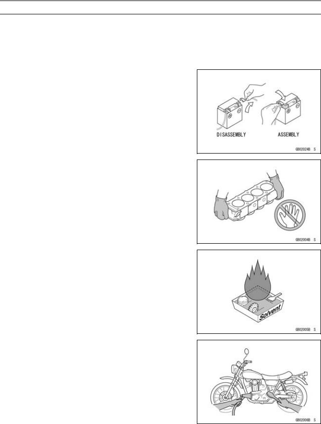
Battery Ground
Before completing any service on the motorcycle, disconnect the battery cables from the battery to prevent the engine from accidentally turning over. Disconnect the ground cable (–) first and then the positive (+). When completed with the service, first connect the positive (+) cable to the positive (+) terminal of the battery then the negative (–) cable to the negative terminal.
Edges of Parts
Lift large or heavy parts wearing gloves to prevent injury from possible sharp edges on the parts.
Solvent
Use a high-flush point solvent when cleaning parts. High -flush point solvent should be used according to directions of the solvent manufacturer.
Cleaning Vehicle before Disassembly
Clean the vehicle thoroughly before disassembly. Dirt or other foreign materials entering into sealed areas during vehicle disassembly can cause excessive wear and decrease performance of the vehicle.

GENERAL INFORMATION 1-3
Before Servicing
Arrangement and Cleaning of Removed Parts
Disassembled parts are easy to confuse. Arrange the parts according to the order the parts were disassembled and clean the parts in order prior to assembly.
Storage of Removed Parts
After all the parts including subassembly parts have been cleaned, store the parts in a clean area. Put a clean cloth or plastic sheet over the parts to protect from any foreign materials that may collect before re-assembly.
Inspection
Reuse of worn or damaged parts may lead to serious accident. Visually inspect removed parts for corrosion, discoloration, or other damage. Refer to the appropriate sections of this manual for service limits on individual parts. Replace the parts if any damage has been found or if the part is beyond its service limit.
Replacement Parts
Replacement parts must be KAWASAKI genuine or recommended by KAWASAKI. Gaskets, O-rings, oil seals, grease seals, circlips, cotter pins or self-locking nuts must be replaced with new ones whenever disassembled.
Assembly Order
In most cases assembly order is the reverse of disassembly, however, if assembly order is provided in this Service Manual, follow the procedures given.

1-4 GENERAL INFORMATION
Before Servicing
Tightening Sequence
Generally, when installing a part with several bolts, nuts, or screws, start them all in their holes and tighten them to a snug fit. Then tighten them according to the specified sequence to prevent case warpage or deformation which can lead to malfunction. Conversely when loosening the bolts, nuts, or screws, first loosen all of them by about a quarter turn and then remove them. If the specified tightening sequence is not indicated, tighten the fasteners alternating diagonally.
Tightening Torque
Incorrect torque applied to a bolt, nut, or screw may lead to serious damage. Tighten fasteners to the specified torque using a good quality torque wrench.
Force
Use common sense during disassembly and assembly, excessive force can cause expensive or hard to repair damage. When necessary, remove screws that have a non -permanent locking agent applied using an impact driver. Use a plastic-faced mallet whenever tapping is necessary.
Gasket, O-ring
Hardening, shrinkage, or damage of both gaskets and O-rings after disassembly can reduce sealing performance. Remove old gaskets and clean the sealing surfaces thoroughly so that no gasket material or other material remains. Install the new gaskets and replace the used O-rings when re-assembling.
Liquid Gasket, Non-permanent Locking Agent
For applications that require Liquid Gasket or a Non-permanent Locking Agent, clean the surfaces so that no oil residue remains before applying liquid gasket or non-permanent locking agent. Do not apply them excessively. Excessive application can clog oil passages and cause serious damage.

GENERAL INFORMATION 1-5
Before Servicing
Press
For items such as bearings or oil seals that must be pressed into place, apply small amount of oil to the contact area. Be sure to maintain proper alignment and use smooth movements when installing.
Ball Bearing and Needle Bearing
Do not remove pressed ball or needle unless removal is absolutely necessary. Replace with new ones whenever removed. Press bearings with the manufacturer and size marks facing out. Press the bearing into place by putting pressure on the correct bearing race as shown.
Pressing the incorrect race can cause pressure between the inner and outer race and result in bearing damage.
Oil Seal, Grease Seal
Do not remove pressed oil or grease seals unless removal is necessary. Replace with new ones whenever removed. Press new oil seals with manufacture and size marks facing out. Make sure the seal is aligned properly when installing.
Apply specified grease to the lip of seal before installing the seal.
Circlips, Cotter Pins
Replace the circlips or cotter pins that were removed with new ones. Take care not to open the clip excessively when installing to prevent deformation.
1-6 GENERAL INFORMATION
Before Servicing
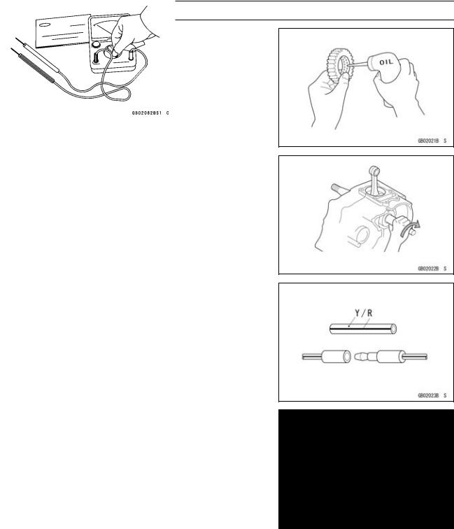
Lubrication
It is important to lubricate rotating or sliding parts during assembly to minimize wear during initial operation. Lubrication points are called out throughout this manual, apply the specific oil or grease as specified.
Direction of Engine Rotation
When rotating the crankshaft by hand, the free play amount of rotating direction will affect the adjustment. Rotate the crankshaft to positive direction (clockwise viewed from output side).
Electrical Wires
A two-color wire is identified first by the primary color and then the stripe color. Unless instructed otherwise, electrical wires must be connected to those of the same color.
Instrument
Use a meter that has enough accuracy for an accurate measurement. Read the manufacture’s instructions thoroughly before using the meter. Incorrect values may lead to improper adjustments.

GENERAL INFORMATION 1-7
Model Identification
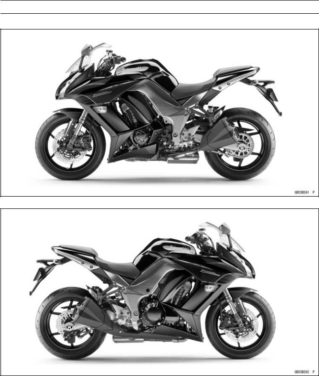
ZX1000GB (United States and Canada) Left Side View
ZX1000GB (United States and Canada) Right Side View
|
Frame Number |
Engine Number |
|
1-8 GENERAL INFORMATION
Model Identification
ZX1000GB (Europe) Left Side View
ZX1000GB (Europe) Right Side View

GENERAL INFORMATION 1-9
Model Identification
ZX1000HB Left Side View
ZX1000HB Right Side View

1-10 GENERAL INFORMATION
General Specifications
|
Items |
ZX1000GB GC/HB HC |
|
Dimensions |
|
|
Overall Length |
2 105 mm (82.87 in.) |
|
Overall Width |
790 mm (31.1 in.) |
|
Overall Height/High Position |
1 170 mm (40.06 in.)/1 230 mm (48.43 in.) |
|
Wheelbase |
1 445 mm (56.89 in.) |
|
Road Clearance |
135 mm (5.31 in.) |
|
Seat Height |
820 mm (32.28 in.) |
|
Curb Mass: |
|
|
ZX1000G |
228 kg (503 lb) |
|
ZX1000H |
231 kg (509 lb) |
|
Front: |
|
|
ZX1000G |
117 kg (258 lb) |
|
ZX1000H |
118 kg (260 lb) |
|
Rear: |
|
|
ZX1000G |
111 kg (245 lb) |
|
ZX1000H |
113 kg (249 lb) |
|
Fuel Tank Capacity |
19 L (5.0 US gal.) |
|
Performance |
|
|
Minimum Turning Radius |
3.1 m (10.1 ft) |
|
Engine |
|
|
Type |
4-stroke, DOHC, 4-cylinder |
|
Cooling System |
Liquid-cooled |
|
Bore and Stroke |
77.0 × 56.0 mm (3.03 × 2.20 in.) |
|
Displacement |
1 043 cm³ (63.64 cu in.) |
|
Compression Ratio |
11.8 : 1 |
|
Maximum Horsepower |
101.5 kW (138 PS) @9 600 r/min (rpm) |
|
(SEA-B1/B2) 100 kW (136 PS) @9 000 r/min (rpm) |
|
|
(WVTA (78.2 H)) 78.2 kW (106 PS) @9 100 r/min (rpm) |
|
|
(CA, US) – – – |
|
|
Maximum Torque |
110 N·m (11.2 kgf·m, 81.1 ft·lb) @7 800 r/min (rpm) |
|
(WVTA (78.2 H)) 95 N·m (9.7 kgf·m, 70 ft·lb) @7 500 r/min (rpm) |
|
|
(CA, US) – – – |
|
|
Carburetion System |
FI (Fuel Injection) KEIHIN TTK38 × 4 |
|
Starting System |
Electric starter |
|
Ignition System |
Battery and coil (transistorized) |
|
Timing Advance |
Electronically advanced (digital igniter) |
|
Ignition Timing |
From 10° BTDC @1 100 r/min (rpm) to 40.2° BTDC |
|
@5 200 r/min (rpm) |
|
|
Spark Plug |
NGK CR9EIA-9 |
|
Cylinder Numbering Method |
Left to right, 1-2-3-4 |
|
Firing Order |
1-2-4-3 |
|
Valve Timing: |
|
|
Intake: |
|
|
Open |
31° BTDC |
|
Close |
65° ABDC |
|
GENERAL INFORMATION 1-11 |
|
|
General Specifications |
|
|
Items |
ZX1000GB GC/HB HC |
|
Duration |
276° |
|
Exhaust: |
|
|
Open |
58° BBDC |
|
Close |
18° ATDC |
|
Duration |
256° |
|
Lubrication System |
Forced lubrication (wet sump) |
|
Engine Oil: |
|
|
Type |
API SG, SH, SJ, SL or SM with JASO MA, MA1 or MA2 |
|
Viscosity |
SAE 10W-40 |
|
Capacity |
4.0 L (4.2 US qt) |
|
Drive Train |
|
|
Primary Reduction System: |
|
|
Type |
Gear |
|
Reduction Ratio |
1.627 (83/51) |
|
Clutch Type |
Wet multi disc |
|
Transmission: |
|
|
Type |
6-speed, constant mesh, return shift |
|
Gear Ratios: |
|
|
1st |
2.600 (39/15) |
|
2nd |
1.950 (39/20) |
|
3rd |
1.600 (24/15) |
|
4th |
1.389 (25/18) |
|
5th |
1.238 (26/21) |
|
6th |
1.136 (25/22) |
|
Final Drive System: |
|
|
Type |
Chain drive |
|
Reduction Ratio |
2.733 (41/15) |
|
Overall Drive Ratio |
5.055 @Top gear |
|
Frame |
|
|
Type |
Tubular, diamond |
|
Caster (Rake Angle) |
24.5° |
|
Trail |
102 mm (4.02 in.) |
|
Front Tire: |
|
|
Type |
Tubeless |
|
Size |
120/70 ZR17 M/C (58W) |
|
Rim Size |
J17M/C × MT3.50 |
|
Rear Tire: |
|
|
Type |
Tubeless |
|
Size |
190/50 ZR17 M/C (73W) |
|
Rim Size |
J17M/C × MT6.00 |
|
Front Suspension: |
|
|
Type |
Telescopic fork (upside-down) |
|
Wheel Travel |
120 mm (4.72 in.) |

1-12 GENERAL INFORMATION
General Specifications
|
Items |
ZX1000GB GC/HB HC |
|
Rear Suspension: |
|
|
Type |
Swingarm |
|
Wheel Travel |
138 mm (5.43 in.) |
|
Brake Type: |
|
|
Front |
Dual discs |
|
Rear |
Single disc |
|
Electrical Equipment |
|
|
Battery |
12 V 8 Ah |
|
Headlight: |
|
|
Type |
Semi-sealed beam |
|
High Beam |
12 V 55 W |
|
Low Beam |
12 V 55 W |
|
Tail/Brake Light |
LED |
|
Alternator: |
|
|
Type |
Three-phase AC |
Specifications are subject to change without notice, and may not apply to every country.
GENERAL INFORMATION 1-13
Unit Conversion Table
|
Prefixes for Units: |
Units of Length: |
|
Prefix |
Symbol |
Power |
||
|
mega |
M |
× 1 000 |
000 |
|
|
kilo |
k |
× |
1 000 |
|
|
centi |
c |
× |
0.01 |
|
|
milli |
m |
× |
0.001 |
|
|
micro |
µ |
× 0.000001 |
Units of Mass:
|
kg |
× |
2.205 |
= |
lb |
|
g |
× |
0.03527 |
= |
oz |
Units of Volume:
|
L |
× |
0.2642 |
= |
gal (US) |
|
L |
× |
0.2200 |
= |
gal (IMP) |
|
L |
× |
1.057 |
= |
qt (US) |
|
L |
× |
0.8799 |
= |
qt (IMP) |
|
L |
× |
2.113 |
= |
pint (US) |
|
L |
× |
1.816 |
= |
pint (IMP) |
|
mL |
× |
0.03381 |
= |
oz (US) |
|
mL |
× |
0.02816 |
= |
oz (IMP) |
|
mL |
× |
0.06102 |
= |
cu in |
Units of Force:
|
N |
× |
0.1020 |
= |
kg |
|
N |
× |
0.2248 |
= |
lb |
|
kg |
× |
9.807 |
= |
N |
|
kg |
× |
2.205 |
= |
lb |
|
km |
× |
0.6214 |
= |
mile |
|
m |
× |
3.281 |
= |
ft |
|
mm |
× |
0.03937 |
= |
in |
Units of Torque:
|
N·m |
× |
0.1020 |
= |
kgf·m |
|
N·m |
× |
0.7376 |
= |
ft·lb |
|
N·m |
× |
8.851 |
= |
in·lb |
|
kgf·m |
× |
9.807 |
= |
N·m |
|
kgf·m |
× |
7.233 |
= |
ft·lb |
|
kgf·m |
× |
86.80 |
= |
in·lb |
Units of Pressure:
|
kPa |
× |
0.01020 |
= |
kgf/cm² |
|
kPa |
× |
0.1450 |
= |
psi |
|
kPa |
× |
0.7501 |
= |
cmHg |
|
kgf/cm² |
× |
98.07 |
= |
kPa |
|
kgf/cm² |
× |
14.22 |
= |
psi |
|
cmHg |
× |
1.333 |
= |
kPa |
Units of Speed:
km/h × 0.6214 = mph
Units of Power:
|
kW |
× |
1.360 |
= |
PS |
|
kW |
× |
1.341 |
= |
HP |
|
PS |
× |
0.7355 |
= |
kW |
|
PS |
× |
0.9863 |
= |
HP |
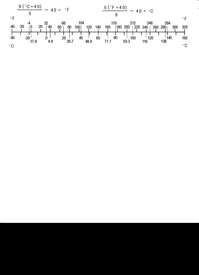
Units of Temperature:

PERIODIC MAINTENANCE 2-1
Periodic Maintenance
Table of Contents
|
Periodic Maintenance Chart ……………………………………………………………………………………… |
2-3 |
||
|
Torque and Locking Agent………………………………………………………………………………………… |
2-7 |
2 |
|
|
Specifications |
2-13 |
||
|
Special Tools ………………………………………………………………………………………………………….. |
2-15 |
||
|
Periodic Maintenance Procedures……………………………………………………………………………… |
2-17 |
||
|
Fuel System (DFI)…………………………………………………………………………………………………. |
2-17 |
||
|
Throttle Control System Inspection……………………………………………………………………….. |
2-17 |
||
|
Engine Vacuum Synchronization Inspection…………………………………………………………… |
2-17 |
||
|
Idle Speed Inspection …………………………………………………………………………………………. |
2-21 |
||
|
Idle Speed Adjustment………………………………………………………………………………………… |
2-22 |
||
|
Fuel Hose Inspection (fuel leak, damage, installation condition) ……………………………….. |
2-22 |
||
|
Evaporative Emission Control System (CAL and SEA-B1 Models) Inspection…………….. |
2-23 |
||
|
Cooling System…………………………………………………………………………………………………….. |
2-24 |
||
|
Coolant Level Inspection……………………………………………………………………………………… |
2-24 |
||
|
Radiator Hose and Pipe Inspection (coolant leak, damage, installation condition) ………. |
2-24 |
||
|
Engine Top End ……………………………………………………………………………………………………. |
2-24 |
||
|
Valve Clearance Inspection …………………………………………………………………………………. |
2-24 |
||
|
Valve Clearance Adjustment………………………………………………………………………………… |
2-26 |
||
|
Air Suction System Damage Inspection…………………………………………………………………. |
2-29 |
||
|
Clutch………………………………………………………………………………………………………………….. |
2-30 |
||
|
Clutch Operation Inspection…………………………………………………………………………………. |
2-30 |
||
|
Wheels/Tires………………………………………………………………………………………………………… |
2-31 |
||
|
Air Pressure Inspection……………………………………………………………………………………….. |
2-31 |
||
|
Wheel/Tire Damage Inspection…………………………………………………………………………….. |
2-31 |
||
|
Tire Tread Wear Inspection………………………………………………………………………………….. |
2-31 |
||
|
Wheel Bearing Damage Inspection ………………………………………………………………………. |
2-32 |
||
|
Final Drive……………………………………………………………………………………………………………. |
2-33 |
||
|
Drive Chain Lubrication Condition Inspection …………………………………………………………. |
2-33 |
||
|
Drive Chain Slack Inspection ……………………………………………………………………………….. |
2-33 |
||
|
Drive Chain Slack Adjustment ……………………………………………………………………………… |
2-34 |
||
|
Wheel Alignment Inspection ………………………………………………………………………………… |
2-34 |
||
|
Wheel Alignment Adjustment……………………………………………………………………………….. |
2-34 |
||
|
Drive Chain Wear Inspection ……………………………………………………………………………….. |
2-35 |
||
|
Chain Guide Wear Inspection ………………………………………………………………………………. |
2-35 |
||
|
Brakes…………………………………………………………………………………………………………………. |
2-36 |
||
|
Brake Fluid Leak (Brake Hose and Pipe) Inspection ……………………………………………….. |
2-36 |
||
|
Brake Hose and Pipe Damage and Installation Condition Inspection…………………………. |
2-37 |
||
|
Brake Operation Inspection …………………………………………………………………………………. |
2-37 |
||
|
Brake Fluid Level Inspection………………………………………………………………………………… |
2-37 |
||
|
Brake Pad Wear Inspection …………………………………………………………………………………. |
2-38 |
||
|
Brake Light Switch Operation Inspection ……………………………………………………………….. |
2-39 |
||
|
Suspension………………………………………………………………………………………………………….. |
2-40 |
||
|
Front Forks/Rear Shock Absorber Operation Inspection ………………………………………….. |
2-40 |
||
|
Front Fork Oil Leak Inspection……………………………………………………………………………… |
2-40 |
||
|
Rear Shock Absorber Oil Leak Inspection ……………………………………………………………… |
2-40 |
||
|
Rocker Arm Operation Inspection…………………………………………………………………………. |
2-40 |
||
|
Tie-Rod Operation Inspection ………………………………………………………………………………. |
2-41 |
||
|
Steering ………………………………………………………………………………………………………………. |
2-41 |
||
|
Steering Play Inspection ……………………………………………………………………………………… |
2-41 |
||
|
Steering Play Adjustment…………………………………………………………………………………….. |
2-41 |

2-2 PERIODIC MAINTENANCE
|
Steering Stem Bearing Lubrication ……………………………………………………………………….. |
2-43 |
|
Electrical System ………………………………………………………………………………………………….. |
2-44 |
|
Lights and Switches Operation Inspection……………………………………………………………… |
2-44 |
|
Headlight Aiming Inspection ………………………………………………………………………………… |
2-46 |
|
Sidestand Switch Operation Inspection …………………………………………………………………. |
2-47 |
|
Engine Stop Switch Operation Inspection………………………………………………………………. |
2-48 |
|
Others…………………………………………………………………………………………………………………. |
2-49 |
|
Chassis Parts Lubrication ……………………………………………………………………………………. |
2-49 |
|
Bolts, Nuts and Fasteners Tightness Inspection……………………………………………………… |
2-51 |
|
Replacement Parts ……………………………………………………………………………………………….. |
2-52 |
|
Air Cleaner Element Replacement………………………………………………………………………… |
2-52 |
|
Fuel Hose Replacement ……………………………………………………………………………………… |
2-52 |
|
Coolant Change …………………………………………………………………………………………………. |
2-54 |
|
Radiator Hose and O-ring Replacement………………………………………………………………… |
2-56 |
|
Engine Oil Change……………………………………………………………………………………………… |
2-57 |
|
Oil Filter Replacement ………………………………………………………………………………………… |
2-57 |
|
Brake Hose Replacement ……………………………………………………………………………………. |
2-58 |
|
Brake Fluid Change ……………………………………………………………………………………………. |
2-59 |
|
Master Cylinder Rubber Parts Replacement ………………………………………………………….. |
2-61 |
|
Caliper Rubber Parts Replacement ………………………………………………………………………. |
2-62 |
|
Spark Plug Replacement …………………………………………………………………………………….. |
2-66 |
PERIODIC MAINTENANCE 2-3
Periodic Maintenance Chart
The scheduled maintenance must be done in accordance with this chart to keep the motorcycle in good running condition.The initial maintenance is vitally important and must not be neglected.
Periodic Inspection
|
FREQUENCY |
Whichever |
* ODOMETER READING |
|||||||||||||
|
comes |
× 1 000 km |
See |
|||||||||||||
|
first |
(× 1 000 mile) |
||||||||||||||
|
Page |
|||||||||||||||
|
1 |
6 |
12 |
18 |
24 |
30 |
36 |
|||||||||
|
ITEM |
Every |
(0.6) |
(3.75) |
(7.5) |
(11.25) |
(15) |
(18.75) |
(22.5) |
|||||||
|
Fuel System |
|||||||||||||||
|
Throttle control system (play, |
year |
• |
• |
• |
• |
2-17 |
|||||||||
|
smooth return, no drag) — inspect |
|||||||||||||||
|
Engine vacuum synchronization — |
• |
• |
• |
2-17 |
|||||||||||
|
inspect |
|||||||||||||||
|
Idle speed — inspect |
• |
• |
• |
• |
2-21 |
||||||||||
|
Fuel leak (fuel hose and pipe) — |
year |
• |
• |
• |
• |
2-22 |
|||||||||
|
inspect |
|||||||||||||||
|
Fuel hose and pipe damage — |
year |
• |
• |
• |
• |
2-22 |
|||||||||
|
inspect |
|||||||||||||||
|
Fuel hose and pipe installation |
year |
• |
• |
• |
• |
2-22 |
|||||||||
|
condition — inspect |
|||||||||||||||
|
Evaporative emission control |
• |
• |
• |
• |
• |
• |
• |
2-23 |
|||||||
|
system function (CAL), (SEA-B1) |
|||||||||||||||
|
— inspect |
|||||||||||||||
|
Cooling System |
|||||||||||||||
|
Coolant level — inspect |
• |
• |
• |
• |
2-24 |
||||||||||
|
Coolant leak (water hose and |
year |
• |
• |
• |
• |
2-24 |
|||||||||
|
pipe) — inspect |
|||||||||||||||
|
Water hose damage — inspect |
year |
• |
• |
• |
• |
2-24 |
|||||||||
|
Water hose installation condition — |
year |
• |
• |
• |
• |
2-24 |
|||||||||
|
inspect |
|||||||||||||||
|
Engine Top End |
|||||||||||||||
|
US, CA, CAL |
• |
2-24 |
|||||||||||||
|
Model |
|||||||||||||||
|
Valve clearance — |
|||||||||||||||
|
Other than |
|||||||||||||||
|
inspect |
Every 42 000 km (26 250 mile) |
2-24 |
|||||||||||||
|
US, CA, CAL |
|||||||||||||||
|
Models |
|||||||||||||||
|
Air suction system damage — |
• |
• |
• |
2-29 |
|||||||||||
|
inspect |
|||||||||||||||
|
Clutch |
|||||||||||||||
|
Clutch operation (play, |
• |
• |
• |
• |
2-30 |
||||||||||
|
disengagement, engagement) — |
|||||||||||||||
|
inspect |
|||||||||||||||
|
Wheels and Tires |
|||||||||||||||
|
Tire air pressure — inspect |
year |
• |
• |
• |
2-31 |
||||||||||
|
Wheel/tire damage — inspect |
• |
• |
• |
2-31 |
|||||||||||
|
Tire tread wear, abnormal wear — |
• |
• |
• |
2-31 |
|||||||||||
|
inspect |
|||||||||||||||
|
Wheel bearing damage — inspect |
year |
• |
• |
• |
2-32 |

2-4 PERIODIC MAINTENANCE
Periodic Maintenance Chart
|
FREQUENCY |
Whichever |
* ODOMETER READING |
|||||||||||
|
comes |
× 1 000 km |
See |
|||||||||||
|
first |
(× 1 000 mile) |
||||||||||||
|
Page |
|||||||||||||
|
1 |
6 |
12 |
18 |
24 |
30 |
36 |
|||||||
|
ITEM |
Every |
(0.6) |
(3.75) |
(7.5) |
(11.25) |
(15) |
(18.75) |
(22.5) |
|||||
|
Final Drive |
|||||||||||||
|
Drive chain lubrication condition — |
Every 600 km (400 mile) |
2-33 |
|||||||||||
|
inspect # |
|||||||||||||
|
Drive chain slack — inspect # |
Every 1 000 km (600 mile) |
2-33 |
|||||||||||
|
Drive chain wear — inspect # |
• |
• |
• |
2-35 |
|||||||||
|
Drive chain guide wear — inspect |
• |
• |
• |
2-35 |
|||||||||
|
Brakes |
|||||||||||||
|
Brake fluid leak (brake hose and |
year |
• |
• |
• |
• |
• |
• |
• |
2-36 |
||||
|
pipe) — inspect |
|||||||||||||
|
Brake hose and pipe damage — |
year |
• |
• |
• |
• |
• |
• |
• |
2-37 |
||||
|
inspect |
|||||||||||||
|
Brake hose and pipe installation |
year |
• |
• |
• |
• |
• |
• |
• |
2-37 |
||||
|
condition — inspect |
|||||||||||||
|
Brake operation (effectiveness, |
year |
• |
• |
• |
• |
• |
• |
• |
2-37 |
||||
|
play, no drag) — inspect |
|||||||||||||
|
Brake fluid level — inspect |
6 |
• |
• |
• |
• |
• |
• |
• |
2-37 |
||||
|
months |
|||||||||||||
|
Brake pad wear — inspect # |
• |
• |
• |
• |
• |
• |
2-38 |
||||||
|
Brake light switch operation — |
• |
• |
• |
• |
• |
• |
• |
2-39 |
|||||
|
inspect |
|||||||||||||
|
Suspension |
|||||||||||||
|
Front forks/rear shock absorber |
• |
• |
• |
2-40 |
|||||||||
|
operation (damping and smooth |
|||||||||||||
|
stroke) — inspect |
|||||||||||||
|
Front forks/rear shock absorber |
year |
• |
• |
• |
2-40 |
||||||||
|
oil leak — inspect |
|||||||||||||
|
Rocker arm operation — inspect |
• |
• |
• |
2-40 |
|||||||||
|
Tie-rods operation — inspect |
• |
• |
• |
2-41 |
|||||||||
|
Steering |
|||||||||||||
|
Steering play — inspect |
year |
• |
• |
• |
• |
2-41 |
|||||||
|
Steering stem bearings — lubricate |
2 years |
• |
2-43 |
||||||||||
|
Electrical System |
|||||||||||||
|
Lights and switches operation — |
year |
• |
• |
• |
2-44 |
||||||||
|
inspect |
|||||||||||||
|
Headlight aiming — inspect |
year |
• |
• |
• |
2-46 |
||||||||
|
Sidestand switch operation — |
year |
• |
• |
• |
2-47 |
||||||||
|
inspect |
|||||||||||||
|
Engine stop switch operation — |
year |
• |
• |
• |
2-48 |
||||||||
|
inspect |
|||||||||||||
|
Others |
|||||||||||||
|
Chassis parts — lubricate |
year |
• |
• |
• |
2-49 |
||||||||
|
Bolts and nuts tightness — inspect |
• |
• |
• |
• |
2-51 |

PERIODIC MAINTENANCE 2-5
Periodic Maintenance Chart
#: Service more frequently when operating in severe conditions; dusty, wet, muddy, high speed or frequent starting/stopping.
*: For higher odometer readings, repeat at the frequency interval established here.
2-6 PERIODIC MAINTENANCE
Periodic Maintenance Chart
Periodic Replacement Parts
|
FREQUENCY |
Whichever |
* ODOMETER READING |
||||||||||
|
comes |
× 1 000 km |
See |
||||||||||
|
first |
(× 1 000 mile) |
|||||||||||
|
Page |
||||||||||||
|
1 |
12 |
24 |
36 |
48 |
||||||||
|
ITEM |
Every |
(0.6) |
(7.5) |
(15) |
(22.5) |
(30) |
||||||
|
Air cleaner element # — replace |
Every 18 000 km (11 250 mile) |
2-52 |
||||||||||
|
Fuel hose — replace |
5 years |
2-52 |
||||||||||
|
Coolant — change |
3 years |
• |
2-54 |
|||||||||
|
Radiator hose and O-ring — replace |
3 years |
• |
2-56 |
|||||||||
|
Engine oil # — change |
year |
• |
• |
• |
• |
• |
2-57 |
|||||
|
Oil filter — replace |
year |
• |
• |
• |
• |
• |
2-57 |
|||||
|
Brake hose — replace |
4 years |
• |
2-58 |
|||||||||
|
Brake fluid — change |
2 years |
• |
• |
2-59 |
||||||||
|
Rubber parts of master cylinder and caliper — |
4 years |
• |
2-61, |
|||||||||
|
replace |
2-62 |
|||||||||||
|
Spark plug — replace |
• |
• |
• |
• |
2-66 |
#: Service more frequently when operating in severe conditions; dusty, wet, muddy, high speed or frequent starting/stopping.
*: For higher odometer readings, repeat at the frequency interval established here.
![]()
PERIODIC MAINTENANCE 2-7
Torque and Locking Agent
The following tables list the tightening torque for the major fasteners requiring use of a non-permanent locking agent or silicone sealant etc.
Letters used in the “Remarks” column mean:
AL: Tighten the two clamp bolts alternately two times to ensure even tightening torque. G: Apply grease.
L: Apply a non-permanent locking agent. MO: Apply molybdenum disulfide oil solution.
(mixture of the engine oil and molybdenum disulfide grease in a weight ratio 10 : 1)
R:Replacement Parts
S:Follow the specified tightening sequence. Si: Apply silicone grease (ex. PBC grease).
SS: Apply silicone sealant.
|
Fastener |
Torque |
Remarks |
|||
|
N·m |
kgf·m |
ft·lb |
|||
|
Fuel System (DFI) |
|||||
|
Upper Air Cleaner Housing Screws |
1.1 |
0.11 |
9.7 in·lb |
||
|
Throttle Body Assy Holder Clamp Bolts |
2.9 |
0.30 |
26 in·lb |
||
|
Air Cleaner Duct Clamp Bolts |
2.0 |
0.20 |
18 in·lb |
||
|
Delivery Pipe Assy Mounting Screws |
3.4 |
0.35 |
30 in·lb |
||
|
Oxygen Sensor (Equipped Models) |
44 |
4.5 |
32 |
||
|
Intake Air Temperature Sensor Mounting Screw |
1.2 |
0.12 |
11 in·lb |
||
|
Water Temperature Sensor |
30 |
3.0 |
22 |
||
|
Exhaust Butterfly Valve Actuator Pulley Bolt |
5.0 |
0.51 |
44 in·lb |
||
|
Exhaust Butterfly Valve Actuator Mounting |
1.2 |
0.12 |
11 in·lb |
||
|
Screws |
|||||
|
Fuel Pump Bolts |
9.8 |
1.0 |
87 in·lb |
L |
|
|
Cooling System |
|||||
|
Hot Windshield Mounting Bolts |
9.8 |
1.0 |
87 in·lb |
||
|
Coolant By-pass Fitting Bolt |
8.8 |
0.90 |
78 in·lb |
L |
|
|
Thermostat Housing Bolts |
5.9 |
0.60 |
52 in·lb |
L |
|
|
Radiator (Water) Hose Clamp Screws |
2.9 |
0.30 |
26 in·lb |
||
|
Water Pipe Bolts |
12 |
1.2 |
106 in·lb |
L |
|
|
Water Pump Impeller Bolt |
9.8 |
1.0 |
87 in·lb |
||
|
Water Pump Cover Bolts |
11 |
1.1 |
97 in·lb |
||
|
Coolant Drain Bolt |
11 |
1.1 |
97 in·lb |
||
|
Engine Top End |
|||||
|
Air Suction Valve Cover Bolts |
9.8 |
1.0 |
87 in·lb |
L |
|
|
Spark Plugs |
13 |
1.3 |
115 in·lb |
||
|
Cylinder Head Cover Bolts |
9.8 |
1.0 |
87 in·lb |
S |
|
|
Hot Windshield Mounting Bolts |
9.8 |
1.0 |
87 in·lb |
||
|
Camshaft Sprocket Bolts |
15 |
1.5 |
11 |
L |
|
|
Front Camshaft Chain Guide Bolt (Upper) |
25 |
2.5 |
18 |
||
|
Rear Camshaft Chain Guide Bolt |
25 |
2.5 |
18 |
||
|
Front Camshaft Chain Guide Bolt (Lower) |
12 |
1.2 |
106 in·lb |
||
|
Throttle Body Assy Holder Bolts |
12 |
1.2 |
106 in·lb |
L |

2-8 PERIODIC MAINTENANCE
Torque and Locking Agent
|
Fastener |
Torque |
Remarks |
|||
|
N·m |
kgf·m |
ft·lb |
|||
|
Cylinder Head Bolts (M6) |
12 |
1.2 |
106 in·lb |
S |
|
|
Upper Camshaft Chain Guide Bolts |
12 |
1.2 |
106 in·lb |
S |
|
|
Plugs |
19.6 |
2.0 |
14 |
L |
|
|
Camshaft Cap Bolts |
12 |
1.2 |
106 in·lb |
S |
|
|
Cylinder Head Bolts (M10) (First) |
20 |
2.0 |
15 |
S, MO |
|
|
Cylinder Head Bolts (M10) (Final) |
54 |
5.5 |
40 |
S, MO |
|
|
Camshaft Chain Tensioner Mounting Bolts |
11 |
1.1 |
97 in·lb |
||
|
Camshaft Chain Tensioner Cap Bolt |
20 |
2.0 |
15 |
||
|
Exhaust Butterfly Valve Actuator Pulley Bolt |
5.0 |
0.51 |
44 in·lb |
||
|
Exhaust Butterfly Valve Actuator Bolts |
1.2 |
0.12 |
11 in·lb |
||
|
Muffler Body Mounting Bolts |
34 |
3.5 |
25 |
||
|
Premuffler Chamber Mounting Bolt |
34 |
3.5 |
25 |
||
|
Muffler Body Clamp Bolts |
21 |
2.1 |
15 |
||
|
Clutch |
|||||
|
Clutch Lever Assembly Clamp Bolts |
7.8 |
0.80 |
69 in·lb |
S |
|
|
Clutch Cover Bolts |
9.8 |
1.0 |
87 in·lb |
||
|
Oil Filler Plug |
2.0 |
0.20 |
18 in·lb |
||
|
Clutch Spring Bolts |
9.0 |
0.90 |
80 in·lb |
||
|
Clutch Hub Nut |
135 |
13.8 |
99.6 |
R |
|
|
Engine Lubrication System |
|||||
|
Oil Filler Plug |
2.0 |
0.20 |
18 in·lb |
||
|
Oil Cooler Bolts |
12 |
1.2 |
106 in·lb |
||
|
Oil Passage Plug |
20 |
2.0 |
15 |
L |
|
|
Radiator (Water) Hose Clamp Screws |
3.0 |
0.31 |
27 in·lb |
||
|
Oil Pressure Switch |
15 |
1.5 |
11 |
SS |
|
|
Oil Pressure Relief Valve |
15 |
1.5 |
11 |
L |
|
|
Oil Filter |
17 |
1.7 |
13 |
G, R |
|
|
Oil Filter Pipe |
25 |
2.5 |
18 |
L |
|
|
Oil Pan Bolts |
12 |
1.2 |
106 in·lb |
S |
|
|
Engine Oil Drain Bolt |
29 |
3.0 |
21 |
||
|
Engine Removal/Installation |
|||||
|
Upper Engine Bracket Bolts |
44 |
4.5 |
32 |
S |
|
|
Lower Engine Bracket Bolts |
59 |
6.0 |
44 |
S |
|
|
Upper Adjusting Collar |
9.8 |
1.0 |
87 in·lb |
S |
|
|
Upper Engine Mounting Bolt (L = 65) |
44 |
4.5 |
32 |
S |
|
|
Upper Adjusting Collar Locknut |
49 |
5.0 |
36 |
S |
|
|
Upper Engine Mounting Bolt (L = 40) |
44 |
4.5 |
32 |
S |
|
|
Lower Engine Mounting Nut |
44 |
4.5 |
32 |
S |
|
|
Lower Adjusting Collar Locknut |
49 |
5.0 |
36 |
S |
|
|
Middle Engine Bracket Bolts |
25 |
2.5 |
18 |
L, S |
|
|
Middle Engine Mounting Nut |
44 |
4.5 |
32 |
S |
|
|
Lower Adjusting Collar |
9.8 |
1.0 |
87 in·lb |
S |
|

PERIODIC MAINTENANCE 2-9
Torque and Locking Agent
|
Fastener |
Torque |
Remarks |
|||
|
N·m |
kgf·m |
ft·lb |
|||
|
Crankshaft/Transmission |
|||||
|
Balancer Shaft Clamp Bolt |
9.8 |
1.0 |
87 in·lb |
||
|
Balancer Shaft Lever Bolt |
25 |
2.5 |
18 |
L |
|
|
Breather Side Plate Bolt |
5.9 |
0.60 |
52 in·lb |
L |
|
|
Connecting Rod Big End Nuts |
see the text |
← |
← |
MO |
|
|
Breather Plate Bolts |
9.8 |
1.0 |
87 in·lb |
L |
|
|
Shift Drum Bearing Holder Bolts |
12 |
1.2 |
106 in·lb |
L |
|
|
Oil Passage Plugs |
20 |
2.0 |
15 |
L |
|
|
Oil Passage Plug |
9.8 |
1.0 |
87 in·lb |
||
|
Starter Motor Clutch Bolts |
12 |
1.2 |
106 in·lb |
L |
|
|
Crankcase Bolts (M7) |
20 |
2.0 |
15 |
S |
|
|
Crankcase Bolts (M9) |
42 |
4.2 |
31 |
S, MO |
|
|
Crankcase Bolts (M6) |
20 |
2.0 |
15 |
S |
|
|
Crankcase Bolts (M8) |
27 |
2.8 |
20 |
S |
|
|
Gear Positioning Lever Bolt |
12 |
1.2 |
106 in·lb |
||
|
Shift Drum Cam Bolt |
12 |
1.2 |
106 in·lb |
L |
|
|
Neutral Switch |
15 |
1.5 |
11 |
||
|
Shift Shaft Return Spring Pin |
39 |
4.0 |
29 |
L |
|
|
Shift Pedal Mounting Bolt |
25 |
2.5 |
18 |
||
|
Wheels/Tires |
|||||
|
Front Axle Clamp Bolt |
20 |
2.0 |
15 |
AL |
|
|
Front Axle |
108 |
11.0 |
79.7 |
||
|
Rear Axle Nut |
98 |
10 |
72 |
||
|
Final Drive |
|||||
|
Engine Sprocket Nut |
125 |
12.7 |
92.2 |
MO |
|
|
Drive Chain Guide Bolts |
9.8 |
1.0 |
87 in·lb |
||
|
Speed Sensor Mounting Bolt |
6.9 |
0.70 |
61 in·lb |
L |
|
|
Chain Adjuster Clamp Bolts |
64 |
6.5 |
47 |
||
|
Rear Sprocket Nuts |
59 |
6.0 |
44 |
||
|
Brakes |
|||||
|
Front Master Cylinder Reservoir Cap Stopper |
1.2 |
0.12 |
11 in·lb |
||
|
Screw |
|||||
|
Brake Lever Pivot Bolt |
1.0 |
0.10 |
8.8 in·lb |
Si |
|
|
Front Master Cylinder Bleed Valve |
5.4 |
0.55 |
48 in·lb |
||
|
Front Master Cylinder Clamp Bolts |
11 |
1.1 |
97 in·lb |
S |
|
|
Brake Lever Pivot Bolt Locknut |
5.9 |
0.60 |
52 in·lb |
||
|
Front Brake Light Switch Screw |
1.2 |
0.12 |
11 in·lb |
||
|
Brake Hose Banjo Bolts |
25 |
2.5 |
18 |
||
|
Front Caliper Assembly Bolts |
22 |
2.2 |
16 |
||
|
Front Caliper Mounting Bolts |
34 |
3.5 |
25 |
||
|
Bleed Valves |
7.8 |
0.80 |
69 in·lb |
||
|
Front Brake Pad Pins |
15 |
1.5 |
11 |
||
|
Front Brake Disc Mounting Bolts |
27 |
2.8 |
20 |
L |

2-10 PERIODIC MAINTENANCE
Torque and Locking Agent
|
Fastener |
Torque |
Remarks |
|||
|
N·m |
kgf·m |
ft·lb |
|||
|
Rear Master Cylinder Mounting Bolts |
25 |
2.5 |
18 |
||
|
Brake Pedal Bolt |
8.8 |
0.90 |
78 in·lb |
L |
|
|
Rear Master Cylinder Push Rod Locknut |
17 |
1.7 |
12 |
||
|
Rear Brake Disc Mounting Bolts |
27 |
2.8 |
20 |
L |
|
|
Rear Caliper Mounting Bolts |
25 |
2.5 |
18 |
||
|
Brake Pipe Joint Nuts |
18 |
1.8 |
13 |
||
|
Rear Brake Disc Mounting Bolts (ABS Equipped |
27 |
2.8 |
20 |
L |
|
|
Models) |
|||||
|
Suspension |
|||||
|
Upper Front Fork Clamp Bolts |
20 |
2.0 |
15 |
||
|
Lower Front Fork Clamp Bolts |
25 |
2.5 |
18 |
AL |
|
|
Piston Rod Nuts |
20 |
2.0 |
15 |
||
|
Front Fork Top Plugs |
34 |
3.5 |
25 |
||
|
Front Axle Clump Bolts |
20 |
2.0 |
15 |
AL |
|
|
Front Fork Bottom Allen Bolts |
35 |
3.6 |
26 |
||
|
Rear Shock Absorber Bolt (Upper) |
34 |
3.5 |
25 |
||
|
Tie-rod Nuts |
34 |
3.5 |
25 |
R |
|
|
Rear Shock Absorber Nut (Lower) |
34 |
3.5 |
25 |
R |
|
|
Rocker Arm Nut |
34 |
3.5 |
25 |
R |
|
|
Swingarm Pivot Adjusting Collar Locknut |
98 |
10 |
72 |
||
|
Swingarm Pivot Shaft Nut |
108 |
11.0 |
79.7 |
||
|
Torque Link Nuts |
|||||
|
34 |
3.5 |
25 |
|||
|
Steering |
|||||
|
Left Switch Housing Screws |
3.5 |
0.36 |
31 in·lb |
||
|
Upper Front Fork Clamp Bolts |
25 |
2.5 |
18 |
||
|
Handlebar Holder Bolts |
25 |
2.5 |
18 |
||
|
Handlebar Bolts |
34 |
3.5 |
25 |
L |
|
|
Right Switch Housing Screws |
3.5 |
0.36 |
31 in·lb |
||
|
Steering Stem Head Bolt |
108 |
11.0 |
79.7 |
||
|
Steering Stem Nut |
25 |
2.5 |
18 |
||
|
Lower Front Fork Clamp Bolts |
20 |
2.0 |
15 |
AL |
|
|
Frame |
|||||
|
Lower Fairing Upper Assembly Screws |
1.2 |
0.12 |
11 in·lb |
||
|
Lower Fairing Lower Assembly Screws |
1.2 |
0.12 |
11 in·lb |
||
|
Front Fender Mounting Bolts |
3.9 |
0.40 |
35 in·lb |
||
|
Stay Assembly Mounting Bolts |
6.9 |
0.70 |
61 in·lb |
||
|
Stopper Mounting Bolts |
4.2 |
0.42 |
37 in·lb |
L |
|
|
Rear Frame Bracket Bolts |
44 |
4.5 |
32 |
||
|
Front Footpeg Bracket Bolts |
25 |
2.5 |
18 |
||
|
Rear Footpeg Bracket Bolts |
25 |
2.5 |
18 |
||
|
Rear Frame Bolts |
25 |
2.5 |
18 |
L |
|
|
Sidestand Switch Bolt |
8.8 |
0.90 |
78 in·lb |
L |
|
|
Sidestand Bracket Bolts |
49 |
5.0 |
36 |
L |

PERIODIC MAINTENANCE 2-11
Torque and Locking Agent
|
Fastener |
Torque |
Remarks |
|||
|
N·m |
kgf·m |
ft·lb |
|||
|
Sidestand Bolt |
44 |
4.5 |
32 |
||
|
Grab Rail Mounting Bolts |
25 |
2.5 |
18 ft·lb |
||
|
Electrical System |
|||||
|
Switch Housing Screws |
3.5 |
0.36 |
31 in·lb |
||
|
Oxygen Sensor (Equipped Models) |
44 |
4.5 |
32 |
||
|
Front Brake Light Switch Screw |
1.2 |
0.12 |
11 in·lb |
||
|
Front Turn Signal Light Mounting Screws |
1.2 |
0.12 |
11 in·lb |
||
|
Licence Plate Light Mounting Screws |
1.2 |
0.12 |
11 in·lb |
||
|
Intake Air Temperature Sensor Mounting Screw |
1.2 |
0.12 |
11 in·ib |
||
|
Spark Plugs |
13 |
1.3 |
115 in·lb |
||
|
Crankshaft Sensor Cover Bolts |
12 |
1.2 |
106 in·lb |
||
|
Water Temperature Sensor |
30 |
3.0 |
22 |
||
|
Timing Rotor Bolt |
39 |
4.0 |
29 |
||
|
Crankshaft Sensor Bolts |
5.9 |
0.60 |
52 in·lb |
||
|
Starter Motor Cable Terminal Nut |
5.9 |
0.60 |
52 in·lb |
||
|
Starter Motor Terminal Locknut |
11 |
1.1 |
97 in·lb |
||
|
Starter Motor Mounting Bolts |
9.8 |
1.0 |
87 in·lb |
||
|
Alternator Rotor Bolt |
155 |
15.8 |
114 |
||
|
Stator Coil Bolts |
12 |
1.2 |
106 in·ib |
L |
|
|
Starter Motor Through Bolts |
4.9 |
0.50 |
43 in·lb |
||
|
Brush Holder Screw |
3.8 |
0.39 |
34 in·ib |
||
|
Oil Pressure Switch |
15 |
1.5 |
11 |
SS |
|
|
Oil Pressure Switch Terminal Bolt |
2.0 |
0.20 |
18 in·ib |
G |
|
|
Alternator Cover Bolts |
12 |
1.2 |
106 in·lb |
||
|
Alternator Lead Holding Plate Bolt |
12 |
1.2 |
106 in·ib |
L |
|
|
Neutral Switch |
15 |
1.5 |
11 |
||
|
Engine Ground Cable Terminal Bolt |
9.8 |
1.0 |
87 in·lb |
||
|
Sidestand Switch Bolt |
8.8 |
0.90 |
78 in·lb |
L |
|
|
Speed Sensor Mounting Bolt |
6.9 |
0.70 |
61 in·lb |
L |

2-12 PERIODIC MAINTENANCE
Torque and Locking Agent
The table below, relating tightening torque to thread diameter, lists the basic torque for the bolts and nuts. Use this table for only the bolts and nuts which do not require a specific torque value. All of the values are for use with dry solvent-cleaned threads.
Basic Torque for General Fasteners
|
Threads Diameter |
Torque |
||||||||
|
(mm) |
N·m |
kgf·m |
ft·lb |
||||||
|
5 |
3.4 |
4.9 |
0.35 |
0.50 |
30 |
43 in·lb |
|||
|
6 |
5.9 |
7.8 |
0.60 |
0.80 |
52 |
69 in·lb |
|||
|
8 |
14 |
19 |
1.4 |
1.9 |
10.0 |
13.5 |
|||
|
10 |
25 |
34 |
2.6 |
3.5 |
19.0 |
25 |
|||
|
12 |
44 |
61 |
4.5 |
6.2 |
33 |
45 |
|||
|
14 |
73 |
98 |
7.4 |
10.0 |
54 |
72 |
|||
|
16 |
115 |
155 |
11.5 |
16.0 |
83 |
115 |
|||
|
18 |
165 |
225 |
17.0 |
23.0 |
125 |
165 |
|||
|
20 |
225 |
325 |
23.0 |
33.0 |
165 |
240 |

PERIODIC MAINTENANCE 2-13
Specifications
|
Item |
Standard |
Service Limit |
||
|
Fuel System (DFI) |
||||
|
Throttle Grip Free Play |
2 3 mm (0.08 0.12 in.) |
– – – |
||
|
Idle Speed |
1 100 ±50 r/min (rpm) |
– – – |
||
|
Bypass Screws (Turn Out) |
2 1/2 (for reference) |
– – – |
||
|
Throttle Body Vacuum |
40.7 ±1.3 kPa (305 ±10 mmHg) at idle |
– – – |
||
|
speed |
||||
|
Air Cleaner Element |
Viscous paper element |
– – – |
||
|
Cooling System |
||||
|
Coolant: |
||||
|
Type (Recommended) |
Permanent type of antifreeze |
– – – |
||
|
Color |
Green |
– – – |
||
|
Mixed Ratio |
Soft water 50%, Coolant 50% |
– – – |
||
|
Freezing Point |
–35°C (–31°F) |
– – – |
||
|
Total Amount |
2.9 L (3.1 US qt) |
– – – |
||
|
Engine Top End |
||||
|
Valve Clearance: |
||||
|
Exhaust |
0.22 |
0.31 mm (0.0087 |
0.0122 in.) |
– – – |
|
Intake |
0.15 |
0.24 mm (0.0059 |
0.0094 in.) |
– – – |
|
Clutch |
||||
|
Clutch Lever Free Play |
2 3 mm (0.08 0.12 in.) |
– – – |
||
|
Engine Lubrication System |
||||
|
Engine Oil: |
||||
|
Type |
API SG, SH, SJ, SL or SM with JASO |
– – – |
||
|
MA, MA1 or MA2 |
||||
|
Viscosity |
SAE 10W-40 |
– – – |
||
|
Capacity |
3.2 L (3.4 US qt) (when filter is not |
– – – |
||
|
removed) |
||||
|
3.8 L (4.0 US qt) (when filter is removed) |
– – – |
|||
|
4.0 L (4.2 US qt) (when engine is |
– – – |
|||
|
completely dry) |
||||
|
Wheels/Tires |
||||
|
Tread Depth: |
||||
|
Front |
3.6 mm (0.14 in.) |
1 mm (0.04 in.), |
||
|
(AT, CH, DE) |
||||
|
1.6 mm (0.06 in.) |
||||
|
Rear |
5.3 mm (0.21 in.) |
Up to 130 km/h (80 mph): |
||
|
2 mm (0.08 in.), |
||||
|
Over 130 km/h (80 mph): |
||||
|
3 mm (0.12 in.) |
||||
|
Air Pressure (when Cold): |
||||
|
Front |
Up to 180 kg (397 lb) load: |
– – – |
||
|
250 kPa (2.5 kgf/cm², 36 psi) |
||||
|
Rear |
Up to 180 kg (397 lb) load: |
– – – |
||
|
290 kPa (2.9 kgf/cm², 42 psi) |
||||
|
Final Drive |
||||
|
Drive Chain Slack |
20 30 mm (0.8 1.2 in.) |
– – – |

2-14 PERIODIC MAINTENANCE
Specifications
|
Item |
Standard |
Service Limit |
|
Drive Chain Wear (20-link |
317.5 318.2 mm (12.50 12.53 in.) |
319 mm (12.56 in.) |
|
Length) |
||
|
Standard Chain: |
||
|
Make |
ENUMA |
– – – |
|
Type |
EK525ZX |
– – – |
|
Link |
112 Links |
– – – |
|
Brakes |
||
|
Brake Fluid: |
||
|
Grade |
DOT4 |
– – – |
|
Brake Pad Lining |
||
|
Thickness: |
||
|
Front |
4.0 mm (0.16 in.) |
1 mm (0.04 in.) |
|
Rear |
5.0 mm (0.20 in.) |
1 mm (0.04 in.) |
|
Brake Light Timing: |
||
|
Front |
Pulled ON |
– – – |
|
Rear |
ON after about 10 mm (0.39 in.) of |
– – – |
|
pedal travel |
||
|
Electrical System |
||
|
Spark Plug: |
||
|
Type |
NGK CR9EIA-9 |
– – – |

PERIODIC MAINTENANCE 2-15
Special Tools
Inside Circlip Pliers: 57001-143
Attachment Jack: 57001-1252
Steering Stem Nut Wrench: 57001-1100
Spark Plug Wrench, Hex 16: 57001-1262
|
Jack: |
Vacuum Gauge: |
|
|
57001-1238 |
57001-1369 |
|
Pilot Screw Adjuster, A: 57001-1239
Throttle Sensor Setting Adapter: 57001-1538
|
Oil Filter Wrench: |
Fuel Hose: |
|
|
57001-1249 |
57001-1607 |
|

2-16 PERIODIC MAINTENANCE
Special Tools
Jack Attachment: 57001-1608
![]()
PERIODIC MAINTENANCE 2-17
Periodic Maintenance Procedures
Fuel System (DFI)
Throttle Control System Inspection
•Check that the throttle grip [A] moves smoothly from full open to close, and the throttle closes quickly and com-
pletely by the return spring in all steering positions.
 If the throttle grip does not return properly, check the throttle cable routing, grip free play, and cable damage. Then lubricate the throttle cable.
•Check the throttle grip free play [B].
Throttle Grip Free Play
Standard: 2 3 mm (0.08 0.12 in.)
 If the free play is incorrect, adjust the throttle cable as follows.
•Loosen the locknuts [A] [B].
•Screw both throttle cable adjusters [C] [D] to give the throttle grip plenty of play.
•Turn the decelerator cable adjuster [C] until 2 3 mm (0.08 0.12 in.) of throttle grip play is obtained.
•Tighten the locknut [A].
•Turn the accelerator cable adjuster [D] until 2 3 mm (0.08 0.12 in.) of throttle grip play is obtained.
•Tighten the locknut [B].
 If the free play can not be adjusted with the adjusters, replace the cable.
Engine Vacuum Synchronization Inspection
NOTE
○These procedures are explained on the assumption that the intake and exhaust systems of the engine are in good condition.
•Situate the motorcycle so that it is vertical.
•Remove the air cleaner housing (see Air Cleaner Housing Removal in the Fuel System (DFI) chapter).
•Pull off the rubber caps [A] and vacuum hose [B] from the fittings of each throttle body.
•For the California and Southeast Asia Models, pull off the vacuum hose [A].

2-18 PERIODIC MAINTENANCE
Periodic Maintenance Procedures
•Plug the vacuum hose end [A].
•Connect a vacuum gauge (special tool) and hoses [A] to the fittings on the throttle body.
Special Tool — Vacuum Gauge: 57001-1369
•Connect a highly accurate tachometer [B] to one of the stick coil primary leads.
•Plug the air switching valve hose end [A] and air cleaner housing fitting [B].
•Install the air cleaner housing (see Air Cleaner Housing Installation in the Fuel System (DFI) chapter).
•Remove the fuel hose (see Fuel Hose Replacement).
•Connect the following parts temporary. Fuel Pump Lead Connector [A]
Fuel Hose [B]
Special Tool — Fuel Hose: 57001-1607

PERIODIC MAINTENANCE 2-19
Periodic Maintenance Procedures
•Start the engine and warm it up thoroughly.
•Check[A]. the idle speed, using a highly accurate tachometer
Idle Speed
Standard: 1 100 ±50 r/min (rpm)
 If the idle speed is out of the specified range, adjust it with the adjusting screw (see Idle Speed Adjustment).
NOTICE
Do not measure the idle speed by the tachometer of the meter unit.
•While idling the engine, inspect the throttle body vacuum, using the vacuum gauge [B].
Throttle Body Vacuum
Standard: 40.7 ±1.3 kPa (305 ±10 mmHg) at idle speed
 If any vacuum is not within specifications, first synchronize the balance of the left (#1, #2 throttle valves) and right (#3, #4 throttle valves) assemblies.
Example:
#1: 260 mmHg #2: 300 mmHg #3: 250 mmHg #4: 280 mmHg
•With the engine at the correct idle speed, equalize higher vacuum of #1 or #2 (for example 300 mmHg) to higher vacuum of #3 or #4 (for example 280 mmHg) by turning the center adjusting screw [A].
NOTE
○After adjustment, the final vacuum measurement between the highest throttle valves may not be 290 mmHg (for example). The goal is to have the highest two vacuums between the left (#1 and #2) and right (#3 and #4) banks be the same.
•Open and close the throttle after each measurement, and adjust the idle speed as necessary.
•Once the throttle valves have been synchronized, inspect output voltage of the main throttle sensor to ensure proper operation (procedure is explained at the end of this section).

2-20 PERIODIC MAINTENANCE
Periodic Maintenance Procedures
 If any one vacuum measurement is out of the specified range after left (#1, #2) and right (#2, #3) synchronization, adjust the bypass screws [A].
Special Tool — Pilot Screw Adjuster, A [B]: 57001-1239
•Adjust the lower vacuum between #1 and #2 to the higher vacuum of #1 and #2.
•Adjust the lower vacuum between #3 and #4 to the higher vacuum of #3 and #4.
•Open and close the throttle valves after each measurement, and adjust the idle speed as necessary.
•Check the vacuums as before.
 If all vacuums are within the specification range, finish the engine vacuum synchronization.
 If any vacuum can not be adjusted within the specification, remove the bypass screws #1 #4 and clean them.
•Turn in the bypass screw [A] with counting the number of turns until it seals fully but not tightly. Record the number of turns.
NOTICE
Do not over tighten them. They could be damaged, requiring replacement.
•Remove:Bypass Screw
Spring [B]
Washer [C]
O-ring [D]
•Check the bypass screw and its hole for carbon deposits.  If any carbons accumulate, wipe the carbons off from the bypass screw and the hole, using a cotton pad penetrated with a high-flash point solvent.
•Replace the O-ring with a new one.
•Check the tapered portion [E] of the bypass screw for wear or damage.
 If the bypass screw is worn or damaged, replace it.
•Turn in the bypass screw until it seats fully but not tightly.

PERIODIC MAINTENANCE 2-21
Periodic Maintenance Procedures
•Back out the same number of turns counted when first turned in. This is to set the screw to its original position.
NOTE
○A throttle body has different “turns out” of the bypass screw for each individual unit. On setting the bypass screw, use the “turns out” determined during disassembly.
•Repeat the same procedure for other bypass screws.
•Repeat the synchronization.
 If the vacuums are correct, check the output voltage of the main throttle sensor (see Main Throttle Sensor Output Voltage Inspection in the Fuel System (DFI) chapter).
Special Tool — Throttle Sensor Setting Adapter: 57001 -1538
Main Throttle Sensor Output Voltage
Connections to Adapter:
Digital Meter (+) → W (sensor BL/W) lead
Digital Meter (–) → BK (sensor BR/BK) lead
Standard: DC 0.985 1.015 V at idle throttle opening
 If the output voltage is out of the standard, check the input voltage of the main throttle sensor (see Main Throttle Sensor Input Voltage Inspection in the Fuel System (DFI) chapter).
•Remove the vacuum gauge hoses and install the rubber caps on the original position.
•For the California and Southeast Asia Models, install the vacuum hoses.
○Run the vacuum hoses according to Cable, Wire, and Hose Routing section in the Appendix chapter. Refer to the diagram of the evaporative emission control system in the Fuel System (DFI) chapter too.
Idle Speed Inspection
•Start the engine and warm it up thoroughly.
•With[A]. the engine idling, turn the handlebar to both sides
 If handlebar movement changes the idle speed, the throttle cables may be improperly adjusted or incorrectly routed or damaged. Be sure to correct any of these conditions before riding (see Throttle Control System Inspection and Cable, Wire, and Hose Routing section in the Appendix chapter).
 WARNING
Operation with improperly adjusted, incorrectly routed or damaged cables could result in an unsafe riding condition. Follow the service manual to be make sure to correct any of these conditions.
•Check the idle speed.
Idle Speed
Standard: 1 100 ±50 r/min (rpm)
 If the idle speed is out of the specified range, adjust it.

2-22 PERIODIC MAINTENANCE
Periodic Maintenance Procedures
Idle Speed Adjustment
•Start the engine and warm it up thoroughly.
•Turn the adjusting screw [A] until the idle speed is correct. ○Open and close the throttle a few times to make sure that the idle speed is within the specified range. Readjust if
necessary.
Fuel Hose Inspection (fuel leak, damage, installation condition)
○If the motorcycle is not properly handled, the high pressure inside the fuel line can cause fuel to leak [A] or the hose to burst. Support the fuel tank with a suitable bar (see Fuel Hose Replacement) and check the fuel hoses.  Replace the hose if any fraying, cracks [B] or bulges [C] are noticed.
•Check that the hoses are routed according to Cable, Wire, and Hose Routing section in the Appendix chapter.
 Replace the hose if it has been sharply bent or kinked. Hose Joints [A]
Fuel Hose [B]
•Check that the hose joints are securely connected. ○Push and pull [A] the hose joint [B] back and forth more
than two times, and make sure it is locked and does not come off.
Fuel Pump Side [C] Throttle Body Assy Side [D]
 WARNING
Leaking fuel can cause a fire or explosion resulting in serious burns. Make sure the hose joint is installed correctly on the delivery pipe.
 If it comes off, reinstall the hose joint.

PERIODIC MAINTENANCE 2-23
Periodic Maintenance Procedures
Evaporative Emission Control System (CAL and
SEA-B1 Models) Inspection
•Inspect the canister as follows.
○Remove the front seat (see Front Seat Removal in the Frame chapter).
○Remove the canister [A], and disconnect the hoses from the canister.
○Visually inspect the canister for cracks or other damage.
 If the canister has any cracks or bad damage, replace it with a new one.
NOTE
○The canister is designed to work well through the motorcycle’s life without any maintenance if it is used under normal conditions.
•Check the liquid/vapor separator as follows.
○Lift up the fuel tank front side, and support the fuel tank with the suitable bar (see Fuel Hose Replacement).
○Disconnect the hoses from the separator, and remove the separator [A] from the motorcycle right side.
○Visually inspect the separator for cracks and other damage.
 If the separator has any cracks or damage, replace it with a new one.
○To prevent the gasoline from flowing into or out of the canister, hold the separator perpendicular to the ground.
•Check the hoses of the evaporative emission control system as follows.
○Check that the hoses are securely connected and clips are in position.
○Replace any kinked, deteriorated or damaged hoses. ○Run the hoses according to Cable, Wire, and Hose Rout-
ing section in the Appendix chapter. Refer to the diagram of the evaporative emission control system in the Fuel System (DFI) chapter too.
○When installing the hoses, avoid sharp bending, kinking, flattening or twisting, and route the hoses with a minimum of bending so that the emission flow will not be obstructed.

2-24 PERIODIC MAINTENANCE
Periodic Maintenance Procedures
Cooling System
Coolant Level Inspection
NOTE
○Check the level when the engine is cold (room or ambient temperature).
•Check the coolant level in the reserve tank [A] with the motorcycle held perpendicular (Do not use the side-
stand.).
 If the coolant level is lower than the “L” level line [B], unscrew the reserve tank cap and add coolant to the “F” level line [C].
“L”: low “F”: full
NOTICE
For refilling, add the specified mixture of coolant and soft water. Adding water alone dilutes the coolant and degrades its anticorrosion properties. The diluted coolant can attack the aluminum engine parts. In an emergency, soft water alone can be added. But the diluted coolant must be returned to the correct mixture ratio within a few days.
If coolant must be added often or the reservoir tank has run completely dry, there is probably leakage in the cooling system. Check the system for leaks.
Coolant ruins painted surfaces. Immediately wash away any coolant that spills on the frame, engine, wheels or other painted parts.
Radiator Hose and Pipe Inspection (coolant leak, damage, installation condition)
○The high pressure inside the radiator hose can cause coolant to leak [A] or the hose to burst if the line is not properly maintained.
•Visually inspect the hoses for signs of deterioration. Squeeze the hoses. A hose should not be hard and
brittle, nor should it be soft or swollen.
 Replace the hose if any fraying, cracks [B] or bulges [C] are noticed.
•Check that the hoses are securely connected and clamps are tightened correctly.
Torque — Radiator (Water) Hose Clamp Screws: 2.9 N·m (0.30 kgf·m, 26 in·lb)
Engine Top End
Valve Clearance Inspection
NOTE
○Valve clearance must be checked and adjusted when the engine is cold (room temperature).
•Remove:Crankshaft Sensor Cover (see Crankshaft Sensor Removal in the Electrical System chapter)
Cylinder Head Cover (see Cylinder Head Cover Removal in the Engine Top End chapter)

PERIODIC MAINTENANCE 2-25
Periodic Maintenance Procedures
•Turn the crankshaft, align the #1, 4 mark on the timing rotor with the crankcase timing mark.
TDC Mark [A] for #1, 4 Pistons
Timing Mark [B] (Crankcase Halves Mating Surface)
•Using the thickness gauge [A], measure the valve clearance between the cam and the valve lifter.
Valve Clearance
Standard:
|
Exhaust |
0.22 |
0.31 mm (0.0087 |
0.0122 in.) |
|
Intake |
0.15 |
0.24 mm (0.0059 |
0.0094 in.) |
NOTE
○Thickness gauge is horizontally inserted on the valve lifter.
Appropriateness [A] Inadequacy [B] Thickness Gauge [C] Horizontally Inserts [D] Cam [E]
Valve Lifter [F]
Hits the Valve Lifter Ahead [G]
○When positioning #4 piston TDC at the end of the compression stroke:
Intake Valve Clearance of #2 and #4 Cylinders Exhaust Valve Clearance of #3 and #4 Cylinders Measuring Valve [A]
○When positioning #1 piston TDC at the end of the compression stroke:
Intake Valve Clearance of #1 and #3 Cylinders Exhaust Valve Clearance of #1 and #2 Cylinders Measuring Valve [A]
 If the valve clearance is not within the specified range, first record the clearance, and then adjust it.

2-26 PERIODIC MAINTENANCE
Periodic Maintenance Procedures
Valve Clearance Adjustment
•To change the valve clearance, remove the camshaft chain tensioner, camshafts and valve lifters. Replace the shim with one of a different thickness.
NOTE
○Mark and record the locations of the valve lifters and shims so that they can be reinstalled in their original positions.
○Besides the standard shims in the valve clearance adjustment charts, the following shims may be installed at the factory. Although they are not available as spare parts, they can be used to adjust valve clearance.
Adjustment Shims
Thickness
3.225 mm
3.275 mm
3.325 mm
2.675 mm
2.725 mm
2.775 mm
2.825 mm
2.875 mm
2.925 mm
2.975 mm
3.025 mm
3.075 mm
3.125 mm
3.175 mm
•Clean the shim to remove any dust or oil.
•Measure the thickness of the removed shim [A].
 Loading…
Материал из BikesWiki — энциклопедия японских мотоциклов
Перейти к: навигация, поиск

Kawasaki Z1000
Ниже представлены прямые ссылки на скачку сервисной документации.
Для Kawasaki Z1000
- Сервисный мануал (Service Manual) на Kawasaki Z1000 (2003-2006)
- Сервисный мануал (Service Manual) на Kawasaki Z1000 (2007-2009)
- Сервисный мануал (Service Manual) на Kawasaki Z1000 (2010-2013)
- Сервисный мануал (Service Manual) на Kawasaki Z1000 (2014-2015)
- Руководство пользователя (Owners Manual) на Kawasaki Z1000SX (на русском)
Обзор модели
- Kawasaki Z1000
Источник — «https://bikeswiki.ru/index.php?title=Kawasaki_Z1000:_мануалы&oldid=9712»
Категория:
- Сервисная документация
Руководство на английском языке по техническому обслуживанию и ремонту мотоциклов Kawasaki серии Z.
- Издательство: Kawasaki Heavy Industries, Ltd.
- Год издания: 1972
- Страниц: 160
- Формат: PDF
- Размер: 26,8 Mb
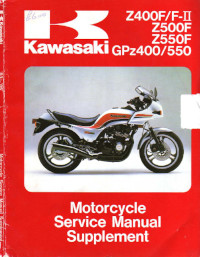
Руководство (дополнение) на английском языке по техническому обслуживанию и ремонту мотоциклов Kawasaki GPZ400/GPZ550/Z400F/Z400F-II/Z500F/Z550F.
- Издательство: Kawasaki Heavy Industries, Ltd.
- Год издания: 1984
- Страниц: 126
- Формат: PDF
- Размер: 9,9 Mb
Руководство на английском языке по техническому обслуживанию и ремонту мотоциклов Kawasaki KZ650 и Z650 с 1976 года выпуска.
- Издательство: Haynes Publishing
- Год издания: 1978
- Страниц: 132
- Формат: PDF
- Размер: 27,0 Mb

Руководство на английском языке по техническому обслуживанию и ремонту мотоциклов Kawasaki Z750.
- Издательство: Kawasaki Heavy Industries, Ltd.
- Год издания: 2007
- Страниц: 681
- Формат: PDF
- Размер: 13,0 Mb

Руководство на английском языке по техническому обслуживанию и ремонту мотоциклов Kawasaki Z750S.
- Издательство: Kawasaki Heavy Industries, Ltd.
- Год издания: 2004
- Страниц: 571
- Формат: PDF
- Размер: 11,3 Mb

Руководство на английском языке по техническому обслуживанию и ремонту мотоциклов Kawasaki Z1000.
- Издательство: Kawasaki Heavy Industries, Ltd.
- Год издания: 2003
- Страниц: 515
- Формат: PDF
- Размер: 10,7 Mb

Руководство по эксплуатации и техническому обслуживанию мотоциклов Kawasaki Z750R.
- Издательство: Kawasaki Heavy Industries, Ltd.
- Год издания: 2011
- Страниц: 173
- Формат: PDF
- Размер: 5,2 Mb

Руководство по эксплуатации и техническому обслуживанию мотоциклов Kawasaki Z800.
- Издательство: Kawasaki Heavy Industries, Ltd.
- Год издания: —
- Страниц: 158
- Формат: PDF
- Размер: 4,7 Mb

Руководство по эксплуатации и техническому обслуживанию мотоциклов Kawasaki Z1000SX.
- Издательство: Kawasaki Heavy Industries, Ltd.
- Год издания: 2011
- Страниц: 172
- Формат: PDF
- Размер: 4,7 Mb

·  СКАЧАТЬ МАНУАЛ ДЛЯ KAWASAKI Kawasaki (7 Мб)
Название: Общее руководство по эксплуатации Kawasaki 
Автор: Производитель
Формат: pdf
Размер: 7,0 МБ
Качество: Хорошее
Язык: Русский
Жанр: Мото-мануал
Издательство: Напечатано в Таиланде
Страниц: 520
Год издания: 2012
Описание: Общее руководство по обслуживанию и эксплуатации дорожных мотоциклов марки Кавасаки на русском языке.
СКАЧАТЬ БЕСПЛАТНО МАНУАЛ ДЛЯ KAWASAKI ZZ-R1100 (312.0Kb)
Название: Инструкция пользователя Kawasaki ZZ-R1100 
Автор: Производитель
Формат: doc
Размер: 0,3 МБ
Качество: Отличное
Язык: Русский
Жанр: Мото-мануал
Издательство: Напечатано в России
Страниц: 26
Год издания: 1998
Описание: Руководство по обслуживанию и эксплуатации мотоцикла Кавасаки ZZ-R1100 на русском языке и без картинок ((.
СКАЧАТЬ БЕСПЛАТНО МАНУАЛ ДЛЯ KAWASAKI Z1000SX (4.66Mb)
Название: Руководство по эксплуатации Kawasaki Z1000SX 
Автор: Производитель
Формат: pdf
Размер: 4,7 МБ
Качество: Хорошее
Язык: Русский
Жанр: Мото-мануал
Издательство: Напечатано в Таиланде
Страниц: 172
Год издания: 2011
Описание: Руководство по обслуживанию и эксплуатации мотоцикла Кавасаки Z1000SX на русском языке.
СКАЧАТЬ БЕСПЛАТНО МАНУАЛ ДЛЯ KAWASAKI Z800 (4.73Mb)
Название: Руководство по эксплуатации Kawasaki Z800

Автор: Производитель
Формат: pdf
Размер: 4,7 МБ
Качество: Хорошее
Язык: Русский
Жанр: Мото-мануал
Издательство: Напечатано в Таиланде
Страниц: 158
Год издания: 2011
Описание: Руководство по обслуживанию и эксплуатации мотоцикла Кавасаки Z800 на русском языке.
СКАЧАТЬ БЕСПЛАТНО МАНУАЛ ДЛЯ KAWASAKI Z750R (5.22Mb)
Название: Руководство по эксплуатации Kawasaki Z750R
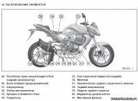
Автор: Производитель
Формат: pdf
Размер: 5,2 МБ
Качество: Хорошее
Язык: Русский
Жанр: Мото-мануал
Издательство: Напечатано в Таиланде
Страниц: 173
Год издания: 2011
Описание: Руководство по обслуживанию и эксплуатации мотоцикла Кавасаки Z750R на русском языке.
СКАЧАТЬ БЕСПЛАТНО МАНУАЛ ДЛЯ KAWASAKI VERSYS1000 (5.73Mb)
Название: Руководство по эксплуатации Kawasaki VERSYS1000
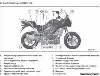
Автор: Производитель
Формат: pdf
Размер: 5,7 МБ
Качество: Хорошее
Язык: Русский
Жанр: Мото-мануал
Издательство: Напечатано в Таиланде
Страниц: 197
Год издания: 2011
Описание: Руководство по обслуживанию и эксплуатации мотоцикла Кавасаки VERSYS1000 на русском языке.
СКАЧАТЬ БЕСПЛАТНО МАНУАЛ ДЛЯ KAWASAKI Ninja ZX-10R (6.45Mb)
Название: Руководство по эксплуатации Kawasaki Ninja ZX-10R
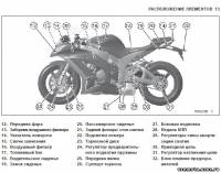
Автор: Производитель
Формат: pdf
Размер: 6,4 МБ
Качество: Хорошее
Язык: Русский
Жанр: Мото-мануал
Издательство: Напечатано в Таиланде
Страниц: 207
Год издания: 2011
Описание: Руководство по обслуживанию и эксплуатации мотоцикла Кавасаки Ninja ZX-10R на русском языке.
СКАЧАТЬ БЕСПЛАТНО МАНУАЛ ДЛЯ KAWASAKI Ninja 300 (3.90Mb)
Название: Руководство по эксплуатации Kawasaki Ninja 300

Автор: Производитель
Формат: pdf
Размер: 3,9 МБ
Качество: Хорошее
Язык: Русский
Жанр: Мото-мануал
Издательство: Напечатано в Таиланде
Страниц: 141
Год издания: 2012
Описание: Руководство по обслуживанию и эксплуатации мотоцикла Кавасаки Ninja 300 на русском языке.
СКАЧАТЬ БЕСПЛАТНО МАНУАЛ ДЛЯ KAWASAKI Ninja 250R (1.84Mb)
Название: Руководство по эксплуатации Kawasaki Ninja 250R
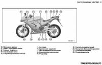
Автор: Производитель
Формат: pdf
Размер: 1,8 МБ
Качество: Хорошее
Язык: Русский
Жанр: Мото-мануал
Издательство: Напечатано в Таиланде
Страниц: 148
Год издания: 2010
Описание: Руководство по обслуживанию и эксплуатации мотоцикла Кавасаки Ninja 250R на русском языке.
СКАЧАТЬ БЕСПЛАТНО МАНУАЛ ДЛЯ KAWASAKI KLX250 (5.54Mb)
Название: Руководство по эксплуатации Kawasaki KLX250

Автор: Производитель
Формат: pdf
Размер: 5,5 МБ
Качество: Хорошее
Язык: Русский
Жанр: Мото-мануал
Издательство: Напечатано в России
Страниц: 147
Год издания: 2011
Описание: Руководство по обслуживанию и эксплуатации кроссового мотоцикла Кавасаки KLX250 на русском языке.
СКАЧАТЬ БЕСПЛАТНО МАНУАЛ ДЛЯ KAWASAKI ER-6n (6.76Mb)
Название: Руководство по эксплуатации Kawasaki ER-6n
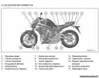
Автор: Производитель
Формат: pdf
Размер: 6,8 МБ
Качество: Хорошее
Язык: Русский
Жанр: Мото-мануал
Издательство: Напечатано в России
Страниц: 163
Год издания: 2011
Описание: Руководство по обслуживанию и эксплуатации мотоцикла Кавасаки ER-6n на русском языке.
СКАЧАТЬ БЕСПЛАТНО МАНУАЛ ДЛЯ KAWASAKI ER-6f (5.44Mb)
Название: Руководство по эксплуатации Kawasaki ER-6f
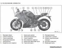
Автор: Производитель
Формат: pdf
Размер: 5,4 МБ
Качество: Хорошее
Язык: Русский
Жанр: Мото-мануал
Издательство: Напечатано в России
Страниц: 166
Год издания: 2011
Описание: Руководство по обслуживанию и эксплуатации мотоцикла Кавасаки ER-6f на русском языке.
· СКАЧАТЬ МАНУАЛ ДЛЯ KAWASAKI ZZR 600 (400) (248,1 МБ)
Название: Руководство по ремонту Kawasaki ZZR 600 (400)
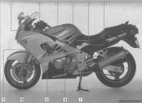
Автор: Производитель
Формат: rar/pdf/doc
Размер: 248,1 МБ (яндекс диск)
Качество: Хорошее
Язык: Русский
Жанр: Мото-мануал
Издательство:
Страниц: Много
Описание: Руководство по ремонту, обслуживанию и эксплуатации мотоцикла Кавасаки ZZR 600/400 на русском языке.