Keithley 2410 Измеритель уровня
Производитель:
Модель:
2410
Дата:
1998
Категория:
Группа:
Описание:
Информация
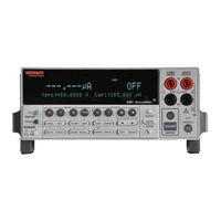
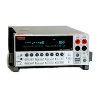
Product overview
The SourceMeter combines a precise, low-noise, highly stable
DC Power supply with a
low-noise, highly repeatable, high-impedance multimeter. It
has 0.012% basic accuracy
with 51⁄2-digit resolution. At 51⁄2 digits, the SourceMeter
delivers 520 readings/second
over the IEEE-488 bus. At 41⁄2 digits, it can read up to
2000 readings/second into its inter-
nal buffer. The unit has broad source and measurement ranges:
Model(2400:
•
Source voltage from 5μV to 210V; measure voltage from 1μV
to 211V.
•
Source current from 50pA to 1.05A; measure current from
10pA to 1.055A.
•
Measure resistance from 100μΩ (<100μΩ in manual ohms) to 211MΩ.
•
Maximum source power is 22W.
Model(2410:
•
Source voltage from 5μV to 1100V; measure voltage from 1μV
to 1100V.
•
Source current from 50pA to 1.05A; measure current from
10pA to 1.055A.
•
Measure resistance from 100μΩ (<100μΩ in manual ohms) to 211MΩ.
•
Maximum source power is 22W.
Model(2420:
•
Source voltage from 5μV to 63V; measure voltage from 1μV to
63.3V.
•
Source current from 500pA to 3.15A; measure current from
100pA to 3.165A.
•
Measure resistance from 10μΩ (<10μΩ in manual ohms) to 21.1MΩ.
•
Maximum source power is 66W.
Models 2425 and(2430:
•
Source DC or pulse voltage from 5μV to 105V; measure
voltage from 1μV to
105.5V.
•
Source DC current from 500pA to 3.15A; measure DC current
from 100pA to
3.165A.
•
Source pulse current from 500pA to 10.5A; measure pulse
current from 100pA to
10.55A. (Model 2430 only.)
•
Measure resistance from 10μΩ (<10μΩ in manual ohms) to 21.1MΩ.
•
Maximum DC source power is 110W.
•
Maximum pulse source power is 1.1kW. (Model 2430 only.)
Model(2440:
•
Source voltage from 5μV to 42V; measure voltage from 1μV to
42V.
•
Source current from 500pA to 5.25A; measure current from
100pA to 5.25A.
•
Measure resistance from 10μΩ (<10μΩ in manual ohms) to 21.1MΩ.
•
Maximum source power is 66W.
NOTESThe Models 2400
2410
2420
2425
2430
and 2440 are
Y2K compliant.
Models with a “-C” suffix have the Contact Check option. See
Appendix F.
Some additional capabilities of the SourceMeter include:
Concurrent measurements of all three functions over the
remote Interface.
Source-measure sweep capabilities (linear and logarithmic
staircase sweeps, source sweep list of up to 2500 points,
memory sweep of up to 100 instrument setups).
6-wire Ω measurement with programmable I-source or V-source
with V or I clamp.
4-quadrant source and sink operation.
Up to 12 stages of limit testing with a built-in comparator
for pass/fail testing.
Digital I/O for stand-alone binning operations or Interface
to component handler.
Programming language and remote interfaces — The SourceMeter
uses the SCPI programming language and two remote Interface
ports (IEEE-488/GPIB and RS-232C).
Trigger-Link Interface to Keithley Series 7000 switching
hardware.
Math expressions — Five built-in, up to five user-defined
(bus only).
Reading and setup storage — Up to 2500 readings and seven
setups (five user defaults, factory default, *RST default)
can be stored and recalled.
Closed-cover calibration — The instrument can be calibrated
either from the front panel or remote Interface.
показать больше
Руководство пользователя
Hасто́льная кни́га тип:
Руководство пользователя

Страницы:
592
Размер:
2.49 Mbytes (2614077 Bytes)
Язык:
english
Пересмотр:
G
Hасто́льная кни́га ID:
2400S-900-01
Дата:
2002 05 01
Качество:
Электронный документ, ни сканирование, очень хорошо читается.
Дата загрузки:
2018 08 23
MD5:
2a4420abc1106276b376316f115a7fa0
Загрузки:
2245
Руководство пользователя
Hасто́льная кни́га тип:
Руководство пользователя

Страницы:
53
Размер:
723.99 Kbytes (741362 Bytes)
Язык:
english
Пересмотр:
C
Hасто́льная кни́га ID:
2400S-903-01
Дата:
Качество:
Электронный документ, ни сканирование, очень хорошо читается.
Дата загрузки:
2014 03 07
MD5:
3c9ff54e64ca0a36a6a083410e1d09e4
Загрузки:
3187
Информация
Quick Results Guide
This guide is designed to familiarize users with fundamental
operation (front panel and
remote) of the Keithley 2400 Series SourceMeters. For
comprehensive information on all
aspects of SourceMeter operation, refer to the 2400 Series
SourceMeter User’s Manual.
Operation information in this guide is divided into four
parts; (1) Fundamental sourcemeasure
operations, (2) Settings to optimize performance, (3)
Features to enhance DUT testing
and (4) More testing techniques. This format allows a new
user to easily progress from basic
simple operation to more complex procedures.
показать больше
Добавить комментарий
- Manuals
- Brands
- Keithley Manuals
- Measuring Instruments
- SourceMeter 2410
Manuals and User Guides for Keithley SourceMeter 2410. We have 3 Keithley SourceMeter 2410 manuals available for free PDF download: User Manual, Quick Results Manual, Quick Start Manual
Keithley
SourceMeter 2400
User Manual
Keithley SourceMeter 2410 User Manual (594 pages)
SourceMeter 2400 Series Source Measure Unit
Brand: Keithley
|
Category: Measuring Instruments
|
Size: 2.79 MB
Table of Contents
-
Table of Contents
8
-
1 Getting Started
38
-
General Information
39
-
Warranty Information
39
-
Contact Information
39
-
Manual Addenda
39
-
Safety Symbols and Terms
39
-
-
-
Getting Started
39
-
Inspection
40
-
Options and Accessories
40
-
General Purpose Probes
40
-
Low Thermal Probes
41
-
Cables and Adapters
41
-
Rack Mount Kits
42
-
Carrying Case
42
-
-
Product Overview
42
-
Front and Rear Panel Familiarization
44
-
Front Panel Summary
44
-
Rear Panel Summary
46
-
-
Power-Up
47
-
Line Power Connection
47
-
Power-Up Sequence
48
-
System Identification
48
-
Line Frequency Setting
49
-
Front Panel Line Frequency
49
-
Remote Command Line Frequency
49
-
-
-
Table
49
-
Line Frequency Remote Commands
49
-
Fuse Replacement
50
-
-
Cooling Fan
50
-
Table 1-2 Power Line Fuse
50
-
Display
51
-
Display Format
51
-
EDIT Key
51
-
TOGGLE Key
52
-
Status and Error Messages
52
-
Remote Display Programming
52
-
-
-
Table
52
-
Basic Display Commands
52
-
Front Panel Tests
53
-
-
Default Settings
53
-
Saving and Restoring User Setups
53
-
Saving Setups
53
-
Restoring Setups
53
-
Power-On Configuration
54
-
-
Factory Default Settings
54
-
-
-
Table
54
-
Remote Setups
57
-
Table 1-5 Main Menu
58
-
-
Main Menu Tree
60
-
Rules to Navigate Menus
61
-
Toggling the Source and Measure Display Fields
62
-
Front Panel Control
63
-
-
Measurement Configuration Menus
64
-
-
Table
64
-
Figure
64
-
Source and Range Configuration Menus
65
-
-
Table
65
-
Figure
65
-
Rel, Filter, and Limit Configuration Menus
66
-
-
Table
66
-
Figure
66
-
Trigger Configuration Menu
68
-
-
Table
68
-
Sweep, Digits, Speed, and Data Store Configuration Menus
69
-
-
Table
69
-
Output and Display Configuration Menus
70
-
-
Table
70
-
Sweep, Digits, Speed, and Output Configuration Menus
71
-
-
Connection Overview
75
-
Remote Command Terminals Selection
76
-
Figure
77
-
Sensing Methods
78
-
Wire Remote Sensing
79
-
-
Guarding Methods
81
-
Ohms Guard
82
-
-
2 Wire Local Sensing
80
-
Guarded Ohms Measurements (Ohms Guard)
83
-
Sense and Guard Selections
84
-
Guard Selection
85
-
-
-
-
3 Basic Source-Measure Operation
87
-
Warning — Caution
87
-
Operation Overview
88
-
Source-Measure Capabilities
88
-
Table
89
-
Table 3-2 Compliance Limits
91
-
Compliance Commands
92
-
-
Table
92
-
Setting the Compliance Limit
92
-
Figure
93
-
-
Operation Considerations
94
-
NPLC Caching
95
-
Typical NPLC Cache Test Times
96
-
Front Panel V-Source Protection
97
-
Table 3-4 Auto Source Delay
98
-
Front Panel Source Delay
98
-
-
Basic Source-Measure Procedure
99
-
Step 3: Select Measurement Function and Range
101
-
Step 4: Turn Output on
102
-
-
Basic Source-Measure Commands
103
-
-
Table
103
-
Step 6: Turn Output off
103
-
Basic Source-Measure Programming Example
104
-
-
Table
104
-
Figure
105
-
Measure Only Programming Example
106
-
-
Table
106
-
Remote Command Measure Only
106
-
Sink Operation
107
-
Sink Programming Example
109
-
-
-
4 Ohms Measurements
110
-
Figure
111
-
Table
112
-
Auto Ohms Default Test Currents
112
-
Ohms Measurement Methods
112
-
Selecting Ohms Measurement Method
113
-
Manual Ohms Measurements
114
-
-
Ohms Sensing
116
-
Sense Selection
117
-
Offset-Compensated Ohms
118
-
Offset-Compensated Ohms Procedure
119
-
Ohms Source Readback
120
-
-
-
Remote Commands for Basic Ohms Measurements
121
-
Table
121
-
Remote Ohms Programming
121
-
Auto Ohms Programming Example
122
-
-
-
5 Pulse Mode Operation (Model 2430 Only)
124
-
Figure
125
-
Pulse Characteristics
126
-
Pulse Width
127
-
Pulse Width Delay
128
-
Pulse Delay
129
-
Auto Zero
130
-
Pulse-Only
131
-
-
Pulse Energy Limitations (10A Range)
132
-
Pulse Mode Configuration
133
-
Disable/Enable Auto Zero
134
-
-
Basic Pulse Mode Operation
135
-
Step 4: Select Source
136
-
Step 7: Turn Output on
137
-
-
Table
138
-
Basic Pulse-Measure Commands
138
-
Remote Command Pulse-Measure Operation
138
-
-
Table
139
-
Basic Pulse Programming Example
139
-
Pulse-Measure Programming Example
139
-
Filter
140
-
Offset-Compensated Ohms
141
-
-
Input Triggers
142
-
Turning Source on
143
-
-
-
-
6 Source-Measure Concepts
144
-
Table
146
-
Maximum Compliance Values
146
-
Compliance Examples
147
-
Table 6-2 Compliance Examples
148
-
Determining Compliance Limit
148
-
Overheating Protection
149
-
Power Equations to Avoid Shutdown
150
-
Model 2410 Sourcemeter
151
-
Models 2425 and 2430 Sourcemeters
152
-
-
-
Source-Delay-Measure Cycle
153
-
Figure
154
-
Sweep Waveforms
155
-
-
Operating Boundaries
157
-
Model 2400 Sourcemeter
158
-
Model 2410 Sourcemeter
159
-
Model 2420 Sourcemeter
160
-
Models 2425 and 2430 Sourcemeters
161
-
Model 2440 Sourcemeter
163
-
-
-
Table 6-1 Compliance Limits
146
-
I-Source Operating Boundaries
164
-
Voltage Compliance Boundaries
167
-
-
V-Source Operating Boundaries
169
-
Current Compliance Boundaries
171
-
Figure 6-13 V-Source Limit Lines
171
-
Figure 6-16 Source
171
-
Figure 6-14 V-Source Operating Examples
172
-
-
Source I Measure I and Source V Measure V
173
-
Basic Circuit Configurations
174
-
Figure 6-15 Source I
174
-
Source V
175
-
Figure 6-17 Measure Only (V or I)
176
-
Guard
177
-
-
Ohms Guard
178
-
Figure 6-18 High-Impedance Measurements
179
-
Figure 6-19 In-Circuit Ohms Measurements
180
-
Guard Sense
181
-
Figure 6-20 In-Circuit Ohms Measurements Using Guard Sense
182
-
Data Flow
183
-
Figure 6-21 Data Flow Front Panel
184
-
Buffer Considerations
185
-
Changing MATH Function
186
-
Manual Ranging
190
-
Figure
191
-
Limits Evaluation
192
-
Table 7-1 Range and Digits Commands
193
-
Table 7-2 Range and Digits Programming Example
193
-
Figure
194
-
Figure
195
-
Table 7-3 Speed Commands
195
-
Figure
196
-
Figure
197
-
Figure 7-2 Moving Average and Repeating Filters
198
-
Figure
199
-
Table 7-4 Filter Commands
199
-
Filter Programming Example
200
-
Relative
203
-
-
-
8 Relative and Math
204
-
Table
204
-
Rel Programming Example
204
-
Remote Rel Programming
204
-
-
Math Operations
205
-
Varistor Alpha
206
-
Figure
207
-
Table 8-3 Math Commands
208
-
Figure
208
-
-
-
Table 8-1 Rel Commands
204
-
Table
209
-
Math Programming Example
209
-
Commands for User-Defined Math Functions
210
-
-
Voltage Coefficient Programming Example
209
-
Table
210
-
User-Defined Math Function Programming Example
211
-
Data Store Overview
213
-
Timestamp
214
-
Average
215
-
-
-
-
9 Data Store
216
-
Timestamp Accuracy
216
-
Table 9-1 Data Store Commands
217
-
Remote Command Data Store
217
-
Table 9-2 Data Store Example
218
-
Sweep Operation
220
-
Sweep Types
221
-
Figure 10-1 Linear Staircase Sweep
222
-
Figure 10-2 Logarithmic Staircase Sweep (Example 5-Point Sweep from 1 to 10 Volts)
223
-
Table
224
-
Logarithmic Sweep Points
224
-
Custom Sweep
224
-
Custom Sweep Examples
225
-
Figure 10-3 Custom Pulse Sweep
225
-
Source Memory Sweep
226
-
Saving Multiple Source Memory Sweeps
227
-
-
-
Table
228
-
Source Memory Saved Configurations
228
-
Table 10-2 Source Memory Saved Configurations
228
-
Sweep Branching
229
-
Diode Test Example
231
-
Configuring and Running a Sweep
233
-
Figure 10-7 Sweep Configuration Menu Tree
234
-
-
Setting Delay
235
-
Performing a Linear Staircase Sweep
236
-
Performing a Log Staircase Sweep
237
-
Performing a Custom Sweep
238
-
Performing a Source Memory Sweep
240
-
-
-
Table
241
-
Linear and Log Staircase Sweep Commands
241
-
Remote Sweep Operation
241
-
Figure 10-9 Diode I-V Curve
242
-
Figure 10-8 Connections for Diode I-V Tests
242
-
Table 10-4 Staircase Sweep Programming Example (Diode Test)
243
-
Table 10-5 Custom Sweep Commands
243
-
-
Custom Sweep Programming Example
244
-
Table
244
-
Source Memory Sweep Commands
244
-
Table 10-8 Source Memory Sweep Programming Example
245
-
Sweep Branching Program Example
246
-
Pulse Mode Sweeps (Model 2430 Only)
251
-
Front Panel Pulse Mode Sweep Procedure
252
-
Figure 10-10 Pulse Mode Linear Staircase Sweep
253
-
-
-
Pulse Mode Linear Staircase Sweep Programming Example
253
-
Remote Pulse Mode Sweep Operation
253
-
-
-
-
11 Triggering
254
-
Remote Trigger Commands
255
-
Front Panel Trigger Operation
255
-
Figure 11-1 Front Panel Trigger Model
256
-
Arm Layer
257
-
Trigger Layer
258
-
Counters
259
-
Bench Defaults
260
-
Configuring Triggering
261
-
Figure 11-2 Trigger Configuration Menu Tree
263
-
-
-
Remote Trigger Operation
264
-
Figure 11-3 Remote Trigger Model
265
-
Event Detection
266
-
Trigger Layer
267
-
Figure 11-4 Measure Action
268
-
Counters
269
-
GPIB Defaults
270
-
-
Remote Trigger Commands
271
-
Figure 11-5 Rear Panel Pinout
272
-
Figure 11-6 Trigger Link Input Pulse Specifications
272
-
Figure 11-7 Trigger Link Output Pulse Specifications
273
-
Figure 11-8 Trigger Model for Front Panel Trigger Example
275
-
External Trigger Example
276
-
Figure 11-10 Trigger Link Connections
277
-
Instrument Configurations
278
-
Operation
279
-
-
Figure 11-9 DUT Test System
276
-
-
Operation Model for Triggering Example
280
-
Remote Trigger Example
281
-
Table 11-2 Commands for Remote Triggering Example
281
-
-
Trigger Model for Remote Trigger Example
282
-
Pulse Mode Triggering (Model 2430)
283
-
Pulse Mode Trigger Model (Front Panel Operation)
284
-
Pulse Mode Trigger Model (Remote Operation)
285
-
Idle
286
-
Output Triggers
287
-
-
Limit Testing
288
-
-
12 Limit Testing
289
-
Figure 12-1 Limit Tests
289
-
Types of Limits
289
-
Pass/Fail Information
290
-
Limit 2, Limit 3, and Limit 5-12 Tests
291
-
-
Operation Overview
292
-
Figure
293
-
Figure 12-3 Immediate Binning
294
-
Figure 12-4 End Binning
294
-
Pass Condition
295
-
-
Sorting Mode
296
-
Figure
297
-
Binning Systems
298
-
Digital Output Lines
299
-
Category Pulse Component Handler
300
-
Basic Binning Systems
301
-
Multiple-Element Device Binning
302
-
-
Binning System Multiple-Element Devices
303
-
Digital Output Clear Pattern
304
-
Auto-Clear Timing
305
-
Configuring and Performing Limit Tests
306
-
Performing Front Panel Limit Tests
308
-
Step 3: Configure Limit Tests
309
-
Table 12-1 Limit Commands
310
-
-
Remote Limit Testing
310
-
-
Figure 12-6 Handler Interface Connections
298
-
Commands to Control Digital I/O Port for Limit Testing
311
-
Limit Test Programming Example
311
-
Figure 12-11 Diode Pass/Fail Limits
312
-
Table 12-3 Limits Test Programming Example
313
-
Table 12-4 Limit Test Results Summary
313
-
-
Digital I/O Port, Safety Interlock, and Output Configuration
314
-
-
13 Digital I/O Port, Safety Interlock, and Output Configuration
315
-
Figure 13-1 Digital I/O Port
315
-
Figure 13-2 Sink Operation
316
-
SOT Line
316
-
Figure 13-3 Source Operation
317
-
Remote Digital Output Control
318
-
Table 13-1 Digital Output Line Settings
318
-
Figure
319
-
Front Panel Output Configuration
320
-
-
Output-Off States
321
-
Zero
322
-
Output-Off States and Inductive Loads
323
-
-
Output Configuration Commands
324
-
Remote Output Configuration
324
-
Output Configuration Programming Example
325
-
Remote Operations
326
-
Differences: Remote Vs. Local Operation
327
-
Remote-To-Local Transition
328
-
Figure 14-1 IEEE-488 Connector
329
-
Figure 14-2 IEEE-488 Connections
330
-
Primary Address
331
-
Table 14-1 General Bus Commands
332
-
LLO (Local Lockout)
333
-
SPE, SPD (Serial Polling)
334
-
Talk
335
-
-
-
-
-
14 Remote Operations
329
-
Programming Syntax
336
-
Query Commands
338
-
Long-Form and Short-Form Versions
339
-
Program Messages
340
-
Command Path Rules
341
-
Response Messages
342
-
-
RS-232 Interface Operation
343
-
Terminator
344
-
-
-
RS-232 Connector Pinout
345
-
RS-232 Interface Connector
345
-
Error Messages
346
-
Status Structure
348
-
Figure
349
-
-
Table 14-3 PC Serial Port Pinout
345
-
-
Figure
350
-
-
15 Status Structure
350
-
Common and SCPI Commands to Reset Registers and Clear Queues
351
-
Figure 15-2 16-Bit Status Register
352
-
Data Format Commands for Reading Status Registers
353
-
Status Byte and Service Request (SRQ)
354
-
Status Byte Register
355
-
Service Request Enable Register
356
-
-
-
Status Byte and Service Request Enable Register Commands
357
-
Status Byte Programming Example
357
-
Status Register Sets
358
-
Figure 15-4 Standard Event Status
359
-
Operation Event Register
359
-
Figure 15-5 Operation Event Status
360
-
Measurement Event Register
360
-
Figure 15-6 Measurement Event Status
361
-
Questionable Event Register
362
-
-
-
Condition Register Commands
363
-
Event Register Commands
363
-
Condition Registers
363
-
-
Event Enable Registers Commands
364
-
Program and Read Register Programming Example
365
-
Error Queue
366
-
Table 15-9 Error Queue Commands
367
-
Programming Example — Read Error Queue
367
-
-
-
16 Common Commands
368
-
Command Summary
369
-
Table 16-1 IEEE-488.2 Common Commands and Queries
369
-
Command Reference
370
-
Table 16-2 *OPC Programming Example
371
-
SAV, *RCL Programming Example
372
-
TRG Programming Example
373
-
WAI — Wait-To-Continue
374
-
-
17 SCPI Signal Oriented Measurement Commands
376
-
Figure
377
-
Signal Oriented Measurement Command Summary
377
-
Acquiring Readings
378
-
Sense[1]]:Data[:Latest]?
379
-
Measure[:<Function>]?
380
-
-
-
18 SCPI Command Reference
382
-
Reference Tables
383
-
Calculate Command Summary
384
-
Display Command Summary
389
-
Format Command Summary
390
-
Output Command Summary
390
-
Table 18-5 Route Command Summary
391
-
Table 18-6 Sense Command Summary
391
-
Source Command Summary
394
-
Status Command Summary
399
-
System Command Summary
400
-
Table 18-10 Trace Command Summary
402
-
Table 18-11 Trigger Command Summary
403
-
Calculate Subsystems
405
-
Program Examples
407
-
Delete[:Selected] <Name>
410
-
Define Math Expression
411
-
-
Enable and Read Math Expression Result
414
-
Latest?
415
-
Null Feed Reading
416
-
Latest?
417
-
Source2 <Nrf> |<NDN>
418
-
Pass:source2 <Nrf> | NDN
420
-
Fail?
421
-
Fail:source2 <Nrf> | <NDN>
422
-
Fail:smlocation <Nrf> | NEXT
423
-
Bcontrol <Name>
424
-
-
-
Clear Test Results
425
-
Acquire Statistic
426
-
-
Display Subsystem
427
-
Attributes?
428
-
Define :TEXT Messages
429
-
-
-
Format Subsystem
430
-
Figure 18-2 IEEE-754 Single Precision Data Format (32 Data Bits)
431
-
Data Elements
432
-
Source2 <Name>
436
-
Byte Order
437
-
-
Output Subsystem
438
-
Interlock Control
439
-
-
Route Subsystem
440
-
Sense1 Subsystem
441
-
ON] <Function List>
442
-
Count?
443
-
Resistance:mode <Name>
444
-
Select Measurement Range
445
-
Upper] <N>
446
-
Select Auto Range
448
-
Ulimit <N>
449
-
Rsynhronize <B>
450
-
Tripped?
451
-
Configure and Control Filter
452
-
State] <B>
453
-
Auto
454
-
MODE] <Name>
455
-
-
Select Range
456
-
AUTO <B>
458
-
Triggered[:Amplitude] <N>
460
-
-
Set Voltage Limit
461
-
Set Delay
464
-
Configure Voltage and Current Sweeps
465
-
Spacing <Name>
466
-
Center <N>
468
-
STEP <N>
469
-
Points <N>
471
-
Direction <Name>
472
-
Append <Nrf List>
473
-
-
Points?
474
-
SAVE <Nrf>
475
-
Points <Nrf>
476
-
Recall <Nrf>
477
-
-
Voltage List
478
-
Current List
479
-
-
Soak Time
480
-
Delay <N>
481
-
MODE <Name>
482
-
Bstate <B>
483
-
AUTO <B>
484
-
-
-
Status Subsystem
485
-
Select Default Conditions
486
-
Disable <List>
487
-
Control Remote Sensing
488
-
Select Guard Mode
489
-
Control Beeper
490
-
Control Auto Zero
491
-
Select Power Line Frequency Setting
492
-
Error Queue
493
-
Simulate Key Presses
494
-
Figure 18-3 Key-Press Codes
495
-
Read Version of SCPI Standard
496
-
Query Timestamp
497
-
-
Auto Range Change Mode
498
-
Clear
499
-
FEED <Name>
500
-
-
-
Trigger Subsystem
501
-
Abort Source/Measure Cycle
502
-
Delay <N>
503
-
Source <Name>
504
-
Timer <N>
505
-
Iline <Nrf>
506
-
Output <Event List>
507
-
Specifications
509
-
Status and Error Messages
520
-
-
Introduction
521
-
-
Table B-1 Status and Error Messages
522
-
Eliminating Common SCPI Errors
527
-
Query UNTERMINATED»
528
-
Introduction
531
-
Fetch?
532
-
Calculate[1]:Data?
533
-
-
IEEE-488 Bus Overview
534
-
Introduction
535
-
-
-
500 D IEEE-488 Bus Overview
536
-
Bus Description
536
-
Figure D-1 IEEE-488 Bus Configuration
537
-
Bus Lines
538
-
Figure D-2 IEEE-488 Handshake Sequence
539
-
IEEE-488 Bus Command Summary
540
-
Bus Commands
540
-
Uniline Commands
541
-
Addressed Multiline Commands
542
-
-
-
Common Commands
543
-
Table D-2 Hexadecimal and Decimal Command Codes
543
-
Figure D-3 Command Codes
544
-
Table D-3 Typical Addressed Multiline Command Sequence
545
-
Table D-4 Typical Addressed Common Command Sequence
545
-
Typical Command Sequences
545
-
-
Table D-5 IEEE Command Groups
546
-
Sourcemeter Interface Function Codes
547
-
Introduction
551
-
Table E-1 IEEE-488 Documentation Requirements
552
-
IEEE-488 and SCPI Conformance Information
553
-
Table E-2 Coupled Commands
553
-
-
-
F Contact Check Function
554
-
100 C Data Flow
555
-
Introduction
555
-
Block Diagram
556
-
Operation
557
-
-
Table F-1 Recommended Contact Resistance Threshold Values
558
-
Contact Check Threshold Resistances
558
-
Trigger Model Operation
559
-
Limit Test Sequence
560
-
Figure F-5 Grading Mode Contact Check Limit Testing
561
-
Figure F-6 Sorting Mode Contact Check Limit Testing
562
-
-
Binning Failure Indications (Grading Mode)
563
-
-
Contact Check Menu Selections
564
-
Auto Clear Off, Immediate Binning
564
-
Using Contact Check
565
-
Using Event Detection with Contact Check
566
-
-
-
Contact Check Remote Commands
567
-
Contact Check Programming Example
569
-
Contact Check Command Reference
570
-
Fail?
571
-
Configure and Control Contact Check Event Detection
572
-
-
Contact Check Defaults
573
-
TOUT <Nrf>
573
-
-
GPIB 488.1 Protocol
574
-
Introduction
575
-
Protocol Differences
576
-
NRFD Hold-Off
577
-
Trigger-On-Talk
578
-
-
Table G-1 SCPI/488.1 Reading Speed Comparisons for Measure-Only Sweep Operation (Rdgs/Sec)
579
-
Table G-2 SCPI/488.1 Reading Speed Comparisons for Source-Measure Sweep Operation (Rdgs/Sec)
579
-
Table G-3 SCPI/488.1 Reading Speed Comparisons for Source-Measure-Limit Test Sweep Operation (Rdgs/Sec)
580
-
Table G-4 SCPI/488.1 Reading Speed Comparisons for Source-Memory Sweep Operation (Rdgs/Sec)
580
-
SCPI/488.1 Reading Speed Comparisons for Measure-Only Single-Shot Operation (Rdgs/Sec
581
-
SCPI/488.1 Reading Speed Comparisons for Source-Measure Single-Shot Operation (Rdgs/Sec
581
-
SCPI/488.1 Reading Speed Comparisons for Source-Measure-Limit Test Single-Shot Operation (Rdgs/Sec
581
-
Advertisement
Keithley SourceMeter 2410 Quick Results Manual (53 pages)
Brand: Keithley
|
Category: Measuring Instruments
|
Size: 0.74 MB
Table of Contents
-
Table of Contents
7
-
Introduction
9
-
Source-Measure Capabilities
9
-
Figure 1 Front Panel
11
-
Figure 2 Rear Panel
11
-
Front and Rear Panels
11
-
Navigating Menus and Entering Numeric Data
12
-
Menu Navigation
12
-
Numeric Data Entry (EDIT Keys)
12
-
-
Editing Source and Compliance Values
12
-
Editing Keys
12
-
Editing Procedure
13
-
Toggling the Source and Measure Display Fields
13
-
-
Basic Connections
13
-
Front/Rear Terminals Selection
14
-
-
2 Wire Connections
14
-
Figure 3 2-Wire Connections
14
-
-
4 Wire Connections
15
-
Figure 4 4-Wire Connections
15
-
Cable Guard
16
-
Figure 5 Cable Guard Connections
16
-
Ohms Guard
16
-
Figure 6 Guarded Ohms Measurements
17
-
Basic Sourcemeter Operations
18
-
Source-Measure
18
-
Table 2 Source-Measure Procedure
19
-
Measure Only (V or I)
20
-
Table 3 Measure Only (V or I) Procedure
20
-
Measure Ohms
21
-
Table 4 Auto Ohms Measurement Procedure
21
-
Table 5 Manual Ohms Measurement Procedure
22
-
Remote Command Programming
23
-
Table 6 SCPI Commands; Source-Measure and Measure Only
24
-
Table 7 SCPI Commands; Measure Ohms
24
-
Table 8 Command Sequence for Source-Measure Example
25
-
Table 9 Command Sequence for Measure Current Only Example
25
-
Table 10 Command Sequence for Auto Ohms Example
26
-
Table 11 Command Sequence for Manual Ohms Example
26
-
-
Remote Command Programming
18
-
Settings to Optimize Performance
27
-
Range
27
-
Speed
27
-
Digits
28
-
Filter
28
-
Rel (Nulling Offsets)
29
-
Remote Command Programming
30
-
Table 12 SCPI Commands; Speed, Digits, Filter, and Rel
30
-
-
Features to Enhance DUT Testing
31
-
Data Store
31
-
Table 13 SCPI Commands; Data Store
32
-
Table 14 Command Sequence for Data Store Example
32
-
Sweep Operation
33
-
Figure 8 Logarithmic Staircase Sweep (Example)
34
-
Figure 9 Custom Pulse Sweep (Example)
35
-
Performing Sweeps
37
-
Table 15 SCPI Commands; Sweeping
39
-
Figure 7 Linear Staircase Sweep
40
-
Table 16 Command Sequences for Sweep Examples
40
-
Limit Testing
42
-
Table 17 SCPI Commands; Basic Non-Binning Limit Testing
43
-
Math Functions
44
-
Table 18 Command Sequence for Limit 2 Test Example
44
-
Table 19 SCPI Commands; Built-In Math Functions
47
-
Table 20 Command Sequence for Power Measurement Example
47
-
Pulse Mode (Model 2430 Only)
48
-
Figure 10 Pulse-Measure Timing
48
-
Table 21
52
-
SCPI Commands; Select and Configure Pulse Mode
52
-
Command Sequence for Pulse Mode Example
52
-
-
Keithley SourceMeter 2410 Quick Start Manual (46 pages)
SourceMeter 2400 series Source Measure Unit
Brand: Keithley
|
Category: Measuring Instruments
|
Size: 0.39 MB
Table of Contents
-
Safety Precautions
3
-
Table of Contents
5
-
Introduction
6
-
Introduction
7
-
Source-Measure Capabilities
7
-
Front and Rear Panels
8
-
Navigating Menus and Entering Numeric Data
9
-
Menu Navigation
9
-
Numeric Data Entry (EDIT Keys)
9
-
-
Editing Source and Compliance Values
9
-
Editing Keys
9
-
Editing Procedure
10
-
Toggling the Source and Measure Display Fields
10
-
-
2 Wire Connections
11
-
Basic Connections
11
-
Front/Rear Terminals Selection
11
-
-
-
4 Wire Connections
12
-
Cable Guard
13
-
Ohms Guard
14
-
Basic Sourcemeter Operations
15
-
Source-Measure
15
-
Measure Only (V or I)
16
-
Measure Ohms
17
-
Remote Command Programming
19
-
Scpi Commands
20
-
Programming Examples
20
-
-
-
Remote Command Programming
15
-
Settings to Optimize Performance
22
-
Range
22
-
Speed
23
-
Digits
23
-
Filter
23
-
Rel (Nulling Offsets)
24
-
Remote Command Programming
25
-
-
Features to Enhance DUT Testing
25
-
Data Store
25
-
Sweep Operation
27
-
Performing Sweeps
31
-
Limit Testing
35
-
Math Functions
38
-
Pulse Mode (Model 2430 Only)
41
-
-
Advertisement
Advertisement
Related Products
-
Keithley 2461
-
Keithley SourceMeter 2400
-
Keithley SourceMeter 2420
-
Keithley SourceMeter 2425
-
Keithley SourceMeter 2440
-
Keithley SourceMeter 2400-LV
-
Keithley SourceMeter 2401
-
Keithley SourceMeter 2430
-
Keithley SourceMeter 2460
-
Keithley 2502
Keithley Categories
Measuring Instruments
Multimeter
![]()
Power Supply
Test Equipment
![]()
Switch
More Keithley Manuals
![]()
Model 2400 Series SourceMeter®
Quick Results Guide
A G R E A T E R M E A S U R E O F C O N F I D E N C E

WARRANTY
Keithley Instruments, Inc. warrants this product to be free from defects in material and workmanship for a period of 1 year from date of shipment.
Keithley Instruments, Inc. warrants the following items for 90 days from the date of shipment: probes, cables, rechargeable batteries, diskettes, and documentation.
During the warranty period, we will, at our option, either repair or replace any product that proves to be defective.
To exercise this warranty, write or call your local Keithley representative, or contact Keithley headquarters in Cleveland, Ohio. You will be given prompt assistance and return instructions. Send the product, transportation prepaid, to the indicated service facility. Repairs will be made and the product returned, transportation prepaid. Repaired or replaced products are warranted for the balance of the original warranty period, or at least 90 days.
LIMITATION OF WARRANTY
This warranty does not apply to defects resulting from product modification without Keithley’s express written consent, or misuse of any product or part. This warranty also does not apply to fuses, software, non-rechargeable batteries, damage from battery leakage, or problems arising from normal wear or failure to follow instructions.
THIS WARRANTY IS IN LIEU OF ALL OTHER WARRANTIES, EXPRESSED OR IMPLIED, INCLUDING ANY IMPLIED WARRANTY OF MERCHANTABILITY OR FITNESS FOR A PARTICULAR USE. THE REMEDIES PROVIDED HEREIN ARE BUYER’S SOLE AND EXCLUSIVE REMEDIES.
NEITHER KEITHLEY INSTRUMENTS, INC. NOR ANY OF ITS EMPLOYEES SHALL BE LIABLE FOR ANY DIRECT, INDIRECT, SPECIAL, INCIDENTAL OR CONSEQUENTIAL DAMAGES ARISING OUT OF THE USE OF ITS INSTRUMENTS AND SOFTWARE EVEN IF KEITHLEY INSTRUMENTS, INC., HAS BEEN ADVISED IN ADVANCE OF THE POSSIBILITY OF SUCH DAMAGES. SUCH EXCLUDED DAMAGES SHALL INCLUDE, BUT ARE NOT LIMITED TO: COSTS OF REMOVAL AND INSTALLATION, LOSSES SUSTAINED AS THE RESULT OF INJURY TO ANY PERSON, OR DAMAGE TO PROPERTY.
|
Keithley Instruments, Inc. |
28775 Aurora Road • Cleveland, Ohio 44139 • 440-248-0400 • Fax: 440-248-6168 |
||
|
1-888-KEITHLEY (534-8453) • www.keithley.com |
|||
|
Sales Offices: BELGIUM: |
Bergensesteenweg 709 • B-1600 Sint-Pieters-Leeuw • 02-363 00 40 • Fax: 02/363 00 64 |
||
|
CHINA: |
Yuan Chen Xin Building, Room 705 • 12Yumin Road, Dewai, Madian • Beijing 100029 • 8610-6202-2886 • Fax: 8610-6202-2892 |
||
|
FINLAND: |
Tietäjäntie 2 • 02130 Espoo • Phone: 09-54 75 08 10 • Fax: 09-25 10 51 00 |
||
|
FRANCE: |
3, allée des Garays • 91127 Palaiseau Cédex • 01-64 53 20 20 • Fax: 01-60 11 77 26 |
||
|
GERMANY: |
Landsberger Strasse 65 • 82110 Germering • 089/84 93 07-40 • Fax: 089/84 93 07-34 |
||
|
GREAT BRITAIN: |
Unit 2 Commerce Park, Brunel Road • Theale • Berkshire RG7 4AB • 0118 929 7500 • Fax: 0118 929 7519 |
||
|
INDIA: |
Flat 2B, Willocrissa • 14, Rest House Crescent • Bangalore 560 001 • 91-80-509-1320/21 • Fax: 91-80-509-1322 |
||
|
ITALY: |
Viale San Gimignano, 38 • 20146 Milano • 02-48 39 16 01 • Fax: 02-48 30 22 74 |
||
|
JAPAN: |
New Pier Takeshiba North Tower 13F • 11-1, Kaigan 1-chome • Minato-ku, Tokyo 105-0022 • 81-3-5733-7555 • Fax: 81-3-5733-7556 |
||
|
KOREA: |
2FL., URI Building • 2-14 Yangjae-Dong • Seocho-Gu, Seoul 137-888 • 82-2-574-7778 • Fax: 82-2-574-7838 |
||
|
NETHERLANDS: |
Postbus 559 • 4200 AN Gorinchem • 0183-635333 • Fax: 0183-630821 |
||
|
SWEDEN: |
c/o Regus Business Centre • Frosundaviks Allé 15, 4tr • 169 70 Solna • 08-509 04 679 • Fax: 08-655 26 10 |
||
|
SWITZERLAND: |
Kriesbachstrasse 4 • 8600 Dübendorf • 01-821 94 44 • Fax: 01-820 30 81 |
||
|
TAIWAN: |
1FL., 85 Po Ai Street • Hsinchu, Taiwan, R.O.C. • 886-3-572-9077 • Fax: 886-3-572-9031 |
4/02

2400 Series SourceMeter®
Quick Results Guide
©2000, Keithley Instruments, Inc.
All rights reserved.
Cleveland, Ohio, U.S.A.
Third Printing, May 2002
Document Number: 2400S-903-01 Rev. C

Manual Print History
The print history shown below lists the printing dates of all Revisions and Addenda created for this manual. The Revision Level letter increases alphabetically as the manual undergoes subsequent updates. Addenda, which are released between Revisions, contain important change information that the user should incorporate immediately into the manual. Addenda are numbered sequentially. When a new Revision is created, all Addenda associated with the previous Revision of the manual are incorporated into the new Revision of the manual. Each new Revision includes a revised copy of this print history page.
|
Revision A (Document Number 2400S-903-01) ……………………………………………….. |
February 2000 |
|
Revision B (Document Number 2400S-903-01) …………………………………………………….. |
April 2001 |
|
Revision C (Document Number 2400S-903-01) ……………………………………………………… |
May 2002 |
All Keithley product names are trademarks or registered trademarks of Keithley Instruments, Inc. Other brand names are trademarks or registered trademarks of their respective holders.

Safety Precautions
The following safety precautions should be observed before using this product and any associated instrumentation. Although some instruments and accessories would normally be used with non-hazardous voltages, there are situations where hazardous conditions may be present.
This product is intended for use by qualified personnel who recognize shock hazards and are familiar with the safety precautions required to avoid possible injury. Read and follow all installation, operation, and maintenance information carefully before using the product. Refer to the manual for complete product specifications.
If the product is used in a manner not specified, the protection provided by the product may be impaired.
The types of product users are:
Responsible body is the individual or group responsible for the use and maintenance of equipment, for ensuring that the equipment is operated within its specifications and operating limits, and for ensuring that operators are adequately trained.
Operators use the product for its intended function. They must be trained in electrical safety procedures and proper use of the instrument. They must be protected from electric shock and contact with hazardous live circuits.
Maintenance personnel perform routine procedures on the product to keep it operating properly, for example, setting the line voltage or replacing consumable materials. Maintenance procedures are described in the manual. The procedures explicitly state if the operator may perform them. Otherwise, they should be performed only by service personnel.
Service personnel are trained to work on live circuits, and perform safe installations and repairs of products. Only properly trained service personnel may perform installation and service procedures.
Keithley products are designed for use with electrical signals that are rated Installation Category I and Installation Category II, as described in the International Electrotechnical Commission (IEC) Standard IEC 60664. Most measurement, control, and data I/O signals are Installation Category I and must not be directly connected to mains voltage or to voltage sources with high transient over-voltages. Installation Category II connections require protection for high transient over-voltages often associated with local AC mains connections. Assume all measurement, control, and data I/O connections are for connection to Category I sources unless otherwise marked or described in the Manual.
Exercise extreme caution when a shock hazard is present. Lethal voltage may be present on cable connector jacks or test fixtures. The American National Standards Institute (ANSI) states that a shock hazard exists when voltage levels greater than 30V RMS, 42.4V peak, or 60VDC are present. A good safety practice is to expect that hazardous voltage is present in any unknown circuit before measuring.
Operators of this product must be protected from electric shock at all times. The responsible body must ensure that operators are prevented access and/or insulated from every connection point. In some cases, connections must be exposed to potential human contact. Product operators in these circumstances must be trained to protect themselves from the risk of electric shock. If the circuit is capable of operating at or above 1000 volts, no conductive part of the circuit may be exposed.
Do not connect switching cards directly to unlimited power circuits. They are intended to be used with impedance limited sources. NEVER connect switching cards directly to AC mains. When connecting sources to switching cards, install protective devices to limit fault current and voltage to the card.
Before operating an instrument, make sure the line cord is connected to a properly grounded power receptacle. Inspect the connecting cables, test leads, and jumpers for possible wear, cracks, or breaks before each use.
When installing equipment where access to the main power cord is restricted, such as rack mounting, a separate main input power disconnect device must be provided, in close proximity to the equipment and within easy reach of the operator.
For maximum safety, do not touch the product, test cables, or any other instruments while power is applied to the circuit under test. ALWAYS remove power from the entire test system and discharge any capacitors before: connecting or disconnecting ca-
5/02

bles or jumpers, installing or removing switching cards, or making internal changes, such as installing or removing jumpers.
Do not touch any object that could provide a current path to the common side of the circuit under test or power line (earth) ground. Always make measurements with dry hands while standing on a dry, insulated surface capable of withstanding the voltage being measured.
The instrument and accessories must be used in accordance with its specifications and operating instructions or the safety of the equipment may be impaired.
Do not exceed the maximum signal levels of the instruments and accessories, as defined in the specifications and operating information, and as shown on the instrument or test fixture panels, or switching card.
When fuses are used in a product, replace with same type and rating for continued protection against fire hazard.
Chassis connections must only be used as shield connections for measuring circuits, NOT as safety earth ground connections.
If you are using a test fixture, keep the lid closed while power is applied to the device under test. Safe operation requires the use of a lid interlock.
If  or
or  is present, connect it to safety earth ground using the wire recommended in the user documentation.
The ! symbol on an instrument indicates that the user should refer to the operating instructions located in the manual.
The  symbol on an instrument shows that it can source or measure 1000 volts or more, including the combined effect of normal and common mode voltages. Use standard safety precautions to avoid personal contact with these voltages.
The WARNING heading in a manual explains dangers that might result in personal injury or death. Always read the associated information very carefully before performing the indicated procedure.
The CAUTION heading in a manual explains hazards that could damage the instrument. Such damage may invalidate the warranty.
Instrumentation and accessories shall not be connected to humans.
Before performing any maintenance, disconnect the line cord and all test cables.
To maintain protection from electric shock and fire, replacement components in mains circuits, including the power transformer, test leads, and input jacks, must be purchased from Keithley Instruments. Standard fuses, with applicable national safety approvals, may be used if the rating and type are the same. Other components that are not safety related may be purchased from other suppliers as long as they are equivalent to the original component. (Note that selected parts should be purchased only through Keithley Instruments to maintain accuracy and functionality of the product.) If you are unsure about the applicability of a replacement component, call a Keithley Instruments office for information.
To clean an instrument, use a damp cloth or mild, water based cleaner. Clean the exterior of the instrument only. Do not apply cleaner directly to the instrument or allow liquids to enter or spill on the instrument. Products that consist of a circuit board with no case or chassis (e.g., data acquisition board for installation into a computer) should never require cleaning if handled according to instructions. If the board becomes contaminated and operation is affected, the board should be returned to the factory for proper cleaning/servicing.

Table of Contents |
|
|
Introduction ……………………………………………………………………….. |
1 |
|
Source-measure capabilities …………………………………………………. |
1 |
|
Front and rear panels …………………………………………………………… |
3 |
|
Navigating menus and entering numeric data …………………………. |
4 |
|
Menu navigation ………………………………………………………….. |
4 |
|
Numeric data entry (EDIT keys) …………………………………….. |
4 |
|
Editing source and compliance values …………………………………… |
4 |
|
Editing keys ………………………………………………………………… |
4 |
|
Editing procedure …………………………………………………………. |
5 |
|
Toggling the source and measure display fields ………………… |
5 |
|
Basic connections ……………………………………………………………….. |
5 |
|
Front/rear terminals selection ………………………………………… |
6 |
|
2-wire connections ……………………………………………………….. |
6 |
|
4-wire connections ……………………………………………………….. |
7 |
|
Cable guard …………………………………………………………………. |
8 |
|
Ohms guard …………………………………………………………………. |
8 |
|
Remote command programming …………………………………… |
10 |
|
Basic SourceMeter operations ……………………………………………. |
10 |
|
Source-measure ………………………………………………………….. |
10 |
|
Measure only (V or I) …………………………………………………. |
12 |
|
Measure ohms ……………………………………………………………. |
13 |
|
Remote command programming …………………………………… |
15 |
|
Settings to optimize performance ……………………………………….. |
19 |
|
Range ……………………………………………………………………….. |
19 |
|
Speed ………………………………………………………………………… |
19 |
|
Digits ………………………………………………………………………… |
20 |
|
Filter …………………………………………………………………………. |
20 |
|
Rel (nulling offsets) ……………………………………………………. |
21 |
|
Remote command programming …………………………………… |
22 |
|
Features to enhance DUT testing ………………………………………… |
23 |
|
Data store ………………………………………………………………….. |
23 |
|
Sweep operation …………………………………………………………. |
25 |
|
Performing sweeps ……………………………………………………… |
29 |
|
Limit testing ………………………………………………………………. |
34 |
|
Math functions …………………………………………………………… |
36 |
|
Pulse mode (Model 2430 only) …………………………………….. |
40 |

List of Illustrations |
||
|
Figure 1 |
Front panel …………………………………………………………………….. |
3 |
|
Figure 2 |
Rear panel ………………………………………………………………………. |
3 |
|
Figure 3 |
2-wire connections ………………………………………………………….. |
6 |
|
Figure 4 |
4-wire connections ………………………………………………………….. |
7 |
|
Figure 5 |
Cable guard connections ………………………………………………….. |
8 |
|
Figure 6 |
Guarded ohms measurements …………………………………………… |
9 |
|
Figure 7 |
Linear staircase sweep ……………………………………………………. |
25 |
|
Figure 8 |
Logarithmic staircase sweep (example) ……………………………. |
26 |
|
Figure 9 |
Custom pulse sweep (example) ……………………………………….. |
27 |
|
Figure 10 |
Pulse-measure timing …………………………………………………….. |
40 |
List of Tables |
||
|
Table 1 |
SCPI commands; terminals, sense, and cable guard …………… |
10 |
|
Table 2 |
Source-measure procedure ……………………………………………… |
11 |
|
Table 3 |
Measure only (V or I) procedure ……………………………………… |
12 |
|
Table 4 |
Auto ohms measurement procedure …………………………………. |
13 |
|
Table 5 |
Manual ohms measurement procedure ……………………………… |
14 |
|
Table 6 |
SCPI commands; source-measure and measure only…………… |
16 |
|
Table 7 |
SCPI commands; measure ohms ……………………………………… |
16 |
|
Table 8 |
Command sequence for source-measure example ……………… |
17 |
|
Table 9 |
Command sequence for measure current only example ………. |
17 |
|
Table 10 |
Command sequence for auto ohms example ……………………… |
18 |
|
Table 11 |
Command sequence for manual ohms example …………………. |
18 |
|
Table 12 |
SCPI commands; speed, digits, filter, and rel …………………….. |
22 |
|
Table 13 |
SCPI commands; data store ……………………………………………. |
24 |
|
Table 14 |
Command sequence for data store example ………………………. |
24 |
|
Table 15 |
SCPI commands; sweeping …………………………………………….. |
31 |
|
Table 16 |
Command sequences for sweep examples ………………………… |
32 |
|
Table 17 |
SCPI commands; basic non-binning limit testing ………………. |
35 |
|
Table 18 |
Command sequence for Limit 2 test example ……………………. |
36 |
|
Table 19 |
SCPI commands; built-in math functions …………………………. |
39 |
|
Table 20 |
Command sequence for power measurement example ……….. |
39 |
|
Table 21 |
SCPI commands; select and configure Pulse Mode ……………. |
44 |
|
Table 22 |
Command sequence for Pulse Mode example …………………… |
44 |

2400 Series
SourceMeter
Quick Results Guide
Introduction
This guide is designed to familiarize users with fundamental operation (front panel and remote) of the Keithley 2400 Series SourceMeters. For comprehensive information on all aspects of SourceMeter operation, refer to the 2400 Series SourceMeter User’s Manual.
Operation information in this guide is divided into four parts; (1) Fundamental sourcemeasure operations, (2) Settings to optimize performance, (3) Features to enhance DUT testing and (4) More testing techniques. This format allows a new user to easily progress from basic simple operation to more complex procedures.
Remote command programming — For the various SourceMeter operating modes covered in this guide, the related SCPI commands for remote operation are summarized in tables. Most commands have a query form. For example, :OUTPut ON turns the output on, while :OUTPut? requests the present state of the output. Note that the SourceMeter must be addressed to talk after sending a query command.
For operations where command sequence is important, programming examples are provided. The exact programming syntax will depend on the test program language.
Source-measure capabilities
Model 2400:
•Source voltage from 5µV to 210V; measure voltage from 1µV to 211V.
•Source current from 50pA to 1.05A; measure current from 10pA to 1.055A.
• Measure resistance from 100µ Ω (<100µ Ω in manual ohms) to 211MΩ .
•Maximum source power is 22W.

2 Quick Results Guide
Model 2410:
•Source voltage from 5µV to 1100V; measure voltage from 1µV to 1100V.
•Source current from 50pA to 1.05A; measure current from 10pA to 1.055A.
• Measure resistance from 100µ Ω (<100µ Ω in manual ohms) to 211MΩ .
•Maximum source power is 22W.
Model 2420:
•Source voltage from 5µV to 63V; measure voltage from 1µV to 63.3V.
•Source current from 500pA to 3.15A; measure current from 100pA to 3.165A.
• Measure resistance from 10µ Ω (<10µ Ω in manual ohms) to 21.1MΩ .
•Maximum source power is 66W.
Model 2425:
•Source voltage from 5µV to 105V; measure voltage from 1µV to 105.5V.
•Source current from 500pA to 3.15A; measure current from 100pA to 3.165A.
• Measure resistance from 10µ Ω (<10µ Ω in manual ohms) to 21.1MΩ .
•Maximum source power is 110W.
Model 2430:
•Source DC or pulse voltage from 5µV to 105V; measure voltage from 1µV to 105.5V.
•Source DC current from 500pA to 3.15A; measure DC current from 100pA to 3.165A.
•Source pulse current from 500pA to 10.5A; measure pulse current from 100pA to 10.55A.
• Measure resistance from 10µ Ω (<10µ Ω in manual ohms) to 21.1MΩ .
•Maximum DC source power is 110W.
•Maximum pulse source power is 1.1kW.
Model 2440:
•Source voltage from 5µV to 42V; measure voltage from 1µV to 42V.
•Source current from 500pA to 5.25A; measure current from 100pA to 5.25A.
• Measure resistance from 10µ Ω (< 10 µ Ω in manual ohms) to 21.1 MΩ .
•Maximum source power is 55W.

Front and rear panels
The front and rear panels of the Model 2400 SourceMeter are shown in Figures 1 and 2. The front and rear panels of the other SourceMeter models are similar. The use of the various instrument controls and connectors will be explained throughout this guide.
2400 SourceMeter
|
MEAS |
SOURCE |
|||||||
|
EDIT |
V |
I |
Ω |
FCTN |
V |
I |
||
|
DISPLAY |
RANGE |
|||||||
|
0 |
1 |
2 |
3 |
4 |
5 |
EDIT |
||
|
TOGGLE |
LOCAL |
REL |
FILTER |
LIMIT |
TRIG |
SWEEP |
AUTO |
|
|
POWER |
6 |
7 |
8 |
9 |
+/- |
RANGE |
||
|
DIGITS |
SPEED |
STORE RECALL |
CONFIG |
MENU |
EXIT |
ENTER |
|
4-WIRE |
INPUT/ |
|
|
SENSE |
HI |
OUTPUT |
|
250V |
5V |
250V |
|
PEAK |
PEAK |
PEAK |
|
LO |
250V |
|
|
PEAK |
||
|
TERMINALS |
||
|
ON/OFF |
FRONT/ |
|
|
REAR |
||
|
OUTPUT |
WARNING: NO INTERNAL OPERATOR SERVICABLE PARTS, SERVICE BY QUALIFIED PERSONNEL ONLY.
|
HI |
5V |
|||||
|
PK |
MADE IN |
C UL US |
||||
|
V, Ω , |
||||||
|
U.S.A. |
||||||
|
GUARD |
||||||
|
LISTED |
||||||
|
250V |
5V |
250V |
5V |
LINE FUSE |
SourceMeter |
|
|
PEAK |
PEAK |
PEAK |
PEAK |
SLOWBLOW |
4ZA4 |
|
|
2.5A, 250V |
||||||
|
LINE RATING |
||||||
|
GUARD |
100-240VAC |
|||||
|
SENSE |
50, 60, Hz |
|||||
|
LO |
190VA MAX. |
|||||
|
4-WIRE |
INPUT/ |
|||||
|
250V |
CAT I |
FUSE DRAWER |
||||
|
SENSE |
! |
OUTPUT |
PEAK |
|||
|
IEEE-488 |
||||||
|
(ENTER IEEE ADDRESS |
TRIGGER |
OUTPUT |
||||
|
WITH FRONT PANEL MENU) |
||||||
|
ENABLE |
||||||
|
RS-232 |
LINK |
|||||
CAUTION: FOR CONTINUED PROTECTION AGAINST FIRE HAZARD, REPLACE FUSE WITH SAME TYPE AND RATING.

4 Quick Results Guide
Navigating menus and entering numeric data
Menu navigation
Many operating modes for the SourceMeter are configured using front panel menus. Throughout this guide, menu navigation will be presented as a sequence of key presses and menu item selections. For example, the following sequence selects the auto ohms source mode:
Press CONFIG > press MEAS Ω > select SOURCE > select AUTO
The above sequence is explained as follows:
1.Press the CONFIG key.
2.Press the MEAS Ω key.
3.Select the SOURCE menu item.
4.Select the AUTO ohms source mode.
A menu item is selected by placing the cursor on it and pressing the ENTER key. The andkeys control cursor position.
Numeric data entry (EDIT keys)
Numeric values must to be entered for some menu items. Numeric entry is also used to set source and compliance values. The edit keys for numeric entry include the EDIT and keys to control cursor position, EDIT and keys to increment or decrement the digit value, and the number keys.
After a value is keyed in, press ENTER to select it. Note that pressing MENU resets a displayed number to its minimum value.
Editing source and compliance values
Editing keys
Use the following keys to edit source and compliance values:
•DISPLAY EDIT — Selects the source or compliance display field for editing. A blinking cursor will appear in the field to be edited. If no key is pressed within a few seconds, the edit mode will be cancelled automatically.
•EDIT and — Places the display cursor on the display digit to be changed.
•SOURCE or — Increments or decrements the source or compliance value. Note that pressing either of these keys will automatically enable the source edit mode.
•RANGE or — Selects the source or compliance range.
•Numeric keys (0-9) — Allow you to directly enter source or compliance values.
•EXIT — Exits the edit mode without waiting for the time-out period.
Editing procedure
1.Press the DISPLAY EDIT key to place the blinking cursor in either the source or compliance display field to be edited.
2.If desired, use the RANGE and keys to select the desired source or compliance range.
3.To simply increment or decrement the display value, use the EDIT and keys to place the blinking cursor on the digit to be changed, then increment or decrement the value with the SOURCE and keys. Note that the source or compliance value will be updated immediately; you need not press ENTER to complete the process.
4.To enter the source or compliance value directly, simply key in the desired value with the numeric keys while the cursor is blinking. Again, the source or compliance value will be updated immediately.
Toggling the source and measure display fields
Normally, the measured reading value will appear in the upper, main display line, while the source and compliance values will appear in the left and right fields respectively of the lower display line. You can toggle the source and measure display fields by pressing the DISPLAY TOGGLE key to place the source and measure values in the desired display fields.
Basic connections
WARNING The SourceMeter uses safety jacks for signal connections. To avoid electric shock:
•Do not leave exposed connections.
•Properly insulate all external circuits.
•The front and rear terminals of the SourceMeters are rated for connection to circuits rated Installation Category I only. Do not connect the SourceMeter terminals to CAT II, CAT III, or CAT IV circuits. Connection of the SourceMeter Input/Output terminals, to circuits higher than CAT I, can cause damage to the equipment or expose the operator to hazardous voltages.
•Hazardous voltages may be present on the output and guard terminals. To prevent electrical shock that could cause injury or death, NEVER make or break connections to the SourceMeter while the unit is on. Power off the equipment from the front panel or disconnect the main power cord from the rear of the SourceMeter before handling cables connected to the outputs. Putting the equipment into standby mode does not guarantee the outputs are not powered if a hardware or software fault occurs.
The three basic connection configurations for the SourceMeter include 2-wire local sensing, 4-wire remote sensing, and cable guard.
NOTE Connections and details for in-circuit ohms measurements (ohms guard) are covered in the “Advanced operation” section of this guide.

6 Quick Results Guide
Front/rear terminals selection
The input/output and sense terminals are accessible from both the front and rear panels, while the guard terminals and chassis ground are only accessible from the rear panel. On the front panel, press the FRONT/REAR key to toggle between front and rear. The REAR annunciator indicates that the rear terminals are selected. With REAR off, the front terminals are selected.
2-wire connections
Connections for 2-wire local sensing are shown in Figure 3. The following menu sequence selects 2-wire local sensing:
Press CONFIG > select SOURCE V (or ΜΕΑ S Ω ) > select SENSE MODE > select 2-WIRE
Figure 3
2-wire connections
|
4-WIRE |
INPUT/ |
|
SENSE |
OUTPUT |
|
HI |
|
|
DUT |
|
|
LO |
|
|
TERMINALS |
|
|
ON/OFF |
FRONT// |
|
REAR |
|
|
OUTPUT |
|
SourceMeter Front Panel |
Sense Selection: 2-wire |

shown in Figure 4. Use 4-wire remote sensing for
V-measure accuracy is required.
annunciator is on. The following menu sequence
MEAS Ω ) > select SENSE MODE > select 4-WIRE
source and measure are achieved only using 4-wire
|
r |
o |
n |
t |
||||||||||||
|
F |
|||||||||||||||
|
r |
|||||||||||||||
|
e |
|||||||||||||||
|
e |
t |
||||||||||||||
|
M |
|||||||||||||||
|
e |
|||||||||||||||
|
c |
|||||||||||||||
|
r |
|||||||||||||||
|
u |
|||||||||||||||
|
o |
|||||||||||||||
|
S |
|||||||||||||||

8 Quick Results Guide
Cable guard
When testing high-impedance DUT (>1GΩ ), cable guard is used to drive the shields of cables and test fixtures to minimize leakage currents and input capacitance. A typical connection scheme using cable guard is shown in Figure 5. The following menu sequence selects cable guard:
Press CONFIG > press SOURCE V (or SOURCE I or MEAS Ω ) > select GUARD > select CABLE
The guard terminal of the SourceMeter is at virtually the same potential as input/output HI. Therefore, if there is hazardous voltage at input/output HI, it is also present on the guard shield for the test circuit.
WARNING To prevent injury from electric shock, the guard shield must be enclosed in a safety shield (i.e., test fixture) that is connected to safety earth ground (as shown in Figure 5).
|
Figure 5 |
Guard Shield |
Test Fixture |
Cable guard connections
DUT
Connect to earth safety ground using #18 AWG wire or larger.
WARNING:NO INTERNAL OPERATOR SERVICAB
HI
V, Ω
GUARD
GUARD SENSE
LO
4-WIRE INPUT/
SENSE OUTPUT
IEEE-488
(ENTER IEEE ADDRESS WITH FRONT PANEL MENU)
RS232
CAUTION:FOR CONTINUED PROTECTION AGAINST FIR
Ohms guard
Ohms guard allows in-circuit resistance measurements on DUT where other parasitic leakage devices are present. Connection schemes for a Delta DUT configuration is shown in Figure 6.
 Loading…
-
104, Tektronix Keithley SourceMeter 2410 Miscellaneous commands Miscellaneous co mmands are those commands that perform such functions as saving calibration constants, locking out calibration, and programming date parameters. :CODE (:CALibration:PROTected:CODE) Purpose Format Parameters Description To unlock calibration so the calibration procedures can be performed. : cal:prot:code ‘<password>’ Up to an 8-charac…
-
17, Performance Verification 1-7 Performing the verification test procedures Test summary • DC voltage output accuracy • DC voltage measurement accuracy • DC current output accuracy • DC current measurement accuracy • Resistance measurement accuracy If the Model 2410 is not within specifications and not under warranty, see the calibration procedures in Section 2 for…
-
28, 1-18 Performance Verification Table 1-6 Ohms measurement accuracy limits Model 2410 range Calibrator resistance* Model 2410 resistance reading limit s** (1 year, 18°C–28°C) 20Ω 200Ω 2kΩ 20kΩ 200kΩ 2MΩ 20MΩ 200MΩ 19Ω 190Ω 1.9kΩ 19kΩ 190kΩ 1.9MΩ 19MΩ 100MΩ 18.9731 to 19.0269Ω 189.709 t o 190.291Ω 1.89788 to 1.90212kΩ 18.9807 to 19.02…
-
41, 14. Note and record the DMM reading, and then adjust the Model 2410 display to agree with the DMM reading. Again, the maximum display adjustment is within ± 10% of the present range. 15. After adjusting the display value to agree with the DMM reading, press ENTER and note th at the instr ument displays: I-CAL Press ENTER to Output -0.0000μA 16. Press ENTER. The Model 2410…
-
117, Introduction This appendix includes a calibration program written in BASIC to help you calibrate the Model 2410, as well as an example program that demonstrates how to request calibration constants. Refer to Section 2 for more details on calibration procedures, equipment, and connections. Computer hardware requirements The following computer hardware is required to run the calibration progra…
-
89, Q220, 225 TRANS,NPN SILICON,MJE340 TG-209 Q221, 226 TRANS,PNP POWER,MJE350 TG-210 Q222, 224 TRANS, N-CHAN JFET, SST4393 TG-263 Q234-239, 244-246, 255, TRANS, N-MOSFET, VN0605T TG-243 256, 400, 401, 404, 229 Q242, 243 TRANS, N-CHAN MOSFET, 2SK1412 TG-276 Q258 TRANSISTOR SMT TG-345 Q259 TRANSISTOR SMT TG-346 Q260 VERTICAL DMOS FET TG-301 Q261 TRANS, N-CHAN MOSFET, T…
-
121, ErrCheck: ‘ Error check routine. PRINT #1, «OUTPUT 24;:SYST:ERR?» ‘ Query error queue. PRINT #1, «ENTER 24» INPUT #2, E, Err$ IF E <> 0 THEN PRINT Err$: GOTO EndProg ‘ Display error. RETURN ‘ ReadDMM: ‘ Get reading from DMM. SLEEP 5 PRINT #1, «ENTE…
-
18, Tektronix Keithley SourceMeter 2410 1-8 Performance Verification Setting the source range and output value Before testing each verification point, you must properly set the source range and output value as outlined below. 1. Press either the SOURCE V or SOURCE I key to select the appropriate source function. 2. Press the EDIT key as required to select the source display field. Note that the cursor will flash in the s…
-
40, Tektronix Keithley SourceMeter 2410 Step 3: Current calibration Perform the following steps for each current range using Table 2-4 as a guide. 1. Connect the Model 2410 to the digital multimeter, as shown in Figure 2-2. Select the multimeter DC current measurement function. 2. From normal display, press the SOURCE I key. 3. Press the EDIT key to select the source display field, and then use the down RANGE key to select the 1�…
-
88, Tektronix Keithley SourceMeter 2410 C605-607, 613, 614, CAP, .1UF, 10%, 25V, CERAMIC C-495-.1 617-625, 650-652, 659, 660 C610, 612 CAP, 2200P, 10%, 100V CERAMIC C-430-2200P C616 CAP, 22UF, 20%, 25V, TANTALUM C-440-22 C661, 662, 524, 554, 555, CAP, .1UF, 10%, 25V, CERAMIC C-495-.1 338, 339, 542, 548 CR200-203, 205, 207, 208, DIODE, SWITCHING, MMBD914 RF-83 210, 216-221, 235 CR206, 209, 230-233, 400, DIODE,IN3595 RF-43 40…
-
123, PRINT Data$ PRINT #1, «OUTPUT 24;:CAL:PROT:SOUR:DATA?» PRINT #1, «ENTER 24» LINE INPUT #2, Data$ PRINT Data$ Range = Range * 10 IF Range > .009 AND Range < .011 THEN Range = .02 IF Range > .19 AND Range < .21 THEN Range = .1 LOOP WHILE Range <= 1 PRINT #1, «OUTPUT 24;:CAL:PROT:LOCK» ‘ Lock out calibration…
Table of Contents for Tektronix Keithley SourceMeter 2410:
-
Introduction Use the procedures in this section to calibrate the Model 2410. These procedures require accurate test equipmen t to measure precise DC voltages and currents. Calibration can be performed either from the front panel, or by sending SCPI calibration commands over the IEEE-488 bus or RS-232 port with the aid of a computer. WARNING The information in this section is intended for qualified service personnel only. Do not attempt these procedures
-
Model 2410 1100V SourceMeter ® Service Manual © Keithley Instrum ents, Inc. All rights reserved. Cleveland, Ohio, U.S.A. Third Printing, April 2017 Document Number: 2410-902-01 Rev. C 2410-902-01.book Page 1 Monday, November 7, 2005 2:49 PM
-
8. Note and record the DMM reading, and then adjust the Model 2410 display to agree exactly with the actual DMM reading. Use the up and down arrow keys to select the digit value, and use the left and right arrow keys to choose the digit position (or use the number keys, 0-9, +/-). Note that the display adjustment range is within ±10% of the present range. 9. After adjusting the display to agree with the DMM reading, press ENTER. The instrument will then display
-
CASE 3, 4, 6, 7, 9, 10, 12 PRINT #1, «OUTPUT 24;»; Cmd$; Reading$; «;*OPC» GOSUB ErrCheck GOSUB CalEnd CASE 5, 11 PRINT #1, «OUTPUT 24;»; Cmd$ GOSUB ReadDMM CASE 8 PRINT #1, «OUTPUT 24;»; Cmd$; Source GOSUB ReadDMM END SELECT NEXT I Range = Range * 10: Source = Range IF J = 1 AND Range = 200 THEN Range = 1000: Source = 975 IF J = 2 AND Range > .009 AND Range < .011 THEN Ra
-
Table 6-1 Analog board parts list Circuit designation Description Keithley part no. C200-203, 205-210, 225, 226 , 231, 232, 237, 238 CAP, .1UF, 10%, 25V, CERAMIC C-495-.1 C204, 404, 608 ,609, CAP, .01UF, 10%, 50V CERAMIC C-491-.01 550-553 C211-214 CAP, 1000PF,10%, 50V, MONO CERAMIC C-452-1000P C215-222, 611 CAP,100PF, 5%, 100V, CERAMIC C-465-100P C223, 224, 227-230, CAP, 33PF, 5%, 100V, CERAMIC C-465-33P 233-236, 239, 240, 3
-
Step 3: Current calibration Perform the following steps for each current range using Table 2-4 as a guide. 1. Connect the Model 2410 to the digital multimeter, as shown in Figure 2-2. Select the multimeter DC current measurement function. 2. From normal display, press the SOURCE I key. 3. Press the EDIT key to select the source display field, and then use the down RANGE key to select the 1µA source range. 4. From normal display, press MENU. 5. Select CAL, and then press ENTER. The unit will display the following: CALIBRATION UNLOCK EXECUTE
-
Performance Verification 1-11 Output voltage accuracy Follow the steps below to verify that Model 2410 output voltage accuracy is within specified limits. This test involves setting the output voltage to each full-range value and measuring the voltages with a precision digital multimeter. 1. With the power off, connect the digital multimeter to the Model 2410 INPUT/ OUTPUT jac ks as shown in Figure 1-1. 2. Select the multimeter DC volts measuring function.
-
Status byte EAV (Error Available) bit Whenever an error is available in the error queue, the EAV (Error Available) bit (bit 2) of the status byte will be set. Use the *STB? query to obtain the status byte, and then test bit 2 to see if it is set. If the EAV bit is set, an error has occurred, and you can use the appropriate error query to read the error and at the same time clear the EAV bit in the status byte. Generating an SRQ on error To program the instrument to generate an IEEE-488 bus SRQ (Service Request) when an error occurs, send the *SRE 4
-
Analog board removal Perform the following steps to remove the analog board. This procedure assumes that the case cover is already removed. 1. Disconnect the front and rear input terminals. You mu st disconnect these input terminal connections for both the front and rear inputs: • INPUT/OUTPUT HI and LO • 4-WIRE SENSE HI and LO • V, Ω, GUARD, and GUARD SENSE (rear panel only) Remov e all the connections by pulling the wires
-
Calibration equipment The following calibration equipment is required: • Hewlett-Packard HP3458A Digital Multimeter See Section 2 for detailed equipment specifications. General program instructions 1. With the power off, connect the Model 2410 and the digital multimeter to the IEEE-488 interface of the computer. Be sure to use shielded IEEE-488 cables for bus connections. Also, connect the digital multimeter to the Model 2410 as discussed in Sec
-
B Command Reference 2410-902-01.book Page 1 Monday, November 7, 2005 2:49 PM
-
Figure 3-1 Rear panel WARNING:NO INTERNAL OPERATOR SERVICABLE PARTS,SERVICE BY QUALIFIED PERSONNEL ONLY. WARNING:NO INTERNAL OPERATOR SERVICABLE PARTS,SERVICE BY QUALIFIED PERSONNEL ONLY. CAUTION:FOR CONTINUED PROTECTION AGAINST FIRE HAZARD,REPLACE FUSE WITH SAME TYPE AND RATING. CAUTION:FOR CONTINUED PROTECTION AGAINST FIRE HAZARD,REPLACE FUSE WITH SAME TYPE AND RATING. MADE IN U.S.A. INPUT/ OUTPUT 250V PEAK 250V PEAK TRIGGER LINK 4-WIRE SENSE HI LO LINE RATING 85-264VAC 50, 60, HZ 70VA MAX RS2
-
Front panel calibration The front panel calibration procedure described below calibrates all ranges of both the current and voltage source and measure functions. Note that each range is separately calibrated by repeating the entire procedure for each range. Step 1: Prepare the Model 2410 for calibration 1. Turn on the Model 2410 and the digital multimeter, and allow them to warm up for at least one hour before performing calibration. 2. Press the MENU key, and then choose CAL and press ENTER. Select UNLOCK,
-
Detecting calibration errors If an error occurs during any calibration step, the Model 2410 will generate an appropriate error message. Several methods to detect calibration errors are discussed below. Reading the error queue As with other Model 2410 errors, any calibration errors will be reported in the error queue. (You can read the error queue by using the :SYST:ERR? query.) Error summary Table B-4 summarizes cali
-
Introduction The informatio n in this section deals with routine type maintenance that can be performed by the operator. Line fuse replacement WARNING Disconnect the line cord at the rear panel, and remove all test leads connected to the instrument (front and rear) before replacing the line fuse. The power line fuse is accessible from the rear panel, just above the AC power receptacle (see Figure 3-1). Perf orm the following steps to replace the line fuse: 1. Carefully grasp a
Questions, Opinions and Exploitation Impressions:
You can ask a question, express your opinion or share our experience of Tektronix Keithley SourceMeter 2410 device using right now.