-
Contents
-
Table of Contents
-
Bookmarks
Quick Links
Operation &
Maintenance Manual
PC210
PC210LC
PC210
PC210LC
HYDRAULIC EXCAVATOR
SERIAL NUMBERS
PC210-10
— K60001
PC210LC-10 — K60001
PC210-10
— 450120
PC210LC-10 — 450120
WARNING
Unsafe use of this machine may cause serious injury or
death. Operators and maintenance personnel must read
this manual before operating or maintaining this
machine. This manual should be kept inside the cab for
reference and periodically reviewed by all personnel who
will come into contact with the machine.
-10
-10
-10
DEMOLITION BASE SPEC
-10
and up
and up
and up
and up
DEMOLITION BASE SPEC
ORIGINAL INSTRUCTIONS
UENAM00902
.
.
Chapters
Summary of Contents for Komatsu PC210-10
ОТПРАВИТЬ ЗАЯВКУ:
Нажимая кнопку «ОТПРАВИТЬ ЗАЯВКУ», Вы соглашаетесь на обработку Ваших данных Подробнее
НАШИ ПРЕИМУЩЕСТВА
![]()
Выезд
к заказчику
![]()
Собственная
ремзона
![]()
Дополнительное
оборудование
![]()
Гарантийное
постгарантийное
сезонное ТО
![]()
Запчасти
в наличии
![]()
Шиномонтаж
МЫ РЕМОНТИРУЕМ:


- Manuals
- Brands
- Komatsu Manuals
- Excavators
- PC210LC-8
Manuals and User Guides for Komatsu PC210LC-8. We have 2 Komatsu PC210LC-8 manuals available for free PDF download: Shop Manual, Operation & Maintenance Manual

Komatsu PC210LC-8 Shop Manual (1201 pages)
HYDRAULIC EXCAVATOR
Brand: Komatsu
|
Category: Excavators
|
Size: 69.18 MB
Table of Contents
-
Table of Contents
6
-
Table of Contents
17
-
Foreword and General Information
18
-
Safety Notice
18
-
General Precautions
18
-
Preparations for Work
18
-
Precautions for Sling Work and Making Signs
20
-
Precautions for Using Mobile Crane
21
-
Precautions for Using Overhead Hoist Crane
21
-
Selecting Wire Ropes
21
-
Wire Ropes
21
-
-
How to Read the Shop Manual
22
-
Filing Method
23
-
Symbols
23
-
Units
23
-
-
Explanation of Terms for Maintenance Standard
24
-
Standard Size and Tolerance
24
-
Standard Clearance and Standard Value
25
-
Standard Interference
25
-
Repair Limit and Allowable Value
25
-
Clearance Limit
25
-
-
Handling Electric Equipment and Hydraulic Component
26
-
Main Failures Occurring in Wiring Harness
26
-
Disconnections in Wiring
27
-
High-Pressure Water Entering Connector
27
-
Oil or Dirt Stuck to Connector
27
-
Disconnecting Connectors
28
-
When Removing from Clips
28
-
Connecting Connectors
29
-
Connecting DT Connectors
29
-
Drying Wiring Harness
30
-
Handling Controller
31
-
Points to Remember When Troubleshooting Electric Circuits
31
-
Points to Remember When Handling Hydraulic Equipment
32
-
Flushing Operations
33
-
Cleaning Operations
33
-
-
How to Read Electric Wire Code
34
-
Type, Symbol, and Material
34
-
Dimensions
35
-
Colour Codes Table
36
-
Types of Circuits and Colour Codes
36
-
-
Method of Disassembling and Connecting Push-Pull Type Coupler
37
-
Standard Tightening Torque Table
40
-
Table of Tightening Torques for Bolts and Nuts
40
-
Table of Tightening Torques for Split Flange Bolts
41
-
Table of Tightening Torques for O-Ring Boss Piping Joints
41
-
Table of Tightening Torques for O-Ring Boss Plugs
41
-
Table of Tightening Torques for Hoses
42
-
Table of Tightening Torques for 102, 107 and 114 Engine Series
42
-
-
Conversion Table
44
-
Millimetres to Inches
44
-
Kilogram to Pound
45
-
Litres to U.S. Gallons
45
-
Litres to U.K. Gallons
46
-
Temperature
48
-
Hydraulic Excavator
51
-
Specification and Technical Data
51
-
-
Specification Dimension Drawings
52
-
Specification and Technical Data
52
-
Working Range Diagram
53
-
Weight Table
58
-
Table of Fuel, Coolant and Lubricants
62
-
Structure, Function and Maintenance Standard
65
-
Engine and Cooling System
66
-
Engine Related Parts
66
-
Structure, Function and
66
-
Radiator, Oil Cooler, Aftercooler and Fuel Cooler
67
-
Diesel Particulate Filter
68
-
Diesel Particulate Filter — Component Parts
69
-
System Description
70
-
Regeneration
70
-
Power Train
73
-
Structure, Function and
74
-
Power Train
74
-
Final Drive
76
-
Swing Machinery
78
-
Swing Circle
82
-
Undercarriage and Frame
85
-
Track Frame and Recoil Spring
86
-
Structure, Function and
86
-
Undercarriage and Frame
86
-
Standard Shoe
87
-
Idler
88
-
Carrier Roller
90
-
Track Roller
91
-
Track Shoe
92
-
Triple Grouser Shoe
96
-
Swamp Shoe
96
-
Road Liner
96
-
Hydraulic System
99
-
-
Hydraulic Equipment Layout Drawing
100
-
Structure, Function and
100
-
Hydraulic System, Part 1
100
-
Hydraulic Tank and Filter
102
-
Hydraulic Pump
103
-
Operation of Pump
109
-
Control of Delivery
110
-
LS Valve
111
-
When the Control Valve Is Situated at Neutral
112
-
Action for the Direction of Maximizing the Pump Delivery
113
-
Action for the Direction of Minimizing the Pump Delivery
114
-
When Servo Piston Is Balanced
115
-
PC Valve
116
-
When Pump Controller Is Normal
117
-
Action of PC-EPC Valve Solenoid
117
-
Action of Spring
118
-
When the Main Pump Is under Heavy Load
123
-
LS (PC)-EPC Valve
124
-
When Signal Current Is 0
125
-
When Signal Current Is very Small
126
-
When Signal Current Is Maximum
126
-
-
Pilot Oil Filter
127
-
Control Valve
130
-
General View
131
-
Sectional View
134
-
Arm Valve
139
-
R.H. Travel Valve
139
-
Swing Valve
139
-
Boom Valve
141
-
Bucket Valve
141
-
L.H. Travel Valve
141
-
Outline of CLSS
143
-
Basic Principle
144
-
Pump Swash Plate Angle Control
144
-
LS Differential Pressure
144
-
Pressure Compensation Control
145
-
Functions and Operation by Valve
148
-
Hydraulic Circuit Diagram and the Name of Valves
148
-
Unload Valve
150
-
When the Unload Valve Is Actuating
150
-
Operation of Relief Valve
151
-
Introduction of LS Pressure
152
-
LS Bypass Valve
153
-
Pressure Compensation Valve
154
-
Integrated Pressure Compensation Valve
154
-
When Compensated
155
-
Pressure Compensation Valve Area Ratio
156
-
Pressure Compensation Valve Inner Shuttle Valve
157
-
In the Case of Travel
158
-
Boom Regeneration Circuit
159
-
Arm Regeneration Circuit
161
-
If the Cylinder Head Pressure Is Lower than the Bottom Pressure
162
-
Merge-Divider Valve
163
-
LS Select Valve
165
-
Self Pressure Reducing Valve
166
-
During Neutral and When Load Pressur (P2) Is Low
167
-
When Load Pressure (P2) Is High
167
-
When Abnormally High Pressure Is Generated
168
-
Travel Junction Valve
169
-
When Pilot Pressure Is Turned on
169
-
When Pilot Pressure Is Turned off
170
-
Travel PPC Shuttle Valve
171
-
Hydraulic Drift Prevention Valve
174
-
When the Piping Is Free of Burst
176
-
If the Piping Is Bursted
176
-
Quick Return Valve
179
-
When Arm out
179
-
When the Arm Is in Neutral
180
-
Lift Check Valve
181
-
While Engine Is Stopped
181
-
While Engine Is Running
181
-
Main Relief Valve
182
-
2-Stage Safety-Suction Valve
183
-
If Pilot Pressure Is on
184
-
-
Swing Motor
189
-
Hydraulic System, Part 3
189
-
Swing Holding Brake
192
-
Relief Valve Portion
193
-
Reverse Prevention Valve
194
-
Explanatory Drawing of Effects
195
-
-
Centre Swivel Joint
198
-
Travel Motor
201
-
Operation of Motor
204
-
At Slow Speed
204
-
At High Speed
205
-
Operation of Parking Brake
206
-
Brake Valve
208
-
Counterbalance Valve and Check Valve
208
-
Operation When Pressurized Oil Is Supplied
208
-
Operation of Brake During Travelling Downhill
209
-
Safety Valve
210
-
The Pump Pressure Rises, Providing a Large
211
-
-
PPC Valve
212
-
Work Equipment and Swing PPC Valve
212
-
Travel PPC Valve
216
-
Pressure Reducing Valve Function
219
-
Travel Signal
220
-
Steering Signal
220
-
-
Service PPC Valve (with EPC Valve)
225
-
EPC Valve
227
-
Service PPC Valve
230
-
Valve Control
232
-
ATT EPC Valve Assembly
234
-
Solenoid Valve
236
-
PPC Accumulator
238
-
Return Oil Filter
239
-
Attachment Circuit Selector Valve
240
-
Quick Coupler Control Valve
242
-
K50001~K50303
242
-
Function
245
-
Hydraulic Cylinder
246
-
Boom Cylinder
248
-
Arm Cylinder
248
-
Bucket Cylinder
248
-
Work Equipment
251
-
Dimensions of Components
252
-
Dimension of Arm
254
-
Dimension of Bucket
256
-
Cab and Its Attachments
259
-
Air Conditioner Piping
260
-
Electrical System
263
-
-
Engine Control
264
-
Starting Engine
264
-
Electrical System
264
-
Fuel Control Dial
265
-
Engine Controller
267
-
Coolant Temperature Sensor
269
-
Oil Pressure Switch
269
-
Rotation Sensor
270
-
Boost Pressure and Temperature Sensor
270
-
WIF (Water-In-Fuel Detection) Sensor
271
-
Engine Oil Level Sensor
271
-
-
Electrical Control System
272
-
Machine Control System Diagram
274
-
Engine and Pump Composite Control Function
276
-
Pump and Valve Control Function
280
-
LS Control Function
281
-
2-Stage Relief Function
281
-
Cut-Off Function
281
-
Power Maximizing Function
282
-
Auto-Deceleration Function
283
-
Auto-Warm-Up and Overheat Prevention Function
284
-
Auto-Warm-Up Function
285
-
Overheat Prevention Function
285
-
Swing Control Function
286
-
Swing Lock and Swing Holding Brake Function
287
-
Travel Control Function
288
-
Function to Control Pump During Travel
289
-
Travel Speed Change Function
289
-
System Component Parts
293
-
PPC Oil Pressure Switch
293
-
Oil Pressure Sensor
294
-
Pump Pressure Sensor
295
-
Quick Coupler Low Pressure Warning Switch
296
-
Auto Grease Pressure Switch
297
-
-
Monitor System
298
-
Machine Monitor
299
-
Input and Output Signals
300
-
Monitor Control, Display Portion
303
-
Monitor Items and Display
305
-
Switches
309
-
Buzzer Cancel Switch
309
-
Auto-Deceleration Switch
309
-
Guidance Icon and Function Switch
309
-
Working Mode Selector Switch
311
-
Travel Speed Selector Switch
311
-
Window Washer Switch
311
-
Air Conditioner Control Switch
311
-
Camera Screen Display Function
312
-
Maintenance Function
315
-
User Mode
317
-
Breaker/Attachment 1 Setting
317
-
Changing Breaker Mode Setting
318
-
Changing Attachment Mode 1 Setting
319
-
Attachment Setting Selection Screen
320
-
Attachment Flow Rate Setting Screen
320
-
Changing Attachment Mode 2 Setting
321
-
Message Display
323
-
Clock Adjustment
324
-
Time Setting
324
-
12/24 Display Mode
324
-
Language Setting
325
-
Economy Mode Adjustment
325
-
Summer Time
325
-
Idle Stop Guidance Function
326
-
Service Meter Check Function
327
-
Display LCD Check Function
327
-
User Code/Failure Code Display
328
-
-
Sensor
329
-
Hydraulic Oil Level Sensor
329
-
Fuel Level Sensor
330
-
Air Cleaner Clogging Sensor
330
-
Coolant Level Sensor
331
-
-
PPC Levers
332
-
LH PPC Lever
332
-
RH PPC Lever
333
-
-
KOMTRAX Terminal System
334
-
KOMTRAX Communication Modem
335
-
Auto Grease System
337
-
-
Outline of Auto Grease System
338
-
The Relief Valve
339
-
The Minimum-Level Switch
339
-
The Test Push-Button
339
-
-
Assembly
339
-
Components
339
-
Distribution Blocks and Metering Units
340
-
Grease Pressure Switch
341
-
The Display
341
-
-
The Greasing Cycle
342
-
The Pumping Phase
342
-
The Re-Grease Phase
342
-
The Pressure Decrease Phase
342
-
Greasing Cycle B
343
-
Pump Unit
343
-
Pump Unit Assembly
343
-
Magnetic Valve
344
-
Metering Units
345
-
Principle of Operation of the Metering Unit — First Phase
345
-
Principle of Operation of the Metering Unit — Second Phase
345
-
Principle of Operation of the Metering Unit — Third Phase
346
-
Principle of Operation of the Metering Unit — Fourth Phase
346
-
-
Introduction
348
-
The Length of the Greasing Cycles
349
-
Maximum Length of the Pumping Phase
349
-
Length of the Re-Grease and Pressure Decrease Phases
349
-
Reaction of the System to Grease Pressure Malfunctions
350
-
Display
350
-
Standard Service Value Table
353
-
Standard Value Table for Engine Related Parts
354
-
Standard Value Table for Chassis Related Parts
356
-
Hydraulic Drift of Travel
371
-
Boom Speed
371
-
Bucket Speed
371
-
Boom Time Lag
371
-
Arm Time Lag
372
-
Bucket Time Lag
372
-
Testing and Adjusting
375
-
-
Tools for Testing, Adjusting, and Troubleshooting
377
-
30 Testing and Adjusting
377
-
Testing and Adjusting, Part 1
377
-
Measuring Engine Speed
380
-
Preparation Work
380
-
Measuring Low Idle Speed
380
-
Measuring High Idle Speed
380
-
-
Measuring Intake Air Pressure (Boost Pressure)
381
-
Checking Exhaust Gas Colour
382
-
Checking Tools for Exhaust Gas Colour
382
-
Adjusting Valve Clearance
383
-
Measuring Tools for Valve Clearance
383
-
Valve Arrangement Drawing
383
-
-
Measuring Compression Pressure
385
-
Measuring Blow-By Pressure
387
-
Measuring Engine Oil Pressure
388
-
Handling Fuel System Parts
389
-
Releasing Residual Pressure from Fuel System
389
-
Measuring Fuel Pressure
390
-
Measuring Fuel Return Rate and Leakage
392
-
Bleeding Air from Fuel Circuit
394
-
Air Bleeding Route of Fuel Circuit
395
-
Checking Fuel Circuit for Leakage
396
-
Checking and Adjusting Air Conditioner Compressor Belt Tension
397
-
Measuring Swing Circle Bearing Clearance
398
-
Checking and Adjusting Track Shoe Tension
399
-
Increasing Tension
399
-
Decreasing Tension
400
-
Measuring Swing Relief Pressure
403
-
Travel Relief Pressure
403
-
-
Measuring Control Circuit Basic Pressure
405
-
Measuring and Adjusting Oil Pressure in Pump PC Control Circuit
406
-
Measuring PC-EPC Valve Output Pressure
407
-
Adjusting Pump PC Valve
408
-
Loosen Locknut
409
-
-
Measuring and Adjusting Oil Pressure in Pump LS Control Circuit
410
-
Measuring LS Differential Pressure
411
-
Measuring Solenoid Valve Output Pressure
416
-
Operation Table of PPC Lock Solenoid Valve
418
-
Operation Table of 2-Stage Relief Solenoid Valve
418
-
Operation Table of Swing Holding Brake Solenoid Valve
418
-
Operation Table of Travel Speed Shifting Solenoid Valve
418
-
-
Measuring PPC Valve Output Pressure
419
-
Connecting Points of PPC Piping
419
-
Measuring Tools for PPC Valve Output Pressure
420
-
-
Adjusting Play of Work Equipment and Swing PPC Valves
421
-
Measuring and Adjusting Quick Coupler Control Valve Output Pressure
422
-
Checking Parts Which Cause Hydraulic Drift of Work Equipment
423
-
Checking Arm Cylinder
423
-
Checking PPC Valve
424
-
-
Releasing Residual Pressure from Hydraulic Circuit
425
-
Releasing Residual Pressure from Swing Motor Circuit
425
-
Releasing Residual Pressure from Travel Motor Circuit
425
-
-
Measuring Oil Leakage
426
-
Measuring Oil Leakage from Arm Cylinder
426
-
Measuring Oil Leakage from Bucket Cylinder
427
-
Measuring Oil Leakage from Swing Motor
427
-
Measuring Oil Leakage from Travel Motor
428
-
-
Bleeding Air from each Part
429
-
Bleeding Air from Hydraulic Pump
429
-
Starting
430
-
Bleeding Air from Cylinder
430
-
Bleeding Air from Swing Motor
431
-
Bleeding Air from Travel Motor
431
-
Checking Oil Level and Starting Work
431
-
-
Checking Cab Tipping Stopper
432
-
Adjusting Mirrors
434
-
Installing Positions of Mirrors
435
-
Adjusting Mirrors (A1) and (B1)
435
-
Adjusting Mirrors (C1) and (D1)
435
-
Special Functions of Machine Monitor
440
-
Air Conditioner Specification
440
-
Heater Specification
441
-
Upper Section of Machine Monitor
441
-
Lower Section of Machine Monitor
441
-
Ordinary Functions and Special Functions of Machine Monitor
442
-
Classification of Operator Mode
443
-
Operator Mode (Outline)
444
-
Display Pattern of Operator Mode
444
-
Display of KOMATSU Logo
444
-
Display of Inputting Password
445
-
Display of Check before Starting
445
-
Display of Check of Breaker Mode
445
-
Display of Warning after Check before Starting
446
-
Display of Ending of Maintenance Interval
446
-
Display of Check of Working Mode and Travel Speed
446
-
Display of Ordinary Screen
446
-
Display of End Screen
447
-
Selection of Working Mode
447
-
Selection of Auto-Deceleration
447
-
Selection of Travel Speed
448
-
Precautions for Selecting Breaker Mode
448
-
Operation to Stop Alarm Buzzer
448
-
Operation of Windshield Wiper
449
-
Operation of Air Conditioner/Heater
449
-
Operation of Window Washer
449
-
Operation to Display Camera Mode
450
-
Operation to Display Clock and Service Meter
450
-
Check of Maintenance Information
451
-
Setting and Display of User Mode
451
-
Display of Energy-Saving Guidance
453
-
Display of Caution Monitor
453
-
Display of Automatic Judgment of Breaker
454
-
Display of User Code and Failure Code
454
-
Function of Checking Display of LCD
456
-
Function of Checking Service Meter
456
-
Function of Changing Attachment/Maintenance Password
457
-
Service Mode
459
-
Selection of Service Menu
459
-
Monitoring
460
-
Selecting Menu
460
-
Selecting Monitoring Items
460
-
Deciding Monitoring Items
460
-
Executing Monitoring
461
-
Holding Monitoring Information
461
-
Changing Machine Setting Mode
461
-
Monitoring Items Table
462
-
Abnormality Record
465
-
Abnormality Record (Electrical Systems)
466
-
Resetting Abnormality Record
466
-
Failure Codes Table
468
-
User Code
472
-
Alarm Buzzer
472
-
Component in Charge
472
-
Category of Record
472
-
Change of Maintenance Mode
475
-
Contents of Setting of each Maintenance Item
476
-
Function of Initializing All Items
476
-
Default (Working Mode with Key ON)
478
-
Default (Setting of Unit)
479
-
Default (With/Without Attachment)
480
-
Default (Setting of ECO Display)
484
-
Default (Setting of Breaker Detect)
485
-
Adjustment (Setting of Travel lo Speed)
488
-
Cylinder Cut-Out Operation
494
-
No Injection Cranking
495
-
Starting no Injection Cranking
496
-
Finishing no Injection Cranking
496
-
Prohibiting no Injection Cranking
496
-
Display of Fuel Consumption
497
-
Starting Measurement
497
-
Display and Function During Measurement
497
-
Finishing Measurement
497
-
Display of KOMTRAX Message
502
-
-
Handling High-Voltage Circuit of Engine Controller
506
-
30 Testing and Adjusting
506
-
Testing and Adjusting, Part 3
506
-
Preparation Work for Troubleshooting of Electrical System
507
-
Procedure for Testing Diodes
511
-
When Using Analog Circuit Tester
511
-
When Using Digital Circuit Tester
511
-
-
Pm Clinic Service
513
-
Items Related to Engine
514
-
Items Related to Oil Pressure
515
-
Check Sheet (PC210/LC/NLC-8/PC230NHD-8)
516
-
General Information on Troubleshooting
527
-
-
General Information on Troubleshooting
528
-
Points to Remember When Troubleshooting
528
-
Sequence of Events in Troubleshooting
529
-
Check before Troubleshooting
530
-
Classification and Procedures for Troubleshooting
531
-
Phenomena Looking Like Troubles and Troubleshooting Nos.
532
-
How to Read Electric Wire Code
535
-
Connection Table for Connector Pin Numbers
538
-
T-Boxes and T-Adapters Table
569
-
Troubleshooting by Failure Code
575
-
Locations of Fusible Links
584
-
Location of Fuse Box and Fuse Nos.
584
-
Troubles that Occur When Power Supply of Pump Controller Is Defective
585
-
Information in Troubleshooting Table
588
-
Failure Code [AB00KE] Charge Voltage Low
592
-
Failure Code [B@BAZG] Eng Oil Press. Low
594
-
Failure Code [B@BCNS] Eng Water Overheat
595
-
Failure Code [B@HANS] Hydr Oil Overheat
596
-
Failure Code [CA111] EMC Critical Internal Failure
596
-
Failure Code [CA115] Eng Ne and Bkup Speed Sens Error
597
-
Failure Code [CA122] Chg Air Press Sensor High Error
598
-
Circuit Diagram Related to Boost Pressure/Temperature Sensor
599
-
Failure Code [CA123] Chg Air Press Sensor Low Error
600
-
Failure Code [CA131] Throttle Sensor High Error
602
-
Failure Code [CA132] Throttle Sensor Low Error
604
-
Failure Code [CA144] Coolant Temp Sens High Error
606
-
Failure Code [CA145] Coolant Temp Sens Low Error
608
-
Circuit Diagram Related to Coolant Temperature Sensor
609
-
Failure Code [CA153] Chg Air Temp Sensor High Error
610
-
Failure Code [CA154] Chg Air Temp Sensor Low Error
612
-
Failure Code [CA155] Chg Air Temp High Speed Derate
614
-
Failure Code [CA187] Sens Supply 2 Volt Low Error
616
-
Failure Code [CA221] Ambient Press Sens High Error
618
-
Failure Code [CA222] Ambient Press Sens Low Error
620
-
Failure Code [CA227] Sens Supply 2 Volt High Error
622
-
Failure Code [CA238] Ne Speed Sens Supply Volt Error
624
-
Failure Code [CA271] IMV/PCV1 Short Error
625
-
Failure Code [CA272] IMV/PCV1 Open Error
626
-
Failure Code [CA322] Inj #1 (L#1) Open/Short Error
628
-
Failure Code [CA323] Inj #5 (L#5) Open/Short Error
630
-
Circuit Diagram Related to No. 5 Injector
631
-
Failure Code [CA324] Inj #3 (L#3) Open/Short Error
632
-
Circuit Diagram Related to No. 3 Injector
633
-
Failure Code [CA325] Inj #6 (L#6) Open/Short Error
634
-
Failure Code [CA331] Inj #2 (L#2) Open/Short Error
636
-
Circuit Diagram Related to No. 2 Injector
637
-
Failure Code [CA332] Inj #4 (L#4) Open/Short Error
638
-
Circuit Diagram Related to No. 4 Injector
639
-
Failure Code [CA342] Calibration Code Incompatibility
643
-
Failure Code [CA351] Injectors Drive Circuit Error
644
-
Circuit Diagram Related to Engine Controller
645
-
Failure Code [CA352] Sens Supply 1 Volt Low Error
646
-
Circuit Diagram Related to Sensor Power Supply 1
647
-
Failure Code [CA386] Sens Supply 1 Volt High Error
648
-
Failure Code [CA428] Water in Fuel Sensor High Error
650
-
Circuit Diagram Related to Water-In-Fuel Sensor
651
-
Failure Code [CA429] Water in Fuel Sensor Low Error
652
-
Failure Code [CA435] Eng Oil Press Sw Error
654
-
Failure Code [CA441] Battery Voltage Low Error
655
-
Circuit Diagram Related to Engine Controller Power Supply
657
-
Failure Code [CA442] Battery Voltage High Error
658
-
Failure Code [CA449] Rail Press very High Error
660
-
Failure Code [CA451] Rail Press Sensor High Error
662
-
Circuit Diagram Related to Common Rail Pressure Sensor
663
-
Failure Code [CA452] Rail Press Sensor Low Error
664
-
Failure Code [CA488] Chg Air Temp High Torque Derate
666
-
Failure Code [CA553] Rail Press High Error
666
-
Failure Code [CA559] Rail Press Low Error
667
-
Failure Code [CA689] Eng Ne Speed Sensor Error
668
-
Circuit Diagram Related to Engine Ne Speed Sensor
669
-
Failure Code [CA731] Eng Bkup Speed Sens Phase Error
670
-
Failure Code [CA757] All Continuous Data Lost Error
672
-
Failure Code [CA778] Eng Bkup Speed Sensor Error
674
-
Circuit Diagram Related to Engine Bkup Speed Sensor
675
-
Failure Code [CA1633] KOMNET Datalink Timeout Error
676
-
Circuit Diagram Related to CAN Communication
677
-
Failure Code [CA2185] Throt Sens Sup Volt High Error
678
-
Failure Code [CA2186] Throt Sens Sup Volt Low Error
679
-
Failure Code [CA2249] Rail Press very Low Error
680
-
Failure Code [CA2311] IMV Solenoid Error
682
-
Circuit Diagram Related to Supply Pump Actuator (Metering Unit)
683
-
Failure Code [CA2555] Grid Htr Relay Volt High Error
684
-
Failure Code [CA2556] Grid Htr Relay Volt Low Error
686
-
Failure Code [D19JKZ] Personal Code Relay Abnormality
688
-
Failure Code [D862KA] GPS Antenna Discon
690
-
Failure Code [DA25KP] 5V Sensor 1 Power Abnormality
691
-
Overload Alarm Monitor Non-Display Specification
691
-
Overload Alarm Monitor Display Specification
695
-
Failure Code [DA29KQ] Model Selection Abnormality
698
-
Circuit Diagram Related to Model Selection Connector (PC210, 210LC-8)
699
-
Circuit Diagram Related to Model Selection Connector (PC240LC-8)
701
-
Failure Code [DA2RMC] CAN Discon (Pump con Detected)
706
-
Failure Code [DAFGMC] GPS Module Error
708
-
Failure Code [DAFRMC] CAN Discon (Monitor Detected)
710
-
Failure Code [DGH2KB] Hydr Oil Sensor Short
712
-
Failure Code [DHPAMA] F Pump Press Sensor Abnormality
714
-
Circuit Diagram Related to F Pump Pressure Sensor
715
-
Failure Code [DHPBMA] R Pump Press Sensor Abnormality
716
-
Circuit Diagram Related to R Pump Pressure Sensor
717
-
Failure Code [DHS3MA] Arm Curl PPC Press Sensor Abnormality
718
-
Circuit Diagram Related to Arm Curl PPC Pressure Sensor
719
-
Failure Code [DHS4MA] Bucket Curl PPC Press Sensor Abnormality
720
-
Circuit Diagram Related to Bucket Curl PPC Pressure Sensor
721
-
Failure Code [DHS8MA] Boom Raise PPC Press Sensor Abnormality
722
-
Circuit Diagram Related to Boom Raise PPC Pressure Sensor
723
-
Failure Code [DHSAMA] Swing RH PPC Press Sensor Abnormality
724
-
Circuit Diagram Related to Swing Right PPC Pressure Sensor
725
-
Failure Code [DHSBMA] Swing LH PPC Press Sensor Abnormality
726
-
Circuit Diagram Related to Swing Left PPC Pressure Sensor
727
-
Failure Code [DHSDMA] Bucket Dump PPC Press Sensor Abnormality
728
-
Circuit Diagram Related to Bucket Dump PPC Pressure Sensor
729
-
Failure Code [DHX1MA] Overload Sensor Abnormality (Analog)
730
-
Circuit Diagram Related to Overload Alarm Pressure Sensor
731
-
Failure Code [DW43KA] Travel Speed Sol Discon
732
-
Circuit Diagram Related to Travel Speed Shifting Solenoid
733
-
Failure Code [DW43KB] Travel Speed Sol Short
734
-
Failure Code [DW45KA] Swing Brake Sol Discon
736
-
Circuit Diagram Related to Swing Holding Brake Solenoid
737
-
Failure Code [DW45KB] Swing Brake Sol Short
738
-
Failure Code [DW91KA] Travel Junction Sol Discon
740
-
Circuit Diagram Related to Travel Junction Solenoid
741
-
Failure Code [DW91KB] Travel Junction Sol Short
742
-
Failure Code [DWA2KA] Service Sol Discon
744
-
Failure Code [DWA2KB] Service Sol Short
745
-
Failure Code [DWK0KA] 2-Stage Relief Sol Discon
746
-
Failure Code [DWK0KB] 2-Stage Relief Sol Short
748
-
Circuit Diagram Related to 2-Stage Relief Solenoid
749
-
Failure Code [DXA8KA] PC-EPC (F) Sol Discon
753
-
Circuit Diagram Related to PC-EPC (F) Solenoid and PC-EPC (R) Solenoid
754
-
Failure Code [DXA8KB] PC-EPC (F) Sol Short
755
-
Failure Code [DXA9KA] PC-EPC (R) Sol Discon
757
-
Failure Code [DXA9KB] PC-EPC (R) Sol Short
759
-
Failure Code [DXE0KA] LS-EPC Sol Discon
761
-
Failure Code [DXE0KB] LS-EPC Sol Short
763
-
Failure Code [DXE4KA] Service Current EPC Discon
765
-
Failure Code [DXE4KB] Service Current EPC Short
767
-
Failure Code [DXE5KA] Merge-Divider Main Sol Discon
769
-
Circuit Diagram Related to Merge-Divider Main EPC Solenoid
770
-
Failure Code [DXE5KB] Merge-Divider Main Sol Short
771
-
Failure Code [DXE6KA] Merge-Divider LS Sol Discon
773
-
Failure Code [DXE6KB] Merge-Divider LS Sol Short
775
-
Failure Code [DY20KA] Wiper Working Abnormality
777
-
Circuit Diagram Related to Windshield Wiper and Window Washer
778
-
Failure Code [DY20MA] Wiper Parking Abnormality
779
-
Failure Code [DY2CKA] Washer Drive Discon
781
-
Failure Code [DY2CKB] Washer Drive Short
783
-
Failure Code [DY2DKB] Wiper Drive (For) Short
785
-
Failure Code [DY2EKB] Wiper Drive (Rev) Short
787
-
Failure Code [DXEAKA] Service Current EPC1 Discon
789
-
Failure Code [DXEAKB] Service Current EPC1 Short
790
-
Failure Code [DXE7KA] Service Current EPC2 Discon
791
-
Failure Code [DXE7KB] Service Current EPC2 Short
792
-
Failure Code [DXE8KA] Service Current EPC3 Discon
793
-
Failure Code [DXE8KB] Service Current EPC3 Short
794
-
Failure Code [DXE9KA] Service Current EPC4 Discon
795
-
Failure Code [DXE9KB] Service Current EPC4 Short
796
-
Failure Code [DFB1KZ] Service Lever Potentio 1 Abnormality
799
-
Failure Code [DFB2KZ] Service Lever Potentio 2 Abnormality
801
-
Failure Code [DFB5KZ] Service Lever Sub Potentio 1 Abnormality
803
-
Failure Code [DFB6KZ] Service Lever Sub Potentio 2 Abnormality
805
-
Failure Code [DFB3L8] Service Lever 1 Potentio Error
807
-
Failure Code [DFB4L8] Service Lever 2 Potentio Error
808
-
Troubleshooting of Electrical System
813
-
Before Carrying out Troubleshooting of Electrical System
815
-
Connection Table of Fuse Box
816
-
E-1 When Starting Switch Turned ON, Machine Monitor Displays
820
-
Circuit Diagram Related to Machine Monitor Power Supply
821
-
When Starting Switch Turned on
822
-
Circuit Diagram Related to Radiator Coolant Level Switch
823
-
Engine Does Not Start (Engine Does Not Turn)
825
-
Preheater Does Not Operate
828
-
Automatic Warm-Up System Does Not Operate
830
-
Precaution Lights up While Engine Is Running
834
-
Circuit Diagram Related to Air Cleaner Clogging Switch
837
-
Emergency Stop Item Lights up While Engine Is Running
839
-
Engine Coolant Temperature Gauge Does Not Indicate Normally
840
-
Hydraulic Oil Temperature Gauge Does Not Indicate Normally
841
-
Circuit Diagram Related to Hydraulic Oil Temperature Sensor
841
-
Fuel Level Gauge Does Not Indicate Normally
843
-
Circuit Diagram Related to Fuel Level Sensor
843
-
Fuel Level Gauge and Fuel Level Monitor
844
-
Machine Monitor Does Not Display some Items
845
-
Function Switch Does Not Work
845
-
Auto-Decelerator Does Not Operate Normally
846
-
Working Mode Does Not Change
847
-
Travel Speed Does Not Change
848
-
Alarm Buzzer Cannot be Stopped
849
-
Circuit Diagram for Quick Coupler System
851
-
Windshield Wiper and Window Washer Do Not Operate
852
-
Power Maximising Function Does Not Operate Normally
854
-
Circuit Diagram Related to Left Knob Switch
854
-
Swing Holding Brake Does Not Operate Normally
858
-
Travel Alarm Does Not Sound or Does Not Stop Sounding
860
-
Air Conditioner Does Not Operate Normally
862
-
Circuit Diagram Related to Air Conditioner
873
-
Machine Monitor Cannot be Set in Service Mode
874
-
Circuit Diagram Related to Travel PPC Pressure Switch and Travel Alarm
879
-
KOMTRAX System Does Not Operate Normally
884
-
Troubleshooting of Hydraulic and Mechanical System (H-Mode)
887
-
System Diagram of Hydraulic and Mechanical System
890
-
Engine Speed Lowers Extremely or Engine Stalls
895
-
Work Equipment, Swing, and Travel Systems Do Not Work
896
-
Abnormal Sound Comes out from Around Hydraulic Pump
896
-
Auto-Decelerator Does Not Operate
897
-
Fine Control Performance or Response Is Low
897
-
Speed or Power of Boom Is Low
898
-
Speed or Power of Arm Is Low
899
-
Speed or Power of Bucket Is Low
900
-
Work Equipment Does Not Move Singly
900
-
Hydraulic Drift of Work Equipment Is Large
901
-
Time Lag of Work Equipment Is Large
903
-
Power Maximizing Function Does Not Work
904
-
Machine Deviates During Travel
906
-
Travel Speed Is Low
907
-
Machine Is Not Steered Well or Steering Power Is Low
908
-
Travel Speed Does Not Change or Travel Speed Is Low/High
909
-
Travel System Does Not Move (Only One Side)
910
-
Upper Structure Does Not Swing
911
-
Swing Acceleration or Swing Speed Is Low
913
-
Upper Structure Overruns Remarkably When It Stops Swinging
914
-
Large Shock Is Made When Upper Structure Stops Swinging
915
-
Large Sound Is Made When Upper Structure Stops Swinging
915
-
Hydraulic Drift of Swing Is Large
916
-
Attachment Circuit Is Not Changed
917
-
Oil Flow in Attachment Circuit Cannot be Controlled
917
-
Attachment Installation Specification
917
-
Quick Coupler
918
-
Troubleshooting of Engine (S-Mode)
925
-
Method of Using Troubleshooting Chart
927
-
Exhaust Gas Is Black
928
-
Starting Performance Is Poor
930
-
Engine Does Not Start
931
-
Engine Does Not Turn
931
-
Exhaust Smoke Comes but Engine Does Not Start
933
-
Engine Does Not Pick up Smoothly
934
-
General Causes Why Engine Does Not Pick up Smoothly
934
-
Engine Stops During Operations
935
-
General Causes Why Engine Stops During Operations
935
-
Engine Does Not Rotate Smoothly
936
-
General Causes Why Engine Does Not Rotate Smoothly
936
-
Engine Lack Output (or Lacks Power)
937
-
General Causes Why Engine Lacks Output
937
-
Exhaust Smoke Is Black (Incomplete Combustion)
939
-
General Causes Why Exhaust Smoke Is Black
939
-
Oil Consumption Is Excessive (or Exhaust Smoke Is Blue)
940
-
General Causes Why Oil Consumption Is Excessive
940
-
Oil Becomes Contaminated Quickly
941
-
Fuel Consumption Is Excessive
942
-
Oil Is in Coolant
943
-
General Causes Why Oil Is in Coolant
943
-
Oil Pressure Drops
944
-
General Causes Why Oil Pressure Drops
944
-
Oil Level Rises (Entry of Coolant/Fuel)
945
-
General Causes Why Oil Level Rises
945
-
Coolant Temperature Becomes too High (Overheating)
946
-
General Causes Why Coolant Temperature Becomes too High
946
-
Abnormal Noise Is Made
947
-
General Causes Why Abnormal Noise Is Made
947
-
Vibration Is Excessive
948
-
General Causes Why Vibration Is Excessive
948
-
Diesel Particulate Filter System
949
-
Troubleshooting of Auto Grease System
951
-
Recognising Malfunctions
952
-
Malfunction Reports of the Display
952
-
Malfunction Finding Procedures
955
-
Disassembly and Assembly Related Information
959
-
Removal and Installation of Assemblies
960
-
List of Adhesives
962
-
Special Tool List
965
-
Sketches of Special Tools
970
-
A8 Plate
970
-
F1 Push Tool
970
-
F3 Plate
971
-
J2 Push Tool
971
-
J6 Push Tool
972
-
S Push Tool
972
-
Engine Cooling Related
975
-
Removal and Installation of Fuel Supply Pump Assembly
976
-
Removal and Installation of Fuel Injector Assembly
978
-
Fuel Injector Assembly
982
-
Rocker Arm and Crosshead Assembly
983
-
High-Pressure Pipes and Common Rail
984
-
Removal and Installation of Engine Front Seal
985
-
Vibration Damper
987
-
Removal and Installation of Engine Rear Seal
988
-
Removal and Installation of Cylinder Head Assembly
991
-
Cylinder Head Assembly
997
-
Removal and Installation of Radiator Assembly
1003
-
Removal and Installation of Aftercooler Assembly
1008
-
Removal and Installation of Fuel Cooler Assembly
1010
-
Disassembly and Assembly of Final Drive Assembly
1026
-
-
427-1510 Push Tool
1026
-
Block T
1026
-
Rod T
1026
-
Puller (30 Ton) T
1026
-
Pump T
1026
-
Hub Assembly
1028
-
Nut
1030
-
No.2 Carrier Assembly
1031
-
-
Wrench T
1034
-
Installer T
1034
-
427-1220 Push Tool T
1034
-
Block T
1034
-
Washer T
1034
-
Jack T
1034
-
Hydraulic Pump T
1034
-
Under Carriage and Frame
1057
-
Disassembly and Assembly of Carrier Roller
1058
-
-
Installer T
1058
-
Disassembly and Assembly of Track Roller Assembly
1061
-
Installer T
1061
-
Disassembly and Assembly of Idler Assembly
1063
-
Installer T
1063
-
Disassembly and Assembly of Recoil Spring
1066
-
Compressor (A) T
1066
-
Compressor (B) T
1066
-
Spacer Extension T
1066
-
Cylinder
1066
-
(686Kn{70Ton})
1066
-
Guide Bolt T
1066
-
Push Tool Kit (B) Q
1066
-
Bolt
1066
-
Push Tool Kit
1066
-
Removal and Installation of Sprocket
1068
-
Expansion and Installation of Track Shoe Assembly
1069
-
Development of Track Shoe
1069
-
Installation of Track Shoe
1070
-
Removal and Installation of Revolving Frame Assembly
1071
-
Removal and Installation of Center Swivel Joint Assembly
1076
-
Disassembly and Assembly of Center Swivel Joint Assembly
1078
-
Removal and Installation of Hydraulic Tank Assembly
1079
-
Removal and Installation of Control Valve Assembly
1082
-
Disassembly and Assembly of Control Valve Assembly
1087
-
Assembly of Control Valve Assembly
1089
-
Removal and Installation of Hydraulic Pump Assembly
1091
-
Removal and Installation of Oil Seal in Hydraulic Pump Input Shaft
1096
-
Disassembly and Assembly of Travel PPC Valve Assembly
1098
-
Disassembly and Assembly of Hydraulic Cylinder Assembly
1099
-
Disassembly of Cylinder Head Assembly
1101
-
Disassembly of Piston Assembly
1101
-
Piston Rod Assembly
1102
-
Disassembly and Assembly of Quick Coupler Valve
1105
-
Removal of Pressure Regulating Valve
1105
-
Removal of Solenoid and Directional Control Valve
1105
-
Removal and Installation of the Work Equipment Assembly
1108
-
Cab Related
1113
-
Removal and Installation of Operator’s Cab Assembly
1114
-
Removal and Installation of Operator Cab Glass (Stuck Glass)
1117
-
Removal and Installation of Front Window Assembly
1127
-
Electric Components
1139
-
Removal and Installation of Air Conditioner Unit Assembly
1140
-
Removal and Installation of Monitor Assembly
1144
-
Removal and Installation of Pump Controller Assembly
1146
-
Removal and Installation of Engine Controller Assembly
1147
-
Hydraulic Diagrams and Drawings
1151
-
Hydraulic Circuit Diagram
1153
-
Electrical Diagrams and Drawings
1163
-
Electrical Circuit Diagram
1165
-
-
Advertisement

Komatsu PC210LC-8 Operation & Maintenance Manual (41 pages)
HYDRAULIC EXCAVATOR
Brand: Komatsu
|
Category: Excavators
|
Size: 1.15 MB
Table of Contents
-
Safety Information
5
-
Directions of Machine
11
-
Breaking-In the New Machine
12
-
Product Information
13
-
Service Meter Location
14
-
Machine Serial Plates
15
-
Location of Safety Labels
32
Advertisement
Related Products
-
Komatsu PC210LC-6K
-
Komatsu PC210LC-6
-
KOMATSU PC210LC-10 DEMOLITION BASE SPEC.
-
Komatsu PC210LC-11
-
Komatsu PC210LCI-11
-
Komatsu PC210LL-10
-
Komatsu PC210
-
Komatsu PC210NLC-8
-
Komatsu PC210NLC-11
-
Komatsu PC210-11
Komatsu Categories
Excavators
Trucks
Construction Equipment
Compact Loader
Tractor
More Komatsu Manuals
![]()
UEBM001701
PC210, 210LC, 210NLC PC240LC, 240NLC-7K
|
MACHINE MODEL |
SERIAL NUMBER |
|
PC210-7K |
K40001 AND UP |
|
PC210LC-7K |
K40001 AND UP |
|
PC210-NLC-7K |
K40001 AND UP |
|
PC240LC-7K |
K40001 AND UP |
|
PC240NLC-7K |
K40001 AND UP |
•This shop manual may contain attachments and optional equipment that are not available in your area. Please consult your local Komatsu distributor for those items you may require.
Materials and specifications are subject to change without notice.
©2002
|
All Rights Reserved |
00-1 |
|
Printed in Belgium 06-02 |
CONTENTS
No. of page
01 GENERAL . . . . . . . . . . . . . . . . . . . . . . . . . . . . . . . . . . . . . . . . . . . . . . . . . . . . .01-1
10 STRUCTURE, FUNCTION AND MAINTENANCE STANDARD . . . . . . .10-1
20 TESTING AND ADJUSTING . . . . . . . . . . . . . . . . . . . . . . . . . . . . . . . . . . . . .20-1
30 DISASSEMBLY AND ASSEMBLY. . . . . . . . . . . . . . . . . . . . . . . . . . . . . . . . .30-1
90 OTHERS. . . . . . . . . . . . . . . . . . . . . . . . . . . . . . . . . . . . . . . . . . . . . . . . . . . . . . .90-1
00-2

LIST OF REVISED PAGES
The affected pages are indicated by the use of the following marks. It is requested that necessary actions be taken to these pages according to the table below.
|
Mark |
Indication |
Action required |
|
|
Page to be newly added |
Add |
||
|
Page to be replaced |
Replace |
||
|
( |
) |
Page to be deleted |
Discard |
Pages having no marks are those previously revised or made additions.
LIST OF REVISED PAGES
|
Mark Page |
Time of |
Mark Page |
Time of |
Mark |
Page |
Time of |
Mark Page |
Time of |
Mark Page |
Time of |
|
|
revision |
revision |
revision |
revision |
revision |
|||||||
|
00-1 |
10-1 |
10-29 |
10-57 |
10-85 |
|||||||
|
00-2 |
10-2 |
10-30 |
10-58 |
10-86 |
|||||||
|
00-2-1 |
10-3 |
10-31 |
10-59 |
10-87 |
|||||||
|
00-2-2 |
10-4 |
10-32 |
10-60 |
10-88 |
|||||||
|
00-2-3 |
10-5 |
10-33 |
10-61 |
10-89 |
|||||||
|
00-2-4 |
10-6 |
10-34 |
10-62 |
10-90 |
|||||||
|
10-7 |
10-35 |
10-63 |
10-91 |
||||||||
|
10-8 |
10-36 |
10-64 |
10-92 |
||||||||
|
01-1 |
10-9 |
10-37 |
10-65 |
10-93 |
|||||||
|
01-2 |
10-10 |
10-38 |
10-66 |
10-94 |
|||||||
|
01-3 |
10-11 |
10-39 |
10-67 |
10-95 |
|||||||
|
01-4 |
10-12 |
10-40 |
10-68 |
10-96 |
|||||||
|
01-5 |
10-13 |
10-41 |
10-69 |
10-97 |
|||||||
|
01-6 |
10-14 |
10-42 |
10-70 |
10-98 |
|||||||
|
01-7 |
10-15 |
10-43 |
10-71 |
10-99 |
|||||||
|
01-8 |
10-16 |
10-44 |
10-72 |
10-100 |
|||||||
|
01-9 |
10-17 |
10-45 |
10-73 |
10-101 |
|||||||
|
01-10 |
10-18 |
10-46 |
10-74 |
10-102 |
|||||||
|
01-11 |
10-19 |
10.47 |
10-75 |
10-103 |
|||||||
|
01-12 |
10-20 |
10-48 |
10-76 |
10-104 |
|||||||
|
01-13 |
10-21 |
10-49 |
10-77 |
10-105 |
|||||||
|
01-14 |
10-22 |
10-50 |
10-78 |
10-106 |
|||||||
|
10-23 |
10-51 |
10-79 |
10-107 |
||||||||
|
10-24 |
10-52 |
10-80 |
10-108 |
||||||||
|
10-25 |
10-53 |
10-81 |
10-109 |
||||||||
|
10-26 |
10-54 |
10-82 |
10-110 |
||||||||
|
10-27 |
10-55 |
10-83 |
10-111 |
||||||||
|
10-28 |
10-56 |
10-84 |
10-112 |
||||||||

LIST OF REVISED PAGES
|
Mark Page |
Time of |
Mark |
Page |
Time of |
Mark |
Page |
Time of |
Mark |
Page |
Time of |
Mark Page |
Time of |
|
revision |
revision |
revision |
revision |
revision |
||||||||
|
10-113 |
10-154 |
10-194 |
20-11 |
20-131 |
||||||||
|
10-114 |
10-155 |
10-195 |
20-12 |
20-132 |
||||||||
|
10-115 |
10-156 |
10-196 |
20-13 |
20-133 |
||||||||
|
10-116 |
10-157 |
10-197 |
20-14 |
20-134 |
||||||||
|
10-117 |
10-158 |
10-198 |
20-15 |
20-135 |
||||||||
|
10-118 |
10-159 |
10-199 |
20-16 |
20-136 |
||||||||
|
10-119 |
10-160 |
10-200 |
20-137 |
|||||||||
|
10-120 |
10-161 |
10-201 |
20-138 |
|||||||||
|
10-121 |
10-162 |
10-202 |
20-139 |
|||||||||
|
10-122 |
10-163 |
10-203 |
20-140 |
|||||||||
|
10-123 |
10-164 |
10-204 |
20-101 |
20-141 |
||||||||
|
10-124 |
10-165 |
10-205 |
20-102 |
20-142 |
||||||||
|
10-125 |
10-166 |
10-206 |
20-103 |
20-143 |
||||||||
|
10-126 |
10-167 |
10-207 |
20-104 |
20-144 |
||||||||
|
10-127 |
10-168 |
10-208 |
20-105 |
20-145 |
||||||||
|
10-128 |
10-169 |
10-209 |
20-106 |
20-146 |
||||||||
|
10-129 |
10-170 |
10-210 |
20-107 |
20-147 |
||||||||
|
10-130 |
10-171 |
10-211 |
20-108 |
20-148 |
||||||||
|
10-131 |
10-172 |
10-212 |
20-109 |
20-149 |
||||||||
|
10-132 |
10-173 |
10-213 |
20-110 |
20-150 |
||||||||
|
10-133 |
10-174 |
10-214 |
20-111 |
20-151 |
||||||||
|
10-134 |
10-175 |
10-215 |
20-112 |
20-152 |
||||||||
|
10-135 |
10-176 |
10-216 |
20-113 |
20-153 |
||||||||
|
10-136 |
10-177 |
10-217 |
20-114 |
20-154 |
||||||||
|
10-138 |
10-178 |
10-218 |
20-115 |
20-155 |
||||||||
|
10-139 |
10-179 |
10-219 |
20-116 |
20-156 |
||||||||
|
10-140 |
10-180 |
20-117 |
20-157 |
|||||||||
|
10-141 |
10-181 |
20-118 |
20-158 |
|||||||||
|
10-142 |
10-182 |
20-119 |
20-159 |
|||||||||
|
10-143 |
10-183 |
20-120 |
20-160 |
|||||||||
|
10-144 |
10-184 |
20-121 |
20-161 |
|||||||||
|
10-145 |
10-185 |
20-1 |
20-122 |
20-162 |
||||||||
|
10-146 |
10-186 |
20-2 |
20-123 |
20-163 |
||||||||
|
10-147 |
10-187 |
20-3 |
20-124 |
20-164 |
||||||||
|
10-148 |
10-188 |
20-4 |
20-125 |
20-165 |
||||||||
|
10-149 |
10-189 |
20-5 |
20-126 |
20-166 |
||||||||
|
10-150 |
10-190 |
20-6 |
20-127 |
20-167 |
||||||||
|
10-151 |
10-191 |
20-7 |
20-128 |
20-168 |
||||||||
|
10-152 |
10-192 |
20-8 |
20-129 |
20-169 |
||||||||
|
10.153 |
10-193 |
20-9 |
20-130 |
20-170 |
||||||||

LIST OF REVISED PAGES
|
Mark Page |
Time of |
Mark Page |
Time of |
Mark |
Page |
Time of |
Mark |
Page |
Time of |
Mark Page |
Time of |
|
revision |
revision |
revision |
revision |
revision |
|||||||
|
20-171 |
20-225 |
20-301 |
20-342 |
20-386 |
|||||||
|
20-172 |
20-226 |
20-302 |
20-343 |
||||||||
|
20-173 |
20-227 |
20-304 |
20-344 |
||||||||
|
20-174 |
20-228 |
20-305 |
20-345 |
||||||||
|
20-175 |
20-229 |
20-306 |
20-346 |
||||||||
|
20-176 |
20-230 |
20-307 |
20-347 |
||||||||
|
20-177 |
20-231 |
20-308 |
20-348 |
20-501 |
|||||||
|
20-178 |
20-232 |
20-309 |
20-349 |
20-502 |
|||||||
|
20-179 |
20-233 |
20-310 |
20-350 |
20-503 |
|||||||
|
20-180 |
20-234 |
20-311 |
20-351 |
20-504 |
|||||||
|
20-181 |
20-235 |
20-312 |
20-352 |
20-505 |
|||||||
|
20-182 |
20-236 |
20-313 |
20-353 |
20-506 |
|||||||
|
20-237 |
20-314 |
20-354 |
20-507 |
||||||||
|
20-238 |
20-315 |
20-355 |
20-508 |
||||||||
|
20-239 |
20-316 |
20-356 |
20-510 |
||||||||
|
20-240 |
20-317 |
20-357 |
20-511 |
||||||||
|
20-201 |
20-241 |
20-318 |
20-358 |
20-512 |
|||||||
|
20-202 |
20-242 |
20-319 |
20-359 |
20-513 |
|||||||
|
20-203 |
20-243 |
20-320 |
20-360 |
20-514 |
|||||||
|
20-204 |
20-244 |
20-321 |
20-362 |
20-515 |
|||||||
|
20-205 |
20-245 |
20-322 |
20-364 |
20-516 |
|||||||
|
20-206 |
20-246 |
20-323 |
20-365 |
20-517 |
|||||||
|
20-207 |
20-247 |
20-324 |
20-366 |
20-518 |
|||||||
|
20-208 |
20-248 |
20-325 |
20-367 |
20-519 |
|||||||
|
20-209 |
20-249 |
20-326 |
20-368 |
20-520 |
|||||||
|
20-210 |
20-250 |
20-327 |
20-369 |
20-521 |
|||||||
|
20-211 |
20-251 |
20-328 |
20-370 |
20-522 |
|||||||
|
20-212 |
20-252 |
20-329 |
20-372 |
20-523 |
|||||||
|
20-213 |
20-253 |
20-330 |
20-374 |
20-524 |
|||||||
|
20-214 |
20-254 |
20-331 |
20-375 |
20-525 |
|||||||
|
20-215 |
20-255 |
20-332 |
20-376 |
20-526 |
|||||||
|
20-216 |
20-256 |
20-333 |
20-377 |
20-527 |
|||||||
|
20-217 |
20-257 |
20-334 |
20-378 |
20-528 |
|||||||
|
20-218 |
20-335 |
20-379 |
20-530 |
||||||||
|
20-219 |
20-336 |
20-380 |
20-531 |
||||||||
|
20-220 |
20-337 |
20-381 |
20-532 |
||||||||
|
20-221 |
20-338 |
20-382 |
20-533 |
||||||||
|
20-222 |
20-339 |
20-383 |
20-534 |
||||||||
|
20-223 |
20-340 |
20-384 |
20-535 |
||||||||
|
20-224 |
20-341 |
20-385 |
20-536 |
||||||||

LIST OF REVISED PAGES
|
Mark Page |
Time of |
Mark |
Page |
Time of |
Mark |
Page |
Time of |
Mark |
Page |
Time of |
Mark |
Page |
Time of |
|
revision |
revision |
revision |
revision |
revision |
|||||||||
|
20-537 |
30-43 |
30-83 |
|||||||||||
|
20-538 |
30-44 |
30-84 |
|||||||||||
|
20-540 |
30-45 |
30-85 |
|||||||||||
|
20-541 |
30-1 |
30-46 |
30-86 |
||||||||||
|
20-542 |
30-2 |
30-47 |
30-87 |
||||||||||
|
20-543 |
30-3 |
30-48 |
30-88 |
||||||||||
|
20-544 |
30-4 |
30-49 |
30-89 |
||||||||||
|
20-545 |
30-5 |
30-50 |
30-90 |
||||||||||
|
20-546 |
30-6 |
30-51 |
30-91 |
||||||||||
|
30-7 |
30-52 |
30-92 |
|||||||||||
|
30-8 |
30-53 |
30-93 |
|||||||||||
|
30-9 |
30-54 |
30-94 |
|||||||||||
|
30-10 |
30-55 |
30-95 |
|||||||||||
|
30-11 |
30-56 |
30-96 |
|||||||||||
|
20-601 |
30-12 |
30-57 |
30-97 |
||||||||||
|
20-602 |
30-13 |
30-58 |
|||||||||||
|
20-603 |
30-14 |
30-59 |
|||||||||||
|
20-604 |
30-15 |
30-60 |
|||||||||||
|
20-605 |
30-16 |
30-61 |
|||||||||||
|
20-606 |
30-17 |
30-62 |
|||||||||||
|
20-607 |
30-18 |
30-63 |
90-1 |
||||||||||
|
20-608 |
30-20 |
30-64 |
90-3 |
||||||||||
|
20-609 |
30-21 |
30-65 |
90-5 |
||||||||||
|
20-610 |
30-22 |
30-66 |
90-7 |
||||||||||
|
20-611 |
30-23 |
30-67 |
90-9 |
||||||||||
|
20-612 |
30-24 |
30-68 |
90-11 |
||||||||||
|
20-613 |
30-25 |
30-69 |
|||||||||||
|
20-614 |
30-26 |
30-70 |
|||||||||||
|
20-615 |
30-27 |
30-71 |
|||||||||||
|
20-616 |
30-28 |
30-72 |
|||||||||||
|
20-617 |
30-29 |
30-73 |
|||||||||||
|
20-618 |
30-30 |
30-74 |
|||||||||||
|
20-619 |
30-31 |
30-75 |
|||||||||||
|
20-620 |
30-32 |
30-76 |
|||||||||||
|
20-621 |
30-33 |
30-77 |
|||||||||||
|
20-622 |
30-34 |
30-78 |
|||||||||||
|
20-623 |
30-35 |
30-79 |
|||||||||||
|
20-624 |
30-36 |
30-80 |
|||||||||||
|
30-37 |
30-81 |
||||||||||||
|
30-38 |
30-82 |
||||||||||||

01 GENERAL
Specification Dimension Drawings
PC210, PC210LC, PC210NLC-7K . . . 01-2
PC240LC, PC240NLC-7K . . . . . . . . . . 01-4
Specifications
PC210, PC210LC, PC210NLC-7K . . . 01-6
PC240LC, PC240NLC-7K . . . . . . . . . . 01-8
Weight Table
PC210, PC210LC, PC210NLC-7K . . 01-10
PC240LC, PC240NLC-7K . . . . . . . . . 01-12
Fuel, Coolant, And Lubricants . . . . . . . . . . . 01-14

|
GENERAL |
SPECIFICATION DIMENSION DRAWINGS |
SPECIFICATION DIMENSION DRAWINGS
PC210-7K, PC210LC-7K, PC210NLC-7K
DIMENSIONS
WORKING RANGES
|
GENERAL |
SPECIFICATION DIMENSION DRAWINGS |
||||
|
DIMENSIONS |
|||||
|
Item |
Unit |
PC210-7K |
PC210LC-7K |
PC210NLC-7K |
|
|
A |
Overall length |
mm |
9,425 |
||
|
B |
Overall height |
mm |
3,000 |
||
|
C |
Overall width |
mm |
2,800 |
3,080 |
2,540 |
|
D |
Track shoe width |
mm |
600 |
700 |
500 |
|
E |
Height of cab |
mm |
3,000 |
||
|
F |
Tail swing radius |
mm |
2,750 |
||
|
G |
Track overall length |
mm |
4,080 |
4,450 |
4,450 |
|
H |
Length of track on ground |
mm |
3,270 |
3,640 |
3,655 |
|
Min. ground clearance |
mm |
440 |
|||
WORKING RANGES
|
Item |
Unit |
PC210-7K |
PC210LC-7K |
PC210NLC-7K |
|
|
A |
Max. digging reach |
mm |
9,875 |
||
|
B |
Max. digging depth |
mm |
6,620 |
||
|
C |
Max. digging height |
mm |
10,000 |
||
|
D |
Max. vertical wall depth |
mm |
5,980 |
||
|
E |
Max. dumping height |
mm |
7,110 |
||
|
F |
Min. dumping height |
mm |
2,645 |
||
|
G |
Max. reach at ground level |
mm |
2,645 |
||

|
GENERAL |
SPECIFICATION DIMENSION DRAWINGS |
PC240LC-7K, PC240NLC-7K
DIMENSIONS
WORKING RANGES
|
GENERAL |
SPECIFICATION DIMENSION DRAWINGS |
|||
|
DIMENSIONS |
||||
|
Item |
Unit |
PC240LC-7K |
PC240NLC-7K |
|
|
A |
Overall length |
mm |
9,885 |
9,885 |
|
B |
Overall height |
mm |
3,160 |
3,160 |
|
C |
Overall width |
mm |
2,980 |
3,280 |
|
D |
Track shoe width |
mm |
600 |
700 |
|
E |
Height of cab |
mm |
3,015 |
3,015 |
|
F |
Tail swing radius |
mm |
2,940 |
2,940 |
|
G |
Track overall length |
mm |
4,250 |
4,640 |
|
H |
Length of track on ground |
mm |
3,460 |
3,845 |
|
Min. ground clearance |
mm |
440 |
400 |
|
WORKING RANGES
|
Item |
Unit |
PC240LC-7K |
PC240NLC-7K |
|
|
A |
Max. digging reach |
mm |
10,180 |
10,180 |
|
B |
Max. digging depth |
mm |
6,920 |
6,920 |
|
C |
Max. digging height |
mm |
10,000 |
10,000 |
|
D |
Max. vertical wall depth |
mm |
6,010 |
6,010 |
|
E |
Max. dumping height |
mm |
7,035 |
7,035 |
|
F |
Min. dumping height |
mm |
2,530 |
2,530 |
|
G |
Max. reach at ground level |
mm |
10,020 |
10,020 |

SPECIFICATIONS
PC210-7K, PC210LC-7K, PC210NLC-7K
|
Machine model |
PC210-7K |
PC210LC-7K |
PC210NLC-7K |
||||
|
Serial Number |
K40001 and up |
||||||
|
Bucket capacity |
m³ |
0.8 |
|||||
|
Operating weight |
kg |
19,300 |
20,700 |
||||
|
Max. digging depth |
mm |
6,620 |
|||||
|
ranges |
Max. vertical wall depth |
mm |
5,980 |
||||
|
Max. digging reach |
mm |
9,875 |
|||||
|
Working |
Max. reach at ground level |
mm |
9,700 |
||||
|
Max. digging height |
mm |
10,000 |
|||||
|
Max. dumping height |
mm |
7,110 |
|||||
|
Performance |
Max. digging force |
kN {kg} |
138.3 {14,100} |
||||
|
(using power max. function) |
(149.1 {15,200}) |
||||||
|
Swing speed |
rpm |
12.4 |
|||||
|
Swing max. slope angle |
deg. |
20 |
|||||
|
Travel speed |
km/h |
Lo: 3.0 ( Mi: 4.1) |
|||||
|
Hi: 5.5 |
|||||||
|
Gradeability |
deg. |
35 |
|||||
|
Ground pressure |
kPa {kg/cm²} |
36.3 {0.37} |
|||||
|
[standard shoe width] |
[mm] |
[700] |
|||||
|
Overall length (for transport) |
mm |
9,425 |
9,425 |
9,425 |
|||
|
Overall width |
mm |
2,800 |
3,080 |
2,540 |
|||
|
Overall width of track |
mm |
2,800 |
3,080 |
2,540 |
|||
|
Overall height (for transport) |
mm |
3,000 |
3,000 |
3,000 |
|||
|
Overall height to chassis |
mm |
3,000 |
3,000 |
3,000 |
|||
|
Dimensions |
Ground clearance to bottom of upper structure |
mm |
1,085 |
1,085 |
1,085 |
||
|
Min. ground clearance |
mm |
440 |
440 |
440 |
|||
|
Tail swing radius |
mm |
2,750 |
2,750 |
2,750 |
|||
|
Min. swing radius of work equipment |
mm |
3,040 |
3,040 |
3,040 |
|||
|
Height of work equipment at min. swing radius |
mm |
8,005 |
8,005 |
8,005 |
|||
|
Length of track on ground |
mm |
3,270 |
3,655 |
3,655 |
|||
|
Track gauge |
mm |
2,200 |
2,380 |
2,040 |
|||
|
Height of machine cab |
mm |
2,335 |
2,335 |
2,335 |
|||
 : The «Mi» mode is on the multi-monitor specification machine only.
|
Machine model |
PC210-7K |
PC210LC-7K |
PC210NLC-7K |
||||||||||||
|
Serial Number |
K40001 and up |
||||||||||||||
|
Model |
SAA6D102E-2-A |
||||||||||||||
|
Type |
4-cycle, water-cooled, in-line, vertical, direct injection, with |
||||||||||||||
|
turbo charger |
|||||||||||||||
|
No. of cylinders — bore x stroke |
mm |
6 — 102 x 120 |
|||||||||||||
|
Piston displacement |
l {cc} |
5.883 {5,883} |
|||||||||||||
|
kW/rpm {HP/ |
|||||||||||||||
|
Performance |
Flywheel horsepower |
rpm} |
106.7/1,950 {143/1,950} |
||||||||||||
|
Engine |
Max. torque |
Nm/rpm {kgm/ |
610.0/1,500 {62.2/1,500} |
||||||||||||
|
Max. speed at no load |
rpm} |
2,150 |
|||||||||||||
|
Min. speed at no load |
rpm |
1,030 |
|||||||||||||
|
Min. fuel consumption |
rpm |
215 {160} |
|||||||||||||
|
g/kWh {g/HPh} |
|||||||||||||||
|
Starting motor |
24V, 4.5 kW |
||||||||||||||
|
Alternator |
24V, 35 A |
||||||||||||||
|
Battery |
12V, 110 Ah x 2 |
||||||||||||||
|
Radiator core type |
Corrugated CWX-4 |
||||||||||||||
|
Carrier roller |
2 on each side |
||||||||||||||
|
Undercarriage |
Track roller |
7 on each side |
9 on each side |
||||||||||||
|
Assembly-type |
Assembly-type triple grouser, 49 on |
||||||||||||||
|
Track shoe |
triple grouser, 45 |
||||||||||||||
|
each side |
|||||||||||||||
|
on each side |
|||||||||||||||
|
Hydraulic |
Type x No. |
HPV95+95, variable displacement |
|||||||||||||
|
pump |
|||||||||||||||
|
Delivery |
l/min |
Piston type: 214 x 2 |
|||||||||||||
|
Set pressure |
|||||||||||||||
|
MPa (kg/cm²) |
Piston type: 37.2 {380} |
||||||||||||||
|
Control |
valve |
Type x No. |
6-spool type x 1 |
||||||||||||
|
Control method |
Hydraulic |
||||||||||||||
|
Hydraulic |
Travel motor |
HMV110ADT-2, Piston type |
|||||||||||||
|
motor |
(with brake valve, parking brake): x 2 |
||||||||||||||
|
system |
Swing motor |
KMF125ABE-5, Piston type |
|||||||||||||
|
(with safety valve, holding brake): x 1 |
|||||||||||||||
|
Hydraulic |
Type |
Boom |
Arm |
Bucket |
|||||||||||
|
culinder |
Double |
Double |
Double |
||||||||||||
|
acting pis- |
acting pis- |
acting pis- |
|||||||||||||
|
ton |
ton |
ton |
|||||||||||||
|
Hydraulic |
Inside diameter of cylinder |
mm |
120 |
135 |
115 |
||||||||||
|
Diameter of piston rod |
mm |
||||||||||||||
|
85 |
95 |
80 |
|||||||||||||
|
Stroke |
mm |
||||||||||||||
|
1,334.5 |
1,490 |
1,120 |
|||||||||||||
|
Max. distance between pins |
mm |
3,204.5 |
3,565 |
2,800 |
|||||||||||
|
Min. distance between pins |
mm |
||||||||||||||
|
1,870 |
2,075 |
1,680 |
|||||||||||||
|
Hrdraulic tank |
Closed box type |
||||||||||||||
|
Hydraulic filter |
Tank return side |
||||||||||||||
|
Hydraulic cooler |
CF40-1 (Air cooled) |
||||||||||||||

PC240LC-7K, PC240NLC-7K
|
Machine model |
PC240LC-7K |
PC240NLC-7K |
|||||
|
Serial Number |
K40001 and up |
||||||
|
Bucket capacity |
m³ |
1.0 |
1.0 |
||||
|
Operating weight |
kg |
22,700 |
24,130 |
||||
|
Max. digging depth |
mm |
6,920 |
6,920 |
||||
|
ranges |
Max. vertical wall depth |
mm |
6,010 |
6,010 |
|||
|
Max. digging reach |
mm |
10,180 |
10,180 |
||||
|
Working |
Max. reach at ground level |
mm |
10,020 |
10,020 |
|||
|
Max. digging height |
mm |
10,000 |
10,000 |
||||
|
Max. dumping height |
mm |
7,035 |
7,035 |
||||
|
Performance |
Max. digging force |
kN {kg} |
158.9 {16,200} (171.6 |
158.9 {16,200} (171.6 |
|||
|
(using power max. function) |
{17,500}) |
{17,500}) |
|||||
|
Swing speed |
rpm |
11.7 |
11.7 |
||||
|
Swing max. slope angle |
deg. |
25 |
25 |
||||
|
Travel speed |
km/h |
Lo: 3.1 ( Mi: 4.2) |
Lo: 3.1 ( Mi: 4.2) |
||||
|
Hi: 5.5 |
Hi: 5.5 |
||||||
|
Gradeability |
deg. |
35 |
35 |
||||
|
Ground pressure |
kPa {kg/cm²} |
50.0 {0.51} |
41.2 {0.42} |
||||
|
[standard shoe width] |
[mm] |
[600] |
[700] |
||||
|
Overall length (for transport) |
mm |
9,885 |
9,885 |
||||
|
Overall width |
mm |
2,980 |
3,280 |
||||
|
Overall width of track |
mm |
2,980 |
3,280 |
||||
|
Overall height (for transport) |
mm |
3,160 |
3,160 |
||||
|
Overall height to chassis |
mm |
3,015 |
3,015 |
||||
|
Dimensions |
Ground clearance to bottom of upper structure |
mm |
1,110 |
1,110 |
|||
|
Min. ground clearance |
mm |
440 |
440 |
||||
|
Tail swing radius |
mm |
2,940 |
2,940 |
||||
|
Min. swing radius of work equipment |
mm |
3,450 |
3,450 |
||||
|
Height of work equipment at min. swing radius |
mm |
8,110 |
8,110 |
||||
|
Length of track on ground |
mm |
3,460 |
3,845 |
||||
|
Track gauge |
mm |
2,380 |
2,580 |
||||
|
Height of machine cab |
mm |
2,390 |
2,390 |
||||
 : The «Mi» mode is on the multi-monitor specification machine only.
|
Machine model |
PC240LC-7K |
PC240NLC-7K |
||||||||||
|
Serial Number |
K40001 and up |
|||||||||||
|
Model |
SAA6D102E-2-C |
|||||||||||
|
Type |
4-cycle, water-cooled, in-line, vertical, direct injection, |
|||||||||||
|
with turbo charger |
||||||||||||
|
No. of cylinders — bore x stroke |
mm |
6 — 102 x 120 |
||||||||||
|
Piston displacement |
l {cc} |
5.883 {5,883} |
||||||||||
|
Performance |
Flywheel horsepower |
kW/rpm {HP/rpm} |
125/2,000 {167/2,000} |
|||||||||
|
Engine |
Max. torque |
Nm/rpm {kgm/rpm} |
686/1,500 {70/1,500} |
|||||||||
|
Max. speed at no load |
rpm |
2,260 |
||||||||||
|
Min. speed at no load |
rpm |
1,060 |
||||||||||
|
Min. fuel consumption |
g/kWh {g/HPh} |
212 {153} |
||||||||||
|
Starting motor |
24V, 4.5 kW |
|||||||||||
|
Alternator |
24V, 35 A |
|||||||||||
|
Battery |
12V, 110 Ah x 2 |
|||||||||||
|
Radiator core type |
Corrugated CF19-5 |
|||||||||||
|
Carrier roller |
2 on each side |
|||||||||||
|
Undercarriage |
||||||||||||
|
Track roller |
8 on each side |
10 on each side |
||||||||||
|
Track shoe |
Assembly-type triple |
Assembly-type triple |
||||||||||
|
grouser, 47 on each side |
grouser, 51 on each side |
|||||||||||
|
Hydraulic |
Type x No. |
HPV95+95, variable displacement |
||||||||||
|
pump |
||||||||||||
|
Delivery |
l/min |
Piston type: 214 x 2 |
||||||||||
|
Set pressure |
||||||||||||
|
MPa (kg/cm²) |
Piston type: 37.2 {380} |
|||||||||||
|
Control |
valve |
Type x No. |
6-spool type x 1 |
|||||||||
|
Control method |
Hydraulic |
|||||||||||
|
Hydraulic |
Travel motor |
HMV110ADT-2, Piston type |
||||||||||
|
motor |
(with brake valve, parking brake): x 2 |
|||||||||||
|
system |
Swing motor |
KMF125ABE-5, Piston type |
||||||||||
|
(with safety valve, holding brake): x 1 |
||||||||||||
|
Hydraulic |
||||||||||||
|
Type |
Boom |
Arm |
Bucket |
|||||||||
|
culinder |
Double acting |
Double acting |
Double acting |
|||||||||
|
piston |
piston |
piston |
||||||||||
|
Inside diameter of cylinder |
mm |
130 |
140 |
130 |
||||||||
|
Hydraulic |
||||||||||||
|
Diameter of piston rod |
mm |
90 |
100 |
90 |
||||||||
|
Stroke |
mm |
1,335 |
1,635 |
1,020 |
||||||||
|
Max. distance between pins |
mm |
3,205 |
2,235 |
2,625 |
||||||||
|
Min. distance between pins |
||||||||||||
|
mm |
1,870 |
3,870 |
1,605 |
|||||||||
|
Hrdraulic tank |
Closed box type |
|||||||||||
|
Hydraulic filter |
Tank return side |
|||||||||||
|
Hydraulic cooler |
CF40-1 (Air cooled) |
|||||||||||

WEIGHT TABLE
PC210-7K, PC210LC-7K, PC210NLC-7K
This weight table is for use when handling components or when transporting the machine.
|
Unit: kg |
||||
|
Machine model |
PC210-7K |
PC210LC-7K |
PC210NLC-7K |
|
|
Serial Number |
K40001 and up |
|||
|
Engine assembly |
749 |
|||
|
• |
Engine |
598 |
||
|
• |
Damper |
6 |
||
|
• |
Hydraulic pump |
145 |
||
|
Radiator oil cooler assembly |
110 |
|||
|
Hydraulic tank, filter assembly (excluding hydraulic oil) |
123 |
|||
|
Fuel tank (excluding fuel) |
121 |
|||
|
Revolving frame |
1,729 |
|||
|
Operator’s cab |
278 |
|||
|
Operator’s seat |
35 |
|||
|
Counterweight |
3,735 |
|||
|
Swing machinery |
160 |
|||
|
Control valve |
263 |
|||
|
Swing motor |
60 |
|||
|
Travel motor |
98 x 2 |
|||
|
Center swivel joint |
36 |
|||
|
Track frame assembly |
4,712 |
|||
|
• |
Track frame |
2,534 |
||
|
• |
Swing circle |
273 |
||
|
• |
Idler |
99 x 2 |
||
|
• |
Idler cushion |
135 x 2 |
||
|
• |
Carrier roller |
16 x 4 |
||
|
• |
Track roller |
36 x 18 |
||
|
• Final drive (including travel motor) |
343 x 2 |
|||
|
Unit: kg |
||||
|
Machine model |
PC210-7K |
PC210LC-7K PC210NLC-7K |
||
|
Serial Number |
K40001 and up |
|||
|
Track shoe assembly |
||||
|
• Standard triple grouser shoe (600 mm) |
1,215×2 |
1,325 x 2 |
1,325 x 2 |
|
|
• Standard triple grouser shoe (700 mm) |
1,405×5 |
1,530 x 2 |
1,530 x 2 |
|
|
• Wide triple grouser shoe (800 mm) |
1,530×2 |
1,670 x 2 |
— |
|
|
• Road liner (rubber pad type) (600 mm) |
1,470×2 |
1,600 x |
— |
|
|
Boom assembly |
1,408 |
|||
|
Arm assembly |
653 |
|||
|
Bucket assembly |
628 |
|||
|
Boom cylinder assembly |
172 x 2 |
|||
|
Arm cylinder assembly |
226 |
|||
|
Bucket cylinder assembly |
136 |
|||
|
Link assembly (large) |
81 |
|||
|
Link assembly (small) |
22 x 2 |
|||
|
Boom pin |
48 + 8 x 2 + 31 + 10 + 26 |
|||
|
Arm pin |
11 + 8 |
|||
|
Bucket pin |
20 x 2 |
|||
|
Link pin |
13 x 2 |
|||
PC240LC-7K, PC240NLC-7K
|
Unit: kg |
|||
|
Machine model |
PC240LC-7K |
PC240NLC-7K |
|
|
Serial Number |
K40001 and up |
K40001 and up |
|
|
Engine assembly |
749 |
749 |
|
|
• |
Engine |
598 |
598 |
|
• |
Damper |
6 |
6 |
|
• |
Hydraulic pump |
145 |
145 |
|
Radiator oil cooler assembly |
119 |
119 |
|
|
Hydraulic tank, filter assembly (excluding hydraulic oil) |
123 |
123 |
|
|
Fuel tank (excluding fuel) |
121 |
121 |
|
|
Revolving frame |
2,048 |
2,048 |
|
|
Operator’s cab |
278 |
278 |
|
|
Operator’s seat |
35 |
35 |
|
|
Counterweight |
5,056 |
5,056 |
|
|
Swing machinery |
237 |
237 |
|
|
Control valve |
263 |
263 |
|
|
Swing motor |
60 |
60 |
|
|
Travel motor |
98 x 2 |
98 x 2 |
|
|
Center swivel joint |
36 |
36 |
|
|
Track frame assembly |
4,828 |
5,460 |
|
|
• |
Track frame |
2,558 |
3,046 |
|
• |
Swing circle |
293 |
293 |
|
• |
Idler |
99 x 2 |
99 x 2 |
|
• |
Idler cushion |
135 x 2 |
135 x 2 |
|
• |
Carrier roller |
16 x 4 |
16 x 4 |
|
• |
Track roller |
36 x 16 |
36 x 20 |
|
• Final drive (including travel motor) |
362 x 2 |
362 x 2 |
|
|
Unit: kg |
||
|
Machine model |
PC240LC-7K |
PC240NLC-7K |
|
Serial Number |
K40001 and up |
K40001 and up |
|
Track shoe assembly |
||
|
• Standard triple grouser shoe (600 mm) |
1,340 x 2 |
1,455 x 2 |
|
• Standard triple grouser shoe (700 mm) |
1,470 x 2 |
1,595 x 2 |
|
• Wide triple grouser shoe (800 mm) |
1,600 x 2 |
1,735 x 2 |
|
• Road liner (rubber pad type) (600 mm) |
1,535 x 2 |
1,665 x 2 |
|
Boom assembly |
1,825 |
1,825 |
|
Arm assembly |
1,213 |
1,213 |
|
Bucket assembly |
722 |
722 |
|
Boom cylinder assembly |
195 x 2 |
195 x 2 |
|
Arm cylinder assembly |
262 |
262 |
|
Bucket cylinder assembly |
161 |
161 |
|
Link assembly (large) |
82 |
82 |
|
Link assembly (small) |
22 x 2 |
22 x 2 |
|
Boom pin |
50 + 10 x 2 + 31 + 10 + 26 |
50 + 10 x 2 + 31 + 10 + 26 |
|
Arm pin |
11 + 10 |
11 + 10 |
|
Bucket pin |
20 x 2 |
20 x 2 |
|
Link pin |
17 x 2 |
17 x 2 |
|
GENERAL |
FUEL, COOLANT, AND LUBRICANTs |
FUEL, COOLANT, AND LUBRICANTS
|
KIND |
AMBIENT TEMPERATURE |
CAPACITY (l) |
||||||||||||||
|
RESERVOIR |
OF |
|||||||||||||||
|
—22 |
-4 |
14 |
32 |
50 |
68 |
86 |
104°F |
Specified |
Refill |
|||||||
|
FLUID |
||||||||||||||||
|
-30 |
-20 |
-10 |
0 |
10 |
20 |
30 |
40°C |
|||||||||
|
SAE 30 |
||||||||||||||||
|
SAE 10W |
||||||||||||||||
|
Engine oil pan |
26.3 |
24 |
||||||||||||||
|
SAE 10W-30 |
||||||||||||||||
|
SAE 15W-40 |
||||||||||||||||
|
Damper case |
0.75 |
— |
||||||||||||||
|
Swing machinery case |
6.6 |
6.6 |
||||||||||||||
|
Engine |
||||||||||||||||
|
Final drive case (each side) |
SAE 30 |
4.7 |
4.5 |
|||||||||||||
|
oil |
||||||||||||||||
|
Idler (1 each) |
0.07-0.08 |
0.07-0.08 |
||||||||||||||
|
Track roller (1 each) |
0.19-0.20 |
0.19-0.20 |
||||||||||||||
|
Carrier roller (1 each) |
0.075-0.085 |
0.075-0.085 |
||||||||||||||
|
SAE 10W |
||||||||||||||||
|
SAE 10W-30 |
||||||||||||||||
|
Hydraulic system |
240 |
143 |
||||||||||||||
|
SAE 15W-40 |
||||||||||||||||
|
Hydraulic |
||||||||||||||||
|
H046-HM ( ) |
||||||||||||||||
|
oil |
||||||||||||||||
|
Fuel tank |
Diesel |
ASTM D975 No. 2 |
400 |
— |
||||||||||||
|
fuel |
||||||||||||||||
|
ASTM D975A |
||||||||||||||||
|
No.1 |
||||||||||||||||
|
PC210, |
PC210, |
|||||||||||||||
|
PC210LC, |
PC210LC, |
|||||||||||||||
|
PC210NLC-7 |
PC210NLC-7 |
|||||||||||||||
|
Cooling system |
Coolant |
Add antifreeze |
22.4 |
22.4 |
||||||||||||
|
PC240LC, |
PC240LC, |
|||||||||||||||
|
PC240NLC-7 |
PC240NLC-7 |
|||||||||||||||
|
30.9 |
30.9 |
|||||||||||||||
For the H-046-HM, use the oil recommended by Komatsu.
![]()
10 STRUCTURE, FUNCTION, AND
MAINTENANCE STANDARD
Engine Related Parts. . . . . . . . . . . . . . . . . . 10-2 Radiator • Oil Cooler • Aftercooler . . . . . . 10-3 Power Train. . . . . . . . . . . . . . . . . . . . . . . . . 10-4 Final Drive . . . . . . . . . . . . . . . . . . . . . . . . . 10-6 Swing Machinery
PC210, 210LC, 210NLC-7 . . . . . . . . . . 10-8 PC240LC, 240NLC-7 . . . . . . . . . . . . . 10-10
Swing Circle
PC210, 210LC, 210NLC-7 . . . . . . . . . 10-12 PC240LC, 240NLC-7 . . . . . . . . . . . . . 10-13 Track Frame • Recoil Spring . . . . . . . . . . 10-14 Idler. . . . . . . . . . . . . . . . . . . . . . . . . . . . . . 10-16 Carrier roller . . . . . . . . . . . . . . . . . . . . . . . 10-18 Track roller . . . . . . . . . . . . . . . . . . . . . . . . 10-19 Track Shoe . . . . . . . . . . . . . . . . . . . . . . . . 10-20
Hydraulic Equipment Layout Drawing
. . . . . . . . . . . . . . . . . . . . . . . . . . . . . . . . . 10-24 Hydraulic Tank . . . . . . . . . . . . . . . . . . . . . 10-26 Hydraulic Pump . . . . . . . . . . . . . . . . . . . . 10-28 Control Valve
PC210-7, PC210LC-7, PC210NLC . . 10-50 PC240LC-7, PC240NLC-7. . . . . . . . . 10-64 CLSS. . . . . . . . . . . . . . . . . . . . . . . . . . . . . 10-80 Self Pressure Reducing Valve. . . . . . . . . . 10-83 Swing Motor . . . . . . . . . . . . . . . . . . . . . . . 10-86 Reverse Prevention Valve. . . . . . . . . . . . . 10-91 Center Swivel Joint. . . . . . . . . . . . . . . . . . 10-93 Travel Motor . . . . . . . . . . . . . . . . . . . . . . . 10-94 Travel Junction Valve. . . . . . . . . . . . . . . 10-103 Travel PPC Shuttle Valve . . . . . . . . . . . . 10-105 Valve Control . . . . . . . . . . . . . . . . . . . . . 10-107
Work Equipment • Swing PPC Valve
. . . . . . . . . . . . . . . . . . . . . . . . . . . . . . . . 10-108 Travel PPC Valve . . . . . . . . . . . . . . . . . . 10-112 Service PPC Valve . . . . . . . . . . . . . . . . . 10-121 Solenoid Valve . . . . . . . . . . . . . . . . . . . . 10-124 PPC Accumulator . . . . . . . . . . . . . . . . . . 10-126 Return Oil Filter . . . . . . . . . . . . . . . . . . . 10-127 Boom Hydraulic Drift Prevention Valve
. . . . . . . . . . . . . . . . . . . . . . . . . . . . . . . . 10-128 Lift Check Valve. . . . . . . . . . . . . . . . . . . 10-131 Attachment Circuit Selector Valve . . . . . 10-132
Hydraulic Cylinder
PC210, 210LC, 210NLC-7 . . . . . . . . 10-134
PC240LC, 240NLC-7 . . . . . . . . . . . . 10-136
Work Equipment. . . . . . . . . . . . . . . . . . . 10-138
Air Conditioner . . . . . . . . . . . . . . . . . . . . 10-146
Engine Control . . . . . . . . . . . . . . . . . . . . 10-147
Electronic Control System . . . . . . . . . . . 10-155
Multi Monitor System. . . . . . . . . . . . . . . 10-180
Sensor . . . . . . . . . . . . . . . . . . . . . . . . . . . 10-209

|
STRUCTURE, FUNCTION, & MAINTENANCE STANDARD |
ENGINE RELATED PARTS |
ENGINE RELATED PARTS
|
1. |
Drive plate |
5. |
Damper assembly |
OUTLINE |
|
2. |
Torsion spring |
6. |
Muffler |
• The damper assembly is a wet type. |
|
3. |
Stopper pin |
7. |
Rear engine mount |
|
|
4. |
Friction plate |
8. |
Front engine mount |
Oil capacity: 0.75 l |

|
RADIATOR • OIL COOLER • |
|
|
STRUCTURE, FUNCTION, & MAINTENANCE STANDARD |
AFTERCOOLER |
RADIATOR • OIL COOLER • AFTERCOOLER
SWP08671
|
1. |
Reservoir tank |
SPECIFICATIONS |
|
2. |
Oil cooler |
Radiator: CWX-4 (PC210-7K, PC210LC-7K, PC210NLC-7K) |
|
3. |
Radiator |
|
|
4. |
Fan |
: CF19-5 (PC240LC-7K, PC240NLC-7K) |
|
5. |
Radiator inlet hose |
Oil cooler: CF40-1 |
6.Radiator outlet hose
7.Radiator cap
8.Net
9.Shroud
10.Aftercooler

|
STRUCTURE, FUNCTION, & MAINTENANCE STANDARD |
POWER TRAIN |
POWER TRAIN
|
1. |
Idler |
7. |
Engine (SAA6D102E-2) |
|
2. |
Center swivel joint |
8. |
Travel speed solenoid valve |
|
3. |
Control valve |
9. |
Swing brake solenoid valve |
|
4. |
Final drive |
10. |
Swing motor (KMF125ABE-5) |
|
5. |
Travel motor (HMV 110ADT-2) |
11. |
Swing machinery |
|
6. |
Hydraulic pump (HPV95+95) |
12. |
Swing circle |
|
STRUCTURE, FUNCTION, & MAINTENANCE STANDARD |
POWER TRAIN |
THIS PAGE LEFT INTENTIONALLY BLANK

|
STRUCTURE, FUNCTION, & MAINTENANCE STANDARD |
FINAL DRIVE |
FINAL DRIVE

|
STRUCTURE, FUNCTION, & MAINTENANCE STANDARD |
FINAL DRIVE |
1. Level plug
2. Drain plug
3. Cover
4. No. 2 sun gear (No. of teeth: 21)
5. No. 1 sun gear (No. of teeth: 10)
4. No. 1 planetary carrier
6. Cover
7. No. 2 planetary carrier
8. Sprocket
9. Floating seal
10. Travel motor
11. Hub
12. No. 2 planetary gear (No. of teeth: 36)
13. Ring gear (No. of teeth: 95)
14. No. 1 planetary gear (No. of teeth: 42)
SPECIFICATIONS
Reduction ratio:
− 10 +95 × 21+95 +1= −57.0010 21
|
Unit: mm |
|||||
|
No. |
Check item |
Criteria |
Remedy |
||
|
15 |
Backlash between No. 1 sun gear and No. 1 |
Standard clearance |
Clearance limit |
||
|
planetary gear |
|||||
|
0.15 — 0.49 |
1.00 |
||||
|
16 |
Backlash between No. 1 planetary gear and |
0.17 — 0.57 |
1.10 |
||
|
ring gear |
|||||
|
17 |
Backlash between No. 1 planetary carrier and |
0.06 — 0.25 |
— |
||
|
motor |
|||||
|
Replace |
|||||
|
18 |
Backlash between No. 2 sun gear and No. 2 |
0.14 — 0.46 |
1.00 |
||
|
planetary gear |
|||||
|
19 |
Backlash between No. 2 planetary gear and |
0.17 — 0.57 |
1.10 |
||
|
ring gear |
|||||
|
20 |
Backlash between No. 2 planetary carrier and |
0.38 — 0.66 |
1.00 |
||
|
No. 1 sun gear |
|||||
|
21 |
End play of sprocket shaft |
0.00 — 0.10 |
— |
||
|
22 |
Amount of wear on sprocket tooth |
Repair limit: 6 |
|||
|
Rebuild or |
|||||
|
Standard size |
Repair limit |
||||
|
23 |
Width of sprocket tooth |
replace |
|||
|
71 |
68 |
||||

|
STRUCTURE, FUNCTION, & MAINTENANCE STANDARD |
SWING MACHINERY |
SWING MACHINERY
PC210-7K, PC210LC-7K, PC210NLC-7K

|
STRUCTURE, FUNCTION, & MAINTENANCE STANDARD |
SWING MACHINERY |
1. Swing pinion (No. of teeth: 15)
2. Spacer
3. Case
4. No. 2 planetary carrier
5. No. 2 sun gear
6. Ring gear
7. No. 1 sun gear
8. Swing motor
9. Oil level gauge
10. No. 1 planetary gear
11. No. 1 planetary carrier
12. No. 2 planetary gear
13. Drain plug
SPECIFICATIONS
Reduction ratio:
17 +58 × 18 +58 =18.627
17 18
Unit: mm
|
No. |
Check item |
Criteria |
Remedy |
||
|
14 |
Backlash between swing motor shaft and No. 1 sun |
Standard clearance |
Clearance limit |
||
|
gear |
0.18 — 0.28 |
— |
|||
|
15 |
Backlash between No. 1 sun gear and No. 1 plane- |
0.16 — 0.50 |
1.00 |
||
|
tary gear |
|||||
|
16 |
Backlash between No. 1 planetary gear and ring |
0.18 — 0.59 |
1.10 |
||
|
gear |
|||||
|
17 |
Backlash between No. 1 planetary carrier and No. 2 |
0.39 — 0.71 |
1.20 |
||
|
sun gear |
|||||
|
Replace |
|||||
|
18 |
Backlash between No. 2 sun gear and No. 2 plane- |
0.16 — 0.50 |
0.90 |
||
|
tary gear |
|||||
|
19 |
Backlash between No. 2 planetary gear and ring |
0.18 — 0.59 |
1.00 |
||
|
gear |
|||||
|
20 |
Backlash between No. 2 planetary carrier and |
0.07 — 0.23 |
— |
||
|
swing pinion |
|||||
|
21 |
Backlash between swing pinion and swing circle |
0.22 — 1.32 |
2.00 |
||
|
22 |
Clearance between plate and planetary carrier |
0.66 — 1.14 |
— |
||
|
Wear of swing pinion surface contacting with oil |
Standard size |
Repair limit |
Apply hard chrome |
||
|
23 |
|||||
|
0 |
plating, recondition, or |
||||
|
seal |
— |
||||
|
115 |
replace |
||||
|
-0.100 |
|||||
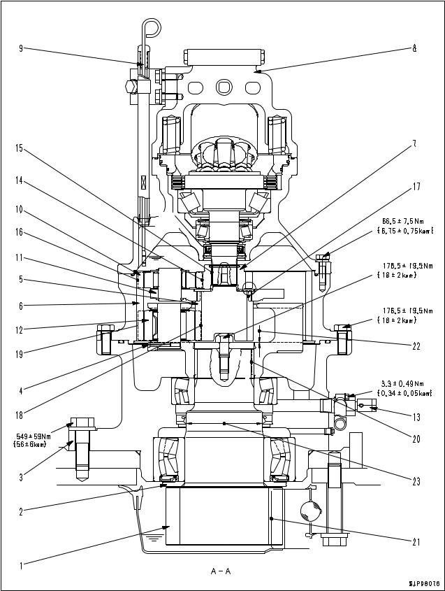
|
STRUCTURE, FUNCTION, & MAINTENANCE STANDARD |
SWING MACHINERY |
PC240LC-7K, PC240NLC-7K
![]()
|
STRUCTURE, FUNCTION, & MAINTENANCE STANDARD |
SWING MACHINERY |
1. Swing pinion (No. of teeth: 13)
2. Spacer
3. Case
4. No. 2 planetary carrier
5. No. 2 sun gear
6. Ring gear
7. No. 1 sun gear
8. Swing motor
9. Oil level gauge
10. No. 1 planetary gear
11. No. 1 planetary carrier
12. No. 2 planetary gear
13. Drain plug
SPECIFICATIONS
Reduction ratio:
17 +58 × 14 +58 = 22.689
17 14
Unit: mm
|
No. |
Check item |
Criteria |
Remedy |
||
|
14 |
Backlash between swing motor shaft and No. 1 sun |
Standard clearance |
Clearance limit |
||
|
gear |
0.18 — 0.28 |
— |
|||
|
15 |
Backlash between No. 1 sun gear and No. 1 plane- |
0.16 — 0.59 |
1.00 |
||
|
tary gear |
|||||
|
16 |
Backlash between No. 1 planetary gear and ring |
0.18 — 0.50 |
1.10 |
||
|
gear |
|||||
|
17 |
Backlash between No. 1 planetary carrier and No. 2 |
0.39 — 0.64 |
1.20 |
||
|
sun gear |
|||||
|
Replace |
|||||
|
18 |
Backlash between No. 2 sun gear and No. 2 plane- |
0.16 — 0.44 |
0.90 |
||
|
tary gear |
|||||
|
19 |
Backlash between No. 2 planetary gear and ring |
0.18 — 0.56 |
1.00 |
||
|
gear |
|||||
|
20 |
Backlash between No. 2 planetary carrier and |
0.08 — 0.23 |
— |
||
|
swing pinion |
|||||
|
21 |
Backlash between swing pinion and swing circle |
0.23 — 1.37 |
2.00 |
||
|
22 |
Clearance between plate and planetary carrier |
0.58 — 0.62 |
— |
||
|
Wear of swing pinion surface contacting with oil |
Standard size |
Repair limit |
Apply hard chrome |
||
|
23 |
|||||
|
0 |
plating, recondition, or |
||||
|
seal |
— |
||||
|
115 |
replace |
||||
|
-0.100 |
|||||

|
STRUCTURE, FUNCTION, & MAINTENANCE STANDARD |
SWING CIRCLE |
SWING CIRCLE
PC210-7K, PC210LC-7K, PC210NLC-7K
1.Swing circle inner race (No. of teeth: 110)
2.Ball
3.Swing circle outer race
a.Inner race soft zone S position
b.Outer race soft zone S position
|
SPECIFICATIONS |
||||
|
Reduction ratio: |
110 |
= 7.333 |
||
|
15 |
Amount of grease: 14.6 l (G2-LI)
Unit: mm
|
No. |
Check item |
Criteria |
Remedy |
|
|
Axial clearance of bearing |
Standard clearance |
Clearance limit |
||
|
4 |
Replace |
|||
|
(when mounted on chassis) |
||||
|
0.5 — 1.6 |
3.2 |
|||

|
STRUCTURE, FUNCTION, & MAINTENANCE STANDARD |
SWING CIRCLE |
PC240LC-7K, PC240NLC-7K
S*P09097
1.Swing circle inner race (No. of teeth: 92)
2.Ball
3.Swing circle outer race
a.Inner race soft zone S position
b.Outer race soft zone S position
|
SPECIFICATIONS |
|||
|
92 |
|||
|
Reduction ratio: − |
= −7.077 |
||
|
13 |
Amount of grease: 15.8 l (G2-LI)
Unit: mm
|
No. |
Check item |
Criteria |
Remedy |
|
|
Axial clearance of bearing |
Standard clearance |
Clearance limit |
||
|
4 |
Replace |
|||
|
(when mounted on chassis) |
||||
|
0.5 — 1.6 |
3.2 |
|||

|
STRUCTURE, FUNCTION, & MAINTENANCE STANDARD |
TRACK FRAME • RECOIL SPRING |
TRACK FRAME • RECOIL SPRING
1Idler
2Track frame
3Carrier roller
4Final drive
5Track roller
6Track shoe
7Center guard
8Recoil spring
•The dimensions and the number of track rollers depend on the model, but the basic structure is not different.
•Number of track rollers
|
Model |
Q’ty |
|
PC210-7K |
7 |
|
PC210LC-7K |
9 |
|
PC210NLC-7K |
9 |
|
PC240LC-7K |
10 |
|
PC240NLC-7K |
9 |

|
STRUCTURE, FUNCTION, & MAINTENANCE STANDARD |
TRACK FRAME • RECOIL SPRING |
Standard shoe
|
Item |
Model |
PC210-7K |
PC210LC-7K |
PC210NLC-7K |
PC240LC-7K |
PC240NLC-7K |
|
Shoe width |
600 mm |
700 mm |
500 mm |
700 mm |
700 mm |
|
|
Link pitch |
190 mm |
190 mm |
190 mm |
190 mm |
190 mm |
|
|
No. on track (one side) |
45 (pieces) |
49 (pieces) |
49 (pieces) |
51 (pieces) |
49 (pieces) |
|
|
Unit: mm |
||||||||
|
No. |
Check item |
Criteria |
Remedy |
|||||
|
Standard size |
Tolerance |
Repair limit |
||||||
|
10 |
Vertical width of idler guide |
Track frame |
107 |
|||||
|
Rebuild or |
||||||||
|
Idler support |
105 |
|||||||
|
replace |
||||||||
|
11 |
Horizontal width of idler guide |
Track frame |
250 |
|||||
|
Idler support |
247.4 |
|||||||
|
Recoil spring |
Standard size |
Repair limit |
||||||
|
Free length |
Installation |
Installation |
Free |
Installation |
||||
|
x O.D. |
length |
load |
length |
load |
||||
|
PC210-7K |
558 X 238 |
437 |
108.8 kN |
534 |
87.3 kN |
|||
|
12 |
(11,100 kg) |
(8,900 kg) |
Replace |
|||||
|
PC210LC-7K |
||||||||
|
PC210NLC-7K |
126.5 kN |
100.9 kN |
||||||
|
PC240LC-7K |
603.5 X 239 |
466 |
576 |
|||||
|
(12,900 kg) |
(10,300 kg) |
|||||||
|
PC240NLC-7K |
||||||||

|
STRUCTURE, FUNCTION, & MAINTENANCE STANDARD |
IDLER |
IDLER
|
STRUCTURE, FUNCTION, & MAINTENANCE STANDARD |
IDLER |
|
Unit: mm |
||||||||
|
No. |
Check item |
Criteria |
Remedy |
|||||
|
1 |
Outside diameter of protruding |
Standard size |
Repair limit |
|||||
|
538 |
— |
|||||||
|
2 |
Outside diameter of tread |
500 |
488 |
Rebuild or |
||||
|
replace |
||||||||
|
3 |
Thickness of tread |
26 |
20 |
|||||
|
4 |
Total width |
159 |
— |
|||||
|
5 |
Width of tread |
37.5 |
43.5 |
|||||
|
Standard |
Tolerance |
Standard |
Clearance limit |
|||||
|
size |
clearance |
|||||||
|
6 |
Clearance between shaft and bushing |
Shaft |
Hole |
|||||
|
65 |
-0.250 |
+0.074 |
0.214 — 0.424 |
1.5 |
||||
|
-0.350 |
-0.036 |
Replace |
||||||
|
bushing |
||||||||
|
Standard |
Tolerance |
Standard inter- |
Interference |
|||||
|
size |
ference |
limit |
||||||
|
7 |
Interference between idler and bushing |
Shaft |
Hole |
|||||
|
72 |
+0.089 |
-0.006 |
0.065 — 0.161 |
— |
||||
|
+0.059 |
-0.072 |
|||||||

|
STRUCTURE, FUNCTION, & MAINTENANCE STANDARD |
CARRIER ROLLER |
CARRIER ROLLER
|
Unit: mm |
|||||||||
|
No. |
Check item |
Criteria |
Remedy |
||||||
|
1 |
Outside diameter of flange |
Standard size |
Repair limit |
||||||
|
145 |
— |
||||||||
|
2 |
Outside diameter of tread |
120 |
106 |
||||||
|
3 |
Width of tread |
43 |
— |
||||||
|
4 |
Thickness of tread |
36.5 |
29.5 |
||||||
|
5 |
Width of flange |
14 |
— |
||||||
|
Standard |
Tolerance |
Standard inter- |
Interference |
Replace |
|||||
|
size |
ference |
limit |
|||||||
|
6 |
Interference between shaft and |
Shaft |
Hole |
||||||
|
bushing |
|||||||||
|
40 |
-0.179 |
+0.284 |
0.339 — 0.474 |
— |
|||||
|
-0.190 |
+0.169 |
||||||||
|
7 |
Interference between roller and |
47 |
-0.061 |
0 |
0.036 — 0.101 |
— |
|||
|
bushing |
-0.036 |
-0.040 |
|||||||
|
8 |
Axial clearance of roller |
Standard clearance |
Clearance limit |
||||||
|
0.44 — 0.76 |
— |
||||||||

|
STRUCTURE, FUNCTION, & MAINTENANCE STANDARD |
TRACK ROLLER |
TRACK ROLLER
|
Unit: mm |
||||||||
|
No. |
Check item |
Criteria |
Remedy |
|||||
|
1 |
Outside diameter of flange |
Standard size |
Repair limit |
|||||
|
188 |
— |
|||||||
|
2 |
Outside diameter of tread |
156 |
144 |
|||||
|
3 |
Thickness of tread |
44.5 |
38.5 |
Rebuild or |
||||
|
replace |
||||||||
|
4 |
Overall width |
225 |
— |
|||||
|
5 |
Inside width |
85 |
— |
|||||
|
6 |
Width of tread |
44.5 |
— |
|||||
|
7 |
Width of flange |
25.5 |
— |
|||||
|
Standard |
Tolerance |
Standard |
Clearance limit |
|||||
|
Clearance between shaft and |
size |
clearance |
||||||
|
8 |
Shaft |
Hole |
||||||
|
bushing |
||||||||
|
60 |
-0.215 |
+0.195 |
0.215 — 0.510 |
1.5 |
||||
|
-0.315 |
0 |
Replace |
||||||
|
bushing |
||||||||
|
Standard |
Tolerance |
Standard inter- |
Interference |
|||||
|
size |
ference |
limit |
||||||
|
9 |
Interference between roller and |
Shaft |
Hole |
|||||
|
bushing |
||||||||
|
67 |
-0.153 |
+0.030 |
0.023 — 0.153 |
— |
||||
|
-0.053 |
0 |
|||||||

|
STRUCTURE, FUNCTION, & MAINTENANCE STANDARD |
TRACK SHOE |
TRACK SHOE
TRIPLE GROUSER SHOE, ROAD LINER, SWAMP SHOE, FLAT SHOE
P portion shows the link of bushing press fitting end.
|
1. Triple-grouser shoe |
3. Swamp shoe |
|
2. Road liner |
4. Flat shoe |
|
10-20 |
PC210/240-7K |
![]()
|
STRUCTURE, FUNCTION, & MAINTENANCE STANDARD |
TRACK SHOE |
|
Unit: mm |
|||||||||
|
No |
Check item |
Criteria |
Remedy |
||||||
|
. |
|||||||||
|
1 |
Link pitch |
Standard size |
Repair limit |
||||||
|
190.25 |
194.25 |
||||||||
|
Reverse or |
|||||||||
|
When turned |
|||||||||
|
Standard size |
replace |
||||||||
|
2 |
Bushing outside diameter |
Normal load |
Impact load |
||||||
|
59.3 |
— |
54.3 |
|||||||
|
3 |
Link height |
Standard size |
Repair limit |
||||||
|
105 |
97 |
Repair or |
|||||||
|
replace |
|||||||||
|
4 |
Thickness of link metal |
28.5 |
20.5 |
||||||
|
(bushing press-fitting portion) |
|||||||||
|
5 |
160.4 |
||||||||
|
6 |
Shoe bolt pitch |
62 |
|||||||
|
7 |
18 |
||||||||
|
8 |
Inside width |
84.8 |
|||||||
|
9 |
Link |
Overall width |
45.4 |
||||||
|
10 |
Tread width |
39.6 |
|||||||
|
11 |
Protrusion of pin |
Regular |
2.5 |
Adjust or |
|||||
|
replace |
|||||||||
|
Master |
2.5 |
||||||||
|
12 |
Protrusion of bush- |
Regular |
4.85 |
||||||
|
ing |
|||||||||
|
Master |
0.0 |
||||||||
|
13 |
Overall length of |
Regular |
212 |
||||||
|
pin |
|||||||||
|
Master |
212 |
||||||||
|
14 |
Overall length of |
Regular |
138.5 |
||||||
|
bushing |
|||||||||
|
Master |
128.7 |
||||||||
|
Thickness of bush- |
Standard |
10.4 |
Reverse or |
||||||
|
15 |
|||||||||
|
When turned / |
|||||||||
|
ing metal |
5.4 |
replace |
|||||||
|
Impact Load |
|||||||||
|
16 |
Thickness of spacer |
— |
|||||||
|
17 |
Bushing |
88.2 — 245 kN {9 — 25 ton} |
|||||||
|
— |
|||||||||
|
18 |
Press-fitting force |
Regular pin |
127.4 — 274.4 kN {13 — 28 ton} |
||||||
|
19 |
Master pin |
78.4 — 147 kN {8 — 15 ton} |
|||||||
 : Dry type track link

|
STRUCTURE, FUNCTION, & MAINTENANCE STANDARD |
TRACK SHOE |
|
Unit: mm |
|||||||||||
|
No. |
Check item |
Criteria |
Remedy |
||||||||
|
Tightening torque |
Additional tightening |
||||||||||
|
(Nm {kgm}) |
angle (deg.) |
||||||||||
|
a. Regular link |
Triple shoe |
490 ± 49 |
120 ± 10 |
||||||||
|
{50 ± 5} |
|||||||||||
|
Shoe bolt |
Road liner |
549 ± 59 |
— |
Retighten |
|||||||
|
20 |
(Rubber pad type) |
{56 ± 6} |
|||||||||
|
Tightening torque |
Additional tightening |
Lower limit torque |
|||||||||
|
b. Master link |
(Nm {kgm}) |
angle (deg.) |
(Nm {kgm}) |
||||||||
|
— |
— |
— |
|||||||||
|
No. of shoes (each side) |
PC210-7K: 45, PC210LC-7K: 49, PC210NLC-7K: 49 |
— |
|||||||||
|
PC240LC-7K: 47, PC240NLC-7K: 51 |
|||||||||||
|
Standard |
Tolerance |
Standard inter- |
|||||||||
|
Interference between |
size |
ference |
|||||||||
|
21 |
Shaft |
Hole |
|||||||||
|
bushing and link |
|||||||||||
|
59 |
+0.304 |
+0.074 |
0.320 — 0.434 |
||||||||
|
+0.394 |
0 |
||||||||||
|
22 |
Interference between |
38 |
+0.222 |
-0.138 |
0.300 — 0.422 |
||||||
|
regular pin and link |
+0.162 |
-0.200 |
|||||||||
|
Standard |
Tolerance |
Standard clear- |
|||||||||
|
size |
ance |
||||||||||
|
23 |
Clearance between regular pin and |
Shaft |
Hole |
||||||||
|
bushing |
|||||||||||
|
38 |
+0.222 |
+0.902 |
0.180 — 0.740 |
Adjust or |
|||||||
|
+0.162 |
+0.402 |
replace |
|||||||||
|
Standard |
Tolerance |
Standard inter- |
|||||||||
|
size |
ference |
||||||||||
|
Interference between master pin and |
Shaft |
Hole |
|||||||||
|
24 |
bushing |
||||||||||
|
37.8 |
+0.280 |
+0.062 |
0.188 — 0.280 |
||||||||
|
+0.250 |
0 |
||||||||||
|
Standard |
Tolerance |
Standard clear- |
|||||||||
|
Clearance between master pin and |
size |
ance |
|||||||||
|
Shaft |
Hole |
||||||||||
|
25 |
bushing |
||||||||||
|
38 |
-0.150 |
+0.902 |
0.552 — 1.252 |
||||||||
|
-0.350 |
+0.402 |
||||||||||
|
Standard size |
Repair limit |
Lug welding, |
|||||||||
|
Triple-grouser |
rebuild or |
||||||||||
|
Height of grouser |
26 |
16 |
|||||||||
|
replace |
|||||||||||
|
Road liner |
70 |
25 |
Replace |
||||||||
 : Dry type track link

|
STRUCTURE, FUNCTION, & MAINTENANCE STANDARD |
TRACK SHOE |
TRIPLE GROUSER SHOE
SWAMP SHOE
Unit: mm
|
No. |
Check item |
Criteria |
Remedy |
|||
|
1 |
Height |
Standard size |
Repair limit |
|||
|
26 |
16 |
|||||
|
2 |
Thickness |
8.5 |
||||
|
3 |
Length of base |
26 |
||||
|
4 |
19 |
|||||
|
5 |
20 |
Rebuild or replace |
||||
|
6 |
Length at tip |
14 |
||||
|
7 |
19 |
|||||
|
8 |
Thickness |
Standard size |
Repair limit |
|||
|
34.5 |
24.5 |
|||||
|
9 |
Height |
102.5 |
90.5 |
|||
|
10 |
Thickness |
17 |
5 |
|||

|
HYDRAULIC EQUIPMENT LAYOUT |
|
|
STRUCTURE, FUNCTION, & MAINTENANCE STANDARD |
DRAWING |
HYDRAULIC EQUIPMENT LAYOUT DRAWING
1.Bucket cylinder
2.Arm cylinder
3.Boom cylinder
4.Hydraulic tank
5.Hydraulic filter
6.R.H. travel motor
7.Swing motor
8.Hydraulic pump
9. Control valve
10.Oil cooler
11.L.H. travel motor
12.L.H. PPC valve
13.Safety lever (electric type)
14.Center swivel joint
15.R.H. PPC valve
16.Travel PPC valve
17.Attachment circuit selector valve
18.Holding valve
19.Accumulator
20.Solenoid valve assembly 20A PPC lock solenoid
20B Travel junction solenoid
20C Pump merge/divider solenoid
20D Travel speed solenoid
20E Swing brake solenoid
20F 2-stage relief solenoid

|
HYDRAULIC EQUIPMENT LAYOUT |
|
|
STRUCTURE, FUNCTION, & MAINTENANCE STANDARD |
DRAWING |

|
STRUCTURE, FUNCTION, & MAINTENANCE STANDARD |
HYDRAULIC TANK |
HYDRAULIC TANK
1.Sight gauge
2.Hydraulic tank
3.Oil filler cap
4.Filter element
5.Strainer
6.Bypass valve
7.Suction strainer
SPECIFICATIONS
Tank capacity: 200 l
Amount of oil inside tank: 143 l Pressure valve
Relief cracking pressure:
16.7 ± 6.9 kPa
{0.17 ± 0.07 kg/cm²} Suction cracking pressure:
0 — 0.49 kPa
{0 — 0.005 kg/cm²} Bypass Valve set pressure:
150 ± 30 kPa
{1.5 ± 0.3 kg/cm²}
|
STRUCTURE, FUNCTION, & MAINTENANCE STANDARD |
HYDRAULIC TANK |
THIS PAGE LEFT INTENTIONALLY BLANK

|
STRUCTURE, FUNCTION, & MAINTENANCE STANDARD |
HYDRAULIC PUMP |
HYDRAULIC PUMP
HPV95 + 95(PC210/LC/NLC-7K)

|
STRUCTURE, FUNCTION, & MAINTENANCE STANDARD |
HYDRAULIC PUMP |
|
1. |
Front main pump |
IM |
: PC mode selector current |
|
2. |
Rear main pump |
ISIG |
: LS set selector current |
|
3F. |
LS valve front |
PAF |
: Front pump delivery port |
|
3R. LS valve rear |
PFC |
: Front pump delivery pressure |
|
|
4. |
PC valve |
detection port |
|
|
5. |
LS-EPC valve |
PAR |
: Rear pump delivery port |
|
6. |
PC-EPC valve |
PRC |
: Rear pump delivery pressure |
|
detection port |
|||
|
PBF |
: Pump pressure input port |
||
|
PD1F: Case drain port |
PENF: Front pump control pressure detection port
PENR : Rear pump control pressure detection port
|
PLSF |
: Front load pressure input port |
|
PLSFC: Front load pressure detection port |
|
|
PLSR |
: Rear load pressure input port |
|
PLSRC: Rear load pressure detection port |
|
|
PS |
: Pump suction port |
|
PSIG |
: LS set selector pressure detection port |
|
PM |
: PC set selector pressure detection port |
|
PEPC |
: EPC basic pressure input port |

|
STRUCTURE, FUNCTION, & MAINTENANCE STANDARD |
HYDRAULIC PUMP |
HPV95 + 95(PC240LC/NLC-7K)
|
1. |
Front main pump |
IM |
: PC mode selector current |
|
2. |
Rear main pump |
ISIG |
: LS set selector current |
|
3. |
LS valve |
PAF |
: Front pump delivery port |
|
4. |
PC valve |
PFC |
: Front pump delivery pressure |
|
5. |
LS-EPC valve |
detection port |
|
|
6. |
PC-EPC valve |
PAR |
: Rear pump delivery port |
|
PRC |
: Rear pump delivery pressure |
||
|
detection port |
|||
|
PBF |
: Pump pressure input port |
||
|
PD1F: Case drain port |
PENF: Front pump control pressure detection port
Outline
•This pump consists of 2 variable capacity swash plate piston pumps, PC valve, LS valve, and EPC valve.
PENR : Rear pump control pressure detection port
|
PLSF |
: Front load pressure input port |
|
PLSFC: Front load pressure detection port |
|
|
PLSR |
: Rear load pressure input port |
|
PLSRC: Rear load pressure detection port |
|
|
PS |
: Pump suction port |
|
PSIG |
: LS set selector pressure detection port |
|
PM |
: PC set selector pressure detection port |
|
PEPC |
: EPC basic pressure input port |
 Loading…
You can only view or download manuals with
Sign Up and get 5 for free
Upload your files to the site. You get 1 for each file you add
Get 1 for every time someone downloads your manual
Buy as many as you need
9,06 Мб
Каталог запчастей экскаваторов Komatsu PC200-7, PC200LC-7,
Формат: pdf
-
Год:
2004
-
Страниц:
536
-
Язык:
английский
-
Размер:
9,06 Мб
-
Категории:
Komatsu PC210
|
Detail Specifications: 1496/1496547-pc21010.pdf file (17 Feb 2023) |
Accompanying Data:
Komatsu PC210-10 Excavators PDF Operation & Maintenance Manual (Updated: Friday 17th of February 2023 09:47:32 PM)
Rating: 4.4 (rated by 33 users)
Compatible devices: PC400LC-8, ecot3 PC300LC-8, PC600 -8E0, PC210LC-11, HB205 -1, PC360NLC-11, PC290LC-10, PW118MR-11.
Recommended Documentation:
Text Version of Operation & Maintenance Manual
(Ocr-Read Summary of Contents, UPD: 17 February 2023)
-
133, OPERATION EXPLANATION OF COMPONENTS 3–63 1. Select an attachment to change its name on the attachment setting screen, then press switch F6. 2. The attachment name setting screen is displayed. On the attachment name setting screen, it is possible to carry out the following operations with switches F1 to F6. F1: «CLEAR» Deletes all the letters. (If some l…
-
102, EXPLANATION OF COMPONENTS OPERATION 3–32 GAUGES AND METER Gauges a nd Meter:A LL-Q1LB-001K00A ENGINE COOLANT TEMPERATURE GAUGE Engine c oolant temp erature gauge:PC22 0_KU-BA80 -043K00A This meter (15) shows the engine coolant temperature. During normal operations, the indicator should be in the green range. If the indicator goes beyond red range (A) during opera- tions, …
-
13, FOREWORD PRODUCT INFORMATION 1–11 DECLARATION OF CONFORMITY The manufacturer: KOMATSU UK Ltd Durham Road Birtley Chester-Le-Street County Durham DH3 2QX Declares that this machine: PC210-10, PC210LC-10 Fulfils all the relevant provisions of the following EC Directives. Machinery Directive 2006/42/EC Electro Magnetic Compatibility Directive 2004/108/EC Outdoor Noise Directive 2000/1…
-
451, Komatsu PC210-10 REPLACEMENT PARTS RECOMMENDED FUEL, COOLANT, AND LUBRICANT 7–7 FUEL, COOLANT, AND LUBRICANTS TO MATCH THE AMBIENT TEMPERATURE FUEL, COOLANT, AND LUBRICANTS TO MATCH THE AMBIENT TEMPERATURE:PC220 -RA1B-05AK03A q ASTM: American Society of Testing and Material REMARK Specified capacity means the total amount of oil including the oil in the tank and the piping. Refill capacity means …
-
434, ATTACHMENTS AND OPTIONS ATTACHMENTS AND OPTIONS 6–36 HANDLING OF RUBBER PAD SHOE AND ROAD LINER HANDLING OF RUBBER PAD SHOE AND ROAD LINER:PC-DTLJ-170K00A Be sure to observe the following instructions, when using a machine equipped with rubber pad shoes or Road Liner. WORKING ENVIRONMENT Use a machine equipped with rubber pad shoes or Road Liner mainly for jobs on the paved roads. I…
-
304, Komatsu PC210-10 TROUBLES AND ACTIONS OPERATION 3–234 START ENGINE WITH BOOSTER CABLES Start Engine with Bo oster Cables :ALL-AW10-1 4BK00A When starting the engine with a booster cable, do as follows. CONNECT AND DISCONNECT BOOSTER CABLES CONNECT AND DISCONNECT BOOSTER CABLES:PC220-AW10-14BK00A k WARNING q When connecting the cables, never contact the positive (+) and negative (-) terminals. q When …
-
85, OPERATION EXPLANATION OF COMPONENTS 3–15 WARNING DISPLAY WARNING DISPLAY:PC-Q1FB-043K00A NOTICE Appearance of any of action levels «L01» to «L04» on the machine monitor indicates presence of an abnormality on the machine. Take appropriate actions following the list of action level monitor displays and remedies. The alarm monitor that is lit in red when an action l…
-
118, EXPLANATION OF COMPONENTS OPERATION 3–48 q Press the wiper switch and washer switch to operate the wipers and washer. Even if the wiper switch or washer switch is pressed, the camera image display screen does not switch to another screen or return to the standard screen display. ACTIONS AGAINST WARNING DURING CAMERA DISPLAY q If an error or alarm occurs while the camera image is being dis…
-
49, Komatsu PC210-10 SAFETY SAFETY MACHINE OPERATION 2–31 WHEN OPERATING When ope rating:AL L-0000-00 1K11A CHECKS BEFORE OPERATION CHECKS BEFORE OPERATION:PC-0000-184K0 0A If the checks before starting are not carried out properly, the machine will be unable to display its full performance, and there is also danger that it may lead to serious personal injury or death. When carrying out the checks, move the m…
-
424, MACHINE READY FOR INSTALLATION OF ATTACHMENT ATTACHMENTS AND OPTIONS 6–26 6. After checking that the oil temperature is low, set the rotor of the stop valve installed to the inlet port on the side face of the arm and the outlet port piping to LOCK position (b). (a) FREE: Hydraulic oil flows (direction of arrow is parallel to longish direction of arm) (b) LOCK: Hyd…
Recommended Instructions:
T-H3M-DV, HC 4S, ST600, LCR4322, 2420-20


-
WX145WX165WX185Utilisation et EntretienPrint No. 875900551st editionFrench 06/07 Operator’s ManualPrint No. 842856621st editionEnglish 01/10 ORIGINAL INSTRUCTIONSWX145 / WX165 / WX185 Wheeled Excavators Stage IIIAWheeled Excavators Stage IIIAUso e ManutenzioneStampato N. 842856631a edizioneItaliano 01/10 ISTRUZIONI ORIGINALIWX145 / WX165 / WX185 E …
WX185 324
-
Part number 478430261st edition EnglishMarch 2015SERVICE MANUALCX350DLC VersionTier 4B (final)Crawler ExcavatorPrintedin U.S.A.© 2015 CNH Industrial Italia S.p.A. All Rights Reserved. Case is a trademark registered in the United States and manyother countries, owned by or licensed to CNH Industrial N.V.,its subsidiaries or affiliates. …
CX350D 81
-
OPERATING MANUAL AND FITTING INSTRUCTIONS OilQuick quick coupler with automatic hydraulic connection for excavators OQ 70/55 and 80 Specifications subject to change without notice. Please read the instructions carefully before using the quick coupler. …
OQ 70/55 32