-
Contents
-
Table of Contents
-
Troubleshooting
-
Bookmarks
Quick Links
Operating Instructions
Smartec S CLD132
Conductivity Measuring System
BA207C/07/en/09.04
51501595
Software version 1.00 or later
Related Manuals for Endress+Hauser Smartec S CLD132
Summary of Contents for Endress+Hauser Smartec S CLD132
-
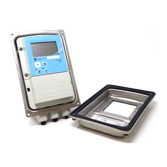
Page 1: Operating Instructions
Operating Instructions Smartec S CLD132 Conductivity Measuring System BA207C/07/en/09.04 51501595 Software version 1.00 or later…
-
Page 2
Spare parts that can be delivered and a system overview are listed on these pages. ▼ Technical data → Page 73 Dimensions → Page 73 ff. Process conditions, weight, material ▼ Index → Page 80 ff. The index helps you to find information and important terms easily and quickly. Endress+Hauser… -
Page 3: Table Of Contents
3.1.1 Measuring system ….9 Maintenance of Smartec S CLD132 … . 54 Incoming acceptance, transport, storage .
-
Page 4
Smartec S CLD132 Technical Data….71 10.1 Input ……..71 10.2 Output . -
Page 5: Safety Instructions
Safety instructions Safety instructions Designated use Smartec S CLD132 is a field-tested and reliable transmitter used to determine the conductivity of liquid media. It is particularly suitable for use in the foodstuffs industry. Any other use than the one described here compromises the safety of persons and the entire measuring system and is, therefore, not permitted.
-
Page 6: Return
Safety instructions Smartec S CLD132 Return If the transmitter has to be repaired, please return it cleaned to the sales centre responsible. Please use the original packaging, if possible. Please enclose the completed «Declaration of contamination» (copy the second last page of these Operating Instructions) with the packaging and the transportation documents.
-
Page 7: Identification
0…+55 °C C07-CLD132xx-18-06-00-xx-001.eps Fig. 1: Nameplate CLD132 (example) 2.1.2 Product structure Smartec S CLD132 Version Compact version Separate transmitter, cable length 20 m / 65.62 ft Separate transmitter, cable length 5 m / 16.41 ft Separate transmitter, cable length 10 m / 32.81 ft Process connection Dairy fitting DN 50 (acc.
-
Page 8: Basic Version And Function Extensions
• Relay can be configured as alarm or limit contact Scope of delivery The scope of delivery of the compact version inlcudes: • Smartec S CLD132 compact measuring system with integrated sensor • Terminal strip set • Expansion bellows (-*GE1***** versions only) •…
-
Page 9: Installation
• If you have not yet installed the sensor at the measuring point, perform an Airset and install the sensor (see the Technical Information of the sensor). • Connect the sensor to the Smartec S CLD132 as described in the chapter «Electrical connection». • Connect the transmitter as described in the chapter «Electrical connection».
-
Page 10: Incoming Acceptance, Transport, Storage
Installation Smartec S CLD132 Incoming acceptance, transport, storage • Make sure the packaging is undamaged! Inform the supplier about damage to the packaging. Keep the damaged packaging until the matter has been settled. • Make sure the contents are undamaged! Inform the supplier about damage to the delivery contents.
-
Page 11: Cld132 Separate Version
Smartec S CLD132 Installation 3.3.2 CLD132 separate version 142 / 5.59 Ø 7 / 0.28 225 / 8.86 175 / 6.89 mm /inch C07-CLD132xx-11-06-00-en-001.EPS Fig. 5: CLD132 wall mounting with mounting plate C07-CLD132xx-11-06-00-en-002.EPS Fig. 6: CLD132 mounting on pipes (Ø 60 mm / 2.36″)
-
Page 12
Installation Smartec S CLD132 Conductivity sensors for the separate transmitter CLS52 conductivity sensors with various process connections covering all common installation conditions are available for the separate version. Note! Perform an Airset and calibrate the sensor before sensor installation. C07-CLD132xx-11-06-00-en-003.EPS Fig. -
Page 13: Cld 132 Compact Version
Smartec S CLD132 Installation Measuring range C07-CLD132xx-05-06-00-xx-002.eps Fig. 8: CLS52 measuring range 3.3.3 CLD 132 compact version 225 / 8.86 142 / 5.59 35.5 / 1.40 ∅ 49 / 1.93 34 / 1.34 mm / inch C07-CLD132xx-11-06-00-en-004.eps Fig. 9: Dimensions of CLD132 compact version…
-
Page 14
Installation Smartec S CLD132 Connection variants Various process connections covering all common installation conditions are available for the compact version. The compact version is installed at the measuring point with the required process connection. C07-CLD132xx-11-06-00-en-005.eps Fig. 10: Process connections for the CLD132 compact version Note! •… -
Page 15: Installation Instructions
Smartec S CLD132 Installation Installation instructions 3.4.1 Mounting CLD132 separate version Wall mounting For wall mounting, attach the mounting plate to the wall by drilling holes as required. Anchors and screws are to be provided by the operator. ∅ 7 / 0.28 225 / 8.86…
-
Page 16: Mounting Cld132 Compact Version Or Cls52 Sensor For Separate Version
Fig. 14: Installation of CLD132 compact version When installing the Smartec S CLD132 or the sensor, make sure that the flow opening of the sensor is oriented in the flow direction of the medium. An orientation arrow on the sensor facilitates orientation (see Fig.
-
Page 17: Post-Installation Check
Smartec S CLD132 Installation Sensor positioning: compact version The sensor in the compact housing must be oriented in the flow direction. If you need to reorient the sensor in relation to the housing, proceed as follows: Remove the cover. Loosen the screws of the electronics box and carefully remove the box from the housing.
-
Page 18: Wiring
• Ensure that there is no voltage at the power cable before beginning the connection work. 4.1.1 Electrical connection of transmitter Proceed as follows to connect the Smartec S CLD132: 1. Loosen the 4 Phillips screws on the housing cover and remove the cover.
-
Page 19: Version
Smartec S CLD132 Wiring C07-CLD132xx-04-06-04-xx-001.eps Fig. 17: Terminal assignments of cable glands on Smartec S CLD132 Separate version Compact version Plug, Pg 13.5, analog output, binary input Plug, Pg 13.5, analog output, digital input Cable gland for alarm contact, Pg 13.5 Cable gland for alarm contact, Pg 13.5…
-
Page 20
10-50 V ∼ – ∼ – 10-50 V C07-CLD132xx-05-06-00-xx-003.eps Fig. 19: Electrical connection of Smartec S CLD132 Signal output 1 conductivity Conductivity sensor Signal output 2 temperature Temperature sensor Auxiliary power output Alarm (contact position: no current) Binary input 2 (MRS1+2) -
Page 21: Version
Smartec S CLD132 Wiring Connection compartment sticker 131082-4A Sensor 31 + 32 — 33 + Temp. (opt.) 34 — 85 + +15V 10mA 86 — 93 + Bin 2 94 — 81 + Bin 1 82 — ∼ – Mains ∼…
-
Page 22: Post-Connection Check
Wiring Smartec S CLD132 Post-connection check After wiring up the electrical connection, carry out the following checks: Device status and specifications Remarks Are the transmitter or the cable externally damaged? Visual inspection Electrical connection Remarks Are the installed cables strain-relieved? No loops and cross-overs in the cable run? Are the signal cables correctly connected acc.
-
Page 23: Operation
Note! For operation via HART or PROFIBUS PA/DP, read the corresponding chapters in the additional operating instructions: • PROFIBUS PA/DP, field communication with Smartec S CLD132, BA 213C/07/en ® • HART , field communication with Smartec S CLD132, BA 212C/07/en The following chapters describe local operation via operating keys.
-
Page 24: Operating Elements
SMARTEC S ALARM – C07-CLD132xx-19-06-00-xx-001.eps Fig. 25: Operating elements of Smartec S CLD132 Liquid crystal display showing measured values and configuration data 4 operating keys for calibration and instrument configuration Field for user labeling LED indicator for alarm function 5.2.3…
-
Page 25
Smartec S CLD132 Operation PLUS key and MINUS key In setup mode, the PLUS and MINUS keys have the following functions: • Selection of function groups Note! To select function groups in the order given in the chapter «Instrument configuration», use the MINUS key. -
Page 26: Local Operation
Operation Smartec S CLD132 Local operation 5.3.1 Operating concept Operating modes Measuring mode: standard mode of operation, displaying current measured values Setup mode Calibration mode: access to all execution of calibration routine configuration settings Code The function groups are selected with the PLUS or MINUS key.
-
Page 27
Smartec S CLD132 Operation Menu structure The configuration and calibration functions are arranged in a menu structure by function groups. The function groups are selected in the setup mode with the PLUS and MINUS keys. The ENTER key is used to move from one function to the next within a function group. -
Page 28: Commissioning
C111 top to the bottom and from the left to the right. C07-CLD132xx-13-06-00-xx-005.eps Fig. 29: Function coding For a detailed description of the function groups available on the Smartec S CLD132 see the chapter «Instrument configuration». Endress+Hauser…
-
Page 29: Endress+Hauser
Smartec S CLD132 Commissioning Factory settings When the instrument is switched on for the first time, the factory settings are in effect. The following table provides an overview of all major settings. Please refer to the description of the individual functions in the chapter «Instrument configuration»…
-
Page 30: Quick Setup
Commissioning Smartec S CLD132 Quick setup After switching the transmitter on, configure the major functions required for accurate measurement. The following section gives you an example for a basic configuration. Input Selection or range Display (factory setting bold) 1. Press the ENTER key.
-
Page 31
Smartec S CLD132 Commissioning Input Selection or range Display (factory setting bold) 14. In A6, press the ENTER key to confirm the factory setting. 1.000 If your wall distance is smaller than 15 mm / 0.59″, 0.10 … 1 … 5.00 refer to the chapters 3.3.1 and 6.4.14 for information… -
Page 32: Endress+Hauser
Commissioning Smartec S CLD132 Input Selection or range Display (factory setting bold) 26. In O2, select the linear characteristic. lin = linear (1) Confirm your selection by pressing ENTER. sim = simulation (2) Sel.Type 27. In O211, select the current range for your output, e.g.
-
Page 33: Instrument Configuration
Smartec S CLD132 Commissioning Instrument configuration The following sections give a detailed description of all Smartec S CLD132 functions. 6.4.1 Setup 1 (conductivity, concentration) In the SETUP 1 function group, you can change the operating mode and the sensor settings.
-
Page 34: Setup 2 (Temperature)
Commissioning Smartec S CLD132 6.4.2 Setup 2 (temperature) The temperature compensation only needs to be performed in the conductivity mode (selection in field A1). The temperature coefficient specifies the change in conductivity per degree of temperature change. It depends on the chemical composition of the medium and the temperature itself.
-
Page 35
Smartec S CLD132 Commissioning k( ) C07-CLD132xx-05-06-00-xx-011.eps Fig. 33: Determination of temperature coefficient Required data Calculated α values Use the following formula to calculate the α values for the temperatures occurring in your process: κ κ (T) — (T ) α… -
Page 36: Current Outputs
Commissioning Smartec S CLD132 Coding Field Selection or range Display Info (factory settings bold) ° 25.0 Enter process 25 °C Only if B1 = fixed. temperature -10.0 … 150.0 °C This value can only be specified in °C. ProcTemp. Display temperature Display and entry of real °…
-
Page 37: Alarm
Smartec S CLD132 Commissioning Coding Field Selection or range Display Info (factory settings bold) Enter the measured value corresponding to Cond: 2000 mS/cm 20 mA value: the maximum current value (20 mA) at the mS/cm 2000 Conc: 99.99 % O213…
-
Page 38: Check
Commissioning Smartec S CLD132 Coding Field Selection or range Display Info (factory settings bold) Select the errors that are to trigger an alarm signal. The errors are selected via the error number. Select error Please refer to the table in chapter 9.2 «System 1 …
-
Page 39: Relay Configuration
(Error no.: E152) 6.4.6 Relay configuration For Smartec S CLD132 equipped with remote parameter set switching (measuring range switching), there are three options for configuring the relay (selection in field R1): • Alarm The relay closes the contact 41/42 (voltage-free, safe state) if an alarm condition according to chapter 9.2 occurs and if the setting in the “Alarm contact”…
-
Page 40
Commissioning Smartec S CLD132 C07-CLD132xx-05-06-00-xx-008.eps Fig. 35: Relation of switch-on and switch-off points and pickup and dropout delays Switch-on point > switch-off point: Max. function Switch-on point Switch-on point < switch-off point: Min. function Switch-off point Contact ON Contact OFF… -
Page 41: Temperature Compensation With Table
Smartec S CLD132 Commissioning Coding Field Selection or range Display Info (factory settings bold) Enter dropout delay 0 … 2000 s Off Delay auto auto This selection can only be made if limit has Select simulation manual been selected in R1.
-
Page 42: Concentration Measurement
6.4.8 Concentration measurement The Smartec S CLD132 transmitter can convert conductivity values to concentration values. For this, set the operating mode to Concentration measurement (see field A1). You must enter the basic data to which the concentration calculation should refer. For the most common substances, the required data is already saved in your device.
-
Page 43
Smartec S CLD132 Commissioning κ κ C07-CLD132xx-05-06-00-xx-012.eps Fig. 36: Measured data for variable process temperatures (example) κ Conductivity Measuring point Concentration Measuring range Temperature κ κ ma x ma x C07-CLD132xx-05-06-00-xx-015.epsB Fig. 37: Measured data for a constant process temperature (example) κ… -
Page 44
Commissioning Smartec S CLD132 • Enter the values in the order of increasing concentration (see the following example). mS/cm °C Coding Field Selection or range Display Info (factory settings bold) Settings for concentration measurement. Four Function group fixed and four editable concentration fields are CONCENTRATION stored in this function group. -
Page 45: Service
Smartec S CLD132 Commissioning Coding Field Selection or range Display Info (factory settings bold) mS/cm Enter uncompensated 0.0 mS/cm conductivity 0.0 … 9999 mS/cm conduct. Enter concentration 0.00 % value for K6 0.00 … 99.99 % concentr. °C Enter temperature 0.0 °C…
-
Page 46: E+H Service
Commissioning Smartec S CLD132 Coding Field Selection or range Display Info (factory settings bold) Manual hold Man.HOLD Enter hold dwell 10 s period 0 … 999 s Cont.Time Enter SW upgrade Entering an incorrect code returns you to the release code of measurement menu.
-
Page 47: Interfaces
Smartec S CLD132 Commissioning Coding Field Selection or range Display Info (factory settings bold) E111 E111: Version of transmitter software xx.xx E121 Software version is E111 E121-141: Version of module firmware (if E131 displayed available) E141 SW-Vers. E112 xx.xx E122…
-
Page 48: Determining The Temperature Coefficient
MRS) You can order the remote parameter set switching via binary inputs directly as an option of your Smartec S CLD132 (see «Product structure») or you can retrofit a standard transmitter with the MRS function extension (see the chapter «Accessories»).
-
Page 49
Smartec S CLD132 Commissioning Assignment of binary inputs The Smartec S CLD132 transmitter has 2 binary inputs. They can be defined in field M1 as follows: Assignment of field M1 Assignment of binary inputs M1 = 0 MRS not active. The binary input 1 can be used for external hold. -
Page 50
Commissioning Smartec S CLD132 Coding Field Selection or range Display Info (factory settings bold) cond. cond = conductivity The operating mode can be individually Select operating mode conc = concentration defined for each parameter set. Oper.Mode NaOH NaOH, H2SO4, H3PO4, HNO3 Select medium Only available if M4 = conc. -
Page 51: Calibration
Smartec S CLD132 Commissioning 6.4.14 Calibration To access the «Calibration» function group, press the CAL key. This function group is used to calibrate the transmitter. Two different types of calibration are possible: • Calibration by measurement in a calibration solution of a known conductivity.
-
Page 52
Commissioning Smartec S CLD132 Coding Field Selection or range Display Info (factory settings bold) If C113 = E xxx, then only no or new. Store calibration C114 C114 If new, return to C. results? If yes/no, return to “Measurement”. Store… -
Page 53: Communication Interfaces
Smartec S CLD132 Commissioning Coding Field Selection or range Display Info (factory settings bold) Airs = Airset (1) Calibration with InstF Cellc = cell constant (2) C1 (3) sensor adaptation for InstF = installation Sensor calibration with compensation of wall…
-
Page 54: Maintenance
• For your own safety, use only original spare parts. Original parts will guarantee functionality, accuracy and reliability after repairs. Note! Please contact your Endress+Hauser representative if you have any questions. You can also send your queries to the Endress+Hauser Service Organisation via the Internet: www.endress.com Maintenance of Smartec S CLD132 7.1.1…
-
Page 55: Special Case: Replacement Of Central Module
– Monitoring functions – Interface parameters Dismantle the instrument as described in the chapter «Dismantling Smartec S CLD132». Refer to the part number of the central module to determine whether the new module has the same part number as the old one.
-
Page 56: Maintenance Of Measuring System
Maintenance Smartec S CLD132 Maintenance of measuring system 7.2.1 Cleaning conductivity sensors Inductive sensors are less sensitive to soiling than conventional conductive sensors since there is no galvanic contact with the medium. However, dirt may collect in the measuring opening (making it narrower), which changes the cell constant.
-
Page 57: Instrument Check By Medium Simulation
Smartec S CLD132 Maintenance 7.2.3 Instrument check by medium simulation The inductive sensor cannot be simulated. However, the overall system comprising the CLD132 and inductive sensor can be checked using equivalent resistances. Note the cell constant ( k = 5.9 for CLS52).
-
Page 58: Checking Line Extension And Junction Box
Maintenance Smartec S CLD132 7.2.4 Checking line extension and junction box • Use the methods described in chapters «Checking inductive conductivity sensors» and «Instrument check by medium simulation» to perform a quick functional check from the conductivity sensor to the measuring instrument via an extension.
-
Page 59: Accessories
Inductive conductivity sensor with fast response time and hygienic design; with integrated temperature sensor. Order according to product structure, see Technical Information TI 167C/07/en. One Indumax H CLS52 is included in the Smartec S CLD132 scope of delivery. Extension cable ❑Extension cable CLK5 for inductive conductivity sensors, for extension via the VBM junction box, sold by the metre;…
-
Page 60: Post Mounting Kit
Accessories Smartec S CLD132 Post mounting kit ❑Mounting kit for installation of Smartec S CLD132 on horizontal or vertical pipes and posts (max. Ø 60 mm / 2.36″), material stainless steel 1.4301; order no.: 50062121 C07-CLD132xx-00-06-06-001.eps Fig. 40: Mounting kit for installing CLD132 separate version on posts or pipes Software upgrade ❑Software upgrade…
-
Page 61: Troubleshooting
Optoscope, see chapter «Service equipment not match hardware (central module) Optoscope»). E002 4. If problem persists, return instrument to your local Endress+Hauser sales agency for repair or replace instrument. Download error Download must not access locked functions (e.g. E003 temperature table in basic version).
-
Page 62: Process-Specific Errors
Troubleshooting Smartec S CLD132 Error no. Display Tests and / or measures Alarm contact Error current Factory User Factory User E063 Below current output range 1 Check measured value and current output assignment (function group O). E064 Current output range 1 exceeded…
-
Page 63
Smartec S CLD132 Troubleshooting Error Possible cause Tests and / or remedial measures Equipment, spare parts, personnel Short circuit / moisture in sensor Check sensor. See chapter «Checking inductive conductivity sensors». Short circuit in cable or junction box Check cable and junction box. -
Page 64
Troubleshooting Smartec S CLD132 Error Possible cause Tests and / or remedial measures Equipment, spare parts, personnel Relay configured for alarm Activate limit contactor. See field R1. Pickup delay setting too long Shorten pickup delay. See field R4. Limit contact does not work «Hold»… -
Page 65: Instrument-Specific Errors
«Spare parts». active Power supply unit defective Replace power supply unit using correct On-site diagnosis by Endress+Hauser Service variant. (test module required) Central module LSCH / LSCP defective Replace central module using correct On-site diagnosis by E+H Service (test variant.
-
Page 66
Troubleshooting Smartec S CLD132 Error Possible cause Tests and / or remedial measures Equipment, spare parts, personnel Ribbon cable or transmitter module not Reinsert transmitter module, use additional Refer to exploded view in chapter «Spare Display shows measured properly installed fastening screw M3 if necessary. -
Page 67: Spare Parts
Smartec S CLD132 Troubleshooting Spare parts Spare parts are to be ordered from your sales centre responsible. Specify the order numbers listed in the chapter «Spare parts kits». To be on the safe side, you should always specify the following data with your spare part orders: •…
-
Page 68: Exploded View
Smartec S CLD132 9.5.1 Exploded view C07-CLD132xx-09-06-06-en-001.eps The exploded view drawing shows all components and spare parts of Smartec S CLD132. Use the position numbers to find the spare parts designation and their order number in the following section. Endress+Hauser…
-
Page 69: Spare Part Kits
Smartec S CLD132 Troubleshooting 9.5.2 Spare part kits Item Kit designation Name Function/content Order number Housing bottom, separate Bottom assembly 51501574 Housing bottom, compact Bottom assembly 51501576 Post mounting kit 1 pair of post mounting parts 50062121 Housing cover Cover with accessories…
-
Page 70: Return
Troubleshooting Smartec S CLD132 Item Kit designation Name Function/content Order number Cable entry kit Conduit Cable glands, plugs, Goretex filter 51502283 Screw and gasket kit All screws and gaskets 51501596 Protection cover kit Protection cover for connection 51502382 compartment Return If the transmitter has to be repaired, please return it cleaned to the sales centre responsible.
-
Page 71: Technical Data
Smartec S CLD132 Technical Data Technical Data 10.1 Input Measured variables Conductivity Concentration Temperature Measuring range Conductivity: recommended range: 100 µS/cm … 2000 mS/cm (uncompensated) Concentration – NaOH: 0 … 15 % – HNO 0 … 25 % – H 0 …
-
Page 72: Power Supply
–10 … +70 °C / 14 … 158 °F (separate version) –10 … +55 °C / 14 … 131 °F (compact version) (see Fig. 41 «Permissible temperature ranges of Smartec S CLD132») Storage temperature –25 … +70 °C / -13 … 158 °F Electromagnetic compatibility Interference emission and interference resistance acc.
-
Page 73: Mechanical Construction
Smartec S CLD132 Technical Data 10.6 Mechanical construction Design, dimensions Separate transmitter with mounting L x W x D: 225 x 142 x 109 mm / plate: 8.86 x 5.59 x 4.29″ Compact transmitter MV1, CS1, L x W x D: 225 x 142 x 242 mm / GE1, SMS versions: 8.86 x 5.59 x 9.53″…
-
Page 74
Technical Data Smartec S CLD132 Permissible temperature ranges of Smartec S CLD132 [°F] [°F] [° C] –10 –5 [° C] Medium temperature C07-CLD132xx-05-06-00-en-013.eps Fig. 41: Permissible temperature ranges of Smartec S CLD132 CLS52 sensor with separate version Compact version short-term for sterilisation (< 30 min) Pressure-temperature load curve of CLS52 sensor C07-CLS52xxx-05-05-00-en-001.eps… -
Page 75: Chemical Durability Of Cls52 Sensor
Indumax H CLS52, Technical Information TI 167C/07/en Order no.: 50086110 PROFIBUS PA/DP, Field communication with Smartec S Order no.: 51502194 CLD132, Operating Instructions BA 213C/07/en ® HART , Field communication with Smartec S CLD132, Order no.: 51502192 Operating Instructions BA 212C/07/en Endress+Hauser…
-
Page 76: Appendix
Appendix Smartec S CLD132 Appendix Operating matrix C07-CLD132xx-13-06-00-en-001.eps Endress+Hauser…
-
Page 77
Smartec S CLD132 Appendix C07-CLD132xx-13-06-00-en-002.eps Endress+Hauser… -
Page 78
Appendix Smartec S CLD132 C07-CLD132xx-13-06-00-en-003.eps Endress+Hauser… -
Page 79
Smartec S CLD132 Appendix C07-CLD132xx-13-06-00-en-004.eps Endress+Hauser… -
Page 80: Index
Connection compartment sticker ….21 Smartec S CLD132 ……54 Connection diagram .
-
Page 81
Smartec S CLD132 Product structure ……. . 7 Quick setup……..30 Relay configuration . -
Page 82
Smartec S CLD132 Endress+Hauser… -
Page 84
www.endress.com/worldwide BA207C/07/en/09.04 Printed in Germany / FM+SGML 6.0 / DT 51501595…
![]()
Operating Instructions
Smartec S CLD132
Conductivity Measuring System
BA207C/07/en/09.04
51501595
Software version 1.00 or later

Brief overview
This overview explains how to use these Operating Instructions to commission your measuring system quickly and safely.
Safety instructions
→Page 5 ff. General safety instructions
→Page 6 ff. Explanation of the warning symbols
You can find special instructions at the appropriate position in the chapter in question. The significance is indicated with the icons Warning #, Caution » and Note !.
|
▼ |
|
|
Installation |
|
|
→ Page 10 ff. |
Here, you can find information on installation conditions and the dimensions of the measuring |
|
→ Page 15 ff. |
system. |
|
These pages explain how to install the measuring system |
|
|
▼ |
|
|
Wiring |
|
|
→ Page 18 ff. |
Here, you can find out how to connect your measuring system. |
|
You also find information on how to connect the CLS52 sensor if you are using a separate |
|
|
version. |
|
|
▼ |
Operation
→Page 23 The display and operating elements are described here.
→Page 26 The operating concept is described here.
→Page 33 ff. The system configuration is explained here.
→Page 51 ff. You can find information on how to calibrate the sensor here.
▼
Maintenance
→Page 54 ff. Here, you can find information on the maintenance of the measuring point.
→Page 59 ff. Accessories which can be supplied for the measuring system are listed on the pages indicated.
→Page 61 ff. Use the trouble-shooting information given here if your system should not work properly.
→Page 67 ff. Spare parts that can be delivered and a system overview are listed on these pages.
|
▼ |
|
|
Technical data |
|
|
→ Page 73 |
Dimensions |
|
→ Page 73 ff. |
Process conditions, weight, material |
|
▼ |
|
|
Index |
|
|
→ Page 80 ff. |
The index helps you to find information and important terms easily and quickly. |
Endress+Hauser

Smartec S CLD132
Table of contents
|
1 |
Safety instructions . . . . . . . . . . . . . . . . |
5 |
1.1 Designated use . . . . . . . . . . . . . . . . . . . . . . . . . . . . 5 1.2 Installation, commissioning and operation . . . . . . . . 5 1.3 Operational safety . . . . . . . . . . . . . . . . . . . . . . . . . . 5 1.4 Return . . . . . . . . . . . . . . . . . . . . . . . . . . . . . . . . . . . 6 1.5 Notes on safety conventions and symbols . . . . . . . . . 6
|
2 |
Identification . . . . . . . . . . . . . . . . . |
. . . 7 |
|
|
2.1 |
Device designation . . . . . . . . . . . . . . . . . . . . |
. . . . . 7 |
|
|
2.1.1 |
Nameplate . . . . . . . . . . . . . . . . . . . . |
. . . . . 7 |
|
|
2.1.2 |
Product structure Smartec S CLD132 |
. . . . . 7 |
2.1.3Basic version and function extensions . . . . . 8
2.2 Scope of delivery . . . . . . . . . . . . . . . . . . . . . . . . . . . 8 2.3 Certificates and approvals . . . . . . . . . . . . . . . . . . . . 8
|
3 |
Installation . . . . . . . . . . . . . . . . . . . . . . |
9 |
3.1 Quick installation guide . . . . . . . . . . . . . . . . . . . . . . 9 3.1.1 Measuring system . . . . . . . . . . . . . . . . . . . . 9 3.2 Incoming acceptance, transport, storage . . . . . . . . . 10
3.3 Installation conditions . . . . . . . . . . . . . . . . . . . . . . 10 3.3.1 Notes on installation . . . . . . . . . . . . . . . . . 10 3.3.2 CLD132 separate version . . . . . . . . . . . . . . 11 3.3.3 CLD 132 compact version . . . . . . . . . . . . . 13
3.4 Installation instructions . . . . . . . . . . . . . . . . . . . . . 15 3.4.1 Mounting CLD132 separate version . . . . . . 15
3.4.2Mounting CLD132 compact version or
CLS52 sensor for separate version . . . . . . . 16 3.5 Post-installation check . . . . . . . . . . . . . . . . . . . . . . 17
|
4 |
Wiring . . . . . . . . . . . . . . . . . . . . . . . . |
18 |
4.1 Electrical connection . . . . . . . . . . . . . . . . . . . . . . . 18 4.1.1 Electrical connection of transmitter . . . . . . 18 4.2 Post-connection check . . . . . . . . . . . . . . . . . . . . . . 22
5 Operation . . . . . . . . . . . . . . . . . . . . . . 23
5.1 Quick operation guide . . . . . . . . . . . . . . . . . . . . . . 23 5.2 Display and operating elements . . . . . . . . . . . . . . . 23 5.2.1 Display . . . . . . . . . . . . . . . . . . . . . . . . . . . 23 5.2.2 Operating elements . . . . . . . . . . . . . . . . . . 24 5.2.3 Key assignment . . . . . . . . . . . . . . . . . . . . . 24
5.3 Local operation . . . . . . . . . . . . . . . . . . . . . . . . . . . 26 5.3.1 Operating concept . . . . . . . . . . . . . . . . . . . 26
6 Commissioning. . . . . . . . . . . . . . . . . . 28
6.1 Function check . . . . . . . . . . . . . . . . . . . . . . . . . . . 28 6.2 Start-up . . . . . . . . . . . . . . . . . . . . . . . . . . . . . . . . . 28 6.3 Quick setup . . . . . . . . . . . . . . . . . . . . . . . . . . . . . . 30
6.4 Instrument configuration . . . . . . . . . . . . . . . . . . . . 33 6.4.1 Setup 1 (conductivity, concentration) . . . . . 33 6.4.2 Setup 2 (temperature) . . . . . . . . . . . . . . . . 34 6.4.3 Current outputs . . . . . . . . . . . . . . . . . . . . . 36 6.4.4 Alarm . . . . . . . . . . . . . . . . . . . . . . . . . . . . 37 6.4.5 Check . . . . . . . . . . . . . . . . . . . . . . . . . . . . 38 6.4.6 Relay configuration . . . . . . . . . . . . . . . . . . 39
6.4.7Temperature compensation with table . . . . 41
6.4.8 Concentration measurement . . . . . . . . . . . 42 6.4.9 Service . . . . . . . . . . . . . . . . . . . . . . . . . . . 45 6.4.10 E+H Service . . . . . . . . . . . . . . . . . . . . . . . 46 6.4.11 Interfaces . . . . . . . . . . . . . . . . . . . . . . . . . . 47
6.4.12Determining the temperature coefficient . . 48
6.4.13Remote parameter set switching
(measuring range switching, MRS) . . . . . . . 48 6.4.14 Calibration . . . . . . . . . . . . . . . . . . . . . . . . 51 6.5 Communication interfaces . . . . . . . . . . . . . . . . . . . 53
7 Maintenance . . . . . . . . . . . . . . . . . . . . 54
7.1 Maintenance of Smartec S CLD132 . . . . . . . . . . . . 54 7.1.1 Dismantling Smartec S CLD132 . . . . . . . . . 54
7.1.2Special case: replacement of
central module . . . . . . . . . . . . . . . . . . . . . 55 7.2 Maintenance of measuring system . . . . . . . . . . . . . 56 7.2.1 Cleaning conductivity sensors . . . . . . . . . . 56
7.2.2Checking inductive conductivity sensors . . 56
7.2.3Instrument check by medium simulation . . 57
7.2.4Checking line extension and
junction box . . . . . . . . . . . . . . . . . . . . . . . 58 7.3 Service equpipment «Optoscope» . . . . . . . . . . . . . . 58
8 Accessories . . . . . . . . . . . . . . . . . . . . . 59
8.1 Sensors . . . . . . . . . . . . . . . . . . . . . . . . . . . . . . . . . 59 8.2 Extension cable . . . . . . . . . . . . . . . . . . . . . . . . . . . 59 8.3 Junction box . . . . . . . . . . . . . . . . . . . . . . . . . . . . . 59 8.4 Post mounting kit . . . . . . . . . . . . . . . . . . . . . . . . . 60 8.5 Software upgrade . . . . . . . . . . . . . . . . . . . . . . . . . . 60 8.6 Calibration solutions . . . . . . . . . . . . . . . . . . . . . . . 60 8.7 Optoscope . . . . . . . . . . . . . . . . . . . . . . . . . . . . . . . 60
9 Troubleshooting . . . . . . . . . . . . . . . . . 61
9.1 Troubleshooting instructions . . . . . . . . . . . . . . . . . 61 9.2 System error messages . . . . . . . . . . . . . . . . . . . . . . 61 9.3 Process-specific errors . . . . . . . . . . . . . . . . . . . . . . 62 9.4 Instrument-specific errors . . . . . . . . . . . . . . . . . . . 65 9.5 Spare parts . . . . . . . . . . . . . . . . . . . . . . . . . . . . . . . 67
9.5.1 Exploded view . . . . . . . . . . . . . . . . . . . . . . 68 9.5.2 Spare part kits . . . . . . . . . . . . . . . . . . . . . . 69 9.6 Return . . . . . . . . . . . . . . . . . . . . . . . . . . . . . . . . . . 70
9.7 Disposal . . . . . . . . . . . . . . . . . . . . . . . . . . . . . . . . . 70

Smartec S CLD132
10 Technical Data. . . . . . . . . . . . . . . . . . . 71
10.1 Input . . . . . . . . . . . . . . . . . . . . . . . . . . . . . . . . . . . 71 10.2 Output . . . . . . . . . . . . . . . . . . . . . . . . . . . . . . . . . 71 10.3 Power supply . . . . . . . . . . . . . . . . . . . . . . . . . . . . . 72 10.4 Performance characteristics . . . . . . . . . . . . . . . . . . 72 10.5 Environment . . . . . . . . . . . . . . . . . . . . . . . . . . . . . 72 10.6 Mechanical construction . . . . . . . . . . . . . . . . . . . . 73 10.7 Measurement data of CLS52 sensor . . . . . . . . . . . . 73 10.8 Process . . . . . . . . . . . . . . . . . . . . . . . . . . . . . . . . . 73 10.9 Chemical durability of CLS52 sensor . . . . . . . . . . . 75 10.10 Documentation . . . . . . . . . . . . . . . . . . . . . . . . . . . 75
11 Appendix. . . . . . . . . . . . . . . . . . . . . . . 76
Index . . . . . . . . . . . . . . . . . . . . . . . . . . 80
|
Smartec S CLD132 |
Safety instructions |
1 Safety instructions
1.1Designated use
Smartec S CLD132 is a field-tested and reliable transmitter used to determine the conductivity of liquid media.
It is particularly suitable for use in the foodstuffs industry.
Any other use than the one described here compromises the safety of persons and the entire measuring system and is, therefore, not permitted.
The manufacturer is not liable for damage caused by improper or non-designated use.
1.2Installation, commissioning and operation
Please note the following items:
•Installation, commissioning, operation and maintenance of the measuring system must only be carried out by trained technical personnel.
The technical personnel must be authorised for the specified activities by the system operator.
•Electrical connection must only be carried out by a certified electrician.
•Technical personnel must have read and understood these Operating Instructions and must adhere to them.
•Before commissioning the entire measuring point, check all the connections for correctness. Ensure that electrical cables and hose connections are not damaged.
•Do not operate damaged products and secure them against unintentional commissioning. Mark the damaged product as being defective.
•Measuring point faults may only be rectified by authorised and specially trained personnel.
•If faults can not be rectified, the products must be taken out of service and secured against unintentional commissioning.
•Repairs not described in these Operating Instructions may only be carried out at the manufacturer’s or by the service organisation.
1.3Operational safety
The transmitter has been designed and tested according to the state of the art and left the factory in perfect functioning order.
Relevant regulations and European standards have been met.
As the user, you are responsible for complying with the following safety conditions:
•Installation instructions
•Local prevailing standards and regulations.
Immunity to interference
This instrument has been tested for electromagnetic compatibility in industrial use according to applicable European standards. It is protected against electromagnetic interference by the following design measures:
•cable screening
•interference suppression filter
•interference suppression capacitors.
Protection against interference as specified above is valid only for an instrument connected according to the instructions in these Operating Instructions.
|
Safety instructions |
Smartec S CLD132 |
1.4Return
If the transmitter has to be repaired, please return it cleaned to the sales centre responsible.
Please use the original packaging, if possible.
Please enclose the completed «Declaration of contamination» (copy the second last page of these
Operating Instructions) with the packaging and the transportation documents.
No repair without completed «Declaration of contamination»!
1.5Notes on safety conventions and symbols
Safety symbols
Warning!
#This symbol alerts you to hazards. They can cause serious damage to the instrument or to persons if ignored.
Caution!
«This symbol alerts you to possible faults which could arise from incorrect operation. They could cause damage to the instrument if ignored.
Note!
This symbol indicates important items of information.
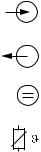
Electrical symbols
Direct Current (DC)
A terminal at which DC is applied or through which DC flows.
Alternating Current (AC)
A terminal at which (sine-form) AC is applied or through which AC flows.
Ground connecting
A terminal, which, from the user’s point of view, is already grounded using a grounding system.
Protective earth terminal
A terminal which must be grounded before other connections may be set up.
Equipotential connection
+A connection which must be connected to the grounding system of the equipment. This can be, i.e., a potential matching line of a star-shaped grounding system, depending on national or company practice.
Protective insulation
The equipment is protected by double insulation.
Alarm relay
Input
Output
Constant voltage source
Temperature sensor
|
Smartec S CLD132 |
Identification |
2 Identification
2.1Device designation
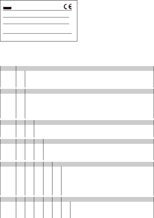
2.1.1Nameplate
Compare the order code on the nameplate (on the Smartec) with the product structure (see below) and check that it agrees with your order.
You can identify the instrument variant by the order code on the nameplate. Under «Codes», you can find the release code for the software upgrade «MRS».
 ENDRESS+HAUSER
SMARTEC S conductivity ind./ Leitfähigkeit ind.
order code / Best.Nr. : CLD 132-PMV130AB2
serial no. / Ser.-Nr. : 1C466C05 G00 Codes: / 8833
measuring range / Messbereich : 10 µS …2000 mS/cm temperature / Temperatur: -10…+125 °C (+140 °C max. 30 min)
|
output 1 / Ausgang 1 |
: 0/4…20 mA |
||
|
output 2 / Ausgang 2 |
: 0/4…20 mA |
||
|
mains / Netz |
: 230 VAC |
50/60 Hz 7,5 VA |
|
|
prot. class |
/ Schutzart |
: IP67 |
ambient temp. / Umgebungstemperatur : 0…+55 °C
131697-4B
C07-CLD132xx-18-06-00-xx-001.eps
Fig. 1: Nameplate CLD132 (example)
2.1.2Product structure Smartec S CLD132
Version
P Compact version
S Separate transmitter, cable length 20 m / 65.62 ft
WSeparate transmitter, cable length 5 m / 16.41 ft
XSeparate transmitter, cable length 10 m / 32.81 ft
Process connection
|
MV1 |
Dairy fitting DN 50 (acc. to DIN 11851) |
|
CS1 |
Clamp connection 2″ (acc. to ISO 2852) |
|
GE1 |
Internal thread G 1 ½ |
|
VA1 |
Varivent connection DN 40 … 125 |
|
AP1 |
APV connection DN 40 … 100 |
|
SMS |
SMS connection 2″ |
Cable entry
|
1 |
Cable gland Pg 13.5 |
|
3 |
Cable gland M 20 x 1.5 |
|
5 |
Conduit adapter NPT ½ « |
Power supply
|
0 |
230 V AC |
|
1 |
115 V AC |
|
5 |
100 V AC |
|
8 |
24 V AC / DC |
Current output / communication
|
AA |
Current output conductivity, without communication |
|
AB |
Current output conductivity and temperature, without communication |
|
HA |
HART, current output conductivity |
|
HB |
HART, current output conductivity and temperature |
|
PE |
PROFIBUS-PA, no current output |
|
PF |
PROFIBUS-PA, M 12 connector, no current output |
PPPROFIBUS-DP, no current output
Additional features
1 Basic version with fast temperature measurement
2 Remote parameter set switching with fast temperature measurement 6 Basic version with encapsulated Pt 100 for high loads
7 Remote parameter set switching with encapsulated Pt 100 for high loads
|
CLD132- |
complete order code |
|
Identification |
Smartec S CLD132 |
2.1.3Basic version and function extensions
|
Functions of the basic version |
Options and their functions |
|||
|
• Measurement |
• |
Second current output for temperature (hardware |
||
|
• |
Calibration of cell constant |
option) |
||
|
• Calibration of residual coupling |
• |
HART communication |
||
|
• |
Calibration of installation factor |
• |
PROFIBUS communication |
|
|
• Read instrument parameters |
Remote parameter set switching (software option): |
|||
|
• |
Linear current output |
|||
|
• |
Remote switching of max. 4 parameter sets |
|||
|
• |
Current output simulation |
|||
|
(measuring ranges) |
||||
|
• |
Service functions |
|||
|
• |
Temperature coefficients can be determined |
|||
|
• |
Temperature compensation selectable (e.g. 1 free |
|||
|
• |
Temperature compensation selectable (e.g. 4 free |
|||
|
coefficient table) |
||||
|
coefficient tables) |
||||
|
• |
Concentration measurement selectable (4 defined |
|||
|
• |
Concentration measurement selectable (4 defined |
|||
|
curves, 1 free table) |
||||
|
curves, 4 free tables) |
||||
|
• |
Relay as alarm contact |
|||
|
• |
Check of measuring system by PCS alarm (live check) |
|||
|
• |
Relay can be configured as alarm or limit contact |
|||
2.2Scope of delivery
The scope of delivery of the compact version inlcudes:
•Smartec S CLD132 compact measuring system with integrated sensor
•Terminal strip set
•Expansion bellows (-*GE1***** versions only)
•Operating Instructions BA 207C/07/en
•Versions with HART communication only:
Operating Instructions Field communication with HART, BA 212C/07/en
•Versions with PROFIBUS interface only:
–Operating Instructions Field communication with PROFIBUS, BA 213C/07/en
–M12 connector (-******PF* versions only)
The scope of delivery of the separate version includes:
•Smartec S CLD132 transmitter
•CLS52 inductive sensor with fixed cable
•Terminal strip set
•Expansion bellows (-*GE1***** versions only)
•Operating Instructions BA 207C/07/en
•Versions with HART communication only:
Operating Instructions Field communication with HART, BA 212C/07/en
•Versions with PROFIBUS interface only:
–Operating Instructions Field communication with PROFIBUS, BA 213C/07/en
–M12 connector (-******PF* versions only)
2.3Certificates and approvals
Declaration of conformity
The product meets the legal requirements of the harmonised European standards.
The manufacturer confirms compliance with the standards by affixing the 4 symbol.
|
Smartec S CLD132 |
Installation |
3 Installation
3.1Quick installation guide
The following procedure should be followed for a complete measuring point installation:
Compact version:
•Perform an Airset. Install the compact version at the measuring point (see chapter «Mounting CLD132 compact version»).
•Connect the compact version as described in the chapter «Electrical connection».
•Start up the compact version as described in the chapter «Commissioning».
Separate version:
•Mount the transmitter (see chapter «Mounting CLD132 separate version»).
•If you have not yet installed the sensor at the measuring point, perform an Airset and install the sensor (see the Technical Information of the sensor).
•Connect the sensor to the Smartec S CLD132 as described in the chapter «Electrical connection».
•Connect the transmitter as described in the chapter «Electrical connection».
•Start up the Smartec S CLD132 as described in the chapter «Commissioning».
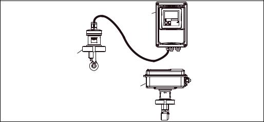
3.1.1Measuring system
The complete measuring system comprises:
•the Smartec S CLD132 transmitter
•the conductivity sensor Indumax H CLS52 with an integrated temperature sensor and a fixed cable
or
•the compact version with an integrated conductivity sensor
Optional for the separate version: CLK5 extension cable, VBM junction box, mounting kit for pipe installation (see chapter «Accessories»)
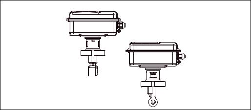
A
C
C07-CLD132xx-14-06-00-xx-001.eps
Fig. 2: Complete measuring systems Smartec S CLD132 as a separate transmitter and compact version with integrated conductivity sensor
ACLS52 conductivity sensor
BSmartec S CLD132
CSmartec S CLD132 as compact version with integrated conductivity sensor
|
Installation |
Smartec S CLD132 |
3.2Incoming acceptance, transport, storage
•Make sure the packaging is undamaged!
Inform the supplier about damage to the packaging.
Keep the damaged packaging until the matter has been settled.
•Make sure the contents are undamaged!
Inform the supplier about damage to the delivery contents. Keep the damaged products until the matter has been settled.
•Check that the scope of delivery is complete and agrees with your order and the shipping documents.
•The packaging material used to store or to transport the product must provide shock protection and humidity protection. The original packaging offers the best protection. Also, keep to the approved ambient conditions (see «Technical data»).
•If you have any questions, please contact your supplier or your sales centre responsible.
3.3Installation conditions
3.3.1Notes on installation
Airset
Perform an Airset before sensor installation (see chapter «Calibration»). Make sure that the instrument is ready for operation, i.e. mains and sensor are connected.
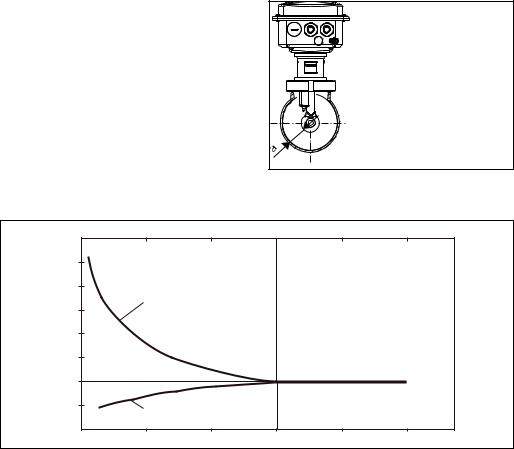
Wall distance
The sensor’s distance from the pipe wall affects the measuring accuracy (see Fig. 4).
In narrow installation conditions, the ion flow in the medium is affected by the pipe walls. This effect is compensated by the so-called installation factor.
When the distance from the wall is sufficient, i.e. a > 15 mm / 0.59″, the installation factor
can be ignored (f = 1.00). When the wall distance is lower, the installation factor
increases in the case of electrically insulating pipes (f > 1) while it decreases for electrically conductive pipes (f < 1); see Fig. 4.
C07-CLD132xx-11-06-00-xx-009.eps
The determination of the installation factor is
Fig. 3: Installation CLD132 compact version
described in the chapter «Calibration».
|
a |
Wall distance |
|||||
|
f |
0.20 |
0.39 |
0.59 |
0.79 |
0.98 |
a [inch] |
|
1,40 |
||||||
|
2 |
||||||
|
1,20 |
||||||
|
1,00 |
||||||
|
1 |
||||||
|
0,80 |
a [mm] |
|||||
|
0 |
5 |
10 |
15 |
20 |
25 |
|
|
C07-CLD132xx-05-06-00-en-001.eps |
Fig. 4: Relationship between installation factor and distance from wall a
1Electrically conductive pipe wall
2Insulating pipe wall
![]()
|
Smartec S CLD132 |
Installation |
3.3.2CLD132 separate version
|
142 / 5.59 |
|||
|
/8.86 |
Ø 7 / 0.28 |
6.30 |
|
|
160/ |
|||
|
225 |
|||
|
225 / 8.86 |
|||
|
175 / 6.89 |
|||
|
95/3.74 |
|||
|
mm /inch |
|||
|
C07-CLD132xx-11-06-00-en-001.EPS |
Fig. 5: CLD132 wall mounting with mounting plate
C07-CLD132xx-11-06-00-en-002.EPS
Fig. 6: CLD132 mounting on pipes (Ø 60 mm / 2.36″)
|
Installation |
Smartec S CLD132 |
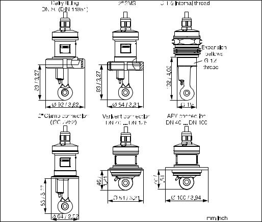
Conductivity sensors for the separate transmitter
CLS52 conductivity sensors with various process connections covering all common installation conditions are available for the separate version.
!Perform an Airset and calibrate the sensor before sensor installation.Note!
C07-CLD132xx-11-06-00-en-003.EPS
Fig. 7: Process connections for CLS52 conductivity sensor
!Note!• Clamp connection
Sensors with clamp connections can be fixed using sheet metal brackets or solid brackets. Sheet metal brackets have a lower dimensional stability, uneven bearing surfaces causing point loads and sometimes sharp edges that can damage the clamp.
We strongly recommend to always use solid brackets because of their higher dimensional stability. Solid brackets may be applied over the total pressure-temperature range (see diagram on page 5).
•Threaded connection
Sensors with threaded connections are supplied with expansion bellows (compensator) to be able to align them in flow direction. The two O-rings (Viton) of the expansion bellows have no sealing function and are not in contact with medium. The process is usually sealed off by PTFE tape on the G 1½ thread.
|
Smartec S CLD132 |
Installation |
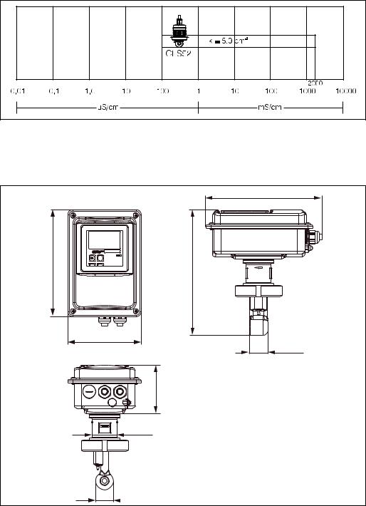
Measuring range
C07-CLD132xx-05-06-00-xx-002.eps
Fig. 8: CLS52 measuring range
3.3.3CLD 132 compact version
|
225 / 8.86 |
|
|
207/8.15 |
(180)*/9.53(7.09)* |
|
242 |
|
|
142 / 5.59 |
|
|
35.5 / 1.40 |
|
|
95/3.74 |
|
|
49 / 1.93 |
C07-CLD132xx-11-06-00-en-004.eps
Fig. 9: Dimensions of CLD132 compact version

|
Installation |
Smartec S CLD132 |
Connection variants
Various process connections covering all common installation conditions are available for the compact version.
The compact version is installed at the measuring point with the required process connection.
C07-CLD132xx-11-06-00-en-005.eps
Fig. 10: Process connections for the CLD132 compact version
!Note!• Clamp connection
Sensors with clamp connections can be fixed using sheet metal brackets or solid brackets. Sheet metal brackets have a lower dimensional stability, uneven bearing surfaces causing point loads and sometimes sharp edges that can damage the clamp.
We strongly recommend to always use solid brackets because of their higher dimensional stability. Solid brackets may be applied over the total pressure-temperature range (see diagram on page 5).
•Threaded connection
Sensors with threaded connections are supplied with expansion bellows (compensator) to be able to align them in flow direction. The two O-rings (Viton) of the expansion bellows have no sealing function and are not in contact with medium. The process is usually sealed off by PTFE tape on the G 1½ thread.

|
Smartec S CLD132 |
Installation |
3.4Installation instructions
3.4.1Mounting CLD132 separate version
Wall mounting
For wall mounting, attach the mounting plate to the wall by drilling holes as required. Anchors and screws are to be provided by the operator.
|
7 / 0.28 |
|
160/6.30 |
|
225 / 8.86 |
|
mm / inch |
|
C07-CLD132-11-06-00-en-007.eps |
Fig. 11: Wall mounting of CLD132 separate version
Post mounting
A mounting kit for installing the housing on horizontal or vertical posts or pipes (max. Ø 60 mm / Ø 2.36″) is available as an accessory (see chapter «Accessories»).
C07-CLD132xx-00-06-06-001.eps
Fig. 12: Mounting kit for installing the CLD132 separate version on posts
1.Remove the mounting plate.
2.Insert the holding bars through the pre-drilled holes of the mounting plate and screw the mounting plate onto the transmitter.
3.Use the brackets to install the Smartec S on the post or pipe (Fig. 13).

|
Installation |
Smartec S CLD132 |
|
max. 60 / 2.36 |
|
|
mm / inch |
|
|
C07-CLD132xx-11-06-00-en-008.eps |
Fig. 13: Post mounting of CLD132 separate version
3.4.2Mounting CLD132 compact version or CLS52 sensor for separate version
Install the compact version or the CLS52 sensor directly on the pipe or vessel socket via the process connection (depending on ordered version).
!Note!Perform an Airset and calibrate the sensor before installing the compact version or the sensor.
|
Horizontal flow |
Vertical flow |
 min. DN 40*
Orientation
arrow
min. DN 40*
Flow direction
Flow direction
C07-CLD132-11-06-00-en-006.eps
Fig. 14: Installation of CLD132 compact version
1.When installing the Smartec S CLD132 or the sensor, make sure that the flow opening of the sensor is oriented in the flow direction of the medium. An orientation arrow on the sensor facilitates orientation (see Fig. 14 above).
2.Tighten the flange.
3.For versions with internal thread G 1½, expansion bellows are supplied for length compensation. Thus, the sensor can always be oriented in flow direction.
!Note!• Choose the immersion depth of the sensor in the medium such that the coil body is completely
immersed.
•Please observe the notes on the wall distance in the chapter «Installation conditions».
•Please observe the limits for the medium and ambient temperature when using the compact version (see chapter «Technical data»).
|
Smartec S CLD132 |
Installation |
Sensor positioning: compact version
The sensor in the compact housing must be oriented in the flow direction.
If you need to reorient the sensor in relation to the housing, proceed as follows:
1.Remove the cover.
2.Loosen the screws of the electronics box and carefully remove the box from the housing.
3.Loosen the three sensor fastening screws until the sensor can be turned.
4.Align the sensor and tighten the screws. Do not exceed the maximum torque of 1.5 Nm!
5.Reassemble the transmitter housing in reverse sequence of operations.
!Note!For exact positions of the electronics box and the sensor screws, see the exploded view in the chapter «Spare parts».
A
B
C07-CLD132xx-11-06-05-xx-010.eps
Fig. 15: Sensor orientation in the transmitter housing
AStandard orientation
BSensor turned by 90°
3.5Post-installation check
•After installation, check the measuring system for damages.
•Check the sensor orientation to the flow direction of the medium.
•Check that the coil body of the sensor is completely immersed in the medium.

4 Wiring
4.1 Electrical connection
#Warning!• The electrical connection must only be carried out by a certified electrician.
• Technical personnel must have read and understood the instructions in this manual and must adhere to them.
• Ensure that there is no voltage at the power cable before beginning the connection work.
4.1.1Electrical connection of transmitter
Proceed as follows to connect the Smartec S CLD132:
|
1. |
Loosen the 4 Phillips screws on the housing |
|
|
cover and remove the cover. |
||
|
2. |
Remove the cover frame from the terminal |
|
|
blocks. To do this, introduce a screwdriver in |
||
|
the recess (m) according to Fig. 16 and push |
1 |
|
|
the tab inward (n). |
||
|
# Warning! |
||
|
Do not remove the cover frame while the |
||
|
instrument is energised! |
||
|
3. |
Thread the cables through the open cable |
1 |
|
glands into the housing according to the |
||
|
terminal assignments in Fig. 17. |
4.Connect the power wires according to the terminal assignments in Fig. 18.
5.Connect the alarm contact according to the terminal assignments in Fig. 18.
6.Connect the housing ground.
7.Separate version: Connect the sensor according to the terminal assignments in Fig. 18.
In the case of the separate version, the conductivity sensor CLS52 is connected using the shielded multi-core special cable CLK5. Preparation instructions are supplied with the cable. Use junction box VBM (see chapter «Accessories») to extend the measuring cable. The maximum cable length if extended using a junction box is 55 m.
8.Tighten the cable glands firmly.
2
2
3
4
5
C07-CLD132xx-04-06-00-xx-001.eps
Fig. 16: View of housing with cover removed
1Cover frame
2Fuse
3Removable electronics box
4Terminals
5Housing ground

|
A |
B |
3 |
||
|
1 |
2 |
|||
|
1 |
2 |
3 |
|
5 |
4 |
||||
|
6 |
5 |
4 |
|||
|
C07-CLD132xx-04-06-04-xx-001.eps |
|||||
|
Fig. 17: |
Terminal assignments of cable glands on Smartec S CLD132 |
||||
|
A |
Separate version |
B |
Compact version |
||
|
1 |
Plug, Pg 13.5, analog output, binary input |
1 |
Plug, Pg 13.5, analog output, digital input |
||
|
2 |
Cable gland for alarm contact, Pg 13.5 |
2 |
Cable gland for alarm contact, Pg 13.5 |
||
|
3 |
Cable gland for power supply, Pg 13.5 |
3 |
Cable gland for power supply, Pg 13.5 |
||
|
4 |
Housing ground |
4 |
Housing ground |
||
|
5 |
Pressure comp. element PCE (Goretex®- filter) |
5 |
Pressure comp. element PCE (Goretex®- filter) |
||
|
6 |
Cable gland for sensor connection, Pg 9 |
Wiring diagram
C07-CLD132xx-04-06-00-de-003.eps
Fig. 18: Electrical connection of Smartec S

Connection diagram
|
31 |
84 |
|||||
|
mA |
15 |
|||||
|
A |
32 |
Lf |
16 |
F |
||
|
83 |
||||||
|
33 |
mA |
optional |
S |
|||
|
11 |
||||||
|
B |
34 |
|||||
|
12 |
G |
|||||
|
13 |
||||||
|
85 |
15 V |
|||||
|
C |
86 |
|||||
|
93 |
41 |
|||||
|
D |
10-50 V |
42 |
H |
|||
|
43 |
||||||
|
94 |
||||||
|
81 |
– |
|||||
|
I |
||||||
|
E |
10-50 V |
– |
||||
|
82 |
||||||
|
PE |
||||||
|
C07-CLD132xx-05-06-00-xx-003.eps |
||||||
|
Fig. 19: |
Electrical connection of Smartec S CLD132 |
|||||
|
A |
Signal output 1 conductivity |
F |
Conductivity sensor |
|||
|
B |
Signal output 2 temperature |
G |
Temperature sensor |
|||
|
C |
Auxiliary power output |
H |
Alarm (contact position: no current) |
|||
|
D |
Binary input 2 (MRS1+2) |
I |
Power supply |
|||
|
E |
Binary input 1 (hold / MRS 3+4) |
MRS |
Remote parameter set switching (measuring range |
|||
|
switching) |
||||||
|
Connection of binary inputs |
||||||
|
A |
B |
|
85 |
86 |
81 |
82 |
93 |
94 |
S1 S2
C07-CLD132xx-05-06-00-xx-004.eps
Fig. 20: Connection of binary inputs when using external contacts
AAuxiliary power output
BContact inputs D1 and D2
S1 External contacts, not energised
S2 External contacts, not energised
![]()
Connection compartment sticker
|
131082-4A |
||||
|
Sensor |
||||
|
31 |
+ |
15 |
||
|
Lf |
||||
|
32 |
— |
84 |
||
|
33 |
+ |
Temp. |
12 |
WH |
|
34 |
— |
(opt.) |
13 |
YE |
|
NC |
11 |
GN |
||
|
85 |
+ |
+15V |
16 |
|
|
86 |
— |
10mA |
83 |
|
|
93 |
+ |
S |
||
|
Bin 2 |
||||
|
94 |
— |
42 |
||
|
81 |
+ |
43 |
||
|
Bin 1 |
||||
|
82 |
— |
41 |
||
|
NC |
||||
|
– |
Mains |
|||
|
Hilfsenergie |
||||
|
NC |
– |
C07-CLD132xx-05-06-00-xx-005.eps
Fig. 21: Connection compartment sticker of Smartec S
!Note!The protection class of this instrument is I. The metal housing must be connected to PE.
«Caution!• Terminals designated as NC may not be switched.
• Undesignated terminals may not be switched.
|
Structure and termination of measuring cable |
||||
|
Semiconductor |
(84) |
(83) |
||
|
screen |
||||
|
Screen |
Screen |
|||
|
(15) |
(16) |
|||
|
WH |
||||
|
RD |
||||
|
GN (11) |
||||
|
WH (12) |
BN |
|||
|
YE (13) |
(unused) |
|||
|
CLK5 |
||||
|
C07-CLK5xxxx-00-05-00-en-002.eps |
C07-CLD132xx-05-06-00-xx-006.eps |
|||
|
Fig. 22: Structure of CLK5 measuring cable |
Fig. 23: |
Electrical connection of the CLS52 sensor for |
||
|
the separate version |
4.2Post-connection check
After wiring up the electrical connection, carry out the following checks:
|
Device status and specifications |
Remarks |
|
Are the transmitter or the cable externally damaged? |
Visual inspection |
|
Electrical connection |
Remarks |
|
Are the installed cables strain-relieved? |
|
|
No loops and cross-overs in the cable run? |
|
|
Are the signal cables correctly connected acc. to the wiring diagram? |
|
|
Are all screw terminals tightened? |
|
|
Are all cable entries installed, tightened and sealed? |
|
|
Are the PE distributor rails grounded (if present)? |
Grounding at place of installation |
|
Smartec S CLD132 |
Operation |
5 Operation
5.1Quick operation guide
You have the following options of operating Smartec S:
•Local operation via operating keys
•Via HART® interface (optional, for corresponding order version) via:
–HART® hand-held terminal or
–PC with HART® modem and Commuwin II software
•Via PROFIBUS PA/DP (optional, for corresponding order version)
PC with a corresponding interface and the Commuwin II software (see «Accessories») or via programmable logic controller (PLC).
!Note!For operation via HART or PROFIBUS PA/DP, read the corresponding chapters in the additional operating instructions:
•PROFIBUS PA/DP, field communication with Smartec S CLD132, BA 213C/07/en
•HART®, field communication with Smartec S CLD132, BA 212C/07/en
The following chapters describe local operation via operating keys.
5.2Display and operating elements
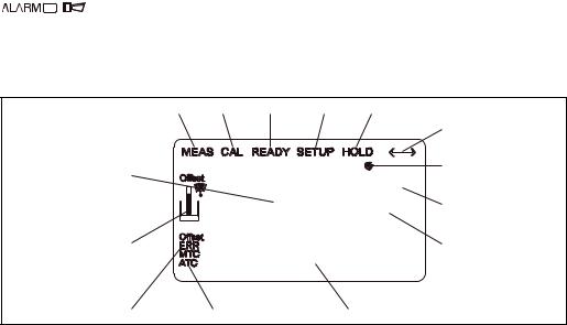
5.2.1Display
LED indicators
Alarm indication for continuous limit violation, temperature sensor failure or system errors (see error list in chapter «Troubleshooting»).
Liquid crystal display
|
1 |
2 |
3 |
4 |
5 |
|
|
6 |
|||||
|
14 |
7 |
||||
|
2000 |
mS/cm |
||||
|
O213 |
8 |
||||
|
13 |
20 |
mA |
9 |
||
|
12 |
11 |
10 |
C07-CLD132xx-07-06-00-xx-001.eps
Fig. 24: LCD of Smartec S CLD132
1Measuring mode indicator (normal operation)
2Calibration mode indicator
3Calibration complete indicator
4Setup mode indicator (configuration)
5«Hold» mode indicator (outputs reflect last current status)
6Signal reception indicator for units with communication
7Indication of relay state: d inactive, c active
8In measuring mode: variable measured In setup mode: parameter adjusted
9Function coding display
10In measuring mode: secondary measured value In setup / calibr. mode: e.g. parameter
11Manual / automatic temperature compensation display
12Error indicator
13Sensor symbol, flashes during calibration
14In measuring mode: Main measured valued In setup / calibr. mode: e.g. parameter

|
Operation |
Smartec S CLD132 |
5.2.2Operating elements
The operating keys are located underneath the housing cover. The display and the alarm LED are visible through the viewing window. For operation, open the housing cover by removing the 4 screws.
1
mS/cm
2000 O213
 ENDRESS+HAUSER
SMARTEC S
ALARM
CAL +
4
E –
2
C07-CLD132xx-19-06-00-xx-001.eps
Fig. 25: Operating elements of Smartec S CLD132
1Liquid crystal display showing measured values and configuration data
24 operating keys for calibration and instrument configuration
3Field for user labeling
4LED indicator for alarm function
5.2.3Key assignment
CAL key
When the CAL key is pressed, the instrument prompts for the calibration access code:
• Code 22 for calibration
• Code 0 or any other number to view the calibration data
Use the CAL key to acknowledge calibration data and to continue through the calibration process.
ENTER key
When the ENTER key is pressed, the instrument prompts for the setup access code:
• Code 22 for setup and configuration
• Code 0 or any other number to view the configuration data.
The ENTER key has several functions:
•It calls up the setup menus from the measuring mode
•It is used to store (acknowledge) data entered in setup mode
•It is used to move on within function groups

|
Smartec S CLD132 |
Operation |
PLUS key and MINUS key
In setup mode, the PLUS and MINUS keys have the following functions:
• Selection of function groups
!Note!
To select function groups in the order given in the chapter «Instrument configuration», use the MINUS key.
• Setting of parameters and numeric values
In measuring mode, repeatedly pressing the PLUS key displays the following settings in sequence:
1.Temperature display in °F
2.Hide temperature display
3.Display of uncompensated conductivity value
4.Back to basic setting
In measuring mode, repeatedly pressing the MINUS key displays the following settings in sequence:
1.Display of current measuring range
2.Display of current errors in sequence (max. 10)
3.After all errors are displayed, the standard display is shown again. In function group F, you can define an alarm for each error code.
Escape function
Press the PLUS and MINUS keys simultaneously to return to the main menu. During calibration, this key combination goes directly to the end of calibration. When the PLUS and MINUS keys are pressed once more, the instrument returns to the measuring mode.
Locking the keypad
Pressing the PLUS and ENTER keys simultaneously for minimum 3s locks the keypad against unintentional entries. However, all settings can still be read.
The code prompt displays the code 9999.
Unlocking the keypad
Pressing the CAL and MINUS keys simultaneously for minimum 3s unlocks the keypad.
The code prompt displays the code 0.

|
Operation |
Smartec S CLD132 |
5.3Local operation
5.3.1Operating concept
Operating modes
Measuring mode: standard mode of operation, displaying current measured values
|
Calibration mode: |
Setup mode |
|
execution of |
access to all |
|
calibration routine |
configuration |
|
settings |
Code
The function groups are selected with the PLUS or MINUS key.
C07-CLD132xx-19-06-00-en-002.eps
Fig. 26: Description of operating modes
!Note!If no key is pressed for 15 min. in setup mode, the instrument automatically switches back to the measuring mode. An active Hold function (Hold at Setup) is then reset.
Access codes
All instrument access codes are fixed, i.e. they cannot be modified. When the instrument requests the access codes, it recognises the difference between codes.
•CAL key + Code 22: access to calibration and offset menus.
•ENTER key + Code 22: access to the configuration menus, allowing configuration and user-specific settings.
•PLUS + ENTER keys: locks the keypad.
•CAL + MINUS keys: unlocks the keypad.
•CAL or ENTER key + any code: access to Read mode, i.e. all settings can be read but not changed.
 Loading…
Цена по запросу

Индуктивный датчик проводимости 100 мкСм/см-2000 мСм/см, идеальное решение для разделения сред в пищевой промышленности,материал сенсора PEEK, рабочая t° -10°C…125°C до 12bar, CIP до 140°C до 5 бар(до 30 минут), Pt 100, вых.сигнал проводимость и температура 0/4-20 мА, HART, Profibus., гигиенические присоединения к трубопроводу CLAMP, DIN 11851. Компактное и раздельное исполнение.
- Описание
- Тех.характеристики
- Документация
Описание
CLD132
CLD132 Smartec – это индуктивная система измерения проводимости, предназначена для использования в областях с высокими гигиеническими требованиями, например при производстве пищевых продуктов, а так же в пивоварении. Благодаря корпусу из PEEK, с конструкцией без щелей и соединений, с гигиеническими сертификатами, соблюдаются все самые высокие требования для упомянутых отраслей промышленности. Прибор представлен как в компактном исполнении, так и в раздельном. Асептические присоединения к процессу, такие как DIN 11851, Clamp ISO 2852, SMS-2″, Varivent N DN 40-125, APV DN40-100 так же гарантируют стерильность процесса измерения. Отличительной особенностью CLD132 от CLD 134 является более быстрый отклик по температурной компенсации прибора PT100. Широкий выбор управляющих сигналов 0/4-20 мА, HART, Profibus. Раздел фаз, контроль CIP-промывки, контроль концентрации, мониторинг качества продукта, мониторинг утечек.
CLD132 применение:

• Раздел фаз продукт/вода и смеси продукт/продукт в трубопроводах
• Контроль в линиях возврата в CIP системах
• Контроль концентрации моющих средств в CIP системах
• Контроль продукции в трубопроводах, разливочных установок для бутылок, проверки качества
• Контроль утечек в следующих отраслях промышленности
• Молочная промышленность и маслодельни
• Пивоварни
• Производство напитков (вода, соки, безалкогольные напитки)
Преимущества CLD132

• Изготовленный из нержавеющей стали корпус трансмиттера
• Датчик из высокостойкого пластика (PEEK)
• Датчик с возможностью стерилизации
• Высокая надежность измерения благодаря всесторонним функциям самодиагностики
• Отсутствие чувствительности к поляризации и загрязнениям
• Доступность вариантов исполнения со сверхбыстрым ответом по температуре (t90 <5 с)
• Варианты исполнения датчика для всех присоединений к процессу, используемых в областях применения с повышенными требованиями к гигиене
• Различные варианты управления:
– Кнопки
– Ручной программатор HART®
– PROFIBUS PA/DP
– ПК с программным обеспечением Commuwin II
• Большой двухстрочный дисплей, позволяющий одновременно просматривать значения измеряемой величины и температуры
• Возможность расширения стандартного исполнения за счет расширения функций путем добавления удаленного переключения конфигурации (переключение диапазонов измерения)
Smartec CLD132 – система измерения проводимости для пищевой промышленности. Комбинация преобразователя и датчика отвечает строгим требованиям к гигиене и стерильности, защищена от помех и чрезвычайно удобна. Корпус датчика выполнен из PEEK для пищевой промышленности, отсутствуют застойные зоны, что подтверждается гигиеническими сертификатами. Таким образом, Smartec CLD132 является идеальным решением, обеспечивающим высочайший уровень безопасности и качества продуктов, а так же безопасность, стерильность и высокую точность непосредственно самих производственных процессов.
Детали
| Принцип измерения |
Индуктиный |
|---|---|
| Диапазоны измерения |
100 мкСм/см – 2000 мСм/см |
| Рабочая температура |
-10°C…125°C |
| Рабочее давление |
12 бар/20°C |
| Конструкция |
Компактный преобразователь с корпусом из нержавеющей стали и индуктивный датчик проводимости из PEEK в компактном или раздельном исполнениях. |
| Значения измеряемых величин |
Проводимость |
| Материал |
Корпус: нержавеющая сталь 1.4301 с полировкой |
| Присоединение к процессу |
Молочная гайка DIN11851 DN40 и DN50, Clamp 2″ ISO 2852, SMS-2″, Varivent N DN 40-125. |
| Датчик температуры |
Pt 100 со мгновенным временем отклика по температуре T90< 5 с. |
| Степень защиты |
IP67 |
| Выходной сигнал |
Значения проводимости, концентрации, температуры. 0/4-20 мА, HART, Profibus |
| Входной сигнал |
1-канальный преобразователь + температура |
| Бренд |
Endress+Hauser |

Smartec CLD132 описание функций прибора на русском языке

Smartec CLD132 руководство по эксплуатации на русском языке
Endress+Hauser Smartec S CLD132: List of Available Documents
Note for Owners:
Guidesimo.com webproject is not a service center of Endress+Hauser trademark and does not carries out works for diagnosis and repair of faulty Endress+Hauser Smartec S CLD132 equipment. For quality services, please contact an official service center of Endress+Hauser company. On our website you can read and download documentation for your Endress+Hauser Smartec S CLD132 device for free and familiarize yourself with the technical specifications of device.
More Measuring Instruments Devices:
-
Greenlee 200EP-G
INSTRUCTION MANUALMANUEL D’INSTRUCTIONSMANUAL DE INSTRUCCIONESBEDIENUNGSANLEITUNGSAFETY ALERT SYMBOLThis symbol is used to call your attention to hazards or unsafe practices which could result in an injury or property damage. The signal word, defined below, indicates the severity of the hazard. The message after the signal word provides information for preventing or avoiding the hazard.Immediat …
200EP-G Measuring Instruments, 2
-
Emerson PENBERTHY LC Series
Before installation these instructions must be read fully and understoodProduct warrantyEmerson warrants its Penberthy products as designed and manufactured to be free of defects in the material and workmanship for a period of one year after the date of installation or eighteen months after the date of manufacture, whichever is earliest. Emerson will, at its option, replace or repair any products …
PENBERTHY LC Series Measuring Instruments, 10
-
Milwaukee MW102
MilwaukeeMilwaukeeWARRANTY:This instrument is warranted from all defects inmaterials and manufacturing for a period of twoyears from the date of purchase.The electrode is warranted for a period of sixmonths.If during this period the repair or replacement ofparts is required, where the damage is not due tonegligence or erroneous operation by the user, pleasereturn the parts to either distributor o …
MW102 Measuring Instruments, 2
-
Anritsu VectorStar ME7838D4
Quick Start GuideVectorStar™ ME7838D4 Multiport Broadband/Banded Millimeter-Wave SystemHigh Performance Modular Broadband/Banded Millimeter-Wave Vector Network Analyzer (VNA) Multiport Measurement SystemME7838D4, 70 kHz to 145 (150) GHzPart Number: 10410-00770Revision: BPublished: December 2019Copyright 2019 Anritsu Company, USA. All Rights Reserved.Anritsu Company490 Jarvis DriveMorgan Hill, CA …
VectorStar ME7838D4 Measuring Instruments, 26