-

Carel
Руководство пользователя. Программируемые электронные контроллеры pCO1
-
Carel
Техническое описание электронных контроллеров pCO3 для управления на базе микропроцессора, программно и аппаратно совместимого с рядом устройств серии pCO2.
-
Carel
Обновление программы pCO через pCOWeb. Справочное руководство.
-
Carel
Инструкция по эксплуатации и програмированию микропроцессорных контроллеров для чиллеров и тепловых насосов pCO.
-
Carel
Руководство по эксплуатации модулей расширения pCO: pCOB, pCO2, pCO1 и pCOC I/O
-
Carel
Руководство по эксплуатации программируемых электронных контроллеров pCOXS
-
Carel
Программируемые электронные контроллеры pCOXS. Руководство пользователя.
-
Carel
Руководство по эксплуатации электронных контроллеров pCO3 (обзор)
-
Carel
Руководство по эксплуатации электронных контроллеров pCO3
-
Carel
Руководство по эксплуатации контроллеров pCO2-pCO sistema
-
Carel
Руководство по эксплуатации программируемых электронных контроллеров pCO2 для приложений в области кондиционирования воздуха и холодильного оборудования.
-
Carel
Руководство пользователя. Программируемые электронные контроллеры pCO2 для приложений в области кондиционирования воздуха и холодильного оборудования.


| Название | Инструкция | Комментарий | |
|---|---|---|---|
|
|
Carel PJ 32 | Carel PJ 32 | Carel PJ32 контролирует работу вентиляторов и циклов оттайки. Два выхода датчика: контроль температуры в объеме и температуры испарителя, для управления циклом оттайки и работой вентиляторов. Три реле выхода для управления компрессором, вентиляторами и оттайкой электрической или горячим газом. |
|
|
Carel IR 33 | Carel IR 33 | Контроллер серии IR33 предназначен для регулирования температуры, давления, влажности в системах отопления, охлаждения и кондиционирования воздуха. |
|
|
Carel Aermec micro chiller 2 | Carel Aermec MicroChiller2 | Carel Aermec micro chiller 2 — для управления и регулировки воздухо-воздушных теплообменников (установок кондиционирования воздуха с двумя ступенями нагрева, двумя ступенями охлаждения и мертвой зоной), холодильников и холодильников с тепловым насосом, оборудованным одним компрессором, установок с одним компрессором с подпрограммой управления мощностью или установок с двумя компрессорами. Регулировкой вентиляторов для принудительного охлаждения конденсатора по температуре, давлению в двухпозиционном режиме или при непрерывном изменении скорости вращения. |
|
|
Carel c.pCOe | Carel c.pCOe | Carel c.pCOe — имеет дополнительные входы и выходы, тем самым расширяя возможности контроллера. Универсальные входы и выходы модуля (отмеченные символами U на схеме слева) легко настраиваются в зависимости от программы управления контроллера, к которому подключен модуль и служат для подсоединения активных и пассивных датчиков, цифровых входов, аналоговых выходов и выходов ШИМ-регулирования. Можно использовать множество различных вариантов конфигурации входов и выходов в зависимости от поставленной задачи |
|
|
Carel c.pCO | Carel c.pCO | Контроллер Carel c.pCO — идеальное решение для управления практически любыми холодильными установками, системами отопления, вентиляции и кондиционирования воздуха (ОВиК). Контроллер легко вписывается в требуемую схему управления климатическим оборудованием и хладотехникой с учетом индивидуальных требований эксплуатирующей организации. В рамках данного семейства представлена новая компактная модель c.pCOmini, которая подходит как для врезного монтажа, так и для монтажа на DIN-рейку. Данная модель комплектуется 10 универсальными входами/выходами и может оснащаться встроенным приводом для управления электронным ТРВ с униполярным двигателем. Количество входов и выходов при необходимости можно легко увеличить, установив дополнительную плату c.pCOe |
|
|
Carel c.pCOMini | Carel c.pCOMini | Контроллер c.pCOMini предусматривает возможность конфигурирования входов и выходов, поддерживает терминалы семейства GD1 и может обмениваться данными с другими устройствами по трем последовательным портам, портам CANbus и Ethernet |
|
|
Carel easy | Carel easy | Контроллеры Carel серии easy, easy compact и easy split предназначены для управления холодильными установками, охлаждаемыми прилавками и витринами. Новые функции повысили динамичность и эффективность регулирования температуры и управления размораживанием. |
|
|
Carel mchiller | Carel mchiller |
Carel mchiller для управления и регулировки воздухо-воздушных установок, а также установок кондиционирования воздуха с двумя ступенями нагрева, двумя ступенями охлаждения и мертвой зоной, холодильников и холодильников с тепловым насосом, оборудованным одним компрессором, установок с одним компрессором с подпрограммой управления мощностью или установок с двумя компрессорами. Регулировка вентиляторов для принудительного охлаждения конденсатора может выполняться как на базе температуры, так и давления в двухпозиционном режиме или при непрерывном изменении скорости вращения |
|
|
Carel mC2SE | Carel μC2SE | Carel μC2SE — компактный электронный контроллер. По размеру модель сопоставима с обычным термостатом и обеспечивает полноценное управление холодильными установками и тепловыми насосами в системах вида воздух/воздух, воздух/вода, вода/вода, а также конденсаторами |
|
|
Carel MasterCella | Carel MasterCella | Carel MasterCella — контроллер для статических или вентилируемых холодильных установок, способным управлять всеми приводами, такими как компрессоры, вентиляторы, разморозкой, тревогами и светом. MasterCella имеет корпус с классом защиты IP65 и прокладка электрических проводов особенно проста благодаря тому, что передняя панель может быть снята |
|
|
Carel FCM | Carel FCM | Контроллеры Carel FCM управляют основными физическими величинами (температурой, давлением, влажностью) в установках кондиционирования, охлаждения и нагрева. Приборы серии FCM в частности эффективны в качестве контроллеров температуры/давления путем управления скоростью конденсации агрегатов |
|
|
Carel рСО2 | Carel рСО2 FLSTDMFC0A | Контроллер Carel рСО2 предназначен для управления компрессорами холодильника и тепловыми насосами, охлаждаемыми помещениями. Контроллер рСО2 выпускается в трех типоразмерах отличаясь количеством входов и выходов |
|
|
Carel IR 32 | Carel IR 32 | Контроллер Carel IR 32 разработан для регулирования давления, влажности и температуры в системах кондиционирования, охлаждения и обогрева воздуха |
|
|
Carel IRMPX | Carel IRMPX | Carel MPX со светодиодным дисплеем специально предназначен для управления холодильными установками. Холодильные установки могут быть автономного типа или сгруппированными вместе в качестве мультиплексных шкафов |
|
|
Carel IR 33 Universale | Carel ir33 Universale |
Контроллеры серии IR33-DN33 Universale предназначены для регулирования основных физических величин (температуры, давления, влажности) в системах отопления, охлаждения и кондиционирования воздуха. Существует две основные линейки контроллеров: контроллеры первой линейки поддерживают только два датчика температуры (NTC, NTC-HT, PTC, PT1000), а контроллеры второй линейки поддерживают два датчика температуры расширенного диапазона (NTC, NTC-HT, PTC, PT100, PT1000, термопары J/K), датчики давления и влажности или датчики общего назначения (входные сигналы напряжения 0 до 1В, от 0 до 10В, от -0,5 до 1,3В, входы логометрических датчиков с сигналом 0-5В или 0-20 мА, входы сигналов тока от 4 до 20 мА) |
|
|
Carel mRack | Carel mRack | Основные функции контроллера Carel — регулировка давления всасывания компрессора, регулировка давления конденсации (нагнетание компрессора), полное управление имеющимися выходами, гибкая настройка аварийных сигналов, возможность работы в составе системы мониторинга. Управляемые устройства: компрессоры (до 4 герметичных компрессоров, без частичной нагрузки), вентиляторы конденсатора (максимум, 4), управление регулятором скорости вращения вентиляторов конденсатора сигналом PWM |
|
|
Carel MX 20 | Carel MX 20 | Carel MX20 (MPXPRO) версии FULL поддерживает следующие функции: тип контроллера (ведущий или ведомый), количество релейных выходов (3 или 5), тип подсоединяемых датчиков (датчики NTC и логометрические 0–5 В или датчики NTC/PTC/PT1000/NTC L243, активные датчики 4–20 мА, 0–10 В), наличие двух выходов ШИМ-регулирования на системной плате, наличие выхода постоянного напряжения 0–10 В на плате привода, часы реального времени (RTC) и интерфейс RS485. Есть возможность установки встроенного привода для вентилей CAREL с шаговым двигателем или электронных расширительных вентилей с ШИМ-регулированием и выхода постоянного напряжения 0–10 В на плате привода |
|
|
Carel MPXPRO | Carel MPXPRO | Контроллер Carel MPXPRO обеспечивает управление как отдельными холодильными витринами и холодильными камерами, так и централизованное управление группой витрин и камер. Контроллер может комплектоваться встроенным приводом электронного расширительного вентиля. Контроллер устанавливается на DIN-рейку и подсоединяется через съемные винтовые клеммы. Контроллер может осуществлять функции сетевого управления типа ведущий/ведомый, максимум 6 агрегатов (1 ведущий и 5 ведомых). Каждый контроллер имеет простой дисплей (только чтение) и/или графический терминал (дисплей с клавиатурой для программирования). При подключении к ведущему контроллеру терминал будет отображать параметры для всех контроллеров, включенных в локальную сеть. Контроллер может работать как ведущий или ведомый, релейных выходов (3 или 5 на ведомом контроллере), тип подсоединяемых датчиков (только датчики NTC и логометрические 0–5 В или датчики NTC/PTC/PT1000/NTC L243, логометрические 0–5 В и активные датчики 4–20 мА, 0–10 В), тип встроенного привода (для вентилей CAREL с шаговым двигателем или электронных расширительных вентилей с ШИМ-регулированием) |
|
|
Carel pCO2 | Carel pCO2 | Контроллер pCO2 – новая разработка CAREL, которая является следующей ступенью в развитии широко известной линейки контроллеров рСО. Новый контроллер специально оптимизирован для работы в сложных системах кондиционирования и охлаждения. Контроллер доступен в трех типоразмерах с различным количеством входов/выходов и разным энергопотреблением: рСО2 SMALL, рСО2 MEDIUM, рСО2 LARGE |
|
|
Carel pCO3 | Carel pCO3 | Контроллер Carel pCO3 представляет собой электронный контроллер на базе микропроцессора, аппаратно и программно совместимый с контроллерами семейства pCO2 |
|
|
Carel PJ Easy | Carel PJ Easy | Carel электронные микропроцессорные контроллеры со встроенным светодиодным дисплеем серии easy, easy compact и easy split предназначены для управления холодильными установками, охлаждаемыми прилавками и витринами |
|
|
Carel pRack PR100 | Carel pRack PR100 | Контроллер Carel pRack PR100 поддерживает 35 возможных конфигураций системы, включающей до 2 линий всасывания и до 2 линий конденсации, на отдельных устройствах или нескольких устройствах, объединенных в сеть pLAN. Конфигурация входов и выходов зависит от выбранной конфигурации системы |


инструкцияCarel c.pCO

Интегрированные системы управления и энергосбережение
Семейство c.pCO
NO POWER
& SIGNAL
CABLES
TOGETHER
READ CAREFULLY IN THE TEXT!
Программируемый контроллер
RUS
Руководство по эксплуатации
Посмотреть инструкция для Carel c.pCO бесплатно. Руководство относится к категории без категории, 2 человек(а) дали ему среднюю оценку 6.4. Руководство доступно на следующих языках: русский. У вас есть вопрос о Carel c.pCO или вам нужна помощь? Задайте свой вопрос здесь
Нужна помощь?
У вас есть вопрос о Carel а ответа нет в руководстве? Задайте свой вопрос здесь Дай исчерпывающее описание проблемы и четко задайте свой вопрос. Чем детальнее описание проблемы или вопроса, тем легче будет другим пользователям Carel предоставить вам исчерпывающий ответ.
Количество вопросов: 0

Главная
Не можете найти ответ на свой вопрос в руководстве? Вы можете найти ответ на свой вопрос ниже, в разделе часто задаваемых вопросов о Carel c.pCO.
Инструкция Carel c.pCO доступно в русский?
Не нашли свой вопрос? Задайте свой вопрос здесь
-
Contents
-
Table of Contents
-
Troubleshooting
-
Bookmarks
Quick Links
pCO sistema
General manual
User manual
LEGGI E CONSERVA
QUESTE ISTRUZIONI
READ AND SAVE
THESE INSTRUCTIONS
Related Manuals for Carel pCO series
Summary of Contents for Carel pCO series
-
Page 1
pCO sistema General manual User manual LEGGI E CONSERVA QUESTE ISTRUZIONI READ AND SAVE THESE INSTRUCTIONS… -
Page 3
CAREL, its employees or subsidiaries be liable for any lost earnings or sales, losses of data and information, costs of replacement goods or services, damage to things or people, downtime or any direct, indirect, incidental, actual, punitive, exemplary,… -
Page 5: Table Of Contents
Contents Contents Contents Contents INTRODUCTION INTRODUCTION INTRODUCTION INTRODUCTION ……………………………………………………………………………………………………………………………………………………………………….7 7 7 7 1. 1. 1. 1. GENERAL FEATURES GENERAL FEATURES ……..
-
Page 6
……………………………………….64 10.2 Local terminal protocol ……………………………………64 10.3 CAREL Slave protocol …………………………………….64 10.4 CAREL Master protocol……………………………………65 10.5 CAREL Master 5 expansions protocol ………………………………..65 10.6 WinLoad protocol……………………………………..66 10.7 PST protocol ……………………………………….67 10.8 Modbus Slave protocol ……………………………………67 10.9 Modbus Master protocol……………………………………68 10.10… -
Page 7: General Features
The CAREL pCO sistema controllers can be programmed using the EasyTools development system, with the following advantages: • transfer of the software to different types of CAREL hardware. The applications developed for the pCO can simply and quickly transferred from one hardware platform to another (and vice-versa), simply adapting only the inputs and the outputs;…
-
Page 8: Description Of The Products Description Of The Products
230 Vac or 24 Vac/Vdc digital inputs; connector for the display panel (external panel with direct signals); connector for all standard pCO series terminals and for downloading the application program; relay digital outputs; connector for connection to the I/O expansion board;…
-
Page 9
pCO Sistema 3 3 3 3 2.1.1 2.1.1 2.1.1 2.1.1 Meaning of the pCO Meaning of the pCO Meaning of the pCO Meaning of the pCO inputs/outputs inputs/outputs inputs/outputs inputs/outputs Connector Connector Connector Connector Signal Signal Signal Signal Description Description Description Description J1-1… -
Page 10
pCO Sistema Connector Connector Connector Connector Signal Signal Signal Signal Description Description Description Description J14-2 normally open contact, relay no. 7 J14-3 common for relay no. 7 J15-1 normally open contact, relay no. 8 J15-2 common for relay no. 8 J15-3 normally closed contact, relay no. -
Page 11: Pco 3 Technical Specifications
Can be selected via software. Passive: 4 (inputs B4, B5, B9, B10) -CAREL NTC (-50T90°C; R/T 10kΩ ±1% at 25°C) or HT NTC (0T150°C) -PT1000 (-100T200°C; R/T 1kΩ at 0°C) or digital input from voltage-free contact Can be selected via software.
-
Page 12
pCO Sistema • 3 3 3 3 digital outputs digital outputs digital outputs digital outputs The relay outputs have different features depending on the model of pCO The outputs can be divided into groups. There is double insulation between the groups (cells in the table) and consequently these may have Insulation distance different voltages. -
Page 13
• EC regulations 37/2005 of 12 January 2005; in particular, if the electronic controller is fitted with standard Carel NTC probes, it is compliant with standard EN13485 on “Thermometers for measuring the air temperature in applications on units for the conservation and sale of refrigerated, frozen and deep-frozen food and ice cream”. -
Page 14: Pco 1 Controller
pCO Sistema 2.3 pCO controller Programming Key Clock card Analog Selection Serial Card Fuse Fig.. 2.d Fig.. 2.d Fig.. 2.d Fig.. 2.d Key: Key: Key: Key: power supply connector [G (+), G0 (-)] 250 Vac, 2 A slow-blow fuse (T2 A) universal analogue inputs: NTC, 0/1V, 0/5 V, 0/20 mA, 4/20 mA passive analogue inputs: NTC and ON/OFF passive analogue inputs: NTC…
-
Page 15
pCO Sistema Connector Connector Connector Connector Signal Signal Signal Signal Description Description Description Description J5-2 digital input no. 2, 24 Vac/Vdc J5-3 digital input no. 3, 24 Vac/Vdc J5-4 digital input no. 4, 24 Vac/Vdc J5-5 digital input no. 5, 24 Vac/Vdc J5-6 digital input no. -
Page 16: Pco 1 Technical Specifications
Type Universal: 4 (inputs B1, B2, B3, B4) -CAREL NTC (-50T90°C; R/T 10kΩ±1% at 25°C) HT NTC (0T150°C) -Voltage 0 to 1 Vdc, 0 to 5 Vdc ratiometric -Current 0 to 20 mA or 4 to 20 mA. Input resistance: 100Ω.
-
Page 17
pCO Sistema • 1 1 1 1 digital outputs digital outputs digital outputs digital outputs The relay outputs have different features depending on the model of pCO The outputs can be divided into groups. There is double insulation between the groups (cells in the table) and consequently these may have Insulation distance different voltages. -
Page 18
pCO Sistema Dipswitches for selecting the type of probe Dipswitches for selecting the type of probe Dipswitches for selecting the type of probe Dipswitches for selecting the type of probe B5 B6 1 2 3 4 5 6 1 2 3 4 5 6 1 2 3 4 5 6 1 2 3 4 5 6 1 2 3 4 5 6… -
Page 19
pCO Sistema 2.5 pCO board Key: Key: Key: Key: Power supply connector [G (+), G0 (-)], 24 Vac or 24 to 48 Vdc; Input (24 Vac) for phase control and NTC, 0/1 V, 0/5 V, 0/20 mA, 4/20 mA analogue inputs, +5Vref for power supply to 5V ratiometric probe and +24 Vdc power to active probes;… -
Page 20
Maximum number Type Universal: 2 (inputs B1, B2) -CAREL NTC (-50T90°C; R/T 10kΩ±1% at 25°C) -Voltage 0 to 1 Vdc, 0 to 5 Vdc ratiometric; -Current 0 to 20 mA or 4 to 20 mA. Input resistance: 100Ω Can be selected via software Universal: 2 (inputs B3, B4) -CAREL NTC (-50T90°C;… -
Page 21
pCO Sistema • XS XS XS XS Mechanical specifications Mechanical specifications Mechanical specifications Mechanical specifications Mechanical dimensions Mechanical dimensions Mechanical dimensions Mechanical dimensions SMALL 13 DIN modules 110 x 227.5 x 60mm Plastic container Plastic container Plastic container Plastic container Assembly Fitted on DIN rail as per DIN 43880 and IEC EN 50022 Material… -
Page 22
pCO Sistema 2.7 pCO controller pCO c I/O board Fig. 2.h Fig. 2.h Fig. 2.h Fig. 2.h Key: Key: Key: Key: Connector for 24 Vac power supply, 50/60 Hz, 15 VA, or 24 Vdc, 10 W. 250 Vac, 2 A slow-blow fuse (T2A). Yellow mains power LED and 3 status LEDs. -
Page 23
pCO Sistema ——— not connected NO-9 normally open contact, relay 9 common for relay 9 NC-9 normally closed contact, relay 9 NO-8 normally open contact, relay 8 common for relay 8 ——— not connected NO-7 normally open contact, relay 7 common for relay 7 ———… -
Page 24: Pco Technical Specifications
, the 0/1 Vdc signal is limited to the restricted 0-1 V range and therefore is not always compatible with the standard 10 mV/°C signal of the Carel probes (for temperatures below 0°C and above 100°C, a probe alarm may be generated). For the temperature signals, use 4/20 mA or NTC. This is also true…
-
Page 25
pCO Sistema • C C C C mechanical specifications mechanical specifications mechanical specifications mechanical specifications Mechanical dimensions Electronic board only available, without plastic case: 108 x 292 x 25mm • C C C C other features other features other features other features Operating conditions -10T60°C, 90% RH non-condensing… -
Page 26
Real Time Clock pLAN Opto-isolated pLAN tLAN Accepts SMART KEY built-in display built-in display 4×20 built-in display LED display Serial port for I/O expansion Black box CAREL protocol ® Metasys compatible ® Modbus RTU protocol ® LonWorks protocol BACnet™ Ethernet™ protocol BACnet™… -
Page 27: User Terminals
These are electronic devices designed as the user interface for the pCO family controllers (contact CAREL to find out the most suitable controller that supports the PGD2/3 for the specific application). 2 2 2 2 is a monochromatic (blue/white) LCD graphic terminal with 320×240 pixel resolution (code PGD2*******) and LED backlighting.
-
Page 28
pCO Sistema 3.1.4 3.1.4 3.1.4 3.1.4 PGD1000F00 (built PGD1000F00 (built- — — — in/panel) / PGD1000W00 pCO graphic display (wall) PGD1000F00 (built PGD1000F00 (built in/panel) / PGD1000W00 pCO graphic display (wall) in/panel) / PGD1000W00 pCO graphic display (wall) in/panel) / PGD1000W00 pCO graphic display (wall) Display Display Display… -
Page 29
Tab. 3.c Tab. 3.c Tab. 3.c These versions with integrated LCD and keypad also support connection to all the pCO series terminals (the two displays, built-in and standard, work at the same time, displaying the same information). built-in terminal Fig. 3.f Fig. -
Page 30
pCO Sistema 3.1.10 3.1.10 3.1.10 3.1.10 Maximum distance Maximum distance Maximum distance Maximum distance The maximum distances between the pCO and the user terminal are shown in the following table. type of cable type of cable type of cable type of cable power supply distance power supply distance power supply distance… -
Page 31: Installing The Pco Controller
• in the event of malfunctions, do not attempt to repair the appliance, but deliver the item directly to CAREL; 4.1.4 4.1.4…
-
Page 32: Power Supply
Connecting active temperature and humidity probes The pCO can be connected to all CAREL AS*2 series active temperature and humidity probes configured with 0 to 1 V or 4 to 20 mA signals. For the temperature probes, use the 4 to 20 mA or NTC configuration, as the 0/1 Vdc signal is limited to the restricted 0-1 V range and therefore is not always compatible with the standard 10 mV/°C signal of the CAREL probes (for temperatures below 0°C and above 100°C, a probe alarm may be generated).
-
Page 33
The pCO can be connected to all CAREL SPK* series active pressure probes or any pressure sensor available on the market with a 0 to 20 mA or 4 to 20 mA signal. The inputs must be configured for 0 to 20 mA or 4 to 20 mA signals by the application program resident in flash memory. -
Page 34
Connecting 0/5 V ratiometric pressure probes The pCO can be connected to all CAREL SPKT series active pressure probes or any pressure sensor available on the market with 0/5 V ratiometric signal. The inputs must be configured for 0/5V ratiometric signals by the application program resident in the memory. -
Page 35
pCO Sistema 4.3.7 4.3.7 4.3.7 4.3.7 Connecting the analogue inputs selected as ON/OFF Connecting the analogue inputs selected as ON/OFF Connecting the analogue inputs selected as ON/OFF Connecting the analogue inputs selected as ON/OFF A number of analogue inputs on the pCO can be configured as voltage-free digital inputs, not optoisolated. The inputs must be configured as voltage-free digital inputs by the application program resident in flash memory. -
Page 36: Connecting The Digital Inputs
pCO Sistema 4.4 Connecting the digital inputs The pCO features digital inputs for connection to safety devices, alarms, device status indictors and remote control signals. These inputs are all optically-isolated from the other terminals and can operate at 24 Vac, 24 Vdc and some at 230 Vac. Note: Note: Note:…
-
Page 37
pCO Sistema 4.4.3 4.4.3 4.4.3 4.4.3 Connecting the digital inputs to the pCO Connecting the digital inputs to the pCOXS XS XS XS Connecting the digital inputs to the pCO Connecting the digital inputs to the pCO The pCO features up to 6 not optoisolated digital inputs, with voltage-free contacts, for connection to safety devices, alarms, device status indictors and remote control signals, etc. -
Page 38: Connecting The Analogue Outputs
pCO Sistema 4.5 Connecting the analogue outputs 4.5.1 4.5.1 4.5.1 4.5.1 Connecting the 0 to 10 V Connecting the 0 to 10 V analogue outputs Connecting the 0 to 10 V Connecting the 0 to 10 V analogue outputs analogue outputs analogue outputs The pCO provides 0-10V optically-isolated analogue outputs, powered externally at 24Vac/Vdc.
-
Page 39: Connecting The Digital Outputs
pCO Sistema 4.5.3 4.5.3 Optional modules Optional modules 4.5.3 4.5.3 Optional modules Optional modules Module for Module for Module for Module for converting a PWM output to a 0 to 10 V analogue output or 4 converting a PWM output to a 0 to 10 V analogue output or 4 converting a PWM output to a 0 to 10 V analogue output or 4 converting a PWM output to a 0 to 10 V analogue output or 4 to 20 mA.
-
Page 40
pCO Sistema 4.6.3 4.6.3 4.6.3 4.6.3 Solid state relay (SSR) digital outputs Solid state relay (SSR) digital outputs Solid state relay (SSR) digital outputs Solid state relay (SSR) digital outputs The pCO also features a version with solid state relays (SSR) for controlling devices which require an unlimited number of switching cycles and thus would not be supported by electromechanical versions. -
Page 41: Configuration Of The Plan Network
5. CONFIGURATION OF THE PLAN NETWORK 5.1 Introduction All the pCO controllers can be connected together and to other Carel devices in a local network (pLAN), without requiring optional devices, thus allowing the communication of data and information from one location (node) to another.
-
Page 42
pCO Sistema From the logical point of view, the connections are shown in the following figure: Private Private Shared Private Private Fig. 5.b Fig. 5.b Fig. 5.b Fig. 5.b In the example, the shared terminal is associated with 4 pCO controllers, however currently only controller 1 can display data and receive commands from the keypad. -
Page 43: Installing The Pgd0 And Pgd1 Terminals
5.2 Installing the pGD0 and pGD1 terminals The connection between the terminal and the pCO is made using a 6-wire telephone cable, supplied by CAREL (code S90CONN). To make the connection, simply plug the telephone connector into the RJ12 jack on the rear of the terminal, and in connector: •…
-
Page 44: Installing The Pgd2 And Pgd3 Terminals
pCO Sistema 5.3 Installing the pGD2 and pGD3 terminals The connection between the terminal and the pCO is made only using an AWG20/22 shielded cable, terminated with 3-pin plug-in connectors. To make the connection, simply plug one of the connectors into the “RS485” jack on the terminal and the other to connector •…
-
Page 45: Installing The Aria Terminal
L5 L5 L5 L5: used to selectively inhibit the reception of some variables; • L6 L6 L6 L6: communication protocol over RS485 line, selectable as pLAN or CAREL Slave. For further information on the parameters and on the variables that can be exchanged, see to the user manual.
-
Page 46: Setting The Plan Address On The Pco
pCO Sistema 5.5 Setting the pLAN address on the pCO , pCO , pCO and pCO The pCO , pCO , pCO and pCO controllers do not have dipswitches for setting the pLAN network address: the pLAN address can set from any terminal, pGD0, pGD1, pGD2, pGD3 or built-in on the models where fitted.
-
Page 47: Remote Installation Of A Terminal In A Plan Network
pCO Sistema Fig. Fig. 5.r shows a diagram of a number of boards connected in a pLAN network and powered by different transformers with the same earth; this is a typical application for a number of boards inside different electrical panels. AWG 20/22 AWG 20/22 AWG 20/22…
-
Page 48: Plan Network Technical Specifications
Standard communication Asynchronous HALF DUPLEX RS485 Baud rate (kbit/s) 62.5 115.2 for pCO (selected by software) Protocol Multimaster (CAREL proprietary protocol) Maximum length of the network (m) 3 3 3 3 5.8.1 5.8.1 Optically- — — — isolated pLAN (pCO Optically…
-
Page 49: Options And External Modules Options And External Modules
CAREL has always offered its customers different to interface the pCO sistema controllers with the more commonly-used BMS (Building Management Systems).. Today in fact, with the expansion of BMS, the issue of communication between controllers made by different companies is increasingly important. CAREL has consequently developed compatibility with all the protocols that are emerging as the standards in HVAC/R and intelligent management systems, such as Modbus®,…
-
Page 50: Connectors
pCO Sistema 6.1 Connectors Example of coding: PCO3CON**0 see the following table for the description: PCO3CON 0= screw S= small 1= spring M= medium L= large Z= extra large N.O. C= extra large N.C. 6.2 Optional pCO sistema boards 6.2.1 6.2.1 Serial boards for supervision and telemaintenance Serial boards for supervision and telemaintenance…
-
Page 51
pCO Sistema LonWorks® LonWorks® serial board serial board: : : : PCO10000F0 PCO10000F0 LonWorks® LonWorks® serial board serial board PCO10000F0 PCO10000F0 The PCO10000F0 and PCO10000R0 optional boards for the pCO electronic controllers are used to interface these with a LonWorks network®. Warning: Warning: Warning:… -
Page 52
The PCOUMI2000 module is an interface for the pCO electronic controllers. This allows the control of the fundamental parameters of the OEM humidifiers manufactured by CAREL (level and conductivity of the water in the cylinder, TAM sensor for current input) directly from the pCO electronic microprocessor controller. -
Page 53
PCOE00TLN0 tLAN version (CAREL proprietary protocol); • PCOE004850 RS485 version (CAREL 3.0 supervisor protocol). For the technical specifications and the meanings of the connections (pins), as well as details on the procedure for fitting the board, follow the instructions shown on the instruction sheet provided in the packaging (code +050003265). -
Page 54: Signal Leds And Software Updates
I/O expansion pCO² pCO² used as I/O expansion used as I/O expansion used as I/O expansion CAREL supervisor protocol (slave) active on serial 0. Ta Ta Ta Tab. 6.a b. 6.a b. 6.a b. 6.a 6.3.1 6.3.1 Cases in which the pCO enters «LOW LEVEL»…
-
Page 55: Firmware And Logs For Pco Controllers
WINLOAD In all CAREL 16-bit pCO sistema controllers the resident software can be updated from a PC. To do this, CAREL provides the WinLoad32.exe program and an RS485 serial converter for the pCO. The special driver needs to be installed on the PC, again supplied by CAREL.
-
Page 56: Smart Key
pCO Sistema 7.1.1 7.1.1 7.1.1 7.1.1 Commissioning Tool Commissioning Tool Commissioning Tool Commissioning Tool Settings required to use the Commissioning Tool Settings on the pCO for using the Commissioning Tool: the application must feature a screen used to set the Winload protocol on the serial port where the PC with the Commissioning Tool is connected. Otherwise, there must be another possible procedure for selecting the protocol (e.g.
-
Page 57
CAREL; this will be used in future applications. Not all the CAREL pCO controllers have an ID number; if this is not present, the following screen informs the user of this situation. NAND FLASH FILES: : : : this row is only displayed on the pCO3 boards that have additional NAND flash memory. Selecting this function displays the names of the IUP,… -
Page 58
pCO Sistema 8. GENERAL CONNECTION DIAGRAMS 3 3 3 3 +Vterm +5 V REF Rx-/Tx- Rx+/Tx+ +VDC analog output 1 (0/10Vdc) analog output 2 (0/10Vdc) analog output 3 (0/10Vdc) analog output 4 (0/10Vdc) IDC1 out H N TC N TC + (G) NO10 ID10… -
Page 59
pCO Sistema 1 1 1 1 230/24Vac +5VRif TERMINALE +VTerm ARIA Rx-/Tx- Rx+/Tx+ probe 1 probe 2 probe 3 (0/1 Vdc o 4/20 mA) +VDC C arel NTC probe ON-OFF digital output 1 digital output 2 digital output 3 analog output 1 (0/10 V dc) analog output 2 (0/10 V dc) analog output 3 (PWM taglio di fase) digital output 4… -
Page 60
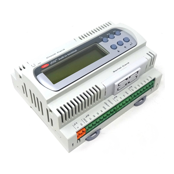
pCO Sistema XS XS XS XS CLOCK CARD built-in terminal SERIAL CARD Fig. 8.c Fig. 8.c Fig. 8.c Fig. 8.c Code: +030220336 — rel. 1.5 — 22/12/10… -
Page 61
Sistema c c c c 230/24 Vac Carel NTC probe 8 +24Vdc RX/TX- Probe 7* RX/TX+ (0 1Vdc o/or 4 20mA) Probe 5 (0 1Vdc o/or 4 20mA) Probe 6 (0 1Vdc o/or 4 20mA) AVSS Carel NTC probe 4… -
Page 62: Troubleshooting
2. the correct power supply to the probes: if the voltage (+Vdc>20V) is near zero, disconnect the probe and measure the power supplied by the pCO. If this is still near zero, turn the controller off and wait a few minutes. If the problem persists, contact CAREL service; otherwise the connection that was removed was short-circuiting the power supply.
-
Page 63
2. that the identification number of the pCO has been set correctly (see the manual for the application program); 3. that the serial cables are connected correctly according to the CAREL diagram shown in the documents corresponding to the supervisor network;… -
Page 64: Networks And Protocols
512KB, pCO one serial port. If CAREL Slave is active on the pLAN serial port the following protocols cannot be used: PSTN, GSM, Modbus Slave, tLAN Slave. * The CAREL SLAVE protocol may be slower on the O-pLAN serial port than on serial 1-BMS or serial 2-FieldBus, where available…
-
Page 65: Carel Master Protocol
CAREL Master protocol The CAREL Master protocol can be used to read and write variables from/to peripherals that use the CAREL Slave protocol. This protocol is used to talk to I/O expansions, drivers and fan coil controllers in a simple and economical manner. There are two versions of the CAREL Master protocol: both versions use a list allocated in the application RAM.
-
Page 66: Winload Protocol
Note: Note: Note: The same CAREL Master protocol (i.e. the same setting of the SERIAL_PROTOCOL system variable) cannot be set on more than one serial port at the same time. 10.6 WinLoad protocol The WinLoad protocol is used to create a point-to-point connection of pCO controllers using the WinLoad software, part of the EasyTools package. With WinLoad, the user can completely manage the unit in a simple and intuitive manner.
-
Page 67: Pst Protocol
SERIAL0_PROTOCOL = 3; 30 Note Note Note Note for pCO1 512KB, pCOXS 512KB, pCO3: the protocol is incompatible with CAREL Slave only if the latter is pCO3 1 – BMS SERIAL1_PROTOCOL = 3; 30 activated on the pLAN serial port.
-
Page 68: Modbus Master Protocol
512KB, pCO : : : : if set on the BMS serial port the protocol is incompatible with the CAREL Slave set on the pLAN serial port. When the protocol is set on the FieldBus serial port, the remote WinLoad connection is not possible.
-
Page 69: Gsm Protocol (Gsm Modem)
10.12 GSM protocol (GSM modem) The GSM protocol allows the pCO controllers to automatically connect to a remote CAREL supervisor and be called by a remote CAREL supervisor or by a remote WinLoad application (see note after Tab. 10.p). All the supervision and management operations already described for the PSTN protocol can thus be performed. In addition to these functions, the GSM protocol is used to send and receive SMS messages over the GSM network using the wireless modems that support this function;…
-
Page 70: Serial Printer Protocol
pCO Sistema 10.14 Serial printer protocol The Serial printer protocol is used to connect the pCO to any printer fitted with an RS232 interface; this allows paper copies to be generated of particularly important information, for example the trend in the temperature in a cold room over time. The information to be printed can be completely configured in the application. Instead of the printer, other devices with RS232 serial interface can be connected, for example a terminal emulator or a PC with a program that saves the data received via the serial link to the hard disk.
-
Page 71: Devices That Can Be Connected To The Pco
FCM series controllers EVD200 pLAN or CAREL Master or EVD400 CAREL Master 5 expansions Can only be activated on one serial port CAREL Slave devices (RS485) CAREL Master or CAREL Master: can only be activated on BMS serial. pCOexp 485 CAREL Master 5 exp.
-
Page 72
CAREL Master: can only be activated on one port, BMS serial or FieldBus CAREL Slave devices (RS485) CAREL Master or serial. CAREL Master 5 exp.: can only be activated on one port, pLAN serial or pCOexp 485 CAREL Master 5 exp. FieldBus serial pCOexp tLAN CAREL Master 5 exp. -
Page 73
CAREL Master: can only be activated on one port, BMS serial or FieldBus CAREL Slave devices (RS485) CAREL Master or serial. CAREL Master 5 exp.: can only be activated on one port, pLAN serial or CAREL Master 5 exp. FieldBus serial pCOexp 485 pCOexp tLAN CAREL Master 5 exp. -
Page 74
CAREL Master: can only be activated on one port, BMS serial or FieldBus serial CAREL Slave devices (485) CAREL Master or or pLAN. CAREL Master 5 exp.: can only be activated on one port, pLAN serial or FieldBus pCOexp 485 CAREL Master 5 exp. serial pCOexp tLAN CAREL Master 5 exp. -
Page 75
Can only be activated on one serial port. CAREL Master 5 exp.: incompatible with CAREL Slave devices (tLAN) Master 5 exp. PST terminal CAREL Master: can only be activated on one port, BMS serial or FieldBus serial or CAREL Slave devices (485) CAREL Master or pLAN. -
Page 76
FCM series controllers EVD200 pLAN or CAREL Master or Can only be activated on one serial port. CAREL Master 5 exp.: incompatible with PST EVD400 CAREL Master 5 exp. terminal CAREL Master or CAREL Master Can only be activated on one serial port. CAREL Master 5 exp.: incompatible with PST 5 exp. -
Page 77
CAREL Slave devices (RS485) CAREL Master or CAREL Master: can only be activated on BMS serial pCOexp 485 CAREL Master 5 exp. CAREL Master 5 exp.: can only be activated on pLAN serial Hydronic fan coil and CANbus CAREL Master PlantVisor local PlantWatch… -
Page 78
PCO1000BA0: BACnet™ interface for RS485 interface board PCOS004850: RS485 OEM series Modbus ® master/ RS485 serial board humidi ers CAREL master CP*: KUE* PCOE004850: humidi er pCO I/O RS485 PCO1000WB0: PCOS00FD20: PCO100MDM0: control board expansion board pCO Web — Ethernet™… -
Page 79: Overview Of The Pco
(ir33, devices PCO1000BA0: BACnet™ µC , etc.) PCOS004850: RS485 interface board RS485 Modbus ® master RS485 serial board CAREL master PCOUMI2000: CP*: KUE* PCOE004850: interface for humidi er pCO I/O RS485 OEM series PCOS00FD20: PCO100MDM0: PCO1000WB0: control board expansion board…
-
Page 80
S90CONN*: PCOE00TLN0: EVD*2* connection cable pCO I/O tLAN EVD*4* expansion board EEV driver PLD*: PGD0-1*: EVD*4* user graphic EVD*2* terminal display EEV driver CVSTDUTLF0: USB/RS485 converter (*): PCOE00TLN0 and PLD* teminals CANNOT be connected PCOS00AKY0: WARNING!!! to the tLAN PCO*: programmable controller smart program. -
Page 81
NOTE:_______________________________________________________________________________ _____________________________________________________________________________________ _____________________________________________________________________________________ _____________________________________________________________________________________ _____________________________________________________________________________________ _____________________________________________________________________________________ _____________________________________________________________________________________ _____________________________________________________________________________________ _____________________________________________________________________________________ _____________________________________________________________________________________ _____________________________________________________________________________________ _____________________________________________________________________________________ _____________________________________________________________________________________ _____________________________________________________________________________________ _____________________________________________________________________________________ _____________________________________________________________________________________ _____________________________________________________________________________________ _____________________________________________________________________________________ _____________________________________________________________________________________ _____________________________________________________________________________________ _____________________________________________________________________________________ _____________________________________________________________________________________ _____________________________________________________________________________________ _____________________________________________________________________________________ _____________________________________________________________________________________ _____________________________________________________________________________________ _____________________________________________________________________________________ _____________________________________________________________________________________ _____________________________________________________________________________________ _____________________________________________________________________________________ _____________________________________________________________________________________… -
Page 82
NOTE:_______________________________________________________________________________ _____________________________________________________________________________________ _____________________________________________________________________________________ _____________________________________________________________________________________ _____________________________________________________________________________________ _____________________________________________________________________________________ _____________________________________________________________________________________ _____________________________________________________________________________________ _____________________________________________________________________________________ _____________________________________________________________________________________ _____________________________________________________________________________________ _____________________________________________________________________________________ _____________________________________________________________________________________ _____________________________________________________________________________________ _____________________________________________________________________________________ _____________________________________________________________________________________ _____________________________________________________________________________________ _____________________________________________________________________________________ _____________________________________________________________________________________ _____________________________________________________________________________________ _____________________________________________________________________________________ _____________________________________________________________________________________ _____________________________________________________________________________________ _____________________________________________________________________________________ _____________________________________________________________________________________ _____________________________________________________________________________________ _____________________________________________________________________________________ _____________________________________________________________________________________ _____________________________________________________________________________________ _____________________________________________________________________________________ _____________________________________________________________________________________… -
Page 84
Agency: CAREL INDUSTRIES CAREL INDUSTRIES CAREL INDUSTRIES CAREL INDUSTRIES — — — — HQs Via dell’Industria, 11 — 35020 Brugine — Padova (Italy) Tel. (+39) 049.9716611 Fax (+39) 049.9716600 www.carel.com — e-mail: carel@carel.com…