-
Contents
-
Table of Contents
-
Bookmarks
Quick Links
User Guide
Capacity Controller
AK-PC 351
ADAP-KOOL® Refrigeration Control System
Related Manuals for Danfoss AK-PC 351
Summary of Contents for Danfoss AK-PC 351
-
Page 1
User Guide Capacity Controller AK-PC 351 ADAP-KOOL® Refrigeration Control System… -
Page 2: Operation
The controller contains several languages. Select the preferred language at start-up. Data communication The controller has built-in Modbus data communication, and it can be connected to an AK-SM 800 type system device. User Guide RS8GZ302 © Danfoss 2015-06 AK-PC 351…
-
Page 3: Suction Group
This contribution can raise or lower the reference, as determined by the momentary cooling need. Min. To limit the reference from values that are too high or too low, set a max. and min. limit. AK-PC 351 User Guide RS8GZ302 © Danfoss 2015-06…
-
Page 4
If controlling a media temperature, the control sensor must be set to S7. This temperature sensor must be located in the desired medium. High-pressure monitoring can occur with an external, high-pres- sure switch on DI8. User Guide RS8GZ302 © Danfoss 2015-06 AK-PC 351… -
Page 5: Safety Functions
On/off signal on a DI8 input If the input is used as general alarm input alarm text and delay times can be connected. Alarm and text will appear when the delay time has elapsed. AK-PC 351 User Guide RS8GZ302 © Danfoss 2015-06…
-
Page 6: Display Overview
1 condenser group Both suction group and condenser group Parameters Access to the menus requires pass- word. Level 1: Only view (100) Level 2: Change values (200) Level 3: Change configuration (300). User Guide RS8GZ302 © Danfoss 2015-06 AK-PC 351…
-
Page 7: Setup Overview
When the Plant type has been selected, it will al- low several settings to be made. For example: Continue to the next menus. All settings are explained on the pages that follow AK-PC 351 User Guide RS8GZ302 © Danfoss 2015-06…
-
Page 8
The total regulation reference can be read here Running capacity Here the connected capacity can be read as a % of total capacity Requested capacity Here the preferred connected capacity can be read as a % of total capacity User Guide RS8GZ302 © Danfoss 2015-06 AK-PC 351… -
Page 9
Select the regulating sensor for the suction circuit: AI-demand • Pressure transmitter Po — Ratiometric (AKS 32R), 1-5V (AKS 32), 0-20mA, 4-20mA (AKS 33) Po / S4 • Temperature sensor S4 (brine regulation). (Pt 1000 ohm) Fac: Po ratiometric AK-PC 351 User Guide RS8GZ302 © Danfoss 2015-06… -
Page 10
Minimum capacity in the time period (without a minimum capacity the compressor Fac: 10% will not be cooled) PWM start cycle For scroll Min: 10% Max: 60% Start capacity: the compressor will only start when the capacity requirement reaches Fac: 30% the value User Guide RS8GZ302 © Danfoss 2015-06 AK-PC 351… -
Page 11: Compressor Timers
Yes /No Fac: No compressor. No = Normal regulation Yes = Regulating is carried out without this compressor, and no alarms are generated by it. Comp.2..The same function for the remaining compressors AK-PC 351 User Guide RS8GZ302 © Danfoss 2015-06…
-
Page 12
• Fixed reference; the reference here will be the defined set point Setpoint / Floating • Variable reference; the reference here will follow the outside temperature, which is meas- Fac: Setpoint ured with Sc3. User Guide RS8GZ302 © Danfoss 2015-06 AK-PC 351… -
Page 13
When a sensor error has occurred, an O.K. signal must be registered within a specified Fac: 10 min. number of minutes before the controller resets the alarm. The regulation will be resumed as soon as the sensor signal is O.K. AK-PC 351 User Guide RS8GZ302 © Danfoss 2015-06… -
Page 14
Fac: 8E1 Reset to factory Return to factory settings If this function is set to “YES”, all settings will be returned to factory default settings, and the alarm list will be cleared. User Guide RS8GZ302 © Danfoss 2015-06 AK-PC 351… -
Page 15
In the event of an override, the function must first be changed to “Manual”, after which the output signal can be changed from 0-100%. Remember to switch to “Auto” when the override is to be completed. AK-PC 351 User Guide RS8GZ302 © Danfoss 2015-06… -
Page 16: Alarm Priorities
If you have corrected the sensor error and want to perform a manual, forced removal of the alarm, go to the “Alarm detail display” Press and hold the “X” key for 2 seconds here. User Guide RS8GZ302 © Danfoss 2015-06 AK-PC 351…
-
Page 17
The assignment of functions on the respective inputs and outputs can be regulated in “IO configuration”. Here is an example of 3 compressors and 2 fans: In this image you can see how many outputs and inputs your settings have provided. AK-PC 351 User Guide RS8GZ302 © Danfoss 2015-06… -
Page 18
1-5 V Modbus It is important that the installation of the data communication cable be done correctly. Cf. separate literature No. RC8AC. 0-20mA 4-20mA AKS 33 Remember termination at the bus termination. User Guide RS8GZ302 © Danfoss 2015-06 AK-PC 351… -
Page 19
The electronic expansion valves in the cooling appliances must be closed when all the compressors are prevented from starting. As a result, the evaporators will not be filled with fluid that can be led to a compressor when the regulation process restarts. The function can be prompted via data communication. AK-PC 351 User Guide RS8GZ302 © Danfoss 2015-06… -
Page 20: Mounting Dimensions
The relays cannot be used for the direct connection of capacitive loads such as LEDs and on/off control of EC motors. All loads with a switch mode power supply must be connected with a suitable con- tactor or similar. User Guide RS8GZ302 © Danfoss 2015-06 AK-PC 351…
-
Page 21
Ordering Type Function Operation Supply voltage Code no. AK-PC 351 Capacity controller With buttons and display 24 V 080G0289 AK-PC 351 User Guide RS8GZ302 © Danfoss 2015-06… -
Page 22
Danfoss can accept no responsibility for possible errors in catalogues, brochures and other printed material. Danfoss reserves the right to alter its products without notice. This also applies to products already on order provided that such alternations can be made without subsequential changes being necessary in specifications already agreed.
Настройка может осуществляться непосредственно с кнопок контроллера. Во время настройки параметры на дисплее могут задаваться таким образом, что только необходимые параметры будут открываться для дополнительных настроек и выполнения операций пользователем. Функции управления защищены паролем, и может быть предоставлено три уровня доступа. В контроллере предусматривается использование нескольких языков. Требуемый язык может быть выбран при вводе в эксплуатацию.
Регулирование холодопроизводительности
Холодопроизводительность включения определяется сигналами от подключенного датчика давления / датчика температуры и заданной уставкой. Вблизи уставки должна быть задана нейтральная зона. Внутри нейтральной зоны холодопроизводительность компрессора регулируется таким образом, чтобы можно было поддерживать давление. Когда станет невозможным поддержание давления в пределах нейтральной зоны, контроллер выключит или включит следующий компрессор. При дальнейшем подключении или отключении дополнительной холодопроизводительности, холодопроизводительность регулируемого компрессора будет соответствующим образом изменяться, чтобы поддерживать давление в пределах нейтральной зоны (только в том случае, если можно плавно регулировать холодопроизводительность компрессора).
– Если давление выше величины “уставка + половина нейтральной зоны”, разрешается включение следующего компрессора (стрелка вверх).
– Если давление ниже величины “уставка — половина нейтральной зоны”, разрешается выключение компрессора (стрелка вниз).
– Если давление находится в нейтральной зоне, продолжается работа с включенными в данное время компрессорами.
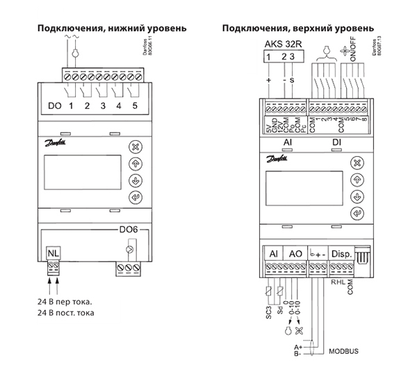
| Напряжение питания | 24 В пер. тока +/-15% 50/60 Гц, 17ВА 24 В пост. тока (20-60 В), 17ВА |
|
| 4 аналоговых входа | Измерение давления: Измерительный преобразователь давления модель AKS 32R Измерительный преобразователь давления 1-5 В, модель AKS 32 Измерительный преобразователь давления 0-20 (4-20) мА, модель AKS 33 |
|
| Измерение температуры Pt 1000 Ом / 0 °C или NTC — 86K для компрессоров типа Digital Scroll / Stream |
||
| 8 дискретных входов | Сигнал от сухих контактов для выполнения, например, следующих функций: Пуск / останов регулирования Мониторинг цепей защиты Предупредительный сигнал общего назначения |
|
| Релейный выход для регулирования холодопроизводительности | 5 шт. SPDT (5 А) | AC-1: 5 A (активная нагрузка) AC-15: 2 А (индуктивная нагрузка) |
| 1 полупроводниковое реле ШИМ для Scroll-разгрузки | Imax. = 0,5 А Imin. = 50 мА Leak<1,5 мА |
|
| 2 выхода напряжения | 0-10 В Ri = 1 кОм | |
| Выход для дисплея | Для типа MMIGRS2 | |
| Передача данных | Modbus для AK-SC 355 или AK-SM 850 | |
| Условия окружающей среды | -20 — 60 °C при эксплуатации -40 — 70 °C при перевозке |
|
| Относительная влажность 20 — 80%, без конденсации | ||
| Отсутствие ударов и вибрации | ||
| Степень защиты | IP 20 | |
| Масса | 0,2 кг | |
| Монтаж | На DIN-рейку | |
| Клеммы подключения | Для многожильных проводов сечением макс. 2,5 мм2 | |
| Сертификация | Выполнение требований директив ЕС для низковольтного оборудования и электромагнитной совместимости с целью маркировки знаком CE Испытания на соответствие требованиям директивы для низковольтного оборудования в соответствии с EN 60730-1 и EN 60730-2-9 Испытания на соответствие требованиям директивы для электромагнитной совместимости в соответствии с EN61000-6-2 и 3 |
Menu
Start/stop
Main switch
Extern Main swich
Plant type
Select Plant type
Refrigerant type
Unit of setpoints
Mains frequency
Alarm output
Suction
Control status
Control status
Actuel zone
Control temp. /
Control pres.
Reference
Running capacity
Requested capacity
8
Main switch
Start and stop regulating here.
The configuration settings will require that regulating is stopped.
If you try to enter a configuration setting when regulating has started, the controller will
ask if regulating should be stopped.
When all settings have been made and the main switch is set to «ON», the controller will
enable the display of the various measurements. Regulation will start. (If an external main
switch has been defined, it must also be «ON» before regulating starts.)
External main switch
On DI6 an external switch can be connected which can be used to start and stop regulating.
If a switch is not connected, the input must be shorted.
Both the internal and external main switch must be ON before regulating starts.
Plant settings:
The following must be regulated:
• Compressor group
• Condenser group
• One compressor group + One condenser group
Refrigerant setting
Before refrigeration is started, the refrigerant must be defined. You may choose between
the following refrigerants:
R12, R22, R134a, R502, R717, R13, R13b1, R23, R500, R503, R114, R142b, user defined,
R32, R227, R401A, R507, R402A, R404A, R407C, R407A, R407B, R410A, R170, R290, R600,
R600a, R744, R1270, R417A, R422A, R413A, R422D, R427A, R438A, R513A (XP10), R407F.
Warning: Wrong selection of refrigerant may cause damage to the compressor.
Other refrigerants: Here Setting «user defined» is selected and then three factors — fac1, fac2
and fac3 and temperature glide (if necessary).
Define reference settings and readings for saturation temperature or pressure
Select pressure or saturation temperature.
(Can be set during initial set-up and must not be subsequently changed.)
Frequency
Set the net frequency
Alarm relay
Define an alarm relay here that will be activated in the event of an alarm.
1. Select the alarm priority that will activate the relay
• No relay
• Critical alarms
• Critical and serious alarms
• All alarms
Select whether the relay will be active (pulled) when the alarm is ON, or when it is OFF.
(If all relays are used to start/stop compressors and condenser fans, it will not be possible to
use an alarm relay.)
Regulation status
Read the status of the control circuit here e.g.:
No comp=no capacity available (error). Normal=regulation. Alarm comp=alarm situa-
tion where the compressor not starts. ON timer=await timer function. Start timer= await
timer function. Normal ctrl=regulation in neutral zone. Inj. ON delay=await time delay,
Cascade=slave or master. 1st comp. del=await first compressor timer. Pump down=suction
down until the set limit before compressor stops. Sensor error=emergency cooling due to
defective signal. Load shed=power limitation function is active. Sd High=temperature moni-
toring effect the regulation. Pc High= temperature monitoring effect the regulation. Manual
ctrl=manuel operation. Main switch off=regulation stops.
You will be able to see how the regulation is in relation to the reference here:
P0 error: No regulation
— Zone: The desired pressure is below the neutral zone
NZ: The pressure is in the neutral zone
+ Zone: The desired pressure is above the neutral zone
The current value of the regulation sensor can be read here
The total regulation reference can be read here
Here the connected capacity can be read as a % of total capacity
Here the preferred connected capacity can be read as a % of total capacity
User Guide RS8GZ302 © Danfoss 2015-06
SW: 1.1x
On / Off
Fac: None
Fac: None
Temp. / press
Fac: Saturated
50 Hz / 60 Hz
Fac: 50 Hz
DO-demand
Fac: No relay
AK-PC 351
- Home
- Brands
- Danfoss
- AK-PC 351
- Operation & User’s Manual
Manual for Danfoss AK-PC 351 Controller (22 pages)
|
Detail Specifications: 1049/1049694-akpc_351.pdf file (09 May 2023) |
Read Danfoss AK-PC 351 Manual Online
Accompanying Data:
Danfoss AK-PC 351 Controller PDF Operation & User’s Manual (Updated: Tuesday 9th of May 2023 06:34:58 AM)
Rating: 4.3 (rated by 67 users)
Recommended Documentation:
Text Version of Operation & User’s Manual
(Ocr-Read Summary of Contents, UPD: 09 May 2023)
-
15, AK-PC 351 User Guide RS8GZ302 © Danfoss 2015-06 15 I/O conguration Here you can see which outputs and inputs your settings have established. The connection points shown cannot be changed, but the analog input measurements can be adjusted. Digital outputs 1: 2: 3: . 6: On/o outputs The outputs are set up automatically in the following order: a) If a PWM output is needed, p…
-
11, Danfoss AK-PC 351 AK-PC 351 User Guide RS8GZ302 © Danfoss 2015-06 11 PWM Max cycle For scroll Limitation of capacity during time period. There is no limit if the setting in 100%. Min: 60% Max: 100% Fac: 100% Comp. 1 Sd temp. For “Scroll” and “Stream” Dene whether the controller should monitor the discharge gas temperature Sd from a digital scroll or a stream compressor (NTC 86K or Pt …
-
17, AK-PC 351 User Guide RS8GZ302 © Danfoss 2015-06 17 Connections when using Setup Wizard The assignment of functions on the respective inputs and outputs can be regulated in “IO conguration”. Here is an example of 3 compressors and 2 fans: Digital outputs (DO1-DO6): If you have used the Setup Wizard for the conguration, the control- ler will automatically assign the outputs in ac…
-
3, AK-PC 351 User Guide RS8GZ302 © Danfoss 2015-06 3 Suction Group Compressor types The following types of compressor combinations can be used for regulation: • Single-step compressors • Speed controlled compressor together with single-step • Digital scroll compressor together with single-step • Stream 4 cylinder compressor together with single-step • Compressor…
-
5, AK-PC 351 User Guide RS8GZ302 © Danfoss 2015-06 5 Safety functions Min./max. suction pressure Po The suction pressure is recorded continuously. If the measured value falls below the set minimum limit, the compressors will immediately cut out. If it exceeds the max. value, an alarm will be generated once the time delay has elapsed. Max. condensing pressure Pc If the condensing pressur…
-
10, Danfoss AK-PC 351 10 User Guide RS8GZ302 © Danfoss 2015-06 AK-PC 351 Compressor mode Set the type of compressor to be used for regulation: None; 1 single, 2 single, 3 single, 4 single 1 speed, 2 speed, 3 speed, 4 speed, 1 digital, 2 digital, 3 digital 1 stream, 2 stream, 3 stream 1×1 unload, 1×2 unload, 1×3 unload, 2×1 unload Application Single step 1 single 2 single 3 single 4 single Speed on the �…
-
16, Danfoss AK-PC 351 16 User Guide RS8GZ302 © Danfoss 2015-06 AK-PC 351 Alarm priorities General Standby mode: Sensor error: Refrigerant: Output in MANUAL: General alarm; Alarm priorities The controller will issue an alarm notication if a specic incident occurs. Each incident is set to indicate the importance of each alarm, but it is possible to modify the importance of each. Choose from between the followi…
-
8, 8 User Guide RS8GZ302 © Danfoss 2015-06 AK-PC 351 Start/stop Main switch Main switch Start and stop regulating here. The conguration settings will require that regulating is stopped. If you try to enter a conguration setting when regulating has started, the controller will ask if regulating should be stopped. When all settings have been made and the main switch is set to …
DOC-93509918
Recommended Instructions:
PSR-5700, VE48, SD-P71SKN, KX-TG1861AL, Intimidator 2.0 HTI, nF2 U400SG-AGF


-
110 V AC, 220 V AC50 Hz, 60 Hz (common)25 A, 35 AProtected by high-speed breaking fuse(externalattachment)Resistive Load/ Inductive Load (use as a switchconversion)Input Current: 4 ~ 20 mA DC, Input Voltage: 1 ~5 V DCInput Contact Point: ON-OFF, External V, R (10 )Phase control, Cycle control, ON/OFF controlSOFT START / DOWNAbove 95 % input voltage (when putting maximum of inpu …
TPR-2N 2
-
69-2042—01 2 69-2042—01 3 69-2042—01 4 69-2042—01 5TECHNICIAN’S QUICK REFERENCE GUIDE69-2042-01S8610U Universal Intermittent Pilot Gas Ignition ControlThe following service procedure provides a quick overview for the S8610U series control. For more information, refer to form 69-1955.Fig. 1. Typical wiring connections.SETTINGS AND ADJUSTMENTSDIP Switch (S1) SettingsWhen replacing …
SUPER TRADELINE S8610U 2
-
MANUAL NO. HW1480782YASKAWA ELECTRIC CORPORATIONFS100 OPTIONSINSTRUCTIONSFOR ANALOG OUTPUT FUNCTION CORRESPONDING TO SPEEDUpon receipt of the product and prior to initial operation, read these instructions thoroughly, and retain for future reference.MOTOMAN INSTRUCTIONSMOTOMAN- INSTRUCTIONSFS100 INSTRUCTIONSFS100 OPERATOR’S MANUALFS100 MAINTENANCE MANU …
MOTOMAN FS100 21
-
SSD7103 Linux Ubuntu 19.10 Server Installation GuideHighPoint NVMe RAID ControllerSSD7103 Linux Ubuntu 19.10 ServerInstallation GuideVersion 1.00Copyright © 2020 HighPoint Technologies, Inc.All rights reserved.Last updated on July 20, 2020 …
SSD7103 12
Additional Information:
Popular Right Now:
Operating Impressions, Questions and Answers:
Table of Contents for Danfoss AK-PC 351:
-
20 User Guide RS8GZ302 © Danfoss 2015-06 AK-PC 351 Mounting /Dimensions For DIN rail mounting only (IP 20) Supply voltage 24 V a.c. +/-15% 50/60 Hz, 9 VA 24 V d.c. (20-60 V), 9 VA 4 analog Input Pressure meauring: Ratiometric pressure transmitter type AKS 32R 1-5 volt pressure transmitter type AKS 32 0-20 (4-20) mA pressure transmitter type AKS 33 Temperature measurement Pt 1000 ohm/0°C NTC — 86K from digital scroll / stream 8 d
-
14 User Guide RS8GZ302 © Danfoss 2015-06 AK-PC 351 General functions Digital input Digital input There are two general digital inputs that can be used by the controller. DI7 cong The DI7 input can be set to: • Not used • Receive night signal. The signal will raise the suction pressure with set oset. • Register signal from an LP switch. The signal will cause the controller to stop all compressors. DI-demand Night / LP switch Fac: N
-
12 User Guide RS8GZ302 © Danfoss 2015-06 AK-PC 351 Condenser Control status Regulation status Control status Here you can read the status of the condenser circuit, e.g.: • Main switch = OFF • Capacity control is ready • Capacity control is in normal run mode • Capacity control is set in manual control mode • Capacity forced to 100% due to High Pc/High Sd prevention functions • Capacity forced to 100% due to external HP switch/HP safety/Sd safety limit violation Control temp./press The current value of
-
AK-PC 351 User Guide RS8GZ302 © Danfoss 2015-06 9 No. of running comp. The number of compressors in operation can be read here Po Pressure The measured pressure for the Po pressure transmitter can be read here To Saturated temp. The measured Po pressure converted to temperature can be read here S4 media temp. The measured S4 sensors actual value can be read here MC Po oset The size of a reference displacement on Po required from the system unit (suction pressure optimisation function) can be read here Pc Press
-
AK-PC 351 User Guide RS8GZ302 © Danfoss 2015-06 13 Fan mode Conguration of fans: Fan speed & DO: Speed controled fans via AO2 and start/stop via DO output. Fan speed: Speed controlled fans via AO2 4 Fan step: step-by-step . Start/stop via 4 pcs. DO outputs 3 Fan step: step-by-step . Start/stop via 3 pcs. DO outputs 2 Fan step: step-by-step . Start/stop via 2 pcs. DO outputs 1 Fan step: step-by-step . Start/st
-
AK-PC 351 User Guide RS8GZ302 © Danfoss 2015-06 7 Start screen upon delivery Set-up overview There are two ways in which the controller can be set up. Select the one that is easiest for you: either “Wizard” or a review of “all parameters”. Hold “Enter” down for 2 sec- onds to come to password entry Press “Enter” Operating principles 1. Select position using arrow keys 2. Select using “Enter” 3. Use the “X” to return Wiz
-
4 User Guide RS8GZ302 © Danfoss 2015-06 AK-PC 351 Condenser Fan control The fans can be controlled incrementally using the controller’s relays, or they can be speed-controlled via the controller’s analogue output. Speed control can be via a frequency VLT-type transformer. If the fans have EC motors, the 0-10 V signal can be used directly. Control Regulation is carried out based on a signal from the Pc pressure transmitter or an S7 media temperature sensor. The signal is co
-
AK-PC 351 User Guide RS8GZ302 © Danfoss 2015-06 11 PWM Max cycle For scroll Limitation of capacity during time period. There is no limit if the setting in 100%. Min: 60% Max: 100% Fac: 100% Comp. 1 Sd temp. For “Scroll” and “Stream” Dene whether the controller should monitor the discharge gas temperature Sd from a digital scroll or a stream compressor (NTC 86K or Pt 1000 Ohm). AI-demand No / Yes Fac: No Comp. 1 Sd m
-
2 User Guide RS8GZ302 © Danfoss 2015-06 AK-PC 351 Introduction Application The controller is used for capacity regulation of compressors and condensers in small refrigeration applications. A maximum of 4 compressors and one condenser can be regulated. For example: • One suction group + one condenser group, max. 6 steps total • One compressor group, max. 4 steps • One condenser group, max. 4 steps Advantages • Energy savings via: — Optimisation of suction pressure — Night set back — Floating condensin
-
Capacity Controller AK-PC 351 User Guide ADAP-KOOL® Refrigeration Control System
-
10 User Guide RS8GZ302 © Danfoss 2015-06 AK-PC 351 Compressor mode Set the type of compressor to be used for regulation: None; 1 single, 2 single, 3 single, 4 single 1 speed, 2 speed, 3 speed, 4 speed, 1 digital, 2 digital, 3 digital 1 stream, 2 stream, 3 stream 1×1 unload, 1×2 unload, 1×3 unload, 2×1 unload Application Single step 1 single 2 single 3 single 4 single Speed on the rst. Then single step 1 speed 2 speed 3 speed 4 speed Digital scroll (stream) on the rst. Then
-
AK-PC 351 User Guide RS8GZ302 © Danfoss 2015-06 17 Connections when using Setup Wizard The assignment of functions on the respective inputs and outputs can be regulated in “IO conguration”. Here is an example of 3 compressors and 2 fans: Digital outputs (DO1-DO6): If you have used the Setup Wizard for the conguration, the control- ler will automatically assign the outputs in accordance with the following prioritised order: • PWM outputs
-
8 User Guide RS8GZ302 © Danfoss 2015-06 AK-PC 351 Start/stop Main switch Main switch Start and stop regulating here. The conguration settings will require that regulating is stopped. If you try to enter a conguration setting when regulating has started, the controller will ask if regulating should be stopped. When all settings have been made and the main switch is set to “ON”, the controller will enable the display of the various measurements. Regulation will start. (If an external main switch has been dened, it
-
AK-PC 351 User Guide RS8GZ302 © Danfoss 2015-06 5 Safety functions Min./max. suction pressure Po The suction pressure is recorded continuously. If the measured value falls below the set minimum limit, the compressors will immediately cut out. If it exceeds the max. value, an alarm will be generated once the time delay has elapsed. Max. condensing pressure Pc If the condensing pressure reaches the upper permissible value, the controller will connect all condenser fans to keep the pressure down. At the s
Questions, Opinions and Exploitation Impressions:
You can ask a question, express your opinion or share our experience of Danfoss AK-PC 351 device using right now.