1 • INSTALLATION
• Dimensions and cut-out; panel mounting
63
48
48
99
10
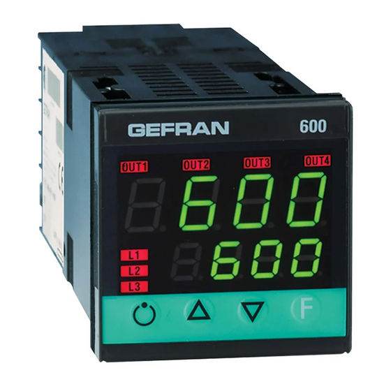
Panel mounting:
To fix the unit, insert the brackets provided into the seats on either side of the
case. To mount two or more units side by side, respect the cut-out dimensions
shown in the drawing.
CE MARKING: EMC conformity (electromagnetic compatibility) with EEC Directive
89/336/CEE with reference to the generic Standard EN50082-2 (immunity in industrial
environments) and EN50081-1 (emission in residential environments). BT (low voltage)
conformity respecting the Directive 73/23/CEE modified by the Directive 93/68.
MAINTENANCE: Repairs must be done only by trained and specialized personnel. Cut
power to the device before accessing internal parts.
Do not clean the case with hydrocarbon-based solvents (Petrol, Trichlorethylene, etc.).
Use of these solvents can reduce the mechanical reliability of the device. Use a cloth
dampened in ethyl alcohol or water to clean the external plastic case.
SERVICE: GEFRAN has a service department. The warranty excludes defects caused
by any use not conforming to these instructions.
600
CONTROLLER
70
45
45
!
For correct and safe
installation, follow the
instructions and
observe the warnings
contained in this
manual.
USER’S MANUAL
SOFTWARE VERSION 2.09
Edition 01.04.2008
GEFRAN spa via Sebina, 74
25050 Provaglio d’Iseo (BS) ITALIA
Tel. 0309888.1 — Fax 0309839063
Internet: http://www.gefran.com
2 • TECHNICAL SPECIFICATIONS
Display
Keys
Accuracy
Main input (settable digital filter)
Type TC Thermocouples
(ITS90)
Cold junction error
RTD type (scale configurable within indicated
range, with or without decimal point) (ITS90)
Max line resistance for RTD
PTC type / NTC Type
Safety
70
°C / °F selection
Linear scale ranges
Controls
pb — dt — it
Action
Control outputs
Maximum power limit heat / cool
Cycle time
Main output type
Softstart
Fault power setting
Automatic blanking
Configurable alarms
Alarm masking
Type of relay contact
Logic output for static relays
Triac output
Transmitter power supply
Analogue retransmission signal
Logic inputs
Serial interface (optional)
Baud rate
Protocol
Optional ammeter input
Power supply (switching type)
Faceplate protection
Working / Storage temperature range
Relative humidity
Installation
Weight
EMC conformity has been tested with the following connections
FUNCTION
Power supply cable
Relay output cable
Digital communication wire
C.T. connection cable
TC input
Pt100 input
1
2 x 4 digits, green, height 10 and 7mm
4 mechanical keys (Man/Aut, INC, DEC, F)
0.2% full scale ± 1 digit at 25°C room temperature
TC, RTD, PTC, NTC
60mV,1V Riž1Mž; 5V,10V Riž10Kž; 20mA Ri=50ž
Sampling time 120 msec.
J, K, R, S, T, B, E, N (IEC 584-1, CEI EN 60584-1,
60584-2) L GOST, U, G, D, C
custom linearization is available
0,1° / °C
DIN 43760 (Pt100), JPT100
20ž
990ž, 25°C / 1Kž, 25°C
detection of short-circuit or opening of probes, LBA
alarm, HB alarm
configurabile da tastieraconfigurable from faceplate
-1999 to 9999 with configurable decimal point position
PID, Self-tuning, on-off
0,0…999,9 % — 0,00…99,99 min — 0,00…99,99 min
Heat / Cool
on / off, continuous
0,0…100,0 %
0…200 sec
relay, logic, continuous (0….10V / 4…20mA)
0,0…500,0 min
-100,0…100,0 %
Displays PV value, optional exclusion
Up to 3 alarm functions assignable to an output,
configurable as: maximum, minimum, symmetrical,
absolute/deviation, LBA, HB
— exclusion during warm up
— latching reset from faceplate or external contact
NO (NC), 5A, 250V/30Vdc cosϕ=1
24V ±10% (10V min at 20mA)
20…240Vac ±10%, 1A max
Snubberless, inductive and resistive load I
2
10 / 24Vdc, max 30mA short-circuit protection
10V/20mA Rload max 500ž resolution 12 bit
Ri = 4,7Kž (24V, 5mA) or no-voltage contact
RS485, isolated
1200, 2400, 4800, 9600, 19200
Gefran CENCAL / MODBUS
T.A. 50mAac, 50/60Hz, Ri = 10ž
(std) 100 … 240Vac/dc ±10%
(opt.) 20…27Vac/dc ±10%;
50/60Hz, 8VA max
IP65
0…50°C / -20…70°C
20 … 85% non-condensing
Panel, plug-in from front
160g for the complete version
CABLE TYPE
LENGTH
1 mm
2
1 m
1 mm
2
3,5 m
0,35 mm
2
3,5 m
1,5 mm
2
3,5 m
0,8 mm
2
compensated
5 m
1 mm
2
3 m
t = 128A
2
s
-
Bookmarks
Quick Links
Italiano
REGOLATORE
English
CONTROLLER
Deutsch
REGLER
Français
RÉGULATEUR
Español
REGULADOR
Portuguese
CONTROLADOR
APPENDIX
600
SOFTWARE 1.1x
cod. 80336B / Edit. 05 — 10/03
— Manuale d’uso
— User’s Manual
Bedienungsanleitung
—
— Manuel d’Utilisation
— Manual de Uso
— Manual do Usuário
2
18
34
50
66
82
98
Related Manuals for gefran 600
Summary of Contents for gefran 600
-
Page 1
SOFTWARE 1.1x cod. 80336B / Edit. 05 — 10/03 Italiano — Manuale d’uso REGOLATORE English — User’s Manual CONTROLLER Deutsch Bedienungsanleitung REGLER Français — Manuel d’Utilisation RÉGULATEUR Español — Manual de Uso REGULADOR Portuguese — Manual do Usuário CONTROLADOR APPENDIX… -
Page 2: Manuale D’uso
3,5 mt pulito inumidito con alcool etilico o con acqua. Fili collegamento T.A. 1,5 mm 3,5 mt ASSISTENZA TECNICA: In GEFRAN è disponibile un reparto di assistenza tecnica. Sonda ingresso termocoppia 0,8 mm compensated 5 mt Sono esclusi da garanzia i difetti causati da un uso non conforme alle istruzioni d’uso.
-
Page 3
3 • DESCRIZIONE FRONTALE STRUMENTO Indicatori di funzione: Indicazione stato delle uscite: Segnalano il tipo di funzionamento dello strumento OUT 1 (AL1); OUT 2 (Main); OUT 3 (HB); OUT 4 MAN/AUTO OFF (regolazione automatica) ON (regolazione manuale) Display PV: Indicazione della variabile di processo SETPONT1/2 = OFF (IN1=OFF-Setpoint locale 1) Visualizzazione errori: LO, HI, Sbr, Err… -
Page 4
5 • PROGRAMMAZIONE E CONFIGURAZIONE “EASY” Ponticello LA CONFIGURAZIONE EASY É ADATTA ALLE VERSIONI CON Menù custom S4 (CPU) DUE USCITE ( OUT1, OUT2). PER L’ACCESSO AGLI ULTERIORI PARAMETRI AGGIUNGERE 128 AL VALORE Pro Impostazioni ingressi VISUALIZZAZIONE LIVELLO 1 Impostazioni uscite Variabile di processo (display PV) P.V. -
Page 5
6 • PROGRAMMAZIONE e CONFIGURAZIONE VISUALIZZAZIONE LIVELLO 1 Visualizzazione informazioni Variabile di processo (display PV) Ponticello P.V. / S.V. Setpoint di lavoro (display SV) o S4 (CPU) =ON valore uscita di controllo con regolatore in manuale Menù custom Setpoint locale Comunicazione seriale SP. -
Page 6
Impostazioni seriale bAud Baudrate Selezione 1200 Baudrate 2400 4800 9600 Codice identificazione strumento 0 … 247 19200 _PAr Parità sr. p Protocollo SER.P Protocollo Seriale Selezione Senza (no parity) interfaccia seriale CENCAL GEFRAN parità Dispari (odd) MODBUS RTU Pari (even) -
Page 7
(dove f.s. è riferito al range -200…850°C) TC N °C 0/1300 0.0/999.9 TC N °F 32/2372 32.0/999.9 L-GOST °C 0/600 0.0/600.0 Filtro digitale ingresso L-GOST °F 32/1112 32.0/999.9 (se=0 esclude il filtro di media sul 0.0 … 20.0 sec TC U °C -200/400 -199.9/400.0… -
Page 8
l5. 2 Limite minimo 0.0 … 999.9 Scala ingresso ausiliario xs. 2 Limite massimo 0.0 … 999.9 Scala ingresso ausiliario of. 2 Offset correzione -99.9 … 99.9 ingresso ausiliario punti scala Limite inferiore lo. l impostabilità SP Lo.S … Hi.S e allarmi assoluti Limite superiore xi. -
Page 9
rl. 1 Out 1 Attribuzione segnale di riferimento rL.o.1, rL.o.2, rL.o.3, rL.o.4 Funzione HEAT (uscita di controllo riscaldamento) COOL (uscita di controllo raffreddamento) AL1 — allarme 1 rl. 2 AL2 — allarme 2 Out 2 AL3 — allarme 3 Attribuzione AL.HB — allarme HB segnale di LBA — allarme LBA… -
Page 10
• Prot Codice di protezione Prot Visualizzazione Modifica SP, In2, allarmi, OuP, INF SP, allarmi SP, In2, allarmi, OuP, INF SP, In2, OuP, INF disabilitazione InP, Out disabilitazione CFG, Ser disabilitazione “accensione — spegnimento” software disabilita la memorizzazione della potenza manuale disabilita la modifica del valore della potenza manuale +128 abilta la configurazione estesa N.B: OuP e INF visualizzazione solo in configurazione estesa… -
Page 11
AL.nr Allarme 1 Allarme 2 Allarme 3 al. n Selezione numero disabilitato disabilitato disabilitato allarmi abilitati abilitato disabilitato disabilitato disabilitato abilitato disabilitato abilitato abilitato disabilitato disabilitato disabilitato abilitato abilitato disabilitato abilitato disabilitato abilitato abilitato abilitato abilitato abilitato + 8 per abilitare l’allarme HB + 16 per abilitare l’allarme LBA b u t t nessuna funzione (tasto disabilitato) -
Page 12
• Lin Linearizzazione custom per ingresso principale s. 0 0 Passo 0 Limiti di visualizzazione del valore inizio scala display (-1999…9999) Il valore del passo n corrisponde ad ingresso: ..mV inizio scala + n*∆mV ∆mV = (mV fondo scala — mV inizio scala) / 32 s. -
Page 13
FUNZIONAMENTO ALLARME HB Questo tipo di allarme è condizionato dall’utilizzo dell’ingresso da trasformatore amperometrico (T.A.). Può segnalare variazioni di assorbimento nel carico discriminando il valore della corrente in ingresso amperometrico nel campo (0 … HS.2). Viene abilitato tramite codice di configurazione (AL.n); in questo caso il valore di intercettazione dell’allarme è espresso in punti scala HB. -
Page 14
Se il valore del Tempo Integrale è troppo lungo (Azione Integrale debole) è possibile una persistenza della deviazione tra variabile regolata e valore desiderato. Per avere ulteriori informazioni relative alle azioni di controllo contattare GEFRAN. 9 • TECNICA DI TUNE MANUALE A) Impostare il set-point al valore operativo. -
Page 15
12 • SELF-TUNING La funzione è valida per sistemi di tipo a singola azione (o caldo o freddo). L’attivazione del self-tuning ha come scopo il calcolo dei parametri ottimali di regolazione in fase di avviamento del processo, la variabile (esempio temperatura) deve essere quella assunta a potenza nulla (temperatura ambiente). Il controllore fornisce il massimo di potenza impostata sino al raggiungimento di un valore intermedio tra il valore di partenza e il set-point, quindi azzera la potenza. -
Page 16
Lunghezza cavo: 5,50m PTC 7 x 25 5m • Cavo Interfaccia RS232 / TTL per configurazione strumenti GEFRAN N.B.: L’interfaccia RS232 per la configurazione da PC è fornito unitamente al software di programmazione WINSTRUM. Il collegamento deve essere effettuato con strumento alimentato con ingressi e uscite non collegate. -
Page 17
220Vac. Le resistenze devono essere almeno di 2W); montare un diodo 1N4007 in parallelo alla bobina dei carichi induttivi che lavorano in continua La GEFRAN spa non si ritiene in alcun caso responsabile per i danni a persone o cose derivati da manomissioni, da un uso errato, improprio e comunque non conforme alle caratteristiche dello strumento. -
Page 18: User’s Manual
Digital communication wire 0,35 mm 3,5 m SERVICE: GEFRAN has a service department. The warranty excludes defects caused C.T. connection cable 1,5 mm 3,5 m by any use not conforming to these instructions.
-
Page 19
3 • DESCRIPTION OF FACEPLATE Function indicators Indication of output states Indicates modes of operation OUT 1 (AL1); OUT 2 (Main); OUT 3 (HB); OUT 4 (HB) MAN/AUTO = OFF (automatic control) ON (manual control) PV Display: Indication of process variable Error Indication: LO, HI, Sbr, Err SETPONT1/2 = OFF (IN1 = OFF — local Setpoint 1) LO= the value of process variable is <… -
Page 20
5 • “EASY” PROGRAMMING and CONFIGURATION THE EASY CONFIGURATION IS SUITABLE FOR VERSIONS WITH S4 Jumper Custom menu TWO OUTPUTS (OUT1, OUT2). TO ACCESS THE OTHER (CPU) PARAMETERS, ADD 128 TO THE Pro VALUE. Input settings LEVEL 1 MENU Output settings P.V. -
Page 21
6 • PROGRAMMING and CONFIGURATION Information display LEVEL 1 MENU P.V. / S.V. S4 Jumper P.V. / S.V. Process variable (PV display) (CPU) = ON Work Setpoint (SV display) or control output value with controller in manual Custom menu Local Setpoint Serial communication SP. -
Page 22
• Ser Serial setting bAud Baudrate Select 1200 Baudrate 2400 4800 9600 Unit identification code 0 … 9999 19200 _PAr Parity sr. p Serial interface SER.P Serial protocol No parity Parity selection protocol CENCAL GEFRAN MODBUS RTU Even… -
Page 23
TC E °F -148/1382 -148.0/999.9 TC N °C 0/1300 0.0/999.9 TC N °F 32/2372 32.0/999.9 L-GOST °C 0/600 0.0/600.0 Digital filter on input L-GOST °F 32/1112 32.0/999.9 (if = 0 excludes averaging filter on 0.0 … 20.0 sec TC U °C -200/400 -199.9/400.0… -
Page 24
l5. 2 Minimum limit auxiliary 0.0 … 999.9 input scale xs. 2 Maximum limit auxiliary 0.0 … 999.9 input scale of. 2 Offset correction -99.9 … 99.9 of aux input scale points lo. l Lower limit for setting SP Lo.S … Hi.S and absolute alarms xi. -
Page 25
rl. 1 Out 1 Allocation of reference signa rL.o.1, rL.o.2, rL.o.3, rL.o.4 Function of main output relay/logic (OUT1) HEAT (control output for heating) rl. 2 COOL (control output for cooling) Out 2 AL1 — alarm 1 Allocation of AL2 — alarm 2 reference signal AL3 — alarm 3 AL.HB — alarm HB… -
Page 26
• Prot Protection code Prot Display Modification SP, In2, alarms, OuP, INF SP, alarms SP, In2, alarms, OuP, INF SP, In2, OuP, INF to disable InP, Out to disable CFG, Ser, + 16 to disable SW “power-up — power down” + 32 disable manual power latching + 64 to disable manual power modification +128 enables full configuration… -
Page 27
AL.nr Alarm 1 Alarm 2 Alarm 3 al. n Select number of disabled disabled disabled enabled alarms enabled disabled disabled disabled enabled disabled enabled enabled disabled disabled disabled enabled enabled disabled enabled disabled enabled enabled enabled enabled enabled + 8 to enable HB alarm + 16 to enable LBA alarm b u t t No function (key disenabled) -
Page 28
• Lin Custom linearization for main input s. 0 0 Step 0 beginning Display limits of scale value (-1999…9999) the n step value corresponds to input: ..mV beginning scale + n*∆mV ∆mV = (mV full scale — mV beginning scale) / 32 s. -
Page 29
HB ALARM FUNCTION This type of alarm depends on use of the current transformer (C.T.) input. It can signal variations in load input by identifying the current value in ammeter input in the range (0 … HS.2). It is enabled by means of configuration code (AL.n);… -
Page 30
If the Integral Time value is too long (Weak integral action), deviation between the controlled variable and the setpoint may persist. Contact GEFRAN for more information on control actions. 9 • MANUAL TUNING A) Enter the setpoint at its working value. -
Page 31
12 • SELF-TUNING The function works for single output systems (heating or cooling). The self-tuning action calculates optimum control parameter values during process startup. The variable (for example, temperature) must be that assumed at zero power (room temperature). The controller supplies maximum power until an intermediate value between starting value and setpoint is reached, after which it zeros power. PID parameters are calculated by measuring overshoot and the time needed to reach peak. -
Page 32
Wire length: 5,50m PTC 7 x 25 5m • RS232 / TTL interface for GEFRAN instrument configuration N.B. RS232 interface for PC configuration is supplied with the WINSTRUM programming software. Make connection with instrument powered but with inputs and outputs disconnected. -
Page 33
1N4007 diode in parallel with the coil of inductive loads that operate in DC. GEFRAN spa will not be held liable for any injury to persons and/or damage to property deriving from tampering, from any incorrect or erroneous use, or… -
Page 34: Bedienungsanleitung
WARTUNG: Dieses Gerät ist wartungsfrei. Sollte der Regler einen Fehler aufweisen, Installation Schalttafeleinbau, von vorn herausnehmbar kontaktieren Sie bitte die nächste GEFRAN Niederlassung. Kundenseitige Reparaturen Gewicht 160 g in Ausführung mit vollständiger Ausstattung sind nicht zulässig. Die EMV-Konformität wurde mit folgenden Verbindungen geprüft: Das Gehäuse nicht mit Lösemitteln auf Kohlenwasserstoffbasis (Trichlorethylen, Benzin…
-
Page 35
3 • BEDIEN- UND ANZEIGEELEMENTE Funktionsanzeiger: Zustandsanzeige der Ausgänge: Sie signalisieren die Betriebsart des Instruments: OUT 1 (AL 1); OUT 2 (Main); OUT 3 (HB); OUT 4 MAN/AUTO AUS (automatische Regelung) EIN (manuelle Steuerung) PV-Anzeige: Istwert SETPONT1/2 = AUS (IN1= AUS — interner Sollwert 1) Fehleranzeige: LO, HI, Sbr, Err LO = der Istwert unterschreitet die Skalengrenze (LO_S) EIN (IN1= EIN — interner Sollwert 2) -
Page 36
5 • PROGRAMMIERUNG und KONFIGURATION «EASY» DIE KONFIGURATION «EASY» EIGNET SICH FÜR DIE VERSIONEN Brücke Kundenspezifisches Menü MIT ZWEI AUSGÄNGEN (OUT1, OUT2). FÜR DEN ZUGRIFF AUF DIE S4 (CPU) WEITEREN PARAMETER ADDIERT MAN 128 ZUM WERT VON Pro Eingangskonfiguration ANZEIGEEBENE 1 Ausgangskonfiguration Istwert (PV-Anzeige) P.V. -
Page 37
6 • PROGRAMMIERUNG und KONFIGURATION ANZEIGEEBENE 1 Informationsdisplay NEIN Istwert (PV-Anzeige) Brücke S4 P.V. / S.V. Sollwert (SV-Anzeige) oder (CPU) = ON Stellgröße bei Handbetrieb des Reglers Kundenspezifisches Menü Interner Sollwert Parameter der seriellen Schnittstelle SP. 1 Sollwert 1 Eingangskonfiguration F-Taste lösen um SP. -
Page 38
Relativverstärkung» (CtrL = 14) im Nur-Lese-Modus angezeigt. • Ser Menü Einstellung serielle Schnittstelle bAud Baudrate Baudrate 1200 2400 4800 9600 Geräteadresse 0 … 9999 19200 _PAr Parität sr. p Schnittstellen- SER.P Schnittstellenprotokoll keine Parität protokoll CENCAL GEFRAN ungerade MODBUS RTU gerade… -
Page 39
TC E °F -148/1382 -148.0/999.9 (Endwert bezogen auf den Bereich -200…850°C) TC N °C 0/1300 0.0/999.9 TC N °F 32/2372 32,0/999.9 L-GOST °C 0/600 0.0/600.0 L-GOST °F 32/1112 32.0/999.9 TC U °C -200/400 -199.9/400.0 Digitalfilter Haupteingang TC U °F -328/752 -199.9/752.0… -
Page 40
l5. 2 Untere Skalengrenze 0.0 … 999.9 Hilfseingang xs. 2 Obere Skalengrenze 0.0 … 999.9 Hilfseingang of. 2 Korrekturoffset -99,9 … 99,9 Hilfseingang Skaleneinheiten Unterer Grenzwert für die lo. l Einstellung des Sollwerts Lo.S … Hi.S und der absoluten Alarme Oberer Grenzwert für die xi. -
Page 41
rl. 1 Out1 Vereinbarung der Ausgangsfunktion rL.o.1, rL.o.2, rL.o.3, rL.o.4 Funktion Heizen (Regelungsausgang Heizen) rl. 2 Kühlen (Regelungsausgang Kühlen) Out2 AL1 — Alarm 1 Vereinbarung der AL2 — Alarm 2 Ausgangsfunktion AL3 — Alarm 3 AL.HB — Alarm HB LBA — Alarm LBA IN — Zustand logischer Eingang Wiederholung Taste but (wenn but = AL1 oder AL2…
 -
Page 42
• Prot Menü Zugangssperre Prot Anzeige Änderung SP, In2, alarme, OuP, INF SP, alarme SP, In2, alarme, OuP, INF SP, In2, OuP, INF zum Sperren von InP, Out zum Sperren von CFG, Ser +16 zum Sperren der Software Geräteabschaltung +32 zum Sperren der Speicherung der manuellen Stellgradvorgabe +64 zum Sperren der Änderung der manuellen Stellgradvorgabe +128 Freigabe der erweiterten Konfiguration •… -
Page 43
Wahl der Anzahl AL.nr Alarm 1 Alarm 2 Alarm 3 al. n der freigegebenen gesperrt gesperrt gesperrt Alarme freigegeben gesperrt gesperrt gesperrt freigegeben gesperrt freigegeben freigegeben gesperrt gesperrt gesperrt freigegeben freigegeben gesperrt freigegeben gesperrt freigegeben freigegeben freigegeben freigegeben freigegeben +8 zum Freigeben von Alarm HB. +16 zum Freigeben von Alarm LBA. -
Page 44
• Lin Menü Kundenspezifische Linearisierung für Haupteingang s. 0 0 Schritt 0 Grenzwerte der Anzeige Skalengrenzwerte (-1999…9999) Der Wert von Schritt n entspricht Eingang ..mV Skalenanfang + n*∆mV ∆mV = (mV Skalenendwert — mV Skalenanfang) / 32 s. 3 2 Schritt 32 Grenzwerte der Anzeige Skalengrenzwerte… -
Page 45
FUNKTIONSWEISE DES HEIZSTROM-ALARMS (HB) Dieser Alarmtyp erfordert die Verwendung des Stromwandlereingangs (T.A.). Er kann Variationen der Stromaufnahme bei der Last signalisieren, indem er den Strom am Stromwandlereingang im Bereich (0… HS.2) liest. Er wird durch den Konfigurationskode (Al.n) aktiviert; in diesem Fall wird der Auslösewert des Alarms in HB- Skaleneinheiten ausgedrückt. -
Page 46
8 • HINWEISE ZU DEN REGELUNGSPARAMETERN Proportionale Regelung: ist die Bezeichnung für den Wert, dessen Einfluss auf den Ausgang proportional zum Unterschied zwischen Soll- und Istwert ist. Vorhalteregelung: ist die Bezeichnung für den Wert, dessen Einfluss auf den Ausgang proportional zur Änderungsgeschwindigkeit des Istwertes ist. Integrale Regelung: ist die Bezeichnung für den Wert, dessen Einfluss auf den Ausgang proportional zum Integral der Sollwertdifferenz über die Zeit ist. -
Page 47
12 • SELBSTOPTIMIERUNG Die Funktion optimiert nur die Regelparameter für Heizen oder Kühlen. Bei Regelstrecken mit Heizen/Kühlen ist es erforderlich jeweils eine Selbstoptimierung für Heizen und Kühlen durchzuführen. Die Selbstoptimierung dient zum Berechnen der optimalen Werte für die Regelparameter während der Anlaufphase des Prozesses. Die Regelstrecke muss sich auf den Wert des Null-Stellgrades befinden (bei Temperaturregelung Umgebungstemperatur). -
Page 48
PVC — Kabel (12/0,18) Kabellänge: 5,50m PTC 7 x 25 5m • Schnittstellenkabel RS232 / TTL für GEFRAN Instrumentenkonfiguration HINWEIS: Die Schnittstelle RS232 für die PC-Konfiguration wird nur in Verbindung mit der Programmiersoftware WINSTRUM geliefert. Beim Anschluss an den PC muss das Instrument eingeschaltet sein, doch die Ein- und Ausgänge… -
Page 49
Last muss eine Diode vom Typ 1N4007 parallel zur Last geschaltet werden. Die Firma GEFRAN spa übernimmt in keinem Fall die Haftung für Sach- oder Personenschäden, die auf unbefugte Eingriffe sowie unsachgemäße oder den technischen Eigenschaften des Gerätes nicht angemessene Bedienung oder Anwendung zurückzuführen sind. -
Page 50
éthylique ou d’eau. Câble raccordement série 0,35 mm 3,5 m ASSISTANCE TECHNIQUE: Gefran met à disposition un service d’assistance Fil raccordement T.I. 1,5 mm 3,5 m technique. Ne sont pas couverts par la garantie les défauts causés par une utilisation Capteur entrée thermocouple… -
Page 51
3 • DESCRIPTION FAÇADE INSTRUMENT Indicateurs de fonction: Indication état des sorties: Signalent le type de fonctionnement de l’instrument: OUT 1 (AL 1); OUT 2 (Main); OUT 3 (HB); OUT 4 MAN/AUTO OFF (réglage automatique) Afficheur PV: Indication de la variable de process ON (réglage manuel) Affichage erreurs: LO, HI, Sbr, Err SETPONT1/2 =… -
Page 52
5 • PROGRAMMATION ET CONFIGURATION “EASY” LA CONFIGURATION «EASY» EST ADAPTÉE AUX VERSIONS À Cavalier Menu personnalisé S4 (CPU) DEUX SORTIES (OUT1, OUT2). POUR L’ACCÈS AUX AUTRES PARAMÈTRES, AJOUTER 128 À LA VALEUR Pro Configurations entrées AFFICHAGE NIVEAU 1 Configurations sorties P.V. -
Page 53
6 • PROGRAMMATION ET CONFIGURATION Affichage informations AFFICHAGE NIVEAU 1 Cavalier P.V. / S.V. Mesure (afficheur PV) P.V. / S.V. S4 (CPU)=ON Consigne de travail (afficheur SV) ou valeur sortie de régulation avec régulateur en manuel Menu personnalisé Consigne locale Communication série SP. -
Page 54
Configuration série bAud Débit en bauds Sélection débit en 1200 bauds 2400 4800 9600 Adresse de l’appareil 0 … 9999 19200 _PAr Parité sr. p Protocole SER.P Protocole série Aucune Sélection parité interface série: CENCAL GEFRAN Impaire MODBUS RTU Paire… -
Page 55
TC E °F -148/1382 -148.0/999.9 (où p.e. se rapporte à la plage -200…850°C) TC N °C 0/1300 0.0/999.9 TC N °F 32/2372 32.0/999.9 L-GOST °C 0/600 0.0/600.0 L-GOST °F 32/1112 32.0/999.9 TC U °C -200/400 -199.9/400.0 TC U °F -328/752 -199.9/752.0 TC G °C… -
Page 56
l5. 2 Limite mini échelle entrée 0.0 … 999.9 auxiliaire xs. 2 Limite maxi échelle entrée 0.0 … 999.9 auxiliaire of. 2 Offset correction entrée -99,9 … 99,9 auxiliaire points d’échelle lo. l Limite basse réglage SP Lo.S … Hi.S et alarmes absolues xi. -
Page 57
rl. 1 Out 1 Attribution signal de référence rL.o.1, rL.o.2, rL.o.3, rL.o.4 Fonction CHAUD (sortie régulation chauffage) rl. 2 FROID (sortie régulation refroidissement) Out 2 AL1 — alarme 1 Attribution signal AL2 — alarme 2 de référence AL3 — alarme 3 AL.HB — alarme HB LBA — alarme LBA IN — Répétition entrée logique… -
Page 58
• Prot Code de protection Prot Affichage Modification SP, In2, alarmes, OuP, INF SP, alarmes SP, In2, alarmes, OuP, INF SP, In2, OuP, INF inhibition InP, Out inhibition CFG, Ser +16 inhibition «marche — arrêt» par voie logicielle +32 inhibe la mémorisation de la puissance manuelle +64 inhibe la modification de la valeur de la puissance manuelle +128 valide la configuration étendue •… -
Page 59
AL.nr Alarme 1 Alarme 2 Alarme 3 al. n Sélection alarmes inhibée inhibée inhibée validées validée inhibée inhibée inhibée validée inhibée validée validée inhibée inhibée inhibée validée validée inhibée validée inhibée validée validée validée validée validée +8 pour valider l’alarme HB. +16 pour valider l’alarme LBA. -
Page 60
• Lin Linéarisation personnalisée pour entrée principale Pas 0 s. 0 0 Limites d’affichage Valeur origine (-1999…9999) échelle la valeur du segment n correspond à l’entrée: ..mV d’origine échelle + n*∆mV ∆mV = (mV fin échelle — mV origine échelle) / 32 s. -
Page 61
FONCTIONNEMENT ALARME HB Ce type d’alarme nécessite l’utilisation de l’entrée par transformateur d’intensité (T.I.). Elle peut signaler des variations d’absorption dans la charge en discriminant la valeur du courant en entrée de courant dans la plage (0 … HS.2). Elle est validée au moyen d’un paramètre de configuration (AL.n); dans ce cas la valeur de franchissement du seuil de l’alarme est exprimée en points d’échelle HB. -
Page 62
Si la valeur du Temps d’Intégrale est trop grande (Action Intégrale faible), on peut avoir une persistance de l’écart entre mesure et consigne. Pour d’autres informations relatives aux actions de régulation, contacter GEFRAN. 9 • TECHNIQUE DE REGLAGE MANUELLE A) Régler la consigne à la valeur de travail.. -
Page 63
12 • AUTOADAPTATIVITÉ Cette fonction est valable pour des systèmes à action simple (chaud ou froid). L’activation de l’autoadaptativité a pour but de calculer les paramètres optimaux de régulation au moment du démarrage du process; la mesure (par ex. température) doit être celle prise à puissance nulle (température ambiante). Le régulateur fournit le maximum de puissance programmée jusqu’à… -
Page 64
Ce type de transformateur est utilisé pour des mesures de courant en 50-60 Hz de 25 A à 600 A (courant primaire nominal). La caractéristique particulière de ce transformateur est le grand nombre de spires au secondaire. Cela permet d’avoir un courant secondaire très faible, adapté… -
Page 65
2 W). Monter une diode 1N4007 en parallèle avec la bobine des charges inductives qui travaillent en continu. GEFRAN spa ne pourra en aucun cas être tenue pour responsable des dommages causés à des personnes ou des biens dus à des déréglages, une… -
Page 66: Manual De Uso
Hilos de conexión serie 0,35 mm 3,5 m ASISTENCIA TÉCNICA. El departamento de asistencia técnica GEFRAN se encuentra Hilos de conexión T.A. 1,5 mm 3,5 m a disposición del cliente. Quedan excluidos de la garantía los desperfectos derivados…
-
Page 67
3 • DESCRIPCIÓN PARTE FRONTAL INSTRUMENTO Indicadores de función: Indicación estado de las salidas Señalan el tipo de funcionamiento del instrumento OUT 1 (AL 1); OUT 2 (Main); OUT 3 (HB); OUT 4 MAN/AUTO OFF (regulación automática) Visualizador PV: Indicación de la variable del proceso ON (regulación manual) Visualización de errores: LO, HI, Sbr, Err SETPONT1/2 =… -
Page 68
5 • PROGRAMACIÓN Y CONFIGURACIÓN «EASY» Puente LA CONFIGURACIÓN EASY ES ADECUADA PARA LAS VERSIONES CON DOS SALIDAS Menú personalizado S4 (CPU) (OUT1, OUT2). PARA EL ACCESO A LOS SUCESIVOS PARÁMETROS AGREGAR 128 AL VALOR Pro Preparación entradas VISUALIZACIÓN NIVEL 1 Preparación salidas Variable de proceso (Visualizador PV) P.V. -
Page 69
6 • PROGRAMACIÓN Y CONFIGURACIÓN Visualización informaciones VISUALIZACIÓN NIVEL 1 Puente S4 Variable de proceso (Visualizador PV) P.V. / S.V. Setpoint de trabajo (Visualizador SV) (CPU) = ON o valor salida de regulación con regulador en manual Menú personalizado Setpoint local Comunicación serie SP. -
Page 70
Selección velocidad de bAud Veloc. de transm. transmisión (en 1200 baudios) 2400 4800 9600 Código identificación instrumento 0 … 9999 19200 _PAr Paridad sr. p Protocolo interfaz SER.P Protocolo serie Selección Sin paridad serie CENCAL GEFRAN paridad Impares MODBUS RTU Pares… -
Page 71
(en que f.s. se refiere al rango -200…850°C) TC N °C 0/1300 0.0/999.9 TC N °F 32/2372 32,0/999.9 L-GOST °C 0/600 0.0/600.0 Filtro digital en la entrada L-GOST °F 32/1112 32.0/999.9 (si = 0 excluye el filtro de media en el 0.0 … 20.0 seg. -
Page 72
l5. 2 Límite mínimo escala 0.0 … 999.9 entrada auxiliar xs. 2 Límite máximo escala 0.0 … 999.9 entrada auxiliar of. 2 Offset corrección entrada -99,9 … 99,9 auxiliar puntos escala Límite inferior lo. l predisponibilidad SP y Lo.S … Hi.S alarmas absolutas Límite superior xi. -
Page 73
rl. 1 Out 1 Asignación señal de referencia rL.o.1, rL.o.2, rL.o.3, rL.o.4 Función salida lógica, relé (OUT1) HEAT (salida de control calentamiento) rl. 2 COOL (salida de control enfriamiento) Out 2 AL1 — alarma 1 Asignación AL2 — alarma 2 señal de AL3 — alarma 3 referencia… -
Page 74
• Prot Código de protección Prot Visualización Modificación SP, In2, alarmas, OuP, INF SP, alarmas SP, In2, alarmas, OuP, INF SP, In2, OuP, INF inhabilitación InP, Out inhabilitación CFG, Ser +16 inhabilitación «encendido-apagado» del software +32 inhabilita la memorización de la potencia manual +64 inhabilita la modificación del valor de la potencia manual +128 habilita la configuración amplia •… -
Page 75
Selección número AL.nr Alarma 1 Alarma 2 Alarma 3 al. n alarmas inhabilitada inhabilitada inhabilitada habilitadas habilitada inhabilitada inhabilitada inhabilitada habilitada inhabilitada habilitada habilitada inhabilitada inhabilitada inhabilitada habilitada habilitada inhabilitada habilitada inhabilitada habilitada habilitada habilitada habilitada habilitada para habilitar la alarma HB +16 para habilitar la alarma LBA b u t t ninguna función (tecla inhabilitada) -
Page 76
• Lin Linearización personalizada para entrada principal s. 0 0 Paso 0 valor de Límites de visualización del inicio escala visualizador (-1999…9999) el valor del paso n corresponde a entrada: ..mV inicio escala + n*∆mV ∆mV = (mV plena escala — mV inicio escala) / 32 s. -
Page 77
FUNCIONAMIENTO ALARMA HB Este tipo de alarma está condicionada por el uso de la entrada desde transformador amperimétrico (T.A.). Puede indicar variaciones de consumo en la carga, discriminando el valor de la corriente en entrada amperimétrica en el campo (0 … HS.2). Es habilitada mediante código de configuración (AL.n); en este caso el valor de interceptación de la alarma es expresado en puntos escala HB. -
Page 78
Si el valor del Tiempo Integral es demasiado largo (Acción Integral débil), es posible que persista la desviación entre la variable regulada y el valor requerido. Para mayor información sobre las acciones de control, sírvase contactar con GEFRAN. 9 • TÉCNICA DE SINTONIA MANUAL A) Ajustar el setpoint a su valor de trabajo. -
Page 79
12 • SELF-TUNING Esta función es válida para sistemas de tipo de acción simple ( calor o frío). La activación del selftuning tiene como objeto el cálculo de los parámetros óptimos de regulación en la fase de inicio del proceso. La variable (por ejemplo, la temperatura) debe ser aquélla considerada como a potencia nula (temperatura ambiente). -
Page 80
Longitud cable: 5,50m PTC 7 x 25 5m • Cable Interfaz RS232 / TTL para configuración instrumentos GEFRAN NOTA: La interfaz RS232 para la configuración desde PC se suministra junto con el software de programación WINSTRUM. La conexión debe efectuarse con instrumento alimentado con entradas y salidas no conectadas. -
Page 81
2 W., como mínimo); montar un diodo 1N4007 en paralelo con la bobina de las cargas inductivas que actúan con corriente contínua. GEFRAN spa declina toda responsabilidad por los daños a personas ó cosas, originados por alteraciones, uso erróneo, impropio o no conforme con las… -
Page 82: Manual Do Usuário
álcool etílico ou com água. Cabo de saída do relé 1 mm 3,5 mt ASSISTÊNCIA TÉCNICA: A GEFRAN tem um departamento de assistência técnica Fios de ligação serial 0,35 mm 3,5 mt nas próprias instalações, que está à disposição do cliente.
-
Page 83
3 • DESCRIÇÃO FRONTAL DO INSTRUMENTO Indicadores de função: Indicação do estado das saídas: Indicam o modo de operação OUT 1 (AL 1); OUT 2 (Principal); OUT 3 (HB); OUT 4 MAN/AUTO OFF (controle automático) Display PV: Indicação da variável de processo ON (controle manual) Visualização do erros: LO, HI, Sbr, Err SETPONT1/2 =… -
Page 84
5 • PROGRAMAÇÃO E CONFIGURAÇÃO «EASY» Ponte A CONFIGURAÇÃO EASY É INDICADA PARA AS VERSÕES COM Menu custom (personalização) S4 (CPU) DUAS SAÍDAS (OUT1, OUT2). PARA ACESSO AOS OUTROS PARÂMETROS ADICIONE 128 AO VALOR Pro Definições das entradas MENU NÍVEL 1 Definições das saídas Variável de processo (display PV) P.V. -
Page 85
6 • PROGRAMAÇÃO E CONFIGURAÇÃO MENU NÍVEL 1 Visualização de informações NÃO Variável de processo (display PV) Ponte S4 P.V. / S.V. Setpoint de trabalho (display SV) ou (CPU) = ON valor de saída de regulagem com o controlador em manual Menu custom (personalização) Setpoint local Comunicação serial… -
Page 86
Configuração serial bAud Baudrate Seleção da 1200 Baudrate 2400 4800 Código de identificação 9600 0 … 9999 do instrumento 19200 _PAr Paridade sr. p Protocolo da SER.P Protocolo serial Seleção de interface serial CENCAL GEFRAN paridade Ímpares MODBUS RTU Pares… -
Page 87
-148.0/999.9 TC N °C 0/1300 0.0/999.9 TC N °F 32/2372 32,0/999.9 L-GOST °C 0/600 0.0/600.0 Filtro digital na entrada L-GOST °F 32/1112 32.0/999.9 (se = 0 exclui o filtro da média no valor 0.0 … 20.0 seg. TC U °C -200/400 -199.9/400.0… -
Page 88
l5. 2 Limite mínimo de escala 0.0 … 999.9 da entrada auxiliar xs. 2 Limite máximo de escala 0.0 … 999.9 da entrada auxiliar of. 2 Offset de correção da -99,9 … 99,9 entrada auxiliar pontos de escala Limite inferior de lo. -
Page 89
rl. 1 Out1 Atribuição do sinal de referência rL.o.1, rL.o.2, rL.o.3, rL.o.4 Função HEAT (saída de controle aquecimento) rl. 2 COOL (saída de controle resfriamento) Out2 AL1 — alarme 1 Atribuição do AL2 — alarme 2 sinal de AL3 — alarme 3 referência AL.HB — alarme HB LBA — alarme LBA… -
Page 90
• Prot Código de proteção Prot Visualização Modificação SP, In2, alarmes, OuP, INF SP, alarmes SP, In2, alarmes, OuP, INF SP, In2, OuP, INF desabilitação InP, Out desabilitação CFG, Ser desabilitação do «ligar-desligar» através de software desabilita a memorização da potência manual desabilita a modificação do valor da potência manual +128 habilita a configuração extensa •… -
Page 91
Seleção do número AL.nr Alarme 1 Alarme 2 Alarme 3 al. n de alarmes desabilitado desabilitado desabilitado habilitados habilitado desabilitado desabilitado desabilitado habilitado desabilitado habilitado habilitado desabilitado desabilitado desabilitado habilitado habilitado desabilitado habilitado desabilitado habilitado habilitado habilitado habilitado habilitado para habilitar o alarme HB +16 para habilitar o alarme LBA b u t t nenhuma função (tecla desabilitada) -
Page 92
• Lin Linearização Custom para a entrada principal Passo 0 s. 0 0 Limites de visualização do (valor de início display (de -1999…9999) de escala) o valor do passo n corresponde na entrada a: ..mV início de escala + n*∆mV ∆mV = (mV fundo de escala — mV início de escala) / 32 Passo 32 s. -
Page 93
FUNCIONAMENTO DO ALARME HB Este tipo de alarme é condicionado à utilização da entrada de transformador amperométrico (T.A.). Pode sinalizar variações de absorção na carga, descriminado o valor da corrente na entrada amperométrica no campo (0 … HS.2). É habilitado através do código de configuração (AL.n). Neste caso o valor de interceptação do alarme é expresso em pontos da escala HB. -
Page 94
Se o valor do Tempo Integral for excessivo (Ação Integral fraca) é possível uma persistência do desvio entre a variável controlada e o valor desejado. Para mais informações relativas às ações de controle contate a GEFRAN. 9 • TÉCNICA DE AJUSTE MANUAL A) Defina o setpoint com o valor operativo B) Defina a banda proporcional ao valor 0,1% (com regulagem do tipo on-off). -
Page 95
12 • SELF-TUNING A função é válida para sistemas do tipo com ação simples (aquecimento ou resfriamento). A ativação do self-tuning tem como objetivo calcular os parâmetros de regulagem ideais em fase de partida do processo. A variável (exemplo temperatura) deve ser a assumida com potência nula (temperatura ambiente). O controlador fornece o máximo da potência definida até… -
Page 96
Unipolar em PVC (12/0,18) Comprimento do cabo: 5,50m PTC 7 x 25 5m • Cabo Interface RS232 / TTL para configuração de instrumentos GEFRAN NOTA: A interface RS232 para configuração usando o PC é fornecida junto com o software de programação WINSTRUM. -
Page 97
2W). Monte um díodo 1N4007 em paralelo com a bobina das cargas indutivas que trabalham em corrente contínua. A GEFRAN spa não se considera, de modo nenhum, responsável por ferimento de pessoas ou danos de objetos provocados por adulteração, uso… -
Page 98
GENERALITES Cette carte supporte la fonction sortie prévue comme OUT2 dans l’outil 600. Elle est apte à piloter les charges en ca jus- qu’à un maximum de 240Vca, 1A. La carte est automatiquement reconnue par l’outil qui habilite la visibilité et la program- mation des paramètres appropriés. -
Page 99
PROFILE This board supports the output function provided as OUT2 on the 600 instrument. Suitable for piloting resistive loads up to a maximum of 5A at 250V AC/30Vdc. The board is automatically recognized by the instrument, which enables display and set- ting of the parameters involved. -
Page 100
PROFILE This board supports the output function provided as OUT3 on the 600 instrument. Suitable for piloting resistive loads up to a maximum of 5A at 250V AC/30Vdc. The board is automatically recognized by the instrument, which enables display and set- ting of the parameters involved. -
Page 101
PERFIL Esta ficha soporta la función de entrada lógica como alternativa a OUT3 en el instrumento 600. Mando de contacto limpio o de tensión 24 V. La ficha es reconocida de modo automático por el instrumento, que habilita visibilidad y programación de los respectivos parámetros. -
Page 102
Parameter. PERFIL Esta ficha soporta la función de salida prevista como OUT3 en el instrumento 600. Idónea para pilotear entradas lógicas, aplicación típica para interfaz hacia interruptores estáticos (GTS). La ficha es reconocida de modo automático por el instrumento, que habilita visibilidad y programación de los respectivos parámetros. -
Page 103
Parameter. PERFIL Esta ficha soporta la función de salida prevista como OUT3 en el instrumento 600. Idónea para pilotear entradas lógicas, aplicación típica para interfaz hacia interruptores estáticos (GTS). La ficha es reconocida de modo automático por el instrumento, que habilita visibilidad y programación de los respectivos parámetros. -
Page 104
PROFILE This board supports the output function provided as OUT3 on the 600 instrument. Normally used to retransmit the probe value. Theboard is automatically recognized by the instrument, which enables display and setting of the parameters involved. -
Page 105
PROFILE This board supports the output function provided as OUT4 on the 600 instrument. Suitable for piloting resistive loads up to a maximum of 5A at 250V AC/30Vdc. The board is automatically recognized by the instrument, which enables display and set- ting of the parameters involved. -
Page 106
Parameter. PERFIL Esta ficha soporta la función de salida prevista como OUT4 en el instrumento 600. Interfaz serie estándar RS485. La ficha es reconocida de modo automático por el instrumento, que habilita visibilidad y programación de los respectivos parámetros PERFIL Esta placa suporta a função de saída prevista como OUT4 no instrumento 600. -
Page 107
The board is automatically recognized by the instrument, which enables display and setting of the parameters involved. GENERALITES Cette carte supporte la fonction sortie prévue comme OUT3 dans l’outil 600. Normalement utilisée en tant que sortie de régu- lation. La carte est automatiquement reconnue par l’outil qui habilite la visibilité et la programmation des paramètres appro- priés. -
Page 108
Das Gerät erkennt die Karte automatisch und aktiviert die Funktionen für die Anzeige und die Einstellung der entsprechenden Parameter. PERFIL Esta ficha soporta la función de entrada desde transformador amperimétrico como alternativa a OUT3 en el instrumento 600. La ficha es reconocida de modo automático por el instrumento, que habilita visibilidad y programación de los respectivos parámetros. -
Page 109
NOTES… -
Page 110
NOTES… -
Page 111
NOTES… -
Page 112
GEFRAN spa via Sebina, 74 — 25050 Provaglio d’Iseo (BS) — ITALIA Tel. +39 0309888.1 — Fax +39 0309839063 www.gefran.com ISO 9001 www.gefranonline.com…
 AL1 oder AL2…
 gefran 600: List of Available Documents
Note for Owners:
Guidesimo.com webproject is not a service center of gefran trademark and does not carries out works for diagnosis and repair of faulty gefran 600 equipment. For quality services, please contact an official service center of gefran company. On our website you can read and download documentation for your gefran 600 device for free and familiarize yourself with the technical specifications of device.
More Controller Devices:
-
Siemens SIMOTION D410
SIMOTION SIMOTION D410ManualValid for SIMOTION D410 DP and D410 PN 04/2014 Preface Safety instructions 1 Description 2 Operation (hardware) 3 Interfaces 4 Assembling 5 Connecting 6 Technical data 7 Spare parts/Accessories 8 Standards and approvals A ESD directives B …
SIMOTION D410 Control Unit, 110
-
UE 120 Series
IMP120-14www.ueonline.com120 SeriesExplosion-Proof Pressure andDifferential Pressure Switches TypesJ120, J120K, H121, H121K, H122, H122K, H122PU N I T E D E L E C T R I C C O N T R O L SInstallation and Maintenance InstructionsIMP120-14which convert the pressure signal into an electrical signal. Control set point(s) may be varied by turning the internal adjustment hex (J120 mod …
120 Series Switch, 6
-
Suisei EFP-LC
(1/24) EFP-LC TypeE Supplementary manual (For RX66T) EFP-LC TypeE Supplementary manual (For RX66T) Suisei Electronics System CO.LTD., 1st Edition issue Apr. 2020 1. General Description This supplement contains information required for reading, writing and erasing data to/from Renesas Electronics RX66T series MCU with built-in flash memory. 2. Operating Environment and Li …
EFP-LC Controller, 24
-
AtlasIED ASP-MG2240
1/11AtlasIED.comTELEPHONE: (800) 876-3333FAX (800) 765-34351601 JACK MCKAY BLVD. ENNIS, TEXAS 75119 U.S.A.©2017 Atlas Sound LP. The Atlas “Circle A”, Soundolier, and Atlas Sound are trademarks of Atlas Sound L.P. IED is a Registered Trademark of Innovative Electronic Designs LLC. All rights reserved. All other trademarks are property of their respective owners. No endorsement is implied. D …
ASP-MG2240 Controller, 11
Recommended Documentation:
-
7/23/2019 Gefran 600 Controller User Manual
1/27
Logic inputs Ri = 4,7K (24V, 5mA) or no-voltage contact
Protocol Gefran CENCAL / MODBUS
Serial interface (optional) RS485, isolated
Analogue retransmission signal 10V/20mA Rload max 500 resolution
12 bitTransmitter power supply 10 / 24Vdc, max 30mA short-circuit
protectionType of relay contact NO (NC), 5A, 250V/30Vdc cos=1
Logic output for static relays 24V 10% (10V min at 20mA)
Cycle time 0…200 sec
Main output type relay, logic, continuous (0….10V /
4…20mA)Control outputs on / off, continuous
Maximum power limit heat / cool 0,0…100,0 %
C / F selection configurabile da tastieraconfigurable from
faceplateLinear scale ranges -1999 to 9999 with configurable decimal
point positionControls PID, Self-tuning, on-offpb — dt — it 0,0…999,9 % —
0,00…99,99 min — 0,00…99,99 minAction Heat / Cool
Softstart 0,0…500,0 min
Configurable alarms
Up to 3 alarm functions assignable to an output,configurable as:
maximum, minimum, symmetrical,absolute/deviation, LBA, HB
Fault power setting -100,0…100,0 %
Automatic blanking Displays PV value, optional exclusion
Alarm masking- exclusion during warm up
— latching reset from faceplate or external contact
Optional ammeter inputT.A. 50mAac, 50/60Hz, Ri = 10
Faceplate protection IP65
Working / Storage temperature range 0…50C / -20…70C
Relative humidity 20 … 85% non-condensing
Installation Panel, plug-in from front
Weight 160g for the complete version
Power supply (switching type)
(std) 100 … 240Vac/dc 10%(opt.) 20…27Vac/dc 10%;
50/60Hz, 8VA max
Safetydetection of short-circuit or opening of probes, LBA
alarm, HB alarm
RTD type (scale configurable within indicated
range, with or without decimal point) (ITS90)
Max line resistance for RTD
DIN 43760 (Pt100), JPT100
20
Cold junction error 0,1 / C
PTC type / NTC Type 990 , 25C / 1K , 25C
600CONTROLLER
SOFTWARE VERSION 2.09Edition 01.04.2008
USERS MANUAL
For correct and safe
installation, follow the
instructions and
observe the warnings
contained in this
manual.
Type TC Thermocouples
(ITS90)
Display 2 x 4 digits, green, height 10 and 7mm
Keys 4 mechanical keys (Man/Aut, INC, DEC, F)Accuracy 0.2% full
scale 1 digit at 25C room temperatureMain input (settable digital filter)TC, RTD, PTC, NTC60mV,1V
Ri1M ; 5V,10V Ri10K; 20mA Ri=50Sampling time 120 msec.
1 INSTALLATION
Dimensions and cut-out; panel mounting
Panel moun ting:
To fix the unit, insert the brackets provided into the seats on
either side of thecase. To mount two or more units side by side, respect the
cut-out dimensionsshown in the drawing.
CE MARKING:EMC conformity (electromagnetic compatibility) with
EEC Directive89/336/CEE with reference to the generic Standard EN50082-2
(immunity in industrialenvironments) and EN50081-1 (emission in residential
environments). BT (low voltage)conformity respecting the Directive 73/23/CEE modified by the
Directive 93/68.MAINTENANCE:Repairs must be done only by trained and specialized
personnel. Cutpower to the device before accessing internal parts.
Do not clean the case with hydrocarbon-based solvents (Petrol,
Trichlorethylene, etc.).Use of these solvents can reduce the mechanical reliability of
the device. Use a clothdampened in ethyl alcohol or water to clean the external plastic
case.SERVICE:GEFRAN has a service department. The warranty excludes
defects causedby any use not conforming to these instructions.
2 TECHNICAL SPECIFICATIONS
!
1
GEFRAN spa via Sebina, 7425050 Provaglio d’Iseo (BS) ITALIA
Tel. 0309888.1 — Fax 0309839063
Internet: http://www.gefran.com
99
10
45
45
48
70
70
63
48
FUNCTION CABLE TYPE LENGTH
Power supply cable 1 mm2 1 mRelay output cable 1 mm2 3,5 m
Digital communication wire 0,35 mm2 3,5 mC.T. connection cable
1,5 mm2 3,5 mTC input 0,8 mm2 compensated 5 mPt100 input 1 mm2 3 m
EMC conformity has been tested with the following
connectionsJ, K, R, S, T, B, E, N (IEC 584-1, CEI EN 60584-1,60584-2) L
GOST, U, G, D, Ccustom linearization is available
Triac output20…240Vac 10%, 1A max
Snubberless, inductive and resistive load I2t = 128A2s
Baud rate 1200, 2400, 4800, 9600, 19200
-
7/23/2019 Gefran 600 Controller User Manual
2/27
4 CONNECTIONS
2
3 DESCRIPTION OF FACEPLATE
Inc and Dec key
Press to increment (decrement) any numerical parameter Increment
(decrement) speed isproportional to time key stays pressed The operation is not
cyclic: once the maximum(minimum) value of a field is reached, the value will not change
even if the key remains pressed.Automatic/Manual adjustment selection
Active only when PV display visualises
the process variable
Function indicators
Indicates modes of operation
MAN/AUTO = OFF (automatic control)
ON (manual control)
SETPONT1/2 = OFF (IN1 = OFF — local Setpoint 1)
ON (IN1 = ON — local Setpoint 2)
SELFTUNING = ON (enabled Self)
OFF (disabled Self)
PV Display: Indication of process variableError Indication: LO,
HI, Sbr, ErrLO= the value of process variable is < di LO_SHI= the value
of process variable is > di HI_SSbr= faulty sensor or input values higher than max. limitsEr r=
PT100 third wire opened for PT100, PTC or inputvalues lower than min. limits (i.e.: TC wrong connection)
Function key
Gives access to the various configuration phases
Confirms change of set parameters and browses next or
previous parameter (if Auto/Man key is pressed)
SV display: Indication of setpoint
Indication of output statesOUT 1 (AL1); OUT 2 (Main); OUT 3
(HB); OUT 4 (HB)-Maximum driving torque for screws: 0,5 Nm
-Maximum Section of flexible or rigid stripped wire: 0,5
mm-Maximum Section of flexible or rigid stripped wire: 1,5 mm1) Hardware:
1.1) Factory settings:The Gefran 600-R-R(D)-0-0-1 is factory set
for PID heating, direct absolute alarm, input type «J» and access
to the «EASY» programming menu(Protection level «0»).
The main control output is mapped to «Out2» (terminals 19 &
20). This is noteworthy as one would intuitively consider OUT1 to
be the main output. Thisimplies that one changes the cycle time of
the main control output by adjusting Ct.2 in the Out menu.The Alarm
output is mapped to Out1 (terminals 21 & 22).1.2) Transmitter supply / Pt100: Inside the controller are
jumper settings to connect either the third wire input for Pt100 or
the internal +24V(10V)transmitter voltage to terminal no. 3Note:
the factory setting of the jumper is for Pt100 input. You need to
change the jumper setting to enable the +24V output on terminal no.
3 (see sketchon hardware).The internal transmitter supply is common negative
(internally linked to negative sensor input on terminal no. 2). The
positive output is connected toterminal 3 via the jumper (see
above).1.3) Transmitter supply voltage: inside the controller is a
solder link to select the transmitter output voltage (24, 15, 10,
5, 1.23VDC). Factory setting is24VDC (small track on PCB needs to be cut when changing to other
voltage). (see sketch on hardware).1.4) Digital input: On models 600(I)-R-?-N-?-? the digital input
is NOT isolated. It is common negative (terminal 6 and terminal 2).
To activate the inputyou need to apply 24VDC to the digital input
(terminals 5 and 6). Alternatively you can enable the internal 24V
transmitter supply (jumper setting, seeabove) and use a dry contact
between terminals no. 3 and no. 51.5) Outputs: Type 600 controllers have up to 4 outputs,
depending on the model. Each output can be mapped via software to
perform one or morefunctions. It is for example possible to assign a combination of
alarms to one output relay. It is also possible to assign the main
control function to any ofthe outputs. If for example the relay
contact on output 2 (factory setting for main control output) is
damaged, you can by software change the maincontrol function to output 1.Factory setting: output 1 is mapped
to alarm 1 and output 2 is mapped to main control (heating).1.6) Analog output: Type 600-R-?-C-?-? and 600-R-?-W-?-? have a
small PC-board attached to the CPU board. There is a jumper setting
on this board: with the jumper in place (factory default) the
output is set to 0(2)-10V. When the jumper is removed the output is
0(4) to 20mA. -
7/23/2019 Gefran 600 Controller User Manual
3/273
Device structure Identification of boards
DISPLAY
POWER
SERIAL INTERFACE/OUT4
Power board
Select
transmittervoltage
Select
signal atcontact 3
CPU board
CPU
24V
15V
10V
5V
1,2
3V
PT100
+VT
—
(*) The automatic return PV/SVdisplay is disabled for these
displaysAL.1
AL.2
A.Hb
0u.P
SPSP.1
SP.2
in.2
If Inc, Dec, F keys are not pressed within 15 sec, display
returnsautomatically to P.V. value.
INF
P.V. / S.V.P.V. / S.V.
Process variable (PV display)
Work Setpoint (SV display) or controloutput value with
controller in manualAlarm point 2 (scale points)
Alarm point 3 (scale points)
Heater break alarm pointscale points of ammeter input)
Control output value
(+Heat / -Cool)
Serial communicationsSEr
InP
Out
PAS = 99
Pro
Lin
Input settings
Output settings
Hardware configuration
Input linearization
NO
Keep the F key
pressed to scrollthe menus
Release the F key
to select the
displayed menu
Press the F key to
access theparameters
Keep the F key
pressed to exit anymenu
Keep F + Auto/Man
keys pressed for 2sec. on any menu
to go immediately
to level 1 display
sw
conf=ON
Local Setpoint
LEVEL 1 MENU
PAS
NO
Hrd
U.CA
Custom menu
Password
User calibration
Protection code
Information display
Setpoint 1
Setpoint 2
Ammeter input value
(with CT input present)
Alarm point 1 (scale points)
N.B.: Once a particular configuration is entered, all
unnecessary parameters are no longer displayedAL.3
CFG
(*)
(*)
5 PROGRAMMING and CONFIGURATION
On the 600-R-?-C-?-? the analog output can only be used for
control purposes.The 600-R-?-W-?-? can be configured for analog control or for
analog retransmission.Change from 0-20 (0-10V) to 4-20mA (2-10V): This is a software
setting. In the «Out» menu set rL.3=64 heat) or 65 (cool) for
control purposes. Forretransmission go into the «U.CAL» menu,
function 1. Connect a mA (V) meter to the analog output and adjust
the value (4mA or 2V) with the UPand DOWN arrow keys. The factory
default setting is 0—20 mA. -
7/23/2019 Gefran 600 Controller User Manual
4/274
2) Configuration menus:
2.1) Description of menus:The programming of the 600 controller
is divided into 10 menus:INF: the information menu contains general information (software
version etc.)CFG: the configuration menu contains all parameters
affecting the control behavior (enabling of self-/autotune, PID
parameters, hysteresis, softstarttime, loop break power etc.)Ser:
The serial communication menu only applies to controllers with
serial communication. It allows selection of addresses, protocol,
baud rate,Parity checking etc.InP: the input menu contains
selection of input type, the input range, filters, and limits for
setpoints.Out: the output menu allows selection of reference
signals for the various alarms, alarm types, heater-and sensor
failure functions, mapping ofcontrol output and alarms to the four
output ports, setting of the cycle time for all PID outputs,
assignment of the reference signal for the analogoutput.PAS: the following menus (7-9) are password protected. Entering
a password of «99» allows access to these menus:Pro: the protection menu allows tamper proofing and restriction
of access to the various menus and settings.Hrd: the hardware
configuration menu allows enabling of control via serial comms,
selection of control type (PID heat, heat-cool), the alarm
types,function of the three LED’s (L1—L3) , the «Auto/Manual»
key, the digital input, function of the lower displayLin: Custom
linearization for the main input can be performed in 35 steps.U.CA: User calibration allows precision calibration of inputs
and analog outputs.2.2) Getting into the various menus:Press and hold the «F» key
on the controller down: The menus INF, CFG, Ser, InP, OuT, PASS and
LEVEL 1(main menu displaying temperature andsetpoint) will appear
in succession.Release the function key whenever the desired menu is
displayed.Press the button briefly to get to the first parameter in
the selected menu. The parameter type is indicated in the top
display, the value is shown in thebottom display.Use the up/down
arrow keys to change the parameter value.Press the function key
briefly to accept the parameter value and to move on to the next
parameter.Press and hold the «F» key down to move to other
menus.Note: It is possible that some menus do not appear while holding
the function key down. This is because the protection level is
preventing access tothese menus. Refer to step 3.2)Password protected menus:Press and hold the «F» key on the
controller down to get to «PAS». Release the F-key and enter the
password: 99To get into the Pro menu, press the F-key briefly.To
get into any subsequent menu (Hrd, Lin, U.CAL) press and hold the
«F» key on the controller down to get to «PAS». Release the F-key
and enterthe password: 99Now press and hold the function key down until the desired menu
is displayed. Release the function key, then press the function key
briefly to get tothe first parameter in the menu.3) Setting up the controller:When setting up a controller it is
advisable to work through the menus in the following sequence:PAS
(password=99)-Pro (enable access to menus), PAS (password=99)-Hrd,
InP, Out and then CFG.The reason is that by selecting options in a
menu, some parameters in another menu become superfluous and are
thus skipped, making setting-upeasier.(e.g. in ON/OFF control the
h.It and h.dt parameters are skipped)3.1) «Pro» protection (barring access to settings):The
protection menu allows tamper proofing by restricting access to the
various menus and settings. After configuring and tuning the
controller werecommend setting Pro=12, thus protecting the setup,
only allowing access to the control setpoint and the alarm
setpoints.Pro=0 (factory default) allows access to the «Easy»
Programming menu, which contains onlythe most commonly used set-up
parameters.Pro=128 enables full access to all parameters.Pro=12
allows access to the control setpoint and alarm setpoint, blocking
access to all othermenus.Pro=13 will prevent changing of alarm
setpoints.Pro=14 will also prevent changes to the control
setpoint.Con figu ratio n Menu s
«Easy» configuration:(only applies to 600-R-R(D)-0-0-1 units)The
«EASY» configuration is an abbreviated version, containing only the
most commonly used parameters. It is enabled by setting the
protectionlevel Pro=0. (factory default setting)
InFo Display
Example: 1 1 1 = R + R + RS 485
SERIAL COMMUNICATION / OUT4
0 = None
1 = RS 4852 = Relay
INPUT /OUTPUT 3
0 = None
1 = Relay2 = Logic
3 = Continuous
4 = Analog5 = In TA
6 = In digital
OUTPUT 2
0 = None
1 = Relay2 = Logic
3 = Triac
0 No Error1 Lo
2 Hi3 ERR
4 SBR
Informationdisplay
+8 error OUT2 card recognition
+16 error OUT3 card recognition
Configuration
hrd
Self diagnosticerror code
Instrument
code
Software
version
INF
Er r
C.Hd
Cod
UPd
-
7/23/2019 Gefran 600 Controller User Manual
5/275
+ 8 to disable at power-on until first alarm+ 16 to enable alarm
memory+ 32 Hys becomes delay time when alarm trips (0…999
sec.)(excluding symmetrical absolute)+ 64 Hys becomes delay time when alarm trips (0…999 min.)
(excluding symmetrical absolute)
1…200 sec.Cycle time for
Out2(Heat or Cool)
Ct .2
A1.tAL.1.t, AL.2.t, AL.3.t
AL.x.t Direct (high limit) Absolute Normal
Inverse (low limi t) or relative Symmetrical
to active setpoint (window)
0 direct absolute normal1 inverse absolute normal
2 direct relative normal3 inverse relative normal
4 direct absolute symmetrical
5 inverse absolute symmetrical
6 direct relative symmetrical
7 inverse relative symmetrical
Alarm
type1
Out
3.2.2) Output parameters (OuT):Press and hold the «F» key down
until you get to the OuP menu,then release the «F» key.Press the
«F» key briefly. The top display will show:«Al.t» Use the up/down arrow keys to select the alarm
functionfor the alarm output 1.Normal (factory default) setting:
Al.t=0See note 4.5Press the «F» key briefly. The top display will show:»Ct.2″ Use
the up/down arrow keys to select the desired cycletime.Set Ct.2=1 If the control output switches a solidstate
relay(controller type 600-R-D-0-0-1).Set Ct.2=20 if the control
output switches a contactor or relay(controller type
600-R-R-0-0-1).See note 4.12InP
3.2.1) Input parameters (InP):press and hold the «F» key down
until you get to the InP menu, then release the «F» key.Press the
«F» key briefly. The top display will show:»tyP.» Use the up/down
arrow keys to select the sensor input type ( 0=J, 2=K, 30=Pt100,
seetable)
Press the «F» key briefly. The display will show:»dP.S» enter
the number of decimal points required. (0=no decimal point, 1=one
decimalpoint. For J, K and Pt100 sensors not more than one decimal
point are possible).NB: See note 4.1Press the «F» key briefly. The top display will show:»Lo.S» this
is the minimum sensor input scale. Leave the setting at 0 (0.0) for
J or K sensorsand set to -200 (-199.9) for Pt100 sensors.See note
4.2Press the «F» key briefly. The display will show:»Hi.S» this is
the maximum sensor input scale. Set to 1000 (999.9) for J sensor,
set to 1300(999.9) for K sensor and set to 850 (850.0) for Pt100
sensors.NB: See note 4.1 and 4.2Press the «F» key briefly. The
display will show:«Lo.L» this is the lower limit for the control and alarm
setpoints.It prevents operators from setting the setpoints below
this limit. Normal setting: Lo.L=0Press the «F» key briefly. The
display will show:»Hi.L» this is the upper limit for the control
and alarm setpoints. It prevents operators fromsetting the setpoints above this limit. Normal setting: Hi.L=
Hi.S (see above)t y P. Probe type, signal, enable custom linearization, and main
inputscale (See type table, page 6)dP.s
Lo.S
Decimal point position formain input scale
Minimum limit of main
input scale
Maximum limit of main
input scale
dP_S Format
0 xxxx1 xxx.x
2 xx.xx
3 x.xxx
min…max input range
selected in tyP
min…max input range
selected in tyP
Hi .L
Lo.LLower limit for local
setpoint and absolutealarms
Lo.S … Hi.S
Upper limit for localsetpoint and absolute
alarms
Lo.S … Hi.S
6 EASY PROGRAMMING and CONFIGURATION
AL.1
P.V. / S.V.
P.V. / S.V.
Process variable (PV display)Work Setpoint (SV display) or
controloutput value with controller in manual
InP
Out
PAS = 99
Input settings
Output settings
sw
conf=ON
PAS
Custom menu
Password
Alarm point 1 (scale points)
CFG
LEVEL 1 MENU
THE EASY CONFIGURATION IS SUITABLE FOR VERSIONS
WITH TWO OUTPUTS (OUT1, OUT2). TO ACCESS THE OTHER
PARAMETERS, ADD 128 TO THE Pro VALUE.
Pro Protection code
Hi .S
-
7/23/2019 Gefran 600 Controller User Manual
6/276
CFG
3.2.3) Configuration parameters (CFG):
Press and hold the «F» key down until you get to the CFG menu,
then release the «F» key.Press the «F» key briefly. The top display
will show:»h.Pb» Use the up/down arrow keys to select the
proportional band for the main controloutput. The value is a % of the input range (Hi.S — Lo.S in the
InP menu).E.g. for Type «J» sensors h.Pb =4 equals 40C (4% of
1000C)Press the «F» key briefly. The top display will show:»h.It» Use
the up/down arrow keys to select the integral time for the main
control output. Thetime is set in minutes.Press the «F» key briefly. The top
display will show:«h.dt» Use the up/down arrow keys to select the derivative time
for the main control output.The time is set in minutes. (this
parameter should not exceed of the h.It parameter)See note 4.10
(PID parameters)Press the «F» key briefly. The top display will show:»hP.H»
Normally this parameter remains set to 100 %. Use the down arrow
key if you want toreduce the maximum output power of the control
output. This parameter is useful ifelements are rated too high for the application.Press the «F»
key briefly. The top display will show:»hy.1″ This sets the
hysteresis for the Alarm output (output 1) and is a % of the input
range. Itshould normally remain set at 0.1 Use the up/down arrow
keys to change thisparameter. Setting it to 100 means the alarm
will latch.Alternatively hy.1 sets the time delay before the alarm trips if
the alarm type (Al.t parameter) in the Out menu is set to n+32 or
n+64.999 scale points0…999 sec.If +32 in A1.t0…999 min.If +64 in
A1.tAlarm 1 hysteresis
0.0 … 100.0%
0.00 … 99.99 min
0.00 … 99.99 min
0 … 999.9%
full scale
Maximum power limit
for heating
Derivative time
for heating
Integral timefor heating
Proportional band
for heating
Hy.i
h.P.H
h.dt
h.1t
h.Pb
Prot
+ 4 to disable InP, Out
+ 8 to disable CFG+128 enables full configuration
Prot Display Modification
0 SP, alarms SP, alarms
1 SP, alarms SP2 SP
Protection codePro
Protecting (tamper proofing) the unit:To get into the Prot. Menu
(changing the protection level) hold the F keydown until PASS appears in the top display. Release the F key
and usethe up/down arrow keys to enter the password 99. Then press
the F keybriefly. Prot will appear in the top display. Use the
up/down arrow keys toselect the desired protection level.Typical
values:0: enabling the EASY configuration menu128: enabling full
access to all parameters1: allowing access to EASY configuration
menu, but barring access to theAlarm setpoint (view only).2:
allowing access to the EASY configuration menu, but barring access
to theAlarm setpoint and disabling alarm setpoint display.5:
barring access to the InP and Out menu and barring access to the
Alarmsetpoint (view only). Access to the CFG menu (PID parameters)
is stillenabled.13: barring access to the EASY configuration menu
and barring access to theAlarm setpoint (view only). Access to the
CFG menu (PID parameters) is stillenabled.Press and hold the F key down until you get to the level 1 menu,
thenrelease the F key. -
7/23/2019 Gefran 600 Controller User Manual
7/27
CFG
S.t u
h.Pb
h.it
h.dt
h.P.H
h.P.L
c.SP
c.Pb
c.i t
c.dt
c.P.H
c.P.L
rSt
P.rS
A.rS
FFd
SoF
Hy.i
Hy.2
Hy.3
Hb.t
Lb.t
Lb.P
FA.P
G.SP
Enabling self-
tuning,autotuning,
softstart
CFG Control parameters
Proportional band for
heating
Integral time for heating
Derivative time for
heating
Maximum power limit for
heating
Setpoint for coolingrelative to heating
setpoint
Proportional band forcooling
Integral time for cooling
Derivative time for
cooling
Maximum power limit forcooling
Manual reset
Alarm 2 hysteresis
Alarm 3 hysteresis
Waiting time for HB alarm
intervention
Waiting time for LBA alarm intervention
(Set to 0 to disable LBA alarm)
Power limit for LBAalarm condition
Power output in fault condition(when probe is faulty)
S.tun Continuous Sel-ftuning Softstartautotuning
0 NO NO NO1 YES NO NO
2 NO YES NO
3 YES YES NO4 NO NO YES
5 YES NO YES
0.00 … 99.99 min
0.00 … 99.99 min
0.0 … 100.0%
-999 … 999
scale points
0 … 999.9%
full scale
0.00 … 99.99 min
0.00 … 99.99 min
0.0 … 100.0%
Minimum power limitfor heating
(not available for doubleheat/cool action)
0.0 … 100.0%
25.0%
full scale
0 … 999.9% f.s.
0999 secIf +32 in A1.t
0999 minIf +64 in A1.t
0999 secIf +32 in A1.t0999 minIf +64 in A1.t
0 … 999
secondos
0.0 … 500.0 min
-100.0 … 100.0%
-100.0 … 100.0%ON / OFF
Set gradient(see applicable note)
0.0…999.9 digit/min.(digit / sec see SP.r)
Antireset
Feedforward
0 … 9999
scale points
-100.0 … 100.0%
Reset power -100.0 … 100.0%
Alarm 1 hysteresis
0999 secIf +32 in A1.t0999 minIf +64 in A1.t
Softstart time0.0 … 500.0 min
(Value has to be higher than cycle time value of
output to which HB alarm is assigned)
Cooling medium 0 … 2
C.MEd Relative gain (Rg)
(see applicable note)0 Air 1
1 Oil 0,82 Water 0,4
Minimum power limit for
cooling (not available forheating/cooling double
action)
0.0 … 100.0%
C.mE
(*)
(*)
(*) LBA alarm may be reset by simultaneously pressing + keys
when OutP is displayed or byswitching to Manual.Nota:
C_Pb, c_it, c_dt parameters are read only if the option relative
gain heat/cool control (Ctrl = 14) hasbeen selected.
999 scale points
999 scale points
999 scale points
7
7 COMPREHENSIVE CONFIGURATIONThe comprehensive menu is enabled
by setting the protection level Pro= 128:Press and hold the «F» key down until you get to PAS then
release the «F» key.Use the UP/DOWN arrow keys to enter the
password 99Now press the «F» key briefly. The protection code Pro
will be displayed.Use UP/DOWN arrow keys to enter the protection level 128 .
-
7/23/2019 Gefran 600 Controller User Manual
8/27
Type Probe type without decimal po int with decimal point
Sensore: TC0 TC J C 0/1000 0.0/999.9
1 TC J F 32/1832 32.0/999.92 TC K C 0/1300 0.0/999.9
3 TC K F 32/2372 32.0/999.9
4 TC R C 0/1750 0.0/999.95 TC R F 32/3182 32.0/999.9
6 TC S C 0/1750 0.0/999.97 TC S F 32/3182 32.0/999.9
8 TC T C -200/400 -199.9/400.09 TC T F -328/752 -199.9/752.0
10 TC B C 44/1800 44.0/999.9
11 TC B F 111/3272 111.0/999.912 TC E C -100/750
-100.0/750.013 TC E F -148/1382 -148.0/999.914 TC N C 0/1300 0.0/999.9
15 TC N F 32/2372 32.0/999.9
16 L-GOST C 0/600 0.0/600.017 L-GOST F 32/1112 32.0/999.9
18 TC U C -200/400 -199.9/400.019 TC U F -328/752
-199.9/752.020 TC G C 0/2300 0.0/999.921 TC G F 32/4172 32.0/999.9
22 TC D C 0/2300 0.0/999.9
23 TC D F 32/4172 32.0/999.924 TC C C 0/2300 0.0/999.9
25 TC C F 32/4172 32.0/999.926 Ni-Ni18Mo C 0/1100 0.0/999.9
27 Ni-Ni18Mo F 32/2012 32.0/999.928 TC CUSTOM CUSTOM
29 TC CUSTOM CUSTOM
30 PT100 C -200/850 -199.9/850.031 PT100 F -328/156 2
-199.9/999.932 JPT100 C -200/600 -199.9/600.033 JPT100 F -328/1112
-199.9/999.934 PTC C -55/120 -55.0/120.035 PTC F -67/248 -67.0/248.0
36 NTC C -10/70 -10.0/70.0
37 NTC F 14/158 14.0/158.038 0…60 mV -1999/9999
-199.9/999.939 0…60 mV Custom scale Custom scale40 12…60 mV -1999/9999
-199.9/999.941 12…60 mV Custom scale Custom scale42 0…20 mA -1999/9999
-199.9/999.943 0…20 mA Custom scale Custom scale
44 4…20 mA -1999/9999 -199.9/999.945 4…20 mA Custom scale
Custom scale46 0…10 V -1999/9999 -199.9/999.947 0…10 V Custom scale
Custom scale48 2…10 V -1999/9999 -199.9/999.949 2…10 V Custom scale
Custom scale50 0…5 V -1999/9999 -199.9/999.9
51 0…5 V Custom scale Custom scale52 1…5 V -1999/9999
-199.9/999.953 1…5 V Custom scale Custom scale54 0…1 V -1999/9999
-199.9/999.955 0…1 V Custom scale Custom scale56 200mv..1V -1999/9999
-199.9/999.957 200mv..1V Custom scale Custom scale
58 Cust10 V-20mA -1999/9999 -199.9/999.959 Cust10 V-20mA Custom
scale Custom scale60 Cust 60mV -1999/9999 -199.9/999.9
61 Cust 60mV Custom scale Custom scale62 PT100-JPT CUSTOM
CUSTOM63 PTC CUSTOM CUSTOM64 NTC CUSTOM CUSTOM
InP
t y P. Probe type, signal, enable custom linearization,and main
input scaleInP Input settings
+2 set gradient in digit / sec
FLt
FLd
dP.S
Lo.S
Hi .S
oFS.
Ft .2
Digital filter on input
(if = 0 excludes averaging filter onsample value)
(*) not available for TC, RTD,PTC and NTC scales
Digital filter on inputdisplay
Decimal point position for
input scale
Minimum limit of maininput scale
Maximum limit of main
input scale
Offset correction
of main input
Digital filter
aux. input
0.0 … 20.0 sec
0 … 9.9
scale points
dP_S Format0 xxxx
1 xxx.x2 xx.xx (*)
3 x.xxx (*)
min…max input range
selected in tyP
min…max input range
selected in tyP
-999 … 999
scale points
0.0 … 20.0 sec
SP.r Def. remote setpoint Val. Type of remote setpoint Absolute
Relative0 Digital Absolute(from serial line)1 Digital Reletive to(from serial line) local setpoint
For custom linearization:
— LO signal is generated with variable below Lo.S or at minimum
calibrationvalue
— HI signal is generated with variable above Lo.S or at maximum
calibrationvalue
Max. non-linearity error forthermocouples (TC),resistors (PT100)
andthermistors (PTC, NTC).The error is calculated asdeviation from theoreticalvalue and is
expressed aspercentage of full scale (inC).S, R range 0…1750C; error < 0.2% f.s. (t > 300C) / for
otherrange; error < 0.5% f.s.T error < 0.2% f.s. (t >
-150C)B range 44…1800C; error < 0.5% f.s. (t > 300C) /
range44,0…999,9; error < 1% f.s. (t > 300C)U range
-99,9…99,9 and -99…99C; error < 0.5% f.s. / for otherrange; error < 0.2% f.s. (t > -150C)G error < 0.2% f.s.
(t > 300C)D error < 0.2% f.s. (t > 200C)
C range 0…2300; error < 0.2% f.s. / for other range;error
< 0.5% f.s.NTC error < 0.5% f.s.
Tc: J, K, E, N, L error < 0,2% f.s.
JPT100 and PTC error < 0,2% f.s.PT100 scale -200…850C
Precision better than 0,2% f.s. at 25C
In range 0…50C: Precision better than 0,2% f.s. in range
-200…400CPrecision better than 0,4% f.s. in range +400…850C(where f.s.
refers to range -200… +850C)8
-
7/23/2019 Gefran 600 Controller User Manual
9/27
Hi .L
Lo.L
oF.2
HS.2
LS.2 Minimum limit auxiliaryinput scale
Offset correctionof aux input
0.0 … 999.9
Maximum limit auxiliary
input scale0.0 … 999.9
-99.9 … 99.9scale points
Lower limit for setting SPand absolute alarms
Lo.S … Hi.S
Upper limit for setting SP
and absolute alarmsLo.S … Hi.S
Out
Out Output settings
Select
reference
signal foralarm 1
AL.1.r, AL.2.r, AL.3.rSelect
referencesignal for
alarm 2
Select
referencesignal for
alarm 3
AL.x.r Variable to be compared Reference setpoint
0 PV (Process variable) AL
1 SSP (active setpoint) AL (only absolute)2 PV (process
variable) AL (only relative andreferred to SP1 withmultiset function)]
Alarm
type1
Alarmtype2
Alarm
type3
+8 to disable on power up until first interception
+16 to latch alarm+ 32 Hys becomes delay time when alarm trips
(0…999 sec.) (excluding symmetrical absolute)+ 64 Hys becomes delay time when alarm trips (0…999 min.)
(excluding symmetrical absolute)AL.x.t Direct (high limit) Absolute or Normal
Inverse (low limi t) relat ive to Symmetricalactive setpoint
(window)0 direct absolute normal1 inverse absolute normal
2 direct relative normal
3 inverse relative normal4 direct absolute symmetrical
5 inverse absolute symmetrical
6 direct relative symmetrical
7 inverse relative symmetrical
AL.1.t, AL.2.t, AL.3.t
HB alarm
function
Val. Function description0 Relay, logic output: alarm active
on load current level lower thansetpoint during the ON
time of the control output
1 Relay, logic output: alarm activeon load current level higher
thansetpoint during the OFFtime of the control output
2 Alarm active if one of functions 0 and 1
is true (OR logic between 0 and 1) (*)
3 For continuous heating output
7 For continuous cooling output
+ 0 assigned to Out1 (only for Hb_F= 0, 1, 2)
+ 4 assigned to Out2 (only for Hb_F= 0, 1, 2)+ 12 assigned to
Out4 (only for Hb_F= 0, 1, 2)+16 inverse HB alarm
(*) minimum setting is fixed at 12% of amperometric full
scaleA1.r
A2.r
A3.r
A1.t
Hb.F
A2 .t
A3.t
9
-
7/23/2019 Gefran 600 Controller User Manual
10/27
An.o
r L.1
r L.2
r L.3
r L.4
Ct .1
rEL
Ct .2
Ct .3
H.An
L.An
Fault action (sets state in
case of probe fault)Err, Sbr
Minimum limit ofanalogue repetition
signal output 0
Maximum limit ofanalogue repetition
signal output
Val Reference value
0 PV — process var iable1 SSP — active setpoint
2 SP — local setpoint
3 -4 Deviation (SSP-PV)
5 HEAT (*)6 COOL (*)
7 AL1 (alarm point)8 AL2 (alarm point)
9 AL3 (alarm point)
10 -11 Value acquired from serial line (*)
Out W
Assignment of signal or reference value
Out 1
Allocation ofreference signa
_rEL. Alarm Alarm Alarm
1 2 30 OFF OFF OFF
1 ON OFF OFF
2 OFF ON OFF3 ON ON OFF
4 OFF OFF ON5 ON OFF ON
6 OFF ON ON
7 ON ON ON
-1999 … 9999
16 for code 0 if input is in error status Err Sbr output
assumesminimum trimming value.(*) — Fixed scale limits- Retransmission output not available
with ON/OFF control actionCycle time for
OUT1(Heat or Cool)
Cycle time for
OUT2(Heat or Cool)
Cycle time for
OUT3(Heat or Cool)
1…200 sec.
1…200 sec.
1…200 sec.
(0.1 sec. fixed with continuous out,Ct. 3 does not appear in
configuration)Out 2
Allocation of
reference signal
Out 3
Allocation ofreference signal
Out 4
Allocation ofreference signal
-1999 … 9999
rL.o.1, rL.o.2, rL.o.3, rL.o.4
+ 32 for inverse logic signal output
Val Function of main output relay/logic (OUT1)
0 HEAT (control output for heating)
1 COOL (control output for cooling)2 AL1 — alarm 1
3 AL2 — alarm 2
4 AL3 — alarm 35 AL.HB — alarm HB
6 LBA — alarm LBA7 IN1 — repetit ion of logic input
8 Repeat but key (i f but = 8)9 AL1 or AL2
10 AL1 or AL2 or AL311 AL1 and AL2
12 AL1 and AL2 and AL3
13 AL1 or ALHB14 AL1 or AL2 or ALHB
15 AL1 and ALHB16 AL1 and AL2 and ALHB
Ct .4 Cycle time forOUT4(Heat or Cool)
1…200 sec.
64 HEAT continuous out 2-10V (*)65 COOL continuous out 2-10V
(*)(*) only for rL.3
10
-
7/23/2019 Gefran 600 Controller User Manual
11/27
Ct r
hd.1
Hrd
Hrd Hardware configuration
Enable multiset
instrument controlby serial
Val Multi set Reversed Instrument(2 SP) LED control by
state serial0
1 x
2 x3 x x
4 x5 x x
6 x x7 x x x
Control type
Val Control type
0 P heat1 P cool
2 P heat / cool3 PI heat4 PI cool
5 PI heat / cool6 PID heat
7 PID cool8 PID heat / cool
9 ON-OFF heat
10 ON-OFF cool11 ON-OFF heat / coo l
12 PID heat + ON-OFF cool13 ON-OFF heat + PID cool
14 PID heat + cool with relative gain(see C.MEd parameter)
Selection of derivative action sampling time:+ 0 sample 1
sec.+ 16 sample 4 sec.
+ 32 sample 8 sec.+ 64 sample 240 msec.
Note: LbA alarm is not enabled with
ON/OFF type control
Prot
Pro Protection code
Prot Display Modification0 SP, In2, alarms, OuP, INF SP,
alarms1 SP, In2, alarms, OuP, INF SP2 SP, In2, OuP, INF
+ 4 to disable InP, Out+ 8 to disable CFG, Ser,
+ 16 to disable SW power-up — power down+ 32 disable manual
power latching+ 64 to disable manual power modification
+128 enables full configuration
11
-
7/23/2019 Gefran 600 Controller User Manual
12/27
di G.
AL .n
but .
+ 8 to enable HB alarm
+ 16 to enable LBA alarm
dig.
Functionof digital input
+ 16 for input in denied logic (NPN)+ 32 to force logic state 0
(OFF)+ 48 to force logic state 1 (ON)
AL.nr Alarm 1 Alarm 2 Alarm 30 disabled disabled disabled
1 enabled disabled disabled
2 disabled enabled disabled3 enabled enabled disabled
4 disabled disabled enabled5 enabled disabled enabled
6 disabled enabled enabled7 enabled enabled enabled
0 No function (key disenabled)
1 MAN / AUTO controller2 LOC / REM
3 HOLD4 Alarms memory reset
5 SP1/SP2 Selection
6 Software on/of f
Select number of
enabled alarms
0 No function (key disenabled)
1 MAN / AUTO controller2 LOC / REM
3 HOLD4 Alarms memory reset
5 SP1 / SP2 Select ion6 Start / Stop self tuning
7 Start / Stop autotuning
8 Set / Reset outputs Out 1… Out 4
+ 16 disable function in configuration menu
b u t t
Function of M/A
keys
Ld.1
Ld.2
Ld.3
Val. Function0 none
1 MAN/AUTO controller 2 LOC / REM
3 HOLD
4 sel f- tuning enab led5 autotuning enabled
6 IN1 repetition7 enable ser ial dialogue
8 Error present
9 Softstart running10 SP1…SP2 Indication
Function of LEDs
+ 16 LED flashes if active
dSP Defining SVdisplay functiondiSP Lower display (SV)
function0 SSP — se tpoint enab led
1 InP.2 — aux input2 Control output value
3 Deviation (SSP — PV)
12
-
7/23/2019 Gefran 600 Controller User Manual
13/27
Step 34 mV full scale
S.34
Step 33 mV beginning scaleS.33
……
S.00
Lin
Lin Custom linearization for main input
the n step value corresponds to input:
mV beginning scale + n*mVmV = (mV full scale — mV beginning
scale) / 32Step 0 beginning
of scale value
Step 32full of scale value
Display limits
(-19999999)
Display limits(-19999999)
U.CAL
U.CAUser
calibration
S.32
Step 35 mV at 50CS.35
Val Function
1 Analogue output (1)
2 Input 1 custom 10V / 20mA
3 Input 1 — custom 60mV4 Custom PT100 / J PT100
5 Custom PTC6 Custom NTC
7 Input 2 — custom TA (2)
Only for TYP = Tc custom
(1) The analog output in 20mA is calibrated with accuracy higher
than 0.2 % f.s.; calibrate whenconverting to 10V output.(2) In the absence of calibration, accuracy is higher than 1%
f.s.; calibrate only if higheraccuracy is required.13
Ser
Ser
Cod
Sr .P
Serial setting
Unit identification code
0 … 9999
Serial interface
protocolSER.P Serial protocol
0 CENCAL GEFRAN1 MODBUS RTU
bAu
PAr
Select
Baudrate
bAud Baudrate
0 12001 2400
2 48003 9600
4 19200
Parity selection
_PAr Parity
0 No parity1 Odd
2 Even
S.in Virtual instrumentinputs 0 … 31Inputs IN PV AL3 AL2
AL1Bit 4 3 2 1 0
Ex: 1 1 0 0 0
Set code 24 in S.in. to manage serial line AN andIN
s.0u Virtual instrumentoutputs 0 … 31Outputs OUTW OUT4 OUT3
OUT2 OUT1Bit 4 3 2 1 0
Ex: 1 0 0 1 1
set code 19 in S.Ou. to manage serial line OUT1, OUT2and
OUTW.S.U.iVirtual instrument user
interface0 … 63
Interf. LED KEYB DISL DISH LED LED LED LED
1/2/3 OUT4 OUT3 OUT2 OUT1
Bit 7 6 5 4 3 2 1 0
Ex: 1 0 1 0 0 0
If you want to manage KEYB and DISH from serial line, set code
80 inS.U.I. -
7/23/2019 Gefran 600 Controller User Manual
14/27
Press and hold the «F» key down until you get to PAS then
release the «F» key.Use the UP/DOWN arrow keys to enter the
password 99Now press and hold the «F» key until you get to the Hrd
menu.Press the «F» key briefly to move from one parameter within
the menu to the next.Use the up/down arrow keys to change the
parameter value.«hd.1» This can be used to select one or a combination of the
following functions: Multiset (having 2 setpoints), Reversed LED
state, or instrumentcontrol by serial communication.»Ctr» This sets the control
type. Usually Ctr=6 (PID heating) or Ctr=7 (PID cooling).For
combined heat/cool applications Ctr=12 (PID heat + ON/OFF cool,
typicalfor extruders with air cooling) or Ctr=14 (advanced PID heat
+ PID cool) is useful.See note 10″AL.n» Use this function to select the combination of
alarms you wish to enable.See note 13″but.» Use this to program the
function of the Manual/Auto key on the faceplate.(but.=5 to switch
between setpoints; but.=6 to start/stop self-tuning; but.=7 to
start/stopauto-tuning)»diG» this parameter defines the function of the
digital input. The digital input serves afunction similar to the
M/A button, but is operated via remote switch.(only applies to
models 600-R-?-N-?-?)»dSP» defines the value to be indicated in the
lower display. Usually dSP=0, i.e. the lowerdisplay indicates the control setpoint.See note 17
«Ld.1» This sets the function of LED 1. (4 to indicate
self-tuning status; 5 to indicate auto-tuning status; 9 to indicate softstart running; 10 to indicate
status of multisetpoint. Add16 to any one of these codes to make
LED flash if the associated function is active.)»Ld.2″ This sets
the function of LED 2.»Ld.3″ This sets the function of LED 3.See
note 17press and hold the «F» key down until you get to the InP menu,
then release the «F» key.Press the «F» key briefly to move from one
parameter within the menu to the next.Use the up/down arrow keys to change the parameter value.»SP.r»
(only applies to models with serial communication) defines if the
remote setpoint isabsolute or relative to the local setpoint.»tyP.»
Selects the sensor input type: 0=J, 2=K, 30=Pt100 (see table)For scaling of analog inputs (e.g. 0-10V, 4-20mA) refer to note
9″FLt» This sets the filtering of the input signal. While the
filter reduces the effect of interferenceon the sensor wiring, it
also delays the response time, thus affecting the
controlperformance. On very fast processes (hotrunner nozzles, air
heating) set FLt=0.1On slow processes set FLt=0.5 (default)«FLd» This filter stabilizes the display when the input variable
fluctuates rapidly. It does notaffect control behavior. (Fld=0.5
factory setting)»dP.S» Enter the number of decimal points required.
(0=no decimal point, 1=one decimalpoint). For J, K and Pt100
sensors not more than one decimal point are possible).NB: See note 8″Lo.S» this is the minimum sensor input scale.
Leave the setting at 0 (0.0) for J or K sensorsand set to -200
(199.9) for Pt100 sensors. On analog input types (e.g. 0-10V,
4-20mA) this defines the minimum value of the input scale.»Hi.S»
this is the maximum sensor input scale. Set to 1000 (999.9) for J
sensor, set to 1300(999.9) for K sensor and set to 850 (850.0) for Pt100 sensors.
On analog input types(e.g. 0-10V, 4-20mA) this defines the maximum
value of the input scale.See note 9″oFS.» Allows offset correction
of the main input. It is normally set to «0».»FT.2″ Sets the
filtering of the auxiliary Input signal (applies only to
600-R-?-H-?)«LS.2″ this is the minimum auxiliary input scale (applies only
to 600-R-?-H-?)»HS.2″ this is the maximum auxiliary input scale
(applies only to 600-R-?-H-?)»oF.2» Allows offset correction of the
auxiliary input. It is normally set to «0»»Lo.L» this is the lower
limit for the control and alarm setpoints. It prevents operators
from setting the setpoints below this limit.«Hi.L» this is the upper limit for the control and alarm
setpoints. It prevents operators fromsetting the setpoints above
this limit.NB: See note 9Hardware Parameters
Input Parameters
14
-
7/23/2019 Gefran 600 Controller User Manual
15/27
press and hold the «F» key down until you get to the InP menu,
then release the «F» key.Press the «F» key briefly to move from one
parameter within the menu to the next.Use the up/down arrow keys to
change the parameter value.»SP.r» (only applies to models with
serial communication) defines if the remote setpoint isabsolute or
relative to the local setpoint.«tyP.» Selects the sensor input type: 0=J, 2=K, 30=Pt100 (see
table)For scaling of analog inputs (e.g. 0-10V, 4-20mA) refer to
note 4.2«FLt» This sets the filtering of the input signal. While the
filter reduces the effect of interferenceon the sensor wiring, it
also delays the response time, thus affecting the controlperformance. On very fast processes (hotrunner nozzles, air
heating) set FLt=0.1On slow processes set FLt=0.5 (default)»FLd» This filter
stabilizes the display when the input variable fluctuates rapidly.
It does notaffect control behavior. (Fld=0.5 factory setting)»dP.S»
Enter the number of decimal points required. (0=no decimal point,
1=one decimalpoint). For J, K and Pt100 sensors not more than one decimal
point are possible).NB: See note 9″Lo.S» this is the minimum sensor
input scale. Leave the setting at 0 (0.0) for J or K sensorsand set
to -200 (199.9) for Pt100 sensors. On analog input types (e.g.
0-10V, 4-20mA) this defines the minimum value of the input scale.»Hi.S»
this is the maximum sensor input scale. Set to 1000 (999.9) for J
sensor, set to 1300(999.9) for K sensor and set to 850 (850.0) for
Pt100 sensors. On analog input types(e.g. 0-10V, 4-20mA) this
defines the maximum value of the input scale.See note 9«oFS.» Allows offset correction of the main input. It is
normally set to «0».»FT.2″ Sets the filtering of the auxiliary
Input signal (applies only to 600-R-?-H-?)»LS.2″ this is the
minimum auxiliary input scale (applies only to 600-R-?-H-?)»HS.2″
this is the maximum auxiliary input scale (applies only to
600-R-?-H-?)»oF.2″ Allows offset correction of the auxiliary input.
It is normally set to «0»«Lo.L» this is the lower limit for the control and alarm
setpoints. It prevents operators from setting the setpoints below
this limit.»Hi.L» this is the upper limit for the control and alarm
setpoints. It prevents operators fromsetting the setpoints above
this limit.NB: See note 93.3.3) Output parameters (OuT):Press and hold the «F» key down
until you get to the OuT menu, then release the «F» key.Press the
«F» key briefly to move from one parameter within the menu to the
next.«Al.r» this sets the variable and the reference setpoint for
Alarm 1.»A2.r» same function as Al.r above but applies to Alarm
2.»A3.r» same function as Al.r above but applies to Alarm 3.See
note 13«Al.t» Selects the alarm function for alarm 1.
«A2.t» Selects the alarm function for alarm 2.»A3.t» Selects the
alarm function for alarm 3.See note 17«Hb.F» defines the Heater Break function. See note 15
«rL.1» sets the function of out1 (terminals 21 + 22). Normally
rL.1=2 resulting in this output being mapped to Alarm1. For
combined Heat/Cool operationthis output is usually set for cooling
(rL.1=1)«rL.2″ sets the function of out2 (terminals 19 + 20). Normally
rL.2=0, (main output for heating)»rL.3» sets the function of out3
(terminals 5 + 6). It only applies to units with a third output.For
controllers with analog control output (600-R-?-C—) this is set
as the main outputFor Heating (rL.3=0)«rL.4» sets the function of out4 (terminals 11 + 12). It only
applies to units with a fourth output.See note 13«Ct.1» sets the cycle time for output 1 (cooling output for
Heat/cool).«Ct.2″ sets the cycle time for output 2 (main or heating
output).»Ct.3″ sets the cycle time for output 3 (main or heating
output).»Ct.4» sets the cycle time for output 4 (main or heating
output).The above parameters only apply to PID control with relay
or logic outputs.Set Ct.=1 If the control output switches a solidstate relay
(controller type 600-R-D-0-0-1).Set Ct.=20 if the control output
switches a contactor or relay (controller type
600-R-R-0-0-1).Setting a shorter cycle time can adversely affect
the life span of the contactor.NB: See note 20″rEL» sets the state
to which the various alarms should revert when a sensor fault
occurs.«An.o» This applies only to units with analog retransmission
(600-R?W-) and assigns thevariable to be transmitted. Apart from
the input variable you can also retransmitdeviation from setpoint
(An.o=4). This is useful to influence other variables in the
process.(e.g. to reduce conveyor speed when the oven temperature drops
below the set value. Use the retransmission output) to feed into
the variable speeddrive or PLC).Setpoints can also be
retransmitted, for example where one controller provides the master
setpoint for various slave units.«L.An» sets the minimum limit («zero») of the retransmission
signal.«H.An» sets the maximum limit («span») of the retransmission
signalThis applies only to units with analog retransmission
(600-R?W-)Output Parameters
15
-
7/23/2019 Gefran 600 Controller User Manual
16/27
Configuration Parameters
(press and hold the «F» key down until you get to the CFG menu,
then release the «F» key.Press the «F» key briefly to move from one
parameter within the menu to the next»S.tu» This enables
self-tuning, auto-tuning and softstart.See note 18«h.Pb» Sets the proportional band for the main control output.
The value is a % of the inputrange (Hi.S — Lo.S,) in the InP
menu.e.g. for Type «J» sensors h.Pb =4 equals 40C (4% of 1000C)«h.It» Sets the integral time for the main control output. The
time is set in minutes.«h.dt» Sets the derivative time for the main control output. The
time is set in minutes. (thisparameter should not exceed of the
h.It parameter)See note 18«hP.H» limits the maximum heating power. Normally this parameter
remains set to 100 %.The parameter can be reduced if elements are
rated too high for the application. Thisreduces overshoot and also
stress due to thermal expansion in the heat-up phase.«hP.L» limits the minimum heating power. Normally this parameter
remains set to 0 %.«C.ME» only applies to PID heat/PID cool control (Ctr=14 in Hrd
menu). By selecting therelevant cooling medium the PID parameters
for cooling are automatically set.»c.SP» sets the deadband between
heating and cooling (only applies to heat / cool controlfunctions). Because the controller prevents overlap between
heating and cooling outputs, the deadband can be set very narrow
(c.SP=2—5).»c.Pb» Sets the proportional band for the cooling
control output. The value is a % of the inputrange (Hi.S — Lo.S,)
in the InP menu.«c.It» Sets the integral time for the cooling control output.
The time is set in minutes.«c.dt» Sets the derivative time for the main control output. The
time is set in minutes. (thisparameter should not exceed of the
c.It parameter)See note 18″cP.H» limits the maximum cooling power.
Normally this parameter remains set to 100 %.«cP.L» limits the minimum cooling power. Normally this parameter
remains set to 0 %.«rSt» Manual reset shifts the proportional band manually by a
fixed amount (scale points -999to 999), in order to remove a steady
error. This function only applies to PID control. Normally
rSt=0See note 18
«P,rS» Power reset shifts the proportional band up and down
about the set point by apercentage of the proportional band
(0-100%). Normally P.rs=0At 0% the proportional band is entirely
below the set point.At 50% the proportional band is centered about the set point.At
100% the proportional band is entirely above the set point.This function only applies to PID control.See note 19
«A.rS» Anti reset reduces the window (scale points 0-9999)
within the proportional band whereintegral action is active.
(Normally integral action is active as soon as the processvariable
enters the proportional band). Outside this window integral action
isdeactivated. Normally A.rs=0See note 19
«FFd» Feed forward adds a calculated proportion to the output
power, and thus effectivelyshifts the proportional band (0-100%)
up. Normally A.rs=0See note 19«SoF» Soft-start time is in the range 0.0 to 99.9 minutes. The
soft-start action terminates whenthe set time has expired or when
the controlled variable enters the Proportional Band.This function
is an alternative to self-tuning and if programmed it is activated
each timethe instrument is powered up.«Hy.1» sets the hysteresis for the Alarm output (output 1) and
is a % of the input range. Itshould normally remain set at 0.1 Use
the up/down arrow keys to change thisparameter. Setting it to 100
means the alarm will latch. Alternatively hy.1 parametersets the time delay before the alarm trips if the alarm type
(Ai.t parameter) in the Outmenu is set to n+32 or n+64.»Hy.2″ sets
the hysteresis for output 2 and is a % of the input range.»Hy.3″
sets the hysteresis for output 3 and is a % of the input
range.»Hb.t» sets the the waiting period for the heater break alarm
(only applies to 600-R-?-H—)«Lb.t» sets the the waiting period for the loop break alarm.
(Lb.t=0 to disable)»Lb.P» sets the default % output power under
loop break conditions.See note 14&15″FA.P» sets the default % output power under
sensor fault conditions.See note 14″G.SP» sets the ramping gradient.See note 21
Press and hold the «F» key down until you get to the level 1
menu, then release the «F» key.16
-
7/23/2019 Gefran 600 Controller User Manual
17/27
Standard Sensor
8 DECIMAL POINT
9 INPUTS (SCALE, TYPE)
When changing the decimal point the parameters Lo.S, Hi.S, oFS,
Lo.L and Hi.L are affected and also the control and alarm
setpoints! Makesure to check and adjust all these parameters after changing the
decimal point.For example changing the decimal point from 0 to 1
will change Hi.S from 1000 to 100.0. As a result the unit will
register a sensor fault if thetemperature exceeds 100C. Set the HI.S parameter to 999.9 to
rectify this.10 CONTROL MODE
The control type is determined by the Ctr parameter in the Hrd
menu.Most commonly used setups are:
Ctr=6 PID heating (factory default setting)Ctr=9 ON / OFF
heating (the h.Pb parameter in the CFG menu sets the hysteresis,
normal setting: h.Pb=0.1)Ctr=10 ON / OFF cooling (the c.Pb parameter in the CFG menu sets
the hysteresis, normalsetting: c.Pb=-0.1)
Ctr=12 PID heating, ON/OFF cooling (c.Pb sets hysteresis, same
as above): This controlmode is ideally suited for extruders with
air cooling using fans. In this mode thecontroller prevents overlap of the heating and cooling
output.The deadband (temperature band between heating and cooling) is
set by adjusting c.SP in the CFG menu. Because overlapping of
heatingand cooling is prevented by the controller, it is possible to
set the deadband very small ( e.g. c.SP=0.2), thus achieving very
accurate control.This control mode is preferable to normal PID heating (Ctr=6)
using the alarm function for cooling. Normal PID heating with Alarm
usuallynecessitates a large deadband (5-10C) to prevent overlapping
of the heat / cool operations.Please note: you have to enable the cooling output (Out1) by
setting rL.1=1 in the Out menu.Also check that the heating output is enabled by rL.2=0
(alternatively rL.3=0 for analog control).You also have to set the deadband c.SP in the CFG menu.
Ctr=12 PID heating, PID cooling: This control mode is ideally
suited for applications where thecooling medium (air, water, oil) is controlled via a solenoid
valve or motorized valve.The deadband (temperature band between heating and cooling) is
set by adjustingc.SP (e.g. c.SP=0.2) in the CFG menu.The PID parameters for the cooling function are automatically
set by entering therelevant cooling medium in C.ME in the CFG menu (e.g. C.ME=2 for
water cooling).Check the note above regarding enabling of the cooling
output.The input scale is defined by the parameters Lo.S and Hi.s in
the CFG menu.If the temperature falls outside the scale defined by Lo.S and
Hi.s, the controller will indicate a sensor fault.Changing the input scale also affects the proportional band in
PID control because h.Pb and c.Pb are a % of the input range.The Gefran 600 controller allows changing of the sensor
scale.For standard temperature sensors (thermocouples, Pt100) the Lo.S
and Hi.s parameters should normally correspond with the minimum
andmaximum temperature scale of the particular sensor, as listed in
the input table.Example: for a type «J» thermocouple Lo.S=0 and
Hi.s=1000 .NB: When a decimal point is selected, these parameters are
affected and must be reset. For instance on a sensor input type «K»
settingdP.S=1 in the InP menu will change Lo.S=0 to 0.0 and Hi.s= 1300
(no decimal point) to130.0 (with decimal point) . When the
temperaturerises above 130.0C, the controller will thus indicate a sensor
fault. The Hi.S parameter must therefor be reset to Hi.s=999.9 to
eliminate thisproblem.
Analog Inputs
For analog inputs (e.g. 4-20mA or 0-10V) Lo.S and Hi.s represent
the zero and span of the input signal.Example: input type is a
temperature transmitter 4-20mA and a zero and span of -5-C and
+100C respectively (4mA representing -50Cand 20mA representing +100C).
The correct setting for Lo.S= -50 and Hi.S= +100. If a decimal
point is set (dP.S=1) then the correct setting is Lo.S= -50.0 and
Hi.S= +100.0Custom Inputs (user calibration)
For custom lnputs the calibration (32 step) is performed in the
LIN menu. The steps are numbered from 5.00 to 5.32Example: Custom
input tyP.=53 (1-5V), corresponding to a reading of 0 to 150CProcedure:
divide the input signal range by 32: (5-1)/32=4/32=0.125 Venter
the corresponding value to be displayed for each step. Since the
curve is not linear, look up the matching reading for each input
valueon the graph or table for the input device.step 5.00 (first
step): enter value for input signal 1V ( in this case «0»)step 5.01 (second step): enter value for input signal 1.125V
step 5.02 (third step): enter value for input signal 1.250V
continue through all 32 steps, increasing the input signal by
0.125V per step and entering the corresponding value to be
displayed.step 5.32 (final step): enter value for input signal 5.0V
(in this case «150»)Now set the input range in the InP menue as follows: Lo.S=0 and
Hi.S=150. This will define when the input signal is out of
range.17
-
7/23/2019 Gefran 600 Controller User Manual
18/27
For very fast processes (e.g. air heaters and Infrared heaters)
PID control performance is improved by:-selecting a faster derivative action sampling time. This is
achieved by adding 64 to the Ctr parameter in the Hrd menu ( e.g.
Ctr=6+64=70).-reducing the digital input filter action by reducing
FLT (e.g. FLt=0.1) in the InP menu.-selecting the shortest possible cycle time for the control
output (e.g. Ct.2=1 in the Out menu)-using analog output (20mA, 10V) in conjunction with Thyristor
drives.12 FAST PROCESSES
time
PV
c_Pb
h_Pb
SP+cSP
SP
+100%Control output
0%
-100%
time
PV
c_Pb
h_Pb
SP+cSP
SP
+100%Control output
0%
-100%
11 CONTROLS
Control output with proportional action only if proportional
heating bandoverlaps proportional cooling band.
Control output with proportional action only if proportional
heating bandoverlaps proportional cooling band.
PV = Process Value SP = Heating Setpoint
SP+cSP = cooling setpoint h_Pb = proportional heating band
c_Pb = Proportional cooling band
Heating/Cooling control with relative gain
In this control mode (enabled with Ctr = 14 parameter) the type
of cooling has to be specified.Cooling PID parameters are therefore calculated based on heating
parameters according to the specified ratio.(for example: C.ME = 1 (oil), H_Pb = 10, H_dt = 1, H_It = 4
implies: C_Pb = 12,5, C_dt = 1, C_It = 4)We advise you to apply the following values when setting output
cycle times:Air T Cool Cycle = 10 sec.Oil T Cool Cycle = 4 sec.
Water T Cool Cycle = 2 sec.
NB.: Cooling parameters cannot be modified in this mode.
Control mode:The control type is determined by the Ctr parameter
in the Hrd menu.Most commonly used setups are:Ctr=6 PID heating (factory default setting)Ctr=9 ON / OFF
heating (the h.Pb parameter in the CFG menu sets the hysteresis,
normal setting: h.Pb=0.1)Ctr=10 ON / OFF cooling (the c.Pb parameter in the CFG menu sets
the hysteresis, normalsetting: c.Pb=-0.1)Ctr=12 PID heating, ON/OFF cooling (c.Pb sets hysteresis, same
as above): This controlmode is ideally suited for extruders with
air cooling using fans. In this mode thecontroller prevents overlap
of the heating and cooling output.The deadband (temperature band
between heating and cooling) is set by adjusting c.SP in the CFG
menu. Because overlapping of heating and coolingis prevented by the
controller, it is possible to set the deadband very small ( e.g.
c.SP=0.2), thus achieving very accurate control.This control mode is preferable to normal PID heating (Ctr=6)
using the alarm function for cooling. Normal PID heating with Alarm
usually necessitatesa large deadband (5-10C) to prevent overlapping
of the heat / cool operations.Please note: you have to enable the
cooling output (Out1) by setting rL.1=1 in the Out menu.Also check
that the heating output is enabled by rL.2=0 (alternatively rL.3=0
for analog control).You also have to set the deadband c.SP in the CFG menu.
Ctr=12 PID heating, PID cooling: This control mode is ideally
suited for applications where thecooling medium (air, water, oil)
is controlled via a solenoid valve or motorized valve.The deadband
(temperature band between heating and cooling) is set by
adjustingc.SP (e.g. c.SP=0.2) in the CFG menu.
The PID parameters for the cooling function are automatically
set by entering therelevant cooling medium in C.ME in the CFG menu
(e.g. C.ME=2 for water cooling).Check the note above regarding
enabling of the cooling output.18
-
7/23/2019 Gefran 600 Controller User Manual
19/27
13 ALARMS
Alarm Reference Signals
Enabling Alarms:Before any alarms can be configured they need to
be enabled (see Al.n in the Hrd menu).If you do not require an alarm function, set AL.n=0. This will
remove the prompt for an alarm setpoint in the level1 menu.For
combined heat/cool control two outputs will be occupied. Hence you
need a controller with more than two outputs (e.g. 600-R-D-R-0-1)
if you wantheat/cool control with alarm.If you use a controller with only two outputs for heat/cool
control (e.g 600-R-R-0-0-1), no spare output for alarm is
available, hence the alarm should bedisabled by setting Al.n=0It is possible to enable up to 3 alarms. In addition the HB
alarm (heater break) and the LBA (sensor fault) alarm can be
activated.Alarm outputs:Each alarm can be assigned to any one of
the available outputs (see parameters rL.1-rL.4 in the Out menu).It
is possible to assign more than one alarm to the same output. It is
therefor possible to use one output relay to operate if either one
( AL1 or AL2)alarm condition occurs. Alternatively the condition can be set
that both alarms have to be flagged ( AL1 and AL2) before the
output relay operates.Alternatively the same alarm can be assigned
to more than one output. For example setting rL.1=2 and rL.3=11
will cause Relay Out1 to operate ifalarm 1 is on and relay Out3 to
operate if both alarm1 and alarm2 are on.This makes alarm functions
very versatile and reduces the number of output relays
necessary.Example: Extruder with heat / cool control, a contactor
to shut down the machine if a high temperature condition or low
temperature condition occurs,and a relay to start the process when the temperature is at
operating temperature.This would normally necessitate 5 outputs
(heat, cool, high alarm, low alarm, symmetrical alarm). On the
Gefran 600 this can be achieved with 4outputs, using the
600-R-D-R-R-1.The alarm reference signals (usually the process variable) are
set by the Al.r-A3. parameters in the Out menu.There are two variables that can cause alarms to trigger:Firstly
you can cause an alarm in response to a change in the process
variable PV ( e.g high temperature condition, low temperature
condition etc.)You can also cause an alarm if the control setpoint
is set to excessive levels.The reference setpoint for an alarm can
either be absolute or relative to the main setpoint (see next
section)Al.r=0 ( normal setting) means the alarm will react if the main
input signal is higher (lower) than the AL.1 setpointAl.r=1 means
the alarm will react if the main (active) setpoint is set higher
(lower) than the AL.1 setpoint. (only applies to absolute alarm).
This featureis useful to draw attention if the main setpoint is set
to excessive levels by machine operators.Al.r=2 is identical to
Al.r=0 except that it only applies to relative alarms, referred to
the active setpoint in multiset function (special case where a
secondcontrol setpoint is introduced via serial communication)The
above also applies to A2.r and A3.rThe alarm types are set by the A1.t-A3.t parameters in the Out
menu.Alarms can be set to be absolute, relative or symmetrical.«Direct» alarm means the alarm contact closes when the input
variable (eg. Temperature) exceeds the alarm setpoint»Inverse»
alarm means the alarm contact closes when the input variable drops
below the alarm setpoint.»Absolute» means the setpoint is
independent of the active (control) setpoint.»Relative» means the
alarm setpoint is relative to the active (control) setpointSP-AL1
Symmetrical deviation AlarmDeviation alarm
Hyst1
time
directalarm
reversealarm
SP
SP+AL1
direct alarm
reverse alarm
SP
SP+AL1
time
For AL1 = Symmetrical Lo deviation alarm with Hyst 1, AL1 t =
7For AL1 = Symmetrical Hi deviation alarm with Hyst 1, AL1 t =
6For AL1 = Lo deviation alarm with negative Hyst 1, AL1 t = 3
For AL1 = Hi deviation alarm with negative Hyst 1, AL1 t = 2
time
AL1 — [ Hyst1 ]
AL1 + [ Hyst1 ]
AL1
direct alarm
reverse alarm
Symmetrical absolute alarmNormal absolute alarm
For AL1 = symmetrical Lo absolute alarm with Hyst1, AL1 t =
5For AL1 = symmetrical Hi absolute alarm with Hyst1, AL1 t =
4For AL1 = reverse absolute alarm (low) with positive Hyst1, AL1
t = 1(*) = OFF if disabled on power-up
For AL2 = direct absolute alarm (high) with negative Hyst2, AL2
t = 0(*)
alarm 2
alarm 1
AL1
AL2
AL2 + Hyst2
AL1 + Hyst1
time
19
-
7/23/2019 Gefran 600 Controller User Manual
20/27
«symmetrical» means the alarm is active inside / outside a
window around the control setpoint. It is used to detect abnormal
deviation (positive andnegative) of the input variable from
setpoint.Alarms can be delayed by adding 32 (delay in seconds)or 64
(delay in minutes) to the selected alarm parameter. The
Hy-parameter (Hy.1 -Hy.4 inCFG menu) becomes the delay time.Examples:Al.t=0 means that the
alarm relay will close when the temperature exceeds the alarm
setpoint («high temperature alarm»)Al.t=2 and an alarm setpoint
AL.1=10 means that the alarm relay will energise when the
temperature rises by 10C above the control setpoint.Al.t=33 (1+32) and Hy.1=45 means that a low temperature alarm
will come on if the low temperature condition has prevailed for 45
seconds20
Alarm Types
The system will indicate a sensor fault whenever the input
signal falls outside the range set by Lo.S and Hi.s ( InP menu).In
this condition the main control output power will default to the %
set in FA.P (CFG menu).This is a useful feature, allowing you to finish a production
run before attending to a sensor fault. We recommend monitoring the
% outputpower during normal operation (temporarily set dSP=2 in HrD
menu) and then entering this value as the FA.P parameter.Alternatively set FA.P=0 to disable the control output (failsafe
mode).Sensor Fault
14 SENSOR FAULT AND LOOP BREAK (LBA) ALARM
LBA loop break alarm:
The LBA alarm is enabled by setting Al.n= (between 16 and 31) in
Hrd menu, but can be disabled by setting Lb.t=0 in the CFG
menu.Lb.t sets the waiting time for a LBA alarm. The % output power
under fault condition is set by Lb.P in the CFG menu. An alarm
output can beenabled by setting rL.1 (2, 3 or4)=6 in the Out menu.
LBA is triggered when the output power is fully on (100%) but the
process variable doesnot respond. This will typically happen when the heating circuit
is defective, a fuse is blown, the thermocouple cable is short
circuited or thesensor is not mounted in position.
Apart from triggering an alarm output, the LBA alarm can be
configured to force the control output into a preset % output power
when a loopfault occurs. The idea is to enter an output power at which the
process will continue at normal temperature without causing
overheating.NB: Do not set the Lb.t too short to avoid nuisance
tripping. Do not set Lb.t too long causing overheating before
output power is reduced.15 HEAT BREAK ALARM (AUX. INPUT 2)
controllers with input/output 3 option =»H» monitor the load
current via a 50mA secondary current transformer (refer to Gefran
CT type 330200and 330201). The load current can be displayed via the bottom SV
display (set dSP=1 in Hrd menu). The scaling of the input is
achieved bysetting LS.2 (normally LS2=0) and HS.2 in the InP
menu.The heater Break (HB) Alarm is enabled by setting either rL.1 or
rL.2 or rL.3 or rL.4=5, 13, 14, 15 or 16 and by setting Hb.F to the
appropriatelevel (see Out menu).
A.Hb in level 1 menu sets the HB alarm setpoint.Hb.t in the CFG
menu sets the waiting period before a HB alarm is triggered.16 MANUAL MODEThe controller can be set into manual mode. This
is achieved by setting but.=1 in the Hrd menu. It is also
recommended to set either Ld.1,LD.2 or Ld.3=17 (flashing) in the the Hrd menu, thus getting LED
indication if the controller is in manual mode. By operating
theAUTO/MANUAL button on the faceplate the controller will switch
from normal control to manual control. The PV display ( bottom
display) willnow show the % output power. The power can be adjusted via the
UP/DOWN arrow keys.The controller will return to AUTO mode if the AUTO/MANUAL
button is operated again.HB ALARM FUNCTION
This type of alarm depends on use of the current transformer
(C.T.) input.It can signal variations in load input by identifying the
current value in ammeter input in the range (0 … HS.2). It is
enabled by means ofconfiguration code (AL.n); in this case, the
alarm trip value is expressed in HB scale points.By means of code Hb.F (Out phase), select the type of
functioning and the assigned control output.The alarm limit setting is A.Hb.
The direct HB alarm trips when the ammeter input value is below
the limit set for Hb.t seconds of the «ON» time for the selected
output.The HB alarm can be activated only with ON times greater
than 0.4 seconds (excludes continuous output).The HB alarm also checks load current during the OFF interval of
the cycle time for the selected output. The HB alarm trips if the
measuredcurrent exceeds approximately 12.5% of the full scale set for
HB.t seconds of OFF status of the output (parameter HS.2 in
InP).The alarm is reset automatically if its cause is
eliminated.Setting limit A.Hb = 0 disables both types of HB alarms,
with de-energizing of the assigned relay.You can display the load current by selecting the item In.2.
(level 1).NOTE: ON/OFF times refer to the cycle time set for the selected
output.Continuous alarm Hb_F = 3 (7) is active for a load current value
below the set limit. It is disabled if the heating (cooling) output
value is below3%.HOLD function
The input value and alarms are frozen while the logic input is
closed.With logic input closed, a reset turns OFF both the relay
outputs and the alarms latch. -
7/23/2019 Gefran 600 Controller User Manual
21/2721
If a process is out of tune we recommend to first disable the
Integral and Derivative action by setting the Integral and
Derivative parameters tozero. Increase the proportional band until you obtain stability
(no cyclic fluctuation). You will get a constant error (offset).
Now introduce integralaction. This will remove the error (offset). If excessive
ringing occurs, increase the integral time. Reduce the integral
time if the error reducestoo slow. Now add a very short Derivative
time (e.g. h.dt=0.02), not more than 25% of the Integral time.A) Enter the setpoint at its working value.
B) Set the proportional band at 0.1% (with on-off type
setting).C) Switch to automatic and observe the behavior of the
variable. It will be similar to that in the figure:D) The PID parameters are calculated s follows: Proportional
bandPeak
P.B.= —————————————- x 100
(V max — V min)
(V max — V min) is the scale range.
Integral time: It = 1.5 x T
Derivative time: dt = It/4
E) Switch the unit to manual, set the calculated parameters.
Return to PID action by settingthe appropriate relay output cycle
time, and switch back to Automatic.F) If possible, to optimize parameters, change the setpoint and
check temporary response. Ifan oscillation persists, increase the
proportional band. If the response is too slow, reduce it.The function of this display can be configured by setting the
dSP parameter in the Hrd menu.Normally dSP=0, showing the control setpoint. However the
display can also be configured to display the value of the
auxiliary input, theoutput power or the deviation of the process variable from the
setpoint.Display of the % output power (dSP=2) is useful to
determine the output power during normal running conditions, thus
obtaining the value tofeed into the FA.P parameter in the CFG menu. This will then be
the % output power the controller defaults to when a LBA (sensor
fault)alarm occurs.
PID parameters must be tuned to provide accurate control . There
is often a tradeoff between rapid response to deviations from the
setpoint ,elimination of overshoot and stability of the process. PID
parameters can either be tuned manually or automatically through
selftuning orautotuning.
PID parameters:
The PID parameters determine the control performance and are
settable in the CFG menu.P: Proportional band:
The function of the Proportional band (see h.Pb and c.Pb) is to
eliminate the cyclic overshoot/undershoot caused by thermal lag.
This isachieved by reducing output power before the setpoint is
reached, thus anticipating the overshoot. The closer one gets to
the setpoint, the lesspower is provided. The proportional band is expressed as a
percentage of the input scale (Hi.S-Lo.S). See example below.A very narrow proportional band can lead to cyclic
overshoot/undershoot. An excessively wide proportional band will
slow down the heat uptime becvause power is reduced too early.Proportional control
results in an error (offset).e.g. for a type «J» input with Lo.S=0 and Hi.S=1000 and h.Pb=4.5
the proportional band is 4.5% of (1000-0)=45C. As a result the
outputpower of the control output will be reduced when the rising
temperature enters a 45C window below the setpoint.I: Integral parameter
The Integral parameter (see h.it and c.it) automatically removes
the error (offset) caused by the proportional control. It reduces
or increasespower to counteract any deviation of the process variable from
setpoint. The integral parameter represents time («Integral time»)
and isexpressed in minutes. A long integral time results in slow
correction of errors. A very fast integral time can cause ringing
(oscillation) as aresult of aggressive error correction.
D: Derivative parameter
The Derivative parameter (see h.dt and c.dt) counteracts rapid
changes in the process variable. It is useful to reduce overshoot
caused byaggressive Integral action. It also provides fast corrective
action to a sudden change in the process variable. The Derivative
parameterrepresents time («Derivative time») and is expressed in minutes.
A long Derivative time results in a strong response to a change in
the processvariable. Derivative time should be used with caution as
it can lead to instability by overreacting to noise
(electromagnetic interference) on thesensor input line. As a rule of thumb the Derivative time should
be less than 25% of the Integral time. Any higher value will lead
to a conflictbetween Integral and Derivative action, resulting in the process
spiraling out of control.18 PID PARAMETERS, AUTOTUNE, SELFTUNE
Manual Tuning
L1, L2,L3 LED Displays
The three LEDs on the left hand side of the faceplate can be
configured to indicate various conditions. The function of each LED
isdetermined by the Ld.1-Ld.3 parameters in the Hrd
menu. The LEDs can also be configured to flash by adding 16 to
the selected parameter.Each LED can be assigned a different function. It is also
possible to assign the same function to all three LEDs . e.g.
settingLd.1=Ld.2=Ld.3=24 will cause all three LEDs to flash when an
error (sensor fault) occurs. This is a very visible indication.It is recommended to assign these LEDs when any of the following
features are being enabled:Softstart, selftuning, autotuning, Manual/Auto mode.
It makes diagnostics easy if one can see in which mode the
controller presently is.Time
SV Display (bottom display)
17 DISPLAY FUNCTIONS
-
7/23/2019 Gefran 600 Controller User Manual
22/2722
Selftune is performed on a cold process (power-up) and is a
once-off process. At power-up the controller will provide full
power for a briefmoment, then monitor rise and fall of the process
variable, calculate the PID parameters and the revert to normal
control. It is useful toconfigure one of the three LEDs L1, L2 or L3 to indicate or
flash while autotuning is active.How to activate self-tuning:1. Activation at power-up1.1 Adjust
the setpoint to the required value1.2 Enable selftuning by setting Stun=2 in the CFG menu)1.3
Switch off power to the instrument and to the process1.4 Make sure
the process has cooled down and is far below the setpoint1.5 Apply power to the controller and the process
2. Activation from keyboard2.1 Adjust the sepoint to the
required value2.2 Enable self tuning by setting S.tu=2 in the CFG menu2.3
Enable stop/start self tuning via the M/A button by setting but.=6
in the Hrd menu2.4 Make sure the process has cooled down and is far
below the setpoint Usually this is done by switching power off or
disabling the heatingelements2.5 Apply power to the process and press the M/A button
on the faceplate of the instrument2. Activation from keyboard1) Continuous autotune:Enable autotuning by setting S.tu=1, 3 or
5 in the CFG menu.The controller measures system oscillations to find the
optimum.The calculated parameters are not stored.2) One-shot autotune:2.1) Enable autotuning by setting S.tu=8,
10 or 12 in the CFG menu.2.2) Enable stop/start autotuning via the
M/A button by setting but.=7 in the Hrd menu2.3) Initiate
autotuning by pressing the M/A button on the faceplate of the
instrument.The controller produces 10% variations from normal
output power, examines the effect and optimizes PID parameters over
time. It then storesthe new PID parameters and automatically ends the autotuning
process.The tuning process can be ended prematurely by pressing the M/A
button.3) Automatic GO autotune:In this mode the controller
automatically triggers an autotune cycle when the process deviates
from the setpoint. There are four sensitivitylevels (deviation thresholds) that can be selected by choosing
the appropriate S.tu parameter.At power-up or after a change of
setpoint, autotuning is inhibited for a time equal to five times
the integral time, with a minimum of 5 minutes.3.1) Deviation
threshold=0.5%: Set S.tu=24, 26 or 28 in the CFG Menu3.2) Deviation
threshold=1%: Set S.tu=40, 42 or 44 in the CFG Menu3.3) Deviation
threshold=2%: Set S.tu=72, 74 or 76 in the CFG Menu.3.4) Deviation
threshold=4%: Set S.tu= 136, 138 or 140 in the CFG Menu.Selftune
The reset facilities listed below effectively shift the
proportional band in order to eliminate the error (offset) caused
by proportional control. Thismethod has its origin in the pre-microprocessor time when offset
was removed by adjusting potentiometers.We recommend that you disable the parameters below buy setting
them to 0.«rSt» This function shifts the proportional band manually, by a
fixed amount (scale points -999 to 999), in order to remove a
steady error. It canbe used instead of the automatic Integral parameter.
This function is only effective for a steady set point, as it
calculates the shift according to the proportional band and not the
set point for whichit aims.
«P,rS» Reset power is interchangeable with Manual Reset. It
shifts the proportional band up and down about the set point by a
percentage ofthe proportional band (0-100%).
At 0% the proportional band is entirely below the set point.At
50% the proportional band is centred about the set point.At 100% the proportional band is entirely above the set
point.This function has no effect on on-off control.
«A.rS» Anti reset reduces the window (scale points 0-9999)
within the proportional band where the integral action is
calculated. Normallyintegral action is active as soon as the process variable enters
the proportional band Outside of this window the integral time is
frozen. ie:Antireset will inhibit the integral action WITHIN the
proportional band. Ultimately, this will decrease overshoot.«FFd» This function adds a calculated proportion of the set
point to the output power, and thus effectively shifts the
proportional band (0-100%). Like Manual Reset, it can be used
instead of the integral parameter, but this function is more suited
to processes that require largevariations of the set point, due to its mechanism of calculating
the shift according to the set point and not the proportional band
itself.The formula for this calculation is as follows:
OUT%(contribution of the feedforward power) = feedforward
coefficient x (Set point — LoS) / (HiS — LoS)This OUT% is then
added to the output power.19 OTHER CONTROL PARAMETERS: RESET, FEED FOWARD, SAMPLING
TIMEAutotune
-
7/23/2019 Gefran 600 Controller User Manual
23/27
The multiset function is enabled in hd.1.
The gradient function is always enabled.
You can select between setpoint 1 and setpoint 2 with the
faceplate key or with digitalinput.You can display the setpoint 1-2 selection by means of LED.
SET GRADIENT: if set to 0, the setpoint is assumed equal to PV
at power-on andauto/man switchover. With gradient set, it reaches the local
setpoint or the oneselected.Every variation in setpoint is subject to a gradient.
The set gradient is inhibited at power-on when self-tuning is
engaged.If the set gradient is set to 0, it is active even with
variations of the local setpoint,settable only on the relative SP
menu.The control setpoint reaches the set value at the speed defined
by the gradient.(*) if the set gradient is
set
t
t
t
LOC/REM
IN1
SP
ON
ON
(*) SP1SPrem
SP2SP1
22 SOFTWARE ON / OFF SWITCHING FUNCTION
How to switch the unit OFF: hold down the F and Raise keys
simultaneously for 5 seconds to deactivate the unit, which will go
to the OFFstate while keeping the line supply connected and keeping the
process value displayed. The SV display is OFF.All outputs (alarms
and controls) are OFF (logic level 0, relays de-energized) and all
unit functions are disabled except the switch-on functionand digital communication.
How to switch the unit ON: hold down the F key for 5 seconds and
the unit will switch OFF to ON. If there is a power failure during
the OFFstate, the unit will remain in OFF state at the next
power-up (ON/OFF state is memorized).The function is normally
enabled, but can be disabled by setting the parameter Prot = Prot
+16. This function can be assigned to a digital input(d.i.G) and excludes deactivation from the keyboard.
23 PROTECTING (TAMPER PROOFING) THE UNIT
To get into the Prot. Menu (changing the protection level) hold
the «F» key down until «PASS» appears in the top display. Release
the»F» key and use the up/down arrow keys to enter the password
«99». Then press the «F» key briefly. «Prot» will appear in the
topdisplay. Use the up/down arrow keys to select the desired
protection level.Typical values:0: enabling the EASY configuration
menu128: enabling full access to all parameters1: allowing access to
EASY configuration menu, but barring access to the Alarm setpoint
(view only).2: allowing access to the EASY configuration menu, but
barring access to the Alarm setpoint and disabling alarm setpoint
display.5: barring access to the InP and Out menu and barring
access to the Alarm setpoint (view only). Access to the CFG menu
(PIDparameters) is still enabled.13: barring access to the EASY
configuration menu and bar
Table of Contents for gefran 600:
-
An.o rL.1 rL.2 rL.3 rL.4 Ct.1 rEL Ct.2 Ct.3 H.An L.An Fault action (sets state in case of probe fault) Err, Sbr Minimum limit of analogue repetition signal output 0 Maximum limit of analogue repetition signal output Val Reference value 0 PV — process variable 1 SSP — active setpoint 2 SP — local setpoint 3- 4 Deviation (SSP-PV) 5 HEAT (*) 6 COOL (*) 7 AL1 (alarm point) 8 AL2 (alarm point) 9 AL3 (alarm point) 10 — 11 Value acquired from serial line (*) Out W Assignment of signal or reference value Out 1 Alloca
-
diG. AL.n but. + 8 to enable HB alarm + 16 to enable LBA alarm dig. Function of digital input + 16 for input in denied logic (NPN) + 32 to force logic state 0 (OFF) + 48 to force logic state 1 (ON) AL.nr Alarm 1 Alarm 2 Alarm 3 0 disabled disabled disabled 1 enabled disabled disabled 2 disabled enabled disabled 3 enabled enabled disabled 4 disabled disabled enabled 5 enabled disabled enabled 6 disabled enabled enabled 7 enabled enabled enabled 0 No function (key disenabled) 1 MAN / AUTO controller 2 LOC / REM 3 HOLD 4 Alarms memory reset 5 S
-
For very fast processes (e.g. air heaters and Infrared heaters) PID control performance is improved by: -selecting a faster derivative action sampling time. This is achieved by adding 64 to the Ctr parameter in the Hrd menu ( e.g. Ctr=6+64=70). -reducing the digital input filter action by reducing FLT (e.g. FLt=0.1) in the InP menu. -selecting the shortest possible cycle time for the control output (e.g. Ct.2=1 in the Out menu) -using analog output (20mA, 10V) in co
-
3 • Device structure • Identification of boards DISPLAY POWER SERIAL INTERFACE/OUT4 Power board Select transmitter voltage Select signal at contact 3 CPU board CPU 24V 15V 10V 5V 1,23V PT100 +VT — (*) The automatic return PV/SV display is disabled for these displays AL.1 AL.2 A.Hb 0u.P SP SP.1 SP.2 in.2 If Inc, Dec, F keys are not pressed within 15 sec, display returns automatically to P.V. value. INF P.V. / S.V. P.V. / S.V. Process variable (PV display) Work Setpoint (SV display) or control output value with controller in manual Alarm point 2
-
Step 34 mV full scale S.34 Step 33 mV beginning scale S.33 …… S.00 • Lin Lin Custom linearization for main input the n step value corresponds to input: mV beginning scale + n*³mV ³mV = (mV full scale — mV beginning scale) / 32 Step 0 beginning of scale value Step 32 full of scale value Display limits (-1999…9999) Display limits (-1999…9999) • U.CAL U.CA User calibration S.32 Step 35 mV at 50°C S.35 Val Function 1 Analogue output (1) 2 Input 1 – custom 10V /
-
Ctr hd.1 • Hrd Hrd Hardware configuration Enable multiset instrument control by serial Val Multiset Reversed Instrument (2 SP) LED control by state serial 0 1x 2x 3x x 4x 5x x 6xx 7x x x Control type Val Control type 0 P heat 1 P cool 2 P heat / cool 3 PI heat 4 PI cool 5 PI heat / cool 6 PID heat 7 PID cool 8 PID heat / cool 9 ON-OFF heat 10 ON-OFF cool 11 ON-OFF heat / cool 12 PID heat + ON-OFF cool 13 ON-OFF heat + P
-
Hi.L Lo.L oF.2 HS.2 LS.2 Minimum limit auxiliary input scale Offset correction of aux input 0.0 … 999.9 Maximum limit auxiliary input scale 0.0 … 999.9 -99.9 … 99.9 scale points Lower limit for setting SP and absolute alarms Lo.S … Hi.S Upper limit for setting SP and absolute alarms Lo.S … Hi.S • Out Out Output settings Select reference signal for alarm 1 AL.1.r, AL.2.r, AL.3.r Select reference signal for alarm 2 Select r
-
5 + 8 to disable at power-on until first alarm + 16 to enable alarm memory + 32 Hys becomes delay time when alarm trips (0…999 sec.) (excluding symmetrical absolute) + 64 Hys becomes delay time when alarm trips (0…999 min.) (excluding symmetrical absolute) 1…200 sec. Cycle time for Out2 (Heat or Cool) Ct.2 A1.t AL.1.t, AL.2.t, AL.3.t AL.x.t Direct (high limit) Absolute Normal Inverse (low limit) or relative Symmetrical to active setpoint (window) 0 direct absolute normal 1 inverse absolute normal 2 direct relative normal 3 inverse relative normal
-
The multiset function is enabled in hd.1. The gradient function is always enabled. You can select between setpoint 1 and setpoint 2 with the faceplate key or with digital input. You can display the setpoint 1-2 selection by means of LED. SET GRADIENT: if set to ¤0, the setpoint is assumed equal to PV at power-on and auto/man switchover. With gradient set, it reaches the local setpoint or the one selected. Every variation in setpoint is subject to a gradient. The set gradient i
-
21 If a process is out of tune we recommend to first disable the Integral and Derivative action by setting the Integral and Derivative parameters to zero. Increase the proportional band until you obtain stability (no cyclic fluctuation). You will get a constant error (offset). Now introduce integral action. This will remove the error (offset). If excessive ringing occurs, incre
Questions, Opinions and Exploitation Impressions:
You can ask a question, express your opinion or share our experience of gefran 600 device using right now.
600
CONTROLLER
SOFTWARE VERSION 4.0x
code 80336L / Edition 15 — 07/2011
USER’S MANUAL
1 • INSTALLATION
• Dimensions and cut-out; panel mounting
Panel mounting:
To fix the unit, insert the brackets provided into the seats on either side of the case.
To mount two or more units side by side, respect the cut-out dimensions shown in the drawing.
CE MARKING: The instrument conforms to the European Directives 2004/108/CE and
2006/95/CE with reference to the generic standards: EN 61000-6-2 (immunity in industrial
environment) EN 61000-6-3 (emission in residential environment) EN 61010-1 (safety).
MAINTENANCE: Repairs must be done only by trained and specialized personnel.
Cut power to the device before accessing internal parts.
Do not clean the case with hydrocarbon-based solvents (Petrol, Trichlorethylene, etc.). Use of
these solvents can reduce the mechanical reliability of the device. Use a cloth dampened in
ethyl alcohol or water to clean the external plastic case.
SERVICE: GEFRAN has a service department. The warranty excludes defects caused by any
use not conforming to these instructions.
99
10
45
45
48
70
70
63
48
FUNCTION CABLE TYPE LENGTH
Power supply cable 1 mm
2
1 m
Relay output cable 1 mm
2
3,5 m
Digital communication wire 0,35 mm
2
3,5 m
C.T. connection cable 1,5 mm
2
3,5 m
TC input 0,8 mm
2
compensated 5 m
Pt100 input 1 mm
2
3 m
EMC conformity has been tested with the following connections
For correct and safe installation, follow
the instructions and observe the warnings
contained in this manual.
!
Logic inputs Ri = 4,7KΩ (24V, 5mA) or no-voltage contact
Protocol Gefran CENCAL / MODBUS
Serial interface (optional) RS485, isolated
Analogue retransmission signal
0…10V Rload ≥ 250KΩ, 0/4…20mA Rload ≤ 500Ω
resolution 12 bit
Transmitter power supply 15/24Vdc, max 30mA short-circuit protection
Type of relay contact NO (NC), 5A, 250V/30Vdc cosϕ=1
Logic output for static relays 24V ±10% (10V min at 20mA)
Cycle time 0…200 sec
Main output type
relay, logic, continuous (0…10V Rload ≥ 250KΩ,
0/4…20mA Rload ≤ 500Ω)
Control outputs on / off, continuous
Maximum power limit heat / cool 0,0…100,0 %
°C / °F selection configurable from faceplate
Linear scale ranges -1999 to 9999 with configurable decimal point position
Controls PID, Self-tuning, on-off
pb — dt — it 0,0…999,9 % — 0,00…99,99 min — 0,00…99,99 min
Action Heat / Cool
Softstart 0,0…500,0 min
Configurable alarms
Up to 3 alarm functions assignable to an output,
configurable as: maximum, minimum, symmetrical,
absolute/deviation, LBA, HB
Fault power setting -100,0…100,0 %
Automatic blanking Displays PV value, optional exclusion
Alarm masking
— exclusion during warm up
— latching reset from faceplate or external contact
Optional ammeter input T.A. 50mAac, 50/60Hz, Ri = 10Ω
Faceplate protection IP65
Working / Storage temperature range 0…50°C / -20…70°C
Relative humidity 20 … 85% non-condensing
Installation Panel, plug-in from front
Weight 160g for the complete version
Power supply (switching type)
(std) 100 … 240Vac ±10%
(opt.) 11…27Vac/dc ±10%;
50/60Hz, 8VA max
Safety
detection of short-circuit or opening of probes,
LBA alarm, HB alarm
RTD type (scale configurable within indicated
range, with or without decimal point)
(ITS90)
Max line resistance for RTD
DIN 43760 (Pt100), JPT100
20Ω
Cold junction error
0,1° / °C
PTC type / NTC Type 990Ω, 25°C / 1KΩ, 25°C
Type TC Thermocouples
(ITS90)
Display 2×4 digit green, high display 10 and 7mm
Keys 4 of mechanical type (Man/Aut, INC, DEC, F)
Accuracy 0.2% f.s. ±1 digit ambient temperature 25°C
Main input (settable digital filter)
TC, RTD, PTC, NTC
60mV,1V Ri≥1MΩ; 5V,10V Ri≥10KΩ; 20mA Ri=50Ω
Tempo di campionamento 120 msec.
2 • TECHNICAL SPECIFICATIONS
Type TC Thermocouples : J,K,R,S,T (IEC 584-1,
CEI EN 60584-1, 60584-2) ; custom linearization
is available / types B,E,N,L GOST,U,G,D,C are
available by using the custom linearization.
Triac output
20…240Vac ±10%, 1A max
Snubberless, inductive and resistive load I
2
t = 128A
2
s
Baude rate 1200, 2400, 4800, 9600, 19200
Environmental conditions of use for internal use only, altitude up to 2000m
Digital Insulated Output
optoinsulated MOS output 1500V
100mA
Load ON max 0,8Ω
180336L_MHW_600_07-2011_ENG
1 / 31