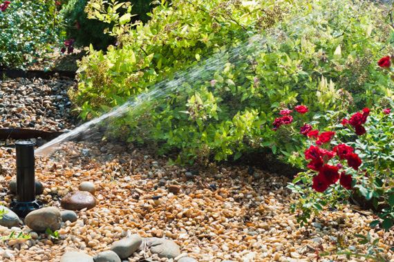
Конроллер HUNTER X-Core. Обзор. Настройка


Как настраивать контроллеры фирмы Hunter X-Core. Подробная инструкция.
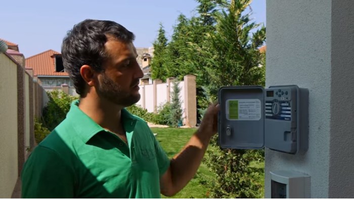
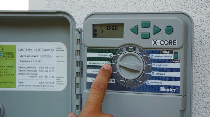
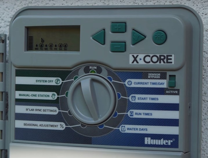
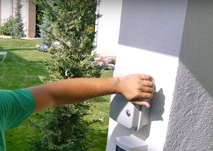
Рассмотрим для примера модель контроллера X-Core для наружного использования. Пульт управления включает в себя дисплей, кнопки
— влево-вправо,
— плюс-минус,
— programm,
— кнопку активации датчика дождя (или байпас) и
— тумблер, который можно вращать вправо и влево.
На лицевой панели контроллера расположены три зоны программирования: зеленая зона, серая и синяя.
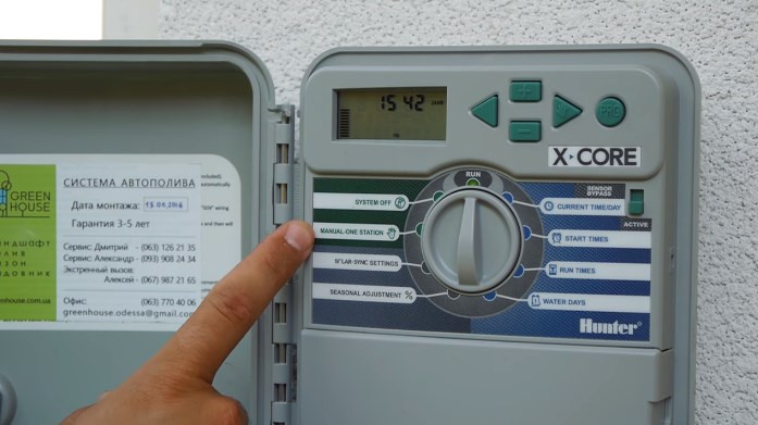
Эти зоны обозначены отдельным цветом не случайно.
Зеленая зона – это безопасная зона, потому что в ней можно легко переключать тумблер, нажимать любые кнопки и при этом никакие настройки не собьются. В синей зоне размещён режим настроек. Если вы, находясь в этой части, будете нажимать на какие-либо клавиши, то либо собьёте установленные настройки, либо настроите так, как в данный момент вам необходимо. В серой зоне расположены дополнительные функции, о которых будет рассказано в конце статьи.
Зеленая зона настроек
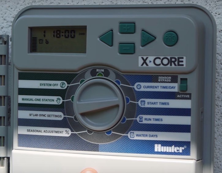
Сразу оговоримся, если на экране мигает надпись АС/0 значит питание отключено.
Настройка контроллера
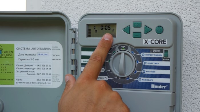
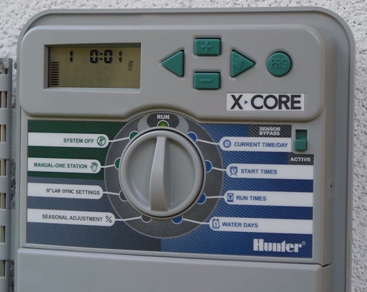
1. Установка текущих даты и времени.
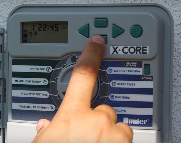
Переключатель в положении CURRENT TIME/DAY
- Год – кнопками «+» и «-» настраиваем год, нажимаем стрелку «>», аналогичным образом задают
- Месяц — кнопками «+» и «-» выбирают месяц; нажимают треугольную стрелку
- Формат времени — 24 или 12;
- Текущее время.

2. Установка времени запуска полива.
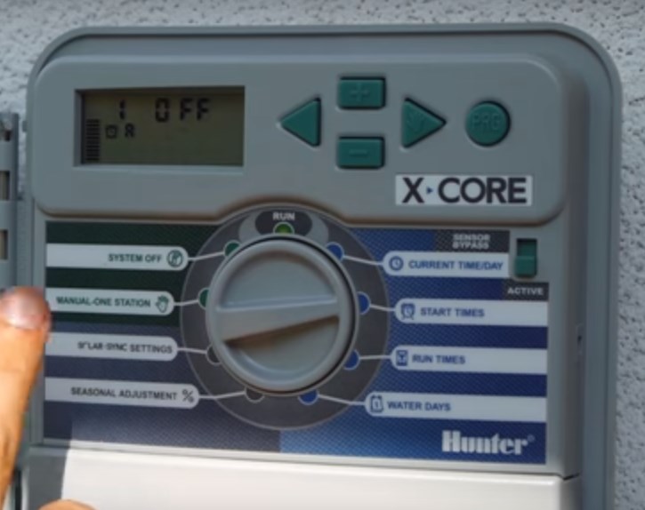
Переключатель в положении START TIMES
В этом положении задают время включения системы полива. В большинстве контроллеров предусмотрены 3-6 программ под номерами, обозначенными арабскими цифрами (1,2,3,…). В каждой программе — присутствуют подпрограммы, обозначенные латинскими прописными литерами (А, В, С,…).
Обычно, полив производят утром и вечером, поэтому необходимо задать два времени запуска полива, к примеру : 1А — 06:00 и 2А — 22:00 . Одно время запуска программы активирует все зоны полива, записанные на эту программу последовательно, одну за другой.
3. Установка длительности орошения.
Переключатель в положении RUN TIMES
В этом положении задают длительность полива каждой из зон.
Эта длительность лежит на пересечении потребности высаженных в данной зоне растений, технических возможностей — объема поливной воды и расхода насосного оборудования и условий — типа грунта, характера местности, и т.п. Если данная величина вам неизвестна, а компания, осуществлявшая монтаж, по каким-либо причинам не может вам помочь, ее придется определить опытным путем или с помощью несложного расчета.
4. Установка дней недели для полива
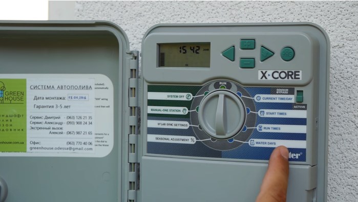
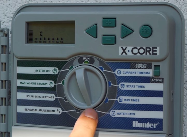
Переключатель в положении WATER DAYS
В некоторых случаях полив нежелателен, например, перед укосом газона, регулярным визитом садовников, вечеринкой в саду. Для того, чтобы без сбоя настроек отменить полив в определенный день недели.
Кнопками « >» или « <» выбираем день, в который полив происходить не должен и нажимаем кнопку «-» выбранный день будет зачеркнут.
Если вышеописанные пункты настройки являются обязательными для работы системы, то дальнейшие относятся, скорее, к опциональным
5. Увеличение/уменьшение длительности полива
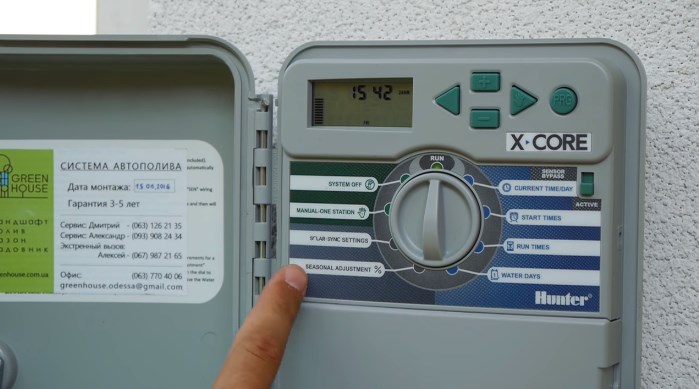
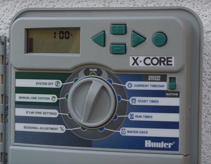
Переключатель в положении SEASONAL ADJUSTMENT%
Функция позволяет без изменения глобальных настроек системы изменить длительность работы полива Такая необходимость может возникнуть во время длительной засухи или затяжных дождей, а также осенью, когда время полива можно постепенно уменьшать. По умолчанию длительность соответствует заданным настройкам, ей присваивается значение 100%, ее значение можно изменить в пределах от 0 до 300 %. Для этого пользуются кнопками «+» и «-».
6. Регулирование в зависимости от погодных условий.
Переключатель в положении SOLAR SYNC SETTINGS
Данная функция дает возможность менять интенсивность полива, если система оборудована датчиком SOLAR SYNC, если датчик в системе отсутствует, интенсивность будет автоматически установлена на отметке 100%.
7. Однократное включение вручную
Переключатель в положении MANUAL ONE STATION
Функция позволяет немедленно запустить вручную нужную программу или зону полива. Это может быть полезно при запуске системы полива для тестирования весной или после смены настроек.
Круглой кнопкой «PRG» выбирают нужную программу, кнопками « >» или « <» — подпрограмму, с помощью кнопок «+» и «-» устанавливают время работы. После чего переводят главный переключатель в положение RUN. Данная функция не меняет глобальных настроек системы.
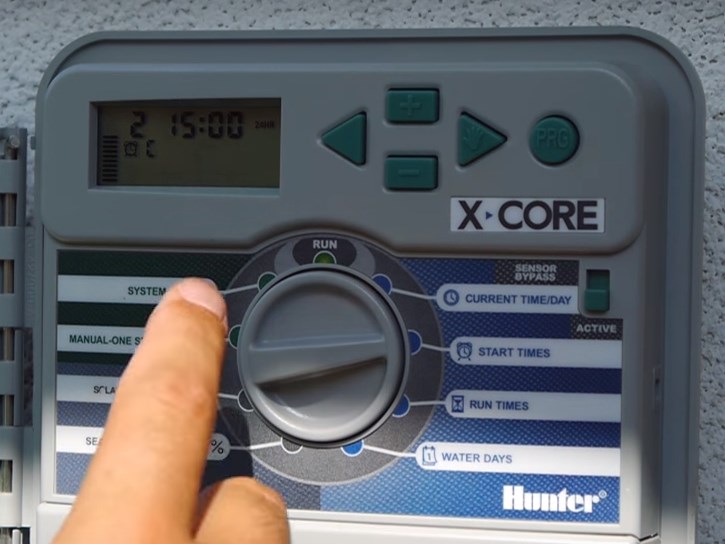
8. Отключение системы.
Переключатель в положении SYSTEM OFF. Функция отключает систему полива без потери глобальных настроек.
Синяя зона. Настройка системы полива.
- Режим CURRENT TIME/DAY – это режим, в котором клавишами настраиваются текущие год, дата и время (как обычные часы).
- Режим START TIMES – режим выставления времени, когда будет включаться автоматический полив.
- Режим RUN TIMES – режим выставления продолжительности полива, т.е. сколько минут или часов будет работать каждая зона полива.
- Режим WATER DAYS – режим выставления дней, в которые будет работать полив зон.
Определение режима полива.
Прежде чем приступить к настройкам режима полива, нужно определиться с тем, что именно необходимо будет поливать на участке. Например, у вас есть газон – это 1-ая зона. Далее, есть высаженные растения – это 2-ая зона. Имеется огород, назовём его 3-ей зоной. Какой выбрать режим полива? Скажем, в тёплых регионах газон принято поливать после 9 вечера и осуществлять его полив ежедневно. Высаженные растения обычно поливаются в вечернее время 3 раза в неделю, а огородным растениям часто нужна влага даже несколько раз в день.
На приведенном ниже примере мы настроим контроллер с условием, чтобы огород поливался утром в 9 часов и даже днем в 15 часов, так как капельному поливу не важно – в какое время будет полив. Он прокапывает очень аккуратно, не вызывая ожогов растений во время солнцепёка. При этом настроим, чтобы огород поливался каждый день, но малыми порциями, чтобы верхний слой почвы и корневая система таких культур, как помидоры, огурцы, петрушка и др. всегда оставались влажными.
Настройка дней полива.
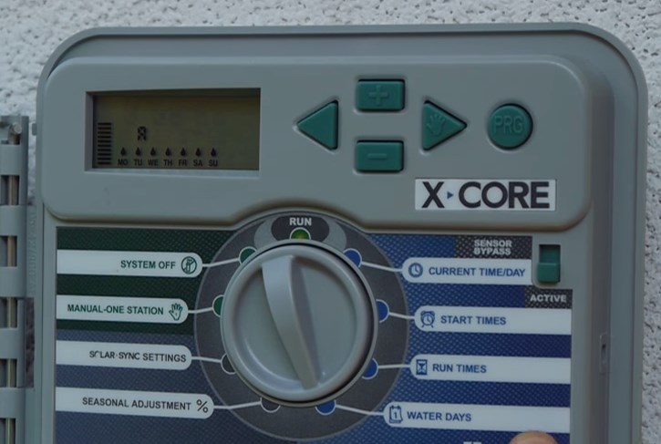
Настройки нужно начинать с режима выставления дней — WATER DAYS. Установив тумблер в это положение, на дисплее отобразится 7 дней недели. Изначально начинает мигать первая капелька, обозначающая понедельник. Если вы хотите, чтобы в понедельник поливало, то нажимаете на зелёную клавишу «плюс». Далее начинает мигать вторая капелька, обозначающая вторник. Если вы не хотите полива во вторник, то нажимаете на клавишу «минус». Среда и четверг – не поливочные дни, значит, по каждому из этих дней жмём «минус». В пятницу – поливает, нажимаем «плюс». Легко изменить настройки с помощью клавиш «влево-вправо», например, вернуться к четвергу и, нажав «плюс», установить полив еще и в этот день.
Объяснения по программам А, В и С
В контроллерах Hunter X-Core предусмотрены настройки трёх программ с помощью круглой зеленой клавиши «Programm». Последовательно нажимая на эту кнопку выбирается одна из трёх необходимых программ А, В или С. Зачем нужны эти программы? Они нужны для того, чтобы каждую зону привязать к соответствующей программе, потому что газон, например, поливается каждый день в определенное время, а высаженные растения не требует полива каждый день. Поэтому правильным будет сначала настроить режим WATER DAYS с привязкой к определенным дням недели. В нашем примере для полива газона клавишей Programm мы выбираем программу «А». Эта зона программируется на полив с частотой 7 дней в неделю.
Для высаженных растений, которым необходим полив 3 раза в неделю в понедельник, среду и пятницу, мы выбираем программу «В». Находясь в режиме WATER DAYS, с помощью клавиш «плюс-минус», выбираем те дни, в которые система будет включать автополив. Те дни, когда полива не будет, на дисплее будут отображены в виде капли внутри круга. Программу «С» мы назначили для огорода, который планируется поливать ежедневно. С помощью клавиши «плюс» программируем полив на каждый день недели.
Сразу оговоримся, если на экране мигает надпись АС/0 значит питание отключено.
Настройка контроллера
1. Установка текущих даты и времени.
Переключатель в положении CURRENT TIME/DAY
- Год – кнопками «+» и «-» настраиваем год, нажимаем стрелку «>», аналогичным образом задают
- Месяц — кнопками «+» и «-» выбирают месяц; нажимают треугольную стрелку
- Формат времени — 24 или 12;
- Текущее время.
2. Установка времени запуска полива.
Переключатель в положении START TIMES
В этом положении задают время включения системы полива. В большинстве контроллеров предусмотрены 3-6 программ под номерами, обозначенными арабскими цифрами (1,2,3,…). В каждой программе — присутствуют подпрограммы, обозначенные латинскими прописными литерами (А, В, С,…).
Обычно, полив производят утром и вечером, поэтому необходимо задать два времени запуска полива, к примеру : 1А — 06:00 и 2А — 22:00 . Одно время запуска программы активирует все зоны полива, записанные на эту программу последовательно, одну за другой.
3. Установка длительности орошения.
Переключатель в положении RUN TIMES
В этом положении задают длительность полива каждой из зон.
Эта длительность лежит на пересечении потребности высаженных в данной зоне растений, технических возможностей — объема поливной воды и расхода насосного оборудования и условий — типа грунта, характера местности, и т.п. Если данная величина вам неизвестна, а компания, осуществлявшая монтаж, по каким-либо причинам не может вам помочь, ее придется определить опытным путем или с помощью несложного расчета.
4. Установка дней недели для полива
Переключатель в положении WATER DAYS
В некоторых случаях полив нежелателен, например, перед укосом газона, регулярным визитом садовников, вечеринкой в саду. Для того, чтобы без сбоя настроек отменить полив в определенный день недели.
Кнопками « >» или « <» выбираем день, в который полив происходить не должен и нажимаем кнопку «-» выбранный день будет зачеркнут.
Если вышеописанные пункты настройки являются обязательными для работы системы, то дальнейшие относятся, скорее, к опциональным
5. Увеличение/уменьшение длительности полива
Переключатель в положении SEASONAL ADJUSTMENT%
Функция позволяет без изменения глобальных настроек системы изменить длительность работы полива Такая необходимость может возникнуть во время длительной засухи или затяжных дождей, а также осенью, когда время полива можно постепенно уменьшать. По умолчанию длительность соответствует заданным настройкам, ей присваивается значение 100%, ее значение можно изменить в пределах от 0 до 300 %. Для этого пользуются кнопками «+» и «-».
6. Регулирование в зависимости от погодных условий.
Переключатель в положении SOLAR SYNC SETTINGS
Данная функция дает возможность менять интенсивность полива, если система оборудована датчиком SOLAR SYNC, если датчик в системе отсутствует, интенсивность будет автоматически установлена на отметке 100%.
7. Однократное включение вручную
Переключатель в положении MANUAL ONE STATION
Функция позволяет немедленно запустить вручную нужную программу или зону полива. Это может быть полезно при запуске системы полива для тестирования весной или после смены настроек.
Круглой кнопкой «PRG» выбирают нужную программу, кнопками « >» или « <» — подпрограмму, с помощью кнопок «+» и «-» устанавливают время работы. После чего переводят главный переключатель в положение RUN. Данная функция не меняет глобальных настроек системы.
8. Отключение системы.
Переключатель в положении SYSTEM OFF. Функция отключает систему полива без потери глобальных настроек.
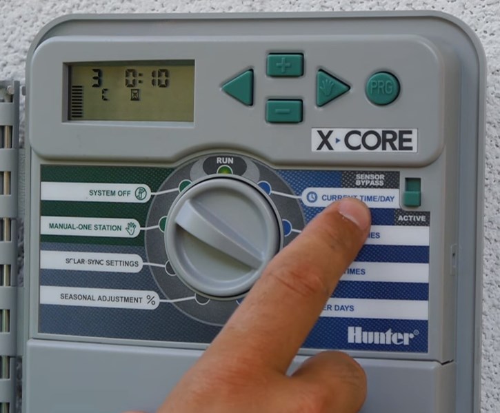
Настройка времени полива
После того, как мы привязали к определенным программам полив газона, высаженных растений и огорода, необходимо задать время включения системы автополива для этих зон. Для этого переводим тумблер в режим START TIMES и выбираем программу А (полив газона). На дисплее появляется значок OFF и цифра 1. Надо помнить, что в этом режиме цифра 1 обозначает начало включения первого полива, а не номер зоны.
Мы хотим, чтобы программа полива газона «А» включалась в 21-00 ч. Следует помнить, что время контроллера необходимо выставлять в формате 24 часа. Нажимая на клавишу «минус», где каждый шаг равен 15 минутам, мы настраиваем время 21-00. Если при этом повернуть тумблер на режим количества дней полива, то увидим, что настройка времени относится ко всем дням недели.
Теперь мы хотим настроить программу «В» для полива высаженных растений. Допустим, начало полива в 18-00 часов. Способом, описанным выше, мы выбираем нужную программу и клавишей «минус» выставляем необходимое время, когда будет стартовать начало полива.
Программа «С» для полива огорода настраивается аналогично предыдущим программам. Огород решено поливать 2 раза в день: в 9 часов утра и в 15-00 ч. Для настройки первого (слева на дисплее цифра 1) утреннего времени полива клавишей «плюс» мы выставляем 9-00 часов. Для того, чтобы установить второе время включения, необходимо нажать на клавишу «стрелка вправо» и при появлении на дисплее цифры 2, настроить необходимое время включения полива на 15-00 часов. У каждой программы предусмотрена возможность задать 4 времени включения полива.
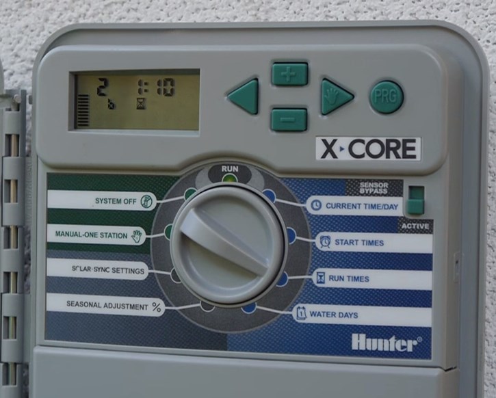
Настройка продолжительности полива.
Устанавливаем тумблер в режим RUN TIMES. Выбираем программу «А» для полива газона, который поливается каждый день и старт полива назначен на 21-00 часов. Клавишей «плюс» мы выставляем продолжительность полива в течение 20 минут. Далее, клавишей «стрелка вправо» выбираем программу «В», где настроена 2-ая зона на полив высаженных растений 3 раза в неделю в 18-00 часов. Этой зоне мы настраиваем продолжительность капельного полива в течение 1 ч. 10 минут. Аналогично настраивается программа «С» для полива огорода на нужную продолжительность полива. Выбрав программу третьей зоны, устанавливаем 10 минут двукратного орошения огородных растений в течение дня. После завершения всех настроек возвращаем тумблер в режим RUN, говорящий о том, что система готова к функционированию.
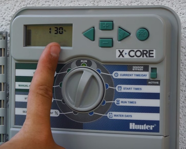
Сезонная корректировка.
Рассмотрим режимы программирования, расположенные в серой зоне контроллера. Они относятся к разряду дополнительных функций. Например, очень удобная функция – сезонная корректировка. Если выставить тумблер в режим SEOSONAL ADJUSTMENT, то на дисплее отобразится значок 100%. Это означает, что все установленные программы со своими настройками будут функционировать строго по заданным параметрам. Если температура воздуха значительно увеличилась, и мы хотим, чтобы по всем зонам увеличилась продолжительность полива, то для этого не обязательно перенастраивать программы для каждой зоны. Достаточно зайти в режим корректировки сезонности и клавишей «плюс» в процентном соотношении увеличить, например, до 130%. Если после таких изменений зайти в каждую зону и просмотреть продолжительность полива, то можно будет увидеть, что время изменилось на 30%. Точно также можно запрограммировать на уменьшение продолжительности полива при похолодании.
Тестовый режим
Если вы хотите проверить как работает ваша система автополива и включить по 1-ой минуте каждую зону, то сделать это достаточно просто. Для этого потребуется зажать кнопку Programm, отпустить её и выставить 1 минуту клавишей «плюс» (можно 2 или 3 минуты). На дисплее появится индикатор полива. Это значит, что система каждую из зон прольёт последовательно по одной минуте.
Датчик дождя RAIN—CLIK
Если на дисплее отображается индикатор с изображением зонтика и значок OFF, то это говорит о том, что сработал датчик дождя. Когда он просохнет, информация на дисплее вернётся в привычное рабочее состояние.

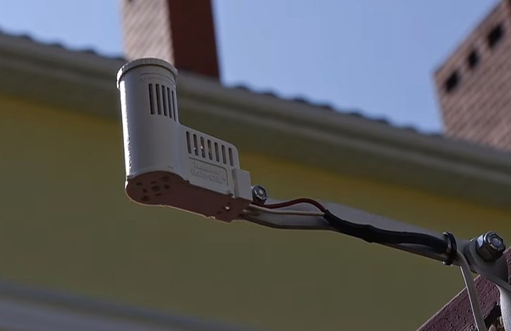
Рекомендация: необходимо контролировать, чтобы во-избежании поломок крышка контроллера всегда была плотно закрытой. Иначе, при дожде в щели может попадать вода.
Вернуться ко всем статьям
-
Contents
-
Table of Contents
-
Troubleshooting
-
Bookmarks
Related Manuals for Hunter X-Core
Summary of Contents for Hunter X-Core
-
Page 1
Residential Irrigation Controller Owner’s Manual and Programming Instructions Compatible with Hunter Remotes and Solar Sync… -
Page 3: Table Of Contents
Testing the Weather Sensor …………11 Programmable Rain Off ……………20 Manually Bypassing the Weather Sensor ……..11 Seasonal Adjustment ………….21 COnneCtInG A HUnteR sOLAR synC et sensOR ….12 Manually Run a Single Station ……….22 Installing Solar Sync Sensor …………12 One Touch Manual Start and Advance ……..22 Installing the Wireless Solar Sync ……….12…
-
Page 4: X-Core Components
X-CorE CompoNENTs Indoor model outdoor model (Internal Transformer Included) note: Plug may look different from illustration Terminal block for -e (International models only)
-
Page 5
X-CorE CompoNENTs lCD Display Allows user to set each valve station run time from 1 minute to 4 hours Run times Allows 1 to 4 start times to be set in each program start times station number Indicates currently selected station number… -
Page 6
Use to attach transformer, sensor, and valve wires from their source to the controller Reset Button Use to reset the controller (located on side of controller) Allows for connection of Hunter SmartPort and Hunter Remote Controls ® sensor Bypass switch Ignores “Clik”… -
Page 7
X-CorE CompoNENTs Dial settings Normal dial position for all controller automatic and manual operation Allows current day and clock time to be set Current time/Day Allows 1 to 4 start times to be set in each program start times Allows user to set each valve station run time from 1 minute to 4 hours… -
Page 8: Mounting The Controller To Wall
THE CoNTrollEr To Wall Note: the indoor version of the X-Core is not water- proof or weather resistant, and must be installed indoors or in a protected area. 1. Secure one screw into the wall. Install screw anchors if attaching to drywall or masonry wall.
-
Page 9: Connecting Valves And Transformer
CoNNECTING ValVEs aND TraNsformEr Installation of the X-Core should only be done by trained personnel. Valve 4 1. Route valve wires between the control valve location and controller. 2. At valves, attach a common wire to either solenoid wire on all valves.
-
Page 10: Activating The Battery
THE baTTEry After installing your X-Core, make sure to remove the battery contact insulator to allow the X-Core to keep time in the event of a power outage. CaUTIoN: RIsk OF eXPLOsIOn IF BAtteRy Is RePLACeD By An InCORReCt tyPe. DIsPOse OF UseD BAtteRIes ACCORDInG tO tHe InstRUCtIOns.
-
Page 11: Connecting A Master Valve
CoNNECTING a masTEr ValVE 1. At the Master Valve, attach the common wire to either solenoid NoTE: Complete this section only if you have a wire of the valve. Attach a separate control wire to the remaining master valve installed in your irrigation system. A solenoid wire.
-
Page 12: Connecting A Pump Start Relay
CoNNECTING a pUmp sTarT rElay NoTE: Complete this section only if you have a pump start relay installed. A pump start relay is a device that uses a signal from the controller to actuate a separate electrical circuit to energize a pump to provide water to your system.
-
Page 13: Connecting A Hunter «Clik» Weather Sensor
CoNNECTING a HUNTEr “ClIk” WEaTHEr sENsor A Hunter weather sensor or other micro-switch type weather When the weather sensor has sensors can be connected to the X-Core. The purpose of this sensor deactivated automatic watering, is to stop automatic watering when weather conditions dictate.
-
Page 14: Connecting A Hunter Solar Sync Et Sensor
CoNNECTING a HUNTEr solar syNC ET sENsor The X-Core is compatible with the Solar Sync and Wireless Solar by using the buttons (refer to page 13 for explanation Sync systems. Solar Sync is a sensor system that will automatically of Solar Sync Region setting). Use the button to advance to the adjust the X-Core controller’s watering schedule (based on…
-
Page 15: Region
CoNNECTING a HUNTEr solar syNC ET sENsor region Use the following table for choosing your region (reference below). You can use methods A, B or C to help you choose which region is For accurate Solar Sync measurements, the controller needs to best for your area: be programmed for the average peak season ET for your region.
-
Page 16: Water Adjustment
Uninstalling a solar sync sensor Water adjustment If a Solar Sync sensor has been installed on the X-Core controller The Water Adjustment is a 1 to 10 scale that allows for easy then the seasonal adjust value used by the controller will be adjustment of the Seasonal Adjust value from the Solar Sync calculated from the weather data supplied by the Solar Sync sensor.
-
Page 17: Calibration/Setup
CoNNECTING a HUNTEr solar syNC ET sENsor Calibration/setup After Solar Sync has been installed and programmed, it is recommended to allow the system to run for a few days at the initial setting. Because of the variety in site conditions (including sensor location, amount of direct sunlight available to the sensor, reflective heat from surrounding structures, etc), the initial setting may require adjustment in order to arrive at the desired performance.
-
Page 18: Connecting A Hunter Remote
(not included). The SmartPort ® wiring harness (included with all • Red wire to left side “24VAC” terminal Hunter Remotes) allows for fast and easy use of the Hunter controls. • White wire to right side “24VAC” terminal The Hunter remotes make it possible for you to operate the system • Blue wire to “REM” terminal without having to walk back and forth to the controller.
-
Page 19: Programming The Controller
THE CoNTrollEr The X-Core display shows the time and day when the controller is NoTE: A basic programming rule is that whatever idle. The display changes when the dial is rotated to indicate the symbol or character is flashing will be the item specific programming information to enter.
-
Page 20: Setting The Program Start Time(S)
2. The display will show the last program morning, afternoon, or evening watering cycles. selected (A, B, or C). You can switch to start times may be entered in any order. the X-Core another program by pressing the button. WATER DAYS will automatically sort them.
-
Page 21: Selecting Specific Days Of The Week To Water
proGrammING THE CoNTrollEr selecting specific Days of the Week to Water selecting Interval Watering 1. With the cursor on a specific day With this option you can select (the cursor will always start with interval watering from 1 to 31 days. MO), press the button to activate 1.
-
Page 22: Setting Event Day(S) Off
THE CoNTrollEr setting Event Day(s) off system off The X-Core allows you to program a No Water Day(s). This feature Valves currently watering will be shut off after SYSTEM OFF is useful to inhibit watering on specific day(s). For example, if you…
-
Page 23: Seasonal Adjustment
THE CoNTrollEr seasonal adjustment Seasonal Adjustment is used to make global run time changes When using a Hunter “Clik” weather sensor, the Seasonal without re-programming the entire controller. To use the Seasonal Adjustment value can be adjusted as described.
-
Page 24: Manually Run A Single Station
proGrammING THE CoNTrollEr manually run a single station one Touch manual start and advance 1. Turn dial to MAnUAL – One stAtIOn position. You can also activate all stations to water without using the dial. 2. Station run time will flash in 1.
-
Page 25: Advanced Features
Test program of all stations The X-Core allows the user to program the controller so that the The X-Core allows the user a simplified method for running a sensor disables watering on only desired stations. For example, test program.
-
Page 26: Easy Retrieve™ Program Memory
Easy retrieve™ program memory programmable Delay between stations The X-Core is capable of saving the preferred watering program This feature allows the user to insert a delay between stations into memory for retrieval at a later time. This feature allows for a between when one station turns off and the next one turns on.
-
Page 27: Troubleshooting Guide
TroUblEsHooTING GUIDE problem Causes solutions The controller is continuously watering Too many start times have been Only one start time is necessary to activate a program programmed (refer to Setting the Program Start Times on page 18) There is no display Check AC power wiring Correct any errors The display reads “No AC”…
-
Page 28
TroUblEsHooTING GUIDE problem Causes solutions Display shows a station is running but The sensor is interrupting irrigation, Check the sensor override status (see page 23) icons are flashing however the station has been programmed to override the sensor Automatic irrigation does not start at • AM/PM of time of day not set correctly • Correct AM/PM of time of day the start time and controller is not in the… -
Page 29
TroUblEsHooTING GUIDE problem Causes solutions Seasonal Adjust seems high • Region too low Decrease the value of the Water Adjustment setting. If you minimize the Water Adjustment scale at 1 and still • Water Adjustment setting too high require reduced seasonal adjustment, move up one Region (from 2 to 3, for example) and start at Water Adjustment setting 5. -
Page 30: Specifications
Use CR2032 3-volt. • Simple manual operation • Electronic short circuit protection • Sensor override by station • Non-volatile memory for program data • Programmable rain delay (1 to 7 days) • UL Listed • Manual Seasonal Adjustment (10% to 150%) • Model X-Core-x00 has an IP2X Rating • Automatic Seasonal Adjustment using Solar Sync sensor • Clean only with a cloth dampened with mild soap and water • Sensor bypass switch Explanation of symbols • X-Core-x00i for indoor use. X-Core-x00 for outdoor use = AC • Sea level to 6500 ft (2000 m) at -13˚ F to 140˚ F (-25° C to 60° C) = Consult Documentation…
-
Page 31: Certificate Of Conformity To European Directives
CErTIfICaTE of CoNformITy To EUropEaN DIrECTIVEs Hunter Industries declares that the irrigation controller Model X-Core complies with the standards of the European Directives of “electromagnetic compatibility” 87/336/EEC and “low voltage” 73/23/EEC. __________________________________ Project Engineer This product should not be used for anything other than what is described in this document. This product should only be serviced by trained and authorized personnel.
-
Page 32
Hunter Industries Incorporated The Irrigation Innovators • © 2011 Hunter Industries Incorporated 1940 Diamond Street San Marcos, California 92078 USA INT-784 9/11 • www.hunterindustries.com… -
Page 33
Pro-C Residential and Light Commercial Irrigation Controllers PCC Series Controller 6, 9, 12 & 15 Station Indoor/Outdoor Models Owner’s Manual and Installation Instructions Please leave with property owner ®… -
Page 36
Selecting Interval Watering …………17 Connecting an SRR or ICR Remote Control ……..8 Run ………………18 Connecting to the Hunter ET System ……….9 System Off …………….18 Connecting to the Hunter Irrigation Management Manually Run a Single Station ……….18 and Monitoring System™… -
Page 37
Pro-C ………………………. -
Page 38
A. – LCD Display C. – Control Dial 1. Program Selector – Identifies the program in use A, B, or C. Run – Normal dial position for automatic operation. 2. Station Number – Identifies currently selected station number. Set Current Date/Time – Set current date time. 3. -
Page 39: Mounting The Indoor Controller To Wall
MoUnTInG THe ConTroller To a Wall …………… All necessary hardware is included for most installations. NOTE: The indoor Pro-C is not weather or water resistant, and must be installed indoors or in a protected area. This device is not intended for use by young children.
-
Page 40: Connecting Valves And Ac Power
ConneCTInG ValVes and aC PoWer …………….1. Route valve wires between control valve location and controller. NOTE: It is recommended that a licensed 2. At valves, attach a common wire to either solenoid wire of all valves. electrician perform the following power This is most commonly a white colored wire.
-
Page 41: Connecting The Battery
ConneCTInG THe baTTerY (optional) ………………Connect a 9-volt alkaline battery (not included) to the battery terminals and place in the battery compartment in the front panel. The battery allows the user to program the controller without AC power. Watering will not occur without AC power. Since this controller has non-volatile memory, the program clock and calendar will be retained during a power outage even if no battery is installed.
-
Page 42: Connecting A Pump Start Relay
Do not connect the controller directly to the pump – damage to controller will result. When a pump is to be operated by the controller, a pump start relay is typically used. Hunter offers a full range a pump start relays for most applications. PSR Series…
-
Page 43: Connecting A Weather Sensor
ConneCTInG a WeaTHer sensor (not included) …………A Hunter Mini-Clik rain sensor or other type of micro-switch weather ® SENSOR BYPASS position to disable the rain sensor from the system sensor may be connected to the Pro-C. The purpose of a rain sensor is to allow for the controller operation.
-
Page 44: Connecting An Srr Or Icr Remote Control
® allowing for fast and easy use of 4. Attach the red wire to the bottom most AC1 the Hunter SRR, or Long Range » Thread screw slot, attach the white wire to the upper ICR remote controls. The SRR…
-
Page 45: Connecting To The Hunter Et System
#SRR-SCWH) with a full 25 feet of shielded cable. ConneCTInG To THe HUnTer eT sYsTeM ET SENSOR The Hunter ET System allows irrigation programs to be created automatically, based on local climate conditions. These programs are then loaded into the controller and run automatically. ET System uses a sensor to determine the local “evapotranspiration”…
-
Page 46: Connecting To The Hunter Irrigation Management And Monitoring System
It’s able to team with any or all of the standard be handled directly at each site’s controller. Scheduling of days to water, automatic controllers in the Hunter line-up, from the SRC to the Pro-C to run times, start times, cycle and soak operations, and more can now the ICC.
-
Page 47: Sprinkler System Fundamentals
sPrInKler sYsTeM fUndaMenTals …………….can be pumped to the location. Each valve is connected via wire to the There are three main components that are involved with all automatic controller. Here the wire is connected to a number that corresponds to sprinkler systems that are made today.
-
Page 48: Creating A Watering Schedule
CreaTInG a WaTerInG sCHedUle ………………. There are some guidelines that should be followed when determining NOTE: It is usually good to water one or two hours when and how long to water. These factors are the soil type, the part before sunrise.
-
Page 49: Watering Schedule Form Example
WaTerInG sCHedUle forM exaMPle …………….
-
Page 50: Programming Fundamentals
1. Select a program (A, B, or C) by pressing We realize that many consumers will have variations in their plant watering needs, so at Hunter we button on the controller (it is equipped the Pro-C with three different programs A, B, and C. These programs are independent recommended to start with Program A).
-
Page 51: Programming The Controller
Pro-C ProGraMMInG THe ConTroller ………………. Residential and Light Commercial Irrigation Controllers Setting the Current Date and Time The display changes when PCC Series Controller the dial is rotated to indicate 1. Turn the dial to the SET the specific programming Owner’s Manual and CURRENT DATE/TIME position.
-
Page 52
ProGraMMInG THe ConTroller (continued) ………….. Setting Program Start Times NOTE: If a program has all four start times turned 1. Turn the dial to the SET off, then that program is off (all other program PROGRAM START TIMES details are retained). Because there are no start position. -
Page 53
ProGraMMInG THe ConTroller (continued) ………….. Selecting Specific Days of the Week to Water Selecting Interval Watering 1. Press the button to activate a particular day of the week to water This feature is convenient if you want to (the display always starts with Monday). Press the button to have a more consistent watering schedule cancel watering for that day. -
Page 54
ProGraMMInG THe ConTroller (continued) ………….. Seasonal Adjustment After programming is complete, turn the dial to Seasonal Adjust is used to make RUN to enable automatic execution of all selected global run time changes without programs and start times. re-programming the entire controller. -
Page 55
ProGraMMInG THe ConTroller (continued) ………….. One Touch Manual Start and Advance You can also activate a program to water without using the dial. 1. Hold down the button for 2 seconds. 2. This feature automatically defaults to program A. You can select program B, or C by pressing program. -
Page 56
adVanCed feaTUres ………………….Set Pump/Master Valve Operation 4. Turn the dial back to the RUN position at which time, OFF, a number and the DAYS The default is for all stations to have the icon all remain on. master valve/pump start circuit ON. The 5. -
Page 57
HIdden feaTUres ……………………. Program Customization Programmable Delay Between Stations The Pro-C comes factory configured with 3 independent programs (A, B, This feature allows the user to C with four start times each) for different plant type requirements. The insert a delay between when Pro-C can be customized to display only the required programs. -
Page 58
HIdden feaTUres (continued) ……………….. Programable Sensor Override When the Pro-C receives an input from the sensor to disable watering, the display will indicate those The Pro-C allows the user to program the controller so that the sensor stations that have been programmed to override disables watering on only desired stations. -
Page 59
When a field wiring short is detected, an ERR symbol preceded by the station number will momentarily flash on the controller LCD display. After the Hunter Quick Check completes running this circuit diagnostic procedure, the controller returns to… -
Page 60
TroUblesHooTInG GUIde ………………..PROBLEM CAUSES SOLUTIONS The controller repeats itself or continu- Too many start times (user error). Only one start time per active program is ously waters, even when it should not be required. Refer to “Setting Program Start on (cycling repeatedly). -
Page 61
TroUblesHooTInG GUIde (continued) …………….PROBLEM CAUSES SOLUTIONS The display reads “SENSOR OFF”. The rain sensor is interrupting irrigation or Slide the Rain Sensor switch on front panel the sensor jumper is not installed. to the BYPASS position to bypass rain sensor circuit, or install the sensor jumper. -
Page 62
sPeCIfICaTIons ……………………Operating Specifications • Station Run Time: 1 minute to 6 hours on programs A, B, and C. • Start Times: 4 per day, per program, for up to 12 daily starts. • Watering Schedule: 7-day calendar, interval watering up to a 31-day interval or true odd or even day programming, made possible by the 365-day clock/calendar. -
Page 63
This booklet is available from the U.S. Government Printing Office, Washington, D.C., Stock No. 004-000-00345-4 (price – $2.00) CerTIfICaTe of ConforMITY To eUroPean dIreCTIVes Hunter Industries declares that the irrigation controller Model Pro-C complies with the standards of the European Directives of “electromagnetic compatibility” 87/336/EEC and “low voltage” 73/23/EEC. -
Page 65
To Decrease Arc 1. Insert the key end of the Hunter wrench into the adjustment socket (Fig. 2 & Fig. 3). 2. While holding the nozzle turret at the right stop, turn the wrench counterclockwise. Each 360˚ turn of the wrench decreases the arc 45˚. -
Page 66
I-25 Ultra Performance Charts I-25 Ultra Nozzle I-25 Ultra Nozzle I-25 Ultra High-Speed Nozzle I-25 Ultra High-Speed Nozzle Performance Data Performance Data Performance Data Performance Data Pressure Radius Flow Precip in/hr Pressure Radius Flow Pressure Precip in/hr Radius Flow Precip in/hr Pressure Radius Flow… -
Page 67
(Fig. 1). Nozzle Installation 1. Insert the key end of the Hunter wrench into the lifting socket Arc Adjustment of a pop-up sprinkler. Pull the riser up to gain access to the Socket nozzle socket. -
Page 68
I-40 Institutional Series ™ Gear-Driven Sprinklers I-40 I-40 I-40 I-40 High Speed I-40 High Speed I-40 High Speed I-40 Dual Opposing I-40 Dual Opposing I-40 Dual Opposing Nozzle Performance Data Nozzle Performance Data Nozzle Performance Data Nozzle Performance Data Nozzle Performance Data Nozzle Performance Data Nozzle Performance Data Nozzle Performance Data… -
Page 69
The right side arc can easily to Decrease the arc: be realigned. One way to 1. Insert the plastic key end of the Hunter wrench into the adjustment socket realign the right stop is to (Fig. 3 & 4). turn the whole sprinkler body assembly and the fitting 2. -
Page 70
0.76 “Looks good, works hard. Pressure Radius Flow Precip mm/hr 0.73 0.84 Nozzle Bars l/min 0.74 0.86 Commit to Hunter’s Blue Nozzles 0.10 0.75 0.87 0.11 10.5 0.78 0.90 for choice coverage with no more 0.13 10.5 0.96 1.10 0.15 11.9… -
Page 71
5000 & 5000 Plus Series Rotors (including PRS models) Installation Instructions Radius Adjustment slot Pull-up slot Cavité de soulèvement de la tige Cavité de réglage de la portée Ö ffnung zum Hochziehen Strahlstörschraube Ranura de elevación Ranura de ajuste del radio de alcance Ranhura de puxar Ranhura de ajuste do raio de alcance Alloggiamento chiave di sollevamento… -
Page 72
English Installation Instructions Deutsche Installationsanleitung Einsetzen und Herausnehmen der Düsen: Installing and Removing Nozzles: 1. Stecken Sie das Werkzeug in die dafür vorgesehene 1. Insert tool into pull-up slot, turn 90 degrees, and lift up stem. (A) Öffnung, drehen es um 90° und ziehen den Aufsteiger hoch. (A) 2. -
Page 73
Instrucciones para la instalación – español Odhgºeq egkatåstashq Cómo instalar y remover las boquillas: Egkatåstash kai apomåkrynsh akrofysºvn: 1. Introduzca la herramienta en la ranura de elevación, gire 90 grados 1. Topoueteºte to ergaleºo sth sxism¸ trab¸gmatoq, peristr™fete y tire hacia arriba para levantar el vástago (portaaspersor). (A) 90 moºreq, kai anyc√nete to st™lexoq toy ektojeyt¸ra (A) 2. -
Page 74
Instruções para instalar — português Istruzioni di installazione — italiano Como instalar e remover bocais: Per Installare e Rimuovere gli Ugelli : Insira uma ferramenta na ranhura de puxar, gire 90 graus e 1. Inserire l’apposita chiave nell’allogamento previsto, ruotare levante a haste. -
Page 75
Instructions d’installation – français Nederlandse Installatie Handleiding Installer et retirer la buse : Installeren en Verwijderen van Nozzles: 1. Steek het hulpstuk in de sleuf, draai dit 90 graden en trek de 1. Introduisez l’outil dans la cavité de soulèvement; tournez à 90 degrés et soulevez la tige escamotable. -
Page 76
5000/5000 Plus Nozzle Performance Türkçe kullanma kılavuzu Nozulların yerles ¸tirilmesi ve çıkartılması: (Standard) (Metric) 1. Gövdeyi kaldırma giris ¸ine aparatı sokarak 90 derece döndürün, Standard Angle Rain Curtain Nozzle Performance Standard Angle Rain Curtain Nozzle Performance ve gövdeyi kaldırın. (A) ■… -
Page 77
5000/5000 Plus Low Angle Nozzle Performance 5000/5000 Plus PRS Nozzle Performance (Standard) (Metric) (Standard) (Metric) Low Angle Nozzle Performance Low Angle Nozzle Performance Standard Angle Rain Curtain Nozzle Performance Standard Angle Rain Curtain Nozzle Performance ■ ▲ ■ ▲ ■ ▲… -
Page 78
5000/5000 Plus PRS Low Angle Nozzle Performance 5000/5000 Plus PRS Series Rotor (Standard) (Metric) Low Angle Rain Curtain Nozzle Performance Low Angle Rain Curtain Nozzle Performance ■ ▲ ■ ▲ Precip. Precip Inlet Precip. Precip. Rubber cover Inlet Radius Flow Nozzle Radius Flow Flow… -
Page 79
Rain Bird Corporation Rain Bird Europe S.A.R.L. Rain Bird Sweden 6991 E. Southpoint Rd., Bldg. #1 900 Rue Ampère, BP 72000 PL 345 (Fleninge) Tucson, AZ 85706 USA 13792 AIX-EN PROVENCE CEDEX 3 260 35 Ödåkra Phone: (520) 741-6100 FRANCE Sweden Fax: (520) 741-6522 Tél. -
Page 80
Advanced Commercial Controller Owner’s Manual, Installation, and Programming Instructions for ACC and ACC Decoder Controllers ■ ■ ACC-1200 12 Station Controller, 42 Station ACC-99D 2-Wire Decoder Controller with Capacity, Metal Cabinet 99 Station Capacity, Metal Cabinet ■ ■ ACC-1200-PP 12 Station Controller, 42 ACC-99D-PP 2-Wire Decoder Controller Station Capacity, Plastic Pedestal with 99 Station Capacity, Plastic Pedestal… -
Page 82
Key COnneCtIOnS 24 VAC teSt terMInAl COnneCtInG the MASter VAlVe(S) AnD/Or PuMP StArt relAy(S) COnneCtInG A rAIn Or freeze Shut Off DeVICe COnneCtInG the hunter flOW SenSOr COnneCtInG Other flOW SenSOrS ICr reMOte COntrOl Multiple Stations simultaneously COnneCtInG tO IMMS… -
Page 83
Setting Station Run Time Duration Changing Seasonal Adjust Using the Global Setting Using a Program Specific Setting (set Season Adjust by Program) Timed Delay between Stations Setting Days to Water Set Days to Water Day of the Week Watering Interval Watering Odd/Even Watering Setting Pump and Master Valve Operation Set Pump and Master Valve Operation… -
Page 84
View Station Logs Advanced Features View Version and Station Size COMMOn AlArM (AttentIOn) MeSSAGeS Overcurrent Overflow Power Outage/Power Restored Underflow eXtenDeD feAtureS Contrast Adjustment No Water Window To set a No Water Window No Water Window rules Delay Between Stations To set a Delay P/MV Style (Normally Closed/Normally On) To change the Normal condition of P/M outputs… -
Page 85
Setup Overview Connect an HFS Meter to an ICD-SEN Connect a Clik Sensor to an ICD-SEN SEN/DEC Setup Other SPeCIAl DeCODer funCtIOnS (ADVAnCeD feAtureS) View Decoder Config Display ADM Current Sen/Dec Alarms ACC SOlAr SynC Preparation Facepack Version Master Module Base Run Times Installation Setup… -
Page 86
COMMunICAtIOn MODule InStAllAtIOn fOr PlAStIC PeDeStAl COntrOller Radio Installation, additional steps SetuP AnD ADDreSSInG the COM MODule Set the Controller Address Other Com Setup Functions Master Controller Contrast Radio Type Last MR Cmd (Radio Only) DTMF Wait (Radio Only) MR Default Run Time (Radio Only) Modem Type Country Code… -
Page 87
With plug-in Com and other modules, the ACC can also communicate with a computerized central control system via hardwired cable, radio, dial-up telephone, or cellular modem. ACC is also prewired to accept Hunter wireless remote controls. -
Page 88
aCC InTerfaCe and Key ComponenTs ……..1. lCD Display – Backlit, adjustable contrast display 8. left and right buttons – Used to move left and right in (re-lights when any button is pressed) some screens 2. + button – Increases flashing value, depending on 9. -
Page 89
WIrInG ComparTmenT InTerIor ……….1. Inner Door – Opens to main wiring compartment 9. Master Module – Includes sensor, Pump/Master Valve, and other accessory connections 2. AC Wiring compartment – For connection of 120/230V AC power with 1 x 0.75″ (19 mm) conduit opening 10. -
Page 90
meTal CabIneT, Wall mounT InsTallaTIon ……. Tools required: Positioning Hanger • Long drill bit and extension • Philips screwdriver or bit (for use with long extension) – magnetic recommended • Wire strippers 31″ (80 cm) Facepack Door Mounting Holes Remove the facepack assembly from the controller. 1. -
Page 91
ConneCTInG aC maIn poWer, Wall mounT CabIneT ….The ACC can operate with either 120 VAC or 230 VAC power, depending on how the incoming AC wires are connected. The green, or green-and-yellow safety ground Supply wires must be 14 AWG (2 mm) or larger. may not be required or permitted with this floating ground, double-insulated transformer. -
Page 92
meTal CabIneT opTIonal pedesTal InsTallaTIon ….. Location Requirement: A) a switch or circuit-breaker 3. Level the mounting bolts before the concrete sets. shall be included in building installations; B) the switch 4. After the concrete sets, remove the door of the or breaker shall be in close proximity to the controller, pedestal and slide the pedestal down onto the four and within easy reach of the operator;… -
Page 93
ConCreTe base InsTallaTIon ………… bottom of the thread and slide each bolt through the 1. Set forms for a 21″ (533 mm) wide x 26″ (660 mm) hole in the template. Put a washer and nut on each long concrete base. The base pad should be 2″ (50 J-bolt to secure it to the template (allow a minimum mm) above grade for proper drainage. -
Page 94
ConneCTInG plasTIC pedesTal aC maIn poWer ……120 VAC COnneCtIOn The ACC Pedestal controller can operate with either 120 Place the Voltage Selector Switch in the “115V” position. VAC or 230 VAC power. Connect the incoming black (or “hot”) wire to the Red wire Supply wires must be 14AWG (2 mm) or larger. -
Page 95
Junction Voltage Selector Switch Controller Power Switch Terminal Block: Terminal Block: red Wire = blue Wire = neutral «hot» or Active White (uS) 120V black blue (International) 230V brown… -
Page 96
ConneCTInG earTh Ground (all ConfIGuraTIons) ….The ACC features a copper earth ground lug, to the Ground Lug immediate right of the transformer assembly. This earth ground connection is isolated from the primary AC power and is used to ground incoming surges from the communications and output valve wires. -
Page 97
InsTallInG sTaTIon modules…………. ACC expands in 6-station increments with intelligent output modules, requiring no tools to install and only a screwdriver for station wiring connections. The base configuration is 12 stations (two 6-station modules installed) with a maximum station capacity in a metal wall cabinet of 42 stations (7 total output modules x 6 stations each). ACC can be expanded at any time with either of the following types of modules: 1. -
Page 98
Upper Deck cover Each station output is rated for 0.56 A, max or enough to operate two typical Hunter solenoids simultaneously. Once the output module is installed in the slot, the station numbers assigned to the output module appear in the upper deck label above each slot. -
Page 99
Hunter HFS flow sensor 7. ET connections (+ and -) – Not used. Connections for Hunter ET Sensor only. If upper ET terminal is colored red, Master Module requires update for use with ET. 8. If Master Module has a sticker that says “ET Ready,” or if the version number of the module is 4.0 or later, the… -
Page 100
Set Pump Operation section of the Programming and Operations portion of this manual. ConneCTInG a raIn or freeze shuT off deVICe ……. Up to 4 Hunter sensors can be connected to the ACC Hunter Clik sensors are usually normally closed, and open controller, including: on alarm. -
Page 101
Set Sensor Operation section of the WRC instructions. Programming and Operations. ConneCTInG The hunTer floW sensor ……..The HFS is the primary flow meter for which ACC flow functions have been designed. Additional types of flow sensor connections may also be possible. -
Page 102
This connection is automatically compatible with Hunter ICR and SRR remote receivers. To connect: remove the weather-resistant rubber cover (metal cabinet versions), align the remote receiver’s pins with the mating receptacle, and push firmly until the receiver is fully seated. -
Page 103
Stacking and SmartStack rules do apply when manual program ICR commands are sent to the ACC. If a program ConneCTInG To Imms …………..hunTer IrrIGaTIon manaGemenT and monITorInG sysTem ACC controllers can upgraded to provide full two-way DIAl-uP telePhOne (ACC-COM-POtS) communications with central control software (IMMS 2.0). -
Page 104
All radio communications for ACC work with RAD3 radio interface to all radio-equipped ACC/AGC controllers. module or later. IMMSR radios, designed for original See Hunter’s ACC System Design Guide for important IMMS Site Interfaces and Controller Interfaces, will NOT details regarding design of central control systems. -
Page 105
6. return the dial to the run position. This is all that Off after the last “real” station has run. is required for the most basic operations. ACC will test actually starts stations, and this will cause water automatically in any dial position except actual watering in a fully installed system. -
Page 106
SettInG Current DAte AnD tIMe To Set Program Start Times Three items are programmed at this position: • Time of Day and Date, the day of the week sets automatically • Daylight Savings time usage • Units of measure, English or Metric Turn the dial to the SET CURRENT DATE/ TIME position 1. -
Page 107
CAUTION: Understand your irrigation system’s hydraulic restrictions before allowing programs to overlap. Overlapping programs may overdrive the hydraulics of your system. Overdriving your hydraulics will damage the components and result in inferior sprinkler performance. More advanced programming overlap options are available by turning the dial to the SET PROGRAM OVERLAP OPTIONS dial position. -
Page 108
nOte: If the ACTUAL value is different from the PROGRAMMED value, Seasonal adjust has been changed from the default of 100% to a new value. The actual run time is the duration the station will water. Turn the dial to the SET STATION RUN TIMES position. Using the Global Setting 1. -
Page 109
Day of the Week Watering 3. Press the – button when the cursor is on a day that you do not want to water. An “N” will appear, to show that day is never able to water, regardless of the schedule. -
Page 110
4. Press the + or – button to change the Cycle cursor value. The default cursor value is N/A. Cycles can be set from 1 minute to 6 hours. 5. Press the right arrow button to move from Cycle to Soak, once a value has been entered into the Cycle field. -
Page 111
…………The ACC is capable of monitoring, learning, and reacting to Real-Time flow. The installation of the optional Hunter Flow Sensor (HFS) or a Data Industrial flow sensor is required for this feature to function. The ACC must first learn the normal flow, by station, for flow sensing to operate correctly. -
Page 112
4. If some individual stations do not have learned flow, the display will show Flow Not Learned at the top, when the Information button is pressed with the dial in the Run position. When a station with no learned flow is running, flow monitoring is temporarily disabled. -
Page 113
5. If the flow sensor selection has been changed to NONE after learning, the display will show FLOW NOT MONITORED. The actual flow may still be viewed, even if all stations have been set to Not Monitored. Station level alarm diagnostics would not be available, but the flow will be visible. -
Page 114
• It may take a full hour or longer to learn flows for The default Limit is always 115%, meaning the station an entire 42-station controller. Each station may must exceed the flow by 15% before it will be treated take from 35 seconds to 5 minutes to be learned, as an alarm (to prevent false alarms due to normal flow depending on stability of the flow. -
Page 115
If the station passes (runs within the Limit), the controller To view the diagnostics while they are in progress, press will Pause the station, and move on to test the next station the Information button. This will clear the Attention, Flow that had been running (if applicable). -
Page 116
• The primary purpose of Underflow alarms is to protect a Pump from deadheading, if a station has failed to open. If a station that has learned flow is activated for test purposes without turning on an actual valve, an Underflow alarm may occur. -
Page 117
Once a response (SUSPEND or PAUSE) has been set for a Program, all sensor responses must either be the same, or Off. A Program cannot be both Paused and Suspended at the same time. If a Pause response is set for Program A to Sensor 2, then Pause is the only response that can be set for Program A. -
Page 118
sensor alarms (ClIK sensors sen 1–4 only) ……Whenever a sensor alarms (changes to Open from its If a Program configured for shutdown by that sensor was Normally Closed state), an ATTENTION message appears active when the alarm occurred, it will either Suspend or in the display if a program response has been configured Pause as configured. -
Page 119
Sensor alarms have no effect on Manual Single-station If a sensor is alarmed, and a Manual Program start is starts that are running. attempted for a Program with a response for that sensor, the display will show “CANNOT RUN MANUAL. A sensor is Sensor alarms have no effect on Custom Manual active for this program.”… -
Page 120
• ET Sensor: A Hunter model ET Sensor may be used for certain alarm inputs. The ET Sensor is a sensor platform, and three of its individual sensors can be used as sensor inputs for alarm purposed to the ACC Controller. The controller still has four sensor inputs, but you may set the location of each sensor to Controller (terminals SEN 1–4 on the controller’s… -
Page 121
SenSOr lOCAtIOnS Individual ET sensors can be used to perform alarm shutdowns, by assigning them to the Sen 1-4 positions in the controller. The ET Sensors will then function exactly like “Clik” Sensor inputs. They may have Suspend or Pause responses set by Program. Assigning ACC Sensor 1-4 alarm functions to an ET Sensor is done without connecting any additional wires. -
Page 122
seTTInG proGram oVerlap opTIons ………. There are three program overlap options. These options allow you to maximize the number of stations operating simultaneously, if the system’s hydraulics can support the flow. To program the Program Overlap option: 1. Turn the dial to the SET PROGRAM OVERLAP OPTIONS position 2. -
Page 123
Information operated as a single unit. screens. The factory default setting is Hunter Industries contact information, but it can be replaced with the Combining stations into SSGs shortens programming… -
Page 124
daTa hIsTory …………….Name a Program (Up to 12 Characters and Spaces) This dial position allows you to view flow totals and various logs containing important histories of all activify. 1. Turn the dial to the SET STATION & PROGRAM NAMES position. -
Page 125
The Station Log will store up to 1500 events, and records all station activity, including every start and stop of each station. It may include alarm events if applicable. A complete list of possible Station Log messages appears near the end of this manual. Alarm log items labeled “Missed Irrigation”… -
Page 126
If station size is incorrect, or shows “0” or “1”, check that Powerlock slide is in the ON (locked) position. Check that all station module contacts are in good order and that the modules are fully inserted. Make sure powerlock tabs on front of modules have good contact with the slide lock. -
Page 127
ADM means the ADM99 decoder output module, and shows that the meter or sensor input has been assigned to an ICD-SEN sensor decoder in the two-wire path. ET followed by a sensor name means the input has been assigned to an ET Sensor. ET Functions are described in their own section in this manual. -
Page 128
Pause and go into alarm diagnostic mode. P/MV outputs have a max output of 0.325 A. Pump start relays with very high current requirements may need a dedicated transformer and an additional relay (such as Hunter Model PSRB) for reliable operations. -
Page 129
unDerflOW Alarm diagnostics consist of pausing all operations, then A station has caused too little flow, indicating a possible starting each station that was running at the time of the problem. The underflow amount cannot be set directly, alarm individually. Each of these suspect stations has its but is twice the percentage of the Limit amount set for flow sampled alone, to see if it caused the overflow. -
Page 130
If a start time has already been programmed, and the nO WAter WInDOW operator attempts to enter a No Water Window which No Water Windows prevent any automatic irrigation overlaps the start time, the display will flash a warning. from occurring during certain hours, by Program. This can be used to protect high traffic areas from accidental programming, or the results of Seasonal Adjust, during busy times of day. -
Page 131
To set a Delay 1. Use the Program button to select the Program for which the Delay is to be set. 2. Use the +/- keys to set the delay in h:mm:ss format. Use the left and right arrows to move through the hour, minutes, and seconds fields until the delay is set. -
Page 132
ACC’s Real Time Flow Monitoring is designed to work with designed to operate with true Normally Open valves. Hunter HFS flow sensors. It is necessary to tell ACC what size fitting the HFS has been installed into, so that flow can ACC’s two Pump/Master Valve outputs (labeled on the… -
Page 133
Additional settings for OTHER 2. Use the down arrow button to move to Select Flow Sensor, and press the + button to choose it. Most other brands of flow sensor require two settings for calibration, the K-factor and the Offset. The correct settings for these values are found in the sensor manufacturer’s documentation, and they are based on the pipe type and size. -
Page 134
To create and use SSGs: In order to create and use SSGs, the controller must first be placed into the SSG/Smartstack mode. 9. Use the down arrow to go to the next station line, to add another station to the SSG. 1. -
Page 135
Once the controller is in ACC Setup mode, all 20 SSGs are available, whether they are used or not. DELETING AN SSG Technically SSGs are never deleted, as there are always 20 available.Instead, simply select the unwanted SSG, and delete the stations contained in it until no stations are listed under the SSG name. -
Page 136
CuStOM MAnuAl PrOGrAM SetuP programmed to use Cycle and Soak with the “Y” selected. If you want the stations or SSGs to use their normal Cycle Press the INFORMATION button and turn the dial to and Soak settings (if applicable), leave the option set to Manual Operation. -
Page 137
StArt A CuStOM MAnuAl • Turn the dial to the Manual Operation position. • Use the Program button to select the Custom Manual program (Custom Manual programs will appear after the A through F selections). • Turn the dial to Run, to start the Program at the beginning. -
Page 138
SAVE will be highlighted. Press the + button to save the • The Test Program will try to start ALL stations counted program, and a confirmation message will appear. The by the controller. If you are running a Test Program on Save can still be cancelled with the –… -
Page 139
one TouCh manual sTarT …………advance through all the stations/SSGs in a Program. • If the controller is running that last (highest numbered) station or SSG with a run time in the selected program, and the right arrow button is pressed again, the station will be stopped and no new stations will be started (the program will have completed). -
Page 140
“Program” will allow an entire Program to be run immediately, and will also allow the Program to be started at any station (to run from that point to the end). • Use the Program button to select the Program (Custom Manual programs will appear after the A through F selections). -
Page 141
(then release the Programs button). these operations are not reversible! Reset should only be performed if: a) a “clean start” is desired for programming purposes, or b) if directed to do so by Hunter Technical Services as a troubleshooting technique. -
Page 142
The display will show the following Reset options: • Programs: Erases Day schedules, start times, and run times. • Flow Totals: Clears the running flow total histories (they will restart with 0.0 for all entries), only. • Logs: Clears alarm, controller, and station logs, only. •… -
Page 143
When programming a 2, 4, or 6-station decoder, you only assign a station number to the first station output. The Blank (Off) : Normal. other stations are automatically filled in by the decoder in Solid Red: Problem in decoder out put Green when communicating down module numerical order, depending on the decoder size. -
Page 144
5. The display will show “DECODER FUNCTIONS,” at the bottom of the selections. Use the down arrow button to select Decoder Functions. Press the + button to select. 6. The Decoder Functions screen will appear, with “Program a Decoder” highlighted. (The other functions are explained in detail in the Special Decoders Section). -
Page 145
Decoders may be reprogrammed at any time. If it is “Controller” means the selected P/MV output will operate necessary to change the station numbers or other settings through the screw terminal with that number on the of a previously programmed decoder, the decoder may be Master Module, in the controller. -
Page 146
Hunter HFS flow meters may only be connected to Port A. path, and that the location of the HFS or Clik Sensors are mapped to the ADM, described in the section titled, “Set Clik sensors may be attached to either port. -
Page 147
• If you are unable to enter an address or port for a inserted into the Programming Port, a screen will sensor or flow meter, the Location for that device appear with the decoder settings. has probably not been set to “ADM.” Return to the •… -
Page 148
address or the sensor selections at anytime, if • Once the sensor decoders are configured, the changes occur to the system. controller will immediately begin polling the sensor • Turn the dial to “Set Sensor Operation.” There decoder continuously to monitor the alarms. This may is a display page for each Program, allowing cause alarm messages until the sensor decoders are the responses for each sensor to be set. -
Page 149
to the current draw, even when they are not running. Decoders require a tiny amount of current just to stay awake, about 5 mA. • With a connected two-wire path, the mA reading in standby mode (no stations running) will vary depending on the number of decoders and other factors. -
Page 150
• Facepack updates may be obtained from the • The Solar-Sync compatible master modules were not Resources section of the Hunter Industries web site available before November, 2009. (www.hunterindustries.com). • Master Modules cannot be updated in the field. -
Page 151
The asterisk disappears after a full 24 hours of sensor data has • The Solar-Sync sensor cannot be installed at the same been collected. time as a Hunter ET Sensor. Only one sensor can be connected to the ET terminals. -
Page 152
SenSOr teSt • The settings will be set to Region 3, Water Adj. 5. Either of these factors can be changed, based on the • When the sensor is installed, it is possible to test the following explanations. connection to the Solar-Sync sensor. •… -
Page 153
• Select Solar Sync Check. The screen will show “Initializing…” for a few seconds as the controller contacts the sensor. • If the check is successful, the screen will show “Sensor Check OK”. Continue with the Operation and Adjustment procedures if necessary. •… -
Page 154
• Press and hold the Information button, while turning • If the Sensors (S1, 2, 3, and 4) are set to Off, they will the ACC dial to the Set Sensor Operation position. not shutdown the selected Program. Then, release the Information button. •… -
Page 155
MAKInG ADjuStMentS • Notice that as the Water Adjustment factor is changed, the current S-Sync Adjust amount at the top of the After programming the Solar Sync module and your screen is changed. This can help you predict how controller, allow the system to operate for 3 days to gather much more or less watering will occur, as a result of sun and temperature data. -
Page 156
SOlAr-SynC SenSOr AlArMS • Use the – or + buttons to step backward and forward through the Controller Log to track the S-Sync S-Sync RAIN ALARM, S-Sync TEMP ALARM changes. Each log will show the date and time, and the Before and After settings for Seasonal Adjustment. -
Page 157
S-SynC COMM fAIlure • If the Solar-Sync sensor fails to respond to the ACC controller, a Comm Failure message will be posted on the display and a log will be entered in the controller Alarm Log. • This may indicate a problem with the wiring from the controller to the Solar Sync sensor. -
Page 158
ET Sensor is connected. When ACC is in a computer central control system, it can be used to report ET from a Hunter ET Sensor to the central After each ET function, it is possible to press the Back computer via IMMS control software. -
Page 159
Operation enabled, and set to YES, more ET FUNCTION ET, Rainfall, Wind speed, and Temperature will be options will be available and viewed in the ET FUNCTIONS displayed according to the Units of Measure setting at the home screen. Set Current Date/Time dial position. NO will hide all ET functions and the daily ET will not Readings can be updated at any time, by performing a new be read or displayed, and no ET will be available for the… -
Page 160
Turn the dial to another position, and then back to the alarm and the actual shutdown. If this is not acceptable, a Set Sensor Operation dial position (without holding separate sensor (such as Rain-Clik or Freeze-Clik) should Information). At this location, choose the Suspend or be installed and wired directly to one of the Sen 1-4 inputs Pause responses for each ET Sensor by program for instant shutdowns. -
Page 161
eVenT mode opTIons (aGC, surVeyor) ……..Event Mode is a special function of the controller designed to work with Surveyor Golf control software. Event mode allows the controller to run individual station events which have been created for it by golf control software. -
Page 162
First, select the Event Day you wish to view (1, 2, or 3). Delete Events: This will permanently delete all downloaded Then press the right arrow button to view the downloaded System Events. The controller will not be able to irrigate events for that day. -
Page 163
ACC-COM-POTS, or the ACC-COM-GSM (E) does not controllers, via optional RAD3 UHF radio modules (sold contain a radio. It is designed for use with a Hunter RAD3 separately) with antenna for wireless communications, UHF radio, which must be ordered separately. -
Page 164
Pedestal mounted controllers have a power terminal switch, which can be pressed to the OFF position. Hardwired communications also requires Hunter GCBL • Note that there are additional steps listed for installation with RAD3 radio modules. CommunICaTIon module InsTallaTIon for Wall mounT ConTroller ……………. -
Page 165
8. Insert the ACC-COM module into the opening where the the RAD3, before installing the radio into the radio logo cover was, with the display and buttons protruding compartment. through the opening. Secure with 4 screws (supplied) • Install the radio into the radio compartment (see on each corner. -
Page 166
+ and – buttons to set the exact number. the same Site. Press the Enter button to enter the Address. The controller • To use a UHF Maintenance Radio (Hunter Model will now be addressed. TRNR) as a remote control for the controller. -
Page 167
wait period has elapsed or the radio carrier signal stops, If your country appears on the following list, change the with no more tones. code display to the number shown: A longer DTMF wait allows slower typing speeds of the Country Code command on the radio. -
Page 168
PInG teSt This is a useful diagnostic tool. The ping test allows any controller to exchange MOD: Shows dial-up or cellular modem activity. communications with another controller for test purposes. RAD: Shows T when the controller radio is transmitting, Select a Target controller from the Source controller. and R when it is receiving data from another radio. -
Page 169
TroubleshooTInG…………… Problem Causes Solutions No Display Check AC~ power to controller Fix power supply Facepack is not firmly seated and locked, Seat facepack in connector and/or 9-pin connector is not fully Connect ribbon cable on back of facepack connected door Gray ribbon cable is not connected from back of inner panel to cabinet Display reads “Attention”… -
Page 170
aCC/aGC loG messaGes …………. Alarm Log, Missed Irrigation “Mode” Labels The controller has 3 separate log files. Mode appears when a station failed to complete irrigation Each individual log has the date and time of the event at for some reason, and indicates why the station was the top of the screen. -
Page 171
COntrOller lOGS Alarm Log, “Reason” Labels Track significant events at the controller, which are not The Reason label indicates the type of alarm condition. necessarily alarms or malfunctions. Unknown No reason specified Message Description Overflow Overflow alarm occurred EASY RETRIEVE Easy retrieve programs Underflow Underflow alarm occurred… -
Page 172
StAtIOn lOGS Message Description Station Log records all station activity in the controller. IRRIGATION STOPPED BY Irrigation was stopped by MAINT RADIO maintenance radio The Mode labels are the same as shown in the Run dial PAUSE MODE SET BY Pause Mode set by position, when stations are running. -
Page 173
Pump/Master Valve output: 325 mA @24 VAC 24 VAC Test terminal output: 420 mA @ 24 VAC Solenoid capacity: 2 standard 24 VAC Hunter solenoids per output (0.56 Amps max), 14 solenoids max simultaneous (includes dual P/MV outputs). Battery, facepack: 9 VDC alkaline, for facepack remote power only. -
Page 174
parTs ………………WAll MOunt COntrOllerS (ACC1200, ACC99D) Item Description Catalog no. Front Faceplate 571500 Face Pack Front Face Pack 589000 Door Frame Metal Front Door 585500 w/o Lock Lock & Key Set 387300 (Not Shown) Key Set (2) 122516 (Not shown) Metal Cabinet 585000 w/o Door… -
Page 175
PeDeStAl COntrOllerS (ACC1200PP, AGC1200PP, ACC99DPP, AGC99DPP) Item Description Catalog no. Front Faceplate 571500 Face Pack (ACC) Front Face Pack (AGC) 571505 Front Face Pack 620000 Door only Plastic Ped Com and Radio APPBRKT Bracket, including Ribbon Cable Frame Adapter 145500 Lid including Lock 553305 Lid Antenna for Ped,… -
Page 176
IndeX ………………Download 40, 59, 76 Address 16, 57, 59, 61, 62, 77, 80, 82 Adjustment 22, 64, 67, 69, 72 Earth 5, 8 19, 24, 25, 34, 41, 42, 46, 47, 57, 59, 60, 63, 84, Easy retrieve Alarm 14, 27, 28, 29, 31, 32, 33, 34, 35, 38, 39, 41, 42, ET sensor 56, 62, 63, 70, 71, 73, 74, 84, 85… -
Page 177
Liters Radio 26, 38, 69 1, 17, 18, 77, 78, 79, 80, 81, 82, 86, 88 Rain 18, 29, 32, 38, 39, 41, 42, 44, 69, 71, 84, 85, 86 14, 15, 30, 31, 34, 35, 55, 67, 68, 70, 71, 73, 74 Rainfall 35, 72, 74 Rain off… -
Page 178
Stop 13, 16, 17, 30, 31, 35, 39, 42, 51, 53, 54, 68, 74, Summary 19, 21, 22, 24 Suspend 30, 31, 32, 85 Sync System 16, 17, 18, 33, 54, 72, 75, 76, 84, 86, 89 Technical support Telephone 1, 17, 18, 37, 77, 78, 79, 81, 82 Temperature 30, 35, 40, 64, 69, 73, 74… -
Page 179
Hunter Industries Incorporated • The Irrigation Innovators © 2010 Hunter Industries Incorporated 1940 Diamond Street • San Marcos, California 92078 www.hunterindustries.com LIT-389 01/10… -
Page 180
DUAL ™ Two-Wire/Decoder Module Owner’s Manual and Programming Instructions For use with I-CORE controller… -
Page 181
For use with Intelligent Modular Intuitive… -
Page 182
TAbLE oF CoNTENTs SyStem ComponentS ………………………………..4 overview of DUAL DeCoDer operAtion …………………………5 ™ Decoder Benefits ………………………………… 5 SyStem overview ………………………………… 6 inStALLAtion of DUAL DeCoDer moDULe …………………………7 Installation for Combined Decoder and ICM-600 Module……………………..7 wire SpeCifiCAtionS AnD inStALLAtion ………………………….. 8 Using Pre-Existing Wire ……………………………….. -
Page 183: System Components
sysTEM CoMpoNENTs DUAL 1 DUAL 2 DUAL S DUAL 48M i r e l i d d i n i e l iD wirE (ExAMpLE) Place ground plate in 6” wide trench, perpendicular to shielding wire, 8 feet away, 36” below ground level. w i r u n d Surround plate evenly with PowerSet material.
-
Page 184: Overview Of Dual ™ Decoder Operation
ovErviEW oF DUAL DECoDEr opErATioN ™ DUAL two-wire decoder technology permits control of irrigation Decoder benefits ™ systems over relatively long distances by attaching waterproof Decoder systems save wire. A significant benefit is the ability decoders as needed in a low voltage, direct burial two-wire to operate up to 48 stations with only two wires, instead of path.
-
Page 185: System Overview
sysTEM ovErviEW i-CorE CoNTroLLEr MAx DisTANCE To END oF TWo-WirE pATh iD1 WirE (14 Ga) 5000 fEET (1500 m) Or iD2 WirE (12 Ga) 7500 fEET (2300 m) DUAL -1 (OnE-STATiOn DEcODEr) groUND pLATE (Or GrOUnD rOD) DBr/y-6 wATErprOOf cOnnEcTOrS in ALL TwO-wirE pATH SpLicES DUAL-s sUrgE ArrEsTor MAxiMUM DiSTAncE 5000 fEET (1500 M)
-
Page 186: Installation Of Dual Decoder Module
Slide the module lock to the locked “Power On” position. Hunter I-CORE series controllers and provides two-wire decoder The I-CORE will apply power to the module and recognize it outputs for the Hunter DUAL family of field decoders. for decoder use (controller maximum station size is now 48 stations).
-
Page 187: Wire Specifications And Installation
As lightning damage is never covered by warranty, service troubles. Hunter provides two types of wire for use with it is in the installer’s best interest to share what Hunter has I-CORE DUAL decoder systems.
-
Page 188: Typical Wire Layout
TypiCAL WirE LAyoUT single Two-Wire path Two Two-Wire paths DUAL-s sUrgE SUpprESSiOn NoTE: Do not loop the two-wire path back to the controller.
-
Page 189
TypiCAL WirE LAyoUT single Two-Wire path With T-splices Decoder Controller iD1: Up TO 5000fT/ 1500 M frOM cOnTrOLLEr TO EAcH EnD Of wirE pATHS. iD2: Up TO 7,500 fT/2300 M frOM cOnTrOLLEr TO EAcH EnD Of wirE pATHS NoTE: Do not loop the two-wire path back to the controller. -
Page 190: Wire Specification And Installation
WirE spECiFiCATioN AND iNsTALLATioN Connecting the Two-Wire paths Turn Controller power OFF. NoTE: if decoder(s) have not been installed on the two-wire path(s), the decoder output Route the red and blue wire paths from the field up through module will display “Line open”. the wire openings or conduit into the controller wiring compartment.
-
Page 191: Overview Of Decoder Programming
Turn controller power ON. two-wire path. Decoders can also be programmed in the field with the Hunter ICD-HP Handheld Programmer, if available. Insert the stripped end of the red wire from a DUAL decoder Program the station number(s) into the decoders, and then write into one of the two Programming Ports to the right of the the station number assignments on the label on the decoders.
-
Page 192
ovErviEW oF DECoDEr progrAMMiNg The display will briefly show “Reading DONE” when the 11. The display will indicate when programming has been module has completed identification of the decoder. completed by showing “Programming DONE”. If the decoder has been accidentally disconnected or If the decoder red/blue wires are not fully inserted into the malfunctions, the display will show “Programming ERROR”. -
Page 193
ovErviEW oF DECoDEr progrAMMiNg NoTE: Decoders may be reprogrammed at any time. if it is necessary to change the station numbers previously programmed into the decoder, the decoder may be reconnected to the programming port. the station number(s) will be displayed. Conduct the programming procedure outlined above to reprogram the decoder. -
Page 194: Installing The Decoders
NoTE: Decoder wire runs and connections temperature changes. hunter recommends at least must be completely waterproof. Decoder 5 feet/1.5 m slack for each decoder to allow it to wiring is more critical than «conventional»…
-
Page 195
iNsTALLiNg ThE DECoDErs Identify the color-coded wires on the decoder. The red Each pair color-coded decoder output wires operates and blue wires connect to the red and blue wire path from one or two solenoids up to 100 feet/33 m away (greater the controller. -
Page 196: Lightning Protection And Grounding
4″ x 36″ x 0.0625″ (100 mm x 2.4 m x 1.58 mm). A 25-foot (8 m) continuous length Hunter DUAL-S surge arrestors must be used on all DUAL (no splices allowed unless using exothermic welding process) of 6 two-wire systems.
-
Page 197: In-Line Surge Arrestor Installation
LighTNiNg proTECTioN AND groUNDiNg in-Line surge Arrestor installation End of Line surge Arrestor installation Controller power must be OFF when installing surge Controller power must be OFF when installing surge protection on the two-wire path. protection in the two-wire path. Select the location for the DUAL-S surge arrestor.
-
Page 198
LighTNiNg proTECTioN AND groUNDiNg in-Line Surge Arrestor installation Solid bare copper shielding wire Decoder ground wire Place ground plate in 6″ (15 cm) wide trench, perpendicular to shielding wire, 8 feet (2.5 m) away, 36″ (1 m) below ground level. Surround plate evenly with PowerSet material. -
Page 199: Diagnostics
DiAgNosTiCs The DUAL decoder module has features and diagnostics to Find solenoid Function help you troubleshoot installation issues and check the status of The “Find Solenoid” function allows the users to activate solenoid operation. Basically, two functions are available to the the solenoid of a single station in a mode the produces a user in the Diagnostic mode: “chattering”…
-
Page 200: Troubleshooting
Wireless programmer If one or more station numbers are listed on the display, troubleshoot those stations. If there is no station number, This Hunter product allows wireless connection troubleshoot the two-wire path connections. with DUAL decoders, even when they are wired into field installations.
-
Page 201
TroUbLEshooTiNg Press the Mode (center) button on the DUAL48M control Observe the current draw with no stations running. Divide panel. Select “Diagnostics” with the arrows, and press the current draw by the number of decoder modules Mode to select. connected to the controller. -
Page 202
TroUbLEshooTiNg Line Fault: If the DUAL48M says “Line Fault” when no stations are running, the most likely cause is a direct short between the two wires in the two wire path (red and blue). If the Line Fault message only appears when a station is turned on, the problem is most likely a short in the decoder-to-solenoid wiring for the affected stations. -
Page 203
TroUbLEshooTiNg * Current Draw Too Low: In a low current situation, the controller If No Stations Will Activate: will retry the command to the station up to 3 times. Verify that slide lock is in the Power On position and that The DUAL48M display will show the station number when it is power is on to the DUAL48M module (display appears). -
Page 204
TroUbLEshooTiNg Clear Fault Alarms: Press the – button on the ICore facepack to clear the Fault message and/or Alarm light. Special Notes: ICore Decoders are not compatible with mechanical relays. When combining DUAL48M with conventional ICore station output modules, not all stations will be available for decoder addressing. -
Page 205
NoTEs… -
Page 206
NoTEs… -
Page 207
The irrigation innovators • © 2010 Hunter Industries Incorporated 1940 Diamond Street San Marcos, California 92078 USA LIT-533 9/10 • www.hunterindustries.com… -
Page 208
Commercial Irrigation Controller RAIN SENSOR ACTIVE BYPASS SYSTEM OFF SET CURRENT DATE / TIME MANUAL OPERATION SET PROGRAM START TIMES SETTINGS SET STATION RUN TIMES ADVANCED FEATURES SET DAYS TO WATER SET SEASONAL ADJUSTMENT SET SENSOR OPERATION SET PUMP OPERATION CYCLE AND SOAK Owner’s Manual and Installation Instructions IC-600PL 6-station Controller expandable to 30 stations, Plastic Cabinet… -
Page 210
Bypassing the Sensor(s) ………………..39 Dimensions …………….10 Sensor Bypass Switch ………………39 Default Settings ConneCtIng a hunter SoLar SynC ………… 11 fCC notICe ………………..39 ……….. 12 ConneCtIng a fLoW SenSor (oPtIonaL) ……..13 ConneCtIng a reMote ControL (oPtIonaL) PoWer faILureS ……………… -
Page 211: Introduction
InTrOduCTIOn The Hunter I-Core controller is a full-featured controller for demanding commercial and high-end residential applications. Versatility is what makes the I-Core one of Hunter’s highest performing irrigation controllers. I-Core features include: note: • Modular design expandable from 6 to 30 stations…
-
Page 212: I-Core Wiring Compartment And Interior
I-COre WIrIng COMparTMenT and InTerIOr battery Compartment (9-volt alkaline battery) – The alkaline battery (not included) keeps time during power outages. The user may also program the controller without AC power. battery Compartment (CR2032 3-volt lithium) – The lithium battery provides backup timekeeping during power outages and when the 9-volt is not installed (location is on the back of the facepack).
-
Page 213: Mounting The Controller To Wall
MOunTIng The COnTrOller TO Wall Wall Mount for plastic and Metal Cabinet All necessary mounting hardware is included with your controller and should be suitable for most installations. Tools required: • Long drill bit and extension Philips screwdriver or bit (for use with long extension) –…
-
Page 214: Mounting The Controller (Metal Pedestal)
MOunTIng The COnTrOller (MeTal pedesTal) pedestal Mount for Metal/stainless Cabinet ½» (13 mm)Conduit Nut 2″ (50 mm)Conduit Nut Location requirement: A) A switch or circuit-breaker shall be included in building installations; B) the switch or breaker shall be in close proximity ½»…
-
Page 215: Connecting Ac Power
COnneCTIng aC pOWer nOTe: It is recommended that a licensed electrician perform the following power installation. The I-Core can operate with either 120VAC or 230VAC power. Supply wires must be 14AWG or larger. Turn AC power off at the source, and verify that it is off. Remove the cover from the junction box.
-
Page 216: Connecting Earth Ground
COnneCTIng earTh grOund The I-Core features a ground lug, which is isolated from the primary AC power, and is used to ground incoming surges from the communications and output valve wires. Do NOT connect the primary AC 120/230V electrical ground wire to the earth ground lug.
-
Page 217: Connecting The Power And Station Modules
COnneCTIng The pOWer and sTaTIOn MOdules station Module Installation The I-Core controller is supplied with one factory installed power module and one station module for six stations. Additional station modules may be Open the inner facepack door and locate the Slide Lock. Move the added in six station increments to expand the controller’s station capability.
-
Page 218: Connecting Valve Wires
Each station output is rated for 0.56A max, or enough to operate two controller directly to the pump — damage to controller will result. Hunter AC solenoids simultaneously. Route valve wires between Master Valve or Pump Start Relay location Route valve wires between control valve location and the controller.
-
Page 219: Connecting A Weather Sensor (Optional And Not Included)
COnneCTIng a WeaTher sensOr (OpTIOnal and nOT InCluded) The I-Core controller has the ability of connecting two Hunter Sensors If the rain sensor switch is left in the ACTIVE position but no sensor is (three with I-Core Metal) including: connected and the jumper wire has been removed, the display on the I-Core will indicate that the sensor is ACTIVE.
-
Page 220: Connecting A Hunter Solar Sync
COnneCTIng a hunTer sOlar synC The Solar Sync is a “smart“ control system that, when connected to the I-Core, will automatically adjust your controller’s station run times based upon changes in local climate conditions. The Solar Sync incorporates a solar and temperature sensor to determine evapotranspiration, also known as ET.
-
Page 221: Connecting A Flow Sensor (Optional)
The I-Core is designed to operate primarily with the Hunter HFS Flow Sensors. However, some non-Hunter flow sensors can be used. To connect a Hunter HFS Flow Sensor, route the pair of 18 AWG (1 mm) wires from the sensor into the cabinet (max distance of 1,000 ft.).
-
Page 222: Connecting A Remote Control (Optional)
Refer to the remote control owner’s If there are stations within the program that follow this station numerically manual for further information on how to operate your Hunter remote. and are NOT programmed to the sensor, these stations will run and the…
-
Page 223: Power Failures
pOWer faIlures Due to the possibility of power failures, the I-Core has nonvolatile memory to preserve programming data indefinitely. The 9-volt battery is required for programming of the controller in the absense of AC power. Both the 9-volt battery and lithium battery (if a 9-volt battery is not installed), will maintain the current time and day during power outages.
-
Page 224: Setting Program Start Times
1. the rest of the start times 2 through 8 would be left blank —:—. The I-Core controller has the ability to operate five Hunter valves at one time, and, therefore, allows for more than one program to run at the same time.
-
Page 225: Setting Days To Water
COnTrOller prOgraMMIng (COnTInued) selecting Odd or even days to Water This feature uses numbered days of the month for watering instead of nOTe: When entering run times the Seasonal adjusted specific days of the week. (For example, Odd Days 1st, 3rd, 5th, etc. and run time will be displayed in the lower right corner of Even Days 2nd, 4th, 6th, etc.) the display.
-
Page 226: Run
Global Seasonal Adjust value. Solar Sync adjust (by Solar Sync) – This mode allows seasonal adjustment to occur on a daily basis when a Hunter Solar Sync is connected to the controller. This provides for the maximum amount of water saving while promoting healthy plant material.
-
Page 227: Set Pump Operation
COnTrOller prOgraMMIng (COnTInued) Cycle will flash OFF. Use the + / – button to set the Cycle time. You The Solar Sync will take over and the percentage will change according to the findings of the Solar Sync sensor. If you set seasonal adjust mode to may select a maximum Cycle time of up to 60 minutes.
-
Page 228
COnTrOller prOgraMMIng (COnTInued) Rotate the dial to the seT sensOr OperaTIOn position. Use the ◄ and ► buttons to select the station that you would like to program a sensor response. The default is to have the sensor input active for each station, therefore indicating a . -
Page 229: Manual Program
Turn the dial to run, and the station will begin irrigating. program or station at the same time, because the I-Core has the ability to Up to five Hunter valves can be operated simultaneously. run up to five stations or events at once. To initiate multiple events, you…
-
Page 230: System Off
COnTrOller prOgraMMIng (COnTInued) If the user has not selected a station’s flow to be monitored the controller Once the correct station number is displayed, turn the dial to Run. Again, will display no flow station, as well as no runtime even if there is a run the controller will go into its diagnostic flow testing for that particular station.
-
Page 231: Advanced Features
The Sensor Configure feature allows you to program the SEN1 or SEN2 terminals to accept a Hunter Clik-type sensor, a Solar Sync sensor, an HFS flow sensor, or a non-Hunter flow sensor. It is important to program the correct flow sensor size.
-
Page 232: Flow Operation
adVanCed feaTures (COnTInued) • expected flow – the amount of flow expected for that station in Gallons Per Minute (GPM )or Liters Per Minute (LPM) • overflow – Can be set from 110% to 300% of Expected Flow. During system operation, if the station flow exceeds the Overflow limit, the controller will shut the system down and begin diagnostic testing.
-
Page 233: Station Delay
adVanCed feaTures (COnTInued) station delay This feature allows the user to insert a delay time between when one station turns off and the next station turns on. This is very helpful on systems with slow closing valves, or on pump systems that are operating near maximum flow or have slow well recovery.
-
Page 234: To Save Your Watering Program Into Memory
adVanCed feaTures (COnTInued) To save your watering program into memory: Total Watering Time Turn the dial to the adVanCed feaTures position. Use the ▲ and The Total Watering Time feature displays the total run time of all stations ▼ to select easy retrieve Memory and use the + button to enter. in a particular Program.
-
Page 235: Lcd Adjust
adVanCed feaTures (COnTInued) Use the ▼ button to select point B. The ► cursor will be displayed next to lCd adjust point B. To reset reference point B, press and hold the + button, the date The LCD Adjust feature allows you to increase or decrease the contrast of will change to the current date and the gallons will be set back to 0.
-
Page 236: Programming Solar Sync Settings
prOgraMMIng sOlar synC seTTIngs The table will assist you in identifying the type of region you live in. There are four basic ET regions, each with descriptions of the region, along with typical ET and temperature characteristics. It is recommended that, if possible, the region be chosen based upon average July ET or peak summer ET (inches/mm per day).
-
Page 237: Clearing Et Memory
prOgraMMIng sOlar synC seTTIngs (COnTInued) Clearing eT memory programming solar sync delay Once the Solar Sync Sensor is installed the controller will begin I-Core with built in Solar Sync has the ability to delay the automatic, daily collecting ET data. This ET data can be erased/cleared if desired. update of the seasonal adjustment value from Solar Sync for up to 99 days.
-
Page 238: Hidden Features
hIdden feaTures The stations run time will be flashing. Use the ◄ or ► buttons to select the programmable rain Off station within the program you would like the manual to begin with, and The Programmable Rain Off allows the user to set period of time in which use the + / –…
-
Page 239
(COnTInued) The Learn Expected Flow display will also indicate if there is a problem with For non-Hunter flow sensors, Custom 1, Custom 2, or Custom 3 (Metal any programming. If station run times were not programmed in the set Version I-Core) can be selected as a flow sensor type. -
Page 240: Controller Diagnostics And Troubleshooting
COnTrOller dIagnOsTICs and TrOubleshOOTIng system status dashboard station status The System Status Dashboard is a quick reference indicator that uses LED The Station System Status light monitors and indicates whether a station lights to provide system status information regarding sensor status, valve is operating normally or if an overcurrent condition for a particular station operation, and flow monitoring.
-
Page 241
COnTrOller dIagnOsTICs and TrOubleshOOTIng (COnTInued) Once a minute has passed, the controller will again activate the station (the The I-Core can activate stations simultaneously. After the Start Delay display will still indicate that it is Isolating the Flow Alarm). After the Start elapses for the flow monitored station, if the controller detects overflow, Up delay has elapsed, if the station flow resembles the learned flow, the it will initiate a diagnostic testing procedure. -
Page 242: Hunter Quick Check
QuICK CheCK ™ The Hunter Quick Check is an efficient and effective way to diagnose problems in the field. Instead of having to physically check each field wiring circuit for potential problems, the user can run the Hunter Quick Check circuit test procedure.
-
Page 243: Troubleshooting
TrOubleshOOTIng problem Causes solutions No display. Check AC power to controller. Fix power supply. 14-Pin connector is not fully connected. Connect ribbon cable on back of facepack door. Module locking bar is in the Power Off Slide the module locking bar into the Power On position. position.
-
Page 244
TrOubleshOOTIng problem Causes solutions Rain or other Clik sensor does not shut Incorrect sensor type or connection Use one normally-closed Clik-type sensor per sensor ports. down system. (Jumper installed). Verify that one wire from each sensor is to each SEN1 or SEN2 terminals. -
Page 245: I-Core: Institutional/Commercial Controller (Ic-600Pl & Ic601Pl) — Plastic Cabinet
I-COre: InsTITuTIOnal/COMMerCIal COnTrOller (IC-600pl & IC601pl) – plasTIC CabIneT Item Description Catalog No. Front Panel 124705 Knob 129300 Rear Cabinet 117805 RAIN SENSOR ACTIVE BYPASS SET CURRENT DATE / TIME SYSTEM OFF Door Without Lock, Plastic I-Core 131305 MANUAL OPERATION SET PROGRAM START TIMES SETTINGS SET STATION RUN TIMES…
-
Page 246: I-Core: Institutional/Commercial Controller (Ic-800M & Ic-800Ss) — Metal Cabinet
I-COre: InsTITuTIOnal/COMMerCIal COnTrOller (IC-800M & IC-800ss) – MeTal CabIneT Item Description Catalog No. Front Panel 124705 Knob 129300 RAIN SENSOR ACTIVE BYPASS SYSTEM OFF SET CURRENT DATE / TIME Door Without Lock, Metal I-Core 125500 MANUAL OPERATION SET PROGRAM START TIMES SETTINGS SET STATION RUN TIMES ADVANCED FEATURES…
-
Page 247: I-Core Plastic Pedestal
I-COre plasTIC pedesTal Item Description Catalog No. I-Core Front Panel 12475 552200 Hinge Pin 558400 Access Door 553200 Lock & Key Set 558800 Key Set (2) 122516 SmartPort Bracket 576000 Mounting Template 558600 Mounting Hardware 420200 Smart Port Wiring Harness SRR-SCWH 25′ Shielded Cable Ribbon Cable — Plastic Ped I-Core…
-
Page 248: Specifications
speCIfICaTIOns Operating specifications • Station Run Time: 1 minute to 12 hours (in 1-minute increments) on programs A, B, C, D. • Start Times: 8 per day, per program (A, B, C), 16 per day (D), for up to 40 daily starts. •…
-
Page 249
nOTes ___________________________________________________________________________________________________________________________________________ ___________________________________________________________________________________________________________________________________________ ___________________________________________________________________________________________________________________________________________ ___________________________________________________________________________________________________________________________________________ ___________________________________________________________________________________________________________________________________________ ___________________________________________________________________________________________________________________________________________ ___________________________________________________________________________________________________________________________________________ ___________________________________________________________________________________________________________________________________________ ___________________________________________________________________________________________________________________________________________ ___________________________________________________________________________________________________________________________________________ ___________________________________________________________________________________________________________________________________________ ___________________________________________________________________________________________________________________________________________ ___________________________________________________________________________________________________________________________________________ ___________________________________________________________________________________________________________________________________________ ___________________________________________________________________________________________________________________________________________ ___________________________________________________________________________________________________________________________________________ ___________________________________________________________________________________________________________________________________________ ___________________________________________________________________________________________________________________________________________ ___________________________________________________________________________________________________________________________________________ ___________________________________________________________________________________________________________________________________________ ___________________________________________________________________________________________________________________________________________ ___________________________________________________________________________________________________________________________________________ ___________________________________________________________________________________________________________________________________________ ___________________________________________________________________________________________________________________________________________ ___________________________________________________________________________________________________________________________________________ ___________________________________________________________________________________________________________________________________________ ___________________________________________________________________________________________________________________________________________ ___________________________________________________________________________________________________________________________________________ ___________________________________________________________________________________________________________________________________________ ___________________________________________________________________________________________________________________________________________ ___________________________________________________________________________________________________________________________________________ ___________________________________________________________________________________________________________________________________________ ___________________________________________________________________________________________________________________________________________ ___________________________________________________________________________________________________________________________________________ ___________________________________________________________________________________________________________________________________________ ___________________________________________________________________________________________________________________________________________… -
Page 251
Industries Incorporated The Irrigation Innovators • © 2011 Hunter Industries Incorporated 1940 Diamond Street San Marcos, California 92078 USA LIT-502 3/11 • www.hunterindustries.com… -
Page 252
Pro-C Residential and Light Commercial Irrigation Controllers PC Series Modular Controller Indoor/Outdoor Models Owner’s Manual and Installation Instructions Please leave with property owner ®… -
Page 253: Troubleshooting And Specifications
Connecting a Weather Sensor …………8 One Touch Manual Start and Advance ……..20 Connecting a Hunter Remote Control ……….9 Advanced Features …………… 21 Connecting to the Hunter Solar Sync ……….. 10 Hidden Features …………….22 Power Failures …………….11 TROUBLESHOOTING AND SPECIFICATIONS CONTROLLER PROGRAMMING AND OPERATION Troubleshooting Guide …………..
-
Page 254
Pro-C ………………………. -
Page 255
A. – LCD Display C. – Control Dial 1. Program Selector – Identifies the program in use A, B, or C. Run – Normal dial position for automatic operation. 2. Station Number – Identifies currently selected station number. Set Current Date/Time – Set current date time. 3. -
Page 256: Mounting The Indoor Controller To Wall
MoUnTInG THe ConTroller To a Wall …………… All necessary hardware is included for most installations. NOTE: The indoor Pro-C is not weather or water resistant, and must be installed indoors or in a protected area. This device is not intended for use by young children.
-
Page 257: Connecting Valves And Ac Power
ConneCTInG ValVes and aC PoWer …………….1. Route valve wires between control valve location and controller. NOTE: It is recommended that a licensed 2. At valves, attach a common wire to either solenoid wire of all valves. electrician perform the following power This is most commonly a white colored wire.
-
Page 258: Installing Station Modules
InsTallInG sTaTIon ModUles ………………Installing PCM Modules The Pro-C controller is supplied with a factory-installed base module for up to 3 stations. Additional modules may be added in increments The Pro-C controller is designed with a simple to use Power Lock feature of 3 stations (PCM-300) or a single 9-station (PCM-900) to expand the that assures that the modules are energized and firmly secured into the controller’s station capability to 15 stations.
-
Page 259: Connecting The Battery
ConneCTInG THe baTTerY (optional) ………………Connect a 9-volt alkaline battery (not included) to the battery terminals and place in the battery compartment in the front panel. The battery allows the user to program the controller without AC power. Watering will not occur without AC power. Since this controller has non-volatile memory, the program clock and calendar will be retained during a power outage even if no battery is installed.
-
Page 260: Connecting A Pump Start Relay
Do not connect the controller directly to the pump – damage to controller will result. When a pump is to be operated by the controller, a pump start relay is typically used. Hunter offers a full range a pump start relays for most applications. PSR Series…
-
Page 261: Connecting A Weather Sensor
ConneCTInG a WeaTHer sensor (not included) …………A Hunter Mini-Clik rain sensor or other type of micro-switch weather ® SENSOR BYPASS position to disable the rain sensor from the system sensor may be connected to the Pro-C. The purpose of a rain sensor is to allow for the controller operation.
-
Page 262: Connecting A Hunter Remote Control
ONE TOUCH MANUAL START (see page 20). During the Manual Cycle, pressing the test button on the Mini-Click will interrupt watering. ConneCTInG a HUnTer reMoTe ConTrol (not included) ……… The Hunter remotes make it 3. Screw the SmartPort harness housing…
-
Page 263: Connecting To The Hunter Solar Sync
(part #SRR-SCWH) with a full 25 feet (7.6 meters) of shielded cable. ConneCTInG To THe HUnTer solar sYnC The Solar Sync is a sensor system that, when connected to Hunter Pro-C, will automatically adjust your controller watering based upon SOLAR SYNC SENSOR changes in local climate conditions.
-
Page 264: Power Failures
PoWer faIlUres ……………………Due to the possibility of power failures, the controller has non-volatile memory to preserve the program indefinitely. There is no default program. The Pro-C is also capable of keeping the current time and date for an extended period of time during power outage conditions.
-
Page 265: Sprinkler System Fundamentals
sPrInKler sYsTeM fUndaMenTals …………….There are three main components that are involved with all automatic can be pumped to the location. Each valve is connected via wire to the sprinkler systems that are made today. They are the controller, valves, controller.
-
Page 266: Creating A Watering Schedule
CreaTInG a WaTerInG sCHedUle ………………. There are some guidelines that should be followed when determining NOTE: It is usually good to water one or two hours when and how long to water. These factors are the soil type, the part before sunrise.
-
Page 267: Watering Schedule Form Example
WaTerInG sCHedUle forM exaMPle …………….
-
Page 268: Programming Fundamentals
1. Select a program (A, B, or C) by pressing We realize that many consumers will have variations in their plant watering needs, so at Hunter we button on the controller (it is equipped the Pro-C with three different programs A, B, and C. These programs are independent recommended to start with Program A).
-
Page 269: Programming The Controller
Pro-C ProGraMMInG THe ConTroller ………………. Residential and Light Commercial Irrigation Controllers Setting the Current Date and Time The display changes when PCC Series Controller the dial is rotated to indicate 1. Turn the dial to the SET the specific programming Owner’s Manual and CURRENT DATE/TIME position.
-
Page 270: Setting Program Start Times
ProGraMMInG THe ConTroller (continued) ………….. Setting Program Start Times NOTE: If a program has all four start times turned off, 1. Turn the dial to the SET then that program is off (all other program details are PROGRAM START TIMES retained).
-
Page 271: Selecting Specific Days Of The Week To Water
ProGraMMInG THe ConTroller (continued) ………….. Selecting Specific Days of the Week to Water Selecting Interval Watering 1. Press the button to activate a particular day of the week to water This feature is convenient if you want to (the display always starts with Monday). Press the button to have a more consistent watering schedule cancel watering for that day.
-
Page 272: Run
ProGraMMInG THe ConTroller (continued) ………….. Seasonal Adjustment After programming is complete, turn the dial to Seasonal Adjust is used to make RUN to enable automatic execution of all selected global run time changes without programs and start times. re-programming the entire controller.
-
Page 273: One Touch Manual Start And Advance
ProGraMMInG THe ConTroller (continued) ………….. One Touch Manual Start and Advance You can also activate a program to water without using the dial. 1. Hold down the button for 2 seconds. 2. This feature automatically defaults to program A. You can select program B, or C by pressing program.
-
Page 274: Advanced Features
adVanCed feaTUres ………………….Set Pump/Master Valve Operation 4. Turn the dial back to the RUN position at which time, OFF, a number and the DAYS The default is for all stations to have the icon all remain on. master valve/pump start circuit ON. The 5.
-
Page 275: Hidden Features
HIdden feaTUres ……………………. Program Customization Programmable Delay Between Stations The Pro-C comes factory configured with 3 independent programs (A, B, This feature allows the user to C with four start times each) for different plant type requirements. The insert a delay between when Pro-C can be customized to display only the required programs.
-
Page 276
HIdden feaTUres (continued) ……………….. Programable Sensor Override When the Pro-C receives an input from the sensor to disable watering, the display will indicate those The Pro-C allows the user to program the controller so that the sensor stations that have been programmed to override disables watering on only desired stations. -
Page 277
When a field wiring short is detected, an ERR symbol preceded by the station number will momentarily flash on the controller LCD display. After the Hunter Quick Check completes running this circuit diagnostic procedure, the controller returns to… -
Page 278: Troubleshooting Guide
TroUblesHooTInG GUIde ………………..PROBLEM CAUSES SOLUTIONS The controller repeats itself or continu- Too many start times (user error). Only one start time per active program is ously waters, even when it should not be required. Refer to “Setting Program Start on (cycling repeatedly).
-
Page 279
TroUblesHooTInG GUIde (continued) …………….PROBLEM CAUSES SOLUTIONS The display reads “SENSOR OFF”. The rain sensor is interrupting irrigation or Slide the Rain Sensor switch on front panel the sensor jumper is not installed. to the BYPASS position to bypass rain sensor circuit, or install the sensor jumper. -
Page 280: Specifications
sPeCIfICaTIons ……………………Operating Specifications • Station Run Time: 1 minute to 6 hours on programs A, B, and C. • Start Times: 4 per day, per program, for up to 12 daily starts. • Watering Schedule: 7-day calendar, interval watering up to a 31-day interval or true odd or even day programming, made possible by the 365-day clock/calendar.
-
Page 281: Fcc Notice
This booklet is available from the U.S. Government Printing Office, Washington, D.C., Stock No. 004-000-00345-4 (price – $2.00) CerTIfICaTe of ConforMITY To eUroPean dIreCTIVes Hunter Industries declares that the irrigation controller Model Pro-C complies with the standards of the European Directives of “electromagnetic compatibility” 87/336/EEC and “low voltage” 73/23/EEC.
-
Page 284
Pro-C Residential and Light Commercial Irrigation Controllers PCC Series Controller 6, 9, 12 & 15 Station Indoor/Outdoor Models Owner’s Manual and Installation Instructions Please leave with property owner ®… -
Page 287
Selecting Interval Watering …………17 Connecting an SRR or ICR Remote Control ……..8 Run ………………18 Connecting to the Hunter ET System ……….9 System Off …………….18 Connecting to the Hunter Irrigation Management Manually Run a Single Station ……….18 and Monitoring System™… -
Page 288
Pro-C ………………………. -
Page 289
A. – LCD Display C. – Control Dial 1. Program Selector – Identifies the program in use A, B, or C. Run – Normal dial position for automatic operation. 2. Station Number – Identifies currently selected station number. Set Current Date/Time – Set current date time. 3. -
Page 290: Mounting The Indoor Controller To Wall
MoUnTInG THe ConTroller To a Wall …………… All necessary hardware is included for most installations. NOTE: The indoor Pro-C is not weather or water resistant, and must be installed indoors or in a protected area. This device is not intended for use by young children.
-
Page 291: Connecting Valves And Ac Power
ConneCTInG ValVes and aC PoWer …………….1. Route valve wires between control valve location and controller. NOTE: It is recommended that a licensed 2. At valves, attach a common wire to either solenoid wire of all valves. electrician perform the following power This is most commonly a white colored wire.
-
Page 292: Connecting The Battery
ConneCTInG THe baTTerY (optional) ………………Connect a 9-volt alkaline battery (not included) to the battery terminals and place in the battery compartment in the front panel. The battery allows the user to program the controller without AC power. Watering will not occur without AC power. Since this controller has non-volatile memory, the program clock and calendar will be retained during a power outage even if no battery is installed.
-
Page 293: Connecting A Pump Start Relay
Do not connect the controller directly to the pump – damage to controller will result. When a pump is to be operated by the controller, a pump start relay is typically used. Hunter offers a full range a pump start relays for most applications. PSR Series…
-
Page 294: Connecting A Weather Sensor
ConneCTInG a WeaTHer sensor (not included) …………A Hunter Mini-Clik rain sensor or other type of micro-switch weather ® SENSOR BYPASS position to disable the rain sensor from the system sensor may be connected to the Pro-C. The purpose of a rain sensor is to allow for the controller operation.
-
Page 295: Connecting An Srr Or Icr Remote Control
® allowing for fast and easy use of 4. Attach the red wire to the bottom most AC1 the Hunter SRR, or Long Range » Thread screw slot, attach the white wire to the upper ICR remote controls. The SRR…
-
Page 296: Connecting To The Hunter Et System
#SRR-SCWH) with a full 25 feet of shielded cable. ConneCTInG To THe HUnTer eT sYsTeM ET SENSOR The Hunter ET System allows irrigation programs to be created automatically, based on local climate conditions. These programs are then loaded into the controller and run automatically. ET System uses a sensor to determine the local “evapotranspiration”…
-
Page 297: Connecting To The Hunter Irrigation Management And Monitoring System
It’s able to team with any or all of the standard be handled directly at each site’s controller. Scheduling of days to water, automatic controllers in the Hunter line-up, from the SRC to the Pro-C to run times, start times, cycle and soak operations, and more can now the ICC.
-
Page 298: Sprinkler System Fundamentals
sPrInKler sYsTeM fUndaMenTals …………….can be pumped to the location. Each valve is connected via wire to the There are three main components that are involved with all automatic controller. Here the wire is connected to a number that corresponds to sprinkler systems that are made today.
-
Page 299: Creating A Watering Schedule
CreaTInG a WaTerInG sCHedUle ………………. There are some guidelines that should be followed when determining NOTE: It is usually good to water one or two hours when and how long to water. These factors are the soil type, the part before sunrise.
-
Page 300: Watering Schedule Form Example
WaTerInG sCHedUle forM exaMPle …………….
-
Page 301: Programming Fundamentals
1. Select a program (A, B, or C) by pressing We realize that many consumers will have variations in their plant watering needs, so at Hunter we button on the controller (it is equipped the Pro-C with three different programs A, B, and C. These programs are independent recommended to start with Program A).
-
Page 302: Programming The Controller
Pro-C ProGraMMInG THe ConTroller ………………. Residential and Light Commercial Irrigation Controllers Setting the Current Date and Time The display changes when PCC Series Controller the dial is rotated to indicate 1. Turn the dial to the SET the specific programming Owner’s Manual and CURRENT DATE/TIME position.
-
Page 303: Setting Program Start Times
ProGraMMInG THe ConTroller (continued) ………….. Setting Program Start Times NOTE: If a program has all four start times turned 1. Turn the dial to the SET off, then that program is off (all other program PROGRAM START TIMES details are retained). Because there are no start position.
-
Page 304: Selecting Specific Days Of The Week To Water
ProGraMMInG THe ConTroller (continued) ………….. Selecting Specific Days of the Week to Water Selecting Interval Watering 1. Press the button to activate a particular day of the week to water This feature is convenient if you want to (the display always starts with Monday). Press the button to have a more consistent watering schedule cancel watering for that day.
-
Page 305: Run
ProGraMMInG THe ConTroller (continued) ………….. Seasonal Adjustment After programming is complete, turn the dial to Seasonal Adjust is used to make RUN to enable automatic execution of all selected global run time changes without programs and start times. re-programming the entire controller.
-
Page 306: One Touch Manual Start And Advance
ProGraMMInG THe ConTroller (continued) ………….. One Touch Manual Start and Advance You can also activate a program to water without using the dial. 1. Hold down the button for 2 seconds. 2. This feature automatically defaults to program A. You can select program B, or C by pressing program.
-
Page 307: Advanced Features
adVanCed feaTUres ………………….Set Pump/Master Valve Operation 4. Turn the dial back to the RUN position at which time, OFF, a number and the DAYS The default is for all stations to have the icon all remain on. master valve/pump start circuit ON. The 5.
-
Page 308: Hidden Features
HIdden feaTUres ……………………. Program Customization Programmable Delay Between Stations The Pro-C comes factory configured with 3 independent programs (A, B, This feature allows the user to C with four start times each) for different plant type requirements. The insert a delay between when Pro-C can be customized to display only the required programs.
-
Page 309
HIdden feaTUres (continued) ……………….. Programable Sensor Override When the Pro-C receives an input from the sensor to disable watering, the display will indicate those The Pro-C allows the user to program the controller so that the sensor stations that have been programmed to override disables watering on only desired stations. -
Page 310
When a field wiring short is detected, an ERR symbol preceded by the station number will momentarily flash on the controller LCD display. After the Hunter Quick Check completes running this circuit diagnostic procedure, the controller returns to… -
Page 311: Troubleshooting Guide
TroUblesHooTInG GUIde ………………..PROBLEM CAUSES SOLUTIONS The controller repeats itself or continu- Too many start times (user error). Only one start time per active program is ously waters, even when it should not be required. Refer to “Setting Program Start on (cycling repeatedly).
-
Page 312
TroUblesHooTInG GUIde (continued) …………….PROBLEM CAUSES SOLUTIONS The display reads “SENSOR OFF”. The rain sensor is interrupting irrigation or Slide the Rain Sensor switch on front panel the sensor jumper is not installed. to the BYPASS position to bypass rain sensor circuit, or install the sensor jumper. -
Page 313: Specifications
sPeCIfICaTIons ……………………Operating Specifications • Station Run Time: 1 minute to 6 hours on programs A, B, and C. • Start Times: 4 per day, per program, for up to 12 daily starts. • Watering Schedule: 7-day calendar, interval watering up to a 31-day interval or true odd or even day programming, made possible by the 365-day clock/calendar.
-
Page 314
This booklet is available from the U.S. Government Printing Office, Washington, D.C., Stock No. 004-000-00345-4 (price – $2.00) CerTIfICaTe of ConforMITY To eUroPean dIreCTIVes Hunter Industries declares that the irrigation controller Model Pro-C complies with the standards of the European Directives of “electromagnetic compatibility” 87/336/EEC and “low voltage” 73/23/EEC. -
Page 316
Rain Sensor Shutoff for Automatic Irrigation Systems Owner’s Manual and Installation Instructions Wireless Rain-Clik WR-CLIK Wireless Rain/Freeze-Clik WRF-CLIK… -
Page 317
Table of ConTenTs Features ……………………………3 Wireless Rain-Clik Components ……………………4 ™ Mounting the Receiver ……………………….6 Mounting the Transmitter ……………………..10 Adjustments and Operation ……………………..11 FCC Notice…………………………..17 FCC Declaration of Conformity …………………….18 Industry of Canada Notice ……………………..20 CE & Australia Notice ……………………….21 Notes ……………………………..22… -
Page 318
feaTures Wireless Rain-Clik sensors attach quickly and easily to your controller. Wireless Rain-Clik ™ ™ features include: 1. Quick Response – Unique technology that Wireless Rain/Freeze-Clik (WRF-CLIK) – The ™ turns off the irrigation system immediately Wireless Rain/Freeze-Clik includes a freeze rather than after it has accumulated a fixed sensor that is designed to keep the irrigation amount of rain. -
Page 319
Wireless rain-Clik ComponenTs ™ 3. Radio Antenna – Transmits a wireless signal Wireless rain-Clik Transmitter ™ to the receiver up to 1. Manual Test Spindle – Press and hold 800 ft. (275m). It is the manual test spindle to confirm proper recommended that the operation of your transmitter. -
Page 320
Wireless rain-Clik ComponenTs ™ Blue/Orange Wires (used for normally open Wireless rain-Clik receiver ™ sensor applications) 1. Bypass Button – Allows automatic or manual 7. Rubber Cover – Used to protect the receiver watering when the sensor is active. when mounted in outdoor locations. 2. -
Page 321
The reCeiver Wiring the receiver to Your Controller Wiring the receiver to a hunter srC Using the hardware supplied, mount the 1. Attach the two yellow wires to the AC terminals. receiver to the wall next to the irrigation 2. -
Page 322
The reCeiver Wiring the receiver to a hunter X-Core, pro-C, Wiring the receiver to a hunter aCC iCC and i-Core 1. Connect the blue and white wire to any of the four Sensor Terminal pairs (Sen 1 shown). 1. Remove the sensor jumper across the two 2. -
Page 323
mounTing The reCeiver Wiring the receiver to other Controllers: normally Closed sensor applications 1. Attach the two yellow wires to the 24 VAC terminals. 2. Attach the blue and white wire to the sensor terminals (if available) or in-line with the valve common wire. -
Page 324
mounTing The reCeiver normally open sensor applications Pump A few controllers on the market require AC AC normally open rain sensors. To attach the receiver to this type of controller, attach the blue and orange wire to the sensor input. SENSOR BYPASS Red light indicates sensor is bypassed… -
Page 325
mounTing The TransmiTTer standard mounting gutter mounting (optional) Using the screws The sensor gutter provided with your mount can be sensor, mount the purchased as an transmitter on any optional accessory surface where it for your Wireless will be exposed Rain-Clik (order ™… -
Page 326
adjusTmenTs and operaTion hints for mounting the transmitter • Choose a location such as the side of a • Correct placement of the Wireless Rain/ building or post. The closer the transmitter is Freeze-Clik model is important for accurate to the receiver, the better the reception. Do temperature sensing. -
Page 327
adjusTmenTs and operaTion Transmitter operation 2. SENSOR BYPASS LED: RED – Rain sensor is bypassed (even though There is nothing to set up with the the sensor is bypassed, the STATUS LED Wireless Rain-Clik ™ will continue to alert you of the state of the sensor (wet or dry). -
Page 328
adjusTmenTs and operaTion bypassing the sensor setting the Transmitter address at the receiver The sensor may be bypassed by using the built in bypass feature on the receiver. To Each transmitter is produced with a unique bypass the sensor, press the SENSOR BYPASS address. -
Page 329
adjusTmenTs and operaTion 1. Prior to applying power (yellow wires) to the battery life receiver, press and hold the bypass button on The Wireless Rain-Clik transmitter is ™ the receiver. designed to operate up to ten years with 2. While the bypass button is depressed, it’s sealed, maintenance-free battery. -
Page 330
adjusTmenTs and operaTion To check the status of the battery in the system will not come on at all: transmitter: • Check to make sure that the sensor discs are dry and the switch “clicks” on and off freely 1. Press and hold the quick response spindle at by pressing the top of the spindle. -
Page 331
adjusTmenTs and operaTion system will not shut off even after sensor bypass led is flashing red: heavy rainfall: • Check that the battery in the transmitter is good (See page 15). • Remove the sensor jumper across the two • Check for obstructions around the transmitter SEN terminals. -
Page 332: Fcc Notice
fCC noTiCe sensor fCC id:m3uWrCe This device complies with FCC rules Part 15. Operation is subject to the following two conditions: 1. This device may not cause harmful interference and 2. This device must accept any interference received, including interference that may cause undesired operation. This equipment has been tested and found to comply with the limits for class B digital devices, pursuant to part 15 of the FCC Rules.
-
Page 333
WR-Clik-R COMPLIANCE TEST REPORT NUMBER B00217D3 COMPLIANCE TEST REPORT DATE Jan. 29, 2010 RESPONSIBLE PARTY Hunter Industries Incorporated ADDRESS 1940 Diamond St. San Marcos, CA 92078 TELEPHONE 760-744-5240 This equipment has been tested and found to comply with the limits for class B digital devices, pursuant to part 15 of the FCC Rules. -
Page 334
fCC deClaraTion of ConformiTY If this equipment does cause harmful interference to radio or television reception, please refer to you user’s manual for instructions on correcting the problem. The undersigned, hereby declare that the equipment specified above conforms to the above requirements. Signature: Place: San Marcos, CA Full Name: Peter Woytowitz… -
Page 335
indusTrY of Canada noTiCe Sensor — IC:2772A-WRCE Receiver — IC:2772A-WRCER Operation is subject to the following two conditions: 1. This device may not cause harmful interference and 2. This device must accept any interference received, including interference that may cause undesired operation. -
Page 336
Ce & ausTralia noTiCe Hunter Industries hereby declares that this remote control device is in compliance with the essential requirements and other relevant provisions of Directive 1999/5/CE. Declaration of Conformity: We, Hunter Industries Incorporated, 1940 Diamond Street, San Marcos, CA 92078, declare… -
Page 337
noTes… -
Page 338
noTes… -
Page 339
The irrigation innovators © 2011 Hunter Industries Incorporated • 1940 Diamond Street San Marcos, California 92078 USA P/N 715182 23-594 02/11 • www.hunterindustries.com… -
Page 340
Residential Irrigation Controller Owner’s Manual and Programming Instructions Compatible with Hunter Remotes and Solar Sync… -
Page 342
Testing the Weather Sensor …………11 Programmable Rain Off ……………20 Manually Bypassing the Weather Sensor ……..11 Seasonal Adjustment ………….21 COnneCtInG A HUnteR sOLAR synC et sensOR ….12 Manually Run a Single Station ……….22 Installing Solar Sync Sensor …………12 One Touch Manual Start and Advance ……..22 Installing the Wireless Solar Sync ……….12… -
Page 343: X-Core Components
X-CorE CompoNENTs Indoor model outdoor model (Internal Transformer Included) note: Plug may look different from illustration Terminal block for -e (International models only)
-
Page 344
X-CorE CompoNENTs lCD Display Allows user to set each valve station run time from 1 minute to 4 hours Run times Allows 1 to 4 start times to be set in each program start times station number Indicates currently selected station number… -
Page 345
Use to attach transformer, sensor, and valve wires from their source to the controller Reset Button Use to reset the controller (located on side of controller) Allows for connection of Hunter SmartPort and Hunter Remote Controls ® sensor Bypass switch Ignores “Clik”… -
Page 346
X-CorE CompoNENTs Dial settings Normal dial position for all controller automatic and manual operation Allows current day and clock time to be set Current time/Day Allows 1 to 4 start times to be set in each program start times Allows user to set each valve station run time from 1 minute to 4 hours… -
Page 347: Mounting The Controller To Wall
THE CoNTrollEr To Wall Note: the indoor version of the X-Core is not water- proof or weather resistant, and must be installed indoors or in a protected area. 1. Secure one screw into the wall. Install screw anchors if attaching to drywall or masonry wall.
-
Page 348: Connecting Valves And Transformer
CoNNECTING ValVEs aND TraNsformEr Installation of the X-Core should only be done by trained personnel. Valve 4 1. Route valve wires between the control valve location and controller. 2. At valves, attach a common wire to either solenoid wire on all valves.
-
Page 349: Activating The Battery
THE baTTEry After installing your X-Core, make sure to remove the battery contact insulator to allow the X-Core to keep time in the event of a power outage. CaUTIoN: RIsk OF eXPLOsIOn IF BAtteRy Is RePLACeD By An InCORReCt tyPe. DIsPOse OF UseD BAtteRIes ACCORDInG tO tHe InstRUCtIOns.
-
Page 350: Connecting A Master Valve
CoNNECTING a masTEr ValVE 1. At the Master Valve, attach the common wire to either solenoid NoTE: Complete this section only if you have a wire of the valve. Attach a separate control wire to the remaining master valve installed in your irrigation system. A solenoid wire.
-
Page 351: Connecting A Pump Start Relay
CoNNECTING a pUmp sTarT rElay NoTE: Complete this section only if you have a pump start relay installed. A pump start relay is a device that uses a signal from the controller to actuate a separate electrical circuit to energize a pump to provide water to your system.
-
Page 352: Connecting A Hunter «Clik» Weather Sensor
CoNNECTING a HUNTEr “ClIk” WEaTHEr sENsor A Hunter weather sensor or other micro-switch type weather When the weather sensor has sensors can be connected to the X-Core. The purpose of this sensor deactivated automatic watering, is to stop automatic watering when weather conditions dictate.
-
Page 353: Connecting A Hunter Solar Sync Et Sensor
CoNNECTING a HUNTEr solar syNC ET sENsor The X-Core is compatible with the Solar Sync and Wireless Solar by using the buttons (refer to page 13 for explanation Sync systems. Solar Sync is a sensor system that will automatically of Solar Sync Region setting). Use the button to advance to the adjust the X-Core controller’s watering schedule (based on…
-
Page 354: Region
CoNNECTING a HUNTEr solar syNC ET sENsor region Use the following table for choosing your region (reference below). You can use methods A, B or C to help you choose which region is For accurate Solar Sync measurements, the controller needs to best for your area: be programmed for the average peak season ET for your region.
-
Page 355: Water Adjustment
Uninstalling a solar sync sensor Water adjustment If a Solar Sync sensor has been installed on the X-Core controller The Water Adjustment is a 1 to 10 scale that allows for easy then the seasonal adjust value used by the controller will be adjustment of the Seasonal Adjust value from the Solar Sync calculated from the weather data supplied by the Solar Sync sensor.
-
Page 356: Calibration/Setup
CoNNECTING a HUNTEr solar syNC ET sENsor Calibration/setup After Solar Sync has been installed and programmed, it is recommended to allow the system to run for a few days at the initial setting. Because of the variety in site conditions (including sensor location, amount of direct sunlight available to the sensor, reflective heat from surrounding structures, etc), the initial setting may require adjustment in order to arrive at the desired performance.
-
Page 357: Connecting A Hunter Remote
(not included). The SmartPort ® wiring harness (included with all • Red wire to left side “24VAC” terminal Hunter Remotes) allows for fast and easy use of the Hunter controls. • White wire to right side “24VAC” terminal The Hunter remotes make it possible for you to operate the system • Blue wire to “REM” terminal without having to walk back and forth to the controller.
-
Page 358: Setting The Date And Time
THE CoNTrollEr The X-Core display shows the time and day when the controller is NoTE: A basic programming rule is that whatever idle. The display changes when the dial is rotated to indicate the symbol or character is flashing will be the item specific programming information to enter.
-
Page 359: Setting The Program Start Time(S)
2. The display will show the last program morning, afternoon, or evening watering cycles. selected (A, B, or C). You can switch to start times may be entered in any order. the X-Core another program by pressing the button. WATER DAYS will automatically sort them.
-
Page 360: Selecting Specific Days Of The Week To Water
proGrammING THE CoNTrollEr selecting specific Days of the Week to Water selecting Interval Watering 1. With the cursor on a specific day With this option you can select (the cursor will always start with interval watering from 1 to 31 days. MO), press the button to activate 1.
-
Page 361: Setting Event Day(S) Off
THE CoNTrollEr setting Event Day(s) off system off The X-Core allows you to program a No Water Day(s). This feature Valves currently watering will be shut off after SYSTEM OFF is useful to inhibit watering on specific day(s). For example, if you…
-
Page 362: Seasonal Adjustment
THE CoNTrollEr seasonal adjustment Seasonal Adjustment is used to make global run time changes When using a Hunter “Clik” weather sensor, the Seasonal without re-programming the entire controller. To use the Seasonal Adjustment value can be adjusted as described.
-
Page 363: Manually Run A Single Station
proGrammING THE CoNTrollEr manually run a single station one Touch manual start and advance 1. Turn dial to MAnUAL – One stAtIOn position. You can also activate all stations to water without using the dial. 2. Station run time will flash in 1.
-
Page 364: Advanced Features
Test program of all stations The X-Core allows the user to program the controller so that the The X-Core allows the user a simplified method for running a sensor disables watering on only desired stations. For example, test program.
-
Page 365: Easy Retrieve™ Program Memory
Easy retrieve™ program memory programmable Delay between stations The X-Core is capable of saving the preferred watering program This feature allows the user to insert a delay between stations into memory for retrieval at a later time. This feature allows for a between when one station turns off and the next one turns on.
-
Page 366: Troubleshooting Guide
TroUblEsHooTING GUIDE problem Causes solutions The controller is continuously watering Too many start times have been Only one start time is necessary to activate a program programmed (refer to Setting the Program Start Times on page 18) There is no display Check AC power wiring Correct any errors The display reads “No AC”…
-
Page 367: Troubleshooting Guide
TroUblEsHooTING GUIDE problem Causes solutions Display shows a station is running but The sensor is interrupting irrigation, Check the sensor override status (see page 23) icons are flashing however the station has been programmed to override the sensor Automatic irrigation does not start at • AM/PM of time of day not set correctly • Correct AM/PM of time of day the start time and controller is not in the…
-
Page 368
TroUblEsHooTING GUIDE problem Causes solutions Seasonal Adjust seems high • Region too low Decrease the value of the Water Adjustment setting. If you minimize the Water Adjustment scale at 1 and still • Water Adjustment setting too high require reduced seasonal adjustment, move up one Region (from 2 to 3, for example) and start at Water Adjustment setting 5. -
Page 369: Specifications
Use CR2032 3-volt. • Simple manual operation • Electronic short circuit protection • Sensor override by station • Non-volatile memory for program data • Programmable rain delay (1 to 7 days) • UL Listed • Manual Seasonal Adjustment (10% to 150%) • Model X-Core-x00 has an IP2X Rating • Automatic Seasonal Adjustment using Solar Sync sensor • Clean only with a cloth dampened with mild soap and water • Sensor bypass switch Explanation of symbols • X-Core-x00i for indoor use. X-Core-x00 for outdoor use = AC • Sea level to 6500 ft (2000 m) at -13˚ F to 140˚ F (-25° C to 60° C) = Consult Documentation…
-
Page 370: Certificate Of Conformity To European Directives
CErTIfICaTE of CoNformITy To EUropEaN DIrECTIVEs Hunter Industries declares that the irrigation controller Model X-Core complies with the standards of the European Directives of “electromagnetic compatibility” 87/336/EEC and “low voltage” 73/23/EEC. __________________________________ Project Engineer This product should not be used for anything other than what is described in this document. This product should only be serviced by trained and authorized personnel.
-
Page 371
Hunter Industries Incorporated The Irrigation Innovators • © 2011 Hunter Industries Incorporated 1940 Diamond Street San Marcos, California 92078 USA INT-784 9/11 • www.hunterindustries.com…
Инструкции и руководства для систем автоматического полива
Инструкции по эксплуатации и программированию пультов управления “HUNTER” для систем автоматического полива (на русском языке).
Самостоятельно перенастроить систему автоматического полива, внести любые изменения в программу пульта управления или заново запрограммировать его Вам помогут оригинальные инструкции по эксплуатации, представленные в этом разделе нашего сайта. Инструкции по эксплуатации имеют подробное описание и помогут Вам при замене или первичной установке и подключении пульта управления, подскажут как правильно настроить ту или иную функцию системы автоматического полива. Также Вы сможете найти информацию о специальных возможностях автоматического полива.
Теперь при любой необходимости или утрате инструкции по эксплуатации, Вы всегда сможете скачать или распечатать оригинальную инструкцию на любую модификацию контроллера (пульта управления) HUNTER на русском языке.
Инструкции по эксплуатации оборудования “HUNTER” для систем автоматического полива (на русском языке).
Часто при эксплуатации систем полива требуется проведение технического обслуживания непосредственно самих поливающих устройств расположенных на территории Вашего участка. Заменить сопло на дождевателе, увеличить или уменьшить дальность полива, перенастроить сектор полива дождевателя или полностью заменить дождеватель, отрегулировать или заменить электромагнитный клапан или соленоид на нем, а также настроить чувствительность метеодатчиков – все эти и другие несложные операции помогут осуществить инструкции по монтажу и эксплуатации на отдельные комплектующие оборудования “HUNTER” для систем автоматического полива.
Для проведения работ по самостоятельному техническому обслуживанию систем автоматического полива: консервации систем автополива на зимний период, плановому запуску автоматического полива или прохождения профилактики на нашем сайте в разделе КОНСЕРВАЦИЯ И ЗАПУСК находятся инструкции для проведения самостоятельных работ по системам автоматического полива
Приобретая систему автополива в нашем магазине, вам, конечно же, не обойтись без инструкции Hunter. Руководство по эксплуатации и программированию пультов управления есть в каждом комплекте оборудования, которое имеется в нашем каталоге. Однако мы решили разместить инструкции Hunter к товарам и на сайте, чтобы любой посетитель или потенциальный клиент имел представление о различных конструкциях автоматического полива.
Зачем нужна инструкция к системе автополива Hunter
Если вы хотите самостоятельно произвести перенастройку оборудования, изменить программу работы контролера или загрузить настройки заново, вам придут на помощь оригинальные инструкции Hunter на русском языке.
Руководства по эксплуатации включают детальные описания процессов замены, первичной установки оборудования, и подключения контролера. Благодаря этому настройка работы системы пройдет легко. Кроме того, вы получите информацию о специальных функциях каждой конструкции.
Сделать распечатку или скачать инструкции к системе автополива Hunter на различные модификации контролера можно также при их утере или при срочной необходимости.
 |
Инструкция по эксплуатации и настройки пультов управления серии Hunter ЕС | Скачать в формате PDF |
 |
Инструкция по эксплуатации и настройки пультов управления серии Hunter X-Core | Скачать в формате PDF |
 |
Инструкция по эксплуатации и настройки пультов управления серии Hunter Pro C | Скачать в формате PDF |
 |
Инструкция по эксплуатации и настройки пультов управления серии Hunter ICC | Скачать в формате PDF |
 |
Инструкция по эксплуатации и настройки пультов управления серии Hunter SVC | Скачать в формате PDF |
 |
Инструкция по эксплуатации и настройки пультов управления серии Hunter NODE | Скачать в формате PDF |