Меры предосторожности
- Для ввода термопары используйте соответствующий компенсационный провод.
- Для входа RTD используйте провод с низким сопротивлением без разницы в сопротивлении между тремя проводами.
- Во избежание индукции помех, держите провод входного сигнала подальше от линии питания прибора, линий нагрузки и линий питания другого электрооборудования.
- Если в непосредственной близости от прибора присутствуют электрические помехи, которые могут повлиять на работу прибора, используйте фильтр помех.
- Провода питания должны быть скручены и иметь низкое падение напряжения.
- При каждом включении прибора требуется около 5-6 секунд в качестве подготовительного времени для вывода контактов. Используйте реле задержки, если выходная линия используется для внешней цепи блокировки.
- Данный прибор не оснащен выключателем питания или предохранителями. Поэтому, если требуется предохранитель или выключатель питания, установите его рядом с прибором.
Назначение клемм
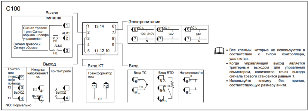
C100
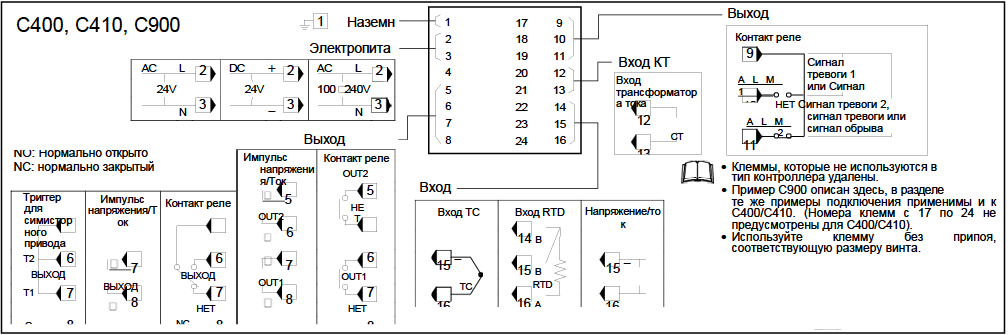
C400, C410, C900
C700
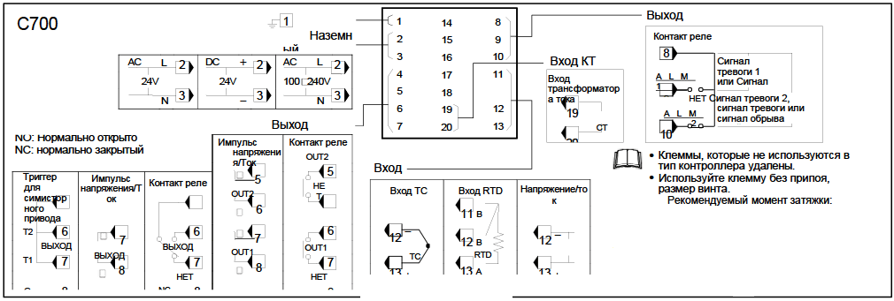
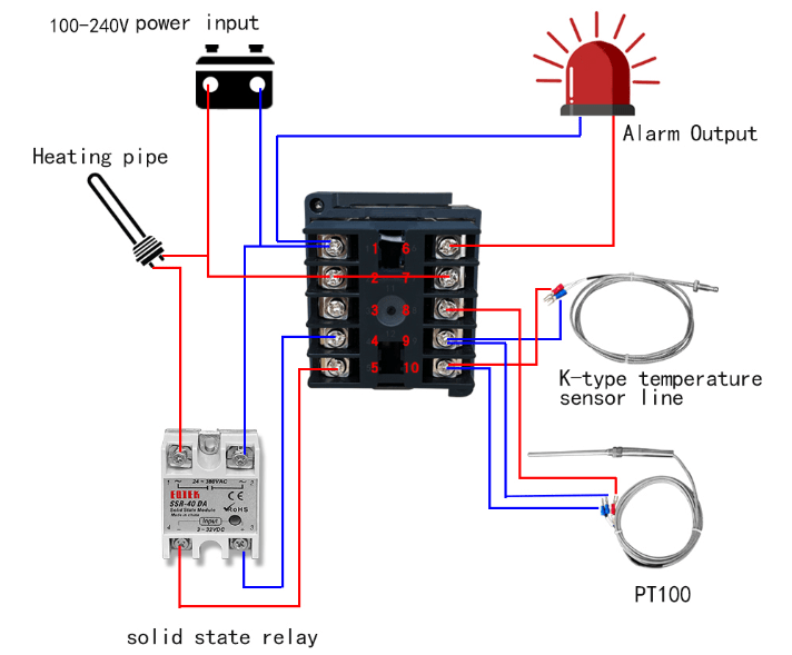
Схема подключения
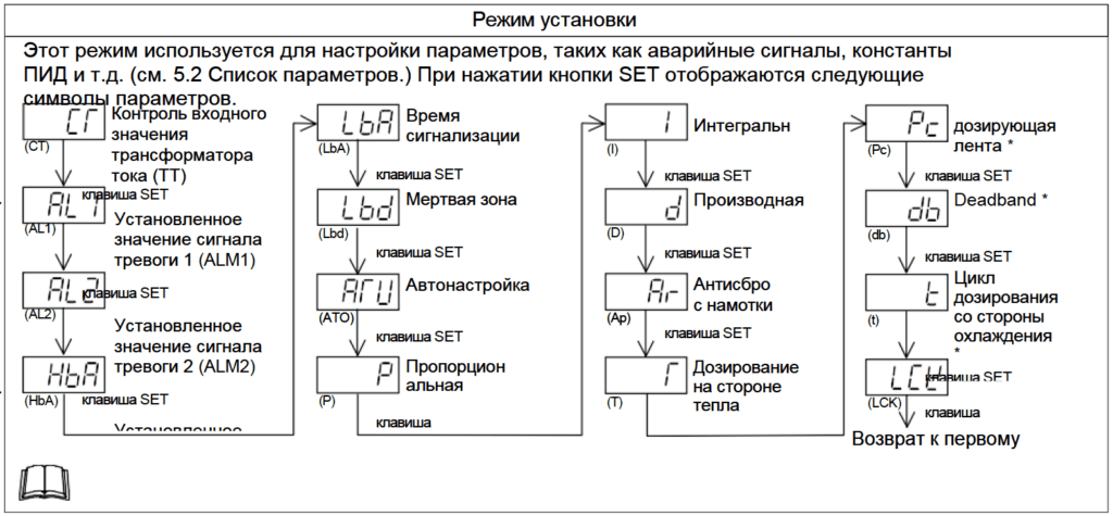
Настройка
Чтобы сохранить новое значение параметра, всегда нажимайте клавишу SET.
Дисплей переключится на следующий параметр, и новое значение будет сохранено. − Новое значение не будет сохранено без нажатия кнопки SET после отображения нового значения на дисплее. − После отображения нового значения с помощью кнопок UP и DOWN
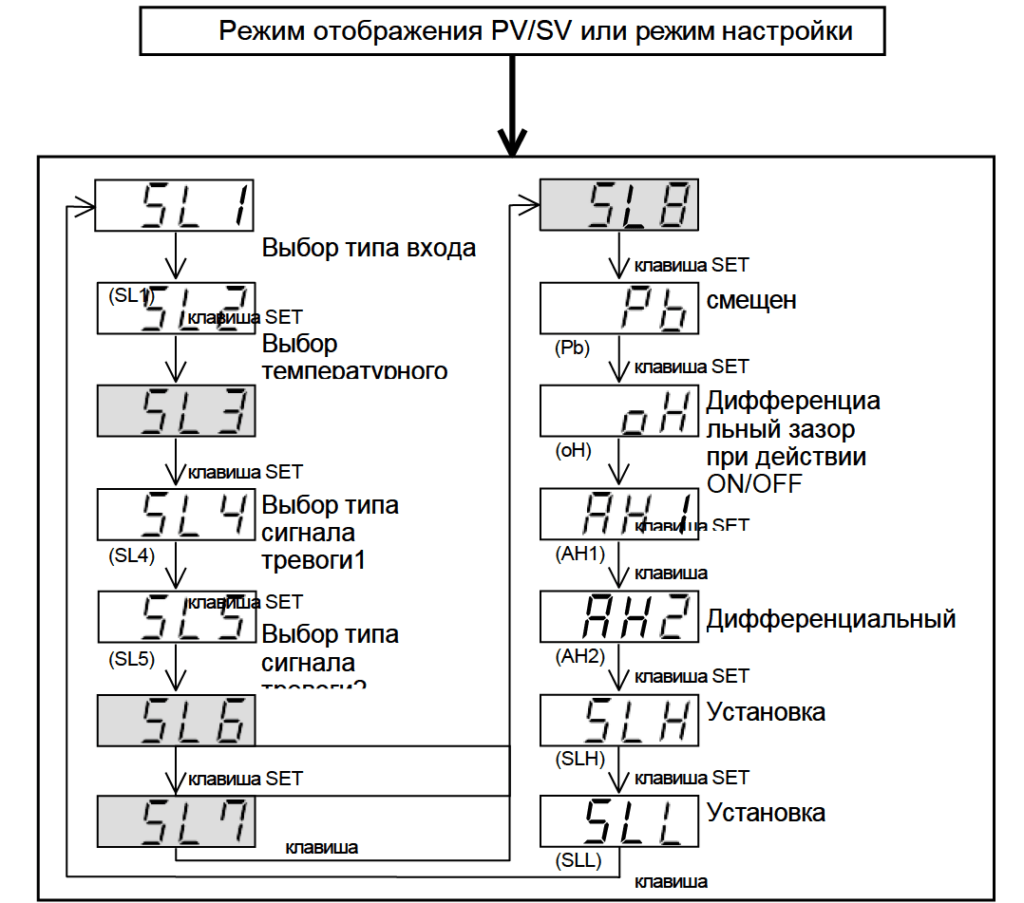
Меню управления
Меню начальной настройки
Нажмите клавишу shift, одновременно удерживая клавишу SET в течение пяти секунд при разблокированном положении.
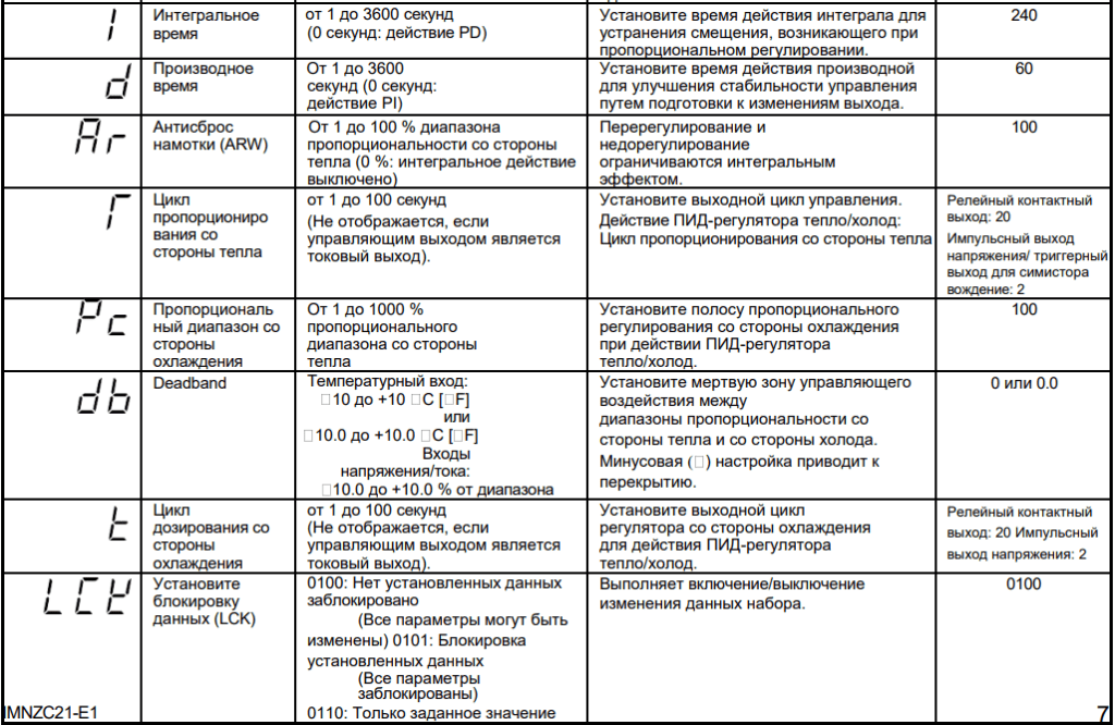
Редактируемые параметры прибора
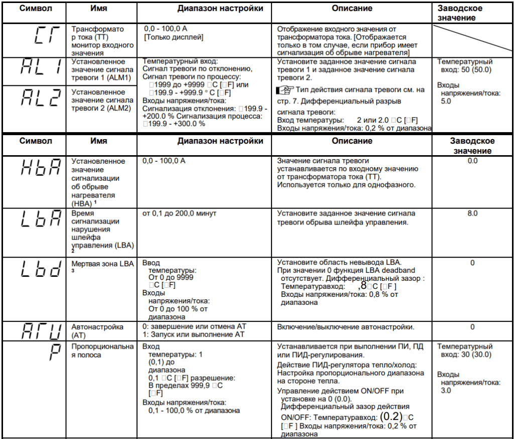
Функция сигнализации об обрыве нагревателя (HBA)
Функция HBA контролирует ток, протекающий через нагрузку, с помощью специального трансформатора тока (ТТ), сравнивает измеренное значение с заданным значением HBA и обнаруживает неисправность в цепи нагрева.
Перегрузка по току или короткое замыкание
Если управляющий выход выключен, а входное значение трансформатора тока равно или больше точки определения обрыва нагревателя в течение заданного количества последовательных циклов выборки, активируется сигнал тревоги.
Функция LBA Deadband
LBA может выйти из строя из-за внешних помех. Для предотвращения сбоев в работе из-за внешних помех, мертвая зона LBA (LBD) устанавливает нейтральную зону, в которой LBA не активируется. Когда измеренное значение (PV) находится в зоне LBD, LBA не активируется. Если настройка LBD неправильная, LBA не будет работать правильно.
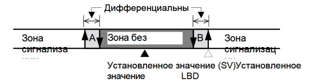
A: Во время повышения температуры: Зона тревоги При понижении температуры: Зона без тревоги
B: Во время повышения температуры: Зона без сигнала тревоги Во время понижения температуры: Зона тревоги
Функция автонастройки (AT)
Автонастройка (AT) автоматически измеряет, рассчитывает и устанавливает оптимальные константы PID и LBA. Для выполнения автонастройки необходимы следующие условия и условия, которые приведут к остановке автонастройки.
Требования для запуска AT
Запустите автонастройку, когда будут выполнены все следующие условия:
- Перед запуском функции AT завершите все настройки параметров, кроме PID и LBA.
- Убедитесь, что функция LCK не была задействована.
Требования для отмены AT
Автонастройка отменяется при наличии любого из следующих условий.
- При изменении заданного значения (SV).
- При изменении значения смещения PV.
- Когда ПВ становится ненормальным из-за перегорания.
- При выключении питания.
- При сбое питания длительностью более 20 мс.
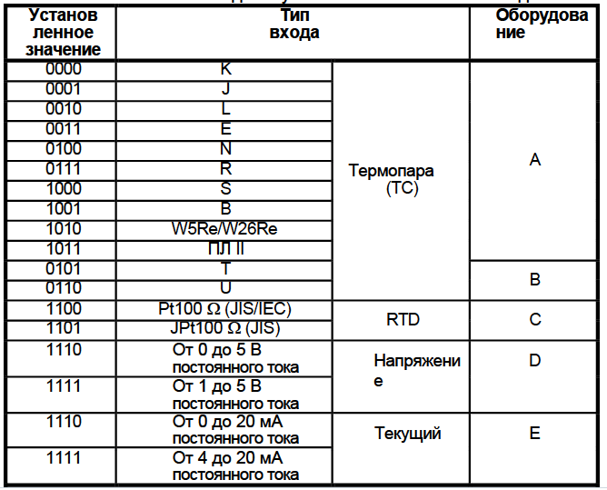
Выбор типа входа (SL1)
Скачать полное руководство.
RU
EN
Инструкция на котлы водогрейные ICI REX 100
Сертификат соответствия на котлы ICI REX 100
| ТЕХНИЧЕСКИЕ ХАРАКТЕРИСТИКИ | Показатель | Значение |
| Номинальная мощность | кВт | 1020 |
| Мощность горелки | кВт | 1106 |
| Противодавление топки | мбар | 4,0 |
| Объем воды в котле | дм. куб. | 1200 |
| Рабочее давление | бар | 5 |
| Вес пустого | кг | 1843 |
Подробные технические характеристики
Водогрейный котел ICI REX 100 – стальной котел с цилиндрической топкой, с реверсивным развитием факела горения.
Котел предназначен для работы с наддувными горелками на жидком или газообразном топливе. Температура нагреваемого теплоносителя от 60 до 110°C.
Отличительные особенности котлов ICI серии REX:
— корпус котла изготовлен из высококачественной стали;
— топка цилиндрической формы с реверсивным развитием факела горения, закрывается задним выпуклым днищем;
— дымогарные трубы изготовлены с помощью электросварки, приварены к трубным пластинам и оснащены турбулизаторами;
— легкий доступ внутрь котла для сервисных работ;
— качественная теплоизоляция из стекловаты высокой плотности;
— электрические и гидравлические соединения сделаны на заводе.
Габаритные размеры и схема:

Условия доставки:
- Доставка в пределах МКАД при заказе от 50000 рублей – бесплатно.
- Доставка в пределах МКАД при заказе менее 50000 рублей – 2500 рублей.
- Доставка за пределы МКАД – 35 рублей за км + Доставка в пределах МКАД.
- Доставка в регионы России до транспортной компании – бесплатно.
- Доставка в регионы России при заказе от 200000 рублей – бесплатно до Вашего города.
Варианты оплаты:
- Наличными курьеру при получении.
- Банковской картой при получении.
- Безналичным банковским переводом от частного или юридического лица.
Digital Controller
REX-C100/C400/C410/C700/C900
INSTRUCTION MANUAL
Thank you for purchasing this RKC product. In order to achieve maximum performance
and ensure proper operation of your new instrument, carefully read all the instructions
in this manual. Please place the manual in a convenient location for easy reference.
!
To prevent injury to persons, damage to instrument and equipment,
a suitable external protection device shall be required.
All wiring must be completed before power is turned on to prevent
electric shock, fire or damage to instrument and equipment.
This instrument must be used in accordance with the specifications
to prevent fire or damage to instrument and equipment.
This instrument is not intended for use in locations subject to
flammable or explosive gases.
Do not touch high-voltage connections such as power supply
terminals, etc. to avoid electric shock.
RKC is not responsible if this instrument is repaired, modified or
disassembled
by
other
Malfunction can occur and warranty is void under these conditions.
This product is intended for use with industrial machines, test and
measuring equipment. (It is not designed for use with medical
equipment and nuclear energy.)
This is a Class A instrument. In a domestic environment, this instrument
may cause radio interference, in which case the user may be required to
take additional measures.
This instrument is protected from electric shock by reinforced insulation.
Provide reinforced insulation between the wire for the input signal and
the wires for instrument power supply, source of power and loads.
Be sure to provide an appropriate surge control circuit respectively for
the following:
— If input/output or signal lines within the building are longer than 30 meters.
— If input/output or signal lines leave the building, regardless the length.
This instrument is designed for installation in an enclosed instrumentation
panel. All high-voltage connections such as power supply terminals must
be enclosed in the instrumentation panel to avoid electric shock by
operating personnel.
All precautions described in this manual should be taken to avoid
damage to the instrument or equipment.
All wiring must be in accordance with local codes and regulations.
All wiring must be completed before power is turned on to prevent
electric shock, instrument failure, or incorrect action. The power must be
turned off before repairing work for input break and output failure
including replacement of sensor, contactor or SSR, and all wiring must
be completed before power is turned on again.
To prevent instrument damage as a result of failure, protect the power line and
the input/output lines from high currents with a suitable overcurrent protection
device with adequate breaking capacity such as fuse, circuit breaker, etc.
Prevent metal fragments or lead wire scraps from falling inside
instrument case to avoid electric shock, fire or malfunction.
Tighten each terminal screw to the specified torque found in the manual
to avoid electric shock, fire or malfunction.
For proper operation of this instrument, provide adequate ventilation for
heat dispensation.
Do not connect wires to unused terminals as this will interfere with
proper operation of the instrument.
Turn off the power supply before cleaning the instrument.
Do not use a volatile solvent such as paint thinner to clean the
instrument. Deformation or discoloration will occur. Use a soft, dry cloth
to remove stains from the instrument.
To avoid damage to instrument display, do not rub with an abrasive
material or push front panel with a hard object.
When high alarm with hold action is used for Alarm function, alarm does
not turn on while hold action is in operation. Take measures to prevent
overheating which may occur if the control device fails.
This manual assumes that the reader has a fundamental knowledge of
the principles of electricity, process control, computer technology and
communications.
The figures, diagrams and numeric values used in this manual are only
for purpose of illustration.
RKC is not responsible for any damage or injury that is caused as a
result of using this instrument, instrument failure or indirect damage.
RKC is not responsible for any damage and/or injury resulting from the
use of instruments made by imitating this instrument.
Periodic maintenance is required for safe and proper operation of this
instrument. Some components have a limited service life, or
characteristics that change over time.
Every effort has been made to ensure accuracy of all information
contained herein. RKC makes no warranty expressed or implied, with
respect to the accuracy of the information. The information in this
manual is subject to change without prior notice.
No portion of this document may be reprinted, modified, copied,
transmitted, digitized, stored, processed or retrieved through any
mechanical, electronic, optical or other means without prior written
approval from RKC.
WARNING
than
factory-approved
CAUTION
NOTICE
1. PRODUCT CHECK
-
C100
(1)(2) (3) (4)
IMNZC22-E1
(1) Control action
F: PID action with autotuning ( Reverse action )
D: PID action with autotuning ( Direct action )
W: Heat/Cool PID action with autotuning ( Water cooling )
A : Heat/Cool PID action with autotuning ( Air cooling )
(2) Input type
Refer to «9. INPUT RANGE TABLE.»
(4) First control output [OUT1] (Heat-side)
M: Relay contact
V: Voltage pulse
(5) Second control output [OUT2] (Cool-side)
No symbol: When control action is F or D.
V: Voltage pulse
(6) Alarm 1 [ ALM1 ] , (7) Alarm 2 [ ALM2 ]
personnel.
N: No alarm
A: Deviation high alarm
B: Deviation low alarm
C: Deviation high/low alarm
D: Band alarm
E: Deviation high alarm
with hold action
F: Deviation low alarm
with hold action
G: Deviation high/low alarm with hold action
1
C100 cannot be specified in Heat/Cool PID action.
2
For the C100, when control output is trigger output for triac driving, only the
ALM1 is available.
3
For the C100, there is no second control output.
4
Heater break alarm (HBA) cannot be specified in case of ALM1. Also, it isn’t
possible to specify when control output is current output.
5
As control loop break alarm (LBA), only either the ALM1 or ALM2 is selected.
Check that power supply voltage is also the same as that specified
when ordering.
Mounting brackets (C100/400/410/700/900): 2
Instruction manual ( IMNZC22-E1):
2. MOUNTING
2.1 Mounting Cautions
(1) This instrument is intended to be used under the following environmental
conditions. ( IEC61010-1 )
[OVERVOLTAGE CATEGORY II, POLLUTION DEGREE 2]
(2) Use this instrument within the following environment conditions:
Allowable ambient temperature:
Allowable ambient humidity:
Installation environment conditions:
(3) Avoid the following conditions when selecting the mounting location:
Rapid changes in ambient temperature which may cause condensation.
Corrosive or inflammable gases.
Direct vibration or shock to the mainframe.
Water, oil, chemicals, vapor or steam splashes.
Excessive dust, salt or iron particles.
Excessive induction noise, static electricity, magnetic fields or noise.
Direct air flow from an air conditioner.
Exposure to direct sunlight.
Excessive heat accumulation.
(4) Mount this instrument in the panel considering the following conditions:
Provide adequate ventilation space so that heat does not build up.
Do not mount this instrument directly above equipment that generates
large amount of heat (heaters, transformers, semi-conductor functional
devices, large-wattage resistors.)
If the ambient temperature rises above 50 C, cool this instrument with a
forced air fan, cooler, etc. Cooled air should not blow directly on this
instrument.
In order to improve safety and the immunity to withstand noise, mount
this instrument as far away as possible from high voltage equipment,
power lines, and rotating machinery.
High voltage equipment: Do not mount within the same panel.
Power lines:
Rotating machinery:
For correct functioning mount this instrument in a horizontal position.
(5) In case this instrument is connected to a supply by means of a permanent
connection, a switch or circuit-breaker shall be included in the installation.
This shall be in close proximity to the equipment and within easy reach of
the operator. It shall be marked as the disconnecting device for the
equipment.
C400
C410
*
-
C700
(6)(7)
(1) (2) (3) (4)(5)
C900
,
(3) Range code
G: Trigger for triac driving
8: Current (4 to 20 mA DC)
8: Current (4 to 20 mA DC)
H: Process high alarm
J: Process low alarm
K: Process high alarm with hold action
L: Process low alarm with hold action
P: Heater break alarm (HBA)[CTL-6]
S: Heater break alarm (HBA)[ CTL-12]
R: Control loop break alarm (LBA)
0 to 50 C
45 to 85 % RH
Indoor use, Altitude up to 2000 m
Separate at least 200 mm.
Separate as far as possible.
*
(6)(7)
1
1
2
3
M: Relay contact
4
4
5
<Accessories>
1