-
Page 2: Table Of Contents
CONTENTS 1. Model number Page 1.1 Model number —————————————————————————— 5 1.2 How to read the rated label ———————————————————— 5 2. Name and functions of the sections ——————————————- 6 3. External dimensions 3.1 External dimensions ———————————————————————- 7 3.2 Tool cable (AKT4H820) external dimensions ————————————— 7 3.3 CT (Current transformer) external dimensions ———————————— 7 3.4 Terminal cover (AKT4H801) external dimensions ——————————— 8 4.
-
Page 3: Safety Precautions
• This instrument must be used under the conditions and environment described in this manual. Panasonic Industrial Devices SUNX Co., Ltd. does not accept liability for any injury, loss of life or damage occurring due to the instrument being used under conditions not otherwise stated in this manual.
-
Page 4: Installation Precautions
• Do not leave bits of wire in the instrument, because they could cause fire or malfunction. • Use the solderless terminal with an insulation sleeve in which the M3 screw fits when wiring the KT4H/B. • The terminal block of this instrument is designed to be wired from the left side.
-
Page 5: Model Number
1. Model number 1.1 Model number A K T 4 (1) (2) (3) (4) (5) (6) (7) (8) (1) Color —————————————- H: Gray, B: Black (2) Supply voltage —————————- 1: 100 to 240V AC 2: 24V AC/DC (3) Input type ———————————- 1: Multi-input (Thermocouple, RTD, DC current and DC voltage can be selected by key operation.
-
Page 6: Name And Functions Of The Sections
2. Name and functions of the sections Model KT4H or KT4B Bottom view (Fig. 2-1) Display (1) Action indicators : Lights respectively when temperature unit is selected. : Lights during Serial communication (optional) TX output. : Flashes during auto-tuning or auto-reset.
-
Page 7: External Dimensions
3. External dimensions 3.1 External dimensions (Unit: mm) Common to KT4H/B Mounting frame Terminal cover (sold separately) Rubber gasket M3 screw (Fig. 3.1-1) 3.2 Tool cable (AKT4H820) external dimensions (Unit: mm) ø2.5 Plug 3-Pole type USB Plug (Fig. 3.2-1) 3.3 CT (current transformer) external dimensions (Unit: mm)
-
Page 8: Terminal Cover (Akt4H801) External Dimensions
3.4 Terminal cover (AKT4H801) external dimensions (Unit: mm) (Fig. 3.4-1) Note when using a Terminal cover (AKT4H801) When using a Terminal cover (AKT4H801), pass terminal wires numbered 7 to 12 into the holes of the terminal cover. See (Fig. 3.4-2). Terminal cover (Fig.
-
Page 9: Mounting To The Control Panel
Tighten screws with one rotation upon the screw tips touching the panel. The torque is approximately 0.05 to 0.06 N•m. How to mount the KT4H Mount the controller vertically to the flat, rigid panel to ensure it adheres to the Dust-proof/Drip-proof specification (IP66).
-
Page 10: Wiring
5. Wiring Warning Turn the power supply to the instrument off before wiring. Working on or touching the terminal with the power switched on may result in severe injury or death due to Electric Shock. 5.1 Terminal arrangement • EVT1 : Alarm 1 output •…
-
Page 11: Settings
Default values: Input (K, -200 to 1370 ), Alarm 1 type (No alarm action), Reverse (Heating) action If the users’ specifications are the same as the default value of the KT4H/B, it is not necessary to set up the controller.
-
Page 12: Operation Flowchart
6.4 Operation flowchart This instrument has been classified into the following modes and setting items. For 3 seconds after power on, the PV display indicates the Power ON input type, and the SV display indicates input range high limit value (thermocouple, RTD input) or scaling high limit value (DC voltage, current input).
-
Page 13: Main Setting Mode
6.5 Main setting mode To enter the Main setting mode, press key in the PV/SV display mode. To set or select each setting item, use key, then register the value with key. Setting item numbers such as [1], [2], etc. are the same as those on the “6.4 Operation flowchart” (p.12). Character Name, Function, Setting range Default value…
-
Page 14: Sub Setting Mode
6.6 Sub setting mode To enter the Sub setting mode, press key while pressing key in the PV/SV display mode. To set or select each setting item, use key, then register the value with key. Setting item numbers such as [5], [6], etc. are the same as those on the “6.4 Operation flowchart” (p.12). Character Name, Function, Setting range Default value…
-
Page 15
• Sets the heater current value for Heater burnout alarm. CT1 current value is indicated on the PV display. When OUT1 is ON, the CT1 current value is updated. When OUT1 is OFF, the KT4H/B memorizes the previous value when OUT1 was ON. -
Page 16: Auxiliary Function Setting Mode
6.7 Auxiliary function setting mode To enter the Auxiliary function setting mode, press key for approximately 3 seconds while pressing key in the PV/SV display mode. To set or select each setting item, use key, then register the value with key.
-
Page 17
Character Name, Function, Setting range Default value [22] Data bit/Parity selection 7 bits/Even parity • Selects the data bit and parity. Not available if the Serial communication option is not added or if Contact input option is added. • : 8 bits/No parity : 7 bits/No parity : 8 bits/Even parity : 7 bits/Even parity… -
Page 18: Setup Mode
6.8 Setup mode To enter the Setup mode, press key while pressing key for approximately 3 seconds in the PV/SV display mode. To set or select each setting item, use key, then register the value with key. Setting item numbers such as [25], [26], etc. are the same as those on the “6.4 Operation flowchart” (p.12). Character Name, Function, Setting range Default value…
-
Page 19
Character Name, Function, Setting range Default value [29] PV filter time constant setting 0.0 seconds • Sets PV filter time constant. If the value is set too large, it affects control result due to the delay of response. • Setting range: 0.0 to 10.0 seconds [30] OUT1 high limit setting 100%… -
Page 20
Character Name, Function, Setting range Default value [38] Alarm 1 type selection No alarm action • Selects an action type for Alarm 1. (Refer to Section “11.4 Alarm action” on p.30.) • : No alarm action : High limit alarm : Low limit alarm : High/Low limits alarm : High/Low limit range alarm… -
Page 21
Character Name, Function, Setting range Default value [46] SV rise rate setting minute • Sets SV rise rate (rising value for 1 minute). Setting to 0 disables the function. • Setting range: 0 to 10000 /min. ( /min.) Thermocouple, RTD input with a decimal point: 0.0 to 1000.0 /min. -
Page 22
Character Name, Function, Setting range Default value [54] PV color selection Green • Selects PV display color. (Refer to Section “8.4 Changing PV color” on p.26.) • : Green : Red : Orange : When Alarm 1 or Alarm 2 is ON, PV color turns from green to red. : When Alarm 1 or Alarm 2 is ON, PV color turns from orange to red. -
Page 23: Operation
After the unit is mounted to the control panel and wiring is completed, operate the unit following the procedures below. (1) Turn the power supply to the KT4H ON. After the power is turned on, the PV display indicates the input type, and the SV display indicates the input range high limit value (for thermocouple, RTD input) or scaling high limit value (for DC input) for approximately 3 seconds.
-
Page 24: Auto/Manual Control Switching
By pressing key again, the unit reverts to the PV/SV display mode (automatic control). Whenever the power to the KT4H is turned on, automatic control starts. 7.4 Indicating output MV (manipulated variable) To indicate output MV (manipulated variable), press key for approx.
-
Page 25: Basic Usage
8. Basic usage 8.1 ON/OFF control In ON/OFF control action, the control output is turned ON when PV is lower than SV, and turned OFF when PV exceeds SV. Overshoot, undershoot and hunting phenomenon occur during ON/OFF action. Therefore, ON/OFF action is not suitable for control which requires accuracy.
-
Page 26: Changing Pv Color
8.4 Changing PV color (1) In the PV/SV display mode, press key for approximately 3 seconds while pressing key. The unit proceeds to the Setup mode, and the Input type selection item appears. (2) Press key several times until [54] PV color selection item appears. (3) Select the PV color with key.
-
Page 27: Auto-Reset And Arw
9. Auto-reset and ARW 9.1 Auto-reset Auto-reset is performed to correct the offset at the point at which PV indication is stabilized within the proportional band during the PD action. Since the corrected value is internally memorized, it is not necessary to perform the auto-reset again as long as the process is the same.
-
Page 28: Auto-Tuning
10. Auto-tuning In order to set each value of P, I, D and ARW automatically, the auto-tuning process should be made to fluctuate to obtain an optimal value. One of 3 types of fluctuation below is automatically selected. For DC input, the auto-tuning process will fluctuate around the SV for conditions of [1], [2] and [3] below. Notice •…
-
Page 29: Out1 Pid, Pi, Pd, P Actions
11. Action explanation 11.1 OUT1 PID, PI, PD, P actions PI action : When derivative time is set to “0” PD action : When integral time is set to “0” P action : When both integral and derivative time are set to “0” [8] Integral time and [9] Derivative time can be set in the Sub setting mode.
-
Page 30: Heater Burnout Alarm Action
11.3 Heater burnout alarm action [15] Heater burnout alarm value and [16] Heater burnout alarm 2 value can be set in the Sub setting mode. (p.15) Alarm action Setting Small Large Load current Output Indicator (EVT2) Unlit If Heater burnout alarm, Heater burnout alarm 2 and Alarm 2 are added together, they (EVT2) utilize common output terminals.
-
Page 31: Out2 (Heating/Cooling Control) Action [Reverse (Heating) Action]
11.5 OUT2 (Heating/Cooling control) action [Reverse (Heating) action] Heating P-band (Cooling P-band) Heating/Cooling control can be used Control Heating (Cooling by adding Heating/Cooling control action action action) option. SV setting Heating proportional band can be Relay contact set during [6] OUT1 proportional band output (OUT1) setting, and cooling proportional band Cycle action is performed according to deviation.
-
Page 32: Out2 (Heating/Cooling Control) Action [Reverse (Heating) Action] (When Setting Overlap Band)
11.7 OUT2 (Heating/Cooling control) action [Reverse (Heating) action] (When setting overlap band) Heating P-band Heating/Cooling control can be used Cooling P-band by adding Heating/Cooling control Overlap band option. Control action Heating (Cooling action action) Heating proportional band can be set during [6] OUT1 proportional band setting, SV setting and cooling proportional band can be set…
-
Page 33: Out2 (Heating/Cooling Control) Action [Direct (Cooling) Action] (When Setting Dead Band)
11.9 OUT2 (Heating/Cooling control) action [Direct (Cooling) action] (When setting dead band) Cooling P-band Dead band Heating P-band Heating/Cooling control can be used (Cooling Heating Control action by adding Heating/Cooling control action) action option. SV setting Heating proportional band can be Relay contact set during [6] OUT1 proportional output (OUT1)
-
Page 34: Sv Rise Rate, Sv Fall Rate Setting Action
11.11 SV rise rate, SV fall rate setting action [46] SV rise rate and [47] SV fall rate can be set in the Setup mode. (p.21) When the SV is adjusted, it approaches the new SV by the preset SV rise rate or SV fall rate. When SV is adjusted while SV is rising (or falling), SV at the given time becomes a starting point, and approaches the new SV.
-
Page 35
When power is turned on or when control output OFF function is cancelled by the key, SV changes as follows in relation to PV. (e.g.) SV=200 , SV rise rate=6 /Min, SV fall rate=30 /Min [When SV>PV] Temperature SV=200 SV display 200 C (on the SV display) approaches by the SV rise rate. -
Page 36: Communication
Serial communication and Tool port communication cannot be used together. When performing Serial communication, remove the tool cable (AKT4H820) from the USB port of the PC and tool connector of the KT4H/B. When performing Tool port communication, it is not required to remove the Serial communication cables.
-
Page 37
Do not connect a terminator with the communication line because each KT4H/B has built-in pull-up and pull-down resistors instead of a terminator. Even though a terminator is not necessary for communication between the PLC and KT4H/B, if a terminator is required due to signal reflection, connect the terminator on the PLC side. -
Page 38: Communication Parameter Setting
12.3 Communication parameter setting Set each parameter following the procedures below. Setting item numbers such as [17, [19], etc. are the same as those on the “6.4 Operation flowchart”. (p.12) Proceed to Auxiliary function setting mode. Press key while pressing key in the PV/SV display mode.
-
Page 39: Communication Procedures
12.4 Communication procedures Communication starts with command transmission from the host computer (hereafter Master) and ends with the response of the KT4H/B (hereafter Slave). Master Slave • Response with data Command When the master sends the reading command, the slave Data responds with the corresponding set value or current status.
-
Page 40: Mewtocol
(23H) (25H) (Decimal) (0DH) (Decimal) (*) (Decimal) (*) (*): KT4H/B cannot read plural word data. Make sure that both top data items are the same. Acknowledgement Command Reading Address code top data (25H) (Decimal) (24H)
-
Page 41
$ (24H) Response (Normal) ! (21H) Response (Error) Command code: RD; Word data reading (Continuous reading of plural data from the KT4H/B is impossible.) WD; Word data writing (Continuous writing of plural data to the KT4H/B is impossible.) Data code : ASCII code D (44H) is used. -
Page 42
12.5.4 Message example (1) Reading (Address 1, PV) • RD (Word data reading) command from the master Command Data Top data item Top data item Address code code (Decimal) (Decimal) (Decimal) 00356 00356 25H 30H 31H 23H 52H 44H 44H 30H 30H 33H 35H 36H 30H 30H 33H 35H 36H 35H 35H 0DH •… -
Page 43
MEWTOCOL Data item Data command code Use in the system DT00100 (Never use WD command. If WD command is sent to the KT4H/B, the KT4H/B may not be operable.) RD/WD DT00102 Set value, Decimal point ignored 0000H: Cancel RD/WD DT00106… -
Page 44
MEWTOCOL Data item Data command code RD/WD DT00202 SV rise rate Set value, Decimal point ignored RD/WD DT00204 SV fall rate Set value, Decimal point ignored RD/WD DT00210 Control output OUT/OFF 0000H: Control output ON 0001H: Control output OFF RD/WD DT00212 Auto/Manual control 0000H: Automatic control… -
Page 45
MEWTOCOL Data item Data command code RD/WD DT00260 Backlight 0000H: All are backlit 0001H: Only PV display is backlit 0002H: Only SV display is backlit 0003H: Only action indicators are backlit 0004H: PV+SV displays are backlit 0005H: PV+ action indicators are backlit 0006H: SV+ action indicators are backlit RD/WD DT00262… -
Page 46
MEWTOCOL Data item Data command code DT00422 Instrument specification flag 0000 0000 0000 0000 : Contact input 0: Not added, 1: Added : Serial communication 0: Not added, 1: Added : Heater burnout alarm 0: Not added, 1: Added : Heater burnout alarm rating 0: 20A, 1: 50A : Heater burnout alarm specification 0: Single phase, 1: 3-phase : Alarm 2 output… -
Page 47: Modbus Protocol
12.6 Modbus protocol 12.6.1 Transmission mode There are 2 transmission modes (ASCII and RTU) in Modbus protocol. 12.6.2 ASCII mode Hexadecimal (0 to 9, A to F), which is divided into high order (4-bit) and low order (4-bit) out of 8-bit binary data in command is transmitted as ASCII characters.
-
Page 48
(2) Error check of ASCII mode After calculating LRC (Longitudinal Redundancy Check) from the slave address to the end of data, the calculated 8-bit data is converted to two ASCII characters and are appended to the end of message. How to calculate LRC Create a message in RTU mode. -
Page 49
Reading (Address 1, SV) • A request message from the master The number of data means the data item to be read, and it is fixed as 1 (30H 30H 30H 31H). Header Slave Function Data item Number of data Error check Delimiter address… -
Page 50
12.6.2 RTU mode 8-bit binary data in command is transmitted as it is. Data format Start bit : 1 bit Data bit : 8 bits Parity : No parity (Even, Odd) Selectable Stop bit : 1 bit (2 bits) Selectable Error detection: CRC-16 (Cyclic Redundancy Check) Data interval : 3.5 character transmission time or less (1) Message configuration… -
Page 51
(2) Error check of RTU mode After calculating CRC-16 (Cyclic Redundancy Check) from the slave address to the end of data, the calculated 16-bit data is appended to the end of message in sequence from low order to high order. How to calculate CRC In the CRC system, the information is divided by the polynomial series. -
Page 52
Reading (Address 1, SV) • A request message from the master The number of data means the data item to be read, and it is fixed as 1 (0001H). Slave Function Data item Number of data Error check 3.5 idle 3.5 idle address code… -
Page 53
Data item Data function code Use in the system 0000H (Never use function code 06H. If function code 06H is sent to the KT4H/B, the KT4H/B may not be operable.) 03H/06H 0001H Set value, Decimal point ignored 0000H: Cancel 03H/06H… -
Page 54
Modbus Data item Data function code 03H/06H 0033H SV rise rate Set value, Decimal point ignored 03H/06H 0034H SV fall rate Set value, Decimal point ignored 0000H: Control output ON 03H/06H 0037H Control output OUT/OFF 0001H: Control output OFF 0000H: Automatic control 03H/06H 0038H Auto/Manual control… -
Page 55
Modbus Data item Data function code 03H/06H 0050H Backlight 0000H: All are backlit 0001H: Only PV display is backlit 0002H: Only SV display is backlit 0003H: Only action indicators are backlit 0004H: PV+SV displays are backlit 0005H: PV+ action indicators are backlit 0006H: SV+ action indicators are backlit 03H/06H 0051H… -
Page 56
Modbus Data item Data function code 00A1H Instrument specification flag 0000 0000 0000 0000 : Contact input 0: Not added, 1: Added : Serial communication 0: Not added, 1: Added : Heater burnout alarm 0: Not added, 1: Added : Heater burnout alarm rating 0: 20A, 1: 50A : Heater burnout alarm specification 0: Single phase 1: 3-phase : Alarm 2 output 0: Not added, 1: Added… -
Page 57: Specifications
13. Specifications 13.1 Standard specifications Mounting : Flush Setting : Input system using membrane sheet key Display PV display : 11-segment backlight LCD Red/Green/Orange, character size 12.0 x 5.4mm (H x W) SV display : 11-segment backlight LCD Green, character size 6.0 x 3.5mm (H x W) MEMO display : 11-segment backlight LCD Green, character size 4.8 x 2.8mm (H x W) : Backlight Orange Action indicators…
-
Page 58
(Depth of control panel interior when rubber gasket is not used: 56.0mm) Material : Flame resistant resin (Case) Color : KT4H: Ash gray (Case) KT4B: Black (Case) Attached functions: [Power failure countermeasure] The setting data is backed up in the non-volatile IC memory. -
Page 59
PV/SV display mode. Auto/Manual control can be switched. [Tool port communication] By connecting to the tool connector of the KT4H/B, the following operations can be conducted from the external computer. (1) Reading and setting of SV, PID and various set values… -
Page 60: Optional Specifications
Accessories included: Mounting frame 1 piece Rubber gasket (Front mounted to the KT4H/B) 1 piece Installation instructions (A3 unfolded, English/Japanese) 1 copy Communication installation instructions (When Serial communication option is added) 1 copy CT (Current transformer) CT1 (AKT4815) (When Heater burnout alarm Single phase 20A option is added) 1piece…
-
Page 61
Serial communication Cannot be used with Tool port communication. If this option is added, Contact input option cannot be added. The following operations can be carried out from the external computer. (1) Reading and setting of the SV, PID values and various set values (2) Reading of the PV and action status (3) Function change Communication line : EIA RS-485… -
Page 62: Troubleshooting
14. Troubleshooting If any malfunctions occur, refer to the following items after checking the power supply to the controller. 14.1 Indication Problem Presumed cause and solution • Control output OFF function is working. ] is indicated on the PV Press the key for approx.
-
Page 63: Key Operation
• Check whether the input lead wire terminals for DC voltage (0 to 5V DC, 0 to 10V DC) or DC current (0 to 20mA DC) are securely mounted to the instrument input terminals. The indication of PV display is •…
-
Page 64: Communication
• The setting command data exceeds the setting range of the slave. “NAK”. • The controller cannot be set when functions such as AT are performing. • The KT4H/B is in the front key operation setting mode. For all other malfunctions, please contact our main office or dealers.
-
Page 65: Revision History
Revision History Issue Date Manual no. Content of revision May, 2005 ARCT1F412E First edition October, 2005 ARCT1F412E-1 edition P.14 P.15 P.16 P.18 Addition of explanation in detail P.19 P.20 P.21 April, 2007 ARCT1F412E-2 edition Addition of explanation in detail P.32~33 Addition of explanation in detail P.34~35 Addition of explanation of “SV rise…

Параметры продукта
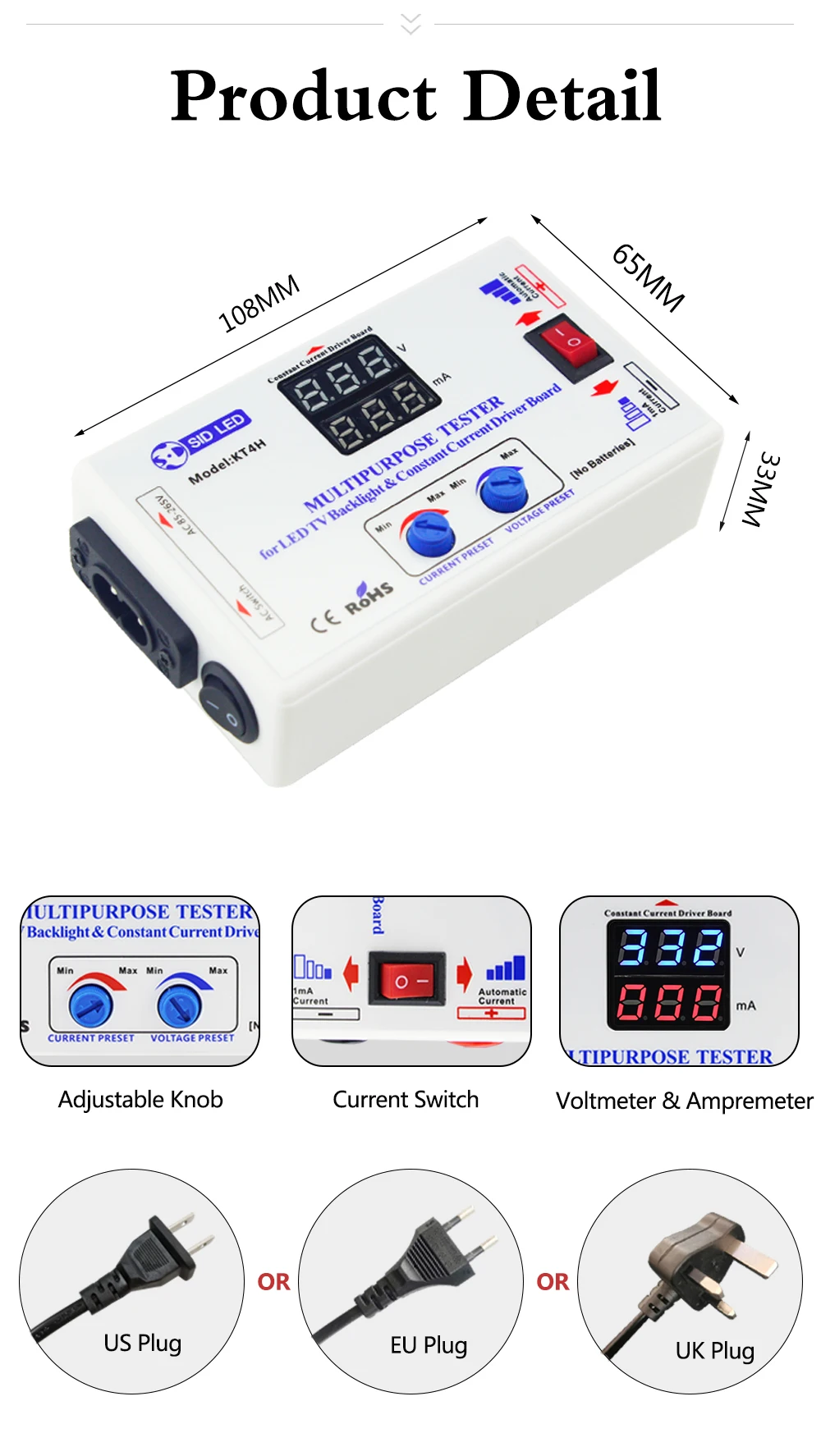
• Модель продукта: KT4H• Вин: 85-265 В переменного тока• Выход: постоянный ток 0-330 в (автоматический + регулируемый)• Точность вольтметра по уровню поверхности: < (± 0,5 ± 1% Vout) v-образный вырез• Iout: 0-150 мА (автоматический + регулируемый)• Постоянный ток тестового тока: 0-999 мА• Точность амперметра: <(± 2 ± 1% Iout) mA• Pinput: 50VA (макс.)• Температура: -20 ℃ ~ + 40 ℃
Введение продукта
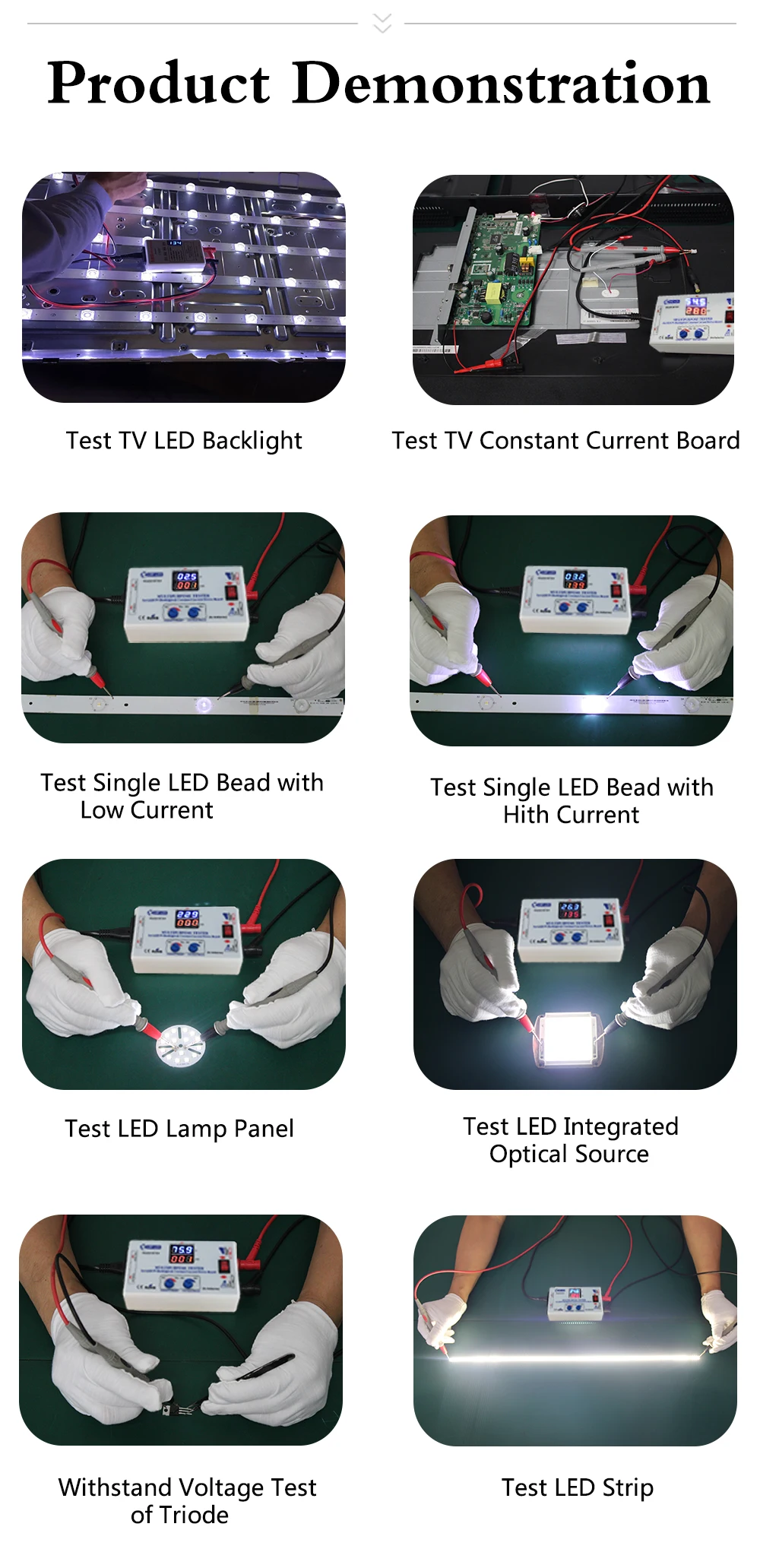
Тестирование напряжения и тока платы постоянного тока в режиме реального времени.1. Светодиодный тест-полоски, СВЕТОДИОДНЫЙ панели, один светодиодный шарик, источники освещения COB и так далее.2. Тестирование подсветки светодиодный-телевизора, дисплеев, компьютеров и так далее.3. Совместим со всеми светодиодный полоски (высокого напряжения или низкого напряжения).4. Ручная регулировка диапазона испытательного напряжения (20-330 в/постоянный ток) и тока (20-150 мА).Регулировка напряжения при открытой цепи (без нагрузки) и регулировка тока с нагрузками или контактными зондами вместе.5. Не выгорает при тестировании один светодиодный шарик с неправильной полярностью. (Установите напряжение около 20 в и переключатель тока до 1 мА)6. Параметры тестирования напряжения различных электронных компонентов.7. Испытательный светодиодный светильник на транспортном средстве.
Методы тестирования
Заводская установка по умолчанию: выходное напряжение 330 в, выходной ток 30 мА. Вы можете протестировать подсветку телевизора с любым размером в этих настройках по умолчанию.1. Самостоятельное тестирование: Подключите, включите выключатель питания. Напряжение около 330 В, ток 0; Свяжитесь с зондами вместе, изменение напряжения на 0 и изменение тока на около 50 мА, затем можно начать тестирование.2. При тестировании:Напряжение = 0, короткое замыкание.Напряжение = ‘330V’, открытая цепь.3. Тестирование одного светодиодный бусин (Установите напряжение около 20 в и переключатель тока до 1 мА):А. С правильной полярностью: напряжение показывает на тестере нормальный светодиодный шарик составляет около 80% от номинального напряжения, например, рабочее напряжение светодиодный шарик 2,4 V в том случае, если его номинальное напряжение 3В;B. С неправильной полярностью: напряжение Отображает напряжение открытой цепи.4. Светодиодный тест-полоски: Установите напряжение около 200 в, измените ток, если требуется Регулировка яркости.

Метод тестирования без демонтажа экрана
Отключите питание от ТВ, отключите интерфейс розетки постоянного пластина тока и светильник бар, вставьте Красного и черного цветов ручки тестера в аноды и катоды интерфейса светодиодный светильник бар.1. Несколько светодиодный полоскиПроверка напряжения каждой ленты и запись их. Сравните Напряжение каждой ленты, это нормально, если разница <2 в или <3%.2. Однополосный светодиодныйА. Светодиодный индикатор не включен (для ремонта необходимо снять экран):Напряжение = 0, короткое замыкание. Напряжение ≥ 300 В, открытая цепь.B. Светодиодный индикатор горит (для определения нормальной подсветки или нет Нужны ссылки на тестирование платы драйвера постоянного тока).
Метод тестирования платы драйвера постоянного тока
Условия тестирования: Светодиодный индикатор подсветки включен с тестером, но он не работает с платой постоянного тока;А. Отключите питание от ТВ, отключите интерфейс розетки постоянного пластина тока и светильник бар;B. Подключите панель постоянного тока с тестером, используя кабели в наборе на правой полярности.C. Вставьте красные и черные ручки тестера в анод и катод интерфейса светодиодный светильникD. Включите питание телевизора.Е. Испытательное напряжение> 30 В, ток> 30 мА и стабильный, и светодиодный индикатор работает нормально, затем плата постоянного тока является нормальной.

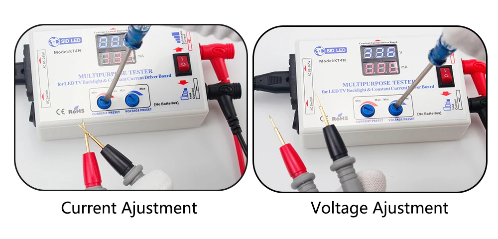
Обратите внимание, что напряжение настраивается при открытии цепи, а ток регулируется во время короткого замыкания.
Введение дополнительной функции
Проверка напряжения электролитического конденсатора:Подключите черную ручку с катодом электролитического конденсатора и красной ручкой с анодом. Значение напряжения, отображаемое в вольтметре, будет быстро расти в начале. При достижении определенной точки скорость подъема заметно замедляется. В это время отображаемое значение напряжения-это фактическое Выдерживаемое Напряжение испытанного электролитического конденсатора. (Конденсаторы квалифицированы, если фактическое значение напряжения выше указанного значения напряжения)Примечание: Избегайте поломки конденсатора, время тестирования не должно быть слишком длинным.1. Установите напряжение около 20 в и ток до 1 мА при тестировании ссылки на напряжение диодов, триодов, MOS труб и IC.2. Установите напряжение около 330 в и ток до 1 мА при тестировании напряжения поломки конденсаторов, stabilivolts, пьезорезисторов и телевизоров.


Гарантия
1. Этот продукт гарантирован до одного года от покупки.2. Если есть некоторые проблемы с производительностью, просто верните его в исходное состояние в течение 30 дней с момента получения. В течение гарантийного срока, мы отремонтируем его и отправим вам хороший тестер.3. Гарантийный срок будет продлен на три месяца после ремонта.4. В течение гарантийного срока перевозка AA.5. Обратите внимание, что политика гарантии не распространяется на:А. Продукт поврежден человеком или случайно поврежден, например, чрезмерное входное напряжение, высокая температура, повреждение воды, падение иПоломки, механические повреждения и коррозии.B. Несанкционированная модификация и разрыв метка даты продукта.

|
KT4H-20200804-V4.2 |
||||||
|
||||||
|
||||||
|


|
|
Все права на контент принадлежат участникам создавшим его. Частичное копирование возможно, только со ссылкой на первоисточник !!!

Статистика сайта
| Последние темы | Читаемые темы | Лучшие пользователи | Новые пользователи | ||||||||||
| Новые Файлы | Новые Прошивки | Новые Статьи, Блоги | Счетчики для пользователей | ||||||||||
|
|||||||||||||
| Новые сайты | Новые Мастера в Вашем городе | Последние Новости | Участники прошедшие тест | ||||||||||
|
 Зарегистрировано всего
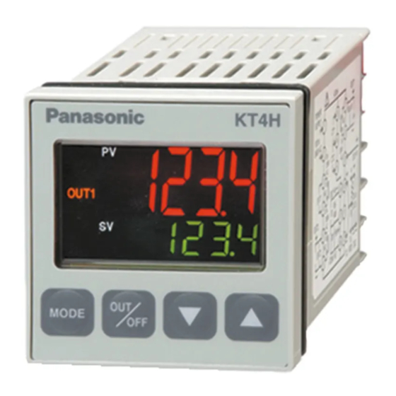
- Manuals
- Brands
- Panasonic Manuals
- Temperature Controller
- KT4H
- User manual
-
Contents
-
Table of Contents
-
Troubleshooting
-
Bookmarks
Quick Links
Related Manuals for Panasonic KT4H
Summary of Contents for Panasonic KT4H
-
Page 2: Table Of Contents
CONTENTS 1. Model number Page 1.1 Model number —————————————————————————— 5 1.2 How to read the rated label ———————————————————— 5 2. Name and functions of the sections ——————————————- 6 3. External dimensions 3.1 External dimensions ———————————————————————- 7 3.2 Tool cable (AKT4H820) external dimensions ————————————— 7 3.3 CT (Current transformer) external dimensions ———————————— 7 3.4 Terminal cover (AKT4H801) external dimensions ——————————— 8 4.
-
Page 3: Safety Precautions
• This instrument must be used under the conditions and environment described in this manual. Panasonic Industrial Devices SUNX Co., Ltd. does not accept liability for any injury, loss of life or damage occurring due to the instrument being used under conditions not otherwise stated in this manual.
-
Page 4: Installation Precautions
• Do not leave bits of wire in the instrument, because they could cause fire or malfunction. • Use the solderless terminal with an insulation sleeve in which the M3 screw fits when wiring the KT4H/B. • The terminal block of this instrument is designed to be wired from the left side.
-
Page 5: Model Number
1. Model number 1.1 Model number A K T 4 (1) (2) (3) (4) (5) (6) (7) (8) (1) Color —————————————- H: Gray, B: Black (2) Supply voltage —————————- 1: 100 to 240V AC 2: 24V AC/DC (3) Input type ———————————- 1: Multi-input (Thermocouple, RTD, DC current and DC voltage can be selected by key operation.
-
Page 6: Name And Functions Of The Sections
2. Name and functions of the sections Model KT4H or KT4B Bottom view (Fig. 2-1) Display (1) Action indicators : Lights respectively when temperature unit is selected. : Lights during Serial communication (optional) TX output. : Flashes during auto-tuning or auto-reset.
-
Page 7: External Dimensions
3. External dimensions 3.1 External dimensions (Unit: mm) Common to KT4H/B Mounting frame Terminal cover (sold separately) Rubber gasket M3 screw (Fig. 3.1-1) 3.2 Tool cable (AKT4H820) external dimensions (Unit: mm) ø2.5 Plug 3-Pole type USB Plug (Fig. 3.2-1) 3.3 CT (current transformer) external dimensions (Unit: mm)
-
Page 8: Terminal Cover (Akt4H801) External Dimensions
3.4 Terminal cover (AKT4H801) external dimensions (Unit: mm) (Fig. 3.4-1) Note when using a Terminal cover (AKT4H801) When using a Terminal cover (AKT4H801), pass terminal wires numbered 7 to 12 into the holes of the terminal cover. See (Fig. 3.4-2). Terminal cover (Fig.
-
Page 9: Mounting To The Control Panel
Tighten screws with one rotation upon the screw tips touching the panel. The torque is approximately 0.05 to 0.06 N•m. How to mount the KT4H Mount the controller vertically to the flat, rigid panel to ensure it adheres to the Dust-proof/Drip-proof specification (IP66).
-
Page 10: Wiring
5. Wiring Warning Turn the power supply to the instrument off before wiring. Working on or touching the terminal with the power switched on may result in severe injury or death due to Electric Shock. 5.1 Terminal arrangement • EVT1 : Alarm 1 output •…
-
Page 11: Settings
Default values: Input (K, -200 to 1370 ), Alarm 1 type (No alarm action), Reverse (Heating) action If the users’ specifications are the same as the default value of the KT4H/B, it is not necessary to set up the controller.
-
Page 12: Operation Flowchart
6.4 Operation flowchart This instrument has been classified into the following modes and setting items. For 3 seconds after power on, the PV display indicates the Power ON input type, and the SV display indicates input range high limit value (thermocouple, RTD input) or scaling high limit value (DC voltage, current input).
-
Page 13: Main Setting Mode
6.5 Main setting mode To enter the Main setting mode, press key in the PV/SV display mode. To set or select each setting item, use key, then register the value with key. Setting item numbers such as [1], [2], etc. are the same as those on the “6.4 Operation flowchart” (p.12). Character Name, Function, Setting range Default value…
-
Page 14: Sub Setting Mode
6.6 Sub setting mode To enter the Sub setting mode, press key while pressing key in the PV/SV display mode. To set or select each setting item, use key, then register the value with key. Setting item numbers such as [5], [6], etc. are the same as those on the “6.4 Operation flowchart” (p.12). Character Name, Function, Setting range Default value…
-
Page 15
• Sets the heater current value for Heater burnout alarm. CT1 current value is indicated on the PV display. When OUT1 is ON, the CT1 current value is updated. When OUT1 is OFF, the KT4H/B memorizes the previous value when OUT1 was ON. -
Page 16: Auxiliary Function Setting Mode
6.7 Auxiliary function setting mode To enter the Auxiliary function setting mode, press key for approximately 3 seconds while pressing key in the PV/SV display mode. To set or select each setting item, use key, then register the value with key.
-
Page 17
Character Name, Function, Setting range Default value [22] Data bit/Parity selection 7 bits/Even parity • Selects the data bit and parity. Not available if the Serial communication option is not added or if Contact input option is added. • : 8 bits/No parity : 7 bits/No parity : 8 bits/Even parity : 7 bits/Even parity… -
Page 18: Setup Mode
6.8 Setup mode To enter the Setup mode, press key while pressing key for approximately 3 seconds in the PV/SV display mode. To set or select each setting item, use key, then register the value with key. Setting item numbers such as [25], [26], etc. are the same as those on the “6.4 Operation flowchart” (p.12). Character Name, Function, Setting range Default value…
-
Page 19
Character Name, Function, Setting range Default value [29] PV filter time constant setting 0.0 seconds • Sets PV filter time constant. If the value is set too large, it affects control result due to the delay of response. • Setting range: 0.0 to 10.0 seconds [30] OUT1 high limit setting 100%… -
Page 20
Character Name, Function, Setting range Default value [38] Alarm 1 type selection No alarm action • Selects an action type for Alarm 1. (Refer to Section “11.4 Alarm action” on p.30.) • : No alarm action : High limit alarm : Low limit alarm : High/Low limits alarm : High/Low limit range alarm… -
Page 21
Character Name, Function, Setting range Default value [46] SV rise rate setting minute • Sets SV rise rate (rising value for 1 minute). Setting to 0 disables the function. • Setting range: 0 to 10000 /min. ( /min.) Thermocouple, RTD input with a decimal point: 0.0 to 1000.0 /min. -
Page 22
Character Name, Function, Setting range Default value [54] PV color selection Green • Selects PV display color. (Refer to Section “8.4 Changing PV color” on p.26.) • : Green : Red : Orange : When Alarm 1 or Alarm 2 is ON, PV color turns from green to red. : When Alarm 1 or Alarm 2 is ON, PV color turns from orange to red. -
Page 23: Operation
After the unit is mounted to the control panel and wiring is completed, operate the unit following the procedures below. (1) Turn the power supply to the KT4H ON. After the power is turned on, the PV display indicates the input type, and the SV display indicates the input range high limit value (for thermocouple, RTD input) or scaling high limit value (for DC input) for approximately 3 seconds.
-
Page 24: Auto/Manual Control Switching
By pressing key again, the unit reverts to the PV/SV display mode (automatic control). Whenever the power to the KT4H is turned on, automatic control starts. 7.4 Indicating output MV (manipulated variable) To indicate output MV (manipulated variable), press key for approx.
-
Page 25: Basic Usage
8. Basic usage 8.1 ON/OFF control In ON/OFF control action, the control output is turned ON when PV is lower than SV, and turned OFF when PV exceeds SV. Overshoot, undershoot and hunting phenomenon occur during ON/OFF action. Therefore, ON/OFF action is not suitable for control which requires accuracy.
-
Page 26: Changing Pv Color
8.4 Changing PV color (1) In the PV/SV display mode, press key for approximately 3 seconds while pressing key. The unit proceeds to the Setup mode, and the Input type selection item appears. (2) Press key several times until [54] PV color selection item appears. (3) Select the PV color with key.
-
Page 27: Auto-Reset And Arw
9. Auto-reset and ARW 9.1 Auto-reset Auto-reset is performed to correct the offset at the point at which PV indication is stabilized within the proportional band during the PD action. Since the corrected value is internally memorized, it is not necessary to perform the auto-reset again as long as the process is the same.
-
Page 28: Auto-Tuning
10. Auto-tuning In order to set each value of P, I, D and ARW automatically, the auto-tuning process should be made to fluctuate to obtain an optimal value. One of 3 types of fluctuation below is automatically selected. For DC input, the auto-tuning process will fluctuate around the SV for conditions of [1], [2] and [3] below. Notice •…
-
Page 29: Out1 Pid, Pi, Pd, P Actions
11. Action explanation 11.1 OUT1 PID, PI, PD, P actions PI action : When derivative time is set to “0” PD action : When integral time is set to “0” P action : When both integral and derivative time are set to “0” [8] Integral time and [9] Derivative time can be set in the Sub setting mode.
-
Page 30: Heater Burnout Alarm Action
11.3 Heater burnout alarm action [15] Heater burnout alarm value and [16] Heater burnout alarm 2 value can be set in the Sub setting mode. (p.15) Alarm action Setting Small Large Load current Output Indicator (EVT2) Unlit If Heater burnout alarm, Heater burnout alarm 2 and Alarm 2 are added together, they (EVT2) utilize common output terminals.
-
Page 31: Out2 (Heating/Cooling Control) Action [Reverse (Heating) Action]
11.5 OUT2 (Heating/Cooling control) action [Reverse (Heating) action] Heating P-band (Cooling P-band) Heating/Cooling control can be used Control Heating (Cooling by adding Heating/Cooling control action action action) option. SV setting Heating proportional band can be Relay contact set during [6] OUT1 proportional band output (OUT1) setting, and cooling proportional band Cycle action is performed according to deviation.
-
Page 32: Out2 (Heating/Cooling Control) Action [Reverse (Heating) Action] (When Setting Overlap Band)
11.7 OUT2 (Heating/Cooling control) action [Reverse (Heating) action] (When setting overlap band) Heating P-band Heating/Cooling control can be used Cooling P-band by adding Heating/Cooling control Overlap band option. Control action Heating (Cooling action action) Heating proportional band can be set during [6] OUT1 proportional band setting, SV setting and cooling proportional band can be set…
-
Page 33: Out2 (Heating/Cooling Control) Action [Direct (Cooling) Action] (When Setting Dead Band)
11.9 OUT2 (Heating/Cooling control) action [Direct (Cooling) action] (When setting dead band) Cooling P-band Dead band Heating P-band Heating/Cooling control can be used (Cooling Heating Control action by adding Heating/Cooling control action) action option. SV setting Heating proportional band can be Relay contact set during [6] OUT1 proportional output (OUT1)
-
Page 34: Sv Rise Rate, Sv Fall Rate Setting Action
11.11 SV rise rate, SV fall rate setting action [46] SV rise rate and [47] SV fall rate can be set in the Setup mode. (p.21) When the SV is adjusted, it approaches the new SV by the preset SV rise rate or SV fall rate. When SV is adjusted while SV is rising (or falling), SV at the given time becomes a starting point, and approaches the new SV.
-
Page 35
When power is turned on or when control output OFF function is cancelled by the key, SV changes as follows in relation to PV. (e.g.) SV=200 , SV rise rate=6 /Min, SV fall rate=30 /Min [When SV>PV] Temperature SV=200 SV display 200 C (on the SV display) approaches by the SV rise rate. -
Page 36: Communication
Serial communication and Tool port communication cannot be used together. When performing Serial communication, remove the tool cable (AKT4H820) from the USB port of the PC and tool connector of the KT4H/B. When performing Tool port communication, it is not required to remove the Serial communication cables.
-
Page 37
Do not connect a terminator with the communication line because each KT4H/B has built-in pull-up and pull-down resistors instead of a terminator. Even though a terminator is not necessary for communication between the PLC and KT4H/B, if a terminator is required due to signal reflection, connect the terminator on the PLC side. -
Page 38: Communication Parameter Setting
12.3 Communication parameter setting Set each parameter following the procedures below. Setting item numbers such as [17, [19], etc. are the same as those on the “6.4 Operation flowchart”. (p.12) Proceed to Auxiliary function setting mode. Press key while pressing key in the PV/SV display mode.
-
Page 39: Communication Procedures
12.4 Communication procedures Communication starts with command transmission from the host computer (hereafter Master) and ends with the response of the KT4H/B (hereafter Slave). Master Slave • Response with data Command When the master sends the reading command, the slave Data responds with the corresponding set value or current status.
-
Page 40: Mewtocol
(23H) (25H) (Decimal) (0DH) (Decimal) (*) (Decimal) (*) (*): KT4H/B cannot read plural word data. Make sure that both top data items are the same. Acknowledgement Command Reading Address code top data (25H) (Decimal) (24H)
-
Page 41
$ (24H) Response (Normal) ! (21H) Response (Error) Command code: RD; Word data reading (Continuous reading of plural data from the KT4H/B is impossible.) WD; Word data writing (Continuous writing of plural data to the KT4H/B is impossible.) Data code : ASCII code D (44H) is used. -
Page 42
12.5.4 Message example (1) Reading (Address 1, PV) • RD (Word data reading) command from the master Command Data Top data item Top data item Address code code (Decimal) (Decimal) (Decimal) 00356 00356 25H 30H 31H 23H 52H 44H 44H 30H 30H 33H 35H 36H 30H 30H 33H 35H 36H 35H 35H 0DH •… -
Page 43
MEWTOCOL Data item Data command code Use in the system DT00100 (Never use WD command. If WD command is sent to the KT4H/B, the KT4H/B may not be operable.) RD/WD DT00102 Set value, Decimal point ignored 0000H: Cancel RD/WD DT00106… -
Page 44
MEWTOCOL Data item Data command code RD/WD DT00202 SV rise rate Set value, Decimal point ignored RD/WD DT00204 SV fall rate Set value, Decimal point ignored RD/WD DT00210 Control output OUT/OFF 0000H: Control output ON 0001H: Control output OFF RD/WD DT00212 Auto/Manual control 0000H: Automatic control… -
Page 45
MEWTOCOL Data item Data command code RD/WD DT00260 Backlight 0000H: All are backlit 0001H: Only PV display is backlit 0002H: Only SV display is backlit 0003H: Only action indicators are backlit 0004H: PV+SV displays are backlit 0005H: PV+ action indicators are backlit 0006H: SV+ action indicators are backlit RD/WD DT00262… -
Page 46
MEWTOCOL Data item Data command code DT00422 Instrument specification flag 0000 0000 0000 0000 : Contact input 0: Not added, 1: Added : Serial communication 0: Not added, 1: Added : Heater burnout alarm 0: Not added, 1: Added : Heater burnout alarm rating 0: 20A, 1: 50A : Heater burnout alarm specification 0: Single phase, 1: 3-phase : Alarm 2 output… -
Page 47: Modbus Protocol
12.6 Modbus protocol 12.6.1 Transmission mode There are 2 transmission modes (ASCII and RTU) in Modbus protocol. 12.6.2 ASCII mode Hexadecimal (0 to 9, A to F), which is divided into high order (4-bit) and low order (4-bit) out of 8-bit binary data in command is transmitted as ASCII characters.
-
Page 48
(2) Error check of ASCII mode After calculating LRC (Longitudinal Redundancy Check) from the slave address to the end of data, the calculated 8-bit data is converted to two ASCII characters and are appended to the end of message. How to calculate LRC Create a message in RTU mode. -
Page 49
Reading (Address 1, SV) • A request message from the master The number of data means the data item to be read, and it is fixed as 1 (30H 30H 30H 31H). Header Slave Function Data item Number of data Error check Delimiter address… -
Page 50
12.6.2 RTU mode 8-bit binary data in command is transmitted as it is. Data format Start bit : 1 bit Data bit : 8 bits Parity : No parity (Even, Odd) Selectable Stop bit : 1 bit (2 bits) Selectable Error detection: CRC-16 (Cyclic Redundancy Check) Data interval : 3.5 character transmission time or less (1) Message configuration… -
Page 51
(2) Error check of RTU mode After calculating CRC-16 (Cyclic Redundancy Check) from the slave address to the end of data, the calculated 16-bit data is appended to the end of message in sequence from low order to high order. How to calculate CRC In the CRC system, the information is divided by the polynomial series. -
Page 52
Reading (Address 1, SV) • A request message from the master The number of data means the data item to be read, and it is fixed as 1 (0001H). Slave Function Data item Number of data Error check 3.5 idle 3.5 idle address code… -
Page 53
Data item Data function code Use in the system 0000H (Never use function code 06H. If function code 06H is sent to the KT4H/B, the KT4H/B may not be operable.) 03H/06H 0001H Set value, Decimal point ignored 0000H: Cancel 03H/06H… -
Page 54
Modbus Data item Data function code 03H/06H 0033H SV rise rate Set value, Decimal point ignored 03H/06H 0034H SV fall rate Set value, Decimal point ignored 0000H: Control output ON 03H/06H 0037H Control output OUT/OFF 0001H: Control output OFF 0000H: Automatic control 03H/06H 0038H Auto/Manual control… -
Page 55
Modbus Data item Data function code 03H/06H 0050H Backlight 0000H: All are backlit 0001H: Only PV display is backlit 0002H: Only SV display is backlit 0003H: Only action indicators are backlit 0004H: PV+SV displays are backlit 0005H: PV+ action indicators are backlit 0006H: SV+ action indicators are backlit 03H/06H 0051H… -
Page 56
Modbus Data item Data function code 00A1H Instrument specification flag 0000 0000 0000 0000 : Contact input 0: Not added, 1: Added : Serial communication 0: Not added, 1: Added : Heater burnout alarm 0: Not added, 1: Added : Heater burnout alarm rating 0: 20A, 1: 50A : Heater burnout alarm specification 0: Single phase 1: 3-phase : Alarm 2 output 0: Not added, 1: Added… -
Page 57: Specifications
13. Specifications 13.1 Standard specifications Mounting : Flush Setting : Input system using membrane sheet key Display PV display : 11-segment backlight LCD Red/Green/Orange, character size 12.0 x 5.4mm (H x W) SV display : 11-segment backlight LCD Green, character size 6.0 x 3.5mm (H x W) MEMO display : 11-segment backlight LCD Green, character size 4.8 x 2.8mm (H x W) : Backlight Orange Action indicators…
-
Page 58
(Depth of control panel interior when rubber gasket is not used: 56.0mm) Material : Flame resistant resin (Case) Color : KT4H: Ash gray (Case) KT4B: Black (Case) Attached functions: [Power failure countermeasure] The setting data is backed up in the non-volatile IC memory. -
Page 59
PV/SV display mode. Auto/Manual control can be switched. [Tool port communication] By connecting to the tool connector of the KT4H/B, the following operations can be conducted from the external computer. (1) Reading and setting of SV, PID and various set values… -
Page 60: Optional Specifications
Accessories included: Mounting frame 1 piece Rubber gasket (Front mounted to the KT4H/B) 1 piece Installation instructions (A3 unfolded, English/Japanese) 1 copy Communication installation instructions (When Serial communication option is added) 1 copy CT (Current transformer) CT1 (AKT4815) (When Heater burnout alarm Single phase 20A option is added) 1piece…
-
Page 61
Serial communication Cannot be used with Tool port communication. If this option is added, Contact input option cannot be added. The following operations can be carried out from the external computer. (1) Reading and setting of the SV, PID values and various set values (2) Reading of the PV and action status (3) Function change Communication line : EIA RS-485… -
Page 62: Troubleshooting
14. Troubleshooting If any malfunctions occur, refer to the following items after checking the power supply to the controller. 14.1 Indication Problem Presumed cause and solution • Control output OFF function is working. ] is indicated on the PV Press the key for approx.
-
Page 63: Key Operation
• Check whether the input lead wire terminals for DC voltage (0 to 5V DC, 0 to 10V DC) or DC current (0 to 20mA DC) are securely mounted to the instrument input terminals. The indication of PV display is •…
-
Page 64: Communication
• The setting command data exceeds the setting range of the slave. “NAK”. • The controller cannot be set when functions such as AT are performing. • The KT4H/B is in the front key operation setting mode. For all other malfunctions, please contact our main office or dealers.
-
Page 65: Revision History
Revision History Issue Date Manual no. Content of revision May, 2005 ARCT1F412E First edition October, 2005 ARCT1F412E-1 edition P.14 P.15 P.16 P.18 Addition of explanation in detail P.19 P.20 P.21 April, 2007 ARCT1F412E-2 edition Addition of explanation in detail P.32~33 Addition of explanation in detail P.34~35 Addition of explanation of “SV rise…
This manual is also suitable for:
Kt4b
1.1 Экспресс-тест SARS-CoV-2-Антиген предназначен для быстрого качественного определения нуклеокапсидного антигена вируса SARS-CoV-2 методом иммунохроматографического анализа в назофарингеальных мазках, взятых у лиц с подозрением на COVID-19 во время острой фазы заболевания.
1.2 COVID-19 — это острое респираторное инфекционное заболевание с высоким фактором риска среди большинства людей. В настоящее время основным источником инфекции являются пациенты, инфицированные новым коронавирусом (SARS-CoV-2); бессимптомно инфицированные люди также могут быть источником инфекции. По данным текущего эпидемиологического исследования, инкубационный период составляет от 1 до 14 дней, в основном от 3 до 7 дней. Коронавирусы — это обширное семейство вирусов, вызывающих заболевания, варьирующиеся от простуды до более тяжелых заболеваний, таких как ближневосточный респираторный синдром (MERSCoV) и тяжелый острый респираторный синдром (SARS-CoV). Новый коронавирус (nCoV) — это новый штамм, который ранее не выявлялся у людей и был впервые обнаружен в 2019 году. Клиническими проявлениями являются системные симптомы, такие как лихорадка и усталость, сопровождающиеся сухим кашлем, одышкой и т.д., которые могут быстро развиваться в тяжелую пневмонию, расстройство дыхания и острую дыхательную недостаточность. Дистресс-синдром, септический шок, полиорганная недостаточность, тяжелые нарушения кислотно-щелочного обмена и другие симптомы еще более опасны для жизни.
1.3 Экспресс-тест для определения антигена коронавируса нового типа обнаруживает нуклеокапсидный антиген нового коронавируса в образце мазка, взятого из носоглотки человека. Тест может быть выполнен в течение 10 минут без использования лабораторного оборудования.
1.4 Наличие быстрого диагностического теста в месте оказания медицинской помощи имеет решающее значение в диагностике пациентов и предотвращении дальнейшего распространения вируса. Он предоставляет возможность получения предварительных данных в диагностике инфицирования новым коронавирусом.
Любая интерпретация или использование этого предварительного теста должна также основываться на других клинических данных, а также на профессиональном суждении медицинских работников. Следует принять к рассмотрению и альтернативные методы для подтверждения результатов, полученных с помощью этого теста.
1.5 Положительные результаты указывают на наличие вирусных антигенов, но для определения статуса инфекции необходимо сопоставление с другими клиническими данными пациента и другой диагностической информацией. Положительные результаты не исключают бактериальную инфекцию или коинфицирование другими вирусами.
1.6 Отрицательные результаты следует рассматривать как предварительные, они не исключают заражение вирусом SARS-CoV-2 и не должны использоваться в качестве единственной основы для принятия решений о лечении или наблюдения за пациентом, включая решения о контроле за инфекцией. Отрицательные результаты следует рассматривать в контексте недавних контактов пациента с источником заражения, истории болезни и наличия клинических признаков и симптомов, соответствующих COVID-19, и, если необходимо, подтверждать молекулярным анализом, для наблюдения за пациентом.
1.7 Экспресс-тест для обнаружения антигена предназначен для использования медицинским персоналом, специально проинструктированным и обученным методам диагностики in vitro и надлежащим процедурам инфекционного контроля, а также для индивидуального использования для самоконтроля состояния при острой респираторной инфекции.
2.1 Высокая скорость и простота использования иммунохроматографического анализа обеспечивается благодаря предварительному нанесению аналитических реагентов на мембрану тестовой кассеты. Контакт с пробой запускает иммунохимические реакции, приводящие к окрашиванию определенных участков мембранной полоски, по которому можно через 10 мин визуально регистрировать результат анализа.
2.2 Экспресс-тест предназначен для обнаружения присутствия или отсутствия нуклеокапсидного белка вируса SARS-CoV-2 в образцах мазков, взятых из носоглотки пациентов, подозреваемых на COVID-19, при наличии соответствующих признаков и симптомов. Когда образцы обрабатываются и добавляются в тестовое устройство, антигены вируса SARS-CoV-2, присутствующие в образце, связываются с антителами, меченными коллоидным золотом на тест-полоске. Комплексы антиген-антитело перемещаются по тест- полоске в зону реакции и захватываются линией антител, связанных на мембране.
2.3 Результат считается положительным, когда комплексы антиген-антитело, осажденные в позиции теста «Т», и контрольная позиция «С» на тестовом устройстве образуют цветные линии.
Результат считается отрицательным, когда цветная линия образуется только в позиции контроля «C», но не появляется видимая цветная линия в позиции теста «T».
2.4 Для контроля качества, чтобы гарантировать достоверность результата теста, цветная линия всегда должна появляться в позиции контроля «C», независимо от того, появляется ли результат (положительный или отрицательный) в позиции теста «T». Если в контрольной позиции «C» нет видимой линии, результат экспресс-теста считается недействительным, и необходимо провести новый тест.
Экспресс-тест SARS-CoV-2-Антиген может изготавливаться в следующих комплектациях:
а) комплектация 1 содержит:
— тестовая кассета, готова к использованию, упакована в пакет из фольги, 20 шт. Каждый пакет содержит 1 тест-кассету и 1 осушитель;
— тампон для взятия образцов, готов к использованию, в индивидуальной упаковке из бумаги с прозрачным верхом, 20 шт;
— экстракционная пробирка, готова к использованию, 20 шт;
— насадка для экстракционной пробирки, готова к использованию, 20 шт;
— буферный раствор для экстракции образцов, готов к использованию, 6 мл, 1 флакон (или 2 флакона по 3 мл);
— инструкция по применению.
б) комплектация 2 содержит:
— тестовая кассета, готова к использованию, упакована в пакет из фольги, 1шт. Каждый пакет содержит 1 тест-кассету и 1 осушитель;
— тампон для взятия образцов, готов к использованию, в индивидуальной упаковке из бумаги с прозрачным верхом, 1 шт;
— экстракционная пробирка, готова к использованию, 1 шт;
— насадка для экстракционной пробирки, готова к использованию, 1 шт;
— буферный раствор для экстракции образцов, готов к использованию, 0,5 мл, 1 пробирка;
— пипетка Пастера, 1 шт;
— инструкция по применению.
Необходимый, но не предоставляемый материал:
— таймер или часы;
— средства индивидуальной защиты, такие как защитные перчатки, медицинская маска, защитные очки и лабораторный халат;
— соответствующий контейнер для биологически опасных отходов и дезинфицирующие средства;
— калиброванная микропипетка на (0,05 — 0,5) мл с наконечниками для дозаторов.
3.1 Использовать экспресс-тест необходимо в строгом соответствии с инструкцией.
3.2 Этот экспресс-тест предназначен только для диагностики in vitro.
3.3 Со всеми образцами следует обращаться как с биомедицинскими отходами, содержащими потенциально инфекционные вещества. Процесс утилизации использованного экспресс-теста и материалов для образцов должен соответствовать местным законам об утилизации инфекционных веществ или лабораторным нормам.
3.4 Надевайте соответствующие средства индивидуальной защиты (например, халат, перчатки, очки, маску) при использовании экспресс-теста. Работы проводить с соблюдением мер предосторожности в соответствии с требованиями.
3.5 Правильный сбор, хранение и транспортировка образцов имеют решающее значение для выполнения этого теста.
3.6 После использования тестовую кассету необходимо утилизировать. Тест нельзя использовать более одного раза.
3.7 Не прикасайтесь к реакционной зоне тестовой кассеты.
3.8 Не используйте экспресс-тест после истечения срока годности.
3.9 Не используйте тестовую кассету, если пакет проколот или если его герметичность нарушена.
3.10 Тестирование должно проводиться специально обученным медицинским персоналом. Образцы также берутся квалифицированным медицинским персоналом.
3.11 Результат теста должен интерпретироваться врачом или обученным медицинским специалистом вместе с клиническими данными и результатами других лабораторных тестов.
3.12 Со всеми образцами и использованными экспресс-тестами следует обращаться как с биомедицинскими отходами, содержащими потенциально инфекционные вещества.
3.13 Результаты должны быть прочитаны сразу же по истечению 10 минут после введения образца в отверстие для образцов тест-кассеты. Результаты теста станут недействительными через 20 минут.
3.14 При взятии мазка из носоглотки используйте тампоны, входящие в комплект. Использование других тампонов может привести к ложноотрицательным результатам.
3.15 Перед использованием проверьте срок годности и целостность упаковки тестовой кассеты. Если упаковка тестовой кассеты повреждена и срок годности истек, его нельзя использовать.
3.16 Необходимо соблюдать время тестирования и считывания результатов.
3.17 После вскрытия пакета с тестовой кассетой, анализ следует провести в течение 60 мин. Тестовую кассету можно использовать только один раз.
3.18 Экспресс-тест должен храниться при температуре (2-30) °С. Беречь от влаги, прямых солнечных лучей, тепла и холода.
3.19 Результаты анализа предназначены для предварительной клинической оценки. Клинический диагноз заболевания следует рассматривать в сочетании с симптомами и признаками заболевания, историей болезни пациента, другими лабораторными тестами и ответом на лечение.
4.1 Настройка теста
Перед использованием экспресс-теста пакет с тестовой кассетой и буферный раствор должны быть доведены до комнатной температуры (18-25) °С.
Извлеките из пакета тестовую кассету непосредственно перед тестированием.
Пометьте тестовую кассету и экстракционную пробирку для каждого исследуемого образца. Поместите промаркированные экстракционные пробирки в штатив.
Снимите крышку с флакона с буфером для экстракции образца, держите флакон вверх дном. Сожмите флакон и добавьте 7 капель (~210 мкл) буферного раствора в пробирку для экстракции. При индивидуальном использовании экспресс-теста отобрать пипеткой Пастера буферный раствор из пробирки и добавить 9 капель (~210 мкл) в пробирку для экстракции.
4.2 Сбор образцов мазков из носа
Чтобы взять мазок из носа, осторожно вставьте тампон для взятия образцов в ноздрю с наибольшей секрецией при визуальном осмотре. Плавным вращением проталкивайте тампон до сопротивления на уровне носовых раковин (около 2,0-2,5 см вглубь ноздри). Прокрутите тампон 5 раз по стенке носа, затем выньте его из ноздри.
4.3 Подготовка образца
После взятия пробы немедленно погрузите тампон в буфер. Чтобы образец, извлеченный из тампона, полностью проник в буфер, 6 раз поверните тампон по стенке пробирки в течение 20 секунд, оставьте тампон в пробирке на 1 минуту, а затем пальцами, удерживая пробирку (стенка пробирки не твердая), несколько раз сожмите тампон, при этом медленно удаляйте его из пробирки. Прижатие тампона к стенке пробирки очень важно, так как при этом образца, содержащего жидкость, остается в пробирке как можно больше. Вынув тампон и выбросив его в контейнер для биологически опасных отходов, плотно наденьте насадку (входит в комплект) на верхнюю часть экстракционной пробирки и осторожно встряхните ее, чтобы качественно перемешать находящуюся внутри жидкость.
5.1 Удерживая экстракционную пробирку вертикально вверх дном. Сожмите ее и через насадку для экстракционной пробирки добавьте 3 капли (около 70-90 мкл) подготовленной ранее жидкости с образцом в центр лунки для образца (S-лунка), убедившись, что в ней нет пузырьков воздуха.

5.2 Запустите таймер. Считайте результат через 10 минут. Не более чем через 20 минут.
6.1 Положительный результат: как в позиции теста «T», так и в контрольной позиции «C» появляются видимые цветные линии. Если тестовая позиция «Т» имеет бледный цвет, результат также считается положительным (рисунок 2).
6.2 Отрицательный результат: цвет отображается только в контрольной позиции «C», а в позиции теста «T» окраски нет.
6.3 Недействительный результат: если контрольная позиция «C» остается без появления цвета, результат теста считается недействительным, поскольку контрольное обнаружение не сработало. В таком случае требуется повторное исследование образца.

6.4 Ограничения исследования
6.4.1 Этот экспресс-тест предназначен для обнаружения наличия или отсутствия антигенов к SARS-CoV-2 в респираторных образцах, взятых у лиц, имеющих контакт с COVID-19, или у лиц при наличии соответствующих признаков и симптомов заболевания в первые 7 дней.
6.4.2 Этот экспресс-тест представляет собой качественный анализ.
6.4.3 Точность анализа зависит от качества взятия пробы. Неправильный сбор образцов, их неправильное хранение повлияют на результат теста.
6.4.4 Результаты этого экспресс-теста предназначены для предварительной клинической оценки. Подтвержденный диагноз может быть установлен только после оценки всех клинических и лабораторных данных.
6.4.5 Из-за ограничений, которые имеет экспресс-тест для обнаружения антигенов, при отрицательных результатах тестирования рекомендуется использовать тест амплификации нуклеиновых кислот или методы идентификации вирусных культур для проверки и подтверждения результатов.
6.4.6 Положительные результаты анализов не исключают коинфицирование другими вирусами. Отрицательный результат этого экспресс-теста может быть вызван:
1) неправильным сбором образцов, неправильной передачей или использованием образцов;
2) уровень вируса SARS-CoV-2 ниже предела обнаружения теста;
3) вариации вирусных генов, которые могли вызвать изменения в детерминантах антигена.
7.1 Чувствительность экспресс-теста SARS-CoV-2-Антиген: 97,8%, в сравнении с тестом на нуклеиновую кислоту, были подтверждены положительные случаи.
7.2 Специфичность набора: 100 %, отрицательные случаи были также подтверждены тестом на нуклеиновую кислоту.
7.3 Воспроизводимость экспресс-теста SARS-CoV-2-Антиген: межсерийная 97%, внутрисерийная 99%.
7.4 Перекрёстная специфичность: перекрестная специфичность с вирусом гриппа A, вирусом гриппа B, аденовирусом, вирусом Коксаки, вирусом ECHO и энтеровирусом отсутствует; отсутствует перекрестная специфичность с Chlamydia pneumoniae, Mycoplasma pneumoniae, Chlamydia psittaci и Chlamydia trachomatis; отсутствует перекрестная специфичность с Acinetobacter baumannii, Bordetella pertussis, Candida albicans, Escherichia coli, Haemophilus influenzae и Neisseria gonorrhoeae.
8.1 Хранить при температуре (2-30) °С в запечатанном пакете до истечения срока годности. Не замораживать.
8.2 Тест-кассету следует использовать в течение 1 часа после ее извлечения из пакета.
8.3 Сразу после использования флакон с буфером для экстракции образца следует закрыть крышкой.
8.4 Экспресс-тест следует использовать до истечения срока годности.
8.5 Срок годности — 18 месяцев с даты изготовления.

УП «ХОП ИБОХ НАН Беларуси» ул. Академика В.Ф.Купревича, д.5, корп.3, 220141, г. Минск, Республика Беларусь
Тел./факс +375-17-272-52-57 E-mail: hopmang.bel@gmail.com http://www.hopiboh.org
По вопросам, касающимся качества набора, обращаться в ОТК, тел. +375-17-396-87-38
Рекламации на качество экспресс-тестов присылайте предприятию-производителю.
В случае нарушения предусмотренных производителем условий хранения,
транспортировки и процедуры постановки экспресс-теста, рекламации рассматриваются как необоснованные.