
KTM 530 EXC-R EU Owner’s Manual (125 pages)
KTM Owner’s Manual Motorcycle 450 EXC-R EU, 450 EXC-R AUS/UK, 450 EXC-R SIX DAYS, 450 EXC-R USA, 450 XCR-W USA, 450 XCR-W ZA, 530 EXC-R EU, 530 EXC-R AUS/UK, 530 EXC-R SIX DAYS, 530 EXC-R USA, 530 XCR-W USA, 530 XCR-W ZA
Table of Contents
Related Products
-
KTM 530 EXC-R USA
-
KTM 530 EXC-R AUS/UK
-
KTM 530 EXC-R SIX DAYS
-
KTM 530 EXC-R EU 2008
-
KTM 530 EXC-R AUS/UK 2008
-
KTM 530 EXC-R SIX
DAYS 2008 -
KTM 530 EXC-R USA 2008
-
KTM 530 EXC EU 2011
-
KTM 530 EXC USA 2009
-
KTM 530 EXC SIX DAYS EU
- Manuals
- Brands
- KTM Manuals
- Motorcycle
- 530 EXC EU
- Owner’s manual
-
Contents
-
Table of Contents
-
Troubleshooting
-
Bookmarks
Quick Links
OWNER’S MANUAL
2009
450 EXC USA
530 EXC USA
ART. NO. 3211356en
Related Manuals for KTM 530 EXC
Summary of Contents for KTM 530 EXC
-
Page 1
OWNER’S MANUAL 2009 450 EXC USA 530 EXC USA ART. NO. 3211356en… -
Page 3
KTM accepts no liability for delivery options, deviations from illustrations and descriptions, as well as printing and other errors. -
Page 4: Table Of Contents
LOCATION OF SERIAL NUMBERS ……..12 Important maintenance work to be carried out by an Chassis number…………. 12 authorized KTM workshop. (as additional order)….32 Type label…………..12 Important checks and maintenance work to be carried Key number …………..12 out by the rider.
-
Page 5
Installing the rear brake linings ……..58 450 EXC USA …………… 88 Changing the rear brake linings ……..59 530 EXC USA …………… 88 Removing the front wheel ………. 60 TECHNICAL DATA — CHASSIS ……….89 Installing the front wheel ……….. -
Page 6: Means Of Representation
All work marked with this symbol requires specialist knowledge and technical understanding. In the interest of your own safety, have these jobs done in an authorized KTM workshop! There, your motorcycle will be serviced optimally by specially trained experts using the specialist tools required.
-
Page 7: Important Notes
Warranty The work prescribed in the service schedule must be carried out in an authorized KTM workshop and confirmed in the customer’s ser- vice record, since otherwise no warranty claims will be recognized. No warranty claims can be considered for damage resulting from manipulations and/or alterations to the vehicle.
-
Page 8: Overview Of Labels
IMPORTANT NOTES Environment Offroad motorcycling is a wonderful sport and we naturally hope that you will be able to enjoy it to the fullest. However, it is a poten- tial problem for the environment and can lead to conflicts with other persons. But if you use your motorcycle responsibly, you can ensure that such problems and conflicts do not have to occur.
-
Page 9
IMPORTANT NOTES 500251-01 Type label for the USA Fuel evaporative system information 500254-01 Chain tension information 500255-01 Information on putting into operation 700210-01 500252-01 Emission control information… -
Page 10
Noise emission warranty KTM Sportmotorcycle AG warrants that this exhaust system, at the time of sale, meets all applicable US EPA Federal noise standards. This warranty extends to the first person who buys this exhaust system for purposes other than resale, and to all subsequent buyers. -
Page 11
Consumer rights Warranty claims should be directed to a KTM workshop. If you wish to make a complaint, please contact: KTM North America, Inc., Customer Support, 1119 Milan Ave., Amherst, OH 44001, USA Telephone: (440) 985–3553… -
Page 12: View Of Vehicle
VIEW OF VEHICLE 3 V IEW OF VEHICLE View of the vehicle from the left front (example) 300399-10 Side stand Shift lever Chain guide Fuel tap Air filter box lid Clutch lever Light switch, headlight flasher button, flasher switch, horn button Hand brake lever…
-
Page 13: View Of The Vehicle From The Right Rear (Example)
VIEW OF VEHICLE View of the vehicle from the right rear (example) 300398-10 Level viewer for brake fluid, rear Fork compression adjustment Foot brake pedal Kickstarter Horn Ignition switch Fork rebound adjustment Filler cap Shock absorber compression adjustment Shock absorber rebound adjustment…
-
Page 14: Location Of Serial Numbers
LOCATION OF SERIAL NUMBERS 4 L OCATION OF SERIAL NUMBERS Chassis number The chassis number is stamped on the steering head on the right. 500127-10 Type label The type label USA is fixed to the front of the steering head. …
-
Page 15: Fork Part Number
LOCATION OF SERIAL NUMBERS Fork part number The fork part number is stamped on the inner side of the fork stub. 500082-10 Shock absorber part number The shock absorber part number is stamped on the top of the shock absorber above …
-
Page 16: Controls
CONTROLS 5 C ONTROLS Clutch lever The clutch lever is fitted on the left side of the handlebar. The clutch is hydraulically operated and self-adjusting. 500133-10 Hand brake lever Hand brake lever is located on the right side of the handlebar. …
-
Page 17: Light Switch
CONTROLS Light switch Light switch is fitted on the left side of the handlebar. Possible states Low beam on – Light switch is turned downward. In this position, the low beam and tail light are switched on. High beam on – Light switch is turned upward. In this position, the high beam and tail light are switched on.
-
Page 18: Speedometer
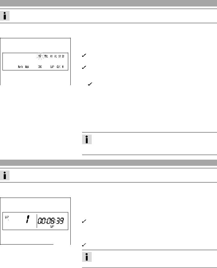
CONTROLS Speedometer 5.11 – Press the key to change the display mode or change to one of the setup menus. – Press the button to control different functions. – Press the button to control different functions. Info In its condition at delivery, the display mode SPEED/H and SPEED/ODO is acti- vated.
-
Page 19: Setting The Clock
CONTROLS – Press the button for 3 — 5 seconds. The settings are saved and the Setup menu closed. Info If no button is pressed for 20 seconds, or if no impulse comes from the wheel speed sensor, the settings are automatically saved and the Setup menu is closed.
-
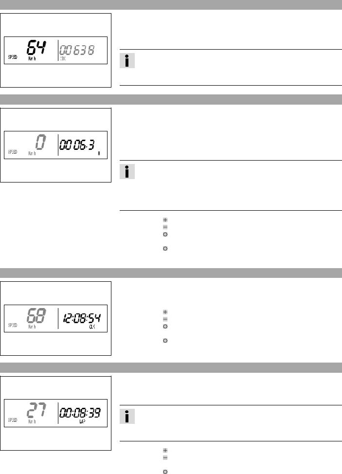
Page 20: Querying The Lap Time
CONTROLS – Press the button for 3 — 5 seconds. The settings are saved and the Setup menu closed. Info If no button is pressed for 20 seconds, or if no impulse comes from the wheel speed sensor, the settings are automatically saved and the Setup menu is closed.
-
Page 21: Speed/Clk Display Mode (Time)
CONTROLS Press the button next display mode briefly. SPEED/CLK display mode (time) 5.20 – Press the button briefly and repeatedly until CLK appears at the bottom right of the display. The time is displayed in the CLK display mode. Press the button .
-
Page 22: Speed/Tr2 Display Mode (Trip Master 2)
CONTROLS Press the button The TR1, A1 and S1 displays are reset to 0.0. for 3 — 5 seconds. Press the button next display mode briefly. SPEED/TR2 display mode (trip master 2) 5.24 – Press the button briefly and repeatedly until TR2 appears at the top right of the display.
-
Page 23: Speed/S1 Display Mode (Stop Watch 1)
CONTROLS SPEED/S1 display mode (stop watch 1) 5.27 – Press the button briefly and repeatedly until S1 appears at the top right of the display. S1 (stop watch 1) shows the trip time on the basis of TR1 and continues running when an impulse is received from the wheel speed sensor.
-
Page 24: Fuel Tap
CONTROLS Table of conditions and activability Display Vehicle at a stand- Menu can be acti- still vated SPEED/CLK display mode (time) • SPEED/LAP display mode (lap time) • SPEED/TR1 display mode (trip master 1) • SPEED/TR2 display mode (trip master 2) •…
-
Page 25: Choke
CONTROLS Choke 5.32 Choke is fitted on the left side of the carburetor. Activating the choke function frees an opening through which the engine can draw extra fuel. This gives a richer fuel-air mixture, which is needed for a cold start. Info If the engine is warm, the choke function must be deactivated.
-
Page 26: Side Stand
CONTROLS Side stand 5.36 Note Danger of damage Danger of damage by the vehicle running away or falling over. – Always place the vehicle on a firm and even surface. Note Material damage Damage and destruction of components by excessive load. – The side stand is designed for the weight of the motorcycle only.
-
Page 27: Unlocking The Steering
CONTROLS Unlocking the steering 5.39 – Insert the key in the steering lock, turn it to the left, pull it out and turn it to the right. Remove the key. You can now steer the bike again. Info Never leave the key in the steering lock.
-
Page 28: General Tips And Hints On Putting Into Operation
When using your motorcycle, remember that others may feel disturbed by excessive noise. – Make sure that the pre-delivery inspection work has been carried out by an authorized KTM workshop. You receive a delivery certificate and the service record at vehicle handover.
-
Page 29: Running In The Engine
GENERAL TIPS AND HINTS ON PUTTING INTO OPERATION – Do not exceed the overall maximum permitted weight and the axle loads. Guideline Maximum permissible overall weight 335 kg (739 lb.) Maximum permissible front axle load 145 kg (320 lb.) Maximum permissible rear axle load 190 kg (419 lb.) –…
-
Page 30: Riding Instructions
RIDING INSTRUCTIONS 7 R IDING INSTRUCTIONS Checks before putting into operation Info Make sure that the motorcycle is in a perfect technical condition before use. Info In the interests of riding safety, make a habit of making a general check before you ride. –…
-
Page 31: Starting Up
Do not change into a low gear at high engine speed. The engine races and the rear wheel can block. Info If you hear unusual noises while riding, stop immediately, switch off the engine and contact an authorized KTM workshop. First gear is used for starting off or for steep inclines.
-
Page 32: Stopping, Parking
RIDING INSTRUCTIONS Stopping, parking Warning Risk of misappropriation Usage by unauthorized persons. – Never leave the vehicle while the engine is running. Secure the vehicle against use by unauthorized persons. Warning Danger of burns Some vehicle components get very hot when the machine is driven. –…
-
Page 33: Service Schedule
SERVICE SCHEDULE 8 S ERVICE SCHEDULE Important maintenance work to be carried out by an authorized KTM workshop. S15A S30A Engine Change the engine oil and oil filter and clean the engine oil screen. p. 75) • • • Change the gear oil and clean the gear oil screen.
-
Page 34: Important Maintenance Work To Be Carried Out By An Authorized Ktm Workshop. (As Additional Order)
SERVICE SCHEDULE Important maintenance work to be carried out by an authorized KTM workshop. (as additional order) Competition use Hobby use S15A S30A S45A S30A S60A S90A • • Carry out a complete fork service. Carry out a complete shock absorber service.
-
Page 35
SERVICE SCHEDULE NB1A Clean the chain. ( p. 48) • Check the chain tension. ( p. 48) • Check the chain wear. ( p. 49) • Check the rear sprocket / engine sprocket for wear. ( p. 49) • Clean the air filter. p. -
Page 36: Maintenance Work On Chassis And Engine
For optimal motorcycle riding characteristics and to avoid damage to forks, shock absorbers, swing arm and frame, the basic set- tings of the suspension components must match your body weight. – As delivered, KTM offroad motorcycles are adjusted for a standard rider weight (with full protective clothing). Guideline Standard rider weight 75……
-
Page 37: Adjusting The Low-Speed Compression Damping Of The Shock Absorber
MAINTENANCE WORK ON CHASSIS AND ENGINE – Turn the adjusting screw clockwise with a ring wrench until it stops. Info Do not loosen nut – Turn back counterclockwise the number of turns corresponding to the shock absorber type. Guideline Compression damping, high-speed 400208-10…
-
Page 38: Measuring Rear Wheel Sag Unloaded
MAINTENANCE WORK ON CHASSIS AND ENGINE – Turn the adjusting screw clockwise until it stops. Info Do not loosen nut – Turn back counterclockwise the number of clicks corresponding to the shock absorber type. Guideline Rebound damping 400210-10 Comfort 26 clicks Standard…
-
Page 39: Checking The Riding Sag Of The Shock Absorber
MAINTENANCE WORK ON CHASSIS AND ENGINE Checking the riding sag of the shock absorber 9.10 – Measure distance of rear wheel unloaded. ( p. 36) – With another person holding the motorcycle, sit on the saddle with full protective clothing in a normal sitting position (feet on footrests) and bounce up and down a few times until the rear suspension levels out.
-
Page 40: Adjusting Riding Sag
MAINTENANCE WORK ON CHASSIS AND ENGINE Adjusting riding sag 9.12 – Remove shock absorber. p. 38) – After removing the shock absorber, clean it thoroughly. – Choose and mount a suitable spring. Guideline Spring rate Weight of rider: 65… 75 kg (143… 165 lb.) 69 N/mm (394 lb/in) Weight of rider: 75……
-
Page 41: Checking Basic Setting Of Fork
MAINTENANCE WORK ON CHASSIS AND ENGINE Checking basic setting of fork 9.15 Info For various reasons, no exact riding sag can be determined for the forks. – As with the shock absorber, smaller weight differences can be compensated by the spring preload.
-
Page 42: Adjusting Spring Preload Of The Fork
MAINTENANCE WORK ON CHASSIS AND ENGINE – Turn back counterclockwise the number of clicks corresponding to the fork type. Guideline Rebound damping Comfort 24 clicks Standard 22 clicks Sport 22 clicks Info Turn clockwise to increase damping, turn counterclockwise to reduce sus- pension damping.
-
Page 43: Loosening The Fork Protection
Danger of accidents Unsafe riding behavior due to incorrect steering head bearing play. – The steering head bearing play should be adjusted immediately in an authorized KTM workshop. Info If the bike is driven for a longer time with play in the steering head bearing, the bearing and the bearing seats in the frame can be damaged after time.
-
Page 44: Adjusting Play Of Steering Head Bearing
MAINTENANCE WORK ON CHASSIS AND ENGINE – Move the handlebar to and fro over the entire steering range. The handlebar must be able to move easily over the entire steering range. No resting locations should be noticeable. » If click positions are noticeable: –…
-
Page 45: Installing The Fork Legs
MAINTENANCE WORK ON CHASSIS AND ENGINE Installing the fork legs 9.26 – Position the fork legs. Info The topmost sunk nut in the fork leg must be flush to the upper edge of the upper triple clamp. Position the bleeder screw to the front.
-
Page 46: Removing The Lower Triple Clamp
MAINTENANCE WORK ON CHASSIS AND ENGINE Removing the lower triple clamp 9.29 – Remove the fork legs. ( p. 42) – Remove the headlight mask with the headlight. ( p. 45) – Dismount the front fender. ( p. 45) – Remove screws and hang the CDI control unit to the side.
-
Page 47: Greasing The Steering Head Bearing
MAINTENANCE WORK ON CHASSIS AND ENGINE – Mount and tighten screw Guideline Screw, top steering stem 17 Nm Loctite ® 243™ (12.5 lbf ft) – Check the cable harness, cable, brake and clutch line for free movement and free laying.
-
Page 48: Refitting The Headlight Mask With The Headlight
MAINTENANCE WORK ON CHASSIS AND ENGINE – Pull out the electric plug connector and remove the headlight mask with the headlight. 500156-10 Refitting the headlight mask with the headlight 9.35 – Connect the electric plug connector 500156-11 – Position the headlight mask and fix it with the rubber band …
-
Page 49: Checking Gas Bowden Cable Route
MAINTENANCE WORK ON CHASSIS AND ENGINE – Position the handlebar. Info Make sure cables and wiring are positioned correctly. – Position the handlebar clamp. Mount and evenly tighten the four screws Guideline Screw, handlebar clamp 20 Nm (14.8 lbf ft) Info Make sure the gap width is even.
-
Page 50: Checking For Chain Dirt Accumulation
MAINTENANCE WORK ON CHASSIS AND ENGINE – Push bellows on. Check the throttle grip for smooth operation. – Install the fuel tank. p. 67) – Check play in the gas Bowden cable. ( p. 47) Checking for chain dirt accumulation 9.41 –…
-
Page 51: Checking The Chain Tension When Fitting Rear Wheel
MAINTENANCE WORK ON CHASSIS AND ENGINE Checking the chain tension when fitting rear wheel 9.44 Warning Danger of accidents Danger caused by incorrect chain tension. – If the chain tension is too high, the components of the secondary power train (chain, engine sprocket, rear sprocket, bear- ings in transmission and rear wheel) are under additional load.
-
Page 52: Adjusting The Chain Tension
MAINTENANCE WORK ON CHASSIS AND ENGINE Adjusting the chain tension 9.47 Warning Danger of accidents Danger caused by incorrect chain tension. – If the chain tension is too high, the components of the secondary power train (chain, engine sprocket, rear sprocket, bear- ings in transmission and rear wheel) are under additional load.
-
Page 53: Adjusting Chain Tension — After Checking
MAINTENANCE WORK ON CHASSIS AND ENGINE Adjusting chain tension — after checking 9.48 – Loosen nut – Loosen nuts – Adjust the chain tension by turning the adjusting screws left and right. Guideline Chain tension 8… 10 mm (0.31… 0.39 in) Turn the adjusting screws left and right so that the markings on the left and …
-
Page 54: Adjusting Chain Guide
Warning Danger of accidents Reduced braking due to worn brake discs. – Worn brake discs should be replaced immediately in an authorized KTM workshop. – Check the thickness of the front and rear brake discs at several places on the disc to see if it conforms to measurement …
-
Page 55: Adjusting Free Travel Of Handbrake Lever
Danger of accidents Reduced braking due to old brake fluid. – Have the front and rear brake fluid replaced according to the service plan in an authorized KTM workshop. – Move the brake fluid reservoir mounted on the handlebar to a horizontal position.
-
Page 56: Checking The Front Brake Linings
Warning Danger of accidents Improper brake maintenance and repair. – Always have your brake system maintained and repaired in an authorized KTM workshop. – Press the brake caliper by hand on to the brake disc in order to press back the brake pistons.
-
Page 57: Mounting Front Brake Linings
Brake linings available from accessory suppliers are often not tested and approved for use on KTM vehicles. The construc- tion and friction factor of the brake linings and therefore the brake power can differ considerably from the original KTM brake linings. If brake linings are used that differ from the originals, there is no guarantee that they comply with the origi- nal license.
-
Page 58: Checking Free Travel Of Foot Brake Lever
MAINTENANCE WORK ON CHASSIS AND ENGINE – Remove the front brake linings. p. 54) – Move the brake fluid reservoir mounted on the handlebar to a horizontal position. – Remove screws – Remove cover with membrane – Press the brake piston back to its basic position and make sure that no brake fluid overflows from the brake fluid reservoir.
-
Page 59: Checking The Rear Brake Fluid Level
Have the brake system checked in an authorized KTM workshop, and do not ride any further. Warning Danger of accidents Reduced braking due to old brake fluid. – Have the front and rear brake fluid replaced according to the service plan in an authorized KTM workshop. – Stand the vehicle upright. –…
-
Page 60: Checking The Rear Brake Linings
Brake linings available from accessory suppliers are often not tested and approved for use on KTM vehicles. The construc- tion and friction factor of the brake linings and therefore the brake power can differ considerably from the original KTM brake linings. If brake linings are used that differ from the originals, there is no guarantee that they comply with the origi- nal license.
-
Page 61: Changing The Rear Brake Linings
If brake fluid gets into your eyes, rinse thoroughly with water and contact a doctor immediately. Warning Danger of accidents Reduced braking due to old brake fluid. – Have the front and rear brake fluid replaced according to the service plan in an authorized KTM workshop. Warning Environmental hazard Problem materials cause environmental damage. –…
-
Page 62: Removing The Front Wheel
MAINTENANCE WORK ON CHASSIS AND ENGINE Removing the front wheel 9.68 – Jack up the motorcycle. ( p. 34) – Press the brake caliper by hand on to the brake disc in order to press back the brake pistons. Info Make sure when pushing back the brake pistons that you do not press the brake caliper against the spokes.
-
Page 63: Removing Rear Wheel
MAINTENANCE WORK ON CHASSIS AND ENGINE – Lift the front wheel into the fork, position it, and insert the wheel spindle. – Mount and tighten screw Guideline Screw, front wheel spindle M24x1.5 45 Nm (33.2 lbf ft) – Operate the hand brake lever several times until the brake pads are lying correctly on the brake disc.
-
Page 64: Tire Condition Checking
9.72 Info Only mount tires approved or recommended by KTM. Other tires could have a negative effect on riding behavior. The type, condition and air pressure of the tires all have an important impact on the riding behavior of the motorcycle.
-
Page 65: Checking Tire Air Pressure
Danger of accidents Unstable riding behavior due to loose spokes. – If you ride with loose spokes, the spokes can break. Have the spoke tension corrected in an authorized KTM workshop. Info A loose spoke can cause wheel imbalance, which leads to more loose spokes in a short time.
-
Page 66: Installing The Battery
MAINTENANCE WORK ON CHASSIS AND ENGINE – Disconnect the negative (minus) cable of the battery. – Pull back the plus pole cover and disconnect the positive (plus) cable of the bat- tery. – Hang the rubber band out to the bottom. …
-
Page 67: Removing A Fuse
Replace a burned-out fuse only by an equivalent fuse. If the new fuse burns out, contact an authorized KTM workshop. – Replace the protection cover. 400273-10 – Install the air filter box lid. ( p.
-
Page 68: Mounting The Seat
MAINTENANCE WORK ON CHASSIS AND ENGINE Mounting the seat 9.81 – Hook in the front of the seat at the collar sleeve of the fuel tank, lower it at the rear and simultaneously push it forward. – Make sure that the seat is correctly locked in. –…
-
Page 69: Installing The Fuel Tank
MAINTENANCE WORK ON CHASSIS AND ENGINE Installing the fuel tank 9.83 Danger Fire hazard Fuel can easily catch fire. – Never fill up the vehicle near open flames or burning cigarettes, and always switch off the engine first. Be careful that no fuel is spilt, especially on hot vehicle components.
-
Page 70: Checking Antifreeze And Coolant Level
MAINTENANCE WORK ON CHASSIS AND ENGINE Checking antifreeze and coolant level 9.85 Warning Danger of scalding The coolant gets very hot when the motorcycle is driven and is under high pressure. – Do not open the radiator, radiator hoses or other cooling system components when the engine is hot. Allow the engine and cooling system to cool down.
-
Page 71: Draining Coolant
MAINTENANCE WORK ON CHASSIS AND ENGINE Draining coolant 9.87 Warning Danger of scalding The coolant gets very hot when the motorcycle is driven and is under high pressure. – Do not open the radiator, radiator hoses or other cooling system components when the engine is hot. Allow the engine and cooling system to cool down.
-
Page 72: Installing The Main Silencer
MAINTENANCE WORK ON CHASSIS AND ENGINE – Disconnect spring – Remove screws and take off main silencer. 800020-10 Installing the main silencer 9.91 – Mount the main silencer. Mount and tighten screws Guideline Remaining screws, chassis 10 Nm (7.4 lbf ft) –…
-
Page 73: Installing The Air Filter
MAINTENANCE WORK ON CHASSIS AND ENGINE – Hang the air filter holder out to the bottom and swing it to the side. Remove the air filter with the air filter support. – Remove the air filter from the air filter support. 500107-10 Installing the air filter 9.95…
-
Page 74: Checking The Fluid Level Of Hydraulic Clutch
MAINTENANCE WORK ON CHASSIS AND ENGINE Checking the fluid level of hydraulic clutch 9.98 Warning Skin irritations Brake fluid can cause skin irritation on contact. – Avoid contact with skin and eyes, and keep out of the reach of children. – If brake fluid gets into your eyes, rinse thoroughly with water and contact a doctor immediately.
-
Page 75: Carburetor — Idle
setting. Guideline Idle mixture adjusting screw (450 EXC USA) Open 1.75 turns Idle mixture adjusting screw (530 EXC USA) Open 2.0 turns Adjustment tool for mixture control screw (77329034000) 400341-10 – Run the engine until warm.
-
Page 76: Emptying The Carburetor Float Chamber
MAINTENANCE WORK ON CHASSIS AND ENGINE – Turn the idle adjusting screw slowly until the idle speed begins to fall. – Note the position and turn the idle adjusting screw slowly counterclockwise until the idle speed falls. – Adjust to the point between these two positions with the highest idle speed. Info If there is a big engine speed rise, reduce the idle speed to a normal level and repeat the above steps.
-
Page 77: Checking Engine Oil Level
MAINTENANCE WORK ON CHASSIS AND ENGINE – Direct the hose of the float chamber into a suitable container. Info Water in the float chamber results in malfunctioning. – Undo the screw (turn it counterclockwise) a few turns and drain the fuel from …
-
Page 78: Removing The Oil Filter
MAINTENANCE WORK ON CHASSIS AND ENGINE Removing the oil filter 9.106 Warning Danger of scalding Engine oil and gear oil get very hot when the motocycle is driven. – Wear suitable protective clothing and gloves. If you scald yourself, hold the affected area under cold water immediately. Warning Environmental hazard Problem materials cause environmental damage.
-
Page 79: Filling Up With Engine Oil
MAINTENANCE WORK ON CHASSIS AND ENGINE Filling up with engine oil 9.108 Info Too little engine oil or poor-quality engine oil results in premature wear to the engine. – Remove the screw cap on the generator cover and fill up with engine oil. …
-
Page 80: Changing Gear Oil, Cleaning Gear Oil Screen
MAINTENANCE WORK ON CHASSIS AND ENGINE Changing gear oil, cleaning gear oil screen 9.111 – Drain the gear oil and clean the gear oil screen. p. 78) – Fill up with gear oil. p. 78) Draining gear oil, cleaning gear oil screen 9.112 Warning Danger of scalding Engine oil and gear oil get very hot when the motocycle is driven.
-
Page 81: Adding Gear Oil
MAINTENANCE WORK ON CHASSIS AND ENGINE Adding gear oil 9.114 Info Too little gear oil or poor-quality oil results in premature wear to the transmission. – Remove gear oil level check screw 200116-10 – Remove screw cap . Stand the vehicle upright. …
-
Page 82: Troubleshooting
TROUBLESHOOTING TROUBLESHOOTING Faults Possible cause Action – The engine cannot be cranked (elec- Operating error Go through the steps of starting the engine. tric starter). p. 28) – Battery discharged Recharge the battery. p. 64) – Check the charging voltage. –…
-
Page 83
TROUBLESHOOTING Faults Possible cause Action – Engine has too little power. Air filter very dirty Clean the air filter. p. 71) – Exhaust system leaky, deformed or Check exhaust system for damage. too little glass fiber yarn filling in – Change glass fiber yarn filling of main main silencer silencer. -
Page 84: Cleaning
CLEANING CLEANING Cleaning motorcycle 11.1 Note Material damage Damage and destruction of components by high-pressure cleaning equipment. – Never clean the vehicle with high-pressure cleaning equipment or a strong water-jet. The excessive pressure can penetrate electri- cal components, connects, Bowden cables, and bearings, etc., and can damage or destroy these parts. Warning Environmental hazard Problem materials cause environmental damage.
-
Page 85: Storage
Storage temperature of battery without direct sunshine. 0… 35 °C (32… 95 °F) – The storage place should be dry and not subject to large temperature differences. Info KTM recommends propping up the motorcycle. – Jack up the motorcycle. ( p. 34) –…
-
Page 86: Technical Data — Engine
TECHNICAL DATA — ENGINE Design 1-cyliner 4-stroke engine, water-cooled Displacement (450 EXC USA) 449.3 cm³ (27.418 cu in) Displacement (530 EXC USA) 510.4 cm³ (31.147 cu in) Stroke (450 EXC USA) 63.4 mm (2.496 in) Stroke (530 EXC USA) 72 mm (2.83 in) Bore 95 mm (3.74 in)
-
Page 87: Capacity — Coolant
TECHNICAL DATA — ENGINE Capacity — coolant 13.3 Coolant 0.95 l (1 qt.) Coolant ( p. 97) Coolant (mixed ready to use) ( p. 97)
-
Page 88: Technical Data — Engine Tightening Torques
TECHNICAL DATA — ENGINE TIGHTENING TORQUES TECHNICAL DATA — ENGINE TIGHTENING TORQUES ® Screw, cable holder in generator cover 4 Nm (3 lbf ft) Loctite 243™ ® Oil jet, rocker arm lubrication 2 Nm (1.5 lbf ft) Loctite 243™ ® Oil jet, piston cooling 2 Nm (1.5 lbf ft) Loctite…
-
Page 89
TECHNICAL DATA — ENGINE TIGHTENING TORQUES Screw, cylinder head M10x1.25 Tightening sequence: lubricated with engine oil Tighten diagonally, begin- ning with the rear screw on the chain shaft. Step 1 10 Nm (7.4 lbf ft) Step 2 30 Nm (22.1 lbf ft) Step 3 50 Nm (36.9 lbf ft) –… -
Page 90: Technical Data — Carburetor
2.15 mm (0.0846 in) Main jet Jet needle OBDYU Idling jet Idle air jet Cold start jet Leakage nozzle 530 EXC USA 15.2 Carburetor type KEIHIN FCR-MX 39 Carburetor identification number 3900Y Needle position 3rd position from top Idle mixture adjusting screw Open 2.0 turns…
-
Page 91: Technical Data — Chassis
TECHNICAL DATA — CHASSIS TECHNICAL DATA — CHASSIS Frame Central tube frame made of chrome molybdenum steel tubing Fork WP Suspension 4860 MXMA PA Suspension travel Front 300 mm (11.81 in) Rear 335 mm (13.19 in) Fork offset 19 mm (0.75 in) WP Suspension PDS 5018 DCC Shock absorber Brake system…
-
Page 92: Tires
90/90 — 21 M/C 54M M+S TT 140/80 — 18 M/C 70M M+S TT Metzeler MCE 6 DAYS EXTREME Metzeler MCE 6 DAYS EXTREME For further information, see the Service section under: http://www.ktm.com Capacity — fuel 16.3 Total fuel tank capacity, 9.2 l (2.43 US gal) Super unleaded (ROZ 95 / RON 95 / PON 91) ( p.
-
Page 93: Technical Data — Fork
TECHNICAL DATA — FORK TECHNICAL DATA — FORK Fork part number 14.18.7E.06 Fork WP Suspension 4860 MXMA PA Compression damping Comfort 26 clicks Standard 22 clicks Sport 20 clicks Rebound damping Comfort 24 clicks Standard 22 clicks Sport 22 clicks Spring length with preload spacer(s) 510 mm (20.08 in) Spring rate…
-
Page 94: Technical Data — Shock Absorber
TECHNICAL DATA — SHOCK ABSORBER TECHNICAL DATA — SHOCK ABSORBER Shock absorber part number 12.18.7E.06 Shock absorber WP Suspension PDS 5018 DCC Compression damping, low-speed Comfort 18 clicks Standard 15 clicks Sport 12 clicks Compression damping, high-speed Comfort 2 turns Standard 1.5 turns Sport…
-
Page 95: Technical Data — Chassis Tightening Torques
TECHNICAL DATA — CHASSIS TIGHTENING TORQUES TECHNICAL DATA — CHASSIS TIGHTENING TORQUES – Spoke nipple, front wheel M4,5 5 Nm (3.7 lbf ft) – Spoke nipple, rear wheel 5 Nm (3.7 lbf ft) – Screw, spoiler on fuel tank M5x12 1.5 Nm (1.11 lbf ft) –…
-
Page 96: Wiring Diagram
WIRING DIAGRAM WIRING DIAGRAM Wiring diagram 20.1 CX/2 CZ/3 DB/4 CW/2 CY/3 DA/4 AK1/2 CW2/2 CW3/2 DG/4 AH1/2 CX2/2 CX3/2 BP/4 bl-wh bu-wh bu-wh ye-re ye-re ye-re ye-bl re-wh re-bl ye-re black BF/1 ye-re ye-re ye-bl BA/1 ye-bl re-bl wh-re re-wh ye-re CR/1…
-
Page 97
WIRING DIAGRAM Components CDI controller Throttle position sensor Wheel speed sensor Battery Generator Right rear flasher Left front flasher Left rear flasher Right front flasher Brake/tail light Parking light Low/high beam Horn Flasher indicator light High beam indicator light Starter relay with main fuse Flasher relay Pulse generator Ignition coil… -
Page 98
WIRING DIAGRAM Yellow ye-bl Yellow-black ye-re Yellow-red… -
Page 99: Substances
– Guideline – Use only brake fluid that complies with the specified standards (see specifications on the container) and that possesses the corre- ® sponding properties. KTM recommends Castrol and Motorex products. Supplier Castrol – RESPONSE BRAKE FLUID SUPER DOT 4 ®…
-
Page 100: Auxiliary Substances
AUXILIARY SUBSTANCES AUXILIARY SUBSTANCES Air filter cleaner Specification – ® KTM recommends Motorex products. Supplier ® Motorex – Twin Air Dirt Bio Remover Chain cleaner Specification – ® KTM recommends Motorex products. Supplier ® Motorex – Chain Clean 611 Cleaning and polishing materials for metal, rubber and plastic Specification –…
-
Page 101
AUXILIARY SUBSTANCES Oil for foam air filter Specification – ® KTM recommends Motorex products. Supplier ® Motorex – Twin Air Liquid Bio Power Universal oil spray Specification – ® KTM recommends Motorex products. Supplier ® Motorex – Joker 440 Universal… -
Page 102: Standards
STANDARDS STANDARDS JASO T903 MA Different technical development directions required a new specification for 4-stroke motorcycles – the JASO T903 MA Standard.Earlier, engine oils from the automobile industry were used for 4-stroke motorcycles because there was no separate motorcycle specification.Whereas long service intervals are demanded for automobile engines, high performance at high engine speeds are in the foreground for motorcycle and ATV engines.With most motorcycles and ATVs, the gearbox and the clutch are lubricated with the same oil as the engine.
-
Page 103: Index
INDEX Clutch lever ……..14 INDEX adjusting basic position ….. . . 71 Accessories .
-
Page 104
INDEX removing ……. . . 45 Overview of indicator lamps . -
Page 105
INDEX Technical data carburetor ……. . 88 chassis ……. . 89-90 chassis tightening torques . -
Page 106
*3211356en* 3211356en KTM-Sportmotorcycle AG 5230 Mattighofen/Austria http://www.ktm.com…
This manual is also suitable for:
450 exc
Не можете найти ответ на свой вопрос в руководстве? Вы можете найти ответ на свой вопрос ниже, в разделе часто задаваемых вопросов о KTM 530 EXC (2009).
Как перевести мили в километры?
В чем разница между топливом E10 и E5?
Какова рекомендуемая частота замены масляного фильтра в двигателе KTM?
Как часто следует менять масло в двигателе KTM?
Как удалить ржавчину с устройства KTM мотоцикл?
Инструкция KTM 530 EXC (2009) доступно в русский?
Не нашли свой вопрос? Задайте свой вопрос здесь
- Инструкции и руководства
- Бренды
- KTM
- 530 exc-r eu
- Справочник Пользователя
OWNER’S MANUAL
2008
450
bEXC-RbEU
450
bEXC-RbAUS/UK
450
bEXC-RbSIXbDAYS
450
bEXC-RbUSA
450
bXCR-WbUSA
450
bXCR-WbZA
530
bEXC-RbEU
530
bEXC-RbAUS/UK
530
bEXC-RbSIXbDAYS
530
bEXC-RbUSA
530
bXCR-WbUSA
530
bXCR-WbZA
ART. NO. 3211254en

OWNER’S MANUAL 2009
400 EXC EU
400 EXC AUS
400 XC-W USA
450 EXC EU
450 EXC AUS
450 EXC SIX DAYS EU
450 XC-W USA
450 XC-W ZA
530 EXC EU
530 EXC AUS
530 EXC SIX DAYS EU
530 XC-W USA
530 XC-W ZA
ART. NO. 3211355en
Congratulations on your decision to purchase a KTM motorcycle. You are now the owner of a state-of-the-art sports motorcycle that will give you enormous pleasure if you service and maintain it accordingly.
We wish you great pleasure riding the vehicle!
Enter the serial numbers of your vehicle below.
|
Chassis number ( p. 9) |
Dealer’s stamp |
Engine number ( p. 9)
p. 9)
Key number (all EXC models) ( p. 9)
p. 9)
The owner’s manual corresponded to the latest state of this series at the time of printing. Slight deviations resulting from continuing development and design of our motorcycles can however not be completely excluded.
All specifications are not binding. KTM Sportmotorcycle AG specifically reserves the right to modify or delete technical specifications, prices, colors, forms, materials, services, designs, equipment, etc., without prior notice and without specifying reasons, to adapt these to local conditions, as well as to stop production of a particular model without prior notice. KTM accepts no liability for delivery options, deviations from illustrations and descriptions, as well as printing and other errors. The models portrayed partly contain special equipment that does not belong to the regular scope of delivery.
© 2008 by KTM-Sportmotorcycle AG, Mattighofen Austria All rights reserved
Reproduction, even in part, is permitted only with the express written permission of the copyright owner.
ISO 9001(12 100 6061)
Within the meaning of the international quality management standard ISO 9001, KTM uses quality assurance processes that lead to the maximum possible quality of the products.
Issued by: TÜV Management Service
KTM-Sportmotorcycle AG
5230 Mattighofen, Austria
|
MEANS OF REPRESENTATION …………………………………….. |
4 |
|
IMPORTANT NOTES…………………………………………………… |
5 |
|
VIEW OF VEHICLE……………………………………………………… |
7 |
|
View of the vehicle from the left front (example)…………….. |
7 |
|
View of the vehicle from the right rear (example) ……………. |
8 |
|
LOCATION OF SERIAL NUMBERS …………………………………. |
9 |
|
Chassis number……………………………………………………… |
9 |
|
Type label…………………………………………………………….. |
9 |
|
Key number (all EXC models) ……………………………………. |
9 |
|
Engine number………………………………………………………. |
9 |
|
Fork part number……………………………………………………. |
9 |
|
Shock absorber part number……………………………………. |
10 |
|
OPERATING ELEMENTS……………………………………………. |
11 |
|
Clutch lever ………………………………………………………… |
11 |
|
Hand brake lever ………………………………………………….. |
11 |
|
Short circuit button (all XC W models)……………………….. |
11 |
|
Short circuit button (all EXC models)…………………………. |
11 |
|
Emergency OFF switch (EXC AUS) ……………………………. |
11 |
|
Electric starter button (EXC EU, EXC SIX DAYS, XC-W) ….. |
12 |
|
Electric starter button (EXC AUS)……………………………… |
12 |
|
Light switch (all EXC models) ………………………………….. |
12 |
|
Light switch (all XC W models) ………………………………… |
12 |
|
Horn button (all EXC models) ………………………………….. |
12 |
|
Flasher switch (all EXC models) ……………………………….. |
13 |
|
Overview of indicator lamps (all EXC models) ………………. |
13 |
|
Speedometer……………………………………………………….. |
13 |
|
Speedometer activation and test ………………………………. |
13 |
|
Tripmaster switch …………………………………………………. |
14 |
|
Setting kilometers or miles ……………………………………… |
14 |
|
Setting the clock ………………………………………………….. |
14 |
|
Adjusting the speedometer functions…………………………. |
15 |
|
Querying the lap time ……………………………………………. |
15 |
|
SPEED display mode (speed)…………………………………… |
16 |
|
SPEED/H display mode (service hours) ………………………. |
16 |
|
SPEED/CLK display mode (time)………………………………. |
16 |
|
SPEED/LAP display mode (lap time)………………………….. |
16 |
|
SPEED/ODO display mode (odometer) ……………………….. |
17 |
|
SPEED/TR1 display mode (trip master 1)……………………. |
17 |
|
SPEED/TR2 display mode (trip master 2)……………………. |
17 |
|
SPEED/A1 display mode (average speed 1) …………………. |
18 |
|
SPEED/A2 display mode (average speed 2) …………………. |
18 |
|
SPEED/S1 display mode (stop watch 1)……………………… |
18 |
|
SPEED/S2 display mode (stop watch 2)……………………… |
18 |
|
Fuel tap……………………………………………………………… |
20 |
|
Opening filler cap…………………………………………………. |
20 |
|
Closing filler cap ………………………………………………….. |
20 |
|
Choke (EXC AUS, XC W)…………………………………………. |
20 |
|
Choke (EXC EU, EXC SIX DAYS) ………………………………. |
21 |
|
Shift lever…………………………………………………………… |
21 |
|
Foot brake pedal ………………………………………………….. |
21 |
|
Kickstarter………………………………………………………….. |
21 |
|
Side stand ………………………………………………………….. |
22 |
|
Steering lock (all EXC models) …………………………………. |
22 |
|
Locking the steering (all EXC models)………………………… |
22 |
|
Unlocking the steering (all EXC models) …………………….. |
23 |
|
GENERAL TIPS AND HINTS ON PUTTING INTO |
|
|
OPERATION……………………………………………………………. |
24 |
|
Advice on first use………………………………………………… |
24 |
|
Running in the engine……………………………………………. |
25 |
|
RIDING INSTRUCTIONS ……………………………………………. |
26 |
|
Checks before putting into operation …………………………. |
26 |
|
Starting ……………………………………………………………… |
26 |
|
Starting up …………………………………………………………. |
27 |
|
Shifting, riding…………………………………………………….. |
27 |
|
Braking ……………………………………………………………… |
27 |
|
Stopping, parking …………………………………………………. |
28 |
|
Refueling……………………………………………………………. |
28 |
|
SERVICE SCHEDULE………………………………………………… |
30 |
|
Important maintenance work to be carried out by an |
|
|
authorized KTM workshop. ……………………………………… |
30 |
|
Important maintenance work to be carried out by an |
|
|
authorized KTM workshop. (as additional order)……………. |
31 |
|
Important checks and maintenance work to be carried |
|
|
out by the rider. …………………………………………………… |
31 |
|
MAINTENANCE WORK ON CHASSIS AND ENGINE………….. |
33 |
|
Jacking up the motorcycle ………………………………………. |
33 |
|
Removing the motorcycle from the work stand……………… |
33 |
|
Checking the basic chassis setting with the rider’s |
|
|
weight ……………………………………………………………….. |
33 |
|
Compression damping of shock absorber…………………….. |
33 |
|
Adjusting high-speed compression damping of the shock |
|
|
absorber …………………………………………………………….. |
33 |
|
Adjusting the low-speed compression damping of the |
|
|
shock absorber …………………………………………………….. |
34 |
|
Adjusting rebound damping of the shock absorber ………… |
34 |
|
Measuring rear wheel sag unloaded …………………………… |
35 |
|
Checking static sag of the shock absorber …………………… |
35 |
|
Checking the riding sag of the shock absorber ……………… |
36 |
|
Adjusting spring preload of the shock absorber x………… |
36 |
|
Adjusting riding sag x………………………………………….. |
37 |
|
Removing the shock absorber x………………………………. |
37 |
|
Installing the shock absorber x………………………………. |
37 |
|
Checking basic setting of fork ………………………………….. |
38 |
|
Adjusting compression damping of fork ……………………… |
38 |
|
Adjusting rebound damping of fork……………………………. |
38 |
|
Adjusting spring preload of the fork…………………………… |
39 |
|
Bleeding fork legs…………………………………………………. |
39 |
|
Cleaning dust boots of fork legs ……………………………….. |
39 |
|
Loosening the fork protection…………………………………… |
40 |
|
Positioning the fork protection …………………………………. |
40 |
|
Checking play of steering head bearing………………………. |
40 |
|
Adjusting play of steering head bearing x(EXC EU, |
|
|
EXC AUS, XC W ZA)………………………………………………. |
41 |
|
Adjusting play of steering head bearing x |
|
|
(EXC SIX DAYS, XC W USA) ……………………………………. |
41 |
|
Removing the fork legs…………………………………………… |
42 |
|
Installing the fork legs x……………………………………….. |
42 |
|
Removing the fork protector x………………………………… |
43 |
|
Installing the fork protector x………………………………… |
43 |
|
Removing the lower triple clamp x(EXC SIX DAYS, |
|
|
XC W USA) …………………………………………………………. |
43 |
|
Removing the lower triple clamp x(EXC EU, EXC AUS, |
|
|
XC W ZA)……………………………………………………………. |
44 |
|
Installing the lower triple clamp x(EXC SIX DAYS, |
|
|
XC W USA) …………………………………………………………. |
45 |
|
Installing the lower triple clamp x(EXC EU, EXC AUS, |
|
|
XC W ZA)……………………………………………………………. |
46 |
|
Greasing the steering head bearing x……………………….. |
46 |
|
Dismounting the front fender …………………………………… |
47 |
|
Installing the front fender……………………………………….. |
47 |
|
Removing headlight mask with headlight (EXC, |
|
|
EXC SIX DAYS, XC W ZA) ……………………………………….. |
47 |
|
Refitting the headlight mask with the headlight (EXC, |
|
|
EXC SIX DAYS, XC W ZA) ……………………………………….. |
47 |
|
Dismount the start number plate (XC W USA)………………. |
48 |
|
Installing the start number plate (XC W USA)………………. |
48 |
|
Handlebar position ……………………………………………….. |
48 |
|
Adjusting handlebar position x……………………………….. |
48 |
|
Checking gas Bowden cable route …………………………….. |
50 |
|
Checking play in the gas Bowden cable ……………………… |
50 |
|
Adjusting the gas Bowden cable play x…………………….. |
50 |
|
Checking for chain dirt accumulation ………………………… |
51 |
|
Cleaning the chain………………………………………………… |
51 |
|
Checking the chain tension …………………………………….. |
52 |
|
Checking the chain tension when fitting rear wheel……….. |
52 |
|
Checking the rear sprocket / engine sprocket for wear ……. |
52 |
|
Checking chain wear……………………………………………… |
53 |
|
Adjusting the chain tension …………………………………….. |
53 |
|
Adjusting chain tension — after checking …………………….. |
54 |
|
Adjusting chain tension — fitting rear wheel …………………. |
55 |
|
Adjusting chain guide x……………………………………….. |
55 |
|
Checking the brake discs………………………………………… |
55 |
|
Checking free travel of hand brake lever……………………… |
56 |
|
Adjusting basic position of handbrake lever (all XC W |
|
|
models) ……………………………………………………………… |
56 |
|
Adjusting free travel of handbrake lever (all EXC |
|
|
models) ……………………………………………………………… |
57 |
|
Checking the front brake fluid level …………………………… |
57 |
|
Adding front brake fluid x…………………………………….. |
57 |
|
Checking the front brake linings……………………………….. |
58 |
|
Removing front brake linings x………………………………. |
58 |
|
Mounting front brake linings x……………………………….. |
59 |
|
Changing the front brake linings x…………………………… |
59 |
|
Checking free travel of foot brake lever ………………………. |
60 |
|
Adjusting basic position of footbrake lever x………………. |
60 |
|
Checking the rear brake fluid level ……………………………. |
61 |
|
Adding brake fluid for the rear brake x…………………….. |
61 |
|
Checking the rear brake linings ………………………………… |
62 |
|
Removing rear brake linings x………………………………… |
62 |
|
Installing the rear brake linings x……………………………. |
62 |
|
Changing the rear brake linings x……………………………. |
63 |
|
Removing the front wheel x…………………………………… |
64 |
|
Installing the front wheel x……………………………………. |
64 |
|
Removing rear wheel x…………………………………………. |
65 |
|
Installing the rear wheel x…………………………………….. |
65 |
|
Tire condition checking………………………………………….. |
66 |
|
Checking tire air pressure……………………………………….. |
67 |
|
Checking spoke tension………………………………………….. |
67 |
|
Removing the battery x………………………………………… |
67 |
|
Installing the battery x…………………………………………. |
68 |
|
Recharging the battery x………………………………………. |
68 |
|
Removing a fuse…………………………………………………… |
69 |
|
Installing the fuse ………………………………………………… |
69 |
|
Removing the seat ………………………………………………… |
69 |
|
Mounting the seat ………………………………………………… |
70 |
|
Dismounting the fuel tank x………………………………….. |
70 |
|
Installing the fuel tank x………………………………………. |
71 |
|
Cooling system …………………………………………………….. |
71 |
|
Checking antifreeze and coolant level ………………………… |
72 |
|
Checking the coolant level………………………………………. |
72 |
|
Draining coolant x………………………………………………. |
73 |
|
Refilling coolant x………………………………………………. |
73 |
|
Glass fiber yarn filling of main silencer ………………………. |
73 |
|
Removing main silencer …………………………………………. |
74 |
|
Installing the main silencer …………………………………….. |
74 |
|
Dismounting the air filter box lid………………………………. |
74 |
|
Installing the air filter box lid…………………………………… |
74 |
|
Removing the air filter x……………………………………….. |
75 |
|
Installing the air filter x……………………………………….. |
75 |
|
Cleaning air filter x……………………………………………… |
75 |
|
Adjusting basic position of clutch lever………………………. |
76 |
|
Checking the fluid level of hydraulic clutch…………………. |
76 |
|
Changing the hydraulic clutch fluid x………………………. |
76 |
|
Carburetor — idle …………………………………………………… |
77 |
|
Carburetor — adjusting idle x………………………………….. |
78 |
|
Emptying the carburetor float chamber x………………….. |
79 |
|
Checking engine oil level………………………………………… |
79 |
|
Changing engine oil and oil filter, cleaning engine oil |
|
|
screen x…………………………………………………………… |
80 |
|
Draining engine oil, cleaning engine oil screen x………… |
80 |
|
Removing the oil filter x……………………………………….. |
80 |
|
Mounting oil filter x…………………………………………….. |
81 |
|
Filling up with engine oil x……………………………………. |
81 |
|
Topping up engine oil ……………………………………………. |
82 |
|
Checking gear oil level …………………………………………… |
82 |
|
Changing gear oil, cleaning gear oil screen x……………… |
82 |
|
Draining gear oil, cleaning gear oil screen x………………. |
82 |
|
Filling up with gear oil x………………………………………. |
83 |
|
Adding gear oil x………………………………………………… |
83 |
|
TROUBLESHOOTING………………………………………………… |
85 |
|
CLEANING……………………………………………………………… |
87 |
|
Cleaning motorcycle ……………………………………………… |
87 |
|
STORAGE ………………………………………………………………. |
88 |
|
Storage………………………………………………………………. |
88 |
|
Putting into operation after storage …………………………… |
88 |
|
TECHNICAL DATA — ENGINE………………………………………. |
89 |
|
Capacityengine oil ………………………………………………. |
89 |
|
Capacity — gear oil…………………………………………………. |
90 |
|
Capacity — coolant…………………………………………………. |
90 |
|
TECHNICAL DATA — ENGINE TIGHTENING TORQUES………. |
91 |
|
TECHNICAL DATA — CARBURETOR………………………………. |
93 |
|
400 EXC…………………………………………………………….. |
93 |
|
400 XC-W USA ……………………………………………………. |
93 |
|
450 EXC, 450 EXC SIX DAYS………………………………….. |
93 |
|
450 XC-W…………………………………………………………… |
94 |
|
530 EXC, 530 EXC SIX DAYS………………………………….. |
94 |
|
530 XC W…………………………………………………………… |
94 |
|
TECHNICAL DATA — CHASSIS …………………………………….. |
95 |
|
Lighting equipment ………………………………………………. |
95 |
|
Tires …………………………………………………………………. |
96 |
|
Capacity — fuel……………………………………………………… |
96 |
|
TECHNICAL DATA — FORK………………………………………….. |
97 |
|
TECHNICAL DATA — SHOCK ABSORBER ……………………….. |
98 |
|
TECHNICAL DATA — CHASSIS TIGHTENING TORQUES …….. |
99 |
|
WIRING DIAGRAM …………………………………………………. |
100 |
|
Wiring diagram (all EXC models) …………………………….. |
100 |
|
Wiring diagram (all XC W models) …………………………… |
104 |
|
SUBSTANCES……………………………………………………….. |
106 |
|
AUXILIARY SUBSTANCES………………………………………… |
107 |
|
STANDARDS…………………………………………………………. |
109 |
|
INDEX …………………………………………………………………. |
110 |
MEANS OF REPRESENTATION |
4 |
Symbols used
The symbols used are explained in the following.
Indicates an expected reaction (e.g. of a work step or a function).
Indicates an unexpected reaction (e.g. of a work step or a function).
All work marked with this symbol requires specialist knowledge and technical understanding. In the interest of your own safety, have these jobs done in an authorized KTM workshop! There, your motorcycle will be serviced optimally by specially trained experts using the specialist tools required.
Identifies a page reference (more information is provided on the specified page).
Formats used
The typographical and other formats used are explained in the following.
|
Specific name |
Identifies a specific name. |
|
Name® |
Identifies a protected name. |
|
Brand™ |
Identifies a brand in merchandise traffic. |
Use definition (all EXC models)
KTM sport motorcycles are designed and built to withstand the normal stresses and strains of competitive use. The motorcycles comply with currently valid regulations and categories of the top international motorsport organizations.
Info
The motorcycle is authorized for public road traffic in the homologous (reduced) version only.
In the derestricted version, the motorcycle must be used only on secluded property remote from public road traffic.
The motorcycle is designed for off-road sport endurance competition (Enduro) and not for the predominant motocross use.
Use definition (all XC W models)
KTM sport motorcycles are designed and built to withstand the normal stresses and strains of competitive use. The motorcycles comply with currently valid regulations and categories of the top international motorsport organizations.
Info
The motorcycle must be used only on secluded property remote from public road traffic.
The motorcycle is designed for off-road sport endurance competition (Enduro) and not for the predominant motocross use.
Maintenance
A prerequisite for perfect operation and prevention of wear is that the engine and chassis maintenance and adjustment work described in the owner’s manual are properly carried out. Poor adjustment and tuning of the engine and chassis can lead to damage and breakage of components.
Using the motorcycle in extreme conditions such as very muddy or wet terrain can lead to above-average wear of components such as the transmission train or the brakes. For this reason, it may be necessary to service or replace worn parts before the limit specified in the service schedule is reached.
Pay careful attention to the prescribed running-in period, inspection and maintenance intervals. If you observe these exactly, you will ensure a much longer service life for your motorcycle.
Warranty
The work prescribed in the service schedule must be carried out in an authorized KTM workshop and confirmed in the customer’s service record, since otherwise no warranty claims will be recognized. No warranty claims can be considered for damage resulting from manipulations and/or alterations to the vehicle.
Fuel, oils, etc.
You should use the fuels, oils and greases according to specifications as listed in the owner’s manual.
Spare parts, accessories
For your own safety, only use spare parts and accessory products that are approved and/or recommended by KTM and have them installed by an authorized KTM workshop. KTM accepts no liability for other products and any resulting damage or loss.
The current KTM PowerParts for your vehicle can be found on the KTM website.
International KTM Website: http://www.ktm.com
Work rules
When the vehicle is assembled, non-reusable parts (e.g., self-locking screws and nuts, gaskets, seal rings, O-rings, splints, lock washers) must be replaced with new parts.
Where thread lockers are used on screw connections (e.g., Loctite®), follow the instructions for use from the manufacturer. After disassembly, clean the parts that are to be reused and check them for damage and wear. Replace damaged or worn parts. After you complete the repair or maintenance work, check the roadworthiness of the vehicle.
Transport
Note
Danger of damage Danger of damage by the vehicle running away or falling over.
–Always place the vehicle on a firm and even surface.
Note
Fire hazard Some components (engine, radiator and exhaust system) get very hot when the engine is running.
–Do not place the vehicle where there are flammable or explosive substances.
–switch off engine.
–Turn handle of the fuel tap to the OFF position. (Figure 500137-10 p. 20)
–Use straps or other suitable devices to secure the motorcycle against accidents or falling over.
Environment
Offroad motorcycling is a wonderful sport and we naturally hope that you will be able to enjoy it to the fullest. However, it is a potential problem for the environment and can lead to conflicts with other persons. But if you use your motorcycle responsibly, you can ensure that such problems and conflicts do not have to occur. To protect the future of motorcycle sport, make sure that you use your motorcycle legally, display environmental consciousness, and respect the rights of others.
Notes/warnings
Be sure to pay attention to the notes and warnings given here.
Info
Various notes and warning stickers are attached to the vehicle. Do not remove any notes and warning stickers. If they are missing, you or others may not recognize dangers and may therefore be injured.
Grades of risks
Danger
Danger that leads immediately and certainly to severe and permanent injury or death.
Warning
Danger that will probably lead to severe and permanent injury or death.
Note
Danger of serious damage to machine or material.
Warning
Risk of environmental damage.
OWNER’S MANUAL
–It is important that you read this owner’s manual carefully and completely before making your first trip. It contains useful information and many tips on how to operate and handle your motorcycle. Only then will you find out how to best customize the motorcycle for your own use and how you can protect yourself from injury. The owner’s manual also contains important information on servicing the motorcycle.
–The owner’s manual is an important component of the motorcycle and should be handed over to the new owner if the vehicle is sold.
3View.1 of the vehicle from the left front (example)
800014-10
1Side stand
2Shift lever
3Chain guide
4Fuel tap
5Air filter box lid
6Clutch lever
7Hand brake lever
View3.2 of the vehicle from the right rear (example)
800013-10
1Level viewer for brake fluid, rear
2Fork compression adjustment
3Foot brake pedal
4Kickstarter
5Horn
6Filler cap
7Fork rebound adjustment
8Electric starter button
9Speedometer
10Short circuit button
11Shock absorber compression adjustment
12Shock absorber rebound adjustment
![]()
LOCATION OF SERIAL NUMBERS |
9 |
4Chassis.1 number
The chassis number is stamped on the steering head on the right.
500127-10
Type4.2 label
The type label is fixed to the front of the steering head.
500128-10
Key4.3 number (all EXC models)
The key number is stamped on the key strap.
500125-10
Engine4.4 number
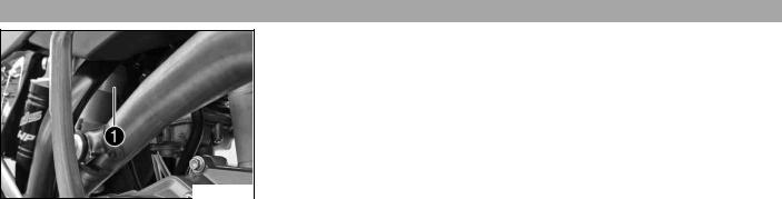
The engine number is stamped on the left side of the engine under the engine sprocket.
500072-10
Fork4.5 part number
The fork part number is stamped on the inner side of the fork stub.
500082-10
|
LOCATION OF SERIAL NUMBERS |
10 |
Shock4.6 absorber part number
The shock absorber part number is stamped on the top of the shock absorber above the adjusting ring on the engine side.
500129-10

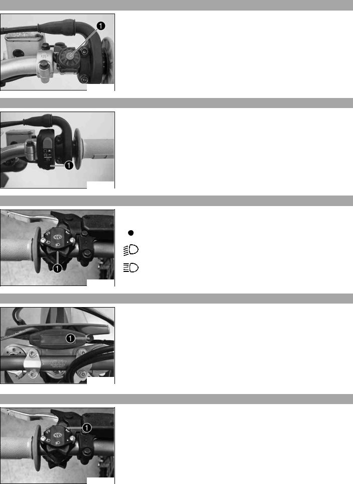
5Clutch.1 lever
The clutch lever is fitted on the left side of the handlebar.
The clutch is hydraulically operated and self-adjusting.
500133-10
Hand5.2 brake lever
Hand brake lever is located on the right side of the handlebar.
The hand brake lever is used to activate the front brake.
400196-10
Short5.3 circuit button (all XC W models)
The short circuit button is fitted on the left side of the handlebar.
Possible states
•Short circuit button  in basic position – In this position, the ignition circuit is closed, and the engine can be started.
•Short circuit button  pressed – In this position, the ignition circuit is interrupted, a running engine stops, and a non-running engine will not start.
500132-10
Short5.4 circuit button (all EXC models)
The short circuit button is fitted on the left side of the handlebar.
Possible states
•Short circuit button  in basic position – In this position, the ignition circuit is closed, and the engine can be started.
•Short circuit button  pressed – In this position, the ignition circuit is interrupted, a running engine stops, and a non-running engine will not start.
500134-10
Emergency5.5 OFF switch (EXC AUS)
The emergency OFF switch is fitted on the left side of the handlebar.
Possible states
Ignition off – In this position, the ignition circuit is interrupted, a running engine stops, and a non-running engine will not start.
Ignition on – In this position, the ignition circuit is closed, and the engine can be started.
500131-10
Electric5.6 starter button (EXC EU, EXC SIX DAYS, XC-W)
The electric starter button is fitted on the right side of the handlebar.
Possible states
•Electric starter button  in basic position
•Electric starter button  pressed – In this position, the electric starter is actuated.
400198-10
Electric5.7 starter button (EXC AUS)
The electric starter button is fitted on the right side of the handlebar.
Possible states
•Electric starter button  in basic position
•Electric starter button  pressed – In this position, the electric starter is actuated.
500131-11
Light5.8 switch (all EXC models)
The light switch is fitted on the left side of the handlebar.
Possible states
Light off – Light switch is turned to the right. In this position, the light is switched off.
Low beam on – Light switch is in the central position. In this position,
the low beam and tail light are switched on.
High beam on – Light switch is turned to the left. In this position, the high beam and the tail light are switched on.
500134-12
Light5.9 switch (all XC W models)
500146-10
The light switch is on the right of the speedometer.
Possible states (XC W ZA)
•Light off – Light switch is pressed in up to the stop. In this position, the light is switched off.
•Light on – Light switch is pulled out to the stop. In this position, the low beam and the tail light are switched on.
(XC W USA)
•The light switch has no function when delivered. – It can be used if lighting is fitted later.
Horn5.10 button (all EXC models)
The horn button is fitted on the left side of the handlebar.
Possible states
•Horn button  in neutral position
•Horn button  pressed – The horn is operated in this position.
500134-11
Flasher5.11 switch (all EXC models)
Flasher switch is fitted on the left side of the handlebar.
Possible states
Flasher light off – Flasher switch is in the central position.
Flasher light, left, on – Flasher switch turned to the left.
Flasher light, right, on – Flasher switch turned to the right.
500145-10
Overview5.12 of indicator lamps (all EXC models)
Possible states
High beam indicator lamp lights up blue – High beam is switched on.
Flasher indicator lamp flashes green – Flasher light is switched on.
500147-01
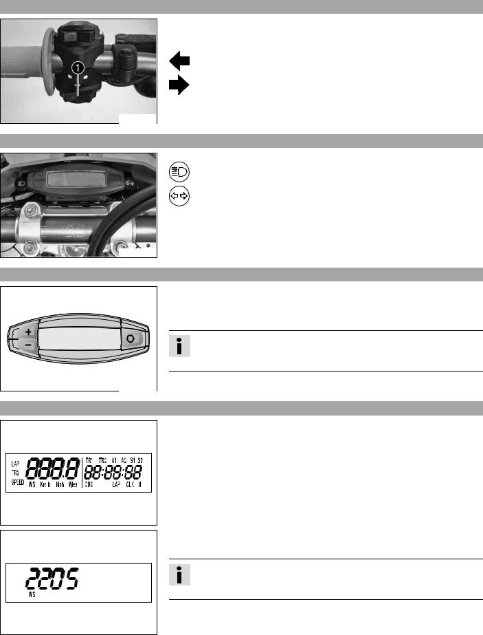
Speedometer5.13
–Press the key  to change the display mode or change to one of the setup menus.
–Press the button  to control different functions.
–Press the button  to control different functions.
Info
In its condition at delivery, the display mode SPEED/H andSPEED/ODO is activated.
Speedometer5.14 activation and test
Activating the speedometer:
The speedometer is activated when one of the keys is pressed or an impulse comes from the wheel speed sensor.
Display test
For the function test of the display, all display segments light up briefly.
400313-01
WS (wheel size)
After the display function test, the wheel size WS is displayed briefly.
Info
2205 mm corresponds to the size of the 21″ front wheel with a series production tire.
The display then changes to the last selected mode.
400314-01
Tripmaster5.15 switch
(Option: Tripmaster switch)
You can use the trip master switch to control the functions of the speedometer from the handlebar.
Info
The trip master is an optional accessory.
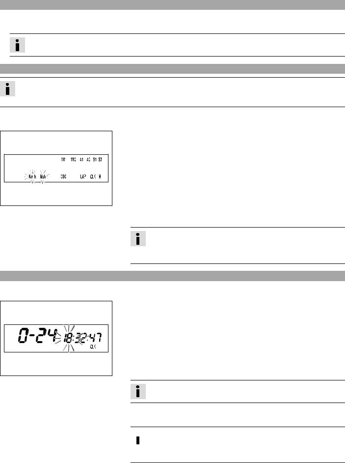
Setting5.16 kilometers or miles
Info
If you change the unit, the value ODO is retained and converted accordingly.
The values TR1, TR2, A1, A2 and S1 are cleared when the unit of measure is changed.
400329-01
Setting5.17 the clock
400330-01
Condition
The motorcycle is standing.
–Press the button  briefly and repeatedly until H appears at the bottom right of the display.
–Press the button  for 3 — 5 seconds.
 The Setup menu opens and the active functions are displayed.
–Press the button  repeatedly until the Km/h/Mph display flashes.
Km/hadjusting
–Press the button  .
.
Mphadjusting
– Press the button  .
.
–Press the button  for 3 — 5 seconds.
 The settings are saved and the Setup menu closed.
Info
If no button is pressed for 20 seconds, or if no impulse comes from the wheel speed sensor, the settings are automatically saved and the Setup menu closed.
Condition
The motorcycle is standing.
–Press the button  briefly and repeatedly until CLK appears at the bottom right of the display.
–Press the button  for 3 — 5 seconds.
 The hour display flashes.
–Set the hour display with the button  and/or button
  .
.
–Press the button  briefly.
 The next segment of the display flashes and can be set.
–You can set the following segments in the same way as the hours by pressing the button  and the button
  .
.
Info
The seconds can only be set to zero.
–Press the button  for 3 — 5 seconds.
 The settings are saved and the Setup menu closed.
 Info
Info
If no button is pressed for 20 seconds, or if no impulse comes from the wheel speed sensor, the settings are automatically saved and the Setup menu closed.
Adjusting5.18 the speedometer functions
Info
Upon delivery, only the SPEED/H and SPEED/ODO display modes are activated.
Condition
The motorcycle is standing.
–Press the button  briefly and repeatedly until H appears at the bottom right of the display.
–Press the button  for 3 — 5 seconds.
The Setup menu opens and the active functions are displayed.
– Switch to the function you require by briefly pressing the button  .
.
The selected function flashes.
Activating a function
–Press the button  .
.
|
400318-01 |
The icon remains in the display and the display changes to the next func- |
|
tion. |
Deactivating a function
–Press the button  .
.
 The icon disappears from the display and the display changes to the next function.
–Activate or deactivate all functions accordingly.
–Press the button  for 3 — 5 seconds.
 The settings are saved and the Setup menu closed.
Info
If no button is pressed for 20 seconds, or if no impulse comes from the wheel speed sensor, the settings are automatically saved and the Setup menu is closed.
Querying5.19 the lap time
Info
This function can be called only if lap times are measured.
Condition
The motorcycle is standing.
–Press the button  briefly and repeatedly until LAP appears at the bottom right of the display.
–Press the button  briefly.
LAP 1 appears on the left side of the display.
– Laps 1-10 can be displayed by pressing the button  .
.
–The  button has no function
–Press the button  briefly.
400321-01
Next display mode
Info
If an impulse is received from the wheel speed sensor, the left side of the display changes back to the SPEED mode.
SPEED5.20 display mode (speed)
–Press the button  briefly and repeatedly until SPEED appears on the left side of the display.
The current speed is displayed in the SPEED display mode.
The current speed can be displayed in Km/h or Mph.
Info
Making the setting according to the country.
When an impulse comes from the front wheel, the left side of the speedometer
display changes to the SPEED mode and the current speed is shown.
400317-02
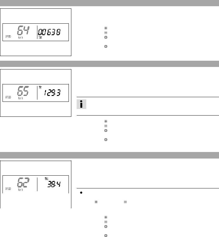
SPEED/H5.21 display mode (service hours)
400316-01
Condition
•Vehicle at a standstill
–Press the button  briefly and repeatedly until H appears at the bottom right of the display.
The number of service hours of the engine is shown in the H display mode. The service hour counter stores the total traveling time.
Info
The service hour counter is necessary for ensuring that maintenance work is carried out at the right intervals.
If the speedometer is in the H display mode at the start of the trip, it automatically changes to the ODO display mode.
The H display mode is suppressed during travel.
|
Press the button . |
No function |
|
Press the button . |
No function |
|
Press the button |
The display changes to the Setup menu of the speedometer |
|
for 3 — 5 seconds. |
functions. |
|
Press the button |
next display mode |
|
briefly. |
SPEED/CLK5.22 display mode (time)
400319-01
–Press the button  briefly and repeatedly until CLK appears at the bottom right of the display.
The time is displayed in the CLK display mode.
|
Press the button . |
No function |
|
Press the button . |
No function |
|
Press the button |
The display changes to the Setup menu of the clock. |
|
for 3 — 5 seconds. |
|
|
Press the button |
next display mode |
|
briefly. |
SPEED/LAP5.23 display mode (lap time)
400320-01
–Press the button  briefly and repeatedly until LAP appears at the bottom right of the display.
In the LAP display mode, up to ten laps can be timed with the stop watch.
Info
If the lap time continues after you press the button  , 9 memory locations are already occupied.
Lap 10 must be timed with the button  .
.
|
Press the button . |
Starts or stops the clock. |
|
Press the button . |
Stops the current lap time and saves it, and the stop watch |
|
starts the next lap. |
|
|
Press the button |
The stop watch and the lap time are reset. |
|
for 3 — 5 seconds. |
SPEED/ODO5.24 display mode (odometer)
400317-01
Press the button  next display mode briefly.
–Press the button  briefly and repeatedly until ODO appears at the bottom right of the display.
The total number of kilometers ridden is shown in the ODO display mode.
|
Press the button . |
No function |
|
Press the button . |
No function |
|
Press the button |
– |
|
for 3 — 5 seconds. |
|
|
Press the button |
next display mode |
|
briefly. |
SPEED/TR15.25 display mode (trip master 1)
–Press the button  briefly and repeatedly until TR1 appears at the top right of the display.
TR1 (trip master 1) runs constantly and counts to 999.9.
You can use it to measure trips or the distance between refueling stops.
TR1 is coupled with A1 (average speed 1) and S1 (stop watch 1).
Info
If 999.9 is exceeded, the values of TR1, A1 and S1 are automatically reset to
0.0.
400323-01
|
Press the button . |
No function |
|
Press the button . |
No function |
|
Press the button |
The TR1, A1 and S1 displays are reset to 0.0. |
|
for 3 — 5 seconds. |
|
|
Press the button |
next display mode |
|
briefly. |
SPEED/TR25.26 display mode (trip master 2)
–Press the button  briefly and repeatedly until TR2 appears at the top right of the display.
TR2 (trip master 2) runs constantly and counts to 999.9.
The displayed value can be set manually with the button  and the button
  . A very practical function for rides by the road book.
|
Info |
||||||||
|
The TR2 value can also be corrected manually during the trip using the but- |
||||||||
|
400324-01 |
ton and the button . |
|||||||
|
If 999.9 is exceeded, TR2 is automatically reset to 0.0. |
||||||||
|
Press the button . |
Increases value TR2. |
|||||||
|
Press the button . |
Decreases value TR2. |
|||||||
|
Press the button |
Clears value TR2. |
|||||||
|
for 3 — 5 seconds. |
||||||||
|
Press the button |
next display mode |
|||||||
|
briefly. |
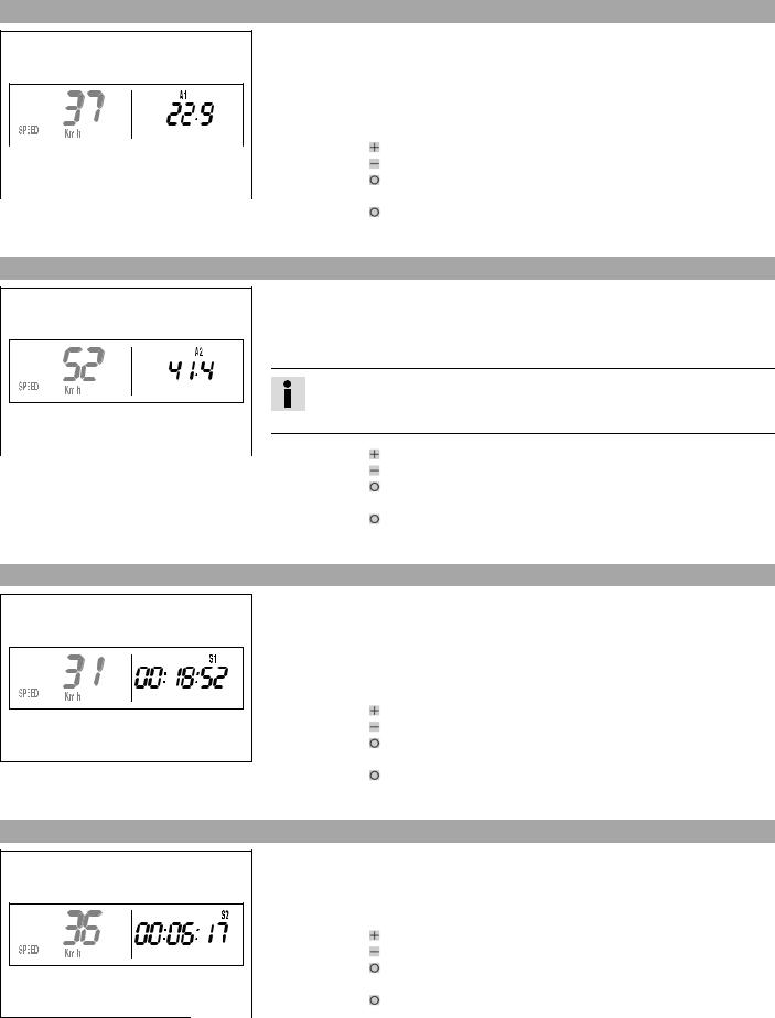
SPEED/A15.27 display mode (average speed 1)
–Press the button  briefly and repeatedly until A1 appears at the top right of the display.
A1 (average speed 1) shows the average speed calculated on the basis of TR1 (trip master 1) and S1 (stop watch 1).
The calculation of this value is activated by the first impulse of the wheel speed sensor and ends 3 seconds after the last impulse.
|
Press the button . |
No function |
|||
|
Press the button . |
No function |
|||
|
400325-01 |
Press the button |
The TR1, A1 and S1 displays are reset to 0.0. |
||
|
for 3 — 5 seconds. |
||||
|
Press the button |
next display mode |
|||
|
briefly. |
SPEED/A25.28 display mode (average speed 2)
–Press the button  briefly and repeatedly until A2 appears at the top right of the display.
A2 (average speed 2) shows the average speed on the basis of the current speed if the stop watch S2 (stop watch 2) is running.
Info
The displayed value can differ from the actual average speed if S2 is not stopped after the ride.
|
400326-01 |
Press the button . |
No function |
|
Press the button . |
No function |
|
|
Press the button |
– |
|
|
for 3 — 5 seconds. |
||
|
Press the button |
next display mode |
|
|
briefly. |
SPEED/S15.29 display mode (stop watch 1)
400327-01
–Press the button  briefly and repeatedly until S1 appears at the top right of the display.
S1 (stop watch 1) shows the trip time on the basis of TR1 and continues running when an impulse is received from the wheel speed sensor.
The calculation of this value starts with the first impulse of the wheel speed sensor and ends three seconds after the last impulse.
|
Press the button . |
No function |
|
Press the button . |
No function |
|
Press the button |
The TR1, A1 and S1 displays are reset to 0.0. |
|
for 3 — 5 seconds. |
|
|
Press the button |
next display mode |
|
briefly. |
SPEED/S25.30 display mode (stop watch 2)
400328-01
–Press the button  briefly and repeatedly until S2 appears at the top right of the display.
S2 (stop watch 2) is a manual stop watch.
If S2 is running in the background, the S2 display flashes in the speedometer display.
|
Press the button . |
Starts or stops S2. |
|
Press the button . |
No function |
|
Press the button |
The S2 and A2 displays are reset to 0.0. |
|
for 3 — 5 seconds. |
|
|
Press the button |
next display mode |
|
briefly. |
![]()
|
OPERATING ELEMENTS |
19 |
|||||||
|
Table of functions |
||||||||
|
Display |
Press the button . |
Press the button . |
Press the button for 3 — |
Press the button |
||||
|
5 seconds. |
briefly. |
|||||||
|
SPEED/H display mode |
No function |
No function |
The display changes to |
next display mode |
||||
|
(service hours) |
the Setup menu of the |
|||||||
|
speedometer functions. |
||||||||
|
SPEED/CLK display mode |
No function |
No function |
The display changes to |
next display mode |
||||
|
(time) |
the Setup menu of the |
|||||||
|
clock. |
||||||||
|
SPEED/LAP display mode |
Starts or stops the |
Stops the current lap |
The stop watch and the |
next display mode |
||||
|
(lap time) |
clock. |
time and saves it, and |
lap time are reset. |
|||||
|
the stop watch starts |
||||||||
|
the next lap. |
||||||||
|
SPEED/ODO display mode |
No function |
No function |
– |
next display mode |
||||
|
(odometer) |
||||||||
|
SPEED/TR1 display mode |
No function |
No function |
The TR1, A1 and S1 dis- |
next display mode |
||||
|
(trip master 1) |
plays are reset to 0.0. |
|||||||
|
SPEED/TR2 display mode |
Increases value TR2. |
Decreases value TR2. |
Clears value TR2. |
next display mode |
||||
|
(trip master 2) |
||||||||
|
SPEED/A1 display mode |
No function |
No function |
The TR1, A1 and S1 dis- |
next display mode |
||||
|
(average speed 1) |
plays are reset to 0.0. |
|||||||
|
SPEED/A2 display mode |
No function |
No function |
– |
next display mode |
||||
|
(average speed 2) |
||||||||
|
SPEED/S1 display mode |
No function |
No function |
The TR1, A1 and S1 dis- |
next display mode |
||||
|
(stop watch 1) |
plays are reset to 0.0. |
|||||||
|
SPEED/S2 display mode |
Starts or stops S2. |
No function |
The S2 and A2 displays |
next display mode |
||||
|
(stop watch 2) |
are reset to 0.0. |
|||||||
|
Table of conditions and activability |
||||||||
|
Display |
Vehicle at a stand- |
Menu can be acti- |
||||||
|
still |
vated |
|||||||
|
SPEED/H display mode (service hours) |
• |
|||||||
|
SPEED/CLK display mode (time) |
• |
|||||||
|
SPEED/LAP display mode (lap time) |
• |
|||||||
|
SPEED/TR1 display mode (trip master 1) |
• |
|||||||
|
SPEED/TR2 display mode (trip master 2) |
• |
|||||||
|
SPEED/A1 display mode (average speed 1) |
• |
|||||||
|
SPEED/A2 display mode (average speed 2) |
• |
|||||||
|
SPEED/S1 display mode (stop watch 1) |
• |
|||||||
|
SPEED/S2 display mode (stop watch 2) |
• |
|||||||
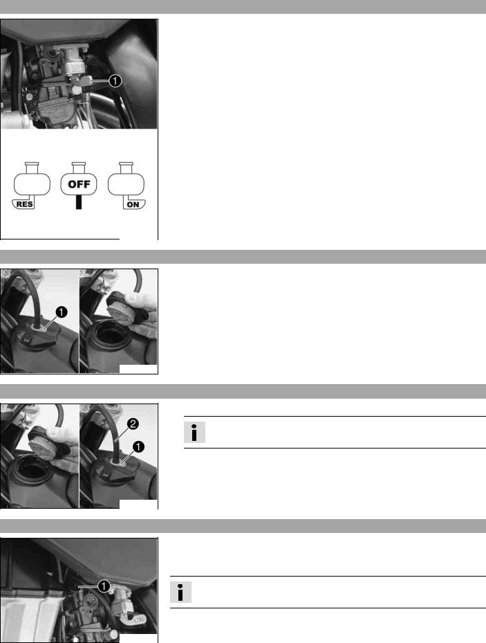
Fuel5.31 tap
The fuel tap is on the left of the fuel tank.
With the tap handle on the fuel tap, you can open or close the supply of fuel to the carburetor.
Possible states
•Fuel supply closed OFF – No fuel can flow from the tank to the carburetor.
•Fuel supply open ON – Fuel can flow from the tank to the carburetor. The fuel tank empties down to the reserve.
•Reserve fuel supply open RES – Fuel can flow from the tank to the carburetor. The fuel tank empties completely.
500137-10
Opening5.32 filler cap
–Press release button , turn filler cap counterclockwise and lift it free.
400199-10
Closing5.33 filler cap
–Replace the filler cap and turn clockwise until the release button locks in place.
Info
Run the fuel tank breather hose without kinks.
400199-11
Choke5.34 (EXC AUS, XC W)
500135-10
Choke is fitted on the left side of the carburetor.
Activating the choke function frees an opening through which the engine can draw extra fuel. This gives a richer fuel-air mixture, which is needed for a cold start.
Info
If the engine is warm, the choke function must be deactivated.
Possible states
•Choke function activated – The choke lever is pulled out to the stop.
•Choke function deactivated – The choke lever is pushed in to the stop.
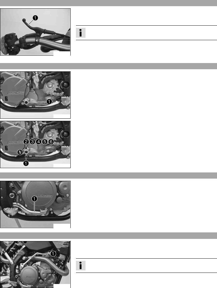
Choke5.35 (EXC EU, EXC SIX DAYS)
500136-10
The flasher switch is fitted on the left side of the handlebar.
Activating the choke function frees an opening through which the engine can draw extra fuel. This gives a richer fuel-air mixture, which is needed for a cold start.
Info
If the engine is warm, the choke function must be deactivated.
Possible states
•Choke function activated – The choke lever is pulled to the stop.
•Choke function deactivated – The choke lever is pushed back to the stop.
Shift5.36 lever
Shift lever is mounted on the left side of the engine.
500138-10
The gear positions can be seen in the photograph.
The neutral or idle position is between the first and second gears.
500138-11
Foot5.37 brake pedal
Foot brake pedal is located in front of the right footrest.
The foot brake pedal is used to activate the rear brake.
500139-10
Kickstarter5.38
Kickstarter is fitted on the right of the engine.
The engine can be started with either the kickstarter or the electric starter.
The upper part of the kickstarter can be swung out.
Info
Before riding, swing the upper part of the kickstarter inward toward the engine.
500148-10
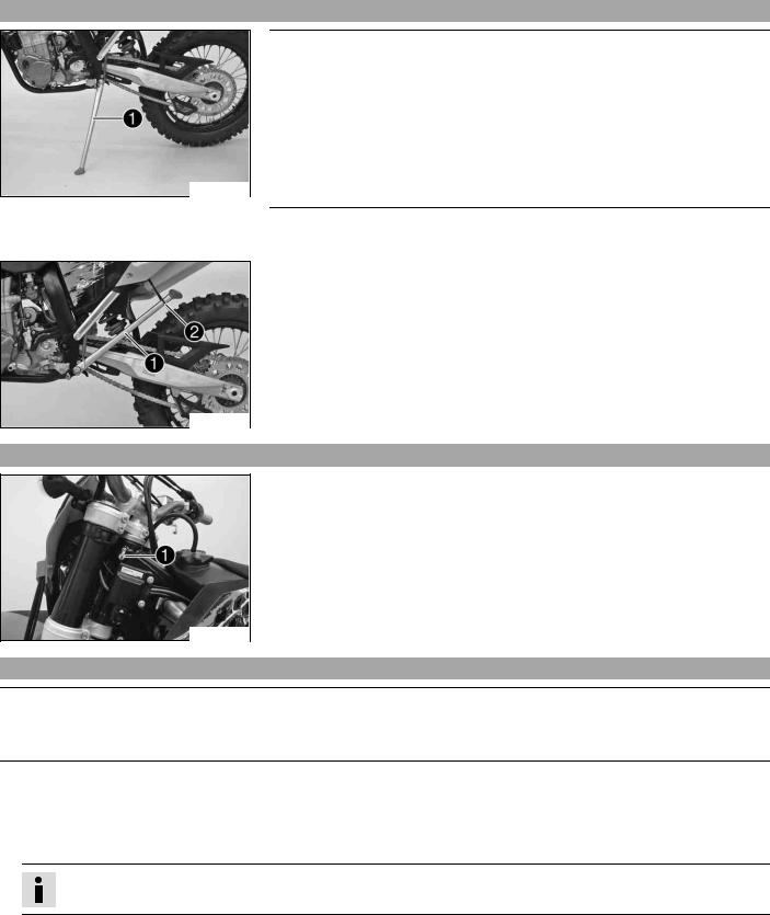
Side5.39 stand
500140-10
500141-10
Note
Danger of damage Danger of damage by the vehicle running away or falling over.
–Always place the vehicle on a firm and even surface.
Note
Material damage Damage and destruction of components by excessive load.
–The side stand is designed for the weight of the motorcycle only. Do not sit on the motorcycle when it is supported by the side stand only. The side stand and/or the frame could be damaged and the motorcycle could fall over.
To park the motorcycle, press the side stand with your foot to the ground and lean the motorcycle on it.
When you are riding, the side stand must be folded up and secured with the rubber band .
Steering5.40 lock (all EXC models)
500126-10
Steering lock is fitted on the left side of the steering head.
The steering lock is used to lock the steering. Steering, and therefore riding, is no longer possible.
Locking5.41 the steering (all EXC models)
Note
Danger of damage Danger of damage by the vehicle running away or falling over.
–Always place the vehicle on a firm and even surface.
–Park the motorcycle.
–Turn the handlebar as far as possible to the right.
–Insert the key in the steering lock, turn it to the left, press it in and turn it to the right. Remove the key.
 Steering is no longer possible.
Info
Never leave the key in the steering lock.

Unlocking5.42 the steering (all EXC models)
–Insert the key in the steering lock, turn it to the left, pull it out and turn it to the right. Remove the key.
 You can now steer the bike again.
Info
Never leave the key in the steering lock.
GENERAL TIPS AND HINTS ON PUTTING INTO OPERATION |
24 |
6Advice.1 on first use
Danger
Danger of accidents Danger from insufficient traffic competence.
–Do not use the vehicle if you are not fit to deal with traffic or if you have consumed alcohol and/or medicaments or drugs.
Warning
Risk of injury Risk of injury by missing/inadequate protective clothing.
–Wear protective clothing (helmet, boots, gloves, pants and jacket with protectors) every time you ride the vehicle. Always wear protective clothing, which must be in perfect condition and meet legal requirements.
Warning
Danger of crashing Impairment of riding behavior due to different tire tread patterns on front and rear wheels.
–The front and rear wheels must be fitted with tires with similar tread patterns to prevent loss of control over the vehicle.
Warning
Danger of accidents Critical riding behavior due to inappropriate riding.
–Adapt your riding speed to the road conditions and your riding ability.
Warning
Danger of accidents Accident risk caused by presence of a passenger.
–Your vehicle is not designed to carry passengers. Do not ride with a passenger.
Warning
Danger of accidents Brake system failure.
–If the foot brake pedal is not released, the brake linings drag permanently. The rear brake can fail due to overheating. Take your foot off the foot brake pedal if you do not want to brake.
Warning
Danger of accidents Unstable riding behavior.
–Do not exceed the maximum permitted weight and axle loads.
Warning
Risk of misappropriation Usage by unauthorized persons.
–Never leave the vehicle while the engine is running. Secure the vehicle against use by unauthorized persons.
Info
When using your motorcycle, remember that others may feel disturbed by excessive noise.
–Make sure that the pre-delivery inspection work has been carried out by an authorized KTM workshop. You receive a delivery certificate and the service record at vehicle handover.
–Before your first trip, read the entire operating instructions carefully.
–Get to know the controls.
–Adjust the basic position of clutch lever. ( p. 76)
(all XC W models)
–adjust the basic position of handbrake lever. ( p. 56)
(all EXC models)
– Adjust the free travel of the handbrake lever. ( p. 57)
–Adjust the basic position of the footbrake lever. x( p. 60)
–Get used to handling the motorcycle on a suitable piece of land before making a longer trip.
Info
Offroad, you should be accompanied by another person on another machine so that you can help each other.
–Try also to ride as slowly as possible and in a standing position to get a better feeling for the vehicle.
–Do not make any offroad trips that over-stress your ability and experience.
–Hold the handlebar firmly with both hands and keep your feet on the footrests when riding.
|
GENERAL TIPS AND HINTS ON PUTTING INTO OPERATION |
25 |
–If you carry any baggage, make sure it is fixed firmly as close as possible to the center of the vehicle and ensure even weight distribution between the front and rear wheels.
Info
Motorcycles react sensitively to any changes of weight distribution.
– Do not exceed the overall maximum permitted weight and the axle loads. Guideline
|
Maximum permissible overall weight |
335 kg (739 lb.) |
|
Maximum permissible front axle load |
145 kg (320 lb.) |
|
Maximum permissible rear axle load |
190 kg (419 lb.) |
– Run the engine in.
Running6.2 in the engine
–During the running-in phase, do not exceed the specified engine speed and engine performance. Guideline
Maximum engine speed
|
During the first 3 service hours |
7,000 rpm |
|
Maximum engine performance during the running-in period |
|
|
During the first 3 service hours |
≤ 50 % |
|
During the next 12 service hours |
≤ 75 % |
– Avoid fully opening the throttle!
7Checks.1 before putting into operation
Info
Make sure that the motorcycle is in a perfect technical condition before use.
Info
In the interests of riding safety, make a habit of making a general check before you ride.
–Check the engine oil level. ( p. 79)
–Check the chain tension. ( p. 52)
–Check for chain dirt accumulation. ( p. 51)
–Check the tire condition. ( p. 66)
–Check the tire air pressure. ( p. 67)
–Check the front brake fluid level. ( p. 57)
–Check the rear brake fluid level. ( p. 61)
–Check the front brake linings. ( p. 58)
–Check the rear brake linings. ( p. 62)
–Check brake system function.
–Check the coolant level. ( p. 72)
–Check that all operating elements are correctly adjusted and free to move.
–Check the functioning of the electrical equipment.
Starting7.2
Danger
Danger of poisoning Exhaust gases are poisonous and can result in unconsciousness and/or death.
–When running the engine, always make sure there is sufficient ventilation, and do not start or run the engine in a closed space.
Note
Engine failure High engine speeds in cold engines have a negative effect on the service life of the engine.
–Always warm up the engine at low engine speeds.
Info
If the motorcycle is unwilling to start, the cause can be old fuel in the float chamber. The flammable elements of the fuel evaporate after a long time of standing.
If the float chamber is filled with fresh fuel, the engine starts immediately.
Press the starter for a maximum of 5 seconds. Wait for a least 5 seconds until trying again.
Motorcycle has been out of use for more than 1 week
– Empty the carburetor float chamber. x( p. 79)
–Turn handle of the fuel tap to the ON position. (Figure 500137-10 p. 20)
 Fuel can flow from the fuel tank to the carburetor.
–Remove the motorcycle from the stand.
–Shift gear to neutral.
(EXC AUS)
–Turn the emergency OFF switch to the position  .
.
Engine cold
(EXC AUS, XC W)
–Pull the choke lever out as far as possible.
(EXC EU, EXC SIX DAYS)
–Pull the choke lever to the stop.
–Press the electric starter button or press the kickstarter robustly through its full range.
Info
Don’t open the throttle.
Starting7.3 up
Info
If your bike has lights, switch them on before riding. You will then be seen earlier by other motorists.
When you are riding, the side stand must be folded up and secured with the rubber band.
–Pull the clutch lever, engage 1st gear, release the clutch lever slowly and simultaneously open the throttle carefully.
Shifting,7.4 riding
Warning
Danger of accidents If you change down at high engine speed, the rear wheel can lock up.
–Do not change into a low gear at high engine speed. The engine races and the rear wheel can block.
Info
If you hear unusual noises while riding, stop immediately, switch off the engine and contact an authorized KTM workshop. First gear is used for starting off or for steep inclines.
–When conditions allow (incline, road situation, etc.), you can shift into a higher gear. To do so, release the throttle while simultaneously pulling the clutch lever, shift into the next gear, release the clutch and open the throttle.
–If the choke function was activated, deactivate it after the engine has warmed up.
–When you reach maximum speed after fully opening the throttle, turn back the throttle to about ¾ of its range; the speed hardly drops, but the fuel consumption falls considerably.
–Always open the throttle only as much as the engine can handle – abrupt throttle opening increases fuel consumption.
–To shift down, brake and close the throttle at the same time.
–Pull the clutch lever and shift into a lower gear, release the clutch lever slowly and open the throttle or shift again.
–Switch off the engine if you expect to be standing for a long time. Guideline
≥2 min
–Avoid frequent and longer slipping of the clutch. This heats the engine oil, the engine and the cooling system.
–Ride with a lower engine speed instead of with a high engine speed and a slipping clutch.
Braking7.5
Warning
Danger of accidents If you brake too hard, the wheels can lock.
–Adapt your braking to the traffic situation and the road conditions.
Warning
Danger of accidents Reduced braking caused by spongy pressure point of front or rear brake.
–Have the brake system checked in an authorized KTM workshop, and do not ride any further.
Warning
Danger of accidents Reduced braking due to wet or dirty brakes.
–Clean or dry dirty or wet brakes by riding and braking gently.
–On sandy, wet or slippery surfaces, use the rear brake.
–Braking should always be completed before you go into a bend. Change down to a lower gear appropriate to your road speed.
–On long downhill stretches, use the braking effect of the engine. Change down one or two gears, but do not overstress the engine. In this way, you have to brake far less and the brakes do not overheat.
Stopping,7.6 parking
Warning
Risk of misappropriation Usage by unauthorized persons.
–Never leave the vehicle while the engine is running. Secure the vehicle against use by unauthorized persons.
Warning
Danger of burns Some vehicle components get very hot when the machine is driven.
–Do not touch hot components such as exhaust system, radiator, engine, shock absorber and brakes. Allow these components to cool down before starting work on them.
Note
Danger of damage Danger of damage by the vehicle running away or falling over.
–Always place the vehicle on a firm and even surface.
Note
Fire hazard Some components (engine, radiator and exhaust system) get very hot when the engine is running.
–Do not place the vehicle where there are flammable or explosive substances.
Note
Material damage Damage and destruction of components by excessive load.
–The side stand is designed for the weight of the motorcycle only. Do not sit on the motorcycle when it is supported by the side stand only. The side stand and/or the frame could be damaged and the motorcycle could fall over.
–Brake the motorcycle.
–Shift gear to neutral.
(all XC W models)
–Press and hold the short circuit button  while the engine is idling until the engine stops.
(all EXC models)
– Press and hold the short circuit button  while the engine is idling until the engine stops.
–Turn handle of the fuel tap to the OFF position. (Figure 500137-10 p. 20)
–Park the motorcycle on firm ground.
Refueling7.7
Danger
Fire hazard Fuel can easily catch fire.
–Never fill up the vehicle near open flames or burning cigarettes, and always switch off the engine first. Be careful that no fuel is spilt, especially on hot vehicle components. Clean up spilt fuel immediately.
–Fuel in the fuel tank expands when warm and can escape if the tank is overfilled. See specifications on filling up with fuel.
Warning
Danger of poisoning Fuel is poisonous and a health hazard.
–Avoid contact between fuel and skin, eyes and clothing. Do not inhale fuel vapors. If fuel gets into your eyes, rinse immediately with water and contact a doctor. Wash affected skin areas immediately with soap and water. If fuel is swallowed, contact a doctor immediately. Change clothing that has come into contact with fuel.
Warning
Environmental hazard Improper handling of fuel is a danger to the environment.
–Do not allow fuel to get into the ground water, the ground, or the sewage system.
–Switch off the engine.
–Open the filler cap. ( p. 20)
![]()
–Fill the fuel tank with fuel up to measurement . Guideline
|
Measurement of |
35 mm (1.38 in) |
||
|
Total fuel tank |
9.0 l |
Super unleaded (ROZ 95 / RON 95 / |
|
|
capacity, |
(2.38 US gal) |
PON 91) ( |
p. 106) |
|
approx. (EXC, |
|||
|
EXC SIX DAYS, |
|||
|
XC W ZA) |
|||
|
Total fuel tank |
9.2 l |
Super unleaded (ROZ 95 / RON 95 / |
|
|
capacity, approx. |
(2.43 US gal) |
PON 91) ( |
p. 106) |
|
(XC W USA) |
|||
–Close the filler cap. ( p. 20)

8Important.1 maintenance work to be carried out by an authorized KTM workshop.
|
S3N |
S15A |
S30A |
||||||||
|
Engine |
Change the engine oil and oil filter and clean the engine oil screen. x( p. 80) |
• |
• |
• |
||||||
|
Change the gear oil and clean the gear oil screen. x( p. 82) |
• |
• |
• |
|||||||
|
Replace spark plug. |
• |
|||||||||
|
Check the valve clearance. x |
• |
• |
• |
|||||||
|
Check engine mounting screws for tightness. |
• |
• |
• |
|||||||
|
Clean spark plug connectors and check for tightness. |
• |
• |
• |
|||||||
|
Check that the screws in the shift lever and the kickstarter are tight. |
• |
• |
• |
|||||||
|
Carburetor |
Check carburetor connection boots for cracks and leakage. |
• |
• |
|||||||
|
Check vent hoses for damage and routing without sharp bends. |
• |
• |
• |
|||||||
|
Check idle. |
• |
• |
• |
|||||||
|
Attachments |
Check the cooling system for leakage. |
• |
• |
• |
||||||
|
Check the antifreeze and coolant level. ( |
p. 72) |
• |
• |
• |
||||||
|
Check the exhaust system for leakage and looseness. |
• |
• |
||||||||
|
Check Bowden cables for damage, smooth operation and routing without sharp |
• |
• |
• |
|||||||
|
bends. |
||||||||||
|
Check the fluid level of the hydraulic clutch. ( |
p. 76) |
• |
• |
• |
||||||
|
Clean the air filter. x( |
p. 75) |
• |
• |
• |
||||||
|
Check cables for damage and routing without sharp bends. |
• |
• |
||||||||
|
Check that the electrical equipment is functioning properly. |
• |
• |
• |
|||||||
|
Check the headlamp setting. |
• |
• |
||||||||
|
Brakes |
Check the front brake linings. ( |
p. 58) |
• |
• |
• |
|||||
|
Check the rear brake linings. ( |
p. 62) |
• |
• |
• |
||||||
|
Check the brake discs. ( |
p. 55) |
• |
• |
• |
||||||
|
Check the front brake fluid level. ( |
p. 57) |
• |
• |
• |
||||||
|
Check the rear brake fluid level. ( |
p. 61) |
• |
• |
• |
||||||
|
Check brake lines for damage and leakage. |
• |
• |
• |
|||||||
|
Check the free travel of the hand brake lever. ( |
p. 56) |
• |
• |
• |
||||||
|
Check the free travel of the foot brake lever. ( |
p. 60) |
• |
• |
• |
||||||
|
Check brake system function. |
• |
• |
• |
|||||||
|
Check screws and guide bolts of brake system for tightness. |
• |
• |
• |
|||||||
|
Chassis |
Check shock absorber and fork for leakage and functioning. x |
• |
• |
• |
||||||
|
Clean dust boots of fork legs. ( |
p. 39) |
• |
• |
|||||||
|
Bleed fork legs. ( |
p. 39) |
• |
• |
|||||||
|
Check the swingarm bearing. x |
• |
• |
||||||||
|
Check play of steering head bearing. ( |
p. 40) |
• |
• |
• |
||||||
|
Check all screws to see if they are tight. |
• |
• |
• |
|||||||
|
Wheels |
Check the spoke tension. ( |
p. 67) |
• |
• |
• |
|||||
|
Check rim run-out. |
• |
• |
• |
|||||||
|
Check the tire condition. ( |
p. 66) |
• |
• |
• |
||||||
|
Check the tire air pressure. ( |
p. 67) |
• |
• |
• |
||||||
|
Check the chain wear. ( |
p. 53) |
• |
• |
• |
||||||
|
Check the chain tension. ( |
p. 52) |
• |
• |
• |
||||||
|
Clean the chain. ( |
p. 51) |
• |
• |
• |
||||||
|
Check the wheel bearing for play. x |
• |
• |
• |
|||||||
|
Clean and grease adjusting screws of chain adjuster. |
• |
• |
• |
|||||||
|
S3N: After 3 service hours |
||||||||||
|
S15A: Every 15 service hours / after every race |
||||||||||
|
S30A: Every 30 service hours |

Important8.2 maintenance work to be carried out by an authorized KTM workshop. (as additional order)
|
Competition use |
Hobby use |
J1A |
J2A |
|||||||
|
S15A |
S30A |
S45A |
S30A |
S60A |
S90A |
|||||
|
Carry out a complete fork service. x |
• |
• |
||||||||
|
Carry out a complete shock absorber service. x |
• |
|||||||||
|
Grease the steering head bearing. x( |
p. 46) |
• |
• |
|||||||
|
Treat electric contacts with contact spray. |
• |
• |
||||||||
|
Change the hydraulic clutch fluid. x( |
p. 76) |
• |
• |
|||||||
|
Change the front brake fluid. x |
• |
• |
||||||||
|
Change the rear brake fluid. x |
• |
• |
||||||||
|
Clean the spark arrestor. x(XC W USA) |
• |
• |
||||||||
|
Check wear of clutch discs. x |
• |
• |
• |
• |
• |
• |
||||
|
Check the clutch. x |
• |
• |
||||||||
|
Check/measure the cylinder. x |
• |
• |
||||||||
|
Change the piston. x |
• |
• |
||||||||
|
Check the camshaft. x |
• |
• |
||||||||
|
Change the camshaft bearing. x |
• |
• |
||||||||
|
Check the valve spring seat. x |
• |
• |
||||||||
|
Check the cylinder head. x |
• |
• |
||||||||
|
Check the valves. x |
• |
• |
||||||||
|
Check the valve springs. x |
• |
• |
||||||||
|
Check the radial clearance of the rocker arm rollers. x |
• |
• |
||||||||
|
Check the timing-chain tensioner function. x |
• |
• |
||||||||
|
Check the balancer shaft. x |
• |
• |
||||||||
|
Check the crankshaft run-out at the bearing pin. x |
• |
• |
||||||||
|
Change the conrod bearing. x |
• |
• |
||||||||
|
Change the crankshaft main bearing. x |
• |
• |
||||||||
|
Check the transmission. x |
• |
• |
||||||||
|
Check the shift mechanism. x |
• |
• |
||||||||
|
Check the spring length of the oil pressure regulator |
• |
• |
||||||||
|
valve. x |
||||||||||
|
Change glass fiber yarn filling of main silencer. x |
• |
• |
||||||||
|
Replace foot brake cylinder seals. x |
• |
• |
||||||||
|
Check/adjust the carburetor components. x |
• |
• |
• |
• |
||||||
|
S15A: Every 15 service hours / after every race |
||||||||||
|
S30A: Every 30 service hours |
||||||||||
|
S45A: Every 45 service hours |
||||||||||
|
S60A: Every 60 service hours |
||||||||||
|
S90A: Every 90 service hours |
||||||||||
|
J1A: annually |
||||||||||
|
J2A: every 2 years |
|
Important8.3 |
checks and maintenance work to be carried out by the rider. |
|||
|
NB1A |
||||
|
Check the engine oil level. ( |
p. 79) |
• |
||
|
Check the front brake fluid level. ( p. 57) |
• |
|||
|
Check the rear brake fluid level. ( |
p. 61) |
• |
||
|
Check the front brake linings. ( |
p. 58) |
• |
||
|
Check the rear brake linings. ( |
p. 62) |
• |
||
|
Check and adjust Bowden cables. |
• |
|||
|
Bleed fork legs. ( p. 39) |
• |
|||
|
Clean dust boots of fork legs. ( |
p. 39) |
• |
||

|
SERVICE SCHEDULE |
32 |
|||
|
NB1A |
||||
|
Clean the chain. ( p. 51) |
• |
|||
|
Check the chain tension. ( |
p. 52) |
• |
||
|
Check the chain wear. ( |
p. 53) |
• |
||
|
Check the rear sprocket / engine sprocket for wear. ( p. 52) |
• |
|||
|
Clean the air filter. x( |
p. 75) |
• |
||
|
Check the tire air pressure. ( p. 67) |
• |
|||
|
Check the tire condition. ( |
p. 66) |
• |
||
|
Check the coolant level. ( |
p. 72) |
• |
||
|
Empty the carburetor float chamber. x( p. 79) |
• |
|||
|
Check that all operating elements for smooth operation. |
• |
|||
|
Check braking. |
• |
|||
|
Check all screws, nuts and hose clamps regularly for tightness. |
• |
|||
|
NB1A: Depending on conditions of use according to requirements. |

MAINTENANCE WORK ON CHASSIS AND ENGINE |
33 |
9Jacking.1 up the motorcycle
500074-01
Note
Danger of damage Danger of damage by the vehicle running away or falling over.
– Always place the vehicle on a firm and even surface.
–Jack up the motorcycle underneath the engine. The wheels must no longer touch the ground.
Work stand (54829055000)
–Secure the motorcycle against falling over.
Removing9.2 the motorcycle from the work stand
Note
Danger of damage Danger of damage by the vehicle running away or falling over.
–Always place the vehicle on a firm and even surface.
–Remove the motorcycle from the work stand.
–Remove the work stand.
Checking9.3 the basic chassis setting with the rider’s weight
Info
When adjusting the basic chassis setting, first adjust the shock absorber and then the fork.
–For optimal motorcycle riding characteristics and to avoid damage to forks, shock absorbers, swing arm and frame, the basic settings of the suspension components must match your body weight.
–As delivered, KTM offroad motorcycles are adjusted for a standard rider weight (with full protective clothing). Guideline
|
Standard rider weight |
75… 85 kg (165… 187 lb.) |
–If your weight is above or below the standard range, you have to adjust the basic setting of the suspension components accordingly.
–Small weight differences can be compensated by adjusting the spring preload, but in the case of large weight differences, the springs must be replaced.
Compression9.4 damping of shock absorber
The shock absorber can regulate compression damping separately in the low-speed and high-speed ranges (Dual Compression Control). The term low and high speed refers to the movement of the shock absorber during compression and not the riding speed of the motorcycle.
The low-speed and high-speed technology works non-specifically.
Adjusting9.5 high-speed compression damping of the shock absorber
Danger
Danger of accidents The shock absorber is under high pressure.
–The shock absorber is filled with highly compressed nitrogen, so never dismantle the shock absorber or carry out any maintenance on it yourself.
Info
The high-speed setting can be seen during the fast compression of the shock absorber.
 Loading…
Скачать файл PDF «KTM 530 EXC-R EU Инструкция по эксплуатации» (4.69 Mb)
Популярность:
6753 просмотры
Подсчет страниц:
125 страницы
Тип файла:
Размер файла:
4.69 Mb
Информация, представленная на Сайте, носит информационный характер и ни при каких условиях не является публичной
офертой, определяемой положениями статьи 437 Гражданского кодекса Российской Федерации. Все содержащиеся на
Сайте сведения носят исключительно информационный характер и не являются исчерпывающими. Все условия
приобретения мототехники, цены, спецпредложения и комлектации мототехники указаны с целью ознакомления.
Комплектации и цены действительны на момент публикации и могут быть изменены без предварительного оповещения.
Представленная на Сайте мототехника может быть укомплектована дополнительным оборудованием, не входящим в
стандартную версию, но доступным за дополнительную плату. Сведения о продукции, касающиеся объёмов поставки,
внешнего вида, характеристик, габаритов и веса, эксплуатационных затрат и т.д. не являются обязательными,
рассматриваются как приблизительные и указаны с условием того, что могут возникнуть ошибки при печати, настройке
и/или наборе текста. Такая информация может быть изменена без предварительного уведомления. Чтобы получить
полную информацию о продукции, услугах, дополнительном оборудовании и спецпредложениях, интересных для Вас,
обращайтесь к менеджерам Дилерского центра