- Manuals
- Brands
- Kubota Manuals
- Engine
- V3800-CR-TIE4
Manuals and User Guides for Kubota V3800-CR-TIE4. We have 3 Kubota V3800-CR-TIE4 manuals available for free PDF download: Diagnosis Manual, Workshop Manual, Operator’s Manual
Kubota V3800-CR-TIE4 Diagnosis Manual (330 pages)
COMMON RAIL SYSTEM
Brand: Kubota
|
Category: Engine
|
Size: 10.2 MB
Table of Contents
-
Contents
3
-
Safety First
4
-
Before Servicing and Repairing
4
-
Safety Starting
4
-
Safety Working
5
-
Avoid Fires
5
-
Ventilate Work Area
6
-
Prevent Acid Burns
6
-
Dispose of Fluids Properly
6
-
Prepare for Emergencies
6
-
Table of Contents
8
-
Mechanism
8
-
Basic System Information
9
-
System Configuration
9
-
Fuel System
10
-
Intake and Exhaust System
11
-
Wiring Diagram
12
-
System Wiring Diagram
12
-
-
Available Data Monitor Signals (Level 2)
13
-
Monitor Items
13
-
Normal Value
16
-
ECU Terminal Layout 1 (A: 96 Pins)
19
-
ECU Terminal Layout 2 (B: 58 Pins)
22
-
Servicing
25
-
General
28
-
Overall Diagnostic Procedure
28
-
Questioning
29
-
Questioning Points
29
-
Trouble Check Sheet for KUBOTA Common Rail System
29
-
Tractor Details
30
-
Replace Parts Details
30
-
Customer Complaint
30
-
Condition When Problem Occurs (Duplicated Answers Can be Possible)
31
-
Dealer Check
31
-
-
List of Malfunction Symptom
32
-
Actions for Non-Reoccurring Malfunctions
33
-
Diagnostic Tool Connection Procedure
35
-
Diagnostic Connector Positions
35
-
CHECKING the COMMUNICATION OPERATION of the INTERFACE (DST-I)
37
-
DST-I Operation Status and Display Specification
37
-
Light Operation During Normal Conditions
37
-
Light Operation During Abnormal Operation
37
-
-
Checking the Operation of the Ecu
38
-
Starting Diagmaster
38
-
DST-I Communication Settings
39
-
Active Test and Supply Pump Difference Learning
44
-
Operation Details
44
-
Injector Non-Injection Instruction
44
-
EGR Actuation Test
44
-
Air Heater Relay Actuation Test
45
-
Supply Pump Difference Learning
45
-
-
Diagnosis by Malfunction Symptom
46
-
List of Malfunction Causes by Symptom
46
-
Engine Warning Light Comes on
50
-
Engine Does Not Start
50
-
Diagnosis by Malfunction Symptom
50
-
Check the Fuel Feed Pump Operation
51
-
Check the DTC
51
-
Communication Error
51
-
DTC Presently Existing
51
-
Check the Starting Assist Device
52
-
Check the Intake System
52
-
Check the Fuel System
53
-
Check the ECU Power Supply and Grounding
53
-
Check the Crankshaft Position Sensor
53
-
Supply Pump Difference Learning and Checking the Monitor
54
-
Check the Engine
54
-
-
Takes a Long Time before Engine Starts
55
-
Possible Causes
55
-
Fuel Feed Pump Operation Fault
55
-
Past DTC Only
56
-
-
Idle Failure
60
-
Engine Fault
60
-
Control System
60
-
Check the Injector
61
-
-
Engine Noise
64
-
High Fuel Consumption
66
-
Usage Habits of the User or Use of Non-Standard Parts
66
-
Powertrain Malfunctions Not Involving the Engine
66
-
Check the Engine and Machine Condition
68
-
Check the Camshaft Position Sensor
70
-
Check the Data Related to Pressure Control
70
-
-
Poor Acceleration (Insufficient Output)
72
-
Abnormal Black Smoke Emitted
78
-
Abnormal White Smoke Emitted
83
-
Engine Stalls on Deceleration
89
-
Check the Final Accelerator Open Position
91
-
Diagnostic Procedure by Dtc
94
-
Dtc List
94
-
NE-G Phase Shift
94
-
Intake Air Temperature Built-In MAF Sensor Abnormality
95
-
Pressure Limiter Emergency Open
96
-
High Rail Pressure
97
-
SCV Stuck
98
-
Fuel Leak (in High Pressured Fuel System)
99
-
Intake Air Volume: Low
100
-
MAF Sensor Abnormality
101
-
Intake Air Temperature Error
102
-
Coolant Temperature Sensor Abnormality
103
-
Fuel Temperature Sensor Abnormality
104
-
Rail Pressure Sensor Abnormality
105
-
Injector Charge Voltage: High
106
-
Open Circuit of Harness/Coil
107
-
Engine Overheat
109
-
Engine Overrun
109
-
Boost Pressure Sensor Abnormality
110
-
Crankshaft Position Sensor (NE Sensor) Abnormality
111
-
Camshaft Position Sensor (G Sensor) Abnormality
112
-
Air Heater Relay Driving Circuit Abnormality
113
-
EGR Actuator Abnormality
114
-
Oil Pressure Error
115
-
Exhaust Gas Temperature Sensor 1 (T1) Abnormality
116
-
Exhaust Gas Temperature Sensor 0 (T0) Abnormality
117
-
Battery Voltage Abnormality
118
-
QR Data Abnormality
119
-
ECU FLASH ROM and CPU Abnormality
120
-
Injector Charge Voltage Abnormality
121
-
SCV Drive System Abnormality
122
-
Sensor Supply Voltage 1 Abnormality
123
-
Sensor Supply Voltage 2 Abnormality
124
-
Main Relay Is Locked in Closed Position
125
-
Pump Seizing
126
-
Intake Throttle Feedback Error
128
-
Accelerator Position Sensor Error (CAN)
128
-
Common 1 System Injector Drive Circuit Open
129
-
Common 1 TWV Actuation System Short
130
-
Common 2 System Injector Drive Circuit Open
131
-
Common 2 TWV Actuation System Short
132
-
Barometric Pressure Sensor Error
133
-
EGR (DC Motor) Abnormality
134
-
Exhaust Gas Temperature Sensor 2 (T2) Abnormality
135
-
Differential Pressure Sensor 1 Abnormality
136
-
Intake Throttle Lift Sensor Abnormality
137
-
Emission Deterioration
138
-
Exhaust Gas Temperature Sensor 0
139
-
Exhaust Gas Temperature Sensor 1
139
-
Exhaust Gas Temperature Sensor 2: Emergency High
140
-
Excessive PM3
141
-
Excessive PM4
142
-
Excessive PM5
142
-
Boost Pressure Low
143
-
Low Coolant Temperature in Parked Regeneration
144
-
Parked Regeneration Time out
144
-
All Exhaust Gas Temperature Sensor Failure
145
-
High Frequency of Regeneration
146
-
CAN2 Bus off
146
-
No Communication with EGR
147
-
CAN1 Bus off
147
-
CAN2 Frame Error
148
-
-
Diagnostic Procedure by Dtc
149
-
NE — G Phase Shift (DTC P0016 / 636-7)
152
-
Crankshaft Position Sensor Side
152
-
Camshaft Position Sensor Side
152
-
-
Intake Air Temperature Built-In MAF Sensor: Abnormality (DTC P0072 / 171-4, DTC P0073 / 171-3)
153
-
Check the Intake Air Temperature Sensor Signals
154
-
Measure the Resistance between Terminals
155
-
Check the Sensor
155
-
Measure the ECU Terminal Voltage
155
-
Behaviour During Malfunction
156
-
DTC Set Preconditions
156
-
DTC Set Parameter
156
-
Recovery from Error
156
-
-
Pressure Limiter Emergency Open (DTC P0087 / 633-7)
156
-
Diagnostic Procedure for Pressure System Dtcs
157
-
If a DTC Currently Exists
157
-
If Only a Past DTC Exists
157
-
Check the Data Related to the Rail Pressure
158
-
Check the Fuel System for the Existence of Air
158
-
Check the Rail Pressure Sensor
159
-
Check the DTC Again
159
-
Check the SCV-Related Data
160
-
Pump Difference Learning Status
160
-
Detection Item
161
-
-
High Rail Pressure (DTC P0088 / 157-0)
161
-
SCV Stuck (DTC P0089 / 1347-7)
166
-
Fuel Leak (in High Pressured Fuel System) (DTC P0093 / 1239-1)
171
-
Intake Air Volume: Low (DTC P0101 / 132-1)
177
-
MAF Sensor Abnormality (DTC P0102 / 132-4, P0103 / 132-3)
178
-
Measure the Sensor Terminal Voltage
179
-
DTC Judgment
179
-
-
Intake Air Temperature Error (DTC P0112 / 172-4, P0113 / 172-3)
180
-
Coolant Temperature Sensor Abnormality (DTC P0117 / 110-4, P0118 / 110-3)
183
-
Fuel Temperature Sensor Abnormality (DTC P0182 / 174-4, P0183 / 174-3)
186
-
Rail Pressure Sensor Abnormality (DTC P0192 / 157-4, P0193 / 157-3)
189
-
Injector Charge Voltage: High (DTC P0200 / 523535-0)
193
-
Open Circuit of Harness/Coil (DTC P0201 / 651-3, P0202 / 653-3, P0203 / 654-3, P0204 / 652-3)
195
-
Measure the Resistance between ECU Terminals
196
-
Check the Connector and Wiring Harnesses for Poor Contact
197
-
Measure the Resistance between Injector Terminals
197
-
-
Engine Overheat (DTC P0217 / 110-0)
198
-
Engine Overrun (DTC P0219 / 190-0)
200
-
Boost Pressure Sensor Abnormality (DTC P0237 / 102-4, P0238 / 102-3)
201
-
Crankshaft Position Sensor (NE Sensor) Abnormality (DTC P0335 / 636-8, P0336 / 636-2)
205
-
Camshaft Position Sensor (G Sensor) Abnormality (DTC P0340 / 723-8, P0341 / 723-2)
210
-
Air Heater Relay Driving Circuit Abnormality (DTC P0380 / 523544-3 / 523544-4)
214
-
Check the Wiring Harness / Connector
216
-
Check the Relay
216
-
ECU Replacement Check
216
-
-
EGR Actuator Abnormality (DTC P0403 / 523574-3, DTC P0404 / 523574-4, P0409 / 523572-4)
217
-
Oil Pressure Error (P0524 / 100-1)
220
-
Check the Wiring Related to the Oil Pressure Switch
221
-
Check the Oil Pressure Switch
221
-
Check the Oil and Oil Filter
221
-
-
Exhaust Gas Temperature Sensor 1 (T1) Abnormality (DTC P0543 / 3242-4, P0544 / 3242-3)
222
-
Exhaust Gas Temperature Sensor 0 (T0) Abnormality (DTC P0546 / 4765-4, P0547 / 4765-3)
225
-
Battery Voltage Abnormality (DTC P0562 / 168-4, P0563 / 168-3)
228
-
QR Data Abnormality (DTC P0602/523538-2, P0602/523538-7)
231
-
ECU Flash-ROM and CPU Abnormality (DTC P0605 / 628-2, P0606 / 1077-2, P0606/ 523527-2)
232
-
Injector Charge Voltage Abnormality (DTC P0611 / 523525-1)
234
-
SCV Drive System Abnormality (DTC P0628 / 1347-4, P0629 / 1347-3)
236
-
Sensor Supply Voltage 1 Abnormality (DTC P0642 / 3509-4, P0643 / 3509-3)
240
-
Sensor Supply Voltage 2 Abnormality (DTC P0652 / 3510-4, P0653 / 3510-3)
242
-
Main Relay Is Locked in Closed Position (DTC P0687 / 1485-2)
244
-
Pump Seizing (DTC P1274 / 523539-2, P1275 / 523540-2)
247
-
Intake Throttle Feedback Error (DTC P2108 / 523580-2)
253
-
Accelerator Position Sensor Error (CAN) (DTC P2131 / 523543-2)
255
-
Common 1 System Injector Drive Circuit Open (DTC P2146 / 523523-2)
257
-
Common 1 TWV Actuation System Short (DTC P2147 / 523523-4, P2148 / 523523-3)
260
-
Common 2 System Injector Drive Circuit Open (DTC P2149 / 523524-2)
264
-
Common 2 TWV Actuation System Short (DTC P2150 / 523524-4, P2151 / 523524-3)
267
-
Barometric Pressure Sensor Error (DTC P2228 / 108-4, P2229 / 108-3)
271
-
EGR (DC Motor) Abnormality (DTC P2413 / 523575-7, P2414 / 523576-2, P2415 / 523577-2)
273
-
Exhaust Gas Temperature Sensor 2 (T2) Abnormality (DTC P242C / 3246-4, P242D / 3246-3)
276
-
Differential Pressure Sensor 1 Abnormality (DTC P2454 / 3251-4, P2455 / 3251-3)
279
-
Intake Throttle Lift Sensor Abnormality (DTC P2621 / 523583-4, P2622 / 523582-3)
283
-
Emission Deterioration (DTC P3001 / 3252-0)
285
-
Exhaust Gas Temperature Sensor 0: Emergency High (DTC P3002 / 4765-0)
287
-
Exhaust Gas Temperature Sensor 1: Emergency High (DTC P3003 / 3242-0)
289
-
Check the Exhaust Gas Temperature
290
-
Exhaust Gas Temperature Sensor 2: Emergency High (DTC P3004 / 3246-0)
291
-
Excessive PM3 (DTC P3006 / 3701-15)
294
-
Excessive PM4 (DTC P3007 / 3701-16)
295
-
Excessive PM5 (DTC P3008 / 3701-0)
296
-
Boost Pressure Low (DTC P3011 / 132-15)
297
-
Low Coolant Temperature in Parked Regeneration (DTC P3012 / 523589-17)
299
-
Parked Regeneration Time out (DTC P3013 / 523590-16)
300
-
All Exhaust Gas Temperature Sensor Failure (DTC P3018 / 523599-0)
302
-
High Frequency of Regeneration (DTC P3024 / 523602-0)
303
-
CAN2 Bus off (DTC U0075 / 523547-2)
305
-
No Communication with EGR (DTC U0076 / 523578-2)
307
-
CAN1 Bus off (DTC U0077 / 523604-2)
309
-
CAN2 Frame Error (DTC U0081 / 523548-2, U0082 / 523591-2, U0083 / 523592-2)
310
-
Inspection Procedure for each System
312
-
Air Intake System Inspection Procedure
312
-
Fuel System Inspection Procedure
314
-
Biodiesel Fuel
314
-
When the B7 Blended Fuel Is Used
314
-
When the B5 Blended Fuel Is Used
314
-
Precautions in Handling Biodiesel Fuels
315
-
Fuel Filter
315
-
Criteria at the Entrance of Supply Pump
315
-
-
Electric System Inspection Procedure
320
-
Basics of Checking Electrical / Electronic Circuit Systems
320
-
Measure the ECU Terminal Voltage and Resistance
320
-
Open Circuit Check
320
-
Check for Continuity
321
-
Check Voltage
321
-
Short Circuit Check
321
-
Ground Continuity Check
322
-
Measurement Results
322
-
Faulty Circuit
322
-
Connector Connection Fault Verification Method
323
-
Checking the Power and Ground System
324
-
Measure the ECU +BP and Ground Voltage
325
-
Check the Relay Terminal Voltage -1
325
-
Ground Terminal Unsatisfactory
325
-
+BP Terminal Unsatisfactory
325
-
Check the Relay Terminal Voltage — 3
326
-
Check the Relay Terminal Voltage — 4
326
-
Check the Relay Terminal Voltage — 5
326
-
Check the Key Switch Signal
327
-
Check the Key Switch
327
-
-
-
Advertisement
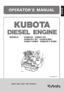
Kubota V3800-CR-TIE4 Operator’s Manual (45 pages)
Brand: Kubota
|
Category: Engine
|
Size: 2.51 MB
Table of Contents
-
Table of Contents
4
-
Safe Operation
12
-
Servicing of the Engine
12
-
Names of Parts
13
-
Pre-Operation Check
16
-
Break-In
16
-
Daily Check
16
-
-
Operating the Engine
17
-
Starting the Engine (Normal)
17
-
Cold Weather Starting
18
-
Stopping the Engine
18
-
Checks During Operation
18
-
Radiator Cooling Water (Coolant)
18
-
Oil Pressure Lamp
19
-
Charge Lamp
19
-
Fuel
19
-
Color of Exhaust
19
-
Immediately Stop the Engine if
19
-
-
Air Flow Sensor
19
-
Air Cleaner-Mounted Type
19
-
Inlet Hose Pipe-Mounted Type
19
-
-
Precautions on Generator-Equipped Engine
19
-
-
Maintenance
20
-
Service Intervals
21
-
Checking of Intake Air Line
23
-
Daily Checks
25
-
Checking of Engine Oil Level
25
-
Checking of Fuel Level
26
-
Checking of Coolant Level
27
-
Anti-Freeze
28
-
Checking of Fan Belt
29
-
-
-
Regular Checks and Maintenance Work
30
-
Every 50 Service Hours
30
-
Checking of Fuel Pipes and Clamp Bands
30
-
Draining of Water Separator
30
-
-
Every 100 Service Hours
31
-
Cleaning of Air Cleaner Element
31
-
Adjustment of Fan Belt Tension
31
-
-
Every 200 Service Hours
32
-
Checking of Radiator Hoses and Clamp Bands
32
-
Checking of Intake Air Line
32
-
-
Every 250 Service Hours
32
-
Precaution at Overheating
32
-
Cleaning of Air Cleaner Element
32
-
Adjustment of Fan Belt Tension
33
-
Checking of Intake Air Line
34
-
-
Every 400 Service Hours
34
-
Changing of Engine Oil
34
-
Replacement of Oil Filter Cartridge
34
-
Replacement of Fuel Filter Cartridge
35
-
-
Every 500 Service Hours
35
-
Changing of Engine Oil
35
-
Replacement of Oil Filter Cartridge
35
-
Replacement of Fuel Filter Cartridge
36
-
Cleaning of Water Separator
36
-
Removal of Sediment in Fuel Tank
36
-
Cleaning of Water Jacket (Radiator Interior)
36
-
Replacement of Fan Belt
36
-
-
Every 800 Service Hours
36
-
Checking of Valve Clearance
36
-
-
Every 1000 Service Hours
36
-
Every 1500 Service Hours
37
-
Checking of Injector Tip
37
-
Checking of EGR Cooler
37
-
Changing of Oil Separator Element
37
-
Checking of PCV Valve (Positive Crankcase Ventilation Valve)
37
-
-
Every 3000 Service Hours
37
-
Checking of Turbo-Charger
37
-
Checking of EGR System
37
-
-
Annual Servicing
38
-
Replacement of Air Cleaner Element
38
-
Checking of EGR Piping
38
-
Checking of Intake Air Line
38
-
Checking of Exhaust Manifold for Cracks or Gas Leak and for Looseness or Damage
38
-
-
Biennial Servicing
38
-
Replacement of Rubber Piping Related Oil Separator
38
-
Replacement of Intake Air Line and Suction Air Pressure Takeout Rubber Piping
38
-
Replacement of Boost Sensor Pressure Rubber Piping
38
-
Replacement of EGR Cooler Rubber Piping
38
-
Remedies for Quick Decrease of Coolant
39
-
Replacement of Radiator Hoses and Clamp Bands
39
-
Replacement of Fuel Pipes and Clamp Bands
39
-
Replacement of Intake Air Line
39
-
Replacement of Fan Belt
39
-
-
-
Carriage and Storage
40
-
Carriage
40
-
Storage
40
-
-
Troubleshooting
41
-
Specifications
43
Kubota V3800-CR-TIE4 Workshop Manual (55 pages)
WSM
Brand: Kubota
|
Category: Engine
|
Size: 7.72 MB
Table of Contents
-
Table of Contents
10
-
1 Function of Diesel Particulate Filter (Dpf)
11
-
2 Dpf Regeneration and Dpf Cleaning
12
-
3 Dpf Maintenance Flow
13
-
Cleaning & Return Flow
14
-
Dpf Exchange Flow
15
-
-
4 Dpf Cleaning Procedure
16
-
To Ensure Safety and Good Performance in Dpf Cleaning Procedure .1-S6
16
-
Separation of Dpf Muffler Full Assy
17
-
D1803-Cr-E4, D1803-Cr-Te4, V2403-Cr-E4, V2403-Cr-Te4
18
-
V2607-Cr-E4
19
-
V2607-Cr-Te4, V3307-Cr-Te4
20
-
V3800-Cr-Te4, V3800-Cr-Tie4, V3800-Cr-Te4C, V3800-Cr-Tie4C
21
-
-
Disassembly of Dpf Muffler Full Assembly
22
-
D1803-Cr-E4, D1803-Cr-Te4, V2403-Cr-E4, V2403-Cr-Te4
22
-
V2607-Cr-E4
23
-
V2607-Cr-Te4, V3307-Cr-Te4
23
-
V3800-Cr-Te4, V3800-Cr-Tie4, V3800-Cr-Te4C, V3800-Cr-Tie4C
24
-
-
Judgment of Reuse of Dpf Filter Complete before Cleaning
25
-
Preparation of «After-Treatment Device Exchange Report Form
25
-
Preparation of «Dpf Cleaning Order Form
26
-
Packing, Delivering, and Handling Standard of Dpf Filter Complete
27
-
Dpf Cleaning Method, Responsible for Cleaning Contractor (Reference)
28
-
Judgment of Reuse of Dpf Filter Complete after Cleaning, Responsible for Cleaning Contractor
29
-
Assembly of Dpf Muffler Full Assembly
32
-
D1803-Cr-E4, D1803-Cr-Te4, V2403-Cr-E4, V2403-Cr-Te4
32
-
V2607-Cr-E4
34
-
V2607-Cr-Te4, V3307-Cr-Te4
36
-
V3800-Cr-Te4, V3800-Cr-Tie4, V3800-Cr-Te4C, V3800-Cr-Tie4C
38
-
-
Mounting of Dpf Muffler Full Assembly
40
-
D1803-Cr-E4, D1803-Cr-Te4, V2403-Cr-E4, V2403-Cr-Te4
40
-
V2607-Cr-E4
41
-
V2607-Cr-Te4, V3307-Cr-Te4
42
-
V3800-Cr-Te4, V3800-Cr-Tie4, V3800-Cr-Te4C, V3800-Cr-Tie4C
43
-
-
Resetting by Using Diagnosis Tool
44
-
In Case of Scheduled Maintenance for Every 3,000 Hours of Operation, or in Case of Heavy Soot Accumulation (P-Code:p3008, J1939:3701-0)
44
-
In Case of Excessive Regeneration Frequency (P-Code:p3024, J1939:523602-0)
46
-
-
Execution Condition for Manual Regeneration
48
-
Attached Form
49
-
After-Treatment Device Exchange Report Form
49
-
DPF Cleaning Order Form
50
-
-
Advertisement
Advertisement
Related Products
-
KUBOTA V3800-DI-T-E3
-
Kubota V3800-DI-T-E3BG
-
Kubota V3800-CR-TE4
-
Kubota V3800-CR-TE4C
-
Kubota V3800-CR-TIE4C
-
Kubota V3800-DI-E
-
Kubota V3800-DI-TE
-
Kubota V3800-TIE4
-
Kubota V3800-CR-TE5
-
Kubota V3800-CR-TE5-BG
Kubota Categories
Tractor
![]()
Lawn Mower
Engine
Excavators
Farm Equipment
More Kubota Manuals
- Manuals
- Brands
- KUBOTA Manuals
- Engine
- V3800-DI-T-E3
Manuals and User Guides for KUBOTA V3800-DI-T-E3. We have 2 KUBOTA V3800-DI-T-E3 manuals available for free PDF download: Shop Manual, Operator’s Manual
KUBOTA V3800-DI-T-E3 Shop Manual (203 pages)
Diesel engine
Brand: KUBOTA
|
Category: Engine
|
Size: 7.25 MB
Table of Contents
-
General
12
-
Specifications
7
-
Performance Curves
9
-
Table of Contents
12
-
1 Engine Identification
13
-
Model Name and Engine Serial Number
13
-
E3B Engine
15
-
Cylinder Number
15
-
-
2 General Precautions
16
-
3 Maintenance Check List
17
-
4 Check and Maintenance
20
-
Daily Check Points
20
-
Check Points of Initial 50 Hours
22
-
Check Point of Every 50 Hours
23
-
Check Points of Every 250 Hours
24
-
Check Points of Every 500 Hours
26
-
Check Point of Every 1000 Hours
30
-
Check Points of Every 1 or 2 Months
31
-
Check Points of Every 1500 Hours
33
-
Check Points of Every 3000 Hours
35
-
Check Points of Every 1 Year
40
-
Check Points of Every 2 Years
41
-
-
5 Special Tools
44
-
-
Mechanism
60
-
1 Feature
62
-
2 Engine Body
64
-
Cylinder Block
64
-
Gear Train
65
-
Half-Floating Head Cover
65
-
Cylinder Head
66
-
E-Tvcs (V3600-E3B, V3600-T-E3B, V3600-E3Cb, V3600-T-E3Cb, V3300-E3Bg, V3600-T-E3Bg
67
-
Center Direct Injection System (E-Cdis)
68
-
V3800Di-T-E3Cb, V3800Di-T-E3Bg
68
-
-
Piston (Except V3300-E3Bg
69
-
Built-In Dynamic Balancer (Factory Option Except V3600-E3Cb, V3600-T-E3Cb, V3800Di-T-E3Cb
69
-
-
3 Lubricating System
70
-
Oil Cooler
70
-
-
4 Cooling System
71
-
Thermostat
71
-
Bottom Bypass System
72
-
-
5 Fuel System
73
-
Governor (Standard Mechanical Type
73
-
Electronic Governor (Factory Option for V3300- E3Bg, V3600-T-E3Bg, Standard for V3800Di-T-E3Bg
75
-
Software Block Diagram
75
-
Construction
76
-
Controlling Mechanism
76
-
Emergency Engine Stop Function
77
-
Main Components
79
-
Wiring Diagram
80
-
-
Mechanical Timer with Cold Start Advance Function (V3600-E3B, V3800Di-T-E3Bg
81
-
Throttle Nozzle (V3600-E3B, V3600-T-E3B, V3600-E3Cb, V3600-T-E3Cb, V3300-E3Bg, V3600-T-E3Bg
83
-
Stage DI Nozzle (V3800Di-T-E3B, V3800Di-T-E3Cb, V3800Di- T-E3Bg
84
-
Injection Pump with F.s.p. (V3800Di-T-E3B, V3800Di-T-E3Cb, V3800Di-T-E3Bg
85
-
-
6 Turbocharger System
86
-
Model
86
-
-
7 Intake System
86
-
Intake Air Heater (V3800Di-T-E3B, V3800Di-T-E3Cb, V3800Di- T-E3Bg
86
-
Internal EGR (V3600-T-E3B, V3600-T-E3CB, V3600-T-E3BG
87
-
Exhaust Gas Recirculation
87
-
-
-
-
Servicing
91
-
1 Troubleshooting
93
-
Engine Body
93
-
Electronic Governor (Factory Option for V3300- E3Bg, V3600-T-E3Bg / Standard for V3800Di-T-E3Bg
97
-
-
2 Servicing Specifications
99
-
3 Tightening Torques
111
-
Tightening Torques for General Use Screws, Bolts and Nuts
111
-
Tightening Torques for Special Use Screws, Bolts and Nuts
112
-
-
4 Checking, Disassembling and Servicing
114
-
Checking and Adjusting
114
-
Engine Body
114
-
Lubricating System
117
-
Cooling System
117
-
Fuel System
120
-
V3600-E3CB, 140.0 Kgf/CM
122
-
Washer
124
-
-
Electrical System
126
-
Turbocharger
130
-
Electronic Governor (Factory Option for V3300-E3BG, V3600-T- E3BG / Standard for V3800DI-T-E3BG
131
-
-
Egr System
136
-
Checking the Function of EGR System (V3800DI-T-E3B, V3800DI-T- E3CB, V3800DI-T-E3BG Only
136
-
-
Disassembling and Assembling
138
-
Draining Oil and Coolant
138
-
External Components
139
-
Turbocharger(V3600-T-E3B, V3800Di-T-E3B, V3600-T- E3Cb, V3800Di-T-E3Cb, V3600-T-E3Bg, V3800Di-T-E3Bg
140
-
Exhaust Gas Recirculation (EGR) (V3800DI-T-E3B, V3800DI-T- E3CB, V3800DI-T-E3BG
141
-
Cylinder Head and Valves
143
-
Thermostat
149
-
Injection Nozzle
150
-
Shaft
156
-
Water Pump and Oil Cooler
163
-
Gear Case and Timing Gears
164
-
Piston and Connecting Rod
167
-
Flywheel and Crankshaft
171
-
Intake Air Heater
175
-
Starter
175
-
Alternator
175
-
-
Servicing
178
-
Cylinder Head
178
-
Timing Gears
188
-
Piston and Connecting Rod
193
-
Crankshaft
196
-
Cylinder
199
-
Oil Pump
200
-
Starter
200
-
-
-
Advertisement
Kubota V3800-DI-T-E3 Operator’s Manual (44 pages)
Diesel enginesines
Brand: Kubota
|
Category: Engine
|
Size: 1.11 MB
Table of Contents
-
Table of Contents
3
-
Safe Operation
12
-
Servicing of the Engine
12
-
Names of Parts
13
-
Pre-Operation Check
14
-
Break-In
14
-
Daily Check
14
-
-
Operating the Engine
15
-
Starting the Engine(Normal)
15
-
Cold Weather Starting
16
-
Stopping the Engine
17
-
Checks During Operation
17
-
Radiator Cooling Water(Coolant)
17
-
Oil Pressure Lamp
17
-
Charge Lamp
17
-
Fuel
18
-
Color of Exhaust
18
-
Immediately Stop the Engine if
18
-
-
Reversed Engine Revolution and Remedies
18
-
How to Tell When the Engine Starts Running Backwards
18
-
Remedies
18
-
-
-
Maintenance
19
-
Service Intervals
20
-
-
Periodic Service
23
-
Fuel
23
-
Fuel Level Check and Refueling
23
-
Air Bleeding the Fuel System
24
-
Checking the Fuel Pipes
25
-
Cleaning the Fuel Filter Pot
25
-
Fuel Filter Cartridge Replacement
26
-
-
Engine Oil
26
-
Checking Oil Level and Adding Engine Oil
26
-
Changing Engine Oil
27
-
Replacing the Oil Filter Cartridge
28
-
-
Radiator
28
-
Checking Coolant Level, Adding Coolant
29
-
Changing Coolant
30
-
Remedies for Quick Decrease of Coolant
30
-
Checking Radiator Hoses and Clamp
30
-
Precaution at Overheating
30
-
Cleaning Radiator Core(Outside)
30
-
Anti-Freeze
31
-
Radiator Cement
31
-
-
Air Cleaner
32
-
Cleaning Primary Air Filter Element
32
-
Evacuator Valve
32
-
For the Air Cleaner with a Dust Cup (Optional)
32
-
Dust Indicator (Optional)
33
-
-
Battery
33
-
Battery Charging
33
-
Direction for Long Term Storage
34
-
-
Electric Wiring
34
-
Fan Belt
35
-
Adjusting Fan Belt Tension
35
-
-
-
Carriage and Storage
36
-
Carriage
36
-
Storage
36
-
-
Troubleshooting
37
-
Specifications
39
-
Wiring Diagrams
43
Advertisement
Related Products
-
Kubota V3800-DI-T-E3BG
-
Kubota V3800-CR-TE4
-
Kubota V3800-CR-TIE4
-
Kubota V3800-CR-TE4C
-
Kubota V3800-CR-TIE4C
-
Kubota V3800-DI-E
-
Kubota V3800-DI-TE
-
Kubota V3800-TIE4
-
Kubota V3800-CR-TE5
-
Kubota V3800-CR-TE5-BG
KUBOTA Categories
Tractor
![]()
Lawn Mower
Engine
Excavators
Farm Equipment
More KUBOTA Manuals
Kubota V3800DI-E2B, V3800DI-T-E2B Diesel Engines Workshop Manual PDF 9Y011-02704
[03/2011]
|
|
|
| Type of catalogue: | repair manual |
| Make: | Kubota |
| Region: | WorldWide |
| Inclusive languages: |
English |
| Amount of disks: |
1 CD, PDF file, 143 pages |
| Availibility | Instant Download |
| OS: | Windows XP 32 bit, Windows 7 32 bit, Windows 7 64 bit, Windows 8/8.1 32 bit, Windows 8/8.1 64 bit, Windows 10 32 bit, Windows 10 64 bit, Windows 11 64 bit |
| Price, USD: | 50 |
Workshop manual contains detailed specifications, repair and service information, instruction manuals, schematics and diagrams for Kubota diesel engines V3800DI-E2B and V3800DI-T-E2B.
This workshop manual helps even novice users who do not have the skills and knowledge to the service Kubota engines, but who wish to improve their own repair and maintenance of engines.
Workshop manual comes in PDf format. Workshop manual can be printed in full or in part, if it is necessary for the user.
We recommend to use Adobe PDF Reader, to be sure all images / graphics will display correctly.
CONTENTS:
GENERAL
1. ENGINE IDENTIFICATION
[1] MODEL NAME AND ENGINE SERIAL NUMBER
[2] CYLINDER NUMBER
2. GENERAL PRECAUTIONS
3. MAINTENANCE CHECK LIST
4. CHECK AND MAINTENANCE
[1] DAILY CHECK POINTS
[2] CHECK POINT OF INTIAL 50 HOURS
[3] CHECK POINTS OF EVERY 50 HOURS
[4] CHECK POINT OF EVERY 250 HOURS
[5] CHECK POINT OF EVERY 500 HOURS
[6] CHECK POINTS OF EVERY 1000 HOURS
[7] CHECK POINT OF EVERY 1 OR 2 MONTHS
[8] CHECK POINT OF EVERY 1500 HOURS
[9] CHECK POINT OF EVERY 3000 HOURS
[10] CHECK POINT OF EVERY 1 YEAR
[11] CHECK POINT OF EVERY 2 YEARS
5. SPECIAL TOOLS
MECHANISM
1. FEATURE
2. ENGINE BODY
[1] CYLINDER BLOCK
[2] HALF-FLOATING HEAD COVER
[3] CYLINDER HEAD
[4] CENTER DIRECT INJECTION SYSTEM (E-CDIS)
[5] PISTON
[6] BUILT-IN DYNAMIC BALANCER (BALANCER MODEL ONLY)
3. LUBRICATING SYSTEM
[1] OIL COOLER
4. COOLING SYSTEM
[1] THERMOSTAT
[2] BOTTOM BYPASS SYSTEM
5. FUEL SYSTEM
[1] GOVERNOR
[2] 2 STAGE DI NOZZLE
[3] INJECTION PUMP WITH F.S.P.
6. TURBOCHARGER SYSTEM
[1] BOOST COMPENSATOR
7. INTAKE SYSTEM
[1] INTAKE AIR HEATER
SERVICING
1. TROUBLESHOOTING
2. SERVICING SPECIFICATIONS
3. TIGHTENING TORQUES
[1] TIGHTENING TORQUES FOR GENERAL USE SCREWS, BOLTS AND NUTS
[2] TIGHTENING TORQUES FOR SPECIAL USE SCREWS, BOLTS AND NUTS
4. CHECKING, DISASSEMBLING AND SERVICING
[1] CHECKING AND ADJUSTING
(1) Engine Body
(2) Lubricating System
(3) Cooling System
(4) Fuel System
(5) Electrical System
(6) Turbocharger
[2] DISASSEMBLING AND ASSEMBLING
(1) Draining Oil and Coolant
(2) External Components
(3) Cylinder Head and Valves
(4) Thermostat
(5) Injection Pump Unit
(6) Water Pump and Oil Cooler
(7) Gear Case and Timing Gears
(8) Piston and Connecting Rod
(9) Flywheel and Crankshaft
(10) Intake Air Heater
(11) Starter
(12) Alternator
[3] SERVICING
(1) Cylinder Head
(2) Timing Gears
(3) Piston and Connecting Rod
(4) Crankshaft
(5) Cylinder
(6) Oil Pump
(7) Starter
(8) Alternator
Screenshots for Kubota V3800DI-E2B, V3800DI-T-E2B Diesel Engines Workshop Manual PDF 9Y011-02704:
Our company provides for sale original spare part catalogs, workshop manuals, diagnostic software for all models of engines, cars, trucks, buses, forklifts, tractors, harvesters, cranes, buldozers, generators, construction and agricultural machines, motorcycles. To purchase a catalog online, please add the product to your cart, fill in the contact form online. Our managers proceed your order the same day.
Related products for Kubota V3800DI-E2B, V3800DI-T-E2B Diesel Engines Workshop Manual PDF 9Y011-02704:

Kubota Engines spare parts catalog
Kubota Engines is a catalog of original spare parts that consists of a comprehensive directory containing full technical information about parts and accessories, parts book, parts manuals, intended for engines of Kubota.
|

Kubota Engines Repair
Repair Manual Engine Kubota dealer documentation is a directory, which contains guidance on repair and maintenance, provides a complete description of the diagnosis, including moments of delays, the process of assembly and disassembly of the engine and other units and units, all electrical devices and control units, the necessary special tool as well as other information. The electronic Kubota Engines Repair Manual contains technical information on these engine models, Kubota — 03-M-E2B, 03-M-E3B SERIES, 03-M-DI-E3B SERIES, 03-M-E3BG SERIES, V3300-E2B, V3300- T-E2B, V3-E3B SERIES, V3-E3CB SERIES, V3-E3BG SERIES, 03-M-E3B Series, 03-M-DI-E3B Series, 03-M-E3BG Series.
|
Kubota KX161
Kubota KX161 electronic catalog is a directory that contains a detailed list of spare parts and accessories of different models of excavators Kubota.
|
Kubota G21LD, G21HD Workshop Manual PDF
PDF workshop manual has been prepared to provide servicing personnel with information on the mechanism, service and maintenance of G21LD and G21HD.
|


KUBOTA ENGINE SERVICE MANUALS:
Kubota 03 Series Diesel Engine Service Repair Manual
Kubota 05 Series Diesel Engine (D905, D1005, D1105, V1205, V1305, V1505) Service Repair Manual
Kubota EA300-E2-NB1, EA300-E2-NB1-APU, EL300-E2-AR, EL300-E2-AR-KCL Diesel Engine Service Manual
Kubota EA330-E4 Series Diesel Engine Workshop Service Repair Manual
KUBOTA Hyundai V3800-CR-TE4B-HHI-1 , V3800-CR-TIE4B-HHI-1 Diesel Engine Service Repair Manual
Kubota V3800-CR-TE4,V3800-CR-TIE4, V3800-CR-TE4C,V3800-CR-TIE4C Diesel Engine Service Repair Manual
Kubota 03-M Series Diesel Engine Service Repair Manual
Kubota 03-E2B Diesel Engine Service Repair Manual
Kubota 03-M-E3B SERIES, 03-M-DI-E3B SERIES, 03-M-E3BG SERIES Diesel Engine Service Repair Manual
Kubota 07-E3B Diesel Engine Service Repair Workshop Manual
Kubota WG752-E2, DF752-E2 Series Gasoline LPG Engine Service Repair Manual
Kubota SM-E2B Series Diesel Engines Service Repair Manual
Kubota 03-M-DI-E2B Series Diesel Engine Service Repair Manual
Kubota S2200-B , S2600-B , S2800-B Diesel Engine Service Repair Workshop Manual ( NINNA 6.280 HE)
KUBOTA V2003-T-B , F2503-T-B DIESEL ENGINE Service Repair Manual
Kubota V2607-CR-E4B, V2607-CR-TE4B, V3307-CR-TE4B Diesel Engine Service Repair Manual
Kubota V3300-E2B, V3300-T-E2B Diesel Engine Service Repair Manual
Kubota Engine V3800DI-E2B , V3800DI-T-E2B Engine Service Repair Manual (NANNI N4.115)
NANNI T4.155 4.380 TDI 4.390 TDI Engines (4-Cylinders) Service Repair Manual
NANNI T4.165 – T4.180 – T4.200 Marine Diesel Engines Service Repair Manual
Kubota Diadema KND2800, KND3200 Diesel Engines Workshop Service Repair Manual
Tractor Service Manuals:
Kubota B1550 B1750 B2150 (HST) Tractors Service Repair Manual
Kubota B1700 B2100 B2400 Series Tractor Service Repair Manual
Kubota B1710, B2110, B2410, B2710 Tractor Service Repair Manual
Kubota B2410 B2710 B2910 Tractor Service Repair Manual
Kubota B1830, B2230, B2530, B3030 Tractor Service Repair Manual
KUBOTA B5100 B6100 B7100 Tractor Service Repair Manual
Kubota B6100HST , B7100HST Tractor Service Repair Manual
Kubota B6200HST , B7200HST Tractor Service Repair Manual
Kubota BX1870 , BX2370 , BX2670 , RCK48-18BX , RCK54-23BX , RCK60B-23BX , RCK48P-18BX , RCK54P-23BX , LA203A , LA243A Tractor Rotary Mower Front Loader Service Repair Manual
Kubota M128X Tractor Workshop Service Repair Manual
Kubota M130X Tractor Workshop Service Repair Manual
Kubota M100GX , M110GX , M126GX , M128GX , M128GX-FS , M135GX , M135GX-FS Tractors Service Repair Manual
Kubota BX23S , LA340 , BT603 , RCK54D , RCK60D , RCK54 , RCK60B Tractor Service Repair Manual
Kubota B2050 , B2350 , B2650 , B3150 Tractor Service Repair Manual
Kubota BX2350D, RCK48-23BX-EU, RCK54-23BX-EU, RCK60B-23BX-EU, LA243 Tractor, Rotary Mower, Front Loader Service Repair Manual
Kubota F2880, F3680, RCK72-F36, RCK72R-F36, RCK60-F36, RCK60R-F36 Front Cut Ride On Mower Service Repair Manual
Kubota RCK54-24B-EC , RCK60-24B-EC , RCK60-27B-EC , RC60-24BR , RC60-27BR Tractor Service Manual
Kubota MX5000 Tractor Service Repair Manual
Kubota G21LD, G21HD Tractors Workshop Manual
Kubota G23 G26 Ride On Mower Service Repair Workshop Manual
Kubota GR1600EU, GR1600F and GR1600ID Tractors Workshop Service Repair Manual
Kubota GR1600EC2 Tractor Service Repair Manual
Kubota GR2100EC Lawnmower Service Repair Manual
Kubota G2160, G2160-R48S, G2460G Tractors Workshop Manual
Kubota STα-30 STα-35 Sta-30 STa-35 Tractor Workshop Service Repair Manual
Kubota STV32 STV36 STV40 Tractor Service Repair Manual
Kobuta RTV500 UTILITY VEHICLE Workshop Manual
Kobuta RTV900 UTILITY VEHICLE Workshop Manual and Operator Manual
Kobuta RTV1140CPX UTILITY VEHICLE Workshop Manual
Kubota ZD1211 , ZD1211R , ZD1211L , ZD1211RL Tractor Service Repair Manual
Kubota GZD15 (GZD15-LD, GZD15-HD) Zero Turn Mower Service Repair Manual
Kubota ZD21N-EC , ZD21-EC , ZD28-EC Tractor Service Repair Manual
Kubota L260P Tractor Workshop Manual
Kubota L175, L210, L225, L225DT, L260 Tractor Service Repair Manual
Kubota L185, L235, L245, L275, L285, L295, L305, L345, L355 Tractor Service Repair Manual
Kubota LA271 , LA301 , LA351 , LA401 , LA272 , LA302 , LA352 , LA402 Tractor Service Repair Manual
Kubota LA1403 , LA1403EC Front Loader Service Repair Manual
Kubota B2301, B2601 Tractor Service Repair Workshop Manual
Kubota B2320, B2620, B2920 Tractors Workshop Service Repair Manual
Kubota L2350, L2650(GST), L2950(GST), L3450(GST), L3650(GST) Tractors Workshop Manual
Kubota L2501 Tractor Service Repair Workshop Manual
Kubota L3010 , L3410 , L3710 , L4310 , L4610 Tractor Service Repair Manual
Kubota L3130 L3430 L3830 L4630 L5030 Tractor Service Repair Manual
Kubota L3200 Tractor Service Repair Manual
Kubota L3301 , L3901 , L4701 Tractor Service Repair Manual
Kubota L3240, L3540, L3940, L4240, L4740, L5040, L5240, L5740 Tractors Workshop Manual
Kubota L3540, L4240, L5040, L5240, L5740 Tractors Workshop Manual
Kubota L3750, L3750DT, L4150, L4150DT Tractors Workshop Manual
Kubota L4100 Tractor Service Repair Manual ( Language: German)
Kubota M95S-ROPS, M105-ROPS Tractors Workshop Manual
Kubota M108S Tractor Workshop Service Repair Manual (German)
Kubota M110, M120 Tractors Workshop Manual
Kubota M5040, M6040, M7040 Tractors Workshop Manual (ENGLISH)
Kubota M6040 , M7040 Tractor Service Repair Manual (German)
Kubota M6800, M6800S, M8200, M9000 Tractor Workshop Service Repair Manual
Kubota M8540, M9540 Tractors Workshop Service Repair Manual
Kubota TG1860, TG1860G Lawn Garden Tractor Workshop Manual
Kubota T1880, T2080, T2380 Lawn Garden Tractor Workshop Manual
Kubota ZD18, ZD21, ZD28, ZD18F, ZD21F, ZD28F Zero Turn Mowers Workshop Manual
Kubota ZD221-48, ZD221-54 Zero Turn Mower Workshop Service Repair Manual (ZD221)
Kubota ZD321N , ZD321 , ZD323 , ZD326S , ZD326P , ZD331P , ZD331LP Zero Turn Mowers Service Repair Manual
Kubota ZD326-EU Tractor Service Repair Manual (English)
Kubota ZD326-EU Tractor Service Repair Manual (German)
Kubota ZG327 Zero Turn Mower Workshop Manual
Kobuta Excavator Service Manuals:
KUBOTA KC70 DUMPER Service Repair Manual
KUBOTA KC100HD DUMPER Service Repair Manual
KUBOTA KC250H, KC250HR DUMPER Service Repair Manual
Kubota K008-3, U10-3 Excavator Service Repair Manual
Kubota R420S, R520S, R420α, R520α Wheel Loader Service Repair Manual
KUBOTA U10, U20, U35, U45 MICRO EXCAVATOR Service Repair Manual
Kubota U15, U15-3 Excavator Service Repair Manual
KUBOTA U17-3α MICRO EXCAVATOR Service Repair Manual
KUBOTA U48-4, U55-4 EXCAVATOR Service Repair Manual
Kubota KH36 KH41 KH51 KH61 KH66 KH91 KH101 KH151 Excavator Service Repair Manual
Kubota KX61-3, KX71-3 Excavator Workshop Service Manual
Kubota KX080-3 Excavator Workshop Service Repair Manual
Kubota KX080-4 Excavator Workshop Service Repair Manual
Kubota KX91-3S α, KX101-3α, KX121-3S α, KX161-3S α, U35S, U35-3S α, U45-3S α Excavator Minor change Chapter WSM
Kubota Parts Manuals Download
Kubota V3800-CR-TE4: List of Available Documents
Note for Owners:
Guidesimo.com webproject is not a service center of Kubota trademark and does not carries out works for diagnosis and repair of faulty Kubota V3800-CR-TE4 equipment. For quality services, please contact an official service center of Kubota company. On our website you can read and download documentation for your Kubota V3800-CR-TE4 device for free and familiarize yourself with the technical specifications of device.
More Engine Devices:
-
Power Gear 1510000199
Content WARNING Always make sure that the bunk lift path is clear of people and objects before and during operation of the bunk lift. Always keep away from the bunk lift rails when room is being operated. The gear assembly may pinch or catch on loose clothing. CAUTION During override mode the control has no stop locations. Damage to the bunk can occur during over travel of the bunk lift rail …
1510000199 Automobile Accessories, 4
-
Nakanishi Rotus IM-301
Thank you for purchasing ROTUS Air Motor » IM — 301 · IM — 300 «. The attachment and Air Line Kit (with lubricator) are rquired to drive this Air Motor. Read this and all the associated component Operation Manuals carefully before use. Always keep this Operation Manual in a place where a user can referred to for reference at any time.① No heat is generated for long continuous use due …
Rotus IM-301 Engine, 2
-
WEICHAI WD615
ContentsChapter I Maintenance for WD615/WD10/WD618/WD12 Diesel Engines …11.1 Daily Maintenance………………………………………………………….31.2 Periodic Maintenance……………………………………………………….51.3 Maintenance Interval ………………………………………………………61.4 Maintenance Contents …………………………� …
WD615 Engine, 75
-
Honda GXV630
−INTRODUCTIONCONTENTSSAFETY MESSAGESENGLISHFRANÇAISESPAÑOLENGLISHOWNER’S MANUALMANUEL DE L’UTILISATEURMANUAL DEL PROPIETARIODAMAGE PREVENTION MESSAGESGXV630 · GXV660 · GXV6901Thank you for purchasing a Honda engine. We want to help you toget the best results from your new engine and to operate it safely.This manual contains information on how to do that; please read itcarefully before op …
GXV630 Engine, 57
Recommended Documentation:
Need a manual for your Kubota V3800-T Engine? Below you can view and download the PDF manual for free. There are also frequently asked questions, a product rating and feedback from users to enable you to optimally use your product. If this is not the manual you want, please contact us.
Is your product defective and the manual offers no solution? Go to a Repair Café for free repair services.
Manual

Rating
Let us know what you think about the Kubota V3800-T Engine by leaving a product rating. Want to share your experiences with this product or ask a question? Please leave a comment at the bottom of the page.
Are you satisfied with this Kubota product?
Yes No
Be the first to rate this product
0 votes