
Учебное пособие с описанием конструкции автомобиля ВАЗ-2121 Нива.
- Автор: В.К. Вахламов
- Издательство: Транспорт
- Год издания: 1984
- Страниц: 81
- Формат: DjVu
- Размер: 4,1 Mb

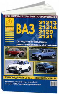
Плакаты по устройству автомобилей ВАЗ-21213/21214.
- Автор: —
- Издательство: АВТОВАЗ
- Год издания: 2001
- Страниц: 40
- Формат: DjVu
- Размер: 5,2 Mb

Цветной иллюстрированный альбом с описание конструкции и рекомендациями по техническому обслуживанию автомобилей ВАЗ классической компоновки, а также ВАЗ-2121 Нива.
- Автор: Б.В. Ершов, М.А. Юрченко
- Издательство: Вища школа
- Год издания: 1979
- Страниц: 169
- Формат: PDF
- Размер: 23,7 Mb

Руководство по эксплуатации и ремонту + каталог запчастей автомобилей ВАЗ-21213/21214 Нива с 1994 года выпуска с карбюраторными и инжекторными двигателями объемом 1,7 л.
- Автор: —
- Издательство: Третий Рим
- Год издания: —
- Страниц: 312
- Формат: —
- Размер: —

Мультимедийное руководство по эксплуатации и ремонту автомобиля ВАЗ-21213.
- Автор: —
- Издательство: —
- Год издания: —
- Страниц: —
- Формат: —
- Размер: 104,7 Mb
Руководство по ремонту автомобилей ВАЗ-21213/21214 Нива.
- Автор: —
- Издательство: За рулем
- Год издания: —
- Страниц: 292
- Формат: DjVu
- Размер: 16,7 Mb

Мультимедийное руководство по ремонту автомобилей ВАЗ-21213/21214 Нива.
- Автор: —
- Издательство: За рулем
- Год издания: —
- Страниц: —
- Формат: —
- Размер: 413,9 Mb

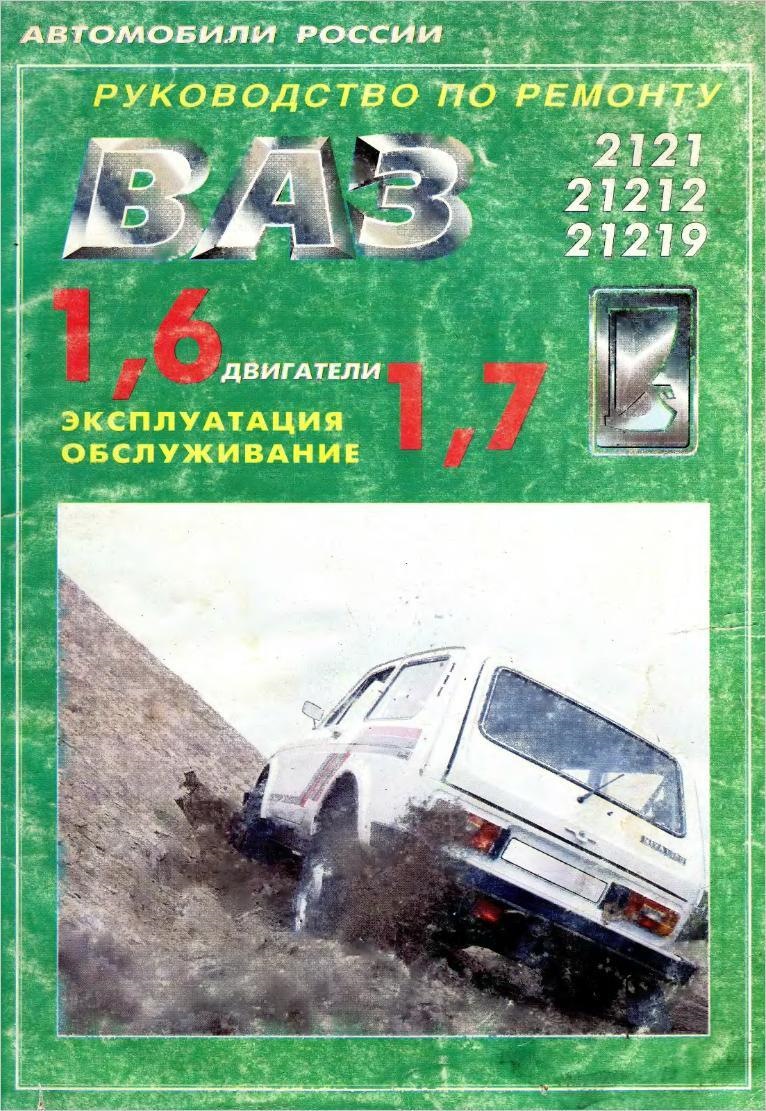
Руководство по эксплуатации, техническому обслуживанию и ремонту автомобилей ВАЗ-2121/21212/21219 с двигателями объемом 1,6/1,7 л.
- Автор: —
- Издательство: Ливр
- Год издания: 1995
- Страниц: 151
- Формат: DjVu
- Размер: 14,5 Mb

Руководство по ремонту и каталог запчастей автомобилей ВАЗ-2121/21213
- Автор: —
- Издательство: Арго-Авто
- Год издания: —
- Страниц: 270
- Формат: —
- Размер: —
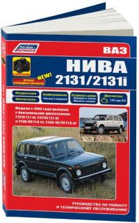
Руководство по ремонту и техническому обслуживанию + каталог расходных запчастей автомобилей ВАЗ-2131 Нива с 1995 года выпуска с бензиновыми двигателями объемом 1,7/1,8 л.
- Автор: —
- Издательство: Легион-Автодата
- Год издания: —
- Страниц: 370
- Формат: —
- Размер: —

Руководство по техническому обслуживанию и ремонту системы управления двигателями ВАЗ-2111 и ВАЗ-21214-11 с распределенным впрыском топлива под нормы токсичности ЕВРО-2 (контроллер М7.9.7).
- Автор: —
- Издательство: АВТОВАЗ
- Год издания: 2004
- Страниц: 175
- Формат: PDF
- Размер: 1,5 Mb

Инструкция по эксплуатации автомобиля Lada 4×4 и его модификаций.
- Автор: —
- Издательство: АВТОВАЗ
- Год издания: —
- Страниц: 76
- Формат: PDF
- Размер: 1,3 Mb
Руководство по эксплуатации, ремонту и техническому обслуживанию автомобилей ВАЗ-21213/21214/2129/2131 Нива с бензиновыми и дизельными двигателями.
- Автор: —
- Издательство: Арго-Авто
- Год издания: —
- Страниц: 286
- Формат: —
- Размер: —

Руководство по эксплуатации, техническому обслуживанию и ремонту автомобиля ВАЗ-21213 Нива и его модификаций.
- Автор: —
- Издательство: Астрель-АСТ
- Год издания: 2005
- Страниц: 241
- Формат: DjVu
- Размер: 13,8 Mb

Описание устройства и диагностика системы управления двигателями автомобилей семейств Lada Kalina/110/Niva с контроллером М7.9.7 ЕВРО-3.
- Автор: —
- Издательство: АВТОВАЗ
- Год издания: 2009
- Страниц: 229
- Формат: PDF
- Размер: 2,7 Mb

За Рулем
- Автор: —
- Издательство: За рулем
- Год издания: 2011
- Страниц: 322
- Формат: —
- Размер: —

Руководство по техническому обслуживанию и ремонту автомобилей ВАЗ-21213/21214 Нива с карбюраторными и инжекторными двигателями объемом 1,7 л.
- Автор: —
- Издательство: За рулем
- Год издания: —
- Страниц: —
- Формат: —
- Размер: —

Руководство по эксплуатации, техническому обслуживанию и ремонту автомобилей Lada 4×4 Нива (включая Lada 4х4 Urban) с двигателями объемом 1,6/1,7/1,8 л.
- Автор: —
- Издательство: Мир Автокниг
- Год издания: —
- Страниц: 320
- Формат: —
- Размер: —

Руководство по эксплуатации, техническому обслуживанию и ремонту + каталог запчастей автомобилей Lada 4×4 Нива (включая Lada 4х4 Urban) с двигателями объемом 1,6/1,7/1,8 л.
- Автор: —
- Издательство: Мир Автокниг
- Год издания: —
- Страниц: 400
- Формат: —
- Размер: —


Книги по ремонту ВАЗ 2121 НИВА, скачанные, когда то мной из интернета. Ссылок и адресов от куда я их качал не помню, так что выкладываю их на диске яндекса. Кому интересно, качайте, сохраняйте, мне не жалко, может, кому ни будь пригодится. 
1) Каталог запасных частей автомобиля ВАЗ 2121 и его модификаций. (Москва «Машиностроение» 1988 год.). yadi.sk/d/mCpprPpzG32yW
2) Руководство по ремонту ВАЗ 2121, 21212, 21219, двигатели 1.6, 1.7, эксплуатация, обслуживание. (г. Москва, издательство «Ливр» 1995 год.). yadi.sk/d/JqkhfouzG2kP9
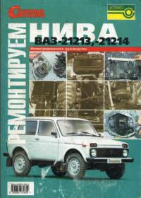
3) Ремонтируем ВАЗ 21213, 21214 – своими руками (издательство «За рулем»). yadi.sk/d/v3er4XdbG32xm
4) Каталог узлов, деталей и запасных частей ВАЗ 21213 и модификаций. (Москва «Астрель-аст» 2004) yadi.sk/d/ySiVWyB_G32xD
5) Автомобили ВАЗ -21213, ВАЗ 21214 альбом плакатов. (Тольятти – Россия- АО Автоваз 2001 год.). yadi.sk/d/mZZ7YgfVG32we
6) ВАЗ 2121, 21211 была скачана у MrJekaP, который любезно предоставил сканы книги, за что ему отдельное спасибо. yadi.sk/d/naWIu9diD2yRx


Вымойте раздаточную коробку снаружи и слейте масло. Закрепите раздаточную коробку на стенде для разборки
Сборка раздаточной коробки проводится в последовательности, обратной разборке, с учетом следующего: соберите межосевой дифференциал,
Снятие Установите автомобиль над смотровой канавой или на подъемник. Опустите рычаг стояночного тормоза и
Устройство раздаточной коробки показано на рис. 3-35. Рис. 3-35. Раздаточная коробка: 1 – ведомая
Устройство привода раздаточной коробки показано на рис. 3-36. Рис. 3-36. Привод раздаточной коробки: 1
Вибрация раздаточной коробки и пола кузова (в зоне передних сидений) при трогании автомобиля с
Правильное положение ведущей шестерни относительно ведомой обеспечивается подбором толщины регулировочного кольца, установленного между торцом
Разборка Промойте коробку передач и установите ее на стенде. Слейте масло и снимите нижнюю
Перед осмотром все детали раздаточной коробки тщательно очистите щеткой и скребком, а затем промойте.
Ослабьте гайки крепления задних колес. Поставьте упоры под передние колеса и вывесите задний мост.
Иллюстрированные руководства
-
-
Ремонтируем своими силами ВАЗ 21213, 21214 Нива 4х4.
Иллюстрированное руководство.
Содержание: Общие сведения; Техника безопасности при ремонте; Диагностика неисправностей; Двигатель; Системы охлаждения и зажигания; Система питания карбюраторного двигателя; Системы питания и управления впрыского двигателя; Система выпуска отработавших газов; Трансмиссия; Сцепление; Коробка передач; Промежуточный вал; Раздаточная коробка; Карданная передача; Передний мост; Приводы передних колёс; Задний мост; Передняя подвеска; Задняя подвеска; Рулевое управление; Тормозная система; Электрооборудование; Кузов и оснащение салона; Уход за кузовом автомобиля; Система отопления и вентиляции; Приложения
Формат DJVU. - 16.66 MiB
-
13 • 2977
-
[ 3 ratings ]
-
-
-
Лада 4×4 «НИВА» — Устройство, обслуживание, диагностика, ремонт.
Книга из серии многокрасочных иллюстрированных руководств по обслуживанию и ремонту автомобилей своими силами. В настоящем руководстве приведена подробная информация о конструкции всех систем, отдельных узлов и агрегатов автомобилей LADA 44, выпускаемых с 2009 г. В книге показаны все изменения, связанные с переходом на экологический класс автомобиля Евро-3, улучшения в конструкции трансмиссии и установка гидроусилителя рулевого управления. Подробно описаны возможные неисправности автомобиля, их причины и способы устранения.
Операции по обслуживанию и ремонту представлены на цветных фотографиях и снабжены подробными комментариями. В Приложениях показаны инструменты, лампы и схемы электрооборудования, приведены смазочные материалы и эксплуатационные жидкости, моменты затяжки резьбовых соединений. Книга предназначена для водителей, желающих обслуживать и ремонтировать автомобиль самостоятельно, а также для работников СТО. - 38.04 MiB
-
0 • 3324
-
[ 7 ratings ]
-
-
-
Мультимедийное руководство по устройству и обслуживанию НИВА 21213
Мультимедийное руководство по эксплуатации, техническому обслуживанию и ремонту легкового автомобиля ВАЗ 21213. Интерактивный просмотрщик электросхем поможет Вам быстро и легко найти неисправность в электрооборудовании автомобиля.
Содержит полную информацию о ремонте, техническом обслуживании и регулировке различных узлов, включая электрические схемы, схемы расположения всех компонентов и необходимый специальный инструмент.
Картинки, описания, рекомендации. Все до мелочей. Удобное меню. Возможность распечатки. Запускается без инсталляции. - 104.76 MiB
-
11 • 3432
-
[ 4 ratings ]
-
-
-
Руководство по ремонту ВАЗ 2121, 21212, 21219.
Руководство по эксплуатации,техническому обслуживанию и ремонту автомобилей ВАЗ-2121, 21212, 21219 с двигателями рабочим объемом 1.6 и 1.7л. В книге дается краткое описание устройства автомобилей, подробно описывается техническое обслуживание и ремонт автомобилей на базе готовых запасных частей. Сведения по запасным частям даются в каталоге запасных частей. Имеются перечни возможных неисправностей и рекомендации по их устранению, а также указания по разборке и сборке, регулировке и ремонту узлов автомобилей. Книга предназначена для инженерно-технических работников центров и станций технического обслуживания, автохозяйств и ремонтных мастерских, а также для владельцев автомобилей.Формат: Djvu
Количество страниц: 150
Язык: Русский
Качество: Отсканированные страницы - 14.5 MiB
-
3 • 1110
-
[ 2 ratings ]
-
-
-
Руководство по эксплуатации, техническому обслуживанию и ремонту автомобиля «Нива» ВАЗ-21213 и его модификаций.
Руководство по устройству, эксплуатации, техническому обслуживанию и ремонту автомобилей ВАЗ-21213 «Нива» и модификаций 1994—2007 г. выпуска.В Руководстве приводятся рекомендации по эксплуатации автомобиля ВАЗ-21213 «Нива» и его модификаций. Представлено подробное описание операций по их техническому обслуживанию и ремонту, а также представлены электросхемы автомобилей. Рекомендованы смазочные материалы и эксплуатационные жидкости.
Руководство предназначено для владельцев автомобилей ВАЗ Нива, станций техобслуживания, персонала СТО, механиков и ремонтных мастерских.
Содержание:
* Предисловие
* Раздел 1. Общие данные
* Раздел 2. Двигатель
* Раздел 3. Трансмиссия
* Раздел 4. Подвески колес
* Раздел 5. Рулевое управление
* Раздел 6. Тормоза
* Раздел 7. Электрооборудование
* Раздел 8. Кузов
* Раздел 9. Модификации автомобилей BA3-21213, вариантное или дополнительное оборудование автомобилей
* Приложениянаименование: Руководство по эксплуатации, техническому обслуживанию и ремонту автомобиля ВАЗ-21213 «Нива» и его модификаций
издательство: Астрель, 2002
автомобили: ВАЗ-21213 «Нива»
тип: электронное руководство (автокнига)
количество страниц: 241 стр.
качество: отличное (сканирование)
язык: русский
формат: djvu
вес файла: 14 мб - 13.75 MiB
-
0 • 1636
-
[ 4 ratings ]
-
-
- 1.67 MiB
-
0 • 10
-
[ One rating ]
Download Extension © by Hotschi, Demolition Fabi, OXPUS
• Download Extension English language © by OXPUS

-
Contents
-
Table of Contents
-
Troubleshooting
-
Bookmarks
Quick Links
VAZ VEHICLES
VAZ-21213, VAZ-21214, VAZ-21214-20, VAZ-21215
REPAIR MANUAL
Related Manuals for Vaz 21213
Summary of Contents for Vaz 21213
-
Page 1
VAZ VEHICLES VAZ-21213, VAZ-21214, VAZ-21214-20, VAZ-21215 REPAIR MANUAL… -
Page 2: Table Of Contents
Valve clearance adjustment ……..27 Cylinder head — removal and refitting ……28 Heater unit…………..183 Cylinder head — dismantling and reassembly….28 Camshaft and timing gear ……….32 Chapter 9. VAZ-21213 vehicle modifications, alternative and addi- Cooling system ……………34 tional equipment……………185 Lubrication system…………38 VAZ-21214 vehicle …………185 Fuel system …………..42…
-
Page 3: About This Manual
VAZ-21215 model — with Turbo Diesel Engine. The chapters of the manual give full descriptions of VAZ-21213 vehicle units. For general description, service and repair procedures applicable to other models, refer to Section 9 where you can also find the information on additional and alternative equipment fitted to the vehicles.
-
Page 4: Section 1. General Data
Section 1. General Data Table 1-1 TECHNICAL SPECIFICATION Features VAZ-21213 VAZ-21214 VAZ-21214-20 VAZ-21215 General Number of seats Kerb weight, kg 1210 1210 1210 1240 Payload, kg Overall dimensions Fig.1-1 Maximum braking distance at GVW and 80 km/h on horizontal dry flat asphalt road, not greater, meters: •…
-
Page 5
Features VAZ-21213 VAZ-21214 VAZ-21214-20 VAZ-21215 Power train Clutch single dry plate, diaphragm spring Clutch release mechanism hydraulic, servo spring Transmission 5-speed, synchro units on all forward gears Gear ratio: • first gear 3.67 3.67 3.67 3.67 • second gear 2.10 2.10… -
Page 6: Braking System
Voltage, volts Battery 6ëí-55Ä, 55 ampere-hour Alternator AC, integral diode plate and electronic voltage regulator Starter motor pre-engaged, solenoid switch and overrun clutch Body Type all-steel unitary construction, monocoque, three-door, double-space Fig.1-1. Basic overall dimensions of VAZ-21213 vehicle…
-
Page 7: Section 2. Engine
Section 2. Engine Refer to Fig.2-1 and Fig.2-2 for front and side sectional views of the engine. Fig.2-1. Side sectional view of the engine…
-
Page 8
Fig.2-2. Front sectional view of the engine… -
Page 9: Fault Diagnosis
Fault diagnosis Symptom/fault Remedy Engine fails to start 1. Carry out the following operations: 1. No fuel to carburettor: — blow fuel pipes, clean fuel tank, renew fuel filter; — blocked fuel pipes or fuel filter; — clean filters; — clogged carburettor or fuel pump filters; — check pump operation and renew any damaged components — faulty fuel pump 2.
-
Page 10
Main bearing knocking Typical knocking or thumping noticeable at sudden throttle opening at idle which intensifies with higher crankshaft rate. Excessive endfloat of crankshaft causes sharper irregular knocking, especially noticeable during smooth increase or decrease in crankshaft speed. 1. Early ignition 1. -
Page 11
Excessive oil consumption 1. Oil leaking through engine gaskets 1. Tighten fittings or replace gaskets and oil seals 2. Restricted crankcase ventilation system 2. Wash components of crankcase ventilation system 3. Worn piston rings 3. Rebore and renew pistons and rings 4. -
Page 12
Undo the nuts holding the downpipe to exhaust manifold. Engine — removal and refitting Detach the downpipe from the bracket on the transmission and Put the vehicle on a lift or over an inspection pit and apply the lower it down. handbrake. -
Page 13
Fig.2-4. Removing the oil filter using tool Ä.60312 Fig.2-5. Releasing the crankshaft nut using tool Ä.50121 Remove the starter motor heat shield, followed by the starter motor, hot air intake complete with the supply hose. Remove from the cylinder head two side brackets together with the front engine mounting rubbers. -
Page 14
Fig.2-7. Removing the camshaft thrust flange: 1 — thrust flange; 2 — camshaft; 3 — bearing housing; 4 — thrust flange securing Fig.2-8. Removing the oil pump shaft: stud 1 — thrust flange; 2 — flange securing bolt; 3 — oil pump shaft; 4 — wrench Remove thrust flange 1 (Fig.2-8) of the oil pump drive shaft and take the shaft out of the cylinder block. -
Page 15
Fig.2-11. Pressing out the bearing from the crankshaft using tool A.40006 Fig. 2-12. Refitting the thrust washers to the rear mounting Fit the centre main bearing shells without an oilway into the bearing recesses. Fit into other cylinder bores the bearing shells with an oilway, while into the relevant main bearing caps — the bearing shells without an oilway. -
Page 16
Fig.2-15. Crankshaft rear oil seal housing. Fig.2-16. Clutch dowels (arrowed black) and clutch housing centering The lugs (arrowed) for centering the housing against the crankshaft flange pins (arrowed white) Locate the flywheel in position so that the marking (a cut-out) near the rim is against the No 4 cylinder crankpin axis. -
Page 17
Turn the flywheel so that the mark on the crankshaft sprock- et is against the cylinder block mark (Fig.2-19). Check to see the camshaft bearing housing centering pins are in position (Fig.2-20). Refit the sprocket to the camshaft com- plete with the bearing housing and turn the camshaft so that the timing mark in the sprocket is aligned against the mark on the bearing housing (Fig.2-21). -
Page 18
Fig.2-23. Timing cover Fig.2-22. Camshaft bearing housing nuts tightening sequence Projections (arrowed) for cover centering against crankshaft pulley hub Adjust the clearance between the camshaft lobes and valve Fit the valve cover complete with the gasket and fuel piping levers. bracket. -
Page 19: Cylinder Block
WARNING. Never check the engine or vehicle on the Engine run-in after overhaul roller stand without additional rollers for the front wheels. After overhaul the engine is bench tested (run-in) at no loads under the following cycle: Cylinder block 750-800 rpm 2 minutes 1000 rpm 3 minutes…
-
Page 20
Fig.2-25. Basic sizes of the cylinder block Fig.2-27. Measuring the cylinder bore with the inside dial gauge: Fig.2-26. Cylinder size class engraved on the cylinder block 1 — inside dial gauge; 2 — setting to zero against reference gauge… -
Page 21: Pistons And Connecting Rods
There is practically no wear in the land 1 area of the cylin- There are five classes (Ä, Ç, ë, D, Ö) of the piston according ders. Compare the values measured on the first and other cylin- to their major diameter, in steps of 0.01 mm. The piston has a complex outside shape: tapered in height and oval in the cross- der lands to see the amount of the cylinder wear.
-
Page 22
The connecting rod small-end features a pressed-in steel- rod. The engine must always be fitted with the connecting rods of the same weight class. The connecting rod weight can be adjust- bronze bush. As to the diameter of the bush, the connecting rods ed by removing excess metal from the bosses on the small-end are divided into three classes in steps of 0.004 mm (similar to the or big-end up to the minimum size of 16.5 mm or 35.5 mm (Fig.2-… -
Page 23: Selecting Piston To Cylinder
Table 2-1 Dismantling and reassembly Connecting rod classification as to Dismantling. Prise out the gudgeon pin circlips from the pis- small-end and big-end weights ton, press out the gudgeon pin and detach the connecting rod from the piston. Remove the piston rings. Connecting rod weight, g Class Paint mark…
-
Page 24: Design Description
0.02-0.05 mm for the oil control ring. When worn, the tolerance must not exceed the specified maximum of 0.15 mm. The piston ring gap should be checked with a feeler gauge via inserting the rings into the gauge (Fig.2-35), with the bore equal to the piston ring nominal diameter ±0.003 mm.
-
Page 25
Fig.2-36. Basic crankshaft dimensions crankpins. Regrind when the wear is in excess of 0.03 mm, oval- ity is over 0.03 mm, or when scoring and scuffing is obvious. Regrind the journals and crankpins through reducing the diameter to the nearest undersize (Fig.2-36). When regrinding, observe the sizes for the crankshaft fillet as shown in Fig.2-36 for the standard-size crankshaft. -
Page 26: Cylinder Head And Valve Gear
Fig.2-38. Measuring the big-end bearing running clearance: Fig.2-39. Flywheel: 1 — crushed Plastigage; 2 — bearing shell; 3 — big end cap; 4 — scale for clear- 1 — surface mating the crankshaft flange; 2 — surface for clutch securing; 3 — ance measurement clutching surface The nominal design clearance is 0.02-0.07 mm for the…
-
Page 27: Valve Clearance Adjustment
Fig.2-40. Basic dimensions of the valves, valve guides and valve seats The outer diameter of the replacement guides is 0.2 mm big- ger. Bearing housing 5 with camshaft 6 is fitted to the cylinder head. Valve train. Valves 2 are operated by the cams through levers 4.
-
Page 28
Fig.2-42. Checking the clearance between the rocker levers and cam lobes: 1 — feeler blade Ä.95111; 2 — adjuster bolt; 3 — lock nut lock nut tightening, until the blade is a firm sliding fit when the lock nut is tightened (Fig.2-42); — after the clearance is adjusted at the cylinder No4 exhaust valve and cylinder No3 intake valve, turn the crankshaft progres- Fig.2-43. -
Page 29: Cylinder Head — Dismantling And Reassembly
Disconnect the leads from the spark plugs and coolant tem- Slacken lock nuts 14, undo adjuster bolts 13 and bushes 15. perature sender, from carburettor idle switch and fuel cutoff sole- Position tool Ä.60311/R, as shown in Fig.2-44, compress the noid.
-
Page 30
Fig. 2-46. Intake valve seat profile: Fig. 2-47. Exhaust valve seat profile: I — new seat; II — reconditioned seat I — new seat; II — reconditioned seat Put spring A.94069/5 on tool Ä.94059, fit tapered wheel A.94078 on spindle Ä.94069 for the exhaust valve seats or wheel Ä.94100 for the inlet valve seats, secure the spindle in a grinder and recut the valve seat (Fig.2-48). -
Page 31
Fig.2-50. Limit sizes for valve chamfer regrinding: Fig.2-53. Valve spring checking diagram: I — inlet valve; II — outlet valve Ä — dimension in free state; Ç — dimension under load When a new valve fails to take up clearance between the valve guide and the valve rim, renew the valve guides using tool Ä.60153/R (Fig.2-51). -
Page 32: Camshaft And Timing Gear
VAZ engines of the same type (2101, 21011, 2103, 2107, removed. 2121), but made of different steel. The 21213 engine bolts have the threaded area of 70 ÏÏ (30 Chain tension adjustment mm for other engines); in addition, the 21213 engine bolts do not have a distinctive mark (a 7.5 mm diameter recess for wrench).
-
Page 33
Fig.2-56. Sectional view of the chain tensioner: 1 — cap nut; 2 — tensioner housing; 3 — core; 4 — spring; 5 — washer; 6 — plunger; 7 — spring; 8 — collet; 9 — spring ring; Ä — plunger surface; Ç — centre-punch points on housing face Before refitting, smear the chain with engine oil. -
Page 34: Cooling System
Check collet 8, core 3 and plunger 6 for scores, check the When necessary, use an areometer to check the coolant mating surfaces of the tensioner shoe and plunger for deep density to be 1.078-1.085 g/cu.cm for TOSOL A-40 which is used scores. Always renew any damaged components. in VAZ vehicles.
-
Page 35
When the level in the expansion tank is below the value spec- — disconnect the heater hose (top) from the union on the vehi- cle body; ified, while its density is in excess of that required, top up distilled water. — pour coolant (10.7 litre) to the radiator (up to the upper filler edge) until it starts flowing from the hose and heater union;… -
Page 36
Fig.2-63. Removing the impeller: Fig.2-61. Checking the water pump belt tension 1 — puller; 2 — impeller Fig.2-62. Sectional view of the coolant pump: 1 — pulley hub; 2 — shaft; 3 — cover; 4 — impeller; 5 — housing; 6 — thrust ring; 7 — oil seal; 8 — bearing stop screw; 9 — pulley; 10 — blower fan; 11 — cover plate; 12 — fan hub… -
Page 37
Water pump drivebelt tension adjustment The belt tension is checked by exerting a hand pressure on the chain between the alternator pulley and pump pulley or between the pump pulley and crankshaft pulley. With proper ten- sion, slack A in the belt (Fig.2-61) at 98 N (10 kgf) must be 10-15 ÏÏ, while at the same pressure the deflection Ç… -
Page 38: Lubrication System
— disconnect the hoses from the radiator; — separate the fan cowl halves and withdraw the fan cowl; — undo two bolts holding the radiator to the body, release the upper catch of the radiator cowling upwards, move the radiator top towards the engine and withdraw the radiator from the engine compartment;…
-
Page 39
Fig.2-67. Lubrication system: 1 — oil passage to main bearing; 2 — main bearing-to-big-end bearing oil passage; 3 — oil filter relief valve; 4 — paper element; 5 — check valve; 6 — oil pump; 7 — oil pump-to- oil filter oil passage; 8 — oil passage from oil filter to main oil gallery; 9 — oil passage to oil pump gear and ignition distributor; 10 — oilway to oil pump shaft and ignition dis- tributor;… -
Page 40
Fig.2-68. Basic dimensions of the oil pump components and associated parts Removal and refitting. When only the oil pump requires recon- housing and cover for cracks, renew when applicable. ditioning, remove it from the vehicle (Refer to section «Engine — Using feeler blades, check the backlash in the gears and the removal and refitting»), place it on the turning stand, drain the oil radial play (Fig.2-70) to be respectfully 0.15 mm (maximum per-… -
Page 41
Fig.2-69. Dismantling the oil pump: 1 — relief valve; 2 — valve spring; 3 — cover; 4 — housing; 5 — shaft Fig. 2-70. Checking the oil pump radial play Oil pump shaft and drive gears Check to see there is no denting or scuffing of the shaft bear- ing journals or eccentric cam surfaces. -
Page 42
Fig.2-73. Removal and refitting of the oil pump / distributor shaft bush: 1 — tool Ä.60333/1/2 Fig.2-75. Crankcase ventilation diagram: 1 — filter element, air cleaner; 2 — exhaust manifold; 3 — flame arrester; 4 — hose to draw crankcase emission on throttle body; 5 — discharge hose; 6 — oil sepa- rator cover;… -
Page 43: Fuel System
Fig.2-76. Air cleaner and temperature regulator: 1 — gasket; 2 — corrugated hose; 3 — air temperature control flap handle; 4 — cold air intake; 5 — temperature regulator; 6 — clamp bolt; 7 — air cleaner cover secur- ing nut; 8 — air cleaner cover; 9 — air cleaner cover gasket; 10 — filter element; 11 — filter cover mounting bracket;…
-
Page 44
Fig.2-78. Fuel tank and fuel pipeline associated components 1 — fuel tank; 2 — hoses, fuel vapour separator and fuel tank; 3 — fuel vapour separator; 4 — filler pipe; 5 — cap; 6 — hose, fuel tank and filler pipe; 7 — hose, fuel vapour sepa- rator and fuel tank cover;… -
Page 45
Check and renew any worn components. Always fit new pump gaskets, remember to lubricate the gaskets with a thin layer of grease before refitting them to the pump. Refitting pump to engine. For correct fitting, use two out of three gaskets as stated below: «Ä»… -
Page 46: Carburettor
The carburettor has two main fuel jet systems for the primary Carburettor and secondary barrels, a primary barrel idling system with air cor- rection, a secondary barrel air correction system, part throttle General description enrichment (economizer), full throttle enrichment (econostat), The engine is fitted with the 21073-1107010 carburettor diaphragm-type accelerator pump, semi-automatic choke control (Fig.2-81) of emulsion, twin progressive throttle type.
-
Page 47
Table 2-2 21073-1107010 CARBURETTOR Parameters Primary barrel Secondary barrel Barrel diameter, mm Venturi diameter,mm Main jet system: • fuel jet marking* 107.5 117.5 • air jet marking Emulsion tube, type Idling and air correction systems, primary barrel: – • fuel jet marking –… -
Page 48
Fig.2-82. Main metering system: 1 — main air jets and emulsion tubes; 2 — atomizers, primary and secondary barrels; 3 — balance orifice; 4 — fuel filter; 5 — return pipe with calibrated orifice to petrol tank; 6 — needle valve; 7 — float; 8 — secondary throttle valve; 9 — main fuel jets; 10 — primary throttle valve Fig.2-83. -
Page 49
Fig.2-84. Part throttle and full throttle enrichment systems: 1 — secondary throttle valve; 2 — main fuel jet, secondary barrel; 3 — fuel jet and tube, full throttle enrichment; 4 — main fuel jet, primary barrel; 5 — primary throttle valve; 6 — vacuum port;… -
Page 50
engine speed. Inner profiles 4.1 and 4.2 operate choke lever 6 allowing choke opening to a certain amount at intermediate posi- tions of lever 4. Rotation of choke lever 4 anticlockwise causes the wider slot to release choke lever 6 stud; the choke is held in a fully closed position by return spring 7. -
Page 51
When the crankshaft speed goes down as low as 1900 rpm Refitting is a reversal of the removal procedure. Before refit- on the overrun, the control unit re-triggers the fuel cutoff solenoid ting, examine the carburettor heat screen and intake pipe/carbu- to feed fuel through the idle jet, and the engine gradually shifts to rettor mating surfaces. -
Page 52
Fig.2-88. Carburettor cover components: 1 — float spindle; 2 — needle valve; 3 — float; 4 — gasket; 5 — diaphragm and rod, choke pull down unit; 6 — spring; 7 — adjusting screw; 8 — cover, choke pull down unit; 9 — idling fuel jet;… -
Page 53
Fig.2-89. Carburettor housing components: 1 — accelerator pump diaphragm; 2 — operating lever, accelerator pump; 3 — cover; 4 — cam, accelerator pump linkage; 5 — cover, part throttle enrichment; 6 — diaphragm, part throttle enrichment; 7 — fuel jet, part throttle enrichment; 8 — valve, part throttle enrichment; 9 — return valve, accelerator pump; 10 — atomizer and fuel feed valve, accel- erator pump;11 — main metering atomizers;… -
Page 54
Fig. 2-91. Throttle stop screw: 1 — throttle stop screw; 2 — idle mixture adjustment screw; 3 — sealing ring; 4 — adjusting screw cap Check the jet marking and consult Table 2-2 to prevent the jet confusion when refitting. Before refitting pivot pit 19 (Fig.2-88), apply sealant ìÉ-9 on the pivot end and over 1-1.5 end turns of thread. -
Page 55: Exhaust Gas Recirculation System
throttle must be fully closed. If not, adjust the pedal and throttle by means of end piece 10 at front rod 1 end. Secure the end of throttle linkage cable 3 so that with knob 5 pulled, the choke is fully closed, while with knob 5 pushed in — fully open.
-
Page 56: Exhaust System
Fig.2-93. Exhaust system: 1 — sealing gasket; 2 — downpipe; 3 — bracket to secure downpipe to transmission; 4 — connection clasp; 5 — suspension ring, main silencer; 6 — main silencer; 7 — front silencer Exhaust system Exhaust gases escape from the engine through the exhaust manifold, front exhaust pipe (downpipe) 2 (Fig.2-93), centre (front) silencer 7 and main (rear) silencer 6.
-
Page 57: Chapter 3. Power Train
Chapter 3. Power train Clutch The design of the clutch is shown on fig. 3-1. The clutch release fork 11 (fig. 3-1) can be of two types: with a leaf or wire spring. Fig. 3-1. Clutch assembly: 1 — bleeder; 2 — central diaphragm spring; 3 — diaphragm spring rivet; 4 — pressure plate; 5 — clutch disc; 6 — flywheel; 7 — clutch bellhousing; 8 — bellhousing-to-flywheel bolt; 9 — gearbox input shaft;…
-
Page 58
Fault diagnosis Diagnosis Remedy Incomplete clutch release (clutch spin) 1. Excessive gaps in clutch release drive 1. Adjust clutch release drive 2. Buckling of clutch disc (camming action more than 0.5 mm) 2. Straighten or replace disc 3. Roughness on clutch disc friction linings 3. -
Page 59
Fig. 3-2. Clutch pedal and master cylinder: 1 — pedal cluster mounting bracket; 2 — clip; 3 — clutch pedal servo spring; 4 — clutch pedal return spring; 5 — clutch pedal limiter bolt; 6 — clutch pedal; 7 — pushrod; 8 — protective cap;… -
Page 60
Fig. 3-3. Slave cylinder and clutch release fork: 1 — release bearing; 2 — ball pivot; 3 — clutch release fork; 4 — pushrod; 5 — adjusting bolt; 6 — locknut; 7 — return spring; 8 — plug; 9 — bleeder; 10 — cylinder body; 11 — sealing ring;… -
Page 61
Fig. 3-5. Clutch check: 1 — pressure plate thrust flange; 2 — central diaphragm spring; 3 — clutch disc; 4 — ring Master and slave cylinders — removal and refitting First, drain working liquid. To do this, attach one end of the hose to bleeder 9 (see fig. -
Page 62
Fig. 3-8. Master cylinder components: 1 — body; 2 — sealing; 3 — plug; 4 — gasket; 5 — union; 6 — retaining washer;7 — cap; 8 — circlip; 9 — pushrod piston; 10 — sealing ring; 11 — master cylinder piston; Fig. -
Page 63
Master and slave cylinders — Clutch master cylinder — bench-check dismantling, inspection, repair and reassembly Checking the leak-proofness of the rear sealing ring. Place the master cylinder on the test-bench (see fig. 3-10), and Master cylinder. Turn out plug 3 (fig. 3-8), remove protective ensure good sealing between the cylinder flange and the surface rubber cap 7 and circlip 8. -
Page 64: Gearbox
Push downward lever rod 27 (see fig. 3-12) and with the help Gearbox of a screwdriver or any other pointed tool take out the retaining The design of the gearbox is shown on fig. 3-12, 3-26, 3-34. sleeve 31 from the groove on the lever rod; remove the rod. Disconnect the brackets that are fixing pipes and mufflers in Fault diagnosis the rear part of the vehicle, and then the muffler pipe from the…
-
Page 65
Fig. 3-12. Gearbox: 1 — input shaft; 2 — front cover with guide sleeve; 3 — input shaft oil seal; 4 — spring washer; 5 — bearing set collar; 6 — gearbox housing; 7 — breather; 8 — output shaft needle bearing;… -
Page 66
Fig. 3-15. Clutch bellhousing, view from inside. Fig. 3-13. Clutch release drive: The black arrows point to the gearbox-to-clutch bellhousing fastening nuts; the 1 — fork return spring; 2 — locknut; 3 — adjusting nut; 4 — cotter pin; 5 — clutch white arrow points to the opening in the front cover for oil outflow from the trans- release fork;… -
Page 67
Remove circlip from the gearbox output shaft end (fig. 3-16). Unbend the lock washer, undo the nut by several turns to move the coupling centering ring, and again turn in the nut. Using a puller A.40006/1 with tool A.40005/4 remove the flexible cou- pling centering ring from the output shaft end (fig. -
Page 68
Fig. 3-23. Removing the reverse idler gear, 5th gear/synchro unit and Fig. 3-21. Removing the 5th gear bush: fork assembly: 1 — bush 1 — reverse idler gear; 2 — 5th speed coupling; 3 — 5th speed/reverse gear Fig. 3-24. Removing the 5th synchro unit hub/reverse driven gear: Fig. -
Page 69
Simultaneously remove the reverse idler gear 1 (fig. 3-23) from the shaft, gear 3 in assembly with the coupling and fork 4 from the output shaft. With the help of a special mandrel (like a screwdriver) remove the 5th synchro unit hub together with reverse driven gear 2 from key 4 (fig. -
Page 70
Fig. 3-27. Undoing the fastening bolts of the output shaft idler gear plate with an impact screwdriver. The arrow shows the direction of the screwdriver thrust stroke when striking with a hammer Fig. 3-28. Withdrawing the input shaft from the transmission casing With the help of a special mandrel (like a screwdriver) take out the input shaft together with the bearing and the synchro unit ring (fig. -
Page 71
— the output shaft rear bearing is press-fitted on the shaft to facilitate the installation of the rear cover; — the reverse idler gear 1 (see fig. 3-23), gear 3 and fork 4 are installed simultaneously; — when reassembling the gear switch lever apply grease ãëñ-15 or ãàíéã-24 on the ball or the cap of the ball socket;… -
Page 72
On surfaces mating with the clutch housing, with the rear and bottom covers there should be no damages that may cause oil leak. Insignificant damages should be smoothed with a file. If parts are badly damaged or worn, renew them. Check the condition of the front cover and ensure that the input shaft does not touch it when rotating. -
Page 73: Transfer Box
should be no roughness or scuffings on the rolling surfaces of the Transfer box shaft front end. Check the condition of needle rolling surface in the opening Fault diagnosis of the primary shaft. Diagnosis Remedy Examine the intermediate shaft, no chipping or excessive wear of teeth is allowed.
-
Page 74
Spontaneous gear or differential lock disengagement Disconnect the speedometer cable from the transfer box and 1. Worn teeth on gears and cou- 1. Renew worn parts the wires from the differential lock warning lamp sensor. Turn the plings driveshafts and disconnect the driveshaft flanges from the trans- 2. -
Page 75
— refit and tighten the flange fastening bolts on the transfer coupling and the front axle shaft. Remove the speedometer drive box and the layshaft; if the bolts fit perfectly in the apertures of the unit housing 3 in assembly with the speedometer driven gear. flanges, the centering is carried out correctly, otherwise the After removing lock washer 8 (see fig. -
Page 76
Fig. 3-36. Transfer box operating system: 1 — differential locking clutch yoke; 2 — differential locking clutch; 3 — yoke stop bolt; 4 — boot; 5 — lever spring; 6 — differential locking fork rod; 7 — front axle case cover; 8 — lock washer;… -
Page 77
Fig. 3-39. Removing the front axle case: 1 — front axle case; 2 — case cover; 3 — speedometer drive housing Remove the bearing setting rings from the front and rear drive shafts. Take the front axle drive shaft 11 (see fig. 3-35) out from the casing together with bearing 8, thrust ring and oil deflec- tor 9. -
Page 78
Remove front cover 4 (fig. 3-40) with the differential, fit the differential bearing setting ring and take out the bearing in assembly with the differential from the front cover. Remove the setting rings from the bearings of the drive- and intermediate shafts and remove both input- and layshafts from the transfer box casing. -
Page 79
Fig. 3-45. Press-fitting the bearing on the differential housing: 1 — tool 67.7853.9558 — remove circlips 8 (see fig. 3-42) and spring washer 14, then press out the differential pinion shaft and remove the differential pinions and the drive shaft gears with support washers. Press out worn or damaged oil seals from the front axle case, from the front bearing cover and from the rear cover. -
Page 80: Drive Line
between the input shaft and top gear should be 0.05-0.10 mm, maximum allowed — 0.15 mm. If wear exceeds the limits, renew the gears. Bearings. Ball and roller bearings should have no damages on races, cages, rollers or balls, and no cracks and choppings on rings.
-
Page 81
Noise and vibration of propeller shafts Check the layshaft balance on a balance bench, as follows. 1. Deformation of front or rear pro- 1. Rectify under press or renew It is not recommended to dismantle the propeller shafts, if the peller shaft yokes are turning smoothly, there is no jamming, the mis-align- 2. -
Page 82
If any of the components are damaged, renew the spider in assembly with the bearings. The diameter of the yoke opening for the needle bearing should not exceed 28.021 mm. In case of damage or if wear of working surfaces of the layshaft U-joint components exceeds 0.1 mm, renew the U-joint assembly. -
Page 83
Fig. 3-52. U-joint reassembling: Fig. 3-51. Installing the bush for dismantling the U-joint: 1 — circlip; 2 — feeler gauge; H — gap; A, B, C, D, E, F, G — feeler gauge blades 1 — bush with thickness in mm: 1.45; 1.48; 1.52; 1.56; 1.60; 1.64; 1.67 Fig. -
Page 84: Rear Axle
Rear axle — removal and refitting Rear axle The removal and refitting of the rear axle beam is described The design of the rear axle is shown on fig. 3-54. in subsection «Rear suspension». To remove the rear axle it is enough to disconnect the suspension arm and the shock- Fault diagnosis absorbers only from the rear axle beam.
-
Page 85
Fig. 3-54. Rear axle: 1 — wheel cap; 2 — brake drum-to-wheel securing bolt; 3 — oil deflector; 4 — brake drum; 5 — brake drum iron ring; 6 — wheel cylinder; 7 — bleeder; 8 — axle shaft bearing; 9 — bearing locking ring;… -
Page 86
Fig. 3-56. Checking for vertical deformations of the rear axle beam using a try-square on the outside surface of flange A.70172 Fig. 3-58. Checking the reduction gear mounting If deformation exceeds this size, straighten the beam, follow- the arrow of the indicator will point to the division equal to the size ing the procedure given below. -
Page 87
Fig. 3-59. Checking for horizontal deformations of the rear axle beam Fig. 3-61. Pressing out the axle shaft bearing stop ring: using a try-square on the outside surface of flange A.70172 1 — fixture; 2 — axle shaft graphite greasing or ãëñ-15. After refitting, check the operation flange end face measured in the centers, should not exceed 0.05 mm, if the runout is above the specified value, but no more than of axle shafts during an actual road test. -
Page 88
The rear axle reduction gear assembly is shown on fig. 3-65. It is unified with the reduction gear of VAZ — 2106 and has a label After press-fitting, ensure, that the ring does not shift under on the housing as figure 6. -
Page 89
— undo nuts fastening the braking plate to the beam and pull out the axle shafts so that they come out from the differential box; — disconnect the propeller shaft from the reduction gear, put a support under the reduction gear casing, turn out the bolts fas- tening it to the rear axle beam and take out the reduction gear from the beam, pay attention not to damage the sealing. -
Page 90
Inspect the differential pinion apertures and the shafts; insignificant surface damages smooth with fine sandpaper, and renew in case of serious damages. Inspect the surfaces of the axle shaft gear journals and their bores in the differential box, check the condition of box apertures for differential pinion shafts. -
Page 91
Fig. 3-69. Rear axle reduction gear components: 1 — drive gear flange; 2 — oil seal; 3 — oil deflector; 4 — front bearing; 5 — rear bearing; 6 — drive gear adjusting ring; 7 — axle shaft gear support washer; 8 — axle shaft gear; 9 — pinion;… -
Page 92
Fig. 3-71. Defining the thickness of the drive gear shim: 1 — indicator; 2 — fixture A.95690; 3 — drive gear rear bearing; 4 — tool A.70184 In this case fit an adjusting ring with thickness of 3.05 mm. Fit an adjusting ring of the necessary thickness on the driving gear and press fit using tool A.70152 (fig. -
Page 93
Fig. 3-73. Final drive gears: 1 — driven gear; 2 — serial number; 3 — allowance in hundredth of mm to nominal; Fig. 3-76. Checking the drive gear bearing preload: 4 — drive gear 1 — dynamometer 02.7812.9501; 2 — casing; 3 — sleeve Differential housing bearings preload and adjustment of the side gap in final drive gears mesh These operations are carried out simultaneously using tool… -
Page 94
After moving the driven gear, check the side gap by indicator 2 (see fig. 3-78). Repeat the adjustment if the clearance does not correspond to the rated value. Remove tool A.95688/R, fit the adjusting nut lock plates and fix them by bolts with spring washers. In spare parts the lock plates are delivered of two types: with one or two tabs depending on the location of the nut slot. -
Page 95
driven gear teeth the contact pattern is located in regular intervals — clean the casing filler neck from oil and wipe dry; closer to the narrow end of the tooth, occupying two thirds of — raise the rear axle and put it on supports; length and without covering the top and the base of the tooth, as — start the engine, engage the fourth gear and at speed of 90- shown on fig. -
Page 96: Front Axle
Loosen the muffler-to-front exhaust pipe clip, disconnect the Front axle pipes and muffler brackets in the rear part of the vehicle and on the gearbox. The design of the front axle is shown on fig. 3-81. A number «13» is painted on the reduction gear casing for distinction. Using key 02.7812.9500 undo the front exhaust pipe-to- exhaust manifold fastening nuts and remove the pipe downward.
-
Page 97
Fig. 3-81. Front axle: 1 — splash guard; 2 — reduction gear casing lower cover; 3 — final drive gear bearing; 4 — differential housing; 5 — drain aperture plug; 6 — check and filler plug; 7 — inner joint housing bearing;… -
Page 98
state this ring should pass free through the spline opening in race — remove the wheel hub cap and undo the wheel hub bearing 11, what allows to connect and to separate the joint and shaft 4. nut, then unscrew the fastening nut of the inner joint housing bearing cover;… -
Page 99
Fig. 3-84. Withdrawing the ball from the cage Fig. 3-85. Withdrawing the cage / race assembly from the joint housing — using a knock-out and a hammer, beat the inner joint race Take the race out from the cage, to do that, place one of the race ledges in the elongated opening of the cage (see fig. -
Page 100: Chapter 4. Wheel Suspensions
Chapter 4 Wheel suspensions Fault diagnosis Diagnosis Remedy Noise and knock in suspension at vehicle movement 1. Faulty shock-absorbers 1. Replace or repair shock absorbers 2. Loose anti-roll bar fastening bolts 2. Tighten securing nuts and bolts; in case of rubber pad wear — replace 3.
-
Page 101
Diagnosis Remedy Un-even tyre tread wear 1. Excessive speed at cornering 1. Low down speed 2. Excessive wear of suspension joints and bushes 2. Repair suspension 3. Wheels out of balance (stains in regular intervals on tread outer path 3. Balance wheels and on central path when driving with a disbalanced wheel for a long time) 4. -
Page 102: Front Suspension
Diagnosis Remedy Excessive wear of tyre tread 1. High driving speed 1. Choose speed according to road conditions 2. Heavy vehicle acceleration 2. Avoid sharp acceleration 3. Often braking 3. Use brakes correctly 4. Wrong wheel alignment angles 4. Adjust wheel alignment angles 5.
-
Page 103
Fig. 4-1. Front suspension: 1 — front suspension crossmember; 2 — lower control arm shaft; 3 — lower arm silent block; 4 — lower control arm; 5 — lower control arm shims; 6 — lower control arm shaft bush; 7 — crossmember bracket; 8 — coil spring lower seat; 9 — coil spring; 10 — compression buffer mounting strut; 11 — compression buffer; 12 — compression restrictor; 13 — shock absorber mounting bracket, lower;… -
Page 104
Before adjusting the wheel alignment angles check the fol- lowing: — pressure in tyres; — axial gap in front wheel hub bearings; — serviceability of shock-absorbers (absence of rod jamming); — radial and axial runout of tyres; — gap in suspension balljoints; — free play of steering wheel. -
Page 105
After adjustment, refit the fastening clamps with the slot fac- ing back with allowable deviation downward by 60° to the hori- zontal plane of the vehicle. With the nuts tightened the clamp slot edges should not contact. After toe-in adjustment, ensure that wheels and steering mechanism components do not hit the adjacent components of the suspension and car body. -
Page 106
Fig. 4-6. Front suspension on the vehicle, rear view: 1 — lower control arm; 2 — crossmember; 3 — tie-rod fastening bracket; 4 — anti-roll bar-to-body securing bracket; 5 — tie-rod; 6 — anti-roll bar — remove old greasing and wash with kerosine the inner cav- Front suspension — removal and refitting ity of the steering knuckle, the outer and inner cavities of the hub, Place the vehicle on the lift or over an inspection pit, set the… -
Page 107
Fig. 4-7. Front suspension, exploded view: 1 — coil spring lower seat; 2 — lower control arm; 3 — lower arm shaft; 4 — lower control arm silent block; 5 — coil spring; 6 — upper seat; 7 — spring insulator gasket; 8 — com- pression buffer;… -
Page 108
— remove the front wheel hub in assembly with the brake disc, Inspection using pusher 67.7823.9516; Balljoint. Ensure the integrity of the balljoint boots; no — remove the front brake splash guard; breaks, cracks, rubber peeling from the metal fixture, traces of — remove the front suspension shock-absorber;… -
Page 109
Fig. 4-11. Press-fitting the upper control arm balljoint: Fig. 4-10. Pressing out the upper control arm balljoint: 1 — control arm shaft; 2 — tool 67.7853.9519; 3 — fixture A.74177/1 1 — control arm shaft; 2 — tool 67.7823.9527; 3 — balljoint; 4 — tool A.47045 the front suspension, it is permissible to install the A class springs on the front suspension. -
Page 110: Rear Suspension
The lower arm. The pressing-out and press-fitting of the joint Disconnect the handbrake rear cable brackets from the can be carried out on a press, using tool 67.7823.9526, and also body, remove the front cable return spring, and after undoing the locknut and the adjusting nut, release the rear cable.
-
Page 111
for the rear suspension, it is permissible to install the B class springs (with black marking). If on the front suspension the springs of B class are installed, the rear suspension should be fit- ted with B class springs only. To avoid damage and excessive tightening of control arm rubber bushes and shock-absorbers: — load the rear part of the vehicle so that distance X, mea-… -
Page 112
Fig. 4-18. Front and rear suspension shock absorbers: 1 — lower eye; 2 — compression valve body; 3 — compression valve discs; 4 — compression valve throttling disc; 5 — compression valve spring; 6 — compression valve holder; 7 — compression valve cap; 8 — recoil valve nut; 9 — recoil valve spring; 10 — shock absorber piston; 11 — recoil valve cap; 12 — recoil valve discs; 13 — piston ring; 14 — recoil valve nut washer;… -
Page 113
Place the rod in assembly with the piston in grips, fix in vice and undo the recoil valve nut 8. Remove piston 10 with valves (bypass and recoil), rod guide bush 23, rod sealing 26, sealing race 25 and other components. Note. -
Page 114
Diagnosis Remedy Chapter 5. Steering 5. Wrong clearance in roller-to- 5. Adjust clearance The steering mechanism design is shown on fig. 5-1, 5-2. worm mesh or in worm bearings 6. Excessive gap in tie-rod 6. Renew ball joints or tie rods Since November, 1998, vehicles are fitted with a telescopic balljoint intermediate shaft instead of a cylindrical intermediate shaft 17… -
Page 115
Fig. 5-1. Steering: 1 — track rod; 2 — drop arm; 3 — relay rod; 4 — idler arm; 5 — adjuster pin; 6 — lower balljoint; 7 — right steering knuckle; 8 — upper balljoint; 9 — right steering knuckle arm; 10 — idler bracket;… -
Page 116: Steering — Inspection, Check And Adjustment
Fig. 5-3. Steering components: 1 — steering box; 2 — shaft seal; 3 — intermediate shaft; 4 — upper shaft; 5 — locking plate, bracket front end; 6 — bracket; 7 — upper shroud; 8 — bearing bush; 9 — needle bear- ing;…
-
Page 117: Steering Mechanism
Inspect the tie-rod balljoint protective caps. Steering mechanism If the protective caps are in good condition and provide inside cleanness, their service life is practically unlimited. Moisture, dust Removal and refitting and other foreign particles inside the joint will result in premature Removal.
-
Page 118: Steering Mechanism
Fig. 5-7. Removing the outer ring of the worm upper bearing using tool 67.7853.9541: 1 — steering box; 2 — worm upper bearing ring, outer; 3 — tool 67.7853.9541 tening nut and fix it in three points. Move the combination switch case fully towards the steering wheel, and tighten the switch fas- tening clip.
-
Page 119
Fig. 5-9. Checking the worm friction moment using a dynamometer: Fig. 5-8. Installing the steering worm 1 — worm; 2 — head A.95697/5; 3 — dynamometer 02.7812.9501; 4 — test-bench 1 — bearing cover; 2 — shim; 3 — worm bracket;… -
Page 120
After press-fitting in the steering box, finally process the screwed in to an angle, smaller than 60° to provide for subse- bushes with a reamer A.90336 up to the size of 28.698-28.720 quent splinting. mm. The mounting gap between the pitman arm shaft and the After refitting adjust the front wheel toe-in. -
Page 121: Chapter 6 Braking System
Vehicle wandering or skidding at braking Chapter 6 1. Leak of brake liquid in one of 1. Renew seals and bleed system wheel cylinders Braking system 2. Jammed piston in brake wheel 2. Check and rectify piston sticking cylinder in cylinder, renew damaged com- The design of the braking system is shown on fig.
-
Page 122
Fig. 6-1. Braking system: 1 — rear brake wheel cylinder; 2 — parking brake rear cable; 3 — rear brake guide; 4 — parking brake front cable; 5 — parking brake lever; 6 — brake pedal; 7 — servo unit; 8 — second circuit pipeline;… -
Page 123: Handbrake Adjustment
If the stoplight switch is too close to the pedal, it does not come back to the initial position, valve 18 (see fig. 6-2), being pressed to housing 21, separates cavities A and B, and it results in incomplete release of wheels when the pedal is let off. To adjust the stop-light switch position slacken nut 8 and by rotating nut 9 (see fig.
-
Page 124
Fig. 6-4. Handbrake linkage: 1 — front cable; 2 — rear cable guide; 3 — front cable return spring; 4 — rear cable; 5 — locknut; 6 — adjusting nut; 7 — spacer Ask an assistant to press the brake pedal with effort of 686- housing, apply a thin layer of Ñí-1 on the shaft and the acting part 784 N (70-80 kgf) and simultaneously observe the outcoming part of the piston, fill 5-6 gr. -
Page 125
All above operations should be carried out through the upper connectors first on the right rear wheel, the most remote from the master cylinder, then further clockwise: the left rear wheel, left and right front wheels. Thus, air from one circuit will be removed. To bleed the other circuit use the lower connectors on the cylin- der block of the left and right front brakes. -
Page 126
Clutch and brake pedal bracket Removal and refitting. To remove the pedal bracket: — remove the steering shaft bracket, as mentioned in section «Steering»; — disconnect the servo unit push rod from the brake pedal, having removed lock shackle 26 (fig. 6-8) and taken out pin 24; — disconnect the wires from the stoplight switch;… -
Page 127
Check and repair. At hard pedal movement examine the — undo the nuts fastening the servo unit bracket to the body working surfaces of pedals, bushes and shaft. front and remove the unit in assembly with the bracket. If there will be small risks or traces of oxidation on surfaces of Refitting of the servo unit is carried out in reverse order. -
Page 128: Front Brakes
Fig. 6-11. Checking the leak-proofness of the master cylinder: 1 — test-bench bleeding valve; 2 — manometer; 3 — reservoir; 4 — master cylinder; 5 — flywheel; 6 — pushrod shift indicator; 7 — vent; 8 — vessel Inspection of components. Before reassembly, wash all components with isopropyl alcohol;…
-
Page 129
Components inspection Carefully examine all components, having previously washed them in warm water with washing liquid and dried by a jet of com- pressed air. If on pistons and on cylinder mirrors any traces of wear or jamming are found, renew the cylinder block complete with pis- tons. -
Page 130: Rear Brakes
Rear brakes The design of the rare brake is shown on fig. 6-17. Removal and dismantling Lift the rear part of the vehicle and take off the wheel. Take care of possible liquid spillage from the tank. Using puller 67.7823.9519 (fig. 6-18) remove the brake drum. Disconnect the cable end piece from the shoe manual lever 18 (see fig.
-
Page 131: Component Inspection
Fig. 6-17. Rear wheel brake mechanism: 1 — wheel cylinder; 2 — upper return spring; 3 — friction lining; 4 — backplate; 5 — inner plate; 6 — rear cable sheath; 7 — lower return spring; 8 — front brake shoe; 9 — thrust plate;…
-
Page 132
Fig. 6-19. Wheel cylinder: 1 — shoe abutment plate; 2 — cap; 3 — cylinder body; 4 — piston; 5 — seal; 6 — backing cup; 7 — spring; 8 — retainers; 9 — thrust ring; 10 — thrust screw; 11 — bleed screw; A — slot in thrust ring Fig. -
Page 133
When reassembling, which is carried out in reverse sequence, grease all components with brake liquid. ATTENTION. To differentiate the VAZ-2121 and -21213 pressure regulators from others of similar design, there is a groove on the bottom part of the piston. -
Page 134: Handbrake
Fig. 6-24. Handbrake linkage components: 1 — cover; 2 — front cable; 3 — lever; 4 — pushbutton; 5 — tie rod spring; 6 — lock tie-rod; 7 — rear cable guide; 8 — distance sleeve; 9 — return spring; 10 — expander strut; 11 — manual shoe operating lever;…
-
Page 137: Wiring And Fuses
ëhapter 7. Electrical system 7 (8 Ä) Left-hand front lamp (side marker light) Wiring and fuses Right-hand front lamp (side marker light) Number plate light The electrical system is of the single-wire negative earth Side marker warning light type. The vehicle basic wiring diagram is illustrated in Fig.7-1. 8 (8Ä) Right-hand rear lamp (side marker light) Most electrical circuits are powered when the ignition is…
-
Page 138
Fig.7-1. Electrical system of VAZ-21213 vehicle: 1 — left-hand front headlamp; 2 — headlights; 3 — left-hand headlamp wiper motor; 4 — horn; 5 — fuel cutoff solenoid; 6 — idle switch; 7 — headlight washer motor; 8 — right-hand headlight wiper motor;… -
Page 139
— stop light switch; 40 — cigarette lighter; 41 — exterior light switch; 42 — heater controls illumination; 43 — rear fog light switch; 44 — rear window heating switch; 45 — heater motor switch; 46 — rear window wipe/wash switch; 47 — hazard warning flasher switch; 48 — ignition switch; 49 — instrument lighting switch; 50 — windscreen wiper switch; 51 — switch, windscreen washer &… -
Page 140: Alternator
Dry-storage battery — putting into operation The vehicles are factory-fitted with ready-to-use batteries, i.e. batteries filled with electrolyte and fully charged. Replacement batteries can be supplied dry, without elec- trolyte. In order to operate such battery, first remove any provi- sional plugs or masking tape.
-
Page 141
Table 7-3 — when electrolyte is «boiling». Wait to see bubbles rising to the surface in the electrolyte, sampled with a hydrometer. Temperature correction values to hydrometer readings for measuring electrolyte density Battery charging Electrolyte temperature, °ë Correction value, g/cm Remove the battery from the vehicle and clean it carefully, -40 to -26 -0.04… -
Page 142: General Description
This chapter describes the alternator of 37.3701 model, prefer- rotor pole end; 24 — buffer bush; 25 — bush; 26 — hold-down bush ably used in VAZ-21213 vehicles. Fig.7-4. Alternator wiring diagram: 1 — battery; 2 — alternator; 3 — instrument cluster; 4 — resistor 51 Ohm, 5 W; 5 — diode; 6 — low battery charge warning light; 7 — fuse box; 8 — ignition relay; 9 — ignition switch…
-
Page 143
Warning light is on with engine running. Battery is overcharged Fault diagnosis Voltage regulator damaged (short- Renew voltage regulator Cause Remedy circuit between terminal «ò» and earth) Warning light does not light up when ignition is switched on. Instruments inoperative Alternator is noisy 1. -
Page 144
Mount the alternator on the tester and connect as shown in mentary diodes from the voltage regulator terminal «Ç» and make sure the lead end does not touch the alternator housing. Connect Fig.7-5. Start the tester motor, using rheostat 4, set the alternator the battery lead to the regulator terminal «Ç»… -
Page 145
When necessary, sand the slip rings with emery paper, then check the winding for continuity or earthing with an ohmmeter or a test bulb. Stator — testing The stator is tested separately after dismantling the alterna- tor and disconnecting the winding from the diodes. First test the stator winding for continuity or earthing using an ohmmeter or a test bulb and battery. -
Page 146: Ignition System
Off-vehicle test. For testing the voltage regulator, removed from the alternator, make the connections as shown in Fig.7-10. The pre-1996 voltage regulator should be tested complete with the brush holder (Fig.7-10, b), since at the same time you can detect a broken brush connection or a poor contact between the voltage regulator terminals and brush holder.
-
Page 147
and withdraw it. In case of pre-1996 alternators to prevent dam- ages to the brushes when removing the brush holder. Insert a screwdriver between regulator 2 housing and brush holder, then partly pull out the regulator from the alternator, leaving the brush holder in place. -
Page 148: Starter Motor
Brush holder — renewal General description The starter motor is of pre-engaged type (35.3708 model), Always renew the complete unit if the regulator fails or brush- DC, with field coils, incorporating a double-winding solenoid. es are worn or protrude from the holder to less than 5 mm. Body 17 (Fig.7-13) houses four poles 18 with field windings, In case of pre-1996 alternators, force the brush holder out of three of which are series and one is parallel.
-
Page 149: Starter Overhaul
Solenoid repetitive cutting in and out Fully locked ring test. Lock the tester ring gear, operate the starter motor and measure the current, voltage and braking 1. Battery discharged 1. Recharge battery 2. Excessive voltage drop in sole- moment to be maximum 550 amps, 7.5 volts and at least 13.7 2.
-
Page 150
Fig.7-13. Starter motor (35.3708 model): 1 — pinion; 2 — overrun clutch; 3 — guide ring; 4 — rubber plug; 5 — operating lever; 6 — drive-end housing; 7 — relay armature; 8 — relay winding; 9 — contact plate; 10 — relay cover;… -
Page 151: Ignition System
Stator. Using megohmmeter or a 220 v test lamp, check the stator winding is not earthed. The test lamp voltage is supplied to the common winding ter- minal and starter housing. When the bulb is lit up or megohm- meter resistance reading is below 10 kOhm, or if the windings have evidence of overheating (blackened insulation), renew the housing complete with the windings.
-
Page 152
Fig.7-16. Exploded view of starter motor: 1 — drive end housing with intermediate ring; 2 — rubber plug; 3 — operating lever; 4 — solenoid; 5 — commutator end housing; 6 — brush; 7 — brush spring; 8 — protective case; 9 — stop ring;… -
Page 153
Engine gasps at all speeds Always ensure the spark control unit is reliably earthed through the retaining dowels, or its trouble-free operation 1. Ignition wires damaged, con- 1. Examine leads and connections. nections loose or lead ends oxi- will be affected. Renew damaged leads dized 2. -
Page 154
— start the engine and point the flashing timing light at the tim- ing mark on the pulley; when the ignition is correct, then at idling speed the TDC mark on the flywheel should be as outlined in Attachment 3. To adjust the ignition timing, switch off the engine, slacken the nuts securing the ignition distributor and turn the latter to the angle desired (clockwise for advance and anticlockwise for retard… -
Page 155: Ignition Coil
up to 1500 rpm or the thicker spring bracket for speeds over 1500 rpm. Increase the spring tension for a smaller angle (retard) or decrease the spring tension for a bigger angle (advance). To obtain the vacuum advance pattern, connect the vacuum advance unit to the vacuum pump of the tester.
-
Page 156
Fig.7-26. Displaying pulse waveform at the oscilloscope: Fig.7-25. Checking the spark control module: I — control module pulses; II — alternator pulses; Ä — dwell (current saturation 1 — spark gap; 2 — ignition coil; 3 — control module; 4 — 0.01 Ohm resistor (1%, at time);… -
Page 157: Lighting And Signalling
When sparking occurs at the pressure below 0.3 åPa (3 The leads and resistors are checked with an ohmmeter. Refer to subsection «Alternator» for the capacitor checking procedure. kgf/Òm ), the spark plug is defective. Only a few sparks are allowed in the spark gap; when no Lighting and signalling sparking is observed either on the spark plug or in the spark gap, it is likely that the insulation is cracked and the central electrode…
-
Page 158
Fig.7-28. Wiring diagram for headlight and foglight: 1 — headlights; 2 — main fusebox; 3 — low beam relay; 4 — ignition switch; 5 — exterior light switch; 6 — warning lights: high beam (left) and fog lamp (right); 7 — rear fog light; 8 — fog light switch;… -
Page 159
Turn signal self-canceling device inoperative General description 1. Cancelling mechanism seized 1. Renew 3-stalk switch The headlight wiring diagram is shown in Fig.7-28. 2. Combination switch guide ring 2. Detto shoulders worn or broken High and low beam is operated through supplementary relays 3 and 11. -
Page 160
Three vertical lines should be drawn on the screen (Fig.7-32): centre line O and lines A and B through the reference points Ö cor- responding to each headlamp center. These lines should run sym- metrical to the centre line of the car. Draw line 1 at the height of 600 mm which is the distance to the centres from the ground and 75 mm below draw line 2 passing through the centres of the headlight beam patterns. -
Page 161: Windscreen Wiper/Washer
Indicators flasher relay Windscreen wiper/washer Relay 8 (Fig.7-30) (231.3747 model) is intended for intermit- General description tent light signals both for direction indication and hazard flashing. It also allows to identify a failed bulb in the direction indicator. The windscreen wipe/wash comprises motor, linkage and With good bulbs in the direction indication mode, the relay blades.
-
Page 162
Continuous operation of wiper blades in intermittent mode Windscreen wiper — removal and refitting 1. Wiper relay breaker winding 1. Renew wiper relay The repair of the wiper is basically restricted to straightening blown the deformed arms and rods or their renewal. A failed motor must 2. -
Page 163
Wiper motor — dismantling, reassembly and Windscreen wiper relay inspection The relay of êë-514 model is used for intermittent operation of the windscreen wiper. The relay is located beneath the instru- Commence to dismantle the motor by undoing cover 1 (Fig.7- ment panel on the left-hand side and is attached to the body by 35) retaining screws. -
Page 164
Fig.7-37. Wiring diagram for rear window wipe/wash and heating: 1 — fusebox; 2 — rear window wipe/wash switch; 3 — rear window washer motor; 4 — rear window wiper motor; 5 — rear window heating element; 6 — rear window heating relay;… -
Page 165
Blower motor specification to zero by pushing the reset knob in the instrument cluster. Reset the trip counter only on a stationary vehicle turning the knob Shaft speed (with fan impeller load) clockwise. at 12 v and (25±10)°ë, rpm ……3000±150 WARNING. -
Page 166
Fig.7-39. Wiring diagram for pre-1996 instrument cluster (rear view): 1 — wiring connector and pin assignment; 2 — tachometer; 3 — voltage stabilizer; 4 — instrument illumination lamp; 5 — coolant temperature gauge; 6 — fuel gauge; 7 — resistor, 470 Ohm, 0.25 W;… -
Page 167
Instrument cluster — dismantling and reassembly at the low end of the scale, while at 77-89 éhm it should stay at the beginning of the red area of scale. Undo the trip counter knob by pulling it outward, then remove Fuel gauge. -
Page 168
Table 7-7 Coolant temperature sender specification Temperature, Supply voltage, Resistance, °ë volts 1350-1880 585-820 6.85 280-390 155-196 87-109 Low oil pressure warning light switch. The switch is fitted to the cylinder head. The switch contacts should close and open at 20-60 kPa (0.2-0.6 kgf/cm Fig.7-42. -
Page 169: Chapter 8. Bodywork
Chapter 8. Bodywork Fault diagnosis Cause Remedy Dark spots over bodywork 1. Hot water was used for washing (above 80°ë) 1. Remove minor blemishes through buffing, respray body in case of major deterioration 2. Leaded petrol or other aggressive agents were used for dewaxing 2.
-
Page 170
Cause Remedy Failure to lock bonnet 1. Lock spring broken or loose 1. Renew spring 2. Shorter lock operating link 2. Adjust operating link length through loop on lock hook 3. Incorrect position of lock 3. Adjust lock position Failure to secure sliding glass in position Spring brake of window lifter broken Renew window lifter Excessive efforts or failure to recline front seat back forward or… -
Page 171: Bodywork — Repair
Bodywork — repair Deformed surfaces — repair The repair of any damaged body parts is carried out by Refer to Fig.8-1, Fig.8-2 and Fig.8-3 for body frame design means of stretching, ding and dent, straightening, cutting out of and relevant cross-sections. irreparable areas, making of maintenance patches from the body rejects or metal sheets by shaping them into a suitable part.
-
Page 172
Fig.8-2. Body components: 1 — front wing; 2 — battery tray; 3 — top bulkhead reinforcement; 4 — instrument panel crossbar; 5 — centre pillar; 6 — outer rear wheel arch; 7 — inner bodyside panel; 8 — rear floor cross-member; 9 — roof panel; 10 — windscreen frame; 11 — bracket for wheel mudflap; 12 — roof reinforcements; 13 — rear pillar; 14 — rear floor panel; 15 — rear cross- piece;… -
Page 173
Polyester fillers of «ïÂÏÔ ÓÔÓÎ-è» or èù-0085 type offer a monolithic layer of plastic mass. Use your usual treating methods reliable adhesion with the panels stripped to the bare metal. They when the layer is hardened well through. consists of two components: unsaturated polyester resin and a Use solders of èéëëÛ… -
Page 174: Paintwork
Detach the roof panel, remove the panel remainder and straighten any areas deformed. Remove loose colour paint and base paint up to bare metal on the roof panel edges, windscreen frame, roof side panels and reinforcements. Renew the gaskets on reinforcements. Fit the roof panel, secure it with quick detachable grips, tack the panel by gas welding in the locations arrowed in Fig.8-5.
-
Page 175
over the weld seams and on the joints of the replaced parts. etc.) all over outer surfaces. The same recommendations are Remove the stopper surplus with a cleaning cloth moistened in applied to the parts restored after ding and dent. white spirit. -
Page 176: Door
Fig.8-6. Front view of the body. Inner cavities of: 1 — top front cross-member; 2 — headlight casings; 3 — bottom front cross-mem- ber; 4 — under front wing; 5 — outer sill; 6 — inner sill Fig.8-7. Rear view of the body. Inner cavities of: 1 — rear chassis arms;…
-
Page 177
over an old layer. In the event of a longer field service with this underbody protection, apply the sealant over the entire under- body and wheel arches surfaces. In cold weather before use, store sealant paste in a warm room to warm it up to at least 20°ë. When thick, thin sealant with ksylol to 3% as a maximum. -
Page 178
Fig.8-9. Rubber seals: 1 — of swivel glass; 2 — front door seal frame; 3 — seal molding; 4 — front door seal; 5 — of sliding glass; 6 — of tailgate aperture; 7 — of side window; 8 — lower seal of sliding win- dow;… -
Page 179
Fig.8-12. Removing the front door: Fig.8-13. Front door inner view: 1 — hinge screw; 2 — impact screwdriver; 3 — hinge; 4 — check strap. 1 — top armrest screw clip; 2 — bottom armrest securing screws Arrowed is the direction to hit the impact screwdriver Arrowed is the location for door trim securing clips Door Front door — dismantling and reassembly… -
Page 180
Fig.8-15. Front left door lock: 1 — inner door handle; 2 — escutcheon; 3 — pivot shaft; 4 — inner door bracket; 5 — inner door operating link; 6 — door locking knob; 7 — locking knob rod; 8 — inner control lever;… -
Page 181: Bonnet, Bumpers
It is a good practice to mark the door striker contour on the body pillar before making any alignments. If the door fits too tight, slacken the door striker securing screws, move the striker outward and tighten the screws. If the door fails to close firmly, move the striker inward.
-
Page 182: Bodywork Glazing And Windscreen Washers
— refit the seal to the windscreen; Bumpers — removal and refitting — using glycerine or soapy water, wet seal 2 groove (Fig.8-24) The bumpers (Fig.8-22) are made from aluminium profile, which is used for attaching it to the body flange; with the face lined lengthwise with black rubber strip 8.
-
Page 183: Instrument Panel, Seats
together with the filter gauze. Extract sleeve 3, then carefully tap- ping rotor 9 shaft 6, push support 7 out and withdraw the shaft and rotor. Reassembly is a reversal of dismantling. Removal and refitting of washer jets. Working from the engine bay, slightly squeeze the holders of plastic housing 1 (Fig.8-27), next pick its top with a screwdriver and force the jet complete with the atomizer.
-
Page 184
8Fig.8-30. Seats: 1 — seat back; 2 — headrest; 3 — headrest frame; 4 — headrest guide; 5 — cotter pin; 6 — front seat back frame; 7 — rear seat back trim; 8 — trim backing; 9 — seat back catch; 10 — seat back clamp;… -
Page 185: Heater Unit
When necessary, remove the centre facia and side facia vent To reassemble, relocate the rollers with the stop into the slid- nozzles together with the associated air ducts. er groove, force the track fully forward and restore the rests mechanically. Lower down handle 2 and Ë check the slides for Refitting is a reversal of removal.
-
Page 186
Fig.8-34. Heater components: 1 — air distribution cover; 2 — fan shroud; 3 — resistor; 4 — guide cowl; 5 — heater matrix housing; 6 — air intake cover gasket; 7 — air intake cover; 8 — spring clips, delivery and return pipes;… -
Page 187: Vaz-21214 Vehicle
Disconnect and remove the supply/return pipes from the cen- tral injection unit and from the bracket on the valve cover. The VAZ-21214 vehicle is fitted with 1.7-L engine, Central Undo the retaining pins and remove the central injection unit, Fuel Injection (CFI). Instead of the carburettor, a single injector is withdraw the gasket from the intake pipe surface.
-
Page 188
Undo the retaining pins and remove the central injection unit Central Injection Unit from the intake pipe complete with the gasket. Plug the intake pipe end to prevent entry of extraneous matter. Removal and refitting Refitting is the reverse order of removing. Pay attention to the condition of the seals and gaskets, renew if applicable. -
Page 189
Apply sealant on the thread of the housing securing screws. Throttle position sensor. Before fitting the TP sensor, fully close the throttle, then turning the sensor anticlockwise, align the flats of the shaft with the sensor pickup lever. Tighten the securing screws. WARNING. -
Page 190
crankshaft position pulses are fed to the ECU when the engine is Evaporative emission control system not running. To re-activate the fuel pump, switch off the ignition Examine the hoses and charcoal canister. If the housing is for ten seconds, then switch it on again. found cracked or damaged, renew the charcoal canister. -
Page 191
Fig.9-5. Wiring diagram for VAZ-21214 vehicle, CFI: 1 — electric fuel pump and fuel level sender; 2 — injector; 3 — oxygen sensor; 4 — octane potentiometer; 5 — air temperature sensor; 6 — MAP sensor; 7 — throttle position sen- sor;… -
Page 192: Vaz-21214-20 Vehicle
Engine 21214-10 The engine 21214-10 is four-stroke, four-cylinder, in-line, SOHC, with Sequential Fuel Injection System. The 21214-10 engine is based on the 21213 engine. Both engines have similar housing components, piston / connection rod mechanism and power unit mounting. The differences…
-
Page 193
Fig.9-8. Removing the components and units of air intake system: 1 — part throttle channel heater hose; 2 — throttle body; 3 — return hose from throttle body; 4 — air intake; 5 — air intake end piece; 6 — intake manifold hose; 7 — MAF sensor; 8 — air cleaner cover;… -
Page 194
Check the injection system for satisfactory operation, as out- Further engine dismantling is as described in chapter 2 of this lined in Repair Manual for Fuel Sequential Injection System. Manual. The engine reassembly is reverse of the dismantling pro- cedure. Before refitting the fuel rail, lubricate the injector sealing Engine — dismantling and reassembly rings with motor oil. -
Page 195
Fig.9-10. Valve actuation: 1 — cylinder head; 2 — valve; 3 — valve lever; 4 — rail, hydraulic valve lifter; 5 — camshaft; 6 — hydraulic valve lifter; 7 — nut Fig.9-11. Exploded view of chain tensioner: 1 — chain; 2 — tensioner shoe; 3 — oil delivery pipe to tensioner; 4 — chain tensioner; 5 — camshaft sprocket; 6 — chain damper; 7 — oil pump shaft sprocket; 8 — crankshaft sprocket… -
Page 196
Fig.9-12. Hydraulic chain tensioner: 1 — tensioner housing; 2 — valve unit; 3 — ball, non-return valve; 4 — stop pin; 5 — plunger; 6 — volume restrictor; 7 — spring; Ç — working cavity; ë — locating slot; Ñ — hole; Ö — reserve cavity Fig.9-13. -
Page 197
When refitting to the engine, the tensioner should be free cleaner housing 10. The air then flows through paper filter ele- from oil, dowel 4 should not protrude from the housing. ment 9, MAF sensor 7, hose 6 and throttle housing 2. From the throttle housing the warm air is directed to receiver unit 12 and Cooling system intake pipe and further to the cylinder head and cylinders. -
Page 198
(Fig.9-16) to connect the ECU with EMS sensors and actua- exceeds 105°ë or cuts off when the coolant temperature goes tors. No headlamp wipe/wash is fitted to VAZ 21214-20 vehicle. below 101°ë. Three wires of the EMS wiring harness through a separate… -
Page 199
Fig.9-16. EMS wiring diagram (Sequential Fuel Injection), VAZ-21214-20 vehicle: 1 — coolant temperature sensor; 2 — throttle position sensor; 3 — mass airflow meter; 4 — canister purge solenoid; 5 — injectors; 6 — spark plugs; 7 — ignition module; 8 — elec- tronic control unit;… -
Page 200: Vaz-21215-10 Vehicle
3. Engine does not start, emitting white smoke (cold engine): VAZ-21215-10 vehicle Check the following items: The VAZ-21215-10 vehicle is fitted with the diesel engine — glow plugs; — secondary warming-up system; DHW (XUD-9SD). — cylinder head gasket; The section gives a brief description of diagnostic procedures — injection timing.
-
Page 201
Using a flat screwdriver, release the ball end and disconnect the fuel delivery operating cable from the high pressure pump. Undo the retaining screw and release the end piece, then dis- connect the cable from the timing advance lever. Remove the transmission, working as described in section «Gearbox»… -
Page 202: Cooling System
The cooling system is fitted with a built-in double-acting ther- mostat, the valve opening temperature is 83°ë. Coolant — level and density check With the cold engine (15-20°ë) the level of water in the expansion tank must be 25-30 mm above the «MIN» mark. WARNING.
-
Page 203
— refit the timing belt over the pulleys in the following order: crankshaft pulley, idler pulley 7, fuel pump pulley, camshaft pul- ley, tensioner pulley, water pump; — slacken bolt 4 to release the tensioner; — remove the retaining bolts and flywheel retainer; — tighten bolt 4 and nut 2;… -
Page 204
Refitting. Refit the belt over the pulleys and ensure the belt When refitting the injectors always renew both copper and steel is located properly within the groove of each pulley. washers. Belt tensioning is carried out in the following sequence: Fuel filter is one-stage with a replaceable filter element, a built-in water separator and a sludge discharge cap. -
Page 205: Exhaust Emission System
«Peugeot» Manual for Diesel Engine Diagnostics. There is a steel heat shield over the catalytic converter. Vehicle antitheft system. The vehicle VAZ-21215-10 is fit- Exhaust gasket 1 is fitted between the downpipe flange and ted with an antitheft system of relay type (Äèë-2ê).
-
Page 206
Fig.9-26. Wiring diagram for alternator: 1 — battery; 2 — alternator; 3 — instrument cluster; 4 — digital tachometer; 5 — resistor 50 éhm, 5 W; 6 — low battery warning light; 7 — fusebox; 8 — ignition relay; 9 — control mod- ule, theft-deterrent system;… -
Page 207
1 — glow plug control module; 2 — glow plugs; 3 — EGR valve; 4 — fuel pump; 5 — battery; 6 — ignition switch; 7 — breaker; 8 — thermoswitch; 9 — relay, EGR valve; 10 — relay, thermoswitch; 11 — glow plug warning light Headlight wipe/wash. The vehicle VAZ-21215-10 is not fit- ted with the headlight wipe/wash. -
Page 208
Fig.9-30. Wiring diagram for theft-deterrent system: 1 — LED for system state indication; 2 — control module; 3 — ignition switch; Ä — to interior light switch; Ç — to interior light; ë — to ignition relay terminal 86; D — to starter relay terminal 86 Fig.9-31. -
Page 209
Fig.9-33. Wiring diagram for tailgate wipe/wash and heating element: 1 — fusebox; 2 — wipe/wash switch; 3 — rear window washer motor; 4 — rear window wiper motor; 5 — rear window heating element; 6 — heated rear window relay; 7 — heated rear window warning light;… -
Page 210
Speedometer — checking. Check the speedometer turning its drive shaft at various speeds. The data required for checking is shown in Fig.9-4. Table 9-4 Speedometer specification Speedometer Drive shaft readings, km/h speed, rpm 433 — 500 600 — 667 766 — 833 933 — 1000 Fig.9-36. -
Page 211
Steering with BREED «SRS-40» driver’s airbag in the steering wheel Design description The SRS-40 system is housed in the steering wheel, being an additional protection to the seat belt, the system is intended to prevent serious chest and head injuries to the driver. The system is activated at the frontal impact and at 30°… -
Page 212
VAZ- ule unit, there is also an original bracket to secure the steering 21213 vehicle and its versions. -
Page 213
6. Always check the steering wheel is reliably secured hole «Ç» in the steering wheel adapter. In this position the gas before fitting the gas generator, never pierce or rotate the generator is set to working order. During installation turn the gas ignitor unit through the D-shaped hole in the housing. -
Page 214: Attachments
ATTACHMENTS Attachment 1 TORQUE WRENCH SETTINGS * Part Thread Tightening torque, N•m (kgf•m) ENGINE Main bearing cap bolt å10ı1.25 68.31-84.38 (6.97-8.61) Oil pump bolt å6 5.10-8.20 (0.52-0.85) Breather cover retaining stud å8 12.7-20.6 (1.3-2.1) Breather cover nut å8 12.7-20.6 (1.3-2.1) Cylinder head bolt å12ı1.25 Refer to chapter «Engine»…
-
Page 215
TRANSMISSION Reversing light switch å14ı1.5 28.4-45.1 (2.9-4.6) Clutch housing-to-engine bolts å12ı1.25 53.9-87.2 (5.5-8.9) Clutch housing-to-transmission retaining nut å10ı1.25 31.8-51.4 (3.25-5.25) Clutch housing-to-transmission retaining nut å8 15.7-25.5 (1.6-2.6) Shift rod detent cover bolt å8 15.7-25.5 (1.6-2.6) End cover retaining nut å8 15.7-25.5 (1.6-2.6) Output shaft rear end nut å20ı1.0… -
Page 216
Nut, bolt holding recoil block bracket to cross-member å8 15.1-18.6 (1.53-1.9) Nut, upper control arm shaft bolt å12ı1.25 66.6-82.3 (6.8-8.4) Shock-absorber upper end retaining nut å10ı1.25 27.4-34 (2.8-3.46) Shock-absorber lower end retaining nut å10ı1.25 50-61.7 (5.1-6.3) Nut, front wheel hub bearing å18ı1.5 Refer to «Running gear»… -
Page 217
Attachment 2 SPECIAL TOOLS FOR MAINTENANCE AND REPAIR * Designation Description ENGINE Ä.40005 Universal pickers kit Ä.40026 Removal tool, coolant pump impeller Ä.50088 Spanner, intake / exhaust pipe nuts Ä.50113 Allen key, crankcase oil drain plug Ä.50121 Spanner, crankshaft pulley bolt Ä.50126 Spanner for checking cylinder head bolt tightening torques (with camshaft in situ) Ä.60153/R… -
Page 218
CLUTCH Ä.70017 Tool, clutch pedal spring removal and installation Ä.70081 Mandrel, clutch disc centering 67.7813.9503 Tooling, clutch disc repair 67.7822.9517 Jig, clutch disc lining renewal 67.7851.9500 Mandrel, clutch disc lining rivetting TRANSMISSION Ä.40006 Puller, front input shaft bearing Ä.55035 Jointed box spanner, gearbox removal and installation 41.7816.4068 Input shaft fixing arm 41.7816.4069… -
Page 219
Ä.57070 Spanner, front shock-absorber removal and installation Ä.74177/1 Tool for fitting silent blocks to front suspension upper control arm (to be used with tool 67.7853.9519) 02.8701.9502 Tool for checking front suspension balljoints 67.7820.9514 Cross-member for engine lifting 67.7820.9520 Mandrel, nut reduction 67.7820.9521 Lever for moving front wheel hub to check clearance in bearings 67.7823.9514… -
Page 220
Attachment 3 Adjustment and checking DATA Valve clearances, cold engine (18-20°ë), mm: inlet valves …………….0.15 exhaust valves . -
Page 221
Fuel, lubricants and fluids Location Capacity, Description litres Fuel tank, VAZ-21213, VAZ-21214, VAZ-21214-20 vehicles Automotive petrol, at least 95 RON as per EN 228 Fuel tank, VAZ-21215-10 vehicle Diesel fuel as per EN 590 Engine cooling system, including heating and ventilation system, 10.7… -
Page 222
Ä‚ÚÓÏÓ·ËÎË ÇÄá-21213, ÇÄá-21214, ÇÄá-21214-20, ÇÄá-21215 êÛÍÓ‚Ó‰ÒÚ‚Ó ÔÓ ÂÏÓÌÚÛ ‡‚ÚÓÏÓ·ËÎÂÈ © ÉÖçÖêÄãúçõâ ÑÖèÄêíÄåÖçí êÄáÇàíàü Ä/é ÄÇíéÇÄá © Ä‚ÚÓ ˚- ‡Á ‡·ÓÚ˜ËÍË: ÇÓ΄ËÌ ë. ç., äÓÁÎÓ‚ è. ã., äÓÒ‡ ‚ ë. ç. © è ‚Ӊ á. ÄÌËÒÓ‚ÓÈ, à. ëÚ‡ÌÍÓ‚ÓÈ © å‡ÍÂÚ-Ó Ë„Ë̇ΠËÁ„ÓÚÓ‚ÎÂÌ Åäå ìèÄÇê Äé ÄÇíéÇÄá. äÓÏÔ¸˛Ú ̇fl ‚fi ÒÚ͇ Ë ÓÙÓ ÏÎÂÌË — Ç. Ä·‚, Ç. à‚ÍÓ‚, Ç. åËÚ ÓÙ‡ÌÓ‚. ÚÂÎ. (8482) 22-54-19.