- Manuals
- Brands
- Lauda Manuals
- Thermostat
- ECO Silver E 4 S
- Operation manual
-
Contents
-
Table of Contents
-
Bookmarks
Quick Links
Operation manual
ECO Silver
Related Manuals for Lauda ECO Silver E 4 S
Summary of Contents for Lauda ECO Silver E 4 S
-
Page 1
Operation manual ECO Silver… -
Page 3
YACE0087 replaces version 05/2019 h11/2018 g, 05/2017 f, 11/2016 e1, 08/2016 b2, 12/2014b1, 08/2011 a1 Valid from: LAUDA DR. R. WOBSER GMBH & CO. KG Software of Control System Version 1.54 Pfarrstraße 41/43 Software of Protection System Version 1.43 97922 Lauda-Königshofen Software of Chilling System Version 1.37… -
Page 5: Table Of Contents
Table of contents SAFETY ………………………………..8 …………………………..8 AFETY INFORMATION …………………………….9 ENERAL SAFETY ……………………….10 PECIAL SAFETY INFORMATION GENERAL REMARKS …………………………..12 ………………………… 12 ESCRIPTION OF THE DEVICE …………………………12 NTENDED APPLICATION ……………………….12 SE OTHER THAN THAT INTENDED …………….
-
Page 6
8.5.1 Disposal of the refrigerant ……………………….62 8.5.2 Disposal of the packaging……………………….62 ……………………..62 AKING THE DEVICE OUT OF SERVICE / LAUDA S …………………. 63 RDERING REPLACEMENT PARTS ERVICE ACCESSORIES …………………………….64 10 TECHNICAL DATA AND GRAPHS……………………….66 11 INDEX ………………………………..76 OTHER SETTINGS …………………………….. -
Page 7
…………………………96 TARTING THE PROGRAM ………………96 NTERRUPTING CONTINUING OR TERMINATING THE PROGRAM ) ………………..97 EFINING THE NUMBER OF PROGRAM LOOPS OOPS CONTROL PARAMETERS …………………………98 ) …………….98 NTERNAL CONTROL VARIABLE INTERNAL TEMPERATURE SENSOR ……………………….99 XTERNAL CONTROL VARIABLE E.2.1 Setting the correcting quantity limit …………………… -
Page 8: Safety
Safety Safety information Type and source Consequences of non-compliance Action 1 Action … Danger! «DANGER» indicates an immediate dangerous situation which – if the safety requirements are ignored – may result in fatal or severe, irreversible injuries. Type and source Consequences of non-compliance Action 1 …
-
Page 9: General Safety
General safety Read through the operating instructions carefully. They contain important information for working with this device. If you have any queries, please contact our Service Department ( 8.6). Follow all the directions in these operating instructions. Only in this way is the correct procedure ensured when work- ing with the device.
-
Page 10: Special Safety Information
Instructions for Class A digital device, USA: “Note: This equipment has been tested and found to comply with the limits for Class A digital device, pursuant to Part 15 of the FCC (Federal Communication Commission) Rules. These limits are designed to provide reasonable protection against harmful interference when the equipment is operated in a commercial environment.
-
Page 11
Use the cooling coil with cooling water only at operating temperatures below 100 °C. At higher temperatures there is danger of hot steam forming. Have repairs carried out only by specialists. Keep to all the service and maintenance intervals ( 8.3.2). … -
Page 12: General Remarks
«cooling thermostat», which is used for cooling and heating liquids. Intended application This LAUDA thermostat is manufactured exclusively for cooling/heating liquid baths. In the case of the immersion thermostat the baths used must have methods of secure mounting. The device may only be put into operation in suitable interior rooms.
-
Page 13: Materials
The device complies with the basic health and safety requirements outline in the Directives listed below. Machinery Directive 2006/42/EC EMC Directive 2014/30/EU LAUDA DR. R. WOBSER GMBH & CO. KG – Pfarrstraße 41/43 – 97922 Lauda-Königshofen – Germany The device does not fall under Pressure Equipment Directive 2014/68/EU because the device is only classified as high as Category 1 and is covered by the Machinery Directive.
-
Page 14: Device Description
Device types Heating thermostats The type designation of the LAUDA heating thermostats is composed of the prefix E for ECO, the approximate bath volume in liters and an S for the SILVER device variant. Example: E 10 S is a heating thermostat with a maximum bath volume of 10 liters in the SILVER device variant.
-
Page 15: Interface Modules (Accessories)
The following modules are currently available: 1. Analog Module (LAUDA catalogue no. LRZ 912) with two inputs and two outputs on a six-pole DIN socket. The inputs and outputs can be set independently of one another as a 0 – 20 mA, 4 – 20 mA or 0 –…
-
Page 16: Operating And Functional Controls
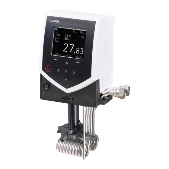
Operating and functional controls On the following pages the ECO SILVER control head, the control panel and the heating/cooling thermostat device types are presented. Control Head ECO SILVER (can be used as immersion thermostat with screw clamp) Light sensor for automatic control of display brightness Monochrome LCD display Control panel (refer to following page) Mains switch…
-
Page 17
Control panel and display ECO SILVER 30,00 °C T 73 °C DISPLAY MENU STOP Display Control panel Status display Soft keys, left and right Display of the internal or external Enter key temperature value (T or T Soft-key bar Cursor keys for Up, Down, Left and Right. -
Page 18
Rear view of Control Head ECO SILVER USB interface Upper module receptacle approx. 51 mm x 27 mm for analog, RS 232/485 module, Profibus module and contact module Lower module receptacle approx. 51 mm x 17 mm for Pt100/LiBus module Connection socket 75S for control cable of cooling underpart for RE 1050 S Rating label Connection socket 51H for power supply between the control head and cooling underpart… -
Page 19
Heating Thermostats ECO SILVER Cooling coil connections Pump connection: outflow and return (as standard only with E 4 S and ET 15 S) Four feet Mains connecting lead Rating label Bath draining tap Bath drain point 10/2019 i ECO Silver 19 / 124… -
Page 20
Viscothermostat Viscotemp 15 S Pump connector set with nipples, diameter 13 mm (plastic) (concealed) Recessed grips (right and left) Viscotemp 15 cover plate (LCZ 0731) Bath with glass windows Drain tap and draining nozzle (right side) Type plate (right side) Four feet (concealed) Viscothermostat Viscotemp 18 S 20 / 124… -
Page 21
Pump connector set with nipples, diameter 13 mm (plastic) Viscotemp 18 cover plate (LCZ 0736) Glass bath 10/2019 i ECO Silver 21 / 124… -
Page 22
Cooling Thermostats ECO SILVER Pump connection: Outflow and return with fittings 13 mm diameter (plastic) Bath cover Front grip recess Ventilation grill (both sides) Front panel (removable without tools) Four feet 22 / 124 ECO Silver 10/2019 i… -
Page 23
Rating label Control cable of cooling underpart (only with RE 1050 S) Rear grip recess Connecting lead between the control head and cooling underpart Bath draining tap Bath drain point Ventilation grill Connections for water cooling 10/2019 i ECO Silver 23 / 124… -
Page 24: Transport And Unpacking
Please immediately inform LAUDA Service Constant Temperature Equipment ( 8.7). 24 / 124…
-
Page 25
Standard accessories: Catalogue number Quantity Description Included with thermostat HDQ 168 Bath Cover E 4 E 4 S HDQ 163 Bath Cover RE 415, RE 420 RE 415 S and RE 420 S HDQ 164 Bath Cover RE 620, RE 630 RE 630 S HDQ 165 Bath Cover RE 1050… -
Page 26: Before Putting The Device Into Operation
Before putting the device into operation Please note: – The device can be operated up to an ambient temperature of 40 °C. – A higher ambient temperature can have a negative effect on the cooling output of the thermostats used. –…
-
Page 27
Operation with cooling coil For the optional operation with the cooling coil (LCZ 0720 and LCZ 0721) mount the cooling coil as follows: Cut the thread with the enclosed screw Cut the thread on the holed flange already before assembly. –… -
Page 28
Assembly as immersion thermostat Place the bath vessel on a flat surface. – The control head is already screwed to the bath bridge. – In the rear part of the bath there are two slots present on the bath edge. Guide the prongs of the bath bridge into the slots to the right and left from the rear of the bath. -
Page 29
Assembly as cooling thermostat Notice Falling / toppling equipment Property damage Do not tilt the cooling device during transport and never turn it upside down. After transport, site the device in place where possible two hours be- – fore putting it into operation so that, if necessary, oil deposits can form again and the compressor can develop its maximum power. -
Page 30
Connection of the cooling water Note that the following conditions apply for the connection of the cooling water supply: Cooling water pressure (feed — outlet) max. 10 bar overpressure Differential pressure (feed — outlet) min. 3.0 bar Cooling water temperature 10 to 15 °C recommended, 10 to 30 °C admissible with power restrictions) Cooling water quantity… -
Page 31: Connection Of External Consumers
Connection of external consumers For heating thermostats a pump connection set is available as an accessory ( 9) for the connection of an external consumer. This pump connection set is included as standard with cooling thermostats and with the heating thermostats E 4 S and ET 15 S.
-
Page 32
Turn the pump output downwards for external bath circulation. – Fit the hose section of the pump connection set onto the outflow elbow – and place the pump connections in the position of the removed blind flange. Push the holed flange under the pump connections and fasten it with –… -
Page 33
Operation as circulation thermostat To ensure the greatest volume flow, with operation as a circulation thermostat ensure the shortest possible hose connections with the largest possible hose internal diameter. Connect a hose with 11 – 12 mm inside diameter ( 6.4) –… -
Page 34: Filling And Emptying
Filling and emptying LAUDA accepts no liability for damage caused by the use of unsuitable heat transfer liquids (approved heat transfer liquids ( 6.4)). Contact with heat transfer liquid when filling / draining Harmful when inhaled, damage to eyes and skin Pay attention to the safety data sheet for the heat transfer …
-
Page 35
Draining and changing the heat transfer liquid Switch off the thermostat and withdraw the mains plug. – Allow the device and heat transfer liquid to cool down to or warm – up to room temperature. Push a hose onto the bath drain point. –… -
Page 36: Heat Transfer Liquids, Cooling Water And Hoses
Water containing iron (rust formation), chlorine (pitting) and untreated river water («algae formation») is unsuit- – able. The bath vessels of the LAUDA ECO thermostats are produced in stainless steel 1.4301 and are accordingly – resistant to mechanical and chemical stresses.
-
Page 37
When choosing the heat transfer liquid, it must be noted that at the lower limit of the operating temperature – range impairment of the heat transfer properties is to be expected due to the increasing viscosity. Therefore, on- ly use the full operating temperature range where necessary. The working ranges of the heat transfer liquids and hoses are general figures which can be tightened due to the –… -
Page 38
Suitable cooling water quality Specification Value and Unit pH – value 7.5 – 9.0 Hydrocarbonates [HCO 70 – 300 mg/L Chlorides (Cl < 50 mg/L Sulfates [SO < 70 mg/L Hydrocarbonates [HCO -] / sulfates [SO > 1.0 Total hardness 4.0 –… -
Page 39
Catalogue Type of hose diameter Application range °C number Ø mm EPDM hose For all LAUDA heat transfer 10 – 90 RKJ 111 uninsulated liquids except mineral oils EPDM hose For all LAUDA heat transfer 10 – 90 RKJ 112… -
Page 40: Cooling Of Heating Thermostats
Cooling of heating thermostats At bath temperatures slightly above the room temperature (approx. 2 – 5 K) operation is possible at a low pump level (1 or 2) without cooling. For temperatures below room temperature cooling must be used. With the immersion thermostat use a cooling coil ( 6.1). With bath and circulation thermostats the cooling coil is already built in as standard.
-
Page 41: Installation Of Modules
Installation of modules When installing modules always follow this safety information: Live parts during module installation Electric shock hazard Disconnect the device from the mains before module instal- Warning! lation. Have the installation carried out only by specialists. The ECO heating and cooling thermostats can be supplemented with interface modules which are inserted at the rear of the control head in two different module slots.
-
Page 42
Plug in the bus connecting lead (red plug in the red sock- – et). Introduce the module into the appropriate receptacle and – fasten it using the two cross-head screws. Insert the mains plug again and switch on the thermostat. –… -
Page 43: Operation
Operation Always follow this safety information: Control head drops into bath Electric shock hazard Make sure that the control head mounting is securely joined to the bath. Warning! Addition of liquids with low boiling points (e.g. water to hot oil), alter- ation of liquid properties (reducing the flash point) Explosion, burns, scalds, fire…
-
Page 44
Bath overflow due to thermal expansion or immersion of objects Burns, scalds, frostbite Take the volume of external consumers into account. Caution! Take into account the increase in volume with a rise in tem- perature. Hot vapor formation / discharge of boiling cooling-water on the cool- ing coil Burns, scalds Filling of cooling coil with cooling water only admissible up to… -
Page 45: Switching On
Switching on Switch on the device with the mains switch at the front. An acous- – tic signal sounds. The current bath temperature (T ), pump level as well as the pump – 30.00 °C Tset symbol, the set-point temperature T and the soft-key bar at the bottom edge of the display appear.
-
Page 46: Menu Structure
Menu structure With the soft keys you can select the following menu points with the SILVER control head: intern Pt100 extern Pt100 Stage 6 extern analog Stage 5 extern serial Stage 4 extern USB Stage 3 Stage 2 intern Pt100 Tv man/auto Stage 1 extern Pt100…
-
Page 47: Display Representation
Display representation The ECO thermostats offer you intuitive menu guidance. In the following the possible window views and the sym- – bols used are explained. 7.3.1 Basic window Basic window in the normal display – The following information is displayed depending on the operating –…
-
Page 48: Menu Window
7.3.2 Menu window The menu of the ECO SILVER thermostats consists of several menu levels. With the cursor keys , , , you – can call the individual menu points and select them with the enter key Symbolizes the enter key or its assigned function. –…
-
Page 49: Entry Window
7.3.3 Entry window Values are input using the entry window. In the entry window the following information is displayed: The first line contains the input parameter in short form (cf. example T Min. and Max. state the limits for the value to be entered. The value to be entered is shown in large characters.
-
Page 50: Setting The Temperature Set-Point Value
Confirm your choice with the enter key – 85 °C 29.76 °C T MAX — — — — — — On releasing you are returned to the menu level without any change. – For T the following applies: 5 Kelvin above the required maximum bath temperature, but below the flash point of the heat transfer liquid.
-
Page 51: Setting The Pump Level
7.4.3 Setting the pump level With the ECO Vario pump you have six pump levels available with which you can optimize the bath circulation, – flow rate and pressure and the mechanical heat input. With small thermostats (e.g. E 4 S, RE 415 S, RE 420 S) without an external consumer power levels 1 to 3 are practicable and sufficient.
-
Page 52: Defining Temperature Limits
7.4.5 Defining temperature limits With this function the temperature limits Til and Tih are defined. If, for example, you are using water as the heat transfer liquid, +5 °C is practicable as the minimum temperature and +95 °C as the maximum temperature. You activate the soft-key bar by pressing any key.
-
Page 53: Maintenance
Errors: If a malfunction occurs, switch off the unit at the mains switch. If the malfunction recurs after switching on the device, contact LAUDA Service Constant Temperature Equipment ( 8.6) or your local service organization. All alarms, warnings or error messages triggered on the ECO thermostat are shown in the display as text. The list with alarms and warnings can be found in the appendix (…
-
Page 54: Low Level: Alarm And Checking
Unlock the «Low Level Pump» display with – Switch the device off immediately and withdraw the mains plug if irregularities occur when checking the safety devices. Contact LAUDA Service Constant Temperature Equipment ( 8.7) or your local service. 54 / 124 ECO Silver…
-
Page 55: Device Status
Device status Here, accumulated error messages as well as device and software data can be recalled. You activate the soft-key bar by pressing any key. – Access to the main menu level is obtained by pressing the en- – ter key Error store ►…
-
Page 56: Software Version
8.2.3 Software version SW version – Control 1.53.00 confirm with – Safety 1.43 Under the menu point SW version the appropriate software versions are Cool 1.37 displayed, depending on the device type and connected modules. Ext Pt 1.35 Analog 3.15 …
-
Page 57: Servicing
Servicing Follow all the safety information for cleaning and servicing the device. Critical temperature of device parts, heat transfer liquid or accesso- ries (hoses) Burns, scalds, frostbite Bring the device parts, accessories and heat transfer liquid to room temperature before touching them. Caution! Have repairs carried out only by a specialist.
-
Page 58: Servicing Intervals
8.3.2 Servicing intervals Device part Mandatory for initial operation Section Remarks and before any longer unsuper- vised operation, then with rec- ommended frequency Complete device External condition of device Monthly Heat transfer liquid Inspecting the heat transfer liquid Every six months (…
-
Page 59: Cleaning The Condenser
8.3.4 Cleaning the condenser 8.3.4.1 Air-cooled condenser The cooling circuit is largely maintenance-free. Remove dust and contamination from the condenser at regular intervals (depending on operating period and exposure conditions). To do this, remove the front grille by grasping it at the –…
-
Page 60
Continue the pump stage until most of the foamy reaction, usually at the start, has decayed. Generally, this is achieved after about 20 to 30 minutes. Decalcifier LAUDA article number: LZB 126 (5 kg) When handling the chemicals, the safety information and the instructions for use on the package are to be followed. -
Page 61: Fault Finding
Fault finding Before you contact the LAUDA Service Constant Temperature Equipment ( 8.7), check whether you can rectify the problem yourself with the following instructions. In doing so, follow all this safety information: Live parts when fault finding Electric shock hazard Disconnect the device from the mains before the repair (e.g.
-
Page 62: Disposal Information
Disposal information The following applies for EU member states: The disposal of the device is regulated by EC Directive 2012/19/EU (WEEE Waste of Electrical and Electronic Equipment). 8.5.1 Disposal of the refrigerant Type and amount of the refrigerant used are stated on the rating label. Repair and disposal are only to be carried out by specialists.
-
Page 63: Ordering Replacement Parts / Lauda Service
Phone: +49 (0)9343 503-350 (English and German) Fax: +49 (0)9343 503-283 e-mail service@lauda.de We are available at any time for queries and ideas! LAUDA DR. R. WOBSER GMBH & CO. KG Pfarrstraße 41/43 97922 Lauda-Königshofen Germany Phone: +49 (0)9343 503-0…
-
Page 64: Accessories
Accessories Please take catalogue numbers for accessories from the following table. Immersion thermostat Accessories Suitable for Catalogue number ECO SILVER, Cooling coil set (small) LCZ 0720 bath vessels up to 6 liters ECO SILVER, Cooling coil set (large) LCZ 0721 bath vessels from 6 liters Pump connection set (outflow and return nozzles) with fitting 13 mm ECO SILVER…
-
Page 65
Cooling thermostats Accessories Suitable for Catalogue number Pump connection set (outflow and return nozzles) with thread All cooling thermostats LCZ 0717 M16 x 1 (stainless steel) Viscothermostats Accessories Suitable for Catalogue number BL 15 backlight Viscotemp 15 LCZ 9738 BL 24 backlight Viscotemp 24, 40 LCZ 9739 ET 15 cooling coil set… -
Page 66: Technical Data And Graphs
Technical data and graphs The figures were determined according to DIN 12876. Data applicable to all ECO SILVER thermostats Ambient temperature range °C 5 – 40 Relative humidity Maximum relative humidity 80% at 31 °C and decreasing linearly to 50% up to 40 °C. Contamination level Setting resolution ±0.01…
-
Page 67
Immersion thermostats ECO SILVER 230 V 220 V 115 V 100 V Working temperature range °C 20 – 200 Working temperature range with water cooling °C 20 – 200 Operating temperature range °C -20 – 200 Temperature stability ±0.01 Heater rating Heater surface loading… -
Page 68
Heating thermostats with stainless steel bath E 4 S E 10 S E 20 S E 25 S E 40 S Working temperature range °C 20 – 200 Working temperature range with water °C 20 – 200 cooling Operating temperature range °C -20 –… -
Page 69
Heating thermostats with transparent bath ET 6 S ET 12 S ET 15 S ET 20 S Working temperature range °C 20 – 100 Working temperature range with water cooling °C 20 – 100 Operating temperature range °C -20 –… -
Page 70
Viscothermostats Viscotemp 18 S 15 S 24 S 40 S Working temperature range °C 30 – 105 Operating temperature range °C 0 – 105 Temperature stability ±0.01 Bath volume 16.5 – 18.5 16 – 19 22.5 – 27 37.5 –… -
Page 71
Cooling thermostats (1) RE 415 S RE 415 SW RE 420 S RE 630 S Operating temperature, ACC * °C -15 – 200 -15 – 200 -20 – 200 -30 – 200 Ambient temperature range °C 5 – 40 Temperature stability ±0.02 Maximum storage temperature °C… -
Page 72
Cooling thermostats (2) RE 1225 S RE 2025 S RE 1050 S Operating temperature, ACC * °C -25 – 200 -25 – 200 -50 – 200 Ambient temperature range °C 5 – 40 Temperature stability ±0.02 Maximum storage temperature °C Cooler 20 °C 10 °C… -
Page 73
Refrigerant and Filling quantity The cooling thermostat contains fluorinated greenhouse gases. RE 415 S Unit RE 420 S RE 630 S RE 415 SW Refrigerant R-134a R-134a R-134a maximum filling quantity 0.065 0.063 0.075 1430 1430 1430 (100a) equivalent Unit RE 1225 S RE 2025 S RE 1050 S… -
Page 74
Pump characteristic ECO Pump characteristics Pumpenkennlinien measured with water Stage 6 gemessen mit Wasser Stage 5 Stage 4 Stage 3 Stage 2 Stage 1 Förderstrom [L/min] Flow rate in L/min Heating curve for ECO SILVER heating thermostats (230 V; 50/60 Hz) with transparent bath ET 6 S ET 12 S ET 15 S… -
Page 75
Heating curve for ECO SILVER heating thermostats (230 V; 50/60 Hz) with stainless steel bath E 10 S E 20 S E 4 S E 25 S Heat transfer liquid: Therm 240, bath closed Heating time in h:min Cooling curves for ECO cooling thermostats Heat transfer liquid: Ethanol, bath closed… -
Page 76: Index
Index Emptying …………….34 Entry window …………..49 Accessories ……………. 64 Error ………………. 53 Acoustic signals …………..82 Error messages …………..53 Alarms …………..53, 54, 87 Error store …………….55 Ambient temperature …………66 EXT ………………30 Analog module …………15, 103 External consumer …………
-
Page 77
Maintenance …………..53 Set-point, bath temperature ……….50 Menu structure …………..46 Soft key …………….17 Menu window …………..48 Software version …………..56 Standby …………….51 Starting mode …………..83 Offset, temperature sensor ……….84 Operating controls …………16 Operation ……………. -
Page 78
78 / 124 ECO Silver 10/2019 i… -
Page 79
10/2019 i ECO Silver 79 / 124… -
Page 80
Appendix with settings 80 / 124 ECO Silver 10/2019 i… -
Page 81: Aother Settings
The adjustments described in this appendix are only intended for specially qualified personnel. Other settings Resetting to factory settings You activate the soft-key bar by pressing any key. – Access to the main menu level is obtained by pressing the enter –…
-
Page 82: Setting The Volume Of The Acoustic Signals
Setting the volume of the acoustic signals The ECO SILVER thermostats sound alarms and faults as a two-tone acoustic signal. Warnings a signaled as a contin- uous tone, You activate the soft-key bar by pressing any key. – Access to the main menu level is obtained by pressing the enter –…
-
Page 83: Setting The Display Brightness
Setting the display brightness The ECO range of thermostats have a sensor which automatically adapts the display brightness according to the ambi- ent light level. However, the automatic adaptation can be deactivated and the brightness set manually. You activate the soft-key bar by pressing any key. –…
-
Page 84: Entering The Offset Of The Displayed Temperature (Calibration)
(ESC) you are returned to the menu level without any change. – Entering the offset of the displayed temperature (calibration) Deviations to the calibrated reference thermometers (e.g. LAUDA DigiCal) can be corrected internally by the «Off- set» function. You activate the soft-key bar by pressing any key.
-
Page 85: Restoring The Factory Setting Of The Internal Temperature Sensor (Factory Calibration)
Restoring the factory setting of the internal temperature sensor (factory calibration) If the offset has been adjusted, the factory setting can be restored again. You activate the soft-key bar by pressing any key. – Access to the main menu level is obtained by pressing the en- –…
-
Page 86: Key Lock
Key lock The entry key and arrow keys on the control panel on the device can be locked. This can be done directly using the control keys on the device or by using write commands provided by an interface module (for example RS 232/485 module, Ethernet USB module, or contact module).
-
Page 87: Blist Of «Alarm And Warning Codes
List of «Alarm and warning codes» Alarms Alarm code Meaning Low Level Pump Pump runs too fast (low level) Low Level Pump Low level in the float Overtemperature Overtemperature (T > Tmax) Pump blocked Pump blocked (standstill) Connection Command Remote control unit command triggered in running operation T ext Pt100 External Pt100 actual value is not present.
-
Page 88
RTC wrong data Internal clock defective valve sm0 break Cable of injection valve 0 defective wrong net voltage Incorrect mains voltage setting valve sm1 break Cable of injection valve 1 defective no eco type Device type not configured valve sm2 break Cable of injection valve 2 defective no eco voltage Mains voltage not configured… -
Page 89
Code 4XX Analog module Meaning Code 5XX Serial Meaning (RS 232/485) CAN receive overf Overflow during CAN reception CAN receive overf Overflow during CAN reception Watchdog Reset Watchdog reset Watchdog Reset Watchdog reset Unknown Modul Unknown module connected Unknown Modul Unknown module connected SW control too old Software version of control panel too old… -
Page 90
Code 6XX Switch contacts Meaning Code 7, 8, 9, 10, 11, Meaning 16XX Solenoid valve SW HTC old Software version of high temperature SW Valve 3 old Software version of solenoid valve 3 too cooler too old SW Ext Pt100 old Software version of external Pt100 too SW Valve 4 old Software version of solenoid valve 4 too… -
Page 91: Cexternal Control
External control The devices can also be optionally controlled via an external Pt100 temperature sensor, which can be connected at the back of the control head. It is necessary to install an external Pt100/LiBus module ( F) for external control. The module is available as an accessory (…
-
Page 92: Setpoint Offset Operating Mode (Diff.set/Actual)
Setpoint offset operating mode (Diff.set/actual) It is possible to apply an offset value to the temperature, which is provided by an external temperature sensor and to process it as the set value. The bath temperature can therefore be operated, for example, -15 °C below the temperature of a reactor measured by the external temperature sensor.
-
Page 93: Dprogrammer
Programmer The programming function enables you to save a temperature/time programs. The program consists of a number of temperature/time segments and details about their repetition. The total number of freely programmable segments is 20. Temperature step changes (time is zero) or also temperature retention phases for the same start and end temperatures in the segment are possible.
-
Page 94: Creating And Editing A Program
The tolerance entry can have a large effect with external bath control. The adjacent graph of the edited trace shows the possible run-on of the actual temperature in the bath vessel (continuous line) for the set-point temperature of the programmer (highlighted in gray). Note: …
-
Page 95
Creating and editing a program: Compare the programming example ( 11.8) You access the editor view of the programmer by selecting and – Tend hh:mm Tol. confirming Programmer Edit. To view the complete win- 35.00 —:— dow information go to the right with . 40.00 00:10 With the keys , ,… -
Page 96: Starting The Program
With go to the segment to be deleted. – – Tend hh:mm Tol. The new segment is removed on pressing (delete). – 35.00 —:— 40.00 00:10 50.00 00:20 70.00 00:50 NEW DELETE Starting the program You activate the soft-key bar by pressing any key. –…
-
Page 97: Defining The Number Of Program Loops (Loops)
To continue a program held by Hold Select the option Continue with or . Continue – Stop Confirm your choice with the enter key – OK STOP Also (STOP) holds the programmer. Pump, heating and chiller are switched off. –…
-
Page 98: Econtrol Parameters
Control parameters The control parameters have been optimized at the factory for operation as a bath thermostat (with water as the heat transfer liquid) with internal control. The standard parameters are already set as default also for the thermostatic control of external applications with external control. Depending on the application, the configuration can be adapted from case to case as required.
-
Page 99: External Control Variable
External control variable The setting options illustrated in this section are only possible with a connected external temperature sensor or with an existing module (as activated as control variable in Section C) for reading in the actual temperature. The control system for external actual values is realized as a two-stage cascade controller to improve the response to setpoint changes.
-
Page 100: Setting The Correcting Quantity Limit
Access to the main menu level is obtained by pressing the enter – Selection and confirmation of Setup Control – Contr.parameter extern Pt100. Tv man/auto 280 (a) The adjacent menu window appears. Apart from the control parameters the currently set values are displayed.
-
Page 101: Procedure For Setting The Control Parameters For External Control
E.2.2 Procedure for setting the control parameters for external control Activating external control ( B.1). Set the slave controller: 2.1. Parameter to auto Xpf in dependence of: Check or adjust device type ( 8.2.4). Select heat transfer liquid with as low-viscosity and with as high a thermal capacity as possible. Ranking list: Water, water/glycol, oils, Fluorinert®.
-
Page 102: Finterface Modules
Interface modules Menu structure of the modules All existing menu points are shown. Modules and menu points which cannot be realized are however masked out. Set-point temperature Calibration external actual temperature Factory calibration Pump power Status Job function Voltage 0-10V closed Interface type Current 0-20mA…
-
Page 103: Analog Module
Analog module Analogue Module (LAUDA catalogue no. LRZ 912) has two inputs and two outputs, which are brought out to a six-pole DIN socket to Namur Recom- mendation (NE28). The inputs and outputs can be set independently of one another as a 0 –…
-
Page 104: Rs 232/485 Interface Module
RS 232/485 interface module RS 232/485 Interface Module (catalogue no. LRZ 913) with nine-pole SUB- D socket. Electrically isolated using optocouplers. With the LAUDA instruction set, extensively compatible to Ecoline, Proline and Integral series. The RS 232 interface can be connected directly to the PC with a 1:1 con- nected cable (catalogue no.
-
Page 105: Rs 232 Protocol
95/98/NT/XP using the program «HyperTerminal». “HyperTerminal” is no longer part of the operating system in Windows Vista, Windows 7, Windows 8 and Win- dows 10. With the LAUDA software “Wintherm Plus” (catalogue number LDSM2002) the RS 232 interface can – be addressed.
-
Page 106: Rs 485 Protocol
LiBus module LiBus module (catalogue number LRZ 920) has a socket (70S) for con- nection of components via the LAUDA device bus LiBus (Command re- mote control, shut down/reverse flow protection, cooling water valve). LiBus = LAUDA internal device bus (CAN based) For extension cord for LiBus, see accessories (…
-
Page 107: Pt100/Libus Module
The Pt100/LiBus module (catalogue no. LRZ 918) has two sockets. A Lemo socket (10S) to connect an external Pt100 temperature probe und a socket (70S) for connection of components via the LAUDA device bus LiBus (Command remote control, shut down/reverse flow protection, cooling-liquid valve).
-
Page 108: Usb Interface
The connecting lead is not included in the items supplied. When connecting up, make sure the correct plug is used. USB interface LAUDA makes the drivers specially produced for the USB interface available free of charge for download at http://www.lauda.de. F.6.2 Installation of the USB driver The driver is installed once per PC.
-
Page 109: Connecting The Thermostat To The Pc
2. Key Continue 3. Key Finish Driver installation is installed F.6.3 Connecting the thermostat to the PC If an ECO thermostat is connected via the USB interface, it is automatically assigned to a free COM port. The PC unambig- uously identifies the thermostat via a serial number internal to the thermostat and always assigns the same COM port to this thermostat.
-
Page 110
instructions. 3. Key Continue 4. Key Continue This window is covered by the following window «Hardware installation» (see below); 110 / 124 ECO Silver 10/2019 i… -
Page 111
5. Click on Continue installation . 6. Click on the key Finish . 10/2019 i ECO Silver 111 / 124… -
Page 112: Where Is The Eco Virtual Com Port
F.6.4 Where is the ECO Virtual COM Port? The thermostat can be operated via conventional communication programs (e.g. HyperTerminal) as a COM port. Further settings, such as baud rate, are not needed. Click on the tab with the mouse and then on Device manager .
-
Page 113
10/2019 i ECO Silver 113 / 124… -
Page 114: Commands And Error Messages Applicable To The Rs
Commands and error messages applicable to the RS 232/485 interface module and to the Ethernet interface F.7.1 Interface write commands (data issued to the thermostat) Command Meaning OUT_PV_05_XXX.XX Specify external temperature via interface OUT_SP_00_XXX.XX Set-value transfer with max. 3 places before the decimal point and max. 2 places after it. OUT_SP_01_XXX Pump power level 1 to 6 OUT_SP_02_XXX…
-
Page 115: Interface Read Commands
For ”_“ ” ” (space character) is also admissible. – Response from thermostat «OK» or with an error » ERR_X“ (RS 485 interface e.g. – “A015_OK” or with an error ”A015_ERR_X”.) The command from the computer must be terminated with a CR, CRLF or LFCR. –…
-
Page 116
Command Meaning IN_DO_01 Status of Contact Output 1: 0 = NO contact open/ 1 = NO contact closed. IN_DO_02 Status of Contact Output 2: 0 = NO contact open/ 1 = NO contact closed. IN_DO_03 Status of Contact Output 3: 0 = NO contact open/ 1 = NO contact closed. -
Page 117: Interface Error Messages
ECO devices. In order to be able to address from the program the ® RS 232/485 interface that is used LAUDA makes the drivers specially produced for LABVIEW available free of charge for download at http://www.lauda.de.
-
Page 118
The inputs provide the following functions: Error Set error – Standby Set standby – Control programmer Control programmer (Input 1 activates the programmer. The programmer is started – on the first «closed» and is put into «hold» on «open». The next «Close» triggers «Continue») with the function. Change mode Control change mode (the switching statuses of contact «Open»… -
Page 119: Contact Module Lrz 915 With 3 Inputs And 3 Outputs
F.8.2 Contact module LRZ 915 with 3 inputs and 3 outputs Contact module (catalogue no. LRZ 915) with 15-pole SUB-D socket. Range of func- tions as LRZ 914, but with three relay contact outputs (changeover, max. 30 V/0.2 A) and three binary inputs for control via external voltage-free contacts. Contact Module LRZ 915;…
-
Page 120
Blank page 120 / 124 ECO Silver 10/2019 i… -
Page 121
Blank page 10/2019 i ECO Silver 121 / 124… -
Page 122
122 / 124 ECO Silver 10/2019 i… -
Page 123
EC DECLARATION OF CONFORMITY Manufacturer: LAUDA DR. R. WOBSER GMBH & CO. KG Pfarrstrasse 41/43 97922 Lauda-Königshofen Germany We hereby declare under our sole responsibility that the machines described below Product Line: Serial number: from S190000001 Types: E 4 S, E 4 G, E 10 S, E 10 G, E 20 S, E 20 G, E 25 S, E 25 G, E 40 S, E 40 G… -
Page 124
EC DECLARATION OF CONFORMITY Manufacturer: LAUDA DR. R. WOBSER GMBH & CO. KG Pfarrstrasse 41/43 97922 Lauda-Königshofen Germany We hereby declare under our sole responsibility that the machines described below Product Line: Serial number: from S190000001 Types: RE 415 S, RE 415 G, RE 415 SW, RE 415 GW, RE 420 S, RE 420 G,… -
Page 128
LAUDA DR. R. WOBSER GMBH & CO. KG Pfarrstraße 41/43 ◦ 97922 Lauda-Königshofen ◦ Germany Tel.: +49 (0)9343 503-0 ◦ Fax: +49 (0)9343 503-222 E-mail: info@lauda.de ◦ Internet: www.lauda.de…
Standard accessories:
Catalogue number
HDQ 168
HDQ 163
HDQ 164
HDQ 165
HDQ 166
HDQ 167
LCZ 0716
LCZ 0720
LCZ 0721
EZB 260
YACE0087
10/2019 i
Quantity Description
1
Bath Cover E 4
1
Bath Cover RE 415, RE 420
1
Bath Cover RE 620, RE 630
1
Bath Cover RE 1050
1
Bath Cover RE 1225
1
Bath Cover RE 2025
1
Pump Connection Set
1
Cooling Coil
1
Cooling Coil
1
Warning Label «HOT»
1
Operating instructions
Included with thermostat
E 4 S
RE 415 S and RE 420 S
RE 630 S
RE 1050 S
RE 1225 S
RE 2025 S
Cooling thermostats; E 4 S, ET 15 S,
Viscotemp
E 4 S, ET 6 S
E 10 S, E 20 S, E 25 S, E 40 S,
ET 12 S, ET 20 S
All thermostats
Note: With applications above 70 °C attach
the warning label at an easily visible point.
All thermostats
ECO Silver
25 / 124
Table of Contents for Lauda ECO Silver E 4 S:
-
94 / 124 ECO Silver 10/2019 i The tolerance entry can have a large effect with external bath control. The adjacent graph of the edited trace shows the possible run-on of the actual temperature in the bath vessel (continuous line) for the set-point temperature of the programmer (highlighted in gray). Note: The tolerance field facilitates exact conformance to the dwell time at a specified temperature. The fol- lowing segment is only processed when the actual temperat
-
10/2019 i ECO Silver 117 / 124 – Note: – For ”_“ ” ” (space character) is also admissible. – Unless otherwise stated with the command, the response from the thermostats is always in the fixed-point format «XXX.XX» or «-XXX.XX» for negative values or «ERR_X». (RS 485 interface e.g. ”A015_XXX.XX” or ”A015_-XXX.XX” or ”A015_ERR_X”). – The command from the computer must be terminated with a CR, CRLF or LFCR. – The response from the thermostat is al
-
10/2019 i ECO Silver 7 / 124 D.3 STARTING THE PROGRAM ………………………………………………………………………………………………………………………………….. 96 D.4 INTERRUPTING, CONTINUING OR TERMINATING THE PROGRAM …………………………………………………………………………… 96 D.5 DEFINING THE NUMBER OF PROGRAM LOOPS (LOOPS) ……….
-
68 / 124 ECO Silver 10/2019 i Heating thermostats with stainless steel bath E 4 S E 10 S E 20 S E 25 S E 40 S Working temperature range °C 20 – 200 Working temperature range with water cooling °C 20 – 200 Operating temperature range °C -20 – 200 Temperature stability K ±0.01 Bath volume liters 3 – 3.5 7.5 – 10 13 – 19 16 – 25 32 – 40 Bath vessels Inner tank in deep-drawn stainless steel 1.4301 conforming to SAE 30304
-
10/2019 i ECO Silver 25 / 124 Standard accessories: Catalogue number Quantity Description Included with thermostat HDQ 168 1 Bath Cover E 4 E 4 S HDQ 163 1 Bath Cover RE 415, RE 420 RE 415 S and RE 420 S HDQ 164 1 Bath Cover RE 620, RE 630 RE 630 S HDQ 165 1 Bath Cover RE 1050 RE 1050 S HDQ 166 1 Bath Cover RE 1225 RE 1225 S HDQ 167 1 Bath Cover RE 2025 RE 2025
-
122 / 124 ECO Silver 10/2019 i
-
10/2019 i ECO Silver 29 / 124 Assembly as cooling thermostat Notice Falling / toppling equipment Property damage Do not tilt the cooling device during transport and never turn it upside down. – After transport, site the device in place where possible two hours be- fore putting it into operation so that, if necessary, oil deposits can form again and the compressor can
-
10/2019 i ECO Silver 95 / 124 Creating and editing a program: Compare the programming example ( 11.8) – You access the editor view of the programmer by selecting and confirming Programmer Edit. To view the complete win- dow information go to the right with . – With the keys , , and you obtain access to the individual segment fields. – If the cursor is located in the first column, the funct
-
6 / 124 ECO Silver 10/2019 i 8 MAINTENANCE ………………………………………………………………………………………………………………………………………………….. 53 8.1 ALARMS, WARNINGS AND ERRORS ……………………………………………………………………………………………………………………. 53 8.1.1 Overtemperature protection: Alarm and checking ………….
-
32 / 124 ECO Silver 10/2019 i – Turn the pump output downwards for external bath circulation. – Fit the hose section of the pump connection set onto the outflow elbow and place the pump connections in the position of the removed blind flange. – Push the holed flange under the pump connections and fasten it with two cross-head screws to the underside of the control head. Holed flange – Use the flat seal. Make sure the seal is in the correct positio
-
10/2019 i ECO Silver 83 / 124 The ECO range of thermostats have a sensor which automatically adapts the display brightness according to the ambi- ent light level. However, the automatic adaptation can be deactivated and the brightness set manually. – You activate the soft-key bar by pressing any key. – Access to the main menu level is obtained by pressing the en- ter key . – Selection and confirmation of Setup Basic se
-
110 / 124 ECO Silver 10/2019 i instructions. 3. Key Continue 4. Key Continue This window is covered by the following window «Hardware installation» (see below);
-
112 / 124 ECO Silver 10/2019 i The thermostat can be operated via conventional communication programs (e.g. HyperTerminal) as a COM port. Further settings, such as baud rate, are not needed. Click on the tab with the mouse and then on the Device manager . F.6.4 Where is the ECO Virtual COM Port?
Questions, Opinions and Exploitation Impressions:
You can ask a question, express your opinion or share our experience of Lauda ECO Silver E 4 S device using right now.
|
Detail Specifications: 1922/1922656-eco_silver_e_4_s.pdf file (14 Feb 2023) |
Accompanying Data:
Lauda ECO Silver E 4 S Thermostat PDF Operation Manual (Updated: Tuesday 14th of February 2023 06:10:18 AM)
Rating: 4.6 (rated by 45 users)
Compatible devices: L 100, Alpha, Ecoline Series, RE 212 J, PROLINE Kryomats Series, PTT, RM 6 T, E 4 G.
Recommended Documentation:
Text Version of Operation Manual
(Ocr-Read Summary of Contents, UPD: 14 February 2023)
-
14, Lauda ECO Silver E 4 S 14 / 124 ECO Silver 10/2019 i 3 Device description 3.1 Device types Heating thermostats The type designation of the LAUDA heating thermostats is composed of the prefix E for ECO, the approximate bath volume in liters and an S for the SILVER device variant. Example: E 10 S is a heating thermostat with a maximum bath volume of 10 liters in the SILVER device var…
-
92, 92 / 124 ECO Silver 10/2019 i It is possible to apply an offset value to the temperature, which is provided by an external temperature sensor and to process it as the set value. The bath temperature can therefore be operated, for example, -15 °C below the temperature of a reactor measured by the external temperature sensor. – You a…
-
65, 10/2019 i ECO Silver 65 / 124 Cooling thermostats Accessories Suitable for Catalogue number Pump connection set (outflow and return nozzles) with thread M16 x 1 (stainless steel) All cooling thermostats LCZ 0717 Viscothermostats Accessories Suitable for Catalogue number BL 15 backlight Viscotemp 15 LCZ 9738 BL 24 backlight Visc…
-
23, 10/2019 i ECO Silver 23 / 124 1 Rating label 2 Control cable of cooling underpart (only with RE 1050 S) 3 Rear grip recess 4 Connecting lead between the control head and cooling underpart 5 Bath draining tap 6 Bath drain point 7 Ventilation grill 1 Connections for water cooling 1 2 3 5 6 7 4 1 1 …
-
6, 6 / 124 ECO Silver 10/2019 i 8 MAINTENANCE ………………………………………………………………………………………………………………………………………………….. 53 8.1 ALARMS, WARNINGS AND ERRORS ……………………………………………………………………………………………………..…
-
37, 10/2019 i ECO Silver 37 / 124 – When choosing the heat transfer liquid, it must be noted that at the lower limit of the operating temperature range impairment of the heat transfer properties is to be expected due to the increasing viscosity. Therefore, on- ly use the full operating temperature range where necessary. – The working ranges of the heat transfer…
-
103, 10/2019 i ECO Silver 103 / 124 Analogue Module (LAUDA catalogue no. LRZ 912) has two inputs and two outputs, which are brought out to a six-pole DIN socket to Namur Recom- mendation (NE28). The inputs and outputs can be set independently of one another as a 0 – 20 mA, 4 – 20 mA or 0 – 10 V interface; Various functions can be selected for the inputs a…
Recommended Instructions:
Planar DC/DC Transformer RM8, VPLFH31/B, SP-8000, CDE-103BT, MC40


-
Chromalox®DIVISION 4 SECTION GNITSALESREFERENCEDATESERVICE REFERENCEInstallation InstructionsPK479-3161-506172-001AUGUST, 2006(Supersedes PK479-2)© 2010 Chromalox, Inc.Model PCNTemperatureVoltsMax CapillaryStockRange (˚F) Amps. Length (Ft.)GNIT-5 360946 30 to 220 120/240 25 5 SGNIT-12 360954 30 to 220 120/240 25 12 SSpecifications —Other temper …
GNIT-5 2
-
CM901 — User Guide1 day ProgrammableRoom ThermostatHoneywell Control Systems Ltd.Arlington Business Park,BracknellBerkshireRG12 1EBTechnical Help Desk: 08457 678999www.honeywelluk.com42010943-103 R1© 2005 Honeywell International Inc.DescriptionThe Honeywell CM901 is a programmable room thermostat designed to control your heating system efciently, providing …
CM901 18
-
Installation and operating instructions for theSiemens RWB27 Timeswitch.Programme ChoiceTo enable you to select the programme most suitable for your needs weoffer a choice of 3 programmes.Daily; Which means the unit will come ON and go OFF at the same timeseach day.Weekday/Weekend; Which means the unit can be altered for weekdays andweekends.7 Day; Which means the unit can be set …
RWB27 Timeswitch 8
Additional Information:
Popular Right Now:
Operating Impressions, Questions and Answers:
Центр загрузок
Найдите информацию, документацию, руководства по эксплуатации и программное обеспечение для ваших изделий LAUDA. Высокое качество продукции и широкий спектр услуг по обслуживанию для компании LAUDA неразрывно связаны между собой.