On this page you can free download service and owner’s manuals in PDF for Honda outboard motors.
![]()
Honda 75 Owner’s Manual [ENG] PDF
Honda 75 Owner’s Manual eng.pdf
Adobe Acrobat Document
5.5 MB
![]()
Honda BF2D/2.3D Owner’s Manual [ENG] PDF
Honda BF2D_2.3D Owner’s eng.rar
compressed file archive
7.9 MB
![]()
Honda BF2D/2.3B Owner’s Manual [RUS] PDF
Honda BF2D_2.3B Owner’s rus.pdf
Adobe Acrobat Document
1.6 MB
![]()
Honda BF4.5/5A Owner’s Manual [ENG] PDF
Honda BF4.5B_5A owner eng.rar
compressed file archive
15.8 MB
![]()
Honda BF4.5D/5A Owner’s Manual [RUS] PDF
Honda BF4.5BD_5A owners rus.pdf
Adobe Acrobat Document
5.9 MB
![]()
Honda BF8A Owner’s Manual [ENG] PDF
Honda BF8A Owner’s eng.pdf
Adobe Acrobat Document
1.6 MB
![]()
Honda BF8D/9.9D/10D/15A/15D/20/20D, BFP8D/9.9D/15D/20D Owner’s Manual [ENG] PDF
Honda BF8D_9.9D_10D_15A_15D_20_20D_ BFP8
compressed file archive
36.3 MB
![]()
Honda BF25A/25D/30A/30D Owner’s Manual [ENG] PDF
Honda BF25A_25D_30A_30D eng.rar
compressed file archive
22.7 MB
![]()
Honda BF40A/50A Owner’s Manual [RUS] PDF
Honda BF40A_50A rus.pdf
Adobe Acrobat Document
2.1 MB
![]()
Honda BF40A/BF50A Owner’s Manual [ENG] PDF
Honda BF40A_BF50A Owner’s eng.pdf
Adobe Acrobat Document
7.4 MB
![]()
Honda BF5A Owner’s Manual [ENG] PDF
Honda BF5A Owner’s eng.pdf
Adobe Acrobat Document
4.7 MB
![]()
Honda BF8B/8D/10B/10D/15D/20D Owner’s Manual [RUS] PDF
Honda BF8B_8D_10B_10D_15D_20D rus.pdf
Adobe Acrobat Document
4.1 MB
![]()
Honda BF8D/BF9.9D Owner’s Manual [ENG] PDF
Honda BF8D_BF9.9D Owner’s eng.pdf
Adobe Acrobat Document
3.3 MB
![]()
Honda BF25D/30D Owner’s Manual [RUS] PDF
Honda BF25D_30D rus.pdf
Adobe Acrobat Document
4.0 MB
![]()
Honda BF35A/40A/40D/45A/50/50A/50D Owner’s Manual [ENG] PDF
Honda BF35A_40A_40D_45A_50_50A_50D.rar
compressed file archive
33.1 MB
![]()
Honda BF40D/50D Owner’s Manual [RUS] PDF
Honda BF40D_50D rus.pdf
Adobe Acrobat Document
8.7 MB
![]()
Honda BF40D/BF50D Owner’s Manual [ENG] PDF
Honda BF40D_BF50D Owner’s eng.pdf
Adobe Acrobat Document
4.8 MB
![]()
Honda BF60A/BFP60A Owner’s Manual [RUS] PDF
Honda BF60A_BFP60A rus.rar
compressed file archive
4.8 MB
![]()
Honda BF75A/90A Owner’s Manual [ENG] PDF
Honda BF75A_90A eng.pdf
Adobe Acrobat Document
9.5 MB
![]()
Honda BF90D Owner’s Manual [ENG] PDF
Honda BF90D Owner’s eng.pdf
Adobe Acrobat Document
5.7 MB
![]()
Honda BF115A/115D/130A/135A/150A Owner’s Manual [ENG] PDF
Honda BF115A_115D_130A_135A_150A eng.rar
compressed file archive
32.3 MB
![]()
Honda BF135A/150A Owner’s Manual [RUS] PDF
Honda BF135A_150A rus.pdf
Adobe Acrobat Document
3.5 MB
![]()
Honda Marine BF200/225 Service Manual [ENG] PDF
Honda BF200_225 Marine Service eng.pdf
Adobe Acrobat Document
200.1 KB
![]()
Honda BF60A/BFP60A Owner’s Manual [ENG] PDF
Honda BF60A_BFP60A eng.pdf
Adobe Acrobat Document
4.4 MB
![]()
Honda BF75/75A/75D/90A/90D/100 Owner’s Manual [ENG] PDF
Honda BF75_75A_75D_90A_90D_100 eng.rar
compressed file archive
58.0 MB
![]()
Honda BF75D/90D Owner’s Manual [RUS] PDF
Honda BF75D_90D rus.pdf
Adobe Acrobat Document
7.7 MB
![]()
Honda BF115A/BF130A Workshop Manual [ENG] PDF
Honda BF115A, BF130A Workshop eng.pdf
Adobe Acrobat Document
14.0 MB
![]()
Honda BF115A/139A Owner’s Manual [RUS] PDF
Honda BF115A_130A rus.pdf
Adobe Acrobat Document
4.8 MB
![]()
Honda BF174A/200A/225A Owner’s Manual [RUS] PDF
Honda BF175A_200A_225A rus.pdf
Adobe Acrobat Document
3.5 MB
![]()
Honda BF200A/225A Owner’s Manual [ENG] PDF
Honda BF200A_225A eng.rar
compressed file archive
13.7 MB
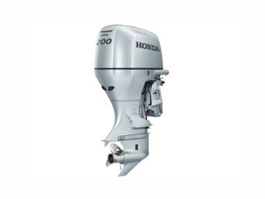
Honda Company is engaged not only in the production and sale of machinery, boats, but also in the manufacture of boat motors and all kinds of boat products and accessories for
boats, yachts and catamarans. Today, it is one of the world leaders in this field, constantly presenting to customers the updated product lines of its products.
Having been on the boat market for several decades, Honda outboard motors managed to win numerous fans. These motors are distinguished by their very reliable uninterrupted work, which no one has
yet complained about. On the contrary, Honda engines, as boatmen note, are capable of serving a very long time. Sometimes even for several decades.
The company produces both two-stroke and four-stroke outboard motors. Most of all, of course, are the four-stroke outboard motors of this brand. They are the most powerful, safe and reliable boat
engines today. The Honda 4-stroke outboard motor is distinguished by its special reliability and practicality in use.
Руководство на английском языке по эксплуатации и техническому обслуживанию гидроциклов Honda ARX1200T2/N2 и Aquatrax R-12X/R-12 2005 года выпуска.
- Год издания: —
- Страниц: 252
- Формат: PDF
- Размер: 2,8 Mb
Руководство по эксплуатации и техническому обслуживанию подвесных лодочных моторов Honda BF2D и BF2.3B.
- Год издания: 2004
- Страниц: 71
- Формат: PDF
- Размер: 1,6 Mb

Сборник руководство на английском языке по эксплуатации и техническому обслуживанию подвесных лодочных моторов Honda BF2D и BF2.3D.
- Год издания: 2008-2011
- Страниц: 78/87/91/91
- Формат: PDF
- Размер: 7,9 Mb
Руководство по эксплуатации и техническому обслуживанию подвесных лодочных моторов Honda BF4.5B и BF5A.
- Год издания: 2004
- Страниц: 88
- Формат: PDF
- Размер: 5,9 Mb

Сборник руководство на английском языке по эксплуатации и техническому обслуживанию подвесных лодочных моторов Honda BF4.5B и BF5A.
- Год издания: 1989-2011
- Страниц: —
- Формат: PDF
- Размер: 15,8 Mb

Руководство по эксплуатации и техническому обслуживанию подвесных лодочных моторов Honda BF8B/BF8D/BF10B/BF10D/BF15D/BF20D.
- Год издания: 2004
- Страниц: 145
- Формат: PDF
- Размер: 4,1 Mb

Сборник руководство на английском языке по эксплуатации и техническому обслуживанию подвесных лодочных моторов Honda BF8A/BF8D/BF9.9D/BF10D/BF15A/BF15D/BF20/BF20D/BFP8D/BFP9.9D/BFP15D/BFP20D.
- Год издания: 1985-2009
- Страниц: —
- Формат: PDF
- Размер: 36,3 Mb

Сборник руководство на английском языке по эксплуатации и техническому обслуживанию подвесных лодочных моторов Honda BF25A/BF25D/BF30A/BF30D.
- Год издания: 1994-2011
- Страниц: —
- Формат: PDF
- Размер: 22,7 Mb

Руководство по эксплуатации и техническому обслуживанию подвесных лодочных моторов Honda BF25D/BF30D.
- Год издания: 2004
- Страниц: 152
- Формат: PDF
- Размер: 4,0 Mb

Сборник руководство на английском языке по эксплуатации и техническому обслуживанию подвесных лодочных моторов Honda BF35A/BF40A/BF40D/BF45A/BF50/BF50A/BF50D.
- Год издания: 1985-2013
- Страниц: —
- Формат: PDF
- Размер: 33,1 Mb

Руководство по эксплуатации и техническому обслуживанию подвесных лодочных моторов Honda BF40A и BF50A.
- Год издания: 2004
- Страниц: 148
- Формат: PDF
- Размер: 2,1 Mb

Руководство по эксплуатации и техническому обслуживанию подвесных лодочных моторов Honda BF40D и BF50D.
- Год издания: 2008
- Страниц: 153
- Формат: PDF
- Размер: 8,7 Mb

Руководство по эксплуатации и техническому обслуживанию подвесных лодочных моторов Honda BF60A и BFP60A.
- Год издания: 2009
- Страниц: 151
- Формат: PDF
- Размер: 4,8 Mb

Сборник руководство на английском языке по эксплуатации и техническому обслуживанию подвесных лодочных моторов Honda BF75/BF75A/BF75D/BF90A/BF90D/BF100.
- Год издания: 1985-2013
- Страниц: —
- Формат: PDF
- Размер: 58,0 Mb
Руководство по эксплуатации и техническому обслуживанию подвесных лодочных моторов Honda BF75A и BF90A.
- Год издания: 2004
- Страниц: 140
- Формат: PDF
- Размер: 9,5 Mb
Руководство по эксплуатации и техническому обслуживанию подвесных лодочных моторов Honda BF75D и BFP90D.
- Год издания: 2006
- Страниц: 156
- Формат: PDF
- Размер: 7,7 Mb

Сборник руководство на английском языке по эксплуатации и техническому обслуживанию подвесных лодочных моторов Honda BF115A/BF115D/BF130A/BF135A/BF150A.
- Год издания: 1998-2011
- Страниц: —
- Формат: PDF
- Размер: 32,3 Mb

Руководство по эксплуатации и техническому обслуживанию подвесных лодочных моторов Honda BF115A и BF130A.
- Год издания: 2004
- Страниц: 114
- Формат: PDF
- Размер: 4,8 Mb
Руководство по эксплуатации и техническому обслуживанию подвесных лодочных моторов Honda BF135A и BFP150A.
- Год издания: 2004
- Страниц: 114
- Формат: PDF
- Размер: 3,5 Mb

Руководство по эксплуатации и техническому обслуживанию подвесных лодочных моторов Honda BF175A/BF200A/BF225A.
- Год издания: 2002
- Страниц: 110
- Формат: PDF
- Размер: 3,5 Mb

Сборник руководство на английском языке по эксплуатации и техническому обслуживанию подвесных лодочных моторов Honda BF200A и BF225A.
- Год издания: 2001/2003/2005/2013
- Страниц: 112/112/126/136
- Формат: PDF
- Размер: 13,7 Mb

SHOP MANUAL NEWS
SHOP MANUAL NEWS
SHOP MANUAL NEWS
SHOP MANUAL NEWS
SHOP MANUAL NEWS
SHOP MANUAL NEWS
BF4OA.BFSOA Paper Book Part No. 66ZV3OOU
PREFACE
This manual covers the construction, function and servicing procedures of the Honda BF40A-BF50A Outboard motors.
For service information which i s not covered in this supplement, please refer to the base shop manual
(66ZV300, 66ZV3OOZ, 66ZV3O0YI 66ZV300X, 66ZV3OOW,
66ZV300V).
CONTENTS
OUTLINE OF CHANGES
SPECIFICATIONS
SERVICE INFORMATION
MAINTENANCE
~~
All
information contained in this manual is based on the latest product information available at the time of printing. We reserve the right to make changes at any time without notice.
No part of this publication may be reproduced, stored in a retrieval system, or transmitted, in any form by any means, electronic, mechanical, photocopying, recording, or otherwise, without the prior written permission of the publisher. This includes text, figures and tables.
FUEL SYSTEM
FLWHEEIAMING BELT
0 Honda Motor Co., Ltd.
Service Publication Office
OIL PANPRIMARY GEAR CASEBWIVEL CASE
GAS ASSISTED/POWER TILT
THROlTLE BRACKETBHIFT LEVER/
HANDLEBAR (TILLER HANDLE TYPE ONLY)
ELECTRICAL EQUIPMENT
WIRING DIAGRAM
The marked sections contain no changes.
They are not covered in this manual.
Date of Issue: Sept. 2003
0 Honda Motor Co., Ltd.
OUTLINE OF CHANGES
ECT sensor installation position changed.
ECT SENSOR
BF40AmBF50A
[3]
Before change
[6] ECT switch
[611 ECT SWITCH
/
[7] Water hose joint
I811
WATER HOSE
JOINT
PI-1
WATER HOSE
JOINT
i
[9]
CDI unit
[lo] to
digital CDI unit
[l 11
Analogue CDI unit
I
I
I
1.1
2
After change
[4] Oil pressure switch [S] Connecting terminal, connection method changed.
151-1
OIL PRESSURE SWITCH
BF40AeBF50A
[3] Before change
151-2
4 x Q m m
TERMINAL SCREW
15l-3
OIL PRESSURE
SWITCH
I
[6] Power coil
[5]4 MALE CONNECTOR
p]
Change to power coil from exciter coil. ml
POWER COIL
[8] Power trimhilt assembly
[eE1
POWER TRlMmLT ASSEMBLY
M-1
I
POWER TRIMmLT ASSEMBLY
[4]
Gas assisted damper
[2] After change
BF40AeBF50A
[3] Before change
161 Inverted type
[7]
Mount frame
[5]-1 GAS ASSISTED DAMPER m-1 MOUNT FRAME
[6]-1 GAS ASSISTED DAMPER m-1 MOUNT FRAME
[8] Stern bracket
FRICTION PLATE MOUNTING SECTION
STERN
BRACKET
181-1
STERN
BRACKET
3
[4] Swivel case
141-1
STEERING FRlNCTlON STUD
INSTALLATION HOLE
~~
[5] Tiller handle
CASE
[6] Long tiller handle type added
M-1
LONG TILLER HANDLE
BF40AaBF50A
[3]
Before change
CASE
[7] Friction adjusting lever
[8] Tiller handle friction lever being added in connection with addition of the long tiller handle type
/
181-1
FRICTION PLATE
FRICTION
ADJUSTING
LEVER
4
5
[4]
Carburetor
141-2
SE THERMAL VALVE
/
BF40AaBF50A
[3] Before change
[4]-3 CHOKEVALVE
/
151 Remote control box [6] Choke switch is no longer installed.
[4]-5 CHOKE ARM [4]-4
CHOKE SOLENOID
(REMOTE CONTROL
TYPE)
161-1
CHOKE
SWITCH
[4] Fuse holder bracket [5] Newly provided.
[51-1
FUSE HOLDER BRACKET
BF40AaBF50A
[3] Before change
[5]-2
FUSE HOLDER
[5]-3
REGU LATOWRECTIFIER
BRACKET
REG U LATO
WR
BRACKET
1.
SPECIFICATIONS
I
1.
SPECIFICATIONS
2. DIMENSIONAL DRAWING
BF40AoBF50A
1.
SPECIFICATIONS
DIMENSIONS AND WEIGHTS
1
Model
Description code
Type
Overall length
Overall width
Overall height
Dry weight
(With propeller mounted)
Operating weight
Transom height
Transom angle
Tiltina anale
Trimming angle
Swivel angle
I
BF40A
SH
LH
770 mm (30.3 in)
LHT
BAYS
SR
I
SRT
685 mm (27.0 in)
1,260 mm 1,365 mm (53.7 in)
370 mm (14.6 in)
1,260 mm (49.6 in)
[
LR
1
LRT
1,365 mm (53.7 in)
(49.6 in)
96 kg tb7
95.5 kg 97.5 kg
(316 Ib)
(322 Ib)
89 kg
(294 Ib)
91 kg
(301 Ib)
91 kg
(301 Ib)
93 kg
(307 Ib)
98 kg 100 kg 91.5 kg 93.5 kg 93.5 kg 95.5 kg
(31 7 Ib) (324 Ib) (322 Ib) (302 Ib) (309 Ib) (309 Ib) (316 Ib)
416 mm 521 mm (20.5 in) 416 mm (16.4 in) 521 mm (20.5 in)
(1 6.4 in)
—
5 stage adjustment (8″, 12″, 16′, 20″, 24′)
-4′
—
63″
1
— 4 » — 1 2 »
I
—
I
— 4 » — 1 2 » j
—
I
— 4 » — 1 2 ‘
37.5″ right and left
Types of Honda BF40A Outboard Motors
It may be necessary to refer to this chart for reference purposes when reading this manual.
1
Model
Shaft Remote Electric
Power assisted enrichment system
~
Type
I length
I
Long
I control
I starter
1 trimhilt
I
Gas- ti,t
I
Starting
I
I
LRT
I
L
~
S:
Short shaft, L: Long shaft
0 0 0 0
1-1
BF40AeBF50A
Model
Description code
Type
Overall length
Overall width
Overall height
Dry weight
(With propeller mounted)
Operating weight
Transom height
Transom angle
Tiltina anale
I
Trimmina anale
I
Swivel angle
Model
Description code
Type
Overall lenath
I
Overall width
Overall height
Dry weight
(With propeller mounted)
Operating weight
Transom height
Transom angle
Tiltina anale
I
Trimmina anale
I
Swivel angle
I
BF50A
BAZS
LH YH XH
Y
HT
770 mm (30.3 in)
I 1,365 mm (53.7 in)
95.5 kg (211
Ib)
I
370 mm (14.6 in)
I
1,400 mm (55.1 in)
I
1,470 mm (57.9 in)
1
1,400 mm (55.1 in)
96.5 kg (213 Ib)
1
99.5 kg (219
Ib)
I
98.5 kg (217 in)
1
98 kg (21 6 Ib)
521 mm (20.5 in)
99 kg (218 Ib)
556 mm (21.9 in)
102 kg (225 Ib)
622 mm (24.5 in)
5 stage adjustment (8″, 12″, 16″, 20″, 24″)
-4″
—
63″
— j
37.5″ right and left
101 kg (223
Ib)
556 mm (21.9 in)
-4′
~
—1
BF50A
BAZS
SRT
I
1,260 mm (49.6 in)
LR LRT
685 mm (27.0 in)
370 mm (14.6 in)
1,365 mm (53.7 in)
YRT XRT
1,400 mm (55.1 in) 1,470 mm (57.9 in)
91 kg (201 Ib) 91 kg (201
Ib)
93 kg (205 Ib) 94 kg (207 Ib) 97 kg (214 Ib)
I
I
93.5 kg (206
Ib) 93.5 kg (206 Ib)
95.5 kg (21 1 Ib) 96.5 kg (213
Ib)
99.5 kg (219
Ib)
41 6 mm (1 6.4 in) 521 mm (20.5 in) 556 mm (21.9 in) 622 mm (24.5 in)
—
5 stage adjustment (8″, 12″, 16″, 20″, 24″)
-4″
—
63″
I
-4″
—
12″
37.5″ right and left
1
Types of Honda BF50A Outboard Motors
1
It may be necessary to refer to this chart for reference purposes when reading this manual.
Model
I
Type
I
Shaft length
~
I
Remote control
~
Electric starter
I trimhilt
I
Gas- tilt
1
Starting
Power assisted enrichment system
I
XH
Y
HT
SRT
LR
LRT
UL
LL
S
L
I
L
0
0
0
0
0
0
0
0
0
0
0
0
0
0
0
0
0
0
0
0
S:
Short shaft, L: Long shaft, LL: Semi-long shaft, UL: Extra long shaft
1-2
ENGINE
Model
Description code
Type
Displacement
Bore x stroke
Rated horsepower
Maximum torque
Compression ratio
Fuel consumption
Cooling system
Ignition system
Ignition timing
Spark plug
Carburetor
Lubricating system
Oil capacity
Recommended oil
Starting system
Stopping system
Fuel used
Fuel tank capacity
Fuel pump
Exhaust system
Recommended battery
I
BF40A
BAY E
I
BF50A
BAZE
Water cooled 4-stroke, overhead valve, vertical 3 cylinders
808 cm3 (21.5 cu. in)
70 x 70 mm (2.8 x
2.8 in)
29.4 kW (40 PS) at 5.500 min-‘ h r n )
I
62.3 N-m (6.36 kgf-m, 46.0 Ibfaft) at 3,500 min-l (rpm)
36.8 kW
(50
at 6,000 min-l (rpm)
1
65.2 N-m (6.65 kgf.m, 48.1 Ibf-ft) at 4,500 min-I (rpm)
9.2: 1
335 g (1 1.9 oz.)/kWh
329 g (1 1.6 oz.)/kWh
Forced water circulation by impeller pump with thermostat
CDI
5″
—
26′ B.T.D.C.
DR7EA (NGK), X22ESR-U (DENSO)
Horizontal butterfly valve type, vertical 3 carburetors
Forced lubrication by trochoid pump
2.0
2.4
e
(2.54 US qt, 2.1 1 Imp qt)
e
(2.12 US qt, 1.76 Imp qt) at oil change
SAE 5W-30, API Service classification SG/SH/SJ
Electric starter
Ignition primary circuit ground
Automotive unleaded gasoline (minimum 86 pump octane)
25
e
(6.6 US gal, 5.5 Imp gal)
Mechanical plunger type
Under water type
12V 65Ah (65D23R)
LOWER
UNIT
Model
Clutch
Gear ratio
Reduction type
Gear case oil capacity
Propeller Rotating direction
BF4OA, BF50A
Dog clutch (Forward-neutral-reverse)
0.48 (26/33 x 14/23)
Spiral bevel gear
0.41
e
(0.43 US qt, 0.36 Imp qt)
Clockwise (viewed from rear)
1-3
2. DIMENSIONAL DRAWING
Tiller Handle Type
H
SType
1,260
(49.6)
T S
416
805
(1 (31.7)
LType
1,365
(53.7)
521 900
(20.5) (35.4)
LLType
1,400
556 930
(57.9) (21.9) (36.6)
ULType
I
1,470 622
(57.9)
I
(24.5)
1
( & :
1,284.5 (50.57)
BF40AaBF50A
Unit: mm (in)
370 (1 4.57)
r 1
i
1
1-5
~~~ ~~~
Remote
Control
Type
370 (1 4.57)
-m m i
I
V
—
770 (30.31)
T
cu
$!
v r
5;
Unit: m m (in)
2.
SERVICE INFORMATION
1. MAINTENANCE STANDARDS
2.
TORQUE VALUES
3.
SPECIAL TOOLS
4. APPLYING LIQUID SEALANT
BF40AoBF50A
5. TROUBLESHOOTING
6. CABLE 8t HARNESS ROUTING
7.
TUBE ROUTING
1.
MAINTENANCE STANDARDS
1
Part
Carburetor
Powercoil
Main jet
Pilot screw opening
BF50A
I
Float height BF40A
BF50A
Exhaust emission
Bondensee type only
con
I
NOX co
Item
BF4OA Bondensee type
Except Bondensee type
BF50A
BMOA Bondensee type
Standard
#loo
#lo5
#135
3-318 turns out
Except Bondensee type 3-112 turns out
2-118 turns out
14.0 mm (0.55 in)
13.0 mm (0.51 in)
15.8
—
24.2
Q
10% min.
I
546oom max.
I
7.0% max.
Measurina idle soeed
I
Resistance
950
—
1,150 min-I (rpm)
I
7.02
—
8.58
Q
I
2. TORQUE
VALUES
Item
Engine
Crankcase cover bolt
Thread dia. x pitch
N-m
Service limit
—
—
—
—
—
—
—
—
—
—
—
—
—
—
Torque kgfom
7
Note
Cylinder head bolt
Oil strainer bolt
Water tube joint
Flywheel bolt
Gear case
Propeller castle nut
Gear case end nut
Gear case nut
(UL type)
Gear case stud (UL type)
M8 x 1.25
M6 x 1
.O
M10 x 1.25
M8 x 1.25
M6 x 1
.O
PT1/8
M l O x 1.0
1
69
34
22
1.5
1.3
1
27
12
39
26
13
9
65
2.8
1.2
4.0
2.7
1.3
0.9
6.6
Water screen screw
M16x 1.0
M80 x 1.5
M l O x 1.25
M8 x 1.25
M l O x 1.25
M8 x 1.25
Id5 x 0.8
0.1
7.0
3.5
2.2
0.15
0.13
0.1
0.7
51
25
16
1.1
0.9
0.7
I
(4)
(5)
1
I
I
2-1
BF40AoBF50A
Nsm
9.5
22
39
34
7
1.3
7
1.3
4.5
54
29
34
4.5
7
2.2
6.5
Toraue kgf-m
0.95
2.2
Ibf*ft
6.9
16
4.0
3.5
5.5
3.0
3.5
0.45
0.7
0.22
0.7
0.13
0.7
0.13
0.45
0.65
29
25
5.1
0.9
5.1
0.9
3.3
40
22
25
3.3
5.1
1.6
4.7
Note
Item
Extension/Mount
Steering friction lever nut
(Long tiller handle type)
Lower motor mount housing bolt
Stern bracket
Stern bracket left side nut
Stern bracket right side nut
Tiller handle
Steering bracket pivot lock nut
Steering bracket pivot nut
Steering bracket nut
Throttle arm holder bolt
Throttle grip bolt
Under cover screw
Cable holder bolt
Emergency stop switch nut
Connector bracket bolt
Throttle cable pivot lock nut
Switch bracket bolt
Gas assisted damper
Tilt lever nut
Thread dia.
x
pitch
M8 x 0.75
M8 x 1.25
7/8-14UNF
M10 x 1.25
M12 x 1.25
M12 x 1.25
MlOx 1.25
M5 x 0.8
M6 x 1
.O
M5 x 0.8
M5 x 1
.O
M16x 1.0
M6 x 1
.O
M6 x 1
.O
M5 x 0.8
M6 x 1
.O
NOTE:
Apply oil to the thread and seating surface.
Tighten to the specified torque first, then tighten an additional 90″- 120″.
Clean
off oil or grease from the crankshaft and flywheel mating surfaces (see page 6-1). Apply oil to the
thread and seating surface of the flywheel bolt, then tighten them to the specified torque.
If the split pin cannot be set by tightening the castle nut to the specified torque, tighten the castle nut addi- tionally until the split pin can be set. Do not exceed the maximum torque of 34 N-m (3.5 kgf-m, 25 Ibf-ft).
If the tab of the washer does not align with the groove of the gear case end nut by tightening it to the speci- fied torque, tighten the castle nut additionally until the groove aligns with the tab.
Do not exceed the maxi- mum torque of 98 Nem (10.0 kgf-m, 72 Ibf-ft).
Turn the friction lever to the right side fully, and hold it in this position and tighten the friction lever nut to the specified torque.
Tighten the stern bracket nut to the specified torque, then turn it back to 180
—
210″.
2-2
3. SPECIAL TOOLS
No.
I
Tool name
1
2
Vacuum gauge attachment
5 x 08 x 120L
Vacuum gauge attachment
5 x 08 x 50L
I
Toolnumber
0751 0-30001 00 or
0751 0-3000200
Application
Carburetor synchronization
BF40A-BF50A
4.
APPLYING LIQUID SEALANT
Apply liquid sealant to the primary gear case gasket and oil pan gasket as follows:
Assemble the crankcase side cover and oil pan within the specified time after application of a sealing agent.
Example:
—
Within 90 minutes when using Three Bond #1211.
—
Within 30 minutes when using Three Bond #1216.
Apply about 1
—
5 mm (0.04
—
0.20 in) width.
Wait for 15 minutes after assembly.
Do not add oil dur- ing this period.
PRIMARY GEAR CASE GASKET
1) Clean the engine and primary gear case mating sur- faces with a degreasing cleaning agent or a clean
shop towel (see base shop manual).
2) Apply liquid sealant to the position shown on both side of a new primary gear case gasket.
OIL PAN GASKET
1) Clean the engine and oil pan mating surfaces with a degreasing cleaning agent or a clean shop towel (see base shop manual).
2) Apply liquid sealant to the position shown on both side of a new primary gear case gasket.
Applying area
,
Apply 1
—
5 mm
(0.04
—
0.20 in) width.
PRIMARY GEAR
CASE GASKET
Applying area
7?L
LJ
OIL PAN GASKET
I
Apply 1
—
5 mm (0.04
—
0.20 in) width.
2-3
BF40A-BF50A
5.
TROUBLESHOOTING a. ENGINE
Hard Starting
Sufficient fuel in the tank
4 and check whether fuel reached the carburetor.
I
Reaching the carburetor.
No fuel in the tank
—
Add fuel.
Not reaching thc carburetor
Check for collapsed or pitched fuel line.
Check for clogged fuel tank breather hole: Close the tank and open the vent knob, listen for hiss.
Check for air leaks past primer bulb.
Squeeze the primer bulb and be sure that the fuel is reaching the car- buretor.
Check for clogged fuel filter, fuel tubes and connector.
4
Dry
Wet
—
SE valve (P.
5-18 and 19).
Clean the electrode and restart with
— the throttle 1/4 open or gradually opening wider.
4.
Perform spark test (See base shop manual).
No spark or weak sparks
—
Perform IGNITION SYSTEM trou-
bleshooting (P. 2-7).
5. Check compression of each cylinder
__
(See base shop manual).
I
Normal compression
1
Reinstall the spark plugs securely and restart the engine according to the bustion chamber. correct.
Check for defective cylinder head gasket, valves or valve seats.
Check that the cylinder head bolts are correctly tightened.
Check for worn piston, piston rings or cylinder.
BF40AoBF50A
Engine Does Not
Run Smoothly
Engine starts, but stalls soon.
Idle speed is not stable or stalls.
~
—+
SE (Starting
Enrichment) valve.
Spark plug faulty.
Inspect: P.
5-18 and 19
Clean and adjust or replace
(see base shop manual).
Adjust (see base shop manual).
throttle stop screw misadjusted.
Overflowed carburetor. and intake manifold mounting bolts, and/or damaged carbure- tor insulator and gasket.
Valve clearance misadjusted.
Low cylinder compression.
Drain the carburetor and prime again. If still not good, check the carburetor float valve.
Retighten the carburetor mounting bolts or intake manifold bolts, if they are loose.
Make sure the carburetor and insulator are installed correct- ly. Replace the gaskets if they are damaged.
Adjust (see base shop manual).
Check for defective cylinder head gasket, valves or valve seats.
Check that the cylinder head bolts are correctly tightened.
Check for worn piston, piston rings or cylinder.
2-5
Throttle cable misadjusted.
Readjust (see base shop manu- al)
.
BF40AeBFSOA
b. IGNITION SYSTEM
These outboard motors are equipped with an engine overrev limiter which is provided in the ignition control module.
The overrev limiter is activated when the engine speed exceeds 6,300 rpm. When activated the sparks are emitted to the No. 1,
No.
2 and No. 3 cylinders. The overrev limiter may be activated under such conditions as; light pro- peller load or propeller ventilation.
Hard
Starting
1.
Measure the spark plug gap and perform the spark test (See base shop manual).
I
No spark or weak spark
Standard plug: DR7EA (NGK), X22ESR-U (DENSO)
Plug gap: 0.6
—
0.7 mm (0.24
—
0.28 in)
2. Perform the spark test again using a new spark plugs.
Goodspark
1
No spark
3. Check that the switch clip is installed on the emergency stop switch correctly.
___
Disengaged
—
Install the clip securely.
I
Installed
c
4. Disconnect the blackhed wire of the emergency stop switch and perform spark test.
Good spark
No spark
c
5. Disconnect the power coil wire con- nector, and check for resistance.
Resistance: 7.02
—
8.58 Q
Abnormal
Normal
c
Go to page 2-8.
2-7
BF40AoBF50A
From page 2-7.
1
Abnormal lation. Check the ignition coil resis- tances (see base shop manual).
Resistance:
Primary: 0.19
—
0.23
R
Secondary: 2.8
—
3.4 kR
Normal
Abnormal resistance between the terminals
(P. 16-1).
~
Normal
9.
Bring a screwdriver or equivalent tool close to the magnetic section of the flywheel and cam pulley and check the magnetic force.
Abnormal Replace the flywheel or cam pulley. open circuit. Replace or repair the wire harness.
2-8
o N
BF40AoBF50A c.
ALERT SYSTEM
Long Tiller Handle Type:
ning.
1.
Stop the engine and check the oil level. Is the oil level correct?
I
CORRECT LEVEL
NOTE:
No problem if the oil pressure light comes
OFF when the engine speed is slowed down suddenly, but goes ON after idling for 1 or 2 minutes.
LOW LEVEL
System is OK (oil level was low). pressure light with the engine idling.
Does the oil pressure light comes
I
NO wire. Does the oil pressure light
I
YES
.
4.
Check the oil pressure switch (see base shop manual). Is the oil pres-
sure switch good?
I
YES
.1
5. Check the oil pressure. Is the oil pressure normal?
YES
c
Check the CDI unit (P. 16-1). Replace
or repair the wire harness if the CDI unit is in good condition.
Replace the oil pressure switch.
Check the oil strainer for clogging.
Clean the oil strainer if necessary.
Check the oil pump. Replace or overhaul the oil pump if necessary.
Check the oil passage for clogging.
Clean the oil passage if necessary.
Replace the oil filter.
2-9
the water intake screen clogged?
I
NO c
2. Start the engine and check the cooling system indicator with the engine idling. Does cooling water constantly flow through the cooling system indicator?
ON while the engine is running
1.
Stop the engine and check the water intake screen for clogging. Is
.
NOTE:
No problem if the overheat indicator light comes ON when restarting the engine after hot soak at high temperature, but comes OFF after
—
YES Remove the foreign material and recheck.
NO
Check the discharge port for clog- ging, clean the discharge port i f necessary.
Check the water pump for wear or damage. Replace or repair the water pump.
Check the water tube for clogging or damage. Clean or replace the water tube if necessary.
~
OFF?
YES
w
System is OK (engine temperature
3. Idle in gear for a few minutes to cool down the engine. Check the overheat indicator light. Does the overheat indicator light go OFF?
4.
Check the thermostat. Is the ther- mostat good?
NO
J.
NO was high).
.
YES
5. Disconnect the ECT (Engine coolant temperature) sensor 2P connector.
Check the overheat indicator light.
Does the overheat indicator light go
Check the CDI unit (P.
16-1).
Replace the ECT sensor.
6.
Check the ECT sensor (P. 16-3). Is
the ECT sensor in good condition.
I
YES
i.
1
Replace or repair the wire harness.
2-1 0
NO
Remote
Control Type:
I
Warning buzzer sounds continuously.
I cator lights.
2. Stop the engine and check the oil level. Is the oil level correct?
YES
3. Start the engine and check the oil
NO
—
Fill to the proper level and recheck.
YES
—
System is OK (oil level was low).
Buzzer stops but oil pressure indicator light does not come
—
Check the indicator light
(see base shop manual).
Oil pressure indicator light ON
NO
Check the CDI unit (P. 16-1).
4.
Disconnect the oil pressure switch wire. Does the buzzer stop?
YES
Replace the oil pressure switch.
base shop manual).
Is the oil pres-
YES
16. Check the oil
L
YES
NO
4
Check the oil strainer for clogging.
I
Clean the oil strainer if necessary.
Check the oil pump. Replace or
I overhaul the oil pump if necessary.
Check the oil passage for clogging.
t
Clean the oil passage if necessary.
Check the CDI unit (P. 16-1). Replace
Replace the oil filter. or repair the wire harness if the CDI unit is in good condition.
2-1 1
BF40AoBF50A
I
4
From P. 2-1 1
water intake screen for clogging.
Is
1
I
NO c
3. Start the engine and check the cooling system indicator with the engine idling. Does cooling water constantly flow through the cooling system indicator?
I
YES
-w
NO
YES
~ cool down the engine. Check the overheat indicator light. Does the overheat indicator light come OFF?
Overheat indicator light ON
Remove the foreign material and
1 recheck.
1
J
Check the discharge port for clog- ging, clean the discharge port if necessary.
Check the water pump for wear or damage. Replace or repair the water pump.
Check the water tube for clogging or damage. Clean or replace the water tube if necessary.
System is OK (engine temperature was high).
Buzzer stops but overheat
—
indicator light does not go
Check the indicator light
(see base shop manual).
mostat good?
I
YES
6. Disconnect the ECT (Engine coolant temperature) sensor 2P connector.
Check the buzzer. Does the buzzer stop?
YES
c
7. Check the ECT sensor (P. 16-3). Is
the ECT sensor in good condition.
I
YES
f
Check the thermostat. Replace the thermostat if necessary.
Replace or repair the wire harness.
2-1 2
NO
Check the CDI unit
(P. 16-1).
d.
SHIFT LEVER
Long Tiller Handle Type:
Shift lever does not move smoothly.
—
Gear shift mechanism (motor side; shift arm and/or shift link)
+ al
.
damaged.
Overhaul: Section 15
Overhaul: Section 15
Readjust: Section 15
Replace: Section 15
Shift cable corroded.
2-1 3
BF40AoBF50A
e. THROTTLE GRIP
Long Tiller Handle Type:
Throttle grip does not move smoothly.
—
~
Throttle arm (tiller handle side) stuck or damaged.
—
Throttle arm (motor side) dam- aged.
Throttle cable misadjusted.
Throttle cable cor
Replace: Section 15
Replace: Section 5
Readjust: P. 3-6
Replace: Section 14
2-1 4
f. GAS ASSISTED TILT
Excessive tilt up load
I
Clean and lubricate: (See base shop manual).
I
Replace: (P. 13-1 thru. 13-5).
I
Does not hold t
Tilt lever is in TILT position.
Faulty gas assisted tilt.
g. POWER TRIM/TILT
Power TriMilt Does Not Move
Check the motor sound.
Sounds
Does not sound
Loose
Tight
Faulty power trim/tilt assembly.
Power TriMilt Does Not Hold
Check the manual valve for tightness.
Tight
1
Faulty power trim/tilt assembly.
I
Loose
Turn to RUN position.
Replace:
(P.
13-1 thru. 13-5).
Turn «TROUBLESHOOTING» on page
2 4 5
Power TriMilt Motor
Does Not Turn
Does not turn
Turn
Check the power trimhlt relay (See base
I
Normal
Check the power trim/tilt switch (See base shop manual).
I
Normal
t
Check the power trimhilt line for open or short circuit. Repair or replace the wire harness if necessary.
—
Abnormal
Abnormal Replace the power trim/tilt switch.
2-1 6
6.
CABLE & HARNESS ROUTING
BF40AoBFSOA
2-1
7
[ l l ] BAlTERY CABLES
’
[lo] TILLER HANDLE WIRE HARNESS
(Long tiller handle type)
REMOTE CONTROL BOX WIRE HARNESS
(Remote control type)
[lo]-1 CASE GROMMET
CABLE TIES
(Remote control type only)
Align the cable ties with the case grommet as shown.
[ l ] STARTER MAGNETIC
SWITCH GROUND
TERMINAL
the engine as shown.
BF40A-BF50A
PI
BATTERY GROUND TERMINAL
Install the battery ground terminal to the starter motor as shown.
[3] MAIN WIRE HARNESS
GROUND TERMINAL
Install the ground terminal to the engine as shown.
I
[81
REGULATOWRECTIFIER
ND TERMINAL
[4] WIRE HARNESS CLIP
open end facing up as
r71
BATTERY POSITIVE CABLE and STARTER MOTOR CABLE
‘
Install the battery positive cable and power trimhilt relay wire (power trimhilt type only), and starter motor cable as shown.
PI-1
BATTERY r71-2
,STARTER
POSITIVE
CABLE
MOTOR
CABLE
[6] WIRE HARNESS CLIP
mal valve heater wire, power trim/tilt relay wire, regulatorhectifier ground wire, and starter magnetic switch wire) with the open end facing up as shown.
[TI-3
POWER TRIM/TILT
POWER SUPPLY WI
(Power trimhilt
[5] WIRE HARNESS CLIP
Clamp the wires (main wire harness, power trimhilt relay wire, regulatorhectifier wire, neutral switch wire, and starter magnetic switch wire) with the open end facing up as shown.
2 4 8
BF40AoBF50A
Power T r i M i l t Type
Frame serial number:
BF40A: Up to BAYS-3400529
1
1
BF50A: Up to BAZS-3400006
[25] 2P CONNECTOR
[24] REGULATOR/
[23] POWER TRIMRILT
SWITCH WIRE
[22] 4P CONNECTOR
[21] POWER T R I W I L T
RELAY WIRE
MAIN WIRE HARNESS
[4] CDI UNIT
[8]
HIGH TENSION
CORD CLAMP
No.
1
IGNITION COIL
No. 2 IGNITION COIL
[12] MAIN WIRE HARNESS open e n d facing u p shown. as
POWER TRIMRILT
MOTOR WIRE
11 61
TRIM ANGLE
SENSOR WIRE
1151 PURSE LOCK CLIP trimhilt switch wire, power
[28] CDI UNIT
WIRE
— L W
121
1
POWER T R I M I L T RELAY WIRE
-W —
1241
REGULATOWRECTIFIER WIRE
-W
[27]
STARTER MAGNETIC SWITCH WIRE
-BW-BW
e
11 61
-BI —BI
TRIM ANGLE SENSOR WIRE
[email protected]/BI
—YiBu—YlBu-
W
2-1 9
1261
BAlTERY CABLE (MAIN FUSE WIRE)
11
21
MAIN WIRE HARNESS
BF40A-BF50A
Gas-Assisted
Tilt
Type:
[3] SENSOR WIRE HARNESS
IGNITION PULSE
GENERATOR WIRE
[4] CDI UNIT
[5] CHARGE COIL WIRE
[6] CORD CLIP the sensor wire ition pulse genera-
2P CONNECTOR pulse generator wire and No. 1 high tension
[8] HIGH TENSION
CORD CLAMP
4P CONNECTOR
No. 2 IGNITION COIL
No. 3 IGNITION COIL
121 MAIN WIRE HARNESS
131 REGULATOWRECTIFIER WIRE
41 NEUTRAL SWITCH WIRE
-Gr
V
— G ~
[I31 REGULATOWRECTIFIER WIRE
-Gr-~r-
— W B I
—
CHARGE COIL WIRE
[12]
MAIN WIRE HARNESS
[21] CDI UNIT WIRE
1131 REGULATOWRECTIFIER WIRE
[20] STARTER MAGNETIC SWITCH WIRE
D
2-21
[l] CHARGE COILS
n
[2]
/
POWER COIL
BF40AoBF50A
PI
WIRE HOLDER B
171
CAM
I
[6] WIRE HOLDER A
[5] POWER COIL WIRE
2-22
Power T r i M i l t
_ .
[ l ] PURSE LOCK CLIP
Clamp the wires (power trimhilt switch wire, power trimhilt relay wires, and trim angle sensor wire).
I
BF40AoBF50A
[2] POWER TRIM/TILT RELAY
GROUND TERMINAL
Install the ground terminal to the engine as shown.
I
1 2 9 0 »
POWER TRIM/TILT SWITCH
151 POWER TRIMnILT RELAY
open end facing up
I shown.
MOTOR WIRE
L. J
TRIM ANGLE SENSOR WIRE
[6] POWER TRIMnILT
SWITCH WIRE
[14] mm TUBE CLIP
,
[lo] TRIM ANGLE SENSOR
protector after clamping the
[9] WIRE HARNESS CLIP
MOTOR CORD BUSH
SENSOR WIRE
MOTOR WIRE
2-23
BF40AoBF50A
Remote Control Type With Power T r i m l t :
R-R-
Y-Y-
*5=/
[2] WIRE BAND
131
EMERGENCY STOP SWITCH
[71
CONTROL BOX
WIRE HARNESS
W/BI-W/BI-
141
IGNITION SWlT
[ l ] INDICATOR
[14] WIRE TIE
131
EMERGENCY STOP
SWITCH
PI
POWER TRIMRILT
SWITCH
191
[5] WARNING BUZZER
11 31
REMOTE CONTROL
BOX WIRE HARNESS
[ l l ] Starboard
edge of the control box as
rnou
[lo] Port mount type
POWER TRlMRlLT
SWITCH WIRE
2-24
Long Tiller Handle
Type:
[l] SHIFT CABLE
BF40AoBF50A
ROTTLE CABLE
[3]
CABLE BRACKET
cable with the cutout of the
2-25
Long Tiller Handle Type:
*: With power trimhilt type only
See
next
page for wire connection.
P I
* POWER T R I M I L T
1
SWITCH
I —
BF40A-BF50A
121
*
POWER T R I M I L T SWITCH WIRE
wire does not interfere with the
5 x 10 mm hex bolt head.
[3]
WIRE TIE (2)
[lo]
BAND CLIP
(3)
-d
k-
10
—
20
—
0.8
in)
[lo]-1
After securing the wires with wire band clips, cut the end as projected length is 10
—
20 mm (0.4
—
0.8 in), provided that the length is not specified in the corresponding drawings.
2-26
J
Align the wire tie with the
Wire Connection in the Long Tiller Handle:
r’
[l] WIRE BAND CLIP (3)
EMERGENCY
STOP SWITCH
— —
COVER B
[A
IGNITION SWITCH
131
TILLER HANDLE
WIRE HARNESS
2-27
141
30 mm
CONNECTOR
COVER
BF40AoBF50A
7. TUBE ROUTING
[27] VINYL TUBE (160 mm)
[26] FUEL TUBE CLAMP
[25] FUEL TUBE (240 mm)
[24] VACUUM TUBE D
[23] FUEL TUBE CLAMP A
[221
FUEL TUBE CLIP
[21] FUEL TUBE F
[20] FUEL PUMP
[41
[3] AIR VENT TUBE A SE TUBE
[2] AIR VENT TUBE B
FUEL CONNECTOR
DASHPOT CHECK VALVE
141 FUEL FILTER
FUEL TUBE B
2-28
3-WAY JOINT A
(2)
AIR VENT TUBE C
[20] 3-WAY JOINT B
AIR VENT TUBE
D
[18] TUBE CLAMP
[17] AIR VENT TUBE
[16] AIR VENT TUBE
(4.5 x 170 mm)
2-29
BF40AoBF50A
[ l ] VACUUM TUBE (3)
(3.5 x 45 mm)
[3] TUBE CLIP B10
[7] FUEL TUBE F
FUEL TUBE CLIP
3-WAY JOINT PIPE
BE CLIP B10 (5)
2.
CARBURETOR SYNCHRONIZATION
CAUTION
Running the outboard motor without sufficient cooling water will damage the water pump and overheat the engine. Be sure that water flows from the cooling system indicator while the engine is running. If not, stop the engine and determine the cause of the problem.
1) Remove the engine cover.
2) Remove the 5 x 10 mm plugs and sealing washers from the intake manifold of each cylinder.
3) Attach the vacuum gauge adapters to each intake manifold plug hole and connect the vacuum gauge hoses to the adapters.
Connect:
The
No. 1 vacuum gauge hose to the No. 1 vacu- um gauge adapter.
The No. 2 vacuum gauge hose to the No. 2 vacu- um gauge adapter.
The No. 3 vacuum gauge hose to the No. 3 vacu- um gauge adapter.
4) Attach an engine tachometer and restart the engine.
Follow the tachometer manufacturer’s instructions.
5) Run the outboard motor in an outboard test tank with the water at least
4 inches above the antiventilation plate. Allow the engine to warm up to normal operat- ing temperature (Approx. 10 minutes).
SEALING WASHER
(3)
Gzi]
111 VACUUM GAUGE ADAPTER
5
x
0.8 x
120L (3)
0751 0-30001 00
or
Engine exhaust contains poisonous carbon monoxide gas that can cause unconsciousness and death.
If the engine must be running, make sure the area is well ventilated.
6)
Check the idle speed (See base shop manual).
VACUUMGAUGE
(Commercially available)
3-2
3. DASHPOT DIAPHRAGM
Adjust the dashpot diaphragm after adjusting the idle
speed (see base shop manual).
1)
Remove the engine cover.
2) Remove the throttle rod from the throttle cam.
121
THROTTLE
ROD
3) Loosen the 6 x 16 mm torx bolts using a commercial- ly available torx bit (T30H).
11
1
TORX BIT T30H
(Commercially available)
4) Disconnect the vacuum tube from the dashpot check valve.
I
[ I ] VACUUM TUBE
PI
DASHPOT
CHECK VALVE
5) Move the throttle cam in the direction pointed by arrow until the throttle cam roller is set free from the throttle cam and hold the throttle cam.
3-4
CAM ROLLER
6) Move the diaphragm up or down slowly until the clearance between the throttle cam roller and throttle opener cam is 0.2
—
0.8 mm (0.008
—
0.031 in). While holding the clearance, tighten the 6 x 16 mm torx bolts to the specified torque.
TORQUE: 9 N*m (0.9 kgfam, 6.5 Ibf*ft)
7)
Connect the vacuum tube to the dashpot check valve and attach the throttle rod to the throttle cam.
4.
THROTTLE LINKAGE ADJUSTMENT
Throttle Rod Length Adjustment
1)
Remove the lock pin and washer, and disconnect the throttle cable from the throttle arm.
6 mm WASHER (2)
BF40AoBF50A
TORX BOLT (2)
0.2
—
0.8 mm
2)
Move the throttle arm to the fully open position and be sure that the throttle arm contacts the fully open stopper.
3)
Check that the throttle cam is also at the fully open position and that there is clearance of 1 mm (0.04 in) or less between the carburetor throttle lever and stop- per on the
No. 3 carburetor.
THROTTLE ARM
THROTTLE CAM
4)
If either the throttle arm or throttle cam is not at the fully open position, adjust as follows.
5) Loosen the throttle rod pivot lock nut, detach the throttle rod pivot from the throttle cam, and adjust by turning the throttle rod pivot.
6) Attach the throttle rod pivot to the throttle cam and tighten the throttle rod pivot lock nut securely.
THROTTLE CAM
131
[2] LOCK NUT
3-5
7)
After adjustment, move the throttle cam to the fully open position and be sure that there is clearance of 1
mm
(0.04
in) or less between the carburetor throttle lever and stopper on the No. 3 carburetor.

If the clearance is more than 1 mm (0.04 in), readjust by turning the throttle rod pivot.
9) Adjust the throttle cable, then connect the throttle cable to the throttle arm.
THROTTLE
CAM ROLLER
[2] 1 mm (0.04 in) or less
Throttle Cable Length Adjustment
Adjust the throttle cable length after adjusting the throttle rod length.
1)
Turn the throttle grip to the fully open position and check that the throttle arm contacts the fully open stopper.
PI
THROTTLE ARM
121
THROTTLE CABLE
/
131
FULLY OPEN
STOPPER
2)
Return the throttle grip to the fully close position.
3) Pushing the throttle arm lightly (i.e. by the amount of throttle link play) in the direction of arrow, check whether the center of throttle cam roller is at the right side (i.e. advancing direction) to the reference marks.
151
/
THROTTLE ARM
[4] REFERENCE
[2] THROTTLE CAM
ROLLER
/
3-6
BF40AoBFSOA
4)
Adjust as follows, if necessary.
5) Loosen the shift pivot lock nut, remove the 6 mm lock pin and 6 mm washer, and disconnect the throttle cable.
6) Turn the throttle grip to the fully open position and hold it in the position using the friction grip.
7) Remove the throttle rod pivot from the throttle cam.
[4] mm LOCK PIN
Pulling the throttle cable’s shift pivot lightly, turn the shift pivot so that the throttle cable can be connected smoothly to the throttle arm that is set in the fully open position (i.e. throttle arm is lightly in contact with the fully open stopper).
9) Connect the throttle cable to the throttle arm and tighten the shift pivot lock nut securely.
11
1
SHIFT PIVOT
1
‘ ‘
1
THROTTLE ARM
10) Install the throttle rod pivot on the throttle cam.
11)
Turn the throttle grip to the fully closed position.
Pushing the throttle arm lightly in the direction of arrow, check whether the center of throttle cam roller is at the right side (advancing side) to the reference marks.
I
STOPPER
MARKS
3-7
5.
SHIFT CABLE ADJUSTMENT
(Long Tiller Handle Type)
Shift Cable Length Adjustment
Adjust the shift cable length after adjusting the shift rod
adjustment (see base shop manual).
Loosen the shift link pivot lock nut, and remove the 6 mm lock pin and 6 mm washer.
Disconnect the shift cable from the shift link B and remove the 6 mm washer.
Set the shift link B in the «N» (neutral) position.
Set the shift lever in the neutral position.
Rotate the shift pivot by the necessary amount until it will easily insert into the shift link B.
Install the 6 mm washer over the pin of the shift pivot and connect to the shift link B using the
6 mm washer and 6 mm lock pin.
Tighten the shift pivot lock nut securely.
After adjustment, be sure that the shift lever moves smoothly into all positions.
141
6 mm WASHER (2)
[ l ] SHIFT LINK B
[2] SHIFT CABLE
3]6mm
A
LOCK PIN
STEERING FRICTION ADJUSTMENT
(Long Tiller Handle Type)
Move the friction adjusting lever to the left side fully until the friction lever contacts to the stopper as shown.
Check the starting torque by measuring the starting force using a spring scale at the center of the throttle grip as shown.
The motor should start to move with 100 N (10.0 kgf,
22.0 Ibf).
If it does not, loosen the lock nut once. Then, retight- en the self-locking nut to the specified torque by turn- ing the adjusting lever to the left side fully.
Tighten the friction adjusting lever and tighten the lock nut to the specified torque.
TORQUE: 9.5 N*m (0.95 kgfm, 6.9 Ibf*ft)
Recheck the starting force. If the starting forces is less than 100 N
(10.0 kgf, 22.0 Ibf), check the friction
discs for contaminated with grease (P. 12-1).
11
1
STOPPER
I I
[2] LOCK NUT
/
ADJUSTING
[4] THROTTLE GRIP
3-8
5.
FUEL SYSTEM
BF40A-BF50A
1.
SILENCER COVER
2.
CARBURETOWMANIFOLD REMOVAL
1. SILENCER COVER a. REMOVAUINSTALLATION
1)
Remove the engine cover.
2) Pull off the breather tube from the silencer cover.
3) Unfasten the SE thermal valve heater wire from the clamp on the silencer cover.
4)
Pull off the vinyl tubes from the engine under case.
5) Remove the 6 mm flange bolts, washers and cover nut, then remove the silencer cover from the silencer plate.
6) Install the removed parts in the reverse order of removal.
3.
CARBURETOR
4.
CARBURETOWMANIFOLD INSTALLATION
[2] BREATHER TUBE
ASSEMBLY:
Insert until the white line aligns with the hole edge as shown.
121-1
BREATHER
TUBE
121-2
WHITE LINE
11
1
COVER NUT
[ 3 ] 6 mm WASHER(2)
SE THERMAL VALVE
HEATER WIRE
[GI
VINYL TUBE (2)
ASSEMBLY:
Insert the vinyl tubes into the holes in the engine under case as shown.
[6]-1 VINYL
SILENCER COVER
5-1
2.
CARBURETOWMANIFOLD REMOVAL
Gasoline is highly flammable and explosive.
You can be burned or seriously injured when han- dling fuel.
Keep heat, sparks, and flame away.
Handle fuel only outdoors.
Wipe up spills immediately.
1) Remove the engine cover.
2)
Remove the flywheel cover (P.
6-1).
3) Drain the carburetor by loosening the drain screws.
4) Pull off the breather tube from the silencer cover.
I
[ l ] BREATHER TUBE
BF40AoBF50A
5) Remove the 14P connector (remote control box wire harness or tiller handle main wire harness) and 2P connector (SE thermal valve heater wire) from the connector holders, and disconnect the 2P connector.
— —
14P CONNECT0
121 2~ CONNECTOR
6) Disconnect the throttle rod from the throttle cam. I
121
THROTTLE
11
1
THROTTLE
CAM
7)
Pinch the fuel tube with a commercially available tube clip and disconnect the fuel tube (No. 1 carburetor supply line) from the fuel pump.
[1
I
TUBE CLIP
BF40AoBF50A
[2] FUEL TUBE
8 )
Pinch the fuel tube with a commercially available tube clip and disconnect the fuel tube E (No. 2 and 3 car- buretor supply line) from the fuel pump.
r i i
L — A
FUEL TUBE E
9) Pull off the vinyl tubes from the engine under case.
FUEL PUMP
[ l ] VINYL TUBES
PI
TUBE CLIP
(Commercially available)
10) Pull off the air vent tubes from the engine under case.
I
ENGINE UNDER CASE
AIR VENT TUBES
5-3
11) Remove the two 6 mm cap nuts and five 6 x 32 mm flange bolts, then remove the carburetor and manifold assembly from the crankcase.
BF40AoBF50A
BF40AoBF50A
THROlTLE CAM/DASHPOT
DIAPHRAGM
The throttle cam and dashpot diaphragm servicing can be made with the engine installed.
1)
Disconnect the throttle rod pivot (P. 5-2).
2) Remove the 6 x 40 mm flange bolt and
6
mm washer.
3) Remove the following:
— throttle cam.
— assist spring.
— assist plate.
— throttle opener cam.
— opener cam return spring.
—
6.7 x 12.5
x 24 mm collar.
PI
THROTTLE CAM
161
ASSIST SPRING
151
THROlTLE OPENER CAM
[41
6.7 x 12.5 x
24 mm x 40
.
[2]
131
OPENER CAM RETURN
SPRING
4) Remove the
6
x
16
rnm torx bolts using a commer- cially available torx bit (T30H) and remove the dash- pot diaphragm.
[31
DASHPOT
DIAPHRAGM
5-7
INTAKE MANIFOLD
1)
Remove the throttle link rod taking care not to bend it.
2) Remove the six 6 x 97 mm flange bolts.
3) Separate the intake manifold and carburetor as shown.
[51
6 x 16 mm TORX BOLT (2)
[6] DASHPOT DIAPHRAGM
5 10 mm PLUG
(3)
[lo]
18 mm SCREW
SILENCER PLATE
6 x
97 (6)
b. DISASSEMBLY
Before disassembly, completely drain the carburetor by loosening the drain screw. Clean the outside of the car- buretor before disassembly.
Gasoline is highly flammable and explosive.
You can be burned or seriously injured when han- dling fuel.
Keep heat, sparks, and flame away.
Handle fuel only outdoors.
Wipe up spills immediately.
1)
No.
1
carburetor only:
Remove the screw and set plate, then remove the SE thermal valve and O-ring with care not to damage the needle.
[l] SE THERMAL
BF40AoBF50A
EW
2)
Remove the four washer screws, and remove the float chamber and bowl gasket.
3)
Remove the drain screw and O-ring from the float chamber if necessary.
[31
WASHER SCREW (4)
PI
FLOAT CHAMBER
J
0
/
I
I
5-9
4)
Remove the float pin by using a commercially avail- able 2.0 mm pin driver.
Drive out the float pin by lightly tapping the pin dri- ver from the opposite side of the knurled section of the float pin.
5) Remove the float and float valve.
[51
KNURLED SECTION
141
FLOAT
BF40AoBF50A
[ I ] 2.0 mm PIN DRIVER
(Commercially available)
PIN
6) Remove the main jet taking care not to damage the main jet.
7)
Remove the plug screw, main nozzle and jet nozzle taking care not to damage them.
11
1
PLUG SCREW
151
MAIN NOZZLE
141
JET NOZZLE
[3] O-RING
Do not reuse.
MAIN JET
5-1 0
c.
CLEANING
CAUTION
Some commercially available chemical cleaners are caustic. These cleaners may damage plastic parts such as O-rings, float and float valve.
Check the container for instructions. If you are in doubt, do not use these products to clean carbu- retor.
High air pressure may damage the carburetor.
Use low pressure setting when cleaning the pas- sages and parts.
1) Clean the carburetor body, removed parts and float chamber with cleaning solvent.
2) Use low air pressure and blow off the removed jets, nozzles and passages of the carburetor body and float chamber.
d.
INSPECTION
Float Level Height
Place the carburetor as shown and measure the distance between the float top and carburetor body when the float just contacts the seat without compressing the valve spring.
Standard float height BF40A: 14 mm (0.55in)
BF50A: 13 mm (0.51 in)
If the height is out of specification, adjust the float height by bending the float mounting tab carefully.
/
,p====
[l]
FLOAT GAUGE
FloatlFloat Valve/Float Valve Seat
1)
Check the float for crack or damage. Replace if nec- essary.
2) Check the float valve for wear or damage. Replace if necessary.
5-1 1
BF40AoBF50A
NouledJets
Check the main jet, main nozzle and jet nozzle for debris or damage. Replace if necessary.
SE (Starter Enrichment) THERMAL VALVE
1) Check the valve piston and needle for wear or scratches. Replace as assembly, if necessary.
[11
VALVE PISTON
[2] NEEDLE
Resistance
15.8
—
24.2 n
3) Install a vinyl tube as shown.
4) At room temperature, gently blow into the tube and verify air passes through the passage.
5-1 2
11
1
VINYL TUBE
[2]
Blow
5) Connect the 12V battery positive terminal to the
Brown/white terminal and negative to the BlacWgreen terminal for about five minutes. A gentle puff of air should not pass through.
Note that inspection with the battery connected must be made quickly.
The SE thermal valve heater becomes very hot when the battery is connected. Take care not to touch it.
BF40AoBF50A
11
1
BLACKI
121
BROWN/
GREEN WHITE
(NEGATIVE) (POSITIVE)
/
/
[4] VINYL TUBE
5-1 3
e. ASSEMBLY
No.
1
CARBURETOR
DRAIN SCREW
[8] O-RING
~ 9 1
BOWL GASKET
Assembly is the reverse order of disassembly.
—
1
P I
FLOAT CHAMBER
[17] PLUG SCREW
[16] MAIN NOZZLE
[14] O-RING
4
[4] JET NOZZLE
P
I—-
[5] MAIN JET
[6] FLOAT PIN
ASSEMBLY:
P.
5-23
[15] THROTTLE STOP
$
’/
[7] CARBURETOR
BODY
BF40AoBFSOA
5-1
4
11 31
PILOT SCREW tb
[I21
SPRING
[ l l ] SCREW
[9] SE THERMAL VALVE
ASSEMBLY:
P.
5-12
.
No.
2
CARBURETOR
[17] O-RING
BF40AoBFSOA
I
A
[11
WASHER SCREW (4)
/
[2] FLOAT CHAMBER
11
51
BOWL GASKET
[14] FLOAT
[13] PLUG SCREW
/
[12] MAIN NOZZLE
dl
[lo] O-RING
I
Do not reuse. k I I I
[31
FLOAT VALVE
11 THROTTLE
STOP SCREW
[*I r i o i
O-RING
r
[6] FLOAT PIN
ASSEMBLY: P.
5-23
I?]
CARBURETOR
BODY
[9] PILOT SCREW
5-1 5
No. 3 CARBURETOR
r11
WASHER SCREW
(4)
/
PI
BF40AoBF50A
11 51
BOWL GASKET
1111
O-RING
1
DO
not
reuse.
I I w — w
C e — Y
h m
1
Do not reuse.
I
THROTTLE STOP
SCREW
1
ASSEMBLY: P.
5-23
r71
CARBURETOR
BODY
5-1 6
FLOAT PIN INSTALLATION
1)
Set the float onto the float tab, then set them on the carburetor body.
2)
Install the float pin using the 2.0 mm commercially available pin driver.
Install the float pin by lightly tapping the pin at the knurled section side of the float pin.
SE THERMAL VALVE INSTALLATION
1) Install a new O-ring to the
SE thermal valve.
2) Install the SE thermal valve with the set plate and loosely install the screw.
3)
Set the SE thermal valve as shown noting the direc- tion and tighten the screw securely.
2.0 mm PIN DRIVER
’
(Commercially available)
[l] SE THERMAL VALVE
BF40AoBF50A
11
1
KNURLED SECTION
EW
[4]
INTAKE
MANIFOLD SIDE kE THERMAL
VALVE
5-1 7
CARBURETOWlNTAKE MANIFOLD
Assembly is the reverse oder of disassembly.
[ l ] CARBURETOR INSULATOR (3)
1
Note the installation direction.
I
[13] THROTTLE LINK ROD
~
1
Install the throttle link rod with the
«UP»
1 ma
Irk facing toward the No. 1 carbure- tor
.
Take care not to bend the throttle
I link rod.
[13]-1
121
CARBURETOR GASKET
(6)
1
DO not reuse.
I
15 mm DOWEL PIN (6)
[4] INTAKE MANIFOLD
J.
I
n-%sc
CARBURETOR
[7’j
No.
1
CARBURETOR
[8] No. 2 CARBURETOR
[9] SILENCER PLATE
(6)
6 97 (6)
I
10
N*m (1.0 kgf*m, 7 Ibf*ft)
I
5-1 8
THROTTLE CAM/DASHPOT DIAPHRAGM
1) Place the dashpot diaphragm on the intake manifold, and loosely install the 6 x 16 mm torx bolts.
2) Apply grease to the sliding surface of the 6.7 x 12.5 x
24 mm collar and install it.
r11
TORX BIT T30H
(Commercially available
3) Install the opener cam return spring by aligning the hook with the boss of the intake manifold.
4)
Install the throttle opener cam by aligning the hole with the dashpot diaphragm rod end and the groove with the opener cam return spring end.
5)
Align the point «A» of the assist spring with the groove in the throttle cam.
I
r31
DASHPOT
DIAPHRAGM
6) Set the projection of the assist plate in the hook of the assist spring and align the flat surface of the throttle cam with the tab of the assist plate.
7) Install the throttle cam, assist spring and assist plate on to the collar as an assembly.
Install the 6 mm washer and tighten the 6 x 40 mm flange bolt to the specified torque.
9)
After assembly, adjust the dashpot diaphragm (P.
3-
4).
6 x 40
[16] 6 mm WASHER
[15] THROTTLE CAM
[14] ASSIST SPRING
[13] ASSIST PLATE
[I21
THROTTLE OPENER CAM
[ l l ] OPENER CAM
RETURN SPRING
ASSIST SPRING r11
THROTTLE CAM
[2]HOOK
[31
PROJECTION
ASSIST PLATE
191
6.7 x 12.5 x 24 mm COLLAR
5-1 9
BF40AoBF50A
.TUBES
1) Install the following:
— fuel tubes.
— air vent tubes, joint pipe and tube joints.
— vacuum tube.
-tube clips.
— vinyl tube.
(4.5 x 9 3 mm)
[2] VACUUMTUBE(3)
(3.5 x 45 mm)
I
[3] AIR VENT TUBE A
[4] TUBE CLIP B10
1231
AIR VENT TUBE C
VACUUM TUBE
[8] FUEL TUBE F
FUEL TUBE CLIP
[21] 3-WAY JOINT B
AIR VENT TUBE D
[19] TUBE CLAMP
[18] AIR VENT TUBE
[17] AIR VENT TUBE
(4.5 x 170 mm)
-WAY JOINT A
5-20
[12] TUBE CLIP B10 (5)
BF40AoBF50A
2)
Install the following:
— vacuum tube D and dashpot check valve.
— fuel tube clamp A.
— air vent tubes.
—
SE
B and tube clips.
—
SE tube A and tube clip B10.
PI
SE TUBE B (2)
[31
TUBE CLIP (4)
VENT TUBE D
5-2 1
CLAMP A
AIR VENT TUBE B VACUUM TUBE D
[6] DASHPOT CHECK VALVE
[7] ARROW MARK
CARBURETOWINTAKE MANIFOLD
INSTALLATION
Install a new intake manifold gasket onto the cylinder head.
Install the carburetor and manifold assembly and loosely install the 6 mm cap nuts, fuel tube clamp and
6 x 32 mm flange bolts.
1
CARBURETORlMANlFOLD
INTAKE MANIFOLD GASKET
[4] FUEL TUBE CLAMP
12
N*m
(1.2
kgf*m,
Tighten the 6 x 32 mm flange bolts and 6 mm cap nuts to the specified torque in the numbered sequence shown in 2
—
3 steps.
TORQUE: 26 N *m (2.7 kgf em, 20 Ibf
O f t )
6
x
32
(5)
5-22
4) Insert the air vent tubes into the holes of the engine under case as shown.
[ l ] AIR VENT TUBES
BF40AoBF50A
5)
Connect the fuel tubes to the fuel pump and secure them with the tube clip B10.
Connect the fuel tube E (No. 2 and 3 carburetor supply line) to the
I’
Q
» marked fitting.
Connect the 240 mm fuel tube (No. 1 carburetor supply line) to the
»
0
» marked fitting.
I
CASE
[ l ] FUEL TUBE (240 mm)
TUBE E
6) Connect the SE thermal valve heater wire 2P connec- tor and set the 2P connector to the lower connector holder, then set the 14P connector to the upper con- nector holder.
14PCONNECTOR
[2] 2P CONNECTOR
7)
Insert the breather tube in the silencer cover until the white mark aligns with the hole edge as shown.
I
r l —
1′
1
BREATHER
TUBE
[31
.
[2] WHITE MARK
5-23
Insert the vinyl tube ends into the holes of the engine under case.
I
[ l ] VINYL TUBES
9) Connect the throttle rod to the throttle cam.
10)
After installation, adjust the throttle linkage (P. 3-5).
11) Install the removed parts in the reverse order of removal.
121
I
ENGINE
UNDER
CASE
121
THROTTLE
ROD
PI
,
6.
FLYWHEEWIMING BELT
1
1. FLYWHEEL
1.
FLYWHEEL a. DlSASSEMBLY/ASSEMBLY
11
10 x
25 (4)
ASSEMBLY:
Apply thin coat of engine oil to the flanged part and threaded part.
Do not apply too much engine oil so that it drips from the thread of the bolt.
Tighten the bolts to the specified torque in crisscross pattern in 2
—
3 steps.
Torque: 65 N-m (6.6 kgf-m, 48 Ibf-ft)
6 x
32 (4)
[2] FLYWHEEL
ASSEMBLY:
Wipe the flywheel and crankshaft mounting surfaces with a clean shop towel sprayed with degreasing agent.
10 x 25 (4)
!r v
IA A A A A
A 1
121-1
FLYWHEEL
T T T ? ? T
PI-2
CRANKSHAFT
~
6-1
12. OIL PAN/PRIMARY GEAR CASUSWIVEL CASE
BF40AoBF50A
1.
STEERING FRICTION LEVER (Long Tiller Handle Type)
1.
STEERING FRICTION LEVER
(Long Tiller Handle Type) a. DISASSEMBLY
1) Remove the engine cover and tiller handle (P. 15-1).
2) Remove the 8 mm self locking nut.
3) Remove the 8 mm washer, friction adjusting lever, 8 mm nylon washer and friction disc.
4) Remove the two 6 x 12 mm flange bolts and friction plate.
5) Remove the friction disc.
LEVER
[71
FRICTION ADJUSTING
x
6 x 1 2
[GI
FRICTION PLATE
w i n — #
i L n
NYLON WASHER
141
FRICTION DISC
12-1
b. ASSEMBLY
1) Install a new friction lever shaft. Turn the friction lever shaft until it stops.
2) Adjust the friction lever shaft direction as shown by turning back the friction lever shaft /4
—
314 turn. p%EyG
3) Before installation, check the disc surface of the fric- tion discs for wear. Replace if necessary.
4) Clean off grease or oil from the disc surfaces of the friction discs and friction plate. Install one of the fric- tion disc onto the friction lever shaft by aligning the cutout with the boss on the swivel case and facing the disc surface toward the friction plate as shown.
131
CUTOUT
5)
Install the friction plate to the mount frame by aligning the groove with the friction lever shaft and loosely install the two 6 x 12 mm flange bolts.
6)
Push the friction plate toward the mount frame in the direction shown by arrow and tighten the 6 x 12 mm flange bolts securely.
12 (2)
11
1
FRICTION PLATE
121 MOUNT FRAME
[ l ] FRICTION PLATE
I
I i
I
12-2
1213
shaft by aligning the cutout with the boss on the swiv- el case and facing the disc surface toward the friction plate.
I
Install the 8 mm nylon washer, friction adjusting lever and 8 mm washer.
9) Turn the adjusting lever to the left side fully, and hold it in this position and tighten the 8 mm self-locking nut to the specified torque.
TORQUE:
9.5 N * m (0.95 kgf*m, 6.9 Ibfoft)
10)
Check the starting torque by measuring the starting force using a spring scale at the center of the throttle
grip (P. 3-8).
[I1
FRICTION
[2]
8 mm
SELF-LOCKING
NUT
/
131
8 mm WASHER
ADJUSTING LEVER
I
I
—
I//-
141
8 mm NYLON
WASHER
/ /
[5] FRICTION
ADJUSTING
LEVER
13.
GAS ASSISTED/POWER TILT
1. GAS ASSISTED DAMPER
1. GAS ASSISTED DAMPER a. REMOVAL
Drain the carburetor by loosening the drain screws.
2.
POWER TRIMnILT ASSEMBLY
Gasoline is highly flammable and explosive.
You can be burned or seriously injured when handling fuel.
Keep heat, sparks, and flame away.
Handle fuel only outdoors.
Wipe up spills immediately.
Lay the outboard motor on its right side (carburetor side).
Raise the outboard motor to the uppermost position and set the tilt stopper to the RUN position.
Remove the 10 mm E-ring from the upper cylinder pin, and then remove the upper cylinder pin.
Remove the upper mount of the gas-assisted damper from the swivel case.
Remove the upper cylinder bushings if necessary.
Replace with new ones when the upper cylinder busings are removed.
Remove the transom angle adjusting rod.
Remove the 6 x 25 mm hex. bolts, 6 mm plain wash- ers and anode metal.
Remove the 10 mm self-locking nut and remove the
10 mm plain washer and
10 x 158 mm hex. bolt.
HEX.
[5]
ANODE
BOLT (2) METAL
—
[3]
121
TRANSOM
ANGLE
ADJUSTING
ROD
WASHER
SELF-LOCKING
NUT
I
10)
Loosen the 7/8-14 UNF self locking nut.
11
1
SELF-LOCKING
NUT
13-1
BF40AoBF50A
11)
Lift the left stern bracket and remove the gas assisted damper.
Make sure that the tilt lever is in «RUN» position before removal.
Store the gas assisted damper with fully extended position
12) Remove the 26 mm wave washer and 10 mm dis- tance collar.
13) Remove the lower cylinder bushings if necessary.
Replace with new ones when the lower cylinder busing is removed.
11
1
10 mm DISTANCE
COLLAR
*TILT LEVER REPLACEMENT
Before removing the tilt lever, set the tilt lever in the
«RUN» position
Install the tilt lever by aligning the mounting hole of the lever with the tilt lever shaft and noting the installation direction as shown.
141
‘
LOWER CYLINDER
BUSHING (2)
DAMPER
[3] 26 mm WAVE
p x E i q
WASHER
1
[41
/
TILT LEVER
[31
6
mm SELF-LOCKING NUT
1
12 N*m (1.2 kgf*m, 9 Ibf*ft)
1
13-2
b. DISPOSAL
1) Set the tilt lever in the «TILT» position with the piston rod fully extended, then remove the tilt lever.
2) Wrap the damper inside a plastic bag and support the damper in a vice as shown.
3)
Through the open end of the plastic bag, insert a drill motor with a sharp 2
—
3 mm
—
1/8
in) drill bit.
CAUTION
The gas assisted damper contains nitrogen gas and oil under high pressure. Do not drill past the reservoir top, or you may drill into the oil chamber; oil escaping under high pressure may cause serious personal injury.
Do not use a dull drill bit which could cause a build-up of excessive heat and pressure inside the damper, leading to explosion and severe personal injury.
Always wear eye protection to avoid getting metal shaving in your eyes when the gas pres- sure is released. The plastic bag is only intend- ed to shield you from the escaping gas.
4)
Hold the bag around the drill motor and briefly run the drill motor inside the bag; this will inflate the bag with air from the drill motor and keep the bag from getting caught in the bit when you start.
5) Drill the plug bolt on the reservoir top.
11
1
PLUG
BF40AoBF50A
13-3
c. INSTALLATION
Install the gas-assisted damper in the reverse order removal.
BF40A-B F50A
[2] TRANSOM ANGLE
ADJUSTING ROD
SELF-LOCKING NUT
[4] 10 mm E-RING
CYLINDER PIN
I I /
ANODE METAL
11 01
LOWER CYLINDER
BUSHING (2)
I
Do not reuse.
I
After installing the gas assisted damper, tighten the
7/8-14
UNF self-locking nut to the specified torque.
Then turn it back
1/2
—
3/4 turns.
TORQUE: 39 Nom (4.0 kgfom, 29 Ibfoft)
DAMPER
171
UPPER
CY LlNDER
BUSHING (2)
I
Do not reuse.
I
11
1
7/8-14 UNF
SELF-LOCKING
NUT
13-4
BF40AoBF50A
2. POWER TRlMITlLT ASSEMBLY a.
REMOVAL
Drain the carburetor by loosening the drain screws and remove the motor from the engine.
Gasoline is highly flammable and explosive.
You can be burned or seriously injured when handling fuel.
Keep heat, sparks, and flame away.
Handle fuel only outdoors.
Wipe up spills immediately.
Lay the outboard motor on its right side (carburetor side).
Raise the outboard motor to the uppermost position and set the tilt stopper in the TILT position.
Remove the engine cover and CDI unit cover (see base shop manual).
Pull the fuse holder from the fuse holder bracket.
Remove the
6 x 12 mm flange bolt and main wire har- ness ground terminal.
I
131
FUSE
6×12
/
GROUND TERMINAL
Remove the 6 x 25 mm flange bolt, 6 mm plain wash- er and fuse holder bracket.
Remove the CDI unit case mounting three 6 x 25 mm flange bolts and 6 mm plain washers, then pull out the CDI unit case slightly from the engine.
6i28
6 mm PLAIN WASHER (3)
13-5
9)
Disconnect the power trimhilt motor wire 2P connec- tor.
‘CONNECTOR
BF40AoBF50A
r n
10) Pull off the trim angle sensor’s three connectors from the connector holder and disconnect them.
I
[ l ] CONNECTOR HOLDER
[2]
CONNECTORS
11) Unfasten the purse lock clip und pull out the trim angle sensor wire through the hole of the CDI unit case.
I
SENSOR
WIREY
SENSOR WIRE
12) Loosen the rivet screw and remove the 14 mm clip.
13) Remove the upper case grommet C from the engine under case and pull the power trimhilt motor and trim angle sensor wires from the engine under case.
TRIM ANGLE
SENSOR WIRE
GROMMET
13-6
14)
Remove the spiral protector, and open the wire har- ness clip and unfasten the power trimhilt motor wire and trim angle sensor wire.
15) Remove the motor cord bushing from left stern brack- et.
[I
1
BF40AoBF50A
[2] WIRE HARNESS CLIP
16) Remove the transom angle adjusting rod.
17) Remove the 6 X 25 mm hex. bolts, 6 mm plain wash- ers and anode metal.
TRl W I L T
MOTORAND
TRIMANGLE
SENSOR
WIRES
0
PI
TRANSOM
ADJUSTING ROD
CORD
BUSH IN G
[4]
6 x 25 mm HEX. BOLT
(2) mm PLAIN WASHER (2)
18)
Remove the 10 mm E-ring from the upper cylinder pin, and then remove the upper cylinder pin.
19) Remove the upper mount of the power trimhilt from the swivel case.
20) Remove the upper cylinder bushings if necessary.
Replace with new ones when the upper cylinder busing is removed.
I
113 10 mm E-RING (2)
CYLINDER PIN
I
BUSHING
13-7
BF40AoBF50A
21) Remove the two 6 x 20 mm hex bolts and 6 mm plain washers and remove the trim angle sensor if neces- sary.
22)
Remove the 10 mm self-locking nut and remove the
10 mm plain washer and 10 x 158 mm hex. bolt.
23) Loosen the 7/8-14 UNF self locking nut.
24) Lift the left stern bracket and remove the power trim/tilt assembly.
25) Remove the 28 mm wave washer, 19.4 x 6 mm thrust washer and distance collar.
26) Remove the lower cylinder bushings if necessary.
Replace with new ones when the lower cylinder busings are removed.
11 21
..
I V
n
I V V 1 1 1 1 1 1
hi&
~
11
1
718
—
14 UNF SELF-LOCKING NUT
[11-1
SELF-LOCKING NUT
(Loosen.)
I
‘
INSPECTION:
See base
20 mm HEX.
[ll] mm PLAIN
WASHER
[lo1
10 mm SELF-LOCKING
NUT
28 mm WAVE
WASHER
THRUST WASHER
POWER TRIM/TILT
13-8
b. INSTALLATION
1)
Install the power trimhilt motor in the reverse order of removal.
Apply grease to the following:
— upper cylinder bushings and upper cylinder pin.
— lower cylinder bushings, 28 mm wave washer, distance collar and 19.4 x 6 mm thrust washer.
If the upper cylinder bushing and lower cylinder bushing have been removed, replace with new ones.
131
BF40AoBF50A
13-9
11 41
LOWER CYLINDER
BUSHING (2)
I
DO
not reuse.
1
[13] 19.4 x
6
THRUST WASHER
2) After installing the power trim/tilt assembly, tighten the 7/8-14 UNF self-locking nut to the specified torque. Then turn it back 1/2
—
3/4 turns.
TORQUE: 39 N*m (4.0 kgfom, 29 Ibfoft)
11
1
7/8-14
UNF
SELF-
LOCKING NUT,
3) Route the power trim/tilt motor and trim angle sensor wires and secure them with the clips.
I
[ l ] WIRE HARNESS CLIP
Clamp the trim angle sensor wire together with the power trimhilt switch wire and power trimhilt relay wires as shown.
[2] PURSE LOCK CLIP
trim/tilt switch wire, power trimhlt relay wires, and trim
151
TRIM ANGLE SENSOR
WIRE
[3] POWER TRIMITILT’
MOTOR WIRE
[9] 14 mm TUBE CLIP
I
Clamp the center of the gray tape position of the power trimhilt motor wire with the wire harness cliD.
SPIRAL PROTECTOR
angle sensor wires, wrap the wires between the 1 4 mm
[3] POWER TRIMITILT
MOTOR WIRE
141
((
TRIM ANGLE SENSOR
,
TRIM ANGLE SENSOR WIRE
POWER TRIMITILT
MOTOR WIRE
[6] MOTOR CORD BUSHING
13-1 0
4)
Set the trim angle sensor wire connectors on the con- nector holder.
5)
Set the CDI unit case in the place and install the 6 mm plain washers and
6
x 25 mm flange bolts, and tighten the bolts securely.
6 )
Install the fuse holder bracket with the
6
x
28 mm flange bolt, then install the fuse holder.
[11
6 mm
PLAIN
WASHER
BF40A-BF50A
PI
CDI UNIT CASE
/
[71
FUSE HOLDER BRACKET
[3]BLACK
LIGHT GREEN/
YELLOWlBLUE
TRIM ANGLE
SENSOR WIRE
7) Set the ground terminal as shown and tighten the 6
x
12 mm flange bolt securely noting the terminal direc- tion.
PI
GROUND
TERMINAL
‘ 6 x 1 2
13-1 1
THROTTLE BRACKETISHIFT LEVER/
15.
HANDLEBAR (TILLER HANDLE TYPE ONLY)
~
1. LONG TILLER HANDLE
1. LONG TILLER HANDLE a. REMOVAL
1) Remove the engine cover and set the shift lever in the neutral position.
2) Remove the two 6 x 28 mm flange bolts, two 6 x 40 mm flange bolts and four 6 mm plain washers, and remove the separator cover.
111
6 mm PLAIN
SEPARATOR
I
3) Remove the 14P connector from the connector holder and disconnect the 14P connector.
PI
14P
121
CONNECTOR
HOLDER
4)
Remove the
6
mm lock pins and 6 mm washers, the disconnect the throttle and shift cables.
I
[ l ] THROTTLE CABLE [2] SHIFT CABLE
[31
6 mm
WASHER (4)
15-1
5) Pull up the control cable from the control cable set plate.
6 )
Remove the under case grommet.
BF40AoBF50A
11
1
THROTTLE CABLE
7) Remove the two 10 mm self-locking nuts and two 10 mm washers, then remove the long tiller handle assembly.
[41
I
TILLER HANDLE
WIRE HARNESS
GROMMET A
15-2
b.
DISASSEMBLY
1) Remove the six screws and under cover.
BF40AoBF50A
I
[2] UNDER COVER
SCREW(6)
T Q
2) Remove the 4 mm E-clips and disconnec the control cables from the throttle arm and shift arm.
Remove the control cables and grommet.
Remove the
6
x 12 mm bolt washer and cable holder.
~
[4] 6 12 mrn
BOLTWASHER
[3] CABLE HOLDER
—
[2] THROTTLE ARM
151
GROMMET
/
[81
4 mm E-CLIP (2)
Release the wire band clip and disconnect the emer- gency stop switch wire connectors.
PI
WIRE BAND CLIP
[7] SHIFT CABLE
PI
. EMERGENCY
STOP SWITCH
15-3
BF40AoBF50A
6)
Remove the connector cover B and disconnect the power trim/tilt switch wire connectors (power trim/tilt type only).
7)
Release the wire band clips and disconnect the con- nectors.
Remove the
30 mm connector cover.
9)
Slide the connector cover A and disconnect the con- nectors, and then remove the tiller handle wire har- ness.
10) Remove the 6 x 12 mm bolt washer and connector bracket
.
[I1
WIRE BAND CLIP
(3)
11 01
POWER TRIM/TILT
SWITCH WIRE
[91
CONNECTOR COVER A
[2] CONNECTOR COVER B
[31
TILLER HANDLE
WIRE HARNESS
[8] IGNITION
SWITCH WIRE
’
[71
INDICATOR WIRE
161
141
30 mm CONNECTOR
COVER
*THROTTLE GRIP, THROlTLE ROD
1)
Remove the grip rubber, then remove the 6 x 12 mm flange bolt.
2) Remove the throttle friction grip and throttle friction pad.
3) Remove the throttle grip pipe by turning clockwise viewed from the grip end, and remove the throttle fric- tion disc.
/
FRICTION GRIP
[4] GRIP PIPE
FRICTION DISC
15-5
BF40AeBF50A
4)
Remove the 9 mm E-clip and 10 mm washer.
5) Disconnect the throttle rod from the throttle arm and remove the 10 mm washer.
6) Remove the throttle cable pin from the cable pivot.
7) Loosen the lock nut and remove the throttle cable pivot.
[ l ] 10 mm WASHER (2)
THROTTLE ROD
9 mm E-CLIP
POWER TRlM/TlLT SWITCH
Power TrimRiIt Type:
1)
Release the wire bands, remove the 5 x 10 mm screws and remove the wire cover.
2) Remove the 5 x 8 mm hex. bolt and 5 mm washer and remove the power trim/tilt switch and switch grommet.
Gas Assisted Tilt Type:
1)
Remove the 5 x
8 mm hex. bolt and
5 mm washer and remove the switch bracket and switch hole grom- met.
131 *1
5 x 10 mm SCREW (2)
—
_-.
—
r21
H t X . EULI
&pa
5 mm
WIRE COVER
SWITCH
181
*1: Power trimhilt type only
*2: Gas assisted tilt type only
1’1
— 1
SWITCH
GROMMET
15-6
BF40AoBFSOA
SHIFT LEVER, SHIFT UNIT, THROTTLE ARM
1) Remove the hole cap and remove the 8 x 50 mm socket bolt.
2) Remove the shift lever stopper and shift lever.
1
111
HOLE CAP
I
121
8 x
50 mm SOCKET BOLT
FT LEVER STOPPER
[51
SHIFT LEVER BUSHING
‘P
[41
SHIFT LEVER
3) Remove the three 5 x 12 mm hex bolts and three 5 mm washers.
4)
Remove the guide plate and throttle arm.
5) Remove the two 6 x 12 mm bolt washers and remove the shift unit.
[ l ] 5 x 12 mm HEX BOLT (3)
1215 mmWASHER(3)
/
PI
[4]
THROTTLE ARM
/
/ /
[5]
6 x 12 mm BOLT
WASHER(2)
15-7
BF40AoBF50A
SHIFT UNIT DISASSEMBLY
1) Remove the two screws and remove the lock plate.
2 Remove the two screws and remove the spring guide, spring, shift arm pin and roller.
3)
Remove the shift gear and plate. bushing from the shift
[3]
( ,
PI
[11
SPRING.
SHIFT ARM PIN
/
151
SHIFT GEAR
[91
BUSHING
[81
ROLLER
STEERING BRACKET
1) Remove the 12 mm lock nut, 12 mm hex. nut, 14 mm wave washer and distance collar.
Remove the 12 x 80 mm hex bolt and 12 mm washer.
Remove the steering bracket.
Remove the 12 mm thrust washer.
Remove the steering handle bushings if necessary.
Replace with new ones when the steering handle busings are removed.
12 mm
191
12 mm LOCK NUT
[81
14 mm WAVE WA
171
12 mm THRUST
SCRE1.1
131
STEERING BRACKET
12 mm WASHER
[51
12 x
80 mm
HEX. BOLT
STEERING HANDLE
BUSHING
(2)
1
Do not reuse.
1
15-8
IGNITION SWITCH, EMERGENCY STOP
SWITCH, INDICATOR
1) Remove the emergency stop switch clip and 16 mm lock nut, and remove the emergency stop switch.
2) Remove the lock nut and remove the ignition switch.
3) Remove the indicator.
[3] EMERGENCY STOP SWITCH
INSPECTION:
See base shop manual.
BF40AoBF50A
11
1
SWITCH
I
INSPECTION: P.
16-4
I
1519
c. ASSEMBLY
Assembly is the reverse order of disassembly.
INDICATOR
Install the indicator noting the direction.
IGNITION SWITCH, EMERGENCY STOP SWITCH
Install the switch by aligning the cutout of the switch with the flat section of the installation hole as shown.
Tighten the lock nut to the specified torque.
Torque:
Ignition switch lock nut: 7 N*m (0.7 kgfom, 5.1 Ibf*ft)
16 mm lock nut: 1.5 N*m (0.15 kgf*m, 1.1 Ibfuft)
[ l ] CUTOUT 121
IGNITION SWITCH
FLAT SECTION t41
IGNITION SWITCH LOCK NUT
I
7
N*m (0.7 kgf*rn, 5.1 Ibfoft)
I
/
[6] 16 mm LOCK NUT
1.3 N*m
PI
EMERGENCY
STOP SWITCH
Y
CUTOUT
[31
FLAT
SECTION
15-1 0
BF40AoBFSOA
SHIFT LEVER, SHIFT UNIT, THROlTLE ARM
r7i
SPRING
[6] SHIFT ARM PIN
[8]SCREW(2)
.
E I
i i n c
[2] 5 x 12 mm HEX BOLT (3)
1
4.5
N*m
(0.45
Ibfoft)
[11
5 mm WASHER (3)
GUIDE PLATE
/
1141
BUSHING
SHIFT FRAME
11 71
SHIFT LEVER STOPPER
154 1
Apply grease to the:
— roller, shift arm pin and spring.
— gear and roller sliding section of the shift gear.
— bushing.
— gear of the shift arm.
Note the installation direction of the shift arm pin.
Set the roller and shift gear in the neutral position as shown.
Install the shift gear and spring guide assembly with the shift arm set in vertical position as shown.
BF40AoBFSOA
[3] SHIFT FRAME SIDE
SHIFT ARM PIN
&
[9] SHIFT GEAWSPRING
GUIDE ASSEMBLY
[6] SPRING GUIDE
171
,
—
‘
FRAME
Apply grease to the pivot point of the throttle arm.
Tighten the
5 x 12 mm hex bolt to the specified torque.
TORQUE: 4.5
N*m (0.45 kgFm, 3.3 I b M )
[ l ]
5
12 mm HEX BOLT (3)
4.5 N*m (0.45 kgf*m, 3.3 Ibf*ft)
[41
5 mm WASHER (3)’
[31
GUIDE PLATE
I ‘
a
//
121
THROTTLE
ARM
15-1 2
BF40AoBF50A
Apply grease to the:
— sliding surface of the lever stopper.
— sliding surface of the shift lever.
— busing.
Position the shift arm in a vertical position to align the shift unit square and shift gear. Install the shift lever.
Install the shift lever by aligning the square of the lever stopper and that of the shift gear.
PI
SHIFT LEVER STOPPER
[3]
SHIFT UNIT
I
141
,6~12rnrnBOLT
SOCKET BOLT
[7]
8
rnrn WASHER
[6] BUSHING
’
[5] SHIFT LEVER
I
AJ
15-1 3
POWER TRIWILT SWITCH
Power trim/tilt type only: Install the power tilt switch so that the
«UP» mark is at the bracket bolt installation hole side (lower side) as shown, and install the switch grommet noting the direction.
Power trimhilt type only: Replace the wire band with a new one, if it has been cut. After securing the wires with a new wire band, cut the end of the wire band so the projected end length is 10
—
20 mm (0.4
—
0.8 in).
Tighten the 5 x 10 mm hex. bolt to the specified torque.
Torque: 4.5 N*m (0.45 kgf*m,
3.3
Ibfuft)
Power trim/tilt type only: Check whether the power tilt switch wire does not interfere with the 5 x
8
mm hex
bolt head.
BF40AoBF50A
[2] POWER T R I W I L T
131
SWITCH GROMMET
/
[4] «UP» MARK
131
*1
5 x 10 mm SCREW (2)
11 01
5 mm WASHER
—
SWITCH BRACKET
POWER TRlM/TlLT
SWITCH
161
*1
SWITCH GROMMET
SWITCH HOLE GROMMET
171
*1:
Power Trim/Tilt Type
*2: Gas assisted Tilt Type
15-1
4
BF40A-BF50A
THROTTLE ROD, THROTTLE GRIP
‘
[3]
LOCK NUT
1.3 N*m (0.13 kgfom, 0.9 Ibf*ft)
1
I
141
I
11
1
THROTTLE
CABLE PIN
[51
10 (2)
4
181
THROTTLE
6×12
/
1
7 N*m (0.7 kgf*m, 5.1 Ibf*ft)
I
15-1 5
Loosen the lock nut fully and screw the cable pivot as shown. Tighten the lock nut to the specified torque.
TORQUE: 1.3 N*m (0.13 kgfem, 0.9 Ibfoft)
Apply grease to the sliding surfaces of the cable pivot.
Apply grease to the pivot point of the throttle arm, then install the throttle rod with the two 10 mm washers and
9 mm w-clip.
Power trim/tilt type only: Check whether the power tilt switch wire does not interfere with throttle rod.
BF40A-BF50A
9
—
10 mm (0.35
—
0.39 in)
9 mm E-CLIP
Apply grease to the throttle grip installation surface of the tiller handle and friction disc. Install the friction disc by aligning the grooves of the throttle friction disc with the bosses of the tiller handle as shown.
[5] THROTTLE
CABLE PIVOT
’
[2] BOSS
Install the throttle cable pin on the cable pivot with the projected length at both ends of the pin equal as shown.
I
11
1
15-1 6
BF40AoBFSOA
Apply grease to the inside of the throttle grip pipe, inside of the friction grip, both ends of the throttle cable pin, handle pipe and both sides of the friction pad. Set the throttle friction pad on the grip pipe.
Install the grip pipe on the tiller handle by slowly turning it clockwise.
161
CUTOU
FRICTION DISC
4——.
PIPE
7
\
151
THROTTLE
FRICTION GRIP
Tighten the throttle friction grip against the thrqttle fric- tion disc by aligning the cutout of the friction pad with the boss of the friction disc. Tighten the 6
x 12 mm flange bolt securely.
Turn the grip pipe to the fully close position and install the grip rubber by aligning the mark.
~~
FRICTION GRIP
/
11
1
GRIP PIPE
[41
GRIP RUBBER
6×12
[31
15-1 7
BF40AeBF50A
STEERING BRACKET
Install a new steering handle busing when it has been removed.
Apply grease to the inside of the steering handle bush- ings, both ends of the 12 mm thrust washer, inside of the distance collar and both ends of the wave washer.
Clean off grease on the threads of the 12 x 80 mm hex. bolt, then tighten the 12 mm hex. nut to the specified torque.
TORQUE: 29 N*m (3.0 kgfam, 22 Ibfdt)
Hold the 12 mm hex. nut and tighten the 12 mm lock nut to the specified torque.
TORQUE: 54 N*m (5.5 kgf*m, 40 Ibfdt)
[l] mm LOCK NUT
1
54
N*m
(5.5 kgf*m, 40
Ibf*ft)
[2] mm WAVE WASHER
i
141
/STEERING BRACKET
. /
1
1
29 N*m (3.0 kgfmrn, 22 Ibfsft)
L
A h
1
[5] 12 mm WASHER
/
[81
12 mm THRUST WP
171
STEERING HANDLE BUSHING (2)
I
Do not reuse.
I
161
12 x 80 mm
HEX. BOLT
15-1 8
*TILLER HANDLE
WIRE
HARNESS
Connect connectors to the wire connectors of the same color, cover the connectors with the connector covers and secure them with the harness band clip.
Replace the wire band with a new one, if it has been cut. After securing the connectors and wires with a new wire band, cut the end of the wire band so the project- ed end length is 10
—
20 mm (0.4
—
0.8 in).
Install the tiller handle wire harness by aligning the wire tie with the grommet as shown
Power Tri m n i It Type:
BF40A-B F50A r11
WIRE BAND CLIP
%
10
—
20 mm
(0.4
—
0.8 in)
[4] GROMMET
%
[6] WIRE BAND CLIP (3)
r51
POWER TRIM/TILT
11 41
CONNECTOR
COVERA
TILLER HANDLE
WIRE HARNESS r71
$ — F +
r81
COVER B
15-1 9
Gas Assisted Tilt Type:
[l] (3)
[lo1
CONNECTOR
COVER A r91
IGNITION
SWITCH WIRE
181
INDICATOR WIRE
BOLT WASHER
BF40AoBFSOA
EMERGENCY STOP
SWITCH WIRE
] CONNECTOR COVER B
141
TILLER HANDLE
WIRE HARNESS
30 mm CONNECTOR
CONNECTOR BRACKET
15-20
B F40AoBF50A
CONTROL CABLES, UNDER COVER
Install the cable holder as shown noting the installation direction and tighten the 6 x 12 mm bolt washer to the specified torque.
TORQUE: 0.7 Nom (0.7 kgfom, 5.1 Ibfa)
Apply grease to the link pins of the throttle arm and shift arm, then connect the throttle cable and shift cable.
Set the shift cable by aligning the groove of the cable with the cutout of the mounting point.
Set the throttle cable by aligning the groove with the cutout of the cable holder.
Route the throttle and shift cable through the grommet
(upper hole: shift cable, lower hole: throttle cable) holes and set the grommet in the case correctly.
Power trimhilt type only:Check whether the power tilt switch wire does not interfere with the throttle cable.
Tighten the cover screw to the specified torque.
TORQUE: 2.2 N*m (0.22 kgfom, 1.6 Ibf*ft)
[ l ] SCREW (6)
I
2.2 N*m
I
[9] 4 mm E-CLIP (2)-
181
THROTTLE ARM
—
[7] SHIFT ARM
A
/
15-21
161
GROMMET
BF40AoBF50A d. INSTALLATION
Install the long tiller handle assembly to the motor.
Install the 10 mm washers and tighten the 10 mm self-locking nuts to the specified torque.
TORQUE: 34 Nom (3.5 kgfom, 25 Ibfoft)
Pass the long tiller handle wire harness through the under case grommet, and secure it with the wire har- ness clamp.
Set the control cable setting plate into the groove of the under case.
Pass the control cables through the under case grom- met and set the control cables by aligning the groove of the control cable with the cutout of the control cable setting plate.
Adjust the control cables (throttle control cable length:
P. 3-6, shift control cable length: P. 3-8).
Connect the control cables to the shift arm and throt- tle arm with the 6 mm plain washers and 6 mm lock pins
[2] SHIFT CABLE
/
P I
WIRE HARNESS r91
THROTTLE CABLE
[5] WIRE HARNESS
CLAMP
[61
SHIFT CABLE
6 mm LOCK PIN (2)
[7] 6 mm
WASHER
(4)
15-22
Install the separator cover with the two 6 x 28 mm
I flange bolts and two 6 mm washers and 6 x 40 mm hex. bolts.
[l]
6 mm PLAIN
WASHER (2)
9) Tighten the two
6
x
28 mm flange bolts and two 6 x
40 mm hex. bolts securely.
BF40AaBF50A
10) Connect the 14P connector of the long tiller handle wire harness to the main wire harness and set the
14P connector to the connector holder.
11)
After installation check the throttle operation and gear shift operation.
131
6 mm PLAIN
WASHER (2)
‘6 x
40 (2)
15-23
16.
ELECTRICAL EQUIPMENT
BF40A-BF50A
~~
1.
CDI UNIT
2.
POWER COIL
1. CDI UNIT
a. INSPECTION
Measure the resistance between the terminals and be sure that the measurements conform to the ranges shown in the table below.
Use a tester that is equivalent to or higher than the performance specified;
Internal resistance: 20 kQNDC, 9 W V A C
Be careful not to touch the metallic part of the tester probe with your body, otherwise correct resistance value cannot be obtained.
Read the tester manufacturer’s operation instructions carefully before operation with a tester. Be sure the tester’s battery is fully charged and check the meter before using the tester.
Use a R x 1 scale of an commercially available multi- meter, and meter shows current flowing from negative
(-) to positive (+).
3. ECT (Engine Coolant Temperature) SENSOR
4.
INDICATOR
—
-J (t4
LLt used)
*14 (Not used)
[2] unit: kQ
2
a z
c
v)
—
d
Y
13
*14
15
16
17
8
9
10
11
12
18
19
20
21
22
1
2
3
*4
*5
6
*7
36-150170-3001 1 4 — 6 0 150-2001
—
1 2 0 — 9 0
1
00
1 1 6 — 7 0 18.5-34/1 8.5
—
34
I
10
—
40
1 7 — 7 0 1 1 5 — 6 0
I
1 . 4 — 6 1 1 1 — 5 0
I m
14.6-191 m
1
2 — 8 . 5 10.4-1.8/
03
I
1 8 — 8 0 1 3 0 — 1 5 0 1 5 . 5 — 2 4 1 2 4 — 1 0 0 1
00
1 4 — 1 6
[
00
1 7 — 2 8 1 3 — 1 3
I .
1 m
12.4-101
1
1 6 — 7 0 30-150 5 . 5 — 2 4 24-100 3.6-15 7 — 2 8 3 — 1 3 2.4-10 7 — 2 8 m
00 00 m m m m m m m m
00 00 00 00
60-300
60-300
20-150
90-400 1 5 — 6 0 60-300
90-400 1 5 — 6 0 60-300
30-150 7 — 2 8 2 2 — 9 0 m m m
22-100
22-100
11 — 4 5 m m m
1 7 — 7 0 9.5-38
1 7 — 7 0 9.5-38
8 — 3 2 4.8-20 m m m
9 — 3 6 1 4 — 6 0
9 — 3 6 1 4 — 6 0
4.4-17
5 — 2 0
24-150 26-150 7 — 2 8 2 2 — 9 0
2 0 — 9 0 1 1 9 — 8 0 13.8-161 1 6 — 7 0 m
11 — 4 5 m
8 — 3 2 4.8-20 m
4.4-17 5 — 2 0
I m
I
7 — 2 8
1 m
14.6-1812.2-9.5j m
I
1 . 8 — 8 12.4-101 m m m m m m m m m
00 00 00
24-150
1 6 — 7 0
26-150 7 — 2 8 22-100
1 5 — 6 0 1 . 4 — 6 11 — 5 0 m
11 — 4 5
03
8 — 3 2 4.8-20 m
4.4-18 5 — 2 0
—
4.2-17
~0
2 — 8 . 5 0.4-1.8 m
0 0.4
—
1.6
I
1 . 4 — 6 1 1 1 — 5 0
I m
14.2-171
00
1 2 — 8 . 5 10.4-1.8/ m
I
0 10.4-1.6
1 6 — 7 0 1 1 5 — 6 0
2 2 — 9 0 1 2 2 — 9 0 1 5 — 2 0 1 1 8 — 6 0 1 m
18.5-341 m
1 6 — 2 4 12.8-121 m
1 2 . 6 — 1 1 1 3 . 2 — 1 3
16-1
BF40AoBF50A
[2]
(+)
[ l ] unit: kQ
16-2
23
24
0.4- 1.6
3.2- 13
m m
2 — 8 2 — 8
3.6-15 3.8-18 1 . 6 — 7 4 — 1 6 3.8-16 0
5.5-24 6 — 2 4 6.5-23 7 — 2 8 4.6- 19
8 — 3 4 7 — 3 0 2.6-11 2.6-11
2.4
—
10
2. POWER COIL
Disconnect the 2P power coil connector, and measure the resistance between the terminals.
I
Standard resistance
I
7.02
—
8.58
R
:
See page 6-1 for the power coil replacement.
BF40AoBF50A
P I
POWER COIL
WIRE
3. ECT (Engine Coolant Temperature) SENSOR
The sensor resistance decreases as the coolant tem- perature increases as shown on the right table.
1)
Disconnect the 2P connector from the thermo sensor and measure the resistance between the sensor ter- minals at the room temperature.
Standard resistance: 1
—
5 k!2
2) Connect the 2P connector and start the engine and warm up the engine to normal operating temperature.
3) Stop the engine, and disconnect the 2P connector and measure the resistance.
Standard resistance: 200
—
400 R
ECT sensor installation/removal is almost the same as installation/removal of the sermo switch.
(See page 8-2 of the Base Manual.)
kR
100
10
W
0 z
3 1
;
W
U
—
E
0.1
111
ECT SENSOR
1
-60
I
0
0 50
I
100
1
I
200
[2] TEMPERATURE
I
300°F
1613
BF40AmBF50A
Paper
Book Part NO. 66ZV300T
PREFACE
This manual covers the construction, function and servicing procedures of the Power Trim/Tilt Assembly for Honda
BF40AoBF50A Outboard motors.
CONTENTS
For service information which is not covered in this supple- ment, please refer to the base shop manual (Parts number
66ZV300U).
.
. . .
. .
Careful observance of these instructions will result in better, safe service work.
Pay attention to these symbols and their meaning:
Indicates a strong possibility of severe per- sonal injury or loss of life if instructions are not followed.
CAUTION: Indicates a possibility of personal injury or equipment damage if instructions are not followed.
All information, illustrations, directions and specifications include in this publication are based on the latest prod- uct information available at the time of approval for print- ing. Honda Motor Co., Ltd. reserves the right to make changes without incurring any obligation whatever. No part of this publication may reproduced without written permission. c c
.
.
……..
… . . . . .
. .
. . . . . . . . . .
. .
..
Honda Motor Co., Ltd
Service Publication Office
GAS ASSISTEDPOWER TILT
.-
The marked sections contain no changes.
They are not covered in this manual.
Date of Issue: October, 2003
INDEX
2
.
SERVICE
INFORMATION ……………………..
2-1
1 . MAINTENANCE STANDARDS
…………………
2-1
2 . TORQUE VALUES
………………………………….
2-1
3
.
SPECIAL TOOLS
……………………………………
2-2
4
.
TROUBLESHOOTING
……………………………..
2-3
13
.
GAS ASSISTED/POWER
TILT
……………..
13-1
1
.
POWER TRlM/TlLT ASSEMBLY
……………….
13-1
BF40A.B F50A
BF40AoBF50A
1.
MAINTENANCE STANDARDS
2.
TORQUE VALUES
1.
MAINTENANCE STANDARDS
POWER TRlM/TlLT
Part
Power trimhilt
I
Item
Lower chamber blow pressure
I
Upper chamber blow pressure
Power t rim/t ilt motor
Brush length
Mica depth
2. TORQUE VALUES
Item
Power trimhilt
Upper joint metal
Oil hole cap bolt
Oil tank socket bolt
Outer tube
Outer tube guide
Gear pump socket bolt
Spool valve cap
Manual valve
2- Way valve
Motor screw
Yoke screw
Thread dia.
x
pitch
M14 x 1.5
3/8- 1 6U N C
M5 x 0.8
M41 x 1.5
M52
x 1.5
M5 x 0.8
M22
x 1
.O
M12 x 1.75
M12
x 1.0
1/4-20 UNC
M5 x 0.8
NOTE:
(1): Apply LOCTITEO #271 to
the thread (See page 13-28).
(2): Apply LOCTITEO #241 to
the thread (See page 13-21).
2.
SERVICE INFORMATION
3.
SPECIAL TOOLS
4.
TROUBLESHOOTING
I
I
Standard
19.3
—
23.0
MPa
(1 97
—
235 kgf/cmz,
2,802
—
3,342 psi)
27.9
(285
—
34.8 MPa
—
355 kgWcm’,
4,054
—
5,049 psi)
9.75 mm (0.384 in)
1.8 mm
(0.07 in)
Service limit
—
5.5 mm (0.22 in)
1.3 mm (0.05 in)
N-m
44
1.1
4.7
64
88
5.1
22
1.7
7
6.4
2.2
Torque kgfom
4.5
0.1 1
0.48
6.5
9.0
0.52
2.2
0.17
0.7
0.65
0.22
Ibf-ft
3.8
16
1.2
6.1
4.7
1.6
33
0.80
3.5
47
65
Note
2-1
BF40AoBF50A
3. SPECIAL TOOLS
No.
Tool name
0
Gauge joint A
0
Gauge joint B
0
Lock nut wrench
@ Lock nut wrench 30 x 40
Tool number
07OPJ-V150100
07OPJ-V150200
Application
Blow pressure inspection
0709A-ZW40100 Outer tube guide removal/installation
0791 6-9690000 Outer tube rernovaVinstallation
0
0
0
2-2
BF40AoBF50A
4. TROUBLESHOOTING
a. POWER TRIM/TILT
Power T r i M i l t
Does
Not Move
1
Check for motor sound.
Sound.
1-
Does not sound
Operate» TROUBLESHOOTING on
page 2-5.
Check the manual valve.
+I
Tighten the manual valve securely.
Tight
~-
A_-
—
Check for oil leakage from each mating
Leaking part. the leaking point.
~
~-
Not leaking
Low
—
j-
Fill with ATF
(P. 13-28).
Check the oil level with the piston rod
fully extended (P. 13-28).
Normal
.1
I
Check ‘or air in the system.
~~
No air
4
Faulty power trim/tilt assembly.
Check and repair the power trim/tilt assembly according to the table on
Air
—
Bleed air
(P. 13-27) and recheck.
I
2-3
Power
T r i d i l t
Does
Not Hold
BF40AoBF50A
Loose
—
Tighten the manual valve securely.
Tight
~
Check for oil leakage from each mating
~ part.
Not leaking
Leaking
Low
~
Check the oil level with the piston rod
fully extended (P. 13-28).
Normal
c
b e
for-air in the system.
No air
_ _
.
~ ~
Air
—+I
_ _ _
Replace the O-ring and/or oil seal at the leaking point.
-1
Fill with ATF (P. 13-28).
Bleed air
(P. 13-27) and recheck:
1
2-4
BF40AmBF50A
Power T r i M i l t Motor
Does
Not Operate
Connect a fully charged battery to the power trirn/tilt motor and check the motor.
’ h
!
Does not turn
Turn
1
Check for open circuit in the motor wire.
Normal
—
Check the motor f-overheat
Normal
-.
Jl
I
Check the breaker.
Open
Overheats
4
Cool down the motor.
3
+ an assembly.
J.
Check for water or oil (ATF) in motor.
Replace the motor.
____
Normal
I-
Disassemble and replace the faulty parts in the motor.
V
Check the power trimhilt relay (See base shop manual).
Abnormal
—
Replace the power trim/tilt relay.
Abnormal
-~
Replace the power trimhlt switch.
T
Check the power trimhilt switch (See base shop manual).
Normal
Check the power trim/tilt line for open or short circuit. Repair or replace the wire harness if necessary.
2-5
BF40AoBFSOA
Faulty Power T r i M i l t Assemblv Quick Reference Chart
Ioes no tilt up
0
0
~.
SYr
Does no tilt down
~
0
0
tom
Does not hold
2ontractec side
Extended side
—
—
__
0
~
0
0
0
0
0
0
~
~
0
0
0
0
~
0
0 0
0
0
0
0 0
0
~
0
0
0
0
0
~
0
0
Pre
Lower chamber blow pressure low or drops u r e
Upper chamber blow pressure low or drops
~
0
0
0
0
0
0
0
0
0
0
0
0
0
0
Check point
See page 2-7
Checkhepair method
Check the motor.
@
Manual valvc Check the manual valve for tight- ening, damage or foreign material.
Check the O-ring for damage, replace if necessary.Replace the manual valve if necessary.
@
Free piton,
O-ring
@
Piston rod,
O-ring, oil seal
Check the O-ring for damage, replace if necessary.
Check the O-ring, oil seal for dam- age, replace if necessary. Replace the piston rod assembly if neces- saw.
@
Oil (ATF)
Check the oil level and add if nec- essarv.
8
ber check valve
Check the check valve for dam- age, wear or foreign material.
Clean and reassemble the upper chamber check valve DroDerlv.
0
(with built-in upper relief valve)
Check the valve for damage, wear or foreign material.Clean and reassemble the spool valve prop- erly.Do not disassemble the spool valve, either as the upper relief valve is built in the
SDOO~
@
Lower cham- ber check valve
Check the check valve for dam- age, wear or foreign material.
Clean and reassemble the lower chamber check valve properly.
8
ReDlace the aear DumD assemblv.
0
0
@I valve
Check the valve for damage, wear or foreign material.Clean and reassemble the down relief valve
DroDerlv. valve (in the manual valve’
Check the check valve for dam- age, wear or foreign material.
Clean and reassemble the manual valve properly.
0
@
Shock relief valve (in the piston)
Check the relief valve for damage, wear or foreign material. Replace the piston assembly if necessary.
Clean and reassemble the piston
DroDerlv.
0
ber safety valve (with built-in the valve body)
Check the lower chamber safety valve for damage, wear or foreign material. Replace the valve body assembly, if necessary. Clean the valve body and reassemble prop- erly.
@
Upper cham- ber safety valve
Check the upper chamber safety valve for damage, wear or foreign material. Replace the upper cham- ber safety valve if necessary.
Clean and reassemble the upper chamber safety valve properly.
0
Check the 2-way valve for dam- age, wear or foreign material.
Replace the 2-way valve if neces- sary. Clean and reassemble the
2-
wav valve properly.
2-6
13.
GAS ASSlSTEDlPOWER TILT
~ W P O W E R T R l M r r l
ASSEMBLY
~-
I
1.
POWER TRlMRlLT ASSEMBLY b.
DISASSEMBLY
ZAUTION:
Do not disassemble the gear pump assembly. If it is faulty, replace it as an assembly.
Do not use a shop towel, cloth, gloves, etc.
Do not reuse the drained automatic transmis- sion fluid
(ATF).
Do not hold at the outer tube when holding the power trimhilt assembly in a vise during opera- tion.
Clean the removed parts i n fresh automatic transmission fluid (ATF), and blow each port of the parts with compressed air. Set the parts neatly in a suitable container with care not to contaminate them with dust and dirt.
Do not reuse the O-rings oil seals.
Remove each valve and sleeve with care not to damage the sliding surface of the parts.
[ l ] O-RING
( D o n o t i
L
I
[Z]
OIL HOLE CAP
POWER TRIM/TILT MOTOR
1) Connect the power trimhilt motor 2P connector and operate the power trimhilt motor assembly until the piston rod extends fully.
I
2) Loosen the manual valve fully.
3) Remove the oil hole cap and drain container through the bolt hole.
ATF
in a suitable
4) Remove the O-ring from the oil hole cap bolt and dis- card it. Replace the O-ring with a new one during reassembly.
Do not drain ATF by pushing in the piston rod.
[ l ] SCREW WASHER
(4)
[2]
MOTOR
ASSY.
131
MOTOR CORD BRACKET
5) Open the two wire band clips and one wire band, and free the motor wire.
6) Remove the four screw washers, and remove wire protector and power trimhilt motor assembly.
7) Drain ATF from the valve body.
Remove the O-ring from the power trimhilt motor assembly and discard it.
Replace the O-ring with a new one during reassem- bly.
9) Remove the drive joint from the gear pump assembly.
[7]
VALVE BODY
I
CLIP (2)
13-1
CYLINDER, PISTON ROD
1) Hold the valve body in a vise with shop towel or soft jaws as shown.
CAUTION:
Take care not to tighten the vise too tight as it damages the valve body.
BF40A-BF50A
2) Hold the piston rod and remove the upper joint metal.
Clean of locking agent from the threaded points of the piston rod.
[l] UPPER JOINT
METAL
[2] PISTON ROD
13-3
BF40A-BF50A
3) Remove the four 5 mm socket bolts and remove the oil tank and motor cord bracket
B.
4)
Remove the O-ring from the cylinder Comp.
Discard the O-ring. Replace it with new one during reassem bl y.
[ l ] 5 mm SOCKET BOLT (4)
[5] MOTOR CORD
BRACKET B
[2] OIL TANK
5) Remove the oil seal using small screw driver as shown.
Discard the oil seal. Replace it with new one during reassem bl
y
.
CAUTION:
Take care not to damage the oil seal installation section when removing the oil seal.
[41
WIRE BAND
CLIP (2)
[3] O-RING
I
1
Do not reuse.
1
[ l ] OIL SEAL
-1
/ p z z r
PI
OIL SEAL
INSTALLATION
SECTION
13-4
6) Remove the outer tube guide using the lock nut wrench.
Remove the O-rings from the outer tube guide and discard them. Replace the O-rings with new ones dur- ing reassembly.
I
r11
LOCK NUT WRENCH
070PA-ZW40100
BF40AoBF50A
GUIDE
[3] O-RINGS
pzizr
7) Remove the valve body and cylinder assembly from the vise.
Remove the cylinder/piston assembly from the valve body, and drain ATF from the cylinder assembly and valve body.
9) Remove the O-ring from the bottom piece and discard it. Replace the O-ring with new one during reassem- bly.
r11
CY LINDEWPISTON
[2] BOTTOM PIECE
I
Do not reuse.
1
I
/ I
131
VALVE BODY
1315
10) Hold the bottom piece in a vise with shop towel or soft jaws as shown and loosen the outer tube using the lock nut wrench, then remove the cylinder/piston assembly from the vise.
CAUTION:
Take care not to tighten the vise too tight as it damages the bottom piece.
(s.TooII)
[l] LOCKNUT
WRENCH 30 x
40
0791 6-9690000
BF40AoBF50A
11)
Remove the outer tube by loosening the outer tube slowly, and drain the residual ATF from the outer tube and cylinder.
Remove the O-ring from the outer tube using a small screw driver taking care not damage the O-ring instal- lation section, and discard the O-ring. Replace the
0-
ring with new one during reassembly.
Clean the threads of the outer tube.
BOTTOM
PIECE
1
~ o n o t
1
13-6
12) Remove the bottom piece from the cylinder.
Remove and discard the O-ring. Replace the O-ring with a new one during reassembly.
Clean the threads of the bottom piece.
14)
Remove the piston and free piston from the cylinder.
Remove and discard the O-rings and discard them.
Replace the O-rings with new ones during reassem- bly.
BF40AoBF50A
[ l ] BOTTOM PIECE
/
I
141 151
FREE PISTON PISTON ROD
161
CY LlNDER
VALVE BODY
1)
Remove the socket bolts and gear pump assembly.
Do not disassemble the gear pump assembly. If it is faulty, replace it as an assembly.
2) Remove the two O-rings from the valve body and dis- card them. Replace the O-rings with new ones during reassembly.
I ‘
[ l ] SOCKET BOLT B
(3)
131
GEAR PUMP
ASSEMBLY
13-7
BF40AoBF50A
6) Remove the spool valve cap using a commercially available 2.8 mm driver bit.
7) Apply small squirt of air pressure to the oil hole in the spool valve cap to remove the valve
B. Remove the valve B from the spool valve cap.
Remove the O-rings from the spool valve cap and valve B and discard them. Replace the O-rings with the new ones during reassembly.
I
PI
DRIVER BIT, 2.8 mm
(Commercially available)
[l] VALVE B
/
/
121 SPOOL
Remove the spool valve from the valve body.
Check the backup ring on the spool valve for damage and scratches. Replace the backup ring if it is dam- aged or scratched.
1
~ o n o t
1
[l] SPOOL VALVE
1
k K U / p R l N G
[ l ] SPOOL VALVE
13-9
9)
Prepare a piece of piano wire of 1.5 mm in diameter as shown.
7) Set the prepared wire in the holes in both sides of the sleeve as shown, and secure the wire by inserting the
10 mm bolt into the sleeve. Remove the sleeve from the valve body by pulling the wire with care not to damage the valve body.
Remove the O-ring from the sleeve and discard it.
Replace the O-ring with a new one during reassembly.
50 m m
i.—————i
in)
3
—
4
—
0.15 in)
I
[2] PIANO WIRE
Set the valve body as shown. Apply small squirt of air pressure to the manual valve installation hole to remove the valve B. Remove the valve B from the valve body.
Remove the O-ring from the valve B. Replace the
0-
ring with a new one during reassembly.
[5] O-RING
Do not reuse.
13-1 0
BF40AoBFSOA
10)
Remove the 2-way valve.
Remove the O-ring from the 2-way valve and discard it. Replace the O-ring with a new one during reassem- bly.
[2] 2-WAY VALVE b.
INSPECTION
DOWN RELIEF VALVE
Check the down relief valve seat, spring guide, steel ball and spring for wear and damage. Replace the down relief valve seat, spring guide or spring if damaged or worn.
[2] SPRING
[l] SPRING GUIDE
UPPER CHAMBER SAFETY VALVE
Check the upper chamber safety valve for wear and dam- age. Replace the upper chamber safety valve if damaged or worn.
[5] STEEL BALL
CYLINDER
Make sure the piston rod is straight and has no damage.
Replace the piston rod assembly with a new one if neces- sary.
PISTON, FREE PISTON
Check the inner and outer surfaces of the cylinder for damage and scratches. Replace the cylinder with a new one if it is damaged or scratched.
[ l ] FREE PISTON
[3] PISTON ROD
MANUAL VALVE
Check the manual valve for damage and scratches.
Replace if it is damaged or scratched.
[3] UPPER CHAMBER
[4] DOWN RELIEF
VALVE SEAT
[2] CYLINDER
,[l] SEAL WASHER
13-1 1
SPOOL VALVE, SLEEVE, VALVE B
Check the sliding surface of the valve
6 ,
spool valve, sleeve for damage, scratches and wear. Replace if nec- essary.
I
2-WAY VALVE
Check the 2-way valve for damage, scratches and wear.
Replace if necessary.
I
[l] SLEEVE
SPOOL VALVE
OIL TANK
Visually inspect the oil seal installation section of the oil tank. Replace the oil tank if scratched or damaged.
[l] OIL SEAL INSTALLATION
SECTION
POWER TRlMfllLT MOTOR
Brush
Measure the brush length.
Standard
10 mm (0.4 in)
Service limit
6 mm (0.2 in)
13-1 2
Armature
1) Check the armature for wear and damage. Replace if necessary.
2) Visually inspect the commutator surface for dust, rust and other damage. If necessary, wipe it with a clean lint-free cloth or dress with a fine emery cloth.
3) Measure the mica depth. If the grooves are clogged, clean the grooves and measure the depth again. If the measurement is less than the service limit, replace the armature.
Service limit 1.3 mm (0.05 in)
4)
Check for continuity between each segment. If an open circuit exists between any two segments, replace the armature.
5)
Check for continuity between the commutator and armature coil core. If continuity exists, replace the armature.
6)
Check for continuity between the commutator and armature shaft. If there is continuity, replace the arma- ture.
I
,
, I
, /
,
I
N ? f
W
P I
MICA
13-1 3
c.
ASSEMBLY
VALVE BODY ASSEMBLY
CAUTION:
Do not reuse the O-ring.
Do not use a shop towel, cloth, gloves, etc. when reassembly.
Assemble the parts with care not to let the for- eign particles and dirt enter the valve body and gear pump assembly.
1)
Clean the parts in the fresh ATF, and blow each port of the parts with compressed air. Check that the parts are free from contamination with dust and dirt before reassembly.
[ l ] SOCKET BOLT A (3)
5 N * m , (0.5 kgf*m, 3.6 Ibf*ft)
VALVE SPRING
SPRING GUIDE
STEEL BALL
DOWN RELIEF
VALVE SEAT
O-RING 1.5 x 3.5 mm
[5] 2-WAY VALVE
[17] BACKUP RING
[16] SPOOL VALVE
[13] O-RING 1.5 x 15.5 mm
’
[I21
O-RING 1.5 x 19.5 mm
I p Z E G 7
I
[
l]SPOOL VALVE C A i
22 N*m,
(2.2 kgf*m, 16 Ibf*ft)
13-1 4
2)
Apply ATF to a new O-ring, and install it on the valve
€3.
3) Apply ATF to the valve B and install the valve B in the valve body noting the installation direction.
4) Apply ATF to a new O-ring, and install it on the sleeve.
5) Set the new backup ring on the spool valve and apply
ATF to the outer surface of the spool valve.
6 )
Install the spool valve in the sleeve noting the installa- tion direction.
7) Apply ATF to the sleeve, and install the sleeve in the valve body noting the installation direction.
[l] B
/
[2]SLEEVE
/ 1
VALVE
[6] O-RING
1.5 x 10.7
’ /
/
1.5 x
13.5 mm
//
141
/
EfNcKUP
-/
~~ Apply ATF to a new O-ring, and install it on the valve
6.
9)
Apply ATF to the valve B and install it in the spool valve cap noting the installation direction.
10)Apply ATF to the new O-rings, and install the O-rings on the spool valve cap.
11)Tighten the spool valve cap to the specified torque using a commercially available 2.8 mm driver bit.
TORQUE: 22 N * m (2.2 kgf*m, 16 Ibf*ft)
.
-r
VALVE CAP
7
B
1.5 x 15.5 mm
1.5 x 10.7
13-1 5
BF40AoBF50A
12)Apply ATF to the sealing washer, and set it in the valve body at right angles. Be careful not to set it at an inclined angle, which can lead to the collapsed sealing washer.
13)Apply ATF to a new D-ring and a new O-ring, and install them on the manual valve.
14)Tighten the manual valve to the specified torque, and set the internal circlip in the groove in the valve body securely.
TORQUE: 1.7 Nom (0.17 kgfom, 1.2 Ibfoft)
[ l ] MANUAL VALVE
1.2 x 5.8 mm
[3] O-RING
2.4×9.8 mm
[4] SEAL WASHER
[5] D-RING
1.2 x 5.8 mm
2.4×9.8 mm
[6] INTERNAL ClRCLlP
15)Apply ATF to new O-ring, and install it on the 2-way valve.
16) Install the 2-way valve to the valve body and tighten the 2-way valve to the specified torque.
TORQUE:
7
Nom (0.7 kgfom, 5.1 Ibfoft)
I
J
2-WAY VALVE
I
[2] O-RING
1.5 x 9.5 mm
[3] O-RING
1.5 x 9.5 mm
/
-1
[ l ] 2-WAY VALVE
13-1 6
17)Apply ATF to a new O-ring, and install it on the down relief valve seat.
18) Apply ATF to the down relief valve seat and install it in the valve body as shown noting the direction.
19) Install the steel ball, spring guide and the valve spring in the down relief valve seat.
20)Apply ATF to a new O-ring, and install it on the upper chamber safety valve.
21)Apply ATF to the upper chamber safety valve and install it in the valve body noting the direction shown.
22)Apply ATF to the two new O-rings and install the
0-
rings in the valve body in the positions shown.
23)lnstall the gear pump assembly in the valve body by aligning the projection at the bottom of the gear pump assembly with the positioning hole in the valve body.
Take care not to let the O-rings come out of posi- tion in the valve body.
24)Tighten the socket bolts to the specified torque.
TORQUE: 5 N * m (0.5 kgfem, 1.3 Ibfoft)
1.5 x 3.5 mm 161
DOWN RELIEF
VALVE SEAT w 1
SAFETYVALVE
POSITIONING
13-1
7
BF40AoBFSOA
CYLINDER, PISTON, OIL TANK
CAUTION:
Do not reuse the O-ring.
Do not use a shop towel, cloth, gloves, etc. when reassembly.
Assemble the parts with care not to let the foreign particles and dirt enter the valve body and gear pump assembly.
1)
Clean the parts in the fresh ATF. Check that the parts are free from contamination with dust and dirt before reassembly.
[ l ] UPPER JOINT METAL
44
N-m, (4.5 kgf-m, 33 Ibf-ft)
[30] 5 mm SOCKET BOLT (4)
-,
[2] OIL SEAL
j
~ o n o t
1
/[3] OIL TANK
[4] CYLINDER
T W I R E ; D [71
[6] MOTOR CORD BRACKET A
WIRE BAND CLIP (2)
BRACKET B
10.82 x 1.78 mm
O-RING 2.0 x 52.5 mm
[23] OUTER TUBE GUIDE
Lp—
[22] O-RING 2.0 x 49.5 mm
[21] O-RING 2.0 x 45.54 mm
I i
[20] O-RING 2.4 x 15.8 mm
DO not reuse. j j
/
II
LOWEREND
,/
[16] O-RING 3.5 x41.7 mm
V
127 N-m, (12.9 kgf-m,
93 Ibf o f t )
~
13-1 8
111 VALVE BODY
[12] PISTON ROD
Do not disassemble.
[;4]FREE PISTON
‘
[15] O-RING 2.0 x
28.5 mm
BF40A-BF50A
11
1
2)
Apply ATF to a new O-ring, and install it on the free piston.
3) Apply ATF to a new O-ring and install it on the piston rod.
4) Apply ATF to the inner wall of the cylinder.
5)
Install the free piston in the cylinder taking care not to damage the O-ring, and pour the fresh ATF on the free piston.
6)
Install the piston rod in the cylinder taking care not to damage the O-ring.
11
1
PISTON ROD
121
O-RING
2.0 x28.5 mm
/ a —
7)
Push in the piston rod until the free piston end aligns with the bottom end as shown.
PI
O-RING
2.0 x 28.5 mm
Apply ATF to a new O-ring, and install it in the bottom piece.
141
CYLINDER
/
~
11
1
O-RING
2.0 x 34.5 mm
[2]
BOTTOM
PIECE
13-1 9
9) Apply ATF to the lower end of the cylinder and install the cylinder to the bottom piece.
10)
Set the cylinder/piston assembly vertically on the vise by holding the bottom piece.
CAUTlO N :
Take care not to tighten the vise too tight as it damages the bottom piece.
11)Pour the fresh ATF into the cylinder up to the top edge of the cylinder.
121
OUTER TUBE
,
LOWER END
12)Apply ATF to a new O-ring, and install it in the groove in the outer tube taking care not to damage the
0-
ring.
13-20
13)Attach a thin sealing tape around the threads at the end of the piston rod.
14)Apply ATF to the top of the piston rod and O-ring of the outer tube install the outer tub to the piston rod.
To install turn the outer tube by hand taking care not to damage the O-ring in the outer tube.
P
1 ‘
L
1
[21
Apply sealing tape.
15)Tighten the outer tube 2 or 3 turns, then apply LOC-
TITEB 241 or equivalent to the thread of the outer tube as shown.
16)Tighten the outer tube to the specified torque using the 30 mm lock nut wrench.
TORQUE: 64 Nom (6.5 kgfom, 47 Ibfoft)
17) Remove the pistonkylinder assembly from the vise and clean off the residual LOCTITEB from the outer tube.
,
121
Apply LOCTITEa 241 or equivalent.
[s.]
[41
LOCK NUT
WRENCH
30 40
0791 6-9690000
I I
13-21
18)Apply ATF to a new O-ring, and install it on the bot- tom piece.
19)Hold the valve body in a vise with shop towel or soft jaws as shown
CAUTION:
Take care not to tighten the vise too tight as it damages the valve body.
20)Loosen the manual valve 3 turns or more and pour the fresh ATF into the cylinder chamber up to the top edge of the valve body.
[1
I
CYLINDEWPISTON ASSY.
;7″
I
PI
O-RING
3.5 x 41.7 mm
21 Install the cylinder piston assembly to the valve body.
22)Apply ATF to new O-rings and install them on the outer tube guide.
23)Pour the fresh ATF into the cylinder chamber of the valve body up to the top edge of the valve body.
24)
Install the outer tube guide loosely.
11
1
O-RING
2.4×41.2 mm
[21
OUTER TUBE
GUIDE
/
[31
O-RING
2.0 x 45.5 mm
141
O-RING
I
2.0 x 49.5 mm
13-22
25)Tighten the outer tube guide to the specified torque using the lock nut wrench.
TORQUE: 88 N * m (9.0 kgf*m, 65 Ibf*ft)
26)Tighten the manual valve securely.
(S.]
LOCK NUT WRENCH
070PA-ZW40100
121
OUTER TUBE
GUIDE
27)Apply rubber grease or ATF to a new oil seal.Holding the oil seal with your fingers so that it shapes “U” and install it in the groove in the outer tube taking care not to damage the oil seal.
[2] Push in by deform- ing it lightly.
[ l ] OIL SEAL
0
28)Apply ATF to new O-ring and install it on the outer tube guide.
29)Apply ATF to the piston rod and install the oil tank by turning it taking care not to damage the oil seal in the oil tank.
30)Set the oil tank as shown and tighten the four 5 mm socket bolts to the specified torque.
TORQUE: 4.7 N * m (0.48 kgfem, 3.5 Ibf*ft)
PI
Push in aslant.
0
141
Hold in the shape “U”.
[5] 5 mm SOCKET BOLT (4)
14.7
N * m , (0.48 kgf*m,
3.5
1
—
161
31)Remove the sealing tape from the top end of the pis- ton rod.
~
DO not reuse.
I
13-23
POWER TRIM/TILT MOTOR
9
Make sure there is no metallic part (e.g. washer, etc.) on the magnets before installation.
After installing the yoke, lightly tap on the outer sur- face of the yoke with a plas- tic hammer (for snug fitting of the armature bearing).
,
[S] ARMATURE
Remove the burrs at the armature shaft with a fine emery paper before assem- bly.
Take care not to damage the oil seal during assem- bly.
[5] FRONT BRACKET ASSEMBLY
[2]5 mm SCREW(3)
2.2 N m, (0.22 kgf m,
1.6 Ibf *ft)
/
13-24
1)
Apply grease to the oil seal lip.
Check the oil seal lip.lf the oil seal lip is damaged, replace the front bracket as assembly.
2)
Expand the brushes and install the armature taking care not to damage the oil seal.
Remove the burrs at the armature shaft with a fine emery paper before assembly.
Make sure that the brush springs are in place
[ l ] ARMATURE
151
FRONT
BRACKET
A
I I
PI
BRUSH
SPRING
USHES
[4] OIL SEAL LIP
3)
Apply grease to a new motor O-ring and install it on the front bracket.
[ l ] 5 x 20 mm SCREW (3)
4)
Make sure there is no metallic part (e.g. washer, etc.) on the magnets before installation.
5) Apply grease to the yoke side end of the armature shaft. Hold the armature shaft and install the yoke.
6) Tighten the three 5 x 20 mm screws to the specified torque.
TORQUE: 2.2 N*m (0.22 kgfom, 1.6 Ibfoft)
7) After assembly, lightly tap on the outer surface of the yoke with a plastic hammer (for snug fitting of the armature bearing).
[3] MOTOR O-RING
pGGGJ
—
,[2]YOKE
13-25
MOTOR INSTALLATION
1)
Install the drive joint in the position of the gear pump assembly as shown.
BF40A-BFSOA
[l ] DRIVE JOINT
/
I
2)
Apply ATF to a new O-ring, and install it on the power trimhilt motor assembly.
[l ] OIL FILLER HOLE
[2] GEAR PUMP ASSEMBLY
, I
PI
3) Fill the gear pump chamber with the fresh ATF up to the upper edge of the chamber. If ATF in the valve body contains air bubbles, remove the air bubbles using an oil bottle or equivalent tool.
Do not pour ATF into the valve body gear pump chamber quickly. Pour the fluid slowly.
Trapped air in the system causes faulty operation.
Remove the air bubbles in the fluid completely.
4)
Install the power trimhlt motor assembly on the valve body so that the motor wires is at the oil filler port on the oil tank and align the motor shaft with the groove of the drive joint as shown.
MOTOR O-RING
2.4×66.6 mm
5) Set the motor cord bracket A as shown and tighten the four screw washers to the specified torque.
TORQUE: 6.4 N o r n (0.65 kgfom,
4.7 Ibfoft)
[l] SCREW WASHER (4)
MOTOR CORD
BRACKET A
13-26
6)
Clamp the motor wire to the motor cord bracket A with the wire band.
After securing the wires with a new wire band , cut the end so projected end length is 3
—
5 mm (0.1
—
0.2 in).
[ l ] WIRE BAND CLIP (2)
7)
Set the wire band clips on the clip bracket B, and secure the motor wire with them.
After securing the wires with new wire band clip, cut the end so projected end length is 3
—
5 mm (0.1
—
0.2 in).
[4] WIRE BAN
131
MOTOR CORE
BRACKET A d. AIR
BLEEDING
1) Lay the power trimhilt assembly on its side with the oil filler port facing up.
2)
Connect the battery, power trimhilt relay and the power trimhilt switch so that the power trim/tilt assem- bly functions while it is dismounted from the outboard motor.
3)
Check that the manual valve is loose. Using a syringe or equivalent tool, pour ATF in the oil tank slowly to fill it up.
4) After filling the oil tank, tighten the manual valve securely.
Check that the oil hole cap bolt is not installed.
5) Push the “UP” side of the power trimhilt switch to extend the piston rod fully.
While extending the piston rod, pour ATF into the oil tank to keep the oil level in the oil tank at full level.
6) Push the “DW” side of the power trimhilt switch to compress the piston rod fully.
Do not tighten the oil hole cap bolt this time. Let
ATF flow out of the oil filler port.
7)
Repeat the above steps 5 and 6 three to five times.
Repeat this procedure until the piston rod moves smoothly.
After the piston rod moves smoothly, push the “UP” side of the power trimhilt switch again to extend the piston rod fully.
While extending the piston rod, pour ATF into the oil tank to keep the oil level in the oil tank at full level.
[ l ]
OIL
FILLER HOLE
[2] OIL TANK
/
BF40AoBFSOA
[2] MOTOR CORE
13-27
BF40AoBFSOA
9) Hold the power trimhilt assembly upright and bring the oil level to the lower edge of the oil filler port. Loosely tighten the oil hole cap.
10)Move the piston rod from the fully compressed posi- tion to the fully extended position two or three times by operating the power trimhilt switch.
11)Push the “UP” side of the power trim/tilt switch again to extend the piston rod fully.
12) Remove the oil cap bolt and check the oil level. If the level is low, add ATF with a syringe or equivalent tool until ATF flows out of the oil filler port.
13) Install the new O-ring on the oil cap and tighten the oil cap to the specified torque.
TORQUE: 0.8 N*m (0.08 kgfom, 0.58 Ibf*ft)
14) Wipe up ATF spilled from the cylinder comp. thor- oughly. Operate the power trimhilt switch and check that the piston rod moves smoothly.
15) Check the blow pressure (P. 13-29).
’OLE
11
3IL FILLER
it
Ib
121
OIL LEVEL
(LOWER EDGE
OF
OIL FILLER HOLE)
[31
O-RING e. UPPER JOINT METAL INSTALLATION
1) Apply LOCTITEa 271 or equivalent to the thread of the piston rod.
2)
Install the upper joint metal against the piston rod.
3) Holding the piston rod and tighten the upper joint metal to the specified torque.
TORQUE: 44 N*m (4.5 kgf*m, 33 Ibfaft)
13-28
[4]
OIL HOLE CAP
0.8
N-m (0.08 kgfom,
0.58
[l] UPPER JOINT METAL
f. BLOW PRESSURE INSPECTION
After reassembling the power trim/tilt assembly, per- form the blow pressure inspection. Install the power trimhilt assembly after the blow pressure inspection.
Remove the power trim/tilt assembly if it is mounted.
Before blow pressure inspection, perform the following:
—
Connect each engine side wire and motor 2P con- nector so that the power trimhilt assembly can oper- ate while it is isolated from the outboard motor.
—
Extend the piston rod of the power trim/tilt assembly fully after operating (moving up and down) the pis- ton rod several times.
—
Check ATF level in the power trimhilt assembly oil
tank. It must be at the specified level (P. 13-28).
—
Perform the cylinder upper chamber side and lower chamber side blow pressure inspection using the special tools and commercially available pressure gauge.
—
Use the pressure gauge which measures 40 MPa
(400 kgf/cm2,
5,600 psi) or above with P/F 1/4 thread.
[ l ] For lower chamber side
[s.TooJ
GAUGE JOINT A
07OPJ-V150100
[2} For upper chamber side
[S.]
GAUGE JOINT B
07OPJ-V150200
LOWER CHAMBER SIDE BLOW PRESSURE
1) Remove the internal circlip, manual valve and sealing washer from the valve body. Install the special tool
(gauge joint body B) and the sealing washer, and tighten the special tool to the specified torque.
TORQUE: 1.7 N * m (0.17 kgf*m, 1.2 Ibf*ft)
Be sure to remove the manual valve with the piston rod fully extended, or ATF spurts out.
A small amount of ATF flows out after removing the valve. Install the special tool quickly.
Install the sealing washer securely not to let it col- lapse in the valve body.
2) Attach a commercially available pressure gauge to the special tool that is set in the valve body.
3) Be sure that ATF level in the oil tank
fied level (P. 13-28).
is
at the speci-
INTERNAL ClRCLlP
07OPJ-V150200
(Commercially available)
/
13-29
3) Push the «DN» side of the power trimhilt switch and compress the piston rod fully. With the piston rod compressed fully, measure the upper chamber blow pressure by reading the pressure gauge.
BLOW PRESSURE
(Upper chamber side)
27.9
—
34.8 MPa
(285
—
355 kgf/crn2,
4,504
—
5,049 psi)
If the blow pressure is out of the specified range, check each part of the power trimhilt assembly for oil leakage.
If there is no oil leakage but the blow pressure drops below the specified pressure quickly, the power trimkilt motor assembly can be faulty.
Replace the motor assembly with a new one and measure the blow pressure again.
[ l ] Compress fully.
BF40AoBFSOA
4) Push the «UP» side of the power trimhilt switch and extend the piston rod fully.
5)
Remove the special tool and pressure gauge from the valve body. Install the sealing washer, manual valve and the internal circlip in the valve body.
Be sure to remove the special tool with the piston rod fully extended, or ATF spurts out.
A small amount of ATF flows out after removing the tool. Install the manual valve quickly.
Install the sealing washer securely not to let it col- lapse in the valve body.
[ l ] SEALING WASHER
(S.]
[2] GAUGE JOINT A
07OPJ-V150100
u
6) Tighten the manual valve to the specified torque.
TORQUE: 1.7 N * m (0.17 kgf*m, 1.2 Ibfeft)
7) With the piston rod fully extended, check whether ATF
level is at the edge of the filler port of the oil tank (P.
13-28). If the oil level is low, add ATF up to the edge
of the filler port.
[6] MANUAL VALVE
[5] INTERNAL ClRCLlP
/
/
[4] PRESSURE GAUGE
(Commercially available)
13-31
1. Specifications
2. Service Information
3. Maintenance
4. Engine cover/Throttle/Choke
2 — 9
10 — 45
46 — 64
65 — 69
5. Fuel system
6. Flywheel/Timing belt
7. Engine removal/Installation
70 — 82
83 — 87
88 — 96
8. Water jacket cover/Thermostat/
Thermo switch 97 — 99
9. Cylinder head/Valves/Oil pump 100 — 115
10. Crankcase/Cylinder block/
Crankshaft/Piston 116 — 130
11. Propeller/Gear case/
Extension case
12. Oil pan/Primary gear case/Swivel case
13. Gas assist/Power tilt
14. Steering rod/Remote Control box (Remote Control type only)
15. Throttle bracket/ Shift lever/
Handlebar
(Tiller handle type only)
16. Electrical equipment
131 — 155
156 — 166
167 — 170
171 — 182
183 — 188
189 — 211
17. Operation
BF35a – 45a Y Supplement
212 — 234
235 — 246
BF40a – 50a X Supplement ‘95 247 — 255
BF40a – 50a V Supplement ‘02
BF40a – 50a U Supplement ‘03
BF40a – 50a T Supplement ‘03
262 — 268
269 — 390
391 — 430

Благодарим за то, что вы приобрели
подвесной мотор Honda.
В данном «Руководстве» приведено
техническое описание и инструкции
по эксплуатации и техническому
обслуживанию подвесного мотора
Honda BF5A/ BF4.5B.
Все сведения в данном «Руководстве»
соответствуют состоянию выпускаемой
продукции на дату подписания
документа в печать.
Компания Honda со. . оставляет
за собой право в любое время вносить
изменения в конструкцию или
комплектацию изделий без каких-либо
предупреждений или обязательств
со своей стороны.
Запрещается воспроизводить
настоящее «Руководство» или любой
его фрагмент без наличия письменного
согласия обладателя авторских прав.
Данное «Руководство» должно
рассматриваться, как неотъемлемая
часть подвесного мотора,
и передаваться следующему владельцу
при продаже мотора.
Если у вас возникнут какие-либо
затруднения или появятся вопросы
по эксплуатации или обслуживанию
подвесного мотора, обращайтесь к
официальному дилеру компании Honda.
Конструкция подвесных моторов
Honda обеспечивает безопасность и
надежность в эксплуатации при
условии соблюдения всех
инструкций изготовителя.
Конструкция подвесных моторов
Honda обеспечивает безопасность и
надежность в эксплуатации при
условии соблюдения всех
инструкций изготовителя.
Внимательно прочтите и изучите
данное «Руководство» перед тем, как
приступать к эксплуатации
подвесного мотора. В противном
случае возможно травмирование
людей или повреждение
оборудования.
· Приведенные в «Руководстве»
иллюстрации могут
не соответствовать некоторым
вариантам исполнения подвесного
мотора.
Honda Motor Co., Ltd. 2004. Все права
защищены
ПРЕДУПРЕЖДЕНИЕ
В тексте настоящего «Руководства»
предупреждения об опасности
выделяются следующими заголовками
и символами. Эти заголовки означают
следующее:
Используется в тех случаях, когда
нарушение инструкций ПРИВЕДЕТ
к серьезному травмированию
или гибели людей.
Обозначает высокую вероятность
серьезного травмирования
или гибели людей в случае
нарушения инструкций.
Обозначает наличие опасности
травмирования людей или
повреждения оборудования в случае
невыполнения инструкций.
Используется в тех случаях,
когда невыполнение инструкций
может привести к повреждению
оборудования или прочего
имущества.
ПРИМЕЧАНИЕ: Обозначает
дополнительные полезные сведения..
ВНИМАНИЕ
ВНИМАНИЕ
ПРЕДУПРЕЖДЕНИЕ
ОПАСНО
1
3zv1632.qxd 30.05.2005 17:25 Page 1
Рундук водномоторника
Отсюда можно не только брать полезное, но и желательно что-либо ложить для других.
Взял — положи от себя. Спасибо всем, кто помогает развивать ресурс!
Проблемы со скачиванием/закачиванием — тебе сюда: Помощь
Honda лодочные моторы: мануалы, сервисмануалы, инструкции, описания, запчасти, сервис, ремонт, обслуживание и эксплуатация.
Для скачивания файлов из этой категории необходима авторизация. Если вы зарегистрированы — выполните авторизацию.
Файлы:
Инструкции – как правильно и безопасно обслуживать этот подвесной лодочный мотор Honda BF40D и BF50D.
Версия: | Добавлен: 2013-12-08 | Размер: 30.88 МБ | Скачан: 250
Сервис мануал N66ZW000
Версия: | Добавлен: 2013-12-08 | Размер: 13,44 МБ | Скачан: 130
Руководство пользователя на моторы HONDA BF2D и BF2,3B
Версия: | Добавлен: 2010-03-29 | Размер: 1,48 МБ | Скачан: 759
Honda BF5A BF5D сервис мануал
Версия: | Добавлен: 2012-04-17 | Размер: 2,73 МБ | Скачан: 1 442
Инструкция по эксплуатации лодочного мотора Honda BF15/BF20
Версия: | Добавлен: 2008-12-20 | Размер: 2,72 МБ | Скачан: 2 770
Мануал Honda BF35A/BF45A
Версия: | Добавлен: 2009-03-22 | Размер: 2,25 МБ | Скачан: 2 540
Honda BF15D BF20D руководство по ремонту.
Версия: | Добавлен: 2010-04-14 | Размер: 8,65 МБ | Скачан: 5 226
Руководство Honda BF40D/BF50D
Версия: | Добавлен: 2012-01-22 | Размер: 6,82 МБ | Скачан: 1 827
Honda BF75D BF90D мануал
Версия: | Добавлен: 2011-04-11 | Размер: 5,36 МБ | Скачан: 1 514
Номер издания 66ZW600.
Версия: | Добавлен: 2015-01-22 | Размер: 2.84 MB | Скачан: 19
————-