Условные обозначения моделей лодочных моторов Honda
Все двигатели Honda — четырехтактные
Условные обозначения:
Буквы в обозначении мотора, например: BF 10 D2 S H S E
- BF – обозначение всех лодочных моторов производства Honda;
- 10 – мощность мотора в л.с.;
- D2 – семейство ( D ) и модельный год (2 = 2002г.);
- S, X, L – высота транца (короткий, длинный, сверхдлинный соответственно);
- H, R – тип управления (дистанционное управление или румпельная рукоятка);
Модели с дистанционным управлением оборудованы электростартером и выходом для зарядки аккумулятора 12В–6А. Все остальные типы оборудованы выходом для зарядки аккумулятора 12В-12А.
Эта позиция может отсутствовать:
- S – электрический стартер, система подзарядки аккумулятора 12В-12А (без электростартера 12В-6А);
- G – газовый подъём мотора;
- E – регион, для которого предназначен мотор ( E = Европа).
Расшифровка буквенных обозначений в лодочных моторах HONDA
BF — обозначение всех 4-х тактных лодочных моторов производства Honda
20 — мощность мотора в л.с.
A2 — семейство (A) и модельный год (2=2002г)
S — высота транца короткий 381 мм.(BF-20 D3 SRTE)
L — высота транца, длинный 508 мм.
X — высота транца, сверхдлинный, 635 мм.
E — регион, для которого предназначен мотор (E-европа);
B — система подзарядки аккумулятора (может не указываться)
H — управление с румпеля
R — дистанционное управление
S — электростартер (если S в последних 2-х буквах BF20D3 LHSU)
D — ручной запуск
G — подъем газовым цилиндром
T — электрогидроподъем
Руководство по эксплуатации и техническому обслуживанию подвесного лодочного мотора Suzuki модели DT2.2.
- Год издания: —
- Страниц: 26
- Формат: PDF
- Размер: 1,0 Mb
Сборник руководств по эксплуатации и техническому обслуживанию + технический паспорт подвесного лодочного мотора Suzuki модели DF2.5.
- Год издания: —
- Страниц: 34+46
- Формат: PDF
- Размер: 2,3 Mb
Сборник руководств по эксплуатации и техническому обслуживанию подвесных лодочных моторов Suzuki моделей DF4, DF5 и DF6.
- Год издания: —
- Страниц: 39+50
- Формат: PDF
- Размер: 4,2 Mb
Руководство по эксплуатации и техническому обслуживанию подвесных лодочных моторов Suzuki моделей DF8A и DF9.9A.
- Год издания: —
- Страниц: 66
- Формат: PDF
- Размер: 2,0 Mb
Руководство по эксплуатации и техническому обслуживанию подвесных лодочных моторов Suzuki моделей FD9.9 и DF15.
- Год издания: —
- Страниц: 41
- Формат: PDF
- Размер: 1,7 Mb
Сборник руководств по эксплуатации и техническому обслуживанию подвесных лодочных моторов Suzuki моделей DT9.9-DT15.
- Год издания: —
- Страниц: 38+51
- Формат: PDF
- Размер: 3,0 Mb
Руководство по эксплуатации и техническому обслуживанию подвесных лодочных моторов Suzuki моделей DF9.9B, DF15A и DF20A.
- Год издания: —
- Страниц: 70
- Формат: PDF
- Размер: 2,4 Mb
Руководство по эксплуатации и техническому обслуживанию подвесных лодочных моторов Suzuki моделей DF20 и DF25.
- Год издания: —
- Страниц: 50
- Формат: PDF
- Размер: 1,5 Mb
Сборник руководств по эксплуатации и техническому обслуживанию подвесного лодочного мотора Suzuki модели DT30.
- Год издания: —
- Страниц: 40+56
- Формат: PDF
- Размер: 4,0 Mb
Руководство по эксплуатации и техническому обслуживанию подвесных лодочных моторов Suzuki моделей DF40 и DF50.
- Год издания: —
- Страниц: 36
- Формат: PDF
- Размер: 1,2 Mb
Сборник руководств по эксплуатации и техническому обслуживанию подвесных лодочных моторов Suzuki моделей DF40A, DF50A и DF60A.
- Год издания: —
- Страниц: 31+72
- Формат: PDF
- Размер: 22,5 Mb
Руководство по эксплуатации и техническому обслуживанию подвесного лодочного мотора Suzuki модели DT40.
- Год издания: —
- Страниц: 37
- Формат: PDF
- Размер: 2,7 Mb
Руководство по эксплуатации и техническому обслуживанию подвесных лодочных моторов Suzuki моделей DT40W, DT40WE и DT40WR.
- Год издания: —
- Страниц: 22
- Формат: PDF
- Размер: 2,6 Mb
Руководство по эксплуатации и техническому обслуживанию подвесного лодочного мотора Suzuki модели DT40WK.
- Год издания: —
- Страниц: 24
- Формат: PDF
- Размер: 1,3 Mb
Руководство по эксплуатации и техническому обслуживанию подвесного лодочного мотора Suzuki модели DF50W.
- Год издания: —
- Страниц: 49
- Формат: PDF
- Размер: 1,2 Mb
Руководство по эксплуатации и техническому обслуживанию подвесных лодочных моторов Suzuki моделей DF60 и DF70.
- Год издания: —
- Страниц: 36
- Формат: PDF
- Размер: 1,2 Mb
Сборник руководств по эксплуатации и техническому обслуживанию подвесных лодочных моторов Suzuki моделей DF70A, DF80A и DF90A.
- Год издания: —
- Страниц: 45+69
- Формат: PDF
- Размер: 8,1 Mb
Руководство по эксплуатации и техническому обслуживанию подвесного лодочного мотора Suzuki модели DF70W.
- Год издания: —
- Страниц: 49
- Формат: PDF
- Размер: 1,2 Mb
Руководство по эксплуатации и техническому обслуживанию подвесных лодочных моторов Suzuki моделей DF90, DF115 и DF140.
- Год издания: —
- Страниц: 41
- Формат: PDF
- Размер: 1,4 Mb
Руководство на английском языке по техническому обслуживанию и ремонту подвесных лодочных моторов Suzuki моделей DF90, DF100, DF115 и DF140.
- Год издания: —
- Страниц: 616
- Формат: PDF
- Размер: 42,9 Mb
Руководство по эксплуатации и техническому обслуживанию подвесных лодочных моторов Suzuki моделей DF115W и DF140W.
- Год издания: —
- Страниц: 49
- Формат: PDF
- Размер: 1,3 Mb
Сборник руководств по эксплуатации и техническому обслуживанию подвесных лодочных моторов Suzuki моделей DF150 и DF175.
- Год издания: —
- Страниц: 43+59
- Формат: PDF
- Размер: 2,6 Mb
Руководство по эксплуатации и техническому обслуживанию подвесных лодочных моторов Suzuki моделей DF200, DF225 и DF250.
- Год издания: —
- Страниц: 61
- Формат: PDF
- Размер: 1,6 Mb
Руководство по эксплуатации и техническому обслуживанию подвесных лодочных моторов Suzuki моделей DF200W, DF225W и DF250.
- Год издания: —
- Страниц: 52
- Формат: PDF
- Размер: 1,4 Mb
Руководство по эксплуатации и техническому обслуживанию подвесных лодочных моторов Suzuki моделей DF250AP и DF300AP.
- Год издания: —
- Страниц: 78
- Формат: PDF
- Размер: 2,0 Mb
Руководство по эксплуатации и техническому обслуживанию подвесного лодочного мотора Suzuki модели DF300.
- Год издания: —
- Страниц: 51
- Формат: PDF
- Размер: 1,3 Mb
На этой странице вы найдете инструкции к лодочным моторам Suzuki на русском языке. Для просмотра используйте Adobe Acrobat Reader.
Suzuki DF2.5
c 2006 года
Suzuki DF4
c 2004 по 2015 год
SUZUKI DF4A
c 2016 года
Suzuki DF5
c 2004 по 2015 год
Suzuki DF5A
c 2016 года
Suzuki DF6
c 2004 по 2015 год
Suzuki DF6A
c 2016 года
Suzuki DF8A
c 2009 по 2014 год
Suzuki DF8A
c 2014 года
Suzuki DF9.9A
c 2009 по 2014 год
Suzuki DF9.9A
c 2014 года
Suzuki DF9.9
c 1994 по 2012 год
Suzuki DF9.9B
c 2013 года
Suzuki DF15
c 1994 по 2012 год
Suzuki DF15A
c 2013 года
Suzuki DF20A
c 2013 года
Suzuki DF25 V-twin
c 2005 по 2014 год
Suzuki DF25A
c 2015 года
Suzuki DF30A
c 2015 года
Suzuki DF40WT
c 1998 по 2012 год
Suzuki DF40A
c 2013 года
Suzuki DF50WT
c 1998 по 2012 год
Suzuki DF50A
c 2013 года
Suzuki DF50AV
c 2014 года
Suzuki DF60A
c 2013 года
Suzuki DF60AV
c 2014 года
Suzuki DF60WT
c 1997 по 2008 год
Suzuki DF70WT
c 1997 по 2008 год
Suzuki DF70A
c 2008 года
Suzuki DF80A
c 2008 года
Suzuki DF90WT
c 2000 по 2008 год
Suzuki DF90A
c 2008 года
Suzuki DF100WT
c 2000 по 2012 год
Suzuki DF100A
c 2012 года
Suzuki DF100B
c 2018 года
Suzuki DF115WT
c 2000 по 2012 год
Suzuki DF115A
c 2012 года
Suzuki DF140WT
c 2000 по 2012 год
Suzuki DF140A
c 2012 года
Suzuki DF150T
c 2005 по 2020 год
Suzuki DF150TG
c 2014 по 2018 год
Suzuki DF150AT
c 2019 года
Suzuki DF150AP
c 2016 года
Suzuki DF175T
c 2005 по 2020 год
Suzuki DF175TG
c 2014 по 2018 год
Suzuki DF175AT
c 2019 года
Suzuki DF175AP
c 2016 года
Suzuki DF200T
c 2004 года
Suzuki DF200AT
c 2015 года
Suzuki DF200AP
c 2015 года
Suzuki DF225T
c 2004 года
Suzuki DF250T
c 2004 года
Suzuki DF250AP
c 2012 года
Suzuki DF300T
c 2006 по 2012 год
Suzuki DF300AP
c 2012 года
Suzuki DF300B
c 2019 года
Suzuki DF325A
c 2018 года
Suzuki DF350A
c 2017 года
Инструкции к двухтактным подвесным моторам Suzuki
Suzuki DT2.2
c 2000 по 2005 год
Suzuki DT9.9
c 2004 по 2014 год
Suzuki DT9.9K
c 2004 по 2018 год
Suzuki DT9.9A
c 2014 года
Suzuki DT15
c 2004 по 2014 год
Suzuki DT15A
c 2014 года
Suzuki DT25K
c 2004 по 2018 год
Suzuki DT30
c 2004 года
SUZUKI DT40W
c 2004 года
Suzuki DT40WK
c 2004 года
Инструкции к приборам и аксессуарам
Дистанционное управление Suzuki NA27S
Бесключевая система запуска Suzuki KLS
Использование режима Troll Mode
Suzuki Modular Instrument System SMIS
Инструкции к Установочным комплектам
комплект для заряда АКБ Suzuki DF4A/5A/6A
КОМПЛЕКТ ДЛЯ ЗАРЯДА АКБ SUZUKI DF9.9B/15A/20A
КОМПЛЕКТ ДЛЯ ЗАРЯДА АКБ SUZUKI DF8A/9.9A
On this page you can free download Suzuki outboard service manual.
|
Title |
File Size |
Download Link |
|
Suzuki DF 25/ 30 Service Manual.pdf |
15Mb |
Download |
|
Suzuki DF115W/ 140W Owners Manual [RUS].pdf |
1.3Mb |
Download |
|
Suzuki DF140 Setup Manual [EN].pdf |
2.2Mb |
Download |
|
Suzuki DF150 Service Manual [EN].pdf |
9.4Mb |
Download |
|
Suzuki DF150/ 150W/ 175 Owners Manual [RUS].rar |
2.6Mb |
Download |
|
Suzuki DF150/ DF175 Service Manual [EN].pdf |
9.4Mb |
Download |
|
Suzuki DF2.5 Owners Manual [RUS].rar |
2.3Mb |
Download |
|
Suzuki DF20/ 25 Owners Manual [RUS].pdf |
1.5Mb |
Download |
|
Suzuki DF200/ 225/ 250 Owners Manual [RUS].pdf |
1.6Mb |
Download |
|
Suzuki DF200/ DF225/ DF250 Service Manual [EN].pdf |
8.6Mb |
Download |
|
Suzuki DF200W/ 225W/ 250 Owners Manual [RUS].pdf |
1.4Mb |
Download |
|
Suzuki DF250AP/ 300AP Owners Manual [RUS].pdf |
2Mb |
Download |
|
Suzuki DF300 Owners Manual [RUS].pdf |
1.3Mb |
Download |
|
Suzuki DF4/ 5/ 6 Owners Manual [RUS].rar |
4.2Mb |
Download |
|
Suzuki DF4/ DF5 Service Manual [EN].pdf |
360.9kb |
Download |
|
Suzuki DF40/ 50 Owners Manual [RUS].pdf |
1.2Mb |
Download |
|
Suzuki DF40/ DF50 Service Manual [EN].pdf |
9.9Mb |
Download |
|
Suzuki DF40A/ 50A/ 60A Owners Manual [RUS].rar |
22.5Mb |
Download |
|
Suzuki DF50W Owners Manual [RUS].pdf |
1.2Mb |
Download |
|
Suzuki DF60/ 70 Owners Manual [RUS].pdf |
1.2Mb |
Download |
|
Suzuki DF60/ DF70 Service Manual [EN].pdf |
15.4Mb |
Download |
|
Suzuki DF70A/ 80A/ 90A Owners Manual [RUS].rar |
8.1Mb |
Download |
|
Suzuki DF70W Owners Manual [RUS].pdf |
1.2Mb |
Download |
|
Suzuki DF8A/ 9.9A Owners Manual [EN].pdf |
2Mb |
Download |
|
Suzuki DF9,9/ DF15 Service Manual [EN].pdf |
14.7Mb |
Download |
|
Suzuki DF9.9/ 15 Owners Manual [RUS].pdf |
1.7Mb |
Download |
|
Suzuki DF9.9B/ 15A/ 20A Owners Manual [RUS].pdf |
2.4Mb |
Download |
|
Suzuki DF90/ 115/ 140 Owners Manual [RUS].pdf |
1.4Mb |
Download |
|
Suzuki DF90/ DF100/ DF115/ DF140 four stroke Service Manual.pdf |
11.3Mb |
Download |
|
Suzuki DT2.2 Owners Manual [RUS].pdf |
1Mb |
Download |
|
Suzuki DT30 Owners Manual [RUS].rar |
4Mb |
Download |
|
Suzuki DT40 Owners Manual [RUS].pdf |
2.7Mb |
Download |
|
Suzuki DT40W(E)/ WR Owners Manual [RUS].pdf |
2.6Mb |
Download |
|
Suzuki DT40WK Owners Manual [RUS].pdf |
1.3Mb |
Download |
|
Suzuki DT9.9/ 15 Owners Manual [RUS].rar |
3Mb |
Download |
|
Suzuki Outboard Engine DT-40 Parts Catalogue [EN].pdf |
1.6Mb |
Download |
|
Suzuki Outboard Service Manual DF90-100-115-140K1-K9 (99500-90J07-03E) [EN].pdf |
42.9Mb |
Download |
|
Suzuki Outboard Workshop Manuals (All motors years 1988 to 2003) [EN].pdf |
21.9Mb |
Download |
|
Ultimate Outboard Model Year Identification Guide [EN].pdf |
983kb |
Download |
Suzuki Motor Corporation (Suzuki Kabushiki-Kaisha) is a multinational corporation headquartered in the Japanese city of Hamamatsu.
She specializes in the production of cars, motorcycles, ATVs, Suzuki outboard engines, other equipment and many different small internal combustion engines. The corporation has thirty five
factories in twenty three countries.
Outboard engines are manufactured by a division of Suzuki Marine.
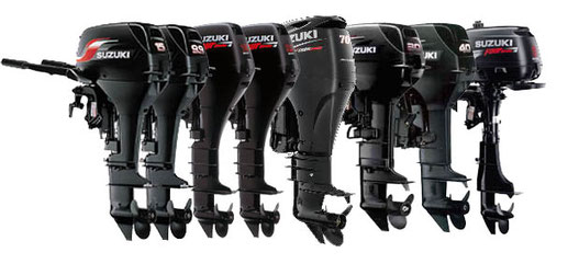
Boat motors, regardless of the power and number of cycles, are thoroughly tested and tested before implementation. The materials and components used are of the highest quality, so all
modifications are characterized by increased reliability and correspond to the stated characteristics.
- Two-stroke engines (DT) are presented in five versions with powers: 2.2; 9.9; 15; thirty; 40 horsepower. Suspended boat motors (PLM) of this type are convenient in terms of frequent
shipments, since they have a lightweight design. They are quickly gaining momentum, easy to manage and maintain. - Four-stroke engines (DF) are represented by a wide power range (from 2.5 to 300 horsepower). Moreover, the gradation occurs with an optimal pitch, which allows you to accurately select the
desired engine for the swimming facility.
All products can be divided into two groups according to engine power. The first (2-10 horsepower) are models for small boats, intended for amateur use. The second group, with an engine capacity
of 15-20 liters. forces already intended for pleasure craft of small capacity and yachts.
The second principle of division is associated with technical features and is based on the number of work cycles. Some engines operate on the principle of fuel intake — exhaust gases. Others
besides these also have intermediate cycles: compression and working stroke. Two-stroke engines are lighter, they are simpler in terms of design, maintenance and cheaper. Four stroke is an
example of excellence in technology. They are more economical, environmentally cleaner, have an increased efficiency, although they cost and are more expensive to maintain.
-
Contents
-
Table of Contents
-
Troubleshooting
-
Bookmarks
Related Manuals for Suzuki DF9,9
Summary of Contents for Suzuki DF9,9
-
Page 1
For 2005 model 9 9 5 0 0 — 9 4 J 0 1 — 0 1 E… -
Page 2: General Information
FOREWORD GROUP INDEX This manual contains an introductory description of the SUZUKI DF9.9/15 Outboard motors and proce- dures for inspection, service and overhaul of their GENERAL INFORMATION main components. General knowledge information is not included. PERIODIC MAINTENANCE Please read the GENERAL INFORMATION section…
-
Page 3: Component Parts And Important Item Illustrations
HOW TO USE THIS MANUAL TO LOCATE WHAT YOU ARE LOOKING FOR: 1. The text of this manual is divided into sections. 2. The section titles are listed on the previous page in a GROUP INDEX. Select the section needed for reference. 3.
-
Page 4
“1333B”. Apply the SUZUKI OUTBOARD Measure in DC voltage range. MOTOR GEAR OIL. Apply the SUZUKI SUPER GREASE “A”. Measure in resistance range. Apply the SUZUKI WATER RESISTANT Measure in continuity test range. GREASE. Apply the SUZUKI BOND “1207B”. -
Page 5: Table Of Contents
GENERAL INFORMATION 1-1 GENERAL INFORMATION CONTENTS WARNING/CAUTION/NOTE ……………..1- 2 GENERAL PRECAUTIONS …………….1- 2 IDENTIFICATION NUMBER LOCATION …………1- 4 FUEL AND OIL ………………..1- 5 GASOLINE RECOMMENDATION …………1- 5 ENGINE OIL ……………….1- 5 ENGINE BREAK-IN ………………1- 6 WARM-UP RECOMMENDATION …………1- 6 THROTTLE RECOMMENDATION …………1- 6 PROPELLERS ………………..1- 7 SPECIFICATIONS ………………1- 8 SERVICE DATA …………………1-10…
-
Page 6: Warning/Caution/Note
1-2 GENERAL INFORMATION WARNING/CAUTION/NOTE Please read this manual and follow its instructions carefully. To emphasize special information, the symbol and the words WARNING, CAUTION and NOTE have special meanings. Pay special attention to the mes- sages highlighted by these signal words. …
-
Page 7
GENERAL INFORMATION 1-3 • If parts replacement is necessary, replace the parts with Suzuki Genuine Parts or their equiv- alent. • When removing parts that are to be reused, keep them arranged in an orderly manner so that they may be reinstalled in the proper order and orientation. -
Page 8: Identification Number Location
MODEL, PRE-FIX, SERIAL NUMBER The MODEL, PRE-FIX and SERIAL NUMBER of motor are stamped on a plate attached to the clamp bracket. Example Model THAI SUZUKI MOTOR CO.,LTD. MADE IN THAILAND FABRIQUE AU THAILANDE Pre-fix Serial number ENGINE SERIAL NUMBER A second engine serial number plate is pressed into a boss on the cylinder block.
-
Page 9: Fuel And Oil
GENERAL INFORMATION 1-5 FUEL AND OIL GASOLINE RECOMMENDATION Suzuki highly recommends that you use alcohol-free unleaded gasoline with a minimum pump octane rating of 87 (R/2+M/2 method) or 91 (Research method). However, blends of unleaded gasoline and alcohol with equivalent octane content may be used.
-
Page 10: Engine Break-In
1-6 GENERAL INFORMATION ENGINE BREAK-IN The first 10 hours are critically important to ensure correct run- ning of either a brand new motor or a motor that has been recon- ditioned or rebuilt. How the motor is operated during this time will have direct bearing on its life span and long-term durability.
-
Page 11: Propellers
GENERAL INFORMATION 1-7 PROPELLERS An outboard motor is designed to develop its rated power within a specified engine speed range. The maximum rated power delivered by the DF9.9/15 models are shown below. Recommended full DF9.9 4 900 – 5 500 r/min throttle speed range DF15 5 400 –…
-
Page 12: Specifications
57.0 (2.24) Total displacement (cu. in) 302 (18.4) Compression ratio Spark plug BKR6E Ignition system SUZUKI PEI (Digital CDI) Fuel supply system Carburetor (Number of carb.: 1) Exhaust system Through prop exhaust Cooling system Water cooled Lubrication system Wet sump by trochoid pump…
-
Page 13
SAE 10W-40 Engine oil amounts 1.0 (1.1/0.9): Oil change only L (US/lmp. qt) 1.1 (1.2/1.0): Oil filter change Gear oil SUZUKI Outboard Motor Gear Oil (SAE #90 hypoid gear oil) Gearcase oil amounts ml (US/lmp. oz) 170 (5.7/6.0) BRACKET Trim angle Degrees 4 –… -
Page 14: Service Data
1-10 GENERAL INFORMATION *SERVICE DATA *: These service data are subject to change without notice. Data Item Unit DF9.9 DF9.9E DF9.9R DF15 DF15E DF15R POWERHEAD Recommended operation r/min 4 900 – 5 500 5 400 – 6 000 range Idle speed r/min 900 ±…
-
Page 15
GENERAL INFORMATION 1-11 Data Item Unit DF9.9 DF9.9E DF9.9R DF15 DF15E DF15R VALVE/VALVE GUIDE mm (in) 26 (1.0) Valve diame- mm (in) 22 (0.9) Valve clearance mm (in) 0.18 – 0.22 (0.007 – 0.009) (cold engine mm (in) 0.18 – 0.22 (0.007 – 0.009) condition) Valve guide mm (in) -
Page 16
1-12 GENERAL INFORMATION Data Item Unit DF9.9 DF9.9E DF9.9R DF15 DF15E DF15R CYLINDER/PISTON/PISTON RING Limit mm (in) 0.05 (0.002) Cylinder distortion Piston to cylinder mm (in) 0.0276 – 0.0425 (0.0011 – 0.0017) clearance Limit mm (in) 0.100 (0.0039) Cylinder bore mm (in) 58.000 –… -
Page 17
GENERAL INFORMATION 1-13 Data Item Unit DF9.9 DF9.9E DF9.9R DF15 DF15E DF15R CRANKSHAFT/CONROD Conrod small end mm (in) 14.006 – 14.014 (0.5514 – 0.5517) inside diameter Limit mm (in) 14.040 (0.5528) Conrod big end mm (in) 0.025 – 0.045 (0.0010 – 0.0018) oil clearance Limit mm (in) -
Page 18
1-14 GENERAL INFORMATION Data Item Unit DF9.9 DF9.9E DF9.9R DF15 DF15E DF15R LOWER UNIT Gearcase oil amounts 170 (5.7/6.0) (US/lmp.oz) Gear ratio 2.08 (12 : 25) Preliminary gear shim & thrust washer Pinion back up shim mm (in) 1.0 (0.04) Forward back up shim mm (in) 1.0 (0.04) -
Page 19
GENERAL INFORMATION 1-15 Data Item Unit DF9.9 DF9.9E DF9.9R DF15 DF15E DF15R ELECTRICAL Ignition timing Degrees – BTDC 30 ATDC 5 Over revolution limiter r/min Approx. 6 500 Condenser charge coil Ω at 20 °C 12.5 – 18.8 [G – B/R] resistance Ω… -
Page 20
1-16 GENERAL INFORMATION PEAK VOLTAGE Requirements for peak voltage measurement • Remove all spark plugs to eliminate the variables at cranking speed. • Crank with recoil starter. • Use a STEVENS peak voltage tester, Model CD-77. • Use the 6-pin connector test cord (Part No. 09930-89920). Tester probe connection Testing sequence… -
Page 21: Tightening Torque
GENERAL INFORMATION 1-17 TIGHTENING TORQUE Tightening torque – Important fasteners THREAD TIGHTENING TORQUE ITEM DIAM. N·m kg-m lb-ft Cylinder head cover bolt 6 mm Cylinder head bolt 8 mm 20.0 Crankcase bolt 6 mm 10.0 8 mm 18.0 Conrod cap bolt 7 mm Oil pump bolt 6 mm…
-
Page 22
1-18 GENERAL INFORMATION Tightening torque – General bolt NOTE: These value are only applicable when torque for a general bolt is not listed in the “Important Fasteners” table. TIGHTENING TORQUE THREAD TYPE OF BOLT DIAMETER N·m kg-m lb-ft 5 mm 2 –… -
Page 23: Special Tools
GENERAL INFORMATION 1-19 SPECIAL TOOLS 09900-00413 (5 mm) 09900-00414 (6 mm) 09900-00415 (8 mm) 09900-20101 (150 mm) 09900-20202 09900-00410 Hexagon bit (included 09900-06108 09900-20102 (200 mm) Micrometer Hexagon wrench set in 09900-00410) Snap ring pliers Vernier calipers (25 – 50 mm) 09900-20203 09900-20205 09900-20530…
-
Page 24
1-20 GENERAL INFORMATION 09915-78211 09916-14521 09916-20610 Oil pressure gauge 09916-10911 09916-14510 Valve lifter attach- Valve seat cutter (15°) adapter Valve lapper Valve lifter ment (N-121) 09916-34550 09916-20620 09916-24440 09916-24450 09916-34542 Valve guide reamer Valve seat cutter (45°) Handle adapter Solid pilot Valve guide reamer … -
Page 25
GENERAL INFORMATION 1-21 09930-49210 09930-89920 09950-59320 Flywheel holder 09930-76420 09930-99320 6-pin connector test Propeller shaft attachment Timing light Digital tester cord remover Pinion bearing installer and remover 09951-59910 Pinion bearing installer shaft A 09951-49910 Pinion bearing remover shaft B 09951-69910 Bearing C 01500-08403 Bolt D 09951-39914 Pinion bearing plate E 09950-69512… -
Page 26: Materials Required
1-22 GENERAL INFORMATION MATERIALS REQUIRED SUZUKI OUTBOARD SUZUKI SUPER WATER RESISTANT SUZUKI SILICONE SUZUKI BOND MOTOR GEAR OIL GREASE “A” GREASE SEAL “1207B” 99000-25030* 99104-33140* 99000-22540 99000-25011 99000-25161 99000-31120 99000-31140 (400 ml × 24 pcs.) (500 g) (250 g) (50 g)
-
Page 27
PERIODIC MAINTENANCE 2-1 PERIODIC MAINTENANCE CONTENTS PERIODIC MAINTENANCE SCHEDULE …………2- 2 PERIODIC MAINTENANCE CHART ………….2- 2 MAINTENANCE AND TUNE-UP PROCEDURES ……….2- 3 ENGINE OIL ……………….2- 3 ENGINE OIL FILTER …………….2- 4 GEAR OIL ………………..2- 5 LUBRICATION ………………2- 6 SPARK PLUG ………………2- 7 VALVE CLEARANCE …………….2- 8 TIMING BELT ………………2-10 IDLE SPEED ……………….2-13… -
Page 28: Periodic Maintenance Schedule
2-2 PERIODIC MAINTENANCE PERIODIC MAINTENANCE SCHEDULE The chart below lists the recommended intervals for all the required periodic service work necessary to keep the motor operating at peak performance and economy. Maintenance intervals should be judged by number of hours or months, whichever comes first. NOTE: More frequent servicing should be performed on outboard motors that are used under severe conditions.
-
Page 29: Maintenance And Tune-Up Procedures
PERIODIC MAINTENANCE 2-3 MAINTENANCE AND TUNE-UP PROCEDURES This section describes servicing procedures for each periodic maintenance requirement. ENGINE OIL Change initially after 20 hours (1 month) and every 100 hours (6 months). NOTE: Engine oil should be changed while engine is warm. 1.
-
Page 30: Engine Oil Filter
2-4 PERIODIC MAINTENANCE 6. Pour recommended engine oil into oil filler opening, then install the oil filler cap. Necessary engine oil amount: Oil change only: 1.0 L (1.1/0.9 US/Imp. qt) Oil filter change:1.1 L (1.2/1.0 US/Imp. qt) Recommended oil: • 4 stroke motor oil •…
-
Page 31: Gear Oil
Gear oil amounts: 170 ml (5.7/6.0 US/Imp. oz) Recommended oil: SUZUKI OUTBOARD MOTOR GEAR OIL or SAE #90 HYPOID GEAR OIL 5. Install oil level plug before removing oil filler tube from drain hole.
-
Page 32: Lubrication
2-6 PERIODIC MAINTENANCE LUBRICATION Inspect every 50 hours (3 months). Apply SUZUKI Water Resistant Grease to the following points. 99000-25161: SUZUKI WATER RESISTANT GREASE Throttle cable Carburetor linkage Swivel bracket NSI cable Clamp screw Steering bracket Propeller shaft…
-
Page 33: Spark Plug
PERIODIC MAINTENANCE 2-7 SPARK PLUG • Inspect every 100 hours (6 months). • Replace every 200 hours (12 months). Standard spark plug: NGK BKR6E Only resistor (R) type spark plugs must be used with this engine. Using a non-resistor spark plug will cause ignition system malfunctions.
-
Page 34: Valve Clearance
2-8 PERIODIC MAINTENANCE VALVE CLEARANCE Inspect initially after 20 hours (1 month) and every 200 hours (12 months). 1. Remove following parts: • Motor cover • Side covers • Recoil starter • Spark plugs 2. Disconnect the fuel hose 1 from fuel pump 2. 3.
-
Page 35
PERIODIC MAINTENANCE 2-9 ADJUSTMENT 6. Loosen valve adjusting lock nut 4. 7. Turn valve adjusting screw using the valve adjustment driver to bring valve clearance to within specification. 09900-20803: Thickness gauge 09917-14910: Valve adjustment driver 8. Tighten valve adjusting lock nut while holding valve adjusting screw. -
Page 36: Timing Belt
2-10 PERIODIC MAINTENANCE TIMING BELT • Inspect every 200 hours (12 months). • Replace every 4 years. If wear, crack or other damage is found, replace the timing belt. 1. Remove the motor cover. 2. Remove the recoil starter. 3. Remove the side covers. 4.
-
Page 37
PERIODIC MAINTENANCE 2-11 8. Loosen the port side bolt securing starter motor band. 9. Remove the four (4) bolts securing stator base 5. Remove the two (2) bolts securing starter motor. 10. Lift stator base from cylinder block and lay it on port side as shown figure. -
Page 38
2-12 PERIODIC MAINTENANCE 12. Remove the timing belt from the cam pulley first, then from the timing pulley. Do not rotate the crankshaft or the cam pulley before installing the belt; the following must be checked: • The PUNCH mark on the timing pulley aligns with the INDEX mark on the cylinder block. -
Page 39: Idle Speed
PERIODIC MAINTENANCE 2-13 IDLE SPEED Inspect initially after 20 hours (1 month) and every 200 hours (12 months). Checking 1. Check throttle link mechanism and carburetor throttle valve for smooth operation. 2. Attach engine tachometer cord to the ignition coil high-ten- sion cord.
-
Page 40: Ignition Timing
2-14 PERIODIC MAINTENANCE IGNITION TIMING Inspect every 200 hours (12 months). NOTE: Before checking the ignition timing, make sure that the idle speed is adjusted within the specification. 1. Start and warm up the engine. 2. Attach the timing light to the No. 1 ignition coil high-tension cord.
-
Page 41: Water Pump/Water Pump Impeller
PERIODIC MAINTENANCE 2-15 WATER PUMP/WATER PUMP IMPELLER WATER PUMP Inspect every 200 hours (12 months). Inspect water pump case and under panel. Replace if wear, cracks, distortion or corrosion is found. WATER PUMP IMPELLER Replace every 200 hours (12 months). Inspect water pump impeller.
-
Page 42: Anodes And Bonding Wires
Never paint the anode. NOTE: Anode The anode securing bolt should be covered with SUZUKI SILI- CONE SEAL. 99000-31120: SUZUKI SILICONE SEAL BONDING WIRES If breakage or other damage is found on the wire, replace the wire.
-
Page 43: Battery
PERIODIC MAINTENANCE 2-17 BATTERY Inspect every 50 hours (3 months). • Never expose battery to open flame or electric spark as batteries generate gas which is flammable and explosive. • Battery acid is poisonous and corrosive. Avoid con- tact with eyes, skin, clothing and painted surfaces. If battery acid comes in contact with any of these, flush immediately with large amounts of water.
-
Page 44: Bolts And Nuts
2-18 PERIODIC MAINTENANCE BATTERY SOLUTION LEVEL CHECK Battery solution level should be between UPPER level and LOWER level. If level is low, add distilled water only. Once the battery has been initially serviced, NEVER add diluted sulfuric acid or battery damage will occur. Follow the battery manufacture’s instructions for spe- cific maintenance procedures.
-
Page 45: Oil Pressure
PERIODIC MAINTENANCE 2-19 OIL PRESSURE Oil pressure (at normal operating temp.): 200 – 500 kPa (2.0 – 5.0 kg/cm , 28 – 71 psi) at 3000 r/min. NOTE: The figure shown above is a guideline only, not an absolute ser- vice limit.
-
Page 46
2-20 PERIODIC MAINTENANCE 6. Install oil pressure gauge adaptor into oil pressure switch hole in place of oil pressure switch. 09915-77311: Oil pressure gauge 09915-78211: Oil pressure gauge adapter 7. Place CDI unit in position. Install ignition coil, then secure with bolts. 8. -
Page 47: Cylinder Compression
PERIODIC MAINTENANCE 2-21 CYLINDER COMPRESSION Cylinder compression: Standard: 550 – 850 kPa (5.5 – 8.5 kg/cm , 78 – 120 psi.): With decompression system (DF9.9/15) 820 – 1 230 kPa (8.2 – 12.3 kg/cm , 116 – 175 psi.): Without decompression system (DF9.9E/R, DF15E/R) Max.
-
Page 48
IGNITION AND ELECTRICAL 3-1 IGNITION AND ELECTRICAL CONTENTS IGNITION SYSTEM………………3- 2 PRINCIPLES OF OPERATION ……………3- 2 IGNITION TIMING CONTROL…………..3- 3 TROUBLESHOOTING …………….3- 4 INSPECTION ……………….3- 5 REMOVAL/INSTALLATION…………..3- 9 CAUTION SYSTEM ………………3-14 OVER-REVOLUTION CAUTION SYSTEM……….3-14 LOW OIL PRESSURE CAUTION SYSTEM……….3-15 TESTING OIL PRESSURE CAUTION SYSTEM ……..3-16 REMOVAL AND INSTALLATION…………3-17 BATTERY CHARGING SYSTEM …………..3-18 OUTLINE ………………..3-18… -
Page 49: Ignition System
3-2 IGNITION AND ELECTRICAL IGNITION SYSTEM PRINCIPLES OF OPERATION A digital CDI (condenser discharge ignition) system is employed on the DF9.9/DF15. The condenser built in the CDI unit stores the electrical energy generated by the condenser charge coil. The electrical energy stored in the condenser is released to the ignition coil primary windings by the ignition timing signal calculated by the CDI microcomputer from the pulser coil signals.
-
Page 50: Ignition Timing Control
IGNITION AND ELECTRICAL 3-3 IGNITION TIMING CONTROL Outline The ignition timing varies based upon engine speed. The pulser coil monitor current engine speed and send signals to the CDI unit. Based on this signal, the CDI unit determines the optimum ignition timing and supplies voltage to the primary winding of the ignition coil.
-
Page 51: Troubleshooting
3-4 IGNITION AND ELECTRICAL TROUBLESHOOTING Perform the following ignition system tests when the engine is hard to start in order to determine if the cause is in the ignition or another system. START The cause will not be in the ignition system.
-
Page 52: Inspection
IGNITION AND ELECTRICAL 3-5 INSPECTION Always disconnect the battery cables from battery before commencing electrical resistance test. CONDENSER CHARGE COIL OUTPUT Peak Voltmeter Stevens CD-77 Tester range: POS 50 1. Disconnect the condenser charge coil lead wire connector. 2.
-
Page 53
3-6 IGNITION AND ELECTRICAL PULSER COIL OUTPUT Peak Voltmeter Stevens CD-77 Tester range: SEN 5 1. Disconnect the pulser coil lead wire connector. 2. Connect the tester probe to the coil lead wires as shown. Tester probe connection + (Red) — (Black) Red/Black Black (Ground) -
Page 54
IGNITION AND ELECTRICAL 3-7 IGNITION COIL RESISTANCE 09930-99320: Digital tester Tester range: Ω (Resistance) Primary side 1. Disconnect the ignition coil lead wire connector. 2. Connect the tester probe to the coil lead wires as shown. Tester probe connection Probe Other probe Orange… -
Page 55
3-8 IGNITION AND ELECTRICAL SPARK PLUG CAP 09930-99320: Digital tester Tester range: Ω (Resistance) Measure the spark plug cap resistance. Tester probe connection Probe Other probe Cap end Other cap end : 8 – 12 kΩ Spark plug cap resistance If measurement is out of specification, replace the spark plug cap. -
Page 56: Removal/Installation
IGNITION AND ELECTRICAL 3-9 REMOVAL/INSTALLATION FLYWHEEL/BATTERY & CONDENSER CHARGE COIL/PULSER COIL 80 N·m (8.0 kg-m, 58.0 lb-ft) 1. Nut 2. Washer 3. Flywheel 4. Key 5. Battery & condenser charge coil 6. Pulser coil 7. Screw 8. Screw 9. Stator base 10.
-
Page 57
3-10 IGNITION AND ELECTRICAL 2. Using special tools, loosen flywheel nut 2–3 turns. 09930-48720: Flywheel holder 09930-49210: Flywheel holder attachment NOTE: Do not remove flywheel nut at this time. This nut prevents damage to the crankshaft when using flywheel remover tools. -
Page 58
IGNITION AND ELECTRICAL 3-11 8. Loosen the PORT side bolt 6 securing starter motor band. 9. Remove the three (3) screws securing battery charge & con- denser charge coil 7. Remove the two (2) screws securing pulser coil 8. Remove the six (6) bolts securing stator base 9. 10. -
Page 59
3-12 IGNITION AND ELECTRICAL INSTALLATION Installation is reverse order of removal with the special attention to the following steps. Battery & Condenser charge coil/Pulser coil • Secure coil lead wire with cable ties, then check that coil lead wire is routed properly and away from hot or rotating parts. Wire routing Pulser coil Pulser coil… -
Page 60
IGNITION AND ELECTRICAL 3-13 • Install stator base, then tighten stator base mounting bolts securely. Stator base mounting bolt: 8 mm 23 N·m (2.3 kg-m, 16.5 lb-ft) 6 mm 10 N·m (1.0 kg-m, 7.0 lb-ft) • Apply Thread Lock 1342 to the coil mounting screws. … -
Page 61: Caution System
3-14 IGNITION AND ELECTRICAL CAUTION SYSTEM The following two caution systems alert the operator when an abnormality occurs on the engine. Caution lamp • OVER-REVOLUTION CAUTION • LOW OIL PRESSURE CAUTION CAUTION CAUTION OVER-REV CAUTION TYPE LAMP BUZZER LIMITER Over-revolution Low oil pressure *: Remote control model only ■…
-
Page 62: Low Oil Pressure Caution System
IGNITION AND ELECTRICAL 3-15 LOW OIL PRESSURE CAUTION SYSTEM Caution lamp CDI unit Magneto LED output circuit Condenser charge coil Oil pressure switch 15 kPa (0.15 kg/cm , 2 psi) CONDITION: Immediate activation of the system when the oil pressure switch turns “ON” due to an engine oil pressure drop below 15 kPa (0.15 kg/cm , 2 psi).
-
Page 63: Testing Oil Pressure Caution System
3-16 IGNITION AND ELECTRICAL TESTING OIL PRESSURE CAUTION SYSTEM To check the oil pressure caution circuit, follow the procedure below. NOTE: Before checking the oil pressure caution circuit, make sure the Oil pressure switch engine oil pressure is within specification. OIL PRESSURE SWITCH a.
-
Page 64: Removal And Installation
IGNITION AND ELECTRICAL 3-17 REMOVAL AND INSTALLATION OIL PRESSURE SWITCH Removal 1. Remove the plate 1 by sliding it upward. 2. Remove CDI unit 2 from electric parts holder. 3. Remove the two (2) bolts 3 securing ignition coil. 4. Loosen screw and disconnect blue lead wire from oil pres- sure switch.
-
Page 65: Battery Charging System
3-18 IGNITION AND ELECTRICAL BATTERY CHARGING SYSTEM OUTLINE The battery charging system circuit is illustrated below. It is composed of the battery charge coil, the rectifier & regulator and the battery. The AC current generated from the battery charge coil is converted by the rectifier into regulated DC current which is used to charge the battery.
-
Page 66: Inspection
IGNITION AND ELECTRICAL 3-19 INSPECTION BATTERY CHARGE COIL OUTPUT Peak Voltmeter Stevens CD-77 Tester range: POS 50 1. Disconnect battery charge coil wires from rectifier. 2. Remove all spark plugs. 3. Connect tester probe to battery charge coil lead wires as shown.
-
Page 67
NOTE: Remote control model The values given below are for a SUZUKI pocket tester. As thyristors, diodes, etc. are used inside this rectifier & regula- tor, the resistance values will differ when an ohmmeter other than SUZUKI pocket tester is used. -
Page 68
IGNITION AND ELECTRICAL 3-21 FUSE CASE/FUSE 09930-99320: Digital tester Tester range: (Continuity) Fuse 1. Remove the plate 1 by sliding it upward. 2. Remove the fuse from fuse case 2. 3. Inspect the fuse and replace with a new 20-amp fuse if needed. -
Page 69: Removal/Installation
3-22 IGNITION AND ELECTRICAL REMOVAL/INSTALLATION REMOVAL Before removing electrical parts: • Disconnect battery cables from battery. • Disconnect spark plug cap from all spark plugs. Battery & Condenser charge coil • Remove flywheel (See page 3-9.) • Remove the stator base and battery charge coil (See page 3-10.) Rectifier &…
-
Page 70: Electric Starter System
IGNITION AND ELECTRICAL 3-23 ELECTRIC STARTER SYSTEM OUTLINE The starting circuit consists of the battery, starting motor, ignition switch (or starter button), neutral switch and related electrical wiring. These components are connected electrically as shown in figure below. STARTING SYSTEM CIRCUIT In the circuit shown in figure below, the magnetic switch coils are magnetized when the starter button is closed (Starter button depressed).
-
Page 71
3-24 IGNITION AND ELECTRICAL For Remote control model Hold-in coil Pull-in coil Magnetic switch Plunger Shift lever Ring gear Starter Pinion & Fuse 20A motor Battery over-running clutch Starter relay Ignition switch PUSH FREE IG OFF STOP BATT START RESET PUSH TURN Movable contact… -
Page 72: Troubleshooting
IGNITION AND ELECTRICAL 3-25 TROUBLESHOOTING NOTE: Before troubleshooting the electric starter system, make sure of the following : • Battery is fully charged. • All cables / wires are securely connected. • Shift is in “NEUTRAL” position. If any abnormality is found, immediately disconnect battery cables from battery. Engine does not start.
-
Page 73: Inspection
3-26 IGNITION AND ELECTRICAL INSPECTION IGNITION SWITCH (Remote control model) » 09930-99320: Digital tester (OFF) (ON) FREE Tester range: (Continuity) (START) 1. Disconnect the ignition switch from remote control wiring harness. 2. Check continuity between wiring leads at the key positions PUSH shown in the chart.
-
Page 74
IGNITION AND ELECTRICAL 3-27 NEUTRAL SWITCH Forward 09930-99320: Digital tester Tester range: (Continuity) 1. Disconnect neutral switch lead wire. Neutral Reverse 2. Check continuity/infinity between Yellow/Green and Brown lead wire while operating the shift lever or remo-con handle. Neutral switch function: Shift position Tester indicates… -
Page 75
3-28 IGNITION AND ELECTRICAL 5. Measure resistance between relay terminals 3 and 4. Tester range: Ω (Resistance) Starter motor relay solenoid coil resistance: 145 – 190 Ω If out of specification, replace starter motor relay. -
Page 76: Starter Motor
IGNITION AND ELECTRICAL 3-29 STARTER MOTOR REMOVAL Prior to removing starter motor: • Disconnect battery cables from battery. 1. Remove the side covers. (See page 7-2.) Remove bolts and recoil starter 1. (See page 5-2.) 2. Remove the flywheel 2. (See page 3-9.) …
-
Page 77
3-30 IGNITION AND ELECTRICAL 6. Remove the six (6) bolts securing stator base 0. 7. Lift up stator base, then remove starter motor A. INSTALLATION Installation is reverse order of removal with special attention to the following steps. • Install starter motor and stator base, then tighten stator base mounting bolts securely. -
Page 78
IGNITION AND ELECTRICAL 3-31 1. Remove nut 1 from magnetic switch, then disconnect the connecting wire 2. 2. Remove two bolts 3 securing magnetic switch. 3. Remove the magnetic switch 4. 4. Remove screws 5, long through bolts 6 and rear cover 7. 5. -
Page 79
3-32 IGNITION AND ELECTRICAL 7. Remove the yoke A and armature B. 8. Remove the center cover plate C. 9. Remove the planetary gears D and internal gear E. 10. Remove the center bracket F (with shift lever H, pinion I and pinion shaft J) from front housing G. -
Page 80
IGNITION AND ELECTRICAL 3-33 13. Remove the E-ring M. 14. Remove the pinion shaft J, washers N and rubber ring O from center bracket. INSPECTION AND SERVICING Armature and Commutator • Inspect the commutator surface. If surface is gummy or dirty, clean with #500 grit emery paper •… -
Page 81
3-34 IGNITION AND ELECTRICAL Wear safety glasses when using compressed air. • Check for continuity between the commutator and the arma- Commutator ture core/shaft. Shaft Replace armature if continuity is indicated. 09930-99320: Digital tester Tester range: (Continuity) Armature core •… -
Page 82
IGNITION AND ELECTRICAL 3-35 BRUSH SPRING Inspect brush spring for wear, damage or other abnormal condi- tions. Check the brush spring tension. Replace if necessary. Brush spring tension Standard: 15 – 18 N (1.5 – 1.8 kg, 3.3 – 4.0 lb) SHIFT LEVER Inspect shift lever for wear. -
Page 83
3-36 IGNITION AND ELECTRICAL PINION SHAFT/PINION SHAFT BUSH • Inspect pinion shaft for wear, damage or other abnormal con- ditions. Replace if necessary. • Inspect pinion shaft bush for wear or other damage. Replace if necessary. FRONT HOUSING • Inspect front housing for wear, damage or other abnormal conditions. -
Page 84
IGNITION AND ELECTRICAL 3-37 MAGNETIC SWITCH Push in plunger and release. The plunger should return quickly to its original position. Replace if necessary. 1. Plunger Pull-in coil Open circuit Test 09930-99320: Digital tester Tester range: (Continuity) Check for continuity across magnetic switch “S” terminal and “M” terminal. -
Page 85
3-38 IGNITION AND ELECTRICAL ASSEMBLY Assembly is reverse order of disassembly with special attention to the following steps. When installing armature, use care to avoid breaking brushes. When installing pinion shift lever, refer to figure in construction diagram for installation direction. Construction diagram 7 N . -
Page 86
IGNITION AND ELECTRICAL 3-39 PERFORMANCE TEST Each test must be performed within 3 – 5 seconds to avoid coil damage from overheating. When performing the following test, be sure to con- nect the battery and the starting motor with a lead wire of the same size as original equipment used there. -
Page 87
3-40 IGNITION AND ELECTRICAL NO-LOAD PERFORMANCE TEST Before performing following test, secure the starter motor to the test bench. 1. Connect battery and ammeter to starter motor as shown. 2. Check that starter rotates smoothly and steadily with pinion moving out. -
Page 88
FUEL SYSTEM 4-1 FUEL SYSTEM CONTENTS PRECAUTION ON FUEL SYSTEM SERVICE ……….4- 2 GENERAL PRECAUTION……………4- 2 FUEL LINE …………………4- 2 REMOVAL/INSTALLATION…………..4- 2 FUEL LEAKAGE CHECK PROCEDURE ……….4- 3 FUEL HOSE CONNECTION …………..4- 3 CARBURETOR ………………..4- 4 REMOVAL ………………..4- 4 INSTALLATION………………4- 5 DISASSEMBLY ………………4- 6 CLEANING &… -
Page 89: Precaution On Fuel System Service
4-2 FUEL SYSTEM PRECAUTION ON FUEL SYSTEM SERVICE GENERAL PRECAUTION Gasoline is extremely flammable and toxic. Always observe the following precautions when working around gasoline or servicing the fuel system. • Disconnect battery cables except when battery power is required for servicing / inspection. •…
-
Page 90: Fuel Leakage Check Procedure
FUEL SYSTEM 4-3 FUEL LEAKAGE CHECK PROCEDURE After performing any fuel system service, always be sure there is not fuel leakage by checking as follows. 1. Squeeze fuel primer bulb until you feel resistance. 2. Once pressurized, check all connections and components for any signs of leakage.
-
Page 91: Carburetor
4-4 FUEL SYSTEM CARBURETOR Before servicing the fuel system, read and understand “PRECAUTION ON FUEL SYSTEM SERVICE” in the previous section. REMOVAL 1. Remove the STBD side cover. (See page 7-2.) 2. Remove the two (2) bolts securing carburetor. 3.
-
Page 92: Installation
FUEL SYSTEM 4-5 6. On remote control model: Disconnect the auto-enrichener lead wire connector. 1. Auto-enrichener INSTALLATION Installation is the reverse order of removal with special attention to the following steps. Do not re-use gasket, as sealing abilities will be insuf- ficient.
-
Page 93: Disassembly
4-6 FUEL SYSTEM Final assembly check Perform the following checks to ensure proper and safe opera- tion. • All parts removed have been returned to their original posi- tions. • No fuel leakage is evident when fuel system is pressurized. (See page 4-3.) DISASSEMBLY NOTE:…
-
Page 94
FUEL SYSTEM 4-7 3. Remove the four (4) screws securing the float chamber 6, then remove the chamber and rubber gasket 7. 4. Remove the screw 8 securing float pin. Account for float 9, float pin 0 and needle valve A. -
Page 95
4-8 FUEL SYSTEM 5. Remove the main jet B and main nozzle C. 6. Remove the cap D and pilot jet E. 7. Remove the acceleration pump plunger F and spring G. -
Page 96: Cleaning & Inspection
FUEL SYSTEM 4-9 CLEANING & INSPECTION Clean thoroughly with cleaning solvent and compressed air before inspection. Wear safety glasses when using compressed air to expel solvent, carburetor cleaner, etc. Do not place any rubber, plastic and non-metallic parts in cleaning solvent, as severe damage or deteri- oration will result.
-
Page 97
4-10 FUEL SYSTEM FLOAT Inspect the float. If cracks or other damage are found on the float, replace it. AUTO-ENRICHENER Inspect the needle valve. If broken tips or wear are found on the needle valve, replace the auto-enrichener. • Connect the positive + terminal of 12 V battery to Yellow lead and the negative — terminal to other yellow lead. -
Page 98: Reassembly
FUEL SYSTEM 4-11 REASSEMBLY Reassembly is reverse order of disassembly with special atten- tion to the following steps. CONSTRUCTION DIAGRAM 1. Carburetor body 2. Main nozzle 3. Main jet 4. Pilot jet 5. Cap 21 26 6. Float 7. Needle valve 8.
-
Page 99
4-12 FUEL SYSTEM CHECKING FLOAT HEIGHT Measure the float height. NOTE: Make sure that float weight is not applied to needle valve. 09900-20101: Vernier calipers Float height H: 13.5 ± 2 mm ACCELERATION PUMP Check that the acceleration pump plunger operates smoothly and together with the throttle lever when turned. -
Page 100: Throttle Control
FUEL SYSTEM 4-13 THROTTLE CONTROL INSTALLATION/ADJUSTMENT TILLER HANDLE MODEL 0 – 2 mm (rib) 1. Fit two throttle cables, 1 and 2, both to the throttle drum 3 and the cable holder 4. 2. Adjust the length of throttle rod 5 to the specification below: Throttle rod length L : 96 mm (3.78 in.) 3.
-
Page 101
4-14 FUEL SYSTEM 8. Loosen the throttle tension adjuster fully. Open the throttle control grip fully and then release your hold. The throttle control grip should return to the closed direction by the return spring force on the carburetor. If the grip does not return, readjustment is necessary because the throttle cable tension is considered excessive. -
Page 102: Fuel Pump
FUEL SYSTEM 4-15 FUEL PUMP REMOVAL/INSTALLATION Before servicing for the fuel system, read and under- stand “PRECAUTION ON FUEL SYSTEM SERVICE” in the previous section. REMOVAL 1. Disconnect the inlet hose 1 and outlet hose 2 from fuel pump. 2.
-
Page 103: Disassembly/Reassembly
4-16 FUEL SYSTEM DISASSEMBLY/REASSEMBLY DISASSEMBLY Remove the six screws 1 and remove in sequence the outer plate 2, gasket 3 and valve body 4. Turn the piston 5 until the pin 6 comes out through cutaway of pump body 7. Remove the following parts: •…
-
Page 104: Inspection
FUEL SYSTEM 4-17 ASSEMBLY Assembly is reverse order of disassembly with special attention to the following steps. Do not re-use the diaphragm set once removed. Always use a new diaphragm set. When connecting the diaphragm set to piston with pin, align punch mark on the piston and the projection of diaphragm.
-
Page 105: Fuel Tank
4-18 FUEL SYSTEM FUEL TANK DISASSEMBLY/REASSEMBLY When disassembling or reassembling the fuel tank, refer to the construction diagram below. & Bolt (1) Fuel tank assembly (1) Fuel plug (1) Fuel connector plug (1) » Fuel hose assembly (1) Outlet (1) Socket (1) Outlet filter (1) Socket (1)
-
Page 106: Inspection
FUEL SYSTEM 4-19 INSPECTION Fuel connector Inspect the fuel connector and connector plug. If leakage, deteri- oration or other damage is found, replace the connector and/or plug. 1. Connector 2. Connector plug Fuel primer bulb Inspect the fuel primer bulb. If crack, leakage or deterioration is found, replace the bulb.
-
Page 107: Operation
4-20 FUEL SYSTEM OPERATION CARBURETOR Float system Float pin Float valve Fuel inlet joint Float valve seat Float FUEL Idling/Trolling » Pilot jet Bypass port #1 Pilot air jet Pilot screw FUEL+AIR (MIXTURE) Pilot outlet FUEL After passing through the pilot jet 1, fuel mixes with air that is supplied from the pilot air jet 2. This mixture then passes through the pilot screw 5 seating area and is jetted both from the pilot outlet 3 and bypass port #1 4.
-
Page 108
FUEL SYSTEM 4-21 Low-Mid speed » Pilot jet Bypass port Pilot air jet Pilot screw FUEL+AIR (MIXTURE) Pilot outlet Throttle valve FUEL As the throttle valve is opened gradually, air flowing through the throttle bore increases in proportion to the valve opening angle. -
Page 109
4-22 FUEL SYSTEM ACCELERATION SYSTEM Acceleration pump Only DF15 model is equipped with an accelerator pump system. When quickly accelerated (opening the throttle valve quickly), the engine suctions a large volume of air with fuel lagging behind causing the mixture to be transitionally lean. To compensate for such a fuel deficiency, an acceleration pump device is provided. -
Page 110
FUEL SYSTEM 4-23 AUTO-ENRICHENER SYSTEM Only the remote control model is equipped with an auto-enrichener system. The automatic enrichener device consists of the PTC heater A, the thermo-wax B and the plunger/needle 1. When the thermo-wax B is cold, the plunger/needle 1 moves upward, fuel is drawn into the enrichener circuit from the float chamber 2. -
Page 111
4-24 FUEL SYSTEM MANUAL STARTER SYSTEM Pulling the starter knob, fuel is drawn into the starter circuit from the float chamber 1. Starter jet 2 meters this fuel, which then flows into fuel pipe 3 and mixes with the air coming from the upper part of float chamber 4. -
Page 112
RECOIL STARTER 5-1 RECOIL STARTER CONTENTS REMOVAL …………………5- 2 DISASSEMBLY …………………5- 3 INSPECTION ………………..5- 5 REASSEMBLY ………………..5- 6 INSTALLATION …………………5- 8 NEUTRAL START INTERLOCK (NSI) …………5- 9 INSTALLATION/ADJUSTMENT ………….5- 9… -
Page 113: Removal
5-2 RECOIL STARTER REMOVAL 1. Loosen the lock nuts 1 and remove NSI cable 2 from cable bracket (stator base) 3. 2. Remove the NSI cable from clutch notch lever 4. 3. Remove the four (4) bolts securing recoil starter. Bolt 4.
-
Page 114: Disassembly
RECOIL STARTER 5-3 DISASSEMBLY Because of the coiled tension in the recoil spring, wear safety glasses and hand protection when wind- ing or unwinding this component. 1. Pull the rope out of recoil case and guide the rope into notch A in the reel, then turn the reel 1 clockwise to release the coiled tension in the recoil spring.
-
Page 115
5-4 RECOIL STARTER 5. Remove the rope. 6. Remove the recoil spring 9. NOTE: Do not remove the recoil spring unless replacement is neces- sary. It should be visually inspected in its assembled position. 7. Remove the NSI cable 0 with spring A. Remove the cotter pin B, washer C and stopper arm D. -
Page 116: Inspection
RECOIL STARTER 5-5 INSPECTION NOTE: If any parts is worn excessively, cracked, defective or damaged in any way, it must be replaced. • Inspect the ratchet (pawl), stopper arm and all springs. If there is any defect such as excessive wear or damage, replace it.
-
Page 117: Reassembly
5-6 RECOIL STARTER REASSEMBLY NSI cable (1) NSI set Cotter pin (1) Washer (1) Stopper arm (1) Spring (1) Reel stopper (1) Bolt (1) Bolt (3) Recoil case (1) Rope guide (1) Grip (1) Screw (1) Recoil spring (1) Reel (1) Rope (1) Ratchet set Friction spring (1)
-
Page 118
• Install NSI set and NSI cable. Apply grease to NSI cable. 99000-25161: SUZUKI WATER RESISTANT GREASE • Secure the outer end of recoil spring on groove in recoil case and wind spring inward towards center of the case in a coun- terclockwise direction. -
Page 119: Installation
5-8 RECOIL STARTER • After assembling, guide the rope into notch in the reel and rotate the reel approximately 5 turns counterclockwise until the spring is tensioned. INSTALLATION Installation is in the reverse order of removal with special atten- tion to the following. •…
-
Page 120: Neutral Start Interlock (Nsi)
“FORWARD” and “REVERSE” position. 5. Tighten the lock nuts 6. 6. Apply SUZUKI WATER RESISTANT GREASE to the inner cable, the cable end and cable holding area. 99000-25161: SUZUKI WATER RESISTANT GREASE …
-
Page 121
POWER UNIT 6-1 POWER UNIT CONTENTS POWER UNIT ………………..6- 2 REMOVAL ………………..6- 2 INSTALLATION………………6- 6 CYLINDER HEAD ASSEMBLY …………..6- 9 REMOVAL ………………..6- 9 ASSEMBLY …………………6- 9 DISASSEMBLY ………………6-10 INSPECTION/SERVICING …………..6-12 REASSEMBLY ………………6-21 CYLINDER/CRANKSHAFT/PISTON………….6-24 DISASSEMBLY ………………6-24 INSPECTION/SERVICING …………..6-26 REASSEMBLY ………………6-37 THERMOSTAT ………………..6-43 REMOVAL ………………..6-43 INSPECTION ……………….6-43 INSTALLATION………………6-43… -
Page 122: Power Unit
6-2 POWER UNIT POWER UNIT REMOVAL Before removing power unit: • Disconnect battery cable from battery. • Drain engine oil. 1. Remove both side covers. (See page 7-2.) 2. Remove recoil starter. (See page 5-2.) 3. Disconnect water hose 1 from thermostat cover and oil pan. Disconnect breather hose 2 from cylinder head cover and silencer.
-
Page 123
POWER UNIT 6-3 6. On tiller handle model: Remove bolt 1 and throttle cable holder 2. 7. Remove bolt 3 and throttle drum 4. 8. Remove flywheel. (See page 3-9.) 09930-48720: Flywheel holder 09930-49210: Flywheel holder attachment 09930-39411: Flywheel remover 09930-39210: Remover bolt 9. -
Page 124
6-4 POWER UNIT 13. Remove bolt, neutral switch/switch bracket 3, then discon- nect the switch lead wire connector. Disconnect the caution lamp lead wire connector 4. 14. Remove the two (2) bolts securing electric parts holder 5, then remove stator base and engine main harness assem- bly. -
Page 125
POWER UNIT 6-5 18. Unscrew the screw 1, then remove the clutch control lever 2 from the clutch lever shaft. 19. Remove the screw 3 securing clutch notch lever 5. Remove clutch lever shaft 4. 20. Remove clutch notch lever 5, then account for clutch notch ball 6 and spring 7. -
Page 126: Installation
Before installing power unit, apply sealant to the two hatched areas shown in the illustration right. 99000-31140: SUZUKI BOND “1207B” • Install dowel pins 1, gasket 2. • Apply Suzuki Water Resistant Grease to driveshaft splines. 99000-25161: SUZUKI WATER RESISTANT GREASE 99000-31140: SUZUKI BOND “1207B” NOTE: •…
-
Page 127
POWER UNIT 6-7 • Apply Suzuki silicone seal to power unit mounting bolts and tighten bolts and nuts to specified torque. 99000-31120: SUZUKI SILICONE SEAL Power unit mounting bolt/nut: 23 N·m (2.3 kg-m, 16.5 lb-ft) TIMING BELT • Install timing belt. (See page 2-11 to 2-12.) CLUTCH LEVER SHAFT •… -
Page 128
6-8 POWER UNIT FLYWHEEL • Install stator base and the battery and condenser charge coil. (See page 3-12.) • Install flywheel and tighten flywheel nut to specified torque. (See page 3-13.) Flywheel nut: 80 N·m (8.0 kg-m, 58.0 lb-ft) … -
Page 129: Cylinder Head Assembly
NOTE: Before installing cylinder head gasket, apply sealant to both sur- faces of the hatched areas shown in illustration. 99000-31140 : SUZUKI BOND “1207B” 2. Position cylinder head assembly on cylinder. 3. Apply engine oil to cylinder head bolts.
-
Page 130: Disassembly
6-10 POWER UNIT DISASSEMBLY 1. Remove the bolt 1, washer 2 and cam pulley 3. Remove the key 4 from camshaft. 2. Remove the four (4) bolts 1 · 2. Remove the oil pump assembly 4 and oil gallery block 3. Turn the oil pump shaft 5 until the pin 6 comes out through hole of oil gallery block 3.
-
Page 131
POWER UNIT 6-11 5. Remove the camshaft. NOTE: Pull out camshaft toward oil pan side. 6. Using valve lifter and attachment, remove valve cotters 1 while compressing valve spring. 09916-14510 : Valve lifter 09916-14521 : Attachment 09916-84511 : Tweezers 7. -
Page 132: Inspection/Servicing
6-12 POWER UNIT INSPECTION/SERVICING NOTE: If cracks, excessive wear or other damage is found on any com- ponent, replace component. CYLINDER HEAD Remove all carbon from combustion chambers. NOTE: • Do not use any sharp edged tool to scrape carbon off cylinder head or its components.
-
Page 133
POWER UNIT 6-13 NOTE: Cylinder head can be resurfaced, using a surface plate and #400 grit wet sandpaper. Move the cylinder head in a figure eight pattern when sanding. Water jackets Inspect water jackets. If clogged or obstructed, clean water jackets. CAMSHAFT Cam face Inspect cam face for scratches and wear. -
Page 134
6-14 POWER UNIT Camshaft journal oil clearance Standard: 0.020 – 0.062 mm (0.0008 – 0.0024 in) Service limit: 0.100 mm (0.0039 in) If the journal oil clearance exceeds the service limit, replace camshaft and if necessary, cylinder head and/or oil gallery block. -
Page 135
POWER UNIT 6-15 Rocker arm shaft to rocker arm clearance Standard: 0.016 – 0.045 mm (0.0006 – 0.0018 in) Service limit: 0.060 mm (0.0024 in) If measurement exceeds service limit, replace rocker arm and/or rocker arm shaft. To check the clearance, measure the following items: •… -
Page 136
6-16 POWER UNIT Valve guide inside diameter Standard: IN & EX 5.500 – 5.512 mm (0.2165 – 0.2170 in) If unable to measure valve guide inside diameter, measure the Valve guide “Valve stem deflection”. Valve stem deflection Measure valve stem deflection as follows: 1. -
Page 137
POWER UNIT 6-17 Valve stem runout Measure valve stem runout. 09900-20602: Dial gauge 09900-20701: Magnetic stand 09900-21304: Steel “V” block set Service limit: IN & EX 0.05 mm (0.002 in) If measurement exceeds service limit, replace valve. Valve head radial runout Measure valve head radial runout. -
Page 138
6-18 POWER UNIT VALVE GUIDE REPLACEMENT Be careful not to damage cylinder head when replac- ing valve guide. 1. Drive valve guide out toward valve spring side. 09916-44910: Valve guide remover/installer NOTE: Do not reuse valve guide once it has been removed. Always use a new valve guide (oversize) when assembling. -
Page 139
POWER UNIT 6-19 VALVE SEAT SERVICING If valve seat contact width is out of specification, reface valve 45˚ 15˚ seat as follows: 09916-20610: Valve seat cutter 15° (N-121) 09916-20620: Valve seat cutter 45° (N-122) Valve seat 09916-24440: Handle adapter (N-503-1) 09916-24450: Solid pilot (N-100-5.52) 09916-54910: Handle (N-505) NOTE:… -
Page 140
6-20 POWER UNIT VALVE SPRING Valve spring free length Measure the spring free length. 09900-20102: Vernier calipers Standard: 32.52 mm (1.280 in) Service limit: 32.40 mm (1.276 in) If measurement is lower than service limit, replace valve spring. Valve spring tension Measure the valve spring tension. -
Page 141: Reassembly
POWER UNIT 6-21 REASSEMBLY Reassembly is reverse order of disassembly with the special attention to the following steps: OIL SEAL Install the oil seal with the spring/lipped side facing inward. Do not re-use the seal once removed. Always install a new oil seal.
-
Page 142
6-22 POWER UNIT CAMSHAFT 1. Apply engine oil to the surface of each camshaft lobe and journals. 2. Install the camshaft from oil pan side. ROCKER ARM/SHAFT 1. Apply engine oil to the rocker arms 1 and the rocker arm shaft 2. -
Page 143
POWER UNIT 6-23 CAMSHAFT PULLEY 1. Install the key and camshaft pulley and secure with bolt. Camshaft pulley bolt: 10 N·m (1.0 kg-m, 7.0 lb-ft) -
Page 144: Cylinder/Crankshaft/Piston
6-24 POWER UNIT CYLINDER/CRANKSHAFT/PISTON DISASSEMBLY Before disassembly • Remove power unit. (See page 6-2 to 6-6.) • Remove cylinder head assembly. (See page 6-9.) 1. Using screw driver, drive locking edges of lock washer 2 downward, and then remove timing pulley nut 1. …
-
Page 145
POWER UNIT 6-25 5. Remove bolts 1, thermostat cover 2 and thermostat 3. 6. Remove six (6) bolts 1. Remove four (4) bolts 2. Remove crankcase 3 from cylinder block. 7. Remove all conrod cap bolts 1 and conrod caps 2. NOTE: For proper assembly, mark cylinder number on all conrod caps, using quick dry paint. -
Page 146: Inspection/Servicing
6-26 POWER UNIT 11. Remove piston pin circlips 1. 12. Remove piston pin 2 from conrod 3. 13. Remove two compression rings (top and 2 nd) and oil ring 5 from piston 4. NOTE: Install the 1 st ring to piston with its original direction. There is no I.D.
-
Page 147
POWER UNIT 6-27 Cylinder bore wear (difference) Measure the cylinder bore in the thrust and axial directions at the three positions A, B and C as shown. Check for the followings: • Difference of the measurements at three positions (Taper) •… -
Page 148
6-28 POWER UNIT Identification of oversize piston/piston ring I.D. mark Piston Oversize I.D. mark 0.50 mm (0.020 in) 1st & 2nd ring Oversize I.D. mark 0.50 mm (0.020 in) I.D. mark 1st, 2nd ring Oil ring Oversize I.D. mark 0.50 mm (0.020 in) Red paint NOTE: For the oil ring side rail, measure the outer diameter of the rail to… -
Page 149
POWER UNIT 6-29 Piston ring end gap Measure piston ring end gap with piston ring in the lowest posi- tion of cylinder bore. 09900-20803: Thickness gauge Standard: 1st & 2nd 0.10 – 0.25 mm (0.004 – 0.010 in) Service limit: 1st & 2nd 0.50 mm (0.020 in) If measurement exceeds service limit, replace piston ring. -
Page 150
6-30 POWER UNIT Piston pin hole diameter Standard: 14.002 – 14.008 mm (0.5513 – 0.5515 in) Service limit: 14.030 mm (0.5524 in) Conrod small end inside diameter Measure the conrod small end inside diameter. 09900-20605: Dial calipers Standard: 14.006 – 14.014 mm (0.5514 – 0.5517 in) Service limit: 14.040 mm (0.5528 in) If measurement is out of specification, replace the conrod. -
Page 151
POWER UNIT 6-31 Crank pin outside diameter/difference Measure the crank pin outside diameter in the thrust and axial directions at two positions as shown. Check for the followings: • Difference of the measurements at two positions (Taper) • Difference between the thrust and axial measurement (Out-of-round) … -
Page 152
6-32 POWER UNIT Conrod big end oil clearance Standard: 0.025 – 0.045 mm (0.0010 – 0.0018 in) Service limit: 0.063 mm (0.0025 in) If measurement exceeds service limit, replace the conrod assembly and/or crankshaft. Measure conrod big end oil clearance as follows: 1. -
Page 153
POWER UNIT 6-33 Crankshaft journal outside diameter/difference Measure the crankshaft journal outside diameter in the thrust and axial directions at two positions as shown. Check for the followings: • Difference of the measurements at two positions (Taper) • Difference between the thrust and axial measurement (Out-of-round) … -
Page 154
6-34 POWER UNIT 2. Install crankshaft main bearing to cylinder and crankcase. NOTE: • Reassemble each bearing to its original position. • Align the tab a of bearing with notch in cylinder and crank- case. • Do not apply oil to bearing. 3. -
Page 155
POWER UNIT 6-35 SELECTION OF MAIN BEARING Whenever a bearing requires replacement, select a new bearing according to following procedure. (1) Crankshaft journal outside diameter Only one kind of crankshaft journal outside diameter is avail- able as follow. Standard: Code Crankshaft journal outside diameter –… -
Page 156
6-36 POWER UNIT (4) Select crankshaft main bearing referring the below table. Bearing selection table Item Crankshaft journal outside diameter Code ———— Crankcase bearing Black holder inside diameter Green NOTE: Measure the crankshaft journal oil clearance again after install- ing the new bearings selected. (See page 6-33.) OIL SEAL Inspect condition. -
Page 157: Reassembly
POWER UNIT 6-37 REASSEMBLY Reassembly is reverse order of disassembly with the special attention to the following steps: • If original components are not replaced, each piston, piston pin and conrod is to be assembled and installed in its original order and position. •…
-
Page 158
6-38 POWER UNIT 1st ring and 2nd ring 1. Apply engine oil to piston rings. 2. Install 2nd ring and 1st ring to piston. 1st ring • Install 2nd ring to piston with the “R” mark toward the piston head side. 2nd ring •… -
Page 159
– marked area shown. 99000-31140: SUZUKI BOND “1207B” A – Oil seal fitting surface (Apply the bond.) B – Groove for the oil seal tab (Do not apply the bond.) 4. Apply engine oil to the lip area of the oil seals. -
Page 160
2. Apply the bond to mating surface of crankcase as shown. – marked area 99000-31140: SUZUKI BOND “1207B” Apply bond to mating surface only. Do not allow bond to contact surface of bearing. A – Fitting surface of the oil seal (Apply the bond.) B –… -
Page 161
POWER UNIT 6-41 3. Install two dowel pins. 4. Install crankcase (with the bearing) to cylinder. 5. Apply engine oil lightly to crankcase bolts. 6. Tighten ten bolts to specified torque according to sequence in figure. Crankcase bolt: 6 mm 14 N·m (1.4 kg-m, 10.0 lb-ft) 8 mm 25 N·m (2.5 kg-m, 18.0 lb-ft) TIMING PULLEY 1. -
Page 162
6-42 POWER UNIT 7. Bend the lock washer edge 4 toward nut for locking. THERMOSTAT Install thermostat 1 and cover 2 to cylinder and secure with bolts 3. Thermostat cover bolt: 10 N·m (1.0 kg-m, 7.0 lb-ft) OIL PRESSURE REGULATOR Install oil pressure regulator 1 to cylinder, then tighten regulator securely. -
Page 163: Thermostat
POWER UNIT 6-43 THERMOSTAT REMOVAL • Disconnect water hose 1 from thermostat cover. • Remove the two (2) bolts 2 securing the thermostat cover, then remove the cover 3 and thermostat 4. INSPECTION • If salt deposits, corrosion, wear or other damage is found, clean or replace.
-
Page 164: Operation
6-44 POWER UNIT OPERATION WATER COOLING SYSTEM The water cooling system consists of the water pump (in the lower unit), the water tube (between the lower unit and the power unit) and the thermostat (in the cylinder). This system cools both the power unit and the exhaust and is shown in schematic form below.
-
Page 165: Engine Lubrication System
POWER UNIT 6-45 ENGINE LUBRICATION SYSTEM Engine oil stored in the oil pan is pumped up by the trochoid type pump. ENGINE OIL LUBRICATION CHART CAMSHAFT CRANKSHAFT UPPER UPPER JOURNAL BEARING OIL PRESSURE SWITCH No. 1 CYLINDER WALL ROCKER ARM No.
-
Page 166
6-46 POWER UNIT OIL PASSAGE LOCATION CRANKSHAFT To CAMSHAFT UPPER BEARING UPPER JOURNAL To #1 CRANK MAIN GALLERY To CAMSHAFT To #2 CRANK LOWER JOURNAL From OIL PUMP FILTER CRANKSHAFT To OIL PUMP LOWER BEARING OIL PUMP RELIEF OIL HOSE OIL REGULATOR OIL PRESSURE SWITCH To CRANKSHAFT… -
Page 167
MID UNIT 7-1 MID UNIT CONTENTS ENGINE SIDE COVER ………………7- 2 REMOVAL ………………..7- 2 INSTALLATION………………7- 3 TILLER HANDLE ……………….7- 4 REMOVAL ………………..7- 4 INSTALLATION………………7- 5 DISASSEMBLY/ASSEMBLY …………..7- 6 DRIVESHAFT HOUSING AND OIL PAN …………7- 7 REMOVAL ………………..7- 7 INSPECTION ……………….7- 9 REASSEMBLY ………………7-10 SWIVEL BRACKET, STEERING BRACKET, CLAMP BRACKET….7-13 REMOVAL/DISASSEMBLY …………..7-13… -
Page 168: Engine Side Cover
7-2 MID UNIT ENGINE SIDE COVER REMOVAL 1. Remove the side cover rubber 1. 2. Remove the two screws 2. 3. Remove the snap pin 3, washer 4, pin 5 and fastener 6. 4. Remove the screw 7. 5. Remove three screws 8 and STBD side cover 9. Disconnect water hose 0.
-
Page 169: Installation
MID UNIT 7-3 INSTALLATION Installation is reverse order of removal. Side cover rubber (1) Screw (2) Nut (2) Plug (1) Cable grommet (1) Side cover (Starboard) (1) Side cover (Port) (1) Side cover plug (1) Bolt (1) Bolt (2) Fastener (1) Pin (1) Washer (1) Snap pin (1)
-
Page 170: Tiller Handle
7-4 MID UNIT TILLER HANDLE REMOVAL 1. Remove the STBD side cover. 2. Loosen lock nuts 1. 3. Remove the throttle rod 2 from throttle lever 3. 4. Remove the bolt 4, throttle lever 3 and throttle drum 5. 5. Remove the throttle cables 6 from throttle drum. 6.
-
Page 171: Installation
MID UNIT 7-5 8. Remove the two (2) bolts securing fuel hose clamp 9. 9. Remove two (2) bolts and handle cover 0. Remove tiller handle and throttle cable assembly A. INSTALLATION Installation is reverse order of removal with special attention to the following.
-
Page 172: Disassembly/Assembly
7-6 MID UNIT DISASSEMBLY/ASSEMBLY When disassembling or reassembling tiller handle, refer to the construction diagram below. 1. Tiller handle 12. Nut 2. Bush (2) 13. Throttle cable 3. Friction rubber 14. Bolt 4. Tiller handle cover 15. Screw 5. Grip 16.
-
Page 173: Driveshaft Housing And Oil Pan
MID UNIT 7-7 DRIVESHAFT HOUSING AND OIL PAN REMOVAL 1. Remove power unit. (See page 6-2 to 6-6.) 2. Remove lower unit. (See page 8-2.) 3. Remove screw and bonding wire from driveshaft housing. 4. Remove screw and bonding wire from swivel bracket. 5.
-
Page 174
7-8 MID UNIT 8. Remove six bolts and oil pan 3 from the driveshaft housing 9. Remove four bolts and upper mounts 5. 10. Remove four bolts and lower mount 6. 11. Remove bolt 7 and water tube 8. -
Page 175: Inspection
MID UNIT 7-9 INSPECTION NOTE: If excessive wear, cracks, defective or other damage is found on any component, replace component. OIL PAN AND DRIVESHAFT HOUSING Inspect the oil pan and driveshaft housing. If crack, defective or other damage is found, replace. MOUNT Inspect the upper mount and lower mount.
-
Page 176: Reassembly
7-10 MID UNIT REASSEMBLY Reassembly is reverse order of removal with the special attention to the following steps. Gasket (1) Oil level gauge (1) Oil level gauge guide (1) Bolt (1) O-ring (1) Oil seal (1) Bolt (6) Plug (2) Gasket (2) Oil pan assembly (1) Bolt (4)
-
Page 177
WATER TUBE UPPER GROMMET • Apply grease to outer surface of the water tube upper grom- met 1. 99000-25161: SUZUKI WATER RESISTANT GREASE • Install water tube grommet 1 to oil pan. LOWER MOUNT 1. Install the lower mount with the lettered mark “UP” facing upward. -
Page 178
7-12 MID UNIT DRIVESHAFT HOUSING/OIL PAN 1. Install the upper mount stoppers 1 to each upper mounts. 2. Install driveshaft housing/oil pan to steering bracket. 3. Apply THREAD LOCK to upper mount bolts. 99000-32050: THREAD LOCK “1342” 4. Tighten upper mount bolts to the specified torque. … -
Page 179: Removal/Disassembly
MID UNIT 7-13 SWIVEL BRACKET, STEERING BRACKET, CLAMP BRACKET REMOVAL/DISASSEMBLY 1. Remove driveshaft housing/oil pan. (See page 7-7.) 2. Remove the two (2) bolts securing steering friction adjuster plate a to the steering bracket. (Tiller handle model) 3. Remove steering adjuster bolt 1, cover 2, washer 3 and spring 4.
-
Page 180
7-14 MID UNIT 7. Remove steering adjuster plate B. 8. Remove nut 1 from clamp bracket shaft. 9. Remove tilt lock pin 2. Remove the nut 3, bolt 4 and spacer 5. 10. Slide PORT clamp bracket 6 off clamp bracket shaft. 11. -
Page 181
MID UNIT 7-15 12. Remove the spring 1. Remove two (2) bolts 2 and shallow drive arm 3. 13. Remove two springs 4 from reverse lock arm and swivel bracket. 14. Remove the release arm pin 5 and release link 6. 15. -
Page 182: Inspection
7-16 MID UNIT INSPECTION NOTE: If excessive wear, cracks, defective or damage is found on any component, replace component. BUSHINGS Inspect all bushings for excessive wear or other damage. Replace if necessary. If bushing fit is loose when installing, replace the bushing. O-RING Inspect swivel bracket O-ring for cuts, nicks, excessive wear or other damage.
-
Page 183: Reassembly
MID UNIT 7-17 REASSEMBLY Reassembly is reverse order of removal with the special attention to the following steps. 43 N·m 4.3 kg-m 31.0 lb-ft 25 N·m 25 N·m 2.5 kg-m 2.5 kg-m 18.0 lb-ft 18.0 lb-ft Clamp bracket shaft (1) Stopper Washer (2) Steering adjuster plate (1)
-
Page 184
Before installing clamp bracket to swivel bracket, apply grease to clamp bracket shaft and bushings. 99000-25161: SUZUKI WATER RESISTANT GREASE 1. Connect the release link 1 to release lever 2. 2. Insert PORT and STBD bushings 3 into the swivel bracket… -
Page 185
Clamp bracket shaft nut : 43 N·m ( 4.3 kg-m, 31.0 lb-ft ) STEERING BRACKET 1. Install the steering adjuster plate 1 to swivel bracket. 99000-25161: SUZUKI WATER RESISTANT GREASE NOTE: Apply grease to bushings, O-ring and pilot shaft portion of steer- ing bracket. -
Page 186
4. Install steering friction adjuster set 7. (Tiller handle model) 5. Apply Water Resistant Grease to steering bracket shaft. 99000-25161: SUZUKI WATER RESISTANT GREASE 6. Install steering bracket 8 to swivel bracket. 7. Install steering friction adjuster plate a to steering bracket, then securely tighten it with bolts. -
Page 187
LOWER UNIT 8-1 LOWER UNIT CONTENTS REMOVAL & DISASSEMBLY ……………8- 2 PINION BEARING ………………8- 6 INSPECTION ………………..8- 8 PROPELLER ……………….8- 8 GEARCASE…………………8- 8 GEARS ………………..8- 8 PROPELLER SHAFT COMPONENTS ………..8- 9 PROPELLER SHAFT BEARING HOUSING………..8- 9 SHIFT CAM AND RELATED ITEMS…………8-10 WATER PUMP AND RELATED ITEMS……….8-10 WATER INLET HOUSING……………8-10 DRIVESHAFT ………………8-11… -
Page 188: Removal & Disassembly
8-2 LOWER UNIT REMOVAL & DISASSEMBLY Before removing lower unit: • Disconnect spark plug caps from all spark plugs. • Disconnect the battery cable. 1. Loosen the clutch rod lock nut 1. To separate the clutch rod from the shift rod, unscrew the turnbuckle 2.
-
Page 189
LOWER UNIT 8-3 To prevent injury from propeller blades, wear gloves and place a block of wood between the anti-cavitation plate and the propeller blade tips to lock the propeller in place. 7. Remove the four bolts, then remove the water pump case B and impeller C. -
Page 190
8-4 LOWER UNIT 11. Using special tools, pull out the propeller shaft bearing hous- ing. Remove the propeller shaft and bearing housing assembly. 09930-30104: Sliding hammer 09950-59320: Propeller shaft remover 12. Remove the circlip from gearcase. Lift out the driveshaft assembly. 13. -
Page 191
LOWER UNIT 8-5 2. Remove the spring 8 from clutch dog shifter. 3. Use special tool to push the dog pin 9 out of clutch dog shifter. 09922-89810: Shift pin remover 4. Remove the clutch dog shifter 0 and spring A. Disassembly of shift rod components 1. -
Page 192: Pinion Bearing
8-6 LOWER UNIT PINION BEARING Removal/installation is in following procedure. Removal & Installation tools 09951-59910: Shaft (Installation) 1 09951-49910: Shaft (Removal) 2 09951-69910: Bearing 3 01500-08403: Bolt 4 09951-39914: Plate 5 09951-19311: Attachment 6 09951-79311: Spacer (Attachment) 7 09951-29910: Nut 8 09930-30104: Sliding hammer 9 REMOVAL 1.
-
Page 193
LOWER UNIT 8-7 INSTALLATION • Before installing the bearing, ensure that the inside of the gearcase is clean and free of debris. • Ensure that the bearing stamped mark faces upward. 1. Set the installation shaft 1, plate 5, spacer 7, attachment 6 and pinion bearing A as shown in the figure. -
Page 194: Inspection
8-8 LOWER UNIT INSPECTION NOTE: Thoroughly wash all metal components with cleaning solvent and dry with compressed air. Wear the safety glasses when using compressed air. PROPELLER • Inspect the propeller for bent, chipped or broken blades. Replace or repair if necessary. •…
-
Page 195: Propeller Shaft Components
3. Using an oil seal installer, drive two oil seals (one at a time) propeller into the housing. The lipped portion of the seal should face toward the propel- ler. Apply the grease to the seal lips. 99000-25161: SUZUKI WATER RESISTANT GREASE…
-
Page 196: Shift Cam And Related Items
Replace if necessary. Replacing oil seal 1. Extract the oil seal using the oil seal remover. 09913-50121: Oil seal remover 2. Apply the water resistant grease to the inner circumference of the housing. 99000-25161: SUZUKI WATER RESISTANT GREASE…
-
Page 197: Driveshaft
The dust lipped portion of the seal should face toward the water pump case. Apply the grease to the seal lips. 99000-25161: SUZUKI WATER RESISTANT GREASE 1. Dust lip DRIVESHAFT • Inspect the driveshaft/splines for wear, twist or other damage.
-
Page 198: Assembly & Installation
8-12 LOWER UNIT ASSEMBLY & INSTALLATION Assembly & installation are reverse order of removal & disassembly with the special attention to the follow- ing steps. Circlip (2) Bearing (1) Driveshaft (1) Washer (1) Bearing (1) Washer (1) Shim (1) Pinion gear (1) Circlip (1) Pinion bearing (2) Dowel pin (2)
-
Page 199
LOWER UNIT 8-13 Nut (1) Turnbuckle (1) Nut (1) Washer (1) Stud bolt (1) Collar (1) 18 N·m Shift rod (1) 1.8 kg-m Boot (1) 13.0 lb-ft Shift rod guide (1) O-ring (1) O-ring (1) Washer (1) Spring pin (2) Shift cam (1) Bolt (4) Bush (1) -
Page 200
SHIFT ROD/SHIFT CAM ASSEMBLY • Apply the grease to the inside of the boot 1, O-ring 2 and O-ring 3. 99000-25161: SUZUKI WATER RESISTANT GREASE • Install the shift rod guide 4 to shift rod 5 as shown in the fig- ure. -
Page 201
Apply gear oil to the forward gear and place the back-up shim 1 in position, then install forward gear. 99000-22540: SUZUKI OUTBOARD MOTOR GEAR OIL PINION GEAR AND DRIVE SHAFT 1. Apply gear oil to the thrust bearing 4 and pinion gear 1. -
Page 202
99000-25161: SUZUKI WATER RESISTANT GREASE • Apply gear oil to the bearing and bush. 99000-22540: SUZUKI OUTBOARD MOTOR GEAR OIL • Assemble the propeller shaft in the following sequence: forward thrust washer 5, reverse thrust washer 4, reverse gear 3, reverse gear back-up shim 2 and propeller shaft housing 1. -
Page 203
LOWER UNIT 8-17 WATER INLET HOUSING 1. Apply grease to the oil seal. 99000-25161: SUZUKI WATER RESISTANT GREASE 2. Install the gasket 1, water inlet tube 2 and water drain tube 3 to the water inlet housing. 3. Install the exhaust seal core 5 and seal rubber 6. -
Page 204
8-18 LOWER UNIT LEAKAGE CHECK Check for leakage of oil seal and O-ring when applying specified pressure inside of the gearcase. 09950-69512 : Oil leakage tester 09952-99310 : Hand air pump Procedure 1. Install the oil leakage tester into oil level hole. 2. -
Page 205
LOWER UNIT 8-19 2. Apply grease to the driveshaft splines. 99000-25161: SUZUKI WATER RESISTANT GREASE 3. Slide the gearcase into place, making sure that the top of driveshaft engages properly with crankshaft and water tube locates in water pump case outlet. -
Page 206
2. Lock the upper nut securely against the turnbuckle when clutch lever adjustment is correct. GEAR OIL Fill the gearcase with specified gear oil. See the “PERIODIC MAINTENANCE/GEAR OIL” section on page 2-5. Necessary amount of gear oil: 170 ml (5.7/6.0 US/lmp.oz) 99000-22540: SUZUKI OUTBOARD MOTOR GEAR OIL… -
Page 207: Lower Unit Gears- Shimming And Adjustment
LOWER UNIT 8-21 LOWER UNIT GEARS- SHIMMING AND ADJUSTMENT If lower unit has been rebuilt or has had components replaced, shimming for correct gear contact and backlash will have to be adjusted to ensure smooth, reliable operation of gears. Shim/Washer & Mounting position Design Available Numerical…
-
Page 208
8-22 LOWER UNIT Checking and adjusting tooth contact pattern (Pinion and forward gear) 1. To assess tooth contact, apply a light coat of Prussian Blue on the convex surface of forward gear. 2. Install propeller shaft and housing assembly (minus reverse gear and internal components). -
Page 209: Pinion Gear/Reverse Gear
LOWER UNIT 8-23 Optimum tooth contact Optimum tooth contact The optimum tooth contact is shown at right. Approx. 1/3 of tooth width A shim adjustment may be necessary to obtain this contact pat- Approx. 1 mm tern. HEEL Gear backlash should be checked when increasing or decreasing shim thickness to adjust tooth contact.
-
Page 210: Checking Propeller Shaft Thrust Play
8-24 LOWER UNIT CHECKING PROPELLER SHAFT THRUST PLAY After adjusting all gear positions, measure the propeller shaft thrust play. If not within the following specification, a shim adjustment is required. Propeller shaft thrust play: 0.2 – 0.4 mm (0.01 – 0.02 in) NOTE: Maintain the forward gear thrust washer at the standard thick- ness (1.5 mm) and adjust only the reverse gear thrust washer…
-
Page 211
WIRE/HOSE ROUTING 9-1 WIRE/HOSE ROUTING CONTENTS WIRING DIAGRAM ………………9- 2 DF9.9/DF15 …………………9- 2 DF9.9E/DF15E………………9- 3 DF9.9R/DF15R ………………9- 4 WIRE ROUTING ………………..9- 5 FUEL/WATER HOSE ROUTING …………..9-11… -
Page 212: Wiring Diagram
9-2 WIRE/HOSE ROUTING WIRING DIAGRAM DF9.9/DF15…
-
Page 213: Df9.9E/Df15E
WIRE/HOSE ROUTING 9-3 DF9.9E/DF15E…
-
Page 214: Df9.9R/Df15R
9-4 WIRE/HOSE ROUTING DF9.9R/DF15R…
-
Page 215: Wire Routing
WIRE/HOSE ROUTING 9-5 WIRE ROUTING Neutral switch Starter motor relay Flywheel connector Oil pressure switch Cover the oil pressure switch with cap. Ignition coil H·T cord protector Fuse/Case CDI stopper Spark plug plate Starter motor band Damper Neutral switch Receptacle GND lead wire (option) Switch bracket Bolt Wiring harness assembly Apply the THREAD…
-
Page 216
9-6 WIRE/HOSE ROUTING Negative battery cable Neutral switch lead wire Clamp Starter motor magnetic switch Fix the lead wire and fuel hose with clamp. Fuel hose Positive battery cable Caution lamp lead wire Remote control harness Positive Positive battery cable harness… -
Page 217
WIRE/HOSE ROUTING 9-7 Auto-enrichener {PTC heater}(R model) Carburetor Cable tie Pulser coil Lead wire Ignition coil CDI unit Battery and condenser charge coil Cable tie Pulser coil ground lead/Bolt Pulser coil ground lead/Bolt Cable tie Cable tie Cable tie To Auto-enrichener Cable tie (PTC heater) (R model) -
Page 218
9-8 WIRE/HOSE ROUTING Tiller handle · Manual starter model Emergency & engine stop switch lead wire Cable tie Route the engine stop switch lead wire under starter cable. Starter cable Tiller handle · Electric starter model Emergency & engine stop switch lead wire Starter button lead wire Tube… -
Page 219
WIRE/HOSE ROUTING 9-9 Remote control model Auto-enrichener PTC heater (PTC heater) lead wire Cable tie Routing of Receptacle lead wire (Optional part) Fuse lead wire Route the fuse lead wire Fuse case assembly between CDI unit and electric parts holder. Receptacle ground lead wire Clamp… -
Page 220
9-10 WIRE/HOSE ROUTING Tiller handle… -
Page 221: Fuel/Water Hose Routing
WIRE/HOSE ROUTING 9-11 FUEL/WATER HOSE ROUTING • Do not over-bend (kink) or twist hoses when installing. • When installing hose clips, position tabs to avoid contact with other parts. • Check that hoses do not contact rods and levers during either engine operation or standstill. •…
-
Page 222
9-12 WIRE/HOSE ROUTING • Route the fuel hose under the clutch lever shaft. • Do not route the fuel hose under the clutch notch lever. Fuel pump Fuel filter Clutch notch lever Clamp Clamp Fuel hose/protector When installing fuel filter, ensure that arrow mark points toward the fuel pump side. -
Page 223
DF9.9/15 “K6” (’06) MODEL 10-1 DF9.9/15 “K6” (2006) MODEL CONTENTS SPECIFICATIONS …………….10- 2 SERVICE DATA……………..10- 4 BATTERY CHARGE COIL ………….. 10-11 NEUTRAL SWITCH BRACKET …………10-11 SHIFT CAM SPRING PIN, SHIFT CAM AND SHIFT ROD ….. 10-12… -
Page 224: Specifications
57.0 (2.24) Total displacement (cu. in) 302 (18.4) Compression ratio Spark plug BKR6E Ignition system SUZUKI PEI (Digital CDI) Fuel supply system Carburetor (Number of carb.: 1) Exhaust system Through prop exhaust Cooling system Water cooled Lubrication system Wet sump by trochoid pump…
-
Page 225
SAE 10W-40 Engine oil amounts 1.0 (1.1/0.9): Oil change only L (US/lmp. qt) 1.1 (1.2/1.0): Oil filter change Gear oil SUZUKI Outboard Motor Gear Oil (SAE #90 hypoid gear oil) Gearcase oil amounts ml (US/lmp. oz) 170 (5.7/6.0) BRACKET Trim angle Degrees 4 –… -
Page 226: Service Data
10-4 DF9.9/15 “K6” (’06) MODEL *SERVICE DATA *: These service data are subject to change without notice. Data Item Unit DF9.9 DF9.9E DF9.9R DF15 DF15E DF15R POWERHEAD Recommended operation r/min 4 900 – 5 500 5 400 – 6 000 range Idle speed r/min…
-
Page 227
DF9.9/15 “K6” (’06) MODEL 10-5 Data Item Unit DF9.9 DF9.9E DF9.9R DF15 DF15E DF15R VALVE/VALVE GUIDE mm (in) 26 (1.0) Valve diame- mm (in) 22 (0.9) Valve clearance mm (in) 0.18 – 0.22 (0.007 – 0.009) (cold engine mm (in) 0.18 –… -
Page 228
10-6 DF9.9/15 “K6” (’06) MODEL Data Item Unit DF9.9 DF9.9E DF9.9R DF15 DF15E DF15R CYLINDER/PISTON/PISTON RING Limit mm (in) 0.05 (0.002) Cylinder distortion Piston to cylinder mm (in) 0.0276 – 0.0425 (0.0011 – 0.0017) clearance Limit mm (in) 0.100 (0.0039) Cylinder bore mm (in) 58.000 –… -
Page 229
DF9.9/15 “K6” (’06) MODEL 10-7 Data Item Unit DF9.9 DF9.9E DF9.9R DF15 DF15E DF15R CRANKSHAFT/CONROD Conrod small end mm (in) 14.006 – 14.014 (0.5514 – 0.5517) inside diameter Limit mm (in) 14.040 (0.5528) Conrod big end mm (in) 0.025 – 0.045 (0.0010 – 0.0018) oil clearance Limit mm (in) -
Page 230
10-8 DF9.9/15 “K6” (’06) MODEL Data Item Unit DF9.9 DF9.9E DF9.9R DF15 DF15E DF15R LOWER UNIT Gearcase oil amounts 170 (5.7/6.0) (US/lmp.oz) Gear ratio 2.08 (12 : 25) Preliminary gear shim & thrust washer Pinion back up shim mm (in) 1.0 (0.04) Forward back up shim mm (in) -
Page 231
DF9.9/15 “K6” (’06) MODEL 10-9 Data Item Unit DF9.9 DF9.9E DF9.9R DF15 DF15E DF15R ELECTRICAL Ignition timing Degrees – BTDC 30 ATDC 5 Over revolution limiter r/min Approx. 6 500 Condenser charge coil Ω at 20 °C 12.5 – 18.8 (G – B/R) resistance Ω… -
Page 232
10-10 DF9.9/15 “K6” (’06) MODEL PEAK VOLTAGE Requirements for peak voltage measurement • Remove all spark plugs to eliminate the variables at cranking speed. • Crank with recoil starter. • Use a STEVENS peak voltage tester, Model CD-77. • Use the 6-pin connector test cord (Part No. 09930-89920). Tester probe connection Testing sequence… -
Page 233: Battery Charge Coil
DF9.9/15 “K6” (’06) MODEL 10-11 BATTERY CHARGE COIL For DF9.9E/DF15E (Electric Start Model) The battery charge coil out put for DF9.9E and DF15E has been changed from 12 V 80 W to 12 V 120 W. BATTERY CHARGE COIL RESISTANCE …
-
Page 234: Shift Cam Spring Pin, Shift Cam And Shift Rod
10-12 DF9.9/15 “K6” (’06) MODEL SHIFT CAM SPRING PIN, SHIFT CAM AND SHIFT ROD The diameter of shift cam spring pin has been changed from 2.15 mm to 2.65 mm. The thickness of shift cam spring pin has been changed, 0.4 to 0.5. In accordance with this change, the pin hole diameter of shift cam and shift rod has been changed.
-
Page 235
DF9.9/15 “K7” (’07) MODEL 11-1 DF9.9/15 “K7” (2007) MODEL CONTENTS SPECIFICATIONS …………….11- 2 SERVICE DATA…………….11- 4 TIGHTENING TORQUE …………..11-11 CYLINDER HEAD, RECOIL STARTER ASSY AND TIMING BELT COVER …………..11-12 CAM SHAFT PULLEY BOLT …………11-12 OIL PAN GASKET …………….11-13 CLUTCH NOTCH LEVER ………….. -
Page 236: Specifications
57.0 (2.24) Total displacement (cu. in) 302 (18.4) Compression ratio Spark plug BKR6E Ignition system SUZUKI PEI (Digital CDI) Fuel supply system Carburetor (Number of carb.: 1) Exhaust system Through prop exhaust Cooling system Water cooled Lubrication system Wet sump by trochoid pump…
-
Page 237
SAE 10W-40 Engine oil amounts 1.0 (1.1/0.9): Oil change only L (US/lmp. qt) 1.1 (1.2/1.0): Oil filter change Gear oil SUZUKI Outboard Motor Gear Oil (SAE #90 hypoid gear oil) Gearcase oil amounts ml (US/lmp. oz) 170 (5.7/6.0) BRACKET Trim angle Degrees 4 –… -
Page 238: Service Data
11-4 DF9.9/15 “K7” (’07) MODEL *SERVICE DATA *: These service data are subject to change without notice. Data Item Unit DF9.9 DF9.9E DF9.9R DF15 DF15E DF15R POWERHEAD Recommended operation r/min 4 900 – 5 500 5 400 – 6 000 range Idle speed r/min…
-
Page 239
DF9.9/15 “K7” (’07) MODEL 11-5 Data Item Unit DF9.9 DF9.9E DF9.9R DF15 DF15E DF15R VALVE/VALVE GUIDE mm (in) 26 (1.0) Valve diame- mm (in) 22 (0.9) Valve clearance mm (in) 0.18 – 0.22 (0.007 – 0.009) (cold engine mm (in) 0.18 –… -
Page 240
11-6 DF9.9/15 “K7” (’07) MODEL Data Item Unit DF9.9 DF9.9E DF9.9R DF15 DF15E DF15R CYLINDER/PISTON/PISTON RING Limit mm (in) 0.05 (0.002) Cylinder distortion Piston to cylinder mm (in) 0.0276 – 0.0425 (0.0011 – 0.0017) clearance Limit mm (in) 0.100 (0.0039) Cylinder bore mm (in) 58.000 –… -
Page 241
DF9.9/15 “K7” (’07) MODEL 11-7 Data Item Unit DF9.9 DF9.9E DF9.9R DF15 DF15E DF15R CRANKSHAFT/CONROD Conrod small end mm (in) 14.006 – 14.014 (0.5514 – 0.5517) inside diameter Limit mm (in) 14.040 (0.5528) Conrod big end mm (in) 0.025 – 0.045 (0.0010 – 0.0018) oil clearance Limit mm (in) -
Page 242
11-8 DF9.9/15 “K7” (’07) MODEL Data Item Unit DF9.9 DF9.9E DF9.9R DF15 DF15E DF15R LOWER UNIT Gearcase oil amounts 170 (5.7/6.0) (US/lmp.oz) Gear ratio 2.08 (12 : 25) Preliminary gear shim & thrust washer Pinion back up shim mm (in) 1.0 (0.04) Forward back up shim mm (in) -
Page 243
DF9.9/15 “K7” (’07) MODEL 11-9 Data Item Unit DF9.9 DF9.9E DF9.9R DF15 DF15E DF15R ELECTRICAL Ignition timing Degrees – BTDC 30 ATDC 5 Over revolution limiter r/min Approx. 6 500 Condenser charge coil Ω at 20 °C 12.5 – 18.8 (G – B/R) resistance Ω… -
Page 244
11-10 DF9.9/15 “K7” (’07) MODEL PEAK VOLTAGE Requirements for peak voltage measurement • Remove all spark plugs to eliminate the variables at cranking speed. • Crank with recoil starter. • Use a STEVENS peak voltage tester, Model CD-77. • Use the 6-pin connector test cord (Part No. 09930-89920). Tester probe connection Testing sequence… -
Page 245: Tightening Torque
DF9.9/15 “K7” (’07) MODEL 11-11 TIGHTENING TORQUE Tightening torque – Important fasteners * Tightening torque has been changed from the 2007 year model. THREAD TIGHTENING TORQUE ITEM DIAM. N·m kg-m lb-ft Cylinder head cover bolt 6 mm Cylinder head bolt 8 mm 20.0 Crankcase bolt…
-
Page 246: Cylinder Head, Recoil Starter Assy And Timing Belt Cover
11-12 DF9.9/15 “K7” (’07) MODEL CYLINDER HEAD, RECOIL STARTER ASSY AND TIMING BELT COVER The cylinder head has been extended at the part of boss for the oil filler cap. The recoil starter case has been changed in shape. The timing belt cover and cover screw have been eliminated. Oil filler cap Oil filler cap Boss…
-
Page 247: Oil Pan Gasket
Added silicone print Before installing the oil pan gasket, apply sealant to both surfaces of the hatched areas shown in illustration. 99000-31140: SUZUKI BOND “1207B” CLUTCH NOTCH LEVER The clutch notch lever has been changed in shape and the spacer has been added.
-
Page 248: Water Pump And Gearcase
11-14 DF9.9/15 “K7” (’07) MODEL WATER PUMP AND GEARCASE The water pump case and related parts have been changed as follows. • The water pump case has been changed in material from stainless steel to resin. • The water inlet housing has been changed in material from aluminum alloy to resin. •…
-
Page 249
DF9.9/15 “K7” (’07) MODEL 11-15 Water pump case sleeve installation 1. Apply SUZUKI BOND “1207B” onto the outer-surface of water pump case sleeve. 2. Install the water pump sleeve into the water pump case by confirming the projection on the sleeve should meet with the groove on the pump case. -
Page 250
DF9.9T/TH “K8” (’08) MODEL 12-1 DF9.9T/TH “K8” (2008) MODEL CONTENTS SPECIFICATIONS …………….12- 2 SERVICE DATA…………….12- 4 TIGHTENING TORQUE …………..12-11 CYLINDER/CRANKSHAFT BEARING ……….12-12 POWER TILT ………………. 12-13 PT MOTOR RELAY …………….. 12-26 PT SWITCH ………………12-27 OPERATION ………………12-28 WIRING DIAGRAM ……………. -
Page 251: Specifications
57.0 (2.24) Total displacement (cu. in) 302 (18.4) Compression ratio Spark plug BKR6E Ignition system SUZUKI PEI (Digital CDI) Fuel supply system Carburetor (Number of carb.: 1) Exhaust system Through prop exhaust Cooling system Water cooled Lubrication system Wet sump by trochoid pump…
-
Page 252
• Viscosity rating: SAE 10W-40 or NMMA FC-W 10W-40 Engine oil amounts 1.0 (1.1/0.9): Oil change only L (US/lmp. qt) 1.1 (1.2/1.0): Oil filter change Gear oil SUZUKI Outboard Motor Gear Oil (SAE #90 hypoid gear oil) Gearcase oil amounts ml (US/lmp. oz) 170 (5.7/6.0) BRACKET Trim angle Degrees 0 –… -
Page 253: Service Data
12-4 DF9.9T/TH “K8” (’08) MODEL *SERVICE DATA *: These service data are subject to change without notice. Data Item Unit DF9.9T DF9.9TH POWERHEAD Recommended operation r/min 4 900 – 5 500 range Idle speed r/min 900 ± 50 (in-gear: approx. 820 – 920) **Cylinder compression 820 –…
-
Page 254
DF9.9T/TH “K8” (’08) MODEL 12-5 Data Item Unit DF9.9T DF9.9TH VALVE/VALVE GUIDE mm (in) 26 (1.0) Valve diame- mm (in) 22 (0.9) Valve clearance mm (in) 0.18 – 0.22 (0.007 – 0.009) (cold engine mm (in) 0.18 – 0.22 (0.007 – 0.009) condition) Valve guide mm (in) -
Page 255
12-6 DF9.9T/TH “K8” (’08) MODEL Data Item Unit DF9.9T DF9.9TH CYLINDER/PISTON/PISTON RING Limit mm (in) 0.05 (0.002) Cylinder distortion Piston to cylinder mm (in) 0.0276 – 0.0425 (0.0011 – 0.0017) clearance Limit mm (in) 0.100 (0.0039) Cylinder bore mm (in) 58.000 –… -
Page 256
DF9.9T/TH “K8” (’08) MODEL 12-7 Data Item Unit DF9.9T DF9.9TH CRANKSHAFT/CONROD Conrod small end mm (in) 14.006 – 14.014 (0.5514 – 0.5517) inside diameter Limit mm (in) 14.040 (0.5528) Conrod big end mm (in) 0.025 – 0.045 (0.0010 – 0.0018) oil clearance Limit mm (in) -
Page 257
12-8 DF9.9T/TH “K8” (’08) MODEL Data Item Unit DF9.9T DF9.9TH LOWER UNIT Gearcase oil amounts 170 (5.7/6.0) (US/lmp.oz) Gear ratio 2.08 (12 : 25) Preliminary gear shim & thrust washer Pinion back up shim mm (in) 1.0 (0.04) Forward back up shim mm (in) 1.0 (0.04) Reverse back up shim… -
Page 258
DF9.9T/TH “K8” (’08) MODEL 12-9 Data Item Unit DF9.9T DF9.9TH ELECTRICAL Ignition timing Degrees – BTDC 30 ATDC 5 Over revolution limiter r/min Approx. 6 500 Condenser charge coil Ω at 20 °C 12.5 – 18.8 (G – B/R) resistance Ω… -
Page 259
12-10 DF9.9T/TH “K8” (’08) MODEL PEAK VOLTAGE Requirements for peak voltage measurement • Remove all spark plugs to eliminate the variables at cranking speed. • Crank with recoil starter. • Use a STEVENS peak voltage tester, Model CD-77. • Use the 6-pin connector test cord (Part No. 09930-89920). Tester probe connection Testing sequence… -
Page 260: Tightening Torque
DF9.9T/TH “K8” (’08) MODEL 12-11 TIGHTENING TORQUE Tightening torque – Important fasteners THREAD TIGHTENING TORQUE ITEM DIAM. N·m kg-m lb-ft Cylinder head cover bolt 6 mm Cylinder head bolt 8 mm 20.0 Crankcase bolt 6 mm 10.0 8 mm 18.0 Conrod cap bolt 7 mm Oil pump bolt…
-
Page 261: Cylinder/Crankshaft Bearing
12-12 DF9.9T/TH “K8” (’08) MODEL CYLINDER/CRANKSHAFT BEARING The number of types of bearing holder inside diameter for the crankcase has been reduced to one, as follows: Because of that, engraving of the bore ID code has been abol- ID code ished.
-
Page 262: Power Tilt
DF9.9T/TH “K8” (’08) MODEL 12-13 POWER TILT SYSTEM WIRING DIAGRAM For DF9.9T PT switch PT relay (Remote control box) PT switch W TUBE Fuse Starter relay Starter motor Battery PT motor For DF9.9TH PT relay PT switch Fuse Starter relay Starter motor Battery PT motor…
-
Page 263: Service Procedure
12-14 DF9.9T/TH “K8” (’08) MODEL SERVICE PROCEDURE OIL LEVEL To check the PT oil level: 1. Raised the engine to a full-tilt position. 2. Push in the tilt up lock knob 1. 3. Remove the oil filler plug 2. 4. If oil can be seen at filler plug level, the unit is full. 5.
-
Page 264: Power Tilt Unit
DF9.9T/TH “K8” (’08) MODEL 12-15 POWER TILT UNIT REMOVAL Disconnect battery cables from battery. Remove the motor cover. Remove side cover. Disconnect the PT motor cable connector 1 from the PT relay. Remove the PT motor cable from the PORT side cover 2. Raise the motor to the full tilt position and push in the tilt up lock knob 3.
-
Page 265
12-16 DF9.9T/TH “K8” (’08) MODEL Connect the PT motor cable connector to PT relay. Lower tilt rod to full down position and disconnect the battery cable. Disconnect the PT motor cable connector from the PT relay. Remove the two (2) screws 6 securing bonding wire 7. Cut the cable ties 8 binding PT motor cable. -
Page 266
DF9.9T/TH “K8” (’08) MODEL 12-17 Remove the two (2) bolts C securing tilt cylinder lower shaft to STBD/PORT clamp bracket. Slide the PORT clamp bracket D fully outward to the left hand side. Remove the PT unit E from between the clamp brackets. -
Page 267
12-18 DF9.9T/TH “K8” (’08) MODEL PT MOTOR REMOVAL NOTE: Before removing PT motor, wash the PT body with a stiff bristle brush and hot, soapy water to remove sand or dirt and dry the PT body with compressed air. Unscrew the oil filler plug 1 and drain PT oil into suitable con- tainer. -
Page 268
DF9.9T/TH “K8” (’08) MODEL 12-19 DISASSEMBLY For correct assembly, scribe an alignment mark on the field case and brush holder. Remove the two (2) screws 1 securing the field case 2 to the brush holder 3. Slide the field case upward and away from the brush holder. Note the position of the O-ring 4 encircling the brush holder. -
Page 269
12-20 DF9.9T/TH “K8” (’08) MODEL Ensure that the mica (insulator) between commutator segments is undercut to specified depth. SEGMENT Commutator undercut: Standard 1.6 – 1.9 mm (0.06 – 0.07 in) Service limit 1.0 mm (0.04 in) If undercut is less than service limit, cut to specified depth. MICA NOTE: Commutator undercut… -
Page 270
DF9.9T/TH “K8” (’08) MODEL 12-21 INSTALLATION Installation is reverse of removal with special attention to follow- ing steps. • Ensure that the drive joint 1 is aligned and firmly inserted into the gear pump assembly. • Fit O-ring 2 to PT motor. •… -
Page 271
12-22 DF9.9T/TH “K8” (’08) MODEL AIR BLEEDING (Air bleeding on unit as alone) Before installing the PT unit on the outboard motor, use the fol- lowing procedure to bleed air from the system. 1. Support the PT unit in an upright position in a vise. Oil level (when full-tilted position) 2. -
Page 272
Install bushes 1 and tilt cylinder lower shaft 2 to PT unit. 99000-25161: SUZUKI WATER RESISTANT GREASE Place the PT unit in position between the clamp brackets. Tighten the clamp bracket shaft nut 3 to specified torque. -
Page 273
Align the tilt rod with the hole in the swivel bracket as the tilt rod extends. 99000-25161: SUZUKI WATER RESISTANT GREASE Apply Water Resistant Grease to the tilt rod upper shaft 8, then insert the shaft through the swivel bracket and tilt rod. -
Page 274
DF9.9T/TH “K8” (’08) MODEL 12-25 Route the PT motor cable in through the port side cover 0 and connect the PT cable connector A to the PT relay. (Cable routing – See the WIRE ROUTING section on page 41.) -
Page 275: Pt Motor Relay
12-26 DF9.9T/TH “K8” (’08) MODEL PT MOTOR RELAY INSPECTION 1. Disconnect battery cable from battery. 2. Disconnect all cables/lead wires from PT relay. 3. Check resistance between each two (2) lead wires. 09930-99320: Digital tester Tester range: Ω (Resistance) wire and “B”…
-
Page 276: Pt Switch
DF9.9T/TH “K8” (’08) MODEL 12-27 PT SWITCH Test continuity between the switch lead wires at each of the three switch positions. 09930-99320: Digital tester Tester range: (Continuity) Tester probe connection Tester Red + Black — indicates • Red •…
-
Page 277: Operation
12-28 DF9.9T/TH “K8” (’08) MODEL OPERATION COMPONENT PARTS Tilt rod PT cylinder Impact relief valve Up check valve Tilt piston Spool valve Down check valve Check valve Gear pump Check valve Manual valve Up relief valve Down relief valve Oil reservoir Filter PT motor * When the manual valve is to be opened, turn the manual release valve to the left about two turns.
-
Page 278
DF9.9T/TH “K8” (’08) MODEL 12-29 TILT UP (1) When the PT switch is operated in the “UP” position, the motor and gear pump will rotate in a clockwise direction. (2) Pressurized oil will open the check valve A and oil flow from the gear pump enters the spool valve B, moving it to the lower. -
Page 279
12-30 DF9.9T/TH “K8” (’08) MODEL TILT DOWN (1) When the PT switch is operated in the “DOWN” position, the motor and gear pump will rotate in a counterclockwise direction. (2) Pressurized oil will open the check valve H and oil flow from the gear pump enters the spool valve B, moving it to the upper. -
Page 280
DF9.9T/TH “K8” (’08) MODEL 12-31 SHOCK ABSORBER CIRCUIT This incorporated safety feature is for protection of the gearcase and prevention of internal PT pressure build-up in the event of an impact. (1) The pressure from a sudden impact will make impact relief valve J open, allowing oil from the upper chamber D of the tilt cylinder to flow into the area between the tilt piston and the lower chamber F. -
Page 281
12-32 DF9.9T/TH “K8” (’08) MODEL MANUAL RELEASE CIRCUIT (UP MODE) (1) With the manual release valve K open, the engine can also be raised manually to the fully tilted position. (2) Oil from the upper chamber D of the tilt cylinder will flow through manual release valve K into the lower chamber F of the cylinder. -
Page 282
DF9.9T/TH “K8” (’08) MODEL 12-33 MANUAL RELEASE CIRCUIT (DOWN MODE) (1) By opening the manual release valve K, the engine can be lowered manually to a running position. Oil underneath the tilt piston will be directed through this valve into the area above the tilt piston. (2) The volume of oil flowing from under the tilt piston will be larger than the area above the tilt piston can accommodate. -
Page 283
12-34 DF9.9T/TH “K8” (’08) MODEL THERMAL VALVE The PT system incorporates a thermal valve L for protection of the internal components, should excessive downward force be exerted on the lower unit with the motor in a tilted position, or (in the case of an impact in reverse gear), the outboard clamp/swivel brackets and the boat transom. -
Page 284: Wiring Diagram
DF9.9T/TH “K8” (’08) MODEL 12-35 WIRING DIAGRAM DF9.9TH (TILLER HANDLE)
-
Page 285
12-36 DF9.9T/TH “K8” (’08) MODEL DF9.9T (REMOTE CONTROL) -
Page 286: Wire Routing
DF9.9T/TH “K8” (’08) MODEL 12-37 WIRE ROUTING PT relay holder PT relay bracket PT relay assy White lead wire Route white lead wire inside Red lead wire, Yellow lead wire and Rectifier & Regulator ground lead wire. Starter motor relay Flywheel Ground lead wire Neutral switch…
-
Page 287
12-38 DF9.9T/TH “K8” (’08) MODEL Negative battery cable PT relay lead wire Clamp PT switch connector (DF9.9TH) Fix the lead wire and fuel hose with clamp. Fuel hose Positive + Caution lamp lead wire battery cable PT switch lead wire (DF9.9TH) PT switch lead wire (DF9.9T) -
Page 288
DF9.9T/TH “K8” (’08) MODEL 12-39 Auto-enrichener (PTC heater) Carburetor Cable tie Pulser coil Lead wire Ignition coil CDI unit Battery and condenser charge coil Cable tie Pulser coil Pulser coil ground lead/Bolt ground lead/Bolt Cable tie Cable tie Cable tie Cable tie 5 mm To Auto-enrichener… -
Page 289
12-40 DF9.9T/TH “K8” (’08) MODEL Emergency & engine DF9.9TH stop switch lead wire Starter switch Route the PT switch lead wire so that lead wire the PT switch connector should not interfere with the clutch lever, and set the connector to the position shown in the illustration. -
Page 290
DF9.9T/TH “K8” (’08) MODEL 12-41 PT relay connector Joint connector bracket Gray tape PT motor cable PT cable grommet Cable tie… -
Page 291
12-42 DF9.9T/TH “K8” (’08) MODEL Wiring harness DF9.9T Battery cable Cable clamp Cable tie The lead wire of each PT switch switch is passed through this hole. PT switch screw DF9.9TH Cable clamp Grommet Battery cable Emergency & Screw Caution lamp engine stop switch Starter button PT switch lead wire… -
Page 292
Prepared by Service Department 1st Ed. July, 2004 2nd Ed. January, 2008 Manual No.99500-94J01-01E Printed in Japan… -
Page 293
Printed in Japan K5, K6, K7, K8… -
Page 294: Outboard Motor
OUTBOARD MOTOR SUPPLEMENTARY SERVICE MANUAL Applicable model and effective serial number: 00993F-110001 and later 01503F-110001 and later Use this supplement with the following service manual: DF9.9/15 Service Manual (P/no., 99500-94J0•-01E) 9 9 5 0 1 — 9 4 J 2 0 — 0 1 E…
-
Page 295
DF9.9T/TH/DF15 (Serial No. 110001 and later) 1 DF9.9T/TH/DF15 (Serial No. 110001 and later) FOREWORD This supplementary service manual describes the outline, technical data and servicing proce- dures which differ from those of the following models. Please read and thoroughly familiarize yourself with this information before using it for your ser- vice activities. -
Page 296: General Information
57.0 (2.24) Total displacement (cu. in) 302 (18.4) Compression ratio Spark plug CPR6EA-9 Ignition system SUZUKI PEI (Digital CDI) Fuel supply system Carburetor (Number of carb.: 1) Exhaust system Through prop exhaust Cooling system Water cooled Lubrication system Wet sump by trochoid pump…
-
Page 297
DF9.9TH FUEL & OIL Fuel Suzuki highly recommends the use of alcohol-free unleaded gaso- line with a minimum pump octane rating of 87 (R/2+M/2 method) or 91 (Research method). However, blends of unleaded gasoline and alcohol with equivalent octane content may be used. -
Page 298
57.0 (2.24) Total displacement (cu in) 302 (18.4) Compression ratio Spark plug CPR6EA-9 Ignition system SUZUKI PEI (Digital CDI) Fuel supply system Carburetor (Number of carb. : 1) Exhaust system Through prop exhaust Cooling system Water cooled Lubrication system Wet sump by trochoid pump… -
Page 299
Engine oil amounts 1.0 (1.1/0.9): Oil change only L (US/Imp. qt) 1.1 (1.2/1.0): Oil filter change Gear oil SUZUKI Outboard Motor Gear Oil or SAE 90 hypoid gear oil, API classification GL-5 Gearcase oil amounts 170 (5.7/6.0) (US/Imp. oz) BRACKET… -
Page 300: Service Data (Df9.9T/Th)
6 DF9.9T/TH/DF15 (Serial No. 110001 and later) *SERVICE DATA (DF9.9T/TH) *: These service data are subject to change without notice. Data Item Unit DF9.9T DF9.9TH POWERHEAD Recommended operation r/min 4 900 – 5 500 range Idle speed r/min 900 ± 50 (in-gear: approx. 820 – 920) **Cylinder compression 820 –…
-
Page 301
DF9.9T/TH/DF15 (Serial No. 110001 and later) 7 Data Item Unit DF9.9T DF9.9TH VALVE/VALVE GUIDE mm (in) 26 (1.0) Valve diame- mm (in) 22 (0.9) Valve clearance mm (in) 0.18 – 0.22 (0.007 – 0.009) (cold engine mm (in) 0.18 – 0.22 (0.007 – 0.009) condition) Valve guide mm (in) -
Page 302
8 DF9.9T/TH/DF15 (Serial No. 110001 and later) Data Item Unit DF9.9T DF9.9TH CYLINDER/PISTON/PISTON RING Limit mm (in) 0.05 (0.002) Cylinder distortion Piston to cylinder mm (in) 0.0276 – 0.0425 (0.0011 – 0.0017) clearance Limit mm (in) 0.100 (0.0039) Cylinder bore mm (in) 58.000 –… -
Page 303
DF9.9T/TH/DF15 (Serial No. 110001 and later) 9 Data Item Unit DF9.9T DF9.9TH CRANKSHAFT/CONROD Conrod small end mm (in) 14.006 – 14.014 (0.5514 – 0.5517) inside diameter Limit mm (in) 14.040 (0.5528) Conrod big end mm (in) 0.025 – 0.045 (0.0010 – 0.0018) oil clearance Limit mm (in) -
Page 304
10 DF9.9T/TH/DF15 (Serial No. 110001 and later) Data Item Unit DF9.9T DF9.9TH LOWER UNIT Gearcase oil amount 170 (5.7/6.0) (US/lmp.oz) Gear ratio 2.08 (12 : 25) Preliminary gear shim & thrust washer Pinion back up shim mm (in) 1.0 (0.04) Forward back up shim mm (in) 1.0 (0.04) -
Page 305
DF9.9T/TH/DF15 (Serial No. 110001 and later) 11 Data Item Unit DF9.9T DF9.9TH ELECTRICAL Ignition timing Degree – BTDC 30 ATDC 5 Over revolution limiter r/min Approx. 6 500 Condenser charge coil Ω at 20 °C 12.5 – 18.8 (G – B/R) resistance Ω… -
Page 306
12 DF9.9T/TH/DF15 (Serial No. 110001 and later) PEAK VOLTAGE Requirements for peak voltage measurement • Remove all spark plugs to eliminate the variables at cranking speed. • Crank with recoil starter. • Use a STEVENS peak voltage tester, Model CD-77. •… -
Page 307: Service Data (Df15)
DF9.9T/TH/DF15 (Serial No. 110001 and later) 13 *SERVICE DATA (DF15) *: These service data are subject to change without notice. Data Item Unit DF15 DF15 DF15E POWERHEAD Recommended operating range r/min 5400 – 6000 Idle speed r/min 900 ± 50 (in-gear: approx. 870) * Cylinder compression 550 –…
-
Page 308
14 DF9.9T/TH/DF15 (Serial No. 110001 and later) Data Item Unit DF15 DF15 DF15E VALVE/VALVE GUIDE Valve diameter mm (in) 26 (1.0) mm (in) 22 (0.9) Valve clearance mm (in) 0.18 – 0.22 (0.007 – 0.009) (Cold engine mm (in) 0.18 – 0.22 (0.007 – 0.009) condition) Valve guide to mm (in) -
Page 309
DF9.9T/TH/DF15 (Serial No. 110001 and later) 15 Data Item Unit DF15 DF15 DF15E CYLINDER/PISTON/PISTON RING Cylinder distortion Limit mm (in) 0.05 (0.002) Piston to cylinder clear- mm (in) 0.0276 – 0.0425 (0.0011 – 0.0017) ance Limit mm (in) 0.100 (0.0039) Cylinder bore mm (in) 58.000 –… -
Page 310
16 DF9.9T/TH/DF15 (Serial No. 110001 and later) Data Item Unit DF15 DF15 DF15E CRANKSHAFT/CONROD Conrod small end mm (in) 14.006 – 14.014 (0.5514 – 0.5517) inside diameter Limit mm (in) 14.040 (0.5528) Conrod big end oil mm (in) 0.025 – 0.045 (0.0010 – 0.0018) clearance Limit mm (in) -
Page 311
DF9.9T/TH/DF15 (Serial No. 110001 and later) 17 Data Item Unit DF15 DF15 DF15E LOWER UNIT Gearcase oil amounts 170 (5.7/6.0) (US/Imp. oz) Gear ratio 2.08 (12:25) Preliminary gear shim & thrust washer Pinion back up shim mm (in) 1.0 (0.04) Forward back up shim mm (in) 1.0 (0.04) -
Page 312
18 DF9.9T/TH/DF15 (Serial No. 110001 and later) Data Item Unit DF15 DF15 DF15E ELECTRICAL Ignition timing Degree ATDC 5 – BTDC 30 Over revolution limiter r/min 6500 Ω at 20 °C Condenser charge coil resistance 12.5 – 18.8 (G–B/R) Ω at 20 °C Pulser coil resistance 148 –… -
Page 313
DF9.9T/TH/DF15 (Serial No. 110001 and later) 19 PEAK VOLTAGE Requirements for peak voltage measurement • Remove all spark plugs to eliminate the variables at cranking speed. • Crank with recoil starter. • Use a STEVENS peak voltage tester, Model CD-77. •… -
Page 314: Special Tools
20 DF9.9T/TH/DF15 (Serial No. 110001 and later) SPECIAL TOOLS 09915-63311 Compression gauge adaptor…
-
Page 315: Periodic Maintenance
DF9.9T/TH/DF15 (Serial No. 110001 and later) 21 PERIODIC MAINTENANCE MAINTENANCE AND TUNE-UP PROCEDURES SPARK PLUG • Inspect every 100 hours (6 months). • Replace every 200 hours (12 months). Standard spark plug: NGK CPR6EA-9 Only resistor (R) type spark plugs must be used with this engine.
-
Page 316: Cylinder Compression
22 DF9.9T/TH/DF15 (Serial No. 110001 and later) CYLINDER COMPRESSION Cylinder compression: Standard: 550 – 850 kPa (5.5 – 8.5 kg/cm , 78 – 120 psi.): With decompression system (DF15) 820 – 1 230 kPa (8.2 – 12.3 kg/cm , 116 – 175 psi.): Without decompression system (DF9.9T/TH, DF15E/R) Max.
-
Page 317: Ignition And Electrical
DF9.9T/TH/DF15 (Serial No. 110001 and later) 23 IGNITION AND ELECTRICAL IGNITION SYSTEM INSPECTION SPARK PLUG CAP 09930-99320: Digital tester Tester range: Ω (Resistance) Measure the spark plug cap resistance. Tester probe connection Probe Other probe Cap end Other cap end Spark plug cap resistance : 4 –…
-
Page 318: Power Unit
24 DF9.9T/TH/DF15 (Serial No. 110001 and later) POWER UNIT CYLINDER HEAD The thread diameter of the spark plug hole on the cylinder head has been changed from 14 mm to 10 mm. NOTE: Interchangeability: The new cylinder head can be installed on the early model with the new cylinder head, spark plug and spark plug cap used together as a set.
-
Page 319
Prepared by Outboard Motor Engineering Department September, 2010 Manual No.99501-94J20-01E Printed in Japan… -
Page 320
Printed in Japan…
This manual is also suitable for:
Df15

