-
Contents
-
Table of Contents
-
Bookmarks
Quick Links
JUMO LOGOSCREEN nt
Paperless recorder with TFT display,
CompactFlash card, and
USB interfaces
B 706581.1
Operating Instructions
2014-05-22/00504667
Related Manuals for JUMO LOGOSCREEN nt
Summary of Contents for JUMO LOGOSCREEN nt
-
Page 1
JUMO LOGOSCREEN nt Paperless recorder with TFT display, CompactFlash card, and USB interfaces B 706581.1 Operating Instructions 2014-05-22/00504667… -
Page 2
Menu structure of the paperless recorder v Chapter 8 «Device Manager» v Chapter 7 «Memory Manager» v Chapter 6 «Alarm and Event Lists» v Chapter 4 «Visualization» v Chapter 5 «Memory Presentation (History)» New device functions The device software version 187.03.xx is replaced by version 187.04.xx. The following ad- ditional functions are available with the new version: — additional horizontal recorder image;… -
Page 3: Table Of Contents
Contents Introduction Preface ………………….7 Arrangement of the Documentation …………8 Typographical Conventions …………..10 Instrument Description Displays and Controls …………….15 Operating Principle Operating Principle and Graphic Elements ……….. 19 Operating Example ……………… 24 Group and Plant Management (Batches) ……….26 Visualization Activating the Operator Level …………..
-
Page 4
Contents Memory Presentation (History) Vertical presentation …………….48 Horizontal presentation …………….50 Alarm and Event Lists Call from One of the Visualization Modes ……….52 Call from the Memory Presentation …………54 Symbols ………………..54 Memory Manager Device Manager Close Device Manager …………….60 Log-in and Log-out ……………… -
Page 5
Contents Web server 10.1 General …………………. 78 10.2 Online Visualization (All Visualizations Except Batches) …… 81 10.3 Three freely programmable HTML pages ……….83 10.4 Online Visualization of Current Batch Reports ……..84 10.5 QuadView ………………..85 10.6 General information …………….. 88 10.7 Online visualization (all visualizations other than batches) …. -
Page 6
Contents… -
Page 7: Introduction
1 Introduction Preface Please read this manual before commissioning the instrument. Keep the instructions in a place which is accessible to all users at all times. Please assist us in improving these instructions where necessary. Your comments will be appreciated. If any difficulties should arise during commissioning, you are asked not to carry out any manipulations that could endanger your rights under the instrument warranty!
-
Page 8: Arrangement Of The Documentation
1 Introduction Arrangement of the Documentation The documentation for this instrument is addressed to equipment manufacturers (OEMs) and users with appropriate technical expertise. It consists of the following parts: Instrument documentation in printed form B 706581.1 Operating instructions The operating instructions are an extract from the operating manual and cover the basic operation of the paperless recorder.
-
Page 9
PC, or across a network. Internet All documents are available for downloading at www.jumo.net h Start the product search on the home page. h Enter 706581 and start the search. h Select the paperless recorder. -
Page 10: Typographical Conventions
1 Introduction Typographical Conventions Warning signs The signs for Danger and Caution are used in this manual under the following conditions: Danger This symbol is used when there may be danger to personnel if the instructions are ignored or not followed correctly! Warning This symbol is used when there may be damage to equipment or data if the instructions are ignored or not followed correctly!
-
Page 11
1 Introduction Presentation modes Screen texts Texts that are displayed in the setup program are indicated by italic script. Program manager Menu items Edit Menu items in the setup and instrument software referred to in this operating Device data manual are shown in italics. Menu name, menu item and submenu item are separated from each other by “… -
Page 12
1 Introduction… -
Page 13: Instrument Description
2 Instrument Description Inputs/outputs Power supply 0…18 analog inputs max. AC 100…240V +10/-15%, 0…24 binary inputs/outputs max. 48…63Hz AC/DC 20…30V, 48…63Hz (maximum of 3 module slots, can be fitted with 6 analog inputs Interface or 3 analog inputs as standard and 8 binary inputs/outputs) 1x Ethernet 10/100 Mbits/sec 4x USB interfaces…
-
Page 14
2 Instrument Description Device features Front panel Zinc die-cast with lid Stainless steel (enclosed) Interfaces 2x USB None locatesd on front panel External memory CF-card located on front None panel, maximum 4 GB Operation Control knob Touchpad Interfaces 2x USB, 2x USB, located on 1x RS232/RS485,… -
Page 15: Displays And Controls
2 Instrument Description Displays and Controls Recorder with zinc die-cast Power LED (green) panel is on continuously as soon as power is applied. TFT color display Status LED (red) 320 x 240 pixels, 256 colors is on continuously if an alarm is present. Cover ®…
-
Page 16
2 Instrument Description Recorder with zinc die-cast Header Status & Numerical panel title bar measurement display USB host USB device for data exchange for communication with the (measurement data, setup program or PCC configuration data, user lists) between the Ejector for the CompactFlash recorder and the PC memory card CompactFlash slot… -
Page 17
2 Instrument Description Recorder with stainless steel Power LED (green) panel is on continuously as soon as power is applied. TFT color display Status LED (red) 320 x 240 pixels, 256 colors is on continuously if an alarm is present. Touchpad The touchpad is used to configure and operate the recorder. -
Page 18
2 Instrument Description… -
Page 19: Operating Principle
3 Operating Principle Operating Principle and Graphic Elements Header Fixed functions Variable functions with changing symbols Function is activated when the control knob is pressed. The functions of the paperless recorder are selected in the header. The selected function is indicated by a blue background. Recorder with control knob — Function selection by rotating the control knob (to right or left).
-
Page 20
3 Operating Principle Operator level (visualization of current data) Alarm and event lists Memory manager Device manager Group step-on Channel step-on Numerical measurement display (diagram view) Memory presentation / history (visualization of the data in internal memory) Group selection Device manager v Chapter 8 Memory manager v Chapter 7… -
Page 21
3 Operating Principle Status This line (bar) shows alarm and error messages, as well as general information, and title bar and information about the active representation mode (e.g. sampling rate). It is automatically blanked out by the system, if necessary. If the text is shown in red, this indicates an error message. -
Page 22
3 Operating Principle Numerical The numerical measurement display is available for the presentation modes: measurement — Curves, display — history (of the curve presentation) and (diagram — digital diagram view) available. In the curve presentation, the numerical display can be switched on or off. This switching on or off also applies to the history presentation. -
Page 23
3 Operating Principle Visualization window (diagram) Symbols for data acquisition: Comment has been entered Event occurred Alarm is no longer present Alarm has been signaled In the visualization window, the measurement data are shown in graphical form. Alarms are indicated by a red or orange color for the curve (can be configured in the setup program). -
Page 24: Operating Example
3 Operating Principle Operating Example Start The normal display is active. Operation h Select the operator level by rotating the control knob. h Activate the operator level by pressing the control knob.
-
Page 25
3 Operating Principle h Select the operator level by rotating the control knob. h Activate the bar graph presentation by pressing the control knob. Result The bar graph presentation starts. -
Page 26: Group And Plant Management (Batches)
3 Operating Principle Group and Plant Management (Batches) Within the recorder, all analog inputs, binary inputs, counters and integrators, are collected together into groups. A maximum of nine groups is available as a total. Each group can consist of a maximum of 6 analog inputs, 6 binary inputs (or outputs), and 4 counters/integrators.
-
Page 27
3 Operating Principle In order for a batch to be usable, its main group must be active (status = “Display” or “Display, save”) and at least one analog channel in the group must be assigned. Batch for plant Main group The number of plants is configured through the parameter Device manager Configuration Batches/plants… -
Page 28
3 Operating Principle… -
Page 29: Visualization
4 Visualization Activating the Operator Level The type of visualization (curve presentation, bar graph etc.) is selected at the operator level. Note that the appearance of the operator level can be influenced by the configuration. h Select the operator level by rotating the control knob. h Activate the operator level by pressing the control knob.
-
Page 30: Overview Of Header Lines
4 Visualization Overview of Header Lines Curve presentation (diagram) Bar graph presentation Text picture presentation Process image presentation Binary presentation Reports Batches (current) Batches (completed) Counters and integrators Comment entry The comment entry does not have its own header. The current header will remain when this function is activated.
-
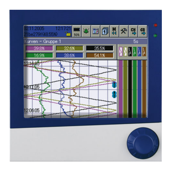
Page 31: Curve Presentation
4 Visualization Curve Presentation For this type of display one distinguishes between vertical and horizontal pre- sentation. Only one of the two presentation types can be active for all groups. v Configuration Screen Show diagrams v Configuration Screen Diagram display 4.3.1 Vertical presentation In the display, signals are continuously displayed on the screen running from…
-
Page 32: Horizontal Presentation
4 Visualization Memory This function starts the presentation of the data that are available in the history presentation memory. v Chapter 5 «Memory Presentation (History)» Numerical This function is used to switch the numerical measurement display (diagram measurement header) and binary traces on or off, as well as to activate the envelope display. display Channel This function activates the scaling display.
-
Page 33: Bar Graph Presentation
4 Visualization Bar Graph Presentation In this visualization mode, the analog inputs are presented both numerically and in bar graph form. In addition to the analog channels, the digital inputs can also be visualized at the bottom of the display. An alarm (Alarm 1 or Alarm 2) is indicated by an orange or red background.
-
Page 34: Text Picture Presentation
4 Visualization Text Picture Presentation In the presentation, the analog channels are presented numerically, together with the channel name and the channel description. In addition to the analog channels, the digital inputs can also be visualized at the right-hand edge of the display.
-
Page 35: Process Image Presentation
4 Visualization Process Image Presentation The display shows selected measurement signals and background pictures in a maximum of nine process images. The setup program is used to prepare and configure the images. Each process image can be freely configured by the user. One background image (316 ×…
-
Page 36: Vertical Presentation
4 Visualization 4.7.1 Vertical presentation In the display, signals are continuously displayed on the screen running from top to bottom. Diagram header Switch on and off Diagram header 4.7.2 Horizontal presentation In the display, signals are continuously displayed on the screen running from right to left.
-
Page 37: Reports
4 Visualization Reports Each one of the reports covers all the analog channels in a group. Each group has its own configurable report. The current reports are visualized in the presentation. Group step-on Channel step-on Report step-on Group selection Maximum Minimum Average Time period…
-
Page 38: Batches/Plants
4 Visualization Batches/Plants When recording batch processes, a distinction is made between the plant and the batch. The instrument can combine and record the data from up to 3 plants in batches (batch report). The number of batches for a plant is not limited. The instrument distinguishes between “current batch”…
-
Page 39
4 Visualization Edit This function can be used to edit the batch text fields that are available batch (configured for this purpose). When the function has been called up, the first editable field in the screen template will be activated. h Press the control knob to start editing. -
Page 40: Completed Batches
4 Visualization 4.9.2 Completed Batches Change batch/plant Batch evaluation Batch Completed batches can be evaluated in three different ways: evaluation — Curves (graphical presentation) — Report (numerical presentation) — Attachments (e.g. recipes) h Rotate the control knob to select a type of presentation, then press the knob to activate this type.
-
Page 41: Batch Control With Barcode Reader
4 Visualization 4.9.3 Batch Control with Barcode Reader If a barcode reader is connected to the interface “RS232 for barcode reader” (connector 2) or “RS232/RS485” (connector 7), then the batch start, batch stop, and input of batch texts in a current batch report, can be controlled by the barcode reader.
-
Page 42
4 Visualization Activate and display (if required) batch report for batch (plant) 3: Start and stop If the batch report is configured for start/stop via barcode reader, then it will be batch started and stopped as follows. report Start batch: h Scan bar code for “Batch report for batch (plant) 1 —… -
Page 43
4 Visualization Activate batch If a line in a batch report is configured for barcode activation, the activation texts proceeds as follows. Activate text: h Scan bar code for “Batch report for batch (plant) 1 — 3”. Scan text. The first line of the activated batch report that has been configured for text input via bar code will automatically be filled with the text that corresponds to the bar code. -
Page 44: Counters And Integrators
4 Visualization 4.10 Counters and Integrators In this presentation, the current states of the counters and integrators (totalizers) are displayed, as well as the operating hours counter. Up to 9 counters and integrators can be shown in one screen template. The functional characteristics (counter, integrator or operating hours counter) are defined in the device configuration.
-
Page 45: Comment Entry
4 Visualization 4.11 Comment Entry This function can be used to enter a text (max. length 31 characters) that is entered in the event list when the input is completed. In curve presentation (in the displayed group), the text entry is marked by a pencil symbol.
-
Page 46
4 Visualization… -
Page 47
5 Memory Presentation (History) The Memory presentation function can be used to display and check data from the internal main memory (SRAM) of the instrument. The size of the memory for memory presentation can be configured. The memory presentation can be activated in the visualization modes “Curve presentation”… -
Page 48: Vertical Presentation
5 Memory Presentation (History) Vertical presentation End memory presentation Channel step-on Numerical measurement display (Min / Max changeover) Zoom and Search Scroll pages Scroll lines Event list Present cursor position A cursor is now shown in the center of the visualization window. The corresponding measurements are shown in the line for “Numerical measurement display”.
-
Page 49
5 Memory Presentation (History) page, as required. “Scroll pages” can be ended by pressing the control knob. Zoom and This function affects how many measurements are used to calculate a point in search the diagram, and to search for measurements according to date and time. Zoom The factory setting is “1:1”, which means that every measurement in the History memory will be displayed. -
Page 50: Horizontal Presentation
5 Memory Presentation (History) Numerical This function decides whether the MAX or MIN values are shown in the measurement “Numerical measurement display”. Min or Max values arise when more display measurements are recorded than are displayed. This will be the case if “Min/ Max recording”…
-
Page 51
6 Alarm and Event Lists The alarm and event lists can be called up in two ways: — A call from one of the visualization modes, e.g. curve presentation (diagram) (Chapter 4.2 «Overview of Header Lines») — A call from the memory presentation (Chapter 5 «Memory Presentation (History)»). -
Page 52: Alarm And Event Lists Call From One Of The Visualization Modes
6 Alarm and Event Lists Call from One of the Visualization Modes h In the header line, rotate and press the control knob to select and activate the bell symbol. h Select the required list. Activate alarm list Complete list of alarms Batch-related alarm lists if the number of…
-
Page 53
6 Alarm and Event Lists h Rotate the control knob to select a list, then press the knob to activate the list. Example In the example, you can see a complete event list. Close list h Close the event list by pressing the control knob. The visualization that was active before the list was called up will now be displayed again. -
Page 54: Call From The Memory Presentation
6 Alarm and Event Lists Call from the Memory Presentation h In the header line, rotate and press the the control knob to select and activate the bell symbol. Only the event list for the active group will be shown in the memory presentation.
-
Page 55: Memory Manager
7 Memory Manager The memory manager contains functions for data exchange between the paperless recorder and CF memory cards or USB memory sticks. Symbols The symbol for the Memory manager (menu: Memory manager) in the header can be shown in different ways. This shows the available memory of the CompactFlash memory card that has been inserted.
-
Page 56
7 Memory Manager Activation for USB stick Access to the Memory manager menu via the header is not possible with a USB memory stick. If one of the visualization modes (Chapter 4 — e.g. Curve Presentation) is active when a USB memory stick is inserted, the menu automatically appears and remains active until the memory stick is removed again. -
Page 57
7 Memory Manager The functions of the memory manager are the same for CF cards and USB memory sticks. For USB sticks, the menu entries have «USB stick» instead of «CF card». Close memory Close the memory manager and reactivate the previous visualization. manager (Exit) Safely The function should always be called before removing a CF card or a USB… -
Page 58
7 Memory Manager General information The function CF card update reads out data that have not yet been read out. After read-out, data are not marked as read in the recorder but are not deleted. Function Backup CF card reads all data from internal memory, including what had already been read. -
Page 59: Device Manager
8 Device Manager The functions of the Device manager vary, depending on whether a user is logged in or not. No user logged in “User” logged in User Close Device Manager “Master” logged in Log-in and log-out Device information Device audit trail Configuration Parameterization Service functions…
-
Page 60: Close Device Manager
8 Device Manager Close Device Manager Close the device manager and reactivate the previous visualization. Log-in and Log-out h Select the Device manager in the header, by rotating the control knob. h Activate the Device manager by pressing the control knob. h In the Device manager activate the function Log in.
-
Page 61
8 Device Manager h Select “OK” with the control knob, and press the control knob. h Enter the password by rotating and pressing the control knob, and finish the entry with “OK”. You are now logged in to the system. -
Page 62: Device Information
8 Device Manager Device information This function provides you with information on the hardware and software components of the instrument. The momentary values of all the internal and external inputs can also be checked. The control knob can be rotated to display every single table. The function is terminated by pressing the control knob.
-
Page 63
8 Device Manager Info Module 1 = bottom module slot Module 2 = middle module slot Module 3 = top module slot Date and time of last reconfiguration Switching state of relay 1 (fitted as standard); 0= not switched Hardware Bottom module slot Middle module slot Top module slot… -
Page 64
8 Device Manager Module 1 The picture below shows a module that has been fitted with 6 analog inputs. Depending on the hardware level, the picture may look different. Module 1 is in the bottom module slot. The * indicates that an offset or fine calibration is Display of the current active on this channel. -
Page 65
8 Device Manager Module 3 The picture below shows a module that has been fitted with a relay card (6 relays). Depending on the hardware level, the picture may look different. Module 3 is in the top slot. Switching state of relays (0 = not switched). -
Page 66
8 Device Manager Eth. info 1 Information about the current Ethernet configuration Eth. info 2 Information about the current Ethernet communication Parameter Description Ethernet status 1 Received Ethernet packets Ethernet status 2 Received Ethernet packets with errors Transmitted Ethernet packets Ethernet status 3 Ethernet status 4 Transmitted Ethernet packets with errors… -
Page 67: Device Audit Trail
8 Device Manager Description Parameter Received TCP packets Ethernet status 5 Received TCP packets with errors Ethernet status 6 Ethernet status 7 Transmitted TCP packets Ethernet status 8 Transmitted TCP packets with errors Received Lease time, in seconds Ethernet status 9 USB info Information appears in the window via the USB interfaces.
-
Page 68: Configuration
8 Device Manager Configuration This function can be used to alter the configuration of the recorder. v B 706581.0. An alteration of the configuration results in the current recording being closed down and the new data being recorded in a separate time frame from the “old”…
-
Page 69: Service
8 Device Manager Service The “Service” functions will also not be available if no user is logged in, or the user who is logged in does not possess access rights for these functions. Config. -> The current configuration can be saved within the device as the new factory factory settings setting.
-
Page 70
8 Device Manager… -
Page 71: Entering Text And Values
9 Entering text and values Text entry 9.1.1 Entering characters If a Text entry field is selected, and then activated by pressing the control knob, then a text can be entered or altered. The cursor (position marker) is at the end of the current setting. The active key or function that will be performed when the control knob is pressed is shown in blue.
-
Page 72
9 Entering text and values Character h Move the cursor onto the required character, and press the control knob. entry Another selection window will open. Reject entry Upper case letter Lower case letter h Rotate the control knob to select upper case (capital) or lower case (small) letters, or reject an entry, and activate/confirm the choice by pressing the control knob. -
Page 73: Insert Spaces
9 Entering text and values Select h Select “ ” and press the control knob. temperature All the temperature units that can be selected will now be shown. For better unit legibility, the degree sign (°) and the unit of measure (C or F) are separated, and must be individually selected.
-
Page 74: Reject Entry
9 Entering text and values 9.1.7 Reject entry h Select the “Cancel” button ( ) and press the control knob. Character entry will now be ended. The text that was entered is not accepted, and the dialog window is closed. The previously active setting is retained. Entry via selection field If a selection field is selected, and then activated by pressing the control knob, then the text (value) can be entered from a previously defined list.
-
Page 75: Entering Values
9 Entering text and values Entering values 9.3.1 Whole numbers (integers) There are two possibilities for entering integer numbers: — selection by altering the individual digits of a number, or — selection by incrementing and decrementing. Digit-by-digit For this entry, each digit of the number (units, tens, …) and the sign are entry of an selected with the control knob.
-
Page 76: Real Numbers (Floating Point)
9 Entering text and values 9.3.2 Real numbers (floating point) To enter real numbers (with a decimal point), each digit of the number (units, tens, etc.), the decimal point position, and the sign are selected with the control knob. Sequence — Position the cursor.
-
Page 77: Web Server
10 Web server The web server functionality depends on the software version of the device. Which device software version is installed? v Chapter 8.3 «Device information» Up to 187.03.xx v Chapter 10.1 «General» to Chapter 10.5 «QuadView» As of 187.04.xx v Chapter 10.6 «General information»…
-
Page 78: General
10 Web server 10.1 General The web server is integrated in the paperless recorder as a standard feature. Four different modes of presentation are available: «Online Visualization (All Visualizations Except Batches)» «Three freely programmable HTML pages» «Online Visualization of Current Batch Reports» «QuadView»…
-
Page 79
10 Web server Home page Online visualization automatically comes up as the home page if the web server is started by the browser or, if it has already been activated, the user (left) clicks the «Recorder» link. Areas The web server’s display is divided into three areas: — Header — Navigation — Visualization area… -
Page 80
10 Web server Navigation Configurable device name; read automatically Online visualization v Chapter 10.2 Three freely programmable HTML pages; created with the setup program v Chapter 10.3 Online visualization of current batch reports v Chapter 10.4 Start of QuadView Configuration of QuadView v Chapter 10.5 Individual pages can be brought up by clicking (left mouse button). -
Page 81: Online Visualization (All Visualizations Except Batches)
10 Web server 10.2 Online Visualization (All Visualizations Except Batches) Data that are displayed correspond to the configured groups of the recorder. Next group Next channel History Groups Visualization Alarm/event list The sample screen shows the web server’s home page. This page can be used to represent channels in the same manner as on the recorder’s screen.
-
Page 82
10 Web server Example Switching to bar graph presentation h (Left) click the Visualization menu. h (Left) click the bar graph. Result: The bar graph visualization type is activated. -
Page 83: Three Freely Programmable Html
10 Web server 10.3 Three freely programmable HTML pages The sample screen shows one of three freely programmable HTML pages. These pages can be created and modified with the setup program. Further information can be obtained from the instructions on the setup program (B 706581.6).
-
Page 84: Online Visualization Of Current Batch Reports
10 Web server 10.4 Online Visualization of Current Batch Reports When batch pages of a plant are called up, the current data from the recorder is read and displayed. Batch recording is active or inactive Editable text field; (left) click and enter text The «Appendix»…
-
Page 85: Quadview
10 Web server 10.5 QuadView Visualization for up to four devices is possible with QuadView. The visualizations may involve one device or up to four different ones. Different visualizations can be activated for each display (for example two views of a device, curve presentation and bar graph display).
-
Page 86
10 Web server Result: IP addresses (or DNS names) that have been entered are saved as cookies in the PC and remain intact until cookies are deleted (forexample by the PC browser). h Click «Start» or «Start visualization». Result: QuadView starts. In the example shown here, two different recorders are accessed (recorder 1 top left and top right, recorder 2 bottom left and bottom right). -
Page 87
10 Web server Unlike a normal online visualization, the header contains modified buttons. View all four visualizations View only top left visualization View only top right visualization View only top right visualization View only bottom right visualization QuadView… -
Page 88: General Information
10 Web server 10.6 General information The web server is integrated into the paperless recorder as standard. Three different display types are available: «Online Visualization (All Visualizations Except Batches)» «Online Visualization of Current Batch Reports» «QuadView» The web server can be queried from the PC with the following programs (among others) without a SVG viewer having to be installed.
-
Page 89
10 Web server Start page The start page is automatically shown after a successful logon. Distribution The display of the web server is divided into two areas: — Navigation — Visualization area Navigation Start and configuration of the 4-fold view (QuadView) v Chapter 10.9 Online visualization of the current batch reports… -
Page 90: Online Visualization (All Visualizations Other Than Batches)
10 Web server Visualization The visualization area shows the current data from the paperless recorder. Up- area dating occurs automatically through the web server. 10.7 Online visualization (all visualizations other than batches) The operation conforms to the operation as described in Chapter 10.2.
-
Page 91: Online Visualization Of The Current Batch Reports
10 Web server 10.8 Online visualization of the current batch reports If batch reports from a plant are requested then the current data is extracted from the recorder and shown. Display available batch report Click text edit fields (marked in yellow) with the left mouse button and enter text (once authorization has been obtained) The «attachment»…
-
Page 92: Quadview
10 Web server 10.9 QuadView Up to four devices can be visualized with the 4-fold view (QuadView). This ap- plies to the same device or to two to four different devices. For each display, different visualizations can be activated (e.g. the curve presentation and the bar graph display of a device in two views).
-
Page 93
10 Web server Delete configu- ration By left-clicking «[-]» the configuration will be deleted and new addresses can be entered. -
Page 94
10 Web server… -
Page 95: Appendix
11 Appendix 11.1 Bar code 11.1.1 Batch control Plant 1 Plant 2 Plant 3 Start Stop Reset entry…
-
Page 96: Batch Texts
11 Appendix 11.1.2 Batch texts Product name SUPER PRODUCT NORMAL PRODUCT TOOTHED DISK 34 AXIS ROD 45 Product 645736 numbers 012876…
-
Page 97
11 Appendix 345435 Job numbers A83737 A4555455 A455445 Personnel 4576 number 7665… -
Page 98
11 Appendix… -
Page 99
12 Index Numerics 1-channel presentation 4-fold view Alarm and event lists – Alarm limits Alarm lists Arrangement of the documentation Audit trail Backup -> CF card Bar code Bar graph presentation – – Batch analyze automatic start change edit Batch start/stop Batch status Batches Start manually… -
Page 100
12 Index Curve presentation – Data readout via interface with a CF memory card Device Information Device Manager Device manager Diagram header Diagram view Display Display off Displays and controls Edit batch Electrostatic discharge (ESD) Entering values Eth. info Event lists Event mode Ext. -
Page 101
12 Index Info Installation Instructions Instrument documentation in printed form Instrument documentation in the form of PDF files Integrators Introduction IP address Keys Log-in Log-in and Log-out Log-out Max. value Memory manager Memory managers Memory presentation Module Normal display Normal mode Note signs Numerical measurement display Operating mode… -
Page 102
12 Index Power LED Presentation modes – Process image presentation QuadView – Report Report step-on Returning Rights Sampling rate Save all + update CF card Screen saver Screen texts Scroll Search Service Stainless steal stainless steel Status bar Status LED Symbols Text entry –… -
Page 103
12 Index logged in logged out Standard (default) password Standard (default) user Version vertical presentation Visualization Visualization window Warning signs Warranty Web server Writing configuration data to CF card / reading from CF card Zoom… -
Page 104
12 Index… -
Page 108
JUMO GmbH & Co. KG JUMO Instrument Co. Ltd. JUMO Process Control, Inc. Street address: JUMO House 6733 Myers Road Moritz-Juchheim-Straße 1 Temple Bank, Riverway East Syracuse, NY 13057, USA 36039 Fulda, Germany Harlow — Essex CM20 2DY, UK Phone:…

4
Параметры конфигурации
60
4.2.2 Конфигурация — Данные прибора
Параметр
Значения / Опции
Описание
Символическое имя
прибора
Конфигурация
Î
Данные прибора
Î
Символическое имя
прибора
16 знаков
Дата
Конфигурация
Î
Данные прибора
Î
Дата и время
Î
Дата
произвольная дата
Ввод текущей даты
Время
Конфигурация
Î
Данные прибора
Î
Дата и время
Î
Время
произвольное время
Ввод текущего времени су-
ток
Синхронизация вре-
мени
Конфигурация
Î
Данные прибора
Î
Дата и время
Î
Синхр. времени
Выключена,
Двоич. вх. 1 … 4,
Логич. канал 1 … 6,
Сигнал Min 1 … 6,
Общий сигнал Min,
Сигнал Max 1 … 6,
Общий сигнал Max,
Сигнал сч./инт. 1 … 6,
Общ. сигнал сч./инт.,
Общий сигнал тревоги,
CF вставлена, сигнал
Память ЗУ/CF, сигнал
Память ЗУ/посл.инт.,
сигнал Память CF, не-
поладка, флаг Modbus
С помощью этого парамет-
ра (функции) можно син-
хронизовать системные ча-
сы нескольких экранных
регистраторов. Если был
выбран какой-либо двоич-
ный вход и он активируется
(переход с низкого на высо-
кий уровень), то можно вы-
полнить синхронизацию.
При изменении времени
следует обратить внимание
на секунды. Они определя-
ют округление времени в
большую или меньшую сто-
рону.
Напр. 12:55:29 -> 12:55:00
12:55:30 -> 12:56:00
Переход с/на летнее
время
Конфигурация
Î
Данные прибора
Î
Летнее время
Î
Переход
Выключен,
Указать время,
Автоматически
Автоматически:
2:00 или 3:00 в последнее
воскресенье марта или ок-
тября
Летнее время (дата
начала)
Конфигурация
Î
Данные прибора
Î
Летнее время
Î
Дата начала
произвольная дата
можно задавать только,
если «Переход» установлен
на «Указать время»
Летнее время (время
начала)
Конфигурация
Î
Данные прибора
Î
Летнее время
Î
Время начала
произвольное время
можно задавать только,
если «Переход» установлен
на «Указать время»
Летнее время (дата
конца)
Конфигурация
Î
Данные прибора
Î
Летнее время
Î
Дата конца
произвольная дата
можно задавать только,
если «Переход» установлен
на «Указать время»
Летнее время (время
конца)
Конфигурация
Î
Данные прибора
Î
Летнее время
Î
Время конца
произвольное время
можно задавать только,
если «Переход» установлен
на «Указать время»
Назначение
Описание
Программное обеспечение
Технические характеристики
Знак утверждения типа
Комплектность
Поверка
Сведения о методах измерений
Нормативные документы
Назначение
Приборы регистрирующие измерительные «LOGOSCREENnt» тип 706581, «LOGOSCREEN 500 cf» тип 706510, «LOGOSCREEN 600» тип 706520 (далее — регистраторы) предназначены для измерений, хранения и передачи сигналов напряжения и силы постоянного электрического тока, сопротивления постоянному току (в том числе выходных сигналов от термопар (ТП) и термопреобразователей сопротивления (ТС)), формирования аналоговых управляющих сигналов силы постоянного электрического тока.
Описание
Принцип работы регистраторов основан на аналого-цифровом преобразовании измеряемой величины и визуальном отображении измеренных величин на дисплее регистратора или персонального ПК.
Регистраторы «LOGOSCREEN 600» тип 706520 представляют собой электронное устройство, оснащенное резистивным сенсорным дисплеем. Регистраторы, в зависимости от комплектации, могут быть не оснащены измерительными входами (в этом случае измеряемые параметры (до 24) считываются или принимаются по протоколу Modbus с внешних систем), оснащены 6 универсальными аналоговыми входами, 2 аналоговыми выходами, 12 цифровыми входами и 12 переключаемыми по отдельности цифровыми входами/выходами.
Регистраторы «LOGOSCREEN 500 cf» тип 706510 представляют собой электронное устройство, с дисплеем, набором функциональных клавиш и дисководом. Регистраторы оснащаются 6 или 12 измерительными входами, с возможностью расширения до 36 измерительных входов. С обратной стороны регистраторов расположены съемные клеммные колодки для подключения проводов электропитания, входных сигналов, сигналов аварийной сигнализации.
Регистраторы«LOGOSCREEN nt» тип 706581 представляют собой электронное устройство в стальном корпусе, дисплеем и ручкой управления. Модульная конструкция регистраторов предусматривает 3 модульных гнезда, каждый из которых может быть о снащен двух типов: с 6 аналоговыми входами или с 3 аналоговыми входами и 8 двоичными входамивыходами. Третье модульное гнездо так же может быть оснащено релейным модулем с 6 реле.
Конфигурирование регистраторов«LOGOSCREEN 600» тип 706520 осуществляется с помощью символьной системы меню на резистивном сенсорном экране, Setup-с использованием персонального компьютера поинтерфейсу USB, RS232 и RS485 или Ethernet. Данные о результатах измерений представляются на 5,7″ цветном дисплее в виде диаграмм, в цифровом виде.
Конфигурирование регистраторов «LOGOSCREEN 500 cf» тип 706510 осуществляется с помощью функциональных клавиш, Compact-Flash карты или Setup-программы с использованием персонального компьютера по интерфейсу RS232 (RS422/RS485) или Ethernet. Аналоговые сигналы преобразуются в цифровые 14-разрядным АЦП. Данные о результатах измерений представляются на 5,7″ цветном дисплее в виде диаграмм, в цифровом виде, и могут быть сохранены во внутренней памяти и на Compact-Flash карту.
Конфигурирование регистраторов «LOGOSCREEN nt» тип 706581 осуществляется с помощью интерфейсаRS-232/RS485, USB или Ethernet. Данные о результатах измерений представляются на 5,5″ цветном дисплее в виде диаграмм, в цифровом виде, и могут быть сохранены в Backup-памяти и на Compact-Flash карту.
Программное обеспечение
Метрологически значимое программное обеспечение (ПО) регистраторов устанавливается в энергонезависимую память регистратора на заводе-изготовителе во время производственного цикла. Оно недоступно пользователю и не подлежит изменению на протяжении всего времени функционирования регистратора, соответствует уровню защиты «высокий» в соответствии с Р 50.2.077-2014.
Прикладное ПО регистратора состоит из трех компонентов: Setup-программы, РСА3000-программыи РСС.
При установке Setup-программы на ПК, подключенный к регистратору по одному из интерфейсов (Ethernet, USB, RS232/RS422/RS485) возможно удаленное управление регистратором. Так же конфигурация может быть сохранена на CF-карту и с ее помощью установлена на регистраторе.
РСА3000-программа — программа для обработки данных на ПК, служит для архивирования, администрирования, визуализации и обработки результатов измерений регистратора.
РСС (РСА-коммуникационный сервер) — данные могут быть считаны с регистратора через последовательный интерфейс (RS232/RS422/RS485) или через Ethernet-интерфейс. Это можно осуществить вручную или автоматически.
Идентификационные данные метрологически значимого ПО приведены в таблице 1.
Метрологические характеристики регистраторов нормированы с учетов влияния на них метрологически значимого ПО.
|
Идентификационные данные (признаки) |
Значение |
|
|
Идентификационное наименование ПО |
JUMO PCC |
JUMO PCA 3000 |
|
Номер версии (идентификационный номер) ПО |
178.03.xx/3.05 |
177.03.xx/3.05 |
|
Цифровой идентификатор ПО |
По номеру версии и идентификационному наименованию ПО |
|
|
Другие идентификационные данные, если имеются |
— |
Технические характеристики
Основные метрологические характеристики регистраторов приведены в таблицах 2-9.
Таблица 2 — Метрологические характеристики регистраторов «LOGOSCREEN 600» тип 706520 и «LOGOSCREEN 500 cf» тип 706510 при преобразовании сигналов от ТП.
|
Тип ТП |
Диапазоны преобразований сигналов от ТП |
Пределы допускаемой основной приведенной погрешности, % от диапазона преобразований |
|
L |
от -200 до +800 °С |
±0,25 |
|
J |
от -210 до +1200°С (от -100 до +1200 °С) |
±0,25 |
|
T |
от -270 до +400 °С (от -150 до +400 °С) |
±0,25 |
|
K |
от -270 до +1372°С (от -80 до +1372 °С) |
±0,25 |
|
E |
от -270 до +1000°С (от -80 до +1000 °С) |
±0,25 |
|
N |
от -270 до +1300°С (от -80 до +1300 °С) |
±0,25 |
|
S |
от -50 до +1768 °С (от 0 до 1768 °С) |
±0,25 |
|
R |
от -50 до +1768 °С (от 0 до 1768 °С) |
±0,25 |
|
B |
от 0 до 1820 °С (от 400 до 1820 °С) |
±0,25 |
|
темпер преобр грешно |
Примечания 1 Пределы допускаемой основной абсолютной погрешности канала компенсации атуры холодного спая (внутренний Pt100 или внешний) для каждого типа ТП ±1 °С. 2 В графе «диапазон преобразований сигналов от ТП» в скобках указан диапазон азований, для которого нормированы значения основной и дополнительной по-стей. |
|
Тип ТП |
Диапазоны преобразований сигналов от ТП |
Пределы допускаемой основной приведенной погрешности, % от диапазона преобразований |
|
L |
от -200 до +900 °C |
±0,1 |
|
J |
от -210 до +1200 °С (от -100 до +1200 °С) |
±0,1 |
|
T |
от -270 до +400 °С (от -150 до +400 °С) |
±0,1 |
|
K |
от -270 до +1372 °С (от -80 до +1372 °С) |
±0,1 |
|
E |
от -270 до +1000 °С (от -80 до +1000 °С) |
±0,1 |
|
N |
от -270 до +1300 °С (от -80 до +1300 °С) |
±0,1 |
|
S |
от -50 до +1768 °С (от 0 до 1768 °С) |
±0,15 |
|
R |
от -50 до +1768 °С (от 0 до 1768 °С) |
±0,15 |
|
B |
от 0 до 1820 °С (от 400 до 1820 °С) |
±0,15 |
|
темпер преобр грешно |
Примечания 1 Пределы допускаемой основной абсолютной погрешности канала компенсации атуры холодного спая (внутренний Pt100 или внешний) для каждого типа ТП ±1 °С. 2 В графе «диапазон преобразований сигналов от ТП» в скобках указан диапазон азований, для которого нормированы значения основной и дополнительной по-стей. |
Таблица 4 — Метрологические характеристики регистраторов «LOGOSCREEN 500 cf» тип 706510 при преобразовании сигналов от ТС._
|
Тип ТС |
Диапазоны преобразований сигналов от ТС |
Пределы допускаемой основной абсолютной погрешности |
|
Pt100 |
от -200 до +500 °C (2-х, 3-х, 4-х пров. соединение) |
±0,4 °С |
|
Pt100 |
от -200 до +850 °С (2-х, 3-х пров. соединение) |
±0,8 °С |
|
Pt100 |
от -200 до +850 °С (4-х пров. соединение) |
±0,5 °С |
|
Pt500 |
от -200 до +500 °C (2-х, 3-х, 4-х пров. соединение) |
±0,4 °С |
|
Pt500 |
от -200 до +850 °С (2-х, 3-х пров. соединение) |
±0,8 °С |
|
Pt500 |
от -200 до +850 °С (4-х пров. соединение) |
±0,5 °С |
|
Pt1000 |
от -200 до +500 °C (2-х, 3-х, 4-х пров. соединение) |
±0,4 °С |
|
Pt1000 |
от -200 до +850 °С (2-х, 3-х пров. соединение) |
±0,8 °С |
|
Тип ТС |
Диапазоны преобразований сигналов от ТС |
Пределы допускаемой основной абсолютной погрешности |
|
Pt1000 |
от -200 до +850 °С (4-х пров. соединение) |
±0,5 °С |
|
Ni100 |
от -60 до +180°С (2-х, 3-х, 4-х пров. соединение) |
±0,4 °С |
|
Cu50 |
от -50 до +200 °С (2-х, 3-х пров. соединение) |
±0,5°С |
|
Cu50 |
от -50 до +200 °С (4-х пров. соединение) |
±0,4 °С |
Таблица 5 — Метрологические характеристики регистраторов «LOGOSCREEN 600» тип 706520 при преобразовании сигналов от ТС._
|
Тип ТС |
Диапазоны преобразований сигналов от ТС |
Пределы допускаемой основной абсолютной погрешности |
|
Pt50 |
от -200 до +850 °С (2-х, 3-х, 4-х пров. соединение) |
±0,1 °С |
|
Pt100 |
от -200 до +850 °С (2-х, 3-х, 4-х пров. соединение) |
±0,1 °С |
|
Ni100 |
от -60 до +180 °С (2-х, 3-х, 4-х пров. соединение) |
±0,2°С |
|
Cu50 |
от -180 до +200 °С (2-х, 3-х, 4-хпров. соединение) |
±0,4°С |
|
Cu100 |
от -180 до +200 °С (2-х, 3-х, 4-хпров. соединение) |
±0,4 °С |
Таблица 6 — Метрологические характеристики регистраторов «LOGOSCREENnt» тип 706581при преобразовании сигналов от ТС._
|
Тип ТС |
Диапазоны преобразований сигналов от ТС |
Пределы допускаемой основной абсолютной погрешности |
|
Pt100 |
от -200 до +100°С (2-х, 3-х пров. соединение) |
±0,5 °С |
|
Pt100 |
от -200 до +850 °С (2-х, 3-х пров. соединение) |
±0,8°С |
|
Pt100 |
от -200 до +850 °С (4-х пров. соединение) |
±0,5 °С |
|
Pt500 |
от -200 до +100°С (2-х, 3-х пров. соединение) |
±0,5 °С |
|
Pt500 |
от -200 до +850 °С (2-х, 3-х пров. соединение) |
±0,8 °С |
|
Pt500 |
от -200 до +850 °С (4-х пров. соединение) |
±0,5 °С |
|
Pt1000 |
от -200 до +100°С (2-х, 3-х пров. соединение) |
±0,5 °С |
|
Pt1000 |
от -200 до +850 °С (2-х, 3-х пров. соединение) |
±0,8 °С |
|
Тип ТС |
Диапазоны преобразований сигналов от ТС |
Пределы допускаемой основной абсолютной погрешности |
|
Pt1000 |
от -200 до +850 °С (4-х пров. соединение) |
±0,5 °С |
|
Cu100 |
от -50 до +100 °С (2-х, 3-х, 4^пров. соединение) |
±0,5 °С |
|
Cu100 |
от -50 до +200 °С (2-х, 3-х пров. соединение) |
±0,9 °С |
|
Cu100 |
от -50 до +200 °С (4^пров. соединение) |
±0,6 °С |
Таблица 7 — Метрологические характеристики регистраторов «LOGOSCREEN 600» тип 706520 при измерении напряжения и силы постоянного тока, сопротивления._
|
Диапазон измерений |
Пределы допускаемой основной абсолютной погрешности |
|
от 0 до 4000 Ом |
±4 Ом |
|
от 0 до 400 Ом |
±400 мОм |
|
от 0 до 4000 Ом |
±4 Ом |
|
от 0 до 70 мВ |
±7 мкВ |
|
от 0 до 10 В |
±0,5 мВ |
|
от -10 до +10 В |
±1 мВ |
|
от -1 до +1 В |
±0,16 мВ |
|
от 0 до 1 В |
±0,08 мВ |
|
от 4 до 20 мА |
±1,6 мкА |
|
от 0 до 20 мА |
±2 мкА |
Таблица 8 — Метрологические характеристики регистраторов «LOGOSCREEN 500 cf» тип 706510при измерении напряжения и силы постоянного тока, сопротивления._
|
Диапазон измерений |
Пределы допускаемой основной абсолютной погрешности |
|
от 0 до 180 Ом |
±150 мОм |
|
от 0 до 390 Ом |
±300 мОм |
|
от 0 до 2000 Ом |
±2 Ом |
|
от 0 до 4000 Ом |
±4 Ом |
|
от -20 до +70 мВ |
±80 мкВ |
|
от -5 до +105 мВ |
±100 мкВ |
|
от -10 до +210 мВ |
±240 мкВ |
|
от -0,5 до +12 В |
±12 мВ |
|
от -0,05 до +1,2 В |
±1 мВ |
|
от -1,2 до +1,2 В |
±2 мВ |
|
от -12 до +12 В |
±12 мВ |
|
от -2 до +22 мА |
±20 мкА |
|
от -22 до +22 мА |
±44 мкА |
|
Диапазон измерений |
Пределы допускаемой основной абсолютной погрешности |
|
от 0 до 4000 Ом |
±4 Ом |
|
от 0 до 400 Ом |
±400 мОм |
|
от 400 до 4000 Ом |
±4 Ом |
|
от -12 до +112 мВ |
±100 мкВ |
|
от -10 до +210 мВ |
±240 мкВ |
|
от -1,5 до +11,5 В |
±6 мВ |
|
от -0,12 до +1,12 В |
±1 мВ |
|
от -1,2 до +1,2 В |
±2 мВ |
|
от -11 до +12 В |
±12 мВ |
|
от -1,3 до +22 мА |
±20 мкА |
|
от -22 до +22 мА |
±44 мкА |
Пределы допускаемой дополнительной приведённой погрешности от воздействия температуры окружающей среды в пределах рабочих условий применения:
— для LOGOSCREENnt» тип 706581, «LOGOSCREEN 500 cf» тип 706510 ± 0,03 % от
диапазона измерений (преобразований)/ °С;
— для «LOGOSCREEN 600» тип 706520 ± 0,01 % от диапазона измерений (преобразо
ваний)/ °С.
Регистраторы «LOGOSCREEN 600» тип 706520 формируют выходной аналоговый сигнал напряжения постоянного тока от 0 до 10 В и силы постоянного тока от 0 (4) до 20 мА с пределами допускаемой основной приведённой от диапазона преобразований погрешности ±0,5 %, пределы допускаемой дополнительной приведённой погрешности от воздействия температуры окружающей среды в пределах рабочих условий применения ±0,015 % от диапазона преобразований/ °С.
Таблица 10 — Технические характеристики регистраторов
|
Параметры |
Значения |
|
Рабочие условия применения. |
|
|
Влажность окружающего воздуха: |
|
|
Регистраторы «LOGOSCREEN 600» тип 706520 |
до 85 % без конденсации |
|
Регистраторы «LOGOSCREEN 500 cf» тип 706510 Регистраторы «LOGOSCREENnt» тип 706581 |
до 75 % без конденсации |
|
Температура окружающего воздуха: |
|
|
Регистраторы «LOGOSCREENnt» тип 706581 |
от 0 до 45 °С |
|
Регистраторы «LOGOSCREEN 600» тип 706520 Регистраторы «LOGOSCREEN 500 cf» тип 706510 |
от 0 до 50 °С |
|
Нормальная температура окружающего воздуха: |
|
|
Регистраторы «LOGOSCREENnt» тип 706581 Регистраторы «LOGOSCREEN 600» тип 706520 Регистраторы «LOGOSCREEN 500 cf» тип 706510 |
(23±2) °С |
|
Напряжение питания: |
|
|
Регистраторы «LOGOSCREEN 600» тип 706520 Регистраторы «LOGOSCREENnt» тип 706581 |
от 110 до 240 В перем. тока -10°%, от 48 до 63 Гц; от 20 до 30 В перем.пост. тока, от 48 до 63 Гц |
|
Параметры |
Значения |
|
Регистраторы «LOGOSCREEN 500 cf» тип 706510 |
от 100 до 240 В перем. тока -10°%, от 48 до 63 Гц; от 20 до 53 В перем.пост. тока, от 48 до 63 Гц |
|
Потребляемая мощность: |
|
|
Регистраторы «LOGOSCREEN 600» тип 706520 |
30 В-А (при напряжении питания от 110 до 240 В перем. тока) 18 В-А (при напряжении питания от 20 до 30 В пост./перем. тока) |
|
Регистраторы «LOGOSCREEN 500 cf» тип 706510 |
25 ВА |
|
Регистраторы «LOGOSCREENnt» тип 706581 |
40 ВА |
|
Температура хранения: |
|
|
Регистраторы «LOGOSCREEN 600» тип 706520 Регистраторы «LOGOSCREEN 500 cf» тип 706510 Регистраторы «LOGOSCREENnt» тип 706581 |
от -20 до +60 °С |
|
Г абаритные размеры, мм, не более |
|
|
Регистраторы «LOGOSCREEN 600» тип 706520 |
144х200х119 |
|
Регистраторы «LOGOSCREEN 500 cf» тип 706510 |
144х200х225 |
|
Регистраторы «LOGOSCREENnt» тип 706581 |
144х144х192 |
|
Масса, кг, не более |
|
|
Регистраторы «LOGOSCREEN 600» тип 706520 |
1,6 |
|
Регистраторы «LOGOSCREEN 500 cf» тип 706510 |
3,5 |
|
Регистраторы «LOGOSCREENnt» тип 706581 |
3,5 |
Знак утверждения типа
наносится на титульный лист руководства по эксплуатации типографским способом и на корпус регистраторов методом наклейки.
Комплектность
В комплект поставки входит:
— прибор регистрирующий измерительный LOGOSCREEN;
— руководство по эксплуатации;
— паспорт;
— методика поверки;
— программа обработки данных PCA3000*;
— программа передачи данных PCA (PCC)*;
— Setup-программа*;
— USB-кабель, штекер A на штекер Micro-B*.
*- в зависимости от исполнения.
Поверка
осуществляетсяв соответствии с документом «Приборы регистрирующие измерительные «LOGOSCREENnt» тип 706581, «LOGOSCREEN 500 cf» тип 706510, «LOGOSCREEN 600» тип 706520. Методика поверки», разработанными утверждённым ФГУП «ВНИИМС» 12.05.2016 г.
Перечень основных средств поверки:
1 Калибратор универсальный Н4-7 (рег. № 22125-01), (А = ±(0,004 % I+ 0,0004 % 1п) в режиме воспроизведения силы постоянного электрического тока в диапазоне от 0 до 20 мА; А =±(0,002 % U+ 0,00025 % ип) в режиме воспроизведения напряжения постоянного тока в
диапазоне от 0 до 2 В; А =±(0,002 % U+ 0,00015 % №) в режиме воспроизведения напряжения постоянного тока в диапазоне от 0 до 20 В);
2 Мультиметр цифровой прецизионный 8508А (рег. № 25984-14);
3 Магазин сопротивления измерительный МСР-60М (рег. № 2751-71), кл.т. 0,02.
Сведения о методах измерений
Методы измерений изложены в руководстве по эксплуатации.
Нормативные документы
Нормативные документы, устанавливающие требования к приборам регистрирующим измерительным «LOGOSCREENnt» тип 706581, «LOGOSCREEN 500 cf» тип 706510, «LOGOSCREEN 600» тип 706520
ГОСТ 6651-2009 ГСИ. Термопреобразователи сопротивления из платины, меди и никеля. Общие технические требования и методы испытаний.
ГОСТ Р 8.585-2001 ГСИ. Термопары. Номинальные статические характеристики преобразования.
ГОСТ 26.011-80 Средства измерений и автоматизации. Сигналы тока и напряжения электрические непрерывные входные и выходные.
ГОСТ Р 52931-2008 Приборы контроля и регулирования технологических процессов. Общие технические условия.
Техническая документация фирмы-изготовителя.
JUMO LOGOSCREEN nt: List of Available Documents
Note for Owners:
Guidesimo.com webproject is not a service center of JUMO trademark and does not carries out works for diagnosis and repair of faulty JUMO LOGOSCREEN nt equipment. For quality services, please contact an official service center of JUMO company. On our website you can read and download documentation for your JUMO LOGOSCREEN nt device for free and familiarize yourself with the technical specifications of device.
More Data Loggers Devices:
-
LI-COR LI-1500
LI-1500 GPS Upgrade KitInstallation InstructionsThis instructionsheet describes howto install the LI-1500GPSUpgrade Kit (p/n1500-GPS) inthe LI-1500 Light Sensor Logger.Note: Some instruments may have different wire colors thanthose shown in these instructions. This will not affect theinstallation.LI-1500 GPS Upgrade Kit includesl GPS board (p/n 9922-135)l GPS flex cable (p/n 388-13760)l Two 2-56 s …
LI-1500 Data Loggers, 2
-
Lascar EL-SIE-2+
EL-SIE-2+High Accuracy Temperature and Humidity USB Data Logger, EasyLog Cloud CompableMonitor the environment you live and work in with the EasyLog EL-SIE-2+. Conguraon is simple, with no soware to install on your PC or Mac – just connect the logger with a USB cable, and use your standard web browser to congure the device for logging. You don’t even need internet access to set …
EL-SIE-2+ Data Loggers, 6
-
NeuLog NUL-217
NEULOG GALVANIC SKIN RESPONSE LOGGER SENSOR GUIDE NeuLog galvanic skin response logger sensor NUL-217 The NeuLog GSR sensor can be used for any science experiment or activity which utilizes the natural galvanic skin response (skin conductance) in the fields of biology, physiology, psychology, etc. Galvanic skin response, or skin conductance, is a measure of the changes in the skin’s conduc …
NUL-217 Data Loggers, 6
-
Aptiv Control-Tec CT-1000
1. Connect the cable(s)1.1 Connect the DB26 cable into the VEHICLE port.1.2 Connect the manual trigger to the DIGITAL I/O port.*2. Connect antenna(s)2.1 Wi-Fi: Connect the two (short) 4.25in Wi-Fi antennas to the WiFi-1 & WiFi-2 ports.*Cellular: Connect the cellular antennas to the CELL-1 and CELL-2 ports.*2.2 The 8in 4G:JCG410L cellular antenna(s) are AT&T specific.2.3 The 3G:JCG016 ante …
Control-Tec CT-1000 Data Loggers, 2
-
Dickson PR125
CLEARMIN/MAXDOWNLOADTO SD/MMCPRESS CLEAR BEFORECHANGING BATTERYPR125/325/525PRESSURE LOGGER WITH DIGITAL DISPLAYUSER MANUAL & PRODUCT GUIDEREV 09/2019SET UNIT OF MEASUREThe preferred unit of measure shown on the logger display and for downloaded data is set separately. Display: The display value is changed using Dickson software. DicksonWare 17.30: Go to Setup and click on the Display Scale ta …
PR125 Data Loggers, 2
Recommended Documentation:
-
Page 1
Paperless Recorder with CompactFlash card as storage medium B 70.6570.0 Operating Manual 11.07/00434166… -
Page 2
Menu structure of the paperless recorder… -
Page 3: Table Of Contents
Contents Introduction Preface ………………….7 Arrangement of the documentation …………8 Typographical conventions …………… 10 Instrument description Displays and controls …………….13 Operating principle and graphic elements ……….16 Analog inputs ………………..18 Digital signals ………………… 19 Counters …………………. 22 Integrator ………………..
-
Page 4
Contents Event list …………………. 60 CompactFlash card ………………63 Device info ………………..67 Text entry ………………… 69 Configuration parameters Operating example ………………71 Table of configuration parameters …………72 4.2.1 Parameterization ………………73 4.2.2 Configuration ………………..75 Setup software Hardware and software requirements …………93 Installation ……………….. -
Page 5
Contents Rights regarding the paperless recorder ……….124 Index… -
Page 6
Contents… -
Page 7: Introduction
Your suggestions will be appreciated. Phone +49 661 6003-0 +49 661 6003-607 E-mail mail@jumo.net However, if any difficulties should arise during start-up, please do not carry out any manipulations. You could endanger your rights under the instrument warranty! Please contact the nearest subsidiary or the head office in such a case.
-
Page 8: Arrangement Of The Documentation
B 70.6570.2.1 Interface Description (LON interface) This provides information on the connection and use of modules of the “JUMO mTRON automation system”. B 70.6570.2.3 Interface Description (PROFIBUS-DP interface) This provides information on the connection of a paperless recorder to a…
-
Page 9
PCA Communications Software (PCC) The operating manual describes the operation and the features of the PCA communications software. PCC is responsible for the data transfer from the recorder to a PC, or to a network. All documents are available for downloading at: www.jumo.net… -
Page 10: Typographical Conventions
1 Introduction 1.3 Typographical conventions Warning signs The symbols for Danger and Caution are used in this manual under the following conditions: Danger This symbol is used when there may be danger to personnel if the instructions are ignored or not followed correctly! Caution This symbol is used when there may be damage to equipment or data if the instructions are ignored or not followed correctly!
-
Page 11
1 Introduction Representation Keys Keys are shown in a box. Both symbols and text are possible. If a key has a multiple function, then the text shown is the one that corresponds to the function that is active at the moment. Screen texts Program Texts that are displayed in the setup program are indicated by italic script. -
Page 12
1 Introduction… -
Page 13: Instrument Description
2 Instrument description 2.1 Displays and controls Power LED (green) is on continuously as soon as power is applied. Flashes when screen saving is active. Pressing any key will de-activate screen saving. Status LED (red) is on continuously while an alarm is present Color display 320 x 240 pixel, 27 colors Cover…
-
Page 14
2 Instrument description CompactFlash slot for exchanging data (measurement data, configuration data, user lists) between the recorder and the PC Signal LED; lights up on accessing the CompactFlash memory card. The card must not be removed while being accessed. Channel line Status line Softkeys Ejector for the… -
Page 15
2 Instrument description Version with stainless steel Status LED (red) front is on continuously while an alarm is present Power LED (green) is on continuously as soon as power is applied. Flashes when screen saving is active. Pressing any key will de-activate screen saving. Softkeys screen-dependent function, represented by text or symbols… -
Page 16: Operating Principle And Graphic Elements
2 Instrument description 2.2 Operating principle and graphic elements Keys The recorder is operated from eight keys. Three of these have fixed functions, the other five (softkeys) have screen-dependent functions. v Chapter 2.1 “Displays and controls” Softkeys The functions of the softkeys appear in the bottom line of the display, as symbols or in plain text.
-
Page 17
2 Instrument description CompactFlash / internal memory indicates the free capacity of the CompactFlash memory or the internal backup memory. Which symbol is shown, can be set in the “Parameterization” menu. v Chapter 4.2.1 “Parameterization” v Chapter 3.6 “CompactFlash card” Free capacity of the CompactFlash memory card. -
Page 18: Analog Inputs
JUMO mTRON modules External analog inputs in the form of modules in the “JUMO mTRON automation system” (e.g. analog input module) can be connected in conjunction with the LON interface, which is available as an extra. When configuring (Chapter 4.2.2 “Configuration”) the external analog inputs, these are designated External input 1 —…
-
Page 19: Digital Signals
External input 1 — 6 External inputs which can be programmed via the serial interface, or which are available in the form of the modules in the “JUMO mTRON automation system” series (extra code). CF plugged in The signal is set when a CompactFlash memory card is inserted in the recorder.
-
Page 20
2 Instrument description Display Each of the digital signals can be assigned to a digital channel within a group. They are represented by various diagrams on the screen: Diagram Representation Group manager On/off represented as switch: Horizontal diagram Representation as a record of time: Bar graph On/off represented as switch Numerical representation… -
Page 21
2 Instrument description Event operation The digital signals can be used to activate event operation. In event operation, the measurements are stored with a storage cycle that is different from normal operation. Example When the available internal memory (during read-out through the CompactFlash memory card) falls below 1Mbyte, the storage cycle of the measurements for group 1 should be set to 20sec. -
Page 22: Counters
Configuration Analog inputs Counter 1 — 2 Scaling start and Scaling end. External The recorder can be expanded by two external counters through the JUMO counters mTRON automation system. The counters are configured using the parameter Configuration Control functions Counters External counter 1 —…
-
Page 23: Integrator
2 Instrument description 2.6 Integrator In addition to minimum, maximum and average value of an (analog) channel in a group, the reports can include an integrator. Activating the An integrator time base has to be specified at the configuration level under integrator Configuration Analog inputs…
-
Page 24: Operating Modes
2 Instrument description 2.7 Operating modes 3 operating The instrument has three operating modes: modes — normal operation — timed operation — event operation The following settings can, among others, be made for each of the three operating modes: — stored value — storage cycle Stored value The stored value determines whether the average/minimum/maximum value of…
-
Page 25: Storing Data
2 Instrument description 2.8 Storing data internal A/D 2 backup 1 0 k B 1 0 k B 10kB Working memory A/D 1 memory 32—128 Mbyte Measurements external CompactFlash memory card 32—128 Mbyte Analog inputs Recording — working memory (RAM): approx. 350,000 measurements capacity — internal backup memory, depending on the memory size that was ordered — external CompactFlash card, depending on the memory size that was…
-
Page 26: Reading Out Data
2 Instrument description Optimization of The recording duration can be optimized by process-oriented selection of the recording storage cycle. duration In normal operation (no error, no alarm, …) a storage cycle that is as long as possible (e.g. 60sec, 180sec, …) should be selected, depending on the particular application.
-
Page 27: Web Server
2 Instrument description 2.11 Web server If the paperless recorder is equipped with the extra code 008 “Ethernet inter- face”, and the device-internal Ethernet software (“Ethernet version“) has the number 183.02.04 or higher, then the paperless recorder has an integrated web server for displaying process data in an alphanumeric form.
-
Page 28
2 Instrument description Now the individual channels of the selected group are displayed. group name; group alarms are indicated by a color switch (red) device name max. six analog channels max. three digital channels group selection The variables that are shown are acquired and displayed automatically by the web server. -
Page 29
2 Instrument description Display of … Activated through menu … Device name Configuration Device data Device name Group name Configuration Grp. configuration Group 1…6 Group name Analog channels Configuration Grp. configuration Group 1…6 Analog channels Analog channel 1…6 Digital channels Configuration Grp. -
Page 30
2 Instrument description… -
Page 31: Operation And Visualization
3 Operation and visualization After starting up the paperless recorder by switching on the supply (power ON), you will see the start logo. During screen build-up, the recorder is initialized with the data of the last configuration. After the initialization phase, the view that was last selected at the visualization level is shown, provided that it was active at the time when the instrument was switched off (power OFF).
-
Page 32: Overview
3 Operation and visualization 3.1 Start menu 3.1.1 Overview The start menu is the central point from which the various instrument levels branch out. The following levels are available: — visualization, — parameterization — configuration — event list, — CompactFlash card and — device info Log in and log off h Select the required level…
-
Page 33: Logging In And Logging Off
3 Operation and visualization 3.1.2 Logging in and logging off Logging in and logging off is one of the most important functions of the recorder. Without valid log-in or authorization, the menus “Configuration” and “CompactFlash card”, for example, will be inhibited.. Logging in and logging off h Call the “Log-in and log-off”…
-
Page 34
3 Operation and visualization h Select ID (user name) and confirm with Logging in h Enter password via softkeys. h Conclude password entry by pressing the key. This position shows the logged-in user An error message is output for wrong entries. Please confirm the message by pressing any key, then repeat entry. -
Page 35
3 Operation and visualization h Select the “Log-off” function. Logging off The user who is currently logged in is shown on the screen. h Please press to log off. You are logged off now. Wrong entries will produce an error message. Confirm the message with repeat entry. -
Page 36
3 Operation and visualization h Select the function “alter password” and press the Altering the key. password h From the list, select the user who the password has to be altered for, and confirm with h Enter the current password (conclude with h Enter the new password (conclude with The new password is entered as described in Chapter 3.8 “Text entry”. -
Page 37: Visualization
3 Operation and visualization 3.2 Visualization Start menu After selecting the level Start menu Visualization, the group manager Visualization appears. Group The instrument manages six visualization groups of measurement inputs. Each manager group can consist of up to six analog and three digital channels. Operation within the visualization level is always group-oriented.
-
Page 38: Vertical Diagram
3 Operation and visualization 3.2.1 Vertical diagram Vertical diagram representation can be accessed from the group manager (v page 37), after a group has been selected: — present measurements of the analog inputs of the group — measurement on a red background ⇒ out of limit Unit of measurement Scaling start of the selected channel Lower limit index of the selected channel…
-
Page 39: Horizontal Diagram
3 Operation and visualization 3.2.2 Horizontal diagram In the horizontal diagram, the analog and, in addition, the digital channels of a group are registered horizontally, from left to right. Present diagram speed Background color: gray = normal operation, blue = timed operation, orange = event operation Channel name of the digital channels…
-
Page 40: Evaluation Of The Stored Measurement Data
3 Operation and visualization 3.2.3 Evaluation of the stored measurement data It is possible to evaluate the measurement data of a group if the status of the group (Group status) has been configured to Displ.+store. History Using this function, all measurement data of the internal RAM (approx. 350,000 measurement data for all groups) can be displayed and evaluated.
-
Page 41
3 Operation and visualization Zoom If the zoom factor has to be adjusted, or specific values have to be searched, then it is necessary to switch the softkey functions. h Press softkey The degree of compression of the measurement data on the screen is given as a ratio in steps (1:1, 1:2, 1:5, 1:10, 1:20, 1:50 and 1:100). -
Page 42
3 Operation and visualization Window for defining the search criteria Position of the value found “no value found” display Current zoom Start search The example above shows the search for the first occurrence of a measurement >50 on channel 1 on the 14.04.03 within the period from 15:16:48 to 15:44:24. -
Page 43: Bar Graph Representation
3 Operation and visualization 3.2.4 Bar graph representation In bar graph representation, the latest measurements of the group are shown as bar graphs, in addition to the numerical display. Scaling end Upper limit index Latest measurement (numerical) Latest measurement as bar graph Out-of-limit On out-of-limit, the color changes to red.
-
Page 44: Numerical Representation
3 Operation and visualization 3.2.5 Numerical representation In numerical representation, the currently measured values of a group are shown in large characters. The exact measurements can then be read easily from a distance of several meters. The window of the selected channel is in the foreground so that the channel name, description and unit can be seen.
-
Page 45: Numerical 1-Channel Representation
3 Operation and visualization 3.2.6 Numerical 1-channel representation The numerical 1-channel representation is called up from the numerical representation, via the softkey In the numerical 1-channel representation, the latest measurement of a channel is shown in large letters both numerically and as a bar graph. Channel name Latest measurement…
-
Page 46: Reports
3 Operation and visualization 3.2.7 Reports Definition A report is a set of statistics covering a specific period of time, which contains the minimum, maximum, average and, possibly, the integration value. Types The recorder can run five different types of report: — periodic report (a report of a specific length of time, which is repeated periodically) — external report/batches…
-
Page 47: Batch Reports
3 Operation and visualization 3.2.8 Batch reports Batch reporting enables the creation of a flexible form to describe a batch process within the recorder. It can only be run parallel to an external report and is active when the parameter Configuration Report/Batches Ext.Report/ Batches…
-
Page 48
3 Operation and visualization General Line 1 Line 2 Line 3 Line 4 Line 5 Line 6 Line 7 Line 8 Line 9 Line 10 The screen arrangement is identical for both batch reports. It consists of 10 lines on the screen and 2 columns. The left column “Text field (1)”… -
Page 49
3 Operation and visualization Text field (1) Text field (1) has to be set up before commissioning the system. Each line consists of a maximum of 15 characters. Example: Parameter setting for line 1 Parameter for line 1 Parameter setting Configuration Report/Batches Program name… -
Page 50
3 Operation and visualization Example: Parameter setting for line 6 Parameter for line 6 Parameter setting Configuration Report/Batches Binary-linked text Ext.Report/Batches Batches Line 6 Contents right column Configuration Report/Batches Logic inp1-2 Ext.Report/Batches Batches Line 6 Binary linking Configuration Report/Batches Ext.Report/Batches Batches Line 6 from text No. -
Page 51
3 Operation and visualization Text field (4) Text field (4) is filled automatically by the recorder and cannot be altered. Example: Parameter setting for line 8 Parameter for line 8 Parameter setting Configuration Report/Batches Batch start Ext.Report/Batches Batches Line 8 Contents right column Example: Parameter setting for line 9 Parameter for line 9… -
Page 52
3 Operation and visualization Batch texts How can something be edited? Here is the summary again: Texts can be edited on the instrument and by using the setup software. They can also be transferred online to an instrument, through the setup software. -
Page 53
3 Operation and visualization Current batch report Change to the previous/ next visualization Change between “current” and last “completed” batch report Edit all editable parameters in the right column Switch the four right-hand softkeys to additional functions Show report data of batch report Show data of batch report as history in “horizontal diagram”… -
Page 54
3 Operation and visualization Texts in the right column can only be edited here, in the current batch report. After calling up the function, the field to be modified can be selected using the buttons. How the field is modified, depends on the field type. -
Page 55
3 Operation and visualization Completed The screenshot shows a completed batch report. batch report Change to the previous/ next visualization Change between “completed” and “current” batch report Switch the four right-hand softkeys to additional functions Show report data of batch report Show data of batch report as history in “horizontal diagram”… -
Page 56: Parameterization
3 Operation and visualization 3.3 Parameterization The following can be set at the parameter level: — contrast, — speed indication, — memory display, — display off (screen saving), — fine calibration and — date and time Depending on the existing user rights, various functions may be inhibited.
-
Page 57
3 Operation and visualization Contrast The contrast of the screen can be set here. This ensures that the screen is always highly legible, even under difficult light conditions. Speed Here, “time/div“ or “mm/h” can be selected for the speed display in the indication vertical and horizontal diagrams. -
Page 58
3 Operation and visualization Fine calibration Using fine calibration, the analog measurements can be calibrated (adjusted). The adjustment is carried out using a linear equation. After selecting the channel, first set the parameter Fine calibration Calibration status = ON (active), then enter the parameters for fine calibration. Actual start value Start value of the actual line Target start value… -
Page 59: Configuration
3 Operation and visualization 3.4 Configuration The configuration level can only be called up if the user who is logged in has the right to do so. Rights are administered through the PC Setup software. Window As for the other levels, the principle of configuration is also based on menu-led technology window technology.
-
Page 60: Event List
3 Operation and visualization 3.5 Event list The tabular event list is concealed behind the menu item: Different events can initiate texts in the recorder, which are included in the event list. The list is saved to the RAM and the CompactFlash memory card. Events Events may include: — alarms triggered by out-of-limit conditions on individual channels,…
-
Page 61
3 Operation and visualization Freely definable 146 texts belonging to the group of standard texts can be freely defined, up to texts a length of 20 characters. Standard text Comment “Text 1 — 146” 146 freely definable texts with 20 characters each In the case of logic signals and alarms, the supplementary text “ON”… -
Page 62
3 Operation and visualization Event list… -
Page 63: Compactflash Card
3 Operation and visualization 3.6 CompactFlash card The CompactFlash card menu can only be called up if the user who is logged in has the right to do so. Rights are administered through the PC Setup software. Automatic The data stored in the paperless recorder are automatically saved to the storage of CompactFlash memory card at regular intervals.
-
Page 64
3 Operation and visualization CompactFlash Measurement data not yet saved are written to the card CompactFlash memory card. All running reports are concluded and written to the CompactFlash memory card, together with the measurement data not yet saved. All measurement data in the memory (also those which have already been fetched) are written to the CompactFlash memory card. -
Page 65
3 Operation and visualization Status Status messages of the CompactFlash card menu are shown in a separate messages window in the menu. — If you use the key to confirm a message, the CompactFlash menu is automatically terminated. — If you use the key to confirm a message, only the message is deleted, the CompactFlash menu continues to be active. -
Page 66
3 Operation and visualization Status message Description The user list was You start the function CF card User list, but the not accepted! user list could not be accepted for unknown reasons. Remedy: Check card on PC and generate list again, if necessary. -
Page 67: Device Info
3 Operation and visualization 3.7 Device info The device info window displays general information about the instrument. It also includes the errors “Battery empty” and “Data lost”. If one of these instrument errors occur, the info symbol flashes in the status line. Start menu The device info is called up from the start menu: Device info…
-
Page 68
3 Operation and visualization Error The following errors may occur: Error Description none Instrument OK Data lost A discharge of the lithium battery/storage capacitor occurred during the last lengthy power interruption. Consequently, the measurement data stored up to now in the SRAM only will be lost. The data in the internal backup memory will be retained. -
Page 69: Text Entry
3 Operation and visualization 3.8 Text entry Entry options The configurable texts can be entered either through the setup program or on the instrument itself. This section describes the entry on the instrument. Character The screen below is shown when a text (e. g. Configuration Group selection config.
-
Page 70
3 Operation and visualization Character Using the button, you can restrict the number of visible restriction characters. The fewer characters are displayed, the easier the selection. -
Page 71: Configuration Parameters
4 Configuration parameters 4.1 Operating example 1.) A user who has configuration authorization must be logged in. 2.) Cancel entry; the old settings are retained 3.) Accept entry…
-
Page 72: Table Of Configuration Parameters
4 Configuration parameters 4.2 Table of configuration parameters The table below lists all the instrument parameters. The order in which the parameters are explained corresponds to the order in which they appear on the instrument (in the menu structure). The first column describes the path via the menus and windows to the particular parameter.
-
Page 73: Parameterization
4 Configuration parameters 4.2.1 Parameterization Parameter Value/selection Description Contrast Parameterization 0 — 13 — 31 Display brightness Contrast Speed indication Parameterization in mm/h, time/div Speed indication CF card (external) Parameterization Always, Your can select here if and (memory display) Memory display If plugged in, how the available memory CF card (external)
-
Page 74
4 Configuration parameters Control signal Parameterization Off, If the selected input or (display off) Display off LogInp.1 — 7, signal is activated, the Control signal Alarm Gr.1 — 6, display is switched off. The Combination alarm, parameter can only be Logged in, entered if the parameter Error, Modbus flag,… -
Page 75: Configuration
4 Configuration parameters 4.2.2 Configuration Configuration Device data Parameter Value/selection Description v Chapter 3.8 “Text entry” Device name Configuration 16 characters Device data Device name Summer time Configuration Off, Automatic: changeover Device data User timed, 2:00 hrs or 3:00 hrs on the (switch) Summer time Automatic…
-
Page 76
4 Configuration parameters Parameter Value/selection Description Time zone Configuration -720 to 60 to +720min Enter here the deviation of (GMT dev.) Device data your time zone from GMT Time zone (GMT dev.) (Greewich Mean Time). For Germany, these are 60 min (= 1h). -
Page 77
4 Configuration parameters Configuration Analog inputs Parameter Value/selection Description Sensor Configuration Off, Depending on the sensor (internal analog Analog inputs Res. therm., that was selected, only the inputs and counters) Analog input 1 — 12 Thermocouple, Current, relevant parameters can be Sensor Voltage, Res. -
Page 78
4 Configuration parameters Parameter Value/selection Description Start temperature Configuration any value Only for sensor: current, (internal analog Analog inputs voltage with linearization, inputs) Analog input 1 — 12 resistance thermometer, Start temperature thermocouple. Only for signals that have not yet been linearized. End temperature Configuration any value… -
Page 79
4 Configuration parameters Parameter Value/selection Description Decimal place Configuration Automatic, Automatic: representation (internal analog Analog inputs X.XXXX, with maximum resolution inputs and counters) Analog input 1 — 12 XX.XXX, Counter 1 — 2 XXX.XX, Addit’l parameters XXXX.X, (with analog inp.), Decimal place XXXXX.(with counters) Integrator… -
Page 80
4 Configuration parameters Parameter Value/selection Description v Chapter 3.8 “Text entry” Unit Configuration 5 characters (external Analog inputs analog inputs and External input counters) 1 — 36 External counter 1—2 Addit’l parameters Unit Decimal place Configuration Automatic, Automatic: representation (external Analog inputs X.XXXX, with maximum resolution… -
Page 81
4 Configuration parameters Configuration Group configuration Parameter Value/selection Description Group status Configuration Off, Displ.+store.: the channels Group config. Display only, in the group are shown in Group 1 — 6 Displ.+store the diagrams and stored in Group status the memory. v Chapter 3.8 “Text entry”… -
Page 82
4 Configuration parameters Parameter Value/selection Description Differential Configuration -99999 to 0 to +99999 (hysteresis) Group config. (analog channels, Group 1 — 6 group 1 — 6) Analog channels Analog channel 1 — 6 Differential (1) = Low limit (2) = High limit (3) = Differential Alarm ON Alarm OFF… -
Page 83
4 Configuration parameters Parameter Value/selection Description Input signal Configuration Off, Assignment of the (digital channels, Group config. LogInp.1 — 7, hardware inputs or the group 1 — 6) Group 1 — 6 Alarm Gr.1 — 6, signals generated by the Digital channels Combination alarm, software to the digital… -
Page 84
4 Configuration parameters Parameter Value/selection Description Measurement Configuration Off, representation Group config. Report Group 1 — 6 (group 1 — 6) Measurement representation Report Measurement Configuration Off, representation Group config. Batch Group 1 — 6 (group 1 — 6) Measurement representation Batch Store status… -
Page 85
4 Configuration parameters Parameter Value/selection Description Start time Configuration any time Off when Timed operation Group config. Start time = (group 1 — 6) Group 1 — 6 End time Timed operation Start time End time Configuration any time Timed operation Group config. -
Page 86
4 Configuration parameters Parameter Value/selection Description Control signal Configuration Off, The configured signal is Outputs Outputs LogInp.1 — 7,, output to the relay. Relay K2 — K5, Alarm Gr.1 — 5,, Open collector Alarm Gr.6, Control signal Combination alarm, Logged in, Error, Modbus flag, Ext. -
Page 87
4 Configuration parameters Parameter Value/selection Description v Chapter 3.5 “Event list” External texts Configuration Standard text, (logic inputs) Control functions Text 1 — 146, v Configuration Texts, External texts No text page 90 Logic input 1 — 7/External input 1 — 6 Key inhibit Configuration Off,… -
Page 88
4 Configuration parameters Parameter Value/selection Description Control signal Configuration LogInp. 1 — 7, If the status of the external (Ext.report/ Report/Batches Alarm Gr.1 — 6, report or the batch report is Batches) Ext. report/Batches Combination alarm, not set to OFF, the report is Control signal Logged in, started and completed by… -
Page 89
4 Configuration parameters Parameter Value/selection Description Default text Configuration any text Only used for “right-hand (Ext.report/ Report/Batches column = fixed text”. v Chapter 3.2.8 “Batch Batches) Ext. report/Batches Batches reports” Line 1 — 10 v Chapter 3.8 “Text entry” Default text Text editable? Configuration Yes,… -
Page 90
4 Configuration parameters Configuration El. signature The parameters Configuration El. signature are only active on recorders with increased security requirements, but not on this type of recorder. Configuration Texts Parameter Value/selection Description v Chapter 3.8 “Text entry” Texts Configuration Text 1 — 146 Texts Configuration Interfaces… -
Page 91
4 Configuration parameters Parameter Value/selection Description Measurement Additional parameters for the measurement normalization of the internal analog in- normalization puts can be configured through the Setup software. (21 (Profibus-DP)) For further information, please see the Operating Instructions B 70.6570.2.3 (Interface Description PROFIBUS-DP). 22 (Ethernet) Configuration Setting the parameters… -
Page 92
4 Configuration parameters… -
Page 93: Setup Software
5 Setup software The setup software is used for the easy creation of configuration files, and to configure the devices from a PC. 5.1 Hardware and software requirements The following hardware and software requirements have to be met for installing and operating the setup software: Minimum — IBM-PC or compatible PC with Pentium III processor or higher,…
-
Page 94: Installation
5 Setup software 5.2 Installation h Start Microsoft Windows® Running the installation program If Microsoft Windows has already been started, all Windows programs must be shut down before installing the setup program. h Insert CD into the disk drive, then close it. After the CD has been inserted, the installation program starts automatically;…
-
Page 95: User Interface
5 Setup software 5.3 User interface Menu bar Toolbar Working area Teleservice Connection status Menu bar Using the menu bar, the individual functions of the setup software can be started. v Chapter 5.8 “Menu functions” Toolbar The tool bar contains selected functions of the menu bar. They can be started from the left mouse button.
-
Page 96
5 Setup software Shifting the The position of the toolbar can be changed, if desired. toolbar h Move the mouse pointer inbetween two symbol groups. h Press the left mouse button. h Keeping the left mouse button pressed, pull the toolbar to the desired position. -
Page 97: Configuration
5 Setup software 5.4 Configuration By using the function File New (or File Open) you can create a new configuration file (setup), or open an already existing one. The working area will be filled with the corresponding settings. Current setup Navigation tree Dialog window for finding the settings…
-
Page 98
5 Setup software … the window becomes an active window. Functions If you use the right mouse button in the dialog window, different functions will of the right be available. These functions concern that part of the configuration on which mouse button the mouse pointer was positioned when using the right mouse button. -
Page 99
5 Setup software Copy all to clipboard This function copies the complete current configuration — not just that of the analog inputs — to the Windows clipboard. The contents of the clipboard can, for instance, be imported to an editor or a text processing program. Online editing of the analog inputs The current setting of the analog inputs are directly read out from the device and the change dialog opens. -
Page 100: Teleservice
5 Setup software 5.5 Teleservice Using the Teleservice, you can poll the latest data of a recorder. In addition, the external logic inputs and the Modbus flag can be switched (activated). v You will find further information about the external logic inputs and the status flag in Chapter 2.4 “Digital signals”…
-
Page 101
5 Setup software h With the left mouse button, repeatedly click on the arrow pointing to the Setting the Modbus flag right ( ), until the register “Additional logic signals” appears on the screen ( h Click on the register “Additional logic signals”. This automatically turns it into an active register. -
Page 102: Data Transfer From And To The Device
5 Setup software 5.6 Data transfer from and to the device There are two ways of transferring the setup data to or from a recorder: — transfer via the CompactFlash memory card and — transfer via interface. 5.6.1 Transfer via CompactFlash memory card In order to be able to read or write to CompactFlash memory cards from a PC, you will need a reader/writer.
-
Page 103: Transfer Via Interface
5 Setup software 5.6.2 Transfer via interface Data transfer via interface is possible via one of the following interfaces: Paperless recorder Setup interface RS232C RS232C RS232C RS422 / 485 RS422/485 (plug-in card or converter) Ethernet Ethernet v The setting for the interface parameter can be found in Chapter 4.2 “Table of configuration parameters”.
-
Page 104: Connection Between The Pc And The Recorder
5 Setup software 5.7 Connection between the PC and the recorder If data are to be exchanged between a recorder and a PC, it is essential to define which device and which route is used for communication, and establishing the connection to the device. Connection to a device is made by using the function Data transfer Esta- blish connection or by a click on the…
-
Page 105
5 Setup software h First select the device version. h Enter an additional description, if appropriate. h Set one of the option fields, if appropriate. h Press the button. Save ID and password Do not log in No log-in The default setting of the setup software is that a user who is logged in is automatically logged in to a device that is found with the user’s name and password, and can thus communicate with the device. -
Page 106
5 Setup software The next steps depend on which interface or type of connection has been selected. TCP/IP PORT The following parameters must be selected. IP address / xxx.xxx.xxx.xxx Enter the IP address of HOST name (Example: 10.11.2.100) your device. If you enter the name, the IP address can be determined by clicking… -
Page 107
5 Setup software Serial The following parameters must be selected. interface Connected to COM1, COM2 The PC interface to which the paperless recorder is connected. Transmission rate 9600, 19200, 38400 The transmission rate must match the one that has been set in the device. -
Page 108: Device List
5 Setup software 5.7.2 Device list All devices that have been defined are shown in a device list. The interface parameters are also administered her, and new, additional devices can also be defined in the device list. Make connection to the selected device Remove device(s) from the list Alter properties Add a new device…
-
Page 109: Incorrect Log-In To Device
5 Setup software 5.7.3 Incorrect log-in to device If you want to access a device from within the setup software, it is possible that you will be unable to log in to the device. Probably, you are not registered as a user (incorrect device-rights file), or PC and device password do not match, or the device password has expired (remedy: alter password).
-
Page 110: Menu Functions
5 Setup software 5.8 Menu functions 5.8.1 File Opens a new setup in the working area. The values will be preset to the factory default settings. Open Opens an existing setup from a file, and present the contents in the working area.
-
Page 111: Editing
5 Setup software 5.8.2 Editing Undo … Undoes the last editing action. In the menu, the setting that is being undone is shown behind Undo. Restore … The Restore function is only available if the Undo function has been called up. This function is used to restore the setting that was deleted with Undo.
-
Page 112: Data Transfer
5 Setup software 5.8.3 Data transfer Make This function establishes a connection to a device. A connection to a device is connection a precondition for transferring a setup to or from a device via an interface (serial or Ethernet). Break Breaks an existing connection.
-
Page 113
5 Setup software Create This function (also known as “print screen”) is another option which is screenshot available for documenting settings or events. Start the function and operate the “Create” button. A screenshot (print-out) will be created for the device that is connected. You can save the screenshot as a bitmap, or print it out directly. -
Page 114
5 Setup software Ethernet This function transmits an Ethernet configuration to a device. It does not interface matter how the device is connected to the PC. Transmission via a serial interface is also possible. If a device is already connected via an Ethernet link, then the function can be used to alter the Ethernet configuration in the device. -
Page 115
5 Setup software Password This function can be used to alter the factory-set user administration for the administra- recorder. You can alter the user names (master and user), the passwords (9200 tion … and 0) as well as the standard rights. After starting the function, you can select how the data are to be transmitted to the recorder. -
Page 116
5 Setup software Expanded password administration The rights of the user can be The name of the user is shown in the modified here. selection list when logging in. Additional name for display purposes The standard rights (rights that exist if nobody is logged in) can be modified here. -
Page 117
5 Setup software h Switch options into display. Show options h Activate the option “After log-in, alter password” and click h Enter passwords — the “Old password” field remains empty. When the entry has been completed, the new password is activated by click- . -
Page 118: Window
5 Setup software Altering the password Altering a password corresponds to activating the password administration, with the difference that the “Old password” field must not be left empty. 5.8.5 Window The usual Windows options are available for the positioning of the dialog windows.
-
Page 119: Info
5 Setup software 5.8.6 Info Info on Setup Here you can find out the version number of the setup software. Please have the version number available if you contact the service hotline. Registered Here you can find out the license number of the setup software. Please have license the license number available if you contact the service hotline.
-
Page 120: Character Set
5 Setup software 5.9 Character set 0162 ¢ 0210 Ò 0163 £ 0211 Ó » 0164 ¤ 0212 Ô 0165 ¥ 0213 Õ 0166 ¦ 0214 Ö 0167 § 0215 × & 0168 ¨ 0216 Ø ’ 0169 © 0217 Ù…
-
Page 121
5 Setup software Entering (Special) characters that cannot be input directly from the keyboard of the PC can be entered with the help of the A key and the numerical combinations special characters that are specified in the table. Example The special character ©… -
Page 122
5 Setup software… -
Page 123: Rights
6 Rights 6.1 Rights regarding the PC Setup software Depending on the installation and log-in, the individual users have different rights within the Setup software. The differences are summarized in the table below. Right Demo Maintenance Specialist installation Write interface texts Open Save, save as, delete Configure undocumented…
-
Page 124
6 Rights 6.2 Rights regarding the paperless recorder The following table lists the rights of the individual users with respect to the recorder. Right User Master logged in Setup Configure (device, CF card, interface) Time setting (device, interface) Fine calibration (on device) Measurement data Fetch stored measurement data (CF card, interface) -
Page 125
7 Index Action (outputs) Active operating mode Address Alarm Alarm delay Alarms – Analog inputs external internal Annual report Arrangement of the documentation Bar graph representation Batch report Completed batch report Current batch report Batch reports Batch texts Batches Baud rate Calibration status Cascade CF card (external) -
Page 126
7 Index – Control function Control signal Control signal (counters) Control signal (Ext.report/ batches) – Control signal (outputs) Counters Control signal Counting direction Start value Text Counting direction (counters) Create screenshot Daily report Data Evaluation Read-out via interface Data export to CF card Data format Data import from CF card Data transfer from device… -
Page 127
7 Index Error Error messages Ethernet Ethernet interface – Evaluation of measurement data Evaluation software Event counter Event definition Event list Event message Event operation Control signal Priority Storage cycle Stored value Events Exit Exit key Export as RTF text External analog inputs External cold junction temperature External report… -
Page 128
7 Index Input signal (analog channel) Input signal (digital channel) Instrument (device) info Instrument documentation in printed form Instrument documentation in the form of PDF files Int.mem./read-out via CF Int.mem./ser.read-out Integrator – Integrator time base – Integrator unit Interfaces – Ethernet PROFIBUS-DP RS232/RS4xx… -
Page 129
7 Index No value found Normal operation Storage cycle Store status Stored value Note signs Numerical 1-channel representation Numerical representation Open Operating modes Out of limit – Outputs Action – Control signal Parameterization Password Password activation Password alteration Password, altering Period (report) Periodic report Power LED… -
Page 130
7 Index Representation Resistance Returning Rights Sales documentation in printed form Save Save as Scaling – Scaling end – Scaling start Screen saving Screen texts Search result Sensor Serial interface Setup plug Setup software Assistant for Device Settings CompactFlash Configuration Current setup Data transfer Device list… -
Page 131
7 Index Start time (timed operation) Start value Actual Target Start value (counters) Status indication of the digital channels Status LED Status line Status message – Storage cycle Store status – Stored value Summer time Supplementary text Supply frequency Switch-off event Synchronization time Synchronization time (report) Teleservice… -
Page 132
7 Index Standard (default) user User administration Users Value found Vertical diagram representation Visualization Waiting time Warning signs Warranty web server Window technology Writing configuration data to CF card / reading from CF card Writing interface texts Zoom… -
Page 136
JUMO GmbH & Co. KG JUMO Instrument Co. Ltd. JUMO Process Control, Inc. Street address: JUMO House 8 Technology Boulevard Moltkestraße 13 — 31 Temple Bank, Riverway Canastota, NY 13032, USA 36039 Fulda, Germany Harlow, Essex CM20 2TT, UK Phone:…