LOVATO ELECTRIC S.P.A.
24020 GORLE (BERGAMO) ITALIA
VIA DON E. MAZZA, 12
TEL. 035 4282111
TELEFAX (Nazionale): 035 4282200
TELEFAX (International): +39 035 4282400
L
E
ovato
lectric.com
E-mail info@
L
E
Web
www.
ovato
lectric.com
ATTENZIONE!
Questi apparecchi devono essere installati
da personale qualificato, nel rispetto delle
vigenti normative impiantistiche, allo scopo
di evitare danni a persone o cose.
I prodotti descritti in questo documento
sono suscettibili in qualsiasi momento di
evoluzioni o modifiche. Le descrizioni ed i
dati contenuti in questo documento non
possono pertanto avere alcun valore
contrattuale.
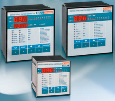
DESCRIZIONE
– Regolatore automatico del fattore di
potenza a microprocessore.
– Display a LED, 3 cifre 7 segmenti.
– Tastiera a membrana 4 tasti.
– Interfaccia seriale TTL-RS232 per set-up
e collaudo automatico mediante PC.
– Sensore di temperatura interno.
– Funzioni avanzate (misura corrente
sovraccarico condensatori, fattore di
potenza medio settimanale,
memorizzazione dei valori massimi).
– 2 relè programmabili come allarme e/o
comando ventilazione.
VERSIONI
DCRK5
contenitore 96x96mm, 5 gradini
DCRK7
contenitore 96x96mm, 7 gradini
DCRK8
contenitore 144x144mm, 8 gradini
DCRK12 contenitore 144x144mm,
12 gradini
INSTALLAZIONE
– Installare l’apparecchio secondo gli schemi
di connessione riportati a pag. 18-19.
– Per inserzione trifase il T.A. deve essere
connesso sulla fase non utilizzata per
alimentare l’apparecchio, come indicato
negli schemi di connessione a pag. 18-19.
– L’apparecchio viene fornito predisposto
per il riconoscimento del senso della
corrente del T.A.. In caso di impianti di
cogenerazione è necessario disabilitare
questa funzione (vedere capitolo menù
avanzato) e provvedere alla corretta
connessione del T.A..
– Il secondario del T.A. deve essere
collegato a terra.
WARNING!
This equipment must be installed by
qualified personnel, in compliance with
regulations in force for electrical systems, to
avoid damages or safety hazards.
The pfoducts, illustrated in this document,
are subject to be revised or improved at any
moment. Technical data and descriptions do
not therefore have any contractual value.
DESCRIPTION
– Digital microprocessor power factor
controller
– 3 digit 7 segment LED display
– 4 key membrane keypad
– TTL-RS232 serial interface for set-up and
automatic testing via PC (Personal
Computer)
– Internal temperature sensor
– Advanced functions for capacitor current
overload measurement, average weekly
power factor, maximum value logging
– 2 relays programmable as alarm and/or
fan control.
VERSIONS
DCRK5
5 steps, 96x96mm housing
DCRK7
7 steps, 96x96mm housing
DCRK8
8 steps, 144x144mm housing
DCRK12 12 steps, 144x144mm housing
INSTALLATION
– Install the controller according to wiring
diagrams given on page 18-19.
– For three-phase connection, the CT
(Current Transformer) must be connected
to the free phase, i.e. not on phases used
to supply the unit, as indicated in the
wiring diagrams on page 18-19.
– The controller automatically recognizes
the CT current flow. In case of
co-generation systems, disable this
function (refer to advanced menu section)
and connect the CT correctly.
– The CT secondary must be
earthed/grounded.
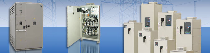
I REGOLATORI AUTOMATICI DI RIFASAMENTO
GB AUTOMATIC POWER FACTOR CONTROLLERS
PL AUTOMATYCZNE REGULATORY WSPÓŁCZYNNIKA MOCY
DCRK5 — DCRK7 — DCRK8 — DCRK12
UWAGA!
By uniknąć uszkodzeń i zagrożenia życia,
urządzenia te powinny być instalowane przez
wykwalifikowany personel i w zgodzie z
odpowiednimi przepisami.
Produkty zaprezentowane w poniższym
dokumencie mogą zostać zmienione lub
ulepszone w każdej chwili, bez konieczności
wcześniejszego informowania o tym fakcie. Dane
techniczne i opisy nie mają wartości kontraktowej.
OPIS
– Mikroprocesorowy regulator współczynnika
mocy
– Wyświetlacz LED: 3 cyfrowy, 7 segmentowy
– 4 przyciski funkcyjne
– Interfejs TTL-RS232 do ustawień i kontroli
przez komputer
– Wewnętrzny czujnik temperatury
– Zaawansowane funkcje do pomiaru prądu
przeciążenia kondensatorów, średniego
tygodniowego współczynnika mocy, zapisu
wartości maksymalnych
– 2 wyjścia przekaźnikowe programowalne jako
alarm i/lub sterowanie wentylatora.
WERSJE
DCRK5
5 stopni, obudowa 96x96mm
DCRK7
7 stopni, obudowa 96x96mm
DCRK8
8 stopni, obudowa 144x144mm
DCRK12 12 stopni, obudowa 144x144mm
INSTALACJA
– Należy podłączyć regulator zgodnie ze
schematem podanym na stronie 18 i 19.
– W układzie trójfazowym przekładnik prądowy
musi być podłączony do wolnej fazy, to jest tej,
która nie jest używana do zasilania
urządzenia, jak pokazano na schemacie
podanym na stronie 18 i 19.
– Regulator automatycznie rozpoznaje przepływ
prądu przez przekładnik. W układach
kogeneracji należy wyłączyć tą funkcję
(zobacz menu zaawansowane) i podłączyć
przekładnik we właściwy sposób.
– Uzwojenie wtórne przekładnika koniecznie
musi być uziemione.
1
Предложите, как улучшить StudyLib
(Для жалоб на нарушения авторских прав, используйте
другую форму
)
Ваш е-мэйл
Заполните, если хотите получить ответ
Оцените наш проект
1
2
3
4
5
Note for Owners:
Guidesimo.com webproject is not a service center of LOVATO ELECTRIC trademark and does not carries out works for diagnosis and repair of faulty LOVATO ELECTRIC DCRK5 equipment. For quality services, please contact an official service center of LOVATO ELECTRIC company. On our website you can read and download documentation for your LOVATO ELECTRIC DCRK5 device for free and familiarize yourself with the technical specifications of device.
More Controller Devices:
-
Johnson Controls M91 GDA-1N Series
Installation InstructionsM91xx-GDA-1N / M91xx-GDC-1N Proportional Actuators P/N 14-88360-2021 Rev. DIssue Date 10 2010www.johnsoncontrols.comJohnson Controls® is registered trademark of Johnson Controls, Inc.All marks herein are the marks of their respective owners. © 2010 Johnson Controls, Inc.Building EfficiencyHeadquarters: Milwaukee, Wisconsin, USABranch Offices: Principal Cities World-wide …
M91 GDA-1N Series Controller, 20
-
GE IC3645SH7R354D2
INSTALLATION AND OPERATION SX TRANSISTOR CONTROL Page 1 April 2002 SEPARATELY EXCITED (SX) TRANSISTORIZED MOTOR CONTROLLERS FOR NEIGHBORHOOD ELECTRIC VEHICLE APPLICATION INSTALLATION AND OPERATION MANUAL (GE MODEL IC3645SH7R354D2) Note: The information contained herein is intended to assist OEM’s, Dealers and Users of electric vehicles in the application, installation and service of …
IC3645SH7R354D2 Controller, 39
-
Watlow DIN-A-MITE A
The DIN-A-MITE is warranted to be free of defects in materialand workmanship for 36 months after delivery to the first purchaser for use, providing that the units have not beenmisapplied. Since Watlow has no control over their use, andsometimes misuse, we cannot guarantee against failure. Watlow’s obligations hereunder, at Watlow’s option, are limited toreplacement, repair, or refund of pur …
DIN-A-MITE A Controller, 7
-
cashco 123-1+6+S
IIl. PRINCIPLE OF OPERATION 1. Movement occurs as pressure variations reg is ter on the diaphragm (3). The registering pressure is the inlet (P1) or upstream pressure which reg is ters on the «un der neath» side of the diaphragm (3). The second pressure registered is the loading (PLOAD) pressure in the spring chamber (2) «above» the diaphragm (3). The range spring (18) det …
123-1+6+S Controller, 10
Recommended Documentation:
MESSA IN TENSIONE
– Alla prima messa in tensione, il display
visualizza
ad indicare che
– – –
l’impostazione dei parametri non è ancora
stata effettuata.
– In questa condizione, è possibile
effettuare una prova manuale dei gradini
utile per la verifica delle connessioni.
– Premendo i tasti
e
è possibile
inserire e disinserire i gradini.
– ATTENZIONE! In questa fase il controllo
degli step è completamente manuale e
l’apparecchio non effettua il controllo dei
tempi di riconnessione per consentire la
scarica dei condensatori.
IMPOSTAZIONE DEI PARAMETRI
Per impostare i parametri e rendere
operativo l’apparecchio si possono seguire
diversi metodi:
1. IMPOSTAZIONE MANUALE DA TASTIERA
2. IMPOSTAZIONE RAPIDA TRAMITE PC
3. IMPOSTAZIONE AUTOMATICA.
1. IMPOSTAZIONE MANUALE DA TASTIERA
5 sec
MODE
fig. 1
– Con l’apparecchio in modalità manuale,
premere il tasto MODE per 5 secondi
consecutivi (fig. 1).
– Sul display comparirà la scritta
SEt
indicare l’accesso ai parametri del menù
base (fig. 2).
– Premere il tasto MAN/AUT per accedere al
parametro successivo (fig. 3).
– Premere il tasto MODE per tornare al
parametro precedente (fig. 3).
– Premere i tasti
e
per visualizzare e
modificare l’impostazione del parametro
selezionato. Dopo alcuni secondi senza
premere tasti, la visualizzazione torna ad
indicare il parametro selezionato (fig. 3).
– L’uscita dal set-up avviene
automaticamente una volta oltrepassato
l’ultimo parametro.
2
CONNECTIONS CONTROL
– At the first power up, the DCRK display
views
which means no parameter
– – –
has been programmed yet.
– In these conditions, a manual test of the
steps can be conducted to check the
connections.
– By pressing the
or
key, the steps are
connected or disconnected.
– WARNING! During this phase, the step
control is totally manual and the unit does
not control the reconnection time to
consent the capacitor discharge.
PARAMETER SET-UP
There are a number of ways to set up the
parameters and commission the controller to
operate properly, as follows:
1. MANUAL KEYPAD SET-UP
2. QUICK SET-UP VIA PC
3. AUTOMATIC SET-UP.
1. MANUAL KEYPAD SET-UP
MAN/
AUT
– Place the unit in manual mode and press
the MODE key for 5 consecutive seconds
(fig. 1).
ad
– The wording
SEt
is viewed on the
display to confirm access to the basic
menu parameters (fig. 2).
– Press the MAN/AUT key to enter the
subsequent parameter (fig. 3).
– Press the MODE key to return to the
previous parameter (fig. 3).
– Press the
and
keys to view and
change the setting of the selected
parameter. If no key is pressed for a few
seconds, the selected parameter is
displayed once again (fig. 3).
– The set-up exit is automatic once the last
parameter is exceeded.
KONTROLA PODŁĄCZENIA
– Przy pierwszym zasileniu urządzenia na
wyświetlaczu DCRK pojawi się symbol
co oznacza, iż nie zostały jeszcze ustawione
żadne parametry.
– W tych warunkach można przeprowadzic
ręczny test poszczególnych stopni w celu
ustalenia poprawności podłączenia.
– Wciskając przyciski
lub
załączamy poszczególne stopnie.
– UWAGA! Podczas tych czynności sterowanie
stopniami i ich kontrola jest tylko ręczna a
urządzenie nie kontroluje czasu odłączania
uwzględniającego rozładowanie kondensatora.
USTAWIANIE PARAMETRÓW
Istnieje kilka sposobów na ustawienie parametrów
by umożliwić właściwą pracę:
1. USTAWIANIE RĘCZNE
2. USTAWIANIE PRZEZ KOMPUTER
3. USTAWIANIE AUTOMATYCZNE.
1. USTAWIANIE RĘCZNE
SEt
fig. 2
– Należy ustawić urządzenie w tryb ręczny,
wcisnąć przycisk MODE i przytrzymać przez 5
sekund (rys. 1).
– Na wyświetlaczu pojawi się słowo
które potwierdza dostęp do menu ustawień
parametrów podstawowych (rys. 2).
– Należy wcisnąć przycisk MAN/AUT by przejść
do kolejnego parametru (rys. 3).
– Należy wcisnąć przycisk MODE by powrócić
do poprzedniego parametru (rys. 3).
– Należy wcisnąć przyciski
zmienić wartość wybranego parametru. Jeśli
żaden z przycisków nie zostanie wciśnięty
przez parę sekund to kod wybranego
parametru pojawi się ponownie na
wyświetlaczu (rys. 3).
– Wyjście z menu ustawień parametrów odbywa
się automatycznie kiedy przejdziemy przez
ostatni parametr z listy.
– – –
,
odłączamy lub
Visualizzare e modificare parametro.
View and change the parameter.
Wyświetlanie i zmiana parametrów.
MODE
Parametro
precedente.
fig. 3
Previous
parameter.
Poprzedni
parametr.
SEt
,
i
by wyświeltlić i
MAN/
AUT
Parametro
successivo.
Subsequent
parameter.
Kolejny
parametr.
|
|||||||||||||||||||||||||||||||||||||||||||||||||||||||||||||||||||||||||||||||||||||||||||||||||||||||||||||||||||||||||||||||||||||||||||||||||||||||||||||||||||||||||||||||||||||||||||||||||||||||||||||||||||||||||||||||||||||||||||||||
|
|||||||||||||||||||||||||||||||||||||||||||||||||||||||||||||||||||||||||||||||||||||||||||||||||||||||||||||||||||||||||||||||||||||||||||||||||||||||||||||||||||||||||||||||||||||||||||||||||||||||||||||||||||||||||||||||||||||||||||||||
| |


© 2023 ООО «НПО Промэлектроавтоматика». Основано в 1997 г.