- Manuals
- Brands
- Lowrance Manuals
- Fish Finder
- HDS Carbon
- Installation manual
-
Contents
-
Table of Contents
-
Troubleshooting
-
Bookmarks
Quick Links
HDS Carbon
Installation Manual
ENGLISH
www.lowrance.com
Related Manuals for Lowrance HDS Carbon
Summary of Contents for Lowrance HDS Carbon
-
Page 1
HDS Carbon Installation Manual ENGLISH www.lowrance.com… -
Page 3
The warranty card is supplied as a separate document. In case of any queries, refer to the brand website of your unit or system: www.lowrance.com. Compliance statements This equipment complies with: • CE under 2014/53/EU Directive Preface | HDS Carbon Installation Manual… -
Page 4
The relevant Declaration of conformity is available in the product’s section at the following website: www.lowrance.com. Industry Canada IC RSS-GEN, Sec 8.4 Warning Statement This device complies with Industry Canada license-exempt RSS standard(s). -
Page 5
DE — Germany GR — Greece HU — Hungary IS — Iceland IE — Ireland IT — Italy LV — Latvia LI — Liechtenstein LT — Lithuania LU — Luxembourg MT — Malta NL — Netherlands Preface | HDS Carbon Installation Manual… -
Page 6
Bluetooth SIG, Inc. Navico product references This manual refers to the following Navico products: • Broadband Sounder™ (Broadband Sounder) • DownScan Overlay™ (Overlay) • GoFree™ (GoFree) • INSIGHT GENESIS® (Insight Genesis) Preface | HDS Carbon Installation Manual… -
Page 7: About This Manual
About this manual This manual is a reference guide for installing HDS Carbon units. Important text that requires special attention from the reader is emphasized as follows: Ú Note: Used to draw the reader’s attention to a comment or some important information.
-
Page 8
Preface | HDS Carbon Installation Manual… -
Page 9: Table Of Contents
Power connection Transducer connection Ethernet connector NMEA 2000 device connection NMEA 0183 device connection Video in 33 Software Setup First time startup Time and Date Data source selection Device list Diagnostics Damping Sonar setup Contents | HDS Carbon Installation Manual…
-
Page 10
HDS 16 Carbon 75 Accessories NMEA 2000 Display accessories Ethernet cables Other accessories Sonar accessories 78 Supported data NMEA 2000 compliant PGN List NMEA 0183 supported sentences 83 Technical specifications HDS Carbon technical specifications Contents | HDS Carbon Installation Manual… -
Page 11: Check The Contents
Fasteners (4x 6G x 1.5 panhead PH1) Power/NMEA 0183 cable Fuse holder (ATC blade) Fuse (5 A) Caps (3x for HDS-7, 4x for HDS-9/12/16 — for ethernet, NMEA 2000, StructureScan) 10 Documentation pack 11 Dash gasket (HDS-16 only) Check the contents | HDS Carbon Installation Manual…
-
Page 12: Overview
The unit may be mounted to the vessel with the supplied mounting bracket, or panel mounted. The unit is intended for 12 V DC operation and will accept the moderate fluctuations commonly seen in DC systems. The front panel and keys Touchscreen Overview | HDS Carbon Installation Manual…
-
Page 13
Power key Press once to display the System Controls dialog. Repeat short presses to cycle the backlight brightness. Press and hold to turn the unit ON/OFF. Card reader door microSD Card readers Overview | HDS Carbon Installation Manual… -
Page 14: Rear Connections
Do not download, transfer or copy files to a chart card. Doing so can damage chart information on the chart card. The card reader door should always be securely shut immediately after inserting or removing a card, in order to prevent possible water ingress. Overview | HDS Carbon Installation Manual…
-
Page 15
All size displays have two card reader slots. The card reader door is opened by sliding the door to the right (1) using your fingernail, then hinging forward (2) from the right hand side. Overview | HDS Carbon Installation Manual… -
Page 16: Installation
If in doubt, consult a qualified boat builder, or marine electronics installer. Ú Note: Where flush mounted, the enclosure should be dry and well ventilated. In small enclosures, it may be required to fit forced cooling. Installation | HDS Carbon Installation Manual…
-
Page 17: Viewing Angle
85° 85° 85° 85° 7″ and 9″ 7″ and 9″ 88° 88° 88° 88° 12″ and 16″ 12″ and 16″ Optimum viewing angle Poor viewing angle or obstructed view Installation | HDS Carbon Installation Manual…
-
Page 18: Bracket Mounting
Mount the unit to the bracket using the knobs. Hand tighten only. The ratchet teeth in the bracket and unit case ensure a positive grip and prevent the unit from changing from the desired angle (B). Installation | HDS Carbon Installation Manual…
-
Page 19: Panel Mounting
Panel mounting The screws for panel mounting are included in the box. For mounting instructions, refer to the mounting template. Installation | HDS Carbon Installation Manual…
-
Page 20: Mounting The Transducer
Select a transducer location The primary aim is to stay clear of propeller and hull generated turbulence, while mounting the transducer as close to the center of the vessel as possible. Mounting the transducer | HDS Carbon Installation Manual…
-
Page 21: Attaching The Transducer
Trim tabs vary in the amount of turbulence they create as they are adjusted, stay clear of these. Attaching the transducer The transducer should be installed parallel with the transom’s waterline, not the bottom of the boat (deadrise). Mounting the transducer | HDS Carbon Installation Manual…
-
Page 22: Adjusting The Transducer
Adjusting the transducer If the sonar image shows interference lines on the screen when moving, which worsen with speed, it may be possible to eliminate these by adjusting the angle of the transducer. Mounting the transducer | HDS Carbon Installation Manual…
-
Page 23
If performance does not improve with tilting, try adjusting the height of the transducer relative to the transom of the boat. If the transducer is too high it may be seeing cavitation caused by the trailing edge of the transom. Mounting the transducer | HDS Carbon Installation Manual… -
Page 24: Wiring
24 V DC systems. Warning: The positive supply wire (red) should always be connected to (+) DC with the supplied fuse or a circuit breaker (closest available to fuse rating). Wiring | HDS Carbon Installation Manual…
-
Page 25: Power Connection
Broadband radar. When connected in this manner, the modules are turned on the moment the unit is powered up. For connection, simply combine all yellow wires on a common bus or to a single termination point. Wiring | HDS Carbon Installation Manual…
-
Page 26: Transducer Connection
Sonar. The 9-pin black StructureScan connector can be plugged in to the socket labelled Structure. For connector location, refer to the embossed labeling on the unit or the section «Rear connections» on page 14. Wiring | HDS Carbon Installation Manual…
-
Page 27: Ethernet Connector
Receive negative RX- Orange Shield Bare Ethernet expansion device Connection of network devices can be made via an Ethernet expansion device. Additional expansion devices can be added to provide the required number of ports. Wiring | HDS Carbon Installation Manual…
-
Page 28: Nmea 2000 Device Connection
NMEA 2000 device connection The NMEA 2000 data port allows the receiving and sharing of a multitude of data from various sources. Unit socket (male) Cable plug (female) Purpose Color Shield Drain NET-S (+12 V DC) Wiring | HDS Carbon Installation Manual…
-
Page 29
Do not connect the NMEA 2000 power cable to the same terminals as the engine start batteries, autopilot computer, bow thruster or other high current devices. The following drawing demonstrates a typical small network. The backbone is made up of directly interconnected T-connectors. Wiring | HDS Carbon Installation Manual… -
Page 30: Nmea 0183 Device Connection
The port uses the NMEA 0183 (serial balanced) standard, and can be configured in the software for different baud rates up to 38,400 baud. The NMEA 0183 cable shares the same plug as the power cable. Wiring | HDS Carbon Installation Manual…
-
Page 31: Video In
A video camera may be added by installing the optional video adaptor cable between the power socket on the unit, and the plug on the power/data cable. For video adapter cable, refer to «Display accessories» on page 75. Wiring | HDS Carbon Installation Manual…
-
Page 32
Ú Note: Both NTSC and PAL formats are supported. POWER Video input adaptor cable (optional part) RCA plug Camera power cable Camera HDS power/data cable Unit power cable Data cable Wiring | HDS Carbon Installation Manual… -
Page 33: Software Setup
You can perform further setup using the system settings option and later change settings made with the setup wizard. Time and Date Configure time settings to suit vessel location, along with time and date formats. Software Setup | HDS Carbon Installation Manual…
-
Page 34: Data Source Selection
Ú Note: Auto data source selection may already have been selected at first time startup, however it should be redone if any new devices have been added to the network since. Software Setup | HDS Carbon Installation Manual…
-
Page 35: Device List
Global source settings available from other networked units. Device list The Device list shows the devices that provide data. This may include a module inside the unit, or any external NMEA 2000 device. Software Setup | HDS Carbon Installation Manual…
-
Page 36
Data option shows all data being output by the device. Some devices will show additional option(s) specific to the device — the RC42 illustrated above has a Calibration option, to allow easy setup of this device. Software Setup | HDS Carbon Installation Manual… -
Page 37: Diagnostics
0. Values around 96 upwards indicate a heavily error prone network. If these numbers go too high for a given device, it will automatically drop off the bus. Rx/Tx Messages Shows actual traffic in and out of device. Software Setup | HDS Carbon Installation Manual…
-
Page 38: Damping
With damping set to off, the data is presented in raw form with no damping applied. Sonar setup Make general settings from the Sonar Settings dialog. Define Sonar sources in the Installation dialog. Software Setup | HDS Carbon Installation Manual…
-
Page 39: Sonar Settings
As a result, water depth readings do not account for the distance from the transducer to the lowest point of the boat in the water or from the transducer to the water surface. Software Setup | HDS Carbon Installation Manual…
-
Page 40
Select Overlay on the Structure options menu to adjust the level of structure overlay shown on the screen. You can make adjustments using the Overlay slider bar. Sonar installation Use this dialog to setup and configure available Sonar sources. Software Setup | HDS Carbon Installation Manual… -
Page 41
As a result, water depth readings do not account for the distance from the transducer to the lowest point of the boat (for example; bottom of the keel, rudder, or skeg) in the water or from the transducer to the water surface. Software Setup | HDS Carbon Installation Manual… -
Page 42
10 knots (11.5 MPH) the calibration value needs to be increased to 117 %. To calculate the adjustment, divide the SOG by the paddlewheel speed, and multiply the product by 100. Calibration range: 50-200 %. Default is 100 %. Software Setup | HDS Carbon Installation Manual… -
Page 43: Structurescan
It is possible to set a Structure depth offset for the structure transducer. This setting is in the Sonar Settings dialog. SpotlightScan This feature is enabled automatically when a SpotlightScan transducer and sensor is plugged in before the unit has been Software Setup | HDS Carbon Installation Manual…
-
Page 44: Radar Setup
Ú Note: The installation can vary depending on the radar. Follow the installation and setup instructions supplied with the radar. Scanner type Identifies the model of scanner connected to the network. Radar status Software Setup | HDS Carbon Installation Manual…
-
Page 45
Adjust the bearing alignment setting, so that the heading marker and land mass intersect. Adjust antenna height Set the radar scanner height relative to the water surface. The Radar uses this value to calculate the correct STC settings. Software Setup | HDS Carbon Installation Manual… -
Page 46
This occurs because not all of the transmitted radar energy can be focused into a single beam by the radar antenna, a small amount energy is transmitted in Software Setup | HDS Carbon Installation Manual… -
Page 47: Autopilot Setup
For the trolling motor autopilot, no special setup is required. See the operator manual for further details. After installation is completed, the NAC-1 autopilot computer (outboard motor autopilot) requires setup as described in the following sections. Software Setup | HDS Carbon Installation Manual…
-
Page 48
For example, if you have 2 compasses on your network you want to ensure that the same compass is selected for the MFD and the autopilot. Ú Note: You change the MDF data sources from the Network settings dialog. Software Setup | HDS Carbon Installation Manual… -
Page 49
— Check for other mechanical issues. — Check wiring connections. — Repeat rudder calibration steps. Hydraulic system calibration Virtual rudder feedback (VRF) calibration is used for vessels with hydraulic steering. Select Commissioning. Select VRF calibration. Software Setup | HDS Carbon Installation Manual… -
Page 50: Troubleshooting
• Check connections from the NAC-1 to the CAN bus network. AP Position data missing* Probable cause: Missing or invalid position data. Recommended action: • Check the GPS cable connections to CAN network. Software Setup | HDS Carbon Installation Manual…
-
Page 51
Check the source selection setting. AP Rudder data missing (For Helm-1/ cable steer only)* Probable cause: • Rudder feedback signal missing due to a broken wire or connection. • Misaligned potentiometer in the Helm-1. Recommended action: Software Setup | HDS Carbon Installation Manual… -
Page 52
Check the drive unit and drive unit installation. • Look for mechanical obstructions. • Check the manual steering. High drive temp* Probable cause: The NAC-1 drive output circuit is overheated due to excessive load. Recommended action: Software Setup | HDS Carbon Installation Manual… -
Page 53: Fuel Setup
«Data source selection» on page 34. Vessel setup The Vessel setup dialog must be used to select the number of engines, the number of tanks and vessel’s total fuel capacity across all tanks. Software Setup | HDS Carbon Installation Manual…
-
Page 54
Calibrate. Only Navico devices can be reset. Calibrate Calibration may be required to accurately match measured flow with actual fuel flow. Access calibration from the Refuel dialog. Calibration is only possible on Navico’s Fuel Flow sensor. Software Setup | HDS Carbon Installation Manual… -
Page 55
Fluid Level devices. Select Device list on the Network page, and view the Device Configuration dialog for each sensor, and set the Tank location, Fluid type, and Tank size. Software Setup | HDS Carbon Installation Manual… -
Page 56: Czone Setup
PC application available from BEP Marine Ltd, and associated CZone distributors. The HDS Carbon system provides a means to load the Config file, as well as apply updates to module firmware, removing the need to take a laptop computer aboard the vessel.
-
Page 57
CZone Display Interfaces set up to share backlight settings. Ú Note: CZone Config also needs to have the HDS Carbon set as a controller. Import and backup a configuration file The files page may be used to import CZone configuration files, or export a copy to a memory card in the card reader. -
Page 58: Nmea 2000 Setup
NMEA 2000. NMEA 0183 setup The NMEA 0183 port must be set to suit the speed of connected devices, and can be configured to output only the sentences required by listening devices. Software Setup | HDS Carbon Installation Manual…
-
Page 59
NMEA 0183 it is desirable to only enable the data that is required. The less sentences that are selected, the higher the output rate of the enabled sentences. Commonly used sentences are enabled by default. Software Setup | HDS Carbon Installation Manual… -
Page 60: Ethernet Setup
(e.g. 4G radar) will automatically start working, and relay data between the two devices. Diagnostics The UDB (User Data Base) tab on the diagnostics page, provides information on Ethernet activity, as shown below. Software Setup | HDS Carbon Installation Manual…
-
Page 61
When powering up a system that has been completely shutdown, a network connectivity issue can be identified if a display does not show any other IP addresses than its own. Software Setup | HDS Carbon Installation Manual… -
Page 62: Wireless Setup
Enter the Network Key in the tablet to connect to the network. Open the GoFree application — the unit should be automatically detected. The name displayed will be either the default, or that assigned in the Device Name setting. If the unit does not Software Setup | HDS Carbon Installation Manual…
-
Page 63
The MFD’s display is shown on the smartphone. To change the MFD’s display on the smartphone, use the MFD to change the display on the MFD. The display change on the MFD is reflected on the smartphone. Software Setup | HDS Carbon Installation Manual… -
Page 64
(SSID), Network key, or Channel) the internal wireless must be in Access Point (Internal Wifi) mode. To select a network (hotspot) to connect to, the internal wireless must be in Client Mode. Network Name (SSID) Displays the name of the internal wireless network. Software Setup | HDS Carbon Installation Manual… -
Page 65
The internal modules do not act as a DHCP server. Channel Only visible if the internal wireless is set to Access Point (Internal Wifi) mode when the device is selected. Select it to change the Software Setup | HDS Carbon Installation Manual… -
Page 66
Access Point mode. This can be a combination of internal wireless and an external WIFI-1, or two external WIF-1 units. Two external WIFI-1 units will offer the advantage of providing both features to all MFDs on the network (where applicable). Software Setup | HDS Carbon Installation Manual… -
Page 67
The application must be installed on and run from a tablet device. The HDS Carbon must be running Iperf server before initiating the test from the tablet. On exiting the page, Iperf automatically stops running. -
Page 68: Bluetooth Wireless Technology
When the features are enabled, the display may prompt the user for some basic configuration information. Refer to the VesselView® manual or engine supplier for further information. Software Setup | HDS Carbon Installation Manual…
-
Page 69: Suzuki Marine
Updates can be found on the website: www.lowrance.com When the unit is connected to the internet, a pop-up can appear advising that a software update is available and encourages you to download the update.
-
Page 70: Software Upgrades
If no device is shown, check that the device to be updated has power, and run any outstanding updates for the unit first. Select the device and initiate the upgrade. Do not interrupt the upgrade process. Software Setup | HDS Carbon Installation Manual…
-
Page 71
• NSS evo2/3, NSS, NSO, NSE, Zeus, Zeus Touch, HDS Gen2, HDS Gen2 Touch, HDS Gen3, HDS Carbon, GO XSE units, Vulcan units, and ELITE Ti units). Offers most detail. User data file version 4: Use with current units (NSO evo2/3, •… -
Page 72
Gen2 Touch, HDS Gen3, HDS Carbon, GO XSE units, Vulcan units, and ELITE Ti units). User data file version 3 (with depth): Use with legacy GPS • chartplotters. User data file version 2 (no depth): Use with legacy GPS •… -
Page 73: Dimensional Drawings
238.4 mm (9.39”) 69.2 mm (2.72”) 96.5 mm (3.8”) HDS 9 Carbon 132.2 mm (5.20”) 86.1 mm (3.39”) 32.2 mm (1.27”) 265.0 mm (10.43”) 60.55 mm (2.38”) 286.7 mm (11.29”) 84.0 mm (3.31”) Dimensional drawings | HDS Carbon Installation Manual…
-
Page 74: Hds 12 Carbon
32.6 mm (1.28”) 62 mm (2.44”) 351.0 mm (13.82”) 85.1mm (3.35”) HDS 16 Carbon 129.6 mm (5.10”) 93.5mm (3.68”) 413.0 mm (16.26”) 32.6 mm (1.28”) 80.0 mm (3.15”) 435.7 mm (17.15”) 103.5 mm (4.08”) Dimensional drawings | HDS Carbon Installation Manual…
-
Page 75: Accessories
Display accessories Part Number Description 000-11010-001 HDS Carbon video adapter cable 000-13978-001 HDS 7 Carbon bezel and card door 000-13979-001 HDS 9 Carbon bezel and card door 000-13980-001 HDS 12 Carbon bezel and card door 000-13995-001 HDS 16 Carbon bezel and card door…
-
Page 76: Ethernet Cables
000-11019-001 HDS 7 Carbon gimbal bracket 000-11020-001 HDS 9 Carbon gimbal bracket 000-11021-001 HDS 12 Carbon gimbal bracket 000-13994-001 HDS 16 Carbon gimbal bracket 000-11050-001 HDS Carbon flush mount kit 000-10467-001 HDS Carbon bracket knobs (pair) 000-0127-49 HDS Carbon power cable…
-
Page 77: Sonar Accessories
Skimmer Low/High CHIRP transducer 000-0106-74 Trolling motor transducer, Medium/High CHIRP 000-0106-73 In-hull shoot-thru transducer, depth only 000-0106-89 In-hull, shoot-thru transducer, depth and remote temperature 000-12572-001 7-pin transducer to 9-pin adapter cable For additional transducer options, visit www.lowrance.com Accessories | HDS Carbon Installation Manual…
-
Page 78: Supported Data
127488 Engine Parameters, Rapid Update 127489 Engine Parameters, Dynamic 127493 Transmission Parameters, Dynamic 127503 AC input status 127505 Fluid Level 127506 DC Detailed Status 127508 Battery Status 127509 Inverter Status 128259 Speed, Water referenced 128267 Water Depth Supported data| HDS Carbon Installation Manual…
-
Page 79
130314 Actual Pressure 130569 Entertainment — Current File and Status 130570 Entertainment — Library Data File 130571 Entertainment — Library Data Group 130572 Entertainment — Library Data Search 130573 Entertainment — Supported Source Data Supported data| HDS Carbon Installation Manual… -
Page 80
127250 Vessel Heading 127258 Magnetic Variation 128259 Speed, Water Referenced 128267 Water Depth 128275 Distance Log 129025 Position, Rapid Update 129026 COG & SOG, Rapid Update 129029 GNSS Position Data 129283 Cross Track Error Supported data| HDS Carbon Installation Manual… -
Page 81: Nmea 0183 Supported Sentences
130311 Environmental Parameters 130312 Temperature 130577 Direction Data NMEA 0183 supported sentences TX / RX — GPS Receive Transmit TX / RX — Navigation Receive Transmit Receive Transmit TX / RX — Sonar Receive Transmit Supported data| HDS Carbon Installation Manual…
-
Page 82
TX / RX — Compass Receive Transmit TX / RX — Wind Receive Transmit TX / RX — AIS / DSC Receive Ú Note: AIS sentences are not bridged to or from NMEA 2000. Supported data| HDS Carbon Installation Manual… -
Page 83: Technical Specifications
Supply voltage 12 V DC (10.8 — 17.0 V DC min — max) Power consumption — Max HDS-7 24 W (2.3 A @ 13.8 V DC) HDS-9 28 W (2.3 A @ 13.8 V DC) Technical specifications| HDS Carbon Installation Manual…
-
Page 84
10Hz high speed update. GPS & GLONASS. WAAS, MSAS, EGNOS Interface Ethernet HDS-7 1 Port HDS-9 2 Ports HDS-12 2 Ports HDS-16 2 Ports NMEA 2000 Micro-C (1) NMEA 0183 input/output. 4800, 9600, 19200, 38400 baud Technical specifications| HDS Carbon Installation Manual… -
Page 85
Sonar frequency CHIRP (high, medium, low) + Broadband (200/83/50 kHz) + StructureScan (800/455 kHz) Sonar output power Max power 500 W RMS Warranty Period 2 Year + part of the 5 year upgrade program Technical specifications| HDS Carbon Installation Manual… -
Page 86
Technical specifications| HDS Carbon Installation Manual…
Прошивки и инструкции для эхолотов Lowrance/
-
#1
Предлагаю в этой теме выкладывать только инструкции, прошивки и прочие полезности. В идеале без обсуждений. Просто описание и собственно сам файл или ссылка на диск. (Если конечно это не возбраняется на данном форуме) Думаю многие новички скажут спасибо за ссылки. А старожилам не нужно будет отправлять новичков пользоваться поиском. Для начала выкладываю ссылку на Яндекс диск с прошивками которые у меня есть. https://yadi.sk/d/rDC6IQCqkurLxQ?w=1
Прошивки и инструкции для эхолотов Lowrance/
-
#2
Добавлю инструкцию на лайв. У кого то скачивал. Не прицепился большой файл.
Прошивки и инструкции для эхолотов Lowrance/
-
#3
Хотелось бы ещё инструкцию как правильно установить новую прошивку. Делать резет до или после, с сохранением точек и настроек, в общем с нуля для чайников.
Прошивки и инструкции для эхолотов Lowrance/
-
#4
Последнее редактирование: 28.01.2021
Прошивки и инструкции для эхолотов Lowrance/
-
#5
Прошивки и инструкции для эхолотов Lowrance/
-
#6

а зачем в этом разьеме плюс и минус? в ответной фишке на моторе только кан.
Прошивки и инструкции для эхолотов Lowrance/
-
#7
Я кстати в этом разьеме на пин 1 припаял экран витой пары .Думаю так надежнее.
Прошивки и инструкции для эхолотов Lowrance/
-
#8
только резистор не 120 а 60 ом
Прошивки и инструкции для эхолотов Lowrance/
-
#9
только резистор не 120 а 60 ом
это если сеть занята только мотором…
Прошивки и инструкции для эхолотов Lowrance/
-
#10
а зачем в этом разьеме плюс и минус? в ответной фишке на моторе только кан.
фото выкладывалось для понимания какой разьем искать. А подключение конечно только два провода надо, как на схеме. Скорее всего это провод для подключения в хаб. Точно утверждать не могу. И резисторы нужны если напрямую к эхолоту. А если в Т-коннектор сети, то там уже есть по краям они.
Прошивки и инструкции для эхолотов Lowrance/
-
#11
Инструкция к Elit TI 7-9 . Для ТИ-2 тоже подходит.Вдруг кому пригодится.
-
3.6 МБ
· Просмотры: 783
Elite7-9Ti_инструкция_ru.pdf
Прошивки и инструкции для эхолотов Lowrance/
-
#12
Еще интструкция для HOOK 2 на русском.Не много корявенький перевод но разобраться можно.
-
7.4 МБ
· Просмотры: 2 817
Hook2-Series-RUS.pdf
Прошивки и инструкции для эхолотов Lowrance/
-
#13
Предлагаю в этой теме выкладывать только инструкции, прошивки и прочие полезности. В идеале без обсуждений. Просто описание и собственно сам файл или ссылка на диск. (Если конечно это не возбраняется на данном форуме) Думаю многие новички скажут спасибо за ссылки. А старожилам не нужно будет отправлять новичков пользоваться поиском. Для начала выкладываю ссылку на Яндекс диск с прошивками которые у меня есть. https://yadi.sk/d/rDC6IQCqkurLxQ?w=1
Добавил прошивки на элиты и карбоны еще.
Прошивки и инструкции для эхолотов Lowrance/
-
#14
Вопрос — на карбон после прошивки 19.1 114 сразу была 153 или между ними еще прошивки были?
Прошивки и инструкции для эхолотов Lowrance/
-
#15
Вопрос — на карбон после прошивки 19.1 114 сразу была 153 или между ними еще прошивки были?
у меня больше нет. Владельцы карбонов дополнят надеюсь.
Posted18.09.2018
Последнее Обновление05.10.2018
При первом подключении устройства у кого то могут возникнуть некоторые трудности или вопросы. В данной статье разберем эту тему поподробнее.
Для начала рассмотрим комплектацию дисплея.
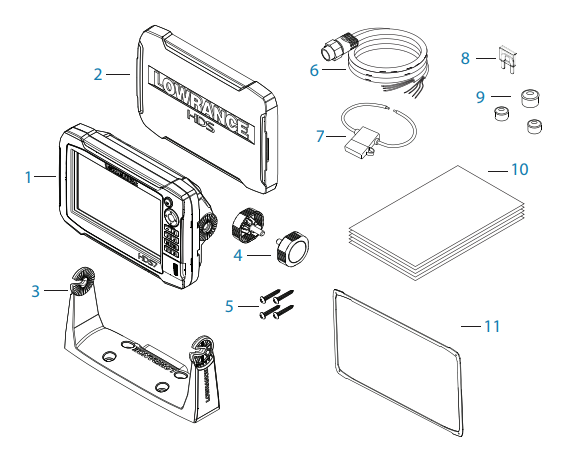
- Дисплей HDS Carbon
- Защитная крышка SunCover
- Скоба крепления дисплея
- Винты для скобы крепления
- Комплект метизов х4
- Кабель питания / NMEA 0183
- Держатель предохранителя
- Предохранитель (5 A)
- Заглушки для Ethernet, NMEA 2000, StructureScan
- Документация
- Шаблон для встраивания в приборную панель (только для HDS-16)
Общие сведения
Устройство имеет встроенный широкополосный эхолот / CHIRP и StructureScan. Имеет поддержку сетевого протокола NMEA 2000, а также Ethernet, который обеспечивает доступ к передаче данных между дисплеями, к управлению доп. устройствами, такими как StructureScan 3D, радар и т.д. Устройство оснащено высокоскоростным GPS-приемником (10 Гц) и поддерживает картографию С-Map, Navionics и самостоятельно созданные карты Genesis Live. Дисплей может быть установлен на судне путем встраивания в панель или на скобу крепления. Предназначен для работы на 12В постоянного тока.
Передняя панель и клавиши управления
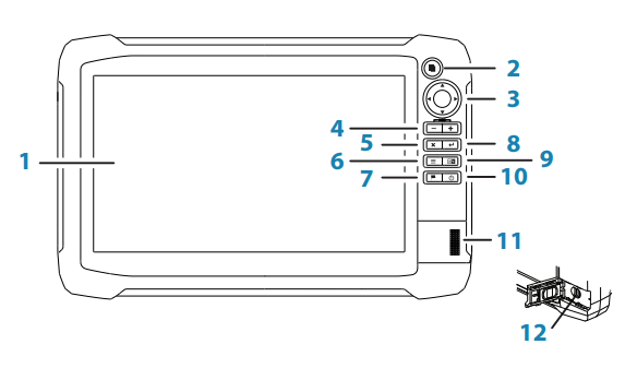
- Рабочая область дисплея.
- Страницы / Главное меню
Нажмите один раз, чтобы перейти на домашнюю страницу. Повторите нажатие для перехода к любимому режиму. Нажмите и удерживайте для перехода на последнюю использованную страницу. - Стрелки курсора
- Масштабирование
Одновременное нажатие + и — сохраняют путевую точку MOB (Человек за бортом) - Кнопка отмены
Нажмите, чтобы выйти из диалогового окна, чтобы вернуться к предыдущему уровню меню, и для удаления курсора с панели. - Меню
Одно нажатие отображает меню активного окна / наложения. Нажмите и удерживайте, чтобы скрыть или показать меню. Быстрое двойное нажатие отображает меню настроек. - Путевая точка
Нажмите, чтобы отобразить диалоговое окно для сохранения новых путевых точек. Нажмите дважды, чтобы быстро сохранить путевую точку. - Подтверждение
- Клавиша окна
Используется при работе с несколькими окнами. Короткий короткое нажатие переключает между окнами, длительное нажатие расширяет активное окно на весь экран. - Клавиша питания
Нажмите один раз, чтобы отобразить диалоговое окно системных элементов управления. Повторное короткое нажатие для циклического изменения яркости подсветки. Нажмите и удерживайте для включения и выключения устройства. - Заглушка разъема microSD
- Разъем microSD х2
Разъемы на задней части прибора
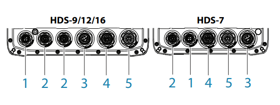
- NMEA 2000 — ввод / вывод данных
- ETHERNET — данные с высокой пропускной способностью (радар, сонар)
- POWER — питание 12V и NMEA 0183. Дополнительный видеовход через
адаптер - SONAR — CHIRP и широкополосный сонар
- Structure — Датчик StructureScan HD и TotalScan
Установка и подключение
Перед началом работы тщательно выберите место для установки. Дисплей должен быть установлен таким образом, чтобы пользователь мог иметь легкий доступ к нему и четко видеть экран. Устройство имеет защиту от прямых солнечных лучей, но для достижения наилучшей видимости размещайте дисплей под углом. Закрытое место установки может повлиять на работу GPS приемника. Убедитесь в возможности прокладки кабеля от места установки дисплея. В случае с встраиванием в панель, прежде чем делать отверстие в панели, убедитесь в отсутствии электрических проводов под ней. В случае сомнений, обратитесь к специалисту по установке.
Установите скобу крепления в нужное место используя монтажные детали, идущие в комплекте. Установите дисплей на кронштейн с помощью винтов и отрегулируйте угол наклона.
Подключите питание к дисплею с помощью кабеля питания и данных, идущего в комплекте в разъем POWER. С обратной же стороны подключите красный и черные провода к источнику питания, где первый это плюс, а второй минус. После подключения датчика и при необходимости дополнительных устройств, включите дисплей, нажав соответствующую настройку на экране, проведите первоначальные настройки и приступайте к работе.
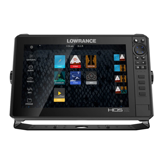
Рыбацкий гаджет Lowrance HDS-12 Carbon один из самых совершенных эхолотов в своём сегменте. Приспособление имеет дисплей диагональю 12 дюймов повышенной чёткости SolarMAX™ HD, производительный процессор, двухканальную линейно-частотную модуляцию, а также высококачественный двойной эхолот.
Комплектация устройства
В комплект Lowrance HDS-12 Carbon входят:
- Устройство;
- Монтажная скоба;
- Фиксирующие монтажные винты;
- Шнур данных NMEA 0183;
- Солнцезащитное полотно;
- Эксплуатационная инструкция;
- Талон гарантии.

Технические параметры приспособления
- Габариты (Ш х В х Г): 328 х 224,5 х 85 мм;
- Водонепроницаемость прибора – IPX7;
- Электропитание – 12 В;
- 2 разъёма MicroSD-накопителей;
- Количество поддерживаемых языков – 36 (русский присутствует);
- Передача данных – NMEA 0183, NMEA 2000.

Данные монитора:
- Диагональ/разрешение — 30.5 см / 1280 x 800;
- Тип — SolarMAX HD;
- Настройка подсветки – 11-уровневая;
- Деление – 4 зоны.

Параметры эхолота:
- Частота – 50/83/200 кГц Broadband; 455/800 кГц SideScan/DownScan;
- Максимальная мощность – 500Вт;
- Индикация мелководья – есть;
- Индикация глубины – есть;
- Измерение температуры – есть;
- Трансдьюсер – Multiple Selections Lowrance and Airmar;
- Пиковый уровень глубины – 1524 м.
Параметры картплоттера:
- GPS оповещения – есть;
- GPS-антенна – внутренняя (10 кГц);
- Маршруты – до 200;
- Путевые точки – до 5000;
- Базовая карта – есть;
- Поддержка карт — HotMaps® и др.
Особенности и достоинства Lowrance HDS-12 Carbon
Благодаря высококачественному дисплею пользователю предоставляется весьма широкий угол обзора. Экран оснащён антибликовой поверхностью, имеет высокий уровень цветопередачи и влагостойкие оптические слои. Всё это способствует хорошей видимости независимо от погодных условий.
Несмотря на высокую функциональность, эхолот весьма прост в эксплуатации. В основе интерфейса Lowrance® заложено простое и понятное программное обеспечение, которое способствует повышенной производительности и лёгкому доступу пользователя к имеющимся опциям.
Используемый двухъядерный процессор обладает даже более высокой мощностью, чем это необходимо. Благодаря такому подходу разработчиков устройство отличается молниеносностью прорисовки и отклика, способно работать с лучшими современными технологиями, такими как StructureScan® 3D и другими. Резерв мощности также позволяет безотказно работать прибору с различными модернизациями в будущем.

Двухканальный CHIRP сонар одновременно функционирует в низком, среднем и высоком режиме, что даёт возможность проследить за каждой рыбой. Рыбак может оставить предпочитаемые частоты видимыми для чёткости выделения целей на дне либо в густом косяке. Параллельно с этим есть возможность просмотра на низкочастотном канале для охвата большей части пространства.
Применение двойного эхолота способствует исследованию обширного пространства толщи воды. Просматривать трансляцию с обоих элементов можно одновременно.
Использование CHIRP сонара и StructureScan® HD значительно повышает качество картинки. Рыбаку проще оценить состояние дна под лодкой и вокруг неё.
Высокомощный процессор создаёт высокую скорость обновления изображения картинки. Его мощности достаточно для безотказной работы пользовательского интерфейса, с поддержкой прокрутки дисплея, дополнительного курсора, горячих клавиш и всплывающих закладок.
Оснащение WI-FI-модулем даёт возможность организовать связь между приспособлением и другим оборудованием на судне, а также со смартфоном или другим гаджетом с установленным Lowrance GoFree App.
Благодаря опции Plug-and-play прибор способен работать совместно со многими другими приборами на судне.
Network Analyzer осуществляет проверку ПО, а Service Assistant даёт возможность отправки отчётов возникших неполадок технического или программного характера в Navico Service.
Пользование прибором на практике
Первое, что стоит отметить, это внушительные габариты модели. Lowrance HDS-12 Carbon один из самых больших эхолотов на отечественном рынке. Внушительный экран рассчитан по большей части на профессиональных рыбаков, которым важна детализированная прорисовка. На дисплее без труда можно рассмотреть всё происходящее в толще воды.

Корпус устройства выполнен в привлекательном дизайне. Ударопрочный пластик обеспечивает целостность при неаккуратном использовании. С правой стороны фронтальной части расположены клавиша «Домашняя страница», навигационные клавиши управления, управление масштабом, кнопки выхода и ввода установок, а также «Меню», клавиша «Панель», «Путевая точка» и «Питание».

Из любой операции можно переключиться на домашнюю страницу кратковременно нажав соответствующую кнопку.
Пользуясь прибором трудно разочароваться в таком приобретении. Помимо всех функций непосредственно связанных с рыбалкой, Эхолот способен принимать аудио сигнал с гаджетов пользователей и транслировать музыку в довольно хорошем качестве.
Заключение
В завершении стоит сказать, что преимущества Lowrance HDS-12 Carbon очевидны. На сегодняшний день это один из наиболее функциональных и надёжных эхолотов среди других предложений современного рынка. Некоторые профессиональные рыбаки решили приобрести для себя сразу два прибора. При использовании на одном устройстве трансляции только с одного луча, левого или правого, в совокупности можно получить ещё более детализированную картинку. Конечно же, это ощутимо затратный подход и такое решение оправдано только при коммерческой рыбалке.
Что касается недостатков, то при тестировании модели их обнаружено не было. Кроме того, многие владельцы утверждают, что не смогли найти слабые стороны прибора и при длительном использовании. Это в очередной раз доказывает, что данный рыболовный гаджет способен составить серьёзную конкуренцию своим аналогам.
Видео обзор эхолота Lowrance HDS-12 Carbon
Скачать файл PDF «Lowrance electronic HDS-12 Инструкция по эксплуатации» (8.16 Mb)
Популярность:
1493 просмотры
Подсчет страниц:
40 страницы
Тип файла:
Размер файла:
8.16 Mb
Lowrance HDS-12 Gen3 Template
Бренд:
Lowrance
Размер:
3 MB
Страниц:
1
Язык(и):
Немецкий, Английский, Испанский, Финский, Французский, Японский, Корейский, Голландский, Португальский, Русский
Открыть в новой вкладке