-
Contents
-
Table of Contents
-
Bookmarks
Quick Links
TEMPERATURE
AND HUMIDITY
TRANSDUCER
P18
TYPE
USER’S MANUAL
Related Manuals for Lumel P18-0
Summary of Contents for Lumel P18-0
-
Page 1
TEMPERATURE AND HUMIDITY TRANSDUCER TYPE USER’S MANUAL… -
Page 3: Table Of Contents
CONTENTS 1. APPLICATION …………….5 2. BASIC REQUIREMENTS, OPERATIONAL SAFETY ….5 3. INSTALLATION …………….5 3.1. Assembly ………………..5 3.2. Electrical Connections …………….7 4. SERVICING …………….9 4.1. Functions of the P18 Transducer …………10 4.2. Individual Characteristic of Analog Outputs ……..11 4.3. RS-485 Interface …………….13 4.4. Standard Parameters …………….18 5. ACCESSORIES ……………. 19 6. TECHNICAL DATA …………..20 7. ORDERING CODES …………..23 8.
-
Page 5: Application
1. APPLICATION The P18 transducer is device destined for the continuous measurement and conversion of relative humidity and ambient temperature into a digital form and into a voltage or current standard signal. The transducer is fixed on a wall. The programming of the transducer is possible by means of the RS-485 interface. Applied sensor shields enable the application of the P18 transducer in various ambient conditions 2. BASIC REQUIREMENTS, OPERATIONAL SAFETY In the security scope, the transducer meets the requirements of the EN 61010 -1 standard.
-
Page 6
Fig.1. Overall Dimensions of the P18 Transducer Fig.2. Lay-out of Assembly Holes of the P18 Transducer… -
Page 7: Electrical Connections
3.2. Electrical Connections The P18 transducer has 8 connecting terminals to which there is access after removing the cover of the transducer housing. For electrical connections, one must use a round wire with external dia- meter from 3.5 mm up to 6 mm. Before the transducer assembly, one must pass supplying wires through the packing. Twist the packing seal in order to obtain the leaktightness. If the packing seal is not twisted, we cannot ensure the required IP 65 leaktightness.
-
Page 8
Way of Electrical Signal Connection Table 1 Transducer without analog outputs Transducer with current outputs Transducer with voltage outputs One must use a spiral for the interface line connection. In case of the transducer work in an environment with high interference, one must apply shielded wires. The shield must be connected to the nearest PE point from the feeder side. -
Page 9: Servicing
— i ndividual characteristics of analog outputs (for executions with analog outputs). There is the possibility to connect the transducer through another trans- mission media, like: ETHERNET, USB, using LUMEL S.A.’s converters. The transducer is equipped of one two-colour signalling diode. The diode pulsation means: — pulsing in green colour – measurements carrying out correctly, — pulsing in red colour –…
-
Page 10: Individual Characteristic Of Analog Outputs
Measured and calculated values of the P18 transducer: — temperature T = measured — relative humidity RH = measured — dew-point 10000 A RH a = 2,1668 — absolute humidity 100 (T + 273,2) where: = temperature [ RH = relative humidity [%] = temperature of the dew-point [ = pressure of the satured water vapour (water vapour pressure) [mbar] = absolute humidity [g/m Coefficients for the dew-point Table 2 < 0 6.119866 7.926104 250.4138 0…50 6.1078…
-
Page 11
given coordinates of two points by the user, the transducer determines (from the system of equations) coefficients a and b of the individual characteristic. Y1Out = a X1In + b Y2Out = a X2In + b where: X1 In and X2 In — measured value Y1 Out i Y2 Out — expected value on the output. -
Page 12: Rs-485 Interface
The configuration of the individual characteristic of analog outputs amounts to the introduction of suitable values X1, X2, Y1, Y2 in cor- responding registers to them from the range 4007 – 4014 tab.3. Values introduced in these registers must be integral values corresponding to set point values multiplied by the value 100.
-
Page 13
Set of parameters of the transducer serial link in the MODBUS protocol: — transducer address 1… 247 — baud rate 4800, 9600, 19200, 38400, 57600 bit/s — work modes — information unit 8N2, 8E1, 8O1, 8N1 — maximal response time 300 ms The configuration of serial link parameters consists on settlement of baud rate (register Baud rate), device address (register Address) and the type information (register Mode). Note: Each transducer connected to the communication network must have: unique address, different from other devices connected to the network, the same baud rate and information unit type. -
Page 14
4.3.3. Registers for Write and Readout Configuration Registers of the P18 Transducer Table 6. Address Name Range Description 4000 Identifier 0xAA Identifier of the P18 transducer 4001 Address 1…247 Device address 4002 Baud rate 0…4 Baud rate of the RS-485 interface (bit/s) 0: 4800 1: 9600 2: 19200 3: 38400 4: 57600 4003 Mode 0…3 Kind of transmission through the RS-485 interface 0: RTU 8N1 1: RTU 8N2… -
Page 15
4010 Y2 temperature 0…2000 Output value Y2 of temperature: c. current output [mA x 100] d. voltage output [Vx100] 4011 X1 humidity 0…10000 Measured value X1 of humidity [% x 100] 4012 Y1 humidity 0…2000 Output value Y1 of humidity: e. current output [mA x 100] f. voltage output [Vx100] 4013 X2 humidity 0…10000 Measured value X2 of humidity [% x 100] 4014 Y2 humidity 0…2000 Output value Y2 of humidity: g. current output [mA x 100] h. voltage output [Vx100] 4017 Status register 0…65535 Status register, description of bits below Bit 0 „1” transducer with current analog outputs Bit 1 „1” transducer with voltage analog outputs Bit 2 „1” the interval of averaging measurement result is expired, Bit 3,4 „0.0” steering up of 1 analog output — temperature… -
Page 16
Caution! The transducer checks as they come, values of the currently introduced parameter. In case, when the introduced value exceeds the upper or the lower change range given in the table above, the transducer does not carry out the parameter write. 4.3.4. -
Page 17: Standard Parameters
4.4. Standard Parameters Standard Parameters of the P18 Transducer Table 8 Standard value Parameter Version Version with Version with description without analog the current output the voltage output outputs Address Baud rate 9600 9600 9600 Mode RTU 8N1 RTU 8N1 RTU 8N1 Measuring time 30 [s] 30 [s] 30 [s] X1 temperature…
-
Page 18
Fig. 5. Placement of the Jumper Setting Temporary Communication Parameters. -
Page 19: Accessories
5. ACCESSORIES As a standard, the P18 transducer is equipped with a metallic shield of the sensor, destined only for indoors applications, for outdoors or indoors applications exposed to the possibility of water vapour condensation, it is recommended to use additional shields of the sensor (interchangeable), depending of the transducer working conditions.
-
Page 20: Technical Data
6. TECHNICAL DATA Basic parameters: — range of relative humidity measurement (RH) 0…100%, without condensation — basic error of humidity conversion ± 2% of the range for RH=10…90% ± 3% for the remaining range — hysteresis of the humidity measurement ± 1% RH — basic range of temperature measurement — 20…60°C — basic error of temperature conversion calculated quantities ± 0.5% of the range absolute humidity (a) [g/m dew-point temperature (Td) [ — additional errors: — temperature influence ± 25% of the basic error/10°C RS-485 digital output: — transmission protocol MODBUS — baud rate 4800, 9600,19200,38400, 57600 bit/s — mode RTU: 8N2, 8E1, 8O1, 8N1 — maximal response time 300 ms Analog outputs: — current 4…20 mA — voltage…
-
Page 21
Rated operating conditions: — supply 9…24 V a.c./d.c. — consumption < 0.5 VA — ambient temperature — 20…23…85 — relative air humidity < 95% 0.5 m/sec — rate of air flow — pre-heating time 15 minutes — protection degree ensured by the housing IP 65 — fixing on a wall — weight 125 g — dimensions (35 ´ 58 ´ 118) mm — working position: i n applications non-exposed ● to a direct contact with water i n applications exposed ● to a direct contact with water with the sensor chamber directed towards the ground. Electromagnetic compatibility: — noise immunity acc. to EN 61000 -6-2 — noise emission acc. to EN 61000 -6-4 Security requirements acc. -
Page 22: Ordering Codes
7. ORDERING CODES Ordering Codes of P18 Transducer Versions Table 10 Temperature and Humidity Transducer P18 — XX X Analog Outputs: without analog outputs current output: 4…20 mA voltage output: 0…10 V Execution: standard custom-made Acceptance Tests: without additional quality inspection requirements with an extra quality inspection certificate other requirements agreed with the customer* The code will be established after agreement with the manufacturer Example of Order: The code: P18-1- 00- 8 means P18 — Humidity and temperature transducer. 1 — current output: 4…20 mA 00 — standard version 8 — without additional quality inspection certificate.
-
Page 23: Maintenance And Guarantee
8. MAINTENANCE AND GUARANTEE The P18 transducer does not require any periodical maintenance. In case of some incorrect operations: 1. In the period of 12 months from the date of purchase: One should take the transducer down from the installation and return it to the Manufacturer Quality Control Dept. If the unit has been used in compliance with the instructions, the Manufacturer garantees to repair it free of charge.
-
Page 24
PRECISION ENGINEERING and THERMOPLASTICS PARTS SUBCONTRACTING of ELECTRONIC DEVICES (SMT) PRESSURE CASTINGS and OTHER TOOLS QUALITY PROCEDURES: According ISO 9001 and ISO 14001 international requirements. All our instruments have CE mark. For more information, please write to or phone our Export Department. Lubuskie Zak³ady Aparatów Elektrycznych LUMEL S.A. ul. Sulechowska 1 65-022 Zielona Góra — Poland tel.: (48-68) 329 51 00 (exchange) fax: (48-68) 329 51 01 Export Department: e-mail: lumel@lumel.com.pl Tel.: (48-68) 329 53 02 or 53 04 http://www.lumel.com.pl Fax: (48-68) 325 40 91 e-mail: export@lumel.com.pl…
4.3.3. Registers for Write and Readout
Configuration Registers of the P18 Transducer
Address
4000
Identifier
4001
Address
4002
Baud rate
4003
Mode
4004
Change of
transmission
parameters
4005
Measurement
averaging time
4006
Erasing of extremes
Parameters of the individual characteristic of analog outputs
4007
X1 temperature
4008
Y1 temperature
4009
X2 temperature
Name
Range
0xAA
1…247
0…4
0…3
0…1
6…3600
0…1
— 5000
….10000
0…2000
— 5000
….10000
Description
Identifier of the P18 transducer
Device address
1
Baud rate of the RS-485 interface
(bit/s)
:
1
0: 4800
1: 9600
2: 19200
3: 38400
4: 57600
Kind of transmission through
the RS-485 interface
1
0: RTU 8N1
1: RTU 8N2
2: RTU 8E1
3: RTU 8O1
Acceptation of transmission para-
meter changes
:
2
0: lack of operation
1: acceptation of changes
Measurement averaging time
given in seconds
Erasing of minimal and maximal
values
:
2
0: lack of operation
1: erasing
Measured value X1
of temperature [
Output value Y1 of temperature:
a. current output [mA x 100]
b. voltage output [Vx100]
Measured value X2 of
temperature [
Table 6.
:
3)
C x 100]
o
C x 100]
o
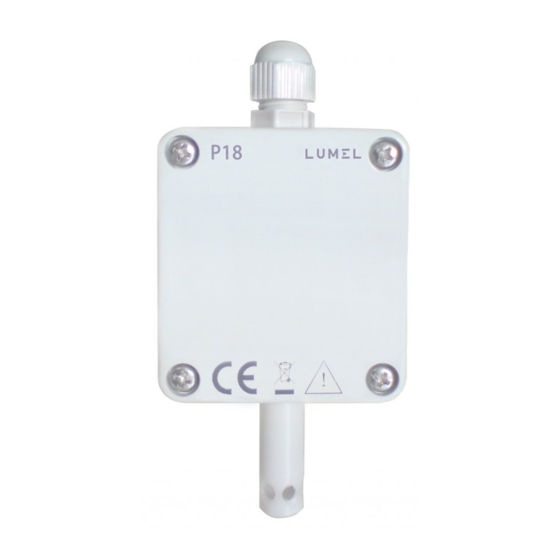
Датчик LUMEL P18 предназначен для измерения и преобразования относительной влажности и температуры окружающей среды в цифровой сигнал и в стандартный сигнал по току или напряжению.
Программирование датчика LUMEL P18 осуществляется с помощью интерфейса RS-485 и программного обеспечения LPCon.
Примененные защитные фильтры позволяют преобразователю P18 работать в различных условиях внешней среды. Применяется для автоматизации обслуживания зданий, в сельском хозяйстве и т.п.
Преобразователь монтируется на стене.
Габариты корпуса: 118 x 58 x 35 мм
![]()
Функции преобразователь LUMEL P18:
- температура точки росы
- абсолютная влажность
- преобразование измеренных величин в выходной сигнал (возможно масштабирование)
- передача данных по интерфейсу RS485, с поддержкой протоколом MODBUS, RTU режим
- память максимального и минимального значения для каждой измеренной и вычисленной величины
- программирование времени усреднения измерений
Формирование кода заказа LUMEL P18:
| Датчик температуры и влажности P18 | |
| Аналоговые выходы: | |
|
С аналоговыми выходами |
0 |
|
Выход тока: 4…20 mA |
1 |
|
Выход напряжения: 0…10 V |
2 |
| Варианты исполнения датчика: | |
|
Cтандартный |
00 |
| Язык документации: | |
|
Английский |
E |
|
Польский |
P |
| Проверка соответствия техническим условиям: | |
| без дополнительных требований | 0 |
Например: P18 100E0
С 2015 г. для приборов LUMEL P18 изменились заказные номера:
P18 0008 на P18 000E0
P18 1008 на P18 100E0
P18 2008 на P18 200E0
Назначение
Описание
Программное обеспечение
Технические характеристики
Знак утверждения типа
Комплектность
Поверка
Сведения о методах измерений
Рекомендации к применению
Назначение
Преобразователи температуры и относительной влажности измерительные моделей P18, P18D, P18L, P19 (далее по тексту — преобразователи или приборы) предназначены для измерений и контроля температуры и относительной влажности воздуха в помещениях.
Описание
Принцип работы приборов основан на измерении и преобразовании сигналов измерения температуры и относительной влажности в цифровой сигнал, в унифицированный выходной сигнал постоянного тока 4^20 мА или напряжения 0^10 В (в зависимости от модели), поступающих от измерительных чувствительных элементов.
Преобразователи моделей P18, P18D, P18L, P19 различаются по метрологическим и техническим характеристикам, а также по конструктивному исполнению.
Преобразователи представляют собой первичные преобразователи температуры и относительной влажности и состоят из пластмассового корпуса, внутри которого находится клеммная колодка для подключения внешних сигнальных проводов и электропитания. Измерительные чувствительные элементы (сенсоры) смонтированы на электронной плате преобразователя и являются конструктивно неотделимой его частью.
Модель P18 предназначена для измерения температуры и относительной влажности. Измеренные значения температуры и относительной влажности могут быть преобразованы в цифровой сигнал для передачи по протоколу Modbus с помощью интерфейса RS-485, в унифицированный выходной сигнал постоянного тока 4^20 мА или напряжения 0-И0 В. Модель P18 также может сохранять измеренные значения температуры и относительной влажности и рассчитывать максимальные и минимальные значения, значения температуры точки росы и абсолютной влажности.
Модель P18D отличается от модели P18 только наличием встроенного ЖК-дисплея для индицирования измеренных значений температуры и относительной влажности. Обе модели выпускаются в трех исполнениях: P18(D)-000 — без дополнительных аналоговых выходов; P18(D)-100 — с дополнительным токовым аналоговым выходом 4^20 мА; P18(D)-200 — с дополнительным аналоговым выходом по напряжению 0^10 В.
Модель P18L предназначена для измерения температуры или относительной влажности и питается от токовой петли. Измеренные значения температуры или относительной влажности преобразуются в аналоговый унифицированный выходной сигнал постоянного тока 4^20 мА.
Модель P19 предназначена для измерения температуры и относительной влажности. Измеренные значения температуры и относительной влажности преобразуются в цифровой сигнал для передачи по протоколу Modbus с помощью интерфейса RS-485. Модель P19 также может сохранять измеренные значения температуры и относительной влажности и рассчитывать максимальные и минимальные значения, значения температуры точки росы и абсолютной влажности.
Фотографии общего вида приборов представлены на рисунках 1-3.
Программное обеспечение
Программное обеспечение (ПО) преобразователей состоит из двух частей: встроенного и автономного.
Метрологически значимым является только встроенное ПО, которое устанавливается в преобразователь на заводе-изготовителе во время производственного цикла. ПО недоступно пользователю и не подлежит изменению на протяжении всего времени функционирования изделия, что соответствует уровню защиты «А» по МИ 32862010. Метрологические характеристики преобразователей оценены с учетом влияния на них ПО.
Идентификационные данные встроенного ПО приведены в таблице 1.
Таблица 1
|
Наименование программного обеспечения |
Идентификационное наименование программного обеспечения |
Номер версии (идентификационный номер) программного обеспечения |
Цифровой идентификатор программного обеспечения (контрольная сумма исполняемого кода) |
Алгоритм вычисления цифрового идентификатора программного обеспечения |
|
ПО для преобразователей моделей P18, P18D, P18L, P19 (встроенное) |
software |
Не ниже 1 |
Не используется |
— |
Автономная часть ПО «LPConfig» устанавливается на персональный компьютер и предназначено для программирования, визуализации, сохранения измеренных значений температуры и относительной влажности и расчета максимальных и минимальных значений, значений температуры точки росы и абсолютной влажности.
Идентификационные данные автономного ПО «LPConfig» приведены в таблице 2.
Таблица 2
|
Наименование программного обеспечения |
Идентификационное наименование программного обеспечения |
Номер версии (идентификационный номер) программного обеспечения |
Цифровой идентификатор программного обеспечения (контрольная сумма исполняемого кода) |
Алгоритм вычисления цифрового идентификатора программного обеспечения |
|
ПО для преобразователей моделей P18, P18D, P19 (автономное) |
LPConfig |
Не ниже 1.3.2 |
Не используется |
— |
Уровень защиты автономной части ПО от непреднамеренных и преднамеренных изменений соответствует уровню «С» (по МИ 3286-2010).
Технические характеристики
Основные метрологические и технические характеристики преобразователей представлены в таблице 3.
Таблице 3
|
Наименование характеристики |
Наименование моделей |
||
|
P18 |
P18D |
P18L |
P19 |
|
Диапазон измерений температуры, °С |
от минус 20 до плюс 60 |
|
Наименование характеристики |
Наименование моделей |
|||
|
P18 |
P18D |
P18L |
P19 |
|
|
Пределы допускаемой абсолютной погрешности канала измерений температуры (А), °С |
± 0,4 (при температуре окружающей среды 23±5 °С) |
± 0,6 (от плюс 10 до плюс 40); ± 1 (в остальном диапазоне) |
||
|
Дополнительная погрешность канала измерений температуры, °С / 10 °С |
± ‘/4 -А |
0,2 или ± / -А |
± / -А |
— |
|
Диапазон измерений относительной влажности, % |
от 5 до 95 |
|||
|
Пределы допускаемой абсолютной погрешности канала измерений относительной влажности, % |
±2 (в диапазоне св.10 до 90 %) ±3 (в остальном диапазоне) |
±3 (в диапазоне св.10 до 90 %) ±5 (в остальном диапазоне) |
||
|
Диапазон изменения аналогового выходного сигнала постоянного тока, мА |
4-20 |
— |
||
|
Допустимое сопротивление нагрузки для аналогового выходного сигнала постоянного тока, Ом, не более |
100 |
100 |
500 |
— |
|
Диапазон изменения аналогового выходного сигнала напряжения, В |
0-10 |
— |
||
|
Допустимое сопротивление нагрузки для аналогового выходного сигнала напряжения, Ом, не менее |
1000 |
— |
— |
|
|
Напряжение питания, В |
9-24 (постоянный или переменный ток) |
19-30 (постоянный ток) |
9-24 (постоянный или переменный ток) |
|
|
Масса, не более, г |
125 |
|||
|
Габаритные размеры, мм |
38 х 58 х 118 |
120 х 80 х 25 |
||
|
Рабочие условия эксплуатации |
||||
|
Температура окружающей среды, °С |
от минус 20 до плюс 60 |
|||
|
Относительная влажность воздуха, %, не более |
95 (без конденсации) |
Знак утверждения типа
Знак утверждения типа наносится на титульный лист руководства по эксплуатации (в правом верхнем углу) типографским способом, а также на корпус преобразователь с помощью наклейки.
Комплектность
В комплект поставки преобразователя входят:
— Преобразователь — 1 шт.;
— Руководство по эксплуатации (на русском языке) — 1 экз.;
— Методика поверки — 1 экз.
По дополнительному заказу: защитные фильтры (для моделей P18, P18D, P18L).
Поверка
осуществляется в соответствии с документом МП 56935-14 «Преобразователи температуры и относительной влажности измерительные моделей P18, P18D, P18L, P19. Методика поверки», утверждённым ФГУП «ВНИИМС» 14.01.2014 г.
Основные средства поверки:
— термометр электронный лабораторный «ЛТ-300», диапазон измеряемых температур: -50…+300 °С; пределы допускаемой основной абсолютной погрешности: ±0,05 °С (в диапазоне: -50.. .+199,9 °С);
— камера климатическая КХТВ-100-0, диапазон воспроизводимых температур:
-70.. .+80 °С, диапазон воспроизведения относительной влажности: 10.98 %;
— измеритель комбинированный Testo 645 с зондом 0636 9741 диапазон измерения относительной влажности: 5.95 %, пределы допускаемой абсолютной погрешности измерения относительной влажности: ±1,0 %;
— калибратор-вольтметр универсальный В1-28, Хв2.095.024 ТУ;
— термостат переливной прецизионный ТПП-1.2, диапазон воспроизводимых температур: -60…+100 °С, нестабильность поддержания заданной температуры: ±(0,004.0,01) °С.
Сведения о методах измерений
отсутствуют.
Нормативные и технические документы, устанавливающие требования к преобразователям температуры и относительной влажности измерительным моделей P18, P18D, P18L, P19
ГОСТ Р 52931-2008 Приборы контроля и регулирования технологических процессов. Общие технические условия.
Техническая документация фирмы-изготовителя.
ГОСТ 8.558-2009 ГСИ. Государственная поверочная схема для средств измерений температуры.
Рекомендации к применению
Осуществление производственного контроля за соблюдением установленных законодательством Российской Федерации требований промышленной безопасности к эксплуатации опасного производственного объекта; выполнение работ по оценке соответствия промышленной продукции и продукции других видов, а также иных объектов установленным законодательством Российской Федерации обязательным требованиям.
|
Detail Specifications: 1312/1312824-p180.pdf file (05 Dec 2022) |
Accompanying Data:
Lumel P18-0 Transducer PDF Operation & User’s Manual (Updated: Monday 5th of December 2022 05:18:58 PM)
Rating: 4.5 (rated by 91 users)
Compatible devices: P30P, P11P, P17, P20, P18S, P18D, P43, P20G series.
Recommended Documentation:
Text Version of Operation & User’s Manual
(Ocr-Read Summary of Contents, UPD: 05 December 2022)
-
23, 23 8. MAINTENANCE AND GUARANTEE The P18 transducer does not require any periodical maintenance. In case of some incorrect operations: 1. In the period of 12 months from the date of purchase: One should take the transducer down from the installation and return it to the Manufacturer Quality Control Dept. If the unit has been used in compliance with the instructions, the Manufac…
-
17, Lumel P18-0 17 Parameter description Standard value Version without analog outputs Version with the current output Version with the voltage output Address 1 1 1 Baud rate 9600 9600 9600 Mode RTU 8N1 RTU 8N1 RTU 8N1 Measuring time 30 [s] 30 [s] 30 [s] X1 temperature 0 -2000 [ o C x 100] -2000 [ o C x 100] Y1 temperature 0 400 [mA x 100] 0 [V x 100] X2 temperature 0 6000 [ o…
-
6, 6 Fig.1. Overall Dimensions of the P18 Transducer Fig.2. Lay-out of Assembly Holes of the P18 Transducer
… -
3, Lumel P18-0 3 CONTENTS 1. APPLICATION ………………………………………………………………… 5 2. BASIC REQUIREMENTS, OPERATIONAL SAFETY ……………. 5 3. INSTALLATION ……………………………………………………………….. 5 3.1. Assembly ………………………………………………………………………………..5…
-
12, Lumel P18-0 12 The conguration of the individual characteristic of analog outputs amounts to the introduction of suitable values X1, X2, Y1, Y2 in cor- responding registers to them from the range 4007 – 4014 tab.3. Values introduced in these registers must be integral values corresponding to set point values multiplied by the value 100. 4.3. RS-…
-
19, 19 5. ACCESSORIES As a standard, the P18 transducer is equipped with a metallic shield of the sensor, destined only for indoors applications, for outdoors or indoors applications exposed to the possibility of water vapour condensation, it is recommended to use additional shields of the sensor (interchangeable), depending of the transducer working conditions. Item Order code De…
-
14, Lumel P18-0 14 4.3.3. Registers for Write and Readout Configuration Registers of the P18 Transducer Table 6. Address Name Range Description 4000 Identifier 0xAA Identifier of the P18 transducer 4001 Address 1…247 Device address 1 4002 Baud rate 0…4 Baud rate of the RS-485 interface (bit/s) 1 : 0: 4800 1: 9600 2: 19200 3: 38400 4: 57600 4003 Mode 0…3 Kind of transmission through the RS-48…
-
15, 15 4010 Y2 temperature 0…2000 Output value Y2 of temperature: c. current output [mA x 100] d. voltage output [Vx100] 4011 X1 humidity 0…10000 Measured value X1 of humidity [% x 100] 4012 Y1 humidity 0…2000 Output value Y1 of humidity: e. current output [mA x 100] f. voltage output [Vx100] 4013 X2 h…
-
8, 8 Way of Electrical Signal Connection Table 1 Transducer without analog outputs Transducer with current outputs Transducer with voltage outputs One must use a spiral for the interface line connection. In case of the transducer work in an environment with high interference, one must apply shielded wires. The shield must be connected …
Recommended Instructions:
I Series, RM-V1000NU, M5350ti, DA1916SX, DR-MH200SE


-
Atex Load Cell Instruction Manual Zemic Europe B.V. T: +31 76 50 39480 Leerlooierstraat 8 Nr. 2021.06 Atex Load cell instruction manual Rev5 F: +31 76 50 39481 4871 EN Etten-Leur [email protected] The Netherlands 1/12 www.zemiceurope.com Specifications and dimensions are subject to change without notice and do not constitute any liability whatsoev …
Atex 12
-
LiveSight Ice transducerInstallation GuideParts included*988-12345-003*DimensionsCompliance statementsTechnical specicationsEnvironmentalWater temperature 0°C to +35°C (+32°F to +95°F)Storage temperature -30°C to +70°C (-22°F to +158°F)PhysicalWeight (without cable) 0,614 kg (1.354 lbs.)Cable length 7,6 m (25 ft) United States of America ¼ Note: The user is cautioned that any changes …
SIMRAD Ice transducer 2
-
mV88TRUE RMS MULTIMETEROFFmAAAµmVVV400mA FUSEDACOMVmA A10A MAXFUSEDMIN MAXRANGEHOLD HzPEAK MIN MAXRELPV350PRESSURE VACUMN MODULEMETRICMETRICOFFkPa.psicmHg.inHgFLUKEMODULESENSORTO PRESSURE/VACUUMINPUTBATTERYOPERATION1. Check battery voltage2. Select units3. Select settings4. Zero module5. Apply pressureBATTERY TEST1. DMM and module off2. DMM to mV range3. If d …
PV350 2
-
Veris Differential Pressure Transducer Connection Instructions For use with HOBO® H22, U12, U30, UX120-006M, and RX3000 data loggers and HOBO ZW data nodes © 2018 Onset Computer Corporation. All rights reserved. Onset, HOBO, HOBOware, and HOBOlink are registered trademarks and FlexSmart is a trademark of Onset Computer Corporation. Other products and brand names …
PX3ULX05 3