M4n68t-m le, Motherboard, Quick start guide
- Текст
- Оригинал
Advertising

Français
Deutsh
Italiano
Español
Русский
Português
Polski
Česky
Magyar
Български
Română
Srpski
Türkçe
Quick Start Guide
First Edition
December 2009
Copyright © 2009 ASUSTeK COMPUTER INC.
All Rights Reserved
U5245
M4N68T-M LE
Motherboard
Advertising

Регистрация устройства поможет вам управлять его гарантией, получать техническую поддержку и отслеживать статус ремонта.
Регистрация продукта
Руководства пользователя
Версия F5971
2.95 MB
M4N68T-M LE V2 user’s manual (French)
Версия E5971
2.38 MB
M4N68T-M SERIES user’s manual(English)
Версия T5971
3.08 MB
M4N68T-M LE V2 & M4N68T-M V2 user’s manual(Traditional Chinese)
Версия C5971
3.09 MB
M4N68T-M LE V2 & M4N68T-M V2 user’s manual(Simple Chinese)
Инструкция и руководство для
Asus M4N68T-M LE на русском на испанском на французском на итальянском на чешском на немецком на польском


42 страницы подробных инструкций и пользовательских руководств по эксплуатации
 15:22
15:22
Улучшение ПК Asus M4N68T + AMD Athlon2 + HDD Toshiba 2ТБ + SSD + ОЗУ 6 ГБ, тест возможностей
 01:35
01:35
Kit Placa Asus M4N68T-M LE + Amd Phenon 2 X4 + Placa Vídeo + Memória
 07:52
07:52
Обзор материнской платы ASUS M5A78L M LE USB3
 12:31
12:31
Сборка бюджетного игрового компьютера
 03:59
03:59
материнка асус M4N68T-M Поддержка процессоров и видеокарт
 04:50
04:50
Распаковка метеринской платы ASUS M4N68T LE V2
 04:27
04:27
ASUS M4N68T-M LE V2 — Usb device over current status detected
 04:19
04:19
Разгон процесора AMD и оперативной памяти через BIOS
Français Deutsh Italiano Español Русский Português Polski Če…
M4n68t-m le, Motherboard, Quick start guide
- Изображение
- Текст
Français
Deutsh
Italiano
Español
Русский
Português
Polski
Česky
Magyar
Български
Română
Srpski
Türkçe
Quick Start Guide
First Edition
December 2009
Copyright © 2009 ASUSTeK COMPUTER INC.
All Rights Reserved
U5245
M4N68T-M LE
Motherboard

Installer le cpu, Layout de la carte mère, Français
Asus m4n68t-m le, F_panel, M4n68t-m le
- Изображение
- Текст
2
Français
ASUS M4N68T-M LE
2.
Installer le CPU
Pour installer le CPU :
1. Localisez le socket du CPU sur la carte mère.
2. Soulevez le levier du support à un angle de 90° minimum.
3. Placez le CPU sur le socket en vous assurant que la marque en forme de triangle
doré soit bien placée en bas à gauche du socket.
4. Insérez avec soin le processeur sur son support jusqu’à ce qu’il s’insère
correctement.
5. Une fois le processeur mis en place, rabattez le levier du support pour sécuriser
le processeur. Le levier se bloque sur le petit ergot latéral pour indiquer qu’il est
en place.
1.
Layout de la carte mère
Le processeur s’insère uniquement dans le bon sens. NE PAS forcer le processeur
sur son support pour éviter de tordre les broches et d’endommager ainsi le
processeur!
M4N68T-M LE
PCIEX16
PCIEX1_1
PCI1
PCI2
PRI_IDE
USB910
USB78
USB56
AAFP
SPDIF_OUT
SPEAKER
ATX12V
EATXPW
R
CPU_FAN
Lithium Cell
CMOS Power
Super
I/O
VIA
VT1708S
RTL
8211CL
KB/MS
COM1
LPT
8Mb
BIOS
SB_PWR
CLRTC
USBPW5-10
USBPW1-4
KBPWR
NVIDIA
®
MCP68 SE
SOCKET AM3
DDR3 DIMM_A1 (64bit, 240-pin module)
DDR3 DIMM_B1 (64bit, 240-pin module)
SATA1
SATA3
SATA2
SATA4
AUDIO
LAN1_USB12
USB34
CHA_FAN
F_PANEL
VG
A
20.8cm(8.2in)
24.4cm(9.6in)
2
1
2 3
+5V
(Default)
+5VSB
USBPW5-10
2
1
2
3
+5V
+5VSB
(Default)
USBPW1-4
1
2
2
3
Normal
(Default)
Clear RTC
CLRTC
2
1
2 3
+5V
(Default)
+5VSB
KBPWR
PIN 1
PWR BTN
PLED
+
PLED
—
PWR
GND
IDE_LED
+
IDE_LED-
Groun
d
Rese
t
F_PANEL
PWR LED
HD_LED
RESET

Français
ASUS M4N68T-M LE
3.
Mémoire Système
Vous pouvez installer des modules DIMM DDR3 ECC/non ECC non tamponnés de
512 Mo, 1 Go, 2 Go et 4 Go dans les socles DIMM en utilisant les configurations de
mémoire données dans cette section.
•
Vous pouvez installer des modules mémoire de tailles variables dans le Canal A et B.
Le système mappe la taille totale du canal de plus petite taille pour les configurations
dual-channel. Tout excédant de mémoire du canal le plus grand est alors mappé pour
fonctionner en single-channel.
• Installez toujours des modules mémoire avec une latence CAS identique.
Pour obtenir une compatibilité optimale, il vous est recommandé de vous
équiper des modules de mémoire auprès du même vendeur.
•
En raison des limitations d’adressage mémoire sur les systèmes d’exploitation
Windows 32-bits, lorsque vous installez 4Go ou plus de mémoire sur cette carte mère,
le montant de mémoire utilisable par le système d’exploitation sera de 3 Go ou moins.
Pour une utilisation effective de la mémoire, vous pouvez :
—
Utiliser un maximum de 3 Go lors de l’utilisation d’un système
d’exploitation 32-bits.
—
Installer un système d’exploitation Windows 64-bits si vous souhaitez
installer 4 Go ou plus de mémoire sur cette carte mère.
•
Cette carte mère ne supporte pas les modules mémoire composés de puces mémoire
de 256 Mo ou moins.
Canal
Emplacements
Canal A
DIMM_A1
Canal B
DIMM_B1

Informations du bios, Informations sur le dvd de support, Français
Страница 4
- Изображение
- Текст
4
Français
ASUS M4N68T-M LE
4.
Informations du BIOS
Utilisez le programme de configuration du BIOS pour mettre à jour le BIOS ou
configurer ses paramètres. Les écrans BIOS comprennent les clés de navigation
et une courte aide en ligne pour vous guider. Si vous rencontrez des problèmes
liés au système ou si le système devient instable une fois que vous aurez modifié
les paramètres, chargez les Paramètres de Réglage Par Défaut. Rendez visite au
site web d’ASUS (www.asus.com) pour obtenir les mises à jour.
Pour accéder au Setup lors du démarrage:
Pressez <Suppr> lors du Test Automatique de Démarrage (POST : Power-On
Self Test ). Si vous ne pressez pas la touche <Suppr>, le POST continuera son
programme de test.
Pour accéder au programme de configuration du BIOS après le POST :
• Redémarrez le système en pressant <Ctrl> + <Alt> + <Suppr>, puis pressez
<Suppr> lors du POST, ou
• Pressez le bouton de réinitialisation situé sur le châssis puis pressez <Suppr>
lors du POST, ou
• Eteignez et rallumez le système puis pressez <Suppr> lors du POST.
Pour mettre à jour le BIOS avec ASUS EZ Flash 2 :
Démarrez le système et appuyez sur <Alt> + <F2> lors du POST pour lancer EZ
Flash 2. Insérez un disque flash USB contenant le dernier fichier image du BIOS.
EZ Flash 2 lance le processus de mise à jour du BIOS et redémarre le système
automatiquement une fois terminé.
Pour restaurer le BIOS avec CrashFree BIOS 3 :
Démarrez le système. Si le BIOS est corrompu, l’outil de restauration automatique
CrashFree BIOS 3 vérifiera la présence du fichier du BIOS sur le lecteur optique et
le disque flash USB. Connectez un disque flash USB ou insérez le DVD de support
dans le lecteur optique contenant le dernier fichier image du BIOS ou celui d’origine.
Redémarrez le système une fois le processus de restauration du BIOS terminé.
5.
Informations sur le DVD de support
Cette carte mère supporte les systèmes d’exploitation Windows
®
XP / Vista / 7. Installez
toujours la dernière version d’OS et les mises à jour correspondantes de manière à profiter
pleinement des caractéristiques de votre matériel.
Le DVD de support livré avec la carte mère contient les pilotes, les applications logicielles, et
les utilitaires que vous pouvez installer pour tirer partie de toutes les fonctions de la carte mère.
Si l
’Exécution automatique n’est pas activée sur votre ordinateur, parcourez le contenu
du DVD de support pour localiser le fichier ASSETUP.EXE dans le répertoire BIN. Double-
cliquez sur
ASSETUP.EXE pour lancer le DVD.

Motherboard-layout 2. installieren der cpu, Deutsch, Asus m4n68t-m le
F_panel, M4n68t-m le
- Изображение
- Текст
ASUS M4N68T-M LE
Deutsch
1.
Motherboard-Layout
2.
Installieren der CPU
So installieren Sie den Prozessor:
1. Suchen Sie auf dem Motherboard den Prozessorsockel.
2. Heben Sie den Sockelhebel bis zu einem Winkel von 90 Grad hoch.
3. Positionieren Sie die CPU oberhalb des Sockels, so dass die CPU-Ecke mit dem
goldenen Dreieck auf der Sockelecke mit dem kleinen Dreieck liegt.
4. Setzen Sie die CPU vorsichtig in den Sockel ein. Achten Sie auf den korrekten
Sitz.
5. Sobald die CPU richtig sitzt, drücken Sie den Sockelhebel nach unten, um die
CPU zu arretieren. Sie hören einen Klickton, wenn der Hebel einrastet.
Die CPU passt nur in einer Richtung in den Sockel. Stecken Sie die CPU nicht
gewaltsam hinein, um verbogene Kontaktstifte und Schäden an der CPU zu
vermeiden!
M4N68T-M LE
PCIEX16
PCIEX1_1
PCI1
PCI2
PRI_IDE
USB910
USB78
USB56
AAFP
SPDIF_OUT
SPEAKER
ATX12V
EATXPW
R
CPU_FAN
Lithium Cell
CMOS Power
Super
I/O
VIA
VT1708S
RTL
8211CL
KB/MS
COM1
LPT
8Mb
BIOS
SB_PWR
CLRTC
USBPW5-10
USBPW1-4
KBPWR
NVIDIA
®
MCP68 SE
SOCKET AM3
DDR3 DIMM_A1 (64bit, 240-pin module)
DDR3 DIMM_B1 (64bit, 240-pin module)
SATA1
SATA3
SATA2
SATA4
AUDIO
LAN1_USB12
USB34
CHA_FAN
F_PANEL
VG
A
20.8cm(8.2in)
24.4cm(9.6in)
2
1
2 3
+5V
(Default)
+5VSB
USBPW5-10
2
1
2
3
+5V
+5VSB
(Default)
USBPW1-4
1
2
2
3
Normal
(Default)
Clear RTC
CLRTC
2
1
2 3
+5V
(Default)
+5VSB
KBPWR
PIN 1
PWR BTN
PLED
+
PLED
—
PWR
GND
IDE_LED
+
IDE_LED-
Groun
d
Rese
t
F_PANEL
PWR LED
HD_LED
RESET

6
ASUS M4N68T-M LE
Deutsch
3.
Arbeitsspeicher
Sie können 512MB, 1GB, 2GB und 4GB ungepufferte ECC/Nicht-ECC DDR3
DIMMs in den DIMM-Steckplätzen entsprechend den in diesem Abschnitt
beschriebenen Arbeitsspeicherkonfigurationen installieren.
Kanal
Steckplätze
Kanal A
DIMM_A1
Kanal B
DIMM_B1
• Sie können verschiedene Speichergrößen in Channel A und Channel B installieren. Das
System ordnet die gesamte Größe des weniger belegten Kanals für die Dual-Channel-
Konfiguration zu. Der überschüssige Speicher des höher belegten Kanals wird dann der
Single-Channel-Konfiguration zugeordnet.
• Installieren Sie immer DIMMs mit gleicher CAS-Latenzzeit. Für optimale Kompatibilität
wird empfohlen, nur Speichermodule eines Herstellers zu verwenden.
• Durch die Speicheradressenbeschränkung in 32-Bit-Windows
®
können vom
Betriebssystem nur 3GB oder weniger benutzt werden, selbst wenn 4GB installiert
wurden. Für eine effektive Speichernutzung empfehlen wir Ihnen folgendes:
—
Installieren Sie maximal 3GB Speicher, wenn Sie ein 32-Bit-Windows
®
—
betriebssystem benutzen.
—
Installieren Sie ein 64-Bit-Windows
®
-betriebssystem, wenn Sie auf dem
Motherboard 4GB oder mehr Speicher installieren wollen.
• Dieses Motherboard unterstützt keine DIMMs, die aus 256 Megabit- (Mb) Chips oder
weniger hergestellt wurden.

7
ASUS M4N68T-M LE
Deutsch
4.
BIOS-Informationen
Benutzen Sie das BIOS-Einstellungsprogramm zum aktualisieren des BIOS oder
zur Konfiguration seiner Parameter. Die BIOS-Anzeigen enthalten Navigations-
anleitungen und eine kurze Online-Hilfe, um Ihnen die Verwendung zu erleichtern.
Falls in Ihrem System Probleme auftauchen, oder das System nach dem Verändern
einiger Einstellungen instabil wird, sollten Sie die Standardeinstellungen zurückholen.
Weitere Neuigkeiten finden Sie auf der ASUS-Webseite (www.asus.com).
So öffnen Sie das BIOS-Setup beim Systemstart:
Drücken Sie <Entf> während des Power-On Self-Test (POST). Wenn Sie nicht <Entf>
drücken, fährt der POST mit seiner Routine fort.
So öffnen Sie das Setup nach dem POST:
• Starten Sie das System neu, indem Sie <Strg> + <Alt> + <Entf> drücken, und
drücken Sie dann <Entf> während des POST, oder
• Drücken Sie den Reset-Schalter am Computergehäuse, und drücken Sie dann
<Entf> während des POST, oder
• Schalten Sie das System aus und wieder an, und drücken Sie dann <Entf>
während des POST
So aktualisieren Sie das BIOS über ASUS EZ Flash 2:
Starten Sie das System und drücken auf <Alt> + <F2> während des POSTs, um EZ
Flash 2 zu starten. Schließen Sie das USB-Flash-Laufwerk an, das die BIOS-Datei
enthält. EZ Flash 2 führt den BIOS-Aktualisierungsprozess aus und startet das System
automatisch nach dem Beenden des Prozesses neu.
So stellen Sie das BIOS über CrashFree BIOS 3 wieder her:
Starten Sie das System. Wenn das BIOS fehlerhaft ist, sucht das
Wiederherstellungshilfsprogramm CrashFree BIOS 3 automatisch nach einer
BIOS-Datei in dem optischen Laufwerk und USB-Flash-Laufwerk, um das BIOS
wiederherzustellen. Schließen Sie das USB-Flash-Laufwerk an oder legen die
Support-DVD ein, welches bzw. welche die originale bzw. neueste BIOS-Datei enthält.
Starten Sie das System nach dem Wiederherstellen des BIOS neu.
5.
Software-Unterstützungbg
Das Motherboard unterstützt Windows
®
XP/Vista/7 Betriebssysteme (OS). Installieren
Sie bitte immer die neueste OS-Version und die entsprechenden Updates, um die
Funktionen Ihrer Hardware zu maximieren.
Die mit dem Motherboard gelieferte Support-DVD enthält die Treiber, Anwendungs-
Software und Programme die Sie installieren können, um alle Motherboard-
Funktionen benutzen zu können. Es wird bei aktivierter Autorun-Funktion
automatisch das Treibermenü angezeigt.
Wenn Autorun nicht aktiviert ist, durchsuchen Sie den Inhalt der Support-DVD, um die
Datei ASSETUP.EXE im Ordner BIN zu finden. Doppelklicken Sie auf das Dateisymbol
ASSETUP.EXE, um die DVD auszuführen.

8
Italiano
ASUS M4N68T-M LE
1.
Diagramma disposizione scheda madre
2.
Installazione della CPU
Installazione della CPU:
1. Trovare la presa CPU nella scheda madre.
2. Sollevare la leva della presa ad un angolo di almeno 90°.
3. Collocare la CPU sul socket in modo tale che l’angolo con il triangolo dorato della
CPU combaci con l’angolo del socket dove c’è il tirandolo.
4. Inserire completamente con delicatezza la CPU nella presa.
5. Quando la CPU è al suo posto, abbassare la leva della presa per bloccare la
CPU. La leva scatta sulla linguetta laterale indicando che è bloccata.
La CPU può essere inserita solamente con un corretto orientamento. NON
forzare la CPU nella presa diversamente si possono piegare i pin e danneggiare
la CPU!
M4N68T-M LE
PCIEX16
PCIEX1_1
PCI1
PCI2
PRI_IDE
USB910
USB78
USB56
AAFP
SPDIF_OUT
SPEAKER
ATX12V
EATXPW
R
CPU_FAN
Lithium Cell
CMOS Power
Super
I/O
VIA
VT1708S
RTL
8211CL
KB/MS
COM1
LPT
8Mb
BIOS
SB_PWR
CLRTC
USBPW5-10
USBPW1-4
KBPWR
NVIDIA
®
MCP68 SE
SOCKET AM3
DDR3 DIMM_A1 (64bit, 240-pin module)
DDR3 DIMM_B1 (64bit, 240-pin module)
SATA1
SATA3
SATA2
SATA4
AUDIO
LAN1_USB12
USB34
CHA_FAN
F_PANEL
VG
A
20.8cm(8.2in)
24.4cm(9.6in)
2
1
2 3
+5V
(Default)
+5VSB
USBPW5-10
2
1
2
3
+5V
+5VSB
(Default)
USBPW1-4
1
2
2
3
Normal
(Default)
Clear RTC
CLRTC
2
1
2 3
+5V
(Default)
+5VSB
KBPWR
PIN 1
PWR BTN
PLED
+
PLED
—
PWR
GND
IDE_LED
+
IDE_LED-
Groun
d
Rese
t
F_PANEL
PWR LED
HD_LED
RESET

9
Italiano
ASUS M4N68T-M LE
3.
Memoria di sistema
Si possono installare moduli DIMM DDR3 ECC/non ECC unbuffered 512 MB, 1GB,
2GB e 4GB nelle prese DIMM utilizzando le configurazioni memoria di questa
sezione.
Canale doppio
Prese
Coppia A
DIMM_A1
Coppia B
DIMM_B1
• È possibile installare diversi formati di memoria nei canali A e B. Il sistema mappa la
dimensione totale del canale di dimensione più piccolo per la configurazione a canale
doppio. Qualsiasi accesso alla memoria dal canale di dimensione maggiore, viene
quindi mappato per il funzionamento a canale singolo.
•
Utilizzare e installare sempre moduli DIMM con la stessa latenza CAS. Per
poter garantire la perfetta compatibilità dei moduli, si raccomanda di utilizzare
moduli di memoria acquistati presso lo stesso venditore.
• A causa dei limiti con gli indirizzi di memoria nel sistema operativo Windows® a 32
bit, quando si installa una memoria da 4GB o più sulla scheda madre, la memoria
effettivamente utilizzabile dal sistema operativa può essere di 3GB o meno. Per usare in
modo efficace la memoria, si raccomanda di eseguire una delle seguenti azioni:
—
Usare 3GB di memoria di sistema al massimo se si utilizza il sistema operativo
Windows® a 32 bit.
—
Per installare 4GB di memoria o più sulla scheda madre, installare il sistema
operativo Windows® a 64 bit.
• Questa scheda madre non supporta DIMM da 256 megabit (Mb) o minori.

Informazioni sul bios, Italiano, Supporto per il software
Страница 10
- Изображение
- Текст
10
Italiano
ASUS M4N68T-M LE
4.
Informazioni sul BIOS
Usare l’utilità per la configurazione del BIOS per aggiornare il BIOS o configurarne i
parametri. La schermata BIOS include tasti di navigazione ed una concisa guida in
linea. Se si riscontrano problemi con il sistema, oppure se questo diventa instabile
dopo avere modificato le impostazioni, caricare le impostazioni predefinite di
configurazione Setup Defaults. Visitare la pagina Web ASUS (www.asus.com) per
gli aggiornamenti.
Per accedere al Setup all’avvio:
Premere il tasto <Delete> durante il POST (Power On Self Test). Se non si preme il
tasto <Delete>, il POST continua le sue routine di diagnostica.
Per accedere al Setup dopo il POST:
• Riavviare il sistema premendo i tasti <Ctrl> + <Alt> + <Delete>, poi premere il
tasto <Delete> durante il POST, oppure
• Premere il tasto di ripristino sul telaio, poi premere il tasto <Delete> durante il
POST, oppure
• Spegnere e riaccendere il sistema e poi premere il tasto <Delete> durante il
POST
Aggiornare il BIOS con ASUS EZ Flash 2:
Avviare il sistema e premere <Alt> + <F2> nel corso del POST per lanciare EZ Flash 2.
Inserire una memoria flash USB contenente il file con la versione più recente del BIOS.
EZ Flash 2 esegue il processo di aggiornamento del BIOS e riavvia automaticamente
il sistema una volta completato.
Ripristinare il BIOS con CrashFree BIOS 3:
Avviare il sistema. Se il BIOS è danneggiato, lo strumento per il ripristino automatico
CrashFree BIOS 3 verifica l’unità ottica e la memoria flash USB per verificare la
presenza di un file BIOS in modo da poter procedere al ripristino del BIOS: Inserire
una memoria flash USB o il DVD di supporto che contiene il file con la versione più
recente o originale del BIOS. Riavviare il sistema dopo avere eseguito il ripristino
del BIOS.
5.
Supporto per il software
Questa scheda madre supporta un sistema operativo (OS) Windows
®
XP/Vista/7.
Installate sempre l’ultima versione OS e gli aggiornamenti corrispondenti, in modo
da massimizzare le funzioni del vostro hardware.
Il DVD di supporto fornito con il pacchetto della scheda madre contiene i driver, le
applicazioni software e le utilità che possono essere installate per poter sfruttare tutte
le caratteristiche della scheda madre. Viene visualizzato automaticamente il menu
Driver se sul computer è attiva l’Esecuzione automatica.
Se sul computer non è attiva ESECUZIONE AUTOMATICA, sfogliare i contenuti del DVD
di supporto per individuare il file ASSETUP.EXE nella cartella BIN. Fare doppio clic su
ASSETUP.EXE per eseguire il DVD.

Комментарии
-
Драйверы
7
-
Инструкции по эксплуатации
4
Языки:

ASUS M4N68T-M LE V2 инструкция по эксплуатации
(66 страниц)
- Языки:Английский
-
Тип:
PDF -
Размер:
3.07 MB -
Описание:
M4N68T-M SERIES user’s manual(English)
Просмотр

ASUS M4N68T-M LE V2 инструкция по эксплуатации
(67 страниц)
- Языки:Китайский
-
Тип:
PDF -
Размер:
3.2 MB -
Описание:
M4N68T-M LE V2 & M4N68T-M V2 user’s manual(Simple Chinese)
Просмотр

ASUS M4N68T-M LE V2 инструкция по эксплуатации
(65 страниц)
- Языки:Китайский
-
Тип:
PDF -
Размер:
3.19 MB -
Описание:
M4N68T-M LE V2 & M4N68T-M V2 user’s manual(Traditional Chinese)
Просмотр

ASUS M4N68T-M LE V2 инструкция по эксплуатации
(63 страницы)
- Языки:Французский
-
Тип:
PDF -
Размер:
3.05 MB -
Описание:
M4N68T-M LE V2 user’s manual (French)
Просмотр
На NoDevice можно скачать инструкцию по эксплуатации для ASUS M4N68T-M LE V2. Руководство пользователя необходимо для ознакомления с правилами установки и эксплуатации ASUS M4N68T-M LE V2. Инструкции по использованию помогут правильно настроить ASUS M4N68T-M LE V2, исправить ошибки и выявить неполадки.
-
Contents
-
Table of Contents
-
Bookmarks
Quick Links
Related Manuals for Asus M4N68T LE V2
Summary of Contents for Asus M4N68T LE V2
-
Page 1
M4N68T V2 M4N68T LE V2… -
Page 2
Product warranty or service will not be extended if: (1) the product is repaired, modified or altered, unless such repair, modification of alteration is authorized in writing by ASUS; or (2) the serial number of the product is defaced or missing. -
Page 3: Table Of Contents
Welcome! ………………1-1 Package contents …………….. 1-1 Special features …………….1-1 1.3.1 Product highlights …………1-1 1.3.2 Innovative ASUS features ……….1-3 Before you proceed …………..1-4 Motherboard overview …………..1-5 1.5.1 Placement direction …………1-5 1.5.2 Screw holes …………..1-5 1.5.3…
-
Page 4
Chapter 2: BIOS information Managing and updating your BIOS ……….2-1 2.1.1 ASUS Update …………..2-1 2.1.2 ASUS EZ Flash 2 …………2-2 2.1.3 ASUS CrashFree BIOS 3 ……….2-3 BIOS setup program …………..2-4 2.2.1 BIOS menu screen …………2-5 2.2.3… -
Page 5
Boot Device Priority …………2-18 2.6.2 Boot Settings Configuration ………. 2-18 2.6.3 Security …………….. 2-19 Tools menu …………….. 2-20 2.7.1 ASUS EZ Flash 2 …………2-20 2.7.2 ASUS O.C. Profile …………2-21 2.7.3 AI NET 2……………. 2-21 Exit menu ………………2-22… -
Page 6: Notices
Complying with the REACH (Registration, Evaluation, Authorisation, and Restriction of Chemicals) regulatory framework, we published the chemical substances in our products at ASUS REACH website at http://csr.asus.com/english/REACH.htm. DO NOT throw the motherboard in municipal waste. This product has been designed to enable proper reuse of parts and recycling.
-
Page 7: Safety Information
Safety information Electrical safety • To prevent electric shock hazard, disconnect the power cable from the electric outlet before relocating the system. • When adding or removing devices to or from the system, ensure that the power cables for the devices are unplugged before the signal cables are connected. If possible, disconnect all power cables from the existing system before you add a device.
-
Page 8: Conventions Used In This Guide
Refer to the following sources for additional information and for product and software updates. ASUS websites The ASUS website provides updated information on ASUS hardware and software products. Refer to the ASUS contact information. Optional documentation Your product package may include optional documentation, such as warranty flyers, that may have been added by your dealer.
-
Page 9: M4N68T V2 Series Specifications Summary
Dual-channel memory architecture Due to CPU spec., AMD 100 and 200 series CPUs support ® up to DDR3 1066MHz. With ASUS design, this motherboard can support up to DDR3 1333MHz. ** Refer to www.asus.com for the latest Memory QVL (Qualified Vendors List).
-
Page 10
— HT frequency tuning from 200MHz to 300MHz at 1MHz increment — PCIe frequency tuning from 100MHz to 150MHz at 1MHz increment Overclocking protection: — ASUS C.P.R. (CPU Parameter Recall) Other features 100% All High-quality Conductive Polymer Capacitors (M4N68T V2 only) Rear panel ports… -
Page 11: Chapter 1: Product Introduction
ASUS motherboard Support DVD Documentation User Manual • M4N68T V2 Series motherboards include M4N68T V2 and M4N68T LE V2 two models. The package contents vary from models. • If any of the items is damaged or missing, contact your retailer.
-
Page 12
Cool ‘n’ Quiet Technology ® This motherboard supports the AMD Cool ‘n’ Quiet technology which ® monitors system operation and automatically adjusts CPU voltage and frequency for a cool and quiet operating environment. Dual-Channel DDR3 1800 (O.C.) support This motherboard supports DDR3 memory that features data transfer rates of 1800 (O.C.)/1600 (O.C.)/1333/1066 MHz to meet the higher bandwidth requirements of the latest operating system, 3D graphics, multimedia, and Internet applications. -
Page 13: Innovative Asus Features
BIOS file using the bundled support DVD or a USB flash disk that contains the BIOS file. ASUS EZ Flash 2 ASUS EZ Flash 2 allows you to update the BIOS from a USB flash disk before entering the OS. ASUS Q-Fan…
-
Page 14: Before You Proceed
This motherboard and its packaging comply with the European Union’s Restriction on the use of Hazardous Substances (RoHS). This is in line with the ASUS vision of creating environment-friendly and recyclable products/packaging to safeguard consumers’ health while minimizing the impact on the environment.
-
Page 15: Motherboard Overview
Place six screws into the holes indicated by circles to secure the motherboard to the chassis. DO NOT overtighten the screws! Doing so can damage the motherboard. Place this side towards the rear of the chassis. M4N68T V2 Series ASUS M4N68T V2 Series…
-
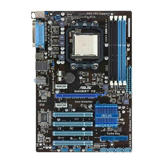
Page 16: Motherboard Layout
1.5.3 Motherboard layout 20.8cm(8.2in) KBMS KBPWR ATX12V USB34 LAN1_USB12 Lithium Cell CMOS Power AUDIO AAFP PCIEX1_1 M4N68T V2 Series 8211CL PCIEX16 PCIEX1_2 NVIDIA ® PCI1 MCP68 SE Super PCI2 BIOS SPEAKER PCI3 PRI_IDE SB_PWR VT1708S CLRTC PCI4 USBPW5-10 SATA1 SATA2 SATA3 SATA4 USB56…
-
Page 17: Layout Contents
CPU into the socket to prevent bending the pins and damaging the CPU! 1.6.1 Installing the CPU To install a CPU: Locate the CPU socket on the motherboard. M4N68T V2 Series M4N68T V2 Series CPU socket AM3 ASUS M4N68T V2 Series…
-
Page 18
Press the lever sideways to unlock the Socket lever socket, then lift it up to a 90°-100° angle. Ensure that the socket lever is lifted up to a 90°-100° angle; otherwise, the CPU will not fit in completely. Position the CPU above the socket such that the CPU corner with the gold triangle matches the socket corner with a small triangle. -
Page 19: Installing The Heatsink And Fan
Your boxed CPU heatsink and fan assembly should come with installation instructions for the CPU, heatsink, and the retention mechanism. If the instructions in this section do not match the CPU documentation, follow the latter. Attach one end of the retention bracket to the retention module base. ASUS M4N68T V2 Series…
-
Page 20: System Memory
Align the other end of the retention bracket to the retention module base. A clicking sound denotes that the retention bracket is in place. Ensure that the fan and heatsink assembly perfectly fits the retention mechanism module base, otherwise you cannot snap the retention bracket in place. Push down the retention bracket lock on the retention mechanism to secure the heatsink and fan to the module base.
-
Page 21: Memory Configurations
• Due to the CPU specification, AMD 100 and 200 series CPUs support up to DDR3 ® 1066MHz. With ASUS design, this motherboard can support up to DDR3 1333MHz. • When overclocking, some AMD CPUs may not support DDR3 1600MHz or higher frequency DIMMs.
-
Page 22
DDR3-1600(O.C.) MHz capability DIMM support Chip Vendor Part No. Size Chip NO. Brand A-Data AD31600X002GMU 4096MB(Kit of 2) Heat-Sink Package 7-7-7-20 • Corsair CM3X1G1600C9DHX 2048MB(Kit of 2) Heat-Sink Package 9-9-9-24 • • • CRUCIAL BL12864BA1608.8SFB(XMP) 3072MB(Kit of 3) Heat-Sink Package 8-8-8-24 •… -
Page 23
Heat-Sink Package • PATRIOT PSD31G13332H 1024MB Heat-Sink Package • • • Patriot PSD31G13332 1024MB Patriot PM64M8D38U-15 • • Takems TMS1GB364D081-107EY 1024MB Heat-Sink Package 7-7-7-20 • • • Takems TMS1GB364D081-138EY 1024MB Heat-Sink Package 8-8-8-24 • • • ASUS M4N68T V2 Series 1-13… -
Page 24
Dual-channel memory configuration. • C*: Supports two pairs of modules inserted into both the blue and the black slots as two pairs of Dual-channel memory configuration. Visit the ASUS website at www.asus.com for the latest QVL. 1-14 Chapter 1: Product introduction… -
Page 25: Installing A Dimm
DIMM. Support the DIMM lightly with your fingers when pressing the retaining clips. The DIMM might get damaged when it flips out with extra force. DIMM notch Remove the DIMM from the socket. ASUS M4N68T V2 Series 1-15…
-
Page 26: Expansion Slots
Expansion slots In the future, you may need to install expansion cards. The following sub-sections describe the slots and the expansion cards that they support. Unplug the power cord before adding or removing expansion cards. Failure to do so may cause you physical injury and damage motherboard components.
-
Page 27: Jumpers
• You do not need to clear the RTC when the system hangs due to overclocking. For system failure due to overclocking, use the CPU Parameter Recall (C.P.R) feature. Shut down and reboot the system so the BIOS can automatically reset parameter settings to default values. ASUS M4N68T V2 Series 1-17…
-
Page 28: Usb Device Wake-Up
USB device wake-up (3-pin USBPW1-4, USBPW5-10) Set these jumpers to +5V to wake up the computer from S1 sleep mode (CPU stopped, DRAM refreshed, system running in low power mode) using the connected USB devices. Set these jumpers to +5VSB to wake up the compurer from S3 and S4 sleep modes (no power to CPU, DRAM in slow refresh, power supply in reduced power mode).
-
Page 29: Connectors
Mic In Bass/Center Bass/Center Lime (Front panel) – – – Side Speaker Out To configure an 8-channel audio output: Use a chassis with HD audio module in the front panel to support 8-channel audio output. ASUS M4N68T V2 Series 1-19…
-
Page 30: Internal Connectors
USB 2.0 ports 1 and 2. These two 4-pin Universal Serial Bus (USB) ports connect to USB 2.0 devices. USB 2.0 ports 3 and 4. These two 4-pin Universal Serial Bus (USB) ports connect to USB 2.0 devices. Serial port. This 9-pin COM1 port is for pointing devices or other serial devices. PS/2 Keyboard port (purple).
-
Page 31: Atx Power Connectors
The system may become unstable or may not boot up if the power is inadequate. • If you are uncertain about the minimum power supply requirement for your system, refer to the Recommended Power Supply Wattage Calculator at http://support.asus. com/PowerSupplyCalculator/PSCalculator.aspx?SLanguage=en-us for details. ASUS M4N68T V2 Series…
-
Page 32
IDE connector (40-1 pin PRI_IDE) The onboard IDE connector is for Ultra DMA 133/100/66 signal cable. There are three connectors on each Ultra DMA 133/100/66 signal cable: blue, black, and gray. Connect the blue connector to the motherboard’s IDE connector, then select one of the following modes to configure your devices: Drive jumper setting Mode of device(s) -
Page 33
XP limitation, Windows XP may not recognize some USB floppy disk ® ® drives. • For more details on RAID/AHCI, refer to the RAID/AHCI Supplementary Guide included in the folder named Manual in the support DVD. ASUS M4N68T V2 Series 1-23… -
Page 34: Speaker Connector
System panel connector (10-1 pin F_PANEL) This connector supports several chassis-mounted functions. PWR LED PWR BTN F_PANEL PIN 1 M4N68T V2 Series HD_LED RESET M4N68T V2 Series System panel connector • System power LED (2-pin PWRLED) This 2-pin connector is for the system power LED. Connect the chassis power LED cable to this connector.
-
Page 35: Digital Audio Connector
Ensure that the audio device of Sound playback is VIA High Definition Audio (the name may be different based on the OS). Go to Start > Control Panel > Sounds and Audio Devices > Sound Playback to configure the setting. The S/PDIF module is purchased separately. ASUS M4N68T V2 Series 1-25…
-
Page 36
DO NOT forget to connect the fan cables to the fan connectors. Insufficient air flow inside the system may damage the motherboard components. These are not jumpers! DO NOT place jumper caps on the fan connectors. Only the 4-pin CPU fan supports the ASUS Q-Fan feature. 1-26 Chapter 1: Product introduction… -
Page 37: Software Support
The contents of the Support DVD are subject to change at any time without notice. Visit the ASUS website at www.asus.com for updates. To run the Support DVD Place the Support DVD into the optical drive.
-
Page 38
1-28 Chapter 1: Product introduction… -
Page 39: Chapter 2: Bios Information
BIOS in the future. Copy the original motherboard BIOS using the ASUS Update utility. 2.1.1 ASUS Update The ASUS Update is a utility that allows you to manage, save, and update the motherboard BIOS in Windows environment. ®…
-
Page 40: Asus Ez Flash 2
Follow the onscreen instructions to complete the updating process. 2.1.2 ASUS EZ Flash 2 The ASUS EZ Flash 2 feature allows you to update the BIOS without using an OS-based utility. Before you start using this utility, download the latest BIOS file from the ASUS website at www.asus.com.
-
Page 41: Asus Crashfree Bios 3
2.1.3 ASUS CrashFree BIOS 3 ASUS CrashFree BIOS 3 is an auto recovery tool that allows you to restore the BIOS file when it fails or gets corrupted during the updating process. You can restore a corrupted BIOS file using the motherboard support DVD or a USB flash drive that contains the BIOS file.
-
Page 42: Bios Setup Program
• The BIOS setup screens in this chapter are for reference only. They may not exactly match what you see on your screen. • Visit the ASUS website at www.asus.com to download the latest BIOS file for this motherboard. Chapter 2: BIOS information…
-
Page 43: Bios Menu Screen
At the bottom right corner of a menu screen are the navigation keys for that particular menu. Use the navigation keys to select items in the menu and change the settings. Some of the navigation keys differ from one screen to another. ASUS M4N68T V2 Series…
-
Page 44: Menu Items
2.2.4 Menu items The highlighted item on the menu bar displays the specific items for that menu. For example, selecting Main shows the Main menu items. The other items (Advanced, Power, Boot, Tools, and Exit) on the menu bar have their respective menu items.
-
Page 45: Main Menu
Enables or disables the onboard IDE port. Configuration options: [Disabled] [Enabled] Serial-ATA Devices [SATA1,2,3,4] Enables or disables the SATA port. Configuration options: [Disabled] [SATA 1,2] [SATA1,2,3,4] nVidia RAID Function [Disabled] Enables or disables the nVidia RAID function. Configuration options: [Disabled] [Enabled] ASUS M4N68T V2 Series…
-
Page 46
2.3.4 Primary IDE Master/Slave, SATA 1/2/3/4 While entering Setup, the BIOS automatically detects the presence of IDE/SATA devices. There is a separate submenu for each IDE/SATA device. Select a device item then press <Enter> to display the IDE/SATA device information. The BIOS automatically detects the values opposite the dimmed items (Device, Vendor, Size, LBA Mode, Block Mode, PIO Mode, Async DMA, Ultra DMA, and SMART monitoring). -
Page 47: System Information
The items and configuration options in this menu may vary depending on the AMD CPU type. CPU Overclocking [Auto] Selects the CPU overclocking options to achieve desired CPU internal frequency. Configuration options: [Manual] [Auto] [Standard] [Overclock Profile] ASUS M4N68T V2 Series…
-
Page 48
The following item only appears when you set CPU Overclocking to [Manual]. CPU Frequency (MHz) [200.0] Sets the CPU frequency. Configuration options: [200.0] [201.0] [202.0] [203.0] ~ [300.0] The following item only appears when you set CPU Overclocking to [Overclock Profile]. Overclock Options [Overclock 5%] Selects the overclocking profile. -
Page 49
Configuration options: [Auto] [4 CLK] ~ [7 CLK] tWRWR [Auto] Configuration options: [Auto] [3 CLK] ~ [10 CLK] tRDRD [Auto] Configuration options: [Auto] [3 CLK] ~ [10 CLK] tRFC0/1/2/3 [Auto] Configuration options: [Auto] [90ns] [110ns] [160ns] [300ns] [350ns] ASUS M4N68T V2 Series 2-11… -
Page 50: Cpu Configuration
® [Disabled] ASUS Core Unlocker [Disabled] Enables the ASUS Core Unlocker to get the full computing power of the processor. Select [Disabled] to disable this function. Configuration options: [Enabled] [Disabled] CPU Core Activation [Auto] Allows you to set the active CPU cores. Configuration options: [Auto] [Manual] The following items appear only when you set CPU Core Activation to [Manual].
-
Page 51: Ecc Configuration
MAC LAN [Auto] Enables or disables the onboard LAN controller. Configuration options: [Auto] [Disabled] OnBoard LAN Boot ROM [Disabled] This item appears only when the MAC LAN item is set to [Auto]. Configuration options: [Disabled] [Enabled] ASUS M4N68T V2 Series 2-13…
-
Page 52: Onboard Devices Configuration
2.4.4 Onboard Devices Configuration Serial Port1 Address [3F8/IRQ4] Allows you to select the Serial Port1 base address. Configuration options: [Disabled] [3F8/IRQ4][2F8/IRQ3] [3E8/IRQ4] [2E8/IRQ3] Parallel Port Address [378] Allows you to select the Parallel Port base addresses. Configuration options: [Disabled] [378] [278] [3BC] Parallel Port Mode [Normal] Allows you to select the Parallel Port mode.
-
Page 53: Usb Mass Storage Device Configuration
Sets the maximum time that the BIOS waits for the USB storage device to initialize. Configuration options: [10 Sec] [20 Sec] [30 Sec] [40 Sec] Emulation Type [Auto] Allows you to set the emulation type. Configuration options: [Auto] [Floppy] [Forced FDD] [Hard Disk] [CDROM] ASUS M4N68T V2 Series 2-15…
-
Page 54: Power Menu
Power menu The Power menu items allow you to change the settings for the Advanced Configuration and Power Interface (ACPI) and the Advanced Power Management (APM). Select an item then press <Enter> to display the configuration options. M4N68T V2 BIOS Setup Version 0301 Main Advanced…
-
Page 55: Hw Monitor Configuration
CPU Q-Fan Function [Enabled] Enables or disables the ASUS Q-Fan feature that smartly adjusts the CPU fan speeds for more efficient system operation. Configuration options: [Disabled] [Enabled] The following item appears only when you set CPU Q-Fan Function to [Enabled].
-
Page 56: Boot Menu
Configuration options: [Removable Dev.] [Hard Drive] [ATAPI CD-ROM] [Disabled] • To select the boot device during system startup, press <F8> when ASUS logo appears. • To access Windows OS in Safe Mode, do any of the following: Press <F5>…
-
Page 57: Security
View Only allows access but does not allow change to any field. Limited allows changes only to selected fields, such as Date and Time. Full Access allows viewing and changing all the fields in the Setup utility. ASUS M4N68T V2 Series 2-19…
-
Page 58: Tools Menu
2.7.1 ASUS EZ Flash 2 Allows you to run ASUS EZ Flash 2. When you press <Enter>, a confirmation message appears. Use the left/right arrow key to select between [Yes] or [No], then press <Enter> to confirm your choice. See section 2.1.2 for details.
-
Page 59: Asus O.c. Profile
• Only the CMO file can be loaded. 2.7.3 AI NET 2 Check Realtek Phy LAN cable [Disabled] Enables or disables checking of the Realtek LAN cable during the Power-On Self-Test (POST). Configuration options: [Disabled] [Enabled] ASUS M4N68T V2 Series 2-21…
-
Page 60: Exit Menu
Exit menu The Exit menu items allow you to load the optimal or failsafe default values for the BIOS items, and save or discard your changes to the BIOS items. Version 0301 M4N68T V2 BIOS Setup Main Advanced Power Boot Tools Exit Exit Options…
-
Page 61: Asus Contact Information
+1-510-739-3777 +1-510-608-4555 Web site usa.asus.com Technical Support Telephone +1-812-282-2787 Support fax +1-812-284-0883 Online support support.asus.com ASUS COMPUTER GmbH (Germany and Austria) Address Harkort Str. 21-23, D-40880 Ratingen, Germany +49-2102-959911 Web site www.asus.de Online contact www.asus.de/sales Technical Support Telephone (Component) +49-1805-010923*…