-
Contents
-
Table of Contents
-
Bookmarks
Quick Links
TUSI-M
R
Socket 370 microATX Motherboard
USER’S MANUAL
Related Manuals for Asus TUSI-M
Summary of Contents for Asus TUSI-M
-
Page 1
TUSI-M Socket 370 microATX Motherboard USER’S MANUAL… -
Page 2
Product warranty or service will not be extended if: (1) the product is repaired, modified or altered, unless such repair, modification of alteration is authorized in writing by ASUS; or (2) the serial number of the product is defaced or missing. -
Page 3: Asus Contact Information
WWW: www.asus.com FTP: ftp.asus.com.tw/pub/ASUS ASUS COMPUTER GmbH (Europe) Marketing Address: Harkort Str. 25, 40880 Ratingen, BRD, Germany Telephone: 49-2102-445011 Fax: 49-2102-442066 Email: sales@asuscom.de Technical Support Hotline: 49-2102-499712 BBS: 49-2102-448690 Email: tsd@asuscom.de WWW: www.asuscom.de FTP: ftp.asuscom.de/pub/ASUSCOM ASUS TUSI-M User’s Manual…
-
Page 4: Table Of Contents
1. INTRODUCTION …………….7 1.1 How This Manual Is Organized ……….7 1.2 Item Checklist …………….7 2. FEATURES ………………8 2.1 The ASUS TUSI-M …………..8 2.1.1 Specifications …………..8 2.1.2 Specifications–Optional Components …….. 9 2.1.3 Performance …………..10 2.1.4 Intelligence ……………
-
Page 5
5. SOFTWARE SETUP …………… 73 5.1 Install Operating System …………73 5.2 Start Windows …………….73 5.3 TUSI-M Motherboard Support CD ……….74 6. SOFTWARE REFERENCE …………75 6.1 ASUS PC Probe ……………. 75 6.2 CyberLink PowerPlayer SE …………81 6.3 CyberLink VideoLive Mail ………… -
Page 6: Federal Communications Commission Statement
Radio Interference Regulations of the Cana- dian Department of Communications. This Class B digital apparatus complies with Canadian ICES-003. Cet appareil numérique de la classe B est conforme à la norme NMB-003 du Canada. ASUS TUSI-M User’s Manual…
-
Page 7: Introduction
1.2 Item Checklist Check that your package is complete. If you discover damaged or missing items, contact your retailer. Optional Items Package Contents ASUS 3-port USB connector set (1) ASUS Motherboard with bracket (1) 40-pin 80-conductor ribbon ASUS consumer infrared set…
-
Page 8: Features
2. FEATURES 2.1 The ASUS TUSI-M The ASUS TUSI-M motherboard is carefully designed for the demanding PC user who wants advanced features processed by the fastest processors. 2.1.1 Specifications • Latest Processor Support ® Intel Pentium 100/133MHz FSB Coppermine core FC-PGA Intel Celeron™…
-
Page 9: Specifications-Optional Components
CMI8738 thus meets PC98® requirements, and supports professional digital audio interface and 4-channel speaker. • Smart Networking: Features the SiS630E 10/100Mb Fast Ethernet Controller, which supports Wired for Management, remote wake-up, and OnNow initiative to reduce Total Cost of Ownership (TCO). ASUS TUSI-M User’s Manual…
-
Page 10: Performance
• ACPI Ready: ACPI (Advanced Configuration and Power Interface) is also imple- mented on all ASUS smart series motherboards. ACPI provides more Energy Saving Features for future operating systems (OS) supporting OS Direct Power Management (OSPM) functionality. With these features implemented in the OS, PCs can be ready around the clock, yet satisfy all the energy saving standards.
-
Page 11: Intelligence
Millenium, Windows NT/2000, and OS/2, require much more memory and hard drive space to present enormous user interfaces and run large applications. The onboard hardware ASUS ASIC in conjunction with either the bundled ASUS PC Probe or Intel LDCM will warn the user before the system resources are used up to prevent possible application crashes.
-
Page 12: Tusi-M Motherboard Components
Network Features SiS630ET Ethernet Controller 1 LAN (RJ45) Connector ……….(Top) 22 Wake-On-LAN Connector …………10 Wake-On-Ring Connector …………1 Other Features ASUS iPanel Connector …………9 ASUS iPanel Audio Connector ……….18 Power ATX Power Supply Connector ……….5 Form Factor microATX…
-
Page 13
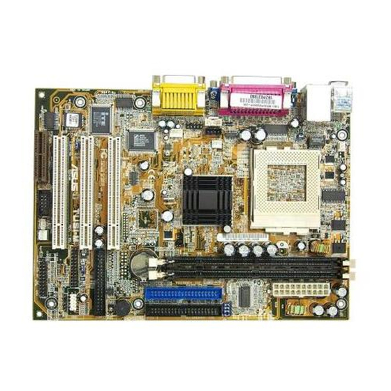
2. FEATURES 2.2.1 Component Locations ASUS TUSI-M User’s Manual… -
Page 14: Hardware Setup
3. HARDWARE SETUP 3.1 TUSI-M Motherboard Layout CPU_FAN PS/2 T: Mouse PWRTMP B: Keyboard Bottom: Top: USB1 RJ-45 USB2 COM1 USBPWR1 SiS630ET Integration PWR_FAN Single Line Chip AUDIO_PANEL Line MODEM 32-bit CR2032 3V Lithium Cell CMOS Power Audio Chipset CLRTC…
-
Page 15: Layout Contents
Internal Audio Connectors (Two 4 pin) (optional) 18) AFPANEL p.34 ASUS iPanel Connector (12-1 pin) 19) AAPANEL p.34 ASUS Audio Panel Connector (12-1 pin) 20) ATXPWR p.35 ATX Power Supply Connector (20 pin) 21) PWRTMP p.35 Power Supply Thermal Sensor Connector (2 pin) 22) SPEAKER p.36 System Warning Speaker Connector (4 pin)
-
Page 16: Hardware Setup Procedure
4. Place components on a grounded antistatic pad or on the bag that came with the compo- nent whenever the components are separated from the system. 5. Ensure that the ATX power supply is switched off before you plug in or remove the ATX power connector on the motherboard. ASUS TUSI-M User’s Manual…
-
Page 17
Disable or both to Enable. 2. These settings must also be set in conjunction with Wake On USB Device in 4.5.1 Power Up Control. USBPWR1 Enable Disable (Default) USBPWR0 ® TUSI-M Enable Disable (Default) TUSI-M USB Device Wake Up ASUS TUSI-M User’s Manual… -
Page 18
133.3MHz 66.8MHz SDRAM 150.0MHz 133.3MHz 66.8MHz 37.5MHz 33.3MHz 33.4MHz TUSI-M ® TUSI-M CPU 97.0MHz 70.0MHz 95.0MHz SDRAM 105.0MHz 97.0MHz External Frequency Selection 95.0MHz 32.3MHz 35.0MHz 31.7MHz 95.0MHz 112.0MHz 97.0MHz SDRAM 126.7MHz 112.0MHz 129.3MHz 31.7MHz 37.3MHz 32.2MHz ASUS TUSI-M User’s Manual… -
Page 19
[2-3] [2-3] [2-3] [2-3] For updated processor settings, visit ASUS’s web site: WWW.ASUS.COM WARNING! Premature wearing of the processor may result when overclocking. Be sure that the DIMM you use can handle the specified SDRAM MHz or else bootup will not be possible. -
Page 20: System Memory (Dimm)
SDRAM chips are generally thinner with higher pin density than EDO (Ex- tended Data Output) chips. • BIOS shows SDRAM memory on bootup screen. • Single-sided DIMMs come in 16, 32, 64,128, 256MB; double-sided come in 32, 64, 128, 256, 512MB. ASUS TUSI-M User’s Manual…
-
Page 21: Dimm Memory Installation
60 Pins TUSI-M ® 20 Pins TUSI-M 168-Pin DIMM Sockets The DIMMs must be 3.3V Unbuffered for this motherboard. To determine the DIMM type, check the notches on the DIMMs (see figure below). 168-Pin DIMM Notch Key Definitions (3.3V) DRAM Key Position…
-
Page 22: Central Processing Unit (Cpu)
NOTE: Do not forget to set the correct Bus Frequency and Multiple (frequency multiple setting is available only on unlocked processors) for your Socket 370 processor or else boot-up may not be possible. Socket 370 processors provide internal thermal sensing: a socket mounted thermal resistor is not needed. ASUS TUSI-M User’s Manual…
-
Page 23: Expansion Cards
4. Secure the card to the slot with the screw you removed earlier. 5. Replace the system cover. 6. Change the necessary BIOS settings, if any. (see section 4.4.3 PCI Configuration to change the settings.) 7. Install the necessary software drivers for the expansion card. ASUS TUSI-M User’s Manual…
-
Page 24: Assigning Irqs For Expansion Cards
PCI slot 3 — shared — — Onboard VGA shared — — — Onboard LAN — — shared — Onboard USB controller — — — shared Onboard Audio — — shared — — shared — — ASUS TUSI-M User’s Manual…
-
Page 25: Audio Modem Riser (Amr) Slot
There are two types of AMR, one defined as primary and another de- fined as secondary. You can only use primary AMRs with this motherboard. NOTE: An AMR is not included with this motherboard. TUSI-M ® TUSI-M Audio Modem Riser (AMR) Connector ASUS TUSI-M User’s Manual…
-
Page 26: Connectors
This connection is for a standard keyboard using an PS/2 plug (mini DIN). This connector will not allow standard AT size (large DIN) keyboard plugs. You may use a DIN to mini DIN adapter on standard AT keyboards. PS/2 Keyboard (6-pin female) ASUS TUSI-M User’s Manual…
-
Page 27
5) Parallel Port Connector (Burgundy 25-pin PRINTER) You can enable the parallel port and choose the IRQ through Onboard Parallel Port (see 4.4.2 I/O Device Configuration). NOTE: Serial printers must be connected to the serial port. Parallel (Printer) Port (25-pin female) ASUS TUSI-M User’s Manual… -
Page 28
COM 1 Serial Port (9-pin male) PIN 1 TUSI-M ® TUSI-M Serial Port Header 7) Monitor Output Connector (Blue 15-pin VGA1) This connector is for output to a VGA-compatible device. VGA Monitor (15-pin female) ASUS TUSI-M User’s Manual… -
Page 29: Game/Midi Connector (On Audio Model Only)
Line In (light blue) allows tape players or other audio sources to be re- corded by your computer or played through the Line Out (lime). Mic (pink) allows microphones to be connected for inputting voice. Line Out Line In 1/8″ Stereo Audio Connectors ASUS TUSI-M User’s Manual…
-
Page 30
(Pin 5 is removed to prevent inserting in the wrong orienta- tion when using ribbon cables with pin 5 plugged). NOTE: Orient the red markings on the floppy ribbon cable to PIN 1. TUSI-M ® PIN 1 TUSI-M Floppy Disk Drive Connector ASUS TUSI-M User’s Manual… -
Page 31
NOTE: The “Rotation” signal is to be used only by a specially designed fan with rotation signal. The Rotations per Minute (RPM) can be monitored using ASUS PC Probe or Intel LDCM Utility. WARNING! The CPU and/or motherboard will overheat if there is no airflow across the CPU and onboard heatsinks. -
Page 32: Lan (Rj45) Connector
15) Wake-On-LAN Connector (3-pin WOL_CON) This connector connects to a LAN card with a Wake-On-LAN output, such as the ASUS PCI-L101 Ethernet card (see 7. Appendix). The connector powers up the system when a wakeup packet or signal is received through the LAN card.
-
Page 33
(such as a phone) and mono_out (such as a speaker) between the onboard audio and a voice modem card. MODEM AUX In (White) CD In (Black) TUSI-M ® TUSI-M Internal Audio Connectors ASUS TUSI-M User’s Manual… -
Page 34
I/O ports, status LEDs, and space reserved for a hard disk drive. If you are not using an ASUS iPanel, you can connect an optional wireless transmitting and receiving infrared module to the SIR connector or an… -
Page 35
+3.3 Volts TUSI-M ® TUSI-M ATX Power Connector 21) Power Supply Thermal Connector (2-pin PWRTMP) This connector connects to an ATX power supply. The plug from the power sup- ply will only insert in one orientation because of the different hole sizes. Find the proper orientation and push down firmly making sure that the pins are aligned. -
Page 36
SMI Lead Switch* Requires an ATX power supply. TUSI-M System Panel Connectors 22) System Warning Speaker Connector (4-pin SPEAKER) This 4-pin connector connects to the case-mounted speaker. Two sources (LINE_OUT and SPEAKER) will allow you to hear system beeps and warn- ings. -
Page 37: Starting Up The First Time
No DRAM installed or detected One long beep followed by Video card not found or video card three short beeps memory bad High frequency beeps when CPU overheated system is working System running at a lower frequency ASUS TUSI-M User’s Manual…
-
Page 38
Shut Down, and then click Shut down the computer? The power supply should turn off after Windows shuts down. NOTE: The message “You can now safely turn off your computer” will not appear when shutting down with ATX power supplies. ASUS TUSI-M User’s Manual… -
Page 39: Bios Setup
4. In DOS mode, type A:AFLASH <Enter> to run AFLASH. IMPORTANT! If “unknown” is displayed after Flash Memory:, the memory chip is either not programmable or is not supported by the ACPI BIOS and there- fore, cannot be programmed by the Flash Memory Writer utility. ASUS TUSI-M User’s Manual…
-
Page 40: Updating Bios Procedures
BIOS revision will solve your problems. Care- less updating can result in your motherboard having more problems! 1. Download an updated ASUS BIOS file from the Internet (WWW or FTP) (see ASUS CONTACT INFORMATION on page 3 for details) and save to the disk you created earlier.
-
Page 41
ROM. The boot block will be updated automatically only when neces- sary. This will minimize the chance that a failed update will prevent your system from booting up. When the programming is finished, Flashed Successfully will be displayed. ASUS TUSI-M User’s Manual… -
Page 42
If the Flash Memory Writer utility was not able to successfully update a complete BIOS file, your system may not be able to boot up. If this happens, your system will need servicing. ASUS TUSI-M User’s Manual… -
Page 43: Bios Setup Program
POST. NOTE: Because the BIOS software is constantly being updated, the following BIOS screens and descriptions are for reference purposes only and may not re- flect your BIOS screens exactly. ASUS TUSI-M User’s Manual…
-
Page 44: Bios Menu Bar
Brings up a selection menu for the highlighted field <Home> or <PgUp> Moves the cursor to the first field <End> or <PgDn> Moves the cursor to the last field <F5> Resets the current screen to its Setup Defaults <F10> Saves changes and exits Setup ASUS TUSI-M User’s Manual…
-
Page 45: General Help
Item Specific Help window located to the right of each menu. This window displays the help text for the currently highlighted field. NOTE: The item heading in square brackets represents the default setting for that field. ASUS TUSI-M User’s Manual…
-
Page 46: Main Menu
This is required to support older Japanese floppy drives. Floppy 3 Mode support will allow reading and writing of 1.2MB (as opposed to 1.44MB) on a 3.5-inch diskette. Configuration options: [Disabled] [Drive A] [Drive B] [Both] ASUS TUSI-M User’s Manual…
-
Page 47: Primary & Secondary Master/Slave
Primary IDE hard disk drives must have its partition set to active (also possible with FDISK). Other options for the Type field are: [None] — to disable IDE devices ASUS TUSI-M User’s Manual…
-
Page 48
NOTE: To make changes to this field, the Type field must be set to [User Type HDD] and the Translation Method field must be set to [Manual]. ASUS TUSI-M User’s Manual… -
Page 49
IDE devices. Set to [Disabled] to suppress Ultra DMA capa- bility. NOTE: To make changes to this field, the Type field must be set to [User Type HDD]. Configuration options: [0] [1] [2] [3] [4] [Disabled] ASUS TUSI-M User’s Manual… -
Page 50: Keyboard Features
[6/Sec] [8/Sec] [10/Sec] [12/Sec] [15/Sec] [20/Sec] [24/Sec] [30/Sec] Keyboard Auto-Repeat Delay [1/4 Sec] This field sets the time interval for displaying the first and second charac- ters. Configuration options: [1/4 Sec] [1/2 Sec] [3/4 Sec] [1 Sec] ASUS TUSI-M User’s Manual…
-
Page 51
Configuration options: [All Errors] [No Error] [All but Keyboard] [All but Disk] [All but Disk/Keyboard] Installed Memory [XXX MB] This display-only field displays the amount of conventional memory detected by the system during bootup. You do not need to make changes to this field. ASUS TUSI-M User’s Manual… -
Page 52: Advanced Menu
CPU Level 1 Cache, CPU Level 2 Cache [Enabled] These fields allow you to choose from the default of [Enabled] or choose [Disabled] to turn on or off the CPU’s Level 1 and Level 2 built-in cache. Configuration options: [Disabled] [Enabled] ASUS TUSI-M User’s Manual…
-
Page 53
USB device or not. Configuration options: [Disabled] [Enabled] [Auto] OS/2 Onboard Memory > 64M [Disabled] When using OS/2 operating systems with installed DRAM of greater than 64MB, you need to set this option to [Enabled]; otherwise, leave this on [Disabled]. Configuration options: [Disabled] [Enabled] ASUS TUSI-M User’s Manual… -
Page 54
If your system crashes or hangs due to improper frequency settings, power OFF your system and restart. The system will start up in safe mode running at a bus speed of 66MHz and enter BIOS setup. ASUS TUSI-M User’s Manual… -
Page 55: Chip Configuration
SDRAM Configuration is set to [User Define]. SDRAM RAS Precharge Time This controls the idle clocks after issuing a precharge command to the SDRAM. NOTE: This field will only be adjustable when SDRAM Configuration is set to [User Define]. ASUS TUSI-M User’s Manual…
-
Page 56
Configuration options: [Disabled] [Enabled] ISA Bus Clock [PCICLK/4] This function allows you to set the ISA bus clock frequency. [PCICLK/4] sets your ISA bus at a quarter speed of the PCI bus. Configuration options: [PCICLK/4] [7.159MHz] ASUS TUSI-M User’s Manual… -
Page 57
Onboard PCI Audio Controller [Enabled] This motherboard has enbedded PCI audio controller. If you want to use it, leave on the default setting [Enabled]. If you want to use an add-on audio card, select [Disabled]. Configuration options: [Disabled] [Enabled] ASUS TUSI-M User’s Manual… -
Page 58: I/O Device Configuration
UART to support the infrared module connector on the motherboard. If your system already has a second serial port connected to the onboard COM2 connector, it will no longer work if you enable the infrared feature. Configuration options: [Disabled] [Enabled] ASUS TUSI-M User’s Manual…
-
Page 59
This field allows you to configure the parallel port DMA channel for the selected ECP mode. This selection is available only if you select [ECP] or [ECP+EPP] in Parallel Port Mode above. Configuration options: [1] [3] ASUS TUSI-M User’s Manual… -
Page 60: Pci Configuration
[Disabled] will disable the motherboard’s Symbios SCSI BIOS so that the BIOS on an add-on Symbios SCSI card can be used. If your Symbios SCSI card does not have a BIOS, the Symbios SCSI card will not function. Con- figuration options: [Auto] [Disabled] ASUS TUSI-M User’s Manual…
-
Page 61: Pci Irq Resource Exclusion
(non-PnP) device. The default value indicates either that the displayed IRQ is not used or that ISA Configuration Utility (ICU) is being used to determine if a legacy device is using that IRQ. Configuration options: [No] [Yes] ASUS TUSI-M User’s Manual…
-
Page 62: Shadow Configuration
ROMs on them, you will need to know which addresses the ROMs use to shadow them specifically. Shadowing a ROM reduces the memory available between 640K and 1024K by the amount used for this purpose. Configuration options: [Disabled] [Enabled] ASUS TUSI-M User’s Manual…
-
Page 63: Power Menu
Windows 3.x and Windows 95, you need to install Windows with the APM feature. For Windows 98 and later, APM is automatically installed. A battery and power cord icon labeled “Power Management” will appear in the “Control Panel.” Choose “Advanced” in the Power Management Properties dialog box. ASUS TUSI-M User’s Manual…
-
Page 64
4 seconds will place the system in sleep mode. Regardless of the setting, holding the ATX switch for more than 4 seconds will power off the system. Configuration options: [Soft off] [Suspend] ASUS TUSI-M User’s Manual… -
Page 65: Power Up Control
Con- figuration options: [Disabled] [Enabled] IMPORTANT: This feature requires an optional network interface card with Wake- On-LAN and an ATX power supply with at least 720mA +5V standby power. ASUS TUSI-M User’s Manual…
-
Page 66
[By Date]. NOTE: Automatic Power Up will not work if the system is powered down by operating sys- tems, such as Windows 98, which have ACPI support enabled. Configura- tion options: [Disabled] [Everyday] [By Date] ASUS TUSI-M User’s Manual… -
Page 67: Hardware Monitor
NOTE: If any of the monitored items is out of range, an error message will appear: “Hardware Monitor found an error. Enter Power setup menu for details”. You will then be prompted to “Press F1 to continue, DEL to enter SETUP”. ASUS TUSI-M User’s Manual…
-
Page 68: Boot Menu
This field allows you to select which ATAPI CD-ROM drive to use in the boot sequence. Pressing [Enter] will show the product IDs of all your con- nected ATAPI CD-ROM drives. Other Boot Device Select [INT18 Device (Network)] Configuration options: [Disabled] [SCSI Boot Device] [INT18 Device (Net- work)] ASUS TUSI-M User’s Manual…
-
Page 69
Boot Up Floppy Seek [Enabled] When enabled, the BIOS will seek the floppy disk drive to determine whether the drive has 40 or 80 tracks. Configuration options: [Disabled] [Enabled] Full Screen Logo [Enabled] Configuration options: [Disabled] [Enabled] ASUS TUSI-M User’s Manual… -
Page 70: Exit Menu
This option should only be used if you do not want to save the changes you have made to the Setup program. If you have made changes to fields other than system date, system time, and password, the system will ask for con- firmation before exiting. ASUS TUSI-M User’s Manual…
-
Page 71: Load Setup Defaults
This option saves your selections without exiting the Setup program. You can then return to other menus and make changes. After selecting this op- tion, all selections are saved and a confirmation is requested. Select [Yes] to save any changes to the non-volatile RAM. ASUS TUSI-M User’s Manual…
-
Page 72
4. BIOS SETUP (This page was intentionally left blank.) ASUS TUSI-M User’s Manual… -
Page 73: Software Setup
NOTE: Because there are various motherboard settings, options, and expansion cards, the following can only be used as a general reference and may not reflect exactly the screen contents displayed on your screen. ASUS TUSI-M User’s Manual…
-
Page 74: Tusi-M Motherboard Support Cd
NOTE: If you do not see this item, set Onboard LAN to Enabled in BIOS setup (see 4.4.1 Chip Configuration). • ASUS PC Probe Vx.xx: Installs a utility to monitor your computer’s fan, tem- perature, and voltages. • Install ASUS Update Vx.xx: Installs a program to help you update your BIOS or download a BIOS image file.
-
Page 75: Software Reference
ASUS Utility, and then click Probe Vx.xx. The PC Probe icon will appear on the taskbar’s system tray indicating that ASUS PC Probe is running. Clicking the icon will allow you to see the status of your PC. ASUS TUSI-M User’s Manual…
-
Page 76: Using Asus Pc Probe
6. SOFTWARE REFERENCE 6.1.2 Using ASUS PC Probe Monitoring Monitor Summary Shows a summary of the items being monitored. Temperature Monitor Shows the PC’s temperature (for supported processors only). Temperature Warning threshold adjustment (Move the slider up to increase the…
-
Page 77
NOTE: This feature is not available on ASUS Probe version 2.12.01/2.12.02 Information Hard Drives Shows the used and free space of the PC’s hard disk drives and the file allo- cation table or file system used. ASUS TUSI-M User’s Manual… -
Page 78
CPU type, CPU speed, and in- ternal/external frequencies, and memory size. Utility Lets you run programs outside of the ASUS Probe modules. To run a program, click Execute Program. NOTE: This feature is currently unavailable. ASUS TUSI-M User’s Manual… -
Page 79: Asus Pc Probe Task Bar Icon
6. SOFTWARE REFERENCE 6.1.3 ASUS PC Probe Task Bar Icon Right clicking the PC Probe icon will bring up a menu to open or exit ASUS PC Probe and pause or resume all sys- tem monitoring. When the ASUS PC Probe…
-
Page 80: Cyberlink Powerplayer Se
Backstep Frame Step Frame Previous Next Play Stop Configuration i-Power! Increase Volume CD Mode Mute Shuffle Decrease Volume Karaoke Next angle Next audio stream Next subtitle Add bookmark Capture frame Go-Up Repeat Menu Go to bookmark ASUS TUSI-M User’s Manual…
-
Page 81: Cyberlink Videolive Mail
VLM 3 supports all the hardware devices that are compliant with Video for Win- dows standard. Video for Windows is a well-accepted and well-tested standard. Thus, users do not have to worry about compatibility issues. ASUS TUSI-M User’s Manual…
-
Page 82: Starting Videolive Mail
Start Playback Save Video File Snapshot to File Stop Recording / Playback Send Mail Start Recording Video Configuration Load Video File Pause Send Mail Increase MIC volume Decrease MIC volume Increase speaker volume Decrease speaker volume ASUS TUSI-M User’s Manual…
-
Page 83: Asus Live Update
6. SOFTWARE REFERENCE 6.4 ASUS Live Update ASUS LiveUpdate is a utility that allows you to update your motherboard’s BIOS and drivers. The use of this utility requires that you are properly con- nected to the Internet through an Internet Service Provider (ISP).
-
Page 84: 3Deep Color Tuner
1. Select the type of monitor connected to the computer, either CRT or LCD. 2. Follow the instructions to manually adjust the brightness level of the monitor. 3. Select the faintest of the three colors: blue, red and green. ASUS TUSI-M User’s Manual…
-
Page 85: The 3Deep Control Panel
Using the Windows Start button, activate the 3Deep Control Panel program from the 3Deep Applications group on the Main Program menu. The control panel offers access to the Color Wizard tuning program, a Game Gamma setting and a Tweak slider for brightness adjustment. ASUS TUSI-M User’s Manual…
-
Page 86: Ali Sis Display Properties Menu
In 16-color and 8-bit color (256-color) modes, gamma correction function is not supported. Sets the preferred tint of your display Sets your monitor’s Permits individual color mapping channel tuning Restores settings to the original program default ASUS TUSI-M User’s Manual…
-
Page 87
Color makes visual adjustments, such as brightness, for all of the RGB colors. Sets the brightness of 3D displays. Changes to settings Previews fullscreen can be previewed changes. Press the on the displayed 3D Esc key to go back scene to this dialog box. ASUS TUSI-M User’s Manual… -
Page 88
D3D supplies basic and advanced performance settings for D3D games. Sets the D3D performance of 3D scenes. Setting the speed to a higher setting results in a trade-off in display quality. Previews changes. Press the Esc key to go back to this dialog box. ASUS TUSI-M User’s Manual… -
Page 89
OpenGL supplies texture and other performance settings for compatible applications. Information Information lists the relevant information about your card, such as the chip type, soft- ware and driver versions, memory size, video memory clock speed, and the drivers. ASUS TUSI-M User’s Manual… -
Page 90
6. SOFTWARE REFERENCE (This page was intentionally left blank.) ASUS TUSI-M User’s Manual… -
Page 91: Appendix
BIOS Setup program. The BIOS can be updated using the provided utility to copy a new BIOS file into the EEPROM. Bit (Binary Digit) Represents the smallest unit of data used by the computer. A bit can have one of two values: 0 or 1. ASUS TUSI-M User’s Manual…
-
Page 92
ROM can be electrically erased. Flash ROM is normally used for system BIOS, which initiates hardware devices and sets up necessary parameters for the OS. Since the flash ROM contents can be modified, users can easily update the BIOS.. ASUS TUSI-M User’s Manual… -
Page 93
POST (Power On Self Test) Powering on the computer initiates the POST, a series of software-controlled diagnostic tests. The POST checks system memory, the motherboard circuitry, the display, the keyboard, the diskette drive, and other I/O devices ASUS TUSI-M User’s Manual… -
Page 94
12Mbit/sec. USB 2.0 provides twice the transfer rate com- pared to USB 1.0 and competes with the 1394 standard. Wake-On-LAN Computer will automatically wake-up upon receiving a wake-up packet through a Network interface when it is under power soft-off, suspend or sleep mode. ASUS TUSI-M User’s Manual… -
Page 95: Index
3Deep Color Tuner Discard Changes 71 Using 84 ECP DMA Select 59 AC PWR Loss Restart 65 Exit Discarding Changes 70 ASUS iPanel Audio Connector 34 Exit Saving Changes 70 ASUS iPanel Connector 34 Expansion Cards ASUS PC Probe AMR 25…
-
Page 96
PWR Button < 4 Secs 64 -12 67 PWR Up On Modem Act 65 -5 67 VCORE 67 Quick Power On Self Test 69 Wake On LAN 65 Wake-On-LAN Connector 32 Removable Device 68 Wake-On-Ring Connector 32 ASUS TUSI-M User’s Manual…
This manual is also suitable for:
Tusi-m
- Manuals
- Brands
- Asus Manuals
- Motherboard
- TUSI-M
Manuals and User Guides for Asus TUSI-M. We have 1 Asus TUSI-M manual available for free PDF download: User Manual

R
TUSI-M
Socket 370 microATX Motherboard
USER’S MANUAL
Скачать
R
TUSI-M
Socket 370 microATX Motherboard
USER’S MANUAL
Page 1 — USER’S MANUAL
R TUSI-MSocket 370 microATX MotherboardUSER’S MANUAL
Page 2 — USER’S NOTICE
10ASUS TUSI-M User’s Manual2. FEATURESPerformance2. FEATURES2.1.3 Performance• UltraPerformance: Onboard IDE Bus Master controller with two connecto
Page 3 — ASUS CONTACT INFORMATION
ASUS TUSI-M User’s Manual 112. FEATURES2. FEATURESIntelligence2.1.4 Intelligence• Fan Status Monitoring and Alarm: To prevent system overheat and sy
Page 4 — CONTENTS
12ASUS TUSI-M User’s Manual2. FEATURES2. FEATURESMB Components2.2 TUSI-M Motherboard ComponentsSee opposite page for locations.LocationProcessor Sup
Page 5
ASUS TUSI-M User’s Manual 132. FEATURES2. FEATURESComponent Locations2.2.1 Component Locations2345156149817192021222371013121611118
Page 6 — FCC & DOC COMPLIANCE
14ASUS TUSI-M User’s Manual3. HARDWARE SETUP3.1 TUSI-M Motherboard LayoutMotherboard Layout3. H/W SETUPFLOPPYCPU_FANPANELWOL_CONRowBUZZERCR2032 3VLit
Page 7 — 1. INTRODUCTION
ASUS TUSI-M User’s Manual 153. HARDWARE SETUPLayout Contents3. H/W SETUP3.2 Layout ContentsMotherboard Settings1) JEN p.17 JumperFree Mode Setting (En
Page 8
16 ASUS TUSI-M User’s Manual3. HARDWARE SETUP3.3 Hardware Setup ProcedureBefore using your computer, you must complete the following steps:• Check Mot
Page 9
ASUS TUSI-M User’s Manual 173. HARDWARE SETUPMotherboard Settings3. H/W SETUP1) JumperFree™ Mode (JEN)This jumper enableS or disableS the JumperFree™
Page 10 — 2. FEATURES
18 ASUS TUSI-M User’s Manual3. HARDWARE SETUP3) CPU External Frequency Setting (JP3, JP1, JP2, JP0)This option tells the clock generator what frequenc
Page 11
ASUS TUSI-M User’s Manual 193. HARDWARE SETUPManual CPU Settings TableSet the jumpers according to the internal speed of your processor as follows:CPU
Page 12
2 ASUS TUSI-M User’s ManualUSER’S NOTICEProduct Name: ASUS TUSI-MManual Revision: 1.00 E894BRelease Date: October 2001No part of this manual, inc
Page 13
20 ASUS TUSI-M User’s Manual3. HARDWARE SETUP3.5 System Memory (DIMM)NOTE: No hardware or BIOS setup is required after adding or removing memory.This
Page 14 — 3. HARDWARE SETUP
ASUS TUSI-M User’s Manual 213. HARDWARE SETUPSystem Memory3. H/W SETUP3.5.2 DIMM Memory InstallationInsert the module(s) as shown. Because the number
Page 15
22 ASUS TUSI-M User’s Manual3. HARDWARE SETUPCPU3. H/W SETUP3.6 Central Processing Unit (CPU)The motherboard provides a ZIF Socket 370, for CPU instal
Page 16
ASUS TUSI-M User’s Manual 233. HARDWARE SETUP3. H/W SETUPExpansion Cards3.7 Expansion CardsIn the future, you may need to install expansion cards. The
Page 17 — TUSI-M USB Device Wake Up
24 ASUS TUSI-M User’s Manual3.7.2 Assigning IRQs for Expansion CardsSome expansion cards need an IRQ to operate. Generally, an IRQ must be exclu-sivel
Page 19
26 ASUS TUSI-M User’s Manual3. HARDWARE SETUP3.8 ConnectorsWARNING! Some pins are used for connectors or power sources. These areclearly distinguished
Page 20
ASUS TUSI-M User’s Manual 273. HARDWARE SETUP Connectors3. H/W SETUP3) Fast-Ethernet Port Connector (RJ45) (optional)An optional RJ-45 connector is l
Page 21
28 ASUS TUSI-M User’s Manual Connectors3. H/W SETUP3. HARDWARE SETUP6) Serial Port Connectors (Teal/Turquoise 9-pin COM1)One serial port is ready for
Page 22
ASUS TUSI-M User’s Manual 293. HARDWARE SETUP DMA Channels3. H/W SETUP Connectors3. H/W SETUP8) Game/MIDI Connector (Gold 15-pin GAME_AUDIO) (optional
Page 23
ASUS TUSI-M User’s Manual 3ASUS CONTACT INFORMATIONASUSTeK COMPUTER INC. (Asia-Pacific)MarketingAddress: 150 Li-Te Road, Peitou, Taipei, Taiwan 112Tel
Page 24
30 ASUS TUSI-M User’s Manual Connectors3. H/W SETUP3. HARDWARE SETUP10) Primary (Blue) / Secondary IDE Connectors (Two 40-1pin IDE)These connectors s
Page 25
ASUS TUSI-M User’s Manual 313. HARDWARE SETUP Connectors3. H/W SETUP12) IDE Activity LED (2-pin PLED)This connector supplies power to the cabinet’s ID
Page 26
32 ASUS TUSI-M User’s Manual3. HARDWARE SETUP Connectors3. H/W SETUP15) Wake-On-LAN Connector (3-pin WOL_CON)This connector connects to a LAN card wit
Page 27
ASUS TUSI-M User’s Manual 333. HARDWARE SETUP Connectors3. H/W SETUP16) USB Headers (10-1 pin USB1, 5-1 pin USB2) ( LAN model only )If the USB Ports o
Page 28
34 ASUS TUSI-M User’s Manual3. HARDWARE SETUP Connectors3. H/W SETUP18) ASUS iPanel Connector (12-1 pin AFPANEL)This connector allows you to connect a
Page 29
ASUS TUSI-M User’s Manual 353. HARDWARE SETUP Connectors3. H/W SETUP20) ATX Power Supply Connector (20-pin block ATXPWR)This connector connects to an
Page 30 — TUSI-M IDE Connectors
36 ASUS TUSI-M User’s Manual3. HARDWARE SETUPThe following is for items 22–28TUSI-M®0 1TUSI-M System Panel Connectors* Requires an ATX power supply.PL
Page 31
ASUS TUSI-M User’s Manual 373. HARDWARE SETUPPowering Up3. H/W SETUP3.9 Starting Up the First Time1. After all connections are made, close the system
Page 32 — Ring# Ground
ASUS TUSI-M User’s Manual383. HARDWARE SETUPPowering Up3. H/W SETUP7. During power-on, hold down <Delete> to enter BIOS setup. Follow theinstruc
Page 33
4. BIOS SETUP4.1 Managing and Updating Your BIOS4.1.1 Upon First Use of the Computer SystemIt is recommended that you save a copy of the original moth
Page 35 — TUSI-M ATX Power Connector
ASUS TUSI-M User’s Manual404. BIOS SETUP4. BIOS SETUP Updating BIOS5. Select 1. Save Current BIOS to File from the Main menu and press<Enter>. T
Page 36
ASUS TUSI-M User’s Manual 414. BIOS SETUP4. BIOS SETUP6. When prompted to confirm the BIOS update, press Y to start the update. Updating BIOS7. The ut
Page 37
ASUS TUSI-M User’s Manual424. BIOS SETUP4. BIOS SETUP Updating BIOSWARNING! If you encounter problems while updating the new BIOS, DO NOTturn off your
Page 38
ASUS TUSI-M User’s Manual 434. BIOS SETUP4. BIOS SETUP4.2 BIOS Setup ProgramThis motherboard supports a programmable EEPROM that can be updated usingt
Page 39 — 4. BIOS SETUP
ASUS TUSI-M User’s Manual444. BIOS SETUP4. BIOS SETUP4.2.1 BIOS Menu BarThe top of the screen has a menu bar with the following selections:MAIN Use th
Page 40
ASUS TUSI-M User’s Manual 454. BIOS SETUP4. BIOS SETUPGeneral HelpIn addition to the Item Specific Help window, the BIOS setup program also pro-vides
Page 41
ASUS TUSI-M User’s Manual464. BIOS SETUP4. BIOS SETUPSystem Time [XX:XX:XX]Sets your system to the time that you specify (usually the current time).Th
Page 42
ASUS TUSI-M User’s Manual 474. BIOS SETUP4. BIOS SETUPNOTE: Before attempting to configure a hard disk drive, make sure youhave the configuration info
Page 43
ASUS TUSI-M User’s Manual484. BIOS SETUP4. BIOS SETUPIMPORTANT: If your hard disk was already formatted on an older previous system,incorrect paramete
Page 44
ASUS TUSI-M User’s Manual 494. BIOS SETUP4. BIOS SETUP Master/Slave DrivesHeadThis field configures the number of read/write heads. Refer to your driv
Page 45
ASUS TUSI-M User’s Manual 5CONTENTS4.4 Advanced Menu … 524.4.1 Chip Configurati
Page 46
ASUS TUSI-M User’s Manual504. BIOS SETUP4. BIOS SETUPOther options for “Type:” are:[CD-ROM] — for IDE CD-ROM drives[LS-120] — for LS-120 compatible fl
Page 47
ASUS TUSI-M User’s Manual 514. BIOS SETUP4. BIOS SETUP Main MenuHalt On [All Errors]This field determines which types of errors will cause the system
Page 48
ASUS TUSI-M User’s Manual524. BIOS SETUP4. BIOS SETUP4.4 Advanced Menu Advanced MenuCurrent CPU Internal FrequencyThis field displays the internal fre
Page 49
ASUS TUSI-M User’s Manual 534. BIOS SETUP4. BIOS SETUPAdvanced MenuCPU Level 2 Cache ECC Check [Disabled]This function controls the ECC capability in
Page 50
ASUS TUSI-M User’s Manual544. BIOS SETUP4. BIOS SETUP JumperFree NotesNotes for JumperFree ModeCPU Upgrade/ReinstallationTo ensure that your system ca
Page 51
ASUS TUSI-M User’s Manual 554. BIOS SETUP4. BIOS SETUPChip Configuration4.4.1 Chip Configuration(Scroll down to see more items as shown.)SDRAM Timing
Page 52
ASUS TUSI-M User’s Manual564. BIOS SETUP4. BIOS SETUP Chip ConfigurationRefresh RAS Assertion [5T]Configuration options: [6T] [7T] [5T] [4T]Refresh Qu
Page 53
ASUS TUSI-M User’s Manual 574. BIOS SETUP4. BIOS SETUPOnboard PCI IDE Enable [Both]You can select to enable the primary IDE channel, secondary IDE cha
Page 54
ASUS TUSI-M User’s Manual584. BIOS SETUP4. BIOS SETUPFloppy Disk Access Control [R/W]When set to [Read Only], this field protects files from being cop
Page 55
ASUS TUSI-M User’s Manual 594. BIOS SETUP4. BIOS SETUP I/O Device ConfigOnboard Parallel Port [378H/IRQ7]This field sets the address of the onboard pa
Page 56
6 ASUS TUSI-M User’s ManualFCC & DOC COMPLIANCEFederal Communications Commission StatementThis device complies with FCC Rules Part 15. Operation i
Page 57
ASUS TUSI-M User’s Manual604. BIOS SETUP4. BIOS SETUPSlot 1 IRQ, Slot 2 IRQ, Slot3 IRQ [Auto]These fields set how IRQ use is determined for each PCI s
Page 58
ASUS TUSI-M User’s Manual 614. BIOS SETUP4. BIOS SETUPPCI ConfigurationIRQ XX Reserved [No]These fields indicate whether or not the displayed IRQ for
Page 59
ASUS TUSI-M User’s Manual624. BIOS SETUP4. BIOS SETUP Shadow ConfigurationVideo ROM BIOS Shadow [Enabled]This field allows you to change the video BIO
Page 60
ASUS TUSI-M User’s Manual 634. BIOS SETUP4. BIOS SETUPPower Menu4.5 Power MenuThe Power menu allows you to reduce power consumption. This feature turn
Page 61
ASUS TUSI-M User’s Manual644. BIOS SETUP4. BIOS SETUP Power MenuVideo Off Option [Suspend -> Off ]This field determines when to activate the video
Page 62
ASUS TUSI-M User’s Manual 654. BIOS SETUP4. BIOS SETUP Power Up ControlAC PWR Loss Restart [Disabled]This allows you to set whether you want your syst
Page 63
ASUS TUSI-M User’s Manual664. BIOS SETUP4. BIOS SETUPPower Up ControlPower Up By PS2 Keyboard [Space Bar]When set to [Any Key], you can press any key
Page 64
ASUS TUSI-M User’s Manual 674. BIOS SETUP4. BIOS SETUPHardware Monitor4.5.2 Hardware MonitorMB Temperature [xxxC/xxxF]CPU Temperature [xxxC/xxxF]JTPWR
Page 65
ASUS TUSI-M User’s Manual684. BIOS SETUP4. BIOS SETUPBoot MenuBoot SequenceThe Boot menu allows you to select among the four possible types of bootdev
Page 66
ASUS TUSI-M User’s Manual 694. BIOS SETUP4. BIOS SETUPBoot MenuPlug & Play O/S [No]This field allows you to use a Plug-and-Play (PnP) operating sy
Page 67
ASUS TUSI-M User’s Manual 71.1 How This Manual Is OrganizedThis manual is divided into the following sections:1. INTRODUCTION Manual information and c
Page 68
ASUS TUSI-M User’s Manual704. BIOS SETUP4. BIOS SETUP Exit MenuExit Saving ChangesOnce you are finished making your selections, choose this option fro
Page 69
ASUS TUSI-M User’s Manual 714. BIOS SETUP4. BIOS SETUPExit MenuLoad Setup DefaultsThis option allows you to load the default values for each of the pa
Page 70
ASUS TUSI-M User’s Manual724. BIOS SETUP4. BIOS SETUP(This page was intentionally left blank.)
Page 71
73ASUS TUSI-M User’s Manual5. S/W SETUPOS5. SOFTWARE SETUP5.1 Install Operating SystemYou should always use the latest operating system and updates
Page 72
745. SOFTWARE SETUPASUS TUSI-M User’s Manual5. S/W SETUPSupport CD5.3 TUSI-M Motherboard Support CDNOTE: The support CD contents are subject to chan
Page 73 — 5. SOFTWARE SETUP
ASUS TUSI-M User’s Manual 756. S/W REFERENCEASUS PC Probe6.1 ASUS PC ProbeASUS PC Probe is a convenient utility to continuously monitor your com-pute
Page 74
ASUS TUSI-M User’s Manual766. SOFTWARE REFERENCE6.1.2 Using ASUS PC ProbeMonitoringMonitor SummaryShows a summary of the items beingmonitored.Tempera
Page 75 — 6. SOFTWARE REFERENCE
ASUS TUSI-M User’s Manual 776. SOFTWARE REFERENCE6. S/W REFERENCEASUS PC ProbeSettingsLets you set threshold levels and poll-ing intervals or refres
Page 76
ASUS TUSI-M User’s Manual786. SOFTWARE REFERENCEDevice SummaryShows a summary of devices in your PC.DMI ExplorerShows information pertinent to the PC
Page 77
ASUS TUSI-M User’s Manual 796. SOFTWARE REFERENCE6.1.3 ASUS PC Probe Task Bar IconRight clicking the PC Probeicon will bring up a menu toopen or exit
Page 78
8ASUS TUSI-M User’s Manual2.1 The ASUS TUSI-MThe ASUS TUSI-M motherboard is carefully designed for the demanding PC userwho wants advanced features pr
Page 79
ASUS TUSI-M User’s Manual806. SOFTWARE REFERENCE6.2 CyberLink PowerPlayer SECyberLink PowerPlayer SE is an intelligent software player that can autom
Page 80
ASUS TUSI-M User’s Manual 816. SOFTWARE REFERENCE6. S/W REFERENCEVideoLive Mail6.3 CyberLink VideoLive MailCyberLink’s VideoLive Mail Plus Ver 3.0 (
Page 81
ASUS TUSI-M User’s Manual826. SOFTWARE REFERENCE6.3.2 CyberLink VideoLive Mail User Interface6.3.1 Starting VideoLive MailTo start VideoLive Mail, cl
Page 82
ASUS TUSI-M User’s Manual 836. SOFTWARE REFERENCE6. S/W REFERENCEASUS Live Update6.4 ASUS Live UpdateASUS LiveUpdate is a utility that allows you to
Page 83
ASUS TUSI-M User’s Manual846. SOFTWARE REFERENCE6.5 3Deep Color TunerThe 3-Deep color tuner is designed to match your CRT or LCD colormonitor to maxi
Page 84
ASUS TUSI-M User’s Manual 856. SOFTWARE REFERENCE4. Select the color squares which mostclosely blend and match with thebackground.5. The next step r
Page 85
ASUS TUSI-M User’s Manual866. SOFTWARE REFERENCE6.6 ALi SiS Display Properties MenuThe motherboard’s 2D/3D AGP /VGA chipset and driver supports profe
Page 86
ASUS TUSI-M User’s Manual 876. SOFTWARE REFERENCE Video SettingVideo Setting sets up the Overlay, Contrast, and Brightness of your display. 3D Settin
Page 87
ASUS TUSI-M User’s Manual886. SOFTWARE REFERENCED3DD3D supplies basic and advanced performance settings for D3D games.Sets the D3Dperformanceof 3D sc
Page 88
ASUS TUSI-M User’s Manual 896. SOFTWARE REFERENCEOpenGLOpenGL supplies texture and other performance settings for compatible applications. Informatio
Page 89
ASUS TUSI-M User’s Manual 92. FEATURES2. FEATURESOptional Components• Smart BIOS: 2Mbit flash ROM gives a new easy-to-use interface which pro-vides
Page 90
ASUS TUSI-M User’s Manual906. SOFTWARE REFERENCE(This page was intentionally left blank.)
Page 91 — 7. APPENDIX
ASUS TUSI-M User’s Manual 917 . APPENDIXGlossary7. APPENDIX7.1 Glossary13941394 is the IEEE designation for a high performance serial bus tht offers d
Page 92
ASUS TUSI-M User’s Manual927. APPENDIX7. APPENDIXGlossaryBootBoot means to start the computer operating system by loading it into system memory. Whent
Page 93
ASUS TUSI-M User’s Manual 937 . APPENDIXGlossary7. APPENDIXIDE (Integrated Drive Electronics)IDE devices integrate the drive control circuitry directl
Page 94
ASUS TUSI-M User’s Manual947. APPENDIX7. APPENDIXGlossaryPS/2 PortPS/2 ports are based on IBM Micro Channel Architecture. This type of architecture tr