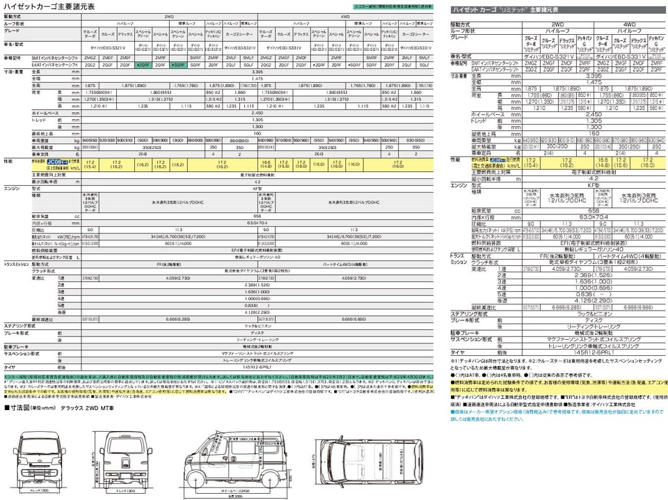
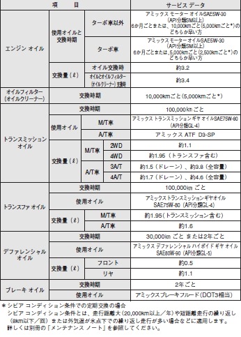
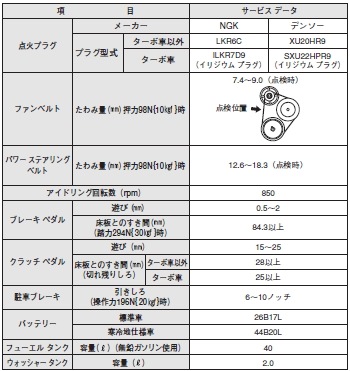
Выложу пока самое интересное, последние страницы, в которых указаны объемы жидкостей, сроки замены и тд.
Вот такая собсно обложка:

При редактировании, обрезании и сжатии фото потерял порядок, в котором они шли, но думаю это не важно.

Тут вроде про свечи, Борисыч ты как-то меня про свечи спрашивал, вот, правильно тетя в магазине подобрала.

Вот тут что-то про 100 тыщ проега.

Ну и на мои ремарки не обращайте внимания


Буду выкладывать хоть какую-то информацию о хайджетах, т.к. найти ее трудно.
Мануал на хайджет (на японском) www.daihatsu.co.jp/servic…/pdf/hijet_cargo_1411.pdf
Обнаружил на официальном сайте дайхатцу www.daihatsu.co.jp следущее:
мощность двигателей автоматного хайджета 53л.с. при 7200об/мин, а на механике 46л.с. при 5700об/мин., но максимальный момент одинаковый 60н*м (6,1кг*м) при 4000об/мин.
У турбового двигателя 64л.с. при тех же 5700об/мин. и 91н*м (9,3кг*м) при 2800об/мин.
Степень сжатия 11.3 для атмосферного и 9,0 для турбо.
Диаметр цилиндра/ ход поршня мм — 63.0×70.4. Вот ссылка www.daihatsu.co.jp/lineup/cargo/spec.htm У меня только квадратики и цифры показывает, переводиться не хочет.
Передаточные числа для всех KF одинаковые
Передача М/Т А/Т
1-я 4.059 2.730
2-я 2.389 1.526
3-я 1.636 1.000
4-я 1.000 0.696
5-я 0.838 ——
Г.П. 6.666 6.666
На турбовом Г.П. 5.571, за счет чего выше крейсерская скорость при тех же оборотах двс.
Из «таблицы» видно, что на механике 4-я передача соответствует 3-й на 4-х ступенчатом автомате, а 4-я у автоматного хайджета длинее 5-й.
Колеса
Стандартные 145R12-6PRLT, что как я понимаю означает 145/80R12
Максимальный размер колес входящих без резки бампера и брызговика 175/65R14 при вылете +40. Такие колеса почти не выпирают за кузов (вровень с кузовом), но зазоры спереди до бампера и брызговика при повороте менее 5мм. 165/65R14 на 7.5мм по радиусу меньше и зазор будет около 1см. Вылет можно былобы и 45 взять, чтобы колесо немного ушло внутрь, тем самым еще немного увеличив зазор. При вывороте руля между колесом-рычагом-кузовом еще есть запас.
На стандартных колесах при скорости 120км/ч навигатор показал 111-112км/ч, при 80км/ч — 74км/ч, при 100км/ч — 93км/ч.
На стандартных колесах одометр приписывает лишние километры к пробегу. Так, проехав 100км по одометру мы проезжаем на самом деле 93,7км по навигатору. Поэтому расход, вычисленный с помощью одометра на стандартных колесах будет не точным. У меня расход составил 6,33л/100км, что значит на самом деле 6,76л/100км с учетом погрешности одометра.
При замене колес на 175/65R14 при 80км/ч по спидометру по навигатору видит те же 80км/ч.

![]()
MANUALE STAZIONE DI SERVIZIO
633530 (IT) — 531 (EN) — 532 (Fr) — 533 (DE) — 534 (ES) — 535 (PT) — 536 (NL) — 537 (EL)
PORTER 1.3 16V

MANUALE
STAZIONE DI
SERVIZIO
PORTER 1.3 16V
COPYRIGHT
© Copyright 2008 — PIAGGIO & C. S.p.A. Pontedera.
All rights reserved. Reproduction of this publication in whole or in part is strictly prohibited. This publication has been edited by:
After sales — PIAGGIO & C. S.p.A.
V.le Rinaldo Piaggio, 23 — 56025 PONTEDERA (Pi)
ITALY www.piaggio.com

MANUALE STAZIONE DI
SERVIZIO
PORTER 1.3 16V
Questo manuale per stazioni di servizio è stato realizzato da Piaggio & C. Spa per essere utilizzato dalle officine dei concessionari e sub-agenzie Piaggio-Gilera. Si presuppone che chi utilizza questa pubblicazione per la manutenzione e la riparazione dei veicoli Piaggio, abbia una conoscenza base dei principi della meccanica e dei procedimenti inerenti la tecnica della riparazione dei veicoli. Le variazioni importanti nelle caratteristiche dei veicoli o nelle specifiche operazioni di riparazione verranno comunicate attraverso aggiornamenti di questo manuale. Non si può comunque realizzare un lavoro completamente soddisfacente se non si dispone degli impianti e delle attrezzature necessarie, ed è per questo che vi invitiamo a consultare le pagine di questo manuale riguardanti l’attrezzatura specifica e il catalogo degli attrezzi specifici.
N.B. Provides key information to make the procedure easier to understand and carry out.
CAUTION Refers to specific procedures to carry out for preventing damages to the vehicle. Refers to specific procedures to carry out for preventing damages to the vehicle. Refers to specific procedures to carry out for preventing damages to the vehicle. Refers to specific procedures to carry out for preventing damages to the vehicle.
WARNING Refers to specific procedures to carry out to prevent injuries to the repairer.
Personal safety Failure to completely observe these instructions will result in serious risk of personal injury.
Safeguarding the environment Sections marked with this symbol indicate the correct use of the vehicle to prevent damaging the environment.
Vehicle intactness The incomplete or non-observance of these regulations leads to the risk of serious damage to the vehicle and sometimes even the invalidity of the guarantee.


INDEX OF TOPICS
|
GENERAL GUIDELINES |
N GEN |
|
CHARACTERISTICS |
CH |
|
SPECIAL TOOLS |
ST |
|
MAINTENANCE |
MA |
|
EMISSION CONTROLO SYSTEM |
CO EM |
|
TROUBLESHOOTING |
TROUBL |
|
ELECTRICAL SYSTEM |
ES |
|
ENGINE |
EN |
|
INIECTION SYSTEM |
IS |
|
GEAR—BOX |
GE |
|
DIFFERENTIAL |
DI |
|
BRAKING SYSTEM |
BS |
|
TRANSMISSION SHAFT |
TS |
|
STEERING COLUMN |
SC |
|
SUSPENSIONS |
SS |
|
TIPPER VERSION |
VR |
|
CHASSIS |
CH |
|
PRE—DELIVERY |
PD |

INDEX OF TOPICS

|
General guidelines |
PORTER 1.3 16V |
RECOMMENDATIONS AND IMPORTANT NOTES
Each symbol has a specific meaning, as shown below.
∙WARNING:- This symbol indicates risks to the health of the operator or persons nearby, if the procedures described are not carried out properly.
∙WARNING:- This symbol indicates that the component on which the operator is working could be damaged, if the procedures described are not carried out properly.
∙NB: — Additional instructions related to the procedure in progress are provided in this section, so that the operation can be performed in an efficient way.
GENERAL RECOMMENDATIONS FOR SAFETY:
1.— Always wear protective goggles and suitable clothing.
2.— Always use a safety support to work under the vehicle.
3.— Check that the ignition switch is always set to «OFF», unless otherwise specified in the procedure.
4.— Pull the hand brake before starting to work on the vehicle.
5.— Let the engine run only in well ventilated places to avoid risks related to carbon monoxide.
6.— Stand well away from moving parts during the engine operation, especially from fans and belts.
7.— In order to avoid serious burns, do not touch hot metal parts, such as the radiator, exhaust manifold, exhaust pipe, catalytic converter and muffler.
8.— Do not smoke during maintenance operations.
9.— To avoid possible injuries, remove rings, watches, jewellery and loose clothes before starting to work on the vehicle.
10.- Keep hands and other objects away from the electric fan blades of the radiator !
11.- The cooling electric fan is fitted on the radiator and can be started at any time due to the increase in coolant temperature or if the air conditioner switch is set to ON, for vehicles equipped with air conditioner. It is important to check that the cooling electric fan motor is disconnected from the cable harness before starting work.
The units of measurement used in this manual are indicated as IS UNITS (International System of Units). Example:24.5 ÷ 34.3 Nm
The abbreviations indicated in this manual are listed in the following table.
∙(B) — Bolt
∙(S) — Screw
∙(N) — Nut
∙(W) — Washer
∙(T) — Tightening torque
|
ABBREVIATIONS |
|
|
Specification |
Desc./Quantity |
|
A/C: |
Air conditioner |
|
API: |
American Petroleum Institute which assesses and classifies |
|
the properties of the different oil types. Oils for petrol engines |
N GEN — 8

|
PORTER 1.3 16V |
General guidelines |
|
Specification |
Desc./Quantity |
|
are classified as SD, SE, SF, etc. ; while those for diesel en- |
|
|
gines are classified as CC, CD, etc. |
|
|
A/Y Assembly |
A group of components or an assembled component which in- |
|
cludes more than two single parts or subassembly parts. |
|
|
ATDC: |
after Top Dead Centre (ATDC) |
|
BTDC: |
before Top Dead Centre (BTDC) |
|
DLC: |
Data Link Connector. |
|
DLI: |
Distribution less ignition |
|
DTC: |
Diagnostic Trouble Code indicates a code for injection system |
|
failures. |
|
|
ECU: |
Electronic Control Unit — Electronic unit. |
|
EFI: |
Electronic Fuel Injection |
|
ESA: |
Electronic Spark Advance |
|
ETR: |
Electronic Tuning Radio — Radio with variable frequency, the |
|
value varies according to voltage or current applied. |
|
|
EX: |
Exhaust pipe / Muffler. |
|
F/L: |
Fuse |
|
GND: |
Bodywork ground |
|
HC: |
Hydrocarbon |
|
IGN: |
Injection system ignition |
|
IN: |
Inlet |
|
ISO: |
International Standards Organisation. |
|
LED: |
Low Emission Diode |
|
LH: |
Left Handed |
|
LHD |
Left hand drive vehicle |
|
MIL: |
Malfunction Indicator Light / Self-diagnosis warning light |
|
MP: Multi Purpose |
Multipurpose, indicates that it has more than one application. |
|
M/T: |
Manual / Transmission |
|
NO: |
Nitric oxide |
|
O/S: Over Size |
Oversize means that upon fitting, there is excessive clearance |
|
due to extended use or due to frequent removal/ refitting oper- |
|
|
ations. If the piece to be fitted (e.g. piston) is replaced with a |
|
|
part with larger dimensions, the other part to be coupled can |
|
|
be still used. «Oversized» parts are those which have larger di- |
|
|
mensions with respect to standard parts. |
|
|
PCV: |
Positive Crankcase Ventilation |
|
RH: |
Right handed |
|
RHD: |
Right hand drive vehicle |
|
S/A: Subassembly |
A subassembly is a component which includes more than two |
|
single parts which are welded or fixed with stud bolts one to the |
|
|
other, constituting a single component. |
|
|
SAE: |
Society of Automotive Engineers — Standardisation body for the |
|
automotive industry. Lubricating oils are classified with a SAE |
|
|
number. These identifying numbers are set by the Society of |
|
|
Automotive Engineers of the United States of America. The |
|
|
larger the SAE number, the thicker the oil is. |
|
|
SST: Special Service Tool |
Special tool: tool designed for a specific purpose. |
|
STD: |
Standard — when making reference to vehicle parts, «standard» |
|
indicates those parts which are installed by the manufacturer |
|
|
and have standard dimensions. |
|
|
T: Torque |
This refers to the tightening torque |
|
TDC: |
Top Dead Centre (TDC) |
|
U/S: Under/ Size |
Undersize — as with «oversized» parts, if the mechanical part |
|
(e.g. bushing and bearing) is replaced with a part having a |
|
|
smaller diameter, the other coupled part can be reused. «Un- |
|
|
dersized» parts are those parts with smaller dimensions with |
|
|
respect to standard parts. |
|
|
VSV: Vacuum Switching Valve |
Vacuum Switching Valve |
|
W: With |
With |
|
4WD: |
Four-Wheel Drive: vehicle with 4 driving wheels. |
General information
This section comprises general information about the manual use and the vehicle, besides important notes relevant to safety.
N GEN — 9

|
General guidelines |
PORTER 1.3 16V |
Safety guidelines
Important notes about safety
Suitable maintenance and repair procedures are essential for safety, vehicle reliability purposes, as well as for the personnel in charge of maintenance operations.
The operations described in this manual provide general information on technical procedures recommended by the manufacturer necessary to guarantee product reliability. Maintenance operations comprise various types of procedures. Technical procedures, tools and parts necessary for each operation can also be significantly different from each other.
The manual does not describe all technical procedures, operations, parts, tools and instructions necessary for performing maintenance operations. Therefore, anyone who consults the manual should first and foremost have suitable technical knowledge and professional skills and assumes responsibility for choosing the procedures to be followed, tools and parts required for proper vehicle maintenance. This person shall bear full responsibility for actions related to their personal safety.
For this reason, operators should not carry out any operation if they are not able to make a responsible selection of techniques and/or if they are not able to understand the content of this manual, since this manual has been drawn up to be used by qualified personnel.
WARNING
THE PRESENCE OF A GREAT QUANTITY OF UNBURNED GASES INSIDE THE CATALYTIC CONVERTER CAN CAUSE OVERHEATING, RESULTING IN FIRE HAZARD. TO PREVENT THIS PROBLEM, STRICTLY OBSERVE THE FOLLOWING PRECAUTIONS, ALSO EXPLAINING THEM TO YOUR CUSTOMERS.
PRECAUTIONS RELATED TO THE CATALYTIC CONVERTER
1.Only use unleaded petrol.
2.Do not let the engine idle for long periods. Do not let the engine idle longer than 20 minutes.
WARNING
CHECK AND REPAIR THE VEHICLE IMMEDIATELY IF IDLE SPEED IS UNSTABLE OR IF THE SYSTEM FAILS. FAILURE TO OBSERVE THESE SPECIFICATIONS MAY CAUSE A FIRE.
3.Follow the procedure below to carry out the spark test of the spark plug. Carry out the test only if strictly necessary and as quickly as possible. Interrupt fuel supply before carrying out this test.
4.Do not run the engine if the fuel tank is almost empty.
Failure to observe this precaution can cause an ignition failure. Besides, an excessive load on the catalytic converter could occur, and it can even get damaged.
5. Do not dispose of the old catalytic converter together with components contaminated with petrol or oil.
VEHICLE HAULAGE AND TOW
To haul or tow a vehicle in case of emergency, strictly follow the instructions below.
NEVER HAUL THE VEHICLE USING HARNESSES. FAILURE TO OBSERVE THIS MEASURE MAY SERIOUSLY DAMAGE THE VEHICLE BODYWORK.
N GEN — 10
![]()
|
PORTER 1.3 16V |
General guidelines |
Towing on a flat truck
This is the better method to choose in order to guarantee greater safety.
∙PULL THE HAND BRAKE ALL THE WAY.
∙TIE THE VEHICLE TO THE MEANS OF
TRANSPORT WITH SUITABLE CABLES. DO
NOT APPLY EXCESSIVE FORCE ON THE
HOOKS WHICH ARE ON THE VEHICLE BODY-
WORK OR YOU RISK DAMAGING THE BODY-
WORK.
Towing with wheels lifted.
Use a towing carriage to tow the vehicle, leaving either front or rear wheels on the ground.
CHECK THAT THERE ARE NO PERSONS IN THE VEHICLE
BEING TOWED.
∙MAKE SURE TO FASTEN THE FRONT AND REAR WHEELS TO THE TOWING CARRIAGE.
∙NEVER TOW THE VEHICLE USING HARNESSES. FAILURE TO OBSERVE THIS PRE-
CAUTION MAY CAUSE SERIOUS DAMAGE
TO THE VEHICLE BODYWORK.
Emergency tow
This procedure can be used if the vehicle has manual transmission or if the road surfaces are firm and even. In this case, strictly observe the safety measures indicated below
∙THE DRIVER OF THE VEHICLE TO BE TOWED SHALL ALWAYS TAKE INTO ACCOUNT THAT BRAKING REQUIRES GREATER FORCE THAN NORMAL, SINCE THE POWER BRAKE REMAINS INACTIVE ONCE THE ENGINE IS SHUT OFF.
∙NEVER HAUL THE VEHICLE AT A SPEED OVER 30 KM/H. SET THE IGNITION SWITCH OF THE VEHICLE TO BE HAULED TO «ACC» DURING HAULAGE OPERATIONS. NEVER REMOVE THE KEY OR SET THE IGNITION SWITCH TO «LOCK» DURING HAULAGE OPERATIONS. FAILURE TO OBSERVE THIS PRECAUTION MAY CAUSE LOSS OF CONTROL OVER THE VEHICLE AND CAUSE ACCIDENTS.
∙NEVER HAUL THE VEHICLE IN THIS WAY UNLESS THE WHEELS, AXLE, STEERING, AND BRAKES ARE IN GOOD CONDITION.
WARNING
∙NEVER HAUL A VEHICLE WITH AUTOMATIC TRANSMISSION IN THIS WAY. ALWAYS USE A TOWING CARRIAGE.
∙WHILE PULLING THE HOOK, ALWAYS KEEP IT IN AN UPRIGHT POSITION TO AVOID DAMAGING IT. NEVER PULL IT SIDEWARDS OR VERTICALLY. ALSO AVOID SUDDEN MOVEMENTS.
∙CONNECT THE TOWING ROPE, CABLE OR SIMILAR ITEMS ONLY TO THE HOOKS ON THE VEHICLE BODY. IF THE TOWING ROPE, CABLE OR SIMILAR ITEMS ARE CONNECTED TO PARTS OTHER THAN THE HOOKS PROVIDED, THIS COULD SERIOUSLY DAMAGE THESE COMPONENTS.
∙CHECK THAT THE HOOKS ARE FIRMLY FIXED TO THE VEHICLE BODY BEFORE STARTING HAULAGE OPERATIONS.
1.Fix the «Towing eye» to the towing rod, avoid using ropes.
2.The driver must be inside the hauled vehicle.
3.Release the hand brake and take the gearshift lever to neutral.
4.For models with four wheel drive (4WD) move the central differential locking switch to the free position.
N.B.
N GEN — 11

|
General guidelines |
PORTER 1.3 16V |
∙IF THE ENGINE DOES NOT START, CHECK THAT THE CENTRAL DIFFERENTIAL LOCKING DEVICE IS FREE, LIFTING ONE OF THE WHEELS AND CHECKING THAT THESE TURN FREELY. ALSO IF THE DIFFERENTIAL LOCKING CHECKING DEVICE WARNING LIGHT INDICATES THAT IT IS FREE, IT IS POSSIBLE THAT IT IS NOT COMPLETELY FREE.
5.Move the ignition switch to «ACC».
6.Start haulage operations.
Lifting points
Support point for 4 arm lift Front part:
Support the vehicle at the bodywork points indicated in the figure.
(A): Front support Point
Rear part
Support the vehicle under the leaf spring.
(P): Rear support Point
N GEN — 12

|
PORTER 1.3 16V |
General guidelines |
Support points for jack Front part
Place the jack on the cross-member of the front suspension.
Rear part
Place the jack under the differential.
Maintenance guidelines
5. LOCKING TORQUE
For operations which require locking torque check, the relevant value is indicated in bold type. Make sure to check the relevant locking torque.
3. SPECIAL TOOLS
The code of special tools necessary for individual operations is indicated in bold type.
4. MAINTENANCE PROCEDURE
The maintenance specifications are indicated in bold type or underlined. Make sure to check the relevant specifications.
DESCRIPTION OF MANUAL USE
1.COMPONENT SKETCH
∙The component sketch shown at the beginning of each section describes the nomenclature and the fitting conditions of each individual component.
∙Those parts marked with ( * ) can not be reused. Be careful to replace these parts with new components during the assembly.
∙During the assembly, lubricate the parts marked in the figure.
(Example)
N GEN — 13

|
General guidelines |
PORTER 1.3 16V |
1.Brake main cylinder unit 2. Reservoir cap 3. Reservoir cap spacer 4. Reservoir diaphragm 5. Float switch 6. Main cylinder reservoir subassembly 7. Clamp 8. Fixing bolt 9. Gasket 10. Gasket 11. Main cylinder repair kit *: Non-reusable parts
2.MAINTENANCE PROCEDURE
—As a rule, the maintenance procedure is described in the following sequence:
∙removal
∙inspection
∙fitting and removal
∙inspection
∙assembly
—The explanation indicates the detailed maintenance procedure, specifications and notes.
—The main point of each item describes the section about maintenance and relevant procedure, with the aid of illustrations.
N GEN — 14

|
PORTER 1.3 16V |
General guidelines |
(Example); Brake pipe fitting,
∙Temporarily fit the brake pipe on the wheel cylinder, manually
∙Tighten the brake pipe on the wheel cylinder, using the special tool «A».
Specific tooling
09751-36011-000 tool description
— The inspection comprises only the checking operations. Therefore, if malfunctions are detected, it is necessary to replace the defective parts with new ones.
Circuit check
Electric fault repair
DIAGNOSIS CONNECTOR (DLC Data Link Connector).
The Electronic Control Unit of the vehicle complies with the ISO protocol 14230 (Euro-OBD). Regarding the position, the configuration of the connector and the terminal pre-installation, the DLC complies with the ISO 15031-3 (SAEJ1962) and ISO 14230 standards.
The OBD II serial data line (K line) is used for the OBD II general scanning device or for the specific diagnostic tester, to communicate with the electronic control unit.
N GEN — 15

|
General guidelines |
PORTER 1.3 16V |
OBD DIAGNOSIS CONNECTOR TERMINALS:
A = OBD (DLC) Diagnosis connector
1.(+B) Battery positive (Voltage always detected: 9 ÷ 14V)
2.ECU-T
3.EFI-T
4.(REV) Engine rpm signal
5.(-) Chassis ground (Resistance < 10 Ω, always detected ).
6.(- ECU) Electronic control unit ground
7.(K line) OBD serial data line (generation of pulses on the line during transmission.
GENERAL INSTRUCTIONS FOR MAINTE-
NANCE OPERATIONS ON THE CABLE HAR-
NESS
1.Do not pull or press connectors during the transport or fitting of the electrical cable harness. To prevent possible malfunctions.
2.Do not scratch or cut the cable harness during transport or fitting.
3.Cable harness fixing system: if there are resin clamps, make sure that the flaps of the fixing clip are properly inserted into the chassis hole.
—Make sure that the fixing clip does not come out of its hole by pulling it gradually in the arrow direction.
—If there are metal clamps welded to the chassis, make sure to fit the cable harness so that it does not make contact with the welded metal surface or with sharp edges to prevent possible malfunctions.
(A)Correct
(B)Incorrect
N GEN — 16

|
PORTER 1.3 16V |
General guidelines |
— In the case of guides or references which indicate the fastening clamp position, make sure that it is placed inside the guides. As regards fixing with references, make sure that the clamp is fastened with a maximum error of ± 10 mm.
C = Guide for clamp
D = The fastening clamp shall be inserted between two points.
— Terminals and connectors
E = Reference for fixing position F = Fixing shall be carried out with a tolerance of ± 10 mm with respect to the reference.
4. Terminals and connectors Connector connection:
—Connector with safety lock, make sure that the lock is properly inserted.
—Connector without lock, insert the connector until it stops at the end of the stroke.
Fixing with screws
—When the locking torque is specified, strictly follow the specifications.
—Make sure that the protruding section is not on the fixing surface.
—After fixing, pull the terminal gradually to make sure that it is not loose.
—While carrying out other operations, make sure not to accidentally disconnect connectors.
A = Correct B = Incorrect (terminal bent)
N GEN — 17

|
General guidelines |
PORTER 1.3 16V |
Using resin clamps
When using resin clamps, do not use pliers or similar tools, as improper use could damage or cut them.
CABLE HARNESS
—THE DIMENSION AND CAPACITY OF EACH CABLE ARE SPECIFIC TO GUARANTEE THE PROPER OPERATION OF THE ELECTRICAL SYSTEM.
—THEREFORE, DO NOT POWER OTHER POSSIBLE ACCESSORIES USING THE EXISTING CABLE HARNESS. FAILURE TO OBSERVE THIS PRECAUTION MAY CAUSE A SYSTEM MALFUNCTION AND ALSO FIRE HAZARD.
Disconnection of connectors with safety lock
— Press the locking lever, as shown in the figure, then pull the connector. Do not pull the cable harness, otherwise the terminals could come out of their seats.
The locking connector can be the following types of connector: a push-piece opening, traction opening, spring closing, one-way closing mechanism and so on.
Once the type of locking has been identified, open the lock. Disconnect the connector holding it.
—NEVER PULL THE CABLE HARNESS WHILE DISCONNECTING.
—MAKE SURE TO TAKE OUT THE CONNECTOR IN AN UPRIGHT POSITION SO AS NOT TO DAMAGE THE TERMINAL.
2. Connection.
Connect the male connector to the female connector. Make sure that the lock is completely disengaged.
3. Terminal removal. Terminal with bayonet lock
Insert a small screwdriver (B) inside the connector opening between the terminal and the locking lever. Lever on the locking lever (A) and take out the terminal.
N GEN — 18

|
PORTER 1.3 16V |
General guidelines |
Disconnection of terminal with metal lock
— Press the indicated lever in the figure with a small screwdriver, then pull the terminal to remove it from the connector.
4. Terminal insertion. Terminal with box locking:
Insert the terminal in the protruding section of the connector, until the lock is completely engaged. Pull the cable harness gradually to make sure that the lock is properly fitted.
Terminal with metal lock:
Insert the terminal in the connector, until the lock is properly engaged. Pull the cable harness gradually to make sure that the lock is properly fitted.
DO NOT DISCONNECT A CONNECTOR WITH SAFETY LOCK, IF NOT STRICTLY NECESSARY. BATTERY MAINTENANCE INSTRUCTIONS.
Before any intervention on the electrical system, disconnect the battery negative (-) terminal.
N.B.
∙BEFORE REMOVING THE GROUND LEAD FROM THE BATTERY NEGATIVE (-) POLE, REMEMBER TO READ THE DIAGNOSTIC FAILURE CODE, IF NECESSARY.
∙AFTER RECONNECTING THE GROUND LEAD TO THE BATTERY NEGATIVE (-) POLE, RESTORE ANY ACCESSORIES ON THE VEHICLE (CLOCK, RADIO, etc…)
In case it is necessary to interrupt the battery power supply to carry out repairs or maintenance; first disconnect the negative (-) ground lead from the battery and then the positive (+) lead.
To avoid damaging the battery, loosen the nut and remove the terminal pushing it up, without turning it or forcing it with a lever.
N.B.
∙USE A SPECIFIC EXTRACTOR (AVAILABLE ON THE MARKET), TO REMOVE THE NEGATIVE (-) AND POSITIVE (+) LEADS FROM THE BATTERY POLES, SHOULD THERE BE ANY DIFFICULTIES IN REMOVAL.
Clean the battery poles and lead terminals with a cloth.
N GEN — 19

|
General guidelines |
PORTER 1.3 16V |
Before connecting the ground lead to the battery, fit the terminal on the battery pole, then tighten the terminal nut. Do not use a hammer or other tools to fit the terminal in the battery pole.
Refit the positive (+) terminal cover.
N GEN — 20
![]()
INDEX OF TOPICS

|
Characteristics |
PORTER 1.3 16V |
Identification
Chassis Identification
(1)Manufacturer’s label.
(2)Chassis identification number
Manufacturer label:
A — Type-approval number B — Vehicle Identification Number C — Technically permissible maximum total weight D — Vehicle plus trailer maximum weight (*) E — Maximum weight permissible on front axle F — Maximum weight permissible on rear axle G — Vehicle model H — Type of engine
(*) NB: This option is not available in some models.
Engine Identification:
(3)Engine identification number
(4)Type of engine
Engine number and type
—The engine number is stamped on the cylinder block.
—the engine type is indicated by the letters stamped on the cylinder block
CH — 22

|
PORTER 1.3 16V |
Characteristics |
|
VEHICLE CODE |
BODYWORK |
|
S85LP-TRME |
Standard loading deck (Pick ) Long |
|
loading deck (Big deck), |
|
|
S85LP-TRME |
Tilting loading deck (Tipper) |
|
S85LV-ZBRME |
Van (Blind Van) |
|
S85LV-ZNDME |
4-seat glass van (Glass van) |
|
S85LV-TRMCE |
Chassis |
VEHICLE MODEL CODE
The code of the vehicle model is assigned according to the following specifications: E: EFI specifications (Electronic Fuel Injection) HC-ES E/G
M: 5-gear manual mechanical transmission R : Standard D : De luxe
ZB : VAN ZN : GLASS VAN T : TIPPER PICK UP V : VAN P : PICK-UP
L: LEFT GUIDE R : RIGHT GUIDE S85: HIJET model
|
CODICE ABBIGLIAMENTO VAN |
|
|
Specification |
Desc./Quantity |
|
LV |
Pelle cloruro di vinile |
|
LV |
YR: Semi tessuto |
|
S2 |
Grigio |
|
CODICE ABBIGLIAMENTO PICK-UP |
|
|
Specification |
Desc./Quantity |
|
LU |
Pelle di cloruro di vinile |
|
LU |
YZ: Semi tessuto |
|
S2 |
Grigio |
|
VAN MODEL BODYWORK COLOUR CODE |
|
|
Specification |
Desc./Quantity |
|
W10 |
White |
|
B24 |
Blue |
|
R16 |
RED |
|
G15 |
Metallic green |
|
S13 |
Metallic dark grey |
|
A01 |
Dark blue |
|
PICK-UP MODEL BODYWORK COLOUR CODES |
|
|
Specification |
Desc./Quantity |
|
W10 |
White |
|
B24 |
Blue |
|
R16 |
RED |
|
A01 |
Dark blue |
Characteristics
KINEMATIC CHAIN SPECIFICATIONS
CH — 23

|
Characteristics |
PORTER 1.3 16V |
|
CLUTCH |
|
|
Specification |
Desc./Quantity |
|
Engine — transmission mechanism |
Engine — clutch — transmission |
|
Type |
Dry single disc |
|
TRANSMISSION |
|
|
Specification |
Desc./Quantity |
|
Forward gear |
Continue drive gear |
|
Reverse gear |
With sliding gears |
|
First gear Ratio |
3.769 |
|
Second gear Ratio |
2.045 |
|
Third gear Ratio |
1.376 |
|
Fourth gear Ratio |
1.000 (-) |
|
Fifth gear Ratio |
0.838 |
|
Reverse gear Ratio |
4.128 |
|
Reducer ratio |
1.23 (27/22) |
|
DIFFERENTIAL UNIT |
|
|
Specification |
Desc./Quantity |
|
Bevel gear pair |
Crown / Pinion |
|
Gear ratio |
4.444 (40/9) |
|
WHEEL ADJUSTMENT |
|
|
Specification |
Desc./Quantity |
|
Toe-in |
2.0 +1.5 / -1.0 mm |
|
Camber |
1°23′ + 40′ / — 50′ (Deck) |
|
1°00′ + 40′ / — 50′ (Van) |
|
|
Caster angle |
3°13′ ± 1° (Deck) |
|
3°02′ ± 1° (Van) |
|
|
Kingpin inclination angle |
10°49′ ± 1° (Deck) |
|
11°25′ ± 1° (Van) |
|
|
Rear axle |
Semi-floating |
|
STEERING |
|
|
Specification |
Desc./Quantity |
|
Wheel outside diameter (mm) |
370 |
|
Steering wheel turns |
4.1 |
|
Steering Housing gear |
Pinion and rack |
|
Internal steering angle (°) |
36.0 |
|
External steering angle (°) |
34.8 |
|
BRAKE |
|
|
Specification |
Desc./Quantity |
|
Front brake |
disc brake |
|
Rear brake |
drum brake |
|
Main brake cylinder (mm) |
Inside diameter 19.05 |
|
Front wheel brake cylinder (mm) |
Inside diameter 51.10 |
|
Rear brake cylinder (mm) |
Inside diameter ø 17.46 |
|
Parking brake |
Mechanical functioning acting on the rear wheels. |
|
SUSPENSION |
|
|
Specification |
Desc./Quantity |
|
Front suspension |
Independent, McPherson type, with suspension arms and |
|
struts fitted on silent-block. |
|
|
Rear suspension |
Rigid semifloating axle. |
|
Front shock absorber spring |
Helicoidal type |
|
Rear shock absorber spring |
semi-elliptical leaf spring |
|
Shock absorber |
Telescopic double-acting |
CH — 24

|
PORTER 1.3 16V |
Characteristics |
PASSENGER PROTECTION DEVICE
|
Specification |
Desc./Quantity |
|
Front safety belt |
3 points, with ELR |
|
GLASS |
|
|
Specification |
Desc./Quantity |
|
Front windshield glass |
Laminated |
|
Front windshield glass |
5.3 mm thickness |
|
MOTORE |
|
|
Specification |
Desc./Quantity |
|
Tipo |
HC — ES E/G a benzina, raffreddamento ad acqua 4 cicli |
|
N. cilindri e posizione |
4 cilindri allineati, montati longitudinalmente |
|
Meccanismo della distribuzione |
trasmissione a cinghia, SOHC |
|
Alesaggio x corsa (cm) |
76,0×71,4 |
|
Cilindrata (cm3) |
1295 |
|
Potenza massima (kW/giri) |
48,0/4800 |
|
Coppia massima (Nm/giri) |
99/2800 |
|
Messa in fase dell’accensione (°) |
BTDC 3 ± 2 |
|
Sistema di accensione |
ESA (Anticipo Accensione Elettronica) |
|
Ordine d’accensione |
1-3-4-2 |
|
Candela |
NGK BKUR6EK |
|
DENSO K20PTR-S |
|
|
Velocità al minimo (giri/min) |
900 ± 50 |
|
Registrazione delle valvole (°) Aspirazione |
Aperta: 1° prima del P.M.S. |
|
Chiusa: 39° dopo il P.M.I. |
|
|
Registrazione delle valvole (°) Scarico |
Aperta: 42 prima del P.M.I. |
|
Chiusa: 2° dopo il P.M.S. |
|
|
Gioco valvola di aspirazione (a caldo) |
0,25 ± 0,05 |
|
Gioco valvola di scarico (a caldo) |
0,33 ± 0,05 |
|
Sistema di lubrificazione |
lubrificazione forzata |
|
Pompa dell’olio |
tipo a trocoide |
|
Capacità olio motore |
Complessiva: 4,2 l |
|
Capacità olio motore |
Al cambio dell’olio: 3,5 l |
|
Capacità olio motore |
Al cambio dell’olio e del filtro dell’olio: 3,7 l |
|
Raffreddamento |
ad acqua, del tipo a elettromotore |
|
Tipo di radiatore |
Alette e Tubi |
|
Coolant circuit |
5,7 (l) heater circuit and expansion tank included. |
|
Pompa dell’acqua |
centrifuga, azionata da cinghia trapezoidale |
|
Termostato |
a cera (84°C) |
|
Pompa del combustibile |
Elettromotore |
|
Filtro del combustibile |
Carta da filtro |
|
CAPACITÀ |
|
|
Specification |
Desc./Quantity |
|
Serbatoio del carburante |
Capacità (Pick Up): 35 l |
|
Serbatoio del carburante |
Capacità (Van): 33 l |
IMPIANTO ELETTRICO
|
Specification |
Desc./Quantity |
|
|
1 |
Alternatore |
trifase a corrente alternata del tipo a commutazione |
|
2 |
Potenza sviluppata (V-A) alternatore |
12-50 |
|
3 |
Regolatore di tensione |
IC Regolatore |
|
4 |
Potenza (V-kw) motorino avviamento |
12-0,8 |
Van
CH — 25

|
Characteristics |
PORTER 1.3 16V |
Pick-Up
CH — 26

|
PORTER 1.3 16V |
Characteristics |
Tightening torques
ENGINE
|
Name |
Torque in Nm |
|
|
Cylinder head — Water outlet joint |
15÷22 |
|
|
Cylinder head — Water temperature sensor |
24.5 |
÷ 34.3 |
|
Water pipe — Radiator electric fan thermal switch |
20÷30 |
|
|
Cylinder block — Water pump |
15 |
÷ 22 |
|
Cylinder block — Water inlet joint |
6 |
÷ 9 |
|
Catalytic converter — Muffler |
39 |
÷ 54 |
|
Exhaust pipe — Catalytic converter |
42 |
÷ 56 |
|
Exhaust manifold — Front exhaust pipe |
42÷62 |
|
|
0X1 Oxygen sensor — Exhaust manifold |
29.4 |
÷ 39.2 |
|
0X2 Oxygen sensor — Exhaust manifold |
29.4 |
÷ 39.2 |
|
Oxygen sensor — Exhaust manifold |
29÷39 |
|
|
Cylinder head — Exhaust manifold |
35 |
÷ 53 |
|
Cylinder head — Inlet manifold |
15 |
÷ 22 |
|
Inlet manifold — Fuel delivery pipe |
6÷11 |
|
|
Inlet manifold — EGR pipe |
15÷22 |
|
|
Inlet manifold — EGR valve |
15÷22 |
|
|
EGR valve — EGR pipe |
47÷71 |
|
|
Inlet manifold — Throttle body |
15÷22 |
|
|
Fuel tank — Canister bleed valve bracket |
3.9 |
÷ 6.9 |
|
Camshaft sensor — Cylinder head |
15÷22 |
|
|
Oil sump — Cylinder block |
7÷12 |
|
|
Oil filter — Cylinder block |
15÷22 |
|
|
Oil pump — Cylinder block |
6÷9 |
|
|
Cover — Oil pump |
8÷13 |
|
|
Oil pressure switch — Cylinder block |
12÷20 |
|
|
Oil sump — Cylinder block |
7÷12 |
|
|
Oil pump body — Oil pump cover |
8÷13 |
|
|
Oil pump — Oil pressure switch |
12÷20 |
|
|
Intake pipe for oil in sump — Oil sump |
15 — 22 |
|
|
Cylinder block — Oil pump |
6÷9 |
|
|
Clutch cover |
15÷22 |
|
|
Connecting rod — Connecting rod cap |
34÷44 |
|
|
Engine shaft — Camshaft control belt pulley |
15÷22 |
|
|
Crankshaft — Crankshaft belt pulley |
88÷98 |
|
|
Crankshaft — Flywheel |
78÷98 |
|
|
Cylinder block — Rear bottom plate |
10÷15 |
|
|
Cylinder block — Generator bracket |
34÷49 |
|
|
Cylinder block — Transmission |
49÷69 |
|
|
Cylinder block — Rear oil seal ring |
6÷9 |
|
|
Cylinder block — Main bearing cap |
44 |
÷ 54 |
|
Cylinder head — Cylinder block |
59÷67 |
|
|
Cylinder head — M 8 Camshaft |
13÷17 |
|
|
Cylinder head — M 10 Camshaft |
29÷36 |
|
|
Cylinder head — Cylinder head cover |
9 ÷ 13 |
|
|
Cylinder head — Spark plug |
15 |
÷ 22 |
|
Valve adjustment lock nut |
17 |
÷ 22 |
|
Timing system pulley screws |
15÷22 |
|
|
Crankshaft — timing system pulley screw |
88 |
÷ 98 |
|
Timing system belt tensioner |
29÷44 |
|
|
Crankshaft pulley — transmission screws |
20÷29 |
|
|
Timing belt cover screw |
2÷4 |
|
|
Cylinder head cover — Ignition coil |
6÷11 |
|
|
Generator fixing screws — M8 |
18÷22 |
|
|
Generator fixing screws — M10 |
28÷32 |
|
|
Fuel filter fixing nut |
34 |
÷ 43 |
|
Cover — Thermostat |
5.9 |
÷ 8.8 |
|
Radiator — Water thermal switch |
24.5 ± 5 |
|
|
Generator shaft fixing nut: |
110 |
|
|
Generator — Pulley |
80 |
CH — 27

|
Characteristics |
PORTER 1.3 16V |
|
BODYWORK |
||
|
Name |
Torque in Nm |
|
|
Muffler front pipe — Exhaust joint |
39.2 |
÷ 53.9 |
|
Instrument panel support — Chassis |
18 |
÷ 28 |
|
Rear seat safety belt — Chassis (external) |
28.4 |
÷ 53.0 |
|
Rear seat safety belt — Chassis (internal) |
28.4 |
÷ 53.0 |
|
Front seat safety belt — Chassis (inside) |
28.4 |
÷ 53.0 |
|
Radiator protection bar — Chassis |
28.4 |
÷ 53.0 |
|
Front seat — Seat slide tracks |
14.7 |
÷ 23.5 |
|
Adjustable seat back regulator — Front seat |
22.6 |
÷ 44.1 |
|
Engine compartment cap — Chassis |
9.8 ÷ 15.7 |
|
|
Front seat back — Front seat |
18.6 |
÷ 30.4 |
|
Tail door support — Tail door |
17.7 |
÷ 23.5 |
|
Door stop plate — Chassis |
20 — 30 |
|
|
BRAKE SYSTEM |
||
|
Name |
Torque in Nm |
|
|
LSPV brake calibrator — Rear axle |
10 |
÷ 16 |
|
LSPV brake calibrator — Bracket |
15 |
÷ 22 |
|
Parking brake cable — Chassis |
4.0 |
÷ 6.8 |
|
Disc brake dust guard — Wheel hub articulation |
39.3 |
÷ 53.9 |
|
Front hub or drum — Front axle shaft or front axle |
176.6 |
÷ 215.7 |
|
Disc brake calliper — Disc brake dust guard |
49 |
÷ 59 |
|
Brake disc dust guard — Wheel hub joint |
39.3 |
÷ 53.9 |
|
Power brake — Pedal assembly plate |
17.7 |
÷ 21.5 |
|
Brake calibrator — Brake pipe |
13 |
÷ 18 |
|
Brake pipe — Wheel brake cylinder |
12.8 |
÷ 17.6 |
|
Wheel cylinder — Bleed cap |
6.9 |
÷ 9.8 |
|
Supporting plate — Wheel cylinder |
9.9 ÷ 12.7 |
|
|
Main cylinder — Pedal bracket |
29.5 |
÷ 44.1 |
|
Brake pipe joint — Brake cylinder |
10 |
÷ 12 |
|
STEERING AND SUSPENSIONS |
||
|
Name |
Torque in Nm |
|
|
Tie rod head — Articulated arm |
39 |
÷ 54 |
|
Tie rod head — Tie rod head lock nut |
34.3 |
÷ 53.9 |
|
Central arm — Tie rod head |
39.3 |
÷ 53.9 |
|
Central arm — Front suspension cross-member |
111.7 |
÷ 137.3 |
|
Longitudinal rod end — Longitudinal rod |
68.6 |
÷ 88.2 |
|
Rack guide protection lock nut — Steering rack housing |
34 |
÷ 44 |
|
Steering rack — Steering rack No. 1 |
49.0 |
÷ 68.6 |
|
Steering rack housing — Body |
53.9 |
÷ 68.6 |
|
Flexible coupling — Steering pinion flange |
9.8 ÷ 15.7 |
|
|
Flexible coupling — Intermediate shaft |
9.8 ÷ 15.7 |
|
|
Universal joint |
19.6 |
÷ 29.4 |
|
Flywheel — Steering shaft |
29.4 |
÷ 39.2 |
|
Nut — Leaf spring shackle |
29.4 |
÷ 49.0 |
|
U-bolt — Leaf spring buffer |
44 |
÷ 54 |
|
Spring support pin — Leaf spring assembly. |
88 ÷ 108 |
|
|
Rear axle shaft housing — Rear shock absorber (lower part) |
34.3 |
÷ 53.9 |
|
Rear shock absorber — Chassis (upper part) |
34 |
÷ 54 |
|
Shoe holding plate — Rear axle shaft housing |
63.7 |
÷ 70.4 |
|
Shock absorber — Front suspension support |
49.0 ÷ 69 |
|
|
Steering joint — Front shock absorber |
78.5 ÷ 98 |
|
|
Brake dust guard — Steering joint |
39.2 |
÷ 53.9 |
|
Tie rod head — Steering joint |
39.2 |
÷ 53.9 |
|
Suspension lower arm — Steering joint |
73.5 ÷ 93 |
|
|
Strut bracket body |
39 |
÷ 54 |
|
Cross-member — Suspension lower arm |
78.5 |
÷ 98.0 |
|
Strut bracket — Suspension lower arm |
69 |
÷ 88 |
|
Castle nut — Front axle hub |
177.0 |
÷ 216.0 |
|
Wheel rim nuts — Wheel hub |
88 ÷ 118 |
|
|
Rack spring cap |
7 |
CH — 28

|
PORTER 1.3 16V |
Characteristics |
PROPELLER SHAFT AND DIFFERENTIAL
|
Name |
Torque in Nm |
|
Differential flange — Propeller shaft |
39÷54 |
|
Differential bearing support — Differential support |
60÷74 |
|
Pinion — Differential coupling flange |
162 ÷ 199* |
|
Rear axle — Oil filler cap |
39÷63 |
|
Universal joint — Rear differential flange |
39÷54 |
|
Filler cap — Differential cover |
39.2 — 49.00 |
|
Differential cover — Differential housing |
8.5 ± 2 |
|
Differential housing — Crown gear |
66.5 — 73.5 |
* Value to be determined according to pinion bearing preloading.
GEAR RETAINERS
|
Name |
Torque in Nm |
|
Propeller shaft — Rear differential flange |
39÷54 |
|
Clutch lower cover — Gearbox |
4÷7 |
|
Direct connection bolt — Transmission |
49÷69 |
|
Engine rear bracket — Gearbox |
29÷44 |
|
Rear bearing lock — Gearbox |
15÷22 |
|
Gear control fork shaft screw — Clutch housing |
19÷30 |
|
Reverse lever — Gearbox |
15÷22 |
|
Inlet shaft bearing locking plate — Clutch housing |
15 ÷ 22 |
|
Gearbox — Oil filler cap |
29 ÷ 49 |
|
Gearbox — Cover |
29 ÷ 44 |
|
Clutch housing — Gearbox |
15 ÷ 22 |
|
Rpm indicator locking plate — Gearbox cover |
7 ÷ 10 |
|
Reverse limiting shaft screw — Gearbox |
19 ÷ 22 |
|
Gearbox cover — Gearbox |
15 ÷ 22 |
|
Reverse limiting pin lock — Gearbox |
29 ÷ 49 |
|
Lock nut — Main shaft |
177÷216 |
|
Reverse transmission gear shaft screw — Gearbox |
19 ÷ 31 |
|
Rear engine support bracket — Chassis |
49 ÷ 69 |
CLUTCH RETAINERS
|
Name |
Torque in Nm |
|||
|
Brake pedal — Brake pedal support |
15÷22 |
|||
|
Clutch cover — Flywheel |
15÷22 |
|||
|
Vehicle overhaul data |
||||
|
Cylinder-piston oversizes |
||||
|
CYLINDER CLOCK |
||||
|
Specification |
Desc./Quantity |
|||
|
Cylinder — standard diameter (mm) |
76.000 |
÷ 76.030 |
||
|
Cylinder diameter — 1st oversize (mm) |
76.250 |
÷ 76.280 |
||
|
Finishing angle of the liner |
35° ± 5° |
|||
|
Roughness |
1 — 4Z |
|||
|
PISTON |
||||
|
Specification |
Desc./Quantity |
|||
|
Standard diameter piston (mm) |
75.965 |
÷ 75.995 |
||
|
1st oversize diameter piston (mm) |
76.215-76.245 |
|||
|
Cylinder — Piston standard clearance (mm) |
0.025 |
÷ 0.045 |
||
|
Maximum clearance between Cylinder — Piston (mm) |
0.11 |
|||
|
Clearance between piston and pin (mm) |
0.005 — 0.011 |
|||
CH — 29

|
Characteristics |
PORTER 1.3 16V |
Piston ring oversizes
OPENING CLEARANCE AFTER USE — PISTON RINGS
|
Specification |
Desc./Quantity |
|
Piston ring max. clearance «1» (mm) |
0.7 |
|
Piston ring max. clearance «2» (mm) |
0.8 |
|
Max. clearance between piston ring «3» and oil scraper (mm) |
1.0 |
STANDARD OPENING — PISTON RINGS
|
Specification |
Desc./Quantity |
|
Piston ring «1» (mm) |
0.27 ÷ 0.37 with reference letter «T» |
|
Piston ring «1» (mm) |
0.27 — 0.40 with reference letter «N» |
|
Piston ring «2» (mm) |
0.45 — 0.55 |
|
Oil scraper ring «3» (mm) |
0.20 — 0.60 (mm) — type «A» |
|
Oil scraper ring «3» (mm) |
0.15 — 0.60 (mm) — type «B» |
THICKNESS — PISTON RINGS
|
Specification |
Desc./Quantity |
|||
|
Compression piston ring «1» (mm) |
1.17 ÷ 1.19 |
|||
|
Compression piston ring «2» (mm) |
1.47 ÷ 1.49 |
|||
|
Piston ring max. clearance «C» (mm) |
0.12 |
|||
|
Piston — Pin |
||||
|
PIN |
||||
|
Specification |
Desc./Quantity |
|||
|
Pin outside diameter (mm) |
18.994-18.997 |
|||
|
Pin coupling interference — Rod small end (mm) |
0.015 ÷ 0.044 |
|||
|
Crankshaft — Rod head |
||||
|
CRANKSHAFT |
||||
|
Specification |
Desc./Quantity |
|||
|
Connecting rod pin bearing diameter (mm) |
49.976 |
— 45.000 |
||
|
Main journal bearing diameter (mm) |
49.976 |
— 50.000 |
||
|
Connecting rod pin standard coupling clearance (mm) |
0.020 |
— 0.044 |
||
|
Main journal standard coupling clearance (mm) |
0.024 |
— 0.042 |
||
|
Connecting rod pin maximum coupling clearance (mm) |
0.050 |
|||
|
Main journal maximum coupling clearance (mm) |
0.050 |
|||
|
Standard axial clearance (mm) |
0.02 |
— 0.20 |
||
|
Maximum axial clearance (mm) |
0.30 |
|||
|
Maximum eccentricity clearance (mm) |
0.06 |
|||
|
CONNECTING ROD |
||||
|
Specification |
Desc./Quantity |
|||
|
Rod small end standard diameters (mm) |
18.953-18.979 |
|||
|
Connecting rod head standard diameters (mm) |
48 000 |
— 48.024 |
||
|
Connecting rod head axial clearance (mm) |
standard 0.15-0.40 |
|||
|
Connecting rod head axial clearance (mm) |
Maximum limit. 0.45 |
|||
|
Maximum off-line (mm) |
0.05 |
|||
|
Maximum torsion (mm) |
0.05 |
|||
CH — 30
![]()
|
PORTER 1.3 16V |
Characteristics |
Valve guide — Valve stem
|
VALVES |
|||
|
Specification |
Desc./Quantity |
||
|
Valve stem diameter (mm): |
Intake valve: 6.6 -0.020-0.040 |
||
|
Valve stem diameter (mm): |
Outlet valve: 6.6 -0.025-0.045 |
||
|
Valve length: (mm) |
Intake valve: 112.8 |
||
|
Valve length: (mm) |
Outlet valve: 114.5 |
||
|
Valve base thickness: (mm) |
Intake valve: 0.8 |
||
|
Valve base thickness: (mm) |
Outlet valve: 1.0 |
||
|
Stem — guide coupling clearance (mm) |
Intake valve: Standard 0.020 — 0.055 |
||
|
Stem — guide coupling clearance (mm) |
Maximum limit: 0.080 |
||
|
Stem — guide coupling clearance (mm) |
Outlet valve: Standard 0.025 — 0.060 |
||
|
Stem — guide coupling clearance (mm) |
Maximum limit: 0.090 |
||
|
Valve seat angle (°) |
45.5° |
||
|
Tappets |
|||
|
VALVE CLEARANCE |
|||
|
Specification |
Desc./Quantity |
||
|
Intake valve clearance (mm) |
0.25 ± 0.05 [hot engine] |
||
|
Outlet valve clearance (mm) |
0.33 ± 0.05 [hot engine] |
||
|
Distribution timing |
Intake — Open — 1° before TDC |
||
|
Distribution timing |
Intake — Closed — 39° after BDC |
||
|
Distribution timing |
Outlet — Open — 42° before TDC |
||
|
Distribution timing |
Outlet — Closed — 2° after BDC |
||
|
ROCKING LEVERS AND PINS |
|||
|
Specification |
Desc./Quantity |
||
|
Rocking lever hole diameter (mm) |
19.500-19.521 |
||
|
Rocking lever pin outside diameter (mm) |
19.468 ÷ 19.488 |
||
|
Rocking lever standard clearance (mm) |
0.015 ÷ 0.053 |
||
|
Maximum limit (mm): |
0.08 |
||
|
Unloaded width (mm) |
22.00 |
||
|
Valve spring |
|||
|
VALVE SPRINGS |
|||
|
Specification |
Desc./Quantity |
||
|
Valve spring unloaded length (marked in ORANGE) |
47.4 mm |
||
|
Valve spring unloaded length (marked in PINK) |
45.2 ± 0.5 mm |
||
|
Valve spring minimum unloaded length (marked in ORANGE) |
46.1 mm |
||
|
Valve spring minimum unloaded length (marked in PINK) |
43.9 mm |
||
|
Valve spring preloading (marked in ORANGE) |
208.9 N to 38.0 mm (Standard fitting height) |
||
|
Valve spring preloading (marked in PINK) |
244.9 N to 38.0 mm (Standard fitting height) |
||
|
Obliquity maximum limit (mm) |
1.6 |
||
|
Camshaft |
|||
|
CAMSHAFT |
|||
|
Specification |
Desc./Quantity |
||
|
Camshaft maximum eccentricity |
0.03 mm |
||
|
Camshaft bearing coupling clearance (mm) |
0.035 ÷ 0.076 |
||
|
Camshaft bearing maximum coupling clearance (mm) |
0.17 |
||
|
Camshaft axial clearance (mm) |
0.1 ÷ 0.25 |
||
|
Camshaft maximum axial clearance (mm) |
0.45 |
CH — 31

|
Characteristics |
PORTER 1.3 16V |
|
Specification |
Desc./Quantity |
||
|
Intake cam standard height (mm) |
33.435 ÷ 33.634 |
||
|
Intake cam minimum height (mm) |
33.2 |
||
|
Outlet cam standard height (mm) |
33.17 ÷ 33.37 |
||
|
Outlet cam minimum height (mm) |
33.0 |
||
|
Testata motore — montaggio e serraggio |
|||
|
INLET — EXHAUST MANIFOLD |
|||
|
Specification |
Desc./Quantity |
||
|
Unevenness (mm) |
0.1 |
||
|
CYLINDER HEAD |
|||
|
Specification |
Desc./Quantity |
||
|
Cylinder block side unevenness (mm): |
0.10 |
||
|
Inlet manifold side unevenness (mm): |
0.10 |
||
|
Exhaust manifold side unevenness (mm): |
0.10 |
||
|
Inlet valve seat angle (mm) |
30° ÷ 45° ÷ 70° |
||
|
Exhaust valve seat angle (mm) |
20° ÷ 45° ÷ 70° |
||
|
TIMING SYSTEM SHAFT PULLEY |
|||
|
Specification |
Desc./Quantity |
||
|
Timing system shaft pulley diameter (mm) |
119.94 |
||
|
Timing shaft pulley wear limit |
119.8 |
||
|
CRANKSHAFT PULLEY |
|||
|
Specification |
Desc./Quantity |
||
|
Crankshaft pulley diameter (mm) |
59.37 |
||
|
Crankshaft pulley wear limit (mm) |
59.3 |
||
CH — 32

INDEX OF TOPICS

|
Special tools |
PORTER 1.3 16V |
Tooling
|
INJECTION SYSTEM TOOL |
|
|
Stores code |
Description |
|
020680Y |
Srumento diagnosi — Navigator |
|
020682Y |
Cablaggio interfaccia EOBD — Navigator |
|
020460Y |
Diagnostic tester |
020463Y ECU-EFI interface cable harness to check the injection system electrical val-
ues.
|
020618Y |
Cable harness for connecting the OBD |
|
Connector and the Diagnostic Tester |
|
|
020469Y |
Reprogramming kit for Diagnostic tester |
ST — 34

|
PORTER 1.3 16V |
Special tools |
|
Stores code |
Description |
|
020492Y |
CD Software Porter 1300 16V |
|
020331Y |
Digital multimeter |
|
020274Y |
Checking tool kit |
|
020400Y |
Fuel pressure checking kit |
|
020275Y |
Cable harness to check fuel injection |
|
ENGINE TOOL |
|
|
Stores code |
Description |
|
020180y |
Engine support |
|
020387Y |
Tool to remove or replace the valve guide |
|
bushing |
ST — 35

|
Special tools |
PORTER 1.3 16V |
|
Stores code |
Description |
|
020401Y |
Clutch guide tool (clutch fitting) |
|
020398Y |
Punch (sealing ring fitting) |
|
020388Y |
Box-spanner for spark plugs (Spark plug |
|
removal and refit) |
|
|
020382Y |
Tool to remove the valve cotters |
|
TRANSMISSION TOOL |
|
|
Stores code |
Description |
|
020206y |
Bearing extractor |
|
CLUTCH TOOL |
|
|
Stores code |
Description |
|
020195y |
Tool kit to align the diaphragm spring |
|
020196y |
Clutch guiding tool |
|
020197y |
Instrument to measure the height of the |
||
|
clutch diaphragm spring |
|||
ST — 36

|
PORTER 1.3 16V |
Special tools |
|
DIFFERENTIAL TOOL |
|
|
Stores code |
Description |
|
020293y |
Expanding tool |
|
020286y |
Adaptor for attachment to the engine sup- |
|
port |
|
020284y |
Tool to adjust pinion position |
|
020177y |
Pinion bearing replacement kit |
|
020213Y |
Bearing extractor |
|
020212y |
Flange locking tool |
ST — 37

|
Special tools |
PORTER 1.3 16V |
|
Stores code |
Description |
|
020211y |
Flange oil seal extractor |
|
020206y |
Bearing extractor |
|
BRAKE TOOL |
|
|
Stores code |
Description |
|
020221y |
Brake drum stop device |
|
020222y |
Front hub and drum extractor |
|
FRONT SUSPENSION TOOL |
|
|
Stores code |
Description |
|
020224y |
Connecting rod bushing extractor and |
|
changer |
|
|
020235y |
Front spiral spring compressor |
|
020231Y |
Tie rod head extractor |
||
ST — 38

|
PORTER 1.3 16V |
Special tools |
|||
|
Stores code |
Description |
|||
|
020188y |
Axial hub support and driving pinion tool |
|||
|
series — Front axle bearing and differential |
||||
|
pinion replacement kit |
||||
|
020222y |
Front hub and drum extractor |
|||
|
020221y |
Brake drum stop device |
|||
|
020223y |
Extractor and changer for front suspen- |
|||
|
sion arm bushing |
||||
|
REAR SUSPENSION TOOL |
||||
|
Stores code |
Description |
|||
|
020227y |
Rear wheel bearing extractor |
|||
|
020226y |
Rear axle shaft extractor |
|||
|
020225y |
Buffer to fit the rear bridge bearing |
|||
ST — 39

|
Special tools |
PORTER 1.3 16V |
|
Stores code |
Description |
|
020201y |
Gear bearing fitting punch |
|
0.20222y |
Front hub and drum extractor |
0.20200y Oil seal extractor
|
STEERING TOOL |
|
|
Stores code |
Description |
|
020177y |
Pinion bearing replacement kit |
|
020196y |
Clutch guiding tool |
|
0.20228y |
Rear conical tool to replace the differen- |
|
tial control pinion bearing |
|
|
0.20229y |
Roller bearing extractor and tool to re- |
|
place the oil seal |
ST — 40
![]()
|
PORTER 1.3 16V |
Special tools |
|
Stores code |
Description |
|
0.20230y |
Tool to replace the differential control pin- |
|
ion bearing |
|
|
020231Y |
Tie rod head extractor |
ST — 41

INDEX OF TOPICS

|
PORTER 1.3 16V |
Maintenance |
Scheduled maintenance chart
SCHEDULED MAINTENANCE TABLE
I: INSPECT AND CLEAN, ADJUST, LUBRICATE OR REPLACE, IF NECESSARY; C : CLEAN; R : REPLACE; A : ADJUST;
L : LUBRICATE
* Check level every 5,000 km ** Replace every 2 years
|
km x 1,000 |
10 |
20 |
30 |
40 |
50 |
60 |
70 |
80 |
90 |
100 |
110 |
120 |
|
Safety clamps |
I |
I |
I |
I |
I |
I |
I |
I |
I |
I |
I |
I |
|
Engine oil * |
R |
R |
R |
R |
R |
R |
R |
R |
R |
R |
R |
R |
|
Gearbox Oil |
R |
R |
R |
|||||||||
|
Differential Oil |
R |
R |
R |
|||||||||
|
Oil filter |
R |
R |
R |
R |
R |
R |
R |
R |
R |
R |
R |
R |
|
Air filter |
C |
C |
C |
R |
C |
C |
C |
R |
C |
C |
C |
R |
|
Fuel filter |
R |
R |
||||||||||
|
Coolant level ** |
I |
I |
I |
I |
I |
I |
I |
I |
I |
I |
I |
I |
|
Brake fluid level ** |
I |
I |
I |
I |
I |
I |
I |
I |
I |
I |
I |
I |
|
Generator belt |
I |
I |
I |
I |
R |
I |
||||||
|
Timing belt |
R |
|||||||||||
|
Idle speed — Engine |
I |
I |
I |
I |
I |
I |
||||||
|
timing |
||||||||||||
|
Ignition spark plug |
I |
I |
I |
I |
I |
I |
||||||
|
Valve clearance |
I |
I |
I |
|||||||||
|
Accelerator control |
I |
I |
I |
I |
I |
I |
||||||
|
Clutch control |
I |
I |
I |
I |
I |
I |
||||||
|
Fuel hoses |
I |
I |
I |
|||||||||
|
Oil vapour recovery |
I |
I |
I |
|||||||||
|
pipe (blow by) |
||||||||||||
|
Suspensions |
I |
I |
I |
|||||||||
|
Steering wheel |
I |
I |
I |
I |
I |
I |
||||||
|
Brake pedal and park- |
I |
I |
I |
I |
I |
I |
||||||
|
ing brake lever |
||||||||||||
|
Parking brake cable |
I |
I |
I |
I |
I |
I |
||||||
|
Brake flexible hoses |
I |
I |
I |
I |
I |
I |
||||||
|
Brake drum — Brake |
I |
I |
I |
|||||||||
|
gasket |
||||||||||||
|
Brake disc — Brake |
I |
I |
I |
|||||||||
|
pads |
||||||||||||
|
Radiator — Cooling sys- |
I |
I |
I |
I |
||||||||
|
tem hoses |
||||||||||||
|
Transmission (lubrica- |
L |
L |
L |
L |
L |
L |
||||||
|
tion) |
||||||||||||
|
Electrical system and |
I |
I |
I |
I |
I |
I |
I |
I |
I |
I |
I |
I |
|
battery |
||||||||||||
|
Headlight aiming |
A |
A |
A |
A |
A |
A |
||||||
|
Tyre pressure and |
I |
I |
I |
I |
I |
I |
I |
I |
I |
I |
I |
I |
|
wear |
||||||||||||
|
Test drive |
I |
I |
I |
I |
I |
I |
I |
I |
I |
I |
I |
I |
|
OPERATION TIMES |
115′ |
240′ |
115′ |
265′ |
115′ |
240′ |
115′ |
265′ |
115′ |
240′ |
115′ |
265′ |
|
EVERY 2 YEARS |
|
|
Specification |
Desc./Quantity |
|
Brake fluid |
Replacement |
|
Coolant |
Replacement |
|
EVERY 4 YEARS |
|||
|
Specification |
Desc./Quantity |
||
|
Servo brake |
Operation |
||
MA — 43

|
Maintenance |
PORTER 1.3 16V |
Suggested products chart
PRODOTTI CONSIGLIATI
|
Product |
Description |
Specifications |
|
AGIP ROTRA MP 80W-90 |
Oil with specifications SAE 80W-90, API |
Gearbox oil |
|
GL-5 |
||
|
AGIP BRAKE FLUID DOT4 |
Brake fluid |
FMVSS DOT 4 |
|
AGIP GREASE PV 2 |
Multipurpose grease |
NLGI 2 specifications; ISO-LXBIB2 |
|
AGIP ARNICA 46 |
Oil for hydraulic tilting system pump |
Oil for hydraulic systems in compliance |
|
with ISO VG 46, DIN 51524 HVLP |
||
|
AGIP SUPERDIESEL MULTIGRADE |
Engine oil |
SAE 15W-40, API CF-4/SG |
|
15W-40 |
||
|
AGIP SINT EVOLUTION |
Olio motore (indicato per climi freddi) |
SAE 5W-40, API SL, ACEA A3 |
Engine assembly
N.B.
∙ADJUSTMENTS OR SERVICES DESCRIBED IN THIS SECTION ARE CARRIED OUT AS A GENERAL RULE WHEN THE ENGINE IS HOT.
∙A «HOT ENGINE» MEANS THAT CONDITION IN WHICH THE COOLING FAN HAS BEEN ACTIVATED AT LEAST ONCE.
∙CHECK THAT ALL THE ACCESSORY SWITCHES ARE SET TO OFF.
∙THE GEARSHIFT LEVER SHALL BE IN NEUTRAL.
∙PULL THE HANDBRAKE ALL THE WAY.
∙POSITION THE STEERING WHEEL SO THAT THE WHEELS ARE PERFECTLY ALIGNED.
∙CHECK THAT THOSE PARTS REMOVED FOR ADJUSTMENTS OR CHECKS ARE REFITTED.
Air filter
1.Remove the filtering element from the air filter housing.
2.Visually inspect the filtering element and check that it is not too dirty, damaged or oily. If necessary, replace the filtering element.
3.Blow compressed air over the entire lower section A of the filtering element. Then, do the same with the upper section B.
4.Refit the filtering element into the filter housing. Close the housing.
MA — 44

|
PORTER 1.3 16V |
Maintenance |
Engine oil replacement
Engine oil level check
Check that the engine oil level is between the «L» and «F» marks on the dipstick to check oil level.
If the oil level is below the reference mark «L», top up with recommended oil until the reference mark «F» is reached. Make sure that there are no leaks.
∙USE SPECIFIC OIL OR OIL WITH A HIGHER
COEFFICIENT OF VISCOSITY.
∙THE QUANTITY OF OIL BETWEEN THE «L»
AND «F» REFERENCE MARKS IS EQUIVALENT TO APPROX. ONE LITRE.
Characteristic
Engine oil capacity at «MAX» level
3.5 l («F» level)
Engine oil capacity at «MIN» level
2.5 l («L» level)
Engine oil capacity (engine sump + filter)
3.7 l
Total engine oil capacity
4.2 l
Oil quality check
Check that the engine oil is not deteriorated, discoloured or diluted, and that there is no water infiltration.
N.B.
∙PARK THE VEHICLE ON A LEVEL SURFACE.
MA — 45

|
Maintenance |
PORTER 1.3 16V |
Engine oil change and filter replacement
1. Shut off the engine after warming it up for a few minutes; remove the protection cover;
2. Remove the oil drainage plug and empty the engine sump;
3. Remove the oil filter with a suitable wrench; 4. Check and clean the filter fitting surface.
5. Apply engine oil on the sealing ring of the new filter before fitting it.
6. Finger screw the oil filter until the sealing ring makes contact with the filter fitting surface.
7. Tighten the oil filter 3/4 of a turn with a filter wrench
8. Clean the oil drainage plug. Fit the plug and place a new gasket in between.
— REMOVE GASKET WASTE OFF THE OIL SUMP USING A SUITABLE SCRAPER.
9. Pour oil in the engine until the maximum level in the oil dipstick is reached.
10. Start the engine and check that there are no leaks.
11. Stop the engine.
12. Check the level again and top up, if necessary.
Leaks
Check that there are no oil leaks from the gasket.
Gear-box oil replacement
Sostituzione olio cambio
Gearbox oil change
1.Remove the drainage plug and the filler cap. Drain the gearbox oil.
2.Refit the drainage plug and place a new gasket in between.
3.Top up with recommended oil until it starts to come out through the fill opening.
Recommended products
AGIP ROTRA MP 80W-90 Transmission oil
MA — 46

|
PORTER 1.3 16V |
Maintenance |
SAE 80W-90, API GL-5
4. Refit the filler cap and place a new gasket in between.
Locking torques (N*m)
Gearbox cover for filler cap 30 ÷ 49
Oil leaks
Check the gearbox for oil leaks. Check the gearbox oil level.
1. Remove the filler cap.
2. The gearbox oil level must reach the level inspection hole or should be below 5 mm.
Differential oil replacement
Differential oil change
1.Remove the drainage plug and the filler cap. Drain the differential oil.
2.Refit the drainage plug and place a new gasket in between.
3.Top up with recommended oil until it starts to come out through the fill opening.
Recommended products
AGIP ROTRA MP 80W-90 Differential oil
SAE 80W-90, API GL-5
4. Refit the filler cap and place a new gasket in between.
Locking torques (N*m)
Differential oil cap 39 ÷ 59 Nm
Oil leak
Check that the differential does not leak oil.
MA — 47

|
Maintenance |
PORTER 1.3 16V |
Coolant replacement
Check
Check that the coolant level is between the MINIMUM and the MAXIMUM reference notches in the auxiliary reservoir. If the coolant level almost reaches the minimum or is below the MINIMUM level, add coolant until the MAXIMUM level is reached.
∙NEVER REMOVE THE RADIATOR CAP WHILE
THE ENGINE STILL HOT. FAILURE TO OB-
SERVE THIS SAFETY MEASURE MAY CAUSE
BURNS.
N.B.
∙IF THERE IS NO COOLANT IN THE AUXILIARY
RESERVOIR OR IF THE FLUID LEVEL IS TOO LOW, CHECK THERE ARE NO WATER LEAKS
USING THE APPROPRIATE TESTER.
∙THE COOLANT SHOULD HAVE A SUITABLE
ANTIFREEZE DEGREE.
N.B.
∙USE A TOP QUALITY ETHYLENE GLYCOL BASED ANTIFREEZE SOLUTION.
N.B.
∙THE QUANTITY INDICATED ABOVE INCLUDES THE LITRES FOR THE EXPANSION TANK.
Characteristic
Coolant reservoir capacity:
5.7 litres
Coolant change
NEVER OPEN THE RADIATOR CAP AND/OR THE DRAINAGE PLUG WHEN THE ENGINE IS STILL HOT.
A. Take the heater control lever to «hot». B. Remove the radiator cap 3.
C. To drain the coolant, remove the drainage plugs located on the radiator lower reservoir and the radiator pipe.
D. Remove plug 2 on the engine side and plug 1 of the heater bleed pipe on the upper part of the engine.
E. Insert a pipe in the radiator fill opening. Clean the radiator internal side. During this operation keep the engine at idle speed.
F. Shut off the engine. Refit and close the drainage plugs.
MA — 48

|
PORTER 1.3 16V |
Maintenance |
G. Pour coolant in the radiator. When the coolant starts coming out through hole 2 located on the engine side and through the heater bleed pipe, close both openings.
H. Pour coolant until the fluid comes out through the radiator fill opening.
I. Close the radiator cap 3 completely.
L. Clean the expansion tank internal side. Fill up with coolant.
M. Start the engine and warm it up to the operating temperature.
N. Make sure there are no leaks.
O. After the fluid temperature decreases, remove plug 2 located on the engine side. Check the coolant level. If the level is too low, add coolant. Tighten plug 2 again.
DURING THIS PHASE, NEVER OPEN THE RADIATOR CAP 3 SO THAT COOLANT DOES NOT COME OUT THROUGH CAP 2.
KEY:
1.Radiator cap
2.Radiator cap
3.Radiator cap
4.Radiator
5.Engine
P. Check the coolant level in the expansion tank. Add water until the maximum level is reached. Refit the expansion tank cap.
MA — 49

|
Maintenance |
PORTER 1.3 16V |
Leaks
A. Fill up the radiator with coolant. Connect the tester to the radiator cap.
B. Warm up the engine.
C. Apply a 117 kPa pressure to the cooling system by means of the tester connected to the radiator cap.
D. Make sure there are no leaks.
Spark plug
Cable check
1.Disconnect the ignition coil connector. Afterwards, remove the ignition coil by taking out the fixing nuts.
2.Disconnect the spark plug from the cable.
3.Carefully remove the spark plug cable from the ignition coil.
4.Visually inspect the spark plug cable by checking if there are signs of wear, cracks or any other damage.
Spark plug check
1.Remove the spark plugs.
2.Spark plug visual inspection.
Visually inspect the spark plug by checking whether the electrodes are worn and that the thread or the insulator is damaged. If necessary, replace the spark plug.
3. Electrode gap inspection.
Measure the electrode gap with the appropriate thickness gauge.
MA — 50
 Loading…
Step-by-step DIY DAIHATSU HIJET repair and maintenance
-
Universal

CV boot replacement [AUTODOC TUTORIAL]
-
Universal
How to replace side mirror glass [AUTODOC TUTORIAL]
-
Universal
How to change glow plugs [AUTODOC TUTORIAL]
-
Universal
How to replace CV joint [AUTODOC TUTORIAL]


![]()
Tips and tricks for DAIHATSU HIJET
-
How to paint a car with a spray can | AUTODOC tips
-
How to clean an EGR valve | AUTODOC tips
-
How to swap the engine on a BMW E30 Turbo | SUPERCAR AUTODOC
-
Things you should never do with an automatic transmission | AUTODOC tips


![]()
![]()
Want to get more useful information?
Ask questions or share your repair experience on the car forum. Subscribe to updates so you don’t miss out on new guides.
![]()
![]()
-
How to change rear brake kit on MERCEDES W124 [TUTORIAL AUTODOC]
-
How to change front wheel bearing on TOYOTA RAV4 II [TUTORIAL AUTODOC]
-
How to change rear brake discs on NISSAN X TRAIL T30 [TUTORIAL AUTODOC]
-
How to change front wheel bearing on TOYOTA YARIS Mk2 [TUTORIAL AUTODOC]
-
How to change oil filter and engine oil on VW LUPO 6×1 [TUTORIAL AUTODOC]
-
How to change serpentine belt on RENAULT MEGANE SCENIC [TUTORIAL AUTODOC]
-
How to change rear brake discs on MERCEDES ML W163 [TUTORIAL AUTODOC]
-
How to change gas struts / tailgate struts on OPEL MERIVA A [TUTORIAL AUTODOC]


Install the AUTODOC CLUB app!
Your personal car expenses manager, maintenance tips, reminders about upcoming appointments and service intervals, DIY repair instructions – all this on your phone.

To download the app:
- — scan the QR code
- — download from App Store
- — download from Google Play


Your profile is your personal assistant.
It can track car expenses, keep a car log and replacement schedule, and save favourite materials, notes and documents
![]()
Manuals for DAIHATSU HIJET models
-
- Manuf. year (from — to): (12/1992 — 05/1998)
- Car body type: Van
- Power (HP): 27 — 82
- Power (KW): 20 — 60
- Type of drive: Rear-Wheel Drive
- Engine type: Diesel, Petrol Engine
-
- Manuf. year (from — to): (12/1992 — 05/1998)
- Car body type: Platform/Chassis
- Power (HP): 37 — 48
- Power (KW): 27 — 35
- Type of drive: Rear-Wheel Drive
- Engine type: Diesel, Petrol Engine
-
- Manuf. year (from — to): (04/1998 — …)
- Car body type: Pickup, Platform/Chassis
- Power (HP): 38 — 97
- Power (KW): 28 — 71
- Type of drive: All-wheel Drive, Front-Wheel Drive, Rear-Wheel Drive
- Engine type: Diesel, Petrol Engine
-
- Manuf. year (from — to): (06/1993 — …)
- Car body type: Bus
- Power (HP): 48 — 65
- Power (KW): 35 — 48
- Type of drive: All-wheel Drive, Rear-Wheel Drive
- Engine type: Petrol Engine
-
- Manuf. year (from — to): (07/1986 — 10/1990)
- Car body type: Platform/Chassis
- Power (HP): 39 — 45
- Power (KW): 29 — 33
- Type of drive: All-wheel Drive, Rear-Wheel Drive
- Engine type: Petrol Engine
-
- Manuf. year (from — to): (12/2004 — …)
- Car body type: Platform/Chassis
- Power (HP): 88 — 97
- Power (KW): 65 — 71
- Type of drive: Rear-Wheel Drive
- Engine type: Petrol Engine
-
- Manuf. year (from — to): (06/1986 — 10/1990)
- Car body type: Van
- Power (HP): 39 — 45
- Power (KW): 29 — 33
- Type of drive: All-wheel Drive, Rear-Wheel Drive
- Engine type: Petrol Engine
-
- Manuf. year (from — to): (06/1986 — 06/1990)
- Car body type: Bus
- Power (HP): 39 — 45
- Power (KW): 29 — 33
- Type of drive: Rear-Wheel Drive
- Engine type: Petrol Engine
DAIHATSU service and maintenance manuals
More information on DAIHATSU maintenance and care
Other replacement manuals

Currency:

-
Pound sterling (£) — GBP
-
Euro (€) — EUR
-
United States dollar ($) — USD
-
Australian dollar ($) — AUD
-
Brazilian real (R$) — BRL
-
Chinese yuan (¥) — CNY
-
Canadian dollar ($) — CAD
-
Danish krone (DKK) — DKK
-
Hong Kong dollar ($) — HKD
-
Indian rupee (₹) — INR
-
Japanese yen (¥) — JPY
-
Malaysian ringgit (RM) — MYR
-
Mexican peso ($) — MXN
-
New Taiwan dollar (NT$) — TWD
-
New Zealand dollar ($) — NZD
-
Norwegian krone (kr) — NOK
-
Polish złoty (zł) — PLN
-
Singapore dollar ($) — SGD
-
South African rand (R) — ZAR
-
South Korean won (₩) — KRW
-
Swedish krona (kr) — SEK
-
Swiss franc (CHF) — CHF
-
Thai baht (฿) — THB
-
Turkish lira (₺) — TRY
-
Ukrainian hryvnia (₴) — UAH
Daihatsu Hijet Workshop Repair Manual Download
This is the same Daihatsu Hijet Manual used by all Daihatsu Main Dealer garages worldwide.
Covers years: 1999-2010
Language: English
Compatibility:
Daihatsu Hijet Workshop Repair Manual is compatible With all operating systems and devices.
Instant Download
Description:
Daihatsu Hijet Workshop Repair Manual Download
Workshop Repair and Service Manual for Daihatsu Hijet containing comprehensive illustrations and wiring diagrams, accurate, clear, step by step instructions and procedures, with all technical information and manufacturer specifications. Including all maintenance operations, scheduled service information, wiring diagrams, tightening torques and operating fluids. Contains all procedures to maintain, service or repair Daihatsu Hijet.
Model: Covers the 1998 facelift Piaggio and daihatsu collaboration Hijet S85.
Engine:
Petrol Gasoline
1.3 L 16v
Transmission
manual
Covers Years:
2010, 2009, 2008, 2007, 2006, 2005, 2004, 2003, 2002, 2001, 2000, 1999.
right and left-hand drive.
Daihatsu Hijet Workshop Repair Manual PDF Key Features:
Comprehensive Diagrams
Zoom-In Illustrations
Torque Specifications
Special Tooling Requirements
1000’s of Photographs and Diagrams
Search via Model, Year, Sales Model, Engine Code, Gearbox Code.
Contents:
General Information, Engine Control, Fuel & Exhaust, Engine Fuel & Emission Control, Engine Lubrication, Engine Mechanical, Transmission, Brake System, Front & Rear Axle, Steering System, Clutch & Gearbox, Propeller Shaft & Differential, Cooling System, Electrical System, Heater & Air Conditioning, Ventilation System, Maintenance, Lights and Switch, Technical Diagnostics, Wiring Diagrams, Fault Finding Diagnostics, Fuel System, Suspension, Wheels & Tyres, Body & Chassis, Interior Fittings, Safety systems, And much more…
Daihatsu Hijet Workshop Repair Manual PDF
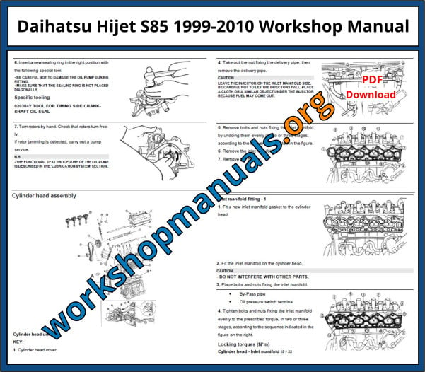
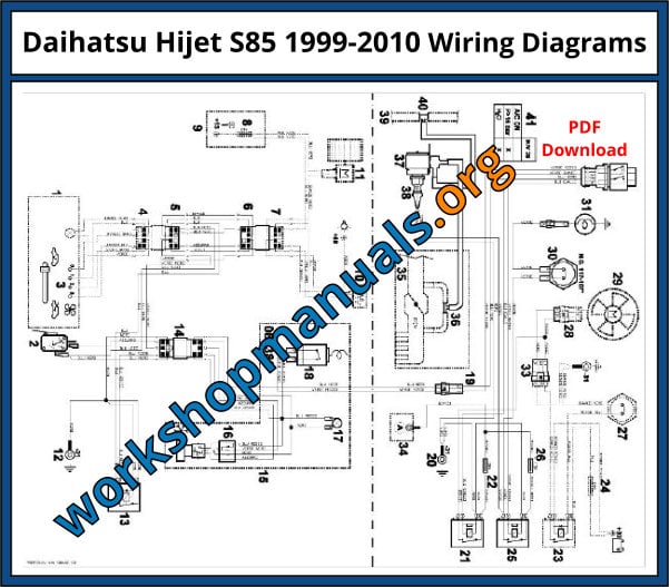
Instant Download