-
Contents
-
Table of Contents
-
Bookmarks
Quick Links
Related Manuals for Akai MPC
Summary of Contents for Akai MPC
-
Page 1
REFERENCE MANUAL… -
Page 2: Table Of Contents
TABLE OF CONTENTS 1. Welcome to the MPC ……3 5. The MPC Software in Detail …. 29 5.0 DRUM Program vs. KEYGROUP 1.1 About this Manual ……3 Program ……….. 31 1.2 Important Notes ……… 3 5.1 The File Browser ……33 2.
-
Page 3: Welcome To The Mpc
MPC Studio offers the most streamlined MPC experience yet. At under one-inch thin, with low- profile controls and a brushed aluminum body, it’s made to move. MPC Studio merges real MPC pads, iconic workflow, and the same MPC Software used by MPC Renaissance to give you a fully integrated portable production solution.
-
Page 4: Overview: Mpc Hardware
2. OVERVIEW: MPC HARDWARE MPC Renaissance and MPC Studio are hardware specifically designed to control the MPC software. This section describes the hardware controls for each device. For a complete explanation of the software, please read the corresponding chapter of this manual.
-
Page 5
Q-LINK TRIGGER – Hold this button down, then touch one of the Q-LINK KNOBS to make that knob’s parameter’s value jump to its minimum or maximum (depending on the Trig parameter in the MPC software). 10. PADS – Use these pads to trigger drum hits or other samples in your software. The pads are velocity-sensitive and pressure-sensitive, which makes them very responsive and intuitive to play. -
Page 6
Hold down SHIFT and press this button to view the Sample Record screen in the display and MPC software. 23. SONG / OTHER – Press this button to view the Song screen in the display and software. -
Page 7
Sequence without having to stop playback. 42. TAP TEMPO – Press this button in time with the desired tempo to enter a new tempo (in BPM) in the MPC software. I/O & LEVEL CONTROLS 43. MIC/LINE / PHONO SWITCH – Use this switch to select the MIC IN or PHONO IN jacks on the rear panel. -
Page 8: Mpc Renaissance: Front Panel
STEREO OUT – Connect these 1/4″ TRS outputs to your speaker system (not included). The signal sent out of these outputs is the main mix. In the MPC software, you can set what is routed to these outputs in the Program Mixer tab, by selecting OUT 1,2 as the OUT for one pad or multiple pads.
-
Page 9
15. MIDI IN – Use a five-pin MIDI cable to connect the MIDI OUT of an optional external MIDI device to the MIDI IN of MPC Renaissance. 16. MIDI OUT – Use a five-pin MIDI cable to connect the MIDI OUT of MPC Renaissance to the MIDI IN of an optional external device. -
Page 10: Mpc Studio: Top Panel
POWER & I/O COMPUTER USB PORT– Use the included USB cable to connect this high-retention-force USB port to an available USB port on your computer. This connection allows MPC Studio to send/receive MIDI and audio data to/from the MPC software.
-
Page 11
CURSOR BUTTONS – Use these buttons to navigate through the fields of menus and options shown in the DISPLAY. DATA DIAL – Use this dial to scroll through the available menu options or adjust the parameter values of the selected field in the DISPLAY. -/+ –… -
Page 12
16 LEVEL – Press this button to activate/deactivate 16 Level. When activated, the last pad that was hit will be temporarily copied to all 16 pads. The pads will now output the same note number as the initial pad, but a selectable parameter will be fixed at the values shown in the diagram on the right, regardless of how hard you hit them. -
Page 13
WINDOW / FULL SCREEN – When this button is lit, it means the selected field in the display contains additional functions; press this button to access them. Use the F- BUTTONS, CURSOR BUTTONS, and DATA DIAL or -/+ buttons to execute (or cancel) these additional functions. -
Page 14: Installing The Mpc Software
3. INSTALLING THE MPC SOFTWARE This chapter explains how to install the MPC software including the plugin version on your computer. It also guides you through the process of authorization. 3.1 SYSTEM REQUIREMENTS In order to be able to use the MPC software, you will need at least: Windows PC: •…
-
Page 15: Installation Under Windows
How to install the MPC software. Installation from DVD: 1. Start your computer and launch your operating system. Insert the MPC DVD into your DVD-ROM drive. If you have enabled the Autostart function in Windows, the Installer will start automatically and you can proceed with Step 5 below. If not, please proceed as follows: 2.
-
Page 16: Installation Under Mac Os X
Double-click on the MPC Installer icon to load the installation software. Follow the on-screen instructions. After installing the MPC software you need to unlock the program on your computer. Please refer to the chapter «Unlocking the MPC Software.» Installation of a downloaded Installer File: Refer to the folder where the downloaded MPC zip archive is located.
-
Page 17: Unlocking The Mpc Software
3.4 UNLOCKING THE MPC SOFTWARE You’ll need to unlock your MPC software before using it. Follow these steps to unlock it: Connect your MPC hardware to a USB port on your computer. If you are using MPC Renaissance, connect it to a power source, too.
-
Page 18: Quick Start Tutorial
4. QUICK START TUTORIAL This Quick Start Tutorial was written to help you to familiarize yourself with the MPC. In order to get the most out of this tutorial, we recommend reproducing each of the described steps. The MPC hardware display reflects what it’s controlling in the software, but due to space and character limitations, the hardware display is slightly different (e.g., parameter names may be…
-
Page 19: Recording A Drum Pattern
UNDO will erase all events from that recording (i.e., since the PLAY or PLAY START was pressed). How about a crash cymbal? Let’s create it directly in the MPC software by clicking on the desired position in the grid, in the same row as the crash sample.
-
Page 20: Basic Sound Edits
Press the F2 button (Level) to control the volume for each pad. You can use the Q-Link knobs of your MPC hardware as well as the corresponding fader in your MPC software. Adjust the levels of each pad to suit your taste.
-
Page 21: The Bassline Track
Press the PAD BANK D button of your MPC hardware to switch to pad bank D and hit Pad 13. You should hear the bass sample played back with its original pitch. You can use the other pads to play your sample chromatically.
-
Page 22
Edit menu. Back to the MPC hardware! The Filter and Envelope display of the MPC hardware Press the PROG EDIT button of your MPC hardware to enter Program Edit Mode. Click on the F4 button (Flt Env) to enter the Filter page. -
Page 23: Working With A Drumloop
The Chop mode of the MPC hardware’s Sample Edit page Press the SAMPLE EDIT button of your MPC hardware to enter Sample Edit Mode. Use the data dial to select the loaded drum loop. You can scroll through all loaded samples seen the top of your MPC hardware display.
-
Page 24: Pad And Track Mute
The Pad Mute display of the MPC hardware First, go back to your basic Drum track. Press and hold the SHIFT button on your MPC hardware and press the TRACK MUTE/ PAD MUTE button to enter Pad Mute Mode. You can now mute a pad by pressing it once. The muted pad will be lit red. This is useful for listening to a sequence without the muted sample.
-
Page 25: Record And Edit A Sample
MIC. Set the MIC IN/PHONO IN switch on the top panel of the MPC hardware to MIC/LINE and turn up the REC GAIN dial. In the MPC software you should now see the input signal. Make sure that the signal gain does not exceed the maximum level (the top input level display segment should be hardly lit).
-
Page 26
Now press F6 (Stop) again, to stop recording. If you’re happy with your recording, please name the new sample in the MPC software in the small window, which will pop up automatically after finishing the recording procedure. Let’s call it «Vocal»… -
Page 27: Step-By-Step With Step Recording
Now, let’s add some spice to our sequence. First, we’ll add an effect to our new recorded sample, e.g., a reverb. In the MPC software, click on the Main tab to open Main Mode. Locate the pad that shows the name «Vocal», indicating that our sample has been assigned to it.
-
Page 28: Creating A Song
Once the MPC software plugin is loaded, it automatically synchronizes with your host sequencer software. When you start your sequencer, the MPC software starts to play back at the same time. The MPC plugin offers the same features and functionality as the standalone software version.
-
Page 29: The Mpc Software In Detail
5. THE MPC SOFTWARE IN DETAIL The following chapters explain the MPC software in detail. Whenever the MPC hardware can be used to control a parameter or a function, this is explained separately in a light-grey box marked by an arrow on its left side.
-
Page 30
MPC plugin playback starts simultaneously. Important! Make sure to save your work in the MPC Software as well as saving all of your work in your host application. For ease of use, we recommend saving your host application projects… -
Page 31: Drum Program Vs. Keygroup Program
5.0 DRUM PROGRAM VS. KEYGROUP PROGRAM A Program in the MPC is a file, which contains a list of all samples used, and settings for each sample (i.e., pad assignments, loop points, pitch tuning, effects, etc.) The MPC’s PROGRAM EDIT mode lets you edit and assign samples. The MPC software can hold a total of 128 programs in a Project.
-
Page 32
These samples are placed in Layers. In the MPC software, click on the Program Edit tab. With the pop-up menus of Layer 2 to Layer 4 you can assign up to four samples – that were loaded into the Project Information beforehand — e.g. -
Page 33: The File Browser
To enter the File Browser, press the BROWSER button on your MPC hardware. Within the MPC software, the File Browser can be found in the left area of the application window. The File Browser section can be hidden or revealed by clicking the «triangle» button in the lower-left corner of the window or by pressing «B»…
-
Page 34
The Browser display of the MPC hardware With the Parent Directory arrow button (in the MPC software, to the right of the data path selector) you can go up one level to the parent directory. FILE directly under the file list window shows the name of the selected file in the list. -
Page 35: The Upper Section
Main, Program Mixer, Track Mixer, Track View or Step Seq tab is selected. Click on the PROG EDIT button of your MPC hardware and use the data dial or the -/+ buttons to select the desired Program. This can also be done in the PGM field on the MAIN page.
-
Page 36: The Lower Section
Click on the REC button to put the MPC software in Record mode. Pressing it on the MPC hardware or in the software will light up its LED to show that Record is armed. To start recording, press PLAY or PLAY START. When the sequence starts to loop in Record mode, it will switch to Overdub mode.
-
Page 37
MPC3000, the MPC60, Other and of course no emulation (no LED will be lit). The Vintage display directly below the output level meter indicates the selected emulation mode. If your MPC Renaissance is set up as audio interface you can use the MAIN VOLUME dial to adjust the volume level. -
Page 38: The Grid
The Grid is always visible, independently from the mode selected (except Sample Record Mode and Sample Edit mode). Click on the SHIFT + WINDOW/FULL SCREEN buttons of the MPC hardware to enlarge the grid. This is ideal for working on tracks and sequences in detail.
-
Page 39
On your MPC hardware, press the MAIN button to edit the described parameters. For selecting a track, use the cursors to navigate to the Trk parameter. You can select the track by using the data dial as well as the -/+ buttons. To change the number of bars, navigate to the Bars parameter. -
Page 40
Press the STOP button to finish your recording. In the MPC software, you can use the Select tool as well as the Draw tool to create notes: Double-click (Select mode) or click (Draw mode) the desired location in the grid to create a note. -
Page 41
(KEYGROUP Program) to select all corresponding notes or use the Select tool as described above. In the MPC software, proceed as follows to record automation data: 1. Click on the Main tab to enter Main Mode. 2. Click and move a corresponding Q-Link knob, so that it is shown in the QLINK display. -
Page 42: Main Mode
5.5 MAIN MODE Main Mode gives you an overview of the most used functions. To enter Main Mode, press the MAIN/ TRACK button on your MPC hardware or click on the Main Tab in the Upper section of your MPC software window.
-
Page 43
• Click on the TRIG field to open a pop-up menu for selecting Min or Max. When you hold down the Q-Link Trigger button on your MPC hardware and touch the top of one the Q-… -
Page 44
Keep in mind that the LAST BAR value depends on the total length of the sequence. On the MPC hardware, move the cursor to Bars and use the data dial or the -/+ buttons to set the desired bar length of your sequence. You can set up to 999 bars. -
Page 45
In the MPC software, click on the TRACK pop-up menu and select the desired track. On the MPC hardware, move the cursor to V% and use the data dial or the -/+ buttons to edit the overall velocity of the selected track in percent. -
Page 46
When Plugin is selected as the INSTRUMENT: On the MPC hardware, move the cursor to Pgm and use the data dial or the -/+ buttons to load the desired plugin. Move the cursor to Midi Ch and use the data dial or the -/+ buttons to select the desired MIDI channel on which the track sequence data is sent to the loaded virtual instrument plugin. -
Page 47: Program Edit Mode
The program settings will change automatically in the display of your MPC hardware. This procedure is not possible for KEYGROUP programs. To select a DRUM program for editing in the MPC software, you have to select the desired pad first in Main Mode.
-
Page 48
This function allows you to define up to four pads that are triggered by hitting one pad only. To select the pads for SIMULTANEOUS PLAY, press the F1 button (Master) on your MPC hardware. Use Q-Link knobs Q5 – Q8 to select the corresponding pads. Keep in mind that this function is only available in DRUM programs. -
Page 49
To edit the KEYGROUP PLAY MODES parameters, press the F1 button (Master) on your MPC hardware. Use Q-Link knobs Q9 – Q11 for direct access of all 3 parameters. Keep in mind that these parameters are available only in KEYGROUP programs. -
Page 50
MPC hardware and changing the displayed values or by clicking in the segment chain on the right side of the LAYER area in your MPC software window and dragging its left and right ends to the desired value. A range from 0 to 127 lets the layer respond to the entire velocity… -
Page 51
With ROOT NOTE, you can change the root key of each loaded sample. The virtual keyboard (only available for KEYGROUP programs) shows the NOTE RANGE which can be set in the KEY GROUP section. In the MPC software, you can also drag the left or right range with your computer mouse. -
Page 52
FILTER & ENVELOPES SECTION Select the pad you wish to filter by hitting it on your MPC hardware or by selecting it in Main Mode of the MPC software. To edit the FILTER, FILTER ENVELOPE & AMP ENVELOPE parameters press the F4 button (Flt Env) on your MPC hardware. -
Page 53
Attack, Decay, Sustain and Release, which is why it is also called ADSR Envelope. Everytime you hit a pad on the MPC, an Envelope is started. Within the period of time you have defined with the ATTACK (ATK) parameter, it rises to its maximum value. After that it will enter the decay phase with its duration defined by the DECAY value until it reaches the sustain level, set by SUSTAIN (SUST) parameter. -
Page 54
In this section, you set how much velocity effects various sound parameters. To edit the Velocity Sensitivity parameters press the F5 button (Lfo Mod) on your MPC hardware. Use Q-Link knobs Q9 – Q12 for direct access of all 4 parameters. Keep in mind that a DRUM program uses different dials for controlling than a KEYGROUP program. -
Page 55
Here you can select up to four audio insert effects for each pad. You can use various effects included in your MPC software as well as optional VST/AU plugins installed on your computer. A list of all available MPC effects including their parameters can be found in the Appendix on Page 93. -
Page 56
-/+ buttons or the data dial. You can use Program Edit Mode to directly edit a set of parameters in a section with your MPC hardware. MPC Renaissance’s 4×4 Q-Link knob matrix corresponds to the MPC software’s controls as well as virtual instrument parameters. -
Page 57: Program Mixer Mode
With the PAD BANK buttons you can also select different pad banks to select different sets of 16 channels. In the MPC software, click on ROUTE tab of the desired channel first, then on the pop-up menu at the bottom the ROUTE tab. Select the desired output (e.g. Out 3,4) to route the audio signal directly to this output.
-
Page 58
With the PAD BANK buttons you can also select different pad banks to select different sets of 16 channels. In the MPC software, click on the SEND button of the desired channel. Click on one of the SEND dials and edit its value with your computer mouse. Alternatively, you can use your mouse scroll wheel. -
Page 59: Track Mixer Mode
The Track Mixer section in the display of the MPC hardware In the MPC software, click on the desired channel fader and move your computer mouse up and down. Alternatively you can use your mouse scroll wheel. To view more mixer channels, use the scroll bar below the channel view.
-
Page 60
PAD BANK buttons, you can also select different pad banks to select different sets of 16 channels. In the MPC software, click on the SEND button of the desired channel. Click on one of the SEND knobs of the desired channel and edit its value with your computer mouse. Alternatively, you can use your mouse scroll wheel. -
Page 61
Next to the send effects, you have access to 8 submix dials which control the volume of the corresponding submix channel. In the Program Mixer, you can route the audio signal to the desired submix bus. Please read more on this on Page 57. Below the Submix section you can find additional master insert effects. -
Page 62: Track View Mode
The Track View mode gives you an overview of the tracks of each sequence. Use this mode to edit tracks and sequences simultaneously. To enter the Track View mode, press SHIFT + MAIN/ TRACK on your MPC hardware. In the MPC software, click on the Track View tab in the Upper section.
-
Page 63: Song Mode
A Project can handle up to 32 songs, each consisting of up to 999 steps. You can create a song by assigning a sequence to each step in the list and also set the number of times the MPC software will repeat the sequence.
-
Page 64
This is useful in live performances, if you need to switch to the next sequence at a certain cue. NEXT jumps to the next sequence at the end of the current sequence. These buttons can be also used in conjunction with HOLD to get the MPC out of a HOLD sequence. -
Page 65: Next Sequence Mode
Next Step mode window. On the MPC hardware, start playback by pressing the PLAY button. Use the 16 pads to select the desired sequence. The currently playing pad will be lit solid green. Used sequences are shown in the MPC hardware display with their names;…
-
Page 66
The Next Sequence section in the display of the MPC hardware In the MPC software, you will find all parameters to create a sequence playlist in the lower section of the Next Seq mode window. The Playlist window gives you an overview of all used Sequences in your MPC project as well as the number of bars and the tempo of each sequence. -
Page 67: Sample Record Mode
To record a signal, you need to connect a suitable microphone, instrument or sound generator to the MIC IN jacks of your MPC Renaissance. You can also connect a turntable or CD player by using the PHONO IN jacks. If a connected microphone requires phantom power, make sure the PHANTOM POWER switch is set to «on.»…
-
Page 68
To adjust the Threshold, use Q-Link knob Q1 on your MPC hardware. With Q3 and Q4 you can set the record time in Minutes and Seconds. -
Page 69
To reset the peak hold on your MPC hardware, press the F1 or F2 button (Reset Peak). The peak hold is shown as a vertical bar within the Level Meter. -
Page 70: Sample Edit Mode
MPC display. In the MPC software, click on the Sample Edit tab in the Upper section. To select a sample for editing, click on the EDIT SAMPLE pop-up menu in the left section below the waveform display and select the desired sample from the Project.
-
Page 71
Use the Q-Link knobs Q13, Q9, Q5 or Q1 of the MPC hardware to adjust the start point of the sample. The smaller the Q-Link knob number, the more precise the adjustment of the start point. -
Page 72
CHOP mode please refer to the end of this chapter. The description below refers to the TRIM mode only. Use the data dial or the -/+ buttons on your MPC hardware to select a sample for editing. The selected sample name is shown at the top of your display. -
Page 73
Here you can directly edit various parameters affecting playback and loop functions. On the MPC hardware, you can edit the sample start, the end and the loop start by navigating with the cursor to the corresponding option (Start, Loop, End). Use the data dial or the -/+ buttons for precise editing. -
Page 74
The Process Sample display for Pitch Shift of the MPC hardware In the MPC software, click on the desired sample editing option. A new window will open. Some options offer additional parameters. To execute a selected option, click on Do It. Otherwise, you can cancel your changes by clicking the Cancel button. -
Page 75
Exp fades the audio out with an exponential curve. An exponential curve will fall quickly in the beginning, and then flatten out as it reaches the end. • PITCH SHIFT changes the pitch of the sample without changing its length. This is useful when you want to change the pitch of the phrase sample in the sequence without changing the tempo. -
Page 76
Click on the F1 button (Chop) to activate the Chop mode. Use the Q-Link knobs Q13, Q9, Q5 or Q1 of the MPC hardware to adjust the start point of the sample. The smaller the Q-Link knob number, the more precise the adjustment of the start point. -
Page 77
Here you can edit various parameters regarding the Chop mode. On the MPC hardware you can select the desired option by navigating with the cursor to the corresponding option (Slice Select, Snap To Zero, Link, Start and End). Use the data wheel or the -/+ buttons for changing the value. -
Page 78
The CHOP To Section in CHOP Mode This section determines the slicing process. On the MPC hardware, you can select the desired processing option by navigating to the Chop to option with the cursor. Use the data dial or the -/+ buttons for selecting the various Chop to options. -
Page 79
The PROCESS section in CHOP mode offers an additional option which affects the whole sample regardless of the selected slice. • CONVERT offers three ways of exporting the sliced sample. o Patched Phrase creates a new sample based on your edits done in the Chop mode and places it in the current Project. -
Page 80: Pad Mute Mode
In the MPC hardware, the 16 blocks displayed represent the 16 pads. Click on the F1 button (PadMute) to activate Pad Mute Mode. Hit the corresponding pad to mute or unmute the desired sound that is assigned to this pad.
-
Page 81
Up to 16 different mute groups can be created. In the MPC hardware, click on the F2 button (PadGroup) to activate the Pad Group mode. Hit a pad to select it, and use the data dial or -/+ buttons to select the desired group. Pads assigned to a mute group will blink yellow when one of the pads in the group is selected. -
Page 82: Track Mute Mode
The Track Mute section in the display of the MPC hardware In the MPC software, select the desired BANK first. Make sure to activate TRACK MUTE Mode in the MODE section. Click the corresponding pad to mute / unmute the desired track that is assigned to it.
-
Page 83
On the MPC hardware, click on the F4 button (Time Div.) to edit the TIME CORRECT value. Press the F5 button (T.C.) to activate or deactivate Time Correct. Press the F6 button (Solo) to solo the selected pad. -
Page 84: Step Sequence Mode
In Step Sequence Mode you can create sequences from scratch as well as edit an existing sequence. It also includes further information about your sequence and track settings. To enter Step Sequence Mode, press the STEP SEQ button on your MPC hardware. Working with Step Sequence Mode in the MPC hardware display In your MPC software, click on the Step Seq tab in the Upper section.
-
Page 85
The F-buttons allows you to select the desired value, e.g., with F1 you can select 1/4, with F2 1/8 etc. In the MPC software, you can use the Pad section for step input. Use the TRACK field at the top of the Grid or the TRACK pop-up menu in the TRACK section to select the desired Track first. -
Page 86: Software Menus
Some of the MPC software’s menu items let you access features that cannot be accessed with the MPC hardware. Keep in mind that the menu structure of the MPC software differs between a Windows PC and a Mac computer. When loaded as plugin, the Menu button is located to the left of the Main tab.
-
Page 87
• For the render option, you can choose between Master and Separate tracks. Master will render an output that will be the same as the final output from the MPC software. Separate tracks will render at the Track Mixer. The rendered audio will not include Track Sends but will include the Track insert effects. -
Page 88
The Active Input Channels displays the active installed inputs on your computer system. When the MPC Renaissance is connected and powered on, the two available ports are displayed. By checking the corresponding input, you can select the audio input you want to use. -
Page 89
When hardware is connected and powered on, the available ports as well as the MPC Public port are displayed. The Midi Mapping lets you define the four Midi Out Port A to D. Here you can select the MIDI output your sequencer data is routed to. -
Page 90
If checked, Filter All Notes OFF CC can filter all note off data. If you have connected another device to your MPC hardware’s MIDI IN, checking this box will cause the MPC software to ignore an «All Notes Off» («MIDI panic») message. That is, if a MIDI device sending MIDI messages into the MPC hardware sends a MIDI panic message, the software will not stop all notes and will continue as before (recording, for instance). -
Page 91
A (a soft touch is enough to create a big velocity value) up to D (you have to hit the pad really hard for a high velocity value). With Footswitch 1 and 2, you can select the functionality of a connected footswitch to your MPC hardware. You can either select transport commands (e.g. PLAY; REC+PLAY) or trigger commands for pads and the F(unction) buttons. -
Page 92
Check for Updates… checks online if a newer version of the MPC software is available. You need an active internet connection to use this function. MPC Help opens this PDF manual. In the Mac MPC software, About MPC and Check for updates are located in the MPC menu. -
Page 93: Appendix
6. APPENDIX In this section, you will find some additional tips and useful information regarding the MPC software. 6.1 EFFECTS & PARAMETERS The MPC software offers various effects for processing samples and sound programs. In the following section, you will find a detailed descriptions how to use effects as well as a list of all available effects and their corresponding parameters with a short explanation of each effect.
-
Page 94
Mixer. If you want, you can change where it is routed to any one of the following outputs: the Track Mixer, Submix 1 to 8, paired Out 1,2 to Out 15,16. Keep in mind, that the MPC Renaissance offers the following physical outputs: 1,2 (main out) and 3,4 (assignable). This can be done in Program Mixer mode. -
Page 95
Use the data dial or -/+ buttons to change the Send Level. In the MPC software, click on the Track Mixer tab in the Upper section. The Master effect section is located on the right end of the Track Mixer. -
Page 96
The Effect Types: Some effects offer a «sync version», e.g. Flanger Sync, which enables the effect to synchronize to the tempo. Flanger A Flanger is an effect that uses a modulated delay line to emulate a classic effect, formerly produced by running two analog tape machines in parallel with a slight time disalignment. Slow rates can produce a jet engine «whoosh»… -
Page 97
Chorus 2-voice Parameter Value Range Default Value Q-Link No. Wet/Dry 0 (DRY) — 100 (WET) 100 (WET) Delay 0 — 100 Amount 0 — 100 Width 0 — 100 Feedback 0 — 100 Rate 0 — 100 Autopan This effect uses an LFO to move the incoming signal back and forth across the stereo field, creating a somewhat rotary effect. -
Page 98
Phaser 1 The Phaser is a classic effect, created by ganged multiple all-pass filters to create «notches», or sharp spikes in the frequency spectrum. The frequencies of these all-pass filters are usually modulated by an LFO to create a sweeping sound. Parameter Value Range Default Value… -
Page 99
HP Filter Sweep Parameter Value Range Default Value Q-Link No. Wet/Dry 0 (DRY) — 100 (WET) Low Frequency 0 — 100 High Frequency 0 — 100 Resonance 0 — 100 Rate 0 — 100 HP Filter Sync Parameter Value Range Default Value Q-Link No. -
Page 100
HP Shelving Filter This filter differs from the standard filter type, as it attenuates all frequencies after the cutoff point equally. Parameter Value Range Default Value Q-Link No. Frequency 10 – 19999 Hz 1500 Hz Resonance 0 — 100 Gain -18.0 — 18.0 dB 0.0 dB LP Shelving Filter… -
Page 101
0 — 100 Gain 1 -18.0 — 18.0 dB 0.0 dB Gain 1 -18.0 — 18.0 dB 0.0 dB Gain 2 -18.0 — 18.0 dB 0.0 dB Gain 4 -18.0 — 18.0 dB 0.0 dB Delay Mono Delays the original signal for a specified period of time and plays it back over an adjustable period of time. -
Page 102
Delay LP The LP and HP Delay is identical to the Mono Delay, but they use a resonant filter in the delay line. Parameter Value Range Default Value Q-Link No. Wet/Dry 0 (DRY) — 100 (WET) Time 2 — 2000 ms Feedback 0 — 100 Cutoff… -
Page 103
Delay Tape Sync Tape Delay emulates a delay system using an analog tape loop and a series of tape heads to produce an echo effect. This delay type yields a very distinct echo sound, often heard in reggae and dub-style music. Parameter Value Range Default Value… -
Page 104
Pan 2 0 — 100 Pan 3 0 — 100 Damping 0 — 100 Gain 1 0 — 100 Gain 2 0 — 100 Gain 3 0 — 100 Distortion Fuzz This popular effect uses hard clipping of the audio signal, which, at extreme settings, can turn a standard waveform into a square wave, producing a «razor»… -
Page 105
Distortion Custom This effect is a highly customized distortion, capable of a wide range of useable sounds. Parameter Value Range Default Value Q-Link No. Wet/Dry 0 (DRY) — 100 (WET) Drive 0 — 100 +Soft 5 — 75 +Clip 5 — 50 -Soft 5 — 75 -Clip… -
Page 106
Compressor Opto A compressor is an effect that changes the dynamic range of a signal by automatically reducing its gain. The Opto Compressor is modeled after a vintage compressor type using an optical circuit to control the volume reduction of the input signal. These compressors are usually associated with soft and unobtrusive attack and release characteristics. -
Page 107
Compressor Master This is the most transparent compressor, able to perform substantial volume adjustments without artifacts. Parameter Value Range Default Value Q-Link No. Wet/Dry 0 (DRY) — 100 (WET) Attack 0 — 100 Release 0 — 100 Threshold -50 – 0 dB 0 dB Ratio 1 — 20… -
Page 108
Reverb Medium This is a spatial effect, designed to emulate a medium room. Parameter Value Range Default Value Q-Link No. Wet/Dry 0 (DRY) — 100 (WET) Pre-Delay 1 — 100 Early Reflection 0 — 100 Density 0 — 100 Diffuse 0 — 100 Decay 0 — 100… -
Page 109
Reverb Out Gate This is a hall reverb that has an additional control. The reverb effect is cut off when the output drops below the level set in the OutGate parameter. Parameter Value Range Default Value Q-Link No. Wet/Dry 0 (DRY) – 100 (WET) Pre-Delay 1 –… -
Page 110
Frequency Shifter A frequency shifter changes the frequencies of an input signal by a fixed amount and alters the relationship of the original harmonics. This can produce a chorus-like effect as well as very crazy artificial timbres. Parameter Value Range Default Value Q-Link No. -
Page 111: Keyboard Shortcuts
6.2 KEYBOARD SHORTCUTS Here you will find all computer keyboard shortcuts for the MPC software. Keyboard modifiers Function Command SHIFT (CTRL) (CTRL) Main Grid – Click and drag to Clicking on Drag Lasso Lasso tool copy selected background: events to add to…
-
Page 112
File Menu Function Command (PC) Command (Mac) New Project CTRL + N COMMAND + N New From Template CTRL + SHIFT + N COMMAND + SHIFT + N Save Project CTRL + S COMMAND + S Open Preferences CTRL + , COMMAND + , Edit Menu Function… -
Page 113: Specifications
6.3 SPECIFICATIONS Technical overview and specifications of the MPC hardware and software. MPC Renaissance HARDWARE Display 360 x 96 dot graphic LCD w/backlight Dimensions 19.75″ x 12.9″ x 2.75″ (4.9″ at max display angle) 502 mm x 328 mm x 70 mm (124 mm at max display angle) (W x D x H) Weight 10.5 lbs.
-
Page 114: Support & Updates
MPC Software • Maximum events: unlimited (based on computer’s CPU) • Resolution: 960 pulses per 1/4-note • Sequences: 128 • Tracks per sequence: 128 • Drum pads: 16 (velocity- and pressure-sensitive) • Drum pad banks: 8 • Sync mode: MIDI clock, MIDI Time Code •…
-
Page 115: Glossary
6.5 GLOSSARY To avoid confusion, the terminology in this manual is based on the MPC parameter names. In this glossary you will find the various terms explained. Aftertouch The majority of contemporary keyboards are capable of generating aftertouch messages. On this type of keyboard, when you press harder on a key you are already holding down, a MIDI Aftertouch message is generated.
-
Page 116
Controllers can be used for effects such as slowly swelling vibrato, changing the stereo panning position and influencing filter frequency. Cutoff The cutoff frequency is a significant factor for filters. A low-pass filter for example dampens the portion of the signal that lies above this frequency. Frequencies below this value are allowed to pass through without being processed. -
Page 117
A Program is a file that contains a list of all samples to be used, and settings for each sample (i.e., pad assignments, loop points, pitch tuning, effects, etc.) The MPC’s PROGRAM EDIT mode is where you can edit and assign samples. The MPC software can have a total of 128 programs in a Project. -
Page 118
Sample When you tap the pads on your MPC, you can trigger sounds that we call ‘samples’. Samples are digitized snippets of audio that can either be recorded using the recording function of your MPC software or loaded from the File Browser. -
Page 119
The MPC software has a special song mode that allows you to arrange different sections (verse, chorus, hook, etc.) in order to build a song. Each song can have up to 250 parts and the MPC software can hold 20 songs in its memory. -
Page 120: Manual Addendum V1.1
Click a feature from the list below to jump to the section of the addendum. NEW FEATURES • Support for Pro Tools: MPC software can now be used as an RTAS plugin in Pro Tools 9 and Pro Tools 10. Pro Tools 10 is recommended for the best performance.
-
Page 121
USING MPC AS AN RTAS PLUGIN You can now use MPC software as an RTAS plugin in Pro Tools 9 and Pro Tools 10. When used as an RTAS plugin, MPC software offers the same features and functionality as the standalone software version. -
Page 122
Plugin Presets: When Inst is set to PLUGIN and a plugin is selected (Plg field), press MAIN, select the Program field, and then press WINDOW. Loop Measures: When Inst is set to MPC, press MAIN, select the Loop field, and then press WINDOW. -
Page 123
Click OK when you are finished. SELECTING PLUGINS AND PRESETS WITH THE HARDWARE You can now use the MPC hardware to select your plugins and their presets. To select a plugin, press the MAIN button on your hardware to enter Main Mode. Use the cursor buttons to select the Inst field, and use the data dial or -/+ buttons to select PLUGIN. -
Page 124
EDITING SEQUENCE LOOP PARAMETERS WITH HARDWARE You can now use the MPC hardware to set the Loop parameters of the sequencer. To edit the sequencer’s Loop parameters, press the MAIN button to enter Main Mode, use the cursor buttons to select the Loop field. You can use the data dial or -/+ buttons to select ON or OFF. -
Page 125: Manual Addendum V1.3
• Improved «legacy» MPC file importing. • Various bug fixes. FUTURE UPDATES Always be sure you’re using the latest version of MPC software by checking for updates. You can do this directly in MPC software’s menus: Windows: Help Check for updates……
-
Page 126
Select to select it or Close to cancel. To make a Plugin Program with your MPC hardware, press MAIN to enter Main Mode. Use the F3 (Track–) and F4 (Track+) buttons to select the Track you want to route to a plugin. Then, use the cursor buttons to select the Type field, and use the data dial or -/+ buttons to select PLUGIN. -
Page 127
After that, click the Track Mixer Mode icon. You will see channel strips for the Tracks on the left and for the Plugin Programs on the immediate right. Above each channel strip’s Pan knob, you will see where its audio is routed. The Tracks you dealt with in the previous step will be routed to the desired plugin. -
Page 128
Plugin drop-down menu to open that plugin’s graphic UI. Custom graphic UIs for included plugins We’ve made graphic UIs for any plugin that came with your MPC hardware and software. We’ve made some for a few other popular, supported third-party plugins, as well. -
Page 129
Tool Select Events When Hitting Pads Select Events is selected, you can hit a pad on your MPC hardware to select all events on that pad in the currently shown Sequence. This option is available in modes where the grid is shown. -
Page 130
You can also use MPC Renaissance or MPC Studio to manage Programs more easily. To delete, create, or copy a Program with your MPC hardware, press MAIN to enter Main Mode. Use the cursor buttons to select the Pgm field, and then press WINDOW. In the Edit Program window that appears, press F2 (Delete) to delete the Program, F3 (New) to create a new Program, F4 (Copy) to copy the Program, and F5 (Close) to cancel. -
Page 131
TRACK MIXER MODE REDESIGN We redesigned some features of Track Mixer Mode window. Showing/hiding channel strips: You can now show or hide (1) unused Tracks’ channel strips (those with no note events) and (2) plugins through which your tracks are routed. To show or hide unused Tracks’ channel strips, click the + icon to the left of the channel strips or in the upper left corner of the grid. -
Page 132
We redesigned some features of the Preferences window. Access this window by doing the following: • Windows: Click the Edit menu, and select Preferences. • Mac: Click the MPC menu, and select Preferences. Hardware tab Several settings from the Other tab in earlier versions are now on a dedicated Hardware tab. -
Page 133
Pro Tools). To set this up, click the Help menu in the MPC software, and select Set Up MMC Control. A PDF will open with instructions for setting it up with select host DAWs. -
Page 134
MPC HARDWARE: ZOOM CONTROL You can now use your MPC hardware to zoom in and out of the grid. In the software, you would do this by adjusting the sliders next to the vertical and horizontal scroll bars. To zoom in and out of the grid, press and hold the SHIFT button and use the up and down cursor buttons (to zoom vertically) or the left and right cursor buttons (to zoom horizontally). -
Page 135
MPC STUDIO Q-LINK KNOB INDICATOR Because MPC Studio has 4 Q-Link knobs (whereas MPC Renaissance has 16), the SCROLL knob allows you to select which row/column of 4 parameters, channels, etc. the Q-Link knobs are currently controlling (shown below). This indicator is present in the upper left corner of the MPC Studio display only in certain modes. -
Page 136
WWW.AKAIPRO.COM…
![]()
МПЦ ОДИН
Инструкция по началу работы
Введение
Особенности:
- Автономный MPC — компьютер не требуется
- Полноцветный мультисенсорный дисплей с диагональю 7 дюймов (177 мм)
- Также действует как панель управления для программного обеспечения MPC.
- Полноразмерный MIDI вход и выход
- 2 ГБ пользовательского хранилища, 2 ГБ предустановленного контента в комплекте
- 2 Гб оперативной памяти
- Полноразмерный слот для SD-карты
- Слот USB-A 2.0 для флэш-накопителя или MIDI-контроллера
Комплектация
MPC One — карта загрузки программного обеспечения
Адаптер питания — Краткое руководство
Кабель USB — Руководство по технике безопасности и гарантии
Важнo: Посещение akaipro.com и найдите webстраницу для MPC One, чтобы загрузить полное руководство пользователя.
Поддержка
Для получения последней информации об этом продукте (документация, технические характеристики, системные требования, информация о совместимости и т. Д.) И регистрации продукта посетите akaipro.com. Для получения дополнительной поддержки по продукту посетите akaipro.com/support.
Схема подключения
Элементы, не указанные в разделе «Введение»> «Содержимое упаковки», продаются отдельно.

Особенности
Верхняя панель

Элементы управления навигацией и вводом данных
1. Дисплей. На этом полноцветном мультисенсорном дисплее отображается информация, относящаяся к текущей работе MPC One. Коснитесь дисплея (и используйте элементы управления оборудованием) для управления интерфейсом MPC. См. «Эксплуатация», чтобы узнать, как использовать некоторые основные функции.
Важнo: Не забудьте снять защитную пленку с сенсорного экрана MPC One!
2. Диск данных: используйте этот диск для прокрутки доступных опций меню или настройки значений параметров в выбранном поле на дисплее. Нажатие на диск также действует как кнопка ввода.
3. — / +: Нажмите эти кнопки, чтобы увеличить или уменьшить значение выбранного поля на дисплее.
4. Отменить / Вернуть: нажмите эту кнопку, чтобы отменить последнее действие. Нажмите и удерживайте Shift, затем нажмите эту кнопку, чтобы повторить последнее отмененное действие.
5. Shift: нажмите и удерживайте эту кнопку, чтобы получить доступ к дополнительным функциям некоторых кнопок (обозначенных красным шрифтом).
Пэды и элементы управления Q-Link
6. Пэды: используйте эти пэды для запуска ударных или других ударов.amples. Пэды чувствительны к скорости и давлению, что делает их очень отзывчивыми и интуитивно понятными для игры. Пэды будут светиться разными цветами в зависимости от того, насколько сильно вы на них играете (от желтого при низкой скорости до красного при максимальной скорости). Вы также можете настроить их цвета.
7. Кнопки банка пэдов: нажмите любую из этих кнопок для доступа к банкам пэдов A – D. Нажмите и удерживайте Shift, одновременно нажимая любую из этих кнопок, чтобы получить доступ к банкам пэдов E – H. Или дважды нажмите одну из этих кнопок.
8. Полный уровень / Половина уровня: нажмите эту кнопку, чтобы активировать / деактивировать полный уровень. При активации пэды всегда запускают своиampфайлы с максимальной скоростью (127), независимо от количества используемого MPC One. Нажмите и удерживайте Shift, а затем нажмите эту кнопку, чтобы активировать / деактивировать половину уровня. При активации пэды всегда запускают своиampфайлы на половинной скорости (64).
9. Уровень 16 / Примечания: Нажмите эту кнопку, чтобы активировать / деактивировать уровень 16. При активации последний ударный пэд будет временно скопирован на все 16 пэдов. Пэды будут воспроизводить одинаковые звуки.ample как исходный пэд, но выбираемый параметр будет увеличиваться в значении с каждым номером пэда, независимо от количества используемого MPC One. Нажмите и удерживайте Shift, затем нажмите эту кнопку, чтобы активировать / деактивировать режим Notes для пэдов. Когда эта функция активирована, вы можете воспроизводить музыкальные гаммы / режимы, аккорды или прогрессии с помощью пэдов в любом режиме. Используйте Pad Perform Mode для настройки параметров пэдов.
10. Копировать / Удалить: Нажмите эту кнопку, чтобы скопировать один пэд на другой. Когда выбрано поле From Pad, нажмите «исходный» пэд (пэд, который вы хотите скопировать). Когда выбрано изображение To Pad (всех пэдов), нажмите пэд «назначения». Вы можете выбрать несколько пэдов назначения, и вы можете выбрать пэды из разных банков пэдов. Нажмите «Сделать», чтобы продолжить, или «Отмена», чтобы вернуться к предыдущему экрану. Нажмите и удерживайте Shift и нажмите эту кнопку, чтобы удалить.
11. Note Repeat / Latch: нажмите и удерживайте эту кнопку, а затем нажмите пэд, чтобы активировать срабатывание этого пэда.ampле неоднократно. Скорость основана на текущем темпе и настройках Time Correct. Нажмите и удерживайте Shift, а затем нажмите эту кнопку, чтобы «зафиксировать» функцию повтора ноты. Когда она зафиксирована, вам не нужно удерживать кнопку Note Repeat, чтобы она была активирована. Еще раз нажмите Note Repeat, чтобы разблокировать его.
12. Ручки Q-Link: используйте эти сенсорные ручки для регулировки различных параметров и настроек. Ручки могут управлять одним столбцом параметров за раз. Индикаторы над ручками Q-Link указывают на текущий выбранный столбец. Нажмите кнопку Q-Link, чтобы изменить столбец параметров, которым они управляют в данный момент.
13. Кнопка Q-Link: Нажмите эту кнопку, чтобы изменить столбец параметров, которым в данный момент управляют ручки Q-Link (на которые указывают индикаторы над ручками Q-Link). При каждом нажатии будет выбираться следующий столбец. Нажмите и удерживайте Shift, а затем нажмите эту кнопку, чтобы выбрать предыдущий столбец.
Режим & View Настройки
14. Меню / настройки: нажмите эту кнопку, чтобы открыть меню режима. Вы можете нажать опцию на экране меню, чтобы войти в этот режим, viewи т. д. Нажмите и удерживайте Shift, а затем нажмите эту кнопку, чтобы открыть страницу настроек в меню.
15. Main / Grid: нажмите эту кнопку, чтобы войти в основной режим. Нажмите и удерживайте Shift, а затем нажмите эту кнопку, чтобы войти в сетку. View Режим.
16. Обзор / Сохранить: нажмите эту кнопку, чтобы view Браузер. Вы можете использовать браузер для поиска и выбора программ.ampфайлы, последовательности и т. д. Нажмите и удерживайте Shift, а затем нажмите эту кнопку, чтобы сохранить текущий проект (включая егоampфайлы, программы, последовательности и песни).
17. Track Mix / Pad Mix: нажмите эту кнопку, чтобы view микшер треков, где вы можете установить уровни, стерео панорамирование и другие настройки для ваших треков, программ, возвратов, субмиксов и мастеров. Нажмите и удерживайте Shift, а затем нажмите эту кнопку, чтобы view Pad Mixer, где вы можете установить уровни программы, стерео панорамирование, маршрутизацию и эффекты.
18. Отключение трека / пэда: нажмите эту кнопку, чтобы view Режим отключения звука дорожки, в котором вы можете легко отключить звук дорожек в последовательности или установить группы отключения звука для каждой дорожки. Нажмите и удерживайте Shift, затем нажмите эту кнопку, чтобы view Pad Mute Mode, в котором вы можете легко отключить звук пэдов в программе или установить группы отключения звука для каждого пэда в программе.
19. Next Seq / XYFX: нажмите эту кнопку, чтобы view Режим следующей последовательности, в котором вы можете запускать различные последовательности, просто играя на пэдах. Это полезно для живых выступлений, позволяя изменять структуру песни в реальном времени. Нажмите и удерживайте Shift и нажмите эту кнопку, чтобы view Режим XYFX, который превращает сенсорный экран в площадку XY, где каждая ось представляет диапазон параметра эффекта. Когда вы перемещаете касание или перемещаете палец по сенсорному экрану, текущая позиция будет определять текущее значение двух параметров. Вы можете использовать этот режим для создания интересных эффектов автоматизации на ваших треках.
20. Step Seq / Automation: нажмите эту кнопку, чтобы view Режим пошагового секвенсора, в котором вы можете создавать или редактировать секвенции, используя пэды в качестве «пошаговых кнопок», имитируя традиционную драм-машину в стиле пошагового секвенсора. Нажмите и удерживайте Shift, затем нажмите эту кнопку, чтобы открыть сетку. View Режим с последним использованным параметром автоматизации для выбранной дорожки.
21. TC / On / Off: нажмите эту кнопку, чтобы открыть окно Timing Correct, которое содержит различные настройки, помогающие квантовать события в вашей последовательности. Нажмите и удерживайте Shift, затем нажмите эту кнопку, чтобы включить или выключить Timing Correct.
22. Sampler / Looper: нажмите эту кнопку, чтобы view Sampлер, где можно записывать аудиоampфайлы для использования в ваших проектах. Нажмите и удерживайте Shift, затем нажмите эту кнопку, чтобы view Looper, с помощью которого вы можете записывать и наложить звук в реальном времени — отличный инструмент для живого выступления, а также для спонтанных моментов в студии. Вы можете экспортировать цикл какample для использования в вашем проекте.
23. Sample Edit / Q-Link Edit: нажмите эту кнопку, чтобы view Sample Режим редактирования, в котором вы можете редактировать своиampфайлы, использующие различные функции и процессы. Нажмите и удерживайте Shift и нажмите эту кнопку, чтобы view Режим редактирования Q-Link, в котором вы можете назначать другие параметры регуляторам Q-Link.
24. Program Edit / MIDI Control: нажмите эту кнопку, чтобы view Режим редактирования программы, который содержит все параметры для редактирования ваших программ. Нажмите и удерживайте Shift, затем нажмите эту кнопку, чтобы view Режим управления MIDI, в котором вы можете настроить, какие MIDI-сообщения будут отправляться с помощью определенных элементов управления на вашем оборудовании.
Управление транспортом и записью
25. Rec: Нажмите эту кнопку, чтобы записать последовательность. Нажмите Play или Play-Start, чтобы начать запись. Запись таким способом (в отличие от использования наложения) стирает события текущей последовательности. После того, как последовательность проигрывается один раз во время записи, наложение будет включено.
26. Наложение: нажмите эту кнопку, чтобы включить наложение. Если этот параметр включен, вы можете записывать события в последовательности, не перезаписывая ранее записанные события. Вы можете включить наложение до или во время записи.
27. Стоп: нажмите эту кнопку, чтобы остановить воспроизведение. Вы можете дважды нажать эту кнопку, чтобы отключить звук, который продолжает звучать после того, как нота перестает играть. Нажмите и удерживайте Shift, а затем нажмите эту кнопку, чтобы вернуть головку воспроизведения к 1: 1: 0.
28. Воспроизведение: нажмите эту кнопку, чтобы воспроизвести последовательность с текущего положения головки воспроизведения.
29. Начало воспроизведения: нажмите эту кнопку, чтобы воспроизвести последовательность с начальной точки.
30. Tap Tempo / Master: Нажмите эту кнопку одновременно с желаемым темпом, чтобы ввести новый темп (в BPM). Удерживая нажатой клавишу Shift, нажмите эту кнопку, чтобы установить, следует ли текущая выбранная последовательность своему собственному темпу (кнопка будет гореть желтым) или основному темпу (кнопка будет гореть красным).
31. Erase: во время воспроизведения последовательности нажмите и удерживайте эту кнопку, а затем нажмите пэд, чтобы удалить событие ноты для этого пэда в текущей позиции воспроизведения. Это быстрый способ удалить нотные события из вашей последовательности без остановки воспроизведения. Когда воспроизведение остановлено, нажмите эту кнопку, чтобы открыть окно «Стереть», в котором можно удалить заметки, автоматизацию и другие данные последовательности из последовательности. Загрузите полную версию Руководства пользователя для получения дополнительной информации.
Передняя панель
1. Слот для SD-карты: вставьте стандартную SD, SDHC или SDXC-карту в этот слот, чтобы получить доступ к ее files напрямую с помощью MPC One.
2. Телефоны (1/8 дюйма / 3.5 мм): подключите к этому выходу стандартные стереонаушники 1/8 дюйма (3.5 мм).

Задняя панель

1. Вход питания: используйте прилагаемый адаптер питания для подключения MPC One к розетке.
2. Ограничитель адаптера питания: закрепите кабель адаптера питания на этом ограничителе, чтобы предотвратить его случайное отключение.
3. Выключатель питания: включает / выключает питание MPC One.
4. Link: подключите стандартный кабель Ethernet к этому порту, чтобы использовать Ableton Link и другие устройства, совместимые с MPC One. Загрузите полную версию Руководства пользователя для получения дополнительной информации.
5. Порт USB-B: используйте прилагаемый USB-кабель для подключения этого USB-порта с высоким удержанием MPC One к свободному USB-порту на вашем компьютере. Это соединение позволяет MPC One отправлять / получать MIDI и аудиоданные в / из программного обеспечения MPC на вашем компьютере.
6. Порт USB-A: подключите флэш-накопитель USB к этому порту USB для доступа files напрямую с помощью MPC One. Вы также можете подключить к этому порту стандартный MIDI-контроллер.
7. Rec Vol: поверните эту ручку, чтобы отрегулировать громкость входов.
8. Входы (1/4 дюйма / 6.35 мм): используйте стандартные кабели TRS 1/4 дюйма (6.35 мм) для подключения этих входов к источнику звука (микшер, синтезатор, драм-машина и т. Д.). В SampВ режиме записи вы можете выбрать, хотите ли вы записывать один или оба канала в стерео или моно.
9. Master Vol: Поверните эту ручку, чтобы отрегулировать громкость выходов и выходов наушников.
10. Выходы (1/4 дюйма / 6.35 мм): используйте стандартные кабели TRS 1/4 дюйма (6.35 мм) для подключения этих выходов к мониторам, микшеру и т. Д.
11. MIDI In: используйте стандартный 5-контактный MIDI-кабель для подключения этого входа к MIDI-выходу внешнего MIDI-устройства (синтезатора, драм-машины и т. Д.).
12. MIDI Out: используйте стандартный 5-контактный MIDI-кабель для подключения этого выхода к MIDI-входу внешнего MIDI-устройства (синтезатора, драм-машины и т. Д.).
13. Выходы CV / Gate: MPC One пошлет контрольную громкость.tage (CV) и / или сигналы Gate по этим выходам для дополнительных внешних секвенсоров. Используйте стандартные кабели TS 1/8 дюйма (3.5 мм) для отправки одного сигнала CV / Gate на выход или используйте переходной кабель стерео TRS-двойной моно TSF (например, Hosa YMM261) для отправки двух сигналов CV / Gate. на выход.
14. Разъем для замка Kensington ®. С помощью этого разъема вы можете закрепить MPC One на столе или другой поверхности.
Эксплуатация
Вот некоторая общая информация о том, как использовать дисплей MPC One:

Нажмите кнопку или параметр, чтобы выбрать его. Используйте диск данных или кнопки — / +, чтобы изменить его настройку или значение.

Разведите два пальца для увеличения (например, части сигнала).ampле). Сведите два пальца, чтобы уменьшить масштаб.

Дважды нажмите кнопку, чтобы получить доступ к расширенным параметрам редактирования. В некоторых случаях это будет отображать цифровую клавиатуру, которую вы можете использовать для ввода значения (альтернатива циферблату данных или кнопкам — / +). Коснитесь верхней левой части экрана, чтобы вернуться к предыдущему view. Верхний край дисплея показывает панель инструментов, которая содержит информацию о текущем view (часто название текущей дорожки, последовательность, положение звукового указателя и т. д.). Коснитесь элемента, чтобы выбрать его. Нижний край дисплея показывает различные кнопки, которые вы можете использовать в текущем view. Нажмите кнопку, чтобы нажать на нее. Чтобы вернуться к предыдущему view, либо коснитесь за пределами окна, отображаемого в данный момент на экране, либо коснитесь стрелки влево (
![]() ) в верхней левой части дисплея.
) в верхней левой части дисплея.
Документы / Ресурсы
Рекомендации
Продолжая использовать наш сайт, вы даете согласие на обработку файлов cookie и пользовательских данных (IP-адрес; сведения о местоположении; тип и версия ОС; тип и версия браузера; тип устройства и разрешение его экрана; источник, откуда пришел на сайт пользователь, с какого сайта или по какой рекламе; язык ОС и браузера; какие страницы открывает и на какие кнопки нажимает пользователь) в целях функционирования сайта, проведения ретаргетинга и проведения статистических исследований и обзоров. Если вы не хотите, чтобы ваши данные обрабатывались, покиньте сайт.
Посмотреть инструкция для AKAI MPC Studio бесплатно. Руководство относится к категории hi-fi системы, 8 человек(а) дали ему среднюю оценку 8.6. Руководство доступно на следующих языках: английский. У вас есть вопрос о AKAI MPC Studio или вам нужна помощь? Задайте свой вопрос здесь
Не можете найти ответ на свой вопрос в руководстве? Вы можете найти ответ на свой вопрос ниже, в разделе часто задаваемых вопросов о AKAI MPC Studio.
Какой вес AKAI MPC Studio?
Когда звук считается слишком громким?
Могут ли устройства разных марок подключаться друг к другу при помощи Bluetooth?
Как лучше всего выполнять чистку hi-fi система?
Какая высота AKAI MPC Studio?
Какая ширина AKAI MPC Studio?
Какая толщина AKAI MPC Studio?
Инструкция AKAI MPC Studio доступно в русский?
Не нашли свой вопрос? Задайте свой вопрос здесь
![]()
REFERENCE MANUAL

TABLE OF CONTENTS
|
1. Welcome to the MPC ……………………. |
3 |
|
|
1.1 |
About this Manual ………………………… |
3 |
|
1.2 |
Important Notes …………………………… |
3 |
|
2. Overview: MPC Hardware …………….. |
4 |
|
|
2.1 |
MPC Renaissance: Top Panel……….. |
4 |
|
2.2 |
MPC Renaissance: Front Panel……… |
8 |
|
2.3 |
MPC Renaissance: Rear Panel ……… |
8 |
|
2.4 |
MPC Studio: Top Panel ………………. |
10 |
|
3 Installing the MPC Software…………. |
14 |
|
|
3.1 |
System Requirements…………………. |
14 |
|
3.2 |
Installation under Windows ………….. |
15 |
|
3.3 |
Installation under Mac OS X ………… |
16 |
|
3.4 |
Unlocking the MPC Software ……….. |
17 |
|
4. Quick Start Tutorial…………………….. |
18 |
|
|
4.1 |
First Start ………………………………….. |
18 |
|
4.2 |
Feeding the MPC Software………….. |
18 |
|
4.3 |
Recording a Drum Pattern …………… |
19 |
|
4.4 |
Organization & Editing ………………… |
19 |
|
4.5 |
Basic Sound Edits………………………. |
20 |
|
4.6 |
The Bassline Track …………………….. |
21 |
|
4.7 |
Working with a Drumloop…………….. |
23 |
|
4.8 |
Pad and Track Mute……………………. |
24 |
|
4.9 |
Record and Edit a Sample …………… |
25 |
|
4.10 Step-by-Step with Step Recording.27 |
||
|
4.11 Automation………………………………. |
27 |
|
|
4.12 Creating a Song……………………….. |
28 |
|
|
4.13 Exporting the whole Song ………….. |
28 |
|
|
4.14 Working with the MPC as an |
||
|
Instrument Plugin …………………….. |
28 |
|
5. The MPC Software in Detail ………… |
29 |
||
|
5.0 DRUM Program vs. KEYGROUP |
|||
|
Program……………………………………. |
31 |
||
|
5.1 |
The File Browser………………………… |
33 |
|
|
5.2 |
The Upper Section……………………… |
35 |
|
|
5.3 |
The Lower Section……………………… |
36 |
|
|
5.4 |
The Grid……………………………………. |
38 |
|
|
5.5 |
Main Mode………………………………… |
42 |
|
|
5.6 |
Program Edit Mode…………………….. |
47 |
|
|
5.7 |
Program Mixer Mode ………………….. |
57 |
|
|
5.8 |
Track Mixer Mode ………………………. |
59 |
|
|
5.9 |
Track View Mode ……………………….. |
62 |
|
|
5.10 Song Mode ……………………………… |
63 |
||
|
5.11 |
Next Sequence Mode ……………….. |
65 |
|
|
5.12 |
Sample Record Mode ……………….. |
67 |
|
|
5.13 |
Sample Edit Mode ……………………. |
70 |
|
|
5.14 Pad Mute Mode ……………………….. |
80 |
||
|
5.15 |
Track Mute Mode……………………… |
82 |
|
|
5.16 |
Step Sequence Mode ……………….. |
84 |
|
|
5.17 |
Software Menus……………………….. |
86 |
|
6. Appendix …………………………………… |
93 |
|
|
6.1 |
Effects & Parameters………………….. |
93 |
|
6.2 |
Keyboard Shortcuts ………………….. |
111 |
|
6.3 |
Specifications…………………………… |
113 |
|
6.4 |
Support & Updates …………………… |
114 |
|
6.5 |
Glossary………………………………….. |
115 |
|
Manual Addendum v1.1………………… |
120 |

1. WELCOME TO THE MPC
Thank you for purchasing the MPC.
Fusing Akai Professional’s legendary MPC layout and workflow with the power of your computer,
MPC Renaissance and MPC Studio are unrivaled instruments for music production.
The new flagship is a fully integrated hardware/software system: MPC Renaissance allows you to create using classic hardware controls and an integrated pop-up display, while its exclusive MPC Software empowers you with unprecedented, expandable production capabilities on your Mac or
PC.
MPC Studio offers the most streamlined MPC experience yet. At under one-inch thin, with lowprofile controls and a brushed aluminum body, it’s made to move. MPC Studio merges real MPC pads, iconic workflow, and the same MPC Software used by MPC Renaissance to give you a fully integrated portable production solution.
Welcome to production anywhere! The world is now your studio! We hope your investment will bring you many years of creative enjoyment and help you achieve your musical goals.
1.1 ABOUT THIS MANUAL
This manual was written to help you to become familiar with the MPC hardware and software. It will also aid experienced users with routine tasks.
To avoid confusion, the terminology in this manual is based on the MPC parameter names. You will find the various terms explained in a glossary at the end of this manual.
We also used a uniform set of symbols to show topics of particular interest or significance. Important terms are highlighted in bold letters.
 Info – Additional information on a given topic.
X MPC hardware – How to use the MPC hardware controls!
All buttons, controls and parameters are highlighted in bold letters throughout the manual.
Example: «Press the PROG EDIT button» or «Turn the Level dial.»
The value range of a parameter is indicated in italic letters.
Example: VELOCITY: 0 to 127.
1.2IMPORTANT NOTES
•READ SAFETY INSTRUCTIONS & WARRANTY INFORMATION BEFORE USING THE MPC HARDWARE AND SOFTWARE.
•Before getting started and connecting devices to the MPC hardware or turning the hardware on/off, make sure all devices are switched off.
•Before connecting the MPC hardware to your computer, insert the included DVD to install the MPC software (visit akaiprompc.com to check for available software updates). For more information about installing the MPC software refer to Chapter 3.
3

2. OVERVIEW: MPC HARDWARE
MPC Renaissance and MPC Studio are hardware specifically designed to control the MPC software. This section describes the hardware controls for each device. For a complete explanation of the software, please read the corresponding chapter of this manual.
2.1 MPC RENAISSANCE: TOP PANEL
|
1 |
|||||||||||||||
|
47 |
43 |
44 |
45 |
46 |
|||||||||||
|
11 11 |
11 |
11 |
|||||||||||||
|
13 14 |
24 |
25 26 |
12 |
2 2 |
2 2 2 2 27 |
19 20 |
21 22 |
23 |
|||||||
|
28 29 30 31 32 |
|||||||||||||||
|
8 |
8 |
8 |
8 |
10 |
10 |
10 |
10 |
16 |
18 |
7 |
|||||
|
4 |
|||||||||||||||
|
8 |
8 |
8 |
8 |
10 |
10 |
10 |
10 |
||||||||
|
17 |
6 |
5 |
5 |
||||||||||||
|
8 |
8 |
8 |
8 |
42 |
3 |
||||||||||
|
10 |
10 |
10 |
10 |
||||||||||||
|
8 |
8 |
8 |
8 |
38 38 40 39 39 |
|||||||||||
|
10 |
10 |
10 |
10 |
||||||||||||
|
9 |
41 |
15 |
36 37 35 33 34 |
||||||||||||
The top panel of the MPC Renaissance
NAVIGATION / DATA ENTRY CONTROLS
1.DISPLAY – This LCD shows all the information relevant to MPC Renaissance’s current operation. Much of this information is also shown in the software. Use the CURSOR
BUTTONS to navigate through the display, and use the DATA DIAL, and -/+ buttons to adjust the currently selected setting/parameter. Use the MODE buttons to change what page is shown, and use the F-BUTTONS to change what tab is shown. You can adjust the display contrast by holding down SHIFT and turning the DATA DIAL.
You can adjust the display contrast by holding down SHIFT and turning the DATA DIAL.
2.F-BUTTONS – Press one of these buttons to select its corresponding tab, shown above the button in the display.
3.CURSOR BUTTONS – Use these buttons to navigate through the fields of menus and options shown in the DISPLAY.
4.DATA DIAL – Use this dial to scroll through the available menu options or adjust the parameter values of the selected field in the DISPLAY.
5.-/+ – Press these buttons to increase/decrease the value of the selected field in the display.
4

6.NUMERIC KEYPAD – If the selected field in the DISPLAY is a number, use these numbered buttons as a standard numeric keypad to enter a value. Press the keypad’s ENTER to enter it.
7.UNDO / REDO – Press this button to undo your last action. You can undo up to 200 actions. Hold down SHIFT and press this button to redo the last action you undid.
PAD / Q-LINK KNOB CONTROLS
8.Q-LINK KNOBS – Use these touch-sensitive knobs to adjust various parameters and settings. The LEDs surrounding each knob indicate the knob’s current position.
9.Q-LINK TRIGGER – Hold this button down, then touch one of the Q-LINK KNOBS to make that knob’s parameter’s value jump to its minimum or maximum (depending on the Trig parameter in the MPC software).
10.PADS – Use these pads to trigger drum hits or other samples in your software. The pads are velocity-sensitive and pressure-sensitive, which makes them very responsive and intuitive to play. The pads will light up different colors, depending on how hard you play them (ranging from yellow at a low velocity to red at the highest velocity). To disable (or re-enable) these lights, press PAD ASSIGN then F6 (Velo Col).
11.PAD BANK BUTTONS – These 4 buttons switch among Pad Banks A – H. Between these 8 banks with 16 pads per bank, you can access up to 128 MIDI events using the pads.
12.PAD ASSIGN / PAD COPY – Press this button to assign a sample to a pad. In the display, the 4×4 grid that appears represents the 16 pads. Use the CURSOR BUTTONS to navigate through the grid, and use the DATA DIAL or -/+ buttons to select a Program (when the
Program field is highlighted) or a sample (when a pad is highlighted). Hold down SHIFT and press this button to copy the samples and parameters from one pad to another. Use the CURSOR BUTTONS to select the From Pad («source») or To Pads («destination») field and hit a pad to select it (you can copy to multiple pads). Use the F-BUTTONS to confirm or cancel the operation.
13.FULL LEVEL / HALF LEVEL – Press this button to activate/deactivate Full Level. When activated, the pads always play back at a maximum velocity (127), no matter how hard or soft you hit them. Hold down SHIFT and press this button activate/deactivate Half Level.
When activated, the pads always play back at a half velocity (63).
14.16 LEVEL – Press this button to activate/deactivate 16 Level. When activated, the last pad that was hit will be temporarily copied to all 16 pads. The pads will now output the same note number as the initial pad, but a selectable parameter will be fixed at the values shown in the diagram on the right, regardless of how hard you hit them. The available parameters are velocity, tuning, filter, layer, attack or decay.
15.NOTE REPEAT / LATCH – Hold this button down and press a pad to retrigger that pad’s sample at a rate based on the current Tempo and Time Correct settings (the available Time Correct settings will appear in the display, which you can select with the F-BUTTONS). Hold down SHIFT and press this button to latch the Note Repeat feature. When latched, the button does not need to be held down for Note Repeat to be activated. Press NOTE REPEAT once more to unlatch it.
MODE / VIEW CONTROLS
16.SHIFT – Hold this button down to access some buttons’ secondary functions (indicated by orange writing).
5

17.MAIN / TRACK – Press this button to view the Main screen in the display and software. Hold down SHIFT and press this button to view the Track View screen in the display and software.
18.BROWSER / SAVE – Press this button to view the file browser in the display. Hold down SHIFT and press this button to save the current Project (including its samples, Programs,
Sequences, and Songs).
19.PROG EDIT / Q-LINK – Press this button to view the Program Edit screen in the display and software. Hold down SHIFT and press this button to assign a parameter to a Q-LINK KNOB: use the CURSOR BUTTONS to select the desired Q-LINK KNOB, then use the DATA DIAL or -/+ buttons to select the desired parameter.
20.PROG MIX / TRACK MIX – Press this button to view the Program Mixer screen in the display and software. Hold down SHIFT and press this button to view the Track Mixer screen in the display and software.
21.SEQ EDIT / EFFECTS – Press this button to enter Sequence Edit mode. Hold down SHIFT and press this button to enter Effects mode, where you can select and route effects as well as edit effects’ parameters.
22.SAMPLE EDIT / SAMPLE REC – Press this button to view the Sample Edit screen in the display and software. Hold down SHIFT and press this button to view the Sample Record screen in the display and MPC software.
23.SONG / OTHER – Press this button to view the Song screen in the display and software.
Hold down SHIFT and press this button to enter Other mode, which allows you to set: the minimum number of taps for the TAP TEMPO button; pad threshold, sensitivity, and curve; the footswitches’ messages; and the Program Change target.
24.STEP SEQ – Press this button to view the Step Sequence screen in the display and software.
25.NEXT SEQ – Press this button to view the Next Sequence screen in the display and software.
26.TRACK MUTE / PAD MUTE – Press this button to view the Track Mute screen in the display and software. Hold SHIFT and press this button to view the Pad Mute screen.
27.WINDOW / FULL SCREEN – When this button is lit, it means the selected field in the display contains additional functions; press this button to access them. Use the F-
BUTTONS, CURSOR BUTTONS, and DATA DIAL or -/+ buttons to execute (or cancel) these additional functions. Hold SHIFT and press this button to switch between Full Screen and Half Screen modes. In Full Screen mode, the workspace occupies the whole screen. In Half Screen mode, the parameter controls (Q-Link knobs, pads, Sequence and Track information, Project Information, etc.) are shown underneath the workspace.
28.PROJECT / FOLDER 1 – Press this button to view only Project files in the File Browser. Hold down SHIFT and press this button to select the Browser’s Folder 1 shortcut.
29.SEQUENCE / FOLDER 2 – Press this button to view only Sequence files in the File
Browser. Hold down SHIFT and press this button to select the Browser’s Folder 2 shortcut.
30.PROGRAM / FOLDER 3 – Press this button to view only Program files in the File Browser. Hold down SHIFT and press this button to select the Browser’s Folder 3 shortcut.
31.SAMPLE / FOLDER 4 – Press this button to view only Sample files in the File Browser. Hold down SHIFT and press this button to select the Browser’s Folder 4 shortcut.
32.NO FILTER / FOLDER 5 – Press this button to view all files in the File Browser. Hold down
SHIFT and press this button to select the Browser’s Folder 5 shortcut.
6

TRANSPORT / RECORDING CONTROLS
33.PLAY – Press this button to play the Sequence from the audio pointer’s current position.
34.PLAY START – Press this button to play the Sequence from its start point.
35.STOP – Press this button to stop playback.
36.REC – Press this button to record-arm the Sequence. Press PLAY or PLAY START to start recording. Recording in this way (rather than using OVERDUB) erases the events of the current Sequence. After the Sequence plays through once while recording, Overdub will be enabled.
37.OVERDUB – Press this button to enable Overdub, which allows you to record note events in a Sequence without overwriting any previously recorded note events. You can enable
Overdub either before or during recording.
38.< / > ( |< / >| ) – Use these buttons to move the audio pointer left/right, one step at a time. Hold LOCATE and press one of these buttons to move the audio pointer to the previous/next event in the Sequence Grid.
39.<< / >> (START/END) – Use these buttons to move the audio pointer left/right, one bar at a time. Hold LOCATE and press one of these buttons to move the audio pointer to the start or end of the Sequence Grid.
40.LOCATE – Hold this button down to activate the secondary functions of the < / > and << / >> buttons (i.e., |< / >| and START/END, respectively).
41.ERASE – As a Sequence is playing, hold this button down and press a pad to delete the note event for that pad at the current playback position. This is a quick way to delete note events from your Sequence without having to stop playback.
42.TAP TEMPO – Press this button in time with the desired tempo to enter a new tempo (in
BPM) in the MPC software.
I/O & LEVEL CONTROLS
43.MIC/LINE / PHONO SWITCH – Use this switch to select the MIC IN or PHONO IN jacks on the rear panel. If you are using a mic or line-level audio source connected to the MIC IN jacks, select MIC IN. If you are using a phono-level device like a turntable connected to the
PHONO IN jacks, select PHONO IN.
44.REC GAIN – Use this knob to adjust the gain of the incoming signal from the MIC IN or
PHONO IN jacks on the rear panel. Monitor the recording level by viewing the level meter (LEDs) above the MIC/LINE / PHONO SWITCH. Be careful when setting this knob at higher levels, which can cause the signal to distort.
45.DIRECT MON – Use this knob to adjust the balance between the INPUT and COMP signals in the headphones. The INPUT signal consists of the MIC IN or PHONO IN jacks – turn the knob all the way to INPUT for zero-latency direct monitoring. The COMP signal is the normal software playback. When not recording, we recommend turning this knob all the way to the COMP position.
46.MAIN VOLUME – Use this knob to adjust the volume level of the STEREO OUT jacks.
47.VINTAGE MODE – Press this to toggle through the available Vintage Modes. The MPC3000 and MPC60 settings emulate the sounds of those classic MPCs, while the OTHER setting emulates the sound of vintage sampling drum machines. When none of the LEDs are lit, Vintage Mode is off.
7
2.2 MPC RENAISSANCE: FRONT PANEL
|
1 |
1 |
2 |
3 |
3 |
4 |
The front panel of the MPC Renaissance
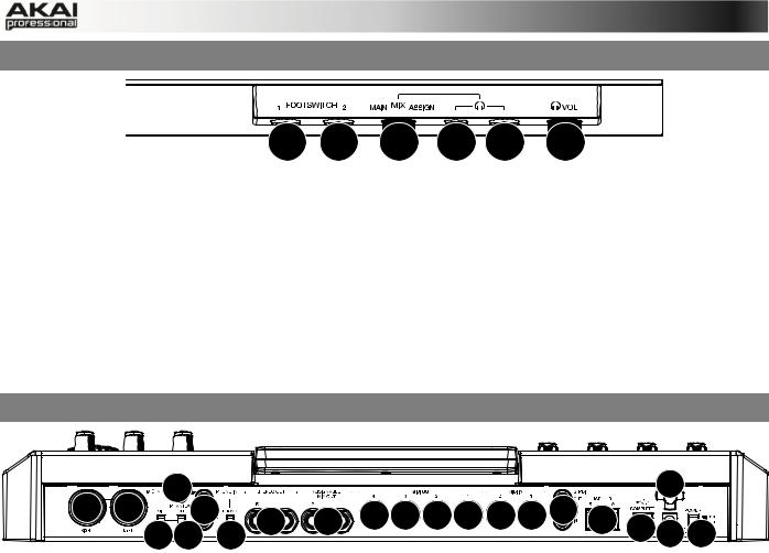
1.FOOTSWITCH INPUTS – Connect optional 1/4” TS footswitches to these inputs.
2.MIX KNOB – Use this knob to adjust the balance between the MAIN and ASSIGN signals in your headphones. The MAIN signal is the STEREO OUTS. The ASSIGN signal is the
ASSIGNABLE MIX OUTS 1 and 2.
3.HEADPHONES – Connect your headphones (not included) to one of these standard TRS outputs (1/8” or 1/4”). Use the MIX KNOB to determine what signal is heard in the headphones.
4.HEADPHONES VOLUME – Use this knob to adjust the headphone volume.
2.3 MPC RENAISSANCE: REAR PANEL
|
14 |
2 |
|||||||||
|
9 |
9 |
12 |
6 |
7 |
16 16 16 16 15 15 |
8 |
5 |
|||
|
10 11 |
13 |
4 1 |
3 |
The rear panel of the MPC Renaissance
1.POWER INPUT – Connect the 12V DC – 2A power adapter (center pin positive) to this jack then into an electrical outlet.
2.POWER ADAPTER RESTRAINT – You can secure a power adapter cable to this restraint to prevent it from accidentally unplugging.
3.POWER SWITCH – Turns MPC Renaissance’s power on/off.
4.COMPUTER USB PORT– Use the included USB cable to connect this high-retention-force
USB port to an available USB port on your computer. This connection allows MPC
Renaissance to send/receive MIDI and audio data to/from the MPC software.
5.USB HUB OUTPUTS – You can connect additional USB devices (controllers, hard drives, etc.) to these powered, high-speed USB 2.0 ports. In addition to being an audio interface, these ports allow MPC Renaissance to function as a powered USB hub when it is powered on.
6.STEREO OUT – Connect these 1/4″ TRS outputs to your speaker system (not included). The signal sent out of these outputs is the main mix. In the MPC software, you can set what is routed to these outputs in the Program Mixer tab, by selecting OUT 1,2 as the OUT for one pad or multiple pads.
7.ASSIGNABLE MIX OUT – Connect these 1/4″ TRS outputs to an external mixer (not included). The signal sent from these outputs is full-volume (0 dB). In the MPC software, you can set what is routed to these outputs in the Program Mixer tab, by selecting OUT 3,4 as the OUT for one pad or multiple pads.
8.S/PDIF IN/OUT – Use standard RCA cables to connect these jacks to devices that can send/receive digital audio.
8

9.MIC IN – Connect an external sound source or microphone to these jacks using standard 1/4″ TRS or XLR cables. Make sure to set the MIC/LINE SWITCH appropriately.
10.MIC/LINE SWITCH – Set this switch appropriately for the device you connected to the MIC IN jacks. If your sound source is a microphone, set it to MIC. If your sound source is a linelevel device, like an external mixer or keyboard, set it to LINE.
11.PHANTOM POWER SWITCH – This switch activates and deactivates phantom power. When activated, phantom power supplies +48V to both MIC IN inputs. Please note that most dynamic microphones do not require phantom power, while most condenser microphones do. Consult your microphone’s documentation to find out whether it needs phantom power.
12.PHONO IN – Connect these RCA inputs to an external sound source (e.g., a turntable, CD player, etc.). Make sure to set the PHONO/LINE SWITCH appropriately.
13.PHONO/LINE SWITCH – Flip this switch to the appropriate position, depending on the device connected to the AUX INPUTS. If you are using phono-level turntables, set this switch to «PHONO» to provide the additional amplification needed for phono-level signals. If using a line-level device, such as a CD player or sampler, set this switch to «LINE.»
14.GROUND TERMINAL – If you connected a phono-level turntable to the PHONO IN jacks and are hearing a low hum or buzz, this could mean that the turntable is not grounded. If the turntable has a grounding wire, connect it to this terminal.
Note: Some turntables have a grounding wire built into the RCA connection and, therefore, nothing needs to be connected to the grounding terminal.
15.MIDI IN – Use a five-pin MIDI cable to connect the MIDI OUT of an optional external MIDI device to the MIDI IN of MPC Renaissance.
16.MIDI OUT – Use a five-pin MIDI cable to connect the MIDI OUT of MPC Renaissance to the MIDI IN of an optional external device.
ÂFor more information about the specifications of the MPC hardware please refer to the corresponding chapter in the Appendix section of this manual.
9
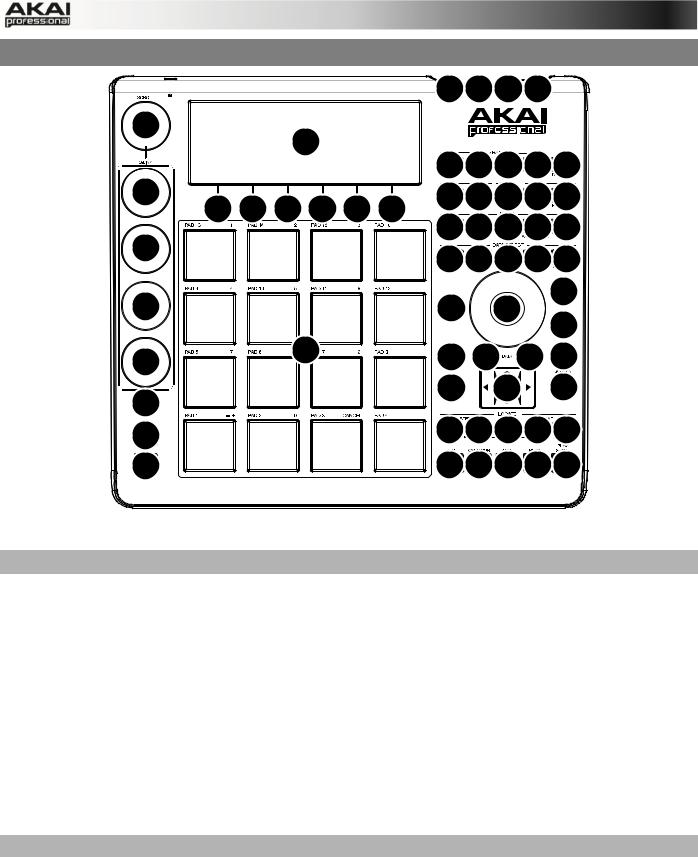
2.4 MPC STUDIO: TOP PANEL
|
3 |
4 |
1 |
2 |
||||||
|
13 |
|||||||||
|
5 |
|||||||||
|
16 16 16 16 17 |
|||||||||
|
12 |
18 |
19 29 30 31 |
|||||||
|
6 |
6 |
6 |
6 |
6 |
6 |
||||
|
24 25 26 27 28 |
|||||||||
|
12 |
33 34 35 36 37 |
||||||||
|
10 |
|||||||||
|
12 |
22 |
8 |
|||||||
|
23 |
|||||||||
|
12 |
15 |
21 |
5 |
5 |
32 |
||||
|
47 |
7 |
11 |
|||||||
|
14 |
|||||||||
|
46 |
43 43 45 44 44 |
||||||||
|
20 |
41 42 40 38 39 |
The top panel of the MPC Studio.
POWER & I/O
1.COMPUTER USB PORT– Use the included USB cable to connect this high-retention-force
USB port to an available USB port on your computer. This connection allows MPC Studio to send/receive MIDI and audio data to/from the MPC software.
2.POWER SWITCH – Turns MPC Studio’s power on/off.
3.MIDI IN – Use the included 1/8″-MIDI adapter and a five-pin MIDI cable to connect the MIDI
OUT of an optional external MIDI device to the MIDI IN of MPC Studio.
4.MIDI OUT – Use the included 1/8″-MIDI adapter and a five-pin MIDI cable to connect the
MIDI OUT of MPC Studio to the MIDI IN of an optional external device.
IMPORTANT: Do NOT connect audio devices (e.g., headphones, monitors, etc.) to the 1/8″
MIDI IN or MIDI OUT jacks. Use the included 1/8″-MIDI adapters to connect MIDI devices only.
NAVIGATION / DATA ENTRY CONTROLS
5.DISPLAY – This LCD shows all the information relevant to MPC Studio’s current operation. Much of this information is also shown in the software. Use the CURSOR BUTTONS to navigate through the display, and use the DATA DIAL, and -/+ buttons to adjust the currently selected setting/parameter. Use the MODE buttons to change what page is shown, and use the F-BUTTONS to change what tab is shown.
Press and hold SHIFT and turn the DATA DIAL to adjust the contrast of the DISPLAY.
6.F-BUTTONS – Press one of these buttons to select its corresponding tab, shown above the button in the display.
10
![]()
7.CURSOR BUTTONS – Use these buttons to navigate through the fields of menus and options shown in the DISPLAY.
8.DATA DIAL – Use this dial to scroll through the available menu options or adjust the parameter values of the selected field in the DISPLAY.
9.-/+ – Press these buttons to increase/decrease the value of the selected field in the display.
10.NUMERIC – If the selected field in the DISPLAY is a number, you can press NUMERIC and use the pads as a standard numeric keypad to enter a value. The numbers are printed in green above the pads.
11.UNDO / REDO – Press this button to undo your last action. You can undo up to 200 actions. Hold down SHIFT and press this button to redo the last action you undid.
PAD / Q-LINK KNOB CONTROLS
12.Q-LINK KNOBS – Use these touch-sensitive knobs to adjust various parameters and settings. The knobs can control one column of parameters at a time. Use the SCROLL
KNOB above them to change which column of parameters they currently control.
13.SCROLL KNOB – Use this knob to change which column of parameters the Q-LINK KNOBS currently control.
14.Q-LINK TRIGGER – Hold this button down, then touch one of the Q-LINK KNOBS to make that knob’s parameter’s value jump to its minimum or maximum (depending on the Trig parameter in the software).
15.PADS – Use these pads to trigger drum hits or other samples in your software. The pads are velocity-sensitive and pressure-sensitive, which makes them very responsive and intuitive to play. The pads will light up different colors, depending on how hard you play them (ranging from yellow at a low velocity to red at the highest velocity). To disable (or reenable) these lights, press PAD ASSIGN then F6 (Velo Col).
If the selected field in the DISPLAY is a number, you can press NUMERIC and use the pads as a standard numeric keypad to enter a value. The numbers are printed in green above the pads.
16.PAD BANK BUTTONS – These 4 buttons switch among Pad Banks A – H (press and hold
SHIFT to access Banks E – H). Between these 8 banks with 16 pads per bank, you can access up to 128 MIDI events using the pads.
17.PAD ASSIGN / PAD COPY – Press this button to assign a sample to a pad. In the display, the 4×4 grid that appears represents the 16 pads. Use the CURSOR BUTTONS to navigate through the grid, and use the DATA DIAL or -/+ buttons to select a Program (when the Program field is highlighted) or a sample (when a pad is highlighted).
Hold down SHIFT and press this button to copy the samples and parameters from one pad to another. Use the CURSOR BUTTONS to select the From Pad («source») or To Pads («destination») field and hit a pad to select it (you can copy to multiple pads). Use the F- BUTTONS to confirm or cancel the operation.
18.FULL LEVEL / HALF LEVEL – Press this button to activate/deactivate Full Level. When activated, the pads always play back at a maximum velocity (127), no matter how hard or soft you hit them.
Hold down SHIFT and press this button to activate/deactivate Half Level. When activated, the pads always play back at half-velocity (63).
11
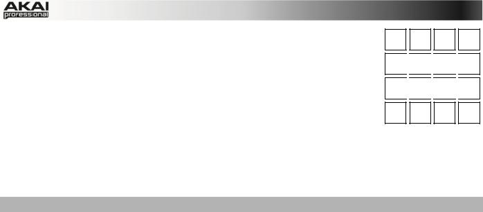
15 23 31
19.16 LEVEL – Press this button to activate/deactivate 16 Level. When 103 111 119 127 activated, the last pad that was hit will be temporarily copied to all 16
pads. The pads will now output the same note number as the initial pad, but a selectable parameter will be fixed at the values shown in the diagram on the right, regardless of how hard you hit them. The available parameters are velocity, tuning, filter, layer, attack or decay.
20. NOTE REPEAT / LATCH – Hold this button down and press a pad to 7 retrigger that pad’s sample at a rate based on the current Tempo and
Time Correct settings (the available Time Correct settings will appear in the display, which you can select with the F-BUTTONS). Hold down SHIFT and press this button to latch the
Note Repeat feature. When latched, the button does not need to be held down for Note Repeat to be activated. Press NOTE REPEAT once more to unlatch it.
MODE / VIEW CONTROLS
21.SHIFT – Hold this button down to access some buttons’ secondary functions (indicated by orange writing).
22.MAIN / TRACK – Press this button to view the Main screen in the display and software. Hold down SHIFT and press this button to view the Track View screen in the display and software.
23.BROWSER / SAVE – Press this button to view the file browser in the display. Hold down
SHIFT and press this button to save the current Project (including its samples, Programs,
Sequences, and Songs).
24.PROG EDIT / Q-LINK – Press this button to view the Program Edit screen in the display and software. Hold down SHIFT and press this button to assign a parameter to a Q-LINK
KNOB: use the CURSOR BUTTONS to select the desired Q-LINK KNOB, then use the
DATA DIAL or -/+ buttons to select the desired parameter.
25.PROG MIX / TRACK MIX – Press this button to view the Program Mixer screen in the display and software. Hold down SHIFT and press this button to view the Track Mixer screen in the display and software.
26.SEQ EDIT / EFFECTS – Press this button to enter Sequence Edit mode. Hold down SHIFT and press this button to enter Effects mode, where you can select and route effects as well as edit effects’ parameters.
27.SAMPLE EDIT / SAMPLE REC – Press this button to view the Sample Edit screen in the display and software. Hold down SHIFT and press this button to view the Sample Record screen in the display and software.
28.SONG / OTHER – Press this button to view the Song screen in the display and software. Hold down SHIFT and press this button to enter Other mode, which allows you to set: the minimum number of taps for the TAP TEMPO button; pad threshold, sensitivity, and curve; the footswitches’ messages; and the Program Change target.
29.STEP SEQ – Press this button to view the Step Sequence screen in the display and software.
30.NEXT SEQ – Press this button to view the Next Sequence screen in the display and software.
31.TRACK MUTE / PAD MUTE – Press this button to view the Track Mute screen in the display and software. Hold SHIFT and press this button to view the Pad Mute screen in the display and software.
12

32.WINDOW / FULL SCREEN – When this button is lit, it means the selected field in the display contains additional functions; press this button to access them. Use the F-
BUTTONS, CURSOR BUTTONS, and DATA DIAL or -/+ buttons to execute (or cancel) these additional functions.
Hold SHIFT and press this button to switch between Full Screen and Half Screen modes. In Full Screen mode, the workspace occupies the whole screen. In Half Screen mode, the parameter controls (Q-Link knobs, pads, Sequence and Track information, Project
Information, etc.) are shown underneath the workspace.
33.PROJECT / FOLDER 1 – Press this button to view only Project files in the File Browser.
Hold down SHIFT and press this button to select the Browser’s Folder 1 shortcut.
34.SEQUENCE / FOLDER 2 – Press this button to view only Sequence files in the File Browser. Hold down SHIFT and press this button to select the Browser’s Folder 2 shortcut.
35.PROGRAM / FOLDER 3 – Press this button to view only Program files in the File Browser. Hold down SHIFT and press this button to select the Browser’s Folder 3 shortcut.
36.SAMPLE / FOLDER 4 – Press this button to view only Sample files in the File Browser.
Hold down SHIFT and press this button to select the Browser’s Folder 4 shortcut.
37.NO FILTER / FOLDER 5 – Press this button to view all files in the File Browser. Hold down SHIFT and press this button to select the Browser’s Folder 5 shortcut.
TRANSPORT / RECORDING CONTROLS
38.PLAY – Press this button to play the Sequence from the audio pointer’s current position.
39.PLAY START – Press this button to play the Sequence from its start point.
40.STOP – Press this button to stop playback.
41.REC – Press this button to record-arm the Sequence. Press PLAY or PLAY START to start recording. Recording in this way (rather than using OVERDUB) erases the events of the current Sequence. After the Sequence plays through once while recording, Overdub will be enabled.
42.OVERDUB – Press this button to enable Overdub, which allows you to record note events in a Sequence without overwriting any previously recorded note events. You can enable
Overdub either before or during recording.
43.< / > ( |< / >| ) – Use these buttons to move the audio pointer left/right, one step at a time.
Hold LOCATE and press one of these buttons to move the audio pointer to the previous/next event in the Sequence Grid.
44.<< / >> (START/END) – Use these buttons to move the audio pointer left/right, one bar at a time. Hold LOCATE and press one of these buttons to move the audio pointer to the start or end of the Sequence Grid.
45.GO TO – Hold this button down to activate the secondary functions of the < / > and << / >> buttons (i.e., |< / >| and START/END, respectively).
46.ERASE – As a Sequence is playing, hold this button down and press a pad to delete the note event for that pad at the current playback position. This is a quick way to delete note events from your Sequence without having to stop playback.
47.TAP TEMPO – Press this button in time with the desired tempo to enter a new tempo (in BPM) in the software.
13

3. INSTALLING THE MPC SOFTWARE
This chapter explains how to install the MPC software including the plugin version on your computer. It also guides you through the process of authorization.
3.1 SYSTEM REQUIREMENTS
In order to be able to use the MPC software, you will need at least:
Windows PC:
•Windows 7 (32or 64-bit)
•2 GHz Pentium 4 processor or better (multi-core recommended)
•2 GB RAM (4 GB recommended)
•14 GB free hard disk space
•Dual Layer DVD-ROM drive
Mac:
•Mac OS X 10.6.8 or above
•2 GB RAM (4 GB recommended)
•14 GB free hard disk space
•Dual Layer DVD-ROM drive
ÂPlease also check the system requirements of your host application!
14

3.2 INSTALLATION UNDER WINDOWS
How to install the MPC software.
Installation from DVD:
1.Start your computer and launch your operating system. Insert the MPC DVD into your
DVD-ROM drive. If you have enabled the Autostart function in Windows, the Installer will start automatically and you can proceed with Step 5 below. If not, please proceed as follows:
2.Launch the Explorer or open the window «My Computer.»
3.Double-click on the icon for the drive that holds the MPC DVD.
4.Double-click on the MPC Installer icon. This launches a special installation program.
5.Follow the on-screen instructions.
ÂAfter installing the MPC software, you need to unlock the program on your computer. Please refer to the chapter «Unlocking the MPC Software.»
Installation of a downloaded Installer File:
1.Refer to the folder where the downloaded MPC zip archive is located.
2.Double-click on the archive file to extract it.
3.Double-click on the MPC Installer icon. This launches a special installation program.
4.Follow the on-screen instructions.
ÂAfter installing the MPC software, you need to unlock the program on your computer. Please refer to the chapter «Unlocking the MPC Software.»
15

3.3 INSTALLATION UNDER MAC OS X
How to install the MPC software:
Installation from DVD:
1.Disable any system activity monitoring software or extension. Then insert the MPC DVD into your computer’s DVD drive.
2.If required, double click on the MPC icon to open the DVD window.
3.Double-click on the MPC Installer icon to load the installation software.
4.Follow the on-screen instructions.
ÂAfter installing the MPC software you need to unlock the program on your computer. Please refer to the chapter «Unlocking the MPC Software.»
Installation of a downloaded Installer File:
1.Refer to the folder where the downloaded MPC zip archive is located.
2.Double-click on the archive file to extract it.
3.Double-click on the MPC Installer DMG icon. This launches a special installation program.
4.Follow the on-screen instructions.
ÂAfter installing the MPC software you need to unlock the program on your computer. Please refer to the chapter «Unlocking of the MPC Software.»
16
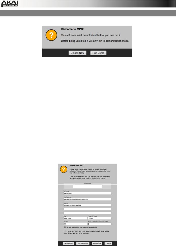
3.4 UNLOCKING THE MPC SOFTWARE
You’ll need to unlock your MPC software before using it. Follow these steps to unlock it:
1.Connect your MPC hardware to a USB port on your computer. If you are using MPC
Renaissance, connect it to a power source, too.
2.Power on the MPC hardware.
3.Open the MPC software.
4.In the dialogue box that appears, click Unlock Now.
5.Enter your information in the window that appears.
6.If your computer is connected to the Internet, click Unlock Now, and enjoy your MPC!
If your computer is not connected to the Internet, follow these additional steps:
7.Click Use Web Form.
8.The window that appears will have your name, serial number, and software ID number. Click Save Details to save this information as a .txt file, or copy the information from each field into another file of your choosing.
9.On a computer connected to the Internet, go to http://authorizations.akaipro.com/MPC, enter the copied information, and click Unlock My MPC.
10.Copy the unlock code from the window that appears.
11.In your MPC software, go to the window from Step 5 and click Enter Code.
12.Enter your name and the unlock code generated by the webpage.
13.Click Unlock, and enjoy your MPC!
17
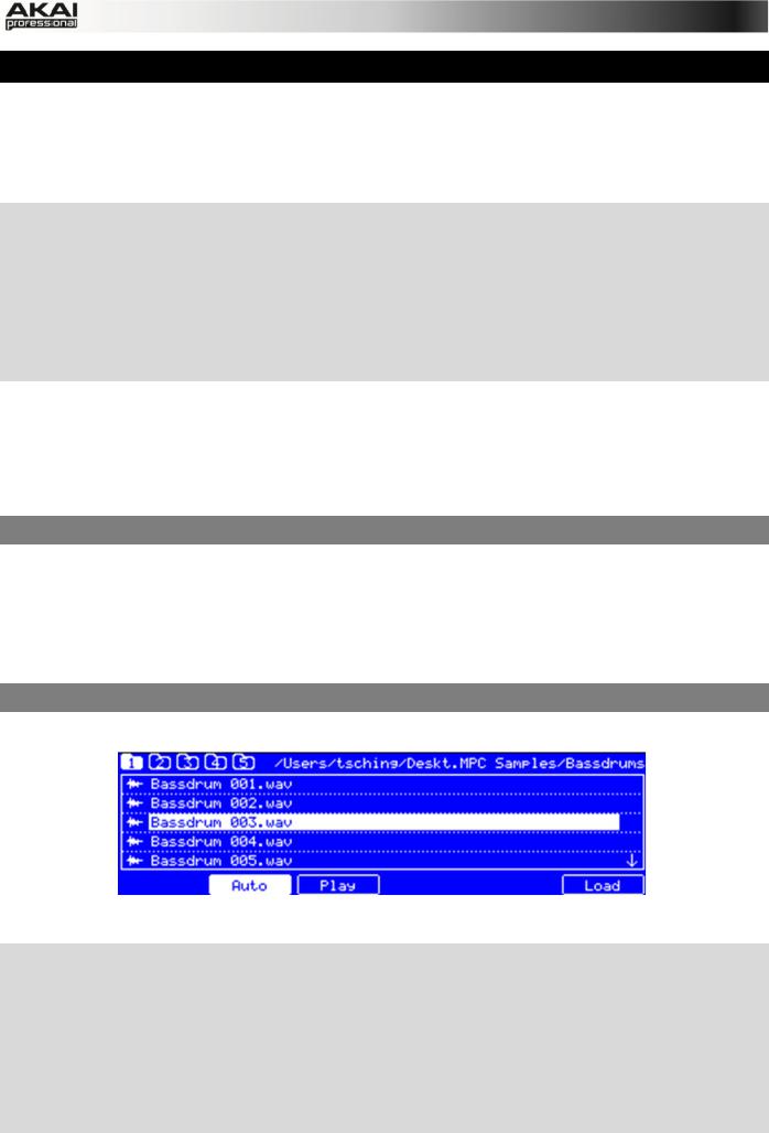
4. QUICK START TUTORIAL
This Quick Start Tutorial was written to help you to familiarize yourself with the MPC. In order to get the most out of this tutorial, we recommend reproducing each of the described steps.
The MPC hardware display reflects what it’s controlling in the software, but due to space and character limitations, the hardware display is slightly different (e.g., parameter names may be abbreviated, the layout may be different or spread across multiple tabs, etc.).
XYou can navigate through the MPC hardware display by using the MPC hardware’s cursor buttons. When a parameter is selected, you can change it by turning the hardware’s data dial or using the -/+ buttons.
XWhen the MPC hardware screen shows a series of parameters that can’t be selected with the cursor buttons, that means it is showing you what the Q-Link knobs are controlling. Touch a Q-
Link knob, and the parameter’s name and setting will appear in the upper right corner of the hardware display. Turn the knob to adjust it (If the Q-Link knob does not control any parameter in the display, this area will show the Q-Link knob number and no text).
ÂMPC Studio users: MPC Studio’s Q-Link knobs control one column of parameters at a time. Whenever this manual instructs you to use the Q-Link knobs to adjust parameters, you can use the SCROLL knob (above the Q-Link knobs) to move through the different columns.
On the following pages we will create a short song to show you important aspects of using the
MPC software in conjunction with the MPC hardware. Let’s get started!
4.1FIRST START
•Make sure that the MPC hardware driver and software are both properly installed on your computer.
•Connect your MPC hardware to your computer with a suitable USB cable and switch it on.
After that, start the MPC software.
Now you’re ready to go!
4.2 FEEDING THE MPC SOFTWARE
Let’s start with a simple drum set.
The Browser display of the MPC hardware
XClick on the BROWSER button of your MPC hardware and use the cursor down button to navigate through your hard disk folders. To enter a selected folder, click on the right cursor button to open it. Navigate to where your drum sounds are located.
XTo preview a selected sound, click on the F3 button (Play). You can also activate the Auto Preview option with the F2 button (Auto).
XFirst, let’s load a bass drum. Hit Pad 1 to select it. The pad will be lit in green. Navigate to a bass drum sample you like and click on the F6 button (Open) to assign it to the selected pad. Now the bass drum sample can be played with Pad 1.
18

XTo create a simple drum set, we repeat the steps described above for other pads. We recommend to load a snare drum on Pad 2, a closed hi-hat on Pad 3 and an open hi-hat on
Pad 4. Feel free to add a crash sample to Pad 5.
Now you’re ready to record a simple drum pattern!
4.3 RECORDING A DRUM PATTERN
Let’s start to record a drum pattern.
XPress the REC button of your MPC hardware to activate the recording mode. To start the actual recording, press the PLAY button. The precount starts to count one measure. We recommend recording the drum sounds one after the other, especially if you are not familiar with playing on the pads.
XPlay a simple bass drum pattern. The initial measure length is 2 bars. After the two bars, the pattern plays again from the beginning and keeps looping. Don’t stop the recording!
XPlay a snare drum pattern, then a hi-hat pattern.
XPress the STOP button to finish the recording.
XThe note events you just recorded will automatically be placed in the grid, in this case, on 16th notes.
XIf you want to repeat the recording, keep in mind that the pads you play in your new recording will automatically replace existing notes played with the same pads. To prevent this, you can use the OVERDUB function, which enables you to record additional note events to an existing pattern. When the sequence loops around, the MPC is automatically placed in OVERDUB mode.
XThe MPC hardware’s UNDO button can be used differently while in Record Mode. Normally, pressing UNDO will undo just the last event. When there is an event to undo, the UNDO button will be lit solid. While recording, the UNDO button will flash. In this case, pressing UNDO will erase all events from that recording (i.e., since the PLAY or PLAY START was pressed).
XHow about a crash cymbal? Let’s create it directly in the MPC software by clicking on the desired position in the grid, in the same row as the crash sample.
Does your drum pattern sound OK? If not, keep on reading!
4.4 ORGANIZATION & EDITING
We recommend doing some naming and editing before recording other patterns.
X Click on the MAIN button of your MPC hardware to enter Main Mode.
Let’s use the MPC software, which is much better for editing.
The pad assignment of your drum sounds is arranged in a Program. Let’s rename the exisiting Program as we will want to create more Programs later on. Right-click on the Program 01 in the PROJECT INFORMATION in the right section of the Main area and select the Rename option. Name the program (e.g. Drums) and click OK.
Right-click on the name of a sample (e.g. the bass drum), and select Rename. Enter a suitable name for the sample (e.g., «Bass Drum 1» or «Kick1»). Repeat this for the other samples in the Program. This will help keep your Program organized as you add more and more sounds to it.
In the Grid, you can see your recorded note events. Click and hold on a note to move it to a different position. By default, you can only position notes by quantization values, defined by the previously set TIME CORRECT value. You may change the value by clicking on the TIME
19
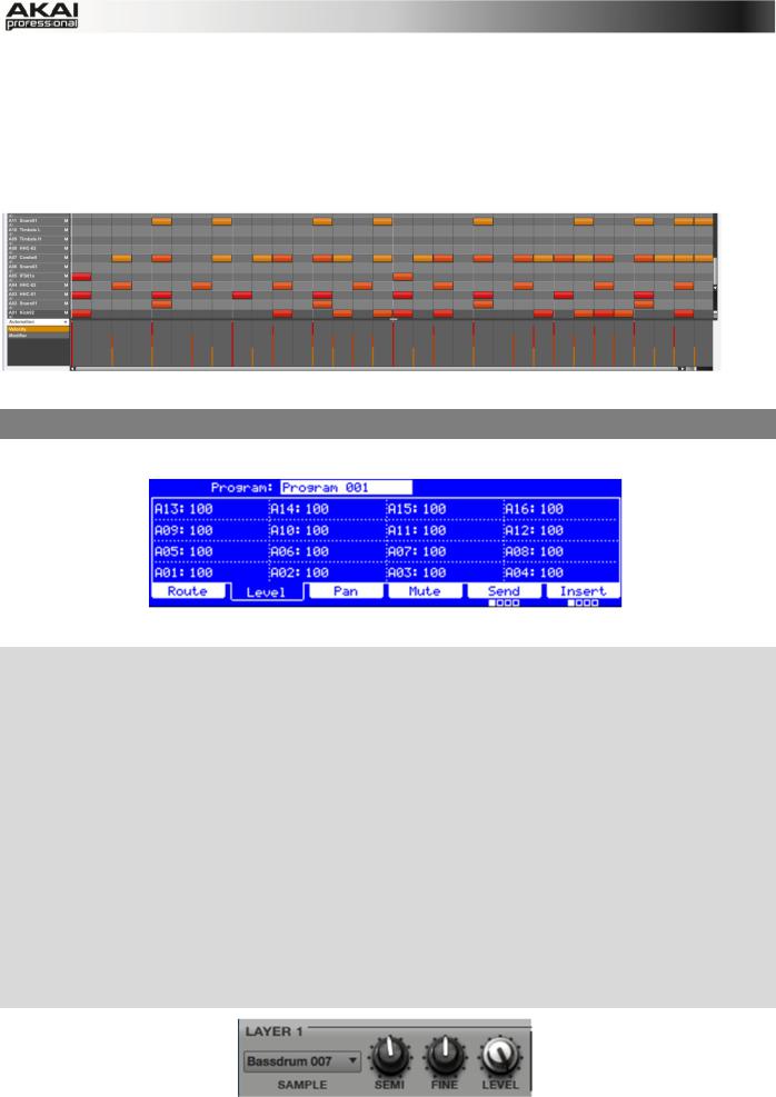
CORRECT pop-up menu. We recommend to work with 8 or 16 values. Hold down your keyboard’s SHIFT and use the ARROW keys to nudge events without restricting to the grid.
Hold down the CTRL key (PC) or Command key (Mac) and click-and-drag a note to copy it.
Double-click on a note to delete it.
Velocity data can be easily edited in the velocity lane below the Grid. Click on a note event (or multiple note events) or place the mouse over a velocity bar in the lane. A small round handle will appear at the top of the velocity bar. Move the mouse vertically to change its value.
Satisfied with your work? Let’s keep on making some basic sound edits.
4.5 BASIC SOUND EDITS
What about levels and effects? Don’t worry, we’ll get there in time!
The Program Mixer display of the MPC hardware
XPress the PROG MIX button of your MPC hardware to enter Program Mixer Mode.
XPress the F2 button (Level) to control the volume for each pad. You can use the Q-Link knobs of your MPC hardware as well as the corresponding fader in your MPC software. Adjust the levels of each pad to suit your taste.
XPress the F3 button (Pan) to control the stereo panorama for each pad. You can use the Q-
Link knobs of your MPC hardware as well as the corresponding PAN knob in your MPC software. We recommend spreading the panning of the bright sounds a little.
XThe snare drum needs a small amount of reverb to give it a more spatial sound. Press the F6 button (Insert 1) to enter the insert effect page. Use the cursor buttons to navigate to the pad (here: A02) where your snare sample is located. With the data dial, you can now select the desired effect. Let’s try the Reverb Medium.
XCould the bass drum use some tuning? No big deal: press the PROG EDIT button and hit Pad 1 to select the bass drum. Click on F2 (Samples) and use the Q14 and Q15 Q-Link knobs to tune the sound. You can also use the corresponding SEMI and FINE parameter in the Layer section of the MPC software.
We’re on the move now… Time to add a new sound!
20
![]()
4.6 THE BASSLINE TRACK
To complete our musical experiment, we need a bassline. In this case, it is important to be able to play a bass sound chromatically. How does that work?
First of all, we need to select a new track. Go back to Main Mode and select Track 02 in the
TRACK pop-up menu above the Grid.
XIn the MPC hardware you have to press the MAIN button. With F4 (Track+) you can switch to the next track.
This new and empty Track should be assigned to a new Program. You can do this in Program Edit Mode. Click on the PROG pop-up menu above the Grid and select the Add Program option. A new window opens. Enter a name, e.g. Bass, and select KEYGROUP as the Program Type. This is necessary because we want to play the bass sound chromatically with the drum pads.
Now let’s load a bass sound. We will use the Browser in the MPC software.
Click on the file browser’s pop-up menu for an overview of your hard disk structure. Locate and select a bass sample. You can double-click on any displayed folder to open it. Click on the Preview button to preview any selected audio sample. If you found a sample to your liking, double-click it to add it to the MPC software’s currently loaded Project. Keep in mind that the sample is not yet assigned to a pad.
XPress the PROG EDIT button of your MPC hardware to enter Program Edit Mode, if not selected already.
In the Layer section click on the LAYER 1 pop-up menu and select the bass sample you just loaded into the MPC software’s currently loaded Project. In this list you will also find your drum samples. Keep in mind that you are working with a KEYGROUP program, so the selected sample is playable across all pads.
XPress the PAD BANK D button of your MPC hardware to switch to pad bank D and hit Pad 13.
You should hear the bass sample played back with its original pitch. You can use the other pads to play your sample chromatically.
To step it up even further, we want to add a second layer. The idea is to have a bass sample that sounds different when played at a higher velocity. Go back to the File Browser and choose a different bass sample that sounds similar
but a little bit brighter to the loaded one.
Double-click on it!
Back in the Layer section, click on the
LAYER 2 pop-up menu and select the new bass sample. If you hit a pad, both samples will be played at once. Maybe
you find that new sound interesting as it is right now, but let’s go further!
Use the VELOCITY slider of Layer 1 and Layer 2 to create a sound with the velocity range of Layer 1 ranging from 0 to 80 while Layer 2 covers within the range of 81 to 127.
Now when you hit a pad, the lower velocities will trigger Layer 1 only, while higher velocities play Layer 2 only.
Now let’s record a bassline. Prepare your recording as described above and record some bass notes. You can edit your recording just like we’ve done earlier.
21
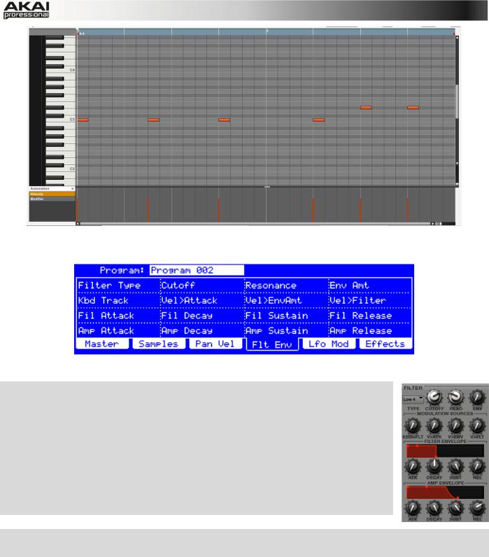
Finally, let’s tweak the bassline sound. This can be done in the FILTER section of the Program Edit menu. Back to the MPC hardware!
The Filter and Envelope display of the MPC hardware
XPress the PROG EDIT button of your MPC hardware to enter Program Edit Mode. Click on the F4 button (Flt Env) to enter the Filter page.
XUse the Filter Type option to select a suitable filter type. We recommend to work with the Low 4 type for a start.
XTurn the Cutoff and Resonance knobs (Q-Link knobs Q14 and Q15) until your bass sample sounds perfect to you.
XUse the Q-Link knobs Q1 to Q4 to set the amplifier envelope. This controls the overall level characteristics of the sound.
XDo you want to add some effect, e.g. Chorus? Press F6 (Effects) and select the desired effect type for your bassline. (Remember to turn the Inserts parameter to «ON.»)
Now we’ve created a simple drum pattern with a bassline. But there’s much more!
22
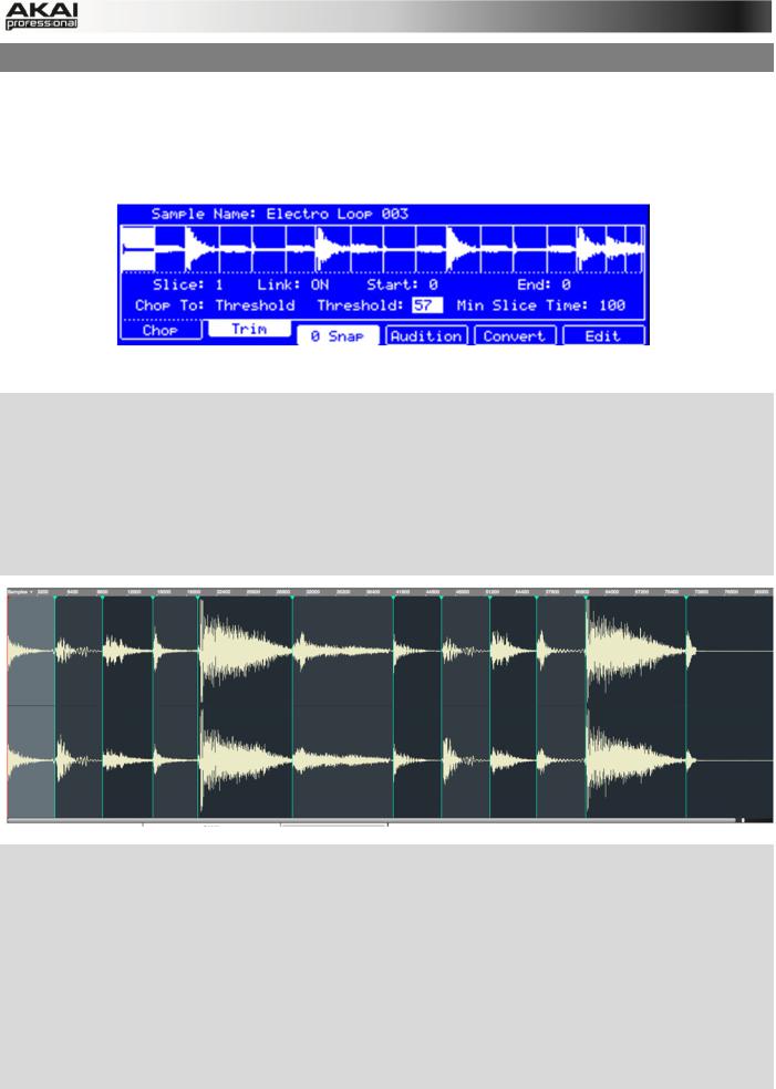
4.7 WORKING WITH A DRUM LOOP
Modern music producers often use drum loops to add grit and dimension to programmed beats.
And this is exactly what we want to do now!
Use the FILE BROWSER to locate a drum loop on your hard disk. It is not necessary that it does match the tempo of your recorded tracks. Double-click the desired drum loop so that it is added to the currently selected Program.
The Chop mode of the MPC hardware’s Sample Edit page
XPress the SAMPLE EDIT button of your MPC hardware to enter Sample Edit Mode.
XUse the data dial to select the loaded drum loop. You can scroll through all loaded samples seen the top of your MPC hardware display.
XPress F1 (Chop) to enter the Chop mode. We are going to cut the drum loop into slices.
XUse the cursor to navigate to the Threshold parameter and select a desired value. The higher the selected value, the more slices will be created. Make sure to choose a threshold value so that every transient peak of the drum loop is shown with a slice line.
XHint: Click on F4 (Audition) to play the created slices via the pads. Each slice is automatically assigned to a pad, starting from Pad A01 with Slice 1 and so on.
XNow we’ll create a new Program containing all created slices as single samples as well as the corresponding note events to playback these slices in a row. This is very easy!
XPress F5 (Convert) to enter the Convert Slices page. Use the cursor to navigate to the following parameters and select the value indicated as follows: Convert to Sliced Samples,
Crop Samples to On, Create New Program to On, Create Events to On and finally the
Number Of Bars to the bar length of your recorded track, in our example that is 2. Press F6
(Do It) to proceed!
XStart the playback and listen how the drum loop matches your song tempo now.
23
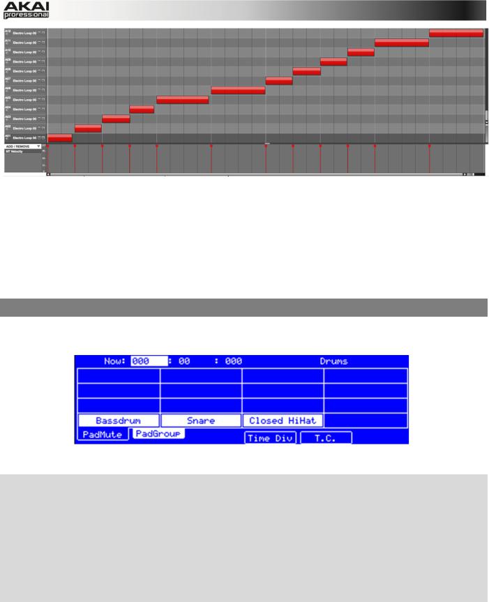
You can also edit the note events of the drum loop slices. Enter Main Mode to do this. A new Track with the note events playing their corresponding slices has been automatically created. Use the Time Correct function (i.e., in the Time Correct menu) to quantize the note events to an exact timing. You can also rearrange the note events, thus creating a new playback order for the slices. It is also possible to edit each slice / sample in Program Edit Mode. You can add effects for slices or use the filter function to change the frequency range of a selected slice. There are almost no limits to what you can do.
4.8 PAD AND TRACK MUTE
In this section, we will mute different pads and tracks to see what the sequence sounds like without some of these parts.
The Pad Mute display of the MPC hardware
XFirst, go back to your basic Drum track.
XPress and hold the SHIFT button on your MPC hardware and press the TRACK MUTE/ PAD MUTE button to enter Pad Mute Mode.
XYou can now mute a pad by pressing it once. The muted pad will be lit red. This is useful for listening to a sequence without the muted sample.
XTo mute pads on another track, press SHIFT + MAIN/ TRACK and click on F3 (Track-) or F4 (Track+) to switch between the recorded tracks. Press SHIFT + TRACK MUTE/ PAD MUTE again to perform the desired mutes.
You can also mute entire tracks by using the Track Mute function.
24
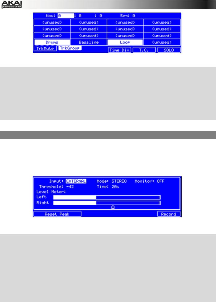
The Track Mute display of the MPC hardware
XPress the TRACK MUTE button on your MPC hardware to enter Track Mute Mode.
XYou can now mute a Track by hitting the corresponding pad once. The muted pad is lit red.
XIf you want to mute a track only at precise note intervals («quantizing» your mutes, essentially), you can set a musical timing value by clicking on the F4 button (Time Div.). Use the data dial to set a musical value, for example 1 bar. Click on F4 (Close) to close the page. When you now hit a pad while in Track Mute mode, the mute will occur precisely at the beginning of the following bar. This lets you test musical combinations of patterns – the stage preliminary to building a song structure.
Now, let’s add some «human feeling» to our song.
4.9 RECORD AND EDIT A SAMPLE
Let’s record some vocals with a connected microphone.
ÂMPC Studio users: This section describes recording using MPC Renaissance as your sound card. MPC Studio can’t be used in this way, but you can use a separate audio interface connected to your computer to record audio.
The Sample Record display of the MPC hardware
XPress and hold the SHIFT button on your MPC hardware and click on the SAMPLE EDIT/ SAMPLE REC button to enter Sample Record mode.
XConnect a suitable microphone to a MIC IN jack of your MPC Renaissance. Make sure to set the input switch to MIC.
XSet the MIC IN/PHONO IN switch on the top panel of the MPC hardware to MIC/LINE and turn up the REC GAIN dial. In the MPC software you should now see the input signal. Make sure that the signal gain does not exceed the maximum level (the top input level display segment should be hardly lit).
XUse the cursor buttons to navigate to the Threshold parameter and set it to a fairly low level, e.g. -70 dB.
25
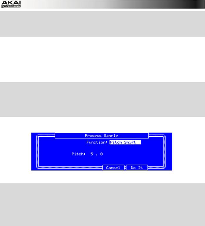
XNow press F6 (Record) and shout something like «Uhhh» or «Yeah!» into the microphone. The recording procedure starts immediately when the input signal level reaches the threshold value.
XNow press F6 (Stop) again, to stop recording.
If you’re happy with your recording, please name the new sample in the MPC software in the small window, which will pop up automatically after finishing the recording procedure. Let’s call it
«Vocal» for now. You should also assign the sample to an unused pad, e.g. Pad 13. Hit it to assign the sample! After that, click on Keep.
Now we can edit our newly recorded sample. Select the sample in the PROJECT INFORMATION section and right-click on it. In the pop-up menu, choose the option Edit. Sample Edit Mode will open.
XPress F2 (Trim) on your MPC hardware to enter the trim mode for editing.
XUse the Q-Link knobs Q1, Q5, Q9 or Q13 to define a suitable start point of your sample. With
Q3, Q7, Q11 or Q15 you can define a suitable end point.
XTo hear your edits, press the Pad A15 to play the sample from the new start point to the new end point.
Finally, let’s apply some transformations to the sample. The MPC software offers some great options.
The Process Sample display of the MPC hardware
XPress F6 (Edit) on your MPC hardware to enter the Process Sample page.
XWith the data dial you can select the desired option. Let’s try some Pitch Shift to change the overall pitch of your sample.
XUse the cursor to navigate to the Pitch parameter and set it to 5.0. This will transpose the sample by 5 semitones but will not affect the length of the sample.
XPress F5 (Do It) to finalize the edit process.
Sounds cool, so let’s include the new sample in your track. In the next chapter, we’ll show you an easy way to record note events.
26
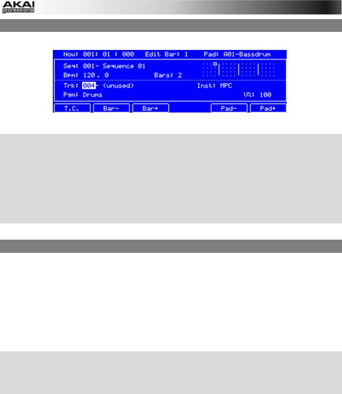
4.10 STEP-BY-STEP WITH STEP RECORDING
You’ve already learned how to record note events on a track. But there’s an easier way to do it.
The Step Seq mode display of the MPC hardware
XIt makes sense to use a new track, so use the cursor buttons to navigate to the Trk parameter to select an unused track. Let’s say Track 04. Navigate to the Bars parameter (the number of bars for the sequence) and set it to Bars: 1.
XPress the STEP SEQ button on your MPC hardware to enter the Step Seq mode.
XPress the PLAY button to start your sequence.
XHit one of the 16 pads to insert a note event in the new track. You can instantly hear and see new events. The green cursor is indicating the current time and the pads represent steps of the timing correct. For example, hit pads 1, 5, 9 and 13 to create a four-on-the-floor kick.
Pretty easy, right?
4.11 AUTOMATION
Now, let’s add some spice to our sequence. First, we’ll add an effect to our new recorded sample, e.g., a reverb.
In the MPC software, click on the Main tab to open Main Mode. Locate the pad that shows the name «Vocal«, indicating that our sample has been assigned to it.
In the Q-Link section, click on the PRG button. Turn Q-Link knob Q1 to activate it for assignment. Now click on the PAD field to select the pad that «Vocal» is assigned to. In the PARAM field, select Filter Cutoff as parameter. In the CHANGE field, select Real Time as the parameter. Do the same steps for Q-Link knob 2: assign it to the «Vocal» pad, and select Real Time as the CHANGE parameter, but select Filter Reso (resonance) for PARAM.
XPress the OVER DUB button on your MPC hardware to arm your automation recording. Press PLAY to start it.
XUse Q-Link knobs Q1 and Q2 to record filter movement as desired. After that, press STOP to finish the automation recording.
Want to see what you’ve recorded?
In the MPC software, to the left of the velocity lane under the Grid, click the Automation menu, select Real Time, and select RT Filter cutoff and RT Filter resonance. The parameters will appear below it. Click either one to show its automation data. By clicking on an automation anchor point, you can edit the automation.
27
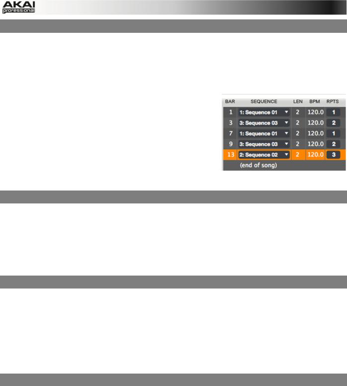
4.12 CREATING A SONG
In the last few chapters, we have learned how to record tracks. But how can we create a song from our track recordings? The next steps will guide you!
Make sure that you have recorded some tracks. All of your tracks combined are called a Sequence. You can create a new Sequence by clicking on the Main tab button and use the SEQ pop-up menu above the Grid to select a new, empty sequence.
Within a Sequence, you can record notes and automation data. In addition, you can use the copy and paste functions from the Edit menu to copy existing tracks to new ones.
Click on the Song tab to open Song Mode. Each Sequence is assigned to a pad. Click and hold a pad with the desired
Sequence, then drag and drop it onto the Sequence Playlist to the left of the pads. You can also drop it onto the workspace above the pads, if you prefer working in a horizontal arrangement. You can easily enter repeats
(RPTS) or drag and drop sequences in the playlist to exchange them.
4.13 EXPORTING THE WHOLE SONG
Want to share your new song with your friends?
All you need to do is to export the complete song. Open the File menu and navigate to Export. Here you need to select As Audio Mixdown.
In the Audio Mixdown window, you can select your mixdown settings. Set the length of your song from Start to End. As the song will most probably be uploaded to the internet, select the mp3 file format option. Choose a path for saving the file and click OK to start exporting the song.
4.14 WORKING WITH THE MPC AS AN INSTRUMENT PLUGIN
Are you working with an audio sequencer? Then you can integrate the MPC software as an instrument plugin in addition to your production tools.
ÂIf you want to know how to load an virtual instrument in your sequencer, please refer to your sequencer’s manual.
Once the MPC software plugin is loaded, it automatically synchronizes with your host sequencer software. When you start your sequencer, the MPC software starts to play back at the same time.
The MPC plugin offers the same features and functionality as the standalone software version.
IMPORTANT!
ÂFor more information about all the features and functionality of the MPC software, we recommend reading the rest of this manual.
28
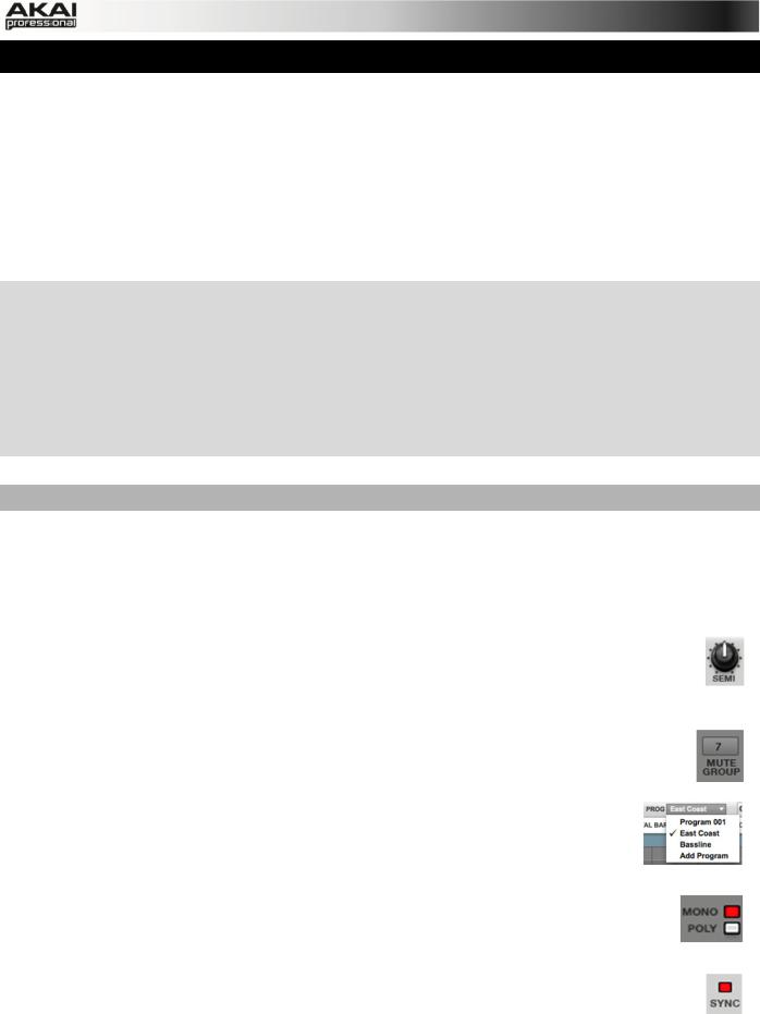
5. THE MPC SOFTWARE IN DETAIL
The following chapters explain the MPC software in detail.
ÂWhenever the MPC hardware can be used to control a parameter or a function, this is explained separately in a light-grey box marked by an arrow on its left side.
ÂWe strongly recommend using the MPC hardware to control the software as its intuitive and fast operation will greatly enhance your creative workflow.
The MPC hardware display reflects what it’s controlling in the software, but due to space and character limitations, the hardware display is slightly different (e.g., parameter names may be abbreviated, the layout may be different or spread across multiple tabs, etc.).
XYou can navigate through the MPC hardware display by using the MPC hardware’s cursor buttons. When a parameter is selected, you can change it by turning the hardware’s data dial or using the -/+ buttons.
XWhen the screen shows a series of parameters that can’t be selected with the cursor buttons, that means the screen is showing you what the Q-Link knobs are controlling. Touch a Q-Link knob, and the parameter’s name and setting will appear in the upper right corner of the hardware display. Turn the knob to adjust it (If the Q-Link knob does not control any parameter in the display, this area will show the Q-Link knob number and no text).
Hints for editing the MPC software with your computer mouse
If you use a computer mouse with scroll wheel, you can use it to change parameters. Move your mouse pointer over the desired value and use the scroll wheel to change it. If you hold down the [SHIFT] key, you can increase the resolution.
The MPC software is simple and straightforward. It uses the following types of control elements:
Knobs
To set a value, click on the knob, hold down the mouse button and drag around the knob in a circle or move the mouse up and down. This depends on the setting of your host application. Alternatively, you can edit values by using your mouse scroll wheel.
Parameter Values
Click and hold the mouse button on the value and drag the mouse up/down or left/right.
Pop-up Menus
Click on the corresponding menu display to open a pop-up menu where you can choose the desired parameter.
Switches
Switches are represented by «LEDs.» If a function is active, its LED will be lit red. To activate a function, click it, which will automatically deactivate another LED in its set.
Buttons
A mouse click on a button activates/deactivates a function. Buttons light up in red when they are activated.
29

Envelope Displays
Click on the respective «handle» of an envelope and drag into the desired direction to change an envelope parameter.
Pencil/ Select Box Icon
Clicking this icon will switch between Draw Mode (Pencil icon) and Select Mode (Select box icon).
Draw Mode:
•Clicking once on an empty square in the grid will place a note in that square.
•Double-clicking a note will erase it.
Select Mode:
•Clicking and dragging the box over notes on the grid will highlight them.
•Double-clicking an empty grid square will add a note.
•Double-clicking an existing note will erase it.
Using the MPC Software as VST or AU Plug-in
The MPC software can be used as a standalone application as well as an instrument plugin in your host application.
ÂFor more information about loading and using an instrument plugin in a host application (e.g., in Cubase, Logic etc.), please refer to the corresponding chapter of your host application’s manual.
The MPC plugin differs in the following ways from the standalone version:
•The MPC plugin doesn’t offer a top menu like in the standalone application. The corresponding menu button is located to the left of the Main tab.
•The MPC plugin is automatically synchronized to the tempo of your host application.
•The start and stop commands are always synchronized to the host application. When the playback of the host application is started, the MPC plugin playback starts simultaneously.
ÂImportant! Make sure to save your work in the MPC Software as well as saving all of your work in your host application. For ease of use, we recommend saving your host application projects and your associated MPC projects in the same folder.
30
![]()
5.0 DRUM PROGRAM VS. KEYGROUP PROGRAM
A Program in the MPC is a file, which contains a list of all samples used, and settings for each sample (i.e., pad assignments, loop points, pitch tuning, effects, etc.) The MPC’s PROGRAM
EDIT mode lets you edit and assign samples. The MPC software can hold a total of 128 programs in a Project.
There are two kinds of programs that use samples as their sound source: DRUM Programs, mostly used for creating drum parts and easy and quick assigning of samples to a pad, and
KEYGROUP Programs. With Keygroup Programs, you can assign one or more samples to one or more keys and play them chromatically via a MIDI keyboard or the MPC hardware pads. That way, you don’t have to sample every note of a keyboard imstrument, e.g. a piano.
How to set up a DRUM Program
Click on the Program Edit tab in the MPC software. Click on the PROG field in the Upper section to open a pop-up menu. Choose Add Program. Type a desired program name and choose DRUM as Program Type. This is the default setting. Click on OK to create the DRUM program. To load samples into a DRUM program, proceed as follows:
XPress the BROWSER button on your MPC hardware. Choose a pad, you want to assign a sample to, e.g. Pad A1. Locate the desired sample and click on F6 (Open) to load it. The sample is now «placed» on the corresponding pad.
The Browser display of the MPC hardware
In the MPC software, click on the Main tab. Locate the desired sample in the File Browser and drag it onto the desired pad. The sample is now «placed» on the corresponding pad.
XPress the PROG EDIT button on your MPC hardware. Click on F1 (Master). With the Q9, Q5 and Q1 Q-Link knobs on your MPC hardware you can assign additional samples to the selected pad. These samples are placed in up to four Layers per pad.
The Master section in the PROG EDIT display of the MPC hardware for a Drum Program
In the MPC software, click on the Program Edit tab. With the pop-up menus of Layer 2 to Layer 4 you can load additional samples to the selected pad. Each pad can hold up to four layers.
ÂKeep in mind: A DRUM Program holds 128 pads. Each pad can hold up to four samples (Layer 1 to 4).
31

How to set up a KEYGROUP Program
Click on the Program Edit tab in the MPC software. Click on the PROG field to open a pop-up menu and choose Add Program. Type a desired program name and choose KEYGROUP as Program Type. Click on OK to create a KEYGROUP program. To load samples into a KEYGROUP program, proceed as follows:
XPress the BROWSER button on your MPC hardware. Locate the desired sample and click on F6 (Open) to load it. The sample is now loaded into the current Project. Now press PROG
EDIT. Click on the F1 (Master) button and use the Q13 Q-Link knob on your MPC hardware to assign the sample from the Project Information to the KEYGROUP program.
The Master section in the PROG EDIT display of the MPC hardware for a Keygroup Program
In the MPC software, locate the desired sample in the File Browser and double click it. The sample is now loaded in the current Project. Now click on the Program Edit tab. Click on the
Layer 1 SAMPLE pop-up display to choose and assign a sample from the Project Information to the KEYGROUP program.
The loaded sample can now be played chromatically with the pads or a connected MIDI keyboard.
XPress the PROG EDIT button on your MPC hardware. Click on F1 (Master). With the Q9, Q5 and Q1 Q-Link knobs on your MPC hardware you can load additional samples to your existing one. These samples are placed in Layers.
In the MPC software, click on the Program Edit tab. With the pop-up menus of Layer 2 to Layer 4 you can assign up to four samples – that were loaded into the Project Information beforehand — e.g. to create velocity layers.
To create complex KEYGROUP Programs, you can add more KEYGROUPS (up to 128). This is useful when working with multi-samples, e.g. when programming a real piano.
ÂKeep in mind: A KEYGROUP Program offers up to 128 KEYGROUPS. Each KEYGROUP can hold up to four samples (Layer 1 to 4). This is a total of 512 samples.
32

5.1 THE FILE BROWSER
The File Browser lets you navigate through your computer’s internal and external hard disks to load samples, sequences, songs etc. Using the predefined and user-definable folders, you can easily adapt the File Browser to your preferred workflow.
X To enter the File Browser, press the BROWSER button on your MPC hardware.
Within the MPC software, the File Browser can be found in the left area of the application window. The File Browser section can be hidden or revealed by clicking the «triangle» button in the lower-left corner of the window or by pressing «B» on your computer keyboard.
The main concept behind the File Browser is to easily locate and load samples, projects, sequences and programs. Samples can be auditioned before loading.
In order to be able to work with the File Browser, you should define a data path to your hard disk(s) first. There are 5 buttons labeled 1 to 5 at the top of the File Browser. Here you can select up to five locations on your hard disk(s) that will offer you a quick access to the corresponding files.
For example: If your MPC projects are saved within your User’s Documents folder, click on the 1 button to select browser path 1.
After that, click on the file browser’s pop-up menu for an overview of your hard disk structure, which looks quite similar to the Windows
Explorer or the Mac Finder. After selecting the desired location, the content of your folder is shown in the target window. To load a project, just double-click on its corresponding xpj file in the target window.
You can filter your search results using the respective filter buttons. The selected buttons will light red. Click on NO FILT to switch the filter function off. Click on the PROJ. button to show only Project files in the target window. Click on SEQ. to show only sequence files. Click on PROG. to show Program files only (Keygroup and Drum Programs). Click on SAMPLE to show only audio samples.
ÂKeep in mind that the target window does not display irrelevant files like Word documents, PDF or pictures (e.g. JPEG, TIFF).
XOn the MPC hardware, you can use the following buttons for the Browser filter functions: NO FILTER to deactivate the filter (same as the NO FILT button in the MPC software), PROJECT for Project filter, SEQUENCE for Sequence filter, PROGRAM for Program filter and SAMPLE for sample filter.
XUse the SHIFT button in conjunction with the five FOLDER buttons to select the desired data path location on your hard disk.
XOnce a data path is selected, you can choose any file with the data dial, the -/+ buttons or the cursor buttons.
XWith the left and right cursor buttons you can go up or down one level to the previous or next directory.
XClick on the F6 button (Load) to load a sample on the selected pad.
33

The Browser display of the MPC hardware
With the Parent Directory arrow button (in the MPC software, to the right of the data path selector) you can go up one level to the parent directory.
FILE directly under the file list window shows the name of the selected file in the list.
X Click on the F3 (Play) button to preview any selected audio sample.
In the MPC software, the Preview Button is located below the File Browser.
ÂKeep in mind that only audio samples can be previewed. Make also sure that your audio hardware is connected properly to listen to the audio file.
XClick on the F2 (Auto) button on your MPC hardware to activate the Auto Preview function. An audio file is played automatically when selected. When active, Auto is highlighted.
Within the MPC software, click on the AUTO PREVIEW button to activate the automatic preview function. An audio file is played automatically when selected. This is very useful when scrolling through a list of samples to find (e.g. to
compare different snare drum sounds without having to load them).
34

5.2 THE UPPER SECTION
The Upper section contains the MPC’s tabs as well as further control for selecting Programs,
Sequences, Songs, etc. depending on the selected mode tab on the left. This section is always visible.
 The different modes are described in detail in the next chapters.
X To select a mode with the MPC hardware, press the corresponding button.
To select a mode within the MPC software, click on the corresponding tab. You can choose from Main, Program Edit, Program Mixer, Track Mixer, Track View, Song, Next Seq, Sample Record, Sample Edit, Pad Mute, Track Mute and Step Seq. Depending on the selected mode some Upper section functions can change.
With the PROGRAM (PROG) pop-up menu, you can select one of your created programs in the currently loaded Project.
With the SEQ (SEQUENCE) pop-up menu, you can select one of the 128 sequences in the currently loaded Project.
XClick on the STEP SEQ button of your MPC hardware and use the cursor to navigate to the Seq field. Use the data dial or the -/+ buttons to select the desired Sequence.
In the MPC software, click the name display or the small triangle to open a pop-up menu to select the desired sequence. The SEQUENCE pop-up
menu is only available when Main, Program Mixer, Track Mixer, Track View or Step Seq tab is selected.
XClick on the PROG EDIT button of your MPC hardware and use the data dial or the -/+ buttons to select the desired Program. This can also be done in the PGM field on the MAIN page.
In the MPC software, click the name display or the small triangle to open a pop-up menu to select the desired program. The PROGRAM pop-up menu is only available when Program Edit or Program Mixer tab is selected.
With the SONG pop-up menu, you can select one of the 32 songs in the currently loaded Project.
XClick on the SONG button of your MPC hardware and use the cursor to navigate to the Song field. Use the data dial or the -/+ buttons to select the desired Song.
In the MPC software, click the name display or the small triangle to open a
pop-up menu to select the desired song. The SONG pop-up menu is only available when the Song tab is selected. Read more about songs on Page 63.
The Screen Scroll button lets you toggle between Scroll mode and Page mode. Depending on the zoom setting, Scroll mode will make the grid display «turn over» to follow the song position marker, whereas Page mode will make the screen scroll along in the background, keeping the song position marker centered.
XClick on the SHIFT + WINDOW/FULL SCREEN buttons of your MPC hardware to toggle between fullscreen for the grid and the divided view with grid and main view.
In the MPC software, click on the Half View mode button to toggle between fullscreen for the grid and the divided view with grid and main view.
35

5.3 THE LOWER SECTION
The Lower section contains the overall controls, such as the measure/tempo display and the transport controls. This section is always visible, independent of the selected mode.
The CPU meter shows the computer CPU usage of the actual project. Keep in mind that an excessive use of synthesis functions such as filter and effects will increase the CPU usage.
ÂIf the CPU meter is very high, software response may slow down. Triple-clicking the STOP button (in this lower section or on the MPC hardware) will send a «MIDI panic» message. This will halt all messages being sent to your computer by the MPC software, and you can resume normal operation.
With the Metronome dial, you can set the volume of your metronome click.
XPress the MAIN button of your MPC hardware and press F2 to enter the CLICK menu. Use the cursor to navigate to the Metronome field. Use the data dial or the -/+ buttons to select the desired metronome setting. You can switch between Off, Play, Record and Record + Play (see also Page 91).
To activate the metronome from the MPC software, click ON, located right of the Metronome dial.
It will light up red when active. Read more about the Metronome on Page 91.
The measure/tempo display shows the actual song position in measures and beats and the song tempo in BPM (beats per minute).
XTo navigate to a particular song position, you can use the < / > buttons on your MPC hardware to move step-by-step within a measure, or advance measure-by-measure with the << / >> buttons. You can also click on the MAIN button and use the cursor to dial in the desired value
(bars, beats, and ticks) and select it by using the data dial or the +/ — buttons. You may also use the numeric buttons to enter a desired value and confirm it by pressing ENTER.
XUse the TAP TEMPO button on your MPC hardware to tap in the Beats per Minute of your desired tempo. An amber LED will blink, indicating the current beats or quarter notes. You can also click on the MAIN button and use the cursor to move to the Bpm parameter. Select the desired value by using the data dial or the +/ — buttons. You may also use the numeric buttons to enter a value and confirm by pressing ENTER.
In the MPC software, you can change a value by double-clicking its digits and entering the desired value with your computer keyboard. You can change the BPM value also by clicking it and dragging the mouse up or down.
ÂThe transport controls can be found on the MPC hardware as well as in the software, so the description below applies to both.
Click on the REC button to put the MPC software in Record mode.
Pressing it on the MPC hardware or in the software will light up its LED to show that Record is armed. To start recording, press PLAY or PLAY START. When the sequence starts to loop in Record mode, it will switch to Overdub mode.
OVERDUB allows you to add data to the existing data on the selected track. It is additive and non-destructive. It will operate like RECORD which means that it is also an «arm» button. Pressing it with the MPC stopped will make its light red while the PLAY LED flashes. The PLAY LED will go solid when you press PLAY or PLAY START.
36

STOP will stop the playback. Quickly pressing STOP 3 times will act as a «MIDI panic» and shut off all voices and stop all audio processing. STOP will also stop loading any files that are being loaded. If you select a Project or Program by accident, pressing STOP will cancel loading and clear the loaded files.
PLAY will start playback from the current time position.
PLAY START will start playback from the beginning of the Song or Sequence or from the First Bar setting.
LEVEL controls the MPC software‘s master output level.
XThe MPC hardware’s UNDO button can be used differently while in Record Mode. Normally, pressing UNDO will undo just the last event. When there is an event to undo, the UNDO button will be lit solid. While recording, the UNDO button will flash. In this case, pressing UNDO will erase all events from that recording (i.e., since the PLAY or PLAY START was pressed).
ÂKeep in mind that the audio level coming out of MPC Renaissance’s STEREO OUTS is determined by its MAIN VOL knob. The MPC software’s LEVEL knob controls the level before the hardware’s MAIN VOL knob. In other words, the software’s LEVEL knob and hardware’s MAIN VOL knob are separate controls.
XClick on the VINTAGE MODE button of your MPC Renaissance to toggle between the different audio quality emulations. This works only if the MPC Renaissance is set up as the audio output in the Preferences. You can choose to emulate the particular sonic qualities of the MPC3000, the MPC60, Other and of course no emulation (no LED will be lit).
The Vintage display directly below the output level meter indicates the selected emulation mode.
ÂIf your MPC Renaissance is set up as audio interface you can use the MAIN VOLUME dial to adjust the volume level.
37

5.4 THE GRID
The Grid is the section where you can record, program and edit your sequences and arrange your songs.
The Grid is always visible, independently from the mode selected (except Sample Record Mode and Sample Edit mode).
XClick on the SHIFT + WINDOW/FULL SCREEN buttons of the MPC hardware to enlarge the grid. This is ideal for working on tracks and sequences in detail.
ÂDepending on which type of Program (DRUM or KEYGROUP) is selected, the grid can look different.
The Grid View for DRUM Programs
When a DRUM Progam is selected, the grid looks as in the following picture.
The left section shows you all available pads (A01 to H16) in a vertical view with their corresponding data. Use the vertical window scroll bar right of the grid windows to move up and down. Under the scroll bar is a slider that can adjust the «vertical zoom.» Below the grid is a similar scroll bar and slider for horizontal scrolling and zooming. Click on the loudspeaker icon under a desired pad number to hear the sample(s) assigned to that pad. Each track also offers a mute (M) and solo (S) button.
In the top-left corner of the grid, you will find a mode button to toggle between Select and
Draw mode. The Select mode is indicated by a small rectangular marquee tool and lets
you select one or more notes by drawing a frame around them. Selected notes will have a white border. When the Draw mode is active – indicated by a small pencil — you can draw notes by clicking on the corresponding position in the grid. You can also use it to draw
automation curves in the velocity/automation lane underneath the grid. The default setting is the Draw mode.
In the top-right corner there are several displays that let you edit the following
functions: Click on the TRACK pop-up display to select one of the 128 tracks. Click and vertically slide the TOTAL BARS field to change the length for the selected track. The default setting is 2 bars. The maximum length is 999 bars. In the TIME CORRECT pop-up menu you can set the note value to quantize to. Default is 1/16 (16th note). SWING sets the amount of swing with values ranging from 50% to 75% so you can shuffle your beats – from subtle to extreme.
38
 Loading…