- Manuals
- Brands
- SUZUKI Manuals
- Scooter
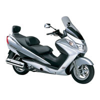
- Burgman AN400
Manuals and User Guides for SUZUKI Burgman AN400. We have 3 SUZUKI Burgman AN400 manuals available for free PDF download: Service Manual, Supplementary Service Manual

Suzuki Burgman AN400 Service Manual (475 pages)
Brand: Suzuki
|
Category: Scooter
|
Size: 37.56 MB
Table of Contents
-
Section 1 Engine
59
-
General Information
13
-
Maintenance and Lubrication
28
-
Scheduled Maintenance
28
-
Lubrication Points
29
-
Brake Hose Replacement
41
-
Table of Contents
59
-
Engine General Information and Diagnosis
64
-
Injection Timing Description
64
-
Self-Diagnosis Function
65
-
-
Schematic and Routing Diagram
67
-
FI System Wiring Diagram
67
-
Terminal Alignment of ECM Coupler (Harness Side)
68
-
-
Component Location
69
-
FI System Parts Location
69
-
-
Diagnostic Information and Procedures
70
-
Engine Symptom Diagnosis
70
-
DTC Table
74
-
Fail-Safe Function Table
74
-
FI System Troubleshooting
75
-
Self-Diagnostic Procedures
76
-
Self-Diagnosis Reset Procedures
77
-
Use of SDS Diagnostic Procedures
77
-
Use of SDS Diagnosis Reset Procedures
78
-
Show Data When Trouble (Displaying Data at the Time of DTC)
79
-
Malfunction
83
-
DTC «C13» (P0105-H/L): IAP Sensor Circuit Malfunction
88
-
DTC «C14» (P0120/H/L): TP Sensor Circuit Malfunction
93
-
DTC «C15» (P0115-H/L): ECT Sensor Circuit Malfunction
96
-
DTC «C16» (P0500): Speed Sensor
99
-
DTC «C21» (P0110-H/L): IAT Sensor Circuit Malfunction
102
-
DTC «C23» (P1651-H/L): to Sensor Circuit Malfunction
105
-
DTC «C24» (P0351): Ignition System Malfunction
108
-
DTC «C28» (P1655): Secondary Throttle Valve Actuator (STVA) Malfunction
108
-
DTC «C29» (P1654-H/L): Secondary Throttle Position Sensor (STPS)
112
-
DTC «C32» (P0201): Fuel Injector Circuit Malfunction
115
-
DTC «C40» (P0505, P0506 or P0507): ISC Valve Circuit Malfunction
118
-
DTC «C41» (P0230-H/L): FP Relay Circuit Malfunction
124
-
DTC «42» (P1650): IG Switch Circuit Malfunction
126
-
DTC «C44» (P0130, P0135): HO2 Sensor (HO2S) Circuit Malfunction
127
-
-
-
Specifications
130
-
Service Data
130
-
-
Special Tools and Equipment
131
-
Special Tool
131
-
-
Emission Control Devices
132
-
Precautions
132
-
Precautions for Emission Control Devices
132
-
-
General Description
132
-
Fuel Injection System Description
132
-
Crankcase Emission Control System Description
133
-
Exhaust Emission Control System Description
134
-
Noise Emission Control System Description
134
-
-
Repair Instructions
135
-
Heated Oxygen Sensor (HO2S) Removal and Installation
135
-
Heated Oxygen Sensor (HO2S) Inspection
135
-
PCV Hose Inspection
136
-
PCV Hose Removal and Installation
136
-
-
Specifications
137
-
Service Data
137
-
Tightening Torque Specifications
137
-
ECM Removal and Installation
138
-
CKP Sensor Inspection
138
-
CKP Sensor Removal and Installation
138
-
IAP Sensor Inspection
139
-
IAP Sensor Removal and Installation
139
-
TP Sensor Inspection
139
-
TP Sensor Adjustment
139
-
TP Sensor Removal and Installation
140
-
ECT Sensor Inspection
140
-
ECT Sensor Removal and Installation
140
-
Speed Sensor Inspection
140
-
Speed Sensor Removal and Installation
141
-
IAT Sensor Inspection
141
-
IAT Sensor Removal and Installation
141
-
TO Sensor Inspection
141
-
TO Sensor Removal and Installation
142
-
STP Sensor Inspection
142
-
STP Sensor Adjustment
142
-
STP Sensor Removal and Installation
143
-
ISC Valve Inspection
143
-
ISC Valve Removal and Installation
143
-
-
Specifications
144
-
Service Data
144
-
Tightening Torque Specifications
144
-
-
Special Tools and Equipment
144
-
Special Tool
144
-
-
1C-7 Engine Electrical Devices
144
-
HO2 Sensor Inspection
144
-
HO2 Sensor Removal and Installation
144
-
-
Engine Mechanical
145
-
Precautions
145
-
Precautions for Engine Mechanical
145
-
-
Schematic and Routing Diagram
145
-
Camshaft and Sprocket Assembly Diagram
145
-
Throttle Cable Routing Diagram
146
-
-
Diagnostic Information and Procedures
147
-
Compression Pressure Check
147
-
-
Repair Instructions
148
-
Engine Components Removable with the Engine in Place
148
-
Engine Assembly Removal and Installation
150
-
Crankcase Bracket Removal and Installation
153
-
Crankcase Bracket Inspection
153
-
Air Cleaner Box Removal and Installation
153
-
Air Cleaner Element Inspection
154
-
Air Cleaner Drain Plug Inspection
154
-
Throttle Cable Removal and Installation
154
-
Throttle Cable Adjustment
154
-
Throttle Body Components
155
-
Throttle Body Construction
156
-
Throttle Body Removal and Installation
157
-
Throttle Body Disassembly and Assembly
157
-
Throttle Body Inspection and Cleaning
159
-
Engine Top Side Disassembly
160
-
Engine Top Side Assembly
162
-
Camshaft Inspection
166
-
Cam Chain Tension Adjuster Inspection
168
-
Cam Chain Guide Inspection
169
-
Cylinder Head Disassembly and Reassembly
169
-
Cylinder Head Related Parts Inspection
173
-
Valve Guide Replacement
176
-
Valve Seat Repair
177
-
Cylinder Disassembly and Assembly
177
-
Cylinder Inspection
178
-
Piston Ring Removal and Installation
178
-
Piston and Related Parts Inspection
179
-
Engine Bottom Side Disassembly
181
-
Engine Bottom Side Assembly
188
-
Cam Chain Tensioner Inspection
195
-
Conrod and Crankshaft Inspection
195
-
Width between Crankshaft Webs
196
-
Bearing Inspection
196
-
Bearing Removal and Installation
196
-
Rear Suspension Mounting Bushing Removal and Installation
198
-
-
Specifications
199
-
Service Data
199
-
Tightening Torque Specifications
201
-
-
Special Tools and Equipment
202
-
Recommended Service Material
202
-
Special Tool
202
-
-
Engine Lubrication System
205
-
Precautions
205
-
Precautions for Engine Oil
205
-
-
Schematic and Routing Diagram
205
-
Engine Lubrication System Chart Diagram
205
-
Engine Lubrication Circuit Diagram
206
-
-
Diagnostic Information and Procedures
207
-
Engine Lubrication Symptom Diagnosis
207
-
Oil Pressure Check
207
-
-
Repair Instructions
208
-
Engine Oil and Filter Replacement
208
-
Oil Sump Filter Removal and Installation
208
-
Oil Sump Filter Cleaning
208
-
Oil Pump Removal and Installation
209
-
Oil Pump Inspection
209
-
Piston Cooling Nozzle Removal and Installation
209
-
Piston Cooling Nozzle Inspection
210
-
-
Specifications
210
-
Service Data
210
-
Tightening Torque Specifications
210
-
-
Special Tools and Equipment
211
-
Special Tool
211
-
-
Engine Cooling System
212
-
Precautions
212
-
Engine Cooling System Warning
212
-
-
General Description
212
-
Cooling System Description
212
-
Engine Coolant Description
212
-
Cooling Fan Thermo-Switch Description
213
-
Engine Coolant Temperature Sensor Description
214
-
-
Schematic and Routing Diagram
215
-
Cooling Circuit Diagram
215
-
Radiator Hose Routing Diagram
216
-
-
Component Location
216
-
Engine Cooling System Components Location
216
-
-
Diagnostic Information and Procedures
217
-
Engine Cooling Symptom Diagnosis
217
-
-
Repair Instructions
217
-
Cooling Circuit Inspection
217
-
Radiator Cap Inspection
218
-
Radiator Removal and Installation
218
-
Radiator Cleaning
219
-
Radiator Hose Inspection
219
-
Radiator Hose Removal and Installation
220
-
Radiator Reservoir Tank Removal and Installation
220
-
Cooling Fan Inspection
220
-
Cooling Fan Removal and Installation
221
-
Cooling Fan Thermo-Switch Removal and Installation
221
-
Cooling Fan Thermo-Switch Inspection
222
-
ECT Sensor Removal and Installation
222
-
ECT Sensor Inspection
222
-
Thermostat Removal and Installation
222
-
Thermostat Inspection
223
-
Water Pump Components
224
-
Water Pump Construction
225
-
Water Pump Removal and Installation
225
-
Water Pump Disassembly and Assembly
226
-
Water Pump Related Parts Inspection
228
-
-
Specifications
229
-
Service Data
229
-
Tightening Torque Specifications
229
-
-
Special Tools and Equipment
230
-
Recommended Service Material
230
-
Special Tool
230
-
-
Fuel System
231
-
Precautions
231
-
Precautions for Fuel System
231
-
-
Schematic and Routing Diagram
232
-
Fuel Tank Hose Construction
232
-
-
Diagnostic Information and Procedures
233
-
Fuel System Diagnosis
233
-
-
Repair Instructions
235
-
Fuel System Components
235
-
Fuel Tank Heat Shield Construction
236
-
Fuel Cut Valve Removal and Installation
236
-
Fuel Tank Removal and Installation
237
-
Fuel Pump Assembly Removal and Installation
238
-
Fuel Drain Tray and FTPC Valve Removal and Installation
239
-
Fuel Cut Valve Inspection
240
-
FTPC Valve Inspection
240
-
Fuel Pump Disassembly and Assembly
240
-
Fuel Pressure Inspection
242
-
Fuel Pump Relay Inspection
243
-
Fuel Mesh Filter Inspection
243
-
Fuel Level Gauge Inspection
243
-
Fuel Pump Inspection
244
-
Fuel Injector Inspection
244
-
Fuel Injector Removal and Installation
244
-
-
Specifications
245
-
Service Data
245
-
Tightening Torque Specifications
245
-
-
Special Tools and Equipment
246
-
Special Tool
246
-
-
Ignition System
247
-
General Description
247
-
Immobilizer Description (for
247
-
-
Schematic and Routing Diagram
248
-
Ignition System Diagram
248
-
-
Diagnostic Information and Procedures
249
-
Ignition System Symptom Diagnosis
249
-
No Spark or Poor Spark
250
-
-
Repair Instructions
251
-
Spark Plug Removal and Installation
251
-
Spark Plug Inspection and Cleaning
251
-
Ignition Coil Inspection
251
-
Ignition Coil Assembly Removal and Installation
252
-
Spark Plug Removal and Installation
252
-
Spark Plug Inspection
252
-
CKP Sensor Inspection
252
-
CKP Sensor Removal and Installation
254
-
Engine Stop Switch Inspection
254
-
Ignition Switch Inspection
254
-
Ignition Switch Removal and Installation
254
-
-
Specifications
255
-
Service Data
255
-
-
Special Tools and Equipment
255
-
Special Tool
255
-
-
Starting System
256
-
Schematic and Routing Diagram
256
-
Starting System Diagram
256
-
-
Component Location
256
-
Starting System Components Location
256
-
-
Diagnostic Information and Procedures
257
-
Starter Motor will Not Run
257
-
-
Repair Instructions
258
-
Starter Motor Components
258
-
Starter Motor Removal and Installation
258
-
Starter Motor Disassembly and Assembly
259
-
Starter Motor Inspection
260
-
Starter Relay Removal and Installation
261
-
Starter Relay Inspection
261
-
Turn Signal / Side-Stand Relay Removal and Installation
262
-
Side-Stand / Ignition Interlock System Parts Inspection
262
-
Starter Clutch Component
264
-
Starter Clutch Removal and Installation
264
-
Starter Clutch Inspection
265
-
Starter Clutch Disassembly and Assembly
265
-
Starter Button Inspection
266
-
-
Specifications
266
-
Service Data
266
-
Tightening Torque Specifications
266
-
-
Special Tools and Equipment
267
-
Recommended Service Material
267
-
Special Tool
267
-
-
Charging System
268
-
Schematic and Routing Diagram
268
-
Charging System Diagram
268
-
-
Component Location
268
-
Charging System Components Location
268
-
-
Diagnostic Information and Procedures
269
-
Charging System Symptom Diagnosis
269
-
Battery Runs down Quickly
270
-
-
Repair Instructions
271
-
Battery Current Leakage Inspection
271
-
Regulated Voltage Inspection
271
-
Generator Coil Resistance Inspection
272
-
Generator No-Load Performance Inspection
272
-
Regulator/Rectifier Inspection
272
-
Generator Removal and Installation
273
-
Battery Components
275
-
Battery Initial Charging
275
-
Battery Visual Inspection
276
-
Battery Recharging
277
-
Battery Removal and Installation
277
-
-
Specifications
278
-
Service Data
278
-
Tightening Torque Specifications
278
-
-
Special Tools and Equipment
278
-
Special Tool
278
-
-
Exhaust System
279
-
Precautions
279
-
Precautions for Exhaust System
279
-
-
Repair Instructions
279
-
Exhaust System Components
279
-
Exhaust Pipe / Muffler Removal and Installation
280
-
Exhaust System Inspection
282
-
HO2 Sensor Inspection
282
-
-
Specifications
283
-
Tightening Torque Specifications
283
-
-
Special Tools and Equipment
283
-
Recommended Service Material
283
-
-
-
Section 2 Suspension
285
-
Precautions
286
-
Precautions for Suspension
286
-
-
Suspension General Diagnosis
287
-
Diagnostic Information and Procedures
287
-
Suspension and Wheel Symptom Diagnosis
287
-
-
Repair Instructions
288
-
Front Fork Components
288
-
Front Fork Removal and Installation
289
-
Front Fork Disassembly and Assembly
290
-
Front Fork Inspection
295
-
Front Fork Parts Inspection
295
-
-
Front Suspension
288
-
Specifications
296
-
Service Data
296
-
Tightening Torque Specifications
296
-
-
Special Tools and Equipment
297
-
Recommended Service Material
297
-
Special Tool
297
-
-
Rear Suspension
298
-
Repair Instructions
298
-
Rear Suspension Components
298
-
Rear Suspension Assembly Construction
299
-
Rear Swingarm Components
300
-
Rear Shock Absorber and Rear Shock Absorber Assembly Removal and Installation
301
-
Rear Suspension Inspection
302
-
Rear Shock Absorber Inspection
302
-
Rear Shock Absorber Gas Pressure Release
302
-
Rear Suspension Adjustment
303
-
Rear Swingarm Removal and Installation
303
-
Rear Swingarm Related Parts Inspection
304
-
Rear Swingarm Dust Seal / Bearing Removal and Installation
305
-
Cushion Lever and Cushion Rod Inspection
306
-
Cushion Lever Bearing Removal and Installation
307
-
Crankcase Bracket Construction
308
-
Crankcase Bracket Removal and Installation
309
-
Crankcase Bracket Related Parts Inspection
309
-
Crankcase Bracket Bearing Removal and Installation
310
-
-
Specifications
311
-
Service Data
311
-
Tightening Torque Specifications
311
-
-
Special Tools and Equipment
312
-
Recommended Service Material
312
-
Special Tool
312
-
-
Precautions
313
-
Precautions for Wheel and Tire
313
-
-
Wheels and Tires
313
-
Repair Instructions
314
-
Front Wheel Components
314
-
Front Wheel Assembly Construction
315
-
Front Wheel Assembly Removal and Installation
316
-
Front Wheel Related Parts Inspection
317
-
Front Wheel Dust Seal / Bearing Removal and Installation
318
-
Rear Wheel Components
320
-
Rear Wheel Assembly Removal and Installation
321
-
Rear Wheel Related Parts Inspection
323
-
Tire Removal and Installation
323
-
Wheel/Tire/Air Valve Inspection and Cleaning
325
-
Air Valve Removal and Installation
326
-
Wheel Balance Check and Adjustment
326
-
-
Specifications
327
-
Service Data
327
-
Tightening Torque Specifications
327
-
-
Special Tools and Equipment
328
-
Recommended Service Material
328
-
Special Tool
328
-
-
-
Section 3 Driveline / Axle
329
-
Precautions
330
-
Precautions for Driveline/Axle
330
-
-
Drive Chain / Drive Train / Drive Shaft
331
-
Diagnostic Information and Procedures
331
-
Drive Chain and Sprocket Symptom Diagnosis
331
-
-
Repair Instructions
332
-
Final Gear Components
332
-
Final Gear Assembly Removal and Installation
333
-
Final Gear Disassembly and Assembly
334
-
Final Drive Gear Bearing Inspection
338
-
-
Specifications
339
-
Tightening Torque Specifications
339
-
-
Special Tools and Equipment
339
-
Recommended Service Material
339
-
Special Tool
339
-
-
-
Section 4 Brake
341
-
Precautions
343
-
Precautions for Brake System
343
-
Brake Fluid Information
343
-
-
Brake Control System and Diagnosis
344
-
Schematic and Routing Diagram
344
-
Front Brake Hose Routing Diagram
344
-
Rear Brake Hose Routing Diagram
345
-
-
Diagnostic Information and Procedures
346
-
Brake Symptom Diagnosis
346
-
-
Repair Instructions
346
-
Brake Light Switch Inspection
346
-
Brake Fluid Level Check
347
-
Brake Hose Inspection
347
-
Air Bleeding from Brake Fluid Circuit
347
-
Brake Fluid Replacement
348
-
Front Brake Hose Removal and Installation
349
-
Rear Brake Hose Removal and Installation
349
-
Front Brake Master Cylinder Components
350
-
Front Brake Master Cylinder Assembly Removal and Installation
351
-
Front Master Cylinder / Brake Lever Disassembly and Assembly
352
-
Front Master Cylinder Parts Inspection
353
-
Rear Brake Master Cylinder Components
354
-
Rear Brake Master Cylinder Assembly Removal and Installation
355
-
Rear Master Cylinder / Brake Lever Disassembly and Assembly
355
-
Rear Master Cylinder Parts Inspection
355
-
Service Data
356
-
-
Special Tools and Equipment
357
-
Recommended Service Material
357
-
Special Tool
357
-
-
Front Brakes
358
-
Repair Instructions
358
-
Front Brake Components
358
-
Front Brake Pad Inspection
359
-
Front Brake Pad Replacement
359
-
Front Brake Caliper Removal and Installation
360
-
Front Brake Caliper Disassembly and Assembly
361
-
Front Brake Caliper Parts Inspection
362
-
Front Brake Disc Removal and Installation
363
-
Front Brake Disc Inspection
363
-
-
Specifications
364
-
Service Data
364
-
Tightening Torque Specifications
364
-
-
Special Tools and Equipment
365
-
Recommended Service Material
365
-
Special Tool
365
-
-
Repair Instructions
366
-
Rear Brake Components
366
-
Rear Brake Pad Inspection
367
-
Rear Brake Pad Replacement
367
-
Rear Brake Caliper Removal and Installation
368
-
Rear Brake Caliper Disassembly and Assembly
369
-
Brake Caliper Piston Disassembly and Assembly
372
-
Rear Brake Caliper Parts Inspection
373
-
Rear Brake Disc Removal and Installation
374
-
Rear Brake Disc Inspection
374
-
-
Rear Brakes
366
-
Special Tools and Equipment
375
-
Recommended Service Material
375
-
Special Tool
375
-
-
Specifications
375
-
Tightening Torque Specifications
375
-
-
Parking Brake
376
-
General Description
376
-
Parking Brake System (Brake-Lock System) Description
376
-
-
Schematic and Routing Diagram
381
-
Parking Brake Cable (Brake-Lock Cable) Routing Diagram
381
-
-
Repair Instructions
382
-
Parking Brake System (Brake-Lock System) Inspection
382
-
Parking Brake System (Brake-Lock System) Removal and Installation
382
-
-
-
Section 5 Tranmission / Transaxle
385
-
Precautions
386
-
Precautions for Transmission/Transaxle
386
-
-
Automatic Transmission
387
-
Schematic and Routing Diagram
387
-
Drive Train System
387
-
-
Diagnostic Information and Procedures
388
-
Automatic Transmission Symptom Diagnosis
388
-
-
Repair Instructions
388
-
Outer Clutch Cover Cushion Construction
388
-
Clutch in / Stall Speed Inspection
389
-
V-Belt Type Continuously Variable Automatic Transmission Removal and Installation
389
-
Drive V-Belt Inspection
392
-
Cooling Fan Filter Inspection
392
-
Inner Clutch Cover Bearing Inspection
393
-
Inner Clutch Cover Bering Removal and Installation
393
-
Movable Drive Face Component
394
-
Movable Drive Face Disassembly and Assembly
394
-
Movable Drive Face Parts Inspection
395
-
Oil Seal Removal and Installation
396
-
Clutch Shoe / Movable Driven Face Components
397
-
Clutch Shoe / Movable Driven Face Disassembly and Assembly
398
-
Clutch Shoe and Movable Driven Face Parts Inspection
402
-
-
Specifications
403
-
Service Data
403
-
Tightening Torque Specifications
403
-
-
Special Tools and Equipment
404
-
Recommended Service Material
404
-
Special Tool
404
-
-
-
Section 6 Steering
405
-
Precautions
406
-
Precautions for Steering
406
-
-
Steering General Diagnosis
407
-
Diagnostic Information and Procedures
407
-
Steering Symptom Diagnosis
407
-
-
Steering / Handlebar
408
-
Repair Instructions
408
-
Handlebars Components
408
-
Handlebars Removal and Installation
409
-
Handlebars Inspection
411
-
Steering Components
412
-
Steering Removal and Installation
413
-
Steering Related Parts Inspection
416
-
Steering System Inspection
416
-
Steering Stem Bearing Removal and Installation
416
-
Steering Tension Adjustment
417
-
-
Specifications
418
-
Tightening Torque Specifications
418
-
-
Special Tools and Equipment
419
-
Recommended Service Material
419
-
Special Tool
419
-
-
Advertisement
Suzuki Burgman AN400 Service Manual (384 pages)
Brand: Suzuki
|
Category: Scooter
|
Size: 31.38 MB
Table of Contents
-
General Information 1
7
-
General Information
2
-
Servicing Information
2
-
Table of Contents
7
-
-
Periodic Maintenance
2
-
Electrical System
2
-
Warning/Caution/Note
8
-
General Precautions
8
-
Suzuki An400 ( 03-Model)
10
-
Serial Number Location
10
-
Fuel, Oil and Engine Coolant Recommendation
10
-
Fuel (for Usa and Canada)
10
-
Fuel (for Other Countries)
10
-
Engine Oil and Transmission Oil (for Usa)
11
-
Engine Oil and Transmission Oil (for Other Countries)
11
-
Final Gear Oil
11
-
Brake Fluid
11
-
Front Fork Oil
11
-
Engine Coolant
11
-
Water for Mixing
11
-
Anti-Freeze/Engine Coolant
11
-
Liquid Amount of Water/Engine Coolant
12
-
-
Break-In Procedures
13
-
Information Labels
14
-
Specifications
15
-
Dimensions and Dry Mass
15
-
Engine
15
-
Drive Train
15
-
Chassis
15
-
-
-
Electrical
16
-
Capacities
16
-
Country and Area Codes
17
-
Periodic Maintenance Schedule
19
-
Periodic Maintenance Chart
19
-
Lubrication Points
20
-
-
Maintenance and Tune-Up Procedures
21
-
Air Cleaner
21
-
Exhaust Pipe Bolt and Muffler Bolt
22
-
Valve Clearance
22
-
Spark Plug
24
-
Fuel Line
25
-
Engine Oil and Oil Filter
25
-
Final Gear Oil
27
-
Idle Speed
28
-
Throttle Cable Play
29
-
Cooling Fan Filter
30
-
Cooling System
30
-
Drive V-Belt Inspection
32
-
Pair(Air Supply)System
32
-
Brake System
33
-
Steering
37
-
Front Fork
38
-
Rear Suspension
38
-
Tire
39
-
Tire Tread Depth
39
-
Chassis Bolt and Nut
40
-
-
Compression Pressure Check
42
-
Compression Test Procedure
42
-
-
Oil Pressure Check
43
-
Oil Pressure Test Procedure
43
-
-
Automatic Clutch Inspection
44
-
Initial Engagement Inspection
44
-
Clutch «Lock-Up» Inspection
44
-
-
Brake-Lock
45
-
Inspection
45
-
Adjustment
45
-
-
-
-
Engine
47
-
Engine Components Removable with the Engine in Place
49
-
Engine Removal and Remounting
50
-
Engine Removal
50
-
Engine Remounting
54
-
-
Engine Disassembly
56
-
Engine Component Inspection and Service
69
-
Cylinder Head Cover
69
-
Camshaft Housing
70
-
Cylinder Head
71
-
Cylinder Head Distortion
72
-
Camshaft
81
-
Cam Chain Tension Adjuster
82
-
Cylinder
84
-
Piston
84
-
Conrod and Crankshaft
86
-
Movable Drive Face Assembly
88
-
Clutch Shoe/Movable Driven Face
90
-
Transmission Cover
96
-
Idle Gear
98
-
Final Driven Gear
99
-
Scissors Gear
99
-
Clutch Inner Cover
100
-
Starter Clutch
102
-
Generator
103
-
Oil Sump Filter
105
-
Oil Pump
105
-
Crankcase
105
-
-
Engine Reassembly
111
-
Crankshaft
111
-
Balancer Shaft
111
-
Crankcase
111
-
Balancer Gear
113
-
Starter Idle Gear
114
-
Cam Chain
115
-
Oil Pump
115
-
Starter Driven Gear
116
-
Generator Rotor
116
-
Oil Sump Filter
116
-
Idle Shaft
117
-
Rear Axle Shaft
117
-
Transmission/Transmission Cover
118
-
Clutch Shoe/Movable Driven Face Assembly
118
-
Movable Drive Face Assembly
120
-
Clutch Inner Cover
120
-
Generator Cover
121
-
Water Pump
121
-
Oil Filter
122
-
Piston Ring
122
-
Piston
123
-
Cylinder
124
-
Cam Chain Guide
124
-
Cylinder Head
124
-
Camshaft
125
-
Cam Chain Tension Adjuster
127
-
Cylinder Head Cover
127
-
Starter Motor
128
-
-
-
Fi System
129
-
Precautions in Servicing
130
-
Eletrical Parts
130
-
Fuse
131
-
Ecm/Various Sensors
131
-
Electrical Circuit Inspection Procedure
133
-
Using Testers
136
-
-
Fi System Technical Features
137
-
Injection Time (Injection Volume)
137
-
Compensation of Injection Time (Volume)
138
-
Injection Stop Control
138
-
Fi System Parts Location
139
-
Fi System Wiring Diagram
141
-
-
Self-Diagnosis Function
142
-
User Mode
142
-
Dealer Mode
143
-
Tps Adjustment
144
-
-
Fail-Safe Function
145
-
Fi System Troubleshooting
146
-
Customer Complaint Analysis
146
-
Self-Diagnostic Procedures
148
-
Self-Diagnosis Reset Procedure
148
-
Malfunction Code and Defective Condition
149
-
C12″ Ckp Sensor Circuit Malfunction
151
-
C13″ Iap Sensor Circuit Malfunction
153
-
C14″ Tp Sensor Circuit Malfunction
156
-
C15″ Ect Sensor Circuit Malfunction
159
-
C21″ Iat Sensor Circuit Malfunction
161
-
C23″ to Sensor Circuit Malfunction
163
-
C24″ Igintion System Malfunction
164
-
C32″ Fuel Injector Circuit Malfunction
165
-
C40″ Iac Valve Circuit Malfunction
167
-
C41″ Fp Relay Circuit Malfunction
169
-
C42″ Ig Switch Circuit Malfunction
169
-
C44″ Ho2 Sensor (Ho2S) Circuit Malfunction (E-02, 19, 54)
170
-
Sensors
172
-
-
-
Fuel System and Throttle Body
174
-
Fuel System
175
-
Removal and Disassembly
176
-
Inspection
178
-
Reassembly and Installation
179
-
Fuel Pressure Inspection
180
-
Fuel Pump Inspection
181
-
Fuel Pump Relay Inspection
182
-
Fuel Pump and Fuel Level Gauge Disassembly
182
-
Fuel Mesh Filter Inspection and Cleaning
183
-
Fuel Level Gauge Inspection
184
-
Fuel Pump and Fuel Level Gauge Reassembly
185
-
-
Throttle Body
186
-
Removal
187
-
Disassembly
189
-
Cleaning and Inspection
191
-
Reassembly
192
-
Installation
193
-
Throttle Cable Adjustment
193
-
Tp Sensor Adjustment
194
-
Fuel Injector Removal
194
-
Fuel Injector Inspection
194
-
Fuel Injector Installation
194
-
-
-
Cooling and Lubrication System
195
-
Cooling System
196
-
Description
196
-
Cooling Circuit
196
-
-
Engine Coolant
197
-
Draining Engine Coolant
197
-
-
Removal and Disassembly
198
-
Radiator
198
-
-
Inspection
199
-
Radiator
199
-
Water Hose
199
-
Cooling Fan
199
-
-
Reassembly and Remounting
200
-
Cooling Fan Thermo-Switch
201
-
Removal
202
-
Inspection
202
-
Inistallation
202
-
-
Engine Coolant Temperature Sensor
203
-
Removal
203
-
Inspection
203
-
Installation
203
-
-
Thermostat
204
-
Removal
204
-
Inspection
204
-
Installtation
205
-
-
Water Pump
206
-
Removal and Disassembly
206
-
Inspection
207
-
Reassembly and Remounting
207
-
-
Lubrication System
210
-
Oil Pressure
210
-
Oil Filter
210
-
Oil Sump Filter
210
-
Oil Pump
210
-
Engine Lubrication System Chart
210
-
Engine Lubrication System
211
-
-
-
Chassis
212
-
Exterior Parts
214
-
Construction
214
-
Removal
220
-
Fastener Removal and Reinstallation
221
-
Installation
230
-
-
Front Wheel
231
-
Removal and Disassembly
231
-
Inspection
232
-
Reassembly and Remounting
233
-
-
Front Brake
236
-
Caliper Removal and Disassembly
237
-
Caliper Inspection
238
-
Caliper Reassembly and Remounting
238
-
Brake Disc Inspection
240
-
Master Cylinder Removal and Disassembly
240
-
Master Cylinder Inspection
241
-
Master Cylinder Reassembly and Remounting
242
-
-
Handlebars
244
-
Removal
244
-
Reassembly
245
-
-
Front Fork
246
-
Removal and Disassembly
246
-
Front Fork Spring Inspection
249
-
Inner Tube and Outer Tube Inspection
249
-
Cylinder Inspection
249
-
Reassembly and Remounting
250
-
-
Steering
254
-
Removal and Disassembly
254
-
Inspection
256
-
Reassembly and Remounting
256
-
-
Rear Wheel
259
-
Removal
259
-
Inspection
260
-
Remounting
260
-
-
Rear Brake
262
-
Brake Pad Replacement
263
-
Caliper Removal and Disassembly
264
-
Caliper Inspection
266
-
Caliper Reassembly and Remounting
266
-
Brake Disc Removal
269
-
Brake Disc Inspection
270
-
Brake Disc Reassembly
270
-
Master Cylinder Removal and Disassembly
271
-
Master Cylinder Inspection
272
-
Master Cylinder Reassembly and Remounting
272
-
Delay Valve Removal
273
-
Delay Valve Remounting
273
-
Brake-Lock Cable Replacement
273
-
Brake System
276
-
-
Rear Suspension
280
-
Removal and Disassembly
280
-
Inspection
281
-
Rear Shock Absorber Disposal
282
-
Reassembly and Remounting
284
-
-
Crankcase Bracket
286
-
Removal and Disassembly
286
-
Inspection
286
-
Bearing Replacement
287
-
Reassembly and Remounting
288
-
-
Tire and Wheel
289
-
Tire Removal
289
-
Inspection
289
-
Valve Inspection
290
-
Tire Installation
291
-
Balancer Weight Installation
292
-
-
-
Electrical System
293
-
Cautions in Servicing
295
-
Connectors
295
-
Couplers
295
-
Clamps
295
-
Fuse
295
-
Semi-Conductor Equipped Parts
296
-
Battery
296
-
Connecting the Battery
296
-
Wiring Procedure
296
-
Using the Multi Circuit Tester
297
-
-
Location of Electrical Components
298
-
Battery
300
-
Charging System
300
-
Trouble Shooting
300
-
Charging System Inspection
302
-
-
Generator
300
-
Main Fuse
300
-
Starter System
305
-
Trouble Shooting
305
-
Starter Motor Removal and Disassembly
306
-
Starter Motor Inspection
307
-
Starter Motor Reassembly and Installation
308
-
Starter Relay Inspection
310
-
Side-Stand/Ignition Interlock System Parts Inspection
310
-
-
Ignition System
313
-
Troubleshooting
313
-
Ignition System Inspection
315
-
-
Combination Meter
318
-
Removal and Disassembly
318
-
Inspection
319
-
Fuel Level Meter Inspection
320
-
-
Headlight
321
-
Lamp
321
-
Front Turn Signal Light
322
-
-
Brake Light/Taillight
323
-
Rear Turn Signal Light/Brake Light/Taillight/License Light
323
-
-
Switches
324
-
Ignition Switch Removal and Remounting
324
-
Inspection
325
-
-
Battery
326
-
Specifications
326
-
Initial Charging
326
-
Servicing
327
-
Recharging Operation
328
-
Battery Removal
328
-
-
Suzuki Burgman AN400 Supplementary Service Manual (143 pages)
Brand: Suzuki
|
Category: Scooter
|
Size: 6.64 MB
Table of Contents
-
General Information
7
-
Service Data
13
-
Fuel System
24
-
Rear Suspension
29
-
Wheels and Tires
30
-
Table of Contents
38
-
Repair Instructions
41
-
Specifications
42
-
Tightening Torque Specifications
42
-
-
Abs
43
-
Precautions
43
-
Precautions for ABS (AN400A/ZAK9)
43
-
ABS Information (AN400A/ZAK9)
43
-
-
General Description
43
-
Wheel Speed Sensor Description (AN400A/ZAK9)
43
-
ABS Control Unit Description (AN400A/ZAK9)
44
-
Hydraulic Unit (HU) Description (AN400A/ZAK9)
46
-
Self-Diagnosis Function and ABS Indicator Light Description (AN400A/ZAK9)
47
-
Fail-Safe Function Description (AN400A/ZAK9)
48
-
-
Schematic and Routing Diagram
49
-
ABS Wiring Diagram (AN400A/ZAK9)
49
-
ABS Unit Diagram (AN400A/ZAK9)
50
-
Front Wheel Speed Sensor Routing Diagram (AN400A/ZAK9)
51
-
Rear Wheel Speed Sensor Routing Diagram (AN400A/ZAK9)
52
-
-
Component Location
53
-
ABS Components Location (AN400A/ZAK9)
53
-
-
Diagnostic Information and Procedures
54
-
ABS Troubleshooting (AN400A/ZAK9)
54
-
Pre-Diagnosis Inspection (AN400A/ZAK9)
56
-
ABS Indicator Light Inspection (AN400A/ZAK9)
58
-
DTC (Diagnostic Trouble Code) Output
64
-
(An400A/Zak9)
67
-
DTC (Diagnostic Trouble Code) Deleting (AN400A/ZAK9)
67
-
SDS Check (AN400A/ZAK9)
69
-
Active Control Inspection (AN400A/ZAK9)
70
-
DTC Table (AN400A/ZAK9)
73
-
DTC «13» (C1613): Wheel Speed Sensor Rotor Malfunction (F) (AN400A/ZAK9)
74
-
DTC «14» (C1614): Wheel Speed Sensor Rotor Malfunction (R) (AN400A/ZAK9)
76
-
DTC «22» (C1622): ABS Actuator Circuit Malfunction (F) (AN400A/ZAK9)
78
-
DTC «23» (C1623): ABS Actuator Circuit Malfunction (R) (AN400A/ZAK9)
80
-
DTC «25» (C1625): Wheel Speed Sensor Related Malfunction (AN400A/ZAK9)
82
-
DTC «35» (C1635): ABS Motor Malfunction (AN400A/ZAK9)
84
-
DTC «41» (C1641): Wheel Speed Sensor Signal Malfunction (F) (AN400A/ZAK9)
86
-
DTC «42» (C1642): Wheel Speed Sensor Circuit Open (F) (AN400A/ZAK9)
88
-
DTC «43» (C1643): Wheel Speed Sensor Circuit Short (F) (AN400A/ZAK9)
94
-
DTC «44» (C1644): Wheel Speed Sensor Signal Malfunction (R) (AN400A/ZAK9)
96
-
DTC «45» (C1645): Wheel Speed Sensor Circuit Open (R) (AN400A/ZAK9)
98
-
DTC «46» (C1646): Wheel Speed Sensor Circuit Short (R) (AN400A/ZAK9)
103
-
DTC «47» (C1647): Supply Voltage (Increased) (AN400A/ZAK9)
105
-
DTC «48» (C1648): Supply Voltage (Decreased) (AN400A/ZAK9)
107
-
DTC «55» (C1655): ABS Control Unit Malfunction (AN400A/ZAK9)
109
-
DTC «61» (C1661): ABS Solenoid Malfunction (AN400A/ZAK9)
111
-
-
-
Repair Instructions
113
-
ABS Control Unit Coupler Disconnect and Connect (AN400A/ZAK9)
113
-
Front Wheel Speed Sensor Removal and Installation (AN400A/ZAK9)
113
-
Rear Wheel Speed Sensor Removal and Installation (AN400A/ZAK9)
114
-
Front Wheel Speed Sensor Rotor Removal and Installation (AN400A/ZAK9)
115
-
Rear Wheel Speed Sensor Rotor Removal and Installation (AN400A/ZAK9)
115
-
Wheel Speed Sensor and Sensor Rotor Inspection (AN400A/ZAK9)
116
-
ABS Control Unit/Hu Removal and Installation (AN400A/ZAK9)
117
-
Advertisement
Advertisement
Related Products
-
Suzuki AN400ZA
-
Suzuki AN400A
-
Suzuki AN650/A
-
Suzuki AP 50
-
Suzuki AN125HK
-
Suzuki AY50
-
Suzuki AN400 2003
-
Suzuki Burgman UH125
-
Suzuki Burgman Series
-
Suzuki AN650
SUZUKI Categories
Motorcycle
Automobile
Motorcycle Accessories
Musical Instrument
Offroad Vehicle
More SUZUKI Manuals
![]()
4-я Красноармейская, 2А
Санкт-Петербург, 190005
Email: info@lenmoto.ru
Телефон: +7 (921) 930-81-18
Телефон: +7 (911) 928-08-06
Компания ЛенМото
Запчасти, аксессуары, экипировка, тюнинг для мотоциклов, скутеров, квадроциклов, снегоходов, багги, гидроциклов, катеров и лодочных моторов.
Подпишитесь на наши новости
Подписаться
В данной статье я постараюсь перечислить узлы и состав процедур технического обслуживания (ТО) SUZUKI Burgman (Skywave) AN400, которые требуют к себе внимания в процессе эксплуатации. Основной акцент будет на особенности данной техники. Отдельно приведем регламент ТО из сервис мануала и пройдемся по недокументированным нюансам. Информация будет полезной для тех, кто предпочитает самостоятельно обслуживать свою технику, т.к. есть ряд моментов, которые становятся понятными с опытом и не указаны в сервис мануалах.
Определить какая именно модификация AN400 у вас в руках, легко можно воспользовавшись соответствующей статьей.
И так, начнем..
В таблицах ниже приведены рекомендуемые производителем действия и нами расходные материалы. Также указаны некоторые комментарии курсивом, не от производителя.
| График ТО AN400X,Y,K1-K6 (кузов CK41, CK42, CK43) | |||||
| Пробег | 1000 | 6000 | 12000 | 18000 | 24000 |
| Время в месяцах | 1 | 2 | 12 | 18 | 24 |
| Воздушный фильтр | Очистка каждые 3000 км | ||||
| Винты крепления выпускного коллектора к ГБЦ (23 Нм), глушителя к выпускному коллектору (30 Нм) и глушителя к кронштейну (23 Нм) | T | T | T | T | T |
| Прверка/регулировка зазора клапанов (впуск ~0,1 мм, выпуск ~0,2 мм) | I | I | I | I | I |
| Свеча зажигания (NGK CR7E, зазор 0,7-0,8 мм.) | I | R | I | R | |
| Топливопровод | I | I | I | I | |
| Замена каждые 4 года (проблем без замены не зафиксировано) | |||||
| Моторное масло (MOTUL 5000 10W40) | R | R | R | R | R |
| Масляный фильтр | R | R | |||
| Масло в редукторе (MOTUL HD 80W90) | R | R | |||
| Проверка/регулировка оборотов холостого хода (1400 +-100) | I | I | I | I | I |
| Проверка/регулировка свободного хода ручки газа (2-4 мм) | I | I | I | I | I |
| Фильтр вариатора | Очистка каждые 3000 км, если пыльно — 1000 км | ||||
| Шланги системы охлаждения ДВС | I | I | I | I | |
| Замена каждые 4 года (проблем без замены не зафиксировано) | |||||
| Антифриз (MOTUL motocool expert) | Замена каждые 2 года | ||||
| Ремень вариатора | I | R | |||
| Проверка системы контроля выбросов (работа соленоида, запорного клапана (не применимо к CK41)) | I | I | |||
| Замена шлангов системы PAIR | Замена каждые 4 года (Реально приходят в негодность) | ||||
| Тормозные колодки | I | I | I | I | I |
| Тормозные шланги | I | I | I | I | |
| Замена каждые 4 года (проблем без замены не зафиксировано, кроме увеличенной мягкости тормозных ручек, если только мягкость не забирает весь свободный ход ручки) | |||||
| Тормозная жидкость | I | I | I | I | |
| Замена каждые 2 года (темный цвет говорит о необходимости замены) | |||||
| Рулевая стойка, плавность хода, отсутствие люфтов | I | I | I | ||
| Перья вилки, сальники | I | I | |||
| Задний амортизатор | I | I | |||
| Износ шин, давление (перед 110/90-13 M/C 55P 1,8 атм. 130/70-13 M/C 63P 2,5 атм.) | I | I | I | I | I |
| Крепеж элементов подвески | T | T | T | T | T |
| T — протяжка, I — проверка, R — замена на новый |
| График ТО AN400K7-K9 L0-> (кузов CK44, CK45) | |||||
| Пробег | 1000 | 6000 | 12000 | 18000 | 24000 |
| Время в месяцах | 1 | 2 | 12 | 18 | 24 |
| Воздушный фильтр | I | I | R | I | |
| Винты креплпния выпускного коллектора к ГБЦ (23 Нм) и глушителя к кронштейну (23 Нм) | T | T | T | ||
| Прверка/регулировка зазора клапанов (впуск ~0,15 мм, выпуск ~0,25 мм) нужны регулировочные шайбы | I | ||||
| Свеча зажигания (NGK CR7E, 0,7-0,8 мм.) | I | R | I | R | |
| Топливопровод | I | I | I | I | |
| Моторное масло (MOTUL 5100 10W40) | R | R | R | R | R |
| Маслянный фильтр | R | R | |||
| Масло в редукторе (MOTUL HD 80W90) | R | R | |||
| Проверка/регулировка свободного хода ручки газа (2-4 мм) | I | I | I | I | I |
| Фильтр вариатора | Очистка каждые 3000 км, если пыльно — 1000 км | ||||
| Шланги системы охлаждения ДВС | I | I | I | I | |
| Антифриз (MOTUL moto expert) | Замена каждые 2 года | ||||
| Ремень вариатора | I | R | |||
| Тормозные колодки | I | I | I | I | I |
| Тормозные шланги | I | I | I | I | |
| Замена каждые 4 года (проблем без замены не зафиксировано, кроме увеличенной мягкости тормозных ручек, если только мягкость не забирает весь свободный ход ручки) | |||||
| Тормозная жидкость | I | I | I | I | |
| Замена каждые 2 года (темный цвет говорит о необходимости замены) | |||||
| Рулевая стойка, плавность хода, отсутствие люфтов | I | I | I | ||
| Перья вилки, сальники | I | I | |||
| Задний аммортизатор | I | I | |||
| Износ шин, давление (перед 120/80 14M/C 58S 1,8 атм. 150/70 13M/C 63P 2,5 атм.) | I | I | I | I | I |
| Крепеж элементов подвески | T | T | T | T | T |
| T — затяжка I — проверка R — замена на новый |
Дальше то, о чем молчат сервисные мануалы:)
в процессе эксплуатации до 2006 г. включительно (кузова СК41, СК42, СК43) моторы любили масло. Любовь прямо пропорциональна близости капитального ремонта ДВС. Ресурс данного мотора примерно 50000 и зависит от стиля езды, внимательности владельца и качества используемых ГСМ. Сориентироваться по расходу можно следующим образом (при условии использовании подходящего масла):
- от 0 до 250 мл. на 1000 км — идеально
- от 250 до 500 мл. на 1000 км — все еще в норме, но нужно готовиться к капиталке
- от 500 до 1000 мл. на 1000 км — нужно делать капиталку
- свыше 1000 мл. на 1000 км — если аппарат еще едет — вы везучий человек.
Правильно проведенный капитальный ремонт ДВС даст мотору еще от 30 до 50 т. км. При условии нормальной обкатки. Ремонтный размер есть сейчас один — 0.5. Потом производится замена цилиндра на новый.
Одним словом за расходом масла необходимо следить. Для предотвращения езды с масляным голоданием можно установить датчик давления масла в магистраль высокого давления ДВС и вывести оповещение на приборную панель.
По кузову CK44, CK45, такой статистики пока нет. ДВС был переработан и вероятно это дало свои плоды — случаи чрезмерного расхода масла не фиксируются. Однако после модификации ДВС был укомплектован слабой цепью ГРМ (12760-19F00), которая со временем вытягивается. Это было замечено и цепь позднее заменили на более прочную (12760-19F01). Аппараты в кузове CK44 выпуска 2007 года как правило нуждаются в замене цепи на новую. Симптомы — ухудшившаяся динамика из-за смещения фаз газораспределения в следствии растянувшейся цепи ГРМ.
Слабым местом кузовов CK41 и CK42 является шлицы на заднем колесном диске. Со временем и при некачественной затяжке гайки заднего колеса шлицы истончаются и потом полностью исчезают, вал начинает проворачиваться. Колесный диск при этом требует замены. На CK43 кузове применена ступица (64110-14G00), что искоренило проблему, но уже через 3 года в кузовах CK44 и CK45 шлицы вернулись на диск (нахожу это решение странным).
Датчик скорости на CK41, CK42 и CK43 расположен на переднем колесе и имеет вращающуюся втулку (34983-14G01), которая с периодичностью 10-20 т.к. требует замены. В CK44 и CK45 перенесли на заднее колесо, ресурс значительно увеличен.
Фильтр вариатора на всех моделях требует периодической очистки в зависимости от запыленности среды эксплуатации аппарата, чистка раз в 1000-3000 км. Эту процедуру проводить нужно для предотвращения перегрева колокола сцепления. Если фильтр будет забит пылью перегрев и деформация колокола не заставят себя долго ждать.
Задний моно-амортизатор CK41, CK42 и CK43 (62100-14FE0) имеет гидравлический регулятор жесткости пружины. Со временем жидкость из регулятора уходит через уплотнители, т.к. система всегда находится под давлением. При этом пружина перестает сжиматься под действием регулятора и находится в полностью открытом состоянии. Проявляется это в максимальной мягкости подвески и, как следствие задевании лежачих полицейских. Раз в 2-3 года регулятор необходимо проверять и до заправлять жидкостью. С кузова CK44 регулятор заменили на механический (62100-05H10), такой же, который ранее устанавливался на более дешевые AN250 и внимания он требовать перестал (правда и регулировка его стала неудобной, из под днища с применением специального ключа (09822-00005) из штатного набора инструментов).
На CK41 кузове, есть необходимость подстройки стояночного тормоза (если вы хотите, чтобы он работал), когда ручка начинает упираться в нижний край механизма включения стояночного тормоза, из-за износа тормозных колодок, необходимо компенсировать износ специальным винтом на суппорте, ослабив контргайку. Есть еще одна причина по которой желательно не лениться и подстройку все-таки делать — со временем регулировочный винт приржавеет к втулке на столько, что при попытке его выкрутить (при установке новых тормозных колодок, к примеру, он просто отломится и для установки колодок нужно будет демонтировать втулку с рычагом стояночного тормоза совсем и думать что с этим дальше делать. С CK42 кузова применили автоматическую систему подстройки, ничего руками подстраивать не нужно.
При замене тормозных колодок на всех всех суппортах с направляющими (CK41,CK42,CK43 задние, CK44,CK45 задние и передние) необходимо проверять плавность движения суппорта по направляющим. Если движение затруднено или его нет, нужно чистить и смазывать направляющие. В противном случае суппорт будет подклинивать и затем перекашивать, что в свою очередь, кроме снижения эффективности торможения, приведет к неравномерному износу отверстий под направляющие в суппорте и необходимости замены тормозного суппорта. Наличие выработки отверстий под направляющие будет хорошо видно по диагональному износу тормозных колодок.

The Cyclepedia.com Suzuki Burgman 400 online service manual features detailed full-color photographs and wiring diagrams, complete specifications with step-by-step procedures performed and written by a seasoned Suzuki dealer trained technician.

The Suzuki AN 400 Burgman scooter online manual will help you repair the following Suzuki scooters:
2006 Suzuki AN400K6 Burgman
2005 Suzuki AN400K5 Burgman
2004 Suzuki AN400K4 Burgman
2003 Suzuki AN400K3 Skywave (UK)
2003 Suzuki AN400K3 Burgman
The Cyclepedia.com Suzuki AN400 Burgman online service guide features detailed full-color photographs and wiring diagrams, complete specifications with step-by-step procedures performed and written by a veteran Suzuki dealer trained technician.
When you become a subscriber you get the following information!

Suzuki Burgman 400 Quick Reference – Specifications, Torque Specifications,VIN and Engine Number Location

Suzuki Burgman 400 Periodic Maintenance – Periodic Maintenance Chart, Air Filter Servicing, Belt Inspection, Brake Fluid, Brake Inspection, Clutch Inspection, Compression Test, CVT Air Filter, Engine Idle Speed, Engine Oil Final Drive Oil,Spark Plug, Suspension Inspection, Throttle Free Play, Tires, Transmission Oil, Valve Adjustment

Suzuki Burgman 400 Brakes – Brake Disc, Brake Pad Replacement, Front Brake Caliper, Master Cylinders, Parking Brake, Rear Brake Caliper

Suzuki Burgman 400 CVT (Transmission) – CVT Removal, CVT Disassembly, CVT Inspection, CVT Assembly, CVT Installation

Suzuki Burgman 400 Cooling System – Coolant, Radiator, Thermostat, Water Pump,

Suzuki Burgman 400 Electrical System – Electrical Specifications, Fuses, Ignition System, Charging System, Battery, Starting System, Starter Motor, Sensors, Switches, Lights, Self-Diagnosis, Wiring Diagrams

Suzuki Burgman 400 Engine – Cylinder Head Cover, Camshaft Removal, Camshaft Installation, Cylinder Head, Valves, Cylinder and Piston, Generator, Starter Clutch, Crankcase Splitting, Crankcase Assembly, Crankshaft, Balancer, Oil Pump, Crankcase Bearings, Engine Removal, Engine Installation,

Suzuki Burgman 400 External Components – Exhaust System, Floorboards, Frame Covers, Front Box, Front Fender, Front Panel, Front Leg Shield, Handlebar, Meter Panel, Mirrors, Pillion Handles, Seat, Side Leg Shield, Trunk, Under Cover, Windshield

Suzuki Burgman 400 Fuel System – Airbox, Fuel Tank, Fuel Pump, Throttle Body Removal, Throttle Body Disassembly, Throttle Body Assembly, Throttle Body Installation, Throttle Position Sensor, IAC Valve, Fuel Injector, Exhaust System, Self-Diagnosis

Suzuki Burgman 400 Final Drive – Final Reduction, Final Drive Oil

Suzuki Burgman 400 Suspension – Front Fork Removal, Front Fork Installation, Fork Disassembly, Fork Assembly, Rear Suspension

Suzuki Burgman 400 Steering – Handlebar, Removal, Installation

Suzuki Burgman 400 Wheels – Wheel Inspection, Front Wheel, Rear Wheel, Bearing Replacement
Online Suzuki Burgman 400 Parts Diagrams
Suzuki Burgman 400 Troubleshooting
Professional Tech Support
My Service Records – Online Service Log With Reminders New!
Access the Suzuki Burgman AN400 Online Motorcycle Manual Now- CLICK HERE!
Suzuki 2004 Burgman 400 K4 Scooters
Service / Repair / Workshop Manual
DIGITAL DOWNLOAD
Fully bookmarked and searchable digital download of the above listed service manual. All of our manuals come as easy-to-use PDF files. Our downloads are FAST and EASY to use. We include instructions on how to use your manual. This manual is UNLOCKED so that you can download and place on as many devices as you want or print it out.
This manual has everything you need to do repairs, service, and maintenance. Step-by-step instructions and exploded views are included to make your repairs simple and quick.
Your download link will be available INSTANTLY after submitting payment.
Browse the images for REAL samples of the pages and the full table of contents.
Format: PDF
Pages: 446
Quality: Very Good. Please note this manual is from a scan and not from the original digital source. That means the pictures are sometimes not perfect quality but overall this manual is totally usable.
Models Covered: Burgman 400, Burgman 400 Type S, AN400, AN400S
Table of Contents: General Information, Periodic Maintenance, Engine, FI System, Fuel System and Throttle Body, Cooling and Lubrication System, Chassis, Electrical System, Servicing Information, Emission Control Information, 2004 Models Supplement, 2005 Models Supplement, 2006 Models Supplement
Part Numbers: 99500-34083-03E