
dimbnz
Модератор
Команда форума
- Регистрация
- 23 Апр 2021
- Сообщения
- 231
- Симпатии
- 213
- Возраст
- 47
- Город
-
Подольск
- Реальное имя
-
Дмитрий
- Машина
-
DFM 580 Glory i-auto Luxury plus
-
12 Апр 2022
-
#1
Инструкция по эксплуатации DFM 580 в формате PDF. За него, говорим спасибо уважаемому DVS (Денису Владимировичу).
Вложения
-
Руководство по эксплуатации DFM 580.pdf
18,1 MB
· Просмотры: 467
Руководство на английском языке по техническому обслуживанию и ремонту Dongfeng DFA1063DJ10(14)-301/303.
- Автор: —
- Издательство: Dongfeng Automobile Co., Ltd
- Год издания: 2006
- Страниц: 142
- Формат: PDF
- Размер: 3,3 Mb
Руководство по эксплуатации Dongfeng DFA1063DJ10(14)-301/303.
- Автор: —
- Издательство: Dongfeng Automobile Co., Ltd
- Год издания: 2006
- Страниц: 107
- Формат: PDF
- Размер: 1,5 Mb
Руководство на английском языке по техническому обслуживанию и ремонту Dongfeng DFA1101GZ5AD6J-907.
- Автор: —
- Издательство: Dongfeng Automobile Co., Ltd
- Год издания: 2006
- Страниц: 175
- Формат: PDF
- Размер: 4,1 Mb

Руководство на английском языке по эксплуатации и техническому обслуживанию Dongfeng DFA1101GZ5AD6J-907.
- Автор: —
- Издательство: Dongfeng Automobile Co., Ltd
- Год издания: 2006
- Страниц: 92
- Формат: PDF
- Размер: 1,9 Mb
Руководство на английском языке по техническому обслуживанию и ремонту Dongfeng EQ1030T47D-820.
- Автор: —
- Издательство: Dongfeng Automobile Co., Ltd
- Год издания: 2006
- Страниц: 175
- Формат: PDF
- Размер: 4,3 Mb

Руководство по эксплуатации Dongfeng EQ1030T47D-820.
- Автор: —
- Издательство: Dongfeng Automobile Co., Ltd
- Год издания: 2005
- Страниц: 135
- Формат: PDF
- Размер: 1,9 Mb

Руководство по эксплуатации Dongfeng DFMH30, DFM H30 Cross и DFM S30.
- Автор: —
- Издательство: Dongfeng Automobile Co., Ltd
- Год издания: —
- Страниц: 200
- Формат: PDF
- Размер: 5,9 Mb
Руководство по эксплуатации Dongfeng DFMH30, DFM H30 Cross и DFM S30.
- Автор: —
- Издательство: Dongfeng Automobile Co., Ltd
- Год издания: —
- Страниц: 200
- Формат: PDF
- Размер: 5,9 Mb

Руководство по эксплуатации шасси автомобиля Dongfeng DFL3251AW1.
- Автор: —
- Издательство: Dongfeng Automobile Co., Ltd
- Год издания: 2011
- Страниц: 188
- Формат: PDF
- Размер: 3,4 Mb
Руководство по эксплуатации Dongfeng DFL3251A.
- Автор: —
- Издательство: Dongfeng Automobile Co., Ltd
- Год издания: 2008
- Страниц: 140
- Формат: PDF
- Размер: 6,2 Mb

Руководство по эксплуатации и техническому обслуживанию + каталог запчастей грузовых автомобилей Dongfeng.
- Автор: —
- Издательство: Диез
- Год издания: —
- Страниц: 496
- Формат: —
- Размер: —
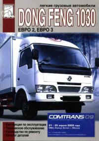
Руководство по эксплуатации, техническому обслуживанию и ремонту + каталог запчастей Dongfeng 1030.
- Автор: —
- Издательство: Диез
- Год издания: 2008
- Страниц: 336
- Формат: —
- Размер: —

Руководство по эксплуатации и ремонту Dongfeng EQ1030 с дизельным двигателем объемом 3.2 л.
- Автор: —
- Издательство: Монолит
- Год издания: —
- Страниц: 92
- Формат: —
- Размер: —

Руководство по эксплуатации и ремонту Dongfeng DFA1063/EQ1074 с дизельными двигателями объемом 3.9 л.
- Автор: —
- Издательство: Монолит
- Год издания: —
- Страниц: 96
- Формат: —
- Размер: —


Admin
Administrator
Команда форума
- Регистрация
- 28 Янв 2016
- Сообщения
- 423
- Симпатии
- 424
-
5 Окт 2018
-
#1
Руководство по эксплуатации DFM AX7 в формате pdf:
(версия от 2016 года, возможны оговорки в переводе с китайского языка)
Вложения
-
Руководство по эксплуатации DFM АХ7 (2016.08.08).pdf
12,4 MB
· Просмотры: 5.639
-
Contents
-
Table of Contents
-
Bookmarks
Quick Links
Dongfeng DFH4180 Series Vehicles
SEMI-TRAILER TRACTOR
User’s Manual
Dongfeng Commercial Vehicle Co., Ltd.
July 2019
Summary of Contents for DongFeng DFH4180 Series
-
Page 1
Dongfeng DFH4180 Series Vehicles SEMI-TRAILER TRACTOR User’s Manual Dongfeng Commercial Vehicle Co., Ltd. July 2019… -
Page 3
As an integral part of the vehicle, this manual should be kept and used with the vehicle. It shall be noted that, to meet users’ demands, Dongfeng Com- mercial Vehicle Co., Ltd. will constantly improve and perfect the vehicle prod- ucts. -
Page 4
This manual describes the structure & operation, starting & driving, mainte- nance & adjustment, as well as technical parameters and service & adjust- ment data for Dongfeng vehicle products. The user should perform the inspection and maintenance work in strict accordance with the maintenance interval mileage specified in the regular maintenance schedule. -
Page 5
Declaration Dongfeng Commercial Vehicle Co., Ltd. shall be relieved of the responsi- bility for products’ reliability, safety or compatibility in case of one of the fol- lowings: 1. The nameplate and the certificate of the complete vehicle or chassis issued by our company do not match the material object, or are altered. -
Page 6
12. Vehicle damage caused by force majeure, such as flood, lightning, storm and hailstone. 13. Normal deterioration of the vehicle like noise, vibration, wear and aging. 14. Delay loss caused by stopping or refusing the service station to perform regular inspection, analysis and evaluation to the vehicle. 15. -
Page 7: Table Of Contents
Catalogue Vehicle Identification…………….1 Location of Vehicle Nameplate ………………1 Location of VIN ………………….1 Read VIN ……………………1 Location of Engine Nameplate and Ex-factory Code ……….2 Precautions ………………..3 China six engine exhaust parts warranty period provisions ……..3 Environment-friendly Operation and Adjustment of Engine ……..4 Daily Inspection ………………….5 Running-in of New Vehicle ………………6 Standard Operation ………………..7…
-
Page 8
Curtain ……………………82 Rearview mirrors and under-view mirrors ……………83 Driving recorder …………………..84 Display screen of on-board information terminal ………….85 Lane departure warning (LDW) …………….105 Forward collision warning (FCW) …………….106 Description of tire pressure monitoring system ………….119 Steering voice alarm ………………..123 Chassis distribution box ………………124 Fuse box ……………….. -
Page 9
Inspection and Adding of Coolant ……………..161 Draining of Coolant ………………..162 Maintenance of Air Filter ………………162 Draining of Fuel Tank ………………..163 Maintenance of Cummins Engine ……………..164 Oil filter ……………………165 Fuel filter ……………………166 Fuel Primary Filter (oil-water separator) …………..166 Bleeding of fuel system ………………168 Drive belt inspection ………………..168 Supercharger maintenance ……………….169 Inspection of Clutch Fluid Level …………….171… -
Page 10
Maintenance lubrication items …………….219 Regular Replacement Parts ………………220 Service & Adjustment Data…………..221 Engine ……………………221 Chassis ……………………221 Tightening Torque ………………..222 Bulb ……………………230 Capacity Data ………………….231 Oil Products and Grease ………………233 Technical Parameters…………….235 Mass Parameters ………………..235 Dimension Parameters ………………235 Performance Parameters ………………236 Parts not included in the vehicle’s overall dimensions ……….237 Assembly Structure……………. -
Page 11: Vehicle Identification
500Kbps. The vehicle VIN code can be read through the com- munication protocol ISO27145. Detection Tool ScanTool (Silver ScanTool software, J2534 interface hardware such as ValueCan) can read the VIN code of dongfeng commercial vehicle. The Tool can be purchased through Beijing yi ‘an hengrui technol- ogy co., LTD or social channels.
-
Page 12: Location Of Engine Nameplate And Ex-Factory Code
Vehicle Identification Location of Engine Nameplate and Ex-factory Code Cummins engine 1. Engine nameplate 1. Location of engine ex-factory code D760.H03E-001.H1907…
-
Page 13: Precautions
Precautions Precautions China six engine exhaust parts warranty period provisions serial Road vehicle/engineering system Part name number vehicle Air intake system supercharger fuel pump injectors High pressure common rail fuel system pressure regulator mixing plant injector spark plug ignition system Ignition coil assembly EGR valve Exhaust…
-
Page 14: Environment-Friendly Operation And Adjustment Of Engine
Precautions Environment-friendly Operation and Adjustment of Engine 1. Dongfeng Commercial Vehicle Co., Ltd shall regard any private or unauthorized removal of lead seals of the engine as automatic abandonment of the warranty. 2. The engine has been strictly adjusted before delivery and met the requirement of the national environmental laws.
-
Page 15: Daily Inspection
Precautions CAUTION: It may be illegal for a vehicle not to use the prescribed fuel and urea. Daily Inspection Please check carefully the vehicle before driving. 1. Check the coolant level. 2. Check the engine lubricating oil level. 3. Check for oil leakage, water leakage and air leakage. 4.
-
Page 16: Running-In Of New Vehicle
1.Re-fasten the wheel nuts after running 200~300km. 2.After running-in of the new truck, please perform running-in maintenance in the nearest technical service center (station) authorized by Dongfeng Commercial Vehicle Co., Ltd in accordance with the provisions in Dongfeng Commercial Vehicle Quality Assurance Manual.
-
Page 17: Standard Operation
Precautions Standard Operation In order to prolong the service life, gain higher economic benefit, and guarantee the travel safety, the following should be noticed during the vehicle operation: 1. When operating the truck, turn on the master power switch, and then make sure that the gear lever is at neutral position in the low range.
-
Page 18
Precautions For the truck equipped with mechanical master power switch: 1. Negative power cable of battery 2. Positive power cable of battery Specific operation steps: a). Shut down the engine and disconnect the master power switch. b). Disconnect the positive and negative power cables of the battery, and connect them reliably as shown in Fig. -
Page 19: Safety Precautions
Precautions Safety Precautions WARNING: Failure to observe the requirement with a warning mark will result in seri- ous personal injury or property loss. 1. According to article 48 of the road traffic safety law of the People’s Republic of China: «the load of a motor vehicle shall conform to the approved load quality, and overload is strictly prohibited».
-
Page 20
12. If the alarm lamp stays on or flashes when the engine is running, then it indicates that some part is in trouble. In this case, please contact the Technical Service Center (Station) authorized by Dongfeng Commercial Vehicle Co., Ltd as soon as possible. -
Page 21
Precautions 12. When mounting the air filter, make sure to mount the filter element and end cover properly; otherwise dirt may be absorbed, sharply shortening the engine service life. Never clean the filter element with gasoline or water. Check the sealing rings during installation. -
Page 22: Safety Precautions For Brake Pipeline Quick Joint
It is strictly prohibited to remove the brake pipeline without authoriza- tion; otherwise, air leakage may be caused. If necessary, always remove hoses with special tools at the service station specified by Dongfeng Commercial Vehicle Co., Ltd, and no sharp tools such as the slotted screwdriver can be used for removal.
-
Page 23: Structure And Operation
Structure and Operation Structure and Operation Arrangement of Instrument and Control Mechanism 1. Steering wheel 8. Storage platform 2. Brake pedal 9. Thermostatic air conditioning controller 3. Accelerator pedal 10.Rocker switch set 4. Cigarette lighter and ashtray 11. Display panel assembly of on-board 5.
-
Page 24: Doors
Structure and Operation Keys are used to control the starter switch of the vehicle, and to lock the door, fuel tank cap or urea tank cap. 1. Remote unlocking. 2. indicator lamp 3. Remote locking 4. Mechanical key release button 5.
-
Page 25: Central Locking
Structure and Operation From the inside When the door is closed, pull the lock knob forward to locking position to lock the door; con- trarily, the door will be unlocked; pull the door inside handle to open the door. CAUTION: 1.It is very dangerous to drive the truck with the door ajar.
-
Page 26: Seats
Structure and Operation Seats Please refer to the specific configuration of the model purchased. Driver’s seat Airbag shockabsorbing seat (for deluxe models) The airbag shockabsorbing type seat is designed for the high-end commercial vehicle, of which the sponge in the seatback and cush- ion conforms to the ergonomics to bring you more comfort.
-
Page 27
Structure and Operation 6. Press the button for adjusting the backrest waist support to adjust the front and rear height of the backrest waist to the comfortable position of the waist. 7. Pull the backrest angle adjustment handle to adjust the backrest angle to the appropriate position. -
Page 28
Structure and Operation 5. Pull the backrest angle adjustment handle to adjust the backrest angle to the appropriate position. Release the handle and lock the backrest angle. CAUTION: 1.Please adjust the seat in case of driving safety. 2. For front and rear adjustment and angle adjustment, the handle should be pulled in place to ensure complete separation of the mechanism before adjustment. -
Page 29
Structure and Operation Passenger seat Please refer to the specific configuration of the purchased model. Air bag seat (for deluxe models) 1. Pull the seat back adjustment handle to adjust the front and rear angle of the seat back. Adjust the angle of the seat back to the appropriate position according to the passenger’s sitting posture to make the seat comfortable. -
Page 30
Structure and Operation Fixed seat (normal) 1. Pull the seat back adjustment handle to adjust the front and rear angle of the seat back. Adjust the angle of the seat back to the appropriate position according to the passenger’s sitting posture to make the seat comfortable. -
Page 31
Structure and Operation Swivel seat (optional) Please check the specific configuration of the purchased product. Pull the adjusting handle of the seat back to adjust the Angle of the back. Adjust the Angle of the back to the appropriate position according to the passenger’s sitting posture to make the seat comfortable. -
Page 32: Seat Belts
Structure and Operation Driver seat cushion depth 1. The seat slide rail is in the last position; 2. On the basis of graphic method, adjust backrest angle to 12 °, this is normal driving position. 3. On the basis of 1 and 2, the seat cushion depth shall be measured according to the requirements of the drawing.
-
Page 33: Berth
Structure and Operation Berth Operation instruction of upper berth 1. To use the upper berth for a rest, firstly insert the safety belt latch plate into the buckle until a click is heard. 2. After entering the upper berth, deploy the guard curtain, and press the safety belt clip at the needed height to lock the guard curtain.
-
Page 34: Instrument Panel
Structure and Operation Instrument Panel Please refer to detailed specification of the vehicle purchased. 1. Fuel gauge, urea gauge 6. Muti-information display screen 2. Front axle barometer 7. Engine tachometer 3. Speedometer 8. Rear axle barometer 4. Turn signal indicator lamp 9.
-
Page 35
Structure and Operation Water thermometer This meter indicates the temperature of the engine coolant. This meter works when the key switch is in the ON position. When the engine cooling water tempera- ture is equal to or higher than 107ºC, the dial in H near the red alarm lamp light, buzzer alarm, at the same time in the LCD screen prompts «engine water temperature high». -
Page 36
Structure and Operation Air pressure gauge The air pressure gauge indicates the air pressure in the air reservoir. Front axle air pres- sure gauge (with the sign FR) detects the pres- sure of the front axle air reservoir, and (middle)rear axle air pressure gauge (with the sign RR) detects the pressure of the (middle) rear axle air reservoir. -
Page 37: Indicator And Alarm Light
Structure and Operation Indicator and alarm light Please refer to the specific configuration of the products purchased. 1. Cruise light 14.High beam indication 2. Low indicator light for urea level 15.Low light indicator 3. Low transmission indicator 16.Repair alarm lamp 4.
-
Page 38
Structure and Operation Bogie differential lock indicator lamp When the bogie differential lock switch is connected, the buzzer will sound. The bogie dif- ferential will work, and then this indicator lamp will be on. CAUTION: The differential lock indicator lamp should not be on when the truck runs normally. -
Page 39
Structure and Operation Auxiliary brake indication The auxiliary brake indicator light is nor- mally on by default. n represents the auxiliary braking gear in use. If the auxiliary braking is not used, there is no digital display. Auxiliary brake operation. Transmission half gear higher indicator light Please refer to the specific configuration of the purchased model. -
Page 40
Structure and Operation Low water indicator When the coolant level in the engine auxil- iary water tank is below the specified limit height, the indicator light is on. At the same time, the buzzer on the meter sounded. CAUTION: If the coolant is insufficient and the engine continues to run, it will cause overheating and damage to the engine. -
Page 41
Structure and Operation Low beam indicator lamp This indicator lamp will come on when the combination switch right handle is at low beam position. High beam indicator lamp When the lamplight combination switch is turned to high beam position, this indicator lamp will be on;… -
Page 42
Structure and Operation Fuel preheating indicator lamp This indicator lamp will be on when the glow plug is electrified. The installation of this indicator lamp depends on the configurations of specific vehi- cle. Preheating indicator lamp This indicator lamp is provided for facilitat- ing the start of the engine in cold weather.When the preheating device is electrified, this indicator lamp will be on.The installation of this indicator… -
Page 43
Structure and Operation When the key switch switches from OFF to ON, the light goes out after 3 seconds. When the cooling liquid temperature is too high, the indica- tor light is on, and the buzzer on the instrument alarm. CAUTION: If the water temperature is too high and you continue driving, you can… -
Page 44
Structure and Operation ECAS warning light (yellow) ECAS alarm indicator light is on: it means the air suspension air bag pressure is less than 6.5bar, and the indicator light flashes alarm. If the indicator light is always on, it means that the air suspension air bag is not at the nor- mal height;… -
Page 45
Structure and Operation Brake shoe wear indicator light Indicates that the brake shoe or friction disc has been overused, and the thickness of the shoe or friction disc has been lower than the specified requirements. At this time, the brake effect is poor, affecting the safety of driving, and the indicator is on. -
Page 46
ABS flashing code diagnostic switch for 1~3 s, and the ABS fault flashing code indicator lamp will flash the fault code. Please contact the Technical Service Center (Station) authorized by Dongfeng Commercial Vehicle Co., Ltd. for the truck inspection and maintenance in time. -
Page 47
Structure and Operation Transmission low gear indicator light Please refer to the specific configuration of the products purchased. When the transmission is in low gear, the light is on. Whether the lamp is installed depends on the product configuration of the specific model. Cruise lamp When the cruise function is activated, the indicator light is on… -
Page 48
ACC system failure indicator If the indicator light is on, the ACC system is out of order. Please contact the authorized tech- nical service center (station) of dongfeng com- mercial vehicle co., LTD to inspect and repair the vehicle. LDWS system failure indicator If this indicator light is on, it indicates that the LDWS system is out of order. -
Page 49
70km/h for 30-45min. You can also choose to carry out parking regeneration or go to the ser- vice station authorized by dongfeng commercial vehicle co., LTD for processing. D760.H03E-001.H1907… -
Page 50
LTD. When the lamp appeared, the DPF carbon load level had reached a certain level and needed to be regenerated. At this point, the driver dongfeng com- mercial vehicle co., LTD. Authorized service station for processing. CAUTION: 1. -
Page 51
If this indicator light continues to light up during the use of the vehicle, please contact the technical service center (station) authorized by Dongfeng Commercial Vehicle Co., Ltd. to check and maintain the engine. -
Page 52: Multi-Information Display And Adjustment
Multi-information display and adjustment 1,startup interface Startup interface: the ignition lock is placed in ON gear, the instrument is self-checked, and the LCD displays the interface of dongfeng logo 2,Running interface After the self-inspection, enter the driving interface 1. Ambient temperature display: display the cur- rent outdoor temperature, display «—«…
-
Page 53
Structure and Operation Axial load and ambient temperature: if there is an axial load display function, the axial load (driv- ing shaft) will be displayed for 10 seconds after power on, and then the ambient temperature will be displayed. 2. Speed, fault code, reminder, etc. : text and icon display, used for fault alarm and prompt display, multiple… -
Page 54
Structure and Operation Interface switching 2 3, alarm interface popover D760.H03E-001.H1907… -
Page 55
Structure and Operation 1. Alarm ICONS are divided into two categories: alarm and indication: a). nalarm: large icon + small icon display. After 1.5s, the large icon disappears while the small icon remains b). Indicator class: small icon display. 2. Alarm icon description: a). -
Page 56
Structure and Operation 2. Itinerary information Under «trip information», you can find «mileage», «fuel consumption», «working hours», «average speed» and «date and time». 2.1 «total mileage» and «subtotal mileage» can be inquired under «mileage»; 2.2 «average fuel consumption», «subtotal fuel consumption» and «total fuel con- sumption»… -
Page 57
Structure and Operation 2.4 average vehicle speed: check the «cumulative average vehicle speed» and «short-range average vehicle speed»; 2.5 date and time: the date and time can be checked and adjusted. It is not avail- able with the driving recorder. D760.H03E-001.H1907… -
Page 58
Structure and Operation 3. Personalization Under «personalization», you can query «language», «unit of measurement», «dis- play effect» and «time display mode». 3.1 language: switch between Chinese and English (not yet implemented); 3.2 units of measurement: switch between «distance», «speed», «fuel consump- tion», «temperature»… -
Page 59
Structure and Operation 3.3 Display effect: LED, backlight, LCD brightness adjustment; 3.4 time display: 24 hours and 12 hours are optional. 4. Instrument self-diagnosis Under «instrument self-diagnosis», you can choose to diagnose information including pointer, alarm lamp, buzzer, LCD display and sensor. 4.1 pointer: pointer self-test can be carried out, zero — full — zero;… -
Page 60
Structure and Operation 4.5. sensor information: sensor power supply and signal information query. 5. Under «driving assistance», you can query or set «mode record query», «subtotal mode», «mile- age mode», «time mode» and «automatic record». D760.H03E-001.H1907… -
Page 61: Master Power Switch
Structure and Operation Master power switch Please refer to the specific configuration of your vehicle. Mechanical Turning this switch can connect or discon- nect the main power of the complete vehicle. Power should be cut off during the servicing and maintenance of electrical system of the vehicle to protect electrical equipment.
-
Page 62
Structure and Operation Ceiling lamp switch Press the ceiling lamp switch to turn on the light. Press the switch again to turn off the light. 1. Rear light switch 2. Ceiling lamp switch Electric sunroof switch This switch is used to open and close of the cab electric sunroof. -
Page 63
Structure and Operation Fuel preheater switch Turning on this switch at low temperature can preheat fuel at a cold start. The installation of this switch depends on the configurations of specific vehicle. Bogie differential lock switch This switch is a differential lock control switch for middle and rear drive axle bogie differ- entials. -
Page 64
Structure and Operation E, P mode switch The switch is used to switch the dynamic mode and economic mode of the vehicle. E: economic model P: dynamic mode ASR function cancel switch It is suitable for vehicle models equipped with ASR function release switch. On vehicles equipped with ASR function, the ASR function can be turned off by the ASR function switch. -
Page 65
Structure and Operation LDWS, FCWS transfer switch Open or close the function of LDWS and FCWS by pressing the key. Main and auxiliary tank change-over switch The switch allows you to choose whether to use the main tank or the auxiliary tank. The amount of oil in the main and auxiliary fuel tanks is indicated by the fuel gauge. -
Page 66
Structure and Operation Light knob switch Knob switch The knob is shown in figure 6 of H-D760- 016.You can rotate and push buttons. When rotating, the position light and headlight gear can be selected, and the fog light can be switched on and off by pressing down and pull- ing up. -
Page 67: Combination Switch, Steering Wheel Switch
Structure and Operation Combination switch, steering wheel switch 1. Wiper, horn, low and high beam switch 3. Audio and volume switch 2. Cruise switch, bluetooth phone (optional) 4. Auxiliary brake, AMT shift switch Steering wheel switch Cruise operation: It is applied for the vehicle with cruise sys- tem.
-
Page 68
Structure and Operation Exit in one of the following ways Cruise: 1. Step on the brake pedal; 2. Use engine brake; 3. Press the cruise ON/OFF switch again; 4. The speed is lower than 20km/h; 5. Step on the throttle to exit cruise temporarily, release the throttle to cruise again; 6. -
Page 69
Structure and Operation Horn switch By default, press the horn switch and the electric horn will ring. To switch the air horn, press the air horn selection switch. Turn signal lamp When the left handle of the combination switch is pushed forward, the right front turn sig- nal light, the right rear turn signal light and the right turn signal light will be lit;… -
Page 70
Structure and Operation 1. The wiper knob switch to intermittent gear: the wiper works intermittently; 2. Turn the wiper knob switch to low speed gear: the wiper works at low speed; 3. Turn the wiper knob switch to high speed gear: wiper works at high speed. -
Page 71: Key Switch
Structure and Operation Please refer to the specific configuration of purchased products. Match engine brake + exhaust brake + retarder Gear number: 4. Position description: 1 gear: constant speed gear; 2~4 gears: auxiliary brake gear (braking capacity increases step by step) Match engine brake + exhaust brake or separate engine brake Gear number: 2.
-
Page 72: Instructions For Acc Switch
Structure and Operation CAUTION: 1.It is forbidden to turn the key to START position when the engine is running to avoid engine damage. 2.Do not start for a long time or frequently; otherwise battery electricity loss or starter damage will be caused. 3.The time for starting the engine each time should not exceed 30 seconds.
-
Page 73: Integrated Door Switch
Structure and Operation Integrated door switch The driver’s side Window regulating Manual: long press the up/down button of the switch, and the glass will rise/fall accord- ingly; Release the up/down button and the glass will stop. Automatic: short press the down button of the switch to automatically lower the glass;…
-
Page 74
Structure and Operation Passenger side There is only window regulator switch on the passenger side: Manual: long press the up/down button of the switch, and the glass will rise/fall accord- ingly; Release the up/down button and the glass will stop. Automatic: short press the down button of the switch to automatically lower the glass;… -
Page 75: Climate Control System
Structure and Operation Climate Control System Thermostatic air conditioning controller 1. Wind speed control knob 5. Mode control knob 2. AC/ECO button 6. Temperature setting + button 3. AMB button 7. Temperature setting — button 4. Air conditioning button 8. Internal and external circulation button Wind speed control knob Rotate the wind speed control knob, when the knob is in the OFF position, the fan stops the…
-
Page 76
Structure and Operation 5. Press the button under AUTO state to exit AUTO adjustment of temperature and enter AC/ECO state. If the wind speed knob is still in AUTO state, the LCD displays AUTO and AC/ECO. Press the button again to enter the previous state. Outdoor temperature button When the air conditioner is turned on, press the AMB button to display the out- door temperature;… -
Page 77
Structure and Operation 5. When the temperature is adjusted to Lo, the mixing damper is completely closed for the coldest working mode. Inner and outer loop button The operation is effective at startup; When the ignition key is in ON gear under shutdown state, the button operation is effective;… -
Page 78: Parking Warm Air System (Optional)
Structure and Operation Notes for use of air conditioning system 1. The heating device uses the coolant temperature of the engine to warm the air, so the coolant temperature is not high, and the temperature of the warm air will not rise.
-
Page 79
Structure and Operation Turn on heater 1. Heating mode: use the heating button 1, start the heater in the heating operation mode (continuous operation), indicator light of heater operation (red) lights same time, required temperature can be adjusted by using the pre-selected temperature knob 7;… -
Page 80
Whether the combustion air duct or exhaust pipe is safe, if all above are nor- mal, and the heater is still out of order, or other functional failure, please contact the maintenance station designated by Dongfeng Commercial Vehicles Co., Ltd. Maintenance instructions The heater should be put into trial operation before the warm season. -
Page 81: Gear Lever And Shift Knob
Structure and Operation Gear lever and shift knob Please refer to the specific configuration of the purchased model. ZF 12-speed automatic transmission The ZF 12-speed automatic transmission has no gear lever, and the shift knob is matched, as shown in figure H-ZF12AMT-001. The func- tions of each shift are as follows: N gear: the vehicle is in neutral;…
-
Page 82
Structure and Operation Trailer brake manual valve The trailer brake manual valve is located beside the parking brake manual valve. Pulling backwards (tail of vehicle) this lever can apply the trailer brake and pushing it forwards can release the brake. When driving the vehicle down a hill with small gradient, the tractor can be braked through the engine brake while the trailer can be braked by pulling the trailer brake lever intermittently. -
Page 83: Method For Releasing Spring Brake
Structure and Operation Method for Releasing Spring Brake Please refer to the specific configurations of your vehicle. Where the vehicle cannot be released from parking brake and cannot start, it may be caused by the pressure drop of spring brake air chamber, which makes the spring brake operate automatically.
-
Page 84: Accessory System
Structure and Operation The spring brake can be released by rotat- ing the spring brake release bolt with a spanner counterclockwise until the bolt cannot be tight- ened any more. WARNING: 1.Manual release of parking brake of spring brake chamber is limited to emergency only.
-
Page 85
Structure and Operation Ash tray When using it, first press the cover to pop it out, and then push it back to close it. When cleaning it, first open the cover, and then pull the whole ash tray out upward. CAUTION: For the sake of safety, always close the ash tray before leaving the vehicle. -
Page 86
10s, and finally reset the sunroof. In case the fault has not been eliminated, please drive your vehicle to the After- sale Service Station of DONGFENG COMMERCIAL VEHICLE CO.,LTD. for related inspection. D760.H03E-001.H1907… -
Page 87
Structure and Operation Ceiling lamp The ceiling lamp, located at the interior top of the cab can be controlled by three switches which work separately: Instrument panel ceiling lamp switch Upper berth ceiling lamp switch Lower berth ceiling lamp switch 1. -
Page 88: Glove Box
Structure and Operation Maintenance lamp It is installed on the inner side of front wall for front wall maintenance lamp. Glove box 1. Maintenance lamp switch Please refer to the specific configurations of your vehicle. Front roof glove box The front roof glove box is composed of a central glove box, a left glove box and a right glove box, which are used for storing large objects.
-
Page 89
Structure and Operation Central glove box This glove box is located at the center of the console and used to keep carry-on tools and small articles. Opening: pull the glove box handle upwards and pull the glove box backwards to open it. -
Page 90
Structure and Operation Side tool kit Out-opening tool kits are provided for driver’s side and passenger’s side in the D760 cab, and they are equipped with lamps for easy taking of objects by readers. The lamp is equipped with a contact switch which will be trig- gered to make the lamp to turn off in case the box cover is closed;… -
Page 91
Structure and Operation Cup holder The cup holder is located below the trans- mission shift console. Opening: press the cup holder to pop the cup up. Closing: push the cup holder back to close 1. Cup holder 220V power socket The 220V power socket, located at back of driver’s seat and passenger’s seat, can be pow- ered on by pulling the handle and pressing the… -
Page 92: Curtain
Structure and Operation Curtain 1. Upon extending curtain, put the rings on curtain into corresponding hooks on the guide rail, then evenly extend it along the guide rail, overlap curtains with nylon buckle, and clip metal fasteners at lower part of side/ rear curtain onto plastic buckles on the protection board.
-
Page 93: Rearview Mirrors And Under-View Mirrors
Structure and Operation Rearview mirrors and under-view mirrors The main exterior rearview mirror and wide- angle mirror are installed on driver’s left and right sides, and the front under-view mirror and close- proximity rearview mirror are installed on the passenger’s side. The driver can adjust the main exterior rearview mirror, wide-angle mirror, front under-view mirror and close-proximity rearview mirror to realize best rearview and down view…
-
Page 94: Driving Recorder
Structure and Operation Driving recorder The operating manual of driving recorder is provided separately. Front panel 1. MIC 6. Confirmation: to confirm the function or 2. Keyhole: used to remove the recorder data column item, press the button for 3s from the bracket continuously in the default display inter- 3.
-
Page 95: Display Screen Of On-Board Information Terminal
Structure and Operation Display screen of on-board information terminal Product introduction Video entertainment system assembly Front panel 1. Power/standby button 2. Hatch cover with USB screen 3. MIC port 4. LCD panel D760.H03E-001.H1907…
-
Page 96
Structure and Operation 1. Video (camera) connector 3. Electrical connector 2. Hd dash CAM (camera) connector 4. Receiver antenna connector Product parameters 1. Nominal voltage: 24V DC 2. Working voltage: 16~32V DC 3. Rated working current: less than 5A 4. Static current: less than 10mA 5. -
Page 97
Structure and Operation CAUTION: Please read this instruction carefully before use. 1.Please make sure all devices and wires are connected correctly before connecting to the power supply of the display screen. Do not install or remove the screen while it is powered. If you find any missing wire or wrong connection, please cut off the power supply first, otherwise it is easy to damage the equipment. -
Page 98
Structure and Operation Product instructions Boot interface The master power switch of the vehicle is turned on and the ignition lock is set to ACC, and the display screen conducts self-inspection. At the same time, the system enters the startup animation interface, as shown in the figure: After the self-check of the display screen is successful, it enters the main inter- face. -
Page 99
Structure and Operation · USB device: Icon Instructions The display screen is connected to the USB device successfully (highlighted) The display screen is not connected to the USB device (gray) or none · Bluetooth: Icon Instructions The display screen has a bluetooth connection (highlighted) The display screen has no bluetooth connection (gray) -
Page 100
Structure and Operation Functional interface Music Click the function icon «music» icon to enter music playback interface, can under the function of music broadcast, the support to the audio files stored in a USB device to broadcast and mobile phone bluetooth music playback, as shown in figure: 1. -
Page 101
Structure and Operation CAUTION: 1. When the media device contains audio files, it will automatically jump to the music playing interface; 2. Click button to return to the main interface, but the program con- tinues to run in the background. Click [music] control again and enter the interface before returning;… -
Page 102
Structure and Operation Registration information (refer to this process for the input interface) Click [registration information] to enter the information interface of the host com- puter, in which vehicle VIN, terminal ID and license plate number can be inquired. The license plate color, provincial ID, municipal ID and vehicle classification can be inquired and set. -
Page 103
Structure and Operation Province ID, city ID, vehicle classification operation can refer to the license plate color Settings. Click [user’s mobile phone number] to enter the user password 12345678 (all interfaces are valid during the ignition after one input) to enter the user’s mobile phone number query interface. -
Page 104
Structure and Operation Location information Click «location information» to enter the location mode interface. Under this func- tion, you can query the current host location mode, as shown in the figure: Tired driving enquiry Click «fatigue driving query» to enter the interface of fatigue driving query. This function can query the driving license number and the corresponding starting and end- ing time of fatigue driving according to the driving time. -
Page 105
Structure and Operation CAUTION: Some of the functions are reserved. Load condition Click [load state] to enter the load state interface, which can be set according to the actual load of the current vehicle, as shown in the figure: Vehicle impulse coefficient The current vehicle pulse coefficient can be viewed under the function list of recorder. -
Page 106
Structure and Operation Video Click the function list interface to enter the video playback interface. Under this function, video can be played. Currently, it supports playing video files stored in USB devices. As shown in figure: CAUTION: 1.In order to ensure the driving safety of drivers, when the driving speed is more than 5km/h and it lasts for more than 10s, the video will not be able to be played. -
Page 107
Structure and Operation E-books Click the [e-book] icon to enter the e-book reading interface, as shown in the pic- ture: D760.H03E-001.H1907… -
Page 108
Structure and Operation Radio Click the «radio» icon to enter the radio interface, as shown in the picture: After entering this menu, adjust the channel by clicking the «left» and «right» fine- tuning controls or adjust the channel by «up and down» buttons on the steering wheel. Click to play the corresponding channel in the selected storage area, or press the channel area for more than 3 seconds to save the currently playing channel to the cor- responding location. -
Page 109
Structure and Operation Click the button, jump to the previous channel of the current channel, or press the «up button» on the steering wheel to achieve the same function; (picture, video, music). · Next channel: Click the button to skip to the next channel of the current channel, or press the «down button»… -
Page 110
Structure and Operation Help Click the «help» icon to enter the help interface, and you can view common ques- tions and solutions, as shown in the figure: Bluetooth Dial-up interface Click the «bluetooth» icon and enter the dial-up interface. Under this function, you can make and receive calls between the display screen and the mobile phone. -
Page 111
Structure and Operation Call records Click the «call record» icon to enter the caller id interface. In this interface, you can query the current incoming call, missed call, outgoing call record and delete func- tions, as shown in the figure: Contact person Click the «contact»… -
Page 112
Structure and Operation Driving auxiliary Click the «driving assistance» icon to enter the driving assistance interface, where there is video display (video display can realize reversing image or right blind area dis- play, specific functions need to enter the Settings, through the setting of the driving assistance function to select the function) function.. -
Page 113
Structure and Operation Background Click «background» to enter the background setting interface. Under this function, the user can set the background. There are two backgrounds available. Key tone Click [key tone] to enter the setting interface of key tone. Under this function, the user can set the key tone. -
Page 114
Structure and Operation System time The display supports setting the time and time display format. The time format can be set to 24h and AM/PM. The date display format can be set to xxx-yy-dd and dd-yy-xxxx. Safe driving mode Safe driving mode refers to the bus speed ≤ 5km/h and lasts for 10s. Safe driving mode can be manually selected to open and close, factory default open, close the need for user password. -
Page 115: Lane Departure Warning (Ldw)
Structure and Operation Lane departure warning (LDW) Please refer to the specific configuration of the purchased model. CAUTION: The lane departure warning (LDW) function only serves as a reminder and the driver is always responsible for the condition of the vehicle. Turn the key switch to «ACC»…
-
Page 116: Forward Collision Warning (Fcw)
Structure and Operation c). The alarm lasts longer than 2 minutes; d). vehicle riding line; When the system is shut down, the system will not give lane departure warning and alarm during the ignition. If the vehicle key is put in LOCK gear and the key is put in ACC gear, the system will automatically restore to the open state.
-
Page 117
Structure and Operation There are two alarm levels of the forward collision warning function, namely, keeping vehicle distance warning and imminent collision warning. Please refer to the following table for details: Alarm level Start the speed prompt meaning At this point the driving speed is Keep distance Frequency 60 km/h… -
Page 118
Structure and Operation Warning: 1. Severe weather conditions lead to poor visibility, such as fog, haze, rain, snow, etc.; 2. Insufficient light in the camera field, such as no street lamp at night; 3. Bright light ahead; 4. The view of the camera is blocked by snow, ice, dirt, water or other objects;… -
Page 119
Structure and Operation Warning: In the following cases, abnormal state of the forward-looking camera may cause abnormal lane departure warning and forward collision warning function. 1. If the camera is affected by external forces and its position or Angle changes, it shall return to the service station to calibrate the camera again;… -
Page 120
(some models have no warning). If the system continues to indicate that the fault can- not be automatically restored, it is recommended to drive to the nearby dongfeng com- mercial vehicle service station for repair. -
Page 121
Structure and Operation Blind spot surveillance (BSM) When the vehicle is moving, the controller outputs the video signal of the right view camera to the vehicle, which controls the display of the image of the right view camera on the vehicle according to the input of the right turn signal. Warning: The BSD function can only serve as a reminder, not in all cases, and can- not replace the judgment of the driver, who is always responsible for safe… -
Page 122
Structure and Operation System function Provide users with images of objects around the vehicle under different operating conditions, such as starting idle speed, going straight and turning. Circular display: 1. When the vehicle is going straight, the system will display the front view +270° viewing Angle by default. -
Page 123
Structure and Operation Video playback function 1. Video playback and set menu buttons Click any position on the screen, the display screen will pop up the following two function buttons. icon instructions Video playback function button, through this function menu, you can set the channel of ringed image recording, as well as video playback of recorded video. -
Page 124
Structure and Operation The second level menu of the video file displays a corresponding hourly interval information called recording. 4. Replay the three-level menu The three-level menu of the video file corresponds to the time and second infor- mation of the beginning of recording video. 5. -
Page 125
Structure and Operation Set menu interface The following figure shows the logical migration diagram of the video recording interface, which can be configured for the display mode of straight line and steering, and the channel of video recording. 1. Set auxiliary line when going straight If shown as «√», the auxiliary line is open;… -
Page 126
Structure and Operation 3. Display mode Settings for steering When turning, the display mode can be set to left/right rear view + panorama view (default setting), left/right front view + panorama view, left/right front view + left/ right rear view, left/right front view, left/right rear view, right/left rear view. 4. -
Page 127
Structure and Operation Video locked and non-locked state Settings As shown in the figure below, the video recorded by long press can pop up the operation screen, and the user can set the corresponding video to be «locked» video. The so-called locked video means that the system will not automatically cover and delete the locked video when the SD card storage space is full. -
Page 128
Structure and Operation Locked behind the video files will appear a lock icon, lock video must manually unlock before can be deleted. CAUTION: AVM is only intended to assist driving and is not applicable in all situa- tions. The driver is always responsible for driving safely. The normal use of the system may be affected under the following circumstances: 1. -
Page 129: Description Of Tire Pressure Monitoring System
Structure and Operation Description of tire pressure monitoring system System function 1. Check the pressure and temperature of each tire through the instrument menu key; 2. The tire pressure is too high or too low to alarm; Tire high temperature alarm; 3.
-
Page 130
Structure and Operation Manual learning function introduction 1. Manual learning provides a convenient way for the driver to update the tire pressure sensor ID. The driver can complete the learning through the sub-menu of «self-learning sensor» of the instrument without the help of after-sales diagnosis instru- ment. -
Page 131
Structure and Operation E. If the learning failure is displayed in the interface menu, please check whether the safety conditions and precautions for manual learning are met according to the failure reasons. Left front and right front switch, no new sensor is replaced A. -
Page 132
Structure and Operation 4. If the reason for failure is «engine speed is not 0», please turn off the engine and keep the ignition key in ON gear; 5. If the reason for failure is «the speed is not 0», please check whether the vehicle is in the running state. -
Page 133: Steering Voice Alarm
Structure and Operation Steering voice alarm When the vehicle is in motion, pull the handle of the right turn signal, and the vehicle will turn right when it makes a voice alarm to remind other road users to pay attention to the movement state of the vehicle turning right in time. Vehicles to resume straight line stop alarm work.
-
Page 134: Chassis Distribution Box
Fuse box Chassis distribution box located in the battery box. Chassis distribution box is used for main circuit fuse of electrical distribution sys- tem. When replacing the fuse or relay of the main circuit, it is necessary to confirm the load of the fuse or relay used and find out the corresponding fuse or relay through the mark on the label of the central distribution box.
-
Page 135
Fuse box CAUTION: The fuse box label is located on the inside of the middle and lower guard on the passenger side. Relay box label CAUTION: The relay label is located on the inside of the middle and lower guard on the passenger side. -
Page 136: Adjustment Of Steering Wheel
Fuse box Adjustment of Steering Wheel Angle adjustment Pneumatic switch 1. Hold the steering wheel by right hand; 2. Press the upper unlock button on the pneumatic valve switch by left hand; 3. Adjust the fore-and-aft angle of the steering wheel as needed;…
-
Page 137: Front Face Shield
Fuse box After using the towing hook, reinstall its pin cover properly by the steps opposite to the above. CAUTION: 1.The front towing hook of the vehicle is only used under the normal driving road surface. If the vehicle is equipped with two front towing hooks, double towing hooks must be used to ensure that the force of the double towing hooks is…
-
Page 138: Side Spoiler
Fuse box 2. Pull the secondary lock handle which is located at the lower edge of the left face shield outside the cab from rightward to leftward by right hand, and hold the middle lower edge of the front face shield by left hand to pull the face shield in heading direction of the vehicle, in this case, the shield can be unlocked.
-
Page 139: Roof Spoiler
Fuse box Opening of side spoiler Hold the rear inner pipe of the lower side spoiler to pull it outward in the heading direction, in this case, the lower side spoiler can be opened. Closing of side spoiler Push the front edge of the lower side spoiler inward and rearward to close the lower side spoiler.
-
Page 140: Fire Extinguisher
Fuse box CAUTION: 1.During adjustment of the roof spoiler, it is required to adjust the adjusting levers on left and right sides, and it is not allowed for adjusting levers to have different lengths; otherwise, the roof spoiler may suffer twist, causing damage to the spoiler.
-
Page 141: Warning Triangle
Fuse box Warning Triangle Warning triangle should be placed 50 m away from the stopped truck, easily being noticed by the drivers of the vehicles behind. 1. Warning triangle Triangular stop block Iron triangular brake block Compare the specific configuration of pur- chased model products.
-
Page 142: Inverter Instructions
Fuse box Inverter instructions Indicator status 1. Green light: normal operation; 2. Red light flashing: overload protection, short-circuit protection, overvoltage protection, overtemperature protection, constant power protection, leakage protection, etc.; 3. Light not on: under voltage protection. The rated power of the inverter is 300W, which can adapt to the electrical appliances below 600W.
-
Page 143: Main Auxiliary Tank Changeover Valve Operation
Fuse box Main auxiliary tank changeover valve operation Instructions for oil route switching 1. When the handle is in the «main fuel tank» position, the fuel inlet of the main fuel tank communicates with the fuel inlet of the engine; The main tank oil return port communicates with the engine oil return port;…
-
Page 144
Fuse box 3. When fuel of different grades is stored in two tanks, if the ambient temperature is lower than 0 degree and the fuel is easy to wax, it is necessary to fill the fuel pipe- line with high-grade fuel before flaring in order to avoid the problem that the engine cannot be started after long-term flaring. -
Page 145: Cab Tilting
Fuse box Cab Tilting Please refer to the specific configurations of your vehicle. CAUTION: Check that the cab door is locked and objects in the cab put in order, so as to avoid objects falling off during cab tilting, damaging the cab. Always open the front face shield prior to tilting the cab;…
-
Page 146: Ecas Operation
Fuse box ECAS operation Please refer to the specific configurations of your vehicle (this section is only applicable to the model with air suspension). The rear air suspension system is designed with the international advanced and mature electronically controlled air suspension (ECAS). The air suspension, a com- plex system element assembly, can bring the elasticity effect by air in the compressive and tensile rubber airbag.
-
Page 147
Fuse box ECAS has powerful functions; it can not only control the normal height (i.e., design index height), but also control preset height. ECU, regarded as the heart of ECAS, has the following functions: 1. Continuously monitoring input signal 2. Comparing input valve and index value 3. -
Page 148
Fuse box CAUTION: ECAS system failure need to use special instruments to detect and adjust. Be sure to contact the vehicle manufacturer and do not replace parts, especially ECU. When the ECU is replaced, if the parameter setting is wrong, the system will not have any function. Use of remote controller For easy use and operation by the driver, ECAS is equipped with a remote controller. -
Page 149: Use Of Differential Lock
Fuse box of M1 and M2. For example, pressing «↑» switch to lift the vehicle to the required height, and with the «STOP» switch and M1 pressed, the height will be stored by M1. In the same way, the height value can be memorized by M2. CAUTION: 1.
-
Page 150: Post-Processing System
Fuse box CAUTION: 1.Never press the differential lock switch when the vehicle is running normally. Never use the differential lock for long time; otherwise, it may damage the differential and result in excessive wear of tire. 2.Differential lock switch must be pressed after the vehicle is stopped fully;…
-
Page 151
During the normal maintenance interval, vehicle users are required to add urea water solution according to actual needs. Urea water solution shall use urea water solution permitted by dongfeng commercial vehicle. Filling steps: 1. Clean the mouth of the urea tank to prevent foreign bodies from falling into the tank after opening the cap of the urea tank;… -
Page 152: Obd Diagnostic Interface
Fuse box OBD diagnostic interface OBD diagnostic interface the diagnostic instrument can access the fault information through the OBD diagnostic interface equipped with the vehicle. Open the cover plate and dock the diagnostic instrument interface with the OBD diagnostic interface to realize the diagno- sis of the vehicle.
-
Page 153: Electrical Connection Between Semi-Trailer Tractor And Trailer
If the semi-trailer tractor is not equipped with the 7-core trainer cable assembly at delivery, please purchase it from the manu- facturer. Product type in DONGFENG COMMER- Plug CIAL VEHICLE CO.,LTD. (7-pin trailer cable assembly): 3730060-H0100. D760.H03E-001.H1907…
-
Page 154: Semi-Trailer Tractor Coupling And Operation
Fuse box Arrangement of trailer power socket outlet contacts Maximum available power Terminal No. Wire No. Usage of trailer(W) Ground wire Clearance lamp 8239 marker lamp 9321 Left turn signal lamp 2533 Brake lamp 9322 Right turn signal lamp 9243 Rear fog lamp 2433 Reversing lamp…
-
Page 155
Fuse box Connecting device CAUTION: 1.Before the saddle is used for the first time, be sure to add sufficient grease. 2.The gap adjustment must be made before the saddle is used for the first time; 3.The lever must be pulled out until the notch can be stuck on the edge bayonet of the saddle shell, otherwise the inclined wedge and locking hook will be damaged;… -
Page 156
Fuse box 1. The position contacted with saddle during connection process 2. Connect a hang: a). Turn the latch spring upward and dial it to the horizontal; b). Pull the lever assembly outward and clip the notch on the handle bar to the bayonet on the edge of the saddle shell (the traction seat is in the pre-hung state);… -
Page 157
Fuse box e). Open the cable socket cover of the trailer, and then align the protruding portion of the cable across the socket with the socket’s notch so that the plug is fully inserted into the socket. Finally close the socket and the plug is fixed. Pre-hanging state: the handle bar is stuck on the bayonet at the edge of the saddle shell, and the lock car is in a horizontal state… -
Page 158: Operating Instructions For Rear Fender Upper Cover Plate
Fuse box Operating instructions for rear fender upper cover plate CAUTION: The upper cover plate of the. fender should be removed when the tractor is carrying a trailer. Upper cover plate of fender Double rear axles: 4 Single rear axles: 2 When the tractor is carrying a trailer, please remove the upper cover plate above the middle axle and the rear axle (the single rear axle…
-
Page 159
Fuse box Operation instructions for installing upper cover plate of fender: 1. Align the upper cover plate with the fender. 2. Insert the rubber band into the limit hole of the fender. 3. Clamp the end of rubber band with pliers, and stretch the rubber band along the direction of arrow a.When the pliers are clamped and stretched,… -
Page 160: Starting & Driving
7. If the vehicle is equipped with fuel tank heating device, please switch on the fuel tank heating switch. 8. Dongfeng Commercial Vehicles Co., Ltd. only provides the electrical interface of fuel tank heating device on the chassis, please consult the manufacturer of the final stage of the whole vehicle for the specific use method.
-
Page 161
Starting & Driving 10. After the engine starts, release the key immediately to let the engine enter the idle running status. Be sure to observe the engine oil pressure within 15s. 11. Cummins engine has the function of quick warm-up, and when the coolant temperature is low, the engine will be, after starting successfully, warmed up automatically at a high speed (higher than idle speed), to make the coolant temperature rise fast. -
Page 162: Steering System Start
Starting & Driving Steering System Start To start the truck at the ambient temperature less than 10ºC, idle the engine for more than 30 s, and rotate the steering wheel only after the temperature of steering fluid rises, so as to avoid hard steering or damaging the power steering pump. Transmission Operation Please refer to the specific configurations of your vehicle.
-
Page 163
Starting & Driving Regardless of AT or MT, A or M may be displayed. «M» displayed for MT. «A» displayed for AT. MT operation Shift the transmission to M gearshift mode. Uplift the gear lever for uplifting; if time for uplifting is not more than 1.5s, one gear will be increased, if more than 1.5s, two gears will be increased, and if uplifting is kept, two gears will… -
Page 164
Starting & Driving E and P gearshift mode E: economic mode P: power mode It defaults the initial mode to E mode, and it will change to P mode by pressing the switch, and return to E mode by pressing the switch again, and so on. -
Page 165
Starting & Driving 1. When depressing the accelerator pedal, keep the pedal stable as much as possible and avoid frequent change of accelerator and fluctuation in the speed. 2. During automatic gearshift transmission, never release the accelerator pedal and keep it stable. 3. -
Page 166
Starting & Driving Parking 1. Release the accelerator pedal and depress the brake pedal to decrease speed till the vehicle stops completely. 2. The clutch will disengage automatically before the vehicle stops to ensure that the engine does not shut down. 3. -
Page 167
5.It is allowed to shift from DM to D, but it is prohibited to shift from RM to 6.With regard to the model with AMT of Dongfeng, it is specified that D, N and R shall be displayed on the instrument, but display of RM and DM on the instrument is not required. -
Page 168: Braking Operation
3s and then go out. If the tractor ABS malfunction indicator lamp stays on, it indicates that the ABS is faulty. In this case, please contact the Technical Service Center (Station) authorized by Dongfeng Com- mercial Vehicle Company immediately for troubleshooting.
-
Page 169: Parking Operation
Starting & Driving more than one wheels, so as to control the vehicle attitude effectively and guarantee driving stability. ESC strengthens protection on rollover, sideslip and folding. As the key switch is turned on, ESC functions will be activated automatically. CAUTION: ESC cannot exceed the physical limit and should adjust driving status according to road and traffic conditions;…
-
Page 170: Auxiliary Brake
Starting & Driving Auxiliary brake See Structure and Operation for auxiliary braking operation Parking 1. Turn the rotary switch of AT back to N position. 2. After the vehicle stops, shift the gear lever of AT to neutral position of low range, and turn the manual valve control lever to parking brake position.
-
Page 171: Maintenance & Adjustment
As for more detailed information about inspection and adjustment as well as the parts replacement, please contact the nearest Technical Service Centre (Station) of Dongfeng Commercial Vehi- cle Company of Dongfeng Motor Co., Ltd.
-
Page 172: Draining Of Coolant
Maintenance & Adjustment Draining of Coolant Open the drain valve under the radiator to drain off the coolant in the cooling sys- tem. CAUTION: Before adding coolant, check the engine and the radiator for leakage, and repair it if any. Maintenance of Air Filter Inspection and cleaning cycle of filter element When the air filter block alarm light is on,…
-
Page 173: Draining Of Fuel Tank
Maintenance & Adjustment Cleaning method of filter element Blow the filter element clean with the com- pressed air of 0.5MPa or lower from inside to outside. Inspection method of filter element Illumine the lamp and place it inside the fil- ter element to check for damage and pinhole.
-
Page 174: Maintenance Of Cummins Engine
Maintenance & Adjustment Maintenance of Cummins Engine Inspection and replacement of engine oil Check the maintenance period refer to page 208. 1. Oil dipstick CAUTION: 1.The lubricating oil new vehicle and lubricating oil used for follow-up maintenance or replacement have different grade, which cannot mix and change the oil replacement mileage.
-
Page 175: Oil Filter
Replacement method 1. Select the oil and oil filter specified by Dongfeng and fill the oil filter with clean oil. Apply a thin layer of clean oil to the sealing surface of the gasket before installing the new oil filter.
-
Page 176: Fuel Filter
Maintenance & Adjustment Fuel filter Check the maintenance period refer to page 208 Replacement method Please refer to the attached Operation and Maintenance Manual of Cummins Engine. CAUTION: 1. Do not tighten the filter with a filter spanner during the installation. Otherwise the threads may deform and the filter may be damaged.
-
Page 177
Maintenance & Adjustment Replace the filter element of the Fuel-water separator Fuel and water separator disassembling operation method 1. Make the engine inoperative for more than 30min, and unscrew the water drain plug and drain water through the water drain plug. -
Page 178: Bleeding Of Fuel System
Maintenance & Adjustment Precautions for removal and refitting 1. When replacing the water separator, it is necessary to handle the drained fuel properly to avoid environmental contamination. 2. When pumping fuel with a hand pump, always unscrew the air drain bolts to avoid damage to the hand pump.
-
Page 179: Supercharger Maintenance
Maintenance & Adjustment Supercharger maintenance Please refer to the Cummins engine operation and maintenance manual accom- panying the vehicle. Maintenance of urea tank Periodic maintenance cycle Check the maintenance period refer to page 208 1. Clean the vent valve with compressed air. 2.
-
Page 180
Maintenance & Adjustment Urea pump maintenance During the use of the jet system, attention should be paid to: 1. After stopping the car and shutting down the engine, the battery power cannot be cut off immediately, and the post-processing sys- tem needs to complete the emptering pro- cess, which… -
Page 181: Inspection Of Clutch Fluid Level
Maintenance & Adjustment Inspection of Clutch Fluid Level This inspection is not required for model with AMT. Normal replacement Check the maintenance period refer to page 208 The clutch reservoir is located inside the front face shield in the cab. Under normal condi- tions, the level of the fluid reservoir should be near the MAX mark.
-
Page 182
Maintenance & Adjustment WARNING: Avoid scalding due to hot transmission fluid and parts and avoid fire caused by contact to the fire source. 1. Remove the drain plug and place it into a proper container. Handle the fluid according to environmental protection requirements. 2. -
Page 183
Maintenance & Adjustment Check the oil level 1. Stop the vehicle, and pull on the hand brake, be careful not to use the retarder 2. Loosen the overflow port screw plug 3. If the oil level is lower than the overflow port, continue to fill the oil until the oil overflows. -
Page 184
Maintenance & Adjustment Filter element replacement Drain the oil first and then replace the filter element. Please use the new filter element every time you change the oil. 1. Loosen the oil absorption filter element bolt; 1. O ring 2. Remove the oil absorption filter element 3. -
Page 185
Maintenance & Adjustment 10. Test run the vehicle (at a speed of about 10 km/h for at least 1 minute), briefly run the retarder (the highest gear) at the beginning, and then cancel it. 11. Engine shut down; 12. Loosen the screw plug at the oil drain plug; 13. -
Page 186
Maintenance & Adjustment 12. Check the oil level, and fill the oil until it overflows if necessary; 13. After using the new gasket, tighten the oil spill port screw plug. CAUTION: 1.Please check the oil level below 40ºC temperature. 2.The correct position of the oil surface is at the bottom of the overflow port, that is, the oil overflow position. -
Page 187: Maintenance And Adjustment Of Brake
Maintenance & Adjustment Maintenance and Adjustment of Brake Manual adjuster Check the maintenance period refer to page 208 Normal inspection Every 5,000km Clearance between friction plates of brake drum and brake shoe: At the center of brake shoe: 0.3-0.5 mm Limit wear of brake drum: 2mm;…
-
Page 188: Automatic Adjuster
Maintenance & Adjustment Automatic Adjuster Please refer to the specific configurations of your vehicle. If the brake is equipped with an automatic adjuster, the clearance between the brake shoe and brake drum can be adjusted smaller auto- matically when the friction lining is worn and the clearance exceeds the set value, so as to reduce the maintenance time and ensure driving safety.
-
Page 189
Maintenance & Adjustment direction); the brake drum should rotate freely without contacting any part at this moment. 2. In case the worm shaft cannot rotate because the automatic adjuster has been in service for a long time or has not been maintained, lubricated in time, remove the fastening bolt of the control arm and follow step 1 to put it into service. -
Page 190
1/3-2/3 turn, and use a feeler gauge to check that the clearance is 0.5-0.8mm. After the automatic adjustment function is disabled, please check and replace the part at Dongfeng service station immediately. D760.H03E-001.H1907… -
Page 191: Disc Brake
Never use pneumatic or electric wrench during all the processes. CAUTION: Expertise is required for the inspection and maintenance of disc brake, so please go to Dongfeng franchised service station to do related mainte- nance. Working principle Floating caliper is adopted, and the wear of friction lining is compensated auto- matically through mechanical adjuster.
-
Page 192
Maintenance & Adjustment Inspection of sliding function 1. locking bolt 1. Plug 2. Pressure plate Applicable to Haldex disc brake only. 1. Park the vehicle safely, and remove wheels of the brake axles to be inspected; 2. Remove the brake pad; 3. -
Page 193
Maintenance & Adjustment Inspection of adjusting screw rubber sleeve Applicable to Haldex disc brake only. Use an 8mm wrench to rotate the adjusting shaft until the push plate is pushed out com- pletely and about 45-50 mm from the cover plate. -
Page 194
Maintenance & Adjustment Inspection of brake pad Inspection of brake pad wear Measure the distance from bottom plate A to friction surface B. Inspection of uneven wear of brake pad Maximum uneven wear: 1mm (measure 4 points) If the wear is uneven, check if the brake caliper can slide properly on the sliding pin, if there is dust between the brake pad and push pate, and if the automatic adjuster functions nor-… -
Page 195: Inspection Of Brake Pedal Stroke
Maintenance & Adjustment Inspection of brake disc cracks B indicates the cracking depth a= Width of friction lining contact face A= Small spots distributed on the surface; continuous use is allowed B= Radial cracks with depth and width less than 1.5 mm, and length less than 3/ 4 the width of friction lining contact face;…
-
Page 196: Inspection Of Air Dryer
Maintenance & Adjustment Inspection of Air Dryer The air dryer is used to dry the compressed Air dryer heater switch air from compressor, thus supplying dry and clean air to the air reservoir. Replacement cycle Cylinder or desiccant of air dryer: every 100,000km or 12 months, or shorter if the vehi- cle always runs under adverse conditions (such as moist or hilly area).
-
Page 197: Inspection And Change Of Power Steering Hydraulic Oil
Maintenance & Adjustment Replacement of air drying cylinder Air drying cylinder 1. Before replacing the air dryer, make sure that the internal pressure has been removed completely; 2. Screw off the air dryer with hand; 3. Apply grease to the sealing ring and threaded sleeve before installing a new air dryer;…
-
Page 198: Maintenance Of Suspension
Maintenance & Adjustment 4. Add clean oil to the oil tank, run the engine at an idle speed for 3-5 s, and then stop the engine to check the oil level again and add oil. Repeat the above prºCedures for three times at least. During the oil addition, make sure that oil level will not drop too fast or there is no oil in the tank to prevent the system from absorbing any air.
-
Page 199
Maintenance & Adjustment Maintenance of air suspension Air spring is a complicated system assem- bly. It realizes the elastic effect by compressing and stretching the air in the rubber bellows, so its rigidity may change with the load. Compared with the traditional leaf spring, it features lower natural frequency, and has the ability to ensure body height as load changes, and the advan- tages such as long service life, light weight, etc. -
Page 200: Inspection Of Drive Axle Final Drive Oil Level
Maintenance & Adjustment ECAS system 1. Working temperature range of ECU: -40ºC — +75ºC. 2. When charging the vehicle with external power supply, be sure to disconnect ECU power supply, so as to protect ECU from being damaged by the external high voltage.
-
Page 201: Use And Maintenance Of Tire
Maintenance & Adjustment Use and Maintenance of Tire Selection of tire Model Dump truck, etc. Cargo truck and tractor, etc. Low speed, High speed, High speed, Service poor road conditions, good road conditions, good road conditions, Conditions overload exceeding overload not exceeding overload not exceeding Tubeless tire Forbidden…
-
Page 202
Maintenance & Adjustment Replacement of tire Tire specifications and relevant parameters are as follows External dimen- Standard Bearing sions Width*diame- Wheel pressure, Tire cate- capacity, sin- Tire specification ter*static loaded specifica- single/ gory gle/ dual radius/rolling tion dual tire(kg) radius(mm) tire(kPa) 12.00-2018PR 315*1125*536/536… -
Page 203: Tire Rotation
Maintenance & Adjustment Inspection of tire pressure and tire tread 1. Use an air pressure gauge to check whether each tire pressure meets the requirements, and inflate the tire if insufficient. 2. Check if there is any foreign matter attached to the tire tread and remove it if any. 3.
-
Page 204: Adjustment Of Front Wheel Alignment
Technical Service Centre (Station) authorized by Dongfeng Commercial Vehicle Co., Ltd. of should be taken by the user. The adjustment of front axle toe-in and tire parallelism with traditional measuring tape can lead to great error.
-
Page 205: Tire Inflater
Maintenance & Adjustment Tire Inflater Tier inflater is a kind of equipment using the inflation valve to take air from the air reser- voir directly. Operation prºCedures are as follows: 1. Unscrew the plug of air inflation valve, connect the tire inflation hose with air inflation valve and tighten the joint.
-
Page 206: Maintenance Of Maintenance-Free Wheel Hub
Conmet maintenance-free wheel hub Check the maintenance period refer to page 208 To the nearest Dongfeng Commercial Vehi- cle Co., Ltd., Authorized technical service center (station) for the following appearance inspec- tion, no disassembly is allowed under the condi- tion of non-fault: 1.
-
Page 207
7. There is no need to check the clearance at the conmet wheel end during inspection and installation. If you need to check the clearance, please go to the technical service center (station) authorized by Dongfeng Commercial Vehicle Co., Ltd., to check with special equipment. The clearance specification is less than or equal to 0.15mm. -
Page 208: Removal And Refitting Of Spare Wheel
Maintenance & Adjustment Lift the axle and rotate the tire in the positive and negative directions by hand. If the tire is not smooth and there is obvious noise, it indicates that the bearing is dam- aged and needs to be replaced. If the noise increases with the increase of tire rotation speed, it indicates that the bearing has been worn and needs to be replaced;…
-
Page 209: Replacement Of Tire
Maintenance & Adjustment Replacement of Tire Removal of tire 1. Wedge the front and rear of the rear wheels (front wheels) with triangular blocks to remove the front wheels (rear wheels). 2. Unscrew the wheel nuts by the wheel nut sºCket spanner in the driver’s tools.
-
Page 210: Inspection And Maintenance Of Battery
In case of troubleshooting failure, contact the nearest Technical Service Centre (Station) authorized by Dongfeng Commercial Vehicle Company. WARNING: Never replace the fusible link with ordinary conducting wire or fusible link of other specifications.
-
Page 211: Arrangement Of Lamplight
Maintenance & Adjustment Arrangement of Lamplight Please refer to the specific configurations of your vehicle. 1. Front fog lamp 4. Side turn signal lamp 2. Front combination lamp 5. Side marker lamp 3. Front end-outline marker lamp 1. Front fog lamp: two pieces, with the left one symmetric to the right one; 2.
-
Page 212: Lamplight Adjusting Method
Maintenance & Adjustment Front combination lamp 1. Daytime running lamp 2. Front position lamp 3. High beam 4. Low beam 5. Front turn signal lamp Rear combination lamp 1. Left rear end-outline marker lamp 2. Left rear turn signal lamp 3.
-
Page 213
Maintenance & Adjustment CAUTION: 1.As per design requirements: if the diameter of cross slot on light adjusting tool is not less than Φ6.5 mm, the tool may fail to reach adjusting screw gear or even damage the light adjusting guide slot on lamp housing, leading to light adjustment failure. -
Page 214
Maintenance & Adjustment After the adjustment of the left low beam, cover the left front combination lamp to let no beam leak out, and adjust the low beam of the right lamp to make the height of the cut-off line angle or the center point of the low beam of the right lamp be 0.6 H — 0.8 H;… -
Page 215: Auxiliary Power Starting
Maintenance & Adjustment Auxiliary Power Starting 1. Negative power cord 2. Positive power cord 3. Booster cable (red) 4. Booster cable (black) 5. Starter power In case the battery is discharged and the engine cannot be started, start the vehi- cle by auxiliary power.
-
Page 216: Maintenance Of Cab Lifting Device
Maintenance & Adjustment Maintenance of Cab Lifting Device Please refer to the specific configuration of the purchased model.. The system adopts No. 10 aviation hydrau- lic oil, which is replaced once a year, and the oil is filtered by more than 200 mesh stainless steel filter net.
-
Page 217: Saddle Maintenance
Maintenance & Adjustment Saddle maintenance Initial maintenance Check the Maintenance period see «Main- tenance and replacement items» Add lubricating oil and grease to the sur- face of saddle hook housing, wedge and arc plate of saddle in 10,000km. 1. lock hook 2.
-
Page 218: Regular Maintenance Schedule
Regular Maintenance Schedule Regular Maintenance Schedule The regular maintenance schedule of this manual is the general maintenance schedule, please refer to the specific vehicle configuration when using. Disassembly of large assembly shall be carried out as required to facilitate maintenance of the tech- nical status of the vehicle.
-
Page 219: Maintenance And Replacement Items
Regular Maintenance Schedule 4. User self-inspection interval: the maintenance mileage unit is 10,000km/ month. First come shall prevail; 5. Running maintenance: » » labeling, the new car driving 2,500~5,000 kilome- ☆ ters or 1 month, whichever comes first; Maintenance and replacement items Running-in Inbound mainte-…
-
Page 220: Maintenance Inspection/Cleaning/Discharge Items
Regular Maintenance Schedule Maintenance inspection/cleaning/discharge items Engine Running-in Inbound mainte- The first confirmed Maintenance and replacement items mainte- nance interval (10,000 km/month) nance (10,000 km/month) Charging system automatic belt ten- 10/12 — — sioner for charger Air leakage faults in the intake and —…
-
Page 221
Regular Maintenance Schedule Engine system first Inbound main- Running- User maintenance Maintenance and replacement confirmed tenance interval in mainte- interval items (10,000 km/ (10,000 nance (10,000 km/month) month) month) The first and sub- sequent users are retightened every Check and tighten engine front 10,000 kilometers and rear suspension bolts for for a total of 3… -
Page 222
Regular Maintenance Schedule Engine aftertreatment system first Running- Maintenance and replacement confirmed Inbound maintenance interval in mainte- items (10,000 km/ (10,000 km/month) nance month) Clean the vent valve of urea tank and release the sediment of urea — — tank Clean the filter screen at the fill- 10/12 —… -
Page 223
Regular Maintenance Schedule Braking system first Inbound main- Running- User maintenance Maintenance and replacement confirmed tenance interval in mainte- interval items (10,000 km/ (10,000 nance (10,000 km/month) month) month) Check the brake pedal for free — — — travel Check running and parking brake efficiency, check and adjust brake —… -
Page 224
Regular Maintenance Schedule Steering system first Inbound main- Running- User maintenance Maintenance and replacement confirmed tenance interval in mainte- interval items (10,000 km/ (10,000 nance (10,000 km/month) month) month) Check the oil level of the power steering system and tighten the —… -
Page 225
Regular Maintenance Schedule Suspension system first Inbound main- Running- User maintenance inter- Maintenance and replace- confirmed tenance interval in mainte- ment items (10,000 km/ (10,000 nance (10,000 km/month) month) month) Check air suspension (includ- ing clean air spring airbags, check air spring assembly Per month —… -
Page 226
Regular Maintenance Schedule Transmission system first Inbound main- Running- User maintenance Maintenance and replacement confirmed tenance interval in mainte- interval items (10,000 km/ (10,000 nance (10,000 km/month) month) month) Check the transmission shaft (including connection parts and cross shaft bearing is loose, there —… -
Page 227
Regular Maintenance Schedule Electrical system first Inbound main- Running- User maintenance Maintenance and replacement confirmed tenance interval in mainte- interval items (10,000 km/ (10,000 nance (10,000 km/month) month) month) Check battery indicator and ter- — — minal voltage first Inbound main- Running- User… -
Page 228
Regular Maintenance Schedule Check the condition of the sus- pension spring assembly in front 10/12 — — — (rear) of the cab and replace if necessary Check the brake pedal (check the pedal rubber cover for serious wear or deformation; Check the free travel of the brake pedal, the normal value is 12~18mm, can normally trigger the brake light… -
Page 229: Maintenance Lubrication Items
Regular Maintenance Schedule Maintenance lubrication items first User mainte- Running- Inbound mainte- Maintenance and replacement confirmed nance interval in mainte- nance interval items (10,000 km/ (10,000 nance (10,000 km/month) month) month) Grease is added to front axle, middle and rear axle air chamber —…
-
Page 230: Regular Replacement Parts
Regular Maintenance Schedule Regular Replacement Parts Regular replacement part means a part that must be replaced by reliable part to guarantee driving safety because its service performance will certainly decrease over time and its performance cannot be predicted to ensure safe driving during general regular servicing and inspection.
-
Page 231: Service & Adjustment Data
Clearance between driving and driven gears of final drive 0.3-0.4mm Dongfeng 460 axle 0.25-0.33mm Dongfeng 435 axle 0.25-0.33mm Differential gear backlash For Dongfeng 300 wheel 0.18-0.23mm reducer Dongfeng 500 axle 0.25-0.45mm Fore-and-aft adjustment angle range of steering wheel 32° Upward and downward adjustment distance of steering wheel 50mm D760.H03E-001.H1907…
-
Page 232: Tightening Torque
CAUTION: This standard provides the tightening torque of critical parts of vehicles manufactured by DONGFENG COMMERCIAL VEHICLE CO., LTD. and is applicable for the critical parts’ threaded fasteners for which the tighten- ing torque is not given in the vehicle product diagram and the technical specifications.
-
Page 233
Service & Adjustment Data M12(Grade 8.8) 65-75 Fastening bolts of brace and engine M12(Grade 10.9) 90-110 M10(Grade 8.8) 38-50 M10(Grade 10.9) 45-55 M08(Grade 8.8) 20-26 Fastening bolts of brace and air spoiler M08(Grade 10.9) 25-30 M10(Grade 8.8) 38-50 M10(Grade 10.9) 45-55 Tightening torque of critical parts of driveline Reference… -
Page 234
Service & Adjustment Data Tightening torque of critical parts of suspension system Reference Control Thread Bolted position tightening Remarks position specification torque(N·m) Subassembly 280-350 1.Adopt coarse thread, U-bolt of front & of grade 10.9 + flange nut of 380-460 rear leaf spring grade 10;… -
Page 235
Service & Adjustment Data 34Z63-01011(M36) 400-550 34Z61-02011(M42) 400-550 400-550 Steering pitman arm /interme- diate pitman arm 210-260 320-420 34N-01012(M20) 380-500 All the lever ball pin nuts shall be tightened to 250-310N·m Lever ball pin nut firstly, and then fitted with the split pins. Never loosen the nuts when aligning the pin holes. -
Page 236
Service & Adjustment Data Tightening torque of critical parts of cab Thread Bolted position Reference tightening torque(N·m) specification Steering wheel 130-150 320-430 230-290 (assembly of cab rear mounting) 220-80(fixing bolts for left/right tilting bracket of rear mounting cross member, shock absorber D760 vehicle body mounting lower bracket, shock absorber bellow upper pin, connecting parts… -
Page 237
160-220 Fastening nuts of shoe shaft 130-170 Fixing nuts of air chamber bracket 55-70 Dongfeng 435 rear axle Fastening bolt of axle shaft 140-180 Fastening bolts of bearing cap of drive gear of rear axle 120-140 Fastening bolts of differential housing for rear axle… -
Page 238
Fastening bolts of front flange yoke of center axle 120-140 Fastening bolts of oil seal seat of bogie differential of center axle 30-50 Dongfeng 460 rear axle Screw plug for checking lubricating oil level of final drive M24X2 130-195 Drain plug of rear axle housing, Z1/2 60-80 Fastening bolts of rear brake bottom plate, M16 X 1.5… -
Page 239
Locking bolt of driving bevel gear flange yoke of rear axle, M45X2 600-740 Dongfeng wheel reduction axle Connecting bolts of Dongfeng wheel-side rear axle final drive Connecting bolts of bearing seat, M14X1.5-6g 200-235 Connecting bolts of inter-wheel differential housing, M14X1.5-6g… -
Page 240: Bulb
Service & Adjustment Data Fixing nuts of shock absorber lower pin and bracket 134-167 Locking bolts of leaf spring pin 54-69 Center bolts of rear leaf spring 170-200 Fastening bolts and nuts of trunnion bracket and vehicle frame 220-280 Safety bolts of fifth wheel friction ring 220-280 Bulb Please refer to the specific configurations of your vehicle.
-
Page 241: Capacity Data
ZF TE-ML 02L/02E 23.5 (ZF AMT) Brake fluid conforming to Clutch system DOT 3 and above For Dongfeng 485 single wheel reduc- tion axle, final drive 18(FAG free-main- tenance hub);Final drive 18(each 1 for two wheel sides, 20 in total)(Conmet (Middle)Rear axle…
-
Page 242
Service & Adjustment Data Designation and service environment of oil, grease and fluid recommended by Dongfeng Commercial Vehicle Co., Ltd Oil product brand and the fill- Applicable ambient tempera- Product brand ing position ture API or CES20086 CK — 4… -
Page 243: Oil Products And Grease
Please refer to the attached Operation and Mainte- nance Manual of Cummins Engine. Designated products Genuine Dongfeng spare parts Dongfeng Commercial Vehicle Co., Ltd. (Special oil for Dongfeng vehicles) Power steering lubricating oil use DFCV-S11 power steering lubricating oil Designated products Genuine Dongfeng spare parts Dongfeng Commercial Vehicle Co., Ltd.
-
Page 244
Designated products Genuine Dongfeng spare parts Dongfeng Commercial Vehicle Co., Ltd. (Special oil for Dongfeng vehicles) Grease It is recommended to use lithium base grease for hubs and points to be lubri- cated. NLGI gc-lb grease of consistency 2 or 3… -
Page 245: Technical Parameters
Technical Parameters Technical Parameters Mass Parameters Mass parameters (kg) DFH4180 Curb weight 8270 No load Axle load 5200/3070 Total mass 18000 Full load Axle load 6500/1150 Saddle loading mass 9600 Allowable trailer towing mass 33600 Dimension Parameters Dimension parameters (mm) DFH4180 Total length 6360…
-
Page 246: Performance Parameters
Technical Parameters Performance Parameters Performance Parameters DFH4180 Drive mode 4 × 2 Max. vehicle speed (km/h) Max. gradability (%) ≥ 30 Parking slope (%) ≥ 18 Approach angle (°) Departure angle (°) Min. ground clearance (mm) Min. turning diameter (m) Vehicle start pressure (kPa) 590 ±…
-
Page 247: Parts Not Included In The Vehicle’s Overall Dimensions
Technical Parameters CAUTION: 1.Curb weight of a vehicle includes the weights of lubricating oil, coolant, fuel, spare wheel and driver’s tools. 2.Total weight of full-loaded truck includes the mass of 3 persons in the cab (195 kg). 3.The minimum turning diameter of vehicle is measured from the center of front external wheel track.
-
Page 248: Assembly Structure
Assembly Structure Assembly Structure Please refer to the specific configuration of your vehicle. Engine Manufacturer Dongfeng Cummins Engine Co., Ltd. Liquid-cooled, in-line, six-cylinder, supercharged medium Type — cooled diesel engines Type of fuel injection High pressure common rail Model Z14EVID520…
-
Page 249: Rear Axle
Max. turning angle of front wheel External wheel 34° Rear axle Dongfeng 485 axle, stamping welding axle housing, single level reduction. Final drive ratio is2.69. Rated load of rear axle is 13T. Wheels and Tires 11 tires for each vehicle, including 1 spare tire.
-
Page 250: Brake System
Assembly Structure Brake System a). Main components: air compressor, air reservoir. Valves: foot brake valve, manual brake valve, trailer control valve, APU, air dryer, differential valve set, quick release valve, exhaust brake valve, pipe connector set (including one- way valve), trailer valve, ABS solenoid valve and fast connection-plug, etc. b).
-
Page 251: Heater And A/C
Electrical Schematic Diagram player, sun visor, coat hook and curtain rail. Both doors are equipped with lock and window regulator while window door glass can be lifted or lowered. It is equipped with tiltable face shield, side spoiler, roof deflector and bumper. The front windshield is equipped with electric wiper and washer;…
|
Title |
File Size |
Download Links |
|
Dongfeng Automates Manual Transmission [PDF] |
245.3kb |
Download |
|
Dongfeng Chaoyang Diesel engine CYQD 32 Series CYQD32EGR, CYQD32T, |
2.6Mb |
Download |
|
Dongfeng DF254G2-6 Service Manual PDF [PDF] |
3.4Mb |
Download |
|
Dongfeng DF304G2-6 Service Manual PDF [PDF] |
3.4Mb |
Download |
|
Dongfeng DF354G2-6 Service Manual PDF [PDF] |
3.4Mb |
Download |
|
Dongfeng DF404G2-6 Service Manual PDF [PDF] |
3.4Mb |
Download |
|
DONGFENG DFA1063DJ10 / 14-301 / 302 / 303 Light Truck Spare Parts |
9Mb |
Download |
|
Dongfeng DFA1063DJ10(14)-301-303 Service Manual [PDF] |
2.8Mb |
Download |
|
Dongfeng DFA1063DJ1014-301303 Operational Manual [PDF] |
1.3Mb |
Download |
|
Dongfeng DFA1101GZ5AD6J-907 Operational Manual [PDF] |
1.4Mb |
Download |
|
Dongfeng DFA1101GZ5AD6J-907 Service Manual [PDF] |
3.4Mb |
Download |
|
Dongfeng DFL3251A Service Manual [PDF] |
6.2Mb |
Download |
|
Dongfeng DFL3251AW1 Service Manual [PDF] |
3.4Mb |
Download |
|
Dongfeng EQ1030T47D-820 Service Manual [PDF] |
3.9Mb |
Download |
![]()
Dongfeng 1030 Service Manual
Dongfeng 1030 Service Manual.pdf
Adobe Acrobat Document
15.7 MB
![]()
Dongfeng DFA1063DJ10-14-301-303 Parts Catalogue
Dongfeng DFA1063DJ10-14-301-303 Parts Ca
Adobe Acrobat Document
6.2 MB
![]()
Dongfeng DFA1063DJ10(14)-301-303 Service Manual
Dongfeng DFA1063DJ10(14)-301-303 Service
Adobe Acrobat Document
3.3 MB
![]()
Dongfeng DFA1063DJ1014-301303 Operational Manual
Dongfeng DFA1063DJ1014-301303 Operationa
Adobe Acrobat Document
1.5 MB
![]()
Dongfeng DFA1101GZ5AD6J-907 Operational Manual
Dongfeng DFA1101GZ5AD6J-907 Operational
Adobe Acrobat Document
1.9 MB
![]()
Dongfeng DFA1101GZ5AD6J-907 Service Manual
Dongfeng DFA1101GZ5AD6J-907 Service Manu
Adobe Acrobat Document
4.1 MB
![]()
Dongfeng DFL3251A Service Manual
Dongfeng DFL3251A Service Manual.pdf
Adobe Acrobat Document
6.2 MB
![]()
Dongfeng DFL4251A Parts Catalogue
Dongfeng DFL4251A Parts Catalogue.rar
compressed file archive
20.6 MB
![]()
Dongfeng EQ1030T47D-820 Parts Catalogue
Dongfeng EQ1030T47D-820 Parts Catalogue.
Adobe Acrobat Document
5.5 MB
![]()
Dongfeng DFA1101GZ5AD6J-907 Parts Catalogue
Dongfeng DFA1101GZ5AD6J-907 Parts Catalo
Adobe Acrobat Document
4.9 MB
![]()
Dongfeng DFL3251A Parts Catalogue
Dongfeng DFL3251A Parts Catalogue.rar
compressed file archive
10.8 MB
![]()
Dongfeng DFL3251AW1 Service Manual
Dongfeng DFL3251AW1 Service Manual.pdf
Adobe Acrobat Document
3.4 MB
![]()
Dongfeng EQ1030 Parts Catalogue
Dongfeng EQ1030 Parts Catalogue.pdf
Adobe Acrobat Document
15.7 MB
![]()
Dongfeng EQ1030T47D-820 Service Manual
Dongfeng EQ1030T47D-820 Service Manual.p
Adobe Acrobat Document
4.3 MB
Dongfeng Motor Corporation is a Chinese state-owned automobile company headquartered in Wuhan. Included in the «big four» of Chinese automakers. Under the brand Dongfeng are
produced cars and commercial vehicles, passenger transport, auto parts, consumables, production equipment for machine building. The carrying capacity of trucks manufactured by Dongfeng ranges
from 500 kg to 220 tonnes.
The company has created a full cycle of production, independently releasing everything from engines and transmissions to filters and oils. Now it owns 42 plants, the world’s largest test site,
and is also included in the Guinness Book of Records thanks to the longest production line.
Dongfeng Motor Corporation cooperates with six world automakers and has more JVs with foreign auto companies than any other Chinese manufacturer. This allows it to sell cars in China Citroen,
Honda, Kia (look: KIA truck PDF Manuals), Nissan (look: Nissan truck
PDF Manuals), Peugeot and Renault. Heavy trucks and buses are sold under the Dongfeng brand.
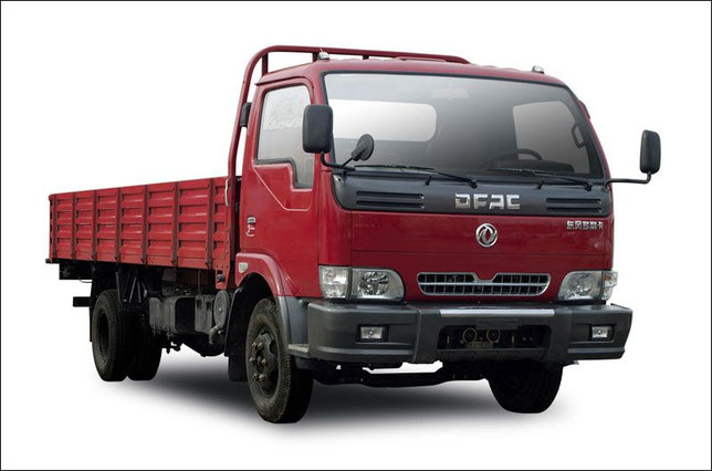
The name Dongfeng in Chinese means «East Wind». The company was founded in 1969. During this period, China severed economic ties with the USSR and the countries of the East, which caused its
industry to develop at an accelerated pace, counting only on its own forces. The state-supported company quickly established a network of plants throughout the country. During the first two
years, the construction of three factory complexes was completed, which began to produce automotive components, military equipment, motors and consumables.
In 1975, a military truck with cross-country capability was launched, its carrying capacity was 2.5 tons.
Up to 1978, Dongfeng did not produce civilian equipment, but with the arrival of the new leadership, the range of products also changed. Since 1985, the brand has received
autonomy and was not directly managed by the state.
In 1980, Dongfeng cooperates with the Ulyanovsk Automobile Plant for the joint production of trucks. More than 100 Russian specialists visited the company to train its employees and help in
organizing the independent design bureau of the brand.
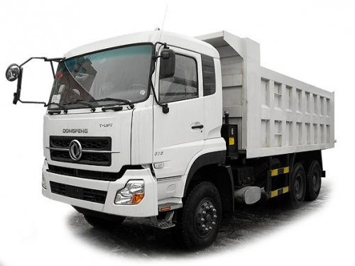
In 1986, Dongfeng produced 100,000 cars. By the early 90’s, it became one of the largest enterprises in China and the largest Chinese manufacturer of trucks and their components for Japanese
brands. In 1992, the Peugeot-Citroen PCA company organized a joint production with a brand, and the company was renamed into Dongfeng Motor Corporation. A year later, the brand starts selling
passenger cars, the Chinese automaker enters into contracts with Honda, Mitsubishi and Nissan, and its annual sales exceed 220,000 units.
In 1994, Dongfeng Motor Corporation products cover 60% of China’s automobile market. Under its own brand, not only trucks, but also cars based on Mitsubishi Colt (look: Mitsubishi truck PDF Manuals), Honda Civic and Nissan Sunny are produced. In addition, the company manufactures special equipment
widely used in China and Thailand, as well as ambulances, fire trucks, loaders and cranes.
In 1998, Dongfeng Motor incurred losses of 396 million yuan. Overcoming the crisis is only two years later, when the sales volume again reaches the level of 220,000 cars.
Since 2001, Dongfeng has been manufacturing a new generation of 4- and 6-cylinder powertrains for the French brands Peugeot and Citroen, as well as 8-cylinder engines for buses. This became
possible after buying several patents of the American company Cummins (look: Cummins Engine PDF Manuals).
In 2003, Dongfeng Motor establishes a joint venture with Nissan, moves the headquarters from Shiyan to Wuhan and takes a new name — Dongfeng Motor Company Limited. This will allow the Chinese
manufacturer to continue development and enter the international market.
In the same year, an agreement was signed to establish a joint venture with Kia. Korean brand cars manufactured at Dongfeng factories are sold in China, Russia and India. The construction of the
company’s plants in Argentina and Chile begins. Since 2004, these enterprises start production of commercial and commercial vehicles Daihatsu and Hyundai.
In 2006, Dongfeng, using the technological developments of Nissan, develops its first own passenger car. In 2007, he made his debut as a model of Rich. This four-door pickup,
which is equipped with a 2.5-liter engine capacity of 110 hp. Its maximum speed is 150 km / h.
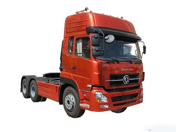
Two years later, the company replaces gasoline engines manufactured under license from Nissan, with its own diesel engines. In addition, Dongfeng is releasing its version of the Mitsubishi Space
Gear minivan, equipped with engines that develop 80 and 120 hp.
In 2007 official deliveries of brand cars to Russia begin. These were large-capacity trucks DFL 3310A, DFL 3251A and DFL4181A. Since 2011, a subsidiary company of Dongfeng Motor Rus has been
operating.
In 2009, Dongfeng buys a 10% stake in Volvo Trucks, expanding its design office by adding the engineering headquarters of the Swedish brand. A
year later, the first factory in China to produce Volvo trucks sold under the Dongfeng brand was opened.
In 2013, with the help of the Chinese government, the company buys a controlling stake in Volvo Trucks and completely transfers the production of the Swedish brand to the territory of China.
In 2011, sales of Honda cars are increasing in the Chinese assembly in the US, which contributes to the growth of the company. In the same year, Dongfeng buys out the rights to release all Nissan
models under its brand, the brand factories in Sweden and the UK are opening.
In 2012, the construction of the Infiniti plant in China begins, as well as the production of hybrid platforms for Toyota.
In 2014, Dongfeng enters the Russian market with passenger cars under the DFM brand — sedan DFM S30 and hatchback DFM H30 Cross. Trucks are represented by dump trucks 6×4 and 8×4. Machines for
the Russian market are assembled from units that come from Europe, the United States and Japan.
Now the company Dongfeng Motor Corporation sells cars in 92 countries, is the main strategic enterprise of China’s military-industrial complex. Its main production facilities are
located in Shiyan, Hiyanfan, Wuhan, Guangzhou. In 2014, it produced more than 3.5 million cars.