Инструкция по ремонту и эксплуатации

Войдите или зарегистрируйтесь, чтобы писать комментарии, задавать вопросы и участвовать в обсуждении.
- Manuals
- Brands
- Volkswagen Manuals
- Automobile
- Golf Plus 2005
Manuals and User Guides for Volkswagen Golf Plus 2005. We have 5 Volkswagen Golf Plus 2005 manuals available for free PDF download: Workshop Manual, Service Manual, Service Training Manual

Volkswagen Golf Plus 2005 Workshop Manual (299 pages)
Brand: Volkswagen
|
Category: Automobile
|
Size: 7.58 MB
Table of Contents
-
Table of Contents
3
-
Technical Data
7
-
Engine Number
7
-
Engine Data
7
-
Removing and Installing Engine
9
-
Removing Engine
10
-
Securing Engine to Assembly Stand
17
-
Notes on Installing
19
-
Assembly Mountings
20
-
Crankshaft Group
21
-
Dismantling and Assembling Engine
21
-
Assembly Overview — Poly V-Belt Drive
21
-
Removing and Installing Poly V-Belt
22
-
Assembly Overview — Toothed Belt Drive
24
-
Assembly Overview — Crankcase
29
-
Removing and Installing Sealing Flange and Flywheel
30
-
Renewing Crankshaft Sealing Flange — Flywheel End
31
-
Renewing Crankshaft Oil Seal — Pulley End
39
-
Removing and Installing Sealing Flange — Pulley End
41
-
Removing and Installing Engine Speed Sender G28
43
-
Pistons and Conrods
45
-
Assembly Overview — Pistons and Conrods
45
-
Piston and Cylinder Dimensions
46
-
Checking Piston Projection at TDC
46
-
Piston Rings, Cylinder Bore and Piston Installation Position
48
-
Crankshaft
50
-
Assembly Overview — Crankshaft
50
-
Crankshaft Dimensions
50
-
Pulling Needle Bearing out of and Driving into Crankshaft
51
-
Cylinder Head, Valve Gear
53
-
Cylinder Head
53
-
Assembly Overview — Cylinder Head
53
-
Removing and Installing Cylinder Head Cover
55
-
Removing, Installing and Tensioning Toothed Belt
57
-
Removing and Installing Cylinder Head
72
-
Checking Compression
77
-
Valve Gear
78
-
Assembly Overview — Valve Gear
78
-
Removing and Installing Roller Rocker Finger
80
-
Valves
82
-
Removing and Installing Camshafts
85
-
Removing and Installing Camshaft Oil Seal
90
-
Lubrication
92
-
Engine Oil
92
-
Oil Capacities — Golf, Golf Plus, Touran
92
-
Oil Capacities — Passat
92
-
Checking Engine Oil Level
92
-
Parts of Lubrication System (Golf, Golf Plus, Touran)
93
-
Assembly Overview — Oil Pump, Sump
93
-
Removing and Installing Oil Sump
95
-
Parts of Lubrication System (Passat)
98
-
Assembly Overview — Oil Pump, Sump, Balancer Shaft Module with Chain Drive
99
-
Removing and Installing Oil Pump (for Balancer Shaft Module with Chain Drive)
101
-
Removing and Installing Balancer Shaft Module with Chain Drive
104
-
Retrofitting Spur Gear Drive for Balancer Shaft Module
107
-
Assembly Overview — Oil Pump, Sump, Balancer Shaft Module with Spur Gear Drive
110
-
Removing and Installing Oil Pump (for Balancer Shaft Module with Spur Gear Drive)
113
-
Removing Balancer Shaft Module with Spur Gear Drive
113
-
Renewing Spur Gear for Crankshaft
114
-
Installing Balancer Shaft Module
117
-
Removing and Installing Oil Sump
123
-
Oil Filter Bracket, Oil Cooler, Oil Pressure and Oil Supply Line
126
-
Assembly Overview — Oil Filter Bracket and Oil Cooler
126
-
Checking Oil Pressure and Oil Pressure Switch
127
-
Assembly Overview — Oil Supply Line to Turbocharger
129
-
Removing and Installing Oil Supply Line to Turbocharger
129
-
Cooling
131
-
Parts of Cooling System
131
-
Parts of Cooling System, Body Side
132
-
Assembly Overview — Parts of Cooling System, Engine Side (Golf, Golf Plus, Touran)
133
-
Assembly Overview — Parts of Cooling System, Engine Side (Passat)
135
-
Coolant Hose Schematic Diagram
137
-
Draining and Filling Coolant
140
-
Removing and Installing Fan Support with Fans
145
-
Removing and Installing Radiator
146
-
Removing and Installing Coolant Pump
148
-
Removing and Installing Thermostat
150
-
Checking Cooling System for Leaks
152
-
Checking Oil Cooler for Leaks
154
-
Fuel Supply System
156
-
Safety Precautions
156
-
Safety Precautions When Working on Fuel Supply System
156
-
Rules for Cleanliness
157
-
Rules for Cleanliness When Working on Fuel Supply System
157
-
Parts of Fuel Supply System (Golf, Golf Plus)
158
-
Fuel Tank, Vehicles with Front-Wheel Drive
158
-
Fuel Tank, Vehicles with Four-Wheel Drive
162
-
Emptying Fuel Tank
168
-
Removing and Installing Fuel Delivery Unit
170
-
Removing and Installing Fuel Gauge Sender
172
-
Checking Fuel Pump
172
-
Assembly Overview — Fuel Filter
177
-
Removing and Installing Fuel Cooler
179
-
Parts of Fuel Supply System (Touran)
181
-
Assembly Overview — Fuel Tank with Attachments
182
-
Emptying Fuel Tank
183
-
Removing and Installing Fuel Tank
186
-
Assembly Overview — Fuel Filter
188
-
Removing and Installing Fuel Cooler
189
-
Removing and Installing Fuel Delivery Unit
190
-
Removing and Installing Fuel Gauge Sender
192
-
Checking Fuel Pump
192
-
Parts of Fuel Supply System (Passat)
198
-
Fuel Tank, Vehicles with Four-Wheel Drive
198
-
Emptying Fuel Tank, Vehicles with Four-Wheel Drive
208
-
Fuel Tank, Vehicles with Front-Wheel Drive
212
-
Emptying Fuel Tank, Vehicles with Front-Wheel Drive
219
-
Checking Fuel Pump
221
-
Assembly Overview — Fuel Filter
225
-
Removing and Installing Fuel Cooler
227
-
Accelerator Mechanism
229
-
Assembly Overview — Accelerator Mechanism
229
-
Tandem Pump
231
-
Checking Tandem Pump
231
-
Removing and Installing Tandem Pump
233
-
Turbocharging/Supercharging
236
-
Charge Air System with Turbocharger
236
-
Safety Precautions
236
-
Rules for Cleanliness
236
-
Hose Connections
237
-
Assembly Overview — Turbocharger with Attachments
238
-
Removing and Installing Turbocharger
241
-
Assembly Overview — Charge Air Cooling
243
-
Checking Charge Air System for Leaks
244
-
Vacuum Hose Schematic Diagram
246
-
Mixture Preparation — Injection
248
-
Diesel Direct Injection System
248
-
Safety Precautions
248
-
Rules for Cleanliness
249
-
Assembly Overview — Intake Manifold with Attachments
250
-
Assembly Overview — Pre-Wired Wiring Harness for Unit Injectors and Glow Plugs
252
-
Removing and Installing Pre-Wired Wiring Harness for Unit Injectors and Glow Plugs
252
-
Assembly Overview — Unit Injector
255
-
Removing and Installing Unit Injector
257
-
Cleaning Unit Injectors (Engine Codes BMN, BKP, BMA, BUZ and BMR)
261
-
Removing and Installing O-Rings for Unit Injector
263
-
Assembly Overview — Air Filter
265
-
Engine Control Unit (Golf)
266
-
Removing and Installing Engine Control Unit
266
-
Removing and Installing Anti-Theft Engine Control Unit
266
-
Engine Control Unit (Golf Plus, Touran)
270
-
Removing and Installing Engine Control Unit
270
-
Removing and Installing Anti-Theft Engine Control Unit
271
-
Engine Control Unit (Passat)
274
-
Removing and Installing Engine Control Unit
274
-
Removing and Installing Anti-Theft Engine Control Unit
275
-
Exhaust System
279
-
Front Exhaust Pipe
279
-
Assembly Overview — Front Exhaust Pipe with Catalytic Converter
279
-
Assembly Overview — Front Exhaust Pipe with Particulate Filter
280
-
Silencer (Golf, Golf Plus)
283
-
Assembly Overview — Silencer, Vehicles with Front-Wheel Drive
283
-
Assembly Overview — Silencer, Vehicles with Four-Wheel Drive
284
-
Cutting Exhaust Pipe
284
-
Installation Position and Specified Torque of the Clamp
285
-
Aligning Exhaust System Free of Stress
286
-
Silencer (Touran)
288
-
Assembly Overview — Silencers
288
-
Cutting Exhaust Pipe
289
-
Aligning Exhaust System Free of Stress
289
-
Silencer (Passat)
290
-
Assembly Overview — Silencer, Vehicles with Front-Wheel Drive
290
-
Assembly Overview — Silencer, Vehicles with Four-Wheel Drive
291
-
Aligning Exhaust System Free of Stress
291
-
Exhaust Gas Recirculation System
293
-
Assembly Overview — Exhaust Gas Recirculation
293
-
Glow Plug System
296
-
Optical Characteristics of Metal or Ceramic Glow Plugs
296
-
Removing and Installing Metal Glow Plug
296
-
Removing and Installing Ceramic Glow Plugs
298
Advertisement
Volkswagen Golf Plus 2005 Service Manual (207 pages)
4-cylinder diesel engine (1.9 l engine)
Brand: Volkswagen
|
Category: Automobile
|
Size: 7.53 MB
Table of Contents
-
Table of Contents
3
-
Technical Data
7
-
Engine Number
7
-
Engine Data
7
-
-
Removing and Installing Engine
8
-
Removing Engine
8
-
Securing Engine to Assembly Stand
13
-
Notes on Installing
13
-
Assembly Mountings
16
-
-
Crankshaft Group
18
-
Dismantling and Assembling Engine
18
-
Assembly Overview — Poly V-Belt Drive
18
-
Removing and Installing Poly V-Belt
19
-
Assembly Overview — Toothed Belt Drive
21
-
Assembly Overview — Crankcase
25
-
Removing and Installing Sealing Flange and Flywheel
26
-
Assembly Overview — Sealing Flanges and Flywheel
26
-
Renewing Crankshaft Oil Seal — Pulley End
27
-
Removing and Installing Sealing Flange — Pulley End
29
-
Renewing Crankshaft Sealing Flange — Flywheel End
31
-
Removing and Installing Engine Speed Sender G28
37
-
Crankshaft
39
-
Assembly Overview — Crankshaft
39
-
Crankshaft Dimensions
44
-
Pistons and Conrods
45
-
Assembly Overview — Pistons and Conrods
45
-
Separating New Conrod
46
-
Checking Piston Projection at TDC
47
-
Piston and Cylinder Dimensions
48
-
Piston Rings, Cylinder Bore and Piston Installation Position
48
-
-
Cylinder Head, Valve Gear
50
-
Cylinder Head
50
-
Assembly Overview — Cylinder Head
51
-
Removing and Installing Cylinder Head Cover
54
-
Removing, Installing and Tensioning Toothed Belts
56
-
Removing and Installing Cylinder Head
73
-
Checking Compression
77
-
Valve Gear
80
-
Assembly Overview — Valve Gear
80
-
Checking Valve Guides
82
-
Renewing Valve Stem Seals
84
-
Removing and Installing Camshaft
86
-
Removing and Installing Camshaft Oil Seal
90
-
-
Lubrication
92
-
Engine Oil
92
-
Oil Capacities
92
-
Checking Engine Oil Level
92
-
Parts of Lubrication System
93
-
Assembly Overview — Oil Pump, Sump
93
-
Removing and Installing Sump
94
-
Oil Filter Bracket, Oil Pressure, Engine Oil Cooler and Oil Supply Line
98
-
Assembly Overview — Oil Filter Bracket and Engine Oil Cooler
98
-
Checking Oil Pressure and Oil Pressure Switch
99
-
Assembly Overview — Oil Supply Line to Turbocharger
100
-
Removing and Installing Oil Supply Line to Turbocharger
101
-
-
Cooling
103
-
Parts of Cooling System
103
-
Parts of Cooling System, Body Side
104
-
Parts of Cooling System, Engine Side
105
-
Coolant Hose Schematic Diagram
107
-
Draining and Filling with Coolant
108
-
Removing and Installing Radiator
111
-
Removing and Installing Coolant Pump
112
-
Removing and Installing Thermostat
114
-
Checking Cooling System for Leaks
116
-
Checking Engine Oil Cooler for Leaks
118
-
-
Fuel Supply System
120
-
Safety Precautions When Working on Fuel Supply System
120
-
Rules for Cleanliness
121
-
Fuel Tank, Vehicles with Front-Wheel Drive
122
-
Assembly Overview — Fuel Tank
122
-
Emptying Fuel Tank
123
-
Removing and Installing Fuel Tank
127
-
Removing and Installing Fuel Delivery Unit
129
-
Removing and Installing Fuel Gauge Sender
130
-
Checking Fuel Pump
131
-
Fuel Tank, Vehicles with Four-Wheel Drive
133
-
Assembly Overview — Fuel Tank
133
-
Emptying Fuel Tank
134
-
Removing and Installing Fuel Tank
138
-
Removing and Installing Fuel Gauge Sender 2 G169
141
-
Removing and Installing Suction-Jet Pump
143
-
Checking Fuel Pump
144
-
Repairing Fuel Supply System
146
-
Assembly Overview — Fuel Filter
146
-
Removing and Installing Fuel Cooler
147
-
Assembly Overview — Accelerator Mechanism
148
-
Checking Tandem Pump
149
-
Removing and Installing Tandem Pump
153
-
-
Turbocharging/Supercharging
157
-
Charge Air System with Turbocharger
157
-
Safety Precautions
157
-
Rules for Cleanliness
157
-
Assembly Overview — Turbocharger
158
-
Removing and Installing Turbocharger
162
-
Assembly Overview — Parts of Charge Air Cooling
164
-
Hose Connections
167
-
Checking Charge Air System for Leaks
168
-
Vacuum Hose Schematic Diagram
170
-
-
Mixture Preparation — Injection
172
-
Diesel Direct Injection System
172
-
Safety Precautions
172
-
Rules for Cleanliness
173
-
Assembly Overview — Unit Injector
173
-
Removing and Installing Unit Injector
175
-
Adjusting Non-Contact Gap of Unit Injectors
177
-
Removing and Installing O-Rings for Unit Injector
178
-
Assembly Overview — Intake Manifold
180
-
Cleaning the Intake Manifold Flap Support, Engine Code BLS and BXJ
182
-
Assembly Overview — Air Filter
183
-
Engine Control Unit
184
-
Reading and Erasing Engine Control Unit Fault Memory
184
-
Adapting Functions and Components
185
-
Removing and Installing Engine Control Unit, Golf
186
-
Removing and Installing Anti-Theft Engine Control Unit, Golf
186
-
Removing and Installing Engine Control Unit, Golf Plus
189
-
Removing and Installing Anti-Theft Engine Control Unit, Golf Plus
189
-
-
Exhaust System
192
-
Assembly Overview — Front Exhaust Pipe with Catalytic Converter
192
-
Assembly Overview — Front Exhaust Pipe with Particulate Filter
193
-
Assembly Overview — Silencer with Mountings (Vehicles with Front Wheel Drive)
195
-
Assembly Overview — Silencer with Mountings (Vehicles with Four-Wheel Drive)
197
-
Aligning Exhaust System Free of Stress
198
-
Exhaust Gas Recirculation System
199
-
Assembly Overview — Parts of Exhaust Gas Recirculation
199
-
-
Glow Plug System
204
-
Checking Glow Plug System
204
-
Removing, Installing and Checking Glow Plugs
204
-
Characteristics of Ceramic Glow Plugs
205
-
Removing, Installing and Checking Ceramic Glow Plugs
206
-

Volkswagen Golf Plus 2005 Service Manual (185 pages)
Golf 2004; Golf Plus 2005
Brand: Volkswagen
|
Category: Automobile
|
Size: 6.79 MB
Table of Contents
-
Table of Contents
3
-
1 Engine List
5
-
Petrol Engines
5
-
Information on Long-Life Service and Time or Distance Dependent Service
11
-
-
2 Service Work
11
-
Service Interval Display
12
-
Service Tables
13
-
Service Intervals
14
-
Delivery Inspection
18
-
Oil Change Service
20
-
Interval Service ▸2007
21
-
Interval Service 2008
22
-
Interval Service Inspection ▸2007
24
-
Inspection Service 2008
26
-
Time or Distance Dependent Additional Work
29
-
-
3 General
33
-
Raising Vehicle with Lifting Platform and Trolley Jack
33
-
Sticker
34
-
Service Schedule
35
-
Connecting Vehicle Diagnostic Tester
36
-
Entries in Service Schedule
36
-
Vehicle Identification Number
38
-
Severe Operating Conditions
40
-
Vehicle Data Sticker
40
-
Engine Code and Engine Number
41
-
RME Fuel (Biodiesel) for Vehicles up to 05.2006
41
-
Type Plate
42
-
-
4 Descriptions of Work
43
-
Removable Towing Bracket: Check and Clean if Necessary
45
-
Driving Light Assist and Cornering Light: Check Function
47
-
Swivel Joints: Visual Check
47
-
Automatic Gearbox: Change ATF (09G Gearbox)
48
-
Automatic Gearbox: Check ATF Level, 09G Gearbox
48
-
Battery: Check Battery Terminal Clamps for Secure Seating
49
-
Battery: Check Using Battery Tester with Printer VAS 5097A or VAS 6161
52
-
Checking Tyres: Condition, Wear Pattern, Tyre Pressure, Tread Depth and Age of Tyres
52
-
General Notes
54
-
Brake and Clutch System: Change Brake Fluid
57
-
Brake Fluid Level: Check
61
-
Brake System and Shock Absorbers: Perform Visual Check for Leaks and Damage
62
-
Front and Rear Brake Pads/Linings: Check Thickness
63
-
Checking Diesel Particulate Filter
64
-
6-Speed Dual Clutch Gearbox (DSG) 02E: Change Oil and Filter
65
-
Electric Windows: Check Positioning (Open and Close Functions)
65
-
Vehicle System Test: Perform Test
66
-
Front Passenger Front Airbag: Check Key Switch and «On/Off Function
67
-
Protective Bellows: Visual Check
69
-
Haldex Coupling (Golf 4Motion): Change Oil
70
-
Poly V-Belt: Adjust Tension on Engines Without Automatic Tensioning Roller
73
-
Poly V-Belt: Check Condition
74
-
Calibrating Compass (for North American Region)
75
-
Cooling System: Check Frost Protection and Coolant Level
76
-
Fuel Filter: Renew
78
-
Air Filter: Clean Housing and Renew Filter Element
84
-
Engine Cover -Top-: Removing and Installing
93
-
Removing and Installing Engine Compartment Cover -Bottom- (Noise Insulation)
103
-
Engine and Components in Engine Compartment (from above and Below): Perform Visual Check for Leaks and Damage
104
-
Engine Oil Level: Check
105
-
Engine Oil: Drain or Extract; Renew Oil Filter and Replenish Engine Oil
105
-
Performing Road Test (Driving Behaviour, Noises, Air Conditioner Etc.)
116
-
Wheel Securing Bolts: Tighten to Prescribed Torque Setting
116
-
Reading Radio Code Using Vehicle Diagnostic Tester
118
-
Radio/Radio Navigation System: Enter PIN of Anti-Theft Coding and Store Local Radio Stations to Station Buttons
119
-
Tyre Pressure Monitoring: Perform Basic Setting
120
-
Dust and Pollen Filter: Clean Housing and Renew Filter Element
122
-
Tyre Repair Set: Check Bottle for Damage and if Used; Check and Enter Date of Tyre Sealant
122
-
Headlight Adjustment: Check
123
-
Adjusting Headlights
126
-
Service Interval Display: Reset
130
-
Service Interval Display: Recode
131
-
Sliding Sunroof Drains: Check Flow and Clean if Necessary
133
-
Sunroof: Check Function, Clean and Grease Guide Rails
133
-
Window Wash/Wipe System and Headlight Washer System: Check Function
135
-
Wiper Blade Protection: Remove
141
-
Wiper Blades: Check Park Position
143
-
Auxiliary Heater: Set Weekday in Menu of Combi-Instrument
144
-
Track Rod Ends: Check Play, Security and Boots
144
-
Door Arrester: Grease
145
-
Transportation Mode: Switch off
145
-
Lines, Plugs Etc
147
-
Transportation Devices: Remove Blocking Pieces from Front Axle Springs
147
-
Underbody: Visual Check for Damage to Underbody Sealant, Underbody Panels, Routing of
147
-
Clock and Date: Set to Correct Time
148
-
Camshaft Drive Toothed Belt: Check (4-Cylinder Petrol Engines 1.4 L 55 Kw and 1.6 L 75 Kw)
149
-
Camshaft Drive Toothed Belt: Renew (Only 2.0 L FSI and TFSI)
149
-
Toothed Belt and Toothed Belt Tensioning Roller: Renew (TDI Unit Injector)
149
-
Spark Plugs: Renew
150
-
Front and Rear Final Drive: Check Oil Level
163
-
-
5 Exhaust Emissions Test
164
-
Exhaust Emissions Test for Petrol Engines
164
-
Exhaust Emissions Test for Diesel Engines Without OBD
171
-
Exhaust Emissions Test for Diesel Engines with OBD
175
-
-
6 Glossary
184
Advertisement
Volkswagen Golf Plus 2005 Workshop Manual (180 pages)
Brand: Volkswagen
|
Category: Automobile
|
Size: 1.72 MB
Table of Contents
-
Table of Contents
5
-
Technical Data
7
-
1 General Notes on Air Conditioning Systems
7
-
Introduction
7
-
Additional Information
7
-
Basics of Air Conditioning
8
-
Vapour Pressure Table for Refrigerant R134A
9
-
Refrigerant R134A
10
-
Characteristics of Refrigerant R134A
11
-
Refrigerant Machine Oil
13
-
Comfort
15
-
How Air Conditioning Works
15
-
General Safety
16
-
Safety Precautions for When Working on Vehicles with Air Conditioning and When Handling
19
-
Refrigerant R134A
19
-
-
Basics for Working on Refrigerant Circuit
20
-
-
2 General Information on Refrigerant Circuit
23
-
Refrigerant Circuit Components
23
-
Design of Refrigerant Circuit
31
-
Evacuation and Charging Valves for Quick-Release Couplings of Air Conditioner Service Station
31
-
On Refrigerant Circuit
31
-
-
Switch and Sender in Refrigerant Circuit and Related Connections
33
-
Electrical Components Not Installed in Refrigerant Circuit
36
-
Pressures and Temperatures in the Refrigerant Circuit
38
-
Refrigerant Circuit with Expansion Valve
38
-
Refrigerant Circuit with Restrictor and Reservoir
40
-
Test and Measurement Work that Can be Performed Using a Pressure Gauge
42
-
Air Conditioner Service and Recycling Equipment
43
-
Notes to Repairs on Refrigerant Circuit
44
-
-
3 Statutory Texts and Instructions
45
-
Statutes and Regulations
45
-
Recycling and Refuse Law
50
-
Converting R12 Refrigerant Circuits to R134A Refrigerant Circuits and Repairing Them (Retrofitting)
51
-
Maintaining Records on Refrigerant
51
-
-
4 Refrigerant Circuit
52
-
Important Repair Notes on Air Conditioning
52
-
Retrofitting Refrigerant Circuit from R12 Refrigerant to R134A Refrigerant
52
-
-
5 Working with the Air Conditioner Service Station
53
-
Important Notes for Working with the Air Conditioner Service Station
54
-
Connecting Air Conditioner Service Station for Measuring and Checking
54
-
Draining Refrigerant Circuit Using Air Conditioner Service Station
55
-
Evacuating Refrigerant Circuit Using Air Conditioner Service Station
56
-
Charging Refrigerant Circuit Using Air Conditioner Service Station
57
-
Bringing Air Conditioning System into Service after Charging
58
-
Charging Container in Air Conditioner Service Station with Refrigerant
59
-
Draining Air Conditioner Service Station
59
-
-
6 Detecting Leaks in Refrigerant Circuit
61
-
Leak Detection in Refrigerant Circuit Using Compressed Air or Nitrogen
62
-
Searching for Leaks in Refrigerant Circuits Using Leak Detector V.A.G 1796
64
-
Detecting Leaks in Refrigerant Circuit Using Leak Detecting System VAS 6196 or Leak Detecting
65
-
System VAS 6201 or a Later Model
65
-
-
-
7 Clearing Refrigerant Circuit of Contaminants
71
-
Blowing through Refrigerant Circuit with Compressed Air and Nitrogen
71
-
Purging (Cleaning) Refrigerant Circuit with Refrigerant R134A
73
-
-
8 Complaints
128
-
Possible Complaints about Refrigerant Circuit
128
-
Smells from Heater and Air Conditioner Unit
129
-
-
9 Connecting Air Conditioner Service Station
132
-
For Vehicles that Have Connections on both Low-Pressure and High-Pressure Sides of
132
-
Refrigerant Circuit
132
-
-
-
10 Checking Pressures on Vehicles
133
-
Checking Pressures in Refrigerant Circuit (Using Air Conditioner Service Station)
133
-
Checking Systems with a Restrictor and Collector
136
-
Compressor
138
-
-
Checking Systems with an Expansion Valve and Reservoir (with Internally Regulated Air Conditioner Compressor)
141
-
Checking Systems with an Expansion Valve and Reservoir
147
-
Compressor)
147
-
-
Checking Systems with a Restrictor and Reservoir and Air Conditioner Compressor Regulating Valve N280 (with Externally Regulated Air Conditioner Compressor)
149
-
Checking Systems with an Expansion Valve, Receiver and Air Conditioner Compressor
154
-
Regulating Valve N280 (with Externally Regulated Air Conditioner Compressor)
154
-
-
With Expansion Valve, Receiver and Electrical Air Conditioner Compressor
164
-
-
11 Renewing Components
165
-
In the Event of Leaking or Damaged Components (Apart from the Air Conditioner Compressor, Receiver or Reservoir)
166
-
Renewing Air Conditioner Compressor
167
-
Renewing Receiver or Reservoir, and Restrictor
169
-
-
12 Testing Equipment and Tools
171
-
List of Test Equipment, Tools and Materials
171
-

Volkswagen Golf Plus 2005 Service Training Manual (56 pages)
Self-study programme 338
Brand: Volkswagen
|
Category: Automobile
|
Size: 3.8 MB
Table of Contents
-
Table of Contents
3
-
In Brief
4
-
Technical Data
6
-
Body
8
-
Height Adjustment
13
-
Pedestrian Protection
16
-
-
Occupant Protection
18
-
Engine-Gearbox Combinations
20
-
Engines
22
-
Power Transmission
26
-
Running Gear
28
-
Electrical System
30
-
Trailer Detector Control Unit J345
34
-
Convenience Electronics
38
-
Radio and Navigation
44
-
Climate Control
48
-
Heater and Air Conditioner
48
-
Special Tools
55
-
Service
55
Advertisement
Related Products
-
Volkswagen Golf Plus 2009
-
VOLKSWAGEN PHAETON —
-
Volkswagen Phaeton 2003
-
Volkswagen Passat 2006
-
Volkswagen Passat 2012
-
Volkswagen Passat Sport T-FSI
-
Volkswagen Passat Sport TDI
-
Volkswagen Passat Sport TDI DPF
-
Volkswagen Passat Estate BlueMotion 2
-
Volkswagen Passat Estate R Line
Volkswagen Categories
Automobile
Automobile Accessories
Car Receiver
Adapter
Engine
More Volkswagen Manuals
Техническая документация по ремонту автомобилей Volkswagen Golf Plus ( все годы выпуска) Бесплатно, без регистрации и СМС


Руководство по ремонту, эксплуатации и техническому обслуживанию Volkswagen Golf Plus
— полные технические характеристик
-особенности эксплуатации
— устранение неисправностей Volkswagen Golf Plus
— цветные электросхемы Volkswagen Golf Plus
СКАЧАТЬ / СКАЧАТЬ С ЗЕРКАЛА 
Руководство по эксплуатации Volkswagen Golf Plus
— полные технические характеристики Volkswagen Golf Plus
— особенности эксплуатации
— устранение неисправностей
— цветные электросхемы
СКАЧАТЬ / СКАЧАТЬ С ЗЕРКАЛА 
Руководство по ремонту Volkswagen Golf Plus в фотографиях
— полные технические характеристики
— особенности эксплуатации Volkswagen Golf Plus
— устранение неисправностей
в фотографиях своими руками
— более 1980 фотографий процесса ремонта
СКАЧАТЬ / СКАЧАТЬ С ЗЕРКАЛА 
Каталог деталей и сборочных единиц Volkswagen Golf Plus
— таблица взаимозаменяемости деталей автомобилей
— предназначен для работников СТО и владельцев автомобилей Volkswagen Golf Plus
— каталог деталей Volkswagen Golf Plus
СКАЧАТЬ / СКАЧАТЬ С ЗЕРКАЛА 
Подробная электросхема Volkswagen Golf Plus
— полное описание электрооборудования Volkswagen Golf Plus , подробная интерактивная электрическая схема Volkswagen Golf Plus
— подробно описан алгоритм поиска неисправностей электрооборудования (стартер, генератор, система зажигания, впрыск, инжектор)
— подробная схема электрооборудования ( электро схема ) Volkswagen Golf Plus
— распиновка разъемов электрических, распиновка электро проводки Volkswagen Golf Plus
СКАЧАТЬ / СКАЧАТЬ С ЗЕРКАЛА 
Руководство по ремонту двигателя Volkswagen Golf Plus
— полные технические характеристики двигателя Volkswagen Golf Plus
— особенности конструкции и ремонта двигателя Volkswagen Golf Plus
— подробное описание процессов разборки, дефектовки и сборки двигателя с фотографиями, ГРМ
СКАЧАТЬ / СКАЧАТЬ С ЗЕРКАЛА 
Руководство по ремонту коробок передач Volkswagen Golf Plus
— полные технические характеристики КПП
— особенности конструкции и ремонта КПП Volkswagen Golf Plus
— устранение неисправностей КПП трансмиссия, валы, шестерни, ШРУС
— подробное описание процессов разборки, дефектовки и сборки КПП с фотографиями
СКАЧАТЬ / СКАЧАТЬ С ЗЕРКАЛА 
а вот здесь можно заработать на новую машину, и тогда старую не придется ремонтировать!!!
Volkswagen Golf Plus
-
nekesha
- Администратор
- Сообщения: 1668
- Зарегистрирован: 17 дек 2014, 03:43
- Благодарил (а): 2 раза
- Поблагодарили: 6 раз
Volkswagen Golf Plus from 2005 / Фольксваген Гольф Плюс c 2005
Руководство по эксплуатации, техобслуживанию и ремонту Volkswagen Golf Plus / Фольксваген Гольф Плюс
Operation, Maintenance and Repair Manual Volkswagen Golf Plus

- Года выпуска: c 2005
Year of release: from 2005
Бензиновые двигатели: 1,4 л., 1,4 л. FSI, 1,4 л. TSI, 1,6 л. FSI, 1,6 л. TSI, 2,0 л. FSI, 2,0 л. TSI
Gasoline engines: 1.4 l., 1.4 l. FSI, 1.4 l. TSI, 1.6 l. FSI, 1.6 l. TSI, 2.0 l. FSI, 2.0 l. TSI
Дизельные двигатели: 1,9 л., 2,0 л.
Diesel Engines: 1.9 l., 2.0 l
- Язык: Русский
Формат: PDF
Размер: 55,5 Мб
Russian language
Format: PDF
Size: 55.5 MB
Скачать документацию Volkswagen Golf Plus / Фольксваген Гольф Плюс
Download the documentation of Volkswagen Golf Plus
для распаковки используйте пароль — avto-ok.info
use the password to unpack — avto-ok.info
Crash test
-
Contents
-
Table of Contents
-
Bookmarks
Quick Links
Service
Workshop Manual
Golf 2004 ➤
Golf Plus 2005 ➤
4-cylinder diesel engine (1.9 l engine)
Engine ID
Edition 01.2009
Service Department. Technical Information
BJB
BKC BRU BLS
BXE
BXF
BXJ
Related Manuals for Volkswagen Golf Plus 2005
Summary of Contents for Volkswagen Golf Plus 2005
-
Page 1
Service Workshop Manual Golf 2004 ➤ Golf Plus 2005 ➤ 4-cylinder diesel engine (1.9 l engine) BKC BRU BLS Engine ID Edition 01.2009 Service Department. Technical Information… -
Page 2
In addition, the normal basic safety precautions for working on motor vehicles must, as a matter of course, be observed. All rights reserved. No reproduction without prior agreement from publisher. Copyright © 2010 Volkswagen AG, Wolfsburg K0059000420… -
Page 3: Table Of Contents
Golf 2004 ➤ , Golf Plus 2005 ➤ 4-cylinder diesel engine (1.9 l engine) — Edition 01.2009 Contents 00 — Technical data ……….. .
-
Page 4
Golf 2004 ➤ , Golf Plus 2005 ➤ 4-cylinder diesel engine (1.9 l engine) — Edition 01.2009 Parts of lubrication system ………. -
Page 5
Golf 2004 ➤ , Golf Plus 2005 ➤ 4-cylinder diesel engine (1.9 l engine) — Edition 01.2009 23 — Mixture preparation — injection ……..166 Diesel direct injection system . -
Page 6
Golf 2004 ➤ , Golf Plus 2005 ➤ 4-cylinder diesel engine (1.9 l engine) — Edition 01.2009 Contents… -
Page 7: Technical Data
Golf 2004 ➤ , Golf Plus 2005 ➤ 4-cylinder diesel engine (1.9 l engine) — Edition 01.2009 00 – Technical data Technical data Engine number ⇒ page 1 Engine data ⇒ page 1 Engine number The engine number (“code letters” and “serial number”) can be found at the joint between engine and gearbox.
-
Page 8: Removing And Installing Engine
Golf 2004 ➤ , Golf Plus 2005 ➤ 4-cylinder diesel engine (1.9 l engine) — Edition 01.2009 10 – Removing and installing engine Removing and installing engine Removing engine ⇒ page 2 Securing engine to assembly stand ⇒ page 7 Notes on installing ⇒…
-
Page 9
Golf 2004 ➤ , Golf Plus 2005 ➤ 4-cylinder diesel engine (1.9 l engine) — Edition 01.2009 ♦ Torque wrench -V.A.G 1331- ♦ Torque wrench -V.A.G 1332- ♦ Engine and gearbox jack — V.A.G 1383 A- ♦ Spring-type clip pliers -VAS 5024- ♦… -
Page 10
Golf 2004 ➤ , Golf Plus 2005 ➤ 4-cylinder diesel engine (1.9 l engine) — Edition 01.2009 WARNING When doing any repair work, especially in the engine compart‐ ment, pay attention to the following due to the cramped condi‐ tions: ♦… -
Page 11
Golf 2004 ➤ , Golf Plus 2005 ➤ 4-cylinder diesel engine (1.9 l engine) — Edition 01.2009 – Remove bolt -arrow A- and pull air filter housing upwards out of mounting. – Remove battery and battery tray. – Disconnect fuel supply and return lines as well as coolant line on cylinder head. -
Page 12
Golf 2004 ➤ , Golf Plus 2005 ➤ 4-cylinder diesel engine (1.9 l engine) — Edition 01.2009 – Open all cable guide fasteners -arrows-. – Remove wiring harness from cable guide on longitudinal mem‐ ber and lay to side on engine. -
Page 13: Securing Engine To Assembly Stand
Golf 2004 ➤ , Golf Plus 2005 ➤ 4-cylinder diesel engine (1.9 l engine) — Edition 01.2009 – Unbolt assembly mounting on engine side from engine bracket -arrows-. Note To remove securing bolts, use stepladder -VAS 5085- . – Unbolt assembly mounting on gearbox side from gearbox bracket -arrows-.
-
Page 14
Golf 2004 ➤ , Golf Plus 2005 ➤ 4-cylinder diesel engine (1.9 l engine) — Edition 01.2009 – Check clutch release bearing for wear and renew if necessary. – Lubricate splines of input shaft lightly with G 000 100. – Check whether dowel sleeves for centring engine and gearbox are in cylinder block and install if necessary. -
Page 15
Golf 2004 ➤ , Golf Plus 2005 ➤ 4-cylinder diesel engine (1.9 l engine) — Edition 01.2009 – Ensure that the edges of the support arm on the gearbox as‐ sembly mounting -2- and gearbox support -1- are parallel. Dimension -x- must be identical at top and bottom. -
Page 16: Assembly Mountings
Golf 2004 ➤ , Golf Plus 2005 ➤ 4-cylinder diesel engine (1.9 l engine) — Edition 01.2009 Specified torques Threaded connection Specified torque Bolts, nuts 10 Nm 20 Nm 45 Nm 60 Nm Assembly mountings Engine assembly mounting A = 20 Nm + 90° (1/4 turn) further B = 40 Nm + 90°…
-
Page 17
Golf 2004 ➤ , Golf Plus 2005 ➤ 4-cylinder diesel engine (1.9 l engine) — Edition 01.2009 Pendulum support Always note the size and strength class of bolt. Different specified torques are valid. Caution From model year 08, in manual gearboxes 02Q Heli Coil in‐… -
Page 18: Crankshaft Group
Golf 2004 ➤ , Golf Plus 2005 ➤ 4-cylinder diesel engine (1.9 l engine) — Edition 01.2009 13 – Crankshaft group Dismantling and assembling engine Assembly overview — poly V-belt drive ⇒ page 12 Removing and installing poly V-belt ⇒ page 13 Assembly overview — toothed belt drive ⇒…
-
Page 19: Removing And Installing Poly V-Belt
Golf 2004 ➤ , Golf Plus 2005 ➤ 4-cylinder diesel engine (1.9 l engine) — Edition 01.2009 Removing and installing poly V-belt Special tools and workshop equipment required ♦ Locking pin -T10060 A- ♦ 16 mm open-end spanner -T 10241- 1.2.1…
-
Page 20
Golf 2004 ➤ , Golf Plus 2005 ➤ 4-cylinder diesel engine (1.9 l engine) — Edition 01.2009 – Lock tensioning element in position with locking pin -T10060 A- . – Remove poly V-belt. 1.2.2 Installing poly V-belt – Installation is carried out in the reverse sequence of removal. -
Page 21: Assembly Overview — Toothed Belt Drive
Golf 2004 ➤ , Golf Plus 2005 ➤ 4-cylinder diesel engine (1.9 l engine) — Edition 01.2009 Assembly overview — toothed belt drive 1 — Toothed belt guard upper part 2 — 100 Nm 3 — 25 Nm 4 — Camshaft pulley 5 — Hub ❑…
-
Page 22
Golf 2004 ➤ , Golf Plus 2005 ➤ 4-cylinder diesel engine (1.9 l engine) — Edition 01.2009 22 — Cover 23 — Toothed belt ❑ Mark direction of rotation before removing. ❑ Check for wear. ❑ Do not kink. ❑ Removing, installing and tensioning ⇒… -
Page 23
Golf 2004 ➤ , Golf Plus 2005 ➤ 4-cylinder diesel engine (1.9 l engine) — Edition 01.2009 – Separate push-on connectors of fuel lines -arrows-. Note Do this by pressing in catch of push-on connectors. ♦ Ensure that no fuel escapes (use a cloth). -
Page 24
Golf 2004 ➤ , Golf Plus 2005 ➤ 4-cylinder diesel engine (1.9 l engine) — Edition 01.2009 – Raise engine with support bracket -10-222A- until both upper bolts of engine support can be loosened and removed. – Lower engine with support bracket -10-222A- until lower bolt can be loosened and removed. -
Page 25: Assembly Overview — Crankcase
Golf 2004 ➤ , Golf Plus 2005 ➤ 4-cylinder diesel engine (1.9 l engine) — Edition 01.2009 Assembly overview — crankcase 1 — Cylinder block ❑ Removing and installing sealing flange and fly‐ wheel ⇒ page 20 ❑ Removing and installing crankshaft ⇒…
-
Page 26: Removing And Installing Sealing Flange And Flywheel
Golf 2004 ➤ , Golf Plus 2005 ➤ 4-cylinder diesel engine (1.9 l engine) — Edition 01.2009 Removing and installing sealing flange and flywheel Assembly overview — sealing flange and flywheel ⇒ page 20 Removing and installing engine speed sender ⇒…
-
Page 27: Renewing Crankshaft Oil Seal — Pulley End
Golf 2004 ➤ , Golf Plus 2005 ➤ 4-cylinder diesel engine (1.9 l engine) — Edition 01.2009 7 — 15 Nm ❑ Renew 8 — Sealing flange with oil seal ❑ Renew complete with oil seal and sender wheel only.
-
Page 28
Golf 2004 ➤ , Golf Plus 2005 ➤ 4-cylinder diesel engine (1.9 l engine) — Edition 01.2009 – Remove crankshaft toothed belt pulley. To do this, lock tooth‐ ed belt pulley using counterhold tool -3099- . Note When bolting on counterhold tool, place two washers between toothed belt pulley and counterhold tool. -
Page 29: Removing And Installing Sealing Flange — Pulley End
Golf 2004 ➤ , Golf Plus 2005 ➤ 4-cylinder diesel engine (1.9 l engine) — Edition 01.2009 – Press oil seal in to stop using assembly tool -T10053- and centre bolt. – Install and tighten toothed belt ⇒ page 50…
-
Page 30
Golf 2004 ➤ , Golf Plus 2005 ➤ 4-cylinder diesel engine (1.9 l engine) — Edition 01.2009 – Remove crankshaft toothed belt pulley. To do this, lock tooth‐ ed belt pulley using counterhold tool -3099- . Note When bolting on counterhold tool, place two washers between toothed belt pulley and counterhold tool. -
Page 31: Renewing Crankshaft Sealing Flange — Flywheel End
Golf 2004 ➤ , Golf Plus 2005 ➤ 4-cylinder diesel engine (1.9 l engine) — Edition 01.2009 – Apply silicone sealant bead as shown to the clean sealing sur‐ face of sealing flange. – Install sealing flange immediately and tighten all bolts lightly.
-
Page 32
Golf 2004 ➤ , Golf Plus 2005 ➤ 4-cylinder diesel engine (1.9 l engine) — Edition 01.2009 – Remove engine speed sender -G28- -arrow- using a commer‐ cially available ball-ended hex key socket ⇒ page 31 – Unscrew sealing flange securing bolts. -
Page 33
Golf 2004 ➤ , Golf Plus 2005 ➤ 4-cylinder diesel engine (1.9 l engine) — Edition 01.2009 2.4.3 A — Assembling seal with sender wheel on assembly tool -T10134- – Screw in hexagon nut -B- to just before clamping surface -A- of threaded spindle. -
Page 34
Golf 2004 ➤ , Golf Plus 2005 ➤ 4-cylinder diesel engine (1.9 l engine) — Edition 01.2009 – Push sealing lip support ring -A- downwards in direction of ar‐ row until it lies on flat surface. – Upper edge of sender wheel and front edge of sealing flange must align -arrows-. -
Page 35
Golf 2004 ➤ , Golf Plus 2005 ➤ 4-cylinder diesel engine (1.9 l engine) — Edition 01.2009 – Screw hexagon nut -B- to end of threaded spindle. – Press threaded spindle of assembly tool -T10134- in direction of arrow, until hexagon nut -B- lies against assembly housing -A-. -
Page 36
Golf 2004 ➤ , Golf Plus 2005 ➤ 4-cylinder diesel engine (1.9 l engine) — Edition 01.2009 2.4.6 D — Pressing sender wheel onto crank‐ shaft flange using assembly tool — T10134- – Tighten hexagon nut of assembly tool -T10134- to 35 Nm us‐… -
Page 37: Removing And Installing Engine Speed Sender G28
Golf 2004 ➤ , Golf Plus 2005 ➤ 4-cylinder diesel engine (1.9 l engine) — Edition 01.2009 – Install engine speed sender -G28- -arrow- and tighten secur‐ ing bolt to 5 Nm. – Install sump ⇒ page 88 – Install intermediate plate.
-
Page 38
Golf 2004 ➤ , Golf Plus 2005 ➤ 4-cylinder diesel engine (1.9 l engine) — Edition 01.2009 ♦ Hexagon key extension, 4 mm -T10370- ♦ Or commercially available ball-ended hexagon key socket, 5 Note Two different bolts are installed, check which tool is to be used. -
Page 39: Crankshaft
Golf 2004 ➤ , Golf Plus 2005 ➤ 4-cylinder diesel engine (1.9 l engine) — Edition 01.2009 Crankshaft Assembly overview — crankshaft ⇒ page 33 Crankshaft dimensions ⇒ page 38 Assembly overview — crankshaft 1 — Bearing shells 1, 2, 4 and 5 ❑…
-
Page 40
Golf 2004 ➤ , Golf Plus 2005 ➤ 4-cylinder diesel engine (1.9 l engine) — Edition 01.2009 3.1.1 Renewing needle bearing in crankshaft — vehicles with dual clutch gearbox 6-speed dual clutch gearbox: If the engine or gearbox has to be removed during repairs, check needle bearing in crankshaft. -
Page 41
Golf 2004 ➤ , Golf Plus 2005 ➤ 4-cylinder diesel engine (1.9 l engine) — Edition 01.2009 1 — -1- Kukko 21/2 2 — Centring mandrel -3176- 3 — Drift -VW 207 C- Puller -T10055- with adapter -T10055/3- Procedure •… -
Page 42
Golf 2004 ➤ , Golf Plus 2005 ➤ 4-cylinder diesel engine (1.9 l engine) — Edition 01.2009 – Pull out needle roller bearing using Kukko 21/2, adapter — T10055/3- and puller -T10055- . 7-speed dual clutch gearbox No gearbox oil cooler is installed. -
Page 43
Golf 2004 ➤ , Golf Plus 2005 ➤ 4-cylinder diesel engine (1.9 l engine) — Edition 01.2009 1 — -1- Kukko 21/2 and -4- Kuk‐ ko 22/1 2 — Centring mandrel -3176- 3 — Drift -VW 207 C- Procedure •… -
Page 44: Crankshaft Dimensions
Golf 2004 ➤ , Golf Plus 2005 ➤ 4-cylinder diesel engine (1.9 l engine) — Edition 01.2009 – Drive needle bearing in with drift -VW 207 C- or with centring mandrel -3176- . – Carefully drive needle bearing in. – Always measure the driving depth when driving in.
-
Page 45: Pistons And Conrods
Golf 2004 ➤ , Golf Plus 2005 ➤ 4-cylinder diesel engine (1.9 l engine) — Edition 01.2009 Pistons and conrods Assembly overview — pistons and conrods ⇒ page 39 Separating new conrod ⇒ page 40 Checking piston projection at TDC ⇒…
-
Page 46: Separating New Conrod
Golf 2004 ➤ , Golf Plus 2005 ➤ 4-cylinder diesel engine (1.9 l engine) — Edition 01.2009 ❑ Do not interchange used bearing shells. ❑ Insert bearing shells centrally. ❑ Check for secure seating. ❑ Axial clearance, wear limit: 0.37 mm.
-
Page 47: Checking Piston Projection At Tdc
Golf 2004 ➤ , Golf Plus 2005 ➤ 4-cylinder diesel engine (1.9 l engine) — Edition 01.2009 Checking piston projection at TDC Special tools and workshop equipment required ♦ Measuring bridge -VW 382/7- ♦ End dimension plate -VW 385/17- ♦ Dial gauge…
-
Page 48: Piston And Cylinder Dimensions
Golf 2004 ➤ , Golf Plus 2005 ➤ 4-cylinder diesel engine (1.9 l engine) — Edition 01.2009 Cylinder head gasket identification ♦ Part number = arrow 1 ♦ Production control code = arrow 2 (can be disregarded) ♦ Holes = arrow 3…
-
Page 49
Golf 2004 ➤ , Golf Plus 2005 ➤ 4-cylinder diesel engine (1.9 l engine) — Edition 01.2009 – Clean ring groove before checking. Piston ring Wear limit dimensions in mm 1. compression ring 0.06…0.09 0.25 2. compression ring 0.05…0.08 0.25 Oil scraper ring 0.03…0.06… -
Page 50: Cylinder Head, Valve Gear
Golf 2004 ➤ , Golf Plus 2005 ➤ 4-cylinder diesel engine (1.9 l engine) — Edition 01.2009 15 – Cylinder head, valve gear Cylinder head Note When installing an exchange cylinder head with fitted cam‐ ♦ shaft, the contact surfaces between the bucket tappets and the cam must be oiled before installing the cylinder head cov‐…
-
Page 51: Assembly Overview — Cylinder Head
Golf 2004 ➤ , Golf Plus 2005 ➤ 4-cylinder diesel engine (1.9 l engine) — Edition 01.2009 Removing and installing cylinder head cover ⇒ page 48 Removing, installing and tensioning toothed belt ⇒ page 50 Removing and installing cylinder head ⇒…
-
Page 52
Golf 2004 ➤ , Golf Plus 2005 ➤ 4-cylinder diesel engine (1.9 l engine) — Edition 01.2009 17 — Pressure regulating valve ❑ For crankcase ventilation. 18 — To turbocharger. 19 — Sealing cap ❑ Renew seal if damaged 20 — Seal ❑… -
Page 53
Golf 2004 ➤ , Golf Plus 2005 ➤ 4-cylinder diesel engine (1.9 l engine) — Edition 01.2009 37 — Glow plug ❑ 15 Nm ❑ Checking ⇒ page 198 38 — Tensioning roller ❑ Remove engine support in order to remove and install ⇒… -
Page 54: Removing And Installing Cylinder Head Cover
Golf 2004 ➤ , Golf Plus 2005 ➤ 4-cylinder diesel engine (1.9 l engine) — Edition 01.2009 Removing and installing cylinder head cover Special tools and workshop equipment required ♦ Torque wrench -V.A.G 1331- ♦ Sealant -AMV 174 004 01- ⇒…
-
Page 55
Golf 2004 ➤ , Golf Plus 2005 ➤ 4-cylinder diesel engine (1.9 l engine) — Edition 01.2009 Engine codes BLS, BXJ: to remove cylinder head cover, addi‐ tionally remove: ♦ -1- upper toothed belt guard ♦ -2- intake hose ♦ -3- intake manifold flap Renew seal. -
Page 56: Removing, Installing And Tensioning Toothed Belts
Golf 2004 ➤ , Golf Plus 2005 ➤ 4-cylinder diesel engine (1.9 l engine) — Edition 01.2009 Cylinder head cover, engine codes: BJB, BKC, BRU, BXE, BXF – Screw on cylinder head cover hand-tight in the sequence -1 to 13.- –…
-
Page 57
Golf 2004 ➤ , Golf Plus 2005 ➤ 4-cylinder diesel engine (1.9 l engine) — Edition 01.2009 -2-: Engine support bolted further away from engine ▸ (removal not necessary) ⇒ page 60 1.3.1 Removing and installing toothed belt (vehicles with engine support bolted… -
Page 58
Golf 2004 ➤ , Golf Plus 2005 ➤ 4-cylinder diesel engine (1.9 l engine) — Edition 01.2009 ♦ Support bracket -10-222A- with adapters -10-222A/1- ♦ Counterhold tool -T10172- with pins -T10172/4- ♦ Crankshaft stop -T10100- (on vehicles with oval crankshaft belt pulley) -
Page 59
Golf 2004 ➤ , Golf Plus 2005 ➤ 4-cylinder diesel engine (1.9 l engine) — Edition 01.2009 – Set up support bracket -10-222A- with adapters -10-222A/22- and support engine in installation position. Note If toothed belt is to be removed in order to remove cylinder head, set up support bracket -10-222A- with higher adapters -10-222A/ 13- . -
Page 60
Golf 2004 ➤ , Golf Plus 2005 ➤ 4-cylinder diesel engine (1.9 l engine) — Edition 01.2009 Characteristics of crankshaft toothed belt pulley A = Round belt pulley, lock using crankshaft stop -T10050- , TDC marking at 12 o’clock B = Oval belt pulley, lock using crankshaft stop -T10100- . TDC… -
Page 61
Golf 2004 ➤ , Golf Plus 2005 ➤ 4-cylinder diesel engine (1.9 l engine) — Edition 01.2009 Note Turn crankshaft until marking on crankshaft pulley and tooth seg‐ ment of camshaft pulley is on top. The marking on the rear toothed belt guard must align with the marking on the camshaft sender wheel -arrow-. -
Page 62
Golf 2004 ➤ , Golf Plus 2005 ➤ 4-cylinder diesel engine (1.9 l engine) — Edition 01.2009 – Now turn pin wrench -T10020- clockwise to stop and tighten securing nut -1- hand tight. – Remove toothed belt first from coolant pump and then from remaining pulleys. -
Page 63
Golf 2004 ➤ , Golf Plus 2005 ➤ 4-cylinder diesel engine (1.9 l engine) — Edition 01.2009 – Fit counterhold tool -T10172- with pins -T10172/4- as shown. Press counterhold tool -T10172- in direction of arrow, keeping camshaft toothed belt pulley under tension. -
Page 64
Golf 2004 ➤ , Golf Plus 2005 ➤ 4-cylinder diesel engine (1.9 l engine) — Edition 01.2009 – Lock hub with locking pin -3359- whilst turning engine in di‐ rection of rotation. – Check whether the crankshaft can be locked with crankshaft stop -T10100- . -
Page 65
Golf 2004 ➤ , Golf Plus 2005 ➤ 4-cylinder diesel engine (1.9 l engine) — Edition 01.2009 – Set engine bracket against cylinder block and tighten securing bolts -arrows- to 40 Nm + / 2 turn (180 °) further. Note Before installing assembly mounting, tighten all engine bracket bolts to prescribed torque. -
Page 66
Golf 2004 ➤ , Golf Plus 2005 ➤ 4-cylinder diesel engine (1.9 l engine) — Edition 01.2009 1.3.2 Removing and installing toothed belt (vehicles with engine support bolted further away from engine) Note A revised engine support has been introduced gradually and it is no longer necessary to remove the engine ♦… -
Page 67
Golf 2004 ➤ , Golf Plus 2005 ➤ 4-cylinder diesel engine (1.9 l engine) — Edition 01.2009 – Remove two-piece engine cover ⇒ page 4 WARNING ♦ In extreme cases the fuel lines and the fuel can reach a temperature of 100 °C on vehicles with unit injector en‐… -
Page 68
Golf 2004 ➤ , Golf Plus 2005 ➤ 4-cylinder diesel engine (1.9 l engine) — Edition 01.2009 – Pull fuel filter out of bracket -arrow-. – Unscrew bolt at filler neck -2- for windscreen washer system reservoir. – Unscrew bracket -3- for fuel filter. -
Page 69
Golf 2004 ➤ , Golf Plus 2005 ➤ 4-cylinder diesel engine (1.9 l engine) — Edition 01.2009 Note Turn crankshaft until marking on crankshaft pulley and tooth seg‐ ment of camshaft pulley is on top. The marking on the rear toothed belt guard must line up with the marking on the camshaft sender wheel -arrow-. -
Page 70
Golf 2004 ➤ , Golf Plus 2005 ➤ 4-cylinder diesel engine (1.9 l engine) — Edition 01.2009 – Now turn tensioning roller eccentric clockwise -arrow- onto stop and tighten securing nut -1- hand-tight. – Remove toothed belt first from coolant pump and then from remaining toothed belt pulleys. -
Page 71
Golf 2004 ➤ , Golf Plus 2005 ➤ 4-cylinder diesel engine (1.9 l engine) — Edition 01.2009 – Fit counterhold tool -T10172- with pin -T10172/4- as shown in illustration, and keep the toothed belt under tension on pulling side, by pressing in -direction of arrow-. -
Page 72
Golf 2004 ➤ , Golf Plus 2005 ➤ 4-cylinder diesel engine (1.9 l engine) — Edition 01.2009 – Turn crankshaft slightly against engine direction of rotation until the pin of the crankshaft stop is positioned just before the hole in the sealing flange -arrow-. -
Page 73: Removing And Installing Cylinder Head
Golf 2004 ➤ , Golf Plus 2005 ➤ 4-cylinder diesel engine (1.9 l engine) — Edition 01.2009 Removing and installing cylinder head Special tools and workshop equipment required ♦ Drip tray -V.A.G 1306- or drip tray -VAS 6208- ♦ Torque wrench — V.A.G 1331-…
-
Page 74
Golf 2004 ➤ , Golf Plus 2005 ➤ 4-cylinder diesel engine (1.9 l engine) — Edition 01.2009 Note All cable ties which are opened or cut through when cylinder head is removed must be replaced in the same position when cylinder head is installed. -
Page 75
Golf 2004 ➤ , Golf Plus 2005 ➤ 4-cylinder diesel engine (1.9 l engine) — Edition 01.2009 – Remove bolt -arrow A- and pull air filter housing upwards out of mounting. – Remove insulation tray. ⇒ General body repairs, exterior;… -
Page 76
Golf 2004 ➤ , Golf Plus 2005 ➤ 4-cylinder diesel engine (1.9 l engine) — Edition 01.2009 – Screw retainer -T10014- into threaded hole above coolant pump and tighten to 20 Nm. – Lift engine slightly using spindle -A- until spindle -B- is relieved. -
Page 77: Checking Compression
Golf 2004 ➤ , Golf Plus 2005 ➤ 4-cylinder diesel engine (1.9 l engine) — Edition 01.2009 – Fit cylinder head and tighten all cylinder head bolts hand-tight. – Tighten cylinder head in four stages in sequence as shown as…
-
Page 78
Golf 2004 ➤ , Golf Plus 2005 ➤ 4-cylinder diesel engine (1.9 l engine) — Edition 01.2009 Special tools and workshop equipment required ♦ Jointed spanner -3220- ♦ Torque wrench — V.A.G 1331- ♦ Adapter -V.A.G 1381/12- ♦ Compression tester — V.A.G 1763-… -
Page 79
Golf 2004 ➤ , Golf Plus 2005 ➤ 4-cylinder diesel engine (1.9 l engine) — Edition 01.2009 – Screw in adapter -V.A.G 1381/12- in place of glow plugs or ceramic glow plugs. – Check compression using compression tester -V.A.G 1763- . -
Page 80: Valve Gear
Golf 2004 ➤ , Golf Plus 2005 ➤ 4-cylinder diesel engine (1.9 l engine) — Edition 01.2009 Valve gear Note Cylinder heads with cracks between the valve seats may be used without reducing engine life, provided the cracks are small and not more than 0.5 mm wide.
-
Page 81
Golf 2004 ➤ , Golf Plus 2005 ➤ 4-cylinder diesel engine (1.9 l engine) — Edition 01.2009 6 — Valve cotter 7 — Valve spring plate 8 — Outer valve spring ❑ Removing and installing: with cylinder head removed, use valve spring compressor -2037- ; with cylinder head installed ⇒… -
Page 82: Checking Valve Guides
Golf 2004 ➤ , Golf Plus 2005 ➤ 4-cylinder diesel engine (1.9 l engine) — Edition 01.2009 Checking camshaft axial clearance Special tools and workshop equipment required ♦ Universal dial gauge bracket -VW 387- ♦ Dial gauge Check with bucket tappets removed and with first, third and last bearing caps fitted.
-
Page 83
Golf 2004 ➤ , Golf Plus 2005 ➤ 4-cylinder diesel engine (1.9 l engine) — Edition 01.2009 ♦ Universal dial gauge bracket -VW 387- ♦ Dial gauge Test procedure – Insert new valve into guide. The end of the valve stem must be flush with the guide. -
Page 84: Renewing Valve Stem Seals
Golf 2004 ➤ , Golf Plus 2005 ➤ 4-cylinder diesel engine (1.9 l engine) — Edition 01.2009 Renewing valve stem seals Special tools and workshop equipment required ♦ Assembly tool -2036- ♦ Puller -3047 A- ♦ Fitting tool -3129- ♦ Valve lever -VW 541/1A- ♦…
-
Page 85
Golf 2004 ➤ , Golf Plus 2005 ➤ 4-cylinder diesel engine (1.9 l engine) — Edition 01.2009 – Insert valve assembly device -2036- and adjust mounting to height of studs. – Remove valve springs using valve lever -VW 541/1A- and press tool -VW 541/5- . -
Page 86: Removing And Installing Camshaft
Golf 2004 ➤ , Golf Plus 2005 ➤ 4-cylinder diesel engine (1.9 l engine) — Edition 01.2009 Removing and installing camshaft Special tools and workshop equipment required ♦ Counterhold tool -T10051- ♦ Puller -T10052- ♦ Torque wrench (5…50 Nm) -V.A.G 1331- ♦…
-
Page 87
Golf 2004 ➤ , Golf Plus 2005 ➤ 4-cylinder diesel engine (1.9 l engine) — Edition 01.2009 – Loosen hub securing bolt -1-. – To do this, use counterhold tool -T10051- . – Loosen hub securing bolt about 2 turns. -
Page 88
Golf 2004 ➤ , Golf Plus 2005 ➤ 4-cylinder diesel engine (1.9 l engine) — Edition 01.2009 2.4.2 Installing Note When camshaft is installed, No. 1 cylinder cams must point ♦ upwards. Do not interchange used bearing shells (mark). ♦… -
Page 89
Golf 2004 ➤ , Golf Plus 2005 ➤ 4-cylinder diesel engine (1.9 l engine) — Edition 01.2009 – Push camshaft toothed belt pulley onto hub. Note The toothed segment -arrow- of the camshaft toothed belt pulley must be on top. -
Page 90: Removing And Installing Camshaft Oil Seal
Golf 2004 ➤ , Golf Plus 2005 ➤ 4-cylinder diesel engine (1.9 l engine) — Edition 01.2009 Removing and installing camshaft oil seal Special tools and workshop equipment required ♦ Fitting sleeves -10-203- ♦ Oil seal extractor -3240- ♦ Torque wrench -V.A.G 1331- ♦…
-
Page 91
Golf 2004 ➤ , Golf Plus 2005 ➤ 4-cylinder diesel engine (1.9 l engine) — Edition 01.2009 2.5.2 Installing Note The oil seal sealing lip must not be additionally oiled or greased. – Remove oil residue from camshaft journal using a clean cloth. -
Page 92: Lubrication
Golf 2004 ➤ , Golf Plus 2005 ➤ 4-cylinder diesel engine (1.9 l engine) — Edition 01.2009 17 – Lubrication Engine oil Note The oil level must not be above the max. mark — danger of damage to catalytic converter! Markings.
-
Page 93: Parts Of Lubrication System
Golf 2004 ➤ , Golf Plus 2005 ➤ 4-cylinder diesel engine (1.9 l engine) — Edition 01.2009 Parts of lubrication system Caution Finding metal shavings or a large quantity of small metal par‐ ticles during engine repair could indicate that the crankshaft bearings or conrod bearings are damaged.
-
Page 94: Removing And Installing Sump
Golf 2004 ➤ , Golf Plus 2005 ➤ 4-cylinder diesel engine (1.9 l engine) — Edition 01.2009 9 — 15 Nm 10 — Suction line ❑ Clean strainer if soiled 11 — Baffle plate 12 — 15 Nm 13 — 15 Nm 14 — Sump ❑…
-
Page 95
Golf 2004 ➤ , Golf Plus 2005 ➤ 4-cylinder diesel engine (1.9 l engine) — Edition 01.2009 ♦ Torque wrench -V.A.G 1331- ♦ Hexagon key extension, 5 mm -3249- ♦ Hand drill with plastic brush attachment ♦ Silicone sealant -D176404A2- ♦… -
Page 96
Golf 2004 ➤ , Golf Plus 2005 ➤ 4-cylinder diesel engine (1.9 l engine) — Edition 01.2009 – Remove sealant residue on sump using a rotating brush, e.g. an electric drill with a plastic brush attachment (wear safety goggles). – Clean sealing surfaces. They must be free of oil and grease. -
Page 97
Golf 2004 ➤ , Golf Plus 2005 ➤ 4-cylinder diesel engine (1.9 l engine) — Edition 01.2009 – Apply silicone sealing compound bead as shown to the clean sealing surface of the sump. (The figure shows the position of the sealant bead on the cylinder block.) –… -
Page 98: Oil Filter Bracket, Oil Pressure, Engine Oil Cooler And Oil Supply Line
Golf 2004 ➤ , Golf Plus 2005 ➤ 4-cylinder diesel engine (1.9 l engine) — Edition 01.2009 Oil filter bracket, oil pressure, engine oil cooler and oil supply line Assembly overview — oil filter bracket and oil cooler ⇒ page 92 Checking oil pressure and oil pressure switch ⇒…
-
Page 99: Checking Oil Pressure And Oil Pressure Switch
Golf 2004 ➤ , Golf Plus 2005 ➤ 4-cylinder diesel engine (1.9 l engine) — Edition 01.2009 ❑ Checking engine oil cooler for leaks ⇒ page 112 15 — Gasket ❑ Renew. 16 — Bracket 17 — 10 Nm Checking oil pressure and oil pressure switch…
-
Page 100: Assembly Overview — Oil Supply Line To Turbocharger
Golf 2004 ➤ , Golf Plus 2005 ➤ 4-cylinder diesel engine (1.9 l engine) — Edition 01.2009 – Remove oil pressure switch -F1- and screw into tester. – Screw tester into oil filter bracket in place of oil pressure switch.
-
Page 101: Removing And Installing Oil Supply Line To Turbocharger
Golf 2004 ➤ , Golf Plus 2005 ➤ 4-cylinder diesel engine (1.9 l engine) — Edition 01.2009 Removing and installing oil supply line to turbocharger Special tools and workshop equipment required ♦ Torque wrench -V.A.G 1331- 3.4.1 Removing – Remove engine cover.
-
Page 102
Golf 2004 ➤ , Golf Plus 2005 ➤ 4-cylinder diesel engine (1.9 l engine) — Edition 01.2009 – Loosen securing nut -2- from retainer -5-. – Start union nuts for oil supply line on connections. – Tighten union nut -8- on oil filter bracket hand tight. -
Page 103: Cooling
Golf 2004 ➤ , Golf Plus 2005 ➤ 4-cylinder diesel engine (1.9 l engine) — Edition 01.2009 19 – Cooling Parts of cooling system WARNING When doing any repair work, especially in the engine compart‐ ment, pay attention to the following due to the cramped condi‐…
-
Page 104: Parts Of Cooling System, Body Side
Golf 2004 ➤ , Golf Plus 2005 ➤ 4-cylinder diesel engine (1.9 l engine) — Edition 01.2009 Perform leakage test of cooling system using cooling system test‐ er -V.A.G 1274- and adapters adapter -V.A.G 1274/8- and adapt‐ er -V.A.G 1274/9- .
-
Page 105: Parts Of Cooling System, Engine Side
Golf 2004 ➤ , Golf Plus 2005 ➤ 4-cylinder diesel engine (1.9 l engine) — Edition 01.2009 15 — Retaining clip ❑ Check for secure seating. 16 — Radiator outlet coolant temperature sender -G83- Parts of cooling system, engine side 1 — To top of expansion tank ❑…
-
Page 106
Golf 2004 ➤ , Golf Plus 2005 ➤ 4-cylinder diesel engine (1.9 l engine) — Edition 01.2009 20 — Connection ❑ For thermostat. 21 — Thermostat ❑ Removing and installing ⇒ page 108 ❑ Observe installation position ⇒ page 108 , removing and installing thermostat. -
Page 107: Coolant Hose Schematic Diagram
Golf 2004 ➤ , Golf Plus 2005 ➤ 4-cylinder diesel engine (1.9 l engine) — Edition 01.2009 Coolant hose schematic diagram 1 — Expansion tank 2 — Bypass flap 3 — Exhaust gas recirculation cooler 4 — Heat exchanger for heater…
-
Page 108: Draining And Filling With Coolant
Golf 2004 ➤ , Golf Plus 2005 ➤ 4-cylinder diesel engine (1.9 l engine) — Edition 01.2009 Draining and filling with coolant Special tools and workshop equipment required ♦ Refractometer -T10007- ♦ Drip tray -V.A.G 1306- ♦ Spring-type clip pliers — VAS 5024 A- ♦…
-
Page 109
Golf 2004 ➤ , Golf Plus 2005 ➤ 4-cylinder diesel engine (1.9 l engine) — Edition 01.2009 – To drain coolant from radiator, open drain plug -arrow-. – To drain coolant from engine, also remove coolant hose from engine oil cooler -arrow-. -
Page 110
Golf 2004 ➤ , Golf Plus 2005 ➤ 4-cylinder diesel engine (1.9 l engine) — Edition 01.2009 1.4.2 Filling Note In vehicles as of model year 2008, only G 12 plus-plus ac‐ ♦ cording to TL VW 774 G may be used as coolant additive. -
Page 111: Removing And Installing Radiator
Golf 2004 ➤ , Golf Plus 2005 ➤ 4-cylinder diesel engine (1.9 l engine) — Edition 01.2009 Removing and installing radiator Special tools and workshop equipment required ♦ Refractometer -T10007- ♦ Drip tray -V.A.G 1306- ♦ Torque wrench — V.A.G 1331- ♦…
-
Page 112: Removing And Installing Coolant Pump
Golf 2004 ➤ , Golf Plus 2005 ➤ 4-cylinder diesel engine (1.9 l engine) — Edition 01.2009 Removing and installing coolant pump Special tools and workshop equipment required ♦ Refractometer -T10007- ♦ Drip tray -V.A.G 1306- ♦ Torque wrench — V.A.G 1331-…
-
Page 113
Golf 2004 ➤ , Golf Plus 2005 ➤ 4-cylinder diesel engine (1.9 l engine) — Edition 01.2009 – Remove securing bolts -1- for coolant pump -2- and carefully remove coolant pump. 1.6.2 Installing Installation is carried out in the reverse order. When installing, note the following: –… -
Page 114: Removing And Installing Thermostat
Golf 2004 ➤ , Golf Plus 2005 ➤ 4-cylinder diesel engine (1.9 l engine) — Edition 01.2009 Removing and installing thermostat Special tools and workshop equipment required ♦ Refractometer -T10007- ♦ Drip tray -V.A.G 1306- ♦ Torque wrench — V.A.G 1331- ♦…
-
Page 115
Golf 2004 ➤ , Golf Plus 2005 ➤ 4-cylinder diesel engine (1.9 l engine) — Edition 01.2009 – Remove securing bolts -1- of connection -2- and remove con‐ nection -2- with thermostat -4-. – Turn thermostat -4- / 4 turn (90°) to left and remove it from connection -2-. -
Page 116: Checking Cooling System For Leaks
Golf 2004 ➤ , Golf Plus 2005 ➤ 4-cylinder diesel engine (1.9 l engine) — Edition 01.2009 Checking cooling system for leaks Special tools and workshop equipment required ♦ Cooling system tester — V.A.G 1274- ♦ Adapter for cooling system tester -V.A.G 1274/8-…
-
Page 117
Golf 2004 ➤ , Golf Plus 2005 ➤ 4-cylinder diesel engine (1.9 l engine) — Edition 01.2009 – Attach cooling system tester -V.A.G 1274- with cooling system tester adapter -V.A.G 1274/8- to expansion tank. – Use hand pump on tester to create a pressure of about 1.0 bar. -
Page 118: Checking Engine Oil Cooler For Leaks
Golf 2004 ➤ , Golf Plus 2005 ➤ 4-cylinder diesel engine (1.9 l engine) — Edition 01.2009 Checking engine oil cooler for leaks Special tools and workshop equipment required ♦ Refractometer -T10007- ♦ Hose clamps up to Ø 25 mm -3094- ♦…
-
Page 119
Golf 2004 ➤ , Golf Plus 2005 ➤ 4-cylinder diesel engine (1.9 l engine) — Edition 01.2009 ♦ Cap -1J0 121 324- ♦ Coolant hose -251 265 056- ♦ Screw clamp Test prerequisite: • Engine cold Test procedure – Remove noise insulation tray ⇒ General body repairs, exteri‐… -
Page 120: Fuel Supply System
Golf 2004 ➤ , Golf Plus 2005 ➤ 4-cylinder diesel engine (1.9 l engine) — Edition 01.2009 20 – Fuel supply system Safety precautions when working on fuel supply system WARNING When doing any repair work, especially in the engine compart‐…
-
Page 121: Rules For Cleanliness
Golf 2004 ➤ , Golf Plus 2005 ➤ 4-cylinder diesel engine (1.9 l engine) — Edition 01.2009 Rules for cleanliness When working on the fuel supply and injection systems, pay care‐ ful attention to the following “6 rules” for cleanliness: ♦…
-
Page 122: Fuel Tank, Vehicles With Front-Wheel Drive
Golf 2004 ➤ , Golf Plus 2005 ➤ 4-cylinder diesel engine (1.9 l engine) — Edition 01.2009 Fuel tank, vehicles with front-wheel drive Observe safety precautions ⇒ page 114 Observe rules for cleanliness ⇒ page 115 Assembly overview — fuel tank ⇒…
-
Page 123: Emptying Fuel Tank
Golf 2004 ➤ , Golf Plus 2005 ➤ 4-cylinder diesel engine (1.9 l engine) — Edition 01.2009 12 — Fuel delivery unit ❑ With fuel gauge sender (G). ❑ Note installation position of flange on fuel tank ⇒ page 117 ❑…
-
Page 124
Golf 2004 ➤ , Golf Plus 2005 ➤ 4-cylinder diesel engine (1.9 l engine) — Edition 01.2009 ♦ Fuel extractor -VAS 5190- ♦ Fuel tank sender unit tool -T10202- ♦ Torque wrench (40…200 Nm) -V.A.G 1332- – Note safety precautions before beginning work ⇒… -
Page 125
Golf 2004 ➤ , Golf Plus 2005 ➤ 4-cylinder diesel engine (1.9 l engine) — Edition 01.2009 – Pull off supply line -arrow- and catch escaping fuel with a cloth. – Connect fuel extractor -VAS 5190- with adapter for fuel ex‐… -
Page 126
Golf 2004 ➤ , Golf Plus 2005 ➤ 4-cylinder diesel engine (1.9 l engine) — Edition 01.2009 3.2.2 Emptying fuel tank if it is more than full Caution Secure earth wire of fuel extractor -VAS 5190- to a bare metal part of the body. -
Page 127: Removing And Installing Fuel Tank
Golf 2004 ➤ , Golf Plus 2005 ➤ 4-cylinder diesel engine (1.9 l engine) — Edition 01.2009 – Remove cover from fuel delivery unit. WARNING Fuel supply line is pressurised. Wear eye protection and pro‐ tective clothing to avoid possible injury and skin contact. Before loosening hose connections, wrap a cloth around the connec‐…
-
Page 128
Golf 2004 ➤ , Golf Plus 2005 ➤ 4-cylinder diesel engine (1.9 l engine) — Edition 01.2009 3.3.1 Removing – Note safety precautions before beginning work ⇒ page 114 Observe rules for cleanliness ⇒ page 115 Note Before carrying out further work, disconnect battery earth ♦… -
Page 129: Removing And Installing Fuel Delivery Unit
Golf 2004 ➤ , Golf Plus 2005 ➤ 4-cylinder diesel engine (1.9 l engine) — Edition 01.2009 ♦ Install breather and fuel hoses free of kinks. ♦ Ensure that fuel hose connections are tight. ♦ Do not interchange supply line and return line (return line blue or with blue marking, supply line black).
-
Page 130: Removing And Installing Fuel Gauge Sender
Golf 2004 ➤ , Golf Plus 2005 ➤ 4-cylinder diesel engine (1.9 l engine) — Edition 01.2009 Note Press buttons on hose couplings to do this. WARNING ♦ The fuel and the fuel lines in the fuel system can become very hot (danger of scalding)! ♦…
-
Page 131: Checking Fuel Pump
Golf 2004 ➤ , Golf Plus 2005 ➤ 4-cylinder diesel engine (1.9 l engine) — Edition 01.2009 – Release connector tabs of lines -3- and -4- and pull them off. – Raise retaining tabs -1- and -2- using a screwdriver and pull fuel sender off downwards -arrow-.
-
Page 132
Golf 2004 ➤ , Golf Plus 2005 ➤ 4-cylinder diesel engine (1.9 l engine) — Edition 01.2009 – Connect diode test lamp -V.A.G 1527 B- to outer contacts of connector using auxiliary cables from auxiliary measuring set -V.A.G 1594 C- . -
Page 133: Fuel Tank, Vehicles With Four-Wheel Drive
Golf 2004 ➤ , Golf Plus 2005 ➤ 4-cylinder diesel engine (1.9 l engine) — Edition 01.2009 Fuel tank, vehicles with four-wheel drive Observe safety precautions ⇒ page 114 Observe rules for cleanliness ⇒ page 115 Assembly overview — fuel tank ⇒…
-
Page 134: Emptying Fuel Tank
Golf 2004 ➤ , Golf Plus 2005 ➤ 4-cylinder diesel engine (1.9 l engine) — Edition 01.2009 7 — Cap ❑ Renew if damaged. 8 — Securing bolt ❑ Tighten to 1.5 Nm. 9 — Earth connection ❑ Check for secure seating.
-
Page 135
Golf 2004 ➤ , Golf Plus 2005 ➤ 4-cylinder diesel engine (1.9 l engine) — Edition 01.2009 ♦ Fuel tank sender unit tool -T10202- ♦ Torque wrench (40…200 Nm) -V.A.G 1332- – Note safety precautions before beginning work ⇒ page 114 Emptying fuel tank when fuel pump is intact ⇒… -
Page 136
Golf 2004 ➤ , Golf Plus 2005 ➤ 4-cylinder diesel engine (1.9 l engine) — Edition 01.2009 – Connect fuel extractor -VAS 5190- with adapter for fuel ex‐ tractor -VAS 5190 /3 — to fuel supply line. – Connect a diagnostic tester. -
Page 137
Golf 2004 ➤ , Golf Plus 2005 ➤ 4-cylinder diesel engine (1.9 l engine) — Edition 01.2009 – Remove cotter -2- from shaft -1- of fuel extractor -VAS 5190- . – At distance -a- = 1180 mm from end, mark extraction hose with insulating tape -arrow-. -
Page 138: Removing And Installing Fuel Tank
Golf 2004 ➤ , Golf Plus 2005 ➤ 4-cylinder diesel engine (1.9 l engine) — Edition 01.2009 – Pull connector and fuel lines off flange. Note Press buttons on hose couplings to do this. – Open locking ring using fuel tank sender wrench -T10202- .
-
Page 139
Golf 2004 ➤ , Golf Plus 2005 ➤ 4-cylinder diesel engine (1.9 l engine) — Edition 01.2009 Note Vehicles up to 06/2007 are fitted with a two-part propshaft. For these vehicles it is sufficient to remove the rear propshaft. Vehi‐… -
Page 140
Golf 2004 ➤ , Golf Plus 2005 ➤ 4-cylinder diesel engine (1.9 l engine) — Edition 01.2009 – Unscrew filler neck from body -arrows- and unclip electrical wire from filler neck. – Remove bench seat ⇒ General body repairs, interior; Rep. -
Page 141: Removing And Installing Fuel Gauge Sender 2 G169
Golf 2004 ➤ , Golf Plus 2005 ➤ 4-cylinder diesel engine (1.9 l engine) — Edition 01.2009 – Support fuel tank using engine and gearbox jack -V.A.G 1383 A- and unscrew tensioning straps and securing bolts. – Slowly lower fuel tank.
-
Page 142
Golf 2004 ➤ , Golf Plus 2005 ➤ 4-cylinder diesel engine (1.9 l engine) — Edition 01.2009 Note Ensure that the fuel gauge sender is not bent. ♦ If necessary, drain fuel tank using fuel extractor -VAS 5190- . ♦… -
Page 143: Removing And Installing Suction-Jet Pump
Golf 2004 ➤ , Golf Plus 2005 ➤ 4-cylinder diesel engine (1.9 l engine) — Edition 01.2009 – Fit suction-jet pump on sender on inside of fuel tank. Locating lugs must engage. – Place a new flange seal dry into opening in fuel tank and mois‐…
-
Page 144: Checking Fuel Pump
Golf 2004 ➤ , Golf Plus 2005 ➤ 4-cylinder diesel engine (1.9 l engine) — Edition 01.2009 Checking fuel pump Checking voltage supply of fuel pump -G6- ⇒ page 138 Checking current consumption of fuel pump -G6- ⇒ page 139 4.6.1…
-
Page 145
Golf 2004 ➤ , Golf Plus 2005 ➤ 4-cylinder diesel engine (1.9 l engine) — Edition 01.2009 – Connect diode test lamp -V.A.G 1527 B- to outer contacts of connector using auxiliary cables from auxiliary measuring set -V.A.G 1594 C- . -
Page 146: Repairing Fuel Supply System
Golf 2004 ➤ , Golf Plus 2005 ➤ 4-cylinder diesel engine (1.9 l engine) — Edition 01.2009 Repairing fuel supply system Assembly overview — fuel filter ⇒ page 140 Removing and installing fuel cooler ⇒ page 141 Assembly overview — accelerator mechanism ⇒…
-
Page 147: Removing And Installing Fuel Cooler
Golf 2004 ➤ , Golf Plus 2005 ➤ 4-cylinder diesel engine (1.9 l engine) — Edition 01.2009 13 — Fuel filter lower part 14 — 8 Nm 15 — Bracket 16 — Seal ❑ Renew. 17 — Retaining clip ❑ Check for secure seating.
-
Page 148: Assembly Overview — Accelerator Mechanism
Golf 2004 ➤ , Golf Plus 2005 ➤ 4-cylinder diesel engine (1.9 l engine) — Edition 01.2009 Assembly overview — accelerator mechanism 1 — Connector ❑ Black, 6-pin. 2 — Accelerator position sender -G79- ❑ Not adjustable. ❑ The accelerator position sender passes the posi‐…
-
Page 149: Checking Tandem Pump
Golf 2004 ➤ , Golf Plus 2005 ➤ 4-cylinder diesel engine (1.9 l engine) — Edition 01.2009 – Before removing accelerator pedal module, remove cover in footwell by removing plastic nuts -arrows-. – Lever out cap ⇒ Item 4 (page 142) using a screwdriver.
-
Page 150
Golf 2004 ➤ , Golf Plus 2005 ➤ 4-cylinder diesel engine (1.9 l engine) — Edition 01.2009 ♦ Diagnosis cable, 3 m with voltage supply -VAS 5051/1- or di‐ agnosis cable, 5 m without voltage supply -VAS 5051/3- ♦ Tandem pump tester -VAS 5187- ♦… -
Page 151
Golf 2004 ➤ , Golf Plus 2005 ➤ 4-cylinder diesel engine (1.9 l engine) — Edition 01.2009 Procedure – Remove plug -arrow-. – Connect tandem pump tester -VAS 5187- as shown. – Start engine and run at idling speed. – Connect vehicle diagnosis, testing and information system — VAS 5051- and select “vehicle self-diagnosis”… -
Page 152
Golf 2004 ➤ , Golf Plus 2005 ➤ 4-cylinder diesel engine (1.9 l engine) — Edition 01.2009 5.4.2 Checking for internal leaks Note The tandem pump must be checked for internal leaks between fuel side and oil side after reinstalling a used tandem pump, for example after renewing or repairing a cylinder head and/or when installing a «short»… -
Page 153: Removing And Installing Tandem Pump
Golf 2004 ➤ , Golf Plus 2005 ➤ 4-cylinder diesel engine (1.9 l engine) — Edition 01.2009 – Connect compressed air hose -1- (compressed air source) to charge air system tester -V.A.G 1687- . Note If there is water in the sight glass, drain at water drain screw -6-.
-
Page 154
Golf 2004 ➤ , Golf Plus 2005 ➤ 4-cylinder diesel engine (1.9 l engine) — Edition 01.2009 Special tools and workshop equipment required ♦ Torque wrench -V.A.G 1331- ♦ Hand vacuum pump with accessories -V.A.G 1390- ♦ Water drainage container — V.A.G 1390/1-… -
Page 155
Golf 2004 ➤ , Golf Plus 2005 ➤ 4-cylinder diesel engine (1.9 l engine) — Edition 01.2009 – Remove bolt -arrow A- and pull air filter housing upwards out of mounting. – Pull vacuum line from brake servo -1- off tandem pump -4-. -
Page 156
Golf 2004 ➤ , Golf Plus 2005 ➤ 4-cylinder diesel engine (1.9 l engine) — Edition 01.2009 – Connect hand vacuum pump with accessories -V.A.G 1390- and water drainage container -V.A.G 1390/1- to return hose -2-. – Operate hand vacuum pump -V.A.G 1390- until fuel comes out of return hose. -
Page 157: Turbocharging/Supercharging
Golf 2004 ➤ , Golf Plus 2005 ➤ 4-cylinder diesel engine (1.9 l engine) — Edition 01.2009 21 – Turbocharging/supercharging Charge air system with turbocharger Safety precautions ⇒ page 151 Rules for cleanliness ⇒ page 151 Installing hose connections with connector couplings ⇒…
-
Page 158: Assembly Overview — Turbocharger
Golf 2004 ➤ , Golf Plus 2005 ➤ 4-cylinder diesel engine (1.9 l engine) — Edition 01.2009 ♦ When system is open: do not work with compressed air if this can be avoided. Do not move vehicle unless absolutely nec‐…
-
Page 159
Golf 2004 ➤ , Golf Plus 2005 ➤ 4-cylinder diesel engine (1.9 l engine) — Edition 01.2009 Engine codes BJB, BKC, BRU, BXE and BXF ⇒ page 153 Engine codes BLS and BXJ ⇒ page 155 1.3.1 Engine codes BJB, BKC, BRU, BXE and BXF… -
Page 160
Golf 2004 ➤ , Golf Plus 2005 ➤ 4-cylinder diesel engine (1.9 l engine) — Edition 01.2009 19 — 20 Nm ❑ First hand tighten all bolts 20 — 20 Nm ❑ Renew. 21 — Heat shield 22 — Gasket ❑… -
Page 161
Golf 2004 ➤ , Golf Plus 2005 ➤ 4-cylinder diesel engine (1.9 l engine) — Edition 01.2009 1.3.2 Engine codes BLS and BXJ 1 — 10 Nm 2 — Bracket 3 — Heat shield 4 — Oil supply hose ❑ To oil supply line con‐… -
Page 162: Removing And Installing Turbocharger
Golf 2004 ➤ , Golf Plus 2005 ➤ 4-cylinder diesel engine (1.9 l engine) — Edition 01.2009 ❑ With oil return line 20 — Exhaust gas temperature sender bank 1 -G235- , 45 Nm ❑ Lubricate thread of sender using high-temperature paste -G 052 112 A3- ❑…
-
Page 163
Golf 2004 ➤ , Golf Plus 2005 ➤ 4-cylinder diesel engine (1.9 l engine) — Edition 01.2009 Caution When a mechanical fault is found on the turbocharger, e.g. a destroyed compressor impeller, it is not only sufficient to renew the turbocharger. To prevent this from causing further damage, perform the following repairs: ♦… -
Page 164: Assembly Overview — Parts Of Charge Air Cooling
Golf 2004 ➤ , Golf Plus 2005 ➤ 4-cylinder diesel engine (1.9 l engine) — Edition 01.2009 – Unbolt pendulum support -arrows-. – Remove turbocharger support and oil return line. – Remove connecting pipe to exhaust gas recirculation cooler. – Separate charge pressure line from turbocharger.
-
Page 165
Golf 2004 ➤ , Golf Plus 2005 ➤ 4-cylinder diesel engine (1.9 l engine) — Edition 01.2009 Engine codes BJB, BKC, BRU, BXE and BXF ⇒ page 159 Engine codes BLS and BXJ ⇒ page 160 Installing hose connections with connector couplings ⇒… -
Page 166
Golf 2004 ➤ , Golf Plus 2005 ➤ 4-cylinder diesel engine (1.9 l engine) — Edition 01.2009 1.5.2 Engine codes BLS and BXJ 1 — 8 Nm Fitting location ⇒ page 160 2 — Bracket ❑ Note installation posi‐ tion. -
Page 167: Hose Connections
Golf 2004 ➤ , Golf Plus 2005 ➤ 4-cylinder diesel engine (1.9 l engine) — Edition 01.2009 Hose connections Installing hose connections with connector couplings ⇒ page 161 Hose connections with spring band ring ⇒ page 162 1.6.1 Installing hose connections with con‐…
-
Page 168: Checking Charge Air System For Leaks
Golf 2004 ➤ , Golf Plus 2005 ➤ 4-cylinder diesel engine (1.9 l engine) — Edition 01.2009 1.6.2 Hose connections with spring band ring Note There is a danger of a “hose detaching” whilst driving after re‐ moving and reinstalling charge pressure lines with spring-type clamps.
-
Page 169
Golf 2004 ➤ , Golf Plus 2005 ➤ 4-cylinder diesel engine (1.9 l engine) — Edition 01.2009 – Connect charge air system tester -V.A.G 1687- to adapter — V.A.G 1687/10- as shown. – Connect compressed air hose -1- (compressed air source) to charge air system tester -V.A.G 1687- . -
Page 170: Vacuum Hose Schematic Diagram
Golf 2004 ➤ , Golf Plus 2005 ➤ 4-cylinder diesel engine (1.9 l engine) — Edition 01.2009 Vacuum hose schematic diagram Vehicles with particulate filter ⇒ page 164 Vehicles without particulate filter ⇒ page 165 1.8.1 Vehicles with particulate filter…
-
Page 171
Golf 2004 ➤ , Golf Plus 2005 ➤ 4-cylinder diesel engine (1.9 l engine) — Edition 01.2009 1.8.2 Vehicles without particulate filter 1 — Solenoid valve block 2 — Non-return valve ❑ Note installation posi‐ tion. 3 — To brake servo… -
Page 172: Mixture Preparation — Injection
Golf 2004 ➤ , Golf Plus 2005 ➤ 4-cylinder diesel engine (1.9 l engine) — Edition 01.2009 23 – Mixture preparation — injection Diesel direct injection system The diesel direct injection system control unit is equipped with a fault memory. Read fault memory before and after making repairs or adjustments.
-
Page 173: Rules For Cleanliness
Golf 2004 ➤ , Golf Plus 2005 ➤ 4-cylinder diesel engine (1.9 l engine) — Edition 01.2009 Rules for cleanliness When working on fuel supply and injection system, pay careful attention to the following rules for cleanliness: ♦ Thoroughly clean all unions and adjacent areas before dis‐…
-
Page 174
Golf 2004 ➤ , Golf Plus 2005 ➤ 4-cylinder diesel engine (1.9 l engine) — Edition 01.2009 1 — 20 Nm + / 4 turn (90°) fur‐ ther ❑ Renew 2 — Rocker arm shaft ❑ With rocker arms ❑ Removing and installing ⇒… -
Page 175: Removing And Installing Unit Injector
Golf 2004 ➤ , Golf Plus 2005 ➤ 4-cylinder diesel engine (1.9 l engine) — Edition 01.2009 Removing and installing unit injector Special tools and workshop equipment required ♦ Universal dial gauge brack‐ et -VW 387- ♦ Special wrench, long reach -3410- ♦…
-
Page 176
Golf 2004 ➤ , Golf Plus 2005 ➤ 4-cylinder diesel engine (1.9 l engine) — Edition 01.2009 – Insert puller -T10055- in place of the clamping block in the slot on the side of the unit injector. – Pull unit injector out of cylinder head seat with gentle upward taps. -
Page 177: Adjusting Non-Contact Gap Of Unit Injectors
Golf 2004 ➤ , Golf Plus 2005 ➤ 4-cylinder diesel engine (1.9 l engine) — Edition 01.2009 – Check dimension “a” from outer edge of cylinder head to roun‐ ded surface of unit injector with a vernier gauge (measuring range min. 400 mm).
-
Page 178: Removing And Installing O-Rings For Unit Injector
Golf 2004 ➤ , Golf Plus 2005 ➤ 4-cylinder diesel engine (1.9 l engine) — Edition 01.2009 Removing and installing O-rings for unit injector Special tools and workshop equipment required ♦ Assembly sleeves -T10056- 1.6.1 Removing – Lever old O-rings very carefully out of unit injector.
-
Page 179
Golf 2004 ➤ , Golf Plus 2005 ➤ 4-cylinder diesel engine (1.9 l engine) — Edition 01.2009 – Place assembly sleeve -T10056/2- onto stop on unit injector. – Slide the middle, thinner O-ring carefully onto assembly sleeve and into seat on unit injector. -
Page 180: Assembly Overview — Intake Manifold
Golf 2004 ➤ , Golf Plus 2005 ➤ 4-cylinder diesel engine (1.9 l engine) — Edition 01.2009 Assembly overview — intake manifold Engine codes BKC, BRU, BXE and BXF ⇒ page 174 Engine code BJB ⇒ page 175 Engine codes BLS and BXJ ⇒…
-
Page 181
Golf 2004 ➤ , Golf Plus 2005 ➤ 4-cylinder diesel engine (1.9 l engine) — Edition 01.2009 1.7.2 Engine code BJB 1 — Intake manifold ❑ Tighten securing bolts to 22 Nm. 2 — O-ring ❑ Renew. 3 — Intake connecting pipe ❑… -
Page 182: Cleaning The Intake Manifold Flap Support, Engine Code Bls And Bxj
Golf 2004 ➤ , Golf Plus 2005 ➤ 4-cylinder diesel engine (1.9 l engine) — Edition 01.2009 1.7.3 Engine codes BLS and BXJ 1 — Gasket ❑ Renew. 2 — Intake manifold ❑ Tighten securing bolts to 22 Nm 3 — Seal ❑…
-
Page 183: Assembly Overview — Air Filter
Golf 2004 ➤ , Golf Plus 2005 ➤ 4-cylinder diesel engine (1.9 l engine) — Edition 01.2009 WARNING Acetone is highly inflammable. Please observe the accidental regulations and safety notes when handling with highly inflam‐ mable fluids. Wear eye protection and protective clothing to avoid possible injury and skin contact.
-
Page 184: Engine Control Unit
Golf 2004 ➤ , Golf Plus 2005 ➤ 4-cylinder diesel engine (1.9 l engine) — Edition 01.2009 Engine control unit Reading and clearing engine control unit fault memory ⇒ page 178 Adapting functions and components ⇒ page 179 Removing and installing engine control unit, Golf ⇒…
-
Page 185: Adapting Functions And Components
Golf 2004 ➤ , Golf Plus 2005 ➤ 4-cylinder diesel engine (1.9 l engine) — Edition 01.2009 – Push diagnosis cable connector onto diagnosis connector. – Start engine and run at idling speed. Only when engine does not start: – Switch on ignition.
-
Page 186: Removing And Installing Engine Control Unit, Golf
Golf 2004 ➤ , Golf Plus 2005 ➤ 4-cylinder diesel engine (1.9 l engine) — Edition 01.2009 Removing and installing engine control unit, Golf – Before removing engine control unit, read the control unit iden‐ tification and thus the coding of the current control unit.
-
Page 187
Golf 2004 ➤ , Golf Plus 2005 ➤ 4-cylinder diesel engine (1.9 l engine) — Edition 01.2009 ♦ Grip pliers Note If the engine control unit is to be renewed, connect vehicle ♦ diagnostic, testing and information system -VAS 5051B- and perform “Renewing engine control unit”… -
Page 188
Golf 2004 ➤ , Golf Plus 2005 ➤ 4-cylinder diesel engine (1.9 l engine) — Edition 01.2009 – Lever up protective housing using screwdriver -A- and pull to side off bracket -arrow-. – Bend catch open slightly -1-. – Then push engine control unit out of retainer -arrow-. -
Page 189: Removing And Installing Engine Control Unit, Golf Plus
Golf 2004 ➤ , Golf Plus 2005 ➤ 4-cylinder diesel engine (1.9 l engine) — Edition 01.2009 Removing and installing engine control unit, Golf Plus Note If the engine control unit is to be renewed, connect vehicle diag‐ nostic, testing and information system -VAS 5051B- and perform “Renewing engine control unit”…
-
Page 190
Golf 2004 ➤ , Golf Plus 2005 ➤ 4-cylinder diesel engine (1.9 l engine) — Edition 01.2009 Note If the engine control unit is to be renewed, connect vehicle ♦ diagnostic, testing and information system -VAS 5051B- and perform “Renewing engine control unit” in guided functions. -
Page 191
Golf 2004 ➤ , Golf Plus 2005 ➤ 4-cylinder diesel engine (1.9 l engine) — Edition 01.2009 – Tighten securing bolts -arrows- to 10 Nm. – Install cover of protective housing. – Tighten new shear-head bolts -arrows- evenly until heads shear-head off. -
Page 192: Exhaust System
Golf 2004 ➤ , Golf Plus 2005 ➤ 4-cylinder diesel engine (1.9 l engine) — Edition 01.2009 26 – Exhaust system Exhaust system Assembly overview — front exhaust pipe with catalytic converter ⇒ page 186 Assembly overview — front exhaust pipe with particulate filter ⇒…
-
Page 193: Assembly Overview — Front Exhaust Pipe With Particulate Filter
Golf 2004 ➤ , Golf Plus 2005 ➤ 4-cylinder diesel engine (1.9 l engine) — Edition 01.2009 Installation position of clamp Position clamp at distance -a- = 5 mm from marking on front ex‐ haust pipe. Assembly overview — front exhaust pipe…
-
Page 194
Golf 2004 ➤ , Golf Plus 2005 ➤ 4-cylinder diesel engine (1.9 l engine) — Edition 01.2009 1 — 8 Nm 2 — Exhaust gas pressure sen‐ sor 1 -G450- 3 — Bracket ❑ For control lines 4 — 10 Nm… -
Page 195: Assembly Overview — Silencer With Mountings (Vehicles With Front Wheel Drive)
Golf 2004 ➤ , Golf Plus 2005 ➤ 4-cylinder diesel engine (1.9 l engine) — Edition 01.2009 18 — 40 Nm 19 — Bracket ❑ Bolted to cylinder head Installation position of clamp – Position double clamp -a- = 5 mm from marking on front ex‐…
-
Page 196
Golf 2004 ➤ , Golf Plus 2005 ➤ 4-cylinder diesel engine (1.9 l engine) — Edition 01.2009 6 — 25 Nm 7 — Tunnel bridge 8 — Front silencer 9 — Mounting ❑ Renew if damaged. Installation position of rear clamp (repair double clamp) –… -
Page 197: Assembly Overview — Silencer With Mountings (Vehicles With Four-Wheel Drive)
Golf 2004 ➤ , Golf Plus 2005 ➤ 4-cylinder diesel engine (1.9 l engine) — Edition 01.2009 – Install repair double clamp so that end of bolt does not extend beyond lower edge of clamp. • Bolted connection faces rear.
-
Page 198: Aligning Exhaust System Free Of Stress
Golf 2004 ➤ , Golf Plus 2005 ➤ 4-cylinder diesel engine (1.9 l engine) — Edition 01.2009 Installation position of clamp – Install clamp so that ends of bolts do not protrude beyond bot‐ tom of clamp. Aligning exhaust system free of stress Prerequisite •…
-
Page 199: Exhaust Gas Recirculation System
Golf 2004 ➤ , Golf Plus 2005 ➤ 4-cylinder diesel engine (1.9 l engine) — Edition 01.2009 Exhaust gas recirculation system Assembly overview — parts of exhaust gas recirculation Engine codes BKC, BRU, BXE and BXF ⇒ page 193 Engine code BJB ⇒…
-
Page 200
Golf 2004 ➤ , Golf Plus 2005 ➤ 4-cylinder diesel engine (1.9 l engine) — Edition 01.2009 1 — 22 Nm 2 — Intake manifold ❑ With exhaust gas recir‐ culation valve and in‐ take manifold flap motor -V157- . -
Page 201
Golf 2004 ➤ , Golf Plus 2005 ➤ 4-cylinder diesel engine (1.9 l engine) — Edition 01.2009 2.1.2 Engine code BJB Note The exhaust gas recirculation system is activated by the diesel ♦ direct injection system control unit -J248- via exhaust gas re‐… -
Page 202
Golf 2004 ➤ , Golf Plus 2005 ➤ 4-cylinder diesel engine (1.9 l engine) — Edition 01.2009 Pin assignment on solenoid valve block for engine code BJB Vacuum connection (on non-return valve for brake servo) Exhaust gas recirculation valve Intake manifold flap… -
Page 203
Golf 2004 ➤ , Golf Plus 2005 ➤ 4-cylinder diesel engine (1.9 l engine) — Edition 01.2009 ❑ Renew only together with exhaust gas recirculation cooler 2. Exhaust gas recirculation system… -
Page 204: Glow Plug System
Golf 2004 ➤ , Golf Plus 2005 ➤ 4-cylinder diesel engine (1.9 l engine) — Edition 01.2009 28 – Glow plug system Checking glow plug system Removing, installing and checking glow plugs ⇒ page 198 Characteristics of ceramic glow plugs ⇒…
-
Page 205: Characteristics Of Ceramic Glow Plugs
Golf 2004 ➤ , Golf Plus 2005 ➤ 4-cylinder diesel engine (1.9 l engine) — Edition 01.2009 – Connect voltage tester -V.A.G 1527 B- cable to battery posi‐ tive, using clamps from adapter set -V.A.G 1594 C- . – Place probe of diode test lamp -V.A.G 1527 B- on each glow plug one after the other.
-
Page 206: Removing, Installing And Checking Ceramic Glow Plugs
Golf 2004 ➤ , Golf Plus 2005 ➤ 4-cylinder diesel engine (1.9 l engine) — Edition 01.2009 Removing, installing and checking ceramic glow plugs Special tools and workshop equipment required ♦ Jointed spanner -3220- ♦ Torque wrench (5…50 Nm) -V.A.G 1331- ♦…
-
Page 207
Golf 2004 ➤ , Golf Plus 2005 ➤ 4-cylinder diesel engine (1.9 l engine) — Edition 01.2009 Note Never oil or grease thread of cylinder head bore or of ceramic glow plugs. – Screw ceramic glow plugs into cylinder head by hand using U/ J extension and socket, 10 mm -3220- .
Volkswagen Golf V / Golf Plus / Jetta / Touran с бензиновыми двигателями: BCA/BKG/BLN 1.4 л FSI/TSI (1390 см³) 75-90-170 л.с./55-66-125 кВт, BGU/BSE/BSF 1.6 л (1595 см³) 102 л.с./75 кВт, BAG/BLF/BLP 1.6 л FSI (1598 см³) 115 л.с./85 кВт, AXW/BLR/BLX/BLY/AXX/BPY 2.0 л FSI/TSI (1984 см³) 150-200 л.с./110-147 кВт и дизельными BRU/AVQ/BJB/BKC/BLS 1.9 л TDI (1896 см³) 90-105 л.с./66-77 кВт, BDK/AZV/BKD/BMM 2.0 л SDI/TDI (1968 см³) 75-136-140-170 л.с./55-100-103-125 кВт; Руководство по эксплуатации, техническому обслуживанию и ремонту, полные технические характеристики, устройство, цветные электросхемы, диагностика, ремонт, особенности конструкции. Производственно-практическое издание Фольксваген Гольф 5 (1K1), Гольф плюс (1KP), Джетта (1K2) и Туран (1T1) модели выпуска с 2003 года
ЕСЛИ ВЫ ВИДИТЕ ОШИБКУ 406 Not Acceptable и не видите документ, то скорей всего у Вас IP РФ и его надо сменить, на любой другой страны, с помощью VPN ( Scribd и SlideShare блокируют посетителей с Российским IP).
Видео VW Golf V/ Golf Plus/ Jetta/ Touran замена ремня ГРМ и стекла зеркала заднего вида/ guide for removing the wing mirror glass (Гольф 5/+ и Туран 2003)
Volkswagen Golf Mark V / Golf Plus / Jetta / Touran общая информация (Фольксваген Гольф 5, Гольф плюс, Джетта и Туран)
Данное Руководство предназначено для того, чтобы автолюбитель мог грамотно обсудить и спланировать ремонт автомобиля с профессиональным механиком или выполнить его своими силами. Руководство поможет Вам определить, какую необходимо сделать работу (даже если вы решите, что Вам могут выполнить ее в мастерской), провести диагностику и предоставить информацию о техническом состоянии, определить последовательность действий и диагностики при обслуживании или ремонте. Тем не менее, надеемся, что Вы воспользуетесь данным Руководством именно для самостоятельного выполнения работ.
Проведение простых работ займет намного меньше времени, чем обслуживание автомобиля в мастерской, куда необходимо дважды приехать, чтобы оставить и забрать автомобиль. И, конечно же, самое главное, можно с:экономить немного денег, которые уйдут на оплату работы.
Для проведения технического обслуживания и ремонта необходимо иметь хороший набор метрических гаечных ключей, отверток и измерительных щупов, так как эти простейшие ручные инструменты используются при выполнении большинства работ. Иногда для ремонта необходимы спец инструменты или специальная подготовка. Об этом говорится в предупреждениях, изложенных в данном руководстве.
В Руководство включены рисунки и описания, показывающие функцию различных деталей и их расположение. Работы описываются и фотографируются в поэтапной последовательности, благодаря чему может выполнить даже новичок. Руководство состоит из 11 Разделов. Разделы поделены на Части и Главы. Имеется много иллюстраций, особенно в тех частях, где приводится детальная последовательность операций, которые нужно выполнит. Текст сопровождается пояснительными иллюстрациями. Они пронумерованы десятичными числами в соответствии с номером Главы и номером пункта в ней, например: 6.4 — иллюстрация относится к пункту 4 Главы 6. В начале Руководства дается подробное Содержание, по которому можно легко найти интересующий Вас вопрос.
«Лево» или «право» автомобиля рассматривается относительно человека, который сидит на сидении водителя лицом вперед. Если не оговорено чего-либо другое, гайки и болты отвинчиваются поворачиванием против часовой стрелки и закручиваются поворотом по часовой стрелке. Производители постоянно модифицируют автомобили, внося изменения в спецификации, технические условия и рекомендации и при уведомлении мы как можно быстрее вносим их в наше Руководство.
Пятый модельный ряд автомобилей VW Golf был представлен покупателю в сентябре 2003 года. Этот модельный ряд включает автомобили с кузовом «седан», Golf Plus и Jetta. Со сменой модельного ряда происходит почти вынужденное увеличение размеров кузова. Golf пятого поколения также стал больше в сравнении со своим предшественником. Он стал длиннее предыдущей модели на 55 мм, шире на 24 мм и выше на 41 мм при габаритах 4204 мм в длину и 1759 мм в ширину. VW Golf имеет объемную систему пассивной безопасности, элементам и которой являются подушки безопасности водителя, переднего пассажира, боковые подушки безопасности и подушки в подголовниках, натяжители ремней безопасности на передних сиденьях.
Автомобили серийно оборудуются системой стабилизации устойчивости (ESP) и усилителем тормозной системы. Усилитель тормозной системы предназначен для экстренной остановки автомобиля в случае аварийной ситуации благодаря гидравлическому приводу. Устройство увеличивает тормозное усилие даже при легком нажатии на педаль тормоза и таким образом сокращает тормозной путь в экстренных ситуациях. Автомобили Golf оснащаются разными по мощности, рабочему объему и конструкции бензиновыми и дизельными двигателями. Этим обеспечивается возможность выбора между экономичными или мощными спортивными автомобилями в соответствии с персональными потребностями и запросами. Мощность двигателя реализуется как на привод только передних колес, так и полный привод всех четырех колес.
Golf Plus
Golf Plus появился: в продаже в январе 2005 года. В сравнении с автомобилями с кузовом «Седан» он выше, а задние фонари оборудованы светодиодными лампочками.
Jetta
Автомобили Jetta в продаже с августа 2005 года. Заднее стекло имеет плавный наклон, что придаёт автомобилю контур седана. Задние фонари, как и у Golf Plus комплектуются светодиодными лампочками.
Touran
В марте 2003 года в продажу поступил компактный вэн Touran. В салоне Touran установлены пять сидений, а при необходимости может дополнительно устанавливаться шестое. Преимуществом Touran является возможность изменения конфигурации салона и его большая вместимость, составляющая 1989 литров.
Коллектив создателей данного Руководства благодарит Вас за покупку книги и желает успехов в обслуживании и ремонте Вашего автомобиля. Убеждены, что книга окажется Вам полезной.
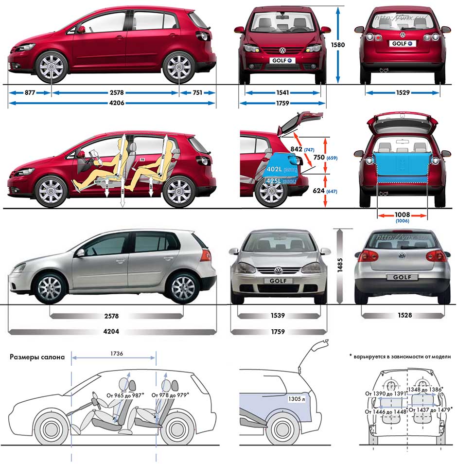
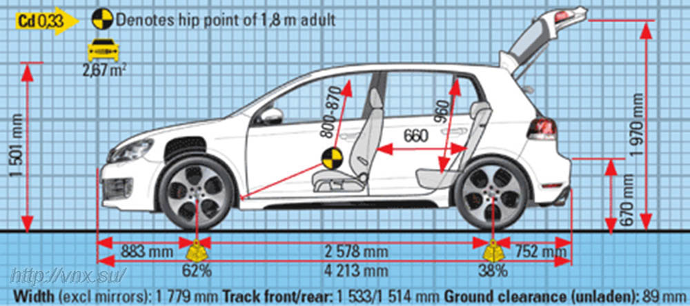
| № | Спецификация / Specs | Данные |
| Габариты (мм/mm) и масса (кг/kg) / Dimensions and Weight | ||
| 1 | Длина / Length | 4204 (4213-4216 GTI) |
| 2 | Ширина (без/с зеркалами) / Width | 1759 (1759-1779 GTI) |
| 3 | Высота (загружен/пустой) / Height | 1485 (1501 GTI) |
| 4 | Колёсная база / Wheelbase | 2578 |
| 5 | Дорожный просвет (клиренс) / Ground clearance | 115 (89 GTI) |
| 6 | Снаряжённая масса / Total (curb) weight | 1335 |
| Полная масса / Gross (max.) weight | 1860 | |
|
Двигатель / Engine |
||
| 7 | Тип / Engine Type, Code | Бензиновый, жидкостного охлаждения, четырехтактный, AXX |
| 8 | Количество цилиндров / Cylinder arrangement: Total number of cylinders, of valves | 4-цилиндровый, 16V, рядный, DOHC с верхним расположением двух распределительных валов |
| 9 | Диаметр цилиндра / Bore | 82.5 мм |
| 10 | Ход поршня / Stroke | 92.8 мм |
| 11 | Объём / Engine displacement | 1984 см³ |
| 12 | Система питания / Fuel supply, Aspiration | Непосредственный впрыск топлива, TSI, Motronic MED 9.1 |
| Двухступенчатый турбонаддув и промежуточное охлаждение наддувочного воздуха | ||
| 13 | Степень сжатия / Compression ratio | 10.5:1 |
| 14 | Максимальная мощность / Max. output power kW (HP) at rpm | 147 кВт (200 л.с.) при 5100-6000 об/мин |
| 15 | Максимальный крутящий момент / Max. torque N·m at rpm | 280 Нм при 1800-5000 об/мин |
|
Трансмиссия / Transmission |
||
| 16 | Сцепление / Clutch type | Однодисковое, сухое, с диафрагменной нажимной пружиной и гасителем крутильных колебаний, постоянно замкнутого типа |
| 17 | КПП / Transmission type | МКПП 6 шестиступенчатая механическая, двухвальная, с синхронизаторами на всех передачах переднего хода |
О Книге
- Название: Volkswagen Golf V / Golf Plus / Jetta / Touran Руководство по ремонту и эксплуатации
- Бензиновые двигатели: BCA/BKG/BLN 1.4 л FSI/TSI (1390 см³) 75-90-170 л.с./55-66-125 кВт, BGU/BSE/BSF 1.6 л (1595 см³) 102 л.с./75 кВт, BAG/BLF/BLP 1.6 л FSI (1598 см³) 115 л.с./85 кВт, AXW/BLR/BLX/BLY/AXX/BPY 2.0 л FSI/TSI (1984 см³) 150-200 л.с./110-147 кВт и дизельными BRU/AVQ/BJB/BKC/BLS 1.9 л TDI (1896 см³) 90-105 л.с./66-77 кВт, BDK/AZV/BKD/BMM 2.0 л SDI/TDI (1968 см³) 75-136-140-170 л.с./55-100-103-125 кВт
- Выпуск с 2003 года
- Серия: «Авторемонт»
- Год издания: 2007
- Автор: Коллектив авторов
- Издательство: «Ассоциация независимых издателей»
- Формат: PDF
- Страниц в книге: 264
- Размер: 57.09 МБ
- Язык: Русский
- Количество электросхем: 28

инструкцияVolkswagen Golf Plus (2011)

Contents
Owner’s Manual 2. . . . . . . . . . . . . . . . . . . . . . . . . . . . . . . .
California Emissions Warranties 377. . . . . . . . . . . . . . . . . . . . . .
Mobile Phone Package 392. . . . . . . . . . . . . . . . . . . . . . . . . . .
RCD 310 Radio 426. . . . . . . . . . . . . . . . . . . . . . . . . . . . . . . .
Supplement 477. . . . . . . . . . . . . . . . . . . . . . . . . . . . . . . . . . .
USA Warranty and Maintenance 487. . . . . . . . . . . . . . . . . . . . .

Volkswagen golf plus руководство по ремонту, инструкция по эксплуатации
Скачать руководство по ремонту, инструкция по эксплуатации Volkswagen golf plus
ПОПУЛЯРНЫЕ РАЗДЕЛЫ
 |
Тюнинг автомобилей
Большой каталог тюнингованных авто. Внешний и внутренний тюнинг. |
![]()
ВСЕ РАЗДЕЛЫ САЙТА
|
Главная |
|
Тюнинг авто |
|
Руководства, документации |
|
Полезности |
Пробки в Москве

Смотреть руководство для Volkswagen Golf Plus (2011) ниже. Все руководства на ManualsCat.com могут просматриваться абсолютно бесплатно. Нажав кнопку «Выбор языка» вы можете изменить язык руководства, которое хотите просмотреть.

MANUALSCAT | RU
Вопросы и ответы
У вас есть вопрос о Volkswagen Golf Plus (2011), но вы не можете найти ответ в пользовательском руководстве? Возможно, пользователи ManualsCat.com смогут помочь вам и ответят на ваш вопрос. Заполните форму ниже — и ваш вопрос будет отображаться под руководством для Volkswagen Golf Plus (2011). Пожалуйста, убедитесь, что вы опишите свои трудности с Volkswagen Golf Plus (2011) как можно более детально. Чем более детальным является ваш вопрос, тем более высоки шансы, что другой пользователь быстро ответит на него. Вам будет автоматически отправлено электронное письмо, чтобы проинформировать вас, когда кто-то из пользователей ответит на ваш вопрос.
Задать вопрос о Volkswagen Golf Plus (2011)
- Бренд:
- Volkswagen
- Продукт:
- автомобили
- Модель/название:
- Golf Plus (2011)
- Тип файла:
- Доступные языки:
- английский