Материал из BikesWiki — энциклопедия японских мотоциклов
Перейти к: навигация, поиск

Suzuki GSF650 Bandit
Ниже представлены прямые ссылки на скачку сервисной документации.
Для Suzuki GSF 650 Bandit
- Сервисный мануал (Service Manual) для Suzuki GSF650/GSF650S Bandit (2005)
- Сервисный мануал (Service Manual) для Suzuki GSF650/A/S/SA/GSX650F Bandit (2007)
Обзор модели
- Suzuki GSF 650 Bandit
Источник — «https://bikeswiki.ru/index.php?title=Suzuki_GSF650_Bandit:_мануалы&oldid=9829»
Категория:
- Сервисная документация
- Manuals
- Brands
- Suzuki Manuals
- Motorcycle
- GSF650SA
Manuals and User Guides for Suzuki GSF650SA. We have 2 Suzuki GSF650SA manuals available for free PDF download: Service Manual

- Manuals
- Brands
- Suzuki Manuals
- Motorcycle
- GSF650S
- Service manual
-
Contents
-
Table of Contents
-
Troubleshooting
-
Bookmarks
Related Manuals for Suzuki GSF650S
Summary of Contents for Suzuki GSF650S
-
Page 1
GSF650 / S… -
Page 2
FOREWORD GROUP INDEX This manual contains an introductory description on the SUZUKI GSF650/S and procedures for its inspection/service and overhaul of its main compo- GENERAL INFORMATION nents. Other information considered as generally known is not included. PERIODIC MAINTENANCE Read the GENERAL INFORMATION section to familiarize yourself with the motorcycle and its main- tenance. -
Page 3: How To Use This Manual
HOW TO USE THIS MANUAL TO LOCATE WHAT YOU ARE LOOKING FOR: 1. The text of this manual is divided into sections. 2. The section titles are listed in the GROUP INDEX. 3. Holding the manual as shown at the right will allow you to find the first page of the section easily.
-
Page 4
Use engine oil unless otherwise speci- 99000-32130 fied. Apply molybdenum oil solution (mixture Use fork oil. of engine oil and SUZUKI MOLY PASTE 99000-99044-10G in a ratio of 1:1). Apply SUZUKI SUPER GREASE “A”. Apply or use brake fluid. 99000-25010 Apply SUZUKI MOLY PASTE. -
Page 5: Table Of Contents
CONTENTS WARNING/CAUTION/NOTE ……………..1- 2 GENERAL PRECAUTIONS …………….1- 2 SUZUKI GSF650 (2005-MODEL) …………..1- 4 SUZUKI GSF650S (2005-MODEL) …………..1- 4 SERIAL NUMBER LOCATION …………..1- 4 FUEL AND OIL RECOMMENDATION …………1- 5 FUEL (For Canada) …………….1- 5 FUEL (For other countries) …………..1- 5 ENGINE OIL ……………….1- 5…
-
Page 6: Warning/Caution/Note
GENERAL INFORMATION WARNING/CAUTION/NOTE Please read this manual and follow its instructions carefully. To emphasize special information, the symbol and the words WARNING, CAUTION and NOTE have special meanings. Pay special attention to the mes- sages highlighted by these signal words. Indicates a potential hazard that could result in death or injury.
-
Page 7
GENERAL INFORMATION » * If parts replacement is necessary, replace the parts with Suzuki Genuine Parts or their equiva- lent. * When removing parts that are to be reused, keep them arranged in an orderly manner so that they may be reinstalled in the proper order and orientation. -
Page 8: Suzuki Gsf650 (2005-Model)
GENERAL INFORMATION SUZUKI GSF650 (2005-MODEL) * Difference between photographs and actual motorcycles may exist depending on the markets. SUZUKI GSF650S (2005-MODEL) * Difference between photographs and actual motorcycles may exist depending on the markets. SERIAL NUMBER LOCATION The frame serial number or V.I.N. (Vehicle Identification Number) 1 is stamped on the right side of the steering head pipe and frame down tube.
-
Page 9: Fuel And Oil Recommendation
Always select good quality engine oil. Use SF/SG or SH/SJ with JASO MA in API (American Petroleum Institute) MULTIGRADE classification. Suzuki recommends the use of SAE 10W-40 engine oil. If SAE 10W-40 engine oil is not available, select an alternative accord- TEMP. ing to the following chart.
-
Page 10: Break-Ln Procedures
GENERAL INFORMATION BREAK-lN PROCEDURES During manufacture only the best possible materials are used and all machined parts are finished to a very high standard but it is still necessary to allow the moving parts to “BREAK-IN” before subjecting the engine to maximum stresses.
-
Page 11: Information Labels
GENERAL INFORMATION INFORMATION LABELS Label name GSF650 GSF650A GSF650U GSF650UA GSF650S GSF600SA GSF650SU GSF650SUA Information label E-28 E-28 Fuel caution label E-02 E-02 E-02 E-02 Screen label Warning steering label Tire information label General warning label ICES Canada label E-28…
-
Page 12: Specifications
DIMENSIONS AND DRY MASS Overall length…………2 110 mm Overall width …………770 mm Overall height…………1 085/1 095 mm ..Low/High ….GSF650 1 225 mm ………….GSF650S Wheelbase …………1 440 mm Ground clearance ……….130 mm Seat height…………770/790 mm …Low/High Dry mass…………..
-
Page 13
Fuse …………..10/15/15/10/10 A Headlight …………. 12 V 60/55 W H4 ……… GSF650 12 V 55 W H7: Upper and Lower beam..GSF650S Parking or city light ……….12 V 5 W …………GSF650 12 V 5 W × 2……….GSF650S Turn signal light……….. -
Page 14: Periodic Maintenance
PERIODIC MAINTENANCE PERIODIC MAINTENANCE CONTENTS PERIODIC MAINTENANCE SCHEDULE …………2- 2 PERIODIC MAINTENANCE CHART ………….2- 2 LUBRICATION POINTS ……………..2- 3 MAINTENANCE AND TUNE-UP PROCEDURES ……….2- 4 VALVE CLEARANCE …………….2- 4 SPARK PLUGS ………………2- 6 EXHAUST PIPE BOLTS AND MUFFLER BOLTS ……..2- 7 AIR CLEANER ………………2- 8 ENGINE OIL AND OIL FILTER …………..2- 9 FUEL LINE …………………2-11…
-
Page 15: Periodic Maintenance Schedule
PERIODIC MAINTENANCE PERIODIC MAINTENANCE SCHEDULE The chart below lists the recommended intervals for all the required periodic service work necessary to keep the motorcycle operating at peak performance and economy. Maintenance intervals are expressed in terms of kilometers and months, and are dependant on whichever comes first. NOTE: More frequent servicing may be performed on motorcycles that are used under severe conditions.
-
Page 16: Lubrication Points
PERIODIC MAINTENANCE LUBRICATION POINTS Proper lubrication is important for smooth operation and long life of each working part of the motorcycle. Major lubrication points are indicated below. 1 Brake lever holder and throttle cables 5 Gearshift pivot and left footrest pivot 2 Brake pedal pivot and right footrest pivot 6 Center stand pivot and spring hook 3 Clutch lever holder and clutch cable…
-
Page 17: Maintenance And Tune-Up Procedures
(24 months). • Remove the fuel tank. (!4-3) • Remove the frame head covers. (GSF650 !5-5) • Remove the cowling. (GSF650S !5-5) • Remove the PAIR valve. (!3-97) • Remove all the spark plugs. • Remove the cylinder head cover and signal generator cover.
-
Page 18
• When installing the cylinder head cover, apply the recom- mended bond to the cylinder head cover groove and camshaft end caps. (!3-83) % 99000-31140: SUZUKI BOND “1207B” • Tighten the cylinder head cover bolts to the specified torque. (!3-84, 7-33) -
Page 19: Spark Plugs
PERIODIC MAINTENANCE SPARK PLUGS Inspect every 6 000 km (6 months) and replace every 12 000 km (24 months). • Remove all of the spark plugs. NOTE: If it is difficult to remove any of the spark plug caps, pry them up using a screwdriver.
-
Page 20: Exhaust Pipe Bolts And Muffler Bolts
PERIODIC MAINTENANCE ELECTRODE’S CONDITION Check the condition of the electrode. If it is extremely worn or burnt, replace the spark plug. Replace the spark plug if it has a broken insulator, damaged threads, etc. Check the thread size and reach when replacing the spark plug.
-
Page 21: Air Cleaner
PERIODIC MAINTENANCE AIR CLEANER Inspect every 6 000 km (12 months) and replace every 18 000 km (36 months). • Remove the fuel tank. (!4-3) • Remove the screws. • Remove the air cleaner element 1. • Carefully use compressed air to clean the air cleaner element. Always apply compressed air to the inside of the air cleaner element.
-
Page 22: Engine Oil And Oil Filter
PERIODIC MAINTENANCE • Remove the drain plug from the air cleaner drain hose to allow any water to drain out. ENGINE OIL AND OIL FILTER (ENGINE OIL) Replace initially at 1 000 km (2 month) and every 6 000 km (12 months) thereafter. (OIL FILTER) Replace initially at 1 000 km (2 month) and every 12 000 km (24 months) thereafter.
-
Page 23
FILTER. Other manufacturer’s oil filters may differ in thread specifications (thread diameter and pitch), filtering performance and durability which may lead to engine damage or oil leaks. Also, do not use a genuine Suzuki automobile oil filter on this motorcycle. -
Page 24: Fuel Line
PERIODIC MAINTENANCE 2-11 FUEL LINE Inspect every 6 000 km (12 months). • Remove the seat. • Remove the fuel tank mounting bolts. (!4-3) • Lift up the fuel tank. Inspect the fuel hoses 1 for damage and fuel leakage. If any defects are found, the fuel hoses must be replaced.
-
Page 25: Carburetor Synchronization
2-12 PERIODIC MAINTENANCE CARBURETOR SYNCHRONIZATION Inspect initially at 1 000 km (2 month) and every 12 000 km (24 months). (!4-25) PAIR (AIR SUPPLY) SYSTEM Inspect every 12 000 km (24 months). (!3-97) FUEL FILTER Inspect every 6 000 km (12 months) and replace every 12 000 km (24 months).
-
Page 26: Drive Chain
PERIODIC MAINTENANCE 2-13 DRIVE CHAIN Inspect initially at 1 000 km (2 month) and every 6 000 km (12 months) thereafter. Lubricate every 1 000 km. With the transmission in neutral, support the motorcycle using the center-stand and turn the rear wheel slowly by hand. Visu- ally check the drive chain for the possible defects listed below.
-
Page 27
* Do not use any oil sold commercially as “drive chain oil”. Such oil can damage the O-rings. * The standard drive chain is a RKFS50SMOZ1. SUZUKI recommends to use this standard drive chain as a replacement. DRIVE CHAIN CUTTING AND RECONNECTING (!5-70) -
Page 28: Brakes
PERIODIC MAINTENANCE 2-15 BRAKES (BRAKE) Inspect initially at 1 000 km (2 month) and every 6 000 km (12 months) thereafter. (BRAKE HOSE AND BRAKE FLUID) Inspect every 6 000 km (12 months). Replace hoses every 4 years. Replace fluid every 2 years.
-
Page 29
2-16 PERIODIC MAINTENANCE BRAKE PADS The extent of brake pad wear can be checked by observing the grooved limit line 1 on the pad. When the wear exceeds the grooved limit line, replace the pads with new ones. (!5-47) Replace the brake pads as a set, otherwise braking performance will be adversely affected. -
Page 30
PERIODIC MAINTENANCE 2-17 AIR BLEEDING THE BRAKE FLUID CIRCUIT Air trapped in the brake fluid circuit acts like a cushion to absorb a large proportion of the pressure developed by the master cyl- inder and thus interferes with the full braking performance of the brake caliper. -
Page 31: Tires
STONE BT011F L, GSF650S: BRIDGESTONE BT011F J) and a 160/60ZR17 M/C (69W) for the rear (GSF650, GSF650S: BRIDGESTONE BT020R L). The use of tires other than those specified may cause instability. It is highly recommended to use the specified tires.
-
Page 32: Front Forks
PERIODIC MAINTENANCE 2-19 FRONT FORKS Inspect every 12 000 km (24 months). Inspect the front fork for oil leakage, scoring or scratches on the outer surface of the inner tubes. Replace any defective parts, if necessary. (!5-15) REAR SUSPENSION Inspect every 12 000 km (24 months). Inspect the rear shock absorbers for oil leakage and check that there is no play in the swingarm.
-
Page 33: Chassis Bolts And Nuts
2-20 PERIODIC MAINTENANCE CHASSIS BOLTS AND NUTS Tighten initially at 1 000 km (2 month) and every 6 000 km (24 months) thereafter. Check that all chassis bolts and nuts are tightened to their specified torque. (Refer to page 2-21 for the loca- tions of the following nuts and bolts.) ITEM N·m…
-
Page 34
PERIODIC MAINTENANCE 2-21… -
Page 35: Compression Pressure Check
2-22 PERIODIC MAINTENANCE COMPRESSION PRESSURE CHECK The compression pressure reading of a cylinder is a good indicator of its internal condition. The decision to overhaul the cylinder is often based on the results of a compression test. Periodic mainte- nance records kept at your dealership should include compression readings for each maintenance service. COMPRESSION PRESSURE SPECIFICATION Standard Limit…
-
Page 36: Oil Pressure Check
PERIODIC MAINTENANCE 2-23 OIL PRESSURE CHECK Check the engine oil pressure periodically. This will give a good indication of the condition of the moving parts. OIL PRESSURE SPECISFICATION Above 300 kPa (3 kgf/cm²) at 3 000 r/min, oil temp. at 60 °C Below 600 kPa (6 kgf/cm²) If the oil pressure is lower or higher than specification, the following causes may be considered.
-
Page 37
ENGINE ENGINE CONTENTS ENGINE COMPONENTS REMOVABLE WITH ENGINE IN PLACE ….3- 2 ENGINE REMOVAL AND INSTALLATION …………3- 3 REMOVAL ………………..3- 3 INSTALLATION ………………3- 7 ENGINE DISASSEMBLY …………….3-12 ENGINE COMPONENTS INSPECTION AND SERVICE ……..3-26 CAMSHAFT/CYLINDER HEAD INSPECTION AND SERVICE …..3-26 CYLINDER BLOCK/PISTON INSPECTION ……….3-39 CLUTCH/CLUTCH RELEASE ASSEMBLY INSPECTION ….3-43 STARTER CLUTCH INSPECTION …………3-45 GEARSHIFT LINKAGE INSPECTION ………..3-45… -
Page 38: Engine Components Removable With Engine In Place
ENGINE ENGINE COMPONENTS REMOVABLE WITH ENGINE IN PLACE The parts listed below can be removed and reinstalled without removing the engine from the frame. Refer to page listed in each section for removal and reinstallation instructions. ENGINE CENTER ITEM REMOVAL INSPECTION INSTALLATION !3-5…
-
Page 39: Engine Removal And Installation
• Drain engine oil. (!2-9) • Remove the seat and frame covers. (!5-4) • Remove the frame head covers. (GSF650: !5-5) • Remove the cowling. (GSF650S: !5-5) • Remove the fuel tank. (!4-3) • Remove the air cleaner box mounting bolts 1.
-
Page 40
ENGINE • Remove the carburetor assembly. (!4-15) • Disconnect the lead wire couplers D to G. D Signal generator E Side-stand switch F Speed sensor G Gear position switch • Open the clamps. • Disconnect the starter motor lead wire 5. •… -
Page 41
ENGINE • Loosen the rear axle nut 0 and chain adjusters A to provide additional chain slack. • Remove the engine sprocket B. • Remove the exhaust pipe bolts. • Loosen the muffler connecting bolt C. • Remove the muffler mounting bolts D. •… -
Page 42
ENGINE • Remove the oil cooler. • Support the engine with a proper jack. • Remove the frame down tube F. • Remove the engine mounting bolts, nuts and spacer G. • Gradually lower the engine. -
Page 43: Installation
ENGINE INSTALLATION Install the engine in the reverse order of engine removal. • Insert the two long bolts from left side. Install the brackets, spacer, bolts and nuts properly, as shown in the following illustration. NOTE: The engine mounting nuts are self-locking. Once the nuts have been removed, they are no longer of any use.
-
Page 44
ENGINE • Tighten the oil cooler mounting bolts 1 to the specified torque. # Oil cooler mounting bolt: 10 N·m (1.0 kgf-m) • Tighten the oil cooler hose union bolts 2 to the specified torque. # Oil cooler hose union bolt: 28 N·m (2.8 kgf-m) Use new gasket washers to prevent oil leakage. -
Page 45
• Tighten the speed sensor rotor bolt 2 to the specified torque. # Speed sensor rotor bolt 2: 20 N·m (2.0 kgf-m) • Before installing the engine sprocket cover, apply a small quantity of SUZUKI SUPER GREASE “A” to the clutch release mechanism. ‘ 99000-25010: SUZUKI SUPER GREASE “A”… -
Page 46
3-10 ENGINE • Position the carburetor clamps as shown. 0 – 10˚ Carburetor clamp position (engine side) Carburetor clamp position (air cleaner side) • After remounting the engine, route the wire harness, cables and hoses properly. (!7-12 to -19) • Install the gearshift lever to the gearshift shaft in the correct position. -
Page 47
ENGINE 3-11 • Pour 3.3 L of SF/SG or SH/SJ with JASO MA (API) engine oil, with a viscosity rating of 10W-40 (SAE), into the engine after overhauling it. • Start up the engine and allow it run for several minutes at idle speed and then stop the engine. -
Page 48: Engine Disassembly
3-12 ENGINE ENGINE DISASSEMBLY Identify the position of each removed part. Organize the parts in their respective groups (e.g., intake, exhaust) so that they can be reinstalled in their origi- nal positions. • Remove each PAIR valve pipe and hose. •…
-
Page 49
ENGINE 3-13 • Remove the signal generator cover 4. • Remove all of the spark plugs. ) 09930-10121: Spark plug wrench set • Turn the crankshaft clockwise and align the “T” mark on the signal generator rotor with the center of the pickup coil. Also, position the notches A on the right end of each camshaft as shown. -
Page 50
3-14 ENGINE • Remove the cam chain guide A. • Remove the cylinder head bolt B. • The cylinder head can be removed after its twelve 14-mm nuts are removed. NOTE: When loosening the cylinder head nuts, loosen each nut little by little, in descending order, according to the numbers cast on the cylinder head. -
Page 51
ENGINE 3-15 • Remove the left and right oil pipes 4. • Remove the cylinder base nut 5. • Firmly grip the cylinder block at both ends and lift it straight up. If the cylinder block does not come off, lightly tap on the finless portions of it using a plastic mallet. -
Page 52
3-16 ENGINE STARTER MOTOR • Remove the starter motor 1. GENERATOR • Remove the generator 1. • Remove the signal generator rotor 2 using the special tool. • Disconnect the oil pressure switch lead wire 3. • Remove the signal generator stator (along with the pickup coil) 4 and oil pressure switch 5. -
Page 53
ENGINE 3-17 • Remove the starter clutch cover 2. • Hold the starter clutch using the special tool and loosen the clutch spring set bolts in a crisscross pattern. Then, remove the bolts. ) 09920-34810: Starter clutch holder • Remove the clutch pressure plate 3, clutch drive plates and clutch driven plates. -
Page 54
3-18 ENGINE • Hold the clutch sleeve hub using the special tool and then remove the nut. ) 09920-53740: Clutch sleeve hub holder • Remove the washer A, washer seat B and clutch sleeve hub • Remove the thrust washer D. •… -
Page 55
ENGINE 3-19 GEARSHIFT • Remove the circlip and washer from the gearshift shaft. ) 09900-06107: Snap ring pliers • Draw out the gearshift shaft 1, and then remove the gearshift cam driven gear 2. NOTE: When removing the gearshift cam driven gear, do not lose the gearshifting pawl 3, pin 4 and spring 5. -
Page 56
3-20 ENGINE • Hold the starter clutch assembly using the special tool and then loosen the starter clutch mounting bolt. ) 09920-34810: Starter clutch holder NOTE: Do not remove the starter clutch mounting bolt at this stage, only loosen it. You will need to use it in conjunction with the special tool when removing the starter clutch assembly. -
Page 57
ENGINE 3-21 CRANKCASE • Remove the countershaft bearing retainer 1. • Remove the upper crankcase bolts and nut. • Remove the oil pan 2. • Remove the shim 3 and O-ring 4. • Remove the oil sump filter 5. • Remove the oil return pipe 6. -
Page 58
3-22 ENGINE • Remove the lower crankcase bolts and nut. • Remove the main oil gallery plug 7 and O-ring. • Loosen the crankcase bolts in descending numerical order and then remove them. NOTE: Two allen bolts are located at position A to tighten the crank- shaft. -
Page 59
ENGINE 3-23 NOTE: If it is difficult to separate the crankcase halves, set the proper bolt and nut to the crankcase by separating the upper and lower crankcase halves, as shown in the illustration. TRANSMISSION • Remove the crankshaft assembly 1 from the upper crank- case. -
Page 60
3-24 ENGINE • Remove the C-rings 9 and bearing pins 0. NOTE: Do not lose the C-rings and bearing pins. • Hold the gearshift forks A and draw out the gearshift fork shaft B from the lower crankcase. • Unhook the gearshift cam stopper spring C from the lower crankcase. -
Page 61
ENGINE 3-25 • Remove the gearshift cam stopper bolt I. OIL PUMP • Remove the oil pump 1. • Remove the O-rings and dowel pins. Oil pump inspection……….!3-86… -
Page 62: Engine Components Inspection And Service
3-26 ENGINE ENGINE COMPONENTS INSPECTION AND SERVICE CAMSHAFT/CYLINDER HEAD INSPECTION AND SERVICE Identify the position of each removed part. Organize the parts in their respective groups (i.e., intake, exhaust, #1 or #2) so that they can be installed in their original locations.
-
Page 63
ENGINE 3-27 Tighten the camshaft journal holder bolts evenly and diagonally to the specified torque. # Camshaft journal holder bolt: 10 N·m (1.0 kgf-m) NOTE: Do not rotate the camshafts with the plastigauge in place. Remove the camshaft journal holders and measure the width of the compressed plastigauge using the envelope scale. -
Page 64
3-28 ENGINE CAMSHAFT SPROCKETS The fixed position of each camshaft sprocket is determined by arrow mark “3” for the intake camshaft, and by arrow marks “1” and “2” for the exhaust camshaft, as located in reference to the notch 1 on the right end of each camshaft. Inspect the teeth of each camshaft sprocket for wear or damage. -
Page 65
ENGINE 3-29 CYLINDER HEAD DISASSEMBLY • Remove the rocker arm shaft set bolt 1 and cylinder head plug 2. • Remove the rocker arm shaft 3, rocker arm 4 and spring 5. NOTE: To remove the rocker arm shaft, screw a 8-mm bolt into the rocker arm shaft end and then pull out the shaft. -
Page 66
3-30 ENGINE • Remove the valve spring seat. • Remove the valve from the combustion chamber side. • Remove the oil seal. CYLINDER HEAD DISTORTION Decarbonize the combustion chambers. Check the gasket surface of the cylinder head for distortion. Use a straightedge and thickness gauge. -
Page 67
ENGINE 3-31 VALVE FACE WEAR Visually inspect each valve face for wear. Replace any valve with an abnormally worn face. The thickness of the valve face decreases as the face wears. Measure the valve face T. If it is out of specification replace the valve with a new one. ) 09900-20102: Vernier calipers ( Valve face thickness T Service Limit: 0.5 mm… -
Page 68
3-32 ENGINE • Re-finish the valve guide holes in the cylinder head using the reamer and handle. ) 09916-34580: Valve guide reamer 09916-34542: Valve guide reamer handle • Install a ring onto each valve guide. Be sure to use new rings. •… -
Page 69
ENGINE 3-33 • The ring-like dye impression left on the valve face must be continuous without any breaks. In addition, the width of the dye ring, which is the valve seat width, must be within the fol- lowing specification. ( Valve seat width W Standard: 0.9 –… -
Page 70
3-34 ENGINE • Seat the pilot snugly. Install the 45° cutter 2, attachment 3 and T-handle 4. INITIAL SEAT CUT • Using the 45° cutter, descale and clean up the seat. Rotate the cutter one or two turns. • Measure the valve seat width W after every cut. 45˚… -
Page 71
ENGINE 3-35 FINAL SEAT CUT Contact area too low and too narrow on face of valve • If the contact area is too low or too narrow, use the 45° cutter to raise and widen the contact area. NOTE: After cutting the 15° angle, it is possible that the valve seat (45°) is too narrow. -
Page 72
3-36 ENGINE VALVE SPRINGS The force of the coil spring keeps the valve seat tight. A weak- ened spring results in reduced engine power output and often accounts for the chattering noise coming from the valve mecha- nism. Check the valve springs for proper strength by measuring their free length and also by the force required to compress them. -
Page 73
• Insert the valves with their stems coated with molybdenum oil solution (mixed engine oil/moly paste). Coat the entire stem making sure that there are no gaps. When inserting each valve, take care not to damage the lip of the oil seal. + 99000-25140: SUZUKI MOLY PASTE… -
Page 74
3-38 ENGINE • Install the valve springs with the smaller pitch A facing the cylinder head. B Larger pitch C Up D Paint mark • Install the valve spring retainer, press down the springs using the valve lifter and then install the cotter halves on to the stem end. -
Page 75: Cylinder Block/Piston Inspection
ENGINE 3-39 INTAKE PIPES • When installing the intake pipe, apply SUZUKI SUPER GREASE “A” to the O-ring. ‘ 99000-25010: SUZUKI SUPER GREASE “A” • When installing the intake pipe bolts, apply a small quantity of THREAD LOCK “1342” to their thread.
-
Page 76
3-40 ENGINE ) 09900-20508: Cylinder gauge set ( Cylinder bore Standard: 65.500 – 65.515 mm Service Limit: 65.615 mm PISTON DIAMETER Measure the piston diameter using the micrometer at 15 mm from the skirt end. If the piston diameter is less than the service limit, replace the piston. -
Page 77: Piston Ring Thickness
ENGINE 3-41 ( Piston ring groove width Standard: (1st) : 1.01 – 1.03 mm (2nd) : 0.81 – 0.83 mm (Oil) : 1.51 – 1.53 mm ( Piston ring thickness Standard: (1st) : 0.97 – 0.99 mm (2nd) : 0.77 – 0.79 mm PISTON RING FREE END GAP AND PISTON RING END GAP Measure the piston ring free end gap using vernier calipers.
-
Page 78
3-42 ENGINE Measure the piston pin outside diameter at three positions using the micrometer. If any of the measurements are out of specifica- tion, replace the piston pin. ) 09900-20205: Micrometer (0 – 25 mm) ( Piston pin O.D. Service Limit: 17.980 mm PISTON RING INSTALLATION •… -
Page 79: Clutch/Clutch Release Assembly Inspection
ENGINE 3-43 • Position the piston ring gaps as shown. Before inserting each piston into its cylinder, check that the gaps are properly posi- tioned. A Exhaust side B Intake side 5 2nd ring and lower side rail 6 Upper side rail 7 1st ring and spacer NOTE: Install the pistons with the “…
-
Page 80
• Before removing the clutch release assembly, operate the clutch lever by hand to inspect it for a smooth movement and any abnormal noise. If excessive resistance is felt, clean and apply SUZUKI SUPER GREASE “A” to the clutch release mechanism. ‘ 99000-25010: SUZUKI SUPER GREASE “A”… -
Page 81: Starter Clutch Inspection
ENGINE 3-45 STARTER CLUTCH INSPECTION STARTER CLUTCH Install the starter driven gear onto the starter clutch and turn the starter driven gear by hand (the gear turns in only one direction). The starter driven gear should turn smoothly. If excessive resis- tance is felt while turning the starter driven gear, inspect the starter clutch.
-
Page 82
) 09943-88211: Pinion bearing installer The removed oil seal must be replaced with a new one. NOTE: Apply SUZUKI SUPER GREASE “A” onto the oil seal lip to pre- vent oil seal damage when installing the lower crankcase. ‘ 99000-25010: SUZUKI SUPER GREASE “A”… -
Page 83: Transmission Inspection And Service
ENGINE 3-47 TRANSMISSION INSPECTION AND SERVICE Identify the position of each removed part. Organize the parts in their respective groups (i.e., drive or driven) so that they can be reinstalled in their original positions. GEARSHIFT FORK-TO-GEARSHIFT FORK GROOVE CLEARANCE Measure the gearshift fork clearance in the groove of its respec- tive gear using the thickness gauge.
-
Page 84
3-48 ENGINE DISASSEMBLY Countershaft assembly • Remove the cap 1, left end bearing 2 and oil seal 3. • Remove the 6th (top) drive gear circlip 4 from its groove and slide it towards the 3rd/4th drive gears 5. ) 09900-06107: Snap ring pliers •… -
Page 85
ENGINE 3-49 • Remove the 1st (low) driven gear bushing 3, washer and the 5th driven gear 4. • Remove the circlip, washer and 4th driven gear 5. • Remove the 4th driven gear bushing 6, lock washers, 3rd driven gear 7, 3rd driven gear bushing 8 and washer. •… -
Page 86
3-50 ENGINE • Remove the 2nd driven gear bushing A. • Remove the oil seal B. -
Page 87
* Before installing the gears, lightly coat the driveshaft, counter- shaft and bushings with molybdenum oil solution. * Before installing the oil seal, apply SUZUKI SUPER GREASE “A” to the oil seal lip. + 99000-25140: SUZUKI MOLY PASTE ‘ 99000-25010: SUZUKI SUPER GREASE “A”… -
Page 88
3-52 ENGINE When installing the 3rd and 4th driven gear bushings onto the driveshaft, align the driveshaft oil hole 1 with the bushing oil hole 2. • After installing the 3rd driven gear onto the driveshaft, install lock washer #2 3 onto the driveshaft, and position it so it fits into the groove. -
Page 89
ENGINE 3-53 1 1st (low) driven gear 2 5th driven gear 3 4th driven gear 4 3rd driven gear 5 6th (top) driven gear 6 2nd driven gear 7 Driveshaft Countershaft/1st (low) drive gear 9 5th drive gear 0 3rd/4th drive gear A 6th (top) drive gear B 2nd drive gear ITEM… -
Page 90
3-54 ENGINE… -
Page 91: Conrod/Crankshaft Inspection
ENGINE 3-55 CONROD/CRANKSHAFT INSPECTION CONROD SMALL END I.D. Measure the conrod small end inside diameter using the small bore gauge. If the conrod small end inside diameter exceeds the service limit, replace the conrod. ) 09900-20602: Dial gauge (1/1 000 mm) 09900-22403: Small bore gauge (18 –…
-
Page 92
3-56 ENGINE • Remove the conrods and mark them to identify their respec- tive cylinders. • Inspect the bearing surfaces for any signs of fusion, pitting, burns, or flaws. If there is any damage, replace them with the specified set of bearings. CONROD-CRANK PIN BEARING SELECTION •… -
Page 93
ENGINE 3-57 • Check the corresponding crank pin O.D. code numbers (“1”, “2” or “3”) 3. Bearing selection table Crank pin O.D. 3 Code Conrod Green Black Brown I.D. 2 Black Brown Yellow Conrod I.D. specification Code I.D. specification 37.000 – 37.008 mm 37.008 –… -
Page 94: Crankcase-Crankshaft Bearing Inspection And Service
• Apply molybdenum oil solution to the crank pin and bearing surface. + 99000-25140: SUZUKI MOLY PASTE • When mounting the conrod on the crankshaft, make sure that the numbers 2 on the conrod faces towards the intake side.
-
Page 95
ENGINE 3-59 • Mate the lower crankcase with the upper crankcase and tighten the crankshaft bolts to the specified torque and in the proper tightening sequence. # Crankcase bolt (Initial) : 13 N·m (1.3 kgf-m) (Final) : 23 N·m (2.3 kgf-m) •… -
Page 96: Crankshaft Thrust Clearance Adjustment
3-60 ENGINE Crankcase journal I.D. specification Code I.D. specification 35.000 – 35.008 mm 35.008 – 35.016 mm Crankshaft journal O.D. specification Code O.D. specification 31.992 – 32.000 mm 31.984 – 31.992 mm 31.976 – 31.984 mm ) 09900-20202: Micrometer (25 – 50 mm) Bearing thickness specification Color (Part No.) Thickness…
-
Page 97
ENGINE 3-61 NOTE: Pull 1 the crankshaft to the left so that there is no clearance on the right-side thrust bearing. ( Crankshaft thrust clearance Standard: 0.04 – 0.09 mm If the thrust clearance exceeds the standard range, adjust the thrust clearance as follows: •… -
Page 98: Crankshaft Runout
3-62 ENGINE • After selecting a left-side thrust bearing, install it and then measure the thrust clearance again. NOTE: The right-side thrust bearing color code 1 and part number are as follows. GREEN (12228-43414). CRANKSHAFT RUNOUT Support the crankshaft using V-blocks as shown, with the two end journals resting on the blocks.
-
Page 99: Engine Reassembly
ENGINE 3-63 ENGINE REASSEMBLY Reassemble the engine in the reverse order of disassembly. The following steps require special attention or precautionary measures should be taken. NOTE: Apply engine oil to each running and sliding part before reas- sembling. OIL PUMP •…
-
Page 100
3-64 ENGINE • Install the gearshift cam 3 and its related parts. 4 Gearshift cam stopper 5 Circlip 6 Spring 7 Circlip Always use new circlips (5 and 7). • Position the gearshift cam in the neutral position as shown. This will allow the gearshift forks and transmission gears to be installed easily. -
Page 101
ENGINE 3-65 • Install the bearing pins C and C-rings D into the upper crank- case. • Install the countershaft assembly E and driveshaft assembly F into the upper crankcase. NOTE: * Be sure to install the bearing dowel pins G in their respective positions. -
Page 102
• Before installing the crankshaft assembly, apply molybdenum oil solution to each crankshaft journal bearing. + 99000-25140: SUZUKI MOLY PASTE • Install the crankshaft assembly along with the cam chain into the upper crankcase. • Insert the right-and left-thrust bearings with the oil grooves facing towards the crankshaft web. -
Page 103
ENGINE 3-67 BOND “1207B” should be applied to the following locations. The line of BOND… -
Page 104
3-68 ENGINE • Install the right oil pipe A with the bolt 1. • Install the copper washers onto bolts 9 and A. • Install the two allen bolts at position B. • Install the ten crankcase bolts (8 mm). •… -
Page 105
ENGINE 3-69 • Install the left oil pipe E. • Install a new O-ring F and shim G. • Install a new gasket and the oil sump filter H. Replace the gasket and O-ring with new ones to pre- vent oil leakage. •… -
Page 106
3-70 ENGINE • Install the oil seal retainer 4 with the four bolts and then bend the tab on the retainer. NOTE: Route the gear position switch lead wire to the inside of the oil seal retainers tab A as shown. STARTER CLUTCH •… -
Page 107
ENGINE 3-71 • Install the gearshift shaft 5. NOTE: Align the center teeth on the gearshift shaft with the center teeth on the gearshift cam driven gear. • Install the washer and fix the gearshift shaft with the circlip. ) 09900-06107: Snap ring pliers OIL PUMP DRIVEN GEAR •… -
Page 108
3-72 ENGINE CLUTCH • Install the primary driven gear assembly onto the counter- shaft, and apply engine oil onto the needle bearing 1 and spacer 2. • Install the thrust washer 3 onto the countershaft. • Install the clutch sleeve hub onto the countershaft. •… -
Page 109
) 09920-34810: Starter clutch holder # Clutch spring set bolt: 12 N·m (1.2 kgf-m) • Apply a light coat of the SUZUKI BOND to the clutch cover gasket mating surface A as shown. , 99000-31140: SUZUKI BOND “1207B”… -
Page 110
3-74 ENGINE • Apply a light coat of SUZUKI BOND to the starter clutch cover gasket mating surface C as shown. , 99000-31140: SUZUKI BOND “1207B” • Install the dowel pin, a new gasket and the starter clutch cover, and tighten the cover bolts securely. -
Page 111
• Install the starter motor 2. # Starter motor mounting bolt: 6 N·m (0.6 kgf-m) NOTE: * Apply SUZUKI SUPER GREASE “A” to the starter motor O- ring. * Apply a small quantity of THREAD LOCK “1342” to the two bolts. -
Page 112
Before installing the cylinder block stud bolt 7, apply a light coat of the recommended bond to its threads. , 99000-31140: SUZUKI BOND “1207B” # Cylinder block stud bolt: 15 N·m (1.5 kgf-m) • Make sure that the oil jets 8 in the upper crankcase are not clogged. -
Page 113
• Install the new O-rings 2 onto the oil pipes and apply SUZUKI SUPER GREASE “A” to the O-rings. • Install the right and left oil pipes. Replace the O-rings 2 with new ones to prevent oil leakage. -
Page 114
3-78 ENGINE CYLINDER HEAD Exhaust side • Place the cylinder head onto the cylinder block. • Cylinder head nuts and washers must be installed in the cor- rect position as shown. A Copper washer with normal nut (4 pcs.) B Copper washer with cap nut (4 pcs.) C Steel washer with normal nut (4 pcs.) •… -
Page 115
3-79 NOTE: Before installing the camshafts onto the cylinder head, apply SUZUKI MOLY PASTE onto the camshaft journals D and do not leave any dry spots. Also, apply engine oil onto the camshaft journal holders. + 99000-25140: SUZUKI MOLY PASTE •… -
Page 116
3-80 ENGINE • The exhaust camshaft sprocket has an arrow marked “1”. Turn the exhaust camshaft so that the arrow is aligned with the gasket surface of the cylinder head. • Engage the cam chain with the exhaust camshaft sprocket. •… -
Page 117
ENGINE 3-81 • Each camshaft journal holder is identified with an embossed letter. Install the dowel pins into each cam- shaft journal holder. • Fasten the camshafts (IN and EX) evenly by tightening the camshaft journal holder bolts sequentially and in a crisscross pattern. -
Page 118
3-82 ENGINE CAM CHAIN TENSIONER ADJUSTER • After removing the spring holder bolt 1 and spring, unlock the ratchet mechanism 2 and push the push rod 3 all the way into the cam chain tensioner adjuster. NOTE: Before installing the cam chain tensioner adjuster, turn the crankshaft clockwise to remove any cam chain slack between the crankshaft sprocket and exhaust camshaft sprocket. -
Page 119
(!2-4) • Apply a light coat of the recommended bond to the signal gen- erator gasket mating surface A as shown. , 99000-31140: SUZUKI BOND “1207B” • Install a new gasket and the signal generator cover 1. NOTE: * Install the gasket washer onto the signal generator cover bolt B as shown. -
Page 120
3-84 ENGINE • Place the cylinder head cover onto the cylinder head. • Install the four gaskets onto each cylinder head cover union bolt 1 and apply oil to thread and gasket before tighten them to the specified torque. Replace the gaskets with new ones to prevent oil leak- age. -
Page 121
ENGINE 3-85 • Turn the oil filter by hand until you feel that the oil filter O-ring has contacted the oil filter mounting surface. Then, tighten the oil filter two full turns using the special tool. ) 09915-40610: Oil filter wrench NOTE: * Before installing the oil filter, apply a light coat of engine oil onto its O-ring. -
Page 122: Engine Lubrication System
3-86 ENGINE ENGINE LUBRICATION SYSTEM OIL PUMP REMOVAL The crankcase must be separated to service the oil pump. The oil pump service requires engine removal and disassembly. Refer to the engine removal and engine disassembly sections for oil pump removal. (!3-25) INSPECTION Rotate the oil pump by hand and check that it moves smoothly.
-
Page 123
ENGINE 3-87 • Oil pressure regulator • Oil sump filter INSPECTION Oil pressure regulator Check the operation of the oil pressure regulator by pushing on the piston with an appropriately shaped tool. If the piston does not operate, replace the oil pressure regulator with a new one. CLEANING Oil sump filter Clean the oil sump filter using compressed air. -
Page 124
3-88 ENGINE INSTALLATION Installation is in the reverse order of removal. NOTE: Refer to the following pages for the details of each step. Install: • Oil sump filter NOTE: Do not loose the O-ring 1 and shim 2. • Oil pressure regulator # Oil pressure regulator: 28 N·m (2.8 kgf-m) •… -
Page 125: Oil Pressure Switch
ENGINE 3-89 OIL PRESSURE SWITCH REMOVAL After draining engine oil, remove the oil pressure switch. NOTE: Refer to the following pages for the details of each step. Drain: • Engine oil (!2-9) Remove: • Signal generator cover • Oil pressure switch INSPECTION !6-40 INSTALLATION…
-
Page 126: Oil Cooler
3-90 ENGINE OIL COOLER INSPECTION AND CLEANING Inspect the oil cooler hoses for damage and oil leaks. If any defects are found, replace the oil cooler hose(-s) with a new one. Inspect the oil cooler for oil leaks. If any defects are found, replace the oil cooler with a new one.
-
Page 127: Oil Jet
ENGINE 3-91 OIL JET OIL JET (for the cylinder head) REMOVAL • The oil jet (for the cylinder head) can be removed after remov- ing the cylinder block. NOTE: Refer to the following pages for the details of each step. Drain: •…
-
Page 128
3-92 ENGINE INSTALLATION Refer to the cylinder block installation, engine reassembly and engine installation sections. NOTE: Before installing the oil jets, apply a light coat of engine oil to the O-rings. -
Page 129: Engine Lubrication System Chart
ENGINE 3-93 ENGINE LUBRICATION SYSTEM CHART…
-
Page 130: Engine Lubrication System
3-94 ENGINE ENGINE LUBRICATION SYSTEM…
-
Page 131: Cylinder Head Cover
ENGINE 3-95 CYLINDER HEAD COOLING SYSTEM CHART STUD BOLT STUD BOLT OIL PIPE OIL PIPE CYLINDER HEAD OIL POOL OIL POOL OIL POOL OIL POOL UNION BOLT UNION BOLT ORIFICE ORIFICE UNION BOLT UNION BOLT CYLINDER HEAD COVER HOSES OIL GALLERY OIL PUMP OIL SUMP FILTER OIL PAN…
-
Page 132: Cylinder Head Cooling System
3-96 ENGINE CYLINDER HEAD COOLING SYSTEM…
-
Page 133: Pair (Air Supply) System
ENGINE 3-97 PAIR (AIR SUPPLY) SYSTEM REMOVAL • Remove the fuel tank. (!4-3) • Disconnect all of the PAIR valve hoses. 1 Vacuum hose 2 Air cleaner hose 3 PAIR hose No. 1 4 PAIR hose No. 2 5 PAIR hose No. 4 6 PAIR hose No.
-
Page 134: Installation
3-98 ENGINE REED VAVLE • Remove the PAIR valve covers. • Inspect the reed valves for the carbon deposit. • If the carbon deposit is found in the reed valve, replace the PAIR valve with a new one. PAIR VALVE •…
-
Page 135
ENGINE 3-99 • Tighten the PAIR pipe mounting nuts to the specified torque. # PAIR pipe mounting nut: 10 N·m (1.0 kgf-m) Use a new gasket 1 to prevent exhaust gas leakage. • Rout the hoses properly. (!7-19) -
Page 136
FUEL SYSTEM 4-1 FUEL SYSTEM CONTENTS FUEL SYSTEM ………………..4- 2 FUEL TANK …………………4- 3 REMOVAL ………………..4- 3 REMOUNTING ………………4- 3 FUEL VALVE ………………..4- 4 REMOVAL ………………..4- 5 INSPECTION AND CLEANING ………….4- 5 INSTALLATION ………………4- 5 FUEL FILTER ………………..4- 6 REMOVAL ………………..4- 6 INSPECTION ………………4- 6 INSTALLATION ………………4- 6 FUEL LEVEL GAUGE ………………4- 7… -
Page 137: Fuel System
4-2 FUEL SYSTEM FUEL SYSTEM The fuel system consists of a fuel tank, fuel valve, vacuum hose, fuel filter, fuel hose and carburetor assem- bly. When there is negative pressure (vacuum) in the combustion chamber, the fuel is able to flow from the fuel tank, through the fuel valve and then to the carburetor assembly.
-
Page 138: Fuel Tank
FUEL SYSTEM FUEL TANK REMOVAL Gasoline is highly flammable and explosive. Keep heat, sparks and flames away from gasoline. • Remove the seat. («5-4) • Remove the fuel tank mounting bolts. • Disconnect the vacuum hose 1, fuel hose 2. •…
-
Page 139: Fuel Valve
4-4 FUEL SYSTEM FUEL VALVE When the engine is not operating, the fuel valve 1 is kept closed by the tension of the spring 2, which closes the fuel passageway and stops the flow of fuel to the carburetors. When the engine has started, negative pressure (vacuum) A is generated in the combustion chamber and reaches the diaphragm through a passage in the carburetor’s main bore and the vacuum hose.
-
Page 140: Removal
FUEL SYSTEM REMOVAL Gasoline is very explosive. Extreme care must be taken. • Remove the fuel tank. («4-3) • Remove the fuel valve 1. INSPECTION AND CLEANING If the fuel filter is dirty with sediment or rust, fuel will not flow smoothly and loss in engine power may result.
-
Page 141: Fuel Filter
4-6 FUEL SYSTEM FUEL FILTER REMOVAL • Remove the fuel tank. («4-3) • Remove the fuel filter 1. INSPECTION • If the fuel filter is dirty with sediment or rust, fuel will not flow smoothly and loss in engine power may result. Replace the fuel filter if necessary.
-
Page 142: Fuel Level Gauge
FUEL SYSTEM FUEL LEVEL GAUGE REMOVAL AND INSTALLATION Gasoline is very explosive. Extreme care must be taken. • Remove the fuel tank. («4-3) • Remove the fuel level gauge 1. Install the fuel level gauge in the reverse order of removal. Pay attention to the following points.
-
Page 143: Carburetor
4-8 FUEL SYSTEM CARBURETOR CONSTRUCTION 1 Top cap C Float pin M Air vent hose 2 Spring D Starter (enricher) plunger N Fuel filter 3 Jet needle stopper E Gasket (O-ring) O Fuel hose 4 Jet needle F Float chamber P Fuel joint pipe No.
-
Page 144: Specifications
FUEL SYSTEM SPECIFICATIONS SPECIFICATION ITEM E-02, 19 E-19 U-type ← Carburetor type KEIHIN CVR32 ← Bore size 32.5 I.D. No. 38G0 38G2 ← Idle r/min 1 200 ± 100 r/min ← Float height 17.0 mm Main jet #105 (For carburetor #1, 4) ←…
-
Page 145: I.d. No. Location
4-10 FUEL SYSTEM I.D. NO. LOCATION Each carburetor has an I.D. number 1 printed on its body.
-
Page 146: Diaphragm And Piston Operation
FUEL SYSTEM 4-11 DIAPHRAGM AND PISTON OPERATION The carburetor is a variable-venturi type, whose venturi cross sectional area is increased or decreased auto- matically by the piston valve 1. The piston valve moves according to the negative pressure present on the downstream side of the venturi A.
-
Page 147: Slow System
4-12 FUEL SYSTEM SLOW SYSTEM This system supplies fuel during engine operation when the throttle valve 1 is closed or slightly opened. The fuel from the float chamber 2 is metered by the slow jet 3 where it mixes with air coming in through the slow air jet 4.
-
Page 148: Main System
FUEL SYSTEM 4-13 MAIN SYSTEM As the throttle valve 1 is opened, engine speed rises and negative pressure in the venturi A increases. This causes the piston valve 2 to move upward. The fuel in the float chamber 3 is metered by the main jet 4. The metered fuel enters the needle jet 5, mixes with the air admitted through the main air jet 6 and forms an emulsion.
-
Page 149: Starter (Enricher) System
4-14 FUEL SYSTEM STARTER (ENRICHER) SYSTEM Pulling the starter (enricher) plunger causes fuel to be drawn into the starter circuit from the float chamber The starter jet 2 meters this fuel. The fuel then flows into the fuel pipe 3 and mixes with the air coming from the float chamber 1.
-
Page 150: Removal
FUEL SYSTEM 4-15 REMOVAL • Remove the seat and frame covers. («5-4) • Remove the fuel tank. («4-3) • Remove the air cleaner box mounting bolts. • Disconnect the throttle position sensor coupler 1. • Loosen the respective carburetor clamp screws. •…
-
Page 151: Disassembly
4-16 FUEL SYSTEM DISASSEMBLY Before disassembly, prepare a clean and well lit work place where carburetor components can be laid out neatly and will not get lost. Study the service manual carburetor diagram and famil- iarize yourself with component locations and the different fuel circuits and their routing through the carburetor.
-
Page 152
FUEL SYSTEM 4-17 • Remove the top cap. Do not use compressed air on the carburetor body, before removing the diaphragm; this may damage the diaphragm. • Remove the spring and piston valve assembly 5. • Remove the jet needle stopper 6, washer 7, E-ring 8 and jet needle 9 from the piston valve. -
Page 153
4-18 FUEL SYSTEM • Remove the float pin C, float D and needle valve E. • Remove the following parts. F Main jet G Needle jet holder H Needle jet I Slow jet J Starter (enricher) jet K Pilot screw NOTE: Before removing the pilot screw K, its setting must be deter- mined. -
Page 154: Cleaning
FUEL SYSTEM 4-19 • Remove the throttle valve O. CLEANING Some carburetor cleaning chemicals, especially dip- type soaking solutions, are very corrosive and must be handled carefully. Always follow the chemical man- ufacturer’s instructions on proper use, handling and storage. •…
-
Page 155: Inspection
4-20 FUEL SYSTEM INSPECTION Check the following items for any damage or clogging. * Slow jet * Valve seat * Main jet * Piston valve * Main air jet * Starter (enricher) jet * Slow air jet * Gasket and O-ring * Needle jet air bleeding hole * Throttle shaft oil seal * Float * Diaphragm…
-
Page 156: Reassembly
FUEL SYSTEM 4-21 FLOAT HEIGHT To check the float height, turn the carburetor upside down. Measure the float height A while the float arm is just contacting the needle valve using vernier calipers. Bend the tongue B as necessary to bring the float height A to the specified level.
-
Page 157
4-22 FUEL SYSTEM PILOT SCREW • After cleaning, reinstall the pilot screw to the original setting by turning the screw in until it lightly seats, and then turn it out the same number of turns counted during disassembly. Replace the O-ring 1 with a new one. CARBURETOR ENGAGEMENT •… -
Page 158
FUEL SYSTEM 4-23 THROTTLE POSITION SENSOR POSITIONING Install the throttle position sensor as described below. • Measure the resistance between the throttle position sensor terminals. («4-21) % 09900-25008: Multi circuit tester set ‘ Tester knob indication: Resistance (Ω) • Measure the resistance between the throttle position sensor terminals as shown. -
Page 159: Remounting
4-24 FUEL SYSTEM REMOUNTING Remount the carburetor assembly in the reverse order of removal. Pay attention to the following points. CARBURETOR CLAMPS Position the carburetor clamps as shown. 0 – 10˚ Carburetor clamp position (engine side) Carburetor clamp position (air cleaner side) THROTTLE CABLE ADJUSTMENT (MAJOR ADJUSTMENT) NOTE: Minor adjustment can be made by the throttle grip side adjuster.
-
Page 160: Carburetor Synchronization
FUEL SYSTEM 4-25 CARBURETOR SYNCHRONIZATION Check and adjust the carburetor synchronization among the four carburetors as follows. USE OF VACUUM BALANCER GAUGE Calibrating each vacuum gauge • Start up the engine and run it in idling condition for warming up. •…
-
Page 161
4-26 FUEL SYSTEM • Turn the air screw 5 of the carburetor balancer gauge so that the vacuum pressure causes the steel ball 6 to rise to the center line 7 of the tube. • After making sure that the steel ball remains at the center line, disconnect the hose from the vacuum inlet and connect the next hose to the vacuum inlet. -
Page 162
FUEL SYSTEM 4-27 • If the steel balls are not at the same level, adjust the throttle valve synchronizing screws 1, 2 and 3. Adjusting order is as follows. 1 → 2 → 3 • After balancing the carburetor, set the engine speed by turn- ing the throttle stop screw. -
Page 163
CHASSIS CHASSIS CONTENTS EXTERIOR PARTS ………………5- 3 CONSTRUCTION ……………… 5- 3 REMOVAL ………………… 5- 4 INSTALLATION ………………5- 6 FRONT WHEEL ……………….. 5- 7 CONSTRUCTION ……………… 5- 7 REMOVAL ………………… 5- 8 INSPECTION AND DISASSEMBLY …………5- 8 REASSEMBLY AND INSTALLATION ……….5-10 FRONT FORK ……………….. -
Page 164
CHASSIS CHASSIS CONTENTS FRONT BRAKE ………………… 5-46 CONSTRUCTION ……………… 5-46 BRAKE PAD REPLACEMENT ………….. 5-47 BRAKE FLUID REPLACEMENT …………5-48 BRAKE CALIPER REMOVAL AND DISASSEMBLY ………………5-49 BRAKE CALIPER INSPECTION …………5-50 BRAKE CALIPER REASSEMBLY AND INSTALLATION ………………5-51 BRAKE DISC INSPECTION …………..5-52 MASTER CYLINDER REMOVAL AND DISASSEMBLY ……………… -
Page 165: Exterior Parts
CHASSIS EXTERIOR PARTS CONSTRUCTION GSF650 GSF650S 1 Frame head cover 4 Upper panel 7 Cowling brace 2 Cowling body 5 Lower panel 8 Cowling side bracket 3 Wind screen 6 Combination meter…
-
Page 166: Removal
CHASSIS REMOVAL SEAT • Unlock the seat with the ignition key. • Remove the front and rear seats as an assembly. SEAT HEIGHT ADJUSTMENT ….(!5-74) LUGGAGE BOX • Remove the seat. (! Above) • Remove the luggage box lid 1. •…
-
Page 167
FRAME HEAD COVER (GSF650) • Remove the frame head cover 1 (LH and RH). «: Hooked point COWLING AND COWLING BRACE (GSF650S) • Remove the caps. • Remove the rear view mirrors (LH and RH). • Remove the combination meter unit. -
Page 168: Installation
CHASSIS • Disconnect the turn signal lead wire couplers 3. • Remove the cowling 4 along with the lower panel 5 and turn signal assemblies. • Disconnect the headlight and position light couplers. • Remove the headlight assembly 6. • Remove the cowling brace 7. FRONT FENDER……..
-
Page 169: Front Wheel
CHASSIS FRONT WHEEL CONSTRUCTION 1 Front axle 6 Bearing (LH) A Balancer 2 Dust seal 7 Brake disc (LH) A Front axle 3 Brake disc (RH) 8 Collar B Brake disc bolt 4 Bearing (RH) 9 Front wheel 5 Spacer 0 Air bleeder valve ITEM N·m…
-
Page 170: Removal
CHASSIS REMOVAL • Remove the brake calipers 1 (LH and RH). • Loosen the front axle pinch bolt 2. • Loosen the front axle 3. • Raise the front wheel off the ground using a jack or wooden block. • Draw out the front axle 3 and remove the front wheel. * Make sure that the motorcycle is supported securely.
-
Page 171
CHASSIS • Remove the brake discs. WHEEL Make sure that the wheel runout (axial and radial) checked as shown do not exceed the service limit. An excessive runout is usually due to worn or loosened wheel bearings and can be reduced by replacing the bearings. -
Page 172: Reassembly And Installation
5-10 CHASSIS REASSEMBLY AND INSTALLATION Reassembly and installation is in the reverse order of removal and disassembly. Pay attention to the follow- ing points: Left Right 39 N . m (3.9 kgf-m) 39 N . m (3.9 kgf-m) 23 N . m (2.3 kgf-m) 23 N .
-
Page 173
CHASSIS 5-11 WHEEL BEARINGS • Apply grease to the bearing before installing. ‘ 99000-25010: SUZUKI SUPER GREASE “A” • Install the wheel bearing using the used bearing and special tool. % 09924-84521: Bearing installer set * First install the left bearing, then install the spacer and right wheel bearing. -
Page 174
5-12 CHASSIS FRONT AXLE • Tighten the front axle 1 to the specified torque. # Front axle: 65 N·m (6.5 kgf-m) NOTE: Before tightening the front axle pinch bolt 2, move the front fork up and down four or five times. •… -
Page 175: Front Fork
CHASSIS 5-13 FRONT FORK CONSTRUCTION 1 Front fork protector 2 Dust seal 3 Oil seal stopper ring 4 Oil seal 5 Oil seal retainer Outer tube slide metal 7 Oil lock piece 8 Outer tube (R) 9 Outer tube (L) 0 Gasket A Ring B Cylinder…
-
Page 176: Removal And Disassembly
5-14 CHASSIS REMOVAL AND DISASSEMBLY • Raise the front wheel off the ground using a jack or wooden block. • Remove the brake calipers and front wheel. (! 5-8) * Make sure that the motorcycle is supported securely. * Do not operate the front brake lever with the front wheel removed.
-
Page 177
CHASSIS 5-15 • Remove the protector 4. • Remove the front fork cap bolt 5, spring seat 6, spacer 7, washer 8 and fork spring 9. Hold the front fork cap bolt when removing it, or it will jump out due to the spring pressure. •… -
Page 178: Inspection
If any defects are found, replace them with new ones. FORK SPRING Measure the fork spring free length. If it is shorter than the ser- vice limit, replace it with a new one. & Front fork spring free length Service Limit: 337 mm (GSF650) 332 mm (GSF650S)
-
Page 179: Reassembly And Installation
* Apply fork oil to the slide metals and oil seal lip. * 99000-99044-10G: SUZUKI FORK OIL #10 • Hold the inner tube vertically, clean the metal groove and install the inner tube slide metal by hand.
-
Page 180
5-18 CHASSIS • Insert the inner tube into the outer tube and install the oil seal 3 using the special tool. % 09940-52861: Front fork oil seal installer • Install the oil seal stopper ring 2. Make sure that the oil seal stopper ring is fitted securely. -
Page 181
5-19 FORK OIL • Pour the specified fork oil into the inner tube. * 99000-99044-10G: SUZUKI FORK OIL #10 & Capacity (each leg): 502 mL (GSF650) 507 ml (GSF650S) • Move the inner tube up and down several strokes until no more bubbles come out from the oil. -
Page 182
5-20 CHASSIS INSTALLATION • Align the edge of the inner tube with the upper surface of the steering stem upper bracket. • Tighten the front fork lower clamp bolts 1. # Front fork lower clamp bolt 1: 23 N·m (2.3 kgf-m) •… -
Page 183: Handlebars And Steering
CHASSIS 5-21 HANDLEBARS AND STEERING CONSTRUCTION 1 Steering stem upper bracket 7 Handlebar A Steering stem head nut 2 Dust seal 8 Handlebar spacer B Handlebar holder bolt 3 Steering stem upper bearing 9 Handlebar switch assembly (LH) C Front fork upper pinch bolt 4 Steering stem lower bearing 0 Handlebar switch assembly (RH) D Steering stem nut…
-
Page 184: Handlebars
5-22 CHASSIS HANDLEBARS REMOVAL • Remove the following items from the handlebars. 1 Rear view mirror 2 Left handlebar switch box 3 Handlebar balancer 4 Grip rubber 5 Clutch switch lead wires 6 Clutch lever holder/Clutch lever 7 Rear view mirror 8 Brake light switch lead wires 9 Front brake master cylinder/Front brake lever 0 Right handlebar switch box…
-
Page 185
# Handlebar clamp bolt: 23 N·m (2.3 kgf-m) • Install the front brake master cylinder. (!5-56) • Apply SUZUKI SUPER GREASE to the throttle cables and cable pulley. ‘ 99000-25010: SUZUKI SUPER GREASE “A” • Insert the projection D of the right handlebar switch into hole of the handlebar. -
Page 186: Steering
5-24 CHASSIS STEERING REMOVAL (GSF650) • Remove the front wheel. (!5-8) • Remove the front forks. (!5-14) • Remove the headlight. (!6-41) • Disconnect the couplers. • Remove the headlight housing 1 and bracket 2. • Remove the brake hose clamp 3. •…
-
Page 187
CHASSIS 5-25 • Remove the dust seal 7 and steering stem upper bearing 8. REMOVAL (GSF650S) • Remove the front wheel. (!5-8) • Remove the front forks. (!5-14) • Remove the brake hose clamp 1. • Remove the cable guides 2. -
Page 188
5-26 CHASSIS INSPECTION AND DISASSEMBLY Inspect the removed parts for the following abnormalities. * Handlebar distortion * Distortion of the steering stem * Bearing wear or damage * Abnormal bearing noise * Race wear or damage If any abnormal points are found, replace defective parts with new ones •… -
Page 189
• Press in the lower inner race using the special tool. % 09941-74911: Steering bearing installer Bearing • Apply SUZUKI SUPER GREASE to the bearings, races and dust seals before remounting the steering stem. ‘ 99000-25010: SUZUKI SUPER GREASE “A”… -
Page 190: Steering Tension Adjustment
5-28 CHASSIS • Install the ignition switch. % 09930-11920: Torx bit JT40H 09930-11940: Bit holder , 99000-32050: THREAD LOCK SUPER “1322” STEERING TENSION ADJUSTMENT Check the steering tension as follows • Support the motorcycle using a jack and raise the front wheel off the floor 20 –…
-
Page 191: Rear Wheel
CHASSIS 5-29 REAR WHEEL CONSTRUCTION 1 Chain adjuster plate 9 Retainer G Rear axle 2 Brake caliper bracket 0 Wheel damper H Rear wheel 3 Brake disc A Rear sprocket bolt I Air valve 4 Collar B Rear sprocket mounting drum J Balancer 5 Dust seal C Rear sprocket…
-
Page 192: Removal
5-30 CHASSIS REMOVAL • Support the motorcycle with the center stand. • Remove the cotter pin. (E-28) • Remove the rear axle nut 1. • Remove the rear axle and disengage the drive chain from the rear sprocket. • Remove the rear wheel. Do not operate the rear brake pedal with the rear wheel removed.
-
Page 193: Inspection And Disassembly
CHASSIS 5-31 INSPECTION AND DISASSEMBLY TIRE …………(!2-18, 5-66) WHEEL …………(!5-9) AXLE SHAFT……….(!5-9) BRAKE DISC ……….(!5-52) (Use the front wheel specifications and procedure.) DUST SEAL • Inspect the wheel and sprocket mounting drum dust seal for wear or damage. If any damage is found, replace the dust seal with a new one.
-
Page 194
5-32 CHASSIS • Remove the sprocket mounting drum bearing and wheel bear- ings using the special tool. % 09921-20240: Bearing remover set The removed dust seal and bearing must be replaced with new ones. WHEEL DAMPERS Inspect the dampers for wear and damage. Replace the damper if there is anything unusual. -
Page 195: Reassembly And Installation
CHASSIS 5-33 REASSEMBLY AND INSTALLATION Reassembly and installation is in the reverse order of removal and disassembly. Pay attention to the follow- ing points: Light Right Clearance 100 N·m (10.0 kgf-m) (For E-28) Left Right Left Right Spacer Clearance Bearing installer…
-
Page 196
( 99000-32130: THREAD LOCK SUPER “1360” # Brake disc bolt: 23 N·m (2.3 kgf-m) • Apply SUZUKI SUPER GREASE to the rear sprocket mount- ing retainer. • Apply SUZUKI SUPER GREASE to the contacting surface between the rear wheel and the sprocket drum. -
Page 197
CHASSIS 5-35 • Tighten the rear sprocket nuts to the specified torque. # Rear sprocket nut: 50 N·m (5.0 kgf-m) NOTE: The stamped mark A on the rear sprocket should face outside. WHEEL • Install the rear wheel. The directional arrow on the wheel and tire must point to the wheel rotation, when remounting the wheel. -
Page 198: Rear Suspension
5-36 CHASSIS REAR SUSPENSION CONSTRUCTION 1 Rear shock absorber 2 Rear cushion lever Rear cushion lever 4 Bearing 5 Spacer 6 Bearing 7 Spacer 8 Bearing 9 Spacer 0 Spacer A Spacer B Bearing C Spacer D Pivot shaft E Bearing F Chain buffer G Swingarm H Chain cover…
-
Page 199: Removal
CHASSIS 5-37 REMOVAL • Remove the rear wheel. (!5-30) • Remove the drive chain cover 1. • Remove the brake hose union bolt 2. • Remove the brake hose from the brake hose guide and clamps. Handle brake fluid with care: the fluid reacts chemi- cally with paint, plastics, rubber materials etc.
-
Page 200: Inspection And Disassembly
5-38 CHASSIS • Remove the chain buffer 7, rear shock absorber 8, cushion lever 9 and cushion rods 0. • Remove the chain adjusters A. INSPECTION AND DISASSEMBLY SPACERS • Remove the spacers from the swingarm and cushion lever. • Inspect the spacers for any flaws or other damage. If any defects are found, replace the spacer with a new one.
-
Page 201
CHASSIS 5-39 • Remove the swingarm bearings using the special tools. % 1 09923-74510: Bearing remover 2 09923-73210: Bearing remover 3 09930-30102: Sliding shaft The removed needle bearings should be replaced with new ones. SWINGARM Inspect the swingarm for damage. CUSHION LEVER BEARINGS Insert the spacers into bearings, check the play by moving the spacers up and down. -
Page 202: Reassembly
• Press needle bearings into the swingarm pivot using the spe- cial tool. NOTE: Install the needle bearings with the stamped mark facing out. % 09941-34513: Steering outer race installer • Apply grease to the spacers, dust seals and needle bearings. ‘ 99000-25010: SUZUKI SUPER GREASE “A”…
-
Page 203: Rear Shock Absorber Disposal
• Press needle bearings into the cushon rod pivot using the special tool. % 09924-84521: Steering outer race installer • Apply grease to the needle bearings. ‘ 99000-25010: SUZUKI SUPER GREASE “A” CUSHION LEVER BEARINGS • Press needle bearings into the cushion lever using the special tool.
-
Page 204: Installation
5-42 CHASSIS • Cover the rear shock absorber with a transparent plastic bag • Hold the rear shock absorber 2 with a vice. • Mark a hole with a 3 mm drill. Wear eye protection to protect your eyes from released gas and metal chips.
-
Page 205
CHASSIS 5-43 • Tighten the cushion lever mounting nut 4 to the specified torque. # Cushion lever mounting nut: 78 N·m (7.8 kgf-m) • Tighten the rear shock absorber upper mounting nut 5 to the specified torque. # Rear shock absorber upper mounting nut: 50 N·m (5.0 kgf-m) REAR BRAKE •… -
Page 206
5-44 CHASSIS Right side Left side 50 N . m (5.0 kgf-m) 50 N . m (5.0 kgf-m) 78 N . m (7.8 kgf-m) 78 N . m (7.8 kgf-m) 78 N . m (7.8 kgf-m) 100 N . m (10.0 kgf-m) -
Page 207: Final Inspection And Adjustment
After installing the rear suspension and rear wheel, adjust the following before riding. * Drive chain slack………(!2-14) * Tire pressure……..(!2-18) SUSPENSION SETTING After installing the rear suspension, adjust the spring pre-load and damping force as follows. Spring pre-load Rebound damping adjuster 1 force adjuster 2 GSF650 GSF650S…
-
Page 208: Front Brake
5-46 CHASSIS FRONT BRAKE CONSTRUCTION 1 Master cylinder reservoir cap 8 Brake hose #2 E Brake caliper pistons 2 Reservoir cap plate 9 Brake pads F Brake caliper 3 Diaphragm 0 Brake pad mounting pin G Brake caliper holder 4 Piston/cup set A Clip A Master cylinder holder bolt 5 Master cylinder holder…
-
Page 209: Brake Pad Replacement
CHASSIS 5-47 * This brake system is filled with an ethylene glycol-based DOT 4 brake fluid. Do not use or mix different types of fluid, such as silicone-based or petroleum-based. * Do not use any brake fluid taken from old, used or unsealed containers. Never reuse brake fluid left over from the last servicing or which has been stored for long periods of time.
-
Page 210: Brake Fluid Replacement
5-48 CHASSIS • Tighten the brake caliper mounting bolts to the specified torque. # Brake caliper mounting bolt: 39 N·m (3.9 kgf-m) After remounting the brake calipers, pump the brake lever until the pistons push the pads correctly. BRAKE FLUID REPLACEMENT •…
-
Page 211: Brake Caliper Removal And Disassembly
CHASSIS 5-49 BRAKE CALIPER REMOVAL AND DISASSEMBLY • Drain brake fluid. (!5-48) • Disconnect the brake hose from the brake caliper by remov- ing the brake hose union bolt 1. NOTE: Place a rag underneath the union bolt to catch any spilt of brake fluid.
-
Page 212: Brake Caliper Inspection
5-50 CHASSIS BRAKE CALIPER INSPECTION BRAKE CALIPER Inspect the brake caliper cylinder wall for nicks, scratches and other damage. If any damage is found, replace the caliper with a new one. CALIPER PISTONS Inspect the caliper pistons for scratches and other damage. If any damage is found, replace the caliper pistons with new ones.
-
Page 213: Brake Caliper Reassembly And Installation
• Install the piston seals as shown in the illustration. • Install the piston to the caliper. 1 Dust seal 2 Piston seal 3 Caliper BRAKE CALIPER HOLDER • Apply SUZUKI SILICONE GREASE to the caliper holder pins. . 99000-25100: SUZUKI SILICONE GREASE…
-
Page 214: Brake Disc Inspection
5-52 CHASSIS • Tighten the brake caliper mounting bolts 1 to the specified torque. # Brake caliper mounting bolt: 39 N·m (3.9 kgf-m) NOTE: Before remounting the brake caliper, push the brake caliper pis- tons all the way into the caliper. •…
-
Page 215: Master Cylinder Removal And Disassembly
CHASSIS 5-53 MASTER CYLINDER REMOVAL AND DISASSEMBLY • Drain brake fluid. (!5-48) • Disconnect the front brake light switch lead wires 1. • Place a rag underneath the brake hose union bolt 2 on the master cylinder to catch any spilt brake fluid. Remove the brake hose union bolt 2 and disconnect the brake hose.
-
Page 216: Master Cylinder Inspection
5-54 CHASSIS • Pull out the dust boot 8 and remove the snap ring 9. % 09900-06108: Snap ring pliers • Remove the piston/secondary cup, primary cup and spring. 0 Secondary cup A Piston B Primary cup C Spring MASTER CYLINDER INSPECTION MASTER CYLINDER Inspect the master cylinder bore for any scratches or other dam- age.
-
Page 217: Master Cylinder Reassembly And Installation
— Specification and classification: DOT 4 • When installing the brake light switch, align the projection on the switch with the hole in the master cylinder. • Apply SUZUKI SUPER GREASE to the brake lever pivot bolt when installing. ‘ 99000-25010: SUZUKI SUPER GREASE “A”…
-
Page 218
5-56 CHASSIS • When installing the master cylinder onto the handlebar, align the master cylinder holder’s mating surface A with the punch mark B on the handlebar and tighten the upper holder bolt first. A Mating surface B Punch mark C Master cylinder D Handlebar E Upper holder bolt… -
Page 219: Rear Brake
CHASSIS 5-57 REAR BRAKE CONSTRUCTION 1 Brake caliper 9 Reservoir G Dust boot 2 Brake caliper pistons 0 Brake hose connector A Air bleeder valve 3 Piston seals A O-ring B Brake caliper mounting bolt 4 Dust seals B Brake hose C Brake caliper housing bolt 5 Brake pads C Master cylinder…
-
Page 220: Brake Pad Replacement
Do not operate the brake pedal with the brake pads removed. NOTE: Before installing pads, apply SUZUKI PBC GREASE or equiva- lent grease to the shim contact surface of caliper pistons. 99000-25110: SUZUKI PBC GREASE • Install new brake pads with shims.
-
Page 221: Brake Fluid Replacement
CHASSIS 5-59 BRAKE FLUID REPLACEMENT • Place the motorcycle on a level surface. • Remove the frame cover (RH). (!5-4) • Remove the brake fluid reservoir cap and diaphragm. • Suck up the old brake fluid as much as possible. •…
-
Page 222: Brake Caliper Removal And Disassembly
5-60 CHASSIS BRAKE CALIPER REMOVAL AND DISASSEMBLY • Drain brake fluid. (!5-59) • Slightly loosen the brake caliper housing bolts 1 to facilitate later disassembly before removing the brake caliper. • Disconnect the brake hose from the brake caliper by remov- ing the brake hose union bolt 2.
-
Page 223: Brake Caliper Inspection
CHASSIS 5-61 • Place a rag over the brake caliper piston to prevent it from popping out and then force out the piston using compressed air. Do not use high pressure air to prevent brake caliper piston damage. • Remove the dust seals and piston seals. Do not reuse the dust seals and piston seals to pre- vent fluid leakage.
-
Page 224
2 Piston seal 3 Caliper NOTE: Before installing pads, apply SUZUKI PBC GREASE or equiva- lent grease to the shim contact surface of caliper pistons. 99000-25110: SUZUKI PBC GREASE • Tighten the brake caliper mounting bolts 4 and housing bolts 5 to the specified torque. -
Page 225: Master Cylinder Removal And Disassembly
CHASSIS 5-63 MASTER CYLINDER REMOVAL AND DISASSEMBLY • Remove the frame cover (RH). (!5-4) • Drain brake fluid. (!5-59) • Remove the reservoir mounting bolt 1. • Place a rag underneath the brake hose union bolt 2 on the master cylinder to catch any spilt brake fluid. Remove the brake hose union bolt 2 and disconnect the brake hose.
-
Page 226: Master Cylinder Inspection
* Apply brake fluid to the master cylinder bore and all of the master cylinder components before reassem- bly. — Specification and classification: DOT 4 • Apply SUZUKI SILICONE GREASE to the push rod end. . 99000-25100: SUZUKI SILICONE GREASE…
-
Page 227
CHASSIS 5-65 • Tighten the master cylinder mounting bolts 1 to the specified torque. • Tighten the locknut 2 to the specified torque. • After setting the brake hose union to the stopper, tighten the union bolt 3 to the specified torque. # Master cylinder mounting bolt 1: 25 N·m (2.5 kgf-m) Master cylinder push rod locknut 2: 18 N·m (1.8 kgf-m) Brake hose union bolt 3: 23 N·m (2.3 kgf-m) -
Page 228: Tire And Wheel
5-66 CHASSIS TIRE AND WHEEL TIRE REMOVAL The most critical factor of a tubeless tire is the seal between the wheel rim and the tire bead. For this reason, it is recommended to use a tire changer that can satisfy this sealing requirement and can make the operation efficient as well as functional.
-
Page 229: Installation
CHASSIS 5-67 VALVE Inspect the valve after the tire is removed from the rim. Replace the valve with a new one if the seal A rubber is peeling or has damage. NOTE: If the external appearance of the valve shows no abnormal con- dition, removing of the valve is not necessary.
-
Page 230
5-68 CHASSIS TIRE • Apply tire lubricant to the tire bead. • When installing the tire onto the wheel, observe the following points. * Do not reuse the valve which has been once removed. * Never use oil, grease or gasoline on the tire bead in place of tire lubricant. -
Page 231
CHASSIS 5-69 • In this condition, check the “rim line” B cast on the tire side walls. The line must be equidistant from the wheel rim all around. If the distance between the rim line and wheel rim varies, this indicates that the bead is not properly seated. If this is the case, deflate the tire completely and unseat the bead for both sides. -
Page 232: Drive Chain
5-70 CHASSIS DRIVE CHAIN Use the special tool in the following procedures, to cut and rejoin the drive chain. % 09922-22711: Drive chain cutting and joining tool set NOTE: When using the special tool, apply a small quantity of grease to the threaded parts of the special tool.
-
Page 233: Connecting
CHASSIS 5-71 • Place the drive chain link being disjointed on the holder part 8 of the tool. • Turn in both the adjuster bolt 6 and pressure bolt “A” 3 so that each of their end hole fits over the chain joint pin properly. •…
-
Page 234
5-72 CHASSIS • Apply grease on the recessed portion of the joint plate holder 3 and set the joint plate 0. NOTE: When positioning the joint plate 0 on the tool, its stamp mark must face the joint plate holder 3 side. •… -
Page 235
CHASSIS 5-73 • Stake the joint pin by turning (approximately 7/8 turn) the pressure bolt “A” 3 with the bar until the pin end diameter becomes the specified dimension. & Pin end diameter specification D 5.45 – 5.85 mm * After joining of the chain has been completed, check to make sure that the link is smooth and no abnormal condition is found. -
Page 236: Riding Position Adjustment
5-74 CHASSIS RIDING POSITION ADJUSTMENT SEAT HEIGHT ADJUSTMENT • Remove the seat assembly. (!5-4) • Remove the dampers. • Remove the front seat. • Adjust the position of bracket 1. A: For low (normal) position B: For high position • Reinstall the front seat and set the position of bracket 2. A: For low (normal) position B: For high position…
-
Page 237: Handlebar Height Adjustment
Position of bracket 1, 2 and direction of dampers must be unified either A or B. HANDLEBAR HEIGHT ADJUSTMENT • Remove the cable guides. (GSF650S) • Remove the handlebar holder nuts and handlebar spacers 1. • Dismount the handlebars. NOTE: Place a rag on the fuel tank to prevent the fuel tank scratched.
-
Page 238: Electrical System
ELECTRICAL SYSTEM ELECTRICAL SYSTEM CONTENTS CAUTIONS IN SERVICING …………….6- 3 CONNECTOR ………………6- 3 COUPLER ………………..6- 3 CLAMP ………………..6- 3 FUSE ………………….6- 3 SEMI-CONDUCTOR EQUIPPED PART ……….6- 4 BATTERY ………………..6- 4 CONNECTING THE BATTERY …………..6- 4 WIRING PROCEDURE …………….6- 4 USING THE MULTI-CIRCUIT TESTER ……….6- 5 LOCATION OF ELECTRICAL COMPONENTS ……….6- 6 CHARGING SYSTEM ………………6- 8 DESCRIPTION (GENERATOR WITH IC REGULATOR) ……6- 8…
-
Page 239
ELECTRICAL SYSTEM ELECTRICAL SYSTEM CONTENTS COMBINATION METER …………….6-36 REMOVAL ………………… 6-36 DISASSEMBLY ………………6-36 INSPECTION ………………6-38 LAMPS ………………….6-41 HEADLIGHT ………………6-41 BRAKE LIGHT/TAILLIGHT AND LICENSE PLATE LIGHT ….6-45 TURN SIGNAL LIGHTS …………….. 6-45 RELAYS ………………….6-46 TURN SIGNAL/SIDE-STAND RELAY ……….. -
Page 240: Cautions In Servicing
ELECTRICAL SYSTEM CAUTIONS IN SERVICING CONNECTOR • When disconnecting a connector, be sure to hold the termi- nals; do not pull the lead wires. Click • When connecting a connector, be sure to push it in until a click is felt. •…
-
Page 241: Semi-Conductor Equipped Part
ELECTRICAL SYSTEM SEMI-CONDUCTOR EQUIPPED PART INCORRECT • Be careful not to drop the part with a semi-conductor built in such as ignitor. • When inspecting this part, follow inspection instruction strictly. Neglecting proper procedure may cause damage to this part. BATTERY •…
-
Page 242: Using The Multi-Circuit Tester
ELECTRICAL SYSTEM USING THE MULTI-CIRCUIT TESTER • Properly use the multi-circuit tester + and — probes. Improper use can cause damage to the motorcycle and tester. • If the voltage and current values are not known, begin mea- suring in the highest range. •…
-
Page 243: Location Of Electrical Components
ELECTRICAL SYSTEM LOCATION OF ELECTRICAL COMPONENTS 1 Ignition coil 5 Rear brake light switch 2 Ignition switch 6 Throttle position sensor 3 Handlebar switch (RH) 7 Signal generator 4 Front brake light switch 8 Oil pressure switch…
-
Page 244
ELECTRICAL SYSTEM 9 Clutch lever position switch D Main fuse I Generator 0 Handlebar switch (LH) E Battery J Speed sensor A Fuse box F Ignitor K Speed sensor rotor B Turn signal/side-stand relay G Horn L Gear position switch C Starter relay H Starter motor M Side-stand switch… -
Page 245: Charging System
ELECTRICAL SYSTEM CHARGING SYSTEM DESCRIPTION (GENERATOR WITH IC REGULATOR) The generator features a solid-state regulator that is mounted inside the generator. All regulator compo- nents are enclosed into a solid mold, and this unit is attached to the brush holder frame. The regulator volt- age setting cannot be adjusted.
-
Page 246: Troubleshooting
ELECTRICAL SYSTEM TROUBLESHOOTING Battery runs down quickly Step 1 1) Check accessories which use excessive amounts of electricity. Are accessories being installed? Remove accessories. Go to Step 2. Step 2 1) Check the battery for current leakage. (!6-11) Is the battery for current leakage OK? Go to Step 3.
-
Page 247
6-10 ELECTRICAL SYSTEM Step 7 1) Inspect wirings. Is the wirings OK? Faulty battery • Short circuit of wire harness • Poor contact of couplers Battery overcharges • Faulty regulator/rectifier • Faulty battery • Poor contact of generator lead wire coupler… -
Page 248: Inspection
ELECTRICAL SYSTEM 6-11 INSPECTION BATTERY CURRENT LEAKAGE • Turn the ignition switch to the OFF position. • Remove the seat. (!5-4) • Remove the luggage box. (!5-4) • Disconnect the battery — lead wire. • Measure the current between — battery terminal and the — battery lead wire using the multi-circuit tester.
-
Page 249: Generator
6-12 ELECTRICAL SYSTEM GENERATOR 1 Generator driven gear 9 Stud bolt G IC regulator 2 Damper (4 pcs.) 0 Retainer H Brush holder 3 Damper housing A Rotor I Generator end cover 4 Oil seal B Bearing cover #2 A Generator driven gear nut 5 O-ring C Slip ring side bearing B Generator mounting bolt…
-
Page 250: Removal And Disassembly
ELECTRICAL SYSTEM 6-13 REMOVAL AND DISASSEMBLY • Disconnect the battery — lead wire. (!6-11) • Remove the engine sprocket cover 1. • Disconnect the generator lead wire 2 and coupler 3. • Remove the generator. • Hold the generator driven gear using a vise 4 and two pieces of wood 5 as shown.
-
Page 251
6-14 ELECTRICAL SYSTEM • Remove the brush holder 8 and IC regulator 9. • Remove the stator coil lead wires mounting screws 0. • Remove the rectifier A. NOTE: Straighten the stator coil lead wires using long-nose pliers, then remove the rectifier. •… -
Page 252: Inspection
ELECTRICAL SYSTEM 6-15 • Remove the bearing retainer G. • Remove the bearing H, washer I and spacer J. • Remove the oil seal K. INSPECTION Play ROTOR BEARINGS Play Inspect the rotor bearings for abnormal noise. Also, rotate the rotor bearings by hand and make sure that they rotate smoothly.
-
Page 253
NOTE: When installing the generator driven gear dampers, apply SUZUKI MOLY PASTE to the damper surface. ) 99000-25140: SUZUKI MOLY PASTE STATER COIL CONTINUITY CHECK Measure the continuity between the lead wires of the stator coil using a tester. -
Page 254
ELECTRICAL SYSTEM 6-17 CARBON BRUSHES Measure the length of the carbon brushes as shown. If the mea- surement is less then the service limit, replace the carbon brushes with new ones. $ Brush length Service Limit: 4.5 mm » 09900-20102: Vernier calipers (200 mm) RECTIFIER Measure the voltage among the terminal 1 and the other termi- ). -
Page 255: Generator Reassembly And Remounting
Pay attention to the following points: The removed oil seal should be replaced with a new one. • Apply SUZUKI SUPER GREASE “A” to the lip of the oil seal. . 99000-25010: SUZUKI SUPER GREASE “A” • Apply a small quantity of THREAD LOCK “1342” to the bear- ing retainer screws and tighten them to the specified torque.
-
Page 256
ELECTRICAL SYSTEM 6-19 NOTE: Before reinstalling the slip ring side bearing onto the generator Expander ring lug end housing, turn the expander ring and align the expander ring lug with the center of the chamfered edge of the bearing outer race. -
Page 257: Starter System And Side-Stand Ignition Interlock System
6-20 ELECTRICAL SYSTEM STARTER SYSTEM AND SIDE-STAND IGNITION INTERLOCK SYSTEM STARTER SYSTEM DESCRIPTION The starter system consists of the following components: the starter motor, starter relay, clutch lever position switch, turn signal/side-stand relay, side-stand switch, gear position switch, starter button, engine stop switch, ignition switch and battery.
-
Page 258
ELECTRICAL SYSTEM 6-21 The circuit consists of the turn signal/side-stand relay, neutral indicator light and switches. The ignition coils will send voltage to the spark plugs dependant on what gear the transmission is in and whether the side- stand is either up or down. The gear position and side-stand switches work together in this system. The ignition coils work only in two situations as follows. -
Page 259: Troubleshooting
6-22 ELECTRICAL SYSTEM TROUBLESHOOTING Starter motor will not run Step 1 1) Shift the transmission into neutral. Grasp the clutch lever, turn on the ignition switch with the engine stop switch in the “RUN” position and listen for a click from the starter relay when the starter button is pushed. Is a click sound heard? Go to Step 2.
-
Page 260: Starter Motor Removal And Disassembly
ELECTRICAL SYSTEM 6-23 STARTER MOTOR REMOVAL AND DISASSEMBLY • Remove the starter motor. • Disassemble the starter motor as shown. 1 O-ring 5 Starter motor case 9 Brush spring 2 Housing end (inside) 6 Armature 0 Housing end (outside) 3 O-ring 7 Brush 4 O-ring 8 Brush holder…
-
Page 261: Starter Motor Inspection
6-24 ELECTRICAL SYSTEM STARTER MOTOR INSPECTION CARBON BRUSHES Inspect the brushes for abnormal wear, cracks, or smoothness in the brush holder. If any damages are found, replace the brush assembly with a new one. COMMUTATOR IInspect the commutator for discoloration, abnormal wear or undercut A.
-
Page 262
6-25 • Apply SUZUKI SUPER GREASE “A” to the oil seal lip. . 99000-25010: SUZUKI SUPER GREASE “A” • Apply a small quantity of SUZUKI MOLY PASTE to the arma- ture shaft. ) 99000-25140: SUZUKI MOLY PASTE • Align the marks on the housing ends with the marks on the starter motor case. -
Page 263: Starter Relay Inspection
6-26 ELECTRICAL SYSTEM STARTER RELAY INSPECTION • Remove the seat. (!5-4) • Pull out the starter relay and remove the luggage box. (!5-4) • Disconnect the battery — lead wire from the battery. (!6-11) • Remove the starter relay cover 1. •…
-
Page 264: Side-Stand/Ignition Interlock System Part Inspection
ELECTRICAL SYSTEM 6-27 SIDE-STAND/IGNITION INTERLOCK SYSTEM PART INSPECTION Check the interlock system for proper operation. If the interlock system does not operate properly, check each component for damage or abnormalities. If any abnormality is found, replace the component with a new one. GEAR POSITION SWITCH •…
-
Page 265
6-28 ELECTRICAL SYSTEM TURN SIGNAL/SIDE-STAND RELAY The turn signal/side-stand relay is composed of the turn signal relay, side-stand relay and diode. • Remove the frame cover (LH). (!5-4) • Remove the turn signal/side-stand relay 1. First check the insulation between D and E terminals with the multi-circuit tester. -
Page 266: Ignition System (Digital Ignitor)
ELECTRICAL SYSTEM 6-29 IGNITION SYSTEM (DIGITAL IGNITOR) DESCRIPTION The fully transistorized ignition system consists of the following components: a signal generator (which is made up of the signal generator rotor and pickup coil), ignitor, throttle position sensor, two ignition coils and four spark plugs.
-
Page 267: Troubleshooting
6-30 ELECTRICAL SYSTEM TROUBLESHOOTING No spark or poor spark NOTE: Check that the transmission is in neutral and the engine stop switch is in the “RUN” position. Grasp the clutch lever. Check that the fuse is not blown and the battery is fully-charged before diagnosing. Step 1 1) Check the ignition system couplers for poor connections.
-
Page 268
ELECTRICAL SYSTEM 6-31 Step 6 1) Measure the signal generator peak voltage and its resistance. (!6-33 to -35) NOTE: The signal generator peak voltage inspection is applicable only with the multi-circuit tester and peak volt adaptor. Is the peak voltage and resistance OK? •… -
Page 269: Inspection
6-32 ELECTRICAL SYSTEM INSPECTION IGNITION COIL PRIMARY PEAK VOLTAGE • Remove the fuel tank. (!4-3) • Disconnect all the spark plug caps. • Connect four new spark plugs to each spark plug cap and ground them on the cylinder. NOTE: Be sure that all the spark plugs are connected properly and the battery used is in fully-charged condition.
-
Page 270
ELECTRICAL SYSTEM 6-33 Measure ignition coil primary peak voltage (for #2 and #3 cylin- ders) in the same manner as for cylinders #1 and #4. Ignition coil (for #2 and #3 cylinders): B/Y terminal – Ground (+ Probe) (- Probe) NOTE: Do not disconnect the ignition coil primary lead wire. -
Page 271
6-34 ELECTRICAL SYSTEM • Shift the transmission into neutral, turn the ignition switch to the “ON” position and grasp the clutch lever. • Press the starter button and allow the engine to crank for a few seconds, and then measure the signal generator peak voltage. -
Page 272
ELECTRICAL SYSTEM 6-35 PICKUP COIL RESISTANCE Signal • Remove the side frame cover and disconnect the signal gen- generator coupler erator coupler. (!6-34) • Measure the resistance between the lead wires and ground. If the resistance is not within the specified value, the signal gen- erator stator must be replaced. -
Page 273: Combination Meter
REMOVAL GSF650 • Remove the headlight. (!6-41) • Disconnect the couplers and remove the headlight housing • Remove the combination meter unit 2. GSF650S • Remove the combination meter unit. (!5-5) DISASSEMBLY • Disassemble the combination meter unit as follows.
-
Page 274
ELECTRICAL SYSTEM 6-37 Speedometer Tachometer High beam Neutral Turn signal (R) Turn signal (L) Select Adjust 1: POWER SOURCE OF SPEED SENSOR 2: TACHOMETER 3: OIL — 4: SPEED SENSOR SIGNAL 5: BATTERY + 6: Blank 7: Blank 8: Lg : TURN (R) 9: Blank 10: Blank… -
Page 275: Inspection
6-38 ELECTRICAL SYSTEM INSPECTION LED (LIGHT EMITTING DIODE) • Check that the LEDs (Oil pressure indicator light and meter panel illumination) immediately light up when the ignition switch is turned to ON. • Check that other LEDs (Neutral indicator light, High-beam indicator light and Turn signal indicator lights) light up/go off by operating each switch.
-
Page 276
ELECTRICAL SYSTEM 6-39 • Replace the 180 Ω resister B with a 5 Ω one C. • The fuel level indicator is operating correctly if the LCD bars increase to five (full) when the ignition switch is turned to ON. •… -
Page 277
6-40 ELECTRICAL SYSTEM • Connect a 12 V battery (between B and B/W), 10 kΩ resistor (Between B/R and B) and multi-circuit tester (tester + probe to B and tester — probe to B/R) as shown. » 09900-25008: Multi circuit tester set ‘ Tester knob indication: Voltage (&) Speed Sensor •… -
Page 278: Lamps
ELECTRICAL SYSTEM 6-41 LAMPS HEADLIGHT GSF650 E-28 only 1: 12 V 60/55 W Headlight bulb Position light bulb 2: 12 V 5 W Headlight beam adjustment • Adjust the headlight beam, both horizontally and vertically. A: Horizontal adjuster B: Vertical adjuster NOTE: To adjust the headlight beam, adjust the beam horizontally first, then vertically.
-
Page 279
6-42 ELECTRICAL SYSTEM • Disconnect the headlight coupler 1 and position light coupler • Remove the position light socket 3. • Remove the socket cover 4. • Remove the headlight bulb 5 by unhooking the bulb holder spring 6. If you touch the bulb with your bare hands, clean the bulb with a cloth moistened with alcohol or soapy water to prevent premature bulb failure. -
Page 280
ELECTRICAL SYSTEM 6-43 GSF650S E-28 only 1: 12 V 55 W × 2 Headlight bulb Position light bulb 2: 12 V 5 W × 2 Headlight beam adjustment • Insert 5 mm hexagon wrench as shown and adjust the Low and Hi headlight beam horizontally. -
Page 281
6-44 ELECTRICAL SYSTEM Bulb replacement • Remove the combination meter unit. (!5-5) • Remove the position light sockets 1. • Disconnect the headlight (Low) coupler 2 and remove the rubber boot 3. • Remove the headlight bulb (Low) 4 by unhooking the bulb holder spring 5. -
Page 282: Brake Light/Taillight And License Plate Light
ELECTRICAL SYSTEM 6-45 BRAKE LIGHT/TAILLIGHT AND LICENSE PLATE LIGHT E-28 only Brake light/taillight bulb 1: 12 V 21/5 W If you touch the bulb with your bare hands, clean the bulb with a cloth moistened with alcohol or soapy water to prevent premature bulb failure. TURN SIGNAL LIGHTS Turn signal light bulb: 12 V 21 W ×…
-
Page 283: Relays
6-46 ELECTRICAL SYSTEM RELAYS TURN SIGNAL/SIDE-STAND RELAY The turn signal/side-stand relay, which is located under the seat, is composed of the turn signal relay, and the side-stand relay and diode. REMOVAL • Remove the turn signal/side-stand relay 1. (!6-28) INSPECTION Before removing the turn signal/side-stand relay, check the operation of the turn signal light.
-
Page 284: Switches
• Remove the headlight housing. (!6-36) • Remove the ignition switch using the special tools. » 09930-11920: Torx bit JT40H 09930-11940: Bit holder GSF650S • Disconnect the ignition switch coupler 1. • Remove the ignition switch using the special tools. » 09930-11920: Torx bit JT40H 09930-11940: Bit holder •…
-
Page 285: Inspection
6-48 ELECTRICAL SYSTEM INSPECTION Inspect each switch for continuity with a tester. If any abnormality is found, replace the respective switch assemblies with new ones. IGNITION SWITCH HORN BUTTON Color Color B/Bl Position Position PUSH LOCK FRONT BRAKE LIGHT SWITCH Color DIMMER SWITCH B/Bl…
-
Page 286: Battery
ELECTRICAL SYSTEM 6-49 BATTERY SPECIFICATIONS Type designation YTX9-BS Capacity 12 V, 28.8 kC (8 Ah)/10 HR Standard electrolyte S.G. 1.320 at 20 °C a Anode plates e Stopper b Separator (fiberglass plate) f Filter c Cathode plates g Terminal d Upper cover breather h Safety valve INITIAL CHARGING FILLING ELECTROLYTE…
-
Page 287
6-50 ELECTRICAL SYSTEM • Make sure that air bubbles 6 are coming up each electrolyte container, and leave in this position for about more than 20 minutes. NOTE: If no air bubbles are coming up from a filler port, tap the bottom of the electrolyte container two or three times. -
Page 288: Servicing
ELECTRICAL SYSTEM 6-51 SERVICING Visually inspect the surface of the battery container. If any signs of cracking or electrolyte leakage from the sides of the battery have occurred, replace the battery with a new one. If the battery terminals are found to be coated with rust or an acidic white powdery substance, clean the battery terminals with sandpaper.
-
Page 289: Servicing Information
GSF650S ………………..7-11 WIRE HARNESS, CABLE AND HOSE ROUTING ……..7-12 WIRE HARNESS ROUTING …………..7-12 CABLE ROUTING (GSF650) …………..7-15 CABLE ROUTING (GSF650S) ……………7-16 CARBURETOR HOSE ROUTING …………7-17 FUEL TANK DRAIN HOSE ROUTING ……….7-18 PAIR (AIR SUPPLY) SYSTEM HOSE ROUTING ……..7-19 FRONT BRAKE HOSE ROUTING …………7-20 REAR BRAKE HOSE ROUTING …………7-21…
-
Page 290: Troubleshooting
SERVICING INFORMATION TROUBLESHOOTING ENGINE Complaint Symptom and possible causes Remedy Engine will not start Compression too low or is hard to start. 1. Worn cylinder. Rebore or replace. 2. Worn piston ring. Replace. 3. Worn valve guide or improper valve seating. Repair or replace.
-
Page 291
SERVICING INFORMATION Complaint Symptom and possible causes Remedy Engine is noisy. Excessive valve chatter 1. Excessive valve clearance. Adjust. 2. Weak or broken valve spring. Replace. 3. Worn rocker arm or rocker arm shaft. Replace. 4. Worn or burnt camshaft journal. Replace. -
Page 292
SERVICING INFORMATION Complaint Symptom and possible causes Remedy Transmission jumps 1. Worn gear. Replace. out of gear. 2. Worn or distorted gearshift fork. Replace. 3. Weakened gearshift stopper spring. Replace. 4. Worn gearshift pawl. Replace. Engine idles poorly. 1. Valve clearance out of adjustment. Adjust. -
Page 293
SERVICING INFORMATION Complaint Symptom and possible causes Remedy Engine overheats. 1. Carbon build-up on piston crown. Clean. 2. Insufficient amount of engine oil. Check level and add. 3. Defective oil pump. Replace. 4. Clogged oil circuit. Clean. 5. Float chamber fuel level too low. Adjust float height. -
Page 294: Carburetor
SERVICING INFORMATION CARBURETOR Complaint Symptom and possible causes Remedy Starting difficulty. 1. Clogged starter jet. Clean. 2. Clogged starter jet passage. Clean. 3. Air leaking from joint between starter body and carbure- Tighten, adjust or replace gas- tor. ket. 4. Air leaking from carburetor joint or vacuum hose joint. Tighten or replace defective part.
-
Page 295: Brakes
SERVICING INFORMATION Complaint Symptom and possible causes Remedy Rear wheel wobbles. 1. Distorted wheel rim. Replace. 2. Worn rear wheel bearing. Replace. 3. Defective or incorrect tire. Replace. 4. Worn swingarm bearing. Replace. 5. Worn rear suspension bush. Replace. 6. Loose rear suspension fastener. Tighten.
-
Page 296: Electrical
SERVICING INFORMATION ELECTRICAL Complaint Symptom and possible causes Remedy No sparking or poor 1. Defective ignition coil. Replace. sparking. 2. Defective spark plug. Replace. 3. Defective signal generator. Replace. 4. Defective ignitor. Replace. Spark plug is wet or 1. Excessively rich air/fuel mixture. Adjust carburetor.
-
Page 297: Battery (Mf Battery)
SERVICING INFORMATION BATTERY (MF BATTERY) Complaint Symptom and possible causes Remedy Sulfation or spots on 1. Cracked battery case. Replace the battery. surfaces of cell 2. Battery has been left in a run-down condition for a long Replace. plates. time. Battery runs down 1.
-
Page 298: Wiring Diagram
7-10 SERVICING INFORMATION WIRING DIAGRAM GSF650…
-
Page 299: Gsf650S
SERVICING INFORMATION 7-11 GSF650S…
-
Page 300: Wire Harness, Cable And Hose Routing
7-12 SERVICING INFORMATION WIRE HARNESS, CABLE AND HOSE ROUTING WIRE HARNESS ROUTING…
-
Page 301
SERVICING INFORMATION 7-13… -
Page 302
7-14 SERVICING INFORMATION Signal generator lead wire Engine oil hose Engine ground wire must be faced to the inside. Engine ground wire Generator lead wire Starter motor lead wire Clamp Clamp Clamp Side-stand switch lead wire VIEW OF A Clamp Speed sensor Gear position switch lead wire… -
Page 303: Cable Routing (Gsf650)
SERVICING INFORMATION 7-15 CABLE ROUTING (GSF650) Trottle cable No. 1 Pass through the cables under the hoses. Pass through the starter cable over the throttle cables. Clutch cable Starter cable Pass through the starter cable left side of the pipe. Pass through the clutch cable behind the #1 carburetor and #2 carburetor.
-
Page 304: Cable Routing (Gsf650S)
7-16 SERVICING INFORMATION CABLE ROUTING (GSF650S) Trottle cable No. 2 Trottle cable No. 1 Pass through the cables Guide under the hoses. Pass through the starter cable over the throttle cables. Clutch cable Starter cable Pass through the starter cable left side of the pipe.
-
Page 305: Carburetor Hose Routing
SERVICING INFORMATION 7-17 CARBURETOR HOSE ROUTING Strainer Fuel hose Wiring harness Air vent hose Breather hose Vacuum hose Air vent hose 3 N·m (0.3 kgf-m) Apply heat sink. For E-02, 19 only Right side 0 – 10˚ Carburetor clamp position Right Engine side Right…
-
Page 306: Fuel Tank Drain Hose Routing
7-18 SERVICING INFORMATION FUEL TANK DRAIN HOSE ROUTING Breather hose No. 1 Drain hose Breather hose No. 3 Breather hose No. 2 Air cleaner drain hose Clamp…
-
Page 307: Pair (Air Supply) System Hose Routing
SERVICING INFORMATION 7-19 PAIR (AIR SUPPLY) SYSTEM HOSE ROUTING Be careful not to touch the hoses and cables. Tighten the valve and bracket together. Pass through the air cleaner hose in front of the oil pipe. Pass through the air cleaner hose inside of the oil hose.
-
Page 308: Front Brake Hose Routing
7-20 SERVICING INFORMATION FRONT BRAKE HOSE ROUTING After the brake hose union touching to the stopper, tighten the union bolt. 23 N·m (2.3 kgf-m) Insert the clamp to the hole of the front fender. 28˚ After positioning the clamp with the stopper, tighten the bolt.
-
Page 309: Rear Brake Hose Routing
SERVICING INFORMATION 7-21 REAR BRAKE HOSE ROUTING After the brake hose union touching to the stopper, tighten the union bolt. 23 N·m (2.3 kgf-m) Face the 42˚ clamp forward Face the clamp backward White marking Insert firmly Pass through the hose guide. After the brake hose union touching to the stopper, tighten the union bolt.
-
Page 310: Ignition Coil Installation
7-22 SERVICING INFORMATION IGNITION COIL INSTALLATION Frame SPARK PLUG CAP INSTALLATION Plug cap Plug cap cover…
-
Page 311: Fuel Tank Set Up
SERVICING INFORMATION 7-23 FUEL TANK SET UP Apply adesive agent to the cushion rubber. Be careful for assembling direction. 4.4 N·m (0.44 kgf-m)
-
Page 312: Front Footrest Bracket Set-Up
7-24 SERVICING INFORMATION FRONT FOOTREST BRACKET SET-UP Frame Footrest bracket Washer Bolt Washer MUFFLER MOUNTING Apply PERMATEX 1372. 23 N·m (2.3 kgf-m) Muffler connector 23 N·m (2.3 kgf-m) Chamfer…
-
Page 313: Side-Stand Springs
SERVICING INFORMATION 7-25 SIDE-STAND SPRINGS 40 N·m (4.0 kgf-m) Side-stand Spring CENTER STAND SPRINGS Spring Center stand Spring…
-
Page 314: Exterior Parts Construction
7-26 SERVICING INFORMATION EXTERIOR PARTS CONSTRUCTION 1 Cowling body 4 Lower panel 7 Frame 2 Wind screen 5 Upper panel 3 Cowling brace 6 Meter panel lid…
-
Page 315: Frame Cover Cushion
SERVICING INFORMATION 7-27 FRAME COVER CUSHION Cushion Cushion SEAT LOCK CABLE ROUTING Screw Seat lock cable Seat lock Plate…
-
Page 316: Taillight Installaion
7-28 SERVICING INFORMATION TAILLIGHT INSTALLAION Tail lamp Seat tail cover Cusion 2.0 N·m (0.2 kgf-m) REFLEX REFRECTOR INSTALLATION 1.8 N·m (0.18 kgf-m) Reflex refrector Rear fender…
-
Page 317: Battery Protector Installation
SERVICING INFORMATION 7-29 BATTERY PROTECTOR INSTALLATION 50 mm Protector 50 mm Protector Battery Protector…
-
Page 318: Special Tools
7-30 SERVICING INFORMATION SPECIAL TOOLS 09900-00410 09900-06106 09900-06107 09900-06108 09900-09004 Hexagon wrench set Snap ring pliers Snap ring pliers Snap ring pliers Impact driver set 09900-20202 09900-20203 09900-20205 09900-20508 09900-20102 Micrometer Micrometer Micrometer Cylinder gauge set Vernier calipers (1/100 mm, 25 – 50 (1/100 mm, 50 –…
-
Page 319
SERVICING INFORMATION 7-31 09914-25811 09913-75520 09913-75830 09940-34520 09940-34531 “T” type hexagon Bearing installer Bearing remover T-handle Attachment (A) wrench (6 mm) 09915-64510 09915-74510 Compression gauge Oil pressure gauge 09915-77330 09915-74540 09915-40610 09913-10750 Meter (for high pres- Oil pressure gauge 09916-10911 Oil filter wrench (Adaptor) sure) -
Page 320
7-32 SERVICING INFORMATION 09922-22711 09923-74510 Drive chain cutting 09923-73210 Bearing remover 09924-84510 09925-98221 and joining tool set Bearing remover (20 – 35 mm) Bearing installer set Bearing remover 09930-10121 Spark plug wrench 09930-11920 09930-11940 09930-30102 09930-33720 Torx bit Bit holder Sliding shaft Rotor remover 09940-14911… -
Page 321: Tightening Torque
SERVICING INFORMATION 7-33 TIGHTENING TORQUE ENGINE ITEM N·m kgf-m Cylinder head cover bolt (10 pcs.) Cylinder head cover plug Cylinder head cover union bolt Cylinder head nut [M: 10] Cylinder head bolt [M: 6] Cylinder head plug Cylinder base nut Cylinder stud bolt Valve clearance adjuster locknut Rocker arm shaft set bolt…
-
Page 322: Chassis
7-34 SERVICING INFORMATION ITEM N·m kgf-m Spark plug Cam chain guide mounting bolt CHASSIS ITEM N·m kgf-m Steering stem head nut Front fork upper clamp bolt Front fork lower clamp bolt Front fork cap bolt Front fork cylinder bolt Front axle Front axle pinch bolt Handlebar clamp bolt Front brake master cylinder mounting bolt…
-
Page 323: Tightening Torque Chart
SERVICING INFORMATION 7-35 TIGHTENING TORQUE CHART For other bolts and nuts not listed in the preceding page, refer to this chart: Bolt Diameter A Conventional or “4” marked bolt “7” marked bolt (mm) N·m kgf-m N·m kgf-m 0.15 0.23 0.45 0.55 13.5 10.5…
-
Page 324: Service Data
7-36 SERVICING INFORMATION SERVICE DATA VALVE + GUIDE Unit: mm ITEM STANDARD LIMIT Valve diameter — — Valve clearance (when cold) 0.10 – 0.15 — 0.18 – 0.23 — Valve-guide to valve-stem 0.020 – 0.047 — clearance 0.040 – 0.067 —…
-
Page 325
SERVICING INFORMATION 7-37 CYLINDER + PISTON + PISTON RING Unit: mm ITEM STANDARD LIMIT Compression pressure 1 000 – 1 500 kPa 800 kPa (10 – 15 kgf/cm (8 kgf/cm Compression pressure difference 200 kPa — (2 kgf/cm Piston-to-cylinder clearance 0.015 –… -
Page 326
7-38 SERVICING INFORMATION OIL PUMP ITEM STANDARD LIMIT Oil pump reduction ratio 1.898 (75/43 × 37/34) — Oil pressure (at 60 °C, 140 °F) Above 300 kPa (3.0 kgf/cm Below 600 kPa (6.0 kgf/cm — at 3 000 r/min. CLUTCH Unit: mm ITEM STANDARD… -
Page 327
SERVICING INFORMATION 7-39 CARBURETOR SPECIFICATION ITEM E-02, 19 E-19 U-type ← Carburetor type KEIHIN CVR32 ← Bore size 32.5 I.D. No. 38G0 38G2 ← Idle r/min 1 200 ± 100 r/min ← Float height 17.0 mm Main jet #105 (For carburetor #1, 4) ←… -
Page 328
7-40 SERVICING INFORMATION ELECTRICAL Unit: mm ITEM SPECIFICATION NOTE Ignition timing 10° B.T.D.C. at 1 200 r/min. Firing order 1•2•4•3 Spark plug NGK: CR8EK Type DENSO: U24ETR 0.6 – 0.7 Spark performance Over 8 at 1 atm. Pickup coil resistance Tester range: Approx. -
Page 329
SERVICING INFORMATION 7-41 WATTAGE Unit: W SPECIFICATION ITEM GSF650 GSF650S Headlight ← Position light 5 × 2 ← Brake light/Taillight 21/5 × 2 ← Turn signal light 21 × 4 ← Speedometer light ← Tachometer light ← Turn signal indicator light LED ×… -
Page 330
Tire size Front 120/70 ZR17 (58W) — Rear 160/60 ZR17 (69W) — Tire type BRIDGESTONE BT011FL (GSF650) Front — BRIDGESTONE BT011FJ (GSF650S) Rear BRIDGESTONE BT020R L — Tire tread depth Front — 1.6 mm (Recommended depth) Rear — 2.0 mm… -
Page 331
SAE 10W-40, API SF/SG or SH/SJ with JASO MA Engine oil capacity Change 3 300 ml Filter 3 500 ml change Overhaul 4 600 ml Front fork oil type Front fork oil capacity (each leg) 502 ml (GSF650) 507 ml (GSF650S) Brake fluid type DOT 4… -
Page 332
Prepared by November, 2004 Part No. 99500-36150-01E Printed in Japan… -
Page 333
Printed in Japan…
This manual is also suitable for:
Gsf650
Руководство на английском языке по ремонту мотоциклов Suzuki GSF400 Bandit.
- Издательство: Suzuki Motor Corporation
- Год издания: 1990
- Страниц: 319
- Формат: PDF
- Размер: 44,1 Mb
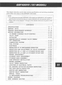
Руководство на английском языке по ремонту мотоциклов Suzuki GSF400VV с 1997 года выпуска.
- Издательство: Suzuki Motor Corporation
- Год издания: —
- Страниц: 49
- Формат: JPG
- Размер: 6,2 Mb
Руководство на английском языке по ремонту мотоциклов Suzuki GSF600.
- Издательство: Suzuki Motor Corporation
- Год издания: 1995
- Страниц: 358
- Формат: PDF
- Размер: 47,7 Mb
Руководство на английском языке по ремонту мотоциклов Suzuki GSF600 и GSF600S.
- Издательство: Suzuki Motor Corporation
- Год издания: 1999
- Страниц: 333
- Формат: PDF
- Размер: 378,2 Mb
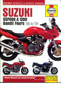
Руководство на английском языке по техническому обслуживанию и ремонту мотоциклов Suzuki GSF600 и GSF1200 Bandit 1995-2001 годов выпуска.
- Издательство: Haynes Publishing
- Год издания: 2001
- Страниц: 281
- Формат: PDF
- Размер: 50,8 Mb
Руководство на английском языке по ремонту мотоциклов Suzuki GSF650, GSF650S и GSX650F.
- Издательство: Suzuki Motor Corporation
- Год издания: 2007
- Страниц: 620
- Формат: PDF
- Размер: 28,9 Mb
Сборник руководств на английском языке по ремонту мотоциклов Suzuki GSF1200 и GSF1200S.
- Издательство: Suzuki Motor Corporation
- Год издания: 1996/1996/2000
- Страниц: -/387/368
- Формат: PDF
- Размер: 118,0 Mb
Руководство на английском языке по ремонту мотоциклов Suzuki GSF1250/GSF1250A/GSF1250S/GSF1250SA.
- Издательство: Suzuki Motor Corporation
- Год издания: 2006
- Страниц: 685
- Формат: PDF
- Размер: 40,2 Mb

Download Service manual of Suzuki GSF650 Motorcycle for Free or View it Online on All-Guides.com. This version of Suzuki GSF650 Manual compatible with such list of devices, as: GSF650, GSF650A, GSF650S, GSF650SA, GSX650F

1

2

3

4

5

6

7

8

9

10

11

12

13

14

15

16

17

18

19

20

21

22

23

24

25

26

27

28

29

30

31

32

33

34

35

36

37

38

39

40

41

42

43

44

45

46

47

48

49

50

51

52

53

54

55

56

57

58

59

60

61

62

63

64

65

66

67

68

69

70

71

72

73

74

75

76

77

78

79

80

81

82

83

84

85

86

87

88

89

90

91

92

93

94

95

96

97

98

99

100

101

102

103

104

105

106

107

108

109

110

111

112

113

114

115

116

117

118

119

120

121

122

123

124

125

126

127

128

129

130

131

132

133

134

135

136

137

138

139

140

141

142

143

144

145

146

147

148

149

150

151

152

153

154

155

156

157

158

159

160

161

162

163

164

165

166

167

168

169

170

171

172

173

174

175

176

177

178

179

180

181

182

183

184

185

186

187

188

189

190

191

192

193

194

195

196

197

198

199

200

201

202

203

204

205

206

207

208

209

210

211

212

213

214

215

216

217

218

219

220

221

222

223

224

225

226

227

228

229

230

231

232

233

234

235

236

237

238

239

240

241

242

243

244

245

246

247

248

249

250

251

252

253

254

255

256

257

258

259

260

261

262

263

264

265

266

267

268

269

270

271

272

273

274

275

276

277

278

279

280

281

282

283

284

285

286

287

288

289

290

291

292

293

294

295

296

297

298

299

300

301

302

303

304

305

306

307

308

309

310

311

312

313

314

315

316

317

318

319

320

321

322

323

324

325

326

327

328

329

330

331

332

333

334

335

336

337

338

339

340

341

342

343

344

345

346

347

348

349

350

351

352

353

354

355

356

357

358

359

360

361

362

363

364

365

366

367

368

369

370

371

372

373

374

375

376

377

378

379

380

381

382

383

384

385

386

387

388

389

390

391

392

393

394

395

396

397

398

399

400

401

402

403

404

405

406

407

408

409

410

411

412

413

414

415

416

417

418

419

420

421

422

423

424

425

426

427

428

429

430

431

432

433

434

435

436

437

438

439

440

441

442

443

444

445

446

447

448

449

450

451

452

453

454

455

456

457

458

459

460

461

462

463

464

465

466

467

468

469

470

471

472

473

474

475

476

477

478

479

480

481

482

483

484

485

486

487

488

489

490

491

492

493

494

495

496

497

498

499

500

501

502

503

504

505

506

507

508

509

510

511

512

513

514

515

516

517

518

519

520

521

522

523

524

525

526

527

528

529

530

531

532

533

534

535

536

537

538

539

540

541

542

543

544

545

546

547

548

549

550

551

552

553

554

555

556

557

558

559

560

561

562

563

564

565

566

567

568

569

570

571

572

573

574

575

576

577

578

579

580

581

582

583

584

585

586

587

588

589

590

591

592

593

594

595

596

597

598

599

600

601

602

603

604

605

606

607

608

609

610

611

612

613

614

615

616

617

618

619

620

621

622

623

624

625

626

627

628

629

630

631

632

633

634

635

636

637

638

639

640

641

642

643

644

645

646

647

648

649

650

651

652

653

654

655

656

657

658

659

660

661

662

663

664

665

666

667

668

669

670

671

672

673

674

675

676

677

678

679

680

681

682

683

684

685

686

687

688

689

690

691

692

693

694

695

696

697

GSF650/A/S/SA
GSX650F
Printed in Japan
K7 K8
K7
·
K8
99500-36172-01E
GSF650/A/S/SA
GSX650F