- Manuals
- Brands
- YAMAHA Manuals
- Scooter
- MAJESTY YP250
Manuals and User Guides for YAMAHA MAJESTY YP250. We have 5 YAMAHA MAJESTY YP250 manuals available for free PDF download: Service Manual, Owner’s Manual
YAMAHA MAJESTY YP250 Service Manual (267 pages)
Motorcycle YP250 4UC-AE1
Brand: YAMAHA
|
Category: Scooter
|
Size: 5.42 MB
Table of Contents
-
Table of Contents
9
-
How to Use this Manual
5
-
Periodic Inspection and
6
-
Chapter 1 General Information Scooter Identification
11
-
Engine Serial Number
11
-
Frame Serial Number
11
-
Model Label
11
-
VEHICLE IDENTIFICATION NUMBER (for E)
11
-
Features
12
-
Oil Indicator Light
12
-
Auto Choke System
13
-
Ignition Circuit Cut-Off System
13
-
-
Important Information
14
-
Preparation for Removal Procedures
14
-
Replacement Parts
14
-
Gaskets, Oil Seals and O-Rings
14
-
Lock Washers/Plates and Cotter Pins
15
-
Bearings and Oil Seals
15
-
Circlips
15
-
Checking of Connections
16
-
How to Use the Conversion Table
17
-
-
Special Tools
18
-
-
Table of Contents
21
-
Chapter 2. Specifications
23
-
General Specifications
23
-
Maintenance Specifications
26
-
Engine
26
-
Chassis
32
-
Electrical
36
-
-
General Torque Specifications
38
-
Lubrication Point and Grade of Lubricant
39
-
Engine
39
-
Chassis
40
-
-
Cable Routing
41
-
-
Table of Contents
49
-
Chapter 3
51
-
Introduction
51
-
Periodic Inspection and Adjustment
51
-
Periodic Maintenance/Lubrication Intervals
51
-
Cover and Panel
53
-
Side Panel and Seat
53
-
Tail Cover and Fuel Tank
54
-
Footrest Board and Lower Cover
56
-
Cowling
57
-
Handle Cover, Meter Assembly and Legshield
58
-
-
Engine
59
-
Valve Clearance Adjustment
59
-
Idling Speed Adjustment
60
-
Throttle Cable Adjustment
61
-
Spark Plug Inspection
62
-
Ignition Timing Check
63
-
Compression Pressure Measurement
64
-
Engine Oil Level Inspection
65
-
Recommended Engine Oil
66
-
Engine Oil Replacement
66
-
Engine Oil Pressure Inspection
67
-
Transmission Oil Replacement
68
-
Exhaust System Inspection
69
-
Air Filter Cleaning
69
-
Crankcase Filter Cleaning
70
-
Coolant Level Inspection
71
-
Coolant Replacement
72
-
Cooling System Inspection
75
-
-
Chassis
76
-
Front Brake Adjustment
76
-
Brake Fluid Level Inspection
77
-
Brake Pad Inspection
78
-
Air Bleeding (Hydraulic Brake System)
78
-
Rear Brake Adjustment
79
-
Brake Shoe Inspection
80
-
Steering Head Inspection
80
-
Front Fork Inspection
82
-
Swingarm Inspection
83
-
Rear Shock Absorber Inspection
83
-
Rear Shock Absorber Adjustment
83
-
Tire Inspection
84
-
Wheel Inspection
86
-
-
Electrical
87
-
Battery Inspection
87
-
Fuse Inspection
92
-
Headlight Beam Adjustment
93
-
-
-
Insp Adj
95
-
Chapter 4. Engine
97
-
Engine Overhaul
97
-
Wireharness and Cable
97
-
Hoses, Air Filter Case, Engine Mounting Bolt and Engine
99
-
Engine Remounting
100
-
-
Cylinder Head
101
-
Cylinder Head Removal
103
-
Cylinder Head Inspection
103
-
Cylinder Head Installation
104
-
-
Camshaft and Rocker Arms
107
-
Camshaft Inspection
108
-
Camshaft and Rocker Arm Installation
109
-
-
Valves and Valve Springs
111
-
Valves and Valve Springs Removal
112
-
Valves and Valve Springs Inspection
112
-
Valve Seat Inspection
114
-
Valves and Valve Springs Installation
115
-
-
Cylinder and Piston
117
-
Piston and Pistonrings Removal
118
-
Cylinder Inspection
118
-
Piston and Piston Pin Inspection
119
-
Piston Rings Inspection
120
-
Piston Rings, Piston and Cylinder Installation
121
-
Crankcase Filter Cover and Crankcase Cover (Left)
123
-
Secondary Sheave
126
-
Primary Sheave Removal
127
-
Secondary Sheave and V Belt Removal
127
-
Secondary Sheave Disassembly
128
-
Clutch Inspection
128
-
Belt Inspection
129
-
Weight Inspection
129
-
Secondary Sheave Inspection
129
-
Primary Sheave Assembly
130
-
Secondary Sheave Installation
130
-
-
A.C. Magneto and Starter Clutch
133
-
Magneto Cover and Stator Coil
133
-
Magneto and Starter Clutch
135
-
Starter Drive Gear Inspection
136
-
-
Oil Pump
138
-
Oil Pump Inspection
139
-
-
Transmission
140
-
Crankcase and Crankshaft
142
-
Crankshaft Removal
144
-
Crankshaft Inspection
144
-
-
-
Table of Contents
147
-
Chapter 5
149
-
Cooling System Radiator
149
-
Inspection
150
-
Water Pump
151
-
Inspection
153
-
Water Pump Installation
153
-
-
Thermostat
155
-
Inspection
156
-
Installation
156
-
-
-
Table of Contents
157
-
Carburetion
159
-
Carburetor Disassembly
160
-
Chapter 6
160
-
Assembly
162
-
Fuel Level Adjustment
163
-
Auto Choke Inspection
164
-
Fuel Pump Inspection
165
-
-
Table of Contents
167
-
Chapter 7. Chassis
169
-
Front Wheel and Brake Disc
169
-
Front Wheel Disassembly
170
-
Front Wheel Disassembly
171
-
Front Wheel Inspection
171
-
Brake Disc Inspection
172
-
Front Wheel Assembly
172
-
Front Wheel Installation
173
-
Wheel Static Balance Adjustment
174
-
-
Rear Wheel and Rear Brake
176
-
Rear Wheel Inspection
178
-
Rear Brake Inspection
178
-
Rear Brake Installation
179
-
-
Front Brake
180
-
Brake Pad
180
-
Brake Pad Replacement
181
-
Master Cylinder
182
-
Master Cylinder Disassembly
183
-
Master Cylinder Inspection
184
-
Master Cylinder Assembly
184
-
Caliper
187
-
Caliper Disassembly
188
-
Brake Caliper Disassembly
189
-
Caliper Inspection
189
-
Brake Caliper Assembly
190
-
-
Front Fork
191
-
Front Fork Disassembly
192
-
Front Fork Removal
193
-
Front Fork Disassembly
193
-
Front Fork Inspection
194
-
Front Fork Assembly
194
-
Front Fork Installation
197
-
-
Handlebar
198
-
Handlebar Removal
200
-
Handlebar Inspection
200
-
Handlebar Installation
200
-
-
Steering
202
-
Steering Removal
204
-
Inspection
204
-
Steering Installation
205
-
-
Rear Shock Absorber and Swingarm
206
-
-
Table of Contents
207
-
Chapter 8. Electrical Electrical Components
209
-
Circuit Diagram
210
-
Checking Switches
212
-
Checking Steps
212
-
Switch Connection as Shown in this Manual
212
-
Switch Position and Terminal Connection
213
-
-
Ignition System
214
-
Circuit Diagram
214
-
Troubleshooting
215
-
-
Charging System
219
-
Circuit Diagram
219
-
Troubleshooting
220
-
-
Electric Starting System
223
-
Circuit Diagram
223
-
Troubleshooting
224
-
Starter Motor
227
-
-
Lighting System
230
-
Circuit Diagram
230
-
Troubleshooting
231
-
-
Signal System
236
-
Circuit Diagram
236
-
Troubleshooting
237
-
Signal System Check
239
-
Checking of Connections
243
-
-
Cooling System
245
-
Circuit Diagram
245
-
Troubleshooting
246
-
Special Tools
246
-
-
Auto Choke System
252
-
Circuit Diagram
252
-
-
-
Troubleshooting
257
-
Chapter 9. Troubleshooting
259
-
Starting Failure/Hard Starting
259
-
Fuel System
259
-
Compression System
259
-
Ignition System
260
-
-
Poor Idle Speed Performance
260
-
Poor Medium and High Speed Performance
261
-
Poor Speed Performance
261
-
Poor Speed Performance
262
-
-
Faulty Clutch
262
-
When Engine Is Run, Scooter Does Not Run
262
-
Poor Starting Performance
262
-
-
Overheating or over Cooling
263
-
Overheating
263
-
Over Cooling
263
-
-
Faulty Brake
264
-
Poor Braking Effect
264
-
-
Front Fork Malfunction
264
-
Oil Leakage
264
-
Malfunction
264
-
-
Instable Handling
265
-
Starter Motor Does Not Operate
265
-
Faulty Signal and Lighting System
266
-
Headlight Dark
266
-
Bulb Burnt out
266
-
Flasher Does Not Blink
266
-
Flasher Keeps on
266
-
Flasher Blinks Slower
266
-
Flasher Blinks Quicker
266
-
Horn Does Not Sound
266
-
-
Advertisement
YAMAHA MAJESTY YP250 Owner’s Manual (114 pages)
Brand: YAMAHA
|
Category: Scooter
|
Size: 2.06 MB
Table of Contents
-
Table of Contents
6
-
Give Safety the Right of Way
8
-
Description
12
-
Left View
13
-
Right View
14
-
Controls and Instruments
15
-
-
-
Instrument and Control Functions
16
-
Instrument and Control Functions
17
-
Indicator Lights
18
-
Speedometer
19
-
Tachometer
19
-
Fuel Gauge
20
-
Coolant Temperature Gauge
21
-
Multi-Function Display
21
-
Anti-Theft Alarm (Optional)
25
-
Handlebar Switches
26
-
Front Brake Lever
28
-
Rear Brake Lever
29
-
Fuel Tank Cap
29
-
Fuel
30
-
Catalytic Converter
31
-
Rider Seat
32
-
Adjusting the Rider Seat
33
-
Storage Compartments
33
-
Adjusting the Shock Absorber Assemblies
35
-
Sidestand
36
-
Ignition Circuit Cut-Off System
37
-
-
Main Switch/Steering Lock
17
-
Pre-Operation Checks
40
-
Pre-Operation Check List
41
-
-
-
Operation and Important Riding Points
44
-
Operation and Important Riding Points
45
-
Starting the Engine
45
-
Starting off
46
-
Acceleration and Deceleration
47
-
Braking
47
-
Engine Break-In
48
-
Tips for Reducing Fuel Consumption
48
-
Parking
49
-
-
Periodic Maintenance and Minor Repair
50
-
Owner’s Tool Kit
51
-
Periodic Maintenance and Lubrication Chart
53
-
Removing and Installing the Cowlings and Panel
56
-
Checking the Spark Plug
62
-
Engine Oil
64
-
Final Transmission Oil
68
-
Coolant
69
-
Air Filter and V-Belt Case Air Filter Elements
71
-
Adjusting the Throttle Cable Free Play
73
-
Adjusting the Valve Clearance
73
-
Air Flow Louver
73
-
Tires
74
-
Cast Wheels
76
-
Adjusting the Front and Rear Brake Lever Free Play
77
-
Checking the Front and Rear Brake Pads
78
-
Checking the Brake Fluid Level
79
-
Changing the Brake Fluid
80
-
Checking and Lubricating the Cables
80
-
Checking and Lubricating the Centerstand and Sidestand
81
-
Checking and Lubricating the Throttle Grip and Cable
81
-
Lubricating the Front and Rear Brake Levers
81
-
Checking the Front Fork
82
-
Checking the Steering
83
-
Checking the Wheel Bearings
83
-
Battery
84
-
To Store the Battery
85
-
-
Removing the Battery Cover
84
-
Replacing the Fuses
86
-
Replacing a Headlight Bulb
87
-
Replacing a Front Turn Signal Light Bulb
89
-
Replacing a Rear Turn Signal Light Bulb
90
-
Replacing a Tail/Brake Light Bulb
90
-
Replacing the License Plate Light Bulb
91
-
Troubleshooting
92
-
Troubleshooting Charts
93
-
Scooter Care and Storage
96
-
Specifications
102
-
Specifications
103
-
Conversion Table
107
-
-
Consumer Information
108
-
Consumer Information
109
-
Identification Numbers
109
-
Key Identification Number
109
-
Vehicle Identification Number
109
-
Model Label
110
-
-

Yamaha MAJESTY YP250 Owner’s Manual (116 pages)
Brand: Yamaha
|
Category: Scooter
|
Size: 2.08 MB
Table of Contents
-
Table of Contents
7
-
Give Safety the Right of Way
9
-
Description
13
-
-
Instrument and Control Functions
17
-
Main Switch/Steering Lock
18
-
Indicator Lights
19
-
Speedometer
20
-
Tachometer
20
-
Fuel Gauge
21
-
Coolant Temperature Gauge
22
-
Multi-Function Display
22
-
Anti-Theft Alarm (Optional)
26
-
Handlebar Switches
27
-
Front Brake Lever
29
-
Fuel Tank Cap
30
-
Rear Brake Lever
30
-
Fuel
31
-
Catalytic Converter
32
-
Rider Seat
33
-
Adjusting the Rider Seat
34
-
Storage Compartments
34
-
Adjusting the Shock Absorber Assemblies
36
-
Sidestand
37
-
Ignition Circuit Cut-Off System
38
-
Pre-Operation Checks
41
-
-
Operation and Important Riding Points
45
-
Starting the Engine
46
-
Starting off
47
-
Acceleration and Deceleration
48
-
Braking
48
-
Engine Break-In
49
-
Tips for Reducing Fuel Consumption
49
-
Parking
50
-
-
Periodic Maintenance and Minor Repair
51
-
Owner’s Tool Kit
52
-
Periodic Maintenance and Lubrication Chart
54
-
Removing and Installing the Cowlings and Panel
57
-
Checking the Spark Plug
63
-
Engine Oil
65
-
Final Transmission Oil
69
-
Coolant
70
-
Air Filter and V-Belt Case Air Filter Elements
72
-
Adjusting the Throttle Cable Free Play
74
-
Adjusting the Valve Clearance
74
-
Air Flow Louver
74
-
Tires
75
-
Cast Wheels
77
-
Adjusting the Front and Rear Brake Lever Free Play
78
-
Checking the Front and Rear Brake Pads
79
-
Checking the Brake Fluid Level
80
-
Changing the Brake Fluid
81
-
Checking and Lubricating the Cables
81
-
Checking and Lubricating the Centerstand and Sidestand
82
-
Checking and Lubricating the Throttle Grip and Cable
82
-
Lubricating the Front and Rear Brake Levers
82
-
Checking the Front Fork
83
-
Checking the Steering
84
-
Checking the Wheel Bearings
84
-
Battery
85
-
To Store the Battery
86
-
-
Removing the Battery Cover
85
-
Replacing the Fuses
87
-
Replacing a Headlight Bulb
88
-
Replacing a Front Turn Signal Light Bulb
90
-
Replacing a Rear Turn Signal Light Bulb
91
-
Replacing a Tail/Brake Light Bulb
91
-
Replacing the License Plate Light Bulb
92
-
Troubleshooting
93
-
Troubleshooting Charts
94
-
Scooter Care and Storage
97
-
Specifications
103
-
Specifications
104
-
Conversion Table
108
-
-
Consumer Information
109
-
Advertisement
YAMAHA MAJESTY YP250 Owner’s Manual (98 pages)
Brand: YAMAHA
|
Category: Scooter
|
Size: 2.09 MB
Table of Contents
-
Table of Contents
7
-
Give Safety the Right of Way
9
-
Description
13
-
Description
16
-
-
Instrument and Control Functions
17
-
Main Switch/Steering Lock
18
-
Indicator Lights
19
-
Oil Change Indicator Light Circuit Check
20
-
Diagnosis Device
21
-
Speedometer
21
-
Antitheft Alarm (Optional)
22
-
Coolant Temperature Gauge
22
-
Fuel Gauge
22
-
Digital Clock
23
-
Handlebar Switches
23
-
Headlight Beam Variation
25
-
Front Brake Lever
26
-
Fuel Tank Cap
27
-
Rear Brake Lever
27
-
Fuel
28
-
Catalyzer
29
-
Rider Seat
29
-
Rider Seat Adjustment
30
-
Storage Compartments
31
-
Rear Shock Absorber Adjustment
32
-
Carrier (Optional)
33
-
Sidestand
33
-
Sidestand Switch Operation Check
34
-
Pre-Operation Checks
35
-
Pre-Operation Check List
36
-
-
-
Operation and Important Riding Points
37
-
Starting a Cold Engine
38
-
Acceleration
39
-
Braking
39
-
Starting off
39
-
Engine Break-In
40
-
Tips for Reducing Fuel Consumption
40
-
Parking
41
-
-
Periodic Maintenance and Minor Repair
43
-
Periodic Maintenance and Minor Repair
44
-
Tool Kit
44
-
Periodic Maintenance and Lubrication
46
-
Panel a
49
-
Panel Removal and Installation
49
-
Panel B
51
-
Panel C
51
-
Spark Plug
53
-
Engine Oil
54
-
Final Gear Oil Replacement
57
-
Coolant
58
-
Tires
61
-
Air Flow Louver
61
-
-
Brake Lever Free Play Adjustment
63
-
Wheels
63
-
Checking the Front and Rear Brake Pads
64
-
Inspecting the Brake Fluid Level
65
-
Brake Fluid Replacement
66
-
Brake Lever Lubrication
66
-
Cable Inspection and Lubrication
66
-
Center and Sidestand Lubrication
67
-
Front Fork Inspection
67
-
Steering Inspection
68
-
Wheel Bearings
68
-
Battery
69
-
Battery Cover Removal
69
-
Fuse Replacement
70
-
Battery Storage
70
-
-
Headlight Bulb Replacement
71
-
Front Turn Signal Light Bulb Replacement
73
-
Tail/Brake Light Bulb Replacement
73
-
Rear Turn Signal Light Bulb Replacement
74
-
License Light Bulb Replacement
75
-
Troubleshooting
76
-
Troubleshooting Chart
77
-
Engine Overheating
78
-
-
Scooter Care and Storage
79
-
Specifications
85
-
Specifications
86
-
How to Use the Conversion Table
90
-
-
Consumer Information
91
-
Consumer Information
92
-
Identification Number Records
92
-
Key Identification Number
92
-
Vehicle Identification Number
92
-
Model Label
93
-
-
Yamaha MAJESTY YP250 Owner’s Manual (106 pages)
Brand: Yamaha
|
Category: Motorcycle
|
Size: 1.73 MB
Table of Contents
-
Table of Contents
6
-
Give Safety the Right of Way
8
-
Description
12
-
-
Instrument and Control Functions
16
-
Main Switch/Steering Lock
17
-
Indicator Lights
18
-
Self-Diagnosis Device
19
-
Speedometer Unit
19
-
Anti-Theft Alarm (Optional)
20
-
Coolant Temperature Gauge
20
-
Fuel Gauge
20
-
Clock
21
-
Handlebar Switches
21
-
Front Brake Lever
24
-
Rear Brake Lever
24
-
Fuel Tank Cap
25
-
Catalytic Converter
26
-
Fuel
26
-
Rider Seat
27
-
Adjusting the Rider Seat
28
-
Storage Compartments
28
-
Adjusting the Shock Absorber Assemblies
30
-
Ignition Circuit Cut-Off System
31
-
Sidestand
31
-
Pre-Operation Checks
34
-
-
Operation and Important Riding Points
38
-
Starting the Engine
39
-
Starting off
40
-
Acceleration and Deceleration
41
-
Braking
41
-
Engine Break-In
42
-
Tips for Reducing Fuel Consumption
42
-
Parking
43
-
-
Periodic Maintenance and Minor Repair
44
-
Owner’s Tool Kit
45
-
Periodic Maintenance and Lubrication Chart
47
-
Removing and Installing Cowlings and Panel
50
-
Checking the Spark Plug
56
-
Engine Oil
58
-
Final Gear Oil
61
-
Coolant
62
-
Air Filter and V-Belt Case Air Filter Elements
64
-
Air Flow Louver
66
-
Tires
67
-
Adjusting the Front and Rear Brake Lever Free Play
69
-
Wheels
69
-
Checking the Front and Rear Brake Pads
70
-
Checking the Brake Fluid Level
71
-
Changing the Brake Fluid
72
-
Checking and Lubricating the Cables
72
-
Lubricating the Front and Rear Brake Levers
72
-
Checking and Lubricating the Centerstand and Sidestand
73
-
Checking the Front Fork
73
-
Checking the Steering
74
-
Battery
75
-
Checking the Wheel Bearings
75
-
Removing the Battery Cover
75
-
Replacing the Fuses
77
-
Replacing a Headlight Bulb
78
-
Replacing a Front Turn Signal Light Bulb
79
-
Replacing a Rear Turn Signal Light Bulb
80
-
Replacing a Tail/Brake Light Bulb
81
-
Replacing the License Plate Light Bulb
81
-
Troubleshooting
82
-
Troubleshooting Charts
83
-
Scooter Care and Storage
86
-
Specifications
92
-
Consumer Information
98
-
Advertisement
Related Products
-
YAMAHA XMAX YP250R
-
YAMAHA XMAX YP250RA
-
YAMAHA MAJESTY YP250A
-
Yamaha YP250R 2005
-
Yamaha MAJESTY YP250A ABS
-
Yamaha YP250 98
-
Yamaha YP250J 98
-
Yamaha YP250R 2014
-
Yamaha YP250RA 2014
-
YAMAHA YP125RA Business Edition
YAMAHA Categories
Motorcycle
Musical Instrument
Electronic Keyboard
Receiver
Amplifier
More YAMAHA Manuals
- Manuals
- Brands
- Yamaha Manuals
- Scooter
- MAJESTY YP250
- Owner’s manual
-
Contents
-
Table of Contents
-
Troubleshooting
-
Bookmarks
Related Manuals for Yamaha MAJESTY YP250
Summary of Contents for Yamaha MAJESTY YP250
-
Page 1
OWNER’S MANUAL YP250 5SJ-28199-E0… -
Page 2
INTRODUCTION Welcome to the Yamaha world of motorcycling! As the owner of the YP250, you are benefiting from Yamaha’s vast experience and newest technolo- gy regarding the design and manufacture of high-quality products, which have earned Yamaha a rep- utation for dependability. -
Page 3
8 This manual should be considered a permanent part of this scooter and should remain with it even if the scooter is subsequently sold. 8 Yamaha continually seeks advancements in product design and quality. Therefore, while this manual contains the most current product information available at the time of printing, there may be minor discrepancies between your scooter and this manual. -
Page 4
IMPORTANT MANUAL INFORMATION EW000002 PLEASE READ THIS MANUAL CAREFULLY AND COMPLETELY BEFORE OPERATING THIS SCOOTER. -
Page 5
EAU04229 YP250 OWNER’S MANUAL ©2001 by Yamaha Motor Co., Ltd. 1st edition, December 2001 All rights reserved. Any reprinting or unauthorized use without the written permission of Yamaha Motor Co., Ltd. is expressly prohibited. Printed in Japan. -
Page 6: Table Of Contents
EAU00009 TABLE OF CONTENTS 1 GIVE SAFETY THE RIGHT OF WAY 2 DESCRIPTION 3 INSTRUMENT AND CONTROL FUNCTIONS 4 PRE-OPERATION CHECKS 5 OPERATION AND IMPORTANT RIDING POINTS 6 PERIODIC MAINTENANCE AND MINOR REPAIR 7 SCOOTER CARE AND STORAGE 8 SPECIFICATIONS 9 CONSUMER INFORMATION INDEX…
-
Page 8: Give Safety The Right Of Way
GIVE SAFETY THE RIGHT OF WAY GIVE SAFETY THE RIGHT OF WAY ……….1-1 Further safe-riding points …………..1-2…
-
Page 9
EAU00021 QGIVE SAFETY THE RIGHT OF WAY Scooters are fascinating vehicles, which can give you an unsurpassed feeling of power and freedom. However, they also impose certain limits, which you must accept; even the best scooter does not ignore the laws of physics. Regular care and maintenance are essential for preserving value and operating condition of your scooter. -
Page 10
QGIVE SAFETY THE RIGHT OF WAY EAU03099 Further safe-riding points Saf e — r i d i n g poi n t s 8 Be sure to signal clearly when making turns. 8 Braking can be extremely difficult on a wet road. Avoid hard braking, because the scooter could slide. -
Page 12: Description
DESCRIPTION Left view ………………..2-1 Right view ………………2-2 Controls and instruments …………..2-3…
-
Page 13: Left View
EAU00026 DESCRIPTION Par t l o cat i o ns Left view 1. Rear storage compartment (page 3-18) 5. V-belt case air filter element (page 6-22) 2. Grab bar (page 5-2) 6. Centerstand (page 6-31) 3. Shock absorber spring preload 7.
-
Page 14: Right View
DESCRIPTION Right view 15, 14 9. Passenger seat 14. Battery (page 6-34) 10. Rider seat (page 3-17) 15. Fuse box (page 6-36) 11. Air flow louver (page 6-23) 16. Coolant reservoir cap (page 6-19) 12. Headlight (page 6-37) 17. Coolant level check window (page 6-19) 13.
-
Page 15: Controls And Instruments
EAU00026 DESCRIPTION Controls and instruments 1. Rear brake lever (page 3-13) 8. Fuel gauge (page 3-4) 2. Left handlebar switches (page 3-10) 9. Right handlebar switches (page 3-12) 3. Front storage compartment A (page 3-17) 10. Front brake lever (page 3-12) 4.
-
Page 16: Instrument And Control Functions
INSTRUMENT AND CONTROL FUNCTIONS Main switch/steering lock …………..3-1 Indicator lights ……………….3-2 Speedometer ………………3-3 Tachometer ………………3-3 Fuel gauge ………………3-4 Coolant temperature gauge ……………3-5 Multi-function display ……………..3-5 Anti-theft alarm (optional) …………..3-9 Handlebar switches ……………..3-10 Front brake lever …………….3-12 Rear brake lever …………….3-13 Fuel tank cap ……………….3-13 Fuel ………………..3-14 Catalytic converter …………….3-15…
-
Page 17: Main Switch/Steering Lock
EAU00027 INSTRUMENT AND CONTROL FUNCTIONS To lock the steering NOTE: 1. Turn the handlebars all the way The headlight comes on automatical- to the left. ly when the engine is started and OPEN 2. Push the key in from the “OFF” stays on until the key is turned to PUSH position, and then turn it to…
-
Page 18: Indicator Lights
Hi g h beam i n di c at o r l i g ht This indicator light comes on when 3. If the indicator light does not the high beam of the headlight is come on, have a Yamaha dealer switched on. check the electrical circuit.
-
Page 19: Speedometer
INSTRUMENT AND CONTROL FUNCTIONS NOTE: The oil change indicator light may flash when the engine is revved with the scooter on the centerstand, but this does not indicate a malfunction. 1. Speedometer 1. Tachometer EAU04581 EAU04582 Speedometer Tachometer Speedomet e r Tachomet e r The speedometer shows the riding The electric tachometer allows the…
-
Page 20: Fuel Gauge
INSTRUMENT AND CONTROL FUNCTIONS ECA00134 8 Do not operate the engine above 8,500 r/min. 8 This scooter is equipped with an engine speed limiter, which prevents the engine speed from exceeding approximately 9,000 r/min. 1. Fuel gauge EAU00110 Fuel gauge Fuel gauge The fuel gauge indicates the amount of fuel in the fuel tank.
-
Page 21: Coolant Temperature Gauge
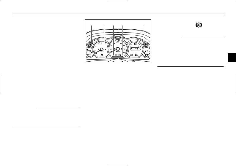
INSTRUMENT AND CONTROL FUNCTIONS 1. Coolant temperature gauge 1. Tripmeter 2. Red mark 2. Odometer, fuel tripmeter 3. Clock, outside temperature and voltage EAU03124 meter display Coolant temperature gauge EAU04589 8 a voltage display (which shows Cool a nt t e mper a t u r e gauge Multi-function display This gauge indicates the coolant tem- the battery voltage)
-
Page 22
8 If the tripmeter indicates “– – – –”, To reset the tripmeter: The odometer has two functions. have a Yamaha dealer check or 8 It shows the total distance trav- 1. Push the “SELECT” button until repair the multi-function display the voltage display appears, then eled. -
Page 23
INSTRUMENT AND CONTROL FUNCTIONS Fuel tripmeter “Trip F” To return to the odometer mode Clock When the fuel level reaches approxi- before refueling, push the “SELECT” To set the clock mately 2.0 L, the odometer display button until “Trip F” begins flashing 1. -
Page 24
INSTRUMENT AND CONTROL FUNCTIONS 3. When the hour digits start flash- 4. Push the “SELECT” button, and Outside temperature display ing, push the “RESET” button to the minute digits will start flash- This display shows the outside tem- set the hours. ing. -
Page 25: Anti-Theft Alarm (Optional)
Ant i — t h ef t al a r m ( o pt i o nal ) This scooter can be equipped with an displayed. optional anti-theft alarm by a Yamaha 8 When the outside temperature dealer. Contact a Yamaha dealer for climbs above 50.0 °C, “50.0”…
-
Page 26: Handlebar Switches
INSTRUMENT AND CONTROL FUNCTIONS EAU03889 Turn signal switch “4/6” Tur n si g nal swi t c h To signal a right-hand turn, push this switch to “6”. To signal a left-hand turn, push this switch to “4”. When released, the switch returns to the center position.
-
Page 27
INSTRUMENT AND CONTROL FUNCTIONS EAU00136 Headlight variations 2 : Low beam light on : High beam light on Headl i g ht var i a t i o ns 1 : Light off : Auxiliary light on Bulb to be used Destination Left Right… -
Page 28: Front Brake Lever
INSTRUMENT AND CONTROL FUNCTIONS EAU03801 Start switch “,” St a r t swi t c h With the sidestand up, push this switch while applying the front or rear brake to crank the engine with the starter. EC000005 See page 5-1 for starting instruc- 1.
-
Page 29: Rear Brake Lever
INSTRUMENT AND CONTROL FUNCTIONS 1. Rear brake lever 1. Lid 1. Fuel tank cap 2. Lever EAU00163 2. Insert the key into the lock and EAU03090 Rear brake lever turn it clockwise. The lock will be Fuel tank cap Br a ke l e ver , r e ar The rear brake lever is located on the released and the fuel tank cap Fuel t a nk cap…
-
Page 30: Fuel
INSTRUMENT AND CONTROL FUNCTIONS EAU00185 Immediately wipe off spilled fuel with a clean, dry, soft cloth, since fuel may deteriorate painted sur- faces or plastic parts. 1. Match marks 1. Filler tube 2. Fuel level To install the fuel tank cap EAU03753 1.
-
Page 31: Catalytic Converter
INSTRUMENT AND CONTROL FUNCTIONS EAU04284 EAU03098 Your Yamaha engine has been Catalytic converter designed to use regular unleaded Recommended fuel: Cat a l y t i c conver t e r This scooter is equipped with a cat- gasoline with a research octane num- REGULAR UNLEADED alytic converter in the muffler.
-
Page 32: Rider Seat
INSTRUMENT AND CONTROL FUNCTIONS EC000114 The following precautions must be observed to prevent a fire hazard OPEN or other damages. PUSH 8 8 Use only unleaded gasoline. LOCK The use of leaded gasoline will PUSH cause unrepairable damage to the catalytic converter. a.
-
Page 33: Adjusting The Rider Seat
INSTRUMENT AND CONTROL FUNCTIONS Compartment A 1. Rider seat 1. Bolt (×4) 1. Button 2. Collar (×4) 2. Lid EAU03096* a. Lock. Adjusting the rider seat 2. Remove the bolts and collars. EAU03331 Ri d er seat , adj u st i n g 3.
-
Page 34
INSTRUMENT AND CONTROL FUNCTIONS Compartment A Compartment B 1. Button 1. Lever 1. Rider seat 2. Lid 2. Lid a. Lock. Rear storage compartment Front storage compartment B Two helmets can be stored in the To lock the storage compartment, To open the storage compartment, storage compartment… -
Page 35: Adjusting The Shock Absorber Assemblies
INSTRUMENT AND CONTROL FUNCTIONS ECA00051 EAU04552 Adjusting the shock absorber assemblies Do not leave the rider seat open Shock absor b er assembl i e s, adj u st i n g for an extended period of time, Each shock absorber assembly is otherwise the light may cause the equipped with…
-
Page 36: Sidestand
Therefore, check this system regularly as described below and holding the scooter upright. have a Yamaha dealer repair it if it NOTE: does not function properly. The built-in sidestand switch is part of…
-
Page 37: Ignition Circuit Cut-Off System
8 It cuts the running engine when the sidestand is moved down. Periodically check the operation of the ignition circuit cut-off system according to the following procedure. EW000045 If a malfunction is noted, have a Yamaha dealer check the system before riding. 3-21…
-
Page 38
Does the engine start? The sidestand switch may be defective. The scooter should not be ridden until checked by a Yamaha dealer. With the engine still off: 6. Move the sidestand up. 7. Keep the front or rear brake applied. -
Page 40: Pre-Operation Checks
PRE-OPERATION CHECKS Pre-operation check list …………..4-1…
-
Page 41: Pre-Operation Check List
• If necessary, add recommended coolant to specified level. 3-5, 6-19–6-20 • Check cooling system for leakage. • Check operation. • If soft or spongy, have Yamaha dealer bleed hydraulic system. • Check lever free play. Front brake • Adjust if necessary.
-
Page 42
• Make sure that operation is smooth. • Check cable free play. Throttle grip 6-23, 6-31 • If necessary, have Yamaha dealer adjust cable free play and lubricate cable and grip housing. • Check for damage. • Check tire condition and tread depth. -
Page 43
PRE-OPERATION CHECKS NOTE: Pre-operation checks should be made each time the scooter is used. Such an inspection can be accomplished in a very short time; and the added safety it assures is more than worth the time involved. EWA00033 If any item in the Pre-operation check list is not working properly, have it inspected and repaired before operat- ing the scooter. -
Page 44: Operation And Important Riding Points
OPERATION AND IMPORTANT RIDING POINTS Starting the engine …………….5-1 Starting off ………………5-2 Acceleration and deceleration …………5-3 Braking ………………..5-3 Tips for reducing fuel consumption …………5-4 Engine break-in ……………..5-4 Parking ………………..5-5…
-
Page 45: Operation And Important Riding Points
See page 5-4 for engine break-in their functions before riding. instructions prior to operating the Consult Yamaha dealer regarding any control or func- vehicle for the first time. tion that you do not thorough- ly understand.
-
Page 46: Starting Off
OPERATION AND IMPORTANT RIDING POINTS 4. Check for oncoming traffic, and NOTE: then slowly turn the throttle grip If the engine does not start, release (on the right) in order to take off. the start switch, wait a few seconds, 5.
-
Page 47: Acceleration And Deceleration
OPERATION AND IMPORTANT RIDING POINTS EW000057 8 Avoid braking hard or sudden- ly (especially when leaning over to one side), otherwise the scooter may skid or over- turn. 8 Railroad crossings, streetcar rails, iron plates on road con- struction sites, and manhole covers become extremely slip- EAU00434 EAU00435…
-
Page 48: Tips For Reducing Fuel Consumption
The vehicle can now be operated ings). ing must be avoided. normally. ECA00137 8 Keep the engine speed below 8,500 r/min. 8 If any engine trouble should occur during the engine break- in period, immediately have a Yamaha dealer check the vehi- cle.
-
Page 49: Parking
OPERATION AND IMPORTANT RIDING POINTS EAU00461 Parking Par k i n g When parking, stop the engine, and then remove the key from the main switch. EW000058 8 Since the engine and exhaust system can become very hot, park in a place where pedestri- ans or children are not likely to touch them.
-
Page 50: Periodic Maintenance And Minor Repair
PERIODIC MAINTENANCE AND MINOR REPAIR Owner’s tool kit …………6-1 Checking the front fork ……..6-32 Periodic maintenance and lubrication chart ..6-3 Checking the steering ……….6-33 Removing and installing the cowlings and panel …6-6 Checking the wheel bearings ……6-33 Checking the spark plug ……..6-12 Removing the battery cover ……..6-34 Engine oil ………….6-14 Battery …………..6-34…
-
Page 51: Owner’s Tool Kit
However, DEPENDING replaced more frequently, other- WEATHER, TERRAIN, wise rapid engine wear may result. GEOGRAPHICAL LOCATION, AND Consult a Yamaha dealer for prop- INDIVIDUAL USE, THE MAINTE- er maintenance intervals. NANCE INTERVALS MAY NEED TO BE SHORTENED.
-
Page 52
PERIODIC MAINTENANCE AND MINOR REPAIR NOTE: If you do not have the tools or experi- ence required for a particular job, have a Yamaha dealer perform it for you. EW000063 Modifications not approved by 1. Mat Yamaha may cause loss of perfor- 2. -
Page 53: Periodic Maintenance And Lubrication Chart
8 The annual checks must be performed every year, except if a kilometer-based maintenance is performed instead. 8 From 50,000 km, repeat the maintenance intervals starting from 10,000 km. 8 Items marked with an asterisk should be performed by a Yamaha dealer as they require special tools, data and technical skills.
-
Page 54
PERIODIC MAINTENANCE AND MINOR REPAIR ODOMETER READING (× 1,000 km) ANNUAL ITEM CHECK OR MAINTENANCE JOB CHECK √ √ √ √ √ • Check for cracks or damage. Brake hoses • Replace. (See NOTE on page 6-5.) Every 4 years √… -
Page 55
PERIODIC MAINTENANCE AND MINOR REPAIR ODOMETER READING (× 1,000 km) ANNUAL ITEM CHECK OR MAINTENANCE JOB CHECK √ Engine oil strainer • Clean. √ √ √ √ √ • Check coolant level and vehicle for coolant leakage. Cooling system • Change. Every 3 years √… -
Page 56: Removing And Installing The Cowlings And Panel
PERIODIC MAINTENANCE AND MINOR REPAIR 1. Cowling A 1. Cowling B 1. Cowling C EAU03624 Removing and installing the cowlings and panel Cowl i n gs and panel , r e movi n g and i n st a l l i n g The cowlings and panel shown above need to be removed to perform some of the maintenance jobs described in…
-
Page 57
PERIODIC MAINTENANCE AND MINOR REPAIR 1. Panel A 1. Mat A 1. Screw (×4) 2. Mat B 2. Cowling A EAU03615 2. Remove the cowling screws. Cowling A To remove the cowling 1. Pull up the left floorboard mats as shown. -
Page 58
PERIODIC MAINTENANCE AND MINOR REPAIR 1. Tab (×10) 1. Mat A 2. Mat B 3. Pull the cowling down slightly, To install the cowling EAU03632 and then pull it outward as 1. Insert the tabs on the cowling Cowling B shown. -
Page 59
PERIODIC MAINTENANCE AND MINOR REPAIR 1. Screw (×4) 1. Tab (×10) 2. Cowling B 3. Pull the cowling down slightly, To install the cowling 2. Remove the screws. and then pull it outward as 1. Insert the tabs on the cowling shown. -
Page 60
PERIODIC MAINTENANCE AND MINOR REPAIR 1. Screw (×2) a. Push. EAU03617 2. Push the cowling in lightly, and Cowling C then pull it back as shown. To remove the cowling ECA00067 1. Remove the cowling screws. Take care not to damage the tabs on the cowling when removing and or installing it. -
Page 61
PERIODIC MAINTENANCE AND MINOR REPAIR 1. Tab (×4) 1. Bolt (×2) 2. Slot (×4) 2. Panel A EAU03628 To install the cowling Panel A 1. Insert the tabs on the cowling To remove the panel into the slots as shown, and then Remove the bolts, and then pull the push the cowling in until it snaps panel out as shown. -
Page 62: Checking The Spark Plug
PERIODIC MAINTENANCE AND MINOR REPAIR EAU03620 Checking the spark plug Spar k pl u g, checki n g The spark plug is an important engine component, which is easy to check. Since heat and deposits will cause any spark plug to slowly erode, the spark plug should be removed and checked in accordance with the periodic maintenance and lubrication…
-
Page 63
Instead, shown, with the spark plug 1. Measure the spark plug gap with have a Yamaha dealer check the wrench included in the owner’s a wire thickness gauge and, if scooter. tool kit. necessary, adjust the gap to specification. -
Page 64: Engine Oil
PERIODIC MAINTENANCE AND MINOR REPAIR EAU03119 To check the engine oil level Tightening torque: Engine oil 1. Place the scooter on the center- Spark plug: Engi n e oi l The engine oil level should be stand. 17.5 Nm (1.75 m·kgf) checked before each ride.
-
Page 65
PERIODIC MAINTENANCE AND MINOR REPAIR 4. If the engine oil is below the min- imum level mark, add sufficient oil of the recommended type to raise it to the correct level. 5. Insert the dipstick into the oil filler hole, and then tighten the oil filler cap. -
Page 66
PERIODIC MAINTENANCE AND MINOR REPAIR 6. Add the specified amount of the 7. Start the engine, and then let it recommended engine oil, and idle for several minutes while then install and tighten the oil checking it for oil leakage. If oil is filler cap. -
Page 67
PERIODIC MAINTENANCE AND MINOR REPAIR NOTE: If the engine oil is changed before the oil change indicator light comes on (i.e. before the periodic oil change interval has been reached), the indi- cator light must be reset after the oil change for the next periodic oil change to be indicated at the correct time. -
Page 68: Final Transmission Oil
The final transmission case must be checked for oil leakage before each ride. If any leakage is found, have a Yamaha dealer check and repair the scooter. In addition, the final trans- mission oil must be changed as fol- lows at the intervals specified in the 1.
-
Page 69: Coolant
PERIODIC MAINTENANCE AND MINOR REPAIR EAU04591 7. Check the final transmission Coolant case for oil leakage. If oil is leak- Cool a nt The coolant reservoir is located ing, check for the cause. under the battery cover. (See page 6-34 for battery cover removal and installation procedures.) To check the coolant level 1.
-
Page 70
8 If water has been added to the Coolant reservoir capacity: coolant, have a Yamaha dealer 0.4 L check the antifreeze content of the coolant as soon as possi- 4. Install the battery cover. -
Page 71: Air Filter And V-Belt Case Air Filter Elements
PERIODIC MAINTENANCE AND MINOR REPAIR EAU03627 Air filter and V-belt case air filter elements Ai r f i l t e r and V- b el t case ai r f i l t e r el e ment s , cl e ani n g The air filter and V-belt case air filter elements should be cleaned at the intervals specified in the periodic…
-
Page 72
PERIODIC MAINTENANCE AND MINOR REPAIR NOTE: The sponge material should be wet but not dripping. Recommended oil: Engine oil 7. Insert the sponge material into the air filter case. 1. V-belt case air filter cover 1. V-belt case air filter cover 8. -
Page 73: Air Flow Louver
To prevent this from occurring, the valve clear- ance must be adjusted by a Yamaha dealer at the intervals specified in the 1. Air flow louver a. Throttle cable free play periodic maintenance and lubrication 2.
-
Page 74: Tires
PERIODIC MAINTENANCE AND MINOR REPAIR EW000082 Tire air pressure (measured on cold tires) Load* Front Rear 8 The tire air pressure must be 175 kPa 200 kPa checked and adjusted on cold Up to 90 kg (1.75kgf/cm (2.00 kgf/cm tires (i.e., when the tempera- 1.75 bar) 2.00 bar) ture of the tires equals the…
-
Page 75
Yamaha dealer replace the tire imme- 8 Do not carry along loosely diately. packed items, which can shift during a ride. -
Page 76: Cast Wheels
EAU00683 EAU03773 NOTE: Cast wheels The tire tread depth limits may differ Wheel s 8 Have a Yamaha dealer replace To maximize the performance, dura- from country to country. Always com- excessively worn tires. bility, and safe operation of your ply with the local regulations.
-
Page 77: Adjusting The Front And Rear Brake Lever Free Play
3. Tighten the locknut. EW000101 If proper adjustment cannot be obtained as described, have a Yamaha dealer make this adjust- ment. 6-27…
-
Page 78: Checking The Front And Rear Brake Pads
If a brake pad has worn to the point that the wear indica- tor groove has almost disap- peared, have a Yamaha dealer replace the brake pads as a set. 6-28…
-
Page 79: Checking The Brake Fluid Level
Recommended brake fluid: disappeared, have a Yamaha dealer brake pads and/or brake system replace the brake pads as a set. DOT 4 leakage. If the brake level is low, be…
-
Page 80: Changing The Brake Fluid
Mixing fluids may result in a Br a ke f l u i d , changi n g cables Have a Yamaha dealer change the harmful chemical reaction and Cabl e s, checki n g and l u br i c at i n g…
-
Page 81: Checking And Lubricating The Throttle Grip And Cable
EW000114 Recommended lubricant: Lithium-soap-based grease If the centerstand or sidestand (all-purpose grease) does not move up and down smoothly, have a Yamaha dealer check or repair it. 6-31…
-
Page 82: Checking The Front Fork
EC000098 If any damage is found or the front fork does not operate smoothly, have a Yamaha dealer check or repair it. 6-32…
-
Page 83: Checking The Steering
Yamaha 1. Place a stand under the engine dealer check the wheel bearings. to raise the front wheel off the ground.
-
Page 84: Removing The Battery Cover
To charge the battery Have a Yamaha dealer charge the battery as soon as possible if it seems to have discharged. Keep in mind that the battery tends to dis-…
-
Page 85: To Store The Battery
PERIODIC MAINTENANCE AND MINOR REPAIR EW000116 8 Batteries produce explosive To store the battery hydrogen gas. Therefore, keep 1. If the scooter will not be used for 8 Electrolyte is poisonous and sparks, flames, cigarettes, more than one month, remove dangerous since it contains etc., away from the battery and the battery, fully charge it, and…
-
Page 86: Replacing The Fuses
7. Spare fuse (×4) Do not use a fuse of a higher 8. Spare main fuse Yamaha dealer charge your amperage rating than recommend- EAU04110 battery. Replacing the fuses ed to avoid causing extensive Fuses, r e pl a ci n g…
-
Page 87: Replacing A Headlight Bulb
EAU04128 4. If the fuse immediately blows Replacing a headlight bulb again, have a Yamaha dealer Headl i g ht bul b , r e pl a ci n g This scooter is equipped with quartz check the electrical system.
-
Page 88
PERIODIC MAINTENANCE AND MINOR REPAIR 1. Headlight bulb holder a. Do not touch the glass part of the bulb. EC000105 4. Unhook the headlight bulb hold- 5. Place a new headlight bulb into er, and then remove the defec- position, and then secure it with Do not touch the glass part of the tive bulb. -
Page 89: Replacing A Front Turn Signal Light Bulb
EAU03111 7. Install the panel. Replacing a front turn signal 8. Have a Yamaha dealer adjust light bulb the headlight beam if necessary. Tur n si g nal l i g ht bul b ( f r o nt ) , r e pl a ci n g 1.
-
Page 90: Replacing A Rear Turn Signal Light Bulb
PERIODIC MAINTENANCE AND MINOR REPAIR EAU03618 EAU03619 Replacing a rear turn signal Replacing a tail/brake light light bulb bulb Tur n si g nal l i g ht bul b ( r e ar ) , r e pl a ci n g Tai l / b r a ke l i g ht bul b , r e pl a ci n g 1.
-
Page 91: Replacing The License Plate Light Bulb
PERIODIC MAINTENANCE AND MINOR REPAIR EAU03621 Replacing the license plate light bulb Li c ense pl a t e l i g ht bul b , r e pl a ci n g 1. Place the scooter on the center- stand.
-
Page 92: Troubleshooting
Do not overtighten the screws, Use only genuine Yamaha replace- otherwise the lens may break. ment parts. Imitation parts may look like Yamaha parts, but they are often 7. Install the cowling. inferior, have a shorter service life and can lead to expensive repair bills.
-
Page 93: Troubleshooting Charts
Remove the spark plug and check the electrodes. The engine does not start. Have a Yamaha dealer check the vehicle. Check the battery. 4. Battery The engine turns over The battery is good.
-
Page 94
Start the engine. If the engine overheats again, have a The coolant level Yamaha dealer check and repair the cooling system. is OK. NOTE: If coolant is not available, tap water can be temporarily used instead, provided that it is changed to the recommended coolant as soon as possible. -
Page 96: Scooter Care And Storage
SCOOTER CARE AND STORAGE Care ………………..7-1 Storage ………………..7-4…
-
Page 97
EAU03434 SCOOTER CARE AND STORAGE Before cleaning Cleaning Care 1. Cover the muffler outlet with a ECA00011 Car e While the open design of a scooter plastic bag after the engine has reveals the attractiveness of the tech- 8 Avoid using strong acidic… -
Page 98
SCOOTER CARE AND STORAGE 8 Do not use any harsh chemical 8 For scooters equipped with a After riding in the rain, near the sea products on plastic parts. Be windshield: Do not use strong or on salt-sprayed roads sure to avoid using cloths or cleaners or hard sponges as Since sea salt or salt sprayed on the sponges which have been in… -
Page 99
NOTE: 8 Before operating the scooter ing chrome- and nickel-plated, Consult a Yamaha dealer for advice test its braking performance surfaces. on what products to use. and cornering behavior. 4. Use spray oil as a universal cleaner to remove any remaining dirt. -
Page 100
SCOOTER CARE AND STORAGE Long-term a. Remove the spark plug cap Storage St o r a ge Before storing your scooter for sever- and spark plug. Short-term al months: b. Pour a teaspoonful of engine Always store your scooter in a cool, 1. -
Page 101
SCOOTER CARE AND STORAGE 5. Lubricate all control cables and 8. Remove the battery and fully the pivoting points of all levers charge it. Store it in a cool, dry and pedals as well as of the place and charge it once a sidestand/centerstand. -
Page 102: Specifications
SPECIFICATIONS Specifications ………………8-1 Conversion table …………….8-5…
-
Page 103: Specifications
EAU01038 SPECIFICATIONS Specifications Speci f i c at i o ns Model YP250 Engine oil Type Dimensions –20° –10° 0° 10° 20° 30° 40° 50°C Overall length 2,145 mm SAE 10W/30 Overall width 770 mm SAE 10W/40 Overall height 1,350 mm Seat height 730 mm SAE 15W/40…
-
Page 104
SPECIFICATIONS Final gear case oil Transmission type V-belt automatic Type Engine oil SAE 10W-30 Operation Centrifugal automatic type (API SE) Chassis Total amount 0.25 L Frame type Steel tube underbone Radiator capacity Caster angle 28° (including all routes) 1.4 L Trail 103 mm Air filter… -
Page 105
SPECIFICATIONS 90 kg load–maximum load* Suspension Front 200 kPa (2.00 kgf/cm , 2.00 bar) Front Telescopic fork Rear 225 kPa (2.25 kgf/cm , 2.25 bar) Rear Unit swing * Total weight of rider, passenger, cargo and accessories Spring/shock absorbers Wheels Front Coil spring/oil damper Front… -
Page 106
SPECIFICATIONS Bulb voltage, wattage × quantity 12 V, 60/55 W × 1 Headlight 12 V, 55 W × 1 12 V, 5/21 W × 2 Tail/brake light 12 V, 21 W × 2 Front turn signal light 12 V, 18 W × 2 Rear turn signal light 12 V, 5 W ×… -
Page 107: Conversion Table
SPECIFICATIONS EAU04513 Conversion table Conversion table METRIC SYSTEM TO IMPERIAL SYSTEM Conver s i o n t a bl e All specification data in this manual are listed in SI and Metric unit Conversion factor Imperial unit METRIC UNITS. × m·kgf 7.233 ft·lbf…
-
Page 108: Consumer Information
CONSUMER INFORMATION Identification numbers ……………9-1 Key identification number …………..9-1 Vehicle identification number ………….9-1 Model label ………………9-2…
-
Page 109: Consumer Information
Record the key identification number, vehicle identification number and model label information in the spaces provided below for assistance when ordering spare parts from a Yamaha dealer or for reference in case the vehicle is stolen. 1. Key identification number 1.
-
Page 110: Model Label
(See page 3-18 for rear stor- age compartment opening and clos- procedures.) Record information on this label in the space provided. This information will be needed when ordering spare parts from a Yamaha dealer.
-
Page 111
INDEX Acceleration and deceleration ….5-3 Final transmission oil ……6-18 License plate light bulb, replacing ..6-41 Air filter and V-belt case air filter Front and rear brake lever free play, elements, cleaning ……6-21 adjusting ……….6-27 Air flow louver ……..6-23 Front fork, checking ……6-32 Main switch/steering lock …….3-1 Anti-theft alarm (optional) …….3-9 Fuel …………3-14… -
Page 112
INDEX Tachometer ……….3-3 Tail/brake light bulb, replacing ….6-40 Throttle cable free play, adjusting ..6-23 Throttle grip and cable, checking and lubricating ……….6-31 Tires ………….6-24 Tool kit …………6-1 Troubleshooting ……..6-42 Troubleshooting charts ……6-43 Turn signal light bulb (front), replacing ……….6-39 Turn signal light bulb (rear), replacing ……….6-40 Valve clearance, adjusting ….6-23 Vehicle identification number ….9-1… -
Page 114
YAMAHA MOTOR CO., LTD. PRINTED ON RECYCLED PAPER PRINTED IN JAPAN 2002·1–0.2×1(E)
Интернет-магазин
OILSHOP55.RU
Масла и смазки для автомобилей и мотоциклов, автохимия, расходные материалы, запчасти.
Суббота, 20.05.2023, 08:17
Приветствую Вас
Гость
| ВХОД НА САЙТ
|
Поиск товара |
|
| ОНЛАЙН КОНСУЛЬТАНТ |
| СТАТИСТИКА |
|
Онлайн всего: 5 Гостей: 5 Пользователей: 0 |

![]()
Yamaha Majesty 250 1995-2003 Инструкции по эксплуатации
|
[ · Скачать удаленно (12.34 Mb) ] |
07.08.2013, 06:40 |
|
Скачать руководство по эксплуатации Состав архва: Yamaha Majesty YP250 Service Manual 1995-1999 Скачать инструкции по эксплуатации Yamaha Majesty 250.zip |
|
|
Категория: Скутеры | Добавил: Richas | Теги: 4HC, скачать Yamaha, руководство по эксплуатации, Majesty, Ямаха, Yamaha, Ownwers manual, YP250, маджести, SG03J |
|
| Просмотров: 27413 | Загрузок: 1694 | Комментарии: 1 | Рейтинг: 0.0/0 |
| Всего комментариев: 1 | |
|
Порядок вывода комментариев: 1 Илия Илиев Не могу понят где място масляной филтар, мотор Ямаха Маджести 250к.с. 2001г |
|
СЕГОДНЯ В НАШЕМ МАГАЗИНЕ МОЖНО ЗАКАЗАТЬ ТОВАРЫ СО СКИДКОЙ…
Приветствую Вас
, Гость!
Регистрация
|
Вход
Категории раздела
|
Yamaha majesty 125/150/180 [36] |
|
Yamaha (grand) majesty 250 [33] |
|
Yamaha (grand) majesty 400 [38] |
|
Maxam/Morphous CP250 [4] |
|
X-max 125/YP125R/Skycruiser [1] |
|
X-max 250/YP250R/Skycruiser [1] |
|
X-max 400 [0] |
|
Yamaha Tricity/ MBK Tryptik 2CM MW125 [1] |
|
Yamaha T-Max [8] |
|
Yamaha Versity VP300 [2] |
Вход на сайт
| Логин: | |
| Пароль: | |
| запомнить | |
|
Забыл пароль | Регистрация |
Наш опрос
Как вы проводите ремонт и ТО?
Все делаю сам
Иногда обращаюсь за помощью к друзьям
Сам только техобслуживание провожу
Все делаю в мотосервисе
Езжу к дилеру
Результаты | Архив опросов
Всего ответов: 42
Мини-чат
Для добавления необходима авторизация
Друзья сайта
- Магазин запчастей для скутеров OILSHOP55.RU
- Масла REPSOL
- Скутерклуб MOSQUITO’S
Статистика
![]()
Онлайн всего: 1
Гостей: 1
Пользователей: 0
»
Файлы
» Руководства Yamaha/MBK » Yamaha (grand) majesty 250
В категории материалов
: 33
Показано материалов
: 1-10
Страницы
: 1 2 3 4 »
Сортировать по
:
Дате ·
Названию ·
Рейтингу ·
Комментариям ·
Загрузкам ·
Просмотрам
Сервис-мануал YP250 4D91 (4D94,4D95) SG20J от 2007 г.в.
 SG20J от 2007 г.в.")
Язык японский, формат pdf
Модель: YP250 4D91 (4D94,4D95) от 2007 г.в.
Данный мануал является сканером обработанным опознавателем текста. Любой участок текста вы можете скопировать для дальнейшего перевода.
По всем вопросам о улучшении качества мануала ( не распознается текст и т.д.) обращайтесь в администрацию или напишите в комментариях.
Читать подробнее / Скачать »
Просмотров: 5627 | Загрузок: 280 |Добавил: laudanum16 | Дата: 27.10.2014
Комментарии (3)
Дополнительный сервис-мануал YP250(R)/YP250A(R) 5SJ2-AS2 (2003)

Язык испанский, , формат pdf (разблокирован)
Модель: YP250®/YP250A® 5SJ2-AS2 (2002)[b]
Читать подробнее / Скачать »
Просмотров: 2123 | Загрузок: 94 |Добавил: laudanum16 | Дата: 05.11.2013
Комментарии (1)
Дополнительный сервис-мануал Yamaha majesty YP250 4UC-AE2 (1998)
Язык английский, , формат pdf (разблокирован)
Модель: YP250 4UC-AE2 (1998)
Читать подробнее / Скачать »
Просмотров: 2008 | Загрузок: 78 |Добавил: laudanum16 | Дата: 05.11.2013
Комментарии (0)
Юзер-мануал Yamaha majesty YP250 5SJ-E0 (2002)
Язык английский, формат pdf (разблокирован)
Модель: YP250 5SJ-E0 (2002)
Читать подробнее / Скачать »
Просмотров: 1730 | Загрузок: 76 |Добавил: laudanum16 | Дата: 18.09.2013
Комментарии (0)
Юзер-мануал Yamaha majesty YP250 5GM-E1 (2000)
Язык английский, формат pdf (разблокирован)
Модель: YP250 5GM-E1 (2000)
Читать подробнее / Скачать »
Просмотров: 1877 | Загрузок: 58 |Добавил: laudanum16 | Дата: 18.09.2013
Комментарии (1)
Каталог частей YP250 5CV1 1997
Формат pdf (защищен), язык испанский
Модель: YP250 5CV1 1997
Читать подробнее / Скачать »
Просмотров: 1283 | Загрузок: 16 |Добавил: laudanum16 | Дата: 18.09.2013
Комментарии (0)
Юзер-мануал YP250N (2001), 5GM-28199-21
Формат pdf (защищен), язык английский
Модель: YP250N (2001), 5GM-28199-21
Читать подробнее / Скачать »
Просмотров: 1462 | Загрузок: 32 |Добавил: laudanum16 | Дата: 13.09.2013
Комментарии (0)
Юзер-мануал YP250L (1999), 4UC-28199-21
Формат pdf (защищен) сканер, язык английский
Модель: YP250L (1999), 4UC-28199-21
Читать подробнее / Скачать »
Просмотров: 1277 | Загрузок: 28 |Добавил: laudanum16 | Дата: 13.09.2013
Комментарии (0)
Юзер-мануал YP250K (1997), 4UC-28199-20
Формат pdf (защищен) сканер, язык английский
Модель: YP250K (1997), 4UC-28199-20
Читать подробнее / Скачать »
Просмотров: 1392 | Загрузок: 26 |Добавил: laudanum16 | Дата: 13.09.2013
Комментарии (0)
Юзер-мануал YP250R 5SJ (2003), 5SJ-28199-21
Формат pdf (защищен) сканер, язык английский
Модель: YP250R 5SJ (2003), 5SJ-28199-21
Читать подробнее / Скачать »
Просмотров: 1480 | Загрузок: 49 |Добавил: laudanum16 | Дата: 13.09.2013
Комментарии (0)
1-10 11-20 21-30 31-33
![]()
5SJ-28199-E1


EAU04576
INTRODUCTION
Welcome to the Yamaha world of motorcycling!
As the owner of the YP250A, you are benefiting from Yamaha’s vast experience and newest technology regarding the design and manufacture of high-quality products, which have earned Yamaha a reputation for dependability.
Please take the time to read this manual thoroughly, so as to enjoy all advantages of your YP250A. The owner’s manual does not only instruct you in how to operate, inspect and maintain your scooter, but also in how to safeguard yourself and others from trouble and injury.
In addition, the many tips given in this manual will help keep your scooter in the best possible condition. If you have any further questions, do not hesitate to contact your Yamaha dealer.
The Yamaha team wishes you many safe and pleasant rides. So, remember to put safety first!

EAU00005
IMPORTANT MANUAL INFORMATION
Particularly important information is distinguished in this manual by the following notations:
Q
The Safety Alert Symbol means ATTENTION! BECOME ALERT! YOUR SAFETY IS INVOLVED!
wFailure to follow WARNING instructions could result in severe injury or death to the scooter operator, a bystander, or a person inspecting or repairing the
scooter.
|
cC |
A CAUTION indicates special precautions that must be taken to avoid damage |
|
|
to the scooter. |
||
|
NOTE: |
A NOTE provides key information to make procedures easier or clearer. |
|
NOTE:
8This manual should be considered a permanent part of this scooter and should remain with it even if the scooter is subsequently sold.
8Yamaha continually seeks advancements in product design and quality. Therefore, while this manual contains the most current product information available at the time of printing, there may be minor discrepancies between your scooter and this manual. If you have any questions concerning this manual, please consult your Yamaha dealer.

IMPORTANT MANUAL INFORMATION
EW000002
w
PLEASE READ THIS MANUAL CAREFULLY AND COMPLETELY BEFORE OPERATING THIS SCOOTER.

EAU04229
YP250A
OWNER’S MANUAL ©2002 by Yamaha Motor Co., Ltd.
1st edition, June 2002 All rights reserved.
Any reprinting or unauthorized use without the written permission of Yamaha Motor Co., Ltd.
is expressly prohibited. Printed in Japan.

EAU00009
TABLE OF CONTENTS
|
1 |
GIVE SAFETY THE RIGHT OF WAY |
1 |
|
|
2 |
DESCRIPTION |
2 |
|
|
3 |
INSTRUMENT AND CONTROL FUNCTIONS |
3 |
|
|
4 |
PRE-OPERATION CHECKS |
4 |
|
|
5 |
OPERATION AND IMPORTANT RIDING POINTS |
5 |
|
|
6 |
PERIODIC MAINTENANCE AND MINOR REPAIR |
6 |
|
|
7 |
SCOOTER CARE AND STORAGE |
7 |
|
|
8 |
SPECIFICATIONS |
8 |
|
|
9 |
CONSUMER INFORMATION |
9 |
|
INDEX


 GIVE SAFETY THE RIGHT OF WAY
|
GIVE SAFETY THE RIGHT OF WAY |
1-1 |
||
|
1 |
|||
|
Further safe-riding points |
1-2 |
||

EAU00021
QGIVE SAFETY THE RIGHT OF WAY
Scooters are fascinating vehicles, which can give you an unsurpassed feeling of power and freedom. However, they also impose certain limits, which you must accept; even the best scooter does not
ignore the laws of physics.
1
Regular care and maintenance are essential for preserving value and operating condition of your scooter. Moreover, what is true for the scooter is also true for the rider: good performance depends on being in good shape. Riding under the influence of medication, drugs and alcohol is, of course, out of the question. Scooter riders—more than car drivers—must always be at their mental and physical best. Under the influence of even small amounts of alcohol, there is a tendency to take dangerous risks.
Protective clothing is as essential for the scooter rider as seat belts are for car drivers and passengers. Always wear a complete motorcycle suit (whether made of leather or tear-resistant synthetic materials with protectors), sturdy boots, motorcycle gloves and a properly fitting helmet. Optimum protective wear, however, should not encourage carelessness. Although full-coverage helmets and suits, in particular, create an illusion of total safety and protection, motorcyclists will always be vulnerable. Riders who lack critical self-control run the risk of going too fast and are apt to take chances. This is even more dangerous in wet weather. The good motorcyclist rides safely, predictably and defensive- ly—avoiding all dangers, including those caused by others.
Enjoy your ride!
1-1
![]()
QGIVE SAFETY THE RIGHT OF WAY
EAU03099
Further safe-riding points
Safe-ridingpoints
8 Be sure to signal clearly when making turns.
8 Braking can be extremely difficult on a wet road. Avoid hard braking, because the scooter could 1 slide. Apply the brakes slowly when stopping on a wet surface.
8Slow down as you approach a corner or turn. Once you have completed a turn, accelerate slowly.
8Be careful when passing parked cars. A driver might not see you and open a door in your path.
8Railroad crossings, streetcar rails, iron plates on road construction sites, and manhole covers become extremely slippery when wet. Slow down and cross them with caution. Keep the scooter upright, otherwise it could slide out from under you.
8The brake pads could get wet when you wash the scooter. After washing the scooter, check the brakes before riding.
8Always wear a helmet, gloves, trousers (tapered around the cuff and ankle so they do not flap), and a bright colored jacket.
8Do not carry too much luggage on the scooter. An overloaded scooter is unstable.
1-2


DESCRIPTION
|
Left view ……………………………………………………………………………….. |
2-1 |
|
Right view ……………………………………………………………………………… |
2-2 |
|
Controls and instruments …………………………………………………………. |
2-3 |
2
EAU00026
DESCRIPTION
Partlocations
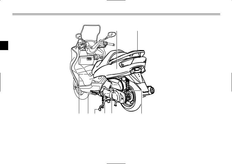
Left view
1 2
2
|
8 |
7 |
6 |
5 |
4 |
3 |
|
1. |
Rear storage compartment |
(page 3-20) |
5. |
V-belt case air filter element |
(page 6-22) |
|
2. |
Grab bar |
(page 5-2) |
6. |
Centerstand |
(page 6-31) |
|
3. |
Shock absorber spring preload |
7. |
Sidestand |
(page 3-22, 6-31) |
|
|
adjusting ring |
(page 3-21) |
8. |
Fuel tank cap |
(page 3-15) |
|
|
4. |
Air filter element |
(page 6-21) |
2-1

DESCRIPTION
12
|
18 |
17 |
16 |
15 14 |
13 |
||||||||||||
|
9. |
Passenger seat |
14. |
Battery |
(page 6-34) |
||||||||||||
|
10. |
Rider seat |
(page 3-18) |
15. |
Fuse box |
(page 6-36) |
|||||||||||
|
11. |
Air flow louver |
(page 6-23) |
16. |
Coolant reservoir cap |
(page 6-20) |
|||||||||||
|
12. |
Headlight |
(page 6-37) |
17. |
Coolant level check window |
(page 6-19) |
|||||||||||
|
13. |
Radiator |
18. |
Engine oil filler cap |
(page 6-15) |
2-2

DESCRIPTION
Controls and instruments
|
1 |
2 |
3 4 |
5 |
6 |
7 |
8 |
9 |
10 |
2
|
13 |
12 |
11 |
|||||||
|
1. |
Rear brake lever |
(page 3-12) |
8. |
Fuel gauge |
(page 3-5) |
||||
|
2. |
Left handlebar switches |
(page 3-10) |
9. |
Right handlebar switches |
(page 3-11) |
||||
|
3. |
Front storage compartment A |
(page 3-19) |
10. |
Front brake lever |
(page 3-11) |
||||
|
4. |
Coolant temperature gauge |
(page 3-5) |
11. |
Throttle grip |
(page 6-23, 6-31) |
||||
|
5. |
Tachometer |
(page 3-4) |
12. |
Front storage compartment B |
(page 3-20) |
||||
|
6. |
Speedometer |
(page 3-4) |
13. |
Main switch/steering lock |
(page 3-1) |
||||
|
7. |
Multi-function display |
(page 3-5) |
2-3

INSTRUMENT AND CONTROL FUNCTIONS
|
………………………………………………………….Main switch/steering lock |
3-1 |
||
|
Indicator and warning lights ……………………………………………………… |
3-2 |
||
|
Speedometer …………………………………………………………………………. |
3-4 |
||
|
Tachometer …………………………………………………………………………… |
3-4 |
||
|
Fuel gauge …………………………………………………………………………….. |
3-5 |
||
|
Coolant temperature gauge ……………………………………………………… |
3-5 |
3 |
|
|
Multi-function display |
3-5 |
||
|
Anti-theft alarm (optional) ………………………………………………………. |
3-10 |
||
|
Handlebar switches ………………………………………………………………. |
3-10 |
||
|
Front brake lever ………………………………………………………………….. |
3-11 |
||
|
Rear brake lever …………………………………………………………………… |
3-12 |
||
|
ABS ……………………………………………………………………………………. |
3-13 |
||
|
Fuel tank cap ……………………………………………………………………….. |
3-15 |
||
|
Fuel …………………………………………………………………………………….. |
3-16 |
||
|
Catalytic converter ………………………………………………………………… |
3-17 |
||
|
Rider seat ……………………………………………………………………………. |
3-18 |
||
|
Adjusting the rider seat ………………………………………………………….. |
3-18 |
||
|
Storage compartments ………………………………………………………….. |
3-19 |
||
|
Adjusting the shock absorber assemblies ………………………………… |
3-21 |
||
|
Sidestand …………………………………………………………………………….. |
3-22 |
||
|
Ignition circuit cut-off system ………………………………………………….. |
3-22 |
||

INSTRUMENT AND CONTROL FUNCTIONS
|
OFF |
ON |
|||
|
OPEN |
||||
|
PUSH |
||||
|
LOCK |
N |
|||
|
PUSH |
TO |
|||
|
P |
||||
|
I |
I |
|||
|
N |
||||
|
3 |
IG |
|||
EAU00029
Main switch/steering lock
Mainswitch/steeringlock
The main switch/steering lock controls the ignition and lighting systems, and is used to lock the steering. The various positions are described below.
EAU04580
ON
All electrical circuits are supplied with power; the meter lighting, taillight, license plate light and auxiliary light come on, and the engine can be started. The key cannot be removed.
NOTE:
The headlight comes on automatically when the engine is started and stays on until the key is turned to “OFF” or the sidestand is moved down.
EAU00038
OFF
All electrical systems are off. The key can be removed.
EAU00040
LOCK
The steering is locked, and all electrical systems are off. The key can be removed.
EAU00027
To lock the steering
1.Turn the handlebars all the way to the left.
2.Push the key in from the “OFF” position, and then turn it to “LOCK” while still pushing it.
3.Remove the key.
To unlock the steering
Push the key in, and then turn it to “OFF” while still pushing it.
EW000016
w
Never turn the key to “OFF” or “LOCK” while the scooter is moving, otherwise the electrical systems will be switched off, which may result in loss of control or an accident. Make sure that the scooter is stopped before turning the key to “OFF” or “LOCK”.
3-1
INSTRUMENT AND CONTROL FUNCTIONS
EAU03733
. (Parking)
The steering is locked, and the taillight, license light and auxiliary light are on, but all other electrical systems are off. The key can be removed.
To turn the main switch to “.”:
1.Turn the key to “LOCK”.
2.Slightly turn the key counterclockwise until it stops.
3.While still turning the key counterclockwise, push it in until it snaps into place.
ECA00043
cC
Do not use the parking position for an extended length of time, otherwise the battery may discharge.
|
1 |
2 |
3 |
4 |
5 |
1.Left turn signal indicator light “4”
2.ABS warning light “  ”
”
3.High beam indicator light “&”
4.Oil change indicator light “7”
5.Right turn signal indicator light “6”
EAU03034
Indicator and warning lights
Indicatorandwarninglights
EAU04121
Turn signal indicator lights “4” and “6”
Turnsignalindicatorlights
The corresponding indicator light flashes when the turn signal switch is pushed to the left or right.
EAU04901
|
ABS warning light “ |
” |
|
ABSwarninglight |
|
|
ECA00019 |
|
|
cC |
If the ABS warning light comes on or flashes while riding, the ABS may be defective. If this occurs,
have a Yamaha dealer check the 3 electrical circuit.
See page 3-13 for an explanation of the ABS.
The electrical circuit of the warning light can be checked by setting the engine stop switch to “#” and turning the key to “ON”.
The warning light should come on for a few seconds, and then go off. If the warning light does not come on or remains on, have a Yamaha dealer check the electrical circuit.
3-2

INSTRUMENT AND CONTROL FUNCTIONS
EWA00069
w
When the ABS warning light comes on or flashes while riding, the brake system reverts to conventional braking. Therefore, be careful not to cause the wheel to
3lock during emergency braking.
NOTE:
The ABS warning light may come on while pushing the start switch and while accelerating the engine with the scooter on its centerstand, but this does not indicate a malfunction.
EAU00063
High beam indicator light “&”
Highbeamindicatorlight
This indicator light comes on when the high beam of the headlight is switched on.
EAU03734
Oil change indicator light “7”
Oilchangeindicatorlight
This indicator light comes on at the initial 1,000 km and every 3,000 km thereafter to indicate that the engine oil should be changed.
If the engine oil is changed before the oil change indicator comes on (i.e. before the periodic oil change interval has been reached), the indicator light must be reset after the oil change for the next periodic oil change to be indicated at the correct time. (See page 6-17 for the resetting procedure.)
The electrical circuit of the indicator light can be checked according to the following procedure.
1.Set the engine stop switch to “#” and turn the key to “ON”.
2.Check that the indicator comes on for a few seconds and then goes off.
3.If the indicator light does not come on, have a Yamaha dealer check the electrical circuit.
NOTE:
The oil change indicator light may flash when the engine is revved with the scooter on the centerstand, but this does not indicate a malfunction.
3-3
![]()
INSTRUMENT AND CONTROL FUNCTIONS
|
1 |
1 |
||
|
1. |
Speedometer |
1. |
Tachometer |
|
ECA00134 |
||
|
cC |
||
|
8 |
Do not operate the engine |
|
|
above 8,500 r/min. |
||
|
8 |
This scooter is equipped with |
|
|
an engine speed limiter, which |
||
|
prevents the engine speed |
||
|
from exceeding approximately |
3 |
|
|
9,000 r/min. |
EAU04581
Speedometer
Speedometer
The speedometer shows the riding speed.
When the key is turned to “ON”, the speedometer needle will move to 160 km/h and back to zero in order to test the electrical circuit.
EAU04582
Tachometer
Tachometer
The electric tachometer allows the rider to monitor the engine speed and keep it within the ideal power range.
When the key is turned to “ON”, the tachometer needle will move to the 10,000 r/min and back to zero r/min in order to test the electrical circuit.
3-4

INSTRUMENT AND CONTROL FUNCTIONS
1
3
1. Fuel gauge
EAU00110
Fuel gauge
Fuelgauge
The fuel gauge indicates the amount of fuel in the fuel tank. The needle moves towards “E” (Empty) as the fuel level decreases. When the needle reaches “E”, approximately 2 L of fuel remain in the fuel tank. If this occurs, refuel as soon as possible.
NOTE:
Do not allow the fuel tank to empty itself completely.
2
1
1.Coolant temperature gauge
2.Red mark
EAU03124
Coolant temperature gauge
Coolanttemperaturegauge
This gauge indicates the coolant temperature when the main switch is on. The engine operating temperature will vary with changes in weather and engine load. If the needle points to the red mark, stop your scooter and let the engine cool. (See page 6-44 for details.)
EC000002
cC
Do not operate the engine if it is overheated.
1.Tripmeter
2.Odometer, fuel tripmeter
3.Clock, outside temperature and voltage display
EAU04906
Multi-function display
Display,multi-function
The multi-function display is equipped with the following:
8a tripmeter (which shows the distance traveled since it was last set to zero)
8a fuel tripmeter (which shows the distance traveled when the fuel
level reaches approximately 2.0 L)
8an odometer (which shows the total distance traveled)
8a clock
8an outside temperature display
3-5

INSTRUMENT AND CONTROL FUNCTIONS
1.“SELECT” button
2.“RESET” button
8a voltage display (which shows the battery voltage)
NOTE:
8When the key is turned to “ON”, all segments of the display come on for a few seconds. During this time, the multi-function display is performing a self-test.
8Be sure to turn the key to “ON” before using the “SELECT” and “RESET” buttons.
|
NOTE: |
||||||||
|
8 |
The tripmeter reset mode auto- |
|||||||
|
matically cancels after five sec- |
||||||||
|
onds. To return to the reset |
||||||||
|
mode, push the “SELECT” but- |
||||||||
|
ton again until “Trip” begins |
||||||||
|
flashing. |
||||||||
|
3 |
||||||||
|
8 |
To cancel the tripmeter reset |
|||||||
|
mode, push the “SELECT” but- |
||||||||
|
Tripmeter “Trip” |
ton. |
|||||||
|
8 |
If the tripmeter indicates “–––– ”, |
|||||||
|
To reset the tripmeter: |
have a Yamaha dealer check or |
|||||||
|
1. Push the “SELECT” button until |
repair the multi-function display |
|||||||
|
the voltage display appears, then |
as it may be faulty. |
|||||||
|
push the “SELECT” button one |
||||||||
|
more time and “Trip” starts flash- |
||||||||
|
ing. |
2.Push the “RESET” button for at least one second to reset the tripmeter to zero.
3-6
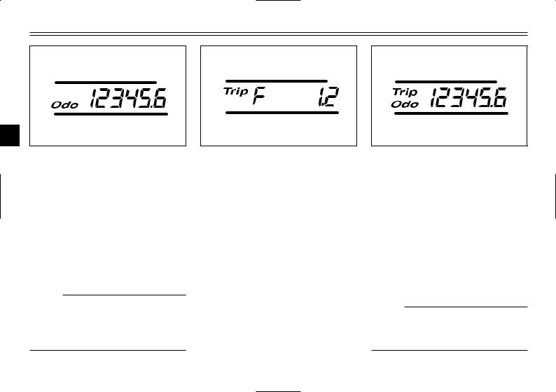
INSTRUMENT AND CONTROL FUNCTIONS
3
Odometer “Odo”
The odometer has two functions.
8It shows the total distance traveled.
8It automatically changes to the fuel tripmeter mode “Trip F” when the fuel level reaches approximately 2.0 L. (See “Fuel tripmeter” for details.)
NOTE:
If the odometer indicates “–––––– ”, have a Yamaha dealer check or repair the multi-function display as it may be faulty.
Fuel tripmeter “Trip F”
When the fuel level reaches approximately 2.0 L, the odometer display automatically changes to the fuel tripmeter mode “Trip F” and starts counting the distance traveled from that point. After refueling and traveling 5 km, the odometer display returns to “Odo”.
To return to the odometer mode before refueling, push the “SELECT” button until “Trip F” begins flashing (“Trip F” will only flash for five seconds). While “Trip F” is flashing, push the “RESET” button for at least one second and the display will return to the odometer mode. From that time, both “Trip” and “Odo” are displayed until you refuel and travel 5 km.
NOTE:
The display cannot be changed back to “Trip F” after pushing the “RESET” button.
3-7

INSTRUMENT AND CONTROL FUNCTIONS
3
|
Clock |
3. When the hour digits start flash- |
4. |
Push the “SELECT” button, and |
|
|
To set the clock |
ing, push the “RESET” button to |
the minute digits will start flash- |
||
|
1. |
Push the “SELECT” button until |
set the hours. |
ing. |
|
|
the clock is displayed. |
5. |
Push the “RESET” button to set |
||
|
2. |
Push the “SELECT” button and |
the minutes. |
||
|
“RESET” button together for at |
6. |
Push the “SELECT” button and |
||
|
least two seconds. |
then release it to start the clock. |
3-8
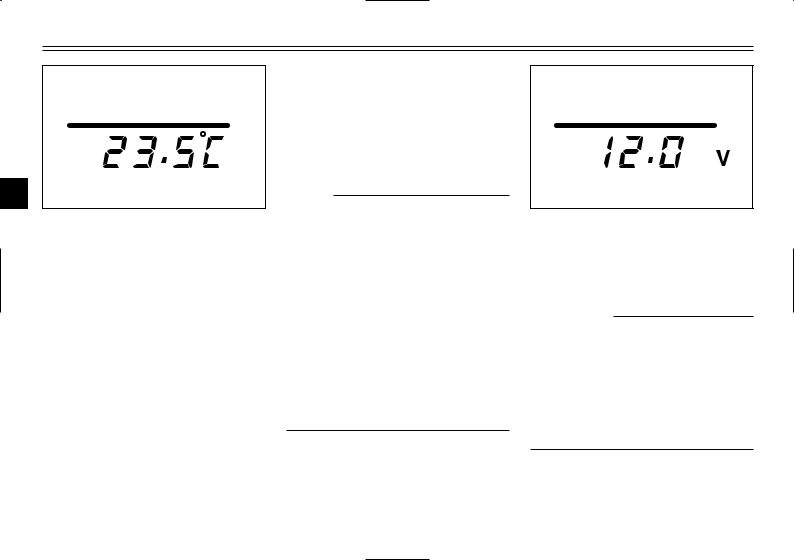
INSTRUMENT AND CONTROL FUNCTIONS
3
Outside temperature display
This display shows the outside temperature from -10.0 °C to 50.0 °C in 0.5 °C increments.
8When the outside temperature falls below -10.0 °C, “–– °C ” is displayed.
8When the outside temperature climbs above 50.0 °C, “50.0” flashes.
NOTE:
8If “–– °C” is displayed or “50.0” flashes while the outside temperature is between -10.0 °C and 50.0 °C, there is a problem with the electrical circuit. Have a Yamaha dealer check or repair the electric circuit.
8The accuracy of the temperature reading may be affected when riding slowly (approximately under 20 km/h) or when stopped at traffic signals, railroad crossings, etc.
Voltage display
This display shows the battery voltage.
ECA00135
cC
If the voltage display indicates “LO” or “HI”, there may be trouble with the battery charging circuit or the battery may be faulty. If “LO” or “HI” appears in the display, have a Yamaha dealer check or repair the scooter.
3-9

INSTRUMENT AND CONTROL FUNCTIONS
EAU00109
Anti-theft alarm (optional)
Anti-theftalarm(optional)
This scooter can be equipped with an optional anti-theft alarm by a Yamaha dealer. Contact a Yamaha dealer for more information.
1.Pass switch “PASS”
2.Dimmer switch “&/%”
3.Turn signal switch “4/6”
4.Horn switch “*”
EAU00118
Handlebar switches
Handlebarswitches
EAU00120
Pass switch “PASS”
Passswitch
Press this switch to flash the headlight.
EAU03888
Dimmer switch “&/%”
Dimmerswitch
Set this switch to “&” for the high beam and to “%” for the low beam.
|
EAU03889 |
|
|
Turn signal switch “4/6” |
|
|
Turnsignalswitch |
|
|
To signal a right-hand turn, push this |
|
|
switch to “6”. To signal a left-hand |
|
|
turn, push this switch to “4”. When |
|
|
released, the switch returns to the |
|
|
center position. To cancel the turn |
|
|
signal lights, push the switch in after |
3 |
|
it has returned to the center position. |
|
EAU00129
Horn switch “*”
Hornswitch
Press this switch to sound the horn.
3-10

INSTRUMENT AND CONTROL FUNCTIONS
1
1.Engine stop switch “#/$”
2.Start switch “,”
EAU03890
Engine stop switch “#/$”
Enginestopswitch
Set this switch to “#” before starting the engine. Set this switch to “$” to stop the engine in case of an emergency, such as when the scooter overturns or when the throttle cable is stuck.
EAU03801
Start switch “,”
Startswitch
With the sidestand up, push this switch while applying the front or rear brake to crank the engine with the starter.
EC000005
cC
See page 5-1 for starting instructions prior to starting the engine.
1
1. Front brake lever
EAU03882
Front brake lever
Brakelever,front
The front brake lever is located on the right handlebar grip. To apply the front brake, pull this lever toward the handlebar grip.
3-11

INSTRUMENT AND CONTROL FUNCTIONS
1
3
1. Rear brake lever
EAU00163
Rear brake lever
Brakelever,rear
The rear brake lever is located on the left handlebar grip. To apply the rear brake, pull this lever toward the handlebar grip.
3-12

INSTRUMENT AND CONTROL FUNCTIONS
EAU03631
ABS
ABS
The Yamaha ABS (Anti-lock Brake System) features a dual electronic control system, which acts on the front and rear brakes independently. The ABS securely controls wheel
3lockup during emergency braking on changing road surfaces and under various weather conditions, thereby maximizing tire adhesion and performance while providing a smooth braking action. The ABS is monitored by an ECU (Electronic Control Unit), which will have recourse to manual braking if a malfunction occurs.
8The ABS performs best on long braking distances.
8On certain (rough or gravel) roads, the braking distance may be longer with than without the ABS. Therefore, always keep a sufficient distance to the vehicle ahead to match the riding speed.
8When the ABS is activated, the brakes are operated in the usual way. A pulsating action may be felt at the brake levers, but this does not indicate a malfunction.
8This ABS has a test mode which allows the owner to experience the pulsating at the brake levers when the ABS is operating. However, special tools are required, so please consult your Yamaha dealer when performing this test.
3-13
![]()
|
INSTRUMENT AND CONTROL FUNCTIONS |
|||||||
|
ABS components |
1. |
Front brake hose |
|||||
|
2. |
Rear brake hose |
||||||
|
3. |
ABS warning light |
||||||
|
1 |
2 |
4. Fail-safe relay |
|||||
|
5. ECU (Electronic Control Unit) |
|||||||
|
3 |
4 |
5 |
6. |
Stop relay |
|||
|
7. |
Hydraulic Unit (HU) |
||||||
|
6 |
8. |
Front brake hose |
3 |
||||
|
9. Front wheel sensor rotor |
|||||||
|
10.Front wheel sensor |
|||||||
|
7 |
11.Fuse boxes |
||||||
|
15 |
12.ABS test coupler |
||||||
|
13.Rear brake hose |
|||||||
|
8 |
|||||||
|
14.Rear wheel sensor rotor |
|||||||
|
15.Rear wheel sensor |
|||||||
|
9 |
|||||||
|
14 |
|||||||
|
13 |
|||||||
|
12 |
10 |
||||||
|
11 |
|||||||
|
3-14 |

INSTRUMENT AND CONTROL FUNCTIONS
1.Lid
2.Lever
EAU03090
Fuel tank cap
Fueltankcap
To open the fuel tank cap
1.Open the lid by sliding the lever forward, and then pull the lever up.
1.Fuel tank cap
2.Insert the key into the lock and turn it clockwise. The lock will be released and the fuel tank cap can be removed.
1. Match marks
To install the fuel tank cap
1.Align the match marks, insert the fuel tank cap into the tank opening, and then push down on the cap.
2.Turn the key counterclockwise to the original position, and then remove it.
3.Close the lid.
EWA00028
w
Be sure that the fuel tank cap is properly installed and locked before riding the scooter.
3-15

INSTRUMENT AND CONTROL FUNCTIONS
1.Filler tube
2.Fuel level
EAU03753
Fuel
Fuel
Make sure that there is sufficient fuel in the tank. Fill the fuel tank to the bottom of the filler tube as shown.
EW000130
w
8Do not overfill the fuel tank, otherwise it may overflow when the fuel warms up and expands.
8Avoid spilling fuel on the hot engine.
EAU00185
cC
Immediately wipe off spilled fuel with a clean, dry, soft cloth, since fuel may deteriorate painted surfaces or plastic parts.
EAU04284
Recommended fuel: REGULAR UNLEADED GASOLINE ONLY
Fuel tank capacity: Total amount:
12 L
3
ECA00104
cC
Use only unleaded gasoline. The use of leaded gasoline will cause severe damage to internal engine parts, such as the valves and piston rings, as well as to the exhaust system.
3-16

INSTRUMENT AND CONTROL FUNCTIONS
Your Yamaha engine has been designed to use regular unleaded gasoline with a research octane number of 91 or higher. If knocking (or pinging) occurs, use a gasoline of a different brand or premium unleaded fuel. Use of unleaded fuel will extend
3spark plug life and reduce maintenance costs.
EAU03098
Catalytic converter
Catalyticconverter
This scooter is equipped with a catalytic converter in the muffler.
EW000128
w
The exhaust system is hot after operation. Make sure that the exhaust system has cooled down before doing any maintenance work.
EC000114
cC
The following precautions must be observed to prevent a fire hazard or other damages.
8Use only unleaded gasoline. The use of leaded gasoline will cause unrepairable damage to the catalytic converter.
8Never park the scooter near possible fire hazards such as grass or other materials that easily burn.
8Do not allow the engine to idle too long.
3-17

INSTRUMENT AND CONTROL FUNCTIONS
a
ON
OFF
OPEN
PUSH
LOCK
|
PUSH |
TO |
||
|
P |
|||
|
I |
I |
||
|
N |
|||
|
IG |
|
a. Open. |
1. Rider seat |
1. Rider seat |
|
|
EAU03091 |
3. Fold the rider seat up. |
EAU03096* |
|
|
Rider seat |
Adjusting the rider seat |
||
Riderseat,adjusting
Riderseat
To open the rider seat
1.Place the scooter on the centerstand.
2.Insert the key into the main switch, and then turn it counterclockwise.
NOTE:
Do not push inward when turning the key.
To close the rider seat
1.Fold the rider seat down, and then push it down to lock it in place.
2.Remove the key from the main switch if the scooter will be left unattended.
NOTE:
Make sure that the seat is properly secured before riding.
The rider seat can be adjusted as follows to change the riding position.
1. Open the rider seat.
3-18
 Loading…
Download Service manual of Yamaha MAJESTY YP250 Motorcycle, Scooter for Free or View it Online on All-Guides.com.

1

2

3

4

5

6

7

8

9

10

11

12

13

14

15

16

17

18

19

20

21

22

23

24

25

26

27

28

29

30

31

32

33

34

35

36

37

38

39

40

41

42

43

44

45

46

47

48

49

50

51

52

53

54

55

56

57

58

59

60

61

62

63

64

65

66

67

68

69

70

71

72

73

74

75

76

77

78

79

80

81

82

83

84

85

86

87

88

89

90

91

92

93

94

95

96

97

98

99

100

101

102

103

104

105

106

107

108

109

110

111

112

113

114

115

116

117

118

119

120

121

122

123

124

125

126

127

128

129

130

131

132

133

134

135

136

137

138

139

140

141

142

143

144

145

146

147

148

149

150

151

152

153

154

155

156

157

158

159

160

161

162

163

164

165

166

167

168

169

170

171

172

173

174

175

176

177

178

179

180

181

182

183

184

185

186

187

188

189

190

191

192

193

194

195

196

197

198

199

200

201

202

203

204

205

206

207

208

209

210

211

212

213

214

215

216

217

218

219

220

221

222

223

224

225

226

227

228

229

230

231

232

233

234

235

236

237

238

239

240

241

242

243

244

245

246

247

248

249

250

251

252

253

254

255

256

257

258

259

260

261

262

263

264

265

266

267

Смотреть руководство для Yamaha Majesty 250 (2003) ниже. Все руководства на ManualsCat.com могут просматриваться абсолютно бесплатно. Нажав кнопку «Выбор языка» вы можете изменить язык руководства, которое хотите просмотреть.

MANUALSCAT | RU
Вопросы и ответы
У вас есть вопрос о Yamaha Majesty 250 (2003), но вы не можете найти ответ в пользовательском руководстве? Возможно, пользователи ManualsCat.com смогут помочь вам и ответят на ваш вопрос. Заполните форму ниже — и ваш вопрос будет отображаться под руководством для Yamaha Majesty 250 (2003). Пожалуйста, убедитесь, что вы опишите свои трудности с Yamaha Majesty 250 (2003) как можно более детально. Чем более детальным является ваш вопрос, тем более высоки шансы, что другой пользователь быстро ответит на него. Вам будет автоматически отправлено электронное письмо, чтобы проинформировать вас, когда кто-то из пользователей ответит на ваш вопрос.
Задать вопрос о Yamaha Majesty 250 (2003)
- Бренд:
- Yamaha
- Продукт:
- скутеры
- Модель/название:
- Majesty 250 (2003)
- Тип файла:
- Доступные языки:
- голландский