Ваша заявка успешно отправлена!
Необходимо принять условия соглашения
Вы заполнили не все обязательные поля
Произошла ошибка, попробуйте ещё раз
Ваше имя:
*
Телефон:
*

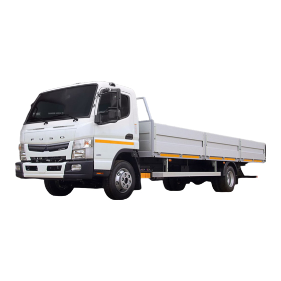
Руководство на английском языке по монтажу кузовов/надстроек для автомобилей Mitsubishi Canter серий FE/FG.
- Автор: —
- Издательство: Mitsubishi Fuso Service
- Год издания: —
- Страниц: 318
- Формат: PDF
- Размер: 46,0 Mb

Руководство по техническому обслуживанию и ремонту автомобиля Mitsubishi Canter 1993-2002 годов выпуска с дизельными двигателями
- Автор: —
- Издательство: Легион-Автодата
- Год издания: —
- Страниц: 484
- Формат: —
- Размер: —
Руководство по эксплуатации, техническому обслуживанию и ремонту автомобиля Mitsubishi Fuso Canter с 2010 года выпуска с дизельным двигателем модели 4M50 (4,9 л).
- Автор: —
- Издательство: Легион-Автодата
- Год издания: —
- Страниц: 416
- Формат: —
- Размер: —
Руководство по эксплуатации и ремонту автомобиля Mitsubishi Fuso Canter с 2010 года выпуска с дизельным двигателем объемом 4,9 л.
- Автор: —
- Издательство: Монолит
- Год издания: —
- Страниц: 376
- Формат: —
- Размер: —
Спецификации на английском языке автомобилей Mitsubishi Canter серий FB/FE/FG.
- Автор: —
- Издательство: Mitsubishi Motors
- Год издания: —
- Страниц: 94
- Формат: PDF
- Размер: 3,0 Mb

- Manuals
- Brands
- Mitsubishi Manuals
- Automobile
- Fuso Canter 2013
- Owner’s manual
-
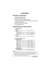
Contents
-
Table of Contents
-
Bookmarks
Quick Links
Related Manuals for Mitsubishi Fuso Canter 2013
Summary of Contents for Mitsubishi Fuso Canter 2013
-
Page 2
OWNER AND VEHICLE INFORMATION OWNER NAME: USER/COMPANY NAME: MAILING ADDRESS: CITY, STATE: ZIP: VEHICLE IDENTIFICATION NUMBER: DATE OF DELIVERY (WARRANTY START DATE): SELLING DEALER IMPRINT HERE… -
Page 3
Please keep this manual in the vehicle so it is always available for reference. If you sell the vehicle, make sure the next owner receives this manual and is aware of its contents. © 2012 Mitsubishi Fuso Truck & Bus Corporation Printed in Japan… -
Page 4
Reading the handbook The information in this manual is accurate as of the time of printing. Because of differ- ences in specifications and improvements that may be added after preparation of this manual, some of the explanations and illustrations in this handbook may not apply to your vehicle. -
Page 5: Table Of Contents
CONTENTS 1. Recommendation to drivers ……… . . 1-1 2.
-
Page 6: Table Of Contents
1. Recommendation to drivers Chassis and engine numbers ……………….. 1-2 Vehicle identification number (VIN) ………………1-3 Maintenance ……………………1-4 Fuels ……………………..1-5 DEF (Diesel exhaust fluid) ………………..1-8 Handling of the new vehicle ………………… 1-13 Reporting safety defects ………………..1-14 Obtaining service ………………….
-
Page 7: Chassis And Engine Numbers
Recommendation to drivers Chassis and engine numbers 1 Chassis number The chassis number is indicated on the left frame, near the left front wheel. Example: FEC52 — Chassis number Vehicle model 2 Engine number The engine number is indicated on the front side of the cylinder head.
-
Page 8: Vehicle Identification Number (Vin)
G: 3.8 to 4.09 m (12.46 to 13.41 ft.) 4.1 to 4.39 m (13.45 to 14.40 ft.) 4.7 to 4.99 m (15.41 to 16.37 ft.) Cab chassis type Chassis cab for Mitsubishi Fuso and make Engine 2.998 L Diesel turbo charged and charge air cooled…
-
Page 9: Maintenance
Recommendation to drivers Maintenance Checking your vehicle at regular intervals is very important for maximizing performance and extend- ing service life. It is recommended that you make a habit of performing the following inspections. This manual describes simple maintenance checks and procedures that can be carried out by the owner.
-
Page 10: Fuels
Mitsubishi Fuso trucks. 1 Diesel-fuel properties The following recommendations concerning diesel fuel used with Mitsubishi Fuso diesel engines are given for optimum fuel economy and performance. Use condition Recommendation Normal operation at…
-
Page 11
Recommendation to drivers 3 Danger of fire and explosion by using mixed fuel Fuel containing 5% gasoline has a flash point as low as 0°C (32°F), which can lead to a fire or explo- sion while the engine is running. DANGER NEVER MIX DIESEL FUEL WITH GASOLINE, GASOHOL OR ALCOHOL. -
Page 12
5 Refueling WARNING • Stop the engine before fueling. • Never smoke when fueling since diesel fuel could ignite or explode. Never operate lighters or other items that emit sparks. • If you inadvertently put gasoline in the fuel tank, pump it all out. Running the engine with gasoline in the tank could cause a fire or explosion endangering your or other people’s lives. -
Page 13: Def (Diesel Exhaust Fluid)
Recommendation to drivers • 113-liter fuel tank The fuel tank is at the rear of the vehicle. To open the fuel tank cap, slowly turn it counterclockwise. To close the cap, turn it clockwise until you hear a click. Fuel tank capacity 113 liters (29.8 gallons) •…
-
Page 14
WARNING DEF is a colorless, transparent, odorless and harmless water solution (urea 32.5%, water 67.5%; Freezing temperature -11°C (12°F)), so no problem will occur if you get it on your skin. However, some persons with delicate skin may in very rare cases get a rash, so carry out the following procedure. -
Page 15
1-10 Recommendation to drivers CAUTION Do not rest your foot on the DEF tank or step on it, because this may damage the tank and/or the sensors on it. NOTE: • Replenish the DEF well before it is used up. •… -
Page 16: In Cold Weather
1-11 3 Method for canceling the driving restric- tion that has engaged due to an empty DEF tank If the DEF tank becomes empty, a driving restriction automatically engages, locking the gear in first or reverse, so the vehicle can be driven only slowly. In the event of a driving restriction, replenish the DEF and then disengage the restriction as follows.
-
Page 17
1-12 Recommendation to drivers NOTE: • You can use frozen DEF after allowing it to thaw, without loss of quality. • If you seal the container so as to prevent the water from evaporating, the quality of the DEF will not change. •… -
Page 18: Handling Of The New Vehicle
1-13 4000 km Handling of the new vehicle (2500 miles) The way the vehicle is handled when new greatly affects its subsequent performance and service life. Observe the following precautions when handling the new vehicle. 1 Maintenance The “first maintenance at 4,000 km (2,500 miles)” is Z18524 very important for extending the service life of your vehicle.
-
Page 19: Reporting Safety Defects
National Highway Traffic Safety Administration (NHTSA) and the Mitsubishi Fuso Truck of America, Inc. (MFTA). If NHTSA receives similar complaints, it may open an investigation, and if it finds that a safety defect exists in a group of vehicles, it may order a recall and remedy campaign.
-
Page 20
Name of Dealer contacted under Step 1, if appli- cable • Details of the Complaint/Comment You also may correspond with the Customer Ser- vice Representative in writing, addressed to: MITSUBISHI FUSO TRUCK OF AMERICA, INC. CUSTOMER SERVICE REPRESENTATIVE 2015 CENTER SQUARE RD. LOGAN TOWNSHIP, NJ 08085… -
Page 21: Warning Labels
2. Warning labels Labels inside the cab ………………….2-3 Exterior labels ……………………2-5…
-
Page 22
Warning labels • The caution and warning labels show important information. Be sure to read them before using the vehicle. • If any label has peeled so it is difficult to read, is scratched or otherwise damaged, or has peeled off completely, please inform an authorized dealer. -
Page 23
Labels inside the cab 1 Around the driver’s seat Z23258 Location Category Information Ref. page WARNING High temperatures of exhaust system components 5-50 WARNING Handling of DPF system with regeneration control 5-50 WARNING Handling of DEF WARNING Use of specified fuses 13-10 WARNING Engine oil level check 12-23… -
Page 24
Warning labels 2 On driver’s door and door pillar Z21446 Location Category Information Ref. page CAUTION Handling of PTO <option> 5-45 WARNING Handling of DUONIC 5-20 WARNING 4WD <FG> CAUTION Towing precautions 13-32 Standard value Tire pressure 12-67 WARNING 113-liter fuel tank refilling precaution Precautions for vehicles with limited slip differential WARNING 12-70… -
Page 25
Exterior labels 1 On frame and exterior equipment Z23259 Location Category Information Ref. page DANGER High temperatures of exhaust system components 5-50 CAUTION Use of diesel fuel WARNING Fuel to use WARNING 113-liter fuel tank refilling precautions CAUTION Prohibition against standing on DEF tank CAUTION Use of DEF CAUTION… -
Page 26
Warning labels 2 On cab outside and engine Z21197 Location Category Information Ref. page Handling of cab tilt function (Vehicles other than WARNING 12-6 Crew-cab models) WARNING Handling of pressure cap 12-57 CAUTION Inspection and replacement of engine oil 12-23 CAUTION Oil to use for clutch and transmission 12-28… -
Page 27: Opening And Closing
3. Opening and closing Starter key …………………….. 3-2 Engine immobilizer (theft prevention device) …………..3-3 Doors ……………………..3-6 Central door locks ………………….3-8 Keyless entry system ………………….3-9 Entering and leaving the vehicle ………………3-13 Door window glass ………………….3-15…
-
Page 28: Starter Key
Opening and closing Starter key • Your vehicle comes with a two-piece starter key • The starter key can be used to start and stop the engine and lock and unlock the doors. • Be sure to remove the number plate and keep it in a safe place.
-
Page 29: Engine Immobilizer
Engine immobilizer (theft prevention device) 1 Engine immobilizer NOTE: The immobilizer complies with part 15 of the FCC Rules. Operation is subject to the following two con- ditions: (1) The immobilizer may not cause harmful inter- ference. (2) The immobilizer must accept any interference received, including interference that may cause undesired operation.
-
Page 30
Opening and closing • A metallic ring is on top of the handle of the engine immobilizer starter key. Z20929 • The handle of the engine immobilizer starter key is in contact with a metallic part of another key. Z20930 •… -
Page 31
The engine immobilizer starter key is an electronic device containing a signal transmitter. Bear in mind the following cautions: • Do not bend the engine immobilizer starter key or subject it to strong shocks. • Do not leave the engine immobilizer starter key in any part of the cab where it could be exposed to direct sunlight and get extremely hot (60°C (140°F) or higher). -
Page 32
Opening and closing Doors WARNING • To help prevent accidents, always check for vehicles and pedestrians approaching from behind before opening the doors. • Driving with a door ajar can be very dan- gerous. Make sure the doors are com- pletely closed before starting. -
Page 33
1 From the outside • To open, pull the outer handle toward you. • Use the starter key to lock or unlock the door. • It is possible to lock each door without using the starter key. With the driver’s door or assistant driver’s door, push the lock knob toward the front of the vehicle then pull the outer handle… -
Page 34: From The Inside
Opening and closing 2 From the inside • To close, use the door waist bar . Close the door completely. • To lock the driver’s door or assistant driver’s door, push the lock knob toward the front of the vehicle. To lock a rear door, push the lock knob down.
-
Page 35: Keyless Entry System
Keyless entry system 1 The Grant of Equipment Authorization certificate for wireless transmitter (remote control switch) 1. FCC ID: OBIH7079TX 2. This device complies with Part 15 of the FCC Rules. Operation is subject to the following two conditions: • This device may not cause harmful interference.
-
Page 36
3-10 Opening and closing 2 Keyless entry system The keyless entry system allows you to lock/unlock the driver’s door, assistant driver’s door and rear doors (Crew-cab model vehicles) by operating the remote control switch WARNING If you carry the keyless entry remote control switch with you when traveling on an air- Z21332 plane, avoid pressing any button on the… -
Page 37
3-11 • When you press the buttons, be sure to press them for at least one second. If a button does not work after one press, press the button again after one or two seconds. • After locking the doors with the remote control switch, always check that the doors are locked by lifting the outside handle of a door. -
Page 38
3-12 Opening and closing CAUTION • Use the designated standard type of battery. If the battery is replaced with an incorrect type, the battery could explode. • Attach the battery with the “+” mark facing upward. • Do not use a metal tool such as tweezers to replace the battery. -
Page 39: Entering And Leaving The Vehicle
3-13 Entering and leaving the vehicle WARNING • Always use the step to climb into or down from the vehicle. Never put your foot on the wheel or tire since it could easily slip off. • The step can become slippery in rain or snow.
-
Page 40
3-14 Opening and closing Z23260 CAUTION • Climb into and out of the cab by holding only the grip. If you hold onto any other parts of the vehicle, they could break or fail. • When entering or leaving an FG model truck, do not place your feet or hands on the fender . -
Page 41: Power Window Switches
3-15 Door window glass WARNING Do not allow a child to put its hands or head out of a window. The child’s head or hands could hit an object outside the vehicle, and the child could be seriously injured in the event of hard braking.
-
Page 42
3-16 Opening and closing To fully close the driver’s window with a single touch of the switch, pull the switch firmly. If you wish to stop the window part-way, give the switch a gentle push. CAUTION Do not keep any door or window open in rainy weather, and be careful not to spill a drink on any of the window switches. -
Page 43: Seat And Steering Wheel Adjustments
4. Seat and steering wheel adjustments Seats ……………………..4-2 Seat belts ……………………… 4-5 Steering wheel ……………………4-9…
-
Page 44
Seat and steering wheel adjustments Seats WARNING • Adjusting the seat while the vehicle is in motion is dangerous as the seat may move more than you intend. Be sure to stop the vehicle and set the parking brake before performing any adjustment of the seat. -
Page 45
Making adjustments • Slide seat forward or backward while holding slide adjustment lever raised. After making the adjustment, release the lever and move the seat back and forth slightly to lock it in position. • To adjust the angle of the seatback , raise reclining lever •… -
Page 46
Seat and steering wheel adjustments 3 Rear seat – Crew-cab models Storage compartments are located under the rear seat. The rear seat can be folded up for access to them. When you wish to stow or remove something from these compartments, release the clamps the base of the seat and raise the seat cushion To retain the seat cushion, use the retaining bands that are attached to the seatback. -
Page 47: Seat Belts
Seat belts • To help prevent injury in the event of a sudden stop or accident, the driver and all passengers must wear their seat belts correctly. • When wearing your seat belt, sit back in your seat with your back straight. If a seat belt is used incorrectly, its effectiveness is greatly dimin- Z21338 ished and it could aggravate injuries in the event…
-
Page 48
Seat and steering wheel adjustments 1 Lap and shoulder belts with ELR NOTE: It is not necessary to adjust the length of these seat belts. An ELR seat belt extends and retracts automatically as its wearer moves but locks automatically for pro- tection in the event of a sudden stop or shock. -
Page 49: Lap Belt
Seat belt anchor <Driver’s seat> WARNING The shoulder belt can be dangerous if worn across the neck. Adjust its position so that it does not cross over the neck. Adjust the seat belt anchor upward or downward Z08772 to ensure that the belt passes across your shoulder. You will need to keep the lock button pulled while moving the seat belt anchor downward.
-
Page 50: Pregnant Women
Seat and steering wheel adjustments 3 Children and babies • When carrying children or babies, they must be restrained properly to minimize the risk of injury in the event of a sudden stop or accident. Never allow children to stand or kneel on the seats. For maximum safety, we recommend fitting and using a restraint system that complies with Fed- eral Motor Vehicle Safety Standards.
-
Page 51: Steering Wheel
Steering wheel WARNING • After every adjustment, try to move the steering wheel back and forth to make sure that it is securely locked. Unless the lever returns to its original position, the steering wheel may move while the vehicle is in motion and cause an accident.
-
Page 53: Switches And Controls
5. Switches and controls Arrangement of switches and controls …………….5-2 Starter switch ……………………5-3 Starting the engine ………………….5-5 Warming up the engine ………………..5-10 Stopping the engine ………………….5-12 Pedals ……………………..5-14 Parking brake lever ………………….5-15 Combination switch ………………….5-16 DUONIC ……………………
-
Page 54
Switches and controls Arrangement of switches and controls Starter switch Accelerator pedal Brake pedal Gearshift lever Parking brake lever Hazard warning lamp switch Combination switch (wiper and washer switch, exhaust brake switch <option>) Combination switch (lighting switch, passing/dimmer switch, turn sig- nal switch) Front drive switch <FG>… -
Page 55: Starter Switch
Starter switch 1 Starter switch position WARNING Never turn the starter switch to any position other than the “ON” position while driving the vehicle. Turning the starter switch to the “ACC” position would be dangerous because the engine would stop and the following problems would occur: •…
-
Page 56
Switches and controls • LOCK The starter key can be inserted and removed in this position only. To place the key in the “LOCK” position, turn it to the “ACC” position then press it in. Keep it pressed in while turning it to the “LOCK”… -
Page 57: Starting The Engine
Starting the engine WARNING • Do not start or warm up the engine in a garage or other closed area. When starting the engine or entering or leaving a garage, do not run the engine for longer than is necessary as the accumulation of exhaust gas in closed areas is very dangerous.
-
Page 58
Switches and controls CAUTION • Do not try to push-start the engine. Push- starting the engine is impossible for this vehicle and could damage the transmission. • Do not use ether or other vapor compound type starting aids. Use of such fluid on this engine could result in serious damage. -
Page 59: Starting Procedure
2 Starting procedure 1. Depress the brake pedal fully. CAUTION For safety, keep the brake pedal depressed until the engine has started. Z15222 2. Turn the starter switch to the “ON” position. Z21163 3. Check whether the indicator lamp illumi- nates or not.
-
Page 60
Switches and controls • When the indicator lamp illuminates Wait until the indicator lamp goes out. While holding down the brake pedal, turn the starter switch to the “START” position to start the engine. NOTE: If the engine is difficult to start after the indicator lamp has gone out, there may be a problem with the engine preheating system. -
Page 61
CAUTION • To ensure maximum safety, be sure to pull the parking brake lever fully to apply the parking brake and block the wheels with chocks thus preventing the vehicle from accidentally moving. • Performing the cranking is of essential importance in terms of protecting the turbo- charger. -
Page 62: Warming Up The Engine
5-10 Switches and controls Warming up the engine Let the engine warm up for 1 to 2 minutes before starting the vehicle. WARNING • Do not warm up the engine in a garage or other closed area. When starting the engine or entering or leaving a garage, do not run the engine for longer than is nec- essary as the accumulation of exhaust gas…
-
Page 63
5-11 NOTE: • Idling the engine for long time wastes fuel, and is therefore detrimental to environmental protec- tion and resource conservation. So shut down the engine whenever you leave the vehicle, even for a short period. If you start to drive immediately after starting the engine (while the engine is still cold), you will encounter the following problems: •… -
Page 64: Stopping The Engine
5-12 Switches and controls Stopping the engine WARNING • Never allow the vehicle to coast with the engine stopped as braking may be danger- ously sluggish and extremely difficult steering may result. This may also cause trouble in the fuel injection system. •…
-
Page 65
5-13 CAUTION • If you stop the engine immediately after uphill or high-speed driving, the oil supplied to the rotor shaft of the turbocharger will rise to an abnormally high temperature and the rotor shafts could seize up. To avoid this, run the engine at idle for at least 3 minutes instead of stopping it immediately. -
Page 66
5-14 Switches and controls Pedals Accelerator pedal WARNING If you use a floor mat, be sure to use a Mitsu- bishi Fuso genuine floor mat and lay it cor- rectly. Do not lay the floor mat over the accelerator pedal or accelerator pedal stop- per. -
Page 67: Parking Brake Lever
5-15 Parking brake lever WARNING • Do not use the parking brake when driv- ing except in an emergency, like if the ser- vice brakes have failed. Such use of the parking brake may make the vehicle spin or, at worst, roll over. It may also cause faults in vehicle components.
-
Page 68: Combination Switch
5-16 Switches and controls Combination switch 1 Arrangement of switches Lighting switch Passing/dimmer switch Turn signal switch Exhaust brake switch <option> Wiper and washer switch Z21344 2 Lighting switch CAUTION Keeping the headlamps on for a long period without the engine running can drain the bat- tery, making the engine impossible to start.
-
Page 69
5-17 3 Passing signal/dimmer switch Passing signal Pulling the lever up activates the high beams until the lever is released. Use this to flash a signal when overtaking another vehicle. Dimmer With the headlamps illuminated, pushing the lever down activates the headlamp high beams and pull- ing it back to the original position reactivates the low Z21346 beams. -
Page 70
5-18 Switches and controls NOTE: • Do not keep the exhaust brake switch in the activation position at all times. Keeping the switch in the activation position worsens fuel consumption, as doing so causes the exhaust brake to work frequently and thus the vehicle to decelerate and accelerate frequently. -
Page 71
5-19 • Do not operate the wipers when the rubber parts of the wiper blades are frozen onto the windshield or otherwise stuck to the wind- shield. The wiper blades could get damaged, and the wiper motor could fail. • When the wipers are not used for a long time, dust, sand, and other substances can collect between the wiper blades and wind-… -
Page 72
5-20 Switches and controls DUONIC The DUONIC system combines the controls of the clutch, transmission and engine into a single system to achieve automatic clutch engagement/ disengagement and gear shifting during start-out and driving. The clutch mechanism incorporates two clutch sys- tems (called “dual-clutch”),… -
Page 73
5-21 Brake pedal operation CAUTION Get into the habit of always using the right foot to depress the brake pedal. If you use the left foot, the pedal-pressing action will not be fully responsive, which could lead to an accident especially in the case of emergency braking. -
Page 74
5-22 Switches and controls Towing If it becomes necessary to tow the vehicle, observe the following. Doing otherwise could damage the DUONIC system. Never attempt to push-start the engine. • On an FE model vehicle, disconnect the propel- ler shaft or rear axle shafts, or get the towing vehicle to raise the rear wheels before towing the vehicle. -
Page 75: Controls And Indicators
5-23 2 Controls and indicators Z21533 Gearshift lever Used to control the operation of the DUONIC system. Move the lever until it completely engages in each position. Gear position indicator Indicates the selected gear of the transmission. Automatic shift mode indicator This indication appears while driving in the auto- matic shift mode.
-
Page 76: Gearshift Lever
5-24 Switches and controls • (amber) Indicates that the DUONIC system is faulty (but the vehicle may be driven if auto- matic or manual gear shifting is possible). 3 Gearshift lever This lever is used to control the operation of the DUONIC system.
-
Page 77
5-25 Gearshift positions P: Parking • Use this position when starting or warming up the engine of a stopped or parked vehicle. • The starter key can be removed when the gear- shift lever is in this position. • Use this position when using the PTO. R: Reverse •… -
Page 78
5-26 Switches and controls 4 ECO mode switch You can use the ECO mode switch only while driv- ing in the automatic shift mode. When the ECO mode is turned on using this switch, the DUONIC system applies the following con- trol: •… -
Page 79
5-27 • On downhill roads, never start the vehicle with the gearshift lever in the “N” position. Be sure to place the lever in the “D” position instead. If the gearshift lever is in the “N” position, engine braking does not work, which increases the risk of an accident. -
Page 80
5-28 Switches and controls 2. Check that the multi-information display is show- ing “ ” and that the gear position indicator is showing “1” or “2”. Z21300 NOTE: • The DUONIC system selects the starting gear automatically according to the steepness of the slope and the vehicle loading. -
Page 81
5-29 • Start the vehicle only when the gear position indicator indicates “1”, “2” or “3”. When starting after the ABS has been activated, the system may take longer than usual to engage the starting gear. 1. Fully depress the brake pedal. 2. -
Page 82
5-30 Switches and controls Reversing 1. While holding the brake pedal fully depressed, place the gearshift lever into the “R” position. 2. Check that the gear position indicator shows “R”. NOTE: • While the vehicle is moving, the reverse gear does not engage even if you place the gearshift lever into the “R”… -
Page 83
5-31 NOTE: • In cold weather when the temperature of the transmission oil is low, you may experience slower automatic shift-downs from 3rd to 2nd and from 2nd to 1st than usual. This does not indicate any problem; shifting will return to nor- mal speed as the oil temperature rises. -
Page 84
5-32 Switches and controls In the manual shift mode, the gear is fixed at the presently selected one even when the vehicle speed changes. So you should change the gear appropriately according to the vehicle speed. • The gear shifts up by one gear each time you move the gearshift lever to the “+”… -
Page 85
5-33 7 Moving out of mud, snow or sand WARNING Be sure to check safety around the vehicle before moving the vehicle by using fore-and- aft rocking motion. Failure to do so could result in an accident. CAUTION Do not try to free a stuck vehicle for more than 5 minutes. -
Page 86
5-34 Switches and controls When you stop the vehicle to wait at signals or in a traffic jam, the clutch automatically disengages as the vehicle slows down and an automatic gear change takes place as follows: • When driving in the automatic shift mode, the 2nd gear will be automatically engaged. -
Page 87
5-35 10 If a transmission system warning is displayed The multi-information display indicates a warning if there is a problem with the DUONIC system. If a transmission system warning is displayed, take nec- essary action according to the following instruc- tions. -
Page 88: Cruise Control
5-36 Switches and controls • Actions to take after stopping the vehicle 1. Place the gearshift lever in the “P” position and shut off the engine. 2. Restart the engine. If the engine cannot be started, contact an authorized dealer. 3.
-
Page 89
5-37 NOTE: For the sake of safety, do not use the cruise control in the following driving conditions: • In heavy traffic which does not allow sufficient vehicle to vehicle distance • On roads with sharp turns or poor visibility •… -
Page 90
5-38 Switches and controls SET/RESUME switch SET: Turn this switch to set a desired speed and to reduce the set speed as well. The switch returns automatically to the neutral position after having been turned. RESUME: Turn this switch to change the set speed to a higher speed and to return to the previously set speed as well. -
Page 91
5-39 3. When the desired speed is reached, turn the RESUME/SET switch toward the “SET” side. indicator lamp will illuminate indicating that the cruise control is activated. Now the desired speed is memorized, so release the accelerator pedal. The vehicle will run maintain- ing that speed automatically. -
Page 92
5-40 Switches and controls 2. When the desired speed is reached, turn the SET/RESUME switch to the “SET” side for 1 second or longer. The vehicle will then cruise at the new, higher speed. Z21526 4 To decrease the set speed in cruise con- trol mode Turn the SET/RESUME switch toward the “SET”… -
Page 93
5-41 CAUTION Placing the gearshift lever in the “N” position temporarily deactivates the cruise control. How- ever, such practice is dangerous during driving because engine braking will no longer be possi- ble. It will also cause malfunction of the trans- mission. -
Page 94: Hazard Warning Lamp Switch
5-42 Switches and controls 8 To deactivate the cruise control Deactivate the cruise control by doing either of the following: • Press the “OFF” side of the main switch • Press the cancel switch CAUTION When there is a problem with the engine control system, the cruise control cannot be used.
-
Page 95: Front Fog Lamp Switch
5-43 Front fog lamp switch CAUTION Avoid using the front fog lamps unless visibility is poor, as they may prove distracting to other motorists during normal driving conditions. Use the front fog lamps when visibility is poor due to fog or snow. The front fog lamps can be used with the lighting switch in the position.
-
Page 96: Mirror Heater Switch
5-44 Switches and controls WARNING • During normal driving, the mirrors must be in their outward positions and adjusted so that clear rear views may be obtained through them. • When turning right or left, bear in mind the difference in tracking of the front and rear inner wheels, and use the rearview mirrors to confirm safety behind you.
-
Page 97: Horn Switch
5-45 Horn switch Press the horn switch pad at the center of the steering wheel to sound the horn. Z21355 Transmission PTO CAUTION • Engage the PTO only with the engine run- ning at idle. • Pay careful attention to the indicator lamp when using the PTO.
-
Page 98
5-46 Switches and controls NOTE: • The transmission PTO delivers power taken from the truck’s transmission to a hydraulic pump or other equipment/implement. • Both automatic DPF regeneration and parked DPF regeneration do not work while the PTO is being used. •… -
Page 99
5-47 Disengagement Press the “OFF” side of the PTO switch. Make sure the multi-information display indicates neither Z21735… -
Page 100
5-48 Switches and controls ® BlueTec system Z20011 DPF muffler Pump module Dosing module Muffler with SCR/Oxidation catalyst DEF tank DEF tube NOTE: ® BlueTec : A brand of Daimler AG • ® The BlueTec system is a combination of the regeneration controlling DPF system and the ®… -
Page 101
5-49 • Continuous filter regeneration is impossible under certain conditions such as low-speed driv- ing. Under these conditions, the system auto- matically raises the exhaust temperature to burn the PM to regenerate the filter (automatic DPF regeneration). However, even automatic DPF regeneration is sometimes impossible if the vehicle is repeatedly driven very slowly and the engine is frequently started and stopped. -
Page 102
5-50 Switches and controls 1 Regeneration controlling DPF system Controls and indicators Z23271 DPF cleaning switch Use this switch for parked DPF regeneration to burn PM in the DPF. Multi-information display The multi-information display indicates the amount of PM in the DPF, a prompt for performing parked DPF regeneration, the predicted time until comple- tion of parked DPF regeneration, and warnings. -
Page 103
5-51 PM indicator If you select the DPF monitor on the multi-informa- tion display, you can check the amount of PM col- lected in the DPF. • Select the DPF monitor mode by pressing the MODE switch to see the PM indicator •… -
Page 104
5-52 Switches and controls Indication by Warning/indicator Parked/automatic Ref. PM indicator lamp regeneration page When the number of displayed segments is 7 or 8: Perform parked DPF regenera- lamp tion within 50 km (amber) (31 miles) or 5-55 flashes slowly 1 hour, which- 5-56 (0.5-second… -
Page 105
5-53 Indication by Warning/indicator Parked/automatic Ref. PM indicator lamp regeneration page When automatic DPF regeneration is in progress: • The lamp (green) lights. • If a prompt for parked DPF regeneration has been issued Automatic DPF following indica- regeneration is in 5-53 tion of 7 or more progress. -
Page 106
5-54 Switches and controls • If you select the DPF monitor mode on the multi- information display during automatic DPF regeneration, the “CLEANING” message is dis- played above the PM indicator, and the PM indi- cator flashes. WARNING If the vehicle must be stopped during auto- matic DPF regeneration, do so after checking that there are no flammable materials, such as dead grass or paper, near the exhaust pipe… -
Page 107
5-55 Parked DPF regeneration (performed fol- lowing illumination of the (amber) indi- cator lamp) system sometimes cannot automatically remove the DPF trapped PM by oxidation, typically when you drive the vehicle at very low speeds or start and stop the engine frequently during opera- tion. -
Page 108
5-56 Switches and controls CAUTION If the (amber) indicator lamp flashes quickly or the warning appears on the multi-informa- tion display, promptly perform parked DPF regeneration by using the DPF cleaning switch to remove PM in the DPF by burning. Continuing to drive with an overloaded DPF will result in system failure. -
Page 109
5-57 • While the accelerator pedal or brake pedal is being depressed • While the vehicle is moving • When the gearshift lever is in any position other than “P” or “N” 1. Park the vehicle in a safe place and warm up the engine. -
Page 110
5-58 Switches and controls ® 2 BlueTec exhaust gas aftertreatment ® Warnings for BlueTec exhaust gas after- treatment Five different combinations (patterns) of warning lamp/indicator lamp operation and buzzer sound warn you of the different abnormal conditions with ® the BlueTec exhaust gas aftertreatment as shown below. -
Page 111
5-59 *1: If you drive more than another 160 km (100 miles) or additional 2 hours, the warning lamp, which has been lit, starts flashing. *2: If you drive more than another 320 km (200 miles) or additional 4 hours, the warning lamp, which has been lit, starts flashing. -
Page 112
5-60 Switches and controls Further reduced DEF level (warning pattern 2) If the DEF level drops further, you are warned of the condition as follows. Refill the DEF tank immedi- ately. P. 1-9 • A buzzer sounds. • indication changes from amber to red. •… -
Page 113
5-61 CAUTION If you continue to drive with the warning lamps lit and/or flashing and a buzzer sounding, the NOx level of exhaust emissions will increase, damaging the environment. In addition, the ® BlueTec exhaust gas aftertreatment will be damaged. Continuing to drive in this condition also results in reduced engine output and finally in the engagement of driving restrictions after which the vehicle can be driven only at slow… -
Page 114
5-62 Switches and controls ® Faulty BlueTec exhaust gas aftertreat- ment (warning pattern 5) ® If there is a problem with the BlueTec exhaust gas aftertreatment, warning lamps will come on, the engine power will be reduced, and a buzzer will sound. -
Page 115
5-63 3 Precautions for inspection and mainte- nance • DEF dosing system The DEF dosing system (pump module plus dosing module) continues to operate for about 2 minutes after the starter switch has been put in the “LOCK” position. Wait for at least 2 min- utes before disconnecting the battery and elec- trical system connectors in order to carry out an inspection, maintenance and so on. -
Page 116
5-64 Switches and controls NOTE: • Because the exhaust gas is cleaned before it is emitted, the odor of the exhaust gas will be dif- ferent from that of a conventional diesel vehicle. • When starting the engine, or moving off immedi- ately after starting it in cold weather, white smoke (water vapor) may be emitted from the muffler, however this does not indicate an… -
Page 117: Instruments And Warning Lamps
6. Instruments and warning lamps Arrangement of instruments and warning lamps …………… 6-2 Speedometer ……………………6-2 Tachometer ……………………6-2 Water temperature gauge ………………..6-3 Fuel gauge ……………………. 6-4 DEF level indicator ………………….6-5 Multi-information system ………………..6-7 Warning/indicator telltale ………………..6-22 Warning/indicator lamps ………………..
-
Page 118: Warning Lamps
Instruments and warning lamps Arrangement of instruments and warning lamps Speedometer Tachometer Fuel gauge Warning/indicator lamps DEF level indicator Multi-information display Z21356 Speedometer The speedometer indicates vehicle speed in miles or kilometers per hour. Z21357 Tachometer • The tachometer indicates engine speed in revo- lutions per minute.
-
Page 119: Water Temperature Gauge
Water temperature gauge • The water temperature gauge is displayed on the multi-information display and indicates the temperature of the engine coolant. • With the engine running normally, the coolant temperature indicator will indicate around the middle point of the scale. •…
-
Page 120: Fuel Gauge
Instruments and warning lamps Fuel gauge The fuel gauge indicates the amount of fuel still remaining in the fuel tank. F: Full E: Empty When the Low-fuel warning lamp is illuminated, Z20965 the approximate quantity of fuel remaining in the tank is as indicated below.
-
Page 121
DEF level indicator CAUTION Do not let the DEF tank become empty. If the tank becomes empty, the vehicle’s operation is automatically restricted, so you can drive only at low speeds. We recommend carrying DEF in a portable con- tainer on your vehicle in case the DEF tank becomes empty. -
Page 122
Instruments and warning lamps • If the DEF level drops further, a different type of warning is issued and additional engine power control is applied as follows: • A buzzer sounds. • indication changes from amber to red. • warning lamp comes on. •… -
Page 123
Multi-information system 1 Outline of multi-information system MODE switch SELECT switch SET/RES switch Multi-information display Information area Warning/indicator area Transmission information area Odometer/trip meter area Time/outside temperature area (outside temper- ature indication is available for vehicles with a fully automatic air conditioner) The multi-information system indicates the following types of information on the multi-information display located on the meter cluster. -
Page 124
Instruments and warning lamps 2 Odometer/trip meter When the starter switch is turned to “ON”, either “ODO” (odometer) or “TRIP” (trip meter) is dis- played. The display toggles between “ODO” and “TRIP” each time the ODO/TRIP switch pressed. • ODO (odometer) Indicates the total distance covered by the vehicle to the nearest mile. -
Page 125
Z21552 Display mode Ref. page Calendar and clock 6-10 Outside air temperature (vehicles with fully automatic air conditioner) 6-12 DPF monitor 6-13 Fuel mileage information 6-14 Maintenance information 6-16 Illumination intensity (brightness adjustment) 6-20… -
Page 126
6-10 Instruments and warning lamps Calendar and clock • Date/time Press the MODE switch to display the date and time on the screen. Z22061 • If you press the SELECT switch while the date and time are displayed on the screen, the month part of the date will change from numeri- cal representation to English representation. -
Page 127
6-11 1. Give a long press on the SET/RES switch while the date and time indication is displayed on the screen. The adjustment screen will appear. 2. Each time you press the SET/RES switch, one of the indication items is selected in the sequence shown below with the selected item flashing. -
Page 128
6-12 Instruments and warning lamps Outside air temperature <vehicles with fully automatic air conditioner> If you select the outside air temperature mode by pressing the MODE switch , the outside air tem- perature around the front of the cab is indicated. NOTE: As the temperature is sensed at the outside air inlet on the cab, the indicated temperature may differ… -
Page 129
6-13 1. Select the outside air temperature mode pressing the MODE switch Give a long press on the SET/RES switch display the adjustment screen 2. Select the adjusting/setting item using the SET/ RES switch. Each time you press the SET/RES switch, the display changes in the following sequence: →… -
Page 130
6-14 Instruments and warning lamps Fuel mileage information The fuel mileage information includes: average fuel mileage , real-time fuel mileage , instantaneous fuel mileage , and average speed • The average fuel mileage indicates the average of the fuel mileage from the time it was last reset to the present. -
Page 131
6-15 NOTE: If you press the SET/RES switch for more than 1 second in the correction coefficient change screen, the coefficient will return to the default value. • The fuel mileages can be indicated in units of “mpg”, “km/l”, or “l/100 km”. •… -
Page 132
6-16 Instruments and warning lamps Maintenance information If you select this mode, the multi-information display indicates the running distance and the number of months since the distance was last reset after replacing oils, fluids, or filter elements according to your selection of screen. Z21556 •… -
Page 133
6-17 • How to set replacement intervals Set the replacement interval for each replacement item according to the table below. Item Replacement interval Every 30,000 km (18,000 miles) or every 12 months Engine oil (Every 15,000 km (9,000 miles) at the severe condi- tion) Engine oil filter (OIL FILTER) Every 30,000 km (18,000 miles) or every 12 months… -
Page 134
6-18 Instruments and warning lamps 1. Press the MODE switch to select the mainte- nance information mode 2. Press the SELECT switch to select the screen for the replacement item for which you want to set the interval. 3. Press the SET/RES switch to select the inter- val distance setting screen (with “mi”… -
Page 135
6-19 • Maintenance alarm indication • For each item for which you have set the replacement interval, an alarm is indicated at 621.5 miles (1,000 km) or 1 month before the set distance or period of time is reached. If this condition is met for an item, an alarm will be indicated for the item every time the starter switch is turned to “ON”. -
Page 136
6-20 Instruments and warning lamps Illumination intensity (brightness adjust- ment) • Selection and adjustment of illumination intensity • Both the illumination intensity screen and the adjustment screen provide different displays between the time when the light switch is in the “OFF”… -
Page 137
6-21 1. Press the MODE switch to select the illumina- tion intensity mode 2. Press the SELECT switch . Each time you press the switch, the display toggles between “DISP (DAY)” and “GAUGE (DAY)” . When the light switch is in the position, the display toggles between “DISP (NIGHT)”… -
Page 138
6-22 Instruments and warning lamps Warning/indicator telltale The warning/indicator telltale function provides warning and indicator indications on the multi-infor- mation display in the following situations: • When a problem occurs with a vehicle system • When a system is activated •… -
Page 139
6-23 Red and amber indications Ref. Indication Warning/indicator Condition for lighting/flashing page Engine power is being automatically Engine system warning 6-25 restricted. (red) Engine system warning Engine must be inspected. 6-25 (amber) Transmission oil temperature Clutch control fluid temperature is too 6-25 warning high. -
Page 140
6-24 Instruments and warning lamps Black indications Ref. Indication Warning/indicator Condition for lighting/flashing page <Vehicles with transmis- sion PTO> Lights when transmission PTO is engaged. 5-45 PTO indicator <Vehicles with transmis- sion PTO> Lights when transmission PTO is preparing to 5-45 PTO engagement engage. -
Page 141
6-25 Engine system warning • Red warning If an engine system warning is shown, have the vehicle inspected by the nearest authorized dealer. • Amber warning If an engine system warning is shown, have the vehicle inspected by the nearest authorized dealer. Z21711 Transmission oil temperature warning This warning is displayed when the clutch control… -
Page 142
6-26 Instruments and warning lamps 3. Turn the starter switch to “ON”. 4. If the warning remains displayed but driving in the manual gearshift mode is possible, take the vehicle to an authorized dealer for inspection as soon as possible. 5. -
Page 143
6-27 Meter cluster warning This warning is displayed when the electrical sys- tem of the meter cluster is faulty. If this warning appears while driving, stop the vehi- cle in a safe place and do the following: 1. Firmly apply the parking brake and move the gearshift lever to “P”. -
Page 144
6-28 Instruments and warning lamps Warning/indicator lamps Z21716 The illustration shows the standard arrangement of the warning and indicator lamps. Some lamps shown here, however, may not be installed on your vehicle. Illumination of certain warning lamps is accompa- nied by sounding of a buzzer. CAUTION The red warning lamps, if illuminated, warn you of vehicle component failures and possible dan-… -
Page 145
6-29 Lamp Ref. Warning/indicator lamp If illuminates or flashes symbol page Level of fuel in fuel tank excessively • Fuel level warning lamp Turn signal or hazard warning lamps Turn signal indicator lamp 5-17 flashing Headlamp high beam indicator Headlamp high beams illuminated 5-17 lamp Exhaust brake indicator lamp… -
Page 146
6-30 Instruments and warning lamps Lamp Ref. Warning/indicator lamp If illuminates or flashes symbol page Slow flashing (0.5-second inter- val; amber) DPF contains a lot of PM Fast flashing (0.25-second interval; amber) DPF indicator lamp 5-50 Parked DPF Illumination regeneration in (amber) progress Automatic DPF… -
Page 147
6-31 The warning lamps shown below come on when the starter switch is turned from the “ACC” position to the “ON” position but almost immediately go off. Lamp Warning lamp Operation symbol Goes off when the parking brake is released. However, when the engine is Brake warning lamp not in operation, this lamp does not go off even if the parking brake is released. -
Page 148
6-32 Instruments and warning lamps 1 Vacuum pressure warning lamp WARNING Braking is dangerously sluggish when the vacuum warning lamp is illuminated. For safety, never drive with the vehicle in this condition. This lamp illuminates when the starter switch is Z10909 turned to the “ON”… -
Page 149: Brake Warning Lamp
6-33 2 Brake warning lamp WARNING If the brake warning lamp comes on owing to an excessively low level of brake fluid, the brakes will not be fully effective and driving will thus be dangerous. Do not drive the vehi- cle in this condition.
-
Page 150
6-34 Instruments and warning lamps 4 Engine oil pressure warning lamp The engine oil pressure/level warning lamp lights up when the starter switch is turned to the “ON” posi- tion and goes out as soon as the engine is turned over. -
Page 151: Abs Warning Lamp
6-35 6 ABS warning lamp This lamp comes on when the starter key is turned to “ON”. It should go out a few seconds later. If the lamp comes on again, this indicates there is a mal- function in the antilock braking system (ABS). Should this lamp illuminate during driving, stop the vehicle in a safe place and perform the following inspection.
-
Page 152
6-36 Instruments and warning lamps 8 Engine immobilizer warning lamp This lamp should normally come on when the starter switch is turned to “ON” and go out a few seconds later. If the lamp fails to go out, communi- cation with the engine immobilizer starter key may be obstructed or the engine immobilizer itself may be faulty. -
Page 153: Starting And Driving
7. Starting and driving Precautions when setting the vehicle in motion …………..7-2 Precautions for driving ………………….. 7-3 Tips for improving fuel economy ………………7-7 Braking ……………………..7-8 Antilock braking system (ABS) ………………. 7-9 On uphill and downhill roads ……………….. 7-12 On rough roads and in bad weather …………….
-
Page 154
Starting and driving Precautions when setting the vehicle in motion • Do not carry containers of fuel or spray cans in the cabin. WARNING • Carrying fuel in the cabin is extremely dan- gerous because an increase in the cabin temperature could cause fuel vapor to catch fire or cause the container to rup- ture. -
Page 155
• Do not attach anything to the windshield. • You should be familiar with how to use the DUONIC system controls before starting your vehicle. P. 5-20 • Check the immediate area around the vehicle, using mirrors as necessary: there should be no persons or obstacles under, in front of, on either side, or behind the vehicle. -
Page 156
Starting and driving WARNING • Never place the starter switch in any posi- tion other than the “ON” position while operating the vehicle. If you turn the starter switch to the “ACC” position, the engine will stop. This is dan- gerous. -
Page 157
• If you notice a strange noise, vibration, or smell, or if steering or braking feels unusual, pull the vehicle off the road as soon as it is safe to do so and check for the source of the trouble. If you cannot determine the cause of the problem and/ or cannot rectify it, contact the nearest autho- rized dealer. -
Page 158
Starting and driving • When driving at high speeds in the rain, it some- times happens that the tires ride on a film of water and lose contact with the road surface. This is known as “hydroplaning”. If this should happen, you will lose control of both steering and braking. -
Page 159
• If you stop temporarily when driving uphill, depress the brake pedal and pull the parking brake lever. Do not attempt to stop the vehicle from rolling backwards with the accelerator pedal. Tips for improving fuel economy Observe the following precautions to achieve maxi- mum fuel economy and to extend tire life. -
Page 160
Starting and driving Braking When driving downhill, use engine braking as well as exhaust braking <option> in combination with the foot brake. P. 7-12 WARNING • When warning lamps and/or light up, immediately stop the vehicle and per- form necessary checks. P. -
Page 161
WARNING Never operate the vehicle if the brake system is faulty or brake fluid is leaking. Failure to observe this instruction could lead to a seri- ous accident. Antilock braking system (ABS) If a vehicle is driven on a slippery road or it is run- ning with no or only light load, the wheels can lock and then skid when the brake pedal is strongly depressed. -
Page 162
7-10 Starting and driving 1 Driving tips NOTE: • If the ABS is malfunctioning and the ABS warn- ing lamp stays on, no ABS functions are avail- able. Even if this condition happens, the brakes work normally. If the warning lamp stays on, have the vehicle repaired by an authorized dealer as soon as possible. -
Page 163
7-11 Brake pedal operation Hold the brake pedal depressed as necessary even when the ABS is in operation. When the ABS is working, you may feel very slight or slow vibration through the brake pedal, but this does not indicate an abnormal condition. Continue depressing the brake pedal. -
Page 164
7-12 Starting and driving On uphill and downhill roads 1 Uphill roads When driving the vehicle using the manual shift mode, downshift early if the vehicle speed begins to drop to minimize the load on the engine. 2 Downhill roads •… -
Page 165
7-13 • First decelerate the engine sufficiently before downshifting. Shifting down will be prohibited by a safety device if the vehicle is driving fast. In such cases, depress the brake pedal and reduce the vehicle speed. NOTE: “Overrev” refers to an operating state of the engine in which it rotates at an RPM higher than the recom- mended maximum RPM. -
Page 166
7-14 Starting and driving CAUTION Do not operate more than 5 minutes since it causes the transmission oil to heat up rapidly. • Drive very slowly on bumpy roads and take care not to allow the undercarriage to bottom out. When the muffler strikes a rock or other obsta- cle, its internal catalyst and ceramic filter may be damaged. -
Page 167
7-15 Parking WARNING • Park the vehicle on a level, flat surface if possible. Do not park on a slope. If it is unavoidable to park the vehicle on a slope, do the following: Firmly apply the parking brake while fully depressing the brake pedal, place the gearshift lever in the “P”… -
Page 168
7-16 Starting and driving WARNING • Never leave lighters, cans of carbonated drink, and spectacles in the cabin when parking the vehicle in hot sunshine. The cabin will become extremely hot, so light- ers and other flammable items may catch fire and unopened drink cans (including beer cans) may rupture. -
Page 169
7-17 CAUTION • Before stopping the engine, allow it to idle so the coolant temperature comes down. Engine parts are particularly hot immediately after the vehicle has been driven uphill or on an expressway. Let the engine idle for at least three minutes. -
Page 170
7-18 Starting and driving NOTE: A vehicle with limited slip differential can be identi- fied by precautionary stickers near its driver’s seat and on the rear axle housing. Z21359 The limited slip differential actions take place auto- matically, but you are recommended to pay atten- tion to the following points: •… -
Page 171: Loading Cargo
7-19 Loading cargo 1 Do not overloading the vehicle. • Overloading the vehicle causes braking per- formance to deteriorate and can thus cause an accident. Also, overloading the vehicle places excessive stress on vehicle parts, shortening their service lives. The vehicle is designed to perform best when loaded within its Gross Vehi- cle Weight Rating (GVWR) and within its front and rear Gross Axle Weight Ratings (GAWR).
-
Page 172
7-20 Starting and driving 2 How to load cargo Improperly loaded cargo not only is unstable but also may result in uneven weight distribution which could damage the cargo deck and frame. WARNING • When roping up cargo or covering it with a tarpaulin, make sure that neither the rope nor the end of the tarpaulin hang down between the cab and the cargo deck as a… -
Page 173
8. 4WD operation <FG models> Control and indicator lamps for 4WD operation …………..8-2 Advice on use of the 4WD mode ………………8-6 Precautions to be taken when selecting the 4WD mode ……….. 8-8… -
Page 174
4WD operation <FG models> Control and indicator lamps for 4WD operation Select the 2WD (rear-wheel-drive) mode or 4WD (all-wheel-drive) mode as necessary for the condi- tion of the road surface. The 4WD mode can be used for extra traction on rough road surfaces and on snow-covered road surfaces (in mountainous regions, for example). -
Page 175
1 Location of control and indicator lamps Front drive switch 4WD indicator lamp Z21361 Front drive switch The front drive switch is used to select either the two-wheel drive (2WD) mode that uses only the two rear wheels as driving wheels or the four-wheel drive (4WD) mode in which the engine power is transmitted to all four wheels. -
Page 176
4WD operation <FG models> 2 Selecting drive mode-transfer gear range combinations You can select any desired drive mode and transfer gear range combination from among those shown in the following table. Select the most suitable com- bination according to the driving conditions. Illumi- Mode-range nated… -
Page 177
4 Free-wheeling hub • Even when the 4WD vehicle is running in the two-wheel drive mode with the engine power transmitted only to the rear wheels, the front wheels are always connected to the power train (differential, propeller shaft and transfer). The free-wheeling hub is a device to release the wheels from the power train to allow them to rotate freely, thus saving energy and improving… -
Page 178
4WD operation <FG models> Advice on use of the 4WD mode When you select the 4WD mode to drive on off-road terrain (sandy or muddy ground) or snow-laden or frozen roads, take sufficient care to avoid inappro- priate operation. 1 Driving on snow-covered or frozen roads Select the 4WD mode if necessary for the snow or road surface conditions. -
Page 179
4 Descending steep hills • Select 4WD mode and descend slowly using engine braking so that the wheels do not slip. • Quick braking can slip the wheels and result in a loss of vehicle control. Check road conditions before descending. •… -
Page 180
4WD operation <FG models> Precautions to be taken when selecting the 4WD mode • In the 4WD mode, you may feel the steering wheel move differently from the way it does in the 2WD mode. Operate the steering wheel carefully until you get the complete feel of 4WD operation. -
Page 181: Heating And Air Conditioning
9. Heating and air conditioning Front air outlets ……………………9-2 Rear air outlets ……………………9-3 Manual air conditioner ………………….9-4 Fully automatic air conditioner ………………9-10 Rear heater ……………………9-15 Outside air inlets ………………….9-15…
-
Page 182: Front Air Outlets
Heating and air conditioning Front air outlets Z21365 1 Adjusting the airflow direction • Adjust the up/down direction of airflow from each outlet as desired by moving up or down the knob or fin • Adjust the left/right direction of airflow from each outlet as desired by pressing the right or left side of the outlet.
-
Page 183: Rear Air Outlets
Rear air outlets Air outlets in vehicle equipped with rear heater Z13164…
-
Page 184: Manual Air Conditioner
Heating and air conditioning Manual air conditioner WARNING Never leave children alone in the cab espe- cially when the air-conditioning is on. They will suffer from dangerously high interior temperatures should the air conditioning accidentally stop. CAUTION To protect the environment, your vehicle’s air conditioning system uses refrigerant HFC-134a which does not harm the ozone layer.
-
Page 185: Control Panel
1 Control panel Z22312 Mode selector dial Fan speed dial Temperature adjustment dial Air selector switch Air conditioner switch…
-
Page 186
Heating and air conditioning Fan speed dial Fan speed dial allows you to select 4 fan speeds. Select the desired speed. 0: Turned off 1: Breeze 2: Weak 3: Medium 4: Strong Z21037 Temperature adjustment dial Turn the dial in the direction of arrow to increase the air temperature and in the direction of arrow to reduce it. -
Page 187
Air conditioner switch Pressing the air conditioner switch activates the air conditioner, which has cooling and dehumidifying functions. The indicator lamp in the switch comes on at this time. Pressing the air conditioner switch once more stops the air conditioner. NOTE: •… -
Page 188
Heating and air conditioning • For airflow toward the feet and toward the windshield Place the mode selector dial in the position. Z21370 • For airflow toward the windshield Place the mode selector dial in the position. Z21371 2 Using the controls To heat the cab Place the mode selector dial in the position or… -
Page 189: Cleaning The Air Filter
To defog the windshield Place the mode selector dial in the position. If you wish to defog the windshield quickly, use the fan speed dial to select the maximum fan speed and use the temperature adjustment dial to select the maximum temperature. Z22325 To ventilate the cab Press the air selector switch to select outside air,…
-
Page 190: Fully Automatic Air Conditioner
9-10 Heating and air conditioning Fully automatic air conditioner WARNING Never leave children alone in the vehicle. If the air conditioner stops for some rea- son or other, the temperature inside the vehicle will rise, and can cause heat stroke, for example.
-
Page 191
9-11 1 Using the air conditioner automatically 1. Set the air volume adjustment dial to “AUTO”. Z21055 2. Set the desired temperature using the tempera- ture adjustment dial. You can adjust the set temperature to a value between 65°F and 85°F (18°C and 29°C). Z21373 3. -
Page 192
9-12 Heating and air conditioning 2 Using the air conditioner manually • Operate each dial as desired. Even during automatic (AUTO) operation, the operated function will take priority. • Functions other than the operated one will be controlled automatically. • To stop operation, set the air volume adjustment dial to OFF. -
Page 193
9-13 Changing the air volume To increase the air volume, turn the air volume adjustment dial to the right, and to reduce the air volume, turn the dial to the left. : Strong : Weak Z21061 Dehumidifying and air conditioning Pressing the air conditioner switch activates the air conditioner, which has cooling and dehumidifying functions. -
Page 194
9-14 Heating and air conditioning • Blowing air toward your feet Z21379 • Blowing air toward your feet and the wind- shield Z21380 • Blowing air toward the windshield Z21381 Stopping all operations Set the air volume adjustment dial to OFF. Z21068… -
Page 195: Rear Heater
9-15 Rear heater <Crew-cab vehicle> The rear heater blows warm air from below the rear seat. Select the desired blower speed by pressing the LO or HI side of the rear heater switch. When operation of the rear heater is not required, keep the switch in its middle position (with neither the LO nor HI side pressed).
-
Page 197: Interior Equipment And Accessories
10-1 10. Interior equipment and accessories Cigarette lighter …………………… 10-2 Ashtrays ……………………… 10-3 Coat hooks ……………………10-4 Sun visors ……………………10-4 Interior lamp ……………………10-5 Step lamp ……………………. 10-6 Small article compartments ………………..10-7 Using the radio ………………….. 10-11 AM/FM radio and CD player ………………10-11 Accessories ……………………
-
Page 198: Cigarette Lighter
10-2 Interior equipment and accessories Cigarette lighter The cigarette lighter can be used when the starter switch is in the “ON” or “ACC” position. Push the cigarette lighter all the way in. It will soon pop back to the original position with its core red hot.
-
Page 199
10-3 Ashtrays Remove and empty the ashtrays when they become full. WARNING • Be sure to put out cigarettes and match- sticks before putting them in the ashtrays. Close ashtrays completely. Leaving an ashtray open could cause a fire, as the heat from cigarettes or matchsticks may ignite things in the ashtray. -
Page 200: Coat Hooks
10-4 Interior equipment and accessories 2 Rear ashtray in crew-cab model • Pull the lid of the ashtray toward you for use. • When you wish to empty the ashtray, push down the spring and pull the ashtray out toward you.
-
Page 201
10-5 Interior lamp The interior lamp(s) can be used with the starter switch in any position. WARNING Do not leave the interior lamp or spot lamps lit while driving. Otherwise, the light reflected by interior surfaces will form images on the windshield which will disturb your forward vision, increasing the risk of an accident. -
Page 202
10-6 Interior equipment and accessories 2 Interior lamp with built-in spot lamps <Option> • “ON” position The interior lamp is illuminated regardless of the door positions. • “•” position The interior lamp comes on when a door is opened and goes off when the door is closed. If the engine is stopped, the lamp will gradually dim and go out 10 seconds after closing the Z23265… -
Page 203: Small Article Compartments
10-7 Small article compartments Z23266 WARNING Always close the glove compartment before operating the vehicle. If left open, their covers could cause injury in the event of a collision or sudden stop. CAUTION • Fuses, relays, and other electrical items are located below the tray .
-
Page 204
10-8 Interior equipment and accessories Overhead shelf WARNING Do not use the overhead shelf to hold items that are heavy and/or prone to rolling. Such items could fall down and cause injuries as the vehicle starts and stops moving. Vertical compartment Hook <Vehicles other than Crew-cab models>… -
Page 205
10-9 Cup holder Pull out the cup holders to use them. Keep them pushed in when they are not being used. WARNING • The contents in a cup or can held in the cup holder may spill during movement of the vehicle. -
Page 206
10-10 Interior equipment and accessories Lower pocket NOTE: If you accidentally drop something like a pen into the lower pocket, take it out through one of the holes that open at both sides of the pocket’s inside bottom using a long, thin rod or similar object. Z21738 Key-locked glove compartment Lock… -
Page 207: Using The Radio
10-11 Using the radio The radio (optional) can be used with the starter switch in the “ON” position or “ACC” position. CAUTION Using the radio for an extended period without the engine running could drain the battery. • Extend the antenna before using the radio. Retract the antenna when it is likely to cause an obstruction, for example, when tilting the cab.
-
Page 208
10-12 Interior equipment and accessories CAUTION • Do not put coins or any other objects in the disc slot of the CD player. • Press the buttons gently; pressing them roughly could cause system malfunctions. Also, avoid touching the display screen (LCD). -
Page 209
10-13 • Use a soft cloth to remove dirt from the disc. Wipe it in straight lines from the center toward the outer edge. Never use thinner or antistatic fluid to clean a CD. • Do not use cracked or evidently warped CDs. Also avoid using CDs with a printable label sur- face. -
Page 210
10-14 Interior equipment and accessories • MP3/WMA files • MP3 (MPEG1/2 Audio Layer III) is a standard coding format for digital audio data compres- sion. • ® WMA (Windows Media Audio) is the coding format for digital audio data compression devel- oped by Microsoft Corporation. -
Page 211
10-15 • The system cannot reproduce the following files: • MP3i and MP3PRO format files • MP3 files in an inappropriate format • Layer 1/Layer 2 format files • When reproducing WMP 10/WMP 9 encoded WMA files, those parts with functional expan- sion from WMA 8 (i.e., Pro, Lossless and Voice) are not supported. -
Page 212
10-16 Interior equipment and accessories 2 Volume and tone adjustments Power/volume knob SOUND button Display Volume/adjustment mode indication Z21760 Volume • Use the power/volume knob to adjust the vol- ume. • Press the knob to turn on the audio system. Give the knob a long press to turn off the sys- tem. -
Page 213
10-17 Adjusting the tone and fade/balance Use both the “SOUND” button and power/volume knob to adjust the tone of the sound and the fader (frond-rear audio level balance)/balance (right-left audio level balance). 1. Press the “SOUND” button to select the desired adjustment mode. -
Page 214
10-18 Interior equipment and accessories • Adjustment modes Display Adjustable Adjustment mode Description indication range If the displayed number has a minus sign, bass tone is de-emphasized as the number increases; bass tone is Bass tone adjustment BASS –5 to +5 emphasized if the number has a plus sign. -
Page 215
10-19 3 Radio “AM/FM” button (FM1/FM2/AM1/AM2 selec- tor button) “ ” and “ ” tuning buttons Scan search button “PS/AS” button (automatic tuning/memory button) Preset buttons Z21761 To listen to the radio 1. With the starter switch in the “ACC” or “ON” position, press the power/volume knob or the “AM/FM”… -
Page 216
10-20 Interior equipment and accessories • To tune to a preset station, use either of the fol- lowing methods: • Press one of the preset buttons “1” to “6”. • Press the “PS/AS” button. The radio will automatically tune to a preset station and receive signals from the station for 10 sec- onds before tuning to the next preset station. -
Page 217
10-21 Programming stations to preset buttons • Manual programming 1. Select the desired band from FM1, FM2, AM1 and AM2 using the “AM/FM” button. Z21762 2. Make the frequency of your desired station appear on the display by using the “ ”… -
Page 218
10-22 Interior equipment and accessories • Automatic programming 1. Select the desired band from FM1, FM2, AM1 and AM2 using the “AM/FM” button. 2. Give the “PS/AS” button a long press. The radio will start automatic tuning. Each time the radio tunes to a station with good reception, the station is automatically programmed to a preset button. -
Page 219
10-23 4 CD player Z21766 “CD” button Disc slot Display Disc eject button Upward track search button/fast forward but- Downward track search button/fast reverse button “DISP” button (display selector button) Upward folder search button (MP3/WMA) Downward folder search button (MP3/WMA) Directory button (MP3/WMA) Random play button Repeat button… -
Page 220
10-24 Interior equipment and accessories Playing a CD 1. Insert the CD into the disc slot with the labeled surface facing up. 2. The CD player will automatically turn on and start playback. • In the case of a music CD, the track number and the playing time are displayed. -
Page 221
10-25 Basic operations • Fast forwarding/fast reversing • Press the “ ” or “ ” tuning button for as long as necessary. Rapid disc reading con- tinues forward or backward until the button is released. : Press this button for fast forwarding. : Press this button for fast reversing. -
Page 222
10-26 Interior equipment and accessories Repeating the music programs in a folder (MP3/WMA file CDs) • Press the “4” preset button. • The display will show “DIR”. • Pressing the same button again cancels the repeated playback mode. Z21084 Playing the tracks in random order •… -
Page 223
10-27 Scan search playback The player plays back the first 10-second part of each track one after another. This function is useful for finding your favorite piece of music. • Press the “1” preset button. • The display shows “INT”, and the player starts playing the first 10-second part of each of the next and following tracks one after another. -
Page 224
10-28 Interior equipment and accessories NOTE: To protect the disc from dust or other contamination, the disc is drawn back inside the player automati- cally if it is left in the ejected state for 10 seconds. Automatic playback does not start in this case. 5 Clock Power/volume knob “DISP”… -
Page 225
10-29 Setting the clock 1. Give the “DISP” button a long press while the display is showing the time of day. A short beep will sound, and the hour part of the time display will start flashing. Z21847 2. Adjust the hour by turning the power/volume knob. -
Page 226
10-30 Interior equipment and accessories 5. Press the power/volume knob to complete the clock setting. The original display will resume about 5 sec- onds later. Z21093 6 Alarm If you set the alarm to the desired time, a buzzer will sound at the preset time. -
Page 227
10-31 3. Adjust the hour by turning the power/volume knob. Clockwise: The hour increases. Counterclockwise: The hour decreases. Z21096 4. Press the “DISP” button. A short beep will sound, and the minute part of the time display will start flashing. Z21850 5. -
Page 228
10-32 Interior equipment and accessories Activating the alarm • Giving the “ALARM” button a long press acti- vates (arms) the alarm; giving another long press deactivates (disarm) the alarm. A short beep sounds every time the alarm is activated or deactivated. -
Page 229
10-33 7 Audio system problems, probable causes and actions • General problems Symptom Probable cause Action System pro- • The mute is turned on. • Turn off the mute. duces no • Fader adjustment is inappropriate. • Adjust the fader appropriately. sound. -
Page 230
10-34 Interior equipment and accessories Accessories • See an authorized dealer if you are considering adding accessories to your vehicle. • Your vehicle contains electronic devices. Even though these are protected against interference from electromagnetic emissions, you should refer to an authorized dealer before fitting equip- ment that emits strong signals, such as mobile telephones. -
Page 231
11-1 11. In cold weather Coolant ……………………..11-2 Engine oil ……………………. 11-2 Fuels ……………………..11-2 When parking the vehicle after replenishing the DEF (Diesel exhaust fluid) ….11-3 Other recommendations for cold weather operation …………11-3 Installing tire chains ………………….11-4… -
Page 232
11-2 In cold weather Coolant • When vehicles are shipped from the factory, genuine FUSO DIESEL LONGLIFE COOLANT is added to the coolant in their cooling systems. This additive combines both antifreeze and anti- rust capabilities to sufficiently protect the cooling system from freezing up. -
Page 233: Diesel Exhaust Fluid
11-3 When parking the vehicle after replenishing the DEF (Diesel exhaust fluid) If the DEF tank becomes empty in cold weather, perform the driving restriction canceling procedure immediately after refilling the tank with DEF. P. 1-11 Other recommendations for cold weather operation •…
-
Page 234
11-4 In cold weather • Do not apply the parking brake in extremely cold conditions that could cause it to freeze up and become impossible to release. In such condi- tions, take the following steps: 1. Stop the vehicle and pull the parking brake lever. -
Page 235
11-5 1. Place the chains over the tires with the hook ends of cross chains facing outward. Z09325 2. Connect the hook of inside chain , leaving no excess links. Then, take up the slack in the inside chain by pulling cross chains for the inside tire outward. -
Page 236
11-6 In cold weather 6. Ensure that hooks are flat on the tire sidewalls. Also make sure that the chains are not twisted. 7. Fasten extra chain links with a metal wire to pre- vent them from hitting against other vehicle parts. -
Page 237: Simple Inspection And Service
12-1 12. Simple inspection and service General precautions for servicing the vehicle …………..12-2 To reach the access opening ………………. 12-4 Tilting the cab ……………………12-6 Pre-operational checks ………………..12-11 Lubrication ……………………12-18 Greasing ……………………12-19 Oils and fluids …………………… 12-23 Filter elements …………………..
-
Page 238: The Vehicle
12-2 Simple inspection and service General precautions for servicing the vehicle WARNING • Never run the engine in a poorly ventilated area. Exhaust emissions contain carbon monoxide, which can cause unconscious- ness or death if breathed. • Never smoke when servicing your vehicle since its fuel and the gases given off by its battery are highly flammable.
-
Page 239
12-3 Please take the following precautions when servic- ing your vehicle: • Make sure the vehicle is on safe, level ground. • Prevent the vehicle from moving by pulling the parking brake lever and blocking the wheels with chocks. • Remove the starter key unless you need to run the engine. -
Page 240: To Reach The Access Opening
12-4 Simple inspection and service To reach the access opening <Crew-cab models> 1 Engine access opening There is an opening under the assistant driver’s seat which provides access to the engine for inspection and servicing. Uncover and cover the opening as follows: •…
-
Page 241
12-5 2 Power steering fluid and engine coolant level inspection opening In front of the rear seat, there is an opening for inspecting and replenishing the power steering fluid and engine coolant. Uncover and cover the opening as follows: 1. Remove the cover 2. -
Page 242: Tilting The Cab
12-6 Simple inspection and service Tilting the cab <Vehicles other than Crew-cab models> NOTE: A Crew-cab cannot be tilted. 1 Preparation WARNING • Before tilting or lowering the cab, make sure that the area around the cab is clear of people and obstructions. •…
-
Page 243
12-7 • Park the vehicle on a flat and level surface and stop the engine. Tilting the cab on a slope is dangerous since the cab could swing up unexpectedly. This could also damage the mechanism because of the huge, sudden stresses on it. •… -
Page 244: Lowering The Cab
12-8 Simple inspection and service 2. Grasp tilt grip and pull lever C . The cab will rise slightly. Z09215 3. Hold the tilt grip and raise the cab until the end of cab stay engages with the notch of the lock lever .
-
Page 245
12-9 1. Release the stopper and retain it in the clip Z11913 2. Hold the tilt grip to support the cab. Lift the lock lever and fold the cab stay WARNING • When you have unlocked the cab stay, immediately move your hands away from the lock lever. -
Page 246
12-10 Simple inspection and service 4 Checking locking of the cab When the cab is lowered down, the state of locking should be checked as follows. If incomplete locking is identified, repeat the cab tilting procedure and lower once again. If incomplete locking still exists, never drive the vehicle and contact your authorized dealer. -
Page 247
12-11 Pre-operational checks Be sure to perform the pre-operational checks for the items listed below at the start of each day’s operation in order to ensure safe and comfortable driving. If you find anything unusual which you are unable to repair yourself, you should have this cor- rected at an authorized dealer before operating the vehicle. -
Page 248
12-12 Simple inspection and service Coolant level Check that the coolant level is between the “FULL” and “LOW” marks on the reservoir tank. P. 12-56 Z15730 Engine oil level Check that there is sufficient engine oil using the oil level gauge. Change the engine oil if its level is above the circle mark on the oil level gauge. -
Page 249
12-13 Engine conditions Check the engine for smooth starting and quiet running. Z09197 Parking brake lever stroke Check that the parking brake lever stroke is 7 to 9 notches when the lever is pulled with a force of 294 N (66 lbs., 30 kgf). P. -
Page 250
12-14 Simple inspection and service Windshield washer fluid level Confirm that the windshield washer fluid level is above the bottom of the inspection window. P. 12-82 Z21402 Steering wheel free play Gently turning the steering wheel, check that its play is more than 10 mm (0.39 in.) and less than 20 mm (0.79 in.). -
Page 251
12-15 Defroster Make sure that warm air blows properly onto the windshield. P. 9-4, 9-9 Z22325 Lighting system Make sure that each lamp lights up or flashes properly. Check lamp lenses for dirt and dam- age. P. 5-16 Z21403 Gauge, warning/indicator lamp operation Check that gauges, warning lamps and indi- cators are working properly. -
Page 252
12-16 Simple inspection and service Door locks Push the lock knob and verify that the door does not open even when the inner handle is operated. Z11951 Seat belts Confirm that the seat belt buckles function correctly when fastening and unfastening. Z11943 3 While walking around the vehicle Z23268… -
Page 253
12-17 Wheels and tires Check the disc wheels for cracks and other damage. Check the tires for inflation pres- sure, tread groove depth, foreign objects in grooves, cracks, and uneven wear. P. 12-67 Z21588 Suspension springs Check for broken springs and tilt of vehicle body toward either side. -
Page 254
12-18 Simple inspection and service 4 While driving at slow speeds Perform the following checks while driving in a safe place at speeds lower than 20 km/h (12 mph). Steering wheel operation Check that the steering wheel does not vibrate or pull to one side and that it is not unduly heavy. -
Page 255
12-19 CAUTION • Apply and replace lubricants regularly. Use of lubricants beyond their designed service life could cause bearings or other compo- nents to seize up and cause an accident. • Any checking, application, or replacement of lubricants should be carried out with the vehicle parked on level ground. -
Page 256
12-20 Simple inspection and service <FE> Z21409 <FG> Z21410… -
Page 257
12-21 Z21152 Z09226 Grease nipple Dust cover Z09227 Z09228 Grease nipple Dust plug hole Z16543 Z09498… -
Page 258
12-22 Simple inspection and service Recommended lubricant: Chassis grease NLGI No. 1 (Li soap) Every 30,000 km Greasing intervals (18,000 miles) or every 12 months Rear spring pin, front (2 points each on both sides) Rear spring pin, rear (4 points each on both sides) King pin bearing (4 points in total on both sides) Recommended lubricant:… -
Page 259
12-23 3 Anchor hooks (two places) <Not applicable to Crew-cab models> Every 30,000 km Greasing intervals (18,000 miles) or every 12 months Recommended lubricant: Chassis grease NLGI No. 1 (Li soap) Z21154 Atmospheric temperatures when engine is started. Oils and fluids 1 Engine oil Performance, life, and startability of the engine depend to a large degree on the engine oil. -
Page 260
12-24 Simple inspection and service Recommended lubricant: Engine oil API classification CJ-4 or ACEA C2 SAE40, 5W-30, 10W-30, 15W-40 CAUTION • Use only the specified engine oil. Any other oils may contain substances that cause the ceramic filter inside the DPF to be loaded with particulate matter (PM) prematurely to the capacity and thus shorten the effectively functioning period of the DPF. -
Page 261
12-25 1. Tilt the cab. P. 12-6 If the vehicle is a Crew-cab model, uncover the engine access opening under the assistant driver’s seat. P. 12-4 2. Remove oil level gauge and wipe off oil with a cloth. 3. Fully insert the oil level gauge in the crankcase, and gently draw it out. -
Page 262
12-26 Simple inspection and service WARNING Take care not to spill engine oil as engine oil on the exhaust manifold or other hot sec- tions of engine could catch fire. Wipe clean the oil if spilt. CAUTION • The added oil should be of the same grade and viscosity as the oil originally placed in the engine. -
Page 263
12-27 3. Remove drain plug from the oil pan to remove the oil. Replace the oil filter at the same time. P. 12-40 WARNING The engine oil is extremely hot immediately after the vehicle has been operated. Take care to avoid being scalded when draining hot oil. -
Page 264
12-28 Simple inspection and service WARNING Take care not to spill engine oil as engine oil on the exhaust manifold or other hot sec- tions of engine could catch fire. Wipe clean the oil if spilt. Resetting the engine control unit 1. -
Page 265: Transmission Gear Oil
12-29 3 Transmission gear oil Every 60,000 km Replacement intervals (36,000 miles) or every 24 months Recommended oil: Gear oil Viscosity Classification SAE viscosity Condition number General API GL-3 Warm region General API GL-4 Tropical region Quantity required: Approx. 3.5 liters (3.7 qts) Plus approx.
-
Page 266
12-30 Simple inspection and service Check WARNING Do not check the oil level immediately after driving, as you could be scalded by extremely hot oil. Give the oil time to cool before performing the inspection. NOTE: Do not confuse the transmission oil inspection plug with the clutch control fluid inspection plug and drain plug , which are located nearer to the front… -
Page 267
12-31 WARNING Do not replace the oil immediately after driv- ing, as you could be scalded by extremely hot oil. Give the oil time to cool before drain- ing it. NOTE: • Oil removal is quicker if performed not so long after the vehicle has been stopped and while the oil is still warm. -
Page 268
12-32 Simple inspection and service 4 Transfer gear oil <FG> Every 60,000 km Replacement intervals (36,000 miles) or every 24 months Recommended oil: Gear oil API classification GL-3 SAE 80 (general) API classification GL-3 SAE 90 (warm regions) API classification GL-4 SAE 80 (general) API classification GL-4 SAE 90 (tropical regions) Quantity required: Quantity… -
Page 269
12-33 4. Coat the inspection plug’s threads with the specified sealant and install and tighten the plug. Sealant ThreeBond 1105 68.6 ± 14.7 N·m (51 ± 11 Tightening torque ft.lbs., 7.0 ± 1.5 kgf·m) Replacement 1. Remove inspection plug and drain plug let the oil flow out. -
Page 270
12-34 Simple inspection and service 7. Like with the drain plug, replace the gasket of the inspection plug with a new one, coat the plug’s threads with the specified sealant, and then install and tighten the plug. 68.6 ± 14.7 N·m (51 ± 11 Tightening torque ft.lbs., 7.0 ±… -
Page 271
12-35 Check WARNING Do not check the oil level immediately after driving, as you could be scalded by extremely hot oil. Give the oil time to cool before performing the inspection. Z09245 1. Remove inspection plug 2. Check that the oil surface reaches the open- ing of the inspection plug hole by putting your… -
Page 272: Brake Fluid
12-36 Simple inspection and service 4. After oil has drained out completely, install and tighten the drain plug. Tightening 110 ± 10 N·m (81 ± 7 ft.lbs., torque 11 ± 1 kgf·m) 5. Add oil through the inspection plug hole until it reaches the bottom of the hole.
-
Page 273
12-37 WARNING • Be sure to use the recommended brake fluid. • Use only one brand of recommended brake fluid. Mixing of different brands or types of fluid will change the properties of the fluid possibly resulting in a lower fluid boiling point and damaged brake compo- nents. -
Page 274
12-38 Simple inspection and service Check The fluid level should be between the “MAX” and “MIN” lines on reservoir tank . Check whether the reservoir tank contains foreign matter. If you see foreign matter in the reservoir tank, have the reser- voir tank inspected and cleaned by an authorized dealer. -
Page 275: Power Steering Fluid
12-39 7 Power steering fluid Every 30,000 km Replacement intervals (18,000 miles) or every 12 months Have an authorized dealer replace the fluid. Recommended fluid: Automatic transmission fluid DEXRON II or DEXRON III type CAUTION When adding power steering fluid, be sure to use fluid of the same brand as the existing fluid.
-
Page 276: Filter Elements
12-40 Simple inspection and service 8. If the fluid level is below the “MIN” line, clean the reservoir tank’s cap and the surrounding area then open the cap and add power steering fluid until it reaches the “MAX” line. 9. Securely fit the cap. CAUTION •…
-
Page 277
12-41 WARNING • Spilt engine oil should be wiped off clean. Oil remaining on the engine surface could catch fire. • Do not replace the oil filter immediately after operating the vehicle since the engine, transmission, exhaust pipe, engine oil, and other items will be extremely hot. -
Page 278
12-42 Simple inspection and service 6. Remove the oil filter case by turning it counter- clockwise. Use a rag to prevent oil from drip- ping down. Z21175 7. Remove the filter element from the filter case. If the claw of the filter element is too firmly engaged to remove the element, insert an Allen wrench and tap it with a hammer… -
Page 279
12-43 If the engine oil is replaced, add the necessary quantity of engine oil. P. 12-26 13. Tighten the oil filter case. 25 to 30 N·m Tightening (18.4 to 22.1 ft.lbs., torque 2.5 to 3.0 kgf·m) 14. After cranking the engine according to the instructions on page 5-8, start the engine. -
Page 280
12-44 Simple inspection and service CAUTION • Fuel filter element must not be cleaned and reused. • Always replace with a new, genuine fuel filter element. Do not use the filter element beyond the recommended replacement inter- vals. Failure to observe these may damage the fuel injection parts. -
Page 281
12-45 6. Disconnect the sensor connector . Do this after pulling up the connector’s lock knob then pulling out the top part of the connector. Z21455 7. Disconnect the connector from the fuel filter case. Do this by pulling the bottom part of the connector toward you to release the lock then pulling the connector directly upward. -
Page 282
12-46 Simple inspection and service 11. Install a new, genuine filter element into the filter case as shown in the illustration, paying atten- tion to its direction. Insert the filter element in a straight line. CAUTION Do not reuse the filter element. Z21460 12. -
Page 283
12-47 WARNING When cleaning air cleaner element, wear gog- gles and a mask to protect your eyes and res- piratory organs from dust. And, use a dust collector to prevent dust from dispersing into the surroundings. CAUTION Clean the air cleaner element at the specified interval. -
Page 284
12-48 Simple inspection and service • Resetting the dust indicator After cleaning the air cleaner element, push the reset button . The red signal will disappear from the window of the dust indicator. Z21263 The air cleaner is located in the illustrated position. •… -
Page 285
12-49 3. Pull element straight down to remove. Z21181 • Installation 1. Insert the air cleaner element into the air cleaner element case in a straight line. 2. Move the lock lever in the air cleaner element case to the “LOCK” position. Z21182 3. -
Page 286
12-50 Simple inspection and service • Inspection and cleaning 1. Remove dust by blowing compressed air over every surface of the air cleaner element from its end fitted with the gasket CAUTION • Dust can damage your health. Wear a dust mask to avoid inhaling dust while cleaning the air cleaner element. -
Page 287: Draining Water From Fuel Filter
12-51 4. Replace the element with a new one if the check reveals a defective cleaner element or when the recommended replacement interval expires. Use a genuine cleaner element for replacement. Remove the air cleaner element from the case and replace it with a new one. Z21187 Draining water from fuel filter If the…
-
Page 288
12-52 Simple inspection and service 5. If only fuel starts flowing out, tighten the drain plug by turning it clockwise. 1.5 N·m (1.1 ft.lbs., Tightening torque 0.15 kgf·m) 6. Bleed the fuel system. P. 13-31 7. Start the engine and check that fuel does not leak. -
Page 289
12-53 1 Recommended coolant Use a coolant containing the FUSO DIESEL LONGLIFE COOLANT additive and soft water in the specified proportions. Having both corrosion preventive and anti-freezing properties, the additive protects the cooling system all year around. Replace and top off the coolant only with water con- taining FUSO DIESEL LONGLIFE COOLANT or an equivalent. -
Page 290
12-54 Simple inspection and service DANGER • FUSO DIESEL LONGLIFE COOLANT IS TOXIC. IF A PERSON HAS ACCIDEN- TALLY SWALLOWED IT, FORCE HIM/HER TO VOMIT AND CONSULT A DOCTOR IMMEDIATELY. IF IT SPLASHES IN THE EYES, IMMEDIATELY FLUSH THE EYES WITH WATER FOR MORE THAN 15 MIN- UTES, AND SEEK MEDICAL ATTENTION. -
Page 291
12-55 CAUTION Do not use methanol-based or methoxypro- panol-based antifreeze products. They can severely damage the engine. Never mix FUSO DIESEL LONGLIFE COOLANT with other brands of long-life coolant or any antifreeze or corrosion-preventive additives. Doing so would reduce the performance of the coolant. -
Page 292
12-56 Simple inspection and service CAUTION Use FUSO DIESEL LONGLIFE COOLANT at a concentration of between 50% and 60%. The proper concentration under normal tempera- tures is 50%. At a concentration below 30%, this additive performs poorly as an anticorrosive, while at a concentration exceeding 60%, it per- forms poorly as an antifreeze. -
Page 293: Adding Coolant
12-57 5 Adding coolant CAUTION • Coolant should normally be added through the reservoir tank without opening the pres- sure cap on the surge tank. • When adding coolant, use new coolant addi- tive of the same brand and concentration as the additive that is already in the vehicle.
-
Page 294
12-58 Simple inspection and service 6 Replacement Be sure to flush the cooling system when replacing the coolant. WARNING • Do not replace the coolant immediately after operating the vehicle since the engine, radiator, coolant, and other items will be extremely hot. If you try to drain the coolant immediately after driving the vehi- cle, you may be scalded. -
Page 295
12-59 4. Remove the pressure cap of the surge tank by turning it counterclockwise. Z21190 5. Open the radiator drain cock to drain engine coolant. NOTE: You can prevent splashes from draining engine coolant by connecting a hose (commercially avail- able with a 7 mm (0.28 in.) inside diameter) to the drain cock nipple 6. -
Page 296
12-60 Simple inspection and service 9. Tilt the cab. If the vehicle is a Crew-cab model vehicle, uncover the engine coolant inspection opening. 10. Pour coolant (FUSO DIESEL LONGLIFE COOLANT plus soft water) up to the top of the pressure cap opening. Pour the coolant slowly to prevent air from mixing with it. -
Page 297
12-61 7 Cleaning the intercooler and radiator core If the front of the intercooler or radiator gets clogged with dirt or dust, cooling efficiency will decrease. It could also be a cause of rust. Clean the intercooler and radiator at regular intervals. P. -
Page 298
12-62 Simple inspection and service 1 Check 1. Confirm that the parking brake lever is pulled. Prevent the vehicle from moving by blocking the wheels with chocks. Tilt the cab. P. 12-6 If the vehicle is a Crew-cab model, uncover the engine access opening under the assistant driver’s seat. -
Page 299
12-63 Steering wheel – check The steering wheel is a safety-critical part of the vehicle. If an inspection reveals any abnormality, contact an authorized dealer and have the abnor- mality rectified before you again drive the vehicle. Driving the vehicle with the abnormality unrectified could result in a serious accident. -
Page 300
12-64 Simple inspection and service 2 Steering wheel looseness Every 30,000 km Inspection intervals (18,000 miles) or every 12 months 1. Try moving steering wheel up and down and also right and left to check for excessive loose- ness. 2. If anything abnormal is found, contact an autho- rized dealer. -
Page 301
12-65 1 Brake pedal play 1. With the engine stopped, turn the starter switch to the “ON” position. 2. Make sure that the gearshift lever is in the “P” position. 3. Pump the brake pedal several times to release all the vacuum from the brake system (zero vac- uum). -
Page 302
12-66 Simple inspection and service WARNING Perform brake tests in a safe place that pro- vides good visibility all around. During the tests, be attentive to surrounding traffic con- ditions. Parking brake – check and adjustment Inspection At the time of pre-operational intervals check 1 Parking brake lever stroke check… -
Page 303
12-67 Tires – check At the time of pre-operational Inspection check and every 30,000 km intervals (18,000 miles) or 12 months 1 Inflation pressure check • Use an air pressure gauge to check for proper tire inflation pressure. If the pressure is incorrect, adjust it to the indi- cated standard pressure. -
Page 304
12-68 Simple inspection and service CAUTION • Your vehicle’s tires will heat up during use, with a corresponding increase in air pres- sure. This is normal; do not release air from the tires when they are hot. Always check tire pressures before driving, when the tires are cold. -
Page 305
12-69 2 Checking tread depth Check the entire circumference of each tire to make sure that the remaining depth of the tread pattern on the part that contacts the road surface is sufficient. Tread groove depth 1.6 mm (0.06 in.) limit When the tread wears down, wear indicators (interrupted sections of the grooves) appear across… -
Page 306: Tire Replacement
12-70 Simple inspection and service Tire replacement 1 Preparation for tire replacement • Park the vehicle on a flat, hard surface. Pull the parking brake all the way on. Place the gearshift lever in the “P” position. • Be sure to stop the engine. •…
-
Page 307: Removing The Wheel
12-71 2 Removing the wheel Front axle jacking points <FE> Bottom surface of the leaf spring at the rear of tie rod. Z12085 <FG> Jack support under the front axle. Z12567 Rear axle jacking point <FE> Bottom surface of the axle housing (beside leaf spring U-bolt mounting).
-
Page 308
12-72 Simple inspection and service How to remove a wheel WARNING • After raising the vehicle slightly, confirm that the jack is securely in position. If the jack slipped out of position with the vehicle fully raised, the vehicle could fall and cause a serious injury. -
Page 309
12-73 WARNING • Fit the socket wrench securely on the wheel nut. If fitted improperly, the wrench will slip off the nut, and could cause injury. • Do not loosen the wheel nuts too much or you could damage the threads. 4. -
Page 310
12-74 Simple inspection and service WARNING • If the above items are dirty, the nuts will become loose during vehicle operation. If wheel bolt or nut threads are damaged or the disc wheel is cracked or otherwise damaged, replace the wheel with a new genuine part. -
Page 311
12-75 NOTE: • The wheel bolts and nuts on the right-hand wheels have right-hand threads, and those on the left-hand wheels have left-hand threads. The bolts and nuts have stamped marks easy identification; an “R” mark for right-hand wheels and an “L” mark for left-hand wheels. •… -
Page 312
12-76 Simple inspection and service WARNING • Fit the socket wrench securely on the wheel nut. If fitted improperly, the wrench will slip off the nut, and could cause injury. • Do not jump or jerk on the wrench handle when tightening the nut by using your own weight. -
Page 313
12-77 6. If only the outer wheel of dual wheels is replaced, retighten the inner wheel nuts to the specified torque before mounting the outer wheel. WARNING As the vehicle is driven after a wheel has been replaced, the wheel nuts loosen up somewhat during the early stages of driving due to “wear-in.”… -
Page 314
12-78 Simple inspection and service WARNING • A loose wheel nut could cause parts dam- age, and result in a tire falling off. This could result in impossibility of driving, and damage of the vehicle and physical injury. Be sure to check the wheel nuts regularly. •… -
Page 315: Tire Rotation
12-79 NOTE: The wheel bolts and nuts on the right-hand wheels have right-hand threads, and those on the left-hand wheels have left-hand threads. The bolts and nuts have stamped marks for easy identification; an “R” mark for right-hand wheels and an “L”…
-
Page 316
12-80 Simple inspection and service WARNING • Be sure to use the specified type of tires. Mixing bias and radial tires results in poor steering and should be avoided at all cost. • As the vehicle is driven after a wheel has been replaced, the wheel nuts loosen up somewhat during the early stages of driv- ing due to “wear-in”. -
Page 317: Replacing Wiper Blade
12-81 Wiper blade – replacement 1 Replacing wiper blade 1. Raise wiper arm , and then push clip spring in the direction of the arrow (see figure). Z05981 2. With the clip spring kept in the pushed position, press wiper toward the wiper arm.
-
Page 318: Fluid Level Check
12-82 Simple inspection and service Windshield washer – fluid level check and refilling 1 Fluid level check Check the washer fluid level through level check window When the level has dropped to the lower part of the window or is not visible at all, refill the tank with washer fluid.
-
Page 319
12-83 Battery – check Inspection At the time of pre-operational intervals check WARNING • The battery generates flammable hydro- gen gas and should be kept away from open flame and spark. • When removing the battery, always dis- connect the negative (–) terminal first and reconnect it last. -
Page 320
12-84 Simple inspection and service 2 Inspecting the battery • The battery fluid level should be between the “UPPER LEVEL” line and “LOWER LEVEL” line marked on the battery case. If the battery fluid level is low, add electrolyte or distilled water to the “UPPER”… -
Page 321
12-85 CAUTION • Whenever battery fluid has been added, either charge the battery or run the vehicle for a while. It is especially important in cold weather as the battery can freeze up and be damaged. • Do not add so much fluid that the fluid in the battery rises above the “UPPER LEVEL”… -
Page 322
12-86 Simple inspection and service 4 Battery removal and installation 1. Disconnect the battery cables (each indicated by an arrow in the illustration) from the bat- tery terminals. WARNING When disconnecting the battery cables, dis- connect the (–) cable first. When connecting the battery cables, connect the (–) cable last. -
Page 323
12-87 CAUTION Install the battery securely in position. If it is left loose, shocks and vibrations from road surface could damage the battery case and electrode plates, shortening battery life. Air filters – cleaning Remove and clean the air filters (heater or air condi- tioner filters) with water or compressed air to elimi- nate dust and dirt at regular intervals (6 months or so). -
Page 324: Cleaning Your Vehicle
12-88 Simple inspection and service 2 Dashboard air filter 1. Remove the lower panel in front of the assis- tant driver’s seat. 2. Pull out the air filter while pushing inward both the tabs on the filter. 3. Reinstall the lower panel by first aligning the claws with the corresponding slots and then pushing the panel forward.
-
Page 325: Exterior Cleaning
12-89 1 Exterior cleaning Cleaning glass surfaces Keep the vehicle’s windows and screens clean at all times. Use glass cleaner and wipe it off with a sponge or soft cloth. CAUTION Never apply rubbing compound to glass since it leaves scratches. Washing You must wash the vehicle whenever it has experi- enced any of the following:…
-
Page 326
12-90 Simple inspection and service • In cold weather, the key holes and rubber parts of the door sometimes freeze, making it hard to open the door. After washing, remove moisture on and around the doors. Applying silicone with antifreeze capabilities is one solution to this problem. -
Page 327
12-91 NOTE: Aluminum wheels may become whitish as oxide film forms on their surface over time. The color on the wheel near the exhaust pipe end may become yel- lowish. Regardless of the color, you can remove the oxide film by using a commercially available polish when washing the wheel. -
Page 328
12-92 Simple inspection and service • The outside air inlets Z21896 Waxing Wax the vehicle once or twice a month or whenever the wax on the vehicle ceases to repel water. Apply wax out of direct sunlight and only when the vehicle’s paintwork is cooler than human body tem- perature. -
Page 329
12-93 3 Interior cleaning • Do not use any organic solvent (for example, thinner or gasoline) or any acidic or alkaline sol- vent. It could cause discoloration and/or stains. • Dirt can leave marks or stains and should be cleaned off as soon as possible. •… -
Page 330
12-94 Simple inspection and service • Shoe polish, wax, crayon, tar, and asphalt can stain the trim if not cleaned off quickly. Carefully use cleaner because it dissolve these contaminants and can cause a smudge. Organic contaminants Use this method to remove marks resulting from tomato ketchup, black coffee, egg, fruit, fruit juice, milk, cold drinks, wine, vomit, urine, and blood. -
Page 331
12-95 Removing floor mat for cleaning 1. Remove the accelerator stopper by removing its screws 2. Install the accelerator stopper being careful not to let the cut edge of the floor mat become caught under the stopper. CAUTION After cleaning the floor mat, dry the felt backing before putting the mat back on the floor. -
Page 333: Useful Advice For Emergencies
13-1 13. Useful advice for emergencies Possible failures, causes and remedies …………….13-2 Stopping your vehicle in an emergency …………….13-7 If the engine overheats ………………..13-8 When a fuse has blown ………………..13-10 When a lamp has burned out ………………13-18 When braking is sluggish ………………..
-
Page 334
13-2 Useful advice for emergencies Possible failures, causes and remedies Performing daily checks and good maintenance are keys to preventing mechanical failures and the resultant accidents. Be sure to check and service your vehicle regularly. Should your vehicle suffer a mechanical failure or malfunction, the measures needed to correct the problem can be found using the following chart. -
Page 335
13-3 Possible cause Remedy Ref. page The engine preheating time is insuffi- Follow the preheating instructions. cient. The fuel injection system is malfunc- Have an authorized dealer perform – tioning. necessary inspection. ® The BlueTec exhaust gas aftertreat- Add the specified DEF. ment is short of DEF. -
Page 336
13-4 Useful advice for emergencies Possible cause Remedy Ref. page The engine pressure cap is not closed Install the cap firmly. – completely. The fan belt is loose. Have an authorized dealer perform – necessary inspection. The coolant is contaminated. Flush the cooling system and replace 12-52 the coolant. -
Page 337
13-5 Drive power is insufficient. Possible cause Remedy Ref. page The parking brake is activated. Release the parking brake com- 5-15 pletely. The air cleaner is clogged. Clean or replace the air cleaner ele- 12-46 ment. The fuel filter is clogged. Replace the filter element. -
Page 338
13-6 Useful advice for emergencies Steering is difficult. Possible cause Remedy Ref. page Cargo is over-loaded on the front Load cargo evenly. 7-19 side. Power steering fluid is insufficient. Add power steering fluid. 12-39 Front tire pressure is insufficient. Inflate tires to recommended pres- 12-67 sures. -
Page 339
13-7 Possible cause Remedy Ref. page Idling speed setting is too low. Have an authorized dealer perform – necessary inspection. Vehicle is used only at nighttime. Charge the battery. – Switches are left on. Be sure to turn off the switches. –… -
Page 340: If The Engine Overheats
13-8 Useful advice for emergencies 2 Repair Check the mechanical failure and if you judge it readily repairable, fix it while paying attention to the traffic. If you are unable to repair it, call an autho- rized dealer for help. WARNING Never attempt to perform repairs on an expressway or in a tunnel as doing so is very…
-
Page 341
13-9 If the warning lamp comes on, the multi-informa- tion display shows (red), and a buzzer sounds, the engine has overheated. Stop the vehicle in a safe place, stop the engine, and perform the following inspections: 1. Tilt the cab. P. -
Page 342
13-10 Useful advice for emergencies When a fuse has blown Your vehicle uses a 12V electrical system. WARNING • Be sure to use fuses of the specified amperages. A fire could result if a fuse of incorrect amperage is used. If a fuse is blown, have the vehicle inspected and the blown fuse replaced by an authorized dealer. -
Page 343
13-11 1 Blade-type fuses Removal and installation of lower panel in front of assistant driver’s seat 1. Remove the lower panel in front of the assis- tant driver’s seat. 2. Reinstall the lower panel by first aligning the claws with the corresponding slots and then pushing the panel forward. -
Page 344
13-12 Useful advice for emergencies Inspection and replacement of blade-type fuses 1. Place the starter switch in the “LOCK” position and turn all other switches OFF. 2. To remove the fuse that is to be replaced, grip it using the fuse puller in the fuse box . -
Page 345
13-13 How to remove the spare fuse Insert the puller into the gap on the outer side of the fuse holder wall to remove the spare fuse Z21577 CAUTION Do not force the puller into the gap on the inner side of the fuse holder wall. -
Page 346
13-14 Useful advice for emergencies Z21425 Fuse Amperage Protected circuit Starter – – Accessory power supply (ignition circuit) Power window (driver’s) – Power window (assistant driver’s) Identification lamp Meter cluster, diagnostic connector – Air conditioner blower fan Z21747 Audio system, room lamp Starter switch, engine immobilizer control unit Horn… -
Page 347
13-15 Fuse Amperage Protected circuit Audio system – Fuel heater ABS control unit Engine control unit – – Meter cluster, air condi- tioner control, rear air con- ditioner – DUONIC control unit Accessory power supply (starter switch ACC circuit) Accessory power supply (battery circuit) Van body dome lamp Engine control unit… -
Page 348
13-16 Useful advice for emergencies Fuse Amperage Protected circuit – – Spare fuse 2 High-current fuse The high-current fuses, which protect circuits in the same way as regular fuses, are fitted in a box next to the battery. If a high-current fuse is blown, most of the vehicle’s electrical circuits become inopera- tive. -
Page 349
13-17 Amperage Protected circuit (casing color) HF08 HF01 140A (russet) HF02 – – HF07 HF03 80A (black) HF06 HF04 – – HF04 HF05 60A (yellow) Glow ECU HF05 HF03 HF06 40A (green) Starter relay HF07 – – HF02 HF08 50A (red) Hydraulic unit HF01 HF21… -
Page 350
13-18 Useful advice for emergencies When a lamp has burned out Whenever replacing a lamp, be sure to place the starter switch in the “LOCK” position and all other switches in the OFF position. WARNING • Use a lamp of the specified voltage and wattage shown in the following table. -
Page 351
13-19 Z23270 Ref. No. Lamp Bulb wattage (bulb type) Q’ty Headlamp 12V-60/55W (HB2) Parking lamp 12V-5W (W5W) Front and side turn signal lamp 12V-21W (W21W) Front fog lamp <option> 12V-55W (H3) Stop/tail lamp (double filament) 12V-21/5W (P21/5W) Rear turn signal lamp 12V-21W (P21W) Backup lamp 12V-21W (P21W) -
Page 352: Headlamp Bulb Replacement
13-20 Useful advice for emergencies 1 Headlamp bulb replacement For safety and simplicity, bulb replacement is per- formed with the headlamp removed. The radiator grill and the front and side turn signal lamp must be removed before the headlamp can be removed. Headlamp removal and installation •…
-
Page 353
13-21 • Headlamp removal 1. For removal of the headlamp , first remove the screw and rivet , then move the lamp rub- under the headlamp toward the centerline of the vehicle and release it from the tabs CAUTION When removing the lamp rubber, do not pull it with excessive force or the tabs could break. -
Page 354
13-22 Useful advice for emergencies 6. Remove the screws of the garnish , then remove the garnish toward the outside of the vehicle. Z21431 NOTE: Do not remove the end rubber piece from the garnish. Z22067 7. Remove the headlamp’s bolts Z21750 8. -
Page 355
13-23 9. Remove the connectors from the headlamp thus pulled out. CAUTION • Do not turn the beam adjusting gear . Turn- ing the beam adjusting gear would change the beam setting, thus creating a nuisance for drivers of other vehicles. If you acciden- tally turn the beam adjusting gear, have an authorized dealer perform necessary inspec- Z21752… -
Page 356
13-24 Useful advice for emergencies 4. Insert the grommet on the garnish into the grommet hole , fit the garnish in place, and tighten the screws CAUTION Do not tighten the screw too tightly or the mounting could get damaged. Z21433 5. -
Page 357
13-25 Headlamp bulb replacement CAUTION • Do not directly touch the glass part of a halo- gen bulb with your fingers. Any oil and other substances contaminating the glass surface could shorten the bulb’s service life. • Do not clean lamps with alcohol and thinner, because their lenses are made of plastic. -
Page 358
13-26 Useful advice for emergencies 2 Replacing the fog lamp bulb • Removal 1. Tilt up the cab if it has a tilting mechanism. 2. Remove the cover after turning it counter- clockwise to a stop. 3. Disconnect the bulb connector 4. -
Page 359
13-27 Type 2 <option> 1. Insert a flat-blade screwdriver into the notches and use it to release the tabs on the top end of the lens . Remove the lens. 2. Remove the bulb by turning it counterclock- wise while pushing inward. 3. -
Page 360
13-28 Useful advice for emergencies When braking is sluggish WARNING • Never use the parking brake during driving except in an emergency. Pulling the park- ing brake lever with full force while driving could cause the vehicle to topple over. •… -
Page 361
13-29 When the battery has run down Perform the following procedure to start your engine by connecting your battery to the well charged bat- tery of another vehicle with booster cables. WARNING • Check the battery’s fluid level before con- necting booster cables. -
Page 362
13-30 Useful advice for emergencies Z22249 1. Stop the engine of the vehicle giving the boost. 2. Remove the battery cover. P. 12-83 3. Connect one end of the red booster cable to the positive (+) terminal of the dead battery. Con- nect the other end of the red booster cable to the positive (+) terminal of the booster bat-… -
Page 363: Bleeding The Fuel System
13-31 If fuel tank becomes empty (Bleeding the fuel system) When the vehicle runs out of fuel and the engine stalls, also when the fuel filter has been replaced, or if water has been drained from the fuel filter, air that has entered the fuel system prevents the engine from being started even if the engine has been refu- eled after running dry.
-
Page 364
13-32 Useful advice for emergencies Towing If you are forced to tow the vehicle, take the follow- ing precautions: • On an FE model vehicle, disconnect either the propeller shaft or the rear axle shaft, whichever is easier. If you disconnect the rear axle shaft, cover the opening to prevent oil and grease from escap- ing. -
Page 365
13-33 • Never use the tie-down hook(s) under the frame for towing purpose. The tie-down hook is to secure the vehicle when transporting it. If the hook is used for towing, damage to the front bumper or frame may result. Z21440 When the vehicle becomes stuck in soft ground… -
Page 366
13-34 Useful advice for emergencies • Never use the tie-down hook(s) under the frame for towing purpose. The tie-down hook is to secure the vehicle when transporting it. If the hook is used for towing, damage to the front bumper or frame may result. Z21440 1. -
Page 367
13-35 6. Slowly drive both vehicles forward. Do not race either vehicle’s engine. 7. When the towed vehicle becomes free, promptly stop it each vehicle by applying the brake pedal. To make the rope or wire rope easy to remove from the towing hooks, let it become slightly slack before stopping the towed vehicle. -
Page 369: Service Data
14-1 14. Service data Recommended lubricants/hydraulic fluids and quantities ……….14-2 Service data ……………………14-4…
-
Page 370
14-2 Service data Recommended lubricants/hydraulic fluids and quantities 1 Quantities of lubricants/hydraulic fluids liters (qts) Item Quantity Engine Approx. 6.2 (6.5) Clutch Approx. 2.0 (2.1) Transmission Approx. 3.5 (3.7) Transfer <FG> Approx. 3.6 (3.8) Approx. 4.5 (4.8) Axle housing Front axle Approx. -
Page 371
14-3 2 Recommended lubricants/hydraulic fluids Be sure to use the specified lubricants. Viscosity Parts Category Classification Atmospheric SAE viscosity temperature number Below 0°C (32°F) 10W–30 API CJ-4 Above –15°C (5°F) 15W–40 Engine Engine oil Above 30°C (86°F) ACEA C2 Below 0°C (32°F) 5W–30 General API GL-3… -
Page 372
14-4 Service data Service data Description Standard value Engine idling speed 650 rpm Vehicles other than those Approx. 14 liters specified below (14.8 qts) Crew cab (with rear air Approx. 15.1 liters Coolant quantity conditioner) (16 qts) Crew cab (with rear Approx. -
Page 373
15-1 15. Maintenance schedule… -
Page 374: Maintenance Schedule
15-2 Maintenance schedule Regular maintenance is vital to maximizing your vehicle’s performance, service life, and safety. Following the maintenance schedule will give optimum results. The preceding sections describe simple maintenance checks and procedures that can be carried out by the owner. If you have difficulty or your vehicle needs maintenance work that is not shown in this manual, please take the vehicle to an authorized dealer.
-
Page 375
15-3 Time of inspection and maintenance Inspection interval Ref. Item Working procedures page Every 120,000 km/ V-belt replacement • • 72,000 miles or Replace V-belt. – 24 months Check radiator and pressure cap for sealing performance Every 30,000 km/ and mounting condition. •… -
Page 376
15-4 Maintenance schedule Time of inspection and maintenance Inspection interval Ref. Item Working procedures page POWER TRAIN Propeller shaft Every 30,000 km/ Check flange yoke bolts for flange torque and • 18,000 miles or looseness and universal joint – universal joint loose- 12 months for play. -
Page 377
15-5 Time of inspection and maintenance Inspection interval Ref. Item Working procedures page SUSPENSION SYSTEM Check for broken springs and Suspension springs • • • • • • tilt of vehicle body toward – either side. Check U-bolt nuts for loose- Every 30,000 km/ ness. -
Page 378
15-6 Maintenance schedule Time of inspection and maintenance Inspection interval Ref. Item Working procedures page Check steering system for Every 30,000 km/ looseness, steering wheel Steering system • • 18,000 miles or play and operating condition. 12-63 12 months Inspect for oil leaks, booster and oil pump function. -
Page 379: Lubrication Schedule
15-7 Time of inspection and maintenance Inspection interval Ref. Item Working procedures page Gauge, warning/ Check that gauges, warning indicator lamp oper- • • • • • • lamps and indicators are ation working properly. Battery • • • • •…
-
Page 380
15-8 Maintenance schedule Time of inspection and maintenance Inspection interval Reference Item page Every 60,000 km/ Transfer gear oil replacement • • 36,000 miles or 12-32 <FG> 24 months Every 60,000 km/ Rear axle housing gear oil • • 36,000 miles or replacement 24 months 12-34… -
Page 381
15-9 Time of inspection and maintenance Inspection interval Reference Item page Every 30,000 km/ Lubrication of rear suspension • • 18,000 miles or spring pin 12 months 12-19 Every 30,000 km/ Lubrication of kingpins • • 18,000 miles or 12 months Every 30,000 km/ Lubrication of door hinge •… -
Page 383: Alphabetical Index
16-1 16. Alphabetical index…
-
Page 384: Maintenance Record
16-2 Alphabetical index 4WD operation <FG models> ….8-1 Engine overheats …….. 13-8 Accelerator pedal …….. 5-14 Entering and leaving the vehicle ..3-13 Air cleaner ……..12-46 Exhaust brake ……..5-17 Air conditioner ……9-4, 9-10 First maintenance at 4,000 km (2,500 miles) ………
-
Page 385
16-3 Alphabetical index Periodic inspection …….. 1-4 Warming up the engine …… 5-10 Possible failures, causes and Warning labels ……..2-1 remedies ……….13-2 Warning lamps ……..6-28 Power steering fluid ……12-39 Washer switch ……..5-18 Power window switches …… 3-15 Water temperature gauge …. -
Page 387
17. MAINTENANCE RECORD NOTE: • The symbols prefixed to some check items stand for Exhaust Emission Control item and Noise Control item respectively. • The latter half of the maintenance record contains the maintenance record sheets used for periodic maintenance scheduled by time (months). 17-1… -
Page 389
4,000 km / 2,500 miles 4,000 km / 2,500 miles SERVICE OPERATIONS SERVICE OPERATIONS Owner’s name: Date: Owner’s name: Address: Vehicle identification number: Lubrication Date: Lubrication of universal joints, slip joint Address: Inspection and maintenance Power train Propeller shaft flange torque and universal joint looseness Front and rear axle Wheel nuts looseness… -
Page 391
15,000 km / 9,000 miles 15,000 km / 9,000 miles SERVICE OPERATIONS SERVICE OPERATIONS Owner’s name: Date: Owner’s name: Address: Vehicle identification number: Lubrication Date: Engine oil replacement Address: Total mileage: Servicing dealer’s name: NOTE: If you drive your vehicle under any of the follow- ing conditions (severe conditions), the engine oil should be replaced every 15,000 km (9,000 miles) in accordance with the replacement inter-… -
Page 393
30,000 km / 18,000 miles 30,000 km / 18,000 miles SERVICE OPERATIONS SERVICE OPERATIONS Owner’s name: Date: Owner’s name: Address: Vehicle identification number: Lubrication Date: Engine oil replacement (or 12 months) Front axle birfield joint grease replacement <FG> Address: Front axle kingpin bearing grease replace- ment <FG>… -
Page 394
Power train Propeller shaft flange torque and universal joint looseness (or 12 months) Front and rear axle Wheel and tire (or 12 months) Tie rod ball joint dust boots (or 12 months) Wheel nuts looseness (or 12 months) Suspension system U-bolts looseness (or 12 months) Braking system Disc brake pad and disc (or 12 months) -
Page 395
45,000 km / 27,000 miles 45,000 km / 27,000 miles SERVICE OPERATIONS SERVICE OPERATIONS Owner’s name: Date: Owner’s name: Address: Vehicle identification number: Lubrication Date: Engine oil replacement Address: Total mileage: Servicing dealer’s name: NOTE: If you drive your vehicle under any of the follow- ing conditions (severe conditions), the engine oil should be replaced every 15,000 km (9,000 miles) in accordance with the replacement inter-… -
Page 397
60,000 km / 36,000 miles 60,000 km / 36,000 miles SERVICE OPERATIONS SERVICE OPERATIONS Owner’s name: Date: Owner’s name: Address: Vehicle identification number: Lubrication Date: Engine oil replacement (or 12 months) Transmission oil replacement (or 24 months) Address: Clutch control fluid replacement (or 24 months) Transfer gear oil replacement <FG>… -
Page 398
Inspection and maintenance Engine Oil filter replacement (or 12 months) Fuel filter replacement (or 12 months) Fuel line leakage and damage (or 12 months) V-belts tension and damage (or 12 months) Cooling system (or 12 months) Air cleaner element replacement (or 12 months) Exhaust system (or 12 months) DPF (or 12 months) -
Page 399
75,000 km / 45,000 miles 75,000 km / 45,000 miles SERVICE OPERATIONS SERVICE OPERATIONS Owner’s name: Date: Owner’s name: Address: Vehicle identification number: Lubrication Date: Engine oil replacement Address: Total mileage: Servicing dealer’s name: NOTE: If you drive your vehicle under any of the follow- ing conditions (severe conditions), the engine oil should be replaced every 15,000 km (9,000 miles) in accordance with the replacement inter-… -
Page 401
90,000 km / 54,000 miles 90,000 km / 54,000 miles SERVICE OPERATIONS SERVICE OPERATIONS Owner’s name: Date: Owner’s name: Address: Vehicle identification number: Lubrication Date: Engine oil replacement (or 12 months) Front axle birfield joint grease replacement <FG> Address: Front axle kingpin bearing grease replace- ment <FG>… -
Page 402
Power train Propeller shaft flange torque and universal joint looseness (or 12 months) Front and rear axle Wheel and tire (or 12 months) Tie rod ball joint dust boots (or 12 months) Wheel nuts looseness (or 12 months) Suspension system U-bolts looseness (or 12 months) Braking system Disc brake pad and disc (or 12 months) -
Page 403
105,000 km / 63,000 miles 105,000 km / 63,000 miles SERVICE OPERATIONS SERVICE OPERATIONS Owner’s name: Date: Owner’s name: Address: Vehicle identification number: Lubrication Date: Engine oil replacement Address: Total mileage: Servicing dealer’s name: NOTE: If you drive your vehicle under any of the follow- ing conditions (severe conditions), the engine oil should be replaced every 15,000 km (9,000 miles) in accordance with the replacement inter-… -
Page 405
120,000 km / 72,000 miles 120,000 km / 72,000 miles SERVICE OPERATIONS SERVICE OPERATIONS Owner’s name: Date: Owner’s name: Address: Vehicle identification number: Lubrication Date: Engine oil replacement (or 12 months) Transmission oil replacement (or 24 months) Address: Clutch control fluid replacement (or 24 months) Transfer gear oil replacement <FG>… -
Page 406
Inspection and maintenance Engine Oil filter replacement (or 12 months) Fuel filter replacement (or 12 months) Fuel line leakage and damage (or 12 months) V-belts replacement (or 24 months) Cooling system (or 12 months) Air cleaner element replacement (or 12 months) Exhaust system (or 12 months) DPF (or 12 months) DEF line leakage and damage (or 12… -
Page 407
135,000 km / 81,000 miles 135,000 km / 81,000 miles SERVICE OPERATIONS SERVICE OPERATIONS Owner’s name: Date: Owner’s name: Address: Vehicle identification number: Lubrication Date: Engine oil replacement Address: Total mileage: Servicing dealer’s name: NOTE: If you drive your vehicle under any of the follow- ing conditions (severe conditions), the engine oil should be replaced every 15,000 km (9,000 miles) in accordance with the replacement inter-… -
Page 409
150,000 km / 90,000 miles 150,000 km / 90,000 miles SERVICE OPERATIONS SERVICE OPERATIONS Owner’s name: Date: Owner’s name: Address: Vehicle identification number: Lubrication Date: Engine oil replacement (or 12 months) Front axle birfield joint grease replacement <FG> Address: Front axle kingpin bearing grease replace- ment <FG>… -
Page 410
Power train Propeller shaft flange torque and universal joint looseness (or 12 months) Front and rear axle Wheel and tire (or 12 months) Tie rod ball joint dust boots (or 12 months) Wheel nuts looseness (or 12 months) Suspension system U-bolts looseness (or 12 months) Braking system Disc brake pad and disc (or 12 months) -
Page 411
165,000 km / 99,000 miles 165,000 km / 99,000 miles SERVICE OPERATIONS SERVICE OPERATIONS Owner’s name: Date: Owner’s name: Address: Vehicle identification number: Lubrication Date: Engine oil replacement Address: Total mileage: Servicing dealer’s name: NOTE: If you drive your vehicle under any of the follow- ing conditions (severe conditions), the engine oil should be replaced every 15,000 km (9,000 miles) in accordance with the replacement inter-… -
Page 413
180,000 km / 108,000 miles 180,000 km / 108,000 miles SERVICE OPERATIONS SERVICE OPERATIONS Owner’s name: Date: Owner’s name: Address: Vehicle identification number: Lubrication Date: Engine oil replacement (or 12 months) Transmission oil replacement (or 24 months) Address: Clutch control fluid replacement (or 24 months) Transfer gear oil replacement <FG>… -
Page 414
Inspection and maintenance Engine Oil filter replacement (or 12 months) Fuel filter replacement (or 12 months) Fuel line leakage and damage (or 12 months) V-belts tension and damage (or 12 months) Cooling system (or 12 months) Air cleaner element replacement (or 12 months) Exhaust system (or 12 months) DPF (or 12 months) -
Page 415
195,000 km / 117,000 miles 195,000 km / 117,000 miles SERVICE OPERATIONS SERVICE OPERATIONS Owner’s name: Date: Owner’s name: Address: Vehicle identification number: Lubrication Date: Engine oil replacement Address: Total mileage: Servicing dealer’s name: NOTE: If you drive your vehicle under any of the follow- ing conditions (severe conditions), the engine oil should be replaced every 15,000 km (9,000 miles) in accordance with the replacement inter-… -
Page 417
210,000 km / 126,000 miles 210,000 km / 126,000 miles SERVICE OPERATIONS SERVICE OPERATIONS Owner’s name: Date: Owner’s name: Address: Vehicle identification number: Lubrication Date: Engine oil replacement (or 12 months) Front axle birfield joint grease replacement <FG> Address: Front axle kingpin bearing grease replace- ment <FG>… -
Page 418
Power train Propeller shaft flange torque and universal joint looseness (or 12 months) Front and rear axle Wheel and tire (or 12 months) Tie rod ball joint dust boots (or 12 months) Wheel nuts looseness (or 12 months) Suspension system U-bolts looseness (or 12 months) Braking system Disc brake pad and disc (or 12 months) -
Page 419
225,000 km / 135,000 miles 225,000 km / 135,000 miles SERVICE OPERATIONS SERVICE OPERATIONS Owner’s name: Date: Owner’s name: Address: Vehicle identification number: Lubrication Date: Engine oil replacement Address: Total mileage: Servicing dealer’s name: NOTE: If you drive your vehicle under any of the follow- ing conditions (severe conditions), the engine oil should be replaced every 15,000 km (9,000 miles) in accordance with the replacement inter-… -
Page 421
240,000 km / 144,000 miles 240,000 km / 144,000 miles SERVICE OPERATIONS SERVICE OPERATIONS Owner’s name: Date: Owner’s name: Address: Vehicle identification number: Lubrication Date: Engine oil replacement (or 12 months) Transmission oil replacement (or 24 months) Address: Clutch control fluid replacement (or 24 months) Transfer gear oil replacement <FG>… -
Page 422
Inspection and maintenance Engine Oil filter replacement (or 12 months) Fuel filter replacement (or 12 months) Fuel line leakage and damage (or 12 months) V-belts replacement (or 24 months) Cooling system (or 12 months) Air cleaner element replacement (or 12 months) Exhaust system (or 12 months) DPF (or 12 months) DEF line leakage and damage (or 12… -
Page 423
255,000 km / 153,000 miles 255,000 km / 153,000 miles SERVICE OPERATIONS SERVICE OPERATIONS Owner’s name: Date: Owner’s name: Address: Vehicle identification number: Lubrication Date: Engine oil replacement Address: Total mileage: Servicing dealer’s name: NOTE: If you drive your vehicle under any of the follow- ing conditions (severe conditions), the engine oil should be replaced every 15,000 km (9,000 miles) in accordance with the replacement inter-… -
Page 425
270,000 km / 162,000 miles 270,000 km / 162,000 miles SERVICE OPERATIONS SERVICE OPERATIONS Owner’s name: Date: Owner’s name: Address: Vehicle identification number: Lubrication Date: Engine oil replacement (or 12 months) Front axle birfield joint grease replacement <FG> Address: Front axle kingpin bearing grease replace- ment <FG>… -
Page 426
Power train Propeller shaft flange torque and universal joint looseness (or 12 months) Front and rear axle Wheel and tire (or 12 months) Tie rod ball joint dust boots (or 12 months) Wheel nuts looseness (or 12 months) Suspension system U-bolts looseness (or 12 months) Braking system Disc brake pad and disc (or 12 months) -
Page 427
285,000 km / 171,000 miles 285,000 km / 171,000 miles SERVICE OPERATIONS SERVICE OPERATIONS Owner’s name: Date: Owner’s name: Address: Vehicle identification number: Lubrication Date: Engine oil replacement Address: Total mileage: Servicing dealer’s name: NOTE: If you drive your vehicle under any of the follow- ing conditions (severe conditions), the engine oil should be replaced every 15,000 km (9,000 miles) in accordance with the replacement inter-… -
Page 429
300,000 km / 180,000 miles 300,000 km / 180,000 miles SERVICE OPERATIONS SERVICE OPERATIONS Owner’s name: Date: Owner’s name: Address: Vehicle identification number: Lubrication Date: Engine oil replacement (or 12 months) Transmission oil replacement (or 24 months) Address: Clutch control fluid replacement (or 24 months) Transfer gear oil replacement <FG>… -
Page 430
Inspection and maintenance Engine Oil filter replacement (or 12 months) Fuel filter replacement (or 12 months) Fuel line leakage and damage (or 12 months) V-belts tension and damage (or 12 months) Cooling system (or 12 months) Air cleaner element replacement (or 12 months) Exhaust system (or 12 months) DPF (or 12 months) -
Page 431
315,000 km / 189,000 miles 315,000 km / 189,000 miles SERVICE OPERATIONS SERVICE OPERATIONS Owner’s name: Date: Owner’s name: Address: Vehicle identification number: Lubrication Date: Engine oil replacement Address: Total mileage: Servicing dealer’s name: NOTE: If you drive your vehicle under any of the follow- ing conditions (severe conditions), the engine oil should be replaced every 15,000 km (9,000 miles) in accordance with the replacement inter-… -
Page 433
24 months (2 years) 24 months (2 years) SERVICE OPERATIONS SERVICE OPERATIONS Owner’s name: Date: Owner’s name: Address: Vehicle identification number: Lubrication Date: Brake fluid replacement Address: Inspection and maintenance Engine Coolant replacement Total mileage: Servicing dealer’s name: Address: Signature:… -
Page 435
48 months (4 years) 48 months (4 years) SERVICE OPERATIONS SERVICE OPERATIONS Owner’s name: Date: Owner’s name: Address: Vehicle identification number: Lubrication Date: Brake fluid replacement Address: Inspection and maintenance Engine Coolant replacement Total mileage: Servicing dealer’s name: Address: Signature:… -
Page 437
72 months (6 years) 72 months (6 years) SERVICE OPERATIONS SERVICE OPERATIONS Owner’s name: Date: Owner’s name: Address: Vehicle identification number: Lubrication Date: Brake fluid replacement Address: Inspection and maintenance Engine Coolant replacement Total mileage: Servicing dealer’s name: Address: Signature:… -
Page 439
96 months (8 years) 96 months (8 years) SERVICE OPERATIONS SERVICE OPERATIONS Owner’s name: Date: Owner’s name: Address: Vehicle identification number: Lubrication Date: Brake fluid replacement Address: Inspection and maintenance Engine Coolant replacement Total mileage: Servicing dealer’s name: Address: Signature:… -
Page 441
120 months (10 years) 120 months (10 years) SERVICE OPERATIONS SERVICE OPERATIONS Owner’s name: Date: Owner’s name: Address: Vehicle identification number: Lubrication Date: Brake fluid replacement Address: Inspection and maintenance Engine Coolant replacement Total mileage: Servicing dealer’s name: Address: Signature:… -
Page 443
144 months (12 years) 144 months (12 years) SERVICE OPERATIONS SERVICE OPERATIONS Owner’s name: Date: Owner’s name: Address: Vehicle identification number: Lubrication Date: Brake fluid replacement Address: Inspection and maintenance Engine Coolant replacement Total mileage: Servicing dealer’s name: Address: Signature:… -
Page 445
168 months (14 years) 168 months (14 years) SERVICE OPERATIONS SERVICE OPERATIONS Owner’s name: Date: Owner’s name: Address: Vehicle identification number: Lubrication Date: Brake fluid replacement Address: Inspection and maintenance Engine Coolant replacement Total mileage: Servicing dealer’s name: Address: Signature:… -
Page 447
192 months (16 years) 192 months (16 years) SERVICE OPERATIONS SERVICE OPERATIONS Owner’s name: Date: Owner’s name: Address: Vehicle identification number: Lubrication Date: Brake fluid replacement Address: Inspection and maintenance Engine Coolant replacement Total mileage: Servicing dealer’s name: Address: Signature:… -
Page 449
216 months (18 years) 216 months (18 years) SERVICE OPERATIONS SERVICE OPERATIONS Owner’s name: Date: Owner’s name: Address: Vehicle identification number: Lubrication Date: Brake fluid replacement Address: Inspection and maintenance Engine Coolant replacement Total mileage: Servicing dealer’s name: Address: Signature:… -
Page 451
240 months (20 years) 240 months (20 years) SERVICE OPERATIONS SERVICE OPERATIONS Owner’s name: Date: Owner’s name: Address: Vehicle identification number: Lubrication Date: Brake fluid replacement Address: Inspection and maintenance Engine Coolant replacement Total mileage: Servicing dealer’s name: Address: Signature:… -
Page 453
264 months (22 years) 264 months (22 years) SERVICE OPERATIONS SERVICE OPERATIONS Owner’s name: Date: Owner’s name: Address: Vehicle identification number: Lubrication Date: Brake fluid replacement Address: Inspection and maintenance Engine Coolant replacement Total mileage: Servicing dealer’s name: Address: Signature:… -
Page 455
288 months (24 years) 288 months (24 years) SERVICE OPERATIONS SERVICE OPERATIONS Owner’s name: Date: Owner’s name: Address: Vehicle identification number: Lubrication Date: Brake fluid replacement Address: Inspection and maintenance Engine Coolant replacement Total mileage: Servicing dealer’s name: Address: Signature:… -
Page 457
312 months (26 years) 312 months (26 years) SERVICE OPERATIONS SERVICE OPERATIONS Owner’s name: Date: Owner’s name: Address: Vehicle identification number: Lubrication Date: Brake fluid replacement Address: Inspection and maintenance Engine Coolant replacement Total mileage: Servicing dealer’s name: Address: Signature:… -
Page 459
336 months (28 years) 336 months (28 years) SERVICE OPERATIONS SERVICE OPERATIONS Owner’s name: Date: Owner’s name: Address: Vehicle identification number: Lubrication Date: Brake fluid replacement Address: Inspection and maintenance Engine Coolant replacement Total mileage: Servicing dealer’s name: Address: Signature:… -
Page 461
360 months (30 years) 360 months (30 years) SERVICE OPERATIONS SERVICE OPERATIONS Owner’s name: Date: Owner’s name: Address: Vehicle identification number: Lubrication Date: Brake fluid replacement Address: Inspection and maintenance Engine Coolant replacement Total mileage: Servicing dealer’s name: Address: Signature:… -
Page 462
• DUONIC is a trademark of Daimler AG • ® BlueTec : A brand of Daimler AG • Windows is a registered trademark of Microsoft Corporation in the United States and other countries. • Windows Media is either a registered trademark or trademark of Microsoft Corporation in the United States and/or other countries.

Body/equipment mounting directives for CANTER EURO V (FB/FE)
Europe
‘HFHPEHU 2010

Mitsubishi Fuso Service
Body/equipment mounting directives for Canter EURO V (FB/FE)
Europe
KAWASAKI, JAPAN

|
1 |
Introduction |
|
|
1.1 |
The aim of these directives |
6 |
|
1.2 |
Conventions |
8 |
|
1.3 |
Vehicle safety |
9 |
|
1.4 |
Operational reliability |
10 |
|
1.5 |
Accident prevention |
11 |
|
2 |
General |
|
|
2.1 |
Vehicle and model designations |
12 |
|
2.2 |
Technical advice and contact persons |
14 |
|
2.3 |
Issue of letter of no objection |
15 |
|
2.4 |
Product safety |
17 |
|
2.5 |
Mitsubishi three diamonds and Fuso emblem |
19 |
|
2.6 |
Recycling of components |
20 |
|
2.7 |
Quality system |
21 |
|
3 |
Planning of bodies |
|
|
3.1 |
Selecting the chassis |
22 |
|
3.2 |
Vehicle modifications |
23 |
|
3.3 |
Dimensions, weights, overall vehicle height |
24 |
|
3.4 |
About vehicle body incline |
28 |
|
3.5 |
Tyres |
29 |
|
3.6 |
Bolted and welded connections |
30 |
|
3.7 |
Soundproofing |
32 |
|
3.8 |
Exhaust system |
33 |
|
3.9 |
Maintenance and repairs |
35 |
|
3.10 |
Special equipment |
38 |
|
4 Technical threshold values for planning |
||
|
4.1 |
Vehicle overhang and technical wheelbases |
39 |
|
4.2 |
Weight distribution, CoG height, anti-roll bars |
41 |
|
4.3 |
Steerability |
42 |
|
4.4 |
Clearance for assemblies and cab |
43 |
|
4.5 |
Wind deflectors |
45 |
|
4.6 |
Governor and transmission power-take-off |
48 |
|
i |
Mitsubishi Fuso body/equipment mounting directives for Canter EURO V (FB/FE) Issue date: 27. Jan. 2010 |
2 |
|
|
!Only print out complete sections from the current version |
|||


 Contents
|
5 |
Damage prevention |
|
|
5.1 |
Electrical system |
55 |
|
5.2 |
Brake hoses/cables and lines |
57 |
|
5.3 |
Mobile communications systems |
58 |
|
5.4 |
Electromagnetic compatibility (EMC) |
59 |
|
5.5 |
Welding work |
60 |
|
5.6 |
Corrosion protection measures |
62 |
|
5.7 |
Corrosion prevention in welding work |
64 |
|
5.8 |
Bolted connections |
65 |
|
5.9 |
Painting work |
67 |
|
5.10 |
Leaf springs |
68 |
|
5.11 |
Tilting the cab |
69 |
|
5.12 |
Towing and tow-starting |
70 |
|
5.13 |
Risk of fire |
71 |
|
5.14 |
Storing and handing over the vehicle |
72 |
|
6 Modifications to the basic vehicle |
||
|
6.1 |
General |
73 |
|
6.2 |
Chassis frame material |
74 |
|
6.3 |
Drilling work on the vehicle frame |
75 |
|
6.4 |
Welding work on the vehicle frame |
77 |
|
6.5 |
Reinforcement on side rail |
79 |
|
6.6 |
Brake systems |
81 |
|
6.7 |
Modifications to the wheelbase |
82 |
|
6.8 |
Frame modifications |
83 |
|
6.9 |
Mounting equipment on the side rail |
86 |
|
6.10 |
Cab |
94 |
|
6.11 |
Seats and bench seat |
95 |
|
6.12 |
Electrics/electronics |
96 |
|
6.13 |
Installation of propeller shafts |
103 |
|
7 |
Construction of bodies |
|
|
7.1 |
General |
104 |
|
7.2 |
Mounting frame |
105 |
|
7.3 |
Mounting frame attachment |
109 |
|
7.4 |
Clearance between chassis parts and bodies |
111 |
|
7.5 |
Fuel tank |
114 |
|
7.6 |
Blue Tec® system |
116 |
|
8 |
Calculations |
|
|
8.1 |
Axle load calculation |
120 |
|
i |
Mitsubishi Fuso body/equipment mounting directives for Canter EURO V (FB/FE) Issue date: 27. Jan. 2010 |
3 |
|
|
!Only print out complete sections from the current version |
|||


 Contents
|
9 |
Technical data |
|
|
9.1 |
Vehicle performance list |
122 |
|
9.2 |
Performance curve |
123 |
|
9.3 |
Weight distribution table |
158 |
|
9.4 |
Chassis cab drawings |
201 |
|
9.5 |
Frame layout |
245 |
|
9.6 |
Spring diagram |
284 |
|
9.7 |
Lamp layout drawings |
300 |
|
9.8 |
Power train |
303 |
|
9.9 |
Maximum height of axle housing and tyre when bounding |
|
|
307 |
||
|
9.10 |
Engine transmission assembly |
309 |
|
9.11 |
Transmission power-take-off layout |
310 |
|
9.12 |
Battery mounting layout |
312 |
|
9.13 |
Fuel tank mounting layout |
315 |
|
9.14 |
Blue Tec® exhaust gas aftertreatment |
318 |
|
9.15 |
Electrical wiring diagram |
322 |
|
i |
Mitsubishi Fuso body/equipment mounting directives for Canter EURO V (FB/FE) Issue date: 27. Jan. 2010 |
4 |
|
|
!Only print out complete sections from the current version |
|||

Mitsubishi Fuso Truck and Bus Corp., as the manufacturer of Mitsubishi Fuso vehicles, publishes this body/ equipment mounting directive to provide body manufacturers with important technical information about the basic vehicle. This information must be observed by the body manufacturer in the production of bodies and equipment, fittings and modifications for Mitsubishi Fuso vehicles.
Due to the large number of body manufacturers and body types, Mitsubishi Fuso Truck and Bus Corp. cannot take into account all the possible modifications to the vehicle, e.g. performance, stability, load distribution, centre of gravity and handling characteristics, that may result from the design of attachments, bodies, equipment or modifications. For this reason, Mitsubishi Fuso Truck and Bus Corp. can accept no body manufacturer liability for accidents or injuries sustained as a result of such modifications to the vehicles if such modifications have a negative impact on the overall vehicle. Accordingly, Mitsubishi Fuso Truck and Bus Corp. will only assume liability as vehicle manufacturer within the scope of the design, production and instruction services which it has performed itself.
The body manufacturer is bound to ensure that its bodies and equipment, fittings and modifications are themselves not defective, nor capable of causing defects or hazards to the overall vehicle. If this obligation is violated in any way, the body manufacturer shall assume full product liability. The body/equipment mounting directives enable Mitsubishi Fuso Truck and Bus Corp. to instruct the body manufacturer about important aspects that must be observed when mounting its bodies and equipment, fittings and modifications.
These body/equipment mounting directives are primarily intended for the professional manufacturers of bodies, equipment, fittings and modifications for our vehicles. As a result, these body/equipment mounting directives assume that the body manufacturer has suitable background knowledge. If you intend to mount attachments, bodies and equipment on or carry out modifications to our vehicles, please be aware that certain types of work (e.g. welding work on load-bearing components) may only be carried out by qualified personnel. This will avoid the risk of injury while also ensuring that the degree of quality required for the attachments, bodies, equipment and modifications is given.
|
i |
Mitsubishi Fuso body/equipment mounting directives for Canter EURO V (FB/FE) Issue date: 27. Jan. 2010 |
5 |
|
|
!Only print out complete sections from the current version |
|||


 1 Introduction
1.1 The aim of these directives
1.1 The aim of these directives
These directives serve as instructions for the manufacture of attachments, bodies, equipment and modification to other make bodies and major assemblies. These directives are divided into 9 interlinked chapters to help you find the information you require more quickly:
1Introduction
2General
3Planning of bodies
4Technical threshold values for planning
5Damage prevention
6Modifications to the basic vehicle
7Construction of bodies
8Calculations
9Technical data
Appendix
Index
i
The index, in PDF format, is linked to help you find the information you require quickly.
Make absolutely sure that you observe the technical threshold values selected in Section 4 as planning must be based on these values.
Section 6 «Modifications to the basic vehicle» and Section 7 «Construction of bodies» represent the main source of technical information contained in these body/equipment mounting directives.
|
i |
Mitsubishi Fuso body/equipment mounting directives for Canter EURO V (FB/FE) Issue date: 27. Jan. 2010 |
6 |
|
|
!Only print out complete sections from the current version |
|||

 1 Introduction
a Risk of accident
Before installing any attachments, special-purpose bodies, equipment or carrying out any modifications to the basic vehicle and/or its assemblies, you must read the relevant sections of the Owner’s Handbook, as well as the operating and assembly instructions issued by the manufacturer of the accessories and items of optional equipment.
You could otherwise fail to recognise dangers, which could result in injury to yourself or others.
The illustrations below explain the difference between «Basic vehicle» and «Body»:
1.1 The aim of these directives
The instructions listed herein must be observed in full to maintain the operational reliability and road safety of the chassis and for observance of material defect claims.
Illustrations and schematic drawings are examples only and serve to explain the texts and tables.
References to regulations, standards, directives etc. are given in keywords and serve for information only.
Additional information is available from any Mitsubishi Fuso Service Centre
Your
Mitsubishi Fuso Truck and Bus Corp.
|
i |
Mitsubishi Fuso body/equipment mounting directives for Canter EURO V (FB/FE) Issue date: 27. Jan. 2010 |
7 |
|
|
!Only print out complete sections from the current version |
|||


 1 Introduction
1.2 Conventions
1.2 Conventions
The following conventions are used in these directives:
a Warning
A warning draws your attention to possible risks of accident and injury to yourself and others.
H Environmental note
An environmental note gives you tips on the protection of the environment.
!
A note draws your attention to possible hazards to your vehicle.
i
A tip contains advice or further information you may find useful.
page
This symbol indicates the page on which you will find further information on the subject. These pages are cross-linked in the PDF file.
|
i |
Mitsubishi Fuso body/equipment mounting directives for Canter EURO V (FB/FE) Issue date: 27. Jan. 2010 |
8 |
|
|
!Only print out complete sections from the current version |
|||


 1 Introduction
1.3 Vehicle safety
1.3 Vehicle safety
a Risk of accident and injury
The use of parts, assemblies or conversion parts and accessories which have not been approved may jeopardise the safety of the vehicle.
Before installing any attachments, special-purpose bodies, equipment or carrying out any modifications to the basic vehicle and/or its assemblies, you must read the relevant sections of the Owner’s Handbook, as well as the operating and assembly instructions issued by the manufacturer of the accessories and items of optional equipment.
You could otherwise fail to recognise dangers, which could result in injury to yourself or others.
Official acceptance by public testing bodies or official approval does not rule out safety hazards.
In many countries, parts that make extensive changes to the vehicle can invalidate the general operating permit. Specifically, this concerns parts which:
•change the vehicle type approved in the general operating permit
•could endanger road users
•could adversely affect exhaust emissions or noise levels
i
Make absolutely sure that you comply with national registration regulations as attachments, bodies, equipment on or modifications to the vehicle will change the vehicle type approved and may invalidate the general operating permit.
Notes on vehicle safety Mitsubishi Fuso recommends
using appropriate parts only for each particular vehicle model.
|
i |
Mitsubishi Fuso body/equipment mounting directives for Canter EURO V (FB/FE) Issue date: 27. Jan. 2010 |
9 |
|
|
!Only print out complete sections from the current version |
|||
![]()

 1 Introduction
1.4 Operational reliability
1.4 Operational reliability
a Risk of accident
Before installing any attachments, special-purpose bodies, equipment or carrying out any modifications to the basic vehicle and/or its assemblies, you must read the relevant sections of the Owner’s Handbook, as well as the operating and assembly instructions issued by the manufacturer of the accessories and items of optional equipment.
You could otherwise fail to recognise dangers, which could result in injury to yourself or others.
Work incorrectly carried out on electronic components and their software could prevent this equipment from working correctly. Since the electronic systems are networked, this might also affect systems that have not been modified.
Malfunctions in the electronic systems could seriously jeopardise the operating safety of the vehicle.
|
i |
Mitsubishi Fuso body/equipment mounting directives for Canter EURO V (FB/FE) Issue date: 27. Jan. 2010 |
10 |
|
|
!Only print out complete sections from the current version |
|||


 1 Introduction
1.5 Accident prevention
1.5 Accident prevention
The body, the attached or installed equipment and any modifications must comply with the applicable laws and ordinances as well as work safety or accident prevention regulations, safety rules and accident insurer leaflets.
All technical means shall be used to avoid operating conditions that may be unsafe or liable to cause an accident.
All national laws, directives and registration requirements must be complied with.
The manufacturer of the attachment, body, equipment or conversion or the device manufacturer is responsible for compliance with these laws and regulations.
|
i |
Mitsubishi Fuso body/equipment mounting directives for Canter EURO V (FB/FE) Issue date: 27. Jan. 2010 |
11 |
|
|
!Only print out complete sections from the current version |
|||

2 General
2.1 Vehicle and model designations
2.1 Vehicle and model designations
2.1.1Model coding system
Cab Style
Drive System & Basic GVM
Development Order
Suspension Type
Engine Type
F E 8 4 S G 6 W L E A 1
F: Forward control
B: 4 x 2, GVM 3.5 tons
E: 4 x 2, GVM 3.5 to 8.0 tons
7:Standard width cab
8:Wide cab (comfort cab)
3:Leaf spring, GVM 3.5 to 6.0 tons
4:Leaf spring, GVM 3.5 to 7.0 tons
5:Leaf spring, GVM 7.0 to 8.0 tons
S: 4P10
|
See following table *1. |
|
|
Code Destination |
EA: Portugal (MFTE) |
|
Steering Wheel Location |
L: Left hand |
|
R: Right hand |
|
|
Cab Type |
S: Single cab |
|
W: Double cab |
|
|
Rear Tyre Arrangement |
4: Double, tyre |
|
6: Double, tyre |
|
|
Z: Double, tyre |
|
|
Wheelbase (mm) |
B: 2300 to 2600 |
|
C: 2600 to 2900 |
|
|
D: 2900 to 3200 |
|
|
E: 3200 to 3500 |
GVM 3.5 to 6.0 tons GVM 6.0 to 8.0 tons
GVM 6.0 to 8.0 tons with wide frame
F:3500 to 3800
G:3800 to 4100
H:4100 to 4400
J:4400 to 4700
*1
|
Engine Model |
Vehicle Model&Engine Output |
|||||
|
FB7 |
FB8 |
FE7 |
FE8 |
|||
|
1 |
4P10 |
0AT2 |
96kw |
96kw |
96kw |
|
|
2 |
4P10 |
0AT3 |
107kw |
107kw |
||
|
3 |
4P10 |
0AT6 |
129kw |
|||
|
4 |
4P10 |
6AT2* |
96kw |
96kw |
96kw |
|
|
5 |
4P10 |
6AT3* |
107kw |
107kw |
||
|
6 |
4P10 |
6AT6* |
129kw |
|||
*: EEV (Enhanced Environmentally — friendly Vehicle) Compliant engine
i
In this document, vehicle model with the last model code of 1 and 4, 2 and 5, 3 and 6 are identical in the vehicle specification except for the engine model type. There are no significant differences between the nonEEV compliant engine type (4P10-0AT2,3,6) with the EEV compliant engine type (4P10-6AT2,3,6) except as otherwise noted.
|
i |
Mitsubishi Fuso body/equipment mounting directives for Canter EURO V (FB/FE) Issue date: 27. Jan. 2010 |
12 |
|
|
!Only print out complete sections from the current version |
|||


 2 General
2.1 Vehicle and model designations
2.1.2Vehicle and model designation
|
FB73 |
FB73 |
FB83 |
FB83 |
FB83 |
FE74 |
FE84 |
FE84 |
FE85 |
FE85 |
|||
|
Engine Type |
4P10T2 |
4P10T2 |
4P10T2 |
4P10T2 4P10T3 4P10T2 4P10T3 4P10T3 4P10T3 4P10T3 |
||||||||
|
Number of Cylinders |
L4 |
L4 |
L4 |
L4 |
L4 |
L4 |
L4 |
L4 |
L4 |
L4 |
||
|
Output |
(kW) |
96 |
96 |
96 |
96 |
107 |
96 |
107 |
107 |
107 |
107 |
|
|
(rpm) |
3500 |
3500 |
3500 |
3500 |
3500 |
3500 |
3500 |
3500 |
3500 |
3500 |
||
|
Maximum torque |
(Nm) |
300 |
300 |
300 |
300 |
370 |
300 |
370 |
370 |
370 |
370 |
|
|
(rpm) |
1600 |
1600 |
1600 |
1600 |
1600 |
1600 |
1600 |
1600 |
1600 |
1600 |
||
|
Cab |
Standard |
• |
• |
• |
• |
• |
• |
• |
• |
• |
• |
|
|
Wide |
• |
|||||||||||
|
Double |
• |
• |
• |
|||||||||
|
Transmission |
6S420 |
6S420 |
6S420 |
6S420 |
6S420 |
6S420 |
6S420 |
6S420 |
6S420 |
6S420 |
||
|
Wheelbase |
(mm) |
2500 |
• |
• |
• |
• |
• |
• |
||||
|
2750 |
• |
• |
• |
• |
||||||||
|
2950 |
||||||||||||
|
3350 |
• |
• |
• |
• |
• |
• |
• |
• |
||||
|
3850 |
• |
• |
• |
• |
• |
• |
||||||
|
4200 |
• |
• |
||||||||||
|
4470 |
• |
|||||||||||
|
Permissible axle load |
Front |
1950 |
1950 |
1950 |
1950 |
1950 |
2300 |
2500 |
2500 |
3100 |
3100 |
|
|
and weight |
(kg) |
Rear |
2700 |
2700 |
2700 |
2700 |
2700 |
3800 |
4500 |
4500 |
5200 |
5200 |
|
Total |
3500 |
3500 |
3500 |
3500 |
3500 |
5500 |
6500 |
6500 |
7500 |
7500 |
||
|
Permissible total |
||||||||||||
|
gross weight of |
(kg) |
7000 |
7000 |
7000 |
7000 |
7000 |
9000 |
10000 |
10000 |
11000 |
11000 |
|
|
combination |
||||||||||||
|
FE84 |
FE84 |
FE85 |
FE85 |
|||||||||
|
Engine Type |
4P10T6 |
4P10T6 |
4P10T6 |
4P10T6 |
||||||||
|
Number of Cylinders |
L4 |
L4 |
L4 |
L4 |
||||||||
|
Output |
(kW) |
129 |
129 |
129 |
129 |
|||||||
|
(rpm) |
3500 |
3500 |
3500 |
3500 |
||||||||
|
Maximum torque |
(Nm) |
430 |
430 |
430 |
430 |
|||||||
|
(rpm) |
1600 |
1600 |
1600 |
1600 |
||||||||
|
Cab |
Standard |
• |
• |
• |
• |
|||||||
|
Wide |
||||||||||||
|
Double |
• |
• |
||||||||||
|
Transmission |
6S420 |
6S420 |
6S420 |
6S420 |
||||||||
|
Wheelbase |
(mm) |
2500 |
||||||||||
|
2750 |
||||||||||||
|
2950 |
• |
• |
||||||||||
|
3350 |
||||||||||||
|
3850 |
• |
• |
• |
• |
||||||||
|
4200 |
• |
• |
||||||||||
|
4470 |
• |
|||||||||||
|
Permissible axle load |
Front |
2640 |
2640 |
3100 |
3100 |
|||||||
|
and weight |
(kg) |
Rear |
4750 |
4750 |
5200 |
5200 |
||||||
|
Total |
6500 |
6500 |
7500 |
7500 |
||||||||
|
Permissible total |
||||||||||||
|
gross weight of |
(kg) |
10000 |
10000 |
11000 |
11000 |
|||||||
|
combination |
||||||||||||
|
i |
Mitsubishi Fuso body/equipment mounting directives for Canter EURO V (FB/FE) Issue date: 27. Jan. 2010 |
13 |
|
|
!Only print out complete sections from the current version |
|||


 2 General
2.2Technical advice and contact persons
2.2Technical advice and contact persons
The staff members of the Daimler development department TP/EVM., the team responsible for conversion/body manufacturers and the body/equipment mounting directive for the overall vehicle development of Mitsubishi Fuso vehicle, issue letter of
no objection for the Canter (FB/FE) and answer technical and design-engineering questions regarding vehicle registration and damage as the representative of Mitsubishi Fuso. The relevant members of staff can be contacted at:
|
Europe and German contacts |
Responsibility |
|
|
Telephone: |
+49 (0)7 11-17-4 30 34 |
Mitsubishi Fuso Canter |
|
+49 (0)7 11-17-5 17 19 |
Team management, standards and procedures for |
|
|
Mercedes-Benz Actros, Axor, Atego, Econic, Zetros |
||
|
and Mitsubishi Fuso Canter series |
||
|
Telefax: |
+49 (0)7 11-17-5 21 91 |
|
|
Postal address: |
Daimler AG |
|
|
HPC (in-house post code) C 108 |
TP/EVM
D-70546 Stuttgart, Germany
|
i |
Mitsubishi Fuso body/equipment mounting directives for Canter EURO V (FB/FE) Issue date: 27. Jan. 2010 |
14 |
|
|
!Only print out complete sections from the current version |
|||


 2 General
2.3 Issue of letter of no objection
2.3.1Letter of no objection
Mitsubishi Fuso Truck and Bus Corp. does not issue body/equipment approval certificates for bodies not manufactured by Mitsubishi Fuso Truck and Bus Corp. These directives only supply important information and technical specifications to body manufacturers explaining how to handle the product. For this reason, Mitsubishi Fuso Truck and Bus Corp. recommends that all work on the basic vehicle and body be carried out in compliance with the Mitsubishi Fuso body/ equipment mounting directives.
Mitsubishi Fuso Truck and Bus Corp. advises against attachments, bodies, equipment and modifications which:
•are not produced in accordance with Mitsubishi Fuso Body/Equipment Mounting Directives
•exceed the permitted maximum gross vehicle weight
•exceed the permissible axle loads
Mitsubishi Fuso Truck and Bus Corp. issues a letter of no objection voluntarily based on the following criteria:
Mitsubishi Fuso Truck and Bus Corp.’s assessment shall be based solely on the documents submitted by the body manufacturer carrying out the modifications. The assessment and the endorsement shall only cover the expressly defined scopes and their basic compatibility with the designated chassis and its connection points or, in the case of chassis modifications, the basic feasibility of the design for the designated chassis.
2.3 Issue of letter of no objection
The letter of no objection shall not refer to the overall design of the body, its functions or its intended field of operation. No objection shall only apply if design, production and assembly are performed by the body manufacturer carrying out the modifications in accordance with the state of the art and in compliance with the valid Mitsubishi Fuso body / equipment Mounting Directives – unless deviations have been endorsed in these directives. Nevertheless, the letter of no objection shall not release the body manufacturer carrying out the modifications from his product liability or his obligation to perform his own calculations, tests and trials on the overall vehicle in order to ensure that the overall vehicle produced by the company meets the required specifications for operating and road safety and handling characteristics. Accordingly, it shall be the sole duty and responsibility of the body manufacturer to ensure the compatibility of his attachments, bodies, equipment and modifications with the basic vehicle and to guarantee the operating and road safety of the vehicle.
All national laws, directives and registration requirements must be complied with.
|
i |
Mitsubishi Fuso body/equipment mounting directives for Canter EURO V (FB/FE) Issue date: 27. Jan. 2010 |
15 |
|
|
!Only print out complete sections from the current version |
|||


 2 General
2.3.2Required documents
In individual cases, the body drawings may be submitted to the department responsible before the start of work Page 14. The drawings shall contain the following information:
•All deviations from Mitsubishi Fuso body/ equipment mounting directives.
•Complete data on dimensions, weights and centre of gravity (weight certificates)
•Attachment of body to the chassis
•Vehicle operating conditions, e.g.
–on poor roads
–in very dusty conditions
–at high altitude
–at extremely high or low ambient temperatures
•Certificates («e» mark, seat tensile strength test, etc.)
Submitting the required documentation in full will make queries on our part unnecessary and will speed up the approval procedure.
If complex calculations and/or vehicle tests are necessary for the no objection check, all costs incurred must be borne by the vehicle body/conversion manufacturer or its client. The extent of testing required is defined by the relevant department of Mitsubishi Fuso Truck Development Page 14.
2.3Issue of letter of no objection
2.3.3Legal claim
•No legal claim can be made as to the issue of a letter of no objection.
•Mitsubishi Fuso Truck and Bus Corp. reserves the right to refuse the issue of a letter of no objection due to ongoing technical development and the knowledge gained from it, even if a similar certificate was issued in the past.
•A letter of no objection may be restricted
to individual vehicles.
•Subsequent issuance of a letter of no objection for vehicles already completed or delivered can be refused.
The body manufacturer alone shall be responsible for:
•The functionality and compatibility of its bodies and equipment, fittings and conversions with the basic vehicle
•Operating and road safety
•All bodies and equipment, fittings, conversions and installed parts
|
i |
Mitsubishi Fuso body/equipment mounting directives for Canter EURO V (FB/FE) Issue date: 27. Jan. 2010 |
16 |
|
|
!Only print out complete sections from the current version |
|||


 2 General
2.4 Product safety
2.4 Product safety
Both the vehicle manufacturer and the body manufacturer must always ensure that they introduce their scopes into the market in a safe condition and that third parties are not at risk of any safety hazard. If this is not adhered to they may be subject to civil, criminal and public law consequences. Every manufacturer is liable for the products it manufactures.
From this, it follows that the vehicle body/conversion manufacturer therefore also bears responsibility for the following:
•the operating and road safety of the body
•the operating and road safety of parts and modifications
•testing and maintaining the operating and handling safety of the vehicle after the body/equipment is mounted (the body and/or equipment must not have a negative effect on the driving, braking or steering characteristics of the vehicle)
•influences of parts on or modifications to the chassis
•consequential damage resulting from the body, attachment, equipment or modification
•consequential damage resulting from retrofitted electrical and electronic systems
•maintaining the operational reliability and freedom of movement of all moving parts of the chassis after the body/equipment is mounted (e.g. axles, springs, propeller shafts, steering, gearbox linkage, etc.) even in the case of diagonal torsion between the chassis and the bodies
|
i |
Mitsubishi Fuso body/equipment mounting directives for Canter EURO V (FB/FE) Issue date: 27. Jan. 2010 |
17 |
|
|
!Only print out complete sections from the current version |
|||


 2 General
2.4 Product safety
2.4.1Guarantee of traceability
Hazards in your implement/body which become known after delivery may necessitate supplementary measures in the market (customer notification, warnings, recalls). In order to make these measures as efficient as possible, your product must be traceable after delivery.
For this purpose and to enable the Federal Office for Motor Vehicles’ Central Vehicle Register (ZFZR) or comparable registers abroad to be used for determining which owners are affected, we advise you to promptly file the serial number/identification number of your equipment/add-on part linked to the vehicle identification number for the truck in your databases. Similarly, it is also advisable to store the addresses of your customers for this purpose and to grant subsequent purchasers the opportunity to register.
|
i |
Mitsubishi Fuso body/equipment mounting directives for Canter EURO V (FB/FE) Issue date: 27. Jan. 2010 |
18 |
|
|
!Only print out complete sections from the current version |
|||


 2 General
2.5Mitsubishi three diamonds and Fuso emblem
2.5Mitsubishi three diamonds and Fuso emblem
The Mitsubishi three diamonds and Fuso emblem are owned or controlled by MITSUBISHI FUSO.
They must not be removed or affixed in another position.
Mitsubishi three diamonds and Fuso emblems supplied separately must be attached at the points specified by MITSUBISHI FUSO.
Overall appearance of the overall vehicle
If the vehicle fails to comply with the appearance and quality standards as required by Mitsubishi Fuso Truck and Bus Corp., the trademarks such as the Mitsubishi three diamonds and Fuso emblem must be removed.
Third-party trademarks
•may not be affixed next to MITSUBISHI FUSO trademarks
Binding ruling
The Mitsubishi Fuso Brand Trademark Directive governs the use of trademarks by body manufacturers on integrated bodies mounted on FB/FE chassis. Mitsubishi Fuso Truck and Bus Corp. reserves the right to prohibit the body manufacturer from using Mitsubishi Fuso trademarks in the event of any violations to this body/equipment mounting directive, including the trademark directive.
•If you have any question, contact the department responsible Page 14.
|
i |
Mitsubishi Fuso body/equipment mounting directives for Canter EURO V (FB/FE) Issue date: 27. Jan. 2010 |
19 |
|
|
!Only print out complete sections from the current version |
|||
![]()

 2 General
2.6 Recycling of components
2.6 Recycling of components
H Environmental note
When planning attachments, bodies, equipment and modifications, and with regard to the legal requirements according to EU Directive 2000/53/EC, the following principles for environ- mentally-compatible design and material selection shall be taken into account.
Materials with risk potential, such as halogen additives, heavy metals, asbestos, CFCs and CHCs, are to be avoided.
•It is preferable to use materials which permit recycling and closed material cycles.
•Materials and production processes are to be selected such that only low quantities of waste are generated during production and that this waste can be easily recycled.
•Plastics are to be used only where they provide advantages in terms of cost, function or weight.
•In the case of plastics, and composite materials in particular, only compatible substances within one material family are to be used.
•For components which are relevant to recycling, the number of different types of plastics used must be kept to a minimum.
•It must be assessed whether a component can be made from recycled material or with recycled elements.
•It must be ensured that components can be dismantled easily for recycling, e.g. by snap connections or predetermined breaking points. These components should generally be easily accessible and should permit the use of standard tools.
•Service products must be capable of being removed simply and in an environmentally responsible manner by means of drain plugs, etc.
•Wherever possible, components should not be painted or coated; coloured plastic parts are to be used instead.
•Components in areas at risk from accidents must be designed in such a way that they are damagetolerant, repairable and easy to replace.
•All plastic parts are to be marked in accordance with VDA code of practice 260, e.g. «PPGF30R».
•EU Directive 2000/53/EC must be complied with.
|
i |
Mitsubishi Fuso body/equipment mounting directives for Canter EURO V (FB/FE) Issue date: 27. Jan. 2010 |
20 |
|
|
!Only print out complete sections from the current version |
|||


 2 General
2.7 Quality system
2.7 Quality system
World-wide competition, increased quality standards demanded by the customer from the product as a whole, national and international product liability laws, new organisational forms and rising cost pressures make efficient quality assurance systems a necessity in all sectors of the automotive industry.
For the reasons quoted above, Mitsubishi Fuso Truck and Bus Corp. urgently advises body manufacturers to set up a quality management system with the following minimum requirements:
•Does the quality management system clearly define responsibility and authority?
•Is there a description of processes/workflows?
•Are the contracts checked/is the feasibility of construction checked?
•Are product checks on the basis of specified instructions carried out?
•What provisions are made for the handling of faulty products?
•Are the inspection results documented and archived?
•Do all employees concerned have currently valid proof of the qualification required?
•Is the test equipment systematically monitored?
•Is there a system for labelling materials/parts?
•Are quality assurance measures carried out at suppliers?
|
i |
Mitsubishi Fuso body/equipment mounting directives for Canter EURO V (FB/FE) Issue date: 27. Jan. 2010 |
21 |
|
|
!Only print out complete sections from the current version |
|||

 3 Planning of bodies

 3 Planning of bodies
3.1 Selecting the chassis
3.1 Selecting the chassis
!
When planning attachments, bodies, equipment or modification work, the selected vehicle must be checked to verify whether it fulfils the necessary requirements.
In order to ensure safe operation of the vehicle, it is essential to choose the chassis and equipment carefully in accordance with the intended use.
Along with the selection of the correct vehicle version, the required series and special equipment such as
•Wheelbase
•Engine/gearbox
•Power take-offs
•Axle ratio
•Position of the centre of gravity
•Legal registration requirements (e.g. underride guard)
•Permissible and technical gross vehicle weight
should be taken into consideration and be appropriate for the intended use.
!
Observe the Model. The axle designation or the load capacity of the tyres has only limited relevance to the gross weight of the vehicle.
i
The non-availability of a vehicle version may be an indication that the vehicle is not suitable for the intended application.
|
i |
Mitsubishi Fuso body/equipment mounting directives for Canter EURO V (FB/FE) Issue date: 27. Jan. 2010 |
22 |
|
|
!Only print out complete sections from the current version |
|||


 3 Planning of bodies
3.2 Vehicle modifications
3.2 Vehicle modifications
a Risk of accident
Do not carry out any modifications to major assemblies (steering, brake system etc.). Any modifications to the steering and the brake system may result in these systems malfunctioning and ultimately failing. The driver could lose control of the vehicle and cause an accident.
Alterations to the basic vehicle are permitted only within the framework of the procedures described in this body/equipment mounting directive.
Standard production vehicles comply ex factory with EU Directives and national regulations
The vehicles must still comply with EC Directives or national regulations after modifications have been carried out.
The body manufacturer must inform the officially recognised approval authority or inspector of any modifications to the chassis when the vehicle is inspected. If necessary, present a letter of no objection from Mitsubishi Fuso Truck and Bus Corp. (e.g. drawing with approval note) or the applicable body/equipment mounting directive.
Following all work on the brake system, i.e. even if merely disassembling parts, a complete check (operation, effectiveness and visibility) of the entire brake system must be performed.
|
i |
Mitsubishi Fuso body/equipment mounting directives for Canter EURO V (FB/FE) Issue date: 27. Jan. 2010 |
23 |
|
|
!Only print out complete sections from the current version |
|||


 3 Planning of bodies
3.3Dimensions, weights, overall vehicle height
3.3Dimensions, weights, overall vehicle height
a Risk of accident
The vehicle tyre load capacity may not be exceeded by overloading the vehicle beyond its specified gross vehicle weight. The tyres could overheat and suffer damage. This could cause you to lose control of the vehicle and cause an accident with possible injury to yourself and others.
Information on the permissible axle loads can be found on the vehicle model plate.
All legal provisions governing the permissible vehicle height must be taken into account when planning bodies. In the Federal Republic of Germany the permissible vehicle height is limited to max. 4 m. In other countries (and if the vehicle is operated on international services), comply with all the relevant national regulations.
Dimensions and weight details can be found in the drawings and technical data. They are based on a vehicle that is fitted with standard equipment. Weight tolerances of ±3% in production must be taken into consideration (2003/19/EC).
The permissible axle loads and the maximum permissible gross vehicle weight specified in the technical data may not be exceeded.
The technical data can be found in the vehicle documents or on the vehicle model plate.
i
Information about changes in weight is available from the department responsible page 14.
|
i |
Mitsubishi Fuso body/equipment mounting directives for Canter EURO V (FB/FE) Issue date: 27. Jan. 2010 |
24 |
|
|
!Only print out complete sections from the current version |
|||


 3 Planning of bodies
3.3Dimensions, weights, overall vehicle height
3.3.1Maximum Rear Body Width
There is a limitation on rear body width for outside Mirror and Lamps.
Outside mirror
The position of outside mirror for wide cabin must be set according to the width of rear body as shown in Fig. 1.
(The mirror is mounted on the inside position until the rear body is assembled.)
Fig. 1
|
MODEL |
|||||
|
STAY LENGTH |
MIRROR SET |
REAR BODY |
SET ANGLE |
θ |
|
|
(CABIN |
WIDTH |
||||
|
WIDTH) |
(mm) |
||||
|
FB7 |
SHORT |
OUTSIDE SET |
1870 to 2000 |
17.5° |
|
|
FE7 |
° |
||||
|
STD |
31.0 |
||||
|
LONG |
INSIDE SET |
2000 to 2100 |
18.0° |
||
|
30.0° |
|||||
|
OUTSIDE SET |
2100 to 2200 |
19.0° |
|||
|
31.5° |
|||||
|
FB8 |
SHORT |
INSIDE SET |
2000 to 2150 |
16.0° |
|
|
FE8 |
° |
||||
|
WIDE |
31.5 |
||||
|
OUTSIDE SET |
2150 to 2280 |
17.5° |
|||
|
33.5° |
|||||
|
LONG |
INSIDE SET |
2280 to 2400 |
18.5° |
||
|
32.0° |
|||||
|
OUTSIDE SET |
2400 to 2550 |
21.0° |
|||
|
34.0° |
|||||
|
i |
Mitsubishi Fuso body/equipment mounting directives for Canter EURO V (FB/FE) Issue date: 27. Jan. 2010 |
25 |
|
|
!Only print out complete sections from the current version |
|||


 3 Planning of bodies
3.3 Dimensions, weights, overall vehicle height
Lamps
Maximum rear body width is divided into the following 3 cases by the rear bumper in which rear combination lamp is installed.
When you add side direction indicator lamp, change flasher relay to the followings and use 21watt bulb of side direction indicator lamp.
Flasher relay
|
Type |
Parts No. |
||||
|
12 V |
MK542356 |
||||
|
• When using no rear bumper |
|||||
|
In case additional |
In case additional |
||||
|
Side direction indicator |
|||||
|
MODEL |
Normal |
Side direction indicator |
|||
|
lamp and End outline mar- |
|||||
|
lamp on rear body sides |
|||||
|
ker lamp on rear body sides |
|||||
|
FB7 / FE7 |
|||||
|
1900mm |
2100mm |
2200*mm |
|||
|
FB7-W |
2070mm |
2100mm |
2200*mm |
||
|
FB8 / FE8 |
2220mm |
2550*mm |
– |
||
|
FB8-W / FE8-W |
2390mm |
2550*mm |
– |
||
*)Limited by outside mirror
•When using the rear bumper with vehicle resistration N1 (Without coupling device)
|
In case additional |
In case additional |
|||
|
Side direction indicator |
||||
|
MODEL |
Normal |
Side direction indicator |
||
|
lamp and End outline mar- |
||||
|
lamp on rear body sides |
||||
|
ker lamp on rear body sides |
||||
|
FB7 / FE7 |
||||
|
1900mm |
2100mm |
2200*mm |
||
|
FB7-W |
2070mm |
2100mm |
2200*mm |
|
|
FB8 / FE8 |
2220mm |
2340***mm |
– |
|
|
FB8-W / FE8-W |
2340**mm |
2340***mm |
– |
|
*) Limited by outside mirror **) Limited by rear bumper
When you mount wider rear body, change the location of rear combination lamp to rear body.
In that case, maximum rear body width is 2390mm
***)Limited by rear bumper
When you mount wider rear body, change the location of rear combination lamp to rear body.
In that case, maximum rear body width is 2550*mm
|
i |
Mitsubishi Fuso body/equipment mounting directives for Canter EURO V (FB/FE) Issue date: 27. Jan. 2010 |
26 |
|
|
!Only print out complete sections from the current version |
|||


 3 Planning of bodies
3.3Dimensions, weights, overall vehicle height
•When using the other rear bumper
|
In case additional |
In case additional |
||||
|
Rear |
Side direction indicator |
||||
|
Side direction indicator |
|||||
|
MODEL |
combination |
Normal |
lamp and End outline |
||
|
lamp on rear body si- |
|||||
|
lamp |
marker lamp on rear |
||||
|
des |
|||||
|
body sides |
|||||
|
FB7 / FE7 |
– |
1900mm |
2100mm |
2200*mm |
|
|
FB7-W |
– |
2070mm |
2100mm |
2200*mm |
|
|
FB8 / FE8 |
inside set |
2220mm |
2250**mm |
– |
|
|
outside set |
2220mm |
2550*mm |
– |
||
|
FB8-W / FE8-W |
inside set |
2250mm |
2250**mm |
– |
|
|
outside set |
2390mm |
2550*mm |
– |
||
*) Limited by outside mirror **) Limited by rear bumper
When you mount wider rear body, change the rear combination lamp to outside set or the location of rear combination lamp to rear body.
In that case, maximum rear body width is 2550*mm
|
i |
Mitsubishi Fuso body/equipment mounting directives for Canter EURO V (FB/FE) Issue date: 27. Jan. 2010 |
27 |
|
|
!Only print out complete sections from the current version |
|||


 3 Planning of bodies
3.4 About vehicle body incline
3.4 About vehicle body incline
•When mounting the rear body onto the chassis, take care to evenly balance weight on the left and right sides. If there is difference in weight between the left and right sides, adjust by adding counterweights or spacers on the sub-frame.
Also, use the chassis height adjustment shims (4.5 mm thickness) set on the front and rear springs.
Spacer Specification
|
Material |
Thickness |
Finish |
|
|
(mm) |
|||
|
SS400(JIS G3101) |
|||
|
E275A(ISO 630) |
Painting for |
||
|
S275JR/JO(EN10025) |
|||
|
4.5 |
rust |
||
|
SUP9(JIS G4801) |
|||
|
prevention |
|||
|
55Cr3(ISO683-14) |
|||
|
or equivalent |
|||
•The following are target reference values for tilting the body of an assembled vehicle.
•Left-right weight difference |HfL — HfR| ≤ 20 mm
|HrL — HrR| ≤ 20 mm
•Front-back deviation
|(HfL — HfR) — (HrL — HrR)| ≤ 20 mm
HfL: Centre height of headlamp (left side) HfR: Centre height of headlamp (right side)
HrL: Lower height of rear end of body outer panel (left side)
HrR: Lower height of rear end of body outer panel (right side)
|
i |
Mitsubishi Fuso body/equipment mounting directives for Canter EURO V (FB/FE) Issue date: 27. Jan. 2010 |
28 |
|
|
!Only print out complete sections from the current version |
|||


 3 Planning of bodies
3.5 Tyres
3.5 Tyres
The body manufacturer must ensure that:
•the largest permissible tyres can be fitted.
•the distance between the tyre and the mudguard or wheel housing is sufficient even when snow or antiskid chains are fitted, with the suspension fully compressed (including any twist) (Adherence to valid regulations).
•that the relevant information in the drawings is observed.
If the option of fitting snow and anti-skid chains cannot be guaranteed, the operator should be informed by the body manufacturer (operating instructions).
a Risk of accident
Exceeding the specified tyre load-bearing capacity or the permissible maximum tyre speed can lead to tyre damage or failure. You can lose control of the vehicle, cause an accident and injuries.
For this reason, only fit tyres of a type and size approved for your vehicle and observe the tyre loadbearing capacity required for your vehicle. Observe tyre speed index.
Comply with national regulations governing the approval of tyres. These regulations may define a specific type of tyre for your vehicle or may forbid the use of certain tyre types which are approved in other countries.
!
If you have other wheels fitted
•the brakes or components of the suspension system could be damaged
•wheel and tyre clearance can no longer be guaranteed
•the brakes or components of the suspension system can no longer function correctly.
|
i |
Mitsubishi Fuso body/equipment mounting directives for Canter EURO V (FB/FE) Issue date: 27. Jan. 2010 |
29 |
|
|
!Only print out complete sections from the current version |
|||
![]()

 3 Planning of bodies
3.6 Bolted and welded connections
3.6 Bolted and welded connections
3.6.1 Nuts and Bolts for Use on Frame
a Risk of accident
Do not modify any bolted connections that are relevant to safety, e.g. that are required for wheel alignment, steering or braking functions.
When unfastening bolted connections make sure that, when work is complete, the connection again corresponds with the original condition.
Welding work on the chassis/body may only be carried out by trained personnel.
The body, the attached or installed equipment and any modifications must comply with the applicable laws and ordinances as well as work safety or accident prevention regulations, safety rules and accident insurer leaflets.
i
Further information on bolted and welded connections can be found in Section 5 «Damage prevention» page 60 and Section 6 «Modifications to the basic vehicle» page 73.
Pay attention to the following when removing nuts and bolts used on a standard vehicle.
•Target Locations
Nuts and bolts used for tightening frame crossmembers and side members (including nuts and bolts used for tightening the fuel tank and battery together)
How to distinguish nuts and bolts Bolt (8T) …. Identifying letter «8»
Nut (6T) …. Identification at diagonal corner
•Handling of nuts and bolts
(a)Bolts that have been removed cannot be used again. Tighten again using new bolts having the same strength.
(b)Nuts and bolts must be tightened to the following torques:
M10: 60 to 80 Nm M12: 98 to 120 Nm
•In particular, cross-members must be tightened when bolts used for tightening cross-members together are removed for moving the fuel tank and battery.
|
i |
Mitsubishi Fuso body/equipment mounting directives for Canter EURO V (FB/FE) Issue date: 27. Jan. 2010 |
30 |
|
|
!Only print out complete sections from the current version |
|||


 3 Planning of bodies
3.6 Bolted and welded connections
3.6.2Welded connections
Welding work on the chassis/body may only be carried out by trained personnel.
!
Parts which must not be welded:
•Assemblies such as the engine, gearbox, axles, etc.
•The chassis frame (except frame modifications).
i
Further information on bolted and welded connections can be found in Section 5 «Damage prevention» page 60 and Section 6″Modifications to the basic vehicle» page 73.
|
i |
Mitsubishi Fuso body/equipment mounting directives for Canter EURO V (FB/FE) Issue date: 27. Jan. 2010 |
31 |
|
|
!Only print out complete sections from the current version |
|||


 3 Planning of bodies
3.7 Soundproofing
3.7 Soundproofing
If modifications are carried out on any parts whose operation produces noise, e.g.
•engine
•exhaust system
•air intake system
•tyres
•Noise absorbing cover, etc.
sound level measurements must be made.
To prevent modifications from changing the vehicle’s sound levels, it must be ensured that interior sound levels are reduced when planning bodies.
•Noise-insulating parts fitted as standard must not be removed or modified.
•The level of interior noise must not be adversely affected.
i
Comply with all national regulations and directives.
In Germany, the EC Directive 70/157/EEC or Article 49.3 of the German licensing regulations (low-noise vehicles) must be observed.
|
i |
Mitsubishi Fuso body/equipment mounting directives for Canter EURO V (FB/FE) Issue date: 27. Jan. 2010 |
32 |
|
|
!Only print out complete sections from the current version |
|||


 3 Planning of bodies
3.8 Exhaust system
3.8 Exhaust system
The exhaust system must not be modified.
If modification is unavoidable, consult with the department in charge of the measures page 14.
!
The original exhaust system mounting, by this we mean the bracket components including framemounted castings, may not be modified. Modifications can lead to damage to the exhaust system.
3.8.1Clearance between exhaust system parts and other parts
•The exhaust pipe and exhaust gas purification devices (Blue Tec® system) become so hot that if they are too close to or interfere with other chassis parts, a serious accident like fire or damage by melting could occur. Malfunction is also a possible consequence. Secure sufficient clearance in accordance with the standards page 112. If this is impracticable, provide a heat shield plate to ensure safety.
•Do not install the tail pipe under the fuel pipe, fuel hose joint or fuel filter drain hose.
Wooden and rubber body parts should be more than 100 mm apart from the diesel particulate filter (DPF) integrated muffler and exhaust pipe. If this is impracticable, provide a heat shielding plate against to ensure safety.
a Risk of accident and injury
The tail pipe of a DPF-equipped vehicle can become considerably hotter than that of a conventional vehicle during automatic regeneration. Provide sufficient clearance between the tail pipe and other parts.
3.8.2Exhaust gas purification devices (Blue Tec® system) and sensors
•Exhaust gas purification devices (Blue Tec® system) may be damaged by heavy impact against their body or fall. When mounting, handle them with sufficient care.
•To prevent the exhaust gas purification devices (Blue Tec® system) and engine proper from being
adversely affected, do not relocate the exhaust gas purification devices (Blue Tec® system), exhaust temperature senor, differential pressure sensor, lambda sensor and NOx sensor.
If temporary removal of these parts becomes inevitable during mounting, be sure to reinstall these parts in the original places. Connect the pressure sensor hose properly, not in reverse, too loose nor too tense. Also, securely clip hose joints and make sure of gas-tightness.
•Exhaust gas purification devices and sensors are periodically removed for maintenance. Install them so that removal and reinstallation work can be carried out without any problems.
3.8.3Regeneration controlling DPF system
•The regeneration controlling DPF system can maintain its full PM (particulate matter) removing capability thanks to an automatic computer control it employs to actively regenerate the filter (or remove the collected PM by oxidation) and thus prevent an overfilled ceramic filter.
Accumulated PM in DPF might not be able to be removed automatically depending on use conditions (e.g. long PTO operation).
Please deal it according to the following when the DPF indicator lamp 


 is on.
•Unless Engine control warning lamp 
 (red) is flashing or Engine control warning lamp
 (amber) is on when this lamp is illuminated, continue driving at a constant speed on the highway.
This will remove particulate matter and regenerates DPF.
•If the lamp comes on again within 30 minutes of driving after it turned off, have the vehicle inspected by an authorised Mitsubishi Fuso distributor or dealer.
|
i |
Mitsubishi Fuso body/equipment mounting directives for Canter EURO V (FB/FE) Issue date: 27. Jan. 2010 |
33 |
|
|
!Only print out complete sections from the current version |
|||


 3 Planning of bodies
3.8 Exhaust system
•If engine control warning lamp 
 (red) is flashing or Engine control warning lamp
 (amber) is on when this lamp is illuminated, have the vehicle inspected by an authorised Mitsubishi Fuso distributor or dealer as soon as possible.
3.8.4Blue Tec® exhaust gas aftertreatment
Blue Tec® exhaust gas aftertreatment removes NOx in the exhaust gas.
Do not modify and transfer the following parts because the performance of the system is deteriorated.
•SCR muffler
•AdBlue® tank unit
•Dosing module
•AdBlue hose
!
The function of Blue Tec® exhaust gas aftertreatment can not work when the fuse of system is blowout.
Blue Tec® exhaust gas aftertreatment requires a lot of electric power to work the heating device for freeze proofing in winter or cold region.
Don’t take out the power supply for other electric components from the fuse of Blue Tec® exhaust gas aftertreatment.
|
i |
Mitsubishi Fuso body/equipment mounting directives for Canter EURO V (FB/FE) Issue date: 27. Jan. 2010 |
34 |
|
|
!Only print out complete sections from the current version |
|||


 3 Planning of bodies
3.9 Maintenance and repairs
3.9 Maintenance and repairs
a Risk of accident and injury
Always have maintenance work performed at a qualified specialist workshop possessing the required expertise and tools in order to perform the necessary work.
Mitsubishi Fuso recommends a Mitsubishi Fuso Service Centre for this work.
It is absolutely essential that all safety-relevant work and all work on safety-relevant systems is performed by a qualified specialist workshop.
Before performing any maintenance work, always read the technical documentation, such as the Instruction Manual and the workshop information. Always have all maintenance work performed at the correct time. If this is not done, malfunctions or failures may occur in systems that could be relevant to safety. This could make you cause an accident, which could result in injury to yourself or others.
Maintenance and repair of the vehicle should not be made unnecessarily difficult by the body.
Maintenance points and major assemblies must be easily accessible.
•The Instruction Manual must be complied with and supplemented as necessary.
•Stowage boxes must be fitted with maintenance flaps or removable rear panels.
•The battery compartment must be sufficiently ventilated, with provision for air to enter and exit.
•Check the condition and capacity of batteries and service them in accordance with the manufacturer’s specifications page 36.
Any additional expenses arising from the body in connection with warranty, maintenance or repair will not be borne by Mitsubishi Fuso Truck and Bus Corp..
3.9.1Maintenance instructions
The following must be observed by the body manufacturer before delivery of the vehicle:
•Due date of inspection
•The load sensing valve (LSV) must be set.
•Check the condition and capacity of batteries and service them in accordance with the manufacturer’s specifications.
•Check the headlamp setting or have this checked at a qualified specialist workshop.
•Retighten the wheel nuts to the specified torque.
•Instruction Manual and directives for maintenance of attachments, bodies, installations or conversions, which have been installed by the body manufacturer, must be provided with the vehicle in the language of the country of use.
•Mitsubishi Fuso recommends adapting to each individual body the scope of maintenance work which has to be carried out on the body, coordinating it by means of the valid Mitsubishi Fuso service systems. This applies both to the scope and type of service work, and for determining the service due dates for servicing intervals based on time elapsed and distance covered.
|
i |
Mitsubishi Fuso body/equipment mounting directives for Canter EURO V (FB/FE) Issue date: 27. Jan. 2010 |
35 |
|
|
!Only print out complete sections from the current version |
|||


 3 Planning of bodies
|
3.9 Maintenance and repairs |
|
|
3.9.2 Preparation for storing the vehicle |
Maintenance work on stored vehicles (in storage |
|
for > 1 month): |
!
For vehicle deliveries in winter (gritted roads). To prevent surface damage, please clean the vehicle at the earliest opportunity. Particular attention should be paid to the gearbox housing and light-alloy wheels.
Storage in an enclosed space:
•Clean the overall vehicle.
•Check the oil and coolant levels.
•Inflate the tyres to 0.5 bar above the specified tyre pressures.
•Release the handbrake and chock the wheels.
•Disconnect the battery and grease battery lugs and terminals.
Storing the vehicle in the open (< 1 month):
•Carry out the same procedure as for storing in an enclosed space.
•Close all air inlets and set the heating system to «Off».
Storing the vehicle in the open (> 1 month):
•Carry out the same procedure as for storing in an enclosed space.
•Fold the windscreen wipers away from the windscreen.
•Close all air inlets and set the heating system to «Off».
•Remove the battery and store it in accordance with the manufacturer’s specifications.
•Check the oil level once a month.
•Check the coolant once a month.
•Check the tyre pressures once a month.
•Remove the battery.
Removing the vehicle from storage:
•Check the fluid levels in the vehicle.
•Correct the tyre pressures to the manufacturer’s specifications.
•Check the battery charge and install the battery.
•Clean the overall vehicle.
3.9.3Battery maintenance and storage
To avoid damage to the battery, disconnect the battery if the vehicle is to be immobilised for a period of longer than 1 week.
If the vehicle is immobilised for periods of longer than 1 month, remove the battery and store it in a dry place at temperatures of between 0 °C to 30 °C.
Store the battery in an upright position.
The battery charge must be kept above 12.55 V at all times.
!
If the battery voltage drops below 12.1 V, the battery is damaged and it will have to be replaced.
Leaving the vehicle parked up for long periods of time can lead to battery damage. This can be avoided by disconnecting the battery and storing it appropriately.
|
i |
Mitsubishi Fuso body/equipment mounting directives for Canter EURO V (FB/FE) Issue date: 27. Jan. 2010 |
36 |
|
|
!Only print out complete sections from the current version |
|||

3.9 Maintenance and repairs
3.9.4Work before handing over the modified vehicle
The manufacturer must confirm the work and modifications carried out by making an entry in the Service Booklet.
Checking the overall vehicle
Check the vehicle for perfect condition. All damage must be repaired.
If it is not known how long a vehicle equipped with a hydraulic clutch operating system has been in storage, the brake fluid must be renewed.
Checking the batteries:
Test the battery charge before handing over the vehicle.
Checking the tyres
Before handing over the vehicle, check that the tyres are inflated to the specified pressure and check the tyres for damage. Damaged tyres must be replaced.
Checking wheel alignment
When equipment, attachments and bodies have been mounted, it is recommended to have the toe setting checked by a qualified specialist workshop. Mitsubishi Fuso recommends a Mitsubishi Fuso Service Centre for this work.
It is absolutely essential that all safety-relevant work and all work on safety-relevant systems is performed by a qualified specialist workshop.
i
Further details are available from any
Mitsubishi Fuso Service Centre.
|
i |
Mitsubishi Fuso body/equipment mounting directives for Canter EURO V (FB/FE) Issue date: 27. Jan. 2010 |
37 |
|
|
!Only print out complete sections from the current version |
|||

3.10 Special equipment
a Risk of accident and injury
The use of parts, assemblies or conversion parts and accessories which have not been approved may jeopardise the safety of the vehicle.
Before installing any attachments, special-purpose bodies, equipment or carrying out any modifications to the basic vehicle and/or its assemblies, you must read the relevant sections of the vehicle Instruction Manual, as well as the operating and assembly instructions issued by the manufacturer of the accessories and items of optional equipment.
You could otherwise fail to recognise dangers, which could result in injury to yourself or others.
3.10 Special equipment
Mitsubishi Fuso recommends using equipment available as option codes to adapt the vehicle to the body optimally.
All code-specific special equipment is available from your Mitsubishi Fuso Service Centre or from body manufacturer advisors page 14.
Optional equipment (e.g. , auxiliary tanks, anti-roll bars, etc.) or retrofitted equipment increases the unladen weight of the vehicle.
When chassis are fitted with different springs or tyre sizes, the frame height can change considerably in both the laden and unladen state.
The actual vehicle weight and axle loads must be determined by weighing before mounting.
Not all optional equipment can be installed in any vehicle without problems. This applies, in particular, for retrofitted equipment because the installation space may already be occupied by other components or the special equipment may require other components.
|
i |
Mitsubishi Fuso body/equipment mounting directives for Canter EURO V (FB/FE) Issue date: 27. Jan. 2010 |
38 |
|
|
!Only print out complete sections from the current version |
|||

4 Technical threshold values for planning

 4 Technical threshold values for planning
4.1Vehicle overhang and technical wheelbases
4.1Vehicle overhang and technical wheelbases
a Risk of accident
The body must be designed in such a way that a placing of excessive load weight at the rear is prevented. It is important to comply with the points listed below, otherwise the necessary steering and braking forces for safe vehicle operation cannot be transferred to the road.
•When calculating the length of the vehicle overhang, always take into account the permissible axle loads and the minimum front axle load.
•Comply with the minimum front axle load
page 42.
•Take the weight of special equipment into consideration when making calculations.
|
i |
Mitsubishi Fuso body/equipment mounting directives for Canter EURO V (FB/FE) Issue date: 27. Jan. 2010 |
39 |
|
|
!Only print out complete sections from the current version |
|||
![]()

 4 Technical threshold values for planning
4.1Vehicle overhang and technical wheelbases
4.1.1Maximum vehicle overhangs
Maximum vehicle overhang
65% of wheelbase (Van body)
50% of wheelbase (Except Van body)
Van body: Body that does not accept load jutting out in the rear of vehicle
Example: Van body, lorry, etc.
i
All national laws, directives and registration requirements must be complied with.
|
i |
Mitsubishi Fuso body/equipment mounting directives for Canter EURO V (FB/FE) Issue date: 27. Jan. 2010 |
40 |
|
|
!Only print out complete sections from the current version |
|||


 4 Technical threshold values for planning
4.2Weight distribution, CoG height, anti-roll bars
4.2Weight distribution, CoG height, anti-roll bars
a Risk of accident
The body must be designed in such a way that a placing of excessive load weight at the rear is prevented. It is important to comply with the points listed below, otherwise the necessary steering and braking forces for safe vehicle operation cannot be transferred to the road.
4.2.1 Weight distribution
Avoid one-sided weight distribution.
The wheel load (1/2 the axle load) may be exceeded by no more than 4%. Observe the tyre load capacity.
Example:
•Permissible axle load 5,000 kg
•Permissible wheel load distribution 2,600 kg to 2,400 kg
4.2.2CoG height
For approval of the vehicle with body/implements mounted, a calculation of the height of the centre of gravity of the laden vehicle must be submitted in accordance with EC Brakes Directive 71/320/EEC. The calculation basis for permissible heights of centre of gravity can be requested from the responsible department page 14.
Mitsubishi Fuso cannot vouch for the handling, braking and steering characteristics of vehicles with attachments, installations or modifications for payloads with unfavourable centres of gravity
(e.g. rear-mounted. overheight and side-mounted loads). The vehicle body/equipment manufacturer/ converter is responsible for the safety of the vehicle in the case of these bodies.
4.2.3Stabilisers roll control
Make sure that the vehicle you are building is correctly equipped. Mitsubishi Fuso provides stabilisers for different model series. Stabilising equipment is required if the vehicle is used for extremely high loads.
If this equipment is unsuitable due to operating conditions (such as a need for off-road capability), the mounting frame must be designed in a manner that stabilises the overall vehicle in consultation with the department responsible page 14.
|
i |
Mitsubishi Fuso body/equipment mounting directives for Canter EURO V (FB/FE) Issue date: 27. Jan. 2010 |
41 |
|
|
!Only print out complete sections from the current version |
|||


 4 Technical threshold values for planning
4.3 Steerability
4.3 Steerability
a Risk of accident
The body must be designed in such a way that a placing of excessive load weight at the rear is prevented. The following points must be complied with otherwise the steering and braking forces necessary for safe driving cannot be transmitted.
To ensure sufficient vehicle steerability, the minimum front axle load (25% of gross vehicle weight) must be maintained under all load conditions. Consult the department responsible in the event of any deviationspage 14.
!
The permissible front axle load must not be exceeded.
Observe the notes on product liability page 17.
|
i |
Mitsubishi Fuso body/equipment mounting directives for Canter EURO V (FB/FE) Issue date: 27. Jan. 2010 |
42 |
|
|
!Only print out complete sections from the current version |
|||


 4 Technical threshold values for planning
4.4 Clearance for assemblies and cab
4.4 Clearance for assemblies and cab
Certain clearances must be maintained in order to ensure the function and operational safety of assemblies.
Dimensional data in the tender drawings must be observed.
i
Read and comply with the relevant sections of the Instruction Manual.
4.4.1Attachment above cab
•Observe the permissible centre of gravity location and the front axle load.
•Make sure that there is sufficient space for tilting.
page 241.
Cab tilting range clearance
|
i |
Mitsubishi Fuso body/equipment mounting directives for Canter EURO V (FB/FE) Issue date: 27. Jan. 2010 |
43 |
|
|
!Only print out complete sections from the current version |
|||


 4 Technical threshold values for planning
4.4 Clearance for assemblies and cab
4.4.2Cab
•The distance between the cab and the body must be keeped per layout drawings.
i
You can obtain tender drawings and technical data.page 241.
|
i |
Mitsubishi Fuso body/equipment mounting directives for Canter EURO V (FB/FE) Issue date: 27. Jan. 2010 |
44 |
|
|
!Only print out complete sections from the current version |
|||


 4 Technical threshold values for planning
4.5 Wind deflectors
4.5 Wind deflectors
4.5.1 Attaching the roof rack or drag foiler Roof
•When attaching externally mounted parts such as roof rack or drag foiler onto the roof, use the exclusive mounting holes provided on the roof.
•Prevent the weight of externally mounted parts attached to the roof from exceeding 50 kg. (See Figs. 1, 2 and 4.)
Cautions
•Use nickel-chrome plated stainless steel bolts and washers.
•Take special care to prevent the body from becoming scratched when attaching externally mounted parts.
•Insert packing between externally mounted parts and the body to prevent rusting. Use packing made of EPDM rubber to prevent ozone cracking.
•After attaching externally mounted parts, coat the entire periphery of the mounting bolts with sealer.
•The top coat of paint must be applied to externally mounted parts before attaching to the roof. (See Fig. 3.)
7
6
5
|
1 |
3 |
2 |
||
|
3 |
||||
|
1 |
2 |
|||
|
4 |
||||
|
Fig. 1 |
||||
|
1 |
Section A-A |
5 |
1408 |
(Standard cab) |
|
2 |
Section B-B |
1664 |
(Wide cab) |
|
|
3 |
80 |
6 |
1436 |
(Standard cab) |
|
4 |
Detail C |
1694 |
(Wide cab) |
|
|
7 |
500 |
|
i |
Mitsubishi Fuso body/equipment mounting directives for Canter EURO V (FB/FE) Issue date: 27. Jan. 2010 |
45 |
|
|
!Only print out complete sections from the current version |
|||


 4 Technical threshold values for planning
4.5 Wind deflectors
|
3 |
7 |
|||
|
2 |
4 |
6 |
8 |
|
|
1 |
5 |
|
A-A |
B-B |
|
(Shipped State) |
(Shipped State) |
DETAIL C (1)
<Standard cab>
DETAIL C (2)
|
<Wide cab> |
|||||||
|
Fig. 2 |
|||||||
|
1 |
14.5° (Standard cab) |
5 |
12.0° (Standard cab) |
||||
|
16.5° (Wide cab) |
14.5° (Wide cab) |
||||||
|
2 |
32.5 |
(Standard cab) |
6 |
21.5 |
(Standard cab) |
||
|
31.0 |
(Wide cab) |
34.5 |
(Wide cab) |
||||
|
3 |
roof top |
7 |
roof top |
||||
|
4 |
1408 |
(Standard cab) |
8 |
1436 |
(Standard cab) |
||
|
1664 |
(Wide cab) |
1694 |
(Wide cab) |
|
i |
Mitsubishi Fuso body/equipment mounting directives for Canter EURO V (FB/FE) Issue date: 27. Jan. 2010 |
46 |
|
|
!Only print out complete sections from the current version |
|||

4.5 Wind deflectors
1Use washer and bolt with plain washer
2Coat periphery with sealer
3Roof deck or drag foiler
4Rubber packing
1Bolt and washer: Left/right total 8 places (For roof deck or drag foiler)
|
i |
Mitsubishi Fuso body/equipment mounting directives for Canter EURO V (FB/FE) Issue date: 27. Jan. 2010 |
47 |
|
|
!Only print out complete sections from the current version |
|||

4.6Governor and transmission power-take-off
4.6Governor and transmission power-take-off
4.6.1Governor
The electronically controlled governor (electronic governor) automatically switches to serve as special equipment governor at the time of PTO activation. Also, the cab back engine control (sensor-based) is provided for use as engine control during PTO activation.
|
Engine |
Governor |
Governor |
Engine |
Operation |
Applicable vehicle*1 |
Remarks |
|
|
model |
type |
& torque |
control |
||||
|
4P10 |
Electronically |
Normal |
– |
– |
Standard |
Vehicles |
|
|
controlled |
engine |
vehicle |
without PTO |
||||
|
governor |
|||||||
|
Special |
Sensor- |
PTO-ON |
Specially |
Vehicles |
*2 |
||
|
equipment |
based |
equipped |
with trans- |
||||
|
governor |
vehicle |
mission PTO |
|||||
Note. — *1 The cab back engine control is not equipped in dump trucks.
— *2 The accelerator pedal is inoperative as long as PTO is activated.
|
i |
Mitsubishi Fuso body/equipment mounting directives for Canter EURO V (FB/FE) Issue date: 27. Jan. 2010 |
48 |
|
|
!Only print out complete sections from the current version |
|||

4.6Governor and transmission power-take-off
4.6.2Governor and torque characteristics
For special equipment governor, appropriate governor and torque characteristics during PTO activation can be selected through change of PTO control resistor.
When governor and torque characteristics are required to change depending on the type of mounted equipment, the suitable PTO control resistor should be selected from options listed in the table below and the existing resistor be replaced with the selected one. When a PTO is installed later in a standard vehicle, the suitable PTO control resistor should be selected from options listed in the table below and the existing resistor be replaced with the selected one.
(PTO resistor, governor and torque characteristics and engine control system)
|
Control |
Color |
Resis- |
See 9.2.3 Governor and |
||||
|
torque characteristics |
|||||||
|
resistor |
Part No. |
tance |
|||||
|
Connec- |
4P10-T2 |
4P10-T3 |
4P10-T6 |
||||
|
No. |
Molding |
value (Ω) |
|||||
|
tor |
(96 kW) |
(107 kW) |
(129 kW) |
||||
|
#1 |
Black |
Natural |
MC854770 |
270 |
Fig. 1 |
Fig. 7 |
Fig. 13 |
|
color |
|||||||
|
#2 |
Black |
Green |
MC854771 |
510 |
Fig. 5 |
Fig. 11 |
Fig. 17 |
|
#3 |
Black |
Yellow |
MC854772 |
820 |
Fig. 1 |
Fig. 7 |
Fig. 13 |
|
#4 |
Black |
Brown |
MC854773 |
1.3K |
Fig. 5 |
Fig. 11 |
Fig. 17 |
|
#5 |
Blue |
Natural |
MC854774 |
2.0K |
Fig. 2 |
Fig. 8 |
Fig. 14 |
|
color |
|||||||
|
#6 |
Blue |
Green |
MC854775 |
3.3K |
Fig. 6 |
Fig. 12 |
Fig. 18 |
|
#7 |
Blue |
Yellow |
MC854776 |
5.6K |
Fig. 3 |
Fig. 9 |
Fig. 15 |
|
#8 |
Blue |
Brown |
MC854777 |
15.0K |
Fig. 4 |
Fig. 10 |
Fig. 16 |
Note. — *1 In either case, the engine governor is operated in the normal characteristics when PTO is not activated, during which the cab back sensor is not working.
— *2 When one of the control resistors #3, #4, #6, #7 and #8 is installed, the accelerator pedal does not work during the PTO activation.
— *3 When one of the control resistors #2 and #5 is installed, the accelerator pedal works even during the PTO activation. (When the cab back sensor and accelerator pedal are operated at the same time, the engine is controlled by input larger in magnitude.)
|
i |
Mitsubishi Fuso body/equipment mounting directives for Canter EURO V (FB/FE) Issue date: 27. Jan. 2010 |
49 |
|
|
!Only print out complete sections from the current version |
|||
 Loading…
We have 16 Mitsubishi
Canter manuals
covering a total of 23 years of production.
In the table below you can see 0
Canter Workshop Manuals,0
Canter Owners Manuals and 12 Miscellaneous
Mitsubishi Canter downloads.
Our most popular manual is the
Mitsubishi — Canter — Workshop Manual — 1995 — 1995
.
This (like all of our manuals) is available to download for free in PDF format.
How to download a Mitsubishi Canter
Repair Manual (for any year)
These Canter manuals have been provided by our users,
so we can’t guarantee completeness. We’ve checked the years that the manuals cover
and we have Mitsubishi Canter repair manuals
for the following years; 1995, 2004, 2005, 2009, 2011, 2013, 2015, 2017 and 2018.
Go through the 16 different PDF’s that are displayed below,
for example this one. You’ll then be shown the first 10 pages of this specific
document, you can then scroll down and click ‘show full PDF’. Then you can click
download you’ve got a totally free car manual, forever!
What topics does the Mitsubishi Canter
Service/Repair Manual cover?
In total, that’s over 1073 pages of content dedicated to your
Mitsubishi Canter. Here’s a non exhaustive list
of what’s covered;
- Mitsubishi Canter service manual for roadside repairs
- Mitsubishi Canter owners manual covering weekly checks
- Mitsubishi Canter workshop manual covering Lubricants, fluids and tyre pressures
- Mitsubishi Canter service PDF’s covering routine maintenance and servicing
- Detailed Mitsubishi Canter Engine and Associated Service Systems (for Repairs and Overhaul) (PDF)
- Mitsubishi Canter Transmission data Service Manual PDF
- Mitsubishi Canter Brakes and suspension PDF
- Mitsubishi Canter Wiring Diagrams
Looking for a Free Mitsubishi Canter Haynes /
Mitsubishi Canter Chilton Manuals?
We get a lot of people coming to the site looking to get themselves a free
Mitsubishi Canter Haynes
manual. There are two things you need to know; firstly it’s illegal, and secondly —
there are much better ways of servicing and understanding your
Mitsubishi Canter engine than
the Haynes manual. That’s essentially what we’re here for — to give you an
alternative to the Haynes and Chilton, online and totally for free.
Show more
Show less