Комментарии
10
Войдите или зарегистрируйтесь, чтобы писать комментарии, задавать вопросы и участвовать в обсуждении.
Войти
Зарегистрироваться

AutoBOTT
Я езжу на Nissan X-Trail I
Можете закинут на Яндекс диск мануал на Xtrail T30, не как не разберусь с Dropbox…
5 месяцев

Romanov-86
Я езжу на Nissan X-Trail II
спасибо. скачал.
6 лет

kyrok84
Я езжу на Jeep Grand Cherokee (WK2)
Есть книга Эксплуатация, обслуживание и ремонт Хитрого с 2007 г. и рестал 2011 г., кому надо пишите, залью куда-нить типа Яндекс диска…
7 лет

ComeAgain
Я езжу на Honda Fit (3G)
отличные ссылки. скачал — спасибо!
7 лет

toor76
Автор
Я езжу на Nissan X-Trail II
Пожалуста)
7 лет

Energy73RUS
Я езжу на Volkswagen Tiguan (2G)
Спасибо, в закладки!
7 лет

SKORPIONCIK
Я езжу на Nissan X-Trail II
а че подругому нельзя скачать?
7 лет
toor76
Автор
Я езжу на Nissan X-Trail II
Черкни куда залить и что именно)
7 лет

sibers42
Я езжу на Honda Stream
Спасибо)
7 лет
toor76
Автор
Я езжу на Nissan X-Trail II
Всегда рад помочь)
7 лет
- Модель Т30 год 2000 — 2009
- Модель Т31 год 2007 — 2014
- Модель Т32 год 2013 — …
Для общего представления о технических возможностях автомобилей Nissan X-Trail воспользуйтесь разделом,
где в одном месте собраны наиболее полные данные о всех моделях данного кроссовера:
-
Ниссан Х Трейл технические характеристики
Книги для модели Т30: год 2000 — 2009
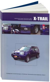
Ниссан Х-Трейл. Руководство по ремонту моделей с 2000 года
выпуска.
Автомобили серии T30 с двигателями QR20DE / QR25DE / YD22DDTi. Обслуживание,
эксплуатация, ремонт. 476 страниц.
Книга Nissan X-Trail Т30
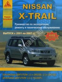
Nissan X-Trail. Руководство по эксплуатации, ремонту и
техническому обслуживанию
Для автомобилей с бензиновым двигателем QR20DE (2.0 л), QR25DE (2.5 л) и с
дизельным двигателем YD22DDTi (2.2 л), выпускавшихся с 2001 по 2007 гг. 448 страниц.
Книга Nissan X-Trail Т30
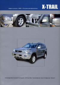
Nissan X-Trail. Модели выпуска с 2000 года с бензиновым
двигателем.
Руководство по эксплуатации, устройство, техническое обслуживание и ремонт
автомобилей с двигателем QR20DE (2.0 л). 400 страниц.
Книга Nissan X-Trail Т30
Nissan X-Trail. Ремонт моделей с 2001 года
выпуска.
Весь ряд двигателей серии T30 2001 — 2007 года выпуска. Полное описание по
эксплуатации, ремонту и обслуживанию. 576 страниц.
Книга Nissan X-Trail Т30
Книги для модели Т31 год 2007 — 2014
Модель Nissan X-Trail T31 с 2007 года
Подробные инструкции по эксплуатации и ремонту для всех типов бензиновых
двигателей. Серия Автолюбитель. 376 страниц.
Книга Nissan X-Trail Т31
Nissan X-Trail (Rogue). Модели T31 с 2007 года выпуска

Бестселлер. Руководство для автомобилей с бензиновыми и дизельными двигателями 2,0
и 2,5 л. 430 страниц.
Книга Nissan X-Trail Т31
Цветное руководство для Nissan X-Trail T31
Ремонт и эксплуатация Ниссан Икс-трэйл для всех типов двигателей выпускаемых с 2007
года. Достоверно и доступно. 320 страниц.
Книга Nissan X-Trail Т31
Руководство Nissan X-Trail T31 с бензиновыми двигателями
Серия Профессионал. Самое подробное руководство для модели T31. 752 страниц.
Книга Nissan X-Trail Т31
Книги для модели Т32 год 2013 — …
Nissan X-Trail Т32 c 2014 года
Техническое обслуживание, инструкции по эксплуатации, диагностика и ремонт. 700
страниц. Самое объемное руководство в технической серии.
Книга Nissan X-Trail Т32
Nissan X-Trail (Rogue). Модели T32 с 2014 года выпуска

Бестселлер. Руководство для автомобилей с бензиновыми и дизельными двигателями
MR20DD (2.0 л), QR25DE (2,5 л), dCi (1,6 л). 526 страниц.
Книга Nissan X-Trail Т32
Nissan X-Trail III (Ниссан Икс-Трэйл 3). Руководство по
ремонту
Модели с 2015 года выпуска с бензиновыми и дизельным двигателями. Серия ремонтирую
я сам. 384 страниц.
Книга Nissan X-Trail Т32
Руководство по самостоятельному обслуживанию и ремонту Nissan
X-Trail Т32 c 2013 года

Пошаговые инструкции по ремонту. Помощь в дороге и гараже. Технологии
само-диагностики. Электрические схемы. 300 страниц.
Книга Nissan X-Trail Т32
Мультимедийное руководство на английском языке по техническому обслуживанию и ремонту автомобиля Nissan X-Trail серии T30 с 2001 года выпуска.
- Автор: —
- Издательство: Nissan
- Год издания: 2006
- Страниц: —
- Формат: —
- Размер: 266,9 Mb
Мультимедийное руководство на английском языке по техническому обслуживанию и ремонту автомобиля Nissan X-Trail серии T31 с 2007 года выпуска.
- Автор: —
- Издательство: Nissan
- Год издания: 2007
- Страниц: —
- Формат: —
- Размер: 365,6 Mb
Руководство на английском языке по техническому обслуживанию и ремонту автомобиля Nissan X-Trail серии T32.
- Автор: —
- Издательство: Nissan
- Год издания: —
- Страниц: —
- Формат: —
- Размер: 196,7 Mb
Мультимедийное руководство на английском языке по техническому обслуживанию и ремонту автомобиля Nissan X-Trail серии T31.
- Автор: —
- Издательство: Nissan
- Год издания: —
- Страниц: —
- Формат: ISZ
- Размер: 197,3 Mb
Руководство по техническому обслуживанию и ремонту автомобиля Nissan X-Trail серии T30 2000-2007 годов выпуска с бензиновыми двигателями объемом 2,0/2,5 л.
- Автор: —
- Издательство: Автонавигатор
- Год издания: —
- Страниц: 480
- Формат: —
- Размер: —
Руководство по эксплуатации и ремонту автомобилей Nissan Roque и Nissan X-Trail серии T31 с 2007 года выпуска с бензиновыми и дизельными двигателями.
- Автор: —
- Издательство: Монолит
- Год издания: —
- Страниц: 430
- Формат: —
- Размер: —

Руководство по эксплуатации и ремонту автомобиля Nissan X-Trail с 2014 года выпуска с бензиновыми и дизельными двигателями.
- Автор: —
- Издательство: Монолит
- Год издания: —
- Страниц: 526
- Формат: —
- Размер: —

Руководство по эксплуатации и техническому обслуживанию автомобиля Nissan X-Trail 2000-2007 годов выпуска.
- Автор: —
- Издательство: MoToR
- Год издания: —
- Страниц: 240
- Формат: —
- Размер: —
Руководство по эксплуатации и техническому обслуживанию автомобиля Nissan X-Trail 2007-2015 годов выпуска.
- Автор: —
- Издательство: MoToR
- Год издания: —
- Страниц: 337
- Формат: —
- Размер: —
Руководство по эксплуатации и техническому обслуживанию автомобиля Nissan X-Trail с 2007 года выпуска.
- Автор: —
- Издательство: Nissan
- Год издания: —
- Страниц: 325
- Формат: PDF
- Размер: 12,0 Mb
Руководство по эксплуатации, техническому обслуживанию и ремонту автомобиля Nissan X-Trail 2001-2007 годов выпуска с бензиновыми и дизельными двигателями.
- Автор: —
- Издательство: Арго-Авто
- Год издания: —
- Страниц: 448
- Формат: —
- Размер: —
Руководство по эксплуатации, техническому обслуживанию и ремонту автомобиля Nissan X-Trail с 2000 года выпуска с бензиновыми двигателями.
- Автор: —
- Издательство: Автонавигатор
- Год издания: 2005
- Страниц: 484
- Формат: PDF
- Размер: 54,0 Mb
Руководство по эксплуатации, техническому обслуживанию и ремонту автомобиля Nissan X-Trail серии T30 с 2000 года выпуска с бензиновым двигателем объемом 2,0 л.
- Автор: —
- Издательство: Автонавигатор
- Год издания: —
- Страниц: 400
- Формат: —
- Размер: —
Руководство по эксплуатации, техническому обслуживанию и ремонту автомобиля Nissan X-Trail серии T31 с 2007 года выпуска с бензиновыми двигателями.
- Автор: —
- Издательство: Автонавигатор
- Год издания: 2008
- Страниц: 375
- Формат: DjVu
- Размер: 12,7 Mb
Руководство по техническому обслуживанию и ремонту автомобиля Nissan X-Trail серии T31 2007-2014 годов выпуска с бензиновыми двигателями объемом 2,0/2,5 л
- Автор: —
- Издательство: Автонавигатор
- Год издания: —
- Страниц: 376
- Формат: —
- Размер: —
Руководство по техническому обслуживанию и ремонту автомобиля Nissan X-Trail серии T31 2007-2010 годов выпуска с бензиновыми двигателями объемом 2,0/2,5 л.
- Автор: —
- Издательство: Автонавигатор
- Год издания: —
- Страниц: 752
- Формат: PDF
- Размер: 95,9 Mb
Руководство по техническому обслуживанию и ремонту автомобиля Nissan X-Trail серии T31 с 2007 года выпуска с бензиновыми двигателями объемом 2,0/2,5 л.
- Автор: —
- Издательство: Автонавигатор
- Год издания: —
- Страниц: 752
- Формат: —
- Размер: —
Руководство по техническому обслуживанию и ремонту автомобиля Nissan X-Trail серии T32 с 2014 года выпуска с бензиновыми и дизельными двигателями.
- Автор: —
- Издательство: Автонавигатор
- Год издания: —
- Страниц: 700
- Формат: —
- Размер: —
Руководство по эксплуатации, техническому обслуживанию и ремонту автомобиля Nissan X-Trail с 2007 года выпуска с бензиновыми двигателями объемом 2,0/2,5 л.
- Автор: —
- Издательство: Мир Автокниг
- Год издания: 2012
- Страниц: 511
- Формат: PDF
- Размер: 104,9 Mb
Руководство по эксплуатации, техническому обслуживанию и ремонту автомобиля Nissan X-Trail с 2015 года выпуска.
- Автор: —
- Издательство: Мир Автокниг
- Год издания: —
- Страниц: 384
- Формат: —
- Размер: —

![]()
B ENGINE
SECTION EC
ENGINE CONTROL SYSTEM
CONTENTS
|
INDEX FOR DTC ………………………………………………. |
8 |
|
DTC No. Index ……………………………………………….. |
8 |
|
Alphabetical Index ………………………………………….. |
11 |
|
PRECAUTIONS ………………………………………………. |
14 |
|
Precautions for Supplemental Restraint System |
|
|
(SRS) “AIR BAG” and “SEAT BELT PRE-TEN- |
|
|
SIONER” ……………………………………………………… |
14 |
|
On Board Diagnostic (OBD) System of Engine and |
|
|
A/T ………………………………………………………………. |
14 |
|
Precaution ……………………………………………………. |
14 |
|
PREPARATION ……………………………………………….. |
18 |
|
Special Service Tools …………………………………….. |
18 |
|
Commercial Service Tools ………………………………. |
19 |
|
ENGINE CONTROL SYSTEM …………………………… |
21 |
|
System Diagram ……………………………………………. |
21 |
|
Multiport Fuel Injection (MFI) System ………………. |
22 |
|
Electronic Ignition (EI) System ………………………… |
24 |
|
Fuel Cut Control (at No Load and High Engine |
|
|
Speed) …………………………………………………………. |
25 |
|
AIR CONDITIONING CUT CONTROL ……………….. |
26 |
|
Input/Output Signal Chart ……………………………….. |
26 |
|
AUTOMATIC SPEED CONTROL DEVICE (ASCD)… |
27 |
|
System Description ……………………………………….. |
27 |
|
Component Description …………………………………… |
28 |
|
CAN COMMUNICATION ………………………………….. |
29 |
|
System Description ……………………………………….. |
29 |
|
EVAPORATIVE EMISSION SYSTEM …………………. |
30 |
|
Description …………………………………………………… |
30 |
|
Component Inspection …………………………………… |
33 |
|
Removal and Installation ………………………………… |
34 |
|
How to Detect Fuel Vapor Leakage …………………. |
34 |
|
ON BOARD REFUELING VAPOR RECOVERY |
|
|
(ORVR) …………………………………………………………… |
37 |
|
System Description ……………………………………….. |
37 |
|
Diagnostic Procedure …………………………………….. |
38 |
|
Component Inspection …………………………………… |
41 |
|
POSITIVE CRANKCASE VENTILATION ……………. |
44 |
|
Description …………………………………………………… |
44 |
|
Component Inspection …………………………………… |
44 |
|
NVIS (NISSAN VEHICLE IMMOBILIZER SYSTEM- |
|
NATS) …………………………………………………………….. |
46 |
|
Description ……………………………………………………. |
46 |
|
ON BOARD DIAGNOSTIC (OBD) SYSTEM ……….. |
47 |
|
Introduction …………………………………………………… |
47 |
|
Two Trip Detection Logic ………………………………… |
47 |
|
Emission-Related Diagnostic Information ………….. |
48 |
|
Malfunction Indicator Lamp (MIL) …………………….. |
61 |
|
OBD System Operation Chart …………………………. |
65 |
|
BASIC SERVICE PROCEDURE ………………………… |
70 |
|
Basic Inspection ……………………………………………. |
70 |
|
Idle Speed and Ignition Timing Check ………………. |
75 |
|
VIN Registration ……………………………………………. |
77 |
|
Accelerator Pedal Released Position Learning ….. |
77 |
|
Throttle Valve Closed Position Learning ……………. |
78 |
|
Idle Air Volume Learning ………………………………… |
78 |
|
Fuel Pressure Check ……………………………………… |
80 |
|
TROUBLE DIAGNOSIS ……………………………………. |
83 |
|
Trouble Diagnosis Introduction ………………………… |
83 |
|
DTC Inspection Priority Chart ………………………….. |
89 |
|
Fail-Safe Chart ……………………………………………… |
91 |
|
Symptom Matrix Chart ……………………………………. |
92 |
|
Engine Control Component Parts Location ……….. |
96 |
|
Vacuum Hose Drawing …………………………………. |
101 |
|
Circuit Diagram ……………………………………………. |
102 |
|
ECM Harness Connector Terminal Layout ………. |
104 |
|
ECM Terminals and Reference Value ……………… |
104 |
|
CONSULT-II Function (ENGINE) ……………………. |
112 |
|
Generic Scan Tool (GST) Function …………………. |
125 |
|
CONSULT-II Reference Value in Data Monitor …. |
127 |
|
Major Sensor Reference Graph in Data Monitor |
|
|
Mode ………………………………………………………….. |
131 |
|
TROUBLE DIAGNOSIS — SPECIFICATION VALUE. 133 |
|
|
Description ………………………………………………….. |
133 |
|
Testing Condition …………………………………………. |
133 |
|
Inspection Procedure ……………………………………. |
133 |
|
Diagnostic Procedure …………………………………… |
134 |
|
TROUBLE DIAGNOSIS FOR INTERMITTENT INCI- |
|
|
DENT ……………………………………………………………. |
143 |
|
Description ………………………………………………….. |
143 |
|
Diagnostic Procedure …………………………………… |
143 |
|
Revision: 2006 July |
EC-1 |
2006 X-Trail |

|
POWER SUPPLY AND GROUND CIRCUIT ………. |
144 |
|
Wiring Diagram ……………………………………………. |
144 |
|
Diagnostic Procedure …………………………………… |
145 |
|
Component Inspection ………………………………….. |
151 |
|
Ground Inspection ……………………………………….. |
151 |
|
DTC U1000, U1001 CAN COMMUNICATION LINE. 152 |
|
|
Description ………………………………………………….. |
152 |
|
On Board Diagnosis Logic …………………………….. |
152 |
|
DTC Confirmation Procedure ………………………… |
152 |
|
Wiring Diagram ……………………………………………. |
153 |
|
Diagnostic Procedure …………………………………… |
154 |
|
DTC P0011 IVT CONTROL ……………………………… |
155 |
|
Description ………………………………………………….. |
155 |
|
CONSULT-IIReferenceValueinDataMonitorMode |
|
|
. 155 |
|
|
On Board Diagnosis Logic …………………………….. |
156 |
|
DTC Confirmation Procedure ………………………… |
156 |
|
Diagnostic Procedure …………………………………… |
157 |
|
Component Inspection ………………………………….. |
158 |
|
Removal and Installation ………………………………. |
158 |
|
DTC P0031, P0032 HO2S1 HEATER ……………….. |
159 |
|
Description ………………………………………………….. |
159 |
|
CONSULT-IIReferenceValueinDataMonitorMode |
|
|
. 159 |
|
|
On Board Diagnosis Logic …………………………….. |
159 |
|
DTC Confirmation Procedure ………………………… |
160 |
|
Wiring Diagram ……………………………………………. |
161 |
|
Diagnostic Procedure …………………………………… |
163 |
|
Component Inspection ………………………………….. |
165 |
|
Removal and Installation ………………………………. |
165 |
|
DTC P0037, P0038 HO2S2 HEATER ……………….. |
166 |
|
Description ………………………………………………….. |
166 |
|
CONSULT-IIReferenceValueinDataMonitorMode |
|
|
. 166 |
|
|
On Board Diagnosis Logic …………………………….. |
166 |
|
DTC Confirmation Procedure ………………………… |
167 |
|
Wiring Diagram ……………………………………………. |
168 |
|
Diagnostic Procedure …………………………………… |
170 |
|
Component Inspection ………………………………….. |
172 |
|
Removal and Installation ………………………………. |
172 |
|
DTC P0075 IVT CONTROL SOLENOID VALVE … |
173 |
|
Component Description ………………………………… |
173 |
|
CONSULT-IIReferenceValueinDataMonitorMode |
|
|
. 173 |
|
|
On Board Diagnosis Logic …………………………….. |
173 |
|
DTC Confirmation Procedure ………………………… |
173 |
|
Wiring Diagram ……………………………………………. |
174 |
|
Diagnostic Procedure …………………………………… |
176 |
|
Component Inspection ………………………………….. |
177 |
|
Removal and Installation ………………………………. |
177 |
|
DTC P0101 MAF SENSOR ……………………………… |
178 |
|
Component Description ………………………………… |
178 |
|
CONSULT-IIReferenceValueinDataMonitorMode |
|
|
. 178 |
|
|
On Board Diagnosis Logic …………………………….. |
178 |
|
DTC Confirmation Procedure ………………………… |
178 |
|
Overall Function Check ………………………………… |
180 |
|
Wiring Diagram ……………………………………………. |
181 |
|
Diagnostic Procedure …………………………………… |
182 |
|
Component Inspection ………………………………….. |
185 |
|
Removal and Installation ……………………………….. |
186 |
|
DTC P0102, P0103 MAF SENSOR …………………… |
187 |
|
Component Description ………………………………… |
187 |
|
CONSULT-IIReferenceValueinDataMonitorMode |
|
|
.187 |
|
|
On Board Diagnosis Logic …………………………….. |
187 |
|
DTC Confirmation Procedure …………………………. |
187 |
|
Wiring Diagram ……………………………………………. |
189 |
|
Diagnostic Procedure ……………………………………. |
190 |
|
Component Inspection ………………………………….. |
193 |
|
Removal and Installation ……………………………….. |
194 |
|
DTC P0112, P0113 IAT SENSOR ……………………… |
195 |
|
Component Description ………………………………… |
195 |
|
On Board Diagnosis Logic …………………………….. |
195 |
|
DTC Confirmation Procedure …………………………. |
195 |
|
Wiring Diagram ……………………………………………. |
197 |
|
Diagnostic Procedure ……………………………………. |
198 |
|
Component Inspection ………………………………….. |
200 |
|
Removal and Installation ……………………………….. |
200 |
|
DTC P0117, P0118 ECT SENSOR ……………………. |
201 |
|
Component Description ………………………………… |
201 |
|
On Board Diagnosis Logic …………………………….. |
201 |
|
DTC Confirmation Procedure …………………………. |
202 |
|
Wiring Diagram ……………………………………………. |
203 |
|
Diagnostic Procedure ……………………………………. |
204 |
|
Component Inspection ………………………………….. |
206 |
|
Removal and Installation ……………………………….. |
206 |
|
DTC P0122, P0123 TP SENSOR ……………………… |
207 |
|
Component Description ………………………………… |
207 |
|
CONSULT-IIReferenceValueinDataMonitorMode |
|
|
.207 |
|
|
On Board Diagnosis Logic …………………………….. |
207 |
|
DTC Confirmation Procedure …………………………. |
208 |
|
Wiring Diagram ……………………………………………. |
209 |
|
Diagnostic Procedure ……………………………………. |
211 |
|
Component Inspection ………………………………….. |
214 |
|
Remove and Installation ……………………………….. |
214 |
|
DTC P0125 ECT SENSOR ………………………………. |
215 |
|
Description ………………………………………………….. |
215 |
|
On Board Diagnosis Logic …………………………….. |
215 |
|
DTC Confirmation Procedure …………………………. |
215 |
|
Diagnostic Procedure ……………………………………. |
216 |
|
Component Inspection ………………………………….. |
217 |
|
Removal and Installation ……………………………….. |
217 |
|
DTC P0127 IAT SENSOR ………………………………… |
218 |
|
Component Description ………………………………… |
218 |
|
On Board Diagnosis Logic …………………………….. |
218 |
|
DTC Confirmation Procedure …………………………. |
218 |
|
Diagnostic Procedure ……………………………………. |
219 |
|
Component Inspection ………………………………….. |
220 |
|
Removal and Installation ……………………………….. |
220 |
|
DTC P0128 THERMOSTAT FUNCTION ……………. |
221 |
|
On Board Diagnosis Logic …………………………….. |
221 |
|
DTC Confirmation Procedure …………………………. |
221 |
|
Diagnostic Procedure ……………………………………. |
221 |
|
Component Inspection ………………………………….. |
222 |
|
Removal and Installation ……………………………….. |
222 |
|
DTC P0132 HO2S1 ………………………………………… |
223 |
|
Revision: 2006 July |
EC-2 |
2006 X-Trail |

|
Component Description ………………………………… |
223 |
|
CONSULT-IIReferenceValueinDataMonitorMode |
|
|
. 223 |
|
|
On Board Diagnosis Logic ……………………………. |
223 |
|
DTC Confirmation Procedure ………………………… |
224 |
|
Wiring Diagram …………………………………………… |
225 |
|
Diagnostic Procedure …………………………………… |
227 |
|
Component Inspection …………………………………. |
228 |
|
Removal and Installation ………………………………. |
230 |
|
DTC P0133 HO2S1 ………………………………………… |
231 |
|
Component Description ………………………………… |
231 |
|
CONSULT-IIReferenceValueinDataMonitorMode |
|
|
. 231 |
|
|
On Board Diagnosis Logic ……………………………. |
231 |
|
DTC Confirmation Procedure ………………………… |
232 |
|
Overall Function Check ………………………………… |
233 |
|
Wiring Diagram …………………………………………… |
234 |
|
Diagnostic Procedure …………………………………… |
236 |
|
Component Inspection …………………………………. |
240 |
|
Removal and Installation ………………………………. |
241 |
|
DTC P0134 HO2S1 ………………………………………… |
242 |
|
Component Description ………………………………… |
242 |
|
CONSULT-IIReferenceValueinDataMonitorMode |
|
|
. 242 |
|
|
On Board Diagnosis Logic ……………………………. |
242 |
|
DTC Confirmation Procedure ………………………… |
243 |
|
Overall Function Check ………………………………… |
244 |
|
Wiring Diagram …………………………………………… |
245 |
|
Diagnostic Procedure …………………………………… |
247 |
|
Component Inspection …………………………………. |
249 |
|
Removal and Installation ………………………………. |
250 |
|
DTC P0137 HO2S2 ………………………………………… |
251 |
|
Component Description ………………………………… |
251 |
|
CONSULT-IIReferenceValueinDataMonitorMode |
|
|
. 251 |
|
|
On Board Diagnosis Logic ……………………………. |
251 |
|
DTC Confirmation Procedure ………………………… |
252 |
|
Overall Function Check ………………………………… |
252 |
|
Wiring Diagram …………………………………………… |
254 |
|
Diagnostic Procedure …………………………………… |
256 |
|
Component Inspection …………………………………. |
258 |
|
Removal and Installation ………………………………. |
259 |
|
DTC P0138 HO2S2 ………………………………………… |
260 |
|
Component Description ………………………………… |
260 |
|
CONSULT-IIReferenceValueinDataMonitorMode |
|
|
. 260 |
|
|
On Board Diagnosis Logic ……………………………. |
260 |
|
DTC Confirmation Procedure ………………………… |
261 |
|
Overall Function Check ………………………………… |
262 |
|
Wiring Diagram …………………………………………… |
263 |
|
Diagnostic Procedure …………………………………… |
265 |
|
Component Inspection …………………………………. |
270 |
|
Removal and Installation ………………………………. |
271 |
|
DTC P0139 HO2S2 ………………………………………… |
272 |
|
Component Description ………………………………… |
272 |
|
CONSULT-IIReferenceValueinDataMonitorMode |
|
|
. 272 |
|
|
On Board Diagnosis Logic ……………………………. |
272 |
|
DTC Confirmation Procedure ………………………… |
273 |
|
Overall Function Check ………………………………… |
273 |
|
Wiring Diagram ……………………………………………. |
275 |
|
Diagnostic Procedure …………………………………… |
277 |
|
Component Inspection ………………………………….. |
279 |
|
Removal and Installation ………………………………. |
280 |
|
DTCP0171FUELINJECTIONSYSTEMFUNCTION. 281 |
|
|
On Board Diagnosis Logic …………………………….. |
281 |
|
DTC Confirmation Procedure ………………………… |
281 |
|
Wiring Diagram ……………………………………………. |
283 |
|
Diagnostic Procedure …………………………………… |
285 |
|
DTCP0172FUELINJECTIONSYSTEMFUNCTION. 289 |
|
|
On Board Diagnosis Logic …………………………….. |
289 |
|
DTC Confirmation Procedure ………………………… |
289 |
|
Wiring Diagram ……………………………………………. |
291 |
|
Diagnostic Procedure …………………………………… |
293 |
|
DTC P0181 FTT SENSOR ………………………………. |
296 |
|
Component Description ………………………………… |
296 |
|
On Board Diagnosis Logic …………………………….. |
296 |
|
DTC Confirmation Procedure ………………………… |
296 |
|
Wiring Diagram ……………………………………………. |
298 |
|
Diagnostic Procedure …………………………………… |
299 |
|
Component Inspection ………………………………….. |
301 |
|
Removal and Installation ………………………………. |
301 |
|
DTC P0182, P0183 FTT SENSOR ……………………. |
302 |
|
Component Description ………………………………… |
302 |
|
On Board Diagnosis Logic …………………………….. |
302 |
|
DTC Confirmation Procedure ………………………… |
302 |
|
Wiring Diagram ……………………………………………. |
303 |
|
Diagnostic Procedure …………………………………… |
304 |
|
Component Inspection ………………………………….. |
306 |
|
Removal and Installation ………………………………. |
306 |
|
DTC P0222, P0223 TP SENSOR ……………………… |
307 |
|
Component Description ………………………………… |
307 |
|
CONSULT-IIReferenceValueinDataMonitorMode |
|
|
. 307 |
|
|
On Board Diagnosis Logic …………………………….. |
307 |
|
DTC Confirmation Procedure ………………………… |
308 |
|
Wiring Diagram ……………………………………………. |
309 |
|
Diagnostic Procedure …………………………………… |
311 |
|
Component Inspection ………………………………….. |
314 |
|
Remove and Installation ……………………………….. |
314 |
|
DTC P0300 — P0304 MULTIPLE CYLINDER MIS- |
|
|
FIRE, NO. 1 — 4 CYLINDER MISFIRE ……………….. |
315 |
|
On Board Diagnosis Logic …………………………….. |
315 |
|
DTC Confirmation Procedure ………………………… |
315 |
|
Diagnostic Procedure …………………………………… |
316 |
|
DTC P0327, P0328 KS …………………………………… |
322 |
|
Component Description ………………………………… |
322 |
|
On Board Diagnosis Logic …………………………….. |
322 |
|
DTC Confirmation Procedure ………………………… |
322 |
|
Wiring Diagram ……………………………………………. |
323 |
|
Diagnostic Procedure …………………………………… |
324 |
|
Component Inspection ………………………………….. |
326 |
|
Removal and Installation ………………………………. |
326 |
|
DTC P0335 CKP SENSOR (POS) ……………………. |
327 |
|
Component Description ………………………………… |
327 |
|
CONSULT-IIReferenceValueinDataMonitorMode |
|
|
. 327 |
|
|
On Board Diagnosis Logic …………………………….. |
327 |
|
Revision: 2006 July |
EC-3 |
2006 X-Trail |
A
EC
C
D
E
F
G
H
I
J
K
L
M

|
DTC Confirmation Procedure ………………………… |
328 |
|
Wiring Diagram ……………………………………………. |
329 |
|
Diagnostic Procedure …………………………………… |
331 |
|
Component Inspection ………………………………….. |
334 |
|
Removal and Installation ………………………………. |
334 |
|
DTC P0340 CMP SENSOR (PHASE) ……………….. |
335 |
|
Component Description ………………………………… |
335 |
|
On Board Diagnosis Logic …………………………….. |
335 |
|
DTC Confirmation Procedure ………………………… |
336 |
|
Wiring Diagram ……………………………………………. |
337 |
|
Diagnostic Procedure …………………………………… |
338 |
|
Component Inspection ………………………………….. |
341 |
|
Removal and Installation ………………………………. |
342 |
|
DTC P0420 THREE WAY CATALYST FUNCTION . 343 |
|
|
On Board Diagnosis Logic …………………………….. |
343 |
|
DTC Confirmation Procedure ………………………… |
343 |
|
Overall Function Check ………………………………… |
344 |
|
Diagnostic Procedure …………………………………… |
345 |
|
DTC P0441 EVAP CONTROL SYSTEM ……………. |
348 |
|
System Description ………………………………………. |
348 |
|
On Board Diagnosis Logic …………………………….. |
348 |
|
DTC Confirmation Procedure ………………………… |
349 |
|
Overall Function Check ………………………………… |
349 |
|
Diagnostic Procedure …………………………………… |
350 |
|
DTC P0442 EVAP CONTROL SYSTEM ……………. |
354 |
|
On Board Diagnosis Logic …………………………….. |
354 |
|
DTC Confirmation Procedure ………………………… |
355 |
|
Diagnostic Procedure …………………………………… |
357 |
|
Component Inspection ………………………………….. |
363 |
|
DTC P0443 EVAP CANISTER PURGE VOLUME |
|
|
CONTROL SOLENOID VALVE ………………………… |
364 |
|
Description ………………………………………………….. |
364 |
|
CONSULT-IIReferenceValueinDataMonitorMode |
|
|
. 364 |
|
|
On Board Diagnosis Logic …………………………….. |
365 |
|
DTC Confirmation Procedure ………………………… |
365 |
|
Wiring Diagram ……………………………………………. |
366 |
|
Diagnostic Procedure …………………………………… |
368 |
|
Component Inspection ………………………………….. |
370 |
|
Removal and Installation ………………………………. |
371 |
|
DTC P0444, P0445 EVAP CANISTER PURGE VOL- |
|
|
UME CONTROL SOLENOID VALVE ………………… |
372 |
|
Description ………………………………………………….. |
372 |
|
CONSULT-IIReferenceValueinDataMonitorMode |
|
|
. 372 |
|
|
On Board Diagnosis Logic …………………………….. |
373 |
|
DTC Confirmation Procedure ………………………… |
373 |
|
Wiring Diagram ……………………………………………. |
374 |
|
Diagnostic Procedure …………………………………… |
376 |
|
Component Inspection ………………………………….. |
377 |
|
Removal and Installation ………………………………. |
378 |
|
DTC P0447 EVAP CANISTER VENT CONTROL |
|
|
VALVE ………………………………………………………….. |
379 |
|
Component Description ………………………………… |
379 |
|
CONSULT-IIReferenceValueinDataMonitorMode |
|
|
. 379 |
|
|
On Board Diagnosis Logic …………………………….. |
379 |
|
DTC Confirmation Procedure ………………………… |
380 |
|
Wiring Diagram ……………………………………………. |
381 |
|
Diagnostic Procedure ……………………………………. |
382 |
|
Component Inspection ………………………………….. |
384 |
|
DTC P0448 EVAP CANISTER VENT CONTROL |
|
|
VALVE …………………………………………………………… |
386 |
|
Component Description ………………………………… |
386 |
|
CONSULT-IIReferenceValueinDataMonitorMode |
|
|
.386 |
|
|
On Board Diagnosis Logic …………………………….. |
386 |
|
DTC Confirmation Procedure …………………………. |
387 |
|
Wiring Diagram ……………………………………………. |
388 |
|
Diagnostic Procedure ……………………………………. |
389 |
|
Component Inspection ………………………………….. |
391 |
|
DTCP0451EVAPCONTROLSYSTEMPRESSURE |
|
|
SENSOR ……………………………………………………….. |
393 |
|
Component Description ………………………………… |
393 |
|
CONSULT-IIReferenceValueinDataMonitorMode |
|
|
.393 |
|
|
On Board Diagnosis Logic …………………………….. |
393 |
|
DTC Confirmation Procedure …………………………. |
394 |
|
Diagnostic Procedure ……………………………………. |
394 |
|
Component Inspection ………………………………….. |
395 |
|
DTCP0452EVAPCONTROLSYSTEMPRESSURE |
|
|
SENSOR ……………………………………………………….. |
396 |
|
Component Description ………………………………… |
396 |
|
CONSULT-IIReferenceValueinDataMonitorMode |
|
|
.396 |
|
|
On Board Diagnosis Logic …………………………….. |
396 |
|
DTC Confirmation Procedure …………………………. |
397 |
|
Wiring Diagram ……………………………………………. |
398 |
|
Diagnostic Procedure ……………………………………. |
399 |
|
Component Inspection ………………………………….. |
402 |
|
DTCP0453EVAPCONTROLSYSTEMPRESSURE |
|
|
SENSOR ……………………………………………………….. |
403 |
|
Component Description ………………………………… |
403 |
|
CONSULT-IIReferenceValueinDataMonitorMode |
|
|
.403 |
|
|
On Board Diagnosis Logic …………………………….. |
403 |
|
DTC Confirmation Procedure …………………………. |
404 |
|
Wiring Diagram ……………………………………………. |
405 |
|
Diagnostic Procedure ……………………………………. |
406 |
|
Component Inspection ………………………………….. |
410 |
|
DTC P0455 EVAP CONTROL SYSTEM ……………. |
411 |
|
On Board Diagnosis Logic …………………………….. |
411 |
|
DTC Confirmation Procedure …………………………. |
412 |
|
Diagnostic Procedure ……………………………………. |
413 |
|
DTC P0456 EVAP CONTROL SYSTEM ……………. |
419 |
|
On Board Diagnosis Logic …………………………….. |
419 |
|
DTC Confirmation Procedure …………………………. |
420 |
|
Overall Function Check …………………………………. |
421 |
|
Diagnostic Procedure ……………………………………. |
422 |
|
Component Inspection ………………………………….. |
429 |
|
DTC P0460 FUEL LEVEL SENSOR …………………. |
430 |
|
Component Description ………………………………… |
430 |
|
On Board Diagnostic Logic ……………………………. |
430 |
|
DTC Confirmation Procedure …………………………. |
430 |
|
Diagnostic Procedure ……………………………………. |
431 |
|
Removal and Installation ……………………………….. |
431 |
|
DTC P0461 FUEL LEVEL SENSOR …………………. |
432 |
|
Component Description ………………………………… |
432 |
|
Revision: 2006 July |
EC-4 |
2006 X-Trail |

|
On Board Diagnostic Logic …………………………… |
432 |
|
Overall Function Check ………………………………… |
432 |
|
Diagnostic Procedure …………………………………… |
433 |
|
Removal and Installation ………………………………. |
433 |
|
DTC P0462, P0463 FUEL LEVEL SENSOR ……… |
434 |
|
Component Description ………………………………… |
434 |
|
On Board Diagnostic Logic …………………………… |
434 |
|
DTC Confirmation Procedure ………………………… |
434 |
|
Diagnostic Procedure …………………………………… |
435 |
|
Removal and Installation ………………………………. |
435 |
|
DTC P0500 VSS ……………………………………………. |
436 |
|
Description …………………………………………………. |
436 |
|
On Board Diagnosis Logic ……………………………. |
436 |
|
DTC Confirmation Procedure ………………………… |
436 |
|
Overall Function Check ………………………………… |
437 |
|
Diagnostic Procedure …………………………………… |
437 |
|
DTC P0506 ISC SYSTEM ……………………………….. |
438 |
|
Description …………………………………………………. |
438 |
|
On Board Diagnosis Logic ……………………………. |
438 |
|
DTC Confirmation Procedure ………………………… |
438 |
|
Diagnostic Procedure …………………………………… |
439 |
|
DTC P0507 ISC SYSTEM ……………………………….. |
440 |
|
Description …………………………………………………. |
440 |
|
On Board Diagnosis Logic ……………………………. |
440 |
|
DTC Confirmation Procedure ………………………… |
440 |
|
Diagnostic Procedure …………………………………… |
441 |
|
DTC P0550 PSP SENSOR ……………………………… |
442 |
|
Component Description ………………………………… |
442 |
|
CONSULT-IIReferenceValueinDataMonitorMode |
|
|
. 442 |
|
|
On Board Diagnosis Logic ……………………………. |
442 |
|
DTC Confirmation Procedure ………………………… |
442 |
|
Wiring Diagram …………………………………………… |
443 |
|
Diagnostic Procedure …………………………………… |
444 |
|
Component Inspection …………………………………. |
446 |
|
Removal and Installation ………………………………. |
446 |
|
DTC P0603 ECM POWER SUPPLY …………………. |
447 |
|
Component Description ………………………………… |
447 |
|
On Board Diagnosis Logic ……………………………. |
447 |
|
DTC Confirmation Procedure ………………………… |
447 |
|
Wiring Diagram …………………………………………… |
448 |
|
Diagnostic Procedure …………………………………… |
449 |
|
DTC P0605 ECM …………………………………………… |
451 |
|
Component Description ………………………………… |
451 |
|
On Board Diagnosis Logic ……………………………. |
451 |
|
DTC Confirmation Procedure ………………………… |
451 |
|
Diagnostic Procedure …………………………………… |
452 |
|
DTC P0643 SENSOR POWER SUPPLY …………… |
454 |
|
On Board Diagnosis Logic ……………………………. |
454 |
|
DTC Confirmation Procedure ………………………… |
454 |
|
Wiring Diagram …………………………………………… |
455 |
|
Diagnostic Procedure …………………………………… |
457 |
|
DTC P0850 PNP SWITCH ………………………………. |
460 |
|
Component Description ………………………………… |
460 |
|
CONSULT-IIReferenceValueinDataMonitorMode |
|
|
. 460 |
|
|
On Board Diagnosis Logic ……………………………. |
460 |
|
DTC Confirmation Procedure ………………………… |
460 |
|
Overall Function Check ………………………………… |
461 |
|
Wiring Diagram ……………………………………………. |
462 |
|
Diagnostic Procedure …………………………………… |
463 |
|
DTC P1143 HO2S1 ………………………………………… |
465 |
|
Component Description ………………………………… |
465 |
|
CONSULT-IIReferenceValueinDataMonitorMode |
|
|
. 465 |
|
|
On Board Diagnosis Logic …………………………….. |
465 |
|
DTC Confirmation Procedure ………………………… |
466 |
|
Overall Function Check ………………………………… |
466 |
|
Diagnostic Procedure …………………………………… |
467 |
|
Component Inspection ………………………………….. |
469 |
|
Removal and Installation ………………………………. |
470 |
|
DTC P1144 HO2S1 ………………………………………… |
471 |
|
Component Description ………………………………… |
471 |
|
CONSULT-IIReferenceValueinDataMonitorMode |
|
|
. 471 |
|
|
On Board Diagnosis Logic …………………………….. |
471 |
|
DTC Confirmation Procedure ………………………… |
472 |
|
Overall Function Check ………………………………… |
472 |
|
Diagnostic Procedure …………………………………… |
473 |
|
Component Inspection ………………………………….. |
475 |
|
Removal and Installation ………………………………. |
476 |
|
DTC P1148 CLOSED LOOP CONTROL …………… |
477 |
|
On Board Diagnosis Logic …………………………….. |
477 |
|
DTC Confirmation Procedure ………………………… |
477 |
|
Overall Function Check ………………………………… |
477 |
|
Diagnostic Procedure …………………………………… |
477 |
|
DTC P1211 TCS CONTROL UNIT ……………………. |
478 |
|
Description ………………………………………………….. |
478 |
|
On Board Diagnosis Logic …………………………….. |
478 |
|
DTC Confirmation Procedure ………………………… |
478 |
|
Diagnostic Procedure …………………………………… |
478 |
|
DTC P1212 TCS COMMUNICATION LINE ……….. |
479 |
|
Description ………………………………………………….. |
479 |
|
On Board Diagnosis Logic …………………………….. |
479 |
|
DTC Confirmation Procedure ………………………… |
479 |
|
Diagnostic Procedure …………………………………… |
479 |
|
DTC P1217 ENGINE OVER TEMPERATURE ……. |
480 |
|
Description ………………………………………………….. |
480 |
|
CONSULT-IIReferenceValueinDataMonitorMode |
|
|
. 481 |
|
|
On Board Diagnosis Logic …………………………….. |
481 |
|
Overall Function Check ………………………………… |
481 |
|
Wiring Diagram ……………………………………………. |
484 |
|
Diagnostic Procedure …………………………………… |
485 |
|
Main 12 Causes of Overheating …………………….. |
491 |
|
Component Inspection ………………………………….. |
492 |
|
DTC P1225 TP SENSOR ………………………………… |
494 |
|
Component Description ………………………………… |
494 |
|
On Board Diagnosis Logic …………………………….. |
494 |
|
DTC Confirmation Procedure ………………………… |
494 |
|
Diagnostic Procedure …………………………………… |
495 |
|
Remove and Installation ……………………………….. |
495 |
|
DTC P1226 TP SENSOR ………………………………… |
496 |
|
Component Description ………………………………… |
496 |
|
On Board Diagnosis Logic …………………………….. |
496 |
|
DTC Confirmation Procedure ………………………… |
496 |
|
Diagnostic Procedure …………………………………… |
497 |
|
Remove and Installation ……………………………….. |
497 |
|
Revision: 2006 July |
EC-5 |
2006 X-Trail |
A
EC
C
D
E
F
G
H
I
J
K
L
M

|
DTC P1564 ASCD STEERING SWITCH …………… |
498 |
|
Component Description ………………………………… |
498 |
|
CONSULT-IIReferenceValueinDataMonitorMode |
|
|
. 498 |
|
|
On Board Diagnosis Logic …………………………….. |
498 |
|
DTC Confirmation Procedure ………………………… |
499 |
|
Wiring Diagram ……………………………………………. |
500 |
|
Diagnostic Procedure …………………………………… |
502 |
|
Component Inspection ………………………………….. |
505 |
|
DTC P1572 ASCD BRAKE SWITCH ………………… |
506 |
|
Component Description ………………………………… |
506 |
|
CONSULT-IIReferenceValueinDataMonitorMode |
|
|
. 506 |
|
|
On Board Diagnosis Logic …………………………….. |
506 |
|
DTC Confirmation Procedure ………………………… |
507 |
|
Wiring Diagram ……………………………………………. |
508 |
|
Diagnostic Procedure …………………………………… |
510 |
|
Component Inspection ………………………………….. |
516 |
|
DTC P1574 ASCD VEHICLE SPEED SENSOR …. |
517 |
|
Component Description ………………………………… |
517 |
|
On Board Diagnosis Logic …………………………….. |
517 |
|
DTC Confirmation Procedure ………………………… |
517 |
|
Diagnostic Procedure …………………………………… |
518 |
|
DTC P1720 VSS …………………………………………….. |
519 |
|
Description ………………………………………………….. |
519 |
|
CONSULT-IIReferenceValueinDataMonitorMode |
|
|
. 519 |
|
|
On Board Diagnosis Logic …………………………….. |
519 |
|
DTC Confirmation Procedure ………………………… |
519 |
|
Diagnostic Procedure …………………………………… |
520 |
|
DTC P1800 VIAS CONTROL SOLENOID VALVE . 521 |
|
|
Component Description ………………………………… |
521 |
|
CONSULT-IIReferenceValueinDataMonitorMode |
|
|
. 521 |
|
|
On Board Diagnosis Logic …………………………….. |
521 |
|
DTC Confirmation Procedure ………………………… |
521 |
|
Wiring Diagram ……………………………………………. |
522 |
|
Diagnostic Procedure …………………………………… |
523 |
|
Component Inspection ………………………………….. |
524 |
|
Removal and Installation ………………………………. |
525 |
|
DTC P1805 BRAKE SWITCH ………………………….. |
526 |
|
Description ………………………………………………….. |
526 |
|
CONSULT-IIReferenceValueinDataMonitorMode |
|
|
. 526 |
|
|
On Board Diagnosis Logic …………………………….. |
526 |
|
DTC Confirmation Procedure ………………………… |
526 |
|
Wiring Diagram ……………………………………………. |
527 |
|
Diagnostic Procedure …………………………………… |
528 |
|
Component Inspection ………………………………….. |
530 |
|
DTCP2100,P2103THROTTLECONTROLMOTOR |
|
|
RELAY ………………………………………………………….. |
531 |
|
Component Description ………………………………… |
531 |
|
CONSULT-IIReferenceValueinDataMonitorMode |
|
|
. 531 |
|
|
On Board Diagnosis Logic …………………………….. |
531 |
|
DTC Confirmation Procedure ………………………… |
531 |
|
Wiring Diagram ……………………………………………. |
533 |
|
Diagnostic Procedure …………………………………… |
535 |
|
Component Inspection ………………………………….. |
537 |
|
DTC P2101 ELECTRIC THROTTLE CONTROL |
|
|
FUNCTION ……………………………………………………. |
538 |
|
Description ………………………………………………….. |
538 |
|
On Board Diagnosis Logic …………………………….. |
538 |
|
DTC Confirmation Procedure …………………………. |
538 |
|
Wiring Diagram ……………………………………………. |
539 |
|
Diagnostic Procedure ……………………………………. |
541 |
|
Component Inspection ………………………………….. |
545 |
|
Remove and Installation ……………………………….. |
545 |
|
DTC P2118 THROTTLE CONTROL MOTOR …….. |
546 |
|
Component Description ………………………………… |
546 |
|
On Board Diagnosis Logic …………………………….. |
546 |
|
DTC Confirmation Procedure …………………………. |
546 |
|
Wiring Diagram ……………………………………………. |
547 |
|
Diagnostic Procedure ……………………………………. |
549 |
|
Component Inspection ………………………………….. |
550 |
|
Removal and Installation ……………………………….. |
550 |
|
DTC P2119 ELECTRIC THROTTLE CONTROL |
|
|
ACTUATOR …………………………………………………… |
551 |
|
Component Description ………………………………… |
551 |
|
On Board Diagnosis Logic …………………………….. |
551 |
|
DTC Confirmation Procedure …………………………. |
551 |
|
Diagnostic Procedure ……………………………………. |
552 |
|
DTC P2122, P2123 APP SENSOR …………………… |
553 |
|
Component Description ………………………………… |
553 |
|
CONSULT-IIReferenceValueinDataMonitorMode |
|
|
.553 |
|
|
On Board Diagnosis Logic …………………………….. |
553 |
|
DTC Confirmation Procedure …………………………. |
554 |
|
Wiring Diagram ……………………………………………. |
555 |
|
Diagnostic Procedure ……………………………………. |
557 |
|
Component Inspection ………………………………….. |
559 |
|
Removal and Installation ……………………………….. |
559 |
|
DTC P2127, P2128 APP SENSOR …………………… |
560 |
|
Component Description ………………………………… |
560 |
|
CONSULT-IIReferenceValueinDataMonitorMode |
|
|
.560 |
|
|
On Board Diagnosis Logic …………………………….. |
560 |
|
DTC Confirmation Procedure …………………………. |
561 |
|
Wiring Diagram ……………………………………………. |
562 |
|
Diagnostic Procedure ……………………………………. |
564 |
|
Component Inspection ………………………………….. |
567 |
|
Remove and Installation ……………………………….. |
567 |
|
DTC P2135 TP SENSOR ………………………………… |
568 |
|
Component Description ………………………………… |
568 |
|
CONSULT-IIReferenceValueinDataMonitorMode |
|
|
.568 |
|
|
On Board Diagnosis Logic …………………………….. |
568 |
|
DTC Confirmation Procedure …………………………. |
569 |
|
Wiring Diagram ……………………………………………. |
570 |
|
Diagnostic Procedure ……………………………………. |
572 |
|
Component Inspection ………………………………….. |
575 |
|
Remove and Installation ……………………………….. |
575 |
|
DTC P2138 APP SENSOR ………………………………. |
576 |
|
Component Description ………………………………… |
576 |
|
CONSULT-IIReferenceValueinDataMonitorMode |
|
|
.576 |
|
|
On Board Diagnosis Logic …………………………….. |
576 |
|
DTC Confirmation Procedure …………………………. |
577 |
|
Revision: 2006 July |
EC-6 |
2006 X-Trail |
|
Wiring Diagram …………………………………………… |
578 |
|
Diagnostic Procedure …………………………………… |
580 |
|
Component Inspection …………………………………. |
583 |
|
Remove and Installation ……………………………….. |
583 |
|
ASCD BRAKE SWITCH …………………………………. |
584 |
|
Component Description ………………………………… |
584 |
|
CONSULT-IIReferenceValueinDataMonitorMode |
|
|
. 584 |
|
|
Wiring Diagram …………………………………………… |
585 |
|
Diagnostic Procedure …………………………………… |
587 |
|
Component Inspection …………………………………. |
592 |
|
ASCD INDICATOR ………………………………………… |
594 |
|
Component Description ………………………………… |
594 |
|
CONSULT-IIReferenceValueinDataMonitorMode |
|
|
. 594 |
|
|
Wiring Diagram …………………………………………… |
595 |
|
Diagnostic Procedure …………………………………… |
597 |
|
ELECTRICAL LOAD SIGNAL …………………………. |
598 |
|
CONSULT-IIReferenceValueinDataMonitorMode |
|
|
. 598 |
|
|
Wiring Diagram …………………………………………… |
599 |
|
Diagnostic Procedure …………………………………… |
600 |
|
Wiring Diagram …………………………………………… |
605 |
|
Diagnostic Procedure …………………………………… |
606 |
|
Wiring Diagram …………………………………………… |
608 |
|
Diagnostic Procedure …………………………………… |
609 |
|
FUEL INJECTOR ……………………………………………. |
611 |
|
Component Description ………………………………….. |
611 |
|
CONSULT-IIReferenceValueinDataMonitorMode |
|
|
..611 |
|
|
Wiring Diagram …………………………………………… |
612 |
|
Diagnostic Procedure …………………………………… |
613 |
|
Component Inspection …………………………………. |
616 |
|
Removal and Installation ………………………………. |
616 |
|
FUEL PUMP …………………………………………………. |
617 |
|
Description …………………………………………………. |
617 |
|
CONSULT-IIReferenceValueinDataMonitorMode |
|
|
. 617 |
|
|
Wiring Diagram …………………………………………… |
618 |
|
Diagnostic Procedure …………………………………… |
619 |
|
Component Inspection …………………………………. |
622 |
|
Removal and Installation ………………………………. |
622 |
|
IGNITION SIGNAL …………………………………………. |
623 |
|
Component Description ………………………………… |
623 |
|
Wiring Diagram ……………………………………………. |
624 |
|
Diagnostic Procedure …………………………………… |
627 |
|
Component Inspection ………………………………….. |
632 |
|
Removal and Installation ………………………………. |
633 |
|
REFRIGERANT PRESSURE SENSOR …………….. |
634 |
|
Component Description ………………………………… |
634 |
|
Wiring Diagram ……………………………………………. |
635 |
|
Diagnostic Procedure …………………………………… |
636 |
|
Removal and Installation ………………………………. |
639 |
|
SNOW MODE SWITCH ………………………………….. |
640 |
|
Description ………………………………………………….. |
640 |
|
CONSULT-II Reference Value in the Data Monitor |
|
|
Mode ………………………………………………………….. |
640 |
|
Wiring Diagram ……………………………………………. |
641 |
|
Diagnostic Procedure …………………………………… |
643 |
|
Component Inspection ………………………………….. |
646 |
|
VIAS …………………………………………………………….. |
647 |
|
Description ………………………………………………….. |
647 |
|
CONSULT-IIReferenceValueinDataMonitorMode |
|
|
. 648 |
|
|
Wiring Diagram ……………………………………………. |
649 |
|
Diagnostic Procedure …………………………………… |
651 |
|
Component Inspection ………………………………….. |
655 |
|
Removal and Installation ………………………………. |
656 |
|
MIL AND DATA LINK CONNECTOR ………………… |
657 |
|
Wiring Diagram ……………………………………………. |
657 |
|
SERVICE DATA AND SPECIFICATIONS (SDS) … |
661 |
|
Fuel Pressure ……………………………………………… |
661 |
|
Idle Speed and Ignition Timing ………………………. |
661 |
|
Calculated Load Value ………………………………….. |
661 |
|
Mass Air Flow Sensor …………………………………… |
661 |
|
Intake Air Temperature Sensor ………………………. |
661 |
|
Engine Coolant Temperature Sensor ……………… |
661 |
|
Heated Oxygen Sensor 1 Heater …………………… |
661 |
|
Heated Oxygen Sensor 2 Heater …………………… |
661 |
|
Crankshaft Position Sensor (POS) …………………. |
661 |
|
Camshaft Position Sensor (PHASE) ………………. |
661 |
|
Throttle Control Motor …………………………………… |
662 |
|
Fuel Injector ………………………………………………… |
662 |
|
Fuel Pump ………………………………………………….. |
662 |
A
EC
C
D
E
F
G
H
I
J
K
L
M
|
Revision: 2006 July |
EC-7 |
2006 X-Trail |

INDEX FOR DTC
INDEX FOR DTC
DTC No. Index
NOTE:
If DTC U1000 or U1001 is displayed with other DTC, first perform the trouble diagnosis for DTC U1000, U1001. Refer to EC-152, «DTC U1000, U1001 CAN COMMUNICATION LINE» .
|
DTC*1 |
Items |
|||
|
Reference page |
||||
|
CONSULT-II |
||||
|
ECM*3 |
(CONSULT-II screen terms) |
|||
|
GST*2 |
||||
|
NO DTC IS DETECTED. |
||||
|
No DTC |
Flashing*6 |
FURTHER TESTING |
EC-62 |
|
|
MAY BE REQUIRED. |
||||
|
U1000 |
1000*4 |
CAN COMM CIRCUIT |
EC-152 |
|
|
U1001 |
1001*4 |
CAN COMM CIRCUIT |
EC-152 |
|
|
NO DTC IS DETECTED. |
||||
|
P0000 |
0000 |
FURTHER TESTING |
— |
|
|
MAY BE REQUIRED. |
||||
|
P0011 |
0011 |
INT/V TIM CONT-B1 |
EC-155 |
|
|
P0031 |
0031 |
HO2S1 HTR (B1) |
EC-159 |
|
|
P0032 |
0032 |
HO2S1 HTR (B1) |
EC-159 |
|
|
P0037 |
0037 |
HO2S2 HTR (B1) |
EC-166 |
|
|
P0038 |
0038 |
HO2S2 HTR (B1) |
EC-166 |
|
|
P0075 |
0075 |
INT/V TIM V/CIR-B1 |
EC-173 |
|
|
P0101 |
0101 |
MAF SEN/CIRCUIT |
EC-178 |
|
|
P0102 |
0102 |
MAF SEN/CIRCUIT |
EC-187 |
|
|
P0103 |
0103 |
MAF SEN/CIRCUIT |
EC-187 |
|
|
P0112 |
0112 |
IAT SEN/CIRCUIT |
EC-195 |
|
|
P0113 |
0113 |
IAT SEN/CIRCUIT |
EC-195 |
|
|
P0117 |
0117 |
ECT SEN/CIRC |
EC-201 |
|
|
P0118 |
0118 |
ECT SEN/CIRC |
EC-201 |
|
|
P0122 |
0122 |
TP SEN 2/CIRC |
EC-207 |
|
|
P0123 |
0123 |
TP SEN 2/CIRC |
EC-207 |
|
|
P0125 |
0125 |
ECT SENSOR |
EC-215 |
|
|
P0127 |
0127 |
IAT SENSOR |
EC-218 |
|
|
P0128 |
0128 |
THERMSTAT FNCTN |
EC-221 |
|
|
P0132 |
0132 |
HO2S1 (B1) |
EC-223 |
|
|
P0133 |
0133 |
HO2S1 (B1) |
EC-231 |
|
|
P0134 |
0134 |
HO2S1 (B1) |
EC-242 |
|
|
P0137 |
0137 |
HO2S2 (B1) |
EC-251 |
|
|
P0138 |
0138 |
HO2S2 (B1) |
EC-260 |
|
|
P0139 |
0139 |
HO2S2 (B1) |
EC-272 |
|
|
P0171 |
0171 |
FUEL SYS-LEAN-B1 |
EC-281 |
|
|
P0172 |
0172 |
FUEL SYS-RICH-B1 |
EC-289 |
|
|
P0181 |
0181 |
FTT SENSOR |
EC-296 |
|
|
P0182 |
0182 |
FTT SEN/CIRCUIT |
EC-302 |
|
|
P0183 |
0183 |
FTT SEN/CIRCUIT |
EC-302 |
|
|
P0222 |
0222 |
TP SEN 1/CIRC |
EC-307 |
|
|
P0223 |
0223 |
TP SEN 1/CIRC |
EC-307 |
|
|
Revision: 2006 July |
EC-8 |
2006 X-Trail |

INDEX FOR DTC
|
DTC*1 |
Items |
A |
||||
|
Reference page |
||||||
|
CONSULT-II |
||||||
|
ECM*3 |
(CONSULT-II screen terms) |
|||||
|
GST*2 |
||||||
|
P0300 |
0300 |
MULTI CYL MISFIRE |
EC-315 |
EC |
||
|
P0301 |
0301 |
CYL 1 MISFIRE |
EC-315 |
|||
|
P0302 |
0302 |
CYL 2 MISFIRE |
EC-315 |
|||
|
C |
||||||
|
P0303 |
0303 |
CYL 3 MISFIRE |
EC-315 |
|||
|
P0304 |
0304 |
CYL 4 MISFIRE |
EC-315 |
|||
|
P0327 |
0327 |
KNOCK SEN/CIRC-B1 |
EC-322 |
D |
||
|
P0328 |
0328 |
KNOCK SEN/CIRC-B1 |
EC-322 |
|||
|
P0335 |
0335 |
CKP SEN/CIRCUIT |
EC-327 |
|||
|
E |
||||||
|
P0340 |
0340 |
CMP SEN/CIRC-B1 |
EC-335 |
|||
|
P0420 |
0420 |
TW CATALYST SYS-B1 |
EC-343 |
|||
|
P0441 |
0441 |
EVAP PURG FLOW/MON |
EC-348 |
F |
||
|
P0442 |
0442 |
EVAP SMALL LEAK |
EC-354 |
|||
|
P0443 |
0443 |
PURG VOLUME CONT/V |
EC-364 |
|||
|
P0444 |
0444 |
PURG VOLUME CONT/V |
EC-372 |
G |
||
|
P0445 |
0445 |
PURG VOLUME CONT/V |
EC-372 |
|||
|
P0447 |
0447 |
VENT CONTROL VALVE |
EC-379 |
|||
|
H |
||||||
|
P0448 |
0448 |
VENT CONTROL VALVE |
EC-386 |
|||
|
P0451 |
0451 |
EVAP SYS PRES SEN |
EC-393 |
|||
|
P0452 |
0452 |
EVAP SYS PRES SEN |
EC-396 |
I |
||
|
P0453 |
0453 |
EVAP SYS PRES SEN |
EC-403 |
|||
|
P0455 |
0455 |
EVAP GROSS LEAK |
EC-411 |
|||
|
J |
||||||
|
P0456 |
0456 |
EVAP VERY SML LEAK |
EC-419 |
|||
|
P0460 |
0460 |
FUEL LEV SEN SLOSH |
EC-430 |
|||
|
P0461 |
0461 |
FUEL LEVEL SENSOR |
EC-432 |
K |
||
|
P0462 |
0462 |
FUEL LEVL SEN/CIRC |
EC-434 |
|||
|
P0463 |
0463 |
FUEL LEVL SEN/CIRC |
EC-434 |
|||
|
L |
||||||
|
P0500 |
0500 |
VEH SPEED SEN/CIRC*5 |
EC-436 |
|||
|
P0506 |
0506 |
ISC SYSTEM |
EC-438 |
|||
|
P0507 |
0507 |
ISC SYSTEM |
EC-440 |
M |
||
|
P0550 |
0550 |
PW ST P SEN/CIRC |
EC-442 |
|||
|
P0603 |
0603 |
ECM BACK UP/CIRC |
EC-447 |
|||
|
P0605 |
0605 |
ECM |
EC-451 |
|||
|
P0643 |
0643 |
SENSOR POWER/CIRC |
EC-454 |
|||
|
P0705 |
0705 |
PNP SW/CIRC |
AT-95 |
|||
|
P0710 |
0710 |
ATF TEMP SEN/CIRC |
AT-100 |
|||
|
P0720 |
0720 |
VEH SPD SEN/CIR AT*5 |
AT-105 |
|||
|
P0725 |
0725 |
ENGINE SPEED SIG |
AT-111 |
|||
|
P0731 |
0731 |
A/T 1ST GR FNCTN |
AT-115 |
|||
|
P0732 |
0732 |
A/T 2ND GR FNCTN |
AT-120 |
|||
|
P0733 |
0733 |
A/T 3RD GR FNCTN |
AT-125 |
|||
|
P0734 |
0734 |
A/T 4TH GR FNCTN |
AT-130 |
|||
|
P0740 |
0740 |
TCC SOLENOID/CIRC |
AT-137 |
|||
|
Revision: 2006 July |
EC-9 |
2006 X-Trail |
|
INDEX FOR DTC |
||||
|
DTC*1 |
Items |
|||
|
Reference page |
||||
|
CONSULT-II |
||||
|
ECM*3 |
(CONSULT-II screen terms) |
|||
|
GST*2 |
||||
|
P0744 |
0744 |
A/T TCC S/V FNCTN |
AT-142 |
|
|
P0745 |
0745 |
L/PRESS SOL/CIRC |
AT-150 |
|
|
P0750 |
0750 |
SFT SOL A/CIRC |
AT-156 |
|
|
P0755 |
0755 |
SFT SOL B/CIRC |
AT-161 |
|
|
P0850 |
0850 |
P-N POS SW/CIRCUIT |
EC-460 |
|
|
P1143 |
1143 |
HO2S1 (B1) |
EC-465 |
|
|
P1144 |
1144 |
HO2S1 (B1) |
EC-471 |
|
|
P1148 |
1148 |
CLOSED LOOP-B1 |
EC-477 |
|
|
P1211 |
1211 |
TCS C/U FUNCTION |
EC-478 |
|
|
P1212 |
1212 |
TCS/CIRC |
EC-479 |
|
|
P1217 |
1217 |
ENG OVER TEMP |
EC-480 |
|
|
P1225 |
1225 |
CTP LEARNING |
EC-494 |
|
|
P1226 |
1226 |
CTP LEARNING |
EC-496 |
|
|
P1564 |
1564 |
ASCD SW |
EC-498 |
|
|
P1572 |
1572 |
ASCD BRAKE SW |
EC-506 |
|
|
P1574 |
1574 |
ASCD VHL SPD SEN |
EC-517 |
|
|
P1610 — P1615 |
1610 — 1615 |
NATS MALFUNCTION |
EC-46 |
|
|
P1705 |
1705 |
TP SEN/CIRC A/T |
AT-166 |
|
|
P1720 |
1720 |
V/SP SEN (A/T OUT) |
EC-519 |
|
|
P1760 |
1760 |
O/R CLTCH SOL/CIRC |
AT-171 |
|
|
P1800 |
1800 |
VIAS S/V CIRC |
EC-521 |
|
|
P1805 |
1805 |
BRAKE SW/CIRCUIT |
EC-526 |
|
|
P2100 |
2100 |
ETC MOT PWR |
EC-531 |
|
|
P2101 |
2101 |
ETC FUNCTION/CIRC |
EC-538 |
|
|
P2103 |
2103 |
ETC MOT PWR |
EC-531 |
|
|
P2118 |
2118 |
ETC MOT |
EC-546 |
|
|
P2119 |
2119 |
ETC ACTR |
EC-551 |
|
|
P2122 |
2122 |
APP SEN 1/CIRC |
EC-553 |
|
|
P2123 |
2123 |
APP SEN 1/CIRC |
EC-553 |
|
|
P2127 |
2127 |
APP SEN 2/CIRC |
EC-560 |
|
|
P2128 |
2128 |
APP SEN 2/CIRC |
EC-560 |
|
|
P2135 |
2135 |
TP SENSOR |
EC-568 |
|
|
P2138 |
2138 |
APP SENSOR |
EC-576 |
|
*1: 1st trip DTC No. is the same as DTC No. *2: This number is prescribed by SAE J2012.
*3: In Diagnostic Test Mode II (Self-diagnostic results), this number is controlled by NISSAN. *4: The troubleshooting for this DTC needs CONSULT-II.
*5: When the fail-safe operations for both self-diagnoses occur, the MIL illuminates. *6: When engine is running.
|
Revision: 2006 July |
EC-10 |
2006 X-Trail |
![]()
INDEX FOR DTC
Alphabetical Index |
ABS00D7Z |
NOTE:
If DTC U1000 or U1001 is displayed with other DTC, first perform the trouble diagnosis for DTC U1000, U1001. Refer to EC-152, «DTC U1000, U1001 CAN COMMUNICATION LINE» .
|
Items |
DTC*1 |
|||
|
Reference page |
||||
|
CONSULT-II |
||||
|
(CONSULT-II screen terms) |
ECM*3 |
|||
|
GST*2 |
||||
|
A/T 1ST GR FNCTN |
P0731 |
0731 |
AT-115 |
|
|
A/T 2ND GR FNCTN |
P0732 |
0732 |
AT-120 |
|
|
A/T 3RD GR FNCTN |
P0733 |
0733 |
AT-125 |
|
|
A/T 4TH GR FNCTN |
P0734 |
0734 |
AT-130 |
|
|
A/T TCC S/V FNCTN |
P0744 |
0744 |
AT-142 |
|
|
APP SEN 1/CIRC |
P2122 |
2122 |
EC-553 |
|
|
APP SEN 1/CIRC |
P2123 |
2123 |
EC-553 |
|
|
APP SEN 2/CIRC |
P2127 |
2127 |
EC-560 |
|
|
APP SEN 2/CIRC |
P2128 |
2128 |
EC-560 |
|
|
APP SENSOR |
P2138 |
2138 |
EC-576 |
|
|
ASCD BRAKE SW |
P1572 |
1572 |
EC-506 |
|
|
ASCD SW |
P1564 |
1564 |
EC-498 |
|
|
ASCD VHL SPD SEN |
P1574 |
1574 |
EC-517 |
|
|
ATF TEMP SEN/CIRC |
P0710 |
0710 |
AT-100 |
|
|
BRAKE SW/CIRCUIT |
P1805 |
1805 |
EC-526 |
|
|
CAN COMM CIRCUIT |
U1000 |
1000*4 |
EC-152 |
|
|
CAN COMM CIRCUIT |
U1001 |
1001*4 |
EC-152 |
|
|
CKP SEN/CIRCUIT |
P0335 |
0335 |
EC-327 |
|
|
CLOSED LOOP-B1 |
P1148 |
1148 |
EC-477 |
|
|
CMP SEN/CIRC-B1 |
P0340 |
0340 |
EC-335 |
|
|
CTP LEARNING |
P1225 |
1225 |
EC-494 |
|
|
CTP LEARNING |
P1226 |
1226 |
EC-496 |
|
|
CYL 1 MISFIRE |
P0301 |
0301 |
EC-315 |
|
|
CYL 2 MISFIRE |
P0302 |
0302 |
EC-315 |
|
|
CYL 3 MISFIRE |
P0303 |
0303 |
EC-315 |
|
|
CYL 4 MISFIRE |
P0304 |
0304 |
EC-315 |
|
|
ECM |
P0605 |
0605 |
EC-451 |
|
|
ECM BACK UP/CIRC |
P0603 |
0603 |
EC-447 |
|
|
ECT SEN/CIRC |
P0117 |
0117 |
EC-201 |
|
|
ECT SEN/CIRC |
P0118 |
0118 |
EC-201 |
|
|
ECT SENSOR |
P0125 |
0125 |
EC-215 |
|
|
ENG OVER TEMP |
P1217 |
1217 |
EC-480 |
|
|
ENGINE SPEED SIG |
P0725 |
0725 |
AT-111 |
|
|
ETC ACTR |
P2119 |
2119 |
EC-551 |
|
|
ETC FUNCTION/CIRC |
P2101 |
2101 |
EC-538 |
|
|
ETC MOT |
P2118 |
2118 |
EC-546 |
|
|
ETC MOT PWR |
P2103 |
2103 |
EC-531 |
|
|
ETC MOT PWR |
P2100 |
2100 |
EC-531 |
|
|
EVAP GROSS LEAK |
P0455 |
0455 |
EC-411 |
|
A
EC
C
D
E
F
G
H
I
J
K
L
M
|
Revision: 2006 July |
EC-11 |
2006 X-Trail |

INDEX FOR DTC
|
Items |
DTC*1 |
|||
|
Reference page |
||||
|
CONSULT-II |
||||
|
(CONSULT-II screen terms) |
ECM*3 |
|||
|
GST*2 |
||||
|
EVAP PURG FLOW/MON |
P0441 |
0441 |
EC-348 |
|
|
EVAP SMALL LEAK |
P0442 |
0442 |
EC-354 |
|
|
EVAP SYS PRES SEN |
P0451 |
0451 |
EC-393 |
|
|
EVAP SYS PRES SEN |
P0452 |
0452 |
EC-396 |
|
|
EVAP SYS PRES SEN |
P0453 |
0453 |
EC-403 |
|
|
EVAP VERY SML LEAK |
P0456 |
0456 |
EC-419 |
|
|
FTT SEN/CIRCUIT |
P0182 |
0182 |
EC-302 |
|
|
FTT SEN/CIRCUIT |
P0183 |
0183 |
EC-302 |
|
|
FTT SENSOR |
P0181 |
0181 |
EC-296 |
|
|
FUEL LEV SEN SLOSH |
P0460 |
0460 |
EC-430 |
|
|
FUEL LEVEL SENSOR |
P0461 |
0461 |
EC-432 |
|
|
FUEL LEVL SEN/CIRC |
P0462 |
0462 |
EC-434 |
|
|
FUEL LEVL SEN/CIRC |
P0463 |
0463 |
EC-434 |
|
|
FUEL SYS-LEAN-B1 |
P0171 |
0171 |
EC-281 |
|
|
FUEL SYS-RICH-B1 |
P0172 |
0172 |
EC-289 |
|
|
HO2S1 (B1) |
P0132 |
0132 |
EC-223 |
|
|
HO2S1 (B1) |
P0133 |
0133 |
EC-231 |
|
|
HO2S1 (B1) |
P0134 |
0134 |
EC-242 |
|
|
HO2S1 (B1) |
P1143 |
1143 |
EC-465 |
|
|
HO2S1 (B1) |
P1144 |
1144 |
EC-471 |
|
|
HO2S1 HTR (B1) |
P0031 |
0031 |
EC-159 |
|
|
HO2S1 HTR (B1) |
P0032 |
0032 |
EC-159 |
|
|
HO2S2 (B1) |
P0137 |
0137 |
EC-251 |
|
|
HO2S2 (B1) |
P0138 |
0138 |
EC-260 |
|
|
HO2S2 (B1) |
P0139 |
0139 |
EC-272 |
|
|
HO2S2 HTR (B1) |
P0037 |
0037 |
EC-166 |
|
|
HO2S2 HTR (B1) |
P0038 |
0038 |
EC-166 |
|
|
IAT SEN/CIRCUIT |
P0112 |
0112 |
EC-195 |
|
|
IAT SEN/CIRCUIT |
P0113 |
0113 |
EC-195 |
|
|
IAT SENSOR |
P0127 |
0127 |
EC-218 |
|
|
INT/V TIM CONT-B1 |
P0011 |
0011 |
EC-155 |
|
|
INT/V TIM V/CIR-B1 |
P0075 |
0075 |
EC-173 |
|
|
ISC SYSTEM |
P0506 |
0506 |
EC-438 |
|
|
ISC SYSTEM |
P0507 |
0507 |
EC-440 |
|
|
KNOCK SEN/CIRC-B1 |
P0327 |
0327 |
EC-322 |
|
|
KNOCK SEN/CIRC-B1 |
P0328 |
0328 |
EC-322 |
|
|
L/PRESS SOL/CIRC |
P0745 |
0745 |
AT-150 |
|
|
MAF SEN/CIRCUIT |
P0101 |
0101 |
EC-178 |
|
|
MAF SEN/CIRCUIT |
P0102 |
0102 |
EC-187 |
|
|
MAF SEN/CIRCUIT |
P0103 |
0103 |
EC-187 |
|
|
MULTI CYL MISFIRE |
P0300 |
0300 |
EC-315 |
|
|
NATS MALFUNCTION |
P1610 — P1615 |
1610 — 1615 |
EC-46 |
|
|
Revision: 2006 July |
EC-12 |
2006 X-Trail |

INDEX FOR DTC
|
Items |
DTC*1 |
|||
|
Reference page |
||||
|
CONSULT-II |
||||
|
(CONSULT-II screen terms) |
ECM*3 |
|||
|
GST*2 |
||||
|
NO DTC IS DETECTED. |
||||
|
FURTHER TESTING |
No DTC |
Flashing*6 |
EC-62 |
|
|
MAY BE REQUIRED. |
||||
|
NO DTC IS DETECTED. |
||||
|
FURTHER TESTING |
P0000 |
0000 |
— |
|
|
MAY BE REQUIRED. |
||||
|
O/R CLTCH SOL/CIRC |
P1760 |
1760 |
AT-171 |
|
|
P-N POS SW/CIRCUIT |
P0850 |
0850 |
EC-460 |
|
|
PNP SW/CIRC |
P0705 |
0705 |
AT-95 |
|
|
PURG VOLUME CONT/V |
P0444 |
0444 |
EC-372 |
|
|
PURG VOLUME CONT/V |
P0445 |
0445 |
EC-372 |
|
|
PURG VOLUME CONT/V |
P0443 |
0443 |
EC-364 |
|
|
PW ST P SEN/CIRC |
P0550 |
0550 |
EC-442 |
|
|
SENSOR POWER/CIRC |
P0643 |
0643 |
EC-454 |
|
|
SFT SOL A/CIRC |
P0750 |
0750 |
AT-156 |
|
|
SFT SOL B/CIRC |
P0755 |
0755 |
AT-161 |
|
|
TCC SOLENOID/CIRC |
P0740 |
0740 |
AT-137 |
|
|
TCS C/U FUNCTIION |
P1211 |
1211 |
EC-478 |
|
|
TCS/CIRC |
P1212 |
1212 |
EC-479 |
|
|
THERMSTAT FNCTN |
P0128 |
0128 |
EC-221 |
|
|
TP SEN 1/CIRC |
P0222 |
0222 |
EC-307 |
|
|
TP SEN 1/CIRC |
P0223 |
0223 |
EC-307 |
|
|
TP SEN 2/CIRC |
P0122 |
0122 |
EC-207 |
|
|
TP SEN 2/CIRC |
P0123 |
0123 |
EC-207 |
|
|
TP SENSOR |
P2135 |
2135 |
EC-568 |
|
|
TP SEN/CIRC A/T |
P1705 |
1705 |
AT-166 |
|
|
TW CATALYST SYS-B1 |
P0420 |
0420 |
EC-343 |
|
|
V/SP SEN (A/T OUT) |
P1720 |
1720 |
EC-519 |
|
|
VEH SPD SEN/CIR AT*5 |
P0720 |
0720 |
AT-105 |
|
|
VEH SPEED SEN/CIRC*5 |
P0500 |
0500 |
EC-436 |
|
|
VENT CONTROL VALVE |
P0447 |
0447 |
EC-379 |
|
|
VENT CONTROL VALVE |
P0448 |
0448 |
EC-386 |
|
|
VIAS S/V CIRC |
P1800 |
1800 |
EC-521 |
|
*1: 1st trip DTC No. is the same as DTC No. *2: This number is prescribed by SAE J2012.
*3: In Diagnostic Test Mode II (Self-diagnostic results), this number is controlled by NISSAN. *4: The troubleshooting for this DTC needs CONSULT-II.
*5: When the fail-safe operations for both self-diagnoses occur, the MIL illuminates. *6: When engine is running.
A
EC
C
D
E
F
G
H
I
J
K
L
M
|
Revision: 2006 July |
EC-13 |
2006 X-Trail |
PRECAUTIONS |
|
|
PRECAUTIONS |
PFP:00001 |
Precautions for Supplemental Restraint System (SRS) “AIR BAG” and “SEAT BELT PRE-TENSIONER” ABS00DCS
The Supplemental Restraint System such as “AIR BAG” and “SEAT BELT PRE-TENSIONER”, used along with a front seat belt, helps to reduce the risk or severity of injury to the driver and front passenger for certain types of collision. Information necessary to service the system safely is included in the SRS and SB section of this Service Manual.
WARNING:
●To avoid rendering the SRS inoperative, which could increase the risk of personal injury or death in the event of a collision which would result in air bag inflation, all maintenance must be performed by an authorized NISSAN/INFINITI dealer.
●Improper maintenance, including incorrect removal and installation of the SRS, can lead to personal injury caused by unintentional activation of the system. For removal of Spiral Cable and Air Bag Module, see the SRS section.
●Do not use electrical test equipment on any circuit related to the SRS unless instructed to in this Service Manual. SRS wiring harnesses can be identified by yellow and/or orange harnesses or harness connectors.
On Board Diagnostic (OBD) System of Engine and A/T |
ABS00CKO |
The ECM has an on board diagnostic system. It will light up the malfunction indicator (MIL) to warn the driver of a malfunction causing emission deterioration.
CAUTION:
●Be sure to turn the ignition switch OFF and disconnect the battery ground cable before any repair or inspection work. The open/short circuit of related switches, sensors, solenoid valves, etc. will cause the MIL to light up.
●Be sure to connect and lock the connectors securely after work. A loose (unlocked) connector will cause the MIL to light up due to the open circuit. (Be sure the connector is free from water, grease, dirt, bent terminals, etc.)
●Certain systems and components, especially those related to OBD, may use a new style slidelocking type harness connector. For description and how to disconnect, refer to PG-46, «HARNESS CONNECTOR» .
●Be sure to route and secure the harnesses properly after work. The interference of the harness with a bracket, etc. may cause the MIL to light up due to the short circuit.
●Be sure to connect rubber tubes properly after work. A misconnected or disconnected rubber tube may cause the MIL to light up due to the malfunction of the EVAP system or fuel injection system, etc.
●Be sure to erase the unnecessary malfunction information (repairs completed) from the ECM and TCM (Transmission control module) before returning the vehicle to the customer.
●Always use a 12 volt battery as power source.
●Do not attempt to disconnect battery cables while engine is running.
●Before connecting or disconnecting the ECM harness connector, turn ignition switch OFF and disconnect battery ground cable. Failure to do so may damage the ECM because battery voltage is applied to ECM even if ignition switch is turned OFF.
●Before removing parts, turn ignition switch OFF and then disconnect battery ground cable.
SEF289H
|
Revision: 2006 July |
EC-14 |
2006 X-Trail |
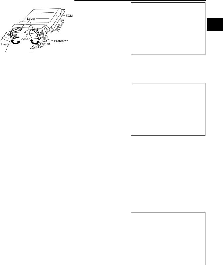
PRECAUTIONS
●Do not disassemble ECM.
●If battery cable is disconnected, the memory will return to the initial ECM values.
The ECM will now start to self-control at its initial values. Engine operation can vary slightly when the cable is disconnected. However, this is not an indication of a malfunction. Do not replace parts because of a slight variation.
●If the battery is disconnected, the following emission related diagnostic information will be lost within 24 hours.
–Diagnostic trouble codes
–1st trip diagnostic trouble codes
–Freeze frame data
–1st freeze frame data
–System readiness test (SRT) codes
–Test values
●When connecting ECM harness connector, fasten it securely with a lever as far as it will go as shown in the figure.
A
EC
C
PBIB1164E
D
E
F
G
H
PBIB1512E
|
I |
||
|
● When connecting or disconnecting pin connectors into or |
||
|
from ECM, take care not to damage pin terminals (bend or |
||
|
break). |
J |
|
|
Make sure that there are not any bends or breaks on ECM |
||
|
pin terminal, when connecting pin connectors. |
||
|
● Securely connect ECM harness connectors. |
K |
|
|
A poor connection can cause an extremely high (surge) |
||
|
voltage to develop in coil and condenser, thus resulting in |
||
|
damage to ICs. |
L |
|
|
● Keep engine control system harness at least 10 cm (4 in) |
||
|
away from adjacent harness, to prevent engine control sys- |
PBIB0090E |
|
|
tem malfunctions due to receiving external noise, degraded |
M |
|
|
operation of ICs, etc. |
|
Keep engine control system parts and harness dry. |
|
|
Before replacing ECM, perform “ECM Terminals and Refer- |
|
|
ence Value” inspection and make sure ECM functions prop- |
|
|
erly. Refer to EC-104, «ECM Terminals and Reference Value» |
|
|
. |
|
|
Handle mass air flow sensor carefully to avoid damage. |
|
|
Do not disassemble mass air flow sensor. |
|
|
Do not clean mass air flow sensor with any type of deter- |
|
|
gent. |
|
|
Do not disassemble electric throttle control actuator. |
|
|
Even a slight leak in the air intake system can cause seri- |
MEF040D |
|
ous incidents. |
●Do not shock or jar the camshaft position sensor (PHASE), crankshaft position sensor (POS).
|
Revision: 2006 July |
EC-15 |
2006 X-Trail |
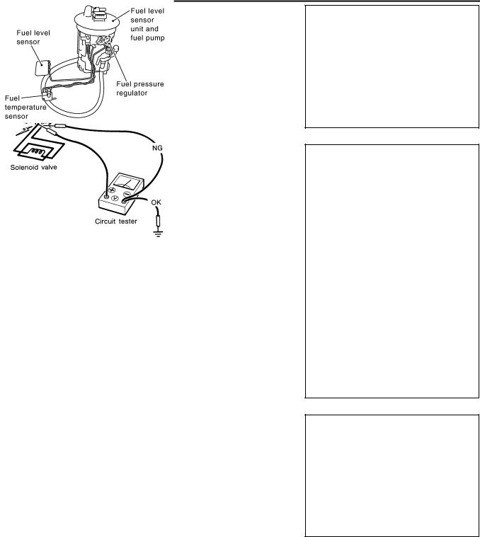
PRECAUTIONS
●After performing each TROUBLE DIAGNOSIS, perform DTC Confirmation Procedure or Overall Function Check.
The DTC should not be displayed in the DTC Confirmation Procedure if the repair is completed. The Overall Function Check should be a good result if the repair is completed.
●When measuring ECM signals with a circuit tester, connect a break-out box (SST) and Y-cable adapter (SST) between the ECM and ECM harness connector.
●When measuring ECM signals with a circuit tester, never allow the two tester probes to contact.
Accidental contact of probes will cause a short circuit and damage the ECM power transistor.
●Do not use ECM ground terminals when measuring input/ output voltage. Doing so may result in damage to the ECM’s transistor. Use a ground other than ECM terminals, such as the ground.
●Do not operate fuel pump when there is no fuel in lines.
●Tighten fuel hose clamps to the specified torque.
SEF217U
SEF348N
PBIB2344E
|
Revision: 2006 July |
EC-16 |
2006 X-Trail |

PRECAUTIONS
●Do not depress accelerator pedal when starting.
●Immediately after starting, do not rev up engine unnecessarily.
●Do not rev up engine just prior to shutdown.
●When installing C.B. ham radio or a mobile phone, be sure to observe the following as it may adversely affect electronic control systems depending on installation location.
–Keep the antenna as far as possible from the electronic control units.
–Keep the antenna feeder line more than 20 cm (8 in) away from the harness of electronic controls.
Do not let them run parallel for a long distance.
–Adjust the antenna and feeder line so that the standingwave radio can be kept smaller.
–Be sure to ground the radio to vehicle body.
A
EC
C
SEF709Y
D
E
F
G
SEF708Y
H
I
J
K
L
M
|
Revision: 2006 July |
EC-17 |
2006 X-Trail |

PREPARATION |
|
|
PREPARATION |
PFP:00002 |
Special Service Tools |
ABS00CKR |
The actual shapes of Kent-Moore tools may differ from those of special service tools illustrated here.
Tool number
(Kent-Moore No.) Description Tool name
|
EG17650301 |
Adapting radiator cap tester to radiator cap and |
|
(J-33984-A) |
radiator filler neck |
|
Radiator cap tester |
a: 28 (1.10) dia. |
|
adapter |
b: 31.4 (1.236) dia. |
|
c: 41.3 (1.626) dia. |
|
|
Unit: mm (in) |
|
|
S-NT564 |
|
|
KV10117100 |
Loosening or tightening heated oxygen sensors |
|
(J-36471-A) |
with 22 mm (0.87 in) hexagon nut |
|
Heated oxygen |
|
|
sensor wrench |
|
|
S-NT379 |
|
|
KV10114400 |
Loosening or tightening heated oxygen sensors |
|
(J-38365) |
a: 22 mm (0.87 in) |
|
Heated oxygen |
|
|
sensor wrench |
|
|
S-NT636 |
|
|
(J-44321) |
Checking fuel pressure |
|
Fuel pressure gauge |
|
|
kit |
|
|
LEC642 |
|
|
(J-44321-6) |
Connecting fuel pressure gauge to quick |
|
Fuel pressure adapter |
connector type fuel lines. |
|
LBIA0376E |
|
|
(J-45488) |
Remove fuel tube quick connectors in engine |
|
Quick connector |
room. |
|
release |
|
|
PBIC0198E |
|
Revision: 2006 July |
EC-18 |
2006 X-Trail |

PREPARATION
|
Tool number |
|
|
(Kent-Moore No.) |
Description |
|
Tool name |
|
|
KV109E0010 |
Measuring ECM signals with a circuit tester |
|
(J-46209) |
|
|
Break-out box |
|
S-NT825 |
|
|
KV109E0080 |
Measuring ECM signals with a circuit tester |
|
(J-45819) |
|
|
Y-cable adapter |
|
S-NT826 |
||
Commercial Service Tools |
ABS00CKS |
|
|
Tool name |
Description |
|
|
(Kent-Moore No.) |
||
|
Leak detector |
Locating the EVAP leak |
|
|
i.e.:(J-41416) |
|
S-NT703 |
|
|
EVAP service port |
Applying positive pressure through EVAP service |
|
adapter |
port |
|
i.e.:(J-41413-OBD) |
|
S-NT704 |
|
|
Fuel filler cap adapter |
Checking fuel tank vacuum relief valve opening |
|
i.e.: (J-41416) |
pressure |
|
S-NT815 |
|
|
Socket wrench |
Removing and installing engine coolant |
|
temperature sensor |
S-NT705
A
EC
C
D
E
F
G
H
I
J
K
L
M
|
Revision: 2006 July |
EC-19 |
2006 X-Trail |

|
PREPARATION |
|||
|
Tool name |
Description |
||
|
(Kent-Moore No.) |
|||
|
Oxygen sensor thread |
Reconditioning the exhaust system threads |
||
|
cleaner |
before installing a new oxygen sensor. Use with |
||
|
i.e.: (J-43897-18) |
anti-seize lubricant shown below. |
||
|
(J-43897-12) |
a: 18 mm diameter with pitch 1.5 mm for |
||
|
Zirconia Oxygen Sensor |
|||
|
b: 12 mm diameter with pitch 1.25 mm for |
|||
|
Titania Oxygen Sensor |
|||
|
AEM488 |
|||
|
Anti-seize lubricant |
Lubricating oxygen sensor thread cleaning tool |
||
|
i.e.: (PermatexTM |
when reconditioning exhaust system threads. |
||
|
133AR or equivalent |
|||
|
meeting MIL |
|||
|
specification MIL-A- |
|||
|
907) |
|||
|
S-NT779 |
|||
|
Revision: 2006 July |
EC-20 |
2006 X-Trail |

ENGINE CONTROL SYSTEM
ENGINE CONTROL SYSTEM
System Diagram
PFP:23710
A
ABS00CKT
EC
C
D
E
F
G
H
I
J
K
L
M
PBIB2361E
|
Revision: 2006 July |
EC-21 |
2006 X-Trail |

ENGINE CONTROL SYSTEM
Multiport Fuel Injection (MFI) System |
ABS00CKW |
||||
INPUT/OUTPUT SIGNAL CHART |
|||||
|
Sensor |
Input Signal to ECM |
ECM |
Actuator |
||
|
function |
|||||
|
Crankshaft position sensor (POS) |
Engine speed*3 |
||||
|
Camshaft position sensor (PHASE) |
Piston position |
||||
|
Mass air flow sensor |
Amount of intake air |
||||
|
Engine coolant temperature sensor |
Engine coolant temperature |
||||
|
Throttle position sensor |
Throttle position |
||||
|
Accelerator pedal position sensor |
Accelerator pedal position |
||||
|
Fuel injec- |
|||||
|
Park/neutral position (PNP) switch |
Gear position |
||||
|
tion & mix- |
|||||
|
Fuel injector |
|||||
|
Knock sensor |
Engine knocking condition |
ture ratio |
|||
|
control |
|||||
|
Power steering pressure sensor |
Power steering operation |
||||
|
Heated oxygen sensor 1 |
Density of oxygen in exhaust gas |
||||
|
Heated oxygen sensor 2*1 |
Density of oxygen in exhaust gas |
||||
|
Wheel sensor |
Vehicle speed*2 |
||||
|
Air conditioner switch |
Air conditioner operation |
||||
|
Battery |
Battery voltage*3 |
*1: This sensor is not used to control the engine system under normal conditions. *2: This signal is sent to the ECM through CAN communication line.
*3: ECM determines the start signal status by the signal of engine speed and battery voltage.
SYSTEM DESCRIPTION
The amount of fuel injected from the fuel injector is determined by the ECM. The ECM controls the length of time the valve remains open (injection pulse duration). The amount of fuel injected is a program value in the ECM memory. The program value is preset by engine operating conditions. These conditions are determined by input signals (for engine speed and intake air) from both the crankshaft position sensor and the mass air flow sensor.
VARIOUS FUEL INJECTION INCREASE/DECREASE COMPENSATION
In addition, the amount of fuel injected is compensated to improve engine performance under various operating conditions as listed below.
<Fuel increase>
●During warm-up
●When starting the engine
●During acceleration
●Hot-engine operation
●When selector lever is changed from N to D (A/T models)
●High-load, high-speed operation
<Fuel decrease>
●During deceleration
●During high engine speed operation
|
Revision: 2006 July |
EC-22 |
2006 X-Trail |

ENGINE CONTROL SYSTEM
MIXTURE RATIO FEEDBACK CONTROL (CLOSED LOOP CONTROL)
PBIB2953E
The mixture ratio feedback system provides the best air-fuel mixture ratio for driveability and emission control. The three way catalyst (manifold) can then better reduce CO, HC and NOx emissions. This system uses heated oxygen sensor 1 in the exhaust manifold to monitor whether the engine operation is rich or lean. The ECM adjusts the injection pulse width according to the sensor voltage signal. For more information about heated oxygen sensor 1, refer to EC-223, «DTC P0132 HO2S1» . This maintains the mixture ratio within the range of stoichiometric (ideal air-fuel mixture).
This stage is referred to as the closed loop control condition.
Heated oxygen sensor 2 is located downstream of the three way catalyst (manifold). Even if the switching characteristics of heated oxygen sensor 1 shift, the air-fuel ratio is controlled to stoichiometric by the signal from heated oxygen sensor 2.
Open Loop Control
The open loop system condition refers to when the ECM detects any of the following conditions. Feedback control stops in order to maintain stabilized fuel combustion.
● Deceleration and acceleration
● High-load, high-speed operation
● Malfunction of heated oxygen sensor 1 or its circuit
● Insufficient activation of heated oxygen sensor 1 at low engine coolant temperature ● High engine coolant temperature
● During warm-up
● After shifting from N to D (A/T models) ● When starting the engine
MIXTURE RATIO SELF-LEARNING CONTROL
The mixture ratio feedback control system monitors the mixture ratio signal transmitted from heated oxygen sensor 1. This feedback signal is then sent to the ECM. The ECM controls the basic mixture ratio as close to the theoretical mixture ratio as possible. However, the basic mixture ratio is not necessarily controlled as originally designed. Both manufacturing differences (i.e., mass air flow sensor hot wire) and characteristic changes during operation (i.e., fuel injector clogging) directly affect mixture ratio.
Accordingly, the difference between the basic and theoretical mixture ratios is monitored in this system. This is then computed in terms of “injection pulse duration” to automatically compensate for the difference between the two ratios.
“Fuel trim” refers to the feedback compensation value compared against the basic injection duration. Fuel trim includes short term fuel trim and long term fuel trim.
“Short term fuel trim” is the short-term fuel compensation used to maintain the mixture ratio at its theoretical value. The signal from heated oxygen sensor 1 indicates whether the mixture ratio is RICH or LEAN compared to the theoretical value. The signal then triggers a reduction in fuel volume if the mixture ratio is rich, and an increase in fuel volume if it is lean.
“Long term fuel trim” is overall fuel compensation carried out long-term to compensate for continual deviation of the short term fuel trim from the central value. Such deviation will occur due to individual engine differences, wear over time and changes in the usage environment.
|
Revision: 2006 July |
EC-23 |
2006 X-Trail |

ENGINE CONTROL SYSTEM
FUEL INJECTION TIMING
SEF337W
Two types of systems are used.
Sequential Multiport Fuel Injection System
Fuel is injected into each cylinder during each engine cycle according to the firing order. This system is used when the engine is running.
Simultaneous Multiport Fuel Injection System
Fuel is injected simultaneously into all four cylinders twice each engine cycle. In other words, pulse signals of the same width are simultaneously transmitted from the ECM.
The four fuel injectors will then receive the signals two times for each engine cycle.
This system is used when the engine is being started and/or if the fail-safe system (CPU) is operating.
FUEL SHUT-OFF
Fuel to each cylinder is cut off during deceleration or operation of the engine at excessively high speeds.
Electronic Ignition (EI) System |
ABS00CKX |
|||
INPUT/OUTPUT SIGNAL CHART |
||||
|
Sensor |
Input Signal to ECM |
ECM func- |
Actuator |
|
|
tion |
||||
|
Crankshaft position sensor (POS) |
Engine speed*2 |
|||
|
Camshaft position sensor (PHASE) |
Piston position |
|||
|
Mass air flow sensor |
Amount of intake air |
|||
|
Engine coolant temperature sensor |
Engine coolant temperature |
|||
|
Ignition |
||||
|
Throttle position sensor |
Throttle position |
|||
|
timing con- |
Power transistor |
|||
|
Accelerator pedal position sensor |
Accelerator pedal position |
|||
|
trol |
||||
|
Knock sensor |
Engine knocking |
|||
|
Park/neutral position (PNP) switch |
Gear position |
|||
|
Wheel sensor |
Vehicle speed*1 |
|||
|
Battery |
Battery voltage*2 |
*1: This signal is sent to the ECM through CAN communication line.
*2: ECM determines the start signal status by the signal of engine speed and battery voltage.
SYSTEM DESCRIPTION
Firing order: 1-3-4-2
The ignition timing is controlled by the ECM to maintain the best air-fuel ratio for every running condition of the engine. The ignition timing data is stored in the ECM.
The ECM receives information such as the injection pulse width and camshaft position sensor (PHASE) signal. Computing this information, ignition signals are transmitted to the power transistor.
During the following conditions, the ignition timing is revised by the ECM according to the other data stored in the ECM.
●At starting
●During warm-up
●At idle
●At low battery voltage
Revision: 2006 July

ENGINE CONTROL SYSTEM
●During acceleration
The knock sensor retard system is designed only for emergencies. The basic ignition timing is programmed within the anti-knocking zone, if recommended fuel is used under dry conditions. The retard system does not operate under normal driving conditions. If engine knocking occurs, the knock sensor monitors the condition. The signal is transmitted to the ECM. The ECM retards the ignition timing to eliminate the knocking condition.
Fuel Cut Control (at No Load and High Engine Speed) |
ABS00CKZ |
|||
INPUT/OUTPUT SIGNAL CHART |
||||
|
Sensor |
Input Signal to ECM |
ECM func- |
Actuator |
|
|
tion |
||||
|
Park/neutral position (PNP) switch |
Neutral position |
|||
|
Accelerator pedal position sensor |
Accelerator pedal position |
|||
|
Engine coolant temperature sensor |
Engine coolant temperature |
Fuel cut |
Fuel injector |
|
|
control |
||||
|
Crankshaft position sensor (POS) |
Engine speed |
|||
|
Camshaft position sensor (PHASE) |
||||
|
Wheel sensor |
Vehicle speed* |
|||
*: This signal is sent to the ECM through CAN communication line.
SYSTEM DESCRIPTION |
||
|
If the engine speed is above 1,800 rpm under no load (for example, the shift position is neutral and engine |
G |
|
|
speed is over 1,800 rpm) fuel will be cut off after some time. The exact time when the fuel is cut off varies |
||
|
based on engine speed. |
||
|
Fuel cut will be operated until the engine speed reaches 1,500 rpm, then fuel cut will be cancelled. |
H |
|
|
NOTE: |
||
|
This function is different from deceleration control listed under EC-22, «Multiport Fuel Injection (MFI) System» . |
||
|
I |
||
|
J |
||
|
K |
||
|
L |
||
|
M |
|
Revision: 2006 July |
EC-25 |
2006 X-Trail |

AIR CONDITIONING CUT CONTROL
AIR CONDITIONING CUT CONTROL
Input/Output Signal Chart
|
Sensor |
Input Signal to ECM |
ECM function |
Actuator |
|
|
Air conditioner switch |
Air conditioner ON signal |
|||
|
Throttle position sensor |
Throttle position |
|||
|
Accelerator pedal position sensor |
Accelerator pedal position |
|||
|
Crankshaft position sensor (POS) |
Engine speed*2 |
|||
|
Camshaft position sensor (PHASE) |
||||
|
Air conditioner |
||||
|
Air conditioner relay |
||||
|
Engine coolant temperature sensor |
Engine coolant temperature |
|||
|
cut control |
||||
|
Refrigerant pressure sensor |
Refrigerant pressure |
|||
|
Power steering pressure sensor |
Power steering operation |
|||
|
Wheel sensor |
Vehicle speed*1 |
|||
|
Battery |
Battery voltage*2 |
*1: This signal is sent to the ECM through CAN communication line.
*2: ECM determines the start signal status by the signal of engine speed and battery voltage.
SYSTEM DESCRIPTION
This system improves engine operation when the air conditioner is used.
Under the following conditions, the air conditioner is turned OFF.
●When the accelerator pedal is fully depressed.
●When cranking the engine.
●At high engine speeds.
●When the engine coolant temperature becomes excessively high.
●When operating power steering during low engine speed or low vehicle speed.
●When engine speed is excessively low.
●When refrigerant pressure is excessively low or high.
|
Revision: 2006 July |
EC-26 |
2006 X-Trail |

AUTOMATIC SPEED CONTROL DEVICE (ASCD)
|
AUTOMATIC SPEED CONTROL DEVICE (ASCD) |
PFP:18930 |
||
System Description |
ABS00D04 |
||
INPUT/OUTPUT SIGNAL CHART |
|||
|
Sensor |
Input signal to ECM |
ECM function |
Actuator |
|
ASCD brake switch |
Brake pedal operation |
||
|
Stop lamp switch |
Brake pedal operation |
||
|
ASCD clutch switch (M/T models) |
Clutch pedal operation |
||
|
Electric throttle control |
|||
|
ASCD steering switch |
ASCD steering switch operation |
ASCD vehicle speed control |
|
|
actuator |
|||
|
Park/Neutral position (PNP) |
Gear position |
||
|
switch |
|||
|
Wheel sensor |
Vehicle speed* |
||
|
TCM(A/T models) |
Powertrain revolution* |
||
*: This signal is sent to the ECM through CAN communication line.
BASIC ASCD SYSTEM
Refer to Owner’s Manual for ASCD operating instructions.
Automatic Speed Control Device (ASCD) allows a driver to keep vehicle at predetermined constant speed without depressing accelerator pedal. Driver can set vehicle speed in advance between approximately 40 km/ h (25 MPH) and 144 km/h (89 MPH).
ECM controls throttle angle of electric throttle control actuator to regulate engine speed.
Operation status of ASCD is indicated by CRUISE indicator and SET indicator in combination meter. If any malfunction occurs in ASCD system, it automatically deactivates control.
NOTE:
Always drive vehicle in safe manner according to traffic conditions and obey all traffic laws.
SET OPERATION
Press MAIN switch. (The CRUISE indicator in combination meter illuminates.)
When vehicle speed reaches a desired speed between approximately 40 km/h (25 MPH) and 144 km/h (89 MPH), press SET/COAST switch. (Then SET indicator in combination meter illuminates.)
ACCELERATE OPERATION
If the RESUME/ACCELERATE switch is depressed during cruise control driving, increase the vehicle speed until the switch is released or vehicle speed reaches maximum speed controlled by the system.
And then ASCD will keep the new set speed.
CANCEL OPERATION
When any of following conditions exist, cruise operation will be canceled.
●CANCEL switch is depressed
●Brake pedal is depressed
●Clutch pedal is depressed or shift position is changed to the neutral position (M/T models)
●Selector lever is changed to N, P, R position (A/T models)
●Vehicle speed decreased to 13km/h (8MPH) lower than the set speed
●VDC/TCS system is operated
When the ECM detects any of the following conditions, the ECM will cancel the cruise operation and inform the driver by blinking indicator lamp.
●Engine coolant temperature is slightly higher than the normal operating temperature, CRUISE lamp may blink slowly.
When the engine coolant temperature decreases to the normal operating temperature, CRUISE lamp will stop blinking and the cruise operation will be able to work by pressing SET/COAST switch or RESUME/ ACCELEATE switch.
●Malfunction for some self-diagnoses regarding ASCD control: SET lamp will blink quickly.
If MAIN switch is turned to OFF during ASCD is activated, all of ASCD operations will be canceled and vehicle speed memory will be erased.
|
Revision: 2006 July |
EC-27 |
2006 X-Trail |

AUTOMATIC SPEED CONTROL DEVICE (ASCD)
COAST OPERATION
When the SET/COAST switch is depressed during cruise control driving, decrease vehicle set speed until the switch is released. And then ASCD will keep the new set speed.
RESUME OPERATION
When the RESUME/ACCELERATE switch is depressed after cancel operation other than depressing MAIN switch is performed, vehicle speed will return to last set speed. To resume vehicle set speed, vehicle condition must meet following conditions.
●Brake pedal is fully released.
●Clutch pedal is fully released (M/T models)
●A/T selector lever is in other than P and N positions (A/T models)
●Vehicle speed is greater than 40 km/h (25 MPH) and less than 144 km/h (89 MPH)
Component Description |
ABS00D05 |
ASCD STEERING SWITCH
Refer to EC-498 .
ASCD BRAKE SWITCH
Refer to EC-506 and EC-584 .
ASCD CLUTCH SWITCH
Refer to EC-506 .
STOP LAMP SWITCH
Refer to EC-506 , EC-526 and EC-584 .
ELECTRIC THROTTLE CONTROL ACTUATOR
Refer to EC-531 , EC-538 , EC-546 and EC-551 .
ASCD INDICATOR
Refer to EC-594 .
|
Revision: 2006 July |
EC-28 |
2006 X-Trail |

CAN COMMUNICATION
|
CAN COMMUNICATION |
PFP:23710 |
System Description |
ABS00DCQ |
CAN (Controller Area Network) is a serial communication line for real time application. It is an on-vehicle multiplex communication line with high data communication speed and excellent error detection ability. Many electronic control units are equipped onto a vehicle, and each control unit shares information and links with other control units during operation (not independent). In CAN communication, control units are connected with 2 communication lines (CAN H line, CAN L line) allowing a high rate of information transmission with less wiring. Each control unit transmits/receives data but selectively reads required data only.
Refer to LAN-21, «CAN Communication Unit» , about CAN communication for detail.
A
EC
C
D
E
F
G
H
I
J
K
L
M
|
Revision: 2006 July |
EC-29 |
2006 X-Trail |

EVAPORATIVE EMISSION SYSTEM
EVAPORATIVE EMISSION SYSTEM
Description
SYSTEM DESCRIPTION
PFP:14950
ABS00CZV
PBIB2360E
The evaporative emission system is used to reduce hydrocarbons emitted into the atmosphere from the fuel system. This reduction of hydrocarbons is accomplished by activated charcoals in the EVAP canister.
The fuel vapor in the sealed fuel tank is led into the EVAP canister which contains activated carbon and the vapor is stored there when the engine is not operating or when refueling to the fuel tank.
The vapor in the EVAP canister is purged by the air through the purge line to the intake manifold when the engine is operating. EVAP canister purge volume control solenoid valve is controlled by ECM. When the engine operates, the flow rate of vapor controlled by EVAP canister purge volume control solenoid valve is proportionally regulated as the air flow increases.
EVAP canister purge volume control solenoid valve also shuts off the vapor purge line during decelerating and idling.
|
Revision: 2006 July |
EC-30 |
2006 X-Trail |
![]()
EVAPORATIVE EMISSION SYSTEM
EVAPORATIVE EMISSION LINE DRAWING
A
EC
C
D
E
F
G
H
I
J
K
L
M
PBIB2363E
|
Revision: 2006 July |
EC-31 |
2006 X-Trail |

EVAPORATIVE EMISSION SYSTEM
PBIB2352E
|
Revision: 2006 July |
EC-32 |
2006 X-Trail |

EVAPORATIVE EMISSION SYSTEM
Component Inspection
EVAP CANISTER
Check EVAP canister as follows:
1.Block port B .
2.Blow air into port A and check that it flows freely out of port C .
3.Release blocked port B .
4.Apply vacuum pressure to port B and check that vacuum pressure exists at the ports A and C .
5.Block port A and B .
6.Apply pressure to port C and check that there is no leakage.
FUEL TANK VACUUM RELIEF VALVE (BUILT INTO FUEL FULLER CAP)
1.Wipe clean valve housing.
2.Check valve opening pressure and vacuum.
Pressure: 15.3 — 20.0 kPa
(0.156 — 0.204 kg/cm2 , 2.22 — 2.90 psi) Vacuum: − 6.0 to − 3.4 kPa
(− 0.061 to − 0.035 kg/cm2 , − 0.87 to − 0.48 psi)
3.If out of specification, replace fuel filler cap as an assembly.
CAUTION:
Use only a genuine fuel filler cap as a replacement. If an incorrect fuel filler cap is used, the MIL may come on.
EVAP CANISTER PURGE VOLUME CONTROL SOLENOID VALVE
Refer to EC-370, «Component Inspection» .
FUEL TANK TEMPERATURE SENSOR
Refer to EC-301, «Component Inspection» .
EVAP CANISTER VENT CONTROL VALVE
Refer to EC-384, «Component Inspection» .
EVAP CONTROL SYSTEM PRESSURE SENSOR
Refer to EC-395, «Component Inspection» .
ABS00CZW
A
EC
C
D
PBIB1044E
E
F
G
H
SEF445Y
I
J
K
SEF943S
L
M
|
Revision: 2006 July |
EC-33 |
2006 X-Trail |

EVAPORATIVE EMISSION SYSTEM
EVAP SERVICE PORT
Positive pressure is delivered to the EVAP system through the EVAP service port. If fuel vapor leakage in the EVAP system occurs, use a leak detector to locate the leak.
Removal and Installation
EVAP CANISTER
Tighten EVAP canister as shown in the figure.
SEF462UC
ABS00CZX
PBIB1628E
EVAP CANISTER VENT CONTROL VALVE
1.Turn EVAP canister vent control valve counterclockwise.
2.Remove the EVAP canister vent control valve.
Always replace O-ring with a new one.
How to Detect Fuel Vapor Leakage
CAUTION:
●Never use compressed air or a high pressure pump.
●Do not exceed 4.12 kPa (0.042 kg/cm2 , 0.6 psi) of pressure in EVAP system.
NOTE:
●Do not start engine.
●Improper installation of EVAP service port adapter to the EVAP service port may cause a leak.
|
Revision: 2006 July |
EC-34 |
2006 X-Trail |

EVAPORATIVE EMISSION SYSTEM
 WITH CONSULT-II
 WITH CONSULT-II
1.Attach the EVAP service port adapter securely to the EVAP service port.
2.Also attach the pressure pump and hose to the EVAP service port adapter.
3.Turn ignition switch ON.
4.Select the “EVAP SYSTEM CLOSE” of “WORK SUPPORT MODE” with CONSULT-II.
5.Touch “START”. A bar graph (Pressure indicating display) will appear on the screen.
6.Apply positive pressure to the EVAP system until the pressure indicator reaches the middle of the bar graph.
7.Remove EVAP service port adapter and hose with pressure pump.
8.Locate the leak using a leak detector.
Refer to EC-31, «EVAPORATIVE EMISSION LINE DRAWING» .
A
EC
C
D
E
PEF838U
F
G
H
PEF917U
I
J
K
L
SEF200U
WITHOUT CONSULT-II |
M |
1.Attach the EVAP service port adapter securely to the EVAP service port.
2.Also attach the pressure pump with pressure gauge to the EVAP service port adapter.
SEF462UC
|
Revision: 2006 July |
EC-35 |
2006 X-Trail |

EVAPORATIVE EMISSION SYSTEM
3.Apply battery voltage between the terminals EVAP canister vent control valve to make a closed EVAP system.
PBIB2341E
4.To locate the leak, deliver positive pressure to the EVAP system until pressure gauge points reach 1.38 to 2.76 kPa (0.014 to 0.028 kg/cm2 , 0.2 to 0.4 psi).
5.Remove EVAP service port adapter and hose with pressure pump.
6.Locate the leak using a leak detector. Refer to EC-31, «EVAPORATIVE EMISSION LINE DRAWING» .
|
Revision: 2006 July |
EC-36 |
2006 X-Trail |

ON BOARD REFUELING VAPOR RECOVERY (ORVR)
|
ON BOARD REFUELING VAPOR RECOVERY (ORVR) |
PFP:00032 |
System Description |
ABS00CZZ |
PBIB2362E
From the beginning of refueling, the fuel tank pressure goes up. When the pressure reaches the setting value of the refueling control valve (RCV) opening pressure, the RCV is opened. After RCV opens, the air and vapor inside the fuel tank go through refueling EVAP vapor cut valve, RCV and EVAP/ORVR line to the EVAP canister. The vapor is absorbed by the EVAP canister and the air is released to the atmosphere.
When the refueling has reached the full level of the fuel tank, the refueling EVAP vapor cut valve is closed and refueling is stopped because of auto shut-off. The vapor which was absorbed by the EVAP canister is purged during driving.
The RCV is always closed during driving and the evaporative emission control system is operated the same as conventional system.
WARNING:
When conducting inspections below, be sure to observe the following:
●Put a “CAUTION: INFLAMMABLE” sign in workshop.
●Do not smoke while servicing fuel system. Keep open flames and sparks away from work area.
●Be sure to furnish the workshop with a CO2 fire extinguisher.
CAUTION:
●Before removing fuel line parts, carry out the following procedures:
–Put drained fuel in an explosion-proof container and put lid on securely.
–Release fuel pressure from fuel line. Refer to EC-80, «FUEL PRESSURE RELEASE» .
–Disconnect battery ground cable.
●Always replace O-ring when the fuel gauge retainer is removed.
●Do not kink or twist hose and tube when they are installed.
●Do not tighten hose and clamps excessively to avoid damaging hoses.
●After installation, run engine and check for fuel leaks at connection.
●Do not attempt to top off the fuel tank after the fuel pump nozzle shuts off automatically. Continued refueling may cause fuel overflow, resulting in fuel spray and possibly a fire.
A
EC
C
D
E
F
G
H
I
J
K
L
M
|
Revision: 2006 July |
EC-37 |
2006 X-Trail |

ON BOARD REFUELING VAPOR RECOVERY (ORVR)
Diagnostic Procedure |
ABS00D00 |
SYMPTOM: FUEL ODOR FROM EVAP CANISTER IS STRONG. |
|
|
1. CHECK EVAP CANISTER |
|
1.Remove EVAP canister with EVAP canister vent control valve and EVAP control system pressure sensor attached.
2.Weigh the EVAP canister with EVAP canister vent control valve and EVAP control system pressure sensor attached.
The weight should be less than 2.5 kg (5.5 lb).
OK or NG
|
OK |
>> GO TO 2. |
|
NG |
>> GO TO 3. |
2. CHECK IF EVAP CANISTER SATURATED WITH WATER
Does water drain from the EVAP canister?
Yes or No
|
Yes |
>> GO TO 3. |
|
No |
>> GO TO 5. |
PBIB1031E
3. REPLACE EVAP CANISTER
Replace EVAP canister with a new one.
>>GO TO 4.
4.CHECK WATER SEPARATOR
Refer to EC-41, «Component Inspection» .
OK or NG
|
OK |
>> GO TO 5. |
|
NG |
>> Replace water separator. |
5. DETECT MALFUNCTIONING PART
Check the EVAP hose between EVAP canister and water separator for clogging or poor connection.
>>Repair or replace EVAP hose.
6.CHECK REFUELING CONTROL VALVE
Refer to EC-41, «Component Inspection» .
OK or NG
|
OK |
>> GO TO 7. |
|
NG |
>> Replace refueling control valve. |
|
Revision: 2006 July |
EC-38 |
2006 X-Trail |

ON BOARD REFUELING VAPOR RECOVERY (ORVR)
7. CHECK REFUELING EVAP VAPOR CUT VALVE
Refer to EC-41, «Component Inspection» .
OK or NG
|
OK |
>> INSPECTION END |
|
NG |
>> Replace refueling EVAP vapor cut valve with fuel tank. |
SYMPTOM: CANNOT REFUEL/FUEL ODOR FROM THE FUEL FILLER OPENING IS STRONG WHILE REFUELING.
1. CHECK EVAP CANISTER
1.Remove EVAP canister with EVAP canister vent control valve and EVAP control system pressure sensor attached.
2.Weigh the EVAP canister with EVAP canister vent control valve and EVAP control system pressure sensor attached.
The weight should be less than 2.5 kg (5.5 lb).
OK or NG
|
OK |
>> GO TO 2. |
|
NG |
>> GO TO 3. |
2. CHECK IF EVAP CANISTER SATURATED WITH WATER
Does water drain from the EVAP canister?
Yes or No
|
Yes |
>> GO TO 3. |
|
No |
>> GO TO 6. |
PBIB1031E
3. REPLACE EVAP CANISTER
Replace EVAP canister with a new one.
>>GO TO 4.
4.CHECK WATER SEPARATOR
Refer to EC-42, «WATER SEPARATOR» .
OK or NG
|
OK |
>> GO TO 5 |
|
NG |
>> Replace water separator. |
5. DETECT MALFUNCTIONING PART
Check the EVAP hose between EVAP canister and vehicle water separator for clogging or poor connection.
>> Repair or replace EVAP hose.
|
Revision: 2006 July |
EC-39 |
2006 X-Trail |

ON BOARD REFUELING VAPOR RECOVERY (ORVR)
6. CHECK VENT HOSES AND VENT TUBES
Check hoses and tubes between EVAP canister and refueling EVAP vapor cut valve for clogging, kink, looseness and improper connection.
OK or NG
|
OK |
>> GO TO 7. |
|
NG |
>> Repair or replace hoses and tubes. |
7. CHECK FILLER NECK TUBE
Check recirculation line for clogging, dents and cracks.
OK or NG
|
OK |
>> GO TO 8. |
|
NG |
>> Replace filler neck tube. |
8. CHECK REFUELING CONTROL VALVE
Refer to EC-41, «Component Inspection» .
OK or NG
|
OK |
>> GO TO 9. |
|
NG |
>> Replace refueling control valve. |
9. CHECK REFUELING EVAP VAPOR CUT VALVE
Refer to EC-41, «Component Inspection» .
OK or NG
|
OK |
>> GO TO 10. |
|
NG |
>> Replace refueling EVAP vapor cut valve with fuel tank. |
10. CHECK FUEL FILLER TUBE
Check filler neck tube and hose connected to the fuel tank for clogging, dents and cracks. OK or NG
|
OK |
>> GO TO 11. |
|
NG |
>> Replace fuel filler tube. |
11. CHECK ONE-WAY FUEL VALVE-I
Check one-way valve for clogging.
OK or NG
|
OK |
>> GO TO 12. |
|
NG |
>> Repair or replace one-way fuel valve with fuel tank. |
12. CHECK ONE-WAY FUEL VALVE-II
1.Make sure that fuel is drained from the tank.
2.Remove fuel filler tube and hose.
3.Check one-way fuel valve for operation as follows.
When a stick is inserted, the valve should open, when removing stick it should close.
Do not drop any material into the tank.
OK or NG
|
OK |
>> INSPECTION END |
|
NG |
>> Replace fuel filler tube or replace one-way fuel valve |
|
with fuel tank. |
SEF665U
|
Revision: 2006 July |
EC-40 |
2006 X-Trail |
![]()
ON BOARD REFUELING VAPOR RECOVERY (ORVR)
Component Inspection |
ABS00D01 |
REFUELING EVAP VAPOR CUT VALVE |
With CONSULT-II
 With CONSULT-II
1. Remove fuel tank. Refer to FL-11, «FUEL TANK» . 2. Drain fuel from the tank as follows:
a. Remove fuel feed hose located on the fuel gauge retainer.
b. Connect a spare fuel hose, one side to fuel gauge retainer where the hose was removed and the other side to a fuel container.
c. Drain fuel using “FUEL PUMP RELAY” in “ACTIVE TEST” mode with CONSULT-II.
3. Check refueling EVAP vapor cut valve for being stuck to close as follows.
Blow air into the refueling EVAP vapor cut valve (from the end of EVAP/ORVR line hose), and check that the air flows freely into the tank.
4. Check refueling EVAP vapor cut valve for being stuck to open as follows.
a.Connect vacuum pump to hose end.
b.Remove fuel gauge retainer with fuel gauge unit.
Always replace O-ring with new one.
c.Put fuel tank upside down.
d.Apply vacuum pressure to hose end [− 13.3 kPa (− 100 mmHg, − 3.94 inHg)] with fuel gauge retainer remaining open and check that the pressure is applicable.
PBIB3100E
Without CONSULT-II
 Without CONSULT-II
1. Remove fuel tank. Refer to FL-11, «FUEL TANK» .
M
2.Drain fuel from the tank as follows:
a.Remove fuel gauge retainer.
b.Drain fuel from the tank using a handy pump into a fuel container.
3.Check refueling EVAP vapor cut valve for being stuck to close as follows.
Blow air into the refueling EVAP vapor cut valve (from the end of EVAP/ORVR line hose), and check that the air flows freely into the tank.
4.Check refueling EVAP vapor cut valve for being stuck to open as follows.
a.Connect vacuum pump to hose end.
b.Remove fuel gauge retainer with fuel gauge unit.
Always replace O-ring with new one.
c.Put fuel tank upside down.
|
Revision: 2006 July |
EC-41 |
2006 X-Trail |

ON BOARD REFUELING VAPOR RECOVERY (ORVR)
d.Apply vacuum pressure to hose end [− 13.3 kPa (− 100 mmHg, − 3.94 inHg)] with fuel gauge retainer remaining open and check that the pressure is applicable.
PBIB3100E
REFUELING CONTROL VALVE
1.Remove fuel filler cap.
2.Check air continuity between hose ends A and B.
Blow air into the hose end B. Air should flow freely into the fuel tank.
3.Blow air into hose end A and check there is no leakage.
4.Apply pressure to both hose ends A and B [20 kPa (150 mmHg, 5.91 inHg)] using a pressure pump and a suitable 3-way connector. Check that there is no leakage.
PBIB3100E
WATER SEPARATOR
1.Check visually for insect nests in the water separator air inlet.
2.Check visually for cracks or flaws in the appearance.
3.Check visually for cracks or flaws in the hose.
|
Revision: 2006 July |
EC-42 |
2006 X-Trail |

ON BOARD REFUELING VAPOR RECOVERY (ORVR)
|
4. Check that A and C are not clogged by blowing air into B with |
|||
|
A , and then C plugged. |
A |
||
|
5. In case of NG in items 2 — 4, replace the parts. |
|||
|
NOTE: |
|||
|
● Do not disassemble water separator. |
EC |
||
|
C |
|||
|
PBIB1032E |
|||
|
D |
|||
|
E |
|||
|
F |
|||
|
G |
|||
|
H |
|||
|
I |
|||
|
J |
|||
|
K |
|||
|
L |
|||
|
M |
|
Revision: 2006 July |
EC-43 |
2006 X-Trail |

POSITIVE CRANKCASE VENTILATION
POSITIVE CRANKCASE VENTILATION
Description
SYSTEM DESCRIPTION
PFP:11810
ABS00D02
PBIB0492E
This system returns blow-by gas to the intake manifold.
The positive crankcase ventilation (PCV) valve is provided to conduct crankcase blow-by gas to the intake manifold. During partial throttle operation of the engine, the intake manifold sucks the blow-by gas through the PCV valve. Normally, the capacity of the valve is sufficient to handle any blow-by and a small amount of ventilating air. The ventilating air is then drawn from the air inlet tubes into the crankcase. In this process the air passes through the hose connecting air inlet tubes to rocker cover. Under full-throttle condition, the manifold vacuum is insufficient to draw the blow-by flow through the valve. The flow goes through the hose connection in the reverse direction.
On vehicles with an excessively high blow-by, the valve does not meet the requirement. This is because some of the flow will go through the hose connection to the air inlet tubes under all conditions.
Component Inspection
PCV (POSITIVE CRANKCASE VENTILATION) VALVE
With engine running at idle, remove PCV valve from rocker cover. A properly working valve makes a hissing noise as air passes through it. A strong vacuum should be felt immediately when a finger is placed over valve inlet.
PBIB1589E
|
Revision: 2006 July |
EC-44 |
2006 X-Trail |

POSITIVE CRANKCASE VENTILATION
PCV VALVE VENTILATION HOSE
1.Check hoses and hose connections for leaks.
2.Disconnect all hoses and clean with compressed air. If any hose cannot be freed of obstructions, replace.
A
EC
C
D
S-ET277
E
F
G
H
I
J
K
L
M
|
Revision: 2006 July |
EC-45 |
2006 X-Trail |

NVIS (NISSAN VEHICLE IMMOBILIZER SYSTEM-NATS)
|
NVIS (NISSAN VEHICLE IMMOBILIZER SYSTEM-NATS) |
PFP:25386 |
Description |
ABS00DCR |
●If the security indicator lights up with the ignition switch in the ON position or “NATS MALFUNCTION” is displayed on “SELF-DIAG RESULTS” screen, perform self-diagnostic results mode with CONSULT-II using NATS program card. Refer to BL-97, «NVIS (NISSAN VEHICLE IMMOBILIZER SYSTEM-NATS)» .
●Confirm no self-diagnostic results of NVIS (NATS) is displayed before touching “ERASE” in “SELF-DIAG RESULTS” mode with CONSULT-II.
●When replacing ECM, initialization of NVIS (NATS) system
|
and registration of all NVIS (NATS) ignition key IDs must be |
SEF543X |
carried out with CONSULT-II using NATS program card.
Therefore, be sure to receive all keys from vehicle owner. Regarding the procedures of NVIS (NATS) initialization and all NVIS (NATS) ignition key ID registration, refer to CONSULT-II Operation Manual, IVIS/NVIS.
|
Revision: 2006 July |
EC-46 |
2006 X-Trail |

ON BOARD DIAGNOSTIC (OBD) SYSTEM
|
ON BOARD DIAGNOSTIC (OBD) SYSTEM |
PFP:00028 |
Introduction |
ABS00CL7 |
The ECM has an on board diagnostic system, which detects malfunctions related to engine sensors or actuators. The ECM also records various emission-related diagnostic information including:
|
Emission-related diagnostic information |
Diagnostic service |
|
Diagnostic Trouble Code (DTC) |
Service $03 of SAE J1979 |
|
Freeze Frame data |
Service $02 of SAE J1979 |
|
System Readiness Test (SRT) code |
Service $01 of SAE J1979 |
|
1st Trip Diagnostic Trouble Code (1st Trip DTC) |
Service $07 of SAE J1979 |
|
1st Trip Freeze Frame data |
|
|
Test values and Test limits |
Service $06 of SAE J1979 |
|
Calibration ID |
Service $09 of SAE J1979 |
The above information can be checked using procedures listed in the table below.
× : Applicable —: Not applicable
|
DTC |
1st trip DTC |
Freeze Frame |
1st trip Freeze |
SRT status |
SRT code |
Test value |
|
|
data |
Frame data |
||||||
|
CONSULT-II |
× |
× |
× |
× |
× |
× |
— |
|
GST |
× |
× |
× |
— |
× |
× |
× |
|
ECM |
× |
× * |
— |
— |
× |
— |
— |
*: When DTC and 1st trip DTC simultaneously appear on the display, they cannot be clearly distinguished from each other.
The malfunction indicator lamp (MIL) on the instrument panel lights up when the same malfunction is detected in two consecutive trips (Two trip detection logic), or when the ECM enters fail-safe mode.
(Refer to EC-91, «Fail-Safe Chart» .)
Two Trip Detection Logic |
ABS00CL8 |
When a malfunction is detected for the 1st time, 1st trip DTC and 1st trip Freeze Frame data are stored in the ECM memory. The MIL will not light up at this stage. <1st trip>
If the same malfunction is detected again during the next drive, the DTC and Freeze Frame data are stored in the ECM memory, and the MIL lights up. The MIL lights up at the same time when the DTC is stored. <2nd trip> The “trip” in the “Two Trip Detection Logic” means a driving mode in which self-diagnosis is performed during vehicle operation. Specific on board diagnostic items will cause the ECM to light up or blink the MIL, and store DTC and Freeze Frame data, even in the 1st trip, as shown below.
× : Applicable —: Not applicable
|
MIL |
DTC |
1st trip DTC |
|||||||||
|
Items |
1st trip |
2nd trip |
1st trip |
2nd trip |
1st trip |
2nd trip |
|||||
|
Lighting |
Lighting |
display- |
|||||||||
|
Blinking |
Blinking |
displaying |
displaying |
displaying |
|||||||
|
ing |
|||||||||||
|
up |
up |
||||||||||
|
Misfire (Possible three way cata- |
|||||||||||
|
lyst damage) — DTC: P0300 — |
× |
— |
— |
— |
— |
— |
× |
— |
|||
|
P0304 is being detected |
|||||||||||
|
Misfire (Possible three way cata- |
|||||||||||
|
lyst damage) — DTC: P0300 — |
— |
— |
× |
— |
— |
× |
— |
— |
|||
|
P0304 is being detected |
|||||||||||
|
One trip detection diagnoses |
|||||||||||
|
(Refer to EC-48, «EMISSION- |
— |
× |
— |
— |
× |
— |
— |
— |
|||
|
RELATED DIAGNOSTIC INFOR- |
|||||||||||
|
MATION ITEMS» .) |
|||||||||||
|
Except above |
— |
— |
— |
× |
— |
× |
× |
— |
|||
When there is an open circuit on MIL circuit, the ECM cannot warn the driver by lighting MIL up when there is malfunction on engine control system.
|
Revision: 2006 July |
EC-47 |
2006 X-Trail |

ON BOARD DIAGNOSTIC (OBD) SYSTEM
Therefore, when electrical controlled throttle and part of ECM related diagnoses are continuously detected as NG for 5 trips, ECM warns the driver that engine control system malfunctions and MIL circuit is open by means of operating fail-safe function.
The fail-safe function also operates when above diagnoses except MIL circuit are detected, and demands the driver to repair the malfunction.
|
Engine operating condition in fail-safe mode |
Engine speed will not rise more than 2,500 rpm due to the fuel cut |
Emission-Related Diagnostic Information
EMISSION-RELATED DIAGNOSTIC INFORMATION ITEMS
ABS00CL9
× : Applicable —: Not applicable
|
Items |
DTC*1 |
Test value/ |
MIL |
Reference |
||||
|
SRT code |
Test limit |
Trip |
||||||
|
(CONSULT-II screen terms) |
CONSULT-II |
ECM*3 |
lighting up |
page |
||||
|
(GST only) |
||||||||
|
GST*2 |
||||||||
|
CAN COMM CIRCUIT |
U1000 |
1000*6 |
— |
— |
1 (A/T) |
× |
EC-152 |
|
|
2 (M/T) |
— |
|||||||
|
CAN COMM CIRCUIT |
U1001 |
1001*6 |
— |
— |
2 |
— |
EC-152 |
|
|
NO DTC IS DETECTED. |
||||||||
|
FURTHER TESTING |
P0000 |
0000 |
— |
— |
— |
Flashing*7 *8 |
EC-62 |
|
|
MAY BE QUIRED. |
||||||||
|
INT/V TIM CONT-B1 |
P0011 |
0011 |
— |
— |
2 |
× |
EC-155 |
|
|
HO2S1 HTR (B1) |
P0031 |
0031 |
— |
× |
2 |
× |
EC-159 |
|
|
HO2S1 HTR (B1) |
P0032 |
0032 |
— |
× |
2 |
× |
EC-159 |
|
|
HO2S2 HTR (B1) |
P0037 |
0037 |
— |
× |
2 |
× |
EC-166 |
|
|
HO2S2 HTR (B1) |
P0038 |
0038 |
— |
× |
2 |
× |
EC-166 |
|
|
INT/V TIM V/CIR-B1 |
P0075 |
0075 |
— |
— |
2 |
× |
EC-173 |
|
|
MAF SEN/CIRCUIT |
P0101 |
0101 |
— |
— |
2 |
× |
EC-178 |
|
|
MAF SEN/CIRCUIT |
P0102 |
0102 |
— |
— |
1 |
× |
EC-187 |
|
|
MAF SEN/CIRCUIT |
P0103 |
0103 |
— |
— |
1 |
× |
EC-187 |
|
|
IAT SEN/CIRCUIT |
P0112 |
0112 |
— |
— |
2 |
× |
EC-195 |
|
|
IAT SEN/CIRCUIT |
P0113 |
0113 |
— |
— |
2 |
× |
EC-195 |
|
|
ECT SEN/CIRC |
P0117 |
0117 |
— |
— |
1 |
× |
EC-201 |
|
|
ECT SEN/CIRC |
P0118 |
0118 |
— |
— |
1 |
× |
EC-201 |
|
|
TP SEN 2/CIRC |
P0122 |
0122 |
— |
— |
1 |
× |
EC-207 |
|
|
TP SEN 2/CIRC |
P0123 |
0123 |
— |
— |
1 |
× |
EC-207 |
|
|
ECT SENSOR |
P0125 |
0125 |
— |
— |
2 |
× |
EC-215 |
|
|
IAT SENSOR |
P0127 |
0127 |
— |
— |
2 |
× |
EC-218 |
|
|
THERMSTAT FNCTN |
P0128 |
0128 |
— |
— |
2 |
× |
EC-221 |
|
|
HO2S1 (B1) |
P0132 |
0132 |
— |
— |
2 |
× |
EC-223 |
|
|
HO2S1 (B1) |
P0133 |
0133 |
× |
× |
2 |
× |
EC-231 |
|
|
HO2S1 (B1) |
P0134 |
0134 |
— |
— |
2 |
× |
EC-242 |
|
|
HO2S2 (B1) |
P0137 |
0137 |
× |
× |
2 |
× |
EC-251 |
|
|
HO2S2 (B1) |
P0138 |
0138 |
× |
× |
2 |
× |
EC-260 |
|
|
HO2S2 (B1) |
P0139 |
0139 |
× |
× |
2 |
× |
EC-272 |
|
|
FUEL SYS-LEAN-B1 |
P0171 |
0171 |
— |
— |
2 |
× |
EC-281 |
|
|
FUEL SYS-RICH-B1 |
P0172 |
0172 |
— |
— |
2 |
× |
EC-289 |
|
|
FTT SENSOR |
P0181 |
0181 |
— |
— |
2 |
× |
EC-296 |
|
|
FTT SEN/CIRCUIT |
P0182 |
0182 |
— |
— |
2 |
× |
EC-302 |
|
|
FTT SEN/CIRCUIT |
P0183 |
0183 |
— |
— |
2 |
× |
EC-302 |
|
|
Revision: 2006 July |
EC-48 |
2006 X-Trail |

ON BOARD DIAGNOSTIC (OBD) SYSTEM
|
Items |
DTC*1 |
Test value/ |
MIL |
Reference |
A |
|||||
|
SRT code |
Test limit |
Trip |
||||||||
|
CONSULT-II |
||||||||||
|
(CONSULT-II screen terms) |
ECM*3 |
lighting up |
page |
|||||||
|
(GST only) |
||||||||||
|
GST*2 |
||||||||||
|
TP SEN 1/CIRC |
P0222 |
0222 |
— |
— |
1 |
× |
EC-307 |
EC |
||
|
TP SEN 1/CIRC |
P0223 |
0223 |
— |
— |
1 |
× |
EC-307 |
|||
|
MULTI CYL MISFIRE |
P0300 |
0300 |
— |
— |
2 |
× |
EC-315 |
|||
|
C |
||||||||||
|
CYL 1 MISFIRE |
P0301 |
0301 |
— |
— |
2 |
× |
EC-315 |
|||
|
CYL 2 MISFIRE |
P0302 |
0302 |
— |
— |
2 |
× |
EC-315 |
|||
|
CYL 3 MISFIRE |
P0303 |
0303 |
— |
— |
2 |
× |
EC-315 |
D |
||
|
CYL 4 MISFIRE |
P0304 |
0304 |
— |
— |
2 |
× |
EC-315 |
|||
|
KNOCK SEN/CIRC-B1 |
P0327 |
0327 |
— |
— |
2 |
— |
EC-322 |
|||
|
E |
||||||||||
|
KNOCK SEN/CIRC-B1 |
P0328 |
0328 |
— |
— |
2 |
— |
EC-322 |
|||
|
CKP SEN/CIRCUIT |
P0335 |
0335 |
— |
— |
2 |
× |
EC-327 |
|||
|
CMP SEN/CIRC-B1 |
P0340 |
0340 |
— |
— |
2 |
× |
EC-335 |
F |
||
|
TW CATALYST SYS-B1 |
P0420 |
0420 |
× |
× |
2 |
× |
EC-343 |
|||
|
EVAP PURG FLOW/MON |
P0441 |
0441 |
× |
× |
2 |
× |
EC-348 |
|||
|
EVAP SMALL LEAK |
P0442 |
0442 |
× |
× |
2 |
× |
EC-354 |
G |
||
|
PURG VOLUME CONT/V |
P0443 |
0443 |
— |
— |
2 |
× |
EC-364 |
|||
|
PURG VOLUME CONT/V |
P0444 |
0444 |
— |
— |
2 |
× |
EC-372 |
H |
||
|
PURG VOLUME CONT/V |
P0445 |
0445 |
— |
— |
2 |
× |
EC-372 |
|||
|
VENT CONTROL VALVE |
P0447 |
0447 |
— |
— |
2 |
× |
EC-379 |
|||
|
VENT CONTROL VALVE |
P0448 |
0448 |
— |
— |
2 |
× |
EC-386 |
I |
||
|
EVAP SYS PRES SEN |
P0451 |
0451 |
— |
— |
2 |
× |
EC-393 |
|||
|
EVAP SYS PRES SEN |
P0452 |
0452 |
— |
— |
2 |
× |
EC-396 |
J |
||
|
EVAP SYS PRES SEN |
P0453 |
0453 |
— |
— |
2 |
× |
EC-403 |
|||
|
EVAP GROSS LEAK |
P0455 |
0455 |
— |
— |
2 |
× |
EC-411 |
|||
|
EVAP VERY SML LEAK |
P0456 |
0456 |
× *4 |
× |
2 |
× |
EC-419 |
K |
||
|
FUEL LEV SEN SLOSH |
P0460 |
0460 |
— |
— |
2 |
× |
EC-430 |
|||
|
FUEL LEVEL SENSOR |
P0461 |
0461 |
— |
— |
2 |
× |
EC-432 |
L |
||
|
FUEL LEVL SEN/CIRC |
P0462 |
0462 |
— |
— |
2 |
× |
EC-434 |
|||
|
FUEL LEVL SEN/CIRC |
P0463 |
0463 |
— |
— |
2 |
× |
EC-434 |
|||
|
VEH SPEED SEN/CIRC*5 |
P0500 |
0500 |
— |
— |
2 |
× |
EC-436 |
M |
||
|
ISC SYSTEM |
P0506 |
0506 |
— |
— |
2 |
× |
EC-438 |
|||
|
ISC SYSTEM |
P0507 |
0507 |
— |
— |
2 |
× |
EC-440 |
|||
|
PW STP SEN/CIRC |
P0550 |
0550 |
— |
— |
2 |
— |
EC-442 |
|||
|
ECM BACK UP/CIRC |
P0603 |
0603 |
— |
— |
2 |
× |
EC-447 |
|||
|
ECM |
P0605 |
0605 |
— |
— |
1 or 2 |
× or — |
EC-451 |
|||
|
SENSOR POWER/CIRC |
P0643 |
0643 |
— |
— |
1 |
× |
EC-454 |
|||
|
PNP SW/CIRC |
P0705 |
0705 |
— |
— |
2 |
× |
AT-95 |
|||
|
ATF TEMP SEN/CIRC |
P0710 |
0710 |
— |
— |
2 |
× |
AT-100 |
|||
|
VEH SPD SEN/CIR AT*5 |
P0720 |
0720 |
— |
— |
2 |
× |
AT-105 |
|||
|
ENGINE SPEED SIG |
P0725 |
0725 |
— |
— |
2 |
× |
AT-111 |
|||
|
A/T 1ST GR FNCTN |
P0731 |
0731 |
— |
— |
2 |
× |
AT-115 |
|||
|
A/T 2ND GR FNCTN |
P0732 |
0732 |
— |
— |
2 |
× |
AT-120 |
|||
|
A/T 3RD GR FNCTN |
P0733 |
0733 |
— |
— |
2 |
× |
AT-125 |
|||
|
Revision: 2006 July |
EC-49 |
2006 X-Trail |

ON BOARD DIAGNOSTIC (OBD) SYSTEM
|
Items |
DTC*1 |
Test value/ |
MIL |
Reference |
||||
|
SRT code |
Test limit |
Trip |
||||||
|
(CONSULT-II screen terms) |
CONSULT-II |
ECM*3 |
lighting up |
page |
||||
|
(GST only) |
||||||||
|
GST*2 |
||||||||
|
A/T 4TH GR FNCTN |
P0734 |
0734 |
— |
— |
2 |
× |
AT-130 |
|
|
TCC SOLENOID/CIRC |
P0740 |
0740 |
— |
— |
2 |
× |
AT-137 |
|
|
A/T TCC S/V FNCTN |
P0744 |
0744 |
— |
— |
2 |
× |
AT-142 |
|
|
L/PRESS SOL/CIRC |
P0745 |
0745 |
— |
— |
2 |
× |
AT-150 |
|
|
SFT SOL A/CIRC |
P0750 |
0750 |
— |
— |
1 |
× |
AT-156 |
|
|
SFT SOL B/CIRC |
P0755 |
0755 |
— |
— |
1 |
× |
AT-161 |
|
|
P-N POS SW/CIRCUIT |
P0850 |
0850 |
— |
— |
2 |
× |
EC-460 |
|
|
HO2S1 (B1) |
P1143 |
1143 |
× |
× |
2 |
× |
EC-465 |
|
|
HO2S1 (B1) |
P1144 |
1144 |
× |
× |
2 |
× |
EC-471 |
|
|
CLOSED LOOP-B1 |
P1148 |
1148 |
— |
— |
1 |
× |
EC-477 |
|
|
TCS C/U FUNCTION |
P1211 |
1211 |
— |
— |
2 |
— |
EC-478 |
|
|
TCS/CIRC |
P1212 |
1212 |
— |
— |
2 |
— |
EC-479 |
|
|
ENG OVER TEMP |
P1217 |
1217 |
— |
— |
1 |
× |
EC-480 |
|
|
CTP LEARNING |
P1225 |
1225 |
— |
— |
2 |
— |
EC-494 |
|
|
CTP LEARNING |
P1226 |
1226 |
— |
— |
2 |
— |
EC-496 |
|
|
ASCD SW |
P1564 |
1564 |
— |
— |
1 |
— |
EC-498 |
|
|
ASCD BRAKE SW |
P1572 |
1572 |
— |
— |
1 |
— |
EC-506 |
|
|
ASCD VHL SPD SEN |
P1574 |
1574 |
— |
— |
1 |
— |
EC-517 |
|
|
NATS MALFUNCTION |
P1610 — |
1610 — |
— |
— |
2 |
— |
EC-46 |
|
|
P1615 |
1615 |
|||||||
|
TPV SEN/CIRC A/T |
P1705 |
1705 |
— |
— |
1 |
× |
AT-166 |
|
|
V/SP SEN (A/T) |
P1720 |
1720 |
— |
— |
2 |
— |
AT-105 |
|
|
O/R CLTCH SOL/CIRC |
P1760 |
1760 |
— |
— |
2 |
× |
AT-171 |
|
|
VIAS S/V CIRC |
P1800 |
1800 |
— |
— |
2 |
— |
EC-521 |
|
|
BRAKE SW/CIRCUIT |
P1805 |
1805 |
— |
— |
2 |
— |
EC-526 |
|
|
ETC MOT PWR |
P2100 |
2100 |
— |
— |
1 |
× |
EC-531 |
|
|
ETC FUNCTION/CIRC |
P2101 |
2101 |
— |
— |
1 |
× |
EC-538 |
|
|
ETC MOT PWR |
P2103 |
2103 |
— |
— |
1 |
× |
EC-531 |
|
|
ETC MOT |
P2118 |
2118 |
— |
— |
1 |
× |
EC-546 |
|
|
ETC ACTR |
P2119 |
2119 |
— |
— |
1 |
× |
EC-551 |
|
|
APP SEN 1/CIRC |
P2122 |
2122 |
— |
— |
1 |
× |
EC-553 |
|
|
APP SEN 1/CIRC |
P2123 |
2123 |
— |
— |
1 |
× |
EC-553 |
|
|
APP SEN 2/CIRC |
P2127 |
2127 |
— |
— |
1 |
× |
EC-560 |
|
|
APP SEN 2/CIRC |
P2128 |
2128 |
— |
— |
1 |
× |
EC-560 |
|
|
TP SENSOR |
P2135 |
2135 |
— |
— |
1 |
× |
EC-568 |
|
|
APP SENSOR |
P2138 |
2138 |
— |
— |
1 |
× |
EC-576 |
|
*1: 1st trip DTC No. is the same as DTC No. *2: This number is prescribed by SAE J2012.
*3: In Diagnostic Test Made II (Self-diagnostic results), this number is controlled by NISSAN. *4: SRT code will not be set if the self-diagnostic result is NG.
*5: When the fail-safe operations for both self-diagnoses occur at the same time, the MIL illuminates. *6: The troubleshooting for this DTC needs CONSULT-II.
*7: When the ECM is in the mode of displaying SRT status, MIL may flash. For the details, refer to EC-56, «How to Display SRT Status» *8: When engine is running, MIL may flash. For the details, refer to EC-62, «MIL Flashing Without DTC» .
|
Revision: 2006 July |
EC-50 |
2006 X-Trail |
 Loading…
X-TRAIL
РУКОВОДСТВО по ЭКСПЛУАТАЦИИ
Содержание
СОДЕРЖАНИЕ В ИЛЛЮСТРАЦИЯХ
ПРИБОРЫ И ОРГАНЫ УПРАВЛЕНИЯ
ПОДГОТОВКА К НАЧАЛУ ДВИЖЕНИЯ
ПУСК ДВИГАТЕЛЯ И ВОЖДЕНИЕ АВТОМОБИЛЯ
В СЛУЧАЕ НЕИСПРАВНОСТИ
УХОД ЗА КУЗОВОМ И САЛОНОМ АВТОМОБИЛЯ
ТЕХНИЧЕСКАЯ ИНФОРМАЦИЯ
алфавитный
указатель
БЕЗОПАСНОСТЬ: СИДЕНЬЯ, РЕМНИ И ПОДУШКИ БЕЗОПАСНОСТИ
информационный
дисплеи
,
система
отопления
и
КОНДИЦИОНИРОВАНИЯ ВОЗДУХА. АУДИОСИСТЕМА
ТЕХНИЧЕСКОЕ ОБСЛУЖИВАНИЯ И ОПЕРАЦИИ, ВЫПОЛНЯЕМЫЕ
ВЛАДЕЛЬЦЕМ
СИДЕНЬЯ, РЕМНИ БЕЗОПАСНОСТИ И ПОДУШКИ
БЕЗОПАСНОСТИ (ЗВЗ)
9. Крепления 150Р1Х для детских удерживающих
систем (стр.1-31)
10. Место крепления верхней лямки детских
удерживающих систем (стр. 1-32)
1. Передние подушки безопасности (стр. 1-18)
5.
2. Боковые подушки безопасности (стр.1-18)
6.
3. Ремни безопасности (стр.1-11)
7.
4. Подголовники (стр.1-8)
Боковые шторки безопасности (стр.1-18)
Передние сиденья (стр.1-2)
Пиротехнинеские преднатяжители ремней
безопасности (стр.1-26)
Задние сиденья (стр.1-7)
— Детские удерживающие системы (стр.1-27)
0-2
Содержание в иллюстрациях
внешний
вид
спереди
и
сзади
вид
АВТОМОБИЛЯ СПЕРЕДИ
1. Капот двигателя (стр.3-25)
2. Фары и указатели поворота
— переключатель (стр. 2-23)
— замена ламп (стр. 8-34, стр. 8-35 )
3. Очиститель и омыватель ветрового стекла
— переключатель (стр. 2-29)
— замена щеток стеклоочистителя (стр. 8-29)
— жидкость смывателя ветрового стекла
(стр.8-19)
Ходовые огни*
— переключатель (стр. 2-28)
~ замена ламп (стр. 8-34)
5. Вентиляционный люк в крыше* (стр. 2-34)
6. Окна с электрическими стеклоподъемниками
(стр. 2-32)
7. Омыватели фар*
— переключатель (стр, 2-27)
8. Буксирный крюк (стр. 6-11)
9. Противотуманные фары*
— переключатель (стр. 2-25)
— замена ламп (стр. 8-34)
10. Шины
— Колеса и шины (стр. 8-41, 9-7)
— Замена поврежденного колеса (стр. 6-3)
— Табличка с информацией о шинах (стр. 9-10)
11. Боковой повторитель указателя поворота
— переключатель (стр. 2-27)
— замена ламп (стр. 8-34)
12. Наружные зеркала заднего вида (стр. 3-31)
13. Двери
— Ключи (стр. 3-2)
— Замки дверей (стр. 3-5)
— Система Intelligent Key* (Р. 3-11)
— Система дистанционного управления замка
ми (стр. 3-9)
— Охранная система (стр. 3-22)
14. Блокировка замков задних дверей от
открывания со стороны салона (стр, 3-9)
*: для некоторых вариантов исполнения автомо
биля
Содержание в иллюстрациях
0-3
вид АВТОМОБИЛЯ СЗАДИ
1. Дверь багажного отделения (стр. 3-26)
— Система Intelligent Key* (Р. 3-11)
— Система дистанционного управления замка
ми (стр. 3-9)
Стеклоочиститель и смыватель заднего стекла
— переключатель (стр. 2-30)
— жидкость смывателя стекла (стр.8-19)
Верхний стоп-сигнал
— замена ламп (стр. 8-34)
Электрооботреватель заднето стекла (стр. 2-31)
5. Указатели поворота
— переключатель (стр. 2-27)
— замена ламп (стр. 8-34)
6. Лючок заливной горловины топливного бака
— открывание (стр. 3-28)
— рекомендуемое топливо (стр. 9-2)
7. Рейлинги* (стр. 2-45)
8. Противотуманный фонарь (а/м с левостронним
управлением) или фонарь заднего хода (а/м с
правосторонним управлением)
— выключатель противотуманного фонаря
(стр. 2-25)
— замена ламп (стр. 8-34)
9. Фонарь заднего хода (а/м с левостронним уп
равлением) или противотуманный фонарь (а/м
с правосторонним управлением)
— выключатель противотуманного фонаря
(стр. 2-25)
— замена ламп (стр. 8-34)
10. Стоп-сигнал/Задний габаритный фонарь
— замена ламп (стр. 8-34)
*: для некоторых вариантов исполнения автомо
биля
0-4
Содержание в иллюстрациях
ПАССАЖИРСКИЙ САЛОН
8. Задние индивидуальные плафоны освещения*
(стр. 2-47)
9. Плафоны освещения салона* (стр. 2-46)
10. Крючки для одежды (стр. 2-43)
11. Плафоны освещения багажного отделения*
(стр. 2-48)
12. Рычаг стояночного тормоза
— работа (стр. 3-33)
— проверка (стр. 8-16)
13. Ящик для мелких вещей в центральной консоли
(стр. 2-39)
14. Задние подстаканники* (стр. 2-41)
15. Подлокотник на заднем сиденье* (стр. 1-10)
16. Багажное отделение
— вещевые отделения (стр. 2-37)
— крюки для крепления багажа (стр. 2-42)
— шторка багажного отделения (стр. 2-44)
— электрическая розетка (стр. 2-36)
— запасное
колесо
(стр. 6-3)
*: для некоторых вариантов исполнения автомо
биля
1 Внутреннее зеркало заднего вида (стр. 3-30)
2, Держатель солнцезащитных очков (стр. 2-39)
3, Плафоны освещения передней части салона
(стр. 2-46)
4. Вентиляционный люк в крыще* (стр. 2-34)
5. Солнцезащитные козырьки (стр. 2-45, стр. 3-33)
Подлокотник двери
— выключатель стеклоподъемника (стр. 2-32)
— выключатель системы центральной блоки
ровки замков дверей (а/м с левосторонним
управлением) (стр. 3-8)
— клавиша управления наружными зеркалами
заднего вида (стр. 3-32)
Передние подстаканники (стр. 2-40)
Содержание в иллюстрациях
0-5
РАСПОЛОЖЕНИЕ ПРИБОРОВ И ОРГАНОВ УПРАВЛЕНИЯ
АВТОМОБИЛИ С ЛЕВОСТОРОННИМ
УПРАВЛЕНИЕМ
1. Подстаканник (стр, 2-40)
2. Переключатель света фар и указателей пово
рота (стр.2-23) / Выключатель противотуман
ных фар (стр. 2-25)
3. Переключатель на рулевом колесе*
— управление аудиосистемой* (стр. 4-56)
— управление жидкокристаллическим дисп
леем (стр. 2-7)
— управление мобильным телефоном, под
ключаемым к системе громкой связи с
помощью беспроводного интерфейса Blue
tooth (для а/м без навигационной системы)*
(стр. 4-47)
4.
5
— управление мобильным телефоном, под
ключаемым к системе громкой связи с
помощью беспроводного интерфейса Blue
tooth (для а/м с навигационной системой)»
Подушка безопасности водителя (стр. 1-25)/
Кнопка включения звукового сигнала (стр.2-32)
Стрелочные указатели и приборы (стр. 2-6)/
Часы (стр. 2-35)
6. Органы управления системой поддержания
постоянной скорости движения* (стр. 5-35)
7. Переключатель очистителя и смывателя (стр. 2-29)
8. Центральная вентиляционная решётка (стр. 4-9)
9. Навигационная система** или центральное ве
щевое отделение* (стр. 2-38)
— дисплей* (стр. 4-2)
— монитор заднего вида* (стр. 4-6)
10. Верхнее вещевое отделение (стр. 2-38)
11. Аудиосистема* (стр. 4-14) или центральное
вещевое отделение* (стр. 2-38)
— управление мобильным телефоном, под
ключаемым к системе громкой связи с
помощью беспроводного интерфейса Blue
tooth (для а/м без навигационной системы)’
(стр. 4-47)
— управление мобильным телефоном, под
ключаемым к системе громкой связи с
помощью беспроводного интерфейса Blue
tooth (для а/м с навигационной системой)»
12. Подушка безопасности переднего пассажира
(стр.1-18)
13. Переключатель корректора фар* (стр. 2-26)
14. Выключатель омывателей фар* (стр. 2-27)
15. Рукоятка открывания капота (стр. 3-25)
О б
Содержание в иллюстрациях
16.
Крышка блока предохранителей (стр. 8-31)
17.
Выключатель ходовых огней* (стр. 2-28)
18.
Выключатель электронной системы динами
ческой стабилизации* (стр. 5-30)
19.
Фиксирующий рычаг регулируемой рулевой
колонки (стр. 3-29)
20.
Замок зажигания/блокировки рулевого колеса
(стр. 5-7)
21.
Сигнализатор не пристегнутого ремня безопас
ности (для пассажиров на задних сиденьях)
(стр. 2-18)
22.
Выключатель электрического обогревателя
заднего стекла и наружных зеркал (стр. 2-31)
23.
Выключатель обогрева сидений* (стр. 1-6)
24.
Электрическая розетка (стр. 2-36)
25.
Кнопка включения системы контроля движения
на спуске (НОС)* (стр. 5-33)
26.
Переключатель режимов работы системы пол
ного привода (4Л/0)* (стр. 5-24)
27.
Селектор диапазонов и рычаг переключения
передач
— автоматическая коробка передач (АКП)
(стр. 5-14)
— бесступенчато-регулируемая передача или
вариатор (СУТ) (стр. 5-19)
— механическая коробка передач (МКП)
(стр. 5-13)
28.
Органы управления системой отопления и
кондиционирования воздуха (стр. 4-10)
29.
Выключатель аварийной световой сигнализации
(стр. 2-31)
30.
Перчаточный ящик (стр. 2-38)
31.
Боковая вентиляционная решётка (стр. 4-9)
для некоторых вариантов исполнения автомо
биля
; Смотри отдельное «Руководство пользователя
навигационной системой» (при наличии).
Содержание в иллюстрациях
0-7
СТРЕЛОЧНЫЕ УКАЗАТЕЛИ И ПРИБОРЫ
Тахометр (стр. 2-7)
Указатель уровня топлива (стр. 2-12)
Жидкокристаллический дисплей (стр. 2-7)
наружного воздуха
— вывод температуры
(стр. 2-8)
— отображение выбранного положения селек
тора АКП* (стр. 2-8, стр. 5-14)
отображение положения селектора СУТ*
(стр. 2-8, стр. 5-19)
вывод показаний одометра/счетчика пробе
га на две поездки (стр. 2-10)
вывод показаний маршрутного компьютера
(стр. 2-9)
отображение времени (стр. 2-8)
Вывод информации об уровне и необходи
мости замены моторного масла* (стр. 2-11)
Указатель температуры охлаждающей жидкос
ти двигателя (стр. 2-13)
Спидометр (стр. 2-7)
Индикаторы и сигнализаторы (стр. 2-14)
Кнопка для установки показаний часов (стр. 2-35)
Кнопка переключения показаний маршрутной
компьютера или сброса показаний одометре
(стр. 2-7, стр. 2-9)
для некоторых вариантов исполнения авто*-
биля
0-10
Содержание в иллюстрациях