- Manuals
- Brands
- Suzuki Manuals
- Motorcycle
- 1200 bandit
Manuals and User Guides for Suzuki 1200 bandit. We have 1 Suzuki 1200 bandit manual available for free PDF download: Service Manual
Материал из BikesWiki — энциклопедия японских мотоциклов
Перейти к: навигация, поиск

Suzuki GSF1200 Bandit
Ниже представлены прямые ссылки на скачку сервисной документации.
Для Suzuki GSF 1200 Bandit
- Сервисный мануал (Service Manual) для Suzuki GSF1200/S Bandit K6
- Сервисный мануал (Service Manual) для Suzuki GSF1200/S Bandit (1996-1997)
- Руководство по ремонту и обслуживанию (Haynes Service & Repair Manual) для Suzuki GSF600/1200 Bandit (1995-2001)
- Руководство пользователя (Owners Manual) для Suzuki GSF1200S (на русском)
Обзор модели
- Suzuki GSF 1200 Bandit
Источник — «https://bikeswiki.ru/index.php?title=Suzuki_GSF1200_Bandit:_мануалы&oldid=9825»
Категория:
- Сервисная документация
![]()
4-я Красноармейская, 2А
Санкт-Петербург, 190005
Email: info@lenmoto.ru
Телефон: +7 (921) 930-81-18
Телефон: +7 (911) 928-08-06
Компания ЛенМото
Запчасти, аксессуары, экипировка, тюнинг для мотоциклов, скутеров, квадроциклов, снегоходов, багги, гидроциклов, катеров и лодочных моторов.
Подпишитесь на наши новости
Подписаться
- Manuals
- Brands
- Suzuki Manuals
- Motorcycle
- GSF1200
Manuals and User Guides for Suzuki GSF1200. We have 1 Suzuki GSF1200 manual available for free PDF download: Service Manual
![]()
GSF1200/GSF1200S
9 9 5 0 0 — 3 9 2 8 0 — 0 1 E
Downloaded from www.Manualsbooks.com manuals search
FOREWORD
This manual contains an introductory description on the SUZUKI GSF1200/GSF1200S and procedures for its inspection/service and overhaul of its main components.
Other information considered as generally known is not included.
Read the GENERAL INFORMATION section to familiarize yourself with the motorcycle and its maintenance. Use this section as well as other sections to use as a guide for proper inspection and service.
This manual will help you know the motorcycle better so that you can assure your customers of fast and reliable service.
*This manual has been prepared on the basis of the latest specifications at the time of publication. If modifications have been made since then, differences may exist between the content of this manual and the actual motorcycle.
*Illustrations in this manual are used to show the basic principles of operation and work procedures. They may not represent the actual motorcycle exactly in detail.
*This manual is written for persons who have enough knowledge, skills and tools, including special tools, for servicing SUZUKI motorcycles. If you do not have the proper knowledge and tools, ask your authorized SUZUKI motorcycle dealer to help you.
!WARNING
Inexperienced mechanics or mechanics without the proper tools and equipment may not be able to properly perform the services described in this manual.
Improper repair may result in injury to the mechanic and may render the motorcycle unsafe for the rider and passenger.
© COPYRIGHT SUZUKI MOTOR CORPORATION 2005
Downloaded from www.Manualsbooks.com manuals search

TABLE OF CONTENTS
|
Precautions…………………………………………………………. |
.. 00-i |
|
|
Precautions………………………………………………………….. |
00-1 |
|
|
General Information……………………………………………… |
..0-i |
|
|
General Information……………………………………….. |
0A-1 |
|
|
Maintenance and Lubrication…………………………… |
0B-1 |
|
|
Service |
Data………………………………………………….. |
0C-1 |
|
Engine……………………………………………………………………. |
..1-i |
|
|
Precautions……………………………………………………………. |
1-1 |
|
|
Engine General Information and Diagnosis……….. |
1A-1 |
|
|
Emission Control Devices……………………………….. |
1B-1 |
|
|
Engine Mechanical…………………………………………. |
1D-1 |
|
|
Engine Lubrication System ……………………………… |
1E-1 |
|
|
Engine Cooling System…………………………………… |
1F-1 |
|
|
FuelSystem………………………………………………….. |
1G-1 |
|
|
Ignition |
System………………………………………………. |
1H-1 |
|
Starting System………………………………………………. |
1I-1 |
|
|
Charging |
System…………………………………………….. |
1J-1 |
|
ExhaustSystem…………………………………………….. |
1K-1 |
|
|
Suspension……………………………………………………………. |
..2-i |
|
|
Precautions……………………………………………………………. |
2-1 |
|
|
Suspension General Diagnosis………………………… |
2A-1 |
|
|
Front Suspension…………………………………………… |
2B-1 |
|
|
RearSuspension……………………………………………. |
2C-1 |
|
|
Wheels and Tires…………………………………………… |
2D-1 |
|
|
Driveline / Axle………………………………………………………. |
.. 3-i |
|
|
Precautions……………………………………………………………. |
3-1 |
|
|
Drive Chain / Drive Train / Drive Shaft………………. |
3A-1 |
|
|
Brake……………………………………………………………………… |
..4-i |
|
|
Precautions……………………………………………………………. |
4-1 |
|
|
Brake Control System and Diagnosis……………….. |
4A-1 |
|
|
Front Brakes………………………………………………….. |
4B-1 |
|
|
RearBrakes………………………………………………….. |
4C-1 |
|
|
Transmission / Transaxle…………………………………….. |
.. 5-i |
|
|
Precautions……………………………………………………………. |
5-1 |
|
|
Manual Transmission……………………………………… |
5B-1 |
|
|
Clutch …………………………………………………………… |
5C-1 |
|
|
Steering…………………………………………………………………. |
.. 6-i |
|
|
Precautions……………………………………………………………. |
6-1 |
|
|
Steering General Diagnosis…………………………….. |
6A-1 |
|
|
Steering / Handlebar………………………………………. |
6B-1 |
|
|
Body and Accessories………………………………………….. |
.. 9-i |
|
|
Precautions……………………………………………………………. |
9-1 |
|
|
Wiring Systems……………………………………………… |
9A-1 |
|
|
Lighting Systems……………………………………………. |
9B-1 |
|
|
Combination Meter / Fuel Meter / Horn……………… |
9C-1 |
|
|
Exterior Parts………………………………………………… |
9D-1 |
|
|
BodyStructure………………………………………………. |
9E-1 |
Downloaded from www.Manualsbooks.com manuals search
Downloaded from www.Manualsbooks.com manuals search

|
Table of Contents 00- i |
||||
|
Section 00 |
||||
|
Precautions |
00 |
|||
|
CONTENTS |
||||
|
Precautions……………………………………………. |
00-1 |
General Precautions…………………………………………. |
00-1 |
|
|
Precautions |
00-1 |
Precautions for Electrical Circuit Service………….. |
00-2 |
|
|
Warning / Caution / Note………………… |
00-1 |
Downloaded from www.Manualsbooks.com manuals search
00-1 Precautions:
Precautions
Precautions
Warning / Caution / Note
B649G10000001
Please read this manual and follow its instructions carefully. Toemphasize special information, the symbol and the words WARNING, CAUTION and NOTE have special meanings. Pay special attention to the messages highlighted by these signal words.
! WARNING
Indicates a potential hazard that could result in death or injury.
! CAUTION
Indicates a potential hazard that could result in motorcycle damage.
NOTE
Indicates special information to make maintenance easier or instructions clearer.
Please note, however, that the warnings and cautions contained in this manual cannot possibly cover all potential hazards relating to the servicing, or lack of servicing, of the motorcycle. In addition to the WARNINGS and CAUTIONS stated, you must use good judgement and basic mechanical safety principles. If you are unsure about how to perform a particular service operation, ask a more experienced mechanic for advice.
General Precautions
B649G10000002
!WARNING
•Proper service and repair proceduresare important for the safety of the service mechanic and the safety and reliabilityof the motorcycle.
•When 2 or more persons work together, pay attention to the safety of eachother.
•When it is necessary to run the engine indoors, make sure that exhaust gasis forced outdoors.
•When working with toxic or flammable materials, make sure that the area you work in is well-ventilated and that you follow all of the materialmanufacturer’s instructions.
•Never use gasoline as a cleaning solvent.
•Toavoid getting burned, do not touch the engine, engine oil, oil cooler and exhaust system until they have cooled.
•After servicing the fuel, oil, exhaust or brake systems, check all lines andfittings related to the system for leaks.
!CAUTION
•If parts replacement is necessary,replace the parts with Suzuki Genuine Parts or their equivalent.
•When removing partsthat are to be reused, keep them arranged in an orderly manner so that they may be reinstalled in the proper order and orientation.
•Be sure to use special toolswhen instructed.
•Make sure that all parts used in reassembly are clean. Lubricatethem when specified.
•Use the specified lubricant, bond,or sealant.
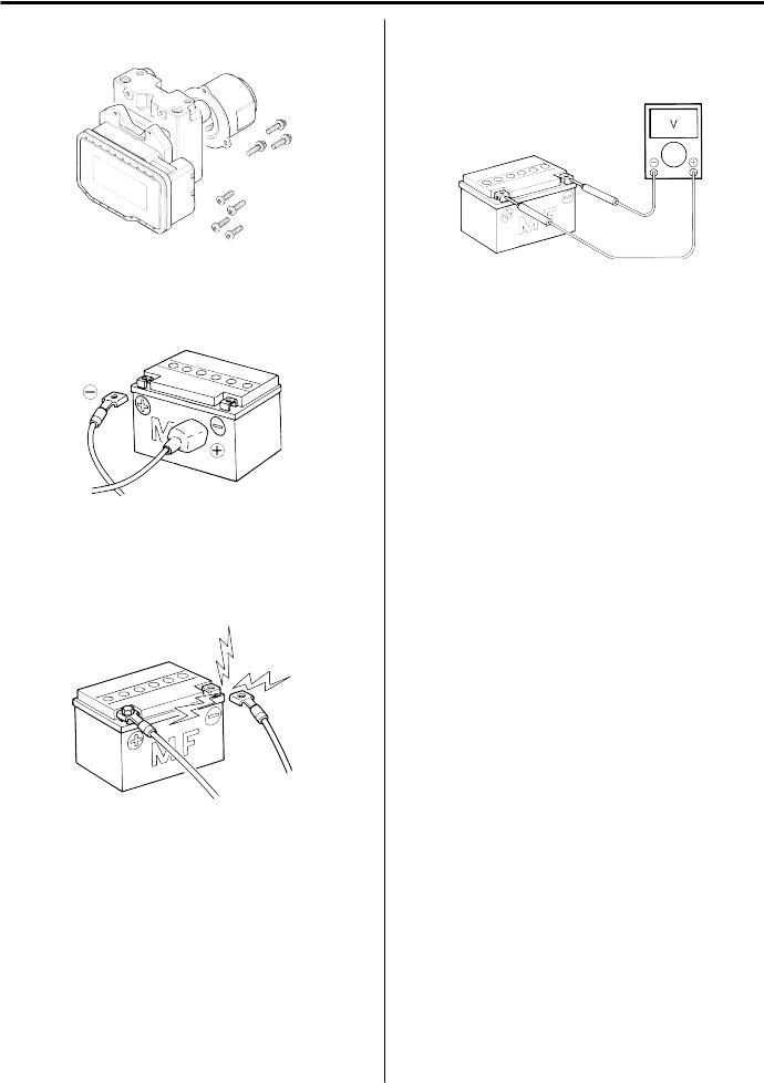
•When removing the battery, disconnect the negative (–) cable first and then the positive cable.
•When reconnecting the battery, connect the positive cable first and then the negative (–) cable, and replace the terminal cover on the positive terminal.
•When performing service to electrical parts, if the service procedures not require use of battery power, disconnect the negative (–) cable the battery.
•When tightening the cylinder head and case bolts and nuts, tighten the larger sizes first. Always tighten the bolts and nuts diagonally from the inside working out and to the specified tighteningtorque.
•Whenever you remove oil seals, gaskets, packing, O-rings, locking washers, selflocking nuts, cotter pins, circlips and certain other parts as specified, be sureto replace them with new ones. Also, before installing these new parts, be sure to remove any left over material from the mating surfaces.
•Never reuse a circlip. When installing a new circlip, take care not to expand the end gap larger than required to slip the circlip over the shaft. After installing a circlip, always ensure that it iscompletely seated in its groove and securely fitted.
Downloaded from www.Manualsbooks.com manuals search
Precautions: 00-2
•Use a torque wrench to tightenfasteners to the specified torque. Wipe off grease and oil if a thread is smeared withthem.
•After reassembling, check partsfor tightness and proper operation.
•Toprotect the environment, do not unlawfully dispose of used motor oil, engine coolant and other fluids:batteries, and tires.
•Toprotect Earth’s natural resources, properly dispose of used motorcycleand parts.
Precautions for Electrical Circuit Service
B649G10000003
When handling the electrical parts or servicing the ABS system, observe the following points for the safety of the system.
Electrical Parts
Connector / Coupler
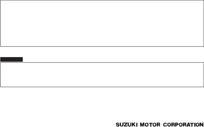
•When connecting a connector, be sure to push it in until a click is felt.
I310G1000001-01
•With a lock type coupler, be sure to release the lock when disconnecting, and push it in fully till the lock works when connecting it.
•When disconnecting the coupler, be sure to hold the coupler body and do not pull the lead wires.
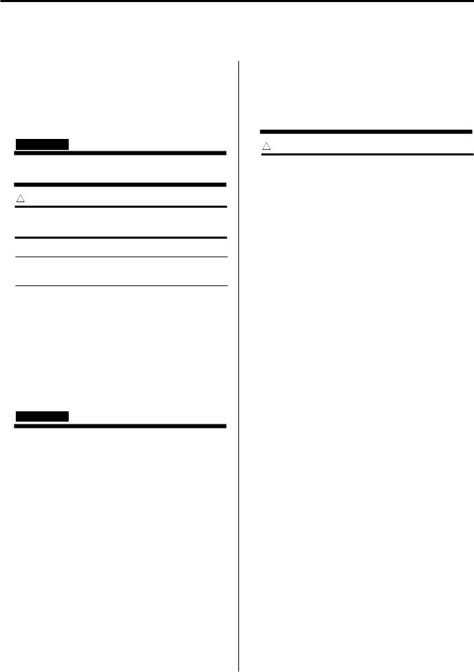
•Inspect each terminal on the connector/couplerfor looseness or bending.
•Inspect each terminal for corrosion and contamination. The terminals must be clean andfree of any foreign material which could impede proper terminal contact.
I310G1000002-01
•Inspect each lead wire circuit for poor connection by shaking it by hand lightly. If any abnormal condition is found, repair or replace.
I310G1000003-01
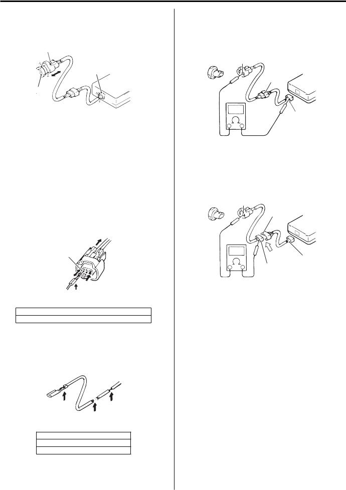
•When taking measurements at electrical connectors using a tester probe, be sure to insert the probefrom the wire harness side (backside) of the connector/ coupler.
2
1
I649G1000013-01
•When connecting meter probe from the terminal side of the coupler (connection from harness side not being possible), use extra care not to force and cause the male terminal to bend or the female terminal to open. Connect the probe as shown to avoid opening of female terminal. Never push in the probe where male terminal is supposed to fit.
Downloaded from www.Manualsbooks.com manuals search
00-3 Precautions:
|
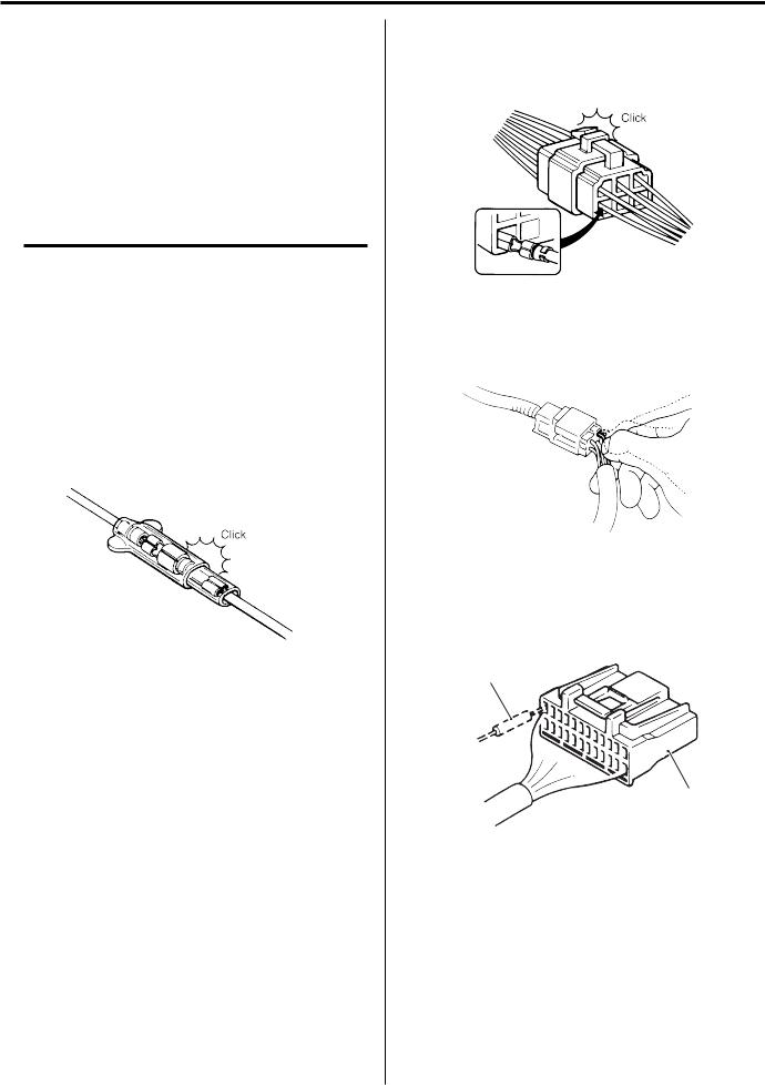
• Check the male connector for bend and female |
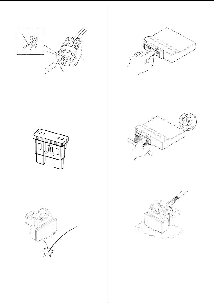
• Be careful not to touch the electrical terminals of the |
|
connector for excessive opening. Also check the |
Ignitor unit and ABS control unit/HU. The static |
|
coupler for locking (looseness), corrosion, dust,etc. |
electricity from your body may damage this part. |
|
4 |
||||||
|
“A” |
||||||
|
3 |
||||||
|
4 |
||||||
|
I649G1000030-01 |
I310G1000008-01 |
|||||
|
3. Coupler |
4. Probe |
“A”: Where male terminal fits |
• When disconnecting and connecting the Ignitor unit |
|||
|
Fuse |
and ABS control unit/HU couplers, make sure toturn |
|||||
|
OFF the ignition switch, or electronic parts mayget |
||||||
|
• When a fuse blows, always investigate thecause, |
||||||
|
damaged. |
||||||
|
correct it and then replace the fuse. |
||||||
|
• Do not use a fuse of a different capacity. |
1 |
|||||
|
• Do not use wire or any other substitute for thefuse. |
||||||
|
I649G1000031-01 |
||||
|
1. Ignition S/W |
||||
|
I649G1000001-01 |
||||
|
• Never allow dust or water to contact the ABScontrol |
||||
|
Ignitor unit / Various sensors / ABS control unit / HU |
unit/HU. |
|||
|
• Since each component is a high-precision part,great |
||||
|
care should be taken not to apply any sharp impacts |
||||
|
during removal and installation. |
I649G1000004-01
I649G1000003-01
Downloaded from www.Manualsbooks.com manuals search
Precautions: 00-4
•The ABS control unit/HU cannot bedisassembled. Replace the whole unit with a new one.
I649G1000005-01
•Battery connection in reverse polarity is strictly prohibited. Such a wrong connection will damage the components of the ABS control unit/HU instantly when reverse power is applied.
I649G1000006-01
•Removing any battery terminal of a running engine is strictly prohibited. The moment such removal is made, damaging counter electromotive force will be applied to the Ignition unit and ABS control unit/HU which may result in serious damage.
I310G1000011-01
•Before measuring voltage at each terminal, check to make sure that battery voltage is 11 V or higher. Terminal voltage check at low battery voltage will lead to erroneous diagnosis.
I310G1000012-01
•Never connect any tester (voltmeter, ohmmeter, or whatever) to the Ignition and ABS control unit/HU when its coupler is disconnected. Otherwise, damage to Ignitor and ABS control unit/HU may result.
•Never connect an ohmmeter to the Ignitor and ABS control unit/HU with its coupler connected. If attempted, damage to Ignitor and ABS control unit/HU or sensors may result.
•Be sure to use a specifiedvoltmeter/ohmmeter. Otherwise, accurate measurements may notbe obtained and personal injury may result.
Electrical Circuit Inspection Procedure
While there are various methods for electrical circuit inspection, described here is a general method to check for open and short circuit using an ohmmeter and a voltmeter.
Open circuit check
Possible causes for the open circuit are as follows. As the cause can exist in the connector/coupler or terminal, they need to be checked carefully.
•Loose connection of connector/coupler
•Poor contact of terminal (due to dirt, corrosion or rust, poor contact tension, entry of foreign object etc.)
•Wire harness being open.
•Poor terminal-to-wire connection.
When checking system circuits including an electronic control unit such as ignitor, ABS control unit/HU, etc., it is important to perform careful check, starting with items which are easier to check.
Downloaded from www.Manualsbooks.com manuals search
00-5 Precautions:
1)Disconnect the negative (–) cable from the battery.
2)Check each connector/coupler at both ends of the circuit being checked for loose connection. Also check for condition of the coupler lock ifequipped.
“A”
“A”
Ignitor
1
I649G1000026-01
|
1. Sensor |
“A”: Check for loose connection |
3)Using a test male terminal, check the female terminals of the circuit being checked for contact tension.
Check each terminal visually for poor contact (possibly caused by dirt, corrosion, rust, entry of foreign object, etc.). At the same time, check to make sure that each terminal is fully inserted in the coupler and locked.
If contact tension is not enough, rectify the contact to increase tension or replace. The terminals must be clean and free of any foreign material which could impede proper terminal contact.
“B”
“C”
I649G1000027-01
“B”: Check contact tension by inserting and removing.
“C”: Check each terminal for bend and proper alignment.
4)Using continuity inspect or voltage check procedure as described below, inspect the wire harness terminals for open circuit and poor connection. Locate abnormality, if any.
“D” “F”
“E”
I649G1000028-01
”D”: Looseness of crimping
“E”: Open
“F”: Thin wire (A few strands left)
Continuity check
1)Measure resistance across coupler “B” (between “A” and “C” in figure).
If no continuity is indicated (infinity or over limit), the circuit is open between terminals “A” and “C”.
“A”
“B” Ignitor
“C”
I649G1000019-03
2)Disconnect the coupler “B” and measureresistance between couplers “A” and “B-1”.
If no continuity is indicated, the circuit is open between couplers “A” and “B-1”. If continuity is indicated, there is an open circuit between couplers “B-2” and “C” or an abnormality in coupler “B-2” or coupler “C”.
“A”
“B-2”
Ignitor
“B” “C”
“B-1”
I649G1000029-02
Voltage check
If voltage is supplied to the circuit being checked, voltage check can be used as circuit check.
1)With all connectors/couplers connected andvoltage applied to the circuit being checked, measure voltage between each terminal and bodyground.
2)If measurements were taken as shown in figureat the right and results are as listed below, it means that the circuit is open between terminals “A” and “B”.
Voltage between
“A” and body ground: Approx. 5V “B” and body ground: Approx. 5V “C” and body ground: 0 V
Downloaded from www.Manualsbooks.com manuals search
![]()
Precautions: 00-6
3)Also, if measured values are as listed below, a resistance (abnormality) exists which causes the voltage drop in the circuit between terminals “A” and “B”.
Voltage between
“A” and body ground: Approx. 5 V
“B” and body ground: Approx. 5 V – 2 V voltage drop
“C” and body ground: 3 V – 2 V voltage drop
“A”
Ignitor
“B”
“C”
5V
|
5V |
||
|
0V |
5V |
|
|
“A” |
“B” “C” |
I649G1000021-02
Short circuit check (Wire harness to ground)
1)Disconnect the negative (–) cable from thebattery.
2)Disconnect the connectors/couplers at both endsof the circuit to be checked.
NOTE
If the circuit to be checked branches to other parts as shown, disconnect all connectors/ couplers of those parts. Otherwise, diagnosis will be misled.
3)Measure resistance between terminal at one endof circuit (“A” terminal in figure) and body ground. If continuity is indicated, there is a short circuit to ground between terminals “A” and “C”.
“A”
“D”
“B” Ignitor
“C”
“E”
5V
“A” “C”
I649G1000022-02
|
“D”: To other parts |
“E”: Other parts |
4)Disconnect the connector/coupler included incircuit (coupler “B”) and measure resistance between terminal “A” and body ground. If continuity is indicated, the circuit is shorted to the ground between terminals “A” and “B”.
“A”
“D”
Ignitor
“B” “C”
I649G1000023-02
“D”: To other parts
Downloaded from www.Manualsbooks.com manuals search
00-7 Precautions:
|
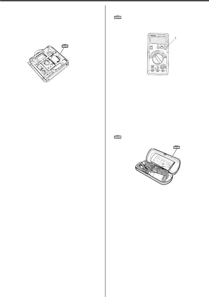
Using The Multi-Circuit Testers |
• After using the tester, turn the power off. |
|
|
• |
Use the Suzuki multi-circuit tester set. |
Special tool |
|
• |
Use well-charged batteries in the tester. |
: 09900–25008 (Multi-circuit tester set) |
•Be sure to set the tester to the correct testingrange.
Special tool
 (A): 09900–25008 (Multi-circuit tester set)
(A)
|
I649G1000002-01 |
|||
|
I649G1000024-02 |
NOTE |
||
|
Using the testers |
|||
|
• When connecting the multi-circuit tester, |
|||
|
• Incorrectly connecting the (+) and (–) probesmay |
use the needle pointed probe to the back |
||
|
cause the inside of the tester to burnout. |
side of the lead wire coupler andconnect |
||
|
• If the voltage and current are not known,make |
the probes of tester to them. |
||
|
• Use the needle pointed probe to prevent |
|||
|
measurements using the highest range. |
|||
|
• When measuring the resistance with themulti-circuit |
the rubber of the water proof couplerfrom |
||
|
damage. |
|||
|
tester (1), will be shown as 10.00 M and “1” |
|||
|
flashes in the display. |
|||
|
Special tool |
|||
|
• Check that no voltage is applied before making the |
|||
|
(A): 09900–25009 (Needle pointed probe set) |
|||
|
measurement. If voltage is applied the tester maybe |
|||
|
damaged. |
(A) |
||
I649G1000025-02
Downloaded from www.Manualsbooks.com manuals search

Table of Contents 0- i
Section 0
General Information
0
CONTENTS
|
General Information………………………………. |
0A-1 |
|
General Description……………………………………… |
0A-1 |
|
Symbols …………………………………………………….. |
0A-1 |
|
Abbreviations ……………………………………………… |
0A-2 |
|
Vehicle Side View ……………………………………….. |
0A-3 |
|
Vehicle Identification Number ……………………….. |
0A-4 |
|
Fuel and Oil Recommendation ……………………… |
0A-4 |
|
BREAK-IN Procedures…………………………………. |
0A-4 |
|
CylinderIdentification…………………………………… |
0A-5 |
|
Country and Area Codes ……………………………… |
0A-5 |
|
Wire Color Symbols …………………………………….. |
0A-5 |
|
Warning, Caution and Information |
|
|
Labels Location…………………………………………. |
0A-6 |
|
ComponentLocation……………………………………. |
0A-7 |
|
Electrical Components Location ……………………. |
0A-7 |
|
Specifications………………………………………………. |
0A-9 |
|
Specifications ……………………………………………… |
0A-9 |
|
Special Tools and Equipment……………………… |
0A-11 |
|
Special Tools ……………………………………………. |
0A-11 |
|
Maintenance and Lubrication…………….. |
0B-1 |
|
Precautions………………………………………………….. |
0B-1 |
|
Precautions for Maintenance ………………………… |
0B-1 |
|
General Description……………………………………… |
0B-1 |
|
Recommended Fluids and Lubricants…………….. |
0B-1 |
|
Scheduled Maintenance……………………………….. |
0B-2 |
|
Periodic Maintenance Schedule Chart……………. |
0B-2 |
|
Lubrication Points ……………………………………….. |
0B-3 |
|
Repair Instructions………………………………………. |
0B-4 |
|
Air Cleaner Element Removal and Installation…. |
0B-4 |
|
Air Cleaner Element Inspection and Cleaning …. |
0B-4 |
|
Spark Plug Removal and Installation……………… |
0B-5 |
|
Spark Plug Inspection and Cleaning………………. |
0B-6 |
|
Exhaust Pipe Bolt and Muffler Mounting Bolt |
|
|
Inspection…………………………………………………. |
0B-6 |
|
Valve Clearance Inspection and Adjustment …… |
0B-7 |
|
Fuel Line Inspection…………………………………….. |
0B-8 |
|
Engine Oil and Filter Replacement…………………… |
0B-9 |
|
Throttle Cable Play Inspection |
|
|
and Adjustment ……………………………………….. |
0B-10 |
|
Engine Idle Speed Inspection |
|
|
and Adjustment……………………………………….. |
0B-11 |
|
Throttle Valve Synchronization……………………. |
0B-11 |
|
PAIR System Inspection …………………………….. |
0B-11 |
|
Clutch System Inspection……………………………. |
0B-11 |
|
Clutch Hose Replacement ………………………….. |
0B-12 |
|
Air Bleeding from Clutch Fluid Circuit …………… |
0B-12 |
|
Clutch Fluid Replacement …………………………… |
0B-12 |
|
Drive Chain Inspection and Adjustment………… |
0B-12 |
|
Drive Chain Cleaning and Lubricating…………… |
0B-13 |
|
Brake System Inspection ……………………………. |
0B-13 |
|
Rear Brake Light Switch Adjustment…………….. |
0B-15 |
|
Brake Hose Replacement…………………………… |
0B-15 |
|
Air Bleeding from Brake Fluid Circuit ……………. |
0B-15 |
|
Brake Fluid Replacement……………………………. |
0B-15 |
|
Tire Inspection…………………………………………… |
0B-15 |
|
Steering System Inspection………………………… |
0B-16 |
|
Front Fork Inspection …………………………………. |
0B-16 |
|
Rear Suspension Inspection……………………….. |
0B-16 |
|
Chassis Bolt and Nut Inspection ………………….. |
0B-17 |
|
Compression Pressure Check …………………….. |
0B-18 |
|
Oil Pressure Check……………………………………. |
0B-18 |
|
Specifications…………………………………………….. |
0B-19 |
|
Tightening Torque Specifications…………………. |
0B-19 |
|
Special Tools and Equipment……………………… |
0B-19 |
|
Recommended Service Material………………….. |
0B-19 |
|
SpecialTool……………………………………………… |
0B-19 |
|
Service Data……………………………………… |
0C-1 |
|
Specifications………………………………………………. |
0C-1 |
|
Service Data……………………………………………….. |
0C-1 |
|
Tightening Torque Specifications…………………… |
0C-7 |
Downloaded from www.Manualsbooks.com manuals search

0A-1 General Information:
General Information
General Description
Symbols
B649G10101001
Listed in the table below are the symbols indicating instructions and other information necessary for servicing. The meaning of each symbol is also included in the table.
Torque control required.
Data beside it indicates specified torque. Apply oil.
Use engine oil unless otherwise specified. Apply molybdenum oil solution
(Mixture of engine oil and SUZUKl MOLY PASTE in a ratio of 1:1). Apply SUZUKI SUPER GREASE “A” or equivalent.
99000-25010
Apply SUZUKI MOLY PASTE or equivalent. 99000-25140
Apply SUZUKI SILICONE GREASE or equivalent. 99000-25100
Apply THERMO-GREASE or equivalent. 99000-59029
Apply SUZUKI BOND “1207B” or equivalent. 99000-31140
Apply SUZUKI BOND “1215” or equivalent. 99000-31110
Apply THREAD LOCK SUPER “1303” or equivalent. 99000-32030
Apply THREAD LOCK SUPER “1322” or equivalent. 99000-32110
Apply THREAD LOCK “1342” or equivalent. 99000-32050
Apply THREAD LOCK SUPER “1360” or equivalent. 99000-32130
Use fork oil or equivalent. 99000-99001-SS8
Apply or use brake fluid.
Measure in voltage range.
Measure in resistance range.
Measure in current range.
Measure in diode test range.
Measure in continuity test range.
Use special tool.
Indication of service data.
Do not reuse.
Note on reassembly.
Downloaded from www.Manualsbooks.com manuals search

General Information: 0A-2
|
Abbreviations |
H: |
|
|
B649G10101002 |
HC: Hydrocarbons |
|
|
A: |
I: |
|
|
ABDC: After Bottom Dead Center |
||
|
IG: Ignition |
||
|
ABS: Anti-lock Brake System AC |
||
|
J: |
||
|
Alternating Current |
||
|
ACL: Air Cleaner, Air Cleaner Box |
L: |
|
|
API: American Petroleum Institute |
||
|
LCD: Liquid Crystal Display |
||
|
ATDC: After Top Dead Center A/F: |
||
|
LED: Light Emitting Diode (Malfunction Indicator Lamp) |
||
|
Air Fuel Mixture |
||
|
LH: Left Hand |
||
|
B: |
||
|
M: |
||
|
BBDC: Before Bottom Dead Center |
||
|
Max: Maximum |
||
|
BTDC: Before Top Dead Center B+: |
||
|
MIL: Malfunction Indicator Lamp (LED) |
||
|
Battery Positive Voltage |
||
|
Min: Minimum |
||
|
C: |
||
|
N: |
||
|
CKP Sensor: Crankshaft Position Sensor (CKPS) |
||
|
NOx: Nitrogen Oxides |
||
|
CKT: Circuit |
||
|
O: |
||
|
CLP Switch: Clutch Lever Position Switch (Clutch |
||
|
OHC: Over Head Camshaft |
||
|
Switch) |
||
|
OPS: Oil Pressure Switch P: |
||
|
CO: Carbon Monoxide |
||
|
PCV: Positive Crankcase Ventilation (Crankcase |
||
|
CPU: Central Processing Unit |
||
|
Breather) |
||
|
D: |
||
|
R: |
||
|
DC: Direct Current |
||
|
RH: Right Hand |
||
|
DMC: Dealer Mode Coupler |
||
|
ROM: Read Only Memory |
||
|
DOHC: Double Over Head Camshaft |
||
|
S: |
||
|
DRL: Daytime Running Light |
||
|
SAE: Society of Automotive Engineers |
||
|
F: |
||
|
T: |
||
|
FTPC Valve: Fuel Tank Pressure Control Valve |
||
|
TP Sensor: Throttle Position Sensor (TPS) |
||
|
G: |
||
|
GEN: Generator |
||
|
GND: Ground |
||
|
GP Switch: Gear Position Switch |
||
Downloaded from www.Manualsbooks.com manuals search

0A-3 General Information:
Vehicle Side View
B649G10101003
NOTE
Difference between photographs and actual motorcycles may exist depending on the markets.
SUZUKI GSF1200 (2006-model)
Right Side
I649G1010008-01
Left Side
I649G1010009-01
SUZUKI GSF1200S (2006-model)
Right Side
I649G1010005-06
Left Side
I649G1010006-05
Downloaded from www.Manualsbooks.com manuals search

General Information: 0A-4
Vehicle Identification Number
B649G10101004
The frame serial number or V.I.N. (Vehicle Identification Number) “A” is stamped on the right side of the steering head pipe. The engine serial number “B” is located on the right side of the crankcase. These numbers are required especially for registering the machine and ordering spare parts.
“A”
I649G1010001-02
“B”
I649G1010002-03
Fuel and OilRecommendation
B649G10101005
Fuel (For USA)
Use only unleaded gasoline of at least 87 pump octane (R/2 + M/2) or 91 octane or higher rated by the research method.
Gasoline containing MTBE (Methyl Tertiary Butyl Ether), less than 10% ethanol, or less than 5% methanol with appropriate cosolvents and corrosion inhibitor is permissible.
Fuel (For Other Countries)
Gasoline used should be graded 91 octane (Research Method) or higher. Unleaded gasoline is recommended.
Engine Oil
Oil quality is a major contributor to your engine’s performance and life. Always select good quality engine oil. Use of SF/SG or SH/SJ in API with MA in JASO. Suzuki recommends the use of SAE 10W-40 engine oil. If SAE 10W-40 engine oil is not available, select an alternative according to the chart.
I310G1010005-01
Brake Fluid
Specification and classification: DOT4
! WARNING
Since the brake system of this motorcycle is filled with a glycol-based brake fluid by the manufacturer, do not use or mix different types of fluid such as silicone-based and petroleum-based fluid for refilling the system, otherwise serious damage will result.
Do not use any brake fluid taken from old or used or unsealed containers.
Never reuse brake fluid left over from a previous servicing, which has been stored for a long period.
Front Fork Oil
Use fork oil SS8 or an equivalent fork oil.
BREAK-IN Procedures
B649G10101007
During manufacture only the best possible materials are used and all machined parts are finished to a very high standard but it is still necessary to allow the moving parts to “BREAK-IN” before subjecting the engine to maximum stresses. The future performance and reliability of the engine depends on the care and restraint exercised during its early life. The general rules are asfollows.
1)Keep to these break-in engine speed limits:
Speed limits
Initial 800 km: Below 5 500 r/min Up to 1 600 km: Below 8 000 r/min Over 1 600 km: Below 11 000 r/min
2)Upon reaching an odometer reading of 1 600 km (1 000 miles) you can subject the motorcycle to full throttle operation. However, do not exceed 11 000r/ min at any time.
Downloaded from www.Manualsbooks.com manuals search
0A-5 General Information:
Cylinder Identification
B649G10101008
The four cylinders of this engine are identified as No.1, 2, 3 and No.4 cylinder, as counted from left to right (as viewed by the rider on the seat).
I649G1010010-01
Country and Area Codes
B649G10101009
The following codes stand for the applicable country(- ies) and area(-s).
|
Code |
Country |
Effective Frame No. |
|
|
or Area |
|||
|
GSF1200 K6 |
U.K. |
JS1CB112200100001 – |
|
|
(E-02) |
|||
|
GSF1200 K6 |
E.U. |
JS1CB112100100001 – |
|
|
(E-19) |
|||
|
GSF1200S K6 |
U.K. |
JS1CB111200100001 – |
|
|
(E-02) |
|||
|
GSF1200S K6 |
E.U. |
JS1CB111100100001 – |
|
|
(E-19) |
|||
|
GSF1200S K6 |
Australia |
JS1CB121300100001 – |
|
|
(E-24) |
|||
|
GSF1200S K6 |
Canada |
JS1GV79A 62100001 – |
|
|
(E-28) |
Wire Color Symbols
|
B649G10101010 |
|||
|
Symbol |
Wire Color |
Symbol |
Wire Color |
|
B |
Black |
Bl/B |
Blue with Black tracer |
|
Bl |
Blue |
Br/B |
Brown with Black tracer |
|
Br |
Brown |
G/B |
Green with Black tracer |
|
Dbr |
Dark brown |
G/Bl |
Green with Blue tracer |
|
Dg |
Dark green |
G/Y |
Green with Yellow tracer |
|
G |
Green |
O/G |
Orange with Green tracer |
|
Lg |
Light green |
O/R |
Orange with Red tracer |
|
W |
White |
O/W |
Orange with White tracer |
|
Y |
Yellow |
O/Y |
Orange with Yellow tracer |
|
B/Bl |
Black with Blue tracer |
P/B |
Pink with Black tracer |
|
B/Br |
Black with Brown tracer |
R/B |
Red with Black tracer |
|
B/G |
Black with Green tracer |
R/W |
Red with White tracer |
|
B/O |
Black with Orange tracer |
W/B |
White with Black tracer |
|
B/R |
Black with Red tracer |
Y/B |
Yellow with Black tracer |
|
B/W |
Black with White tracer |
Y/W |
Yellow with White tracer |
|
B/Y |
Black with Yellow tracer |
Downloaded from www.Manualsbooks.com manuals search
General Information: 0A-6
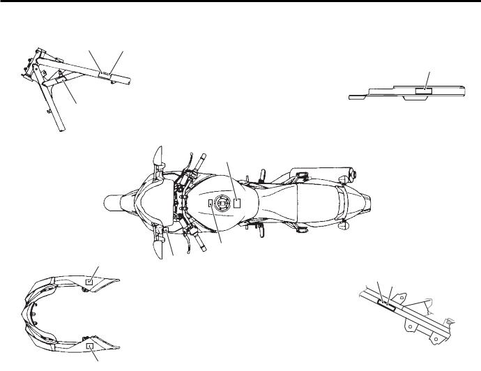
Warning, Caution and Information Labels Location
|
B649G10101011 |
||
|
[A] |
1 |
[C] |
|
2 |
6
8
7
|
3 |
|||
|
5 |
|||
|
4 |
|||
|
[B] |
[D] |
10 |
|
|
9 |
4
I649G1010011-04
|
GSF1200 |
GSF1200S |
||
|
1. |
Noise label |
— |
For E-24 |
|
2. |
Information label |
— |
For E-28 |
|
3. |
Fuel caution label |
For E-02 |
For E-02, 24 |
|
4. |
Screen label |
— |
For E-02, 19, 24, 28 |
|
5. |
Warning steering label |
— |
For E-02, 19, 24, 28 |
|
6. |
Tire information label |
For E-02, 19 |
For E-02, 19, 24, 28 |
|
7. |
General warning label |
For E-02, 19 |
For E-02, 19, 24, 28 |
|
8. |
ICES Canada label |
— |
For E-28 |
|
9. |
I.D. plate |
For E-02, 19 |
For E-02, 19, 24 |
|
10. |
Safety plate |
— |
For E-28 |
|
[A]: |
Frame head (Left side) |
||
|
[B]: |
Cowling body |
||
|
[C]: |
Chain cover |
||
|
[D]: |
Frame side tube (Right side) |
||
Downloaded from www.Manualsbooks.com manuals search
0A-7 General Information:
Component Location
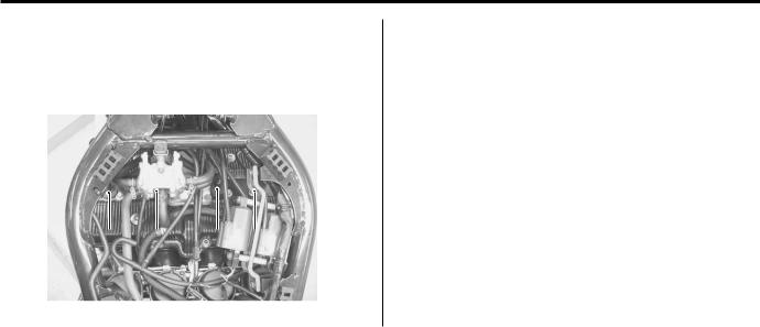
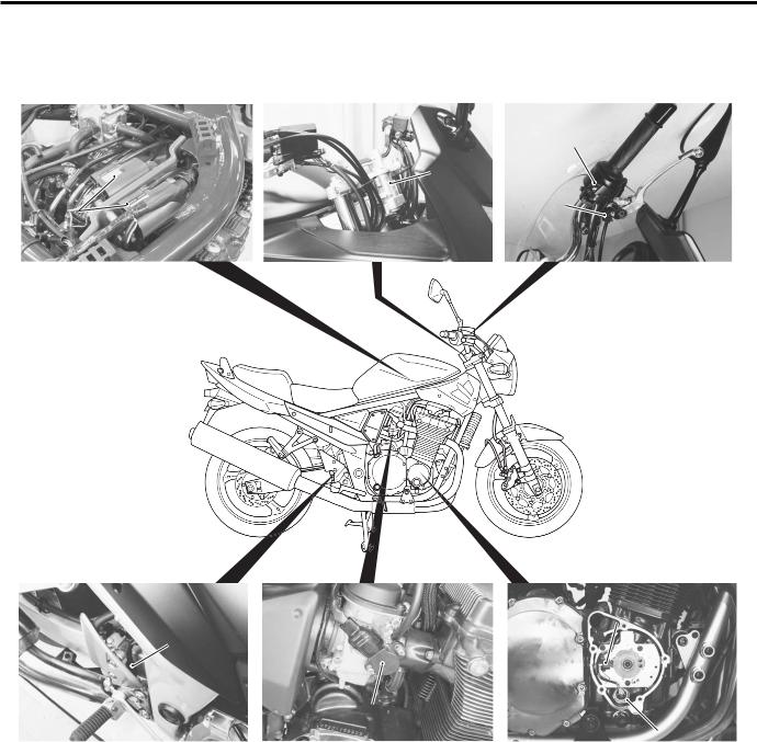
Electrical ComponentsLocation
B649G10103001
3
|
7 |
||||||||||
|
5 |
||||||||||
|
6 |
||||||||||
|
8 |
||||||||||
|
I649G1010003-05 |
||||||||||
|
1. |
Ignition coil |
3. |
Handlebar switch (RH) |
5. |
Rear brake light switch |
7. |
CKP sensor |
|||
|
2. |
Ignition switch |
4. |
Front brake light switch |
6. |
Throttle position sensor |
8. |
Oil pressure switch |
|||
Downloaded from www.Manualsbooks.com manuals search
![]()
General Information: 0A-8
12
9
13 14
16
15
|
21 |
||||||||||||
|
20 |
19 |
|||||||||||
|
17 |
18 |
23 |
22 |
|||||||||
|
I649G1010004-04 |
||||||||||||
|
9. |
Clutch lever position switch |
14. |
Main fuse |
19. |
Generator |
|||||||
|
10. |
Handlebar switch (LH) |
15. |
Battery |
20. |
Carburetor heater (For E-02, 19) |
|||||||
|
11. Fuse box |
16. Ignitor |
21. Speed sensor |
||||||||||
|
12. |
Turn signal/Side-stand relay |
17. |
Horn |
22. |
Gear position switch |
|||||||
|
13. |
Starter relay |
18. |
Starter motor |
23. |
Side-stand switch |
|||||||
Downloaded from www.Manualsbooks.com manuals search

0A-9 General Information:
Specifications
Specifications
|
NOTE |
B649G10107001 |
||||||
|
These specifications are subject to change without notice. |
|||||||
|
Dimensions and dry mass |
|||||||
|
Item |
Specification |
Remark |
|||||
|
Overall length |
2 130 mm (83.9 in) |
||||||
|
Overall width |
790 mm (31.1 in) |
||||||
|
Overall height |
1 095 mm (43.1 in) |
GSF1200 |
|||||
|
1 235 mm (48.6 in) |
GSF1200S |
||||||
|
Wheelbase |
1480 mm (58.3 in) |
||||||
|
Ground clearance |
135 mm (5.3 in) |
||||||
|
Seat height |
785/805 mm (30.9/31.7 in) |
Low/High |
|||||
|
Dry mass |
212 kg (467 lbs) |
GSF1200 |
|||||
|
215 kg (474 lbs) |
GSF1200S |
||||||
|
Engine |
|||||||
|
Item |
Specification |
Remark |
|||||
|
Type |
4-stroke, air-cooled, DOHC |
||||||
|
Number of cylinders |
4 |
||||||
|
Bore |
79.0 mm (3.110 in) |
||||||
|
Stroke |
59.0 mm (2.323 in) |
||||||
|
Displacement |
1 157 cm3 (70.6 cu. in) |
||||||
|
Compression ratio |
9.5 : 1 |
||||||
|
Carburetor |
MIKUNI BSR36 |
||||||
|
Air cleaner |
Non-woven fabric element |
||||||
|
Starter system |
Electric |
||||||
|
Lubrication system |
Wet sump |
||||||
|
Idle speed |
1 300 100 r/min |
E-28 |
|||||
|
1 200 100 r/min |
Others |
||||||
|
Drive train |
|||||||
|
Item |
Specification |
Remark |
|||||
|
Clutch |
Wet multi-plate type |
||||||
|
Transmission |
5-speed constant mesh |
||||||
|
Gearshift pattern |
1-down, 4-up |
||||||
|
Primary reduction ratio |
1.565 (72/46) |
||||||
|
Low |
2.384 (31/13) |
||||||
|
2nd |
1.631 (31/19) |
||||||
|
Gear ratios |
3rd |
1.250 (25/20) |
|||||
|
4th |
1.045 (23/22) |
||||||
|
Top |
0.913 (21/23) |
||||||
|
Final reduction ratio |
3.000 (45/15) |
||||||
|
Drive chain |
RK GB50GSVZ3, 116 links |
Downloaded from www.Manualsbooks.com manuals search
|
General Information: 0A-10 |
||||||
|
Chassis |
||||||
|
Item |
Specification |
Remark |
||||
|
Front suspension |
Telescopic, coil spring, oil damped |
|||||
|
Rear suspension |
Link type, coil spring, oil damped |
|||||
|
Front suspension stroke |
130 mm (5.1 in) |
|||||
|
Rear wheel travel |
136 mm (5.4 in) |
|||||
|
Caster |
35 (right & left) |
|||||
|
Trail |
25 20’ |
|||||
|
Steering angle |
104 mm (4.10 in) |
|||||
|
Turning radius |
2.8 m (9.2 ft) |
|||||
|
Front brake |
Disc brake, twin |
|||||
|
Rear brake |
Disc brake |
|||||
|
Front tire size |
120/70ZR17M/C (58W), tubeless |
|||||
|
Rear tire size |
180/55ZR17M/C (73W), tubeless |
|||||
|
Electrical |
||||||
|
Item |
Specification |
Remark |
||||
|
lgnition type |
Electronic ignition (Transistorized) |
|||||
|
lgnition timing |
7 B.T.D.C. at 1 300 r/min |
E-28 |
||||
|
7 B.T.D.C. at 1 200 r/min |
Others |
|||||
|
Spark plug |
NGK JR9B |
|||||
|
Battery |
12 V 36 kC (10 Ah)/10 HR |
|||||
|
Generator |
Three-phase A.C. generator |
|||||
|
Main fuse |
30 A |
|||||
|
Fuse |
10/10/15/15/10 A |
|||||
|
Headlight |
12 V 60/55 W (H4) |
GSF1200 |
||||
|
12 V 55 W (H7) + 12 V 55 W (H7) |
GSF1200S |
|||||
|
Position light |
12 V 5 W |
GSF1200 |
||||
|
12 V 5W x 2 |
GSF1200S |
|||||
|
Turn signal light |
12 V 21 W x 4 |
|||||
|
Brake light/Taillight |
12 V 21/5 W |
|||||
|
License plate light |
12 V 5 W |
|||||
|
Speedometer light |
LED |
|||||
|
Tachometer light |
LED |
|||||
|
Neutral indicator light |
LED |
|||||
|
High beam indicator light |
LED |
|||||
|
Turn signal indicator light |
LED |
|||||
|
Oil pressure indicator light |
LED |
|||||
|
Capacities |
||||||
|
Item |
Specification |
Remark |
||||
|
Fuel tank |
Including reserve |
20.0 L (5.3/4.4 US/lmp gal) |
||||
|
Reserve |
4.4 L (1.2/1.0 US/lmp gal) |
|||||
|
Engine oil |
Oil change |
3 300 ml (3.4/2.9 US/lmp qt) |
||||
|
With filter change |
3 500 ml (3.6/3.0 US/lmp qt) |
|||||
|
Overhaul |
4 600 ml (4.9/4.0 US/lmp qt) |
Downloaded from www.Manualsbooks.com manuals search

0A-11 General Information:
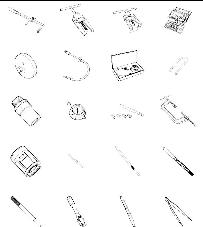
Special Tools and Equipment
Special Tools
|
B649G10108001 |
|||
|
TT09900-06106-01 |
TT09900-06107-02 |
TT09900-06108-02 |
TT09900-20102-01 |
|
09900-06106 |
09900-06107 |
09900-06108 |
09900-20102 |
|
Snap ring pliers |
Snap ring pliers |
Snap ring pliers |
Vernier calipers |
|
(1/20 mm, 200 mm) |
|||
|
TT09900-20202-01 |
TT09900-20204-01 |
TT09900-20205-01 |
TT09900-20508-01 |
|
09900-20202 |
09900-20204 |
09900-20205 |
09900-20508 |
|
Micrometer |
Micrometer |
Micrometer |
Cylinder gauge set |
|
(1/100 mm, 25 – 50 mm) |
(1/100 mm, 75 – 100 mm) |
(1/1 000 mm, 0 – 25 mm) |
(1/100 mm, 40 – 80 mm) |
|
TT09900-20602-01 |
TT09900-20605-01 |
TT09900-20607-01 |
TT09900-20701-01 |
|
09900-20602 |
09900-20605 |
09900-20607 |
09900-20701 |
|
Dial gauge |
Dial calipers |
Dial gauge |
Magnetic stand |
|
(1/1 000 mm) |
(1/100 mm, 10 – 34 mm) |
(1/100 mm) |
|
|
TT09900-20803-01 |
TT09900-20805-01 |
TT09900-21304-01 |
TT09900-22301-01 |
|
09900-20803 |
09900-20805 |
09900-21304 |
09900-22301 |
|
09900-22302 |
|||
|
Thickness gauge |
Tire depth gauge |
V-block set |
Plastigauge |
|
(100 mm) |
|||
|
TT09900-22403-01 |
TT09900-25008-01 |
TT09900-25009-01 |
TT09910-60611-01 |
|
09900-22403 |
09900-25008 |
09900-25009 |
09910-60611 |
|
Small bore gauge |
Multi circuit tester set |
Needle pointed probe set |
Universal clamp wrench |
|
(18 – 35 mm) |
Downloaded from www.Manualsbooks.com manuals search
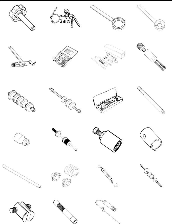
General Information: 0A-12
|
TT09913-50121-01 |
TT09913-60910-01 |
TT09913-61510-01 |
TT09913-70210-01 |
|
09913-50121 |
09913-60910 |
09913-61510 |
09913-70210 |
|
Oil seal remover |
Bearing remover |
Bearing remover |
Bearing installer set |
|
TT09915-40610-01 |
TT09915-63210-01 |
TT09915-64510-01 |
TT09915-74521-01 |
|
09915-40610 |
09915-63210 |
09915-64510 |
09915-74521 |
|
Oil filter wrench |
Compression gauge adaptor |
Compression gauge set |
Oil pressure gauge hose |
|
TT09915-74540-01 |
TT09915-77331-01 |
TT09916-10911-01 |
TT09916-14510-02 |
|
09915-74540 |
09915-77331 |
09916-10911 |
09916-14510 |
|
Oil pressure gauge |
Meter (for high pressure) |
Valve lapper set |
Valve spring compressor |
|
attachment |
|||
|
TT09916-14910-01 |
TT09916-34542-01 |
TT09916-34570-01 |
TT09916-34580-01 |
|
09916-14910 |
09916-34542 |
09916-34570 |
09916-34580 |
|
Valve lifter attachment |
Reamer handle |
Valve guide reamer |
Valve guide reamer |
|
(4.95 mm) |
(10.8 mm) |
||
|
TT09916-44310-01 |
TT09916-74521-01 |
TT09916-74550-01 |
TT09916-84511-01 |
|
09916-44310 |
09916-74521 |
09916-74550 |
09916-84511 |
|
Valve guide remover/ |
Holder body |
Band (73 – 85 mm) |
Tweezers |
|
installer |
Downloaded from www.Manualsbooks.com manuals search
0A-13 General Information:
|
TT09917-14920-01 |
TT09917-47010-01 |
TT09920-34820-01 |
TT09920-34840-01 |
|
09917-14920 |
09917-47010 |
09920-34820 |
09920-34840 |
|
Valve adjuster driver |
Vacuum pump gauge |
Clutch pressure plate holder |
Starter clutch holder |
|
TT09920-53740-02 |
TT09921-20240-01 |
TT09922-22711-01 |
TT09923-73210-01 |
|
09920-53740 |
09921-20240 |
09922-22711 |
09923-73210 |
|
Clutch sleeve hub holder |
Bearing remover set |
Drive chain cutting and |
Bearing remover |
|
joining tool |
|||
|
TT09924-84510-01 |
TT09924-84521-01 |
TT09930-10121-01 |
TT09930-11920-01 |
|
09924-84510 |
09924-84521 |
09930-10121 |
09930-11920 |
|
Bearing installer set |
Bearing installer set |
Spark plug wrench set |
Torx bit (JT 40H) |
|
TT09930-11940-01 |
TT09930-30102-01 |
TT09930-30721-01 |
TT09940-14911-01 |
|
09930-11940 |
09930-30102 |
09930-30721 |
09940-14911 |
|
Bit holder |
Sliding shaft |
Rotor remover |
Steering stem nut wrench |
|
TT09940-52841-01 |
TT09940-52861-01 |
TT09940-92720-01 |
TT09941-34513-01 |
|
09940-52841 |
09940-52861 |
09940-92720 |
09941-34513 |
|
Inner rod holder |
Front fork oil seal installer |
Spring scale |
Steering race installer |
|
TT09941-54911-01 |
TT09941-74911-01 |
TT09943-74111-01 |
|
|
09941-54911 |
09941-74911 |
09943-74111 |
|
|
Bearing outer race remover |
Steering bearing installer |
Fork oil level gauge |
|
Downloaded from www.Manualsbooks.com manuals search
Maintenance and Lubrication: 0B-1
Maintenance and Lubrication
Precautions
Precautions for Maintenance
B649G10200001
The “Periodic Maintenance Schedule Chart” lists the recommended intervals for all the required periodic service work necessary to keep the motorcycle operating at peak performance and economy. Maintenance intervals are expressed in terms of kilometers, miles and months for your convenience.
NOTE
More frequent servicing may be required on motorcycles that are used under severe conditions.
General Description
Recommended Fluids and Lubricants
B649G10201001
Refer to “Fuel and Oil Recommendation: in Section 0A”.
Downloaded from www.Manualsbooks.com manuals search

0B-2 Maintenance and Lubrication:
Scheduled Maintenance
Periodic Maintenance Schedule Chart
B649G10205001
NOTE
I = Inspect and clean, adjust, replace or lubricate as necessary.
R = Replace
T = Tighten
|
Interval |
|||||||
|
Item |
km |
1 000 |
6 000 |
12 000 |
18 000 |
24 000 |
|
|
mile |
600 |
4 000 |
7 500 |
11 000 |
14 500 |
||
|
months |
2 |
12 |
24 |
36 |
48 |
||
|
Air cleaner element |
— |
I |
I |
R |
I |
||
|
Exhaust pipe bolts and muffler bolts |
T |
— |
T |
— |
T |
||
|
Valve clearance |
I |
— |
I |
— |
I |
||
|
Spark plugs |
— |
I |
R |
I |
R |
||
|
Fuel line |
— |
I |
I |
I |
I |
||
|
Engine oil |
R |
R |
R |
R |
R |
||
|
Engine oil filter |
R |
— |
— |
R |
— |
||
|
Throttle cable play |
I |
I |
I |
I |
I |
||
|
Engine idle speed |
I |
I |
I |
I |
I |
||
|
Throttle valve synchronization |
— |
— |
I |
— |
I |
||
|
PAIR (air supply) system |
— |
— |
I |
— |
I |
||
|
Clutch hose |
— |
I |
I |
I |
I |
||
|
Replace every 4 years. |
|||||||
|
Clutch fluid |
— |
I |
I |
I |
I |
||
|
Replace every 2 years. |
|||||||
|
Drive chain |
I |
I |
I |
I |
I |
||
|
Clean and lubricate every 1 000 km (600 mile). |
|||||||
|
Brakes |
I |
I |
I |
I |
I |
||
|
Brake hose |
— |
I |
I |
I |
I |
||
|
Replace every 4 years. |
|||||||
|
Brake fluid |
— |
I |
I |
I |
I |
||
|
Replace every 2 years. |
|||||||
|
Tires |
— |
I |
I |
I |
I |
||
|
Steering |
I |
— |
I |
— |
I |
||
|
Front forks |
— |
— |
I |
— |
I |
||
|
Rear suspension |
— |
— |
I |
— |
I |
||
|
Chassis bolts and nuts |
T |
T |
T |
T |
T |
Downloaded from www.Manualsbooks.com manuals search

Maintenance and Lubrication: 0B-3
Lubrication Points
B649G10205002
Proper lubrication is important for smooth operation and long life of each working part of the motorcycle. Major lubrication points are indicated as follows.
NOTE
•Before lubricating each part, clean off any rusty spots and wipe off any grease, oil, dirt orgrime.
•Lubricate exposed parts which are subject to rust, with a rust preventative spray whenever the motorcycle has been operated under wet or rainy conditions.
1
2
3
|
7 |
||||
|
4 |
5 |
|||
|
6 |
||||
|
I649G1020001-03 |
||||
|
1. |
Brake lever holder and throttle cables |
5. |
Gearshift pivot and left footrest pivot |
|
|
2. |
Brake pedal pivot and right footrest pivot |
6. |
Center stand pivot and spring hook |
|
|
3. |
Clutch lever holder |
7. |
Drive chain |
|
|
4. |
Side-stand pivot and spring hook |
|||
Downloaded from www.Manualsbooks.com manuals search
0B-4 Maintenance and Lubrication:
Repair Instructions
Air Cleaner Element Removal and Installation
B649G10206001
Inspect air cleaner element
Every 6 000 km (4 000 miles, 12 months)
Replace air cleaner element
Every 18 000 km (11 000 miles, 36 months) Removal
1)Remove the fuel tank. Refer to “Carburetor Assembly Removal and Installation: in Section1G”.
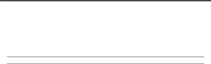
2)Remove the two screws and slide the aircleaner cover backward.
I649G1020002-02
3) Remove the air cleaner element(1).
1
I649G1020003-02
Installation
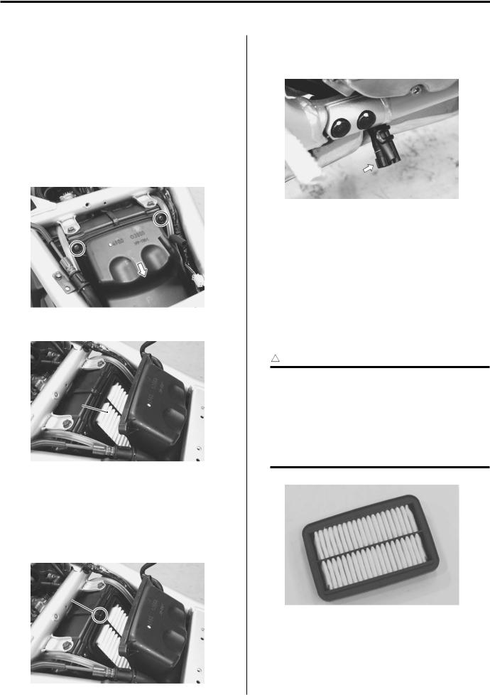
Reinstall the cleaned or new air cleaner element in the reverse order of removal. Pay attention to thefollowing points:
•When installing the air cleaner element into the air cleaner box, make sure that the mark points “A”up.
•After cleaning or installing the air cleaner element, drain water from the air cleaner by removing the drain plug.
I649G1020005-01
Air Cleaner Element Inspection and Cleaning
B649G10206002
Refer to “Air Cleaner Element Removal and Installation: ”.
Inspect air cleaner element
Every 6 000 km (4 000 miles, 12 months)
Replace air cleaner element
Every 18 000 km (11 000 miles, 36 months)
Inspection
Inspect the air cleaner element for clogging.
! CAUTION
If driving under dusty conditions, clean the air cleaner element more frequently. The surest way to accelerate engine wear is to operate the engine without the element or to use a torn element. Make sure that the air cleaner is in good condition at all times. Life of the engine depends largely on this component.
“A”
I649G1020006-01
I649G1020004-02
Downloaded from www.Manualsbooks.com manuals search
![]()
Maintenance and Lubrication: 0B-5
Cleaning
Carefully use compressed air to clean the aircleaner element.
! CAUTION
Always apply compressed air to the inside of the air cleaner element. If compressed air is applied to the outside, dirt will be forced into the pores of the air cleaner element, restricting air flow through the air cleaner element.
I649G1020007-01
Spark Plug Removal and Installation
B649G10206003
Inspect spark plug
Every 6 000 km (4 000 miles, 12 months)
Replace spark plug
Every 12 000 km (7 500 miles, 24months)
Removal
! WARNING
The hot engine can burn you.
Wait until the engine is cool enough to touch.
!
Confirm the thread size and reach when replacing the plug. If the reach is too short, carbon will be deposited on the screw portion of the plug hole and enginedamage may result.
1) Remove the spark plug caps.
I649G1020008-02
2)Remove the spark plugs with the spark plug wrench.
Special tool
 (A): 09930–10121 (Spark plug wrench set)
(A)
I649G1020009-02
Installation
Install the spark plugs in the reverse order of removal. Pay attention to the following points:
! CAUTION
Before tightening the spark plug to the specified torque,carefully turnthespark plug by finger into the threads of the cylinder head to prevent damage the aluminum threads.
•Install the spark plugs to the cylinder heads byfinger tight, and then tighten them to the specifiedtorque.
Tightening torque
Spark plug: 11 N·m (1.1 kgf-m, 8.0 lb-ft)
•Install the spark plug caps onto the spark plugs. Make sure that each spark plug cap is installed in the correct location and direction.
Downloaded from www.Manualsbooks.com manuals search

0B-6 Maintenance and Lubrication:
Spark Plug Inspection and Cleaning
B649G10206004
Refer to “Spark Plug Removal and Installation: ”.
Inspect spark plug
Every 6 000 km (4 000 miles, 12 months)
Replace spark plug
Every 12 000 km (7 500 miles, 24 months)
Heat Range
Check spark plug heat range by observing electrode color.
If it is white or glazed appearing, replace the spark plug with colder type one.
|
Heat range |
||||
|
Standard |
Cold type |
Hot type |
||
|
NGK |
JR9B |
JR10B |
JR8B |
Carbon Deposits
Check to see if there are carbon deposits on the spark plug.
If carbon is deposited, remove it using a spark plug cleaner machine or carefully use a tool with a pointed end.
I649G1020010-01
Spark Plug Gap
Measure the spark plug gap using a thickness gauge. Adjust the spark plug gap if necessary.
Spark plug gap
0.6 – 0.7 mm (0.024 – 0.028 in)
Special tool
 (A): 09900–20803 (Thickness gauge)
Electrodes Condition
Check to see the worn or burnt condition of the electrodes.
If it is extremely worn or burnt, replace the plug. And also replace the plug if it has a broken insulator, damaged thread.
Exhaust Pipe Bolt and Muffler Mounting Bolt Inspection
B649G10206021
Tighten exhaust pipe bolt and muffler mounting bolt Initially at 1 000 km (600 miles, 2 month) and every 12 000 km (7 500 miles, 24 months) thereafter.
Check the exhaust pipe bolts, muffler mounting bolts and nut to the specified torque.
Tightening torque
Exhaust pipe bolt (a): 23 N·m (2.3 kgf-m, 16.5 lb-ft) Muffler mounting bolt (b): 23 N·m (2.3 kgf-m, 16.5 lb-ft)
Muffler connecting bolt (c): 23 N·m (2.3 kgf-m, 16.5 lb-ft)
(a)
(a)
(a)
I649G1020054-03
(b)
 (b)
(b)
(A)
I649G1020053-02
I649G1020011-03
Downloaded from www.Manualsbooks.com manuals search

Maintenance and Lubrication: 0B-7
Valve Clearance Inspection and Adjustment
B649G10206005
Inspect valve clearance
Initially at 1 000 km (600 miles, 2 month) and every 12 000 km (7 500 miles, 24 months) thereafter.
Valve clearance adjustment must be checked and adjusted, a) at the time of periodic inspection, b) when the valve mechanism is serviced, and c) when the camshafts are removed for servicing.
1)Remove the fuel tank. Refer to “Fuel TankRemoval and Installation: in Section 1G”.
2)Remove the frame head covers. (GSF1200) Refer to “Exterior Parts Removal and Installation: in Section 9D”.
3)Remove the PAIR valve. Refer to “PAIRSystem Removal and Installation: in Section 1B”.
4)Remove all the spark plugs. Refer to “SparkPlug Removal and Installation: ”.
5)Remove the breather cover (1).
1
I649G1020066-01
6)Remove the cylinder head cover. Refer to “Engine Top Side Disassembly: in Section 1D”.
NOTE
The valve clearance specification is different for both intake and exhaust valves.
Valve clearance (When cold)
IN.: 0.10 – 0.15 mm (0.004 – 0.006 in) EX.: 0.18 – 0.23 mm (0.007 – 0.009 in)
NOTE
•The camshafts must be at positions “A” or
“B”, in order to check or adjust the valve clearance. Clearance readings should not be taken with the camshafts in any other position than the ones shown.
•The valve clearance should onlybe checked when the engine is cold.
I649G1020012-01
7)Remove the CKP sensor cover. Refer to “CKP Sensor Removal and Installation: in Section1H”.
 Turn the crankshaft clockwise and align the “T” mark on the rotor with the center of the CKP sensor. Also, position the notches “C” on the right end of each camshaft as shown. Then, measure the following valve clearances “D”.
•Cylinder #1: Intake and exhaust valve clearances
•Cylinder #2: Exhaust valve clearance
•Cylinder #3: Intake valve clearance
I649G1020013-02
“C” “C”
I649G1020014-02
“D” “D”
|
“D” |
“D” |
|
|
I649G1020017-02 |
||
|
Camshaft position |
Notch “C” position |
|
|
faces outside |
||
|
Measuring position |
“D” |
Downloaded from www.Manualsbooks.com manuals search

0B-8 Maintenance and Lubrication:
|
9) Insert the thickness gauge between the valve stem |
|||||||||
|
end and adjusting screw on the rocker arm. If the |
|||||||||
|
Camshaft position |
Notch “C” position |
||||||||
|
clearance is out of specification, hold the lock-nut |
faces inside |
||||||||
|
with a wrench and use the special tools to adjust the |
|||||||||
|
Measuring position |
“E” |
||||||||
|
clearance. |
|||||||||
|
12) Turn the crankshaft and recheck the valve |
|||||||||
|
! CAUTION |
|||||||||
|
clearances. |
|||||||||
|
Both the right and left valve clearances |
13) After finishing the valve clearanceadjustment, |
||||||||
|
should be as closely as possible. |
reinstall the following items. |
||||||||
|
a) CKP sensor cover (Refer to “CKP Sensor |
|||||||||
|
Removal and Installation: in Section1H”.) |
|||||||||
|
(B) |
b) Cylinder head cover (Refer to “Engine TopSide |
||||||||
|
Assembly: in Section 1D”.) |
|||||||||
|
(A) |
c) |
Breather cover |
|||||||
|
d) Spark plugs and plug caps (Refer to “SparkPlug |
|||||||||
|
Removal and Installation: ”.) |
|||||||||
|
e) PAIR valve (Refer to “PAIRSystem Removal and |
|||||||||
|
Installation: in Section 1B”.) |
|||||||||
|
f) Frame head covers (for GSF1200) (Referto |
|||||||||
|
“Exterior Parts Removal and Installation: in |
|||||||||
|
I649G1020015-03 |
Section 9D”.) |
||||||||
|
Special tool |
g) |
Fuel tank (Refer to “Fuel Tank Removal and |
|||||||
|
(A) : 09900–20803 (Thickness gauge) (B): |
Installation: in Section 1G”.) |
||||||||
|
09917–14920 (Valve adjusterdriver) |
h) |
Seat (Refer to “Exterior Parts Removaland |
|||||||
|
10) Turn the crankshaft clockwise 360 (one full rotation) |
Installation: in Section 9D”.) |
||||||||
|
and align the “T” mark on the rotor with the center of |
Fuel Line Inspection |
||||||||
|
the CKP sensor. Also, position the notches “C” on |
B649G10206006 |
||||||||
|
the right end of each camshaft as shown. Then, |
|||||||||
|
Inspect fuel line |
|||||||||
|
measure the following valve clearances “E”. |
|||||||||
|
• Cylinder #2: Intake valveclearance |
Every 6 000 km (4 000 miles, 12 months) |
||||||||
|
• Cylinder #3: Exhaust valveclearance |
Inspect the fuel line in the following procedures: |
||||||||
|
• Cylinder #4: Intake and exhaust valveclearances |
1) Remove the seat. Refer to “Exterior PartsRemoval |
||||||||
|
11) Measure the valve clearances of theremaining |
and Installation: in Section 9D”. |
||||||||
|
valves “E” and adjust them if necessary. |
2) Remove the fuel tank mounting bolts. Refer to “Fuel |
||||||||
|
Tank Removal and Installation: in Section 1G”. |
|||||||||
|
“C” |
“C” |
3) Lift up the fuel tank. |
|||||||
|
4) Inspect the fuel hose for damage and fuel leakage. If |
|||||||||
|
any defects are found, the fuel hose must be |
|||||||||
|
replaced. |
|||||||||
|
I649G1020016-03 |
|||||||||
|
“E” |
“E” |
I649G1020065-01
“E” “E”
I649G1020018-02
Downloaded from www.Manualsbooks.com manuals search

Maintenance and Lubrication: 0B-9
Engine Oil and Filter Replacement
B649G10206007
Replace engine oil
Initially at 1 000 km (600 miles, 2 month) and every 6 000 km (4 000 miles, 12 months) thereafter.
Replace oil filter
Initially at 1 000 km (600 miles, 2 month) and every 18 000 km (11 000 miles, 36 months) thereafter.
Oil should be changed while the engine is warm. Oil filter replacement at the above intervals, should be done together with the engine oil change.
Engine Oil Replacement
1)Keep the motorcycle upright.
2)Place an oil pan below the engine, and drainengine oil by removing the oil drain plug (1) and filler cap
(2).
1
I649G1020019-01
2
I649G1020020-01
3)Tighten the oil drain plug (1) to the specified torque, and pour new oil through the oil filler. When performing an oil change (without oil filter replacement), the engine will hold about 3.3 L of oil. Use of SF/SG or SH/SJ in API with MA in JASO.
Tightening torque
Oil drain plug (a): 23 N·m (2.3 kgf-m, 16.5 lb-ft)
1, (a)
I649G1020021-03
4)Start up the engine and allow it to run forseveral minutes at idling speed.
5)Turn off the engine and wait about three minutes, then check the oil level through the inspection window (3). If the level is below the “L” mark, addoil to the “F” mark. If the level is above the “F” mark, drain the oil until the level reaches the “F” mark.
3
I649G1020022-01
Oil Filter Replacement
1)Drain engine oil as described in the engineoil replacement procedure.
2)Remove the oil filter (1) using the special tool.
Special tool
 (A): 09915–40610 (Oil filter wrench)
(A)
1
I649G1020023-02
Downloaded from www.Manualsbooks.com manuals search

0B-10 Maintenance and Lubrication:
|
3) Apply engine oil lightly to the O-ring of new oil filter, |
Throttle Cable Play Inspection and Adjustment |
|
|
before installation. |
B649G10206012 |
|
|
! CAUTION |
Inspect throttle cable play |
|
|
Initially at 1 000 km (6 000 miles, 2 month) and every |
||
|
ONLY USE A GENUINE SUZUKI |
6 000 km (4 000 miles, 12 months) thereafter. |
|
|
MOTORCYCLE OIL FILTER. |
Inspect and adjust the throttle cable play “a” as follows. |
|
|
Other manufacturer’s oil filters may differin |
||
|
Throttle cable play “a” |
||
|
thread specifications (thread diameter and |
||
|
pitch), filtering performance and durability |
2.0 – 4.0 mm (0.08 – 0.16 in) |
|
|
which may lead to engine damage or oil |
||
|
leaks. Also, do not use a genuine Suzuki |
||
|
automobile oil filter on this motorcycle. |
4)Install a new oil filter. Turn it by hand until you feel that the oil filter O-ring contacts the oil filter mounting
|
surface. Then, tighten the oil filter two full turns (or to |
“a” |
||||
|
specified torque) using the special tool. |
|||||
|
NOTE |
|||||
|
To properly tighten the oil filter, use the |
|||||
|
special tool. Never tighten the oil filter by |
I649G1020026-01 |
||||
|
hand only. |
|||||
|
1) Loosen the lock-nut (1) of the throttle pullingcable |
|||||
|
Special tool |
(2). |
||||
|
2) Turn the adjuster(3) in or out until the throttle cable |
|||||
|
(A): 09915–40610 (Oil filter wrench) |
|||||
|
Tightening torque |
play “a” (at the throttle grip) is between 2 – 4 mm |
||||
|
(0.08 – 0.16 in). |
|||||
|
Oil filter (a): 20 N·m (2.0 kgf-m, 14.5 lb-ft) |
|||||
|
3) Tighten the lock-nut (1) while holding theadjuster |
|||||
|
1, (a) |
(3). |
||||
|
(A) |
|||||
|
1 |
3 |
||||
|
2 |
|
I649G1020024-03 |
|||
|
5) Add new engine oil and check the oil level is as |
|||
|
described in the engine oil replacement procedure. |
I649G1020027-01 |
||
|
Necessary amount of engine oil |
! WARNING |
||
|
Oil change: 3.3 L (3.4/2.9 US/lmp qt) |
|||
|
Oil and filter change: 3.5 L (3.6/3.0 US/lmpqt) |
After the adjustment is completed, check that |
||
|
Engine overhaul: 4.6 L (4.9 /4.0 US/lmp qt) |
handlebar movement does not raise the |
||
|
engine idle speed and that the throttle grip |
|||
|
returns smoothly and automatically. |
|||
Downloaded from www.Manualsbooks.com manuals search

Maintenance and Lubrication: 0B-11
Engine Idle Speed Inspection and Adjustment
B649G10206011
Inspect engine idle speed
Initially at 1 000 km (600 miles, 2 month) and every 6 000 km (4 000 miles, 12 months) thereafter.
NOTE
Make this adjustment when the engine is hot.
Start the engine, turn the throttle stop screw (1) and set the engine idle speed “a”.
Engine idle speed “a”
1300 100 r/min (E-28)
1200 100 r/min (Others)
1
I649G1020025-02
Throttle Valve Synchronization
B649G10206013
Inspect throttle valve synchronization Every 12 000 km (7 500 miles, 24months)
Inspect the throttle valve synchronization periodically. Refer to “Carburetor Synchronization: in Section 1G”.
PAIR System Inspection
B649G10206014
Inspect PAIR system
Every 12 000 km (7 500 miles, 24months)
Inspect the PAIR (air supply) system periodically.Refer to “PAIR System Inspection: ”.
Clutch SystemInspection
B649G10206026
Inspect clutch hose and clutch fluid Every 6 000 km (4 000 miles, 12 months)
Replace clutch hose Every 4 years
Replace clutch fluid Every 2 years
! WARNING
The clutch system of this motorcycle is filled with a glycol-based brake fluid. Do not use or mix different types of fluid such as siliconebased or petroleum-based. Do not use any brake fluid taken from old, used or unsealed containers. Never reuse brake fluid left over from the last servicing or stored for a long period of mine. Check the clutch hose and hose joints for cracks and fluid leakage.
Clutch Fluid Level Check
1)Keep the motorcycle upright and placethe handlebars straight.
2)Check the clutch fluid level by observing thelower limit line on the clutch fluid reservoir.
When the clutch fluid level is below the lowerlimit line, replenish with clutch fluid that meets the following specification.
BF: Brake fluid (DOT 4)
I649G1020028-01
Clutch Hose Inspection
1)Remove the left frame cover. Refer to “Exterior Parts Removal and Installation: in Section 9D”.
2)Remove the fuel tank. Refer to “Fuel TankRemoval and Installation: in Section 1G”.
3)Inspect the clutch hose for crack, damage or clutch fluid leakage. If it is defected, replace the clutch hose with a new one.
I649G1020031-01
4)After finishing the clutch hose inspection,reinstall the removed parts.
Downloaded from www.Manualsbooks.com manuals search

0B-12 Maintenance and Lubrication:
Clutch Hose Replacement
B649G10206031
Refer to “Clutch Hose Removal and Installation: in Section 5C”.
Air Bleeding from Clutch Fluid Circuit
B649G10206032
Refer to “Air Bleeding from Clutch Fluid Circuit: ”.
Clutch Fluid Replacement
B649G10206033
Refer to “Clutch Fluid Replacement: in Section 5C”.
Drive Chain Inspection and Adjustment
B649G10206028
Inspect drive chain
Initially at 1 000 km (600 miles, 2 month) and every 6 000 km (4 000 miles, 12 months) thereafter.
Drive Chain Visual Check
1)With the transmission in neutral, support the motorcycle using the center-stand and turn therear wheel slowly by hand.
2)Visually check the drive chain for the possible defects listed as follows. If any defects are found, the drive chain must be replaced. Refer to “Drive Chain Replacement: in Section 3A”.
•Loose pins
•Damaged rollers
•Dry or rusted links
•Kinked or binding links
•Excessive wear
•Improper chain adjustment
•Missing O-ring seals
NOTE
When replacing the drive chain, replace the drive chain and sprockets as a set.
2
1
I649G1020032-01
Drive Chain Length Inspection
1)Remove the cotter pin. (For E-28)
2)Loosen the axle nut (1).
3)Loosen the chain adjuster lock-nuts (2).
4)Give tension to the drive chain fully by turningboth chain adjuster bolts (3).
|
2 |
3 |
1 |
2 |
||||
|
3 |
|||||||
I649G1020033-01
5)Count out 21 pins (20 pitches) on the chain and measure the distance between the two points. If the distance exceeds the service limit, the chain must be replaced.
Drive chain 20-pitch length Service limit: 319.4 mm (12.57 in)
I649G1020034-01
6)After finishing the drive chain lengthinspection, adjust the drive chain slack.
Downloaded from www.Manualsbooks.com manuals search

Maintenance and Lubrication: 0B-13
Drive Chain Slack Adjustment
1)Place the motorcycle on its side-stand foraccurate adjustment.
2)Loosen the axle nut (1).
3)Loosen the chain adjuster lock-nuts (2).
4)Loosen or tighten both chain adjuster bolts (3) until there is 20 – 30 mm (0.8 – 1.2 in) “a” of slack atthe middle of the chain between the engine and rear sprockets as shown.
! CAUTION
The reference marks “A” on both sides of the swingarm and the edge of each chain adjuster must be aligned to ensure that the front and rear wheels are correctly aligned.
Drive chain slack “a”
Standard 20 – 30 mm (0.8 – 1.2 in)
“A” “A” 1 
I649G1020035-02
“a”
I649G1020036-01
5)After adjusting the drive chain, tighten the axle nut
(1) to the specified torque.
6)Tighten both chain adjuster lock-nuts (2) securely.
Tightening torque
Rear axle nut: 100 N·m (10.0 kgf-m, 72.5 lb-ft)
7)Install a new cotter pin. (For E-28)
Recheck the drive chain slack after tighteningthe axle nut.
Drive Chain Cleaning and Lubricating
B649G10206029
Clean and lubricate drive chain Every 1 000 km (600 miles)
Clean and lubricate the drive chain in the following procedures:
1)Clean the drive chain with kerosine. If the drive chain tends to rust quickly, the intervals must be shortened.
! CAUTION
Do not use trichloroethylene, gasoline or any similar solvent.
These fluids have too great a dissolving power for this chain and they can damage the O-rings. Use only kerosine to clean the drive chain.
2)After cleaning and drying the chain, oil it witha heavyweight motor oil.
!CAUTION
•Do not use any oil sold commercially as “drive chain oil”. Such oil can damagethe O-rings.
•The standard drive chain is a RK GB50GSVZ3. SUZUKI recommends to use this standard drive chain as a replacement.
I649G1020037-01
Brake System Inspection
B649G10206030
Inspect brake system
Initially at 1 000 km (600 miles, 2 month) and every 6
000 km (4 000 miles, 12 months) thereafter.
Inspect brake hose and brake fluid Every 6 000 km (4 000 miles, 12 months)
Replace brake hose Every 4 years
Replace brake fluid Every 2 years
Downloaded from www.Manualsbooks.com manuals search

0B-14 Maintenance and Lubrication:
!WARNING
•The brake system of this motorcycle is filled with a glycol-based brake fluid. Do not use or mix different types of fluid such as silicone-based and petroleum-based fluids. Do not use any brake fluid taken from old, used or unsealed containers. Never reuse brake fluid left over from the last servicing or stored for a long period of time.
•Brake fluid, if it leaks, will interfere with safe running and immediately discolor painted surfaces. Check the brake hoses and hose joints for cracks and oilleakage before riding.
Brake Fluid Level Check
1)Keep the motorcycle upright and placethe handlebars straight.
2)Check the brake fluid level by observing the lower limit lines on the front and rear brake fluid reservoirs. When the brake fluid level is below the lower limit line, replenish with brake fluid that meets the following specification.
BF: Brake fluid (DOT 4)
I649G1020038-01
I649G1020039-01
Brake Pads Check
The extent of brake pad wear can be checked by observing the grooved limit line “A” on the pad. When the wear exceeds the grooved limit line, replace the pads with new ones. Refer to “Front Brake Pad Replacement: in Section 4B” and “Rear Brake Pad Replacement: in Section 4C”.
! CAUTION
Replace the brake pad as a set, otherwise braking performance will be adversely affected.

 “A”
“A”
I649G1020040-02
“A”
I649G1020041-02
Front Brake Hose Inspection
Inspect the brake hoses and hose joints for crack, damage or oil leakage. If any defects are found, replace the brake hose with a new one.
I649G1020047-01
Downloaded from www.Manualsbooks.com manuals search
![]()
Maintenance and Lubrication: 0B-15
Rear Brake Hose Inspection
Inspect the brake hose for crack, damage or brakeoil leakage. If any defects are found, replace the brake hose with a new one.
I649G1020048-01
Brake Pedal Height Inspection and Adjustment
1)Inspect the brake pedal height “a” between the pedal top face and footrest.
Adjust the brake pedal height if necessary.
Brake pedal height “a” Standard: 60 mm (2.4 in)
2)Loosen the lock-nut (1).
3)Turn the push rod (2) until the brake pedal is 60mm (2.4 in) below the top of the footrest.
4)Tighten the lock-nut (1) securely.
Tightening torque
Rear master cylinder rod lock-nut (a): 18 N·m ( 1.8 kgf-m, 13.0 lb-ft)
|
2 |
|||||
|
1, |
(a) |
“a” |
|||
I649G1020042-04
Rear Brake Light Switch Adjustment
B649G10206036
Refer to “Rear Brake Light Switch Inspection and Adjustment: in Section 4A”.
Brake Hose Replacement
B649G10206037
Refer to “Front Brake Hose Removal and Installation: in Section 4A” and “Rear Brake Hose Removal and Installation: in Section 4A”.
Air Bleeding from Brake Fluid Circuit
B649G10206034
Refer to “Air Bleeding from Brake Fluid Circuit: in Section 4A”.
Brake Fluid Replacement
B649G10206035
Refer to “Brake Fluid Replacement: in Section 4A”.
Tire Inspection
B649G10206017
Inspect tire
Every 6 000 km (4 000 miles, 12months)
Tire Tread Condition
Operating the motorcycle with excessively worn tires will decrease riding stability and consequently invite a dangerous situation. It is highly recommended to replace a tire when the remaining depth of tire tread reaches the following specification.
Special tool
 : 09900–20805 (Tire depth gauge)
Tire tread depth (Service limit) Front: 1.6 mm (0.06 in)
Rear: 2.0 mm (0.08 in)
I310G1020068-01
Tire Pressure
If the tire pressure is too high or too low, steering will be adversely affected and tire wear increased. Therefore, maintain the correct tire pressure for good roadability or shorter tire life will result. Cold inflation tire pressure is as follows.
|
Cold inflation tire pressure |
||||||||||
|
Solo riding |
Dual riding |
|||||||||
|
kPa |
kgf/cm2 |
psi |
kPa |
kgf/cm2 |
psi |
|||||
|
Front |
250 |
2.50 |
36 |
250 |
250 |
36 |
||||
|
Rear |
250 |
2.50 |
36 |
250 |
250 |
36 |
I310G1020069-01
Downloaded from www.Manualsbooks.com manuals search

0B-16 Maintenance and Lubrication:
|
! CAUTION |
Front Fork Inspection |
|||
|
B649G10206019 |
||||
|
The standard tire fitted on this motorcycle is |
Inspect front fork |
|||
|
120/70 ZR17 M/C (58W) for front and 180/55 |
||||
|
Every 12 000 km (7 500 miles, 24months) |
||||
|
ZR17 M/C (73W) for rear. The use of tires |
||||
|
Inspect the front forks for oil leakage, scoring or |
||||
|
other than those specified may cause |
||||
|
instability. It is highly recommended to use a |
scratches on the outer surface of the inner tubes. |
|||
|
SUZUKI Genuine Tire. |
Replace any defective parts, if necessary. Refer to |
|||
|
“Front Fork Parts Inspection: in Section 2B”. |
||||
|
Tire type |
||||
|
DUNLOP |
||||
|
• |
Front: D218 FN |
|||
|
• |
Rear: D218 N |
|||
|
Steering System Inspection |
||||
|
B649G10206018 |
||||
|
Inspect steering system |
||||
|
Initially at 1 000 km (600 miles, 2 month) and every |
||||
|
12 000 km (7 500 miles, 24 months) thereafter. |
||||
|
Steering should be adjusted properly for smooth turning |
I649G1020050-01 |
|||
|
of handlebars and safe running. Overtight steering |
||||
|
prevents smooth turning of the handlebars and too loose |
Rear Suspension Inspection |
|||
|
steering will cause poor stability. |
B649G10206020 |
|||
|
1) Check that there is no play in the front fork. |
Inspect rear suspension |
|||
|
2) Support the motorcycle so that the front wheel isoff |
Every 12 000 km (7 500 miles, 24months) |
|||
|
the ground, with the wheel facing straightahead, |
Inspect the rear shock absorbers for oil leakage and |
|||
|
grasp the lower fork tubes near the axle and pull |
check that there is no play in the swingarm. |
|||
|
forward. |
Replace any defective parts, if necessary. Refer to “Rear |
|||
|
If play is found, readjust the steering. Refer to |
Shock Absorber Removal and Installation: in Section |
|||
|
“Steering Tension Adjustment: in Section 6B”. |
2C”, “Cushion Lever Removal and Installation: in |
|||
|
Section 2C” and “Swingarm / Cushion Rod Removal and |
||||
|
Installation: in Section 2C”. |
I649G1020049-01
I649G1020051-01
I649G1020052-01
Downloaded from www.Manualsbooks.com manuals search

Maintenance and Lubrication: 0B-17
Chassis Bolt and Nut Inspection
B649G10206022
Tighten chassis bolt and nut
Initially at 1 000 km (600 miles, 2 month) and every 6 000 km (4 000 miles, 12 months) thereafter.
Check that all chassis bolts and nuts are tightened to their specified torque.
|
2, |
(b) |
|||||
|
2, |
(b) |
1, |
(a) |
|||
|
I649G1020055-04 |
||||||
|
1. |
Steering stem head nut |
: 65 N m (6.5 kgf-m, 47.0lb-ft) |
||||
|
2. |
Front fork cap bolt |
: 23 N m (2.3 kgf-m, 16.5lb-ft) |
||||
|
3. |
Handlebar holder bolt |
|||||
5, (c)
|
4, |
(b) |
2, |
(b) |
||
|
I649G1020056-05 |
|||||
|
2. Front fork cap bolt |
: 23 N m (2.3 kgf-m, 16.5 lb-ft) |
||||
|
4. |
Front fork upper clamp bolt |
: 8 N m (0.8 kgf-m, 6.0 lb-ft) |
|||
|
5. |
Air bleeder valve (Clutch) |
||||
8, (b) 7, (b)
|
6, |
(d) |
|||
|
6, |
(d) |
|||
|
I649G1020057-03 |
||||
|
6. |
Front brake/Clutch master |
: 23 N m (2.3 kgf-m, 16.5 lb-ft) |
||
|
cylinder mounting bolt |
||||
|
7. |
Brake hose union bolt (Front |
: 10 N m (1.0 kgf-m, 7.0lb-ft) |
||
|
brake) |
||||
|
8. |
Clutch hose union bolt |
|||
10, (f)
|
9, |
(e) |
||
|
I649G1020058-03 |
|||
|
9. |
Rear shock absorber mounting |
: 50 N m (5.0 kgf-m, 36.0lb-ft) |
|
|
nut (Upper) |
|||
|
10. |
Cushion rod mounting nut |
: 78 N m (7.8 kgf-m, 56.5lb-ft) |
|
|
12, |
(f) |
11, |
(e) |
|||||
|
13, |
(f) |
|||||||
|
I649G1020059-03 |
||||||||
|
11. Rear shock absorber mounting |
: 50 N m (5.0 kgf-m, 36.0 lb-ft) |
|||||||
|
nut (Lower) |
||||||||
|
12. |
Cushion lever mounting nut |
: 78 N m (7.8 kgf-m, 56.5 lb-ft) |
||||||
|
13. |
Cushion rod mounting nut |
|||||||
14, (b)
I649G1020060-03
14. Front fork lower clamp bolt
 : 23 N m (2.3 kgf-m, 16.5 lb-ft)
Downloaded from www.Manualsbooks.com manuals search

0B-18 Maintenance and Lubrication:
21, (o) 17, (h)
16, (b)
|
19, |
15, |
(g) |
|||||||||
|
(b) |
18, |
(i) |
20, |
(b) |
|||||||
|
I649G1020061-04 |
|||||||||||
|
15. |
Front axle bolt |
21. |
Air bleeder valve (Brake) |
||||||||
|
16. |
Front axle pinch bolt |
: |
23 N m (2.3 kgf-m, 16.5 lb-ft) |
||||||||
|
17. |
Front brake caliper mounting |
: |
100 N m (10.0 kgf-m, 72.5lb-ft) |
||||||||
|
bolt |
|||||||||||
|
18. |
Front brake caliper housing |
: |
26 N m (2.6 kgf-m, 19.0 lb-ft) |
||||||||
|
bolt |
|||||||||||
|
19. |
Brake hose union bolt (Front) |
: |
21 N m (2.1 kgf-m, 15.0 lb-ft) |
||||||||
|
20. |
Brake disc bolt (Front) |
: 7.5 N m (0.75 kgf-m, 5.5 lb-ft) |
|||||||||
|
21, (j) |
24, (b) |
||||||||||
|
22, (b) |
|||||||||||
|
23, (k) |
|||||||||||
|
22, (b) |
I649G1020062-03 |
||||||||||
|
21. Air bleeder valve (Brake) |
: 23 N m (2.3 kgf-m, 16.5 lb-ft) |
||||||||||
|
22. Brake disc bolt (Rear) |
: 6 N m (0.6 kgf-m, 4.5 lb-ft) |
||||||||||
|
23. Rear brake caliper mounting bolt |
: |
22 N m (2.2 kgf-m, 16.0 lb-ft) |
|||||||||
|
24. Brake hose union bolt (Rear) |
|||||||||||
|
26, |
(b) |
29, |
(b) |
|||
|
27, (b) |
||||||
|
28, |
(m) 25, |
(l) |
||||
|
I649G1020063-04 |
||||||
|
25. |
Front footrest bolt |
29. |
Front footrest bracket |
|||
|
mounting bolt |
||||||
|
26. |
Brake hose union bolt (Rear) |
: 23 N m (2.3 kgf-m, 16.5 lb-ft) |
||||
|
27. |
Rear brake master cylinder |
: |
35 N m (3.5 kgf-m, 25.5 lb-ft) |
|||
|
mounting bolt |
||||||
|
28. |
Rear brake master cylinder rod |
: |
18 N m (1.8 kgf-m, 13.0 lb-ft) |
|||
|
lock-nut |
||||||
|
30, |
(n) |
|||
|
31, (g) |
||||
|
30, |
(n) |
|||
|
I649G1020064-04 |
||||
|
30. |
Rear sprocket nut |
: 100 N m (10.0 kgf-m, 72.5 lb-ft) |
||
|
31. |
Rear axle nut |
: 60 N m (6.0 kgf-m, 43.5 lb-ft) |
||
Refer to “Compression Pressure Check: in Section1D”.
Oil Pressure Check
B649G10206024
Refer to “Oil Pressure Check: in Section 1E”.
Downloaded from www.Manualsbooks.com manuals search

|
Maintenance and Lubrication: 0B-19 |
|||||||
|
Specifications |
|||||||
|
Tightening TorqueSpecifications |
B649G10207001 |
||||||
|
Fastening part |
Tightening torque |
Note |
|||||
|
N m |
kgf-m |
lb-ft |
|||||
|
Spark plug |
11 |
1.1 |
8.0 |
||||
|
Exhaust pipe bolt |
23 |
2.3 |
16.5 |
||||
|
Muffler mounting bolt |
23 |
2.3 |
16.5 |
||||
|
Muffler connecting bolt |
23 |
2.3 |
16.5 |
||||
|
Oil drain plug |
23 |
2.3 |
16.5 |
||||
|
Oil filter |
20 |
2.0 |
14.5 |
||||
|
Rear axle nut |
100 |
10.0 |
72.5 |
||||
|
Rear master cylinder rod lock-nut |
18 |
1.8 |
13.0 |
NOTE
The specified tightening torque is also described in the following. “Chassis Bolt and Nut Inspection: ”
Reference:
For the tightening torque of fastener not specified in this section, refer to “Tightening Torque Specifications: in Section 0C”.
Special Tools and Equipment
Recommended Service Material
|
B649G10208001 |
|||
|
Material |
SUZUKI recommended product or Specification |
Note |
|
|
Brake fluid |
DOT 4 |
— |
/ |
Special Tool
|
B649G10208002 |
|
|
09900–20803 |
09900–20805 |
|
Thickness gauge |
Tire depth gauge |
|
/ |
|
|
09915–40610 |
09917–14920 |
|
Oil filter wrench |
Valve adjuster driver |
|
/ |
|
|
09930–10121 |
|
|
Spark plug wrench set |
|
Downloaded from www.Manualsbooks.com manuals search

0C-1 Service Data:
Service Data
Specifications
Service Data
|
Valve + Guide |
B649G10307003 |
||||
|
Unit: mm (in) |
|||||
|
Item |
Standard |
Limit |
|||
|
Valve diameter |
IN. |
28.5 (1.12) |
— |
||
|
EX. |
25 (1.0) |
— |
|||
|
Valve clearance (when cold) |
IN. |
0.10 – 0.15 (0.004 – 0.006) |
— |
||
|
EX. |
0.18 – 0.23 (0.007 – 0.009) |
— |
|||
|
Valve guide to valve stem clearance |
IN. |
0.020 – 0.047 (0.0008 – 0.0019) |
— |
||
|
EX. |
0.040 – 0.067 (0.0016 – 0.0026) |
— |
|||
|
Valve stem deflection |
IN. & EX. |
— |
0.35 |
(0.014) |
|
|
Valve guide I.D. |
IN. & EX. |
5.000 – 5.012 (0.1969 – 0.1973) |
— |
||
|
Valve stem O.D. |
IN. |
4.965 – 4.980 (0.1955 – 0.1961) |
— |
||
|
EX. |
4.945 – 4.960 (0.1947 – 0.1953) |
— |
|||
|
Valve stem runout |
IN. & EX. |
— |
0.05 |
(0.002) |
|
|
Valve face thickness |
IN. & EX. |
— |
0.5 |
(0.02) |
|
|
Valve stem end length |
IN. & EX. |
— |
2.5 |
(0.10) |
|
|
Valve seat width |
IN. & EX. |
0.9 – 1.1 (0.035 – 0.043) |
— |
||
|
Valve head radial runout |
IN. & EX. |
— |
0.03 |
(0.001) |
|
|
Valve spring free length (IN. & EX.) |
INNER |
— |
35.0 (1.38) |
||
|
OUTER |
— |
37.8 (1.49) |
|||
|
INNER |
53 – 65 N (5.3 – 6.5 kgf, 11.7 – 14.3 lbs) |
— |
|||
|
at length 28 mm (1.10 in) |
|||||
|
Valve spring tension (IN. & EX.) |
|||||
|
OUTER |
131 – 151 N (13.1 – 15.1 kgf, 28.9 – 33.3 lbs) |
— |
|||
|
at length 31.5 mm (1.24 in) |
|||||
|
Camshaft + Cylinder Head |
|||||
|
Unit: mm (in) |
|||||
|
Item |
Standard |
Limit |
|||
|
Cam height |
IN. |
33.58 – 33.62 (1.3220 – 1.3236) |
33.28 |
(1.3102) |
|
|
EX. |
32.65 – 32.69 (1.2854 – 1.2870) |
32.35 |
(1.2736) |
||
|
Camshaft journal oil clearance |
IN. & EX. |
0.032 – 0.066 (0.0013 – 0.0026) |
0.150 |
(0.0059) |
|
|
Camshaft journal holder I.D. |
IN. & EX. |
22.012 – 22.025 (0.8666 – 0.8671) |
— |
||
|
Camshaft journal O.D. |
IN. & EX. |
21.959 – 21.980 (0.8645 – 0.8654) |
— |
||
|
Camshaft runout |
IN. & EX. |
— |
0.10 |
(0.004) |
|
|
Cam chain pin (at arrow “3”) |
24th pin |
— |
|||
|
Rocker arm I.D. |
IN. & EX. |
12.000 – 12.018 (0.4724 – 0.4731) |
— |
||
|
Rocker arm shaft O.D. |
IN. & EX. |
11.973 – 11.984 (0.4714 – 0.4718) |
— |
||
|
Cylinder head distortion |
— |
0.20 |
(0.008) |
Downloaded from www.Manualsbooks.com manuals search
|
Service Data: 0C-2 |
||||||||
|
Cylinder + Piston + Piston Ring |
||||||||
|
Unit: mm (in) |
||||||||
|
Item |
Standard |
Limit |
||||||
|
Compression pressure |
1 250 kPa (12.5 kgf/cm2, 178 psi) |
875 kPa |
||||||
|
(8.75 kgf/cm2, 124 psi) |
||||||||
|
Compression pressure difference |
— |
200 kPa |
||||||
|
(2 kgf/cm2, 28 psi) |
||||||||
|
Piston-to-cylinder clearance |
0.050 – 0.060 (0.0020 – 0.0024) |
0.120 (0.0047) |
||||||
|
Cylinder bore |
79.000 – 79.015 (3.1102 – 3.1108) |
79.080 (3.1134) |
||||||
|
Piston diameter |
78.945 – 78.960 (3.1081 – 3.1087) |
78.880 (3.1055) |
||||||
|
Measure 15 mm (0.6 in) from the skirt end. |
||||||||
|
Cylinder distortion |
— |
0.20 (0.008) |
||||||
|
Piston ring free end gap |
1st |
N |
Approx. 10 (0.39) |
8.0 (0.31) |
||||
|
2nd |
2N |
Approx. 9.5 (0.37) |
7.6 (0.30) |
|||||
|
Piston ring end gap |
1st |
0.15 – 0.30 (0.006 – 0.012) |
0.5 (0.020) |
|||||
|
2nd |
0.30 – 0.45 (0.012 – 0.018) |
0.7 (0.028) |
||||||
|
Piston ring-to-groove clearance |
1st |
— |
0.180 (0.007) |
|||||
|
2nd |
— |
0.150 (0.006) |
||||||
|
1st |
1.01 – 1.03 (0.040 – 0.041) |
— |
||||||
|
Piston ring groove width |
2nd |
1.01 – 1.03 (0.040 – 0.041) |
— |
|||||
|
Oil |
2.01 – 2.03 (0.079 – 0.080) |
— |
||||||
|
Piston ring thickness |
1st |
0.975 – 0.990 (0.0384 – 0.0390) |
— |
|||||
|
2nd |
0.970 – 0.990 (0.038 – 0.039) |
— |
||||||
|
Piston pin bore |
20.002 – 20.008 (0.7875 – 0.7877) |
20.030 (0.7886) |
||||||
|
Piston pin O.D. |
19.992 – 20.000 (0.7871 – 0.7874) |
19.980 (0.7866) |
||||||
|
Conrod + Crankshaft |
||||||||
|
Unit: mm (in) |
||||||||
|
Item |
Standard |
Limit |
||||||
|
Conrod small end I.D. |
20.010 – 20.018 (0.7878 – 0.7881) |
20.040 (0.7890) |
||||||
|
Conrod big end side clearance |
0.10 – 0.20 (0.004 – 0.008) |
0.30 (0.012) |
||||||
|
Conrod big end width |
20.95 – 21.00 (0.825 – 0.827) |
— |
||||||
|
Crank pin width |
21.10 – 21.15 (0.831 – 0.833) |
— |
||||||
|
Conrod big end oil clearance |
0.032 – 0.056 (0.0013 – 0.0022) |
0.080 (0.0031) |
||||||
|
Crank pin O.D. |
37.976 – 38.000 (1.4951 – 1.4961) |
— |
||||||
|
Crankshaft journal oil clearance |
0.020 – 0.044 (0.0008 – 0.0017) |
0.080 (0.0031) |
||||||
|
Crankshaft journal O.D. |
35.976 – 36.000 (1.4164 – 1.4173) |
— |
||||||
|
Crankshaft thrust clearance |
0.04 – 0.08 (0.0016 – 0.0031) |
— |
||||||
|
Crankshaft thrust bearing thickness |
Left side |
2.360 – 2.520 (0.0929 – 0.0992) |
— |
|||||
|
Right side |
2.420 – 2.440 (0.0953 – 0.0961) |
— |
||||||
|
Crankshaft runout |
— |
0.05 (0.002) |
Downloaded from www.Manualsbooks.com manuals search

0C-3 Service Data:
|
Oil Pump |
|||||||||||
|
Item |
Standard |
Limit |
|||||||||
|
Oil pump reduction ratio |
1.703 (72/46 x 37/34) |
— |
|||||||||
|
Oil pressure (at 60 C, 140 F) |
Above 300 kPa (3.0 kgf/cm2, 43 psi) |
||||||||||
|
Below 600 kPa (6.0 kgf/cm2, 85psi) |
— |
||||||||||
|
at 3 000 r/min. |
|||||||||||
|
Clutch |
|||||||||||
|
Unit: mm (in) |
|||||||||||
|
Item |
Standard |
Limit |
|||||||||
|
Clutch drive plate thickness |
2.92 – 3.08 (0.115 – 0.121) |
2.62 (0.103) |
|||||||||
|
Clutch drive plate claw width |
— |
13.0 (0.51) |
|||||||||
|
Clutch driven plate distortion |
— |
0.10 (0.004) |
|||||||||
|
Clutch spring free height |
— |
3.1 (0.12) |
|||||||||
|
Clutch master cylinder bore |
14.000 – 14.043 (0.5511 – 0.5529) |
— |
|||||||||
|
Clutch master cylinder piston diam |
13.957 – 13.984 (0.5495 – 0.5506) |
— |
|||||||||
|
Clutch release cylinder bore |
38.18 – 38.23 (1.503 – 1.505) |
— |
|||||||||
|
Clutch release cylinder piston diam |
38.08 – 38.13 (1.500 – 1.501) |
— |
|||||||||
|
Transmission + Drive Chain |
|||||||||||
|
Unit: mm (in) Except ratio |
|||||||||||
|
Item |
Standard |
Limit |
|||||||||
|
Primary reduction ratio |
1.565 (72/46) |
— |
|||||||||
|
Final reduction ratio |
3.000 (45/15) |
— |
|||||||||
|
1st (Low) |
2.384 (31/13) |
— |
|||||||||
|
2nd |
1.631 (31/19) |
— |
|||||||||
|
Gear ratios |
3rd |
1.250 (25/20) |
— |
||||||||
|
4th |
1.045 (23/22) |
— |
|||||||||
|
5th (Top) |
0.913 (21/23) |
— |
|||||||||
|
Gearshift-fork to gearshift-fork |
No.1, No.2 & |
0.1 – 0.3 (0.004 – 0.012) |
0.50 (0.020) |
||||||||
|
groove clearance |
No.3 |
||||||||||
|
Gearshift fork groove width |
No.1, No.2 & |
5.0 – 5.1 (0.197 – 0.201) |
— |
||||||||
|
No.3 |
|||||||||||
|
Gearshift fork thickness |
No.1, No.2 & |
4.8 – 4.9 (0.189 – 0.193) |
— |
||||||||
|
No.3 |
|||||||||||
|
Type |
RK GB50GSVZ3 |
— |
|||||||||
|
Drive chain |
Links |
116 links |
— |
||||||||
|
20-pitch length |
— |
319.4 (12.57) |
|||||||||
|
Drive chain slack |
20 – 30 (0.8 – 1.2) |
— |
|||||||||
|
Gearshift lever height |
55 (2.2) |
— |
|||||||||
|
Carburetor |
|||||||||||
|
Item |
E-02, 19, 24 |
Specification |
E-28 |
||||||||
|
Carburetor type |
MIKUNI BSR36 |
||||||||||
|
Bore size |
36 mm (1.42 in) |
||||||||||
|
I.D. No. |
49G0 |
49G1 |
|||||||||
|
Idle r/min. |
1 200 100 r/min |
1 300 100 r/min |
|||||||||
|
Float height |
13.0 1.0 mm (0.51 0.04 in) |
||||||||||
|
Main jet (M.J.) |
#100 |
||||||||||
|
Jet needle (J.N.) |
5C70-3rd |
5C71 |
|||||||||
|
Needle jet (N.J.) |
P-0M |
||||||||||
|
Throttle valve (Th. V.) |
#100 |
||||||||||
|
Pilot jet (P.J.) |
#15 |
||||||||||
|
Pilot screw (P.S.) |
PRE-SET (3-1/2 turns back) |
||||||||||
|
Throttle cable play (pulling cable) |
2.0 – 4.0 mm (0.08 – 0.16 in) |
||||||||||
|
Starter (enricher) plunger cable play |
0.5 – 1.0 mm (0.02 – 0.04 in) |
Downloaded from www.Manualsbooks.com manuals search
|
Service Data: 0C-4 |
||||||||||
|
Electrical |
||||||||||
|
Unit: mm (in) |
||||||||||
|
Item |
Specification |
Note |
||||||||
|
Ignition timing |
7 B.T.D.C. at 1 300 r/min. |
E-28 |
||||||||
|
7 B.T.D.C. at 1 200 r/min. |
Others |
|||||||||
|
Firing order |
1 2 4 3 |
|||||||||
|
Spark plug |
Type |
NGK: JR9B |
||||||||
|
Gap |
0.6 – 0.7 (0.024 – 0.028) |
|||||||||
|
Spark performance |
Over 8 (0.3) at 1 atm. |
|||||||||
|
CKP sensor resistance |
Approx. 130 – 200 |
Tester range: (x 100 ) |
||||||||
|
CKP sensor peak voltage |
1.0 V and more |
|||||||||
|
Primary |
(+) tap – (–) tap |
Tester range: (x 1 ) |
||||||||
|
Approx. 2 – 4 |
||||||||||
|
Ignition coil resistance |
||||||||||
|
Secondary |
Spark plug cap – Spark plug cap |
Tester range: (x 1 k ) |
||||||||
|
Approx. 30 – 40 k |
||||||||||
|
Ignition coil primary peak voltage |
140 V and more |
|||||||||
|
Generator |
Slip ring O.D. |
Limit: 14.0 (0.55) |
DENSO |
|||||||
|
Brush length |
Limit: 4.5 (0.18) |
|||||||||
|
Generator maximum output |
More than 550 W at 5 000 r/min. |
|||||||||
|
Regulated voltage |
13.5 – 15 V at 5 000 r/min. |
|||||||||
|
Starter motor brush length |
Standard |
12.5 (0.49) |
||||||||
|
Limit |
6.0 (0.24) |
|||||||||
|
Starter relay resistance |
3 – 6 |
|||||||||
|
Type designation |
FT12A-BS |
|||||||||
|
Battery |
Capacity |
12 V 36.0 kC (10 Ah)/10 HR |
||||||||
|
Standard electrolyte S.G. |
1.320 at 20 C (68 F) |
|||||||||
|
Headlight |
HI |
10 A |
||||||||
|
LO |
10 A |
|||||||||
|
Fuse size |
Ignition |
15 A |
||||||||
|
Signal |
15 A |
|||||||||
|
Meter |
10 A |
|||||||||
|
Main |
30 A |
|||||||||
|
Wattage |
||||||||||
|
Unit: W |
||||||||||
|
Item |
GSF1200 |
Specification |
GSF1200S |
|||||||
|
Headlight |
HI |
60 |
55 |
|||||||
|
LO |
55 |
55 |
||||||||
|
Parking or position light |
5 |
5 x 2 |
||||||||
|
Brake light/Taillight |
21/5 |
|||||||||
|
Turn signal light |
21 x 4 |
|||||||||
|
Speedometer light |
LED |
|||||||||
|
Tachometer light |
LED |
|||||||||
|
Turn signal indicator light |
LED x 2 |
|||||||||
|
High beam indicator light |
LED |
|||||||||
|
Neutral position indicator light |
LED |
|||||||||
|
Oil pressure indicator light |
LED |
|||||||||
|
License plate light |
5 |
Downloaded from www.Manualsbooks.com manuals search

0C-5 Service Data:
Brake + Wheel
Unit: mm (in)
|
Item |
Standard |
Limit |
|||||||||||
|
Rear brake pedal height |
60 (2.4) |
— |
|||||||||||
|
Brake disc thickness |
Front |
4.8 – 5.2 (0.189 – 0.205) |
4.5 (0.18) |
||||||||||
|
Rear |
4.8 – 5.2 (0.189 – 0.205) |
4.5 (0.18) |
|||||||||||
|
Brake disc runout |
— |
0.30 (0.012) |
|||||||||||
|
Master cylinder bore |
Front |
15.870 – 15.913 (0.6248 – 0.6264) |
— |
||||||||||
|
Rear |
14.000 – 14.043 (0.5512 – 0.5529) |
— |
|||||||||||
|
Master cylinder piston diameter |
Front |
15.827 – 15.854 (0.6231 – 0.6242) |
— |
||||||||||
|
Rear |
13.957 – 13.984 (0.5495 – 0.5506) |
— |
|||||||||||
|
Front |
Leading |
30.230 – 30.306 (1.1902 – 1.1931) |
— |
||||||||||
|
Brake caliper cylinder bore |
Trailing |
33.960 – 34.036 (1.3370 – 1.3400) |
— |
||||||||||
|
Rear |
38.180 – 38.256 (1.5031 – 1.5061) |
— |
|||||||||||
|
Front |
Leading |
30.150 – 30.200 (1.1870 – 1.1890) |
— |
||||||||||
|
Brake caliper piston diameter |
Trailing |
33.884 – 33.934 (1.3340 – 1.3360) |
— |
||||||||||
|
Rear |
38.098 – 38.148 (1.4999 – 1.5019) |
— |
|||||||||||
|
Wheel rim runout |
Axial |
— |
2.0 (0.08) |
||||||||||
|
Radial |
— |
2.0 (0.08) |
|||||||||||
|
Wheel axle runout |
Front |
— |
0.25 (0.010) |
||||||||||
|
Rear |
— |
0.25 (0.010) |
|||||||||||
|
Wheel rim size |
Front |
17 M/C x MT3.50 |
— |
||||||||||
|
Rear |
17 M/C x MT5.50 |
— |
|||||||||||
|
Suspension |
|||||||||||||
|
Unit: mm (in) |
|||||||||||||
|
Item |
Standard |
Limit |
|||||||||||
|
Front fork stroke |
130 (5.1) |
— |
|||||||||||
|
Front fork inner tube O.D. |
43 (1.69) |
— |
|||||||||||
|
Front fork spring free length |
392.8 (15.46) |
384 (15.1) |
|||||||||||
|
Front fork oil level |
107 (4.2) |
— |
|||||||||||
|
Front fork spring adjuster |
3rd groove from top |
— |
|||||||||||
|
Rear shock absorber spring adjuster |
4th position |
— |
|||||||||||
|
GSF1200 |
1-1/8 turns out from |
||||||||||||
|
Rear shock absorber damping force |
stiffest position |
||||||||||||
|
Rebound |
— |
||||||||||||
|
adjuster |
GSF1200S |
1-1/4 turns out from |
|||||||||||
|
stiffest position |
|||||||||||||
|
Rear wheel travel |
136 (5.4) |
— |
|||||||||||
|
Swingarm pivot shaft runout |
— |
0.3 (0.01) |
Downloaded from www.Manualsbooks.com manuals search
 Loading…
![]()
- previous post: Manual Honda CB 1000 -94 ENG
- next post: Manual Suzuki V-MAX 1200 -2001 (German)
Нужна консультация?
Мы перезвоним!

© GARANT.MOTO . Все права защищены. All rights reserved.
Дизайн и разработка: Pixel ◆ Perfect
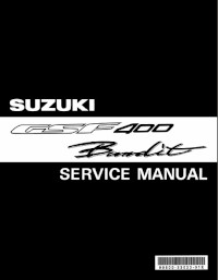
Руководство на английском языке по ремонту мотоциклов Suzuki GSF400 Bandit.
- Издательство: Suzuki Motor Corporation
- Год издания: 1990
- Страниц: 319
- Формат: PDF
- Размер: 44,1 Mb
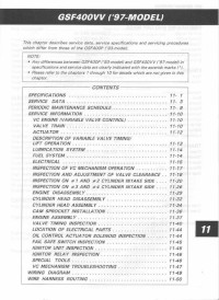
Руководство на английском языке по ремонту мотоциклов Suzuki GSF400VV с 1997 года выпуска.
- Издательство: Suzuki Motor Corporation
- Год издания: —
- Страниц: 49
- Формат: JPG
- Размер: 6,2 Mb
Руководство на английском языке по ремонту мотоциклов Suzuki GSF600.
- Издательство: Suzuki Motor Corporation
- Год издания: 1995
- Страниц: 358
- Формат: PDF
- Размер: 47,7 Mb
Руководство на английском языке по ремонту мотоциклов Suzuki GSF600 и GSF600S.
- Издательство: Suzuki Motor Corporation
- Год издания: 1999
- Страниц: 333
- Формат: PDF
- Размер: 378,2 Mb
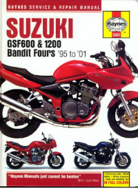
Руководство на английском языке по техническому обслуживанию и ремонту мотоциклов Suzuki GSF600 и GSF1200 Bandit 1995-2001 годов выпуска.
- Издательство: Haynes Publishing
- Год издания: 2001
- Страниц: 281
- Формат: PDF
- Размер: 50,8 Mb
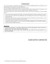
Руководство на английском языке по ремонту мотоциклов Suzuki GSF650, GSF650S и GSX650F.
- Издательство: Suzuki Motor Corporation
- Год издания: 2007
- Страниц: 620
- Формат: PDF
- Размер: 28,9 Mb
Сборник руководств на английском языке по ремонту мотоциклов Suzuki GSF1200 и GSF1200S.
- Издательство: Suzuki Motor Corporation
- Год издания: 1996/1996/2000
- Страниц: -/387/368
- Формат: PDF
- Размер: 118,0 Mb
Руководство на английском языке по ремонту мотоциклов Suzuki GSF1250/GSF1250A/GSF1250S/GSF1250SA.
- Издательство: Suzuki Motor Corporation
- Год издания: 2006
- Страниц: 685
- Формат: PDF
- Размер: 40,2 Mb
