Материал из BikesWiki — энциклопедия японских мотоциклов
Перейти к: навигация, поиск

Suzuki GSX-R600
Ниже представлены прямые ссылки на скачку сервисной документации.
Для Suzuki GSX-R 600
- Сервисный мануал (Service Manual) на Suzuki GSX-R 600 (1997-2000)
- Сервисный мануал (Service Manual) на Suzuki GSX-R 600 (2001-2003)
- Сервисный мануал (Service Manual) на Suzuki GSX-R 600 (2004-2005)
- Сервисный мануал (Service Manual) на Suzuki GSX-R 600 (2006-2007)
- Сервисный мануал (Service Manual) на Suzuki GSX-R 600 (2008-2009)
- Сервисный мануал (Service Manual) на Suzuki GSX-R 600 (2010-2012)
Обзор модели
- Suzuki GSX-R 600
Источник — «https://bikeswiki.ru/index.php?title=Suzuki_GSX-R600:_мануалы&oldid=9844»
Категория:
- Сервисная документация
- Manuals
- Brands
- SUZUKI Manuals
- Motorcycle
- GSX-R600
Manuals and User Guides for SUZUKI GSX-R600. We have 3 SUZUKI GSX-R600 manuals available for free PDF download: Manual, Service Manual

suzuki GSX-R600 Manual (653 pages)
Brand: suzuki
|
Category: Motorcycle
|
Size: 21.59 MB
Table of Contents
-
Section 1 Engine
63
-
General Information
13
-
Cylinder Identification
17
-
Maintenance and Lubrication
28
-
Scheduled Maintenance
28
-
Lubrication Points
29
-
Front Fork Inspection
47
-
Table of Contents
63
-
Precautions
68
-
Precautions for Engine
68
-
-
Engine General Information and Diagnosis
69
-
General Description
69
-
Injection Timing Description
69
-
Self-Diagnosis Function
71
-
-
Schematic and Routing Diagram
72
-
FI System Wiring Diagram
72
-
Terminal Alignment of ECM Coupler
74
-
-
Component Location
75
-
FI System Parts Location
75
-
-
Diagnostic Information and Procedures
77
-
Engine Symptom Diagnosis
77
-
Self-Diagnostic Procedures
81
-
Use of SDS Diagnosis Reset Procedures
83
-
Show Data When Trouble (Displaying Data at the Time of DTC)
84
-
SDS Check
85
-
DTC Table
89
-
Fail-Safe Function Table
91
-
FI System Troubleshooting
92
-
Malfunction Code and Defective Condition Table
94
-
DTC «C11» (P0340): CMP Sensor Circuit Malfunction
98
-
DTC «C12» (P0335): CKP Sensor Circuit Malfunction
101
-
DTC «C13» (P0105-H/L): IAP Sensor Circuit Malfunction
104
-
DTC «C14» (P0120-H/L): TP Sensor Circuit Malfunction
113
-
DTC «C15» (P0115-H/L): ECT Sensor Circuit Malfunction
120
-
DTC «C21» (P0110-H/L): IAT Sensor Circuit Malfunction
125
-
DTC «C22» (P1450-H/L): AP Sensor Circuit Malfunction
130
-
DTC «C23» (P1651-H/L): to Sensor Circuit Malfunction
139
-
-
DTC «C24» (P0351), «C25» (P0352), «C26» (P0353) or «C27» (P0354): Ignition System Malfunction
146
-
DTC «C28» (P1655): Secondary Throttle Valve Actuator (STVA) Malfunction
146
-
DTC «C29» (P1654-H/L): Secondary Throttle Position Sensor (STPS) Circuit Malfunction
150
-
DTC «C31» (P0705): GP Switch Circuit Malfunction
157
-
DTC «C32» (P0201), «C33» (P0202), «C34» (P0203) or «C35» (P0204): Primary Fuel Injector Circuit Malfunction
159
-
DTC «C36» (P1764), «C37» (P1765), «C38» (P1766) or «C39» (P1767): Secondary Fuel Injector Circuit Malfunction
162
-
DTC «C40» (P0505 / P0506 / P0507): ISC Valve Circuit Malfunction
165
-
DTC «C41» (P0230-H/L): FP Relay Circuit Malfunction
169
-
DTC «C41» (P2505): ECM Power Input Signal Malfunction
172
-
DTC «C42» (P1650): IG Switch Circuit Malfunction
174
-
DTC «C44» (P0130/P0135): HO2 Sensor (HO2S) Circuit Malfunction
174
-
DTC «C46» (P1657-H/L or P1658): EXCV Actuator Circuit Malfunction
180
-
DTC «C49» (P1656): PAIR Control Solenoid Valve Circuit Malfunction
194
-
DTC «C60» (P0480): Cooling Fan Relay Circuit Malfunction
197
-
DTC «C62» (P0443): EVAP System Purge Control Solenoid Valve Circuit Malfunction (E-33 Only)
200
-
DTC «C91» (P0500): Vehicle Speed Sensor Circuit Malfunction
203
-
DTC «C93» (P1769): Steering Damper Solenoid Valve Circuit Malfunction
206
-
-
Specifications
210
-
Service Data
210
-
-
Special Tools and Equipment
211
-
Special Tool
211
-
-
Emission Control Devices
213
-
Precautions
213
-
Precautions for Emission Control Devices
213
-
-
General Description
213
-
Fuel Injection System Description
213
-
Crankcase Emission Control System Description
214
-
Exhaust Emission Control System Description
215
-
Noise Emission Control System Description
216
-
Evaporative Emission Control System Diagram (Only for
216
-
-
Schematic and Routing Diagram
217
-
PAIR System Hose Routing Diagram
217
-
EVAP Canister Hose Routing Diagram
218
-
-
Repair Instructions
219
-
Heated Oxygen Sensor (HO2S) Removal and Installation
219
-
Heated Oxygen Sensor (HO2S) Inspection
219
-
PAIR Reed Valve Removal and Installation
219
-
PAIR Control Solenoid Valve Removal and Installation
221
-
PAIR System Inspection
221
-
Crankcase Breather (PCV) Hose Inspection
222
-
Crankcase Breather (PCV) Hose / Reed Valve / Cover Removal and Installation
223
-
Crankcase Breather (PCV) Cover Inspection
224
-
Crankcase Breather (PCV) Reed Valve Inspection
224
-
Evaporative Emission Control System Removal and Installation (Only for
224
-
Evaporative Emission Control System
224
-
Inspection (Only for
224
-
-
Specifications
229
-
Service Data
229
-
Tightening Torque Specifications
229
-
-
Special Tools and Equipment
229
-
Special Tool
229
-
-
Engine Electrical Devices
230
-
Precautions
230
-
Precautions for Engine Electrical Device
230
-
-
Component Location
230
-
Engine Electrical Components Location
230
-
-
Diagnostic Information and Procedures
230
-
Engine Symptom Diagnosis
230
-
-
Repair Instructions
230
-
ECM Removal and Installation
230
-
CMP Sensor Inspection
231
-
CMP Sensor Removal and Installation
231
-
CKP Sensor Inspection
232
-
CKP Sensor Removal and Installation
232
-
IAP Sensor Inspection
232
-
IAP Sensor Removal and Installation
232
-
TP Sensor Inspection
232
-
TP Sensor Removal and Installation
232
-
TP Sensor Adjustment
233
-
ECT Sensor Removal and Installation
233
-
ECT Sensor Inspection
234
-
IAT Sensor Removal and Installation
234
-
IAT Sensor Inspection
235
-
AP Sensor Inspection
235
-
AP Sensor Removal and Installation
235
-
TO Sensor Inspection
235
-
TO Sensor Removal and Installation
235
-
STP Sensor Inspection
236
-
STP Sensor Adjustment
236
-
STP Sensor Removal and Installation
237
-
STV Actuator Inspection
237
-
STV Actuator Removal and Installation
237
-
ISC Valve Inspection
237
-
ISC Valve Removal and Installation
237
-
ISC Valve Preset and Opening Initialization
238
-
HO2 Sensor Inspection
238
-
HO2 Sensor Removal and Installation
238
-
GP Switch Inspection
238
-
GP Switch Removal and Installation
238
-
-
Specifications
239
-
Service Data
239
-
Tightening Torque Specifications
239
-
-
Special Tools and Equipment
240
-
Special Tool
240
-
-
Engine Mechanical
241
-
Schematic and Routing Diagram
241
-
Camshaft and Sprocket Assembly Diagram
241
-
Throttle Cable Routing Diagram
242
-
-
Diagnostic Information and Procedures
243
-
Engine Mechanical Symptom Diagnosis
243
-
Compression Pressure Check
243
-
-
Repair Instructions
244
-
Engine Components Removable with the Engine in Place
244
-
Air Cleaner Element Removal and Installation
246
-
Air Cleaner Box Removal and Installation
247
-
Air Cleaner Element Inspection and Cleaning
247
-
Throttle Cable Removal and Installation
247
-
Throttle Cable Inspection
247
-
Throttle Cable Play Inspection and Adjustment
247
-
Throttle Body Components
248
-
Throttle Body Construction
249
-
Throttle Body Removal and Installation
250
-
Throttle Body Disassembly and Assembly
251
-
Throttle Body Inspection and Cleaning
255
-
ISC Valve Visual Inspection
256
-
Throttle Valve Synchronization
256
-
ISC Valve Reset
258
-
TP Reset
258
-
Engine Assembly Removal
259
-
Engine Assembly Installation
263
-
Engine Top Side Disassembly
265
-
Engine Top Side Assembly
267
-
Camshaft Inspection
274
-
Camshaft Sprocket
276
-
Cam Chain Tension Adjuster Inspection
276
-
Cam Chain Guide / Cam Chain Tensioner Removal and Installation
277
-
Cam Chain Guide Inspection
277
-
Cam Chain Tensioner Inspection
277
-
Cylinder Head Disassembly and Assembly
278
-
Cylinder Head Related Parts Inspection
282
-
Valve Guide Replacement
285
-
Valve Seat Repair
287
-
Engine Bottom Side Disassembly
287
-
Engine Bottom Side Assembly
294
-
Cylinder Inspection
309
-
Piston Ring Removal and Installation
309
-
Piston and Piston Ring Inspection
311
-
Conrod Crank Pin Bearing Removal and Installation
313
-
Conrod and Crankshaft Inspection
313
-
Conrod Crank Pin Bearing Inspection and Selection
314
-
Crankshaft Journal Bearing Inspection and Selection
316
-
Crankshaft Thrust Clearance Inspection and Selection
319
-
-
Specifications
321
-
Service Data
321
-
Tightening Torque Specifications
323
-
-
Special Tools and Equipment
324
-
Recommended Service Material
324
-
Special Tool
324
-
-
Engine Lubrication System
327
-
Precautions
327
-
Precautions for Engine Oil
327
-
-
Schematic and Routing Diagram
328
-
Engine Lubrication System Chart Diagram
328
-
Oil Pan
328
-
Engine Lubrication Circuit Diagram
329
-
-
Diagnostic Information and Procedures
331
-
Engine Lubrication Symptom Diagnosis
331
-
Oil Pressure Check
331
-
-
Repair Instructions
332
-
Engine Oil and Filter Replacement
332
-
Engine Oil Level Inspection
332
-
Oil Pan / Oil Strainer / Oil Pressure Regulator
332
-
Removal and Installation
332
-
-
Oil Pressure Regulator / Oil Strainer Inspection
333
-
Oil Cooler / Oil Cooler Hose Inspection
334
-
Oil Cooler Removal and Installation
334
-
Oil Pressure Switch Removal and Installation
335
-
Oil Pressure Switch Inspection
335
-
Oil Jet / Oil Gallery Jet Removal and Installation
335
-
Oil Jet / Oil Gallery Jet Inspection
337
-
Oil Pump Removal and Installation
338
-
Oil Pump Inspection
339
-
Oil Pump Drive Gear Removal and Installation
339
-
-
Specifications
340
-
Service Data
340
-
Tightening Torque Specifications
341
-
-
Special Tools and Equipment
341
-
Recommended Service Material
341
-
Special Tool
341
-
-
Engine Cooling System
342
-
Precautions
342
-
Precautions for Engine Cooling System
342
-
Precautions for Engine Coolant
342
-
-
General Description
342
-
Engine Coolant Description
342
-
-
Schematic and Routing Diagram
343
-
Cooling Circuit Diagram
343
-
Water Hose Routing Diagram
344
-
-
Diagnostic Information and Procedures
345
-
Engine Cooling Symptom Diagnosis
345
-
-
Repair Instructions
345
-
Cooling Circuit Inspection
345
-
Radiator Cap Inspection
346
-
Radiator Inspection and Cleaning
346
-
Radiator / Cooling Fan Motor Removal and Installation
346
-
Water Hose Inspection
347
-
Water Hose Removal and Installation
348
-
Radiator Reservoir Tank Inspection
348
-
Radiator Reservoir Tank Removal and Installation
349
-
Cooling Fan Inspection
349
-
Cooling Fan Relay Inspection
349
-
ECT Sensor Removal and Installation
350
-
ECT Sensor Inspection
350
-
Thermostat Removal and Installation
350
-
Thermostat Inspection
351
-
Water Pump Components
352
-
Water Pump Construction
353
-
Water Pump Removal and Installation
353
-
Water Pump Disassembly and Assembly
354
-
Water Pump Related Parts Inspection
357
-
-
Specifications
359
-
Service Data
359
-
Tightening Torque Specifications
359
-
-
Special Tools and Equipment
360
-
Recommended Service Material
360
-
Special Tool
360
-
-
Fuel System
361
-
Precautions
361
-
Precautions for Fuel System
361
-
-
General Description
362
-
Fuel Injection System Description
362
-
-
Schematic and Routing Diagram
363
-
Fuel Tank Drain Hose and Breather Hose Routing Diagram
363
-
-
Diagnostic Information and Procedures
364
-
Fuel System Diagnosis
364
-
-
Repair Instructions
365
-
Fuel Pressure Inspection
365
-
Fuel Pump Inspection
365
-
Fuel Discharge Amount Inspection
366
-
Fuel Pump Relay Inspection
367
-
Fuel Hose Inspection
367
-
Fuel Level Gauge Inspection
367
-
Fuel Tank Construction
368
-
Fuel Tank Removal and Installation
369
-
Fuel Pump Components
370
-
Fuel Pump Disassembly and Assembly
371
-
Fuel Mesh Filter Inspection and Cleaning
373
-
Fuel Injector / Fuel Delivery Pipe / T-Joint Removal and Installation
373
-
Fuel Injector Inspection and Cleaning
373
-
-
Specifications
374
-
Special Tools and Equipment
375
-
Recommended Service Material
375
-
Special Tool
375
-
-
Ignition System
376
-
General Description
376
-
Immobilizer Description (for
376
-
Drive Mode Selector Description
377
-
-
Schematic and Routing Diagram
378
-
Ignition System Diagram
378
-
Ignition System Components Location
378
-
-
Diagnostic Information and Procedures
379
-
Ignition System Symptom Diagnosis
379
-
No Spark or Poor Spark
380
-
-
Repair Instructions
381
-
Ignition Coil / Plug Cap and Spark Plug Removal and Installation
381
-
Spark Plug Inspection and Cleaning
382
-
Ignition Coil / Plug Cap Inspection
382
-
CKP Sensor Inspection
384
-
CKP Sensor Removal and Installation
385
-
Engine Stop Switch Inspection
385
-
Ignition Switch Inspection
385
-
Ignition Switch Removal and Installation
386
-
Drive Mode Selector Inspection
387
-
-
Specifications
388
-
Service Data
388
-
Tightening Torque Specifications
388
-
-
Special Tools and Equipment
389
-
Recommended Service Material
389
-
Special Tool
389
-
-
Starting System
390
-
Schematic and Routing Diagram
390
-
Starting System Diagram
390
-
-
Component Location
390
-
Starting System Components Location
390
-
-
Diagnostic Information and Procedures
390
-
Starting System Symptom Diagnosis
390
-
Starter Motor will Not Run
391
-
Starter Motor Runs but Does Not Crank the Engine
391
-
-
Repair Instructions
392
-
Starter Motor Components
392
-
Starter Motor Removal and Installation
393
-
Starter Motor Disassembly and Assembly
393
-
Starter Motor Inspection
394
-
Starter Relay Removal and Installation
395
-
Starter Relay Inspection
396
-
Turn Signal / Side-Stand Relay Removal and Installation
396
-
Side-Stand / Ignition Interlock System Parts Inspection
397
-
Starter Clutch Removal and Installation
399
-
Starter Clutch Inspection
401
-
Starter Button Inspection
402
-
-
Specifications
403
-
Service Data
403
-
Tightening Torque Specifications
403
-
-
Special Tools and Equipment
404
-
Recommended Service Material
404
-
Special Tool
404
-
-
Charging System
405
-
Schematic and Routing Diagram
405
-
Charging System Diagram
405
-
-
Component Location
405
-
Charging System Components Location
405
-
-
Diagnostic Information and Procedures
405
-
Charging System Symptom Diagnosis
405
-
Battery Runs down Quickly
406
-
-
Repair Instructions
407
-
Battery Current Leakage Inspection
407
-
Regulated Voltage Inspection
407
-
Generator Inspection
407
-
Generator Removal and Installation
408
-
Regulator / Rectifier Construction
412
-
Regulator / Rectifier Removal and Installation
413
-
Regulator / Rectifier Inspection
414
-
Battery Components
415
-
Battery Charging
415
-
Battery Removal and Installation
417
-
Battery Visual Inspection
418
-
-
Specifications
418
-
Service Data
418
-
Tightening Torque Specifications
418
-
-
Special Tools and Equipment
419
-
Recommended Service Material
419
-
Special Tool
419
-
-
Exhaust System
420
-
Precautions
420
-
Precautions for Exhaust System
420
-
-
General Description
420
-
Exhaust Control System Description
420
-
Exhaust Control System Operation
421
-
-
Repair Instructions
423
-
Exhaust Control System Construction
423
-
Exhaust System Components
424
-
EXCV Cable Removal and Installation
425
-
EXCVA Removal and Installation
426
-
EXCVA Inspection
428
-
EXCVA Pulley Inspection
428
-
EXCVA Adjustment
428
-
-
-
Section 2 Suspension
435
-
Precautions
436
-
Precautions for Suspension
436
-
-
Suspension General Diagnosis
437
-
Diagnostic Information and Procedures
437
-
Suspension and Wheel Symptom Diagnosis
437
-
-
Repair Instructions
438
-
Front Fork Components
438
-
Front Fork Removal and Installation
439
-
Front Suspension Adjustment
441
-
Front Fork Disassembly and Assembly
441
-
Front Fork Parts Inspection
448
-
-
Front Suspension
438
-
Specifications
449
-
Service Data
449
-
Tightening Torque Specifications
449
-
-
Special Tools and Equipment
450
-
Recommended Service Material
450
-
Special Tool
450
-
-
Rear Suspension
451
-
Repair Instructions
451
-
Rear Suspension Components
451
-
Rear Suspension Assembly Construction
452
-
Rear Shock Absorber Removal and Installation
453
-
Rear Suspension Inspection
454
-
Rear Shock Absorber Inspection
454
-
Rear Suspension Adjustment
454
-
Rear Shock Absorber Disposal
455
-
Cushion Lever Removal and Installation
456
-
Cushion Lever Inspection
456
-
Cushion Lever Bearing Removal and Installation
457
-
Cushion Rod Removal and Installation
458
-
Cushion Rod Inspection
458
-
Cushion Rod Bearing Removal and Installation
459
-
Swingarm Removal and Installation
460
-
Swingarm Related Parts Inspection
462
-
Swingarm Bearing Removal and Installation
463
-
-
Specifications
465
-
Service Data
465
-
Tightening Torque Specifications
465
-
-
Special Tools and Equipment
466
-
Recommended Service Material
466
-
Special Tool
466
-
-
Wheels and Tires
467
-
Precautions
467
-
Precautions for Wheel and Tire
467
-
-
Repair Instructions
468
-
Front Wheel Components
468
-
Front Wheel Assembly Construction
469
-
Front Wheel Assembly Removal and Installation
470
-
Front Wheel Related Parts Inspection
472
-
Front Wheel Dust Seal / Bearing Removal and Installation
473
-
Rear Wheel Components
475
-
Rear Wheel Assembly Construction
476
-
Rear Wheel Assembly Removal and Installation
477
-
Rear Wheel Related Parts Inspection
477
-
Rear Wheel Dust Seal / Bearing Removal and Installation
479
-
Tire Removal and Installation
481
-
Wheel / Tire / Air Valve Inspection and Cleaning
482
-
Air Valve Removal and Installation
483
-
Wheel Balance Check and Adjustment
484
-
-
Specifications
485
-
Service Data
485
-
Tightening Torque Specifications
485
-
-
Special Tools and Equipment
486
-
Recommended Service Material
486
-
Special Tool
486
-
-
-
Section 3 Driveline / Axle
487
-
Precautions
488
-
Precautions for Driveline / Axle
488
-
-
Diagnostic Information and Procedures
489
-
Drive Chain and Sprocket Symptom Diagnosis
489
-
-
Repair Instructions
489
-
Drive Chain Related Components
489
-
Engine Sprocket Removal and Installation
490
-
Rear Sprocket / Rear Sprocket Mounting Drum Removal and Installation
491
-
Drive Chain Related Parts Inspection
492
-
Sprocket Mounting Drum Dust Seal / Bearing Removal and Installation
493
-
Drive Chain Replacement
495
-
-
Drive Chain / Drive Train / Drive Shaft
489
-
Specifications
498
-
Service Data
498
-
Tightening Torque Specifications
498
-
-
Special Tools and Equipment
499
-
Recommended Service Material
499
-
Special Tool
499
-
-
Advertisement

Suzuki GSX-R600 Service Manual (466 pages)
Brand: Suzuki
|
Category: Motorcycle
|
Size: 52.53 MB
Table of Contents
-
Foreword
2
-
Group Index
2
-
How to Use this Manual
3
-
Component Parts and Work to be Done
3
-
Symbol
4
-
Abbreviations Used in this Manual
5
-
Wire Color
7
-
General Information
8
-
Contents
8
-
Warning/Caution/Note
9
-
Suzuki GSX-R600K4 (’04-Model) View
11
-
Serial Number Location
11
-
Fuel, Oil and Engine Coolant Recommendation Fuel (for USA and Canada)
12
-
Fuel (for Other Countries)
12
-
Engine Oil (for USA)
12
-
Engine Oil (for Other Countries)
12
-
Engine Coolant
13
-
Water for Mixing
13
-
Anti-Freeze/Engine Coolant
13
-
Liquid Amount of Water/Engine Coolant
13
-
Break-In Procedures
14
-
Cylinder Identification
14
-
Information Labels
15
-
Specifications
16
-
Dimensions and Dry Mass
16
-
Drive Train
16
-
Electrical
17
-
Capacities
17
-
Periodic Maintenance
18
-
Periodic Maintenance Schedule
19
-
Periodic Maintenance Chart
19
-
Lubrication Points
20
-
Maintenance and Tune-Up Procedures
21
-
Air Cleaner
21
-
Spark Plug and Ignition Coil/Plug Cap Removal
22
-
Heat Range
22
-
Carbon Deposits
22
-
Spark Plug Gap
23
-
Electrode’s Condition
23
-
Spark Plug and Ignition Coil/Plug Cap Installation
23
-
Valve Clearance
24
-
Valve Clearance Adjustment
26
-
Intake Side
27
-
Tappet Shim Selection Table
27
-
Exhaust Side
28
-
Engine Oil and Oil Filter
29
-
Engine Oil Replacement
29
-
Oil Filter Replacement
30
-
Fuel Line
31
-
Engine Idle Speed
31
-
Throttle Valve Synchronization
32
-
Evaporative Emission Control System (E-33 Only)
32
-
Pair (Air Supply) System
32
-
Throttle Cable Play
33
-
Clutch
33
-
Cooling System
34
-
Engine Coolant Level Check
34
-
Engine Coolant Change
34
-
Air Bleeding the Cooling Circuit
35
-
Radiator Hoses
36
-
Drive Chain
37
-
Checking
37
-
Adjusting
38
-
Cleaning and Lubricating
39
-
Brake Fluid Level Check
40
-
Brake Pads
41
-
Front Brake
41
-
Rear Brake
41
-
Brake Pedal Height
41
-
Brake Light Switch
42
-
Air Bleeding from Brake Fluid Circuit
42
-
Front Brake (Caliper Side)
42
-
Front Brake (Master Cylinder Side)
43
-
Tire Tread Condition
44
-
Tire Pressure
44
-
Steering
45
-
Front Fork
45
-
Rear Suspension
45
-
Exhaust Pipe Bolt and Muffler Bolt and Nut
46
-
Chassis Bolts and Nuts
47
-
Compression Pressure Check
49
-
Compression Pressure Specification
49
-
Compression Test Procedure
49
-
Oil Pressure Check
50
-
Oil Pressure Specification
50
-
Oil Pressure Test Procedure
50
-
Engine
52
-
Engine Components Removable with Engine in Place
53
-
Engine Center
53
-
Engine Right Side
53
-
Engine Left Side
53
-
Engine Removal
54
-
Radiator
55
-
Exhaust Pipe and Muffler
56
-
Electric Parts and Pair Hose
57
-
Engine Sprocket and Gear Shift Lever
58
-
Engine Mounting
59
-
Engine Installation
61
-
Engine Disassembly
67
-
Starter Motor
67
-
Cylinder Head Cover and Pair Reed Valve
67
-
Camshafts
68
-
Cylinder Head
69
-
Oil Pump
72
-
Gearshift System
72
-
Starter Idle Gear
73
-
Starter Clutch
74
-
Cam Chain, Cam Chain Tensioner and Cam Chain Guide
74
-
CKP Sensor
74
-
Generator Cover
75
-
Generator Rotor
75
-
Water Pump
75
-
Gear Position Switch
76
-
Crankcase Breather (PCV) Cover
76
-
Oil Filter
76
-
Lower Crank Case
77
-
Middle Crankcase
78
-
Crankshaft
78
-
Piston and Conrod
78
-
Engine Components Inspection and Service
80
-
Cylinder Head Cover
80
-
CMP Sensor
80
-
Pair Reed Valve
80
-
PCV Hose
81
-
Camshaft Identification
81
-
Cam Wear
81
-
Camshaft Journal Wear
82
-
Сamshaft Runout
83
-
Сam Sprocket
83
-
Сam Chain Tension Adjuster
83
-
Сam Chain Tensioner
84
-
Сam Chain Guide
84
-
Сylinder Head and Valve
84
-
Valve and Valve Spring Disassembly
84
-
Cylinder Head Distortion
86
-
Valve Stem Runout
86
-
Valve Head Radial Runout
86
-
Valve Stem and Valve Face Wear Condition
87
-
Valve Stem Deflection
87
-
Valve Stem Wear
87
-
Valve Guide Servicing
88
-
Valve Seat Width Inspection
89
-
Valve Seat Servicing
90
-
Initial Seat Cut
90
-
Top Narrowing Cut
91
-
Bottom Narrowing Cut
91
-
Final Seat Cut
92
-
Valve Spring
93
-
Valve and Valve Spring Reassembly
94
-
Intake Pipe
95
-
Water Bypass Union
96
-
Clutch Drive Plates Inspection
96
-
Clutch Spring Inspection
97
-
Clutch Bearing Inspection
97
-
Clutch Sleeve Hub/Primary Driven Gear Assembly
97
-
Generator
98
-
Gearshift Shaft/Gearshift Arm Disassembly
99
-
Gearshift Shaft/Gearshift Arm Inspection
99
-
Gearshift Shaft/Gearshift Arm Reassembly
99
-
Oil Pressure Regulator
100
-
Transmission
101
-
Disassembly
101
-
Reassembly
102
-
Transmission Parts Location
103
-
Cylinder Distortion
104
-
Cylinder Bore
104
-
Piston and Piston Ring
105
-
Piston Diameter
105
-
Piston-To-Cylinder Clearance
105
-
Piston Pin and Pin Bore
105
-
Piston Ring-To-Groove Clearance
106
-
Piston Ring Free End Gap and Piston Ring End Gap
106
-
Crankcase
107
-
Gearshift Fork and Gearshift Cam
107
-
Gearshift Fork-To-Groove Clearance
107
-
Gearshift Fork Groove Width
107
-
Gearshift Fork Thickness
108
-
Gearshift Cam Bearing and Gearshift Shaft Bearing
108
-
Bearing Inspection
108
-
Bearing Removal
108
-
Installation
109
-
Oil Jet
111
-
Inspection and Cleaning
111
-
Plug
112
-
Conrod Big End Side Clearance
113
-
Conrod-Big End Bearing Inspection
113
-
Conrod-Big End Bearing Selection
113
-
Crankshaft and Conrod
114
-
Crankshaft Runout
114
-
Conrod Small End I.D.
114
-
Crank Pin O.D.
115
-
Bearing Thickness
115
-
Bearing Selection Table
116
-
Conrod I.D.
116
-
Crankshaft Journal Bearing
118
-
Selection
118
-
Crankcase I.D. Specification
119
-
Crankshaft Journal O.D. Specification
120
-
Bearing Thickness Specification
120
-
Crankshaft Thrust Bearing
121
-
Crankshaft Thrust Clearance Adjustment
121
-
Thrust Bearing Selection Table
122
-
Engine Reassembly
123
-
Piston Ring
123
-
Oil Strainer
133
-
Oil Pan
133
-
Oil Pressure Switch
134
-
Crankcase Breather Cover
135
-
Cam Chain Drive Sprocket
138
-
Cam Chain Tensioner and Cam Chain Guide
138
-
Clutch Cover
146
-
Camshaft
149
-
Cam Chain Tension Adjuster
152
-
FI System Diagnosis
157
-
Precautions in Servicing
159
-
Electrical Parts
159
-
Connector/Coupler
159
-
Fuse
160
-
Ecm/Various Sensors
160
-
Electrical Circuit Inspection Procedure
162
-
Open Circuit Check
162
-
Continuity Check
163
-
Voltage Check
163
-
Short Circuit Check (Wire Harness to Ground)
164
-
Using the Multi-Circuit Tester
165
-
Using the Tester
165
-
FI System Technical Features
166
-
Injection Time (Injection Volume)
166
-
Compensation of Injection Time (Volume)
167
-
Injection Stop Control
167
-
Injection Timing
168
-
FI System Parts Location
169
-
FI System Wiring Diagram
171
-
Self-Diagnosis Function
172
-
User Mode
172
-
Dealer Mode
173
-
TPS Adjustment
175
-
Fail-Safe Function
176
-
FI System Troubleshooting
178
-
Self-Diagnostic Procedures
180
-
Self-Diagnosis Reset Procedure
180
-
Malfunction Code and Defective Condition
181
-
«C11» CMP Sensor Circuit Malfunction
183
-
«C12» CKP Sensor Circuit Malfunction
185
-
«C13» IAP Sensor Circuit Malfunction
187
-
«C14» TP Sensor Circuit Malfunction
190
-
«C15» ECT Sensor Circuit Malfunction
191
-
Output Voltage
193
-
«C21» IAT Sensor Circuit Malfunction
195
-
«C22» AP Sensor Circuit Malfunction
197
-
«C23» to Sensor Circuit Malfunction
200
-
«C28» STV Actuator Circuit Malfunction
202
-
«C29» STP Sensor Circuit Malfunction
204
-
«C31» GP Switch Circuit Malfunction
207
-
«C32», «C33», «C34» or «C35» Fuel Injector Circuit Malfunction
208
-
«C41» FP Relay Circuit Malfunction
210
-
«C42» IG Switch Circuit Malfunction
210
-
«C49» Pair Control Solenoid Valve Circuit Malfunction
211
-
Sensors
213
-
Fuel System and Throttle Body
216
-
Fuel Delivery System
217
-
Fuel System
218
-
Fuel Tank Lift-Up
218
-
Fuel Tank Removal
218
-
Fuel Pressure Inspection
219
-
Fuel Pump Inspection
220
-
Fuel Discharge Amount Inspection
220
-
Fuel Pump Relay Inspection
221
-
Fuel Pump and Fuel Filter Removal
222
-
Construction
222
-
Fuel Mesh Filter Inspection and Cleaning
224
-
Fuel Pump and Fuel Mesh Filter Installation
224
-
Throttle Body Construction
228
-
Air Cleaner Box Removal
229
-
Throttle Body Removal
230
-
Throttle Body Disassembly
231
-
Throttle Body Cleaning
233
-
Throttle Body Reassembly
234
-
Throttle Body Installation
236
-
Air Cleaner Box Installation
237
-
STP Sensor Adjustment
237
-
Fuel Injector Removal
238
-
Fuel Injector Inspection
238
-
Fuel Injector Installation
238
-
Fast Idle Adjustment
239
-
Use for Digital Vacuum Tester
241
-
Use for Vacuum Balancer Gauge
242
-
Calibrating each Vacuum Gauge
242
-
Throttle Position Sensor (TPS) Setting
244
-
Exhaust System
246
-
Precautions for Exhaust System
247
-
Exhaust System Components
247
-
Cooling and Lubrication System
250
-
Cooling Circuit Inspection
252
-
Radiator and Water Hoses
253
-
Radiator Removal
253
-
Radiator Cap Inspection
253
-
Radiator Inspection and Cleaning
253
-
Water Hose Inspection
254
-
Cooling Fan
255
-
Cooling Fan Thermo-Switch
256
-
ECT Sensor
257
-
Temperature Sensor Specification
257
-
Thermostat
258
-
Mechanical Seal
263
-
Oil Seal
263
-
Impeller Shaft Journal
263
-
Seal Washer
263
-
Lubrication System
267
-
Oil Cooler
267
-
Engine Lubrication System Chart
269
-
Engine Lubrication System
270
-
Chassis
273
-
Exterior Parts
275
-
Fastener Removal and Reinstallation
275
-
Screen
276
-
Body Cowling Cover and Lower Bracket Cover
276
-
Right and Left under Cowlings
276
-
Body Cowling
278
-
Right and Left Air Intake Pipes
279
-
Cowling Brace
279
-
Front Seat
279
-
Rear Seat and Seat Tail Cover
280
-
Frame Cover
280
-
Front Wheel Construction
281
-
Axle Shaft
283
-
Wheel Bearing
283
-
Reassembly and Installation
284
-
Brake Disc
285
-
Spacer Nut
286
-
Brake Caliper
286
-
Front Axle
286
-
Front Fork Construction
287
-
Inner and Outer Tubes
291
-
Damper Rod
292
-
Compression Damping Force Adjuster
292
-
Oil Seal and Dust Seal
292
-
Damper Rod Bolt
293
-
Fork Oil
293
-
Fork Spring
294
-
Front Fork Cap Bolt
295
-
Suspension Setting
298
-
Spring Pre-Load Adjustment
298
-
Damping Force Adjustment
298
-
Standard Front Suspension Setting
298
-
Steering Damper Construction
299
-
Steering Construction
301
-
Inner Race
303
-
Stem Nut
304
-
Front Fork and Steering Stem Upper Bracket
305
-
Steering Tension Adjustment
306
-
Handlebars Construction
307
-
Rear Wheel Construction
311
-
Rear Axle
313
-
Wheel Damper
313
-
Sprocket
314
-
Dust Seals
317
-
Rear Sprocket and Sprocket Mounting Drum
317
-
Rear Shock Absorber Construction
319
-
Rear Shock Absorber Scrapping Procedure
321
-
Rear Shock Absorber Gas Release
321
-
Rear Suspension Construction
323
-
Spacer
326
-
Swingarm Bearing
326
-
Cushion Lever Bearing
327
-
Cushion Lever and Cushion Lever Rods
327
-
Swingarm Pivot Shaft
327

Suzuki GSX-R600 Manual (165 pages)
Brand: Suzuki
|
Category: Motorcycle
|
Size: 2.75 MB
Table of Contents
-
Table of Contents
4
-
The Sport of Motorcycling
6
-
Most Accidents Can be Avoided
7
-
If You Don’t Have a Helmet, Buy a Helmet and Wear It Every Time You Ride
7
-
If a Collision Is Imminent, Do Something
8
-
Special Situations Require Special Care
9
-
Know Your Limits
9
-
Be Extra Safety-Conscious on Bad Weather Days
10
-
Practice Away from Traffic
10
-
Inspection before Riding
10
-
Accessories and Loading
10
-
Carrying a Passenger
11
-
Motorcycle Safety Foundation’s «Riding Tips and Practice Guide» Handbook (for Owners in Usa)
11
-
Be Street Smart
11
-
Labels
11
-
Conclusion
12
-
-
Fuel, Engine Oil and Coolant Recommendations
14
-
-
Controls, Equipment and Adjustments
22
-
Location of Parts
23
-
Ignition Switch
26
-
Key
26
-
Instrument Panel
29
-
Left Handlebar
43
-
Right Handlebar
46
-
Fuel Tank Cap
49
-
Gearshift Lever
50
-
Rear Brake Pedal
51
-
Seat Lock and Helmet Holders
51
-
Side Stand
53
-
Suspension Adjustment
54
-
Footrests and Gearshift Lever Position Change
59
-
Break-In and Inspection before Riding
62
-
-
Riding Tips
66
-
Starting the Engine
67
-
Starting off
69
-
Using the Transmission
70
-
Riding on Hills
71
-
Stopping and Parking
72
-
Carrying a Passenger
73
-
-
Accessory Use and Motorcycle Loading
74
-
Accessory Installation Guidelines
75
-
Accessory Use
75
-
Loading Limit
76
-
Loading Guidelines
77
-
Modification
77
-
-
Inspection and Maintenance
80
-
Maintenance Schedule
81
-
Steering Damper Maintenance
85
-
Tools
85
-
Lubrication Points
86
-
Battery
87
-
Air Cleaner
89
-
Spark Plugs
93
-
Engine Oil
99
-
Engine Idle Speed Inspection
105
-
Throttle Cable Play
105
-
Fuel Hose
106
-
Clutch Adjustment
107
-
Engine Coolant
107
-
Drive Chain
109
-
Brakes
113
-
Tires
118
-
Side Stand/Ignition Interlock System
121
-
Front Wheel Removal
122
-
Rear Wheel Removal
125
-
Light Bulb Replacement
128
-
Fuses
134
-
Catalytic Converter
136
-
Troubleshooting
138
-
Advertisement
Advertisement
Related Products
-
Suzuki GSX-R600 2006
-
Suzuki GSX-R600 2007
-
Suzuki GSX R600 2003
-
Suzuki GSX-R1000K5
-
Suzuki GSX-R750W 1993
-
Suzuki GSX-R250
-
Suzuki GSX-R1000/A
-
Suzuki GSX-R1000 2007
-
Suzuki GSX-R750UD
-
Suzuki GSX-R750UF
SUZUKI Categories
Motorcycle
Automobile
Motorcycle Accessories
Musical Instrument
Offroad Vehicle
More SUZUKI Manuals

- Manuals
- Brands
- Suzuki Manuals
- Motorcycle
- GSX-R600
- Manual
-
Contents
-
Table of Contents
-
Troubleshooting
-
Bookmarks
Quick Links
Chapters
-
Section 1 Engine
63 -
Section 2 Suspension
435 -
Section 3 Driveline / Axle
487 -
Section 4 Brake
501 -
Section 5 Transmission / Transaxle
541 -
Section 6 Steering
581 -
Section 9 Body and Accessories
597
Related Manuals for Suzuki GSX-R600
Summary of Contents for Suzuki GSX-R600
-
Page 1
GSX-R600… -
Page 2
FOREWORD This manual contains an introductory description on the SUZUKI GSX-R600 and procedures for its inspection/ser- vice and overhaul of its main components. Other information considered as generally known is not included. Read the GENERAL INFORMATION section to familiarize yourself with the motorcycle and its maintenance. Use this section as well as other sections to use as a guide for proper inspection and service. -
Page 3
TABLE OF CONTENTS Precautions…………… 00-i Precautions …………00-1 General Information ……….. 0-i General Information ……….0A-1 Maintenance and Lubrication ……… 0B-1 Service Data…………0C-1 Engine …………….. 1-i Precautions ………….. 1-1 Engine General Information and Diagnosis … 1A-1 Emission Control Devices ……..1B-1 Engine Electrical Devices……..1C-1 Engine Mechanical……….1D-1 Engine Lubrication System …….. -
Page 5
Table of Contents 00- i Section 00 Precautions CONTENTS Precautions ……….00-1 General Precautions ……….. 00-1 Precautions for Electrical Circuit Service …. 00-2 Precautions…………00-1 Warning / Caution / Note……..00-1… -
Page 6
CAUTION Indicates a potential hazard that could result • If parts replacement is necessary, replace in death or injury. the parts with Suzuki Genuine Parts or their equivalent. CAUTION • When removing parts that are to be reused, keep them arranged in an orderly manner… -
Page 7
Precautions: 00-2 • Never reuse a circlip. When installing a • Inspect each terminal for corrosion and new circlip, take care not to expand the contamination. The terminals must be clean and free end gap larger than required to slip the of any foreign material which could impede proper circlip over the shaft. -
Page 8
00-3 Precautions: • When connecting meter probe from the terminal side Fuse of the coupler (where connection from harness side • When a fuse is blown, always investigate the cause to not being possible), use extra care not to force and correct it and then replace the fuse. -
Page 9
Precautions: 00-4 • When disconnecting and connecting the coupler, • Before measuring voltage at each terminal, check to make sure to turn OFF the ignition switch, or make sure that battery voltage is 11 V or higher. electronic parts may get damaged. Terminal voltage check with a low battery voltage will lead to erroneous diagnosis. -
Page 10
00-5 Precautions: 2) Check each connector/coupler at both ends of the Continuity check circuit being checked for loose connection. Also 1) Measure resistance across coupler “B” (between “A” check for condition of the coupler lock if equipped. and “C” in figure). If no continuity is indicated (infinity or over limit), the circuit is open between terminals “A”… -
Page 11
Precautions: 00-6 3) Also, if measured values are as listed following, a Short circuit check (Wire harness to ground) resistance (abnormality) exists which causes the 1) Disconnect the negative (–) cable from the battery. voltage drop in the circuit between terminals “A” and 2) Disconnect the connectors/couplers at both ends of “B”. -
Page 12
: 09900–25008 (Multi-circuit tester set) I705H1000009-02 “D”: To other parts Using The Multi-Circuit Testers • Use the Suzuki multi-circuit tester set. • Use well-charged batteries in the tester. • Be sure to set the tester to the correct testing range. Special tool (A): 09900–25008 (Multi-circuit tester set) -
Page 13: General Information
Table of Contents 0- i Section 0 General Information CONTENTS General Information …….. 0A-1 Valve Clearance Inspection and Adjustment ..0B-4 Spark Plug Replacement ……..0B-9 General Description ……….0A-1 Spark Plug Inspection and Cleaning ….0B-9 Symbols ………….. 0A-1 Fuel Line Inspection ……….0B-10 Abbreviations …………
-
Page 14
Apply oil. Use engine oil unless otherwise specified. Apply molybdenum oil solution. (Mixture of engine oil and SUZUKl MOLY PASTE in a ratio of 1:1). Apply SUZUKI SUPER GREASE “A” or equivalent. 99000-25010 Apply SUZUKI MOLY PASTE or equivalent. 99000-25140 Apply SUZUKI SILICONE GREASE or equivalent. -
Page 15
ECM: Engine Control Module Engine Control Unit SAE: Society of Automotive Engineers (ECU) (FI Control Unit) SDS: Suzuki Diagnosis System ECT Sensor: Engine Coolant Temperature Sensor SRAD: Suzuki Ram Air Direct (ECTS) STC System: Secondary Throttle Control System Water Temp. Sensor (WTS) (STCS) -
Page 16
Use of SF/SG or SH/SJ in API with MA in JASO. spare parts. Suzuki recommends the use of SAE 10W-40 engine oil. If SAE 10W-40 engine oil is not available, select and alternative according to the chart. -
Page 17: Cylinder Identification
2) Upon reaching an odometer reading of 1 600 km (1 Suzuki recommends the use of SUZUKI COOLANT anti- 000 miles) you can subject the motorcycle to full freeze/engine coolant. If this is not available, use an throttle operation.
-
Page 18
0A-5 General Information: Country and Area Codes B837H10101009 The following codes stand for the applicable country(-ies) and area(-s). Code Country or Area Effective Frame No. GSX-R600 K8 (E-02) U.K. JS1CV111100100001 – GSX-R600 K8 (E-19) E.U. JS1CV111100100001 – GSX-R600U2 K8 (E-19) E.U. -
Page 19
General Information: 0A-6 Warning, Caution and Information Labels Location B837H10101011 7, 9 2, 3 19, 21 10, 11 14, 15, 16, 17 12, 13 I837H1010005-01 1. Noise label (For E-03, 33) 15. General warning label (French) (For GSX-R600U2 E-19) 2. Noise label (For E-24) 16. -
Page 20
0A-7 General Information: Component Location Electrical Components Location B837H10103001 I837H1010006-03 1. EXCV actuator 9. CMP sensor 17. Fuel pump relay 2. IAP sensor 10. PAIR control solenoid valve 18. Cooling fan relay 3. TP sensor 11. Starter relay/Main fuse 19. AP sensor 4. -
Page 21
General Information: 0A-8 I837H1010007-03 25. IAT sensor 31. Head light relay 37. Oil pressure switch 26. ISC valve 32. Turn signal/Side-stand relay 38. Generator 27. Secondary fuel injector 33. Steering damper solenoid valve 39. GP switch 28. Primary fuel injector 34. -
Page 22
0A-9 General Information: Specifications Specifications B837H10107001 NOTE These specifications are subject to change without notice. Dimensions and dry mass Item Specification Remark Overall length 2 040 mm (80.3 in) Overall width 715 mm (28.1 in) Overall height 1 125 mm (44.3 in) Wheelbase 1 400 mm (55.1 in) Ground clearance… -
Page 23
General Information: 0A-10 Chassis Item Specification Remark Front suspension Inverted telescopic, coil spring, oil damped Rear suspension Link type, coil spring, oil damped Front suspension stroke 120 mm (4.7 in) Rear wheel travel 130 mm (5.1 in) Caster 23° 45’ Tail 97 mm (3.8 in) Steering angle… -
Page 24
0A-11 General Information: Special Tools and Equipment Special Tool B837H10108002 09900–06104 09900–06107 09900–06108 09900–18740 09900–20102 Snap ring pliers Snap ring pliers Snap ring pliers Hexagon socket (24 Vernier calipers (1/20 mm, 200 mm) 09900–20202 09900–20203 09900–20205 09900–20530 09900–20602 Micrometer (1/100 Micrometer (1/100 Micrometer (0 –… -
Page 25
General Information: 0A-12 09913–50121 09913–70210 09915–40610 09915–64512 09915–74521 Oil seal remover Bearing installer set Oil filter wrench Compression gauge Oil pressure gauge hose 09915–74540 09915–77331 09916–10911 09916–14510 09916–14522 Oil pressure gauge Meter (for high Valve lapper set Valve spring Valve spring attachment pressure) compressor… -
Page 26
0A-13 General Information: 09924–84521 09925–18011 09930–10121 09930–11920 09930–11940 Bearing installer set Steering bearing Spark plug wrench set Torx bit (JT40H) Bit holder installer 09930–11950 09930–30104 09930–34980 09930–44520 09930–44530 Torx wrench Rotor remover slide Rotor remover Rotor holder Rotor holder shaft 09930–82720 09940–14911 09940–14940… -
Page 27
General Information: 0A-14 09944–28320 99565–01010–015 Hexagon socket (19 CD-ROM Ver.15… -
Page 28: Maintenance And Lubrication
0B-1 Maintenance and Lubrication: Maintenance and Lubrication General Information Precautions Precautions for Maintenance B837H10200001 The “Periodic Maintenance Schedule Chart” lists the recommended intervals for all the required periodic service work necessary to keep the motorcycle operating at peak performance and economy. Maintenance intervals are expressed in terms of kilometers, miles and months for your convenience.
-
Page 29: Lubrication Points
Maintenance and Lubrication: 0B-2 Interval 1 000 6 000 12 000 18 000 24 000 Item miles 4 000 7 500 11 000 14 500 months Tires — Steering — — Front fork — — — Rear suspension — — —…
-
Page 30
0B-3 Maintenance and Lubrication: Repair Instructions Air Cleaner Element Replacement 3) Drain water from the air cleaner box by removing the B837H10206001 drain plug (1). Replace air cleaner element Every 18 000 km (11 000 miles, 36 months) Refer to “Air Cleaner Element Removal and Installation in Section 1D (Page 1D-6)”. -
Page 31
Maintenance and Lubrication: 0B-4 Exhaust Control Valve Inspection Valve Clearance Inspection and Adjustment B837H10206028 B837H10206004 Inspect exhaust control valve Inspect valve clearance Initially at 1 000 km (600 miles, 2 months) and every Initially every 24 000 km (14 500 miles, 48 months) 12 000 km (7 500 miles, 24 months) thereafter Inspection Inspect exhaust control valve as follows:… -
Page 32
0B-5 Maintenance and Lubrication: 4) Remove the valve timing inspection cap (1). 5) Turn the crankshaft to bring the line “C” on the CKP sensor rotor to the rib “D” behind the clutch cover and also to bring the notches “E” on the left ends of both camshafts (EX and IN) to the positions as shown. -
Page 33
Maintenance and Lubrication: 0B-6 7) Turn the crankshaft 360 degrees (one rotation) to 3) Check the figures printed on the shim. These figures bring the line on the CKP sensor rotor to the rib indicate the thickness of the shim, as illustrated. behind the clutch cover and also to bring the notches “E”… -
Page 34
0B-7 Maintenance and Lubrication: (INTAKE SIDE) I837H1020015-02… -
Page 35
Maintenance and Lubrication: 0B-8 (EXHAUST SIDE) I837H1020016-02… -
Page 36
0B-9 Maintenance and Lubrication: 6) Install the camshafts and cam chain tension adjuster. Spark Plug Gap Refer to “Engine Top Side Assembly in Section 1D 1) Remove the spark plugs. Refer to “Ignition Coil / (Page 1D-27)”. Plug Cap and Spark Plug Removal and Installation in 7) Rotate the engine so that the tappet is depressed Section 1H (Page 1H-6)”. -
Page 37
Maintenance and Lubrication: 0B-10 Fuel Line Inspection Engine Oil Replacement B837H10206007 1) Place the motorcycle on the side-stand. Inspect fuel line 2) Place an oil pan below the engine, and drain engine Every 6 000 km (4 000 miles, 12 months) oil by removing the oil drain plug (1) and filler cap (2). -
Page 38
Other manufacturer’s oil filters may differ in thread specifications (thread diameter and pitch), filtering performance and durability which may lead to engine damage or oil leaks. Also, do not use a genuine Suzuki I815H1020023-01 automobile oil filter on this motorcycle. Oil Level Inspection 5) Install the new oil filter. -
Page 39
Maintenance and Lubrication: 0B-12 Throttle Cable Play Inspection and Adjustment Throttle Valve Synchronization B837H10206009 B837H10206010 Inspect throttle cable play Inspect throttle valve synchronization Initially at 1 000 km (600 miles, 2 months) and every Initially at 1 000 km (600 miles, 2 months) (E-33 only) 6 000 km (4 000 miles, 12 months) thereafter and every 12 000 km (7 500 miles, 24 months) Inspect and adjust the throttle cable play “a”… -
Page 40
0B-13 Maintenance and Lubrication: Engine Coolant Change Air Bleeding From the Cooling Circuit Refer to “Engine Coolant Description in Section 1F 1) Remove the right under cowling. Refer to “Exterior (Page 1F-1)”. Parts Removal and Installation in Section 9D (Page 9D-11)”. WARNING 2) Add engine coolant up to the radiator inlet. -
Page 41
Maintenance and Lubrication: 0B-14 Clutch Cable Play Inspection and Adjustment 5) Loosen the lock-nut (5) and turn out the adjusting B837H10206029 screw (6) two or three rotations. Inspect clutch cable play 6) From that position, slowly turn in the adjusting screw Every 6 000 km (4 000 miles, 12 months) (6) until resistance is felt. -
Page 42
0B-15 Maintenance and Lubrication: Drive Chain Inspection and Adjustment Drive Chain Length Inspection B837H10206017 1) Loosen the axle nut (1). Inspect drive chain 2) Loosen the left and right chain adjuster lock-nuts (2). Initially at 1 000 km (600 miles, 2 months) and every 3) Give tension to the drive chain fully by turning both 6 000 km (4 000 miles, 12 months) thereafter chain adjuster bolts (3). -
Page 43
“drive chain oil”. Such oil can damage the I837H1020035-01 O-rings. • The standard drive chain is a RK 525SMOZ8. SUZUKI recommends to use this standard drive chain as a replacement. “a” I649G1020036-02 5) After adjusting the drive chain, tighten the axle nut (1) to the specified torque. -
Page 44
0B-17 Maintenance and Lubrication: Brake System Inspection B837H10206019 Inspect brake system Initially at 1 000 km (600 miles, 2 months) and every 6 000 km (4 000 miles, 12 months) thereafter Inspect brake hose and brake fluid “A” Every 6 000 km (4 000 miles, 12 months) WARNING •… -
Page 45
Maintenance and Lubrication: 0B-18 Front and Rear Brake Hose Inspection 4) Tighten the lock-nut (1) securely. Inspect the brake hoses and hose joints for crack, Tightening torque damage or brake oil leakage. If any defects are found, Rear master cylinder rod lock-nut (a): 18 N·m ( replace the brake hose with a new one. -
Page 46
0B-19 Maintenance and Lubrication: Tire Inspection CAUTION B837H10206020 The standard tire fitted on this motorcycle is Inspect tire 120/70 ZR17 M/C (58W) for front and 180/55 Every 6 000 km (4 000 miles, 12 months) ZR17 M/C (73W) for rear. The use of tires Tire Tread Condition other than those specified may cause Operating the motorcycle with excessively worn tires will… -
Page 47: Front Fork Inspection
Maintenance and Lubrication: 0B-20 Front Fork Inspection Chassis Bolt and Nut Inspection B837H10206022 B837H10206024 Inspect front fork Tighten chassis bolt and nut Every 12 000 km (7 500 miles, 24 months) Initially at 1 000 km (600 miles, 2 months) and every 6 000 km (4 000 miles, 12 months) thereafter Inspect the front forks for oil leakage, scoring or scratches on the outer surface of the inner tubes.
-
Page 48
0B-21 Maintenance and Lubrication: I837H1020052-01 I837H1020055-01 Brake hose union bolt 23 N⋅m (2.3 kgf-m, 16.5 lb-ft) Rear shock absorber bracket nut 115 N⋅m (11.5 kgf-m, 83.0 lb-ft) Front axle bolt 100 N⋅m (10.0 kgf-m, 72.5 lb-ft) Rear shock absorber mounting bolt/nut 50 N⋅m (5.0 kgf-m, 36.0 lb-ft) Front axle pinch bolt 23 N⋅m (2.3 kgf-m, 16.5 lb-ft) Front brake disc bolt 18 N⋅m (1.8 kgf-m, 13.0 lb-ft) -
Page 49
Maintenance and Lubrication: 0B-22 Compression Pressure Check B837H10206025 Refer to “Compression Pressure Check in Section 1D (Page 1D-3)”. Oil Pressure Check B837H10206026 Refer to “Oil Pressure Check in Section 1E (Page 1E- 5)”. SDS Check B837H10206027 Refer to “SDS Check in Section 1A (Page 1A-17)”. I837H1020058-01 Brake hose union bolt 23 N⋅m (2.3 kgf-m, 16.5 lb-ft) Brake caliper air bleeder valve 7.5 N⋅m (0.75 kgf-m, 5.5 lb-ft) -
Page 50
0B-23 Maintenance and Lubrication: Special Tools and Equipment Recommended Service Material B837H10208001 Material SUZUKI recommended product or Specification Note Brake fluid DOT 4 — (Page 0B-17) NOTE Required service material is also described in the following. “Lubrication Points (Page 0B-2)”… -
Page 51
Service Data: 0C-1 Service Data General Information Specifications Service Data B837H10307001 Valve + Guide Unit: mm (in) Item Standard Limit 27.2 (1.07) — Valve diam. 22.0 (0.87) — 0.08 – 0.18 (0.003 – 0.007) — Valve clearance (when cold) 0.18 – 0.28 (0.007 – 0.011) —… -
Page 52
0C-2 Service Data: Cylinder + Piston + Piston Ring Unit: mm (in) Item Standard Limit 900 kPa Compression pressure 1 200 – 1 600 kPa (12 – 16 kgf/cm , 171 – 228 psi) (9 kgf/cm , 128 psi) 200 kPa Compression pressure difference —… -
Page 53
Service Data: 0C-3 Oil Pump Item Standard Limit Oil pressure (at 60 °C, 140 °F) 100 – 400 kPa (1.0 – 4.0 kgf/cm , 14 – 57 psi) at 3 000 r/min — Clutch Unit: mm (in) Item Standard Limit Clutch drive plate thickness No. -
Page 54
0C-4 Service Data: Thermostat + Radiator + Fan + Coolant Item Standard/Specification Note Thermostat valve opening Approx. 82 °C (180 °F) — temperature Over 8 mm (0.31 in) and at 95 °C (203 °F) Thermostat valve lift — 20 °C Approx. -
Page 55
Service Data: 0C-5 FI Sensors Item Standard/Specification Note 142 – 194 Ω CKP sensor resistance CKP sensor peak voltage 0.28 V and more When cranking IAP sensor input voltage 4.5 – 5.5 V IAP sensor output voltage Approx. 2.7 V at idle speed TP sensor input voltage 4.5 –… -
Page 56
0C-6 Service Data: Throttle Body Item Specification Bore size 40 mm (1.57 in) I.D. No. 37H1 (For E-33), 37H0 (For the others) 1 300 ± 100 r/min Idle r/min Throttle cable play 2.0 – 4.0 mm (0.08 – 0.16 in) Electrical Unit: mm Item… -
Page 57
Service Data: 0C-7 Wattage Unit: W Specification Item E-02, 19, 24 The other countries ← 60 x 2 Headlight ← ← Position light ← Brake light/Taillight ← Turn signal light 21 x 4 ← License plate light ← Combination meter light ←… -
Page 58
Front fork oil level (Without spring, 110 (4.3) — outer tube fully compressed) Front fork oil type SUZUKI FORK OIL SS-05 or an equivalent fork oil — Front fork oil capacity (Each leg) 410 ml (13.9/14.4 US/lmp oz) — Front fork inner tube O.D 41 (1.6) -
Page 59
Service Data: 0C-9 Tightening Torque List B837H10307002 Engine Item N⋅m kgf-m lb-ft Exhaust pipe bolt 16.5 Exhaust pipe mounting bolt 16.5 Exhaust pipe bracket bolt 18.0 Muffler connecting bolt 16.5 Muffler cover bolt 0.55 Muffler mounting bolt 18.0 Speed sensor rotor bolt 18.0 Speed sensor bolt 0.45… -
Page 60
0C-10 Service Data: Item N⋅m kgf-m lb-ft Breather cover bolt Oil pan bolt Oil cooler mounting bolt Driveshaft bearing case bolt (LH and RH) Gearshift arm stopper 13.5 Gearshift cam stopper bolt Gearshift cam stopper plate bolt Driveshaft retainer bolt Gearshift cam bearing retainer screw Starter motor mounting bolt Starter motor lead wire mounting nut… -
Page 61
Service Data: 0C-11 Chassis Item N⋅m kgf-m lb-ft Steering stem head nut 65.0 Steering stem lock-nut 65.0 Steering damper bolt 16.5 Steering damper nut 16.5 Front fork upper clamp bolt 16.5 Front fork lower clamp bolt 16.5 Front fork cap bolt 25.5 Front fork inner rod lock-nut 14.5… -
Page 62
0C-12 Service Data: Tightening Torque Chart For other bolts and nuts not listed in the preceding page, refer to this chart: Bolt Diameter Conventional or “4” marked bolt “7” marked bolt “a” (mm) N⋅m kgf-m lb-ft N⋅m kgf-m lb-ft 0.15 0.23 0.45 0.55… -
Page 63: Table Of Contents
Table of Contents 1- i Section 1 Engine CONTENTS Precautions ……….1-1 DTC “C24” (P0351), “C25” (P0352), “C26” (P0353) or “C27” (P0354): Ignition System Precautions…………. 1-1 Malfunction…………1A-78 Precautions for Engine………. 1-1 DTC “C28” (P1655): Secondary Throttle Engine General Information and Valve Actuator (STVA) Malfunction….1A-78 DTC “C29”…
-
Page 64
1-ii Table of Contents Emission Control Devices …… 1B-1 ECT Sensor Inspection ……..1C-5 IAT Sensor Removal and Installation ….1C-5 Precautions…………1B-1 IAT Sensor Inspection………1C-6 Precautions for Emission Control Devices ..1B-1 AP Sensor Inspection……….1C-6 General Description ……….1B-1 AP Sensor Removal and Installation….1C-6 Fuel Injection System Description……. -
Page 65
Table of Contents 1-iii Cam Chain Guide / Cam Chain Tensioner Special Tools and Equipment ……1E-15 Removal and Installation………1D-37 Recommended Service Material …….1E-15 Cam Chain Guide Inspection ……1D-37 Special Tool …………1E-15 Cam Chain Tensioner Inspection……1D-37 Engine Cooling System ……1F-1 Cylinder Head Disassembly and Assembly ..1D-38 Cylinder Head Related Parts Inspection …1D-42 Precautions………… -
Page 66
1-iv Table of Contents Fuel Hose Inspection ……… 1G-7 Starter Motor Inspection……..1I-5 Fuel Level Gauge Inspection ……1G-7 Starter Relay Removal and Installation ….1I-6 Fuel Tank Construction ……..1G-8 Starter Relay Inspection……..1I-7 Fuel Tank Removal and Installation….1G-9 Turn Signal / Side-stand Relay Removal and Fuel Pump Components …….. -
Page 67
Table of Contents 1-v Exhaust Pipe / Muffler Removal and Specifications ………….1K-15 Installation …………1K-11 Tightening Torque Specifications……1K-15 Exhaust System Inspection……. 1K-14 Special Tools and Equipment ……1K-15 Recommended Service Material …….1K-15 Special Tool …………1K-15… -
Page 68: Precautions
1-1 Precautions: Precautions Engine Precautions Precautions for Engine B837H11000001 Refer to “General Precautions in Section 00 (Page 00-1)” and “Precautions for Electrical Circuit Service in Section 00 (Page 00-2)”.
-
Page 69: Engine General Information And Diagnosis
Engine General Information and Diagnosis: 1A-1 Engine General Information and Diagnosis Engine General Description Injection Timing Description B837H11101001 Injection Time (Injection Volume) The factors to determine the injection time include the basic fuel injection time, which is calculated on the basis of the intake air pressure, engine speed and throttle opening angle, and various compensations.
-
Page 70
1A-2 Engine General Information and Diagnosis: Compensation of Injection Time (Volume) The following different signals are output from the respective sensors for compensation of the fuel injection time (volume). Signal Descriptions When atmospheric pressure is low, the sensor sends the signal to ATMOSPHERIC PRESSURE SENSOR SIGNAL the ECM and reduce the injection time (volume). -
Page 71: Self-Diagnosis Function
Engine General Information and Diagnosis: 1A-3 Self-Diagnosis Function B837H11101002 The self-diagnosis function is incorporated in the ECM. The function has two modes, “User mode” and “Dealer mode”. The user can only be notified by the LCD (DISPLAY) panel and LED (FI indicator light). To check the function of the individual FI system devices, the dealer mode is provided.
-
Page 72: Schematic And Routing Diagram
1A-4 Engine General Information and Diagnosis: Dealer Mode The defective function is memorized in the computer. Use the special tool’s coupler to connect to the mode select switch. The memorized malfunction code is displayed on LCD (DISPLAY) panel. Malfunction means that the ECM does not receive signal from the devices.
-
Page 73
Engine General Information and Diagnosis: 1A-5 Combination meter Cooling fan Cooling fan relay motor 15 A Br/Y Y/Bl R/Bl *1 Immobilizer *2 Ignition switch 23 11 42 Fuel 64*1 Lg/W pump 64*2 Lg/G Speed sensor 53*1 Lg/Bl O/Bl 65*1 Gr/W Gr/B Gr/Y Gr/R… -
Page 74: Terminal Alignment Of Ecm Coupler
1A-6 Engine General Information and Diagnosis: Terminal Alignment of ECM Coupler B837H11102002 I837H1110004-01 TERMINAL NO. CIRCUIT TERMINAL NO. CIRCUIT EXCVA power (MO+) ISC valve signal (ISC, 2A) Speed sensor signal ISC valve signal (ISC, 1B) STVA signal (STVA, 2A) ISC valve signal (ISC, 1A) STVA signal (STVA, 1A) Fuel pump relay (FP relay) —…
-
Page 75: Component Location
Engine General Information and Diagnosis: 1A-7 Component Location FI System Parts Location B837H11103001 “L” “I” “K” “C” “A” “J” “F” “H” “G” I837H1110126-01 “A”: ECM “E”: Intake air pressure sensor (IAPS) “I”: Fuel pump relay (FP relay) “B”: Throttle position sensor (TPS) “F”: Exhaust control valve actuator (EXCVA) “J”: Fuel pump (FP) “C”: Secondary throttle position sensor (STPS)
-
Page 76
1A-8 Engine General Information and Diagnosis: “M” “O” “S” “A” “P” “T” “Z” “W” “N” “U” “X” “V” I837H1110127-01 “A”: ECM “Q”: Camshaft position sensor (CMPS) “V”: Speed sensor “M”: Cooling fan relay “R”: Ignition coil (IG coil) “W”: Atmospheric pressure sensor (APS) “N”: Cooling fan “S”: Secondary fuel injector “X”: Gear position switch (GP switch) -
Page 77: Diagnostic Information And Procedures
Engine General Information and Diagnosis: 1A-9 Diagnostic Information and Procedures Engine Symptom Diagnosis B837H11104001 Condition Possible cause Correction / Reference Item Engine will not start or is Valve clearance out of adjustment. Adjust. hard to start Worn valve guide or poor seating of Repair or replace.
-
Page 78
1A-10 Engine General Information and Diagnosis: Condition Possible cause Correction / Reference Item Engine stalls often Defective IAP sensor or circuit. Repair or replace. (Incorrect fuel/air mixture) Clogged fuel filter. Clean or replace. Defective fuel pump. Replace. Defective fuel pressure regulator. Replace. -
Page 79
Engine General Information and Diagnosis: 1A-11 Condition Possible cause Correction / Reference Item Engine runs poorly in Weakened valve spring. Replace. high speed range Worn camshaft. Replace. (Defective engine internal/ Valve timing out of adjustment. Adjust. electrical parts) Too narrow spark plug gap. Adjust. -
Page 80
1A-12 Engine General Information and Diagnosis: Condition Possible cause Correction / Reference Item Engine lacks power Low fuel pressure. Repair or replace. (Defective control circuit Defective TP sensor. Replace. or sensor) Defective IAT sensor. Replace. Defective CKP sensor. Replace. Defective GP switch. Replace. -
Page 81: Self-Diagnostic Procedures
Engine General Information and Diagnosis: 1A-13 Self-Diagnostic Procedures 5) Check the DTC to determine the malfunction part. B837H11104002 Refer to “DTC Table (Page 1A-21)”. Use of Mode Select Switch Special tool NOTE (A): 09930–82720 (Mode select switch) • Do not disconnect the coupler from ECM, battery cable from battery, ECM ground wire from engine or main fuse before confirming DTC (Diagnostic Trouble Code)
-
Page 82
1A-14 Engine General Information and Diagnosis: Use of SDS NOTE • Do not disconnect the coupler from ECM, battery cable from battery, ECM ground wire from the engine or main fuse before confirming DTC (Diagnostic Trouble Code) stored in memory. Such disconnection will erase the memorized information in ECM memory. -
Page 83: Use Of Sds Diagnosis Reset Procedures
Engine General Information and Diagnosis: 1A-15 5) Check the DTC to determine the malfunction part. 4) The previous malfunction history code (Past DTC) Refer to “DTC Table (Page 1A-21)”. still remains stored in the ECM. Therefore, erase the history code memorized in the ECM using SDS tool. NOTE 5) Click “Clear”…
-
Page 84: Show Data When Trouble (Displaying Data At The Time Of Dtc)
1A-16 Engine General Information and Diagnosis: Show Data When Trouble (Displaying Data at the Time of DTC) B837H11104004 Use of SDS ECM stores the engine and driving conditions (in the form of data as shown in the figure) at the moment of the detection of a malfunction in its memory.
-
Page 85: Sds Check
Engine General Information and Diagnosis: 1A-17 2) Click the drop down button (2), either “Failure #1” or “Failure #2” can be selected. I718H1110270-01 SDS Check B837H11104005 Using SDS, sample the data at the time of new and periodic vehicle inspections. After saving the sampled data in the computer, file them by model and by user.
-
Page 86
1A-18 Engine General Information and Diagnosis: Sample Data sampled from cold starting through warm-up Check the engine r/min. XXX r/min Check the engine coolant temperature. XX ˚C Check the manifold absolute pressure. XXX kPa I837H1110131-01 Data at 3 000 r/min under no load Approx. -
Page 87
Engine General Information and Diagnosis: 1A-19 Data at the time of racing Throttle: Quick wide open Throttle: Slowly open Secondary throttle valve opens closes in according with the throttle valve opening PAIR control solenoid valve OFF in according with the throttle valve opens closes I823H1110210-02 Data of intake negative pressure during idling (100 °C) -
Page 88
1A-20 Engine General Information and Diagnosis: Data of manifold absolute pressure operation at the time of starting Check the manifold absolute pressure. XXX kPa I837H1110134-01… -
Page 89: Dtc Table
Engine General Information and Diagnosis: 1A-21 Example of Trouble Three data; value 3 (current data 3), value 1 (past data 1) and value 2 (past data 2); can be made in comparison by showing them in the graph. Read the change of value by comparing the current data to the past data that have been saved under the same condition, then you may determine how changes have occurred with the passing of time and identify what problem is currently occurring.
-
Page 90
1A-22 Engine General Information and Diagnosis: Code Malfunction Part Remarks C25 (P0352) Ignition signal #2 (IG coil #2) For #2 cylinder (Page 1A-78) C26 (P0353) Ignition signal #3 (IG coil #3) For #3 cylinder (Page 1A-78) C27 (P0354) Ignition signal #4 (IG coil #4) For #4 cylinder (Page 1A-78) C28 (P1655) -
Page 91: Fail-Safe Function Table
Engine General Information and Diagnosis: 1A-23 Fail-Safe Function Table B837H11104007 FI system is provided with fail-safe function to allow the engine to start and the motorcycle to run in a minimum performance necessary even under malfunction condition. Item Fail-Safe Mode Starting Ability Running Ability When camshaft position signal has failed…
-
Page 92: Fi System Troubleshooting
1A-24 Engine General Information and Diagnosis: Item Fail-Safe Mode Starting Ability Running Ability EVAP system purge control ECM stops controlling EVAP system purge “YES” “YES” solenoid valve (E-33 only) control solenoid valve. ECM stops controlling steering damper Vehicle speed sensor “YES”…
-
Page 93
Engine General Information and Diagnosis: 1A-25 MOTORCYCLE/ENVIRONMENTAL CONDITION WHEN PROBLEM OCCURS Environmental condition Weather Fair / Cloudy / Rain / Snow / Always / Other Cold ( °C / °F) / Temperature Hot / Warm / Cool / Always Frequency Always / Sometimes ( times / day, month) / Only once… -
Page 94: Malfunction Code And Defective Condition Table
1A-26 Engine General Information and Diagnosis: Malfunction Code and Defective Condition Table B837H11104009 Malfunction Detected Item Detected Failure Condition Check For Code NO FAULT — — CMP sensor wiring and The signal does not reach ECM for 3 sec. or mechanical parts CMP sensor P0340…
-
Page 95
Engine General Information and Diagnosis: 1A-27 Malfunction Detected Item Detected Failure Condition Check For Code The sensor voltage should be the following for 2 sec. and more, after ignition switch is turned TO sensor, lead wire/coupler 0.2 V ≤ Sensor voltage < 4.8 V connection In other than the above value, C23 (P1651) is TO sensor… -
Page 96
1A-28 Engine General Information and Diagnosis: Malfunction Detected Item Detected Failure Condition Check For Code No voltage is applied to the fuel pump, Fuel pump relay, lead wire/ although fuel pump relay is turned ON, or coupler connection, power voltage is applied to fuel pump although fuel source to fuel pump relay and pump relay is turned OFF. -
Page 97
Engine General Information and Diagnosis: 1A-29 Malfunction Detected Item Detected Failure Condition Check For Code Speedometer does not receive signal from the vehicle speed sensor for more than 6 sec. when the motorcycle is running. Speed sensor and ECM does not receive signal from the vehicle speedometer wiring/coupler Vehicle speed sensor P0500… -
Page 98: Dtc «C11» (P0340): Cmp Sensor Circuit Malfunction
1A-30 Engine General Information and Diagnosis: DTC “C11” (P0340): CMP Sensor Circuit Malfunction B837H11104010 Detected Condition and Possible Cause Detected Condition Possible Cause The signal does not reach ECM for 3 sec. or more, after • CMP sensor circuit open or short. receiving the starter signal.
-
Page 99
Engine General Information and Diagnosis: 1A-31 Step Action 1) Turn the ignition switch OFF. • B/Y, R or B/Br wire • Inspect that metal open or shorted to particles or foreign 2) Lift and support the fuel tank. Refer to “Fuel Tank ground. -
Page 100
1A-32 Engine General Information and Diagnosis: Step Action 5) Connect 3 new 1.5 V batteries in series, 1 kΩ resistor • B/Y, R or B/Br wire • Inspect that metal and the multi-circuit tester as shown in the figure. open or shorted to particles or foreign ground. -
Page 101: Dtc «C12» (P0335): Ckp Sensor Circuit Malfunction
Engine General Information and Diagnosis: 1A-33 DTC “C12” (P0335): CKP Sensor Circuit Malfunction B837H11104011 Detected Condition and Possible Cause Detected Condition Possible Cause The signal does not reach ECM for 3 sec. or more, after • Metal particles or foreign material being stuck on the receiving the starter signal.
-
Page 102
1A-34 Engine General Information and Diagnosis: Step Action 1) Turn the ignition switch OFF. Go to Step 2. Replace the CKP sensor with a new one. 2) Lift and support the fuel tank. Refer to “Fuel Tank Removal and Installation in Section 1G (Page 1G-9)”. 3) Check the CKP sensor coupler (1) for loose or poor contacts. -
Page 103
Engine General Information and Diagnosis: 1A-35 Step Action 5) If OK, then check the continuity between each terminal Go to Step 2. Replace the CKP and ground. sensor with a new one. Special tool (A): 09900–25008 (Multi-circuit tester set) CKP sensor continuity ∞… -
Page 104: Dtc «C13» (P0105-H/L): Iap Sensor Circuit Malfunction
1A-36 Engine General Information and Diagnosis: DTC “C13” (P0105-H/L): IAP Sensor Circuit Malfunction B837H11104012 Detected Condition and Possible Cause Detected Condition Possible Cause IAP sensor voltage is not within the • Clogged vacuum passage between throttle body and following range. IAP sensor.
-
Page 105
Engine General Information and Diagnosis: 1A-37 C13 (Use of mode select switch) Step Action 1) Turn the ignition switch OFF. Go to Step 3. • Loose or poor contacts on the ECM 2) Lift and support the fuel tank. Refer to “Fuel Tank coupler. -
Page 106
1A-38 Engine General Information and Diagnosis: P0105-H for IAP sensor (Use of SDS) Step Action 1) Turn the ignition switch OFF. Go to Step 3. G/B wire shorted to VCC, or B/Br wire open. 2) Lift and support the fuel tank. Refer to “Fuel Tank Removal and Installation in Section 1G (Page 1G-9)”. -
Page 107
Engine General Information and Diagnosis: 1A-39 Step Action 6) Disconnect the ECM coupler. Refer to “ECM Removal Go to Step 3. G/B wire shorted to and Installation in Section 1C (Page 1C-1)”. VCC, or B/Br wire open. 7) Insert the needle pointed probes to the lead wire coupler. Check the continuity between the G/B wire and terminal “19”.
 -
Page 108
1A-40 Engine General Information and Diagnosis: P0105-L for IAP sensor (Use of SDS) Step Action 1) Turn the ignition switch OFF. Go to Step 2. R and G/B wire open, G/ B wire shorted to 2) Lift and support the fuel tank. Refer to “Fuel Tank ground. -
Page 109
Engine General Information and Diagnosis: 1A-41 Step Action 6) Disconnect the ECM coupler. Refer to “ECM Removal Go to Step 2. R and G/B wire open, G/ and Installation in Section 1C (Page 1C-1)”. B wire shorted to ground. 7) Insert the needle pointed probes to the lead wire coupler. Check the continuity between the R wire and terminal “7”. -
Page 110
1A-42 Engine General Information and Diagnosis: Step Action 1) Connect the ECM coupler. Go to Step 3. • Loose or poor contacts on the ECM 2) Turn the ignition switch OFF. coupler. 3) Lift and support the fuel tank. Refer to “Fuel Tank •… -
Page 111
Engine General Information and Diagnosis: 1A-43 Step Action 1) Turn the ignition switch OFF. Go to Step 4. • Check the vacuum hose for crack or 2) Connect the ECM coupler and IAP sensor coupler. damage. 3) Insert the needle pointed probes to the lead wire coupler. •… -
Page 112
1A-44 Engine General Information and Diagnosis: Step Action 1) Turn the ignition switch OFF. • G/B, R or B/Br wire If check result is not open or shorted to satisfactory, replace the 2) Remove the IAP sensor. Refer to “IAP Sensor Removal ground, or poor “19”, IAP sensor with a new and Installation in Section 1C (Page 1C-3)”. -
Page 113: Dtc «C14» (P0120-H/L): Tp Sensor Circuit Malfunction
Engine General Information and Diagnosis: 1A-45 DTC “C14” (P0120-H/L): TP Sensor Circuit Malfunction B837H11104013 Detected Condition and Possible Cause Detected Condition Possible Cause Output voltage is not within the following • TP sensor maladjusted. range. • TP sensor circuit open or short. Difference between actual throttle opening •…
-
Page 114
1A-46 Engine General Information and Diagnosis: C14 (Use of mode select switch) Step Action 1) Turn the ignition switch OFF. Go to Step 3. • Loose or poor contacts on the ECM 2) Lift and support the fuel tank. Refer to “Fuel Tank coupler. -
Page 115
Engine General Information and Diagnosis: 1A-47 P0120-H (Use of SDS) Step Action 1) Turn the ignition switch OFF. Go to Step 3. P/B wire shorted to VCC, or B/Br wire open. 2) Lift and support the fuel tank. Refer to “Fuel Tank Removal and Installation in Section 1G (Page 1G-9)”. -
Page 116
1A-48 Engine General Information and Diagnosis: Step Action 7) Disconnect the ECM coupler. Refer to “ECM Removal Go to Step 3. P/B wire shorted to and Installation in Section 1C (Page 1C-1)”. VCC, or B/Br wire open. Check the continuity between the P/B wire and terminal “6”. -
Page 117
Engine General Information and Diagnosis: 1A-49 P0120-L (Use of SDS) Step Action 1) Turn the ignition switch OFF. Go to Step 2. R and P/B wire open, or P/B wire shorted to 2) Lift and support the fuel tank. Refer to “Fuel Tank ground. -
Page 118
1A-50 Engine General Information and Diagnosis: Step Action 7) Disconnect the ECM coupler. Refer to “ECM Removal Go to Step 2. R and P/B wire open, or and Installation in Section 1C (Page 1C-1)”. P/B wire shorted to ground. Check the continuity between the P/B wire and terminal “6”. -
Page 119
Engine General Information and Diagnosis: 1A-51 Step Action 1) Turn the ignition switch OFF. • P/B, R or B/Br wire If check result is not open or shorted to satisfactory, replace TP 2) Connect the special tool between the TP sensor and its ground, or poor “6”, sensor with a new one. -
Page 120: Dtc «C15» (P0115-H/L): Ect Sensor Circuit Malfunction
1A-52 Engine General Information and Diagnosis: DTC “C15” (P0115-H/L): ECT Sensor Circuit Malfunction B837H11104014 Detected Condition and Possible Cause Detected Condition Possible Cause Output voltage is not with in the following • ECT sensor circuit open or short. range. • ECT sensor malfunction. 0.15 V ≤…
-
Page 121
Engine General Information and Diagnosis: 1A-53 C15 (Use of mode select switch) Step Action 1) Turn the ignition switch OFF. Go to Step 2. • Loose or poor contacts on the ECM 2) Lift and support the fuel tank. Refer to “Fuel Tank coupler. -
Page 122
1A-54 Engine General Information and Diagnosis: P0115-H (Use of SDS) Step Action 1) Turn the ignition switch OFF. Go to Step 2. B/Bl or B/Br wire open. 2) Lift and support the fuel tank. Refer to “Fuel Tank Removal and Installation in Section 1G (Page 1G-9)”. 3) Check the ECT sensor coupler (1) for loose or poor contacts. -
Page 123
Engine General Information and Diagnosis: 1A-55 P0115-L (Use of SDS) Step Action 1) Turn the ignition switch OFF. Go to Step 2. • B/Bl wire shorted to ground. 2) Lift and support the fuel tank. Refer to “Fuel Tank Removal and Installation in Section 1G (Page 1G-9)”. •… -
Page 124
1A-56 Engine General Information and Diagnosis: Step Action 9) Measure the output voltage between the B/Bl wire and Go to Step 2. • B/Bl wire shorted to ground. ground. • If wire is OK, go to Special tool Step 2. (A): 09900–25008 (Multi-circuit tester set) (B): 09900–25009 (Needle pointed probe set) Tester knob indication… -
Page 125: Dtc «C21» (P0110-H/L): Iat Sensor Circuit Malfunction
Engine General Information and Diagnosis: 1A-57 DTC “C21” (P0110-H/L): IAT Sensor Circuit Malfunction B837H11104015 Detected Condition and Possible Cause Detected Condition Possible Cause Output voltage is not with in the following • IAT sensor circuit open or short. range. • IAT sensor malfunction. 0.15 V ≤…
-
Page 126
1A-58 Engine General Information and Diagnosis: C21 (Use of mode select switch) Step Action 1) Turn the ignition switch OFF. Go to Step 2. • Loose or poor contacts on the ECM 2) Lift and support the fuel tank. Refer to “Fuel Tank coupler. -
Page 127
Engine General Information and Diagnosis: 1A-59 P0110-H (Use of SDS) Step Action 1) Turn the ignition switch OFF. Connect the ECM Dg or B/Br wire open. coupler and go to Step 2) Lift and support the fuel tank. Refer to “Fuel Tank Removal and Installation in Section 1G (Page 1G-9)”. -
Page 128
1A-60 Engine General Information and Diagnosis: P0110-L (Use of SDS) Step Action 1) Turn the ignition switch OFF. Go to Step 2. • Dg wire shorted to ground. 2) Lift and support the fuel tank. Refer to “Fuel Tank Removal and Installation in Section 1G (Page 1G-9)”. •… -
Page 129
Engine General Information and Diagnosis: 1A-61 Step Action 10) Measure the output voltage between the Dg wire and Go to Step 2. • Dg wire shorted to ground. ground. • If wire is OK, go to Special tool Step 2. (A): 09900–25008 (Multi-circuit tester set) (B): 09900–25009 (Needle pointed probe set) Tester knob indication… -
Page 130: Dtc «C22» (P1450-H/L): Ap Sensor Circuit Malfunction
1A-62 Engine General Information and Diagnosis: DTC “C22” (P1450-H/L): AP Sensor Circuit Malfunction B837H11104016 Detected Condition and Possible Cause Detected Condition Possible Cause AP sensor voltage is not within the • Clogged vacuum passage with dust. following range. • AP sensor circuit open or shorted to ground. 0.5 V ≤…
-
Page 131
Engine General Information and Diagnosis: 1A-63 C22 (Use of mode select switch) Step Action 1) Turn the ignition switch OFF. Go to Step 3. • Loose or poor contacts on the ECM 2) Remove the front seat. Refer to “Exterior Parts Removal coupler. -
Page 132
1A-64 Engine General Information and Diagnosis: P1450-H (Use of SDS) Step Action 1) Turn the ignition switch OFF. Go to Step 2. G/Y wire shorted to VCC, or B/Br wire open. 2) Remove the front seat. Refer to “Exterior Parts Removal and Installation in Section 9D (Page 9D-11)”. -
Page 133
Engine General Information and Diagnosis: 1A-65 Step Action 6) Disconnect the ECM coupler. Refer to “ECM Removal Go to Step 2. G/Y wire shorted to and Installation in Section 1C (Page 1C-1)”. VCC, or B/Br wire open. 7) Insert the needle pointed probes to the lead wire coupler. Check the continuity between the G/Y wire and terminal “20”. -
Page 134
1A-66 Engine General Information and Diagnosis: P1450-L (Use of SDS) Step Action 1) Turn the ignition switch OFF. Go to Step 2. R and G/Y wire open, G/ Y wire shorted to 2) Remove the front seat. Refer to “Exterior Parts Removal ground. -
Page 135
Engine General Information and Diagnosis: 1A-67 Step Action 6) Disconnect the ECM coupler. Refer to “ECM Removal Go to Step 2. R and G/Y wire open, G/ and Installation in Section 1C (Page 1C-1)”. Y wire shorted to ground. 7) Insert the needle pointed probes to the lead wire coupler. Check the continuity between the R wire and terminal “7”. -
Page 136
1A-68 Engine General Information and Diagnosis: Step Action 1) Turn the ignition switch OFF. Go to Step 3. • Loose or poor contacts on the ECM 2) Remove the front seat. Refer to “Exterior Parts Removal coupler. and Installation in Section 9D (Page 9D-11)”. •… -
Page 137
Engine General Information and Diagnosis: 1A-69 Step Action 1) Turn the ignition switch OFF. Go to Step 3. • Check the vacuum port for crack or 2) Connect the ECM coupler and AP sensor coupler. damage. 3) Insert the needle pointed probes to the lead wire coupler. •… -
Page 138
1A-70 Engine General Information and Diagnosis: Step Action 1) Turn the ignition switch OFF. • G/Y, R or B/Br wire If check result is not open or shorted to satisfactory, replace the 2) Remove the AP sensor. Refer to “AP Sensor Removal ground, or poor “7”, AP sensor with a new and Installation in Section 1C (Page 1C-6)”. -
Page 139: Dtc «C23» (P1651-H/L): To Sensor Circuit Malfunction
Engine General Information and Diagnosis: 1A-71 DTC “C23” (P1651-H/L): TO Sensor Circuit Malfunction B837H11104017 Detected Condition and Possible Cause Detected Condition Possible Cause The sensor voltage should be the • TO sensor circuit open or short. following for 2 sec. and more, after ignition •…
-
Page 140
1A-72 Engine General Information and Diagnosis: C23 (Use of mode select switch) Step Action 1) Turn the ignition switch OFF. Go to Step 2. Replace the TO sensor with a new one. Refer to 2) Remove the front seat. Refer to “Exterior Parts Removal “TO Sensor Removal and Installation in Section 9D (Page 9D-11)”. -
Page 141
Engine General Information and Diagnosis: 1A-73 P1651-H (Use of SDS) Step Action 1) Turn the ignition switch OFF. Go to Step 2. B wire shorted to VCC, or B/Br wire open. 2) Remove the front seat. Refer to “Exterior Parts Removal and Installation in Section 9D (Page 9D-11)”. -
Page 142
1A-74 Engine General Information and Diagnosis: Step Action 6) Disconnect the ECM coupler. Refer to “ECM Removal Go to Step 2. B wire shorted to VCC, and Installation in Section 1C (Page 1C-1)”. or B/Br wire open. 7) Insert the needle pointed probes to the lead wire coupler. Check the continuity between the B wire and terminal “31”. -
Page 143
Engine General Information and Diagnosis: 1A-75 P1651-L (Use of SDS) Step Action 1) Turn the ignition switch OFF. Go to Step 2. R or B wire open, or B wire shorted to ground. 2) Remove the front seat. Refer to “Exterior Parts Removal and Installation in Section 9D (Page 9D-11)”. -
Page 144
1A-76 Engine General Information and Diagnosis: Step Action 6) Disconnect the ECM coupler. Refer to “ECM Removal Go to Step 2. R or B wire open, or B and Installation in Section 1C (Page 1C-1)”. wire shorted to ground. 7) Insert the needle pointed probes to the lead wire coupler. Check the continuity between the R wire and terminal “7”. -
Page 145
Engine General Information and Diagnosis: 1A-77 Step Action 1) Connect the ECM coupler and TO sensor coupler. • R, B or B/Br wire • Loosen or poor open or shorted to contacts on the ECM 2) Insert the needle pointed probes to the lead wire coupler. ground, or poor “7”, coupler. -
Page 146: Dtc «C24» (P0351), «C25» (P0352), «C26» (P0353) Or «C27» (P0354): Ignition System Malfunction
1A-78 Engine General Information and Diagnosis: DTC “C24” (P0351), “C25” (P0352), “C26” (P0353) or “C27” (P0354): Ignition System Malfunction B837H11104018 NOTE Refer to “No Spark or Poor Spark in Section 1H (Page 1H-5)” for details. DTC “C28” (P1655): Secondary Throttle Valve Actuator (STVA) Malfunction B837H11104019 Detected Condition and Possible Cause Detected Condition…
-
Page 147
Engine General Information and Diagnosis: 1A-79 Step Action 1) Lift and support the fuel tank. Refer to “Fuel Tank Go to Step 2. • Loose or poor Removal and Installation in Section 1G (Page 1G-9)”. contacts on the STVA coupler. 2) Remove the air cleaner box. -
Page 148
1A-80 Engine General Information and Diagnosis: Step Action 1) Turn the ignition switch OFF. • B/Lg, P/W, G and W/ • Loose or poor B wire open or contacts on the ECM 2) Disconnect the STVA lead wire coupler. shorted to ground, or coupler. -
Page 149
Engine General Information and Diagnosis: 1A-81 Active Control Inspection 1) Set up the SDS tool. (Refer to the SDS operation manual for further details.) 2) Turn the ignition switch ON. 3) Click “Secondary throttle operating control” (1). I837H1110136-01 4) Click each button (2). At this time, if an operation sound is heard from the STVA, the function is normal. -
Page 150: Dtc «C29» (P1654-H/L): Secondary Throttle Position Sensor (Stps) Circuit Malfunction
1A-82 Engine General Information and Diagnosis: DTC “C29” (P1654-H/L): Secondary Throttle Position Sensor (STPS) Circuit Malfunction B837H11104020 Detected Condition and Possible Cause Detected Condition Possible Cause Output voltage is not within the following • STP sensor maladjusted. range. • STP sensor circuit open or short. Difference between actual throttle opening •…
-
Page 151
Engine General Information and Diagnosis: 1A-83 C29 (Use of mode select switch) Step Action 1) Turn the ignition switch OFF. Go to Step 3. • Loose or poor contacts on the ECM 2) Lift and support the fuel tank. Refer to “Fuel Tank coupler. -
Page 152
1A-84 Engine General Information and Diagnosis: P1654-H (Use of SDS) Step Action 1) Turn the ignition switch OFF. Go to Step 3. Y/W wire shorted to VCC, or B/Br wire open. 2) Lift and support the fuel tank. Refer to “Fuel Tank Removal and Installation in Section 1G (Page 1G-9)”. -
Page 153
Engine General Information and Diagnosis: 1A-85 Step Action 6) Disconnect the ECM coupler. Refer to “ECM Removal Go to Step 3. Y/W wire shorted to and Installation in Section 1C (Page 1C-1)”. VCC, or B/Br wire open. 7) Check the continuity between the Y/W wire and terminal “18”. -
Page 154
1A-86 Engine General Information and Diagnosis: P1654-L (Use of SDS) Step Action 1) Turn the ignition switch OFF. Go to Step 2. R or Y/W wire open, or Y/W wire shorted to 2) Lift and support the fuel tank. Refer to “Fuel Tank ground. -
Page 155
Engine General Information and Diagnosis: 1A-87 Step Action 6) Disconnect the ECM coupler. Refer to “ECM Removal Go to Step 2. R or Y/W wire open, or and Installation in Section 1C (Page 1C-1)”. Y/W wire shorted to ground. 7) Check the continuity between the Y/W wire and terminal “18”. -
Page 156
1A-88 Engine General Information and Diagnosis: Step Action 1) Turn the ignition switch OFF. • R, Y/W or B/Br wire If check result is not open or shorted to satisfactory, replace the 2) Connect the ECM coupler and STP sensor coupler. ground, or poor “7”, STP sensor with a new 3) Disconnect the STVA lead wire coupler. -
Page 157: Dtc «C31» (P0705): Gp Switch Circuit Malfunction
Engine General Information and Diagnosis: 1A-89 DTC “C31” (P0705): GP Switch Circuit Malfunction B837H11104021 Detected Condition and Possible Cause Detected Condition Possible Cause No Gear Position switch voltage • GP switch circuit open or short. GP switch voltage is not within the following range. •…
-
Page 158
1A-90 Engine General Information and Diagnosis: Step Action 1) Turn the ignition switch OFF. • P wire open or • P or B/W wire open, shorted to ground. or P wire shorted to 2) Lift and support the fuel tank. Refer to “Fuel Tank ground. -
Page 159: Dtc «C32» (P0201), «C33» (P0202), «C34» (P0203) Or «C35» (P0204): Primary Fuel Injector Circuit Malfunction
Engine General Information and Diagnosis: 1A-91 DTC “C32” (P0201), “C33” (P0202), “C34” (P0203) or “C35” (P0204): Primary Fuel Injector Circuit Malfunction B837H11104022 Detected Condition and Possible Cause Detected Condition Possible Cause CKP signal is produced but fuel injector signal is •…
-
Page 160
1A-92 Engine General Information and Diagnosis: Step Action 1) Turn the ignition switch OFF. Go to Step 2. Replace the injector with a new one. Refer to 2) Lift and support the fuel tank. Refer to “Fuel Tank “Throttle Body Removal and Installation in Section 1G (Page 1G-9)”. -
Page 161
Engine General Information and Diagnosis: 1A-93 Step Action 5) If OK, then check the continuity between each terminal Go to Step 2. Replace the injector and ground. with a new one. Refer to “Throttle Body Special tool Disassembly and (A): 09900–25008 (Multi-circuit tester set) Assembly in Section 1D Injector continuity (Page 1D-11)”. -
Page 162: Dtc «C36» (P1764), «C37» (P1765), «C38» (P1766) Or «C39» (P1767): Secondary Fuel Injector Circuit Malfunction
1A-94 Engine General Information and Diagnosis: DTC “C36” (P1764), “C37” (P1765), “C38” (P1766) or “C39” (P1767): Secondary Fuel Injector Circuit Malfunction B837H11104023 Detected Condition and Possible Cause Detected Condition Possible Cause Some failure exists in the fuel injector signal in a high •…
-
Page 163
Engine General Information and Diagnosis: 1A-95 Step Action 1) Turn the ignition switch OFF. Go to Step 2. Replace the injector with a new one. Refer to 2) Lift and support the fuel tank. Refer to “Fuel Tank “Throttle Body Removal and Installation in Section 1G (Page 1G-9)”. -
Page 164
1A-96 Engine General Information and Diagnosis: Step Action 5) If OK, then check the continuity between each terminal Go to Step 2. Replace the injector and ground. with a new one. Refer to “Throttle Body Special tool Disassembly and (A): 09900–25008 (Multi-circuit tester set) Assembly in Section 1D Injector continuity (Page 1D-11)”. -
Page 165: Dtc «C40» (P0505 / P0506 / P0507): Isc Valve Circuit Malfunction
Engine General Information and Diagnosis: 1A-97 DTC “C40” (P0505 / P0506 / P0507): ISC Valve Circuit Malfunction B837H11104024 Detected Condition and Possible Cause Detected Condition Possible Cause The circuit voltage of motor drive is • ISC valve circuit open or shorted to ground. C40/P0505 unusual.
-
Page 166
1A-98 Engine General Information and Diagnosis: Step Action 1) Turn the ignition switch OFF. Go to Step 2. Bl, Y, G or Br wire open. 2) Remove the air cleaner box. Refer to “Air Cleaner Box Removal and Installation in Section 1D (Page 1D-7)”. 3) Check the ISC valve coupler (1) for loose or poor contacts. -
Page 167
Engine General Information and Diagnosis: 1A-99 Step Action 1) Check the continuity between each ISC valve terminal If wire is OK, Replace the ISC valve and ground. intermittent trouble or with a new one. Refer to faulty ECM. “Throttle Body Removal Special tool and Installation in (A): 09900–25008 (Multi-circuit tester set) -
Page 168
1A-100 Engine General Information and Diagnosis: ACTIVE CONTROL INSPECTION (ISC RPM Check 2 CONTROL) 1) Click the button (4) and decrease the “Spec” (2) to 1 Check 1 100 rpm slowly. 1) Set up the SDS tool. (Refer to the SDS operation 2) Check that the “Desired idle speed”… -
Page 169: Dtc «C41» (P0230-H/L): Fp Relay Circuit Malfunction
Engine General Information and Diagnosis: 1A-101 Check 4 1) Click the button (6) and increase the “Spec” (2) to 1 900 rpm. 2) Check that the “Desired idle speed” (3) is approx. 1 900 rpm. 3) Check that the “Engine speed” (7) is close to 1 900 I837H1110087-01 If the ISC valve does not function properly, inspect the rpm.
-
Page 170
1A-102 Engine General Information and Diagnosis: Troubleshooting CAUTION When using the multi-circuit tester, do not strongly touch the terminal of the ECM coupler with a needle pointed tester probe to prevent terminal damage. NOTE After repairing the trouble, clear the DTC using SDS tool. Refer to “Use of SDS Diagnosis Reset Procedures (Page 1A-15)”. -
Page 171
Engine General Information and Diagnosis: 1A-103 P0230-H (Use of SDS) Step Action 1) Turn the ignition switch OFF. • Y/B wire shorted to Replace the FP relay power source. with a new one. 2) Remove the front seat. Refer to “Exterior Parts Removal and Installation in Section 9D (Page 9D-11)”. -
Page 172: Dtc «C41» (P2505): Ecm Power Input Signal Malfunction
1A-104 Engine General Information and Diagnosis: DTC “C41” (P2505): ECM Power Input Signal Malfunction B837H11104026 Detected Condition and Possible Cause Detected Condition Possible Cause No voltage is applied to the ECM. • Lead wire/coupler connection of ECM terminal to fuel fuse.
-
Page 173
Engine General Information and Diagnosis: 1A-105 Step Action 1) Turn the ignition switch OFF. • Fuel pump relay Open or short circuit in circuit malfunction. the R/Bl wire. 2) Remove the front seat. Refer to “Exterior Parts Removal and Installation in Section 9D (Page 9D-11)”. Refer to “DTC “C41”… -
Page 174: Dtc «C42» (P1650): Ig Switch Circuit Malfunction
1A-106 Engine General Information and Diagnosis: DTC “C42” (P1650): IG Switch Circuit Malfunction B837H11104027 Detected Condition and Possible Cause Detected Condition Possible Cause Ignition switch signal is not input to the ECM. • Ignition system circuit open or short. • ECM malfunction. When the ID agreement is not verified.
-
Page 175
Engine General Information and Diagnosis: 1A-107 Troubleshooting (When Indicating C44/P0130:) CAUTION When using the multi-circuit tester, do not strongly touch the terminal of the ECM coupler with a needle pointed tester probe to prevent terminal damage. NOTE After repairing the trouble, clear the DTC using SDS tool. Refer to “Use of SDS Diagnosis Reset Procedures (Page 1A-15)”. -
Page 176
1A-108 Engine General Information and Diagnosis: Step Action 6) Disconnect the ECM coupler. Refer to “ECM Removal Go to Step 2. W/G wire shorted to the and Installation in Section 1C (Page 1C-1)”. power source, or W/G or B/Br wire open. 7) Check the continuity between the W/G wire and terminal “34”. -
Page 177
Engine General Information and Diagnosis: 1A-109 Step Action 1) Connect the ECM coupler and HO2 sensor coupler. • W/G or B/Br wire Replace the HO2 open or shorted to sensor with a new one. 2) Warm up the engine enough. the power source, or Refer to “HO2 Sensor 3) Insert the needle pointed probes to the lead wire coupler. -
Page 178
1A-110 Engine General Information and Diagnosis: Troubleshooting (When Indicating C44/P0135:) NOTE After repairing the trouble, clear the DTC using SDS tool. Refer to “Use of SDS Diagnosis Reset Procedures (Page 1A-15)”. Step Action 1) Turn the ignition switch OFF. Go to Step 2. Replace the HO2 sensor with a new one. -
Page 179
Engine General Information and Diagnosis: 1A-111 Step Action 1) Connect the HO2 sensor coupler. • O/W or W/B wire • Open or short circuit open or shorted to in the W/B wire or O/ 2) Insert the needle pointed probes to the lead wire coupler. ground, or poor “41”… -
Page 180: Dtc «C46» (P1657-H/L Or P1658): Excv Actuator Circuit Malfunction
1A-112 Engine General Information and Diagnosis: DTC “C46” (P1657-H/L or P1658): EXCV Actuator Circuit Malfunction B837H11104032 Detected Condition Possible Cause The operation signal does not reach the • EXCVA maladjusted. EXCV actuator. • EXCVA circuit open or short. EXCVA position sensor voltage low or •…
-
Page 181
Engine General Information and Diagnosis: 1A-113 C46 (Use of mode select switch) Step Action 1) Turn the ignition switch OFF. Go to Step 2. Go to Step 6. 2) Lift and support the fuel tank. Refer to “Fuel Tank Removal and Installation in Section 1G (Page 1G-9)”. 3) Check the EXCVA position sensor coupler (1) and EXCVA motor coupler (2) for loose or poor contacts. -
Page 182
1A-114 Engine General Information and Diagnosis: P1657-H (Use of SDS) Step Action 1) Turn the ignition switch OFF. Go to Step 4. Y wire shorted to VCC, or B/Br wire open. 2) Lift and support the fuel tank. Refer to “Fuel Tank Removal and Installation in Section 1G (Page 1G-9)”. -
Page 183
Engine General Information and Diagnosis: 1A-115 Step Action 6) Disconnect the ECM coupler. Go to Step 4. Y wire shorted to VCC, or B/Br wire open. 7) Check the continuity between Y wire and terminal “14”. Also, check the continuity between B/Br wire and terminal “35”. -
Page 184
1A-116 Engine General Information and Diagnosis: P1657-L (Use of SDS) Step Action 1) Turn the ignition switch OFF. Go to Step 2 and go to R or Y wire open, or Y Step 4. wire shorted to ground. 2) Lift and support the fuel tank. Refer to “Fuel Tank Removal and Installation in Section 1G (Page 1G-9)”. -
Page 185
Engine General Information and Diagnosis: 1A-117 Step Action 7) Disconnect the ECM coupler. Go to Step 2 and go to R or Y wire open, or Y Step 4. wire shorted to ground. Check the continuity between Y wire and terminal “14”. 9) Also, check the continuity between R wire and terminal “7”. -
Page 186
1A-118 Engine General Information and Diagnosis: P1658 (Use of SDS) Step Action 1) Turn the ignition switch OFF. Go to Step 6. Loose or poor contacts on the EXCV motor 2) Lift and support the fuel tank. Refer to “Fuel Tank coupler. -
Page 187
Engine General Information and Diagnosis: 1A-119 Step Action 5) Turn the ignition switch ON. Go to Step 3. • Loose or poor contacts on the ECM 6) Measure the voltage between the R wire and ground. coupler (terminal “7” 7) If OK, then measure the voltage between the R wire and or “35”). -
Page 188
1A-120 Engine General Information and Diagnosis: Step Action 1) Turn the ignition switch OFF. Go to Step 4. Replace the EXCVA with a new one. 2) Check the continuity between Y wire and ground. Special tool (A): 09900–25008 (Multi-circuit tester set) EXCVA position sensor continuity ∞… -
Page 189
Engine General Information and Diagnosis: 1A-121 Step Action 1) Turn the ignition switch OFF. Replace the ECM with a Go to Step 5. known good one, and 2) Connect the EXCVA position sensor coupler (1). inspect it again. 3) Disconnect the EXCVA motor coupler (2). 4) Measure the EXCVA position sensor output voltage at EXCV fully closed position and fully opened position. -
Page 190
1A-122 Engine General Information and Diagnosis: Step Action Then, to set the EXCV to fully opened position, apply 12 Replace the ECM with a Go to Step 5. V to the terminals oppositely. known good one, and Positive wire – Gr wire terminal inspect it again. -
Page 191
Engine General Information and Diagnosis: 1A-123 Step Action 1) If the EXCVA position sensor output voltage is 0.45 V Replace the ECM with a Replace the EXCVA and less at EXCV fully closed position, adjust the output known good one, and with a new one. -
Page 192
1A-124 Engine General Information and Diagnosis: Step Action 1) Turn the ignition switch OFF. • Loose or poor • Replace the EXCVA contacts on the with a new one. 2) Disconnect the EXCVA motor coupler (1). EXCVA or ECM • Inspect that the coupler (terminal “13”… -
Page 193
Engine General Information and Diagnosis: 1A-125 Active Control Inspection 1) Set up the SDS tool. (Refer to the SDS operation manual for further details.) 2) Turn the ignition switch ON. 3) Click “Exhaust valve operating control” (1). I837H1110164-01 4) Click each button (2). At this time, if an operation sound is heard from the EXCVA, the function is normal. -
Page 194: Dtc «C49» (P1656): Pair Control Solenoid Valve Circuit Malfunction
1A-126 Engine General Information and Diagnosis: DTC “C49” (P1656): PAIR Control Solenoid Valve Circuit Malfunction B837H11104029 Detected Condition and Possible Cause Detected Condition Possible Cause PAIR control solenoid valve voltage is not input to ECM. • PAIR control solenoid valve circuit open or short. •…
-
Page 195
Engine General Information and Diagnosis: 1A-127 Step Action 1) Turn the ignition switch OFF. Go to Step 2. Replace the PAIR control solenoid valve 2) Remove the air cleaner box. Refer to “Air Cleaner Box with a new one. Refer to Removal and Installation in Section 1D (Page 1D-7)”. -
Page 196
1A-128 Engine General Information and Diagnosis: Step Action 1) Turn the ignition switch ON. • W/G wire open or Open or short circuit in shorted to ground, or the O/W wire. 2) Measure the voltage between the O/W wire and ground. poor “55”… -
Page 197: Dtc «C60» (P0480): Cooling Fan Relay Circuit Malfunction
Engine General Information and Diagnosis: 1A-129 DTC “C60” (P0480): Cooling Fan Relay Circuit Malfunction B837H11104030 Detected Condition and Possible Cause Detected Condition Possible Cause Cooling fan relay signal is not input to ECM. • Cooling fan relay circuit open or short. •…
-
Page 198
1A-130 Engine General Information and Diagnosis: Step Action 1) Turn the ignition switch OFF. • O/W and G/R wire Replace the cooling fan open or shorted to relay with a new one. 2) Remove the front seat. Refer to “Exterior Parts Removal ground, or poor “42”… -
Page 199
Engine General Information and Diagnosis: 1A-131 4) Click the “Operate” (2). At this time, if an operation sound is heard from the cooling fan relay and cooling fan motors are operated, the function is normal. NOTE The cooling fan relay and cooling fan motor inspection is operational at any engine coolant temperature until reaching 100 °C (212 °F). -
Page 200: Dtc «C62» (P0443): Evap System Purge Control Solenoid Valve Circuit Malfunction (E-33 Only)
1A-132 Engine General Information and Diagnosis: DTC “C62” (P0443): EVAP System Purge Control Solenoid Valve Circuit Malfunction (E-33 only) B837H11104031 Detected Condition and Possible Cause Detected Condition Possible Cause EVAP system purge control valve voltage is not input to • EVAP system purge control valve circuit open or short. ECM.
-
Page 201
Engine General Information and Diagnosis: 1A-133 Step Action 1) Turn the ignition switch OFF. Go to Step 2. Replace the EVAP system purge control 2) Lift and support the fuel tank. Refer to “Fuel Tank with a new one. Refer to Removal and Installation in Section 1G (Page 1G-9)”. -
Page 202
1A-134 Engine General Information and Diagnosis: Step Action 1) Turn the ignition switch ON. • Dbr wire open or Open or short circuit in shorted to ground, or the O/W wire. 2) Measure the voltage between the O/W wire and ground. poor “61”… -
Page 203: Dtc «C91» (P0500): Vehicle Speed Sensor Circuit Malfunction
Engine General Information and Diagnosis: 1A-135 DTC “C91” (P0500): Vehicle Speed Sensor Circuit Malfunction B837H11104033 Detected Condition and Possible Cause Detected Condition Possible Cause Speedometer does not receive signal from the vehicle • Speed sensor circuit open or short. speed sensor for more than 6 sec. when the motorcycle is •…
-
Page 204
1A-136 Engine General Information and Diagnosis: Step Action 1) Turn the ignition switch OFF. • P wire open or • Inspect that metal shorted to ground. particles or foreign 2) Lift and support the fuel tank. Refer to “Fuel Tank material stuck on the Removal and Installation in Section 1G (Page 1G-9)”. -
Page 205
Engine General Information and Diagnosis: 1A-137 Step Action 5) Under this condition, if a suitable screwdriver touching • P wire open or • Inspect that metal the pick-up surface of the speed sensor is moved, the shorted to ground. particles or foreign tester reading voltage changes (0 V →… -
Page 206: Dtc «C93» (P1769): Steering Damper Solenoid Valve Circuit Malfunction
1A-138 Engine General Information and Diagnosis: DTC “C93” (P1769): Steering Damper Solenoid Valve Circuit Malfunction B837H11104034 Detected Condition and Possible Cause Detected Condition Possible Cause Steering damper control current does not flow to • Steering damper solenoid valve circuit the solenoid valve. With IG turned ON, ECM interrupter element shorted.
-
Page 207
Engine General Information and Diagnosis: 1A-139 Step Action 1) Turn the ignition switch OFF. Go to Step 2. Replace the steering damper with a new one. 2) Check the steering damper solenoid valve coupler (1) for loose or poor contacts. If OK, then measure the steering damper solenoid valve resistance. -
Page 208
1A-140 Engine General Information and Diagnosis: Step Action 1) Turn the ignition switch ON. • W wire shorted to • Low battery voltage VCC, or poor “26” or fuse is blown. 2) Measure the voltage between W wire and ground. connection failure. -
Page 209
Engine General Information and Diagnosis: 1A-141 Active Control Inspection 1) Set up the SDS tool. (Refer to SDS operation manual for further details.) 2) Raise the front wheel off the ground. 3) Turn the ignition switch ON. 4) Click “Steering damper solenoid operating control” (1). I837H1110123-03 5) Click each button (2) ON/OFF while turning the handlebars left and right. -
Page 210: Specifications
1A-142 Engine General Information and Diagnosis: Specifications Service Data B837H11107001 Injector + Fuel Pump + Fuel Pressure Regulator Item Specification Note 11 – 13 Ω at 20 °C (68 °F) Injector resistance FI Sensors Item Standard/Specification Note 142 – 194 Ω CKP sensor resistance CKP sensor peak voltage 0.28 V and more…
-
Page 211: Special Tools And Equipment
Engine General Information and Diagnosis: 1A-143 Special Tools and Equipment Special Tool B837H11108001 09900–25008 09900–25009 Multi-circuit tester set Needle pointed probe set (Page 1A-32) / (Page 1A-109) / (Page 1A-34) / (Page 1A-111) / (Page 1A-35) / (Page 1A-115) / (Page 1A-110) / (Page 1A-117) / (Page 1A-111) /…
-
Page 212
1A-144 Engine General Information and Diagnosis: 09917–47011 09930–82720 Vacuum pump gauge Mode select switch (Page 1A-44) / (Page 1A-4) / (Page 1A- (Page 1A-70) 13) / (Page 1A-13) 99565–01010–015 CD-ROM Ver.15 (Page 1A-14) / (Page 1A-17) -
Page 213: Emission Control Devices
Fuel Injection System Description B837H11201001 GSX-R600 motorcycles are equipped with a fuel injection system for emission level control. This fuel injection system is precision designed, manufactured and adjusted to comply with the applicable emission limits. With varying engine conditions, all of the fuel injection volumes are precisely controlled by the programmed injection maps in the ECM to reduce CO, NOX and HC.
-
Page 214: Crankcase Emission Control System Description
1B-2 Emission Control Devices: Crankcase Emission Control System Description B837H11201002 The engine is equipped with a PCV system to prevent discharging crankcase emissions into the atmosphere. Blow-by gas in the engine is constantly drawn into the crankcase, which is returned to the combustion chamber through the PCV (breather) hose, air cleaner and throttle body.
-
Page 215: Exhaust Emission Control System Description
Emission Control Devices: 1B-3 Exhaust Emission Control System Description B837H11201003 The exhaust emission control system is composed of the PAIR system, exhaust control system, HO2 sensor, three- way catalyst system and ISC system. The fresh air is drawn into the exhaust port through the PAIR control solenoid valve and PAIR reed valve.
-
Page 216: Noise Emission Control System Description
1B-4 Emission Control Devices: Noise Emission Control System Description B837H11201004 TAMPERING WITH THE NOISE CONTROL SYSTEM PROHIBITED: Local law or federal law prohibits the following acts or the causing thereof: • The removal or rendering inoperative by any person, other than for purposes of maintenance, repair or replacement, of any device or element of design incorporated into any new vehicle for the purpose of noise control prior to its sale or delivery to the ultimate purchaser or while it is in use, or •…
-
Page 217: Schematic And Routing Diagram
Emission Control Devices: 1B-5 Schematic and Routing Diagram PAIR System Hose Routing Diagram B837H11202001 “a” “C” “A” “D” “A” “ b ” “ b ” “ b ” “B” I837H1120044-03 1. PAIR control solenoid valve “B”: Yellow marking “a”: 45° 2.
-
Page 218: Evap Canister Hose Routing Diagram
1B-6 Emission Control Devices: EVAP Canister Hose Routing Diagram (Only for E-33) B837H11202002 “C” “A” “B” “F” “E” “D” “ a ” “G” “A” “H” “I” I837H1120045-02 1. EVAP system purge control solenoid valve 7. Seat rail “E”: Clamp the hoses and battery (+) lead wire at this part. 2.
-
Page 219: Repair Instructions
Emission Control Devices: 1B-7 Repair Instructions Heated Oxygen Sensor (HO2S) Removal and Installation Install the HO2 sensor in the reverse order of removal. Installation Pay attention to the following points: B837H11206001 Removal CAUTION WARNING Do not apply oil or other materials to the Do not remove the HO2 sensor while it is hot.
-
Page 220
1B-8 Emission Control Devices: 6) Disconnect the CMP sensor coupler (2) and remove 11) Remove the cylinder head cover. Refer to “Engine the cylinder head cover shield (3). Top Side Disassembly in Section 1D (Page 1D-25)”. 12) Remove the PAIR reed valves (7) with the gaskets. I837H1120004-02 7) Remove the radiator mounting bolts. -
Page 221: Pair Control Solenoid Valve Removal And Installation
Emission Control Devices: 1B-9 PAIR Control Solenoid Valve Removal and 3) Inspect the PAIR hoses for wear or damage. If it is worn or damaged, replace the PAIR hose with a new Installation one. Refer to “PAIR System Hose Routing Diagram B837H11206004 (Page 1B-5)”.
-
Page 222: Crankcase Breather (Pcv) Hose Inspection
1B-10 Emission Control Devices: PAIR Control Solenoid Valve 4) Check the resistance between the terminals of the PAIR control solenoid valve. NOTE Special tool PAIR control solenoid valve can be checked (A): 09900–25008 (Multi-circuit tester set) without removing it from the motorcycle. Refer to “DTC “C49”…
-
Page 223: Crankcase Breather (Pcv) Hose / Reed Valve / Cover Removal And Installation
Emission Control Devices: 1B-11 Crankcase Breather (PCV) Hose / Reed Valve /
Remove the EXCVA (4). Cover Removal and Installation B837H11206007 Removal 1) Lift and support the fuel tank with the prop stay. Refer to “Fuel Tank Removal and Installation in Section 1G (Page 1G-9)”. -
Page 224: Crankcase Breather (Pcv) Cover Inspection
1B-12 Emission Control Devices: Crankcase Breather (PCV) Cover Inspection Evaporative Emission Control System Removal B837H11206008 and Installation (Only for E-33) Inspect the crankcase breather (PCV) cover in the B837H11206009 following procedures: Hose Removal 1) Remove the crankcase breather (PCV) cover. Refer to “Crankcase Breather (PCV) Hose / Reed Valve / 1) Lift and support the fuel tank.
-
Page 225
Emission Control Devices: 1B-13 EVAP System Purge Control Solenoid Valve Fuel Shut-off Valve Removal Removal 1) Lift and support the fuel tank with the prop stay. 1) Remove the front seat. Refer to “Exterior Parts Refer to “Fuel Tank Removal and Installation in Removal and Installation in Section 9D (Page 9D- Section 1G (Page 1G-9)”. -
Page 226
1B-14 Emission Control Devices: 9) Remove the rear fender (rear) plate (6) and rear 13) Disconnect the surge hose (10). fender (rear) (7). I837H1120038-02 14) Move the rear fender (front) backward. I837H1120034-02 10) Remove the rear fender (front) cover (8). 15) Disconnect the surge hose (11). -
Page 227
Emission Control Devices: 1B-15 • Clamp the EVAP hoses at white taping point. EVAP System Purge Control Solenoid Valve NOTE EVAP system purge control solenoid valve can be checked without removing it from the motorcycle. Refer to “DTC “C62” (P0443): EVAP System Purge Control Solenoid Valve Circuit Malfunction (E-33 only) in Section 1A (Page 1A-132)”. -
Page 228
1B-16 Emission Control Devices: 3) Check the resistance between the terminals of the 1) When air is blown into the fuel shut-off valve with its EVAP system purge control solenoid valve. If the side “A” positioned upward, the air can pass through resistance is not within the standard range, replace to the canister side. -
Page 229: Specifications
Emission Control Devices: 1B-17 Specifications Service Data B837H11207001 FI sensors Item Specification Note 0.4 V and less at idle speed HO2 sensor output voltage 0.6 V and more at 5 000 r/min 6.7 – 9.5 Ω at 23 °C (73 °F) HO2 sensor heater resistance PAIR control solenoid valve 20 –…
-
Page 230: Engine Electrical Devices
1C-1 Engine Electrical Devices: Engine Electrical Devices Engine Precautions Precautions for Engine Electrical Device B837H11300001 Refer to “General Precautions in Section 00 (Page 00-1)” and “Precautions for Electrical Circuit Service in Section 00 (Page 00-2)”. Component Location Engine Electrical Components Location B837H11303001 Refer to “Electrical Components Location in Section 0A (Page 0A-7)”.
-
Page 231: Cmp Sensor Inspection
Engine Electrical Devices: 1C-2 CMP Sensor Inspection 5) Move the radiator forward. B837H11306002 6) Remove the front engine cover (3). Refer to “DTC “C11” (P0340): CMP Sensor Circuit 7) Disconnect the horn couplers (4). Malfunction in Section 1A (Page 1A-30)”.
Remove the horn (5). -
Page 232: Ckp Sensor Inspection
1C-3 Engine Electrical Devices: IAP Sensor Inspection Installation Install the CMP sensor in the reverse order of removal. B837H11306006 Refer to “DTC “C13” (P0105-H/L): IAP Sensor Circuit Pay attention to the following points: Malfunction in Section 1A (Page 1A-36)”. CAUTION IAP Sensor Removal and Installation When installing the CMP sensor, make sure B837H11306007…
-
Page 233: Tp Sensor Adjustment
Engine Electrical Devices: 1C-4 2) Remove the TP sensor (1) with the special tool. 5) If the TP sensor adjustment is necessary, remove the right under cowling. Refer to “Exterior Parts Special tool Removal and Installation in Section 9D (Page 9D- : 09930–11950 (Torx wrench) 11)”.
-
Page 234: Ect Sensor Inspection
1C-5 Engine Electrical Devices: Installation Special tool Install the ECT sensor in the reverse order of removal. (A): 09900–25008 (Multi-circuit tester set) Pay attention to the following points: Tester knob indication • Tighten the ECT sensor (1) to the specified torque. Resistance (Ω) CAUTION ECT sensor specification…
-
Page 235: Iat Sensor Inspection
Engine Electrical Devices: 1C-6 AP Sensor Removal and Installation Installation Install the IAT sensor in the reverse order of removal. B837H11306016 Removal Pay attention to the following point: 1) Remove the front seat. Refer to “Exterior Parts • Tighten the IAT sensor screw (1) to the specified Removal and Installation in Section 9D (Page 9D- torque.
-
Page 236: Stp Sensor Inspection
1C-7 Engine Electrical Devices: Installation 5) Close the secondary throttle valve by finger and Install the TO sensor in the reverse order of removal. measure the STP sensor output voltage. Pay attention to the following point: Special tool • When installing the TO sensor, bring the “UP” letters (A): 09900–25008 (Multi-circuit tester set) upward.
-
Page 237: Stp Sensor Removal And Installation
Engine Electrical Devices: 1C-8 STV Actuator Inspection
Tighten the STP sensor mounting screw to the specified torque. B837H11306022 Refer to “DTC “C28” (P1655): Secondary Throttle Valve Tightening torque Actuator (STVA) Malfunction in Section 1A (Page 1A- STP sensor mounting screw: 3.5 N·m (0.35 kgf- 78)”. -
Page 238: Isc Valve Preset And Opening Initialization
1C-9 Engine Electrical Devices: ISC Valve Preset and Opening Initialization NOTE B837H11306026 The leaned value of the ISC valve is set at When removing or replacing the ISC valve, set the ISC Preset position. valve to the following procedures: 1) Turn the ignition switch ON. 2) Set up the SDS tool.
-
Page 239: Specifications
Engine Electrical Devices: 1C-10 Specifications Service Data B837H11307001 FI Sensors Item Standard/Specification Note 142 – 194 Ω CKP sensor resistance CKP sensor peak voltage 0.28 V and more When cranking IAP sensor input voltage 4.5 – 5.5 V IAP sensor output voltage Approx.
-
Page 240: Special Tools And Equipment
1C-11 Engine Electrical Devices: Special Tools and Equipment Special Tool B837H11308001 09900–25008 09900–25009 Multi-circuit tester set Needle pointed probe set (Page 1C-5) / (Page 1C- (Page 1C-7) 09930–11950 09930–82720 Torx wrench Mode select switch (Page 1C-4) / (Page 1C- (Page 1C-4) 4) / (Page 1C-7) / (Page 1C-8)
-
Page 241: Engine Mechanical
Engine Mechanical: 1D-1 Engine Mechanical Engine Schematic and Routing Diagram Camshaft and Sprocket Assembly Diagram B837H11402001 I837H1140299-01…
-
Page 242: Throttle Cable Routing Diagram
1D-2 Engine Mechanical: Throttle Cable Routing Diagram B837H11402002 “A” “ a ” “B” “ a ” “ a ” “C” I837H1140300-01 1. Throttle cable No. 1 6. Throttle cable guide No. 2 2. Throttle cable No. 2 “A”: Pass the throttle cables to the front of brake hose. 3.
-
Page 243: Diagnostic Information And Procedures
Engine Mechanical: 1D-3 Diagnostic Information and Procedures Engine Mechanical Symptom Diagnosis 6) Keep the throttle grip in the fully-opened position. B837H11404001 Refer to “Engine Symptom Diagnosis in Section 1A (Page 1A-9)”. Compression Pressure Check B837H11404002 The compression pressure reading of a cylinder is a good indicator of its internal condition.
-
Page 244: Repair Instructions
1D-4 Engine Mechanical: Repair Instructions Engine Components Removable with the Engine in Place B837H11406001 Engine components which can be removed while the engine is installed on the frame are as follows. For the installing and removing procedures, refer to respective paragraphs describing each component. Center of Engine Item Removal…
-
Page 245
Engine Mechanical: 1D-5 Engine Right Side Item Removal Inspection Installation Refer to “Exhaust Pipe / Refer to “Exhaust Pipe / Refer to “Exhaust System Muffler Removal and Muffler Removal and Exhaust pipes/Muffler Inspection in Section 1K Installation in Section 1K Installation in Section 1K (Page 1K-14)”. -
Page 246: Air Cleaner Element Removal And Installation
1D-6 Engine Mechanical: Engine Left Side Item Removal Inspection Installation Refer to “Speed Sensor Refer to “Speed Sensor Refer to “Speed Sensor Speed sensor Removal and Installation in Inspection in Section 9C Removal and Installation in Section 9C (Page 9C-5)”. (Page 9C-6)”.
-
Page 247: Air Cleaner Box Removal And Installation
Engine Mechanical: 1D-7 Air Cleaner Box Removal and Installation 7) Disconnect the PAIR hose (6). B837H11406003 Removal 1) Lift and support the fuel tank. Refer to “Fuel Tank Removal and Installation in Section 1G (Page 1G- 9)”. 2) Remove the air cleaner box mounting bolt (1). I837H1140291-01
Remove the air cleaner box. -
Page 248: Throttle Body Components
1D-8 Engine Mechanical: Throttle Body Components B837H11406008 I837H1140292-02 1. Fuel delivery pipe 5. STP sensor 9. ISC valve [A]: For E-33 only 2. Fuel delivery pipe T-joint 6. Secondary fuel injector 10. Air screw : 3.5 Nm (0.35 kgf-m, 2.5 lb-ft) 3.
-
Page 249: Throttle Body Construction
Engine Mechanical: 1D-9 Throttle Body Construction B837H11406009 “A” “A” “C” “B” “F” “3” “D” “5” “1” “2” “4” “E” “G” I837H1140304-05 1. Intake pipe “A”: Turn and tighten the #1 and #4 clamps after “G”: Pass the fuel pump lead wire tightening the #2 and #3 clamps.
-
Page 250: Throttle Body Removal And Installation
1D-10 Engine Mechanical: Throttle Body Removal and Installation 5) Disconnect the STP sensor lead wire coupler (2), B837H11406010 IAP sensor lead wire coupler (3) and STVA lead wire Removal coupler (4). 1) Remove the under cowlings. Refer to “Exterior Parts Removal and Installation in Section 9D (Page 9D- 11)”.
-
Page 251: Throttle Body Disassembly And Assembly
Engine Mechanical: 1D-11 11) Disconnect the purge hose from the EVAP system • Connect the throttle pulling cable (3) and throttle purge control solenoid valve (8). (E-33 only) returning cable (4) to the throttle cable drum. “ a ” “ a ” I837H1140013-01 I837H1140016-01 12) Disconnect the TP sensor lead wire coupler (9).
-
Page 252
1D-12 Engine Mechanical: 4) Remove the fuel delivery pipe assembly (6). 7) Remove the ISC valve hoses (10) and ISC valve (11). CAUTION Be careful not to twist the fuel delivery pipe T-joint (7) when removing the fuel delivery pipes, or joint part “A” of the fuel delivery pipe get damage. -
Page 253
• Align the secondary throttle shaft end “A” with the groove “B” of the STP sensor. • Apply grease to the secondary throttle shaft end “A” if necessary. : Grease 99000–25010 (SUZUKI SUPER GREASE A or equivalent) I837H1140024-01 Special tool CAUTION : 09930–11950 (Torx wrench) -
Page 254
• Align the throttle shaft end “C” with the groove “D” of the TP sensor. • Apply grease to the throttle shaft end “C” if necessary. : Grease 99000–25010 (SUZUKI SUPER GREASE A or equivalent) Special tool : 09930–11950 (Torx wrench) -
Page 255: Throttle Body Inspection And Cleaning
Engine Mechanical: 1D-15 • Assemble the fuel delivery pipes as shown in the • Install the fuel delivery pipe assembly to the throttle figure. body. • Tighten the fuel delivery pipe mounting screws (7) to CAUTION the specified torque. Be careful not to twist the fuel delivery pipe Tightening torque T-joint when installing the fuel delivery pipes, Fuel delivery pipe mounting screw (b): 3.5 N·m (…
-
Page 256: Isc Valve Visual Inspection
1D-16 Engine Mechanical: Inspection 5) Disconnect the respective vacuum hoses (1) from Check following items for any defects or clogging. each vacuum nipple on the throttle body. Replace the damaged part if necessary. • O-rings • Throttle valves • Secondary throttle valves •…
-
Page 257
Engine Mechanical: 1D-17 11) Click “Active control”. 15) Equalize the vacuum of the cylinders by turning each air screw (6) and keep it running at idling speed. 12) Click “ISC air volume control” (4). NOTE Always set the engine rpm at idle rpm. I837H1140294-02 13) Click “ON”… -
Page 258: Isc Valve Reset
1D-18 Engine Mechanical: ISC Valve Reset NOTE B837H11406015 The learned value of the ISC valve is set at When removing or replacing the throttle body assembly, RESET position. reset the ISC valve learned value in the following procedures: 1) Turn the ignition switch ON position. 2) Set up the SDS tools.
-
Page 259: Engine Assembly Removal
Engine Mechanical: 1D-19 5) Click the “Reset” button (2) to clear the TP learned 2) Disconnect the battery (–) lead wire (1). value. I837H1140247-01 3) Jack up the motorcycle and fix it for safety. 4) Drain engine oil. Refer to “Engine Oil and Filter Replacement in Section 0B (Page 0B-10)”.
-
Page 260
1D-20 Engine Mechanical: 11) Remove the oil cooler outlet hose (5). 17) Disconnect the GP switch lead wire coupler (13), ground lead wire coupler (14) and CKP sensor lead wire coupler (15). I837H1140286-01 12) Remove the muffler (6) and exhaust pipes (7) along with the HO2 sensor. -
Page 261
Engine Mechanical: 1D-21 20) Disconnect the CMP sensor lead wire coupler (23), 24) Remove the engine sprocket cover (30). PAIR solenoid valve lead wire coupler (24) and PAIR solenoid valve hose (25). I837H1140257-02 25) Remove the clutch push rod (31). I837H1140254-01 21) Remove the PAIR solenoid valve (26). -
Page 262
1D-22 Engine Mechanical: 30) Remove the engine mounting bolt (35). 36) Loosen the engine mounting thrust adjuster (41) fully. Special tool (A): 09940–14980 (Rotor remover) NOTE Do not remove the engine mounting bolts at this stage. I837H1140261-02 31) Remove the engine mounting nut (36). 32) Remove the engine mounting thrust adjuster lock- nut (37) with the special tool. -
Page 263: Engine Assembly Installation
Engine Mechanical: 1D-23 Engine Assembly Installation • Tighten the engine mounting thrust adjuster lock-nuts B837H11406018 (3) and (4) to the specified torque with the special tool. Install the engine in the reverse order of engine removal. Tightening torque Pay attention to the following points: Engine mounting thrust adjuster lock-nut (b): 45 •…
-
Page 264
1D-24 Engine Mechanical: • Tighten the engine mounting pinch bolt to the specified torque, as shown in the following illustration. “ b ” “ a ” 2 “ e ” “c” “ f ” “ f ” “ d ” I837H1140274-03 1. -
Page 265: Engine Top Side Disassembly
Engine Mechanical: 1D-25 Engine Top Side Disassembly • Install the engine sprocket. Refer to “Engine Sprocket Removal and Installation in Section 3A (Page 3A-2)”. B837H11406019 It is unnecessary to remove the engine assembly from • Install the exhaust pipe assembly and muffler. Refer to the frame when servicing the cylinder head cover and “Exhaust Pipe / Muffler Removal and Installation in camshafts.
-
Page 266
1D-26 Engine Mechanical: Camshafts 3) Remove the cam chain tension adjuster (2). 1) Remove the valve timing inspection cap (1). I837H1140205-01 4) Remove the gasket (3). I837H1140201-01 2) Turn the crankshaft to bring the line “A” on the CKP sensor rotor to the rib “B” behind the clutch cover and also to bring the cams to the position as shown. -
Page 267: Engine Top Side Assembly
Engine Mechanical: 1D-27 7) Remove the dowel pins. 4) Remove the cylinder head.
Remove the intake camshaft (6) and exhaust 5) Remove the dowel pins (3) and cylinder head gasket camshaft (7). (4). I837H1140208-01 I837H1140211-01 Cylinder Head Engine Top Side Assembly B837H11406020 NOTE Assemble the engine top side in the reverse order of… -
Page 268
1D-28 Engine Mechanical: • Tighten the cylinder head bolts (M10) to the specified Camshaft torque with a torque wrench sequentially and • The cam shafts are identified by the embossed letters. diagonally. IN: Intake camshaft • Additionally tighten the cylinder head bolts with the EX: Exhaust camshaft specified angles diagonally using an angular torque •… -
Page 269
Engine Mechanical: 1D-29 • Pull the cam chain lightly. • Bind the cam chain and the sprocket with a proper clamp (2) to prevent the cam chain disengagement • Turn the exhaust camshaft so that the arrow is aligned while installing the camshaft journal holders. with the gasket surface of the cylinder head. -
Page 270
1D-30 Engine Mechanical: • Apply engine oil to journals and cam faces. I837H1140226-02 Embossed letter Cylinder I837H1140223-02 • Install the dowel pins. No. 1 and No. 2 No. 3 and No. 4 • Install the can chain guide No. 2 (4). •… -
Page 271
Engine Mechanical: 1D-31 I837H1140228-01 • Remove the clamps. • Fit a new gasket (1). CAUTION Use a new gasket to prevent oil leakage. I837H1140229-01 Cam Chain Tension Adjuster • Holding the cam chain tension adjuster as shown in the figure, compress the plunger by turning the I837H1140230-01 adjuster body until the outer circlip “A”… -
Page 272
1D-32 Engine Mechanical: • Rotate the crankshaft (some turns) and recheck the NOTE valve timing. The cam chain tension adjuster can be serviced with the engine installed in the CAUTION frame. • Make sure that the adjuster works properly • Tighten the cam chain tension adjuster service cap (6) by checking no slack at point “C”. -
Page 273
• Install a new gasket to the cylinder head cover. • Apply bond to the cam end cap points of the gasket as shown. : Sealant 99000–31140 (SUZUKI BOND No.1207B or equivalent) CAUTION Use a new gasket to prevent oil leakage. -
Page 274: Camshaft Inspection
1D-34 Engine Mechanical: Camshaft Inspection Camshaft Runout B837H11406021 Measure the runout using the dial gauge. Replace the Refer to “Engine Top Side Disassembly (Page 1D-25)”. camshaft if the runout exceeds the limit. Refer to “Engine Top Side Assembly (Page 1D-27)”. Special tool (A): 09900–20607 (Dial gauge (1/100 mm, 10 Camshaft Identification…
-
Page 275
Engine Mechanical: 1D-35 4) Tighten the camshaft journal holder bolts in 7) If the camshaft journal oil clearance exceeds the ascending order of numbers to the specified torque. limit, measure the inside diameter of the camshaft Refer to “Engine Top Side Assembly (Page 1D-27)”. journal holder and the outside diameter of the camshaft journal. -
Page 276: Camshaft Sprocket
1D-36 Engine Mechanical: Camshaft Sprocket NOTE B837H11406022 If it is difficult to compress the plunger Inspect the camshaft sprocket in the following because of internal engine oil, disassemble procedures: the adjuster by releasing the inner circlip “C” 1) Remove the intake and exhaust camshafts. Refer to and spill out the oil.
-
Page 277: Cam Chain Guide / Cam Chain Tensioner Removal And Installation
Engine Mechanical: 1D-37 Cam Chain Guide / Cam Chain Tensioner Cam Chain Guide Inspection B837H11406025 Removal and Installation Inspect the cam chain guide in the following procedures: B837H11406024 Removal 1) Remove the cam chain guides. Refer to “Cam Chain Guide / Cam Chain Tensioner Removal and 1) Remove the cylinder head cover.
-
Page 278: Cylinder Head Disassembly And Assembly
1D-38 Engine Mechanical: Cylinder Head Disassembly and Assembly 4) Remove the valve spring retainer (4) and valve B837H11406027 spring (5). Refer to “Engine Top Side Disassembly (Page 1D-25)”. 5) Pull out the valve (6) from the combustion chamber Refer to “Engine Top Side Assembly (Page 1D-27)”. side.
-
Page 279
I837H1140045-01 13) Remove the intake pipes (14). CAUTION Replace the O-rings with new one. : Grease 99000–25010 (SUZUKI SUPER GREASE A or equivalent) I837H1140046-01 14) Remove the oil gallery plug (15). 15) Remove the cam chain tension adjuster service cap (16). -
Page 280
1D-40 Engine Mechanical: • Apply thread lock to the intake pipe mounting bolts. • Install the thermostat (4). : Thread lock cement 99000–32110 NOTE (THREAD LOCK CEMENT SUPER 1322 or The air bleeder hole “A” of the thermostat equivalent) faces upside. “A”… -
Page 281
Engine Mechanical: 1D-41 • Apply engine oil to the oil seal (8), and press-fit it into • Put on the valve spring retainer (9), and using the the position. special tools, press down the spring, fit the cotter halves to the stem end, and release the lifter to allow CAUTION the cotter halves to wedge in between retainer and stem. -
Page 282: Cylinder Head Related Parts Inspection
1D-42 Engine Mechanical: • Install the tappet shims and the tappets to their Valve Stem Runout original positions. Support the valve using V-blocks, as shown in the figure, and check its runout using the dial gauge. If the runout NOTE exceeds the service limit, replace the valve.
-
Page 283
Engine Mechanical: 1D-43 Valve Stem and Valve Face Wear Condition Valve Stem Wear Measure the valve stem O.D. using the micrometer. If it • Visually inspect each valve stem and valve face for is out of specification, replace the valve with a new one. wear and pitting. -
Page 284
1D-44 Engine Mechanical: Valve Spring Valve Seat Width The force of the coil spring keeps the valve seat tight. A 1) Visually check for valve seat width on each valve weakened spring results in reduced engine power output face. If the valve face has worn abnormally, replace and often accounts for the chattering noise coming from the valve. -
Page 285: Valve Guide Replacement
Engine Mechanical: 1D-45 Valve Guide Replacement Valve Seat Sealing Condition B837H11406029 1) Clean and assemble the cylinder head and valve 1) Remove the cylinder head. Refer to “Engine Top components. Side Disassembly (Page 1D-25)”. 2) Fill the intake and exhaust ports with gasoline to 2) Remove the valves.
-
Page 286
1D-46 Engine Mechanical: 5) Cool down the new valve guides in a freezer for After installing the valve guides, refinish their guiding about one hour and heat the cylinder head to 100 – bores using the reamer. Be sure to clean and oil the 150 °C (212 –… -
Page 287: Valve Seat Repair
Engine Mechanical: 1D-47 Valve Seat Repair Engine Bottom Side Disassembly B837H11406030 B837H11406035 The valve seats (1) for both the intake and exhaust NOTE valves are machined to three different angles. The seat The crankcase must be separated to service contact surface is cut at 45°. the crankshaft and conrod.
-
Page 288
1D-48 Engine Mechanical: Starter Motor 3) Remove the thrust washer (5). Remove the starter motor (1). I837H1140075-01 I837H1140072-01 Gearshift System Clutch 1) Remove the snap ring (1) and washer (2) from the Remove the clutch component parts (1). Refer to “Clutch gearshift shaft. -
Page 289
Engine Mechanical: 1D-49 Starter Idle Gear / Generator Cover Cam Chain / Cam Chain Tensioner / Cam Chain Guide 1) Remove the starter idle gear component parts (1). Refer to “Starter Clutch Removal and Installation in 1) While holding the generator rotor with the special Section 1I (Page 1I-10)”. -
Page 290
1D-50 Engine Mechanical: Water Pump Oil Filter Remove the oil filter (1) with the special tool. 1) Remove the oil cooler water hose (1), cylinder inlet hose (2) and water inlet connector (3). Special tool 2) Remove the water pump (4). (A): 09915–40610 (Oil filter wrench) I837H1140084-01 I837H1140088-01… -
Page 291
Engine Mechanical: 1D-51 Oil Pressure Regulator / Oil Strainer 4) Remove the crankshaft journal bolts (M9). 1) Remove the oil pressure regulator (1). NOTE 2) Remove the oil strainer (2). Loosen the crankcase bolts diagonally and the smaller sizes first. I837H1140091-01 Oil Pump I837H1140094-01… -
Page 292
1D-52 Engine Mechanical: Transmission Piston Cooling Oil Jet Remove the transmission component. Refer to Remove the piston cooling oil jets (1) from the upper “Transmission Removal in Section 5B (Page 5B-3)”. crankcase. I837H1140097-01 I837H1140101-01 Piston / Conrod 1) Push the conrod to cylinder head side and remove the piston and conrod from the upper crankcase. -
Page 293
Engine Mechanical: 1D-53 2) Remove the piston pin circlip (1). NOTE • Do not remove the crankshaft journal bearings unless absolutely necessary. • Make a note of where the crankshaft journal bearings are removed from so that they can be reinstalled in their original positions. -
Page 294: Engine Bottom Side Assembly
1D-54 Engine Mechanical: 2) Remove the oil jet (2) (for transmission) from the Water Jacket Plug lower crankcase. Remove the water jacket plugs (1) from the upper crankcase. I837H1140115-03 I837H1140119-01 Oil Gallery Plug Oil seal / Bearing 1) Remove the oil gallery plug (1) from the lower Remove the oil seal and bearings if necessary.
-
Page 295
Engine Mechanical: 1D-55 Water Jacket Plug • Apply thread lock to the oil gallery plug (for upper crankcase) and tighten it to the specified torque. • Apply engine coolant to the O-rings of the water jacket plugs. : Thread lock cement 99000–32110 •… -
Page 296
1D-56 Engine Mechanical: • Install the oil jet (2) (for transmission). Piston and Conrod • Apply a small quantity of molybdenum oil solution onto each piston pin. M/O: Molybdenum oil (MOLYBDENUM OIL SOLUTION) • Assemble the piston and conrod. NOTE When installing the pistons, the indent “A”… -
Page 297
Engine Mechanical: 1D-57 • Apply a small quantity of molybdenum oil solution to • Check that I.D. code “E” on each conrod faces intake the sliding surface of the pistons and cylinder walls. side. M/O: Molybdenum oil (MOLYBDENUM OIL CAUTION SOLUTION) Be sure to clean the conrod big end. -
Page 298
1D-58 Engine Mechanical: • Install each piston cooling oil jet. 3) Set the crankshaft to the conrods and upper crankcase. NOTE Apply a small quantity of thread lock to the bolts and tighten them to the specified torque. : Thread lock cement 99000–32110 (THREAD LOCK CEMENT SUPER 1322 or equivalent) Tightening torque… -
Page 299
Engine Mechanical: 1D-59 7) Tighten the conrod cap bolt by using a 10 mm, 12 11) Insert the right and left-thrust bearings with the oil point socket wrench in the following two steps. grooves “A” facing towards the crankshaft web. Tightening torque NOTE conrod cap bolt: 15 N⋅m (1.5 kgf-m, 11.0 lb-ft) -
Page 300
• Take extreme care not to apply sealant to any oil hole, oil groove and bearing. • Apply sealant to distorted surfaces as it forms a comparatively thick film. : Sealant 99000–31140 (SUZUKI BOND No.1207B or equivalent) I837H1140140-02 I837H1140281-02 : Apply bond. -
Page 301
Engine Mechanical: 1D-61 • Tighten the crankshaft journal bolts (M9). Tighten each bolt a little at a time to equalize the pressure in the following two steps. CAUTION “B” Fit new gasket washers to the bolts “A” to prevent oil leakage. Tightening torque Crankshaft journal bolt (M9): 18 N⋅m (1.8 kgf-m, 13.0 lb-ft) then turn in 50°… -
Page 302
: Thread lock cement 99000–32110 strainer (1) and oil pressure regulator (2) to the (THREAD LOCK CEMENT SUPER 1322 or crankcase. equivalent) : Grease 99000–25010 (SUZUKI SUPER GREASE A or equivalent) CAUTION Use a new O-ring to prevent oil leakage. I837H1140146-01 Oil Pump •… -
Page 303
Be careful not to apply bond to the hole of Oil Cooler thread end. • Apply grease to the O-ring (1). : Sealant 99000–31140 (SUZUKI BOND CAUTION No.1207B or equivalent) Use a new O-ring to prevent oil leakage. Tightening torque Oil pressure switch: 14 N·m (1.4 kgf-m, 10.0 lb-ft) -
Page 304
CAUTION Replace the O-ring with a new one. Use the new O-ring to prevent oil leakage. NOTE : Grease 99000–25010 (SUZUKI SUPER GREASE A or equivalent) Align the gear position switch pin “A” with the gearshift cam hole “B”. : Grease 99000–25010 (SUZUKI SUPER… -
Page 305
Engine Mechanical: 1D-65 • Tighten the water inlet connector mounting bolts (3) to • Tighten the cam chain tensioner bolt (2) and cam the specified torque. chain guide No. 1 bolt (3). Tightening torque Tightening torque Water inlet connector mounting bolt (b): 10 N·m ( Cam chain tensioner bolt (a): 23 N·m (2.3 kgf-m, 1.0 kgf-m, 7.0 lb-ft) 16.5 lb-ft) -
Page 306
1D-66 Engine Mechanical: • While holding the generator rotor with the special tool, • Apply a small quantity of thread lock to the gearshift tighten the CKP sensor rotor/cam chain drive sprocket cam stopper bolt (2) and tighten it to the specified bolt (5) and tighten its bolt to the specified torque. -
Page 307
Engine Mechanical: 1D-67 • Apply a small quantity of thread lock to the gearshift • Install the gearshift shaft assembly (8) and washers cam stopper plate bolt (6) and tighten it to the (9) as shown. specified torque. NOTE : Thread lock cement 99000–32110 Pinch the gearshift arm stopper (7) with (THREAD LOCK CEMENT SUPER 1322 or return spring ends “D”. -
Page 308
1D-68 Engine Mechanical: • Install the oil pump drive sprocket (2) to the Starter Motor countershaft. • Install the starter motor (1). Refer to “Starter Motor Removal and Installation in Section 1I (Page 1I-4)”. NOTE Teeth “A” on the sprocket must face the clutch side. -
Page 309: Cylinder Inspection
Engine Mechanical: 1D-69 Cylinder Inspection B837H11406032 Refer to “Engine Top Side Disassembly (Page 1D-25)”. Refer to “Engine Top Side Assembly (Page 1D-27)”. Cylinder Distortion Check the gasket surface of the cylinder for distortion. Use a straightedge and thickness gauge. Take clearance readings at several places.
-
Page 310
1D-70 Engine Mechanical: Installation b) Install the 2nd ring (3) and 1st ring (4) to piston. NOTE NOTE 1st ring (4) and 2nd ring (3) differ in shape. • When installing the piston ring, be careful not to damage the piston. •… -
Page 311: Piston And Piston Ring Inspection
Engine Mechanical: 1D-71 Piston and Piston Ring Inspection Piston-to-cylinder Clearance B837H11406034 Subtract the piston diameter from the cylinder bore Refer to “Piston Ring Removal and Installation diameter. If the piston-to-cylinder clearance exceeds the (Page 1D-69)”. service limit, replace both the cylinder and the piston. Piston-to-cylinder clearance Piston Diameter Service limit: 0.120 mm (0.0047 in)
-
Page 312
1D-72 Engine Mechanical: Piston Ring Free End Gap and Piston Ring End Gap Piston Pin and Pin Bore Measure the piston ring free end gap using vernier Measure the piston pin bore inside diameter using the calipers. Next, fit the piston ring squarely into the small bore gauge. -
Page 313: Conrod Crank Pin Bearing Removal And Installation
Engine Mechanical: 1D-73 Conrod Crank Pin Bearing Removal and Conrod and Crankshaft Inspection B837H11406040 Installation Refer to “Engine Bottom Side Disassembly (Page 1D- B837H11406044 47)”. Refer to “Engine Bottom Side Disassembly (Page 1D- Refer to “Engine Bottom Side Assembly (Page 1D-54)”. 47)”.
-
Page 314: Conrod Crank Pin Bearing Inspection And Selection
1D-74 Engine Mechanical: Conrod Crank Pin Bearing Inspection and 2) If the clearance exceeds the limit, remove the conrod and measure the conrod big end width and crank pin Selection width. Refer to “Engine Bottom Side Assembly B837H11406041 Refer to “Engine Bottom Side Disassembly (Page 1D- (Page 1D-54)”.
-
Page 315
Engine Mechanical: 1D-75 4) Remove the conrod cap bolts and measure the width 2) Check the corresponding crank pin O.D. code of the compressed plastigauge using the envelope numbers ([1], [2] or [3]) “B”. scale. This measurement should be taken at the widest part of the compressed plastigauge. -
Page 316: Crankshaft Journal Bearing Inspection And Selection
1D-76 Engine Mechanical: Crankshaft Journal Bearing Inspection and 4) Select the specified bearings from the bearing selection table. Selection B837H11406042 Refer to “Engine Bottom Side Disassembly (Page 1D- CAUTION 47)”. The bearings should be replaced as a set. Refer to “Engine Bottom Side Assembly (Page 1D-54)”. Inspection Bearing selection table 1) Inspect each upper and lower crankcase bearing for…
-
Page 317
Engine Mechanical: 1D-77 5) Tighten the crankshaft journal bolts (M9). Tighten Selection each bolt a little at a time to equalize the pressure in 1) Check the corresponding crankcase journal I.D. the following two steps. codes “A” ([A], [B] or [C]), which are stamped on the rear of the upper crankcase. -
Page 318
1D-78 Engine Mechanical: 3) Measure the crankshaft O.D. with the special tool. If 4) Select the specified bearings from the bearing any of the measurements are out of specification, selection table. replace the crankshaft. Bearing selection table Crankshaft journal O.D. specification Crankshaft O.D. -
Page 319: Crankshaft Thrust Clearance Inspection And Selection
Engine Mechanical: 1D-79 Crankshaft Thrust Clearance Inspection and Selection Selection 1) Remove the right-side thrust bearing and measure B837H11406043 its thickness using the micrometer. If the thickness of Refer to “Engine Bottom Side Disassembly (Page 1D- the right-side thrust bearing is below standard, 47)”.
-
Page 320
1D-80 Engine Mechanical: 4) Select a left-side thrust bearing from the selection table. NOTE Right-side thrust bearing has the same specification as the GREEN (12228-17E00-0D0) of left-side thrust bearing. Left-side thrust bearing selection table Clearance before inserting Color “A” (Part No.) Thrust bearing thickness Thrust clearance the left-side thrust bearing… -
Page 321: Specifications
Engine Mechanical: 1D-81 Specifications Service Data B837H11407001 Valve + Guide Unit: mm (in) Item Standard Limit 27.2 (1.07) — Valve diam. 22.0 (0.87) — 0.08 – 0.18 (0.003 – 0.007) — Valve clearance (when cold) 0.18 – 0.28 (0.007 – 0.011) —…
-
Page 322
1D-82 Engine Mechanical: Cylinder + Piston + Piston Ring Unit: mm (in) Item Standard Limit 900 kPa Compression pressure 1 200 – 1 600 kPa (12 – 16 kgf/cm , 171 – 228 psi) (9 kgf/cm , 128 psi) 200 kPa Compression pressure difference —… -
Page 323: Tightening Torque Specifications
Engine Mechanical: 1D-83 Tightening Torque Specifications B837H11407002 Tightening torque Fastening part Note N⋅m kgf-m lb-ft STP sensor mounting screw 0.35 (Page 1D-13) ISC valve mounting screw (Page 1D-14) TP sensor mounting screw 0.35 (Page 1D-14) Fuel delivery pipe mounting screw 0.35 (Page 1D-15) Engine mounting thrust adjuster…
-
Page 324: Special Tools And Equipment
For the tightening torque of fastener not specified in this section, refer to “Tightening Torque List in Section 0C (Page 0C-9)”. Special Tools and Equipment Recommended Service Material B837H11408001 Material SUZUKI recommended product or Specification Note Grease SUZUKI SUPER GREASE A or P/No.: 99000–25010 (Page 1D-13) /…
-
Page 325
Engine Mechanical: 1D-85 09900–20203 09900–20205 Micrometer (1/100 mm, 50 – Micrometer (0 – 25 mm) 75 mm) (Page 1D-71) (Page 1D-35) / (Page 1D-43) / (Page 1D-71) / (Page 1D-72) / (Page 1D-74) / (Page 1D-79) 09900–20530 09900–20602 Cylinder gauge set Dial gauge (1/1000 mm, 1 (Page 1D-69) (Page 1D-35) /… -
Page 326
1D-86 Engine Mechanical: 09915–40610 09915–64512 Oil filter wrench Compression gauge (Page 1D-50) / (Page 1D-3) (Page 1D-63) 09916–10911 09916–14510 Valve lapper set Valve spring compressor (Page 1D-44) (Page 1D-38) / (Page 1D-41) 09916–14522 09916–33210 Valve spring compressor Valve guide reamer (4.5 attachment (Page 1D-38) / (Page 1D-46) -
Page 327: Engine Lubrication System
Engine Lubrication System: 1E-1 Engine Lubrication System Engine Precautions Precautions for Engine Oil B837H11500001 Refer to “Fuel and Oil Recommendation in Section 0A (Page 0A-3)”.
-
Page 328: Schematic And Routing Diagram
1E-2 Engine Lubrication System: Schematic and Routing Diagram Engine Lubrication System Chart Diagram B837H11502001 CAMSHAFT JOURNALS, INTAKE CAMSHAFT CAMFACES AND TAPPETS CAM CHAIN OIL JET (#8) EXHAUST CAMSHAFT TENSION ADJUSTER CAM DRIVE CHAIN CAMSHAFT JOURNALS, CAMSHAFT JOURNAL HOLDER B CAMFACES AND TAPPETS SUB GALLERY #2 #1 PISTON COOLING #2 PISTON COOLING…
-
Page 329: Engine Lubrication Circuit Diagram
Engine Lubrication System: 1E-3 Engine Lubrication Circuit Diagram B837H11502002 I837H1150046-01…
-
Page 330
1E-4 Engine Lubrication System: I837H1150040-01… -
Page 331: Diagnostic Information And Procedures
Engine Lubrication System: 1E-5 Diagnostic Information and Procedures Engine Lubrication Symptom Diagnosis B837H11504001 Condition Possible cause Correction / Reference Item Engine overheats Insufficient amount of engine oil. Check level and add. Defective oil pump. Replace. Clogged oil circuit. Clean. Clogged oil cooler. Clean or replace.
-
Page 332: Repair Instructions
“Engine Assembly Removal in Section 1D CAUTION (Page 1D-19)”. Use the new O-rings to prevent oil leakage. 2) Remove the plate (1). 3) Remove the oil pan (2) and gasket. : Grease 99000–25010 (SUZUKI SUPER GREASE A or equivalent) I837H1150006-01…
-
Page 333: Oil Pressure Regulator / Oil Strainer Inspection
Engine Lubrication System: 1E-7 • Install the oil pressure regulator (1) and oil strainer (2). : Thread lock cement 99000–32030 (THREAD LOCK CEMENT SUPER 1303 or NOTE equivalent) When installing the oil strainer, fit the concave part “A” of the oil strainer onto the “D”…
-
Page 334: Oil Cooler / Oil Cooler Hose Inspection
Parts Removal and Installation in Section 9D (Page 9D-11)”. : Grease 99000–25010 (SUZUKI SUPER 2) Inspect the oil cooler for engine oil leakage. If any GREASE A or equivalent) defects are found, replace the oil cooler with a new one.
-
Page 335: Oil Pressure Switch Removal And Installation
Engine Lubrication System: 1E-9 Oil Pressure Switch Removal and Installation 2) Connect the oil pressure switch lead wire securely. B837H11506007 Refer to “Wiring Harness Routing Diagram in Refer to “Electrical Components Location in Section 0A Section 9A (Page 9A-5)”. (Page 0A-7)”. Tightening torque Oil pressure switch lead wire bolt (b): 1.5 N·m ( Removal…
-
Page 336
1E-10 Engine Lubrication System: Installation Oil Jet (For Cam Chain Tension Adjuster) Installation is in the reverse order of removal. Pay Removal attention to the following points: 1) Remove the throttle body. Refer to “Throttle Body • Fit the new O-ring (1) to each piston cooling oil jet and Removal and Installation in Section 1D (Page 1D- apply engine oil to them. -
Page 337: Oil Jet / Oil Gallery Jet Inspection
Engine Lubrication System: 1E-11 Oil Jet (For Transmission) Installation Installation is in the reverse order of removal. Pay Removal attention to the following point: 1) Remove the engine assembly. Refer to “Engine • Apply thread lock to the oil gallery jet and tighten it to Assembly Removal in Section 1D (Page 1D-19)”.
-
Page 338: Oil Pump Removal And Installation
NOTE Use a new O-ring to prevent oil leakage. Be careful not to drop any parts into the crankcase. : Grease 99000–25010 (SUZUKI SUPER GREASE A or equivalent) Removal 1) Remove the oil pan, oil strainer and oil pressure regulator. Refer to “Oil Pan / Oil Strainer / Oil Pressure Regulator Removal and Installation (Page 1E-6)”.
-
Page 339: Oil Pump Inspection
Engine Lubrication System: 1E-13 Oil Pump Inspection 3) Tighten the oil pump mounting bolts to the specified torque. B837H11506012 Inspect the oil pump in the following procedures: Tightening torque 1) Remove the oil pump. Refer to “Oil Pump Removal Oil pump mounting bolt (a): 10 N·m (1.0 kgf-m, and Installation (Page 1E-12)”.
-
Page 340: Specifications
1E-14 Engine Lubrication System: 3) Remove the oil pump drive sprocket (3) and chain • Install the oil pump drive sprocket (2) to the (4). countershaft. 4) Remove the thrust washer (5). NOTE Teeth “B” on the sprocket must face the clutch side.
-
Page 341: Tightening Torque Specifications
For the tightening torque of fastener not specified in this section, refer to “Tightening Torque List in Section 0C (Page 0C-9)”. Special Tools and Equipment Recommended Service Material B837H11508001 Material SUZUKI recommended product or Specification Note Grease SUZUKI SUPER GREASE A or P/No.: 99000–25010 (Page 1E-6) /…
-
Page 342: Engine Cooling System
1F-1 Engine Cooling System: Engine Cooling System Engine Precautions Precautions for Engine Cooling System B837H11600001 WARNING • You can be injured by boiling fluid or steam if you open the radiator cap when the engine is hot. After the engine cools, wrap a thick cloth around cap and carefully remove the cap by turning it a quarter turn to allow pressure to escape and then turn the cap all the way off.
-
Page 343: Schematic And Routing Diagram
Engine Cooling System: 1F-2 Schematic and Routing Diagram Cooling Circuit Diagram B837H11602001 RESERVOIR THERMOSTAT CYLINDER HEAD ECT SENSOR TANK CYLINDER RADIATOR WATER PUMP Oil cooler I837H1160001-01…
-
Page 344: Water Hose Routing Diagram
1F-3 Engine Cooling System: Water Hose Routing Diagram B837H11602002 “b” “a” “ a ” “A” “ a ” “B” “A” “C” “E” “D” “E” “I” “F” “G” “J” “H” “P” “K” “F” “I” “M” “O” “M” “F” “L” “L” “L” “M”…
-
Page 345: Diagnostic Information And Procedures
Engine Cooling System: 1F-4 Diagnostic Information and Procedures Engine Cooling Symptom Diagnosis B837H11604001 Condition Possible cause Correction / Reference Item Engine overheats Not enough engine coolant. Add engine coolant. Radiator core clogged with dirt or scale. Clean. Faulty cooling fan. Repair or replace.
-
Page 346: Radiator Cap Inspection
1F-5 Engine Cooling System: Radiator Cap Inspection Radiator Cleaning B837H11606002 Blow out any foreign matter that is stuck in the radiator Inspect the radiator cap in the following procedures: fins using compressed air. 1) Remove the radiator cap. Refer to “Cooling Circuit CAUTION Inspection (Page 1F-4)”.
-
Page 347: Water Hose Inspection
Engine Cooling System: 1F-6 4) Disconnect the radiator outlet hose (3) and water
Remove the cooling fan motor (8) from the radiator. bypass hose (4). I837H1160011-02 I837H1160007-01 Installation 5) Disconnect the radiator inlet hose (5) and oil cooler Install the radiator in the reverse order of removal. Pay water inlet hose (6). -
Page 348: Water Hose Removal And Installation
1F-7 Engine Cooling System: Water Hose Removal and Installation 3) Any leakage from the connecting section should be corrected by proper tightening. Refer to “Water Hose B837H11606006 Removal Routing Diagram (Page 1F-3)”. 1) Remove the under cowlings. Refer to “Exterior Parts Removal and Installation in Section 9D (Page 9D- 11)”.
-
Page 349: Radiator Reservoir Tank Removal And Installation
Engine Cooling System: 1F-8 Radiator Reservoir Tank Removal and 2) Test the cooling fan motor for load current with an ammeter connected as shown in the figure. Installation If the fan motor does not turn, replace the cooling fan B837H11606007 Removal assembly with a new one.
-
Page 350: Ect Sensor Removal And Installation
1F-9 Engine Cooling System: 3) First check the insulation between “A” and “B” 4) Remove the thermostat cover (2). terminals with tester. Then apply 12 volts to “C” and “D” terminals, (+) to “C” and (–) to “D”, and check the continuity between “A”…
-
Page 351: Thermostat Inspection
Engine Cooling System: 1F-10 • Tighten the thermostat cover bolts to the specified 4) Immerse the thermostat (1) in the water contained in torque. a beaker and note that the immersed thermostat is in suspension. Tightening torque 5) Heat the water by placing the beaker on a stove and Thermostat cover bolt (a): 10 N·m (1.0 kgf-m, 7.0 observe the rising temperature on a thermometer lb-ft)
-
Page 352: Water Pump Components
1F-11 Engine Cooling System: Water Pump Components B837H11606015 I837H1160026-02 1. Water pump case : 8 N⋅m (0.8 kgf-n, 6.0 Ib-ft) : Apply molybdenum oil solution. 2. O-ring : 5.5 N⋅m (0.55 kgf-n, 4.0 Ib-ft) : Apply thread lock. 3. Impeller : 10 N⋅m (1.0 kgf-n, 7.0 Ib-ft) : Do not reuse.
-
Page 353: Water Pump Construction
Filter Replacement in Section 0B (Page 0B-10)” CAUTION and “Cooling System Inspection in Section 0B (Page 0B-12)”. Replace the O-ring with the a new one. 3) Disconnect the cylinder inlet hose (1). : Grease 99000–25010 (SUZUKI SUPER GREASE A or equivalent)
-
Page 354: Water Pump Disassembly And Assembly
1F-13 Engine Cooling System: • Install the water pump assembly with the slot on the 2) Remove the water pump case (2). pump shaft end “A” securely engaged with the flat “B” on the oil pump shaft. “B” “A” I837H1160031-01 3) Remove the O-ring (3).
-
Page 355
Special tool (A): 09921–20240 (Bearing remover set) I837H1160038-01 2) Apply a small quantity of the grease to the oil seal lip. : Grease 99000–25010 (SUZUKI SUPER GREASE A or equivalent) I837H1160036-01 9) Remove the oil seal (10). NOTE If there is no abnormal condition, the oil seal removal is not necessary. -
Page 356
1F-15 Engine Cooling System: 3) Install a new mechanical seal using a suitable size 6) Install the rubber seal (3) into the impeller. socket wrench. 7) After wiping off the oily or greasy matter from the mechanical seal ring (4), install it into the impeller. CAUTION NOTE The removed mechanical seal must be… -
Page 357: Water Pump Related Parts Inspection
Engine Cooling System: 1F-16 10) Apply a small quantity of thread lock to the impeller 13) Tighten the water pump air bleeder bolt (10) to the securing bolt and tighten it to the specified torque. specified torque. : Thread lock cement 99000–32110 CAUTION (THREAD LOCK CEMENT SUPER 1322 or Use a new gasket washer to prevent engine…
-
Page 358
1F-17 Engine Cooling System: Oil Seal Impeller / Shaft Visually inspect the oil seal for damage, with particular Visually inspect the impeller and its shaft for damage. attention given to the lip. Replace the impeller or shaft if necessary. Replace the oil seal that shows indications of leakage. I837H1160050-01 I837H1160048-01 Impeller Shaft Journal… -
Page 359: Specifications
Engine Cooling System: 1F-18 Specifications Service Data B837H11607001 Thermostat + Radiator + Fan + Coolant Item Specification Note Thermostat valve opening Approx. 82 °C (180 °F) — temperature Over 8 mm (0.31 in) and at 95 °C (203 °F) Thermostat valve lift —…
-
Page 360: Special Tools And Equipment
1F-19 Engine Cooling System: Special Tools and Equipment Recommended Service Material B837H11608001 Material SUZUKI recommended product or Specification Note Grease SUZUKI SUPER GREASE A or P/No.: 99000–25010 (Page 1F-12) / equivalent (Page 1F-14) Molybdenum oil MOLYBDENUM OIL SOLUTION — (Page 1F-15)
-
Page 361: Fuel System
Fuel System: 1G-1 Fuel System Engine Precautions Precautions for Fuel System B837H11700001 WARNING • Keep away from fire or spark. • During disassembling, use care to minimize spillage of gasoline. • Spilled gasoline should be wiped off immediately. • Work in a well-ventilated area. •…
-
Page 362: General Description
1G-2 Fuel System: General Description Fuel Injection System Description B837H11701001 Fuel System The fuel delivery system consists of the fuel tank (1), fuel pump (2), fuel filters (3) and (4), fuel feed hose (5), fuel delivery pipes (6) including fuel injectors (7) and (8), fuel pressure regulator (9). There is no fuel return hose. The fuel in the fuel tank is pumped up by the fuel pump and pressurized fuel flows into the injectors installed in the fuel delivery pipe.
-
Page 363: Schematic And Routing Diagram
Fuel System: 1G-3 Schematic and Routing Diagram Fuel Tank Drain Hose and Breather Hose Routing Diagram B837H11702001 “ a ” “ d ” “ b ” “c ” “a” “A” “B” I837H1170001-03 1. Fuel tank water drain hose 6. Breather hose clamp (Except for E-33) “b”: 13 mm (0.5 in) 2.
-
Page 364: Diagnostic Information And Procedures
1G-4 Fuel System: Diagnostic Information and Procedures Fuel System Diagnosis B837H11704001 Condition Possible cause Correction / Reference Item Engine will not start or is Clogged fuel filter or fuel hose. Clean or replace. hard to start (No fuel Defective fuel pump. Replace.
-
Page 365: Repair Instructions
Fuel System: 1G-5 Repair Instructions Fuel Pressure Inspection 4) Turn the ignition ON and check for fuel pressure. B837H11706001 Fuel pressure WARNING Approx. 300 kPa (3.0 kgf/cm , 43 psi) • Keep away from fire or spark. If the fuel pressure is lower than the specification, •…
-
Page 366: Fuel Discharge Amount Inspection
1G-6 Fuel System: Fuel Discharge Amount Inspection 6) Connect a proper lead wire into the fuel pump lead B837H11706003 wire coupler (fuel pump side) and apply 12 V to the WARNING fuel pump (between (+) Y/R wire and (–) B/W wire) for 10 seconds and measure the amount of fuel •…
-
Page 367: Fuel Pump Relay Inspection
Fuel System: 1G-7 Fuel Pump Relay Inspection Fuel Hose Inspection B837H11706004 B837H11706005 Refer to “Electrical Components Location in Section 0A Refer to “Fuel Line Inspection in Section 0B (Page 0B- (Page 0A-7)”. 10)”. Inspect the fuel pump relay in the following procedures: Fuel Level Gauge Inspection 1) Remove the front seat.
-
Page 368: Fuel Tank Construction
1G-8 Fuel System: Fuel Tank Construction B837H11706007 “A” “B” “B” “B” I837H1170032-02 1. Fuel tank heat shield 3. Fuel tank front bracket “A”: Insert to the fuel tank heat shield bracket. : Aluminum film side should face the engine side. 2.
-
Page 369: Fuel Tank Removal And Installation
Fuel System: 1G-9 Fuel Tank Removal and Installation 6) Place a rag under the fuel feed hose (4) and B837H11706009 disconnect the fuel feed hose from the fuel tank. Removal CAUTION When removing the fuel tank, do not leave WARNING the fuel feed hose on the fuel pump side.
-
Page 370: Fuel Pump Components
1G-10 Fuel System: Fuel Pump Components B837H11706010 I837H1170033-02 1. Fuel level gauge 4. Fuel pump case : 10 N⋅m (1.0 kgf-m, 7.0 lb-ft) : Do not reuse. 2. Fuel filter cartridge 5. Fuel mesh filter : Apply engine oil. 3. Fuel pump 6.
-
Page 371: Fuel Pump Disassembly And Assembly
Fuel System: 1G-11 Fuel Pump Disassembly and Assembly 5) Remove the fuel filter cartridge (4). B837H11706011 Disassembly CAUTION 1) Remove the fuel tank. Refer to “Fuel Tank Removal Never remove the fuel pressure regulator (5) and Installation (Page 1G-9)”. from the holder. 2) Remove the fuel pump assembly (1) by removing its mounting bolts diagonally.
-
Page 372
1G-12 Fuel System: Remove the O-ring (10) and lead wires (11). I837H1170025-01 • Connect all lead wires securely so as not to cause I837H1170022-01 9) Remove the fuel mesh filter (12). contact failure. 10) Remove the fuel pump (13). I837H1170026-01 I837H1170023-01 Assembly… -
Page 373: Fuel Mesh Filter Inspection And Cleaning
• Install a new O-ring and apply grease to it. 2) If the fuel mesh filter is clogged with foreign particles, it hinders smooth gasoline flow resulting in loss of : Grease 99000–25010 (SUZUKI SUPER engine power. Such a filter should be cleaned by GREASE A or equivalent) blowing with compressed air.
-
Page 374: Specifications
1G-14 Fuel System: Specifications Service Data B837H11707001 Injector + Fuel Pump + Fuel Pressure Regulator Item Specification Note 11 – 13 Ω at 20 °C (68 °F) Injector resistance Fuel pump discharge amount 167 ml (5.6/5.9 US/lmp oz) and more/10 sec. Fuel pressure regulator operating Approx.
-
Page 375: Special Tools And Equipment
Fuel System: 1G-15 Special Tools and Equipment Recommended Service Material B837H11708001 Material SUZUKI recommended product or Specification Note Grease SUZUKI SUPER GREASE A or P/No.: 99000–25010 (Page 1G-13) equivalent NOTE Required service material is also described in the following. “Fuel Pump Components (Page 1G-10)”…
-
Page 376: Ignition System
1H-1 Ignition System: Ignition System Engine General Description Immobilizer Description (For E-02, 19, 24) Operation B837H11801001 When the ignition switch is turned ON with the engine The immobilizer, an anti-theft system, is installed as a stop switch in ON, the immobi-antenna and ECM are standard equipment.
-
Page 377: Drive Mode Selector Description
• GSX-R600U3’s drive mode is fixed and it will be not changed by switching the Suzuki drive mode selector. The Suzuki drive mode indicator on the instrument panel will be changed from A to B to C by switching the Suzuki drive mode selector.
-
Page 378: Schematic And Routing Diagram
1H-3 Ignition System: Schematic and Routing Diagram Ignition System Diagram B837H11802001 Refer to “Wire Color Symbols in Section 0A (Page 0A-5)”. Engine stop switch Side-stand relay Fuse sensor Ignition switch Fuse Battery sensor sensor switch I837H1180001-02 Ignition System Components Location B837H11802002 Refer to “Electrical Components Location in Section 0A (Page 0A-7)”.
-
Page 379: Diagnostic Information And Procedures
Ignition System: 1H-4 Diagnostic Information and Procedures Ignition System Symptom Diagnosis B837H11804001 Condition Possible cause Correction / Reference Item Spark plug not sparking Damaged spark plug. Replace. Fouled spark plugs. Clean or replace. Wet spark plugs. Clean and dry or replace. Defective ignition coil/plug caps.
-
Page 380: No Spark Or Poor Spark
1H-5 Ignition System: No Spark or Poor Spark B837H11804002 Troubleshooting NOTE Check that the transmission is in neutral and the engine stop switch is in the “RUN” position. Grasp the clutch lever. Check that the fuse is not blown and the battery is fully-charged before diagnosing. Step Action Check the ignition system couplers for poor connections.
-
Page 381: Repair Instructions
Ignition System: 1H-6 Repair Instructions Ignition Coil / Plug Cap and Spark Plug Removal 5) Remove the spark plugs with a spark plug wrench. and Installation Special tool B837H11806001 (A): 09930–10121 (Spark plug wrench set) Removal WARNING The hot engine can burn you. Wait until the engine is cool enough to touch.
-
Page 382: Spark Plug Inspection And Cleaning
1H-7 Ignition System: • Install the ignition coil/plug caps and connect their 2) Disconnect all ignition coil/plug caps. Refer to lead wire couplers. “Ignition Coil / Plug Cap and Spark Plug Removal and Installation (Page 1H-6)”. CAUTION Do not hit the ignition coil/plug cap with a plastic hammer when installing it.
-
Page 383
Ignition System: 1H-8 5) Insert the needle pointed probe to the lead wire 7) Measure the ignition coil primary peak voltage in the coupler. following procedures: CAUTION WARNING Use the special tool to prevent the rubber of Do not touch the tester probes and spark the water proof coupler from damage. -
Page 384: Ckp Sensor Inspection
1H-9 Ignition System: Ignition Coil / Plug Cap Resistance 2) Disconnect the CKP sensor coupler (1). 1) Remove the ignition coil/plug caps. Refer to “Ignition NOTE Coil / Plug Cap and Spark Plug Removal and Be sure that all of the couplers are connected Installation (Page 1H-6)”.
-
Page 385: Ckp Sensor Removal And Installation
Ignition System: 1H-10 5) Repeat the b) procedure several times and measure 4) After measuring the CKP sensor resistance, connect the highest CKP sensor peak voltage. the CKP sensor coupler. 5) Reinstall the fuel tank. Refer to “Fuel Tank Removal CKP sensor peak voltage and Installation in Section 1G (Page 1G-9)”.
-
Page 386: Ignition Switch Removal And Installation
1H-11 Ignition System: Ignition Switch Removal and Installation Installation B837H11806008 Install the ignition switch in the reverse order of removal. Removal Pay attention to the following points: 1) Remove the air cleaner box. Refer to “Air Cleaner • Tighten the ignition switch mounting bolts (1), right Box Removal and Installation in Section 1D and left with the special tools.
-
Page 387: Drive Mode Selector Inspection
Ignition System: 1H-12 Drive Mode Selector Inspection B837H11806009 Inspect the drive mode selector in the following procedures: 1) Set up the SDS tool. (Refer to the SDS operation manual for further details.) 2) Turn the ignition switch ON. 3) Click “Date monitor”. 4) Make sure each of “Driving mode selection”…
-
Page 388: Specifications
1H-13 Ignition System: Specifications Service Data B837H11807001 Electrical Unit: mm (in) Item Specification Note 1 ⋅ 2 ⋅ 4 ⋅ 3 Firing order NGK: CR9EIA-9 Type Spark plug DENSO: IU27D 0.8 – 0.9 (0.031 – 0.035) Spark performance Over 8 (0.3) at 1 atm. 142 –…
-
Page 389: Special Tools And Equipment
Ignition System: 1H-14 Special Tools and Equipment Recommended Service Material B837H11808001 Material SUZUKI recommended product or Specification Note Thread lock cement THREAD LOCK CEMENT SUPER P/No.: 99000–32110 (Page 1H-11) 1322 or equivalent Special Tool B837H11808002 09900–25008 09900–25009 Multi-circuit tester set…
-
Page 390: Starting System
1I-1 Starting System: Starting System Engine Schematic and Routing Diagram Starting System Diagram B837H11902001 Refer to “Wire Color Symbols in Section 0A (Page 0A-5)”. Ignition Engine stop switch switch Fuse (30 A) ignition coil Gear position Starter Fuse Starter switch button motor Starter relay…
-
Page 391: Starter Motor Will Not Run
Starting System: 1I-2 Starter Motor Will Not Run B837H11904002 NOTE Make sure the fuses are not blown and the battery is fully-charged before diagnosing. Troubleshooting Step Action 1) Shift the transmission into neutral. Go to Step 2. Go to Step 3. 2) Grasp the clutch lever, turn on the ignition switch with the engine stop switch in the “RUN”…
-
Page 392: Repair Instructions
1I-3 Starting System: Repair Instructions Starter Motor Components B837H11906001 I837H1190035-03 1. O-ring 6. Starter motor case : 3.5 N⋅m (0.35 kgf-m, 2.5 lb-ft) 2. Housing end (Inside) 7. Housing end (Outside) : Apply grease to sliding surface. 3. O-ring 8. Starter motor lead wire nut : Apply moly paste to sliding surface.
-
Page 393: Starter Motor Removal And Installation
Disassemble the starter motor as shown in the starter motor components diagram. Refer to “Starter Motor • Apply grease to the O-ring. Components (Page 1I-3)”. : Grease 99000–25010 (SUZUKI SUPER GREASE A or equivalent) Assembly Reassemble the starter motor in the reverse order of CAUTION removal.
-
Page 394: Starter Motor Inspection
Starter motor housing bolt (a): 3.5 N·m (0.35 kgf- m, 2.5 lb-ft) I837H1190005-01 • Apply a small quantity of moly paste to the armature shaft. I837H1190007-03 : Moly paste 99000–25140 (SUZUKI MOLY Starter Motor Inspection PASTE or equivalent) B837H11906004 Refer to “Starter Motor Disassembly and Assembly (Page 1I-4)”.
-
Page 395: Starter Relay Removal And Installation
Starting System: 1I-6 Commutator Oil Seal Inspect the commutator for discoloration, abnormal wear Check the seal lip for damage. or undercut “A”. If any damage is found, replace the housing end. If the commutator is abnormally worn, replace the armature assembly. If the commutator surface is discolored, polish it with #400 sandpaper and wipe it using a clean, dry cloth.
-
Page 396: Starter Relay Inspection
1I-7 Starting System: Starter Relay Inspection 3) Measure the relay coil resistance between the B837H11906006 terminals using the multi-circuit tester. If the Inspect the starter relay in the following procedures: resistance is not within the specified value, replace 1) Remove the starter relay. Refer to “Starter Relay the starter relay with a new one.
-
Page 397: Side-Stand / Ignition Interlock System Parts Inspection
Starting System: 1I-8 Side-stand / Ignition Interlock System Parts 5) Connect the side-stand switch coupler. Inspection 6) Install the removed parts. B837H11906008 Check the interlock system for proper operation. If the Turn Signal / Side-stand Relay interlock system does not operate properly, check each The turn signal/side-stand relay is composed of the turn component for damage or abnormalities.
-
Page 398
1I-9 Starting System: Diode inspection Gear Position Switch 1) Remove the turn signal/side-stand relay. Refer to 1) Lift and support the fuel tank. Refer to “Fuel Tank “Turn Signal / Side-stand Relay Removal and Removal and Installation in Section 1G (Page 1G- Installation (Page 1I-7)”. -
Page 399: Starter Clutch Removal And Installation
Starting System: 1I-10 7) Measure the voltage between P and B/W lead wires 3) Remove the shaft (4), bearing (5), starter idle gear using the multi-circuit tester when shifting the (6) and thrust washer (7). gearshift lever from low to top. Special tool (A): 09900–25008 (Multi-circuit tester set) (B): 09900–25009 (Needle pointed probe…
-
Page 400
1I-11 Starting System: Remove the starter driven gear (12). Installation Install the starter clutch in the reverse order of removal. Pay attention to the following points: • When inserting the one way clutch (1) into the starter clutch guide (2), fit the flange “A” in the step of the starter clutch guide (2). -
Page 401: Starter Clutch Inspection
Replace to the O-ring with a new one. Tightening torque Starter clutch bolt (a): 13 N·m (1.3 kgf-m, 9.5 lb-ft) : Grease 99000–25010 (SUZUKI SUPER GREASE A or equivalent) I837H1190028-02 • Apply engine oil to the bushing of the starter driven I837H1190031-01 gear.
-
Page 402: Starter Button Inspection
1I-13 Starting System: Starter Button Inspection Starter Clutch B837H11906013 1) Install the starter driven gear onto the starter clutch. Inspect the starter button in the following procedures: 2) Turn the starter driven gear by hand to inspect the 1) Remove the air cleaner box. Refer to “Air Cleaner starter clutch for a smooth movement.
-
Page 403: Specifications
Starting System: 1I-14 Specifications Service Data B837H11907001 Electrical Unit: mm Item Specification Note Standard 10.0 (0.39) Starter motor brush length Limit 6.5 (0.26) 3 – 6 Ω Starter relay resistance Tightening Torque Specifications B837H11907002 Tightening torque Fastening part Note N⋅m kgf-m lb-ft Starter motor mounting bolt…
-
Page 404: Special Tools And Equipment
SUZUKI SUPER GREASE A or P/No.: 99000–25010 (Page 1I-4) / (Page 1I-4) equivalent (Page 1I-5) / (Page 1I- Moly paste SUZUKI MOLY PASTE or equivalent P/No.: 99000–25140 (Page 1I-5) Molybdenum oil MOLYBDENUM OIL SOLUTION — (Page 1I-12) / (Page 1I- NOTE Required service material is also described in the following.
-
Page 405: Charging System
Charging System: 1J-1 Charging System Engine Schematic and Routing Diagram Charging System Diagram B837H11A02001 Regulator/Rectifier Ignition switch Generator I718H11A0001-01 Component Location Charging System Components Location B837H11A03001 Refer to “Electrical Components Location in Section 0A (Page 0A-7)”. Diagnostic Information and Procedures Charging System Symptom Diagnosis B837H11A04001 Condition…
-
Page 406: Battery Runs Down Quickly
1J-2 Charging System: Condition Possible cause Correction / Reference Item Battery overcharges Faulty regulator/rectifier. Replace. Faulty battery. Replace. Poor contact of generator lead wire Repair. coupler. Battery runs down quickly Trouble in charging system. Check the generator, regulator/rectifier and circuit connections and make necessary adjustments to obtain specified charging operation.
-
Page 407: Repair Instructions
Charging System: 1J-3 Repair Instructions Battery Current Leakage Inspection 3) Measure the DC voltage between the battery (+) and B837H11A06002 (–) terminals using the multi-circuit tester. If the Inspect the battery current leakage in the following voltage is not within the specified value, inspect the procedures: generator and regulator/rectifier.
-
Page 408: Generator Removal And Installation
1J-4 Charging System: 3) Measure the resistance between the three lead 4) Using the multi-circuit tester, measure the voltage wires. between three lead wires. If the resistance is out of specified value, replace the If the tester reads under the specified value, replace stator with a new one.
-
Page 409
Charging System: 1J-5 4) Remove the starter idle gear No. 1 component parts Hold the generator rotor with the special tool. (2). Refer to “Starter Clutch Removal and Installation Special tool in Section 1I (Page 1I-10)”. (A): 09930–44520 (Rotor holder) 9) Remove the generator rotor bolt. -
Page 410
I837H11A0016-02 • Apply a bond lightly to the mating surfaces at the parting line between the upper and lower crankcases as shown. : Sealant 99000–31140 (SUZUKI BOND No.1207B or equivalent) I837H11A0014-02 • Degrease the tapered portion “A” of generator rotor and also the crankshaft “B”. -
Page 411
• Route the generator lead wire. Refer to “Wiring Harness Routing Diagram in Section 9A (Page 9A-5)”. I837H11A0019-02 • Apply grease to the starter motor O-ring. : Grease 99000–25010 (SUZUKI SUPER GREASE A or equivalent) CAUTION Replace the O-ring with a new one. -
Page 412: Regulator / Rectifier Construction
1J-8 Charging System: Regulator / Rectifier Construction B837H11A06006 “A” “B” “C” I837H11A0027-02 1. Regulator/rectifier 4. Clamp “B”: Pass the regulator/rectifier harness between the bracket and frame. 2. Regulator/rectifier bracket mold 5. Frame “C”: After the clamp has contacted to the projection on the bracket, tighten the bolt.
-
Page 413: Regulator / Rectifier Removal And Installation
Charging System: 1J-9 Regulator / Rectifier Removal and Installation B837H11A06007 Removal 1) Turn the ignition switch OFF. 2) Lift the air cleaner box upside. Refer to “Air Cleaner Box Removal and Installation in Section 1D (Page 1D-7)”. 3) Remove the left under cowling. Refer to “Exterior Parts Removal and Installation in Section 9D (Page 9D-11)”. 4) Disconnect the regulator/rectifier couplers (1).
-
Page 414: Regulator / Rectifier Inspection
1J-10 Charging System: Regulator / Rectifier Inspection B837H11A06008 Inspect the regulator/rectifier in the following procedures: 1) Turn the ignition switch OFF. 2) Disconnect the regulator/rectifier couplers. Refer to “Regulator / Rectifier Removal and Installation (Page 1J-9)”. 3) Measure the voltage between the terminals using the multi-circuit testers as indicated in the following table. If the voltage is not within the specified value, replace the regulator/rectifier with a new one.
-
Page 415: Battery Components
Charging System: 1J-11 Battery Components 2) Remove the caps (2) from the electrolyte container. B837H11A06009 NOTE • Do not remove or pierce the sealed areas “B” of the electrolyte container. • After filling the electrolyte completely, use the removed cap (2) as sealing caps of battery-filler holes.
-
Page 416
1J-12 Charging System: 5) Make sure that air bubbles (4) rise to the top of each electrolyte container, and leave in this position for about more than 20 minutes. I718H11A0027-01 Correct I649G11A0042-03 NOTE If no air bubbles come out from a filler port, tap the bottom of the electrolyte container two or three times. -
Page 417: Battery Removal And Installation
Charging System: 1J-13 Battery Recharging 4) Install the battery to the motorcycle. Refer to “Battery Removal and Installation (Page 1J-13)”. CAUTION Do not remove the caps on the battery top while recharging. NOTE When the motorcycle is not used for a long period, check the battery every 1 month to prevent the battery discharge.
-
Page 418: Battery Visual Inspection
1J-14 Charging System: Battery Visual Inspection • Tighten the battery lead wire mounting bolts securely. B837H11A06012 Inspect the battery in the following procedures: 1) Remove the front seat. Refer to “Exterior Parts Removal and Installation in Section 9D (Page 9D- 11)”.
-
Page 419: Special Tools And Equipment
Charging System: 1J-15 Special Tools and Equipment Recommended Service Material B837H11A08001 Material SUZUKI recommended product or Specification Note Grease SUZUKI SUPER GREASE A or P/No.: 99000–25010 (Page 1J-7) equivalent Molybdenum oil MOLYBDENUM OIL SOLUTION — (Page 1J-7) Sealant SUZUKI BOND No.1207B or P/No.: 99000–31140…
-
Page 420: Exhaust System
1K-1 Exhaust System: Exhaust System Engine Precautions Precautions for Exhaust System B837H11B00001 WARNING To avoid the risk of being burned, do not touch the exhaust system when the system is hot. Any service on the exhaust system should be performed when the system is cool. CAUTION Make sure that the exhaust pipes and muffler have enough clearance from the rubber parts and plastic parts to avoid melting.
-
Page 421: Exhaust Control System Operation
Exhaust System: 1K-2 Exhaust Control System Operation B837H11B01002 The EXCS is operated by the signal supplied from the ECM. The open/close operation of the EXCV is performed by the EXCVA which is controlled by the ECM by changing the current direction of the actuator motor. The position sensor (incorporated in the EXCVA) detects the EXCVA movement by measuring the voltage and then the ECM determines the EXCV opening angle based on the engine rpm and gear positions.
-
Page 422
1K-3 Exhaust System: FULL OPEN I837H11B0043-02… -
Page 423: Repair Instructions
Exhaust System: 1K-4 Repair Instructions Exhaust Control System Construction B837H11B06001 “ a ” “ b ” “A” “c ” I837H11B0040-02 1. EXCV cable No. 1 “A”: When loosening or tightening the pulley bolt, : 5 N⋅m (0.5 kgf-m, 3.5 lb-ft) “b”: 60 –…
-
Page 424: Exhaust System Components
1K-5 Exhaust System: Exhaust System Components B837H11B06004 “A” I837H11B0041-04 1. Exhaust pipe gasket “A”: When loosening or tightening the pulley bolt, be sure to fix the : 25 N⋅m (2.5 kgf-m, 18.0 lb-ft) pulley with an adjustable wrench, or EXCVA may get damaged. 2.
-
Page 425: Excv Cable Removal And Installation
Exhaust System: 1K-6 EXCV Cable Removal and Installation 9) Loosen the lock-nut (5) on the No. 1 cable (6) and B837H11B06005 turn in the cable adjuster (4) fully. Removal 1) Turn the ignition switch OFF. 2) Lift and support the fuel tank. Refer to “Fuel Tank Removal and Installation in Section 1G (Page 1G- 9)”.
-
Page 426: Excva Removal And Installation
1K-7 Exhaust System: Installation 6) Connect the other end of EXCV cable No. 1 (1) and No. 2 (2) to the EXCVA pulley. CAUTION The cable slots of EXCVA pulley must be located adjustment position. 1) Temporarily connect the EXCV cable No. 1 (37H0CL) (1) and No.
-
Page 427
Exhaust System: 1K-8 5) After turning the mode select switch ON, turn the 11) Hold the pulley with an adjustable wrench, and ignition switch ON. loosen the pulley mounting bolt (5). Special tool CAUTION (A): 09930–82720 (Mode select switch) • When loosening or tightening the pulley bolt, be sure to fix the pulley with an adjustable wrench, or EXCVA may get damaged. -
Page 428: Excva Inspection
1K-9 Exhaust System: EXCVA Pulley Inspection • Hold the pulley with an adjustable wrench, and then tighten the pulley mounting bolt (1) to the specified B837H11B06008 Inspect the EXCVA pulley in the following procedures: torque. 1) Remove the EXCVA pulley. Refer to “EXCV Cable Tightening torque Removal and Installation (Page 1K-6)”.
-
Page 429
Exhaust System: 1K-10 4) Turn the mode select switch ON. If DTC “C46” is not 6) Measure the EXCVA position sensor output voltage indicated on the LCD display, the adjustment is at fully closed position. correctly completed. If “C46” is indicated, repeat the Special tool procedures from Step 3 to Step 4. -
Page 430
1K-11 Exhaust System: Step 4 b) Turn out the No. 2 cable adjuster (1) in or out to set the output voltage within the specified value. 1) To set the EXCV to fully opened position, apply 12 V to the terminal oppositely. Positive wire —… -
Page 431
Exhaust System: 1K-12 5) Lift and support the fuel tank with the prop stay. 11) Move the radiator forward. Refer to “Fuel Tank Removal and Installation in 12) Remove the exhaust pipe assembly by removing the Section 1G (Page 1G-9)”. exhaust pipe bolts and exhaust pipe mounting bolts. -
Page 432
1K-13 Exhaust System: 14) Remove the HO2 sensor (8) from the exhaust pipe. • Install the exhaust pipe gaskets (1). CAUTION CAUTION Replace the gaskets with new ones. • Be careful not to expose the HO2 sensor to an excessive shock. •… -
Page 433
Exhaust System: 1K-14 • Tighten the EXCV cables mounting nuts to the • Tighten the muffler mounting nut (3) and muffler specified torque. connecting bolt (4) to the specified torque. Tightening torque Tightening torque EXCV cable mounting nut (d): 5.5 N·m (0.55 kgf- Muffler mounting nut (e): 25 N·m (2.5 kgf-m, 18.0 m, 4.0 lb-ft) lb-ft) -
Page 434
For the tightening torque of fastener not specified in this section, refer to “Tightening Torque List in Section 0C (Page 0C-9)”. Special Tools and Equipment Recommended Service Material B837H11B08001 Material SUZUKI recommended product or Specification Note Muffler seal MUFFLER SEAL LOCTITE 5920 — (Page 1K-14) -
Page 435
Table of Contents 2- i Section 2 Suspension CONTENTS Precautions ……….2-1 Swingarm Removal and Installation….2C-10 Swingarm Related Parts Inspection ….2C-12 Precautions…………. 2-1 Swingarm Bearing Removal and Installation ..2C-13 Precautions for Suspension ……..2-1 Specifications ………….2C-15 Suspension General Diagnosis….2A-1 Service Data…………2C-15 Tightening Torque Specifications……2C-15 Diagnostic Information and Procedures….2A-1 Special Tools and Equipment ……2C-16… -
Page 436: Precautions
2-1 Precautions: Precautions Suspension Precautions Precautions for Suspension B837H12000001 Refer to “General Precautions in Section 00 (Page 00-1)”. WARNING All suspensions, bolts and nuts are an important part in that it could affect the performance of vital parts. They must be tightened to the specified torque periodically and if the suspension effect is lost, replace it with a new one.
-
Page 437: Suspension General Diagnosis
Suspension General Diagnosis: 2A-1 Suspension General Diagnosis Suspension Diagnostic Information and Procedures Suspension and Wheel Symptom Diagnosis B837H12104001 Condition Possible cause Correction / Reference Item Wobbly front wheel Distorted wheel rim. Replace. Worn front wheel bearings. Replace. Defective or incorrect tire. Replace.
-
Page 438: Front Suspension
2B-1 Front Suspension: Front Suspension 9Suspension Repair Instructions Front Fork Components B837H12206001 I837H1220040-03 1. Front fork cap bolt 10. Oil seal retainer : 35 N⋅m (3.5 kgf-m, 25.5 lb-ft) 2. O-ring 11. Oil seal : 20 N⋅m (2.0 kgf-m, 14.5 lb-ft) 3.
-
Page 439: Front Fork Removal And Installation
Front Suspension: 2B-2 Front Fork Removal and Installation 7) Loosen the handlebar clamp bolt (5). B837H12206002 NOTE NOTE The right and left front forks are installed • Slightly loosen the front fork cap bolt (6) to symmetrically and therefore the removal facilitate later disassembly.
-
Page 440
2B-3 Front Suspension: 2) Tighten the front fork cap bolt (2) to the specified 7) Tighten the handlebar clamp bolt (4). torque. Tightening torque Tightening torque Handlebar clamp bolt (d): 23 N·m (2.3 kgf-m, Front fork cap bolt (a): 35 N·m (3.5 kgf-m, 25.5 16.5 lb-ft) lb-ft) 3) Loosen the lower clamp bolts. -
Page 441: Front Suspension Adjustment
Front Suspension: 2B-4 Front Suspension Adjustment Compression damping force B837H12206003 Fully turn the damping force adjuster (1) clockwise. From After installing the front fork, adjust the spring pre-load that position (stiffest), turn it out to the standard setting and two kinds of damping force as follows: position.
-
Page 442
2B-5 Front Suspension: 3) Compress the fork spring with the special tool (A) 6) Remove the spring retainer (3), spacer (4), spring (5) and insert the special tool (B) between the lock-nut and adjuster rod (6). (2) and spring retainer (3). Special tool (A): 09940–94930 (Front fork spacer holder) (B): 09940–94922 (Front fork spring stopper… -
Page 443
Front Suspension: 2B-6 11) Remove the damper rod bolt with the special tool. 14) Remove the dust seal (10) and oil seal stopper ring (11). Special tool (C): 09940–30221 (Front fork assembling tool) I837H1220022-02 15) Remove the oil seal (12) with the special tool. 16) Remove the oil seal retainer (13). -
Page 444
2B-7 Front Suspension: • Apply fork oil to the oil seal lip. • Install the oil seal stopper ring (2). : Fork Oil 99000–99001–SS5 (SUZUKI FORK CAUTION OIL SS-05 or equivalent) Make sure that the oil seal stopper ring is fitted securely. -
Page 445
• Compress it fully. • Pour specified front fork oil up to the top level of the outer tube. : Fork Oil 99000–99001–SS5 (SUZUKI FORK OIL SS-05 or equivalent) Front fork oil capacity (each leg) 410 ml (13.9/14.4 lmp oz) -
Page 446
2B-9 Front Suspension: • Move the inner rod slowly with the special tool (A) • Hold the front fork vertically and adjust fork oil level more than ten times until bubbles do not come out with the special tool. from the oil. NOTE NOTE When adjusting the fork oil level, remove the… -
Page 447
• Apply fork oil to the O-ring. CAUTION Use a new O-ring to prevent oil leakage. : Fork Oil 99000–99001–SS5 (SUZUKI FORK OIL SS-05 or equivalent) • Insert the adjuster rod (1) in to the front fork cap bolt I837H1220035-02 (2). -
Page 448: Front Fork Parts Inspection
Use a new O-ring to prevent oil leakage. Front fork spring free length Service limit: 260 mm (10.2 in) : Fork Oil 99000–99001–SS5 (SUZUKI FORK OIL SS-05 or equivalent) I837H1220037-01 Damper Rod…
-
Page 449: Specifications
Front fork oil level (Without spring, 110 (4.3) — outer tube fully compressed) Front fork oil type SUZUKI FORK OIL SS-05 or an equivalent fork oil — Front fork oil capacity (Each leg) 410 ml (13.9/14.4 US/lmp oz) — Front fork inner tube O.D 41 (1.6)
-
Page 450: Special Tools And Equipment
2B-13 Front Suspension: Special Tools and Equipment Recommended Service Material B837H12208001 Material SUZUKI recommended product or Specification Note Fork Oil SUZUKI FORK OIL SS-05 or P/No.: 99000–99001– (Page 2B-7) / (Page 2B- equivalent 7) / (Page 2B-8) / (Page 2B-8) /…
-
Page 451: Rear Suspension
Rear Suspension: 2C-1 Rear Suspension Suspension Repair Instructions Rear Suspension Components B837H12306001 I837H1230055-05 1. Rear shock absorber 9. Swingarm pivot nut : 78 N⋅m (7.8 kgf-m, 56.5 lb-ft) 2. Rear shock absorber mounting nut 10. Swingarm : 90 N⋅m (9.0 kgf-m, 65.0 lb-ft) 3.
-
Page 452: Rear Suspension Assembly Construction
2C-2 Rear Suspension: Rear Suspension Assembly Construction B837H12306002 “ a ” “a” “ b ” “ b ” “ b” “ b ” “ a ” “ a ” I837H1230056-02 1. Rear shock absorber mounting bolt (Upper) 6. Swingarm pivot shaft : 78 N⋅m (7.8 kgf-m, 56.5 lb-ft) 2.
-
Page 453: Rear Shock Absorber Removal And Installation
Rear Suspension: 2C-3 Rear Shock Absorber Removal and Installation 7) Remove the rear shock absorber upward. B837H12306003 Removal 1) Remove the under cowlings. Refer to “Exterior Parts Removal and Installation in Section 9D (Page 9D- 11)”. 2) Support the motorcycle with a jack to relieve load on the rear shock absorber.
-
Page 454: Rear Suspension Inspection
2C-4 Rear Suspension: • Tighten the cushion rod rear mounting bolt and nut. Tightening torque Cushion rod rear mounting nut (d): 78 N·m (7.8 kgf-m, 56.5 lb-ft) I837H1230009-01 3) Install the rear shock absorber. Refer to “Rear Shock Absorber Removal and Installation (Page 2C-3)”. Rear Suspension Adjustment I837H1230007-02 B837H12306006…
-
Page 455: Rear Shock Absorber Disposal
Rear Suspension: 2C-5 Rebound side Gas Pressure Release Turn the damping force adjuster (1) to the desired Make sure to observe the following precautions: position. WARNING STD position 2 turns out from stiffest position • Never apply heat or disassemble the damper unit since it can explode or oil can splash hazardously.
-
Page 456: Cushion Lever Removal And Installation
2C-6 Rear Suspension: Cushion Lever Removal and Installation Spacer B837H12306008 1) Remove the spacers from the cushion lever. 2) Inspect the spacers for any flaws or other damage. If Removal any defects are found, replace the spacers with new 1) Remove the under cowlings. Refer to “Exterior Parts ones.
-
Page 457: Cushion Lever Bearing Removal And Installation
Rear Suspension: 2C-7 Cushion Lever Bearing Removal and Installation Installation CAUTION B837H12306010 The removed bearings must be replaced with Removal new ones. 1) Remove the cushion lever. Refer to “Cushion Lever Removal and Installation (Page 2C-6)”. 1) Press the bearings into the cushion lever at 1 mm 2) Remove the cushion lever bearings with the special (0.04 in) depth “A”…
-
Page 458: Cushion Rod Removal And Installation
2) Apply grease to the bearings. Installation Install the cushion rod in the reverse order of removal. : Grease 99000–25010 (SUZUKI SUPER Pay attention to the following points: GREASE A or equivalent) • Tighten each bolts and nuts to the specified torque.
-
Page 459: Cushion Rod Bearing Removal And Installation
Inspect the cushion lever for damage. If any defect is found, replace the cushion rod with a new one. “A” I837H1230030-01 2) Apply grease to the bearings. : Grease 99000–25010 (SUZUKI SUPER GREASE A or equivalent) I837H1230028-01 Cushion Rod Bearing Removal and Installation B837H12306016 Removal 1) Remove the cushion rod.
-
Page 460: Swingarm Removal And Installation
2C-10 Rear Suspension: Swingarm Removal and Installation 7) Remove the swingarm pivot shaft lock-nut with the B837H12306011 special tool. Special tool Removal (A): 09940–14940 (Swingarm pivot thrust 1) Cut the drive chain. Refer to “Drive Chain adjuster socket wrench) Replacement in Section 3A (Page 3A-7)”. 2) Remove the rear wheel assembly.
-
Page 461
Rear Suspension: 2C-11 12) Remove the plate (10). • Adjust swingarm pivot thrust clearance in the following procedures: – Insert the swingarm pivot shaft (2) and tighten it to the specified torque. Special tool (A): 09944–28320 (Hexagon socket (19 mm)) Tightening torque Swingarm pivot shaft (a): 15 N·m (1.5 kgf-m, 11.0 lb-ft) -
Page 462: Swingarm Related Parts Inspection
2C-12 Rear Suspension: Swingarm Related Parts Inspection – Tighten the swingarm pivot lock-nut (4) to the B837H12306012 specified torque with the special tool. Refer to “Swingarm Removal and Installation (Page 2C- 10)”. Special tool (B): 09940–14940 (Swingarm pivot thrust Spacers adjuster socket wrench) 1) Remove the spacers from the swingarm.
-
Page 463: Swingarm Bearing Removal And Installation
Rear Suspension: 2C-13 Swingarm Bearing Removal and Installation Swingarm Bearing B837H12306013 1) Insert the spacers into bearings. 2) Check the play by moving the spacers up and down. Removal If excessive play is noted, replace the bearing with a 1) Remove the swingarm. Refer to “Swingarm Removal new ones.
-
Page 464
2C-14 Rear Suspension: Installation 3) Apply grease to the bearings. : Grease 99000–25010 (SUZUKI SUPER CAUTION GREASE A or equivalent) The removed bearings must be replaced with new ones. 1) Install the center spacer. 2) Press the bearings into the swingarm pivot with the special tool. -
Page 465: Specifications
Rear Suspension: 2C-15 Specifications Service Data B837H12307001 Suspension Unit: mm (in) Item Standard Limit Rear shock absorber spring pre-set 181.4 (7.14) — length Rebound 2 turns from stiffest position — Rear shock absorber damping force Lo: 1-3/4 turns from stiffest position adjuster Compression —…
-
Page 466: Special Tools And Equipment
2C-16 Rear Suspension: Special Tools and Equipment Recommended Service Material B837H12308001 Material SUZUKI recommended product or Specification Note Grease SUZUKI SUPER GREASE A or P/No.: 99000–25010 (Page 2C-8) / (Page 2C- equivalent 9) / (Page 2C-14) Thread lock cement THREAD LOCK CEMENT SUPER P/No.: 99000–32110…
-
Page 467: Wheels And Tires
Wheels and Tires: 2D-1 Wheels and Tires Suspension Precautions Precautions for Wheel and Tire B837H12400001 WARNING • Proper tire pressure and proper tire loading are important factors. Over loading tire can lead to tire failure and loss of motorcycle control. •…
-
Page 468: Repair Instructions
2D-2 Wheels and Tires: Repair Instructions Front Wheel Components B837H12406001 I837H1240035-02 1. Front axle 6. Spacer 11. Collar : Apply thread lock to the thread part. 2. Brake disc bolt 7. Air valve 12. Front axle bolt : Do not reuse. 3.
-
Page 469: Front Wheel Assembly Construction
Wheels and Tires: 2D-3 Front Wheel Assembly Construction B837H12406002 “ a ” I837H1240036-01 1. Brake disk bolt “a”: Clearance : 23 N⋅m (2.3 kgf-m, 16.5 lb-ft) 2. Brake caliper mounting bolt : 18 N⋅m (1.8 kgf-m, 13.0 lb-ft) : Apply grease. 3.
-
Page 470: Front Wheel Assembly Removal And Installation
2D-4 Wheels and Tires: Front Wheel Assembly Removal and Installation
Remove the collar (4) (RH only). B837H12406003 NOTE Removal After removing the front wheel, fit the 1) Remove the under cowlings. Refer to “Exterior Parts calipers temporarily to the original positions. Removal and Installation in Section 9D (Page 9D- 11)”. -
Page 471
Wheels and Tires: 2D-5 3) Tighten the brake caliper mounting bolts (2) to the 6) Move the front fork up and down 4 or 5 times. specified torque. Tightening torque Front brake caliper mounting bolt (a): 39 N·m ( 3.9 kgf-m, 28.0 lb-ft) WARNING After remounting the brake calipers, pump the brake lever until the pistons push the… -
Page 472: Front Wheel Related Parts Inspection
2D-6 Wheels and Tires: Front Wheel Related Parts Inspection Wheel B837H12406004 1) Remove the brake pads. Refer to “Front Brake Pad Refer to “Front Wheel Assembly Removal and Replacement in Section 4B (Page 4B-2)”. Installation (Page 2D-4)”. 2) Make sure that the wheel runout checked as shown in the figure does not exceed the service limit.
-
Page 473: Front Wheel Dust Seal / Bearing Removal And Installation
CAUTION The removed dust seals and bearings must be replaced with new ones. 1) Apply grease to the wheel bearings. : Grease 99000–25010 (SUZUKI SUPER GREASE A or equivalent) I837H1240011-01 3) Remove the bearings (2) using the special tool. Special tool (B): 09921–20240 (Bearing remover set)
-
Page 474
CAUTION The sealed cover of the bearing must face outside. I837H1240015-01 4) Apply grease to the lip of dust seals. : Grease 99000–25010 (SUZUKI SUPER GREASE A or equivalent) I837H1240014-01 I837H1240016-01 5) Install the front wheel assembly. Refer to“Front Wheel Assembly Removal and Installation (Page 2D-4)”. -
Page 475: Rear Wheel Components
Wheels and Tires: 2D-9 Rear Wheel Components B837H12406006 I837H1240038-01 1. Rear axel nut 9. Spacer : 100 N⋅m (10.0 kgf-m, 72.5 lb-ft) 2. Spacer 10. Air valve : 35 N⋅m (3.5 kgf-m, 25.5 lb-ft) 3. Dust seal 11. Rear wheel : 60 N⋅m (6.0 kgf-m, 43.0 lb-ft) 4.
-
Page 476: Rear Wheel Assembly Construction
2D-10 Wheels and Tires: Rear Wheel Assembly Construction B837H12406007 “ a” I837H1240039-03 1. Rear sprocket nut “a”: Clearance : 35 N⋅m (3.5 kgf-m, 25.5 lb-ft) 2. Rear axle nut : 60 N⋅m (6.0 kgf-m, 43.0 lb-ft) : Apply grease. 3. Brake disc bolt : 100 N⋅m (10 kgf-m, 72.5 lb-ft) : Apply thread lock to the thread part.
-
Page 477: Rear Wheel Assembly Removal And Installation
Wheels and Tires: 2D-11 Rear Wheel Assembly Removal and Installation Installation B837H12406008 1) Install the spacer (1) and collar (2). Removal 1) Loosen the axle nut (1). 2) Raise the rear wheel off the ground and support the motorcycle with a jack or wooden block. CAUTION Make sure that the motorcycle is supported securely.
-
Page 478
2D-12 Wheels and Tires: Sprocket Wheel Refer to “Drive Chain Related Components in Section 1) Remove the rear brake pads. Refer to “Rear Brake 3A (Page 3A-1)”. Pad Replacement in Section 4C (Page 4C-2)”. 2) Make sure that the wheel runout checked as shown Dust Seal in the figure does not exceed the service limit. -
Page 479: Rear Wheel Dust Seal / Bearing Removal And Installation
I837H1240027-02 Installation CAUTION The removed dust seal and bearings must be replaced with new ones. 1) Apply grease to the wheel bearings. I837H1240024-02 4) Remove the wheel dampers (3). : Grease 99000–25010 (SUZUKI SUPER GREASE A or equivalent) I837H1240025-02 I649G1240019-02…
-
Page 480
The sealed cover of the bearing must face outside. I837H1240028-01 4) Install the rear sprocket mounting drum assembly (2). 5) Apply grease to the dust seal lip. : Grease 99000–25010 (SUZUKI SUPER GREASE A or equivalent) I649G1240030-02 I837H1240029-02 “ a ” I837H1240030-01 6) Install the rear wheel assembly. -
Page 481: Tire Removal And Installation
Wheels and Tires: 2D-15 Tire Removal and Installation Installation B837H12406011 Removal CAUTION The most critical factor of a tubeless tire is the seal Do not reuse the valve which has been once between the wheel rim and the tire bead. For this removed.
-
Page 482: Wheel / Tire / Air Valve Inspection And Cleaning
2D-16 Wheels and Tires: Wheel / Tire / Air Valve Inspection and Cleaning 4) Install the valve core and inflate the tire. B837H12406012 Refer to “Tire Removal and Installation (Page 2D-15)”. WARNING Wheel • Do not inflate the tire to more than 400 kPa Wipe the wheel clean and check for the following points: (4.0 kgf/cm , 57 psi).
-
Page 483: Air Valve Removal And Installation
Wheels and Tires: 2D-17 Air Valve Installation Inspect the air valve for peeling and damage. If any Install the air valve in the reverse order of removal. Pay defect is found, replace the air valve with a new one. attention to the following points: Refer to “Air Valve Removal and Installation (Page 2D- •…
-
Page 484: Wheel Balance Check And Adjustment
2D-18 Wheels and Tires: Wheel Balance Check and Adjustment 5) Recheck the wheel balance. B837H12406014 6) Install the mounting drum to the rear wheel. (For rear Check and adjust the wheel balance in the following wheel) procedures: Refer to “Rear Wheel Assembly Removal and 1) Removal the wheel assembly.
-
Page 485: Specifications
Wheels and Tires: 2D-19 Specifications Service Data B837H12407001 Wheel Unit: mm (in) Item Standard Limit Axial Wheel rim runout — 2.0 (0.08) Radial Front Wheel axle runout — 0.25 (0.010) Rear Front 17 M/C x MT3.50 — Wheel rim size Rear 17 M/C x MT5.50 —…
-
Page 486: Special Tools And Equipment
2D-20 Wheels and Tires: Special Tools and Equipment Recommended Service Material B837H12408001 Material SUZUKI recommended product or Specification Note Grease SUZUKI SUPER GREASE A or P/No.: 99000–25010 (Page 2D-7) / (Page 2D- equivalent
/ (Page 2D-13) / (Page 2D-14) NOTE Required service material is also described in the following. -
Page 487
Table of Contents 3- i Section 3 Driveline / Axle CONTENTS Precautions ……….3-1 Rear Sprocket / Rear Sprocket Mounting Drum Removal and Installation ……3A-3 Precautions…………. 3-1 Drive Chain Related Parts Inspection ….3A-4 Precautions for Driveline / Axle ……3-1 Sprocket Mounting Drum Dust Seal / Bearing Drive Chain / Drive Train / Drive Shaft… -
Page 488: Precautions
• Lubricate the drive chain with a heavy weight motor oil. Wipe off any excess oil or chain lubricant. Do not use any oil sold commercially as “drive chain oil”. Such oil can damage the O-rings. • The standard drive chain is RK 525SMOZ7Y. Suzuki recommends to use this standard drive chain as a replacement.
-
Page 489: Drive Chain / Drive Train / Drive Shaft
Drive Chain / Drive Train / Drive Shaft: 3A-1 Drive Chain / Drive Train / Drive Shaft Driveline / Axle Diagnostic Information and Procedures Drive Chain and Sprocket Symptom Diagnosis B837H13104001 Condition Possible cause Correction / Reference Item Noisy Drive Chain Worn sprocket.
-
Page 490: Engine Sprocket Removal And Installation
3A-2 Drive Chain / Drive Train / Drive Shaft: Engine Sprocket Removal and Installation 7) Remove the speed sensor rotor (6) by removing its B837H13106002 bolt while depressing the rear brake pedal. Removal 1) Remove the gearshift link arm (1) by removing the bolt.
-
Page 491: Rear Sprocket / Rear Sprocket Mounting Drum Removal And Installation
• Before installing the engine sprocket cover, apply a small quantity of grease to the clutch push rod. Removal : Grease 99000–25010 (SUZUKI SUPER 1) Remove the rear wheel assembly by disengaging GREASE A or equivalent) the drive chain. Refer to “Rear Wheel Assembly Removal and Installation in Section 2D (Page 2D- 11)”.
-
Page 492: Drive Chain Related Parts Inspection
• Apply grease to the contacting surface between the rear wheel hub and rear sprocket mounting drum. : Grease 99000–25010 (SUZUKI SUPER GREASE A or equivalent) • Apply a special tire lubricant or neutral soapy liquid to the wheel damper surface.
-
Page 493: Sprocket Mounting Drum Dust Seal / Bearing Removal And Installation
Drive Chain / Drive Train / Drive Shaft: 3A-5 Sprocket Mounting Drum Dust Seal / Bearing Engine Sprocket and Rear Sprocket Inspect the sprocket teeth for wear. If they are worn as Removal and Installation shown, replace the engine sprocket, rear sprocket and B837H13106005 drive chain as a set.
-
Page 494
Special tool (B): 09921–20240 (Bearing remover set) I837H1310022-01 3) Apply grease to the retainer before installing the rear sprocket mounting drum. : Grease 99000–25010 (SUZUKI SUPER GREASE A or equivalent) I837H1310021-02 Installation CAUTION The removed dust seal and bearing must be replaced with new ones. -
Page 495: Drive Chain Replacement
Drive Chain / Drive Train / Drive Shaft: 3A-7 6) Install the spacer. Drive Chain Cutting 1) Set up the special tool as shown in the figure. I837H1310024-01 I649G1310024-02 7) Install the rear wheel assembly. Refer to “Rear 1. Tool body Wheel Assembly Removal and Installation in Section 2.
-
Page 496
3A-8 Drive Chain / Drive Train / Drive Shaft: 4) Tighten the pressure bolt [A] (3) with the bar. Drive Chain Connecting WARNING Do not use joint clip type of drive chain. The joint clip may have a chance to drop which may cause severe damage to motorcycle and severe injury. -
Page 497
Drive Chain / Drive Train / Drive Shaft: 3A-9 4) Apply grease on the recessed portion of the joint Continue pressing the joint plate until the distance plate holder (3) and set the joint plate (10). between the two joint plates comes to the specification. -
Page 498: Specifications
3A-10 Drive Chain / Drive Train / Drive Shaft: 2) Stake the joint pin by turning (approximately 7/8 turn) the pressure bolt [A] (3) with the bar until the pin end diameter becomes the specified dimension. CAUTION • After joining of the chain has been completed, check to make sure that the link is smooth and no abnormal condition is found.
-
Page 499: Special Tools And Equipment
Drive Chain / Drive Train / Drive Shaft: 3A-11 Special Tools and Equipment Recommended Service Material B837H13108001 Material SUZUKI recommended product or Specification Note Grease SUZUKI SUPER GREASE A or P/No.: 99000–25010 (Page 3A-3) / (Page 3A- equivalent 4) /…
-
Page 500
3A-12 Drive Chain / Drive Train / Drive Shaft:… -
Page 501
Table of Contents 4- i Section 4 Brake CONTENTS Precautions ……….4-1 Tightening Torque Specifications……4A-19 Special Tools and Equipment ……4A-20 Precautions…………. 4-1 Recommended Service Material …….4A-20 Precautions for Brake System ……4-1 Special Tool …………4A-20 Brake Fluid Information ……… 4-1 Front Brakes ……….4B-1 Brake Control System and Diagnosis … -
Page 502: Precautions
4-1 Precautions: Precautions Brake Precautions Precautions for Brake System B837H14000001 Refer to “General Precautions in Section 00 (Page 00-1)”. Brake Fluid Information B837H14000002 WARNING • This brake system is filled with an ethylene glycol-based DOT 4 brake fluid. Do not use or mix different types of fluid, such as silicone-based or petroleum-based.
-
Page 503: Brake Control System And Diagnosis
Brake Control System and Diagnosis: 4A-1 Brake Control System and Diagnosis Brake Schematic and Routing Diagram Front Brake Hose Routing Diagram B837H14102001 “a” “C” “B” “B” “ b ” “ c” “A” “ d ” I837H1410054-03 1. Hose clamp “B”: Clamp the brake hose firmly. “b”: 15°…
-
Page 504: Rear Brake Hose Routing Diagram
4A-2 Brake Control System and Diagnosis: Rear Brake Hose Routing Diagram B837H14102002 “ a ” “ c” “ b ” “A” “ d ” “B” I837H1410055-01 1. Stopper : 23 N⋅m (2.3 kgf-m, 16.5 lb-ft) “a”: 28° : After the brake hose union has contacted to the stopper, tighten the union bolt.
-
Page 505: Diagnostic Information And Procedures
Brake Control System and Diagnosis: 4A-3 Diagnostic Information and Procedures Brake Symptom Diagnosis B837H14104001 Condition Possible cause Correction / Reference Item Insufficient brake power Leakage of brake fluid from hydraulic Repair or replace. system. Worn pads and disc. Replace. Oil adhesion on friction surface of pads. Clean disc and pads. Air in hydraulic system.
-
Page 506: Repair Instructions
4A-4 Brake Control System and Diagnosis: Repair Instructions Brake Pedal Height Inspection and Adjustment 2) Disconnect the rear brake light switch lead wire B837H14106001 coupler (1). Refer to “Brake System Inspection in Section 0B (Page 0B-17)”. Front Brake Light Switch Inspection B837H14106002 Inspect the front brake light switch in the following procedures:…
-
Page 507: Brake Fluid Level Check
Brake Control System and Diagnosis: 4A-5 Brake Fluid Level Check 3) Squeeze and release the brake lever several times B837H14106005 in rapid succession and squeeze the lever fully Refer to “Brake System Inspection in Section 0B without releasing it. (Page 0B-17)”. Brake Hose Inspection B837H14106006 Refer to “Brake System Inspection in Section 0B…
-
Page 508
4A-6 Brake Control System and Diagnosis: Fill the reservoir with brake fluid to the upper mark of • Fill the reservoir with brake fluid to the upper mark of the reservoir. the reservoir. Place the reservoir cap to prevent dirt from entering. -
Page 509: Brake Fluid Replacement
Brake Control System and Diagnosis: 4A-7 • Fill the reservoir with brake fluid to the upper mark of 6) Loosen the air bleeder valve and pump the brake the reservoir. lever until the old brake fluid flows out of the brake system.
-
Page 510
4A-8 Brake Control System and Diagnosis: Fill the reservoir with brake fluid to the upper mark of 7) Loosen the air bleeder valve and pump the brake the reservoir. pedal until the old brake fluid flows out of the brake system. -
Page 511: Front Brake Hose Removal And Installation
Brake Control System and Diagnosis: 4A-9 Rear Brake Hose Removal and Installation 9) Fill the reservoir with brake fluid to the upper mark of the reservoir. B837H14106010 Removal 1) Remove the brake fluid reservoir tank mounting bolt. 2) Drain brake fluid. Refer to “Brake Fluid Replacement (Page 4A-7)”.
-
Page 512: Front Brake Master Cylinder Components
4A-10 Brake Control System and Diagnosis: Front Brake Master Cylinder Components B837H14106011 I837H1410056-02 1. Reservoir cap 8. Brake lever : 1 N⋅m (0.1 kgf-m, 0.7 lb-ft) 2. Insulator 9. Brake lever pivot bolt : 6 N⋅m (0.6 kgf-m, 4.5 lb-ft) 3.
-
Page 513: Front Brake Master Cylinder Assembly Removal And Installation
Brake Control System and Diagnosis: 4A-11 Front Brake Master Cylinder Assembly Removal Installation Install the front brake master cylinder in the reverse and Installation order of removal. Pay attention to the following points: B837H14106012 • When installing the master cylinder (1) onto the Removal handlebars (2), align the master cylinder holder’s 1) Drain brake fluid.
-
Page 514: Front Brake Master Cylinder / Brake Lever Disassembly And Assembly
4A-12 Brake Control System and Diagnosis: • Bleed air from the master cylinder in the same manner 2) Remove the brake light switch (5) and brake lever as caliper side. (6). NOTE If air is trapped in the master cylinder, bleed air from the master cylinder first.
-
Page 515
I837H1410032-01 7) Remove the connector (17), O-ring (18) and air bleeder valve (19). I837H1410035-01 • Apply grease to the push rod. : Grease 99000–25100 (SUZUKI SILICONE GREASE or equivalent) I837H1410033-01 Assembly Assemble the master cylinder in the reverse order of disassembly. -
Page 516: Front Brake Master Cylinder Parts Inspection
4A-14 Brake Control System and Diagnosis: Front Brake Master Cylinder Parts Inspection • Tighten the pivot bolt (1) and lock-nut (2) to the specified torque. B837H14106014 Refer to “Front Brake Master Cylinder / Brake Lever Tightening torque Disassembly and Assembly (Page 4A-12)”. Brake lever pivot bolt (a): 1 N·m (0.1 kgf-m, 0.7 lb-ft) Master Cylinder…
-
Page 517: Rear Brake Master Cylinder Components
Brake Control System and Diagnosis: 4A-15 Rear Brake Master Cylinder Components B837H14106015 I837H1410057-02 1. Reservoir cap 6. Brake hose 11. Push rod : Apply silicone grease. 2. Insulator 7. Brake hose union bolt 12. Dust boot : Apply thread lock to the thread part. 3.
-
Page 518: Rear Brake Master Cylinder Assembly Removal And Installation
4A-16 Brake Control System and Diagnosis: Rear Brake Master Cylinder Assembly Removal • Apply thread lock to the master cylinder mounting and Installation bolts (1) and tighten them to the specified torque. B837H14106016 Refer to “Rear Brake Hose Routing Diagram (Page 4A- : Thread lock cement 99000–32110 2)”.
-
Page 519
BF: Brake fluid (DOT 4) Special tool : 09900–06108 (Snap ring pliers) I649G1410036-02 • Apply grease to the push rod end. : Grease 99000–25100 (SUZUKI Silicone I837H1410047-01 Grease or equivalent) 5) Remove the push rod (8), piston/cup set (9) and spring (10). -
Page 520: Rear Brake Master Cylinder Parts Inspection
4A-18 Brake Control System and Diagnosis: Rear Brake Master Cylinder Parts Inspection Piston / Rubber Parts B837H14106018 Inspect the piston surface for any scratches or other Refer to “Rear Brake Master Cylinder Disassembly and damage. Assembly (Page 4A-16)”. Inspect the primary cup, secondary cup and dust boot for wear or damage.
-
Page 521: Rear Brake Pedal Removal And Installation
Brake Control System and Diagnosis: 4A-19 Rear Brake Pedal Removal and Installation Installation B837H14106020 Removal CAUTION 1) Remove the master cylinder assembly. Refer to Replace the snap ring with a new one. “Rear Brake Master Cylinder Assembly Removal and Installation (Page 4A-16)”. Install the rear brake pedal as shown in the rear brake 2) Disconnect the rear brake light switch lead wire pedal construction.
-
Page 522: Special Tools And Equipment
4A-20 Brake Control System and Diagnosis: Special Tools and Equipment Recommended Service Material B837H14108001 Material SUZUKI recommended product or Specification Note Brake fluid DOT 4 — (Page 4A-7) / (Page 4A-
/ (Page 4A-13) / (Page 4A-17) Grease SUZUKI SILICONE GREASE or P/No.: 99000–25100… -
Page 523: Front Brakes
Front Brakes: 4B-1 Front Brakes Brake Repair Instructions Front Brake Components B837H14206001 I837H1420022-02 1. O-ring 7. Front brake disc : Apply thread lock to the thread part. 2. Piston seal : 22 N⋅m (2.2 kgf-m, 16.0 lb-ft) : Apply brake fluid. 3.
-
Page 524: Front Brake Pad Inspection
4B-2 Front Brakes: Front Brake Pad Inspection 4) Clean up the caliper especially around the caliper B837H14206002 piston. The extent of brake pads wear can be checked by 5) Install the spring to caliper, bring its wider side of observing the grooved limit line “A” on the pads. When pawl “A”…
-
Page 525: Front Brake Caliper Removal And Installation
Front Brakes: 4B-3
Tighten the front brake caliper mounting bolts (4) and 2) Remove the brake hose from the caliper by front brake pad mounting pins (5) to the specified removing the union bolt (1) and catch the brake fluid torque. -
Page 526: Front Brake Caliper Disassembly And Assembly
4B-4 Front Brakes: Front Brake Caliper Disassembly and Assembly Installation Install the brake caliper in the reverse order of removal. B837H14206005 Refer to “Front Brake Caliper Removal and Installation Pay attention to the following points: (Page 4B-3)”. • Tighten each bolt to the specified torque. NOTE Tightening torque The right and left calipers are installed…
-
Page 527
Front Brakes: 4B-5 4) Place a rag over the pistons to prevent it from Assembly popping out and then force out the pistons using Assemble the caliper in the reverse order of compressed air. disassembly. Pay attention to the following points: •… -
Page 528: Front Brake Caliper Parts Inspection
4B-6 Front Brakes: Front Brake Caliper Parts Inspection • Install a new O-ring and reassemble caliper halves. B837H14206006 Refer to “Front Brake Caliper Disassembly and CAUTION Assembly (Page 4B-4)”. Replace the O-ring with a new one. Brake Caliper Cylinder Inspect the brake caliper cylinder wall for nicks, scratches or other damage.
-
Page 529: Front Brake Disc Removal And Installation
Front Brakes: 4B-7 Brake Pad Spring Installation Inspect the brake pad spring for damage and excessive Install the front brake disc in the reverse order of bend. If any damage is found, replace it with a new one. removal. Pay attention to the following points: •…
-
Page 530: Specifications
4B-8 Front Brakes: Brake Disc Runout 1) Dismount the front brake caliper. Refer to “Front Brake Caliper Removal and Installation (Page 4B- 3)”. 2) Measure the runout using the dial gauge. Replace the disc if the runout exceeds the service limit.
-
Page 531: Special Tools And Equipment
Front Brakes: 4B-9 Special Tools and Equipment Recommended Service Material B837H14208001 Material SUZUKI recommended product or Specification Note Brake fluid DOT 4 — (Page 4B-5) / (Page 4B- Thread lock cement Thread Lock Cement Super 1360 or P/No.: 99000–32130 (Page 4B-7)
-
Page 532: Rear Brakes
4C-1 Rear Brakes: Rear Brakes Brake Repair Instructions Rear Brake Components B837H14306001 I837H1430022-02 1. Rear caliper 7. Rear brake disc : 35 N⋅m (3.5 kgf-m, 2.5 lb-ft) 2. Piston seal 8. Brake pad spring : Apply silicone grease to sliding surface. 3.
-
Page 533: Rear Brake Pad Inspection
Rear Brakes: 4C-2 Rear Brake Pad Inspection 3) Remove the brake pads (3) with the rear caliper B837H14306002 pivoted up. The extent of brake pads wear can be checked by observing the grooved limit line “A” on the pads. When NOTE the wear exceeds the grooved limit line, replace the When removing the pads, push the piston all…
-
Page 534: Rear Brake Caliper Removal And Installation
4C-3 Rear Brakes: 6) Tighten the caliper mounting bolt (4) and pad 4) Pivot the caliper up and remove the caliper from the mounting pin (5) to the specified torque. caliper bracket. Tightening torque Rear brake caliper mounting bolt (a): 18 N·m ( 1.8 kgf-m, 13.0 lb-ft) Rear brake pad mounting pin (b): 16 N·m (1.6 kgf-m, 11.5 lb-ft)
-
Page 535: Rear Brake Caliper Disassembly And Assembly
Rear Brakes: 4C-4 Rear Brake Caliper Disassembly and Assembly 5) Remove the dust seal (7) and piston seal (8). B837H14306005 Refer to “Rear Brake Caliper Removal and Installation (Page 4C-3)”. Disassembly 1) Remove the pad spring (1), rubber boot (2) and sliding pin (3).
-
Page 536: Rear Brake Caliper Parts Inspection
• Install the brake caliper to its bracket. I649G1420013-02 I837H1430020-01 • Apply grease to the inside of the rubber boot. Rear Brake Caliper Parts Inspection : Grease 99000–25100 (SUZUKI Silicone B837H14306006 Grease or equivalent) Refer to “Rear Brake Caliper Disassembly and Assembly (Page 4C-4)”.
-
Page 537: Rear Brake Disc Removal And Installation
Rear Brakes: 4C-6 Rear Brake Disc Removal and Installation Brake Caliper Sliding Pin Inspect the brake caliper sliding pin for wear and other B837H14306007 damage. If any damage is found, replace the sliding pin Removal with a new one. 1) Remove the rear wheel assembly. Refer to “Rear Wheel Assembly Removal and Installation in Section 2D (Page 2D-11)”.
-
Page 538: Rear Brake Disc Inspection
4C-7 Rear Brakes: Rear Brake Disc Inspection 2) Measure the runout using the dial gauge. B837H14306008 Replace the disc if the runout exceeds the service Brake Disc Thickness limit. Check the brake disc for damage or cracks and measure Special tool the thickness using the micrometer.
-
Page 539: Special Tools And Equipment
Rear Brakes: 4C-8 Special Tools and Equipment Recommended Service Material B837H14308001 Material SUZUKI recommended product or Specification Note Brake fluid DOT 4 — (Page 4C-4) / (Page 4C- Grease SUZUKI Silicone Grease or P/No.: 99000–25100 (Page 4C-5) / (Page 4C-…
-
Page 540
4C-9 Rear Brakes:… -
Page 541
Table of Contents 5- i Section 5 Transmission / Transaxle CONTENTS Precautions ……….5-1 Specifications ………….5B-20 Service Data…………5B-20 Precautions…………. 5-1 Tightening Torque Specifications……5B-20 Precautions for Transmission / Transaxle….. 5-1 Special Tools and Equipment ……5B-21 Manual Transmission……5B-1 Recommended Service Material …….5B-21 Special Tool …………5B-21 Diagnostic Information and Procedures….5B-1 Manual Transmission Symptom Diagnosis .. -
Page 542: Precautions
5-1 Precautions: Precautions Transmission / Transaxle Precautions Precautions for Transmission / Transaxle B837H15000001 Refer to “General Precautions in Section 00 (Page 00-1)”.
-
Page 543: Manual Transmission
Manual Transmission: 5B-1 Manual Transmission Transmission / Transaxle Diagnostic Information and Procedures Manual Transmission Symptom Diagnosis B837H15204001 Condition Possible cause Correction / Reference Item Engine is noisy (Noise Worn or rubbing gear. Replace. seems to come from the Worn countershaft spline. Replace countershaft.
-
Page 544: Repair Instructions
5B-2 Manual Transmission: Repair Instructions Transmission Components B837H15206001 I837H1520070-03 1. 2nd drive gear 11. 5th driven gear : 115 N⋅m (11.5 kgf-m, 83.0 lb-ft) 2. 6th drive gear 12. 1st driven gear : 10 N⋅m (1.0 kgf-m, 7.0 lb-ft) 3. 3rd/4th drive gears 13.
-
Page 545: Transmission Removal
Manual Transmission: 5B-3 Transmission Removal Gearshift Fork and Gearshift Cam B837H15206002 1) Remove the screws (1). 1) Remove the engine assembly from the frame. Refer 2) Remove the gearshift fork shaft (2). to “Engine Assembly Removal in Section 1D 3) Remove the gearshift cam (3) along with its bearing (Page 1D-19)”.
-
Page 546
5B-4 Manual Transmission: 5) Remove the dowel pin (5). Bearing and Oil Seal 1) Remove the gearshift cam bearing (1) with the special tools. CAUTION Be careful not to lean the bearing remover. Special tool (A): 09923–74511 (Bearing remover) (B): 09930–30104 (Rotor remover slide shaft) I837H1520006-01 6) Remove the driveshaft right bearing case bolts. -
Page 547: Transmission Installation
Manual Transmission: 5B-5 Transmission Installation 4) Remove the driveshaft left bearing (4) with the special tool. B837H15206003 Install the transmission in the reverse order of removal. Special tool Pay attention to the following points: (D): 09913–70210 (Bearing installer set) Bearing and Oil Seal CAUTION Replace the removed bearings and oil seals with new ones.
-
Page 548
I837H1520019-03 • Install the dowel pin (3). • Apply grease to the oil seal lip. • Apply grease to the O-ring (4). : Grease 99000–25010 (SUZUKI SUPER GREASE A or equivalent) CAUTION Replace the O-ring (4) with a new one. -
Page 549
: Thread lock cement 99000–32110 Replace the O-ring (6) with a new one. (THREAD LOCK CEMENT SUPER 1322 or equivalent) : Grease 99000–25010 (SUZUKI SUPER Tightening torque GREASE A or equivalent) Driveshaft left bearing case bolt (b): 12 N·m (1.2 •… -
Page 550
5B-8 Manual Transmission: • With engaging each fork end to the cam groove, insert • Install the countershaft assembly to the upper the fork shaft (3). crankcase. • Apply thread lock to the screws and tighten them to NOTE the specified torque. Align the C-ring with the groove of bearing : Thread lock cement 99000–32110 and the bearing pin with the indent on the… -
Page 551: Transmission Construction
Manual Transmission: 5B-9 Transmission Construction B837H15206004 I837H1520068-01 1. Countershaft 2. Driveshaft Countershaft Gear / Driveshaft Gear • Remove the 6th drive gear snap ring (1) from its Disassembly and Assembly groove and slide it towards the 3rd/4th drive gears (2). B837H15206005 Refer to “Transmission Removal (Page 5B-3)”…
-
Page 552
Refer to “Transmission Construction (Page 5B-9)”. : Grease 99000–25010 (SUZUKI SUPER GREASE A or equivalent) • When installing a new snap ring (1), pay attention to its direction. Fit it to the side where the thrust is as shown in the figure. -
Page 553: Transmission Related Parts Inspection
Manual Transmission: 5B-11 Driveshaft • When installing the gear bushing onto the countershaft, align the shaft oil hole “A” with the • When installing the gear bushings onto the driveshaft, bushing oil hole “B”. align the shaft oil holes “A” with the bushing oil hole “B”.
-
Page 554
5B-12 Manual Transmission: Gearshift Fork Groove Width Driveshaft Bearing Measure the gearshift fork groove width using the • Inspect the driveshaft left bearing for abnormal noise vernier calipers. and smooth rotation while it is in the case. Replace the bearing if there is anything unusual. Special tool Refer to “Transmission Removal (Page 5B-3)”… -
Page 555: Gear Position (Gp) Switch Inspection
Align the gear position switch pin “A” with Removal and Installation in Section 1G (Page 1G- the gearshift cam hole “B”. 9)”. : Grease 99000–25010 (SUZUKI SUPER 3) Remove the engine sprocket cover. Refer to “Engine GREASE A or equivalent) Sprocket Removal and Installation in Section 3A (Page 3A-2)”.
-
Page 556: Gearshift Lever Construction
5B-14 Manual Transmission: Gearshift Lever Construction B837H15206009 “ a ” “ b ” “A” “ c ” I837H1520073-02 “A”: Footrest top surface “b”: 30 mm (1.2 in) : 40 N⋅m (4.0 kgf-m, 29.0 lb-ft) : Apply grease. “a”: Approx. 4° 50’ “c”: 65 –…
-
Page 557: Gearshift Shaft / Gearshift Cam Plate Components
Manual Transmission: 5B-15 Gearshift Shaft / Gearshift Cam Plate Components B837H15206012 I837H1520072-06 1. Gearshift shaft : 19 N⋅m (1.9 kgf-m, 13.5 lb-ft) : Apply thread lock to the thread part. 2. Gearshift cam drive plate : 13 N⋅m (1.3 kgf-m, 9.5 lb-ft) : Apply thread lock to the thread part.
-
Page 558: Gearshift Shaft / Gearshift Cam Plate Removal And Installation
5B-16 Manual Transmission: Gearshift Shaft / Gearshift Cam Plate Removal 6) Remove the gearshift cam plate bolt (11) and gearshift cam plate (12). and Installation B837H15206014 7) Remove the gearshift cam stopper (13).
Remove the gearshift arm stopper (14). Removal 1) Remove the engine sprocket cover. -
Page 559
Manual Transmission: 5B-17 • Install the gearshift cam stopper (1), bolt (2), collar (3) • Apply a small quantity of thread lock to the gearshift and return spring (4). cam stopper plate bolt and tighten it to the specified torque. •… -
Page 560: Gearshift Linkage Inspection
5B-18 Manual Transmission: Gearshift Linkage Inspection • Install the washer (6) and gearshift shaft assembly (7) as shown in the figure. B837H15206015 Refer to “Gearshift Shaft / Gearshift Cam Plate Removal and Installation (Page 5B-16)”. NOTE Pinch the gearshift arm stopper (8) with Gearshift Shaft return spring ends “F”.
-
Page 561: Gearshift Shaft Oil Seal / Bearing Removal And Installation
(A): 09921–20210 (Bearing remover) (B): 09930–30104 (Rotor remover slide shaft) I837H1520069-01 • Apply grease to the oil seal lip. : Grease 99000–25010 (SUZUKI SUPER I837H1520065-01 GREASE A or equivalent) Installation Install the oil seal and bearing in the reverse order of removal.
-
Page 562: Specifications
5B-20 Manual Transmission: Specifications Service Data B837H15207001 Transmission + Drive Chain Unit: mm (in) Except ratio Item Standard Limit Primary reduction ratio 1.974 (77/39) — Final reduction ratio 2.687 (43/16) — 2.785 (39/14) — 2.052 (39/19) — 1.714 (36/21) — Gear ratios 1.500 (36/24) —…
-
Page 563: Special Tools And Equipment
Manual Transmission: 5B-21 Special Tools and Equipment Recommended Service Material B837H15208001 Material SUZUKI recommended product or Specification Note Grease SUZUKI SUPER GREASE A or P/No.: 99000–25010 (Page 5B-6) / (Page 5B- equivalent 6) / (Page 5B-7) / (Page 5B-7) /…
-
Page 564
5B-22 Manual Transmission: 09930–30104 Rotor remover slide shaft (Page 5B-4) / (Page 5B-… -
Page 565: Clutch
Clutch: 5C-1 Clutch Transmission / Transaxle Precautions Precautions for Clutch System B837H15300001 Refer to “General Precautions in Section 00 (Page 00-1)”. Schematic and Routing Diagram Clutch Cable Routing Diagram B837H15302001 Refer to “Throttle Cable Routing Diagram in Section 1D (Page 1D-2)”. Diagnostic Information and Procedures Clutch System Symptom Diagnosis B837H15304001…
-
Page 566: Repair Instructions
5C-2 Clutch: Repair Instructions Clutch Lever Position Switch Inspection Clutch Cable Inspection B837H15306001 B837H15306003 Inspect the clutch lever position switch in the following Refer to “Clutch Cable Play Inspection and Adjustment procedures: in Section 0B (Page 0B-14)”. 1) Disconnect the clutch lever position switch lead Clutch Cable Removal and Installation wires (1).
-
Page 567: Clutch Control System Components
Clutch: 5C-3 Clutch Control System Components B837H15306007 I837H1530049-04 1. Push rod 4. Clutch cable : 10 N⋅m (1.0 kgf-m, 0.7 lb-ft) 2. Clutch release camshaft : 1 N⋅m (0.1 kgf-m, 0.7 lb-ft) : Apply grease. 3. Clutch release arm : 6 N⋅m (0.6 kgf-m, 4.5 lb-ft) : Do not reuse.
-
Page 568: Clutch Components
5C-4 Clutch: Clutch Components B837H15306015 I837H1530047-02 1. Clutch pressure plate 8. Spring washer 15. Primary driven gear assembly 2. Clutch push piece 9. Spring washer seat 16. Push rod 3. No. 2 drive plate 10. Clutch sleeve hub : 10 N⋅m (1.0 kgf-m, 7.0 lb-ft) 4.
-
Page 569: Clutch Removal
Clutch: 5C-5 Clutch Removal 6) Remove the clutch springs and pressure plate (4). B837H15306016 NOTE 1) Drain engine oil. Refer to “Engine Oil and Filter Replacement in Section 0B (Page 0B-10)”. Loosen the clutch spring set bolts little by 2) Lift and support the fuel tank with the prop stay. little and diagonally.
-
Page 570
5C-6 Clutch: 9) Remove the thrust washer (9), bearing (10) and 13) Remove the clutch sleeve hub nut. clutch push piece (11). I837H1530010-02 14) Remove the conical spring washer (13), washer (14) I837H1530007-01 10) Remove the clutch push rod (12). and clutch sleeve hub (15). -
Page 571: Clutch Installation
Clutch: 5C-7 17) Remove the clutch lifter drive cam (19) and thrust 2) Install the spacer (2) and bearing (3), and apply washer (20). engine oil to them. I837H1530014-01 I837H1530018-02 18) Remove the spacer (21) and bearing (22). 3) Install the thrust washer (4). 19) Remove the primary driven gear assembly (23).
-
Page 572
5C-8 Clutch: 7) Install the clutch lifter drive cam (8). 10) Tighten the clutch sleeve hub nut to the specified torque. Tightening torque Clutch sleeve hub nut (a): 95 N·m (9.5 kgf-m, 68.7 lb-ft) I837H1530020-02 Install the clutch sleeve hub (9), washer (10) and spring washer (11). -
Page 573
Clutch: 5C-9 13) Install the clutch push piece (13), bearing (14) and thrust washer (15) to the countershaft. NOTE Thrust washer (15) is located between the pressure plate and bearing (14). “C” 21 22 I837H1530029-01 18. No. 3 drive plate 19. -
Page 574
NOTE as shown in the figure. When install the pressure plate, fit the : Sealant 99000–31140 (SUZUKI BOND convex part “E” of the pressure plate onto No.1207B or equivalent) the concave part “F” of the clutch sleeve hub. -
Page 575: Clutch Parts Inspection
Clutch: 5C-11 24) Install the clutch cover and tighten the clutch cover Measure the claw width of drive plates with a vernier bolts. calipers. Replace the drive plates found to have worn down to the limit. NOTE Special tool Fit the new gasket washer to the bolt “G”. (A): 09900–20102 (Vernier calipers (1/20 mm, 200 mm)) Clutch drive plate claw width…
-
Page 576
5C-12 Clutch: Clutch Spring Clutch Sleeve Hub and Primary Driven Gear Measure the free length of each coil spring with a vernier Assembly calipers, and compare the length with the specified limit. Inspect the slot of the clutch sleeve hub and primary Replace all the springs if any spring is not within the driven gear assembly for damage or wear caused by the limit. -
Page 577: Clutch Lifter Pin Inspection And Adjustment
Clutch: 5C-13 Clutch Lifter Pin Inspection and Adjustment 3) Inspect the height “A” of clutch lifter adjusting pin B837H15306019 screws at three positions using the thickness gauge. Refer to “Clutch Removal (Page 5C-5)” and “Clutch If the measurement is out of the specification, adjust Installation (Page 5C-7)”.
-
Page 578: Specifications
5C-14 Clutch: 7) Slowly turn in the adjusting pin screw (1) until resistance is felt. Tighten the lock-nut (2). Tightening torque Clutch lifter lock-nut: 23 N·m (2.3 kgf-m, 16.5 lb- I837H1530042-01 I837H1530046-02 Specifications Service Data B837H15307001 Clutch Unit: mm (in) Item Standard Limit…
-
Page 579: Special Tools And Equipment
Clutch: 5C-15 Special Tools and Equipment Recommended Service Material B837H15308001 Material SUZUKI recommended product or Specification Note Molybdenum oil MOLYBDENUM OIL SOLUTION — (Page 5C-7) Sealant SUZUKI BOND No.1207B or P/No.: 99000–31140 (Page 5C-10) / equivalent (Page 5C-10) NOTE Required service material is also described in the following.
-
Page 580
5C-16 Clutch:… -
Page 581
Table of Contents 6- i Section 6 Steering CONTENTS Precautions ……….6-1 Steering Damper Construction……6B-6 Steering / Steering Damper Removal and Precautions…………. 6-1 Installation …………6B-6 Precautions for Steering ……..6-1 Steering / Steering Damper Related Parts Steering General Diagnosis….6A-1 Inspection…………6B-9 Steering System Inspection ……6B-10 Diagnostic Information and Procedures….6A-1 Steering Stem Bearing Removal and… -
Page 582: Precautions
6-1 Precautions: Precautions Steering Precautions Precautions for Steering B837H16000001 Refer to “General Precautions in Section 00 (Page 00-1)”.
-
Page 583: Steering General Diagnosis
Steering General Diagnosis: 6A-1 Steering General Diagnosis Steering Diagnostic Information and Procedures Steering Symptom Diagnosis B837H16104001 Condition Possible cause Correction / Reference Item Heavy steering Over tightened steering stem nut. Adjust. Broken bearing in steering stem. Replace. Distorted steering stem. Replace.
-
Page 584: Steering / Handlebar
6B-1 Steering / Handlebar: Steering / Handlebar Steering Repair Instructions Handlebar Components B837H16206001 “A” I837H1620038-01 1. Throttle grip 5. Right handlebar “A”: Apply handle grip bond. 2. Grip rubber 6. Left handlebar : 23 N⋅m (2.3 kgf-m, 16.5 lb-ft) 3. Right handlebar switch box 7.
-
Page 585: Handlebar Removal And Installation
Steering / Handlebar: 6B-2 Handlebar Removal and Installation 3) Loosen the handlebar clamp bolts (10) and front fork B837H16206003 upper clamp bolts (11). Removal 1) Remove the following parts from the left handlebar. a) Left handlebar switch box (1) b) Handlebar balancer (2) c) Grip rubber (3) d) Disconnect the clutch cable (4) e) Clutch lever (5)
-
Page 586
• Install the front brake master cylinder. Refer to “Front Brake Master Cylinder Assembly Removal and Installation in Section 4A (Page 4A-11)”. • Apply grease to the end of the throttle cables and cable pulley. : Grease 99000–25010 (SUZUKI SUPER GREASE A or equivalent) -
Page 587: Handlebars Inspection
Steering / Handlebar: 6B-4 • Insert the projection “C” of the right handlebar switch • After installing the steering, the following adjustments box into the hole of the handlebars. are required before driving. – Throttle cable routing (Refer to “Throttle Cable Routing Diagram in Section 1D (Page 1D-2)”) –…
-
Page 588: Steering Components
6B-5 Steering / Handlebar: Steering Components B837H16206005 I837H1620039-02 1. Steering stem head nut 7. Dust seal cover : 90 N⋅m (9.0 kgf-m, 65.0 lb-ft) 2. Steering stem upper bracket 8. Dust seal : 80 N⋅m (8.0 kgf-m, 58.0 lb-ft) 3. Handlebars 9.
-
Page 589: Steering Damper Construction
Steering / Handlebar: 6B-6 Steering Damper Construction B837H16206006 I837H1620040-01 1. Steering damper 2. Dust seal 3. Bearing : 23 N⋅m (2.3 kgf-m, 16.5 lb-ft) : Apply grease. Steering / Steering Damper Removal and 6) Remove the steering damper (6). Installation B837H16206012 Removal Steering damper…
-
Page 590
6B-7 Steering / Handlebar: 6) Lift and support the fuel tank. Refer to “Fuel Tank 12) It is not necessary to remove the ignition switch from Removal and Installation in Section 1G (Page 1G- the upper bracket when servicing the steering 9)”. -
Page 591
• Apply grease to the bearings, bearing races and dust bearings seat properly. seals before remounting the steering stem. • Loosen the steering stem nut 1/4 – 1/2 turn “a”. : Grease 99000–25010 (SUZUKI SUPER GREASE A or equivalent) NOTE This adjustment will vary from motorcycle to motorcycle. -
Page 592: Steering / Steering Damper Related Parts Inspection
4) Tighten the front fork upper and lower clamp bolts. Refer to “Front Fork Removal and Installation in Section 2B (Page 2B-2)”. Steering damper • Apply grease to the bearings and dust seals. : Grease 99000–25010 (SUZUKI SUPER GREASE A or equivalent) I837H1620028-01 I823H1620019-02…
-
Page 593: Steering System Inspection
Steering / Handlebar: 6B-10 Steering System Inspection Bearing B837H16206009 • Bearing wear or damage Refer to “Steering System Inspection in Section 0B • Abnormal bearing noise (Page 0B-19)”. • Race wear or damage Steering Stem Bearing Removal and Installation • Bearing lower seal damage B837H16206010 Removal 1) Remove the steering stem lower bracket.
-
Page 594: Steering Tension Adjustment
6B-11 Steering / Handlebar: Steering Tension Adjustment Installation Install the steering stem bearings in the reverse order of B837H16206011 Check the steering movement in the following removal. Pay attention to the following points: procedures: CAUTION 1) By supporting the motorcycle with a jack, lift the front wheel unit is off the floor 20 –…
-
Page 595: Specifications
Steering / Handlebar: 6B-12 Specifications Tightening Torque Specifications B837H16207001 Tightening torque Fastening part Note N⋅m kgf-m lb-ft Front fork upper clamp bolt 16.5 (Page 6B-3) Handlebar clamp bolt 16.5 (Page 6B-3) Steering stem head nut (Page 6B-3) / 65.0 (Page 6B-9) Steering stem nut 45 N⋅m (4.5 kgf-m, 32.5 lb-ft) then turn back (Page 6B-8)
-
Page 596: Special Tools And Equipment
6B-13 Steering / Handlebar: Special Tools and Equipment Recommended Service Material B837H16208001 Material SUZUKI recommended product or Specification Note Grease SUZUKI SUPER GREASE A or P/No.: 99000–25010 (Page 6B-3) / (Page 6B- equivalent
/ (Page 6B-9) Handle grip bond Handle Grip Bond (commercially —… -
Page 597
Table of Contents 9- i Section 9 Body and Accessories CONTENTS Precautions ……….9-1 Passing Light Switch Inspection……9B-13 Dimmer Switch Inspection………9B-14 Precautions…………. 9-1 Specifications ………….9B-14 Precautions for Electrical System ……9-1 Service Data…………9B-14 Component Location ……….9-1 Tightening Torque Specifications……9B-14 Electrical Components Location ……9-1 Special Tools and Equipment ……9B-15 Wiring Systems…….. -
Page 598
9-ii Table of Contents Rear Fender Construction……..9D-4 Body Structure……… 9E-1 Frame Cover Construction ……..9D-5 Repair Instructions ……….9E-1 Frame Side Cover Cushion Attachment….9D-6 Body Frame Construction ……..9E-1 Fuel Tank Cover Cushion Attachment ….9D-7 Front Footrest Bracket Construction ….9E-2 Rear View Mirror Construction ……9D-8 Side-stand Construction……..9E-3 Rear View Mirror Cushion Attachment….9D-9 Pillion Footrest Construction …….9E-3… -
Page 599: Precautions
Precautions: Precautions Body and Accessories Precautions Precautions for Electrical System B837H19000001 Refer to “General Precautions in Section 00 (Page 00-1)” and “Precautions for Electrical Circuit Service in Section 00 (Page 00-2)”. Component Location Electrical Components Location B837H19003001 Refer to “Electrical Components Location in Section 0A (Page 0A-7)”.
-
Page 600: Wiring Systems
9A-1 Wiring Systems: Wiring Systems Body and Accessories Schematic and Routing Diagram Wiring Diagram B837H19102001 Refer to “Wire Color Symbols in Section 0A (Page 0A-5)”. For E-02, 19, 24 PAIR CONTROL IGNITION IGNITION IGNITION IGNITION SOLENOID COIL #1 COIL #2 COIL #3 COIL #4 VALVE…
-
Page 601
Wiring Systems: 9A-2 ISC VALVE LICENSE PLATE LIGHT REAR TURN SIGNAL LIGHT (R) REAR COMBINATION LIGHT REAR TURN SIGNAL LIGHT (L) FUEL PUMP TO SENSOR COOLING RELAY SENSOR FAN RELAY HO2 SENSOR COOLING SENSOR SENSOR FAN MOTOR SWITCH EXCVA SENSOR SENSOR PRIMARY PRIMARY… -
Page 602
9A-3 Wiring Systems: For E-03, 28, 33 PAIR CONTROL IGNITION IGNITION IGNITION IGNITION SOLENOID COIL #1 COIL #2 COIL #3 COIL #4 VALVE HANDLEBAR SWITCH (R) DRIVE MODE ENGINE STOP STARTER FRONT BRAKE : TURNSIGNAL INDICATOR LIGHT SELECTOR SWITCH SWITCH BUTTON : HI-BEAM INDICATOR LIGHT : NEUTRAL INDICATOR… -
Page 603
Wiring Systems: 9A-4 EVAP SYSTEM PURGE CONTROL SOLENOID VALVE (E-33 only) ISC VALVE LICENSE PLATE LIGHT REAR TURN SIGNAL LIGHT (R) REAR COMBINATION LIGHT REAR TURN SIGNAL LIGHT (L) FUEL PUMP TO SENSOR COOLING RELAY SENSOR FAN RELAY HO2 SENSOR COOLING SENSOR SENSOR… -
Page 604: Wiring Harness Routing Diagram
9A-5 Wiring Systems: Wiring Harness Routing Diagram B837H19102002 “B” “A” “C” “D” “E” “G” “F” I837H1910901-03 1. Horn 10. Clamp 19. IAP sensor : Bind the wiring harness, CKP sensor lead wire, rear brake light switch lead wire, HO2 sensor lead wire and side-stand switch lead wire with the clamp.
-
Page 605
Wiring Systems: 9A-6 “ a ” “ a ” “A” “C” “B” “D” I837H1910902-02 1. ECM cushion 7. Clamp “B”: Do not slacken the lead wires. : Bind the wiring harness and battery (–) lead wire with the clamp. Set the lock part of the clamp to inside. 2. -
Page 606
9A-7 Wiring Systems: “C” “B” “A” I837H1910903-04 1. CMP sensor 7. Clamp : 14 N⋅m (1.4 kgf-m, 10 lb-ft) : Fix the clamp in parallel with the cover surface. 2. CKP sensor “A”: White tape : 6.5 N⋅m (0.65 kgf-m, 4.7 lb-ft) 3. -
Page 607
Wiring Systems: 9A-8 “C” “B” “A” I837H1910904-04 1. HO2 sensor “B”: Pass the HO2 sensor lead wire between the frame and engine. 2. Clutch cable “C”: Pass the HO2 sensor lead wire rear of the clutch cable. 3. Oil pan : 25 N⋅m (2.5 kgf-m, 18.0 lb-ft) “A”: Pass the HO2 sensor lead wire inside the right side cowling. -
Page 608: Specifications
9A-9 Wiring Systems: Specifications Service Data B837H19107001 Electrical Item Specification Note 15 A Headlight 10 A Ignition 15 A Fuse size Signal 10 A Fuel 10 A 15 A Main 30 A Tightening Torque Specifications B837H19107002 NOTE The specified tightening torque is also described in the following. “Wiring Harness Routing Diagram (Page 9A-5)”…
-
Page 609: Lighting Systems
Lighting Systems: 9B-1 Lighting Systems Body and Accessories Repair Instructions Headlight Components B837H19206001 I837H1920001-02 1. Headlight Low beam bulb (12 V 55 W, H11) 2. Headlight High beam bulb (12 V 60 W, HB3 x 2) 3. Position light bulb (12 V 5 W)
-
Page 610: Headlight Removal And Installation
9B-2 Lighting Systems: Headlight Removal and Installation 6) Remove the headlight assembly (7) from body B837H19206002 cowling (8). Removal 1) Remove the body cowlings. Refer to “Exterior Parts Removal and Installation in Section 9D (Page 9D- 11)”. “A” 2) Remove the air intake pipes. Refer to “Exterior Parts Removal and Installation in Section 9D (Page 9D- 11)”.
-
Page 611
Lighting Systems: 9B-3 3) Remove the headlight bulb/socket (Low beam) (2) Disconnect the position light coupler (5). by turning it counterclockwise. I837H1920011-02 9) Remove the back cover assembly (6) by turning it I837H1920007-01 4) Replace the headlight bulb (Low beam) with a new coupler clockwise. -
Page 612: Headlight Beam Adjustment
9B-4 Lighting Systems: Headlight Beam Adjustment B837H19206004 Adjust the headlight beam, both horizontally and vertically. NOTE To adjust the headlight beam, adjust the beam horizontally first, then vertically. “B” I837H1920015-01 “B”: Horizontal adjuster “A” I837H1920014-02 “A”: Vertical adjuster Front Turn Signal Light Components B837H19206005 I837H1920016-02 1.
-
Page 613: Front Turn Signal Light Removal And Installation
Lighting Systems: 9B-5 Front Turn Signal Light Removal and Front Turn Signal Light Bulb Replacement B837H19206007 Installation B837H19206006 CAUTION Removal When you touch the bulb with your bare 1) Remove the turn signal light assembly (1). hands, clean the bulb with a cloth moistened with alcohol or soap water to prevent premature bulb failure.
-
Page 614: Rear Lighting System Construction
9B-6 Lighting Systems: Rear Lighting System Construction B837H19206008 I837H1920021-03 1. License plate light assembly : 5 N⋅m (0.5 kgf-m, 3.5 lb-ft) 2. Reflex reflector (E-03, 28, 33 only) : 1.8 N⋅m (0.18 kgf-m, 1.5 lb-ft) 3. Rear combination light screw : 2.8 N⋅m (0.28 kgf-m, 2.0 lb-ft) 4.
-
Page 615: Rear Combination Light Removal And Installation
Lighting Systems: 9B-7 Rear Combination Light Removal and Installation Install the rear combination light in the reverse order of Installation removal. Pay attention to the following point: B837H19206009 Removal • Tighten the combination light mounting bolts (1) to the 1) Remove the frame cover assembly. Refer to specified torque.
-
Page 616: Rear Combination Light Replacement
9B-8 Lighting Systems: Rear Combination Light Replacement B837H19206010 CAUTION If LED operation is abnormal, replace the rear combination light with a new one. License Plate Light Components B837H19206011 I837H1920025-01 1. License plate light bulb (12 V 5 W) 3. Lens 2.
-
Page 617: License Plate Light Bulb Replacement
Lighting Systems: 9B-9 License Plate Light Bulb Replacement Installation Install the license plate light in the reverse order of B837H19206013 CAUTION removal. Pay attention to the following point: • Tighten the license plate light mounting nuts (1) to the When you touch the bulb with your bare specified torque.
-
Page 618: Rear Turn Signal Light Components
9B-10 Lighting Systems: Rear Turn Signal Light Components B837H19206014 I837H1920034-02 1. Rear turn signal light lens 2. Rear turn signal light bulb (12 V 21 W) 3. Socket Rear Turn Signal Light Removal and Installation 5) Remove the side frame cover (3) from the center B837H19206015 frame cover (4).
-
Page 619: Rear Turn Signal Light Bulb Replacement
Lighting Systems: 9B-11 Installation 1) Remove the rear turn signal light lens (1). Install the rear turn signal light in the reverse order of removal. Pay attention to the following point: • Insert the convex part “A” of the side frame cover to the hole “B”…
-
Page 620: Headlight Relay Inspection
9B-12 Lighting Systems: Headlight Relay Inspection Turn Signal / Side-Stand Relay Removal and B837H19206024 Installation Refer to “Electrical Components Location in Section 0A B837H19206019 (Page 0A-7)”. Removal Inspect the headlight relay in the following procedure: 1) Remove the frame cover. Refer to “Exterior Parts 1) Remove the frame cover.
-
Page 621: Turn Signal Switch Inspection
Lighting Systems: 9B-13 Passing Light Switch Inspection 3) Inspect the hazard switch for continuity with a tester. If any abnormality is found, replace the left B837H19206022 Inspect the passing light switch in the following handlebar switch assembly with a new one. Refer to procedures: “Handlebar Removal and Installation in Section 6B 1) Remove the air cleaner box.
-
Page 622: Dimmer Switch Inspection
9B-14 Lighting Systems: Dimmer Switch Inspection 3) Inspect the dimmer switch for continuity with a tester. B837H19206023 If any abnormality is found, replace the left Inspect the dimmer switch in the following procedures: handlebar switch assembly with a new one. 1) Remove the air cleaner box.
-
Page 623: Special Tools And Equipment
Lighting Systems: 9B-15 Special Tools and Equipment Recommended Service Material B837H19208001 Material SUZUKI recommended product or Specification Note Thread lock cement THREAD LOCK CEMENT SUPER P/No.: 99000–32110 (Page 9B-7) / (Page 9B- 1322 or equivalent Special Tool B837H19208002 09900–25008 Multi-circuit tester set…
-
Page 624: Combination Meter / Fuel Meter / Horn
9C-1 Combination Meter / Fuel Meter / Horn: Combination Meter / Fuel Meter / Horn Body and Accessories General Description Combination Meter System Description B837H19301001 This combination meter mainly consists of the stepping motor, LCD (Liquid Crystal Display) and LED (Light Emitting Diode).
-
Page 625: Repair Instructions
Combination Meter / Fuel Meter / Horn: 9C-2 Repair Instructions Combination Meter Components B837H19306001 I837H1930022-01 1. Combination meter unit 2. Combination meter case 3. Combination meter cover Combination Meter Removal and Installation Installation B837H19306002 Install the combination meter in the reverse order of Removal removal.
-
Page 626: Combination Meter Inspection
9C-3 Combination Meter / Fuel Meter / Horn: Combination Meter Inspection 2) With the ADJ button (1) pressed, turn the ignition B837H19306004 switch ON. LED Inspection 3) Keep pushing the ADJ button for more than 3 to 5 Check that the LEDs (FI, fuel, engine RPM, indicator sec.
-
Page 627: Ect Sensor Removal And Installation
Combination Meter / Fuel Meter / Horn: 9C-4 3) Connect a variable resistor (2) between the terminals. I718H1930009-05 4) Turn the ignition switch ON. 5) Check the engine coolant temperature meter (3) and indicator light (LED) (4) operations when the resistance is adjusted to the specified values.
-
Page 628: Fuel Level Indicator Inspection
9C-5 Combination Meter / Fuel Meter / Horn: Fuel Level Indicator Inspection 3) Install the fuel pump. Refer to “Fuel Pump B837H19306007 Disassembly and Assembly in Section 1G (Page 1G- If the fuel level indicator light does not function properly, 11)”.
-
Page 629: Speed Sensor Inspection
Combination Meter / Fuel Meter / Horn: 9C-6 Installation 3) Move a screwdriver back and forth across the pick- Install the speed sensor in the reverse order of removal. up surface of the speed sensor. The voltage readings should cycle as follows (0 V → 12 V or 12 V Pay attention to the following points: →…
-
Page 630: Oil Pressure Switch Removal And Installation
9C-7 Combination Meter / Fuel Meter / Horn: Ignition Switch Inspection 4) Check if the oil pressure indicator (LED) (2) will light up and LCD (3) will flicker when grounding the lead B837H19306015 Inspect the ignition switch in the following procedures: wire (1).
-
Page 631: Ignition Switch Removal And Installation
Combination Meter / Fuel Meter / Horn: 9C-8 Ignition Switch Removal and Installation Horn Inspection B837H19306016 1) Disconnect the horn coupler (1). Refer to “Ignition Switch Removal and Installation in Section 1H (Page 1H-11)”. Horn Inspection B837H19306017 NOTE If the horn sound condition is normal, it is not necessary to inspect the horn button continuity.
-
Page 632: Specifications
9C-9 Combination Meter / Fuel Meter / Horn: Specifications Service Data B837H19307001 Wattage Unit: W Specification Item E-02, 19, 24 The other countries ← Combination meter light ← Turn signal indicator light ← High beam indicator light ← Neutral position indicator light FI indicator light/Oil pressure ←…
-
Page 633: Exterior Parts
Exterior Parts: 9D-1 Exterior Parts Body and Accessories Repair Instructions Exterior Parts Construction B837H19406001 “A” “B” “B” “A” “A” “A” “A” I837H1940026-02 “A”: To frame “B”: To headlight assembly : 5.5 N⋅m (0.55 kgf-m, 4.0 lb-ft)
-
Page 634: Body Cowling Cushion Attachment
9D-2 Exterior Parts: Body Cowling Cushion Attachment B837H19406017 I837H1940027-01 1. Cushion 2. Velcro fastening 3. Body cowling…
-
Page 635: Under Cowling Heat Shield / Cushion Attachment
Exterior Parts: 9D-3 Under Cowling Heat Shield / Cushion Attachment B837H19406018 “ a ” I837H1940028-01 1. Cushion 2. Heat shield 3. Heat shield 4. Cushion “a”: 15 mm (0.59 in)
-
Page 636: Rear Fender Construction
9D-4 Exterior Parts: Rear Fender Construction B837H19406008 I837H1940029-02 1. Rear fender (Front) 3. Plate 5. Rear fender (Lower) 7. Rivet 2. Rear fender (Rear) 4. Bracket 6. Bracket (For E-24) 8. Hooking…
-
Page 637: Frame Cover Construction
Exterior Parts: 9D-5 Frame Cover Construction B837H19406009 “ a ” “ b ” Outside I837H1940030-02 1. Frame cover (Rear) 3. Frame cover (Center) 5. Frame cover (LH/RH) 7. Rear fender front cover “a”: 3 mm (0.12 in) 2. Cushion 4. Cushion 6.
-
Page 638: Frame Side Cover Cushion Attachment
9D-6 Exterior Parts: Frame Side Cover Cushion Attachment B837H19406019 “ a ” I837H1940031-02 1. Frame side cover 3. Cushion “a”: 15 mm (0.59 in) 2. Cushion 4. Double-faced adhesive tape : Adhere the cushion along the rib of the cover.
-
Page 639: Fuel Tank Cover Cushion Attachment
Exterior Parts: 9D-7 Fuel Tank Cover Cushion Attachment B837H19406020 I837H1940032-01 1. Fuel tank cover No. 2 2. Cushion 3. Velcro fastenings…
-
Page 640: Rear View Mirror Construction
9D-8 Exterior Parts: Rear View Mirror Construction B837H19406021 I837H1940033-01 1. Body cowling 4. Turn signal lead wire 7. Mirror body 2. Cowling brace 5. Turn signal lead wire coupler : 10 N⋅m (1.0 kgf-m, 7.0 lb-ft) : Locate the turn signal lead wire coupler (5) between the mirror cover (6) and mirror body (7).
-
Page 641: Rear View Mirror Cushion Attachment
Exterior Parts: 9D-9 Rear View Mirror Cushion Attachment B837H19406022 “ a ” I837H1940034-03 1. Tape affix mark rib 4. Cushion : Align the cushion corner to the indicated point. 2. Tape “a”: 1.5 mm (0.06 in) : Tape should not run over the indicated line. 3.
-
Page 642: Fastener Removal And Installation
9D-10 Exterior Parts: Fastener Removal and Installation Type B B837H19406015 Removal Type A 1) Pry up the head of fastener center piece (1) with a Removal screw driver. 1) Depress the head of fastener center piece (1). 2) Pull out the fastener “A”. 2) Pull out the fastener (2).
-
Page 643: Exterior Parts Removal And Installation
Exterior Parts: 9D-11 Exterior Parts Removal and Installation B837H19406016 Seat Tail Cover Front Seat Removal Remove the front seat by removing the bolts. I837H1940004-02 Installation Slide the seat hooks into the seat hook retainers and I837H1940001-03 push down firmly until the seat snaps into the locked Installation position.
-
Page 644
9D-12 Exterior Parts: Installation Inner Under Cowling Install the windscreen in the reverse order of removal. Removal Pay attention to the following point: 1) Remove the body cowling cover. 2) Remove the inner under cowlings (1). NOTE The screws “A” are 3 mm longer than the others. -
Page 645
Exterior Parts: 9D-13 3) Pull out the hooked points “A” from each lug hole 6) Disconnect the lead wire coupler (2) and remove the and remove the side cowling (2). wire clamp (3). “A” I837H1940011-04 I837H1940016-01 7) Disconnect the steering damper lead wire coupler “A”: Hooked point (4). -
Page 646
9D-14 Exterior Parts: Installation Cowling Brace Install the body cowling in the reverse order of removal. Removal Pay attention to the following points: 1) Remove the body cowling. • Fit the lead wire clamp to the screw “A”. 2) Remove the cowling brace (1). “A”… -
Page 647: Specifications
Exterior Parts: 9D-15 4) Remove the following fasteners. Installation Install the frame cover assembly in the reverse order of removal. Front Fender Removal Refer to “Front Fork Removal and Installation in Section 2B (Page 2B-2)”. Installation Refer to “Front Fork Removal and Installation in Section 2B (Page 2B-2)”.
-
Page 648: Body Structure
9E-1 Body Structure: Body Structure Body and Accessories Repair Instructions Body Frame Construction B837H19506001 I837H1950001-03 1. Frame 5. Adjuster : 23 N⋅m (2.3 kgf-m, 16.5 lb-ft) 2. Seat rail 6. Adjuster lock-nut : 45 N⋅m (4.5 kgf-m, 32.5 lb-ft) 3. Seat rail bolt 7.
-
Page 649: Front Footrest Bracket Construction
Body Structure: 9E-2 Front Footrest Bracket Construction B837H19506002 “A” I837H1950002-03 1. Footrest bracket bolt 8. Rear brake pedal : 10 N⋅m (1.0 kgf-m, 7.0 lb-ft) 2. Rear master cylinder bolt 9. Footrest bracket No. 2 (Left) : 4.5 N⋅m (0.45 kgf-m, 3.0 lb-ft) 3.
-
Page 650: Side-Stand Construction
9E-3 Body Structure: Side-stand Construction B837H19506003 I837H1950003-02 : 40 N⋅m (4.0 kgf-m, 29.0 lb-ft) : 50 N⋅m (5.0 kgf-m, 36.0 lb-ft) : 50 N⋅m (5.0 kgf-m, 36.0 lb-ft) : Apply grease to sliding surface. Pillion Footrest Construction B837H19506004 I837H1950004-03 1. Footrest 2.
-
Page 651: Side-Stand Removal And Installation
Body Structure: 9E-4 Side-stand Removal and Installation B837H19506006 Removal 1) Support the motorcycle with a jack or wooden block. CAUTION • Do not support the motorcycle with the exhaust pipes. • Make sure that the motorcycle is supported securely. 2) Remove the side-stand as shown in the side-stand construction. Refer to “Side-stand Construction (Page 9E-3)”. Installation Install the side-stand as shown in the side-stand construction.
-
Page 652
Prepared by February, 2008 Printed in Japan… -
Page 653
Printed in Japan…
 Check the continuity between the G/B wire and terminal “19”.
 ![]()
4-я Красноармейская, 2А
Санкт-Петербург, 190005
Email: info@lenmoto.ru
Телефон: +7 (921) 930-81-18
Телефон: +7 (911) 928-08-06
Компания ЛенМото
Запчасти, аксессуары, экипировка, тюнинг для мотоциклов, скутеров, квадроциклов, снегоходов, багги, гидроциклов, катеров и лодочных моторов.
Подпишитесь на наши новости
Подписаться
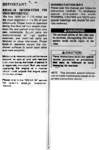
Руководство на английском языке по эксплуатации и техническому обслуживанию мотоциклов Suzuki GSX-R250.
- Издательство: Suzuki Motor Corporation
- Год издания: —
- Страниц: 22
- Формат: PNG
- Размер: 6,2 Mb
Руководство на английском языке по ремонту мотоциклов Suzuki GSX-R400.
- Издательство: Suzuki Motor Corporation
- Год издания: —
- Страниц: 246
- Формат: PDF
- Размер: 22,3 Mb
Руководство на английском языке по ремонту мотоциклов Suzuki GSX-R600 1997-2000 годов выпуска.
- Издательство: Suzuki Motor Corporation
- Год издания: —
- Страниц: 429
- Формат: PDF
- Размер: 48,5 Mb
Руководство на английском языке по ремонту мотоциклов Suzuki GSX-R600 2001-2002 годов выпуска.
- Издательство: Suzuki Motor Corporation
- Год издания: —
- Страниц: 399
- Формат: PDF
- Размер: 41,8 Mb
Руководство на английском языке по ремонту мотоциклов Suzuki GSX-R600.
- Издательство: Suzuki Motor Corporation
- Год издания: 2003
- Страниц: 466
- Формат: PDF
- Размер: 48,9 Mb
Руководство на английском языке по ремонту мотоциклов Suzuki GSX-R600.
- Издательство: Suzuki Motor Corporation
- Год издания: 2006
- Страниц: 517
- Формат: PDF
- Размер: 45,9 Mb
Руководство на английском языке по ремонту мотоциклов Suzuki GSX-R750.
- Издательство: Suzuki Motor Corporation
- Год издания: 1995
- Страниц: 558
- Формат: PDF
- Размер: 188,3 Mb
Руководство на английском языке по ремонту мотоциклов Suzuki GSX-R750 2000-2002 годов выпуска.
- Издательство: Suzuki Motor Corporation
- Год издания: —
- Страниц: 498
- Формат: PDF
- Размер: 142,6 Mb
Руководство на английском языке по ремонту мотоциклов Suzuki GSX-R750.
- Издательство: Suzuki Motor Corporation
- Год издания: 2004
- Страниц: 471
- Формат: PDF
- Размер: 40,8 Mb
Руководство на английском языке по ремонту мотоциклов Suzuki GSX-R750.
- Издательство: Suzuki Motor Corporation
- Год издания: 2006
- Страниц: 522
- Формат: PDF
- Размер: 46,0 Mb
Руководство на английском языке по техническому обслуживанию и ремонту мотоциклов Suzuki GSX600F Katana, GSX750F Katana, GSX1100F Katana 1988-1996 годов выпуска и GSX-R750, GSX-R1100 1985-1992 годов выпуска.
- Издательство: Haynes Publishing
- Год издания: —
- Страниц: 256
- Формат: PDF
- Размер: 37,5 Mb
Руководство на французском языке по техническому обслуживанию и ремонту мотоциклов Suzuki GSX-R750T 1996 года выпуска.
- Издательство: —
- Год издания: —
- Страниц: 86
- Формат: PDF
- Размер: 43,1 Mb
Руководство на английском языке по ремонту мотоциклов Suzuki GSX-R750W.
- Издательство: Suzuki Motor Corporation
- Год издания: 1992
- Страниц: 352
- Формат: PDF
- Размер: 50,6 Mb
Руководство на английском языке по ремонту мотоциклов Suzuki GSX-R1000.
- Издательство: Suzuki Motor Corporation
- Год издания: 2000
- Страниц: 424
- Формат: PDF
- Размер: 211,4 Mb
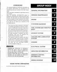
Руководство на английском языке по ремонту мотоциклов Suzuki GSX-R1000.
- Издательство: Suzuki Motor Corporation
- Год издания: 2003
- Страниц: 460
- Формат: PDF
- Размер: 18,8 Mb
Руководство на английском языке по ремонту мотоциклов Suzuki GSX-R1000.
- Издательство: Suzuki Motor Corporation
- Год издания: 2007
- Страниц: 549
- Формат: PDF
- Размер: 48,8 Mb
Руководство на английском языке по эксплуатации и техническому обслуживанию мотоциклов Suzuki GSX-R1100.
- Издательство: Suzuki Motor Corporation
- Год издания: 1988
- Страниц: 90
- Формат: PDF
- Размер: 38,1 Mb
Руководство на английском языке по ремонту мотоциклов Suzuki GSX-R1100.
- Издательство: Suzuki Motor Corporation
- Год издания: 1986
- Страниц: 295
- Формат: PDF
- Размер: 105,4 Mb
Руководство на английском языке по ремонту мотоциклов Suzuki GSX-R1100.
- Издательство: Suzuki Motor Corporation
- Год издания: 1990
- Страниц: 358
- Формат: PDF
- Размер: 50,7 Mb
Руководство на английском языке по ремонту мотоциклов Suzuki GSX-R1100W.
- Издательство: Suzuki Motor Corporation
- Год издания: 1992
- Страниц: 380
- Формат: PDF
- Размер: 52,8 Mb
Руководство на английском языке по ремонту мотоциклов Suzuki GSX-R1300R.
- Издательство: Suzuki Motor Corporation
- Год издания: 2007
- Страниц: 663
- Формат: PDF
- Размер: 26,9 Mb
