- Manuals
- Brands
- Ducati Manuals
- Motorcycle
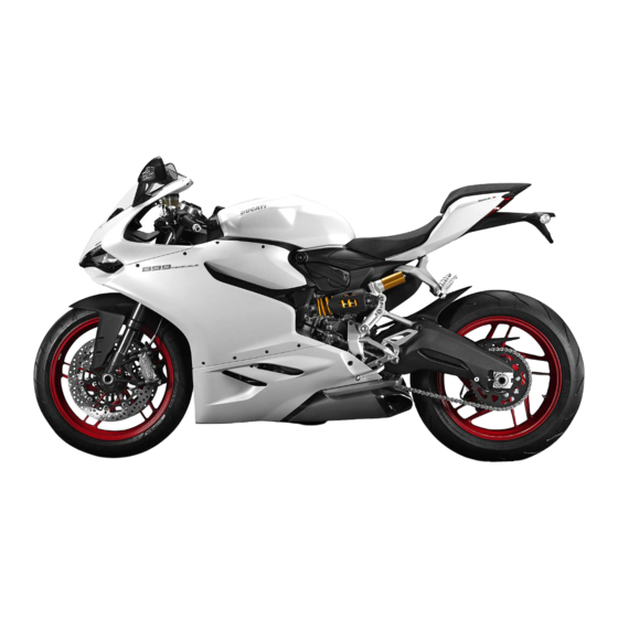
- superbike 899 panigale
- Owner’s manual
-
Contents
-
Table of Contents
-
Bookmarks
Quick Links
Owner’s manual
US/CANADA
1
Related Manuals for Ducati superbike 899 panigale
Summary of Contents for Ducati superbike 899 panigale
-
Page 1
Owner’s manual US/CANADA… -
Page 2
We’d like to welcome you among Ducati enthusiasts and congratulate you on your excellent choice of motorcycle. We imagine you’ll be riding your Ducati motorcycle for long trips as well as short daily excursions. Ducati Motor Holding S.p.A. wishes you smooth and enjoyable riding. -
Page 3: Table Of Contents
Table of Contents California emission control warranty statement Your warranty rights and obligations Manufacturer’s warranty coverage Owner’s warranty responsibilities California evaporation emission system Ducati limited warranty on emission control system Introduction Instrument Panel (Dashboard) Safety guidelines Instrument Panel Warning symbols used in the manual.
-
Page 4
Menu 1: Trip meter 1 (TRIP B) Customizing Riding Modes: Engine setting Menu 1: Partial fuel reserve counter (TRIP Customizing Riding Modes: Restore default FUEL) settings MENU 1: Trip time Engine rpm digital indication (RPM) MENU 1: Clock Battery voltage Menu 1: LAP time MENU 2 functions Pin Code… -
Page 5
Right-hand switch Stopping the motorcycle Throttle twistgrip Parking Front brake lever Refueling Rear brake pedal Tool kit and accessories Gear change pedal Adjusting the position of the gearchange and rear Main maintenance operations brake pedals Remove the fairing Side fairings Main components and devices Change the air filter Position on the vehicle… -
Page 6
Storing the motorcycle Exhaust system Important notes Available colors Electrical system Scheduled maintenance chart Routine maintenance record Scheduled maintenance chart: operations to be performed by the Dealer Routine maintenance record Scheduled maintenance chart: operations to be performed by the customer Technical data Weights Overall dimensions… -
Page 7: Introduction
Safety guidelines Important Your safety and that of others are very important. Possibility of damaging the motorcycle and/or Ducati Motor Holding S.p.A. urges you to ride your its components. motorcycle responsibly. Before using your motorcycle for the first time, Note…
-
Page 8: Permitted Use
This motorcycle carries the rider and may carry one passenger upon installation of a dedicated kit performed exclusively at a Ducati Dealer or Authorized Service Center. Attention The total weight of the motorcycle in running order with rider, passenger, baggage and additional accessories must not exceed 816 lb/ 370 kg.
-
Page 9: Rider’s Obligation
Rider’s obligation Attention All riders must hold a driver’s license. Some medications may induce sleepiness or other effects that impair reflexes and the ability of the Attention rider to control the motorcycle, which may lead to accident. Riding without a license is illegal and punishable by law.
-
Page 10
Attention 1) the removal or rendering inoperative by any person, other than for purposes of maintenance, Failure to be wearing a helmet in case of repair, or replacement, of any device or element accident increases the chance of serious injury and of design incorporated into any new vehicle for even death. -
Page 11: Reporting Of Safety Defects
However, NHTSA cannot become involved in individual problems between you, your dealer, or Ducati North America. To contact NHTSA, you may either call the Auto Safety Hotline toll-free at 1-800-424-9393 (or 366-0123 in Washington, D.C.
-
Page 12: Rider Education
Rider education Suitable clothing includes: helmet, eye protection, gloves, boots, long-sleeved jacket and long pants. Accidents are frequently due to inexperience. Riding, maneuvering and or braking are carried out differently The helmet must have the requisites as listed on from other vehicles. page 9, if the helmet model has no visor, use suitable goggles;…
-
Page 13
Important For the safety of the passenger, make sure that he or she also wears appropriate clothing. -
Page 14: Best Practices» For Safety
Exhaust gases are poisonous and may lead to loss of Failure to follow these instructions releases Ducati consciousness or even death within a short time. Motor Holding S.p.A. from any liability whatsoever for During the ride, assume a correct body position and any engine damage or shorter engine life.
-
Page 15
Important Important The passenger should always hold on to the Visually inspect the tires at regular intervals for strap on passenger seat with both hands. cracks and cuts, especially on sidewalls, bulges or large spots which are indicative of internal damage. Replace them if badly damaged. -
Page 16: Refueling
Refueling Attention Refuel the motorcycle in an open area and with the In case of malaise caused by prolonged engine switched off. inhalation of fuel vapors, stay outdoors and consult a Do not smoke or ever use flames during refueling. physician.
-
Page 17: Carrying The Maximum Load Allowed
Carrying the maximum load allowed Important Your motorcycle is designed for long-distance riding Be sure to secure the luggage to the supports with the maximum load allowed carried in full safety. provided on the motorcycle as firmly as possible. Even weight distribution is critical to preserving these Improperly secured luggage may affect stability.
-
Page 18: Dangerous Products — Warnings
Dangerous products — warnings Attention Used engine oil The brake fluid used in the brake system is corrosive. In the event of accidental contact with eyes or skin, wash the affected area with generous Attention quantities of running water. Prolonged or repeated contact with used engine oil may cause skin cancer.
-
Page 19
The cooling fan operates automatically: keep hands well clear and make sure your clothing does not get caught in the fan. Battery Attention The battery gives off explosive gases; keep it away from any source of ignition such as sparks, flames and cigarettes. -
Page 20: Vehicle Id Number
These numbers identify the motorcycle model and should always be indicated when ordering spare parts. We recommend that you note the frame number of your motorcycle in the space below. Frame number Fig 1 DUCATI PLANT OF MANU FACTURE TYPE OF MOTORCYCLE SEQUENTIAL MODEL…
-
Page 21: Engine Id Number
Engine ID number Note These numbers identify the motorcycle model and should always be indicated when ordering spare parts. The engine identification number is located in the motorcycle front side on the horizontal head cylinder lower side, near the starter motor and the generator cover.
-
Page 22: Plate Positioning
Plate positioning Fig 4…
-
Page 23
Appog giare il veicolo sulla stampella l aterale. Con la sola p ressione del di to, spinge re la catena verso il basso nel pu nto di misu ra e poi rilascia rla. M isu rare la distanza (A) tra il centro dei pe rni della c atena ÷… -
Page 24
Fig 6… -
Page 25
Fig 7… -
Page 26
(Only Canada) Fig 8… -
Page 27
8 (Only Canada) Fig 9… -
Page 28: Noise And Exhaust Emission Control System Information
Carbon monoxide does not react in the same way, Problems that may affect motorcycle but is toxic. Ducati utilizes lean carburetor settings emissions and other systems to reduce carbon monoxide and hydrocarbons. If you are aware of any of the following symptoms,…
-
Page 29: Your Warranty Rights And Obligations
Your emission control system may include parts such You are responsible for presenting your as fuel-injection system, the ignition system, catalytic motorcycle to a Ducati dealer as soon as a converter, and engine computer. Also included may problem exists. The warranty repairs should be…
-
Page 30: California Evaporation Emission System
California evaporation emission system This system consists of: 1) Warn air inlet; 2) Canister; 3) Dell’Orto jet; 4) Fuel tank; 5) Breather pipe; 6) Intake manifolds. Attention In the event of a fuel system malfunction, contact a Ducati Authorized Service Center. Fig 10…
-
Page 31: Ducati Limited Warranty On Emission Control System
Air Resources Board. Any part or parts replaced under Ducati North America, Inc., 10443 Bandley Drive this warranty shall become the property of Ducati. In Cupertino, California, 95014 warrants that each new the state of California only, emissions related…
-
Page 32
Ducati dealer. Ducati shall not be liable A. Repair or replacement required as a result of for any other expenses, loss or damage, whether… -
Page 33
This warranty gives you specific legal rights, and you may also have other rights which vary from state to state. V. This warranty is in addition to the Ducati limited motorcycle warranty. VI. Additional information Any replacement part that is equivalent in performance and durability may be used in the performance of any maintenance or repairs. -
Page 34: Instrument Panel (Dashboard)
Instrument Panel (Dashboard) Turns on when fuel is low and there are about 5 liters of fuel left in the tank. 6) TURN INDICATOR LIGHTS (GREEN). Illuminates and flashes when the turn indicator is in operation. They flash together when the «Hazard» Instrument Panel function is in operation.
-
Page 35
9) ABS LIGHT (AMBER YELLOW) . This turns on to indicate that ABS is disabled or not functioning. Engine on / speed under or equal to 3 mph (5 km/h) Light off Light flashing Light steady ABS disabled with the menu function «ABS» ABS enabled but not working yet Engine on/ speed over 3 mph (5 km/h) Light off Light flashing… -
Page 36
10) DTC INTERVENTION (AMBER YELLOW). Immobilizer Key-on status Light OFF No intervention Light OFF Key-off status Light ON flashing Spark advance cut Light steady ON Key-off status for over Light OFF 12 hours Injection cut Light steady ON 11) OVER REV / IMMOBILIZER / ANTI-THEFT SYSTEM (RED) Over rev No intervention… -
Page 37
Fig 11… -
Page 38: Acronyms And Abbreviations Used In The Manual
DUCATI Quick Shift and pick the one that best suits his/her riding style or ground conditions. The Riding Modes allow the user DUCATI Engine Brake Control to instantly change the engine power delivery (Power Mode), the ABS settings, DTC, DQS, EBC and Engine Control Unit instrument panel graphics.
-
Page 39
(EBC), thereby Ducati Quick Shift (DQS) helping to control the rear wheel slipping (DTC). The Ducati Quick Shift (DQS) is the electronic shifter Ducati Traction Control (DTC) control system used for racing purposes that allows… -
Page 40
Ducati Data Analyzer+ (DDA+) DDA+ is the latest generation of the Ducati Data Analyzer, with built-in GPS signal to create a «virtual finish line». The system automatically detects lap end and stops the lap timer, without the rider needing to do anything. -
Page 41: Function Pushbuttons
Function pushbuttons 1) CONTROL SWITCH UP » » Button used to display and set instrument panel parameters with the position » «. 2) CONTROL SWITCH DOWN » » Button used to display and set instrument panel parameters with the position » «.
-
Page 42: How To Set/Display Parameters
How to set/display parameters Upon start, the instrument panel: turns on the display backlighting; temporarily turns on all its elements; turns the engine rpm bargraph ON and OFF progressively; displays all available speed values progressively from the minimum to the maximum one and vice versa;…
-
Page 43
During the start check stage, if the vehicle speed exceeds 6 mph (10 km/h) (actual speed), the instrument panel will stop: the display check routine and display the Standard Screen containing updated information; the warning light check routine and leave on only the warning lights that are actually active at the moment. -
Page 44
Data displayed on the main screen are as follows: Rpm bar graph. Vehicle speed. Gear engaged. Menu 1 (Odometer, Trip 1, Trip 2, Trip Fuel, Trip Time, Clock, Lap time — only if active). MENU 2 (External air temperature, Instantaneous fuel consumption, Average fuel consumption, Average speed, Trip time). -
Page 45
Fig 14… -
Page 46
Press button (1) to display MENU 1 information. The data displayed in a sequence are: Odometer (TOT); TRIP A; TRIP B; — TRIP FUEL (when function is active); Trip time (TRIP TIME). Clock; Lap time (when LAP function is active). Fig 15… -
Page 47
Press button (2) to display MENU 2 information. The data displayed in a sequence are: Air temperature; Instantaneous fuel consumption (CONS.); Average Fuel Consumption (CONS. AVG); Average speed (SPEED AVG); Fig 16… -
Page 48
Upon the Key-ON, the data displayed for MENU 1 and MENU 2 are the ones displayed upon the previous Key-OFF. Note The factory set default parameter (Odometer — TOT) is displayed for 10 seconds upon Key-ON for MENU 1 and then the parameter from last Key-OFF is displayed. -
Page 49
If the key is not acknowledged upon Key-ON and once the initial check routine is over, the following will happen: if the PIN CODE function is not active, the instrument panel performs the initial check, displays the Standard screen with an E-LOCK error warning and does not allow accessing the SETTING MENU, except for the Error page (ERR);… -
Page 50: Main Functions
Main functions Auxiliary functions The functions displayed in the Standard Screen are DDA (only if present) the following: GPS (only if present) Engine rpm indication (RPM) (CLOCK) Vehicle speed Service warning (SERVICE) Gear ERROR indication Riding Mode Engine coolant temperature MENU 1 displays the following functions: — Odometer (TOT) — Trip meter 1 (TRIP A)
-
Page 51
The functions within the SETTING MENU that can be modified by the user are the following: RIDING MODE (R.M.) customization: within this menu, rider can customize the following: — EBC level (EBC) — DTC level (DTC) — DQS ON/OFF (DQS) — ABS setting (ABS) — Engine setting (ENGINE) — Reset to default factory settings (DEFAULT) -
Page 52
Engine rpm indicator (RPM). The instrument panel receives the engine rpm information and displays it on the relevant bargraph. The information is displayed by the bargraph filling from the left to the right according to the engine rpm and with the negative display (switching OFF of the digit and switching on of its rectangle) of the numerical digit of the relevant miles. -
Page 53
Vehicle speed The instrument panel receives information about the actual vehicle speed (calculated in km/h) and displays the value increased by 5% and converted in the set unit of measurement (mph or km/h). A string of dashes «- — -» is displayed with the set unit of measurement if: speed is equal to 186 mph or 299 km/h or if instrument panel is not receiving the speed value… -
Page 54
Gear The instrument panel receives information about the gear engaged and displays the corresponding value. If a gear is engaged, the displayed value may range from «1» to «6», while if in neutral «N» is displayed. Letter «C» is displayed when system requires you to shift gear. -
Page 55
Gear sensor learning During the gear learning procedure to be performed on the motorcycle the operator is guided by the displayed information. The instrument panel indicates the saved gear and prompts the operator to proceed with the next gear. When the instrument panel displays letter «C» instead of the gear number and switches Neutral «N»… -
Page 56: Riding Mode
RACE Every Riding Mode contains the following SPORT parameters set by Ducati or customized by the user through the setting function pages: a specific level of intervention for the DTC One of these will be marked by an arrow near its traction control (1, 2, 3, 4, 5, 6, 7, 8, off);…
-
Page 57
Once the desired riding mode is highlighted, confirm the selection by holding down the CONFIRM MENU button (4) for 2 seconds: the new riding mode selection is saved and the Standard Screen is displayed. Once the desired riding mode is highlighted, if the CONFIRM MENU button (4) is not pressed within 10 seconds, the new riding mode selection is not stored and the Standard Screen is displayed. -
Page 58
When the system requests rider to confirm the riding mode change, the procedure will output an error if: the throttle twistgrip is open, brakes are activated and the motorcycle is not still; in this case «CLOSE GAS» and «DON’T BRK» warnings flash on the display in MENU 1 and MENU 2, by alternating each writing every second. -
Page 59
Note If the change of riding mode is associated with the ABS change of state from «ON» to «OFF» or vice- versa, the instrument panel also starts the procedure for disabling or activating the ABS, respectively, upon confirmation of the selected riding mode. Note If at least one error is present upon Riding Mode change, priority is given to messages «CLOSE GAS»… -
Page 60: Dtc
The instrument panel displays DTC status as follows: if DTC is active, DTC indication and the rectangle with the Traction Control intervention level number (1 to 8); if DTC is disabled, DTC indication and the rectangle with the steady symbol «- -«; if DTC is in fault or the Black Box is in fault, DTC and the rectangle with the flashing «- -«…
-
Page 61
Attention DTC is a rider aid that can be used both on the track and the road. The system is designed to make riding easier and to enhance safety, but in no way relieves the rider of the obligation to ride responsibly and maintain a high standard of conduct in accordance with traffic laws so as to avoid accident or force emergency maneuvers, whether caused by… -
Page 62
RIDING MODE DEFAULT RACE Track use, for very expert riders, opti- mized for Pirelli tires with SC2 com- pound. System permits sliding side- ways. RACE Track use, for very expert riders, opti- It is the default level for the mized for OEM tires (Original Equipment «RACE»… -
Page 63
RIDING MODE DEFAULT WET (RAIN) Track use, with rain tires, it was specifi- cally optimized for Pirelli Diablo Rain tires (rear tire 190/60 ZR17). WET (HEAVY Wet road and slippery asphalt with OEM It is the default level for the RAIN) tires;… -
Page 64
Tips on how to select the sensitivity level Attention The DTC levels 2-3-4-5-6-8 settings have been calibrated using the tires originally supplied with your Attention motorcycle (Pirelli Diablo Rosso Corsa SP The DTC level 1 setting has been calibrated 120/70ZR17 at the front and 180/60ZR17 at the rear). using tires with SC2 compound (Pirelli Diablo Using tires with different size and characteristics Supercorsa SC2), which are not originally supplied… -
Page 65
slide: these levels are recommended on the track The relation of the DTC intervention level to riding only and exclusively for expert riders: in particular, mode: The DTC will tend to kick in more with a level 1 is designed to work at best only with tires «smooth»… -
Page 66
to level 5, 4, etc., until you find the level that suits you best. If changes occur in the grip conditions and/or circuit characteristics and/or your riding style, and the level setting is no longer suitable, switch to the next level up or down and proceed to determine the best setting (e.g. -
Page 67: Ebc
The instrument panel displays EBC status as follows: if EBC is active, EBC indication and the rectangle with the intervention level number (1 to 3); if EBC system is disabled, EBC indication and the rectangle with the steady symbol «- -«; if EBC system or control unit is in fault, EBC and the rectangle with the flashing «- -«…
-
Page 68
The EBC is a system controlling the engine brake while riding with throttle fully closed (both when downshifting and when simply releasing throttle with the same gear engaged, and both under braking or not), this system independently sets the throttles in order to make the torque transmitted backward from wheel to engine during these stages constant. -
Page 69
The following table indicates the most suitable level of EBC intervention for the various riding types as well as the default settings in the «Riding Mode» that can be selected by the rider: CHARACTERISTIC DEFAULT Maximum engine brake Rather important engine brake, but less than that It is the default level for all Riding obtained with EBC OFF Modes… -
Page 70
Tips on how to select the sensitivity level level 1 the engine brake is increasing progressively; with EBC OFF you set the maximum engine brake possible. Attention The choice of the correct level mainly depends on the The EBC levels 1-2-3 settings have been following parameters: calibrated using the tires originally supplied with your The tire/asphalt grip (type of tire, amount of tire… -
Page 71: Dqs
The instrument panel displays DQS status as follows: if DQS is enabled, DQS indication and the relevant box; if DQS or the control unit is in fault, the EOBD light and warning symbol turn on as well and the corresponding error is displayed. Fig 29 Fig 30…
-
Page 72: Abs
If the vehicle is equipped with ABS and the instrument panel displays the box with ABS status. The instrument panel displays: if ABS is active, ABS indication and the rectangle with the set intervention level number (1 to 3); if ABS is disabled, ABS indication and the rectangle with the steady symbol «- -«;…
-
Page 73
The following table indicates the most suitable level of ABS intervention for the various riding types, as well as the default settings in the «Riding Mode» that can be selected by the rider: RIDING MODE CHARACTERISTIC DEFAULT The ABS is disabled RACE Exclusively for track use, for expert riders It is the default level for the… -
Page 74: Engine Coolant Temperature
Tips on how to select the sensitivity level keeps a good alignment during the whole braking. Settings between level 3 and level 1 privilege more and more the braking power rather than stability and Attention lift-up control; level 1 provides no lift-up control, the The ABS levels 1-2-3 settings have been rear brake is not controlled by the ABS.
-
Page 75
If reading is: <= (lower than or equal to) -40 °F (-40 °C), a string of flashing dashes «- — -» is displayed; included within the interval -38 °F (-39 °C) and + 102 °F (+39 °C) «LO» is displayed steadily; included within the interval +104 °F (+40 °C) and +248 °F (+120 °C) the value is displayed steadily;… -
Page 76
Fig 33… -
Page 77: Menu 1 Functions
Menu 1 functions MENU 1 functions are: Odometer (TOT); Trip meter 1 (TRIP A); Trip meter 2 (TRIP B); Partial fuel reserve counter (TRIP FUEL); Trip time (TRIP TIME); Clock; LAP time (only if active). By pressing button (1) it is possible to view the functions of MENU 1.
-
Page 78: Menu 1: Odometer (Tot)
Menu 1: Odometer (TOT) The odometer counts and displays the total distance covered by the vehicle with the set unit of measurement (mi or km). The odometer number (mi or km) is displayed with the «TOT» indication and unit of measurement. When the maximum value is reached (199999 mi or 199999 km) the instrument panel will permanently display said value.
-
Page 79
Note If a string of flashing dashes » —— » is displayed within odometer function, please contact a Ducati Dealer or Authorized Service Center. -
Page 80: Menu 1: Trip Meter 1 (Trip A)
Menu 1: Trip meter 1 (TRIP A) The trip meter counts and displays the partial distance covered by the vehicle with the set unit of measurement (mi or km) and is used as a basis to calculate average fuel consumption, average speed and trip time.
-
Page 81: Menu 1: Trip Meter 1 (Trip B)
Menu 1: Trip meter 1 (TRIP B) The trip meter counts and displays the partial distance covered by the vehicle with the set unit of measurement (mi or km). The value (mi or km) is displayed with the TRIP B indication and unit of measurement.
-
Page 82: Menu 1: Partial Fuel Reserve Counter (Trip Fuel)
Menu 1: Partial fuel reserve counter (TRIP FUEL) The fuel trip meter counts and displays the distance covered by the vehicle on reserve (since the low fuel light turns on) with the set unit of measurement (mi or km). When the Low fuel light (A) turns on, the display automatically shows the TRIP FUEL function, regardless of the currently displayed function;…
-
Page 83: Menu 1: Trip Time
MENU 1: Trip time The instrument panel calculates and displays the trip time as «hhh:mm» followed by TRIP TIME. The calculation considers the time since TRIP A was last reset. When TRIP A is reset, this value is reset as well.
-
Page 84: Menu 1: Clock
MENU 1: Clock The instrument panel receives information about the time to be displayed. The time indication is displayed in MENU 1. The instrument panel shows the time in the following format: hh (hours) : mm (minutes) with «AM» indication (for values ranging between 0:00 and 11:59), or with «PM»…
-
Page 85: Menu 1: Lap Time
Menu 1: LAP time LAP function information is available when the function is active. After the LAP function activation from the SETTING MENU, when going back to the Standard screen the LAP function is automatically displayed as first page of MENU 1 and the messages «TIME»…
-
Page 86
If the GPS is installed, the «Start/Stop» command of the lap is sent by GPS. To allow the GPS to automatically identify the «Start/Stop» at every lap, the user must save the finish line coordinates by pressing the FLASH (3) button upon first crossing of the finish line. -
Page 87
If lap timer is active but vehicle is at standstill, lap when the FLASH button (3) is pressed for the first timer is temporarily stopped after 5 seconds and it is time, or upon an equivalent command (optional displayed with the initial indication «0’00’’00». the next GPS) the instrument panel displays the lap timer time rider pushes the FLASH button (3) or any with resolution of a tenth of a second (0’… -
Page 88
Laps are numbered from 01 to 30 and are in a loop: after the first 30 laps the instrument panel will overwrite information starting from Lap 01. If the LAP function is interrupted and then reactivated but memorized laps are not deleted, lap information will be recorded by overwriting data of the oldest Lap. -
Page 89: Menu 2 Functions
MENU 2 functions MENU 2 functions are: External air temperature Instantaneous fuel consumption (CONS.) Average Fuel Consumption (CONS. AVG) Average speed (SPEED AVG) By pressing button (2) it is possible to view the functions of MENU 2. Fig 43…
-
Page 90: Menu 2: External Air Temperature
MENU 2: External air temperature The instrument panel displays the ambient temperature in the set unit of measurement (°C or °F), followed by the set unit of measurement, and the «T-AIR» text. The temperature value is displayed when ranging from -38 °F to +255 °F (or -39 °C to +124 °C). For different temperature values (lower than -39 °C or higher than +124 °C) a string of three steady dashes «…
-
Page 91: Menu 2: Instantaneous Fuel Consumption
MENU 2: Instantaneous fuel consumption The instrument panel calculates and displays the vehicle instantaneous fuel consumption, the set unit of measurement and CONS. text. The calculation is made considering the quantity of fuel used and the distance traveled during the last second.
-
Page 92: Menu 2: Average Fuel Consumption
MENU 2: Average fuel consumption The instrument panel calculates and displays the vehicle average fuel consumption, the set unit of measurement and CONS. AVG text. The calculation is made considering the quantity of fuel used and the distance traveled since TRIP A was last reset. When TRIP A is reset, the value is reset and the first value available is displayed 10 seconds after the reset.
-
Page 93: Menu 2: Average Speed
MENU 2: Average speed The instrument panel calculates and displays the vehicle average speed, the set unit of measurement and SPEED AVG text. The calculation considers the distance and time since TRIP A was last reset. When TRIP A is reset, the value is reset and the first value available is displayed 10 seconds after the reset.
-
Page 94: Auxiliary Functions
Auxiliary functions The instrument panel indicates DDA status only if the vehicle fits the DDA. If the DDA indication is displayed it means that the DDA is active and recording. If the DDA indication is not displayed it means that the DDA is not active.
-
Page 95
GPS (optional) The instrument panel provides information only on the GPS receiver (optional). The instrument panel displays the status of the GPS receiver if it is installed on the motorcycle. If «GPS» is displayed steady on then the GPS receiver is in a correctly acquired position and in active satellite reception. -
Page 96: Service Warning (Service)
Service warning (SERVICE) This indication shows the user that the bike is due for service and must be taken to a Ducati Authorized Service Center. The service warning indication can be reset only by the Authorized Ducati Service Center during servicing.
-
Page 97: Oil Service Zero Indication
«SERVICE», the Oil symbol and the message «OIL» upon each Key-ON; after 5 seconds both the message «SERVICE» and the Oil symbol become steady until Key-OFF or until an Authorized Ducati Service Center performs a reset. Fig 51…
-
Page 98
OIL SERVICE or DESMO SERVICE countdown indication After OIL SERVICE zero reset (at 600 mi — 1000 km), the instrument panel activates the countdown of the miles (or kilometers) left before the following service operation: OIL SERVICE (A) or DESMO SERVICE (B). The kilometer count indication is shown upon Key-On for 2 seconds whereas when there are 600 mi (1000 km) left before the next service operation, the… -
Page 99: Oil Service Or Desmo Service Indication
«OIL» or «DESMO» upon each Key-ON; after 5 seconds both the message «SERVICE» and the Oil or Desmo symbol becomes steady until Key-OFF or until an Authorized Ducati Service Center performs a reset. Fig 54 Fig 55…
-
Page 100: Errors
Errors The instrument panel manages error warnings in order to allow the rider to identify any abnormal vehicle behavior in real time. Upon Key-On, if there are active errors, the instrument panel turns on the EOBD light, the Warning symbol and activates the SETTING MENU Error page.
-
Page 101
ON for 3 seconds. When an error is triggered the EOBD light turns on as well. Attention When one or more errors are displayed, always contact a Ducati Dealer or Authorized Service Center. -
Page 102: Displayed Error Description
Displayed error description Displayed error Description CAN LINE CAN line BUS Off UNK-D Control unit not acknowledged by the system — wrong SW ABS control unit faulty communication / operation BBS control unit faulty communication / operation BBS control unit general malfunction Exhaust valve motor malfunction DSB control unit faulty communication / operation ELOCK…
-
Page 103
Displayed error Description Intake duct air temperature sensor malfunction Injection relay malfunction Ignition coil malfunction Injector malfunction Engine rpm sensor malfunction Lambda sensor or Lambda sensor heater malfunction Vehicle starting relay malfunction Quick shift device switch malfunction Secondary air sensor malfunction GEAR Gear sensor malfunction FUEL… -
Page 104
Note «FAN» indication can be activated also by BBS ECU malfunction and its faulty communication with fans. Pay attention to engine temperature indication. -
Page 105
Error icons table WARNING LIGHT / ERROR MESSAGE ERROR Black-Box ABS control unit instrument panel control unit ELOCK E-LOCK control unit ENG. Can Bus OFF UNK-D Software compatibility Cooling fan BATT. Battery voltage… -
Page 106
WARNING LIGHT / ERROR MESSAGE ERROR STOP Rear stop light STAND Side stand sensor GEAR Gear sensor SPEED Speed sensor FUEL Low fuel sensor Note «FAN» indication can be activated also by BBS ECU malfunction and its faulty communication with fans. Pay attention to engine temperature indication. -
Page 107: Setting Menu
Setting MENU Press buttons (1) and (2) to highlight the customizable parameters one by one: in particular, use button (1) This menu allows enabling, disabling and setting to highlight the following item and button (2) to some vehicle functions. highlight the previous item. To enter the Setting MENU hold button (2) for 3 After highlighting the required parameter, press seconds, with Key-On and vehicle actual speed…
-
Page 108
Fig 58… -
Page 109: Customizing Riding Modes
Customizing Riding Modes All settings of every riding mode can be customized. Enter the Setting MENU. Select R.M. (Riding Mode) option by pressing button (1) or (2). Once function is highlighted, press CONFIRM MENU button (4). You open the R.M. MENU (Riding mode). When accessing this function, the three riding modes (RACE, SPORT or WET) will be displayed.
-
Page 110
If the parameters are changed accidentally, use the «DEFAULT» function to reset the parameters. DEFAULT (to reset the parameters set by Ducati for each riding mode) When entering the customization menu of the… -
Page 111
Fig 60… -
Page 112: Riding Mode Customization: Storing Riding Mode Settings
Riding mode customization: Storing Riding Mode settings It is possible to save the parameters set for each riding mode. To save the parameter settings of a Riding Mode it is necessary to gain access to the SETTING MENU, use buttons (1) and (2) to select the message «R.M.» (Riding Mode) and press button (4).
-
Page 113
Attention Changes should only be made to the parameters by people who are experts in motorcycle setup; If the parameters are changed accidentally, use the «DEFAULT» function to reset the parameters. -
Page 114: Customizing Riding Modes: Ebc Level Setting
Customizing Riding Modes: EBC level confirm. The value will become automatically steady and the message EXIT will be highlighted. setting To exit the menu and go back to previous page, select This function disables or sets the rear wheel anti- EXIT and press button (4).
-
Page 115
Fig 62… -
Page 116: Customizing Riding Modes: Dtc Level Setting
Customizing Riding Modes: DTC level become automatically steady and the message «EXIT» will be highlighted. setting To exit the menu and go back to previous page, select This function disables or sets DTC level for the EXIT and press button (4). The instrument panel will selected riding mode.
-
Page 117
Fig 63… -
Page 118: Customizing Riding Modes: Dqs Enable/ Disable
Customizing Riding Modes: DQS enable/ become automatically steady and the message «EXIT» will be highlighted. disable To exit the menu and go back to previous page, select This function disables or enables the DQS for the EXIT and press button (4). The instrument panel will selected riding mode.
-
Page 119
Fig 64… -
Page 120: Customizing Riding Modes: Abs Setting
Customizing Riding Modes: ABS setting go back to the previous level and will automatically highlight the message «MEMORY». This function disables or sets ABS level for the selected riding mode. Enter the Setting MENU. Note Select R.M. (Riding Mode) option by pressing button (1) or (2).
-
Page 121
Fig 65… -
Page 122: Customizing Riding Modes: Engine Setting
Customizing Riding Modes: Engine setting Note This function customizes engine power associated To save the new ENGINE parameter setting with each riding mode. follow the procedure «Storing Riding Mode settings» Enter the Setting MENU. Select R.M. (Riding Mode) described in paragraph «Storing Riding Mode option by pressing button (1) or (2).
-
Page 123
Fig 66… -
Page 124: Customizing Riding Modes: Restore Default Settings
Customizing Riding Modes: Restore default settings This function allows restoring the default values set by Ducati for the parameters relating to each riding mode. Enter the Setting MENU. Select R.M. (Riding Mode) option by pressing button (1) or (2). Once function is highlighted, press CONFIRM MENU button (4).
-
Page 125
The parameter restoration takes 2 seconds and the display shows the message «DEFAULT» and its box steady ON. Then «EXIT» is automatically highlighted. To exit the menu and go back to Setting MENU main page, select «EXIT» and press button (4). -
Page 126: Engine Rpm Digital Indication (Rpm)
Engine rpm digital indication (RPM) This function displays the number of RPM in digital format (recommended for improved accuracy when setting idle rpm). Enter the Setting MENU. Select «RPM» option, by pressing button (1) or (2). Once function is highlighted, press CONFIRM MENU button (4).
-
Page 127: Battery Voltage
Battery voltage This function allows you to check the vehicle battery voltage. Enter the Setting MENU. Select BAT. (Battery) option, by pressing button (1) or (2). Once function is highlighted, press CONFIRM MENU button (4). You open the BAT. (Battery) menu. The information will be displayed as follows: if battery voltage is below 11.0 V, a flashing LOW warning is displayed;…
-
Page 128
If the battery voltage error is present, the instrument panel will show three flashing dashes » — — — » as voltage value, the EOBD light and the Warning symbol will turn on and the corresponding «Batt.» error is displayed in the Error Menu. If the instrument panel is not receiving battery voltage value, a string of three steady dashes «- — -«… -
Page 129: Dda
This function allows you to enable and disable the DDA, view the percentage of memory used and to delete data stored in the DDA memory. The page for the DDA is only available when the device is fitted to the bike.
-
Page 130
DDA enable/disable To enable / disable the DDA device enter the SETTING MENU. Select DDA option, by pressing button (1) or (2). Once function is highlighted, press CONFIRM MENU button (4). You open the DDA menu. When entering this function the display shows the currently set DDA status: status ON indicates that the DDA is active, otherwise status will be OFF. -
Page 131
Fig 71… -
Page 132
Viewing/deleting the DDA memory If deletion is successful, the instrument panel will read OK for 2 seconds and refresh the memory status This function allows displaying the DDA memory displayed. If deletion is not successful, the status and erasing the stored data. instrument panel will still show memory used status. -
Page 133
Fig 72… -
Page 134: Pin Code
The motorcycle owner must activate (store) the PIN code; if there is already a stored PIN, contact an Authorized Ducati Dealer to have the function «reset». To perform this procedure, the Authorized Ducati Dealer may ask you to demonstrate that you are the…
-
Page 135
Entering the PIN CODE To activate the PIN CODE function and enter your own PIN CODE you must open the Setting MENU. Select PIN option, by pressing button (1) or (2). Once function is highlighted, press CONFIRM MENU button (4). When accessing this function, the «N:»… -
Page 136
Fig 73… -
Page 137
PIN CODE. The page for entering the very first PIN CODE is active and available again only in case the PIN CODE function is reset (but this is only possible at a DUCATI Authorized Service Center). Fig 74… -
Page 138: Changing The Pin Code
Changing the PIN CODE To change the existing PIN CODE and activate a new one, you must open the Setting MENU. Select PIN option, by pressing button (1) or (2). Once function is highlighted, press CONFIRM MENU button (4). When accessing this function, the «O:» (old) indication followed by four flashing dashes «- — — -«…
-
Page 139
Fig 75… -
Page 140
When you press button (4) to confirm the fourth and last digit: if the PIN code is correct, the instrument panel displays «OK» for 2 seconds and then displays the message » N:» (new) followed by four flashing dashes «- — — -» of the new PIN. if the PIN is not correct, the instrument panel displays KO for 2 seconds and then highlights the string of four dashes «- — — -«… -
Page 141
Entering the «new» code: 1) Press button (4), one digit starts flashing indicating «0»; 2) Each time you press the button (2) the displayed number increases by one (+ 1) up to «9» and then starts back from «0»; 3) Each time you press the button (1) the displayed number decreases by one (- 1) up to «1»… -
Page 142
Fig 77… -
Page 143
When you press button (4) to confirm the fourth and last digit, the instrument panel highlights the «MEMORY» item and the relevant box will start flashing. To save the new setting, hold button (4) for 2 seconds while the «MEMORY» item is highlighted. If settings have been saved, the message «MEMORY»… -
Page 144: Clock
Clock This function allows user to set or adjust the time. To set the clock gain access to the SETTING MENU, and keys (1) and (2) to select the CLK indication, then press button (4) to confirm. When entering this function, the current time is displayed (e.g.: AM 10 : 30) and the message «AM»…
-
Page 145
Setting the hours Use buttons (1) and (2) to select the digits corresponding to the hours (the selected status will flash) and press button (4) to confirm. The «hour» value starts flashing more quickly. Use buttons (1) and (2) to decrease by 1 («0», «11», ..»1″, «0» for AM and «12», «11», ..»1″, «12»… -
Page 146
Setting the minutes Use buttons (1) and (2) to select the digits corresponding to the minutes (the selected status will flash) and press button (4) to confirm. The «minute» value starts flashing more quickly. Use buttons (1) and (2) to decrease by 1 («59», «58», ..»00″, «59») and increase by 1 the minute value («00», «01», ..»59″, «00»). -
Page 147
Setting am/pm Use buttons (1) and (2) to select the «AM» or «PM» indication (the selected status will flash) and press button (4) to confirm. The «day time» value starts flashing more quickly. Use buttons (1) and (2) to change from «AM» to «PM» and vice versa. Once you reach the value to be set, press button (4) to confirm and the set «day time»… -
Page 148: Setting Backlighting
Setting backlighting This function allows adjusting the backlighting intensity. To adjust the backlighting gain access to the SETTING MENU, and keys (1) and (2) to select the «B.L.» indication, then press button (4) to confirm. When entering this function, the currently used mode name flashes.
-
Page 149
Fig 83… -
Page 150: Lap
The LAP function can be enabled and disabled by the user through the SETTING MENU, in the LAP page. When activating this function, the instrument panel displays the stopped timer ( 0’ 00’’ 00 ) in MENU 1 on the main screen. Note When the LAP function is active, the FLASH button takes on the dual function of high beam…
-
Page 151
Enabling / disabling Lap recording To enable / disable the Lap recording gain access to the SETTING MENU, use keys (1) and (2) to select the LAP indication, then press button (4). When entering the function, the currently set LAP function status starts flashing. -
Page 152
Fig 84… -
Page 153
The LAPs previously stored with the «LAP recording» function of the Menu can be displayed. The information displayed is lap time, maximum rpm and top speed. Saved LAPs can also be deleted. -
Page 154
Displaying the stored LAPs next lap (laps are displayed in increasing order, i.e. LAP 01 … LAP 02 … LAP 03 ..LAP 30); and then To view the stored LAPs, you must enter the Setting highlight EXIT; use button (1) to view the previous lap MENU. -
Page 155
Fig 85… -
Page 156
Erasing stored LAPs To erase the stored LAPs, you must enter the Setting MENU. Select LAP option, by pressing button (1) or (2). Once function is highlighted, press CONFIRM MENU button (4). Use buttons (1) and (2) to select the «ERASE» indication (the selected status will flash) and press button (4) for 2 seconds to confirm. -
Page 157
It is possible to erase the memorized LAPs also in the DATA sub-menu. When entering the DATA page, the instrument panel shows the memorized lap information (ref. to paragraph «Displaying the stored LAPs»). Press button (4) to highlight the option ERASE. User must confirm deletion by pressing button (4) for 2 seconds. -
Page 158: Setting The Unit Of Measurement
Setting the unit of measurement This function allows you to change the units of measurement of the displayed values, regardless of the «Country» configuration. To manually set the units of measurement, you must enter the SETTING MENU. Select UNT option, by pressing button (1) or (2). Once function is highlighted, press CONFIRM MENU button (4).
-
Page 159
Fig 88… -
Page 160
Setting the unit of measurement: Speed This function allows you to change the speed measurement units (and therefore those of distance traveled). To enter this function gain access to the SETTING MENU, and keys (1) and (2) to select the UNT indication, then press button (4). -
Page 161
Setting the unit of measurement: Temperature This function allows you to change the units of measurement of the temperature. To enter this function gain access to the SETTING MENU, and keys (1) and (2) to select the UNT indication, then press button (4). Select TEMP option, by pressing button (1) or (2). -
Page 162
Setting the unit of measurement: Fuel Instantaneous fuel consumption and Average fuel consumption. consumption This function allows you to change the units of measurement of the fuel consumption. To enter this function gain access to the SETTING MENU, and keys (1) and (2) to select the UNT indication, then press button (4). -
Page 163
Fig 91… -
Page 164
Setting the unit of measurement: Restore automatic settings This function allows you to restore the automatic settings for the units of measurement of all indications displayed on the instrument panel. To enter this function gain access to the SETTING MENU, and keys (1) and (2) to select the UNT indication, then press button (4). -
Page 165
Chart of the units of measurement SPEED T_ENGINE INSTANTANEOUS TRIPA AVERAGE SPEED T_AIR FUEL CONSUMP- TRIPB TION TRIP FUEL AVERAGE FUEL CONSUMPTION Europe km/h °C l/100 km miles °C mpg UK miles °F mpg USA Canada km/h °C l/100 km France km/h °C… -
Page 166: Light Control
Light control Low / High beam This function allows you to reduce current consumption from the battery, by managing headlight switching-on and off. At Key-On, the high beam and low beam lights are off, only the parking lights are turned on. Once the engine is started, the low beam is turned on;…
-
Page 167
If engine is not started within 60 seconds since the button was first pressed, the low and high beam lights are turned off. If the low beam or high beam was turned on before starting the engine (with the procedure described above), the headlight turns off automatically when starting the engine and will turn on again when the engine has been completely started. -
Page 168
Parking function Note If there is a sudden interruption in the battery while the function is active, the instrument panel will disable the function when the voltage is restored. The «Parking» function activates the front and rear parking lights when the vehicle is turned off so it is visible when parked. -
Page 169
Hazard function The HAZARD function activates all four turn indicators at the same time to warn about an emergency situation. Take button (4) in HAZARD position (6) for 3 seconds to activate this function. It can only be activated when vehicle is on (i.e. when key is turned to ON, engine condition is irrelevant). -
Page 170
Once the HAZARD function is activated, if vehicle is turned off (i.e. key turned to OFF), the function stays active until manually turned off by the user or as long as the battery voltage is 12.2 V. If voltage is < (below) 12.2 V the turn indicators turn off automatically in order to save battery charge. -
Page 171: The Immobilizer System
The Immobilizer system For improved anti-theft protection, the motorcycle is equipped with an IMMOBILIZER, an electronic system that inhibits engine operation whenever the ignition switch is turned off. Housed in the handgrip of each ignition key is an electronic device that modulates an output signal. When the ignition is turned on this signal is generated by a special antenna incorporated in the switch and changes every time.
-
Page 172: Keys
Keys The owner receives 2 keys with the vehicle. These keys contain the «immobilizer system code». The keys (B) are regular ignition keys and are used to: start up the engine; open the fuel tank filler plug; open the seat lock. Attention Keep the keys separate and use only one of the keys to start the motorcycle.
-
Page 173: Operation
When the ignition key is turned to OFF, the immobilizer inhibits engine operation. If the other key does not work out either, contact the Ducati Service network. Attention Any important shock might damage the electronic components fitted into the key. Use only one key during the procedure.
-
Page 174: Duplicate Keys
Duplicate keys If you need any duplicate keys, contact the Ducati Service network with all the keys you have left. The Ducati Service Center will program all the new keys as well as any keys you already have. You may be asked to provide proof that you are the legitimate owner of the motorcycle.
-
Page 175: Vehicle Release Through Pin Code
Vehicle release through PIN CODE In case of key acknowledgment system or key malfunction, the instrument panel allows the user to enter his/her own PIN code to temporarily restore vehicle operation. If the PIN CODE function is not active, the instrument panel does not activate the page for entering the code, but shows the Standard Screen instead, triggers the E-Lock error to inform the user that there is a problem with key reading/…
-
Page 176
Entering the code (A): 1) Press button (4), one digit starts flashing indicating «0»; 2) Each time you press the button (2) the displayed number increases by one (+ 1) up to «9» and then starts back from «0»; 3) Each time you press the button (1) the displayed number decreases by one (- 1) up to «1»… -
Page 177
When you press button (4) to confirm the fourth and last digit: if the PIN code is correct, the instrument panel displays OK for 2 seconds and then shows the «standard screen» and triggers the E-Lock error to still show the user that there is a problem with key reading/acknowledgment. -
Page 178
Important If this procedure is necessary in order to start the vehicle, contact an Authorized Ducati Service Center as soon as possible to fix the problem. -
Page 179: Controls
Controls Position of motorcycle controls Attention This section shows the position and function of the controls used to ride the motorcycle. Be sure to read this information carefully before you use the controls. 1) Instrument Panel. 2) Key-operated ignition switch and steering lock. 3) LH switch.
-
Page 180: Key-Operated Ignition Switch And Steering Lock
Key-operated ignition switch and steering lock It is located in front of the fuel tank and has three positions: A) ON: enables lights and engine operation; B) OFF: disables lights and engine operation; C) LOCK: the steering is locked; Note To move the key to the last position, press it down before turning it.
-
Page 181: Left-Hand Switch
Left-hand switch 1) Dip switch, light dip switch, two positions: (A) every time it is pressed down the light switches from low beam on ( ) to low beam and high beam (B) pushed to the side ( ) = high beam flasher (FLASH), START/STOP LAP function.
-
Page 182: Clutch Lever
Clutch lever Lever (1) disengages the clutch. It features a dial adjuster (2) for lever distance from the twistgrip on handlebar. The lever distance can be adjusted through 10 clicks of the dial (2). Turn clockwise to increase lever distance from the twistgrip. Turn the adjuster counterclockwise to decrease lever distance.
-
Page 183: Right-Hand Switch
Right-hand switch 1) Red ON/OFF switch. 2) Black ENGINE START button. The switch (1) has three positions: A) center: RUN OFF. In this position, the engine cannot be started and all electronic devices are off. B) pushed down: ON/OFF. In this position, the system can be turned on (Key-On) and off (Key-Off).
-
Page 184: Throttle Twistgrip
Throttle twistgrip The twistgrip (1) on the right handlebar opens the throttles. When released, it will spring back to the initial position (idling speed). Fig 105…
-
Page 185: Front Brake Lever
Front brake lever Pull in the lever (1) towards the twistgrip to operate the front brake. The system is hydraulically operated and you just need to pull the lever gently. The control lever (1) features a dial adjuster (2) for lever distance from the twistgrip on handlebar adjustment.
-
Page 186: Rear Brake Pedal
Rear brake pedal Push down the pedal (1) to operate the rear brake. The system is hydraulically operated. Fig 107…
-
Page 187: Gear Change Pedal
Gear change pedal When released, the gear change pedal (A) automatically returns to rest position (N) in the center. This is indicated by the instrument panel light NEUTRAL N coming on. The pedal can be moved: down = press down the pedal to engage the 1 gear and to shift down.
-
Page 188: Adjusting The Position Of The Gearchange And Rear Brake Pedals
Adjusting the position of the gearchange and rear brake pedals The position of the gearchange and rear brake pedals in relation to the footrests can be adjusted to suit the requirements of the rider. Adjust the pedals as follows: Gear change pedal hold the linkage (1) and slacken the lock nuts (2) and (3).
-
Page 189
Operate the pedal (8) by hand to check that there is 1.5 to 2 mm of freeplay before the brake bites. If not, adjust the length of the master cylinder pushrod. Attention Have the pedal adjusted at a Ducati Dealer or Authorized Service Center. Fig 110 Fig 111… -
Page 190: Main Components And Devices
Main components and devices Position on the vehicle 1) Fuel tank plug. 2) Seat lock. 3) Side stand. 4) Rear-view mirrors. 5) Front fork adjusters. 6) Rear shock absorber adjusters. 7) Catalytic converter (both sides).
 Exhaust muffler (both sides). Fig 112…
 -
Page 191: Tank Filler Plug
Tank filler plug Opening Lift the protection lid (1) and fit the ignition key into the lock. Turn the key clockwise 1/4 turn to unlock. Lift the plug (2). Closing Close the cap (2) with the key inserted and press it into its seat.
-
Page 192: Seat Lock
Seat lock Opening Insert the key into the seat lock (1) and turn it until the seat (2) disengages with an audible click. Slide out the seat cover (2) towards front of the motorcycle until it comes off. Closing Insert the seat cover (2) from the seat side and slide the cover towards the rear of the motorcycle until it fits in place.
-
Page 193: Side Stand
Side stand Important Use the side stand to support the motorcycle only during short stops. Before lowering the side stand, make sure that the supporting surface is hard and flat. Do not park on soft or pebbled ground or on asphalt melted by the sun, etc.
-
Page 194
Note The engine can be started with the sidestand down and the gearbox in neutral. If starting with a gear engaged, pull in the clutch lever (in this case the sidestand must be up). -
Page 195: Steering Damper
Steering damper It is located up front before the handlebar and is secured to the steering head. It provides stable and accurate steering, improving the motorcycle’s handling response under any conditions. Fig 118…
-
Page 196: Adjusting The Front Fork
Adjusting the front fork The front fork used on this motorcycle has rebound, compression and spring preload adjustment. Use the external screw adjusters to make adjustments. 1) to adjust the rebound damping (1, Fig 119); 2) to adjust the compression damping (2, Fig 119); 3) to adjust the preload of the inner springs (3, Fig 120);…
-
Page 197
Turn the adjusting screws (1) and (2) to adjust the damping. The stiffest damping setting is obtained with the adjuster turned fully clockwise to the «0» position. Starting from this position and by rotating counterclockwise, you can count the turns. To change preload of the spring inside each fork leg, turn the hex. -
Page 198: Adjusting The Rear Shock Absorber
Adjusting the rear shock absorber The rear shock absorber has commands that enable you to adjust the setting to suit the load on the motorcycle. The adjuster (1) located on the front connection holding the shock absorber to the crankcase adjusts the rebound damping.
-
Page 199
STANDARD calibration; from the fully closed position (clockwise) unscrew: compression: 2.5 turns from fully closed; rebound: 12 clicks from fully closed; spring preload: 0.67 in (17 mm). Attention The shock absorber is filled with gas under pressure and may cause severe damage if taken apart by someone who is unskilled. -
Page 200
CHOOSING THE SUSPENSION SETTING Ducati recommends following the front fork and rear suspension settings indicated in the table: these set- tings are to be considered as indications according to the various riding situations and considering the rider’s skills and need in terms of comfort. -
Page 201
The setting of the vehicle when it is put on the market (standard settings indicated in the previous paragraphs) corresponds to a setting suitable to all use conditions (riding situations, rider’s skills and needs), to obtain the best solution for a sport use on the road. -
Page 202: Riding The Motorcycle
Riding the motorcycle Break-in recommendations Maximum rpm Rotation speed for Break-in period and during standard use (rpm): 1) Up to 621 mi (1000 km); 2) 621 mi (1000 km) to 1553 mi (2500 km). Up to 621 mi (1000 km) Fig 123 To achieve this, roads with plenty of bends and even During the first 621 mi (1000 km) keep an eye on the…
-
Page 203
Warranty Booklet. Failure to follow these instructions releases Ducati Motor Holding S.p.A. from any liability whatsoever for any engine damage or shorter engine life. Strict observance of Break-in recommendations will ensure longer engine life and reduce the likelihood of overhauls and tune-ups. -
Page 204: Pre-Ride Checks
Pre-ride checks CONTROLS Work the brake, clutch, throttle and gear change controls (levers, pedals and twistgrip) and check Attention for proper operation. Failure to carry out these checks before riding LIGHTS AND INDICATORS may lead to motorcycle damage and injury to rider Make sure lights, indicators and horn work and passenger.
-
Page 205
When the vehicle speed exceeds 5 km/h, the warning light switches off to indicate the correct operation of the ABS system. Attention In case of malfunction, do not ride the motorcycle and contact a Ducati Dealer or Authorized Service Center. -
Page 206
Check that the front (1) and rear (2) phonic wheels are clean. Attention Clogged reading slots would compromise system proper operation. It is advisable to disable ABS in case of a very muddy road surfaces, as in these conditions the system might be subject to sudden failure. -
Page 207: Starting The Engine
Starting the engine Attention Before starting the engine, become familiar with the controls you will need to use when riding. Attention Never start or run the engine indoors. Exhaust gases are poisonous and may lead to loss of consciousness or even death within a short time. Move the ignition key to ON.
-
Page 208
Attention The side stand must be fully up (in a horizontal position), as its safety sensor prevents engine start when down. Note The engine can be started with side stand down and the gearbox in neutral. When starting the bike with a gear engaged, pull the clutch lever (in this case the side stand must be up). -
Page 209: Moving Off
Moving off Attention 1) Disengage the clutch by squeezing the clutch Avoid harsh accelerations, as this may lead to lever. misfiring and transmission snatching. The clutch 2) Push down the gear change lever firmly with the lever should not be pulled longer than necessary after tip of your foot to engage first gear.
-
Page 210
The Anti-lock Brake System (ABS) has been Attention developed to enable riders to use the vehicle’s When ABS is disabled, the vehicle restores the braking force to the fullest during emergency braking, standard brake system features; using the two brake adverse weather conditions or when pavement is controls separately reduces the motorcycle braking compromised. -
Page 211: Stopping The Motorcycle
Stopping the motorcycle Attention Reduce speed, shift down and release the throttle The exhaust system might be hot, even after twistgrip. Shift down to engage first gear and then engine is switched off; take special care not to touch neutral. the exhaust system with any body part and do not Apply the brakes and bring the motorcycle to a park the vehicle next to flammable material (wood,…
-
Page 212: Refueling
Refueling Never overfill the tank when refueling. Fuel should never be touching the rim of filler recess. Attention Use fuel with a minimum octane rating of 90 (RON+MON)/2 Attention The vehicle is compatible only with fuel having a maximum content of ethanol of 10% (E10). Using fuel with ethanol content over 10% is prohibited.
-
Page 213: Tool Kit And Accessories
Double-tip screwdriver; Allen wrench for fairings. To access the compartment, remove the passenger seat (page 192). Have the following parts (supplied as standard) installed by a Ducati Dealer or Authorized Service Center: Fig 130 passenger seat; left and right rear footpegs…
-
Page 214: Main Maintenance Operations
Important At every reassembly, to avoid damaging the painted areas and the Plexiglas windscreen, always place the nylon washers at the retaining screws. Important Have the fairings removed at a Ducati Dealer or Authorized Service Center.
-
Page 215: Side Fairings
Side fairings To remove the fairings, use the Allen wrench fitted under the seat to loosen the following: the two screws (1) securing the fairing panels to the brackets; the four screws (2) securing the fairing panels to the headlight fairing; the three screws (3) securing the fairing panels to the frame;…
-
Page 216: Change The Air Filter
Change the air filter Important Have the air filter maintenance performed at a Ducati Dealer or Authorized Service Center.
-
Page 217: Check And Top Up The Coolant Level
Check and top up the coolant level Check coolant level in the expansion tank on the right side of the vehicle. Check that the level is between the MIN (1) and MAX (2) marks on the side of the expansion reservoir. Top up if the level is below the MIN mark.
-
Page 218
Cooling circuit capacity: 2.3 cu. dm (liters). Attention Place the motorcycle upright on a flat surface and make sure the engine is cold before proceeding. Fig 134 Important Have the top-up performed at a Ducati Dealer or Authorized Service Center. -
Page 219: Check Brake And Clutch Fluid Level
Brake and clutch fluid must be topped up and changed at the intervals specified in the scheduled maintenance table contained in the Warranty Booklet; please contact a Ducati Dealer or Authorized Service Center. Fig 135 Important All brake and clutch lines should be changed every four years.
-
Page 220
Do not exceed the brake pads are still in good condition, contact your specified level (3 mm above the minimum level). Ducati Dealer or Authorized Service Center to have the system inspected and any air drained out of the circuit. -
Page 221: Check Brake Pads For Wear
Friction material wear beyond this limit would lead to metal support contact with the brake disc thus compromising braking efficiency, disc integrity and rider safety. Fig 137 Important Have the brake pads replaced at a Ducati Dealer or Authorized Service Center. Fig 138…
-
Page 222: Charge The Battery
Charge the battery Before charging the battery, it is best to remove it from the motorcycle. Remove the left-hand side fairing (page 215). Unscrew the screw (1) and remove the battery mounting cover (2). Slide out the battery (3) from its housing and, always starting from the negative terminal (-), loosen the screws (4).
-
Page 223
Attention The battery produces explosive gases: keep it away from heat sources Attention Keep the battery out of the reach of children. Charge the battery at 0.9 A for 5÷10 hours. Charge the battery in a ventilated room. Connect the battery charger leads to the battery terminals: the red one to the positive terminal (+), the Fig 141 black one to the negative terminal (-). -
Page 224
Connect the positive cable (5), previously assembled to ABS cable (6), to battery positive terminal, and negative cable (7) to battery negative terminal, by starting the other screw (4) in its thread. Tighten the terminal clamp screws (4) to a torque of 5 Nm ±10% and apply grease onto the battery terminals to prevent oxidation. -
Page 225: Charge And Maintenance Of The Battery During Winter Storage
Charge and maintenance of the battery during winter storage Your motorcycle is equipped with a connector (1) to which you can connect a special battery charger (2) (Battery maintainer kit part no. 69924601A — various countries; Battery maintainer kit part no. 69924601AX — for Japan, China and Australia only) available from our sales network.
-
Page 226
Note When the motorcycle is left unused (approximately for more than 30 days). We recommend owners to use the Ducati battery charge maintainer (Battery maintainer kit part no. 69924601A — various countries; Battery maintainer kit part no. 69924601AX — for Japan, China and Australia only) since its electronics monitors the battery voltage and features a maximum charge current of 1.5 Ah. -
Page 227: Check Drive Chain Tension
Check drive chain tension Important Have chain tension adjusted by a Ducati Dealer or Authorized Service Center. Turn the rear wheel until you find the position where 49÷51mm chain is tightest. Set the vehicle on the side stand. With just a finger, push down the chain at the point 1.93÷2in…
-
Page 228
Attention Correct tightening of swinging arm screws (1) is critical to rider and passenger safety. Important Improper chain tension will lead to rapid wear of transmission parts. Check the correspondence of the positioning marks on both sides of the swinging arm to ensure a perfect wheel alignment. -
Page 229: Chain Lubrication
Chain lubrication The chain fitted on your motorcycle has O-rings to protect its moving parts from dirt and to hold the lubricant inside. The seals might be irreparably damaged if the chain is cleaned using any solvent other than those specific for O-ring chains or washed using steam or water cleaners.
-
Page 230: Replace The High And Low Beam Bulbs
Replace the high and low beam bulbs Before replacing a blown bulb, make sure that the replacement bulb has the same voltage and power as that specified in the paragraph «Electrical System» on page 259. Always check that the bulb functions before reassembling removed parts.
-
Page 231
Headlight Replacing the parking light bulb Gain access to the left bulb. LED parking lights are maintenance-free. Turn the ring nut on upper bulb holder counterclockwise and remove the burnt-out bulb. Replace the bulb with an identical one. Turn the ring nut clockwise to lock. -
Page 232: Rear Turn Indicators
Rear turn indicators To change the rear turn indicator bulbs, rotate the indicator body (1) by a 1/4 turn so that the lens is up, and then extract indicator body from the indicator light unit. The bulb is the banjo-type: press and rotate counterclockwise to remove.
-
Page 233: Beam Setting
Beam setting To check the headlight aim, place the motorcycle upright with the tires inflated to the correct pressure and one person sitting astride the motorcycle. The motorcycle should be perfectly vertical, with its longitudinal axis at right angles to a wall or screen at a distance of 10 meters.
-
Page 234
The headlight vertical position can be adjusted by working on screws (1) located on the front, right and left side of the vehicle. Attention The headlight might fog up if the vehicle is used under the rain or after washing. Switch headlight on for a short time to dry up any condensate. -
Page 235: Adjust Rear-View Mirrors
Adjust rear-view mirrors The rear view mirror can be adjusted manually by pressing on point (A). Fig 154…
-
Page 236: Tubeless Tyres
Tubeless tyres In the event of a tiny puncture, tubeless tires will take a long time to deflate, as they tend to keep air inside. Road use If you find the pressure low in one tire, check the tire Front tire pressure: for punctures.
-
Page 237
Note Have the tires replaced at a Ducati Dealer or Authorized Service Center. Correct removal and installation of the wheels is essential. Some parts of the ABS (such as sensors and phonic wheels) are mounted to the wheels (ABS version) and require… -
Page 238
Minimum tread depth Measure tread depth (S, Fig 155) at the point where tread is most worn down: It should not be less than 2 mm, and in any case not less than the legal limit. Important Visually inspect the tires at regular intervals for cracks and cuts, especially on sidewalls, bulges or large spots which are indicative of internal damage. -
Page 239: Check Engine Oil Level
Refit the plug. Important Engine oil and oil filters must be changed by a Fig 156 Ducati Dealer or Authorized Service Center at the intervals specified in the scheduled maintenance chart contained in the Warranty Booklet.
-
Page 240
Viscosity SAE 15W-50 The other viscosity degrees indicated in the table can be used if the local average temperature is within the limits specified for that oil viscosity. 20W–40 20W–50 15W–40 15W–50 10W–40 10W–30 –10 40 C Fig 157… -
Page 241: Clean And Replace The Spark Plugs
Clean and replace the spark plugs Spark plugs are essential to smooth engine running and should be checked at regular intervals. Have the spark plug replaced at a Ducati Dealer or Authorized Service Center. Fig 158…
-
Page 242: Clean The Motorcycle
Clean the motorcycle Important To preserve the finish of metal parts and paintwork, Do not wash your motorcycle right after use. wash and clean your motorcycle at regular intervals When the motorcycle is still hot, water drops will according to the road conditions you ride in. Use evaporate faster and spot hot surfaces.
-
Page 243: Storing The Motorcycle
Protect the motorcycle with a suitable canvas. dry up any condensate. This will protect paintwork and prevent retaining condensate. The canvas is available from Ducati Carefully clean the phonic wheels of the ABS to Performance. ensure system efficiency. Do not use aggressive products in order to avoid damaging the phonic wheels and sensors.
-
Page 244: Important Notes
Laws in some countries (France, Germany, Great Britain, Europe, Switzerland, etc.) set certain noise and pollution standards. Periodically carry out the required checks and replace parts as necessary using Ducati original spare parts to be in compliance with regulations in the given country.
-
Page 245: Scheduled Maintenance Chart
Attention Please contact a Ducati Dealer or Authorized Service Center for customized service advice on the sport use of your 899 Panigale. List of operations and type of interven- Km.
-
Page 246
List of operations and type of interven- Km. x1000 Time tion (months) mi. x1000 0.6 22.5 [set mileage (km/mi) or time interval *] Visual check for wear of the chain timing system Replace the spark plugs Clean the air filter Change the air filter Check tightening of clutch cover and clutch protection cover bolts… -
Page 247
List of operations and type of interven- Km. x1000 Time tion (months) mi. x1000 0.6 22.5 [set mileage (km/mi) or time interval *] Check tightening of secondary drive front and rear sprocket nuts Check chain sliding shoes for wear Check the drive chain tension and lubrication Check steering bearings and lubricate, if necessary Change the front fork fluid Visually check the front fork and rear shock absorber… -
Page 248
List of operations and type of interven- Km. x1000 Time tion (months) mi. x1000 0.6 22.5 [set mileage (km/mi) or time interval *] Check tire pressure and wear Check the battery charge level Check idling Check secondary air system operation Check the operation of the safety electrical devices (side stand sensor, front and rear brake switches, engine stop switch, gear/neutral sensor) -
Page 249: Scheduled Maintenance Chart: Operations To Be Performed By The Customer
Scheduled maintenance chart: operations to be performed by the customer km x1000 List of operations and type of intervention [set mileage (km/mi) or time mi x1000 interval *] Months Check engine oil level Check brake and clutch fluid level Check tire pressure and wear Check the drive chain tension and lubrication.
-
Page 250: Technical Data
Technical data Weights Overall weight (in running order with 90% of fuel — 93/93/EC): 425 lb (193 kg). Overall weight (without fluids and battery): 372 lb (169 kg). Maximum allowed weight (carrying full load): 370 lb ( 816 kg). Attention Failure to observe weight limits could result in poor handling and impair the performance of your motorcycle and may cause you to lose control of the…
-
Page 251: Overall Dimensions
Overall dimensions 730 mm — 29 in 644 mm — 25 in 404 mm 15 in 125 mm — 5 in 1430 mm — 56 in 2050 mm — 80 in Fig 159…
-
Page 252: Top-Ups
Top-ups TOP-UPS TYPE Unleaded fuel with a minimum octane rat- Fuel tank, including a reserve of 5 cu. dm 4.5 gallon 17 cu. dm (lit- ing of 90 (RON+MON)/2. (liters) ers) Oil sump and filter SHELL — Advance 4T Ultra 0.97 gallon — 3.9 cu.
-
Page 253: Engine
Engine Twin cylinder, four-stroke, 90° «L» type, longitudinal, with deep sump die-cast crankcase. Bore: 3.94 in (100 mm). Stroke: 2.25 in (57.2 mm). Total displacement, cu. cm: 898 Compression ratio: 12.5:1± 0.5 Max. crankshaft power (95/1/EC), kW/HP: 109 kW/148 HP at 10750 rpm Max.
-
Page 254: Timing System
Timing system Double overhead camshaft (DOHC) driven by chain and gearwheels, 4 valves per cylinder, desmodromic system. Desmodromic timing system 1) Opening (or upper) rocker. 2) Opening rocker shim. 3) Closing (or lower) rocker shim. 4) Return spring for lower rocker. 5) Closing (or lower) rocker.
-
Page 255: Performance Data
10% will render the Failure to follow these instructions will release Warranty null and void. Ducati Motor Holding S.p.A. from any liability for any engine damage or shortened engine life. Brakes Separate-action anti-lock brake system operated by…
-
Page 256: Transmission
Drive is transmitted from engine to gearbox main S.p.A. will be pleased to provide information about shaft via spur gears. the special ratios available. Contact a Ducati Dealer or Front chain sprocket/clutch gearwheel ratio: 30/53 Authorized Service Center. 6-speed gearbox with constant mesh gears, gear…
-
Page 257: Frame
Attention Size: 120/70. If the rear sprocket needs replacing, contact a Rear Ducati Dealer or Authorized Service Center. Tubeless, radial tire. If improperly replaced, this component could Size: 180/60. seriously endanger your safety and that of your Suspensions passenger, and cause irreparable damage to your Front motorcycle.
-
Page 258: Exhaust System
Monocoque Gray frame and black rims. Arctic White Silk Primer (Dual primer Arctic White) code L2920057 (Lechler); Primer (Pearl White Ducati SF) code L2909004 (Lechler); Clear coat code 96598 (Lechler); sub-frame Matt Black 4 Gloss; Monocoque Gray frame and red rims.
-
Page 259: Electrical System
Electrical system ELECTRONIC RECTIFIER, protected by a 30A fuse located on the solenoid starter, under the battery Basic electric items are:. (C, Fig 163). Headlight type: Starter motor: 12V-0.6 kW. no. 2 bulbs: H11 12 V 55 W (low beam); Number plate light: LED.
-
Page 260
Fuses There are twelve fuses that protect the electric components located inside the front fuse boxes, and one on the electric solenoid starter. There is a spare fuse in every box. Refer to the table below to identify the circuits protected by the various fuses and their ratings. -
Page 261
Front left fuse box key Front right fuse box key El. item Rat. 10 A Black Box System 15 A (BBS) Spare 20 A Key-sense 10 A Spare 10 A Diagnostics Spare Throttle opening relay 10 A (ETV) Instrument panel 10 A Spare Spare… -
Page 262
To access the main fuse, remove the left half-fairing (page 215). The main fuse (C, Fig 163), is positioned next to the battery, on the solenoid starter (D, Fig 163). Remove the fuse cap (E, Fig 163) to reach it. A blown fuse is identified by the interrupted center link (F, Fig 164). -
Page 263
Injection /electric system diagram key Fuel level Vertical coil Right-hand switch Horizontal coil E-lock control unit Timing/rpm sensor E-lock relay Vertical lambda sensor Fuse box 1 Horizontal lambda sensor Fuse box 2 Quick shifter Side stand switch Oil pressure sensor Starter motor Rear stop switch Fused solenoid… -
Page 264
ABS control unit G Green Left-hand switch Bn Brown Horn O Orange P Pink Front left turn indicator Instrument panel Note Left high beam The electric system wiring diagram is at the end Left low beam of this manual. Parking light Right low beam Right high beam Front right turn indicator… -
Page 265: Routine Maintenance Record Routine Maintenance Record
Routine maintenance record Routine maintenance record DUCATI SERVICE MILEAGE DATE 1000 12000 7500 24000 15000 36000 22500 48000 30000 60000 37500…
Не можете найти ответ на свой вопрос в руководстве? Вы можете найти ответ на свой вопрос ниже, в разделе часто задаваемых вопросов о Ducati 899 Panigale (2015).
Как перевести мили в километры?
В чем разница между топливом E10 и E5?
Какова рекомендуемая частота замены масляного фильтра в двигателе Ducati?
Как часто следует менять масло в двигателе Ducati?
Как удалить ржавчину с устройства Ducati мотоцикл?
Инструкция Ducati 899 Panigale (2015) доступно в русский?
Не нашли свой вопрос? Задайте свой вопрос здесь
|
Title |
File Size |
Download Links |
|
Ducati Monster 798 Service Manual.pdf |
6Mb |
Download |
|
Ducati 1000LE Smart Parts Manual 2006.pdf |
3.2Mb |
Download |
|
Ducati 1000S Parts Manual 2006.pdf |
3Mb |
Download |
|
Ducati 1000SS Parts Manual 2003.pdf |
2.9Mb |
Download |
|
Ducati 1098 Parts Manual 2007.pdf |
4.5Mb |
Download |
|
Ducati 1098 Service Manual 2007.pdf |
33.4Mb |
Download |
|
Ducati 1098 Wiring Diagram.jpg |
35.1kb |
Download |
|
Ducati 1098s Wiring Diagram.png |
27.6kb |
Download |
|
Ducati 350 Mototrans Wiring Diagram.pdf |
74.9kb |
Download |
|
Ducati 350 Scrambler Owners Maint. & Service Manual.pdf |
6.9Mb |
Download |
|
Ducati 500SL Pantah Workshop Manual.pdf |
11.8Mb |
Download |
|
Ducati 620 S 2002 Repair Manual.pdf |
4.2Mb |
Download |
|
Ducati 748-916 workshop manual.pdf |
32.8Mb |
Download |
|
Ducati 749 749D Partsbiposto Service Manual 2006.pdf |
4.8Mb |
Download |
|
Ducati 749 749S Workshop Manual.pdf |
38.4Mb |
Download |
|
Ducati 750 Sport Wiring Diagram.jpg |
105.4kb |
Download |
|
Ducati 750 Sport Wiring Diagram.pdf |
1Mb |
Download |
|
Ducati 750-900 Electrical Wiring Diagram.jpg |
78.5kb |
Download |
|
Ducati 750-900SS Wiring Diagram.pdf |
166.9kb |
Download |
|
Ducati 750-900SS Workshop Manual 1975-77.pdf |
11.2Mb |
Download |
|
Ducati 750GT Wiring Diagram.jpg |
106.8kb |
Download |
|
Ducati 800S 2003 Workshop Manual.pdf |
4.4Mb |
Download |
|
Ducati 848 Electrical System Wiring Diagram 2008.jpg |
62.8kb |
Download |
|
Ducati 888 Service Manual.pdf |
63.7Mb |
Download |
|
Ducati 998S service manual.pdf |
59.7Mb |
Download |
|
Ducati 999RS04 Workshop Manual 2006.pdf |
27.4Mb |
Download |
|
Ducati D16RR repair manual.pdf |
3.9Mb |
Download |
|
Ducati Hypermotard 796 Repair Manual.rar |
140.3Mb |
Download |
|
Ducati Monster 600-750 Service Manual.pdf |
18Mb |
Download |
|
Ducati Monster 900 Service Manual.pdf |
46.9Mb |
Download |
|
Ducati Monster S2R 1000 Workshop Manual 2006.pdf |
26.4Mb |
Download |
|
Ducati Monster Workshop Manual.pdf |
30.6Mb |
Download |
|
Ducati Mototrans Wiring Diagram.jpg |
60.3kb |
Download |
|
Ducati Multistrada 1000ds Workshop Manual.pdf |
109.2Mb |
Download |
|
Ducati Pantah 500sl Electrical Wiring Diagram.png |
15.6kb |
Download |
|
Ducati S4 Workshop manual.pdf |
567.3Mb |
Download |
|
Ducati S4RS/S4R/998 Workshop Manual.pdf |
34.4Mb |
Download |
|
Ducati Singles Workshop Manual.pdf |
1.6Mb |
Download |
|
Ducati ST3 2004 Workshop Manual.pdf |
36.1Mb |
Download |
|
Ducati Superbike 848 MY Workshop Manual.pdf |
83.7Mb |
Download |
|
Title |
File Size |
Download Links |
|
Ducati 1299 Panigale Owner’s Manual.pdf |
4.2Mb |
Download |
|
Ducati 1299 Panigale R Final Edition Owner’s Manual.pdf |
5.2Mb |
Download |
|
Ducati 1299 Panigale S Anniversario Owner’s Manual.pdf |
4.4Mb |
Download |
|
Ducati 1299 Panigale S Owner’s Manual.pdf |
3.7Mb |
Download |
|
Ducati 899 Panigale Owner’s Manual.pdf |
8.7Mb |
Download |
|
Ducati 959 Panigale Corse Owner’s Manual.pdf |
9.2Mb |
Download |
|
Ducati 959 Panigale Owner’s Manual.pdf |
10Mb |
Download |
|
Ducati Diavel 1260 Owner’s Manual.pdf |
11.2Mb |
Download |
|
Ducati Diavel AMG Owner’s Manual.pdf |
8.8Mb |
Download |
|
Ducati Diavel Carbon Owner’s Manual.pdf |
4.1Mb |
Download |
|
Ducati Diavel Cromo Owner’s Manual.pdf |
8.7Mb |
Download |
|
Ducati Diavel Owner’s Manual.pdf |
4.1Mb |
Download |
|
Ducati Diavel Titanium Owner’s Manual.pdf |
4.1Mb |
Download |
|
Ducati Hypermotard 1100 EVO Manual.pdf |
4.9Mb |
Download |
|
Ducati Hypermotard 1100 EVO SP Owner’s Manual.pdf |
4.7Mb |
Download |
|
Ducati Hypermotard 1100 Manual.pdf |
4.9Mb |
Download |
|
Ducati Hypermotard 1100 S Owner’s Manual.pdf |
4.3Mb |
Download |
|
Ducati Hypermotard 796 Owner’s Manual.pdf |
5.3Mb |
Download |
|
Ducati Hypermotard 939 Owner’s Manual.pdf |
7.1Mb |
Download |
|
Ducati Hypermotard 939 SP Owner’s Manual.pdf |
7.1Mb |
Download |
|
Ducati Hypermotard 950 Owner’s Manual.pdf |
8Mb |
Download |
|
Ducati Hypermotard 950 SP Owner’s Manual.pdf |
7.9Mb |
Download |
|
Ducati Hypermotard Hyperstrada 939 Owner’s Manual.pdf |
6.7Mb |
Download |
|
Ducati Hypermotard Hyperstrada Owner’s Manual.pdf |
6.6Mb |
Download |
|
Ducati Hypermotard Owner’s Manual.pdf |
6.5Mb |
Download |
|
Ducati Hypermotard SP Owner’s Manual.pdf |
6.7Mb |
Download |
|
Ducati Hyperstrada 939 Owner’s Manual.pdf |
6.7Mb |
Download |
|
Ducati Hyperstrada Owner’s Manual.pdf |
6.6Mb |
Download |
|
Ducati MH900e Owner’s Manual.pdf |
2.7Mb |
Download |
|
Ducati Monster 1000 Owner’s Manual.pdf |
5.1Mb |
Download |
|
Ducati Monster 1000S Owner’s Manual.pdf |
15.7Mb |
Download |
|
Ducati Monster 1100 EVO Owner’s Manual.pdf |
4.9Mb |
Download |
|
Ducati Monster 1100 Owner’s Manual.pdf |
5.9Mb |
Download |
|
Ducati Monster 1100 S Owner’s Manual.pdf |
5.4Mb |
Download |
|
Ducati Monster 1200 25° Anniversario Owner’s Manual.pdf |
8.1Mb |
Download |
|
Ducati Monster 1200 Owner’s Manual.pdf |
4.9Mb |
Download |
|
Ducati Monster 1200 R Owner’s Manual.pdf |
5.3Mb |
Download |
|
Ducati Monster 1200 S Owner’s Manual.pdf |
7Mb |
Download |
|
Ducati Monster 1200 S Stripe Owner’s Manual.pdf |
3.7Mb |
Download |
|
Ducati Monster 400 Owner’s Manual.pdf |
2.7Mb |
Download |
|
Ducati Monster 600 Owner’s Manual.pdf |
7.4Mb |
Download |
|
Ducati Monster 620 Dark 1 dis Owner’s Manual.pdf |
4.7Mb |
Download |
|
Ducati Monster 620 Dark 2 dis Owner’s Manual.pdf |
9.1Mb |
Download |
|
Ducati Monster 620 Dark Owner’s Manual.pdf |
3.9Mb |
Download |
|
Ducati Monster 620 i.e. Owner’s Manual.pdf |
8.7Mb |
Download |
|
Ducati Monster 620 Owner’s Manual.pdf |
3.9Mb |
Download |
|
Ducati Monster 620 S i.e. Owner’s Manual.pdf |
8.7Mb |
Download |
|
Ducati Monster 620S Owner’s Manual.pdf |
3.7Mb |
Download |
|
Ducati Monster 695 Owner’s Manual.pdf |
3.1Mb |
Download |
|
Ducati Monster 696 Owner’s Manual.pdf |
3.9Mb |
Download |
|
Ducati Monster 750 i.e. Owner’s Manual.pdf |
8.7Mb |
Download |
|
Ducati Monster 750 Owner’s Manual.pdf |
7.4Mb |
Download |
|
Ducati Monster 795 Owner’s Manual.pdf |
2.9Mb |
Download |
|
Ducati Monster 796 Corse Stripe Owner’s Manual.pdf |
3Mb |
Download |
|
Ducati Monster 796 Owner’s Manual.pdf |
3.7Mb |
Download |
|
Ducati Monster 797 Owner’s Manual.pdf |
7Mb |
Download |
|
Ducati Monster 797+ Owner’s Manual.pdf |
7Mb |
Download |
|
Ducati Monster 800 Owner’s Manual.pdf |
4.9Mb |
Download |
|
Ducati Monster 800S Owner’s Manual.pdf |
3.7Mb |
Download |
|
Ducati Monster 821 Dark Owner’s Manual.pdf |
7.2Mb |
Download |
|
Ducati Monster 821 Owner’s Manual.pdf |
5.1Mb |
Download |
|
Ducati Monster 821 stealth Owner’s Manual.pdf |
5.1Mb |
Download |
|
Ducati Monster 821 Stripe Dark Owner’s Manual.pdf |
7.9Mb |
Download |
|
Ducati Monster 821 Stripe Owner’s Manual.pdf |
7.6Mb |
Download |
|
Ducati Monster 900 i.e. Owner’s Manual.pdf |
8.7Mb |
Download |
|
Ducati Monster Diesel Owner’s Manual.pdf |
4.1Mb |
Download |
|
Ducati Monster S2R 1000 Owner’s Manual.pdf |
3.1Mb |
Download |
|
Ducati Monster S2R 800 Owner’s Manual.pdf |
3.8Mb |
Download |
|
Ducati Monster S2R Dark Owner’s Manual.pdf |
5Mb |
Download |
|
Ducati Monster S2R Owner’s Manual.pdf |
3Mb |
Download |
|
Ducati Monster S4 Fogarty Owner’s Manual.pdf |
2.9Mb |
Download |
|
Ducati Monster S4 Owner’s Manual.pdf |
2.5Mb |
Download |
|
Ducati Monster S4R Owner’s Manual.pdf |
10.7Mb |
Download |
|
Ducati Monster S4R S Testastretta Owner’s Manual.pdf |
3.6Mb |
Download |
|
Ducati Monster S4R Testastretta Owner’s Manual.pdf |
3.3Mb |
Download |
|
Ducati Monster S4Rs Owner’s Manual.pdf |
5.5Mb |
Download |
|
Ducati Multistrada 1000 DS Owner’s Manual.pdf |
8.6Mb |
Download |
|
Ducati Multistrada 1000 Owner’s Manual.pdf |
4.2Mb |
Download |
|
Ducati Multistrada 1100 Owner’s Manual.pdf |
4.4Mb |
Download |
|
Ducati Multistrada 1100 S Owner’s Manual.pdf |
4.4Mb |
Download |
|
Ducati Multistrada 1200 Enduro Owner’s Manual.pdf |
7.7Mb |
Download |
|
Ducati Multistrada 1200 Enduro Pro Owner’s Manual.pdf |
7Mb |
Download |
|
Ducati Multistrada 1200 Owner’s Manual.pdf |
8.8Mb |
Download |
|
Ducati Multistrada 1200 Pikes Peak Owner’s Manual.pdf |
6.3Mb |
Download |
|
Ducati Multistrada 1200 S D-air Owner’s Manual.pdf |
6.9Mb |
Download |
|
Ducati Multistrada 1200 S Granturismo Owner’s Manual.pdf |
14.1Mb |
Download |
|
Ducati Multistrada 1200 S Owner’s Manual.pdf |
7.4Mb |
Download |
|
Ducati Multistrada 1200 S Pikes Peak Owner’s Manual.pdf |
14.2Mb |
Download |
|
Ducati Multistrada 1200 S Sport Owner’s Manual.pdf |
21.2Mb |
Download |
|
Ducati Multistrada 1200 S Touring Owner’s Manual.pdf |
14.3Mb |
Download |
|
Ducati Multistrada 1260 Owner’s Manual.pdf |
12.2Mb |
Download |
|
Ducati Multistrada 620 Owner’s Manual.pdf |
7.4Mb |
Download |
|
Ducati Multistrada 950 Owner’s Manual.pdf |
9.8Mb |
Download |
|
Ducati Panigale R Owner’s Manual.pdf |
4.5Mb |
Download |
|
Ducati Panigale V4 Owner’s Manual.pdf |
11Mb |
Download |
|
Ducati SportClassic GT 1000 Owner’s Manual.pdf |
4.5Mb |
Download |
|
Ducati SportClassic PaulSmart 1000 LE Owner’s Manual.pdf |
3.4Mb |
Download |
|
Ducati SportClassic Sport 1000 Owner’s Manual.pdf |
6.2Mb |
Download |
|
Ducati SportTouring ST2 Owner’s Manual.pdf |
62.1Mb |
Download |
|
Ducati SportTouring ST3 Owner’s Manual.pdf |
4.1Mb |
Download |
|
Ducati SportTouring ST4 Owner’s Manual.pdf |
62.1Mb |
Download |
|
Ducati Streetfighter 848 Owner’s Manual.pdf |
7.2Mb |
Download |
|
Ducati Streetfighter Owner’s Manual.pdf |
6Mb |
Download |
|
Ducati Superbike 1098 Owner’s Manual.pdf |
7.9Mb |
Download |
|
Ducati Superbike 1198 Owner’s Manual.pdf |
6Mb |
Download |
|
Ducati Superbike 1199 Panigale Owner’s Manual.pdf |
4Mb |
Download |
|
Ducati Superbike 1299 Panigale Owner’s Manual.pdf |
3.7Mb |
Download |
|
Ducati Superbike 748 Owner’s Manual.pdf |
39.7Mb |
Download |
|
Ducati Superbike 749 Owner’s Manual.pdf |
8.6Mb |
Download |
|
Ducati Superbike 848 Owner’s Manual.pdf |
6.2Mb |
Download |
|
Ducati Superbike 899 Panigale Owner’s Manual.pdf |
8.7Mb |
Download |
|
Ducati Superbike 959 Panigale Owner’s Manual.pdf |
8.6Mb |
Download |
|
Ducati Superbike 996 Owner’s Manual.pdf |
9.5Mb |
Download |
|
Ducati Superbike 998 Owner’s Manual.pdf |
39.7Mb |
Download |
|
Ducati Superbike 999 Owner’s Manual.pdf |
9.4Mb |
Download |
|
Ducati Superbike Panigale R Owner’s Manual.pdf |
4.5Mb |
Download |
|
Ducati SuperSport 1000 Owner’s Manual.pdf |
9Mb |
Download |
|
Ducati SuperSport 620 S Owner’s Manual.pdf |
5.3Mb |
Download |
|
Ducati SuperSport 750 Owner’s Manual.pdf |
12.3Mb |
Download |
|
Ducati SuperSport 800 Owner’s Manual.pdf |
9Mb |
Download |
|
Ducati SuperSport 900 Owner’s Manual.pdf |
12.3Mb |
Download |
|
Ducati SuperSport Owner’s Manual.pdf |
13.8Mb |
Download |
|
Ducati SuperSport S Owner’s Manual.pdf |
13.8Mb |
Download |
|
Ducati XDiavel Owner’s Manual.pdf |
5.2Mb |
Download |
|
Ducati XDiavel S Owner’s Manual.pdf |
5.2Mb |
Download |
Ducati Motor Holding S.p.A. Is an Italian motorcycle company headquartered in the Borgo Panigale area of Bologna. Ducati is owned by the German car manufacturer
Audi AG.
Ducati was founded in 1926 by the Ducati brothers, whose surname later became the brand. At first, this small enterprise was engaged in the production of radio components. After
the war ended, in the second half of the 40s, the company became state-owned. Due to the huge shortage of inexpensive vehicles, management decided to produce motorcycles. So the company Ducati
survived its rebirth.
The beginning of the 50s was marked by a huge demand for motorcycles. Most Italians when choosing light vehicles preferred the Ducati models. At first, the bikes had a 50 cc
engine and good traction. A few years later, Ducati motorcycles were equipped with an electric starter and a continuously variable transmission.
In the next few years after the appearance of a new designer at the enterprise, the brand became the leader in the production of sports models. In the 90s, in the production of Ducati engines,
they began to use a water cooling system and fuel injection into the combustion chamber. Until today, the brand introduces the most advanced computer technologies to increase competitiveness.
Audi AG became the owner of the company in 2012.
Ducati Cucciolo
The first-born of the company was created on the basis of a reinforced bicycle frame. This model is the ancestor of modern mopeds with pedals. Despite the small engine capacity of 50 cubic
meters. cm, has a fairly large traction at low speeds. This, along with low weight, caused increased demand for Cucciolo in the distant 50s. Subsequent modifications were equipped with a
three-speed gearbox and an engine, which had a volume of 98 cubic meters. cm, and the rear pendulum and telescopic fork appeared in the frame design.
Ducati 100 Grand Sport
This model began to be produced in 1954, and it became a representative of a new generation. 9 hp engine and a volume of 98 cc gave out 9000 rpm. Such characteristics allowed the development of
these motorcycles up to 130 km / h, and their weight was only 80 kg. Such indicators were achieved due to the location of the camshaft in the head, which attracted the attention of motorcycle
racers of the time to the model. Athletes used this model in their competitions. The engine could withstand overloads for a long time and give out more than 11,000 revolutions.
Ducati Supersport 750
A new generation of sports bikes takes on fresh forms and design at the very beginning of the 70s. The Ducati Supersport 750 received the brand new Apollo engine, which allowed it to race at
speeds up to 215 km / h. Its power was 60 hp. with a weight of 185 kg. The frames of these motorcycles were made of an alloy of chromium and molybdenum, and the cylinders were made of aluminum,
covering them inside with special additives made of silicon and nickel.
Ducati Testatretta
At the beginning of 2000, the production of this Ducati motorcycle began. Every detail of the engine was designed on a computer. After a long and painstaking work, the designers managed to get
high technical indicators: 135 hp and 10,200 rpm. The engines that were used in the assembly of this motorcycle are widely used on subsequent models.
View a manual of the Ducati 899 Panigale (2014) below. All manuals on ManualsCat.com can be viewed completely free of charge. By using the ‘Select a language’ button, you can choose the language of the manual you want to view.
Page: 1
Owner’s manual
US/CANADA
1
Page: 2
We’d like to welcome you among Ducati enthusiasts and congratulate you on your excellent choice of
motorcycle. We imagine you’ll be riding your Ducati motorcycle for long trips as well as short daily excursions.
Ducati Motor Holding S.p.A. wishes you smooth and enjoyable riding.
Your motorcycle is the result of constant research and development by Ducati Motor Holding S.p.A., so it’s
important that the standard of quality is upheld through careful observance of the scheduled maintenance
chart and the use of original spare parts. In the Owner’s Manual you’ll find instructions for performing small
maintenance procedures. The most important servicing and maintenance procedures are contained in the
Service Manual available at Authorized Service Centers of Ducati Motor Holding S.p.A..
In your own interest and safety, and in order to guarantee product reliability, we strongly recommend that
you go to an Authorized Dealer or Service Center for any servicing included on the scheduled maintenance
chart, see page 245.
Our highly skilled staff has access to the special tools and equipment needed to perform any servicing
procedure with expertise. They use only Ducati original spare parts as the best guarantee for full
interchangeability, smooth running and long life.
All Ducati motorcycles come with a Warranty Booklet. The Warranty does not extend to motorcycles used
in competitions or competitive trials. Any tampering or even partial modification of the components will result
in automatic invalidation of Warranty rights. Incorrect or insufficient servicing procedures, use of non-original
spare parts or parts not explicitly approved by Ducati may lead to the invalidation of the Warranty, besides
potential damage and reduced performance.
2
Page: 3
Table of Contents
Introduction 7
Safety guidelines 7
Warning symbols used in the manual. 7
Permitted use 8
Rider’s obligation 9
Reporting of safety defects 11
Rider education 12
Clothing 12
«Best Practices» for safety 14
Refueling 16
Carrying the maximum load allowed 17
Dangerous products — warnings 18
Vehicle ID number 20
Engine ID number 21
Plate positioning 22
Noise and exhaust emission control system
information 28
California emission control warranty statement
Your warranty rights and obligations 29
Manufacturer’s warranty coverage 29
Owner’s warranty responsibilities 29
California evaporation emission system 30
Ducati limited warranty on emission control
system 31
Instrument Panel (Dashboard) 34
Instrument Panel 34
Acronyms and abbreviations used in the
Manual 38
Technological Dictionary 38
Function pushbuttons 41
How to set/display parameters 42
Main functions 50
Riding Mode 56
DTC 60
EBC 67
DQS 71
ABS 72
Engine coolant temperature 74
Menu 1 functions 77
Menu 1: Odometer (TOT) 78
Menu 1: Trip meter 1 (TRIP A) 80
3
Page: 4
Menu 1: Trip meter 1 (TRIP B) 81
Menu 1: Partial fuel reserve counter (TRIP
FUEL) 82
MENU 1: Trip time 83
MENU 1: Clock 84
Menu 1: LAP time 85
MENU 2 functions 89
MENU 2: External air temperature 90
MENU 2: Instantaneous fuel consumption 91
MENU 2: Average fuel consumption 92
MENU 2: Average speed 93
Auxiliary functions 94
Service warning (SERVICE) 96
OIL SERVICE zero indication 97
OIL SERVICE or DESMO SERVICE indication 99
Errors 100
Displayed error description 102
Setting MENU 107
Customizing Riding Modes 109
Riding mode customization: Storing Riding Mode
settings 112
Customizing Riding Modes: EBC level setting 114
Customizing Riding Modes: DTC level setting 116
Customizing Riding Modes: DQS enable/
disable 118
Customizing Riding Modes: ABS setting 120
Customizing Riding Modes: Engine setting 122
Customizing Riding Modes: Restore default
settings 124
Engine rpm digital indication (RPM) 126
Battery voltage 127
DDA 129
Pin Code 134
Changing the PIN CODE 138
Clock 144
Setting backlighting 148
LAP 150
Setting the unit of measurement 158
Light control 166
The Immobilizer system 171
Keys 172
Operation 173
Duplicate keys 174
Vehicle release through PIN CODE 175
Controls 179
Position of motorcycle controls 179
Key-operated ignition switch and steering
lock 180
Left-hand switch 181
Clutch lever 182
4
Page: 5
Right-hand switch 183
Throttle twistgrip 184
Front brake lever 185
Rear brake pedal 186
Gear change pedal 187
Adjusting the position of the gearchange and rear
brake pedals 188
Main components and devices 190
Position on the vehicle 190
Tank filler plug 191
Seat lock 192
Side stand 193
Steering damper 195
Adjusting the front fork 196
Adjusting the rear shock absorber 198
Riding the motorcycle 202
Break-in recommendations 202
Pre-ride checks 204
Starting the engine 207
Moving off 209
Braking 209
ABS system 209
Stopping the motorcycle 211
Parking 211
Refueling 212
Tool kit and accessories 213
Main maintenance operations 214
Remove the fairing 214
Side fairings 215
Change the air filter 216
Check and top up the coolant level 217
Check brake and clutch fluid level 219
Check brake pads for wear 221
Charge the battery 222
Charge and maintenance of the battery during winter
storage 225
Check drive chain tension 227
Chain lubrication 229
Replace the high and low beam bulbs 230
Rear turn indicators 232
Beam setting 233
Adjust rear-view mirrors 235
Tubeless tyres 236
Check engine oil level 239
Clean and replace the spark plugs 241
Clean the motorcycle 242
5
Page: 6
Storing the motorcycle 243
Important notes 244
Scheduled maintenance chart 245
Scheduled maintenance chart: operations to be
performed by the Dealer 245
Scheduled maintenance chart: operations to be
performed by the customer 249
Technical data 250
Weights 250
Overall dimensions 251
Top-ups 252
Engine 253
Timing system 254
Performance data 255
Spark plugs 255
Fuel system 255
Brakes 255
Transmission 256
Frame 257
Wheels 257
Tires 257
Suspensions 257
Exhaust system 258
Available colors 258
Electrical system 259
Routine maintenance record 265
Routine maintenance record 265
6
Page: 7
Introduction
Safety guidelines
Your safety and that of others are very important.
Ducati Motor Holding S.p.A. urges you to ride your
motorcycle responsibly.
Before using your motorcycle for the first time,
please read this manual carefully from start to finish
and closely follow the guidelines. This will allow you
to obtain all information regarding a correct use and
maintenance. If you have any doubts or questions,
consult a Dealer or Authorized Service Center.
Warning symbols used in the manual.
Different forms of information regarding potential
hazards that may affect you or others have been
used. These include:
— Safety stickers on the motorcycle;
— Safety warnings preceded by a warning symbol
and by one or the two words CAUTION or
IMPORTANT.
Attention
Failure to observe these instructions may lead
to a hazardous situation and cause severe injury to
the rider or others, or even death.
Important
Possibility of damaging the motorcycle and/or
its components.
Note
Additional information regarding the job being
performed.
The terms RIGHT and LEFT are referred to the
motorcycle viewed from the riding position.
7
Page: 8
Permitted use
This motorcycle must be used only on road surfaces
with asphalt or flat and even pavement. This
motorcycle may not be used on dirt roads or for off-
road riding.
Attention
Using the bike off-road may cause the rider to
lose control, which in turn may lead to vehicle
damage, injury or death.
Attention
This motorcycle must not be used for towing or
for the addition of a sidecar, since this may cause a
loss or control and consequent accident.
This motorcycle carries the rider and may carry one
passenger upon installation of a dedicated kit
performed exclusively at a Ducati Dealer or
Authorized Service Center.
Attention
The total weight of the motorcycle in running
order with rider, passenger, baggage and additional
accessories must not exceed 816 lb/ 370 kg.
8
Page: 9
Rider’s obligation
All riders must hold a driver’s license.
Attention
Riding without a license is illegal and punishable
by law. Make sure you always have your license on
you when setting out on the motorcycle. Do not allow
inexpert riders or those not in possession of an
authorized driver’s license to ride the motorcycle.
Do not ride the motorcycle when under the influence
of alcohol or drugs.
Attention
Riding under the influence of alcohol or drugs is
illegal and punishable by law.
Avoid taking medication before riding the motorcycle
if you have not consulted your doctor about potential
side effects.
Attention
Some medications may induce sleepiness or
other effects that impair reflexes and the ability of the
rider to control the motorcycle, which may lead to
accident.
Some countries require mandatory insurance
coverage.
Attention
Check the laws applicable to your country. Take
out an insurance policy and keep the policy in a safe
place along with the other motorcycle documents.
To protect the safety of the rider and/or passenger,
some countries have made it a law to wear a
homologated helmet.
Attention
Check the laws applicable to your country.
Riding without a helmet may be punishable by a fine.
9
Page: 10
Attention
Failure to be wearing a helmet in case of
accident increases the chance of serious injury and
even death.
Attention
Make sure that the helmet is in compliance with
safety specifications, provides excellent visibility, is
the correct size for the head, and has the DOT
(Department of Transportation) label affixed to the
helmet surface. Laws regulating traffic vary from
country to country. Check the laws in force in your
country before riding the motorcycle and pay strict
adherence to them .
Attention
Tampering with Noise Control System
Prohibited. Federal Law prohibits the following acts
or causing thereof:
1) the removal or rendering inoperative by any
person, other than for purposes of maintenance,
repair, or replacement, of any device or element
of design incorporated into any new vehicle for
the purpose of noise control prior to its sale or
delivery to the ultimate purchaser or while it is in
use; or
2) the use of the vehicle after such device or
element of design has been removed or
rendered inoperative by any person.
Among the acts presumed to constitute tampering
are those listed below:
1) Removal of, or puncturing the muffler, baffles,
header pipes or any other component that
conducts exhaust gases.
2) Removal or puncturing of any part of the intake
system.
3) Lack of proper maintenance.
4) Replacing any moving part of the vehicle, or parts
of the exhaust or intake system, with parts other
than those specified by the manufacturer.
This product should be checked for repair or
replacement if the motorcycle noise has increased
10
Page: 11
significantly through use. Otherwise, the owner may
become subject to penalties under state and local
ordinances.
Reporting of safety defects
If you believe your vehicle has a defect that could
cause a crash or cause injury or death, you should
immediately inform the National Highway Traffic
Safety Administration (NHTSA), in addition to
notifying Ducati North America, 10443 Bandley Drive
Cupertino, California, 95014, Tel: 001.408.253.0499,
Fax: 001.408.253.4099. If NHTSA receives similar
complaints, it may open an investigation, and if it
finds that a safety defect exists in a group of vehicles,
it may order a recall and remedy campaign. However,
NHTSA cannot become involved in individual
problems between you, your dealer, or Ducati North
America. To contact NHTSA, you may either call the
Auto Safety Hotline toll-free at 1-800-424-9393 (or
366-0123 in Washington, D.C. area) or write to:
NHTSA, 1200 New Jersey Avenue SE W43-488,
Washington, D.C. 20590. You can also obtain other
information about motor vehicle safety from the
Hotline.
11
Page: 12
Rider education
Accidents are frequently due to inexperience. Riding,
maneuvering and or braking are carried out differently
from other vehicles.
Attention
A rider’s lack of preparation or an inappropriate
use of the vehicle may result in a loss of control, death
or serious damage.
Check your knowledge of current «TRAFFIC LAWS»;
read carefully and familiarize yourself with the
contents of the M.O.M (Motorcycle Operator
Manual) pertinent to your state available at the M.S.F.
website (Motorcycle Safety Foundation) (www.msf-
usa.org).
You are strongly recommended to take a riding
course approved by the M.S.F. (Motorcycle Safety
Foundation).
Clothing
Clothing in the use of the motorcycle plays an
important role in safety, as the motorcycle provides
a person no protection from impact in the same way
as an automobile.
Suitable clothing includes: helmet, eye protection,
gloves, boots, long-sleeved jacket and long pants.
— The helmet must have the requisites as listed on
page 9, if the helmet model has no visor, use
suitable goggles;
— Gloves must have five fingers and be made of
leather or other abrasion-resistant material;
— Boots or shoes used for riding must have non-slip
soles and ankle protection;
— Jacket and pants, or even riding suits, must be
made of leather or abrasion-resistant material
and in a color with inserts that are very visible.
Important
In any case, avoid wearing loose or floppy
clothing that can become stuck in the motorcycle
parts.
Important
For your safety this type of clothing must be
used in both summer and winter.
12
Page: 13
Important
For the safety of the passenger, make sure that
he or she also wears appropriate clothing.
13
Page: 14
«Best Practices» for safety
Before, during and after use, remember to follow
some simple rules that are extremely important for
safety and for maintaining the motorcycle at top
efficiency.
Important
Closely follow the indications provided in
chapter «Riding the Motorcycle» during the running-in
period.
Failure to follow these instructions releases Ducati
Motor Holding S.p.A. from any liability whatsoever for
any engine damage or shorter engine life.
Attention
Do not ride the motorcycle unless you are well
familiarized with the controls to be used during the
ride.
Before starting the motorcycle, always perform the
checks detailed in this manual (see page 209).
Attention
Failure to perform checks may cause damage to
the vehicle and serious injury to the rider and/or
passenger.
Attention
Start the engine when outdoors or in a well
ventilated place. Never start the engine in a closed
environment.
Exhaust gases are poisonous and may lead to loss of
consciousness or even death within a short time.
During the ride, assume a correct body position and
make sure the passenger does the same.
Important
The rider should ALWAYS keep both hands on
the handlebar.
Important
Both rider and passenger should keep their feet
on the footpegs when the motorcycle is in motion.
14
Page: 15
Important
The passenger should always hold on to the
strap on passenger seat with both hands.
Important
Be very careful when maneuvering
intersections or when riding in areas near exits from
private grounds, parking lots or access roads to
highways.
Important
Be sure you are clearly visible and do not ride in
the blind spot of the vehicles ahead.
Important
ALWAYS signal your intention to turn or pull
over to the next lane with due warning using the turn
indicators.
Important
Park your motorcycle where no one is likely to
hit it, and use the side stand. Never park on uneven
or soft ground or your motorcycle may fall over.
Important
Visually inspect the tires at regular intervals for
cracks and cuts, especially on sidewalls, bulges or
large spots which are indicative of internal damage.
Replace them if badly damaged.
Remove any stones or other foreign bodies caught in
the tread.
Attention
The engine, exhaust pipes and silencers remain
hot for a long time after engine is switched off; pay
particular attention not to touch exhaust system with
any body part and do not park the vehicle next to
inflammable material (wood, leaves etc.).
Attention
When you leave the motorcycle unattended,
always remove the ignition key and make sure it is
inaccessible to anyone unsuitable to ride the
motorcycle.
15
Page: 16
Refueling
Refuel the motorcycle in an open area and with the
engine switched off.
Do not smoke or ever use flames during refueling.
Be careful never to drop fuel on the engine or exhaust
pipe.
When refueling, do not fill the tank completely: fuel
should never be touching the rim of filler recess.
When refueling, avoid inhaling fuel vapors and take
care that they do not come in contact with eyes, skin
or clothing.
Attention
The vehicle is compatible only with fuel having
a maximum content of ethanol of 10% (E10).
Using fuel with ethanol content over 10% is
prohibited. Using it could result in severe damage of
the engine and motorcycle components. Using fuel
with ethanol content over 10% will render the
Warranty null and void.
Attention
In case of malaise caused by prolonged
inhalation of fuel vapors, stay outdoors and consult a
physician. In case of contact with eyes, rinse eyes
thoroughly with water. In case of contact with skin,
wash the area immediately with soap and water.
Attention
Fuel is highly flammable. If it accidentally spills
onto clothes, change them.
16
Page: 17
Carrying the maximum load allowed
Your motorcycle is designed for long-distance riding
with the maximum load allowed carried in full safety.
Even weight distribution is critical to preserving these
safety features and avoiding difficulties when
performing sudden maneuvers or riding on bumpy
roads.
Attention
Do not exceed the total permitted weight for the
motorcycle and pay attention to the information
below regarding load capacity.
Information about carrying capacity
Important
Arrange your luggage or heavy accessories in
the lowest possible position and close to motorcycle
center.
Important
Never fix bulky or heavy objects to the steering
head or front mudguard, as this would affect stability
and be dangerous.
Important
Be sure to secure the luggage to the supports
provided on the motorcycle as firmly as possible.
Improperly secured luggage may affect stability.
Important
Do not insert any objects you may need to carry
into the gaps of the frame, as these may interfere
with moving parts.
Attention
Make sure tires are inflated to the correct
pressure and that they are in good condition.
Please refer to paragraph «Tires» on page 236.
17
Page: 18
Dangerous products — warnings
Used engine oil
Attention
Prolonged or repeated contact with used engine
oil may cause skin cancer. If exposed to used engine
oil on a daily basis, make it a rule to wash your hands
thoroughly with soap immediately after use. Keep
away from children.
Brake lining debris
Never attempt to clean the brake assembly using
compressed air or a dry brush.
Brake fluid
Attention
Avoid spilling brake fluid onto plastic, rubber or
painted parts of the motorcycle to avoid the risk of
damage. Protect these parts with a clean shop rag
before servicing the motorcycle. Keep away from
children.
Attention
The brake fluid used in the brake system is
corrosive. In the event of accidental contact with eyes
or skin, wash the affected area with generous
quantities of running water.
Coolant
Engine coolant contains ethylene glycol, which may
ignite under particular conditions, producing invisible
flames. Although the flames from burning ethylene
glycol are not visible, they are still capable of causing
severe burns.
Attention
Take care not to spill engine coolant on the
exhaust system or engine parts.
These parts may be hot and ignite the coolant, which
will subsequently burn with invisible flames. Coolant
(ethylene glycol) is an irritant and is poisonous when
ingested. Keep away from children. Never remove
the radiator cap when the engine is hot. The coolant
will be scalding hot and is under high pressure.
18
Page: 19
The cooling fan operates automatically: keep hands
well clear and make sure your clothing does not get
caught in the fan.
Battery
Attention
The battery gives off explosive gases; keep it
away from any source of ignition such as sparks,
flames and cigarettes. Charge the battery in a well-
ventilated area.
19
Page: 20
Vehicle ID number
Note
These numbers identify the motorcycle model
and should always be indicated when ordering spare
parts.
We recommend that you note the frame number of
your motorcycle in the space below.
Frame number
Fig 1
ZDM 1 4 B UW E B 0 0 0 0 0 0
DUCATI
TYPE OF
MOTORCYCLE
MODEL
YEAR
PLANT OF
MANU FACTURE
SEQUENTIAL
NUMBER
{
{
{
Varies-can be Ø thru 9 or X (Check digit)
Fig 2
20
Page: 21
Engine ID number
Note
These numbers identify the motorcycle model
and should always be indicated when ordering spare
parts.
The engine identification number is located in the
motorcycle front side on the horizontal head cylinder
lower side, near the starter motor and the generator
cover.
We recommend that you note the engine number of
your motorcycle in the space below.
Engine number
Fig 3
21
Page: 22
Plate positioning
2 3
4
1
Fig 4
22
Page: 23
Noise and exhaust emission control
system information
Source of Emissions
The combustion process produces carbon monoxide
and hydrocarbons. Control of hydrocarbons is very
important because under certain conditions, they
react to form photochemical smog when subjected
to sunlight.
Carbon monoxide does not react in the same way,
but is toxic. Ducati utilizes lean carburetor settings
and other systems to reduce carbon monoxide and
hydrocarbons.
Exhaust Emission Control System
Exhaust Emission Control System is controlled by an
Electronic Control Unit (ECU), and no adjustments
should be made except idle speed adjustments with
the throttle stop screw. The Exhaust Emission
Control System is separate from the crankcase
emission control system.
Crankcase Emission Control System
The engine is equipped with a closed crankcase
system to prevent discharging crankcase emissions
into the atmosphere. Blow-by gas is returned to the
combustion chamber through the air cleaner and the
throttle body.
Evaporative Emission Control System
The motorcycles are equipped with an evaporative
emission control system which consists of a charcoal
canister and associated piping. This system prevents
the escape of fuel vapors from the engine and fuel
tank.
Problems that may affect motorcycle
emissions
If you are aware of any of the following symptoms,
have the vehicle inspected and repaired by your local
Ducati dealer.
Symptoms:
Hard starting or stalling after starting.
Rough idle.
Misfiring or backfiring during acceleration.
After-burning (backfiring).
Poor performance (drivability) and poor economy.
California emission control warranty
statement
Your warranty rights and obligations
28
Page: 24
The California Air Resources Board is pleased to
explain the emission control system warranty on your
MY 2014 motorcycle. In California, new motor
vehicles must be designated, built and equipped to
meet the State’s stringent anti-smog standards.
Ducati North America, Inc. must warrant the
emission control system on your motorcycle for the
periods of time listed below provided there has been
no abuse, neglect or improper maintenance of your
motorcycle.
Your emission control system may include parts such
as fuel-injection system, the ignition system, catalytic
converter, and engine computer. Also included may
be hoses, belts, connectors and other emission-
related assemblies. Where a warrantable condition
exists, Ducati North America, Inc. will repair your
motorcycle at no cost to you including diagnosis,
parts and labor.
Manufacturer’s warranty coverage
Manufacturer’s warranty coverage
— 5 years or 30,000 kilometers (18641 miles),
whichever first occurs.
Owner’s warranty responsibilities
— As the motorcycle owner, you are responsible for
the performance of the required maintenance
listed in your owner’s manual. Ducati North
America, Inc. recommends that you retain all
receipts covering maintenance on your
motorcycle, but Ducati North America, Inc.
cannot deny warranty solely for the lack of
receipts or for your failure to ensure the
performance of all scheduled maintenance.
— You are responsible for presenting your
motorcycle to a Ducati dealer as soon as a
problem exists. The warranty repairs should be
completed in a reasonable amount of time, not
to exceed 30 days.
— As the motorcycle owner, you should also be
aware that Ducati North America, Inc. may deny
you warranty coverage if your motorcycle or a
part has failed due to abuse, neglect, improper
maintenance or unapproved modifications.
If you have any questions regarding your warranty
rights and responsibilities, you should contact Ducati
North America, Inc. at 001.408.253.0499 or the
California Air Resource Board at 9528 Telstar Avenue,
El Monte, CA 91731.
29
Page: 25
California evaporation emission system
This system consists of:
1) Warn air inlet;
2) Canister;
3) Dell’Orto jet;
4) Fuel tank;
5) Breather pipe;
6) Intake manifolds.
Attention
In the event of a fuel system malfunction,
contact a Ducati Authorized Service Center.
1
5
3
6
2
4
Fig 10
30
Page: 26
Ducati limited warranty on emission
control system
Ducati North America, Inc., 10443 Bandley Drive
Cupertino, California, 95014 warrants that each new
1998 and later Ducati motorcycle, that includes as
standard equipment a headlight, tail-light and
stoplight, and is street legal:
A) is designed, built and equipped so as to conform
at the time of initial retail purchase with all applicable
regulations of the United States Environmental
Protection Agency, and the California Air Resources
Board; and
B) is free from defects in material and workmanship
which cause such motorcycle to fail to conform with
applicable regulations of the United States
Environmental Protection Agency or the California Air
Resources Board for a period of use of 30,000
kilometers (18,641 miles) or 5 (five) years from the
date of initial retail delivery, whichever first occurs.
I. Coverage
Warranty defects shall be remedied during
customary business hours at any authorized Ducati
motorcycle dealer located within the United States of
America in compliance with the Clean Air Act and
applicable regulations of the United States
Environmental Protection Agency and the California
Air Resources Board. Any part or parts replaced under
this warranty shall become the property of Ducati. In
the state of California only, emissions related
warranted parts are specifically defined by that
state’s Emissions Warranty Parts List. These
warranted parts are: carburetor and internal parts;
intake manifold; fuel tank, fuel injection system; spark
advance mechanism; crankcase breather; air cutoff
valves; fuel tank cap for evaporative emission
controlled vehicles; oil filler cap; pressure control
valve; fuel/vapor separator; canister; igniters; breaker
governors; ignition coils; ignition wires; ignition
points, condensers, and spark plugs if failure occurs
prior to the first scheduled replacement, and hoses,
clamps, fittings and tubing used directly in these
parts. Since emission related parts may vary from
model to model, certain models may not contain all
of these parts and certain models may contain
functionally equivalent parts. In the state of California
only, Emission Control System emergency repairs, as
provided for in the California Administrative Code,
may be performed by other than an authorized Ducati
dealer. An emergency situation occurs when an
31
Page: 27
authorized Ducati dealer is not reasonably available,
a part is not available within 30 days, or a repair is not
complete within 30 days. Any replacement part can
be used in an emergency repair. Ducati will reimburse
the owner for the expenses, including diagnosis, not
to exceed Ducati’s suggested retail price for all
warranted parts replaced and labor charges based on
Ducati’s recommended time allowance for the
warranty repair and the geographically appropriate
hourly labor rate. The owner may be required to keep
receipts and failed parts in order to receive
compensation.
II. Limitations
This Emission Control System Warranty shall not
cover any of the following:
A. Repair or replacement required as a result of
(1) accident,
(2) misuse,
(3) repairs improperly performed or replacements
improperly installed,
(4) use of replacement parts or accessories not
conforming to Ducati specifications which adversely
affect performance and/or
(5) use in competitive racing or related events.
B. Inspections, replacement of parts and other
services and adjustments required for routine
maintenance.
C. Any motorcycle on which odometer mileage has
been changed so that actual mileage cannot be
readily determined.
III. Limited liability
A. The liability of Ducati under this Emission Control
Systems Warranty is limited solely to the remedying
of defects in material or workmanship by an
authorized Ducati motorcycle dealer at its place of
business during customary business hours. This
warranty does not cover inconvenience or loss of use
of the motorcycle or transportation of the motorcycle
to or from the Ducati dealer. Ducati shall not be liable
for any other expenses, loss or damage, whether
direct, incidental, consequential or exemplary arising
in connection with the sale or use of or inability to use
the Ducati motorcycle for any purpose. Some states
do not allow the exclusion or limitation of any
incidental or consequential damages, so the above
limitations may not apply to you. B. No express
emission control system warranty is given by Ducati
except as specifically set forth herein. Any emission
control system warranty implied by law, including any
32
Page: 28
warranty of merchantability or fitness for a particular
purpose, is limited to the express emission control
systems warranty terms stated in this warranty. The
foregoing statements of warranty are exclusive and
in lieu of all other remedies. Some states do not allow
limitations on how long an implied warranty lasts so
the above limitation may not apply to you. C. No
dealer is authorized to modify this Ducati Limited
Emission Control Systems Warranty.
IV. Legal rights
This warranty gives you specific legal rights, and you
may also have other rights which vary from state to
state.
V. This warranty is in addition to the Ducati limited
motorcycle warranty.
VI. Additional information
Any replacement part that is equivalent in
performance and durability may be used in the
performance of any maintenance or repairs.
However, Ducati is not liable for these parts. The
owner is responsible for the performance of all
required maintenance. Such maintenance may be
performed at a service establishment or by any
individual. The warranty period begins on the date the
motorcycle is delivered to an ultimate purchaser.
Ducati North America, Inc..
10443 Bandley Drive
Cupertino, California, 95014
Tel: 001.408.253.0499
Fax: 001.408.253.4099
E-mail: customerservice@ducatiusa.com
Web site: www.ducatiusa.com
33
Page: 29
Instrument Panel (Dashboard)
Instrument Panel
1) Display.
2) NEUTRAL LIGHT N (GREEN).
Comes on when in neutral position.
3) HIGH BEAM LIGHT (BLUE).
Turns on to indicate that the high beam lights are on
and when the flasher is activated.
4) ENGINE OIL PRESSURE LIGHT (RED).
Comes on when engine oil pressure is too low. It
must turn on at «Key-On», but must turn off a few
seconds after the engine has started. May come on
briefly when the engine is hot, but should go off as
the engine revs up.
Important
If the ENGINE OIL light stays on, stop the
engine or it may suffer severe damage.
5) FUEL WARNING LIGHT (AMBER YELLOW).
Turns on when fuel is low and there are about 5 liters
of fuel left in the tank.
6) TURN INDICATOR LIGHTS (GREEN).
Illuminates and flashes when the turn indicator is in
operation. They flash together when the «Hazard»
function is in operation.
If the right or left warning light flashes «quickly» it
indicates an error / failure of at least one of the turn
indicators.
7) «ENGINE/VEHICLE DIAGNOSIS — EOBD» LIGHT
(AMBER YELLOW).
Turns on in the case of «engine» and/or «vehicle» errors
and in some cases will lock the engine.
 GENERAL WARNING LIGHTS (RED).
the lights (8a) turn on when RPM value reaches the
first threshold before the rpm limiter kicks in;
the lights (8b) turn on when RPM value reaches the
second threshold before the rpm limiter kicks in.
34
Page: 30
9) ABS LIGHT (AMBER YELLOW) .
This turns on to indicate that ABS is disabled or not functioning.
Engine on / speed under or equal to 3 mph (5 km/h)
Light off Light flashing Light steady
— ABS disabled with the menu function «ABS» ABS enabled but not working yet
Engine on/ speed over 3 mph (5 km/h)
Light off Light flashing Light steady
ABS enabled and function-
ing
— «Slowly» flashing warning light if the ABS
system has been disabled with the cor-
rect procedure.
— «Quickly» flashing warning light if the
ABS system is in the temporary ena-
bling/disabling status.
ABS disabled and not functioning
due to a problem
35
Page: 31
10) DTC INTERVENTION (AMBER YELLOW).
DTC
No intervention Light OFF
Spark advance cut Light steady ON
Injection cut Light steady ON
11) OVER REV / IMMOBILIZER / ANTI-THEFT
SYSTEM (RED)
Over rev
No intervention Light OFF
First threshold (N
RPM before the limit-
er kicks in)
Light steady ON
Limiter Light ON flashing
Note
Each calibration of the Engine Control Unit may
have a different setting for the thresholds that
precede the rev limiter and the rev limiter itself.
Immobilizer
Key-on status Light OFF
Key-off status Light ON flashing
Key-off status for over
12 hours
Light OFF
36
Page: 32
1
4 3
8c 8c 5 6
2 8a 8b 11 10
9
7
6
Fig 11
37
Page: 33
Acronyms and abbreviations used in the
Manual
ABS
Anti-lock Braking System
BBS
Black Box System
CAN
Controller Area Network
DDA
DUCATI Data Acquisition
DSB
Instrument panel
DTC
DUCATI Traction Control
DQS
DUCATI Quick Shift
EBC
DUCATI Engine Brake Control
ECU
Engine Control Unit
E-Lock
Electronic Main Switch Set
GPS
Global Positioning System
Technological Dictionary
Engine Brake Control (EBC)
The engine brake control system (EBC) works
together with the slipper clutch to avoid and control
the rear wheel lockup during aggressive
downshifting.
If the system detects wheel slipping, it sends a signal
to the engine control unit to slightly increase engine
rpm until the rear wheel speed is again consistent
with vehicle speed.
EBC features a three-tiered operating system and is
integrated in the three Riding Modes.
Riding Mode
The rider of an 899 Panigale can choose from 3
different preset bike configurations (Riding Modes)
and pick the one that best suits his/her riding style or
ground conditions. The Riding Modes allow the user
to instantly change the engine power delivery (Power
Mode), the ABS settings, DTC, DQS, EBC and
instrument panel graphics.
The Riding modes available for the 899 Panigale are:
Race, Sport and Wet. Within every Riding Mode, the
rider can customize any setting.
Power Mode
38
Page: 34
The Power Modes are the different engine maps the
rider can select to change power level and delivery to
suit his/her own riding style and surface conditions.
For the 899 Panigale there are three Power Modes,
one for each Riding Mode:
— HIGH;
— MED;
— LOW.
Ride by Wire (RbW)
The Ride by Wire system is the electronic device that
controls throttle opening and closing. Since there is
no mechanical connection between the throttle
twistgrip and the throttle bodies, the ECU can adjust
power delivery by directly affecting throttle opening
angle.
The Ride by Wire system allows you to obtain
different power level and delivery according to the
selected Riding Mode (Power Mode), but even to
accurately control the engine brake (EBC), thereby
helping to control the rear wheel slipping (DTC).
Ducati Traction Control (DTC)
The Ducati Traction Control system (DTC) supervises
the rear wheel slipping control and settings vary
through eight different levels that are programmed to
offer a different tolerance level to rear wheel slipping.
Each Riding Mode features a preset intervention
level.
Level eight indicates system intervention whenever
a slight slipping is detected, while level one is for very
expert riders because it is less sensitive to slipping
and intervention is thus rarer.
Anti-lock Braking System (ABS) 9M
ABS 9M system fitted to 899 Panigale is a two-
channel latest-generation system that actuates
combined braking with anti lift-up function for the rear
wheel so as to guarantee not only a reduced stopping
distance, but also a higher stability under braking.
ABS 9M system is specifically calibrated for sport
use, and features 3 different levels of intervention,
one per Riding Mode. In RACE mode the system only
works on the front disks to ensure top performance
for track use.
Ducati Quick Shift (DQS)
The Ducati Quick Shift (DQS) is the electronic shifter
control system used for racing purposes that allows
the rider to shift up under acceleration without using
39
Page: 35
the clutch and keeping the throttle open: this results
in lower shifting time and hence faster lap time.
Ducati Data Analyzer+ (DDA+)
DDA+ is the latest generation of the Ducati Data
Analyzer, with built-in GPS signal to create a «virtual
finish line». The system automatically detects lap end
and stops the lap timer, without the rider needing to
do anything. Thanks to the built-in GPS signal, it also
shows the trajectories on track map and the key
vehicle parameters: throttle opening, speed, rpm,
gear engaged, engine temperature, DTC
intervention.
40
Page: 36
Function pushbuttons
1) CONTROL SWITCH UP » »
Button used to display and set instrument panel
parameters with the position » «.
2) CONTROL SWITCH DOWN » »
Button used to display and set instrument panel
parameters with the position » «.
3) HIGH-BEAM FLASH BUTTON FLASH
The high-beam flash button may also be used for LAP
functions.
4) TURN INDICATORS CANCEL BUTTON
The turn indicators cancel button may also be used
for the CONFIRM MENU function, for selecting the
riding style. Press this button for 3 seconds to the left
side to activate the HAZARD lights.
3
3
2
4
1
Fig 12
41
Page: 37
How to set/display parameters
Upon start, the instrument panel:
— turns on the display backlighting;
— temporarily turns on all its elements;
— turns the engine rpm bargraph ON and OFF
progressively;
— displays all available speed values progressively
from the minimum to the maximum one and vice
versa;
— it turns on the LED warning lights in three steps
(«initial check»).
At the end of the «initial check» the instrument panel
displays the main screen called «Standard screen».
Fig 13
42
Page: 38
During the start check stage, if the vehicle speed
exceeds 6 mph (10 km/h) (actual speed), the
instrument panel will stop:
— the display check routine and display the
Standard Screen containing updated information;
— the warning light check routine and leave on only
the warning lights that are actually active at the
moment.
Note
When turning the key to OFF, vehicle power is
cut only after 70 seconds and not immediately.
43
Page: 39
Data displayed on the main screen are as follows:
1) Rpm bar graph.
2) Vehicle speed.
3) Gear engaged.
4) Menu 1 (Odometer, Trip 1, Trip 2, Trip Fuel, Trip
Time, Clock, Lap time — only if active).
5) MENU 2 (External air temperature,
Instantaneous fuel consumption, Average fuel
consumption, Average speed, Trip time).
6) Engine coolant temperature.
7) Set Riding Mode.
DTC level indication (ON) or DTC OFF
indication.
9) EBC level indication (ON) or EBC OFF
indication.
10) ABS level indication (ON) or ABS OFF
indication.
11) DQS ON indication or DQS OFF indication.
12) DDA indication (ON).
13) GPS receiving indication (if fitted).
14) Current LAP indication (only if present).
44
Page: 40
Press button (1) to display MENU 1 information.
The data displayed in a sequence are:
— Odometer (TOT);
— TRIP A;
— TRIP B;
— — TRIP FUEL (when function is active);
— Trip time (TRIP TIME).
— Clock;
— Lap time (when LAP function is active).
1
Fig 15
46
Page: 41
Press button (2) to display MENU 2 information.
The data displayed in a sequence are:
— Air temperature;
— Instantaneous fuel consumption (CONS.);
— Average Fuel Consumption (CONS. AVG);
— Average speed (SPEED AVG);
2
Fig 16
47
Page: 42
Upon the Key-ON, the data displayed for MENU 1 and
MENU 2 are the ones displayed upon the previous
Key-OFF.
Note
The factory set default parameter (Odometer —
TOT) is displayed for 10 seconds upon Key-ON for
MENU 1 and then the parameter from last Key-OFF
is displayed.
Note
In case of sudden and unexpected power off,
the instrument panel displays the default settings
upon the following Key-ON; in particular:
— for MENU 1 — Odometer (TOT);
— for MENU 2 — Air temperature (TOT).
When the Standard Screen is displayed, hold the
button (2) for 3 seconds with the actual vehicle speed
lower or equal to 12 mph (20 km/h) to gain access to
the Setting MENU, where you can set any function.
2
Fig 17
Important
You can enter the SETTING MENU only when
the actual vehicle speed is lower or equal to 12 mph
(20 km/h). If you are inside the Setting MENU and the
actual vehicle speed exceeds 12 mph (20 km/h), the
instrument panel automatically exits from this Menu
and displays the Standard Screen.
48
Page: 43
If the key is not acknowledged upon Key-ON and
once the initial check routine is over, the following will
happen:
— if the PIN CODE function is not active, the
instrument panel performs the initial check,
displays the Standard screen with an E-LOCK
error warning and does not allow accessing the
SETTING MENU, except for the Error page
(ERR);
— if the PIN CODE function is active, the instrument
panel displays the PIN CODE function page,
allowing the rider to enter the personal code.
Fig 18
49
Page: 44
Main functions
The functions displayed in the Standard Screen are
the following:
— Engine rpm indication (RPM)
— Vehicle speed
— Gear
— Riding Mode
— DTC
— EBC
— DQS
— ABS
— Engine coolant temperature
— MENU 1 displays the following functions:
— Odometer (TOT)
— Trip meter 1 (TRIP A)
— Trip meter 2 (TRIP B)
— Partial fuel reserve counter (TRIP FUEL)
— Trip time (TRIP TIME)
— Clock
— LAP time — only if active
— MENU 2 displays the following functions:
— External air temperature
— Instantaneous fuel consumption (CONS.)
— Average Fuel Consumption (CONS. AVG)
— Average speed (SPEED AVG)
Auxiliary functions
— DDA (only if present)
— GPS (only if present)
— (CLOCK)
— Service warning (SERVICE)
— ERROR indication
50
Page: 45
The functions within the SETTING MENU that can be
modified by the user are the following:
— RIDING MODE (R.M.) customization: within this
menu, rider can customize the following:
— EBC level (EBC)
— DTC level (DTC)
— DQS ON/OFF (DQS)
— ABS setting (ABS)
— Engine setting (ENGINE)
— Reset to default factory settings (DEFAULT)
— Battery voltage — BATTERY (BAT.)
— Display backlighting — BACK LIGHT (B.L.)
— LAP (view/delete/reset automatic settings)
— DDA (on/off — view — delete)
— Clock setup — CLOCK (CLK);
— PIN CODE enter/change (PIN)
— Engine rpm digital indication (RPM)
— Unit setting (Speed — Temperature — Fuel
consumption) UNT
— Error display — only if active errors are present
(ERR.)
51
Page: 46
Engine rpm indicator (RPM).
The instrument panel receives the engine rpm
information and displays it on the relevant bargraph.
The information is displayed by the bargraph filling
from the left to the right according to the engine rpm
and with the negative display (switching OFF of the
digit and switching on of its rectangle) of the
numerical digit of the relevant miles.
When reaching 12,000 rpm no numerical digit must
be displayed in negative.
The rev limiter thresholds indicated by the red
warning light switching on are:
1st threshold 10500 rpm (A).
2nd threshold 10900 rpm (B).
A
B B
A
Fig 19
52
Page: 47
Vehicle speed
The instrument panel receives information about the
actual vehicle speed (calculated in km/h) and displays
the value increased by 5% and converted in the set
unit of measurement (mph or km/h).
A string of dashes «- — -» is displayed with the set unit
of measurement if:
— speed is equal to 186 mph or 299 km/h or if
instrument panel is not receiving the speed value
(«- — -» steady on);
— the rear speed sensor is in fault («- — -» flashing,
EOBD light (A) on, WARNING symbol (B) and
SPEED SENSOR error displayed).
A
B
Fig 20
53
Page: 48
Gear
The instrument panel receives information about the
gear engaged and displays the corresponding value.
If a gear is engaged, the displayed value may range
from «1» to «6», while if in neutral «N» is displayed.
Letter «C» is displayed when system requires you to
shift gear.
A string of dashes «- -» is displayed if:
— gear teach-in has not been carried out yet («- -»
flashing and Neutral light (A) blinking);
— the gear sensor is in fault («- -» flashing, EOBD
light (B) on, WARNING symbol (C) and GEAR
SENSOR error displayed);
— the instrument panel is not receiving the gear
data («- -» steady on).
C
B
A
Fig 21
54
Page: 49
Gear sensor learning
During the gear learning procedure to be performed
on the motorcycle the operator is guided by the
displayed information.
The instrument panel indicates the saved gear and
prompts the operator to proceed with the next gear.
When the instrument panel displays letter «C» instead
of the gear number and switches Neutral «N» warning
light on, both flashing quickly, it is necessary to shift
gear.
Fig 22
55
Page: 50
Riding Mode
The Riding Mode can be selected from the
instrument panel. Preset riding modes are three:
RACE, SPORT, WET.
The selected and active riding mode is displayed on
the Standard screen of the instrument panel.
Every Riding Mode contains the following
parameters set by Ducati or customized by the user
through the setting function pages:
— a specific level of intervention for the DTC
traction control (1, 2, 3, 4, 5, 6, 7, 8, off);
— a specific engine power that will change throttle
behavior (HIGH, MED, LOW);
— a specific ABS calibration (1, 2, 3, off);
— a specific level of intervention of the EBC engine
brake control system (1, 2, 3, off);
— the activation or deactivation of the quick shifter
DQS (DQS on or DQS off).
Attention
Ducati recommends changing the Riding mode
when the vehicle is stopped. If the riding mode is
changed while riding, be very careful (it is
recommended to change the Riding mode at a low
speed).
Selecting the Riding Mode
Press CONFIRM MENU button (4) to enter the menu
for selecting the Riding Mode. The instrument panel
displays the name of the Riding Modes in the
Standard screen:
— RACE
— SPORT
— WET
One of these will be marked by an arrow near its
name to indicate that it was the last memorized
setting and is currently in use.
Attention
It is not possible to open the menu for selecting
the riding mode, if button (4) is in the position for
activating the turn indicators (to the left or right)
The stored settings may be the factory ones (Ducati
default settings) or the ones customized by the
owner. Whenever CONFIRM MENU button (4) is
pressed, instrument panel will display in sequence all
riding modes one after the other in a scroll up-and-
down view.
56
Setting the unit of measurement: Restore automatic settings This function allows you to restore the automatic settings for the units of measurement of all indications displayed on the instrument panel. To gain access to this function enter the SETTING MENU, use buttons (1) and (2) to select UNT and press button (4). Select DEFAULT option, by pressing button (1) or (2). Once DEFAULT function (D) is highlighted, press CONFIRM MENU button (4) for 2 seconds.
After 2 seconds the display shows the message «DEFAULT» and its box steady ON for 2 seconds. Then EXIT is automatically highlighted. To exit the menu and go back to previous page, select EXIT and press button (4). Light control: Low / High beam: This function allows you to reduce current consumption from the battery, by managing headlight switching-on and off.
At Key-ON, the high beam and low beam lights are OFF, only the parking lights are turned on. Once the engine is started, the low beam is turned on; with engine running the standard operation of the lights is restored: it is possible to switch on and OFF the high beam using button (1) in position (A), or FLASH using button (1) in position (B). If the engine is not started after Key-ON, it is still possible to turn on the low/high beam by pressing button (1) in position (A) on the left switch; press it once to turn on the low beam; any further time you press it you switch between low and high beam.