Комментарии
12
Войдите или зарегистрируйтесь, чтобы писать комментарии, задавать вопросы и участвовать в обсуждении.

А как перевести на русский?

Вставляете ссылку вот сюда translate.google.com/ и выберите на какой язык вам перевести. Денег не надо, только спасибо!

Пост конечно хороший, но не поможет, народ настолько отупел что даже не предполагает что инструкция по эксплуатации находится на сайте производителя.

Я езжу на Isuzu Bighorn (II)
Все с телефона работает. Почти четыреста страниц « веселых картинок» с объяснениями о том как включаются поворотники и как правильно пристегиваться ремнями безопасности)))
И как вооон та лампочка называется и как буксировать и какие куда жижи льются чтобы вопросы в телегах и на форумах не задавать.


Скорее всего через комп нудно зайти. Это уже вторая ссылка, которая не открывается. Но я так и не добрался до компа там попробовать.

Fenix125rus
Ссылка не работает
На ПК все ок.

California Proposition 65 Warning
Event Data Recorders
This vehicle is equipped with an event data recorder (EDR).
The main purpose of an EDR is to record, in certain crash or near
crash-like situations, such as an air bag deployment or hitting a
road obstacle, data that will assist in understanding how a vehicle’s
systems performed. The EDR is designed to record data related
to vehicle dynamics and safety systems for a short period of
time, typically 30 seconds or less. The EDR in this vehicle is
designed to record such data as:
• How various systems in your vehicle were operating;
• Whether or not the driver and passenger safety belts were
buckled/fastened;
• How far (if at all) the driver was depressing the accelerator
and/or brake pedal; and,
• How fast the vehicle was traveling.
These data can help provide a better understanding of the
circumstances in which crashes and injuries occur. NOTE: EDR data
are recorded by your vehicle only if a non-trivial crash situation
occurs; no data are recorded by the EDR under normal driving
conditions and no personal data (e.g., name, gender, age, and
crash location) are recorded. However, other parties, such as law
enforcement, could combine the EDR data with the type of
personally identifying data routinely acquired during a crash
investigation.
WARNING: This product contains or emits
chemicals known to the state of California to cause
cancer and birth defects or other reproductive
harm.
To read data recorded by an EDR, special equipment is required,
and access to the vehicle or the EDR is needed. In addition to the
vehicle manufacturer, other parties, such as law enforcement, that
have the special equipment, can read the information if they have
access to the vehicle or the EDR.
The data belongs to the vehicle owner and may not be accessed by
anyone else except as legally required or with the permission of the
vehicle owner.
Service Diagnostic Recorders
This vehicle is equipped with service-related devices that record
information about powertrain performance. The data can be used
to verify emissions law requirements and/or help technicians
diagnose and solve service problems. It may also be combined with
data from other sources for research purposes, but it remains
confidential.
California Perchlorate Contamination Prevention Act
The airbags, seat belt tensioners, and CR type batteries in this
vehicle may contain perchlorate materials — special handling may
apply. See www.dtsc.ca.gov/hazardouswaste/perchlorate/
As you read this manual, you will find information that is preceded
by a symbol. This information is intended to help you avoid
damage to your vehicle, other property, or the environment.
17 FIT -31T5A6200.book 0 ページ 2016年5月27日 金曜日 午後6時33分
00X31
-T5A-6200 2017 Fit Owner’s Manual AOM04052

- Manuals
- Brands
- Honda Manuals
- Automobile
- FIT 2019
- Owner’s manual
-
Contents
-
Table of Contents
-
Troubleshooting
-
Bookmarks
Quick Links
owners.honda.com (U.S.)
myhonda.ca (Canada)
2019
31T5AG30
OG10427
2019 Honda FIT Owner’s Guide
OWNER’S GUIDE
©
00X31-T5A-G302
2018 Honda Motor Co., Ltd. — All Rights Reserved
Printed in U.S.A.
Related Manuals for Honda FIT 2019
Summary of Contents for Honda FIT 2019
-
Page 1
(U.S.) myhonda.ca (Canada) 2019 31T5AG30 OG10427 2019 Honda FIT Owner’s Guide OWNER’S GUIDE © 00X31-T5A-G302 2018 Honda Motor Co., Ltd. — All Rights Reserved Printed in U.S.A. -
Page 2
The information and data contained herein are believed to be accurate and may also be combined with data from other sources for research purposes, but reliable. American Honda Motor Co., Inc. makes no warranty of any kind and it remains confidential. Some diagnostic and maintenance information is accepts no responsibility for the results obtained through application of this uploaded to Honda upon vehicle start up. -
Page 3: Table Of Contents
Basic HFL Operation……68 Tailgate Operation……34 Pairing a Phone……..69 Your authorized Honda dealer should be able to answer any questions you have Power Window Operation….35 Making a Call……..72 about your vehicle. However, if you are dissatisfied with the information you…
-
Page 4
(VSA Under the Hood……..128 Steering Wheel and Nearby Controls System……….95 Engine Oil………. 129 ® Honda Sensing — If equipped..96 Engine Coolant……… 131 Cruise Control- If equipped….97 Checking the Battery…… 133 Adaptive Cruise Control (ACC)- If Window Washer Fluid….133 equipped………99… -
Page 5: Visual Index
VISUAL INDEX SAFETY INFORMATION SAFETY INFORMATION Dashboard and Nearby Controls Your safety—and the safety of others—is very important and operating this vehicle safely is an important responsibility. While we strive to help you make informed decisions about safety, it is not practical or possible to warn you about all the hazards associated with operating or maintaining your vehicle.
-
Page 6: Safety Information
SAFETY INFORMATION SAFETY INFORMATION freely while keeping some tension on the belt. During a collision or sudden Carbon Monoxide Gas stop, the retractor locks to restrain your body. The front passenger’s and The engine exhaust from this vehicle contains carbon monoxide, a rear seat belts also have a lockable retractor for use with child seats.
-
Page 7: Airbags
SAFETY INFORMATION SAFETY INFORMATION • Check that the latch plates and buckles work smoothly and the belts 3. Position the lap part of the belt as retract easily. If a belt does not retract easily, cleaning the belt may low as possible across your hips, correct the problem.
-
Page 8
SAFETY INFORMATION SAFETY INFORMATION SRS (Supplemental Restraint System) indicates that the airbags are Side Curtain Airbags designed to supplement seat belts, not replace them. Seat belts are the Side curtain airbags help protect the heads of the driver and passengers in occupant’s primary restraint system. -
Page 9
SAFETY INFORMATION SAFETY INFORMATION Do not attach any objects to the side windows or roof pillars. They can Passenger Airbag Off Indicator interfere with the proper operation of the side curtain airbags. Do not cover or replace the front seat-back covers. This can prevent your side airbags from properly deploying during a side impact. -
Page 10
During a crash event the unit can record such Honda dealer. For U.S. vehicles, call Honda Automobile Customer Service at information. (800) 999-1009. For Canadian vehicles, call Honda Canada Customer 5. -
Page 11
SAFETY INFORMATION SAFETY INFORMATION To reduce the number of child deaths and injuries, every state, Canadian Protecting Infants province, and territory requires that infants and children be properly restrained An infant must be properly restrained in a rear-facing, reclining child seat when they ride in a vehicle. -
Page 12
SAFETY INFORMATION SAFETY INFORMATION passenger’s front airbag off. A rear seat is the safest place for a child. 1. Locate the anchor marks affixed to the base of the seat cushion. Make sure there are no objects near the Placing a forward-facing child seat in the front seat can result in serious anchors that could prevent a secure injury or death if the front airbag inflates. -
Page 13
SAFETY INFORMATION SAFETY INFORMATION 8. Make sure any unused seat belt that a child can reach is buckled. 2. Place the child seat on the vehicle seat. 3. Route the seat belt through the child Never attach two child seats to the same anchor. In a collision, one anchor seat according to the seat may not be strong enough to hold two child seats attachments and may manufacturer’s instructions, and… -
Page 14
SAFETY INFORMATION SAFETY INFORMATION A tether anchorage point is provided behind each rear seating position. If • The child’s knees bend comfortably you have a child seat that comes with a tether but can be installed with a over the edge of the seat. seat belt, the tether may be used for additional security. -
Page 15: Instrument Panel
In Canada If you believe that your vehicle has a defect which could cause a crash or could cause injury or death, you should immediately inform Honda Canada, Inc., and you may also inform Transport Canada. If Transport Canada receives similar complaints, it may open an investigation, and if it finds that a safety defect exists in a group of vehicles, it may lead to a recall and remedy campaign.
-
Page 16
INSTRUMENT PANEL INSTRUMENT PANEL Malfunction Indicators Low Tire Pressure / Tire Pressure Monitoring System (TPMS) These are the most critical indicators. If they come on and stay lit while driving • Blinks and remains on: or at any other time, there may be a problem. See your dealer if necessary. Have your vehicle checked by a dealer. -
Page 17
INSTRUMENT PANEL INSTRUMENT PANEL Condition Indicators On/Off Indicators These indicators may require you to perform an action. These indicators remind you when an item is on or off. ® Parking Brake Turn signals/hazards on Release the parking brake before driving. You will hear a beep if U.S. -
Page 18
INSTRUMENT PANEL INSTRUMENT PANEL Driver Information Interface/Information Display Models with Multi-Information Display Consists of several displays that provide you with useful information. Main Displays To switch the display press the information button. Models with Information Display To switch the display press the select/reset knob. Lower Displays Press the Select/Reset button to cycle through the lower displays shown below: *1 — If equipped… -
Page 19: Vehicle Controls
VEHICLE CONTROLS VEHICLE CONTROLS VEHICLE CONTROLS Unlocking/Locking the Doors To unlock: Grab the driver’s door handle Learn about the various controls necessary for operating and driving the to unlock the driver’s door. Grab the vehicle. front passenger’s door handle to unlock all the doors and the tailgate.
-
Page 20: Door Operation
VEHICLE CONTROLS VEHICLE CONTROLS 3. Select Door Setup. Customizing Door Lock Settings 4. Select Auto Door Lock or Auto Door Unlock then select an option. Door Operation Use several methods to lock or unlock the doors. Using the Lock Tab To unlock: When you unlock either front door using the lock tab, the specific door (driver’s or passenger’s) unlocks.
-
Page 21: Tailgate Operation
VEHICLE CONTROLS VEHICLE CONTROLS Childproof Door Locks Closing the Tailgate The childproof door locks prevent the Grab the inner handle and pull the rear doors from being opened from the tailgate down. Push it closed from the inside regardless of the position of the outside.
-
Page 22
VEHICLE CONTROLS VEHICLE CONTROLS Power Moonroof Operation Brightness Control Adjust instrument panel brightness The moonroof can be opened and closed when the vehicle is on by using the when the vehicle is on. switch on the ceiling. To brighten: Turn the knob to the right. Automatic Operation To dim: Turn the knob to the left. -
Page 23: One-Touch Turn Signal
VEHICLE CONTROLS VEHICLE CONTROLS One-Touch Turn Signal Exterior Lights Use this quick and convenient method to Rotate the switches on the lever to operate the exterior lights. Push the signal a lane change. lever forward to turn on the high beams. Return the lever to its original Lightly push the turn signal lever up or position for low beams.
-
Page 24
VEHICLE CONTROLS VEHICLE CONTROLS Automatically switching between high beam and low beam Turning the System On or Off When auto high beam is active, the headlights switch between high beam Make sure the headlight lever is in the and low beam based on the following conditions. low beam position with the switch rotated to the AUTO position. -
Page 25
VEHICLE CONTROLS VEHICLE CONTROLS Headlight Integration with Wipers Front Manual Seat(s) When the headlights are in the AUTO position, they automatically turn on when the front wipers operate several times within a certain interval. The headlights turn off shortly after the wipers are turned off or if there is enough ambient light. -
Page 26: Adjusting The Rear Seats
VEHICLE CONTROLS VEHICLE CONTROLS Adjusting the Rear Seats • Install each restraint in its proper location. Pull the release lever on the left or right side to change the angle of the seat back. Improperly positioning head restraints reduces their effectiveness and increases the likelihood of serious injury in a crash.
-
Page 27: Floor Mats
VEHICLE CONTROLS VEHICLE CONTROLS 5. Pull up the release lever and fold Rearview Mirror with Day/Night Positions down the seat-back. Manually adjust the position to reduce To return the seat to the original headlight glare from vehicles behind position, pull up the seat-back in the you.
-
Page 28: Climate Control System- If Equipped
VEHICLE CONTROLS VEHICLE CONTROLS Front Operation Climate Control System The automatic climate control system maintains the interior temperature you select. The system also selects the proper mix of heated or cooled air that raises or lowers the interior temperature to your preference as quickly as Front Seat Heaters possible.
-
Page 29: Customized Features
VEHICLE CONTROLS VEHICLE CONTROLS Customized Features Models with Display Audio Customize certain features when the vehicle is in Park (CVT models) or the parking brake is set (manual transmission models). When you customize settings, make sure that the vehicle is at a complete stop and shift to Park (P).
-
Page 30: Setting The Clock
VEHICLE CONTROLS AUDIO AND CONNECTIVITY AUDIO AND CONNECTIVITY Setting the Clock On vehicles with navigation, the time is automatically set using GPS signals. Learn how to operate the vehicle’s audio system. On vehicles without navigation, use the following steps to adjust the time in the clock display.
-
Page 31: Color Audio System
AUDIO AND CONNECTIVITY AUDIO AND CONNECTIVITY Accessory Power Socket Adjusting the Sound Console Panel Adjust various sound settings. Open the cover to use it. Models with Color Audio Use the selector knob to make and enter selections. 1. Press the Sound button. 2.
-
Page 32: Display Audio System
You can select them when the vehicle is stopped or use voice have good cellular connection. Visit commands. www.hondalink.com (U.S.) or honda.ca/ Wearing gloves may limit or prevent touchscreen response. hondalinkassist (Canada) for more ®…
-
Page 33: Android Auto
See dealer for details. Only use Android Owner’s Manual at owners.honda.com (U.S.) or myhonda.ca (Canada) for further license and Auto when conditions allow you to do so safely. See your Owner’s Manual at owners.honda.com warranty terms.
-
Page 34: Fm/Am Radio
(U.S.) or www. contact your dealer, or visit sirius.ca/subscribe-now (Canada). To learn about additional features—such as multi-channel preset, replay, or SportsFlash—see your Owner’s Manual at owners.honda.com (U.S.) or myhonda.ca (Canada). *1 — If equipped *1 — If equipped 60 |…
-
Page 35: Ipod
AUDIO AND CONNECTIVITY AUDIO AND CONNECTIVITY Models with Display Audio Searching for Music Models with Color Audio ® iPod Use the selector knob to search for tracks stored on the iPod. ® Play and operate an iPod through the vehicle’s audio system. Connect your 1.
-
Page 36: Usb Flash Drive
AUDIO AND CONNECTIVITY AUDIO AND CONNECTIVITY 1. Select Menu, then select Music Models with Color Audio Search. 2. Select the items on that menu. ® Pandora ® Your audio system allows you to listen to music from the Pandora app on a Models with Display Audio compatible smartphone.
-
Page 37: Bluetooth ® Audio
AUDIO AND CONNECTIVITY AUDIO AND CONNECTIVITY 1. From the audio screen, press Searching for Music MENU. Models with Color Audio 2. Select Music Search. Use the selector knob to search for tracks stored on the device. 3. Select a folder. 1.
-
Page 38: Bluetooth ® Handsfreelink
® ® ® ® BLUETOOTH HANDSFREELINK BLUETOOTH HANDSFREELINK ® ® BLUETOOTH HANDSFREELINK Models with Display Audio Learn how to operate the vehicle’s hands-free calling system. Basic HFL Operation Make and receive phone calls using the vehicle’s audio system, without handling your phone. Visit handsfreelink.com (US) to check phone compatibility.
-
Page 39
® ® ® ® BLUETOOTH HANDSFREELINK BLUETOOTH HANDSFREELINK 1. Select Phone. Pairing the First Phone 2. Select Yes. Models with Color Audio 3. Make sure your phone is search or Use the selector knob to make and enter selections. discoverable mode, then select OK. 1. -
Page 40: Making A Call
® ® ® ® BLUETOOTH HANDSFREELINK BLUETOOTH HANDSFREELINK 6. Make sure your phone is in Models with Display Audio discovery mode. Select OK. Enter a 10-digit phone number to call. 7. The system searches for your 1. Go to the phone menu screen. phone.
-
Page 41: Sms Text Messaging And E
® ® ® ® BLUETOOTH HANDSFREELINK BLUETOOTH HANDSFREELINK 1. Go to the phone menu screen. Models with Display Audio 2. Select Phonebook. Using Speed Dial 3. Select a name. Make calls quickly using stored speed dial entries or call history numbers. You can also search by letter.
-
Page 42: Siri Eyes Free
® ® ® ® BLUETOOTH HANDSFREELINK BLUETOOTH HANDSFREELINK 1. A pop-up appears and notifies you «Read my new text message» of a new text message. «Find a nearby sushi restaurant» 2. Select Read to listen to the «Remind me to pick up dinner» message.
-
Page 43: Navigation
NAVIGATION NAVIGATION NAVIGATION 1. From the Home screen, select Settings. 2. Select System. Learn how to enter a destination and operate the navigation system 3. Select the Sound/Beep tab. Basic Navigation Operation 4. Adjust the Guidance Volume level. 5. Press BACK to exit the menus. A real-time navigation uses GPS and a map database to show your current location and help guide you to a desired destination.
-
Page 44: Routing
NAVIGATION NAVIGATION 5. Select Search All. 6. Enter the house number and select Done. 7. Enter the street name and select Done. Select the street from the list. 8. Select the address from the list. A map of the address is shown. Select Select.
-
Page 45: Driving
DRIVING DRIVING DRIVING • Make sure items placed on the floor behind the front seats cannot roll under the seats. Learn about preparation for driving, as well as other features. • Everyone in the vehicle must fasten their seat belt. •…
-
Page 46: Towing A Trailer
DRIVING DRIVING 2. Determine the combined weight of the driver and passengers that will be riding in your vehicle. The headlight aim on your vehicle was set by the factory, and does not need to be adjusted. However, if you regularly carry heavy items in the cargo area 3.
-
Page 47
DRIVING DRIVING 2. Check that the transmission is in Before Starting the Engine — Continuously Variable Transmission Models Park, then depress the brake pedal. Models without smart entry system Although it is possible to start the 1. Make sure the parking brake is vehicle in Neutral, it is safer to start applied. -
Page 48
DRIVING DRIVING 3. Turn the ignition switch to START 3. Press the ENGINE START/STOP without depressing the accelerator button / turn the ignition switch pedal. START without depressing the accelerator pedal. Models with smart entry system 1. Make sure the parking brake is applied. -
Page 49: Shifting
DRIVING DRIVING Shifting Changing the Power Mode Change the position based on your driving needs. Shift Lever Change the shift position in accordance with your driving needs. Continuously Variable Transmission models Park (P): Used for parking or starting/ stopping the engine. Press the Accessory or On mode: Press the ENGINE START/STOP button once without brake pedal, then press the release button to shift.
-
Page 50: Braking
DRIVING DRIVING Manual Transmission models Fully press the clutch pedal to operate the shift lever and change gears, then slowly release the pedal. Shift indicators come on when an upshift or downshift is recommended. Braking Slow down or stop your vehicle, and keep it from moving when parked. Foot Brake Press the brake pedal to slow down or stop your vehicle from moving.
-
Page 51: Ambient Meter
DRIVING DRIVING The ABS may not function correctly if you use an incorrect tire type and To apply: 1. Fully pull up the lever size. without pressing the release button. Ambient Meter Color-coded bars around the speedometer change based on your driving style and brake or accelerator pedal operation.
-
Page 52: Honda Sensing ® — If Equipped
These are the components of Honda ® Sensing Adaptive Cruise Control (ACC) : Helps…
-
Page 53
DRIVING DRIVING Press CRUISE to turn the system off. Activating and Setting the Vehicle Speed 1. Press the CRUISE button. The CRUISE MAIN indicator appears. Improper use of cruise control can lead to a crash. Use cruise control only 2. Accelerate to the desired speed when traveling on open highways in good weather. -
Page 54
DRIVING DRIVING Activating and Setting the Vehicle Speed During Operation 1. Press the MAIN button. The ACC If a vehicle is detected ahead of you indicator appears in the driver when ACC is turned on, the system information interface. maintains, accelerates, or decelerates your vehicle’s set speed to keep the vehicle’s set following interval from the vehicle ahead. -
Page 55
DRIVING DRIVING Press and hold the interval button again Turning the System On or Off to switch back to ACC . ACC Mode 1. Press the MAIN button. LKAS appears Selected appears on the driver in the driver information interface. information interface for two seconds. -
Page 56
DRIVING DRIVING Braking may also be applied if the lane 5. Select from the options. lines are solid and continuous. If the Normal (default): Steering control starts from inside the lane edge. system operates several times without Wide: Steering control starts from outside the lane edge. detecting driver response, the system Warning Only: The system provides only a BRAKE message and steering beeps to alert you. -
Page 57
DRIVING DRIVING ™ Press and hold the CMBS OFF button. Alert Stages A beep sounds and a message appears The system has three alert stages for a possible collision. Depending on the in the Multi-Information DisplayDriver ™ ™ circumstances or CMBS settings, CMBS may not go through all of the ™… -
Page 58: Multi-View Rear Camera
DRIVING DRIVING 5. Press BACK to exit the menu. Important Safety Reminder Like all assistance systems, LaneWatch has limitations. Over-reliance on the system may result in a collision. Multi-View Rear Camera When you shift into Reverse (R), a real-time image of the area behind your vehicle is shown in the upper display, along with helpful parking guidelines.
-
Page 59: Improving Fuel Economy And Reducing Co Emissions
Use of unleaded gasoline of 87 octane or higher is recommended. • Stop the engine, and keep heat, sparks, and flame away. • Honda recommends TOP TIER Detergent Gasoline where available. • Handle fuel only outdoors. • Do NOT use gasoline containing more than 15% ethanol.
-
Page 60: Handling The Unexpected
HANDLING THE UNEXPECTED HANDLING THE UNEXPECTED HANDLING THE UNEXPECTED 1. Touch the back of the remote transmitter to the ENGINE START/STOP button while the indicator is flashing. Learn about what to do in critical or emergency situations. 2. With the brake pedal or clutch pedal Shift Lever Does Not Move pressed, press the ENGINE START/ For Continuously Variable Transmission (CVT) models: Follow the procedure…
-
Page 61: Overheating
HANDLING THE UNEXPECTED HANDLING THE UNEXPECTED 7. Attempt to start your vehicle’s engine. If it turns over slowly, make sure that Once the engine has cooled sufficiently, restart it and check the temperature the jumper cables have good metal-to-metal contact. gauge.
-
Page 62: Emergency Towing
HANDLING THE UNEXPECTED HANDLING THE UNEXPECTED Do not press the button while driving unless it is absolutely necessary for the Tire Pressure Monitoring System (TPMS) — Required Federal Explanation engine to be switched off. U.S. models Emergency Towing Each tire, including the spare (if provided), should be checked monthly when cold and inflated to the inflation pressure recommended by the Call a professional towing service if you need to tow your vehicle.
-
Page 63
HANDLING THE UNEXPECTED HANDLING THE UNEXPECTED the compact spare tire or use the temporary repair kit to temporarily repair the 5. Place the spare tire (wheel side up) tire. Go to a dealer as soon as possible to have the full-size tire repaired or under the vehicle body, near the tire replaced. -
Page 64
HANDLING THE UNEXPECTED HANDLING THE UNEXPECTED 2. Turn the end bracket clockwise (as Replacing the Flat Tire shown in the image) until the top of 1. Remove the wheel nuts and flat tire. the jack contacts the jacking point. Make sure that the jacking point tab is resting in the jack notch. -
Page 65: Fuse Locations
Fuse locations are shown on the fuse box cover. Locate the fuse in question by the fuse number and box cover number. Refer to the Owner’s Manual at www.owners.honda.com for a complete fuse chart. 122 | | 123…
-
Page 66: Maintenance
HANDLING THE UNEXPECTED MAINTENANCE MAINTENANCE Fuse Box B Located inside the driver’s side outer Learn about basic maintenance that you can perform on the vehicle yourself, as panel. Remove the cover by putting the well as information about how to best maintain the vehicle. flat-tip screwdriver into the side slot.
-
Page 67: Maintenance Minder Tm
MAINTENANCE MAINTENANCE Maintenance Minder Maintenance Minder Service Codes These codes indicate what services are due on your vehicle. When maintenance is due, the system message indicator comes on and a message appears on the display every time you turn the vehicle on. The messages notify you when to change the engine oil, or when to bring your vehicle to a dealer for indicated maintenance services.
-
Page 68: Under The Hood
It should be between the upper and lower marks. Add oil if necessary. Recommended Engine Oil • Genuine Honda Motor Oil • Premium-grade 0W-16 or0W-20 detergent oil with an API Certification Seal on the container 128 | | 129…
-
Page 69: Engine Coolant
Engine Coolant Park the vehicle on level ground. Check the reserve tank and the coolant level in the radiator. Use Honda Long Life Antifreeze/Coolant Type 2. 130 | | 131…
-
Page 70: Checking The Battery
The fluid level should be between the MIN and MAX marks on the side of the tank. We recommend using Honda Heavy Duty Brake Fluid DOT 3. Use the same fluid for both the brakes and clutch Pour the fluid slowly and carefully so you do not spill any. Clean up any spills immediately;…
-
Page 71: Changing Wiper Blades
MAINTENANCE MAINTENANCE If the fluid level is at or below the MIN mark, have a dealer inspect for leaks or • Measure the air pressure when tires are cold. This means the vehicle has worn brake pads as soon as possible. been parked for at least 3 hours, or driven less than 1 mile (1.6 km).
-
Page 72: Tire Labeling
MAINTENANCE MAINTENANCE service after 10 years from the date of manufacture, regardless of their Tire and Loading Information Label condition or state of wear. The label attached to the driver’s doorjamb provides necessary tire and loading information. Winter Tires If driving on snowy or frozen roads, mount all season tires marked “M+S”, snow tires, or tire chains;…
-
Page 73: Dot Tire Quality Grading
MAINTENANCE MAINTENANCE • P: tire type (passenger vehicle) Uniform Tire Quality Grading • 185: tire width in millimeters Quality grades can be found where applicable on the tire sidewall between tread shoulder and maximum section width. • 55: aspect ratio (tire section height as a percentage of its width) For example: •…
-
Page 74: Air Conditioning
MAINTENANCE MAINTENANCE WARNING: The temperature grade for this tire is established for a tire that 7. Select a nearby, lightly traveled major highway where you can maintain a is properly inflated and not overloaded. Excessive speed, underinflation, or speed of 50 mph (80 km/h) for at least 20 minutes. Drive on the highway in excessive loading, either separately or in combination, can cause heat DRIVE (D) (continuously variable transmission) or 5th (manual).
-
Page 75: Specifications
SPECIFICATIONS SPECIFICATIONS SPECIFICATIONS 142 | | 143…
-
Page 76: Customer Information
Q: Every time I press the Talk button, the system gives me voice prompts. Can I turn these off? Learn about information specific to you as a Honda customer and how to get A: You can press the Talk button a second time to interrupt the guidance. Or, help.
-
Page 77: Warranty Coverages
Rust Perforation Limited Warranty: Covers all exterior body panels that rust through from the inside. Accessory Limited Warranty: Covers Honda accessories. Replacement Parts Limited Warranty: Covers all Honda replacement parts against defects in materials and workmanship. Replacement Battery Limited Warranty: Provides prorated coverage for a replacement battery purchased from a Honda dealer.
-
Page 78: Voice Command Index
VOICE COMMAND INDEX INDEX VOICE COMMAND INDEX INDEX Learn about the available voice commands to help you operate the vehicle. Airbags……..7–10, 12, 13 Climate Control System….48, 49 Advanced Airbags…….8 Heated Seats……..49 Available on vehicles with navigation. The system recognizes only those Airbag Care………13 Clock…………52 commands shown here.
-
Page 79: Index
You may opt out of the arbitration provisions within 30 days of your initial use of Window……….35 Seating……..42, 43, 45 the Software by sending a signed, written notice to HONDA at American Honda Power Windows…….. 35 Driver Seat……….42 Motor Co., Inc. Honda Automobile Customer Services Mail Stop 100-5E-8A, 1919 Wipers……….41, 42…
Замена топливного на хомяке, взято с хомяковского форума
Сегодня поменял топливный фильтр тонкой очистки17048-TF0-000, купил в Хонда центр Иркутск за 2170 р. и грубой очистки сеточкуза 1150 в СТО Кузьмиха. Честное слово меня жаба задавила за 1600 с копейкамипокупать у официалов, хотя на автодоке и екзисте можно было взять около 700 р.но я не планировал его менять, но когда разобрал, то понял, что лучше заменачем промыка и пришлось обзванивать все СТО и ехать покупать. кстати номер17516SAA000, говорят подходит и на 1-ое поколение.
Вобщем пробег у меня 89816 из них по РФ около 7 тысяч. езжус февраля. решил поменять т.к. к 90 тырам подкатываюсь. а кто знает меняли лиего япы.
специально докатался до лампочки и после «0»проехал еще км 15, еще можно ездить, в баке остается литра 3-4, а то и больше.стенки бака чистые без налета.
для начала я решил снять сиденья чтобы удобно было работатьи в случае розлива топлива не облить их, хотя я и стравил давление.

клипса снизу консоли

снял крышку


открутил ручник и снял его вообще чтобы не мешал

———- Добавлено в 11:48 ———- Предыдущее сообщение было размещено в 11:47 ———-
чтобы добраться до реле снял панель кнопки подогрева стеклоочистителей ирегулировки фар

вот само реле

патрубок высокого давления замотал пакетом


———- Добавлено в 11:48 ———- Предыдущее сообщение было размещено в 11:48 ———-
на насос одел новый фильтр грубой очистки и промаялся скольцом стопорным

это старый фильтр, гайку-держатель фильтра сорвал молотком иотверткой


A Few Words About Safety
A/T gear position indicator does not indicate shift lever positions/modes (CVT)
A/T gear position indicator does not indicate the same position as the shift lever (CVT)
A/T gear position indicator does not work (CVT)
ABS indicator, brake system indicator (red), and VSA indicator do not go off (VSA System Components)
ABS indicator, brake system indicator (red), VSA indicator, or VSA OFF indicator do not come on at start-up (bulb check) (VSA System Components)
ACC activation indicator (on the MID) does not come on (Adaptive Cruise Control (ACC))
ACC activation indicator (on the MID) does not go off (Adaptive Cruise Control (ACC))
ACC indicator (on the MID) does not come on (Adaptive Cruise Control (ACC))
ACC indicator (on the MID) does not go off (Adaptive Cruise Control (ACC))
Accessory Power Sockets Circuit Diagram
Accessory Power Sockets Component Location Index
Adaptive Cruise Control (ACC) Circuit Diagram
Adaptive Cruise Control (ACC) Component Location Index
Adaptive Cruise Control (ACC) Symptom Troubleshooting Index (Adaptive Cruise Control (ACC))
Adaptive Cruise Control (ACC) System Description
Adaptive Cruise Control (ACC) System Description — System Diagram
After warming up, idle speed is above specifications without load (MIL works OK, no DTCs set) (KA/KC models)
After warming up, idle speed is below specifications without load (MIL works OK, no DTCs set) (KA/KC models)
All the doors and the tailgate will not lock and unlock
All the doors will not lock or unlock with drivers door key cylinder or door lock switch or keyless transmitter
AM radio reception changes at night (With Display Audio (7-inch Screen))
Audio and Visual System Circuit Diagram (With Color Audio (5-inch Screen))
Audio and Visual System Circuit Diagram (With Display Audio (7-inch Screen), Without Navigation)
Audio and Visual System Circuit Diagram (With Navigation)
Audio and Visual System Circuit Diagram (With Normal Audio)
Audio disc does not eject (With Color Audio (5-inch Screen))
Audio disc does not eject (With Normal Audio)
Audio disc does not load (With Color Audio (5-inch Screen))
Audio disc does not load (With Normal Audio)
Audio disc does not play (With Color Audio (5-inch Screen))
Audio disc does not play (With Normal Audio)
Audio disc skips (With Color Audio (5-inch Screen))
Audio disc skips (With Normal Audio)
Audio remote switch does not work properly (audio unit buttons work) (With Color Audio (5-inch Screen))
Audio remote switch does not work properly (audio unit buttons work) (With Display Audio (7-inch Screen))
Audio remote switch does not work properly (audio unit buttons work) (With Normal Audio)
Audio remote switch does not work properly (audio-navigation unit buttons work) (With Display Audio (7-inch Screen))
Audio System Component Location Index
Audio System Component Location Index (With Color Audio (5-inch Screen))
Audio System Description — Overview
Audio System Description — System Diagram (With Color Audio)
Audio System Description — System Diagram (With Display Audio, Without Navigation)
Audio System DTC Troubleshooting Index
Audio system sound is weak or distorted (display is normal) (With Color Audio (5-inch Screen))
Audio system sound is weak or distorted (display is normal) (With Display Audio (7-inch Screen))
Audio system sound is weak or distorted (display is normal) (With Normal Audio)
Audio System Symptom Troubleshooting Index (With Display Audio (7-inch Screen))
Audio touch panel does not work (With Display Audio (7-inch Screen))
Audio unit button does not work (With Color Audio (5-inch Screen))
Audio unit button does not work (With Display Audio (7-inch Screen))
Audio unit button does not work (With Normal Audio)
Audio unit button illumination does not work (With Color Audio (5-inch Screen))
Audio unit button illumination does not work (With Display Audio (7-inch Screen))
Audio unit button illumination does not work (With Normal Audio)
Audio Unit Connector for Inputs and Outputs (With Color Audio (5-inch Screen))
Audio Unit Connector for Inputs and Outputs (With Display Audio (7-inch Screen))
Audio Unit Connector for Inputs and Outputs (With Normal Audio)
Audio unit will not turn on (No information display and no sound) (With Color Audio (5-inch Screen))
Audio unit will not turn on (No information display and no sound) (With Display Audio (7-inch Screen))
Audio unit will not turn on (No information display and no sound) (With Normal Audio)
Audio-navigation unit button illumination does not work
Audio-Navigation Unit Connector for Inputs and Outputs
Audio-navigation unit will not turn on (No information display and no sound)
Auto door unlock does not work
Auto High-Beam (High-Beam Support System) Circuit Diagram
Auto High-Beam (High-Beam Support System) Component Location Index
Auto High-Beam (High-Beam Support System) Description
Auto High-Beam (High-Beam Support System) Description — System Diagram
Automatic Lighting Control Unit-Sensor Connector for Inputs and Outputs
Auxiliary input sound is low or cannot be heard (With Color Audio (5-inch Screen))
Auxiliary input sound is low or cannot be heard (With Normal Audio)
Auxiliary Jack Assembly Connector for Inputs and Outputs
Blower fan runs slower than expected in cold weather (when in AUTO mode) (With Climate Control)
Bluetooth audio does not work (With Color Audio (5-inch Screen))
Bluetooth audio does not work (With Display Audio (7-inch Screen))
Bluetooth audio does not work (With Normal Audio)
Both the radiator fan and the A/C condenser fan do not run at low speed
Brake system indicator (amber) does not go off
Bumpers Component Location Index
Cannot select ON mode with keyless access and with the keyless remote touching the engine start/stop switch
Cannot select ON mode with keyless access, but can select ON mode with the keyless remote touching the engine start/stop switch
Cannot select ON mode with the keyless remote touching the engine start/stop switch, but can select ON mode with keyless access
Charging System Circuit Diagram
Charging system indicator stays on
Climate Control System Circuit Diagram
Climate Control System Component Location Index
Climate Control System DTC Troubleshooting Index
Climate Control Unit Connector for Inputs and Outputs
Clock will not set to correct time
CMBS indicator does not come on
CMBS indicator does not go off
CMBS OFF switch does not turn On/turn Off (CMBS indicator does not change)
Cold fast idle too high (MIL works OK, no DTCs set) (KA/KC models)
Cold fast idle too low (MIL works OK, no DTCs set) (KA/KC models)
Collision Mitigation Brake System (CMBS) Description
Collision Mitigation Brake System (CMBS) Description — System Diagram
Collision Mitigation Braking System (CMBS) Circuit Diagram
Collision Mitigation Braking System (CMBS) Component Location Index
Collision Mitigation Braking System (CMBS) Symptom Troubleshooting Index
Communication Systems (F-CAN) Description — Overview (With Multipurpose Camera Unit)
Communication Systems Circuit Diagram
Communication Systems Component Location Index (With Multipurpose Camera Unit)
Communication Systems DTC Troubleshooting Index (With Multipurpose Camera Unit)
Conventional Brake Symptom Troubleshooting Index
Cooling Fan Controls Circuit Diagram
Cruise control can be set, but the CRUISE CONTROL indicator does not come on (Cruise Control)
Cruise control can be set, but the CRUISE MAIN indicator does not come on (Cruise Control)
Cruise control cannot be set (Cruise Control)
CVT Electronic Control System Circuit Diagram (CVT)
Design Specifications (KA/KC models)
Difficult to refuel (MIL works OK, NO DTCs set) (KA/KC models)
Display does not dim or brighten with dimmer (With Normal Audio)
Does not sense the vehicle driving ahead (Adaptive Cruise Control (ACC))
Does not switch to the LaneWatch screen
Doors automatically relock 30 seconds after being unlocked with the keyless remote even though a door has been opened
Driver can select reverse gear when vehicle speed is 12 mph (20 km/h) or more (M/T)
Driver cannot select reverse gear when vehicle speed is 9 mph (15 km/h) or less (M/T)
Drivers door will not lock or unlock
Driving Support DTC Troubleshooting Index
Driving Support Symptom Troubleshooting Index
Driving Support System Description
DTC Advanced Diagnostics: ABS related DTCs (ABS Control Unit)
DTC Advanced Diagnostics: EPS related DTCs (KA/KC models (EPS Control Unit))
DTC Advanced Diagnostics: P0010
DTC Advanced Diagnostics: P0011
DTC Advanced Diagnostics: P006A (KA/KC models)
DTC Advanced Diagnostics: P0096 (KA/KC models)
DTC Advanced Diagnostics: P0101 (KA/KC models)
DTC Advanced Diagnostics: P0102
DTC Advanced Diagnostics: P0103
DTC Advanced Diagnostics: P0105 (KA/KC models)
DTC Advanced Diagnostics: P0111 (KA/KC models)
DTC Advanced Diagnostics: P0112
DTC Advanced Diagnostics: P0113
DTC Advanced Diagnostics: P0115 (KA/KC models)
DTC Advanced Diagnostics: P0116
DTC Advanced Diagnostics: P0121 (KA/KC models)
DTC Advanced Diagnostics: P0125
DTC Advanced Diagnostics: P0128 (KA/KC models)
DTC Advanced Diagnostics: P0130 (KA/KC models)
DTC Advanced Diagnostics: P0133
DTC Advanced Diagnostics: P0134
DTC Advanced Diagnostics: P0135
DTC Advanced Diagnostics: P0137
DTC Advanced Diagnostics: P0139
DTC Advanced Diagnostics: P0141
DTC Advanced Diagnostics: P0171
DTC Advanced Diagnostics: P0172
DTC Advanced Diagnostics: P0191 (KA/KC models)
DTC Advanced Diagnostics: P0192
DTC Advanced Diagnostics: P0193
DTC Advanced Diagnostics: P0201, P0202, P0203, P0204
DTC Advanced Diagnostics: P0221 (KA/KC models)
DTC Advanced Diagnostics: P0300, P0301, P0302, P0303, P0304
DTC Advanced Diagnostics: P0327
DTC Advanced Diagnostics: P0328
DTC Advanced Diagnostics: P0335
DTC Advanced Diagnostics: P0339
DTC Advanced Diagnostics: P0344
DTC Advanced Diagnostics: P0351, P0352, P0353, P0354
DTC Advanced Diagnostics: P0400 (KA/KC models)
DTC Advanced Diagnostics: P0401
DTC Advanced Diagnostics: P0404
DTC Advanced Diagnostics: P0405 (KA/KC models)
DTC Advanced Diagnostics: P0420
DTC Advanced Diagnostics: P0441 (KA/KC models)
DTC Advanced Diagnostics: P0443
DTC Advanced Diagnostics: P0452 (KA/KC models)
DTC Advanced Diagnostics: P0453 (KA/KC models)
DTC Advanced Diagnostics: P0455 (KA/KC models)
DTC Advanced Diagnostics: P0456 (KA/KC models)
DTC Advanced Diagnostics: P0462 (KA/KC models)
DTC Advanced Diagnostics: P0463 (KA/KC models)
DTC Advanced Diagnostics: P046C (KA/KC models)
DTC Advanced Diagnostics: P0498 (KA/KC models)
DTC Advanced Diagnostics: P0499 (KA/KC models)
DTC Advanced Diagnostics: P049D (KA/KC models)
DTC Advanced Diagnostics: P04DF (KA/KC models)
DTC Advanced Diagnostics: P04F1 (KA/KC models)
DTC Advanced Diagnostics: P0506 (KA/KC models)
DTC Advanced Diagnostics: P0507 (KA/KC models)
DTC Advanced Diagnostics: P050A (KA/KC models)
DTC Advanced Diagnostics: P050D (KA/KC models)
DTC Advanced Diagnostics: P0522
DTC Advanced Diagnostics: P0523
DTC Advanced Diagnostics: P0563
DTC Advanced Diagnostics: P0571
DTC Advanced Diagnostics: P0615 (With Keyless Access System)
DTC Advanced Diagnostics: P0616 (With Keyless Access System)
DTC Advanced Diagnostics: P0617 (With Keyless Access System)
DTC Advanced Diagnostics: P061B
DTC Advanced Diagnostics: P0685
DTC Advanced Diagnostics: P0703
DTC Advanced Diagnostics: P0716 (CVT)
DTC Advanced Diagnostics: P0717 (CVT)
DTC Advanced Diagnostics: P0746 (CVT)
DTC Advanced Diagnostics: P0777 (CVT)
DTC Advanced Diagnostics: P0796 (CVT)
DTC Advanced Diagnostics: P0797 (CVT)
DTC Advanced Diagnostics: P0835 (KA/KC models)
DTC Advanced Diagnostics: P0976 (CVT)
DTC Advanced Diagnostics: P0977 (CVT)
DTC Advanced Diagnostics: P1009
DTC Advanced Diagnostics: P1454 (KA/KC models)
DTC Advanced Diagnostics: P1458 (KA/KC models)
DTC Advanced Diagnostics: P154A
DTC Advanced Diagnostics: P1658
DTC Advanced Diagnostics: P1659
DTC Advanced Diagnostics: P1683
DTC Advanced Diagnostics: P1684
DTC Advanced Diagnostics: P16F3 (With Keyless Access System)
DTC Advanced Diagnostics: P16F4 (With Keyless Access System)
DTC Advanced Diagnostics: P16F5 (With Keyless Access System)
DTC Advanced Diagnostics: P16F6 (With Keyless Access System)
DTC Advanced Diagnostics: P1703
DTC Advanced Diagnostics: P1855 (CVT)
DTC Advanced Diagnostics: P1890 (CVT)
DTC Advanced Diagnostics: P1898 (CVT)
DTC Advanced Diagnostics: P1899 (CVT)
DTC Advanced Diagnostics: P2073 (KA/KC models)
DTC Advanced Diagnostics: P2074 (KA/KC models)
DTC Advanced Diagnostics: P2096 (KA/KC models)
DTC Advanced Diagnostics: P2097 (KA/KC models)
DTC Advanced Diagnostics: P2101
DTC Advanced Diagnostics: P2108
DTC Advanced Diagnostics: P2118
DTC Advanced Diagnostics: P2119
DTC Advanced Diagnostics: P2121 (KA/KC models)
DTC Advanced Diagnostics: P2126 (KA/KC models)
DTC Advanced Diagnostics: P2176
DTC Advanced Diagnostics: P2182 (KA/KC models)
DTC Advanced Diagnostics: P2195 (KA/KC models)
DTC Advanced Diagnostics: P219A (KA/KC models)
DTC Advanced Diagnostics: P2237
DTC Advanced Diagnostics: P2238
DTC Advanced Diagnostics: P2252
DTC Advanced Diagnostics: P2270
DTC Advanced Diagnostics: P2279 (KA/KC models)
DTC Advanced Diagnostics: P2413
DTC Advanced Diagnostics: P2422 (KA/KC models)
DTC Advanced Diagnostics: P2610
DTC Advanced Diagnostics: P2715 (CVT)
DTC Advanced Diagnostics: P2A00
DTC Advanced Diagnostics: P2A01 (KA/KC models)
DTC Advanced Diagnostics: SRS related DTCs (KA/KC models (SRS Control Unit))
DTC Advanced Diagnostics: U0029
DTC Advanced Diagnostics: U0029-00 (With CAN gateway)
DTC Advanced Diagnostics: U0047-00 (With CAN gateway)
DTC Advanced Diagnostics: U0104
DTC Advanced Diagnostics: U0122 (KA/KC models)
DTC Advanced Diagnostics: U0131
DTC Advanced Diagnostics: U0146
DTC Advanced Diagnostics: U0155
DTC Advanced Diagnostics: U129E (With Keyless Access System)
DTC Advanced Diagnostics: U3000-49 (With CAN gateway)
DTC Advanced Diagnostics: U3000-51 (With CAN gateway)
DTC Advanced Diagnostics: VSA related DTCs (VSA Control Unit)
During auto close operation, moonroof glass reverses when no object is trapped
Engine cranks slowly
Engine cranks, but does not start
Engine does not crank
Engine does not crank (power supply is normal)
Engine does not start (CVT)
Engine is hard to start
Engine is hard to start (MIL works OK, no DTCs set) (KA/KC models)
Engine overheats
Engine revs up abnormally high while driving, and no acceleration (CVT)
Engine runs, but vehicle does not move in any positions/modes (CVT)
Engine stalls (MIL works OK, no DTCs set) (KA/KC models)
Engine stalls when shifted to D position/mode from N position/mode (CVT)
Engine stalls when shifted to R position/mode from N position/mode (CVT)
Engine start/stop switch does not work
Engine starts but stalls immediately (MIL works OK, no DTCs set, immobilizer indicator stays on or flashes) (KA/KC models)
Engine will not start (MIL works OK, no DTCs set) (KA/KC models)
Engine will not start (MIL works OK, no DTCs set, immobilizer indicator stays on or flashes) (KA/KC models)
Engine will not start and HDS does not communicate with the PCM(MIL comes on and stays on, no DTCs set) (KA/KC models)
EPS Circuit Diagram (KA/KC models, With LKAS)
EPS Control Unit Connector for Inputs and Outputs (KA/KC models)
EPS DTC Troubleshooting Index (KA/KC models)
EPS indicator does not come on
EPS indicator does not go off
EPS Symptom Troubleshooting Index
EPS System Description — System Diagram (KA/KC models)
Excessive idle vibration in N and P positions/modes (CVT)
Excessive idle vibration in R, D, S, or L positions/modes (CVT)
Excessive shock when accelerating and decelerating (CVT)
Excessive shock when starting off (CVT)
Excessive transition between analog broadcast and digital HD Radio(TM) broadcast (With Display Audio (7-inch Screen))
Exterior Lights Circuit Diagram
Exterior Lights Component Location Index
Exterior Lights System Description — Overview
Exterior Trim Component Location Index
Front passengers airbag cutoff indicator does not come on (KA/KC models)
Front passengers airbag cutoff indicator flashes (KA/KC models)
Front passengers airbag cutoff indicator stays on or comes on suddenly (KA/KC models)
Front passengers doors will not lock or unlock
Front Passengers Power Window Switch Connector for Inputs and Outputs
Front seat belt reminder indicator does not come on, turn off, or flash (KA/KC models)
Fuel and Emissions Systems Circuit Diagram
Fuel and Emissions Systems DTC Troubleshooting Index (KA/KC models)
Fuel overflows during refueling (No DTCs set) (KA/KC models)
Fuse to Components Index
Fuse/Relay Box Connector Locations
Gauge Control Module Connector for Inputs and Outputs
Gauges Circuit Diagram
Gauges Component Location Index
Gauges Component Location Index (With Multi-Information Display)
Gauges Component Location Index (Without Multi-Information Display)
Gauges Self-Diagnostic Function
Gauges System Description — Control/Function
Gauges System Description — Overview
Gauges System Description — System Diagram
GPS icon is white or not shown
Ground to Components Index
HandsFreeLink System Component Location Index
HandsFreeLink System Description — Overview
Hard to shift into 1st gear (M/T)
Hard to shift into 2nd gear (M/T)
Hard to shift into 3rd gear (M/T)
Hard to shift into 4th gear (M/T)
Hard to shift into 5th gear (M/T)
Hard to shift into 6th gear (M/T)
Hard to shift into reverse (M/T)
HD Radio(TM) changes HD channel on its own (With Display Audio (7-inch Screen))
HDS does not communicate with the climate control unit or the vehicle (With Climate Control)
HDS does not communicate with the EPS control unit or the vehicle
HDS does not communicate with the multipurpose camera unit
HDS does not communicate with the PCM (CVT)
HDS does not communicate with the PCM or the vehicle (KA/KC models)
HDS does not communicate with the vehicle (KA/KC models)
HDS does not communicate with the VSA modulator-control unit or the vehicle (TPMS)
HDS does not communicate with the VSA modulator-control unit or the vehicle (VSA System Components)
Heating and A/C Systems Circuit Diagram (With Manual A/C)
Heating and A/C Systems Circuit Diagram (Without A/C)
HFL does not respond
HFL Microphone Connector for Inputs and Outputs
Horns Circuit Diagram
How to Read Deployed History
How to Start LaneWatch Camera Aiming
How to Troubleshoot the Adaptive Cruise Control (ACC)
How to Troubleshoot the Audio System
How to Troubleshoot the Auto High-Beam (High-Beam Support System)
How to Troubleshoot the Body Electrical
How to Troubleshoot the Climate Control System
How to Troubleshoot the Collision Mitigation Braking System (CMBS)
How to Troubleshoot the Lane Keeping Assist System (LKAS)
How to Troubleshoot the Navigation System
How to Troubleshoot the Road Departure Mitigation
How to Troubleshoot the SRS (KA/KC models)
Idle speed fluctuates (MIL works OK, no DTCs set) (KA/KC models)
Immobilizer indicator does not go off or does not come on
Immobilizer System Description — Overview (Without Keyless Access System)
Immobilizer System Circuit Diagram
Immobilizer System Component Location Index (CVT)
Immobilizer-Keyless Control Unit Connector for Inputs and Outputs
Insufficient heating (With Climate Control)
Intermittently senses the vehicle driving ahead (Adaptive Cruise Control (ACC))
Judder when starting off (CVT)
Keyless Access Control Unit Connector for Inputs and Outputs
Keyless access indicator does not go off or does not come on
Keyless Access System Circuit Diagram
Keyless Access System Component Location Index
Keyless Access System Component Location Index (CVT)
Keyless Access System Description — Overview
Keyless/Power Door Locks/Security System Circuit Diagram
Keyless/Power Door Locks/Security System Component Location Index
Keyless/Power Door Locks/Security System Description — Overview
Lane Keeping Assist System (LKAS) Circuit Diagram
Lane Keeping Assist System (LKAS) Component Location Index
Lane Keeping Assist System (LKAS) Description
Lane Keeping Assist System (LKAS) Symptom Troubleshooting Index
Lane Keeping Assist System (LKAS) System Description — System Diagram
LaneWatch camera image does not come on
LaneWatch camera image does not come on (With Display Audio (7-inch Screen))
LaneWatch camera image does not come on(Switches to the black screen)
LaneWatch Circuit Diagram
Late shift after shifting to D position/mode from N position/mode, and return to N position/mode (CVT)
Late shift after shifting to R position/mode from N position/mode, and return to N position/mode (CVT)
Left rear door will not lock or unlock
LKAS activation indicator (on the MID) does not come on
LKAS activation indicator (on the MID) does not go off
LKAS indicator (on the MID) does not come on
LKAS indicator (on the MID) does not go off
Low power (MIL works OK, no DTCs set) (KA/KC models)
Low tire pressure/TPMS indicator comes on (TPMS)
Low tire pressure/TPMS indicator does not come on when the tire pressure has decreased (TPMS)
M indicator does not come on even though the paddle shifter is operated in the S-paddle shift mode (with paddle shifter) (CVT)
Maintenance Main Items (KA/KC models)
Maintenance Sub Items (KA/KC models)
MIL comes on and stays on, or never comes on at all, no DTCs set (KA/KC models)
Moonroof glass does not move and motor does not turn.
Moonroof glass does not move smoothly.
Moonroof glass does not move, but motor turns
Moonroof glass does not stop at proper flush closed position
Moonroof glass moves, but there is no AUTO function
Moonroof Motor-Control Unit Connector for Inputs and Outputs
Motor noise from moonroof
Multiplex Integrated Control System Circuit Diagram
Multiplex Integrated Control System Component Location Index
Multipurpose Camera Unit Connector for Inputs and Outputs
Navigation System Component Location Index
Navigation System Description — Overview
Navigation System Description — System Diagram
Navigation System DTC Troubleshooting Index
Navigation system stays on the CSF screen
Navigation System Symptom Troubleshooting Index
Network Communication DTC Troubleshooting Index
Network Communications System Description
No engine braking (CVT)
No HD traffic information
No sound is heard from all the speakers (display is normal) (With Color Audio (5-inch Screen))
No sound is heard from all the speakers (display is normal) (With Display Audio (7-inch Screen))
No sound is heard from all the speakers (display is normal) (With Normal Audio)
Noise from the transmission (M/T)
Noise from transmission in D, S, or L positions/modes (CVT)
Noise from transmission in N and P positions/modes (CVT)
Noise from transmission in R position/mode (CVT)
Passenger doors will not unlock with the keyless remote or key cylinder switch, but will unlock with the inside door unlock switch
PCM Connector for Inputs and Outputs
PCM CVT Control System PCM Connector for Inputs and Outputs (CVT)
Poor acceleration (CVT)
Poor AM or FM radio reception or interference (With Color Audio (5-inch Screen))
Poor AM or FM radio reception or interference (With Display Audio (7-inch Screen))
Poor AM or FM radio reception or interference (With Normal Audio)
Power Window Master Switch Connector for Inputs and Outputs
Radio preset memory is lost (With Color Audio (5-inch Screen))
Radio preset memory is lost (With Display Audio (7-inch Screen))
Radio preset memory is lost (With Normal Audio)
Rapid brake pad wear, vehicle vibration (after a long drive), or high, hard brake pedal
RDM indicator (on the MID) does not come on
RDM indicator (on the MID) does not go off
RDM system does not warn when warning is necessary
RDM system warns when warning is unnecessary
RDM warning buzzer does not sound
Rear Power Window Switch Connector for Inputs and Outputs
Rear Window Defogger Circuit Diagram
Rearview Camera Connector for Inputs and Outputs
Rearview camera image does not change when selecting different views
Rearview camera image does not change when selecting different views (With Color Audio (5-inch Screen))
Rearview camera image does not change when selecting different views (With Display Audio (7-inch Screen))
Rearview camera image does not come on
Rearview camera image does not come on (With Color Audio (5-inch Screen))
Rearview camera image does not come on (With Display Audio (7-inch Screen))
Relay and Control Unit Locations
Reminder Systems Circuit Diagram
Right rear doors will not lock or unlock
Road Departure Mitigation Circuit Diagram
Road Departure Mitigation Component Location Index
Road Departure Mitigation Symptom Troubleshooting Index
Road Departure Mitigation System Description
Road Departure Mitigation System Description — System Diagram
Safety Indicator System Component Location Index
Security alarm system will not arm
Senses a vehicle driving in another lane (Adaptive Cruise Control (ACC))
Set distance cannot be adjusted with the distance switch (Adaptive Cruise Control (ACC))
Set speed does not cancel (engine rpm stays high) when the clutch pedal is pressed for more than 5 seconds (M/T) (Cruise Control)
Set speed does not cancel when the brake pedal is pressed (Adaptive Cruise Control (ACC))
Set speed does not cancel when the brake pedal is pressed (Cruise Control)
Set speed does not cancel when the CANCEL button is pressed (Cruise Control)
Set speed does not cancel when the CRUISE button is pressed (Cruise Control)
Set speed does not cancel when the MAIN switch is turned off (Adaptive Cruise Control (ACC))
Set speed does not resume when the RES+ button is pressed (with the CRUISE button pressed on, and set speed temporarily canceled by pressing the brake pedal) (Cruise Control)
Set speed does not resume when the RES+ button is pressed (with the cruise control main switch turned on, and set speed temporarily canceled by pressing the clutch pedal) (M/T) (Cruise Control)
Shift lever cannot be moved from P position/mode while pressing on the brake pedal (CVT)
Shift lever does not operate smoothly (CVT)
Shift lever does not operate smoothly (M/T)
SRS Circuit Diagram (KA/KC models)
SRS Component Location Index (KA/KC models)
SRS DTC Troubleshooting Index (KA/KC models)
SRS indicator does not come on (KA/KC models)
SRS indicator stays on, but no DTCs are stored, or cannot be read (KA/KC models)
SRS Symptom Troubleshooting Index (KA/KC models)
SRS System Description — Front Passengers Weight Sensor (KA/KC models)
SRS System Description — Overview (KA/KC models)
SRS System Description — SRS Unit (KA/KC models)
SRS Unit Connector for Inputs and Outputs (KA/KC models)
Stall speed high (CVT)
Stall speed low (CVT)
Standards and Service Limits (KA/KC models)
Starting System Circuit Diagram
System always comes up in-line diagnostic mode
System always comes up in-line diagnostic mode (without navigation) (With Display Audio (7-inch Screen))
The A/C compressor clutch and the A/C condenser/radiator fans are inoperative, but the blower and heater controls work (With Climate Control)
The A/C compressor clutch and the A/C condenser/radiator fans are inoperative, but the blower and heater controls work (Without Climate Control)
The A/C compressor clutch cycles rapidly on and off (With Climate Control)
The A/C compressor clutch cycles rapidly on and off (Without Climate Control)
The A/C compressor clutch does not disengage when the A/C switch is off (Without Climate Control)
The A/C compressor clutch does not engage, but the A/C condenser/radiator fans operate, and the blower and heater controls work (With Climate Control)
The A/C compressor clutch does not engage, but the A/C condenser/radiator fans operate, and the blower and heater controls work (Without Climate Control)
The A/C compressor relief valve has vented refrigerant (Without Climate Control)
The A/C condenser fan and/or the radiator fan do not run with the A/C on (Without Climate Control)
The A/C condenser fan does not run at high speed
The A/C condenser/radiator fans do not run at high speed, but do run at low speed (Without Climate Control)
The A/C condenser/radiator fans do not run at high speed, but do run at low speed with the A/C on (With Climate Control)
The A/C condenser/radiator fans do not run at low speed with the A/C on, but the blower and heater controls work normally (With Climate Control)
The blower and the heater controls and the A/C system do not work (With Climate Control)
The blower motor does not run at all (Without Climate Control)
The blower motor runs with the heater fan switch off (Without Climate Control)
The blower motor runs, but one or more speeds are inoperative (Without Climate Control)
The buzzer does not sound
The buzzer does not sound when the CMBS OFF switch is operated
The CMBS did not operate
The CMBS operated without danger of collision
The CMBS operates frequently
The doors will not unlock or lock with the door outer handle touch sensor or lock switch, but will unlock or lock with the keyless remote
The doors will not unlock or lock with the keyless remote, but will unlock or lock with the door outer handles
The engine starts, but stalls immediately
The Honda approved Bluetooth cell phone cannot use all its functions
The Honda approved Bluetooth cell phone does not place or receive calls using the HFL system
The Honda approved Bluetooth cell phone is having problems pairing to the vehicle
The horn does not sound and/or the headlights do not flash when the PANIC button on the remote is pressed
The key-in reminder does not sound
The key-in reminder sounds when in vehicle OFF (LOCK) mode door is open
The MID does not indicate when the CMBS OFF switch is operated
The mode changes between ACCESSORY mode and ON mode, but it does not change to OFF (LOCK) mode
The mode changes between ACCESSORY mode and ON mode, but it is difficult to change to OFF (LOCK) mode
The radiator fan does not run at high speed
The security system sounds randomly while the doors are locked.
Though CMBS operates, the information is not displayed on the MID
TPMS cannot be calibrated (TPMS)
TPMS Component Location Index
TPMS System Description — Calibration
TPMS warning is indicated (TPMS)
Transmission does not change to higher or lower ratio (CVT)
Transmission jumps out of gear (M/T)
Transmission will not shift into P position/mode, or transmission cannot shift out of P position/mode (CVT)
Turn Signal/Hazard Warning Lights Component Location Index
Under-Dash Fuse/Relay Box Connector for Inputs and Outputs
Unstable engine speed (CVT)
USB Adapter Connector for Inputs and Outputs
USB device does not function (With Color Audio (5-inch Screen))
USB device does not function (With Display Audio (7-inch Screen))
USB device does not function (With Normal Audio)
Vehicle does not accelerate accordingly when the RES+ button is pressed (Cruise Control)
Vehicle does not creep on a flat road in D, S, or L positions/modes (CVT)
Vehicle does not decelerate or accelerate accordingly when the SET or RES switch is pressed (Adaptive Cruise Control (ACC))
Vehicle does not move in D, S, or L positions/modes (CVT)
Vehicle does not move in R position/mode (CVT)
Vehicle moves in N position/mode, shift cable is properly adjusted (CVT)
Vehicle position icon constantly leaves road, moves erratically, or is displayed very far from actual vehicle position (no GPS reception) (With Display Audio (7-inch Screen))
Vehicle position icon constantly leaves road, moves erratically, or is displayed very far from actual vehicle position (while going through a tunnel) (With Display Audio (7-inch Screen))
Vehicle position icon wanders across the map when driving (does not follow a displayed road) or map vehicle ICON spins
Vehicle speed can be set, but there is no ACC indication on the MID (Adaptive Cruise Control (ACC))
Vehicle speed can be set, but vehicle decelerates (Adaptive Cruise Control (ACC))
Vehicle speed cannot be set when the SET switch is pressed between the 25 mph (40 km/h) and 90 mph (145 km/h). (Adaptive Cruise Control (ACC))
Vent temperatures vary by more than 20 °F (11 °C) (With Climate Control)
Vibration in all positions (CVT)
Voice control does not work/respond
Volume does not increase with speed (With Color Audio (5-inch Screen))
Volume does not increase with speed (With Display Audio (7-inch Screen))
Volume is too high or too low when driving at freeway speeds (With Color Audio (5-inch Screen))
Volume is too high or too low when driving at freeway speeds (With Display Audio (7-inch Screen))
VSA cannot be turned OFF (VSA System Components)
VSA Modulator-Control Unit Connector for Inputs and Outputs
VSA OFF indicator does not go off (VSA System Components)
VSA System Circuit Diagram (With ACC)
VSA System Circuit Diagram (Without ACC)
VSA System Description — Overview
VSA System Description — System Diagram
VSA System Description — VSA Modulator
VSA System DTC Troubleshooting Index
Water leaks from moonroof
When you press the paddle shifter + (upshift switch) in D or S position/mode, the transmission does not upshift (with paddle shifter) (CVT)
When you press the paddle shifter — (downshift switch) in D or S position/mode, the transmission does not downshift (with paddle shifter) (CVT)
Wind noise from moonroof
Wipers/Washers Component Location Index (CVT)
Wipers/Washers System Description — Overview
Wire Harness and Ground Locations
With the vehicle in the ON mode, the A/T gear position indicator displays an improper position, or it never displays at all (CVT)
XM radio display is blank and no station information is displayed (With Display Audio (7-inch Screen))
XM Receiver Connector for Inputs and Outputs
A/C Service Tips and Precautions (1234yf)
ACC System Auto Stop Control History
Audio System Error Codes
Emergency Towing
Fuel Line/Quick-Connect Fitting Precautions (KA/KC models)
Service Precautions
Symbols
Under-Hood Emission Control Label (KA/KC models)
VIN, Engine, (Motor), and Transmission Number Locations
VIN, Engine, (Motor), Transmission Numbers, and Paint Codes (KA/KC models)
A/C Compressor Relief Valve Removal and Installation
A/C Compressor Removal and Installation
A/C Condenser Removal and Installation
A/C Pressure Sensor Removal and Installation
A/C Refrigerant Leak Check (1234yf)
A/C Refrigerant Oil Replacement (1234yf)
A/C Refrigerant Recovery/Evacuation/Charging (1234yf)
A/C System Test (1234yf)
A/C System Test (134a)
ACC Combination Switch Removal, Installation, and Test
Adaptive Cruise Control (ACC) Distance Switch Removal, Installation, and Test
Adaptive Cruise Control (ACC) Symptom Troubleshooting — ACC activation indicator (on the MID) does not come on
Adaptive Cruise Control (ACC) Symptom Troubleshooting — ACC activation indicator (on the MID) does not go off
Adaptive Cruise Control (ACC) Symptom Troubleshooting — ACC indicator (on the MID) does not come on
Adaptive Cruise Control (ACC) Symptom Troubleshooting — ACC indicator (on the MID) does not go off
Adaptive Cruise Control (ACC) Symptom Troubleshooting — Does not sense the vehicle driving ahead
Adaptive Cruise Control (ACC) Symptom Troubleshooting — Intermittently senses the vehicle driving ahead
Adaptive Cruise Control (ACC) Symptom Troubleshooting — Senses a vehicle driving in another lane
Audio System Diagnostic Mode (With Display Audio (7-inch Screen))
Audio System DTC Troubleshooting: 2607
Audio System DTC Troubleshooting: 2608
Audio System DTC Troubleshooting: 2618
Audio System DTC Troubleshooting: 2701
Audio System DTC Troubleshooting: 2703
Audio System DTC Troubleshooting: 2706
Audio System DTC Troubleshooting: 2707
Audio System Symptom Troubleshooting — Audio remote switch does not work properly (audio unit buttons work) (With Display Audio (7-inch Screen), Without Navigation)
Audio System Symptom Troubleshooting — Audio remote switch does not work properly (audio unit buttons work) (Without Display Audio (7-inch Screen))
Audio System Symptom Troubleshooting — Audio remote switch does not work properly (audio-navigation unit buttons work)
Audio System Symptom Troubleshooting — Audio system sound is weak or distorted (display is normal) (With Navigation)
Audio System Symptom Troubleshooting — Audio system sound is weak or distorted (display is normal) (Without Navigation)
Audio System Symptom Troubleshooting — Audio unit button illumination does not work (Without Normal Audio)
Audio System Symptom Troubleshooting — Audio unit will not turn on (No information display and no sound)
Audio System Symptom Troubleshooting — Auxiliary input sound is low or cannot be heard (With Color Audio (5-inch Screen))
Audio System Symptom Troubleshooting — No sound is heard from all the speakers (display is normal) (With Navigation)
Audio System Symptom Troubleshooting — No sound is heard from all the speakers (display is normal) (Without Navigation)
Audio System Symptom Troubleshooting — Rearview camera image does not change when selecting different views (Without Navigation)
Audio System Symptom Troubleshooting — Rearview camera image does not come on (With Color Audio (5-inch Screen))
Audio System Symptom Troubleshooting — Rearview camera image does not come on (With Display Audio (7-inch Screen), Without Navigation)
Audio System Symptom Troubleshooting — Volume does not increase with speed (With Navigation)
Audio System Symptom Troubleshooting — Volume does not increase with speed (Without Navigation)
Audio Unit Removal and Installation (With Display Audio (7-inch Screen))
Audio-Navigation System DTC Troubleshooting: 2607
Audio-Navigation System DTC Troubleshooting: 2608
Audio-Navigation System DTC Troubleshooting: 2618
Audio-Navigation System DTC Troubleshooting: 2701
Audio-Navigation System DTC Troubleshooting: 2703
Audio-Navigation System DTC Troubleshooting: 2706
Audio-Navigation System DTC Troubleshooting: 2707
Audio-Navigation Unit Removal and Installation
Body Electrical Troubleshooting — B-CAN System Diagnosis Test Mode 1 and Test Mode 2 (without the HDS)
Body Electrical Troubleshooting — B-CAN System Diagnosis Test Mode A — Initial Communication and DTC Checks
Body Electrical Troubleshooting — B-CAN System Diagnosis Test Mode B — Control Unit Not Communicating
Bumper Finisher Cover Removal and Installation
CAN Gateway Removal and Installation (With Multipurpose Camera Unit)
CAN Gateway Update (With Multipurpose Camera Unit)
CMBS OFF Switch Removal, Installation, and Test
Collision Mitigation Braking System (CMBS) Symptom Troubleshooting — CMBS indicator does not go off
DLC Circuit Troubleshooting (With Multipurpose Camera Unit)
DLC Circuit Troubleshooting (Without Multipurpose Camera Unit)
DTC Troubleshooting: B0001-11 (KA/KC models)
DTC Troubleshooting: B0001-12 (KA/KC models)
DTC Troubleshooting: B0001-1A (KA/KC models)
DTC Troubleshooting: B0002-11
DTC Troubleshooting: B0002-12
DTC Troubleshooting: B0002-1A
DTC Troubleshooting: B0010-1A, B0011-1A
DTC Troubleshooting: B0021-11
DTC Troubleshooting: B0021-11 (KA/KC models)
DTC Troubleshooting: B0021-12
DTC Troubleshooting: B0021-12 (KA/KC models)
DTC Troubleshooting: B0021-13 (KA/KC models)
DTC Troubleshooting: B0021-1A (KA/KC models)
DTC Troubleshooting: B0029-11
DTC Troubleshooting: B0029-11 (KA/KC models)
DTC Troubleshooting: B0029-12
DTC Troubleshooting: B0029-12 (KA/KC models)
DTC Troubleshooting: B0029-13 (KA/KC models)
DTC Troubleshooting: B0029-1A (KA/KC models)
DTC Troubleshooting: B0050-13 (KA/KC models)
DTC Troubleshooting: B0052-13 (KA/KC models)
DTC Troubleshooting: B0070-11
DTC Troubleshooting: B0070-11 (KA/KC models)
DTC Troubleshooting: B0070-12
DTC Troubleshooting: B0070-12 (KA/KC models)
DTC Troubleshooting: B0070-13 (KA/KC models)
DTC Troubleshooting: B0070-1A (KA/KC models)
DTC Troubleshooting: B0072-11
DTC Troubleshooting: B0072-11 (KA/KC models)
DTC Troubleshooting: B0072-12
DTC Troubleshooting: B0072-12 (KA/KC models)
DTC Troubleshooting: B0072-13 (KA/KC models)
DTC Troubleshooting: B0072-1A (KA/KC models)
DTC Troubleshooting: B0079-11
DTC Troubleshooting: B0079-12
DTC Troubleshooting: B0079-13
DTC Troubleshooting: B0079-1A
DTC Troubleshooting: B0082-11
DTC Troubleshooting: B0082-12
DTC Troubleshooting: B0082-13
DTC Troubleshooting: B0082-1A
DTC Troubleshooting: B0090-87 (KA/KC models)
DTC Troubleshooting: B0091-87, B0092-87
DTC Troubleshooting: B0095-87 (KA/KC models)
DTC Troubleshooting: B0096-87, B0097-87
DTC Troubleshooting: B00A0-54
DTC Troubleshooting: B00B5-11
DTC Troubleshooting: B00B5-13
DTC Troubleshooting: B00C0-16, B00C0-96, B00C1-16, B00C1-96, B00C2-16, B00C2-96, B00C3-16, B00C3-96
DTC Troubleshooting: B00C0-4A, B00C1-4A, B00C2-4A, B00C3-4A
DTC Troubleshooting: B00C0-54, B00C1-54, B00C2-54, B00C3-54
DTC Troubleshooting: B00C0-87
DTC Troubleshooting: B00C1-87
DTC Troubleshooting: B00C2-87
DTC Troubleshooting: B00C3-87
DTC Troubleshooting: B00D5-14 (KA/KC models)
DTC Troubleshooting: B00D5-17 (KA/KC models)
DTC Troubleshooting: B123F (17)
DTC Troubleshooting: B12C5
DTC Troubleshooting: B1931
DTC Troubleshooting: B2802-49
DTC Troubleshooting: B2A00-F8
DTC Troubleshooting: B2A10-14
DTC Troubleshooting: B2A60-52
DTC Troubleshooting: B2A60-54
DTC Troubleshooting: B2A60-97
DTC Troubleshooting: B2A70-12
DTC Troubleshooting: B2A70-14
DTC Troubleshooting: C0023-12
DTC Troubleshooting: C0023-14
DTC Troubleshooting: C0031-62, C0034-62, C0037-62, C003A-62 (Multipurpose Camera Unit)
DTC Troubleshooting: C0041-14
DTC Troubleshooting: C0051-2A
DTC Troubleshooting: C0051-62 (Multipurpose Camera Unit)
DTC Troubleshooting: C0051-96
DTC Troubleshooting: C0062-F0 (Multipurpose Camera Unit)
DTC Troubleshooting: C0063-27 (Multipurpose Camera Unit)
DTC Troubleshooting: C0063-28 (Multipurpose Camera Unit)
DTC Troubleshooting: C0063-62 (Multipurpose Camera Unit)
DTC Troubleshooting: C0063-96 (Multipurpose Camera Unit)
DTC Troubleshooting: C1014-1C, C1014-62, C1015-1C, C1015-62
DTC Troubleshooting: C1040-00 (Multipurpose Camera Unit)
DTC Troubleshooting: C1432-62 (KA/KC models)
DTC Troubleshooting: P006A
DTC Troubleshooting: P0101
DTC Troubleshooting: P0105
DTC Troubleshooting: P0115
DTC Troubleshooting: P0121
DTC Troubleshooting: P0130
DTC Troubleshooting: P0171
DTC Troubleshooting: P0172
DTC Troubleshooting: P0191
DTC Troubleshooting: P0192
DTC Troubleshooting: P0221
DTC Troubleshooting: P0300, P0301, P0302, P0303, P0304
DTC Troubleshooting: P0405
DTC Troubleshooting: P0420
DTC Troubleshooting: P0441
DTC Troubleshooting: P0443
DTC Troubleshooting: P046C
DTC Troubleshooting: P049D
DTC Troubleshooting: P04DF
DTC Troubleshooting: P04F1
DTC Troubleshooting: P050D
DTC Troubleshooting: P0564-11
DTC Troubleshooting: P0564-15
DTC Troubleshooting: P0564-F0
DTC Troubleshooting: P0589-11
DTC Troubleshooting: P0589-15
DTC Troubleshooting: P061B
DTC Troubleshooting: P0720-62
DTC Troubleshooting: P0883-14 (Multipurpose Camera Unit)
DTC Troubleshooting: P2096, P2097
DTC Troubleshooting: P2108
DTC Troubleshooting: P2119
DTC Troubleshooting: P2121
DTC Troubleshooting: P2126
DTC Troubleshooting: P2182
DTC Troubleshooting: P219A
DTC Troubleshooting: P2237
DTC Troubleshooting: P2583-4A
DTC Troubleshooting: P2583-54
DTC Troubleshooting: P2583-64
DTC Troubleshooting: P2583-87
DTC Troubleshooting: P2583-92
DTC Troubleshooting: P2583-96
DTC Troubleshooting: P2583-97
DTC Troubleshooting: P2A01
DTC Troubleshooting: U0029 (Gauge Control Module with CAN gateway)
DTC Troubleshooting: U0029 (PGM-FI System, With Multipurpose Camera Unit)
DTC Troubleshooting: U0029-00 (KA/KC models, With LKAS)
DTC Troubleshooting: U0029-00 (Multipurpose Camera Unit)
DTC Troubleshooting: U0029-00 (PGM-FI System, With Multipurpose Camera Unit)
DTC Troubleshooting: U0029-00 (With ACC (VSA Control Unit))
DTC Troubleshooting: U0047-00 (PGM-FI System, With Multipurpose Camera Unit)
DTC Troubleshooting: U0073 (With CAN gateway)
DTC Troubleshooting: U0100, U0104, U0122, U0131, U0151, U1100
DTC Troubleshooting: U0100, U0122 (Keyless Access Power Control Unit with CAN gateway)
DTC Troubleshooting: U0100-00, U0101-00, U0104-00, U0126-00, U0155-00 (With ACC (VSA Control Unit))
DTC Troubleshooting: U0100-00, U0101-00, U0122-00, U0126-00, U0131-00, U0155-00 (Multipurpose Camera Unit)
DTC Troubleshooting: U0100-00, U0122-00, U0126-00, U129C-00 (KA/KC models, With LKAS)
DTC Troubleshooting: U0104, U0122, U0131, U0155, U129E (PGM-FI System, With Multipurpose Camera Unit)
DTC Troubleshooting: U0123-00
DTC Troubleshooting: U0146 (PGM-FI System, With Multipurpose Camera Unit)
DTC Troubleshooting: U0180 (92)
DTC Troubleshooting: U0401-68 (Multipurpose Camera Unit)
DTC Troubleshooting: U0402-68 (Multipurpose Camera Unit)
DTC Troubleshooting: U0416-68, U0416-F8
DTC Troubleshooting: U0420-68
DTC Troubleshooting: U0423-68
DTC Troubleshooting: U0481-68 (Multipurpose Camera Unit)
DTC Troubleshooting: U1280 (MICU (Multiplex Integrated Control Unit))
DTC Troubleshooting: U1280-00 (Multipurpose Camera Unit)
DTC Troubleshooting: U1281-00, U1291-00 (Multipurpose Camera Unit)
DTC Troubleshooting: U128D (Automatic Lighting Control Unit)
DTC Troubleshooting: U1483-68, U1483-94 (KA/KC models, With LKAS)
DTC Troubleshooting: U1484-68 (Multipurpose Camera Unit)
DTC Troubleshooting: U3000-49 (Multipurpose Camera Unit)
DTC Troubleshooting: U3000-49 (PGM-FI System, With Multipurpose Camera Unit)
DTC Troubleshooting: U3000-49 (SRS Unit (KA/KC models))
DTC Troubleshooting: U3000-51 (Multipurpose Camera Unit)
DTC Troubleshooting: U3000-51 (PGM-FI System, With Multipurpose Camera Unit)
Emblem/Sticker Removal and Installation
Engine Oil Jet Inspection
Engine Oil Pan Removal and Installation
Engine Start/Stop Switch Test
EPS Symptom Troubleshooting — EPS indicator does not go off (With LKAS)
Evaporator Expansion Valve Removal and Installation
Exhaust Pipe and Muffler Removal and Installation (With Exhaust Pipe Finisher)
F-CAN Circuit Troubleshooting (Without Multipurpose Camera Unit)
Fog Light Adjustment
Fog Light Bulb Removal and Installation
Fog Light Removal and Installation
Front Bumper Disassembly and Reassembly
Front Bumper Lip Spoiler Removal and Installation
Front Bumper Removal and Installation
Front Driveshaft Disassembly and Reassembly (Except Suzuka Produced)
Front Grille Cover Removal and Installation
Front Grille Disassembly and Reassembly
Front Inner Fender Removal and Installation
Front Passengers Weight Sensor Initialization (KA/KC models)
Front Passengers Weight Sensor Operation Check After Replacing Front Passengers Seat Component(s) (KA/KC models)
Front Passengers Weight Sensor Output Check After a Vehicle Collision (KA/KC models)
Front Passengers Weight Sensor Removal and Installation (KA/KC models)
Fuel Line/Quick-Connect Fitting Removal and Installation
HandsFreeLink System Symptom Troubleshooting — HFL does not respond (With Color Audio (5-inch Screen))
HandsFreeLink System Symptom Troubleshooting — HFL does not respond (With Display Audio (7-inch Screen))
Headliner Removal and Installation
HFL Microphone Removal and Installation
High Pressure Fuel Pump Removal and Installation
HVAC Unit Disassembly and Reassembly
HVAC Unit Removal and Installation
Idle Speed Inspection (KA/KC models)
Keyless Access System Symptom Troubleshooting — Cannot select ON mode with keyless access and with the keyless remote touching the engine start/stop switch (With Electric Steering Lock)
Keyless Access System Symptom Troubleshooting — Cannot select ON mode with keyless access and with the keyless remote touching the engine start/stop switch (Without Electric Steering Lock)
Keyless Access System Symptom Troubleshooting — Cannot select ON mode with keyless access, but can select ON mode with the keyless remote touching the engine start/stop switch
Keyless Access System Symptom Troubleshooting — The key-in reminder sounds in vehicle OFF (LOCK) mode when door is open
Lane Keeping Assist System (LKAS) Symptom Troubleshooting — LKAS activation indicator (on the MID) does not come on
Lane Keeping Assist System (LKAS) Symptom Troubleshooting — LKAS activation indicator (on the MID) does not go off
Lane Keeping Assist System (LKAS) Symptom Troubleshooting — LKAS indicator (on the MID) does not come on
Lane Keeping Assist System (LKAS) Symptom Troubleshooting — LKAS indicator (on the MID) does not go off
LaneWatch Symptom Troubleshooting — Does not switch to the LaneWatch screen
LaneWatch Symptom Troubleshooting — LaneWatch camera image does not come on (Switches to the black screen)
LKAS Switch Removal, Installation, and Test
Lubricants and Fluids (KA/KC models)
Maintenance Minder™ General Information (KA/KC models)
Millimeter Wave Radar Aiming
Millimeter Wave Radar Removal and Installation
Multipurpose Camera Aiming
Multipurpose Camera Unit Removal and Installation
Multipurpose Camera Unit Update
Navigation System Diagnostic Mode
Navigation System Symptom Troubleshooting — Audio-navigation unit button illumination does not work
Navigation System Symptom Troubleshooting — Audio-navigation unit will not turn on (No information display and no sound)
Navigation System Symptom Troubleshooting — Rearview camera image does not change when selecting different views
Navigation System Symptom Troubleshooting — Rearview camera image does not come on
Navigation System Symptom Troubleshooting — Vehicle position icon wanders across the map when driving (does not follow a displayed road) or map vehicle ICON spins
Navigation System Symptom Troubleshooting — Voice control does not work/respond
Outside Air Temperature Indicator Calibration (With Multi-Information Display)
Paddle Shifter Removal and Installation (CVT)
Power Relay Test
RDM Switch Removal, Installation, and Test
Rear Bumper Disassembly and Reassembly
Rear Bumper Removal and Installation
Rear Fender Cover Removal and Installation
Receiver/Dryer Desiccant Removal and Installation
Road Departure Mitigation Symptom Troubleshooting — RDM indicator does not come on
Road Departure Mitigation Symptom Troubleshooting — RDM indicator does not go off
Safety Messages
Select/Reset/Information Switch Removal, Installation, and Test (With Multi-Information Display)
Side Curtain Airbag Removal and Installation
SRS Component Replacement/Inspection After Deployment (KA/KC models)
SRS Symptom Troubleshooting — Front passengers airbag cutoff indicator stays on or comes on suddenly (KA/KC models)
SRS Symptom Troubleshooting — SRS indicator stays on, but no DTCs are stored, or cannot be read (KA/KC models)
SRS Unit Removal and Installation (KA/KC models)
Steering Wheel Disassembly and Reassembly
TPMS Calibration
TPMS Symptom Troubleshooting — TPMS cannot be calibrated (Without TPMS Switch)
VSA System Symptom Troubleshooting — ABS indicator, brake system indicator, and VSA indicator do not go off (With ACC)
Windshield Removal and Installation
Automatic Lighting Control Unit-Sensor Input Test
Gauge Control Module Input Test
MICU Input Test
A/C System Description — Compressor
A/C System Description — Condenser
A/C System Description — Evaporator Temperature Sensor
A/C System Description — Overview
A/T Interlock System Component Location Index (CVT)
ABS System Description — ABS Control
ABS System Description — ABS Modulator
ABS System Description — EBD Control
ABS System Description — Overview
ABS System Description — System Diagram
ABS System Description — Wheel Speed Sensor
Audio System Component Location Index (With Color Audio (5-inch Screen))
Audio System Description — System Diagram (With Normal Audio)
Audio System Self-Diagnostic Function
Audio System Symptom Troubleshooting Index (With Color Audio (5-inch Screen))
Audio System Symptom Troubleshooting Index (With Normal Audio)
Brake System Description — Overview
Catalytic Converter System Component Location Index
Catalytic Converter System Description — Overview
Charging System Component Location Index
Charging System Description — Overview
Charging System Symptom Troubleshooting Index
Climate Control System Description — A/C Pressure Sensor
Climate Control System Description — Customize Function
Climate Control System Description — Humidity/In-Car Temperature Sensor
Climate Control System Description — Outside Air Temperature Sensor
Climate Control System Description — Overview
Climate Control System Description — Sunlight Sensor
Climate Control System Symptom Troubleshooting Index (With Climate Control)
Clutch Component Location Index (M/T)
Clutch System Description — Clutch Pedal Position Switch (M/T)
Communication Systems (F-CAN) Description — Overview (Without Multipurpose Camera Unit)
Consoles Component Location Index
Conventional Brake Component Location Index
Cooling Fan Controls Component Location Index
Cooling Fan Controls Symptom Troubleshooting Index
Cooling Fan Controls System Description — Overview
Cooling System Component Location Index
Cooling System Description
Cruise Control Circuit Diagram
Cruise Control Component Location Index
Cruise Control Symptom Troubleshooting Index (Cruise Control)
Cruise Control System Description — Overview
Cruise Control System Description — System Diagram
CVT Differential Component Location Index (CVT)
CVT Symptom Troubleshooting Index (CVT)
CVT System Component Location Index (CVT)
CVT System Description — Clutches (CVT)
CVT System Description — Electronic Control System (CVT)
CVT System Description — General Operation (CVT)
CVT System Description — Hydraulic Controls (CVT)
CVT System Description — Hydraulic Flow (CVT)
CVT System Description — Lock-Up System (CVT)
CVT System Description — Power Flow (CVT)
CVT System Description — Shift Lock System (CVT)
CVT System DTC Troubleshooting Index (KA/KC models (CVT))
Cylinder Bore Honing
Cylinder Head Assembly Component Location Index
Dashboard Component Location Index
Driveline/Axle Component Location Index
DTC Advanced Diagnostics: P0069 (KA/KC models)
DTC Advanced Diagnostics: P0087
DTC Advanced Diagnostics: P0088
DTC Advanced Diagnostics: P0097
DTC Advanced Diagnostics: P0098
DTC Advanced Diagnostics: P0107
DTC Advanced Diagnostics: P0108
DTC Advanced Diagnostics: P0117
DTC Advanced Diagnostics: P0118
DTC Advanced Diagnostics: P011A (KA/KC models)
DTC Advanced Diagnostics: P011B (KA/KC models)
DTC Advanced Diagnostics: P0122
DTC Advanced Diagnostics: P0123
DTC Advanced Diagnostics: P0138
DTC Advanced Diagnostics: P0222
DTC Advanced Diagnostics: P0223
DTC Advanced Diagnostics: P0326
DTC Advanced Diagnostics: P0340
DTC Advanced Diagnostics: P0341
DTC Advanced Diagnostics: P0406
DTC Advanced Diagnostics: P0451 (KA/KC models)
DTC Advanced Diagnostics: P0461 (KA/KC models)
DTC Advanced Diagnostics: P0501 (CVT)
DTC Advanced Diagnostics: P0502 (CVT)
DTC Advanced Diagnostics: P0532
DTC Advanced Diagnostics: P0533
DTC Advanced Diagnostics: P0562
DTC Advanced Diagnostics: P0600
DTC Advanced Diagnostics: P0602
DTC Advanced Diagnostics: P060A
DTC Advanced Diagnostics: P062B
DTC Advanced Diagnostics: P062F
DTC Advanced Diagnostics: P0630
DTC Advanced Diagnostics: P0641
DTC Advanced Diagnostics: P0651
DTC Advanced Diagnostics: P065A
DTC Advanced Diagnostics: P06A8
DTC Advanced Diagnostics: P0705 (CVT)
DTC Advanced Diagnostics: P0706 (CVT)
DTC Advanced Diagnostics: P0711 (CVT)
DTC Advanced Diagnostics: P0712 (CVT)
DTC Advanced Diagnostics: P0713 (CVT)
DTC Advanced Diagnostics: P0714 (CVT)
DTC Advanced Diagnostics: P0720
DTC Advanced Diagnostics: P0741 (CVT)
DTC Advanced Diagnostics: P0780 (CVT)
DTC Advanced Diagnostics: P0792 (CVT)
DTC Advanced Diagnostics: P0793 (CVT)
DTC Advanced Diagnostics: P0831 (KA/KC models)
DTC Advanced Diagnostics: P0842 (CVT)
DTC Advanced Diagnostics: P0843 (CVT)
DTC Advanced Diagnostics: P0962 (CVT)
DTC Advanced Diagnostics: P0963 (CVT)
DTC Advanced Diagnostics: P0966 (CVT)
DTC Advanced Diagnostics: P0967 (CVT)
DTC Advanced Diagnostics: P0970 (CVT)
DTC Advanced Diagnostics: P0971 (CVT)
DTC Advanced Diagnostics: P1549
DTC Advanced Diagnostics: P16BB
DTC Advanced Diagnostics: P16E2
DTC Advanced Diagnostics: P16E3
DTC Advanced Diagnostics: P16E4
DTC Advanced Diagnostics: P1717 (CVT)
DTC Advanced Diagnostics: P1840 (CVT)
DTC Advanced Diagnostics: P1841 (CVT)
DTC Advanced Diagnostics: P1844 (CVT)
DTC Advanced Diagnostics: P1845 (CVT)
DTC Advanced Diagnostics: P2122
DTC Advanced Diagnostics: P2123
DTC Advanced Diagnostics: P2127
DTC Advanced Diagnostics: P2128
DTC Advanced Diagnostics: P2135
DTC Advanced Diagnostics: P2138
DTC Advanced Diagnostics: P2183 (KA/KC models)
DTC Advanced Diagnostics: P2184
DTC Advanced Diagnostics: P2185
DTC Advanced Diagnostics: P2199 (KA/KC models)
DTC Advanced Diagnostics: P2226
DTC Advanced Diagnostics: P2228
DTC Advanced Diagnostics: P2229
DTC Advanced Diagnostics: P2623
DTC Advanced Diagnostics: P2646
DTC Advanced Diagnostics: P2647
DTC Advanced Diagnostics: P2648
DTC Advanced Diagnostics: P2649
DTC Advanced Diagnostics: P2720 (CVT)
DTC Advanced Diagnostics: P2721 (CVT)
DTC Advanced Diagnostics: U0121 (CVT)
EGR System Component Location Index
EGR System Description — Overview
Electronic Throttle Control System Component Location Index
Electronic Throttle Control System Description
Engine Block Assembly Component Location Index
Engine Lubrication System Component Location Index
Engine Lubrication System Description — Hydraulic Circuit
Entry Lights Control System Circuit Diagram
Entry Lights Control System Component Location Index
EPS Circuit Diagram (KA/KC models, Without LKAS)
EPS Component Location Index (KA/KC models)
EPS System Description — EPS Control (KA/KC models)
EPS System Description — Failsafe
EPS System Description — Motion Adaptive-EPS Control (KA/KC models)
EPS System Description — Overview (KA/KC models)
EPS System Description — Steering Column (KA/KC models)
EPS System Description — Torque Sensor (KA/KC models)
EVAP Control System Component Location Index
EVAP System Description (KA/KC models)
Exterior Lights Component Location Index (CVT)
Exterior Lights System Description — Components
Exterior Lights System Description — Control/Function
Exterior Lights System Description — Failsafe Function
Exterior Lights System Description — System Diagram
Fenderwell Component Location Index
Frame Component Location Index
Front and Rear Suspension Component Location Index
Front Door Component Location Index
Fuel and Emissions Systems Symptom Troubleshooting Index (KA/KC models)
Fuel Fill Door Mechanical Component Location Index
Fuel Supply System Component Location Index
Fuel Supply System Description — Fuel Pump
Fuel Supply System Description — High Pressure Fuel Pump
Fuel Supply System Description — Returnless Fuel System
Gauges Component Location Index (Without Multi-Information Display)
Glass Component Location Index
HandsFreeLink System Self-Diagnostic Function
HandsFreeLink System Symptom Troubleshooting Index
Heating and A/C Systems Component Location Index
Heating and A/C Systems Symptom Troubleshooting Index (Without Climate Control)
Hood Component Location Index
Horns Component Location Index
How to Enter VSA System Maintenance Mode
How to Set Readiness Codes
How to Troubleshoot the CVT System (CVT)
How to Troubleshoot the EPS
How to Troubleshoot the Fuel and Emissions Systems
How to Troubleshoot the HandsFreeLink System
How to Troubleshoot the LaneWatch
How to Troubleshoot the SRS
How to Troubleshoot the TPMS
How to Troubleshoot the VSA System
Ignition Switch Circuit Diagram
Ignition Switch Component Location Index (CVT)
Ignition System Component Location Index
Immobilizer System Description — Components (Without Keyless Access System)
Immobilizer System Description — Control/Function (Without Keyless Access System)
Immobilizer System Description — System Diagram (Without Keyless Access System)
Immobilizer System Component Location Index (CVT)
Immobilizer System Symptom Troubleshooting Index
Improvement Control in Practical Use Fuel Consumption System Description — Effective Control
Intake Air System and Exhaust System Component Location Index
Interior Lights Circuit Diagram
Interior Lights Component Location Index
Interior Lights System Description — Components
Interior Lights System Description — Control/Function
Interior Lights System Description — Overview
Interior Lights System Description — System Diagram
Interior Trim Component Location Index
Keyless Access System Component Location Index (CVT)
Keyless Access System Description — Components
Keyless Access System Description — Control/Function
Keyless Access System Description — Failsafe Function
Keyless Access System Description — System Diagram
Keyless Access System Symptom Troubleshooting Index
Keyless/Power Door Locks/Security System Component Location Index (With Keyless Access System)
Keyless/Power Door Locks/Security System Description — Components
Keyless/Power Door Locks/Security System Description — Control/Function
Keyless/Power Door Locks/Security System Description — System Diagram
Keyless/Power Door Locks/Security System Symptom Troubleshooting Index
LaneWatch Component Location Index
LaneWatch Symptom Troubleshooting Index
LaneWatch System Description — Overview
LaneWatch System Description — System Diagram
M/T Differential Component Location Index (M/T)
Manual Transmission Component Location Index (M/T)
Manual Transmission Symptom Troubleshooting Index (M/T)
Manual Transmission System Description (M/T)
Mirrors Component Location Index
Moonroof Circuit Diagram
Moonroof Electrical Component Location Index
Moonroof Electrical Symptom Troubleshooting Index
Moonroof Mechanical Component Location Index
Moonroof System Description — Components
Moonroof System Description — Control/Function
Moonroof System Description — Overview
Moonroof System Description — System Diagram
Multiplex Integrated Control System Description — Control/Function
Multiplex Integrated Control System Description — Failsafe Function
Multiplex Integrated Control System Description — Functional Control
Multiplex Integrated Control System Description — Overview
PCV System Component Location Index
PCV System Description — Overview
PGM-FI System Component Location Index
PGM-FI System Description — A/F Sensor/HO2S Feedback Air/Fuel Ratio Control
PGM-FI System Description — Components (KA/KC models)
PGM-FI System Description — Electronic Control
PGM-FI System Description — Fuel Cut-off Control
PGM-FI System Description — Ignition Timing Control
PGM-FI System Description — Injection Control
PGM-FI System Description — OBD
PGM-FI System Description — On-Board Snapshot
Power Mirrors Circuit Diagram
Power Mirrors Component Location Index
Power Mirrors System Description — Components
Power Mirrors System Description — Control/Function
Power Mirrors System Description — Overview
Power Mirrors System Description — System Diagram
Power Windows Circuit Diagram
Power Windows Component Location Index
Power Windows System Description — Components
Power Windows System Description — Control/Function
Power Windows System Description — Failsafe Function
Power Windows System Description — Overview
Power Windows System Description — System Diagram
Rear Door Component Location Index
Rear Window Defogger Component Location Index
Rear Window Defogger System Description — Control/Function
Rear Window Defogger System Description — Overview
Rear Window Defogger System Description — System Diagram
Rear Window Defogger Wire Repair
Reminder Systems Component Location Index
Reverse Lockout System Circuit Diagram (M/T)
Reverse Lockout System Component Location Index (M/T)
Safety Indicator System Circuit Diagram
Seat Belts Component Location Index
Seat Heaters Circuit Diagram
Seat Heaters Component Location Index
Seat Heaters System Description — Components
Seat Heaters System Description — Overview
Seats Component Location Index
Shift Position Indicator Component Location Index (CVT)
SRS System Description — Drivers and Front Passengers Airbag
SRS System Description — Drivers Seat Position Sensor
SRS System Description — Front Passengers Weight Sensor Unit
SRS System Description — Impact Sensor
SRS System Description — Seat Belt Outer Lap Tensioner
SRS System Description — Seat Belt Tensioner
SRS System Description — Selectable Energy Absorption Device
SRS System Description — Side Airbag and Side Curtain Airbag
Starting System Component Location Index
Starting System Symptom Troubleshooting Index
Steering Component Location Index (KA/KC models)
Suspension System Description — Overview
Tailgate Component Location Index
TPMS Circuit Diagram
TPMS DTC Troubleshooting Index
TPMS Symptom Troubleshooting Index (TPMS)
TPMS System Description — Low Pressure Detection Methods
TPMS System Description — Overview
TPMS System Description — System Diagram
Turn Signal/Hazard Warning Lights Circuit Diagram
Valve Seat Reconditioning
VSA System Component Location Index
VSA System Description — ABS Control
VSA System Description — Brake Assist Control
VSA System Description — EBD Control
VSA System Description — Engine Drag Torque Control
VSA System Description — Hill Start Assist Control
VSA System Description — Steering Angle Sensor
VSA System Description — TCS Control
VSA System Description — VSA Control
VSA System Description — VSA OFF MODE
VSA System Description — Wheel Speed Sensor
VSA System Description — Yaw Rate-Acceleration Sensor
VSA System Symptom Troubleshooting Index (VSA System Components)
VTEC/VTC System Component Location Index
VTEC/VTC System Description — VTC
VTEC/VTC System Description — VTEC
Wipers/Washers Circuit Diagram
Wipers/Washers Component Location Index (CVT)
Wipers/Washers System Description — Components
Wipers/Washers System Description — Control/Function
Wipers/Washers System Description — System Diagram
A/C Service Tips and Precautions (134a)
Danger/Warning/Caution Label Locations (KA/KC models)
Engine Configuration
Immobilizer System Symptom Troubleshooting Information
Keyless Access System Symptom Troubleshooting Information
Keyless/Power Door Locks/Security System Tripped Sensor Recall
Lift and Support Points
Navigation System Error Messages
Parts Marking (KA/KC models)
SRS Precautions and Procedures
12 Volt Battery Removal and Installation
12 Volt Battery Sensor Removal and Installation
12 Volt Battery Symptom Troubleshooting — Low or Dead 12 Volt Battery
12 Volt Battery Terminal Disconnection and Reconnection
12 Volt Battery Terminal Fuse Box Removal and Installation
12 Volt Battery Test
A/C Compressor Clutch Check
A/C Compressor Clutch Circuit Troubleshooting (With Climate Control)
A/C Compressor Clutch Circuit Troubleshooting (With Manual A/C)
A/C Compressor Clutch Overhaul
A/C Condenser Fan High Speed Circuit Troubleshooting
A/C Diagnostic Process
A/C Line Removal and Installation
A/C Refrigerant Leak Check (134a)
A/C Refrigerant Oil Replacement (134a)
A/C Refrigerant Recovery/Evacuation/Charging (134a)
A/C Signal Circuit Troubleshooting (Idle Control System)
A/C Signal Circuit Troubleshooting (With Manual A/C)
A/C Switch Test
A/C System Contamination Inspection
A/C System Inspection
A/C System Noise Check
A/F Sensor Removal and Installation
Accelerator Pedal Module Removal and Installation
Air Cleaner Element Removal, Installation, and Inspection
Air Cleaner Removal and Installation
Air Mix Control Motor Removal and Installation
Air Mix Control Motor Test
Airbag and Tensioner Disposal
Alternator Overhaul
Alternator Performance Test
Alternator Removal and Installation
APP Sensor Signal Inspection
Audio Remote Switch Removal, Installation, and Test
Audio System Diagnostic Mode (With Color Audio (5-inch Screen))
Audio System DTC Troubleshooting: 1002
Audio System DTC Troubleshooting: 1101
Audio System DTC Troubleshooting: 1102
Audio System DTC Troubleshooting: 1301
Audio System DTC Troubleshooting: 1302
Audio System DTC Troubleshooting: 1303
Audio System DTC Troubleshooting: 1402
Audio System DTC Troubleshooting: 2610
Audio System DTC Troubleshooting: 2702
Audio System Sound Quality Diagnosis
Audio System Symptom Troubleshooting — Audio disc does not play
Audio System Symptom Troubleshooting — Audio disc skips
Audio System Symptom Troubleshooting — Audio remote switch does not work properly (audio unit buttons work) (With Display Audio (7-inch Screen))
Audio System Symptom Troubleshooting — Audio unit button illumination does not work (With Color Audio (5-inch Screen))
Audio System Symptom Troubleshooting — Audio unit button illumination does not work (With Display Audio (7-inch Screen))
Audio System Symptom Troubleshooting — Audio unit button illumination does not work (With Normal Audio)
Audio System Symptom Troubleshooting — Auxiliary input sound is low or cannot be heard (With Normal Audio)
Audio System Symptom Troubleshooting — Display audio does not recognize the smartphone
Audio System Symptom Troubleshooting — Display does not dim or brighten with dimmer
Audio System Symptom Troubleshooting — HDMI device does not function (With Navigation)
Audio System Symptom Troubleshooting — HDMI device does not function (Without Navigation)
Audio System Symptom Troubleshooting — Poor AM or FM radio reception or interference (With Navigation)
Audio System Symptom Troubleshooting — Poor AM or FM radio reception or interference (Without Navigation)
Audio System Symptom Troubleshooting — Poor or no sound with XM radio (Audio-navigation unit does display XM channels)
Audio System Symptom Troubleshooting — Volume does not increase with speed (With Color Audio (5-inch Screen))
Audio System Symptom Troubleshooting — Volume does not increase with speed (With Display Audio (7-inch Screen), Without Navigation)
Audio System Symptom Troubleshooting — Volume is too high or too low when driving at freeway speeds
Audio Unit Removal and Installation (With Color Audio (5-inch Screen))
Audio Unit Removal and Installation (With Normal Audio)
Audio-Navigation System DTC Troubleshooting: 1002
Audio-Navigation System DTC Troubleshooting: 1101
Audio-Navigation System DTC Troubleshooting: 1102
Audio-Navigation System DTC Troubleshooting: 1301
Audio-Navigation System DTC Troubleshooting: 1302
Audio-Navigation System DTC Troubleshooting: 1303
Audio-Navigation System DTC Troubleshooting: 1304
Audio-Navigation System DTC Troubleshooting: 1305
Audio-Navigation System DTC Troubleshooting: 1306
Audio-Navigation System DTC Troubleshooting: 1402
Audio-Navigation System DTC Troubleshooting: 1702
Audio-Navigation System DTC Troubleshooting: 2610
Audio-Navigation System DTC Troubleshooting: 2702
Automatic Lighting Control Unit-Sensor Removal and Installation
Auxiliary Under-Dash Fuse Box Removal and Installation
Back-Up Light Switch Removal and Installation (M/T)
Back-Up Light Switch Test (M/T)
Ball Joint Boot Replacement and Inspection
Ball Joint Removal
Before Aiming Setting
Beverage Holder Light Removal and Installation (With Climate Control)
Beverage Holder Light Removal and Installation (Without Climate Control)
Block and Piston Inspection
Blower Motor Circuit Troubleshooting
Blower Motor Removal and Installation
Blower Power Transistor Removal and Installation
Blower Power Transistor Test
Blower Resistor Removal and Installation
Blower Resistor Test
Body Electrical Troubleshooting — B-CAN System Diagnosis Test Mode C — No DTCs and Output Won’t Shut OFF
Body Electrical Troubleshooting — B-CAN System Diagnosis Test Mode D — No DTCs and Output Won’t Turn ON
Brake Booster Removal and Installation
Brake Booster Test
Brake Fluid Level Switch Test
Brake Hose and Line Inspection
Brake Hose Removal and Installation
Brake Master Cylinder Inspection (KA/KC models)
Brake Master Cylinder Removal and Installation
Brake Pedal and Brake Pedal Position Switch Adjustment
Brake Pedal Position Switch Removal and Installation
Brake Pedal Position Switch Test
Brake Pedal Removal and Installation
Brake System Inspection and Test
Brake System Symptom Troubleshooting — Rapid brake pad wear, vehicle vibration (after a long drive), or high, hard brake pedal
Breather Line and Suction Line Inspection (KA/KC models)
Cable Reel Removal and Installation
Cam Chain Auto-Tensioner Removal and Installation
Cam Chain Inspection
Cam Chain Removal and Installation
Camshaft Inspection
Camshaft Timing Inspection
Camshaft, VTC Actuator, and Camshaft Sprocket Removal and Installation
Cargo Area Light Removal, Installation, and Test
Carpet Removal and Installation
Catalytic Converter Inspection
Ceiling Light Removal, Installation, and Test
Center Console Armrest Removal and Installation
Center Console Beverage Holder Removal and Installation
Center Console Disassembly and Reassembly
Center Console Pocket Removal and Installation
Center Console Rear Trim Removal and Installation
Center Console Removal and Installation
Change Lever Clearance Inspection (M/T)
CKP Pattern Clear/CKP Pattern Learn Procedure
CKP Sensor Removal and Installation
Climate Control Unit Power and Ground Circuit Troubleshooting
Climate Control Unit Removal and Installation
Clutch Hose Removal and Installation (M/T)
Clutch Hydraulic System Bleeding (M/T)
Clutch Master Cylinder Removal and Installation (M/T)
Clutch Pedal and Clutch Pedal Position Switch Adjustment (M/T)
Clutch Pedal Assembly Removal and Installation (M/T)
Clutch Pedal Position Switch A Test (M/T)
Clutch Pedal Position Switch B Test
Clutch Pedal Position Switch Removal and Installation (M/T)
Clutch Removal and Installation (M/T)
Clutch Slave Cylinder Removal and Installation (M/T)
CMP Sensor Removal and Installation
Combination Light Switch Removal, Installation, and Test
Connecting Rod and Crankshaft End Play Inspection
Connecting Rod Bearing Replacement
Console Accessory Power Socket Removal and Installation
Conventional Brake System Bleeding
Coolant Check
Coolant Replacement
Correction of Inclination Sensor Learn Procedure with Driving the Vehicle (CVT)
Countershaft Assembly Clearance Inspection (M/T)
Countershaft Bearing Replacement (M/T)
Countershaft Disassembly, Reassembly, and Inspection (M/T)
Cowl Cover Removal and Installation
Crankshaft and CKP Pulse Plate Removal, Installation, and Inspection
Crankshaft Main Bearing Replacement
Crankshaft Pulley Removal and Installation
Cruise Control Combination Switch Removal, Installation, and Test
CVT Clutch Pressure Control Solenoid Valve Test (CVT)
CVT Differential Backlash Inspection (CVT)
CVT Differential Carrier Bearing Outer Race Replacement (CVT)
CVT Differential Carrier Bearing Preload Inspection (CVT)
CVT Differential Carrier Disassembly and Reassembly (CVT)
CVT Differential Oil Seal Replacement (CVT)
CVT Drive Pulley Pressure Control Solenoid Valve Test (CVT)
CVT Drive Pulley Speed Sensor Removal and Installation (CVT)
CVT Driven Pulley Pressure Control Solenoid Valve Test (CVT)
CVT Driven Pulley Pressure Sensor Removal and Installation (CVT)
CVT Lock-Up Clutch Control Solenoid Valve Test (CVT)
CVT Pressure Test (CVT)
CVT Road Test (CVT)
CVT Speed Sensor Removal and Installation (CVT)
CVT Transmission Disassembly and Reassembly (CVT)
CVT Transmission Removal and Installation (CVT)
CVTF Warmer Removal and Installation (CVT)
Cylinder Head Cover Removal and Installation
Cylinder Head Inspection for Warpage
Cylinder Head Removal and Installation
Dashboard Center Lower Cover Removal and Installation
Dashboard Meter Visor Removal and Installation
Dashboard Removal and Installation
Dashboard Vent Removal and Installation
Dashboard/Steering Hanger Beam Removal and Installation
Door Glass Adjustment
Door Key Cylinder Switch Test
Door Lock Actuator Test
Door Lock Knob Switch Test
Door Outer Handle Lock Switch Test
Door Position Adjustment
Door Striker Adjustment
Door Subseal Removal and Installation
Drive Belt Auto-Tensioner Inspection
Drive Belt Auto-Tensioner Pulley Removal and Installation
Drive Belt Auto-Tensioner Removal and Installation
Drive Belt Inspection
Drive Belt Removal and Installation
Drive Plate Removal and Installation (CVT)
Drivers Airbag Removal and Installation
Drivers Dashboard Lower Cover Removal and Installation
Drivers Dashboard Panel Removal and Installation
Drivers Power Window Motor Test
Drivers Seat Position Sensor Operation Check
Drivers Seat Position Sensor Removal and Installation
Driveshaft Inspection
DTC Troubleshooting: B0001-13 (KA/KC models)
DTC Troubleshooting: B0002-13
DTC Troubleshooting: B0010-11, B0011-11
DTC Troubleshooting: B0010-12, B0011-12
DTC Troubleshooting: B0010-13, B0011-13
DTC Troubleshooting: B0020-11
DTC Troubleshooting: B0020-12
DTC Troubleshooting: B0020-13
DTC Troubleshooting: B0020-1A
DTC Troubleshooting: B0021-13
DTC Troubleshooting: B0021-1A
DTC Troubleshooting: B0028-11
DTC Troubleshooting: B0028-12
DTC Troubleshooting: B0028-13
DTC Troubleshooting: B0028-1A
DTC Troubleshooting: B0029-13
DTC Troubleshooting: B0029-1A
DTC Troubleshooting: B0050-11
DTC Troubleshooting: B0050-13
DTC Troubleshooting: B0052-11
DTC Troubleshooting: B0052-13
DTC Troubleshooting: B0070-13
DTC Troubleshooting: B0070-1A
DTC Troubleshooting: B0072-13
DTC Troubleshooting: B0072-1A
DTC Troubleshooting: B0090-4A, B0090-92
DTC Troubleshooting: B0090-87
DTC Troubleshooting: B0091-4A, B0091-92
DTC Troubleshooting: B0091-87 (Without Side Curtain Airbag)
DTC Troubleshooting: B0092-4A, B0092-92
DTC Troubleshooting: B0095-4A, B0095-92
DTC Troubleshooting: B0095-87
DTC Troubleshooting: B0096-4A, B0096-92
DTC Troubleshooting: B0096-87 (Without Side Curtain Airbag)
DTC Troubleshooting: B0097-4A, B0097-92
DTC Troubleshooting: B00A0-87
DTC Troubleshooting: B1002
DTC Troubleshooting: B1003
DTC Troubleshooting: B1028
DTC Troubleshooting: B1036
DTC Troubleshooting: B1077
DTC Troubleshooting: B1127
DTC Troubleshooting: B1128
DTC Troubleshooting: B1129
DTC Troubleshooting: B1175
DTC Troubleshooting: B1176
DTC Troubleshooting: B121A (49)
DTC Troubleshooting: B121B (4A)
DTC Troubleshooting: B121D (89)
DTC Troubleshooting: B121E (8E)
DTC Troubleshooting: B1220 (56)
DTC Troubleshooting: B1227 (05)
DTC Troubleshooting: B1228 (06)
DTC Troubleshooting: B1229 (07)
DTC Troubleshooting: B1230 (08)
DTC Troubleshooting: B1231 (09)
DTC Troubleshooting: B1232 (0A)
DTC Troubleshooting: B1233 (40)
DTC Troubleshooting: B1234 (41)
DTC Troubleshooting: B1235 (42)
DTC Troubleshooting: B1240 (4B)
DTC Troubleshooting: B1241 (59)
DTC Troubleshooting: B1275, B1276, B1277, B1278
DTC Troubleshooting: B1279
DTC Troubleshooting: B1280
DTC Troubleshooting: B1281, B1282, B1283, B1284
DTC Troubleshooting: B12C6
DTC Troubleshooting: B12C7
DTC Troubleshooting: B12D0
DTC Troubleshooting: B12D1
DTC Troubleshooting: B12D2
DTC Troubleshooting: B12D3
DTC Troubleshooting: B12E0
DTC Troubleshooting: B12E1
DTC Troubleshooting: B12E2
DTC Troubleshooting: B12E3
DTC Troubleshooting: B12E4
DTC Troubleshooting: B12E5
DTC Troubleshooting: B12F0
DTC Troubleshooting: B1575
DTC Troubleshooting: B1601
DTC Troubleshooting: B1602
DTC Troubleshooting: B1632
DTC Troubleshooting: B1640
DTC Troubleshooting: B1645
DTC Troubleshooting: B1646
DTC Troubleshooting: B1647
DTC Troubleshooting: B1648
DTC Troubleshooting: B1657
DTC Troubleshooting: B1658
DTC Troubleshooting: B1659
DTC Troubleshooting: B1660
DTC Troubleshooting: B1663
DTC Troubleshooting: B1664
DTC Troubleshooting: B1926
DTC Troubleshooting: B2800-49, B2801-49, U3000-49
DTC Troubleshooting: B2840-13
DTC Troubleshooting: B2841-13
DTC Troubleshooting: B2983 (57)
DTC Troubleshooting: B2986 (55)
DTC Troubleshooting: C0010-49, C0011-49, C0014-49, C0015-49, C0018-49, C0019-49, C001C-49, C001D-49
DTC Troubleshooting: C0020-12
DTC Troubleshooting: C0020-14, C1022-14
DTC Troubleshooting: C0031-14, C0034-14, C0037-14, C003A-14
DTC Troubleshooting: C0031-3A, C0034-3A, C0037-3A, C003A-3A
DTC Troubleshooting: C0031-62, C0034-62, C0037-62, C003A-62
DTC Troubleshooting: C0040-12
DTC Troubleshooting: C0040-16
DTC Troubleshooting: C0044-49
DTC Troubleshooting: C0044-62
DTC Troubleshooting: C0049-7B
DTC Troubleshooting: C0051-62
DTC Troubleshooting: C0051-96 (VSA Control Unit)
DTC Troubleshooting: C0051-96, C0063-96 (KA/KC models (EPS Control Unit))
DTC Troubleshooting: C0061-49, C0063-49
DTC Troubleshooting: C0061-62, C0062-62, C0063-62 (VSA Control Unit)
DTC Troubleshooting: C0077-78
DTC Troubleshooting: C0078-4A
DTC Troubleshooting: C1000-94
DTC Troubleshooting: C1020-49, C1021-49
DTC Troubleshooting: C1030-13
DTC Troubleshooting: C1040-00
DTC Troubleshooting: C1041-00, C1042-00, C1043-00, C1044-00
DTC Troubleshooting: C1400-13, C1400-14 (KA/KC models)
DTC Troubleshooting: C1400-1D, U3000-49, U3000-55 (KA/KC models (EPS Control Unit))
DTC Troubleshooting: C1403-14, C1403-29, C1404-11, C1404-13, C1405-11, C1405-13, C1406-11, C1406-13 (KA/KC models)
DTC Troubleshooting: C1420-29 (KA/KC models)
DTC Troubleshooting: C1421-14, C1422-14, C1423-14 (KA/KC models)
DTC Troubleshooting: C1C21-12
DTC Troubleshooting: C1C21-14
DTC Troubleshooting: P0010
DTC Troubleshooting: P0011
DTC Troubleshooting: P0069
DTC Troubleshooting: P0087
DTC Troubleshooting: P0088
DTC Troubleshooting: P0096
DTC Troubleshooting: P0097
DTC Troubleshooting: P0098
DTC Troubleshooting: P0102
DTC Troubleshooting: P0103
DTC Troubleshooting: P0107
DTC Troubleshooting: P0108
DTC Troubleshooting: P0111, P011B
DTC Troubleshooting: P0112
DTC Troubleshooting: P0113
DTC Troubleshooting: P0116
DTC Troubleshooting: P0117
DTC Troubleshooting: P0118
DTC Troubleshooting: P011A
DTC Troubleshooting: P0122
DTC Troubleshooting: P0123
DTC Troubleshooting: P0125
DTC Troubleshooting: P0128
DTC Troubleshooting: P0133
DTC Troubleshooting: P0134
DTC Troubleshooting: P0135
DTC Troubleshooting: P0137
DTC Troubleshooting: P0138
DTC Troubleshooting: P0139
DTC Troubleshooting: P0141
DTC Troubleshooting: P0193
DTC Troubleshooting: P0201, P0204
DTC Troubleshooting: P0202, P0203
DTC Troubleshooting: P0222
DTC Troubleshooting: P0223
DTC Troubleshooting: P0326
DTC Troubleshooting: P0327
DTC Troubleshooting: P0328
DTC Troubleshooting: P0335
DTC Troubleshooting: P0339
DTC Troubleshooting: P0340
DTC Troubleshooting: P0341
DTC Troubleshooting: P0344
DTC Troubleshooting: P0351, P0352, P0353, P0354
DTC Troubleshooting: P0400
DTC Troubleshooting: P0401
DTC Troubleshooting: P0404
DTC Troubleshooting: P0406
DTC Troubleshooting: P0451
DTC Troubleshooting: P0452
DTC Troubleshooting: P0453
DTC Troubleshooting: P0455
DTC Troubleshooting: P0456
DTC Troubleshooting: P0461
DTC Troubleshooting: P0462
DTC Troubleshooting: P0463
DTC Troubleshooting: P0498
DTC Troubleshooting: P0499
DTC Troubleshooting: P0501 (CVT)
DTC Troubleshooting: P0502 (CVT)
DTC Troubleshooting: P0506
DTC Troubleshooting: P0507
DTC Troubleshooting: P050A
DTC Troubleshooting: P0522
DTC Troubleshooting: P0523
DTC Troubleshooting: P0532
DTC Troubleshooting: P0533
DTC Troubleshooting: P0562
DTC Troubleshooting: P0563
DTC Troubleshooting: P0571
DTC Troubleshooting: P0600
DTC Troubleshooting: P0602
DTC Troubleshooting: P060A
DTC Troubleshooting: P0615
DTC Troubleshooting: P0616
DTC Troubleshooting: P0617
DTC Troubleshooting: P062B
DTC Troubleshooting: P062F
DTC Troubleshooting: P0630
DTC Troubleshooting: P0641
DTC Troubleshooting: P0651
DTC Troubleshooting: P065A
DTC Troubleshooting: P0685
DTC Troubleshooting: P06A8
DTC Troubleshooting: P0703
DTC Troubleshooting: P0705 (CVT)
DTC Troubleshooting: P0706 (CVT)
DTC Troubleshooting: P0711 (CVT)
DTC Troubleshooting: P0712 (CVT)
DTC Troubleshooting: P0713 (CVT)
DTC Troubleshooting: P0714 (CVT)
DTC Troubleshooting: P0716 (CVT)
DTC Troubleshooting: P0717 (CVT)
DTC Troubleshooting: P0720
DTC Troubleshooting: P0741 (CVT)
DTC Troubleshooting: P0746 (CVT)
DTC Troubleshooting: P0777 (CVT)
DTC Troubleshooting: P0780 (CVT)
DTC Troubleshooting: P0792 (CVT)
DTC Troubleshooting: P0793 (CVT)
DTC Troubleshooting: P0796 (CVT)
DTC Troubleshooting: P0797 (CVT)
DTC Troubleshooting: P0831
DTC Troubleshooting: P0833-12
DTC Troubleshooting: P0833-14 (VSA Control Unit)
DTC Troubleshooting: P0835
DTC Troubleshooting: P0842 (CVT)
DTC Troubleshooting: P0843 (CVT)
DTC Troubleshooting: P0962 (CVT)
DTC Troubleshooting: P0963 (CVT)
DTC Troubleshooting: P0966 (CVT)
DTC Troubleshooting: P0967 (CVT)
DTC Troubleshooting: P0970 (CVT)
DTC Troubleshooting: P0971 (CVT)
DTC Troubleshooting: P0976 (CVT)
DTC Troubleshooting: P0977 (CVT)
DTC Troubleshooting: P1009
DTC Troubleshooting: P1172
DTC Troubleshooting: P1454
DTC Troubleshooting: P1458
DTC Troubleshooting: P1549
DTC Troubleshooting: P154A
DTC Troubleshooting: P1658
DTC Troubleshooting: P1659
DTC Troubleshooting: P1683
DTC Troubleshooting: P1684
DTC Troubleshooting: P16BB
DTC Troubleshooting: P16E2
DTC Troubleshooting: P16E3
DTC Troubleshooting: P16E4
DTC Troubleshooting: P16F3
DTC Troubleshooting: P16F4
DTC Troubleshooting: P16F5
DTC Troubleshooting: P16F6
DTC Troubleshooting: P1703
DTC Troubleshooting: P1717 (CVT)
DTC Troubleshooting: P1840 (CVT)
DTC Troubleshooting: P1841 (CVT)
DTC Troubleshooting: P1844 (CVT)
DTC Troubleshooting: P1845 (CVT)
DTC Troubleshooting: P1855 (CVT)
DTC Troubleshooting: P1890 (CVT)
DTC Troubleshooting: P1898 (CVT)
DTC Troubleshooting: P1899 (CVT)
DTC Troubleshooting: P2073
DTC Troubleshooting: P2074
DTC Troubleshooting: P2101
DTC Troubleshooting: P2118
DTC Troubleshooting: P2122
DTC Troubleshooting: P2123
DTC Troubleshooting: P2127
DTC Troubleshooting: P2128
DTC Troubleshooting: P2135
DTC Troubleshooting: P2138
DTC Troubleshooting: P2176
DTC Troubleshooting: P2183
DTC Troubleshooting: P2184
DTC Troubleshooting: P2185
DTC Troubleshooting: P2195
DTC Troubleshooting: P2199
DTC Troubleshooting: P2226
DTC Troubleshooting: P2228
DTC Troubleshooting: P2229
DTC Troubleshooting: P2238
DTC Troubleshooting: P2252
DTC Troubleshooting: P2270
DTC Troubleshooting: P2279
DTC Troubleshooting: P2413
DTC Troubleshooting: P2422
DTC Troubleshooting: P2610
DTC Troubleshooting: P2623
DTC Troubleshooting: P2646
DTC Troubleshooting: P2647
DTC Troubleshooting: P2648
DTC Troubleshooting: P2649
DTC Troubleshooting: P2715 (CVT)
DTC Troubleshooting: P2720 (CVT)
DTC Troubleshooting: P2721 (CVT)
DTC Troubleshooting: P2A00
DTC Troubleshooting: U0029 (Gauge Control Module without CAN gateway)
DTC Troubleshooting: U0029 (PGM-FI System, Without Multipurpose Camera Unit)
DTC Troubleshooting: U0029-00 (KA/KC models, Without LKAS)
DTC Troubleshooting: U0029-00 (Without ACC (VSA Control Unit))
DTC Troubleshooting: U0073 (Without CAN gateway)
DTC Troubleshooting: U0100 (Gauge Control Module without CAN gateway)
DTC Troubleshooting: U0100 (Keyless Access Power Control Unit without CAN gateway)
DTC Troubleshooting: U0100-00 (KA/KC models, Without LKAS)
DTC Troubleshooting: U0100-00, U0101-00 (Without ACC (VSA Control Unit))
DTC Troubleshooting: U0101-00 (SRS Unit)
DTC Troubleshooting: U0121 (CVT)
DTC Troubleshooting: U0121 (Gauge Control Module)
DTC Troubleshooting: U0121 (PGM-FI System, Without Multipurpose Camera Unit)
DTC Troubleshooting: U0122 (Gauge Control Module without CAN gateway)
DTC Troubleshooting: U0122 (Keyless Access Power Control Unit without CAN gateway)
DTC Troubleshooting: U0122 (PGM-FI System, Without Multipurpose Camera Unit)
DTC Troubleshooting: U0122-00 (KA/KC models, Without LKAS)
DTC Troubleshooting: U0126-00 (KA/KC models, Without LKAS)
DTC Troubleshooting: U0126-00 (Without ACC (VSA Control Unit))
DTC Troubleshooting: U0131 (Gauge Control Module without CAN gateway)
DTC Troubleshooting: U0131 (PGM-FI System, Without Multipurpose Camera Unit)
DTC Troubleshooting: U0151 (Without CAN gateway)
DTC Troubleshooting: U0155 (PGM-FI System, Without Multipurpose Camera Unit)
DTC Troubleshooting: U0155-00 (SRS Unit)
DTC Troubleshooting: U0155-00 (Without ACC (VSA Control Unit))
DTC Troubleshooting: U0401-68, U0402-68 (VSA Control Unit)
DTC Troubleshooting: U0416-68 (KA/KC models)
DTC Troubleshooting: U1280 (80) (Climate Control Unit)
DTC Troubleshooting: U1280 (Automatic Lighting Control Unit)
DTC Troubleshooting: U1280 (Gauge Control Module)
DTC Troubleshooting: U1280 (Immobilizer-Keyless Control Unit)
DTC Troubleshooting: U1280 (Keyless Access Backup Control Unit)
DTC Troubleshooting: U1280 (Keyless Access Control Unit)
DTC Troubleshooting: U1280 (Keyless Access Power Control Unit)
DTC Troubleshooting: U1281 (Automatic Lighting Control Unit)
DTC Troubleshooting: U1281 (Gauge Control Module)
DTC Troubleshooting: U1281 (Immobilizer-Keyless Control Unit)
DTC Troubleshooting: U1281 (Keyless Access Control Unit)
DTC Troubleshooting: U1281 (Keyless Access Power Control Unit)
DTC Troubleshooting: U128D (81), U128D (82), U128D (83) (Climate Control Unit)
DTC Troubleshooting: U128D (Immobilizer-Keyless Control Unit)
DTC Troubleshooting: U128D (Keyless Access Backup Control Unit)
DTC Troubleshooting: U128D (Keyless Access Control Unit)
DTC Troubleshooting: U128D (Keyless Access Power Control Unit)
DTC Troubleshooting: U128D (MICU (Multiplex Integrated Control Unit))
DTC Troubleshooting: U129E (PGM-FI System, Without Multipurpose Camera Unit)
DTC Troubleshooting: U3000-49 (Gauge Control Module)
DTC Troubleshooting: U3000-49 (VSA Control Unit)
DTC Troubleshooting: U3000-51 (Gauge Control Module)
DTC Troubleshooting: U3000-51 (KA/KC models (EPS Control Unit))
DTC Troubleshooting: U3000-51 (SRS Unit)
DTC Troubleshooting: U3000-51 (VSA Control Unit)
DTC Troubleshooting: U3003-16 (KA/KC models)
DTC Troubleshooting: U3003-17 (KA/KC models)
DTC Troubleshooting: U3006-16 (VSA Control Unit)
DTC Troubleshooting: U3006-17 (VSA Control Unit)
Dust and Pollen Filter Removal and Installation
ECON Switch Removal and Installation
ECON Switch Test
ECT Sensor 1 Removal and Installation
ECT Sensor 2 Removal and Installation
EGR Valve and EGR Pipe Removal and Installation
End Cover Driven Pulley Shaft Bearing Replacement (CVT)
Engine Assembly Torque Rod Bracket Removal and Installation
Engine Assembly Torque Rod Removal and Installation
Engine Block Drain Bolt/Sealing Bolt Removal and Installation
Engine Compression Inspection
Engine Oil Filter Feed Pipe Removal and Installation
Engine Oil Filter Removal and Installation
Engine Oil Jet Removal and Installation
Engine Oil Level Check
Engine Oil Pressure Test
Engine Oil Pump Overhaul
Engine Oil Pump Removal and Installation
Engine Oil Replacement
Engine Oil/Air Separator Removal and Installation
Engine Removal and Installation
Engine Start/Stop Switch Removal and Installation
Engine Undercover Removal and Installation
EPS Control Unit Update
EPS Motor/Control Unit Removal and Installation (KA/KC models)
EPS Symptom Troubleshooting — EPS indicator does not go off (Without LKAS)
EVAP Canister Purge Valve Removal and Installation
EVAP Canister Removal and Installation (KA/KC models)
EVAP Canister Vent Shut Valve Removal and Installation (KA/KC models)
EVAP System Troubleshooting
Evaporator Core Removal and Installation
Evaporator Temperature Sensor Removal, Installation, and Test
Exhaust Pipe and Muffler Removal and Installation (Without Exhaust Pipe Finisher)
Exterior Lights Bulb Removal and Installation
Final Drive Shaft Disassembly and Reassembly (CVT)
Final Drive Shaft Tapered Roller Bearing Outer Race Replacement (CVT)
Final Drive Shaft Tapered Roller Bearing Preload Inspection (CVT)
Forward Clutch Clearance Inspection (CVT)
Front Accessory Power Socket Removal and Installation
Front Brake Caliper Overhaul
Front Brake Caliper Removal and Installation
Front Brake Disc Inspection
Front Brake Disc Removal and Installation
Front Brake Pad Inspection
Front Brake Pad Removal and Installation
Front Bumper Air Spoiler Removal and Installation
Front Corner Glass Removal and Installation
Front Damper/Spring Disassembly, Reassembly, and Inspection
Front Damper/Spring Removal and Installation
Front Door Channel Tape Replacement
Front Door Glass and Regulator Removal and Installation
Front Door Glass Inner Weatherstrip Removal and Installation
Front Door Glass Outer Weatherstrip Removal and Installation
Front Door Inner Handle Removal and Installation
Front Door Latch Removal and Installation
Front Door Lock Cylinder Removal and Installation
Front Door Lower Seal Removal and Installation
Front Door Outer Handle Removal and Installation
Front Door Panel Removal and Installation
Front Driveshaft Removal and Installation
Front Fender Fairing Removal and Installation
Front Floor Undercover Removal and Installation
Front Grille Removal and Installation
Front Impact Sensor Removal and Installation
Front Individual Map Light Removal, Installation, and Test
Front Knuckle/Hub/Wheel Bearing Replacement
Front Lower Arm Removal and Installation
Front Passengers Airbag Cutoff Indicator Removal and Installation
Front Passengers Airbag Removal and Installation
Front Passengers Power Window Motor Test
Front Passengers Power Window Switch Removal and Installation
Front Passengers Weight Sensor Unit Initialization
Front Passengers Weight Sensor Unit Operation Check
Front Passengers Weight Sensor Unit Removal and Installation
Front Passengers Weight Sensor Unit Update
Front Seat Belt Buckle Removal and Installation
Front Seat Belt Removal and Installation
Front Seat Cushion Cover Removal and Installation
Front Seat Frame Removal and Installation
Front Seat Recline Cover Removal and Installation
Front Seat Removal and Installation
Front Seat-Back Cover Removal and Installation
Front Stabilizer Bar Removal and Installation
Front Stabilizer Link Removal and Installation
FTP Sensor Removal and Installation (KA/KC models)
Fuel and Emissions Systems Symptom Troubleshooting — Engine stalls
Fuel and Emissions Systems Symptom Troubleshooting — Engine stalls Diagnostic interview
Fuel and Emissions Systems Symptom Troubleshooting — Engine will not start, engine starts but stalls immediately, or engine is hard to start
Fuel and Emissions Systems Symptom Troubleshooting — Hard to start engine Diagnostic interview
Fuel Cap Adapter Removal and Installation
Fuel Cap Warning Message System Troubleshooting
Fuel Fill Door Adjustment
Fuel Fill Door Opener Cable Removal and Installation
Fuel Fill Door Opener Removal and Installation
Fuel Fill Pipe Removal and Installation (KA/KC models)
Fuel Gauge Sending Unit Test
Fuel Line Inspection
Fuel Pressure Relieving
Fuel Pressure Test
Fuel Pump Circuit Troubleshooting
Fuel Tank Draining
Fuel Tank Removal and Installation (KA/KC models)
Fuel Tank Unit Disassembly and Reassembly
Fuel Tank Unit Removal and Installation
Gauge Control Module Removal and Installation
Gauges Symptom Troubleshooting — Fuel gauge indication does not rise
Gauges Symptom Troubleshooting — Outside air temperature indicator does not change
Gauges Symptom Troubleshooting — The fuel gauge indication fluctuates
Gearshift Mechanism Removal and Installation (M/T)
Glove Box Removal and Installation
Glove Box Striker Removal and Installation
GPS Antenna Removal and Installation
Grab Handle Removal and Installation
HandsFreeLink System Symptom Troubleshooting — HFL does not respond (With Normal Audio)
HandsFreeLink System Troubleshooting
Hazard Warning Switch Removal and Installation
Hazard Warning Switch Test
Headlight Adjustment
Headlight Removal and Installation
Heater Control Cable Removal and Installation
Heater Control Panel Disassembly and Reassembly
Heater Control Panel Removal and Installation
Heater Fan Switch Test
Heater Unit/Core Removal and Installation
HFL Switch Removal, Installation, and Test
High Mount Brake Light Removal and Installation
Hood Adjustment
Hood Insulator Removal and Installation
Hood Latch Removal and Installation
Hood Opener Cable Removal and Installation
Hood Release Handle Removal and Installation
Hood Seal Removal and Installation
Hood Trim Removal and Installation
Horn Circuit Troubleshooting
Horn Removal, Installation, and Test
Humidity/In-Car Temperature Sensor Removal and Installation
Humidity/In-Car Temperature Sensor Test
HVAC DTC Troubleshooting: C0
IAT Sensor 2 Removal and Installation
Ignition Coil and Spark Plug Removal and Installation
Ignition Key Switch Test (Without Keyless Access System)
Ignition Switch Removal and Installation (Without Keyless Access System)
Ignition Switch Test (Without Keyless Access System)
Ignition Timing Inspection
Immobilizer Key Registration (Without Keyless Access System)
Immobilizer System Check
Immobilizer System Registration (Without Keyless Access System)
Immobilizer System Symptom Troubleshooting — Engine does not start with the immobilizer key
Immobilizer System Symptom Troubleshooting — Immobilizer indicator blinks
Immobilizer System Symptom Troubleshooting — Immobilizer indicator does not go off
Immobilizer-Keyless Control Unit Removal and Installation (Without Keyless Access System)
Inclination Sensor Initial Learn Procedure (CVT)
Inclination Sensor Removal and Installation (CVT)
Injector Removal and Installation
Input Shaft Thrust Clearance Adjustment (CVT)
Intake Air Resonator Removal and Installation
Intake Manifold Removal and Installation
Interior Light Switch Removal, Installation, and Test (With Moonroof)
Interior Trim Removal and Installation — Cargo Areas
Interior Trim Removal and Installation — Door Areas
Interior Trim Removal and Installation — Rear Side Area
Interior Trim Removal and Installation — Tailgate Areas
Interior Trim Removal/Installation — Pillar Areas — With Side Curtain Airbags
Interior Trim Removal/Installation — Pillar Areas — Without Side Curtain Airbags
Key Interlock Solenoid Test (Without Keyless Access System)
Key Interlock System Circuit Troubleshooting
Keyless Access Control Unit Removal and Installation
Keyless Access LF Antenna (Front Interior) Removal and Installation
Keyless Access LF Antenna (Rear Bumper) Removal and Installation
Keyless Access LF Antenna (Rear Interior) Removal and Installation
Keyless Access Remote Removal, Installation, and Test
Keyless Access System Check
Keyless Access System Registration
Keyless Access System Symptom Troubleshooting — All the doors and the tailgate will not lock and unlock
Keyless Access System Symptom Troubleshooting — Immobilizer indicator does not go off or does not come on
Keyless Access System Symptom Troubleshooting — Keyless access indicator does not go off or does not come on
Keyless Access System Symptom Troubleshooting — The doors will not unlock or lock with the door outer handle touch sensor or lock switch, but will unlock or lock with the keyless remote
Keyless Access System Symptom Troubleshooting — The doors will not unlock or lock with the keyless remote, but will unlock or lock with the door outer handles
Keyless Access System Symptom Troubleshooting — The engine starts but stalls immediately
Keyless Access System Symptom Troubleshooting — The key-in reminder does not sound
Keyless Access System Touch Sensor Circuit Troubleshooting
Keyless Buzzer Circuit Troubleshooting
Keyless Buzzer Removal and Installation
Keyless Entry Transmitter Removal, Installation, and Test (Without Keyless Access System)
Keyless/Power Door Locks/Security System Symptom Troubleshooting — AUTO DOOR UNLOCK does not work
Keyless/Power Door Locks/Security System Symptom Troubleshooting — Doors automatically relock 30 seconds after being unlocked with the remote even though a door has been opened
Keyless/Power Door Locks/Security System Symptom Troubleshooting — Security alarm system will not arm
Keyless/Power Door Locks/Security System Symptom Troubleshooting — The horn does not sound and/or the headlights do not flash when the PANIC button on the remote/transmitter is pressed
Knock Sensor Removal and Installation
LaneWatch Camera Aiming
LaneWatch Camera Removal and Installation
LaneWatch Switch Removal, Installation, and Test
License Plate Light Removal and Installation
Low Fuel Indicator Test
M/T Differential Backlash Inspection (M/T)
M/T Differential Carrier and Final Driven Gear Removal and Installation (M/T)
M/T Differential Carrier Bearing Replacement (M/T)
M/T Differential Oil Seal Replacement (M/T)
M/T Differential Thrust Clearance Adjustment (M/T)
MAF Sensor/IAT Sensor 1 Removal and Installation
Mainshaft Assembly Clearance Inspection (M/T)
Mainshaft Bearing and Oil Seal Replacement (M/T)
Mainshaft Disassembly, Reassembly, and Inspection (M/T)
Mainshaft Thrust Clearance Adjustment (M/T)
Manual Transmission Disassembly and Reassembly (M/T)
Manual Transmission Removal and Installation (M/T)
MAP Sensor Removal and Installation
MIL Circuit Troubleshooting
Mirror Holder Removal and Installation
Mirror Housing Cover Removal and Installation
Mode Control Motor Removal and Installation
Mode Control Motor Test
Mode Control Switch Test
Moonroof Drain Channel Removal and Installation
Moonroof Drain Channel Slider and Cable Assembly Removal and Installation
Moonroof Frame and Drain Tube Removal and Installation
Moonroof Glass Position Adjustment
Moonroof Glass Removal and Installation
Moonroof Motor-Control Unit Removal and Installation
Moonroof Sunshade Removal and Installation
Moonroof Switch Removal, Installation, and Test
Moonroof Wind Deflector Removal and Installation
MTF Inspection and Replacement (M/T)
Output Shaft (Countershaft) Speed Sensor Removal and Installation (M/T)
Outside Air Temperature Indicator Calibration (Without Multi-Information Display)
Outside Air Temperature Sensor Removal, Installation, and Test
Over-Run Alternator Decoupler (OAD) Pulley Inspection
Over-Run Alternator Decoupler (OAD) Pulley Removal and Installation
Paddle Shifter + (Upshift Switch) Circuit Troubleshooting (CVT)
Paddle Shifter — (Downshift Switch) Circuit Troubleshooting (CVT)
Parasitic Draw Check
Park Pin Switch Test
Parking Brake Cable Removal and Installation
Parking Brake Inspection and Adjustment
Parking Brake Lever Removal and Installation
Parking Brake Switch Test
Passengers Dashboard Pad Removal and Installation
Passengers Dashboard Trim Removal and Installation
Passengers Dashboard Undercover Removal and Installation
Passengers Power Window Switch Test
PCM Idle Learn Procedure
PCM Power and Ground Circuit Troubleshooting
PCM Removal and Installation
PCM Reset (CVT)
PCM Reset (PGM-FI System)
PCM Update
PCV Valve Inspection
PCV Valve Removal and Installation
Piston, Ring, Pin, and Connecting Rod Removal and Installation
Power Door Lock Switch Test
Power Mirror Actuator Removal and Installation
Power Mirror Actuator Test
Power Mirror Removal and Installation
Power Mirror Switch Removal and Installation
Power Mirror Switch Test
Power Steering Assist Check
Power Window Master Switch Removal and Installation
Power Window Master Switch Test
Power Windows Symptom Troubleshooting — Auto Reverse Power Window Operation Malfunction
Pulley End Crankshaft Oil Seal Replacement — In Car
Quarter Glass Removal and Installation
Radiator and A/C Condenser Fan Low Speed Circuit Troubleshooting
Radiator and A/C Condenser Fan Motor Test
Radiator and A/C Condenser Fan, Motor, and Shroud Removal and Installation
Radiator Cap Test
Radiator Fan High Speed Circuit Troubleshooting
Radiator Hose Joint Cover Removal and Installation
Radiator Removal and Installation
Radiator Test
Rear Air Outlet Removal and Installation
Rear Axle Beam Removal and Installation
Rear Brake Drum Removal and Installation
Rear Brake Shoe Removal and Installation
Rear Damper Removal, Installation, and Inspection
Rear Door Channel Tape Replacement
Rear Door Glass and Regulator Removal and Installation
Rear Door Glass Inner Weatherstrip Removal and Installation
Rear Door Glass Outer Weatherstrip Removal and Installation
Rear Door Inner Handle Removal and Installation
Rear Door Latch Removal and Installation
Rear Door Lower Seal Removal and Installation
Rear Door Outer Handle Removal and Installation
Rear Door Panel Removal and Installation
Rear Door Sash Outer Trim Removal and Installation
Rear Drum Brake Inspection
Rear Hub Bearing Unit Removal and Installation
Rear Inner Fender Removal and Installation
Rear License Trim Removal and Installation
Rear Power Window Motor Test
Rear Power Window Switch Removal and Installation
Rear Power Window Switch Test
Rear Seat Belt Buckle Removal and Installation
Rear Seat Belt Removal and Installation
Rear Seat Cushion Disassembly and Reassembly
Rear Seat Disassembly and Reassembly
Rear Seat Foot Guide Removal and Installation
Rear Seat Removal and Installation
Rear Seat-Back Disassembly and Reassembly
Rear Seat-Back Latch Removal and Installation
Rear Seat-Back Striker Removal and Installation
Rear Spring Removal and Installation
Rear Strake Removal and Installation
Rear Wheel Cylinder Removal and Installation
Rear Window Defogger Switch Removal and Installation (Without Climate Control)
Rear Window Defogger Switch Test (Without Climate Control)
Rear Window Removal and Installation
Rearview Camera Removal and Installation
Rearview Mirror Removal and Installation
Recirculation Control Motor Removal and Installation
Recirculation Control Motor Test
Resetting the Lifetime Points
Resetting the Moonroof Motor-Control Unit
Resetting the Power Window Control Unit
Reverse Lockout Solenoid Disassembly and Reassembly (M/T)
Reverse Lockout Solenoid Test (M/T)
Reverse Lockout System Symptom Troubleshooting — Driver can select reverse gear when vehicle speed is 12 mph (20 km/h) or more (M/T)
Reverse Lockout System Symptom Troubleshooting — Driver cannot select reverse gear when vehicle speed is 9 mph (15 km/h) or less (M/T)
Reverse Shift Fork Clearance Inspection (M/T)
Rewriting the ODO Data and Transferring the Maintenance Minder™ Data to a New Gauge Control Module
Rocker Arm and Shaft Disassembly, Reassembly, and Inspection
Rocker Arm Assembly Removal and Installation
Rocker Arm Oil Control Valve Removal and Installation
Rocker Arm Oil Pressure Sensor Removal and Installation
Rocker Arm Oil Pressure Switch Removal and Installation
Roof Antenna Removal and Installation
Roof Molding Removal and Installation
Seat Belt Inspection
Seat Belt Shoulder Anchor Adjuster Removal and Installation
Seat Heater Replacement
Seat Heater Switch Removal and Installation
Seat Heater Switch Test
Seat Heater Test
Secondary HO2S Removal and Installation
Security Hood Switch Test
Shift Cable Adjustment (CVT)
Shift Cable Removal and Installation (CVT)
Shift Fork Clearance Inspection (M/T)
Shift Fork Disassembly and Reassembly (M/T)
Shift Lever Disassembly and Reassembly (CVT)
Shift Lever Housing Removal and Installation (M/T)
Shift Lever Removal and Installation (CVT)
Shift Lock Solenoid Test (CVT)
Shift Lock System Circuit Troubleshooting (CVT)
Shift Solenoid Valve B Test (CVT)
Side Airbag Removal and Installation
Side Engine Mount Removal and Installation
Side Impact Sensor (First) Removal and Installation
Side Impact Sensor (Second) Removal and Installation
Side Sill Panel Removal and Installation
Side Turn Signal Light Removal and Installation
Solenoid Wire Harness Removal and Installation (CVT)
Spark Plug Inspection
Speaker Removal, Installation, and Test
SRS Component Replacement/Inspection After Deployment
SRS DTC Troubleshooting: 81-51, 81-52, 81-53
SRS DTC Troubleshooting: 81-54
SRS DTC Troubleshooting: 81-55
SRS DTC Troubleshooting: 81-56
SRS DTC Troubleshooting: 81-61, 84-81
SRS DTC Troubleshooting: 81-71, 84-92
SRS DTC Troubleshooting: 82-11, 82-12, 82-21, 82-22, 83-31, 83-32, 83-41, 83-42
SRS DTC Troubleshooting: 82-13
SRS DTC Troubleshooting: 82-23
SRS DTC Troubleshooting: 83-33
SRS DTC Troubleshooting: 83-43
SRS DTC Troubleshooting: 84-91
SRS DTC Troubleshooting: 84-93, 84-94, 84-95, 84-96
SRS Symptom Troubleshooting — Front seat belt reminder indicator does not come on, turn off, or flash (KA/KX models)
SRS Symptom Troubleshooting — SRS indicator does not come on
SRS Symptom Troubleshooting — SRS indicator stays on, but no DTCs are stored, or cannot be read
SRS Unit Removal and Installation
SRS Unit Update
Stall Speed Test (CVT)
Starter Overhaul
Starter Removal, Installation, and Performance Test
Starter System Circuit Troubleshooting (With Keyless Access System)
Starter System Circuit Troubleshooting (Without Keyless Access System)
Steering Angle Sensor Removal and Installation
Steering Column Cover Removal and Installation
Steering Column Inspection (KA/KC models)
Steering Column/EPS Control Unit Removal and Installation (KA/KC models)
Steering Gearbox Disassembly and Reassembly
Steering Gearbox Removal and Installation
Steering Linkage and Gearbox Inspection
Steering Lock Removal and Installation
Steering Rack End Removal and Installation (KA/KC models)
Steering Rack Guide Adjustment (KA/KC models)
Steering Shaft Removal and Installation
Steering Tie-Rod End Ball Joint Boot Replacement
Steering Wheel Removal and Installation
Steering Wheel Rotational Play Check
Subframe Removal and Installation
Sunlight Sensor Removal and Installation
Sunlight Sensor Test
Sunvisor Removal and Installation
Synchro Ring and Gear Inspection (M/T)
Synchro Sleeve and Hub Disassembly, Reassembly, and Inspection (M/T)
Tailgate Adjustment
Tailgate Dynamic Damper Removal and Installation
Tailgate Handle Removal and Installation
Tailgate Latch Removal and Installation
Tailgate Latch Switch Test
Tailgate Lock Actuator Test (Without Keyless Access System)
Tailgate Lock Cylinder Removal and Installation
Tailgate Outer Handle/Lock Switch Removal, Installation, and Test
Tailgate Release Actuator Test (With Keyless Access System)
Tailgate Spoiler Trim Removal and Installation
Tailgate Support Strut Removal and Installation
Tailgate Weatherstrip Removal and Installation
Taillight Removal and Installation
Thermostat Removal, Installation, and Test
Throttle Body Carbon Accumulation Check
Throttle Body Cleaning
Throttle Body Removal and Installation
Torque Converter Housing Bearing Replacement (CVT)
Torque Converter Housing Oil Seal Replacement (CVT)
Torque Converter Turbine Speed Sensor Removal and Installation (CVT)
TPMS Switch Removal, Installation, and Test
TPMS Symptom Troubleshooting — TPMS cannot be calibrated (With TPMS Switch)
Transmission End Crankshaft Oil Seal Replacement — In Car
Transmission Fluid (HCF-2) Level Check (CVT)
Transmission Fluid (HCF-2) Replacement (CVT)
Transmission Fluid Pan Removal and Installation (CVT)
Transmission Fluid Pump Removal and Installation (CVT)
Transmission Fluid Temperature Sensor Test (CVT)
Transmission Housing Control Shaft Oil Seal Replacement (CVT)
Transmission Housing Driven Pulley Shaft Bearing Replacement (CVT)
Transmission Housing Secondary Drive Gear Removal and Installation (CVT)
Transmission Housing Transmission Fluid Pump Drive Sprocket Bearing Replacement (CVT)
Transmission Mount Removal and Installation
Transmission Range Switch Removal and Installation (CVT)
Transmission Range Switch Test (CVT)
Under-Cowl Panel Removal and Installation
Under-Dash Fuse/Relay Box Removal and Installation (KA/KX models)
Under-Dash Subrelay Box Removal, Installation, and Test
Under-Floor TWC Removal and Installation
Under-Hood Fuse/Relay Box Removal and Installation
Upper Tailgate Trim Removal and Installation
USB Adapter Holder/Auxiliary Jack Assembly Removal and Installation
Valve Body Assembly Removal and Installation (CVT)
Valve Clearance Adjustment
Valve Guide Replacement
Valve Inspection
Valve Stem-to-Guide Clearance Inspection
Valve, Spring, and Valve Seal Removal and Installation
VSA Modulator-Control Unit Removal and Installation
VSA Modulator-Control Unit Update
VSA Off Switch Removal, Installation, and Test
VSA Sensor Neutral Position Memorization
VSA System Symptom Troubleshooting — ABS indicator, brake system indicator, and VSA indicator do not go off (Without ACC)
VSA System Symptom Troubleshooting — VSA cannot be turned OFF
VTC Actuator Inspection
VTC Oil Control Solenoid Valve Removal, Installation, and Test
VTEC Rocker Arm Test
VTEC System Oil Pressure Troubleshooting
Warm Up TWC Removal and Installation
Washer Motor Removal and Installation (KA/KX models)
Washer Motor Test (KA/KX models)
Washer Reservoir Removal and Installation
Washer Tube Removal and Installation
Water Outlet Removal and Installation
Water Passage Removal and Installation
Water Pump Inspection
Water Pump Removal and Installation
Wheel Alignment
Wheel Bearing End Play Inspection
Wheel Bolt Removal and Installation
Wheel Removal and Installation
Wheel Runout Inspection
Wheel Speed Sensor Removal and Installation
Wiper Arm Removal and Installation
Wiper Arm/Nozzle Adjustment
Wiper Blade Removal and Installation
Wiper Motor Removal and Installation
Wiper Motor Test
Wiper/Washer Switch Removal, Installation, and Test
Cruise Control (ECM/PCM) Input Test
Entry Lights Control System (MICU) Input Test
Exterior Lights (MICU) Input Test
Immobilizer System Status Log
Immobilizer-Keyless Control Unit Input Test
Keyless Access LF Antenna Function Test
Keyless Access System (Keyless Access Control Unit, Keyless Access and Electric Steering Lock) Input Test
Keyless Access System Status Log
Keyless/Power Door Locks/Security System (MICU) Input Test
Moonroof Motor-Control Unit Input Test
Multiplex Integrated Control System Sleep and Wake-Up Mode Test
Power Mirror Function Test
Power Window Master Switch Input Test
Rear Window Defogger Function Test
Reminder Systems (MICU and Gauge Control Module) Input Test
Safety Indicator System (MICU and Gauge Control Module) Input Test
Turn Signal/Hazard Warning Lights (MICU) Input Test
Wipers/Washers (MICU) Input Test
Honda Jazz (Fit) Хонда Джаз (Фит) третьего поколения.
Регламенты и интервалы технического обслуживания.

Моторное масло: Honda 0W20, 5W20, Honda Next. Для замены потребуется 4 литра. Интервал замены, — 5000-7500 км. Наши рекомендованные интервалы отличаются от интервалов, указанных в мануалах Honda Russia в два раза. Удвоить частоту замены масла мы предлагаем руководствуясь рекомендациями Honda Japan.
Масляный фильтр: вместе с заменой масла (хотя оригинальный мануал допускает замену фильтра через одну смену масла).
Топливный фильтр: каждые 40 000 – 60 000 км (официальная рекомендация, 75 000 км).
Воздушный фильтр: 15 000 км, или по внешнему состоянию.
Жидкость в КПП:
CVT – до 4 литра HCF-2, интервал замены 25 000 — 30 000 км (официальная рекомендация 30 000).
ГРМ: установлена цепь. Плановое обслуживание не требуется.
Жидкость в ГУР: Не требуется. Установлена система электроусилителя руля.
Тормозная жидкость: DOT 3, DOT 4. Замена по интервалу, — 1 раз в 2 года. Для полной замены требуется около 1 литра жидкости.
Охлаждающая жидкость (антифриз): Оригинальная охлаждающая жидкость- 10 лет с момента выпуска автомобиля. Рекомендуемый интервал замены, — 1 раз в 2-3 года. Рекомендуется охлаждающая жидкость не ниже класса G12. Для полной замены потребуется чуть больше 4-х литров жидкости. Для частичной замены, — меньше 4-х.
Свечи зажигания: Ресурс замены 70 000 — 80 000 км (официальный ресурс 105 000). ВНИМАНИЕ! Свечи имеют размер под 14-й ключ, а не под 16, как на остальных автомобилях Honda.
Замена тормозных колодок: Передние тормозные колодки: в зависимости от производителя и стиля езды, замена передних тормозных колодок осуществляется каждые 25 000 – 30 000 км. Рекомендуются колодки проверенных производителей, — Nisshinbo, Nissin, Sumitomo (SEI), или оригинальные тормозные колодки.
Задние тормозные колодки: европейская версия: дисковые тормозные колодки. Ресурс 25000-30 000 км.
Регулировка клапанов. Регламент регулировки клапанов, — 40 000 км пробега. Для проведения операции потребуются прокладки клапанной крышки и кольца свечных колодцев.
Если вы нашли ошибку, пожалуйста, выделите фрагмент текста и нажмите Ctrl+Enter.
Еще интересные статьи
Руководство по эксплуатации
ВНИМАНИЕ: при проведении работ в салоне автомобиля, оборудованного системой подушек безопасности и преднатяжителей ремней (система «SRS»), следует быть особенно внимательными, чтобы не повредить блок управления системы «SRS». Во избежание случайного срабатывания подушек безопасности или преднатяжителей ремней перед началом работ установите колеса в положение прямолинейного движения и замок зажигания в положение «0», отсоедините провод от отрицательной клеммы аккумулятора и подождите не менее 90 секунд (время разряда резервного питания). Не пытайтесь разбирать узел подушки безопасности или узел преднатяжителя ремня, т.к. в данных узлах нет деталей, требующих обслуживания. Если подушки безопасности и/или преднатяжители ремней срабатывали (разворачивались), то их нельзя отремонтировать или использовать повторно.
Блокировка дверей
1. В комплект входят два ключа: один главный и один дополнительный. Так же в комплект может входить ключ- карта.
Номер ключей выбит на бирке, прилагаемой к ключам. Храните ее в надежном месте. Если вы потеряете ключи, дубликаты могут быть изготовлены вашим дилером фирмы «Honda» по номеру.
Главный ключ позволяет запустить двигатель, открыть боковые двери, заднюю дверь и вещевой ящик. Дополнительный ключ позволяет открыть боковые двери, запустить двигатель, открыть заднюю дверь, но не позволяет открыть вещевой ящик. При ремонте автомобиля в автосервисе рекомендуется отдавать дополнительный ключ представителям автосервиса, что позволит хранить документы в вещевом ящике.
Модели до 2006 года. 1 — брелок «SMART-KEY», 2 — основной ключ, 3 — дополнительный ключ, 4 — номер комплекта.
Модели с 2006 года. 1 — главный ключ, 2 — брелок «SMART KEY», 3 — дополнительный ключ, 4 — номер комплекта.
2. Для отпирания/запирания передних дверей необходимо вставить ключ в дверной замок и провернуть его вперед/назад.

Передние двери можно закрыть без ключа. Для этого нажмите кнопку блокировки замка двери, потяните ручку открывания двери на себя и, удерживая ручку, закройте дверь.
Для задних боковых дверей нажмите кнопку блокировки замка двери и за-кройте дверь.
При отпирании или запирании ключом двери водителя автоматически отпираются/запираются замки всех боковых дверей и заднюю дверь.
3. Модели оборудованные системой дистанционного управления цен-тральным замком.
Отпирание/запирание боковых дверей и двери багажника осуществляется нажатием на кнопку, расположенную на главном ключе.
Расстояние до автомобиля при этом должно быть не более 1 м.
Модели до 2006 года и модели с 2006 года без брелка «SMART KEY».
Запирание дверей сопровождается однократным миганием указателей поворотов. Отпирание дверей сопровождается двойным миганием указателей поворотов.
Примечание: система дистанционно го управления замками не срабатывает, если ключ зажигания находится в замке зажигания, неплотно за крыта какая — либо из дверей или разрядилась батарейка передатчика. Процедуру замены батарейки см. в главе «Электрооборудование кузова*
4. Модели оборудованные системой «SMART KEY».
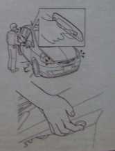 Для отпирания/запирания боковых дверей и двери багажника с помощью брелка «SMART KEY» нажмите на со-ответствующую кнопку.
Также отпереть/запереть двери и заднюю дверь можно, если брелок «SMART KEY» находится у вас в кармане или в сумке.
Модели до 2006 года Двери автоматически отопрутся, когда вы подойдете к автомобилю и возьметесь за ручку любой из передних две¬рей или за ручку задней двери.
Двери автоматически запрутся, когда вы отойдете от автомобиля на рас-стояние более одного метра.
Модели с 2006 года Двери автоматически отопрутся, когда вы подойдете к автомобилю и возьметесь за ручку любой из передних дверей или за ручку задней двери.
Чтобы запереть боковые двери на-жмите на кнопку, показанную на рисунке.
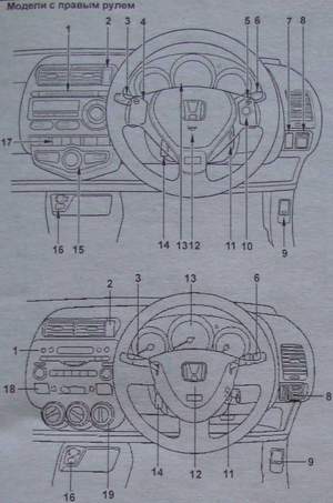
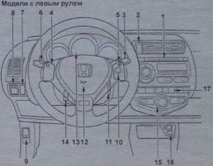
Панель приборов со стороны водителя. 1 — магнитола, 2 — выключатель аварийной сигнализации, 3 — переключатель управления стеклоочистителем и омывателем, 4 — переключатель понижения передачи в режиме ручного переключения, 5 — переключатель повышения передачи в режиме ручного переключения,
6 — переключатель света фар и указателей поворотов,
7 — заглушка, регулятор системы коррекции фар (модели с галогеновыми лампами дальнего света фар), 8 — панель управления положением боковых зеркал, 9 — рычаг привода замка капота, 10 — выключатель режима ручного переключения передач (АКПП), 11 — замок зажигания, 12 — сигнал, 13 — комбинация приборов, 14 — рычаг блокировки рулевой колонки, 15 — панель управления отопителем и кондиционером (с автоматическим управлением), 16 — разъем для подключения внешнего аудиоустройства, 17 — выключатель подогрева боковых зеркал, 18- выключатель обогрева заднего стекла, 19 — панель управления отопителем и кондиционером (с механическим управлением).
Чтобы запереть заднюю дверь нажмите на кнопку, показанную на рисунке.
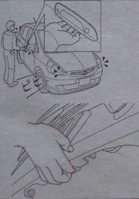
Запирание дверей сопровождается однократным миганием указателей поворотов. Отпирание дверей сопровождается двойным миганием указателей поворотов.
Примечание: двери не запрутся, если ключ находится в замке зажигания, не закрыта какая-либо из дверей. Двери не отопрутся, если после их запирания прошло менее 5 секунд.
 5. На задних боковых дверях установлена дополнительная блокировка дверей. Данная функция позволяет запереть дверь так, что она может быть открыта только снаружи. Рекомендуется
использовать эту функцию каждый раз,
когда в автомобиле находятся маленькие дети. Для включения переместите
запорный рычаг в положение «LOCK».
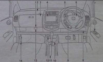 Панель приборов. 1 — разъем для подключения аудио-видеоустройств, 2 — подушка безопасности переднего пассажира, 3 — вещевой ящик, 4 — многофункциональный дисплей, 5 — панель управления магнитолой. 6 — подушка безопасности водителя, 7 — панель управления стеклоподъемниками, 8 — блок предохранителей, 9 — переключатели коммуникационной системы,10 — подстаканники, 11 — рычаг стояночного тормоза, 12 — разъем для подключения дополнительного оборудования, 13 — разъем коммуникационной системы, 14 — фальшфейер.
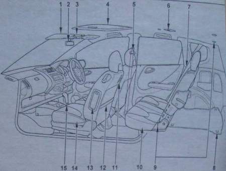 Одометр и счетчик пробега
Одометр и счетчик пробега.
а) Одометр показывает общий пробег автомобиля.
б) Счетчики пробега показывают расстояние, которое проехал автомобиль с момента последней установки счетчика на ноль.
в) Кнопка «ODO/TRIP» предназначена для переключения режимов и для сброса показаний счетчиков пробега на ноль. При кратковременном нажатии на кнопку идет переключение: одометр — счетчик пробега средний расход топлива. При каждом режиме горит соответствующий индикатор. Обнуление счетчика пробега происходит при длительном нажатии на кнопку «ODO/TRIP».
Расположение компонентов в салоне автомобиля. 1 — солнцезащитный козырек, 2 — внутреннее зеркало заднего вида, 3 — лампа местной подсвет ки/лампа освещения передней части салона, 4 — люк, 5 — регулируемое крепление ремня, 6 — лампа освещения задней части салона, 7 — ремень безопасности заднего пассажира, 8 — крюки для крепления сетки фиксации груза, 9 — крепления для детского сиденья ISO FIX, 10 — заднее сиденье, 11 — крючок, 12 — карман, 13 — боковая подушка безопасности, 14 — переднее сиденье, 15 — селектор АКПП
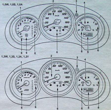
Тахометр
Тахометр показывает число оборотов коленчатого вала двигателя в минуту (об/мин).
Внимание: во время движения следите за показаниями тахометра. Его стрелка, показывающая частоту вращения коленчатого вала двигателя, не должна входить в красную зону (зона повышенных оборотов двигателя).
Указатель количества топлива
Указатель показывает уровень топлива в топливном баке (F — полный бак, Е — пустой бак), когда ключ в замке зажигания находится в положении «II». Индикатор низкого уровня топлива загорается, когда уровень топлива в баке менее 6 литров. В зависимости от комплектации автомобиля топлива может хватить на 40 — 60 км пути. На склонах или при поворотах индикатор может загораться из-за колебаний топлива в баке.
Емкость топливного бака 42 л
Внимание: не ездите при слишком низком уровне топлива в баке. Полная выработка топлива может привести к выходу из строя топливного насоса.
Комбинация приборов (модели до 2006 года). 1 — тахометр, 2 — спидометр, 3 — кнопка переключения одометр/счетчик пробега, 4 — указатель количества топлива, 5 — одометр/счетчик пробега, 6 — индикаторы.
Индикаторы комбинации приборов
1. Индикаторы указателей поворотов. Индикаторы мигают при включении указателей поворотов или аварийной сигнализации. Слишком частое мигание индикаторов указывает на плохое соединение в цепи указателей поворотов или на отказ лампы указателя поворота.
2. Индикатор включения дальнего света фар загорается при включении дальнего света фар.
3. Индикатор включения габаритных огней загорается при включении габаритных огней.
4. Индикатор пониженной температуры охлаждающей жидкости двигателя. Индикатор загорается (зеленый), когда двигатель холодный, и горит до тех пор, пока двигатель не прогреется. Начинать движение рекомендуется, когда двигатель прогреется и индикатор погаснет.
5 Индикатор системы блокировки двигателя.
Индикатор загорается на несколько секунд при переводе ключа в замке зажигания в положение «II», а затем гаснет.
Индикатор начинает мигать, если датчик иммобилайзера не может распознать сигнал от ключа или брелка «SMART KEY”. В этом случае вы не сможете запустить двигатель.
6. Индикатор отключения боковых подушек безопасности.
Индикатор загорается на 5 секунд при переводе ключа в замке зажигания в положение «II». Если на переднем сиденье нет пассажира, то индикатор продолжает гореть, при наличии пассажира на переднем сиденье индикатор гаснет.
7. Индикатор состояния стояночной тормозной системы и уровня тормозной жидкости.
а) Индикатор загорается, если:
— включен стояночный тормоз;
— низкий уровень тормозной жидкости или нарушена герметичность вакуумного усилителя тормозов;
— неисправна электрическая цепь индикатора.
б) Если во время движения загорелся индикатор, то необходимо замедлить скорость, съехать с дороги и осторожно остановить автомобиль. Замедлить скорость можно торможением двигателя и применением стояночного тормоза, но не забудьте при этом нажать на тормозную педаль для включения стоп-сигналов, чтобы предупредить о торможении водителей едущих сзади.
Проверьте стояночный тормоз, возможно, он включен. Если стояночный тормоз выключен, а индикатор горит после его выключения, то возникла неисправность в тормозной системе.
Проверьте уровень тормозной жидкости в бачке.
— Если уровень тормозной жидкости низок, долейте жидкость и в безопасном месте проверьте эффективность торможения автомобиля. Если вы считаете, что тормоза все еще работают достаточно эффективно, то осторожно доведите автомобиль до ближайшего места ремонта. Если тормоза не работают, то автомобиль необходимо отбуксировать или эвакуировать для ремонта.
Внимание: движение в автомобиле с низким уровнем тормозной жидкости опасно.
8. Индикатор низкого давления моторного масла.
а) Индикатор загорается, если давление моторного масла слишком низкое.
б) Если во время движения индикатор мигает или горит, то необходимо съехать на обочину и выключить двигатель.
— Индикатор может мигать после резкого торможения или когда двигатель работает на холостом ходу. Неисправность отсутствует, если индикатор гаснет при небольшом увеличении оборотов двигателя.
— Индикатор может загореться, когда уровень масла в двигателе слишком низок. Но данный индикатор не предназначен для информирования о низком уровне масла, поэтому периодически проверяйте уровень с помощью щупа.
Проверьте уровень масла и убедитесь в отсутствии утечек.
— Если уровень масла находится в допустимых пределах и утечки отсутствуют, отбуксируйте или эвакуируйте автомобиль для ремонта.
— Если уровень масла, ниже минимально допустимого и утечки отсутствуют, долейте масло и запустите двигатель. Если индикатор мигает или горит, то выключите двигатель и отбуксируйте или эвакуируйте автомобиль для ремонта.
9. Индикатор «проверь двигатель» (CHECK ENGINE).
Индикатор загорается при повороте ключа в замке зажигания в положение «II» на несколько секунд, а затем гаснет, информируя водителя о проверке системы управления двигателем. Если индикатор продолжает гореть или загорается во время движения, это свидетельствует о наличии неисправностей в электронной системе управления двигателем. В данном случае необходимо двигаться к месту ремонта и произвести диагностику системы управления двигателем.
10. Индикатор зарядки аккумуляторной батареи.
А) Индикатор загорается при повороте ключа в замке зажигания в положение «II» и должен погаснуть после запуска двигателя.
Б) Если во время движения загорелся индикатор, то неисправна система зарядки или ослаблен (оборван) ремень привода генератора. Однако двигатель будет продолжать работать, пока аккумуляторная батарея полностью не разрядится. Выключите дополнительное оборудование (кондиционер, вентилятор, радио – приемник и др.) и двигайтесь к месту ремонта.
11. Индикатор положения селектора в диапазоне «D».
Мигание индикатора говорит о неисправности АКПП.
12. Индикатор низкого уровня топлива. Индикатор загорается, когда уровень топлива в топливном баке менее 7 литров.
13. Индикатор непристегнутого ремня безопасности водителя.
Индикатор загорается при включении зажигания на несколько секунд, а затем гаснет, если водитель пристегнут. В случае если водитель не пристегнут ремнем безопасности, индикатор продолжает гореть.
14. Индикатор открытой или неплотно закрытой двери.
Индикатор остается включенным до тех пор, пока все двери не будут плотно закрыты.
15. Индикатор повышенной температуры охлаждающей жидкости двигателя. Индикатор загорается (красный) при приближении температуры к критической отметке, что указывает на перегрев двигателя. В этом случае немедленно остановите автомобиль в безопасном месте и выполните процедуры, описанные в разделе «Перегрев двигателя» данной главы. Устраните причину перегрева.
16. Индикатор системы подушек безопасности (SRS).
Индикатор загорается, когда ключ в замке зажигания находится в положении «1» или «II». Через несколько секунд индикатор погаснет. В случае если индикатор не загорелся или горит во время движения, имеется неисправность в компонентах системы SRS.
17. Индикатор антиблокировочной системы тормозов (ABS).
После включения зажигания индикатор загорается на несколько секунд, а затем гаснет. Если во время движения загорается индикатор или индикатор не загорается, или не гаснет при включении двигателя, то возможны неисправности в антиблокировочной системе.
18. Индикатор электроусилителя рулевого управления.
Индикатор загорается при возникновении неисправности в электроусилителе рулевого управления.
Остановите автомобиль в безопасном месте и заглушите двигатель. Подождите несколько минут и вновь запустите двигатель, если индикатор продолжает гореть, эвакуируйте ваш автомобиль на место ремонта.
19. Индикатор брелка «SMART KEY». Индикатор загорается на несколько секунд при переводе ключа в замке зажигания в положение «II», или «0», а затем гаснет.
Если индикатор продолжает гореть, это говорит о не исправности в системе «SMART KEY».
20. Индикатор режима ручного переключения передач загорается, если селектор АКПП находится в положении «D» и нажат выключатель режима ручного переключения. Более подробное описание смотрите в разделе «Управление автомобилем с АКПП». Если индикатор мигает во время движения, то возможна неисправность в системе.
21. Индикатор выбранной передачи в режиме ручного переключения. Индикатор показывает включенную передачу, если селектор АКПП находится в положении «D» и включен режим ручного переключения передач. Более подробное описание смотрите в разделе «Управление автомобилем с АКПП».
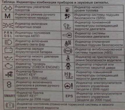
Стеклоподъемники
На моделях с электроприводом стеклоподъемников дверей регулировка положения стекол дверей осуществляется нажатием на соответствующий выключатель. При этом ключ в замке зажигания должен быть установлен в положение «IP.
С панели двери водителя можно управлять положением стекол всех дверей, а также осуществлять их блокировку соответствующим выключателем.
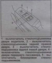
На панели каждой пассажирской двери находится выключатель, нажатием и удерживанием которого пассажир может регулировать положение стекла только со своей стороны.
При легком нажатии на выключатель стеклоподъемника двери водителя вниз стекло будет опускаться до тех пор, пока выключатель будет удерживаться. Для поднятия стекла необходимо слегка потянуть за выключатель вверх и удерживать в таком положении, пока стекло полностью не поднимется.
У выключателя стеклоподъемника двери водителя есть дополнительная функция — полное опускание и полное закрытие стекла водителя («AUTO»), при котором нет необходимости удерживать выключатель в соответствующем положении.
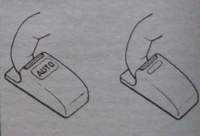
Для опускания стекла нужно нажать на выключатель до конца его хода. При необходимости остановки стекла в приоткрытом положении кратковременно нажмите на выключатель вверх и снова опустите. Для поднимания стекла необходимо потянуть выключатель до конца хода вверх.
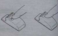
На панели управления стеклоподъемниками находится выключатель блокировки стеклоподъемников «WINDOW LOCK». При его нажатом положении опускание стекол невозможно.
Световая сигнализация в автомобиле
1. Включение габаритов, фар, подсветки комбинации приборов и номерного знака.
Примечание: переключатель света фар и указателей поворота работает независимо от положения ключа в замке зажигания. а) При повороте ручки переключателя до первого щелчка (положение «ON1») включаются габариты, подсветка комбинации приборов и номерного знака. б) При повороте ручки переключателя до второго щелчка (положение «ON2») включается ближний свет фар.
|
Положение ручки |
ON1 |
ON2 |
|
Передние фары |
—- |
О |
|
Габариты |
О |
О |
|
Подсветка номерного знака |
О |
О |
|
Подсветка комбинации приборов |
О |
О |
Внимание: во избежание разряда аккумуляторной батареи при выключенном двигателе не оставляйте фары включенными на длительный промежуток времени.
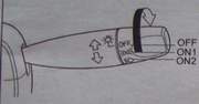 2. Для включения дальнего света фар нажмите на переключатель от себя. Работа фар дальнего света сопровождается высвечиванием на комбинации приборов соответствующего индикатора.
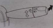
Для выключения дальнего света фар и включения ближнего света фар переведите переключатель в исходное положение.
3. Для кратковременного включения дальнего света фар (сигнализация дальним светом фар) потяните переключатель на себя до упора, затем отпустите.
4. Для включения указателя поворота переведите переключатель в положение вверх или вниз. Переключатель автоматически вернется в исходное положение после завершения поворота. Однако при смене полосы движения, возможно, потребуется рукой вернуть переключатель в нейтральное положение.
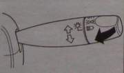
Для включения сигнала смены полосы переведите переключатель вверх или вниз до момента возникновения сопротивления перемещению и установите его в этом положении.
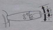
6. Аварийная сигнализация включается нажатием на выключатель, расположенный, как показано на рисунке.
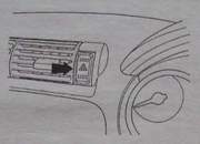
Капот и задняя дверь
1. Для открывания капота необходимо произвести следующие процедуры:
а) Потяните вверх за рычаг привода замка капота, как показано на рисунке.
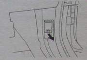
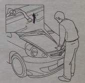
б) Слега приподнимите капот и потяните рычаг блокировки замка капота вверх.
в) Поднимите капот и зафиксируйте его на стойке, как показано на рисунке.
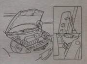
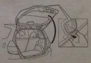 2. Для того чтобы закрыть капот, необходимо освободить стойку капота, уложить ее в штатное место и закрыть капот.
3. Чтобы открыть заднюю дверь возьмитесь за ручку, показанную на рисунке и плавно откройте дверь.
Продолжение следует . .
—>
Найди любой мануал:
Например: Sony VGN-FW460J/T
Вы можете бесплатно скачать Руководство по эксплуатации для Honda 2015 Fit.
Также вы сможете прочесть онлайн этот документ без скачивания.
Скачать Руководство по эксплуатации для Honda 2015 Fit
Тип файла
PDF
Размер
21.19 Mb
Кол-во страниц
453
Просмотров
4263
Читать онлайн Руководство по эксплуатации для Honda 2015 Fit (Страница 1)

Другие Автомобили Honda 2015 Fit
Топ Honda Автомобили
Вопросы
Ранее вы смотрели
Эта страница полезна для вас? Поделитесь ссылкой: